KR100630653B1 - Start control system for internal combustion engine - Google Patents
Start control system for internal combustion engine Download PDFInfo
- Publication number
- KR100630653B1 KR100630653B1 KR1020057003686A KR20057003686A KR100630653B1 KR 100630653 B1 KR100630653 B1 KR 100630653B1 KR 1020057003686 A KR1020057003686 A KR 1020057003686A KR 20057003686 A KR20057003686 A KR 20057003686A KR 100630653 B1 KR100630653 B1 KR 100630653B1
- Authority
- KR
- South Korea
- Prior art keywords
- internal combustion
- combustion engine
- cylinder
- engine
- output shaft
- Prior art date
Links
Images


Classifications
-
- F—MECHANICAL ENGINEERING; LIGHTING; HEATING; WEAPONS; BLASTING
- F02—COMBUSTION ENGINES; HOT-GAS OR COMBUSTION-PRODUCT ENGINE PLANTS
- F02N—STARTING OF COMBUSTION ENGINES; STARTING AIDS FOR SUCH ENGINES, NOT OTHERWISE PROVIDED FOR
- F02N99/00—Subject matter not provided for in other groups of this subclass
- F02N99/002—Starting combustion engines by ignition means
- F02N99/006—Providing a combustible mixture inside the cylinder
-
- F—MECHANICAL ENGINEERING; LIGHTING; HEATING; WEAPONS; BLASTING
- F02—COMBUSTION ENGINES; HOT-GAS OR COMBUSTION-PRODUCT ENGINE PLANTS
- F02D—CONTROLLING COMBUSTION ENGINES
- F02D29/00—Controlling engines, such controlling being peculiar to the devices driven thereby, the devices being other than parts or accessories essential to engine operation, e.g. controlling of engines by signals external thereto
- F02D29/02—Controlling engines, such controlling being peculiar to the devices driven thereby, the devices being other than parts or accessories essential to engine operation, e.g. controlling of engines by signals external thereto peculiar to engines driving vehicles; peculiar to engines driving variable pitch propellers
-
- F—MECHANICAL ENGINEERING; LIGHTING; HEATING; WEAPONS; BLASTING
- F02—COMBUSTION ENGINES; HOT-GAS OR COMBUSTION-PRODUCT ENGINE PLANTS
- F02D—CONTROLLING COMBUSTION ENGINES
- F02D17/00—Controlling engines by cutting out individual cylinders; Rendering engines inoperative or idling
-
- F—MECHANICAL ENGINEERING; LIGHTING; HEATING; WEAPONS; BLASTING
- F02—COMBUSTION ENGINES; HOT-GAS OR COMBUSTION-PRODUCT ENGINE PLANTS
- F02D—CONTROLLING COMBUSTION ENGINES
- F02D41/00—Electrical control of supply of combustible mixture or its constituents
- F02D41/009—Electrical control of supply of combustible mixture or its constituents using means for generating position or synchronisation signals
-
- F—MECHANICAL ENGINEERING; LIGHTING; HEATING; WEAPONS; BLASTING
- F02—COMBUSTION ENGINES; HOT-GAS OR COMBUSTION-PRODUCT ENGINE PLANTS
- F02D—CONTROLLING COMBUSTION ENGINES
- F02D41/00—Electrical control of supply of combustible mixture or its constituents
- F02D41/02—Circuit arrangements for generating control signals
- F02D41/04—Introducing corrections for particular operating conditions
- F02D41/06—Introducing corrections for particular operating conditions for engine starting or warming up
- F02D41/062—Introducing corrections for particular operating conditions for engine starting or warming up for starting
-
- F—MECHANICAL ENGINEERING; LIGHTING; HEATING; WEAPONS; BLASTING
- F02—COMBUSTION ENGINES; HOT-GAS OR COMBUSTION-PRODUCT ENGINE PLANTS
- F02B—INTERNAL-COMBUSTION PISTON ENGINES; COMBUSTION ENGINES IN GENERAL
- F02B2275/00—Other engines, components or details, not provided for in other groups of this subclass
- F02B2275/16—Indirect injection
-
- F—MECHANICAL ENGINEERING; LIGHTING; HEATING; WEAPONS; BLASTING
- F02—COMBUSTION ENGINES; HOT-GAS OR COMBUSTION-PRODUCT ENGINE PLANTS
- F02D—CONTROLLING COMBUSTION ENGINES
- F02D41/00—Electrical control of supply of combustible mixture or its constituents
- F02D41/02—Circuit arrangements for generating control signals
- F02D41/04—Introducing corrections for particular operating conditions
- F02D41/042—Introducing corrections for particular operating conditions for stopping the engine
-
- F—MECHANICAL ENGINEERING; LIGHTING; HEATING; WEAPONS; BLASTING
- F02—COMBUSTION ENGINES; HOT-GAS OR COMBUSTION-PRODUCT ENGINE PLANTS
- F02N—STARTING OF COMBUSTION ENGINES; STARTING AIDS FOR SUCH ENGINES, NOT OTHERWISE PROVIDED FOR
- F02N19/00—Starting aids for combustion engines, not otherwise provided for
- F02N19/005—Aiding engine start by starting from a predetermined position, e.g. pre-positioning or reverse rotation
- F02N2019/007—Aiding engine start by starting from a predetermined position, e.g. pre-positioning or reverse rotation using inertial reverse rotation
-
- Y—GENERAL TAGGING OF NEW TECHNOLOGICAL DEVELOPMENTS; GENERAL TAGGING OF CROSS-SECTIONAL TECHNOLOGIES SPANNING OVER SEVERAL SECTIONS OF THE IPC; TECHNICAL SUBJECTS COVERED BY FORMER USPC CROSS-REFERENCE ART COLLECTIONS [XRACs] AND DIGESTS
- Y02—TECHNOLOGIES OR APPLICATIONS FOR MITIGATION OR ADAPTATION AGAINST CLIMATE CHANGE
- Y02T—CLIMATE CHANGE MITIGATION TECHNOLOGIES RELATED TO TRANSPORTATION
- Y02T10/00—Road transport of goods or passengers
- Y02T10/10—Internal combustion engine [ICE] based vehicles
- Y02T10/12—Improving ICE efficiencies
Abstract
본 발명에 관한 내연기관의 시동제어 장치는 포트 분사형의 내연기관에 있어서, 각 내연기관의 운전정지시에 압축행정 또는 팽창행정이 되는 기관내에 미리 연료를 공급해 두어, 다음 시동시에는 상기 기관내의 연료를 연소시키는 것에 의해, 연료가 연소될 때에 발생하는 압력을 이용하여 기관 출력축을 회전시켜, 이로써 내연기관을 크랭크할 때에 필요한 토크를 저하시켜, 스타트 모터 등의 시동장치에 걸리는 부하는 저하시키는 특징이 있다.The start control apparatus for an internal combustion engine according to the present invention is a port injection type internal combustion engine, which supplies fuel in advance to an engine that becomes a compression stroke or an expansion stroke when each internal combustion engine is stopped, and the fuel in the engine at the next start-up. By burning the engine, the engine output shaft is rotated using the pressure generated when the fuel is combusted, thereby lowering the torque required when cranking the internal combustion engine, thereby reducing the load on the starting device such as a start motor. have.
Description
본 발명은, 자동차등에 탑재되는 내연기관에 관한 것이며, 특히 내연기관의 시동제어기술에 관한 것이다. BACKGROUND OF THE INVENTION 1. Field of the Invention The present invention relates to an internal combustion engine mounted on an automobile or the like, and more particularly to a start control technology for an internal combustion engine.
최근, 내연기관의 시동시에 크랭크샤프트를 회전구동 (즉, 크랭킹) 시키는 수단으로서는 전동기가 일반적이다. 이러한 전동기는 실린더 내의 가스압축력이나 내연기관 각부분의 마찰에 저항하여 크랭크샤프트를 회전구동시킬 필요가 있기 때문에, 전동기의 정격 (high rated performance) 이 커지기 쉽고, 그 결과, 전동기의 소비전력도 커지기 쉽다. In recent years, an electric motor is generally used as a means for rotationally driving (i.e., cranking) a crankshaft at the start of an internal combustion engine. Since such a motor needs to rotate and drive a crankshaft against the gas compression force in a cylinder or friction of each part of an internal combustion engine, the high rated performance of a motor becomes easy, and as a result, the power consumption of an electric motor also becomes large. .
특히, 차량의 정지 기간 중에 내연기관의 운전을 자동적으로 정지시키는 시스템 (소위, 아이들 스톱 시스템 (idle stop system)) 에서는, 내연기관의 운전정지와 시동이 빈번히 반복될 가능성이 있기 때문에, 전동기에 걸리는 부하가 증대하여 전동기의 소비전력이 한층 더 커지는 것이 우려된다. In particular, in a system that automatically stops the operation of the internal combustion engine during a vehicle stopping period (so-called idle stop system), the stopping and starting of the internal combustion engine may be repeated frequently. It is feared that the load increases and the power consumption of the motor becomes even larger.
이에 대하여, 내연기관의 운전이 정지한 상태에서 팽창행정에 있는 실린더를 검출하여, 그 실린더 내에 연료를 분사하여 연소시키는 것에 의해, 전동기에 걸리는 부하를 감소시키고자 하는 기술이 개시되어 있다. On the other hand, the technique which detects the cylinder in an expansion stroke in the state which stopped operation of an internal combustion engine, and injects fuel into the cylinder and burns it, and the technique which reduces the load on an electric motor is disclosed.
상기와 같은 종래의 기술은, 실린더 내에 직접 연료를 분사하는 연료분사밸브를 구비한 내연기관 (소위, 직접 분사 방식의 내연기관) 에 대하여는 유리하나, 실린더의 흡기 포트에 연료를 분사하는 연료 분사 밸브를 구비한 내연기관 (소위, 포트 분사 방식의 내연기관) 에 대하여는 유리하다고 할 수 없다. The prior art as described above is advantageous for an internal combustion engine (so-called direct injection type internal combustion engine) having a fuel injection valve for directly injecting fuel into a cylinder, but a fuel injection valve for injecting fuel into an intake port of the cylinder. It cannot be said that it is advantageous with respect to the internal combustion engine (so-called internal combustion engine of the port injection method) provided with a.
본 발명은, 상기한 바와 같은 문제점을 감안하여 이루어진 것으로, 포트분사형의 내연기관을 효과적으로 시동시키는 것이 가능한 기술을 제공하는 것을 목적으로 한다. The present invention has been made in view of the above problems, and an object thereof is to provide a technique capable of effectively starting a port injection type internal combustion engine.
본 발명은, 상기한 바와 같은 문제를 해결하기 위하여 이하와 같은 수단을 채용하였다. 즉, 본 발명에 있어서 내연기관의 시동제어장치는The present invention employs the following means in order to solve the above problems. That is, in the present invention, the start control device of the internal combustion engine
내연기관의 흡기통로에 연료분사하는 연료분사밸브와,A fuel injection valve for injecting fuel into the intake passage of the internal combustion engine,
내연기관의 실린더 내에서 점화하는 점화플러그와, Spark plugs that ignite in the cylinder of the internal combustion engine,
내연기관의 운전정지조건이 성립하였을 때에, 상기 점화플러그의 작동만을 정지시키는 점화정지수단 및, Ignition stop means for stopping only the operation of the spark plug when the operation stop condition of the internal combustion engine is established;
내연기관의 시동조건이 성립한 때에, 팽창행정에 있는 실린더의 점화플러그를 작동시키는 시동제어 수단을 구비하는 것을 특징으로 하는 내연기관의 시동제어장치이다.And a start control means for operating a spark plug of a cylinder in an expansion stroke when the start condition of the internal combustion engine is established.
본 발명은, 흡기통로에 연료를 분사하는 연료분사밸브를 구비한 내연기관에 있어서, 내연기관의 운전정지조건이 성립한 때에 연료분사밸브의 작동을 계속하면서 점화플러그의 작동을 정지하는 것에 의해, 내연기관의 운전을 정지시킴과 동시에 내연기관의 운전정지 시에 팽창행정이 되는 실린더 내에 미연의 연료를 봉입하여, 그 후의 시동 시에는 상기 실린더 내의 연료를 연소시키는 것에 의해, 연료가 연소할 때에 발생하는 압력을 이용하여 내연기관을 시동시키는 것을 최대의 특징으로 한다. The present invention is directed to an internal combustion engine including a fuel injection valve for injecting fuel into an intake passage, wherein the operation of the fuel injection valve is stopped while the operation of the fuel injection valve is satisfied when the operating stop condition of the internal combustion engine is established. Occurs when fuel is combusted by stopping the operation of the internal combustion engine and enclosing unburned fuel in a cylinder that becomes an expansion stroke when the internal combustion engine is stopped. It is the biggest feature to start the internal combustion engine by using pressure.
이러한 내연기관의 시동제어장치에서는, 내연기관의 운전정지요구가 발생하였을 때에, 점화정지수단이 점화플러그의 작동만을 정지시킨다. In such a start control device of the internal combustion engine, when the operation stop request of the internal combustion engine occurs, the ignition stop means stops only the operation of the spark plug.
이 경우, 연료분사밸브가 계속 작동하기 때문에, 연료분사밸브로 부터 흡기통로에 분사된 연료는 흡기통로 내의 공기와 함께 내연기관의 실린더 내로 흡입되어 혼합기를 형성한다. 다만, 점화플러그의 작동이 이미 정지되어 있기 때문에, 내연기관의 실린더 내에 형성된 혼합기는 연소되지 않게 된다. In this case, since the fuel injection valve continues to operate, fuel injected into the intake passage from the fuel injection valve is sucked into the cylinder of the internal combustion engine together with the air in the intake passage to form a mixer. However, since the operation of the spark plug is already stopped, the mixer formed in the cylinder of the internal combustion engine is not burned.
이 결과, 기관출력축 (크랭크샤프트) 의 회전이 정지하여 내연기관의 운전이 정지됨과 동시에, 그 순간에 팽창행정이 되는 실린더 (이하, 정지시 팽창행정실린더라 칭함) 안에 미연의 혼합기가 봉입된 상태가 된다. As a result, the rotation of the engine output shaft (crankshaft) stops, the operation of the internal combustion engine is stopped, and an unburned mixer is enclosed in a cylinder (hereinafter referred to as an expansion stroke cylinder when it stops) at that moment. Becomes
그 후, 내연기관의 시동조건이 성립하였을 때에, 시동제어수단은 정지시 팽창행정실린더의 점화플러그를 작동시켜, 정지시 팽창행정실린더 내에 봉입되어 있는 미연혼합기를 연소시킨다. Thereafter, when the start condition of the internal combustion engine is established, the start control means operates the spark plug of the expansion stroke cylinder at the stop, and burns the unburned mixer enclosed in the expansion stroke cylinder at the stop.
이와같이 정지시 팽창행정실린더에서 혼합기가 연소하면, 그 순간에 발생하는 연소압력이 기관출력축을 회전시키도록 작용하기 때문에, 내연기관을 크랭킹시키는데에 필요한 토크가 감소된다. Thus, when the mixer burns in the expansion stroke cylinder at rest, the torque required to crank the internal combustion engine is reduced because the combustion pressure generated at that moment acts to rotate the engine output shaft.
이 결과, 시동 모터나 모터 제너레이터 등과 같은 시동장치에 걸리는 부하가 감소된다. As a result, the load on the starting device such as a starting motor, a motor generator, or the like is reduced.
또, 본 발명의 내연기관의 시동제어장치에 있어서, 점화정지수단은 내연기관의 운전정지요구가 발생하였을 때에 점화플러그 및 연료분사밸브의 작동을 일단 정지시켜, 내연기관 기관출력축의 회전이 정지하기 직전에 연료분사밸브만을 재차 작동시키도록 해도 좋다. Further, in the start control device of the internal combustion engine of the present invention, the ignition stop means stops the operation of the ignition plug and the fuel injection valve once the operation stop request of the internal combustion engine occurs, so that the rotation of the internal combustion engine output shaft stops. Only the fuel injection valve may be operated again immediately before.
이것은, 내연기관의 운전정지조건이 성립하였을 때부터 내연기관의 운전이 실제로 정지할 때까지의 기간에는 기관출력축이 몇바퀴 회전하게 되기 때문에, 내연기관의 운전정지조건이 성립한 직후에 연료분사밸브로부터 분사되는 연료는 실린더 내에 머물러있지 않고 배출되어 버리는 가능성이 높기 때문이다. This is because the engine output shaft rotates several times during the period from when the operation stop condition of the internal combustion engine is established until the operation of the internal combustion engine is actually stopped. Therefore, the fuel injection valve immediately after the operation stop condition of the internal combustion engine is established. This is because the fuel injected from the gas is likely to be discharged without remaining in the cylinder.
또한, 본 발명의 내연기관의 시동제어장치에 있어서, 시동제어수단은 내연기관의 운전정지기간이 소정기간 이상이 된 경우에는, 내연기관을 강제적으로 시동시키도록 해도 좋다. Further, in the start control apparatus of the internal combustion engine of the present invention, the start control means may force the internal combustion engine to be forcibly started when the operation stop period of the internal combustion engine is equal to or longer than a predetermined period.
이것은, 내연기관의 운전정지기간이 지나치게 길게되면, 정지시 팽창행정실린더 내에 봉입되어 있는 혼합기가 연료와 공기로 분리되고 또한 피스톤과 실린더 사이의 틈 등으로 부터 누출될 수 있기 때문이다. This is because, if the operation stop period of the internal combustion engine is too long, the mixer enclosed in the expansion stroke cylinder at the stop may separate into fuel and air and leak from the gap between the piston and the cylinder or the like.
또한, 본 발명은 전술한 바와 같은 과제를 해결하기 위하여, 이하와 같은 수단을 채용해도 좋다. 즉, 본 발명에 있어서 내연기관의 시동제어장치는 In addition, the present invention may employ the following means in order to solve the problems as described above. That is, in the present invention, the start control device of the internal combustion engine
내연기관의 흡기통로에 연료분사하는 연료분사밸브와,A fuel injection valve for injecting fuel into the intake passage of the internal combustion engine,
내연기관의 실린더 내에서 점화하는 점화플러그와, Spark plugs that ignite in the cylinder of the internal combustion engine,
내연기관의 운전정지조건이 성립하였을 때에, 상기 점화플러그 및 상기 연료분사밸브의 작동을 정지시키는 운전정지수단과, An operation stop means for stopping the operation of the spark plug and the fuel injection valve when an operation stop condition of the internal combustion engine is established;
내연기관의 기관출력축의 회전이 정지하는 순간에 팽창행정이 되는 실린더를 예측하는 예측수단과, Prediction means for predicting a cylinder that becomes an expansion stroke at the moment when the rotation of the engine output shaft of the internal combustion engine stops;
내연기관의 기관출력축의 회전이 정지하기 직전에, 상기 예측수단에 의해 예측된 실린더의 연료분사밸브를 재차 작동시키는 연료분사제어수단과,Just before the rotation of the engine output shaft of the internal combustion engine stops, fuel injection control means for operating the fuel injection valve of the cylinder predicted by the prediction means again;
내연기관의 시동조건이 성립하였을 때에, 상기 예측수단에 의해 예측된 실린더의 점화플러그를 작동시키는 시동제어수단을 구비하게 해도 된다. When the start condition of the internal combustion engine is established, a start control means for operating the spark plug of the cylinder predicted by the predicting means may be provided.
본 발명은, 흡기통로에 연료를 분사하는 연료분사밸브를 구비한 내연기관에 있어서, 내연기관의 운전정지시에 팽창행정이 되는 실린더를 예측하여, 그 실린더에 대하여 내연기관의 운전정지 직전에 미리 연료를 공급한 놓은 것에 의해, 그 후의 시동시에 상기 실린더내의 연료를 연소시켜 그 순간에 발생하는 압력을 이용하여 내연기관을 시동시키는 것을 최대의 특징으로 한다. The present invention is directed to an internal combustion engine including a fuel injection valve for injecting fuel into an intake passage, which predicts a cylinder to be an expansion stroke when the internal combustion engine is stopped, and advances the cylinder immediately before the internal combustion engine is stopped. By supplying fuel, it is the biggest feature that the internal combustion engine is started using the pressure generated at that moment by burning the fuel in the cylinder at the time of subsequent start.
내연기관의 시동제어장치에 있어서, 내연기관의 운전정지 조건이 성립하였을 때에, 운전정지수단이 점화플러그 및 연료분사밸브의 작동을 정지시킨다. 점화플러그 및 연료분사밸브의 작동이 정지되면, 기관출력축의 회전이 점차 저하하게 된다.In the start control device of the internal combustion engine, the operation stop means stops the operation of the spark plug and the fuel injection valve when the operation stop condition of the internal combustion engine is satisfied. When the operation of the spark plug and the fuel injection valve is stopped, the rotation of the engine output shaft gradually decreases.
그 때에, 예측수단은 기관출력축의 회전이 정지할 때에 팽창행정이 되는 실린더 (이하, 정지시 팽창행정실리더라 칭함) 를 예측한다. 이어서, 연료분사제어수단은 기관출력축의 회전이 정지하기 직전에 상기 정지시 팽창행정 실린더의 연료분사밸브를 작동시킨다. At that time, the predicting means predicts a cylinder (hereinafter referred to as an expansion stroke cylinder at rest) that becomes an expansion stroke when the rotation of the engine output shaft stops. Then, the fuel injection control means operates the fuel injection valve of the expansion stroke cylinder at the stop immediately before the rotation of the engine output shaft stops.
상기 연료분사밸브로부터 흡기통로에 분사된 연료는, 정지시 팽창 행정실린더가 흡기행정에 있을 때에 흡기 통로내의 공기와 함께 정지시 팽창행정실린더에 흡입되어 혼합기를 형성한다. 그 후, 정지시 팽창행정실린더가 압축행정을 거쳐 팽창행정에 이르는 시점에서 기관출력축의 회전이 정지한다. The fuel injected from the fuel injection valve into the intake passage is sucked into the expansion stroke cylinder at the stop with the air in the intake passage when the expansion stroke cylinder is at the intake stroke to stop the mixer. Thereafter, the rotation of the engine output shaft stops when the expansion stroke cylinder reaches the expansion stroke through the compression stroke at the stop.
이 결과, 정지시 팽창행정 실린더 내에 미연혼합기가 봉입된 상태로 내연기관의 운전이 정지되게 된다. As a result, the operation of the internal combustion engine is stopped while the unmixed mixer is sealed in the expansion stroke cylinder at the time of stopping.
내연기관의 다음 시동시에는 시동제어수단이 정지시 팽창행정 실린더의 점화플러그를 작동시키는 것에 의해, 정지시 팽창행정실린더 내의 미연혼합기를 연소시킨다. At the next start of the internal combustion engine, the start control means activates the spark plug of the expansion stroke cylinder at stop, thereby burning the unmixed mixture in the expansion stroke cylinder at stop.
이와 같이 정지시 팽창행정 실린더에 있어서 혼합기가 연소하면, 이 순간에 발생하는 연소압력이 기관출력축을 회전시키도록 작용하기 때문에, 내연기관을 크랭킹시킬 때에 필요하게 되는 토크가 감소된다. In this way, when the mixer burns in the expansion stroke cylinder at rest, since the combustion pressure generated at this moment acts to rotate the engine output shaft, the torque required when cranking the internal combustion engine is reduced.
이 결과, 시동모터나 모터제너레이터 등과 같은 시동장치에 걸리는 부하가 감소된다. As a result, the load on the starting device such as the starting motor, the motor generator, or the like is reduced.
본 발명에 있어서 내연기관의 시동제어장치는 정지시 팽창행정 실린더가 팽창행정에 도달하기 이전에 기관출력축의 회전이 정지해 버리는 경우에, 정지시 팽창행정실린더가 팽창행정이 될 때까지 기관출력축을 회전시키는 출력축회전수단을 구비해도 좋다. In the present invention, when the start control device of the internal combustion engine stops the rotation of the engine output shaft before the expansion stroke cylinder reaches the expansion stroke when stopped, the engine output shaft until the expansion stroke cylinder becomes the expansion stroke when stopped. An output shaft rotating means for rotating may be provided.
이 출력축회전수단은 내연기관의 운전정지시 (예를들면, 기관출력축의 회전이 정지했을 때) 에 정지시 팽창행정실린더가 팽창행정이 될 때까지 기관출력축을 회전시켜도 좋고, 또는 내연기관의 다음 시동시에 상기 정지시 팽창행정 실린더가 팽창행정이 될 때 까지 기관출력축을 회전시켜도 좋다.The output shaft rotation means may rotate the engine output shaft when the internal combustion engine stops operating (e.g., when the rotation of the engine output shaft stops) until the expansion stroke cylinder becomes an expansion stroke, or the next of the internal combustion engine. The engine output shaft may be rotated at startup until the expansion stroke cylinder at the stop becomes the expansion stroke.
이 경우에, 시동제어수단은 상기 정지시 팽창행정 실린더가 팽창행정이 된 시점에서 그 정지시 팽창행정실린더의 점화플러그를 작동시키게 해도 된다.In this case, the start control means may cause the ignition plug of the expansion stroke cylinder to be activated at the stop at the time when the expansion stroke cylinder becomes the expansion stroke at the stop.
정지시 팽창행정실린더가 팽창행정이 될 때까지 기관출력축을 회전시키는 경우에는, 예를 들어, 시동모터나 모터제너레이터 등의 시동장치를 작동시킬 필요가 있지만, 그 작동시간은 극히 짧게된다. 또한 정지시 팽창행정실린더가 팽창행정이 된 시점에서 이 정지시 팽창행정실린더 내의 미연혼합기가 연소되어, 이 순간에 발생하는 연소압력이 기관출력축을 회전시키도록 작용하기 때문에 정지시 팽창행정실린더가 압축행정에서 팽창행정으로 이동된 후에 시동장치에 걸리는 부하가 감소하게 된다.When the engine output shaft is rotated until the expansion stroke cylinder becomes an expansion stroke at the time of stop, it is necessary to operate a starter such as a starting motor or a motor generator, for example, but its operation time is extremely short. In addition, when the expansion stroke is stopped at the expansion stroke, the unmixed mixture in the expansion stroke is burned, and the combustion pressure generated at this moment acts to rotate the engine output shaft. After moving from the stroke to the expansion stroke, the load on the starting device is reduced.
또한, 본 발명의 내연기관의 시동제어장치에 있어서, 예측수단은 정지시 팽창행정실린더를 예측하는 대신에, 내연기관의 기관출력축의 회전이 정지할 때에 압축행정이 되는 실린더 (이하, 정지시 압축행정실린더라 칭함) 를 예측하게 해도 좋다.Further, in the start control apparatus of the internal combustion engine of the present invention, the predicting means is a cylinder which becomes a compression stroke when the rotation of the engine output shaft of the internal combustion engine stops instead of predicting the expansion stroke cylinder at the stop (hereinafter, the compression at the stop) May be called an administrative cylinder).
이 경우, 연료분사제어수단은, 내연기관의 기관출력축의 회전이 정지하기 직전에, 예측수단에 의해 예측된 실린더의 연료분사밸브를 재차 작동시킨다. 출력축회전수단은, 예측수단에 의해 예측된 실린더가 팽창행정이 될 때까지 기관출력축을 회전시킨다. 더욱이, 시동제어수단은 내연기관의 시동조건이 성립하였을 때에, 정지시 압축행정실린더의 점화플러그를 작동시킨다. In this case, the fuel injection control means again operates the fuel injection valve of the cylinder predicted by the predicting means just before the rotation of the engine output shaft of the internal combustion engine stops. The output shaft rotating means rotates the engine output shaft until the cylinder predicted by the predicting means becomes the expansion stroke. Further, the start control means operates the spark plug of the compression stroke cylinder at the stop when the start condition of the internal combustion engine is established.
이와 같이 정지시 압축행정실린더가 팽창행정이 될 때까지 기관출력축이 회전한 상태로 정지시 압축행정실린더 내의 혼합기가 연소하면, 그 순간에 발생하는 연소압력이 기관출력축을 회전시키도록 작용하기 때문에, 내연기관을 크랭킹시키는 데 필요한 토크가 감소된다. In this way, when the engine output shaft rotates until the compression stroke cylinder becomes the expansion stroke when stopped, and the mixer in the compression stroke cylinder stops burning, the combustion pressure generated at that moment acts to rotate the engine output shaft. The torque required to crank the internal combustion engine is reduced.
정지시 압축행정실린더가 팽창행정이 될 때까지 기관출력축을 회전시키는 경우에는, 예를 들어, 시동모터나 모터제너레이터 등의 시동장치를 작동시키는 필요가 있지만, 작동시간은 극히 짧다. 또한, 정지시 압축행정 실린더가 팽창행정이 된 시점에서 그 정지시 압축행정 실린더의 미연 혼합기가 연소되어, 그 순간에 발생하는 연소압력이 기관출력축을 회전시키도록 작용하기 때문에, 정지시 압축행정실린더가 압축행정에서 팽창행정으로 이행한 후는 시동장치에 걸리는 부하가 감소되게 된다. When the engine output shaft is rotated until the compression stroke cylinder becomes an expansion stroke at the time of stop, it is necessary to operate a starter such as a starting motor or a motor generator, for example, but the operation time is extremely short. In addition, the uncompressed mixer of the compression stroke cylinder is burned at the time when the compression stroke cylinder becomes the expansion stroke at rest, and the combustion pressure generated at that moment acts to rotate the engine output shaft. After the transition from the compression stroke to the expansion stroke, the load on the starting device is reduced.
이 결과, 시동모터나 모터 제너레이터 등과 같은 시동장치에 걸리는 부하가 감소된다. As a result, the load on the starting device such as a starting motor, a motor generator, or the like is reduced.
또한, 본 발명의 내연기관의 시동제어장치에 있어서, 시동제어수단은, 내연기관의 운전정지기간이 소정기간 이상이 된 경우에는, 내연기관을 강제적으로 시동시켜도 좋다. Further, in the start control apparatus of the internal combustion engine of the present invention, the start control means may forcibly start the internal combustion engine when the operation stop period of the internal combustion engine is longer than a predetermined period.
이것은, 내연기관의 운전정지기간이 지나치게 길게 되면, 정지시 팽창행정 실린더 내에 봉입되어 있는 혼합기가 연료와 공기로 분리되어 버리고, 피스톤과 실린더 사이의 틈 등으로부터 누출될 수 있기 때문이다. This is because, when the operation stop period of the internal combustion engine becomes too long, the mixer enclosed in the expansion stroke cylinder at the time of stop may separate into fuel and air, and may leak from the gap between the piston and the cylinder.
또한, 본 발명의 내연기관의 시동제어장치에 있어서, 예측수단이 기관출력축의 회전정지시에 팽창행정이 되는 실린더 (정지시 팽창행정 실린더) 에 더하여 압축행정이 되는 실린더 (이하 정지시 압축행정 실린더라 칭함) 를 예측하여, 연료분사제어수단이 기관출력축의 회전정지 직전에 정지시 압축행정 실린더 및 정지시 팽창행정실린더의 연료분사밸브를 작동시키는 것에 의해, 정지시 압축행정실린더 및 정지시 팽창행정실린더 내에 미연의 혼합기를 봉입해도 좋다. Further, in the start control apparatus of the internal combustion engine of the present invention, the predicting means is a cylinder that becomes a compression stroke in addition to a cylinder that becomes an expansion stroke when rotation of the engine output shaft is stopped (expansion stroke when stopped). By the fuel injection control means operating the fuel injection valve of the compression stroke cylinder at the stop and the expansion stroke cylinder at the stop immediately before the rotational stop of the engine output shaft, the compression stroke cylinder at the stop and the expansion stroke at the stop You may enclose an unburned mixer in a cylinder.
이 경우, 내연기관의 다음 시동조건이 성립했을 때에 시동제어수단은 먼저 정지시 팽창행정 실린더의 점화플러그를 작동시켜서 기관출력축을 회전시키고, 이어서 정지시 압축행정실린더가 팽창행정이 된 시점에서 그 정지시 압축행정실린더의 점화플러그를 작동시켜도 된다.In this case, when the next starting condition of the internal combustion engine is established, the start control means first activates the spark plug of the expansion stroke cylinder when it stops to rotate the engine output shaft, and then stops the compression stroke when the compression stroke cylinder becomes the expansion stroke. The spark plug of the compression stroke cylinder may be activated.
이와 같이 정지시 팽창행정실린더 및 정지시 압축행정실린더에 있어서 미연혼합기가 연소되면, 정지시 팽창행정실린더 내의 미연혼합기가 연소되었을 순간에 발생하는 연소압력에 더하여, 정지시 압축행정 실린더 내의 미연혼합기가 연소되는 순간에 발생하는 연소압력이 기관출력축을 회전시키도록 작용하기 때문에, 내연기관을 크랭킹시키는데 필요하게 되는 토크가 한층 더 감소하게 된다. In this way, when the unmixed mixture is burned in the expansion stroke cylinder at standstill and the compression stroke cylinder at standstill, the unmixed mixture in the compression stroke cylinder at standstill is added to the combustion pressure generated at the moment when the unmixed mixture in the expansion stroke cylinder is stopped. Since the combustion pressure generated at the moment of combustion acts to rotate the engine output shaft, the torque required to crank the internal combustion engine is further reduced.
본 발명은, 전술한 바와 같은 과제를 해결하기 위하여 이하와 같은 수단을 채용해도 좋다. 즉, 본 발명의 내연기관의 시동제어장치는, In order to solve the problems as described above, the present invention may employ the following means. That is, the start control device of the internal combustion engine of the present invention,
내연기관의 흡기통로에 연료분사하는 연료분사밸브와, A fuel injection valve for injecting fuel into the intake passage of the internal combustion engine,
내연기관의 실린더 내에서 점화하는 점화플러그와, Spark plugs that ignite in the cylinder of the internal combustion engine,
내연기관의 운전정지조건이 성립하였을 때에, 상기 점화플러그 및 상기 연료분사밸브의 작동을 정지시키는 운전정지수단과, An operation stop means for stopping the operation of the spark plug and the fuel injection valve when an operation stop condition of the internal combustion engine is established;
내연기관의 기관출력축의 회전이 정지하기 전에 특정 실린더의 연료분사밸브를 재차 작동시키는 연료분사제어수단과, Fuel injection control means for restarting the fuel injection valve of the specific cylinder before the rotation of the engine output shaft of the internal combustion engine stops;
상기 특정 실린더가 팽창행정이 된 시점에서 상기 기관출력축의 회전을 정지시키는 출력축정지수단과, An output shaft stop means for stopping the rotation of the engine output shaft when the specific cylinder becomes the expansion stroke;
내연기관의 시동조건이 성립하였을 때에, 상기 특정실린더의 점화플러그를 작동시키는 시동제어수단을 구비해도 좋다. The start control means for operating the spark plug of the specific cylinder when the start condition of the internal combustion engine is established may be provided.
본 발명은 흡기통로에 연료를 분사하는 연료분사밸브를 구비한 내연기관에 있어서, 내연기관의 운전이 정지하기 전에 특정 실린더의 연료분사밸브를 작동시킴과 동시에, 특정 실린더가 팽창행정이 된 시점에서 내연기관의 운전을 정지시키는 것에 의해, 상기 특정실린더 내에 미연의 연료를 봉입하여, 그 후의 시동 시에는 상기 특정실린더 내의 연료를 연소시키는 것에 의해, 연료가 연소하는 순간에 발생하는 연소압력을 이용하여 내연기관을 시동시키는 것을 최대의 특징으로 한다. The present invention relates to an internal combustion engine having a fuel injection valve for injecting fuel into an intake passage, wherein the fuel injection valve of a specific cylinder is operated before the operation of the internal combustion engine is stopped, and at the time when the specific cylinder becomes an expansion stroke, By unloading unburned fuel in the specific cylinder by stopping the operation of the internal combustion engine, and burning the fuel in the specific cylinder at a subsequent start-up, by using the combustion pressure generated at the moment of combustion of the fuel Starting the internal combustion engine is the biggest feature.
내연기관의 시동제어장치에서는, 내연기관의 운전정지조건이 성립했을 때에, 운전정지수단이 점화플러그 및 연료분사밸브의 작동을 정지시킨다. 점화플러그 및 연료분사밸브의 작동이 정지되면, 기관출력축의 회전이 서서히 저하하게 된다. In the start control device of the internal combustion engine, the operation stop means stops the operation of the spark plug and the fuel injection valve when the operation stop condition of the internal combustion engine is established. When the operation of the spark plug and the fuel injection valve is stopped, the rotation of the engine output shaft gradually decreases.
기관출력축의 회전이 저하하여 정지하기 직전에, 연료분사제어수단이 특정실린더의 연료분사밸브를 작동시킨다. 연료분사밸브로부터 흡기통로에 분사된 연료는, 특정실린더가 흡기행정에 있을 때에, 흡기통로 내의 공기와 함께 상기 특정실린더 내에 흡입되어 혼합기를 형성한다. Immediately before the rotation of the engine output shaft decreases and stops, the fuel injection control means operates the fuel injection valve of the specific cylinder. The fuel injected from the fuel injection valve into the intake passage is sucked into the specific cylinder together with the air in the intake passage when the specific cylinder is in the intake stroke to form a mixer.
이어서, 상기 특정실린더가 압축행정을 거쳐 팽창행정에 이를 때에, 출력축정지수단이 기관출력축의 회전을 정지시킨다. Subsequently, when the specific cylinder reaches the expansion stroke through the compression stroke, the output shaft stop means stops the rotation of the engine output shaft.
이 결과, 특정 실린더 내에 미연혼합기가 봉입된 상태로 내연기관의 운전이 정지되게 된다. As a result, the operation of the internal combustion engine is stopped while the unburned mixer is sealed in the specific cylinder.
내연기관의 다음 시동 시에는, 시동제어수단이 특정실린더의 점화플러그를 작동시키는 것에 의해, 특정실린더 내의 미연혼합기를 연소시킨다. At the next start of the internal combustion engine, the start control means burns the unburned mixer in the specific cylinder by operating the spark plug of the specific cylinder.
이와 같이 특정 실린더에 있어서, 혼합기가 연소하면, 그 순간에 발생하는 연소압력이 기관출력축을 회전시키도록 작용하기 때문에, 내연기관을 크랭킹시킬 순간에 필요하게 되는 토크가 감소된다. Thus, in a specific cylinder, when a mixer burns, since the combustion pressure which generate | occur | produces at that moment acts to rotate an engine output shaft, the torque required at the time of cranking an internal combustion engine is reduced.
이 결과, 시동모터나 모터 제너레이터 등과 같은 시동장치에 걸리는 부하가 감소된다. As a result, the load on the starting device such as a starting motor, a motor generator, or the like is reduced.
또한, 본 발명의 내연기관의 시동제어장치는 특정실린더가 팽창행정에 도달하기 전에 기관출력축의 회전이 정지되어 버린 경우에, 특정실린더가 팽창행정이 될 때까지 기관출력축을 회전시키는 출력축회전수단을 구비해도 좋다. In addition, the start control apparatus of the internal combustion engine of the present invention includes an output shaft rotating means for rotating the engine output shaft until the specific cylinder becomes an expansion stroke, when the rotation of the engine output shaft is stopped before the specific cylinder reaches the expansion stroke. You may provide it.
이러한 구성으로, 내연기관의 운전정지시 (예를 들어, 기관출력축의 회전이 정지했을 시) 에 출력축회전수단은 정지시 팽창행정실린더가 팽창행정이 될 때까지 기관출력축을 회전시켜도 좋고, 또는 내연기관의 다음 시동 시에 상기 정지시 팽창행정실린더가 팽창행정이 될 때까지 기관출력축을 회전시켜도 좋다. With such a configuration, the output shaft rotating means may rotate the engine output shaft until the expansion stroke cylinder becomes an expansion stroke when the internal combustion engine stops operating (for example, when the rotation of the engine output shaft stops), or the internal combustion engine At the next start of the engine, the engine output shaft may be rotated until the expansion stroke cylinder at the stop reaches the expansion stroke.
이 경우, 시동제어수단은 상기 특정실린더가 팽창행정이 된 시점에서 그 특정실린더의 점화플러그를 작동시키면 된다. In this case, the start control means may operate the ignition plug of the specific cylinder at the time when the specific cylinder becomes the expansion stroke.
또한, 본 발명의 내연기관의 시동제어장치에 있어서, 출력축정지수단은, 특정실린더가 압축행정이 된 시점에서 기관출력축의 회전을 정지시키도록 해도 좋다. Further, in the start control apparatus of the internal combustion engine of the present invention, the output shaft stop means may stop the rotation of the engine output shaft when the specific cylinder is compressed.
이 경우, 본 발명의 내연기관의 시동제어장치는, 특정실린더가 팽창행정이 될 때까지 기관출력축을 회전시키는 출력축회전수단을 구비하여, 이 출력축회전수단은 내연기관의 운전정지시 또는 내연기관의 다음 시동시에 특정실린더가 팽창행정이 될 때까지 기관출력축을 회전시키고, 시동제어수단은 특정실린더가 팽창행정에 있는 조건으로 그 특정실린더의 점화플러그를 작동시키도록 해도 좋다. In this case, the start control apparatus of the internal combustion engine of the present invention includes an output shaft rotating means for rotating the engine output shaft until the specific cylinder becomes an expansion stroke, and the output shaft rotating means is configured to stop the operation of the internal combustion engine or the internal combustion engine. At the next start-up, the engine output shaft may be rotated until the specific cylinder reaches the expansion stroke, and the start control means may operate the spark plug of the specific cylinder under the condition that the specific cylinder is in the expansion stroke.
또한, 본 발명의 내연기관의 시동제어장치에 있어서, 시동제어수단은 내연기관의 운전정지기간이 소정기간 이상이 된 경우에는, 내연기관을 강제적으로 시동시켜도 좋다. Further, in the start control apparatus of the internal combustion engine of the present invention, the start control means may forcibly start the internal combustion engine when the operation stop period of the internal combustion engine is longer than a predetermined period.
이것은 내연기관의 운전정지기간이 지나치게 길게되면, 특정실린더 내에 봉입되어 있는 혼합기가 연료와 공기로 분리되어 버리고, 피스톤과 실린더 사이의 틈 등으로 부터 누출될 수 있기 때문이다. This is because if the operation stop period of the internal combustion engine is too long, the mixer enclosed in the specific cylinder may be separated into fuel and air, and may leak from the gap between the piston and the cylinder.
도 1 은 본 발명에 적용되는 내연기관의 개략구성을 도시하는 도.1 is a diagram showing a schematic configuration of an internal combustion engine applied to the present invention.
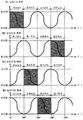
도 2 는 크랭크각도와 각 실린더 행정의 관계를 도시하는 도.Fig. 2 is a diagram showing the relationship between the crank angle and each cylinder stroke.
도 3 은 제 1 실시형태에 있어서, 정지제어루틴을 도시하는 순서도.Fig. 3 is a flowchart showing a stop control routine in the first embodiment.
도 4 는 제 1 실시형태에 있어서, 시동제어루틴을 도시하는 순서도.Fig. 4 is a flowchart showing a start control routine in the first embodiment.
도 5 는 제 2 실시형태에 있어서, 정지제어루틴을 도시하는 순서도.Fig. 5 is a flowchart showing a stop control routine in the second embodiment.
도 6 은 제 2 실시형태에 있어서, 시동제어루틴을 도시하는 순서도.Fig. 6 is a flowchart showing a start control routine in the second embodiment.
도 7 은 제 3 실시형태에 있어서, 정지제어루틴을 도시하는 순서도.Fig. 7 is a flowchart showing a stop control routine in the third embodiment.
도 8 은 제 3 실시형태에 있어서 시동제어루틴을 도시하는 순서도.Fig. 8 is a flowchart showing a start control routine in the third embodiment.
이하, 본 발명의 내연기관의 시동제어장치의 구체적인 실시형태에 관해서 도면을 참조로 설명한다. EMBODIMENT OF THE INVENTION Hereinafter, the specific embodiment of the starting control apparatus of the internal combustion engine of this invention is described with reference to drawings.
<실시형태 1> <Embodiment 1>
먼저, 본 발명의 내연기관의 시동제어장치의 제 1 실시형태에 관해서 도 1 ∼ 도 4 를 참조로 설명한다. First, a first embodiment of a start control apparatus for an internal combustion engine of the present invention will be described with reference to FIGS. 1 to 4.
도 1 은 본 발명이 적용되는 내연기관의 개략구성을 나타내는 도이다. 도 1 로 보인 내연기관 (1) 은 4 개의 실린더 (2) 가 직렬로 배치된 4 행정 사이클의 가솔린기관이다. 1 is a view showing a schematic configuration of an internal combustion engine to which the present invention is applied. The internal combustion engine 1 shown in FIG. 1 is a four-stroke cycle gasoline engine in which four
내연기관 (1) 의 각 실린더 (2) 에는, 흡기밸브 (3) 와 배기밸브 (4) 가 설치되어 있으며 또한 점화플러그 (5) 가 설치되어 있다. Each
내연기관 (1) 에는, 흡기통로 (6) 와 배기통로 (7) 가 접속되어 있다. 상기 흡기통로 (6) 는 흡기포트 (8) 를 통해 내연기관 (1) 의 각 실린더 (2) 와 연결되어 있다.The intake passage 6 and the exhaust passage 7 are connected to the internal combustion engine 1. The intake passage 6 is connected to each
각 흡기포트 (8) 에는 연료분사밸브 (9) 가 부착되어 있어, 연료분사밸브 (9) 가 흡기포트 (8) 내로 연료를 분사할 수 있게 되어있다. A fuel injection valve 9 is attached to each
또한, 내연기관 (1) 에는, 기관출력축 (크랭크샤프트, 10) 이 소정각도 (예를 들어, 10°) 회전할 때마다 펄스신호를 출력하는 크랭크위치센서 (11) 가 설치되어 있다. In addition, the internal combustion engine 1 is provided with a crank
내연기관 (1) 의 크랭크샤프트 (10) 에는 크랭크풀리 (crank pulley, 12) 가 설치되어 있다. 이 크랭크풀리 (12) 는 모터제너레이터 (100) 의 모터샤프트 (101) 에 고정된 모터풀리 (102) 와 벨트 (200) 를 매개로 연결되어 있다. The crank shaft 10 of the internal combustion engine 1 is provided with a
이와 같이 구성된 내연기관 (1) 에는, 그 내연기관 (1) 을 제어하기 위한 전자제어유닛 (ECU: E1ectronic Control Unit, 13) 이 제공되어 있다. ECU (13) 은 CPU, ROM, RAM, 백업램 (backup RAM) 등으로 구성되는 산술논리연산회로이다.The internal combustion engine 1 configured in this way is provided with an electronic control unit (ECU: E1ectronic Control Unit) 13 for controlling the internal combustion engine 1. The
ECU (13) 에는 전술한 크랭크위치센서 (11) 뿐만아니라, 시동스위치 (14), 차속 센서 (15) 및 브레이크 스위치 (16) 가 전기적으로 접속되어, 이것들의 출력신호가 ECU (13) 에 입력되도록 되어있다.The
또한, ECU (13) 에는 전술한 점화플러그 (5) , 연료분사밸브 (9) 및 모터제너레이터 (100) 가 전기적으로 접속되어, ECU (13) 가 점화플러그 (5) , 연료분사밸브 (9) 및 모터제너레이터 (100) 를 제어할 수 있게 되어있다. In addition, the above-described spark plug 5, fuel injection valve 9 and
예를 들어, 내연기관 (1) 이 운전상태에 있고 또한 차량의 전기부하가 소정치 보다 높을 때, 내연기관 (1) 이 운전상태에 있고 또한 배터리 (도시안됨) 의 잔여 축전량이 소정량 이하가 되었을 때, 또는 내연기관 (1) 이 감속운전상태에 있을 때, ECU (13) 는 모터제너레이터 (100) 를 제네레이터로서 작동시킨다. For example, when the internal combustion engine 1 is in the operating state and the electric load of the vehicle is higher than the predetermined value, the internal combustion engine 1 is in the operating state and the remaining amount of storage of the battery (not shown) is less than or equal to the predetermined amount. When the internal combustion engine 1 is in a deceleration operation state, the
이 경우, 크랭크샤프트 (10) 의 회전토크가 크랭크풀리 (12) , 벨트 (200) 및 모터풀리 (102) 를 통해 모터샤프트 (101) 로 전달되어, 모터샤프트 (101) 가 회전운동한다. 모터제너레이터 (100) 는 모터샤프트 (101) 의 운동에너지를 전기에너지로 변환하여 발전을 행한다. In this case, the rotational torque of the crankshaft 10 is transmitted to the
또한, ECU (13) 는 내연기관 (1) 의 시동 시에 모터 제너레이터 (100) 를 모터로서 작동시킨다. In addition, the
이 경우, 모터 제너레이터 (100) 가 모터샤프트 (101) 를 회전구동시키는 것에 의해, 모터샤프트 (101) 의 회전토크가 모터풀리 (102) , 벨트 (200) 및 크랭크풀리 (12) 를 통해 크랭크샤프트 (10) 로 전달되어, 크랭크샤프트 (10) 가 회전하게 된다. In this case, the
다음으로, 내연기관 (1) 이 운전상태에 있을 때 브레이크 스위치 (16) 의 출력신호가 ON 이 되면서 차속센서 (15) 의 출력신호가 "0" 가 되면, 다시 말하면, 내연기관 (1) 이 운전상태에 있을 때에 차량이 정지상태가 되면, ECU (13) 는 점화플러그 (5) 및 연료분사밸브 (9) 의 작동을 일시적으로 정지시킴으로서, 내연기관 (1) 의 운전을 일시적으로 정지시킨다. Next, when the output signal of the
그 후, 브레이크 스위치 (16) 의 출력신호가 ON 으로부터 OFF 로 바뀌면, ECU (13) 은 모터제너레이터 (100) 를 시동모터로서 작동시킴과 동시에 점화플러그 (5) 및 연료분사밸브 (9) 를 작동시키는 것에 의해 내연기관 (1) 을 시동시켜, 내연기관 (1) 의 운전을 재개시킨다. After that, when the output signal of the
그런데, 상기한 바와 같이 내연기관 (1) 의 시동과 정지가 자동적으로 전환되는 경우에는, 브레이크 스위치 (16) 의 출력신호가 ON 으로부터 OFF 로 바뀌는 시점에서, 내연기관 (1) 을 빠르게 시동시킬 필요가 있다. By the way, when starting and stopping of the internal combustion engine 1 are automatically switched as mentioned above, it is necessary to start the internal combustion engine 1 quickly at the time when the output signal of the
그러나, 내연기관 (1) 을 시동시키는 경우에는, 모터 제너레이터 (100) 가 실린더 (2) 내의 가스압축력이나 내연기관 (1) 의 마찰등에 저항하여 크랭크샤프트 (10) 를 회전시킬 필요가 있기 때문에 , 내연기관 (1) 을 단시간에 확실히 시동시키기 위해서는 모터제너레이터 (100) 의 정격 및 소비전력이 커져 버릴 염려가 있다. However, when starting the internal combustion engine 1, since the
이에 대하여, 본 실시형태에 따른 내연기관의 시동제어장치에서 ECU (13) 는 내연기관 (1) 을 시동시킬 때에 이하에 설명하는 시동제어를 실행하게 하였다. 여기서 내연기관 (1) 의 점화순서가 1 번 실린더 (2) -> 3 번 실린더 (2) -> 4 번 실린더 (2) -> 2 번 실린더 (2) 로 하는 경우와, 1 번 실린더 (2) 가 압축상사점에 있을 때에 크랭크샤프트 (10) 의 회전각도 (이하, 크랭크 각도라 칭함) 가 0°(또는 720°) 가 되는 경우를 예로 들어 설명한다. In contrast, in the start control apparatus of the internal combustion engine according to the present embodiment, the
본 실시형태의 시동제어에서 ECU (13) 은, 미리 내연기관 (1) 의 운전정지시에 팽창행정이 되는 실린더 (2, 이하 정지시 팽창행정실린더 (2) 라 칭함) 안에 미연혼합기를 공급하여 둔다. In the start control of the present embodiment, the
구체적으로, 내연기관 (1) 의 운전정지조건이 성립하였을 때에, ECU (13) 은 연료분사밸브 (9) 의 작동을 유지시키면서 점화플러그 (5) 의 작동을 정지시킨다. Specifically, when the operation stop condition of the internal combustion engine 1 is established, the
이 경우, 연료분사밸브 (9) 의 작동이 계속되기 때문에 상기 연료분사밸브 (9) 로 부터 분사된 연료가 실린더 (2) 내로 공급되지만, 점화플러그 (5) 의 작동이 정지하고 있기 때문에 실린더 (2) 내에 공급된 연료가 착화 또는 연소되지 않게 된다. In this case, since the operation of the fuel injection valve 9 is continued, the fuel injected from the fuel injection valve 9 is supplied into the
이 결과, 내연기관 (1) 는 크랭크샤프트 (10) 를 회전시키는 토크를 발생하지않게 되어, 크랭크샤프트 (10) 가 관성력만으로 회전하게 된다. As a result, the internal combustion engine 1 does not generate torque for rotating the crankshaft 10, so that the crankshaft 10 rotates only with an inertia force.
다만, 상기 관성력은 압축행정의 실린더 (2) 에서 발생하는 가스압축력이나 내연기관 (1) 각부의 마찰 등에 의해서 소비되기 때문에, 크랭크샤프트 (10) 의 회전은, 점화플러그 (5) 의 작동이 정지된 시점으로부터 몇바퀴 더 회전한 후에 정지한다. However, since the inertia force is consumed by the gas compression force generated in the
점화플러그 (5) 의 작동이 정지된 시점으로부터 크랭크샤프트 (10) 의 회전이 정지하기까지의 기간 (이하, 기관정지 소요기간이라 칭함) 에서는, 연료분사밸브 (9) 로부터 분사된 연료가 흡기포트 (8) 내부를 흐르는 공기와 함께 흡기행정 중의 실린더 (2) 내로 흡입되어 혼합기를 형성한다. In the period from when the operation of the spark plug 5 stops until the rotation of the crankshaft 10 stops (hereinafter referred to as engine stop required period), the fuel injected from the fuel injection valve 9 enters the intake port. (8) It is sucked into the cylinder (2) in the intake stroke together with the air flowing inside to form a mixer.
이 결과, 크랭크샤프트 (10) 의 회전이 정지한 시점에서 팽창행정이 되는 실린더 (정지시 팽창행정실린더, 2) 내부에는, 미연상태의 혼합기가 봉입되게 된다. As a result, an unopened mixer is enclosed in the cylinder (
다음으로, 내연기관 (1) 의 시동조건이 성립한 경우, ECU (13) 은 상기 정지시 팽창행정실린더 (2) 를 판별한다. 정지시 팽창행정실린더 (2) 를 판별하는 방법으로는, 내연기관 (1) 의 운전정지시, 보다 상세히는 크랭크샤프트 (10) 의 회전이 정지하였을 때의 크랭크각도 (이하, 정지시 크랭크각도라 칭함) 에 근거하여 정지시 팽창행정실린더 (2) 을 판별하는 방법을 예로 들 수 있다. Next, when the start condition of the internal combustion engine 1 is established, the
여기서, 내연기관 (1) 에 관해서는, 도 2 에 나타낸 바와 같이, 크랭크각도가 0°∼180°의 범위 내에 있을 때는 1 번 실린더 (2) 가 팽창행정이 되며, 크랭크각도가 180°∼360°의 범위 내에 있을 때는 3 번 실린더 (2) 가 팽창행정이 되며, 크랭크각도가 360°∼540°의 범위 내에 있을 때는 4 번 실린더 (2) 가 팽창행정이 되며, 크랭크각도가 540°∼720°의 범위 내에 있을 때는 2 번 실린더 (2) 가 팽창행정이 된다. Here, as for the internal combustion engine 1, as shown in Fig. 2, when the crank angle is in the range of 0 ° to 180 °, the number 1
따라서, 정지시 크랭크각도가 0°∼180°의 범위 내에 있을 경우에는 ECU (13) 는 1 번 실린더 (2) 가 정지시 팽창행정실린더 (2) 라고 판정하며, 정지시 크랭크각도가 180°∼ 360° 의 범위 내에 있는 경우에는 3 번 실린더 (2) 가 정지시 팽창행정실린더 (2) 라고 판정하며, 정지시 크랭크각도가 360°∼540°의 범위 내에 있는 경우에는 4 번 실린더 (2) 가 정지시 팽창실린더 (2) 라고 판정하며, 정지시 크랭크각도가 540°∼720°의 범위 내에 있는 경우에는 2 번 실린더 (2) 가 정지시 팽창행정실린더 (2) 라고 판정할 수 있다. Therefore, when the crank angle at stop is in the range of 0 ° to 180 °, the
이렇게 하여 정지시 팽창행정실린더 (2) 가 판별되면, ECU (13) 은 정지시 팽창행정실린더 (2) 의 점화플러그 (5) 를 작동시킨다. In this way, when the
또한, ECU (13) 은 내연기관 (1) 의 시동조건이 성립한 시점에서 정지시 팽창행정실린더 (2) 를 판별하지않고, 모든 실린더 (2) 의 점화플러그 (5) 를 작동시켜도 된다. In addition, the
이 경우, 정지시 팽창행정실린더 (2) 내에 봉입되어 있던 미연혼합기가 착화 및 연소하여, 그 순간에 발생하는 연소압력에 의해 그랭크샤프트 (10) 가 회전하게 된다. 즉, 정지시 팽창행정실린더 (2) 내의 미연혼합기가 연소하는 것에 의해, 내연기관 (1) 의 크랭킹이 행해지게 된다. In this case, the unmixed mixture encapsulated in the
이 다음에, ECU (13) 는 크랭크위치센서 (11) 의 출력신호에 근거하여 크랭킹 시의 기관회전수 (이하, 크랭킹 회전수라 칭함) 를 연산한다. 구체적으로는, ECU (13) 은 크랭크위치센서 (11) 가 펄스신호를 출력하는 시간적 간격에 근 거하여 크랭킹 회전수를 연산한다.Next, the
ECU (13) 는 상기 크랭킹 회전수가 소정회전수 이상인지의 여부를 판단 한다. 상기 소정회전수는 예를 들어, 모터제너레이터 (100) 가 시동모터로서 작용할 때의 기관회전수와 같거나 그 이상의 회전수이다. The
상기 크랭킹 회전수가 상기 소정회전수 이상인 경우에는, ECU (13) 은 모터제너레이터 (100) 를 모터로서 작동시키지 않고 점화플러그 (5) 및 연료분사밸브 (9) 를 작동시킨다. When the cranking speed is more than the predetermined speed, the
이 경우, 내연기관 (1) 은 모터제너레이터 (100) 의 동력을 이용하지않고 시동하게 된다. In this case, the internal combustion engine 1 starts without using the power of the
한편, 기관회전수가 상기 소정회전수 미만인 경우에, ECU (13) 은 모터 제너레이터 (100) 를 모터로서 작동시키면서 점화플러그 (5) 및 연료분사밸브 (9) 를 작동시킨다. On the other hand, when the engine speed is less than the predetermined speed, the
이 경우, 내연기관 (1) 은 모터제너레이터 (100) 의 동력을 이용하여 시동하게 되지만, 그 순간의 모터제네레이터 (100) 의 부하는 정지시 팽창행정실린더 (2) 에서 미연혼합기가 연소되지 않은 경우와 비교하여 충분히 낮게 된다. In this case, the internal combustion engine 1 is started by using the power of the
이하, 본 실시형태의 시동제어에 대하여, 도 3 및 도 4 를 참조로 설명한다. 도 3 은 정지제어루틴을 나타내는 순서도이고, 도 4 는 시동제어루틴을 나타내는 순서도이다. Hereinafter, the start control of the present embodiment will be described with reference to FIGS. 3 and 4. 3 is a flowchart showing a stop control routine, and FIG. 4 is a flowchart showing a start control routine.
상기 정지제어루틴은 내연기관 (1) 의 운전시에 운전정지조건이 성립한 것을 조건으로서 ECU (13) 가 실행되는 루틴이며, 상기 시동제어루틴은 내연기관 (1) 의 운전정지시에 시동조건이 성립한 것을 조건으로서 ECU (13) 이 실행되는 루틴이다. The stop control routine is a routine in which the
정지제어루틴에서 ECU (13) 은 먼저 단계 S 301 에서 내연기관 (1) 의 운전정지조건이 성립되어 있는지 여부를 판별한다. 상기 운전정지조건으로서는, 브레이크 스위치 (16) 의 출력신호가 ON 이며 또한, 차속센서 (15) 의 출력신호가 "0" 인 것을 예로 들수 있다. In the stop control routine, the
상기 S 301 에서 운전정지조건이 성립되어 있지 않다고 판정된 경우에, ECU (13) 은 이 루틴의 실행을 종료한다. In the case where it is determined in S 301 that the operation stop condition is not satisfied, the
한편, 상기 S 301 에 있어서 운전정지조건이 성립하고 있다고 판정된 경우에 ECU (13) 의 처리는 S 302 로 진행하여, 점화플러그 (5) 의 작동을 정지시킨다. 즉, ECU (13) 은 점화플러그 (5) 의 작동을 정지시키며 또한 연료분사밸브 (9) 의 작동을 유지시킨다. On the other hand, when it is determined in S 301 that the operation stop condition is satisfied, the process of the
이 경우에, 연료분사밸브 (9) 로부터 분사된 연료가 흡기포트 (8) 내부를 흐르는 공기와 함께 흡기행정중의 실린더 (2) 내로 흡입되어 혼합기를 형성하지만, 그 혼합기가 착화 또는 연소하지 않기 때문에 내연기관 (1) 의 운전이 정지되게 된다. · In this case, the fuel injected from the fuel injection valve 9 is sucked into the
S 303 에서 ECU (13) 은 크랭크위치센서 (11) 의 출력신호에 근거하여 기관회전수를 계산한다. In S 303 the
S 304 에서 ECU (13) 은, 상기 S 303 에서 산출된 기관회전수가 "0" 인가의 여부 즉, 크랭크샤프트 (10) 의 회전이 정지하였는가의 여부를 판별한다. The
상기 S 304 에서 기관회전수가 "0" 이 아니라고 판정된 경우는, ECU (13) 는 크랭크샤프트 (10) 의 회전이 정지하지 않았다고 간주하여 상기 S 303 및 S 304 의 처리를 재실행한다. When it is determined in S304 that the engine speed is not " 0 ", the
한편, 상기 S 304 에서 기관회전수가 “0" 이라고 판정된 경우는 ECU (13) 은 크랭크샤프트 (10) 의 회전이 정지하였다고 간주하여 S 305 로 진행한다. On the other hand, when it is determined in S304 that the engine speed is "0", the
S 305 에서 ECU (13) 은 크랭크샤프트 (10) 의 회전이 정지하였을 때의 크랭크각도 (정지시 크랭크각도) 를 백업램에 저장시킨다. In S305, the
S 306 에서 ECU (13) 은 연료분사밸브 (9) 의 작동을 정지시켜 이 루틴의 실행을 종료한다. In S306, the
이와 같이 ECU (13) 가 정지제어루틴을 실행함으로써, 점화플러그 (5) 의 작동이 정지된 시점으로 부터 크랭크샤프트 (10) 의 회전이 정지하기까지의 기간 (기관정지소요기간) 에서, 내연기관 (1) 의 각 실린더 (2) 에 혼합기가 공급되기 때문에, 크랭크샤프트 (10) 의 회전이 정지했을 때에 팽창행정이 되는 실린더 (정지시 팽창행정실린더, 2) 내부에는 미연의 혼합기가 봉입되게 된다. In this way, when the
그 후, 내연기관 (1) 의 시동조건이 성립하면, ECU (13) 는 도 4 의 시동제어루틴을 실행하게 된다. 이 시동제어루틴에서, ECU (13) 은 먼저 S 401 에서, 내연기관 (1) 의 시동조건이 성립되었는지 여부를 판단한다. 상기 시동조건으로서, 예를 들어 브레이크스위치 (16) 의 ON 에서 OFF 로의 전환, 또는 시동스위치 (14) 의 OFF 에서 ON 으로의 전환을 예로 들 수 있다.After that, when the start condition of the internal combustion engine 1 is established, the
상기 S 401 에서 시동조건이 성립되어 있지 않다고 판정된 경우는 ECU (13) 은 이 루틴의 실행을 종료한다. If it is determined in S401 that the start condition is not satisfied, the
한편, 상기 S 401 에 있어서 시동조건이 성립하고 있다고 판정된 경우, ECU (13) 의 처리는 S 402 로 진행하여, 백업램으로부터 정지시 크랭크각도를 읽어 낸다. On the other hand, when it is determined that the start condition is satisfied in S401 above, the process of
S 403 에서 ECU (13) 은, 상기 정지시 크랭크각도에 근거하여 정지시 팽창행정실린더 (2) 를 판별한다. 그 때 정지시 크랭크각도가 0°∼ 180°의 범위 내에 있는 경우에 ECU (13) 은 1 번 실린더 (2) 가 정지시 팽창행정실린더 (2) 라고 판단하며, 정지시 크랭크각도가 180°∼ 360°의 범위 내에 있는 경우에는 3 번 실린더 (2) 가 정지시 팽창행정실린더 (2) 라고 판단하며, 정지시 크랭크각도가 360°~ 540°의 범위 내에 있는 경우에는 4 번 실린더 (2) 가 정지시 팽창행정실린더 (2) 라고 판단하며, 정지시 크랭크각도가 540°∼720°의 범위 내에 있는 경우에는 2 번 실린더 (2) 가 정지시 팽창행정실린더 (2) 라고 판정한다. In S 403, the
S 404 에서 ECU (13) 은 상기 S 403 에서 판별된 정지시 팽창행정실린더 (2) 의 점화플러그 (5) 를 작동시킨다. In S 404, the
이 경우에, 정지시 팽창행정실린더 (2) 내에 봉입되어 있던 미연혼합기가 착화 및 연소하여, 그 순간에 발생하는 연소압력이 크랭크샤프트 (10) 를 회전시키도록 작용하기 때문에, 크랭크샤프트 (10) 가 모터제너레이터 (100) 의 동력을 이용하지 않고 회전하게 된다. 결국, 정지시 팽창행정실린더 (2) 내의 혼합기가 연소되는 것에 의해, 내연기관 (1) 의 크랭킹이 이루어지게 된다. In this case, since the unmixed mixture encapsulated in the
S 405 에서, ECU (13) 은 크랭크위치센서 (11) 의 출력신호에 근거하여 크랭킹 회전수를 연산한다. In S 405, the
S 406 에서, ECU (13) 은 상기 S 405 에서 산출된 크랭킹회전수가 소정회전수 이상인지의 여부를 판별한다. In S406, the
상기 S 406 에 있어서, 상기 크랭킹회전수가 소정회전수 이상이라고 판정된 경우, ECU (13) 의 처리는 S 407 로 진행하여, 시동처리를 실행한다. 시동처리에서 ECU (13) 은 통상의 시동시와 동일한 순서에 따라 점화플러그 (5) 및 연료분사밸브 (9) 를 작동시킨다. When it is determined in S406 that the cranking speed is equal to or greater than the predetermined speed, the process of the
이 경우에 내연기관 (1) 은 모터제너레이터 (100) 의 동력을 이용하지 않고 시동되게 된다. In this case, the internal combustion engine 1 is started without using the power of the
한편, 상기 S 406 에 있어서, 상기 크랭킹회전수가 소정회전수 미만이라고 판정된 경우 ECU (13) 은 S 408 에서 모터제너레이터 (100) 를 모터로서 작동시킨 후에 S 407 의 처리를 실행한다. On the other hand, when it is determined in S406 that the cranking speed is less than the predetermined speed, the
이 경우에, 내연기관 (1) 은 정지시 팽창행정실린더 (2) 내의 미연혼합기가 연소되는 순간에 발생하는 연소압력과 모터제너레이터 (100) 의 동력을 이용하여 시동되게 된다. In this case, the internal combustion engine 1 is started by using the combustion pressure generated at the moment when the unburned mixture in the
이와 같이 ECU (13) 가 시동제어루틴을 실행함으로써, 정지시 팽창행정실린더 (2) 내의 혼합기가 연소하는 순간에 발생하는 연소압력을 이용하여 내연기관 (1) 의 크랭킹을 실현하는 것이 가능해진다. As described above, the
따라서, 이 실시형태에 있어서, 내연기관의 시동제어장치에 따르면 포트분사형의 내연기관에 있어서, 기관 시동시에 모터제너레이터 (100) 의 부하를 감소시키는 것이 가능해진다. Therefore, in this embodiment, according to the start control apparatus of the internal combustion engine, in the port injection type internal combustion engine, it becomes possible to reduce the load of the
또한, 본 실시형태에 있어서, 시동제어에서 기관정지 소요기간에서 연료분사밸브 (9) 를 작동시키고 있지만, 기관정지 소요기간에서 점화플러그 (5) 의 작동이 정지된 시점으로부터 기관 회전수가 어느정도 낮게될 때까지는 연료분사밸브 (9) 의 작동을 정지시켜도 좋다. In addition, in this embodiment, although the fuel injection valve 9 is operating in the engine stop required period in the start control, the engine speed becomes somewhat lower from the time when the operation of the spark plug 5 is stopped in the engine stop required period. The operation of the fuel injection valve 9 may be stopped until this time.
이것은 크랭크샤프트 (10) 가 점화플러그 (5) 의 작동이 정지된 시점으로부터 몇바퀴 더 회전한 후에 정지하기 때문에, 점화플러그 (5) 의 작동이 정지된 직후에 연료분사밸브 (9) 로부터 분사된 연료는 내연기관의 실린더 (2) 내에 머물러 있지 않고 배출될 수 있기 때문이다. This is because the crankshaft 10 stops after a few more turns from the time when the operation of the spark plug 5 stops, so that it is injected from the fuel injection valve 9 immediately after the operation of the spark plug 5 stops. This is because the fuel can be discharged without remaining in the
또한, 본 실시형태에 따른, 시동제어에서는 내연기관 (1) 의 운전정지시에 팽창행정이 되는 실린더 (정지시 팽창행정실린더) 만을 판별하여, 이 정지시 팽창행정실린더 내의 미연혼합기를 연소시켜 내연기관 (1) 을 시동시키고 있으나, 내연기관 (1) 의 운전정지시에 팽창행정이 되는 실린더 (정지시팽창행정실린더) 에 더하여 압축행정이 되는 실린더 (2, 이하 정지시 압축행정실린더 (2) 라 칭함) 를 판별하여, 먼저 정지시 팽창행정실린더 내의 미연혼합기를 연소시키고, 이어서 정지시 압축행정실린더가 팽창행정이 된 시점에서 그 정지시 압축행정실린더 내의 미연혼합기 또한 연소시켜도 좋다. In addition, in the start control according to the present embodiment, only a cylinder (expansion stroke cylinder at stop) that becomes an expansion stroke at operation stop of the internal combustion engine 1 is discriminated, and the unburned mixer in the expansion stroke cylinder is burned at this stop to burn the internal combustion engine. The engine 1 is started, but a cylinder that becomes a compression stroke in addition to a cylinder that expands in operation when the internal combustion engine 1 is stopped (expansion stroke in stop) (hereinafter, compression stroke cylinder in stop) The unmixed mixer in the expansion stroke cylinder at the stop may be burned first, and then the unmixed mixer in the compression stroke cylinder at the stop may also be combusted at the time when the compressed stroke cylinder at the stop becomes the expansion stroke.
이 경우, 정지시 팽창행정실린더 내의 미연혼합기가 연소하는 순간에 발생하는 연소압력에 더하여, 정지시 압축행정실린더 내의 미연혼합기가 연소하는 순간에 발생하는 연소압력을 이용하여 내연기관 (1) 의 크랭킹을 실현할 수 있기 때문에, 모터제너레이터 (100) 의 부하를 한층 더 감소시키는 것이 가능해진다. In this case, in addition to the combustion pressure generated at the moment of combustion of the unmixed mixture in the expansion stroke cylinder at standstill, the combustion pressure generated at the moment of combustion of the unmixed mixture in the compression stroke cylinder at standstill is used to increase the size of the internal combustion engine 1. Since the ranking can be realized, the load of the
<실시형태 2> <
다음으로, 본 발명의 내연기관의 시동제어장치의 제 2 실시형태에 대해서 도 5 ∼도 6 을 참조로 설명한다. 여기에서는 전술한 제 1 실시형태와 다른 구성에 관해서만 설명하고, 같은 구성에 관해서는 설명을 생략한다. Next, a second embodiment of the start control apparatus of the internal combustion engine of the present invention will be described with reference to FIGS. 5 to 6. Here, only the configuration different from the above-described first embodiment will be described, and the description of the same configuration will be omitted.
본 실시형태와 전술한 제 1 실시형태와의 상이점은, 전술한 제 1 실시형태에서는 기관정지소요기간에 모든 실린더 (2) 의 연료분사밸브 (9) 를 작동시키는 것에 반하여, 본 실시형태에서는 기관정지소요기간 내에 정지시 팽창행정실린더 (2) 를 예측함과 동시에 예측된 정지시 팽창행정실린더 (2) 의 연료분사밸브 (9) 만을 작동시키는 점에 있다.The difference between the present embodiment and the above-described first embodiment is that in the first embodiment, the engine injection valves 9 of all the
이하, 본 실시형태의 시동제어에 대해서, 도 5 를 참조로 설명한다.Hereinafter, the start control of the present embodiment will be described with reference to FIG. 5.
도 5 는 이 실시형태에 있어서, 정지제어루틴을 나타내는 루틴이고, 도 6 는 이 실시형태에 있어서의 시동제어루틴이다. Fig. 5 is a routine showing a stop control routine in this embodiment, and Fig. 6 is a start control routine in this embodiment.
상기 정지제어루틴은 전술한 제 1 실시형태의 정지제어루틴과 동일하게 내연기관 (1) 이 운전상태에 있을 때에 정지조건이 성립한 것을 조건으로 ECU (13) 에 의해 실행되는 루틴이며, 상기 시동제어루틴은 전술한 제 1 실시형태에 있어서 시동제어루틴과 동일하게 내연기관 (1) 이 운전정지상태에 있을 때에 시동조건이 성립한 것을 조건으로 ECU (13) 에 의해 실행되는 루틴이다.The stop control routine is a routine executed by the
우선, 정지제어루틴에서 ECU (13) 은 S 501 에 있어서 내연기관 (1) 의 운전정지조건의 성립여부를 판별한다. First, in the stop control routine, the
상기 S 501 에 있어서 운전정지조건이 성립하지 않았다고 판정된 경우에 ECU (13) 은 이 루틴의 실행을 종료한다. When it is determined in S501 that the operation stop condition is not satisfied, the
한편, 상기 S 501 에 있어서 운전정지조건이 성립하고 있다고 판정된 경우에 ECU (13) 의 처리는 S 502 로 진행하여, 점화플러그 (5) 및 연료분사밸브 (9) 의 작동을 정지시킨다. On the other hand, when it is determined in S501 that the operation stop condition is satisfied, the process of the
이 경우, 내연기관 (1) 의 각 실린더 (2) 에서, 연료가 연소되지 않기 때문에, 크랭크 샤프트 (10) 의 회전속도가 점차 감소하게 된다. In this case, in each
S 503 에서, ECU (13) 은 정지시 팽창행정실린더 (2) 를 예측한다. 정지시 팽창행정실린더 (2) 를 예측하는 방법으로는, 기관정지 소요기간에서 기관회전수가 특정의 회전수까지 저하했을 때에, 바뀌 말하면, 기관정지 소요기간에서 기관회전속도가 특정 회전속도까지 감소했을 때의 크랭크각도를 파라미터로서 사용하여 정지시 크랭크각도를 예측하는 방법을 예로 들 수 있다. In S 503, the
이때, 기관회전수가 특정회전수까지 저하하였을 때의 크랭크각도와 정지시 크랭크각도와의 관계를 미리 실험적으로 구해놓음과 동시에, 그 관계를 맵 (map) 화 시켜 두어도 좋다. At this time, the relationship between the crank angle when the engine speed drops to the specific speed and the crank angle when stopped may be experimentally determined in advance, and the relationship may be mapped.
또한, 기관정지 소요기간에서, 내연기관 (1) 에 작용하는 마찰의 크기는 윤활유의 온도나 냉각수의 온도 등에 따라 변화하기 때문에, 기관회전수가 특정회전수까지 저하했을 때의 크랭크각도에 더하여, 윤활유의 온도나 냉각수의 온도를 파라메터로서 사용하여 정지시 크랭크각도를 예측 해도 좋다. In addition, since the magnitude of the friction acting on the internal combustion engine 1 varies depending on the temperature of the lubricating oil, the temperature of the cooling water, and the like in the engine stop required period, the lubricating oil in addition to the crank angle when the engine speed drops to the specific rotational speed The crank angle at standstill may be predicted using the temperature of or the temperature of the coolant as a parameter.
S 504 에서 ECU (13) 은 상기 S 503 에서 예측된 정지시 팽창행정실린더 (2) 의 연료분사밸브 (9) 를 작동시킨다. In S 504 the
S 505 에서 ECU (13) 은 크랭크위치센서 (11) 의 출력신호에 근거하여 기관회전수를 계산한다. In S 505 the
S 506 에서 ECU (13) 은 상기 S 505 에서 산출된 기관회전수가 "0" 인지의 여부, 즉, 크랭크샤프트 (10) 의 회전이 정지했는가의 여부를 판별한다. In S 506, the
상기 S 506 에 있어서 기관회전수가 "0" 이 아니라고 판정된 경우에 ECU (13) 는 상기 S 504 ∼ S 506 의 처리를 재차 실행한다. If it is determined in S506 that the engine speed is not " 0 ", the
상기 S 506 에서, 기관회전수가 "0" 이라고 판정된 경우에 ECU (13) 은 크랭크샤프트 (10) 의 회전이 정지하였다고 간주하여 S 507 로 진행한다. In step S506, when it is determined that the engine speed is "0", the
S 507 에서 ECU (13) 은 상기 S 503 에서 예측된 정지시 팽창행정실린더 (2) 를 식별하는 정보를 백업랩에 저장시킨다. In S 507 the
S 508 에서 ECU (13) 은 정지시 팽창행정실린더 (2) 의 연료분사밸브 (9) 의 작동을 정지시켜 이 루틴의 실행을 종료한다. In S 508, the
이와 같이 ECU (13) 이 정지제어루틴을 실행함으로써, 정지시 팽창행정실린더 (2) 내에 미연혼합기를 봉입하는 것이 가능해진다.In this way, by the
그 후, 내연기관 (1) 의 시동조건이 성립하면, ECU (13) 은 도 6 의 시동제어루틴을 실행하게 된다. 이 시동제어루틴에서 ECU (13) 은 먼저 S 601 에서 내연기관 (1) 의 시동조건이 성립하고 있는지의 여부를 판별한다.After that, when the start condition of the internal combustion engine 1 is established, the
상기 S 601 에 있어서 시동조건이 성립하지 않았다고 판정된 경우에 ECU (13) 은 이 루틴의 실행을 종료한다. When it is determined in S601 that the start condition is not satisfied, the
한편, 상기 S 601 에 있어서, 시동조건이 성립하고 있다고 판정된 경우에 ECU (13) 의 처리는 S 602 로 진행하여, 백업램으로 부터 정지시 팽창행정실린더 (2) 를 식별하는 정보를 읽어내어, 그 식별정보에 근거하여 정지시 팽창행정실린더 (2) 을 판별한다. On the other hand, when it is determined in S601 that the start condition is established, the process of the
S 603 에서는 상기 S 602 에서 판별된 정지시 팽창행정실린더 (2) 의 점화플러그 (5) 를 작동시킨다. In S 603, the spark plug 5 of the
이 경우에, 정지시 팽창행정실린더 (2) 내에 봉입되어 있던 미연혼합기가 착화 및 연소하여, 그 순간에 발생하는 연소압력이 크랭크샤프트 (10) 를 회전시키도록 작용하기 때문에, 크랭크샤프트 (10) 가 모터제너레이터 (100) 의 동력을 이용하지 않고 회전하게 된다. 결국, 정지시 팽창행정실린더 (2) 내의 혼합기가 연소되는 것에 의해, 내연기관 (1) 의 크랭킹이 실현되게 된다.In this case, since the unmixed mixture encapsulated in the
S 604 ∼ S 607 의 처리는 전술한 제 1 실시형태에 있어서 시동제어루틴의 S 405 ∼ S 408 의 처리와 동일하다. The processing of S 604 to S 607 is the same as the processing of S 405 to S 408 of the start control routine in the above-described first embodiment.
이와 같이, ECU (13) 이 시동제어루틴을 실행하는 것에 의해, 정지시 팽창행정실린더 (2) 내의 혼합기가 연소하는 순간에 발생하는 연소압력을 이용하여 내연기관 (1) 의 크랭킹을 실현할 수 있다. In this way, by the
따라서, 이 실시형태에 있어서, 내연기관의 시동제어장치에 따르면, 전술한 제 1 실시형태와 동일한 효과를 얻는 것이 가능하다. 또한, 이 실시형태에 있어서, 내연기관의 시동제어장치에서는, 기관정지 소요기간 중 기관회전수가 특정회전으로부터 "0" 이 될 때까지의 기간에서 정지시 팽창행정실린더 (2) 의 연료분사밸브 (9) 만을 작동시키기 때문에, 전술한 제 1 실시형태에 따른 내연기관의 시동 제어장치에 비하여 연료소비량을 감소시키는 것이 가능하게 된다.Therefore, in this embodiment, according to the start control apparatus of the internal combustion engine, it is possible to obtain the same effects as in the above-described first embodiment. Further, in this embodiment, in the start control apparatus of the internal combustion engine, the fuel injection valve of the
또한, 내연기관 (1) 의 운정정지시에 있어서 정지시 팽창행정실린더 (2) 가 팽창행정에 이르기 전의 압축행정에 있을 때에 크랭크샤프트 (10) 의 회전이 정지된 경우에, ECU (13) 은 모터제너레이터 (100) 를 작동시켜서 정지시 팽창행정실린더 (2) 가 팽창행정에 이를 때까지 크랭크샤프트 (10) 를 회전시켜도 좋다. In addition, when the rotation of the crankshaft 10 is stopped when the
구체적으로, ECU (13) 은 내연기관 (1) 의 운전정지시 또는 내연기관 (1) 의 다음 시동 시에, 정지시 크랭크 각도에 근거하여, 정지시 팽창행정실린더 (2) 가 압축행정에 있거나 또는 팽창행정에 있는 가를 판별한다.Specifically, the
정지시 팽창행정실린더 (2) 가 팽창행정에 있다고 판정된 경우에 ECU (13) 는 내연기관 (1) 의 다음 시동시에 도 6 을 참조로 설명한 바와 같은 시동제어루틴을 실행시켜 내연기관 (1) 을 시동시킨다. When it is determined that the
한편, 정지시 팽창행정실린더 (2) 가 압축행정에 있다고 판정된 경우에, ECU (13) 은 내연기관 (1) 의 운전정지시 또는 내연기관 (1) 의 다음 시동시에, 상기 정지시 팽창행정실린더 (2) 가 팽창행정이 될 때까지 모터제너레이터 (100) 을 작동시킨다. 또한, ECU (13) 은 내연기관 (1) 의 다음 시동시에, 정지시 팽창행정실린더 (2) 의 점화플러그 (5) 를 작동시킨다.On the other hand, when it is determined that the
이 경우에, 정지시 팽창행정실린더 (2) 가 압축행정에서 팽창행정으로 이동할 때까지 모터제너레이터 (100) 를 작동시키게 되지만, 이 순간의 모터제너레이터 (100) 의 작동시간은 모터제너레이터 (100) 만으로 크랭킹을 행하는 경우에 비하여 극히 짧은 시간임과 동시에, 정지시 팽창행정실린더 (2) 가 팽창행정으로 이동한 후는 그 정지시 팽창행정실린더 (2) 내의 미연혼합기를 연소시키는 것에 의해 내연기관 (1) 의 크랭킹을 실현할 수 있기 때문에, 시동시에 있어서 모터제너레이터 (100) 의 부하를 감소시킬 수 있게 된다.In this case, the
또한, 이 실시형태의 정지제어에서 ECU (13) 은 기관정지 소요기간에서 정지시 팽창행정실린더 (2) 를 예측하여 그 정지시 팽창행정실린더 내에 미연혼합기를 봉입하고 있지만, 내연기관 (1) 의 운전정지시에 압축행정이 되는 실린더 (2, 이하, 정지시 압축행정실린더 (2) 라 칭함) 를 예측하여 그 정지시 압축행정실린더 (2) 내에 미연혼합기를 봉입해도 좋다. Further, in the stop control of this embodiment, the
이 경우에, ECU (13) 는 시동제어에 있어서 정지시 압축행정실린더 (2) 가 팽창행정이 될 때까지 모터제너레이터 (100) 를 작동시킨 후에 그 정지시 압축행정실린더 (2) 의 점화플러그 (5) 를 작동시킨다. In this case, the
이와 같이 정지제어 및 시동제어가 실행되면, 정지시 압축행정실린더 (2) 가 압축행정에서 팽창행정으로 이동할 때 까지 모터제너레이터 (100) 를 작동시키게되지만, 그 순간에 모터제너레이터 (100) 의 작동시간은 모터제너레이터 만으로 크랭킹을 행하는 경우에 비하여 극히 짧은 시간임과 동시에, 정지시 팽창행정실린더 (2) 가 팽창행정으로 이동한 후는 그 정지시 팽창행정실린더 (2) 내의 미연혼합기를 연소시키는 것에 의해 내연기관 (1) 의 크랭킹을 실현할 수 있기 때문에, 시동시에 있어서 모터제너레이터 (100) 의 부하를 감소시킬 수 있게된다.When the stop control and the start control are executed in this manner, the
또한, 이 실시형태의 정지제어에서, ECU (13) 은 기관정지소요기간에서 정지시 팽창행정실린더 (2) 를 예측하여 그 정지시 팽창행정실린더 내에 미연혼합기를 봉입하고 있지만, 내연기관 (1) 의 운전정지시에 팽창행정이 되는 실린더 (2, 정지시 팽창행정실린더) 에 더하여 압축행정이 되는 실린더 (2, 정지시 압축행정실린더) 를 예측하여, 그들 정지시 팽창행정실린더 (2) 내부 및 정지시 압축행정실린더 (2) 내부에 미연혼합기을 봉입해도 좋다.Further, in the stop control of this embodiment, the
이 경우에, ECU (13) 는 시동제어에 있어서, 먼저 정지시 팽창행정실린더 (2) 의 점화플러그 (5) 를 작동시켜 크랭크샤프트 (10) 를 회전시켜, 이어서 정지시 압축행정실린더 (2) 가 팽창행정이 된 시점에서 그 정지시 압축행정실린더 (2) 의 점화플러그 (5) 를 작동시킨다. In this case, in the start control, the
이와 같은 정지제어 및 시동제어가 실행되면, 정지시 팽창행정실린더 (2) 내의 미연혼합기가 연소하는 순간에 발생하는 연소압력에 더하여, 정지시 압축행정실린더 (2) 내의 미연혼합기가 연소하는 순간에 발생하는 연소압력을 이용하여 내연기관 (1) 의 크랭킹을 실현할 수 있기 때문에, 시동시에 모터제너레이터 (100) 의 부하를 한층 더 감소시킬 수 있다. When such stop control and start control are executed, in addition to the combustion pressure generated at the moment of combustion of the unmixed mixture in the
<실시형태 3> <Embodiment 3>
다음으로, 본 발명의 내연기관의 시동제어장치의 제 3 실시형태에 대하여 도 7 ∼도 8 을 참조로 설명한다. 여기에서는 전술한 제 1 실시형태와 다른 구성에 대하여 설명하며, 동일 구성에 대해서는 설명을 생략한다. Next, a third embodiment of a start control apparatus for an internal combustion engine of the present invention will be described with reference to FIGS. 7 to 8. Here, the structure different from 1st Embodiment mentioned above is demonstrated, and description is abbreviate | omitted about the same structure.
이 실시형태와 전술한 제 1 실시형태와의 상이점은 전술한 제 1 실시형태에서는 기관정지소요기간에 모든 실린더 (2) 의 연료분사밸브 (9) 를 작동시키는 것에 의해 크랭크샤프트 (10) 의 회전이 정지하였을 순간에 팽창행정이 되는 실린더 (2) 내에 미연혼합기를 봉입하는 데 반하여, 이 실시형태에서는 크랭크샤프트 (10) 의 회전이 정지하기 직전에 특정 실린더 (2) 의 연료분사밸브 (9) 를 작동시킴과 동시에 그 특정실린더 (2) 가 팽창행정이 된 시점에서 크랭크샤프트 (10) 의 회전을 정지시키는 점에 있다. The difference between this embodiment and the first embodiment described above is that in the first embodiment described above, the crankshaft 10 is rotated by operating the fuel injection valves 9 of all the
이하, 본 실시형태의 시동제어에 대해서 도 7 및 도 8 를 참조로 설명한다. Hereinafter, the start control of the present embodiment will be described with reference to FIGS. 7 and 8.
도 7 는 이 실시형태에 있어서 정지제어루틴을 나타내는 루틴이고, 도 8 는 이 실시형태의 시동제어루틴이다. Fig. 7 is a routine showing a stop control routine in this embodiment, and Fig. 8 is a start control routine in this embodiment.
상기 정지제어루틴은 전술한 제 1 실시형태의 정지제어루틴과 동일하게 내연기관 (1) 이 운전상태에 있을 때에 정지조건이 성립한 것을 조건으로서 ECU (13) 에 의해 실행되는 루틴이고, 상기 시동제어루틴은 전술한 제 1 실시형태에 있어서 시동제어루틴과 동일하게 내연기관 (1) 이 운전정지상태에 있을 시에 시동조건이 성립한 것을 조건으로 ECU (13) 에 의해 실행되는 루틴이다. The stop control routine is a routine executed by the
먼저, 정지제어루틴에서 ECU (13) 은 S 701 에 있어서 내연기관 (1) 의 운전정지조건이 성립하여 있는지 여부를 판별한다. First, in the stop control routine, the
상기 S 701 에 있어서 운전정지조건이 성립하지 않았다고 판정된 경우에 ECU (13) 은 이 루틴의 실행을 종료한다. When it is determined in S701 that the operation stop condition is not satisfied, the
한편, 상기 S 701 에 있어서, 운전정지조건이 성립하고 있다고 판정된 경우에 ECU (13) 은 S 702 로 진행하여, 점화플러그 (5) 및 연료분사밸브 (9) 의 작동을 정지시킨다. On the other hand, when it is determined in S701 that the operation stop condition is satisfied, the
이 경우, 내연기관 (1) 의 각 실린더 (2) 에서 연료가 연소하지 않기 때문 에, 크랭크샤프트 (10) 의 회전속도가 점차 감소하게 된다. In this case, since the fuel does not burn in each
S 703 에서, ECU (13) 은 크랭크위치센서 (11) 의 출력신호에 근거하여 기관회전수를 계산한다. In S 703, the
S 704 에서 ECU (13) 은 상기 S 703 에서 산출된 기관회전수가 미리 설정된 특정회전수 이하까지 저하되었는지 여부를 판별한다. In S 704, the
상기 S 704 에서 기관회전수가 특정회전수 이하까지 저하하지 않았다고 판정된 경우 ECU (13) 은 전술한 S 703 및 S 704 의 처리를 재차 실행한다. When it is determined in S704 that the engine speed has not decreased to the specific speed or less, the
상기 S 704 에서 기관회전수가 특정회전수 이하까지 저하했다고 판정된 경우 ECU (13) 은, S 705 로 진행하여, 4 개의 실린더 (2) 중의 1 개의 실린더 (2, 특정실린더 (2) 라 칭함) 가 흡기행정에 있는가 여부를 판별한다. 예를 들어, 특정실린더 (2) 가 1 번 실린더 (2) 인 경우에 ECU (13) 는 크랭크각도가 360°∼540°의 범위 내에 있는 것을 조건으로 특정실린더 (2) 가 흡기행정에 있다고 판정할 수 있다. When it is determined in S 704 that the engine speed has fallen to the specific speed or less, the
상기 S 705 에서 상기 특정실린더 (2) 가 흡기행정에 있지 않다고 판정된 경우에 ECU (13) 은 상기 특정실린더 (2) 가 흡기행정이 될 때까지 상기 S 705 의 처리를 반복 실행한다. When it is determined in S705 that the
상기 S 705 에서 상기 특정실린더 (2) 가 흡기행정에 있다고 판정된 경우에 ECU (13) 은 S 706 로 진행하여, 상기 특정실린더 (2) 의 연료분사밸브 (9) 를 작동시킨다. When it is determined in S705 that the
이 경우, 상기 연료분사밸브 (9) 로부터 분사된 연료가 흡기포트 (8) 내의 공기와 함께 상기 특정실린더 (2) 내로 흡입되어 혼합기를 형성한다. In this case, fuel injected from the fuel injection valve 9 is sucked into the
또한, 특정실린더 (2) 의 연료분사밸브 (9) 를 작동시키는 타이밍은 특정실린더 (2) 가 흡기행정에 있을 때 뿐만 아니라, 특정실린더 (2) 가 배기행정에 있을 때라도 좋다. Incidentally, the timing of operating the fuel injection valve 9 of the
S 707 에서, ECU 13 은 상기 특정실린더 (2) 가 팽창행정에 있는지 여부를 판별한다. 예를 들어, 특정실린더 (2) 가 1 번 실린더 (2) 인 경우에 ECU (13) 은 크랭크 각도가 0°~ 180°의 범위내에 있는 것을 조건으로 특정실린더 (2) 가 팽창행정에 있다고 판정할 수 있다. In S 707,
상기 S 707 에서 상기 특정실린더 (2) 이 팽창행정에 있지않다고 판정된 경우에 ECU (13) 은 상기 특정실린더 (2) 가 팽창행정이 될 때까지 상기 S 707 의 처리를 반복 실행한다. When it is determined in S 707 that the
상기 S 707 에서 상기 특정실린더 (2) 가 팽창행정에 있다고 판정된 경우에 ECU (13) 은 S 708 로 진행하여, 크랭크샤프트 (10) 의 회전을 정지시키도록 크랭크샤프트 정지처리를 실행한다. When it is determined in S707 that the
크랭크샤프트 정지처리에서, ECU (13) 은 예를 들어, 모터제너레이터 (100) 를 제너레이터로서 작용시키는 것에 의해, 크랭크샤프트 (10) 의 회전을 정지시키도록 해도 좋고, 모터제너레이터 (100) 를 크랭크샤프트 (10) 의 회전방향과 역방향으로 회전시키는 것에 의해, 크랭크샤프트 (10) 의 회전을 정지시켜도 좋다. In the crankshaft stop processing, the
이 때, 크랭크샤프트 (10) 의 정지위치는 특정실린더 (2) 의 팽창행정 상사점과 팽창행정 하사점의 중간 위치이며, 특정실린더 (2) 내의 압력이 대기압과 대 략 동등하게 되는 위치인 것이 바람직하다. At this time, the stop position of the crankshaft 10 is an intermediate position between the expansion stroke top dead center of the
이것은 특정실린더 (2) 내의 압력이 대기압에 비하여 너무 높게 되면, 내연기관 (1) 의 운전정지 기간에 있어서 특정실린더 (2) 내의 혼합기가 피스톤과 실린더 사이의 틈으로부터 누출될 수 있기 때문이다. This is because if the pressure in the
이와 같이 특정실린더 (2) 가 팽창행정에 있을 때에 크랭크샤프트 (10) 의 회전이 정지되면, 특정실린더 (2) 내에 미연혼합기가 봉입된 상태로 내연기관 (1) 의 운전이 정지되게 된다. In this way, when the rotation of the crankshaft 10 is stopped while the
여기서 도 7 을 다시 참조하면, ECU (13) 은 S 709 에서 상기 특정실린더 (2) 를 식별하는 정보를 백업램에 저장시키고 이 루틴의 실행을 종료한다. Here, referring again to FIG. 7, the
이와 같이 ECU (13) 가 정지제어루틴을 실행하는 것에 의해, 특정실린더 (2) 가 정지시 팽창행정실린더 (2) 로 됨과 동시에, 특정실린더 (2) 내에 미연혼합기를 봉입하는 것이 가능하게된다.As a result of the execution of the stop control routine by the
또한, 상기 특정실린더 (2) 는 내연기관 (1) 의 운전이 정지될 때 마다 변경되는 것이 바람직하다. In addition, the
이것은, 내연기관 (1) 의 운전이 정지될 때 마다 동일 실린더 (2) 가 특정실린더로 된다면, 특정실린더와 그 외의 실린더 간에, 보어 플러싱 (bore flushing, 실린더 내의 벽면에 형성되어 있는 유막이 연료에 의해 씻겨 내려가는 현상) 의 정도 또는 습식 연료량 (wet fuel amount, 흡기포트 또는 실린더 내의 벽면에 부착되는 연료량) 이 다르게 되기 때문이다. This means that if the
그 후, 내연기관 (1) 의 시동조건이 성립하면, ECU (13) 은 도 8 의 시동제 어루틴을 실행하게 된다. 이 시동제어루틴에서 ECU (13) 은 먼저 S 801 에 내연기관 (1) 의 시동조건이 성립되어있는지 여부를 판별한다.After that, when the start condition of the internal combustion engine 1 is established, the
상기 S 801 에서 시동조건이 성립되지 않았다고 판정된 경우에, ECU (13) 는 이 루틴의 실행을 종료한다. If it is determined in S801 that the start condition is not established, the
한편, 상기 S 801 에서 시동조건이 성립하고 있다고 판정된 경우에 ECU (13) 은 S 802 로 진행하여, 백업램으로 부터 상기 특정실린더 (2) 를 식별하는 정보를 읽어내어, 그 식별정보에 따라 특정실린더 (2) 를 판별한다. On the other hand, when it is determined in S801 that the starting condition is established, the
S 803 에서 ECU (13) 은, 상기 S 802 에서 판별된 특정실린더 (2) 의 점화플러그 (5) 를 작동시킨다. The
이 경우, 특정실린더 (2) 내에 봉입되어 있던 미연혼합기가 착화 및 연소하여, 그 순간에 발생하는 연소압력이 크랭크샤프트 (10) 를 회전시키도록 작용하기 때문에, 크랭크샤프트 (10) 가 모터제너레이터 (100) 의 동력을 이용하지 않고 회전하게 된다. 결국, 정지시 팽창행정실린더 (2) 내의 혼합기가 연소되는 것에 의해, 내연기관 (1) 의 크랭킹이 실현되게 된다. In this case, since the unmixed mixture enclosed in the
S 804 ∼ S 807 의 처리는 전술한 제 1 실시형태의 시동제어루틴 S 405 ∼ S 408 의 처리와 동일하다. The processing of S 804 to S 807 is the same as the processing of the start control routines S 405 to S 408 of the first embodiment described above.
이와 같이, ECU (13) 가 시동제어루틴을 실행하는 것에 의해, 특정실린더 (2) 내의 혼합기가 연소하는 순간에 발생하는 연소압력을 이용하여 내연기관 (1) 의 크랭킹을 실현 가능하게 된다. In this way, by the
따라서, 본 실시형태의 내연기관의 시동제어장치에 의하면, 전술한 제 1 실 시형태와 동일한 효과를 얻는 것이 가능하게 된다. 또한, 이 실시형태의 내연기관의 시동제어장치에서는 기관정지 소요기간에서 특정실린더 (2) 의 연료분사밸브 (9) 를 일회 작동시키는 것에 의해 특정실린더 (2) 내에 미연혼합기를 봉입할 수 있기 때문에, 전술한 제 1 실시형태의 내연기관의 시동제어장치에 비하여 연료소비량을 감소시키는 것이 가능해진다. Therefore, according to the start control apparatus of the internal combustion engine of this embodiment, the same effect as the above-mentioned 1st embodiment can be acquired. In addition, in the starting control apparatus of the internal combustion engine of this embodiment, the unburned mixer can be enclosed in the
또한, 내연기관 (1) 의 운전정지시에 특정실린더 (2) 가 팽창행정에 이르기 전의 압축행정 중에 정지된 경우에 ECU (13) 은 모터제너레이터 (100) 를 작동시켜 특정실린더 (2) 가 팽창행정에 이를 때까지 크랭크샤프트 (10) 를 회전시켜도 좋다. In addition, when the
구체적으로, ECU (13) 은 정지시 크랭크각도에 근거하여 특정실린더 (2) 가 압축행정에 있는지 또는 팽창행정에 있는지 여부를 판별한다. Specifically, the
특정실린더 (2) 가 팽창행정에 있다고 판정된 경우에 ECU (13) 은 내연기관 (1) 의 다음 시동시에 도 8 을 참조하여 설명한 바와 같은 시동제어루틴을 실행하는 것에 의해, 내연기관 (1) 을 시동시킨다. In the case where it is determined that the
한편, 특정실린더 (2) 가 압축행정에 있다고 판정된 경우에 ECU (13) 은 내연기관 (1) 의 운전정지시 또는 내연기관 (1) 의 다음 시동시에, 상기 특정 실린더 (2) 가 팽창행정이 될 때까지 모터제너레이터 (100) 을 작동시킨다. 또한, ECU (13) 은 내연기관 (1) 의 다음 시동시에 특정실린더 (2) 가 팽창행정에 있는 것을 조건으로 그 특정실린더 (2) 의 점화플러그 (5) 를 작동시킨다. On the other hand, when it is determined that the
이 경우, 특정실린더 (2) 가 압축행정으로부터 팽창행정으로 이행할 때까지 모터제너레이터 (100) 을 작동시키게 되지만, 그 순간의 모터제너레이터 (100) 의 작동시간은 모터제너레이터 (100) 만으로 크랭킹을 행하는 경우에 비하여 극히 짧은 시간이 되는 동시에, 정지시 팽창행정실린더 (2) 가 팽창행정으로 이행한 후는 그 정지시 팽창행정실린더 (2) 내의 미연혼합기를 연소시키는 것에 의해 내연기관 (1) 의 크랭킹이 실현되기 때문에, 시동시에 있어서 모터제너레이터 (100) 의 부하를 감소시킬 수 있게 된다.In this case, the
또한, 이 실시형태의 정지제어에서 ECU (13) 은 특정실린더 (2) 가 팽창행정에 있을 때에 크랭크샤프트 (10) 의 회전을 정지시키고 있지만, 특정실린더 (2) 가 압축행정에 있을 때에 크랭크샤프트 (10) 의 회전을 정지시켜도 좋다.Further, in the stop control of this embodiment, the
이 경우, ECU (13) 은 시동제어에 있어서 특정실린더 (2) 가 팽창행정이 될 때까지 모터제너레이터 (100) 를 작동시킨 후에 그 특정실린더 (2) 의 점화플러그 (5) 를 작동시킨다.In this case, the
이와 같은 정지제어 및 시동제어가 실행되면, 특정실린더 (2) 가 압축행정에서 팽창행정으로 이동할 때까지 모터제너레이터 (100) 를 작동시키게 되지만, 그 순간의 모터제너레이터 (100) 의 작동시간은 모터제너레이터 (100) 만으로 크랭킹을 행하는 경우에 비하여 극히 짧은 시간이 되는 동시에, 특정실린더 (2) 가 팽창행정으로 이동한 후는 그 특정실린더 (2) 내에 미연혼합기를 연소시키는 것에 의해 내연기관 (1) 의 크랭킹이 가능하게 되기 때문에, 시동 시에 있어서 모터제너레이터 (100) 의 부하를 감소시킬 수 있게 된다.When such stop control and start control are executed, the
또한, 전술한 제 1 ~ 제 3 실시형태에 있어서, 내연기관 (1) 의 운전정지시 로부터 시동 시까지의 경과시간이 지나치게 길게되면, 정지시 팽창행정실린더 (2) 내의 혼합기가 연료와 공기로 분리되어 가연성이 저하될 수 있기 때문에, 내연기관 (1) 의 운전정지시로부터의 경과시간이 소정시간 이상이 된 시점에서, 내연기관 (1) 을 강제적으로 시동시키는 것이 바람직하다. In addition, in the above-described first to third embodiments, when the elapsed time from the stop of operation of the internal combustion engine 1 to the start of the engine is too long, the mixer in the
이와 같이, 내연기관 (1) 의 운전정지시로부터의 경과시간이 소정시간 이상이 된 시점에서 내연기관 (1) 이 강제적으로 시동되게하면, 정지시 팽창행정실린더 (2) 내의 혼합기의 가연성 저하를 방지하는 것이 가능하므로, 내연기관 (1) 의 시동시에는 정지시 팽창행정실린더 (2) 의 혼합기를 확실히 연소시키는 것이 가능하게 된다.In this manner, when the internal combustion engine 1 is forcibly started at the time when the elapsed time from when the internal combustion engine 1 stops operating becomes a predetermined time or more, the flammability of the mixer in the
본 발명에 따른 내연기관의 시동제어장치에 의하면, 흡기통로에 연료를 분사하는 연료분사밸브를 구비한 내연기관으로서, 이 내연기관의 시동시에 실린더 내에서 연료를 연소시키는 것이 가능하게 됨으로써 연료가 연소하는 순간에 발생하는 압력을 이용하여 내연기관을 시동시킬 수 있다.According to the start control apparatus of an internal combustion engine according to the present invention, an internal combustion engine having a fuel injection valve for injecting fuel into an intake passage, which makes it possible to burn fuel in a cylinder at the start of the internal combustion engine. The internal combustion engine can be started using the pressure generated at the moment of combustion.
Claims (22)
Applications Claiming Priority (4)
| Application Number | Priority Date | Filing Date | Title |
|---|---|---|---|
| JP2002307223 | 2002-10-22 | ||
| JPJP-P-2002-00307223 | 2002-10-22 | ||
| JPJP-P-2002-00371972 | 2002-12-24 | ||
| JP2002371972A JP3821090B2 (en) | 2002-10-22 | 2002-12-24 | Start control device for internal combustion engine |
Publications (2)
| Publication Number | Publication Date |
|---|---|
| KR20050035292A KR20050035292A (en) | 2005-04-15 |
| KR100630653B1 true KR100630653B1 (en) | 2006-10-04 |
Family
ID=32179076
Family Applications (1)
| Application Number | Title | Priority Date | Filing Date |
|---|---|---|---|
| KR1020057003686A KR100630653B1 (en) | 2002-10-22 | 2003-09-01 | Start control system for internal combustion engine |
Country Status (6)
| Country | Link |
|---|---|
| US (1) | US7028656B2 (en) |
| EP (1) | EP1555411B1 (en) |
| JP (1) | JP3821090B2 (en) |
| KR (1) | KR100630653B1 (en) |
| CN (1) | CN100359147C (en) |
| WO (1) | WO2004038201A1 (en) |
Families Citing this family (22)
| Publication number | Priority date | Publication date | Assignee | Title |
|---|---|---|---|---|
| US7263959B2 (en) * | 2003-01-27 | 2007-09-04 | Toyota Jidosha Kabushiki Kaisha | Control apparatus of internal combustion engine |
| EP1464833A3 (en) * | 2003-04-03 | 2008-06-11 | Continental Automotive GmbH | Process for preparation of a fuel-air mixture for direct starting of a combustion engine |
| DE10322361A1 (en) * | 2003-05-09 | 2004-11-25 | Robert Bosch Gmbh | Method of starting motor vehicle internal combustion engine involves filling combustion chamber with charge immediately after ignition for holding during stopped phase |
| JP4419655B2 (en) * | 2004-04-08 | 2010-02-24 | 株式会社デンソー | Engine stop / start control device |
| JP4345587B2 (en) * | 2004-06-21 | 2009-10-14 | トヨタ自動車株式会社 | Engine start control system for internal combustion engine |
| JP4539354B2 (en) | 2005-02-04 | 2010-09-08 | 日産自動車株式会社 | Starter for internal combustion engine |
| US7679360B2 (en) * | 2005-03-14 | 2010-03-16 | Continental Automotive Systems Us, Inc. | Method for initializing increment position sensor |
| US7562650B2 (en) | 2005-05-13 | 2009-07-21 | Toyota Jidosha Kabushiki Kaisha | Start-up control apparatus for an internal combustion engine |
| JP2006348826A (en) * | 2005-06-15 | 2006-12-28 | Yanmar Co Ltd | Fuel injection control device |
| JP4923600B2 (en) * | 2006-02-09 | 2012-04-25 | トヨタ自動車株式会社 | Stop position control device for internal combustion engine |
| JP4277883B2 (en) * | 2006-07-28 | 2009-06-10 | トヨタ自動車株式会社 | In-cylinder injection spark ignition internal combustion engine |
| JP2009007933A (en) * | 2007-06-26 | 2009-01-15 | Mitsubishi Motors Corp | Starter for internal combustion engine |
| US7610800B2 (en) * | 2007-08-29 | 2009-11-03 | Gm Global Technology Operations, Inc. | Method and system for collecting crankshaft position data |
| US8423271B2 (en) | 2011-11-09 | 2013-04-16 | Ford Global Technologies, Llc | Method for fueling an engine at start |
| FI123903B (en) * | 2012-10-24 | 2013-12-13 | Waertsilae Finland Oy | Liquid detection system of an internal combustion engine |
| WO2014170962A1 (en) * | 2013-04-16 | 2014-10-23 | トヨタ自動車株式会社 | Vehicle control device |
| DE102013210392A1 (en) * | 2013-06-05 | 2014-12-11 | Robert Bosch Gmbh | Method for operating an internal combustion engine |
| JP6191552B2 (en) * | 2014-06-19 | 2017-09-06 | トヨタ自動車株式会社 | Automatic stop control device for internal combustion engine |
| JP6250484B2 (en) * | 2014-06-20 | 2017-12-20 | 日立オートモティブシステムズ株式会社 | Automatic stop / restart control system for internal combustion engine and variable valve operating device |
| JP6485651B2 (en) * | 2016-08-31 | 2019-03-20 | トヨタ自動車株式会社 | Control device for internal combustion engine |
| JP2018193897A (en) * | 2017-05-16 | 2018-12-06 | いすゞ自動車株式会社 | Control device and control method |
| CN112228263B (en) * | 2019-12-20 | 2022-05-17 | 株式会社电装 | Idle speed start-stop system and control method thereof |
Family Cites Families (19)
| Publication number | Priority date | Publication date | Assignee | Title |
|---|---|---|---|---|
| US6040634A (en) * | 1989-12-19 | 2000-03-21 | Larguier; Rene | Electric motor/thermal engine drive for a vehicle in which the electric motor functions as a flywheel, starter motor, and generator |
| IT1291361B1 (en) * | 1996-06-03 | 1999-01-07 | Bosch Gmbh Robert | STARTING UNIT OR DRIVING UNIT FOR AN ENDOTHERMIC ENGINE OF A MOTOR VEHICLE |
| JP3196646B2 (en) * | 1996-07-18 | 2001-08-06 | トヨタ自動車株式会社 | Fuel injection control device for multi-cylinder internal combustion engine |
| US6098585A (en) * | 1997-08-11 | 2000-08-08 | Ford Global Technologies, Inc. | Multi-cylinder four stroke direct injection spark ignition engine |
| DE19742969C2 (en) * | 1997-09-29 | 2002-08-14 | Siemens Ag | Method for starting a multi-cylinder internal combustion engine |
| DE19743492B4 (en) * | 1997-10-01 | 2014-02-13 | Robert Bosch Gmbh | Method for starting an internal combustion engine, in particular of a motor vehicle |
| US5893349A (en) * | 1998-02-23 | 1999-04-13 | Ford Global Technologies, Inc. | Method and system for controlling air/fuel ratio of an internal combustion engine during cold start |
| DE19841752A1 (en) * | 1998-09-11 | 2000-03-16 | Bayerische Motoren Werke Ag | Method for starting an internal combustion engine |
| US6593356B2 (en) * | 1999-10-20 | 2003-07-15 | Bristol-Myers Squibb Pharma Company | Acylsemicarbazides as cyclin dependent kinase inhibitors useful as anti-cancer and anti-proliferative agents |
| JP3661535B2 (en) * | 1999-12-17 | 2005-06-15 | 三菱自動車工業株式会社 | In-cylinder injection engine starter |
| JP3714078B2 (en) * | 1999-12-17 | 2005-11-09 | 三菱自動車工業株式会社 | Automatic engine start control device for vehicle |
| JP2001342876A (en) * | 2000-06-01 | 2001-12-14 | Toyota Motor Corp | Automatic stopping starting control device for internal combustion engine |
| JP3821202B2 (en) * | 2000-06-16 | 2006-09-13 | 三菱自動車工業株式会社 | Starter for in-cylinder injection internal combustion engine |
| US6453864B1 (en) * | 2001-01-16 | 2002-09-24 | General Motors Corporation | Crankshaft rotation control in a hybrid electric vehicle |
| FR2827911B1 (en) * | 2001-07-27 | 2004-01-30 | Peugeot Citroen Automobiles Sa | STOP ADJUSTMENT PROCESS AND RESTART PROCESS OF AN INTERNAL COMBUSTION ENGINE |
| JP3571014B2 (en) * | 2001-08-30 | 2004-09-29 | 本田技研工業株式会社 | Automatic stop / start control device for internal combustion engine |
| US6681173B2 (en) * | 2002-03-15 | 2004-01-20 | Delphi Technologies, Inc. | Method and system for determining angular crankshaft position prior to a cranking event |
| JP3815441B2 (en) * | 2003-02-04 | 2006-08-30 | トヨタ自動車株式会社 | Internal combustion engine stop / start control device |
| JP3941705B2 (en) * | 2003-02-13 | 2007-07-04 | トヨタ自動車株式会社 | Internal combustion engine stop / start control device |
-
2002
- 2002-12-24 JP JP2002371972A patent/JP3821090B2/en not_active Expired - Fee Related
-
2003
- 2003-09-01 WO PCT/JP2003/011161 patent/WO2004038201A1/en active Application Filing
- 2003-09-01 KR KR1020057003686A patent/KR100630653B1/en active IP Right Grant
- 2003-09-01 EP EP03809423A patent/EP1555411B1/en not_active Expired - Lifetime
- 2003-09-01 CN CNB038204290A patent/CN100359147C/en not_active Expired - Fee Related
-
2004
- 2004-12-30 US US11/024,712 patent/US7028656B2/en not_active Expired - Lifetime
Also Published As
| Publication number | Publication date |
|---|---|
| KR20050035292A (en) | 2005-04-15 |
| JP2004197725A (en) | 2004-07-15 |
| JP3821090B2 (en) | 2006-09-13 |
| EP1555411A4 (en) | 2009-04-15 |
| US20050115534A1 (en) | 2005-06-02 |
| WO2004038201A1 (en) | 2004-05-06 |
| US7028656B2 (en) | 2006-04-18 |
| CN1678824A (en) | 2005-10-05 |
| CN100359147C (en) | 2008-01-02 |
| EP1555411A1 (en) | 2005-07-20 |
| EP1555411B1 (en) | 2012-12-05 |
Similar Documents
| Publication | Publication Date | Title |
|---|---|---|
| KR100630653B1 (en) | Start control system for internal combustion engine | |
| US6877470B2 (en) | Starting control system of internal combustion engine and starting control method thereof | |
| KR100871308B1 (en) | Control apparatus of internal combustion engine | |
| JP3939905B2 (en) | Engine starter | |
| JP2006299997A (en) | Internal combustion engine starting device | |
| KR20080017037A (en) | Starting system and method of internal combustion engine | |
| US6988477B2 (en) | Control apparatus for an internal combustion engine and control method thereof | |
| US7096841B2 (en) | Start control apparatus of internal combustion engine | |
| EP2213870B1 (en) | Startup Control Apparatus And Method For Internal Combustion Engine | |
| JP2004316561A (en) | Start controller for internal combustion engine | |
| JP4367646B2 (en) | Engine starter | |
| JP4407832B2 (en) | Engine control device | |
| JP2000205096A (en) | Knocking detector for internal combustion engine | |
| JP4239730B2 (en) | Control device for internal combustion engine | |
| JP2004346770A (en) | Device and method for starting internal combustion engine, and its power system | |
| JP2005337110A (en) | Internal combustion engine | |
| JP2006316689A (en) | Control device for internal combustion engine | |
| JP2005299481A (en) | Starter for cylinder injection type internal combustion engine | |
| JP2020101120A (en) | Valve timing control device and valve timing control method | |
| JP2001221073A (en) | Device for preventing reverse rotation of internal combustion engine | |
| JP2019060298A (en) | Vehicle control device | |
| JP2005330913A (en) | Internal combustion engine | |
| JP2005194913A (en) | Starter of internal combustion engine | |
| JP2009209729A (en) | Control device for internal combustion engine | |
| JPH01151752A (en) | Starting device for internal combustion engine |
Legal Events
| Date | Code | Title | Description |
|---|---|---|---|
| A201 | Request for examination | ||
| E701 | Decision to grant or registration of patent right | ||
| GRNT | Written decision to grant | ||
| FPAY | Annual fee payment |
Payment date: 20120907 Year of fee payment: 7 |
|
| FPAY | Annual fee payment |
Payment date: 20130903 Year of fee payment: 8 |
|
| FPAY | Annual fee payment |
Payment date: 20140901 Year of fee payment: 9 |
|
| FPAY | Annual fee payment |
Payment date: 20150827 Year of fee payment: 10 |
|
| FPAY | Annual fee payment |
Payment date: 20160831 Year of fee payment: 11 |
|
| FPAY | Annual fee payment |
Payment date: 20170830 Year of fee payment: 12 |
|
| FPAY | Annual fee payment |
Payment date: 20180904 Year of fee payment: 13 |