KR100465345B1 - X-ray generator and photoionizer using the same - Google Patents
X-ray generator and photoionizer using the same Download PDFInfo
- Publication number
- KR100465345B1 KR100465345B1 KR1019970049277A KR19970049277A KR100465345B1 KR 100465345 B1 KR100465345 B1 KR 100465345B1 KR 1019970049277 A KR1019970049277 A KR 1019970049277A KR 19970049277 A KR19970049277 A KR 19970049277A KR 100465345 B1 KR100465345 B1 KR 100465345B1
- Authority
- KR
- South Korea
- Prior art keywords
- ray tube
- ray
- output window
- target
- support plate
- Prior art date
Links
Images


Classifications
-
- H—ELECTRICITY
- H01—ELECTRIC ELEMENTS
- H01J—ELECTRIC DISCHARGE TUBES OR DISCHARGE LAMPS
- H01J35/00—X-ray tubes
- H01J35/02—Details
- H01J35/16—Vessels; Containers; Shields associated therewith
- H01J35/18—Windows
-
- H—ELECTRICITY
- H01—ELECTRIC ELEMENTS
- H01J—ELECTRIC DISCHARGE TUBES OR DISCHARGE LAMPS
- H01J35/00—X-ray tubes
- H01J35/02—Details
- H01J35/16—Vessels; Containers; Shields associated therewith
- H01J35/18—Windows
- H01J35/186—Windows used as targets or X-ray converters
-
- H—ELECTRICITY
- H05—ELECTRIC TECHNIQUES NOT OTHERWISE PROVIDED FOR
- H05F—STATIC ELECTRICITY; NATURALLY-OCCURRING ELECTRICITY
- H05F3/00—Carrying-off electrostatic charges
- H05F3/04—Carrying-off electrostatic charges by means of spark gaps or other discharge devices
-
- H—ELECTRICITY
- H05—ELECTRIC TECHNIQUES NOT OTHERWISE PROVIDED FOR
- H05G—X-RAY TECHNIQUE
- H05G1/00—X-ray apparatus involving X-ray tubes; Circuits therefor
- H05G1/02—Constructional details
- H05G1/025—Means for cooling the X-ray tube or the generator
-
- H—ELECTRICITY
- H05—ELECTRIC TECHNIQUES NOT OTHERWISE PROVIDED FOR
- H05G—X-RAY TECHNIQUE
- H05G1/00—X-ray apparatus involving X-ray tubes; Circuits therefor
- H05G1/02—Constructional details
- H05G1/04—Mounting the X-ray tube within a closed housing
- H05G1/06—X-ray tube and at least part of the power supply apparatus being mounted within the same housing
-
- H—ELECTRICITY
- H01—ELECTRIC ELEMENTS
- H01J—ELECTRIC DISCHARGE TUBES OR DISCHARGE LAMPS
- H01J2235/00—X-ray tubes
- H01J2235/12—Cooling
- H01J2235/122—Cooling of the window
-
- H—ELECTRICITY
- H01—ELECTRIC ELEMENTS
- H01J—ELECTRIC DISCHARGE TUBES OR DISCHARGE LAMPS
- H01J35/00—X-ray tubes
- H01J35/02—Details
- H01J35/04—Electrodes ; Mutual position thereof; Constructional adaptations therefor
- H01J35/08—Anodes; Anti cathodes
- H01J35/112—Non-rotating anodes
- H01J35/116—Transmissive anodes
Abstract
소형이며, 공냉(air cooling) 장치를 구비한 X-선 발생 장치를 만들기 위하여 전자선으로 표적을 조사하는 음극(cathode)을 가지는 X-선관 및 전원이 내장된 보호 용기를 가지는 X-선 발생 장치를 구성하였다. 여기서 표적은 접지 전위를 가지며, 출력창의 안쪽 면에 고정되어 있고, 출력창은 전기 및 열의 전도체로 만들어져 있으며, 벌브(bulb)의 말단에 설치되어 있는 출력창 지지대에 고정되어 있다. 출력창 지지대 위에 형성되어 외측을 향하여 돌출되어 있는 플랜지(flange)부가 열 전도체인 보호 용기에 접촉하여 고정되어 있다. 그 결과, X-선관에서 계속적으로 발산되는 100℃에 가까운 열이 보호 용기에 전달되어 외부로 방출된다.An X-ray generator having an X-ray tube having a cathode for irradiating a target with an electron beam and a protective container with a built-in power source to make an X-ray generator having a compact, air cooling device Respectively. The target has a ground potential and is fixed to the inside of the output window. The output window is made of electrical and thermal conductors and is fixed to the output window support at the end of the bulb. A flange portion formed on the output window support and protruding outward is fixed in contact with a protective container which is a thermal conductor. As a result, heat close to 100 ° C, which is continuously emitted from the X-ray tube, is transferred to the protective container and released to the outside.
Description
이 발명은 X-선 발생 장치 특히, 연한(soft) X-선을 발생시키는 소형 X-선관을 보호 용기 안에 내장하고 있는 장치에 관한 것이다. 이 발명은 또한 X-선 발생 장치를 이용한 정전기 제거기(electrostatic remover)와도 관련되어 있다.This invention relates to an X-ray generator, in particular a device incorporating a compact X-ray tube for generating soft X-rays in a protective container. The invention also relates to electrostatic removers using X-ray generators.
일본 특허 공개 공보 제 HEI-7-50594호에 종래의 X-선관의 한 예가 개시되어 있다. 이 X-선관에서는 내부를 흐르는 전류에 의해 가열된 필라멘트(filament)가 전자선을 방출하고, 이 전자선은 초점 전극(focus grid)등에 의해 가속되어 고속으로 표적에 충돌한다. 그 결과, 표적 물질의 고유 X-선이 표적과 분리되어 설치되어 있는 반투명한 X-선창을 통하여 외부로 방출된다. 이런 형태의 X-선관은 고온으로 가열되기 때문에 냉각되어야만 한다. X-선관을 공냉시켜서 X-선 발생 효율을 유지하고, 표적이 손상되는 것을 방지하기 위하여 봉인(envelop, bulb)으로부터 돌출되어 있는 표적 고리(target ring)가 표적에 고정되어 있다. 이런 형태의 X-선관은 9.5㎸의 전압을 발생하는 전원부와 함께 보호 용기에 내장되어 X-선 발생 장치의 일부를 구성한다.Japanese Patent Laid-Open Publication No. Hei-7-50594 discloses an example of a conventional X-ray tube. In this X-ray tube, a filament heated by a current flowing in the inside emits an electron beam, which is accelerated by a focus grid or the like and impinges on the target at high speed. As a result, the intrinsic X-ray of the target material is emitted to the outside through the semi-transparent X-ray pod installed separately from the target. This type of X-ray tube must be cooled because it is heated to high temperatures. A target ring protruding from the envelope is fixed to the target to maintain the X-ray generation efficiency by cooling the X-ray tube and prevent the target from being damaged. This type of X-ray tube is embedded in a protective vessel together with a power source generating a voltage of 9.5 kV to form part of the X-ray generator.
그런데, 이러한 구조를 갖춘 종래의 X-선 발생 장치에는 문제점이 있다. 즉, 반투명의 X-선창과 표적이 분리되어 있는 형태의 X-선관에서는 그 봉인이 크기 때문에, 자연적 공냉을 위하여 봉인 주변에 넓은 공간을 필요로 한다. 결과적으로, 보호 용기 역시 커야 한다. 이러한 문제를 해결하기 위하여 표적과 X-선창(출력창)을 통합한 형태의 초소형 X-선관이 개발되었으나, 그 작은 크기로 인해, 봉인의 직경 역시 작게 되어 자연적 공냉이 잘 안되고, 기존의 보호 용기에 장착이 어려운 단점이 있다.However, there is a problem in the conventional X-ray generator having such a structure. In other words, in an X-ray tube in which the translucent X-dock and the target are separated from each other, since the seal is large, a large space is required around the seal for natural air cooling. As a result, the protective container must also be large. In order to solve this problem, an ultra-small X-ray tube having an integrated target and an X-ray window (output window) has been developed. However, due to its small size, the diameter of the seal is also small, It is difficult to mount it on the body.
본 발명의 목적은 소형이면서 공냉 장치를 구비한 X-선 발생 장치를 제공하는 것이다.An object of the present invention is to provide an X-ray generator having a small size and an air cooling device.
본 발명의 X-선 발생 장치는, 벌브의 선단에 설치된 도전성 및 열전도성의 출력창 지지부에 고정된 출력창의 내면에, 접지 전위를 가지는 표적이 고착되고, 상기 표적에 향하여 전자빔을 조사하는 음극을 가진 X-선관과, 이 X-선관을 구동하는 전원부를 보호 용기내에 수용하고, 상기 출력창 지지부에 형성되어 외측으로 돌출하는 플랜지부를, 열전도성을 가지는 상기 보호 용기에 접촉시키고 또한 고정시킨 것을 특징으로 한다.The X-ray generating apparatus of the present invention is characterized in that a target having a ground potential is fixed to the inner surface of an output window fixed to a conductive and thermally conductive output window support provided at the tip of a bulb and has a cathode for irradiating the electron beam toward the target The X-ray tube and the power source for driving the X-ray tube are housed in a protective container, and a flange portion formed on the output window support portion and protruding outwardly is contacted and fixed to the protective container having thermal conductivity .
이 X-선 발생 장치에서는 표적이 접지 전위를 가지므로 -9.5㎸의 음의 고전압이 보호 용기내의 전원으로부터 필라멘트(filament)에 인가된다. 전자가 음극으로부터 조사되어 접지 전위를 가지는 표적에 충돌하여 표적에서 X-선을 방사시키고, 이것은 출력창을 통하여 외부로 방출된다. In this X-ray generator, a negative high voltage of -9.5 kV is applied to the filament from the power source in the protective vessel, since the target has a ground potential. An electron is irradiated from the cathode and impinges on a target having a ground potential to emit X-rays from the target, which is emitted to the outside through the output window.
X-선 발생 효율을 유지하고, 표적이 손상되는 것을 방지하기 위하여 표적과 벌브는 반드시 냉각되어야만 한다. 이를 위해, 고온의 표적은 출력창을 통해 출력창 지지대에 고정되어 있다. 벌브도 출력창 지지대에 고정되어 있다. 그 결과, 표적과 벌브로부터 열이 출력창 지지대에 형성되어 있는 플랜지부에 전달되어 플랜지부를 고온으로 데운다. 플랜지부는 열전도체인 보호 용기에 접촉하여 고정되어 있으므로 플랜지부로부터 보호 용기로 열이 전달되어 외부로 방출된다. 즉, 보호 용기는 그 자체로서 냉각기 역할을 한다. 상기한 바와 같이, 표적이나 벌브 등으로부터 발산된 열은 보호 용기에 전달되어 방출된다. 우수한 냉각 장치가 보호 용기 자체에 의해 조성되었다. 따라서, 따로 냉각 장치를 보호 용기 내에 설치할 필요가 없게 되어 보호 용기를 소형으로 만들 수 있고, 결국 X-선 발생 장치의 크기를 작게 할 수 있다. The target and bulb must be cooled to maintain x-ray generation efficiency and to prevent damage to the target. To this end, the hot target is secured to the output window support through the output window. The bulb is also secured to the output window support. As a result, heat is transferred from the target and the bulb to the flange portion formed on the output window support to heat the flange portion to a high temperature. Since the flange portion is fixed in contact with the protective container, which is a heat conduction, heat is transferred from the flange portion to the protective container and is discharged to the outside. That is, the protective container itself serves as a cooler. As described above, the heat emitted from the target, bulb or the like is transferred to the protective container and released. An excellent cooling device was created by the protective container itself. Therefore, it is not necessary to separately install the cooling device in the protective container, so that it is possible to make the protective container small, and as a result, the size of the X-ray generating device can be reduced.
이 구성에 있어서, 상기 전원부를 수용하는 전원 용기에 X-선관 수용부를 설치하고, 이 X-선관 수용부의 전단에 형성된 제1 지지판과, 상기 보호 용기의 전단에 설치되어 상기 제1 지지판에 대향하는 제2 지지판으로, 상기 플랜지부를 협지한다. 이런 형태를 채용하게 되면, X-선관을 보호 용기 내에 설치하기가 용이하여 X-선 발생 장치의 조립 능률이 향상되고, 생산비를 절감할 수 있다.In this configuration, the X-ray tube accommodating portion is provided in the power source container accommodating the power source portion, the first support plate formed at the front end of the X-ray tube accommodating portion, and the second support plate provided at the front end of the protective container, And the flange portion is sandwiched by the second support plate. When this type is adopted, it is easy to install the X-ray tube in the protective container, so that the efficiency of assembling the X-ray generator can be improved and the production cost can be reduced.
또한, 상기 제1 지지판과 제2 지지판과의 사이에 열전도성을 가지는 중간 부재를 배치하고, 이 중간 부재를 개재하여, 상기 플랜지부를 상기 제1 지지판과 상기 제2 지지판으로 협지하면 바람직하다. 이런 구조를 취하게 되면, 중간 부재가 보호 용기 위에 설치되어 있는 제2 지지판과 접촉하게 되어 플랜지부로부터 제2 지지판으로 전달되는 열전달경로가 실질적으로 확장되고, 그 결과, 보호 용기를 통한 열 방출이 가속화된다.It is also preferable that an intermediate member having thermal conductivity is disposed between the first support plate and the second support plate and the flange portion is sandwiched between the first support plate and the second support plate via the intermediate member. With this structure, the intermediate member comes into contact with the second support plate provided on the protective container, so that the heat transfer path from the flange portion to the second support plate is substantially expanded, and as a result, Accelerated.
상기의 X-선 발생 장치는 정전기 제거기로서 사용되기에 최적이다. 특별한 변경을 가하지 않고도 정전기 제거기로서 사용될 수 있다.The above-described X-ray generator is optimal for use as a static eliminator. It can be used as a static eliminator without any particular modification.
첨부한 도면을 참고로 하여, 본 발명의 실시예에 따른 X-선 발생 장치에 대하여 상세히 설명한다.An X-ray generator according to an embodiment of the present invention will be described in detail with reference to the accompanying drawings.
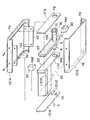
도 1은 첫 번째 실시예에 따른 X-선 발생 장치를 나타낸 단면도이고, 도 2는 X-선 발생 장치의 분해 사시도이다. X-선 발생 장치(1)는 높은 열전도성을 가지는 알루미늄, 구리, 니켈 등의 물질로 이루어지며 4개의 분리된 부분으로 구성되어 있는 상자형의 보호 용기(2)를 포함한다. 보호 용기는 평평하면서 좌우 양측이 아래로 약간 구부러져서 늘려진 C자형을 하고 있는 상부 덮개(3), 좌우 양측이 위로 구부러진 것을 제외하고는 상부 덮개(3)와 동일한 모양인 하부 덮개(4), 평평한 정면판(5) 및 평평한 배면판(6)의 4개 부분으로 구성되어 있다. 2개의 판 지지홈(3a, 3b)이 상부 덮개(3)의 전후단의 내면에 패여 있어, 각각 정면판(5)과 배면판(6)의 상측단을 끼울 수 있도록 되어 있다. 마찬가지로, 하부 덮개(4)의 전후단의 내면에도 두 개의 판 지지홈(4a, 4b)이 패여 있어, 정면판(5)과 배면판(6)의 하측단을 끼울 수 있도록 되어 있다. FIG. 1 is a cross-sectional view of an X-ray generator according to a first embodiment, and FIG. 2 is an exploded perspective view of an X-ray generator. The X-ray generating apparatus 1 includes a box-shaped
보호 용기(2)를 조립할 때는 먼저 보강판(29)의 하면을 하부 덮개(4)의 내면에 나사를 이용하여 고정한다. 다음, 정면판(5)과 배면판(6)의 하측단을 하부 덮개(4)의 내면에 패여 있는 판 지지홈(4a, 4b)에 끼운다. 상부 덮개(3)를 하부 덮개(4)의 위에 위치시켜 상부 덮개(3)의 내면에 있는 판 지지홈(3a, 3b)에 정면판(5)과 배면판(6)의 상단이 끼워지도록 한다. 보강판(29)의 상면을 나사를 이용하여 상부 덮개(3)의 내면에 고정하여 상부 덮개와 하부 덮개를 단단히 고정한다. 이렇게 하면, 정면판(5)과 배면판(6)이 상부 덮개(3)와 하부 덮개(4) 사이에 끼워져 지지되므로, 보호 용기(2)는 매우 단단하게 된다. When assembling the protective container (2), the lower surface of the reinforcing plate (29) is first fixed to the inner surface of the lower cover (4) with a screw. Next, the lower ends of the
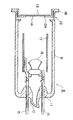
X-선관(8)이 보호 용기(2)에 내장되는데, 이것은 후술하는 정전기 제거기를 비롯하여 매우 다양한 용도로 사용되는 연한(soft) X-선을 발생시킨다. 도 3에 나타낸 바와 같이, X-선관(8)은 코발(kovar) 유리로 이루어진 원통형의 벌브(9)를 가진다. 벌브의 끝에는 축(11)이 형성되어 있으며, 축(stem)(11)에는 배기관(10)이 있다. 코발(kovar) 금속으로 이루어진 원통형의 출력창 지지대(12)는 벌브(9)의 개방단에 융착 접속되어 있다. 출력창 지지대(12)에는 중앙 개구부(12a)가 있다. 원반형의 출력창(13)이 출력창 지지대(12)에 은(Ag)땜질되어 개구부(12a)를 밀봉하고 있다. 표적(14)이 출력창(13)의 내측면에 증착되어 있어, 표적에 전자선이 조사되면 X-선이 발생하도록 되어 있다.An
2개의 축핀(stem pin)(15)이 축(11)에 고정되어 있다. 필라멘트(16)가 음극으로서 벌브(9) 내에 설치되어 있는데, 이것은 일정한 전압하에서 전자선을 방출한다. 필라멘트(16)는 축핀(15)의 말단부에 고정되어 있다. 스테인리스 스틸(stainless steel)로 이루어진 원통형의 초점 전극(17)이 축핀(15) 중의 하나에 고정되어 있다. 코발 금속으로 이루어진 출력창 지지대(12)는 열 및 전기의 전도체이다. 따라서, 접지된 보호 용기(2)에 전기적으로 접속되면 출력창 지지대(12)는 접지 전위가 되고, 결국, 표적도 접지 전압하에 있게 된다. Two
후술할 전원(21)이 X-선관(8) 내에 있는 축핀(15)에 -9.5㎸의 음의 고전압을 인가하면, 필라멘트(16)가 접지 전위의 표적(14)을 향해 전자를 방출하게 된다. 표적(14)에 전자선이 충돌하면, 표적(14)은 출력창(13)을 통해 X-선을 방사한다. 이러한 구조하에서는, 벌브(9)는 직경이 약 15㎜이고, 길이가 약 30㎜이면 되며, X-선관(8)의 총 길이는 약 40㎜로 축소할 수 있다. 그런데, 이 작은 X-선관(8)내의 표적(14)이 매우 높은 온도에까지 이르게 되므로, X-선 발생 효율을 유지하고 표적(14)이 손상되는 것을 방지하기 위하여서는 냉각되어야만 한다.When the
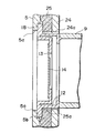
그러면, 냉각 수단에 대하여 설명한다. 플랜지(flange)부(18)가 출력창 지지대(12)와 일체로 형성되어 있으며, X-선관(18)의 외부로 돌출되어 있다. 이 플랜지부(18)는 열 및 전기의 전도체이고, 출력창 지지대(12)를 통하여 표적(14)과 연결되어 있으므로, 표적(14)이 발산하는 열이 출력창 지지대(12)를 약 100℃까지 데우면, 플랜지부(18)가 데워진다. 도 1과 4에 나타낸 바와 같이, 플랜지부(18)는 알루미늄으로 이루어진 정면판(5)의 내측면에 접촉하여 고정되어 있다. 따라서, 열은 플랜지부(18)로부터 보호 용기(2)로 전달되고, 플랜지부(18)는 영 전위로 유지될 수 있다. 원형의 X-선 방사구(5a)가 보호 용기(2)의 정면판(5)에 형성되어 있다. X-선관(8)의 출력창(13)과 X-선 방사구(5a)를 일렬로 정렬시켜서 X-선이 보호 용기(2) 외부로 방출될 수 있도록 한다. The cooling means will be described below. A
다시 도 1과 2를 본다. 저전압 발생기(19)와 고전압 발생기(20)를 가지는 전원(21)이 보호 용기(2)에 내장되어 있다. 이 전원(21)은 X-선관을 구동하기 위한 -9.5㎸의 음의 고전압을 축핀(15)에 인가한다. 먼저, 저전압 발생기(19)에 의해 -1㎸까지 전압이 승압된 후, 고전압 발생기(20)에 의해 -9.5㎸까지 승압된다. 이런 유형의 전원(21)은 강철로 이루어진 전원 용기(22)에 내장되어 고정된다. 전원 용기(22)와 함께, X-선관 내장부(23)가 X-선관(8)의 벌브(9)를 내장하기 위하여 설치된다. 이 X-선관 내장부(23)는 전원의 측면에 인접하여 설치된다. 전원(21)과 X-선관 내장부(23)가 평행하게 설치되기 때문에 보호 용기(2)의 길이가 짧아질 수 있다. See Figures 1 and 2 again. A
도 2와 4에 나타낸 바와 같이, 평평한 첫 번째 지지판(24)이 전원 용기(22) 위에, 정면판(5)과 평행하게 마주보며 설치되어 X-선관 내장부(23)의 전단부를 구성한다. 첫 번째 지지판(24)에는 X-선관(8)의 벌브(9)가 끼워질 수 있도록 구멍(24a)이 뚫려 있다. 구멍(24a)에 벌브(9)가 끼워지면, 플랜지부(18)는 첫 번째 지지판(24)의 전면과 두 번째 지지판 역할을 하는 정면판(5)의 배면 사이에 오게 된다. 전원 용기(22)는 보호 용기(2)의 하부 덮개(4)에 나사로 고정되어 있으므로, 플랜지부(18)는 전원 용기(22)의 첫 번째 지지판(24)과 보호 용기(2)의 판 지지홈(3a, 3b)에 끼워져 고정된 정면판(5) 사이에 단단하게 끼워지게 된다. 따라서, 플랜지부(18)는 보호 용기(2)에 단단하게 고정된다.As shown in Figs. 2 and 4, a flat first supporting
열전도체인 중간 부재(25)가 첫 번째 지지판(24)과 두 번째 지지판 역할을 하는 정면판(5) 사이에 채워져 있다. 중간 부재(25)는 규소고무(silicon rubber)로 이루어져 있어 탄력성이 있고, 높은 열전도성을 가지며, 첫 번째 지지판(24)과 정면판(5) 사이의 공간을 거의 채울 수 있도록 형성되어 있다. 그리고, 중간 부재(25)에는 벌브(9)가 끼워질 수 있도록 구멍(25a)이 뚫려 있다. 이런 구조에서는, 플랜지부(18)가 첫 번째 지지판 구멍(24a)의 둘레와 X-선 방사구(5a)의 둘레 사이에 끼워지게 되면, 중간 부재(25)에 있는 구멍(25a)의 둘레가 플랜지부(18)와 접촉하게 된다. 이 때, 중간 부재(25)의 거의 모든 면이 첫 번째 지지판(24)과 정면판(5)에 접촉한다. 그 결과, 플랜지부(18)와 정면판(5) 사이의 열전도로가 획기적으로 확장되어, 알루미늄인 보호 용기(2)를 통한 열발산이 촉진된다. 나아가, 중간 부재(25)가 탄력성을 가지므로, 플랜지부(18)를 정면판(5)에 압착할 수 있고, X-선관(8)의 충격 흡수 능력을 향상시킬 수 있다.An
도 1과 2에 나타낸 바와 같이, 한 쌍의 진동 흡수기(26)가 보호 용기(2)내의 X-선관(8)을 지지하기 위하여 X-선관 내장부(23) 안에 설치되어 있다. 이들 진동 완충기(26)는 우레탄(uretane) 수지로 이루어져 있으며, 벌브(9)를 감싸기 위한 호형(弧形) 압력면(26a)을 가지고 있다. 진동 완충기(26) 중의 하나가 보호 용기(2)의 한 측면에 고정되어 있는 보강판(29)과 접촉하고 있고, 다른 하나는 전원 용기(22)내의 분리벽(22a)과 접촉하고 있다. 호형 압력면(26a) 사이에 벌브(9)가 끼워지므로 X-선관(8)은 보호 용기(2)내에 단단히 고정된다. As shown in Figs. 1 and 2, a pair of
더하여, X-선 발생 장치(1)는 전원(21)의 저전압 발생기(19)에 고유 전압을 인가하기 위한, 외부 인출선(31)을 가지고 있다. 인출선(31)은 고무 마개(30)를 가지고 있다. 이 마개(30)를 배면판(6)에 형성되어 있는 구멍(6a)에 끼워서 인출선(31)을 보호 용기(2)에 고정시킨다. 음극 인입선(32)이 고전압 발생기(20)로부터 유도되어 X-선관(8)의 축핀(15)에 연결되어 있어서, -9.5㎸의 고전압이 필라멘트에 인가될 수 있다. In addition, the X-ray generator 1 has an
다음으로, 본 발명의 두 번째 실시예에 의한 X-선 발생 장치(41)를 도면을 참조하여 설명한다. 여기에서, X-선 발생 장치(41)는 첫 번째 실시예에 의한 X-선 발생 장치(1)와 동일하고, 유사한 부분과 요소들은 중복 설명을 피하기 위하여 동일한 도면 부호로 나타낸다.Next, an
도 5와 6에 나타낸 바와 같이, 보호 용기(42)가 가늘고, 긴 모양으로 만들어져 있다. 가늘고, 긴 모양의 전원 용기(43)가 보호 용기(42)에 내장되어 있다. 전원 용기(43)의 전반부에는 X-선관(8)과 진동 완충기(26)를 내장하는 X-선관 내장부(44)가 있고, 후반부에는 전원이 있다. 이런 구조에서는, 전원(21)과 X-선관 내장부(44)를 직렬로 정렬함으로써, 보호 용기(42)가 가늘고, 긴 모양으로 만들어질 수 있어서, 좁은 공간에 X-선 발생 장치를 설치하기에 적합하다. 정면판(5)이나 중간 부재(25) 등 나머지 구조는, 보호 용기(42)에 맞도록 작게 만들어지는 것을 제외하고, 첫 번째 실시예에 의한 X-선 발생 장치(1)와 그 기능과 특징이 동일하다.As shown in Figs. 5 and 6, the
이러한 형태의 X-선 발생 장치는 정전기 제거기로서 사용되기에 최적이다. 정전기 제거기는 반도체 웨이퍼(wafer) 등에서 정전기를 제거하는데 사용되는 기기이다. 집적 회로(ICs), 액정 표시 장치(LCDs) 등의 제조 과정에서 정전 인력으로 인하여 먼지 입자들이나 다른 오염 물질이 들러붙는 것은 매우 심각한 문제이다. 정전기 제거기는 제품에 대전된 전하를 제거함으로써 이러한 문제를 해결할 수 있다. X-선이 전하가 대전되어 있는 제품을 향하여 정전기 제거기로부터 방사되면, 질소를 비롯한 공기의 구성 기체들이 양 또는 음의 이온이 된다. 이들 이온중 음의 이온들이 정전인력에 의하여 양전하로 대전된 제품에 끌려가서 축적된 양전하를 중화한다. 정전기 제거기는 3keV에서 9.5keV의 X-선을 발생시킨다. X-선의 세기가 이 정도이므로, 이온화 공간은 0.5mm의 강철판이나 1mm의 유리판으로 충분하게 차폐된다.This type of X-ray generator is optimal for use as a static eliminator. A static electricity eliminator is a device used for removing static electricity from a semiconductor wafer or the like. In the manufacturing process of integrated circuits (ICs) and liquid crystal display devices (LCDs), it is a very serious problem that dust particles or other contaminants adhere due to electrostatic attraction. The static eliminator can solve this problem by removing the electrified charge on the product. When X-rays are emitted from a static eliminator toward a charged product, constituent gases of air, including nitrogen, become positive or negative ions. Negative ions in these ions are attracted to positively charged products by electrostatic attraction and neutralize the accumulated positive charges. The static eliminator generates 9.5 keV X-rays at 3 keV. Since the X-ray intensity is this level, the ionization space is sufficiently shielded by a steel plate of 0.5 mm or a glass plate of 1 mm.
이상에서 본 발명의 실시예가 상세하게 설명되었지만, 이 발명이 속하는 분야의 통상의 지식인이라면 매우 다양한 변형들과 수정된 형태들이 있다는 것을 알 수 있을 것이며, 그러한 것들은 대부분 이 발명의 새로운 특징이나 장점을 그대로 간직하는 것이 될 것이다. 따라서, 그러한 모든 변형들과 수정된 형태들은 첨부된 특허청구범위 내에 포함되는 것이 될 것이다. While the present invention has been particularly shown and described with reference to exemplary embodiments thereof, many modifications and variations will be apparent to those skilled in the art to which the invention pertains, It will be to keep it. Accordingly, all such modifications and variations are intended to be included within the scope of the appended claims.
예를 들어, 도 7에 나타낸 바와 같이, 플랜지부(18)를 수용하기 위하여, 정면판(5)의 X-선 방사구(5a)의 둘레에 환형 함몰부(5b)가 형성될 수 있다. 이러한 함몰부(5b)는 정면판(5)에 플랜지부(18)가 들어맞도록 하는 데뿐만 아니라, X-선관(8)의 출력창(13)과 정면판(5)의 X-선 방사구(5a)를 일렬로 정렬시키는 데에도 유리하다. 나아가, 도면에는 나타나 있지 않으나, 나사나 접착제를 사용하여 플랜지부(18)를 정면판(5)에 접촉시켜 고정시킬 수도 있도록 한다. For example, as shown in Fig. 7, an
본 발명에 의한 X-선 발생 장치는 다음과 같은 이점이 있다. The X-ray generator according to the present invention has the following advantages.
접지 전위를 가지는 표적이 출력창의 안쪽 면에 고정되어 있고, 출력창은 벌브의 말단에 설치되어 있으면서 전기 및 열의 전도체인 출력창 지지부에 고정되어 있다. X-선관은 전자선을 표적에 조사하는 음극을 포함한다. X-선관 및 그 구동 전원은 보호 용기에 내장되어 X-선 발생 장치의 일부를 구성한다. 출력창 지지부 위에 형성되어 외측으로 돌출되어 있는 플랜지부가 열전도체인 보호 용기에 접촉하여 고정되어 있다. 그 결과, X-선 발생 효율을 저하시키고, 표적에 손상을 입히는 원인이 되는 X-선관내의 열이 보호 용기로 전달되어 외부로 방출될 수 있게 되고, 저렴한 비용으로 소형의 X-선관 냉각 장치를 구성할 수 있다. 나아가, X-선관을 적절히 냉각시킬 수 있어서, 전원 내부의 전기 회로가 악영향을 받는 것을 방지할 수 있다. The target with the ground potential is fixed to the inner surface of the output window, and the output window is fixed to the output window support, which is an electrical and thermal conductor, installed at the end of the bulb. The X-ray tube includes a cathode for irradiating the electron beam to the target. The X-ray tube and its driving power are built into the protective vessel and form part of the X-ray generator. A flange portion formed on the output window support portion and protruding outwardly is fixed in contact with the protective container which is a thermal conduction. As a result, the heat in the X-ray tube, which causes the X-ray generation efficiency to be lowered and cause damage to the target, can be transferred to the protective container and released to the outside, and a small X- . Furthermore, the X-ray tube can be cooled appropriately, thereby preventing the electric circuit inside the power source from being adversely affected.
도 1은 본 발명의 첫 번째 실시예에 따른 엑스(X)-선 발생 장치의 수평 단면도이다.1 is a horizontal sectional view of an X-ray generator according to a first embodiment of the present invention.
도 2는 도 1에 나타낸 X-선 발생 장치의 분해 사시도이다.2 is an exploded perspective view of the X-ray generator shown in Fig.
도 3은 도 1에 나타낸 X-선 발생 장치에 채용된 X-선관의 단면도이다.3 is a cross-sectional view of an X-ray tube employed in the X-ray generator shown in Fig.
도 4는 도 1에 나타낸 X-선 발생 장치의 해당 부분을 확대한 단면도이다.4 is an enlarged cross-sectional view of a corresponding portion of the X-ray generator shown in Fig.
도 5는 본 발명의 두 번째 실시예에 따른 X-선 발생 장치의 단면도이다.5 is a cross-sectional view of an X-ray generator according to a second embodiment of the present invention.
도 6은 도 5에 나타낸 X-선 발생 장치를 분해 사시도이다.6 is an exploded perspective view of the X-ray generator shown in Fig.
도 7은 도 5에 나타낸 X-선 발생 장치의 해당 부분을 확대한 단면도이다.Fig. 7 is an enlarged cross-sectional view of a corresponding portion of the X-ray generator shown in Fig. 5;
Claims (4)
Applications Claiming Priority (2)
| Application Number | Priority Date | Filing Date | Title |
|---|---|---|---|
| JP25678096A JP3839528B2 (en) | 1996-09-27 | 1996-09-27 | X-ray generator |
| JP96-256780 | 1996-09-27 |
Related Child Applications (1)
| Application Number | Title | Priority Date | Filing Date |
|---|---|---|---|
| KR1020040089634A Division KR100465346B1 (en) | 1996-09-27 | 2004-11-05 | X-ray generator and electrostatic remover using the same |
Publications (2)
| Publication Number | Publication Date |
|---|---|
| KR19980025059A KR19980025059A (en) | 1998-07-06 |
| KR100465345B1 true KR100465345B1 (en) | 2005-04-13 |
Family
ID=17297351
Family Applications (2)
| Application Number | Title | Priority Date | Filing Date |
|---|---|---|---|
| KR1019970049277A KR100465345B1 (en) | 1996-09-27 | 1997-09-26 | X-ray generator and photoionizer using the same |
| KR1020040089634A KR100465346B1 (en) | 1996-09-27 | 2004-11-05 | X-ray generator and electrostatic remover using the same |
Family Applications After (1)
| Application Number | Title | Priority Date | Filing Date |
|---|---|---|---|
| KR1020040089634A KR100465346B1 (en) | 1996-09-27 | 2004-11-05 | X-ray generator and electrostatic remover using the same |
Country Status (7)
| Country | Link |
|---|---|
| US (1) | US5949849A (en) |
| EP (1) | EP0833365B1 (en) |
| JP (1) | JP3839528B2 (en) |
| KR (2) | KR100465345B1 (en) |
| CN (4) | CN100438717C (en) |
| DE (1) | DE69726535T2 (en) |
| TW (1) | TW344841B (en) |
Cited By (1)
| Publication number | Priority date | Publication date | Assignee | Title |
|---|---|---|---|---|
| KR100902946B1 (en) * | 2007-05-15 | 2009-06-15 | (주)에이치시티 | Soft x-ray photoionization charger |
Families Citing this family (38)
| Publication number | Priority date | Publication date | Assignee | Title |
|---|---|---|---|---|
| JP3594716B2 (en) * | 1995-12-25 | 2004-12-02 | 浜松ホトニクス株式会社 | Transmission X-ray tube |
| JP3514568B2 (en) * | 1995-12-25 | 2004-03-31 | 浜松ホトニクス株式会社 | X-ray tube manufacturing method |
| JP3839528B2 (en) * | 1996-09-27 | 2006-11-01 | 浜松ホトニクス株式会社 | X-ray generator |
| US5802140A (en) | 1997-08-29 | 1998-09-01 | Varian Associates, Inc. | X-ray generating apparatus with integral housing |
| US6361208B1 (en) * | 1999-11-26 | 2002-03-26 | Varian Medical Systems | Mammography x-ray tube having an integral housing assembly |
| US6430263B1 (en) * | 2000-12-01 | 2002-08-06 | Koninklijke Philips Electronics, N.V. | Cold-plate window in a metal-frame x-ray insert |
| US7447298B2 (en) * | 2003-04-01 | 2008-11-04 | Cabot Microelectronics Corporation | Decontamination and sterilization system using large area x-ray source |
| JP4223863B2 (en) * | 2003-05-30 | 2009-02-12 | 浜松ホトニクス株式会社 | X-ray generator |
| KR100512129B1 (en) * | 2003-08-14 | 2005-09-05 | (주)선재하이테크 | A device for removing electrostatic charges on an object using soft X-ray |
| CN1316545C (en) * | 2003-11-17 | 2007-05-16 | 釜山科技园财团法人 | Static electricity preventing device using flexible x-ray and method for making its flexible x-ray tubes |
| US20050213710A1 (en) * | 2004-03-29 | 2005-09-29 | Lawrence Brian L | System and method for laser X-ray generation |
| JP4589062B2 (en) * | 2004-09-02 | 2010-12-01 | 浜松ホトニクス株式会社 | X-ray source |
| KR100785620B1 (en) * | 2005-03-15 | 2007-12-12 | 오므론 가부시키가이샤 | Antistatic method, antistatic device, charging prevention method of glass substrate and charging prevention device of glass substrate |
| KR100680760B1 (en) * | 2005-04-19 | 2007-02-08 | (주)선재하이테크 | A flexible soft X-ray ionizer |
| EP1950788B1 (en) * | 2005-10-07 | 2014-12-10 | Hamamatsu Photonics Kabushiki Kaisha | X-ray tube and x-ray source including same |
| KR100676527B1 (en) * | 2006-10-16 | 2007-01-30 | (주)선재하이테크 | An ionizer using soft x-ray and a method for removing electric charges of a charged body |
| KR100823990B1 (en) * | 2007-03-19 | 2008-04-22 | (주)선재하이테크 | A photo ionizer |
| US7796727B1 (en) | 2008-03-26 | 2010-09-14 | Tsi, Incorporated | Aerosol charge conditioner |
| US8559599B2 (en) * | 2010-02-04 | 2013-10-15 | Energy Resources International Co., Ltd. | X-ray generation device and cathode thereof |
| JP5825892B2 (en) * | 2011-07-11 | 2015-12-02 | キヤノン株式会社 | Radiation generator and radiation imaging apparatus using the same |
| JP6039282B2 (en) * | 2011-08-05 | 2016-12-07 | キヤノン株式会社 | Radiation generator and radiation imaging apparatus |
| WO2013111255A1 (en) * | 2012-01-23 | 2013-08-01 | キヤノン株式会社 | Radiation target and method of manufacturing same |
| JP5899006B2 (en) * | 2012-03-02 | 2016-04-06 | 浜松ホトニクス株式会社 | X-ray irradiation source |
| CN102956419A (en) * | 2012-11-27 | 2013-03-06 | 公安部第一研究所 | Soft X-ray tube and manufacturing method thereof and photoion electrostatic eliminator with ray tube |
| JP2014154423A (en) * | 2013-02-12 | 2014-08-25 | Toshiba Corp | X-ray generator |
| US9173279B2 (en) * | 2013-03-15 | 2015-10-27 | Tribogenics, Inc. | Compact X-ray generation device |
| US9282622B2 (en) | 2013-10-08 | 2016-03-08 | Moxtek, Inc. | Modular x-ray source |
| KR101471382B1 (en) * | 2013-10-15 | 2014-12-10 | (주)선재하이테크 | Apparatus for removing electro static |
| JP2015111504A (en) * | 2013-12-06 | 2015-06-18 | 株式会社東芝 | X-ray tube and method of manufacturing x-ray tube |
| CN105758872A (en) * | 2014-12-17 | 2016-07-13 | 中国科学院高能物理研究所 | X-ray detector and outlet-beam seal window protector |
| KR101686821B1 (en) | 2015-05-18 | 2016-12-15 | (주)선재하이테크 | X-ray generator |
| JP6611490B2 (en) * | 2015-07-02 | 2019-11-27 | キヤノン株式会社 | X-ray generator and X-ray imaging system using the same |
| TWI589190B (en) * | 2016-03-07 | 2017-06-21 | 禪才高科技股份有限公司 | X-ray ionizer |
| TWI620470B (en) * | 2017-02-24 | 2018-04-01 | 禪才高科技股份有限公司 | X-ray tube for improving electron focusing |
| KR102065655B1 (en) | 2018-04-24 | 2020-01-13 | 주식회사 태영이앤티 | Apparatus for generating a x-ray |
| CN110379588B (en) * | 2019-07-12 | 2021-11-16 | 上海埃斯凯变压器有限公司 | Voltage doubling plate assembly for transformer equipment and transformer equipment |
| KR20210021668A (en) | 2019-08-19 | 2021-03-02 | (주)선재하이테크 | 360-degree radial photo ionizer |
| KR20210145471A (en) * | 2020-05-25 | 2021-12-02 | (주)선재하이테크 | Rotary module coupled ionizer |
Citations (2)
| Publication number | Priority date | Publication date | Assignee | Title |
|---|---|---|---|---|
| US4384360A (en) * | 1978-09-12 | 1983-05-17 | Tokyo Shibaura Denki Kabushiki Kaisha | X-Ray apparatus |
| EP0275592A1 (en) * | 1986-12-23 | 1988-07-27 | Koninklijke Philips Electronics N.V. | X-ray tube comprising an annular focus |
Family Cites Families (15)
| Publication number | Priority date | Publication date | Assignee | Title |
|---|---|---|---|---|
| US2307612A (en) * | 1941-02-18 | 1943-01-05 | Gen Electric | High voltage apparatus |
| FR2333344A1 (en) * | 1975-11-28 | 1977-06-24 | Radiologie Cie Gle | HOT CATHODE RADIOGENIC TUBE WITH END ANODE AND APPARATUS INCLUDING SUCH A TUBE |
| US4034251A (en) * | 1976-02-23 | 1977-07-05 | North American Philips Corporation | Transmission x-ray tube |
| JPS5916254A (en) * | 1983-06-03 | 1984-01-27 | Toshiba Corp | Portable x-ray equipment |
| CN85102523B (en) * | 1985-04-10 | 1988-01-27 | 北京市理化分析测试中心 | X-ray generator |
| US4827371A (en) * | 1988-04-04 | 1989-05-02 | Ion Systems, Inc. | Method and apparatus for ionizing gas with point of use ion flow delivery |
| CN2098736U (en) * | 1991-06-07 | 1992-03-11 | 刘振琴 | X-ray tube |
| DE69316040T2 (en) * | 1992-01-27 | 1998-07-23 | Koninkl Philips Electronics Nv | X-ray tube with improved heat balance |
| CA2093256C (en) * | 1992-04-08 | 1999-06-01 | Katsuhiro Ono | X-ray tube of the rotary anode type |
| WO1994005138A1 (en) * | 1992-08-14 | 1994-03-03 | Takasago Netsugaku Kogyo Kabushiki Kaisha | Appararus and method for producing gaseous ions by use of x-rays, and various apparatuses and structures using them |
| JP2710913B2 (en) * | 1993-06-18 | 1998-02-10 | 浜松ホトニクス株式会社 | X-ray generating tube |
| JPH0750594A (en) * | 1993-08-06 | 1995-02-21 | Mitsubishi Electric Corp | Error correcting method |
| CN2203496Y (en) * | 1994-02-05 | 1995-07-12 | 周仕涛 | X-ray tube |
| CN2203521Y (en) * | 1994-11-14 | 1995-07-12 | 上海国嘉光电有限公司 | Low dose X-ray generator |
| JP3839528B2 (en) * | 1996-09-27 | 2006-11-01 | 浜松ホトニクス株式会社 | X-ray generator |
-
1996
- 1996-09-27 JP JP25678096A patent/JP3839528B2/en not_active Expired - Lifetime
-
1997
- 1997-09-26 EP EP97307598A patent/EP0833365B1/en not_active Expired - Lifetime
- 1997-09-26 KR KR1019970049277A patent/KR100465345B1/en not_active IP Right Cessation
- 1997-09-26 DE DE69726535T patent/DE69726535T2/en not_active Expired - Lifetime
- 1997-09-26 US US08/937,921 patent/US5949849A/en not_active Expired - Lifetime
- 1997-09-27 CN CNB971228213A patent/CN100438717C/en not_active Expired - Fee Related
- 1997-09-27 CN CN2007101418698A patent/CN101160013B/en not_active Expired - Fee Related
- 1997-09-27 CN CN2008101674148A patent/CN101370347B/en not_active Expired - Fee Related
- 1997-09-27 CN CN2008100057076A patent/CN101232768B/en not_active Expired - Fee Related
- 1997-09-27 TW TW086114157A patent/TW344841B/en not_active IP Right Cessation
-
2004
- 2004-11-05 KR KR1020040089634A patent/KR100465346B1/en not_active IP Right Cessation
Patent Citations (2)
| Publication number | Priority date | Publication date | Assignee | Title |
|---|---|---|---|---|
| US4384360A (en) * | 1978-09-12 | 1983-05-17 | Tokyo Shibaura Denki Kabushiki Kaisha | X-Ray apparatus |
| EP0275592A1 (en) * | 1986-12-23 | 1988-07-27 | Koninklijke Philips Electronics N.V. | X-ray tube comprising an annular focus |
Cited By (1)
| Publication number | Priority date | Publication date | Assignee | Title |
|---|---|---|---|---|
| KR100902946B1 (en) * | 2007-05-15 | 2009-06-15 | (주)에이치시티 | Soft x-ray photoionization charger |
Also Published As
| Publication number | Publication date |
|---|---|
| CN1183022A (en) | 1998-05-27 |
| TW344841B (en) | 1998-11-11 |
| JP3839528B2 (en) | 2006-11-01 |
| KR19980025059A (en) | 1998-07-06 |
| DE69726535T2 (en) | 2004-10-14 |
| CN101370347A (en) | 2009-02-18 |
| EP0833365B1 (en) | 2003-12-03 |
| CN101160013B (en) | 2012-09-05 |
| CN101160013A (en) | 2008-04-09 |
| CN101370347B (en) | 2012-01-18 |
| DE69726535D1 (en) | 2004-01-15 |
| EP0833365A1 (en) | 1998-04-01 |
| CN101232768B (en) | 2012-09-05 |
| CN100438717C (en) | 2008-11-26 |
| JPH10106463A (en) | 1998-04-24 |
| KR100465346B1 (en) | 2005-01-13 |
| US5949849A (en) | 1999-09-07 |
| CN101232768A (en) | 2008-07-30 |
Similar Documents
| Publication | Publication Date | Title |
|---|---|---|
| KR100465345B1 (en) | X-ray generator and photoionizer using the same | |
| US4964148A (en) | Air cooled metal ceramic x-ray tube construction | |
| EP0935812B1 (en) | X-ray generating apparatus with integral housing | |
| JP4308332B2 (en) | Air-cooled metal-ceramic X-ray tube with window at the end for low power XRF applications | |
| KR101515049B1 (en) | Radiation generating apparatus and radiation imaging apparatus | |
| US2329318A (en) | X-ray generator | |
| EP2547177B1 (en) | Radiation generating apparatus and radiation imaging apparatus | |
| JPH11273597A (en) | X-ray tube | |
| US8110974B2 (en) | Electron beam generating apparatus | |
| CN103733734A (en) | Radiation generating apparatus and radiation imaging apparatus | |
| JP4223863B2 (en) | X-ray generator | |
| JP2009245806A (en) | X-ray tube and x-ray generating device equipped therewith | |
| US4884292A (en) | Air-cooled X-ray tube | |
| HU202676B (en) | Electric lamp | |
| JP2005116534A (en) | X ray generation apparatus | |
| JP2007005319A (en) | X-ray generation device and static eliminator using the same | |
| JP2007250328A (en) | X-ray tube and x-ray tube device | |
| JP2003123999A (en) | X-ray tube device | |
| KR102065655B1 (en) | Apparatus for generating a x-ray | |
| US2019602A (en) | Shockproof x-ray unit window | |
| RU2032258C1 (en) | Electron-beam installation | |
| JP4451540B2 (en) | Light irradiation type static eliminator with cooling function | |
| CN117596759B (en) | X-ray apparatus | |
| JP2008135397A (en) | X-ray generating device | |
| RU98102521A (en) | LASER ELECTRON BEAM DEVICE |
Legal Events
| Date | Code | Title | Description |
|---|---|---|---|
| A201 | Request for examination | ||
| E902 | Notification of reason for refusal | ||
| A107 | Divisional application of patent | ||
| E701 | Decision to grant or registration of patent right | ||
| GRNT | Written decision to grant | ||
| J202 | Request for trial for correction [limitation] | ||
| J204 | Request for invalidation trial [patent] | ||
| J301 | Trial decision |
Free format text: TRIAL DECISION FOR INVALIDATION REQUESTED 20060419 Effective date: 20070119 |
|
| J301 | Trial decision |
Free format text: TRIAL DECISION FOR CORRECTION REQUESTED 20060331 Effective date: 20070214 |
|
| J2X1 | Appeal (before the patent court) |
Free format text: INVALIDATION |
|
| J202 | Request for trial for correction [limitation] | ||
| J301 | Trial decision |
Free format text: TRIAL DECISION FOR CORRECTION REQUESTED 20070702 Effective date: 20071030 |
|
| J2X1 | Appeal (before the patent court) |
Free format text: CORRECTION |
|
| J2X2 | Appeal (before the supreme court) |
Free format text: APPEAL BEFORE THE SUPREME COURT FOR INVALIDATION |
|
| J302 | Written judgement (patent court) |
Free format text: JUDGMENT (PATENT COURT) FOR CORRECTION REQUESTED 20071203 Effective date: 20081010 |
|
| J2X2 | Appeal (before the supreme court) |
Free format text: APPEAL BEFORE THE SUPREME COURT FOR CORRECTION |
|
| EXTG | Ip right invalidated | ||
| J303 | Written judgement (supreme court) |
Free format text: JUDGMENT (SUPREME COURT) FOR CORRECTION REQUESTED 20081103 Effective date: 20090924 |
|
| J302 | Written judgement (patent court) |
Free format text: JUDGMENT (PATENT COURT) FOR INVALIDATION REQUESTED 20070223 Effective date: 20071123 |
|
| J303 | Written judgement (supreme court) |
Free format text: JUDGMENT (SUPREME COURT) FOR INVALIDATION REQUESTED 20071217 Effective date: 20090924 |
|
| G170 | Publication of correction |