KR100456957B1 - Method and device for recording optical information - Google Patents
Method and device for recording optical information Download PDFInfo
- Publication number
- KR100456957B1 KR100456957B1 KR1019970703863A KR19970703863A KR100456957B1 KR 100456957 B1 KR100456957 B1 KR 100456957B1 KR 1019970703863 A KR1019970703863 A KR 1019970703863A KR 19970703863 A KR19970703863 A KR 19970703863A KR 100456957 B1 KR100456957 B1 KR 100456957B1
- Authority
- KR
- South Korea
- Prior art keywords
- power
- recording
- pulse
- laser light
- cooling
- Prior art date
Links
Images


Classifications
-
- G—PHYSICS
- G11—INFORMATION STORAGE
- G11B—INFORMATION STORAGE BASED ON RELATIVE MOVEMENT BETWEEN RECORD CARRIER AND TRANSDUCER
- G11B7/00—Recording or reproducing by optical means, e.g. recording using a thermal beam of optical radiation by modifying optical properties or the physical structure, reproducing using an optical beam at lower power by sensing optical properties; Record carriers therefor
- G11B7/12—Heads, e.g. forming of the optical beam spot or modulation of the optical beam
- G11B7/125—Optical beam sources therefor, e.g. laser control circuitry specially adapted for optical storage devices; Modulators, e.g. means for controlling the size or intensity of optical spots or optical traces
- G11B7/126—Circuits, methods or arrangements for laser control or stabilisation
- G11B7/1263—Power control during transducing, e.g. by monitoring
-
- G—PHYSICS
- G11—INFORMATION STORAGE
- G11B—INFORMATION STORAGE BASED ON RELATIVE MOVEMENT BETWEEN RECORD CARRIER AND TRANSDUCER
- G11B7/00—Recording or reproducing by optical means, e.g. recording using a thermal beam of optical radiation by modifying optical properties or the physical structure, reproducing using an optical beam at lower power by sensing optical properties; Record carriers therefor
- G11B7/004—Recording, reproducing or erasing methods; Read, write or erase circuits therefor
- G11B7/0045—Recording
- G11B7/00454—Recording involving phase-change effects
-
- G—PHYSICS
- G11—INFORMATION STORAGE
- G11B—INFORMATION STORAGE BASED ON RELATIVE MOVEMENT BETWEEN RECORD CARRIER AND TRANSDUCER
- G11B7/00—Recording or reproducing by optical means, e.g. recording using a thermal beam of optical radiation by modifying optical properties or the physical structure, reproducing using an optical beam at lower power by sensing optical properties; Record carriers therefor
- G11B7/004—Recording, reproducing or erasing methods; Read, write or erase circuits therefor
- G11B7/006—Overwriting
-
- G—PHYSICS
- G11—INFORMATION STORAGE
- G11B—INFORMATION STORAGE BASED ON RELATIVE MOVEMENT BETWEEN RECORD CARRIER AND TRANSDUCER
- G11B7/00—Recording or reproducing by optical means, e.g. recording using a thermal beam of optical radiation by modifying optical properties or the physical structure, reproducing using an optical beam at lower power by sensing optical properties; Record carriers therefor
- G11B7/004—Recording, reproducing or erasing methods; Read, write or erase circuits therefor
- G11B7/0055—Erasing
- G11B7/00557—Erasing involving phase-change media
Abstract
종래 광학적 정보를 기록할 때, 마크 후단이 급격히 냉각되고 있었기 때문에 마크 후단부가 크게 되어 오버라이트 후의 재생 지터가 나쁘고, 또 다사이클하는 것에 의한 열 손상에 의한 신호 열화가 생기게 하는 등의 문제가 있었다. 그래서 마크 길이 변조 기록에 있어서, 기록 펄스열에 마크 후단 보정 펄스열을 부가하는, 기록 펄스열과 냉각 파워에서의 레이저 광 조사나 마크 후단 보정 펄스열과의 사이에 바이어스 파워에서의 레이저 광 조사를 행하고, 또 기록 마크 길이에 따라 냉각 파워 조사 개시 시간, 냉각 파워 조사 폭, 마크 후단 보정 펄스열 형상을 변화한다. 또, CAV 모드에서의 디스크의 반경에 따라 냉각 파워 조사 시간 혹은 냉각 파워 개시 시간을 변화한다. 또, 기록 펄스열이 시단 펄스, 종단 펄스, 시단ㆍ종단 펄스 사이의 펄스로 이루어지는 경우, 냉각 파워에서의 레이저 광 조사를 행하고, 기록 펄스열과 냉각 파워와의 사이에 바이어스 파워에서의 레이저 광 조사를 행하고, 또 상기 기록 펄스열에서 마크 길이 및 마크 간격에 따라 변화하는 경우, 냉각 파워에서의 레이저 광 조사 개시의 타이밍을 종단 펄스의 지연량이나 클록에 기초하여 행한다.There has been a problem that when recording optical information in the past, the trailing edge of the mark has been rapidly cooled and the trailing edge of the mark has become large, resulting in poor reproduction jitter after overwriting and signal degradation due to thermal damage due to multiple cycles. Thus, in the mark length modulation recording, the laser light irradiation at the bias power is performed between the recording pulse train and the laser light irradiation at the cooling power or the mark rear stage correction pulse train, which adds the mark rear end correction pulse train to the recording pulse train, The cooling power irradiation start time, the cooling power irradiation width, and the mark rear end correction pulse string shape are changed according to the mark length. The cooling power irradiation time or the cooling power start time is changed according to the radius of the disk in the CAV mode. When the recording pulse train is composed of the leading pulse, the trailing pulse, and the pulses between the leading and trailing pulses, the laser light is irradiated at the cooling power and the laser light is irradiated at the bias power between the recording pulse train and the cooling power , And when the recording pulse train changes in accordance with the mark length and the mark interval, the timing of starting the laser light irradiation at the cooling power is performed based on the delay amount and the clock of the end pulse.
Description
레이저 광선을 이용하여 고밀도로 정보의 재생 또는 기록을 행하는 기술은 공지의 사실이며, 주로 광디스크로서 실용화되고 있다.BACKGROUND ART [0002] Techniques for reproducing or recording information at high density using a laser beam are well known and have been put to practical use mainly as an optical disk.
광디스크는 재생 전용형(read-only type), 추기형(write-once read-many type), 개서형(rewritable type)으로 크게 나눌 수 있다.The optical disc can be largely divided into a read-only type, a write-once read-many type, and a rewritable type.
재생 전용형은, 예를 들면 콤팩트 디스크나 레이저 디스크로서, 또 추기형이나 개서형은 문서 파일, 데이터 파일 등으로서 실용화되고 있다.The reproduction-only type is used as, for example, a compact disc or a laser disc, and a write-once type or a rewritable type is put to practical use as a document file, a data file and the like.
또, 개서형 디스크 중에는 주로 광자기와 상변화형(相變化型)이 있다.Among rewritable discs, there are mainly magneto-optical and phase-change type discs.
상변화 광디스크는 기록층이 레이저 광선 등의 조사에 의해, 예를 들면 비결정과 결정간, 또는 결정과 또 다른 구조의 결정간의 어느 것 등으로, 가역적으로 상태 변화를 일으키는 것을 이용한다. 이것은 레이저 광 조사에 의해 박막의 굴절율 또는 소쇄계수(exhaustion coefficient)중 적어도 어느 하나가 변화하여 기록을 하고, 이 부분에서 투과광 또는 반사광의 진폭이 변화하고, 그 결과 검출 시스템에이르는 투과 광량 또는 반사 광량이 변화하는 것을 검출하여 신호를 재생한다. 또, 비결정과 결정 사이에서 상태 변화를 일으키는 대표적인 재료로서는 Te, Se, In, Sb 등의 합금이 주로 이용되고 있다.The phase change optical disk utilizes the fact that the recording layer reversibly changes state by irradiation of a laser beam or the like, for example, between amorphous and crystalline, or between crystalline and crystalline of another structure. This is because at least one of the refractive index or the exhaustion coefficient of the thin film is changed by the laser light irradiation and the amplitude of the transmitted light or the reflected light changes at this portion and as a result the amount of transmitted light or the amount And reproduces the signal. In addition, alloys such as Te, Se, In, Sb and the like are mainly used as typical materials that cause a change in state between amorphous and crystalline.
또, 상변화 광디스크에서는 기록 마크의 오버라이트를 위해 1 빔 오버라이트를 이용할 수 있다. 1 빔 오버라이트란 기록 신호에 의해 레이저 파워를 기록 파워와 해당 기록 파워보다도 낮은 파워의 바이어스 파워(소거 파워라고도 함)의 사이에서 변조하여 신호 트랙 상에 조사함으로써 이미 기록되어 있는 오래된 신호를 소거하면서 새로운 신호를 기록하는 방법이다. 오버라이트 자체로는 기록 파워 레벨과 바이어스 파워 레벨 및 재생 2레벨로 되지만 기록·소거·재생을 고려하면 기록 파워 레벨, 바이어스 파워 레벨 및 재생 파워 레벨의 3레벨이 필요하다.In addition, in the phase-change optical disk, one-beam overwriting can be used to overwrite recording marks. One-beam overwriting is a technique in which a laser power is modulated between a recording power and a bias power (also referred to as an erasing power) lower than the recording power by a recording signal and is irradiated onto a signal track to erase an already recorded old signal It is a method of recording a new signal. In the overwrite itself, the recording power level, the bias power level, and the
예를 들면, 결정·비결정 사이의 상변화 광디스크에서는 기록 레벨로 조사된 영역은 원래의 상태가 비결정인지 결정인지에 관계없이 용융 후 급속히 냉각되기 때문에 비결정으로 되고, 소거 레벨로 조사된 영역은 결정화 온도 이상으로 승온되기 때문에 원래의 상태에 관계없이 결정화하여 새로운 신호가 오버라이트된다.For example, in a phase-change optical disc between crystals and amorphous regions, the region irradiated with the recording level is amorphous because it is rapidly cooled after melting, regardless of whether the original state is determined to be indefinite, Or more, so that it is crystallized irrespective of the original state and a new signal is overwritten.
한편, 광디스크의 기록 재생 장치에서는 광디스크의 회전 방식은 크게 나누어 두 가지가 있다. 디스크의 내외 둘레에서 선속도가 같아지도록 디스크를 회전시키는 방법(이하 CLV)과, 디스크를 일정한 각속도로 회전시키는 방법(이하 CAV)이다.On the other hand, in the optical disc recording / reproducing apparatus, there are two types of rotation of the optical disc. (Hereinafter referred to as CLV) for rotating the disk so that the linear velocity is equal to the inner and outer peripheries of the disk, and a method for rotating the disk at a constant angular velocity (hereinafter referred to as CAV).
예를 들면, 컴퓨터용 외부 메모리 등에 이용되는 데이터 파일과 같이 고속의액세스가 필요하게 되는 경우에는 디스크 회전수를 바꾸려면 시간이 걸리기 때문에CAV가 사용되고 있고, 이 경우, 디스크의 둘레 방향의 선속도가 외주부에서 빠르고내주부에서 늦어진다.For example, when a high-speed access is required as in a data file used in a computer external memory or the like, CAV is used because it takes time to change the number of rotations of the disk. In this case, It is fast on the outskirts and slow in my housewives.
또, 기록 변조 방식에서는 마크간(마크 포지션이라고도 함)변조와, 마크 길이(마크 에지라고도 함)변조의 2종류가 있다.In the recording modulation method, there are two types of modulation: between mark (also called mark position) modulation and mark length (also called mark edge) modulation.
마크간 변조 기록은 마크 간격을 변화시켜서 기록하고, 재생시에는 마크의 위치를 검출하여 신호 검출하는 것이다.The inter-mark modulation recording is performed by changing the mark interval, and at the time of reproduction, the position of the mark is detected to detect the signal.
마크 길이 변조 기록은 각종 길이의 마크를 각종 마크 간격으로 기록하고, 재생시에는 마크의 양단의 위치를 검출하여 신호를 검출하는 것이다. 마크 길이 변조 방식은 마크간 변조 방식에 비하여 원리적으로 2배의 고밀도화가 가능하다.In the mark length modulation recording, marks of various lengths are recorded at various mark intervals, and at the time of reproduction, positions of both ends of the mark are detected to detect a signal. The mark length modulation method can be doubled in principle in comparison with the inter-mark modulation method.
상변화 광디스크 상으로의 레이저 기록은 원리적으로는 비트 모드에 의한 것이며, 따라서 길이 마크를 기록하는 경우에는 축열 효과에 의해 마크의 선단보다 종단이 두꺼워져서 마크가 방울형상으로 변형되고, 결과적으로 재생 파형도 변형마크 양단의 위치가 어긋나 버린다.The laser recording on the phase change optical disk is basically a bit mode, and therefore, when a long mark is recorded, the end becomes thicker than the tip of the mark due to the heat storage effect so that the mark is deformed into a droplet shape, The position of both ends of the deformed mark is deviated from the waveform.
그래서, 상술한 마크 길이 변조 방식에 있어서는 하나의 기록 마크를 형성하기 위한 기록 파형을 복수의 펄스로 이루어지는 기록 펄스열로 구성(멀티 펄스 기록이라고도 함)하는 기록 방법이 제안되어 있다(예를 들면, 일본국 특개평 3-185628호 공보). 이로써 단(單)펄스로 기록하는 방법에 비해 기록막이 받는 열이 제어되고, 마크 형상이 단 펄스의 경우와 같이 마크의 시종단에서 비대칭이 되지 않는 양호한 마크 형상으로 된다.Thus, in the above-mentioned mark length modulation method, there has been proposed a recording method in which a recording waveform for forming one recording mark is composed of a recording pulse string composed of a plurality of pulses (also referred to as multi-pulse recording) 3-185628). This makes it possible to control the column to which the recording film is subjected as compared with the method of recording by a single pulse and to obtain a good mark shape which does not become asymmetric at the end of the mark as in the case of the short pulse.
그러나, 상기와 같은 멀티펄스 기록 방법에서도 고밀도화의 요청 때문에 마크간격을 좁게 하면 마크 사이에서 열 간섭을 일으켜서 마크의 길이나 형상이 변화한다.However, in the above-described multi-pulse recording method, if the mark interval is narrowed due to the request for high density, heat interference occurs between the marks, and the length and shape of the mark change.
이것을 개선하는 방법으로서, 예를 들면 일본국 특개평7-129959호 공보가 제안되어 있다. 이 공보에서는 열 간섭량을 미리 예측하고, 상기 멀티펄스의 기록에있어서 기록 마크 길이 및 마크 간격에 의해 기록 펄스열의 시단(始端)부분과 종단(終端)부분의 위치를 변화시키고, 마크 사이의 열 간섭을 억제하고 신호 특성을 양호하게 한다는 것이다.As a method for improving this, for example, Japanese Patent Application Laid-Open No. 7-129959 has been proposed. In this publication, the heat interference amount is predicted in advance, and the positions of the start and end portions of the write pulse string are changed according to the recording mark length and the mark interval in the recording of the multi-pulse, And the signal characteristics are improved.
또, 1 빔 오버라이트에 있어서, 기록 펄스를 기록 파워, 바이어스 파워 및 기록 파워의 직후에 설치한 바이어스 파워보다 낮은 파워의 3단계로 변조하는 기록방법이 제안되어 있다(예를 들면, 일본국 특개소 63-113938호 공보).In addition, in the one-beam overwriting, a recording method has been proposed in which recording pulses are modulated in three stages of recording power, bias power, and power lower than bias power provided immediately after recording power (see, for example, 63-113938).
또, 멀티펄스 기록 방법에 바이어스 파워보다 낮은 파워에서의 레이저 광 조사를 부가한 기록 방법도 제안되어 있다(예를 들면, 일본국 특개평 6-295440호 공보).Also, a recording method in which laser light irradiation at a power lower than bias power is added to the multi-pulse recording method has been proposed (for example, Japanese Patent Application Laid-Open No. 6-295440).
또, 마크 간격에 의해 냉각 파워에서의 조사 시간(이하, 냉각 파워 조사 시간)을 변화시킨다는 기록 방법이 제안되어 있다(일본국 특원평 5-80491).In addition, a recording method of changing the irradiation time (hereinafter, referred to as cooling power irradiation time) at the cooling power by the mark interval has been proposed (Japanese Patent Application No. 5-80491).
개서 가능한 상변화 재료를 이용한 광디스크 등의 소위 광디스크에, 예를 들어 반도체 레이저 등의 광원에 의해 빛을 조사하고, 물리적 상태 변화를 생기게 하여 신호를 기록하는 경우, 광원의 빛에 기인한 열에 의해 기록층의 온도는 수백 도까지 도달하고, 기록 박막은 용융된다.When a signal is recorded by irradiating light to a so-called optical disc such as an optical disc using a rewritable phase change material by a light source such as a semiconductor laser and causing a physical state change to occur, The temperature of the layer reaches several hundred degrees, and the recording thin film is melted.
따라서 개서 횟수를 중복하는, 즉 다(多)사이클함으로써 열 손상에 의한 신호 열화가 생긴다.Therefore, signal degradation due to thermal damage occurs due to redundancy, i.e., multiple cycles.
신호 열화의 원인으로서는 유전체층이나 기록층의 파괴와 기록층의 물질 유동이라 불리우는 현상이 있다. 물질 유동이란 기록시에 기록층 및 그 주변이 고온이 되기 때문에 다사이클함으로써 기록층 물질이 트랙 방향으로 이동하고, 동일 트랙 상에 기록막이 얇은 곳과 두꺼운 곳이 생기는 현상이며, 그 결과로서 신호의 재생 파형이 변형되어 버리고 해당 부분에서는 신호가 재생되지 않는다. 어떻게 해도 다사이클에 의한 신호 열화가 큰 경우에는 그에 따라 광디스크의 용도가 한정된다.The cause of signal deterioration is a phenomenon called breakdown of the dielectric layer or the recording layer and material flow of the recording layer. The material flow is a phenomenon in which the recording layer material moves in the track direction due to multiple cycles due to the high temperature of the recording layer and its surroundings at the time of recording, and a thin and thick recording film is formed on the same track. As a result, The reproduction waveform is deformed and the signal is not reproduced at the corresponding portion. In any case, when signal deterioration due to multiple cycles is large, the use of the optical disk is limited accordingly.
또, 광디스크 장치에서는 반도체 레이저에 의해 빛을 조사하여 물리적 상태변화를 생기게 하는 경우, 예를 들면 개서 가능한 상변화 재료를 이용한 광디스크에서 신호를 기록하는 경우, 레이저 광에 의해 가열된 기록층의 냉각 방법에 따라기록 마크 형상이 변화한다.In the optical disc device, when a signal is recorded on an optical disc using a rewritable phase change material, for example, when a light is irradiated by a semiconductor laser to cause a physical state change, The recording mark shape changes.
즉, 내부적으로 열이 있는 경우에는 한 번 용융된 기록층이 비결정화되지 않고 결정화된다. 그 결과, 기록 마크가 작아지거나 또는 기록 마크의 형상이 변형되어 재생 신호 품질이 악화된다.That is, when there is heat internally, the once-melted recording layer is crystallized without being crystallized. As a result, the recording mark becomes small or the shape of the recording mark is deformed and the quality of the reproduction signal deteriorates.
그리고, 종래와 같은 냉각 펄스를 채용한 경우, 마크 후단부에서의 열의 체류가 저감되어 비결정화는 용이하게 되지만 경우에 따라서는 후단부에서 냉각 속도가 너무 커지는 것에 기인하여 비결정영역이 마크 선단부보다 커지는 일이 있다.In the case of adopting the cooling pulse as in the prior art, the stagnation of the heat at the trailing edge of the mark is reduced to facilitate the non-crystallization. However, in some cases, the cooling rate at the trailing edge becomes too large, There is work.
또, 냉각 파원 및 조사 시간의 조건에 따라서는 오버라이트 특성이 악화되는 경우가 있다. 이 원인은 기록 마크가 후단에서 횡방향으로 너무 커지기 때문에 오히려 마크 변형이 되거나 또는 오버라이트에 의해 소거되지 않은 부분이 발생하기때문이라고 생각된다.In addition, depending on the condition of the cooling power source and the irradiation time, the overwrite characteristic may be deteriorated. This is thought to be because the recording mark is too large in the lateral direction at the rear end, and therefore, the mark is deformed or a portion which is not erased due to overwriting occurs.
또한, 고밀도로 기록을 행하는 경우에는 마크의 전단부와 후단부의 대칭성이 충분하지 않기 때문에 오버라이트 후의 재생 지터(jitter)가 크고, 재생 신호 품질로서는 충분하지 않았다.Further, in the case of performing recording at a high density, since the symmetry between the front end portion and the rear end portion of the mark is not sufficient, the jitter of reproduction after overwriting is large and the reproduction signal quality is not sufficient.
또, 마크간 변조 기록에서는 냉각 펄스를 부가함으로써 마크를 크게 형성하고, C/N을 크게 하고 양호한 신호 품질을 실현할 수 있다. 여기에서 C/N이란 반송파 레벨(carrier level)과 잡음(noise level)의 비를 취한 것이다.Further, in the inter-mark modulation recording, a mark is formed to be large by adding a cooling pulse, and C / N can be increased to realize good signal quality. Here, C / N is the ratio of the carrier level to the noise level.
그러나, 냉각 파워의 조건에 따라서는 오버라이트 특성이 악화하는 경우가 있다. 이 원인은 기록 마크가 횡방향으로 너무 커지기 때문에 오버라이트에 의해 소거되지 않은 부분이 발생하기 때문이라는 원인 등을 생각할 수 있다.However, the overwrite characteristic may deteriorate depending on the condition of the cooling power. This may be caused by the fact that a recording mark is too large in the lateral direction, and therefore an unerased portion occurs due to overwriting.
본 발명은 마크 후단부에서의 열의 냉각 조건을 세밀하게 제어하고, 기록 마크를 원하는 형상으로 형성하고, 재생 신호 품질이 더욱 향상할 수 있고, 또 열에의한 손상을 완화하고, 양호한 사이클 특성을 얻을 수 있는 기록 방법 빚 기록 장치를 제공하기 위한 것이다.The present invention is characterized in that the cooling condition of heat at the mark rear end is finely controlled and the recording mark is formed in a desired shape to further improve the quality of the reproduction signal and to mitigate the damage by heat and obtain good cycle characteristics It is intended to provide a recording method that can record debt.
본 발명은 레이저 광선 등의 광학적 수단을 이용하여 정보를 고속, 고밀도로기록·재생하는 광디스크의 기록 방법 및 그 기록 장치에 관한 것이다.The present invention relates to an optical disc recording method and apparatus for recording and reproducing information at high speed and high density using an optical means such as a laser beam.
도 1은 본 발명의 일실시예에 이용한 기록 파형도.1 is a recording waveform diagram used in an embodiment of the present invention;
도 2는 본 발명의 일실시예에 이용한 광디스크의 구조도.2 is a structural view of an optical disc according to an embodiment of the present invention;
도 3은 본 발명의 일실시예에 이용한 광디스크 장치의 도면.3 is a view of an optical disc apparatus used in an embodiment of the present invention.
도 4는 본 발명의 일실시예에 이용한 기록 펄스열의 도면.4 is a diagram of a write pulse train used in an embodiment of the present invention.
도 5는 본 발명의 일실시예에 이용한 기록 파형의 도면.5 is a view of a recording waveform used in an embodiment of the present invention.
도 6은 본 발명의 일실시예에 이용한 기록 파형의 도면.6 is a view of a recording waveform used in an embodiment of the present invention.
도 7은 본 발명의 일실시예에 이용한 기록 파형의 도면.7 is a view of a recording waveform used in an embodiment of the present invention.
도 8은 본 발명의 일실시예에 이용한 기록 파형의 도면.8 is a view of a recording waveform used in an embodiment of the present invention.
도 9는 본 발명의 일실시예에 이용한 기록 파형의 도면.9 is a view of a recording waveform used in an embodiment of the present invention.
도 10은 본 발명의 일실시예에 이용한 기록 파형의 도면.10 is a view of a recording waveform used in an embodiment of the present invention.
도 11은 본 발명의 일실시예에 이용한 디스크 기록 장치의 블록도.11 is a block diagram of a disk recording apparatus used in an embodiment of the present invention.
도 12는 본 발명의 일실시예에 이용한 디스크 기록 장치의 각부의 신호 파형도.12 is a signal waveform diagram of each part of a disk recording apparatus used in an embodiment of the present invention.
도 13은 본 발명의 일실시예에 이용한 디스크 기록 장치의 블록도.13 is a block diagram of a disk recording apparatus used in an embodiment of the present invention.
도 14는 본 발명의 일실시예에 이용한 디스크 기록 장치의 각부의 신호 파형도.14 is a signal waveform diagram of each part of a disk recording apparatus used in an embodiment of the present invention.
도 15는 본 발명의 일실시예에 이용한 기록 파형의 도면.15 is a diagram of a recording waveform used in an embodiment of the present invention.
*도면의 주요부분에 대한 부호의 설명*Description of the Related Art [0002]
1 : 데이터 3 : 시단 펄스1: data 3: start pulse
5 : 버스트 게이트 신호 7 : 종단 펄스5: Burst gate signal 7: Termination pulse
9 : 2T 마크 신호 10 : 2T 스페이스 신호9: 2T mark signal 10: 2T space signal
12 : 셀렉트 신호 13 : 복수의 시단 설정값12: select signal 13: plural start setting values
15 : 선택 시단 설정값 18 : 지연 시단 펄스15: Selection start setting value 18: Delay start pulse
19 : 복수의 종단 설정값 21 : 선택 종단 설정값19: Multiple end set value 21: Selected end set value
24 : 지연 종단 펄스 25 : 클록24: delay termination pulse 25: clock
26 : AND 게이트 27 : 버스트 펄스26: AND gate 27: burst pulse
28 : OR 게이트 29 : 기록 신호28: OR gate 29: write signal
30 : 기록 전류원 31 : 바이어스 전류원30: write current source 31: bias current source
32 : 재생광 전류원 33, 34 : 스위치32: regenerative light
35 : 레이저 다이오드 38 : 인버터35: laser diode 38: inverter
39 : 홀드 시단 설정값 41 : 냉각 펄스39: Hold start setting value 41: Cooling pulse
42 : 지연 냉각 펄스 43 : 지연 냉각 펄스(반전)42: delayed cooling pulse 43: delayed cooling pulse (inverted)
45 : 홀드 종단 설정값 36 : 냉각 펄스 발생 회로45: Hold termination setting value 36: Cooling pulse generating circuit
37 : 냉각 펄스용 지연 라인 51 : 기판37: cooling pulse delay line 51: substrate
52 : 제 1 유전체층 53 : 기록층52: first dielectric layer 53: recording layer
54 : 제 2 유전체층 55 : 반사층54: second dielectric layer 55: reflective layer
56 : 보호층 61 : 광디스크56: protective layer 61: optical disc
62 : 스핀들 모터 63 : 광학 헤드62: spindle motor 63: optical head
64 : 레이저 구동 회로 65 : 파형 보정 회로64: laser drive circuit 65: waveform correction circuit
상기 목적을 달성하기 위한 본 발명의 기록 방법은 마크 길이, 마크간 변조기록에 있어서, 기록 파워에서의 레이저 광 조사 후에 바이어스 파워보다 파워가 낮은 냉각 파워까지 레이저 파워를 저하시키고, 그것을 소정 시간 유지한 후, 다시바이어스 파워까지 상승시키는 기록 방식에 있어서, 기록 파워에서의 레이저 광 조사와 해당 기록 파워의 직후의 냉각 파워에서의 조사 사이에 바이어스 파워에서의레이저 광 조사를 행하는 것이다.The recording method of the present invention for achieving the above object is a recording method in which laser power is lowered to a cooling power having a power lower than a bias power after irradiating the recording power with laser power for mark length and recording between marks, The laser beam irradiation at the bias power is performed between the irradiation of the laser beam at the recording power and the irradiation at the cooling power immediately after the recording power.
또, 마크 길이 기록에서는 멀티펄스에서의 레이저 광 조사 후에 바이어스 파워보다 낮은 냉각 파워까지 레이저 파워를 저하시키고, 그것을 일정 시간 유지한후, 다시 바이어스 파워까지 상승시키는 기록 방식에 있어서, 기록하는 마크 길이에 의해 냉각 파워 조사 시간 또는 냉각 파워 개시 시간의 적어도 어느 한쪽을 변화시키는 것이다.Further, in the mark length recording, in the recording system in which the laser power is lowered to the cooling power lower than the bias power after the laser light irradiation in the multi-pulse, and the laser power is raised for a predetermined time and then increased to the bias power, At least one of the cooling power irradiation time or the cooling power start time is changed.
또, 마크간 변조 기록에 있어서, CAV 모드에서 디스크의 반경에 따라 냉각파워 개시 시간을 변화시키는 것이다.In the inter-mark modulation recording, the cooling power start time is changed in accordance with the radius of the disk in the CAV mode.
또, 마크 길이 변조 기록에 있어서, CAV 모드에서 디스크의 반경에 따라 냉각 파워 조사 시간 또는 냉각 파워 개시 시간의 적어도 어느 한쪽을 변화시키는 것이다.In the mark length modulation recording, at least one of the cooling power irradiation time or the cooling power start time is changed according to the radius of the disk in the CAV mode.
또, 마크 길이 변조 기록에 있어서, 기록 펄스열이 시단 펄스와 종단 펄스와시단·종단 펄스 사이의 데이터 클록의 1주기 이하의 주기로 번갈아 전환하는 펄스로 이루어지는 경우, 상기 기록 펄스열의 종단 펄스 후에 냉각 파워에서의 레이저 광 조사를 행하는 것, 또는 상기 기록 펄스열의 종단 펄스와 냉각 파워에서의 레이저 광의 조사 사이에 바이어스 파워에서의 레이저 광 조사를 행하는 것이다.In the mark length modulation recording, when the write pulse string is composed of pulses alternately switched at a cycle equal to or shorter than one period of the data clock between the start pulse, the end pulse, and the start and end pulse, Or irradiating the laser beam at a bias power between the irradiation of the laser beam at the cooling pulse and the termination pulse of the recording pulse train.
그리고, 마크 길이 변조 기록에 있어서, 기록 펄스열이 시단 펄스와 종단 펄스와 시단·종단 펄스 사이의 데이터 클록의 1주기 이하의 주기로 번갈아 전환되는펄스로 이루어지고, 마크 길이 및 마크 간격에 따라 상기 기록 펄스열의 시단 펄스, 종단 펄스의 위치가 변화하는 경우, 냉각 파워에서의 레이저 광 조사 시간은일정하게 기록 펄스열의 시단 펄스나 종단 펄스의 위치에 의하지 않고 냉각 펄스에서의 레이저 광 조사까지의 시간이 기록 펄스열의 종단 펄스의 레이저 광 조사 개시로부터 일정한, 또는 냉각 파워에서의 레이저 광 조사 개시의 타이밍이 클록에 기초한 구성을 구비한다.In the mark length modulation recording, the write pulse string is composed of pulses alternately switched at a cycle of one cycle or less of the data clock between the start pulse, the end pulse, and the start and end pulse, When the position of the start pulse and the end pulse of the recording pulse train change, the laser light irradiation time at the cooling power is kept constant regardless of the position of the start pulse or the end pulse of the write pulse train, And the start timing of the laser light irradiation at the cooling power is based on the clock.
또, 상기 기록 방법을 실현하기 위한 기록 장치는 데이터의 Hi 기간의 시단위치에 일정 폭의 시단 펄스를 발생하는 시단 펄스 발생 회로와, 데이터의 Hi 기간이 긴 경우는 마크의 중간 위치에 버스트 게이트 선호를 발생하고, 데이터의 Hi 기간이 짧은 경우는 버스트 게이트 신호를 발생하지 않는 버스트 게이트 발생 회로와, 데이터의 Hi 기간의 종단 위치에 일정 폭의 종단 펄스를 발생하는 종단 펄스 발생 회로와, 데이터의 Hi 기간이 n 클록일 때, 상기 시단 펄스와 종단 펄스를 포함하는 nT 마크 신호가 발생하고, 데이터의 Lo 기간이 m 클록일 때 스페이스 양단의 상기 종단 펄스와 시단 펄스를 포함하는 mT 스페이스 신호를 발생하는 마크/스페이스 길이 검출 회로(단, n, m은 데이터열에 존재하는 자연수)와 상기 nT 마크신호와 mT 스페이스 신호로부터 후기 시단용 셀렉터 및 종단용 셀렉터를 제어하기 위한 셀렉트 신호를 발생하는 인코더와, 후기 종단용 프로그래머블 지연 라인으로부터의 지연 종단 펄스로부터 일정 폭의 냉각 펄스를 발생하는 냉각 펄스 발생 회로와, 상기 셀렉터 신호에 의해 복수의 시단 설정값으로부터 하나를 선택하여 출력하는 시단용 셀렉터와, 상기 시단용 셀렉터의 시단 설정값 출력을 상기 시단 펄스가 왔을 때만 갱신하고, 오지 않을 때는 앞의 값을 유지하는 시단용 샘플/홀드 회로와, 상기 시단용 샘플/홀드 회로의 출력의 시단 설정값으로 지연량을 변화시켜서상기 시단 펄스를 지연시킨 지연 시단 펄스를 출력하는 시단용 프로그래머블 지연라인과, 상기 셀렉터 신호에 의해 복수의 종단 설정값으로부터 하나를 선택하여 출력하는 종단용 셀렉터와, 상기 종단용 셀렉터의 종단 설정값 출력용 상기 종단 펄스가 왔을 때만 갱신하고, 오지 않을 때는 앞의 값을 유지하는 종단용 샘플/홀드 회로와, 상기 종단용 샘플/홀드 회로의 출력의 종단 설정값으로 지연량을 변화시켜서 상기 종단 펄스를 지연시켜서 상기 종단 펄스를 지연시킨 지연 종단 펄스를 출력하는 종단용 프로그래머블 지연 라인과, 냉각 펄스의 지연량을 변화시켜 지연 냉각 펄스를 출력하는 냉각 펄스용 지연 라인과 상기 버스트 펄스와 클록의 논리곱을 취하여 버스트 펄스를 출력하는 AND 게이트와, 상기 지연 시단 펄스와 상기 버스트 펄스와 상기 지연 종단 펄스의 논리합을 취하여 기록 신호를 출력하는 OR 게이트와, 상기 냉각 펄스용 지연 라인으로부터의 냉각 펄스 신호를 반전시키는 인버터와, 레이저 다이오드의 바이어스 전류를 공급하는 바이어스 전류원과, 상기 바이어스 전류원과 병렬로 레이저 다이오드의 기록 전류를 공급하는 기록 전류원과, 상기 바이어스 전류원과 병렬로 레이저 다이오드로 재생 전류를 공급하는 재생광 전류원과, 상기 기록 전류원의 전류를 상기 기록 신호로 On/Off하는 스위치와, 상기 바이어스 전류원의 전류를 냉각 펄스 신호로 On/Off하는 스위치와, 상기 바이어스 전류원과 상기 기록 전류원 및 재생광 전류원으로 병렬 구동된 디스크 신호를 기록하는 레이저 다이오드를 구비한 구성이다.In addition, a recording apparatus for realizing the above-described recording method includes a start pulse generating circuit for generating a start pulse having a constant width at a start position of a Hi period of data and a burst pulse generating circuit for generating a burst gate preference A burst pulse generating circuit for generating a burst pulse having a constant width at a terminal position of a Hi period of data and a burst pulse generating circuit for generating a burst signal having a Hi An nT mark signal including the start pulse and the end pulse is generated when the period is n clocks and an mT space signal including the end pulse and the start pulse at both ends of the space when the Lo period of the data is m clock A mark / space length detection circuit (where n and m are natural numbers existing in the data string) and the nT mark signal and the mT space signal, And a selector for selecting one of a plurality of pulses for generating a plurality of pulses of a predetermined width from delay termination pulses from a programmable delay line for a later termination, End sample / hold circuit for updating the start set value output of the start end selector only when the start end pulse has arrived, and holding the previous value when not present, End programmable delay line for outputting a delayed start pulse delayed by the start pulse by changing the delay amount to the set value of the start of the output of the sample and hold circuit for starting; And a selector for selecting one end of the terminating selector Hold circuit for updating only when the terminal pulse for constant value output has arrived and for retaining the previous value when the terminal pulse for normal output is not present; and a terminal sample / hold circuit for changing the delay amount to the terminal set value of the output of the terminal sample / A delay line for a cooling pulse for outputting a delay cooling pulse by changing a delay amount of the cooling pulse, and a delay circuit for delaying the logical product of the burst pulse and the clock An AND gate for outputting a burst pulse and an OR gate for taking a logical sum of the delayed start pulse, the burst pulse and the delayed end pulse to output a write signal, and a control circuit for inverting the cooling pulse signal from the delay line for cooling pulse An inverter, a bias current source for supplying a bias current of the laser diode, A write current source for supplying a write current of the laser diode in parallel with the bias current source; a regenerative light current source for supplying a regenerative current to the laser diode in parallel with the bias current source; A switch for turning on and off the current of the bias current source to a cooling pulse signal and a laser diode for recording a disk signal driven in parallel by the bias current source and the write current source and the regenerative light current source.
또, 상기 기록 방법을 가능하게 하기 위한 다른 기록 장치는 데이터의 Hi 기간의 시단 위치에 일정 폭의 시단 펄스를 발생하는 시단 펄스 발생 회로와, 데이터의 Hi 기간이 긴 경우는 마크의 중간 위치에 버스트 게이트 신호를 발생하고, 데이터의 Hi 기간이 짧은 경우는 버스트 게이트 신호를 발생하지 않는 버스트 게이트 발생 회로와, 데이터의 Hi 기간의 종단 위치에 일정 폭의 종단 펄스를 발생하는 종단 펄스 발생 회로와, 데이터의 Hi 기간이 n 클록일 때 상기 시단 펄스와 종단 펄스를 포함하는 nT 마크 신호를 발생하고, 데이터의 Lo 기간이 m 클록일 때, 스페이스 양단의 상기 종단 펄스와 시단 펄스를 포함하는 mT 스페이스 신호를 발생하는 마크/스페이스 길이 검출 회로(단, n, m은 데이터열에 존재하는 자연수)와, 상기 nT 마크 신호와 mT 스페이스 신호로부터 후기 시단용 셀렉터 및 종단용 셀렉터를 제어하기 위한 셀렉트 신호를 발생하는 인코더와 상기 종단 펄스 발생 회로로부터 출력된 종단 펄스로부터 일정 폭의 냉각 펄스를 발생하는 냉각 펄스 발생 회로와,상기 셀렉터 신호에 의해 복수의 시단 설정값으로부터 하나를 선택하여 출력하는 시단용 셀렉터와, 상기 시단용 셀렉터의 시단 설정값 출력을 상기 시단 펄스가 왔을 때만 갱신하고 오지 않을 때는 앞의 값을 유지하는 시단용 샘플/홀드 회로와, 상기 시단용 샘플/홀드 회로의 출력의 시단 설정값으로 지연량을 변화시켜서 상기시단 펄스를 지연시킨 지연 시단 펄스를 출력하는 시단용 프로그래머블 지연 라인과, 상기 셀렉터 신호에 의해 복수의 종단 설정값으로부터 하나를 선택하여 출력하는 종단용 셀렉터와, 상기 종단용 셀렉터의 종단 설정값 출력을 상기 종단 펄스가왔을 때만 갱신하고, 오지 않을 때는 앞의 값을 유지하는 종단용 샘플/홀드 회로와, 상기 종단용 샘플/홀드 회로의 출력의 종단 설정값으로 지연량을 변화시키고,상기 종단 펄스를 지연시키고, 상기 종단 펄스를 지연시킨 지연 종단 펄스를 출력하는 종단용 프로그래머블 지연 라인과, 냉각 펄스 회로로부터 출력되는 냉각 펄스의 지연량을 변화시켜서 지연 냉각 펄스를 출력하는 냉각 펄스용 지연 라인과, 상기 버스트 게이트 발생 회로로부터의 버스트 펄스와 클록의 논리곱을 취하여 버스트 펄스를 출력하는 AND 게이트와, 상기 지연 시단 펄스와 상기 버스트 펄스와 상기 지연 종단 펄스의 논리합을 취하고 기록 신호를 출력하는 OR 게이트와, 상기 냉각 펄스용 지연 라인으로부터의 지연 냉각 펄스 신호를 반전시키는 인버터와, 레이저 다이오드의 바이어스 전류를 공급하는 바이어스 전류원과, 상기 바이어스 전류원과 병렬로 레이저 다이오드의 기록 전류를 공급하는 기록 전류원과, 상기 바이어스 전류원과 병렬로 레이저 다이오드에 재생 광전류를 공급하는 재생광 전류원과,상기 기록 전류원의 전류를 상기 기록 신호에서 On/Off하는 스위치와, 상기 바이어스 전류원의 전류를 냉각 펄스 신호로 On/Off하는 스위치와, 상기 바이어스 전류원과 상기 기록 전류원과 재생광 전류원으로 병렬 구동된 디스크 신호를 기록하는 레이저 다이오드를 구비한 구성의 기록 장치이다.Another recording apparatus for enabling the above-described recording method includes a start pulse generating circuit for generating a start pulse of a predetermined width at a start position of a Hi period of data and a burst pulse generating circuit for generating bursts at intermediate positions of the mark when the Hi period of data is long. A burst pulse generating circuit for generating a pulse signal having a constant width at the end position of the Hi period of data and a pulse signal generating circuit for generating a pulse signal having a constant width at the end position of the data Hi period, Generates an nT mark signal including the start pulse and the end pulse when the Hi period of the data is an n clock and outputs the mT space signal including the end pulse and the start pulse at both ends of the space when the Lo period of the data is m clock A mark / space length detection circuit (where n and m are natural numbers existing in the data string) and an nT mark signal and an mT space signal An encoder for generating a select signal for controlling a selector for a later stage start and a selector for a termination and a cooling pulse generating circuit for generating a cooling pulse having a constant width from the terminal pulse outputted from the terminal pulse generating circuit, Hold circuit for holding the previous value when the start end set value output of the start end selector is updated only when the start end pulse is received, End programmable delay line for outputting a delayed start pulse delayed by the start pulse by changing the delay amount to the set value of the start of the output of the sample and hold circuit for starting; And a selector for selecting a termination selector Hold circuit for updating the value output only when the terminal pulse arrives and holding the previous value when the terminal does not come; and a control circuit for changing the delay amount to the terminal set value of the output of the terminal sample / And a cooling pulse delay line for outputting a delay cooling pulse by changing the delay amount of the cooling pulse output from the cooling pulse circuit. An AND gate for taking a logical product of a burst pulse from the burst gate generating circuit and a clock to output a burst pulse, and an OR gate for taking the logical sum of the delayed first stage pulse, the burst pulse and the delayed terminal pulse, And an inverter for inverting the delayed cooling pulse signal from the cooling pulse delay line A bias current source for supplying a bias current of the laser diode; a write current source for supplying a write current of the laser diode in parallel with the bias current source; a regenerative light current source for supplying a regenerative photocurrent to the laser diode in parallel with the bias current source; A switch for turning on / off the current of the bias current source to a cooling pulse signal; a switch for turning on / off the bias current source in parallel with the bias current source and the write current source; And a laser diode for recording a disk signal.
또, 마크 길이 변조 기록에 있어서, 하나의 기록 마크를 형성하기 위한 기록펄스열 후에 기록 마크의 후단 부분의 형상을 정돈하는 상기 기록 펄스열과는 다른냉각 펄스로서의 펄스열(이하, 마크 후단 보정 펄스열)을 부가하는 것이다.Further, in the mark length modulation recording, a pulse train (hereinafter referred to as a mark trailing edge correction pulse train) different from the above-mentioned recording pulse train that shapes the trailing end portion of the recording mark after the recording pulse train for forming one recording mark .
마크 후단 보정 펄스열이란 구체적으로는 바이어스 파워보다 작은 파워를 포함하는 적어도 2개 이상의 다른 파워로 레이저 광을 조사한다.Specifically, the mark rear end correction pulse string irradiates the laser light with at least two or more different powers including a power smaller than the bias power.
또는 기록 펄스열에서의 레이저 광 조사로부터, 연속적으로 레이저 광의 파워가 기록 펄스열이 낮은 파워 또는 바이어스 파워 중 어느 하나 보다 작은 파워까지 변화하는기간을 갖는 것이다.Or a period in which the power of the laser beam continuously changes from the irradiation of the laser beam in the recording pulse train to the power lower than either of the low power or the bias power of the recording pulse train.
또, 기록 펄스열 후, 마크 후단 보정 펄스열까지의 사이에 바이어스 파워에서의 레이저 광 조사를 행하는, 또는 기록 마크 길이마다 마크 후단 보정 펄스열 개시 시간, 마크 후단 보정 펄스열의 펄스 형상을 변화한다.The pulse shape of the mark trailing edge correction pulse train start time and mark trailing edge correction pulse train is changed for each recording mark length by laser light irradiation at the bias power between the recording pulse train and the mark trailing edge correction pulse train.
또는 광디스크를 일정한 각속도로 회전시키는 경우, 반경에 따라 마크 후단 보정 펄스열 개시 시간, 마크 후단 보정 펄스열의 펄스 형상을 변화하는 것이다.Or when the optical disk is rotated at a constant angular velocity, the pulse shape of the mark rear end correction pulse string start time and mark rear end correction pulse string is changed according to the radius.
본 발명의 광학적 정보 기록 방법에 의하면, 기록 마크 후단부를 원하는 형상으로 형성할 수 있고, 양호한 재생 신호 특성이 얻어지고, 또 본 발명의 광학적 정보 기록 방법 및 기록 장치에 의하면 열적 손상을 현저하게 완화할 수 있고, 양호한 사이클 특성이 얻어진다.According to the optical information recording method of the present invention, the trailing edge of the recording mark can be formed in a desired shape, good reproduced signal characteristics can be obtained, and according to the optical information recording method and recording apparatus of the present invention, And good cycle characteristics can be obtained.
본 발명의 기록 방법은 마크 길이 변조 기록에 있어서,In the recording method of the present invention, in mark length modulation recording,
(A) 기록 펄스열과 냉각 파워에서의 레이저 광의 조사 개시까지 바이어스 파워에서의 레이저 광 조사를 행한다.(A) The laser beam is irradiated at the bias power until the start of the irradiation of the laser beam at the writing pulse train and the cooling power.
(B) 기록 마크 길이에 따라 냉각 파워 조사 시간 또는 냉각 파워에서의 레이저 광 조사 개시 시간을 변화시킨다.(B) The laser light irradiation start time at cooling power irradiation time or cooling power is changed according to the recording mark length.
(C) 기록 마크 길이가 미리 결정된 길이 이하인 경우에만 냉각 파워 조사 시간 또는 냉각 파워에서의 레이저 광 조사 개시 시간을 변화시킨다.(C) The laser light irradiation start time at the cooling power irradiation time or the cooling power is changed only when the recording mark length is not more than the predetermined length.
(D) 기록 마크 길이가 미리 결정된 길이 이하인 경우에만 일정한 냉각 파워조사 시간 및 냉각 파워 개시 시간의 냉각 펄스를 부가한다.(D) A cooling pulse of a constant cooling power irradiation time and a cooling power start time is added only when the recording mark length is equal to or less than a predetermined length.
(E) 광디스크를 일정한 각속도로 회전시킬 때, 디스크 내주부에서 미리 결정된 마크 길이 이하의 마크를 기록할 때만 냉각 펄스를 부가한다.(E) When the optical disk is rotated at a constant angular velocity, a cooling pulse is added only when a mark of a predetermined mark length or less is recorded in the inner periphery of the disk.
(F) 광디스크를 일정한 각속도로 회전시킬 때, 디스크의 반경에 따라 냉각 파워 조사 시간, 냉각 파워 개시 시간을 변화시킨다.(F) When the optical disk is rotated at a constant angular velocity, the cooling power irradiation time and the cooling power start time are changed according to the radius of the disk.
또, 본 발명의 기록 방법은 마크간 변조 기록에 있어서,Further, in the recording method of the present invention, in inter-mark modulation recording,
(G) 기록 파워와 냉각 파워에서의 레이저 광의 조사 개시까지 바이어스 파워에서의 레이저 광 조사를 행한다.(G) laser light irradiation at bias power is performed from the start of the irradiation of the laser light at the recording power and the cooling power.
(H) 광디스크를 각속도로 일정하게 회전시킬 때, 디스크의 반경에 따라 냉각 파워 개시 시간을 변화시킨다.(H) When the optical disk is constantly rotated at the angular speed, the cooling power start time is changed according to the radius of the disk.
상기 구성 중 어느 하나로 구성한 것이므로 마크 전단부·후단부에서의 형상의 비대칭성을 억제하고, 기록 마크를 원하는 형상으로 형성하고, 양호한 재생신호 품질이 실현된다.As a result, the asymmetry of the shape at the front end and the rear end of the mark can be suppressed and the recording mark can be formed in a desired shape, thereby realizing a good reproduction signal quality.
그리고, 본 발명의 기록 방법은 마크 길이 변조 기록에 있어서, 기록 펄스열이 시단 펄스와, 종단 펄스와, 시단·종단 펄스 사이의 데이터 클록의 1주기 이하의 주기로 번갈아 전환되는 펄스로 구성되는 경우에,In the recording method of the present invention, in the case where the recording pulse train is constituted by pulses alternately switched at a period of one cycle or less of the data pulse between the leading pulse, the terminating pulse and the leading and trailing pulses in the mark length modulation recording,
(I) 상기 기록 펄스열의 종단 펄스 후에 냉각 파워에서의 레이저 광 조사를행한다.(I) Laser light irradiation is performed at cooling power after the end pulse of the write pulse train.
(J) 상기 기록 펄스열의 종단 펄스와 냉각 파워에서의 레이저 광의 조사 개시까지 바이어스 파워에서의 조사를 행한다.(J) The laser beam is irradiated at the bias power from the end pulse of the write pulse string to the start of irradiation of the laser beam at the cooling power.
또, 마크 길이 변조 기록에 있어서, 기록 펄스열이 시단 펄스와, 종단 펄스와, 시단·종단 펄스 사이의 데이터 클록의 1주기 이하의 주기로 번갈아 전환되는펄스로 구성되고, 시단 펄스와 종단 펄스의 위치가 각각 마크 길이 및 마크 간격에따라 변화하는 경우에,In the mark length modulation recording, the recording pulse string is composed of pulses alternately switched at a period of one cycle or less of the leading pulse, the terminating pulse, and the data clock between the leading and trailing pulses, and the positions of the leading pulse and the terminating pulse are In the case where they vary depending on the mark length and the mark spacing,
(K) 냉각 파워에서의 레이저 광 조사 시간은 일정하며, 기록 펄스열의 시단펄스나 종단 펄스의 위치에 의하지 않고, 냉각 파워에서의 레이저 광 조사 개시까지의 시간이 기록 펄스열의 종단 펄스로부터 일정, 또는 냉각 파워에서의 레이저 광 조사 개시의 타이밍이 클록에 기초한다.(K) cooling power is constant and the time from the start pulse of the write pulse train to the start of the laser light irradiation at the cooling power is constant from the end pulse of the write pulse train, The timing of initiation of laser light irradiation at the cooling power is based on the clock.
상기 구성 중 어느 하나의 구성으로 한 것이므로 시단 펄스와 종단 펄스의 위치를 변동시키는 것으로, 기록 마크 사이의 열간섭에 의한 마크 길이 변동이 억제되므로 고밀도 기록이 가능한 동시에, 바이어스 레벨의 일부를 냉각 파워로 하는것으로 기록 박막의 기록시의 토탈 에너지가 저감되고, 다사이클한 경우의 열적 손상에 의한 신호 열화를 경감하고 양호한 사이클 특성도 실현할 수 있다.By changing the positions of the leading pulse and the trailing pulse, the mark length variation due to thermal interference between the recording marks is suppressed. Therefore, it is possible to perform high density recording, and at the same time, The total energy at the time of recording of the recording thin film is reduced, signal deterioration due to thermal damage in the case of multiple cycles can be reduced, and good cycle characteristics can be realized.
또, 본 발명의 기록 장치는 데이터의 Hi 기간의 시단 위치에 일정 폭의 시단펄스를 발생하는 시단 펄스 발생 회로와, 데이터의 Hi 기간이 긴 경우는 마크의 중간 위치에 버스트 게이트 신호를 발생하고, 데이터의 Hi 기간의 종단 위치에 일정폭의 종단 펄스를 발생하는 종단 펄스 발생 회로와, 데이터의 Hi 기간이 n 클록일때 상기 시단 펄스와 종단 펄스를 포함하는 nT 마크 신호를 발생하고, 데이터의 Lo기간이 m 클록일 때 스페이스 양단의 상기 종단 펄스와 시단 펄스를 포함하는 mT 스페이스 신호를 발생하는 마크/스페이스 길이 검출 회로(단, n, m은 데이터열에 존재하는 자연수)와, 상기 nT 마크 신호와 mT 스페이스 신호로부터 후술하는 시단용 셀렉터 및 종단용 셀렉터를 제어하기 위한 셀렉트 신호를 발생하는 인코더와, 후술하는 종단용 프로그래머블 지연 라인으로부터의 지연 종단 펄스로부터 일정 폭의 냉각 펄스를 발생하는 냉각 펄스 발생 회로와, 상기 셀렉터 신호에 의해 복수의 시단 설정값으로부터 하나를 선택하여 출력하는 시단용 셀렉터와, 상기 시단용 셀렉터의 시단 설정값 출력을 상기 시단 펄스가 왔을 때만 갱신하고, 오지 않을 때는 앞의 값을 유지하는 시단용 샘플/홀드 회로와, 상기 시단용 샘플/홀드 회로의 출력의 시단 설정값으로 지연량을 변화시켜서 상기 시단 펄스를 지연시킨 지연 시단 펄스를 출력하는 시단용 프로그래머블 지연 라인과, 냉각 펄스 발생 회로로부터 출력되는 냉각 펄스의 지연량을 변화시켜서 지연 냉각 펄스를 출력하는 냉각 펄스용 지연 라인과, 상기 셀렉터 신호에 의해 복수의 종단 설정값으로부터 하나를 선택하여출력하는 종단용 셀렉터와, 상기 종단용 셀렉터의 종단 설정값 출력을 상기 종단펄스가 왔을 때만 갱신하고, 오지 않을 때는 앞의 값을 유지하는 종단용 샘플/홀드 회로와, 상기 종단용 샘플/홀드 회로의 출력의 종단 설정값으로 지연량을 변화시키고, 상기 종단 펄스를 지연시키고, 상기 종단 펄스를 지연시킨 지연 종단 펄스를 출력하는 종단용 프로그래머블 지연 라인을 구비하고,The recording apparatus of the present invention includes a start pulse generating circuit for generating a start pulse having a predetermined width at a start end of a Hi period of data and a burst pulse generating circuit for generating a burst gate signal at an intermediate position of a mark when a Hi period of data is long, A terminal pulse generating circuit for generating a terminal pulse having a constant width at a terminal position of the Hi period of data and an nT mark signal including the terminal pulse and the terminal pulse when the Hi period of the data is n clocks, A mark / space length detecting circuit (where n and m are natural numbers existing in the data string) for generating an mT space signal including the end pulse and the leading end pulse at both ends of the space when the m clock is m, An encoder for generating a select signal for controlling a start selector and a terminal selector, which will be described later, from a space signal, A cold start pulse generating circuit for generating a cold pulse of a predetermined width from a delay termination pulse from the line, a start end selector for selecting one of a plurality of start end set values by the selector signal, Hold circuit for updating the value output only when the start pulse is received and holding the previous value when the start pulse is not present; and a start / stop circuit for changing the delay amount to the start value of the output of the start / A delay line for a cooling pulse for outputting a delayed cooling pulse by changing a delay amount of a cooling pulse output from the cooling pulse generation circuit; An end selector for selecting and outputting one of a plurality of end set values, Hold circuit for updating the terminal set value output of the terminal only when the terminal pulse arrives and retaining the previous value when the terminal is not set, and a terminal setting circuit for setting the delay amount to the terminal set value of the output of the terminal sample / And a terminating programmable delay line for delaying the terminating pulse and outputting a delay terminating pulse delaying the terminating pulse,
(L) 이 냉각 펄스 발생 회로에 종단용 프로그래머블 지연 라인으로부터의 지연 종단 펄스를 입력함으로써 냉각 펄스를 발생시키고,(L) generates a cooling pulse by inputting a delay termination pulse from the programmable delay line for termination to the cooling pulse generation circuit,
(M) 이 냉각 펄스 발생 회로에 종단 펄스 발생 회로로부터의 종단 펄스를 입력함으로써 냉각 펄스를 발생시킨 구성으로 한 것이며,(M) inputs a termination pulse from the termination pulse generation circuit to the cooling pulse generation circuit to generate a cooling pulse,
상기 기록 방법과 같은 작용에 의해 기록 박막의 기록시의 토탈 에너지를 저감할 수 있고, 다사이클 기록한 경우의 열적 손상에 의한 신호 열화를 경감하고, 양호한 사이클 특성을 갖는 장치를 제공할 수 있다.The total energy at the time of recording of the recording thin film can be reduced by the same function as the above-described recording method, and signal deterioration due to thermal damage in the case of multi-cycle recording can be reduced and an apparatus having good cycle characteristics can be provided.
또, 본 발명의 기록 방법은 마크 길이 변조 기록하는 경우에,Further, in the recording method according to the present invention, when mark length modulation recording is performed,
(N) 하나의 기록 마크를 형성하기 위한 기록 펄스열 후에 바이어스 파워보다 작은 파워를 포함하는 적어도 2개 이상의 다른 파워로 레이저 광을 조사하는 냉각펄스로서의 마크 후단 보정 펄스열을 설치한다.(N) a mark post-stage correction pulse train as a cooling pulse for irradiating the laser light with at least two or more different powers including a power smaller than the bias power after the recording pulse string for forming one recording mark is provided.
(O) 기록 펄스열에서의 레이저 광 조사후, 연속적으로 바이어스 파워보다 작은 파워까지 파워가 변화하는 기간을 갖는 냉각 펄스로서의 후단 보정 펄스열을 설치한다.(O) After the irradiation of the laser beam in the recording pulse train, a subsequent-stage correction pulse train as a cooling pulse having a period in which the power is continuously changed to a power smaller than the bias power is provided.
(P) 기록 펄스열 후, 냉각 펄스로서의 마크 후단 보정 펄스열까지의 사이에 바이어스 파워에서의 레이저 광 조사를 행한다.Laser light irradiation at a bias power is performed between the (P) write pulse string and the mark rear end correction pulse string as a cooling pulse.
(Q) 기록하는 마크 길이에 따라 냉각 펄스로서의 마크 후단 보정 펄스열 개시 시간 또는 냉각 펄스로서의 마크 후단 보정 펄스열의 펄스 형상을 변화시킨다.(Q) The pulse shape of the mark rear end correction pulse string start time as the cooling pulse or the mark rear end correction pulse string as the cooling pulse is changed according to the mark length to be recorded.
(R) 광디스크를 일정한 각속도로 회전시킬 때, 디스크의 반경 방향의 위치에 따라 상기 2개의 마크 후단 보정 펄스열 개시 시간 또는 마크 후단 보정 펄스열의 펄스 형상을 변화시킨다.(R) optical disk is rotated at a constant angular velocity, the pulse shape of the two mark rear end correction pulse string start time or mark rear end correction pulse string is changed according to the radial position of the disk.
상기 구성 중 어느 하나의 구성으로 한 것이기 때문에 마크 전단부·후단부에서의 형상의 비대칭성을 억제하고, 기록 마크를 원하는 형상으로 형성하고, 양호한 재생 신호 품질이 실현된다.As described above, since the asymmetry of the shapes at the front and rear ends of the mark is suppressed, the recording marks are formed in a desired shape, and a good reproduction signal quality is realized.
이하, 도면을 이용하여 본 발명의 구체적 실시예를 들고 본 발명을 보다 상세히 설명하기로 한다.Hereinafter, the present invention will be described in more detail with reference to specific embodiments of the present invention with reference to the drawings.
도 2를 이용하여 본 실시예에서 이용한 디스크의 구조에 대하여 설명하기로한다. 유전체층, 기록층, 반사층은 진공 증착 또는 스퍼터링 등의 통상의 박막 형성 방법으로, 투명 기판(51) 상에 형성한다. 기판(51) 위에 제 1 유전체층(52), 기록층(53), 제 2 유전체층(54), 반사층(55)을 순차적으로 설치한다. 또, 그 위에 밀착한 보호층(56)을 설치한다. 또, 광디스크로서는 반사층(55) 이나 보호층(56)이 없는 구조의 광디스크라도 적용할 수 있다. 기록, 재생을 행하는 레이저 광은 기판(51) 측으로부터 입사시킨다.The structure of the disk used in this embodiment will be described with reference to FIG. The dielectric layer, the recording layer, and the reflective layer are formed on the
기판(51)의 재질은 유리, 석영, 폴리카보네이트, 또는 폴리메틸메타크릴레이트를 사용할 수 있다. 또, 기판은 평활한 평판이거나 표면에 트래킹 가이드용 홈형상의 요철이 있는 것이거나 상관없다.As the material of the
보호층(56)으로서는 수지를 용제에 녹여서 도포·건조한 것이나, 수지판을 접착제로 접착한 것 등이 사용된다.The
기록층(53)에 이용하는 기록층 재료로서는 비결정과 결정 사이의 상변화를 하는 칼코겐 합금(chalcogen alloy)이 잘 알려져 있고, 예를 들어 SbTe계, GeSbTe계, GeSbTeSe계, GeSbTePd계, TeGeSnAu계, AgSbTe계, GeTe계, GaSb계, InSe계, InSb계, InSbTe계, InSbSe계, InSbTeAg계 등, 예를 들면 상기 계통의 합금의 상변화 특성 또는 광학 특성에 영향을 미치지 않는 범위에서 다른 원소를 포함하는 합금 등이 사용된다.As the recording layer material used for the
유전체층(52, 54)으로서는 SiO2, SiO, TiO2, MgO, Ta2O5, Al2O3, GeO2, Si3N4, BN, AlN, SiC, ZnS, ZnSe, ZnTe, PbS 등 또는 이들의 혼합물이 사용된다.As the
반사층(55)으로서는 Au, Al, Cu, Cr, Ni, Ti 등의 금속 재료를 주성분으로 한 재료, 또는 이들의 혼합물 또는 소정의 파장에서의 반사율이 큰 유전체 다층막 등이 사용된다.As the
상기 재료 중, 후술하는 본 실시예에서 이용한 디스크는 φ130nm의 폴리카보네이트제 신호 기록용 트랙을 갖는 기판을 이용하고, 기판 상에 제 1 유전체층으로서 ZnS-Si02혼합막의 두께 1300Å 스퍼터링으로 형성했다.Of the above materials, a disk used in this embodiment, which will be described later, was formed by sputtering a ZnS-SiO 2 mixed film having a thickness of 1300 Å as a first dielectric layer on a substrate using a substrate having a signal recording track made of polycarbonate having a diameter of 130 nm.
또, 후술하는 제 1, 제 2 실시예에서 이용한 디스크의 기록층 조성은Ge22Sb24Te54, 또, 실시예 3∼18에서 이용한 디스크의 기록층 조성은 Ge21Sb26Te53으로 하고, 기록층을 250Å, 제 2 유전체층으로서 ZnS-Si02혼합막을 두께 200Å 형성했다. 반사층은 A1막을 1500Å 스퍼터링으로 성막했다. 그리고 그 위에 폴리카보네이트의 보호층을 설치했다.The recording layer composition of the disk used in the first and second embodiments described later is Ge 22 Sb 24 Te 54 , and the recording layer composition of the disk used in Examples 3 to 18 is Ge 21 Sb 26 Te 53 , a recording layer 250Å, as the second dielectric layer was formed ZnS-Si0 2 mixture film is 200Å thick. The reflection layer was formed by sputtering the Al film by 1500 Å. And a protective layer of polycarbonate was provided thereon.
여기에서, 후술하는 모든 본 실시예에서 이용한 광디스크 장치에 대하여 도 3을 이용하여 설명하기로 한다. 광디스크(61)는 스핀들 모터(62)에 부착되어 회전가능하다. 광학 헤드(63)는 반도체 레이저를 광원으로 하고, 콜리메이터 렌즈, 대물 렌즈 등으로 광디스크 상에 레이저 스폿을 형성한다.Hereinafter, an optical disc apparatus used in all the embodiments to be described later will be described with reference to FIG. The optical disc 61 is attached to the spindle motor 62 and is rotatable. The optical head 63 uses a semiconductor laser as a light source, and forms a laser spot on the optical disk with a collimator lens, an objective lens, or the like.
반도체 레이저는 레이저 구동 회로(64)로 구동되지만, 신호를 기록하는 경우에는 입력 신호는 파형 보정 회로(65)에 의해 파형 보정된 후, 레이저 구동 회로(64)로 입력된다.The semiconductor laser is driven by the laser drive circuit 64. However, when recording a signal, the input signal is subjected to waveform correction by the waveform correction circuit 65 and then input to the laser drive circuit 64. [
일반적으로 파형 보정 회로를 복잡한 것으로 하는 것은 가격면에서도 바람직한 것은 아니고, 그 때문에 파형 보정에 관해서도 가능한 한 간소한 패턴, 예를 들면 모든 마크 길이 각각에 대하여 기록 파형을 변화하는 것은 아니고, 미리 결정된마크 길이에 대해서만 기록 파형을 변화하는 편이 좋다고 생각된다.Generally, complicating the waveform correction circuit is not preferable in terms of cost. Therefore, even in the case of waveform correction, it is not possible to change the recording waveform to a simple pattern as far as possible, for example, for every mark length, It is preferable that the recording waveform should be changed only for the recording layer.
실시예에서 이용한 구체적인 기록 펄스열의 1형상을 도 4에 도시한다. 단, 도 4의 기록 펄스열 A∼D에는 마크 길이 변조 기록에 있어서, 6T 마크를 기록하는경우의 대표적인 기록 펄스열 패턴을 나타낸다.FIG. 4 shows one specific shape of the write pulse string used in the embodiment. However, the write pulse strings A to D in FIG. 4 represent representative write pulse train patterns in the case of
또, 본 실시예의 마크 길이 변조 기록에 있어서는 모두 레이저 광의 제 1 파워를 기록 파워, 제 2 파워를 바이어스 파워, 냉각 파워나 냉각 펄스로서의 마크후단 보정 펄스열의 최저 파워를 재생 파워로서 행한 결과를 나타낸다. 이와 같이, 제 1 파워를 기록 파워, 제 2 파워를 바이어스 파워, 최저 파워를 재생 파워로 하면, 특히 파형 보정 회로의 구성이 간략화되기 때문에 바람직하지만 본 발명에 적용하는 레이저 광의 파워는 이것에 한정되는 것은 아니고, 제 1 파워는 기록 파워이상, 제 2 파워는 적어도 제 1 파워보다도 낮은 파워, 최저 파워를 제 2 파워 또는 바이어스 파워의 어느 하나보다 낮은 파워라면 자유롭게 설정할 수 있음은 물론이다.In the mark length modulation recording of this embodiment, the first power of the laser light is the recording power, the second power is the bias power, and the lowest power of the mark post-stage correction pulse train as the cooling power and the cooling pulse is the reproduction power. In this way, when the first power is the recording power, the second power is the bias power, and the lowest power is the reproducing power, the configuration of the waveform correction circuit is particularly preferable, but the power of the laser beam applied to the present invention is limited to this It is needless to say that the first power may be set to be higher than the recording power, the second power may be set to be lower than at least the first power, and the lowest power may be set to be lower than either the second power or the bias power.
도 4에서 기록 펄스열 A는 기록 마크를 형성하기 때문에 레이저 광 제 1 파워 1.5T로 구성되는 시단 펄스와, 제 1과 제 2 파워를 0.5T의 주기로 번갈아 전환한 펄스로 구성된 기록 펄스열이다. 여기에서 말하는 T란 클록이다.In FIG. 4, the recording pulse train A is a recording pulse train composed of a leading end pulse composed of a laser light first power of 1.5T and a pulse alternately switched between a first power and a second power at a cycle of 0.5T to form a recording mark. T here is the clock.
기록 펄스열 B는 기록 마크를 형성하기 위하여 레이저 광 제 1 파워 1.OT로이루어지는 시단 펄스와, 제 1 파워와 제 2 파워를 0.5T의 주기로 번갈아 전환한 펄스와, 제 1 파워 1.OT로 이루어지는 종단 펄스로 구성된 기록 펄스열이다.The recording pulse string B includes a start pulse made up of the laser light first power 1.OT, a pulse obtained by alternately switching the first power and the second power at intervals of 0.5T, and a pulse composed of the first power 1.OT And is a write pulse string composed of end pulses.
기록 펄스열 C는 기록 펄스열 B와 같은 펄스 구성이며, 또 기록할 마크 길이및 전후의 마크 간격에 의해 기록 펄스열의 시단 펄스와 종단 펄스의 위치가 변화하는 것이다.The write pulse string C has the same pulse structure as the write pulse string B, and the positions of the start pulse and the end pulse of the write pulse string change depending on the mark length to be recorded and the mark intervals before and after.
기록 펄스열 D는 기록 마크를 형성하기 위하여 레이저 광 제 1 파워와 제 2파워를 0.5T 주기로 번갈아 전환한 펄스로 구성된 기록 펄스열이다.The write pulse string D is a write pulse string composed of pulses obtained by alternately switching the laser power first power and the second power at intervals of 0.5T in order to form a recording mark.
또, 본 발명에 적응하는 기록 펄스열의 펄스폭(시단 펄스폭, 종단 펄스폭, 시단·종단 펄스 사이의 펄스폭, 기록 펄스열 D의 경우의 기록 펄스열의 펄스폭 등)은 도 4에 도시한 것에 한정되는 것은 아니고, 자유롭게 설정할 수 있음은 물론이다.The pulse width of the write pulse train (the start pulse width, the end pulse width, the pulse width between the leading and trailing pulses, the pulse width of the write pulse string in the case of the write pulse string D, etc.) It is needless to say that the present invention is not limited and can be freely set.
또, 본 실시예에서 마크간 변조 기록으로 냉각 펄스를 부가한 경우에 채용한구체적인 기록 파형의 1형상을 도 5에 도시한다.5 shows a specific shape of the recording waveform used when the cooling pulse is added by the inter-mark modulation recording in the present embodiment.
입력 파형 A는 (2, 7) 변조 방식의 예이다. 이 경우의 마크폭은 O.5T이다. 여기에서는 마크 간격을 2.0T, 3.5T, 1.5T로 한 경우를 도시하고 있다.The input waveform A is an example of the (2, 7) modulation scheme. The mark width in this case is 0.5T. Here, the case where the mark intervals are 2.0T, 3.5T, and 1.5T is shown.
기록 파형 E는 입력 파형 A를 기록하는 경우이며, 기록 펄스폭은 0.25T이다.The recording waveform E is a case of recording the input waveform A, and the recording pulse width is 0.25T.
기록 파형 F는 입력 파형 A를 기록하는 경우이며, 기록 파워 조사 직후에 냉각 파워 레벨을 조사한 것이다. 기록 펄스폭은 0.25T로 냉각 파워 조사 시간은0.25T이다.The recording waveform F is a case of recording the input waveform A, and the cooling power level is examined immediately after the recording power is irradiated. The recording pulse width is 0.25T and the cooling power irradiation time is 0.25T.
기록 파형 G는 입력 파형 A를 기록하는 경우이며, 기록 파워 레밸 조사후에바이어스 파워 레밸에서의 조사를 행하고, 그 후, 냉각 파워 레밸에서의 조사를 한 것이다. 기록 펄스폭은 0.25T이고, 냉각 파워 조사 시간은 0.25T, 냉각 파워 개시 시간은 0.25T이다.In the case of recording the input waveform A, the recording waveform G is irradiated at the bias power level after the recording power level is irradiated, and then irradiated at the cooling power level. The recording pulse width is 0.25T, the cooling power irradiation time is 0.25T, and the cooling power start time is 0.25T.
또, 본 실시예에서 마크 길이 변조 기록으로 냉각 펄스를 부가한 경우에 채용한 구체적인 기록 파형의 1형상을 도 1에 도시한다. 도 1에서는 도 4의 기록 펄스열 A를 이용한 경우에 대하여 도시한다.1 shows a specific shape of a recording waveform used when a cooling pulse is added to the mark length modulation recording in the present embodiment. FIG. 1 shows a case where the write pulse string A of FIG. 4 is used.
입력 파형 B는 EFM(Eight to Fourteen Modulation) 신호의 입력 파형의 예이다. EFM 변조는 3T로부터 11T 사이의 9종류의 길이의 신호 조합으로 데이터를 변조하는 것으로, 여기에서 말하는 T란 클록이다.The input waveform B is an example of an input waveform of an EFM (Eight to Fourteen Modulation) signal. EFM modulation modulates data with a signal combination of nine kinds of lengths ranging from 3T to 11T, which is the T-law clock mentioned here.
기록 파형 H는 입력 파형 B를 기록하는 경우이며, 냉각 펄스를 부가하지 않는 경우이다.The recording waveform H is a case in which the input waveform B is recorded, and the case where the cooling pulse is not added.
기록 파형 I는 입력 파형 B를 기록하는 경우에 냉각 펄스를 부가한 기록 파형이며, 직전의 기록 마크 길이에 의하지 않고 냉각 파워 조사 시간을 0.5T, 냉각파워 개시 시간을 0과 일정하게 하여 부가한 것이다.The recording waveform I is a recording waveform obtained by adding a cooling pulse in the case of recording the input waveform B and is added with the cooling power irradiation time being 0.5 T and the cooling power start time being fixed to 0 regardless of the recording mark length immediately before .
기록 파형 J는 입력 파형 B를 기록하는 경우에 냉각 펄스를 부가한 기록 파형이며, 직전의 기록 마크 길이에 의하지 않고 냉각 파워 조사 시간을 0.5T, 냉각파워 개시 시간을 0.25T로 일정하게 하여 부가한 것이다.The recording waveform J is a recording waveform obtained by adding a cooling pulse in the case of recording the input waveform B and added with the cooling power irradiation time being fixed at 0.5 T and the cooling power starting time at 0.25 T constant irrespective of the recording mark length immediately before will be.
이하, 구제적인 실시예를 갖고 본 발명을 더욱 상세히 설명하기로 한다.Hereinafter, the present invention will be described in more detail with reference to examples.
(제 1 실시예)(Embodiment 1)
본 실시예에서는 마크간 변조이며, 기록 파워와 냉각 파워와의 레이저 광 조사 사이에 바이어스 파워에서의 레이저 광 조사를 행한 경우에 대하여 설명하기로한다.In the present embodiment, a case in which irradiation with laser light at a bias power is performed between mark-to-mark modulation and irradiation of laser light between recording power and cooling power will be described.
광 디스크의 평가 조건은 레이저 광의 파장이 680nm, 기록 장치의 기록 재생에 이용하는 광학 헤드의 대물 렌즈의 NA를 0.55, (2, 7) 변조를 최단 마크 피치가 2.1㎛로 되도록 클록(T)을 설정하고, 1 빔 오버라이트에 의해 100회 기록하고, 재생 신호를 미분하여 피크 검출을 행하고, 극 검출 신호의 지터값 : σsum/Tw(%)를측정했다. 여기에서, σ는 지터의 표준 편차, Tw는 검출 시스템의 원도우 폭이다. 선속도는 6.0m/s이다.The evaluation conditions of the optical disk are set as follows: the wavelength of the laser beam is set to 680 nm; the NA of the objective lens of the optical head used for recording and reproduction of the recording apparatus is set to 0.55; (2, 7) modulation is set so that the shortest mark pitch is 2.1 m; And 100 times by 1-beam overwriting. The reproduced signal was differentiated to perform peak detection, and the jitter value of the pole detection signal:? Sum / Tw (%) was measured. Here,? Is the standard deviation of the jitter, and Tw is the window width of the detection system. The linear velocity is 6.0 m / s.
이 디스크에 대하여 신호의 기록은 마크 피치가 2.1㎛로 되는 단일 주파수를기록했을 때 C/N이 포화하는 기록 파워와 그 신호를 마크 피치가 5.6㎛로 되는 신호로 오버라이트한 경우에 소거율이 -20dB를 넘는 파워 마진과의 중앙값의 파워를설정했다.Recording power for this disc is such that when a single frequency at which the mark pitch is 2.1 mu m is recorded, the recording power at which C / N saturates and the signal is overwritten with a signal with a mark pitch of 5.6 mu m We set the median power with a power margin of over -20dB.
본 실시예에서 이용한 기록 파형과 지터를 각각 표 1, 표 2에 도시한다.The recording waveform and the jitter used in the present embodiment are shown in Tables 1 and 2, respectively.


표 1의 기록 파형 1-1은 도 5의 기록 파형 E와 같이 냉각 펄스를 부가하지 않는 경우이다. 기록 파형 1-2는 도 5의 기록 파형 F와 같이 냉각 펄스를 기록 파워에서의 레이저 광 조사 직후에 부가한 경우이다. 단, 그 때의 냉각 파워 조사 시간은 0.25T이다. 또, 기록 파형 1-3은 도 5의 기록 파형 G와 같이 기록 파워에서의 조사 후 바이어스 파워에서의 조사를 행하고, 그 후, 냉각 파워에서의 조사를 행하는 경우이다. 단, 그 때의 냉각 파워 조사 시간을 0.25T로 하고, 냉각 파워개시 시간을 기록 파워에서의 조사 종료후 0.20T 지연시킨 경우이다.The recording waveform 1-1 in Table 1 is a case in which no cooling pulse is added as in the recording waveform E in Fig. The recording waveform 1-2 is a case where a cooling pulse is added immediately after laser light irradiation at recording power as in the recording waveform F of Fig. However, the cooling power irradiation time at this time is 0.25T. The recording waveforms 1-3 are the case of irradiating with a bias power after irradiating with a recording power as in the recording waveform G of Fig. 5, and thereafter irradiating with a cooling power. However, the cooling power irradiation time at this time is set to 0.25T, and the cooling power start time is delayed by 0.20T after completion of irradiation with the recording power.
표 2에서 기록 파형 1-1의 경우는 다른 기록 파형에 비하여 지터가 나쁘게 되어 있다. 기록 파형 1-2의 경우는 기록 파형 1-1에 비하면 지터가 개선되어 있으나 기록 파형 1-3과 비교하면 나쁘다. 즉, 본 발명에 의한 냉각 파워 개시 시간을 지연시킨 기록 파형 1-3의 경우는 다른 기폭 파형에 비하여 지터가 개선된다.In the case of the recording waveform 1-1 in Table 2, the jitter is worse than the other recording waveforms. Compared with the recording waveform 1-1, jitter is improved in the case of the recording waveform 1-2, but is worse in comparison with the recording waveform 1-3. That is, in the case of the recording waveforms 1-3 in which the cooling power start time according to the present invention is delayed, the jitter is improved as compared with other erase waveforms.
이상과 같이, 마크간 변조로 냉각 펄스의 개시를 지연시킴으로써 지터가 작은 기록이 가능하게 된다.As described above, by delaying the start of the cooling pulse by inter-mark modulation, recording with small jitter becomes possible.
또, 본 실시예에서는 냉각 파워의 예로서 재생 파워의 경우를 들었으나, 냉각 파워가 바이어스 파워와 레이저 오프 레벨 사이의 경우에 대해서도 같은 결과가얻어졌다.In this embodiment, the case of the regenerative power is mentioned as an example of the cooling power, but the same result is obtained in the case where the cooling power is between the bias power and the laser off level.
(제 2 실시예)(Second Embodiment)
본 실시예에서는 광디스크를 일정한 각속도로 회전시키고, 마크간 변조로 기록했을 때 냉각 파워 개시 시간을 디스크의 반경에 따라 변화시킨 경우에 대하여 설명하기로 한다.In this embodiment, a description will be given of a case where the optical disk is rotated at a constant angular velocity and the cooling power start time is changed according to the radius of the disk when the marks are recorded by modulation between marks.
평가 조건은 디스크의 회전수 1500rpm으로 일정하며, (2, 7) 변조 신호를 최단 마크 피치가 항상 2.1㎛로 되도록 클록(T)을 바꾸어 1 빔 오버라이트에 의해 100회 기록하고, 지터 : σsum/Tw(%)를 반경 23, 30, 37, 43, 50, 57mm의 위치에서측정했다. 여기에서, σ는 지터의 표준편차, Tw는 검출 시스템의 원도우 폭이다.The evaluation conditions are constant at a rotation speed of 1500 rpm of the disk and the modulation signal of (2, 7) is recorded 100 times by 1-beam overwriting by changing the clock T so that the shortest mark pitch always becomes 2.1 탆, Tw (%) was measured at a radius of 23, 30, 37, 43, 50, and 57 mm. Here,? Is the standard deviation of the jitter, and Tw is the window width of the detection system.
또, 이 반경에서의 각각의 선속도는 약 3.6, 4.7, 5.8, 6.8, 7.9, 9.0m/s이다.Also, the respective linear velocities in this radius are about 3.6, 4.7, 5.8, 6.8, 7.9 and 9.0 m / s.
또, 디스크 및 그 밖의 측정 조건은 제 1 실시예와 같다.The disk and other measurement conditions are the same as in the first embodiment.
본 실시예에서 이용한 기록 파형과 지터를 각각 표 3, 표 4에 나타낸다.The recording waveform and the jitter used in this embodiment are shown in Tables 3 and 4, respectively.

표 3의 기록 파형 2-1은 도 5의 기록 파형 E와 같이 냉각 펄스를 부가하지 않는 경우이다. 기록 파형 2-2는 도 5의 기록 파형 F와 같이 냉각 파워에서의 레이저 광 조사를 기록 파워에서의 레이저 광 조사후에 행하는 경우이다. 단, 그 때의 냉각 파워 조사 시간은 0.30T이다. 또, 기록 파형 2-3은 도 5의 기록 파형 G와 같이 기록 파워에서의 조사 후, 바이어스 파워에서의 조사를 행하고, 그 후 냉각파워에서의 조사를 행하는 경우이다. 단, 그 때의 냉각 파워 조사 시간은 0.30T, 냉각 파워 개시 시간은 기록 파워에서의 조사 종료후 O.1OT 후이다.The recording waveform 2-1 in Table 3 is a case in which no cooling pulse is added as in the recording waveform E in Fig. The recording waveform 2-2 is a case where the laser light irradiation at the cooling power is performed after the laser light irradiation at the recording power as in the recording waveform F of Fig. However, the cooling power irradiation time at this time is 0.30T. The recording waveform 2-3 is a case of irradiating with a bias power after irradiation with a recording power as in the recording waveform G shown in Fig. 5, and thereafter irradiating with a cooling power. However, the cooling power irradiation time at this time is 0.30 T and the cooling power starting time is after 0.1 OT after the irradiation at the recording power.
표 4로부터 기록 파형 2-1의 경우는 다른 기록 파형에 비하여 지터가 디스크의 내외주부에서 악화하고 있다. 기록 파형 2-2를 이용한 경우에는 디스크 내주부에서 다른 기록 파형에 비하여 지터가 개선되어 있다. 또, 기록 파형 2-3을 이용한 경우에는 디스크 내주부에서 기록 파형 2-2보다 지터가 악화하고 있다. 그러나, 디스크 외주부에서는 다른 기록 파형으로부터 지터가 개선되어 있다.Table 4 shows that, in the case of the recording waveform 2-1, the jitter is worsened in the inner and outer circumferences of the disk as compared with other recording waveforms. When the recording waveform 2-2 is used, jitter is improved in the inner portion of the disk compared to other recording waveforms. Further, in the case of using the recording waveform 2-3, the jitter in the inner portion of the disk is worse than the recording waveform 2-2. However, the jitter is improved from the other recording waveform at the outer periphery of the disk.
이상에서 본 발명과 같이 디스크 내주부에서는, 예를 들면 기록 파형 2-2를적용하고, 디스크 외주부에서는 예를 들면 기록 파형 2-3을 적용하는 식으로, 디스크 내주부에서 냉각 파워 개시 시간을 앞당긴 기록 파형을 이용함으로써 재생 지터의 양호한 기록이 가능하게 된다.As described above, in the inner periphery of the disk, for example, the recording waveform 2-2 is applied. In the outer periphery of the disk, for example, the recording waveform 2-3 is applied. By using the recording waveform, it is possible to perform good recording of the reproduction jitter.
이상과 같이 광디스크를 일정한 각속도로 회전시키는 경우, 디스크 내주부에서 냉각 파워 개시 시간을 빠르게 함으로써 디스크 전체 둘레에서 지터가 작은 기록이 가능하게 된다.As described above, when the optical disk is rotated at a constant angular velocity, the cooling power start time is increased at the inner peripheral portion of the disk, thereby enabling recording with a small jitter at the entire disk periphery.
또, 본 실시예에서는 제 1 실시예와 마찬가지로 냉각 파워가 재생 파워의 경우에 대한 결과이지만 냉각 파워가 바이어스 파워와 레이저 오프 레벨 사이의 경우에 대해서도 같은 결과가 얻어지는 것은 물론이다.It is needless to say that the same result is obtained in the present embodiment in the case where the cooling power is the reproduction power in the same manner as in the first embodiment, but also in the case where the cooling power is between the bias power and the laser off level.
(제 3 실시예)(Third Embodiment)
본 실시예에서는 마크 길이 변조에서 기록 파워와 냉각 파워와의 레이저 광조사 사이에 바이어스 파워에서의 레이저 광 조사를 행한 경우에 대하여 설명하기로 한다.In the present embodiment, a description will be given of the case where laser light irradiation at a bias power is performed between recording power and cooling power irradiation with laser light in mark length modulation.
광디스크의 평가 조건은 레이저 광의 파장이 680nm, 기록 장치의 기록 재생에 이용하는 광학 헤드의 대물 렌즈의 NA를 0.55로 하고, 8-14 변조(EFM)된 입력 신호를 최단 마크 길이가 0.99㎛로 되도록 클록 T를 설정하고, 1 빔 오버라이트에 의해 100회 기록했을 때의 3T로부터 11T까지의 재생 신호의 제로 교차점의 지터값 : σsum/Tw(%)를 측정했다. 여기에서, σsum은 3T로부터 11T까지의 지터의 총합의 표준편차, Tw는 검출 시스템의 원도우 폭이다. 선속도는 4.0m/s이다.The optical disk was evaluated under the following conditions: the wavelength of the laser beam was 680 nm; the NA of the objective lens of the optical head used for recording and reproduction of the recording apparatus was 0.55; and the input signal of 8-14 modulation (EFM) T and the jitter value:? Sum / Tw (%) of the zero crossing point of the reproduction signal from 3T to 11T when 100 times recording by 1-beam overwriting was performed. Here, σsum is the standard deviation of the sum of jitter from 3T to 11T, and Tw is the window width of the detection system. The linear velocity is 4.0 m / s.
이 디스크에 있어서, 신호의 기록은 기록 마크 길이가 0.9㎛으로 되는 단일주파수를 기록했을 때 C/N이 포화되는 기록 파워를 기록 파워로 하고, 그 3T 마크의 신호를 11T 상당의 단일 주파수로 오버라이트한 경우에 소거율이 -20dB을 넘는 파워 마진의 중앙값의 파워를 설정하고, 바이어스 파워로 했다.In this disc, when recording a signal, the recording power at which C / N is saturated when a single frequency with a recording mark length of 0.9 m is recorded is used as a recording power, and the signal of the 3T mark is overwritten In the case of writing, the power of the median value of the power margin exceeding -20 dB was set as the bias power.
본 실시예에서 이용한 기록 파형과 지터를 각각 표 5, 표 6에 나타낸다.The recording waveform and the jitter used in this embodiment are shown in Tables 5 and 6, respectively.


표 5에서는 3T∼11T까지의 각 마크 길이의 마크를 기록하는 경우의 냉각 파워 조사 시간과 냉각 파워 개시 시간을 3종류의 기록 파형마다 나타내고 있다.In Table 5, the cooling power irradiation time and the cooling power start time in the case of recording marks of respective mark lengths of 3T to 11T are shown for each of three types of recording waveforms.
본 실시예에서는 도 4의 기록 펄스열 A를 이용했다.In this embodiment, the write pulse train A of FIG. 4 is used.
표 5의 기록 파형 3-1은 도 1의 기록 파형 H와 같이 냉각 펄스를 부가하지 않는 경우이다. 기록 파형 3-2는 도 1의 기록 파형 I와 같이 기록 펄스열 직후에냉각 파워에서의 레이저 광 조사를 행하는 경우이다. 단, 그 때의 냉각 파워 조사시간은 마크 길이 3T∼11T에 의하지 않고 0.5T와 일정하게 하고, 냉각 파워 개시 시간은 0으로 한 경우이다. 또, 기록 파형 3-3은 도 1의 기록 파형 J와 같이 기록펄스열 직후에 바이어스 파워에서의 조사를 하고, 그 후 냉각 파워에서의 조사를 행하는 경우이다. 단, 그 때의 냉각 파워 조사 시간, 냉각 파워 개시 시간은 마크길이에 의하지 않고 각각 0.5T와 0.2T이다.The recording waveform 3-1 in Table 5 is a case in which no cooling pulse is added as in the recording waveform H in Fig. The recording waveform 3-2 is a case of irradiating the laser beam at the cooling power immediately after the recording pulse train as in the recording waveform I in Fig. However, the cooling power irradiation time at this time is set to 0.5 T instead of the mark length of 3T to 11T, and the cooling power start time is set to zero. The recording waveform 3-3 corresponds to the case of irradiating with a bias power immediately after the recording pulse train as in the recording waveform J of Fig. 1, and thereafter irradiating with a cooling power. However, the cooling power irradiation time and the cooling power start time at this time are 0.5 T and 0.2 T, respectively, regardless of the mark length.
표 6에서 기록 파형 3-1의 경우에는 다른 기록 파형에 비하여 지터가 나쁘게되어 있다. 기록 파형 3-2를 이용한 경우에는 기록 파형 3-1에 비하여 지터가 개선되어 있다. 한편 본원 발명에 의한 냉각 파워 개시 시간을 지연시킨 기록 파형 3-3의 경우에는 마크 전단부·후단부에서의 대칭성이 보다 양호하게 제어되어 있기 때문에 다른 기록 파형에 비하여 지터가 작아지고 있다.In the case of the recording waveform 3-1 in Table 6, the jitter is worse than the other recording waveforms. In the case of using the recording waveform 3-2, the jitter is improved as compared with the recording waveform 3-1. On the other hand, in the case of the recording waveform 3-3 in which the cooling power start time is delayed according to the present invention, the symmetry at the front end portion and the rear end portion of the mark is better controlled, so that the jitter is smaller than other recording waveforms.
이상과 같이, 기록 파워와 냉각 파워의 레이저 광 조사 사이에 바이어스 파워에서의 레이저 광 조사를 넣는 것에 의해 지터가 작은 기록이 가능하게 된다.As described above, by irradiating laser light at a bias power between the irradiation of the recording power and the laser power of the cooling power, recording with small jitter becomes possible.
또, 본 실시예에서는 냉각 파워를 재생 광 파워인 경우에 대하여 나타내었으나, 냉각 파워가 0부터 바이어스 파워보다 작은 파워인 경우에도 같은 결과가 얻어졌다.In this embodiment, the cooling power is shown for the case of the regenerative optical power, but the same result is obtained even when the cooling power is less than the bias power.
또, 본 실시예에서는 기록 펄스열의 제 2 파워가 바이어스 파워인 경우에 대하여 나타내었으나 제 2 파워가 0이상 기록 파워 이하인 경우에도 같은 결과가 얻어겼다.In this embodiment, the case where the second power of the write pulse train is the bias power is shown, but the same result is obtained even when the second power is equal to or more than 0 and the write power.
또, 본 실시예에서는 기록 펄스열로서 도 4의 기록 펄스열 A의 경우에 대하여 나타냈으나, 도 4의 기록 펄스열 B, C, D의 경우에도 같은 결과가 얻어졌다.In the present embodiment, the case of the write pulse string A of FIG. 4 is shown as the write pulse string, but the same result is obtained in the case of the write pulse string B, C, and D of FIG.
(제 4 실시예)(Fourth Embodiment)
본 실시예에서는 냉각 파워 조사 시간만을 기록 마크 길이에 의해 변화시킨경우에 대하여 설명하기로 한다.In the present embodiment, the case where only the cooling power irradiation time is changed by the recording mark length will be described.
각각의 기록 파형과 지터를 각각 표 7, 표 8에 나타낸다. 또, 측정 조건은 제 3 실시예와 같다.Table 7 and Table 8 show the respective recording waveforms and jitter, respectively. The measurement conditions are the same as those in the third embodiment.
표 7에서는 3T∼11T까지의 각 마크 길이의 마크를 기록하는 경우의 냉각 파워 조사 시간과 냉각 파워 개시 시간을 4종류의 기록 파형마다 나타내고 있다.In Table 7, the cooling power irradiation time and the cooling power start time in the case of recording marks of respective mark lengths of 3T to 11T are shown for each of four kinds of recording waveforms.
본 실시예에서는 도 4의 기록 펄스열 A를 이용했다.In this embodiment, the write pulse train A of FIG. 4 is used.
표 7의 기록 파형 4-1은 도 1의 기록 파형 H와 같이 냉각 펄스를 부가하지 않는 경우이다. 기록 파형 4-2는 도 1의 기록 파형 I와 같이 냉각 파워 조사 시간을 마크 길이에 의하지 않고 O.1OT로 일정하게 하고, 그 냉각 파워 조사 개시를 기록 펄스열 직후로 한 경우이다. 또, 기록 파형 4-3은 도 1의 기록 파형 I와 같이 기록 펄스열 직후에 냉각 파워에서의 조사를 행하는 경우이다. 단, 그 때의 냉각 파워 조사 시간은 기록 파형 4-2보다 길게 0.50T로 한 경우이다. 또, 기록 파형 4-4는 도 1의 기록 파형 I와 같이 기록 펄스열 직후에 냉각 파워에서의 조사를 행하는 것이며, 그 냉각 파워 조사 시간은 마크 길이가 짧을수록 길게 한 경우이다.The recording waveform 4-1 in Table 7 is a case in which the cooling pulse is not added as in the recording waveform H in Fig. The recording waveform 4-2 is a case in which the cooling power irradiation time is fixed to 0.1 OOT without depending on the mark length as in the recording waveform I of Fig. 1, and the start of the cooling power irradiation is immediately after the recording pulse train. The recording waveform 4-3 is a case in which irradiation with cooling power is performed immediately after the recording pulse train as in the recording waveform I in Fig. However, the cooling power irradiation time at that time is 0.50 T longer than the recording waveform 4-2. The recording waveform 4-4 is for irradiating with the cooling power immediately after the recording pulse train as in the recording waveform I of FIG. 1, and the cooling power irradiation time is longer as the mark length is shorter.


표 7에서 기록 파형 4-1의 경우에는 다른 기록 파형에 비하여 지터가 나빠지고 있다. 기록 파형 4-2, 4-3을 이용한 경우에는 지터는 기록 파형 4-1보다는 개선되어 있지만 기록 파형 4-4에 비하면 나쁜 값이다.In the case of the recording waveform 4-1 in Table 7, the jitter is worse than the other recording waveforms. In the case of using the recording waveforms 4-2 and 4-3, the jitter is improved rather than the recording waveform 4-1, but is a bad value in comparison with the recording waveform 4-4.
한편, 본원 발명에 의한 기록 마크 길이가 짧을수록 냉각 파워 조사 시간을길게 한 기록 파형 4-4의 경우에는 마크 전단부·후단부에서의 대칭성이 각 마크길이에 대하여 보다 양호하게 제어되어 있기 때문에 지터값이 다른 기록 파형에 비하여 크게 개선되어 있다.On the other hand, in the case of the recording waveform 4-4 in which the cooling power irradiation time is made longer as the recording mark length according to the present invention is shorter, the symmetry at the front end and the rear end of the mark is better controlled with respect to the length of each mark, Value is significantly improved as compared with other recording waveforms.
이상과 같이, 기록 마크 길이에 따라 냉각 파워 조사 시간을 변화시킴으로써지터의 작은 기록이 가능하게 된다.As described above, by changing the cooling power irradiation time according to the recording mark length, it is possible to perform recording with small jitter.
또, 본 실시예에서는 냉각 파워를 재생 광 파워로 한 경우에 대하여 나타냈으나, 냉각 파워가 0부터 바이어스 파워보다 작은 파워인 경우에도 같은 결과가 얻어 졌다.In this embodiment, the case where the cooling power is regenerated optical power is shown, but the same result is obtained even when the cooling power is smaller than the bias power from zero.
또, 본 실시예에서는 기록 펄스열의 제 2 파워가 바이어스 파워인 경우에 대하여 나타냈으나, 제 2 파워가 0 이상 기록 파워 이하인 경우에도 같은 결과가 얻어 졌다.In this embodiment, the case where the second power of the write pulse train is the bias power is shown, but the same result is obtained even when the second power is equal to or more than 0 and the write power or less.
또, 본 실시예에서는 기록 펄스열로서 도 4의 기록 펄스열 A의 경우에 대하여 나타냈으나, 도 4의 기록 펄스열 B, C, D의 경우에도 같은 결과가 얻어졌다.In the present embodiment, the case of the write pulse string A of FIG. 4 is shown as the write pulse string, but the same result is obtained in the case of the write pulse string B, C, and D of FIG.
(제 5 실시예)(Fifth Embodiment)
본 실시예에서는 마크 길이가 미리 결정된 것보다 짧을 때에만 냉각 파워 조사 시간을 마크의 길이에 따라 변화시킨 경우에 대하여 설명하기로 한다.In the present embodiment, the case where the cooling power irradiation time is changed according to the mark length only when the mark length is shorter than a predetermined value will be described.
각각의 기록 파형과 지터를 각각 표 9, 표 10에 나타낸다. 또 측정 조건은 제 3 실시예와 같다.Table 9 and Table 10 show the respective recording waveforms and jitters, respectively. The measurement conditions are the same as in the third embodiment.


표 9에서는 3T∼11T까지의 각 마크 길이의 마크를 기록하는 경우의 냉각 파워 조사 시간과 냉각 파워 개시 시간을 3종류의 기록 파형마다 나타내고 있다.In Table 9, the cooling power irradiation time and the cooling power start time in the case of recording marks of respective mark lengths of 3T to 11T are shown for each of three kinds of recording waveforms.
본 실시예에서는 도 4의 기록 펄스열 A를 이용했다.In this embodiment, the write pulse train A of FIG. 4 is used.
표 9의 기록 파형 5-1은 도 1의 기록 파형 H와 같이 냉각 펄스를 부가하지 않는 경우이다. 기록 파형 5-2는 도 1의 기록 파형 I와 같이 기록 펄스열 조사 직후에 냉각 파워의 조사를 마크 길이가 3T∼6T의 마크 길이가 짧은 경우에만 변화시키는 것이며, 냉각 파워 조사 시간은 기록 마크 길이가 짧을수록 길게 한 경우이다. 또, 기록 파형 5-3은 마크 길이가 3T인 경우만 냉각 파워 조사 시간이 길고,냉각 펄스를 기록 펄스열 조사 직후에 부가한 경우이다.The recording waveform 5-1 in Table 9 is a case in which no cooling pulse is added as in the recording waveform H in Fig. The recording waveform 5-2 is for changing the irradiating of the cooling power just after the recording pulse train irradiation as in the recording pulse I of Fig. 1 only when the mark length of the mark length is from 3T to 6T is short, The shorter the time, the longer the time. The recording waveform 5-3 is a case in which the cooling power irradiation time is long only when the mark length is 3T and the cooling pulse is added immediately after the recording pulse train irradiation.
표 10에서 기록 파형 5-1의 경우에는 다른 기록 파형에 비하여 지터가 나쁘게 되어 있다. 한편 본원 발명에 의한 3T∼6T의 기록 마크 길이의 경우, 그 마크 길이가 짧을수록 냉각 파워 조사 시간을 길게 한 기록 파형 5-2에서는 기록 파형5-1에 비하여 지터가 개선되어 있다.In the case of the recording waveform 5-1 in Table 10, the jitter is worse than the other recording waveforms. On the other hand, in the case of the recording mark length of 3T to 6T according to the present invention, the jitter is improved in the recording waveform 5-2 in which the cooling power irradiation time is made longer as the mark length is shorter, as compared with the recording waveform 5-1.
또, 본원 발명에 의한 기록 마크 길이가 3T의 경우만 긴 냉각 파워 조사 시간을 부가한 기록 파형 5-3에서는 기록 파형 5-2에 비하면 지터는 크지만 기록 파형 5-1에 비하여 지터가 개선되어 있다.In the recording waveform 5-3 to which the long cooling power irradiation time is added only when the recording mark length according to the present invention is 3T, the jitter is larger than that of the recording waveform 5-2, but the jitter is improved as compared with the recording waveform 5-1 have.
이상과 같이 미리 결정된 기록 마크 길이 이하의 경우에만 냉각 펄스 조사시간을 변화시켜서 부가함으로써 지터가 작은 기록이 가능하게 된다. 이 기록 파형에서는 기록 회로적으로도 간소하게 되고 가격면에서도 좋다고 생각된다.As described above, only when the recording mark length is equal to or less than the predetermined recording mark length, the cooling pulse irradiation time is changed and added, thereby enabling recording with small jitter. This recording waveform is considered to be simpler in terms of the recording circuit and also in terms of cost.
또, 본 실시예에서는 냉각 파워를 재생 광 파워의 경우에 대하여 나타내었으나, 냉각 파워가 0부터 바이어스 파워보다 작은 파워인 경우에도 같은 결과가 얻어졌다.In this embodiment, the cooling power is shown for the regenerated optical power, but the same result is obtained even when the cooling power is smaller than the bias power.
또, 본 실시예에서는 기록 펄스열의 제 2 파워가 바이어스 파워인 경우에 대하여 나타냈으나, 제 2 파워가 1이상 기록 파워 이하인 경우에도 같은 결과가 얻어졌다.In this embodiment, the case where the second power of the write pulse train is the bias power is shown, but the same result is obtained even when the second power is not less than 1 and not more than the write power.
또, 본 실시예에서는 기록 펄스열로서 도 4의 기록 펄스열 A의 경우에 대하여 나타냈으나, 도 4의 기록 펄스열 B, C, D의 경우에도 같은 결과가 얻어졌다.In the present embodiment, the case of the write pulse string A of FIG. 4 is shown as the write pulse string, but the same result is obtained in the case of the write pulse string B, C, and D of FIG.
(제 6 실시예)(Sixth Embodiment)
본 실시예에서는 냉각 파워 조사 시간이 마크 길이에 의하지 않고 일정하게냉각 파워 개시 시간만을 기록하는 마크 길이에 따라 변화시킨 경우에 대하여 설명하기로 한다.In the present embodiment, the case where the cooling power irradiation time is changed according to the mark length recording only the cooling power start time constantly regardless of the mark length will be described.
각각의 기록 파형과 지터를 각각 표 11, 표 12에 나타낸다. 또, 측정 조건은제 3 실시예와 같다.Tables 11 and 12 show the respective recording waveforms and jitters, respectively. The measurement conditions are the same as those in the third embodiment.


표 11에서는 3T∼1lT까지의 각 마크 길이의 마크를 기록하는 경우의 냉각 파워 조사 시간과 냉각 파워 개시 시간을 4종류의 기록 파형마다 나타내고 있다.In Table 11, the cooling power irradiation time and the cooling power start time in the case of recording marks of respective mark lengths of 3T to 11T are shown for each of four kinds of recording waveforms.
본 실시예에서는 도 4의 기록 펄스열 A를 이용했다.In this embodiment, the write pulse train A of FIG. 4 is used.
표 11의 기록 파형 6-1은 도 1의 기록 파형 H와 같이 기록 펄스열 조사 후에냉각 펄스를 부가하지 않은 경우이다. 기록 파형 6-2는 도 1의 기록 파형 I와 같이 기록 펄스열 조사 직후에 냉각 파워의 조사를 행하는 경우이다. 단, 냉각 파워조사 시간은 기록할 마크 길이에 의하지 않고 0.50T이다. 또, 기록 6-3은 도 1의 기록 파형 J와 같이 기록 펄스열 조사후 바이어스 파워에서의 조사를 행하고, 그후, 냉각 파워에서의 조사를 행하는 경우이다. 단, 냉각 파워 조사 시간은 0.50T,냉각 파워 개시 시간을 0.4T로 하고, 기록할 마크 길이에 상관없이 일정하게 한 경우이다. 또, 기록 파형 6-4는 기록 파형 6-3과 마찬가지로 냉각 파워 조사 시간은 0.50T와 마크 길이에 의하지 않고 일정하지만, 냉각 파워 개시 시간을 기록 마크 길이가 짧을수록 빨라진 경우이다.The recording waveform 6-1 in Table 11 is a case in which the cooling pulse is not added after the recording pulse train irradiation as in the recording waveform H in Fig. The recording waveform 6-2 is a case where the cooling power is irradiated immediately after the recording pulse train irradiation as in the recording waveform I in Fig. However, the cooling power irradiation time is 0.50 T regardless of the mark length to be recorded. The recording 6-3 is a case in which the irradiation with the bias power is performed after the irradiation of the recording pulse string as in the recording waveform J in Fig. 1, and thereafter the irradiation with the cooling power is performed. It should be noted that the cooling power irradiation time is 0.50 T, the cooling power start time is 0.4 T, and it is constant regardless of the mark length to be recorded. Similarly to the recording waveform 6-3, the recording waveform 6-4 is a case where the cooling power irradiation time is constant regardless of the mark length and 0.50T, but the cooling power start time becomes shorter as the recording mark length becomes shorter.
표 12에서 기록 파형 6-1의 경우에는 다른 기록 파형에 비하여 지터가 나쁘게 되어 있다. 기록 파형 6-2, 기록 파형 6-3을 이용한 경우에는 기록 파형 6-1에비하여 지터는 개선되어 있다. 한편, 본원 발명에 의한 기록 마크 길이가 짧을수록냉각 파워 개시 시간을 빠르게 한 기록 파형 6-4의 경우에는 다른 기록 파형에 비하여 지터가 작아진다.In the case of the recording waveform 6-1 in Table 12, the jitter is worse than the other recording waveforms. When the recording waveform 6-2 and the recording waveform 6-3 are used, the jitter is improved by the recording waveform 6-1. On the other hand, in the case of the recording waveform 6-4 in which the cooling power start time is shortened as the recording mark length according to the present invention is shortened, the jitter becomes smaller than other recording waveforms.
이상과 같이, 기록 마크 길이에 따라 냉각 파워 개시 시간을 변화시킴으로써지터의 작은 기록이 가능하게 된다.As described above, by changing the cooling power start time according to the recording mark length, small recording of jitter becomes possible.
또, 본 실시예에서는 냉각 파워를 재생 광 파워로 한 경우에 대하여 나타냈으나, 냉각 파워가 0부터 바이어스 파워보다 작은 파워인 경우에도 같은 결과가 얻어졌다.In this embodiment, the case where the cooling power is regenerated optical power is shown, but the same result is obtained even when the cooling power is smaller than the bias power from zero.
또, 본 실시예에서는 기록 펄스열의 제 2 파워가 바이어스 파워인 경우에 대하여 나타냈으나, 제 2 파워가 1이상 기록 파워 이하인 경우에도 같은 결과가 얻어졌다.In this embodiment, the case where the second power of the write pulse train is the bias power is shown, but the same result is obtained even when the second power is not less than 1 and not more than the write power.
또, 본 실시예에서는 기록 펄스열로서 도 4의 기록 펄스열 A의 경우에 대하여 나타냈으나, 도 4의 기록 펄스열 B, C, D의 경우에도 같은 결과가 얻어졌다.In the present embodiment, the case of the write pulse string A of FIG. 4 is shown as the write pulse string, but the same result is obtained in the case of the write pulse string B, C, and D of FIG.
(제 7 실시예)(Seventh Embodiment)
본 실시예에서는 냉각 파워 조사 시간이 일정하고, 파워길이가 미리 결정된것보다 짧을 때에만 냉각 파워 개시 시간을 기록하는 마크 길이에 따라 변화시킨 경우에 대하여 설명하기로 한다.In this embodiment, the case where the cooling power start time is changed according to the mark length for recording only when the cooling power irradiation time is constant and the power length is shorter than a predetermined value will be described.
각각의 기록 파형과 지터를 각각 표 13, 표 14에 나타낸다. 또, 측정 조건은제 3 실시예와 같다.Table 13 and Table 14 show the respective recording waveforms and jitter, respectively. The measurement conditions are the same as those in the third embodiment.
표 13에서는 3T∼11T까지의 각 마크 길이의 마크를 기록하는 경우의 냉각 파워 조사 시간과 냉각 파워 개시 시간을 3종류의 기록 파형마다 나타내고 있다.In Table 13, the cooling power irradiation time and the cooling power start time in the case of recording the marks of the respective mark lengths of 3T to 11T are shown for each of the three kinds of recording waveforms.
본 실시예에서는 도 4의 기록 펄스열 A를 이용했다.In this embodiment, the write pulse train A of FIG. 4 is used.
표 13의 기록 파형 7-1은 도 1의 기록 파형 H와 같이 냉각 펄스를 부가하지않는 경우이다. 기록 파형 7-2는 도 1의 기록 파형 J와 같이 기록 펄스열 조사 후바이어스 파워에서의 조사를 행하고, 그 후 냉각 파워에서의 조사를 행하는 경우이며, 또 기록할 마크 길이가 3T∼6T의 경우에는 마크 길이가 짧을수록 냉각 펄스 개시 시간을 빠르게 한 경우이다. 단, 냉각 파워 조사 시간은 0.50T로 마크 길이에의하지 않고 일정하다.The recording waveform 7-1 in Table 13 is a case in which no cooling pulse is added as in the recording waveform H in Fig. The recording waveform 7-2 is a case of irradiating with a bias power after irradiating a recording pulse train as in the recording waveform J of Fig. 1, and irradiating with a cooling power thereafter. When the mark length to be recorded is 3T to 6T The shorter the mark length is, the faster the cooling pulse start time is. However, the cooling power irradiation time is 0.50 T, which is constant regardless of the mark length.


또, 기록 파형 7-3은 3T 마크를 기록하는 경우만 냉각 펄스를 기록 펄스열 조사 직후에 행하고, 4T∼11T의 마크를 기록하는 경우에는 냉각 파워 개시 시간을0.20T로 일정하게 한 경우이다.The recording waveform 7-3 is a case in which the cooling pulse is performed immediately after the recording pulse train irradiation only when the 3T mark is recorded and when the 4T to 11T mark is recorded, the cooling power start time is kept constant at 0.20T.
표 14에서 기록 파형 7-1의 경우에는 다른 기록 파형에 비하여 지터가 나쁘게 되어 있다. 한편 본원 발명에 의한 3T~6T의 기록 마크 길이의 경우, 그 마크 길이가 짧을수록 냉각 파워 개시 시간을 빠르게 한 기록 파형 7-2에서는 기록 파형 7-1에 비하여 지터가 개선되어 있다. 또, 본원 발명에 의한 3T의 기록 마크 길이의 경우만 냉각 펄스 개시 시간을 빠르게 한 기록 파형 7-3에서는 기록 파형 7-2에 비하면 지터는 크지만 기록 파형 7-1에 비하면 지터가 개선되어 있다.In the case of the recording waveform 7-1 in Table 14, the jitter is worse than the other recording waveforms. On the other hand, in the case of the recording mark length of 3T to 6T according to the present invention, jitter is improved in the recording waveform 7-2 in which the cooling power start time is shortened as the mark length is shorter, as compared with the recording waveform 7-1. In the recording waveform 7-3 in which the cooling pulse start time is advanced only in the case of the recording mark length of 3T according to the present invention, the jitter is larger than that of the recording waveform 7-2, but the jitter is improved in comparison with the recording waveform 7-1 .
이상과 같이, 미리 결정된 기록 마크 길이 이하의 경우에만 냉각 펄스 개시 시간을 변화시켜 부가함으로써 지터가 작은 기록이 가능하게 된다. 이 기록 파형에서는 기록 회로적으로도 간소하게 되고 가격면에서도 좋다고 생각된다.As described above, by adding the cooling pulse start time only when the recording mark length is equal to or smaller than the predetermined recording mark length, recording with a small jitter becomes possible. This recording waveform is considered to be simpler in terms of the recording circuit and also in terms of cost.
또, 본 실시예에서는 냉각 파워를 재생 광 파워로 한 경우에 대하여 나타냈으나, 냉각 파워가 0부터 바이어스 파워보다 작은 파워인 경우에도 같은 결과가 얻어졌다.In this embodiment, the case where the cooling power is regenerated optical power is shown, but the same result is obtained even when the cooling power is smaller than the bias power from zero.
또, 본 실시예에서는 기록 펄스열의 제 2 파워가 바이어스 파워인 경우에 대하여 나타냈으나, 제 2 파워가 0이상 기록 파워 이하인 경우에도 같은 결과가 얻어졌다.In this embodiment, the case where the second power of the write pulse train is the bias power is shown, but the same result is obtained even when the second power is equal to or more than 0 and the write power or less.
또, 본 실시예에서는 기록 펄스열로서 도 4의 기록 펄스열 A의 경우에 대하여 나타냈으나, 도 4의 기록 펄스열 B, C, D의 경우에도 같은 결과가 얻어졌다.In the present embodiment, the case of the write pulse string A of FIG. 4 is shown as the write pulse string, but the same result is obtained in the case of the write pulse string B, C, and D of FIG.
(제 8 실시예)(Eighth Embodiment)
본 실시예에서는 미리 결정된 길이 이하의 마크를 기록하는 경우에만 일정한냉각 파워 조사 시간 및 일정한 냉각 파워 개시 시간의 냉각 펄스를 부가하는 경우에 대하여 설명하기로 한다.In the present embodiment, a description will be given of a case where a cooling pulse with a constant cooling power irradiation time and a constant cooling power start time is added only when a mark of a predetermined length or less is recorded.
각각의 기록 파형과 지터를 각각 표 15, 표 16에 나타낸다. 또, 측정 조건은제 3 실시예와 같다.Table 15 and Table 16 show the respective recording waveforms and jitters, respectively. The measurement conditions are the same as those in the third embodiment.


표 15에서는 3T∼11T까지의 각 마크 길이의 마크를 기록하는 경우의 냉각 파워 조사 시간과 냉각 파워 개시 시간을 3종류의 기록 파형마다 나타내고 있다.In Table 15, the cooling power irradiation time and the cooling power start time in the case of recording marks of respective mark lengths of 3T to 11T are shown for each of three kinds of recording waveforms.
본 실시예에서는 도 4의 기록 펄스열 A를 이용했다.In this embodiment, the write pulse train A of FIG. 4 is used.
표 15의 기록 파형 8-1은 도 1의 기록 파형 H와 같이 냉각 펄스를 부가하지 않는 경우이다. 기록 파형 8-2는 도 1의 기록 파형 J와 같이 기록할 마크 길이가 3T~6T의 경우만 기록 펄스열 조사후 바이어스 파워에서의 조사를 행하고, 그 후 냉각 파워에서의 조사를 행하는 경우이다. 단, 마크 길이가 3T~6T 까지의 경우, 냉각 파워 조사 시간은 0.43T, 냉각 파워 개시 시간은 0.08T로 한 냉각 펄스를 부가한경우이다. 또, 기록 파형 8-3은 기록할 마크 길이가 3T인 경우만 냉각 파워 조사 시간을 0.43T, 냉각 파워 개시 시간은 0.08로 일정한 냉각 펄스를 부가한 경우이다.The recording waveform 8-1 in Table 15 is a case in which the cooling pulse is not added as in the recording waveform H in Fig. The recording waveform 8-2 is a case where irradiation with a bias power is performed after irradiation of a recording pulse train only when the mark length to be recorded is 3T to 6T, and irradiation with cooling power is performed thereafter as in the recording waveform J in Fig. However, when the mark length is from 3T to 6T, the cooling power irradiation time is 0.43T and the cooling power start time is 0.08T. The recording waveform 8-3 is a case in which a constant cooling pulse is added at a cooling power irradiation time of 0.43 T and a cooling power start time of 0.08 only when the mark length to be recorded is 3T.
표 16에서 기록 파형 8-1의 경우에는 다른 기록 파형에 비하여 지터가 나쁘게 되어 있다. 한편, 본원 발명에 의한 미리 결정된 마크 길이 이하의 마크를 기록할 때만 냉각 펄스폭 및 개시 시간을 일정하게 한 냉각 펄스를 부가한 기록 파형 8-2를 이용한 경우에는 기록 파형 8-1의 경우보다 지터가 개선되어 있다. 또, 본원 발명에 의한 최단 마크 길이의 마크를 기록할 때만 냉각 펄스를 부가한 기록 파형 8-3을 이용한 경우에는 기록 파형 8-2에는 약하지만 기록 파형 8-1에 비하여 지터가 개선되어 있다.In the case of the recording waveform 8-1 in Table 16, the jitter is worse than the other recording waveforms. On the other hand, in the case of using the recording waveform 8-2 to which the cooling pulse having the constant cooling pulse width and the start time is added only when a mark having a mark length equal to or less than a predetermined mark length according to the present invention is used, Is improved. In the case of using the recording waveform 8-3 in which the cooling pulse is added only when the mark of the shortest mark length according to the present invention is used, the recording waveform 8-2 is weak, but the jitter is improved as compared with the recording waveform 8-1.
이상과 같이, 미리 결정된 기록 마크 길이 이하의 마크를 기록할 때의 냉각 펄스 개시 시간을 일정하게 한 냉각 펄스를 부가함으로써 지터의 작은 기록이 가능하게 된다. 이 기록 파형에서는 기록 회로적으로도 간소하게 되고, 가격면에서도 좋다고 생각된다.As described above, by adding a cooling pulse with a constant cooling pulse start time at the time of recording a mark equal to or smaller than a predetermined recording mark length, recording with small jitter becomes possible. In this recording waveform, it is considered that the recording circuit is also simple, and also in terms of cost.
또, 본 실시예에서는 냉각 파워를 재생 광 파워로 한 경우에 대하여 나타냈으나, 냉각 파워가 0부터 바이어스 파워보다 작은 파워인 경우에도 같은 결과가 얻어졌다.In this embodiment, the case where the cooling power is regenerated optical power is shown, but the same result is obtained even when the cooling power is smaller than the bias power from zero.
또, 본 실시예에서는 기록 펄스열의 제 2 파워가 바이어스 파워인 경우에 대하여 나타냈으나, 제 2 파워가 0이상 기록 파워 이하인 경우에도 같은 결과가 얻어졌다.In this embodiment, the case where the second power of the write pulse train is the bias power is shown, but the same result is obtained even when the second power is equal to or more than 0 and the write power or less.
또, 본 실시예에서는 기록 펄스열로서 도 4의 기록 펄스열 A의 경우에 대하여 나타냈으나, 도 4의 기록 펄스열 B, C, D의 경우에도 같은 결과가 얻어졌다.In the present embodiment, the case of the write pulse string A of FIG. 4 is shown as the write pulse string, but the same result is obtained in the case of the write pulse string B, C, and D of FIG.
(제 9 실시예)(Ninth Embodiment)
본 실시예에서는 광디스크를 회전시켰을 때 디스크 내주부에서 미리 결정된 마크 길이 이하의 마크를 기록할 때만 냉각 펄스를 부가하는 경우에 대하여 설명하기로 한다.In the present embodiment, a description will be given of a case where a cooling pulse is added only when a mark having a mark length equal to or smaller than a predetermined mark length is recorded in the inner peripheral portion of the disc when the optical disc is rotated.
평가 조건은 디스크의 회전수 1OOOrpm, EFM 신호를 최단 마크 길이가 항상 0.90㎛으로 되도록 클록 T를 바꾸어 1 빔 오버라이트에 의해 100회 기록하고, 3T부터 11T까지의 재생 신호의 제로 교차점의 지터값 : σ/Tw(%)를, 반경 23, 30, 37, 43, 50, 57mm의 위치에서 측정했다. 여기에서, σ는 지터의 표준 편차, Tw는 검출시스템의 원도우폭이다. 또, 이 반경에서의 각각의 선속도는 약 2.4, 3.1, 3.9, 4.5, 5.2, 6.0m/s이다. 또, 그 밖의 측정 조건은 제 3 실시예와 같다.The evaluation conditions are as follows: the number of rotations of the disk is 10000 rpm; the EFM signal is recorded 100 times by 1-beam overwriting while changing the clock T so that the shortest mark length is always 0.90 탆; and the jitter value of the zero crossings of the reproduced signals from 3T to 11T: ? / Tw (%) was measured at a position of a radius of 23, 30, 37, 43, 50, and 57 mm. Here,? Is the standard deviation of the jitter, and Tw is the window width of the detection system. Also, the respective linear velocities in this radius are about 2.4, 3.1, 3.9, 4.5, 5.2, and 6.0 m / s. Other measurement conditions are the same as in the third embodiment.
각각의 기록 파형과 지터를 각각 표 17, 표 18에 나다낸다.The respective recording waveforms and jitter are shown in Tables 17 and 18, respectively.
표 17에서는 3T∼11T 까지의 각 마크 길이의 마크를 기록하는 경우의 냉각 파워 조사 시간과 냉각 파워 개시 시간을 3종류의 기록 파형마다 나타내고 있다.In Table 17, the cooling power irradiation time and the cooling power start time in the case of recording the marks of the respective mark lengths of 3T to 11T are shown for each of the three recording waveforms.
본 실시예에서는 도 4의 기록 펄스열 A를 이용했다. 표 17의 기록 파형 9-1은 도 1의 기록 파형 H와 같이 냉각 펄스를 부가하지 않는 경우이다.In this embodiment, the write pulse train A of FIG. 4 is used. The recording waveform 9-1 in Table 17 is a case in which the cooling pulse is not added as in the recording waveform H in Fig.


기록 파형 9-2는 3T∼6T 마크를 기록할 때만 도 1의 기록 파형 J와 같이 기록 펄스열 조사후, 바이어스 파워에서의 조사를 행하고, 그 후에 냉각 파워에서의조사를 행하는 경우이다. 단, 그 냉각 파워 조사 시간은 0.43T, 냉각 파워 개시 시간은 0.08T로 균일하다. 또, 7T∼11T 마크를 기록하는 경우에는 냉각 펄스는 부가하지 않는다. 또, 기록 파형 9-3은 3T 마크를 제외하고 도 1의 기록 파형 H와 같이 냉각 펄스를 부가하지 않는 경우이다. 단, 3T 마크를 기록할 때만 냉각 파워조사 시간을 0.43T, 냉각 파워 개시 시간을 0.08T로 하고 있다.The recording waveform 9-2 is a case of irradiating with a bias power after irradiating a recording pulse train as in the recording waveform J of Fig. 1 only when 3T to 6T mark is recorded, and thereafter irradiating with a cooling power. However, the cooling power irradiation time is 0.43 T and the cooling power start time is 0.08 T. In the case of recording 7T to 11T marks, no cooling pulse is added. The recording waveform 9-3 is a case in which the cooling pulse is not added as in the recording waveform H of Fig. 1 except for the 3T mark. However, the cooling power irradiation time is 0.43 T and the cooling power start time is 0.08 T only when the 3T mark is recorded.
표 18에서 기록 파형 9-1의 경우에는 지터가 다른 기록 파형에 비하여 특히내주부에서 나쁘게 되어 있다. 한편, 짧은 마크를 기록할 때 냉각 펄스를 부가한 기록 파형 9-2를 이용한 경우에는 디스크 내주부에서 기록 파형 9-1에 비하여 지터가 개선되어 있다. 또, 3T 마크를 기록할 때만 냉각 펄스를 부가한 기록 파형 9-3을 이용한 경우에도 디스크 내주부에서 기록 파형 9-1에 비하여 지터가 개선되어 있다. 따라서, 예를 들면 반경 37mm, 또는 43mm까지의 디스크 내주부에는 기록 파형 9-2 또는 9-3을 이용하고 그보다 외주부에는 기록 파형 9-1을 이용하면 된다.In the case of the recording waveform 9-1 in Table 18, the jitter is worse than the other recording waveforms, especially in the inner circumference. On the other hand, in the case of using the recording waveform 9-2 in which the cooling pulse is added when recording the short mark, the jitter is improved in the inner circumference portion of the disk as compared with the recording waveform 9-1. Further, even when the recording waveform 9-3 in which the cooling pulse is added only when recording the 3T mark is used, the jitter is improved in the inner portion of the disk as compared with the recording waveform 9-1. Therefore, for example, the recording waveform 9-2 or 9-3 may be used for the inner circumference of the disk up to a radius of 37 mm or 43 mm, and the recording waveform 9-1 may be used for the outer circumference of the disk.
본원 발명과 같이 디스크 내주부에서는 기록파형 9-2 또는 9-3을, 외주부에서는 냉각 펄스를 부가하지 않는 기록 파형 9-1을 이용함으로써 디스크의 어느 반경에서도 양호한 지터가 얻어진다.By using the recording waveform 9-2 or 9-3 in the inner circumference portion of the disk and the recording waveform 9-1 not adding the cooling pulse in the outer circumference portion as in the present invention, good jitter is obtained in any radius of the disk.
이상과 같이, 광디스크를 일정한 각속도로 회전시키는 경우, 소정 반경의 내측으로 되는 디스크 내주부에서 미리 결정된 마크 길이 이하인 마크를 기록할 때만 냉각 펄스를 부가함으로써 디스크의 어느 반경에서도 지터가 작은 양호한 기록이 가능하게 된다. 이 기록 파형에서는 기록 회로적으로도 간소하게 되고 가격면에서도 좋다고 생각된다.As described above, in the case of rotating the optical disc at a constant angular velocity, a cooling pulse is added only when a mark having a predetermined mark length or less is recorded in the inner circumferential portion of the disc, the inner radius of which is within a predetermined radius, . This recording waveform is considered to be simpler in terms of the recording circuit and also in terms of cost.
또, 본 실시예에서는 냉각 파워를 재생 광 파워로 한 경우에 대하여 나타냈으나 냉각 파워가 0부터 바이어스 파워보다 작은 파워인 경우에도 같은 결과가 얻어 졌다.In this embodiment, the case where the cooling power is regenerated optical power is shown, but the same result is obtained even when the cooling power is smaller than the bias power from zero.
또, 본 실시예에서는 기록 펄스열의 제 2 파워가 바이어스 파워인 경우에 대하여 나타냈으나, 제 2 파워가 0이상 기록 파워 이하인 경우에도 같은 결과가 얻어졌다.In this embodiment, the case where the second power of the write pulse train is the bias power is shown, but the same result is obtained even when the second power is equal to or more than 0 and the write power or less.
또, 본 실시예에서는 기록 펄스열로서 도 4의 기록 펄스열 A의 경우에 대하여 나타냈으나, 도 4의 기록 펄스열 B, C, D의 경우에도 같은 결과가 얻어졌다.In the present embodiment, the case of the write pulse string A of FIG. 4 is shown as the write pulse string, but the same result is obtained in the case of the write pulse string B, C, and D of FIG.
(제 10 실시예)(Tenth Embodiment)
본 실시예에서는 광디스크를 일정한 각속도로 회전시켰을 때 디스크의 반경에 따라 냉각 파워 조사 시간, 냉각 파워 개시 시간을 변화시킨 경우에 대하여 설명하기로 한다.In this embodiment, the case where the cooling power irradiation time and the cooling power start time are changed according to the radius of the disk when the optical disk is rotated at a constant angular velocity will be described.
각각의 기록 파형과 지터를 각각 표 19, 표 20에 나타낸다. 또, 측정 조건은 제 9 실시예와 같다.Table 19 and Table 20 show the respective recording waveforms and jitter, respectively. The measurement conditions are the same as in the ninth embodiment.
표 19에서는 3T∼11T 까지의 각 마크 길이의 마크를 기록하는 경우의 냉각 파워 조사 시간과 냉각 파워 개시 시간을 3종류의 기록 파형마다 나타내고 있다.In Table 19, the cooling power irradiation time and the cooling power start time in the case of recording the marks of the respective mark lengths of 3T to 11T are shown for each of the three kinds of recording waveforms.
본 실시예에서는 도 4의 기록 펄스열 A를 이용했다.In this embodiment, the write pulse train A of FIG. 4 is used.
표 19의 기록 파형 10-1은 도 1의 기록 파형 H와 같이 냉각 펄스를 부가하지않는 경우이다. 기록 파형 10-2는 도 1의 기록 파형 I와 같이 기록 펄스열 조사후, 냉각 파워에서의 조사를 행하는 경우이다. 단, 그 냉각 파워 조사 시간은 기록할 마크 길이에 따라 다르고 마크 길이가 짧을수록 냉각 파워 조사 시간이 길게 되어 있다.The recording waveform 10-1 in Table 19 is a case in which no cooling pulse is added as in the recording waveform H in Fig. The recording waveform 10-2 is a case where the irradiation with the cooling power is performed after the irradiation of the recording pulse train as in the recording waveform I in Fig. However, the cooling power irradiation time differs depending on the mark length to be recorded, and the shorter the mark length, the longer the cooling power irradiation time is.

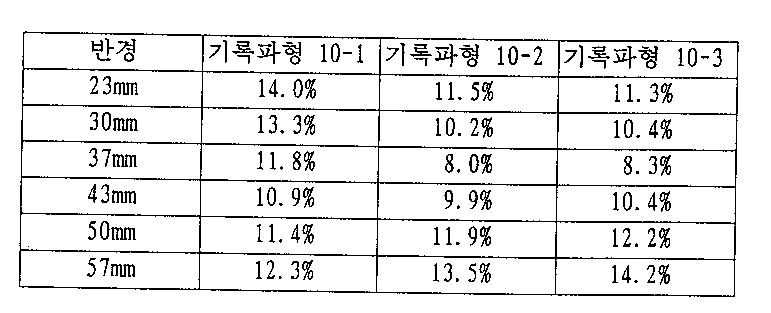
또, 기록 파형 10-3은 도 1의 기록 파형 J와 같이 기록 펄스열의 조사후, 바이어스 파워에서의 조사를 행하고, 그 후 냉각 파워에서의 조사를 행하는 경우이다. 단, 그 냉각 파워 조사 시간은 0.50T, 냉각 파워 개시 시간은 기록할 마크 길이에 따라 변화하고, 그 마크 길이가 짧을수록 개시 시간은 빠르게 되는 것이다.The recording waveform 10-3 is a case of irradiating with a bias power after irradiating a recording pulse train as in the recording waveform J of Fig. 1, and thereafter irradiating with a cooling power. However, the cooling power irradiation time is 0.50 T, the cooling power start time varies with the mark length to be recorded, and the shorter the mark length, the faster the start time.
표 20에서 기록 파형 10-1의 경우에는 지터가 내주부에서 다른 기록 파형에비하여 나쁘게 되어 있다. 한편, 기록 파형 10-2를 이용한 경우에는 기록 파형 10-1에 비하여 디스크 내주부에서는 지터가 개선되어 있으나, 외주부에서는 지터가 반대로 악화되어 있다. 기록 파형 10-3을 이용한 경우에는 기록 파형 10-1에 비하여 디스크 내주부에서는 지터가 개선되어 있으나, 외주부에서는 지터가 반대로 악화되어 있다. 따라서, 소정의 반경보다 내측의 영역, 예를 들면 반경 43mm까지의 디스크 내주부에는 기록 파형 10-2 또는 10-3을 이용하고, 그보다 외주부에는 기록 파형 10-1을 이용하면 된다.In the case of the recording waveform 10-1 in Table 20, the jitter is worse than the other recording waveforms in the inner peripheral portion. On the other hand, in the case of using the recording waveform 10-2, jitter is improved in the inner circumference portion of the disk as compared with the recording waveform 10-1, but jitter is worsened in the outer circumference portion. In the case of using the recording waveform 10-3, jitter is improved in the inner circumference portion of the disk as compared with the recording waveform 10-1, but jitter is worsened on the outer circumference portion. Therefore, the recording waveform 10-2 or 10-3 may be used for the inner peripheral portion of the disc up to a predetermined radius, for example, up to a radius of 43 mm, and the recording waveform 10-1 may be used for the outer peripheral portion.
본원 발명과 같이 디스크 내주부에서는 기록파형 10-2 또는 기록 파형 10-3을, 디스크 외주부에서는 기록 회로를 간소하게 하는 점에서도 기록 파형 10-1을 이용함으로써 디스크의 어느 반경에서도 양호한 지터가 얻어진다.The recording waveform 10-1 or the recording waveform 10-3 is used in the inner peripheral portion of the disk and the recording waveform 10-1 is used in the outer peripheral portion of the disk in that the recording circuit is simplified as in the present invention so that good jitter is obtained in any radius of the disk .
이상과 같이, 광디스크를 일정한 각속도로 회전시키는 경우, 디스크 내주부에서 마크 길이가 짧을수록 냉각 파워 조사 시간을 넓게 또는 냉각 파워 개시 시간을 빠르게 함으로써 디스크의 어느 반경에서도 지터가 작은 기록이 가능하게 된다.As described above, in the case where the optical disk is rotated at a constant angular velocity, the shorter the mark length in the inner peripheral portion of the disk, the wider the cooling power irradiation time or the faster the cooling power start time, the smaller the jitter can be recorded in any radius of the disk.
또, 본 실시예에서는 냉각 파워를 재생 광 파워로 한 경우에 대하여 나타냈으나 냉각 파워가 0부터 바이어스 파워보다 작은 파워인 경우에도 같은 결과가 얻어졌다.In this embodiment, the case where the cooling power is regenerated optical power is shown, but the same result is obtained even when the cooling power is smaller than the bias power from zero.
또, 본 실시예에서는 기록 펄스열의 제 2 파워가 바이어스 파워인 경우에 대하여 나타냈으나, 제 2 파워가 0이상 기록 파워 이하인 경우에도 같은 결과가 얻어졌다.In this embodiment, the case where the second power of the write pulse train is the bias power is shown, but the same result is obtained even when the second power is equal to or more than 0 and the write power or less.
또, 본 실시예에서는 기록 펄스열로서 도 4의 기록 펄스열 A의 경우에 대하여 나타냈으나, 도 4의 기록 펄스열 B, C, D의 경우에도 같은 결과가 얻어졌다.In the present embodiment, the case of the write pulse string A of FIG. 4 is shown as the write pulse string, but the same result is obtained in the case of the write pulse string B, C, and D of FIG.
(제 11 실시예)(Eleventh Embodiment)
각종 냉각 펄스로서의 마크 후단 보정 펄스열을 기록 펄스열 직후에 부가한경우에 대하여 설명하기로 한다.A description will be given of a case where a mark rear end correction pulse train as various cooling pulses is added immediately after the recording pulse train.
본 실시예에서는 도 4의 기록 펄스열 A를 이용했다. 그리고, 그 기록 펄스열직후에 각종 마크 후단 보정 펄스열을 부가했다. 측정 조건은 제 3 실시예와 같다.In this embodiment, the write pulse train A of FIG. 4 is used. Then, various mark rear end correction pulse strings were added immediately after the recording pulse string. The measurement conditions are the same as in the third embodiment.
본 실시예에서 이용한 각종 기록 파형을 도 6을 이용하여 설명하기로 한다.Various recording waveforms used in this embodiment will be described with reference to FIG.
단, 도 6에는 6T 마크를 기록하는 경우의 대표적인 기록 파형 패턴을 도시한다.6 shows a typical recording waveform pattern in the case of recording a 6T mark.
기록 파형 11-1은 마크 후단 보정 펄스열을 부가하지 않은 경우이다.The recording waveform 11-1 is a case in which the mark rear end correction pulse string is not added.
기록 파형 11-2는 기록 펄스열 직후에 재생광 파워에서 0.5T의 기간 레이저광을 조사하고, 그 후 바이어스 파워에서 레이저 광 조사를 행한 것이다.The recording waveform 11-2 is obtained by irradiating a periodic laser beam of 0.5T at the reproduction light power immediately after the recording pulse train, and then irradiating the laser beam at the bias power.
기록 파형 11-3은 기록 펄스열 직후에 바이어스 파워와 재생광 파워의 중간레벨까지 파워를 떨어뜨리고 0.25T의 기간 레이저 광을 조사하고, 그 직후에 재생 광 파워까지 파워를 떨어뜨려서 0.25T의 기간 레이저 광을 조사한 바, 마크 후단 펄스열을 부가하고, 그 후는 바이어스 파워로 레이저 광 조사를 한 것이다.Immediately after the write pulse train, the power was dropped to the middle level between the bias power and the reproduction optical power, the laser beam was irradiated for 0.25T, and the power was dropped to the reproduction optical power immediately after the recording pulse 11-3, When the light was irradiated, a mark rear end pulse train was added, and thereafter laser light irradiation was performed with a bias power.
기록 파형 11-4는 기록 펄스열 직후에 바이어스 파워보다 2mW 높은 파워로0.15T의 기간 레이저 광을 조사하고, 그 직후에 0.35T의 기간 재생광 파워로 레이저 광을 조사한 바, 마크 후단 보정 펄스열을 부가하고, 그 후는 바이어스 파워로레이저 광 조사를 한 것이다.Immediately after the write pulse train 11-4, a laser beam of 0.15T was irradiated with a power of 2mW higher than the bias power, and immediately thereafter the laser beam was irradiated at a reproduction optical power of 0.35T. Thereafter, laser light irradiation was performed with bias power.
기록 파형 11-5는 기록 펄스열 직후에 재생 광 파워로 0.2T의 기간 레이저 광을 조사하고, 그 직후에 O.1T의 기간 바이어스 파워로 조사하고, 그 직후 재생광파워로 0.2T의 기간 조사한 바, 마크 후단 보정 펄스열을 부가하고, 그 후는 바이어스 파워로 레이저 광 조사를 한 것이다.The recording waveform 11-5 was obtained by irradiating a periodic laser beam of 0.2T with a reproducing light power immediately after the recording pulse train, irradiating with a period bias power of 0.1T immediately thereafter, , A mark post-stage correction pulse train is added, and thereafter laser light irradiation is performed with a bias power.
기록 파형 11-6은 기록 펄스열 직후부터 0.2T의 기간을 거쳐서 바이어스 파워부터 재생 광 파워까지 연속적으로 파워를 떨어뜨려가고, 재생광 파워로 0.3T의기간 조사한 바, 마크 후단 보정 펄스열을 부가하고, 그 후는 바이어스 파워로 레이저 광 조사를 한 것이다.In the recording waveform 11-6, the power was continuously dropped from the bias power to the reproducing optical power through the period of 0.2T immediately after the writing pulse train, and the mark rear end correction pulse train was added to the period of 0.3T with the reproducing optical power, Thereafter, laser light irradiation was performed with bias power.
기록 파형 11-7은 기록 펄스열 직후부터 0.25T의 기간을 걸쳐서 바이어스 파워로부터 재생광 파워까지 연속적으로 파워를 떨어뜨려가고, 그 후 0.25T의 기간을거쳐서 재생 광 파워로부터 바이어스 파워까지 연속적으로 파워를 올린 바, 마크 후단 보정 펄스열을 부가하고, 그 후는 바이어스 파워로 레이저 광을 조사한 것이다. 각각의 기록 파형과 100회 오버라이트 후의 지터값을 표 21에 나타낸다.The recording waveforms 11-7 successively drop the power from the bias power to the reproducing optical power over a period of 0.25T immediately after the recording pulse train, and then power is continuously supplied from the reproducing optical power to the bias power through the period of 0.25T And a mark post-stage correction pulse train is added to the laser beam, and thereafter laser light is irradiated at a bias power. Table 21 shows the respective recording waveforms and the jitter values after 100 times overwrite.

표 21에서 기록 파형 11-1에 비하여 기록 파형 11-2와 같이 기록 마크 후단보정 펄스로서 바이어스 파워보다 낮은(냉각 파워라고도 함) 재생 파워에서의 레이저 광 조사를 부가한 쪽이 100회 오버라이트 후의 지터값이 개선되어 있다.In Table 21, as compared with the recording waveform 11-1, the recording mark rear end correction pulse as shown in the recording waveform 11-2 is the one in which laser light irradiation at a reproducing power lower than the bias power (also referred to as cooling power) The jitter value is improved.
한편, 본 발명과 같이 마크 후단 보정 펄스열을 가한 기록 파형 11-3, 11-4, 11-5, 11-6, 11-7에서는 마크 전단부·후단부에서의 대칭성이 보다 양호하게 제어되어 있기 때문에 기록 파형 14-2보다 더욱 지터가 개선되어 있다.On the other hand, in the recording waveforms 11-3, 11-4, 11-5, 11-6, and 11-7 in which the mark rear end correction pulse train is added as in the present invention, the symmetry at the front end and the rear end of the mark is better controlled Therefore, the jitter is improved more than the recording waveform 14-2.
이상과 같이 기록 펄스열 후에 마크 후단 보정 펄스열을 부가함으로써 100회오버라이트에서의 지터가 양호한 기록이 가능하게 된다.By adding the trailing edge correction pulse train to the mark after the recording pulse train as described above, it is possible to perform recording with good jitter in 100 times of overwriting.
또, 본 실시예에서는 마크 후단 보정 펄스열의 파워를 2단계로 변화시킨 경우를 나타냈으나, 상기 파워를 3단계 이상으로 한 경우에도 같은 결과가 얻어지는 것은 물론이다.In the present embodiment, the case where the power of the mark rear end correction pulse train is changed in two stages is shown, but it goes without saying that the same result is obtained even when the power is set to three or more stages.
또, 본 실시예에서는 냉각 파워를 재생광 파워로 한 경우에 대하여 나타냈으나, 냉각 파워를 0부터 바이어스 파워보다 작은 파워로 설정한 경우에도 같은 결과가 얻어졌다.In this embodiment, the case where the cooling power is set to the regenerative optical power is shown, but the same result is obtained even when the cooling power is set from 0 to a power smaller than the bias power.
또, 본 실시예에서는 기록 펄스열의 제 2파워가 바이어스 파워의 경우에 대하여 나타냈으나, 제 2 파워가 0이상 기록 파워 미만인 경우에도 같은 결과가 얻어졌다.Although the second power of the write pulse train is shown in the case of the bias power in this embodiment, the same result is obtained even when the second power is less than 0 and the recording power.
(제 12 실시예)(Twelfth Embodiment)
다음에 기록 펄스열과 마크 후단 보정 펄스열 사이에 바이어스 파워에서의 레이저 광 조사를 한 경우에 대하여 설명하기로 한다.Next, a description will be made of a case where laser light irradiation is performed at a bias power between a write pulse train and a mark rear end correction pulse train.
본 실시예에서는 도 4의 기록 펄스열 A를 이용했다. 또, 측정 조건은 제 11실시예와 같다.In this embodiment, the write pulse train A of FIG. 4 is used. The measurement conditions are the same as in the eleventh embodiment.
본 실시예에서 이용한 각종 기록 파형을 도 7을 이용하여 설명하기로 한다.Various recording waveforms used in this embodiment will be described with reference to FIG.
단, 도 7에는 6T 마크를 기록하는 경우의 대표적인 기록 파형 패턴을 도시한다.However, Fig. 7 shows a typical recording waveform pattern in the case of
기록 파형 12-1은 제 11 실시예의 기록 파형 11-3과 같은 기록 파형이다.The recording waveform 12-1 is a recording waveform similar to the recording waveform 11-3 in the eleventh embodiment.
한편, 본원 발명의 기록 펄스열과 마크 후단 보정 펄스열과의 사이에 바이어스 파워에서의 레이저 광 조사를 한 기록 파형 12-2는 기록 펄스열 후에 바이어스 파워에서의 레이저 광 조사를 0.2T의 기간 행하여, 그 후 바이어스 파워와 재생 파워의 중간까지 파워를 떨어뜨리고 0.25T의 기간 레이저 광을 조사하고, 그 직후에재생 파워까지 파워를 떨어뜨리고 0.25T의 기간 레이저 광을 조사하고, 그 후는 바이어스 파워로 레이저 광 조사를 한 것이다.On the other hand, in the recording waveform 12-2 in which the recording pulse train of the present invention is irradiated with the laser light at the bias power between the mark rear end correction pulse train, the laser light irradiation at the bias power is performed for 0.2T period after the recording pulse train, Immediately thereafter, the power was dropped to regeneration power, and the laser beam was irradiated for a period of 0.25 T, and thereafter the laser beam was irradiated with a bias power It is an investigation.
각각의 기록 파형과 100회 오버라이트 후의 지터값을 표 22에 나타낸다.Table 22 shows the respective recording waveforms and the jitter values after 100 times overwrite.

표 22에서 본 발명과 같이 기록 펄스열과 마크 후단 보정 펄스열 사이에 바이어스 파워에서의 레이저 광 조사를 한 기록 파형 12-2에서는 마크 전단부와 후단부의 대칭성이 좋게 되어 있으므로 기록 파형 12-1보다 더욱 지터가 개선되어 있다.In the recording waveform 12-2 in which laser light is irradiated with bias power between the write pulse train and the mark rear end correction pulse train as in the present invention in Table 22, symmetry between the front end portion and the rear end portion of the mark is improved, Is improved.
이상과 같이, 기록 펄스열 후에 마크 후단 보정 펄스열 사이에 바이어스 파워에서의 레이저 광 조사를 함으로써 100회 오버라이트 후의 지터가 양호한 기록이가능하게 된다.As described above, by irradiating the laser beam at the bias power between the write pulse train and the mark trailing pulse train after the write pulse train, it is possible to perform recording with good jitter after overwriting 100 times.
또, 본 실시예에서는 마크 후단 보정 펄스열의 파워를 2단계로 변화시킨 경우를 나타냈으나, 상기 파워를 3단계 이상으로 한 경우나, 레이저 광을 기록 펄스열 직후부터 연속적으로 바이어스 파워보다 작은 파워까지 변화시키는 기간을 가진마크 후단 보정 펄스열의 경우에도 같은 결과가 얻어지는 것은 물론이다.In the present embodiment, the case where the power of the mark rear end correction pulse train is changed in two stages is shown. However, in the case where the power is set to three or more stages, or when the laser light is continuously supplied from immediately after the recording pulse train to a power smaller than the bias power It is needless to say that the same result is obtained also in the case of the mark rear end correction pulse string having a period for changing.
또, 본 실시예에서는 기록 펄스열로서 도 4의 기록 펄스열 A의 경우에 대하여 나타냈으나, 도 4의 기록 펄스열 B, C, D의 경우에도 같은 결과가 얻어졌다.In the present embodiment, the case of the write pulse string A of FIG. 4 is shown as the write pulse string, but the same result is obtained in the case of the write pulse string B, C, and D of FIG.
또, 본 실시예에서는 냉각 파워를 재생 광 파워로 한 경우에 대하여 나타냈으나, 냉각 파워를 0부터 바이어스 파워보다 작은 파워로 설정한 경우에도 같은 결과가 얻어졌다.In this embodiment, the case where the cooling power is set to the regenerative optical power is shown, but the same result is obtained even when the cooling power is set from 0 to a power smaller than the bias power.
또, 본 실시예에서는 기록 펄스열의 제 2 파워가 바이어스 파워의 경우에 대하여 나타냈으나, 제 2 파워가 0이상 기록 파워 이하인 경우에도 같은 결과가 얻어졌다.In this embodiment, the second power of the write pulse train is shown for the case of the bias power, but the same result is obtained even when the second power is equal to or more than 0 and the recording power.
(제 13 실시예)(Thirteenth Embodiment)
다음에 각종 냉각 펄스열에 마크 후단 보정 펄스열을 부가한 경우에 대하여설명하기로 한다.Next, a description will be given of a case where a mark post-stage correction pulse train is added to various cooling pulse strings.
본 실시예에서 이용한 각종 기록 파형을 도 8을 이용하여 설명하기로 한다.Various recording waveforms used in this embodiment will be described with reference to FIG.
단, 도 8에는 6T 마크를 기록하는 경우의 대표적인 기록 파형 패턴을 도시한다.8 shows a typical recording waveform pattern when a 6T mark is recorded.
또, 측정 조건은 제 11 실시예와 같다.The measurement conditions are the same as in the eleventh embodiment.
기록 파형 13-1, 2, 3의 기록 펄스열은 앞에서 설명한 도 4의 기록 펄스열 B이다.The write pulse strings of the write waveforms 13-1, 2 and 3 are the write pulse string B of FIG. 4 described above.
기록 파형 13-1은 마크 후단 보정 펄스열을 부가하지 않은 경우이다.The recording waveform 13-1 is a case in which the mark rear end correction pulse string is not added.
기록 파형 13-2는 기록 펄스열 직후에 재생광 파워에서 0.5T의 기간 레이저광을 조사하고, 그 후 바이어스 파워로 레이저 광 조사를 행한 것이다.The recording waveform 13-2 is obtained by irradiating a periodic laser beam of 0.5T at the reproduction light power immediately after the recording pulse train, and then irradiating the laser beam at a bias power.
기록 파형 13-3은 기록 펄스열 직후에 바이어스 레벨과 재생광 파워의 중간레벨까지 파워를 떨어뜨리고 0.25T의 기간 레이저 광을 조사하고, 그 직후에 재생광 파워까지 파워를 떨어뜨려서 0.25T의 기간 레이저 광을 조사한 바, 마크 후단보정 펄스열을 부가하고, 그 후는 바이어스 파워로 레이저 광 조사를 한 것이다.Immediately after the write pulse train, the power was dropped to the middle level between the bias level and the reproducing optical power, the laser beam was irradiated for 0.25T, and the power was dropped to the reproducing optical power immediately thereafter, When the light was irradiated, the mark rear end correction pulse train was added, and thereafter laser light irradiation was performed with bias power.
기록 파형 13-4, 5, 6은 앞에서 설명한 도 4의 기록 펄스열 C이며,The write waveforms 13-4, 5, and 6 are the write pulse string C of FIG. 4 described above,
기록 파형 13-4는 마크 후단 보정 펄스열을 부가하지 않은 경우,When the mark rear end correction pulse string is not added,
기록 파형 13-5는 기록 펄스열 직후에 재생 광 파워로 0.5T의 기간 레이저광을 조사하고, 그 후 바이어스 파워로 레이저 광 조사를 행한 경우,In the recording waveform 13-5, when the periodic laser light of 0.5T was irradiated with the reproduction light power immediately after the write pulse train, and then the laser light irradiation was performed with the bias power,
기록 파형 13-6은 기록 펄스열 직후에 기록 파형 13-3과 같은 마크 후단 보정 펄스열을 부가하고, 그 후는 바이어스 파워로 레이저 광 조사를 한 경우이다.The recording waveform 13-6 is a case in which the mark rear end correction pulse string like that of the recording waveform 13-3 is added immediately after the recording pulse string, and thereafter laser light irradiation is performed with bias power.
기록 파형 13-7, 8, 9는 앞에서 설명한 도 4의 기록 펄스열 D이며,The write waveforms 13-7, 8, and 9 are the write pulse string D shown in FIG. 4,
기록 파형 13-7은 마크 후단 보정 펄스열을 부가하지 않은 경우,When the mark rear end correction pulse string is not added to the recording waveform 13-7,
기록 파형 13-8은 기록 펄스열 직후에 재생광 파워로 0.5T의 기간 레이저 광을 조사하고, 그 후 바이어스 파워로 레이저 광 조사를 행한 경우,In the recording waveform 13-8, when the periodic laser light of 0.5T was irradiated with the reproducing light power immediately after the recording pulse train, and then the laser light irradiation was performed with the bias power,
기록 파형 13-9는 기록 펄스열 직후에 기록 파형 13-3과 같은 마크 후단 보정 펄스열을 부가하고, 그 후는 바이어스 파워로 레이저 광 조사를 행한 경우이다.The recording waveform 13-9 corresponds to a case in which the mark rear end correction pulse train as shown in the recording waveform 13-3 is added immediately after the recording pulse train, and thereafter laser light irradiation is performed with the bias power.
각각의 기록 파형과 100회 오버라이트 후의 지터값을 표 23에 나타낸다.Table 23 shows the respective recording waveforms and jitter values after 100 times overwrite.

표 23에서 기록 파형 13-1에 비하여 기록 파형 13-2와 같이 기록 펄스열 직후에 재생 파워에서의 레이저 광 조사를 부가한 쪽이 100회 오버라이트 후의 지터값이 개선되어 있다.In Table 23, as compared with the recording waveform 13-1, the jitter value after overwriting 100 times is improved in the case where laser light irradiation at the reproducing power is added immediately after the recording pulse train as in the recording waveform 13-2.
한편, 본 발명과 같이 마크 후단 보정 펄스열을 가한 기록 파형 13-3에서는기록 파형 13-2와 비교해도 지터가 작다. 이와 같이 도 4의 기록 펄스열 B에 있어서도 마크 후단 보정 펄스열을 부가한 쪽이 마크 전단부·후단부에서의 대칭성이 좋게 되어 있기 때문에 지터가 개선되어 있다.On the other hand, in the recording waveform 13-3 in which the mark rear end correction pulse train is added as in the present invention, the jitter is small even when compared with the recording waveform 13-2. Thus, in the recording pulse string B of FIG. 4, jitter is improved because the symmetry at the front end and the rear end of the mark is improved when the mark rear end correction pulse train is added.
마찬가지로, 도 4의 기록 펄스열 C, D의 경우에도 마크 후단 보정 펄스열을부가한 쪽이 마크 전단부·후단부에서의 대칭성이 좋게 되어 있기 때문에 지터가 개선되어 있다.Similarly, in the case of the recording pulse arrays C and D in Fig. 4, jitter is improved because symmetry at the front end and rear end of the mark is improved by adding the mark rear end correction pulse string.
이상과 같이, 도 4의 기록 펄스 B, C, D에 마크 후단 보정 펄스열을 부가함으로써 100회 오버라이트 후의 지터가 양호한 기록이 가능하게 된다.As described above, by adding the mark post-stage correction pulse train to the recording pulses B, C, and D in Fig. 4, it is possible to perform recording with good jitter after overwriting 100 times.
또, 본 실시예에서는 마크 후단 보정 펄스열의 파워를 2단계로 변화시킨 경우를 나타냈으나, 상기 파워를 3단계 이상으로 한 경우나, 레이저 광을 기록 펄스열 직후부터 연속적으로 바이어스 파워보다 작은 파워까지 변화시키는 기간을 가진마크 후단 보정 펄스열의 경우에도 같은 결과가 얻어지는 것은 물론이다.In the present embodiment, the case where the power of the mark rear end correction pulse train is changed in two stages is shown. However, in the case where the power is set to three or more stages, or when the laser light is continuously supplied from immediately after the recording pulse train to a power smaller than the bias power It is needless to say that the same result is obtained also in the case of the mark rear end correction pulse string having a period for changing.
또, 본 실시예에서는 냉각 파워를 재생광 파워로 한 경우에 대하여 나타냈으나, 냉각 파워를 0부터 바이어스 파워보다 작은 파워의 경우에도 같은 결과가 얻어졌다.In this embodiment, the case where the cooling power is set to the regenerated optical power is shown, but the same result is obtained even when the cooling power is from 0 to the power smaller than the bias power.
또, 본 실시예에서는 기록 펄스열의 제 2파워가 바이어스 파워의 경우에 대하여 나타냈으나, 제 2 파워가 0이상 기록 파워 이하인 경우에도 같은 결과가 얻어졌다.In this embodiment, the second power of the write pulse train is shown for the case of the bias power, but the same result is obtained even when the second power is equal to or more than 0 and the recording power.
(제 14 실시예)(Fourteenth Embodiment)
다음에 기록 마크 길이에 의해 마크 후단 보정 펄스열을 변화시킨 경우에 대하여 설명하기로 한다.Next, the case where the mark rear end correction pulse string is changed by the recording mark length will be described.
본 실시예에서는 제 11 실시예와 같은 측정 조건이다. 또, 본 실시예에서는도 4의 기록 펄스열 A를 이용했다.In this embodiment, the same measurement conditions as in the eleventh embodiment are used. In this embodiment, the write pulse string A of FIG. 4 is used.
본 실시예에서 이용한 각종 기록 파형을 표 24를 이용하여 설명하기로 한다.Various recording waveforms used in this embodiment will be described with reference to Table 24.

기록 파형 14-1은 기록 마크 길이에 의하지 않고 기록 펄스열 직후에 바이어스 레벨과 재생광 파워의 중간 레벨까지 파워를 떨어뜨리고 0.25T의 기간 레이저광을 조사하고, 그 직후에 재생광 파워까지 파워를 떨어뜨리고 0.25T의 기간 레이저 광을 조사하고, 그 후는 바이어스 파워로 레이저 광 조사를 행한 것이다.In the recording waveform 14-1, the power is dropped to the intermediate level between the bias level and the reproducing optical power immediately after the recording pulse train, regardless of the recording mark length, and the laser light is irradiated for 0.25T period. And irradiated with laser light for a period of 0.25 T, and thereafter irradiated with laser light at a bias power.
기록 파형 14-2는 기록 파형 14-1과 같은 마크 후단 보정 펄스열을 갖고, 그 마크 후단 보정 펄스열의 개시 시간은 11T 마크를 기록하는 경우가 0.8T이며, 마크길이가 짧을수록 개시 시간을 0.1T씩 빠르게 해 가고, 3T 마크를 기록하는 경우에는 기록 펄스열 직후에 마크 후단 보정 펄스열을 부가하고, 그 후는 바이어스 파워로 레이저 광 조사를 행한 것이다.The recording waveform 14-2 has the same mark rear end correction pulse string as that of the recording waveform 14-1. The start time of the mark rear end correction pulse string is 0.8T in the case of recording the 11T mark, and the shorter the mark length, In the case of recording the 3T mark, the mark rear end correction pulse train is added immediately after the recording pulse train, and thereafter laser light irradiation is performed with bias power.
각각의 기록 파형과 100회 오버라이트 후의 지터값을 표 25에 나타낸다.Table 25 shows the respective recording waveforms and the jitter values after 100 times overwrite.

표 25에서 본 발명과 같이 마크 후단 보정 펄스열 개시 시간을 마크 길이에따라 변화시킨 기록 파형 14-2에서는 기록 파형 14-1에 비하여 전체 마크 길이로 마크 전단부·후단부에서의 대칭성이 좋아져서 지터가 더욱 개선되어 있다.In Table 25, in the recording waveform 14-2 in which the mark rear end correction pulse string start time is changed in accordance with the mark length as in the present invention, the symmetry at the front end and the rear end of the mark is improved by the total mark length as compared with the recording waveform 14-1, Is further improved.
이상과 같이 마크 후단 보정 펄스열 개시 시간을 기록하는 마크 길이에 따라변화시킴으로써 100회 오버라이트 후의 지터가 양호한 기록이 가능하게 된다.As described above, by changing the mark trailing edge correction pulse train start time according to the mark length for recording, it is possible to perform recording with good jitter after 100 times overwrite.
또, 본 실시예에서는 마크 후단 보정 펄스열의 파워를 2단계로 변화시킨 경우를 나타냈으나, 상기 파워를 3단계 이상으로 한 경우나 레이저 광을 기록 펄스열직후부터 연속적으로 바이어스 파워보다 작은 파워까지 변화시키는 기간을 가진 마크 후단 보정 펄스열의 경우에도 같은 결과가 얻어지는 것은 물론이다.In this embodiment, the power of the mark rear-end correction pulse train is changed in two stages. However, in the case where the power is set to three or more stages, or when the laser light is continuously changed from power immediately after the write pulse train to power It is needless to say that the same result is obtained also in the case of the mark rear end correction pulse string having the period for making the mark.
또, 본 실시예에서는 냉각 파워를 재생광 파워로 한 경우에 대하여 나타냈으나, 냉각 파워가 0부터 바이어스 파워보다 작은 파워의 경우에도 같은 결과가 얻어졌다.In the present embodiment, the case where the cooling power is regenerated optical power is shown, but the same result is obtained even when the cooling power is less than the bias power.
또, 본 실시예에서는 기록 펄스열의 제 2 파워가 바이어스 파워인 경우에 대하여 나타냈으나, 제 2 파워가 0이상 기록 파워 이하인 경우에도 같은 결과가 얻어졌다.In this embodiment, the case where the second power of the write pulse train is the bias power is shown, but the same result is obtained even when the second power is equal to or more than 0 and the write power or less.
또, 본 실시예에서는 기록 펄스열로서 도 4의 기록 펄스열 A의 경우에 대하여 나타냈으나, 도 4의 기록 펄스열 B, C, D의 경우에도 같은 결과가 얻어졌다.In the present embodiment, the case of the write pulse string A of FIG. 4 is shown as the write pulse string, but the same result is obtained in the case of the write pulse string B, C, and D of FIG.
(제 15 실시예)(Example 15)
다음에 기록 마크 길이에 의해 마크 후단 보정 펄스열의 펄스 형상을 변화시킨 경우에 대하여 설명하기로 한다.Next, the case where the pulse shape of the mark rear end correction pulse train is changed by the recording mark length will be described.
본 실시예에서는 기록 펄스열(도 4의 기록 펄스열 A)을 이용했다. 또, 측정조건도 제 11 실시예와 같다.In this embodiment, a write pulse train (write pulse train A in Fig. 4) is used. The measurement conditions are also the same as those in the eleventh embodiment.
본 실시예에서 이용한 각종 기록 파형을 도 9를 이용하여 설명하기로 한다.The various recording waveforms used in this embodiment will be described with reference to FIG.
단, 도 9의 기록 파형 15-1에는 6T 마크를 기록하는 경우의 대표적인 기록 파형 패턴을 도시한다. 또 기록 파형 15-2에는 3T∼11T까지의 마크 길이 중, 3∼5T와 11T에 대해서만 기록 파형 패턴을 나타낸다.However, the recording waveform 15-1 in Fig. 9 shows a typical recording waveform pattern in the case of recording a 6T mark. In the recording waveform 15-2, the recording waveform pattern is shown only for 3 to 5T and 11T among the mark lengths from 3T to 11T.
기록 파형 15-1은 제 11 실시예의 기록 파형 11-3과 같다.The recording waveform 15-1 is the same as the recording waveform 11-3 in the eleventh embodiment.
기록 파형 15-2는 본 발명과 같이 기록 펄스열 직후의 파워를 기록 마크 길이가 짧을수록 작게 되도록 변화시킨 것이다. 구체적으로는 3T 마크를 기록하는 경우는 재생 광 파워, 4T 마크에서는 재생광보다 바이어스 파워와 재생광 파워와의 사이의 8분의 1의 큰 파워와, 마크 길이가 길어질수록 차차 파워를 크게 하고, 0.25T의 기간 그 파워로 파워 광을 조사하고, 그 직후에 재생광 파워까지 파워를 떨어뜨리고 0.25T의 기간 레이저 광을 조사하는 상태의 마크 후단 보정 펄스열을 부가하고, 그 후는 바이어스 파워로 레이저 광 조사를 행한 것이다.The recording waveform 15-2 is obtained by changing the power immediately after the write pulse train so that the shorter the recording mark length becomes, as in the present invention. Concretely, when the 3T mark is recorded, the reproducing power is increased. In the 4T mark, the 1/8 power greater between the bias power and the reproducing light power than the reproducing light. The longer the mark length, Immediately thereafter, power is dropped to the regenerated optical power, and a mark rear end correction pulse string in a state of irradiating the laser light for 0.25T for a period of 0.25T is added. Thereafter, Light irradiation was performed.
각각의 기록 파형과 100회 오버라이트후의 지터값을 표 26에 나타낸다.Table 26 shows the respective recording waveforms and jitter values after 100 times overwrite.

표 26에서 본 발명의 기록 파형 15-2와 같이 기록 마크 길이에 따라 마크 후단 보정 펄스열의 형상을 변화시킨 기록 파형에서는 기록 파형 15-1에 비하여 100사이클에서의 지터값이 개선되어 있다.In Table 26, in the recording waveform in which the shape of the mark rear end correction pulse train is changed according to the recording mark length as in the recording waveform 15-2 of the present invention, the jitter value at 100 cycles is improved as compared with the recording waveform 15-1.
이상과 같이, 마크 후단 보정 펄스열의 펄스 형상을 기록하는 마크 길이에 따라 변화시킴으로써 마크 전단부와 후단부의 대칭성이 좋아지고, 재생 신호 품질이 양호한 기록이 가능하게 된다.As described above, when the pulse shape of the mark rear end correction pulse train is changed in accordance with the mark length for recording, symmetry between the front end portion and the rear end portion of the mark is improved and recording with good reproduction signal quality is made possible.
또, 본 실시예에서는 마크 후단 보정 펄스열의 파워를 2단계로 변화시킨 경우를 나타냈으나, 상기 파워를 3단계 이상으로 한 경우나 레이저 광을 기록 펄스열직후부터 연속적으로 바이어스 파워보다 작은 파워까지 변화시키는 기간을 가진 마크 후단 보정 펄스열의 경우에도 같은 결과가 얻어지는 것은 물론이다.In this embodiment, the power of the mark rear-end correction pulse train is changed in two stages. However, in the case where the power is set to three or more stages, or when the laser light is continuously changed from power immediately after the write pulse train to power It is needless to say that the same result is obtained also in the case of the mark rear end correction pulse string having the period for making the mark.
또, 본 실시예에서는 냉각 파워를 재생광 파워로 한 경우에 대하여 나타냈으나, 냉각 파워가 0부터 바이어스 파워보다 작은 파워의 경우에도 같은 결과가 얻어졌다.In the present embodiment, the case where the cooling power is regenerated optical power is shown, but the same result is obtained even when the cooling power is less than the bias power.
또, 본 실시예에서는 기록 펄스열의 제 2 파워가 바이어스 파워인 경우에 대하여 나타냈으나, 제 2 파워가 0이상 기록 파워 이하인 경우에도 같은 결과가 얻어겼다.In the present embodiment, the case where the second power of the write pulse train is the bias power is shown, but the same result is obtained even when the second power is 0 or more and the recording power or less.
또, 본 실시예에서는 기록 펄스열로서 도 4의 기록 펄스열 A의 경우에 대하여 나타냈으나, 도 4의 기록 펄스열 B, C, D의 경우에도 같은 결과가 얻어졌다.In the present embodiment, the case of the write pulse string A of FIG. 4 is shown as the write pulse string, but the same result is obtained in the case of the write pulse string B, C, and D of FIG.
(제 16 실시예)(Sixteenth Embodiment)
다음에 광디스크를 일정한 각속도로 회전시켰을 경우, 디스크의 반경 방향의위치에 따라 마크 후단 보정 펄스열의 개시 시간을 변화시킨 경우에 대하여 설명하기로 한다.Next, the case where the start time of the mark rear end correction pulse string is changed according to the radial position of the disc when the optical disc is rotated at a constant angular velocity will be described.
또, 디스크의 회전수를 1000rpm, 반경에 따라 EFM 신호를 최단 마크 길이가항상 0.90㎛으로 되도록 클록 T를 바꾼다.The clock T is changed so that the rotation number of the disc is 1000 rpm and the EFM signal according to the radius is always 0.90 mu m at the shortest mark length.
본 실시예에서는 제 11 실시예와 같은 기록 펄스열(도 4의 기록 펄스열 A)을이용했다.In this embodiment, the same write pulse string (write pulse string A in FIG. 4) as in the eleventh embodiment is used.
본 실시예에서 이용한 각종 기록 파형을 표 27을 이용하여 설명하기로 한다.The various recording waveforms used in this embodiment will be described with reference to Table 27.

기록 파형 16-1은 마크 후단 보정 펄스열을 부가하지 않은 경우이다.The recording waveform 16-1 is a case in which the mark rear end correction pulse string is not added.
기록 파형 16-2는 제 11 실시예의 기록 파형 11-3과 같다.The recording waveform 16-2 is the same as the recording waveform 11-3 in the eleventh embodiment.
기록 파형 16-3도 제 11 실시예의 기록 파형 11-3과 같은 마크 후단 보정 펄스열을 갖고 있으나, 본원 발명과 같이 그 마크 후단 보정 펄스열의 개시 시간이 디스크 반경 위치가 내주측일수록 짧게 한 것이다. 구체적으로는 반경이 23∼34mm까지는 마크 후단 보정 펄스열은 기록 펄스열 직후에 부가하고, 35∼46mm까지는 마크 후단 보정 펄스열 개시 시간을 0.2T 지연시키고, 47∼57mm까지는 마크 후단 보정 펄스열 개시시간을 0.5T 지연시켰다.The recording waveform 16-3 has the same mark rear end correction pulse string as the recording waveform 11-3 of the eleventh embodiment, but the start time of the mark rear end correction pulse string is shorter as the disk radius position is on the inner circumference side, as in the present invention. Specifically, the mark rear-end correction pulse string is added immediately after the recording pulse string up to a radius of 23 to 34 mm, the mark rear-end correction pulse string start time is delayed by 0.2 T up to 35 to 46 mm, Delayed.
각각의 기록 파형과 100회 오버라이트 후의 지터값을 표 28에 나타낸다.Table 28 shows the respective recording waveforms and the jitter values after 100 times overwrite.
또, 측정은 내주부가 26mm, 중주부가 38mm, 외주부가 50mm의 각 반경에서 행해졌다. 또, 이 반경에서의 각각의 선속도는 약 2.7, 4.0, 5.2m/s이다.The measurement was carried out at an inner radius of 26 mm, a middle radius of 38 mm, and an outer radius of 50 mm. Also, the respective linear velocities in this radius are about 2.7, 4.0 and 5.2 m / s.
또, 그 밖의 측정 조정은 제 11 실시예와 같다.Other measurement adjustments are the same as those in the eleventh embodiment.

표 28에서 기록 파형 16-1에서는 열의 체류 때문에 지터가 악화하고 있으나,기록 파형 16-2와 같이 마크 후단 보정 펄스열을 부가하면 열의 체류가 없어지기 때문에 100회 오버라이트에서의 지터값이 디스크의 전 둘레에 걸쳐서 개선되어 있다.In Table 28, jitter is deteriorated due to the stagnation of the column in the recording waveform 16-1. However, since the heat stagnation is lost when the mark rear end correction pulse train is added as in the recording waveform 16-2, the jitter value in the 100- And is improved around the circumference.
한편, 본 발명과 같이 마크 후단 보정 펄스열 개시 시간을 디스크 반경 방향위치에 따라 변화시킨 기록 파형 16-3에서는 중외주부에서 열제어를 더욱 세밀하게행했기 때문에 지터도 더욱 개선되어 있다.On the other hand, in the recording waveform 16-3 in which the mark rear end correction pulse train start time is changed in accordance with the disc radial position as in the present invention, the thermal control is more finely performed in the middle and outer circumferential portions, and thus the jitter is further improved.
이상과 같이 마크 후단 보정 펄스열 개시 시간을 디스크 반경 위치에 따라 변화시킴으로써 100회 오버라이트에서의 지터가 양호한 기록이 가능하게 된다.As described above, by changing the start timing of the mark rear end correction pulse string in accordance with the position of the disk radius, it is possible to perform recording with good jitter in 100 times overwrite.
또, 본 실시예에서는 마크 후단 보정 펄스열의 파워를 2단계로 변화시킨 경우를 나타냈으나, 상기 파워를 3단계 이상으로 한 경우나, 레이저 광을 기록 펄스열 직후부터 연속적으로 바이어스 파워보다 작은 파워까지 변화시키는 기간을 가진마크 후단 보정 펄스열의 경우에도 같은 결과가 얻어지는 것은 물론이다.In the present embodiment, the case where the power of the mark rear end correction pulse train is changed in two stages is shown. However, in the case where the power is set to three or more stages, or when the laser light is continuously supplied from immediately after the recording pulse train to a power smaller than the bias power It is needless to say that the same result is obtained also in the case of the mark rear end correction pulse string having a period for changing.
또, 본 실시예에서는 냉각 파워를 재생 광 파워로 한 경우에 대하여 나타냈으나, 냉각 파워가 0부터 바이어스 파워보다 작은 파워의 경우에도 같은 결과가 얻어졌다.In the present embodiment, the case where the cooling power is regenerated optical power is shown, but the same result is obtained even when the cooling power is less than the bias power.
또, 본 실시예에서는 기록 펄스열의 제 2 파워가 바이어스 파워인 경우에 대하여 나타냈으나, 제 2 파워가 0이상 기록 파워 이하인 경우에도 같은 결과가 얻어졌다.In this embodiment, the case where the second power of the write pulse train is the bias power is shown, but the same result is obtained even when the second power is equal to or more than 0 and the write power or less.
또, 본 실시예에서는 기록 펄스열로서 도 4의 기록 펄스열 A의 경우에 대하여 나타냈으나, 도 4의 기록 펄스열 B, C, D의 경우에도 같은 결과가 얻어졌다.In the present embodiment, the case of the write pulse string A of FIG. 4 is shown as the write pulse string, but the same result is obtained in the case of the write pulse string B, C, and D of FIG.
(제 17 실시예)(Example 17)
다음에 광디스크를 일정한 각속도로 회전시켰을 때, 디스크의 반경 방향의 위치에 따라 마크 후단 보정 펄스열의 형상을 변화시킨 경우에 대하여 설명하기로 한다.Next, the case where the shape of the mark rear end correction pulse string is changed according to the radial position of the disk when the optical disk is rotated at a constant angular velocity will be described.
본 실시예에서는 제 11 실시예와 같은 기록 펄스열(도 4의 기록 펄스열 A)을이용했다.In this embodiment, the same write pulse string (write pulse string A in FIG. 4) as in the eleventh embodiment is used.
또, 제 16 실시예와 같은 측정 조건이다.The measurement conditions are the same as those in the 16th embodiment.
본 실시예에서 이용한 각종 기록 파형을 도 10을 이용하여 설명하기로 한다.단, 도 10에는 6T 마크를 기록하는 경우의 대표적인 기록 펄스열 패턴을 나타낸다.또, 기록 파형 17-2에서는 디스크 내, 중, 외주부에서의 기록 파형을 나타낸다.10 shows a typical write pulse train pattern in the case of recording a 6T mark. In the write waveform 17-2, in-disk, intermediate , And a recording waveform at the outer peripheral portion.
기록 파형 17-1은 디스크의 반경 방향의 위치에 의하지 않고 마크 후단 보정펄스열의 형상은 같으며, 그 기록 파형은 제 11 실시예의 기록 파형 11-3과 같다.In the recording waveform 17-1, the shape of the mark rear end correction pulse train is the same regardless of the position in the radial direction of the disk, and the recording waveform thereof is the same as the recording waveform 11-3 in the eleventh embodiment.
기록 파형 17-2는 기록 펄스열 직후의 마크 후단 보정 펄스열의 파워를 디스크 반경 방향의 위치가 내주부측에 있을수록 작아지도록 변화시킨 것이다. 구체적으로는 기록 펄스열 직후의 파워를 각각 반경이 23∼34mm 까지의 재생 광 파워보다 1mW 높은 파워, 35∼46mm까지는 바이어스 파워와 재생광 파워의 중간의 파워, 47∼57mm까지는 바이어스 파워보다 1mW 낮은 파워로 하고, 0.25T의 기간 그 파워로 레이저 광을 조사하고, 그 직후에 재생광 파워까지 파워를 떨어뜨리고 0.25T의 기간레이저 광을 조사하는 상태의 마크 후단 보정 펄스열을 부가하고 그 후는 바이어스파워로 레이저 광 조사를 행한 것이다.The recording waveform 17-2 is obtained by changing the power of the mark rear end correction pulse string immediately after the recording pulse string so that the position in the radial direction of the disk becomes smaller as the inner peripheral side becomes smaller. Specifically, the power immediately after the write pulse train is set to a
각각의 기록 파형과 100회 오버라이트 후의 지터값을 표 29에 나타낸다.Table 29 shows the respective recording waveforms and the jitter values after 100 times overwrite.

표 29에서 본 발명과 같이 기록 펄스열 직후의 마크 후단 보정 펄스열의 파워를 디스크의 내주부측일수록 작게 한 기록 파형 17-2에서는 내외주부에 있어서,마크 전단부·후단부에서의 대칭성이 좋기 때문에 지터가 기록 파형 17-1에 비하여개선되어 있다.In the recording waveform 17-2 in which the power of the trailing edge correction pulse train immediately after the recording pulse train is made smaller toward the inner circumference side of the disk as in the present invention in Table 29, symmetry is excellent at the front and rear ends of the mark in the inner and outer circumferences, Is improved as compared with the recording waveform 17-1.
이상과 같이 마크 후단 보정 펄스열의 펄스 형상을 디스크의 반경 방향의 위치에 따라 변화시킴으로써 100회 오버라이트 후의 지터가 양호한 기록이 가능하게된다.As described above, by changing the pulse shape of the mark trailing edge correction pulse train in accordance with the radial position of the disk, it is possible to perform recording with good jitter after overwriting 100 times.
또, 본 실시예에서는 마크 후단 보정 펄스열의 파워를 2단계로 변화시킨 경우를 나타냈으나, 상기 파워를 3단계 이상으로 한 경우나, 레이저 광을 기록 펄스열 직후부터 연속적으로 바이어스 파워보다 작은 파워까지 변화시키는 기간을 가진마크 후단 보정 펄스열의 경우에도 같은 결과가 얻어지는 것은 물론이다.In the present embodiment, the case where the power of the mark rear end correction pulse train is changed in two stages is shown. However, in the case where the power is set to three or more stages, or when the laser light is continuously supplied from immediately after the recording pulse train to a power smaller than the bias power It is needless to say that the same result is obtained also in the case of the mark rear end correction pulse string having a period for changing.
또, 본 실시예에서는 냉각 파워를 재생 광 파워로 한 경우에 대하여 나타냈으나, 냉각 파워가 0부터 바이어스 파워보다 작은 파워의 경우에도 같은 결과가 얻어졌다.In the present embodiment, the case where the cooling power is regenerated optical power is shown, but the same result is obtained even when the cooling power is less than the bias power.
또, 본 실시예에서는 기록 펄스열의 제 2 파워가 바이어스 파워인 경우에 대하여 나타냈으나, 제 2 파워가 0이상 기록 파워 이하인 경우에도 같은 결과가 얻어졌다.In this embodiment, the case where the second power of the write pulse train is the bias power is shown, but the same result is obtained even when the second power is equal to or more than 0 and the write power or less.
또, 본 실시예에서는 기록 펄스열로서 도 4의 기록 펄스열 A의 경우에 대하여 나타냈으나, 도 4의 기록 펄스열 B, C, D의 경우에도 같은 결과가 얻어졌다.In the present embodiment, the case of the write pulse string A of FIG. 4 is shown as the write pulse string, but the same result is obtained in the case of the write pulse string B, C, and D of FIG.
(제 18 실시예)(Eighteenth Embodiment)
우선, 본 발명 중 기록 펄스열의 종단 펄스로부터 냉각 파워에서의 레이저 광조사를 개시할 때까지의 시간이 일정한 경우의 동작명을 도 11의 디스크 기록 장치의 블록도, 도 12의 각부의 신호 파형도를 이용하여 설명한다.11 is a block diagram of the disk recording apparatus of Fig. 11, and Fig. 12 is a block diagram of the signal waveform of each part of Fig. 12 .
또, 본 실시예에서는 데이터(1)는 클록 단위의 길이로, 클록의 2주기 이상의Hi 기간 및 Lo 기간을 갖는 PWM 데이터(도 12a)로 하고, 데이터의 Hi 기간을 디스크상에서 마크, Lo 기간을 스페이스에 대응시켜서 기록한다.In the present embodiment, the data (1) is PWM data (Fig. 12A) having a length of a clock unit and having a Hi period and a Lo period of two or more clock cycles, and the Hi period of the data is marked on the disk and Lo period Record in association with a space.
또, 시단(始端) 펄스(3) 및 종단(終端) 펄스(7)의 폭은 클록의 1주기 하나의버스트 펄스(27)의 폭은 클록의 2분의 1 주기로 한다.The width of the
냉각 펄스폭은 클록의 2분의 1 주기, 기록 펄스열의 종단 펄스로부터 냉각 파워에서의 레이저 광 조사 개시까지의 시간도 클록의 2분의 1 주기로 했다.The cooling pulse width was set to one-half cycle of the clock, and the time from the end pulse of the write pulse train to the start of the laser light irradiation at the cooling power was set to one-half cycle of the clock.
또, 마크/스페이스 길이 검출 회로(8)는 고밀도 기록으로 마크간의 열간섭이발생하는 스페이스 길이 및 재생 시스템의 주파수 특성에 의해 피크 시프트가 발생하는 마크/스페이스 길이에 대하여 검출하기로 한다.The mark / space length detecting circuit 8 detects the mark / space length at which the peak shift occurs due to the space length in which thermal interference between marks occurs in high-density recording and the frequency characteristics of the reproducing system.
본 실시예에서는 기록할 데이터열에 존재하는 최단의 2T 마크 및 2T 스페이스를 검출하는 것으로 한다.In this embodiment, it is assumed that the shortest 2T mark and 2T space existing in the data string to be recorded are detected.
우선, 시단 펄스 발생 회로(2)에 있어서, 데이터(1)의 Hi 기간의 시단 부분에, 클록의 1주기 폭의 시단 펄스(3)를 발생한다(도 12의 b).First, in the start
버스트 게이트 발생 회로(4)에 있어서, 마크의 중간 위치에 마크 길이로부터3클록만큼 감소된 길이로 버스트 게이트 신호(5)를 발생한다. 단, 마크 길이가 3클록 이하일 때는 버스트 게이트 신호는 발생하지 않는다(도 12의 c).In the burst gate generating circuit 4, a
종단 펄스 발생 회로(6)에서 데이터(1)의 Hi 기간의 종단 부분에 클록의 1주기폭의 종단 펄스(7)를 발생한다(도 12의 e).The termination
마크/스페이스 길이 검출 회로(8)에 있어서 2클록 폭의 데이터, 즉 2T 마크와 2T 스페이스를 검출하고, 2T 마크가 왔을 때는 2T 마크의 시단 펄스 종단 펄스를 포함하도록 2클록 폭의 2T 마크 신호(9)를 발생하고(도 12의 f), 2T 스페이스가왔을 때는 2T 스페이스의 양단의 종단 펄스 시단 펄스를 포함하도록 4클록 폭의 2T 스페이스 신호(10)를 발생한다(도 12의 g).When the 2T mark is detected, data of two clock widths, that is, 2T mark and 2T space, are detected in the mark / space
인코더(11)에서 2T 마크 신호(9)와 2T 스페이스 신호(10)에 의해 시단 펄스(3) 및 종단 펄스(7)의 속성을 결정하고, 셀렉트 신호(12)로서 출력한다. 즉, 3T 이상의 마크이며 3T 이상의 스페이스를 normal, 3T 이상의 마크이며 2T 스페이스를2Ts, 2T 마크이며 3T 이상의 스페이스를 2Tm, 2T 마크이며, 2T 스페이스를 2Ts-2Tm이라는 명칭의 4종류의 속성으로 분류한다(도 12h).The
다음에 시단용 셀렉터(14)에 있어서, 복수의 시단 설정값(13), 즉 normal일때의 시단 설정값, 2Ts일 때의 시단 설정값, 2Tm일 때의 시단 설정값, 2Ts-2Tm일때의 시단 설정값 중에서 셀렉트 신호(12)에 의해 하나를 선택하고 선택 시단 설정값(15)을 출력한다.Next, in the
시단용 샘플/홀드 회로(16)에서 시단 펄스(3)가 왔을 때만 갱신하고, 시단펄스(3)가 오지 않을 때는 앞의 값을 유지하여 홀드 시단 설정값(39)으로서 출력한다(도 12의 I).End
그리고, 시단용 프로그래머블 지연 라인(17)에서 시단 펄스(3)는 홀드 시단설정값(39)에 기초한 값의 지연 시간 후에 지연 시단 펄스(17)로서 출력된다(도 12의 j).The
마찬가지로 종단용 셀렉터(20)에서 복수의 종단 설정값(19) 중에서 셀렉트 신호(12)에 의해 하나를 선택하고, 선택 종단 설정값(21)을 출력하고, 종단용 샘플/홀드 회로(22)에서 종단 펄스(7)가 왔을 때만 갱신하고, 종단 펄스(7)가 오지 않을 때는 앞의 값을 유지한 홀드 종단 설정값(45)으로서 출력한다(도 12의 k).Likewise, in the
그리고 종단용 프로그래머블 지연 라인(23)에서 종단 펄스(7)는 홀드 종단 설정값(45)에 기초한 값의 지연 시간 후에 지연 종단 펄스(24)로서 출력된다(도 12의 l).Then, in the end
여기에서, 지연 냉각 펄스 신호의 출력에 대하여 설명하기로 한다.Here, the output of the delayed cooling pulse signal will be described.
냉각 펄스 발생 회로(36)에 있어서, 지연 종단 펄스의 상승 타이밍으로 냉각펄스를 클륵의 2분의 1 주기분 발생시킨다(도 12의 n).In the cooling
다음에 냉각 펄스용 지연 라인(37)에서 냉각 펄스 발생 회로(36)로부터 출력되는 냉각 펄스(41)를 일정량 지연하고, 냉각 펄스 신호(42)가 출력된다(도 12의o).Next, the cooling
그것을 인버터(38)를 통하여 Hi와 Lo를 반전한 지연 냉각 펄스 신호(43)로서출력한다(도 12의 p).And outputs it as a delayed
또, AND 게이트(26)에서 상기 버스트 게이트 신호(5)와 클록(25)의 논리곱을취하고, 버스트 펄스(27)를 발생한다(도 12의 m).The AND
OR 게이트(28)에서 지연 시단 펄스(18)와 버스트 펄스(27)와 지연 종단 펄스(24)의 논리합을 취하고, 기록 신호(29)를 발생시킨다.The
레이저 다이오드(35)는 재생광 전류원(32)에 의해 상변화 광디스크의 재생 광파워를 발광하도록 바이어스가 부가되어 있다.The
재생광 전류원(32)과 병렬로 바이어스 레벨 전류원(31)과 기록 레벨 전류원(30)을 설치하고, 스위치(33)에 의해 기록 레벨 전류원(30)의 전류를 스위치(34)에 의해 바이어스 레벨 전류원(31)을 on/off하면 레이저 다이오드(35)의 구동 전류가 기록 레벨 전류, 바이어스 레벨 전류, 재생광 레벨 전류의 3자 사이에서 스위칭된다.A bias level
즉, 이 스위치(33)를 상기 기록 신호(29)에서 스위치(34)를 지연 냉각 펄스신호(43)로 제어함으로써 레이저 다이오드(35)를 기록 파워, 바이어스 파워, 냉각파워로 전환하면서 발광시킬 수 있고, 레이저 다이오드(35)를 내장한 광학 헤드를이용하여 상변화 광디스크에 마크 및 스페이스를 냉각 펄스를 부가한 기록 방법으로 형성한다(도 12q).That is, by controlling this
다음에 냉각 파워에서의 광 조사 개시의 타이밍이 클록에 기초하고 있는 경우의 지연 냉각 펄스 신호의 제작 방법을 도 13의 디스크 장치의 클록도와 도 14의각부의 신호 파형도를 이용하여 설명하기로 한다.Next, a method of manufacturing the delayed cooling pulse signal when the timing of starting irradiation of light in the cooling power is based on the clock will be described using the clock of the disk device of Fig. 13 and the signal waveform diagram of the angular part of Fig.
이 경우에는 종단 펄스 발생 회로(6)로부터 출력된 종단 펄스의 상승과 같은 타이밍으로 냉각 펄스 발생회로(46)로부터 냉각 펄스(48)가 출력된다(도 14f).In this case, the cooling pulse 48 is outputted from the cooling pulse generating circuit 46 at the same timing as the rise of the end pulse output from the end pulse generating circuit 6 (Fig. 14 (f)).
냉각 펄스용 지연 라인(37)에서 지연량이 일정한 지연을 행한 냉각 펄스를 출력한다(도 14의 o).The cooling
그 밖의 동작 원리에 대해서는 상기 경우와 같다.Other operating principles are the same as those described above.
이상의 일련의 동작으로 본 실시예의 디스크 기록 장치는 냉각 파워에서의 레이저 광 조사를 부가하여 마크의 시단 부분과 종단 부분의 위치를 기록하는 마크길이 및 해당 기록하는 마크 길이의 전후의 스페이스 길이에 따라 각각 변화시키고, 데이터에 대응한 마크 및 스페이스를 기록할 수 있다.With the above series of operations, the disk recording apparatus of the present embodiment is capable of recording laser light at the cooling power, and recording the position of the start and end portions of the mark in accordance with the length of the marks before and after the mark length And marks and spaces corresponding to the data can be recorded.
또, 본 실시예에서는 (1-7)RLL 코드 신호 기록을 상정하고, 마크/스페이스길이 검출 회로에서는 최단 반전 간격인 2T 마크, 2T 스페이스와 2T 이상의 마크와스페이스의 4패턴으로 나타냈으나, 다시 3T 이상에 대해서도 분류하는 것으로 다시각 마크의 에지 위치 정밀도를 높일 수 있다.In this embodiment, the (1-7) RLL code signal recording is assumed. In the mark / space length detection circuit, the 2T mark is the shortest inversion interval, and the 2T space and the mark and space are 2T or more. 3T or more, the edge position accuracy of each mark can be improved.
또, 시단 펄스, 종단 펄스는 1T 폭, 버스트 펄스는 0.5T 폭으로 했으나, 기록 박막 또는 기록 매체와 광 스폿의 상대 속도 등에 의해 최적 펄스폭을 선택하는것도 가능하다.The start pulse, the end pulse, and the burst pulse have a width of 1T and a width of 0.5T, respectively. However, it is also possible to select the optimum pulse width based on the relative speed between the recording thin film or the recording medium and the light spot.
또, 냉각 펄스폭은 일정값의 0.5T로 했으나 마크 길이 또는 마크간격에 따라 변화시킴으로서 더욱 토탈 에너지를 저감시키는 것도 가능하다.The cooling pulse width is set to a constant value of 0.5 T, but it is also possible to reduce the total energy by changing the mark length or the mark spacing.
광디스크의 평가 조건은 레이저 광의 파장이 680nm, 기록 장치의 기록 재생에 이용하는 광학 헤드의 대물 렌즈의 NA를 0.55로 하고, (1-7)RLL 신호를 최단마크 길이가 0.60㎛으로 되도록 클록(T)을 설정하고, 기록했을 때의 2T부터 8T까지의재생 신호의 제로 교차점의 지터값 : σsum/Tw(%)를 측정했다. 여기에서 σsum은 2T부터 8T까지의 지터의 총합의 표준 편차, Tw는 검출 시스템의 원도우폭이다. 선속도는 4.0m/s이다.The evaluation conditions of the optical disc are as follows: the wavelength of the laser beam is 680 nm; the NA of the objective lens of the optical head used for recording and reproduction of the recording apparatus is 0.55; (1-7) the RLL signal is recorded as the clock T, And the jitter value:? Sum / Tw (%) of the zero crossing point of the reproduction signal from 2T to 8T at the time of recording was measured. Where σsum is the standard deviation of the total jitter from 2T to 8T, and Tw is the window width of the detection system. The linear velocity is 4.0 m / s.
이 디스크에서 신호의 기록은 기록 마크 길이가 0.6㎛으로 되는 단일 주파수를 기록했을 때, C/N이 포화하는 기록 파워를 기록 파워로 하고, 그 2T 마크의 신호를 7T 상당의 단일 주파수로 오버라이트한 경우에 소거율이 20dB를 넘는 파워 마진의 중앙값의 파워를 설정하고, 바이어스 파워로 했다.When recording a signal on this disc, the recording power at which C / N saturates is set to be the recording power when a single frequency with a recording mark length of 0.6 mu m is recorded, and the signal of the 2T mark is overwritten with a single frequency equivalent to 7T In one case, the power of the median value of the power margin exceeding 20 dB was set, and the bias power was set.
디스크의 사이클 특성의 판단으로서는 2T부터 8T까지의 재생 신호의 제로 교차점의 지터값 : σsum/Tw(%)가 13% 미만을 만족하는 사이클 수에 의해 판단했다.Judgment of the cycle characteristics of the disc was made based on the number of cycles satisfying the jitter value:? Sum / Tw (%) of the zero crossing point of the reproduction signal from 2T to 8T less than 13%.
도 15를 이용하여 본 실시예에서 이용한 기록 파형을 설명하기로 한다. 단,도 15에는 7T 마크를 기록하는 경우의 대표적인 기록 파형 패턴을 도시한다. 기록파형 18-1∼3까지는 도 4의 기록 펄스열 B, 기록 파형 18-4∼7까지는 도 4의 기록펄스열 C의 기록 펄스열을 이용하고 있다.The recording waveform used in this embodiment will be described with reference to FIG. However, Fig. 15 shows a typical recording waveform pattern when 7T marks are recorded. The recording pulse strings B-1 to B3 of FIG. 4 are used for the recording waveforms 18-1 to 18-3, and the recording pulse string of the recording pulse string C of FIG. 4 is used for the recording waveforms 18-4 to 18-4.
기록 파형 18-1은 시단 펄스폭 1.0T, 종단 펄스폭 1.0T, 시단·종단 펄스 사이에서는 제 2 파워에서의 0.5T, 제 1 파워로 0.5T 번갈아 레이저 광을 조사하는 기록 펄스열이며, 또 냉각 펄스를 부가하지 않는 경우이다.The recording waveform 18-1 is a recording pulse train for alternately irradiating a laser beam with a leading end pulse width of 1.0T, a terminating pulse width of 1.0T, 0.5T at a second power and 0.5T at a first power between leading and trailing pulses, And no pulse is added.
기록 파형 18-2는 상기 기록 파형 18-1에 기록 마크 길이에 관계없이 기록 펄스열의 종단 펄스의 직후에 냉각 파워에서의 조사 시간이 0.5T인 냉각 펄스를 부가한 경우이다.The recording waveform 18-2 is a case in which a cooling pulse having an irradiation time of 0.5T at the cooling power is added immediately after the end pulse of the recording pulse train irrespective of the recording mark length in the recording waveform 18-1.
기록 파형 18-3은 상기 기록 파형 18-1에 기록 마크 길이에 관계없이 냉각파워에서의 조사 시간이 0.5T이고, 기록 펄스열의 종단 펄스의 하강으로부터 냉각파워에서의 레이저 광 조사 개시까지의 시간이 0.5T로 일징한 상태의 냉각 펄스를 부가한 경우이다.The recording waveform 18-3 shows that the irradiation time at the cooling power is 0.5T in the recording waveform 18-1 regardless of the recording mark length and the time from the fall of the end pulse of the recording pulse train to the start of the laser light irradiation at the cooling power is And a cooling pulse in a state of being uniform at 0.5 T is added.
기록 파형 18-4는 기록 파형 18-1에서 기록하는 마크 길이 및 전후의 마크 간격에 의해 기록 펄스열의 시단 펄스와 종단 펄스의 위치가 변화하고, 또, 냉각펄스를 부가하지 않는 경우이다.The recording waveform 18-4 is a case where the positions of the leading pulse and the trailing pulse of the recording pulse train change depending on the mark length recorded in the recording waveform 18-1 and the mark intervals before and after the recording pulse 18-1 and no cooling pulse is added.
기록 파형 18-5는 기록 파형 18-4에 기록 마크 길이에 관계없이 기록 펄스열의 종단 펄스의 직후에 냉각 파워에서의 조사 시간이 0.5T인 냉각 펄스를 부가한 경우이다.The recording waveform 18-5 is a case in which a cooling pulse having an irradiation time of 0.5T at the cooling power is added immediately after the end pulse of the write pulse string regardless of the recording mark length in the recording waveform 18-4.
기록 파형 18-6은 기록 파형 18-4에 기록 마크 길이에 관계없이 냉각 파워에서의 조사 시간이 0.5T이고, 기록 펄스열의 종단 펄스의 상승으로부터 냉각 파워에서의 레이저 광 조사 개시까지의 시간이 1.5T로 일정한 상태의 냉각 펄스를 부가한 경우이다.The recording waveform 18-6 shows that in the recording waveform 18-4, the irradiation time at the cooling power is 0.5T regardless of the recording mark length, and the time from the rise of the end pulse of the write pulse train to the start of the laser light irradiation at the cooling power is 1.5 T is a case in which a cooling pulse in a constant state is added.
기록 파형 18-7은 기록 파형 18-4에 기록 마크 길이에 관계없이 냉각 파워에서의 조사 시간이 0.5T이고, 냉각 파워에서의 조사 개시가 서브 펄스(시단 펄스와종단 펄스의 사이의 펄스)의 최종단 펄스의 상승으로부터 2.5T로 일정하게 지연시킨 상태의 냉각 펄스를 추가한 경우이다. 즉, 냉각 펄스 조사 개시 시간이 클록에기초하고 있는 경우이다.The recording waveform 18-7 shows that the irradiation time at the cooling power is 0.5T in the recording waveform 18-4 regardless of the recording mark length, and the irradiation start at the cooling power is the sub pulse (pulse between the leading pulse and the trailing pulse) And a cooling pulse with a constant delay of 2.5 T from the rise of the final-stage pulse is added. That is, the case where the cooling pulse irradiation start time is based on the clock.
각각의 기록 파형은 100 사이클 후의 지터값과 지터값이 13% 미만을 만족하는 사이클 수를 표 30에 나타낸다.Table 30 shows the jitter value after 100 cycles and the number of cycles in which the jitter value satisfies 13% or less in each of the recording waveforms.

표 30에서 본원 발명과 같이 냉각 펄스를 부가한 기록 파형 18-2에서는 냉각펄스를 부가하지 않은 기록 파형 18-1에 비하여 열적 손상이 개선되었기 때문에 지터<13%를 만족하는 사이클수도 양호한 것으로 되어 있다.In Table 30, in the recording waveform 18-2 in which the cooling pulse is added as in the present invention, since the thermal damage is improved as compared with the recording waveform 18-1 in which the cooling pulse is not added, the cycle satisfying jitter < 13% .
또, 기록 파형 18-3과 같이 기록 펄스열 후에 0.5T 바이어스 파워에서의 레이저 광 조사를 행하는 것으로 마크 전단부·후단부에서의 대칭성이 보다 제어되기때문에 기록 파형 18-2에 비하여 지터가 작게 되어 있다.In addition, as in the recording waveform 18-3, since the symmetry at the front end and the rear end of the mark is more controlled by irradiating the laser beam at 0.5T bias power after the write pulse train, the jitter is smaller than that of the recording waveform 18-2 .
그리고, 기록할 마크 길이 및 전후 마크 간격에 의해 기록 펄스열의 시단 펄스와 종단 펄스의 위치가 변화하는 경우에도 본원 발명과 같이 냉각 펄스를 부가한기록 파형 18-5에서는 냉각 펄스를 부가하지 않은 기록 파형 18-4에 비하여 열적 손상이 개선되었기 때문에 지터<13%를 만족하는 사이클수도 양호한 것으로 되어있다.Even when the positions of the start pulse and the end pulse of the write pulse string change depending on the mark length to be recorded and the gap between the preceding and following marks, the recording waveform 18-5 to which the cooling pulse is added as in the present invention, Since the thermal damage is improved as compared with 18-4, the cycle satisfying the jitter <13% is also good.
또, 기록할 마크 길이 및 전후의 마크 간격에 의해 기록 펄스열의 시단 펄스와 종단 펄스의 위치가 변화하는 경우, 변화하지 않는 경우보다도 보다 마크 형상의 제어가 가능하기 때문에 지터가 작게 되어 있다.When the positions of the leading pulse and the trailing pulse of the recording pulse train change depending on the mark length to be recorded and the mark spacings before and after the recording, the jitter can be controlled more than that in the case where the mark shape is not changed.
게다가 본원 발명의 기록 파형 18-6, 18-7과 같이 기록 펄스열의 종단 펄스와 냉각 파워에서의 레이저 광 조사와의 사이에 바이어스 파워에서의 조사를 행함으로써 100 사이클에서의 지터값도 지터<13%를 만족하는 사이클수도 더욱 개선되고, 기록 펄스열 직후에 냉각 파워에서의 레이저 광 조사를 행하는 기록 파형 18-5보다도 양호한 값이 얻어지고 있다.Further, as in the recording waveforms 18-6 and 18-7 of the present invention, by irradiating the end pulse of the recording pulse string with the laser light irradiation at the cooling power at the bias power, the jitter value at 100 cycles is also jitter < 13 % Is further improved, and a better value is obtained than the recording waveform 18-5 in which laser light irradiation is performed immediately after the write pulse train at the cooling power.
이상과 같이, 냉각 파워에서의 레이저 광 조사를 행하는 기록 펄스열의 종단부와 냉각 파워에서의 레이저 광 조사의 사이에 바이어스 파워에서의 레이저 광 조사를 넣음으로써 100 사이클에서의 지터 및 다사이클을 행한 경우에도 양호한 기록이 가능하게 된다.As described above, when jitter and multi-cycle are carried out at 100 cycles by irradiating the laser beam at the bias power between the end portion of the recording pulse train to be irradiated with the cooling power and the laser light irradiation at the cooling power It is possible to achieve good recording.
또, 본 실시예에서는 냉각 파워를 재생광 파워로 한 경우에 대하여 나타냈으나, 냉각 파워가 0부터 바이어스 파워보다 작은 파워인 경우에도 같은 결과가 얻어졌다.In this embodiment, the case where the cooling power is regenerated optical power is shown, but the same result is obtained even when the cooling power is smaller than the bias power from zero.
또, 본 실시예에서는 기록 펄스열의 제 2 파워가 바이어스 파워인 경우에 대하여 나타냈으나 제 2 파워가 0 이상 기록 파워 이하인 경우에도 같은 결과가 얻어In this embodiment, the case where the second power of the write pulse train is a bias power is shown, but the same result is obtained even when the second power is 0 or more and the recording power is less than or equal to
졌다.lost.
본 발명의 기록 방법에 의해 기록 마크 사이의 열간섭에 의한 마크 길이 변동이 억제되고, 기록 마크 전단부와 후단부의 대칭성이 좋아지기 때문에 원하는 기록 마크 형상이 형성되고, 광디스크의 고밀도화나 디스크의 회전 방식이 각속도 일정한 경우에도 재생 신호 품질의 향상이 실현된다. 또, 다사이클한 경우의 열적 손상에 의한 신호 열화를 경감하고, 양호한 사이클 특성도 실현할 수 있다.According to the recording method of the present invention, since the mark length variation due to thermal interference between recording marks is suppressed and the symmetry of the recording mark front end portion and the rear end portion is improved, a desired recording mark shape is formed, Even when the angular velocity is constant, improvement of reproduction signal quality is realized. In addition, signal deterioration due to thermal damage in the case of multiple cycles can be reduced, and favorable cycle characteristics can be realized.
Claims (53)
Applications Claiming Priority (9)
| Application Number | Priority Date | Filing Date | Title |
|---|---|---|---|
| JP95-261,246 | 1995-10-09 | ||
| JP26124695 | 1995-10-09 | ||
| JP95-261246 | 1995-10-09 | ||
| JP95-261,262 | 1995-10-09 | ||
| JP95-261262 | 1995-10-09 | ||
| JP26126295 | 1995-10-09 | ||
| JP96-195,880 | 1996-07-25 | ||
| JP19588096 | 1996-07-25 | ||
| JP96-195880 | 1996-07-25 |
Publications (2)
| Publication Number | Publication Date |
|---|---|
| KR980700643A KR980700643A (en) | 1998-03-30 |
| KR100456957B1 true KR100456957B1 (en) | 2005-01-17 |
Family
ID=27327159
Family Applications (1)
| Application Number | Title | Priority Date | Filing Date |
|---|---|---|---|
| KR1019970703863A KR100456957B1 (en) | 1995-10-09 | 1996-10-04 | Method and device for recording optical information |
Country Status (11)
| Country | Link |
|---|---|
| US (1) | US5745467A (en) |
| EP (5) | EP0991058B1 (en) |
| JP (2) | JP4145958B2 (en) |
| KR (1) | KR100456957B1 (en) |
| CN (3) | CN1146869C (en) |
| DE (5) | DE69618034T2 (en) |
| HK (1) | HK1005275A1 (en) |
| MX (1) | MX9704098A (en) |
| MY (1) | MY113691A (en) |
| TW (1) | TW359812B (en) |
| WO (1) | WO1997014143A1 (en) |
Cited By (2)
| Publication number | Priority date | Publication date | Assignee | Title |
|---|---|---|---|---|
| KR102448582B1 (en) | 2021-10-14 | 2022-09-29 | 대한전열공업(주) | Assembly appartus of flow path formation ring for repeater |
| KR20230033406A (en) | 2021-09-01 | 2023-03-08 | 대한전열공업(주) | Manufacturing method through brazing joint of cooling device for repeater |
Families Citing this family (61)
| Publication number | Priority date | Publication date | Assignee | Title |
|---|---|---|---|---|
| WO1997030440A2 (en) * | 1996-02-16 | 1997-08-21 | Philips Electronics N.V. | Method and device for recording at different writing speeds on an optical information carrier |
| JPH10105970A (en) * | 1996-09-27 | 1998-04-24 | Toshiba Corp | Method and device for optical information recording |
| WO1998028735A1 (en) * | 1996-12-20 | 1998-07-02 | Matsushita Electric Industrial Co., Ltd. | Optical recording method and optical recorder |
| US6243339B1 (en) * | 1997-08-12 | 2001-06-05 | U.S. Philips Corporation | Method and device for writing optical record carriers |
| US7158461B1 (en) * | 1997-12-30 | 2007-01-02 | Samsung Electronics Co., Ltd. | Adaptive writing method for high-density optical recording apparatus and circuit thereof |
| US7391698B2 (en) * | 1998-07-23 | 2008-06-24 | Samsung Electronics Co., Ltd. | Adaptive writing method for high-density optical recording apparatus and circuit thereof |
| KR100354732B1 (en) * | 1998-04-03 | 2002-11-18 | 삼성전자 주식회사 | Apparatus method for recording adaptively in optical recording device |
| MY125795A (en) * | 1998-07-23 | 2006-08-30 | Samsung Electronics Co Ltd | Adaptive writing method for high-density optical recording apparatus and circuit thereof |
| TW468177B (en) * | 1998-08-04 | 2001-12-11 | Hitachi Ltd | Data storage method, data storage medium and data storage recording device |
| US6925040B1 (en) | 1998-08-04 | 2005-08-02 | Hitachi, Ltd. | Information recording method, information recording medium and information recording apparatus |
| JP3076033B1 (en) * | 1998-09-14 | 2000-08-14 | 松下電器産業株式会社 | Optical information recording / reproducing apparatus and information recording medium |
| EP1170731B1 (en) * | 1999-03-19 | 2011-02-09 | Panasonic Corporation | Method for optically recording information and device for optically recording information by the same |
| TW561463B (en) | 1999-03-30 | 2003-11-11 | Koninkl Philips Electronics Nv | Method and device for recording marks in an information layer of an optical record carrier |
| JP3762847B2 (en) * | 1999-04-13 | 2006-04-05 | 株式会社日立製作所 | Information recording method and information recording apparatus |
| EP1056077B1 (en) | 1999-05-19 | 2006-05-10 | Mitsubishi Kagaku Media Co., Ltd. | Phase change optical recording by divided recording pulses |
| EP1199715A4 (en) * | 1999-05-31 | 2005-04-13 | Matsushita Electric Ind Co Ltd | Optical information recording method, optical information recording device and optical information recording medium |
| EP1571657A3 (en) * | 1999-07-15 | 2008-07-23 | Koninklijke Philips Electronics N.V. | Method and device for recording marks in an information layer of an optical record carrier, and record carriers for use therein |
| US7272094B2 (en) * | 1999-07-15 | 2007-09-18 | Koninklike Philips Electronics N.V. | Methods and devices for recording marks in an information layer of an optical record carrier, and record carriers for use therein |
| US6654325B1 (en) | 1999-08-09 | 2003-11-25 | Hitachi, Ltd. | Trial writing method and optical disk system using the same |
| JP2001067669A (en) * | 1999-08-31 | 2001-03-16 | Sony Corp | Recorder and recording method |
| KR100339478B1 (en) * | 1999-09-18 | 2002-05-31 | 구자홍 | An apparatus and method for recording the data on a optical disc using optimal writing condition |
| TW518580B (en) * | 2000-05-11 | 2003-01-21 | Koninkl Philips Electronics Nv | Methods and devices for recording marks on a recording surface of an optical record carrier |
| CN1306493C (en) * | 2000-07-28 | 2007-03-21 | 松下电器产业株式会社 | Optical disk device |
| DE60133571T2 (en) | 2000-10-05 | 2009-05-14 | Panasonic Corp., Kadoma | Optical recording medium, method for recording on an optical recording medium and apparatus for recording on an optical recording medium |
| JP3793437B2 (en) * | 2000-10-10 | 2006-07-05 | Tdk株式会社 | Optical recording method and optical recording medium |
| US20020051415A1 (en) * | 2000-10-26 | 2002-05-02 | Matsushita Electric Industrial Co., Ltd. | Recording waveform generator and disk recording device |
| JP3969958B2 (en) * | 2001-02-14 | 2007-09-05 | 株式会社リコー | Optical information recording method |
| JP4405115B2 (en) | 2001-09-03 | 2010-01-27 | パイオニア株式会社 | Information recording apparatus and information recording method |
| TWI260603B (en) * | 2001-09-29 | 2006-08-21 | Samsung Electronics Co Ltd | Method for recording data on optical recording medium |
| CN1248201C (en) * | 2001-10-02 | 2006-03-29 | 松下电器产业株式会社 | optical information recording method, regenerater and medium |
| JP2003208713A (en) * | 2002-01-16 | 2003-07-25 | Tdk Corp | Information recording method on optical recording medium, optical recording medium, and information recording/reproducing apparatus |
| CN1320531C (en) * | 2002-03-15 | 2007-06-06 | 株式会社理光 | Recording apparatus and recording method |
| CN101694774B (en) | 2002-04-03 | 2012-07-25 | 松下电器产业株式会社 | Optical disc drive and optical storage medium |
| JP2004005872A (en) * | 2002-04-09 | 2004-01-08 | Matsushita Electric Ind Co Ltd | Master optical disk manufacturing method, optical disk and its manufacturing method |
| TWI254934B (en) * | 2002-04-26 | 2006-05-11 | Tdk Corp | Optical recording medium and method for optically recording data in the same |
| US8018817B2 (en) * | 2002-05-20 | 2011-09-13 | Samsung Electronics Co., Ltd. | Method of recording erase pattern information on an optical recording medium, erasing information on the optical recording medium based on the erase pattern information, and optical recording medium therefor |
| KR100677104B1 (en) * | 2002-05-20 | 2007-02-01 | 삼성전자주식회사 | Optical recording medium which power information of erase pattern is recorded |
| US7369470B2 (en) * | 2002-05-20 | 2008-05-06 | Samsung Electronics Co., Ltd. | Method of recording erase pattern information on an optical recording medium, erasing information on the optical recording medium based on the erase pattern information, and optical recording medium therefor |
| US20050213468A1 (en) * | 2002-07-26 | 2005-09-29 | Koninklijke Philips Electronics N.V. | Method and device for optical recording and optical record carrier |
| JP4282285B2 (en) * | 2002-08-12 | 2009-06-17 | Tdk株式会社 | Optical recording medium and optical recording method |
| US7474603B2 (en) * | 2002-09-04 | 2009-01-06 | Ricoh Company, Ltd. | Optical information recording method, apparatus, and medium, laser control circuit, wobble signal detection method, and servo signal detection method |
| JP2004103100A (en) * | 2002-09-09 | 2004-04-02 | Tdk Corp | Method and device for recording information on optical recording medium, and the optical recording medium |
| JP2004171642A (en) * | 2002-11-19 | 2004-06-17 | Tdk Corp | Optical recording medium, optical recording method, and optical recording apparatus |
| EP1422712B1 (en) * | 2002-11-21 | 2007-08-01 | Matsushita Electric Industrial Co., Ltd. | Method and apparatus for adjusting a recording pulse using data from the user area of an optical disk. |
| US20050213467A1 (en) * | 2002-12-17 | 2005-09-29 | Yoshihiro Noda | Optical recording medium, and recording/reading method and recording/reading apparatus for optical recording medium |
| KR20040067778A (en) * | 2003-01-23 | 2004-07-30 | 삼성전자주식회사 | Optical recording medium, method and apparatus for recording data thereon |
| AU2003288773A1 (en) * | 2003-01-23 | 2004-08-13 | Samsung Electronics Co., Ltd. | Optical recording medium, method and apparatus for recording data thereon |
| WO2004075181A1 (en) * | 2003-02-19 | 2004-09-02 | Victor Company Of Japan, Limited | Optical recording method, optical recording medium, optical recording medium recording device, optical recording device, optical disk, optica disk recording/reproducing device |
| KR100532955B1 (en) * | 2003-06-16 | 2005-12-01 | 주식회사 하이닉스반도체 | Shared delay circuit of a semiconductor device |
| JP2005038559A (en) * | 2003-07-18 | 2005-02-10 | Sony Corp | Device and method for recording information |
| JPWO2005041175A1 (en) * | 2003-10-27 | 2007-08-23 | パイオニア株式会社 | Information recording device and information recording method |
| CN101645280B (en) * | 2004-01-09 | 2011-08-03 | 松下电器产业株式会社 | Method and device for optical recording onto optical disc medium |
| CN100356455C (en) * | 2004-09-08 | 2007-12-19 | 上海乐金广电电子有限公司 | Phase-change disk recording plusing structure and information recording method |
| EP1807829A1 (en) * | 2004-10-19 | 2007-07-18 | Koninklijke Philips Electronics N.V. | Method of writing data on a master substrate for optical recording |
| US20090251524A1 (en) * | 2004-12-22 | 2009-10-08 | Koninklijke Philips Electronics, N.V. | Pulsed laser mode for writing labels |
| KR20080108282A (en) * | 2006-03-13 | 2008-12-12 | 코닌클리케 필립스 일렉트로닉스 엔.브이. | Real time power control for optical recording drives |
| JP2007317343A (en) * | 2006-04-28 | 2007-12-06 | Sharp Corp | Recording parameter setting device, program thereof, computer-readable recording medium containing the program, information recording medium, and recording parameter setting method |
| CN101427308B (en) * | 2006-04-28 | 2011-02-16 | 夏普株式会社 | Recording parameter setting device, program thereof, computer-readable recording medium containing the program, information recording medium, recording/reproducing device, and recording parameter sett |
| JP2007334921A (en) | 2006-06-12 | 2007-12-27 | Hitachi Ltd | Recording method, laser driving device, and optical disk device using them |
| TW200834558A (en) * | 2006-12-15 | 2008-08-16 | Taiyo Yuden Kk | Optical information recording device, optical information recording method, and optical information recording medium |
| US8848808B2 (en) * | 2007-03-01 | 2014-09-30 | Lightfleet Corporation | Time domain symbols |
Family Cites Families (14)
| Publication number | Priority date | Publication date | Assignee | Title |
|---|---|---|---|---|
| JPS63113938A (en) * | 1986-10-31 | 1988-05-18 | Matsushita Electric Ind Co Ltd | Recording method for optical information |
| US5257256A (en) * | 1987-04-24 | 1993-10-26 | Hitachi, Ltd. | Recording waveform for mark-length modulation optical recording |
| JP2574379B2 (en) * | 1988-03-31 | 1997-01-22 | 松下電器産業株式会社 | Optical information recording / erasing method |
| JP2707774B2 (en) * | 1989-12-13 | 1998-02-04 | 松下電器産業株式会社 | Optical information recording method and recording apparatus |
| JP2972899B2 (en) * | 1991-01-24 | 1999-11-08 | 株式会社リコー | Magneto-optical recording method |
| JPH05120685A (en) * | 1991-10-25 | 1993-05-18 | Olympus Optical Co Ltd | Method and device for recording information |
| EP0594425A3 (en) * | 1992-10-21 | 1996-10-09 | Nippon Kogaku Kk | Pulse train condition/heat shut off condition determination method and apparatus for optical recording, and optical recording method and apparatus |
| JPH06301978A (en) * | 1992-10-28 | 1994-10-28 | Nikon Corp | Method and device for deciding pre-pulse condition and heat shielding condition of optical recording and method and device for optical recording |
| JPH06162507A (en) * | 1992-11-24 | 1994-06-10 | Toshiba Corp | Method and device for information recording |
| JP2684952B2 (en) * | 1993-04-07 | 1997-12-03 | 松下電器産業株式会社 | Disc recording method and disc recording apparatus |
| US5490126A (en) * | 1993-04-07 | 1996-02-06 | Matsushita Electric Industrial Co., Ltd. | Apparatus for recording and reproducing data on a disk |
| JP2679596B2 (en) * | 1993-11-09 | 1997-11-19 | 松下電器産業株式会社 | Disc recording method and disc recording apparatus |
| JP3231533B2 (en) * | 1994-01-31 | 2001-11-26 | 株式会社日立製作所 | Optical information recording method |
| JPH0969246A (en) * | 1995-08-30 | 1997-03-11 | Canon Inc | Optical information recording/reproducing apparatus |
-
1996
- 1996-10-04 DE DE69618034T patent/DE69618034T2/en not_active Expired - Lifetime
- 1996-10-04 DE DE69618680T patent/DE69618680T2/en not_active Expired - Lifetime
- 1996-10-04 KR KR1019970703863A patent/KR100456957B1/en not_active IP Right Cessation
- 1996-10-04 DE DE69614005T patent/DE69614005T2/en not_active Expired - Lifetime
- 1996-10-04 EP EP99121145A patent/EP0991058B1/en not_active Expired - Lifetime
- 1996-10-04 EP EP00106331A patent/EP1018727B1/en not_active Expired - Lifetime
- 1996-10-04 DE DE69618681T patent/DE69618681T2/en not_active Expired - Lifetime
- 1996-10-04 EP EP00106335A patent/EP1020850B1/en not_active Expired - Lifetime
- 1996-10-04 JP JP51490497A patent/JP4145958B2/en not_active Expired - Fee Related
- 1996-10-04 EP EP96932820A patent/EP0797193B1/en not_active Expired - Lifetime
- 1996-10-04 DE DE69612833T patent/DE69612833T2/en not_active Expired - Lifetime
- 1996-10-04 CN CNB961918284A patent/CN1146869C/en not_active Expired - Fee Related
- 1996-10-04 MX MX9704098A patent/MX9704098A/en not_active IP Right Cessation
- 1996-10-04 WO PCT/JP1996/002897 patent/WO1997014143A1/en active IP Right Grant
- 1996-10-04 EP EP99121158A patent/EP0991059B1/en not_active Expired - Lifetime
- 1996-10-08 TW TW085112297A patent/TW359812B/en not_active IP Right Cessation
- 1996-10-08 US US08/725,944 patent/US5745467A/en not_active Expired - Lifetime
- 1996-10-08 MY MYPI96004162A patent/MY113691A/en unknown
-
1998
- 1998-05-21 HK HK98104407A patent/HK1005275A1/en not_active IP Right Cessation
-
1999
- 1999-08-10 JP JP11226038A patent/JP2000155946A/en active Pending
- 1999-09-30 CN CNB991210727A patent/CN1137473C/en not_active Expired - Fee Related
- 1999-09-30 CN CN99121073A patent/CN1128442C/en not_active Expired - Fee Related
Cited By (2)
| Publication number | Priority date | Publication date | Assignee | Title |
|---|---|---|---|---|
| KR20230033406A (en) | 2021-09-01 | 2023-03-08 | 대한전열공업(주) | Manufacturing method through brazing joint of cooling device for repeater |
| KR102448582B1 (en) | 2021-10-14 | 2022-09-29 | 대한전열공업(주) | Assembly appartus of flow path formation ring for repeater |
Also Published As
Similar Documents
| Publication | Publication Date | Title |
|---|---|---|
| KR100456957B1 (en) | Method and device for recording optical information | |
| JP3323782B2 (en) | How information is recorded | |
| EP0737967B1 (en) | Optical recording media and a method for recording on the optical recording media | |
| JPH0612674A (en) | Method and device for recording optical information | |
| JP4063978B2 (en) | Information recording method | |
| JP2000182274A (en) | Optical recording medium and optical recording method | |
| US7376065B2 (en) | Optical recording method, optical recording apparatus and optical storage medium | |
| EP1418574A2 (en) | Information recording apparatus and information recording method | |
| US20040213124A1 (en) | Optical recording medium and data recording apparatus for recording data in the same | |
| US7668071B2 (en) | Phase-change optical recording medium having tracking signal smaller than saturation value | |
| JP3740151B2 (en) | Optical recording method and optical recording apparatus | |
| JP3277733B2 (en) | Method and apparatus for recording optical information on optical disc | |
| JP3218235B2 (en) | Recording device | |
| JP2000132836A (en) | Optical recording method | |
| JPH04212735A (en) | Optical disk and method for recording optical information | |
| US7362682B2 (en) | Method for recording data in an optical recording disc and an apparatus for recording data in an optical recording disc | |
| JP3866598B2 (en) | Optical information recording method and medium | |
| JP2000043414A (en) | Phase change type optical recording medium | |
| JP3452050B2 (en) | How information is recorded | |
| JP3912517B2 (en) | Phase change recording medium and recording apparatus | |
| US7680010B2 (en) | Method for recording information on optical recording medium | |
| JP4299216B2 (en) | Phase change optical recording medium and optimum recording power prediction method for high-speed recording | |
| JPH0877600A (en) | Optical information recording medium | |
| JP2001229539A (en) | Optical recording method and optical recording medium | |
| KR19990074356A (en) | Phase change optical disk |
Legal Events
| Date | Code | Title | Description |
|---|---|---|---|
| A201 | Request for examination | ||
| E902 | Notification of reason for refusal | ||
| E701 | Decision to grant or registration of patent right | ||
| GRNT | Written decision to grant | ||
| FPAY | Annual fee payment |
Payment date: 20111019 Year of fee payment: 8 |
|
| FPAY | Annual fee payment |
Payment date: 20121019 Year of fee payment: 9 |
|
| LAPS | Lapse due to unpaid annual fee |