KR100307078B1 - Glass bonding layer for ceramic circuit board supporting substrate - Google Patents
Glass bonding layer for ceramic circuit board supporting substrate Download PDFInfo
- Publication number
- KR100307078B1 KR100307078B1 KR1019970705052A KR19970705052A KR100307078B1 KR 100307078 B1 KR100307078 B1 KR 100307078B1 KR 1019970705052 A KR1019970705052 A KR 1019970705052A KR 19970705052 A KR19970705052 A KR 19970705052A KR 100307078 B1 KR100307078 B1 KR 100307078B1
- Authority
- KR
- South Korea
- Prior art keywords
- oxide
- glass
- ceramic
- substrate
- green tape
- Prior art date
Links
- 239000011521 glass Substances 0.000 title claims abstract description 93
- 239000000758 substrate Substances 0.000 title claims abstract description 93
- 239000000919 ceramic Substances 0.000 title claims abstract description 67
- 229910052751 metal Inorganic materials 0.000 claims abstract description 41
- 239000002184 metal Substances 0.000 claims abstract description 40
- XLOMVQKBTHCTTD-UHFFFAOYSA-N Zinc monoxide Chemical compound [Zn]=O XLOMVQKBTHCTTD-UHFFFAOYSA-N 0.000 claims abstract description 24
- PXHVJJICTQNCMI-UHFFFAOYSA-N Nickel Chemical compound [Ni] PXHVJJICTQNCMI-UHFFFAOYSA-N 0.000 claims abstract description 22
- 238000004519 manufacturing process Methods 0.000 claims abstract description 17
- 239000000292 calcium oxide Substances 0.000 claims abstract description 13
- ODINCKMPIJJUCX-UHFFFAOYSA-N calcium oxide Inorganic materials [Ca]=O ODINCKMPIJJUCX-UHFFFAOYSA-N 0.000 claims abstract description 13
- 239000011787 zinc oxide Substances 0.000 claims abstract description 13
- 229910052759 nickel Inorganic materials 0.000 claims abstract description 11
- 229910052810 boron oxide Inorganic materials 0.000 claims abstract description 10
- JKWMSGQKBLHBQQ-UHFFFAOYSA-N diboron trioxide Chemical compound O=BOB=O JKWMSGQKBLHBQQ-UHFFFAOYSA-N 0.000 claims abstract description 10
- BRPQOXSCLDDYGP-UHFFFAOYSA-N calcium oxide Chemical compound [O-2].[Ca+2] BRPQOXSCLDDYGP-UHFFFAOYSA-N 0.000 claims abstract description 9
- 229910052878 cordierite Inorganic materials 0.000 claims abstract description 9
- 239000000463 material Substances 0.000 claims abstract description 7
- 239000000203 mixture Substances 0.000 claims description 34
- 229910052802 copper Inorganic materials 0.000 claims description 17
- 238000010438 heat treatment Methods 0.000 claims description 16
- 238000000034 method Methods 0.000 claims description 15
- QVQLCTNNEUAWMS-UHFFFAOYSA-N barium oxide Chemical compound [Ba]=O QVQLCTNNEUAWMS-UHFFFAOYSA-N 0.000 claims description 11
- 229910001374 Invar Inorganic materials 0.000 claims description 6
- VYPSYNLAJGMNEJ-UHFFFAOYSA-N Silicium dioxide Chemical compound O=[Si]=O VYPSYNLAJGMNEJ-UHFFFAOYSA-N 0.000 claims description 5
- 229910052814 silicon oxide Inorganic materials 0.000 claims description 5
- 229910000416 bismuth oxide Inorganic materials 0.000 claims description 4
- TYIXMATWDRGMPF-UHFFFAOYSA-N dibismuth;oxygen(2-) Chemical compound [O-2].[O-2].[O-2].[Bi+3].[Bi+3] TYIXMATWDRGMPF-UHFFFAOYSA-N 0.000 claims description 4
- 229910044991 metal oxide Inorganic materials 0.000 claims description 3
- 150000004706 metal oxides Chemical class 0.000 claims description 3
- TWNQGVIAIRXVLR-UHFFFAOYSA-N oxo(oxoalumanyloxy)alumane Chemical compound O=[Al]O[Al]=O TWNQGVIAIRXVLR-UHFFFAOYSA-N 0.000 claims description 3
- 239000002131 composite material Substances 0.000 claims description 2
- 230000003647 oxidation Effects 0.000 claims description 2
- 238000007254 oxidation reaction Methods 0.000 claims description 2
- 239000000654 additive Substances 0.000 claims 1
- 230000000996 additive effect Effects 0.000 claims 1
- 238000000151 deposition Methods 0.000 claims 1
- 238000000059 patterning Methods 0.000 claims 1
- JSKIRARMQDRGJZ-UHFFFAOYSA-N dimagnesium dioxido-bis[(1-oxido-3-oxo-2,4,6,8,9-pentaoxa-1,3-disila-5,7-dialuminabicyclo[3.3.1]nonan-7-yl)oxy]silane Chemical compound [Mg++].[Mg++].[O-][Si]([O-])(O[Al]1O[Al]2O[Si](=O)O[Si]([O-])(O1)O2)O[Al]1O[Al]2O[Si](=O)O[Si]([O-])(O1)O2 JSKIRARMQDRGJZ-UHFFFAOYSA-N 0.000 abstract description 4
- 238000010276 construction Methods 0.000 abstract 1
- 239000010949 copper Substances 0.000 description 27
- 239000000976 ink Substances 0.000 description 18
- 239000000843 powder Substances 0.000 description 8
- BQCADISMDOOEFD-UHFFFAOYSA-N Silver Chemical compound [Ag] BQCADISMDOOEFD-UHFFFAOYSA-N 0.000 description 7
- 239000011230 binding agent Substances 0.000 description 7
- 229920005989 resin Polymers 0.000 description 7
- 239000011347 resin Substances 0.000 description 7
- 239000004332 silver Substances 0.000 description 7
- RYGMFSIKBFXOCR-UHFFFAOYSA-N Copper Chemical compound [Cu] RYGMFSIKBFXOCR-UHFFFAOYSA-N 0.000 description 5
- 229910004298 SiO 2 Inorganic materials 0.000 description 5
- 239000002241 glass-ceramic Substances 0.000 description 5
- 229910000833 kovar Inorganic materials 0.000 description 5
- 229910052709 silver Inorganic materials 0.000 description 5
- 238000005245 sintering Methods 0.000 description 5
- 239000002002 slurry Substances 0.000 description 5
- 239000004020 conductor Substances 0.000 description 4
- 239000011368 organic material Substances 0.000 description 4
- 239000004065 semiconductor Substances 0.000 description 4
- 239000004094 surface-active agent Substances 0.000 description 4
- ZWEHNKRNPOVVGH-UHFFFAOYSA-N 2-Butanone Chemical compound CCC(C)=O ZWEHNKRNPOVVGH-UHFFFAOYSA-N 0.000 description 3
- CSCPPACGZOOCGX-UHFFFAOYSA-N Acetone Chemical compound CC(C)=O CSCPPACGZOOCGX-UHFFFAOYSA-N 0.000 description 3
- XEKOWRVHYACXOJ-UHFFFAOYSA-N Ethyl acetate Chemical compound CCOC(C)=O XEKOWRVHYACXOJ-UHFFFAOYSA-N 0.000 description 3
- FYYHWMGAXLPEAU-UHFFFAOYSA-N Magnesium Chemical compound [Mg] FYYHWMGAXLPEAU-UHFFFAOYSA-N 0.000 description 3
- YXFVVABEGXRONW-UHFFFAOYSA-N Toluene Chemical compound CC1=CC=CC=C1 YXFVVABEGXRONW-UHFFFAOYSA-N 0.000 description 3
- 239000005354 aluminosilicate glass Substances 0.000 description 3
- 238000000280 densification Methods 0.000 description 3
- 229910052749 magnesium Inorganic materials 0.000 description 3
- 239000011777 magnesium Substances 0.000 description 3
- 239000000395 magnesium oxide Substances 0.000 description 3
- CPLXHLVBOLITMK-UHFFFAOYSA-N magnesium oxide Inorganic materials [Mg]=O CPLXHLVBOLITMK-UHFFFAOYSA-N 0.000 description 3
- 239000004014 plasticizer Substances 0.000 description 3
- 239000002904 solvent Substances 0.000 description 3
- DAFHKNAQFPVRKR-UHFFFAOYSA-N (3-hydroxy-2,2,4-trimethylpentyl) 2-methylpropanoate Chemical compound CC(C)C(O)C(C)(C)COC(=O)C(C)C DAFHKNAQFPVRKR-UHFFFAOYSA-N 0.000 description 2
- 229910001316 Ag alloy Inorganic materials 0.000 description 2
- 229910018072 Al 2 O 3 Inorganic materials 0.000 description 2
- IJGRMHOSHXDMSA-UHFFFAOYSA-N Atomic nitrogen Chemical compound N#N IJGRMHOSHXDMSA-UHFFFAOYSA-N 0.000 description 2
- LFQSCWFLJHTTHZ-UHFFFAOYSA-N Ethanol Chemical compound CCO LFQSCWFLJHTTHZ-UHFFFAOYSA-N 0.000 description 2
- KFZMGEQAYNKOFK-UHFFFAOYSA-N Isopropanol Chemical compound CC(C)O KFZMGEQAYNKOFK-UHFFFAOYSA-N 0.000 description 2
- 229910045601 alloy Inorganic materials 0.000 description 2
- 239000000956 alloy Substances 0.000 description 2
- 229910052782 aluminium Inorganic materials 0.000 description 2
- XAGFODPZIPBFFR-UHFFFAOYSA-N aluminium Chemical compound [Al] XAGFODPZIPBFFR-UHFFFAOYSA-N 0.000 description 2
- 239000005388 borosilicate glass Substances 0.000 description 2
- 238000011049 filling Methods 0.000 description 2
- 239000010419 fine particle Substances 0.000 description 2
- PCHJSUWPFVWCPO-UHFFFAOYSA-N gold Chemical compound [Au] PCHJSUWPFVWCPO-UHFFFAOYSA-N 0.000 description 2
- 229910052737 gold Inorganic materials 0.000 description 2
- 239000010931 gold Substances 0.000 description 2
- 238000010030 laminating Methods 0.000 description 2
- 238000002156 mixing Methods 0.000 description 2
- 229920002037 poly(vinyl butyral) polymer Polymers 0.000 description 2
- 229920000728 polyester Polymers 0.000 description 2
- 238000007650 screen-printing Methods 0.000 description 2
- 229910052710 silicon Inorganic materials 0.000 description 2
- 239000010703 silicon Substances 0.000 description 2
- 239000011877 solvent mixture Substances 0.000 description 2
- VXQBJTKSVGFQOL-UHFFFAOYSA-N 2-(2-butoxyethoxy)ethyl acetate Chemical compound CCCCOCCOCCOC(C)=O VXQBJTKSVGFQOL-UHFFFAOYSA-N 0.000 description 1
- 241000273930 Brevoortia tyrannus Species 0.000 description 1
- 229910000881 Cu alloy Inorganic materials 0.000 description 1
- 239000001856 Ethyl cellulose Substances 0.000 description 1
- ZZSNKZQZMQGXPY-UHFFFAOYSA-N Ethyl cellulose Chemical compound CCOCC1OC(OC)C(OCC)C(OCC)C1OC1C(O)C(O)C(OC)C(CO)O1 ZZSNKZQZMQGXPY-UHFFFAOYSA-N 0.000 description 1
- ZOKXTWBITQBERF-UHFFFAOYSA-N Molybdenum Chemical compound [Mo] ZOKXTWBITQBERF-UHFFFAOYSA-N 0.000 description 1
- BPQQTUXANYXVAA-UHFFFAOYSA-N Orthosilicate Chemical compound [O-][Si]([O-])([O-])[O-] BPQQTUXANYXVAA-UHFFFAOYSA-N 0.000 description 1
- 229910001252 Pd alloy Inorganic materials 0.000 description 1
- HCHKCACWOHOZIP-UHFFFAOYSA-N Zinc Chemical compound [Zn] HCHKCACWOHOZIP-UHFFFAOYSA-N 0.000 description 1
- MCMNRKCIXSYSNV-UHFFFAOYSA-N ZrO2 Inorganic materials O=[Zr]=O MCMNRKCIXSYSNV-UHFFFAOYSA-N 0.000 description 1
- 125000006177 alkyl benzyl group Chemical group 0.000 description 1
- 125000005907 alkyl ester group Chemical group 0.000 description 1
- HZVVJJIYJKGMFL-UHFFFAOYSA-N almasilate Chemical compound O.[Mg+2].[Al+3].[Al+3].O[Si](O)=O.O[Si](O)=O HZVVJJIYJKGMFL-UHFFFAOYSA-N 0.000 description 1
- 229910052788 barium Inorganic materials 0.000 description 1
- DSAJWYNOEDNPEQ-UHFFFAOYSA-N barium atom Chemical compound [Ba] DSAJWYNOEDNPEQ-UHFFFAOYSA-N 0.000 description 1
- 230000002146 bilateral effect Effects 0.000 description 1
- WMWLMWRWZQELOS-UHFFFAOYSA-N bismuth(III) oxide Inorganic materials O=[Bi]O[Bi]=O WMWLMWRWZQELOS-UHFFFAOYSA-N 0.000 description 1
- 239000005385 borate glass Substances 0.000 description 1
- 239000002775 capsule Substances 0.000 description 1
- 238000010344 co-firing Methods 0.000 description 1
- 239000011248 coating agent Substances 0.000 description 1
- 238000000576 coating method Methods 0.000 description 1
- 230000008602 contraction Effects 0.000 description 1
- PMHQVHHXPFUNSP-UHFFFAOYSA-M copper(1+);methylsulfanylmethane;bromide Chemical compound Br[Cu].CSC PMHQVHHXPFUNSP-UHFFFAOYSA-M 0.000 description 1
- 239000013078 crystal Substances 0.000 description 1
- 238000007766 curtain coating Methods 0.000 description 1
- 229910003460 diamond Inorganic materials 0.000 description 1
- 239000010432 diamond Substances 0.000 description 1
- 238000001652 electrophoretic deposition Methods 0.000 description 1
- 235000019441 ethanol Nutrition 0.000 description 1
- 229920001249 ethyl cellulose Polymers 0.000 description 1
- 235000019325 ethyl cellulose Nutrition 0.000 description 1
- 235000021323 fish oil Nutrition 0.000 description 1
- 230000004907 flux Effects 0.000 description 1
- 229910052839 forsterite Inorganic materials 0.000 description 1
- 230000005764 inhibitory process Effects 0.000 description 1
- HCWCAKKEBCNQJP-UHFFFAOYSA-N magnesium orthosilicate Chemical compound [Mg+2].[Mg+2].[O-][Si]([O-])([O-])[O-] HCWCAKKEBCNQJP-UHFFFAOYSA-N 0.000 description 1
- AXZKOIWUVFPNLO-UHFFFAOYSA-N magnesium;oxygen(2-) Chemical compound [O-2].[Mg+2] AXZKOIWUVFPNLO-UHFFFAOYSA-N 0.000 description 1
- 150000002739 metals Chemical class 0.000 description 1
- 238000004377 microelectronic Methods 0.000 description 1
- 229910052750 molybdenum Inorganic materials 0.000 description 1
- 239000011733 molybdenum Substances 0.000 description 1
- 229910052757 nitrogen Inorganic materials 0.000 description 1
- 230000001590 oxidative effect Effects 0.000 description 1
- RVTZCBVAJQQJTK-UHFFFAOYSA-N oxygen(2-);zirconium(4+) Chemical compound [O-2].[O-2].[Zr+4] RVTZCBVAJQQJTK-UHFFFAOYSA-N 0.000 description 1
- 239000010665 pine oil Substances 0.000 description 1
- 238000007747 plating Methods 0.000 description 1
- 229920000058 polyacrylate Polymers 0.000 description 1
- 229920000193 polymethacrylate Polymers 0.000 description 1
- HBMJWWWQQXIZIP-UHFFFAOYSA-N silicon carbide Chemical compound [Si+]#[C-] HBMJWWWQQXIZIP-UHFFFAOYSA-N 0.000 description 1
- 229910010271 silicon carbide Inorganic materials 0.000 description 1
- 238000005476 soldering Methods 0.000 description 1
- 238000004528 spin coating Methods 0.000 description 1
- 238000005507 spraying Methods 0.000 description 1
- 239000000126 substance Substances 0.000 description 1
- 238000010345 tape casting Methods 0.000 description 1
- DLYUQMMRRRQYAE-UHFFFAOYSA-N tetraphosphorus decaoxide Chemical compound O1P(O2)(=O)OP3(=O)OP1(=O)OP2(=O)O3 DLYUQMMRRRQYAE-UHFFFAOYSA-N 0.000 description 1
- 230000008646 thermal stress Effects 0.000 description 1
- BIKXLKXABVUSMH-UHFFFAOYSA-N trizinc;diborate Chemical compound [Zn+2].[Zn+2].[Zn+2].[O-]B([O-])[O-].[O-]B([O-])[O-] BIKXLKXABVUSMH-UHFFFAOYSA-N 0.000 description 1
- 229910052725 zinc Inorganic materials 0.000 description 1
- 239000011701 zinc Substances 0.000 description 1
Images

Classifications
-
- C—CHEMISTRY; METALLURGY
- C03—GLASS; MINERAL OR SLAG WOOL
- C03C—CHEMICAL COMPOSITION OF GLASSES, GLAZES OR VITREOUS ENAMELS; SURFACE TREATMENT OF GLASS; SURFACE TREATMENT OF FIBRES OR FILAMENTS MADE FROM GLASS, MINERALS OR SLAGS; JOINING GLASS TO GLASS OR OTHER MATERIALS
- C03C8/00—Enamels; Glazes; Fusion seal compositions being frit compositions having non-frit additions
- C03C8/02—Frit compositions, i.e. in a powdered or comminuted form
- C03C8/04—Frit compositions, i.e. in a powdered or comminuted form containing zinc
-
- H—ELECTRICITY
- H01—ELECTRIC ELEMENTS
- H01L—SEMICONDUCTOR DEVICES NOT COVERED BY CLASS H10
- H01L23/00—Details of semiconductor or other solid state devices
- H01L23/34—Arrangements for cooling, heating, ventilating or temperature compensation ; Temperature sensing arrangements
- H01L23/36—Selection of materials, or shaping, to facilitate cooling or heating, e.g. heatsinks
- H01L23/373—Cooling facilitated by selection of materials for the device or materials for thermal expansion adaptation, e.g. carbon
-
- C—CHEMISTRY; METALLURGY
- C03—GLASS; MINERAL OR SLAG WOOL
- C03C—CHEMICAL COMPOSITION OF GLASSES, GLAZES OR VITREOUS ENAMELS; SURFACE TREATMENT OF GLASS; SURFACE TREATMENT OF FIBRES OR FILAMENTS MADE FROM GLASS, MINERALS OR SLAGS; JOINING GLASS TO GLASS OR OTHER MATERIALS
- C03C3/00—Glass compositions
- C03C3/04—Glass compositions containing silica
- C03C3/062—Glass compositions containing silica with less than 40% silica by weight
- C03C3/064—Glass compositions containing silica with less than 40% silica by weight containing boron
- C03C3/066—Glass compositions containing silica with less than 40% silica by weight containing boron containing zinc
-
- C—CHEMISTRY; METALLURGY
- C03—GLASS; MINERAL OR SLAG WOOL
- C03C—CHEMICAL COMPOSITION OF GLASSES, GLAZES OR VITREOUS ENAMELS; SURFACE TREATMENT OF GLASS; SURFACE TREATMENT OF FIBRES OR FILAMENTS MADE FROM GLASS, MINERALS OR SLAGS; JOINING GLASS TO GLASS OR OTHER MATERIALS
- C03C3/00—Glass compositions
- C03C3/04—Glass compositions containing silica
- C03C3/062—Glass compositions containing silica with less than 40% silica by weight
- C03C3/064—Glass compositions containing silica with less than 40% silica by weight containing boron
- C03C3/068—Glass compositions containing silica with less than 40% silica by weight containing boron containing rare earths
-
- C—CHEMISTRY; METALLURGY
- C03—GLASS; MINERAL OR SLAG WOOL
- C03C—CHEMICAL COMPOSITION OF GLASSES, GLAZES OR VITREOUS ENAMELS; SURFACE TREATMENT OF GLASS; SURFACE TREATMENT OF FIBRES OR FILAMENTS MADE FROM GLASS, MINERALS OR SLAGS; JOINING GLASS TO GLASS OR OTHER MATERIALS
- C03C3/00—Glass compositions
- C03C3/04—Glass compositions containing silica
- C03C3/076—Glass compositions containing silica with 40% to 90% silica, by weight
- C03C3/097—Glass compositions containing silica with 40% to 90% silica, by weight containing phosphorus, niobium or tantalum
-
- C—CHEMISTRY; METALLURGY
- C03—GLASS; MINERAL OR SLAG WOOL
- C03C—CHEMICAL COMPOSITION OF GLASSES, GLAZES OR VITREOUS ENAMELS; SURFACE TREATMENT OF GLASS; SURFACE TREATMENT OF FIBRES OR FILAMENTS MADE FROM GLASS, MINERALS OR SLAGS; JOINING GLASS TO GLASS OR OTHER MATERIALS
- C03C3/00—Glass compositions
- C03C3/04—Glass compositions containing silica
- C03C3/076—Glass compositions containing silica with 40% to 90% silica, by weight
- C03C3/102—Glass compositions containing silica with 40% to 90% silica, by weight containing lead
- C03C3/108—Glass compositions containing silica with 40% to 90% silica, by weight containing lead containing boron
-
- H—ELECTRICITY
- H01—ELECTRIC ELEMENTS
- H01L—SEMICONDUCTOR DEVICES NOT COVERED BY CLASS H10
- H01L21/00—Processes or apparatus adapted for the manufacture or treatment of semiconductor or solid state devices or of parts thereof
- H01L21/02—Manufacture or treatment of semiconductor devices or of parts thereof
- H01L21/04—Manufacture or treatment of semiconductor devices or of parts thereof the devices having at least one potential-jump barrier or surface barrier, e.g. PN junction, depletion layer or carrier concentration layer
- H01L21/48—Manufacture or treatment of parts, e.g. containers, prior to assembly of the devices, using processes not provided for in a single one of the subgroups H01L21/06 - H01L21/326
- H01L21/4803—Insulating or insulated parts, e.g. mountings, containers, diamond heatsinks
- H01L21/481—Insulating layers on insulating parts, with or without metallisation
-
- H—ELECTRICITY
- H01—ELECTRIC ELEMENTS
- H01L—SEMICONDUCTOR DEVICES NOT COVERED BY CLASS H10
- H01L23/00—Details of semiconductor or other solid state devices
- H01L23/12—Mountings, e.g. non-detachable insulating substrates
- H01L23/14—Mountings, e.g. non-detachable insulating substrates characterised by the material or its electrical properties
- H01L23/142—Metallic substrates having insulating layers
-
- H—ELECTRICITY
- H01—ELECTRIC ELEMENTS
- H01L—SEMICONDUCTOR DEVICES NOT COVERED BY CLASS H10
- H01L23/00—Details of semiconductor or other solid state devices
- H01L23/34—Arrangements for cooling, heating, ventilating or temperature compensation ; Temperature sensing arrangements
- H01L23/36—Selection of materials, or shaping, to facilitate cooling or heating, e.g. heatsinks
- H01L23/373—Cooling facilitated by selection of materials for the device or materials for thermal expansion adaptation, e.g. carbon
- H01L23/3735—Laminates or multilayers, e.g. direct bond copper ceramic substrates
-
- H—ELECTRICITY
- H05—ELECTRIC TECHNIQUES NOT OTHERWISE PROVIDED FOR
- H05K—PRINTED CIRCUITS; CASINGS OR CONSTRUCTIONAL DETAILS OF ELECTRIC APPARATUS; MANUFACTURE OF ASSEMBLAGES OF ELECTRICAL COMPONENTS
- H05K1/00—Printed circuits
- H05K1/02—Details
- H05K1/03—Use of materials for the substrate
- H05K1/05—Insulated conductive substrates, e.g. insulated metal substrate
- H05K1/053—Insulated conductive substrates, e.g. insulated metal substrate the metal substrate being covered by an inorganic insulating layer
-
- H—ELECTRICITY
- H01—ELECTRIC ELEMENTS
- H01L—SEMICONDUCTOR DEVICES NOT COVERED BY CLASS H10
- H01L2224/00—Indexing scheme for arrangements for connecting or disconnecting semiconductor or solid-state bodies and methods related thereto as covered by H01L24/00
- H01L2224/01—Means for bonding being attached to, or being formed on, the surface to be connected, e.g. chip-to-package, die-attach, "first-level" interconnects; Manufacturing methods related thereto
- H01L2224/42—Wire connectors; Manufacturing methods related thereto
- H01L2224/47—Structure, shape, material or disposition of the wire connectors after the connecting process
- H01L2224/48—Structure, shape, material or disposition of the wire connectors after the connecting process of an individual wire connector
- H01L2224/481—Disposition
- H01L2224/48151—Connecting between a semiconductor or solid-state body and an item not being a semiconductor or solid-state body, e.g. chip-to-substrate, chip-to-passive
- H01L2224/48221—Connecting between a semiconductor or solid-state body and an item not being a semiconductor or solid-state body, e.g. chip-to-substrate, chip-to-passive the body and the item being stacked
- H01L2224/48225—Connecting between a semiconductor or solid-state body and an item not being a semiconductor or solid-state body, e.g. chip-to-substrate, chip-to-passive the body and the item being stacked the item being non-metallic, e.g. insulating substrate with or without metallisation
- H01L2224/48227—Connecting between a semiconductor or solid-state body and an item not being a semiconductor or solid-state body, e.g. chip-to-substrate, chip-to-passive the body and the item being stacked the item being non-metallic, e.g. insulating substrate with or without metallisation connecting the wire to a bond pad of the item
-
- H—ELECTRICITY
- H01—ELECTRIC ELEMENTS
- H01L—SEMICONDUCTOR DEVICES NOT COVERED BY CLASS H10
- H01L2924/00—Indexing scheme for arrangements or methods for connecting or disconnecting semiconductor or solid-state bodies as covered by H01L24/00
- H01L2924/095—Indexing scheme for arrangements or methods for connecting or disconnecting semiconductor or solid-state bodies as covered by H01L24/00 with a principal constituent of the material being a combination of two or more materials provided in the groups H01L2924/013 - H01L2924/0715
- H01L2924/097—Glass-ceramics, e.g. devitrified glass
- H01L2924/09701—Low temperature co-fired ceramic [LTCC]
-
- H—ELECTRICITY
- H01—ELECTRIC ELEMENTS
- H01L—SEMICONDUCTOR DEVICES NOT COVERED BY CLASS H10
- H01L2924/00—Indexing scheme for arrangements or methods for connecting or disconnecting semiconductor or solid-state bodies as covered by H01L24/00
- H01L2924/15—Details of package parts other than the semiconductor or other solid state devices to be connected
- H01L2924/151—Die mounting substrate
- H01L2924/153—Connection portion
- H01L2924/1531—Connection portion the connection portion being formed only on the surface of the substrate opposite to the die mounting surface
- H01L2924/15311—Connection portion the connection portion being formed only on the surface of the substrate opposite to the die mounting surface being a ball array, e.g. BGA
-
- H—ELECTRICITY
- H05—ELECTRIC TECHNIQUES NOT OTHERWISE PROVIDED FOR
- H05K—PRINTED CIRCUITS; CASINGS OR CONSTRUCTIONAL DETAILS OF ELECTRIC APPARATUS; MANUFACTURE OF ASSEMBLAGES OF ELECTRICAL COMPONENTS
- H05K3/00—Apparatus or processes for manufacturing printed circuits
- H05K3/0058—Laminating printed circuit boards onto other substrates, e.g. metallic substrates
-
- Y—GENERAL TAGGING OF NEW TECHNOLOGICAL DEVELOPMENTS; GENERAL TAGGING OF CROSS-SECTIONAL TECHNOLOGIES SPANNING OVER SEVERAL SECTIONS OF THE IPC; TECHNICAL SUBJECTS COVERED BY FORMER USPC CROSS-REFERENCE ART COLLECTIONS [XRACs] AND DIGESTS
- Y10—TECHNICAL SUBJECTS COVERED BY FORMER USPC
- Y10T—TECHNICAL SUBJECTS COVERED BY FORMER US CLASSIFICATION
- Y10T29/00—Metal working
- Y10T29/49—Method of mechanical manufacture
- Y10T29/49002—Electrical device making
- Y10T29/49117—Conductor or circuit manufacturing
- Y10T29/49124—On flat or curved insulated base, e.g., printed circuit, etc.
- Y10T29/49128—Assembling formed circuit to base
-
- Y—GENERAL TAGGING OF NEW TECHNOLOGICAL DEVELOPMENTS; GENERAL TAGGING OF CROSS-SECTIONAL TECHNOLOGIES SPANNING OVER SEVERAL SECTIONS OF THE IPC; TECHNICAL SUBJECTS COVERED BY FORMER USPC CROSS-REFERENCE ART COLLECTIONS [XRACs] AND DIGESTS
- Y10—TECHNICAL SUBJECTS COVERED BY FORMER USPC
- Y10T—TECHNICAL SUBJECTS COVERED BY FORMER US CLASSIFICATION
- Y10T29/00—Metal working
- Y10T29/49—Method of mechanical manufacture
- Y10T29/49002—Electrical device making
- Y10T29/49117—Conductor or circuit manufacturing
- Y10T29/49124—On flat or curved insulated base, e.g., printed circuit, etc.
- Y10T29/49155—Manufacturing circuit on or in base
- Y10T29/49163—Manufacturing circuit on or in base with sintering of base
-
- Y—GENERAL TAGGING OF NEW TECHNOLOGICAL DEVELOPMENTS; GENERAL TAGGING OF CROSS-SECTIONAL TECHNOLOGIES SPANNING OVER SEVERAL SECTIONS OF THE IPC; TECHNICAL SUBJECTS COVERED BY FORMER USPC CROSS-REFERENCE ART COLLECTIONS [XRACs] AND DIGESTS
- Y10—TECHNICAL SUBJECTS COVERED BY FORMER USPC
- Y10T—TECHNICAL SUBJECTS COVERED BY FORMER US CLASSIFICATION
- Y10T428/00—Stock material or miscellaneous articles
- Y10T428/24—Structurally defined web or sheet [e.g., overall dimension, etc.]
- Y10T428/24802—Discontinuous or differential coating, impregnation or bond [e.g., artwork, printing, retouched photograph, etc.]
- Y10T428/24917—Discontinuous or differential coating, impregnation or bond [e.g., artwork, printing, retouched photograph, etc.] including metal layer
-
- Y—GENERAL TAGGING OF NEW TECHNOLOGICAL DEVELOPMENTS; GENERAL TAGGING OF CROSS-SECTIONAL TECHNOLOGIES SPANNING OVER SEVERAL SECTIONS OF THE IPC; TECHNICAL SUBJECTS COVERED BY FORMER USPC CROSS-REFERENCE ART COLLECTIONS [XRACs] AND DIGESTS
- Y10—TECHNICAL SUBJECTS COVERED BY FORMER USPC
- Y10T—TECHNICAL SUBJECTS COVERED BY FORMER US CLASSIFICATION
- Y10T428/00—Stock material or miscellaneous articles
- Y10T428/24—Structurally defined web or sheet [e.g., overall dimension, etc.]
- Y10T428/24802—Discontinuous or differential coating, impregnation or bond [e.g., artwork, printing, retouched photograph, etc.]
- Y10T428/24926—Discontinuous or differential coating, impregnation or bond [e.g., artwork, printing, retouched photograph, etc.] including ceramic, glass, porcelain or quartz layer
Abstract
세라믹 또는 금속 지지 기판을 가지는 세라믹 회로 보드의 제조에서, 상기 기판 재료와 상부에 인쇄 회로를 가지는 다중층 그린 테이프 구성물 둘다에 접착되는 본딩 글라스 충은 상기 지지 기판상에 증착되고 플로우된다. 니켈 도금된 금속 기판과 사용하기에 적당한 본딩 글라스와 포스테라이트-코오디어라이트 타입 글라스는 산화칼슘, 산화아연 및 산화붕소와 다른 산화물을 포함하는 혼합된 산화물이 다. 이런 본딩 글라스는 금속 기판보다 더 큰 열팽창 계수와 코오디어라이트 타입 글라스의 플로우 온도보다 낮은 플로우 온도를 가진다.In the manufacture of a ceramic circuit board having a ceramic or metal support substrate, a bonding glass charge adhered to both the substrate material and the multilayer green tape construction having the printed circuit thereon is deposited and flowed on the support substrate. Bonding glass and forsterite-cordierite type glass suitable for use with nickel plated metal substrates are mixed oxides comprising calcium oxide, zinc oxide and boron oxide and other oxides. Such bonding glass has a larger coefficient of thermal expansion than the metal substrate and a flow temperature lower than that of the cordierite type glass.
Description
화이어링된 다층 세라믹 회로 보드는 공지되어 있고 그린 테이프(green tape)로서 공지된 세라믹 유전체 테이프의 충 스택으로 제조되며, 각각의 층은 회로를 형성하기 위해 프린트된 금속 패턴을 포함할 수 있다. 상기 각각의 층은 다수의 작은 홀, 또는 비아를 가지고, 상기 층에 뚫린 홀 또는 비아는 여러 회로 층이 서로 전기적으로 접촉할 수 있도록 도전성 금속으로 채워진다. 그린 테이프는 적당한 유기 접합제 또는 수지, 용매, 가소제 및 계면 활성제와 혼합되는 세라믹 및/또는 글라스 분말을 포함한다. 고밀도 공동-가열처리된 세라믹 다중층 회로 보드 제조 방법은 회로에 구멍난 비아와 비아를 충전하기 위한 도전 잉크, 예를 들어 용매 혼합물의 도전 금속 분말 및 글라스 분말의 혼합물을 사용함으로써 인쇄 배선 회로 패턴을 가지는 다수의 예비제조된 그린 테이프 층을 적층하는 단계, 및 스택내에 이들을 압축함으로써 동시에 테이프 층을 적층하는 단계를 포함한다. 다음에 적층된 층은 700℃이상의 상승된 온도로 가열처리된다. 이런 가열처리는 유기 재료를 달구어 그린 테이프를 제조하는데 사용되는 글라스 및/또는 세라믹을 치밀하게 한다.Wired multilayer ceramic circuit boards are known and made from a fill stack of ceramic dielectric tape known as green tape, each layer comprising a printed metal pattern to form a circuit. Each layer has a number of small holes, or vias, and the holes or vias in the layer are filled with a conductive metal so that the various circuit layers can be in electrical contact with each other. Green tapes include ceramic and / or glass powders mixed with suitable organic binders or resins, solvents, plasticizers and surfactants. The high density co-heated ceramic multilayer circuit board manufacturing method utilizes a printed wiring circuit pattern by using a conductive ink for filling the vias and vias in the circuit, for example, a mixture of conductive metal powder and glass powder of a solvent mixture. Laminating the plurality of prefabricated green tape layers and laminating the tape layers simultaneously by compressing them in the stack. The laminated layer is then heat treated to an elevated temperature of 700 ° C. or higher. This heat treatment densifies the glass and / or ceramics used to heat the organic material to produce the green tape.
가열처리된 글라스 또는 세라믹 회로 보드는 깨지기 쉽기 때문에, 인쇄 배선회로 보드(printed circuit board)에 기계적 강도를 추가로 부여하기 위해, 회로 보드는 적당한 지지 기판, 또는 코어를 한측면 또는 양측면에 부착될 수 있다. 양측면 세라믹-금속 지지 기판의 경우에, 금속내의 절연된 전기적 피드스루(feedthrough)는 회로 밀도를 보다더 증가시키기 위해 다층 세라믹 기판의 회로 비아와 접촉하도록 제공될 수 있다.Since heated glass or ceramic circuit boards are fragile, circuit boards may be attached to one or both sides with suitable support substrates, or cores, to provide additional mechanical strength to the printed circuit board. have. In the case of a bilateral ceramic-metal support substrate, insulated electrical feedthroughs in the metal may be provided to contact the circuit vias of the multilayer ceramic substrate to further increase circuit density.
이렇게 지지된 다층 기판의 형성하는 바람직한 방법으로 종래 방식에서는 그린 테이프 및 금속을 함유한 도전성 잉크를 사용하여 다층 적층물을 형성하고, 적당히 준비된 지지 기판의 한측면 또는 양측면에 상기 적층물을 배치시키고, 그린 테이프와 도체 잉크의 유기 재료를 제거하고, 그린 테이프 조성물의 글라스 미립자와 도체 잉크의 금속 미립자를 소결하거나 치밀하고, 지지 기판과 다층 세라믹 기판을 접착시키는데 요구되는 온도로 복합 구조를 함께 가열처리한다.As a preferred method of forming a multi-layered substrate thus supported, in a conventional manner, a multi-layered laminate is formed by using a conductive tape containing a green tape and a metal, and the laminate is disposed on one or both sides of a properly prepared supporting substrate, The organic material of the green tape and the conductor ink is removed, the glass fine particles of the green tape composition and the metal fine particles of the conductor ink are sintered or dense, and the composite structure is heat treated together to the temperature required to bond the support substrate and the multilayer ceramic substrate. .
일반적으로, 그린 테이프로부터 유기 재료의 제거와 이들의 순차적 치밀화는 세라믹에서 x, y 및 z 방향으로 약 20%에 이르는 큰 정도의 체적 수축을 초래한다. 그러나, 전술된 지지 인쇄 배선 회로 보드내의 지지 기판은 어떤 치밀화 수축도 받지 않기 때문에, 그린 테이프의 큰 수축, 특히 x 및 y 방향으로의 수축은 지지 기판과의 비점착성 및 이들이 접촉되는 것으로 가정할 경우, 지지 기판상에 있는 다층 세라믹내의 비아와 전기적 피드스루(feedthrough) 사이에 심각한 오정렬(misalignment)과 같은 문제점이 발생된다. 그러므로 적어도 그린 테이프 층의 x와 y 방향으로의 수축을 억제하는 방법이 제공되어야 한다.In general, the removal of organic materials from the green tape and their sequential densification result in a large volume shrinkage of up to about 20% in the x, y and z directions in the ceramic. However, since the support substrates in the above-mentioned support printed wiring circuit boards do not undergo any densification shrinkage, large shrinkage of the green tape, especially in the x and y directions, is assumed to be non-stick with the support substrates and that they are in contact. Problems such as severe misalignment between vias and electrical feedthrough in multilayer ceramics on a supporting substrate arise. Therefore, at least a method of suppressing shrinkage in the x and y directions of the green tape layer should be provided.
본 발명은 고밀도 공동-가열처리되는(co-firing) 세라믹 다층 회로 보드의 제조에 관한 것으로서, 특히 열적으로 도전성이 있는 지지 기판의 양측면에 접속되는 공동-가열처리된 다층 회로 보드의 제조에 관한 것이다.FIELD OF THE INVENTION The present invention relates to the manufacture of high density co-firing ceramic multilayer circuit boards, and more particularly to the manufacture of co-heated multilayer circuit boards connected to both sides of a thermally conductive support substrate. .
제1도는 본 발명의 결합 글라스를 사용하는 전자 팩키지의 단면도이다.1 is a cross-sectional view of an electronic package using the bonding glass of the present invention.
지지 기판상에서 가열처리된 그린 테이프 적층물의 측방 수축을 억제하기 위한 방법은 적층물 내의 치밀화 수축이 시작되기 전에 적층물을 지지 기판에 부착시킬 수 있게 적층물과 지지 기판 사이에 결합층(bonding layer)을 제공하는 것이다.A method for suppressing lateral shrinkage of a heated green tape stack on a support substrate is a bonding layer between the stack and the support substrate to allow the stack to adhere to the support substrate before densification shrinkage in the stack begins. To provide.
글라스 결합층은 특정 세트의 금속 코어와 세라믹 조성물에 대해 이것을 달성하도록 제시되었다. Prabhu의 미국 특허 제5,277,724호를 참조하라. 글라스 결합층은 지지 기판과 적층물의 세라믹 또는 글라스에 접착되어야 한다 그러므로, 결합 글라스 층상에 배치된 그린 테이프 적층물이 가열처리되는 경우, 글라스 결합층은 x및 y 측방으로의 수축을 억제시켜, 그린 테이프층에서의 거의 모든 수축은 두께 방향, 또는 z 방향에서 발생된다. 따라서, 다층 세라믹 스택 및 지지 기판의 비아와 콘택트는 가열처리되는 동안 서로 정렬된 채로 있다. Cherukuri 등의 미국 특허 제5,256,469호는 다양한 지지 기판에 적당한 결합 글라스로서 Pb-Zn-Ba 보로실리케이트 글라스와 MgO-B2O3-SiO2타입의 마그네슘 함유 그린 테이프 세라믹을 개시한다.Glass bonding layers have been suggested to achieve this for a particular set of metal cores and ceramic compositions. See Prabhu, US Pat. No. 5,277,724. The glass bonding layer must be bonded to the ceramic or glass of the support substrate and the laminate. Therefore, when the green tape stack disposed on the bonding glass layer is heat treated, the glass bonding layer suppresses shrinkage to the x and y sides, so that the green Almost all shrinkage in the tape layer occurs in the thickness direction or in the z direction. Thus, the vias and contacts of the multilayer ceramic stack and support substrate remain aligned with each other during the heat treatment. US Pat. No. 5,256,469 to Cherukuri et al. Discloses Pb-Zn-Ba borosilicate glass and MgO-B 2 O 3 -SiO 2 type magnesium containing green tape ceramics as suitable bonding glass for various support substrates.
이들 세라믹은 90-130×10-7/℃의 가열처리된 세라믹 열팽창 계수를 갖는다.These ceramics have a heat-treated ceramic thermal expansion coefficient of 90-130 × 10 −7 / ° C.
그린 테이프 스택이 회로 보드상의 소자 밀도를 보다더 증가시키기 위해 세라믹 또는 금속 지지 기판의 양측면에 대해 적층될 때, 수축 문제는 중요하게 된다. 지지 기판상의 비아 홀과 콘택트 패드를 통해 접속되는 지지 기판의 양측면상에 있는 다층 회로는 이런 비아 홀과 콘택트 패드와 정합(registration)되어 있어야 한다. 세라믹 또는 금속 지지체 또는 코어는 가열처리 동안 크게 수축하지 않기 때문에, x와 y 방향에서는 내성이 있는 글라스/세라믹 그린 테이프의 수축양은 여러 가지 층과 지지 기판내의 비아 사이의 정합을 유지하도록 단지 약 1% 미만이 될 수 있다.When green tape stacks are stacked on both sides of a ceramic or metal support substrate to further increase the device density on the circuit board, shrinkage issues become important. Multi-layer circuits on both sides of the support substrate that are connected through via holes and contact pads on the support substrate must be registered with these via holes and contact pads. Since the ceramic or metal support or core does not shrink significantly during the heat treatment, the shrinkage of the resistant glass / ceramic green tape in the x and y directions is only about 1% to maintain the match between the various layers and the vias in the support substrate. Can be less.
그러므로, 세라믹 또는 금속 지지 기판, 이를테면 니켈 도금된 Cu/Mo/Cu(13/74/13) 기판 또는 코바르(Kovar) 기판에 포스테라이트-코오디어라이트 타입의 글라스/세라믹을 결합하기 위해 약 950℃에 이르는 온도에서 그린 테이프의 소결 동안 지지 기판과 글라스/세라믹 사이의 1% 이상의 x-y 수축을 방지할 결합층을 제공하는 것이 바람직하다.Therefore, it is difficult to bond glass / ceramic of the forsterite-cordierite type to ceramic or metal support substrates such as nickel plated Cu / Mo / Cu (13/74/13) substrates or Kovar substrates. It is desirable to provide a bonding layer that will prevent at least 1% xy shrinkage between the support substrate and the glass / ceramic during sintering of the green tape at temperatures up to 950 ° C.
결합 글라스가 950℃에 이르는 온도에서 가열처리되는 동안 세라믹 또는 금속 지지 기판과 중첩 포스테라이트-코오디어라이트 타입 글라스/세라믹 그린 테이프 조성물 사이의 수축이 1% 이하인 것을 확인했다. 적당한 결합 글라스의 열팽창 계수는 세라믹 또는 금속 지지 기판의 열팽창 계수 보다 높고, 이들은 높은 연화점을 가져야 한다. 현재의 글라스는 75-110×10-7/℃의 열팽창 계수를 가진다.It was found that the shrinkage between the ceramic or metal support substrate and the overlapping forsterite-cordierite type glass / ceramic green tape composition was 1% or less while the bonding glass was heated at a temperature up to 950 ° C. The coefficient of thermal expansion of suitable bond glass is higher than that of ceramic or metal support substrates, and they should have a high softening point. Current glass has a coefficient of thermal expansion of 75-110 × 10 −7 / ° C.
특히, 글라스/세라믹은 본 발명의 결합 글라스를 사용하여 낮은 수축으로 가열처리될 수 있는 Cu/Mo/Cu의 구리 도금 금속 기판에 결합될 수 있다. 결합 글라스는 금속 기판에 스크린 인쇄되고, 그린 테이프층 내의 회로와 금속 기판내의 콘택트 또는 비아 사이의 접속을 허용하도록 금속 기판과 정렬된 다층 그린 테이프층이 패턴화되어, 가열된다. 결합 글라스 층은 그린 테이프 층의 x와 y 측방으로의 수축을 1% 미만으로 감소시킨다.In particular, the glass / ceramic can be bonded to a Cu / Mo / Cu copper plated metal substrate that can be heat treated with low shrinkage using the bonding glass of the present invention. The bond glass is screen printed onto the metal substrate and the multilayer green tape layer aligned with the metal substrate is patterned and heated to allow connection between the circuit in the green tape layer and the contacts or vias in the metal substrate. The bonding glass layer reduces the shrinkage of the green tape layer to the x and y sides to less than 1%.
본 발명의 기술은 첨부 도면과 관련한 발명의 상세한 설명을 고려함으로써 쉽게 이해될 수 있다.The technique of the present invention can be easily understood by considering the detailed description of the invention in connection with the accompanying drawings.
소결단계 동안 공동-가열처리된 세라믹과 세라믹 또는 금속 지지 기판 사이의 작은 수축을 유지하기 위해, 결합 글라스 층은 공동-가열처리된 세라믹 그린 테이프 조성물과 지지 기판에 대해 아주 특수한 것이 요구된다. 지지 기판의 표면, 세라믹의 화학적 조성물, 세라믹 그린 테이프의 연화점 및 소결 특성과 지지 기판과 세라믹의 재료 모두의 열팽창 계수가 고려되어야 한다. 결합 글라스 층은 약 800℃ 이하로 그린 테이프의 글라스 세라믹의 연화점 보다 낮은 연화점을 갖고, 지지 기판과 중첩 그린 테이프 층 모두에 대한 양호한 접착력을 가져야 한다. 결합 글라스는 바람직하게 가열처리 동안 중첩 세라믹의 수축을 방지 또는 억제하기 위해서 그린 테이프를 형성하는데 사용되는 글라스의 소결 온도 보다 낮은 약 25-250℃ 소결 온도를 가진다. 결합 글라스는 글라스/세라믹 또는 지지 기판의 열팽창 계수보다 더 높은 열팽창 계수를 갖는다.In order to maintain a small shrinkage between the co-heated ceramic and the ceramic or metal support substrate during the sintering step, the bonding glass layer is required to be very special for the support substrate and the co-heated ceramic green tape composition. The surface of the support substrate, the chemical composition of the ceramic, the softening point and sintering properties of the ceramic green tape, and the coefficient of thermal expansion of both the support substrate and the material of the ceramic should be considered. The bonding glass layer should have a softening point below about 800 ° C. below the softening point of the glass ceramic of the green tape, and should have good adhesion to both the supporting substrate and the overlapping green tape layer. The bond glass preferably has a sintering temperature of about 25-250 ° C. lower than the sintering temperature of the glass used to form the green tape to prevent or inhibit shrinkage of the overlapping ceramics during heat treatment. The bonded glass has a higher coefficient of thermal expansion than that of the glass / ceramic or support substrate.
마그네슘 산화물-알루미노실리케이트 글라스는 이들이 강도가 높고 낮은 열팽창 계수의 특성 때문에 세라믹 다층 인쇄 배선 회로 보드를 제조하는데 광범위하게 사용된다. 고강도는 세라믹 또는 금속 지지 기판으로 보상되기 때문에 본 발명에서는 요구되지 않는다. 종래 기술은 실리콘과 매칭되는 열팽창 계수를 요구했고, 상기 재료는 현재 대부분의 반도체 소자를 제조하는데 사용된다. 그러나 코오디어라이트 타입 글라스의 또다른 특성 즉, 낮은 손실, 낮은 유전 상수 등은 본 발명에 중요하다.Magnesium oxide-aluminosilicate glasses are widely used in the manufacture of ceramic multilayer printed wiring boards because of their high strength and low thermal expansion properties. High strength is not required in the present invention because it is compensated with a ceramic or metal support substrate. The prior art required a coefficient of thermal expansion that matches silicon, and the material is currently used to manufacture most semiconductor devices. However, other properties of cordierite type glass, namely low loss, low dielectric constant and the like, are important to the present invention.
회로 보드를 제조하는데 유용한 글라스는 포그테라이트 결정상 분야의 마그네슘 산화물-알루미노실리케이트 글라스로, 이것은 코오디어라이트(cordierite)보다 열팽창 계수가 높다. 포스테라이트(forsterite) 글라스는 특정 특성, 이를테면 본 발명에 중요한 낮은 유전 상수, 낮은 손실 등을 가지지만, 열팽창 계수는 높다.A useful glass for the production of circuit boards is magnesium oxide-aluminosilicate glass in the field of pogrite crystal phase, which has a higher coefficient of thermal expansion than cordierite. Forsterite glass has certain properties such as low dielectric constant, low loss, etc., which are important for the present invention, but have a high coefficient of thermal expansion.
실리콘의 열팽창 계수는 약 22-23×10-7/℃ 인 반면, 본 세라믹 또는 금속 지지 기판은 일반적으로 더 높은 약 45-55×10-7/℃의 열팽창 계수를 가진다.The coefficient of thermal expansion of silicon is about 22-23 × 10 −7 / ° C., while the ceramic or metal support substrate generally has a higher coefficient of thermal expansion of about 45-55 × 10 −7 / ° C.
지지 기판으로서 현재 바람직한 상기 금속 기판은 Climax Metals Co.부터 상업적으로 시판되는 니켈 도금된(약 25 미크론의 두께까지) 구리/몰리브덴/구리(13/74/13) 금속 기판이다. 그러나, 코바르(Kovar), 인바르(Invar) 또는 Cu/W/Cu, Cu/인바르/Cu 또는 Cu/코바르/Cu 등의 조성물을 포함하는 다른 기판 금속이 사용될 수 있다. 또한 세라믹 기판은 알루미늄 질화물, 실리콘 카바이드, 다이아몬드와 같은 것을 사용할 수 있고, 이들 모두는 열 도전성이 양호하다. 상기 금속 기판의 주표면은 세정되며 종래의 니켈 도금 기술을 사용하여 0.5-25 미크론 두께로 니켈 도금될 수 있다.The metal substrates currently preferred as support substrates are nickel plated (up to about 25 microns thick) copper / molybdenum / copper (13/74/13) metal substrates commercially available from Climax Metals Co. However, Kovar, Invar or other substrate metals may be used, including compositions such as Cu / W / Cu, Cu / Invar / Cu or Cu / Kobar / Cu. In addition, as the ceramic substrate, an aluminum nitride, silicon carbide, diamond or the like can be used, all of which have good thermal conductivity. The major surface of the metal substrate is cleaned and can be nickel plated to a thickness of 0.5-25 microns using conventional nickel plating techniques.
본 발명에 중요한 상기 세라믹 그린 테이프 조성물은 다른 금속 산화물을 소량을 함유할 수 있는, 포스테라이트-코오디어라이트 타입, 예를 들어MgO-Al203-SiO2타입 글라스의 특정 글라스를 포함한다.The ceramic green tape compositions of interest to the present invention include certain glasses of the forsterite-cordierite type, for example MgO-Al 2 O 3 -SiO 2 type glass, which may contain small amounts of other metal oxides. .
예를 들면, 상기 그린 테이프 글라스는 다음과 같은 산화 조성으로부터 적당히 구성된다.For example, the green tape glass is suitably configured from the following oxidizing composition.
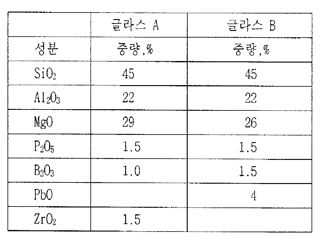
또한 소정량으로 상기 글라스 혼합물이 사용될 수 있다. 또한 상기 글라스는 다른 글라스의 소량(50 중량% 미만)을 함유할 수 있다. 이런 글라스는 20 중량%에 이르는 결정 코디어라이트, 40 중량%에 이르는 납 비실리케이트, 25 중량%에 이르는 CaO(26.8%)-MgO(4,6%)-ZnO(12.2%)-A1203(15.4%)-SiO2(41.0%) 글라스 또는 35 중량%에 이르는 CaO(8.6%)-ZnO(17.1%)-MgO(20.9%)-A1203(8,9%)-SiO2(40.5%)-P2O5(2.0%)-ZrSi04(2.0%) 글라스를 포함한다. 또한 다른 유사한 글라스가 첨가될 수 있다.Also, the glass mixture may be used in a predetermined amount. The glass may also contain small amounts (less than 50% by weight) of other glasses. These glasses contain up to 20% by weight crystalline cordierite, up to 40% by weight lead silicate, up to 25% by weight CaO (26.8%)-MgO (4,6%)-ZnO (12.2%)-A1 2 0 3 (15.4%)-SiO 2 (41.0%) glass or up to 35% by weight CaO (8.6%)-ZnO (17.1%)-MgO (20.9%)-A1 2 0 3 (8,9%)-SiO 2 (40.5%)-P 2 O 5 (2.0%)-ZrSi0 4 (2.0%) glass. Other similar glasses may also be added.
그린 테이프 조성물을 형성하기 위해, 상기 글라스 또는 분말 형태의 글라스혼합물은 가소제(plasticizer), 유기 접합제(organic binder), 계면 활성제(surfactant) 및 용매 혼합물과 혼합된다. 적당한 가소제는 산티시저(Santiclzer) 160으로서 Monsanto Co.로부터 상업적으로 시판되는 가능한 알킬 벤질 프탈레이트(alkyl benzyl phthalate)와 알킬 에스테르(alkyl ester)이다. 적당한 수지 접합제는 Monsanto Co.의 부트바르(Butvar) B-98, 폴리비닐 브티럴(polyvinyl butyral), Menhaden 어유(fish oil)와 같은 계면 활성제 또는 해교제(deflocculant), 및 메틸에틸케톤(methylethylketone), 이소프로판올(isopropanol), 톨루안(toluene), 아세톤(acetone), 에틸 아세테이트(ethylacetate), 에틸 알콜(ethyl alcohol) 등을 포함한다. 상기 글라스, 수지 등으로부터 그린 테이프 조성물의 제조는 일반적이고, 다른 공지된 재료가 대체될 수 있다. 슬러리는 균일한 슬러리를 제조하기 위해 볼 밀 분쇄(ball milled)되는 상기 성분으로 형성된다. 상기 슬러리는 몰드 또는 폴리에스테르 테이프상에서 닥터 블레이딩(doctor blading)에 의해 테이프 형태로 형성되고, 건조된다. 다음에 상기 테이프는 원하는 회로 패턴을 형성하기 위해 도체 잉크로 스크린 인쇄된다.To form the green tape composition, the glass mixture in glass or powder form is mixed with a plasticizer, an organic binder, a surfactant and a solvent mixture. Suitable plasticizers are possible alkyl benzyl phthalates and alkyl esters commercially available from Monsanto Co. as Santiclzer 160. Suitable resin binders include surfactants or deflocculants, such as Monsanto Co. Butvar B-98, polyvinyl butyral, Menhaden fish oil, and methylethylketone ), Isopropanol, toluene, acetone, ethyl acetate, ethyl alcohol, and the like. The production of green tape compositions from such glasses, resins, and the like is common, and other known materials may be substituted. The slurry is formed of the above components that are ball milled to produce a uniform slurry. The slurry is formed in tape form by doctor blading on a mold or polyester tape and dried. The tape is then screen printed with conductor ink to form the desired circuit pattern.
도체 잉크는 수지 접합제, 용매 및 계면 활성제를 포함할 수 있는 유기 용액과 함께 금, 은, 구리 및 이들의 혼합물 및 이들의 합금과 같은 도전성 금속 분말을 혼합함으로써 제조된다. 이런 조성물은 또한 공지되어 있다. 세라믹 층들 사이의 비아를 충전하는데 사용되는 비아 충전 잉크는 실질적으로 동일한 방식으로 제조되지만, 이들은 상당히 많은 양의 글라스 분말을 포함한다.Conductor inks are prepared by mixing conductive metal powders such as gold, silver, copper and mixtures thereof and alloys thereof with organic solutions that may include resin binders, solvents and surfactants. Such compositions are also known. Via filling inks used to fill vias between ceramic layers are made in substantially the same way, but they contain a significant amount of glass powder.
상기 스크린 인쇄된 그린 테이프는 약 950℃에 이르는 온도로 적절히 가열처리 된다.The screen printed green tape is suitably heat treated to a temperature up to about 950 ° C.
그러나, 상기 그린 테이프 조성물은 상기 가열처리 단계 동안 모든 방향으로 약 20%까지 수축되기 때문에, 이러한 그린 테이프 조성물이 세라믹 또는 금속 지지기판, 특히 상기 기판의 양측면에 사용되는 경우, 결합 글라스 층은 모든 회로 및 비아 홀과 콘택트가 가열처리 후 정렬 상태로 있도록 x 또는 y 측방의 수축을 제어 또는 방지한다. 상기 결합 글라스의 사용으로 2방향으로의 수축을 억제하고, z, 또는 두께 방향으로만 발생하는 모든 수축을 허용한다.However, since the green tape composition shrinks by about 20% in all directions during the heat treatment step, when such a green tape composition is used on a ceramic or metal support substrate, in particular on both sides of the substrate, the bonding glass layer is used for all circuits. And control or prevent shrinkage of the x or y side such that the via holes and contacts are aligned after heat treatment. The use of the bonding glass suppresses shrinkage in two directions and allows all shrinkage to occur only in the z, or thickness direction.
상기 결합층은 글레이징(glazing) 잉크를 사용하여 형성되고, 지지 기판의 니켈 도금된 표면 상에 스크린 인쇄 또는 마찬가지로 코팅되고, 그 다음에 잉크에서의 유기 재료를 제거하도록 충분한 온도로 가열되며, 글레이즈 지지 기판을 얻기 위해 상기 글라스와 다른 무기 조성물을 용융한다. 금속 및 세라믹 유전체 조성물의 특정 조합에 효과가 있는 글레이즈 결합충의 조성물은 지지 기판-세라믹 다층 제조물의 성공적인 제조에 있어 중요하며, 여기서 세라믹 다층 적층물 구조는 x 또는 y 방향으로 어떠한 수축도 받지 않고, 지지 기판과 세라믹 다층 구조가 제조 및, 어셈블리 단계 동안 일어나는 기계적 열적 스트레스를 견뎌내어 서로 잘 부착되어 혼합 구조에 사용된다.The bonding layer is formed using a glazing ink, screen printed or likewise coated on the nickel plated surface of the support substrate, and then heated to a temperature sufficient to remove organic material from the ink and supporting the glaze The glass and other inorganic compositions are melted to obtain a substrate. Compositions of glaze binders that are effective in certain combinations of metal and ceramic dielectric compositions are important for the successful manufacture of support substrate-ceramic multilayer fabrications, where the ceramic multilayer stack structure is not subjected to any shrinkage in the x or y direction and is supported. Substrates and ceramic multilayer structures withstand the mechanical thermal stresses occurring during the fabrication and assembly steps and adhere well to each other for use in mixed structures.
본 출원인은 2가지 글라스 족의 상기 그린 테이프 조성물이 니켈 도금된 Cu/Mo/Cu, Cu/코바르/Cu 또는 Cu/인바르/Cu 조성물, 또는 인바르 또는 코바르 지지 기판 또는 코어에 결합하여 그린 테이프 적층물의 수축을 1% 미만으로 제한할 것이라는 것을 발견했다. 또한 추가로 단독 또는 혼합물의 1/3 중량의 비스무트 삼산 화물과의 혼합으로 사용되는 이런 글라스는 양호한 기계적 열적 세기를 가지는 지지된 세라믹 조성물을 산출하도록 전술된 마그네슘 알루미노실리케이트 글라스로 형성된 그린 테이프 적층물의 x, y 방향 수축의 요구된 억제를 달성할 수 있는 결합 글레이즈를 형성한다는 것을 발견했다.Applicant has incorporated the green tape composition of the two glass families into a nickel plated Cu / Mo / Cu, Cu / Cobar / Cu or Cu / Invar / Cu composition, or an Invar or Cobar support substrate or core It was found that the shrinkage of the green tape stack would be limited to less than 1%. These glasses, which are further used either alone or in admixture with one-third weight bismuth trioxide in combination, produce a green tape laminate formed of the aforementioned magnesium aluminosilicate glass to yield a supported ceramic composition with good mechanical thermal strength. It has been found that it forms a bond glaze that can achieve the required inhibition of the x, y direction contraction.
제1그룹의 글라스는 소량의 다른 개선된 산화물을 포함하는 붕산 아연 글라스로서 분류될 수 있다. 결합 글레이즈에 적합한 글라스에 대한 유용한 조성 범위는 중량 퍼센트 단위로 45-55% 산화아연 ZnO에서부터, 30-40% 산화붕소 B2O3로부터, 3-7% 산화칼슘 CaO로부터 및 3-7% 산화알루미늄 Al2O3로부터이다. 특히, 유용한 글라스(NO.1)는 50중량%의 ZnO, 39중량%의 B2O3, 5%의 CaO 및 6%의 A1203의 조성물이다.The first group of glasses can be classified as zinc borate glass containing small amounts of other improved oxides. Useful composition ranges for glass suitable for bonding glazes range from 45-55% zinc oxide ZnO, from 30-40% boron oxide B 2 O 3, from 3-7% calcium oxide CaO and 3-7% oxidation in weight percent. From aluminum Al 2 O 3 . Particularly useful glass (NO.1) is a composition of 50% by weight ZnO, 39% by weight B 2 O 3 , 5% CaO and 6% A1 2 0 3 .
여기에 사용되는 결합 글레이즈 조성물에 적합한 제2그룹의 글라스는 바륨, 아연 및 알루미늄의 산화물 및 그 외의 산화물에 의하여 개선된 보로실리케이트 글라스이다. 결합 글레이즈에 적합한 글라스에 대한 유용한 조성 범위는 중량 퍼센트 단위로 20-45% 산화바륨 BaO, 5-15% 산화칼슘, 15-22% 산화아연, 15-25% 산화규소 SiO2및 15-25% 산화붕소이다. 제2그룹의 적합한 두 개의 글라스가 이하에 나타나 있다.A second group of glasses suitable for the bonding glaze composition used herein is borosilicate glass improved by oxides of barium, zinc and aluminum and other oxides. Useful composition ranges for glass suitable for bonding glazes are 20-45% barium oxide BaO, 5-15% calcium oxide, 15-22% zinc oxide, 15-25% silicon oxide SiO 2 and 15-25% by weight percent. Boron oxide. Two suitable glasses of the second group are shown below.

산화 비스무트의 융제가 필요하다면 상기 결합 글라스 조성물의 약 30중량%까지 첨가될 수 있다. 산화 비스무트는 이들 글라스에 플로우 및 접착성을 개선시킨다.If flux of bismuth oxide is required, up to about 30% by weight of the bonded glass composition may be added. Bismuth oxide improves flow and adhesion to these glasses.
글라스 결합층은 사용되는 지지 기판보다 높은 열 팽창 계수를 가진다. 결합층은 금속 기판의 주표면중 한쪽 측면 또는 양측면에 대하여 슬러리로서 첨가될 수 있다. 슬러리는 스크린 프린팅 , 스프레이닝, 스핀 코팅, 커튼 코팅, 유체화 베드 코팅, 전기영동(electrophoretic) 증착 또는 다른 등가의 방법에 의하여 첨가될 수 있는데, 다층 회로 보드를 제조할 때는 주로 스크린 프린팅이 선택된다. 바람직하게 결합 글라스 조성물은 지지 기판 위에 부착되고 플로우 온도로 가열되어, 약 10 내지 50 미크론의 얇고 균일한 층 두께가 지지 기판 위에 형성되도록 한다.The glass bonding layer has a higher coefficient of thermal expansion than the support substrate used. The bonding layer can be added as a slurry to one or both sides of the major surface of the metal substrate. Slurries can be added by screen printing, spraying, spin coating, curtain coating, fluidized bed coating, electrophoretic deposition or other equivalent methods, where screen printing is often chosen when manufacturing multilayer circuit boards. . Preferably, the bonded glass composition is attached onto the support substrate and heated to the flow temperature such that a thin, uniform layer thickness of about 10 to 50 microns is formed over the support substrate.
결합 글라스는 바람직하게 표준 두께 막 잉크 스크린 방법에 의하여 세라믹또는 금속 기판에 부착된다. 적합한 잉크는 예를 들면, 듀퐁사에서 제조한 Elvacite 2045, 또는 에틸 셀룰로오스, 폴리아크릴레이트, 폴리메타크릴레이트, 폴리에스테르 등과 같은 수지 접합제 및 파인(pine) 오일, 테르핀올(terpineol), 브틸 카르비톨 아세테이트(butyl carbitol acetate), TexanolTM, Texas Eastman Company가 제조한 2,2,4-트리메틸-1,3-펜탄디올 모노이소브티레이트등을 포함하는 적합한 용매와 결합 글라스를 혼합함으로써 만들어질 수 있다. 용액은 일반적으로 약 2 내지 약 25 중량 퍼센트의 수지 접합제를 포함한다.The bonding glass is preferably attached to the ceramic or metal substrate by a standard thickness film ink screen method. Suitable inks are, for example, Elvacite 2045 manufactured by DuPont, or resin binders such as ethyl cellulose, polyacrylates, polymethacrylates, polyesters and the like, pine oils, terpineols, butylcart It can be made by mixing the binding glass with a suitable solvent including butyl carbitol acetate, Texanol ™ , 2,2,4-trimethyl-1,3-pentanediol monoisobutyrate manufactured by Texas Eastman Company, etc. have. The solution generally comprises about 2 to about 25 weight percent resin binder.
결합 글라스는 다음에 전기 콘택트가 금속 코어에 대한 다층 세라믹 상부층과 그 콘택트 및 비아 사이에 만들어지도록 패턴화될 수 있다. 지지 기판에 부착된 후에 결합 글라스는 약 750-850℃ 사이의 온도로 가열되어 리플로우되어,지지 기판의 처리를 용이하게 하고 기판위에 균일하게 두꺼운 충을 제공하도록 한다.The bond glass can then be patterned such that an electrical contact is made between the multilayer ceramic top layer to the metal core and its contacts and vias. After being attached to the support substrate, the bonding glass is heated to a temperature of between about 750-850 ° C. to reflow, to facilitate processing of the support substrate and to provide a uniformly thick charge over the substrate.
다층 세라믹 회로 보드는 전술한 바와 같이 스택이 예열될 수 있는, 기판 위에 인쇄 배선 회로를 갖는 세라믹 조성물의 다중 스택층을 포함하는 미리형성된 다층 그린 테이프 적층물을 정렬시킴으로써 결합 글라스 코팅된 지지판이 구성되어, 비아 및 인쇄 배선 회로가 정렬되고 950℃에 이르는 적절한 온도로 가열처리된다. 상기 가열처리는 여러 가지 층 및 인쇄 회로의 조성물에 따라 질소 또는 공기 상태에서 이루어질 수 있다. 시간 및 온도의 가열처리 파라미터는 그린 테이프 글라스의 결정성을 제어하도록 조절할 수 있어, 여러 가지 층의 팽창을 제어할 수 있다.The multilayer ceramic circuit board is constructed with a bond glass coated support plate by aligning a preformed multilayer green tape stack comprising multiple stack layers of ceramic composition having a printed wiring circuit on a substrate, on which the stack may be preheated as described above. , Vias and printed wiring circuits are aligned and heat treated to an appropriate temperature up to 950 ° C. The heat treatment can be carried out in nitrogen or air depending on the composition of the various layers and the printed circuit. The heat treatment parameters of time and temperature can be adjusted to control the crystallinity of the green tape glass, thereby controlling the expansion of the various layers.
제1도는 본 발명의 결합층을 이용하는 마이크로전자 패키지를 도시한다. 금속 상의 공동-가열처리된 세라믹 구조체(10)는 제1 및 제2주표면(14, 16)을 가진 금속 베이스(12)를 포함한다. 본 발명의 글라스 결합층(18)은 하나 또는 두 개의 주표면(14, 16)을 커버한다. 적층된 다층 스택 및 글라스-세라믹/충전 테이프(19)는 반도체 소자(24)를 배치하기 위한 개구부(20)를 가진다. 글라스 세라믹 스택(19)에서의 인쇄 배선 회로 및 비아(도시안됨)는 구리, 은, 은/팔라듐 합금, 금, 이들의 합금 등과 같은 도전성 금속 분말로부터 만들어진다.1 illustrates a microelectronic package using the bonding layer of the present invention. The co-heated
결합 글라스-기판 코어를 세라믹 스택에 공동-가열처리한 후에, 반도체 소자 (24)는 당업자에게 공지된 와이어 본드(28) 또는 다른 수단에 의하여 기판에 조립 되어, 반도체 소자에 인쇄 배선 회로 스택을 전기적으로 연결하도록 한다. 칩은 다음에 기판에 금속 뚜껑을 납땜하거나 또는 상기 칩 위에 유기체 캡슐을 투여함으로써 밀봉된다.After co-heating the bonded glass-substrate core to the ceramic stack, the
본 발명은 다음 실시예에서보다 상세히 설명되지만, 본 발명은 이에 한정되지 않는다.The invention is described in more detail in the following examples, but the invention is not so limited.
[실시예 1]Example 1
0.020 인치 두께의 니켈 도금 Cu/Mo/Cu(14/62/14) 지지 기판은 결합 글라스 No.2의 분말을 함유하는 결합 글레이즈 잉크 패턴층을 스크린 인쇄하고, 다음에 기판에 결합 글라스층을 리플로우시켜 융합되도록 공기 중에 850℃로 가열처리함으로써 제조된다.A 0.020 inch thick nickel plated Cu / Mo / Cu (14/62/14) support substrate screen prints a bonded glaze ink pattern layer containing powder of bonded glass No. 2, and then ripples the bonded glass layer onto the substrate. Prepared by heating to 850 ° C. in air to fuse to low temperatures.
그린 테이프의 6층은 전술한 포스테라이트-코오더어라이트를 이용하여 만들어지며, 은(silver) 잉크로 구성된 스크린 인쇄된 두꺼운 막 회로 패턴을 갖는 각각의 그린 테이프 및 적절하게 은을 함유한 비아 잉크로 채워진 구멍난 비아 홀들이 90℃에서 1500psi 압력에서 서로 정렬되고 적층된다.Six layers of green tape are made using the aforementioned forsterite-coderarite, each green tape having a screen printed thick film circuit pattern composed of silver ink and a suitably silver containing via Perforated via holes filled with ink are aligned and stacked on each other at 1500 psi pressure at 90 ° C.
다음 그린 적층물은 지지 기판의 글레이즈 표면 위에서 압착되고 이러한 어셈블리는 최고 900℃온도에서 공기 중에 가열처리된다. Cu/Mo/Cu 지지 기판에 포함되어 결합되어 소결처리된 글라스-세라믹 다층 기판이 얻어진다.The green stack is then pressed onto the glaze surface of the support substrate and this assembly is heated in air at temperatures up to 900 ° C. A glass-ceramic multilayer substrate, which is included in the Cu / Mo / Cu support substrate and bonded and sintered, is obtained.
가열처리된 세라믹 적층물은 지지 기판에 양호하게 부착되며 상기 가열처리 단계 중에 어떠한 x, y 수축도 발생하지 않으며, 모든 가열처리 수축은 z방향으로 발생한다.The heat treated ceramic laminate is well adhered to the support substrate and no x, y shrinkage occurs during the heat treatment step, and all heat shrink occurs in the z direction.
[실시예 2]Example 2
실시예1의 공정 다음에, 결합 그레이즈 잉크는 분말 결합 글라스 No.1과 산화비스무트가 3:1중량 비율로 혼합된 혼합물로 대치된다.After the process of Example 1, the bonded gray ink was replaced with a mixture of powder-bonded glass No. 1 and bismuth oxide in a 3: 1 weight ratio.
Cu/Mo/Cu 지지 기판 위에 혼합 다층 세라믹 구조체가 얻어지면, 상기 구조체는 가열처리 단계 중에 어떠한 x, y 수축도 발생하지 않는다.If a mixed multilayer ceramic structure is obtained on a Cu / Mo / Cu support substrate, the structure does not produce any x, y shrinkage during the heat treatment step.
[실시예 3]Example 3
중량 퍼센트 단위로, 32.5%의 산화마그네슘, 17%의 산화바륨, 7%의 산화알루미늄, 24%의 산화규소, 16%의 산화붕소, 2.5%의 이산화지르코늄 및 1%의 5산화인으로 이루어진 조성물을 가진 다른 유전체 글라스로 만들어지며, 각각 은(silver) 잉크로 만들어진 스크린 인쇄된 두꺼운 막 회로 패턴 및 적절히 은을 함유한 비아 잉크로 충전된 구멍난 비아 홀을 가진 6층의 그린 테이프는 서로 정렬되어 약1500psi 압력 및 90℃에서 적층된다.Composition by weight percent, consisting of 32.5% magnesium oxide, 17% barium oxide, 7% aluminum oxide, 24% silicon oxide, 16% boron oxide, 2.5% zirconium dioxide and 1% phosphorus pentaoxide 6 layers of green tape, each made of different dielectric glass, with screen printed thick film circuit patterns made of silver ink and perforated via holes filled with appropriately silver containing via ink Laminate at about 1500 psi pressure and 90 ° C.
개별적으로, 0.020인치 두께의 코바르 지지 기판은 글라스 No.2를 함유한 결합 그레이즈 잉크를 함유한 패턴층을 스크린 인쇄하고, 다음에 기판에 결합 글라스층이 리플로우되고 융합되도록 공기 중에서 850℃로 가열처리로서 제조된다. 상기 그린 적층물은 지지 기판의 글레이즈 표면 위에서 압착되고 이러한 어셈블리는 최고 900℃로 공기 중에서 가열처리된다.Individually, a 0.020 inch thick Kovar support substrate was screen printed with a patterned layer containing a bond gray ink containing glass No. 2, followed by 850 ° C. in air to reflow and fuse the bonded glass layer to the substrate. It is manufactured as a furnace heat treatment. The green stack is pressed onto the glaze surface of the support substrate and this assembly is heated in air up to 900 ° C.
코바르 지지 기판에 포함되어 결합되어 소결처리된 글라스-세라믹 다층 기판이 얻어진다.A glass-ceramic multilayer substrate included in the Kovar support substrate and bonded and sintered is obtained.
그린 테이프 적층물은 코바르 지지 기판에 양호하게 접착되며 상기 가열처리단계 중에 어떠한 x, y 수축도 발생하지 않는다. 따라서, 모든 가열처리 수축은 z방향으로 발생한다.The green tape stack is well adhered to the kovar support substrate and no x, y shrinkage occurs during the heat treatment step. Thus, all heat treatment shrinkage occurs in the z direction.
본 발명은 특정 실시예를 기초로 설명하였지만, 당업자는 그린 테이프 및 도전성 잉크를 만들기 위하여 이용된 다른 수지 및 재료와 전술한 범위를 만족하는 다른 금속 기판 및 다른 결합 글라스를 대체할 수 있다. 따라서 본 발명은 첨부된 청구범위에 의해서만 한정된다.Although the present invention has been described based on certain embodiments, those skilled in the art can replace other resins and materials used to make green tapes and conductive inks and other metal substrates and other bonding glasses that meet the foregoing ranges. Accordingly, the invention is limited only by the appended claims.
Claims (8)
Applications Claiming Priority (4)
| Application Number | Priority Date | Filing Date | Title |
|---|---|---|---|
| US08/379,263 US5581876A (en) | 1995-01-27 | 1995-01-27 | Method of adhering green tape to a metal support substrate with a bonding glass |
| US08/379263 | 1995-01-27 | ||
| US8/379263 | 1995-01-27 | ||
| PCT/US1996/000315 WO1996023321A1 (en) | 1995-01-27 | 1996-01-29 | Glass bonding layer for a ceramic circuit board support substrate |
Publications (2)
| Publication Number | Publication Date |
|---|---|
| KR19980701656A KR19980701656A (en) | 1998-06-25 |
| KR100307078B1 true KR100307078B1 (en) | 2001-12-17 |
Family
ID=23496519
Family Applications (1)
| Application Number | Title | Priority Date | Filing Date |
|---|---|---|---|
| KR1019970705052A KR100307078B1 (en) | 1995-01-27 | 1996-01-29 | Glass bonding layer for ceramic circuit board supporting substrate |
Country Status (7)
| Country | Link |
|---|---|
| US (1) | US5581876A (en) |
| EP (1) | EP0806056B1 (en) |
| JP (1) | JP3226280B2 (en) |
| KR (1) | KR100307078B1 (en) |
| CA (1) | CA2211533C (en) |
| DE (1) | DE69632722T2 (en) |
| WO (1) | WO1996023321A1 (en) |
Families Citing this family (56)
| Publication number | Priority date | Publication date | Assignee | Title |
|---|---|---|---|---|
| US5725808A (en) * | 1996-05-23 | 1998-03-10 | David Sarnoff Research Center, Inc. | Multilayer co-fired ceramic compositions and ceramic-on-metal circuit board |
| AU1827097A (en) * | 1996-01-11 | 1997-08-01 | Containerless Research, Inc. | Fiber drawing from undercooled molten materials |
| US5858145A (en) * | 1996-10-15 | 1999-01-12 | Sarnoff Corporation | Method to control cavity dimensions of fired multilayer circuit boards on a support |
| TW353762B (en) * | 1996-10-21 | 1999-03-01 | Dainippon Printing Co Ltd | Transfer sheet, and pattern-forming method |
| US5953203A (en) * | 1997-03-06 | 1999-09-14 | Sarnoff Corporation | Multilayer ceramic circuit boards including embedded capacitors |
| KR100546471B1 (en) * | 1997-03-06 | 2006-01-26 | 샤프 가부시키가이샤 | Thick ceramic on metal multilayer circuit board |
| US6399230B1 (en) * | 1997-03-06 | 2002-06-04 | Sarnoff Corporation | Multilayer ceramic circuit boards with embedded resistors |
| US6055151A (en) * | 1997-03-06 | 2000-04-25 | Sarnoff Corp | Multilayer ceramic circuit boards including embedded components |
| US5866240A (en) * | 1997-03-06 | 1999-02-02 | Sarnoff Corporation | Thick ceramic on metal multilayer circuit board |
| US6120906A (en) * | 1997-03-31 | 2000-09-19 | Kyocera Corporation | Insulated board for a wiring board |
| EP0924755A3 (en) * | 1997-12-19 | 1999-12-29 | CTS Corporation | Method of fabricating a multilayer circuit board |
| US6471805B1 (en) | 1998-11-05 | 2002-10-29 | Sarnoff Corporation | Method of forming metal contact pads on a metal support substrate |
| US6247986B1 (en) * | 1998-12-23 | 2001-06-19 | 3M Innovative Properties Company | Method for precise molding and alignment of structures on a substrate using a stretchable mold |
| US6352763B1 (en) * | 1998-12-23 | 2002-03-05 | 3M Innovative Properties Company | Curable slurry for forming ceramic microstructures on a substrate using a mold |
| JP3656484B2 (en) * | 1999-03-03 | 2005-06-08 | 株式会社村田製作所 | Manufacturing method of ceramic multilayer substrate |
| JP3630021B2 (en) * | 1999-07-23 | 2005-03-16 | 株式会社村田製作所 | Crystallized glass composition and sintered body thereof, and circuit board using the same |
| JP3687443B2 (en) * | 1999-10-12 | 2005-08-24 | 株式会社村田製作所 | Low temperature fired ceramic composition and ceramic multilayer substrate |
| US6712486B1 (en) | 1999-10-19 | 2004-03-30 | Permlight Products, Inc. | Mounting arrangement for light emitting diodes |
| US7183640B2 (en) | 1999-12-13 | 2007-02-27 | Lamina Ceramics, Inc. | Method and structures for enhanced temperature control of high power components on multilayer LTCC and LTCC-M boards |
| US6455930B1 (en) * | 1999-12-13 | 2002-09-24 | Lamina Ceramics, Inc. | Integrated heat sinking packages using low temperature co-fired ceramic metal circuit board technology |
| US6821178B2 (en) | 2000-06-08 | 2004-11-23 | 3M Innovative Properties Company | Method of producing barrier ribs for plasma display panel substrates |
| US6518502B2 (en) * | 2001-05-10 | 2003-02-11 | Lamina Ceramics, In | Ceramic multilayer circuit boards mounted on a patterned metal support substrate |
| US6578986B2 (en) * | 2001-06-29 | 2003-06-17 | Permlight Products, Inc. | Modular mounting arrangement and method for light emitting diodes |
| US6553662B2 (en) | 2001-07-03 | 2003-04-29 | Max Levy Autograph, Inc. | Method of making a high-density electronic circuit |
| US7176492B2 (en) * | 2001-10-09 | 2007-02-13 | 3M Innovative Properties Company | Method for forming ceramic microstructures on a substrate using a mold and articles formed by the method |
| US7033534B2 (en) * | 2001-10-09 | 2006-04-25 | 3M Innovative Properties Company | Method for forming microstructures on a substrate using a mold |
| JP4030285B2 (en) * | 2001-10-10 | 2008-01-09 | 株式会社トクヤマ | Substrate and manufacturing method thereof |
| US6699571B1 (en) * | 2002-03-27 | 2004-03-02 | Morgan Advanced Ceramics, Inc. | Devices and methods for mounting components of electronic circuitry |
| US7095053B2 (en) * | 2003-05-05 | 2006-08-22 | Lamina Ceramics, Inc. | Light emitting diodes packaged for high temperature operation |
| US7777235B2 (en) * | 2003-05-05 | 2010-08-17 | Lighting Science Group Corporation | Light emitting diodes with improved light collimation |
| US7300182B2 (en) * | 2003-05-05 | 2007-11-27 | Lamina Lighting, Inc. | LED light sources for image projection systems |
| US7528421B2 (en) * | 2003-05-05 | 2009-05-05 | Lamina Lighting, Inc. | Surface mountable light emitting diode assemblies packaged for high temperature operation |
| US7633093B2 (en) * | 2003-05-05 | 2009-12-15 | Lighting Science Group Corporation | Method of making optical light engines with elevated LEDs and resulting product |
| US7138347B2 (en) * | 2003-08-14 | 2006-11-21 | E. I. Du Pont De Nemours And Company | Thick-film conductor paste for automotive glass |
| US20050040908A1 (en) * | 2003-08-21 | 2005-02-24 | Lamina Ceramics Inc. | Low temperature co-fired ceramic-metal circulators and isolators |
| US7964883B2 (en) * | 2004-02-26 | 2011-06-21 | Lighting Science Group Corporation | Light emitting diode package assembly that emulates the light pattern produced by an incandescent filament bulb |
| US20050225222A1 (en) * | 2004-04-09 | 2005-10-13 | Joseph Mazzochette | Light emitting diode arrays with improved light extraction |
| US8188503B2 (en) | 2004-05-10 | 2012-05-29 | Permlight Products, Inc. | Cuttable illuminated panel |
| US7309540B2 (en) | 2004-05-21 | 2007-12-18 | Sarnoff Corporation | Electrical power source designs and components |
| US7186461B2 (en) * | 2004-05-27 | 2007-03-06 | Delaware Capital Formation, Inc. | Glass-ceramic materials and electronic packages including same |
| US7387838B2 (en) * | 2004-05-27 | 2008-06-17 | Delaware Capital Formation, Inc. | Low loss glass-ceramic materials, method of making same and electronic packages including same |
| US7252408B2 (en) * | 2004-07-19 | 2007-08-07 | Lamina Ceramics, Inc. | LED array package with internal feedback and control |
| EP1858078A4 (en) * | 2005-01-20 | 2009-03-04 | Almt Corp | Member for semiconductor device and method for manufacture thereof |
| JP4905874B2 (en) * | 2005-04-27 | 2012-03-28 | 京セラ株式会社 | Radio communication apparatus and control method in radio communication apparatus |
| US20060243700A1 (en) * | 2005-04-28 | 2006-11-02 | International Business Machines Corporation | Composite electroformed screening mask and method of making the same |
| US7719021B2 (en) * | 2005-06-28 | 2010-05-18 | Lighting Science Group Corporation | Light efficient LED assembly including a shaped reflective cavity and method for making same |
| WO2007002476A2 (en) * | 2005-06-28 | 2007-01-04 | Lamina Ceramics, Inc. | Backlight module display with optical coupler and lightguide |
| EP2100331A1 (en) * | 2006-11-30 | 2009-09-16 | Osram Gesellschaft mit Beschränkter Haftung | Electronic component module and method for the production thereof |
| WO2011122406A1 (en) * | 2010-03-30 | 2011-10-06 | 株式会社村田製作所 | Metal base substrate and manufacturing method thereof |
| US9240526B2 (en) | 2010-04-23 | 2016-01-19 | Cree, Inc. | Solid state light emitting diode packages with leadframes and ceramic material |
| JP5693940B2 (en) * | 2010-12-13 | 2015-04-01 | 株式会社トクヤマ | Ceramic via substrate, metallized ceramic via substrate, and manufacturing method thereof |
| JP2015129684A (en) * | 2014-01-08 | 2015-07-16 | 株式会社アルバック | Metal ceramic joint, diaphragm vacuum gage, joining method of metal to ceramic, and manufacturing method of diaphragm vacuum gage |
| DE102016125348B4 (en) * | 2016-12-22 | 2020-06-25 | Rogers Germany Gmbh | Carrier substrate for electrical components and method for producing a carrier substrate |
| US11903472B2 (en) * | 2019-02-08 | 2024-02-20 | Lexmark International, Inc. | Hair iron having a ceramic heater |
| US11692754B2 (en) | 2020-04-21 | 2023-07-04 | Lexmark International, Inc. | Ice maker heater assemblies |
| US11828490B2 (en) | 2020-04-24 | 2023-11-28 | Lexmark International, Inc. | Ceramic heater for heating water in an appliance |
Citations (1)
| Publication number | Priority date | Publication date | Assignee | Title |
|---|---|---|---|---|
| US5277724A (en) * | 1991-12-18 | 1994-01-11 | General Electric Co. | Method of minimizing lateral shrinkage in a co-fired, ceramic-on-metal circuit board |
Family Cites Families (9)
| Publication number | Priority date | Publication date | Assignee | Title |
|---|---|---|---|---|
| US4712161A (en) * | 1985-03-25 | 1987-12-08 | Olin Corporation | Hybrid and multi-layer circuitry |
| US4739443A (en) * | 1985-12-30 | 1988-04-19 | Olin Corporation | Thermally conductive module |
| US4997698A (en) * | 1987-05-04 | 1991-03-05 | Allied-Signal, Inc. | Ceramic coated metal substrates for electronic applications |
| US4808460A (en) * | 1987-06-02 | 1989-02-28 | Corning Glass Works | Laminated structures containing an inorganic corrugated or honeycomb member |
| US4924590A (en) * | 1988-01-08 | 1990-05-15 | Siemens Aktiengesellschaft | Method for making metal core printed circuit board |
| US5043222A (en) * | 1988-03-17 | 1991-08-27 | Olin Corporation | Metal sealing glass composite with matched coefficients of thermal expansion |
| JPH0227832B2 (en) * | 1989-03-10 | 1990-06-20 | Okuno Chem Ind Co | SERAMITSUKUSUKIBAN |
| US5013360A (en) * | 1989-09-15 | 1991-05-07 | Vlsi Packaging Materials, Inc. | Sealing glass compositions |
| US5256469A (en) * | 1991-12-18 | 1993-10-26 | General Electric Company | Multi-layered, co-fired, ceramic-on-metal circuit board for microelectronic packaging |
-
1995
- 1995-01-27 US US08/379,263 patent/US5581876A/en not_active Expired - Lifetime
-
1996
- 1996-01-29 DE DE69632722T patent/DE69632722T2/en not_active Expired - Lifetime
- 1996-01-29 CA CA002211533A patent/CA2211533C/en not_active Expired - Fee Related
- 1996-01-29 KR KR1019970705052A patent/KR100307078B1/en not_active IP Right Cessation
- 1996-01-29 JP JP52288096A patent/JP3226280B2/en not_active Expired - Fee Related
- 1996-01-29 EP EP96903414A patent/EP0806056B1/en not_active Expired - Lifetime
- 1996-01-29 WO PCT/US1996/000315 patent/WO1996023321A1/en active IP Right Grant
Patent Citations (1)
| Publication number | Priority date | Publication date | Assignee | Title |
|---|---|---|---|---|
| US5277724A (en) * | 1991-12-18 | 1994-01-11 | General Electric Co. | Method of minimizing lateral shrinkage in a co-fired, ceramic-on-metal circuit board |
Also Published As
| Publication number | Publication date |
|---|---|
| CA2211533C (en) | 2006-10-17 |
| WO1996023321A1 (en) | 1996-08-01 |
| EP0806056A1 (en) | 1997-11-12 |
| KR19980701656A (en) | 1998-06-25 |
| JPH11504159A (en) | 1999-04-06 |
| DE69632722D1 (en) | 2004-07-22 |
| US5581876A (en) | 1996-12-10 |
| DE69632722T2 (en) | 2005-07-14 |
| JP3226280B2 (en) | 2001-11-05 |
| CA2211533A1 (en) | 1996-08-01 |
| EP0806056B1 (en) | 2004-06-16 |
Similar Documents
| Publication | Publication Date | Title |
|---|---|---|
| KR100307078B1 (en) | Glass bonding layer for ceramic circuit board supporting substrate | |
| US5370759A (en) | Method for producing multilayered ceramic substrate | |
| JP3267299B2 (en) | Electric feedthrough for ceramic circuit board support board | |
| US4109377A (en) | Method for preparing a multilayer ceramic | |
| US4645552A (en) | Process for fabricating dimensionally stable interconnect boards | |
| CA1123115A (en) | Multi-layered glass-ceramic structures having an internal distribution of copper-based conductors | |
| KR0179404B1 (en) | Ceramic substrate and manufacturing method thereof | |
| EP0332457B1 (en) | Multilayered ceramic substrates and method for manufacturing of the same | |
| KR100521231B1 (en) | Method of forming a multilayer printed circuit boards | |
| US5757611A (en) | Electronic package having buried passive components | |
| KR20050026369A (en) | Method for producing ceramic substrate, and ceramic substrate | |
| EP0211603B1 (en) | Method of making ceramic dielectric bodies | |
| JPH1075060A (en) | Method for manufacturing multi-layer glass/ceramic substrate | |
| US5147484A (en) | Method for producing multi-layer ceramic substrates with oxidation resistant metalization | |
| JP2002505805A (en) | Ceramic multilayer printed circuit board with embedded passive components | |
| JP3351043B2 (en) | Method for manufacturing multilayer ceramic substrate | |
| KR100744855B1 (en) | High Thermal Cycle Conductor System | |
| JPH05213679A (en) | Interface area between metal and ceramics in metal/ceramic substrate and formation method thereof | |
| US6846375B2 (en) | Method of manufacturing multilayer ceramic wiring board and conductive paste for use | |
| JP3188086B2 (en) | Ceramic wiring board, its manufacturing method and its mounting structure | |
| EP0312824B1 (en) | Ceramic structure with copper based conductors and method for forming such a structure | |
| JPH05218654A (en) | Manufacture of ceramic composite structure using microwave | |
| JP3426920B2 (en) | Wiring board | |
| KR100607119B1 (en) | Multilayer ceramic composition | |
| JPH0661649A (en) | Production of multilayer ceramic board |
Legal Events
| Date | Code | Title | Description |
|---|---|---|---|
| A201 | Request for examination | ||
| E902 | Notification of reason for refusal | ||
| E701 | Decision to grant or registration of patent right | ||
| GRNT | Written decision to grant | ||
| FPAY | Annual fee payment |
Payment date: 20120806 Year of fee payment: 12 |
|
| FPAY | Annual fee payment |
Payment date: 20130808 Year of fee payment: 13 |
|
| LAPS | Lapse due to unpaid annual fee |