JP7619400B1 - 車両のタイヤ拘束装置 - Google Patents
車両のタイヤ拘束装置 Download PDFInfo
- Publication number
- JP7619400B1 JP7619400B1 JP2023124244A JP2023124244A JP7619400B1 JP 7619400 B1 JP7619400 B1 JP 7619400B1 JP 2023124244 A JP2023124244 A JP 2023124244A JP 2023124244 A JP2023124244 A JP 2023124244A JP 7619400 B1 JP7619400 B1 JP 7619400B1
- Authority
- JP
- Japan
- Prior art keywords
- tire
- vehicle
- roller
- free
- free rollers
- Prior art date
- Legal status (The legal status is an assumption and is not a legal conclusion. Google has not performed a legal analysis and makes no representation as to the accuracy of the status listed.)
- Active
Links
- 230000000452 restraining effect Effects 0.000 claims description 15
- 125000006850 spacer group Chemical group 0.000 claims description 7
- 238000012360 testing method Methods 0.000 abstract description 52
- 102100034112 Alkyldihydroxyacetonephosphate synthase, peroxisomal Human genes 0.000 description 5
- 101000799143 Homo sapiens Alkyldihydroxyacetonephosphate synthase, peroxisomal Proteins 0.000 description 5
- 238000000848 angular dependent Auger electron spectroscopy Methods 0.000 description 5
- 238000011156 evaluation Methods 0.000 description 5
- 102100039814 E3 ubiquitin-protein ligase RNF170 Human genes 0.000 description 2
- 101000667666 Homo sapiens E3 ubiquitin-protein ligase RNF170 Proteins 0.000 description 2
- 238000001514 detection method Methods 0.000 description 2
- 230000009191 jumping Effects 0.000 description 2
- 238000005259 measurement Methods 0.000 description 2
- 238000010586 diagram Methods 0.000 description 1
- 230000000694 effects Effects 0.000 description 1
- 239000000446 fuel Substances 0.000 description 1
- 238000007689 inspection Methods 0.000 description 1
- 238000003466 welding Methods 0.000 description 1
Images


Classifications
-
- G—PHYSICS
- G01—MEASURING; TESTING
- G01M—TESTING STATIC OR DYNAMIC BALANCE OF MACHINES OR STRUCTURES; TESTING OF STRUCTURES OR APPARATUS, NOT OTHERWISE PROVIDED FOR
- G01M17/00—Testing of vehicles
- G01M17/007—Wheeled or endless-tracked vehicles
Landscapes
- Physics & Mathematics (AREA)
- General Physics & Mathematics (AREA)
- Tires In General (AREA)
Abstract

【解決手段】シャシダイナモメータシステム2のローラ装置19に載せられた試験車両1のフロントタイヤ1aの前後にプレート6の一端部6aを配置する。このプレート6の一端部6aにはフロントタイヤ1aを挟むように弧状のフリーローラ8群が配列されている。この各フリーローラ8は前記一端部6a上のブラケット7に回転自在に軸支されている。
【選択図】図5
Description
前記タイヤを載せるタイヤ載置部材と、
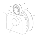
前記タイヤ載置部材に載せられた前記タイヤの周囲に弧状に配列され、かつ前記タイヤを拘束するフリーローラ群と、
を備え、
前記各フリーローラは、回転自在に縦置きに設けられていることを特徴としている。
シャシダイナモメータシステム2は、ピット3上のフロアを構成するピットカバー4を備えている。このピットカバー4には、試験車両1の前後方向(図5のY-Y方向)に沿って横断面凹状に形成された左右一対のレール12が埋設されている(図4参照)。
図5に基づき「AD/ADAS」のセンサ評価試験時の拘束動作を説明する。ここでは試験車両1の左右のフロントタイヤ1aをローラ装置19に載せた後、スペーサパネル25を介して各プレート6の一端部6aを各フロントタイヤ1aの前後に配置し、図5(a)に示すように、フロントタイヤ1aの前後をフリーローラ8群で挟んだ状態とする。
したがって、特許文献1,3のように試験車両1のサイドシルを左右のクランプで挟み込む必要が無く、ステアリング操作の操舵による車体の破損を回避することができる。また、ステアリング操舵角の検出と実舵角との間にズレが生じても、フリーローラ8が同期回転するため、特許文献3のように試験車両1のフロントタイヤ1aを破損させるおそれもない。これにより以下の効果が得られる。
1a…フロントタイヤ
1b…リアタイヤ
2…シャシダイナモメータシステム
6…プレート
7…ブラケット
8…フリーローラ
19…ローラ装置
20…補助ローラ
22…スペーサパネル
Claims (8)
- 車両のタイヤを旋回可能に拘束する装置であって、
前記タイヤを載せるタイヤ載置部材と、
前記タイヤ載置部材に載せられた前記タイヤの前後のフロア上にそれぞれ配置された一対のプレートと、
前記一対のプレート上に前記タイヤの前後を囲んで挟むような弧状にそれぞれ配列され、かつ前記タイヤを拘束するフリーローラ群と、
を備え、
前記フリーローラ群の各フリーローラは、回転自在に縦置きされていることを特徴とする車両のタイヤ拘束装置。 - 前記各プレートを前記車両の前後方向または幅方向に移動させることにより、
前記各フリーローラ群の位置を調整可能なことを特徴とする請求項1に記載された車両のタイヤ拘束装置。 - 前記プレートの下にスペーサを配置することにより、
前記各フリーローラ群の高さを調整可能なことを特徴とする請求項1記載の車両のタイヤ拘束装置。 - 前記各フリーローラは、前記プレート上に立設されたブラケットに回転自在に軸支されている
ことを特徴とする請求項1記載の車両のタイヤ拘束装置。 - 前記各ブラケットをそれぞれ同方向に傾斜状に立設し、
前記各フリーローラを斜めに傾斜させた
ことを特徴とする請求項4記載の車両のタイヤ拘束装置。 - 前記ブラケットには、タイヤ逸脱防止用の補助ローラが回転自在に設けられている
ことを特徴とする請求項4または5記載の車両のタイヤ拘束装置。 - 前記補助ローラは、前記フリーローラよりも高い位置に配置されていることを特徴とする請求項6記載の車両のタイヤ拘束装置。
- 前記タイヤ載置部材は、シャシダイナモメータシステムのローラ装置であることを特徴とする請求項1記載の車両のタイヤ拘束装置。
Priority Applications (2)
| Application Number | Priority Date | Filing Date | Title |
|---|---|---|---|
| JP2023124244A JP7619400B1 (ja) | 2023-07-31 | 2023-07-31 | 車両のタイヤ拘束装置 |
| PCT/JP2024/026613 WO2025028392A1 (ja) | 2023-07-31 | 2024-07-25 | 車両のタイヤ拘束装置 |
Applications Claiming Priority (1)
| Application Number | Priority Date | Filing Date | Title |
|---|---|---|---|
| JP2023124244A JP7619400B1 (ja) | 2023-07-31 | 2023-07-31 | 車両のタイヤ拘束装置 |
Publications (2)
| Publication Number | Publication Date |
|---|---|
| JP7619400B1 true JP7619400B1 (ja) | 2025-01-22 |
| JP2025020711A JP2025020711A (ja) | 2025-02-13 |
Family
ID=94279055
Family Applications (1)
| Application Number | Title | Priority Date | Filing Date |
|---|---|---|---|
| JP2023124244A Active JP7619400B1 (ja) | 2023-07-31 | 2023-07-31 | 車両のタイヤ拘束装置 |
Country Status (2)
| Country | Link |
|---|---|
| JP (1) | JP7619400B1 (ja) |
| WO (1) | WO2025028392A1 (ja) |
Cited By (1)
| Publication number | Priority date | Publication date | Assignee | Title |
|---|---|---|---|---|
| CN120971051A (zh) * | 2025-10-20 | 2025-11-18 | 中国人民解放军陆军装备部驻南京地区军事代表局 | 一种特种车辆轮胎耐划伤性能试验方法 |
Citations (5)
| Publication number | Priority date | Publication date | Assignee | Title |
|---|---|---|---|---|
| JP2009133750A (ja) | 2007-11-30 | 2009-06-18 | Toyota Motor Corp | シャシダイナモメータ用車両拘束装置 |
| US20100058851A1 (en) | 2008-09-08 | 2010-03-11 | Burke E. Porter Machinery Company | Vehicle testing assembly |
| JP2013195316A (ja) | 2012-03-22 | 2013-09-30 | Horiba Ltd | 車両固定装置及び車両性能試験装置 |
| JP2017009545A (ja) | 2015-06-26 | 2017-01-12 | トヨタ自動車九州株式会社 | ラフロードテスタ |
| JP2021148762A (ja) | 2020-03-20 | 2021-09-27 | サンエンジニアリング株式会社 | 車輌の衝撃吸収機能付き固縛装置 |
-
2023
- 2023-07-31 JP JP2023124244A patent/JP7619400B1/ja active Active
-
2024
- 2024-07-25 WO PCT/JP2024/026613 patent/WO2025028392A1/ja active Pending
Patent Citations (5)
| Publication number | Priority date | Publication date | Assignee | Title |
|---|---|---|---|---|
| JP2009133750A (ja) | 2007-11-30 | 2009-06-18 | Toyota Motor Corp | シャシダイナモメータ用車両拘束装置 |
| US20100058851A1 (en) | 2008-09-08 | 2010-03-11 | Burke E. Porter Machinery Company | Vehicle testing assembly |
| JP2013195316A (ja) | 2012-03-22 | 2013-09-30 | Horiba Ltd | 車両固定装置及び車両性能試験装置 |
| JP2017009545A (ja) | 2015-06-26 | 2017-01-12 | トヨタ自動車九州株式会社 | ラフロードテスタ |
| JP2021148762A (ja) | 2020-03-20 | 2021-09-27 | サンエンジニアリング株式会社 | 車輌の衝撃吸収機能付き固縛装置 |
Cited By (1)
| Publication number | Priority date | Publication date | Assignee | Title |
|---|---|---|---|---|
| CN120971051A (zh) * | 2025-10-20 | 2025-11-18 | 中国人民解放军陆军装备部驻南京地区军事代表局 | 一种特种车辆轮胎耐划伤性能试验方法 |
Also Published As
| Publication number | Publication date |
|---|---|
| JP2025020711A (ja) | 2025-02-13 |
| WO2025028392A1 (ja) | 2025-02-06 |
Similar Documents
| Publication | Publication Date | Title |
|---|---|---|
| US10386270B2 (en) | Method for simulating real impact test of vehicle wheels | |
| US9067617B2 (en) | Wheel turn initiator | |
| US9187053B2 (en) | Advanced engagement small overlap deflector | |
| DE102006040389B4 (de) | Aufprallerfassungssensor-Befestigungsanordnung für ein Motorrad | |
| JP7711043B2 (ja) | 車両試験システム、操舵反力入力装置、及び操舵機能評価方法 | |
| JP7619400B1 (ja) | 車両のタイヤ拘束装置 | |
| JPH11170992A (ja) | 車両の横転防止装置 | |
| US20160176441A1 (en) | Device for the Enhancement of Vehicle Safety | |
| US6938910B2 (en) | Towing carriage | |
| US20160144894A1 (en) | Vehicle wheel twist system for small overlap frontal collisions | |
| CN102785713A (zh) | 车辆防倾翻设备 | |
| US10759244B2 (en) | Suspension system including releasable connection | |
| CN202806865U (zh) | 转向节限位结构、转向系统和车辆 | |
| US11878564B2 (en) | Vehicle suspension link device and system, and work vehicle with such system | |
| US7246833B2 (en) | Energy absorbing system for attaching a trailing device to a vehicle | |
| Laine et al. | Proposal for using sine with dwell on low friction for the evaluation of yaw stability for heavy vehicle combinations | |
| JP2025033616A (ja) | 車両のタイヤ拘束装置 | |
| Larson et al. | Heavy truck stability with a trailing axle tire blowout | |
| US4159751A (en) | Suspension system for tandem axle vehicles | |
| CN213933136U (zh) | 可检测前后双向行驶汽车侧滑性能的装置 | |
| Barickman et al. | NHTSA's Class 8 Truck-Tractor Stability Control test Track Effectiveness | |
| US20230049528A1 (en) | Corner brake pressure reduction | |
| WO2026033611A1 (ja) | シャーシダイナモメータ及びシャーシダイナモメータにおけるローラ設計方法 | |
| JP7113450B2 (ja) | 連結車両およびその走行方法 | |
| JPH07329531A (ja) | 牽引装置 |
Legal Events
| Date | Code | Title | Description |
|---|---|---|---|
| A621 | Written request for application examination |
Free format text: JAPANESE INTERMEDIATE CODE: A621 Effective date: 20240822 |
|
| A871 | Explanation of circumstances concerning accelerated examination |
Free format text: JAPANESE INTERMEDIATE CODE: A871 Effective date: 20240822 |
|
| A131 | Notification of reasons for refusal |
Free format text: JAPANESE INTERMEDIATE CODE: A131 Effective date: 20241015 |
|
| A521 | Request for written amendment filed |
Free format text: JAPANESE INTERMEDIATE CODE: A523 Effective date: 20241113 |
|
| TRDD | Decision of grant or rejection written | ||
| A01 | Written decision to grant a patent or to grant a registration (utility model) |
Free format text: JAPANESE INTERMEDIATE CODE: A01 Effective date: 20241210 |
|
| A61 | First payment of annual fees (during grant procedure) |
Free format text: JAPANESE INTERMEDIATE CODE: A61 Effective date: 20241223 |
|
| R150 | Certificate of patent or registration of utility model |
Ref document number: 7619400 Country of ref document: JP Free format text: JAPANESE INTERMEDIATE CODE: R150 |