JP7594990B2 - Earthquake-resistant wall and construction method thereof - Google Patents
Earthquake-resistant wall and construction method thereof Download PDFInfo
- Publication number
- JP7594990B2 JP7594990B2 JP2021170584A JP2021170584A JP7594990B2 JP 7594990 B2 JP7594990 B2 JP 7594990B2 JP 2021170584 A JP2021170584 A JP 2021170584A JP 2021170584 A JP2021170584 A JP 2021170584A JP 7594990 B2 JP7594990 B2 JP 7594990B2
- Authority
- JP
- Japan
- Prior art keywords
- stiffener
- frame
- earthquake
- steel
- lattice
- Prior art date
- Legal status (The legal status is an assumption and is not a legal conclusion. Google has not performed a legal analysis and makes no representation as to the accuracy of the status listed.)
- Active
Links
Images




Landscapes
- Load-Bearing And Curtain Walls (AREA)
- Buildings Adapted To Withstand Abnormal External Influences (AREA)
- Panels For Use In Building Construction (AREA)
- Working Measures On Existing Buildindgs (AREA)
Description
本発明は、鋼製のフレームと木製の補剛材とを備える耐震壁、および、その耐震壁の構築方法に関する。 The present invention relates to a seismic wall having a steel frame and wooden stiffeners, and a method for constructing such a seismic wall.
従来より、鋼板が組み合わされて複数の開口部が形成されたフレームと、この複数の開口部のうちの少なくとも1つに取り付けられた補剛材と、を備える耐震壁が知られている。
特許文献1には、交差する第一斜材と第二斜材とによって複数の開口部が形成された格子と、格子の周囲を囲う枠材と、複数の開口部の少なくとも一部に配設された補剛材とを備える耐力壁が示されている。
2. Description of the Related Art Conventionally, a seismic wall is known that includes a frame in which a plurality of openings are formed by combining steel plates, and a stiffener attached to at least one of the plurality of openings.
特許文献2には、木造制振筋交が示されている。すなわち、木造筋交の木口に雌ネジラグが埋め込まれ、この雌ネジラグにはボルトがねじ込まれている。ボルトの基端部は木造筋交の木口から突き出され、このボルトには、コネクタの端板がナットで固定されている。建物の柱と梁又は土台が形成する軸組み架構面内の内隅には、接合金物が固定され、この接合金物とコネクタとは、ピンボルトにより接合されている。
特許文献3には、耐震補強構造が示されている。すなわち、既存柱の柱脚部には、耐震補強材である火打ち部が設けられており、この火打ち部および既存柱の柱脚部には、繊維シートが巻かれている。既存柱の柱脚部は、既存基礎に後施工アンカーで固着されている。
Patent Document 2 shows a wooden vibration-damping brace. That is, a female screw lug is embedded in the end of the wooden brace, and a bolt is screwed into this female screw lug. The base end of the bolt protrudes from the end of the wooden brace, and a connector end plate is fixed to this bolt with a nut. A metal joint is fixed to the inner corner of the frame structure surface formed by the pillars and beams or foundation of the building, and this metal joint and the connector are joined by a pin bolt.
Patent Document 3 shows an earthquake-resistant reinforcement structure. That is, a fire stopper, which is an earthquake-resistant reinforcement material, is provided at the base of an existing column, and a fiber sheet is wrapped around the fire stopper and the base of the existing column. The base of the existing column is fixed to the existing foundation with a post-installed anchor.
本発明は、鋼材同士の溶接部を保護し、鋼材と補剛材とを密着させることが可能な、耐震壁およびその構築方法を提供することを課題とする。 The objective of the present invention is to provide a seismic wall and a method for constructing the wall that can protect the welds between steel members and bond the steel members to stiffeners.
第1の発明の耐震壁(例えば、後述の耐震壁1)は、格子状の鋼製のフレーム(例えば、後述の格子フレーム22)と、前記フレームに取り付けられた木製の補剛材(例えば、後述の補剛材30)と、を備える耐震壁であって、前記格子状のフレームは、互いに交差して配置された複数の鋼板(例えば、後述の斜材23)同士が溶接されて形成され、正面視で、前記補剛材の奥行き寸法は、前記鋼板の奥行き寸法より大きく、前記補剛材は、前記鋼製のフレームの側面の少なくとも一部を覆っていることを特徴とする。
The earthquake-resistant wall of the first invention (e.g., earthquake-
この発明によれば、格子状のフレームと、このフレームに取り付けられた木製の補剛材とを備える耐震壁であって、フレームを構成する鋼板の正面側から視て、鋼製のフレームの少なくとも一部を木製の補剛材で覆った。格子状のフレームの鋼板が交差する交差部では、後半同士が溶接されているため、その鋼板の溶接部を隠蔽することができる。よって、耐震壁の意匠性を向上できるうえに、溶接部を保護できる。また、鋼製のフレームと補剛材との間に隙間が生じず、密着させることができる。 According to this invention, a seismic wall is provided that includes a lattice frame and wooden stiffeners attached to the frame, and when viewed from the front side of the steel plates that make up the frame, at least a portion of the steel frame is covered with the wooden stiffeners. At the intersections where the steel plates of the lattice frame intersect, the rear halves are welded together, so the welds of the steel plates can be concealed. This not only improves the design of the seismic wall, but also protects the welds. Also, no gaps are created between the steel frame and the stiffeners, allowing them to be tightly attached.
第2の発明の耐震壁は、前記木製の補剛材の奥行き方向の中間部には、凹部(例えば、後述の凹部31)が形成されており、前記鋼板同士の溶接部(例えば、後述のビード24)は、前記凹部に収容されることを特徴とする。
The earthquake-resistant wall of the second invention is characterized in that a recess (e.g.,
この発明によれば、木製の補剛材の凹部に鋼板同士の溶接部を収容したので、鋼板同士の溶接部と補剛材との干渉を低減して、鋼板に補剛材を容易に取り付けることができる。 According to this invention, the welds between the steel plates are housed in recesses in the wooden stiffener, reducing interference between the welds between the steel plates and the stiffener, making it easy to attach the stiffener to the steel plate.
第3の発明の耐震壁の構築方法は、上述の耐震壁の構築方法であって、柱梁架構(例えば、後述の柱梁架構10)の構面内に、互いに交差して配置された複数の鋼板(例えば、後述の斜材23)同士を溶接することで、格子状のフレーム(例えば、後述の格子フレーム22)を構築する第1の工程(例えば、後述のステップS1)と、奥行き方向の中間部に凹部(例えば、後述の凹部31)を設けた木製の補剛材(例えば、後述の補剛材30)を用意し、前記補剛材を前記鋼板に取り付ける第2の工程(例えば、後述のステップS2)と、を含み、前記第2の工程では、前記鋼板同士の溶接部(例えば、後述のビード24)を前記補剛材の凹部に収容することを特徴とする。
The method for constructing a seismic wall of the third invention is the above-mentioned method for constructing a seismic wall, and includes a first step (e.g., step S1 described below) of constructing a lattice frame (e.g.,
この発明によれば、木製の補剛材の凹部に鋼板同士の溶接部を収容したので、正面側から鋼板同士を溶接した部分である溶接部を隠蔽することができる。よって、耐震壁を構成する鋼製のフレームと補剛材との間に隙間が生じず、密着性を高められるうえに、溶接部を保護できる。また、耐震壁の意匠性を向上できる。
また、鋼板同士の溶接部と補剛材との干渉を低減して、鋼板に補剛材を容易に取り付けることができる。
According to this invention, the welded portion of the steel plates is accommodated in the recess of the wooden stiffener, so that the welded portion where the steel plates are welded together can be concealed from the front side. Therefore, no gap is generated between the steel frame and the stiffener that constitutes the earthquake-resistant wall, and the adhesion is improved and the welded portion can be protected. Also, the design of the earthquake-resistant wall can be improved.
In addition, interference between the welds between the steel plates and the stiffeners can be reduced, making it easier to attach the stiffeners to the steel plates.
本発明によれば、鋼材同士の溶接部を保護し、鋼材と補剛材とを密着させることが可能な、耐震壁およびその構築方法を提供できる。 The present invention provides a seismic wall and a method for constructing the wall that can protect the welds between steel members and bond the steel members to the stiffeners.
本発明は、格子状の鋼製のフレームとこのフレームに取り付けられた木製の補剛材とを備える耐震壁、およびその耐震壁の構築方法である。本発明の特徴の1つは、補剛材の奥行き方向の中間部に凹部に設け、凹部にフレームを構成する鋼板同士の溶接部を収容し、これにより、鋼製のフレームと補剛材との間に隙間が生じることなく、密着させることができる点である。
以下、本発明の実施形態を図面に基づいて説明する。なお、以下の実施形態の説明にあたって、同一構成要件については同一符号を付し、その説明を省略もしくは簡略化する。
〔第1実施形態〕
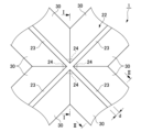
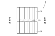
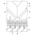
図1は、本発明の第1実施形態に係る耐震壁1の正面図である。図2は、図1の耐震壁1の破線Aで囲んだ部分の拡大図である。図3は、図2の耐震壁1のI-I断面図である。図4は、図2の耐震壁1のII-II断面図である。図5は、図1の耐震壁1の破線Bで囲んだ部分の拡大図である。
耐震壁1は、既存の鉄筋コンクリート造の柱梁架構10の構面内に構築されている。柱梁架構10は、一対の鉄筋コンクリート造の既存柱11と、この既存柱11同士を連結する上下一対の鉄筋コンクリート造の既存梁12と、を備える。
耐震壁1は、鋼板を組み合わせて形成されたフレーム20と、フレーム20に取り付けられた木製の補剛材30と、フレーム20と柱梁架構10とを接合する接合部40と、を備える。
The present invention relates to an earthquake-resistant wall that includes a lattice-shaped steel frame and wooden stiffeners attached to the frame, and a method for constructing the earthquake-resistant wall. One of the features of the present invention is that a recess is provided in the middle of the stiffener in the depth direction, and the welded parts of the steel plates that make up the frame are housed in the recess, so that the steel frame and the stiffeners can be tightly attached to each other without any gaps.
Hereinafter, an embodiment of the present invention will be described with reference to the drawings. In the following description of the embodiments, the same components are denoted by the same reference numerals, and the description thereof will be omitted or simplified.
First Embodiment
Fig. 1 is a front view of a
The earthquake-
The earthquake-
フレーム20は、矩形枠状の外周フレーム21と、この外周フレーム21の内側に設けられた正面視で格子状の格子フレーム22と、を備える。
格子フレーム22は、複数の互いに交差する複数の鋼板としての斜材23同士を溶接することで形成されている。斜材23は、正面側に端面が向いた状態で、水平に対して斜め方向に延びており、斜材23同士が交差する交差部では、斜材23同士が溶接されて、溶接部としてのビード24が形成されている。
外周フレーム21および格子フレーム22により、略三角形状または略四角形状の開口部25が形成される。
The
The
The
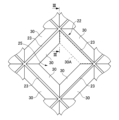
補剛材30は、格子フレーム22を構成する斜材23の上下面(表裏面)に取り付けられている。具体的には、略四角形状の開口部25には、補剛材30が4つ取り付けられ、略三角形状の開口部25には、補剛材30が2つ取り付けられている。
この補剛材30は、並べたひき板を繊維方向が直交するように積層して接着したCLT(Cross Laminated Timber)である。補剛材30は、斜材23の正面側および背面側の端面の一部を覆っており、耐震壁1の正面視では、斜材23が幅dの隙間で視認可能となっている。言い換えると、補剛材30は、鋼製の格子フレーム22の側面の少なくとも一部を覆っている。
また、正面視で、補剛材30の奥行き寸法L1は、斜材23の奥行き寸法L2より大きくなっている。補剛材30の奥行き方向の中間部には、凹部31が形成されており、斜材23同士の溶接部であるビード24は、凹部31に収容されている。
The
The
In addition, in a front view, the depth dimension L1 of the
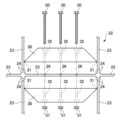
図6は、耐震壁1の一部の分解斜視図である。
補剛材30には、ボルトを挿通するボルト挿通孔32が形成されており、格子フレーム22の斜材23には、ボルトを挿通する貫通孔26が形成されている。斜材23の上下に補剛材30を配置し、ボルト50を上下の補剛材30のボルト挿通孔32および斜材23の貫通孔26に挿通して、ナット51を締め付けることで、補剛材30は、格子フレーム22に取り付けられるとともに、斜材23同士の溶接部であるビード24が凹部31に収容される。
FIG. 6 is an exploded perspective view of a portion of the earthquake-
The
図5に示すように、接合部40は、セメント系結合材であるコンクリートを打設して形成されている。この接合部40には、外周フレーム21に設けられたスタッドボルト27と、柱梁架構10にあと施工で設けられたあと施工アンカー13とが、埋設されている。
As shown in FIG. 5, the
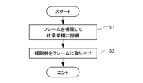
以下、耐震壁1を構築する手順について、図7のフローチャートを参照しながら説明する。
ステップS1では、フレーム20を構築し、フレーム20と柱梁架構10との隙間にコンクリートを打設して接合部40を形成して、接合部40を介してフレーム20と柱梁架構10とを接合する。
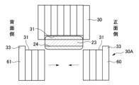
ステップS2では、補剛材30をボルト50およびナット51で格子フレーム22の斜材23に取り付ける。このとき、斜材23同士の溶接部であるビード24を補剛材30の凹部31に収容する。なお、図8および図9に示すように、四角形状の開口部25に4つの補剛材30を取り付ける際、4番目に取り付ける補剛材30Aについては、正面側あるいは背面側から嵌め込んで取り付けようとしても、補剛材30Aの凹部31を形成する突部33がビード24に引っ掛かる。そこで、図8に示すように、補剛材30Aを凹部31で二分割して補剛材ピース60、61とし、例えば、補剛材ピース60を正面側から差し込み、補剛材ピース61を背面側から差し込んで、補剛材ピース60、61でビード24を挟み込むように取り付ける。これにより、4番目の補剛材30Aを格子フレーム22に円滑に取り付けることができる。
耐震壁1の具体的な寸法は、例えば、図8および図9に示すような開口部25が400mm×400mm、補剛材30の正面視の見付け幅が70mm、補剛材30Aの突部33の奥行き方向の長さが30mm、凹部31の深さが30mm程度である。
The procedure for constructing the earthquake-
In step S1, the
In step S2, the
The specific dimensions of the earthquake-
本実施形態によれば、以下のような効果がある。
(1)格子状の格子フレーム22とこの格子フレーム22に取り付けられた木製の補剛材30とを備える耐震壁1において、格子フレーム22を構成する斜材23の正面側の端面の少なくとも一部を木製の補剛材30で覆ったので、正面側から斜材23同士を溶接した溶接部のビード24を隠蔽することができる。よって、耐震壁1の意匠性を向上できるうえに、溶接部であるビード24を保護できる。また、図4に示すように、鋼製の格子フレーム22の斜材23と補剛材30との間には隙間が生じず、密着させることができる。
According to this embodiment, the following effects are obtained.
(1) In a
(2)木製の補剛材30の凹部31に斜材23同士の溶接部であるビード24を収容したので、斜材23同士の溶接部と補剛材30との干渉を解消して、斜材23からなる格子フレーム22に補剛材30を容易に取り付けることができる。
(2) The
〔第2実施形態〕
図10は、本発明の第2実施形態に係る耐震壁1Aの部分拡大図である。図11は、図10の耐震壁1AのIV-IV断面図である。
本実施形態では、補剛材30が斜材23の正面側および背面側の端面を全面に亘って覆っている点が、第1実施形態と異なる。すなわち、耐震壁1Aの正面視では、斜材23が視認できないようになっている。
本実施形態によれば、上述の(1)、(2)と同様の効果がある。
Second Embodiment
Fig. 10 is a partially enlarged view of an earthquake-
This embodiment differs from the first embodiment in that the
According to this embodiment, there are effects similar to those of (1) and (2) described above.
なお、本発明は前記実施形態に限定されるものではなく、本発明の目的を達成できる範囲での変形、改良等は本発明に含まれるものである。
例えば、上述の各実施形態では、四角形状の開口部25に取り付ける4番目の補剛材30Aについて、補剛材30Aを二分割することで格子フレーム22に取り付けたが、これに限らず、図11に示すように、補剛材30Aの一端側のみに突部33を設け、補剛材30Aを正面側あるいは背面側から差し込むことで、格子フレーム22に取り付けてもよい。
The present invention is not limited to the above-described embodiment, and modifications and improvements within the scope of the present invention that can achieve the object of the present invention are included in the present invention.
For example, in each of the above-described embodiments, the
1、1A…耐震壁 10…柱梁架構 11…既存柱 12…既存梁
13…あと施工アンカー
20…フレーム 21…外周フレーム 22…格子フレーム
23…斜材(鋼板) 24…ビード 25…開口部 26…貫通孔
27…スタッドボルト
30、30A…補剛材 31…凹部 32…ボルト挿通孔 33…突部
40…接合部
50…ボルト 51…ナット 60、61…補剛材ピース
Claims (3)
前記格子状のフレームは、互いに交差して配置された複数の鋼板同士が溶接されて形成され、
正面視で、前記補剛材の奥行き寸法は、前記鋼板の奥行き寸法より大きく、
前記補剛材は、前記鋼製のフレームの側面の少なくとも一部を覆っていることを特徴とする耐震壁。 A seismic wall comprising a lattice-shaped steel frame and a wooden stiffener attached to the frame,
The lattice-shaped frame is formed by welding a plurality of steel plates arranged to cross each other,
When viewed from the front, the depth dimension of the stiffener is greater than the depth dimension of the steel plate,
A seismic wall characterized in that the stiffener covers at least a portion of a side surface of the steel frame.
前記鋼板同士の溶接部は、前記凹部に収容されることを特徴とする請求項1に記載の耐震壁。 A recess is formed in the middle of the wooden stiffener in the depth direction,
The earthquake-resistant wall according to claim 1 , wherein the welded portion between the steel plates is accommodated in the recess.
柱梁架構の構面内に、互いに交差して配置された複数の鋼板同士を溶接することで、格子状のフレームを構築する第1の工程と、
奥行き方向の中間部に凹部を設けた木製の補剛材を用意し、前記補剛材を前記鋼板に取り付ける第2の工程と、を含み、
前記第2の工程では、前記鋼板同士の溶接部を前記補剛材の凹部に収容することを特徴とする耐震壁の構築方法。 A method for constructing a seismic wall according to claim 1 or 2, comprising the steps of:
A first step of constructing a lattice-shaped frame by welding a plurality of steel plates arranged crosswise to each other within a structural surface of a column-beam structure;
a second step of preparing a wooden stiffener having a recess in a middle portion in a depth direction and attaching the stiffener to the steel plate;
A method for constructing a seismic wall, characterized in that in the second step, the welded portions between the steel plates are accommodated in recesses in the stiffener.
Priority Applications (1)
| Application Number | Priority Date | Filing Date | Title |
|---|---|---|---|
| JP2021170584A JP7594990B2 (en) | 2021-10-18 | 2021-10-18 | Earthquake-resistant wall and construction method thereof |
Applications Claiming Priority (1)
| Application Number | Priority Date | Filing Date | Title |
|---|---|---|---|
| JP2021170584A JP7594990B2 (en) | 2021-10-18 | 2021-10-18 | Earthquake-resistant wall and construction method thereof |
Publications (2)
| Publication Number | Publication Date |
|---|---|
| JP2023060785A JP2023060785A (en) | 2023-04-28 |
| JP7594990B2 true JP7594990B2 (en) | 2024-12-05 |
Family
ID=86098183
Family Applications (1)
| Application Number | Title | Priority Date | Filing Date |
|---|---|---|---|
| JP2021170584A Active JP7594990B2 (en) | 2021-10-18 | 2021-10-18 | Earthquake-resistant wall and construction method thereof |
Country Status (1)
| Country | Link |
|---|---|
| JP (1) | JP7594990B2 (en) |
Citations (4)
| Publication number | Priority date | Publication date | Assignee | Title |
|---|---|---|---|---|
| JP2006057352A (en) | 2004-08-20 | 2006-03-02 | Nippon Oil Corp | Method of repairing steel structure with carbon fiber reinforced resin plate, carbon fiber reinforced resin plate used in the method, and repaired steel structure |
| JP2008000760A (en) | 2006-06-20 | 2008-01-10 | Kawasaki Heavy Ind Ltd | Fatigue reduction type weld joint structure forming method and reinforced resin block |
| JP2012245566A (en) | 2012-09-18 | 2012-12-13 | Kawasaki Heavy Ind Ltd | Welded joint structure for reducing fatigue damage |
| JP2020143502A (en) | 2019-03-06 | 2020-09-10 | 大成建設株式会社 | Bearing wall |
-
2021
- 2021-10-18 JP JP2021170584A patent/JP7594990B2/en active Active
Patent Citations (4)
| Publication number | Priority date | Publication date | Assignee | Title |
|---|---|---|---|---|
| JP2006057352A (en) | 2004-08-20 | 2006-03-02 | Nippon Oil Corp | Method of repairing steel structure with carbon fiber reinforced resin plate, carbon fiber reinforced resin plate used in the method, and repaired steel structure |
| JP2008000760A (en) | 2006-06-20 | 2008-01-10 | Kawasaki Heavy Ind Ltd | Fatigue reduction type weld joint structure forming method and reinforced resin block |
| JP2012245566A (en) | 2012-09-18 | 2012-12-13 | Kawasaki Heavy Ind Ltd | Welded joint structure for reducing fatigue damage |
| JP2020143502A (en) | 2019-03-06 | 2020-09-10 | 大成建設株式会社 | Bearing wall |
Also Published As
| Publication number | Publication date |
|---|---|
| JP2023060785A (en) | 2023-04-28 |
Similar Documents
| Publication | Publication Date | Title |
|---|---|---|
| KR100684931B1 (en) | Prefabricated closed steel member using bending steel plate and its installation structure | |
| JP6530959B2 (en) | Seismic wall structure | |
| JP5491962B2 (en) | Structural wall | |
| JP2024143166A (en) | Joint structure between beam and earthquake-resistant wall | |
| KR102217178B1 (en) | Non-welding beam-to-column connection structure with reinforcing plate and through bolt | |
| JP7233153B2 (en) | bearing wall | |
| JP2001040881A (en) | Reinforcement structure of beam-column joint | |
| JP7396623B2 (en) | Dissimilar material joining structure | |
| JP7118507B2 (en) | Steel reinforced concrete wall pillar building structure | |
| JP4945428B2 (en) | Reinforced structure | |
| JP4949116B2 (en) | Wall unit and shear wall | |
| JP4095534B2 (en) | Joint structure of column and beam in ramen structure and its construction method | |
| JPH11100900A (en) | Joint structure between reinforced concrete columns and steel beams | |
| JP2007197936A (en) | Wall unit, earthquake-resistant wall and construction method thereof | |
| KR102540266B1 (en) | Joint structure between improved CFT column and prefabricated beam with concrete form | |
| JP3991876B2 (en) | Seismic reinforcement structure | |
| JP2023060785A (en) | Seismic wall and its construction method | |
| JP6567368B2 (en) | Reinforcement structure and reinforcement method for existing columns | |
| JP3043938B2 (en) | Joint structure between reinforced concrete columns and steel beams | |
| JP4285427B2 (en) | Seismic reinforcement structure for buildings | |
| JP3218297B2 (en) | Buildings with parallel multistory shear walls | |
| JP2001164658A (en) | Beam joint structure and unit building | |
| JP7782609B1 (en) | Building walls and structures | |
| JP6240420B2 (en) | Seismic reinforcement structure | |
| JP2010216075A (en) | Joint structure of reinforced concrete column and steel frame beam |
Legal Events
| Date | Code | Title | Description |
|---|---|---|---|
| A621 | Written request for application examination |
Free format text: JAPANESE INTERMEDIATE CODE: A621 Effective date: 20240312 |
|
| TRDD | Decision of grant or rejection written | ||
| A977 | Report on retrieval |
Free format text: JAPANESE INTERMEDIATE CODE: A971007 Effective date: 20241030 |
|
| A01 | Written decision to grant a patent or to grant a registration (utility model) |
Free format text: JAPANESE INTERMEDIATE CODE: A01 Effective date: 20241105 |
|
| A61 | First payment of annual fees (during grant procedure) |
Free format text: JAPANESE INTERMEDIATE CODE: A61 Effective date: 20241125 |
|
| R150 | Certificate of patent or registration of utility model |
Ref document number: 7594990 Country of ref document: JP Free format text: JAPANESE INTERMEDIATE CODE: R150 |