JP7013041B2 - Pachinko machine - Google Patents
Pachinko machine Download PDFInfo
- Publication number
- JP7013041B2 JP7013041B2 JP2020032241A JP2020032241A JP7013041B2 JP 7013041 B2 JP7013041 B2 JP 7013041B2 JP 2020032241 A JP2020032241 A JP 2020032241A JP 2020032241 A JP2020032241 A JP 2020032241A JP 7013041 B2 JP7013041 B2 JP 7013041B2
- Authority
- JP
- Japan
- Prior art keywords
- effect
- special
- game
- symbol
- special symbol
- Prior art date
- Legal status (The legal status is an assumption and is not a legal conclusion. Google has not performed a legal analysis and makes no representation as to the accuracy of the status listed.)
- Active
Links
- 230000000694 effects Effects 0.000 claims description 4401
- 238000004519 manufacturing process Methods 0.000 claims description 190
- 238000013461 design Methods 0.000 claims description 32
- 238000000034 method Methods 0.000 description 494
- 230000008569 process Effects 0.000 description 490
- 238000003860 storage Methods 0.000 description 300
- 230000008859 change Effects 0.000 description 286
- 230000000875 corresponding effect Effects 0.000 description 200
- 238000012545 processing Methods 0.000 description 156
- 239000002243 precursor Substances 0.000 description 146
- 238000001514 detection method Methods 0.000 description 120
- 230000007704 transition Effects 0.000 description 120
- 230000005540 biological transmission Effects 0.000 description 92
- 238000010586 diagram Methods 0.000 description 66
- 238000011161 development Methods 0.000 description 57
- 230000009471 action Effects 0.000 description 45
- 238000004904 shortening Methods 0.000 description 38
- 238000013500 data storage Methods 0.000 description 37
- 230000009467 reduction Effects 0.000 description 32
- 230000001276 controlling effect Effects 0.000 description 29
- 238000010304 firing Methods 0.000 description 29
- 238000004458 analytical method Methods 0.000 description 18
- 239000011521 glass Substances 0.000 description 18
- 230000000007 visual effect Effects 0.000 description 17
- 230000002087 whitening effect Effects 0.000 description 17
- 230000001965 increasing effect Effects 0.000 description 15
- 241000283070 Equus zebra Species 0.000 description 14
- 239000003086 colorant Substances 0.000 description 14
- 230000033001 locomotion Effects 0.000 description 13
- 230000004044 response Effects 0.000 description 10
- 239000002131 composite material Substances 0.000 description 8
- 230000004397 blinking Effects 0.000 description 7
- 239000003795 chemical substances by application Substances 0.000 description 7
- ZPUCINDJVBIVPJ-LJISPDSOSA-N cocaine Chemical compound O([C@H]1C[C@@H]2CC[C@@H](N2C)[C@H]1C(=O)OC)C(=O)C1=CC=CC=C1 ZPUCINDJVBIVPJ-LJISPDSOSA-N 0.000 description 7
- 238000010924 continuous production Methods 0.000 description 7
- 230000001151 other effect Effects 0.000 description 7
- 206010048909 Boredom Diseases 0.000 description 6
- 230000001186 cumulative effect Effects 0.000 description 6
- 239000013078 crystal Substances 0.000 description 5
- 230000007423 decrease Effects 0.000 description 5
- 230000003247 decreasing effect Effects 0.000 description 5
- 230000006870 function Effects 0.000 description 5
- 230000006872 improvement Effects 0.000 description 5
- 230000007246 mechanism Effects 0.000 description 5
- 206010049976 Impatience Diseases 0.000 description 4
- 238000012790 confirmation Methods 0.000 description 4
- 230000001960 triggered effect Effects 0.000 description 4
- 238000012800 visualization Methods 0.000 description 4
- 230000033228 biological regulation Effects 0.000 description 3
- 239000003990 capacitor Substances 0.000 description 3
- 230000006835 compression Effects 0.000 description 3
- 238000007906 compression Methods 0.000 description 3
- 230000008451 emotion Effects 0.000 description 3
- 230000001360 synchronised effect Effects 0.000 description 3
- 230000002238 attenuated effect Effects 0.000 description 2
- 230000008901 benefit Effects 0.000 description 2
- 238000005282 brightening Methods 0.000 description 2
- 230000002708 enhancing effect Effects 0.000 description 2
- 230000000977 initiatory effect Effects 0.000 description 2
- 239000004973 liquid crystal related substance Substances 0.000 description 2
- 230000036651 mood Effects 0.000 description 2
- 238000002360 preparation method Methods 0.000 description 2
- 238000012546 transfer Methods 0.000 description 2
- 230000001133 acceleration Effects 0.000 description 1
- 230000002844 continuous effect Effects 0.000 description 1
- 230000006866 deterioration Effects 0.000 description 1
- 238000005286 illumination Methods 0.000 description 1
- 238000007726 management method Methods 0.000 description 1
- 239000000463 material Substances 0.000 description 1
- 238000012986 modification Methods 0.000 description 1
- 230000004048 modification Effects 0.000 description 1
- NJPPVKZQTLUDBO-UHFFFAOYSA-N novaluron Chemical compound C1=C(Cl)C(OC(F)(F)C(OC(F)(F)F)F)=CC=C1NC(=O)NC(=O)C1=C(F)C=CC=C1F NJPPVKZQTLUDBO-UHFFFAOYSA-N 0.000 description 1
- 230000001105 regulatory effect Effects 0.000 description 1
- 230000005236 sound signal Effects 0.000 description 1
- 230000007480 spreading Effects 0.000 description 1
- 238000003892 spreading Methods 0.000 description 1
- 238000002834 transmittance Methods 0.000 description 1
Images


Landscapes
- Display Devices Of Pinball Game Machines (AREA)
Description
本発明は、遊技機に関する。 The present invention relates to a gaming machine.
従来の遊技機においては、始動条件の成立に基づき実行した図柄の変動表示が予め定められた特別結果になると、遊技者に有利な特別遊技を実行可能なものが一般的である。 In conventional gaming machines, it is common to be able to execute a special game that is advantageous to the player when the variable display of the symbol executed based on the establishment of the starting condition has a predetermined special result.
このような遊技機では、表示手段に演出図柄を表示させ、図柄の変動表示中に演出図柄の変動表示を伴う変動演出を実行するようになっているものがある(特許文献1参照)。 In some such gaming machines, the effect symbol is displayed on the display means, and the variation effect accompanied by the variation display of the effect symbol is executed during the variation display of the symbol (see Patent Document 1).
しかしながら、上記特許文献に記載された遊技機では、表示手段の表示内容に改良の地余地があり、遊技の興趣が低いという問題があった。 However, in the gaming machine described in the above patent document, there is room for improvement in the display content of the display means, and there is a problem that the interest of the game is low.
本発明は、上記した問題点に鑑みてなされたものであり、遊技の興趣を向上させることが可能な遊技機を提供することを目的とする。 The present invention has been made in view of the above-mentioned problems, and an object of the present invention is to provide a gaming machine capable of improving the interest of gaming.
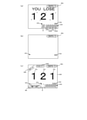
上記課題を解決するため、本発明は、始動条件の成立(始動口への遊技球の入球)に基づき実行した図柄(特別図柄)の変動表示が予め定められた特別結果になると、遊技者に有利な特別遊技(大当たり遊技)を実行可能な遊技機において、通常遊技状態と、該通常遊技状態よりも遊技者に有利な特定遊技状態とに制御することが可能な遊技状態制御手段(主制御基板101)と、表示手段(画像表示装置14)に複数の演出図柄を表示させ、前記図柄の変動表示中に前記複数の演出図柄の変動表示を伴う変動演出を実行することが可能な変動演出実行手段(演出制御基板102、画像制御基板105)と、前記変動演出を実行する演出モードを複数の演出モード(図106の演出モードA0~A3、B1~B2)のうちの何れかに制御することが可能な演出モード制御手段(演出制御基板102、画像制御基板105)と、を備え、前記変動演出実行手段は、前記通常遊技状態中に制御される第1の演出モード(図106の演出モードA1)において、前記複数の演出図柄を第1の表示態様(図107の第1表示態様)で表示し、前記特定遊技状態中に制御される第2の演出モード(図106の演出モードB1)において、前記複数の演出図柄を前記第1の表示態様とは異なる第2の表示態様(図108の第4表示態様)で表示し、遊技機の電源断から復旧したとき、前記第1の演出モードおよび前記第2の演出モードの何れであっても、前記複数の演出図柄に含まれる数字情報の組み合わせを共通(図107及び図108の「1」「3」「5」)とすると共に、前記複数の演出図柄に含まれる数字情報をそれぞれ異なる数字情報(図107及び図108の「1」「3」「5」)で表示し、前記演出図柄は、前記第1の表示態様で表示される前記変動表示中に導出可能な総種類数(1~9の何れかの数字を示す9種類の通常の演出図柄、2種類の変化図柄、1種類の擬似連図柄)よりも、前記第2の表示態様で表示される前記変動表示中に導出可能な総種類数(1~9の何れかの数字を示す9種類の通常の演出図柄)の方が少なく、前記第1の演出モードにおける前記変動演出で特定のリーチ演出を実行する場合、前記特定のリーチ演出前に前記演出図柄を前記第1の表示態様で表示し、前記特定のリーチ演出中に前記演出図柄を前記第1の表示態様よりも装飾性が低い表示態様で表示し、前記特定のリーチ演出の終了時よりも後(復帰演出後)に前記演出図柄を前記第1の表示態様で表示し、前記第2の演出モードにおける前記変動演出で特定のリーチ演出を実行する場合、前記特定のリーチ演出前に前記演出図柄を前記第2の表示態様で表示し、前記特定のリーチ演出中に前記演出図柄を前記第2の表示態様で表示し、前記特定のリーチ演出後に前記演出図柄を前記第2の表示態様で表示することを特徴とする。
In order to solve the above-mentioned problems, in the present invention, when the variation display of the symbol (special symbol) executed based on the establishment of the starting condition (the entry of the gaming ball into the starting port) becomes a predetermined special result, the player In a gaming machine capable of performing a special game (big hit game) that is advantageous to the player, a gaming state control means (mainly) that can control a normal gaming state and a specific gaming state that is more advantageous to the player than the normal gaming state. It is possible to display a plurality of effect symbols on the control board 101) and the display means (image display device 14) and execute a variation effect accompanied by the variation display of the plurality of effect symbols during the variation display of the symbols. The effect execution means (
本発明によれば、遊技の興趣を向上させることが可能となる。 According to the present invention, it is possible to improve the interest of the game.
(第1実施形態)
以下、本発明の第1実施形態について図面を参照しながら具体的に説明する。
(First Embodiment)
Hereinafter, the first embodiment of the present invention will be specifically described with reference to the drawings.
図1に示すように、遊技機Yは、遊技盤取付枠Y1と、遊技盤取付枠Y1に対して回動可能に支持されるガラス扉Y2、遊技球が流下する遊技領域2Aが形成されている遊技盤2とを有する。
As shown in FIG. 1, in the game machine Y, a game board mounting frame Y1, a glass door Y2 rotatably supported with respect to the game board mounting frame Y1, and a
遊技盤取付枠Y1は、遊技店の島設備に固定される外枠(図示なし)に回動可能に支持され、脱着可能に取り付けられている。 The game board mounting frame Y1 is rotatably supported by an outer frame (not shown) fixed to the island equipment of the game store, and is detachably mounted.
ガラス扉Y2は、水平方向の一端側においてヒンジ機構部Hを介して遊技盤取付枠Y1に脱着自在に連結されており、ヒンジ機構部Hを支点として回動可能に支持されている。よって、ガラス扉Y2を、ヒンジ機構部Hを支点として扉のように回動することによって、遊技領域2Aおよび遊技盤取付枠Y1の前面部分を開閉することができる。ガラス扉Y2は、中央に設けられる窓部に裏面側から取り付けられるガラス(透明部材)によって遊技領域2Aの前面部分を視認可能に覆っている。
The glass door Y2 is detachably connected to the game board mounting frame Y1 via the hinge mechanism portion H on one end side in the horizontal direction, and is rotatably supported with the hinge mechanism portion H as a fulcrum. Therefore, by rotating the glass door Y2 like a door with the hinge mechanism portion H as a fulcrum, the front portion of the
また、ガラス扉Y2の他端側には、ガラス扉Y2を遊技盤取付枠Y1に固定するロック機構Rが設けられている。ロック機構Rによる固定は、専用の鍵によって解除することが可能とされている。 Further, on the other end side of the glass door Y2, a lock mechanism R for fixing the glass door Y2 to the game board mounting frame Y1 is provided. The fixing by the lock mechanism R can be released by a dedicated key.
ガラス扉Y2には、複数の遊技球を貯留する受け皿50と、遊技球を発射させるための操作が可能な発射操作装置3とが設けられている。発射操作装置3は遊技球を遊技領域2Aに向けて発射可能な発射装置4(図3参照)に接続されている。なお、発射装置4は、遊技盤取付枠Y1の前面に設けられている。受け皿50に貯留されている遊技球が発射装置4に供給される。
The glass door Y2 is provided with a
発射操作装置3は、ガラス扉Y2に固定されている基体31、基体31に回動可能に設けられている発射ハンドル32を有する。発射装置4は、発射ハンドル32の回動角度に応じた強さ(以下、「遊技球発射強度」という)で、遊技球を発射する。
The
遊技盤2の遊技領域2Aには、枠状の飾り枠29Aと、湾曲形状を呈した内側レール部材29Bと、外側レール部材29Cと、後述する大入賞口8の直下に配置され、遊技球を第2始動口7に誘導可能な誘導経路が上面に形成された誘導部材29Dとが設けられている。
In the
飾り枠29Aは、遊技盤2の略中央部に嵌め込まれている。飾り枠29Aの内側には、液晶ディスプレイからなる画像表示装置14が嵌め込まれている。また、飾り枠29Aの内側端部には、演出用役物装置17が設けられている。
The
内側レール部材29Bが飾り枠29Aの外側に配置され、外側レール部材29Cが内側レール部材29Bの外側に配置されている。所定の遊技球発射強度で発射された遊技球は、内側レール部材29Bと外側レール部材29Cとの間を上昇して遊技領域2Aに進入する。なお、遊技領域2Aには、複数の釘や風車が設けられている。遊技領域2Aに進入した遊技球は、複数の釘や風車によって様々な方向に流下し得る。
The
遊技領域2Aには、複数(本実施の形態では4つ)の一般入賞口11が設けられている。各一般入賞口11には、一般入賞口検出センサ11aが設けられており、この一般入賞口検出センサ11aが遊技球を検出すると、所定個数(例えば10個)の遊技球が賞球として払い出される(遊技価値が付与される)。
The
また、遊技領域2Aにおける飾り枠29Aの右斜下側に、遊技球の通過が可能な入賞ゲート10が設けられている。入賞ゲート10には、遊技球を検出する入賞ゲート検出センサ10aが設けられている。入賞ゲート検出センサ10aが遊技球を検出することを条件に、遊技者にとって有利な補助遊技を実行するか否かの普通図柄抽選が行われる。普通図柄抽選の詳細については後述する。
Further, a winning
遊技領域2Aの下部で、画像表示装置14の下方に、不変であり、且つ、常時入球可能である第1始動口6が設けられている。第1始動口6には、遊技球を検出する第1始動口検出センサ6aが設けられている。第1始動口検出センサ6aが遊技球を検出することを条件に遊技者にとって有利な大当たり遊技(特別遊技)を実行するか否かの第1特別図柄抽選が行われる。第1特別図柄抽選の詳細については後述する。また、第1始動口検出センサ6aが遊技球を検出すると、所定個数(例えば、3個)の遊技球が賞球として払い出される(遊技価値が付与される)。
At the lower part of the
第1始動口6の直下に、可変の第2始動口7が設けられている。第2始動口7は、第2始動口制御装置70によって入賞不可能な基本態様(閉態様)又は入賞可能な特別態様(開態様)のいずれかに制御される。第2始動口7にも、遊技球を検出する第2始動口検出センサ7aが設けられている。第2始動口検出センサ7aが遊技球を検出することを条件に遊技者にとって有利な大当たり遊技(特別遊技)を実行するか否かの第2特別図柄抽選が行われる。第2特別図柄抽選の詳細については後述する。また、第2始動口検出センサ7aが遊技球を検出すると、所定個数(例えば、3個)の遊技球が賞球として払い出される(遊技価値が付与される)。
A variable
第2始動口制御装置70は、回動可能な普通可動片70A及び普通可動片70Aを回動させる駆動部としての第2始動口開閉ソレノイド70Bを具備している。
The second start
普通可動片70Aは、矩形状の扉部材で構成されており、通常は(所定条件が成立する以外は)、表面が遊技領域2Aと面一になる状態で停止し、第2始動口7を閉鎖している。この普通可動片70Aによる第2始動口7の閉鎖が、第2始動口7の基本態様を構成する。
The normally
一方、所定条件が成立すると、普通可動片70Aが下端部に形成された回転軸を中心に前方側に回動して第2始動口7を開放する。第2始動口7が入球可能な特別態様に制御される。この普通可動片70Aによる第2始動口7の開放が第2始動口7の特別態様を構成する。普通可動片70Aは、第2始動口7を開放するとき、遊技領域2Aから突出した状態になり、流下する遊技球を受けて第2始動口7へ誘導することが可能となる。
On the other hand, when a predetermined condition is satisfied, the normally
なお、第2始動口制御装置70についての所定条件とは、上述した普通図柄抽選において、補助遊技を実行すると決定されることである。
The predetermined condition for the second start
入賞ゲート10の下流側には、可変の大入賞口8が設けられている。大入賞口8は、大入賞口制御装置80によって入賞不可能な基本態様又は入賞可能な特別態様のいずれかに制御される。大入賞口8には、遊技球を検出する大入賞口検出センサ8aが設けられている。大入賞口検出センサ8aが遊技球を検出すると、所定個数(例えば、15個)の遊技球が賞球として払い出される(遊技価値が付与される)。
A variable large winning
大入賞口制御装置80は、回動可能な特別可動片80A及び特別可動片80Aを回動させる駆動部としての大入賞口開閉ソレノイド80Bを具備している。
The special winning
特別可動片80Aは、矩形状の扉部材で構成されており、通常は(所定条件が成立する以外は)、表面が遊技領域2Aと面一になる状態で停止し、大入賞口8を遊技球が入球不能なように閉鎖している。この特別可動片80Aによる大入賞口8の閉鎖が、大入賞口8の基本態様を構成する。
The special
一方、所定条件が成立すると、特別可動片80Aが下端部に形成された回転軸を中心に前方側に回動させることで大入賞口8を遊技球が入球可能なように開放させる。この特別可動片80Aによる大入賞口8の開放が大入賞口8の特別態様を構成する。特別可動片80Aは、大入賞口8を開放するとき、遊技領域2Aから突出した状態になり、流下する遊技球を受けて大入賞口8へ誘導することが可能となる。
On the other hand, when a predetermined condition is satisfied, the special
なお、大入賞口制御装置80についての所定条件とは、上述した第1特別図柄抽選又は第2特別図柄抽選(以下、第1特別図柄抽選と第2特別図柄抽選とをまとめて「特別図柄抽選」と総称する)において、特別遊技(大当たり遊技)を実行すると決定されることである。
The predetermined condition for the large winning
遊技盤2の表面であって遊技領域2Aの下方には、第1特別図柄表示装置20、第2特別図柄表示装置21及び普通図柄表示装置22からなる図柄表示装置、並びに、第1特別図柄保留表示装置23、第2特別図柄保留表示装置24及び普通図柄保留表示装置25からなる保留表示装置が設けられている。
On the surface of the
第1特別図柄表示装置20は、第1始動口6に遊技球が入球することを条件に行われる第1特別図柄抽選の結果を表示する可変表示装置、第2特別図柄表示装置21は、第2始動口7に遊技球が入球することを条件に行われる第2特別図柄抽選の結果を表示する可変表示装置である。
The first special
第1特別図柄抽選とは、第1始動口6への遊技球の入球に基づき取得した特図判定情報に基づいて大当たりに当選したか否かの大当たり判定を行ったり、大当たり判定の結果に基づき第1特別図柄表示装置20に表示させる特別図柄の種類を判定する特別図柄判定を行ったりすることをいう。また、第2特別図柄抽選とは、第2始動口7への遊技球の入球に基づき取得した特図判定情報に基づいて大当たりに当選したか否かを判定したり、第2特別図柄表示装置21に表示させる特別図柄の種類を判定したりすることをいう。つまり、各特別図柄抽選とは、遊技者にとって有利な特別遊技(大当たり遊技)を実行するか否かを決定(判定)するための抽選であるといえる。
The first special symbol lottery is a big hit judgment as to whether or not a big hit is won based on the special figure judgment information acquired based on the entry of the game ball into the
第1特別図柄抽選が行われると、第1特別図柄表示装置20において第1特別図柄の変動表示が行われ、所定時間経過後に第1特別図柄抽選の結果を報知するための第1特別図柄の停止表示が行われる。また、第2特別図柄抽選が行われると、第2特別図柄表示装置21において第2特別図柄の変動表示が行われ、所定時間経過後に第2特別図柄抽選の結果を報知するための第2特別図柄の停止表示が行われる。
When the first special symbol lottery is performed, the first special
例えば、第1特別図柄表示装置20及び第2特別図柄表示装置21はそれぞれ一列に並んだ複数のLEDを具備している。各特別図柄の変動表示において、例えば、対応する第1特別図柄表示装置20又は第2特別図柄表示装置21の所定のLEDが所定の間隔で移動点滅する。そして、特別図柄の停止表示においては、各特別図柄抽選の結果を表す特定のLEDが点灯する。
For example, the first special
普通図柄表示装置22は、入賞ゲート10に遊技球が通過することを条件に行われる普通図柄抽選の結果を表示する可変表示装置である。普通図柄抽選とは、入賞ゲート10への遊技球の通過に基づき取得した普図判定情報に基づいて当たりに当選したか否かの当たり判定を行ったり、当たり判定の結果に基づき普通図柄表示装置22に表示させる普通図柄の種類を判定する普通図柄判定を行ったりすることをいう。つまり、普通図柄抽選とは、遊技者にとって有利な補助遊技を実行するか否かを決定(判定)するための抽選であるといえる。
The ordinary
普通図柄抽選が行われると、普通図柄表示装置22において普通図柄の変動表示が行われ、所定時間経過後に普通図柄抽選の結果を報知するための普通図柄の停止表示が行われる。
When the normal symbol lottery is performed, the normal
例えば、普通図柄表示装置22はそれぞれ複数のLEDを具備している。普通図柄の変動表示において、例えば、普通図柄表示装置22の所定のLEDが所定の間隔で点滅する。そして、普通図柄の停止表示において、普通図柄抽選の結果を表す特定のLEDが点灯する。
For example, the ordinary
ところで、特別図柄の変動表示中や大入賞口制御装置80が作動する大当たり遊技(特別遊技)中に、始動口6、7に遊技球が入球しても、即座に特別図柄の変動表示が行われて特別図柄抽選の結果が報知される訳ではない。すなわち、一定条件下で特別図柄の変動表示が保留されることがある。本実施の形態では、一定条件として、特別図柄の変動表示を保留できる個数に上限値が設けられている。本実施の形態では、その上限値は各始動口6、7に対して「4」に設定されている。すなわち、各始動口6、7に対して特別図柄の変動表示を実行する権利を4個まで保留することができる。
By the way, even if a game ball enters the starting
第1特別図柄保留表示装置23は、第1特別図柄の変動表示(以下、「第1特図変動表示」という)の保留数(U1:以下、「第1特図保留数」という)を表示する。第2特別図柄保留表示装置24は、第2特別図柄の変動表示(以下、「第2特図変動表示」という)の保留数(U2:以下、「第2特図保留数」という)を表示する。第1特別図柄保留表示装置23及び第2特別図柄保留表示装置24は、例えばそれぞれ複数のLEDを具備し、各保留数に応じて所定のLEDを点灯する。
The first special symbol
なお、普通図柄の変動表示(以下、「普図変動表示」という)についても同様に、上限保留数が4個に設定されており、その保留数(G:以下、「普図保留数」という)が、普通図柄保留表示装置25において表示される。普通図柄保留表示装置25は、例えば複数のLEDを具備し、普図保留数に応じて所定のLEDを点灯する。
Similarly, the upper limit number of holdings is set to 4 for the variable display of ordinary symbols (hereinafter referred to as "normal figure variable display"), and the number of holdings (G: hereinafter referred to as "normal figure holding number") is set. ) Is displayed on the normal symbol
また、遊技機Yには、様々な演出を実行する演出装置が設けられている。本実施の形態では、演出装置は、画像表示装置14、音声出力装置15、演出用照明装置16、及び、演出用役物装置17で構成されている。画像表示装置14と演出用役物装置17とが遊技盤2に設けられ、音声出力装置15と演出用照明装置16とがガラス扉Y2に設けられている。
Further, the gaming machine Y is provided with an effect device for executing various effects. In the present embodiment, the effect device is composed of an
画像表示装置14は、遊技の進行に応じて様々な静止画や動画を表示することで画像による演出表示を行う。なお、本実施形態においては、画像表示装置14として液晶ディスプレイが用いられているが、プラズマディスプレイ、有機ELディスプレイ等他の方式の表示装置を用いこともできる。
The
上記演出用役物装置17は、可動部17Aを具備し、可動部17Aを作動させることで、動作による演出を行う。音声出力装置15は、BGM(バックグランドミュージック)、SE(サウンドエフェクト)等を出力することで音声による演出を行う。演出用照明装置16は、各ランプの光の照射方向や発光色を変更することで照明による演出を行う。
The
また、受け皿50には、後述する種々の演出に係る操作を行うための入力装置として機能する演出ボタン装置18及び選択ボタン装置19が設けられている。
Further, the
演出ボタン装置18は、操作可能な演出ボタン18A、演出ボタン18Aに対する操作を検出するための演出ボタン検出スイッチ18a、演出ボタン18Aを通常位置(通常状態)と該通常位置よりも上方に突出する突出位置(突出状態)とに移動(変化)させるための演出ボタン駆動モータ18bを具備する(図2及び図3参照)。また、演出ボタン18Aを所定態様で発光させるための発光素子(フルカラーLED、ランプ等)も備えている。
The
選択ボタン装置19は、操作可能な選択ボタン19A及び選択ボタン19Aに対する操作を検出するための選択ボタン検出スイッチ19aを具備する(図2及び図3参照)。また、選択ボタン19Aを所定態様で発光させるための発光素子(フルカラーLED、ランプ等)も備えている。
The
選択ボタン19Aは、上ボタン191A、左ボタン192A、下ボタン193A及び右ボタン194Aからなる。各ボタン191A~194Aは、受け皿50から突出した状態で押圧可能に設けられている。
The selection button 19A includes an
演出装置は、遊技の進行(状態)に応じて様々な演出を実行する。演出としては、例えば、第1特別図柄抽選及び第2特別図柄抽選の結果に基づき画像表示装置14で行われる変動演出(特図抽選演出)がある。変動演出(特図抽選演出)は、演出図柄の変動表示と演出図柄の停止表示を伴って行われる。
The effect device executes various effects according to the progress (state) of the game. As the effect, for example, there is a variable effect (special symbol lottery effect) performed by the
演出図柄の変動表示は、特別図柄の変動表示に対応して行われ、演出図柄が所定の態様で所定時間変動する。演出図柄の停止表示は、特別図柄の停止表示に対応して行われる(以下、演出図柄の変動表示と停止表示をまとめて称呼する場合、「演出図柄表示」という)。演出図柄の停止表示では、演出図柄が特別図柄抽選の結果を表す所定の態様で所定時間停止する。 The variable display of the effect symbol is performed in response to the variable display of the special symbol, and the effect symbol fluctuates in a predetermined mode for a predetermined time. The stop display of the effect symbol is performed corresponding to the stop display of the special symbol (hereinafter, when the variable display and the stop display of the effect symbol are collectively referred to, it is referred to as "effect symbol display"). In the stop display of the effect symbol, the effect symbol is stopped for a predetermined time in a predetermined mode indicating the result of the special symbol lottery.
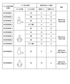
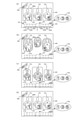
演出図柄は、例えば、画像表示装置14の表示部140の左側領域、中央領域及び右側領域に配列された3列の演出図柄TZ1~TZ3(例えば、「1」から「9」までの数字を表す演出図柄)と、画像表示装置14の表示部140の端側領域に配列された3列の特殊演出図柄TZ4(「1」から「9」までの数字を表す演出図柄)とからなる。演出図柄の変動表示では、各列の演出図柄が、リールが回転しているかのうように、上から下に移動(変動表示)する。なお、演出図柄の変動表示の態様はこれに限られない。また、演出図柄の変動表示中には、特別図柄抽選の結果に応じて、背景画像やキャラクタ等のオブジェクト画像といった様々な演出画像、また、ムービー等が表示される。
The effect symbols represent, for example, three rows of effect symbols TZ1 to TZ3 (for example, numbers from "1" to "9") arranged in the left side region, the center region, and the right side region of the
一方、演出図柄の停止表示においては、画像表示装置14等の表示部140の左側領域、中央領域及び右側領域において、上記の3列の演出図柄TZ1~TZ3が仮停止した後に停止表示し、端側領域において演出図柄TZ1~TZ3の停止表示に合わせて上記3列の特殊演出図柄TZ4が停止表示する。そして、演出図柄の停止表示が行われたときの所定の有効ライン(例えば、表示部140における中央の水平線)上の演出図柄TZ1~TZ3の配列によって特別図柄抽選の結果を報知する。また、特殊演出図柄TZ4の停止表示によって演出図柄TZ1~TZ3が停止表示されたことを報知する。
On the other hand, in the stop display of the effect symbols, in the left side region, the center region, and the right side region of the
なお、有効ライン上の演出図柄TZ1~TZ3の配列によって特別図柄抽選の結果を報知するのではなく、有効ライン上の演出図柄TZ1~TZ3の配列と特殊演出図柄TZ4の配列によって特別図柄抽選の結果を報知してもよい。また、特殊演出図柄TZ4については画像表示装置14に表示(変動表示及び停止表示)するではなく、専用の表示部(LED表示器等)で表示(変動表示及び停止表示)されるようにしてもよいし、特殊演出図柄TZ4をなくして演出図柄TZ1~TZ3だけとしてもよい。 The result of the special symbol lottery is not notified by the arrangement of the effect symbols TZ1 to TZ3 on the effective line, but by the arrangement of the effect symbols TZ1 to TZ3 on the effective line and the arrangement of the special effect symbols TZ4. May be notified. Further, the special effect symbol TZ4 is not displayed on the image display device 14 (variation display and stop display), but is displayed (variation display and stop display) on a dedicated display unit (LED display, etc.). Alternatively, the special effect symbols TZ4 may be eliminated and only the effect symbols TZ1 to TZ3 may be used.
演出装置では、変動演出(特図抽選演出)の他にも、大当たり遊技が実行されるときに行われる特別遊技演出、及び、特別図柄の変動表示又は特別遊技が所定期間行われない内部的な待機状態(所謂、客待ち状態)において行われるデモ演出等の様々な演出が行われる。 In the effect device, in addition to the variable effect (special figure lottery effect), the special game effect performed when the jackpot game is executed, and the variable display of the special symbol or the special game is not performed internally for a predetermined period. Various productions such as demonstration productions performed in the standby state (so-called waiting state for customers) are performed.
遊技盤2及びガラス扉Y2の裏面には、遊技に係る種々の制御を行う主制御基板101、演出制御基板102、払出制御基板103、ランプ制御基板104、画像制御基板105、電源基板107、遊技情報出力端子板108が設けられている。
On the back surfaces of the
(遊技機Yの内部構成)
次に、図3を用いて、遊技機Yの内部構成について説明する。
(Internal configuration of gaming machine Y)
Next, the internal configuration of the gaming machine Y will be described with reference to FIG.
電源基板107は、遊技機の外部から供給される電源から遊技機の動作に必要なメイン電源(動作電源)を生成し、該メイン電源を遊技機Y(主制御基板101、演出制御基板102、払出制御基板103、ランプ制御基板104、画像制御基板105や各種電子部品)に供給する。また、外部から供給される電源電圧を監視し、電源電圧が所定値以下となったときに電源断(停電)が発生したことを検知してローレベルの電断検知信号を主制御基板101に出力する。
The
また、電源基板107は、外部からの電源供給によって蓄電されるコンデンサからなるバックアップ電源を備えており、電源断(停電)時においても主制御基板101にバックアップ電源を供給可能となっている。なお、バックアップ電源を演出制御基板102や払出制御基板103に供給するようにしてもよい。また、バックアップ電源はコンデンサに限らず、例えば、電池でもよいし、コンデンサと電池とを併用してもよい。
Further, the
主制御基板101は、遊技の進行(基本動作)を統括的に制御する。この主制御基板101は、メインCPU101a、メインROM101b、及び、メインRAM101cを備えている。メインCPU101aは、各種検出センサやタイマ(水晶振動子)等からの入力信号に基づいて、メインROM101bに格納されたプログラムを読み出して遊技に関する演算処理を行うと共に、各種制御装置や表示装置を直接制御し、演算処理の結果に基づく所定のコマンドなどを演出制御基板102や払出制御基板103等に送信する。メインRAM101cは、メインCPU101aの演算処理時におけるデータのワークエリアとして機能する。
The
上記主制御基板101の入力側には、入力ポート(図示せず)を介して、第1始動口検出センサ6a、第2始動口検出センサ7a、大入賞口検出センサ8a、入賞ゲート検出センサ10a、及び、一般入賞口検出センサ11aが接続されている。各検出センサは、遊技球を検出すると、検出信号を主制御基板101に出力する。
On the input side of the
主制御基板101の出力側には、出力ポート(図示せず)を介して、第2始動口制御装置70の普通可動片70Aを作動させる第2始動口開閉ソレノイド70B、及び、大入賞口制御装置80の特別可動片80Aを作動させる大入賞口開閉ソレノイド80Bが接続されている。主制御基板101は、各ソレノイドを制御するための制御信号を第2始動口開閉ソレノイド70B及び大入賞口開閉ソレノイド80Bに出力する。
On the output side of the
また、主制御基板101の出力側には、出力ポート(図示せず)を介して、第1特別図柄表示装置20、第2特別図柄表示装置21、普通図柄表示装置22、第1特別図柄保留表示装置23、第2特別図柄保留表示装置24及び普通図柄保留表示装置25が接続されている。主制御基板101は、各表示装置を制御するための表示制御信号を各表示装置20~25に出力する。
Further, on the output side of the
さらに、主制御基板101の出力側には、出力ポート(図示せず)を介して、遊技情報出力端子板108が接続されている。主制御基板101は、所定の遊技に関する情報(以下、遊技情報という)を外部信号として遊技情報出力端子板108に出力する。
Further, a game information
遊技情報出力端子板108には、遊技情報表示装置が接続されている。遊技情報出力端子板108は、遊技情報表示装置及びホールコンピュータに外部信号を出力する。遊技情報表示装置は、遊技機Yの上に設けられ、上記の所定の遊技情報(外部信号)に基づいて所定の遊技情報を表示し得る。
A game information display device is connected to the game information
演出制御基板102は、演出の進行(演出動作)を統括的に制御する。この演出制御基板102は、サブCPU102a、サブROM102b、及び、サブRAM102cを備えている。演出制御基板102は、主制御基板101に対して、当該主制御基板101から演出制御基板102への一方向に通信可能に接続されている。主制御基板101は、遊技に関する処理に基づいて所定のコマンドを演出制御基板102に送信し、演出制御基板102は、所定のコマンドを受信する。
The
演出制御基板102の入力側には、ランプ制御基板104を介して、演出ボタン検出スイッチ18a及び選択ボタン検出スイッチ19aが接続されている。
An effect button detection switch 18a and a selection button detection switch 19a are connected to the input side of the
演出ボタン検出スイッチ18aは、演出ボタン18Aが操作されると、ランプ制御基板104を中継して演出ボタン18Aの操作が行われたことを示す演出ボタン検出信号を演出制御基板102に出力する。つまり、ランプ制御基板104は、演出ボタン検出信号を中継する中継基板の役割を果たしている。
When the
選択ボタン検出スイッチ19aは、選択ボタン19Aが操作されると、ランプ制御基板104を中継して選択ボタン19Aの操作が行われたことを示す選択ボタン検出信号を演出制御基板102に出力する。つまり、ランプ制御基板104は、選択ボタン検出信号を中継する中継基板の役割を果たしている。
When the selection button 19A is operated, the selection button detection switch 19a relays the
選択ボタン検出スイッチ19aは、上ボタン191Aに接続されて上ボタン191Aの被操作を検出する上ボタン検出スイッチ191a、左ボタン192Aに接続されて左ボタン192Aの被操作を検出する左ボタン検出スイッチ192a、下ボタン193Aに接続されて下ボタン193Aの被操作を検出する下ボタン検出スイッチ193a、及び、右ボタン194Aに接続されて右ボタン194Aの被操作を検出する右ボタン検出スイッチ194aからなる。
The selection button detection switch 19a is connected to the
なお、各ボタン検出スイッチ191a、192a、193a、194aは、被操作を検出すると、それぞれ、上ボタン検出信号、左ボタン検出信号、下ボタン検出信号、右ボタン検出信号を、ランプ制御基板104を介して演出制御基板102に出力する。なお、上ボタン検出信号、左ボタン検出信号、下ボタン検出信号、及び、右ボタン検出信号を総称して「選択ボタン検出信号」という。
When each button detection switch 191a, 192a, 193a, 194a detects an operation, the upper button detection signal, the left button detection signal, the lower button detection signal, and the right button detection signal are transmitted via the
また、本実施形態では、演出ボタン検出スイッチ18aや選択ボタン検出スイッチ19aによって遊技者からの操作(動作)入力を検出するようになっているが、これに限定されず、例えば、遊技者の手かざし等の動作を検出するための赤外線センサ(モーションセンサ)、遊技者の所定の操作を検出するためのタッチパネル等の遊技者の動作や操作といった入力を検出可能な検出素子を備えるようにしてもよい。 Further, in the present embodiment, the effect button detection switch 18a and the selection button detection switch 19a are used to detect the operation (operation) input from the player, but the present invention is not limited to this, and for example, the player's hand. Even if it is equipped with an infrared sensor (motion sensor) for detecting the movement of the holding, and a detection element capable of detecting an input such as the movement or operation of the player such as a touch panel for detecting a predetermined operation of the player. good.
サブCPU102aは、主制御基板101から出力されたコマンド、演出ボタン装置18から出力された演出ボタン検出信号、選択ボタン装置19から出力された選択ボタン検出信号、タイマ(水晶振動子)からの入力信号等に基づいて、サブROM102bに格納されたプログラムを読み出して演算処理を行うと共に、当該処理に基づいて、ランプ制御基板104及び画像制御基板105に演出を制御するためのコマンドを送信する。サブRAM102cは、サブCPU102aの演算処理時におけるデータのワークエリアとして機能する。
The
払出制御基板103は、発射装置4から遊技球を発射させるための発射制御と、遊技球を遊技者に払い出すための払出制御とを行う。この払出制御基板103は、払出CPU103a、払出ROM103b、払出RAM103cを備えており、主制御基板101及び電源基板107に対して、双方向に通信可能に接続されている。
The
払出制御基板103の入力側には、タッチセンサ32aと発射ボリュームのつまみ32bが接続されている。タッチセンサ32aは発射操作装置3の発射ハンドル32内に取り付けられている。タッチセンサ32aは、遊技者や店員等が発射ハンドル32に触れると、発射ハンドル32に人が接触したことを検知し、発射制御基板106に発射ハンドル検出信号を送信する。発射ボリュームのつまみ32bは発射ハンドル32に接続されている。発射ボリュームのつまみ32bは、発射ハンドル32に連動して回動し、回動角度を検出する。
A
また、払出制御基板103の出力側には、電源基板107を介して発射装置4の発射ソレノイド41が接続されている。払出制御基板103は、タッチセンサ32aから発射ハンドル検出信号を受信すると、発射ソレノイド41の通電を許可する。
Further, the firing
そして、発射ハンドル32が操作されて、発射ハンドル32の回転角度が変化すると、発射ハンドル32に連結されているギアが回転すると共に、ギアに連結した発射ボリュームのつまみ32bが回転する。この発射ボリュームのつまみ32bが検出する発射ハンドル32の回動角度に応じた電圧が、発射ソレノイド41に印加される。
Then, when the firing handle 32 is operated and the rotation angle of the firing handle 32 changes, the gear connected to the firing handle 32 rotates, and the
発射ソレノイド41に電圧が印加されると、発射ソレノイド41が印加電圧に応じて作動する。このように、払出制御基板103は、タッチセンサ32aからの発射ハンドル検出信号及び発射ボリュームのつまみ32bからの入力信号が有する情報に基づいて、発射ソレノイド41を通電制御し、遊技球を発射させる。
When a voltage is applied to the firing
なお、本実施の形態では、発射ソレノイド41の往復速度は、発射制御基板106に設けられた水晶発振器の出力周期に基づく周波数から、約99.9(回/分)に設定されている。発射ソレノイド41が1往復する毎に1個の遊技球が発射されるため、1分間における発射される遊技球の個数は、約99.9(個/分)となる。
In the present embodiment, the reciprocating speed of the firing
また、払出制御基板103の出力側には、遊技盤取付枠Y1の裏面上部に設けられる貯留タンク(図示なし)から供給される遊技球を受け皿50(遊技者)に払い出すための払出装置5の払出駆動部51が接続されている。払出CPU103aは、主制御基板101から送信された賞球要求信号に基づいて、払出ROM103bから所定のプログラムを読み出して演算処理を行うと共に、払出装置5を制御して所定の遊技球を遊技者に払い出す。このとき、払出RAM103cは、払出CPU103aの演算処理時におけるデータのワークエリアとして機能する。
Further, on the output side of the
ランプ制御基板104は、上記各基板と同様に、ランプCPU104a、ランプROM104b、ランプRAM104cを備えている。ランプ制御基板104の出力側には、演出用照明装置16及び演出用役物装置17が接続されている。
The
ランプCPU104aは、演出制御基板102から送信される演出制御に係るコマンド(以下、「演出制御コマンド」という)に基づいて演出用照明装置16の発光制御、および、演出用照明装置16の光の照射方向を変更するためのモータに対する駆動制御を行う。また、ランプCPU104aは、演出制御コマンドに基づいて演出用役物装置17を作動させるソレノイドやモータに対する駆動制御を行う。
The lamp CPU 104a controls the light emission of the
また、ランプ制御基板104には、演出ボタン装置18の演出ボタン検出スイッチ18a及び選択ボタン装置19の選択ボタン検出スイッチ19aに接続されており、演出制御基板102と演出ボタン装置18及び選択ボタン装置19との間で演出ボタン検出信号及び選択ボタン検出信号を中継する。
Further, the
画像制御基板105は、少なくとも画像表示装置14の表示部140に表示させる動画や静止画等の画像に係る映像信号を生成し、画像表示装置14に出力する画像生成部105Bと、音声出力装置15に出力させる音声に係る音声信号を生成し、音声出力装置15に出力する音声生成部105Cと、画像生成部105B及び音声生成部105Cを統括して制御する統括部105Aとを有する。
The
画像制御基板105の統括部105Aは、画像表示装置14による画像表示制御を行うために統括CPU105Aa、統括ROM105Ab、及び、統括RAM105Acを備えている。
The control unit 105A of the
統括CPU105Aaは、制御プログラム等が記憶されている統括ROM105Abに接続されており、統括CPU105Aaの動作に必要な制御プログラムが読み出されるようになっている。統括CPU105Aaは、演出制御基板102から送信される演出制御に係るコマンドを受信すると、該コマンドに基づいて画像生成部105Bに画像表示装置14に表示させる画像の指示を出すと共に、音声生成部105Cに音声出力装置15から出力させる音声の指示を出す。
The control CPU 105Aa is connected to a control ROM 105Ab in which a control program or the like is stored, and a control program necessary for the operation of the control CPU 105Aa is read out. Upon receiving the command related to the effect control transmitted from the
統括RAM105Acは、統括CPU105Aaの演算処理時におけるデータのワークエリアとして機能し、統括ROM105Abから読み出されたデータを一時的に記憶するものである。 The control RAM 105Ac functions as a data work area during arithmetic processing of the control CPU 105Aa, and temporarily stores the data read from the control ROM 105Ab.
また、統括ROM105Abは、マスクROMで構成されており、画像表示を行うための制御プログラム、描画制御コマンド群から構成されるディスプレイリストを生成するためのディスプレイリスト生成プログラム、演出パターンのアニメーションを表示するためのアニメパターン、アニメシーン情報等が記憶されている。 Further, the integrated ROM 105Ab is composed of a mask ROM, and displays a control program for displaying an image, a display list generation program for generating a display list composed of drawing control commands, and an animation of an effect pattern. The animation pattern, animation scene information, etc. for the purpose are stored.
このアニメパターンは、画像による演出の具体的な内容を構成するアニメーションを表示するにあたり参照され、アニメパターンにはアニメシーン情報や各アニメシーンの表示順序等に関連付けられている。なお、アニメシーン情報には、ウェイトフレーム(表示時間)、対象データ(スプライトの識別番号、転送元アドレス等)、描画のためのパラメータ(スプライトの表示位置、表示倍率、透過率等)、描画方法、画像表示装置14の輝度のパラメータとなるデューティー比等などの各種情報が含まれている。
This animation pattern is referred to when displaying an animation constituting a specific content of an effect by an image, and the animation pattern is associated with animation scene information, a display order of each animation scene, and the like. The animation scene information includes weight frames (display time), target data (sprite identification number, transfer source address, etc.), drawing parameters (sprite display position, display magnification, transmittance, etc.), drawing method. , Various information such as a duty ratio which is a parameter of the brightness of the
画像生成部105Bは、画像プロセッサであるVDP105Ba(Video Display Processor)と、画像データが格納されたCGROM105Bb、及び、画像データから生成される描画データを一時的に記憶するフレームバッファ等を有するVRAM105Bcを備えている。
The
VDP105Baは、画像データが記憶されているCGROM105Bbに接続されており、統括CPU105Aaからの指示に基づいて、画像データに基づいて映像信号(RGB信号等)の元となる描画データを生成する。画像データは、画像表示装置14に表示させる画像(フレーム)、例えば、演出図柄画像や演出図柄の背景を構成する、景色、キャラクタ、及び台詞等の背景画像等の個々の画像を表す素材的なデータである。一方、描画データは個々の画像が複合されて(重ね合わされて)構成されるフレーム全体の画像を表す合成的なデータである。
The VDP105Ba is connected to the CGROM105Bb in which the image data is stored, and generates drawing data that is the source of the video signal (RGB signal or the like) based on the image data based on the instruction from the control CPU 105Aa. The image data is a material representing an image (frame) to be displayed on the
CGROM105Bbは、フラッシュメモリ、EEPROM、EPROM、マスクROM等から構成され、所定範囲の画素(例えば、32×32ピクセル)における画素情報の集まりからなる画像データ(スプライト、ムービー)等を圧縮して記憶している。画素情報は、それぞれの画素毎に色番号を指定する色番号情報と画像の透明度を示すα値とから構成されている。 The CGROM 105Bb is composed of a flash memory, EEPROM, EPROM, a mask ROM, etc., and compresses and stores image data (sprites, movies), etc., which are a collection of pixel information in a predetermined range of pixels (for example, 32 × 32 pixels). ing. The pixel information is composed of color number information that specifies a color number for each pixel and an α value that indicates the transparency of the image.
また、CGROM105Bbは、色番号を指定する色番号情報と実際に色を表示するための表示色情報とが対応づけられたパレットデータを圧縮せずに記憶している。なお、CGROM105Bbは、全ての画像データを圧縮せずとも、一部のみ圧縮している構成でもよい。また、ムービーの圧縮方式としては、MPEG4等の公知の種々の圧縮方式を用いることができる。 Further, the CGROM 105Bb stores the palette data in which the color number information for designating the color number and the display color information for actually displaying the color are associated with each other without compression. The CGROM 105Bb may be configured to compress only a part of the image data without compressing all the image data. Further, as the movie compression method, various known compression methods such as MPEG4 can be used.
また、画像生成部105Bは、水晶発振器を有している。水晶発振器は、VDP105Baにパルス信号を出力する。VDP105Baは、このパルス信号を分周することで、画像表示装置14と同期を図るための同期信号(水平同期信号・垂直同期信号)を生成し、画像表示装置14に出力する。
Further, the
次に、図4~図12を参照して、メインROM101bに記憶されている各種テーブルの詳細について説明する。
Next, the details of the various tables stored in the
(大当たり判定テーブル)
図4(a-1)、図4(a-2)は、大当たり判定を行うための大当たり判定テーブルの一例を示す図である。大当たり判定とは、上述した特別図柄抽選を構成するものであり、遊技者にとって有利な大当たり遊技(特別遊技)を実行するための「大当たり」であるか否かを判定することである。
(Big hit judgment table)
4 (a-1) and 4 (a-2) are diagrams showing an example of a jackpot determination table for performing jackpot determination. The jackpot determination constitutes the above-mentioned special symbol lottery, and is to determine whether or not the jackpot is a "big hit" for executing a jackpot game (special game) that is advantageous to the player.
図4(a-1)は、遊技球の第1始動口6への入球に基づいて行われる第1大当たり判定で参照されるテーブル(以下、「第1大当たり判定テーブル」という)である。一方、図4(a-2)は、遊技球の第2始動口7への入球に基づいて行われる第2大当たり判定で参照されるテーブル(以下、「第2大当たり判定テーブル」という)である。 FIG. 4A-1 is a table referred to in the first jackpot determination performed based on the entry of the game ball into the first start opening 6 (hereinafter referred to as “first jackpot determination table”). On the other hand, FIG. 4A-2 is a table referred to in the second jackpot determination performed based on the entry of the game ball into the second starting port 7 (hereinafter referred to as “second jackpot determination table”). be.
いずれの大当たり判定テーブルも、後述する大当たりの当選確率が、相対的に低い(標準値に設定された)状態のときに参照される大当たり判定テーブル(以下、「低確率用大当たり判定テーブル」という)と、相対的に高い(標準値より高く設定された)状態のときに参照される大当たり判定テーブル(以下、「高確率用大当たり判定テーブル」という)とで構成されている。 Each jackpot judgment table is a jackpot judgment table referred to when the jackpot winning probability described later is relatively low (set to a standard value) (hereinafter referred to as "low probability jackpot judgment table"). It is composed of a jackpot determination table (hereinafter referred to as "high probability jackpot determination table") referred to when the state is relatively high (set higher than the standard value).
各大当たり判定テーブルには、大当たり判定値と判定結果とが一義的に対応付けられて格納されている。後述するように、第1始動口6又は第2始動口7への遊技球の入球に基づいて取得された大当たり判定用乱数を大当たり判定テーブルに照合することで、「大当たり」又は「ハズレ」と判定(決定)される。
In each jackpot determination table, the jackpot determination value and the determination result are uniquely associated and stored. As will be described later, by collating the random number for jackpot determination acquired based on the entry of the game ball into the
大当たり判定の結果が「大当たり」であると、当該結果を示す特別図柄(特別結果)の停止表示後に、大入賞口8の開放を伴う大当たり遊技(特別遊技)が実行され、通常よりも賞球を獲得し易い状態となる。つまり、遊技者に遊技価値が付与されることになる。
If the result of the big hit determination is "big hit", the big hit game (special game) accompanied by the opening of the big winning
大当たり判定の結果が「ハズレ」である場合は、さらに、図4(b)のリーチ判定テーブルに基づいてリーチ判定が行われる。リーチ判定テーブルには、リーチ判定値とリーチ演出の実行の有無とが一義的に対応付けられて格納されている。後述するように、第1始動口6又は第2始動口7への遊技球の入球に基づいて取得されたリーチ判定用乱数をリーチ判定テーブルに照合することで、変動演出においてリーチ演出を実行するか否かが判定(決定)される。
If the result of the jackpot determination is "missing", the reach determination is further performed based on the reach determination table of FIG. 4B. In the reach determination table, the reach determination value and the presence / absence of execution of the reach effect are uniquely associated and stored. As will be described later, the reach effect is executed in the variable effect by collating the reach determination random number acquired based on the entry of the game ball into the
リーチ判定の結果がリーチ演出を実行する「リーチ有り」であると、変動演出(特図抽選演出)において遊技者の大当たり当選への期待感を高めるためのリーチ演出が行われる。なお、本実施の形態では、第1始動口6への遊技球の入球に基づいて実行されるリーチ判定で用いられるリーチ判定テーブルの「リーチ有り」と判定される確率は、後述する第1特図保留数によって分けられていないが、当該「リーチ有り」と判定される確率は、第1特図保留数によって分けられ、第1特図保留数によって異なるようにすることもできる。例えば、第1特図保留数が第1の値(例えば、第1特図保留数=0~1)のときに用いられるリーチ判定テーブルで「リーチ有り」と判定される確率は、第1特図保留数が第1の値より大きい第2の値(例えば、第1特図保留数≧2)のときに用いられるリーチ判定テーブルで「リーチ有り」と判定される確率より高いようにすることができる。
If the result of the reach determination is "with reach" to execute the reach effect, the reach effect is performed to raise the expectation of the player to win the big hit in the variable effect (special figure lottery effect). In the present embodiment, the probability that the reach determination table used in the reach determination executed based on the entry of the game ball into the
また、同様に、第2始動口7への遊技球の入球に基づいて実行されるリーチ判定で用いられるリーチ判定テーブルの「リーチ有り」と判定される確率は、後述する第2特図保留数によって分けられていないが、当該「リーチ有り」と判定される確率は第2特図保留数によって分けられ、第2特図保留数によって異なるようにすることもできる。例えば、第2特図保留数が第3の値(例えば、第2特図保留数=0~1)のときに用いられるリーチ判定テーブルで「リーチ有り」と判定される確率は、第2特図保留数が第3の値より大きい第4の値(例えば、第2特図保留数≧2)のときに用いられるリーチ判定テーブルで「リーチ有り」と判定される確率より高いようにすることができる。
Similarly, the probability of being determined to have "reach" in the reach determination table used in the reach determination executed based on the entry of the game ball into the
リーチ演出としては、例えば、演出図柄の変動表示中に画像表示装置14の表示部140の左側領域、中央領域、及び、右側領域のうちの2つの領域で演出図柄(例えば、演出図柄TZ1及び演出図柄TZ3)が仮停止し、残り1つの領域における所定の有効ライン上に所定の演出図柄が停止すれば大当たりの当選を表す演出図柄の配列となる状態(所謂「リーチ状態」)となる通常のリーチ演出が挙げられる。この他にも、画像表示装置14の表示部140の左側領域、中央領域及び右側領域において同一種類の演出図柄が並んだ状態で変動表示する全回転リーチ演出等がある。
As the reach effect, for example, during the variable display of the effect symbol, the effect symbol (for example, the effect symbol TZ1 and the effect) is used in two areas of the left side area, the center area, and the right side area of the
リーチ演出においてリーチ状態が発生した後には、大当たり当選の期待を高める(特別図柄の変動表示が特別結果になることを期待させる)特定演出(所謂「SPリーチ」や「SPSPリーチ」)が発展的に行われる場合と、行われない場合とがある。また、リーチ演出において、必ずリーチ状態が発生するとは限らない。すなわち、リーチ状態が発生せずに、遊技者の大当たり当選への期待感を高める特定演出が行われるリーチ演出もある。なお、本実施形態では、大当たり判定の結果が「大当たり」であればリーチ演出が行われる。しかしながら、大当たりの場合であってもリーチ判定を行って、リーチ判定で「リーチ有り」と判定された場合にのみリーチ演出を行うようにすることもできる。 After a reach state occurs in the reach production, a specific production (so-called "SP reach" or "SPSP reach") that raises the expectation of winning a big hit (expecting that the variable display of the special symbol will be a special result) is evolving. It may or may not be done. In addition, the reach state does not always occur in the reach production. That is, there is also a reach effect in which a specific effect is performed that raises the player's expectation for a big hit winning without the occurrence of a reach state. In this embodiment, if the result of the jackpot determination is "big hit", the reach effect is performed. However, even in the case of a big hit, the reach determination can be performed, and the reach effect can be performed only when the reach determination determines that "there is a reach".
(特別図柄判定テーブル)
図5(a)~図5(b)は、特別図柄判定を行うための特別図柄判定テーブルの一例を示す図である。特別図柄判定とは、上述した特別図柄抽選を構成するものであり、大当たり判定の結果に基づいて特別図柄表示装置20、21において停止表示する特別図柄の種類(特別図柄の停止表示態様)を決定することである。
(Special symbol judgment table)
5 (a) to 5 (b) are diagrams showing an example of a special symbol determination table for performing special symbol determination. The special symbol determination constitutes the above-mentioned special symbol lottery, and the type of special symbol to be stopped and displayed on the special
特別図柄判定テーブルは、大当たり判定の結果(大当たり又はハズレ)によって大きく分けられている。すなわち、図5(a)は、大当たり判定の結果が「大当たり」である場合の特別図柄判定において参照される大当たり当選用の特別図柄判定テーブル、図5(b)は、大当たり判定の結果が「ハズレ」である場合の特別図柄判定において参照されるハズレ用の特別図柄判定テーブルである。 The special symbol determination table is roughly divided according to the result of the jackpot determination (big hit or loss). That is, FIG. 5 (a) shows a special symbol determination table for jackpot winning referred to in the special symbol determination when the result of the jackpot determination is “big hit”, and FIG. 5 (b) shows that the result of the jackpot determination is “big hit”. It is a special symbol determination table for loss referred to in the special symbol determination in the case of "loss".
これらの各テーブルは、さらに、当該特別図柄判定の契機となる遊技球の入球があった始動口の種類(第1始動口6又は第2始動口7)によっても分けられている。大当たり判定の結果が「ハズレ」である場合には、特別図柄判定テーブルがさらにリーチ演出の実行の有無(リーチ判定結果)によっても分けられている。
Each of these tables is further divided according to the type of starting port (first starting
各特別図柄判定テーブルには、特別図柄判定値と、停止表示される特別図柄の種類(判定結果)とが一義的に対応付けられて格納されている。後述するように、第1始動口6又は第2始動口7への遊技球の入球に基づいて取得された特別図柄判定用乱数を特別図柄判定テーブルに照合することで、停止表示される特別図柄の種類が判定(決定)される。停止表示される特別図柄の種類を示す情報として、特図停止図柄データ及び演出図柄指定コマンドが設定されている。 In each special symbol determination table, the special symbol determination value and the type of special symbol to be stopped and displayed (determination result) are uniquely associated and stored. As will be described later, the special symbol determination random number acquired based on the entry of the game ball into the first start opening 6 or the second start opening 7 is collated with the special symbol determination table to be stopped and displayed. The type of symbol is determined (determined). As information indicating the type of the special symbol to be stopped and displayed, the special symbol stop symbol data and the effect symbol designation command are set.
特図停止図柄データは、主制御基板101における処理で用いられ、演出図柄指定コマンドは、演出制御基板102に送信され、演出制御基板102における処理で用いられる。演出図柄指定コマンドは、特別図柄の変動表示の開始時に演出制御基板102に送信され、演出制御基板102における処理で用いられる。
The special symbol stop symbol data is used in the processing on the
演出図柄指定コマンドは、当該特別図柄判定に係る特別図柄が停止表示される特別図柄表示装置(第1特別図柄表示装置20又は第2特別図柄表示装置21)を識別するための1バイトのMODEデータと、停止表示される特別図柄の種類を識別するための1バイトのDATAデータとから構成されている。
The effect symbol designation command is 1-byte MODE data for identifying a special symbol display device (first special
演出図柄指定コマンドについては、MODEデータが「E3H」であれば、第1特別図柄表示装置20で特別図柄の停止表示が行われることを表し、MODEデータが「E4H」であれば、第2特別図柄表示装置21で特別図柄の停止表示が行われることを表す。なお、MODEデータが「E3H」の演出図柄指定コマンドのことを「第1演出図柄指定コマンド」、MODEデータが「E4H」の演出図柄指定コマンドのことを「第2演出図柄指定コマンド」という。
Regarding the effect symbol designation command, if the MODE data is "E3H", it means that the first special
(大当たり遊技制御テーブル)
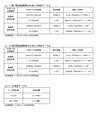
図6(a)は、大当たり遊技を制御する際に用いられる大当たり遊技制御テーブルの一例を示す図である。
(Big hit game control table)
FIG. 6A is a diagram showing an example of a jackpot game control table used when controlling a jackpot game.
大当たり遊技制御テーブルには、大当たり遊技を制御するための条件が格納されている。大当たり遊技を制御するための条件として、大当たり遊技が開始されてから、大入賞口8の最初の開放が行われるまでの期間であるオープニングの時間と、オープニング開始時に演出制御基板102に送信するオープニング指定コマンド、大入賞口8の開閉を制御するために用いるテーブルの種類、大入賞口8の最後の開放が終了してから、大当たり遊技が終了するまでの期間であるエンディングの時間、及び、エンディング開始時に演出制御基板102に送信するエンディング指定コマンドが設定されている。これらの大当たり遊技を制御するための条件は、大当たりの種類、すなわち、特別図柄の種類(特図停止図柄データ)に関連付けられている。すなわち、大当たり遊技の際に、いずれの制御条件を用いるかは特別図柄の種類に基づいて選択される。
The jackpot game control table stores conditions for controlling the jackpot game. As a condition for controlling the big hit game, the opening time, which is the period from the start of the big hit game to the first opening of the big winning
(大入賞口開閉制御テーブル)
図6(b)~図6(c)は、大当たり遊技における大入賞口8の開閉を制御する際に用いる大入賞口開閉制御テーブルの一例を示す図である。図6(b)は大当たり遊技を構成する長当たり遊技において参照される長当たり遊技用大入賞口開閉制御テーブル、図6(c)は大当たり遊技を構成する短当たり遊技において参照される短当たり遊技用大入賞口開閉制御テーブルである。
(Large winning opening opening / closing control table)
6 (b) to 6 (c) are diagrams showing an example of a big winning opening opening / closing control table used when controlling the opening / closing of the big winning
大当たり遊技用の大入賞口開閉制御テーブルには、大当たり遊技における大入賞口8の開閉を制御するための条件が格納されている。大入賞口8の開閉を制御するための条件として、ラウンド遊技の番号であるラウンド番号(R)、各ラウンド遊技における大入賞口8の開放(大入賞口制御装置80の作動)番号である特電作動番号(K)、及び、大入賞口8の開放時間・閉鎖時間(作動時間・未作動時間)が設定されている。
The jackpot opening / closing control table for the jackpot game stores conditions for controlling the opening / closing of the
(遊技条件データ判定テーブル)
図7(a)は、大当たり遊技の終了後に新たに設定する遊技条件データを判定(決定)するための遊技条件データ判定テーブルの一例を示す図である。遊技条件データ判定テーブルは、大当たりの当選確率の状態(低確率遊技状態/高確率遊技状態)によって分けられており、分けられた各テーブルにおいて、特別図柄の種類(特図停止図柄データ)と遊技条件データとが一義的に対応付けられて格納されている。遊技条件データは、当該大当たり当選により新たに設定される大当たりの当選確率の状態及び始動口入賞容易性の状態並びに当該遊技条件の状態によって実行可能な特別図柄表示の回数(Xa、Ja:以下、「実行可能回数」という)を表し、「00H」~「02H」の3種類が設定されている。
(Game condition data judgment table)
FIG. 7A is a diagram showing an example of a game condition data determination table for determining (determining) game condition data newly set after the end of the jackpot game. The game condition data determination table is divided according to the state of the winning probability of the jackpot (low probability game state / high probability game state), and in each divided table, the type of special symbol (special symbol stop symbol data) and the game. Condition data is uniquely associated and stored. The game condition data includes the status of the jackpot winning probability newly set by the jackpot winning, the status of the start opening winning ease, and the number of times of special symbol display that can be executed depending on the status of the game condition (Xa, Ja: hereinafter, It represents "the number of executions"), and three types of "00H" to "02H" are set.
図7(b)は、遊技条件データから遊技条件を判定するための遊技条件判定テーブルの一例を示す図である。遊技条件判定テーブルは、遊技条件データと、各遊技条件の状態を示すフラグ(高確率フラグ及び時短フラグ)のON/OFF及び当該遊技条件の状態によって実行可能な特別図柄の変動表示の回数(Xa、Ja:以下、「実行可能回数」という)とが一義的に関連付けられて格納されている。この特別図柄の変動表示の実行可能回数とは、特別図柄抽選の回数ともいえる。 FIG. 7B is a diagram showing an example of a game condition determination table for determining a game condition from the game condition data. In the game condition determination table, the game condition data, the ON / OFF of the flag (high probability flag and the time saving flag) indicating the state of each game condition, and the number of times of variable display of the special symbol that can be executed depending on the state of the game condition (Xa). , Ja: Hereinafter referred to as "executable number of times") is uniquely associated and stored. The number of times that the variable display of the special symbol can be executed can be said to be the number of times the special symbol lottery is performed.
(特別図柄の変動パターン判定テーブル)
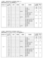
図8~図9は、特別図柄の変動表示の態様(以下、「特図変動パターン」という)を決定する際に参照される特図変動パターン判定テーブルの一例を示す図である。特図変動パターンには、特別図柄の変動表示に要する時間(以下、「特図変動時間」という)及び当該特別図柄の変動表示に応じた変動演出(特図抽選演出)の演出種別が関連付けられている。変動演出についての詳細は後述するが、特別図柄の変動表示に開始に伴って、当該特別図柄の変動表示が終了まで行われる演出のことであり、上述した演出図柄の変動表示が含まれ、演出図柄の変動表示の他、画像表示装置14によるキャラクタ等のオブジェクト画像や所定のムービー画像による画像演出、音声出力装置15による音声演出、演出用照明装置16による照明演出及び可動部17Aによる動作演出等で構成される。
(Variation pattern judgment table for special symbols)
8 to 9 are diagrams showing an example of a special figure variation pattern determination table referred to when determining an mode of variation display of a special symbol (hereinafter, referred to as “special figure variation pattern”). The special symbol variation pattern is associated with the time required for displaying the variation of the special symbol (hereinafter referred to as "special symbol variation time") and the effect type of the variation effect (special figure lottery effect) according to the variation display of the special symbol. ing. The details of the variation effect will be described later, but it is an effect in which the variation display of the special symbol is performed until the end of the variation display of the special symbol, and the variation display of the above-mentioned effect symbol is included in the effect. In addition to variable display of patterns, object images such as characters by the
なお、特図変動パターンは、第1特別図柄表示装置20において表示される第1特別図柄の変動表示の態様である第1特図変動パターンと、第2特別図柄表示装置21において表示される第2特別図柄の変動表示の態様である第2特図変動パターンとで区別される。
The special symbol variation patterns are the first special symbol variation pattern, which is an aspect of the variation display of the first special symbol displayed on the first special
図8は、後述する非時短遊技状態において特図変動パターンを決定する際に参照される特図変動パターン判定テーブルの一例を示す図であり、図9は、後述する時短遊技状態において特図変動パターンを決定する際に参照される特図変動パターン判定テーブルの一例を示す図である。すなわち、特図変動パターン判定テーブルは、遊技状態によって大きく分けられている。 FIG. 8 is a diagram showing an example of a special figure variation pattern determination table referred to when determining a special figure variation pattern in a non-time saving gaming state described later, and FIG. 9 is a diagram showing a special map variation in a time saving gaming state described later. It is a figure which shows an example of the special figure variation pattern determination table which is referred when determining a pattern. That is, the special figure fluctuation pattern determination table is roughly divided according to the gaming state.
特図変動パターン判定テーブルは、さらに、変動表示される特別図柄の種類(当該変動表示に係る始動口の種類)及び特別図柄判定の結果を特定可能な特図停止図柄データ及び特図保留数(U1又はU2)によって分けられている。 In the special symbol fluctuation pattern determination table, the type of special symbol to be variablely displayed (the type of the start port related to the variable display), the special symbol stop symbol data capable of specifying the result of the special symbol determination, and the number of special symbol reservations (the number of reserved special symbols) It is divided by U1 or U2).
各テーブルにおいて、特図変動パターン判定値と、一又は複数の特図変動パターンとが一義的に関連付けられて格納されている。後述するように、第1始動口6又は第2始動口7への遊技球の入球に基づいて取得された特図変動パターン判定用乱数を特図変動パターン判定テーブルに照合することで、特図変動パターンが決定される。
In each table, the special figure fluctuation pattern determination value and one or more special figure fluctuation patterns are uniquely associated and stored. As will be described later, by collating the random number for determining the special figure variation pattern acquired based on the entry of the game ball into the
特図変動パターンは、各テーブルにおいて予め設定された所定の確率で割り振られているため、特図変動パターンには大当たり当選の期待度や特定の大当たり当選(例えば、確変大当たり、長当たり等)の期待度が対応付けられていることになる。 Since the special figure fluctuation pattern is assigned with a predetermined probability set in advance in each table, the special figure fluctuation pattern has an expectation of a jackpot winning or a specific jackpot winning (for example, probabilistic jackpot, long hit, etc.). The degree of expectation is associated.
また、特図変動パターンは、特別図柄の変動表示開始時に(ステップS310の特別図柄記憶判定処理時に)特図変動パターン判定(ステップS313-3)によって正式に決定されるが、遊技球の始動口6、7への入球時に(ステップS200の入力制御処理時に)第1事前判定(ステップS236)又は第2事前判定(ステップS246)によって暫定的に決定される。
Further, the special symbol variation pattern is formally determined by the special symbol variation pattern determination (step S313-3) at the start of the variation display of the special symbol (during the special symbol memory determination process in step S310). It is tentatively determined by the first pre-determination (step S236) or the second pre-determination (step S246) at the time of entering the
なお、各特図変動パターンに対応して始動口入賞指定コマンド及び特図変動パターン指定コマンドが設定されている。始動口入賞指定コマンドは後述する第1事前判定又は第2事前判定によって決定された特図変動パターンに対応し、第1事前判定又は第2事前判定の実行後に演出制御基板102に送信される。特図変動パターン指定コマンドは特図変動パターン判定によって決定された特図変動パターンに対応し、特図変動パターン判定の実行後に演出制御基板102に送信される。
In addition, a start opening winning designation command and a special figure fluctuation pattern designation command are set corresponding to each special figure fluctuation pattern. The start opening winning designation command corresponds to the special figure fluctuation pattern determined by the first pre-determination or the second pre-determination described later, and is transmitted to the
特図変動パターン指定コマンドは、当該特別図柄判定に係る特別図柄の変動表示が行われる特別図柄表示装置(第1特別図柄表示装置20又は第2特別図柄表示装置21)を識別するための1バイトのMODEデータと、特図変動パターンを識別するための1バイトのDATAデータとから構成されている。特図変動パターン指定コマンドについては、MODEデータが「E6H」であれば、第1特別図柄表示装置20で特別図柄の変動表示が行われることを表し、MODEデータが「E7H」であれば、第2特別図柄表示装置21で特別図柄の変動表示が行われることを表す。
The special symbol variation pattern designation command is a 1-byte unit for identifying a special symbol display device (first special
なお、MODEデータが「E6H」の特図変動パターン指定コマンドのことを「第1特図変動パターン指定コマンド」、MODEデータが「E7H」の特図変動パターン指定コマンドのことを「第2特図変動パターン指定コマンド」という。 The special figure fluctuation pattern specification command whose MODE data is "E6H" is the "first special figure fluctuation pattern specification command", and the special figure fluctuation pattern specification command whose MODE data is "E7H" is the "second special figure". It is called "variation pattern specification command".
始動口入賞指定コマンドは、始動口の種別を識別するための1バイトのMODEデータと、特図変動パターンを識別するための1バイトのDATAデータとから構成されている。 The start opening winning designation command is composed of 1-byte MODE data for identifying the type of the start opening and 1-byte DATA data for identifying the special figure fluctuation pattern.
始動口入賞指定コマンドについては、MODEデータが「E1H」であれば、第1始動口6に遊技球が入球したことを表し、MODEデータが「E2H」であれば、第2始動口7に遊技球が入球したことを表す。なお、MODEデータが「E1H」の始動口入賞指定コマンドのことを「第1始動口入賞指定コマンド」、MODEデータが「E2H」の始動口入賞指定コマンドのことを「第2始動口入賞指定コマンド」という。
Regarding the start port winning designation command, if the MODE data is "E1H", it means that the game ball has entered the
また、特図変動パターン判定テーブルの最右欄には、参考として、その特図変動パターンに対応する変動演出の演出種別(大まかな区分)を記載している。 Further, in the rightmost column of the special figure fluctuation pattern determination table, as a reference, the production type (rough classification) of the fluctuation effect corresponding to the special figure fluctuation pattern is described.
ここで、図8及び図9の演出種別の欄に記載されている特図変動パターンに係る変動演出の演出種別について説明する。 Here, the effect type of the variation effect related to the special figure variation pattern described in the effect type column of FIGS. 8 and 9 will be described.
図8及び図9に記載の「通常変動」とは、リーチを伴わない通常の変動演出のことであり、遊技者に大当たり当選の期待を持たせることが困難な変動演出である。「短縮変動」とは、通常変動よりも変動時間が短くてリーチを伴わない変動演出のことであり、遊技者に大当たり当選の期待を持たせることが困難な変動演出である。「超短縮変動」とは、短縮変動よりも変動時間が短くてリーチを伴わない変動演出のことであり、遊技者に大当たり当選の期待を持たせることが困難な変動演出である。 The "normal variation" shown in FIGS. 8 and 9 is a normal variation effect without reach, and it is difficult for the player to have the expectation of winning a big hit. The "shortened fluctuation" is a fluctuation production in which the fluctuation time is shorter than the normal fluctuation and does not involve reach, and it is difficult to give the player the expectation of winning a big hit. The "ultra-shortened fluctuation" is a fluctuation production in which the fluctuation time is shorter than the shortened fluctuation and does not involve reach, and it is difficult for the player to have the expectation of winning a big hit.
「リーチ」とは、大当たりを報知する演出図柄TZ1~TZ3の組合せの一部が仮停止して、他の演出図柄及び特殊演出図柄TZ4が変動を行うような、遊技者に大当たりの期待感を付与する変動態様を意味する。例えば、大当たりを報知する演出図柄TZ1~TZ3の組合せとして「777」の3桁の演出図柄の組み合わせが設定されている場合に、2つの演出図柄TZ1及びTZ3が「7」で仮停止(擬似停止)して、残りの演出図柄TZ2及び特殊演出図柄TZ4が変動を行っている態様をいう。 "Reach" means that a part of the combination of the effect symbols TZ1 to TZ3 for notifying the jackpot is temporarily stopped, and the other effect symbols and the special effect symbol TZ4 fluctuate, giving the player a sense of expectation of the jackpot. It means the variation mode to be given. For example, when a combination of three-digit effect symbols of "777" is set as a combination of effect symbols TZ1 to TZ3 for notifying a jackpot, two effect symbols TZ1 and TZ3 are temporarily stopped at "7" (pseudo stop). ), The remaining effect symbol TZ2 and special effect symbol TZ4 are changing.
なお、「仮停止」とは、演出図柄TZ1~TZ3が小さく揺れ動いたり、演出図柄TZ1~TZ3が小さく変形したりして、遊技者に演出図柄TZ1~TZ3が停止しているかのようにみせている態様をいい、擬似停止と呼ばれることもある。また、特殊演出図柄TZ4については、特別図柄の変動表示の開始に同期(同調)して変動表示が開始され、特別図柄の停止表示に同期(同調)して停止表示されるため、演出図柄TZ1~TZ3のように仮停止することはないが、演出図柄TZ1~TZ3の変動表示及び変動停止(仮停止を含む)に同期(同調)した表示を行うようにしてもよい。 In addition, "temporary stop" means that the effect symbols TZ1 to TZ3 sway slightly or the effect symbols TZ1 to TZ3 are slightly deformed to make the player appear as if the effect symbols TZ1 to TZ3 are stopped. This mode is sometimes called pseudo-stop. Further, for the special effect symbol TZ4, the variation display is started in synchronization with the start of the variation display of the special symbol, and the stop display is synchronized with the stop display of the special symbol. Therefore, the effect symbol TZ1 Although the temporary stop is not performed unlike the TZ3, the variable display of the effect symbols TZ1 to TZ3 and the display synchronized with the variable stop (including the temporary stop) may be performed.
図8及び図9に記載の「ノーマルリーチ」とは、画像表示装置14の表示部140の左側領域と右側領域に2つの演出図柄TZ1及びTZ3が仮停止し、中央領域で残り1つの演出図柄TZ2が変動すると共に、端側領域で特殊演出図柄TZ4が変動する大当たり当選の(特別遊技が実行される)期待度が低いリーチである。
The "normal reach" described in FIGS. 8 and 9 means that two effect symbols TZ1 and TZ3 are temporarily stopped in the left side region and the right side region of the
なお、本実施形態においては、大当たり当選に係る特図変動パターンとしては「ノーマルリーチ」が選択されないようになっているものの、大当たり当選に係る特図変動パターンとして「ノーマルリーチ」が選択されるようにすることもできる。 In this embodiment, although "normal reach" is not selected as the special figure fluctuation pattern related to the jackpot winning, "normal reach" is selected as the special map fluctuation pattern related to the jackpot winning. You can also do it.
図8及び図9に記載の「SPリーチ」とは、ノーマルリーチよりも大当たり当選の(特別遊技が実行される)期待度が高いスーパーリーチである。例えば、仮停止していない中央領域の演出図柄TZ2が特殊な変動をしたり、特殊な演出画像やムービー等が表示されたりする。 The "SP reach" shown in FIGS. 8 and 9 is a super reach with a higher expectation of winning a big hit (a special game is executed) than a normal reach. For example, the effect symbol TZ2 in the central region that has not been temporarily stopped may undergo special fluctuations, or a special effect image, movie, or the like may be displayed.
図8及び図9に記載の「SPSPリーチ」とは、スーパーリーチよりも大当たり当選の(特別遊技が実行される)期待度が高いスペシャルリーチである。例えば、スーパーリーチの後に実行されたり、スーパーリーチとは異なる特別な演出画像やムービー等が表示されたりする。 The "SPSP reach" shown in FIGS. 8 and 9 is a special reach with a higher expectation of winning a big hit (a special game is executed) than a super reach. For example, it may be executed after Super Reach, or a special production image or movie different from Super Reach may be displayed.
なお、図8及び図9の演出種別の欄には記載されていないが、本実施の形態では、何れの変動演出においても、擬似連演出が実行され得る。「擬似連演出」とは、1回の特別図柄抽選に対応する特別図柄の変動表示中に、演出図柄TZ1~TZ3を一旦仮停止させた後に再び変動させる特殊演出を1回又は複数回行う(複数回の変動表示を擬似する)変動態様による予告演出を意味している。なお、特殊演出図柄TZ4については、擬似連演出の実行中であっても特殊演出が行われず、特別図柄の変動停止まで変動表示を継続するようになっている。 Although not described in the column of the effect type in FIGS. 8 and 9, in the present embodiment, the pseudo continuous effect can be executed in any of the variable effects. The "pseudo-continuous effect" is a special effect of temporarily stopping the effect symbols TZ1 to TZ3 and then changing the effect symbols TZ1 to TZ3 once or multiple times during the variable display of the special symbol corresponding to one special symbol lottery (. It means a notice effect according to the variation mode (simulating the variation display multiple times). As for the special effect symbol TZ4, the special effect is not performed even during the execution of the pseudo-continuous effect, and the variable display is continued until the change of the special effect stops.
図8に示す非時短遊技状態における変動演出パターン判定テーブルの第1の特徴として、特図保留数が多いほど短縮変動が選択・決定される割合が高くなる点が挙げられる。 The first feature of the variation effect pattern determination table in the non-time-saving gaming state shown in FIG. 8 is that the ratio of selection / determination of shortened variation increases as the number of reserved special figures increases.
図9に示す時短遊技状態における変動演出パターン判定テーブルの第1の特徴として、特図保留数が多いほど超短縮変動が選択・決定される割合が高くなる点が挙げられる。
第2の特徴として、図8の短縮変動(4秒)よりも変動時間が短い超短縮変動(2秒)が設定されている点が挙げられる。
第3の特徴として、図8の通常変動(8秒)よりも変動時間が短い通常変動(6秒)が設定されている点が挙げられる。
第4の特徴として、図8のロング変動(13.5秒)よりも変動時間が短いロング変動(10秒)が設定されている点が挙げられる。
The first feature of the variation effect pattern determination table in the time-saving gaming state shown in FIG. 9 is that the larger the number of reserved special figures, the higher the ratio of selection / determination of ultra-shortening variation.
The second feature is that the ultra-shortening fluctuation (2 seconds), which has a shorter fluctuation time than the shortened fluctuation (4 seconds) in FIG. 8, is set.
The third feature is that a normal fluctuation (6 seconds) having a shorter fluctuation time than the normal fluctuation (8 seconds) in FIG. 8 is set.
The fourth feature is that a long fluctuation (10 seconds) having a shorter fluctuation time than the long fluctuation (13.5 seconds) in FIG. 8 is set.
図10(a)~図10(f)は、入賞ゲート10への入賞に基づく普通図柄系遊技を制御する際に用いられるテーブルの一例を示す。
10 (a) to 10 (f) show an example of a table used when controlling a normal symbol-based game based on winning a prize at the winning
(当たり判定テーブル)
図10(a)は、当たり判定を行うための当たり判定テーブルの一例を示す図である。当たり判定とは、第2始動口7の開放を伴う補助遊技を実行するか否かを判定(決定)することである。
(Collision detection table)
FIG. 10A is a diagram showing an example of a hit determination table for performing a hit determination. The hit determination is to determine (determine) whether or not to execute an auxiliary game accompanied by opening the
当たり判定テーブルは、始動口入賞容易性によって分けられている。具体的には、当たり判定テーブルは、非時短遊技状態のときに参照される当たり判定テーブルと、時短遊技状態のときに参照される当たり判定テーブルとで分けられている。 The hit determination table is divided according to the ease of winning the starting opening. Specifically, the hit determination table is divided into a hit determination table referred to in the non-time saving game state and a hit determination table referred to in the time reduction game state.
各当たり判定テーブルには、当たり判定値と判定結果とが一義的に対応付けられて格納されている。後述するように、入賞ゲート10への遊技球の通過に基づいて取得された当たり判定用乱数を当たり判定テーブルに照合することで、「当たり」又は「ハズレ」のいずれかが決定される。「当たり」に当選すると、当該結果を示す普通図柄(特定結果)の停止表示後に、第2始動口7の開放を伴う補助遊技が実行され、通常よりも第2始動口7に遊技球が入球し易く、賞球を獲得し易い状態となる。つまり、遊技者に遊技価値が付与されることになる。
In each hit determination table, the hit determination value and the determination result are uniquely associated and stored. As will be described later, either "hit" or "miss" is determined by collating the hit determination random number acquired based on the passage of the game ball to the winning
(普通図柄判定テーブル)
図10(b)は、普通図柄判定を行うための普通図柄判定テーブルの一例を示す図である。普通図柄判定とは、普通図柄表示装置22において停止表示される普通図柄の種類を判定(決定)することである。普通図柄判定テーブルは、当たり判定の結果(当たり及びハズレ)によって分けられている。
(Ordinary symbol judgment table)
FIG. 10B is a diagram showing an example of a normal symbol determination table for performing normal symbol determination. The normal symbol determination is to determine (determine) the type of the normal symbol that is stopped and displayed on the normal
各普通図柄判定テーブルには、普通図柄判定値と、停止表示される普通図柄とが一義的に対応付けられて格納されている。後述するように、入賞ゲート10への遊技球の通過に基づいて取得される普通図柄判定用乱数を普通図柄判定テーブルに照合することで、停止表示される普通図柄の種類が決定される。停止表示される普通図柄の種類を示す情報として、普図停止図柄データ及び普通演出図柄指定コマンドが設定されている。
In each ordinary symbol determination table, the ordinary symbol determination value and the ordinary symbol that is stopped and displayed are uniquely associated and stored. As will be described later, the type of the normal symbol to be stopped and displayed is determined by collating the random number for normal symbol determination acquired based on the passage of the game ball to the winning
普図停止図柄データは、主制御基板101における処理で用いられ、普通演出図柄指定コマンドは、普通図柄の変動表示の開始時に演出制御基板102に送信され、演出制御基板102における処理で用いられる。
The normal symbol stop symbol data is used in the processing on the
(普図変動パターン判定テーブル)
図10(c)は、普通図柄の変動表示に要する時間(以下、「普図変動時間」という)に対応付けられた普通図柄の変動パターン(以下、「普図変動パターン」という)を判定するための普図変動パターン判定テーブルを示す図である。普図変動パターン判定テーブルは、非時短遊技状態のときに参照される普図変動パターン判定テーブルと、時短遊技状態のときに参照される普図変動パターン判定テーブルとで構成されている。
(Public map fluctuation pattern judgment table)
FIG. 10 (c) determines a fluctuation pattern of a normal symbol (hereinafter referred to as “normal map fluctuation pattern”) associated with a time required for displaying the fluctuation of a normal symbol (hereinafter referred to as “normal map fluctuation time”). It is a figure which shows the ordinary figure fluctuation pattern determination table for this. The normal map fluctuation pattern determination table is composed of a normal map variation pattern determination table referred to in the non-time saving gaming state and a normal map variation pattern determination table referred to in the time saving gaming state.
各テーブルにおいて、普図変動パターン判定値と、一又は複数の普図変動パターンとが一義的に関連付けられて格納されている。後述するように、入賞ゲート10への遊技球の通過に基づいて取得される普図変動パターン判定用乱数を普図変動パターン判定テーブルに照合することで、普図変動パターンの種類が決定される。
In each table, the normal map fluctuation pattern determination value and one or more normal map fluctuation patterns are uniquely associated and stored. As will be described later, the type of the normal map fluctuation pattern is determined by collating the random number for determining the normal map fluctuation pattern acquired based on the passage of the game ball to the winning
(補助遊技参照データ判定テーブル)
図10(d)は、補助遊技を制御する際に用いられる補助遊技参照データ判定テーブルの一例を示す図である。このテーブルには、補助遊技を行う際に参照されるデータ(補助遊技参照データ)が格納されている。図10(d)に示す様に、補助遊技参照データ判定テーブルには、現在の始動口入賞容易性と普図停止図柄データとの組み合わせと、補助遊技参照データとが対応付けられている。すなわち、補助遊技参照データは、当該普通図柄判定が行われた際の始動口入賞容易性状態及び当該普通図柄判定の結果に関する情報を有する。
(Auxiliary game reference data judgment table)
FIG. 10D is a diagram showing an example of an auxiliary game reference data determination table used when controlling an auxiliary game. Data (auxiliary game reference data) referred to when performing an auxiliary game is stored in this table. As shown in FIG. 10D, the auxiliary game reference data determination table is associated with the combination of the current start opening winning ease and the normal figure stop symbol data, and the auxiliary game reference data. That is, the auxiliary game reference data has information on the start opening winning ease state when the normal symbol determination is performed and the result of the normal symbol determination.
(補助遊技制御テーブル)
図10(e)は、補助遊技を制御する際に用いられる補助遊技制御テーブルの一例を示す図である。このテーブルには、補助遊技を制御するための条件が格納されている。補助遊技を制御するための条件として、補助遊技が開始されてから、第2始動口7の最初の開放が行われるまでの期間であるオープニングの時間と、オープニング開始時に演出制御基板102に送信するオープニング指定コマンド、第2始動口7の開閉を制御するために用いるテーブルの種類、第2始動口7の最後の開放が終了してから、補助遊技が終了するまでの期間であるエンディングの時間、及び、エンディング開始時に演出制御基板102に送信するエンディング指定コマンドが設定されている。これらの補助遊技を制御するための条件は、補助遊技参照データに関連付けられている。
(Auxiliary game control table)
FIG. 10 (e) is a diagram showing an example of an auxiliary game control table used when controlling an auxiliary game. Conditions for controlling the auxiliary game are stored in this table. As a condition for controlling the auxiliary game, the opening time, which is the period from the start of the auxiliary game to the first opening of the
(第2始動口開閉制御テーブル)
図10(f)は、第2始動口7の開閉を制御する際に用いる補助遊技用の第2始動口開閉制御テーブルの一例を示す図である。補助遊技用の第2始動口開閉制御テーブルには、補助遊技時の第2始動口7の開閉を制御するための条件が格納されている。第2始動口7の開閉を制御するための条件として、補助遊技における第2始動口7の開放(第2始動口制御装置70の作動)番号である普電作動番号(D)、及び、第2始動口7の開放時間・閉鎖時間(作動時間・未作動時間)が設定されている。
(2nd starting port open / close control table)
FIG. 10 (f) is a diagram showing an example of a second start port open / close control table for auxiliary games used when controlling the opening / closing of the
(特別遊技の種類の説明)
本実施の形態においては、大入賞口8の開放(大入賞口制御装置80の作動)を伴い、遊技者にとって有利な特別遊技として、「大当たり」に当選した際に実行される「大当たり遊技」が設けられている。大当たり遊技は、主に大入賞口8の開閉態様の相違によって「長当たり遊技」、「短当たり遊技」に分けられる。
(Explanation of types of special games)
In the present embodiment, the "big hit game" is executed when the "big hit" is won as a special game advantageous to the player, accompanied by the opening of the big winning opening 8 (operation of the big winning opening control device 80). Is provided. The big hit game is mainly divided into a "long hit game" and a "short hit game" according to the difference in the opening / closing mode of the big winning
大当たり遊技では、大入賞口8の1回以上の開放を伴うラウンド遊技が所定回数実行される。各ラウンド遊技において、大入賞口8が開放し得る回数(以下、最大開放回数という)と、開放し得る時間の合計(以下、最大開放時間という)とが予め設定されている。「開放し得る」となっているのは、1回のラウンド遊技中に大入賞口8に入球できる遊技球の個数が制限されているからである(例えば9個)。したがって、大入賞口8が最大開放回数開放していなくても大入賞口8が閉鎖し、そのラウンド遊技が終了することがある。また、最大開放時間が経過していなくても大入賞口8が閉鎖し、そのラウンド遊技が終了することもある。なお、各ラウンド遊技における大入賞口8の最大開放回数及び最大開放時間は、各大当たり遊技で統一されていても統一されていなくてもよい。
In the jackpot game, a round game involving opening of the
(遊技条件の説明)
次に、遊技が進行する際の条件となる遊技条件について説明する。本実施形態において、遊技条件として、大当たり当選確率と始動口入賞容易性が設定されている。大当たりの当選確率については、低確率遊技状態又は高確率遊技状態のもとで遊技が進行し、遊技球の始動口入賞容易性については時短遊技状態又は非時短遊技状態のもとで遊技が進行する。初期(電源投入時)の遊技条件は、低確率遊技状態且つ非時短遊技状態に設定されており、この低確率遊技状態且つ非時短遊技状態を基準として通常遊技状態と称する。また、低確率遊技状態且つ時短遊技状態を低確時短遊技状態と称し、高確率遊技状態且つ時短遊技状態を確変遊技状態と称する。なお、本実施形態では、低確時短遊技状態と確変遊技状態とを総称して特定遊技状態と呼ぶ場合がある。
(Explanation of game conditions)
Next, the game conditions that are the conditions for the progress of the game will be described. In the present embodiment, the jackpot winning probability and the ease of winning the starting point are set as the game conditions. Regarding the winning probability of the jackpot, the game progresses under the low probability game state or the high probability game state, and regarding the ease of winning the starting opening of the game ball, the game progresses under the time-saving game state or the non-time-saving game state. do. The initial (when the power is turned on) gaming condition is set to a low-probability gaming state and a non-time-saving gaming state, and is referred to as a normal gaming state based on this low-probability gaming state and the non-time-saving gaming state. Further, the low-probability gaming state and the time-saving gaming state are referred to as the low-probability time-saving gaming state, and the high-probability gaming state and the time-saving gaming state are referred to as the probability-changing gaming state. In addition, in this embodiment, a low probability time short game state and a probability change game state may be collectively referred to as a specific game state.
本実施形態において大当たり当選確率についての低確率遊技状態とは、大当たり判定における大当たり当選確率が、1/350と相対的に遊技者に不利に設定されていることをいう。これに対して高確率遊技状態とは、大当たり当選確率が低確率遊技状態より高く、すなわち、相対的に遊技者に有利な1/40に設定されていることである。したがって、大当たり当選確率が高確率遊技状態のときは、低確率遊技状態のときよりも大当たりの当選が容易となり、単位時間当たりの大当たりの当選可能回数が相対的に多くなるので、遊技者に有利な状態と言える。 In the present embodiment, the low-probability gaming state regarding the jackpot winning probability means that the jackpot winning probability in the jackpot determination is set to 1/350, which is relatively disadvantageous to the player. On the other hand, the high-probability gaming state means that the jackpot winning probability is higher than that of the low-probability gaming state, that is, it is set to 1/40, which is relatively advantageous to the player. Therefore, when the jackpot winning probability is in the high-probability gaming state, it is easier to win the jackpot than in the low-probability gaming state, and the number of times the jackpot can be won per unit time is relatively large, which is advantageous for the player. It can be said that it is in a state of being.
非時短遊技状態とは、始動口入賞容易性が通常の状態である。具体的には、非時短遊技状態では、普図変動時間が、15秒に設定され、当たり判定において「当たり」に当選したときに作動する第2始動口制御装置70の作動時間(第2始動口7の開放時間)の合計が0.2秒又は5.1秒に設定され、普通図柄用の当たり判定において当たりに当選する確率が1/50に設定されていることをいう。なお、「開放時間の合計」となっているのは、1回の当たりに対して第2始動口7が複数回開放することがあるからである。なお、1回の当たりに対して遊技球が入賞できる個数が制限されているため、遊技球がその個数入賞すると開放時間や開放回数の経過を待たず閉鎖する。
The non-time-saving game state is a state in which the ease of winning a prize at the starting opening is normal. Specifically, in the non-time saving game state, the normal figure fluctuation time is set to 15 seconds, and the operation time of the second start port control device 70 (second start) that operates when a "hit" is won in the hit determination. It means that the total of the opening time of the mouth 7) is set to 0.2 seconds or 5.1 seconds, and the probability of winning in the hit determination for a normal symbol is set to 1/50. The reason for the "total opening time" is that the
これに対して時短遊技状態(低確/高確)とは、非時短遊技状態に比べて、単位時間当たりにおける第2始動口7の開放時間(第2始動口制御装置70の作動時間)が長く、第2始動口7が開放態様になり易い遊技状態のことをいう。始動口入賞容易性が相対的に高いことや変動パターン判定テーブルに設定された特図変動パターンの変動時間が相対的に短いことによって、非時短遊技状態よりも短い変動時間が選択される割合が多く(変動時間の平均値が短く)なり、単位時間当たりにおける第2特別図柄判定の実行可能回数も多くなる。そのため、同一の大当たり当選確率のもとでは、単位時間当たりにおける第2特別図柄判定の実行回数が多い方が、必然的に単位時間当たりにおける大当たりの当選回数も多くなることから、時短遊技状態(低確/高確)は非時短遊技状態に比して遊技者に有利な状態といえる。
On the other hand, in the time-saving gaming state (low accuracy / high accuracy), the opening time of the second starting port 7 (operating time of the second starting port control device 70) per unit time is larger than that in the non-time-saving gaming state. It refers to a gaming state in which the
上述したように、本実施の形態では、時短遊技状態では、普図変動時間が3.0秒に設定され、第2始動口7の最大開放時間の合計が5.2秒に設定され、当たりに当選する確率が49/50に設定される。すなわち、始動口入賞容易性の構成要素全てについて非時短遊技状態より遊技者に有利に設定されている。なお、時短遊技状態では、第2始動口7は1.5秒間の閉鎖(インターバル)を介して2回開放しているが、当該閉鎖がなく、1回開放するだけでも良い。また、閉鎖が複数回設けられていても良い。
As described above, in the present embodiment, in the time-saving game state, the normal figure fluctuation time is set to 3.0 seconds, and the total maximum opening time of the
なお、本実施の形態では、始動口6、7に遊技球が入球すると、3球の賞球を得ることができるものの、遊技者が適切な発射ハンドル32の操作で遊技球の発射を行っても、遊技者が所持する遊技球の個数が減少し易い。しかしながら、時短遊技状態のときは、非時短遊技状態に比して第2始動口7への入球が容易になるので、遊技者が所持する遊技球の個数の減少を抑えることができる。つまり、遊技者が所持する遊技球の個数の観点からも時短遊技状態は非時短遊技状態に比べて遊技者に有利に設定されている。
In the present embodiment, when a game ball enters the starting
このように、大当たりの当選によって、大当たり遊技の種類(長当たり遊技/短当たり遊技)と、大当たり遊技後に新たに設定される遊技条件(低確率遊技状態/高確率遊技状態と非時短遊技状態/時短遊技状態との組み合わせ)とが決定される。このことを鑑みると、実質的な大当たりの種類(遊技者が享受する利益度に基づく大当たりの種類)は、実行される大当たり遊技の種類と、当該大当たり遊技終了後に新たに設定される遊技条件(遊技状態)との組合せと言える。そこで、以下、特図停止図柄データに基づく大当たりの種類とは別に、大当たりによって導かれた大当たり遊技の種類と大当たり遊技後の遊技条件との組合せ、すなわち、遊技者が享受する利益の種類に基づいて、大当たりの種類を分類することができる。 In this way, depending on the winning of the jackpot, the type of jackpot game (long hit game / short hit game) and the game conditions newly set after the jackpot game (low probability game state / high probability game state and non-time saving game state / Combination with the time-saving game state) is determined. In view of this, the actual types of jackpots (types of jackpots based on the profitability enjoyed by the player) are the types of jackpot games to be executed and the game conditions newly set after the jackpot game is completed ( It can be said that it is a combination with the game state). Therefore, in the following, apart from the type of jackpot based on the special figure stop symbol data, the combination of the type of jackpot game guided by the jackpot and the game conditions after the jackpot game, that is, the type of profit enjoyed by the player is used. It is possible to classify the types of jackpots.
大当たりの当選により長当たり遊技を実行させ、その後に50回の高確率遊技状態且つ100回の時短遊技状態(確変遊技状態)に設定させる大当たりを「高確率ロング時短長当たり(確変大当たり1)」、大当たりの当選により長当たり遊技を実行させ、その後に50回の高確率遊技状態且つ80回の時短遊技状態に設定させる大当たりを「高確率ミドル時短長当たり(確変大当たり2)」、当選により短当たり遊技を実行させ、その後に50回の高確率遊技状態且つ60回の時短遊技状態に設定させる大当たりを「高確率ショート時短短当たり(確変大当たり3)」と称する。 The jackpot that is executed by winning the jackpot and then set to 50 high-probability gaming states and 100 time-saving gaming states (probability-changing game state) is "high-probability long-time-short-long hit (probability-changing jackpot 1)". , The jackpot that causes the long hit game to be executed by winning the jackpot and then set to the high probability game state of 50 times and the time saving game state of 80 times is "high probability middle time saving long hit (probability variable jackpot 2)", short by winning. A jackpot in which a winning game is executed and then set to a high-probability gaming state of 50 times and a time-saving gaming state of 60 times is referred to as a "high-probability short-time-short-short hit (probability variation jackpot 3)".
なお、大当たり当選すると、当該大当たり遊技前の状態に関わらず当該大当たり遊技が開始する際に通常遊技状態に設定される。すなわち、大当たり遊技中は、低確率遊技状態且つ非時短遊技状態になる。 If the jackpot is won, the normal gaming state is set when the jackpot game starts regardless of the state before the jackpot game. That is, during the jackpot game, the game is in a low-probability game state and a non-time-saving game state.
(主制御基板の制御処理)
次に、主制御基板101におけるメインCPU101aにより実行される制御処理について説明する。
(Control processing of the main control board)
Next, the control process executed by the
(主制御基板のメイン処理)
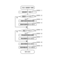
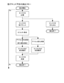
図12を用いて、主制御基板101のメイン処理を説明する。
(Main processing of main control board)
The main processing of the
電源基板107からメインCPU101aに電力が供給されると、メインCPU101aにシステムリセットが発生し、メインCPU101aは、以下のメイン処理を行う。
When power is supplied from the
まず、ステップS10において、メインCPU101aは、初期化処理を行う。この処理において、メインCPU101aは、電源投入に応じて、メインROM101bから起動プログラムを読み込むと共に、図示していないRAMクリアスイッチがONしているか否かを判定し、RAMクリアスイッチがONしている場合には、メインRAM101cの各記憶領域を初期化する処理を行い、RAMクリアスイッチがONしていない場合には、電源断(停電)前の制御状態に復旧(復帰)させる処理を行う。
First, in step S10, the
ステップS20において、メインCPU101aは、リーチ判定用乱数、及び、特図変動パターン判定用乱数で構成される特別図柄の変動表示における特図変動パターンを決定するための特図変動用乱数の更新を行う。
In step S20, the
ステップS30において、メインCPU101aは、大当たり判定用初期値乱数、特別図柄判定用初期値乱数、当たり判定用初期値乱数等で構成される初期値乱数の更新を行う。以降は、所定の割込み処理が行われるまで、ステップS20とステップS30との処理を繰り返し行う。
In step S30, the
(主制御基板のタイマ割込処理)
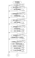
図13を用いて、主制御基板101のタイマ割込処理を説明する。主制御基板101に設けられたリセット用クロックパルス発生回路によって、所定の周期(4ミリ秒)毎にクロックパルスが発生されることで、以下のタイマ割込処理が実行される。
(Timer interrupt processing on the main control board)
The timer interrupt process of the
まず、ステップS100において、メインCPU101aは、メインCPU101aのレジスタに格納されている情報をスタック領域に退避させる。
First, in step S100, the
ステップS110において、メインCPU101aは、特別図柄の変動時間の更新処理、特別図柄の停止時間の更新処理、オープニング時間の更新処理、大入賞口8の開閉時間の更新処理等を行う特別遊技タイマカウンタ、及び、普通図柄の変動時間の更新処理、普通図柄の停止時間の更新処理、並びに、第2始動口7の開閉時間の更新処理等を行う補助遊技タイマカウンタを更新する時間制御処理を行う。
In step S110, the
ステップS120において、メインCPU101aは、大当たり判定用乱数、特別図柄判定用乱数、当たり判定用乱数、普通図柄判定用乱数で構成される特定乱数の更新を行う。
In step S120, the
ステップS130において、メインCPU101aは、大当たり判定用初期値乱数、特別図柄用初期値乱数、当たり判定用初期値乱数を更新する初期値乱数更新処理を行う。
In step S130, the
なお、各種の乱数の更新については、乱数の種別毎に設けられた乱数カウンタを「1」加算することで、乱数の更新を行う。各種の乱数には乱数範囲が設けられている。乱数範囲は、「0」から、その乱数に定められた最大値までとなっている。そして、乱数の更新において、乱数カウンタが示す乱数が乱数範囲の最大値である場合、乱数カウンタを「1」加算せずに「0」に戻し、乱数カウンタが示す乱数が1周して既にセットされている周回初期値になると、その時の初期値乱数を新たな周回初期値としてセットし、それぞれの乱数値を新たに更新する。 Regarding the update of various random numbers, the random numbers are updated by adding "1" to the random number counter provided for each type of random number. A random number range is provided for various random numbers. The random number range is from "0" to the maximum value defined for the random number. Then, in updating the random number, if the random number indicated by the random number counter is the maximum value in the random number range, the random number counter is returned to "0" without adding "1", and the random number indicated by the random number counter is already set once. When the lap initial value is reached, the initial value random number at that time is set as a new lap initial value, and each random number value is newly updated.
ステップS200において、メインCPU101aは、入力制御処理を行う。この処理において、メインCPU101aは、所定の検出センサから新たに有効な信号が送信されたか否か判定する入力制御処理を行う。詳しくは、図14~図17を用いて後述する。
In step S200, the
ステップS300において、メインCPU101aは、第1特別図柄表示装置20、第2特別図柄表示装置21、第1特別図柄保留表示装置23、第2特別図柄保留表示装置24、及び、大入賞口制御装置80の制御(特別図柄系装置の制御)を行うための特図特電制御処理(特別図柄係処理)を行う。詳しくは、図18~図26を用いて後述する。
In step S300, the
ステップS400において、メインCPU101aは、普通図柄表示装置22、普通図柄保留表示装置25、第2始動口制御装置70の制御(普通図柄系装置の制御)を行うための普図普電制御処理(普通図柄系処理)を行う。詳しくは、図27~図31を用いて後述する。
In step S400, the
ステップS500において、メインCPU101aは、払出制御処理を行う。この処理において、メインCPU101aは、始動口(第1始動口6、第2始動口7)、大入賞口8及び、一般入賞口11に対応する賞球カウンタが「0」を超えているか否かのチェックを行い、「0」を超えている場合、それぞれの入賞口に対応する賞球数を示す賞球要求信号を払出制御基板103に送信する。そして賞球信号を送信するとき、その信号に係る賞球カウンタを「1」減算する更新処理を行う。
In step S500, the
ステップS600において、メインCPU101aは、遊技に関する情報を外部信号として遊技情報表示装置700等の外部装置に出力するための外部信号出力制御データ、第2始動口開閉ソレノイド70B、及び、大入賞口開閉ソレノイド80Bを駆動させるための駆動制御データ(始動口開閉ソレノイド駆動データ及び大入賞口開閉ソレノイド駆動データ)、及び、図柄表示装置20、21、22や保留表示装置23、24、25に所定の図柄を表示させるための表示制御データ(特別図柄表示データ、普通図柄表示データ、特別図柄保留表示データ、普通図柄保留表示データ)のデータ作成処理を行う。
In step S600, the
ステップS700において、メインCPU101aは、出力制御処理を行う。この処理において、まず上記S600で作成した外部信号出力制御データ、駆動制御データに基づいて信号を出力させるポート出力処理が行われる。次いで、図柄表示装置20、21、22及び保留表示装置23、24、25の各LEDを点灯させるために、上記ステップS600で作成した表示制御データに基づいて信号を出力させる表示装置出力処理を行う。最後に、メインRAM101cの送信バッファにセットされているコマンドを他の基板に送信するコマンド送信処理も行う。
In step S700, the
ステップS800において、メインCPU101aは、ステップS100で退避した情報をメインCPU101aのレジスタに復帰させる。
In step S800, the
図14を用いて、入力制御処理を説明する。まず、ステップS210において、メインCPU101aは、一般入賞口検出センサ11aから検出信号を入力したか、すなわち、遊技球が一般入賞口11に入球したか否かを判定する。メインCPU101aは、一般入賞口検出センサ11aから検出信号を入力していない場合には、ステップS220に処理を移す。メインCPU101aは、一般入賞口検出センサ11aから検出信号を入力した場合には、賞球のために用いる一般入賞口賞球カウンタに所定のデータを加算して更新する。
The input control process will be described with reference to FIG. First, in step S210, the
ステップS220において、メインCPU101aは、大入賞口検出センサ8aからの検出信号を入力したか、すなわち、遊技球が大入賞口8に入球したか否かを判定する。メインCPU101aは、大入賞口検出センサ8aから検出信号を入力していない場合には、ステップS230に処理を移す。メインCPU101aは、大入賞口検出センサ8aから検出信号を入力した場合には、賞球のために用いる大入賞口賞球カウンタに所定のデータを加算して更新すると共に、大入賞口8に入賞した遊技球を計数するための大入賞口規定入賞カウンタ(C)のカウンタ値を加算して更新する。
In step S220, the
ステップS230において、メインCPU101aは、第1始動口検出センサ6aからの検出信号を入力したか、すなわち、遊技球が第1始動口6(始動領域)に入球したか否かを判定する。詳細は、図15を用いて後述する。
In step S230, the
ステップS240において、メインCPU101aは、第2始動口検出センサ7aからの検出信号を入力したか、すなわち、遊技球が第2始動口7(始動領域)に入球したか否かを判定する。詳細は、図16を用いて後述する。
In step S240, the
ステップS250において、メインCPU101aは、入賞ゲート検出センサ10aからの検出信号を入力したか、すなわち、遊技球が入賞ゲート10(始動領域)を通過したか否かを判定する。詳細は、図17を用いて後述する。
In step S250, the
(主制御基板の第1始動口検出信号入力処理)
次に、図15を用いて第1始動口検出信号入力処理について説明する。ステップS231において、メインCPU101aは、第1始動口検出センサ6aから有効な検出信号かあったか否かを判定する。有効な検出信号がなければ本第1始動口検出信号入力処理を終了し、有効な検出信号があれば、ステップS232において、賞球を払い出すための始動口賞球カウンタを「1」加算して更新すると共に、メインRAM101cの第1始動口入賞フラグ記憶領域に第1始動口入賞フラグをONする第1始動口入賞処理を行う。
(First start port detection signal input processing of the main control board)
Next, the first start port detection signal input process will be described with reference to FIG. In step S231, the
メインCPU101aは、ステップS233において、第1特図保留数(U1)を計数する第1特図保留数カウンタのカウンタ値が4(上限値)より小さいか否かを判定する。メインCPU101aは、カウンタ値(U1)が4より小さくないと判定すれば本第1始動口検出信号入力処理を終了し、第1特図保留数(U1)が4より小さいと判定すれば、ステップS234において第1特図保留数カウンタのカウンタ値を「1」加算して更新する。
In step S233, the
メインCPU101aは、ステップS234において、第1特別図柄保留表示装置23に表示される第1特図保留数(U1)を更新するために、その保留数を示す特別図柄保留表示データをメインRAM101cの所定領域にセットする。また、メインCPU101aは、ステップS235において、第1特図保留数(U1)に対応する第1特別図柄記憶指定コマンドをメインRAM101cの演出用伝送データ格納領域(送信バッファ)にセットする。これにより、第1特図保留数(U1)が演出制御基板102に通知される。
In step S234, the
メインCPU101aは、ステップS236において、大当たり判定用乱数カウンタが示す大当たり判定用乱数、特別図柄判定用乱数カウンタが示す特別図柄判定用乱数、リーチ判定用乱数カウンタが示すリーチ判定用乱数及び特図変動パターン判定用乱数カウンタが示す特図変動パターン判定用乱数を第1特別図柄保留記憶領域に記憶する。なお、以降は、大当たり判定用乱数、特別図柄判定用乱数、リーチ判定用乱数及び特図変動パターン判定用乱数をまとめて「特図判定情報」という。
In step S236, the
第1特別図柄保留記憶領域は、第1記憶部~第4記憶部に分けられており(図11(a)参照)、特図判定情報は、乱数が記憶されていない記憶部の中で番号の小さい記憶部から順に記憶されていく。なお、各記憶部は、記憶される乱数毎に領域が分けられている(図11(b)参照)。 The first special symbol reservation storage area is divided into a first storage unit to a fourth storage unit (see FIG. 11A), and the special symbol determination information is numbered in the storage unit in which random numbers are not stored. It is memorized in order from the smallest storage part of. Each storage unit is divided into areas for each stored random number (see FIG. 11B).
メインCPU101aは、ステップS237において、遊技球の第1始動口6への入球に基づく第1事前判定を行う。ここで、第1事前判定について説明する。
In step S237, the
具体的には、第1事前判定において、上記ステップS236で取得された特図判定情報に基づいて、第1特別図柄の停止図柄データ及び第1特図変動パターンを判定する。すなわち、メインCPU101aは、後述する大当たり判定処理(ステップS311)、特別図柄判定処理(ステップS312)及び特図変動パターン判定処理(ステップS313)を行う前に第1事前判定として第1特別図柄の停止図柄データ及び第1特図変動パターンを判定する。
Specifically, in the first pre-determination, the stop symbol data of the first special symbol and the first special symbol fluctuation pattern are determined based on the special symbol determination information acquired in step S236. That is, the
そして、メインCPU101aは、ステップS238において、第1事前判定で決定した第1特別図柄の停止図柄データ及び第1特図変動パターンに対応する第1始動口入賞指定コマンドをメインRAM101cの演出用伝送データ格納領域(送信バッファ)にセットし、本第1始動口検出信号入力処理を終了する。
Then, in step S238, the
(主制御基板の第2始動口検出信号入力処理)
次いで、図16を用いて、第2始動口検出信号入力処理について説明する。ステップS241において、メインCPU101aは、第2始動口検出センサ7aから有効な検出信号かあったか否かを判定する。メインCPU101aは、有効な検出信号がないと判定すれば本第2始動口検出信号入力処理を終了し、有効な検出信号があると判定すれば、ステップS242に処理を移す。
(Second start port detection signal input processing of the main control board)
Next, the second start port detection signal input process will be described with reference to FIG. In step S241, the
メインCPU101aは、ステップS242おいて、賞球を払い出すための始動口賞球カウンタを「1」加算して更新し、第2始動口入賞規定カウンタを「1」加算して更新すると共に、メインRAM101cの第2始動口入賞フラグ記憶領域に第2始動口入賞フラグをONする第2始動口入賞処理を行う。第2始動口入賞規定カウンタは、1回の補助遊技における第2始動口7への入賞個数を計数する。これは、本実施の形態では、1回の補助遊技に対する遊技球の第2始動口7への入球個数が制限されているからである。
In step S242, the
メインCPU101aは、ステップS243において、第2特図保留数(U2)を計数する第2特別図柄保留数カウンタのカウンタ値が4(上限値)より小さいか否かを判定する。メインCPU101aは、カウンタ値(U2)が4より小さくないと判定すれば本第2始動口検出信号入力処理を終了し、第2特図保留数(U2)が4より小さいと判定すれば、ステップS244に処理を移す。
In step S243, the
メインCPU101aは、ステップS244において、第2特図保留数カウンタのカウンタ値(U2)を「1」加算して更新する。また、メインCPU101aは、ステップS244において、第2特別図柄保留表示装置24に表示される第2特図保留数(U2)を更新するために、その保留数を示す特別図柄保留表示データをメインRAM101cの所定領域にセットする。また、メインCPU101aは、ステップS245において、第2特図保留数(U2)に対応する第2特別図柄記憶指定コマンドをメインRAM101cの演出用伝送データ格納領域(送信バッファ)にセットする。これにより、第2特図保留数(U2)が演出制御基板102に通知される。
In step S244, the
メインCPU101aは、ステップS246において、大当たり判定用乱数カウンタが示す大当たり判定用乱数、特別図柄判定用乱数カウンタが示す特別図柄判定用乱数、リーチ判定用乱数カウンタが示すリーチ判定用乱数及び特図変動パターン判定用乱数カウンタが示す特図変動パターン判定用乱数を第2特別図柄保留記憶領域に記憶する。
In step S246, the
なお、第2特別図柄保留記憶領域は第1記憶部~第4記憶部に分けられており(図11(a)参照)、特図判定情報は乱数が記憶されていない記憶部の中で番号の小さい記憶部から順に記憶されていく。なお、各記憶部は、記憶される乱数毎に領域が分けられている(図11(b)参照)。 The second special symbol reservation storage area is divided into a first storage unit to a fourth storage unit (see FIG. 11A), and the special symbol determination information is numbered in the storage unit in which random numbers are not stored. It is memorized in order from the smallest storage part of. Each storage unit is divided into areas for each stored random number (see FIG. 11B).
そして、メインCPU101aは、ステップS247において第2始動口7への入球に基づく第2事前判定を行う。ここで、第2事前判定について説明する。
Then, the
具体的には、第2事前判定において、上記ステップS246で取得された特図判定情報に基づいて、第2特別図柄の停止図柄データ及び第2特図変動パターンを判定する。すなわち、メインCPU101aは、大当たり判定処理(ステップS311)、特別図柄判定処理(ステップS312)及び特図変動パターン判定処理(ステップS313)を行う前に第2事前判定として第2特別図柄の停止図柄データ及び第2特図変動パターンを判定する。
Specifically, in the second preliminary determination, the stop symbol data of the second special symbol and the second special symbol fluctuation pattern are determined based on the special symbol determination information acquired in step S246. That is, the
そして、メインCPU101aは、ステップS248において、第2事前判定で決定した第2特別図柄の停止図柄データ及び第2特図変動パターンに対応する第2始動口入賞指定コマンドをメインRAM101cの演出用伝送データ格納領域(送信バッファ)にセットし、本第2始動口検出信号入力処理を終了する。
Then, in step S248, the
(主制御基板の入賞ゲート検出信号入力処理)
次に、図17を用いて入賞ゲート検出信号入力処理について説明する。ステップS251において、入賞ゲート検出センサ10aから有効な検出信号かあったか否かを判定する。メインCPU101aは、有効な検出信号がないと判定すれば本入賞ゲート検出信号入力処理を終了し、有効な検出信号があると判定すれば、ステップS252に処理を移す。
(Winning gate detection signal input processing of the main control board)
Next, the winning gate detection signal input process will be described with reference to FIG. In step S251, it is determined from the winning
メインCPU101aは、ステップS252において、普図保留数(G)を計数する普通図柄保留数カウンタのカウンタ値が4(上限値)より小さいか否かを判定する。メインCPU101aは、カウンタ値(G)が4より小さくないと判定すれば本入賞ゲート検出信号入力処理を終了し、カウンタ値(G)が4より小さいと判定すれば、ステップS253に処理を移す。
In step S252, the
メインCPU101aは、ステップS253において、普図保留数カウンタのカウンタ値(G)を「1」加算して更新する。また、メインCPU101aは、ステップS253において、普通図柄保留表示装置25に表示される普図保留数(G)を更新するために、その保留数を示す普通図柄保留表示データをメインRAM101cの所定領域にセットする。また、メインCPU101aは、ステップS254において、普図保留数(G)に対応する普通図柄記憶指定コマンドをメインRAM101cの演出用伝送データ格納領域(送信バッファ)にセットする。これにより、普図保留数(G)が演出制御基板102に通知される。
In step S253, the
メインCPU101aは、ステップS255において当たり判定用乱数カウンタが示す当たり判定用乱数、普通図柄判定用乱数カウンタが示す普通図柄判定用乱数及び普図変動パターン判定用乱数カウンタが示す普図変動パターン判定用乱数を普通図柄保留記憶領域に記憶し、当該入賞ゲート検出信号入力処理を終了する。なお、以降は、当たり判定用乱数、普通図柄判定用乱数及び普図変動パターン判定用乱数をまとめて「普図判定情報」という。
In step S255, the
普通図柄保留記憶領域は第1記憶部~第4記憶部に分けられており(図11(c)参照)、普図判定情報は、乱数が記憶されていない記憶部の中で番号の小さい記憶部から順に記憶されていく。なお、各記憶部は、記憶される乱数毎に領域が分けられている(図11(d)参照)。 The normal symbol reservation storage area is divided into a first storage unit to a fourth storage unit (see FIG. 11 (c)), and the normal symbol determination information is stored in a storage unit having a small number in the storage unit in which random numbers are not stored. It is memorized in order from the part. Each storage unit is divided into areas for each stored random number (see FIG. 11D).
(主制御基板の特図特電制御処理)
次に、図18を用いて、特図特電制御処理を説明する。ステップS301において特図特電処理データの値をロードし、ステップS302においてロードした特図特電処理データから分岐先アドレスを参照し、特図特電処理データ=0であれば特別図柄記憶判定処理(ステップS310)に処理を移し、特図特電処理データ=1であれば特別図柄変動処理(ステップS320)に処理を移し、特図特電処理データ=2であれば特別図柄停止処理(ステップS330)に処理を移し、特図特電処理データ=3であれば大当たり遊技処理(ステップS340)に処理を移し、特図特電処理データ=4であれば大当たり遊技終了処理(ステップS350)に処理を移す。詳しくは、図19~図26を用いて後述する。
(Special figure special electric control processing of main control board)
Next, the special figure special electric control process will be described with reference to FIG. The value of the special figure special electric processing data is loaded in step S301, the branch destination address is referred to from the special figure special electric processing data loaded in step S302, and if the special figure special electric processing data = 0, the special symbol storage determination processing (step S310). ), If the special symbol special electric processing data = 1, the processing is transferred to the special symbol variation processing (step S320), and if the special symbol special electric processing data = 2, the processing is performed in the special symbol stop processing (step S330). If the special figure special electric processing data = 3, the processing is transferred to the jackpot game processing (step S340), and if the special figure special electric processing data = 4, the processing is transferred to the big hit game end processing (step S350). Details will be described later with reference to FIGS. 19 to 26.
(主制御基板の特別図柄記憶判定処理)
図19を用いて、特別図柄記憶判定処理を説明する。まず、ステップS310-1において、メインCPU101aは、特別図柄の変動表示中であるか否かを判断する。メインCPU101aは、特別図柄の変動表示中と判定すれば、本特別図柄記憶判定処理を終了し、特別図柄の変動表示中ではないと判定すれば、ステップ310-2に処理を移す。
(Special symbol memory judgment processing of the main control board)
The special symbol memory determination process will be described with reference to FIG. First, in step S310-1, the
ステップS310-2において、メインCPU101aは、第2特図保留数(U2)が1以上であるか否かを判定する。第2特図保留数(U2)が1以上ではないと判定すると、ステップS310-4に処理を移し、第2特図保留数(U2)が1以上であると判定すると、ステップS310-3に処理を移す。
In step S310-2, the
メインCPU101aは、ステップS310-3において、第2特別図柄保留数カウンタのカウンタ値を「1」減算して更新し、ステップS310-6において、減算後の第2特図保留数(U2)に対応する特別図柄記憶指定コマンドをメインRAM101cの演出用伝送データ格納領域(送信バッファ)にセットする。
In step S310-3, the
メインCPU101aは、ステップS310-7において、現在の遊技状態に対応する遊技状態指定コマンドを演出用伝送データ格納領域にセットし、ステップS310-8において、第2特別図柄保留記憶領域に記憶されたデータのシフト処理を行い、第1記憶部~第4記憶部に記憶されている特図判定情報を1つ前の記憶部にシフトさせる。
In step S310-7, the
例えば、第2特別図柄保留記憶領域の第4記憶部に記憶されている特図判定情報は、第2特別図柄保留記憶領域の第3記憶部にシフトされる。また、第2特別図柄保留記憶領域の第1記憶部に記憶されている特図判定情報は、第1特別図柄及び第2特別図柄に共通の特別図柄当該記憶領域(第0記憶部)にシフトされ、第0記憶部に記憶されていた特図判定情報は、消去される。これにより、前回の遊技で用いられた特図判定情報が消去される。さらに、前回の遊技で用いた特図停止図柄データ及び遊技条件データも各々に対応する記憶領域から消去される。 For example, the special symbol determination information stored in the fourth storage unit of the second special symbol reservation storage area is shifted to the third storage unit of the second special symbol reservation storage area. Further, the special symbol determination information stored in the first storage area of the second special symbol reservation storage area is shifted to the special symbol storage area (0th storage unit) common to the first special symbol and the second special symbol. The special figure determination information stored in the 0th storage unit is erased. As a result, the special figure determination information used in the previous game is deleted. Further, the special figure stop symbol data and the game condition data used in the previous game are also deleted from the storage areas corresponding to each.
一方、ステップS310-4において、メインCPU101aは、第1特図保留数(U1)が1以上であるか否かを判定する。メインCPU101aは、ステップS310-4において、第1特図保留数(U1)が1以上であると判定すると、ステップS310-5に処理を移す。
On the other hand, in step S310-4, the
メインCPU101aは、ステップS310-5において第1特別図柄保留数カウンタのカウンタ値を「1」減算して更新し、ステップS310-6において、減算後の第1特図保留数(U1)に対応する特別図柄記憶指定コマンドをメインRAM101cの演出用伝送データ格納領域(送信バッファ)にセットする。
The
メインCPU101aは、ステップS310-7において、現在の遊技状態に対応する遊技状態指定コマンドを演出用伝送データ格納領域にセットし、ステップS310-8において、第1特別図柄保留記憶領域に記憶されたデータのシフト処理を行い、第1記憶部~第4記憶部に記憶されている特図判定情報を1つ前の記憶部にシフトさせる。
In step S310-7, the
例えば、第1特別図柄保留記憶領域の第4記憶部に記憶されている特図判定情報は、第1特別図柄保留記憶領域の第3記憶部にシフトされる。また、第1特別図柄保留記憶領域の第1記憶部に記憶されている特図判定情報は、特別図柄当該記憶領域(第0記憶部)にシフトされ、第0記憶部に記憶されていた特図判定情報は、消去される。これにより、前回の遊技で用いた特図判定情報が消去される。さらに、前回の遊技で用いた特図停止図柄データ及び遊技条件データも各々に対応する記憶領域から消去される。 For example, the special symbol determination information stored in the fourth storage unit of the first special symbol reservation storage area is shifted to the third storage unit of the first special symbol reservation storage area. Further, the special symbol determination information stored in the first storage unit of the first special symbol reservation storage area is shifted to the special symbol storage area (0th storage unit) and stored in the 0th storage unit. The figure determination information is deleted. As a result, the special figure determination information used in the previous game is deleted. Further, the special figure stop symbol data and the game condition data used in the previous game are also deleted from the storage areas corresponding to each.
なお、ステップS310-8における特図判定情報のシフト処理にともなって、第1特図保留数(U1)又は第2特図保留数(U2)を更新するために、具体的には、そのデータに係る始動口の種類に対応する特別図柄保留表示装置23、24の表示内容を変更するために、第1、第2特別図柄保留表示データをメインRAM101cの所定領域にセットする。この保留表示データには、特別図柄保留表示装置の種類に関する情報及び特別図柄保留数(U1又はU2)に関する情報が含まれている。
In addition, in order to update the first special figure reservation number (U1) or the second special figure reservation number (U2) with the shift processing of the special figure determination information in step S310-8, specifically, the data. In order to change the display contents of the special symbol
また、本実施形態では、ステップS310-2~S310-8において第2特別図柄保留記憶領域を第1特別図柄保留記憶領域よりも優先させてシフト(第2特図保留数を第1特図保留数よりも優先して消化)させることとしたが、遊技球が始動口に入球した順序で、第1特別図柄保留記憶領域または第2特別図柄保留記憶領域をシフト(第1特図保留数と第2特図保留数を入賞順で消化)させてもよいし、第1特別図柄保留記憶領域を第2特別図柄保留記憶領域よりも優先させてシフト(第1特図保留数を第2特図保留数よりも優先して消化)させてもよい。 Further, in the present embodiment, in steps S310-2 to S310-8, the second special symbol reservation storage area is prioritized over the first special symbol reservation storage area and shifted (the number of second special symbol reservations is set to the first special symbol reservation). Although it was decided to digest the game with priority over the number, the first special symbol holding storage area or the second special symbol holding storage area is shifted (the first special symbol holding number) in the order in which the game balls enter the starting port. And the 2nd special symbol holding number may be digested in the order of winning), or the 1st special symbol holding storage area may be prioritized over the 2nd special symbol holding storage area and shifted (the 1st special symbol holding number may be the second). It may be digested with priority over the number of special figures reserved).
ステップS310-4において、第1特図保留数(U1)が1以上でないと判定された場合には、ステップS319-1~ステップS319-3に処理を移し、客待ち状態を設定するための客待ち状態設定処理を行う。なお、客待ち状態とは、特別図柄の変動表示及び特別遊技(大当たり遊技)が実行されていない状態のことをいうが、普通図柄の変動表示及び補助遊技が実行されていないことを要件に含めてもよい。 If it is determined in step S310-4 that the number of reserved first special figures (U1) is not 1 or more, the process is transferred to steps S319-1 to S319-3 to set the customer waiting state. Performs wait state setting processing. In addition, the customer waiting state means a state in which the variable display of the special symbol and the special game (big hit game) are not executed, but the requirement includes that the variable display of the normal symbol and the auxiliary game are not executed. You may.
メインCPU101aは、客待ち状態設定処理として、最初に、ステップS319-1において、客待ち状態判定フラグ記憶領域に客待ち状態判定フラグ「01H」がセットされているか否かを判定する。メインCPU101aは、客待ち状態判定フラグ記憶領域に客待ち状態判定フラグ「01H」がセットされている場合には当該特別図柄記憶判定処理を終了し、客待ち状態判定フラグ記憶領域に客待ち状態判定フラグ「01H」がセットされていない場合にはステップS319-2に処理を移す。
As the customer waiting state setting process, the
ステップS319-2において、メインCPU101aは、客待ち状態が繰り返し重複して設定されないために、客待ち状態判定フラグ記憶領域に客待ち状態判定フラグ「01H」をセットする。
In step S319-2, the
ステップS319-3において、メインCPU101aは、客待ち状態指定コマンドを演出用伝送データ格納領域にセットし、特別図柄記憶判定処理を終了する。これにより、客待ち状態であることが演出制御基板102に通知される。
In step S319-3, the
ステップS311において、メインCPU101aは、上記ステップS310-8においてシフトされて新しく第0記憶部に記憶されたデータに基づいて、大当たり判定処理を実行する。
In step S311 the
(主制御基板の大当たり判定処理)
ここで、図20を用いて、大当たり判定処理を説明する。まず、メインCPU101aは、ステップS311-1において、今回の特別図柄の変動表示が第1特図保留数(U1)の減算に基づく第1特別図柄の変動表示であるか否かを判定する。
(Big hit judgment process of main control board)
Here, the jackpot determination process will be described with reference to FIG. First, in step S311-1, the
メインCPU101aは、ステップS311-1において、第1特別図柄の変動表示であると判定すると、ステップS311-2において、第1特別図柄用大当たり判定テーブルを選択する。一方、メインCPU101aは、ステップS311-1において第1始動口6ではない(第2始動口7である)と判定すると、ステップS311-3において、第2特別図柄用大当たり判定テーブルを選択する。
When the
次に、ステップS311-4において、メインCPU101aは、高確率フラグ記憶領域にフラグがONされているか否かを判断する。ここで、高確率フラグ記憶領域にフラグがONされているということは、現在の大当たり当選確率について高確率遊技状態であるということである。
Next, in step S311-4, the
メインCPU101aは、ステップS311-4において、高確率フラグ記憶領域にフラグがONされていると判定すると、ステップS311-5において、ステップS311-2又はステップS311-3で選択したテーブルの中からさらに「第1高確率用大当たり判定テーブル」又は「第2高確率用大当たり判定テーブル」を選択する。
When the
一方、メインCPU101aは、高確率フラグ記憶領域にフラグがONされていないと判定すると、ステップS311-6において、ステップS311-2又はステップS311-3で選択したテーブルの中からさらに「第1低確率用大当たり判定テーブル」又は「第2低確率用大当たり判定テーブル」を選択する。
On the other hand, when the
ステップS311-7において、メインCPU101aは、上記ステップS310-6においてシフトされて第0記憶部にある大当たり判定用乱数を、上記ステップS311-5またはステップS311-6で選択された「高確率用大当たり判定テーブル」または「低確率用大当たり判定テーブル」に照合して、「大当たり」又は「ハズレ」のいずれであるかを決定し、本大当たり判定処理を終了する。
In step S311-7, the
メインCPU101aは、大当たり判定処理が終了したら、図19に示す特別図柄記憶判定処理に戻り、ステップS312において特別図柄判定処理を行う。特別図柄判定処理では、大当たり判定処理の結果に基づいて、特別図柄表示装置20、21において停止表示される特別図柄が決定される。ここで、図21を用いて特別図柄判定処理を説明する。
When the jackpot determination process is completed, the
まず、メインCPU101aは、ステップS312-1において、当該大当たり判定の結果が「大当たり当選」であるか否かを判定する。ここで「大当たり当選」と判定された場合には、メインCPU101aは、ステップS312-4において、大当たり当選用の特別図柄判定テーブルを選択し、「大当たり当選」と判定されなかった場合には、ステップS312-2に処理を移す。
First, in step S312-1, the
メインCPU101aは、ステップS312-2において、リーチ判定を行う。具体的には、上記ステップS310-8でシフトされて第0記憶部にあるリーチ判定用乱数値をリーチ判定テーブルに照合する。
The
ステップS312-3においてメインCPU101aは、上記ステップS312-2におけるリーチ判定の結果、「リーチ有り」と判定されたか否かを判定する。「リーチ有り」と判定された場合には、ステップS312-5に処理を移し、リーチ有りハズレ用の特別図柄判定テーブルを選択する。一方、「リーチ有り」ではない、すなわち、「リーチなし」と判定された場合には、ステップS312-6に処理を移し、リーチ無しハズレ用の特別図柄判定テーブルを選択する。
In step S312-3, the
メインCPU101aは、ステップS312-7において、始動口入賞フラグ記憶領域にONされているフラグに基づいて本特別図柄記憶判定処理に係る始動口を確認し(第1始動口6又は第2始動口7)、ステップS312-8において始動口の種類に基づいて、第1始動口用の特別図柄判定テーブル、又は、第2始動口用の特別図柄判定テーブルのいずれか一方を選択する。
In step S312-7, the
ステップS312-9において、メインCPU101aは、上記ステップS310-8においてシフトされて第0記憶部にある特別図柄判定用乱数値を、選択された特別図柄判定テーブルに照合する特別図柄判定を行う。
In step S312-9, the
そして、ステップS312-10において、ステップS312-9での特別図柄判定の結果に基づいて演出図柄指定コマンドを決定し、決定した演出図柄指定コマンドを演出用伝送データ格納領域にセットする。 Then, in step S312-10, the effect symbol designation command is determined based on the result of the special symbol determination in step S212-9, and the determined effect symbol designation command is set in the effect transmission data storage area.
次いで、メインCPU101aは、ステップS312-11において、ステップS312-11での特別図柄判定の結果に基づいて特別図柄に係る停止図柄データ(以下、「特図停止図柄データ」という)、すなわち、特別図柄の種類を決定し、決定した特図停止図柄データをメインRAM101cの所定領域にセットする。
Next, in step S312-11, the
決定された特図停止図柄データは、後述するように図22の特図変動パターン判定処理において特図変動パターンを決定する際、図24の特別図柄停止処理において「大当たり特別図柄」等を判断する際、図25の大当たり遊技処理において大入賞口8の開閉態様を決定する際にも用いられる。
As will be described later, the determined special symbol stop symbol data determines a "big hit special symbol" or the like in the special symbol stop process of FIG. 24 when the special symbol variation pattern is determined in the special symbol variation pattern determination process of FIG. 22. At the same time, it is also used when determining the opening / closing mode of the big winning
ステップS312-12において、メインCPU101aは、遊技条件データ判定テーブルに特図停止図柄データを照合して遊技条件データをセットし、本特別図柄判定処理を終了する。具体的には、メインCPU101aは、高確率フラグ記憶領域を確認して、現在の大当たりの当選確率の状態に応じた遊技条件データ判定テーブルを選択する。次いで、選択された遊技条件データ判定テーブルに特図停止図柄データを照合して遊技条件データを決定し、メインRAM101cの遊技条件データ記憶領域にセットする。
In step S312-12, the
上記のようにして特別図柄判定処理が終了したら、メインCPU101aは、図19に示す特別図柄記憶判定処理に戻り、ステップS313において、特図変動パターン判定処理を行う。特図変動パターン判定処理では、大当たり判定の結果、特別図柄判定の結果及びリーチ判定の結果に基づいて、特図変動時間及び後述する変動演出の演出種別等に関する情報が含まれる特図変動パターンを決定する。
When the special symbol determination process is completed as described above, the
(主制御基板の特図変動パターン判定処理)
図22を用いて、特図変動パターン判定処理を説明する。まず、メインCPU101aは、ステップS313-1において、後述する高確率フラグのON/OFFと、時短フラグのON/OFFを参照して、現在の遊技状態(高確率遊技状態/低確率遊技状態、且つ、時短遊技状態/非時短遊技状態)を確認して、遊技状態に対応付けられた特図変動パターン判定テーブルを選択する。
(Special figure fluctuation pattern judgment processing of the main control board)
The special figure fluctuation pattern determination process will be described with reference to FIG. 22. First, in step S313-1, the
メインCPU101aは、ステップS313-2において、メインRAM101cに記憶されている特図停止図柄データを確認し、特図停止図柄データに基づいて特図変動パターン判定テーブルを決定する。これは、本実施の形態では、遊技状態によって分けられた特図変動パターン判定テーブルは、さらに特図停止図柄データによって分けられているからである。
In step S313-2, the
なお、特図停止図柄データが「19」又は「29」の場合、すなわち、特別図柄抽選の結果がリーチ無しハズレである場合は、さらに本特図変動パターン判定に係る特図保留数(U1又はU2)にも基づいて特図変動パターン判定テーブルを決定する。これは、本実施の形態では、リーチ無しハズレに係る特図変動パターン判定テーブルが特図保留数によっても分けられているからである。 If the special symbol stop symbol data is "19" or "29", that is, if the result of the special symbol lottery is a loss without reach, the number of special symbol reservations related to this special symbol fluctuation pattern determination (U1 or The special figure fluctuation pattern determination table is determined based on U2). This is because, in the present embodiment, the special figure fluctuation pattern determination table relating to the loss without reach is also divided according to the number of special figure reservations.
特図変動パターン判定テーブルが決定されると、メインCPU101aは、ステップS313-3において、特図変動パターン判定を行う。具体的には、決定した特図変動パターン判定テーブルに特図変動パターン判定用乱数を照合し、特図変動パターンを決定する。
When the special figure variation pattern determination table is determined, the
メインCPU101aは、特図変動パターンを決定すると、図19に示す特別図柄記憶判定処理に戻り、ステップS310-9において、特図変動パターンに対応する特図変動パターン指定コマンドをメインRAM101cの演出用伝送データ格納領域にセットする。
When the
これにより、特図変動パターン指定コマンドは演出制御基板102に送信され、演出制御基板102は遊技状態指定コマンド、演出図柄指定コマンド、特図変動パターン指定コマンドを受信することによって、特別図柄の変動表示が開始することを認識し、遊技状態指定コマンド、演出図柄指定コマンド、特図変動パターン指定コマンドに基づいて変動演出の内容に関連付けられた変動演出パターンを決定する。なお、演出制御基板102が演出図柄指定コマンド及び/又は特図変動パターン指定コマンドの受信によって特別図柄の変動表示が開始することを認識するようにしてもよい。また、遊技状態指定コマンドを演出図柄指定コマンド又は特図変動パターン指定コマンドの送信後に送信するようにしてもよい。
As a result, the special symbol variation pattern designation command is transmitted to the
そして、メインCPU101aは、ステップS310-10において、当該特図変動パターンに対応付けられた特図変動時間(図8、図9参照)を特別遊技タイマカウンタにセットする。なお、特別遊技タイマカウンタは上記ステップS110において4ms毎に減算処理されていく。
Then, in step S310-10, the
メインCPU101aは、ステップS310-11において、第1特別図柄表示装置20または第2特別図柄表示装置21で特別図柄の変動表示を行うために特別図柄変動表示用データをセットする。特別図柄変動表示用データには、作動させる特別図柄表示装置の種類、変動表示の態様、変動時間等の情報が含まれる。
In step S310-11, the
メインCPU101aは、ステップS310-12において、客待ち状態判定フラグ記憶領域にフラグ「00H」をセットする、すなわち、客待ち状態判定フラグ記憶領域をクリアすることで客待ち状態を終了し、ステップS310-13において、特図特電処理データ=1をセットし、本特別図柄記憶判定処理を終了する。
In step S310-12, the
(主制御基板の特別図柄変動処理)
次に、図23を用いて、特別図柄変動処理を説明する。メインCPU101aは、最初に、ステップS320-1において、特別図柄の変動表示が終了するか否か、換言すれば、ステップS310-10でセットした特図変動時間が経過したか否か(特別遊技タイマカウンタ=0か?)を判定する。その結果、特別図柄の変動表示が終了しないと判定した場合には、特別図柄変動処理を終了し、次のサブルーチンを実行する。
(Special symbol variation processing of the main control board)
Next, the special symbol variation processing will be described with reference to FIG. 23. First, the
メインCPU101aは、特別図柄の変動表示が終了すると判定した場合には、ステップS320-2において、演出制御基板102に特別図柄の変動表示が終了することを伝えるために特図変動停止指定コマンドを演出用伝送データ格納領域にセットする。
When the
メインCPU101aは、ステップS320-3において、特別図柄表示装置20、21に特別図柄を停止表示するために、上記ステップS312-11でセットされた特図停止図柄データに基づいて特図停止表示用データをセットする。これにより、遊技者に当該特別図柄抽選の結果が報知される。ステップS320-4において、メインCPU101aは、特別図柄の停止表示に要する時間(以下、「特図停止時間」という。例えば、0.8秒)を特別遊技タイマカウンタにセットする。なお、特別遊技タイマカウンタは、ステップS110において、4ms毎に減算処理されていく。
In step S320-3, the
そして、メインCPU101aは、ステップS320-5において、特図特電処理データに2をセットし、ステップS320-6において第1始動口入賞フラグ又は第2始動口入賞フラグをOFFし、本特別図柄変動処理を終了する。
Then, the
(主制御基板の特別図柄停止処理)
図24を用いて、特別図柄停止処理を説明する。メインCPU101aは、まず、最初に、ステップS330-1において、特別図柄の停止表示が終了するか否か、換言すれば、ステップS320-4で特別遊技タイマカウンタにセットされた特図停止時間が経過したか否かを判定する。その結果、特別図柄の停止表示が終了しないと判定した場合には、本特別図柄停止処理を終了し、特別図柄の停止表示が終了すると判定した場合には、ステップS330-2に処理を移す。
(Special symbol stop processing of main control board)
The special symbol stop processing will be described with reference to FIG. 24. First, the
メインCPU101aは、ステップS330-2において、メインRAM101cの時短フラグ記憶領域に時短フラグがON(セット)されているか否かを判断する。時短フラグ記憶領域に時短フラグがONされているということは、現在、時短遊技状態であることを意味する。時短フラグ記憶領域に時短フラグがONされている場合には、ステップS330-3に処理を移し、時短フラグ記憶領域に時短フラグがOFFされている場合には、ステップS330-7に処理を移す。
In step S330-2, the
ステップS330-3において、メインCPU101aは、時短遊技状態による特別図柄の変動表示の残り回数(J:以下「時短遊技状態残り回数」という)を示す時短遊技状態の残り回数カウンタのカウンタ値から「1」を減算した演算値(J-1)を、時短遊技状態残り回数(J)として記憶する。
In step S330-3, the
ステップS330-4において、メインCPU101aは、時短遊技状態残り回数(J)に対応する時短回数指定コマンドを演出用伝送データ格納領域にセットする。これにより、時短遊技状態残り回数(J)が演出制御基板102に通知され、画像表示装置14に時短残り回数情報(残り時短回数情報ともいう)を表示させるための処理が行われる。
In step S330-4, the
ステップS330-5において、メインCPU101aは、時短遊技状態残り回数(J)=0か否かを判定する。時短遊技状態残り回数(J)=0であれば、ステップS330-6に処理を移し、時短遊技状態残り回数(J)=0でなければ、ステップS330-7に処理を移す。
In step S330-5, the
ステップS330-6において、メインCPU101aは、メインRAM101cの時短フラグ記憶領域に記憶されている時短フラグをOFF(クリア)する。なお、上記時短遊技状態残り回数(J)が「0」になるということは、時短遊技状態において特別図柄の変動表示が実行可能回数(Ja)行われ、「時短」状態による特別図柄の変動表示が終了することを意味する。
In step S330-6, the
ステップS330-7において、メインCPU101aは、メインRAM101cの高確率フラグ記憶領域に高確率フラグがON(セット)されているか否かを判断する。高確率フラグ記憶領域に高確率フラグがONされているということは、現在、高確率遊技状態であることを意味する。高確率フラグ記憶領域に高確率フラグがONされている場合には、ステップS330-8に処理を移し、高確率フラグ記憶領域にフラグがOFFされている場合には、ステップS330-12に処理を移す。
In step S330-7, the
ステップS330-8において、メインCPU101aは、高確率遊技状態による特別図柄の変動表示の残り回数(X:以下、「高確率遊技状態残り回数」という)を示す高確率遊技状態残り回数カウンタのカウンタ値から「1」を減算した演算値(X-1)を、新たな高確率遊技状態残り回数(X)として記憶する。
In step S330-8, the
ステップS330-9において、メインCPU101aは、高確率遊技状態残り回数カウンタにセットされている高確率遊技状態残り回数(X)に対応する高確率回数指定コマンドを演出用伝送データ格納領域にセットする。これにより、高確率遊技状態残り回数(J)が演出制御基板102に通知され、画像表示装置14に高確率残り回数情報(残り確変回数情報ともいう)を表示させるための処理が行われる。
In step S330-9, the
ステップS330-10において、メインCPU101aは、高確率遊技状態残り回数(X)=0か否かを判定する。高確率遊技状態残り回数(X)=0であれば、ステップS330-11に処理を移し、高確率遊技状態残り回数(X)=0でなければ、ステップS330-12に処理を移す。
In step S330-10, the
ステップS330-11において、メインCPU101aは、高確率フラグ記憶領域に記憶されている高確率フラグをOFFする。なお、上記高確率遊技状態残り回数(X)が「0」になるということは、高確率遊技状態において特別図柄の変動表示が実行可能回数(Xa)行われ、「高確率」状態による特別図柄の変動表示が終了することを意味する。
In step S330-11, the
ステップS330-12において、メインCPU101aは、現在の遊技条件の状態を確認し、該遊技状態を示す遊技状態指定コマンドを演出用伝送データ格納領域にセットする。これにより、現在の遊技状態が演出制御基板102に通知される。
In step S330-12, the
ステップS330-13において、メインCPU101aは、本特別図柄停止処理に係る大当たり判定の判定結果が「大当たり」であるか否かを判定する。具体的には特図停止図柄データ記憶領域に記憶されている特図停止図柄データが大当たり特別図柄(特図停止図柄データ=10~12、20~21)に係るものであるか否かを判定する。ここで、大当たり特別図柄と判定されなかった場合には、ステップS330-14に処理を移し、大当たり特別図柄と判定された場合には、ステップS330-15に処理を移す。
In step S330-13, the
ステップS330-14において、メインCPU101aは、特図特電処理データに0をセットし、図19に示す特別図柄記憶判定処理に処理を移すための処理を行う。
In step S330-14, the
メインCPU101aは、ステップS330-15において、特図特電処理データに3をセットし、ステップS330-16において、遊技条件フラグ記憶領域(時短フラグ記憶領域及び高確率フラグ記憶領域)、高確率遊技状態の残り変動回数カウンタ、及び、時短遊技状態の残り変動回数カウンタをリセット(クリア)する。つまり、低確率遊技状態且つ非時短遊技状態に制御される。
In step S330-15, the
メインCPU101aは、ステップS330-17において、大当たり遊技オープニング処理として、特図停止図柄データに応じたオープニング指定コマンドを演出用伝送データ格納領域にセットする。次いで、メインCPU101a、特図停止図柄データに応じたオープニング時間を特別遊技タイマカウンタにセットする。なお、特別遊技タイマカウンタは、上記ステップS110において、4ms毎に減算処理される。
In step S330-17, the
(主制御基板の大当たり遊技処理)
図25を用いて、大当たり遊技処理を説明する。まず、メインCPU101aは、ステップS340-1において、現在オープニング中であるか否かを判定する。ここでいうオープニングとは、大当たり遊技が開始されてから第1ラウンド遊技(大入賞口8の最初の開放)が開始するまでの期間のことをいう。現在オープニング中であると判定した場合には、ステップS340-2に処理を移し、現在オープニング中でないと判定した場合には、ステップS340-6に処理を移す。
(Big hit game processing of the main control board)
The jackpot game process will be described with reference to FIG. 25. First, the
ステップS340-2において、メインCPU101aは、予め設定されたオープニング時間を経過したか否かを判定する。すなわち、特別遊技タイマカウンタ=0であるか否かを判定し、特別遊技タイマカウンタ=0であると、オープニング時間を経過したと判定する。その結果、設定されたオープニング時間を経過していない場合には、本大当たり遊技処理を終了し、次のサブルーチンを実行し、オープニング時間を経過している場合にはステップS340-3に処理を移す。
In step S340-2, the
ステップS340-3において、メインCPU101aは、大当たり遊技開始処理を行う。具体的には、特図停止図柄データに応じて、いずれの大当たりであるかを確認し、大当たりの種類に応じた大入賞口開閉制御テーブルを選択すると共に、メインRAM101cの所定領域にセットする。具体的には、特図停止図柄データに応じて、長当たり遊技用大入賞口開閉制御テーブル、又は、短当たり遊技用大入賞口開閉制御テーブルをメインRAM101cの所定領域にセットする。次に、メインCPU101aは、ラウンド遊技回数記憶領域に記憶されている値(ラウンド番号(R)に「1」を加算して記憶する。なお、ステップS340-3の時点ではラウンド遊技が1回も実行されていないので、メインCPU101aは、ラウンド遊技回数記憶領域には「1」を記憶することとなる。
In step S340-3, the
ステップS340-4において、メインCPU101aは、大入賞口開放処理を行う。具体的には、特電作動番号記憶領域に記憶されている値(特電作動番号(K)に「1」を加算して記憶する。そして、メインCPU101aは、大入賞口開閉ソレノイド80Bを通電して大入賞口8を開放するために、大入賞口開閉ソレノイド通電開始データをメインRAM101cの所定領域にセットする。ここで、メインCPU101aは、ステップ340-3において決定された大入賞口開閉制御テーブルを参照して、ラウンド番号(R)及び特電作動番号(K)に基づいて、大入賞口8の開放時間(大入賞口制御装置80の作動時間)を特別遊技タイマカウンタにセットする。なお、特別遊技タイマカウンタは、上記ステップS110において、4ms毎に減算処理される。
In step S340-4, the
ステップS340-5において、メインCPU101aは、ラウンド指定コマンド送信判定処理を行う。具体的には、K=1であるか否かを判定し、K=1であった場合には、ラウンド遊技回数記憶領域の記憶値により特定される現在のラウンド遊技回数を示すラウンド指定コマンドを演出用伝送データ格納領域にセットする。これは、ラウンド遊技が開始する旨の情報を演出制御基板102に送信するためである。例えば、長当たり遊技の1回目のラウンド遊技の1回目の開放時においては、ラウンド遊技回数記憶領域に「1」がセットされ、特電作動番号記憶領域に「1」がセットされているので、第1ラウンド遊技を示すラウンド指定コマンドを演出用伝送データ格納領域にセットする。一方、特電作動番号記憶領域に「1」がセットされていない場合には、ラウンド指定コマンドを演出用伝送データ格納領域にセットせずに、本大当たり遊技処理を終了する。すなわち、K=1である場合というのはラウンド遊技の開始を意味するので、メインCPU101aは、ラウンドの開始時にのみ、ラウンド指定コマンドを送信する。なお、演出制御基板102がラウンド指定コマンドを受信すると、例えば「ROUND1」といった具合に演出用の表示が画像表示装置14にて行われる。
In step S340-5, the
ステップS340-6において、メインCPU101aは、現在エンディング中であるか否かを判定する。ここでいうエンディングとは、予め設定されたラウンド遊技を全て終了した後(大入賞口8の最後の開放が終了して)から本大当たり遊技が終了するまでの期間のことをいう。したがって、現在エンディング中であると判断した場合には、ステップS340-17に処理を移し、エンディング時間を経過したか否かが判断され、現在エンディング中でないと判断した場合には、ステップS340-7に処理を移す。
In step S340-6, the
ステップS340-7において、メインCPU101aは、大入賞口8が開放中であるか否か、すなわち、大入賞口制御装置80が作動中であるか否かを判定する。メインCPU101aは、大入賞口8が開放中であると判定した場合には、ステップS340-8において、大入賞口8の開放を終了させるための「開放終了条件」が成立したか否かを判定する。この「開放終了条件」として、大入賞口規定入賞カウンタのカウンタ値がラウンド遊技における規定個数(例えば9個)に達したこと、又は、最大開放時間が経過したこと(特別遊技タイマカウンタ=0となったこと)が採用されている。そして、「開放終了条件」が成立したと判定した場合にはステップS340-9に処理を移し、「開放終了条件」が成立しないと判定した場合には本大当たり遊技処理を終了する。
In step S340-7, the
ステップS340-9において、メインCPU101aは、大入賞口閉鎖処理を行う。大入賞口閉鎖処理は、大入賞口8を閉鎖するために大入賞口開閉ソレノイド80Bの通電停止データをサブRAM102cの所定領域にセットすると共に、上記ステップ340-3において決定された大入賞口開閉制御テーブルを参照して、現在のラウンド番号(R)および特電作動番号(K)に基づいて、大入賞口8の閉鎖時間を特別遊技タイマカウンタにセットする。これにより、大入賞口8が閉鎖することになる。
In step S340-9, the
ステップS340-10において、メインCPU101aは、1回のラウンド遊技が終了したか否かを判定する。具体的には、1回のラウンド遊技は、特電作動番号(K)が当該ラウンド遊技において設定された開放回数となること、又は、大入賞口規定入賞カウンタのカウンタ値(C)が規定個数(例えば9個)に達したことを条件に終了するので、かかる条件が成立したか否かを判定する。そして、1回のラウンド遊技が終了したと判定した場合にはステップS340-12に処理を移し、1回のラウンドが終了していないと判定した場合には、本大当たり遊技処理を終了する。
In step S340-10, the
メインCPU101aは、ステップS340-7において、大入賞口8が開放中ではないと判定した場合には、ステップS340-11において、予め設定された閉鎖時間が経過したか否かを判断する。その結果、閉鎖時間が経過していない場合には、本大当たり遊技処理を終了し、閉鎖時間が経過している場合にはステップS340-4に処理を移す。
If the
ステップS340-12において、メインCPU101aは、リセット処理を行う。具体的には、特電作動番号記憶領域をクリアすると共に、大入賞口規定入賞カウンタのカウンタ値をクリアする。
In step S340-12, the
ステップS340-13において、メインCPU101aは、大当たり遊技終了か否か、すなわち、ラウンド遊技回数記憶領域に記憶された値(ラウンド番号(R)が当該大当たり遊技で実行されるラウンド遊技回数であるか否かを判定する。メインCPU101aは「Yes」と判定する場合には、ステップS340-15に処理を移し、「No」と判定する場合には、ステップS340-14に処理を移す。
In step S340-13, the
ステップS340-14において、メインCPU101aは、ラウンド遊技回数記憶領域に記憶されている現在のラウンド番号(R)に「1」を加算することで更新して記憶する。
In step S340-14, the
ステップS340-15において、メインCPU101aは、大当たり遊技終了処理を行う。具体的には、ラウンド遊技回数記憶領域に記憶されたラウンド番号(R)をリセットする。
In step S340-15, the
ステップS340-16において、メインCPU101aは、エンディング処理を行う。具体的には、特図停止図柄データに応じて、大当たりの種類を確認し、演出制御基板102に送信する大当たりの種類に対応付けられたエンディング指定コマンドを演出用伝送データ格納領域にセットする。次に、メインCPU101aは、大当たりの種類に応じたエンディング時間を特別遊技タイマカウンタにセットする。
In step S340-16, the
ステップS340-17において、メインCPU101aは、設定されたエンディング時間を経過したか否かを判定し、エンディング時間を経過したと判定した場合にはステップS340-18に処理を移し、エンディング時間を経過していないと判定した場合には、そのまま本大当たり遊技処理を終了する。
In step S340-17, the
ステップS340-18において、メインCPU101aは、特図特電処理データに4をセットし、図26に示す大当たり遊技終了処理に処理を移す。
In step S340-18, the
(主制御基板の大当たり遊技終了処理)
図26を用いて、大当たり遊技終了処理を説明する。まず、ステップS350-1において、メインCPU101aは、遊技条件データをロードする。
(Main control board jackpot game end processing)
The jackpot game end process will be described with reference to FIG. 26. First, in step S350-1, the
ステップS350-2において、メインCPU101aは、ロードした遊技条件データを遊技条件判定テーブルに照合し、高確率フラグ記憶領域に高確率フラグをONするか否かの判定を行う。メインCPU101aは、高確率フラグをONしないと判定すると、ステップS350-5に処理を移し、高確率フラグをONすると判定すると、ステップS350-3において、メインRAM101cの高確率フラグ記憶領域に高確率フラグ(01H)をONすると共に、高確率遊技状態残り回数カウンタに実行可能回数(Xa)をセットする高確率遊技状態設定処理を行う。
In step S350-2, the
ステップS350-4において、メインCPU101aは、高確率遊技状態残り回数カウンタにセットされている高確率遊技状態残り回数(X)に対応する高確率回数指定コマンドを演出用伝送データ格納領域にセットする。これにより、高確率遊技状態残り回数(J)が演出制御基板102に通知され、画像表示装置14に高確率残り回数情報(残り確変回数情報ともいう)を表示させるための処理が行われる。
In step S350-4, the
ステップS350-5において、メインCPU101aは、ロードした遊技条件データを遊技条件判定テーブルに照合し、時短フラグ記憶領域に時短フラグをONするか否かの判定を行う。メインCPU101aは、時短フラグをONしないと判定すると、ステップS350-8に処理を移し、時短フラグをONすると判定すると、ステップS350-6において、メインRAM101cの時短フラグ記憶領域に時短フラグをONすると共に、時短遊技状態残り回数カウンタに実行可能回数(Ja)をセットする時短遊技状態設定処理を行う。
In step S350-5, the
ステップS350-7において、メインCPU101aは、時短遊技状態残り回数カウンタにセットされている時短遊技状態残り回数(J)に対応する時短回数指定コマンドを演出用伝送データ格納領域にセットする。これにより、時短遊技状態残り回数(J)が演出制御基板102に通知され、画像表示装置14に時短残り回数情報(残り時短回数情報ともいう)を表示させるための処理が行われる。
In step S350-7, the
メインCPU101aは、ステップS350-8において、現在の遊技条件の状態を確認し、現在の遊技条件の状態を示す遊技状態指定コマンドを演出用伝送データ格納領域にセットし、ステップS350-9において、特図特電処理データに0をセットし、図19に示す特別図柄記憶判定処理に処理を移す。
In step S350-8, the
なお、本実施形態では、時短回数指定コマンドとして、時短遊技状態残り回数(J)を示すコマンドを送信しているが、時短遊技状態で実行された変動表示の回数を示すコマンドとしてもよい。また、高確率回数指定コマンドとして、高確率遊技状態残り回数(X)を示すコマンドを送信しているが、高確率遊技状態で実行された変動表示の回数を示すコマンドとしてもよい。 In the present embodiment, the command indicating the remaining number of times of the reduced working hours (J) is transmitted as the command for specifying the number of times of shortening of working hours, but it may be a command indicating the number of times of variation display executed in the reduced working hours game state. Further, although a command indicating the number of remaining high-probability gaming states (X) is transmitted as the high-probability number-of-times designation command, it may be a command indicating the number of fluctuation displays executed in the high-probability gaming state.
また、時短回数指定コマンドや高確率回数指定コマンドを遊技状態指定コマンドとは別個に演出制御基板102に送信するようにしているが、時短遊技状態残り回数(J)や高確率遊技状態残り回数(X)を遊技状態指定コマンドに含ませて演出制御基板102に送信するようにしてもよい。また、時短回数指定コマンドや高確率回数指定コマンドを演出制御基板102に送信しないようにしてもよい。
Further, although the time reduction number of times specification command and the high probability number of times specification command are transmitted to the
(主制御基板の普図普電制御処理)
図27を用いて、普図普電制御処理を説明する。メインCPU101aは、まず、ステップS401において普図普電処理データの値をロードし、ステップS402においてロードした普図普電処理データから分岐先アドレスを参照し、普図普電処理データ=0であれば、入賞ゲート10への入賞に基づいて取得された普図判定情報に基づいて補助遊技を実行(第2始動口7を開放)するか否かの普通図柄判定等を含む普通図柄記憶判定処理(ステップS410)に処理を移し、普図普電処理データ=1であれば、普通図柄判定に基づいて普通図柄表示装置22が変動しているときの普通図柄変動処理(ステップS420)に処理を移し、普図普電処理データ=2であれば、普通図柄表示装置22が停止しているときの普通図柄停止処理(ステップS430)に処理を移し、普図普電処理データ=3であれば第2始動口7の開閉制御を行う(第2始動口制御装置70を作動させる)補助遊技処理(ステップS440)に処理を移す。
(Fundamental control processing of the main control board)
FIG. 27 will be used to explain the Fuzu Fuden control process. First, the
(主制御基板の普通図柄記憶判定処理)
図28を用いて、普通図柄記憶判定処理を説明する。まず、ステップS410-1において、メインCPU101aは、普通図柄の変動表示中であるか否かを判定し、変動表示中であると判定すれば本普通図柄記憶判定処理を終了し、変動表示中ではないと判定すればステップS410-2に処理を移す。
(Ordinary symbol memory judgment processing of the main control board)
A normal symbol memory determination process will be described with reference to FIG. 28. First, in step S410-1, the
ステップS410-2において、メインCPU101aは、普図保留数(G)を計数する普図保留数カウンタのカウンタ値が1以上であるかを判定する。普図保留数(G)が「0」の場合には普通図柄の変動表示は行われないため、普通図柄変動処理を終了する。
In step S410-2, the
メインCPU101aは、ステップS410-2において、普図保留数(G)が「1」以上であると判定した場合には、ステップS410-3において、普通図柄保留数カウンタのカウンタ値(G)から「1」を減算して更新し、新たな普図保留数(G)を設定し、ステップS410-4において、減算後の普図保留数(G)に対応する普通図柄記憶指定コマンドを演出用伝送データ格納領域にセットする。これにより、普図保留数(G)が演出制御基板102に通知される。
When the
ステップS410-5において、メインCPU101aは、普通図柄保留記憶領域に記憶されている普図判定情報のシフト処理を行う。具体的には、第1記憶部~第4記憶部に記憶された普図判定情報を1つ前の番号の記憶部にシフトさせる。このとき、1つ前の記憶部に記憶されている普図判定情報は、所定の処理領域に書き込まれると共に、普通図柄保留記憶領域からは消去されることとなる。ここで、普図判定情報のシフトにともなって普通図柄保留表示装置25の表示内容を変更するために、具体的には現時点の普図保留数(G)を表示するために普通図柄保留表示データをメインRAM101cの所定領域にセットする。
In step S410-5, the
ステップS410-6において、メインCPU101aは、当たり判定、すなわち、普通図柄保留記憶領域に記憶された当たり判定用乱数の判定を行う。具体的には、メインCPU101aは、上記ステップS410-5でシフトされて第0記憶部にある当たり判定用乱数をメインROM101bに格納された普通図柄用の当たり判定テーブルに照合して当たりか否かの判定を行う。なお、本実施の形態では、当たり判定テーブルは、始動口入賞容易性の状態(非時短遊技状態/時短遊技状態)に対応付けられているので(図10(a)参照)、時短フラグ記憶領域を確認して、現在の始動口入賞容易性の状態に係る普通図柄用の当たり判定テーブルを選択する。
In step S410-6, the
ステップS410-7において、メインCPU101aは、普通図柄判定を行う。具体的には、メインCPU101aは、上記ステップS410-5でシフトされて第0記憶部にある普通図柄判定用乱数をメインROM101bに格納された普通図柄判定テーブルに照合して普通図柄判定を行う。上述したようにこの普通図柄判定テーブルは、当たり判定の結果(当たり/ハズレ)に対応付けられているので、当該当たり判定の結果を確認して、当該当たり判定の結果に係る普通図柄判定テーブルを選択する。
In step S410-7, the
そして、メインCPU101aは、ステップS410-8において、普通図柄判定の結果に基づいて普通図柄に係る停止図柄データ(以下、「普図停止図柄データ」という)、すなわち、普通図柄の種類を決定し、決定した普図停止図柄データをメインRAM101cの所定領域にセットし、ステップS410-9において、普図停止図柄データに対応する普通演出図柄指定コマンドを演出用伝送データ格納領域にセットする。これにより、普図停止データが演出制御基板102に通知される。
Then, in step S410-8, the
決定された普図停止図柄データは普図変動パターン判定において普図変動パターンを決定する際、図30の普通図柄停止処理において、当たり普通図柄か否かを判断する際、図31の補助遊技処理において第2始動口7の開閉態様を決定する際にも用いられる。
The determined normal symbol stop symbol data is used in the auxiliary game process of FIG. 31 when determining the normal symbol fluctuation pattern in the normal map fluctuation pattern determination, and in determining whether or not the normal symbol is a hit normal symbol in the normal symbol stop process of FIG. It is also used in determining the opening / closing mode of the
ステップS410-10において、メインCPU101aは、普図変動パターン判定を行う。具体的には、普図変動パターン判定を行うための普図変動パターン判定テーブルが始動口入賞容易性の状態によって分類されているので、メインCPU101aは、まず、時短フラグ記憶領域を確認して、現在の始動口入賞容易性の状態に係る普図変動パターン判定テーブルを選択する。そして、メインCPU101aは、上記ステップS410-5でシフトされて第0記憶部にある普図変動パターン判定用乱数を、選択された普図変動パターン判定テーブルに照合して普図変動パターン(普図変動時間)を決定する。
In step S410-10, the
メインCPU101aは、ステップS410-11において、決定した普図変動パターンに対応する普図変動パターン指定コマンドをメインRAM101cの演出用伝送データ格納領域にセットする。普図変動パターン指定コマンドは演出制御基板102に送信され、演出制御基板102はこのコマンドを受信することによって、普通図柄の変動表示が開始することを認識し、後述するルーレット演出を実行し得る。
In step S410-11, the
メインCPU101aは、ステップS410-12おいて、決定した普図変動パターンに対応する普図変動時間を補助遊技タイマカウンタにセットする。なお、補助遊技タイマカウンタは、上記ステップS110において、4ms毎に減算処理される。
In step S410-12, the
メインCPU101aは、ステップS410-13において、普通図柄表示装置22において普通図柄の変動表示を行うために普通図柄変動表示用データをセットし、当たり判定の結果が当たりであれば、ステップS410-14において、普図停止図柄データを補助遊技参照データ判定テーブルに照合して補助遊技参照データを決定し、メインRAM101cの補助遊技参照データ記憶領域にセットする。
In step S410-13, the
メインCPU101aは、ステップS410-15において、普図普電処理データに「1」をセットし、本普通図柄変動処理を終了する。なお、普通図柄変動表示用データには、作動させる普通図柄表示装置22の種類、変動表示の態様、変動時間等の情報が含まれる。
In step S410-15, the
(主制御基板の普通図柄変動処理)
次に、図29を用いて、普通図柄変動処理を説明する。メインCPU101aは、最初に、ステップS420-1において、普通図柄の変動表示が終了するか、換言すれば、ステップS410-12でセットされた普図変動時間が経過したか否か(補助遊技タイマカウンタ=0か?)を判定する。その結果、普通図柄の変動表示が終了しないと判断した場合には、普通図柄変動処理を終了し、次のサブルーチンを実行する。
(Ordinary symbol fluctuation processing of main control board)
Next, the normal symbol variation processing will be described with reference to FIG. 29. First, the
メインCPU101aは、ステップS420-2において、普通演出図柄停止指定コマンドを演出用伝送データ格納領域にセットし、ステップS420-3において、上記ステップS410-8でセットされた普図停止図柄データに基づき普通図柄表示装置22に停止表示するための普図停止表示用データをセットする。これにより、遊技者に当該普通図柄抽選の結果が報知されることになる。ステップS420-4において、メインCPU101aは、補助遊技カウンタに普通図柄停止時間(例えば、0.8秒)をセットする。なお、補助遊技タイマカウンタは、ステップS110において、4ms毎に減算処理されていく。
In step S420-2, the
そして、メインCPU101aは、ステップS420-5において、普図普電処理データに2をセットし、本普通図柄変動処理を終了する。
Then, in step S420-5, the
(主制御基板の普通図柄停止処理)
次に、図30を用いて普通図柄停止処理を説明する。メインCPU101aは、最初に、ステップS430-1において、普通図柄の停止表示が終了するか否か、換言すれば、ステップS420-4で補助遊技タイマカウンタにセットされた普通図柄停止時間が経過したか否か(補助遊技タイマカウンタ=0?)を判定する。その結果、普通図柄の停止表示が終了しないと判定した場合には、本普通図柄停止処理を終了し、次のサブルーチンを実行する。
(Normal symbol stop processing of main control board)
Next, the normal symbol stop processing will be described with reference to FIG. First, in step S430-1, whether or not the stop display of the normal symbol ends, in other words, whether or not the normal symbol stop time set in the auxiliary game timer counter in step S420-4 has elapsed. Whether or not (auxiliary game timer counter = 0?) Is determined. As a result, if it is determined that the stop display of the normal symbol is not completed, the normal symbol stop process is terminated and the next subroutine is executed.
メインCPU101aは、普通図柄の停止表示が終了すると判定した場合には、ステップS430-2において、本普通図柄停止処理に係る当たり判定の判果が「当たり」であるか否かを判定する。具体的には、普図停止図柄データ記憶領域に記憶されている普図停止図柄データが当たり普通図柄に係るものであるか否かを判定する。ここで、当たり普通図柄と判定された場合には、ステップS430-4に処理を移し、当たり普通図柄と判定されなかった場合には、ステップS430-3に処理を移す。
When the
メインCPU101aは、ステップS430-4において、普図普電処理データに3をセットする。そして、メインCPU101aは、ステップS430-5において、普図停止図柄データに応じたオープニング指定コマンドをメインRAM101cの演出用伝送データ格納領域にセットし、補助遊技制御テーブルに基づいて普図停止図柄に応じたオープニング時間を補助遊技タイマカウンタにセットする補助遊技オープニング処理を行う。なお、補助遊技タイマカウンタは、上記ステップS110において、4ms毎に減算処理される。本処理が終了されることで、普通図柄停止処理を終了する。
In step S430-4, the
メインCPU101aは、ステップS430-3において、普図普電処理データに0をセットし、本普通図柄停止処理を終了する。
In step S430-3, the
(主制御基板の補助遊技処理)
図31を用いて、補助遊技処理を説明する。メインCPU101a、まず、ステップS440-1において、現在オープニング中であるか否かを判断する。現在オープニング中であると判断した場合には、ステップS440-2に処理を移し、現在オープニング中でないと判断した場合には、ステップS440-5に処理を移す。
(Auxiliary game processing of the main control board)
Auxiliary game processing will be described with reference to FIG. 31. First, in step S440-1, the
ステップS440-2において、メインCPU101aは、予め設定されたオープニング時間を経過したか否かを判定する。すなわち、補助遊技タイマカウンタ=0であるか否かを判定し、補助遊技タイマカウンタ=0となったら、オープニング時間を経過したと判定する。その結果、オープニング時間を経過していない場合には、本補助遊技処理を終了し、オープニング時間を経過している場合にはステップS440-3に処理を移す。
In step S440-2, the
ステップS440-3において、メインCPU101aは、補助遊技開始処理を行う。補助遊技開始処理では、メインCPU101aは、まず、メインRAM101cの補助遊技参照データ記憶領域に記憶されている補助遊技参照データに基づいて第2始動口開閉制御テーブルを選択し、メインRAM101cの所定領域にセットする。
In step S440-3, the
ステップS440-4において、メインCPU101aは、第2始動口開放処理を行う。第2始動口開放処理では、まず普電作動番号記憶領域に記憶されている値(普電作動番号(D)に「1」を加算して記憶する。そして、普通可動片70Aを作動させるために第2始動口開閉ソレノイド70Bの通電開始データをセットすると共に、上記ステップS440-3でセットされた第2始動口開閉制御テーブルを参照して、現在の普電作動番号(D)に基づいた第2始動口7の開放時間を補助遊技タイマカウンタにセットする。
In step S440-4, the
ステップS440-5において、メインCPU101aは、現在エンディング中であるか否かを判定する。ここでいうエンディングとは、第2始動口7の最後の開放が終了してから補助遊技が終了するまでの期間のこという。したがって、メインCPU101aは、現在エンディング中であると判定した場合には、ステップS440-12に処理を移し、現在エンディング中でないと判定した場合には、ステップS440-6に処理が移す。
In step S440-5, the
ステップS440-6において、メインCPU101aは、第2始動口7が開放中であるか否かを判定する。メインCPU101aは、第2始動口7が開放中であると判定した場合には、ステップS440-7において、第2始動口7の開放を終了させるための「開放終了条件」が成立したか否かを判定する。この「開放終了条件」として、始動口規定入賞カウンタのカウンタ値が規定(最大)個数(例えば10個)に達したこと、又は、第2始動口7の1回の開放時間が経過したこと(補助遊技タイマカウンタ=0となったこと)が採用される。そして、メインCPU101aは、「開放終了条件」が成立したと判定した場合にはステップS440-8に処理を移し、「開放終了条件」が成立しないと判定した場合には本補助遊技処理を終了する。
In step S440-6, the
ステップS440-8において、メインCPU101aは、第2始動口閉鎖処理を行う。第2始動口閉鎖処理では、第2始動口7を閉鎖するために第2始動口開閉ソレノイド70Bの通電停止データをセットすると共に、上記ステップS440-3でセットされた第2始動口開閉制御テーブルを参照して、現在の普電作動番号(D)に基づいて、第2始動口7の閉鎖時間を補助遊技タイマカウンタにセットする。これにより、第2始動口7が閉鎖することになる。
In step S440-8, the
ステップS440-9において、メインCPU101aは、補助遊技終了条件が成立し、補助遊技が終了するか否かを判定する。補助遊技終了条件とは、普電作動番号(D)が予め設定された第2始動口7の開放回数になること、又は、第2始動口規定入賞カウンタのカウンタ値が最大個数(例えば10個)に達したことである。そして、メインCPU101aは、補助遊技終了条件が成立したと判定した場合にはステップS440-10に処理を移し、補助遊技終了条件が成立していないと判定した場合には本補助遊技処理を終了する。
In step S440-9, the
ステップS440-10において、メインCPU101aは、普電作動番号記憶領域に「0」をセットすると共に、第2始動口入賞規定カウンタに「0」をセットする補助遊技終了処理を行う。すなわち、普電作動番号記憶領域および第2始動口規定入賞カウンタをクリアする。
In step S440-10, the
ステップS440-11において、メインCPU101aは、普図停止図柄データに応じたエンディング指定コマンドを演出用伝送データ格納領域にセットすると共に、補助遊技制御テーブルに基づいて普図停止図柄データに応じたエンディング時間を補助遊技タイマカウンタにセットする。
In step S440-11, the
メインCPU101aは、ステップS440-6において第2始動口7が開放中ではないと判定した場合には、ステップS440-13において、ステップS440-8で設定された閉鎖時間が経過したか否かを判定する。なお、閉鎖時間も、オープニング時間と同様に補助遊技タイマカウンタ=0であるか否かで判定される。その結果、メインCPU101aは、閉鎖時間を経過していないと判定した場合には、本補助遊技処理を終了し、閉鎖時間を経過したと判定した場合には、ステップS440-4に処理を移す。
When the
メインCPU101aは、ステップS440-12において、設定されたエンディング時間を経過したか否かを判定し、エンディング時間を経過したと判定した場合には、ステップS440-14に処理を移し、エンディング時間を経過していないと判定した場合には、本補助遊技処理を終了する。
In step S440-12, the
ステップS440-14において、メインCPU101aは、普図普電処理データ=0をセットし、本補助遊技処理を終了する。
In step S440-14, the
(演出制御基板の制御処理)
次に、演出制御基板102におけるサブCPU102aにより実行される制御処理について説明する。
(Control processing of production control board)
Next, the control process executed by the
(演出制御基板のメイン処理)
最初に、図32を用いて、演出制御基板102のメイン処理を説明する。このメイン処理は、電源基板107からサブCPU102aに電力が供給されると、サブCPU102aにシステムリセットが発生することで実行される。
(Main processing of production control board)
First, the main process of the
まず、ステップS1001において、サブCPU102aは、初期化処理を行う。この処理において、サブROM102bからメイン処理プログラムを読み込むと共に、フラグやコマンドなどが記憶されるサブRAM102cを初期化する初期化処理を行う。
First, in step S1001, the
ステップS1002において、サブCPU102aは、後述するアイコン表示態様判定用乱数、演出図柄停止表示パターン判定用乱数、先読みゾーン演出シナリオ判定用乱数、最終人数判定用乱数、前兆演出シナリオ判定用乱数、変動演出パターン判定用乱数、及び、演出モード判定用乱数等からなり演出を制御するための判定に用いる演出用乱数を更新する演出用乱数更新処理を行う。
In step S1002, the
なお、演出用乱数を構成する各種乱数毎に、サブRAM102cにおいて乱数カウンタが設けられている。演出用乱数の更新処理においては、乱数の種別毎に設けられた乱数カウンタを「1」加算する。演出用乱数を構成する各種の乱数には乱数範囲が設けられている。乱数範囲は、「0」から、その乱数に定められた最大値までとなっている。そして、乱数の更新において、乱数カウンタが示す乱数値が乱数範囲の最大値である場合、乱数カウンタを「1」加算せずに「0」に戻す。
A random number counter is provided in the
また、乱数範囲の最大値は、乱数の種別によって異なるように設定されている。これは、演出用乱数に係る乱数カウンタが完全に同期し、常時同一の乱数値となることを防ぐためである。演出用乱数に係る乱数カウンタが完全に同期することを防ぐことができれば良いので、各種の乱数範囲の最大値を異ならせるのではなく、各種の演出用乱数に相互に異なる初期値乱数を設け、乱数の更新において、乱数カウンタが示す乱数値が乱数範囲の最大値である場合、その時の初期値乱数からそれぞれの乱数値を新たに更新するようにしてもよい。 Further, the maximum value of the random number range is set so as to differ depending on the type of random number. This is to prevent the random number counters related to the random numbers for production from being completely synchronized and always having the same random number value. Since it is only necessary to prevent the random number counters related to the production random numbers from completely synchronizing, instead of making the maximum values of the various random number ranges different, the various production random numbers are provided with different initial value random numbers. When updating a random number, if the random number value indicated by the random number counter is the maximum value in the random number range, each random number value may be newly updated from the initial value random number at that time.
(演出制御基板のタイマ割込処理)
図33を用いて、演出制御基板102のタイマ割込処理を説明する。このタイマ割込処理は、演出制御基板102に設けられたリセット用クロックパルス発生回路によって、所定の周期(例えば、4ミリ秒)毎にクロックパルスが発生されることで実行される。
(Timer interrupt processing of production control board)
The timer interrupt process of the
まず、ステップS1100において、サブCPU102aは、サブCPU102aのレジスタに格納されている情報をスタック領域に退避させる。
First, in step S1100, the
ステップS1200において、サブCPU102aは、各種の演出に係る時間管理を行うための各タイマカウンタを更新する時間制御処理を行う。
In step S1200, the
ステップS1300において、サブCPU102aは、コマンド解析処理を行う。この処理において、サブCPU102aは、サブRAM102cの受信バッファに格納されているコマンドを解析する処理を行う。詳しくは、図34及び図35を用いて後述する。
In step S1300, the
なお、演出制御基板102は、主制御基板101から送信されたコマンドを受信すると、図示しない演出制御基板102の受信割込処理を行い、受信したコマンドを受信バッファに格納する。その後、コマンド解析処理において受信したコマンドを解析する処理が行われる。
When the
ステップS1400において、サブCPU102aは、特別図柄の変動表示や特別遊技(大当たり遊技)が実行されていない客待ち状態において行われる客待ち演出を制御する客待ち演出制御処理を行う。
In step S1400, the
ステップS1500において、サブCPU102aは、演出ボタン検出スイッチ18a、または選択ボタン検出スイッチ19aからの入力信号のチェックを行い、演出ボタン18A、または選択ボタン19Aに対する操作に基づいて操作演出等を実行するための演出入力制御処理を行う。詳しくは、図47を用いて後述する。
In step S1500, the
ステップS1600において、サブCPU102aは、現在の遊技状態において報知(表示)すべき遊技に係る遊技情報(遊技領域2Aの右側領域に遊技球を発射することを促す右打ち情報、確変遊技状態で実行可能となる変動表示の残り回数である高確率残り回数情報、低確時短遊技状態で実行可能となる変動表示の残り回数である時短残り回数情報、時短遊技状態が継続している間に発生した大当たりの回数である大当たり連荘回数情報、遊技領域2Aの左側領域に遊技球を発射することを促す左打ち情報等)を画像表示装置14に表示させるための遊技情報表示制御処理を行う。
In step S1600, the
ステップS1700において、サブCPU102aは、サブRAM102cの送信バッファにセットされている各種の演出制御コマンドをランプ制御基板104及び画像制御基板105へ送信するデータ出力処理を行う。
In step S1700, the
ステップS1700において、サブCPU102aは、ステップS1100で退避した情報をサブCPU102aのレジスタに復帰させる。
In step S1700, the
(演出制御基板のコマンド解析処理)
図34及び図35を用いて、演出制御基板102によるコマンド解析処理を説明する。
(Command analysis processing of the production control board)
The command analysis process by the
ステップS1301において、サブCPU102aは、新たにコマンドを受信し、受信バッファにコマンドが記憶されているか否かを判定する。サブCPU102aは、コマンドを受信していないと判定すると本コマンド解析を終了し、コマンドを受信したと判定するとステップS1302に処理を移す。
In step S1301, the
ステップS1302において、サブCPU102aは、受信バッファに格納されているコマンドが、客待ち状態指定コマンドであるか否かを判定する。サブCPU102aは、受信バッファに格納されているコマンドが客待ち状態指定コマンドであると判定すると、ステップS1303に処理を移し、客待ち状態指定コマンドではないと判定するとステップS1304に処理を移す。
In step S1302, the
サブCPU102aは、ステップS1303において、客待ち演出準備処理を行い、本コマンド解析処理を終了する。客待ち演出準備処理では、サブCPU102aは、サブRAM102cの客待ち演出フラグ記憶領域に客待ち演出待機フラグをONすると共に、客待ち演出を開始するまでの待機時間(客待ち演出待機時間:例えば、30秒)を客待ち演出タイマカウンタにセットする。
In step S1303, the
なお、サブCPU102aは、ステップS1400の客待ち演出制御処理において、客待ち演出タイマカウンタにセットされた客待ち演出待機時間が経過したか否かを判定し、客待ち演出待機時間が経過したと判定すると、客待ち演出待機フラグをOFFして客待ち演出実行フラグをONすると共に、客待ち演出の演出情報を示す客待ち演出制御コマンドをサブRAM102cの送信バッファにセットする。
In the customer waiting effect control process of step S1400, the
これにより、客待ち演出制御コマンドがステップS1700のデータ出力処理によってランプ制御基板104及び画像制御基板105に送信され、ランプ制御基板104及び画像制御基板105によって所定時間(例えば、20秒)の客待ち演出が繰り返し実行される。なお、客待ち演出の実行及び待機は、遊技状態指定コマンド、特別図柄指定コマンド、特図変動パターン指定コマンド等が主制御基板101から演出制御基板102に送信されたことに基づいて終了する。
As a result, the customer waiting effect control command is transmitted to the
サブCPU102aは、ステップS1304において、受信バッファに格納されているコマンドが、特別図柄記憶指定コマンドであるか否かを判定する。サブCPU102aは、受信バッファに格納されているコマンドが特別図柄記憶指定コマンドであると判定すると、ステップS1305に処理を移し、特別図柄記憶指定コマンドではないと判定するとステップS1306に処理を移す。
In step S1304, the
サブCPU102aは、ステップS1305において、特別図柄記憶指定コマンドに応じて後述するサブRAM102cの演出情報保留記憶領域に記憶されている特図保留数を更新したり、演出情報保留記憶領域に記憶された各種演出情報をシフトしたり、特図保留数に対応する数の保留アイコンを画像表示装置14に表示させたりするための保留情報更新処理を行い、本コマンド解析処理を終了する。保留情報更新処理については、図36を用いて後述する。
In step S1305, the
サブCPU102aは、ステップS1306において、受信バッファに格納されているコマンドが、始動口入賞指定コマンドであるか否かを判定する。サブCPU102aは、受信バッファに格納されているコマンドが始動口入賞指定コマンドであると判定すると、ステップS1307に処理を移し、始動口入賞指定コマンドではないと判定するとステップS1308に処理を移す。
In step S1306, the
サブCPU102aは、ステップS1307において、事前判定結果に基づいて1又は複数の特別図柄の変動表示(変動演出)にわたって実行される先読みゾーン演出(連続予告演出)や保留アイコン変化予告などの、所謂先読み予告(演出)に関する判定や先読み予告(演出)に関する情報の設定等を行う始動口入賞時処理を行い、本コマンド解析処理を終了する。始動口入賞時処理については、図37及び図38を用いて後述する。
In step S1307, the
なお、連続予告演出として、予告対象の変動演出に向けて変動演出毎に画像表示装置14でカウントダウン表示を行うカウントダウン予告演出、予告対象の変動演出に向けて変動演出毎に画像表示装置14で予告画像のカットイン表示を行う連続カットイン予告演出、予告対象の変動演出に向けて変動演出毎に画像表示装置14で予告画像のステップアップ表示を行う連続ステップアップ予告演出、予告対象の変動演出までの変動演出毎に所定の規則性を持った配列で演出図柄(演出図柄TZ1~TZ3)を停止表示させるチャンス目予告演出等を実行するようにしてもよい。
As continuous notice effects, a countdown notice effect in which the
サブCPU102aは、ステップS1308において、受信バッファに格納されているコマンドが、遊技状態指定コマンドであるか否かを判定する。サブCPU102aは、受信バッファに格納されているコマンドが遊技状態指定コマンドであると判定すると、ステップS1309に処理を移し、遊技状態指定コマンドではないと判定するとステップS1311に処理を移す。
In step S1308, the
サブCPU102aは、ステップS1309において、サブRAM102cの所定の記憶領域に記憶されている遊技状態を遊技状態指定コマンドにより特定される遊技状態に更新するための遊技状態更新処理を行い、ステップS1310において、変動演出の実行に係る複数の演出モードの何れかを設定するための演出モード設定処理を行い、本コマンド解析処理を終了する。演出モード設定処理については、図40を用いて後述する。
In step S1309, the
なお、演出モードとは、本実施の形態では、大当たり判定の結果に基づいて実行される特別図柄の変動表示に対応して画像表示装置14等の演出装置で行われる変動演出の分類態様(カテゴリー)であり、本実施形態においては、演出モードA、演出モードB、及び、演出モードCの3種類の演出モードが設けられている。
In the present embodiment, the effect mode is a classification mode (category) of the variation effect performed by the effect device such as the
演出モードAは、低確率遊技状態且つ非時短遊技状態である通常遊技状態に対応して設定される遊技者にとって不利な遊技状態であることを表す通常の演出モードである。演出モードBは、高確率遊技状態且つ時短遊技状態である確変遊技状態に対応して設定される最も遊技者に有利な遊技状態であることを表す演出モードである。演出モードCは、低確率遊技状態且つ時短遊技状態である低確時短遊技状態に対応して設定される2番目に有利な遊技状態であることを表す演出モードである。 The effect mode A is a normal effect mode indicating that the gaming state is disadvantageous to the player, which is set corresponding to the normal gaming state which is a low-probability gaming state and a non-time-saving gaming state. The effect mode B is an effect mode indicating that the game state is the most advantageous to the player, which is set corresponding to the probabilistic game state, which is a high-probability game state and a time-saving game state. The effect mode C is an effect mode indicating that the gaming state is the second most advantageous game state set corresponding to the low probability time-saving gaming state, which is the low-probability gaming state and the time-saving gaming state.
サブCPU102aは、ステップS1311において、受信バッファに格納されているコマンドが、演出図柄指定コマンドであるか否かを判定する。サブCPU102aは、受信バッファに格納されているコマンドが演出図柄指定コマンドであると判定すると、ステップS1312に処理を移し、演出図柄指定コマンドではないと判定すると、ステップS1313に処理を移す。
In step S1311, the
サブCPU102aは、ステップS1312において、特別図柄の変動表示中に行われる変動演出(特図抽選演出)の結果として画像表示装置14に停止表示させる演出図柄、すなわち、所定の有効ライン上に停止される演出図柄の配列(組み合わせ)を決定するための演出図柄停止表示パターン決定処理を行う。演出図柄停止表示パターン決定処理については、図41を用いて後述する。
The
サブCPU102aは、ステップS1313において、受信バッファに格納されているコマンドが、特図変動パターン指定コマンドであるか否かを判定する。サブCPU102aは、受信バッファに格納されているコマンドが特図変動パターン指定コマンドであると判定すると、ステップS1314に処理を移し、特図変動パターン指定コマンドではないと判定すると、ステップS1318に処理を移す。
In step S1313, the
サブCPU102aは、ステップS1314において、事前判定結果に基づく先読み予告(演出)の一種である先読みゾーン演出を開始させるか否かの判定や先読みゾーン演出を開始させるための処理を行う先読みゾーン演出開始判定処理を行う。先読みゾーン演出開始判定処理については、図42を用いて後述する。
In step S1314, the
サブCPU102aは、ステップS1315において、特別図柄の変動表示中に行われる変動演出(特図抽選演出)の演出内容(態様)である変動演出パターンを決定するための変動演出パターン決定処理を行う。変動演出パターン決定処理については、図43を用いて後述する。
In step S1315, the
サブCPU102aは、ステップS1316において、大当たり判定処理の判定結果や変動演出パターン決定処理で決定された変動演出パターンに基づいて変動演出中に操作演出を実行するか否かに加え、実行する操作演出の種類等を決定するための操作演出決定処理を行う。操作演出決定処理については、図44を用いて後述する。
In step S1316, the
サブCPU102aは、ステップS1317において、画像表示装置14に表示されている保留アイコンや変動中アイコン(以下、保留アイコン及び変動中アイコンのいずれも指す場合を単に「アイコン」という)を変化させるか否かのアイコン変化予告判定処理を行い、本コマンド解析処理を終了する。アイコン変化予告判定処理については、図45を用いて後述する。
Whether or not the
サブCPU102aは、ステップS1318において、受信バッファに格納されているコマンドが、特図変動停止指定コマンドであるか否かを判定する。サブCPU102aは、受信バッファに格納されているコマンドが特図変動停止指定コマンドであると判定すると、ステップS1319に処理を移し、特図変動停止指定コマンドはないと判定すると、ステップS1321に処理を移す。
In step S1318, the
サブCPU102aは、ステップS1319において、演出図柄の停止表示を行わせて変動演出を終了させることを示す演出図柄停止制御コマンドをサブRAM102cの送信バッファにセットする演出図柄変動停止処理を行う。演出図柄変動停止制御コマンドは、ステップS1700のデータ出力処理によってランプ制御基板104及び画像制御基板105に送信される。ランプ制御基板104及び画像制御基板105は、演出図柄停止制御コマンドを受信することにより、当該変動演出が終了することを認識し、演出図柄の停止表示を行わせて変動演出を終了させる。
In step S1319, the
サブCPU102aは、ステップS1320において、特別図柄の変動表示の終了を契機に先読みゾーン演出を終了させるための先読みゾーン演出終了処理を行い、本コマンド解析処理を終了する。先読みゾーン演出終了処理については、図46を用いて後述する。
In step S1320, the
サブCPU102aは、ステップS1321において、受信バッファに格納されているコマンドが、高確率回数指定コマンド又は時短回数指定コマンドであるか否かを判定する。サブCPU102aは、受信バッファに格納されているコマンドが高確率回数指定コマンド又は時短回数指定コマンドであると判定すると、ステップS1322に処理を移し、高確率回数指定コマンド又は時短回数指定コマンドではないと判定すると、ステップS1323に処理を移す。
In step S1321, the
サブCPU102aは、ステップS1322において、受信した高確率回数指定コマンドに基づき確変遊技状態で実行可能となる変動表示(変動演出)の残り回数である高確率残り回数を更新したり、受信した時短回数指定コマンドに基づき低確時短遊技状態で実行可能となる変動表示(変動演出)の残り回数である時短残り回数を更新したりする残り回数更新処理を行い、本コマンド解析処理を終了する。
In step S1322, the
サブCPU102aは、ステップS1323において、受信バッファに格納されているコマンドが、大当たり遊技のオープニング指定コマンドであるか否かを判定する。サブCPU102aは、受信バッファに格納されているコマンドが大当たり遊技のオープニング指定コマンドであると判定すると、ステップS1324に処理を移し、大当たり遊技オープニング指定コマンドはないと判定すると、ステップS1326に処理を移す。
In step S1323, the
サブCPU102aは、ステップS1324において、大当たり遊技のオープニング中に行うオープニング演出の演出態様であるオープニング演出パターンを決定し、決定したオープニング演出パターンに対応するオープニング演出パターン指定コマンドをサブRAM102cの送信バッファにセットするオープニング演出パターン決定処理を行う。
In step S1324, the
なお、オープニング演出パターン指定コマンドは、ステップS1700のデータ出力処理によってランプ制御基板104及び画像制御基板105に送信され、ランプ制御基板104及び画像制御基板105によって大当たり遊技のオープニング演出が実行される。
The opening effect pattern designation command is transmitted to the
サブCPU102aは、ステップS1325において、時短遊技状態(高確率遊技状態及び低確率遊技状態を含む)が継続している間に発生した大当たり遊技の回数である連荘回数を更新する連荘回数更新処理を行い、本コマンド解析処理を終了する。
In step S1325, the
具体的には、通常遊技状態中において大当たり遊技が実行される場合に連荘回数に「1」をセットし、時短遊技状態(高確率遊技状態及び低確率遊技状態を含む)中において大当たり遊技が実行される場合に連荘回数に「1」を加算する処理を行う。 Specifically, when the jackpot game is executed during the normal gaming state, the number of consecutive villas is set to "1", and the jackpot game is performed during the time-saving gaming state (including the high-probability gaming state and the low-probability gaming state). When it is executed, a process of adding "1" to the number of consecutive villas is performed.
サブCPU102aは、ステップS1326において、受信バッファに格納されているコマンドが、ラウンド指定コマンドであるか否かを判定する。サブCPU102aは、受信バッファに格納されているコマンドがラウンド指定コマンドであると判定すると、ステップS1327に処理を移し、ラウンド指定コマンドはないと判定すると、ステップS1328に処理を移す。
In step S1326, the
サブCPU102aは、ステップS1327において、大当たり遊技のラウンド中に行うラウンド演出の態様であるラウンド演出パターンを決定し、決定したラウンド演出パターンに対応するラウンド演出パターン指定コマンドをサブRAM102cの送信バッファにセットするラウンド演出パターン決定処理を行い、本コマンド解析処理を終了する。ラウンド演出パターン指定コマンドは、ステップS1700のデータ出力処理によってランプ制御基板104及び画像制御基板105に送信され、ランプ制御基板104及び画像制御基板105によって大当たり遊技のラウンド演出が実行される。
In step S1327, the
サブCPU102aは、ステップS1328において、受信バッファに格納されているコマンドが、大当たり遊技のエンディング指定コマンド(大当たり遊技エンディング指定コマンド)であるか否かを判定する。サブCPU102aは、受信バッファに格納されているコマンドが大当たり遊技エンディング指定コマンドであると判定するとステップS1329に処理を移し、大当たり遊技エンディング指定コマンドではないと判定すると、本コマンド解析処理を終了する。
In step S1328, the
サブCPU102aは、ステップS1329において、大当たり遊技のエンディング中に行うエンディング演出の演出態様であるエンディング演出パターンを決定し、決定したエンディング演出パターンに対応するエンディング演出パターン指定コマンドをサブRAM102cの送信バッファにセットする大当たり遊技エンディング演出パターン決定処理を行い、本コマンド解析処理を終了する。エンディング演出パターン指定コマンドは、ステップS1700のデータ出力処理によってランプ制御基板104及び画像制御基板105に送信され、ランプ制御基板104及び画像制御基板105によって大当たり遊技のエンディング演出が実行される。
In step S1329, the
(演出制御基板の保留情報更新処理)
図36を用いて、演出制御基板102による保留情報更新処理を説明する。
(Holding information update processing of production control board)
The hold information update process by the
サブCPU102aは、ステップS1305-1において、サブRAM102cの演出情報保留記憶領域に記憶されている現在の特図保留数を確認し、ステップS1305-2において、特別図柄記憶指定コマンドに応じて第1特図保留数(U1)又は第2特図保留数(U2)を更新する。
In step S1305-1, the
演出情報保留記憶領域は、図49(a)に示すように、第1特図保留数(U1)が記憶される第1特図保留数記憶領域と、第2特図保留数(U2)が記憶される第2特図保留数記憶領域と、第1事前判定の結果に基づく先読み予告(演出)等に係る演出情報が記憶される第1演出情報保留記憶領域と、第2事前判定の結果に基づく先読み予告(演出)に係る演出情報が記憶される第2演出情報保留記憶領域と、第1演出情報保留記憶領域又は第2演出情報保留記憶領域からシフトされる演出情報が記憶される演出情報当該記憶領域とで構成されている。 As shown in FIG. 49A, the effect information hold storage area includes a first special figure hold number storage area in which the first special figure hold number (U1) is stored and a second special figure hold number (U2). The second special figure reserved number storage area to be stored, the first effect information reserved storage area in which the effect information related to the look-ahead notice (effect) based on the result of the first prior determination is stored, and the result of the second prior determination. A second effect information hold storage area in which the effect information related to the look-ahead notice (effect) based on the above is stored, and an effect in which the effect information shifted from the first effect information hold storage area or the second effect information hold storage area is stored. Information Consists of the storage area.
第1演出情報保留記憶領域及び第2演出情報保留記憶領域は、メインRAM101cの第1特図保留記憶領域及び第2特図保留記憶領域のように、第1記憶部~第4記憶部に分けられている。また、演出情報当該記憶領域は、現在行われている特別図柄の変動表示(変動演出)に対応すると共に、第1演出情報保留記憶領域及び第2演出情報保留記憶領域に共通の記憶領域であるため、便宜上、第0記憶部としている。
The first effect information hold storage area and the second effect information hold storage area are divided into a first storage unit to a fourth storage unit like the first special figure hold storage area and the second special figure hold storage area of the
各記憶部は、図49(b)に示すように、先読み予告(演出)に係る演出情報の記憶領域として、始動口入賞指定コマンドが記憶される始動口入賞指定コマンド領域と、後述する先読みゾーン演出のシナリオを表す先読みゾーン演出シナリオデータを記憶する先読みゾーン演出シナリオ領域と、後述する前兆演出のシナリオを表す前兆演出シナリオデータを記憶する前兆演出シナリオ領域と、後述するアイコン表示態様のシナリオを表すアイコン表示態様シナリオデータを記憶するアイコン表示態様シナリオ領域と、を備えている。 As shown in FIG. 49 (b), each storage unit has a start opening prize designation command area in which a start opening prize designation command is stored and a look-ahead zone described later as storage areas for effect information related to the look-ahead notice (effect). Look-ahead zone that represents the scenario of the production The look-ahead zone that stores the production scenario data, the precursory effect scenario area that stores the precursory effect scenario data that represents the scenario of the precursory effect described later, and the scenario of the icon display mode that will be described later. Icon display mode A scenario area for storing icon display mode scenario data is provided.
サブCPU102aは、ステップS1305-3において、特図保留数(U1、U2)が減少したか否かを判定し、特図保留数が減少していると判定すると、ステップS1305-4に処理を移し、特図保留数が減少していないと判定すると、特図保留数が増加したものとしてステップS1305-8に処理を移す。
In step S1305-3, the
サブCPU102aは、ステップS1305-4において、サブRAM102cの演出情報保留記憶領域のうち、減少した特図保留数(始動口)の種類に対応する演出情報保留記憶領域の各記憶部に記憶された各種の演出情報をシフトする。
In step S1305-4, the
具体的には、第1記憶部~第4記憶部に記憶された演出情報(データ)を、1つ前の記憶部にシフトさせる。例えば、第1演出情報保留記憶領域の第4記憶部に記憶されている各種の演出情報を第1演出情報保留記憶領域の第3記憶部にシフトさせる。また、第1演出情報保留記憶領域の第1記憶部に記憶されている演出情報を、第1演出情報保留記憶領域及び第2演出情報保留記憶領域に共通の演出情報当該記憶領域(第0記憶部)にシフトさせる。これにより、演出情報当該記憶領域に記憶されていた演出情報が消去される。 Specifically, the effect information (data) stored in the first storage unit to the fourth storage unit is shifted to the previous storage unit. For example, various effect information stored in the fourth storage unit of the first effect information reservation storage area is shifted to the third storage unit of the first effect information reservation storage area. Further, the effect information stored in the first storage unit of the first effect information hold storage area is stored in the effect information common to the first effect information hold storage area and the second effect information hold storage area (the 0th storage area). Part). As a result, the effect information stored in the storage area is deleted.
サブCPU102aは、ステップS1305-5において、減少した特図保留数(始動口)の種類を示す保留アイコンシフト制御コマンド(第1保留表示シフト制御コマンド又は第2保留表示シフト制御コマンド)をサブRAM102cの送信バッファにセットする。
In step S1305-5, the
送信バッファにセットされた保留アイコンシフト制御コマンドは、ステップS1700のデータ出力処理でランプ制御基板104及び画像制御基板105に送信される。画像制御基板105は、保留アイコンシフト制御コマンドを受信すると、受信した保留アイコンシフト制御コマンドが示す始動口に係る保留アイコンを後述する変動中アイコン表示領域に向けてシフトするシフト処理を行う。
The hold icon shift control command set in the transmission buffer is transmitted to the
サブCPU102aは、ステップS1305-6において、サブRAM102cの演出情報保留記憶領域に記憶されているアイコン表示態様シナリオデータ(詳細は後述)を確認し、既に表示されているアイコンで、これから行う保留アイコンのシフト(変動演出の実行)に応じて、表示態様を変化させる(保留アイコン変化予告を実行する)アイコンがあるか否かを判定し、表示態様を変化させるアイコンがあると判定すると、ステップS1305-7に処理を移し、表示態様を変化させるアイコンがないと判定すると、本保留情報更新処理を終了する。
In step S1305-6, the
サブCPU102aは、ステップS1305-7において、表示態様を変化させるアイコンに係るアイコン表示態様シナリオデータが示すアイコン表示態様シナリオに応じた変化内容を示すアイコン変化制御コマンドをサブRAM102cの送信バッファにセットする。ここで、「アイコン表示態様シナリオデータが示すアイコン表示態様シナリオに応じた変化内容」には、表示態様を変化させる対象のアイコンと、変化させる表示態様とが含まれる。
In step S1305-7, the
送信バッファにセットされたアイコン変化制御コマンドは、ステップS1700のデータ出力処理でランプ制御基板104及び画像制御基板105に送信される。画像制御基板105は、アイコンシフト制御コマンドを受信すると、本保留アイコンシフト処理に係る保留アイコンのシフトと共に、受信したアイコン変化制御コマンドが示すアイコン表示態様シナリオに応じてアイコンの表示態様を変化させる。
The icon change control command set in the transmission buffer is transmitted to the
サブCPU102aは、ステップS1305-8において、特図保留数の増加に基づき保留アイコンの追加と、増加した特図保留数(始動口)の種類を示す保留アイコン追加制御コマンドをサブRAM102cの送信バッファにセットし、本保留情報更新処理を終了する。
In step S1305-8, the
送信バッファにセットされた保留アイコン追加制御コマンドは、ステップS1700のデータ出力処理でランプ制御基板104及び画像制御基板105に送信される。画像制御基板105は、保留アイコン追加制御コマンドを受信すると、受信した保留追加制御コマンドが示す始動口に対応する保留アイコンを追加表示させる。
The hold icon addition control command set in the transmission buffer is transmitted to the
(先読みゾーン演出、アイコン表示、アイコン表示領域の説明)
図37及び図38に示す始動口入賞時処理を説明する前に、まずは始動口入賞指定コマンドが示す事前判定結果等に基づいて行われる先読みゾーン演出並びに保留アイコン表示及び変動中アイコン表示等について説明しておく。
(Explanation of look-ahead zone production, icon display, icon display area)
Before explaining the start opening winning process shown in FIGS. 37 and 38, first, the look-ahead zone effect, the hold icon display, the changing icon display, etc., which are performed based on the pre-judgment result and the like indicated by the starting opening winning designation command, will be described. I will do it.
(先読みゾーン演出)
最初に、先読みゾーン演出について説明する。先読みゾーン演出とは、1又は複数の変動演出(特別図柄の変動表示)に亘って、大当たりに当選している期待度(期待値)が高いことを示唆する(特別遊技の実行を期待させる)先読み予告演出であり、本実施の形態では、通常遊技状態において設定される演出モードAにおいて実行可能であり、始動口入賞指定コマンドが示す事前判定結果に基づいて行われる。
(Look-ahead zone production)
First, the look-ahead zone effect will be described. The look-ahead zone effect suggests that the expectation (expected value) of winning the jackpot is high over one or more variable effects (variable display of special symbols) (expecting the execution of a special game). It is a look-ahead notice effect, and in the present embodiment, it can be executed in the effect mode A set in the normal gaming state, and is performed based on the preliminary determination result indicated by the start opening winning designation command.
先読みゾーン演出が実行されている間は、画像表示装置14の表示部140において先読みゾーン演出専用のゾーン背景画像が表示され(図示省略箇所有り)、また、先読みゾーン演出専用のゾーンBGMが音声出力装置15から出力され、演出用照明装置16において先読みゾーン演出専用のゾーン照明が実行される。なお、ゾーン背景画像、ゾーンBGM及びゾーン照明をまとめてゾーン演出ということもできる。
While the look-ahead zone effect is being executed, the zone background image dedicated to the look-ahead zone effect is displayed on the
また、先読みゾーン演出に関連する演出として、ゾーン煽り演出が設けられている。ゾーン煽り演出は、先読みゾーン演出が実行されるか否かを煽る演出であり、演出図柄の変動表示及び停止表示において、ゾーン煽り演出専用の特殊な演出図柄(以下、「特殊図柄」という)を用いて行われる。なお、本実施の形態では、ゾーン煽り演出は、特殊図柄を用いて行われるが、ゾーン煽り演出に専用の演出図柄ではないが、通常とは異なる特別な演出図柄を用いて行うことも可能であり、また、通常の演出図柄によってチャンス目(所定の演出図柄の組み合わせ)を停止表示させるなどで行うことも可能である。さらには、ゾーン煽り演出は、演出図柄ではなく他の演出画像(キャラクタ等)を用いて行うことも可能であり、また、画像表示装置14でない他の演出装置(例えば、音声出力装置15や演出用照明装置16など)に所定態様の演出を実行させるなどで行うことも可能である。
Further, as an effect related to the look-ahead zone effect, a zone fanning effect is provided. The zone fanning effect is an effect of fanning whether or not the look-ahead zone effect is executed, and in the variable display and stop display of the effect symbol, a special effect symbol dedicated to the zone fanning effect (hereinafter referred to as "special symbol") is used. It is done using. In the present embodiment, the zone fanning effect is performed using a special pattern, but it is not a dedicated effect symbol for the zone fanning effect, but it is also possible to use a special effect symbol different from the usual one. There is also a possibility that the chance eye (combination of predetermined production symbols) is stopped and displayed by a normal production symbol. Further, the zone fanning effect can be performed by using another effect image (character or the like) instead of the effect symbol, and another effect device other than the image display device 14 (for example, an
本実施の形態では、ゾーン煽り演出の種類として、ゾーン煽り成功演出と、ゾーン煽り失敗演出とが設けられている。ゾーン煽り成功演出は、先読みゾーン演出が実行されるか否かを煽る演出と当該演出後に先読みゾーン演出が実行されることを報知する演出とで構成される。ゾーン煽り成功演出では、予め設定された複数の特殊図柄が停止表示又は仮停止して、予め設定された全ての特殊図柄が揃うことによって、先読みゾーン演出が実行されることが報知される。本実施形態では、ゾーン煽り成功演出が実行された後に開始される演出図柄の変動表示(擬似連演出における再変動表示を含む)の開始時から先読みゾーン演出が実行されることとなる。 In the present embodiment, as the types of the zone fanning effect, the zone fanning success effect and the zone fanning failure effect are provided. The zone fanning success effect is composed of an effect of inciting whether or not the look-ahead zone effect is executed and an effect of notifying that the look-ahead zone effect is executed after the effect. In the zone fanning success effect, it is notified that the look-ahead zone effect is executed by displaying or temporarily stopping a plurality of preset special symbols and aligning all the preset special symbols. In the present embodiment, the look-ahead zone effect is executed from the start of the variable display (including the re-variable display in the pseudo-continuous effect) of the effect symbol that is started after the zone fanning success effect is executed.
一方、ゾーン煽り失敗演出は、先読みゾーン演出が実行されるか否かを煽る演出と当該演出後の先読みゾーン演出が実行されないことを報知する演出とで構成される。ゾーン煽り失敗演出では、予め設定された複数の特殊図柄の一部のみが停止表示して、予め設定された全ての特殊図柄が揃わないことによって、先読みゾーン演出が実行されないことが報知される。本実施の形態では、ゾーン煽り失敗演出が実行された後に開始される演出図柄の変動表示(擬似連演出における再変動表示を含む)においては先読みゾーン演出が実行されない。しかしながら、ゾーン煽り失敗演出が実行された後に開始される演出図柄の変動表示(擬似連演出における再変動表示を含む)において、ゾーン煽り成功演出が実行されることは可能であり、この場合、当該ゾーン煽り成功演出が実行された後に開始される演出図柄の変動表示(擬似連演出における再変動表示を含む)の開始時から先読みゾーン演出が実行されることとなる。 On the other hand, the zone fanning failure effect is composed of an effect of inciting whether or not the look-ahead zone effect is executed and an effect of notifying that the look-ahead zone effect after the effect is not executed. In the zone fanning failure effect, only a part of a plurality of preset special symbols is stopped and displayed, and it is notified that the look-ahead zone effect is not executed because all the preset special symbols are not aligned. In the present embodiment, the look-ahead zone effect is not executed in the variable display of the effect symbol (including the re-variable display in the pseudo-continuous effect) that is started after the zone fanning failure effect is executed. However, it is possible to execute the zone fanning success effect in the variable display of the effect symbol (including the re-variable display in the pseudo-continuous effect) that is started after the zone fanning failure effect is executed. The look-ahead zone effect is executed from the start of the variable display (including the re-variable display in the pseudo-continuous effect) of the effect symbol that is started after the zone fanning success effect is executed.
本実施の形態では、ゾーン煽り演出に用いられる特殊図柄として、「先読み」という文字が含まれた特殊図柄(「先読み」図柄)という)、「ゾーン」という文字が含まれた特殊図柄(「ゾーン」図柄という)と、「突入」という文字が含まれた特殊図柄(「突入」図柄という)とが設定されている。これらの「先読み」図柄、「ゾーン」図柄及び「突入」図柄の全ての特殊図柄が停止表示されるゾーン煽り演出が「ゾーン煽り成功演出」であり、これらの「先読み」図柄、「ゾーン」図柄及び「突入」図柄の一部の特殊図柄が停止表示されるゾーン煽り演出が「ゾーン煽り失敗演出」である。ゾーン煽り失敗演出は、一部の特殊図柄として「先読み」図柄及び「ゾーン」図柄が停止表示されるゾーン煽り失敗演出1と、一部の特殊図柄として「先読み」図柄のみが停止表示されるゾーン煽り失敗演出2とからなる。
In the present embodiment, as the special symbol used for the zone fanning effect, a special symbol including the character "look-ahead" (referred to as "look-ahead" symbol) and a special symbol including the character "zone" ("zone"). A special symbol (called a "rush" symbol) containing the characters "rush" is set. The zone fanning effect in which all the special symbols of these "look-ahead" symbols, "zone" symbols, and "rush" symbols are stopped and displayed is the "zone fanning success effect", and these "look-ahead" symbols and "zone" symbols And the zone fanning effect in which some special symbols of the "rush" symbol are stopped and displayed is the "zone fanning failure effect". The zone fanning failure effect is the zone fanning
また、本実施の形態では、特殊図柄は1つずつ停止していく。例えば、ゾーン煽り成功演出では、最初に「先読み」図柄が停止し、次に「ゾーン」図柄が停止し、最後に「突入」図柄が減速しながら停止するか否かを煽った上で「突入」図柄が予め設定された停止位置に停止することで全ての特殊図柄が揃う。そして、この最初に「先読み」図柄が停止してから、最後に「突入」図柄が停止するまでの間が、先読みゾーン演出が実行されるか否かの演出を構成する。 Further, in the present embodiment, the special symbols are stopped one by one. For example, in the zone fanning success production, the "look-ahead" symbol stops first, then the "zone" symbol stops, and finally the "rush" symbol stops while decelerating, and then "rushes". All special symbols are aligned by stopping the symbols at the preset stop position. Then, the period from the first stop of the "look-ahead" symbol to the final stop of the "rush" symbol constitutes an effect of whether or not the look-ahead zone effect is executed.
一方、ゾーン煽り失敗演出では、例えば、最初に「先読み」図柄が停止し、次に「ゾーン」図柄が停止し、最後に「突入」図柄が減速しながら停止するか否かを煽った上で、滑って予め設定された停止位置を通り過ぎて、結果として一部の特殊図柄のみが揃う。そして、この最初に「先読み」図柄が停止してから、「突入」図柄が滑るまでの間が、先読みゾーン演出が実行されるか否かの演出を構成している。 On the other hand, in the zone fanning failure effect, for example, the "look-ahead" symbol stops first, then the "zone" symbol stops, and finally the "rush" symbol stops while decelerating. , Sliding past a preset stop position, resulting in only some special symbols. The period from the first stop of the "look-ahead" symbol to the slipping of the "rush" symbol constitutes an effect of whether or not the look-ahead zone effect is executed.
なお、本実施の形態では、「全ての特殊図柄が揃う」態様として、「先読み」図柄、「ゾーン」図柄及び「突入」図柄が徐々に停止するが、これらの全ての特殊図柄が同時に揃う、換言すれば、先読みゾーン演出が実行されるか否かの演出が実行されずに全ての特殊図柄が突然揃うようにすることも可能である。 In the present embodiment, as the mode of "all special symbols are aligned", the "look-ahead" symbol, the "zone" symbol, and the "rush" symbol are gradually stopped, but all these special symbols are aligned at the same time. In other words, it is also possible to suddenly align all the special symbols without executing the effect of whether or not the look-ahead zone effect is executed.
(アイコン表示)
次に、保留アイコン表示及び変動中アイコン表示について説明する。保留アイコン表示とは、後述する第1保留アイコン表示領域141及び第2保留アイコン表示領域143に保留アイコンを表示することである。保留アイコンは、ステップS230の第1始動口検出信号入力処理又はステップS240の第2始動口検出信号入力処理で特図判定情報がメインRAM101cに記憶され、特別図柄の変動表示(あるいは、特別図柄抽選)を実行する権利を得たものの、当該特別図柄の変動表示を直ぐには開始できない保留状態にあるため、当該保留状態にある特別図柄の変動表示を実行する権利(以下、「特図保留」という)を表すアイコン(画像)であり、画像表示装置14の表示部140に表示される。
(Icon display)
Next, the hold icon display and the changing icon display will be described. The hold icon display is to display the hold icon in the first hold
保留アイコンは、第1始動口6への入賞に基づく第1特別図柄の変動表示を実行する権利を表す第1保留アイコンと、第2始動口7への入賞に基づく第2特別図柄の変動表示を実行する権利を表す第2保留アイコンと、を含む(以下、第1保留アイコンと第2保留アイコンの何れも指す場合は、単に「保留アイコン」という)。
The hold icons are the first hold icon representing the right to execute the variable display of the first special symbol based on the winning of the
変動中アイコン表示とは、後述する変動中アイコン表示領域142に変動中アイコンを表示することである。変動中アイコンは、メインRAM101cの特別図柄当該記憶領域に記憶されている特図判定情報に対応する実行中の特別図柄の変動表示を表すアイコン(画像)であり、画像表示装置14の表示部140に表示される。換言すれば、保留アイコンが表示されているときに、該保留アイコンが示す特図保留に対して図柄の変動表示の開始条件が成立すると、該開始条件の成立に係る図柄の変動表示に対応する保留アイコンが変動中アイコンとして表示される。
The changing icon display is to display the changing icon in the changing
なお、以降においては、保留アイコンと変動中アイコンの何れも指す場合は、単に「アイコン」という。 In the following, when both the hold icon and the changing icon are referred to, they are simply referred to as "icons".
本実施の形態では、アイコンの表示態様として、通常態様と、特別態様とが設定されている。通常態様は、アイコンについての標準的な表示態様であり、特別態様は、予め設定された所定事項を示唆又は報知する特別な表示態様である。本実施の形態では、通常態様は1種類設定されており、特別態様は、示唆又は報知する内容等によって複数種類に分類されている。本実施の形態では、特別態様は、第1特別態様、第2特別態様、第3特別態様及び第4特別態様に分類されており、保留アイコンを特別態様で表示したり、特別態様の種類を変化させることで先読み予告演出としての保留アイコン変化予告が実行され、変動中アイコンを特別態様で表示したり、特別態様の種類を変化させることで変動中アイコン変化予告が実行される。なお、アイコンの表示態様については、これらの通常態様、第1特別態様、第2特別態様、第3特別態様及び第4特別態様に限られず、適宜に設定することができる。 In the present embodiment, a normal mode and a special mode are set as the display mode of the icon. The normal mode is a standard display mode for an icon, and the special mode is a special display mode that suggests or informs a predetermined predetermined item set in advance. In the present embodiment, one type of normal mode is set, and the special mode is classified into a plurality of types according to the content to be suggested or notified. In the present embodiment, the special aspects are classified into the first special aspect, the second special aspect, the third special aspect, and the fourth special aspect, and the hold icon is displayed in the special aspect or the type of the special aspect is displayed. By changing, the hold icon change notice as a look-ahead notice effect is executed, and the changing icon change notice is executed by displaying the changing icon in a special mode or changing the type of the special mode. The display mode of the icon is not limited to these normal modes, the first special mode, the second special mode, the third special mode, and the fourth special mode, and can be appropriately set.
通常態様は、標準的な表示態様であり、予め設定された所定事項に対しての基準となっている。図61に示すように、通常態様のアイコンの形象は円形であり、通常態様のアイコンの色彩は白色となっている。 The normal mode is a standard display mode and serves as a reference for preset predetermined items. As shown in FIG. 61, the icon of the normal mode has a circular shape, and the color of the icon of the normal mode is white.
第1特別態様は、大当たり当選の可能性があること及び/又は大当たり当選の期待度を示唆する表示態様であり、他の特別態様に変化する可能性があることを示唆する表示態様ともいえ、本実施の形態では、1種類のみ設定されている。図61に示すように、第1特別態様のアイコンの形象は円形であり、第1特別態様のアイコンの色彩は、白色の点滅となっている。すなわち、第1特別態様は、通常態様が点滅している状態と言える。なお、第1特別態様が示唆する大当たり当選期待度については、通常態様<第1特別態様となっている。 The first special aspect is a display mode that suggests the possibility of winning a big hit and / or the degree of expectation of winning a big hit, and can be said to be a display mode that suggests that the game may change to another special mode. In this embodiment, only one type is set. As shown in FIG. 61, the icon of the first special aspect has a circular shape, and the color of the icon of the first special aspect is blinking white. That is, it can be said that the first special mode is a state in which the normal mode is blinking. Regarding the jackpot winning expectation degree suggested by the first special aspect, the normal aspect <the first special aspect.
第2特別態様は、大当たり当選の可能性があること及び/又は大当たり当選の期待度を示唆する表示態様であり、本実施の形態では、第2特別態様の種類として、示唆する大当たり当選期待度が異なる第2特別態様21~第2特別態様25の5種類が設定されている。
The second special aspect is a display mode that suggests the possibility of winning a big hit and / or the degree of expectation of winning a big hit. 5 types of the second
図61に示すように、第2特別態様11~第2特別態様15のアイコンの形象は、種類に関わらず、1人の人のシルエットで同一であり、第2特別態様11~第2特別態様15のアイコンの色彩については、種類に応じて異なる。具体的には、第2特別態様11のアイコンの色彩は白色、第2特別態様12のアイコンの色彩は緑色、第2特別態様13のアイコンの色彩は赤色、第2特別態様14のアイコンの色彩はゼブラ柄、第2特別態様15のアイコンの色彩は虹色となっている。
As shown in FIG. 61, the icons of the second
第2特別態様に係る大当たり当選期待度については、通常態様<第1特別態様<第2特別態様11<第2特別態様12<第2特別態様13<第2特別態様14<第2特別態様15の順で高くなっている。なお、第2特別態様15は、大当たり当選期待度が100%であることを示唆、すなわち、大当たり当選を報知している。
Regarding the degree of expectation of winning a big hit according to the second special aspect, the normal aspect <first special aspect <second
また、第2特別態様11~第2特別態様14は、保留アイコン及び変動中アイコンの何れについても発生し得るが、第2特別態様15は、変動中アイコンについてのみ発生する。これは、特図保留を表す保留アイコンが第2特別態様15で表示され、当該特図保留に係る特別図柄の変動表示が開始されていない段階で大当たり当選を報知すると、遊技の興趣が低下するおそれがあるため、保留アイコンについては第2特別態様15を発生させないようにしている。しかしながら、当該事項は適宜に設定することができ、保留アイコンについても第2特別態様15で表示させることは可能である。
Further, the second
なお、通常態様、第1特別態様及び第2特別態様を通常遊技状態と時短遊技状態(高確時短及び低確時短含む)とで共通態様とするのではなく、時短遊技状態用の通常態様(例えば、アイコンの形象を四角とし、アイコンの色彩を青とする)、時短遊技状態用の第1特別態様(例えば、アイコンの形象を四角とし、アイコンの色彩を青点滅とする)、時短遊技状態用の第2特別態様(例えば、アイコンの形象を四角とし、アイコンの色彩は同一とする)を設定してもよい。また、通常遊技状態と高確時短遊技状態と低確時短遊技状態とで通常態様及び第1特別態様を異ならせてもよい。 It should be noted that the normal mode, the first special mode, and the second special mode are not common to the normal gaming state and the time-saving gaming state (including the high-accuracy time-saving and the low-accuracy time-saving), but the normal mode for the time-saving gaming state (including the high-accuracy time-saving and the low-accuracy time-saving). For example, the icon shape is a square and the icon color is blue), the first special mode for the time-saving game state (for example, the icon shape is a square and the icon color is blinking blue), and the time-saving game state. The second special aspect (for example, the shape of the icon is a square and the color of the icon is the same) may be set. Further, the normal mode and the first special mode may be different between the normal gaming state, the high-accuracy time-shortening gaming state, and the low-accuracy time-shortening gaming state.
第3特別態様は、先読みゾーン演出の実行に対する期待度(以下、「先読みゾーン実行期待度」という)を示唆する。第3特別態様の種類として、示唆する先読み演出実行期待度が異なる第3特別態様1~第3特別態様6の6種類が設定されている。
The third special aspect suggests the degree of expectation for the execution of the look-ahead zone effect (hereinafter, referred to as "pre-reading zone execution expectation degree"). As the type of the third special aspect, six types of the third
ここで、第3特別態様1~第3特別態様3は、先読みゾーン演出又はゾーン煽り演出を実行させることとなった始動口入賞指定コマンドに対応するアイコン(以下、「ゾーン演出対象アイコン」という)の表示態様であり、第3特別態様4~第3特別態様6は、先読みゾーン演出又はゾーン煽り演出を実行させることとなった始動口入賞指定コマンドに対応するアイコンではないアイコン(以下、「ゾーン演出非対象アイコン」という)の表示態様である。換言すると、ゾーン演出非対象アイコンは、先読みゾーン演出又はゾーン煽り演出を実行させることとなった始動口入賞指定コマンドに対応するアイコンよりも前又は後の始動口入賞指定コマンドに対応するアイコン(前又は後に変動演出が実行されるアイコン)である。
Here, in the third
図62に示すように、第3特別態様1~第3特別態様3のアイコンの形象は、第2特別態様に係るアイコンの形象を含んだ形象となっている。具体的には、第3特別態様1(11~15)のアイコンの形象は、第2特別態様に係る1人の人のシルエットの左側及び右側のそれぞれに1人の人のシルエットが配されると共に、略中央部分に「?ゾーン?」という、先読みゾーン演出の実行を示唆する文字が付されて構成されている。第3特別態様2(21~25)のアイコンの形象は、第2特別態様に係る1人の人のシルエットの左側及び右側のそれぞれに2人の人のシルエットが配されると共に、略中央部分に「△ゾーン△」という、先読みゾーン演出の実行と、該実行の期待度が第3特別態様1の「?ゾーン?」より高いことを示唆する文字が付されて構成されている。第3特別態様3(31~35)のアイコンの形象は、第2特別態様に係る1人の人のシルエットの左側及び右側のそれぞれに4人の人のシルエットが配されると共に、略中央部分に「○ゾーン○」という先読みゾーン演出の実行を報知する文字が付されて構成されている。
As shown in FIG. 62, the icon of the third
また、図63に示すように、第3特別態様4~第3特別態様6のアイコンの形象も、第2特別態様に係るアイコンの形象を含んだ形状となっている。具体的には、第3特別態様4(41~45)のアイコンの形象は、第2特別態様に係る1人の人のシルエットの左側及び右側のそれぞれに1人の人のシルエットが配される構成となっている。第3特別態様5(51~55)のアイコンの形象は、第2特別態様に係る1人の人のシルエットの左側及び右側のそれぞれに2人の人のシルエットが配される構成となっている。第3特別態様6(61~65)のアイコンの形象は、第2特別態様に係る1人の人のシルエットの左側及び右側のそれぞれに3人の人のシルエットが配される構成となっている。なお、第3特別態様4~第3特別態様6では、第3特別態様1~第3特別態様3のように、「?ゾーン?」等の文字が付されていない。すなわち、第3特別態様1の「?ゾーン?」、第3特別態様2の「△ゾーン△」及び第3特別態様3の「○ゾーン○」はそれぞれ、ゾーン演出対象アイコンであることも示唆している。
Further, as shown in FIG. 63, the icon of the third
ゾーン演出対象アイコンに係る先読みゾーン実行期待度については、(通常態様<)第2特別態様<第3特別態様1<第3特別態様2<第3特別態様3の順で高くなっている。一方、ゾーン演出非対象アイコンに係る先読みゾーン実行期待度については、(通常態様<)第2特別態様<第3特別態様4<第3特別態様5<第3特別態様6の順で高くなっている。
The pre-reading zone execution expectation degree related to the zone effect target icon is higher in the order of (normal aspect <) second special aspect <third
ここで、ゾーン演出対象アイコン及びゾーン演出非対象アイコンに係る先読みゾーン実行期待度に関して第2特別態様が含まれているのは、アイコンの表示態様を第2特別態様及び第3特別態様にすることで、後述する先読みゾーン演出の実行を示唆又は報知するゾーン前兆演出を実行し、第2特別態様も先読みゾーン実行期待度を示唆するからである。 Here, the reason why the second special mode is included with respect to the look-ahead zone execution expectation degree related to the zone effect target icon and the zone effect non-target icon is that the display mode of the icon is set to the second special mode and the third special mode. This is because the zone precursor effect that suggests or notifies the execution of the look-ahead zone effect, which will be described later, is executed, and the second special aspect also suggests the read-ahead zone execution expectation level.
上述した通り、第2特別態様及び第3特別態様のアイコンの形象は、人のシルエットを含んでおり、第2特別態様のアイコンのシルエットの人数は「1」人であり、第3特別態様1、4のアイコンのシルエットの人数は「3」人であり、第3特別態様2、5のアイコンのシルエットの人数は「5」人であり、第3特別態様3、6のアイコンのシルエットの人数は「7」人となっている。そして、アイコンのシルエットの人数が多いほど、先読みゾーン実行期待度が高くなっている。
As described above, the iconic figures of the second special aspect and the third special aspect include the silhouette of a person, the number of silhouettes of the icon of the second special aspect is "1", and the third
また、本実施の形態では、第3特別態様1と第3特別態様4、第3特別態様2と第3特別態様5、第3特別態様3と第3特別態様6のそれぞれは、当該表示態様の対象となるアイコンの属性について(ゾーン演出対象アイコンとゾーン演出非対象アイコン)異なるが、対応関係にあり、同一の先読みゾーン実行期待度が設定されているものとする。すなわち、第3特別態様1が示唆する先読みゾーン実行期待度と第3特別態様4が示唆する先読みゾーン実行期待度とは同一であり、第3特別態様2が示唆する先読みゾーン実行期待度と第3特別態様5が示唆する先読みゾーン実行期待度とは同一であり、第3特別態様3が示唆する先読みゾーン実行期待度と第3特別態様6が示唆する先読みゾーン実行期待度とは同一である。
Further, in the present embodiment, the third
また、第3特別態様3、6は、先読みゾーン実行期待度が100%であることを示唆、すなわち、先読みゾーン演出が実行されることを報知している。また、詳細は後述するが、先読みゾーン演出が実行されているときにも、第3特別態様3、6でアイコンが表示される。よって、第3特別態様3、6は先読みゾーン演出を実行されていることを報知することもある。
Further, the third
なお、以下において、第3特別態様1、4のことを「先読みゾーン演出示唆態様1」と称し、第3特別態様2、5のことを「先読みゾーン演出示唆態様2」と称し、第3特別態様3、6のことを「先読みゾーン演出報知態様」と称す。また、先読みゾーン演出示唆態様1と先読みゾーン演出示唆態様2の何れも指す場合は、単に「先読みゾーン演出示唆態様」という。
In the following, the third
また、上述した通り、第3特別態様に係るアイコンの形状は、人のシルエットで構成されており、第2特別態様に係る1人の人のシルエットが含まれているが、この第2特別態様に係る1人の人のシルエットの部分を主シルエット部とし、主シルエット部の左側及び右側の人のシルエットの部分を副シルエット部とする。 Further, as described above, the shape of the icon according to the third special aspect is composed of the silhouette of a person, and includes the silhouette of one person according to the second special aspect. The silhouette part of one person according to the above is the main silhouette part, and the silhouette part of the person on the left side and the right side of the main silhouette part is the sub-silhouette part.
そして、第3特別態様1~第3特別態様6のそれぞれに係るアイコンの主シルエット部については、第2特別態様と同様に、複数種類の色彩が設定されている。主シルエット部の色彩に応じて、第3特別態様1は第3特別態様11~第3特別態様15に分けられ、第3特別態様2は第3特別態様21~第3特別態様25に分けられ、第3特別態様3は第3特別態様31~第3特別態様35に分けられ、第3特別態様4は第3特別態様41~第3特別態様45に分けられ、第3特別態様5は第3特別態様51~第3特別態様55に分けられ、第3特別態様6は第3特別態様61~第3特別態様65に分けられている。
As for the main silhouette portion of the icon according to each of the third
第3特別態様11、第3特別態様21、第3特別態様31、第3特別態様41、第3特別態様51及び第3特別態様61に係る主シルエット部の色彩は白色となっている。第3特別態様12、第3特別態様22、第3特別態様32、第3特別態様42、第3特別態様52及び第3特別態様62に係る主シルエット部の色彩は緑色となっている。第3特別態様13、第3特別態様23、第3特別態様33、第3特別態様43、第3特別態様53及び第3特別態様63に係る主シルエット部の色彩は赤色となっている。第3特別態様14、第3特別態様24、第3特別態様34、第3特別態様44、第3特別態様54及び第3特別態様64に係る主シルエット部の色彩はゼブラ柄となっている。第3特別態様35及び第3特別態様65に係る主シルエット部の色彩は虹色となっている。そして、第2特別態様と同様に、第3特別態様の主シルエット部の色彩は大当たり当選期待度を示唆しており、白色<緑色<赤色<ゼブラ柄<虹色の順で高くなっている。
The color of the main silhouette portion according to the third
一方、第4特別態様は、握手会予告に関する所定事項を示唆又は報知している。握手会予告とは、変動中アイコンを用いて大当たり当選期待度を示唆する演出であり、本実施の形態では、演出モードAにおいて実行可能であり、始動口入賞指定コマンドが示す事前判定結果に基づいて行われるが、変動演出の開始時の判定結果に基づいて行ってもよい。握手会予告の具体的な演出内容については後述する。 On the other hand, the fourth special aspect suggests or informs a predetermined matter regarding the handshake event notice. The handshake event notice is an effect that suggests the expectation of winning a big hit by using a changing icon. In this embodiment, it can be executed in the effect mode A, and is based on the preliminary judgment result indicated by the start opening prize designation command. However, it may be performed based on the determination result at the start of the variation effect. The specific content of the handshake event notice will be described later.
第4特別態様の種類として、第4特別態様1~第4特別態様4の4種類が設定されている。ここで、第4特別態様1(11~15)は、握手会予告を実行させることとなった始動口入賞指定コマンドに対応する変動中アイコン(以下、「握手会予告対象変動中アイコン」という)の表示態様であり、第4特別態様2(21~24)は、握手会予告を実行させることとなった始動口入賞指定コマンドに対応する保留アイコン(以下、「握手会予告対象保留アイコン」という)の表示態様であり、第4特別態様3(31)は、握手会予告を実行させることとなった始動口入賞指定コマンドではない始動口入賞指定コマンドに対応する変動中アイコン(以下、「握手会予告非対象変動中アイコン」という)の表示態様であり、第4特別態様4(41)は、握手会予告を実行させることとなった始動口入賞指定コマンドではない始動口入賞指定コマンドに対応する保留アイコン(以下、「握手会予告非対象保留アイコン」という)の表示態様である。
As the type of the fourth special aspect, four types of the fourth
換言すると、握手会予告非対象保留アイコンは、握手会予告を実行させることとなった始動口入賞指定コマンドに対応するアイコンよりも前又は後の始動口入賞指定コマンドに対応するアイコン(前又は後に変動演出が実行されるアイコン)である。 In other words, the handshake event notice non-target hold icon is the icon (before or after) corresponding to the start opening prize designation command before or after the icon corresponding to the start opening prize designation command that caused the handshake event notice to be executed. It is an icon) on which a variable effect is executed.
図64に示すように、第4特別態様1(11~15)の変動中アイコンの形象は、握手をしている人を略横から見たシルエットと、当該シルエットの胸辺りに付されたハートとで構成されている。第4特別態様2(21~24)の保留アイコンの形象は、所定のポーズを取った人を正面から見たシルエットと、当該シルエットの胸辺りに付されたハートとで構成されている。第4特別態様1及び第4特別態様2のアイコンに共通して付されている「ハート」は、握手会予告の対象であることを示している。
As shown in FIG. 64, the figure of the changing icon of the fourth special aspect 1 (11 to 15) is a silhouette of a person shaking hands seen from the side and a heart attached to the chest of the silhouette. It is composed of and. The shape of the hold icon in the fourth special aspect 2 (21 to 24) is composed of a silhouette of a person in a predetermined pose viewed from the front and a heart attached to the chest of the silhouette. The "heart" commonly attached to the icons of the fourth
また、第4特別態様3(31)の変動中アイコンの形象は、第4特別態様1に係る変動中アイコンと同一の人のシルエットで構成されており、第4特別態様1のようにハートは付されていない。第4特別態様4(41)の保留アイコンの形象も、第4特別態様2に係る保留アイコンと同一の人のシルエットで構成されており、第4特別態様2のようにハートは付されていない。
Further, the figure of the changing icon of the fourth special aspect 3 (31) is composed of the silhouette of the same person as the changing icon according to the fourth
また、第4特別態様1~第4特別態様2のアイコンに含まれる人のシルエットの部分については、第2特別態様と同様に、複数種類の色彩が設定されている。当該シルエット部分の色彩に応じて、第4特別態様1は第4特別態様11~第4特別態様15の5種類に分けられ、第4特別態様2は第4特別態様21~第4特別態様24の4種類に分けられている。
Further, as in the case of the second special aspect, a plurality of kinds of colors are set for the silhouette portion of the person included in the icons of the fourth
第4特別態様11及び第4特別態様21に係るアイコンのシルエット部分の色彩は白色であり、第4特別態様12及び第4特別態様22に係るアイコンのシルエット部分の色彩は緑色であり、第4特別態様13及び第4特別態様23に係るアイコンのシルエット部分の色彩は赤色であり、第4特別態様14及び第4特別態様24に係るアイコンのシルエット部分の色彩はゼブラ柄であり、第4特別態様15に係るアイコンのシルエット部分の色彩は虹色となっている。
The color of the icon silhouette portion according to the fourth
第4特別態様1にのみ虹色が設定されているのは、握手会予告対象保留アイコンが虹色で表示され、変動中アイコンに対応する特図保留に係る特別図柄の変動表示が開始されていない段階で大当たり当選を報知すると、遊技の興趣が低下するおそれがあるからである。しかしながら、当該事項は適宜に設定することができ、握手会予告対象保留アイコンについても虹色の表示態様を設けることは可能である。
The reason why the rainbow color is set only in the fourth
また、本実施の形態では、握手会予告非対象変動中アイコン及び握手会予告非対象保留アイコンに係る色彩は白色の一種類となっているが、複数種類設定して、握手会予告対象変動中アイコン及び握手会予告対象保留アイコンと同様に、色彩によって大当たり当選期待度を示唆するようにすることができる。 Further, in the present embodiment, the color related to the handshake event notice non-target changing icon and the handshake event notice non-target pending icon is one type of white, but a plurality of types are set and the handshake event notice target is changing. Similar to the icon and the handshake event notice pending icon, the color can indicate the degree of expectation of winning a big hit.
以上のように、アイコンの表示態様として、通常態様と特別態様とが設定されており、遊技中にアイコンの表示態様を通常態様から特別態様に、また、ある特別態様から異なる特別態様に変化させることで、遊技の興趣を向上させている。アイコンの表示態様の変化パターンについては後述する。 As described above, the normal mode and the special mode are set as the display mode of the icon, and the display mode of the icon is changed from the normal mode to the special mode and from a certain special mode to a different special mode during the game. By doing so, the interest of the game is improved. The change pattern of the icon display mode will be described later.
(アイコン表示領域)
次に、保留アイコンを表示する保留アイコン表示領域141、143及び変動中アイコンを表示する変動中アイコン表示領域142について説明する。図78(a)に示すように、保留アイコン表示領域141、143及び変動中アイコン表示領域142は画像表示装置14の表示部140に形成される。
(Icon display area)
Next, the hold
第1保留アイコンが表示される第1保留アイコン表示領域141は、表示部140の下部左側に形成され、第2保留アイコンが表示される第2保留アイコン表示領域143は、表示部140の下部右側に形成され、変動中アイコンが表示される変動中アイコン表示領域142は、第1保留アイコン表示領域141と第2保留アイコン表示領域143の間に形成され、相互に重ならないようなっている。
The first hold
第1保留アイコン表示領域141は、変動中アイコン表示領域142の側から第1表示部141a、第2表示部141b、第3表示部141c及び第4表示部141dに分けられている。各表示部141a~141dは、メインRAM101cの第1特別図柄保留記憶領域の第1記憶部~第4記憶部に対応している。
The first reserved
よって、第1表示部141aに表示される第1保留アイコンは、第1特別図柄保留記憶領域の第1記憶部に記憶される特図判定情報に基づく特図保留を表し、第2表示部141bに表示される第1保留アイコンは、第1特別図柄保留記憶領域の第2記憶部に記憶される特図判定情報に基づく特図保留を表し、第3表示部141cに表示される第1保留アイコンは、第1特別図柄保留記憶領域の第3記憶部に記憶される特図判定情報に基づく特図保留を表し、第4表示部141dに表示される第1保留アイコンは、第1特別図柄保留記憶領域の第4記憶部に記憶される特図判定情報に基づく特図保留を表す。
Therefore, the first hold icon displayed on the
第2保留アイコン表示領域143は、変動中アイコン表示領域142の側から第1表示部143a、第2表示部143b、第3表示部143c及び第4表示部143dに分けられている。各表示部143a~143dは、メインRAM101cの第2特別図柄保留記憶領域の第1記憶部~第4記憶部に対応している。
The second hold
よって、第1表示部143aに表示される第2保留アイコンは、第2特別図柄保留記憶領域の第1記憶部に記憶される特図判定情報に基づく特図保留を表し、第2表示部143bに表示される第2保留アイコンは、第2特別図柄保留記憶領域の第2記憶部に記憶される特図判定情報に基づく特図保留を表し、第3表示部143cに表示される第2保留アイコンは、第2特別図柄保留記憶領域の第3記憶部に記憶される特図判定情報に基づく特図保留を表し、第4表示部143dに表示される第2保留アイコンは、第2特別図柄保留記憶領域の第4記憶部に記憶される特図判定情報に基づく特図保留を表す。
Therefore, the second hold icon displayed on the
また、変動中アイコン表示領域142に表示される変動中アイコンは、特別図柄当該記憶領域(第0記憶部)に記憶される特図判定情報に基づき現在実行されている特別図柄の変動表示を表す。
Further, the changing icon displayed in the changing
なお、変動中アイコンが表示される変動中アイコン表示領域142は、第1保留アイコン表示領域141や第2保留アイコン表示領域143と明確に区別するために台座画像Dの上に設けられている。なお、図78(a)における破線部は、各表示部や表示領域を示すためのものであり、実際には表示されるものではないが、表示するようにしてもよい。
The changing
(演出制御基板による始動口入賞時処理)
図37及び図38を用いて、演出制御基板102による始動口入賞時処理を説明する。
(Processing at the time of winning the start opening by the production control board)
With reference to FIGS. 37 and 38, a process at the time of winning a start opening by the
サブCPU102aは、ステップS1307-1において、ステップS1304で受信したと判定された始動口入賞指定コマンドをサブRAM102cの演出情報保留記憶領域に記憶する。
In step S1307-1, the
具体的には、受信した始動口入賞指定コマンドが第1始動口入賞指定コマンドであれば、第1演出情報保留記憶領域の第1記憶部~第4記憶部のうち第1特図保留数(U1)に対応する記憶部に記憶される。また、受信した始動口入賞指定コマンドが第2始動口入賞指定コマンドであれば、第2演出情報保留記憶領域の第1記憶部~第4記憶部のうち第2特図保留数(U2)に対応する記憶部に記憶される。 Specifically, if the received start opening prize designation command is the first start opening winning designation command, the number of first special figure reservations among the first storage unit to the fourth storage unit of the first effect information reservation storage area ( It is stored in the storage unit corresponding to U1). Further, if the received start opening winning designation command is the second starting opening winning designation command, the number of reserved special figures (U2) in the first storage unit to the fourth storage unit of the second effect information reservation storage area is set. It is stored in the corresponding storage unit.
サブCPU102aは、ステップS1307-2において、サブRAM102cに設けられているアイコン表示態様シナリオ判定用乱数カウンタが示すアイコン表示態様シナリオ判定用乱数を取得して、サブRAM102cの所定領域に記憶する。
In step S1307-2, the
サブCPU102aは、ステップS1307-3において、現在、通常の演出モードである演出モードAが設定されているか否かを判定する。サブCPU102aは、ステップS1307-3で演出モードAが設定されていないと判定するとステップS1307-4に処理を移し、ステップS1307-3で演出モードAが設定されていると判定するとステップS1307-5に処理を移す。
In step S1307-3, the
サブCPU102aは、ステップS1307-5において、現時点で既に表示されているアイコンの表示態様が、先読みゾーン演出報知態様又は先読みゾーン演出示唆態様であるか否か、換言すれば、ゾーン前兆演出が実行されているか否かを判定する。
In step S1307-5, the
ゾーン前兆演出とは、先読みゾーン演出の実行を示唆又は報知するための演出であり、上述の先読みゾーン演出報知態様、又は、先読みゾーン演出示唆態様でアイコンを表示することで行われる。ゾーン前兆演出は、始動口入賞指定コマンドが示す事前判定結果に基づいて実行するか否かが判定され、当該始動口入賞指定コマンドが記憶された時、換言すれば、当該始動口入賞指定コマンドに対応する特図保留の発生時から、当該特図保留に対応する特別図柄の変動表示が終了するまでの間において実行可能となっている。 The zone precursor effect is an effect for suggesting or notifying the execution of the look-ahead zone effect, and is performed by displaying an icon in the above-mentioned look-ahead zone effect notification mode or the look-ahead zone effect suggestion mode. It is determined whether or not to execute the zone precursor effect based on the pre-judgment result indicated by the start opening prize designation command, and when the start opening prize designation command is stored, in other words, the start opening prize designation command is used. It can be executed from the time when the corresponding special figure hold occurs to the end of the variable display of the special symbol corresponding to the special figure hold.
なお、ゾーン前兆演出が実行されても、先読みゾーン演出が実行されない場合もある。以下においては、この場合のゾーン前兆演出を「ガセゾーン前兆演出」という。また、ガセゾーン前兆演出としては、ゾーン前兆演出が実行された後にゾーン煽り失敗演出が実行されるが、先読みゾーン演出が実行されない場合もある。さらに、ガセゾーン前兆演出として、ゾーン前兆演出が実行されたが、ゾーン煽り演出と先読みゾーン演出のいずれも実行されない場合もある。 Even if the zone precursor effect is executed, the look-ahead zone effect may not be executed. In the following, the zone precursor effect in this case is referred to as "Gase zone precursor effect". Further, as the gasse zone precursor effect, the zone fanning failure effect is executed after the zone precursor effect is executed, but the look-ahead zone effect may not be executed. Further, although the zone precursor effect is executed as the gasse zone precursor effect, neither the zone fanning effect nor the look-ahead zone effect may be executed.
ステップS1307-5において、現時点で既に表示されているアイコンの表示態様が、先読みゾーン演出報知態様又は先読みゾーン演出示唆態様であるか否かを判定するのは、アイコンが既に先読みゾーン演出報知態様又は先読みゾーン演出示唆態様で表示され、ゾーン前兆演出が実行されているときに、新たな保留アイコンが表示される場合には、当該新たな保留アイコンを、既に表示されている先読みゾーン演出報知態様又は先読みゾーン演出示唆態様で表示させるためである。 In step S1307-5, it is determined whether or not the display mode of the icon already displayed at the present time is the look-ahead zone effect notification mode or the look-ahead zone effect suggestion mode. If a new hold icon is displayed when it is displayed in the look-ahead zone effect suggestion mode and the zone precursor effect is being executed, the new hold icon is displayed in the look-ahead zone effect notification mode or the already displayed look-ahead zone effect notification mode. This is to display in the look-ahead zone effect suggestion mode.
新たな保留アイコンを、既に表示されている先読みゾーン演出報知態様又は先読みゾーン演出示唆態様と同一の表示態様で表示させることで、先読みゾーン演出の実行の報知又は示唆を遊技者に確実に認識させることができる。なお、現時点で既に表示されているアイコンの表示態様が、先読みゾーン演出報知態様又は先読みゾーン演出示唆態様であるか否かについては、サブRAM102cに記憶されている前兆演出シナリオデータが示す前兆演出シナリオに基づいて判定することができる。
By displaying the new hold icon in the same display mode as the already displayed look-ahead zone effect notification mode or look-ahead zone effect suggestion mode, the player is surely recognized the notification or suggestion of the execution of the look-ahead zone effect. be able to. Whether or not the display mode of the icon already displayed at the present time is the look-ahead zone effect notification mode or the look-ahead zone effect suggestion mode is determined by the precursor effect scenario data stored in the
サブCPU102aは、ステップS1307-5で、現時点で既に表示されているアイコンの表示態様が先読みゾーン演出報知態様又は先読みゾーン演出示唆態様で表示されていると判定するとステップS1307-6に処理を移し、現時点で既に表示されているアイコンの表示態様が、先読みゾーン演出報知態様又は先読みゾーン演出示唆態様ではないと判定するとステップS1307-7に処理を移す。
When the
サブCPU102aは、ステップS1307-6において、本始動口入賞時処理に係る始動口入賞指定コマンドに対応する保留アイコンの表示態様を、現時点で既に表示されているアイコンの表示態様と同一種別の表示態様(先読みゾーン演出報知態様、先読みゾーン演出示唆態様1又は先読みゾーン演出示唆態様2)にすることを示すゾーン前兆演出用アイコン演出制御コマンドをサブRAM102cの送信バッファにセットする。
In step S1307-6, the
送信バッファにセットされたゾーン前兆演出用アイコン演出制御コマンドは、ステップS1700のデータ出力処理によってランプ制御基板104及び画像制御基板105に送信される。画像制御基板105は、当該ゾーン前兆演出用アイコン演出制御コマンドを受信すると、当該始動口入賞時処理に係る始動口入賞指定コマンドに対応する保留アイコンを、現時点で既に表示されているアイコンの表示態様(先読みゾーン演出報知態様または先読みゾーン演出示唆態様)と同一種別の表示態様(先読みゾーン演出報知態様、先読みゾーン演出示唆態様1又は先読みゾーン演出示唆態様2)で表示することで、ゾーン前兆演出を行う。
The zone precursor effect icon effect control command set in the transmission buffer is transmitted to the
なお、ゾーン前兆演出の実行の契機となる始動口入賞指定コマンドに対応する特別図柄の変動表示が終了し、先読みゾーン演出報知態様または先読みゾーン演出示唆態様で表示されているゾーン演出対象アイコン(変動中アイコン)が消去されると、先読みゾーン演出報知態様または先読みゾーン演出示唆態様で表示されているゾーン演出非対象アイコンの表示態様は通常態様になる。 In addition, the variation display of the special symbol corresponding to the start opening prize designation command that triggers the execution of the zone precursor effect ends, and the zone effect target icon (variation) displayed in the look-ahead zone effect notification mode or the look-ahead zone effect suggestion mode. When the middle icon) is deleted, the display mode of the zone effect non-target icon displayed in the look-ahead zone effect notification mode or the look-ahead zone effect suggestion mode becomes the normal mode.
サブCPU102aは、ステップS1307-10において、本始動口入賞時処理に係る始動口入賞指定コマンドに対応する保留アイコンの表示態様を、通常態様にすると共に、以後、基本的には特別態様に変化させない通常アイコン表示態様シナリオを示す通常アイコン表示態様シナリオデータをサブRAM102cの演出情報保留記憶領域に記憶する。当該通常アイコン表示態様シナリオデータの記憶は、ステップS1305-1で始動口入賞指定コマンドを記憶した記憶部と同一の記憶部のアイコン表示態様シナリオ領域に行う。
In step S1307-10, the
ここで、「基本的には」となっているのは、上述したように、アイコンが通常態様で表示されているときにゾーン前兆演出が実行される場合には、当該実行に応じて、通常態様が先読みゾーン演出実行示唆態様または先読みゾーン演出実行報知態様に変化するからである。 Here, "basically" means, as described above, when the zone precursor effect is executed when the icon is displayed in the normal mode, it is usually according to the execution. This is because the mode changes to the look-ahead zone effect execution suggestion mode or the look-ahead zone effect execution notification mode.
また、同一の始動口入賞指定コマンドに対して、換言すれば、同一の始動口入賞時処理において、後述する通常アイコン表示態様シナリオを示すアイコン演出制御コマンドがセットされる(ステップS1307-22)と共に、ゾーン前兆演出用アイコン演出制御コマンドがセットされる(ステップS1307-6)と、アイコン表示制御コマンドが先に画像制御基板105及びランプ制御基板104に送信されるものとする。よって、この場合は、通常態様の保留アイコンが表示された後、即座に当該保留アイコンの表示態様が先読みゾーン演出実行示唆態様または先読みゾーン演出実行報知態様に変化する。
Further, for the same start opening winning designation command, in other words, in the same starting opening winning process, an icon effect control command indicating a normal icon display mode scenario described later is set (step S1307-22). When the icon effect control command for zone precursor effect is set (step S1307-6), the icon display control command is first transmitted to the
サブCPU102aは、ステップS1307-7において、サブRAM102cの演出情報保留記憶領域に記憶されている先読みゾーン演出シナリオデータ及び前兆演出シナリオデータに基づいて、先読みゾーン演出、ゾーン煽り演出、又は、ゾーン前兆演出のいずれか(以下、「先読みゾーン演出等」という)が現時点では実行されていないが、既に実行する予定であるか否かを判定する。このように判定するのは、先読みゾーン演出等が重複して実行されることを防止するためである。
In step S1307-7, the
サブCPU102aは、先読みゾーン演出等が実行される予定であると判定すると、ステップS1307-10に処理を移し、先読みゾーン演出等が実行される予定ではないと判定すると、ステップS1307-8に処理を移す。
When the
サブCPU102aは、ステップS1307-8において、後述するサブRAM102cの変動演出データ記憶領域に記憶されている変動演出データに基づいて、現在実行されている変動演出に係る大当たり判定の判定結果は「大当たり」であるか否かを判定する。変動演出データは、変動演出の演出内容を示す識別情報であるが、変動演出データには、当該変動演出が実行される契機となる大当たり判定結果も含まれている。サブCPU102aは、「大当たり」であると判定するとステップS1307-10に処理を移し、「大当たり」ではないと判定すると、ステップS1307-9に処理を移す。
In step S1307-8, the
サブCPU102aは、ステップS1307-9において、現在、サブRAM102cの第1演出情報保留記憶領域に記憶されている始動口入賞指定コマンドの中で、本始動口入賞時処理に係る始動口入賞指定コマンドより前に記憶された始動口入賞指定コマンドに対応する第1特図保留(以下、「先行保留」という)に係る事前判定結果は、全て「リーチ無しハズレ」であるか否かを判定する。サブCPU102aは、全て「リーチ無しハズレ」であると判定するとステップS1307-11に処理を移し、全て「リーチ無しハズレ」ではないと判定すると、ステップS1307-10に処理を移す。
In step S1307-9, the
サブCPU102aは、ステップS1307-11において、サブRAM102cに設けられている先読みゾーン演出シナリオ判定用乱数カウンタが示す先読みゾーン演出シナリオ判定用乱数を取得する。
In step S1307-11, the
サブCPU102aは、ステップS1307-12において、先読みゾーン演出シナリオ判定を行うための先読みゾーン演出シナリオ判定テーブル(図50参照)を選択して、該選択した判定テーブルに上記ステップS1307-11で取得した先読みゾーン演出シナリオ判定用乱数を照合することで先読みゾーン演出シナリオを決定する先読みゾーン演出シナリオ判定を行う。
In step S1307-12, the
先読みゾーン演出シナリオとは、ゾーン煽り演出及び先読みゾーン演出の演出内容を意味する。ゾーン煽り演出及び先読みゾーン演出の演出内容には、煽り演出の実行の可否、煽り演出が実行される場合の煽り演出が実行されるタイミング、実行される煽り演出の種類、先読みゾーン演出の実行の可否、先読みゾーンが実行される場合の先読みゾーン演出が実行されるタイミングと、が含まれている。 The look-ahead zone effect scenario means the effect contents of the zone fanning effect and the look-ahead zone effect. The contents of the zone fanning effect and the look-ahead zone effect include whether or not the fanning effect can be executed, the timing at which the fanning effect is executed when the fanning effect is executed, the type of the fanning effect to be executed, and the execution of the look-ahead zone effect. Whether or not the look-ahead zone is executed, and the timing at which the look-ahead zone effect is executed when the look-ahead zone is executed are included.
図50に示す先読みゾーン演出シナリオ判定テーブルは、本始動口入賞時処理の対象である始動口入賞指定コマンドが示す事前判定結果及び現在の第1特図保留数(U1)に関連付けられている。よって、サブCPU102aは、先読みゾーン演出判定テーブルを選択する際には、サブRAM102cに記憶されている本始動口入賞時処理の対象である始動口入賞指定コマンドが示す事前判定結果及びサブRAM102cの第1演出情報保留記憶領域(第1記憶部~第4記憶部)に記憶されている第1始動口入賞指定コマンドの個数、つまり、第1特図保留数(U1)を参照する。
The look-ahead zone effect scenario determination table shown in FIG. 50 is associated with the pre-determination result indicated by the start opening winning designation command, which is the target of the main start opening winning process, and the current number of reserved first special figures (U1). Therefore, when the
また、事前判定結果及び第1特図保留数(U1)に関連付けられた各先読みゾーン演出シナリオ判定テーブルには、シナリオ毎の選択率(%)となるように、先読みゾーン演出シナリオ判定値と、先読みゾーン演出シナリオとが対応付けられて格納されている。 Further, in each look-ahead zone effect scenario determination table associated with the preliminary determination result and the first special figure hold number (U1), the look-ahead zone effect scenario determination value and the look-ahead zone effect scenario determination value are set so as to be the selection rate (%) for each scenario. It is stored in association with the look-ahead zone effect scenario.
また、先読みゾーン演出シナリオ判定テーブルに記載されている「当該変動」、「1変動前」、「2変動前」及び「3変動前」は、先読みゾーン演出、煽り成功演出、煽り失敗演出1又は煽り失敗演出2が実行されるタイミングを表している。ここで、「当該変動」は、本始動口入賞時処理に係る始動口入賞指定コマンドに対応する特別図柄の変動表示(以下、「当該変動」という)を表し、「1変動前」は、当該変動が行われる1つ前の特別図柄の変動表示を表し、「2変動前」は、当該変動が行われる2つ前の特別図柄の変動表示を表し、「3変動前」は、当該変動が行われる3つ前の特別図柄の変動表示を表している。
In addition, "the change", "1 before change", "2 before change" and "3 before change" described in the look-ahead zone effect scenario determination table are the look-ahead zone effect, the fanning success effect, the fanning
なお、サブCPU102aは、ステップS1307-12において、先読みゾーン演出シナリオ判定を行うと、当該判定結果である先読みゾーン演出シナリオを示す先読みゾーン演出シナリオデータを、サブRAM102cの演出情報保留記憶領域に記憶する。当該先読みゾーン演出シナリオデータの記憶は、ステップS1307-1で始動口入賞指定コマンドを記憶した記憶部と同一の記憶部の先読みゾーン演出シナリオ領域に行う。
When the look-ahead zone effect scenario determination is performed in step S1307-12, the
サブCPU102aは、ステップS1307-13において、上記ステップS1307-12での先読みゾーン演出シナリオ判定の結果が、先読みゾーン演出の実行の有無に限らず、ゾーン煽り演出の実行を含む先読みゾーン演出シナリオであるか否か、換言すれば、当該始動口入賞時処理に係る始動口入賞指定コマンドに基づいてゾーン煽り演出を実行するか否かを判定する。サブCPU102aは、ゾーン煽り演出を実行すると判定するとステップS1307-14に処理を移し、ゾーン煽り演出を実行しないと判定するとステップS1307-4に処理を移す。
In step S1307-13, the
サブCPU102aは、ステップS1307-14において、ゾーン前兆演出のアイコンに係る人の最終人数(以下、単に「最終人数」という)を決定するために、サブRAM102cに設けられている最終人数判定用乱数カウンタが示す最終人数判定用乱数を取得する。
In step S1307-14, the
サブCPU102aは、ステップS1307-15において、最終人数を決定するための最終人数判定テーブルを選択して、該選択したテーブルにステップS1305-14で取得した最終人数判定用乱数を照合することで最終人数を決定する最終人数判定を行う。
In step S1307-15, the
最終人数とは、ゾーン前兆演出に用いられるアイコンを構成する人の人数であって、最終的に到達する人数のことをいう。「最終的」となっているのは、ゾーン前兆演出の演出態様、換言すれば、ゾーン前兆演出に用いられるアイコンを構成する人の人数(アイコンの表示態様)は、途中で変化し得るからである。本実施の形態では、最終人数は、1人、3人、5人及び7人の4種類に設定されており、この「1人」は第2特別態様に対応し、「3人」は第3特別態様1に対応し、「5人」は第3特別態様2に対応し、「7人」は第3特別態様3に対応する。すなわち、最終人数を決定するということは、ゾーン前兆演出についての最終的なアイコンの表示態様を決定するということもできる。
The final number of people is the number of people who make up the icon used for the zone precursor effect, and is the number of people who will finally reach it. The reason why it is "final" is that the production mode of the zone precursor effect, in other words, the number of people constituting the icon used for the zone precursor effect (icon display mode) can change on the way. be. In the present embodiment, the final number of people is set to four types of 1, 3, 5, and 7, and this "1 person" corresponds to the second special aspect, and "3 people" is the first. 3 Corresponding to the
図51に示す最終人数判定テーブルは、上記先読みゾーン演出シナリオ判定で判定された先読みゾーン演出シナリオに関連付けられている。先読みゾーン演出シナリオに関連付けられた各最終人数判定テーブルには、図51に示す選択率(%)となるように、最終人数判定値と、最終人数とが対応付けられて格納されている。よって、サブCPU102aは、最終人数判定テーブルを選択する際には、サブRAM102cに記憶されている先読みゾーン演出シナリオデータが示す先読みゾーン演出シナリオを参照する。
The final number determination table shown in FIG. 51 is associated with the look-ahead zone effect scenario determined in the look-ahead zone effect scenario determination. In each final number determination table associated with the look-ahead zone effect scenario, the final number determination value and the final number of people are stored in association with each other so as to have the selection rate (%) shown in FIG. 51. Therefore, when selecting the final number determination table, the
また、最終人数判定テーブルに記載されている「前兆演出シナリオ判定TBL.No」とは、後述するゾーン前兆演出シナリオ判定で用いる前兆演出シナリオ判定テーブルの識別情報であり、本始動口入賞時処理における先読みゾーン演出シナリオ判定の判定結果と最終人数判定の判定結果とが関連付けられている。よって、最終人数判定で、最終人数が決定されると共に、ゾーン前兆演出シナリオ判定で用いる前兆演出シナリオ判定テーブルが決定されることとなる。 Further, the "precursor effect scenario determination TBL.No" described in the final number of people determination table is the identification information of the precursor effect scenario determination table used in the zone precursor effect scenario determination described later, and is the identification information of the precursor effect scenario determination table in the present start opening winning process. The judgment result of the look-ahead zone effect scenario judgment and the judgment result of the final number of people judgment are associated with each other. Therefore, the final number of people is determined in the final number of people determination, and the precursor effect scenario determination table used in the zone precursor effect scenario determination is determined.
サブCPU102aは、ステップS1307-16において、ゾーン前兆演出シナリオを決定するために、サブRAM102cに設けられているゾーン前兆演出シナリオ判定用乱数カウンタが示すゾーン前兆演出シナリオ判定用乱数を取得する。
In step S1307-16, the
ゾーン前兆演出シナリオとは、ゾーン前兆演出の演出内容を意味する。ゾーン前兆演出の演出内容には、ゾーン前兆演出の実行の可否、ゾーン前兆演出が実行される場合のアイコン表示態様が第2特別態様又は第3特別態様1~第3特別態様3の何れかに変化するタイミング、変化する場合の当該変化後のアイコン表示態様(アイコンを構成する人の人数)と、が含まれている。
The zone precursor effect scenario means the effect content of the zone precursor effect. The content of the zone precursor effect includes whether or not the zone precursor effect can be executed, and the icon display mode when the zone precursor effect is executed is either the second special mode or the third
サブCPU102aは、ステップS1307-17において、ゾーン前兆演出シナリオ判定を行うためのゾーン前兆演出シナリオ判定テーブル(図52参照)を選択して、該選択した判定テーブルに、ステップS1307-16で取得したゾーン前兆演出シナリオ判定用乱数を照合することでゾーン前兆演出シナリオを決定するゾーン前兆演出シナリオ判定を行う。
In step S1307-17, the
図52に示すゾーン前兆演出シナリオ判定テーブルは、上述した通り、本始動口入賞時処理における先読みゾーン演出シナリオ判定の判定結果と最終人数判定の判定結果とが対応付けられた前兆演出シナリオ判定TBL.Noに関連付けられている。よって、サブCPU102aは、ゾーン前兆演出シナリオ判定テーブルを選択する際には、ステップS1307-15の最終人数判定の判定結果として導出される前兆演出シナリオ判定TBL.Noを参照する。
As described above, the zone precursor effect scenario determination table shown in FIG. 52 is a precursor effect scenario determination TBL in which the determination result of the look-ahead zone effect scenario determination and the determination result of the final number determination in the present start opening winning process are associated with each other. It is associated with No. Therefore, when the
ゾーン前兆演出シナリオ判定テーブルに記載されている「入賞時」、「3変動前→2変動前」及び「2変動前→1変動前」は、ゾーン前兆演出に係るアイコンを構成する人数となるタイミングを表している。ここで、「入賞時」は、本始動口入賞時処理に係る始動口入賞指定コマンドに対応する特図保留の発生時を表し、「3変動前→2変動前」は、当該変動が行われる3つ前の特別図柄の変動表示が終了して2つ前の特別図柄の変動表示が開始されるまでの間(保留アイコンのシフト時)を表し、「2変動前→1変動前」は、当該変動が行われる2つ前の特別図柄の変動表示が終了して1つ前の特別図柄の変動表示が開始されるまでの間(保留アイコンのシフト時)を表している。 "At the time of winning", "3 before change → 2 before change" and "2 before change → 1 before change" described in the zone precursor effect scenario judgment table are the timings that are the number of people constituting the icon related to the zone precursor effect. Represents. Here, "at the time of winning" represents the time when the special figure hold corresponding to the start opening winning designation command related to the processing at the time of winning the main starting opening occurs, and "3 before change → 2 before change" means that the change is performed. It represents the period from the end of the variation display of the 3rd previous special symbol to the start of the variation display of the 2nd previous special symbol (when the hold icon is shifted), and "2 before change → 1 before change" means It represents the period from the end of the variation display of the special symbol two before the change to the start of the variation display of the previous special symbol (when the hold icon is shifted).
なお、図52では、ゾーン前兆演出に係るアイコンを構成する人数となるタイミングとして「入賞時」、「3変動前→2変動前」及び「2変動前→1変動前」が設けられているが、これは、本実施の形態では、ゾーン前兆演出に係るアイコンを構成する人数が変化するタイミングは、「入賞時」と「4変動前→3変動前」と「3変動前→2変動前」と「2変動前→1変動前」の何れかに設定されており、図52に示すゾーン前兆演出シナリオ判定テーブルが第1特図保留数「3」の場合に用いられるゾーン前兆演出シナリオ判定テーブルであることから、「入賞時」と「3変動前→2変動前」と「2変動前→1変動前」しか起こり得ないからである。 In addition, in FIG. 52, "at the time of winning", "3 before change → 2 before change" and "2 before change → 1 before change" are provided as the timing of the number of people constituting the icon related to the zone precursor effect. In this embodiment, the timing at which the number of people constituting the icon related to the zone precursor effect changes is "at the time of winning", "4 before change → 3 before change", and "3 before change → 2 before change". And "2 before change → 1 before change", and the zone precursor effect scenario determination table used when the zone precursor effect scenario determination table shown in FIG. 52 is the first special figure hold number "3". Therefore, only "at the time of winning", "3 before change → 2 before change", and "2 before change → 1 before change" can occur.
なお、第1特図保留数「4」の場合に用いられるゾーン前兆演出シナリオ判定テーブルでは、ゾーン前兆演出に係るアイコンを構成する人数が変化するタイミングとして、「入賞時」、「4変動前→3変動前」、「3変動前→2変動前」及び「2変動前→1変動前」が設定され、第1特図保留数「2」の場合に用いられる前兆演出シナリオ判定テーブルでは、ゾーン前兆演出に係るアイコンを構成する人数が変化するタイミングとして、「入賞時」及び「2変動前→1変動前」が設定され、第1特図保留数「1」の場合に用いられる前兆演出シナリオ判定テーブルでは、ゾーン前兆演出に係るアイコンを構成する人数が変化するタイミングとして「入賞時」が設定される。 In the zone precursor effect scenario determination table used in the case of the first special figure hold number "4", the timing at which the number of people constituting the icon related to the zone precursor effect changes is "at the time of winning" and "before 4 changes →". In the precursor effect scenario judgment table used when "3 before change", "3 before change → 2 before change" and "2 before change → 1 before change" are set and the first special figure hold number is "2", the zone is set. As the timing when the number of people constituting the icon related to the precursor effect changes, "at the time of winning" and "2 before change → 1 before change" are set, and the precursor effect scenario used when the first special figure hold number "1" is set. In the determination table, "at the time of winning" is set as the timing at which the number of people constituting the icon related to the zone precursor effect changes.
また、図52においてゾーン前兆演出に係るアイコンを構成する人数が変化するタイミングの欄の下方に記載されている数字「1」、「3」、「5」及び「7」は、そのタイミングにおいて、その数字の人数の人で構成される表示態様のアイコンに変化することを示している。 Further, in FIG. 52, the numbers "1", "3", "5" and "7" described at the bottom of the column of the timing at which the number of people constituting the icon related to the zone precursor effect changes are at that timing. It shows that the icon changes to a display mode composed of the number of people.
よって、例えば、前兆演出シナリオ17-1は、入賞時に発生する保留アイコン及びその時点で表示されているアイコンの表示態様が人数「1人」からなる表示態様(第2特別態様)となり、「3変動前→2変動前」において、その時点で表示されているアイコンの表示態様が人数「3人」からなる表示態様(第3特別態様1)となり、「2変動前→1変動前」において、その時点で表示されているアイコンの表示態様が人数「5人」からなる表示態様(第3特別態様2)となるゾーン前兆演出の演出内容を表している。 Therefore, for example, in the precursory effect scenario 17-1, the display mode of the hold icon generated at the time of winning and the icon displayed at that time is the display mode (second special mode) consisting of the number of people "1 person", and "3. In "Before change → 2 Before change", the display mode of the icon displayed at that time is the display mode consisting of "3 people" (3rd special mode 1), and in "2 Before change → 1 Before change", The display mode of the icon displayed at that time represents the production content of the zone precursor effect, which is the display mode consisting of the number of people "5 people" (third special mode 2).
なお、サブCPU102aは、ステップS1307-17において、ゾーン前兆演出シナリオ判定を行うと、当該判定結果であるゾーン前兆演出シナリオを示すゾーン前兆演出シナリオデータを、サブRAM102cの演出情報保留記憶領域に記憶する。当該ゾーン前兆演出シナリオデータの記憶は、ステップS1307-1で始動口入賞指定コマンドを記憶した記憶部と同一の記憶部のゾーン前兆演出シナリオ領域に行う。
When the zone precursor effect scenario determination is performed in step S1307-17, the
サブCPU102aは、ステップS1307-18において、ステップS1307-12の先読みゾーン演出シナリオ判定の判定結果である先読みゾーン演出シナリオ及びステップS1307-17のゾーン前兆演出シナリオ判定の判定結果であるゾーン前兆演出シナリオの演出内容を示す先読みゾーン演出制御コマンドをサブRAM102cの送信バッファにセットする。
In step S1307-18, the
送信バッファにセットされた先読みゾーン演出制御コマンドは、ステップS1700のデータ出力処理によってランプ制御基板104及び画像制御基板105に送信される。ランプ制御基板104及び画像制御基板105は、当該先読みゾーン演出制御コマンドを受信すると、当該先読みゾーン演出制御コマンドが示すゾーン前兆演出シナリオ及び先読みゾーン演出シナリオが示す演出内容に従って、ゾーン前兆演出及びゾーン煽り演出並びに先読みゾーン演出を制御する。
The read-ahead zone effect control command set in the transmission buffer is transmitted to the
サブCPU102aは、ステップS1307-19において、上記ステップS1307-12での先読みゾーン演出シナリオ判定の結果が、先読みゾーン演出の実行を含む先読みゾーン演出シナリオであるか否か、換言すれば、当該始動口入賞時処理に係る始動口入賞指定コマンドに基づいて先読みゾーン演出を実行するか否かを判定する。サブCPU102aは、先読みゾーン演出を実行すると判定するとステップS1307-20に処理を移し、先読みゾーン演出を実行しないが、ゾーン煽り演出を実行する(以下、先読みゾーン演出を実行しないが、ゾーン煽り演出を実行することを「ガセゾーン煽り演出」という)と判定するとステップS1307-21に処理を移す。
In step S1307-19, the
サブCPU102aは、ステップS1307-20において、先読みゾーン演出を実行する場合のアイコン表示態様シナリオを判定するための先読みゾーン演出実行用のアイコン表示態様シナリオ判定テーブル(図53参照)を選択し、該選択した判定テーブルに、ステップS1307-2で取得したアイコン表示態様シナリオ判定用乱数を照合することでアイコン表示態様シナリオを決定するアイコン表示態様シナリオ判定を行う。
In step S1307-20, the
図53に示す先読みゾーン演出実行用のアイコン表示態様シナリオ判定テーブルは、本始動口入賞時処理における先読みゾーン演出シナリオ判定の判定結果と最終人数判定の判定結果とが対応付けられている前兆演出シナリオ毎に設けられている。よって、サブCPU102aは、先読みゾーン演出実行用のアイコン表示態様シナリオ判定テーブルを選択する際には、サブRAM102cに記憶されている前兆演出シナリオデータが示す前兆演出シナリオを参照する。
The icon display mode scenario determination table for executing the look-ahead zone effect shown in FIG. 53 is a precursor effect scenario in which the determination result of the look-ahead zone effect scenario determination and the determination result of the final number of people determination in the present start opening winning process are associated with each other. It is provided for each. Therefore, when the
前兆演出シナリオ毎に設けられた各アイコン表示態様シナリオ判定テーブルには、複数のアイコン表示態様シナリオが設けられており、各アイコン表示態様シナリオに対してアイコン表示態様シナリオ判定値が、適宜に割り振られている。 A plurality of icon display mode scenarios are provided in each icon display mode scenario determination table provided for each precursor effect scenario, and icon display mode scenario judgment values are appropriately assigned to each icon display mode scenario. ing.
また、先読みゾーン演出実行用のアイコン表示態様シナリオ判定テーブルに記載されている「入賞時」、「2変動前」及び「1変動前」及び「当該変動」は、アイコン表示態様が変化するタイミングを表している。上述したように、先読みゾーン演出が実行されているときには、表示されているゾーン演出対象アイコンの表示態様が第3特別態様3となり、ゾーン演出非対象アイコンの表示態様が第3特別態様6となる。
In addition, "at the time of winning", "2 before change", "1 before change", and "the change" described in the icon display mode scenario determination table for executing the look-ahead zone effect indicate the timing at which the icon display mode changes. Represents. As described above, when the look-ahead zone effect is being executed, the display mode of the displayed zone effect target icon is the third
また、先読みゾーン演出が実行されていなくても、先読みゾーン演出が実行される前には、ゾーン前兆演出として、ゾーン演出対象アイコンが第2特別態様または第3特別態様1、2となり、ゾーン演出非対象アイコンが第2特別態様または第3特別態様4、5となる。そして、このように、人のシルエットを含む第2特別態様または第3特別態様のアイコンが表示されているときに、変動中アイコンを構成する人のシルエット(第3特別態様については主シルエット部)の色彩が変化し得る。
Further, even if the look-ahead zone effect is not executed, before the look-ahead zone effect is executed, the zone effect target icon becomes the second special mode or the third
例えば、図53におけるアイコン表示態様シナリオ「5」の「2変動前」の「白→緑」は、白色で表示されているアイコンを構成する人のシルエット(第3特別態様については主シルエット部)の色彩が緑色に変化することを表している。 For example, the “white → green” of “2 before change” in the icon display mode scenario “5” in FIG. 53 is the silhouette of the person constituting the icon displayed in white (the main silhouette portion for the third special mode). It shows that the color of is changed to green.
また、同様に、図53におけるアイコン表示態様シナリオ「15」の「当該変動」の「白→緑→赤→ゼブラ→虹」は、白色で表示されているアイコンを構成する人のシルエット(第3特別態様については主シルエット部)の色彩が緑色→赤色→ゼブラ柄→虹色と段階的に変化することを表している。 Similarly, in the icon display mode scenario "15" in FIG. 53, the "white-> green-> red-> zebra-> rainbow" of the "correspondence" is the silhouette of the person constituting the icon displayed in white (third). As for the special aspect, it shows that the color of the main silhouette part) changes stepwise in the order of green → red → zebra pattern → rainbow color.
なお、アイコンを構成する人のシルエット(第3特別態様については主シルエット部)の色彩の変化はそのとき行われている変動演出の演出内容に応じて適宜に行われる。人のシルエットの色彩が変化するための変動演出の演出内容としては、擬似連演出の仮停止若しくは再変動や、大当たり当選の期待度に応じて変動演出中に1又は複数回に亘って段階的に演出(演出画像や演出音等)をステップアップさせる所謂ステップアップ予告のステップアップ時、大当たり当選の期待度に応じたカットイン画像を画像表示装置14に表示させる所定のカットイン予告、大当たり当選の期待度に応じた台詞画像を画像表示装置14に表示しつつ台詞音声を音声出力装置15から出力させる台詞予告、キャラクタの出現、又は、スーパーリーチに発展する発展演出の実行時、リーチ状態成立時、演出用役物装置17による所定の動作演出など、そのときに変動演出に応じて適宜に設定される。
It should be noted that the color change of the silhouette of the person constituting the icon (the main silhouette portion in the third special aspect) is appropriately performed according to the effect content of the variable effect being performed at that time. As the production content of the variable production for changing the color of the silhouette of a person, the temporary stop or re-variation of the pseudo-continuous production, or stepwise over one or multiple times during the variable production depending on the expectation of winning the jackpot. At the time of step-up of the so-called step-up notice that steps up the effect (effect image, effect sound, etc.), a predetermined cut-in notice that displays a cut-in image according to the expectation of the jackpot winning on the
また、本実施の形態では、先読みゾーン演出実行用のアイコン表示態様シナリオに係るアイコンを構成する人のシルエット(第3特別態様については主シルエット部)の色彩が変化するタイミングは、本実施の形態に限られず、所定の変動演出が終わって次の変動演出が開始される際に、アイコンがシフトするときなど適宜に設定することができる。 Further, in the present embodiment, the timing at which the color of the silhouette of the person constituting the icon related to the icon display mode scenario for executing the look-ahead zone effect (main silhouette portion for the third special mode) changes is the timing of the present embodiment. The present invention is not limited to the above, and can be appropriately set when the icon shifts when a predetermined variation effect is completed and the next variation effect is started.
なお、サブCPU102aは、ステップS1307-20において、アイコン表示態様シナリオ判定を行うと、当該判定結果を示すアイコン表示態様シナリオを示すアイコン表示態様シナリオデータを、サブRAM102cの演出情報保留記憶領域に記憶する。変動中アイコン表示態様シナリオデータの記憶は、ステップS1307-1で始動口入賞指定コマンドを記憶した記憶部と同一の記憶部のアイコン表示態様シナリオ領域に行う。
When the icon display mode scenario determination is performed in step S1307-20, the
サブCPU102aは、ステップS1307-21において、ガセゾーン煽り演出を実行する契機となる始動口入賞指定コマンドに対応するアイコンのアイコン表示態様シナリオとして、上記ステップS1307-10と同一の通常アイコン表示態様シナリオを示す通常アイコン表示態様シナリオデータをサブRAM102cの演出情報保留記憶領域に記憶する。
In step S1307-21, the
なお、本実施の形態では、基本的にはガセゾーン煽り演出を実行する契機となる始動口入賞指定コマンドに対応するアイコンのアイコン表示態様シナリオは通常態様となるが、ガセゾーン煽り演出を実行する契機となる始動口入賞指定コマンドに対応するアイコンのアイコン表示態様シナリオについても、先読みゾーン演出実行用のアイコン表示態様シナリオ判定テーブルと同様な判定テーブルが設けられており、当該テーブルに基づいてステップS1307-20の先読みゾーン演出用アイコン表示態様シナリオ判定と同様に判定を行うようにすることもできる。 In the present embodiment, the icon display mode scenario of the icon corresponding to the start opening winning designation command, which is basically an opportunity to execute the Gasezone fanning effect, is a normal mode, but it is an opportunity to execute the Gasezone fanning effect. As for the icon display mode scenario of the icon corresponding to the start opening winning designation command, a judgment table similar to the icon display mode scenario judgment table for executing the look-ahead zone effect is provided, and step S1307-20 is based on the table. It is also possible to make a judgment in the same manner as the scenario judgment of the look-ahead zone effect icon display mode.
ここで、「基本的には」となっているのは、上述したように、アイコンが通常態様で表示されているときにゾーン前兆演出が実行される場合には、当該実行に応じて、通常態様が先読みゾーン演出実行示唆態様または先読みゾーン演出実行報知態様に変化するからである。なお、当該通常アイコン表示態様シナリオデータの記憶は、ステップS1307-1で始動口入賞指定コマンドを記憶した記憶部と同一の記憶部のアイコン表示態様シナリオ領域に行う。 Here, "basically" means, as described above, when the zone precursor effect is executed when the icon is displayed in the normal mode, it is usually according to the execution. This is because the mode changes to the look-ahead zone effect execution suggestion mode or the look-ahead zone effect execution notification mode. The normal icon display mode scenario data is stored in the icon display mode scenario area of the same storage unit as the storage unit in which the start opening winning designation command is stored in step S1307-1.
サブCPU102aは、ステップS1307-22において、本始動口入賞時処理でサブRAM102cのアイコン表示態様シナリオ領域にセットされたアイコン表示態様シナリオが示すアイコン表示制御コマンドを送信バッファにセットし、本始動口入賞時処理を終了する。
In step S1307-22, the
送信バッファにセットされたアイコン表示制御コマンドは、ステップS1700のデータ出力処理によってランプ制御基板104及び画像制御基板105に送信される。ランプ制御基板104及び画像制御基板105は、アイコン表示制御コマンドを受信すると、変動中アイコン表示制御コマンドが示すアイコン表示態様シナリオに沿ったアイコンの表示を行う。
The icon display control command set in the transmission buffer is transmitted to the
サブCPU102aは、ステップS1307-4において、ゾーン煽り演出を実行しない場合のアイコン表示態様シナリオ決定処理(煽り演出不実行用のアイコン表示態様シナリオ決定処理)を行う。
In step S1307-4, the
(演出制御基板による煽り演出不実行用のアイコン表示態様シナリオ決定処理)
ここで、煽り演出不実行用のアイコン表示態様シナリオ決定処理について、図39を用いて説明する。
(Icon display mode scenario determination process for non-execution of fanning effect by effect control board)
Here, the icon display mode scenario determination process for non-execution of the fanning effect will be described with reference to FIG. 39.
サブCPU102aは、ステップS1307-4-1において、現在、アイコンの表示態様を特別態様にするアイコン変化予告が禁止されている期間であるアイコン変化予告禁止期間、具体的には、大当たり遊技中、SPSPリーチ中やSPリーチ中などのリーチ演出中、特別図柄の変動表示が開始されてから所定時間(例えば、3秒)が経過するまでの期間、特別図柄の停止表示が行われる所定時間前(例えば、10秒)の期間、又は、アイコンの表示態様を変化させる演出が既に実行されている若しくは既に実行することが予定されているか否かを判定する。サブCPU102aは、アイコン変化予告期間であると判定するとステップS1307-4-16に処理を移し、アイコン変化予告期間ではないと判定するとステップS1307-4-2に処理を移す。
In step S1307-4-1, the
サブCPU102aは、ステップS1307-4-16において、ステップS1307-10で記憶される通常アイコン表示態様シナリオデータと同一の通常アイコン表示態様シナリオデータをサブRAM102cの演出情報保留記憶領域に記憶する。当該通常アイコン表示態様シナリオデータの記憶は、ステップS1307-1で始動口入賞指定コマンドを記憶した記憶部と同一の記憶部のアイコン表示態様シナリオ領域に行う。
In step S1307-4-16, the
サブCPU102aは、ステップS1307-4-2において、現在、通常の演出モードである演出モードAが設定されているか否かを判定する。これは、本実施の形態では、後述する握手会予告が演出モードAにおいてのみ行われるからである。サブCPU102aは、演出モードAが設定されていると判定するとステップS1307-4-3に処理を移し、演出モードAが設定されていないと判定するとステップS1307-4-12に処理を移す。
In step S1307-4-2, the
サブCPU102aは、ステップS1307-4-3において、先行保留に係る事前判定結果は、全て「リーチ無しハズレ」であるか否かを判定する。サブCPU102aは、全て「リーチ無しハズレ」であると判定するとステップS1307-4-4に処理を移し、全て「リーチ無しハズレ」ではないと判定すると、ステップS1307-4-12に処理を移す。
In step S1307-4-3, the
サブCPU102aは、ステップS1307-4-4において、握手会予告を実行するか否かを判定する握手会予告判定を行うために、サブRAM102cに設けられている握手会予告実行判定用乱数カウンタが示す握手会予告実行判定用乱数を取得する。
The
握手会予告とは、大当たり当選の可能性があること及び/又は大当たり当選の期待度を示唆する一種の予告演出であり、変動中アイコンを用いて行われる。握手会予告では、当該予告の対象となる変動中アイコンが第4特別態様1で表示され、当該第4特別態様1の変動中アイコンを構成する人(以下、「握手会主人公」という)と、握手会予告の実行に伴って変動中アイコン表示領域142付近に出現する所定の握手キャラクタとが握手をする。そして、握手会主人公と握手キャラクタとが握手をしているときに、表示部140上で握手キャラクタから所定の台詞が出現することを契機に、握手会主人公の色が徐々に変化していく。この握手会主人公の色が徐々に変化していくと、その後に、握手会主人公の色が完全に変化して色の変化が成功する場合と、色の変化の途中で元の色に戻って色の変化が失敗する場合とがある。
The handshake event notice is a kind of notice effect that suggests the possibility of winning a big hit and / or the degree of expectation of winning a big hit, and is performed using the changing icon. In the handshake event notice, the changing icon subject to the notice is displayed in the fourth
1回の握手会予告において台詞が出現する回数(以下、「台詞回数」という)は複数設定されている。本実施の形態では、台詞回数は、1~4回の4種類設定されている。 The number of times a line appears in one handshake event notice (hereinafter referred to as "the number of lines") is set. In this embodiment, the number of dialogues is set to 4 types of 1 to 4 times.
また、握手会予告に関連して握手会予告示唆演出が設けられている。握手会予告示唆演出とは、握手会予告が実行されることを示唆する演出である。握手会予告示唆演出は、握手会予告を実行すると決定されてから、当該握手会予告が開始されるまでの間、当該握手会予告の実行に向けて、握手会予告対象保留アイコンを第4特別態様2で表示すると共に、握手会予告非対象変動中アイコンを第4特別態様3で表示し、握手会予告非対象保留アイコンを第4特別態様4で表示することで実行される。
In addition, a handshake event notice suggestion effect is provided in connection with the handshake event notice. The handshake event notice suggestion effect is an effect that suggests that the handshake event notice will be executed. In the handshake event notice suggestion production, from the time it is decided to execute the handshake event notice until the handshake event notice starts, the handshake event notice target hold icon is set to the 4th special for the execution of the handshake event notice. It is executed by displaying in the second aspect, displaying the handshake event notice non-target changing icon in the fourth
サブCPU102aは、ステップS1307-4-5において、握手会予告実行判定するための握手会予告実行判定テーブル(図54参照)を選択して、該選択したテーブルにステップS1307-4-4で取得した握手会予告実行判定用乱数を照合し、握手会の実行の可否を決定する握手会予告実行判定を行う。
In step S1307-4-5, the
図54に示す握手会予告実行判定テーブルは、本始動口入賞時処理の対象である始動口入賞指定コマンドの事前判定結果に関連付けられている。よって、サブCPU102aは、握手会予告実行判定テーブルを選択する際には、サブRAM102cに記憶されている本始動口入賞時処理の対象である始動口入賞指定コマンドが示す事前判定結果を参照する。
The handshake event notice execution determination table shown in FIG. 54 is associated with the pre-determination result of the start opening winning designation command, which is the target of the main starting opening winning process. Therefore, when the
図54に示すように、事前判定結果に関連付けられた各握手会予告実行判定テーブルでは、図54に示す選択率(%)となるように、握手会予告の実行の可否に、握手会予告実行判定値が対応付けられて格納されている。 As shown in FIG. 54, in each handshake event notice execution determination table associated with the preliminary judgment result, the handshake event notice is executed depending on whether or not the handshake event notice is executed so as to have the selection rate (%) shown in FIG. 54. Judgment values are associated and stored.
サブCPU102aは、ステップS1307-4-6において、上記ステップS1307-4-5の握手会予告実行判定の判定結果が「握手会予告を実行する」であるか否かを判定する。サブCPU102aは、握手会予告を実行すると判定するとステップS1307-4-7に処理を移し、握手会予告を実行しないと判定するとステップS1307-4-12に処理を移す。
In step S1307-4-6, the
サブCPU102aは、ステップS1307-4-7において、握手会予告を実行する場合のアイコンの最終表示態様、具体的には、握手会予告対象変動中アイコンを構成する握手会予告主人公の最終色を判定するアイコン最終表示態様判定を行うために、サブRAM102cに設けられている握手会予告用のアイコン最終表示態様判定用乱数カウンタが示す握手会予告用のアイコン最終表示態様判定用乱数を取得する。
In step S1307-4-7, the
サブCPU102aは、ステップS1307-4-8において、握手会予告用のアイコン最終表示態様判定を行うための握手会予告用のアイコン最終表示態様判定テーブル(図55参照)を選択して、該選択したテーブルにステップS1307-4-7で取得したアイコン最終表示態様判定用乱数を照合することで握手会予告用のアイコン最終表示態様を決定する握手会予告用のアイコン最終表示態様判定を行う。
In step S1307-4-8, the
図55に示す握手会予告用のアイコン最終表示態様判定テーブルは、本始動口入賞時処理の対象である始動口入賞指定コマンドの事前判定結果及び現在の第1特図保留数(U1)に関連付けられている。よって、サブCPU102aは、握手会予告用のアイコン最終表示態様判定テーブルを選択する際には、サブRAM102cに記憶されている本始動口入賞時処理の対象である始動口入賞指定コマンドが示す事前判定結果及びサブRAM102cの第1演出情報保留記憶領域に記憶されている第1始動口入賞指定コマンドの個数を参照する。
The icon final display mode determination table for handshake event notice shown in FIG. 55 is associated with the pre-judgment result of the start opening winning designation command, which is the target of the main starting opening winning process, and the current number of reserved first special figures (U1). Has been done. Therefore, when the
図55に示すように、事前判定結果及び第1特図保留数(U1)に関連付けられた握手会予告用のアイコン最終表示態様判定テーブルには、複数のアイコン最終表示態様が設けられており、図55に示す選択率(%)となるように、各アイコン最終表示態様に、アイコン最終表示態様判定値が対応付けられて格納されている。 As shown in FIG. 55, a plurality of icon final display modes are provided in the icon final display mode determination table for the handshake event notice associated with the preliminary determination result and the first special figure hold number (U1). The icon final display mode determination value is associated and stored in each icon final display mode so as to have the selection rate (%) shown in FIG. 55.
また、握手会予告用のアイコン最終表示態様判定テーブルに記載されている「最終色パターン」とは、後述する台詞回数判定で用いる台詞回数判定テーブルを選択する際に用いられ、本始動口入賞時処理に係る始動口入賞指定コマンドが示す事前判定結果、第1特図保留数及びアイコン最終表示態様が関連付けられた識別情報である。よって、握手会予告用のアイコン最終表示態様判定で、アイコン最終表示態様が決定されることとなる。 In addition, the "final color pattern" described in the icon final display mode determination table for the handshake event notice is used when selecting the dialogue count determination table used in the dialogue count determination described later, and at the time of winning the main start opening. This is identification information associated with the pre-determination result indicated by the start opening winning designation command related to the process, the number of reserved first special figures, and the final display mode of the icon. Therefore, the icon final display mode is determined by the icon final display mode determination for the handshake event notice.
サブCPU102aは、ステップS1307-4-9において、当該握手会予告で出現する台詞の回数を判定する台詞回数判定を行うために、サブRAM102cに設けられている台詞回数判定用乱数カウンタが示す台詞回数判定用乱数を取得する。
In step S1307-4-9, the
サブCPU102aは、ステップS1307-4-10において、台詞回数判定を行うための握手会予告用の台詞回数判定テーブル(図56参照)を選択して、該選択したテーブルにステップS1307-4-9で取得した台詞回数判定用乱数を照合することで握手会予告用の台詞回数を決定する台詞回数判定を行う。
In step S1307-4-10, the
図56に示す台詞回数判定テーブルは、台詞回数を判定するためのテーブルであり、アイコン最終表示態様が対応付けられた最終色パターンに関連付けられている。よって、サブCPU102aは、台詞回数判定テーブルを選択する際には、ステップS1307-4-8の握手会予告用のアイコン最終表示態様判定の判定結果として導出される最終色パターンを参照する。
The dialogue count determination table shown in FIG. 56 is a table for determining the dialogue count, and is associated with the final color pattern associated with the icon final display mode. Therefore, when selecting the dialogue count determination table, the
最終色パターンに関連付けられた各台詞回数判定テーブルには、台詞回数が設けられており、図56に示す選択率(%)となるように、各台詞回数に、台詞回数判定値が適宜に対応付けられて格納されている。よって、握手会予告用のセリフ回数判定で、セリフ回数が決定されることとなる。 Each dialogue count determination table associated with the final color pattern is provided with a dialogue count, and the dialogue count determination value corresponds appropriately to each dialogue count so that the selection rate (%) shown in FIG. 56 is obtained. It is attached and stored. Therefore, the number of dialogues is determined by the determination of the number of dialogues for the handshake event notice.
サブCPU102aは、ステップS1307-4-11において、握手会予告用のアイコン表示態様シナリオ判定TBL決定テーブル(図57参照)を選択して、該選択したテーブルに最終色パターンとセリフ回数を照合することで握手会予告を実行する場合のアイコン表示態様を判定するためのアイコン表示態様シナリオ判定テーブル(図58参照)を決定する。
In step S1307-4-11, the
図57に示すアイコン表示態様シナリオ判定TBL決定テーブルに記載されている「握手会予告用のアイコン表示態様シナリオ判定TBL.No」とは、後述する握手会予告用のアイコン表示態様シナリオ判定で用いる握手会予告用のアイコン表示態様シナリオ判定テーブル(図58参照)の識別情報であり、当該台詞回数判定に係る最終色パターンと台詞回数とが関連付けられている。よって、最終色パターンと台詞回数を照合することで握手会予告用のアイコン表示態様シナリオ判定テーブルが決定されることとなる。 The "icon display mode scenario determination TBL.No for handshake event notice" described in the icon display mode scenario determination TBL determination table shown in FIG. 57 is a handshake used in the icon display mode scenario determination for handshake event notice described later. This is the identification information of the icon display mode scenario determination table (see FIG. 58) for the announcement of the meeting, and the final color pattern related to the determination of the number of dialogues is associated with the number of dialogues. Therefore, the icon display mode scenario determination table for handshake event notice is determined by collating the final color pattern with the number of dialogues.
サブCPU102aは、ステップS1307-4-12において、握手会予告を実行する場合のアイコン表示態様シナリオを判定するための握手会予告用のアイコン表示態様シナリオ判定テーブル(図58参照)を選択して、該選択した判定テーブルにステップS1307-2で取得したアイコン表示態様シナリオ判定用乱数を照合することで握手会予告用のアイコン表示態様シナリオを決定する握手会予告用アイコン表示態様シナリオ判定を行う。
In step S1307-4-12, the
図58に示す握手会予告用のアイコン表示態様シナリオ判定テーブルは、握手会予告を実行する場合のアイコン表示態様シナリオを判定するためのテーブルであり、握手会予告用のアイコン表示態様シナリオ判定TBL.Noに関連付けられている。よって、サブCPU102aは、握手会予告用のアイコン表示態様シナリオ判定テーブルを選択する際には、ステップS1307-4-11で決定される握手会予告用のアイコン表示態様シナリオ判定TBL.Noを参照する。
The icon display mode scenario determination table for the handshake event notice shown in FIG. 58 is a table for determining the icon display mode scenario when the handshake event notice is executed, and the icon display mode scenario determination table for the handshake event notice TBL. It is associated with No. Therefore, when the
図58に示すように、握手会予告用のアイコン表示態様シナリオ判定TBL.Noに関連付けられた各握手会予告用のアイコン表示態様シナリオ判定テーブルには、握手会予告用のアイコン表示態様シナリオが設けられており、予め設定された選択率となるように、各握手会予告用のアイコン表示態様シナリオに、アイコン表示態様シナリオ判定値が適宜に対応付けられて格納されている。本実施の形態では、各握手会予告用のアイコン表示態様シナリオ判定テーブルに設けられているアイコン表示態様シナリオの数は様々であり、各握手会予告用のアイコン表示態様シナリオ判定テーブルにおいては、変動中アイコン表示態様シナリオ判定テーブルに設けられている各アイコン表示態様シナリオの選択率が均一になるように、各握手会予告用のアイコン表示態様シナリオに、アイコン表示態様シナリオ判定値が適宜に対応付けられているとする。 As shown in FIG. 58, the icon display mode scenario determination TBL. The icon display mode scenario determination table for each handshake event notice associated with No is provided with an icon display mode scenario for the handshake event notice, and each handshake event notice is provided so as to have a preset selection rate. The icon display mode scenario determination value is appropriately associated and stored in the icon display mode scenario. In the present embodiment, the number of icon display mode scenarios provided in the icon display mode scenario determination table for each handshake event notice varies, and the number of icon display mode scenario determination tables for each handshake event notice varies. The icon display mode scenario judgment value is appropriately associated with the icon display mode scenario for each handshake event notice so that the selection rate of each icon display mode scenario provided in the middle icon display mode scenario judgment table becomes uniform. It is assumed that it has been done.
なお、図58は、握手会予告用のアイコン表示態様シナリオ判定テーブルの一例である。握手会予告用のアイコン表示態様シナリオ判定テーブルに記載されている「入賞時」、「1変動前→当該変動」及び「当該(台詞)1回目」、「当該(台詞)2回目」「当該(台詞)3回目」、「当該(台詞)4回目」は、握手会予告によってアイコン表示態様が変化するタイミングを表している。 Note that FIG. 58 is an example of an icon display mode scenario determination table for handshake event notice. Icon display mode for handshake event notice "At the time of winning", "1 change before → the change", "the (line) first time", "the (line) second time", "the (line)" "3rd time (line)" and "4th time (line)" indicate the timing when the icon display mode changes due to the handshake event notice.
上述したように、1回の握手会予告において所定のキャラクタから出現し得る台詞回数は1~4回であり、「当該(台詞)1回目」はその握手会予告における1回目の台詞の出現を表し、「当該(台詞)2回目」はその握手会予告における2回目の台詞の出現を表し、「当該(台詞)3回目」はその握手会予告における3回目の台詞の出現を表し、「当該(台詞)4回目」はその握手会予告における4回目の台詞の出現を表している。 As described above, the number of lines that can appear from a predetermined character in one handshake event notice is 1 to 4, and "the (line) first time" indicates the appearance of the first line in the handshake event notice. "The (line) second time" represents the appearance of the second line in the handshake event notice, and "the (line) third time" represents the appearance of the third line in the handshake event notice. (Line) 4th "represents the appearance of the 4th line in the handshake event notice.
図58に記載されている「入賞時」についての「白」は、握手会予告対象保留アイコンが入賞時に表示される際に、いきなり白色の第4特別態様21で表示されることを表している。一方、「1変動前→当該変動」についての「白」は、入賞時には通常態様で表示された握手会予告対象保留アイコンが、変動中アイコン表示領域142にシフトされて、握手会予告対象変動中アイコンとなる際に、当該握手会予告対象変動中アイコンが白色の第4特別態様11で表示されることを表している。
The "white" for "at the time of winning" shown in FIG. 58 indicates that when the handshake event notice target hold icon is displayed at the time of winning, it is suddenly displayed in the white fourth
また、図58に記載されている「~煽り成功」とは、当該「~煽り成功」の「~」に当てはまる色への変化が成功することを表し、「~煽り失敗」とは、当該「~煽り成功」の「~」に当てはまる色への変化が失敗、具体的には、「~」に当てはまる色へ変化しようとするが、その変化途中で変化前の色に戻ることを表している。なお、本実施の形態では、色の変化は、握手会予告主人公の下端から上端に向かって行われる。 Further, the "-successful fanning" described in FIG. 58 means that the change to the color corresponding to the "-" of the "successful fanning" is successful, and the "failed fanning" is the "failure of fanning". It means that the change to the color that applies to "-" in "Successful fanning" fails, specifically, it tries to change to the color that applies to "-", but returns to the color before the change in the middle of the change. .. In this embodiment, the color change is performed from the lower end to the upper end of the handshake event notice hero.
例えば、握手会予告用のアイコン表示態様シナリオ「120」は、入賞時に第4特別態様21(人の部分が白色)の握手会予告対象保留アイコンが表示され、当該握手会予告対象保留アイコンが、変動中アイコン表示領域142にシフトされて、握手会予告対象変動中アイコンとなる際に、第4特別態様11(握手会主人公が白色)の握手会予告対象変動中アイコンとなり、握手会予告において、1回目の台詞の出現を契機に、握手会予告対象変動中アイコンの握手会主人公の色が緑に変化するか否かの煽り演出が行われた後に握手会主人公の色が緑色に変化し、2回目の台詞の出現を契機に、握手会主人公の色が赤色に変化するか否かの煽り演出が行われた後に握手会主人公の色が赤色に変化し、3回目の台詞の出現を契機に、握手会主人公の色がゼブラ柄に変化するか否かの煽り演出が行われた後に握手会主人公の色がゼブラ柄に変化し、4回目の台詞の出現を契機に、握手会主人公の色が虹色に変化するか否かの煽り演出が行われた後に握手会主人公の色が虹色に変化する演出内容を表している。
For example, in the handshake event notice display mode scenario "120", the handshake event notice target hold icon of the fourth special mode 21 (the person part is white) is displayed at the time of winning, and the handshake event notice target hold icon is displayed. When the icon is shifted to the changing
また、握手会予告用のアイコン表示態様シナリオ「122」は、入賞時に第4特別態様21(人の部分が白色)の握手会予告対象保留アイコンが表示され、当該握手会予告対象保留アイコンが、変動中アイコン表示領域142にシフトされて、握手会予告対象変動中アイコンとなる際に、第4特別態様12(握手会主人公が緑色)の握手会予告対象変動中アイコンとなり、握手会予告において、1回目の台詞の出現を契機に、握手会主人公の色が赤色に変化するか否かの煽り演出が行われた後に握手会主人公の色が赤色に変化し、2回目の台詞の出現を契機に、握手会主人公の色がゼブラ柄に変化するか否かの煽り演出が行われた後に握手会主人公の色がゼブラ柄に変化せずに赤色に戻り、3回目の台詞の出現を契機に、握手会主人公の色がゼブラ柄に変化するか否かの煽り演出が行われた後にゼブラ柄に変化せずに赤色に戻り、4回目の台詞の出現を契機に、握手会主人公の色が虹色に変化するか否かの煽り演出が行われた後に握手会主人公の色が虹色に変化する演出内容を表している。
Further, in the handshake event notice display mode scenario "122", the handshake event notice target hold icon of the fourth special mode 21 (the person part is white) is displayed at the time of winning, and the handshake event notice target hold icon is displayed. When the icon is shifted to the changing
なお、サブCPU102aは、ステップS1307-4-12において、握手会予告用アイコン表示態様シナリオ判定を行うと、当該判定結果を示す握手会予告用アイコン表示態様シナリオを示す握手会予告用アイコン表示態様シナリオデータを、サブRAM102cの演出情報保留記憶領域に記憶する。当該握手会予告用アイコン表示態様シナリオデータの記憶は、ステップS1307-1で始動口入賞指定コマンドを記憶した記憶部と同一の記憶部のアイコン表示態様シナリオ領域に行う。
When the
サブCPU102aは、ステップS1307-4-13において、先読みゾーン演出等が実行されず、さらに握手会予告が実行されない場合のアイコンの最終表示態様(以下、「通常用のアイコン最終表示態様」という)を判定する通常用のアイコン最終表示態様判定を行うために、サブRAM102cに設けられている通常用のアイコン最終表示態様判定用乱数カウンタが示す通常用のアイコン最終表示態様判定用乱数を取得する。
In step S1307-4-13, the
サブCPU102aは、ステップS1307-4-14において、通常用のアイコン最終表示態様判定を行うための通常用のアイコン最終表示態様判定テーブルを選択して、該選択したテーブルにステップS1307-4-13で取得した通常用のアイコン最終表示態様判定用乱数を照合することで通常用のアイコン最終表示態様を決定する通常用のアイコン最終表示態様判定を行う。
In step S1307-4-14, the
通常用のアイコン最終表示態様判定テーブルは、本始動口入賞時処理の対象である始動口入賞指定コマンドの事前判定結果及び現在の第1特図保留数(U1)に関連付けられている(図59参照)。よって、サブCPU102aは、通常用のアイコン最終表示態様判定テーブルを選択する際には、サブRAM102cに記憶されている本始動口入賞時処理の対象である始動口入賞指定コマンドが示す事前判定結果及びサブRAM102cの第1演出情報保留記憶領域に記憶されている第1始動口入賞指定コマンドの個数を参照する。
The icon final display mode determination table for normal use is associated with the pre-judgment result of the start opening winning designation command, which is the target of the main start opening winning process, and the current number of reserved first special figures (U1) (FIG. 59). reference). Therefore, when the
図59に示すように、事前判定結果及び第1特図保留数(U1)に関連付けられた通常用のアイコン最終表示態様判定テーブルには、複数のアイコン最終表示態様が設けられており、図59に示す選択率(%)となるように、各アイコン最終表示態様に、アイコン最終表示態様判定値が対応付けられて格納されている。 As shown in FIG. 59, a plurality of icon final display modes are provided in the normal icon final display mode determination table associated with the preliminary determination result and the first special figure hold number (U1), and FIG. 59. The icon final display mode determination value is associated and stored in each icon final display mode so as to have the selection rate (%) shown in.
また、図59の通常用のアイコン最終表示態様判定テーブルに記載されている「通常用のアイコン表示態様シナリオ判定TBL.No」とは、後述する通常用のアイコン表示態様シナリオ判定テーブルを選択する際に用いられる。よって、通常用のアイコン最終表示態様判定で、アイコン最終表示態様が決定されると共に、通常用のアイコン表示態様シナリオ判定テーブルが決定されることとなる。 Further, the "normal icon display mode scenario determination TBL.No" described in the normal icon final display mode determination table of FIG. 59 is when selecting the normal icon display mode scenario determination table described later. Used for. Therefore, in the icon final display mode determination for normal use, the icon final display mode is determined and the icon display mode scenario determination table for normal use is determined.
サブCPU102aは、ステップS1307-4-15において、先読みゾーン演出等が実行されず、さらに握手会予告が実行されない場合のアイコン表示態様シナリオ判定を行うための通常用のアイコン表示態様シナリオ判定テーブル(図60参照)を選択して、該選択したテーブルにステップS1307-2で取得したアイコン表示態様シナリオ判定用乱数を照合することで通常用のアイコン表示態様シナリオを決定する通常用アイコン表示態様シナリオ判定を行う。
The
図60に示す通常用のアイコン表示態様シナリオ判定テーブルは、先読みゾーン演出等が実行されず、さらに握手会予告が実行されない場合のアイコン表示態様シナリオを判定するためのテーブルであり、サブRAM102cに記憶されている本始動口入賞時処理の対象である始動口入賞指定コマンドが示す事前判定結果、サブRAM102cの第1演出情報保留記憶領域に記憶されている第1始動口入賞指定コマンドの個数、及び、通常用のアイコン最終表示態様に対応付けられた通常用のアイコン表示態様シナリオ判定TBL.Noに関連付けられている。よって、サブCPU102aは、通常用のアイコン表示態様シナリオ判定テーブルを選択する際には、ステップS1307-4-13の通常用のアイコン最終表示態様判定の判定結果として導出される通常用のアイコン表示態様シナリオ判定TBL.Noを参照する。
The normal icon display mode scenario determination table shown in FIG. 60 is a table for determining an icon display mode scenario when the look-ahead zone effect or the like is not executed and the handshake event notice is not executed, and is stored in the
図60に示すように、通常用のアイコン表示態様シナリオ判定TBL.Noに関連付けられた各通常用のアイコン表示態様シナリオ判定テーブルには、通常用のアイコン表示態様シナリオが設けられており、予め設定された選択率となるように、各通常用のアイコン表示態様シナリオに、アイコン表示態様シナリオ判定値が適宜に対応付けられて格納されている。本実施の形態では、各通常用のアイコン表示態様シナリオ判定テーブルに設けられているアイコン表示態様シナリオの数は様々であり、各通常用のアイコン表示態様シナリオ判定テーブルにおいては、変動中アイコン表示態様シナリオ判定テーブルに設けられている各アイコン表示態様シナリオの選択率が均一になるように、各通常用のアイコン表示態様シナリオに、アイコン表示態様シナリオ判定値が適宜に対応付けられているとする。 As shown in FIG. 60, a normal icon display mode scenario determination TBL. Each normal icon display mode scenario determination table associated with No is provided with a normal icon display mode scenario, and each normal icon display mode scenario is provided so as to have a preset selection rate. The icon display mode scenario determination value is appropriately associated and stored in. In the present embodiment, the number of icon display mode scenarios provided in each normal icon display mode scenario determination table varies, and in each normal icon display mode scenario judgment table, the changing icon display mode is used. It is assumed that the icon display mode scenario determination value is appropriately associated with each normal icon display mode scenario so that the selection rate of each icon display mode scenario provided in the scenario judgment table becomes uniform.
図60は、通常用のアイコン表示態様シナリオ判定テーブルの一例である。通常用のアイコン表示態様シナリオ判定テーブルに記載されている「入賞時」、「2変動前→1変動前」、「1変動前」、「1変動前→当該変動」及び「当該変動」は、アイコン表示態様が変化するタイミングを表している。 FIG. 60 is an example of an icon display mode scenario determination table for normal use. "At the time of winning", "2 before change → 1 before change", "1 before change", "1 before change → the change" and "the change" described in the icon display mode scenario judgment table for normal use are It represents the timing at which the icon display mode changes.
図60に記載されている「投げキッス予告成功」は、後述する投げキッス予告が行われて、保留アイコン又は変動中アイコンの表示態様が変化することを示している。また、「投げキッス予告失敗1」は、後述する投げキッス予告が行われるが、保留アイコン又は変動中アイコンの表示態様が変化しないことを示している。さらに、「投げキッス予告失敗2」は、後述する投げキッス予告が行われようとするが、投げキッス予告が実行されないことを示している。
The "successful throwing kiss notice" described in FIG. 60 indicates that the throwing kiss notice described later is performed and the display mode of the hold icon or the changing icon is changed. Further, "throw
また、図60に記載されている「投げキッス予告成功」の後に続く括弧書きの中は、その投げキッス予告によって、変化する保留アイコン又は変動中アイコンの表示態様を示している。 Further, in the parentheses following the "successful throwing kiss notice" shown in FIG. 60, the display mode of the hold icon or the changing icon that changes depending on the throwing kiss notice is shown.
例えば、通常用のアイコン表示態様シナリオ「70」は、入賞時に第2特別態様の保留アイコンが表示され、当該変動の2つ前の特別図柄の変動表示が終了してから1つ前の特別図柄の変動表示が開始される際に、保留アイコンの表示態様が第2特別態様11に変化し、1つ前の特別図柄の変動表示において、投げキッス予告で保留アイコンの表示態様が第2特別態様12に変化し、1つ前の特別図柄の変動表示が終了してから当該変動が開始される際に、保留アイコンの表示態様が第2特別態様13に変化する演出内容である。
For example, in the normal icon display mode scenario "70", the hold icon of the second special mode is displayed at the time of winning, and the special symbol one before the change display of the special symbol two before the change is completed. When the variable display of the above is started, the display mode of the hold icon changes to the second
また、通常用のアイコン表示態様シナリオ「73」は、入賞時に通常態様の保留アイコンが表示され、当該変動の1つ前の特別図柄の変動表示において、投げキッス予告で保留アイコンの表示態様が第2特別態様11に変化しようとするが、当該変化が失敗に終わり、通常態様のままとなり、1つ前の特別図柄の変動表示が終了してから当該変動が開始される際に、保留アイコンの表示態様が第2特別態様12に変化し、当該変動において、投げキッス予告で変動中アイコンの表示態様が第2特別態様13に変化する演出内容である。
Further, in the icon display mode scenario "73" for normal use, the hold icon in the normal mode is displayed at the time of winning, and in the change display of the special symbol immediately before the change, the display mode of the hold icon is the first in the throwing kiss notice. 2 An attempt is made to change to the
なお、サブCPU102aは、ステップS1307-4-15において、通常用アイコン表示態様シナリオ判定を行うと、当該判定結果を示す通常用アイコン表示態様シナリオを示す通常用アイコン表示態様シナリオデータを、サブRAM102cの演出情報保留記憶領域に記憶する。当該通常用アイコン表示態様シナリオデータの記憶は、ステップS1307-1で始動口入賞指定コマンドを記憶した記憶部と同一の記憶部のアイコン表示態様シナリオ領域に行う。
When the
なお、本実施の形態では、先読みゾーン演出も握手会予告も行わない場合の通常用のアイコンの表示態様として第1特別態様が設定されている。第1特別態様としては、形象が円形で色彩が白色の点滅の表示態様の1種類が設定されているが、この他にも第2特別態様11~第2特別態様15と同様に、色彩が変化する第1特別態様を複数種類設定することもできる。
In this embodiment, the first special mode is set as the display mode of the icon for normal use when neither the look-ahead zone effect nor the handshake event notice is performed. As the first special aspect, one kind of display mode in which the image is circular and the color is white blinking is set, but in addition to this, the color is set as in the second
この場合、例えば、形象が円形で色彩が白色の点滅の表示態様を第1特別態様11、形象が円形で色彩が緑色の表示態様を第1特別態様12、形象が円形で色彩が赤色の表示態様を第1特別態様13、形象が円形で色彩がゼブラ柄の表示態様を第1特別態様14、形象が円形で色彩が虹色の表示態様を第1特別態様15とする。そして、アイコンを何れの第1特別態様で表示するかは、変動中アイコンに係る始動口入賞指定コマンドが示す事前判定結果が大当たりであるか否か等に基づいて決定することができる。
In this case, for example, the display mode in which the figure is circular and the color is blinking is the first
この場合、第1特別態様11~第1特別態様15に係る大当たり当選期待度は、第2特別態様と同様に、第1特別態様11<第1特別態様12<第1特別態様13<第1特別態様14<第1特別態様15の順番で高くなるようにすることもできる。そして、アイコンの表示態様を第1特別態様11~第1特別態様15に変化させる場合は、アイコンが変動中アイコンになる前で保留アイコンとして表示されている段階(所謂「先読み段階」)において(アイコンが保留アイコンとして第1保留アイコン表示領域141に表示されているときに)、第1特別態様11~第1特別態様15に変化し易くなるようにすることができる。
In this case, the jackpot winning expectation degree according to the first
(演出制御基板の演出モード設定処理)
次に、図40を用いて、演出制御基板102による演出モード設定処理を説明する。
(Production mode setting process of the effect control board)
Next, the effect mode setting process by the
サブCPU102aは、ステップS1310-1において、変動演出の実行に係る演出モードを設定するための演出モード判定テーブル(図65参照)を選択し、ステップS1310-2において、サブRAM102cに記憶される遊技状態、時短残り回数、高確率残り回数を確認する。
In step S1310-1, the
図65に示す演出モード判定テーブルは、演出モードを判定するためのテーブルであり、遊技状態(低確率遊技状態、高確率遊技状態、非時短遊技状態、時短遊技状態)、時短残り回数、高確率残り回数、演出モード、演出モードフラグが関連付けられている。 The effect mode determination table shown in FIG. 65 is a table for determining the effect mode, and includes a gaming state (low probability gaming state, high probability gaming state, non-time saving gaming state, time saving gaming state), time saving remaining number, and high probability. The remaining number of times, the effect mode, and the effect mode flag are associated.
サブCPU102aは、ステップ1310-3において、選択した演出モード判定テーブルに遊技状態、時短残り回数、高確率残り回数を照合することで演出モードを決定し、ステップS1310-4において、決定した演出モードに対応する演出モードフラグ(00H~02H)をサブRAM102cの演出モードフラグ記憶領域にセット(記憶)し、本演出モード設定処理を終了する。
In step 1310-3, the
(演出制御基板の演出図柄停止表示パターン決定処理)
次に、図41を用いて、演出制御基板102による演出図柄停止表示パターン決定処理を説明する。
(Production design stop display pattern determination process on the production control board)
Next, the effect symbol stop display pattern determination process by the
サブCPU102aは、ステップS1312-1において、サブRAM102cの演出モードフラグ記憶領域に記憶されている演出モードフラグを参照することで現在の演出モードを確認して、現在の演出モードに対応付けられている演出図柄停止表示パターン判定テーブルを選択する。これは、演出図柄の停止表示における所定の有効ライン上の演出図柄の組み合わせ(配置)を表す演出図柄停止表示パターンを判定するための演出図柄停止表示パターン判定テーブルが演出モードによって分けられているからである。
In step S1312-1, the
サブCPU102aは、ステップS1312-2において、サブRAM102cの演出情報当該記憶領域の演出図柄指定コマンド領域に記憶されている演出図柄指定コマンドを解析する。これは、演出モードによって分けられた各演出図柄停止表示パターン判定テーブルが演出図柄指定コマンドによってもさらに分けられているからである。ステップS1312-3において、上記ステップS1307-2で解析した演出図柄指定コマンドに対応付けられている演出図柄停止表示パターン判定テーブル(図66参照)を選択する。サブCPU102aは、ステップS1312-4において、演出図柄停止表示パターン判定用乱数に係る乱数カウンタが示す乱数値を取得する。
In step S1312-2, the
各演出図柄停止表示パターン判定テーブルにおいては、1つ又は複数の演出図柄停止表示パターンは、演出図柄停止表示パターン判定値に対応付けられて格納されており、例えば図66(a)に示すように、予め設定された選択率となるように演出図柄停止表示パターン判定値が演出図柄停止表示パターンに適宜に割り振られている。 In each effect symbol stop display pattern determination table, one or a plurality of effect symbol stop display patterns are stored in association with the effect symbol stop display pattern determination value, and are stored, for example, as shown in FIG. 66 (a). , The effect symbol stop display pattern determination value is appropriately assigned to the effect symbol stop display pattern so as to have a preset selection rate.
サブCPU102aは、ステップS1312-5において、上記ステップS1312-4で取得した演出図柄停止表示パターン判定用乱数を、上記ステップS1312-3で選択した演出図柄停止表示パターン判定テーブルに照合して演出図柄停止表示パターンを決定する演出図柄停止表示パターン判定を行い、演出図柄停止表示パターンを決定する。
In step S1312-5, the
サブCPU102aは、ステップS1312-6において、上記ステップS1312-5で決定した演出図柄停止表示パターンに対応する演出図柄停止表示制御コマンドをサブRAM102cの送信バッファにセットし、ステップS1312-7において当該演出図柄停止表示パターンに対応する演出図柄停止表示パターンデータをサブRAM102cの演出図柄停止表示パターンデータ記憶領域にセットする。
In step S1312-6, the
なお、送信バッファにセットされた演出図柄停止表示制御コマンドは、ステップS1700のデータ出力処理によってランプ制御基板104及び画像制御基板105に送信される。そして、ランプ制御基板104及び画像制御基板105は、演出図柄停止表示制御コマンドを受信すると、特別図柄の停止表示が行われる時に、そのコマンドが示す演出図柄停止表示パターンに基づく演出図柄の停止表示を画像表示装置14の表示部140において実行させる。
The effect symbol stop display control command set in the transmission buffer is transmitted to the
サブCPU102aは、ステップS1312-8において、サブRAM102cの演出情報当該記憶領域を確認して、ステップS1312-9において本演出図柄停止表示パターン決定処理に係る演出図柄の停止表示に対応する変動演出(これから行われようとする変動演出)において、ゾーン煽り演出が実行されるか否かを確認する。サブCPU102aは、ゾーン煽り演出が実行されると判定するとステップS1312-10に処理を移し、ゾーン煽り演出が実行されないと判定すると本演出図柄停止表示パターン決定処理を終了する。
In step S1312-8, the
サブCPU102aは、ステップS1312-10において、サブROM102bに格納されているゾーン煽り演出用の演出図柄停止表示パターン判定テーブル(図66参照)を用いて、ゾーン煽り演出用の演出図柄停止表示パターン判定を行う。図66(b)に示すように、ゾーン煽り演出用の演出図柄停止表示パターン判定テーブルでは、ゾーン煽り演出の種別(種類)と、当該演出図柄の停止表示で用いられる特殊図柄とが対応付けられて格納されている。
In step S1312-10, the
サブCPU102aは、ステップS1312-11において、上記1312-10で決定した演出図柄停止表示パターンに対応するゾーン煽り演出用の演出図柄停止表示制御コマンドをサブRAM102cの送信バッファにセットする。
In step S1322-11, the
なお、送信バッファにセットされたゾーン煽り演出用の演出図柄停止表示制御コマンドは、ステップS1700のデータ出力処理によってランプ制御基板104及び画像制御基板105に送信される。そして、ランプ制御基板104及び画像制御基板105は、ゾーン煽り演出用の演出図柄停止表示制御コマンドを受信すると、特別図柄の停止表示が行われる時に、そのコマンドが示す演出図柄停止表示パターンに基づく演出図柄(特殊図柄)の停止表示を、上記の通常用の演出図柄停止表示制御コマンドに基づく演出図柄の停止表示より優先して画像表示装置14の表示部140において実行させる。
The effect symbol stop display control command for the zone fanning effect set in the transmission buffer is transmitted to the
そのため、煽り成功演出では、表示部140の左側領域、中央領域及び右側領域に対して、当該煽り演出に係る特殊図柄が停止表示されることとなる。一方、煽り失敗演出1では、表示部140の左側領域及び右側領域に対して、当該煽り演出に係る特殊図柄が停止表示され、中央領域に対しては、ステップS1312-5で判定された通常の演出図柄が停止表示されることとなる。また、煽り失敗演出2では、表示部140の左側領域に対して、当該煽り演出に係る特殊図柄が停止表示され、中央領域及び右側領域に対して、ステップS1312-5で判定された通常の演出図柄が停止表示されることとなる。
Therefore, in the fanning success effect, the special symbol related to the fanning effect is stopped and displayed on the left side area, the center area, and the right side area of the
(演出制御基板の先読みゾーン演出開始判定処理)
図42を用いて、演出制御基板102による先読みゾーン演出開始判定処理を説明する。
(Pre-reading zone effect start determination process on the effect control board)
A look-ahead zone effect start determination process by the
サブCPU102aは、ステップS1314-1において、サブRAM102cの演出情報当該記憶領域に記憶されている先読みゾーン演出シナリオデータが示す先読みゾーン演出シナリオを確認して、ステップS1314-2において、本先読みゾーン演出実行判定処理に係る特図変動パターン指定コマンドに対応する(今回の)変動演出で先読みゾーン演出を実行させるか否かを判定する。サブCPU102aは、先読みゾーン演出を実行させると判定するとステップS1314-3に処理を移し、先読みゾーン演出を実行させないと判定すると本先読みゾーン演出開始判定処理を終了する。
The
サブCPU102aは、ステップS1314-3において、先読みゾーン演出シナリオに対応する先読みゾーン演出制御コマンドをサブRAM102cの送信バッファにセットし、ステップS1314-4において、先読みゾーン演出用のアイコン演出制御コマンドをサブRAM102cの送信バッファにセットする。
In step S1314-3, the
送信バッファにセットされた先読みゾーン演出制御コマンドは、ステップS1700のデータ出力処理でランプ制御基板104及び画像制御基板105に送信される。ランプ制御基板104及び画像制御基板105は、先読みゾーン演出制御コマンドを受信した場合には、今回の変動演出で先読みゾーン演出を実行させ、先読みゾーン演出制御コマンドを受信していない場合には、今回の変動演出で先読みゾーン演出を実行しない。
The read-ahead zone effect control command set in the transmission buffer is transmitted to the
また、送信バッファにセットされた先読みゾーン演出用のアイコン演出制御コマンドは、ステップS1700のデータ出力処理でランプ制御基板104及び画像制御基板105に送信される。画像制御基板105は、先読みゾーン演出用のアイコン演出制御コマンドを受信すると、現在表示されているアイコンの表示態様が先読みゾーン演出報知態様ではない場合には、先読みゾーン演出報知態様に変化させる。画像制御基板105は、先読みゾーン演出用のアイコン演出制御コマンドを受信したときに、既にアイコンが先読みゾーン演出報知態様で表示されていると、先読みゾーン演出報知態様を継続させる。
Further, the icon effect control command for the look-ahead zone effect set in the transmission buffer is transmitted to the
(演出制御基板の変動演出パターン決定処理)
図43を用いて、演出制御基板102による変動演出パターン決定処理を説明する。
(Variation effect pattern determination process of effect control board)
A variation effect pattern determination process by the
ステップS1315-1において、サブRAM102cの演出モードフラグ記憶領域に記憶されている演出モードフラグ及びサブRAM102cの演出情報当該記憶領域に記憶される先読みゾーン演出シナリオデータを参照することで現在の演出モード及び先読みゾーン演出シナリオを確認する。
In step S1315-1, by referring to the effect mode flag stored in the effect mode flag storage area of the
ステップS1315-2において、現在の演出モード及び先読みゾーン演出シナリオに対応付けられている変動演出パターン判定テーブル(図67~図72参照)を選択する。これは、変動演出の演出内容を決定するための変動演出パターン判定テーブルが演出モード(演出モードA~C)及び先読みゾーン演出シナリオに対応付けて設定されているからである。 In step S1315-2, the variation effect pattern determination table (see FIGS. 67 to 72) associated with the current effect mode and the look-ahead zone effect scenario is selected. This is because the variation effect pattern determination table for determining the effect content of the variation effect is set in association with the effect mode (effect modes A to C) and the look-ahead zone effect scenario.
図67~図72に示すように、各演出モードに対応付けられている変動演出パターン判定テーブルには、大当たり判定の判定結果、特図変動パターン指定コマンド、変動演出パターン判定用乱数による選択率(%)、選択される変動演出パターンの種類、変動演出パターンに対応する変動演出制御コマンド、変動演出パターンに対応する変動演出の時間、変動演出の演出内容が対応付けられている。 As shown in FIGS. 67 to 72, in the variation effect pattern determination table associated with each effect mode, the determination result of the jackpot determination, the special figure variation pattern designation command, and the selection rate by the random number for the variation effect pattern determination ( %), The type of the variable effect pattern to be selected, the variable effect control command corresponding to the variable effect pattern, the time of the variable effect corresponding to the variable effect pattern, and the effect content of the variable effect are associated with each other.
変動演出パターンとは、変動演出の演出態様のことであり、変動演出パターンが決定されることで画像表示装置14、音声出力装置15、演出用照明装置16、演出用役物装置17、及び、演出ボタン装置18によって行われる変動演出の具体的な演出内容(態様)も決定されることになる。例えば、画像表示装置14における変動演出の演出内容には、演出図柄の変動表示の態様(擬似連演出の有無)、リーチ演出の有無、リーチ演出の内容、演出展開構成等の変動演出の構成要素が対応付けられている。変動演出パターン判定テーブルの詳細については、図67~72を用いて後述する。
The variable effect pattern is an effect mode of the variable effect, and the
サブCPU102aは、ステップS1315-3において、サブRAM102cの演出情報当該記憶領域に記憶されている特図変動パターン指定コマンドを確認し、ステップS1315-4において、変動演出パターン判定用乱数に係る乱数カウンタが示す乱数値を取得し、ステップS1315-5において、ステップS1315-2で選択した変動演出パターン判定テーブルに大当たり判定の判定結果、特図変動パターン指定コマンド、変動演出パターン判定用乱数を照合することで変動演出パターンを決定する。
In step S1315-3, the
サブCPU102aは、ステップS1315-6において、決定した変動演出パターンに対応する変動演出制御コマンドをサブRAM102cの送信バッファにセットし、ステップS1315-7において、当該変動演出の演出時間である変動演出時間をサブRAM102cの変動演出タイマカウンタにセットし、ステップS1315-8において、当該変動演出パターンに対応する変動演出データをサブRAM102cの変動演出データ記憶領域にセットする。
In step S1315-6, the
なお、送信バッファにセットされた変動演出制御コマンドは、ステップS1700のデータ出力処理によってランプ制御基板104及び画像制御基板105に送信される。そして、ランプ制御基板104及び画像制御基板105は、変動演出制御コマンドを受信すると、そのコマンドが示す変動演出パターンに基づく変動演出を画像表示装置14等の演出装置に実行させる。
The variation effect control command set in the transmission buffer is transmitted to the
また、変動演出タイマカウンタは、上記ステップS1200において4ms毎に減算処理されていく。サブCPU102aは、変動演出タイマカウンタによって、当該変動演出の残り時間、換言すれば、当該変動演出が開始されてから経過した時間を特定することができる。
Further, the fluctuation effect timer counter is subtracted every 4 ms in step S1200. The
(変動演出パターン判定テーブル)
図67~図72は、変動演出パターンを決定する場合に参照される変動演出パターン判定テーブルを示す図である。図67~図70は、演出モードA用の変動演出パターン判定テーブルを示す図であり、図71は、演出モードB用の変動演出パターン判定テーブルであり、図72は、演出モードC用の変動演出パターン判定テーブルを示す図である。
(Variation effect pattern judgment table)
67 to 72 are diagrams showing a variation effect pattern determination table referred to when determining a variation effect pattern. 67 to 70 are diagrams showing a variation effect pattern determination table for effect mode A, FIG. 71 is a variation effect pattern determination table for effect mode B, and FIG. 72 is a variation effect pattern determination table for effect mode C. It is a figure which shows the effect pattern determination table.
なお、演出モードA用の変動演出パターン判定テーブルのうち、図67は、ゾーン前兆演出及び先読みゾーン演出の非実行時に選択されるテーブルであり、図68(a)は、ゾーン煽り失敗演出1の実行時に選択されるテーブルであり、図68(b)は、ゾーン煽り失敗演出2の実行時に選択されるテーブルであり、図69は、ゾーン煽り成功演出の実行(先読みゾーン演出への突入)時に選択されるテーブルであり、図70は、先読みゾーン演出の実行中に選択されるテーブルである。
Of the variation effect pattern determination tables for the effect mode A, FIG. 67 is a table selected when the zone precursor effect and the look-ahead zone effect are not executed, and FIG. 68 (a) shows the zone fanning
ここで、図67~図72に示す変動演出パターン判定テーブルの演出内容に記載される各用語について説明する。 Here, each term described in the effect content of the variation effect pattern determination table shown in FIGS. 67 to 72 will be described.
「擬似煽りなし」とは、擬似連演出の発生を示唆する擬似連図柄又はチャンス目が仮停止するか否かの(擬似連演出の発生を期待させる)擬似煽り演出を実行しないことを意味する。「擬似煽り失敗」とは、擬似煽り演出が実行されるが擬似連図柄やチャンス目が仮停止しないことを意味する。「擬似煽り成功」とは、擬似煽り演出が実行されて擬似連図柄やチャンス目が仮停止することを意味する。「擬似連」とは、仮停止した演出図柄の再変動が実行されることを意味する。 "No pseudo-fanning" means that the pseudo-fanning effect that suggests the occurrence of the pseudo-continuous effect or whether or not the chance eye is temporarily stopped (expected to generate the pseudo-continuous effect) is not executed. .. "Pseudo-fanning failure" means that the pseudo-fanning effect is executed, but the pseudo-continuous symbol and the chance eye do not temporarily stop. "Successful pseudo-fanning" means that the pseudo-fanning effect is executed and the pseudo-ream pattern and the chance eye are temporarily stopped. The "pseudo-ream" means that the re-variation of the temporarily stopped effect symbol is executed.
「リーチ煽り失敗」とは、リーチ演出が実行されるか否かのリーチ煽り演出が実行されるがリーチが成立せずにリーチ演出が実行されないことを意味する。「リーチ煽り成功」とは、リーチ煽り演出が実行されてリーチが成立してリーチ演出が実行されることを意味する。 The "failure of reach fanning" means that the reach fanning effect is executed depending on whether or not the reach effect is executed, but the reach is not established and the reach effect is not executed. "Successful reach fanning" means that the reach fanning effect is executed, the reach is established, and the reach effect is executed.
「短縮変動」とは、通常変動(6秒又は8秒)よりも演出時間(変動時間)が短くリーチが発生しない短縮変動演出が実行されることを意味する。「超短縮変動」とは、短縮変動演出(2秒又は4秒)よりも演出時間(変動時間)が短くリーチが発生しない超短縮変動演出が実行されることを意味する。 The "shortened variation" means that the shortened variation effect is executed in which the effect time (variation time) is shorter than the normal variation (6 seconds or 8 seconds) and reach does not occur. The "ultra-shortened variation" means that the super-shortened variation effect is executed in which the effect time (variation time) is shorter than the shortened variation effect (2 seconds or 4 seconds) and reach does not occur.
「Nリーチ」とは、ノーマルリーチ演出が実行されることを意味する。「Nリーチ(移行演出)」とは、ノーマルリーチ演出及びSPリーチ演出やSPSPリーチ演出への発展を示唆する(SPリーチ演出やSPSPリーチ演出に発展する過程で実行される)移行演出(発展演出)が実行されることを意味する。「Nリーチ(移行/復帰演出)」とは、ノーマルリーチ演出及び移行演出が実行されるが復帰演出が実行されることでSPリーチ演出若しくはSPSPリーチ演出に発展しないことを意味する。 "N reach" means that the normal reach effect is executed. "N reach (transition production)" is a transition production (development production) that suggests the development of normal reach production, SP reach production, and SPSP reach production (executed in the process of developing into SP reach production and SPSP reach production). Means that is executed. "N reach (transition / return effect)" means that the normal reach effect and the transition effect are executed, but the return effect does not develop into the SP reach effect or the SPSP reach effect.
「SPリーチ1」とは、演出モードA(通常遊技状態)に専用(固有)の第1SPリーチ演出が実行されることを意味する。「SPリーチ2」とは、演出モードA(通常遊技状態)に専用(固有)の第2SPリーチ演出が実行されることを意味する。なお、第2SPリーチ演出は、第1SPリーチ演出よりも大当たり当選の(特別遊技が実行される)期待度が高くなるように設定されている。 The “SP reach 1” means that the first SP reach effect dedicated (unique) to the effect mode A (normal game state) is executed. The “SP reach 2” means that the second SP reach effect dedicated (unique) to the effect mode A (normal game state) is executed. The second SP reach effect is set so that the expectation of winning a big hit (the special game is executed) is higher than that of the first SP reach effect.
「SPリーチ3」とは、演出モードB(確変遊技状態)に専用(固有)の第3SPリーチ演出が実行されることを意味する。「SPリーチ4」とは、演出モードB(確変遊技状態)に専用(固有)の第4SPリーチ演出が実行されることを意味する。なお、第4SPリーチ演出は、第3SPリーチ演出よりも大当たり当選の(特別遊技が実行される)期待度が高くなるように設定されている。 The “SP reach 3” means that the third SP reach effect dedicated (unique) to the effect mode B (probability variation game state) is executed. The “SP reach 4” means that the fourth SP reach effect dedicated (unique) to the effect mode B (probability variation game state) is executed. The 4th SP reach effect is set so that the expectation of winning a big hit (the special game is executed) is higher than that of the 3rd SP reach effect.
「SPリーチ5」とは、演出モードC(低確時短遊技状態)に専用(固有)の第5SPリーチ演出が実行されることを意味する。「SPリーチ6」とは、演出モードC(低確時短遊技状態)に専用(固有)の第6SPリーチ演出が実行されることを意味する。なお、第6SPリーチ演出は、第5SPリーチ演出よりも大当たり当選の(特別遊技が実行される)期待度が高くなるように設定されている。 The “SP reach 5” means that a dedicated (unique) fifth SP reach effect is executed in the effect mode C (low probability time and short game state). The “SP reach 6” means that a dedicated (unique) sixth SP reach effect is executed in the effect mode C (low probability short game state). The 6th SP reach effect is set so that the expectation of winning a big hit (the special game is executed) is higher than that of the 5th SP reach effect.
「SPSPリーチ1」とは、演出モードA(通常遊技状態)に専用(固有)の第1SPSPリーチ演出が実行されることを意味する。「SPSPリーチ2」とは、演出モードA(通常遊技状態)に専用(固有)の第2SPSPリーチ演出が実行されることを意味する。なお、第2SPSPリーチ演出は、第1SPSPリーチ演出よりも大当たり当選の(特別遊技が実行される)期待度が高くなるように設定されている。 The “SPSP reach 1” means that the first SPSP reach effect dedicated (unique) to the effect mode A (normal game state) is executed. The “SPSP reach 2” means that the second SPSP reach effect dedicated (unique) to the effect mode A (normal gaming state) is executed. The second SPSP reach effect is set so that the expectation of winning a big hit (the special game is executed) is higher than that of the first SPSP reach effect.
「SPSPリーチ3」とは、演出モードB(確変遊技状態)に専用(固有)の第3SPSPリーチ演出が実行されることを意味する。「SPSPリーチ4」とは、演出モードB(確変遊技状態)に専用(固有)の第4SPSPリーチ演出が実行されることを意味する。なお、第4SPSPリーチ演出は、第3SPSPリーチ演出よりも大当たり当選の(特別遊技が実行される)期待度が高くなるように設定されている。 The “SPSP reach 3” means that the third SPSP reach effect dedicated (unique) to the effect mode B (probability variation game state) is executed. The “SPSP reach 4” means that the fourth SPSP reach effect dedicated (unique) to the effect mode B (probability variation game state) is executed. The 4th SPSP reach effect is set so that the expectation of winning a big hit (the special game is executed) is higher than that of the 3rd SPSP reach effect.
「SPSPリーチ5」とは、演出モードC(低確時短遊技状態)に専用(固有)の第5SPSPリーチ演出が実行されることを意味する。「SPSPリーチ6」とは、演出モードC(低確時短遊技状態)に専用(固有)の第6SPSPリーチ演出が実行されることを意味する。なお、第6SPSPリーチ演出は、第5SPSPリーチ演出よりも大当たり当選の(特別遊技が実行される)期待度が高くなるように設定されている。 The “SPSP reach 5” means that a dedicated (unique) fifth SPSP reach effect is executed in the effect mode C (low probability short game state). The “SPSP reach 6” means that a dedicated (unique) sixth SPSP reach effect is executed in the effect mode C (low probability short game state). The 6th SPSP reach effect is set so that the expectation of winning a big hit (the special game is executed) is higher than that of the 5th SPSP reach effect.
「ST演出1」とは、画像表示装置14の表示部140において複数のステップ(段階)からなるストーリー演出の最初のステップである第1ステップ演出が実行されることを意味する。「ST演出2」とは、ストーリー演出の2番目のステップである第2ステップ演出が実行されることを意味する。「ST演出3」とは、ストーリー演出の最終のステップである第3ステップ演出が実行されることを意味する。
The “
なお、ストーリー演出は、擬似連演出における演出図柄の仮停止と再変動(特殊演出)に伴ってステップ演出が次以降のステップ演出に進展することで大当たりに当選している期待度が高いことを示唆する(特別遊技の実行を期待させる)予告演出であり、ストーリー演出が実行されない場合よりも特別遊技が実行される期待度が高いことを示唆する(特別遊技の実行を期待させる)予兆演出の一種である。また、ストーリー演出の各ステップ演出が実行された場合の特別遊技に当選している期待度は、第1ステップ演出<第2ステップ演出<第3ステップ演出となっている。 In addition, in the story production, it is highly expected that the big hit will be won because the step production progresses to the next and subsequent step productions due to the temporary stop and re-variation (special production) of the production symbols in the pseudo-continuous production. It is a preview effect that suggests (expects the execution of the special game), and suggests that the expectation that the special game will be executed is higher than when the story effect is not executed (expects the execution of the special game). It is a kind. Further, the degree of expectation of winning the special game when each step effect of the story effect is executed is 1st step effect <2nd step effect <3rd step effect.
「ゾーン煽り失敗1」とは、先読みゾーン演出が実行されるか否かを煽るゾーン煽り失敗演出1が実行されることを意味する。「ゾーン煽り失敗2」とは、先読みゾーン演出が実行されるか否かを煽るゾーン煽り失敗演出2が実行されることを意味する。「ゾーン煽り成功」とは、先読みゾーン演出が実行されることを報知(演出)するゾーン煽り成功演出が実行されることを意味する。
The "
「ゾーン演出」とは、画像表示装置14の表示部140において先読みゾーン演出の第1ゾーン演出が実行されることを意味する。「熱ゾーン演出」とは、画像表示装置14の表示部140において先読みゾーン演出の第2ゾーン演出が実行されることを意味する。
The “zone effect” means that the first zone effect of the look-ahead zone effect is executed on the
なお、先読みゾーン演出は、1又は複数の変動演出(特別図柄の変動表示)に亘ってゾーン演出を実行することで大当たり当選を期待させる先読み予告演出であり、特別遊技が実行される期待度が高いことを示唆する予兆演出の一種である。また、各先読みゾーン演出が実行された場合の特別遊技に当選している期待度は、第1ゾーン演出<第2ゾーン演出となっている。 The look-ahead zone effect is a look-ahead notice effect that expects a big hit by executing the zone effect over one or more variable effects (variable display of special symbols), and the degree of expectation that the special game is executed is high. It is a kind of sign production that suggests that it is expensive. Further, the degree of expectation of winning the special game when each look-ahead zone effect is executed is 1 zone effect <2nd zone effect.
このように、各変動演出パターン判定テーブルには、専用の変動演出パターンが設定されていたり、各種演出が異なる割合で実行されるように設定されていたりすることで、画像表示装置14で実行される変動演出の演出態様が演出モード(遊技状態)毎に異なるようになっている。なお、通常遊技状態と確変遊技状態とで実行される変動演出パターンの種類を同じにしてもよいし、通常遊技状態と低確時短遊技状態とで実行される変動演出パターンの種類を同じにしてもよいし、確変遊技状態と低確時短遊技状態とで実行される変動演出パターンの種類を同じにしてもよい。
In this way, each variation effect pattern determination table is executed by the
図67、図71及び図72に示す変動演出パターン判定テーブルの第1の特徴として、演出時間(変動時間)が同一の変動演出パターンであれば、擬似連演出が実行されない変動演出パターンよりも擬似連演出が実行される変動演出パターンの方が大当たり当選の(特別遊技が実行される)期待度が高い点が挙げられる。このようにすることで、擬似連演出が実行されるか否かに対する遊技者の期待感を盛り上げることができ、遊技の興趣を向上させることが可能となる。 The first feature of the variation effect pattern determination table shown in FIGS. 67, 71 and 72 is that if the variation effect patterns have the same effect time (variation time), they are more simulated than the variation effect patterns in which the pseudo-continuous effect is not executed. One point is that the variable production pattern in which the continuous production is executed has a higher expectation of winning the big hit (the special game is executed). By doing so, it is possible to raise the player's expectation as to whether or not the pseudo-continuous production is executed, and it is possible to improve the interest of the game.
図67、図71及び図72に示す変動演出パターン判定テーブルの第2の特徴として、演出時間(変動時間)が同一の変動演出パターンであれば、ストーリー演出を伴わずに擬似連演出が実行される変動演出パターンよりも、ストーリー演出を伴って擬似連演出が実行される変動演出パターンの方が大当たり(特別遊技が実行される)の期待度が高い点が挙げられる。このようにすることで、擬似連演出がストーリー演出を伴うか否かに対する遊技者の期待感を盛り上げることができ、遊技の興趣を向上させることが可能となる。 As the second feature of the variation effect pattern determination table shown in FIGS. 67, 71 and 72, if the effect time (variation time) is the same variation effect pattern, the pseudo-continuous effect is executed without the story effect. There is a point that the expectation of a big hit (a special game is executed) is higher in the variable effect pattern in which the pseudo-continuous effect is executed with the story effect than in the variable effect pattern. By doing so, it is possible to raise the player's expectation as to whether or not the pseudo-continuous production is accompanied by a story production, and it is possible to improve the interest of the game.
図67、図71及び図72に示す変動演出パターン判定テーブルの第3の特徴として、変動演出パターンとして、ストーリー演出(予兆演出に相当)が実行された後に移行演出が実行されることで特定リーチ演出(SP/SPSPリーチ演出)に発展する第1ストーリー擬似変動演出パターン(第1特定演出態様に相当)と、ストーリー演出が実行された後に移行演出が実行されるが復帰演出が実行されることでストーリー演出に復帰してから移行演出が実行されて特定リーチ演出に発展する第2ストーリー擬似変動演出パターン(第2特定演出態様に相当)と、が設定されている点が挙げられる。このようにすることで、従来にない斬新な変動演出を実行することができ、遊技の興趣を向上させることが可能となる。 As a third feature of the variation effect pattern determination table shown in FIGS. 67, 71 and 72, a specific reach is performed by executing a transition effect after a story effect (corresponding to a sign effect) is executed as a variation effect pattern. The first story pseudo-variable production pattern (corresponding to the first specific production mode) that develops into the production (SP / SPSP reach production), and the transition production is executed after the story production is executed, but the return production is executed. The second story pseudo-variable effect pattern (corresponding to the second specific effect mode), in which the transition effect is executed after returning to the story effect and develops into a specific reach effect, is set. By doing so, it is possible to execute a novel variation effect that has never existed in the past, and it is possible to improve the interest of the game.
図67、図71及び図72に示す変動演出パターン判定テーブルの第4の特徴として、第1ストーリー擬似変動演出パターンよりも第2ストーリー擬似変動演出パターンの方が大当たり当選の(特別遊技が実行される)期待度が高い点が挙げられる。このようにすることで、ストーリー演出が実行された場合に第1ストーリー擬似変動演出パターンであるのか第2ストーリー擬似変動演出パターンであるのかに対する遊技者の期待感を盛り上げることができ、遊技の興趣を向上させることが可能となる。 As the fourth feature of the variation effect pattern determination table shown in FIGS. 67, 71 and 72, the second story pseudo variation effect pattern is more successful than the first story pseudo variation effect pattern (a special game is executed). There is a high degree of expectation. By doing so, when the story production is executed, the player's expectation as to whether it is the first story pseudo-variable production pattern or the second story pseudo-variable production pattern can be raised, and the interest of the game can be raised. Can be improved.
図67、図71及び図72に示す変動演出パターン判定テーブルの第5の特徴として、第2ストーリー擬似変動演出パターンにおいて復帰演出が実行された後に復帰するストーリー演出が移行演出の実行前の第1ステップ演出に続く第2ステップ演出ではなく第3ステップ演出である(移行演出を挟んでステップ飛ばしが行われる)点が挙げられる。このようにすることで、第1ストーリー擬似変動演出パターンと第2ストーリー擬似変動演出パターンとの差を明確にできると共に、第2ストーリー擬似変動演出パターンに対する遊技者の期待感を盛り上げることができ、遊技の興趣を向上させることが可能となる。 As the fifth feature of the variation effect pattern determination table shown in FIGS. 67, 71 and 72, the story effect of returning after the return effect is executed in the second story pseudo-variation effect pattern is the first before the execution of the transition effect. The point is that it is not the second step effect following the step effect but the third step effect (step skipping is performed with the transition effect in between). By doing so, the difference between the first story pseudo-variable effect pattern and the second story pseudo-variable effect pattern can be clarified, and the player's expectation for the second story pseudo-variable effect pattern can be raised. It is possible to improve the interest of the game.
なお、上述の第2ストーリー擬似変動演出パターンでは、復帰演出が実行された後に復帰するストーリー演出を第3ステップ演出としていたが、第2ステップ演出としてもよい。また、復帰演出が実行された後に第2ステップ演出を実行するものを第2ストーリー擬似変動演出パターンとし、復帰演出が実行された後に第3ステップ演出を実行するものを第3ストーリー擬似変動演出パターンとし、各ストーリー擬似変動演出パターンが実行された場合の大当たり当選の(特別遊技が実行される)期待度を第1ストーリー擬似変動演出パターン<第2ストーリー擬似変動演出パターン<第3ストーリー擬似変動演出パターンとしてもよい。このようにすることで、復帰演出を挟んでステップ飛ばしが行われるか否かに対する遊技者の期待感を盛り上げることができ、遊技の興趣を向上させることが可能となる。 In the above-mentioned second story pseudo-variation effect pattern, the story effect of returning after the return effect is executed is set as the third step effect, but the second step effect may be used. Further, the pattern in which the second step effect is executed after the return effect is executed is defined as the second story pseudo-variable effect pattern, and the pattern in which the third step effect is executed after the return effect is executed is the third story pseudo-variable effect pattern. The expectation of winning the jackpot (when a special game is executed) when each story pseudo-variation effect pattern is executed is set to the first story pseudo-variation effect pattern <second story pseudo-variation effect pattern <third story pseudo-variation effect effect. It may be a pattern. By doing so, it is possible to raise the player's expectation as to whether or not the step skipping is performed with the return effect in between, and it is possible to improve the interest of the game.
また、各ストーリー擬似変動演出パターンにおいて、移行演出の後にSPリーチ演出を経由してSPSPリーチ演出を実行するようにしてもよいし、移行演出の後にSPリーチ演出を経由せずにSPSPリーチ演出を実行するようにしてもよい。また、ストーリー演出(予兆演出)を擬似連演出の実行を伴う変動演出パターンにおいて実行するようになっていたが、擬似連演出の実行を伴わない変動演出パターンにおいて実行するようにしてもよい。 Further, in each story pseudo-variable effect pattern, the SPSP reach effect may be executed via the SP reach effect after the transition effect, or the SPSP reach effect may be performed after the transition effect without going through the SP reach effect. You may want to do it. Further, although the story effect (predictive effect) is executed in the variable effect pattern accompanied by the execution of the pseudo-continuous effect, it may be executed in the variable effect pattern not accompanied by the execution of the pseudo-continuous effect.
図69及び図70に示す変動演出パターン判定テーブルの第1の特徴として、変動演出パターンとして、ゾーン演出(予兆演出に相当)が実行された後に移行演出が実行されることで特定リーチ演出(SP/SPSPリーチ演出)に発展する第1ゾーン擬似変動演出パターン(第1特定演出態様に相当)と、ゾーン演出が実行された後に移行演出が実行されるが復帰演出が実行されることでゾーン演出に復帰してから移行演出が実行されて特定リーチ演出に発展する第2ゾーン擬似変動演出パターン(第2特定演出態様に相当)とが設定されている点が挙げられる。このようにすることで、従来にない斬新な変動演出を実行することができ、遊技の興趣を向上させることが可能となる。 As the first feature of the variation effect pattern determination table shown in FIGS. 69 and 70, a specific reach effect (SP) is performed by executing a transition effect after a zone effect (corresponding to a sign effect) is executed as a variation effect pattern. / SPSP reach effect) 1st zone pseudo-variable effect pattern (corresponding to the 1st specific effect mode), and the transition effect is executed after the zone effect is executed, but the return effect is executed to perform the zone effect. There is a point that a second zone pseudo-variable effect pattern (corresponding to the second specific effect mode) is set, in which the transition effect is executed after returning to, and the specific reach effect is developed. By doing so, it is possible to execute a novel variation effect that has never existed in the past, and it is possible to improve the interest of the game.
図69及び図70に示す変動演出パターン判定テーブルの第2の特徴として、上述の第1ゾーン擬似変動演出パターンよりも第2ゾーン擬似変動演出パターンの方が大当たり当選の(特別遊技が実行される)期待度が高い点が挙げられる。このようにすることで、先読みゾーン演出が実行された場合に第1ゾーン擬似変動演出パターンであるのか第2ゾーン擬似変動演出パターンであるのかに対する遊技者の期待感を盛り上げることができ、遊技の興趣を向上させることが可能となる。 As the second feature of the variation effect pattern determination table shown in FIGS. 69 and 70, the second zone pseudo-variation effect pattern wins a big hit (special game is executed) than the above-mentioned first zone pseudo-variation effect pattern. ) There is a high degree of expectation. By doing so, when the look-ahead zone effect is executed, it is possible to raise the player's expectation as to whether the pattern is the first zone pseudo-variation effect pattern or the second zone pseudo-variation effect pattern. It is possible to improve the interest.
図69及び図70に示す変動演出パターン判定テーブルの第3の特徴として、第1ゾーン擬似変動演出パターンよりも第2ゾーン擬似変動演出パターンの方が大当たり当選の(特別遊技が実行される)期待度が高い点が挙げられる。このようにすることで、ゾーン演出が実行された場合に第1ゾーン擬似変動演出パターンであるのか第2ゾーン擬似変動演出パターンであるのかに対する遊技者の期待感を盛り上げることができ、遊技の興趣を向上させることが可能となる。 As the third feature of the variation effect pattern determination table shown in FIGS. 69 and 70, it is expected that the second zone pseudo-variation effect pattern will win a big hit (special game will be executed) than the first zone pseudo-variation effect pattern. The point is that the degree is high. By doing so, when the zone effect is executed, the player's expectation as to whether it is the first zone pseudo-variation effect pattern or the second zone pseudo-variation effect pattern can be raised, and the interest of the game can be raised. Can be improved.
図69及び図70に示す変動演出パターン判定テーブルの第4の特徴として、第1ゾーン演出が実行された後に移行演出が実行されるが復帰演出が実行されることで第2ゾーン演出に復帰してから移行演出が実行されて特定リーチ演出に発展する第3ゾーン擬似変動演出パターン(第3特定演出態様に相当)とが設定されている点が挙げられる。このようにすることで、復帰演出を挟んでゾーン演出の昇格が行われるか否かに対する遊技者の期待感を盛り上げることができ、遊技の興趣を向上させることが可能となる。 As the fourth feature of the variation effect pattern determination table shown in FIGS. 69 and 70, the transition effect is executed after the first zone effect is executed, but the return effect is executed to return to the second zone effect. The point is that a third zone pseudo-variable effect pattern (corresponding to the third specific effect mode) is set, in which the transition effect is executed after that and the specific reach effect is developed. By doing so, it is possible to raise the player's expectation as to whether or not the zone effect is promoted with the return effect in between, and it is possible to improve the interest of the game.
図69及び図70に示す変動演出パターン判定テーブルの第5の特徴として、第2ゾーン擬似変動演出パターンよりも第3ゾーン擬似変動演出パターンの方が大当たり当選の(特別遊技が実行される)期待度が高い点が挙げられる。このようにすることで、ゾーン演出が実行された場合に第1~第3ゾーン擬似変動演出パターンの何れであるのかに対する遊技者の期待感を盛り上げることができ、遊技の興趣を向上させることが可能となる。 As a fifth feature of the variation effect pattern determination table shown in FIGS. 69 and 70, it is expected that the third zone pseudo-variation effect pattern will win a big hit (special game will be executed) than the second zone pseudo-variation effect pattern. The point is that the degree is high. By doing so, it is possible to raise the player's expectation as to which of the first to third zone pseudo-variable effect patterns is when the zone effect is executed, and it is possible to improve the interest of the game. It will be possible.
なお、各ゾーン擬似変動演出パターンでは、移行演出の後にSPリーチ演出に移行(発展)してからSPSPリーチ演出に移行(発展)するものとしていたが、移行演出の後にSPリーチ演出を経由せずにSPSPリーチ演出に移行(発展)するようにしてもよい。また、ゾーン演出(予兆演出)を擬似連演出の実行を伴う変動演出パターンにおいて実行するようになっていたが、擬似連演出の実行を伴わない変動演出パターンにおいて実行するようにしてもよい。 In each zone pseudo-variable effect pattern, it was assumed that after the transition effect, the SP reach effect was transferred (developed) and then the SPSP reach effect was transferred (developed), but after the transition effect, the SP reach effect was not used. You may shift (develop) to SPSP reach production. Further, although the zone effect (predictive effect) is executed in the variable effect pattern accompanied by the execution of the pseudo-continuous effect, it may be executed in the variable effect pattern not accompanied by the execution of the pseudo-continuous effect.
また、ゾーン前兆演出及び先読みゾーン演出が演出モードB(確変遊技状態)及び演出モードC(低確時短遊技状態)において実行されないようになっているが、演出モードB及び演出モードCにおいて実行するようにしてもよいし、演出モードB又は演出モードCにおいて実行するようにしてもよい。 Further, although the zone precursor effect and the look-ahead zone effect are not executed in the effect mode B (probability variation game state) and the effect mode C (low probability time-shortening game state), they are executed in the effect mode B and the effect mode C. It may be executed in the effect mode B or the effect mode C.
また、各演出モードにおいてゾーン前兆演出及び先読みゾーン演出の実行確率を異ならせるようにしてもよく、例えば、遊技者の煩わしさを解消するために遊技者にとって有利な演出モードになるほどゾーン前兆演出及び先読みゾーン演出の実行確率が低くなるように(演出モードA>演出モードB、演出モードA>演出モードC、演出モードA>演出モードC>演出モードBなど)してもよいし、それとは逆に遊技者の期待感をより一層盛り上げるために遊技者にとって有利な演出モードになるほどゾーン前兆演出及び先読みゾーン演出の実行確率が高くなるように(演出モードA<演出モードB、演出モードA<演出モードC、演出モードA<演出モードC<演出モードBなど)してもよい。 Further, the execution probabilities of the zone precursor effect and the look-ahead zone effect may be different in each effect mode. The look-ahead zone effect may be executed so that the execution probability is low (effect mode A> effect mode B, effect mode A> effect mode C, effect mode A> effect mode C> effect mode B, etc.), or vice versa. In order to further raise the expectations of the player, the more advantageous the production mode is for the player, the higher the probability of executing the zone precursor effect and the look-ahead zone effect (production mode A <production mode B, production mode A <production). Mode C, effect mode A <effect mode C <effect mode B, etc.) may be used.
さらに、各演出モードにおいてゾーン前兆演出を実行せずに先読みゾーン演出だけを実行するようにしてもよいし、一部の演出モードにおいてゾーン前兆演出及び先読みゾーン演出を実行するがその他の演出モードにおいて先読みゾーン演出だけを実行するようにしてもよい。この場合であっても各演出モードにおける先読みゾーン演出の実行確率を上述のように異ならせてもよい。 Further, in each effect mode, only the look-ahead zone effect may be executed without executing the zone precursor effect, or the zone precursor effect and the look-ahead zone effect may be executed in some effect modes, but in other effect modes. Only the look-ahead zone effect may be executed. Even in this case, the execution probabilities of the look-ahead zone effects in each effect mode may be different as described above.
(演出制御基板の操作演出決定処理)
次に、図44を用いて操作演出決定処理について説明する。
(Operation effect determination process of the effect control board)
Next, the operation effect determination process will be described with reference to FIG. 44.
サブCPU102aは、ステップS1316-1において、サブRAM102cの変動演出データ記憶領域に記憶されている変動演出データを確認し、ステップS1316-2において、サブRAM102cの演出モードフラグ記憶領域に記憶されている演出モードフラグにより特定される現在の演出モードに対応する操作演出判定テーブル(図73参照)を選択する。これは、操作演出の実行の有無や演出内容を決定するための操作演出パターンが演出モード(演出モードA~C)に対応付けて設定されているからである。
In step S1316-1, the
図73(a)~図73(c)に示すように、各演出モードに対応付けられている操作演出判定テーブルには、変動演出パターン、操作演出パターン判定用乱数による選択率、選択される操作演出パターンの種類、操作演出の演出内容が対応付けられている。 As shown in FIGS. 73A to 73C, the operation effect determination table associated with each effect mode includes a variation effect pattern, a selection rate based on a random number for operation effect pattern determination, and an operation to be selected. The type of effect pattern and the effect content of the operation effect are associated with each other.
操作演出パターンとは、操作演出の実行態様のことであり、操作演出パターンが決定されることで、変動演出において操作演出煽りや操作演出を実行するか否かや何れのタイミングで(時期に)操作演出煽りや操作演出を実行するかが決定されることになる。操作演出パターン判定テーブルの詳細については、図73を用いて後述する。 The operation effect pattern is an execution mode of the operation effect, and by determining the operation effect pattern, whether or not to execute the operation effect fanning or the operation effect in the variable effect, and at any timing (at any time). It will be decided whether to perform the operation effect fanning or the operation effect. The details of the operation effect pattern determination table will be described later with reference to FIG. 73.
サブCPU102aは、ステップS1316-3において、操作演出パターン判定用乱数に係る乱数カウンタが示す乱数値を取得し、ステップS1316-4において、ステップS1316-2で選択した操作演出パターン判定テーブルに変動演出パターン、操作演出パターン判定用乱数を照合することで操作演出パターンを決定し、ステップS1316-5において、決定した操作演出パターンをサブRAM102cの操作演出パターン記憶領域にセットする。
In step S1316-3, the
サブCPU102aは、ステップS1316-6において、決定された操作演出パターンが操作演出(操作演出煽りを含む)を実行する操作演出パターンか否かを判定し、操作演出を実行する操作演出パターンであると判定するとステップS1316-7に処理を移し、操作演出を実行する操作演出パターンでないと判定すると本操作演出決定処理を終了する。
The
サブCPU102aは、ステップS1316-7において、決定された操作演出パターンに対応する操作演出シナリオ判定テーブル(図74~図76参照)を選択する。これは、操作演出のシナリオを決定するための操作演出シナリオが操作演出パターンに対応付けて設定されているからである。
In step S1316-7, the
図74~図76に示すように、各操作演出シナリオ判定テーブルには、大当たり判定の判定結果、操作演出シナリオ判定用乱数による選択率(%)、選択される操作演出シナリオ、操作演出の演出内容が対応付けられている。 As shown in FIGS. 74 to 76, in each operation effect scenario determination table, the determination result of the jackpot determination, the selection rate (%) by the random number for the operation effect scenario determination, the selected operation effect scenario, and the effect contents of the operation effect are displayed. Are associated with each other.
操作演出シナリオとは、操作演出の演出態様のことであり、操作演出シナリオが決定されることで画像表示装置14、音声出力装置15、演出用照明装置16、演出用役物装置17、及び、演出ボタン装置18によって行われる操作演出煽りや操作演出の具体的な演出内容(態様)も決定されることになる。
The operation effect scenario is an effect mode of the operation effect, and when the operation effect scenario is determined, the
例えば、操作演出の演出内容には、操作演出が実行される可能性があること及び/又は実行される操作演出の種類を示唆(予告)する操作演出煽りの種類、画像表示装置14に表示される演出ボタン18Aの操作(操作入力)を促すための促進画像の種類、促進画像の表示中における演出ボタン18Aの発光態様、演出ボタン18Aの操作によって実行される操作演出の演出態様が対応付けられている。操作演出シナリオ判定テーブルの詳細については、図74~図76を用いて後述する。
For example, in the effect content of the operation effect, the type of operation effect fan that suggests (notices) the possibility that the operation effect may be executed and / or the type of the operation effect to be executed is displayed on the
サブCPU102aは、ステップS1316-8において、操作演出シナリオ判定用乱数に係る乱数カウンタが示す乱数値を取得し、ステップS1316-9において、ステップS1316-7で選択した操作演出シナリオ判定テーブルに大当たりの判定結果、操作演出シナリオ判定用乱数を照合することで操作演出シナリオを決定し、ステップS1316-10において、決定した操作演出シナリオをサブRAM102cの操作演出シナリオ記憶領域にセットする。
The
なお、操作演出パターン記憶領域にセットされた操作演出パターンや操作演出シナリオ記憶領域にセットされた操作演出シナリオは、ステップS1500の演出入力制御処理において参照され、操作演出シナリオに基づく操作演出煽りや操作演出が画像表示装置14等の演出装置で実行されることになる。
The operation effect pattern set in the operation effect pattern storage area and the operation effect scenario set in the operation effect scenario storage area are referred to in the effect input control process of step S1500, and the operation effect fanning and operation based on the operation effect scenario are referenced. The effect is executed by an effect device such as the
(操作演出判定テーブル)
図73(a)~図73(c)は、操作演出パターンを決定する場合に参照される操作演出パターン判定テーブルを示す図である。図73(a)は、演出モードA用の操作演出判定テーブルであり、図73(b)は、演出モードB用の操作演出判定テーブルを示す図であり、図73(c)は、演出モードC用の操作演出判定テーブルを示す図である。
(Operation effect judgment table)
73 (a) to 73 (c) are diagrams showing an operation effect pattern determination table referred to when determining an operation effect pattern. 73 (a) is an operation effect determination table for the effect mode A, FIG. 73 (b) is a diagram showing an operation effect determination table for the effect mode B, and FIG. 73 (c) is an effect mode. It is a figure which shows the operation effect determination table for C.
図73(a)~図73(c)に示す操作演出判定テーブルの演出内容において、「Nリーチ」とは、ノーマルリーチ演出を意味する。「△」とは、操作演出が実行されないガセの操作演出煽りが実行されることを意味する。「○」とは、操作演出が実行される操作演出煽り及び操作演出が実行されることを意味する。 In the effect contents of the operation effect determination table shown in FIGS. 73 (a) to 73 (c), “N reach” means a normal reach effect. “Δ” means that the operation effect fanning of the Gase is executed without the operation effect being executed. “○” means that the operation effect is executed and the operation effect is executed.
図73(a)に示す演出モードA用の操作演出判定テーブルの第1の特徴として、大当たり当選の期待度が高い変動演出パターンほどガセの操作演出煽りが実行される割合が低くなる点が挙げられる。このようにすることで、大当たり遊技が実行されるか否かに対する遊技者の期待感が減衰されにくくなり、遊技の興趣を向上させることが可能となる。 The first feature of the operation effect determination table for the effect mode A shown in FIG. 73 (a) is that the higher the expectation of winning a big hit, the lower the rate at which the operation effect fanning of Gase is executed. Be done. By doing so, it becomes difficult for the player's expectation of whether or not the jackpot game is executed to be attenuated, and it becomes possible to improve the interest of the game.
図73(a)に示す演出モードA用の操作演出判定テーブルの第2の特徴として、2回目のノーマルリーチ演出中、SPリーチ演出中、SPSPリーチ演出中においてはガセの操作演出煽りが実行されないように設定されている点が挙げられる。このようにすることで、変動演出がある程度進行してから遊技者に喪失感を与えてしまうことがなくなり、遊技の興趣を向上させることが可能となる。 As the second feature of the operation effect determination table for the effect mode A shown in FIG. 73 (a), the operation effect fanning of the Gase is not executed during the second normal reach effect, the SP reach effect, and the SPSP reach effect. The points set to are mentioned. By doing so, it is possible to improve the interest of the game by preventing the player from giving a sense of loss after the variable effect has progressed to some extent.
図73(b)に示す演出モードB用の操作演出判定テーブルの第1の特徴として、ガセの操作演出煽りが実行されることがない点が挙げられる。このようにすることで、遊技者にとって最も有利な演出モードB(確変遊技状態)において、遊技者の気分を損ねることなく遊技を行わせることができ、遊技の興趣を向上させることが可能となる。 The first feature of the operation effect determination table for the effect mode B shown in FIG. 73 (b) is that the operation effect fanning of the Gase is not executed. By doing so, it is possible to play the game without damaging the player's mood in the production mode B (probability changing game state), which is the most advantageous for the player, and it is possible to improve the interest of the game. ..
図73(c)に示す演出モードC用の操作演出判定テーブルの第1の特徴として、大当たり当選の期待度が高い変動演出パターンほどガセの操作演出煽りが実行される割合が低くなる点が挙げられる。このようにすることで、大当たり遊技が実行されるか否かに対する遊技者の期待感が減衰されにくくなり、遊技の興趣を向上させることが可能となる。 The first feature of the operation effect determination table for the effect mode C shown in FIG. 73 (c) is that the higher the expectation of winning a big hit, the lower the rate at which the operation effect fanning of Gase is executed. Be done. By doing so, it becomes difficult for the player's expectation of whether or not the jackpot game is executed to be attenuated, and it becomes possible to improve the interest of the game.
図73(c)に示す演出モードC用の操作演出判定テーブルの第2の特徴として、2回目のノーマルリーチ演出中、SPリーチ演出中、SPSPリーチ演出中においてはガセの操作演出煽りが実行されないように設定されている点が挙げられる。このようにすることで、変動演出がある程度進行してから遊技者に喪失感を与えてしまうことがなくなり、遊技の興趣を向上させることが可能となる。 As the second feature of the operation effect determination table for the effect mode C shown in FIG. 73 (c), the operation effect fanning of the Gase is not executed during the second normal reach effect, the SP reach effect, and the SPSP reach effect. The points set to are mentioned. By doing so, it is possible to improve the interest of the game by preventing the player from giving a sense of loss after the variable effect has progressed to some extent.
図73(c)に示す演出モードC用の操作演出判定テーブルの第3の特徴として、演出モードA用の操作演出判定テーブルよりもガセの操作演出煽りの実行確率が低い点が挙げられる。このようにすることで、演出モードAよりも遊技者に有利な演出モードC(低確時短遊技状態)において、遊技者の気分を損ねることなく遊技を行わせることができ、遊技の興趣を向上させることが可能となる。 The third feature of the operation effect determination table for the effect mode C shown in FIG. 73 (c) is that the execution probability of the operation effect fanning of the Gase is lower than that of the operation effect determination table for the effect mode A. By doing so, in the production mode C (low-accuracy time-shortening gaming state), which is more advantageous to the player than the production mode A, it is possible to play the game without damaging the player's mood, and the interest of the game is improved. It is possible to make it.
なお、演出モードA及び演出モードCでは、1回目のノーマルリーチ演出中以外でガセの操作演出煽りが実行されることはないが、それ以降のタイミング(2回目のノーマルリーチ演出中、SPリーチ演出中、SPSPリーチ演出中)においてガセの操作演出煽りが実行されるようにしてもよい。その場合には、変動演出が進展したタイミングになるほどガセの操作演出煽りが実行される割合が低くなるようにしてもよく、SPSPリーチ演出中だけガセの操作演出煽りが実行されないようにしてもよい。 In addition, in the effect mode A and the effect mode C, the operation effect fanning of the Gase is not executed except during the first normal reach effect, but the timing after that (during the second normal reach effect, during the SP reach effect, During the SPSP reach effect), the operation effect fanning of the Gase may be executed. In that case, the rate at which the operation effect fanning of Gase is executed may be lowered as the fluctuation effect progresses, or the operation effect fanning of Gase may not be executed only during the SPSP reach effect. ..
また、演出モードBでは、ガセの操作演出煽りが実行されることはないが、1回目のノーマルリーチ演出中だけガセの操作演出煽りを実行してもよいし、各タイミングにおいてガセの操作演出煽りを実行するようにしてもよいし、SPSPリーチ演出中だけガセの操作演出煽りが実行されないようにしてもよい。その場合には、他の演出モードよりも各タイミングにおけるガセの操作演出煽りが実行される割合が低くなるようにするとよい。 Further, in the effect mode B, the operation effect fanning of the gasse is not executed, but the operation effect fanning of the gasse may be executed only during the first normal reach effect, or the operation effect fanning of the gasse may be executed at each timing. It may be executed, or the operation effect fanning of Gase may not be executed only during the SPSP reach effect. In that case, it is preferable that the ratio of the operation effect fanning of the Gase at each timing is lower than that of the other effect modes.
また、各演出モードにおいて1回目のノーマルリーチ演出以降のタイミングにおいてガセの操作演出煽りを実行する場合には、1回目のノーマルリーチ演出中よりも2回目のノーマルリーチ演出中の方がガセの操作演出煽りが実行される割合が高くなるようにしてもよいし、SPリーチ演出中及びSPSPリーチ演出中よりも1回目のノーマルリーチ演出中の方がガセの操作演出煽りが実行される割合が高くなるようにしてもよい。 In addition, in each effect mode, when the operation effect fanning of Gase is executed at the timing after the first normal reach effect, the operation effect fanning of Gase is performed during the second normal reach effect than during the first normal reach effect. The rate of execution may be higher, or the rate of execution of the operation effect of Gase may be higher during the first normal reach effect than during the SP reach effect and SPSP reach effect. May be good.
(操作演出シナリオ判定テーブル)
図74~図76は、操作演出シナリオを決定する場合に参照される操作演出シナリオ判定テーブルである。図74は、演出モードAにおいて決定された操作演出パターンA8用の操作演出シナリオ判定テーブルであり、図75は、演出モードBにおいて決定された操作演出パターンB4の操作演出シナリオ判定テーブルであり、図76は、演出モードCにおいて決定された操作演出パターンC4用の操作演出シナリオ判定テーブルである。
(Operation production scenario judgment table)
74 to 76 are operation effect scenario determination tables referred to when determining an operation effect scenario. FIG. 74 is an operation effect scenario determination table for the operation effect pattern A8 determined in the effect mode A, and FIG. 75 is an operation effect scenario determination table for the operation effect pattern B4 determined in the effect mode B. FIG.
操作演出シナリオ判定テーブルの演出内容において、「操作演出煽り」の項目は、操作演出が実行される可能性があること及び/又は実行される操作演出の種類を示唆(予告)する操作演出煽りの種類が規定されている。 In the effect content of the operation effect scenario determination table, the item of "operation effect fan" indicates (notice) that the operation effect may be executed and / or the type of the operation effect to be executed. The type is specified.
「操作演出煽り」の項目における「ガセ煽り演出」は、操作演出が実行されない場合に選択されるガセの操作演出煽りであり、「煽り演出A」及び「煽り演出B」は、操作演出が実行される場合に選択される操作演出煽りである。各煽り演出の具体例については、図83~図84を用いて後述する。 In the item of "Operation effect fanning", "Gase fanning effect" is the operation effect fanning of Gase selected when the operation effect is not executed, and "Faning effect A" and "Faning effect B" are executed by the operation effect. It is an operation effect fan that is selected when it is done. Specific examples of each fanning effect will be described later with reference to FIGS. 83 to 84.
操作演出シナリオ判定テーブルの演出内容において、「促進画像」の項目は、演出ボタン18Aの操作(操作入力)を促すために画像表示装置14に表示される促進画像の種類(図77参照)が規定されている。
In the effect content of the operation effect scenario determination table, the item of "promotion image" defines the type of promotion image (see FIG. 77) displayed on the
「促進画像」の項目における「促進画像1A」は、図77に示すように、所定の装飾性を有する第1形態(形状)のベース画像AGと、通常状態の演出ボタン18Aを模した(示す)ボタン画像BGと、有効期間の残り時間を示すゲージ画像CGとで構成されている。促進画像1Aは、2種類の表示態様からなり、ボタン画像BGの色彩が白色だと促進画像1A-1となり、ボタン画像BGの色彩が黄色だと促進画像1A-2となる。
As shown in FIG. 77, the "promoted
「促進画像1B」は、図77に示すように、第1形態(形状)のベース画像AGと、突出状態の演出ボタン18Aを模した(示す)ボタン画像BGと、ゲージ画像とで構成されている。促進画像1Bは、2種類の表示態様からなり、ボタン画像BGの色彩が白色だと促進画像1B-1となり、ボタン画像の色彩が黄色だと促進画像1B-2となる。
As shown in FIG. 77, the "promoted
「促進画像2A」は、図77に示すように、第1形態よりも装飾性が高い第2形態(形状)のベース画像AGと、通常状態の演出ボタン18Aを模した(示す)ボタン画像BGと、ゲージ画像とで構成されている。促進画像2Aは、3種類の表示態様からなり、ボタン画像BGの色彩が青色だと促進画像2A-1となり、ボタン画像の色彩が緑色だと促進画像2A-2となり、ボタン画像の色彩が赤色だと促進画像2A-3となる。
As shown in FIG. 77, the "promoted
「促進画像2B」は、図77に示すように、第2形態(形状)のベース画像AGと、突出状態の演出ボタン18Aを模した(示す)ボタン画像BGと、ゲージ画像とで構成されている。促進画像2Bは、3種類の表示態様からなり、ボタン画像BGの色彩が青色だと促進画像2B-1となり、ボタン画像の色彩が緑色だと促進画像2B-2となり、ボタン画像の色彩が赤色だと促進画像2B-3となる。
As shown in FIG. 77, the "promoted image 2B" is composed of a base image AG of the second form (shape), a button image BG imitating (showing) the
「促進画像3A」は、図77に示すように、第2形態よりも装飾性が高い第3形態(形状)のベース画像AGと、通常状態の演出ボタン18Aを模した(示す)ボタン画像BGと、ゲージ画像とで構成されている。促進画像3Aは、3種類の表示態様からなり、ボタン画像BGの色彩が青色だと促進画像3A-1となり、ボタン画像の色彩が緑色だと促進画像3A-2となり、ボタン画像の色彩が赤色だと促進画像3A-3となる。
As shown in FIG. 77, the "promoted image 3A" is a base image AG of a third form (shape) having a higher decorativeness than the second form, and a button image BG imitating (showing) the
「促進画像3B」は、図77に示すように、第3形態(形状)のベース画像AGと、突出状態の演出ボタン18Aを模した(示す)ボタン画像BGと、ゲージ画像とで構成されている。促進画像3Bは、3種類の表示態様からなり、ボタン画像BGの色彩が青色だと促進画像3B-1となり、ボタン画像の色彩が緑色だと促進画像3B-2となり、ボタン画像の色彩が赤色だと促進画像3B-3となる。
As shown in FIG. 77, the "promoted image 3B" is composed of a base image AG of a third form (shape), a button image BG imitating (showing) the
促進画像の種類に対応する大当たり当選の(特別遊技が実行される)期待度は、促進画像1A<促進画像1B(詳しくは、促進画像1A-1<促進画像1A-2、促進画像1B-1<促進画像1B-2)となり、促進画像2<促進画像3となり、促進画像2A<促進画像2B(詳しくは、促進画像2A-1<促進画像2A-2<促進画像2A-3、促進画像2B-1<促進画像2B-2、促進画像2B-3、)であり、促進画像3A<促進画像3B(詳しくは、促進画像3A-1<促進画像3A-2<促進画像3A-3、促進画像3B-1<促進画像3B-2<促進画像3B-3)である。つまり、促進画像のボタン画像BGの色彩に対応する大当たり当選の(特別遊技が実行される)期待度は、白<黄、青<緑<赤となっている。
The degree of expectation of the jackpot winning (special game is executed) corresponding to the type of the promotion image is the
操作演出シナリオ判定テーブルの演出内容において、「演出ボタン」の項目は、演出ボタン18Aの操作が有効となる有効期間中における演出ボタン18Aの動作状態と発光態様が規定されている。
In the effect content of the operation effect scenario determination table, the item of the
「演出ボタン」の項目における「通常」は、演出ボタン18Aが通常位置(通常状態)に配置されることを意味し、「突出」は、演出ボタン18Aが突出位置(突出状態)に配置されることを意味する。また、「○発光」は、演出ボタン18Aの発光態様を意味している。
"Normal" in the item of "effect button" means that the
演出ボタン18Aの配置(状態)に対応する大当たり当選の(特別遊技が実行される)期待度は、通常状態(通常位置)<突出位置(突出状態)となっている。また、演出ボタン18Aの発光態様に対応する大当たり当選の(特別遊技が実行される)期待度は、白発光<黄発光<黄点滅であり、青発光<緑発光<赤発光<赤点滅となっている。
The expectation level of the jackpot winning (the special game is executed) corresponding to the arrangement (state) of the
操作演出シナリオ判定テーブルの演出内容において、「操作演出」の項目は、有効期間中に演出ボタン18Aが操作された場合に実行される操作演出の種類が規定されている。
In the effect content of the operation effect scenario determination table, the item of "operation effect" defines the type of operation effect to be executed when the
「操作演出」の項目における「花吹雪1」は、画像表示装置14に少量の花びらが舞い散る操作演出画像が表示されることを意味し、「花吹雪2」は、画像表示装置14に中量の花びらが舞い散る操作演出画像が表示されることを意味し、「花吹雪3」は、画像表示装置14に大量の花びらが舞い散る操作演出画像が表示されることを意味する。各花吹雪に対応する大当たり当選の(特別遊技が実行される)期待度は、花吹雪1<花吹雪2<花吹雪3となっている。
"
「緑カットイン1」は、画像表示装置14に背景及び/又は縁が緑色でキャラクタ1によるカットイン画像が表示されることを意味し、「緑カットイン2」は、画像表示装置14に背景及び/又は縁が緑色でキャラクタ2によるカットイン画像が表示されることを意味し、「赤カットイン2」は、背景及び/又は縁が赤色でキャラクタ2によるカットイン画像が表示されることを意味し、「虹カットイン2」は、背景及び/又は縁が虹色でキャラクタ2によるカットイン画像が表示されることを意味する。
"Green cut-in 1" means that the background and / or the edge is green and the cut-in image by the
各カットイン画像に対応する大当たり当選の(特別遊技が実行される)期待度は、緑カットイン1<緑カットイン2<赤カットイン2<虹カットイン2(大当たり確定)となっている。なお、虹カットイン2を遊技者に最も有利な特別遊技が実行されることが確定する演出としてもよい。 The expectation of the jackpot winning (special game is executed) corresponding to each cut-in image is green cut-in 1 <green cut-in 2 <red cut-in 2 <rainbow cut-in 2 (big hit confirmed). The rainbow cut-in 2 may be used as an effect to confirm that the special game most advantageous to the player is executed.
図74~図76に示す操作演出シナリオ判定テーブルの第1の特徴として、演出モードAにおいて選択・決定される促進画像の種類と、演出モードB及び演出モードCにおいて選択・決定される促進画像の種類とが異なる点が挙げられる。このようにすることで、遊技状態(演出モード)の変化に応じて画像表示装置14に表示される促進画像を変化させることができ、遊技の興趣を向上させることが可能となる。また、遊技者の飽きを抑制することができると共に、遊技状態の変化を遊技者に認識(把握)させ易くすることが可能となる。
The first feature of the operation effect scenario determination table shown in FIGS. 74 to 76 is the type of the promotion image selected / determined in the effect mode A, and the promotion image selected / determined in the effect mode B and the effect mode C. There is a difference from the type. By doing so, the promotion image displayed on the
なお、全ての演出モードにおいて選択・決定される促進画像の種類を異ならせてもよいし、演出モードAと演出モードBにおいて選択・決定される促進画像の種類を同一とし、演出モードCにおいて選択・決定される促進画像の種類と異ならせるようにしてもよいし、演出モードAと演出モードCにおいて選択・決定される促進画像の種類を同一とし、演出モードBにおいて選択・決定される促進画像の種類と異ならせるようにしてもよい。 The type of the promotion image selected / determined in all the effect modes may be different, or the type of the promotion image selected / determined in the effect mode A and the effect mode B may be the same and selected in the effect mode C. -The type of the promotion image may be different from the type of the promotion image to be determined, or the type of the promotion image selected / determined in the effect mode A and the effect mode C may be the same, and the type of the promotion image selected / determined in the effect mode B may be the same. It may be different from the type of.
また、演出モードAにおいて選択・決定される促進画像の種類を演出モードB及び演出モードCにおいて選択・決定される促進画像の種類よりも多くしてもよい。このようにすることで、演出モードB及び演出モードCよりも滞在期間が長い演出モードAにおいて画像表示装置14に表示される促進画像の種類が多くなり、遊技者の飽きを抑制することができ、遊技の興趣を向上させることが可能となる。
Further, the types of the promotion images selected / determined in the effect mode A may be larger than the types of the promotion images selected / determined in the effect mode B and the effect mode C. By doing so, the types of the promotion images displayed on the
さらに、演出モードBにおいて選択・決定される促進画像の種類を演出モードA及び演出モードCにおいて選択・決定される促進画像の種類よりも多くしてもよいし、演出モードCにおいて選択・決定される促進画像の種類を演出モードA及び演出モードBにおいて選択・決定される促進画像の種類よりも多くしてもよい。 Further, the types of the promotion images selected / determined in the effect mode B may be larger than the types of the promotion images selected / determined in the effect mode A and the effect mode C, or may be selected / determined in the effect mode C. The types of facilitating images may be larger than the types of facilitating images selected / determined in the effect mode A and the effect mode B.
図74~図76に示す操作演出シナリオ判定テーブルの第2の特徴として、演出モードB(高確率遊技状態)及び演出モードC(低確時短遊技状態)において選択・決定される促進画像の方が演出モードA(通常遊技状態)において選択・決定される促進画像よりも装飾性(遊技者に対する訴求力)が高い、換言すると演出モードAにおいて選択・決定される促進画像の方がシンプルである点が挙げられる。このようにすることで、通常遊技状態よりも遊技者にとって有利な遊技状態における遊技者の大当たり当選に対する期待感を向上させることができ、遊技の興趣を向上させることが可能となる。 As the second feature of the operation effect scenario determination table shown in FIGS. 74 to 76, the promotion image selected and determined in the effect mode B (high probability gaming state) and the effect mode C (low probability time and short game state) is better. The decorativeness (appeal to the player) is higher than the promotion image selected / determined in the production mode A (normal gaming state), in other words, the promotion image selected / determined in the production mode A is simpler. Can be mentioned. By doing so, it is possible to improve the expectation of the player to win the big hit in the game state which is more advantageous to the player than the normal game state, and it is possible to improve the interest of the game.
なお、全ての演出モードにおいて選択・決定される促進画像の装飾性(遊技者に対する訴求力)を異ならせてもよいし、演出モードB及び演出モードCにおいて選択・決定される促進画像の装飾性よりも、演出モードAにおいて選択・決定される促進画像の装飾性を高くしてもよいし、演出モードA及び演出モードCにおいて選択・決定される促進画像の装飾性よりも、演出モードBにおいて選択・決定される促進画像の装飾性を高くしてもよいし、演出モードA及び演出モードBにおいて選択・決定される促進画像の装飾性よりも、演出モードCにおいて選択・決定される促進画像の装飾性を高くしてもよい。 The decorativeness (appeal to the player) of the promoted image selected / determined in all the effect modes may be different, and the decorativeness of the promoted image selected / determined in the effect mode B and the effect mode C may be different. The decorativeness of the promoted image selected / determined in the effect mode A may be enhanced, and the decorativeness of the promoted image selected / determined in the effect mode A and the effect mode C may be enhanced in the effect mode B. The decorativeness of the promoted image selected / determined may be enhanced, or the promoted image selected / determined in the effect mode C may be enhanced rather than the decorativeness of the promoted image selected / determined in the effect mode A and the effect mode B. The decorativeness of the image may be enhanced.
図74~図76に示す操作演出シナリオ判定テーブルの第3の特徴として、演出モードB及び演出モードCにおいて選択・決定される促進画像が複数種類(促進画像2A、促進画像2B、促進画像3A、促進画像3B)あり、各促進画像に対応する大当たり当選の(特別遊技が実行される)期待度がそれぞれ異なると共に、各促進画像の出現率が演出モードB(高確率遊技状態)と演出モードC(低確時短遊技状態)においてそれぞれ異なる点が挙げられる。このようにすることで、遊技状態(演出モード)の変化に応じて画像表示装置14に表示され易い促進画像を変化させることができ、遊技の興趣を向上させることが可能となる。
As the third feature of the operation effect scenario determination table shown in FIGS. 74 to 76, there are a plurality of types of promotion images selected / determined in the effect mode B and the effect mode C (
なお、促進画像2の出現率は演出モードB<演出モードCとなっており、促進画像3は演出モードB>演出モードCとなっているが、促進画像2の出現率を演出モードB>演出モードCとし、促進画像3の出現率を演出モードB<演出モードCとしてもよい。また、促進画像2A、促進画像2B、促進画像3A、促進画像3Bの演出モードBにおける出現率と演出モードCにおける出現率とが異なるように個別に設定してもよい。
The appearance rate of the
図74~図76に示す操作演出シナリオ判定テーブルの第4の特徴として、演出モードAにおいて選択・決定される演出ボタン18Aの発光態様(発光色、点灯態様)と演出モードB及びCの演出ボタン18Aにおいて選択・決定される発光態様とを異ならせている点が挙げられる。このようにすることで、遊技状態(演出モード)の変化に応じて演出ボタン18Aの発光態様を変化させることができ、遊技の興趣を向上させることが可能となる。また、遊技者の飽きを抑制することができると共に、遊技状態の変化を遊技者に認識(把握)させ易くすることが可能となる。
As the fourth feature of the operation effect scenario determination table shown in FIGS. 74 to 76, the light emission mode (emission color, lighting mode) of the
なお、全ての演出モードにおいて選択・決定される演出ボタン18Aの発光態様を異ならせてもよいし、演出モードAと演出モードBにおいて選択・決定される演出ボタン18Aの発光態様を同一とし、演出モードCにおいて選択・決定される演出ボタン18Aの発光態様と異ならせるようにしてもよいし、演出モードAと演出モードCにおいて選択・決定される演出ボタン18Aの発光態様を同一とし、演出モードBにおいて選択・決定される演出ボタン18Aの発光態様と異ならせるようにしてもよい。
The light emitting mode of the
図74~図76に示す操作演出シナリオ判定テーブルの第5の特徴として、何れの演出モードであっても、選択・決定される促進画像のボタン画像BGの表示色と、選択・決定される演出ボタン18Aの発光色とが同じ色である点が挙げられる。このようにしたことで、画像表示装置14に表示されるボタン画像BGの表示色と演出ボタン18Aの発光色とに矛盾が生じなくなり、演出効果を向上させることが可能となる。
As the fifth feature of the operation effect scenario determination table shown in FIGS. 74 to 76, the display color of the button image BG of the promotion image to be selected / determined and the effect to be selected / determined are selected and determined in any effect mode. The point that the emission color of the
なお、大当たり当選している場合の所定の割合(例えば、10%等)で、選択・決定される促進画像のボタン画像BGの表示色と、選択・決定される演出ボタン18Aの発光色に矛盾が生じるように設定してもよい。このようにすると、演出ボタン18Aを操作する以前から大当たり当選していることを遊技者に示唆することができ、遊技の興趣を向上させることが可能となる。
In addition, there is a contradiction between the display color of the button image BG of the promotion image selected / determined and the emission color of the
図74~図76に示す操作演出シナリオ判定テーブルの第6の特徴として、何れの演出モードであっても、選択・決定される促進画像のボタン画像BGの形態(通常、突出)と、選択・決定される演出ボタン18Aの形態(通常、突出)とが同じ形態である点が挙げられる。このようにしたことで、画像表示装置14に表示されるボタン画像BGの形態と演出ボタン18Aの形態とに明らかな矛盾が生じなくなり、演出効果を向上させることが可能となる。
As the sixth feature of the operation effect scenario determination table shown in FIGS. 74 to 76, the form (usually, protrusion) of the button image BG of the promotion image to be selected / determined and the selection / selection are performed regardless of the effect mode. The point is that the form (usually, protrusion) of the
なお、大当たり当選している場合の所定の割合(例えば、10%等)で、選択・決定される促進画像のボタン画像BGの形態と、選択・決定される演出ボタン18Aの形態に明らかな矛盾が生じるように設定してもよい。このようにすると、演出ボタン18Aを操作する以前から大当たり当選していることを遊技者に示唆することができ、遊技の興趣を向上させることが可能となる。
It should be noted that there is a clear contradiction between the form of the button image BG of the promotion image selected / determined and the form of the
なお、本実施形態では、各演出モードにおいて選択・決定される促進画像の種類が異なっていたが、各演出モードにおいて選択・決定される促進画像の種類を同じものとして画像表示装置14に表示される促進画像の表示サイズだけを異ならせるようにしてもよい。例えば、演出モードAでは促進画像を第1の表示サイズで表示し、演出モードBでは促進画像を第2の表示サイズで表示し、演出モードBでは促進画像を第3の表示サイズで表示するなどである。
In the present embodiment, the types of promoted images selected / determined in each effect mode are different, but the types of promoted images selected / determined in each effect mode are displayed on the
この場合における第1の表示サイズ~第3の表示サイズの何れを最も大きな表示サイズとするかは任意に設定するとよいが、第1の表示サイズ<第3の表示サイズ<第2の表示サイズといったように、遊技者に有利な演出モードになるほど促進画像の表示サイズが大きくなるように設定しておくと、大当たりに対する遊技者の期待感を高め易くなり、遊技の興趣を向上させることが可能となる。 In this case, which of the first display size to the third display size should be the largest display size may be arbitrarily set, but the first display size <third display size <second display size, etc. By setting the display size of the promotion image to be larger as the production mode becomes more advantageous to the player, it becomes easier to raise the player's expectation for the jackpot, and it is possible to improve the interest of the game. Become.
また、演出モードA~Cの何れか2つの演出モードでは促進画像を第1の表示サイズで表示し、残りの1つの演出モードでは促進画像を第2の表示サイズで表示するようにしてもよい。さらに、各演出モードにおける促進画像の表示サイズを複数設定してもよい。 Further, in any two of the effect modes A to C, the promotion image may be displayed in the first display size, and in the remaining one effect mode, the promotion image may be displayed in the second display size. .. Further, a plurality of display sizes of the promotion image in each effect mode may be set.
また、本実施形態では、各演出モードA~Cにおける演出ボタン18Aの形態が同一となっていたが、各演出モードA~Cにおける演出ボタン18Aの形態(突出状態)が異なるように設定し、各演出モードA~Cにおいて演出ボタン18Aの形態に応じた促進画像を表示するようにしてもよい。例えば、演出モードAでは演出ボタン18Aを通常状態として該通常状態の演出ボタン18Aを模した促進画像を表示し、演出モードBでは演出ボタン18Aを第1突出状態として該第1突出状態の演出ボタン18Aを模した促進画像を表示し、演出モードCでは演出ボタン18Aを第2突出状態として該第2突出状態の演出ボタン18Aを模した促進画像を表示するなどである。
Further, in the present embodiment, the form of the
この場合における第1突出状態と第2突出状態のどちらが演出ボタン18Aの突出量が大きいかは任意に設定するとよいが、第1突出状態>第2突出状態といったように、遊技者に有利な演出モードになるほど演出ボタン18Aの突出量が大きくなるように設定しておくと、大当たりに対する遊技者の期待感を高め易くなり、遊技の興趣を向上させることが可能となる。
In this case, which of the first protruding state and the second protruding state has the larger protruding amount of the
また、演出モードA~Cの何れか2つの演出モードでは演出ボタン18Aを通常状態として該通常状態の演出ボタン18Aを模した促進画像を表示し、残りの1つの演出モードでは演出ボタン18Aを突出状態として該突出状態の演出ボタン18Aを模した促進画像を表示するようにしてもよい。さらに、各演出モードA~Cにおける演出ボタン18Aの配置の相違を有効期間中だけに限ってもよい。
Further, in any two of the effect modes A to C, the
また、本実施形態では、有効期間中に操作する演出ボタンが1つしなかったが、形状の異なる演出ボタンを複数設けると共に演出モードA~Cにおいて操作対象となる演出ボタンの種類を異ならせ、各演出モードA~Cにおいて操作対象となる演出ボタンを模した促進画像を表示させるようにしてもよい。例えば、演出モードAでは操作対象を第1演出ボタンとして該第1演出ボタンを模した促進画像を表示し、演出モードBでは操作対象を第2演出ボタンとして該第2演出ボタンを模した促進画像を表示し、演出モードCでは操作対象を第3演出ボタンとして該第3演出ボタンを模した促進画像を表示するなどである。 Further, in the present embodiment, there is no one effect button to be operated during the valid period, but a plurality of effect buttons having different shapes are provided, and the types of effect buttons to be operated in the effect modes A to C are different. In each of the effect modes A to C, a promotion image imitating the effect button to be operated may be displayed. For example, in the effect mode A, the operation target is set as the first effect button and a promotion image imitating the first effect button is displayed, and in the effect mode B, the operation target is set as the second effect button and the promotion image imitating the second effect button is displayed. Is displayed, and in the effect mode C, the operation target is set as the third effect button, and a promotion image imitating the third effect button is displayed.
また、演出モードA~Cの何れか2つの演出モードでは操作対象を第1演出ボタンとして該第1演出ボタンを模した促進画像を表示し、残りの1つの演出モードでは操作対象を第2演出ボタンとして該第2演出ボタンを模した促進画像を表示するようにしてもよい。さらに、演出モードの数よりも多い数の演出ボタンを設け、各演出モードにおいて操作対象となる演出ボタンを複数設定してもよい。また、操作対象は演出ボタンだけに限られず、遊技者からの入力を受け付けることが可能なものであればよく、タッチパネルのようなものであってもよいし、操作部がない赤外線センサ等のモーションセンサとしてもよい。 Further, in any two of the effect modes A to C, the operation target is set as the first effect button and a promotion image imitating the first effect button is displayed, and in the remaining one effect mode, the operation target is set as the second effect. As a button, a promotion image imitating the second effect button may be displayed. Further, a number of effect buttons larger than the number of effect modes may be provided, and a plurality of effect buttons to be operated may be set in each effect mode. Further, the operation target is not limited to the effect button, as long as it can accept input from the player, it may be something like a touch panel, or a motion such as an infrared sensor without an operation unit. It may be a sensor.
(演出制御基板のアイコン変化予告判定処理)
次に、図45を用いてアイコン変化予告判定処理について説明する。
(Icon change notice judgment processing of the production control board)
Next, the icon change notice determination process will be described with reference to FIG. 45.
サブCPU102aは、ステップS1317-1において、サブRAM102cの演出情報当該記憶領域に記憶されているアイコン表示態様シナリオデータを確認して、ステップS1317-2において、本アイコン変化予告判定処理に係る特図変動パターン指定コマンドに対応する(今回の)変動演出で投げキッス予告を実行するか否かを判定する。
In step S1317-1, the
サブCPU102aは、投げキッス予告を実行すると判定するとステップS1317-3に処理を移し、投げキッス予告を実行しないと判定するとステップS1317-4に処理を移す。
When the
サブCPU102aは、ステップS1317-3において、上記ステップS1317-1で確認したアイコン表示態様シナリオに応じた演出内容を示す投げキッス予告演出制御コマンドをサブRAM102cの送信バッファにセットし、本アイコン変化予告判定処理を終了する。ここで、「アイコン表示態様シナリオに応じた演出内容」には、投げキッス予告に係るキャラクタが投げキッスをするかまたは立ち去るかと、投げキッスをする場合の投げられるハートが命中するアイコン(当該予告の対象となるアイコン)と、アイコンの表示態様を変化させるか否かと、変化させる場合の変化後の表示態様とが含まれる。
In step S1317-3, the
送信バッファにセットされた投げキッス予告演出制御コマンドは、ステップS1700のデータ出力処理でランプ制御基板104及び画像制御基板105に送信される。画像制御基板105は、投げキッス予告演出制御コマンドを受信すると、受信した投げキッス予告演出制御コマンドが示すアイコン表示態様シナリオに応じて投げキッス予告を実行させる。投げキッス予告の詳細については後述する。
The throwing kiss notice effect control command set in the transmission buffer is transmitted to the
サブCPU102aは、ステップS1317-4において、本アイコン変化判定処理に係る特図変動パターン指定コマンドに対応する(今回の)変動演出で握手会予告を実行するか否かを判定し、握手会予告を実行すると判定するとステップS1317-5に処理を移し、握手会予告を実行しないと判定すると本アイコン変化予告判定処理を終了する。
In step S1317-4, the
サブCPU102aは、ステップS1317-5において、上記ステップS1317-1で確認したアイコン表示態様シナリオに応じた演出内容を示す握手会予告演出制御コマンドをサブRAM102cの送信バッファにセットし、本アイコン変化予告判定処理を終了する。ここで、「アイコン表示態様シナリオに応じた演出内容」には、握手会予告における台詞回数と、変動中アイコンの表示態様の変化パターンとが含まれる。
In step S1317-5, the
送信バッファにセットされた握手会予告演出制御コマンドは、ステップS1700のデータ出力処理でランプ制御基板104及び画像制御基板105に送信される。画像制御基板105は、握手会予告演出制御コマンドを受信すると、受信した握手会予告演出制御コマンドが示すアイコン表示態様シナリオに応じて握手会予告を実行させる。握手会予告の詳細については後述する。
The handshake event notice effect control command set in the transmission buffer is transmitted to the
(演出制御基板の先読みゾーン演出終了処理)
次に、図46を用いて先読みゾーン演出終了処理について説明する。
(Pre-reading zone effect end processing of the effect control board)
Next, the look-ahead zone effect end process will be described with reference to FIG.
サブCPU102aは、ステップS1320-1において、現在、演出モードAであるか否か、すなわち、演出モードフラグ記憶領域に演出モードフラグ「00H」がセットされているか否かを判定し、演出モードAであると判定するとステップS1320-2に処理を移し、演出モードAでないと判定すると、本先読みゾーン演出終了処理を終了する。
In step S1320-1, the
サブCPU102aは、ステップS1320-2において、サブRAM102cの演出情報当該記憶領域に記憶されている先読みゾーン演出シナリオデータが示す先読みゾーン演出シナリオを確認して、今回の変動演出で先読みゾーン演出が終了するか否かを判定し、先読みゾーン演出が終了すると判定するとステップS1320-3に処理を移し、先読みゾーン演出が終了しないと判定するとステップS1320-5に処理を移す。
In step S1320-2, the
サブCPU102aは、ステップS1320-3において、先読みゾーン演出を終了させ、演出モードA用の背景画像等に戻すための先読みゾーン演出終了制御コマンドをサブRAM102cの送信バッファにセットする。
In step S1320-3, the
送信バッファにセットされた先読みゾーン演出終了制御コマンドは、ステップS1700のデータ出力処理でランプ制御基板104及び画像制御基板105に送信される。ランプ制御基板104及び画像制御基板105は、先読みゾーン演出終了制御コマンドを受信すると、先読みゾーン演出を終了させて、背景画像、BGM及び演出用照明装置16の照明演出の態様を演出モードA用のものに戻す。
The read-ahead zone effect end control command set in the transmission buffer is transmitted to the
サブCPU102aは、ステップS1320-4において、先読みゾーン演出が実行されることにより先読みゾーン演出報知態様で表示されている全てのアイコンの表示態様を通常態様にするアイコン演出制御コマンド(以下、「第1リセットアイコン演出制御コマンド」という)をサブRAM102cの送信バッファにセットする。
In step S1320-4, the
これにより、アイコン演出制御コマンドがステップS1700のデータ出力処理で画像制御基板105に送信され、画像制御基板105によって画像表示装置14に表示されている全ての先読みゾーン演出報知態様のアイコンを通常態様に変化(復帰)させるための処理が行われる。
As a result, the icon effect control command is transmitted to the
サブCPU102aは、ステップS1320-5において、サブRAM102cの演出情報当該記憶領域に記憶されているゾーン前兆演出シナリオデータが示すゾーン前兆演出シナリオを確認して、今回の変動演出でガセゾーン前兆演出が終了するか否かを判定し、ガセゾーン前兆演出が終了すると判定するとステップS1320-6に処理を移し、ガセゾーン前兆演出が終了しないと判定すると本先読みゾーン演出終了処理を終了する。
In step S1320-5, the
サブCPU102aは、ステップS1320-6において、ガセゾーン前兆演出が実行されることにより先読みゾーン演出示唆態様で表示されている全てのアイコンの表示態様を通常態様にするアイコン演出制御コマンド(以下、「第2リセットアイコン演出制御コマンド」という)をサブRAM102cの送信バッファにセットする。
In step S1320-6, the
これにより、第2リセットアイコン演出制御コマンドがステップS1700のデータ出力処理で画像制御基板105に送信され、画像制御基板105によって画像表示装置14に表示されている全ての先読みゾーン演出示唆態様のアイコンを通常態様に変化(復帰)させるための処理が行われる。
As a result, the second reset icon effect control command is transmitted to the
(演出制御基板の演出入力制御処理)
次に、図47を用いて演出入力制御処理について説明する。
(Production input control processing of the production control board)
Next, the effect input control process will be described with reference to FIG. 47.
サブCPU102aは、ステップS1500-1において、現在が変動演出の実行中であるか否かを判定し、変動演出の実行中であると判定するとステップS1500-2に処理を移し、変動演出の実行中でないと判定すると本演出入力制御処理を終了する。
In step S1500-1, the
サブCPU102aは、ステップS1500-2において、サブRAM102cの操作演出パターン記憶領域にセットされている操作演出パターンを確認して、ステップS1500-3において、操作演出の実行パターンであるか否かを判定し、操作演出の実行パターンであると判定するとステップS1500-4に処理を移し、操作演出の実行パターンでないと判定すると本演出入力制御処理を終了する。
In step S1500-2, the
サブCPU102aは、ステップS1500-4において、サブRAM102cの操作演出シナリオ記憶領域にセットされている操作演出シナリオと現在の変動演出の演出状態を確認して、ステップS1500-5において、操作演出煽り条件が成立したか否かを判定し、操作演出煽り条件が成立したと判定するとステップS1500-6に処理を移し、操作演出煽り条件が成立していないと判定するとステップS1500-7に処理を移す。
In step S1500-4, the
具体的には、現在の変動演出の演出状態が操作演出シナリオにより特定される操作演出煽りを発生させるタイミングである場合に操作演出煽り条件が成立したものと判定し、現在の変動演出の演出状態が操作演出シナリオにより特定される操作演出煽りを発生させるタイミングでない場合に操作演出煽り条件が成立していないものと判定する。 Specifically, when the current effect state of the variable effect is the timing to generate the operation effect fan specified by the operation effect scenario, it is determined that the operation effect fanning condition is satisfied, and the current variable effect effect state is determined. Is not the timing to generate the operation effect fanning specified by the operation effect fanning, it is determined that the operation effect fanning condition is not satisfied.
サブCPU102aは、ステップS1500-6において、操作演出シナリオにより特定される操作演出煽りの種類に対応する操作演出煽り指定コマンドをサブRAM102cの送信バッファにセットし、本演出入力制御処理を終了する。これにより、操作演出煽り指定コマンドがステップS1700のデータ出力処理で画像制御基板105に送信され、画像制御基板105によって操作演出煽り指定コマンドに対応する種類の煽り画像(動画)を画像表示装置14に表示させるための処理が行われる。
In step S1500-6, the
サブCPU102aは、ステップS1500-7において、有効期間発生条件が成立したか否かを判定し、有効期間発生条件が成立していると判定するとステップS1500-8に処理を移し、有効期間発生条件が成立していないと判定するとステップS1500-10に処理を移す。
In step S1500-7, the
具体的には、現在の変動演出の演出状態が操作演出シナリオにより特定される有効期間を発生させるタイミング(操作演出煽りの実行後)である場合に有効期間発生条件が成立したものと判定し、現在の変動演出の演出状態が操作演出シナリオにより特定される有効期間を発生させるタイミング(操作演出煽りの実行後)でない場合に有効期間発生条件が成立していないものと判定する。 Specifically, it is determined that the valid period generation condition is satisfied when the current variable effect effect state is the timing to generate the effective period specified by the operation effect scenario (after the operation effect fanning is executed). If the effect state of the current variable effect is not the timing to generate the effective period specified by the operation effect scenario (after the execution of the operation effect fan), it is determined that the effect period generation condition is not satisfied.
サブCPU102aは、ステップS1500-8において、サブRAM102cの所定の領域に有効期間フラグ及び有効時間をセットし、ステップS1500-9において、操作演出シナリオにより特定される操作促進演出の種類に対応する操作促進指定コマンドをサブRAM102cの送信バッファにセットし、本演出入力制御処理を終了する。
In step S1500-8, the
これにより、操作促進指定コマンドがステップS1700のデータ出力処理でランプ制御基板104及び画像制御基板105に送信され、ランプ制御基板104によって操作促進指定コマンドに対応する発光態様で演出ボタン18Aを発光させたり、演出ボタン18Aを突出状態に変化させたりするための処理が行われると共に、画像制御基板105によって操作促進指定コマンドに対応する種類の促進画像(動画)を画像表示装置14に表示させるための処理が行われ、操作促進演出が実行されることになる。
As a result, the operation promotion designation command is transmitted to the
サブCPU102aは、ステップS1500-10において、サブRAM102cに有効期間フラグがセットされているか否か(有効期間中であるか否か)を判定し、有効期間フラグがセットされていると判定するとステップS1500-11に処理を移し、有効期間フラグがセットされていないと判定すると本演出入力制御処理を終了する。
In step S1500-10, the
サブCPU102aは、ステップS1500-11において、演出ボタン18Aの操作があったか否かを判定し、演出ボタン18Aの操作があったと判定するとステップS1500-12に処理を移し、演出ボタン18Aの操作がなかったと判定するとステップS1500-13に処理を移す。
The
サブCPU102aは、ステップS1500-12において、操作演出シナリオにより特定される操作演出の種類に対応する操作演出指定コマンドをサブRAM102cの送信バッファにセットし、ステップS1500-14に処理を移す。
In step S1500-12, the
これにより、操作演出指定コマンドがランプ制御基板104及び画像制御基板105に送信され、ランプ制御基板104によって演出用照明装置16や演出用役物装置17を駆動させるための処理が行われると共に、画像制御基板105によって画像表示装置14に操作演出コマンドに対応する操作演出画像(動画)を表示させるための処理が行われ、操作演出が実行されることになる。
As a result, the operation effect designation command is transmitted to the
サブCPU102aは、ステップS1500-13において、有効時間が経過したか否かを判定し、有効時間が経過したと判定するとステップS1500-14に処理を移し、有効時間が経過していないと判定すると本演出入力制御処理を終了する。
In step S1500-13, the
サブCPU102aは、ステップS1500-14において、サブRAM102cにセットされている有効期間フラグをクリアし、操作促進演出の終了を示す操作促進終了指定コマンドをサブRAM102cの送信バッファにセットし、本演出入力制御処理を終了する。
In step S1500-14, the
これにより、操作促進終了指定コマンドがランプ制御基板104及び画像制御基板105に送信され、ランプ制御基板104によって演出ボタン18Aの発光を終了させたり、演出ボタン18Aを通常状態に復帰させたりするための処理が行われると共に、画像制御基板105によって促進画像(動画)の表示を終了させるための処理が行われ、操作促進演出の実行が終了することになる。
As a result, the operation promotion end designation command is transmitted to the
なお、有効期間の発生タイミングよりも所定期間(例えば、0.5秒)前の時点で操作促進コマンドを送信するようにしてもよい。このようにすると、有効期間の発生前に操作促進画像が表示されるため、有効期間の冒頭部分が演出ボタン18Aを操作できない無駄な期間となることを解消できる。
The operation promotion command may be transmitted at a time before a predetermined period (for example, 0.5 seconds) before the occurrence timing of the valid period. By doing so, since the operation promotion image is displayed before the valid period occurs, it is possible to eliminate the wasteful period in which the
また、有効期間の終了タイミングよりも所定期間(例えば、0.5秒)前の時点で操作促進終了コマンドを送信するようにしてもよい。このようにすると、有効期間の終了前に促進画像の表示が終了するため、操作促進演出の最終部分での演出ボタン18Aの操作が無駄な操作となることを解消でき、遊技の興趣を向上させることが可能となる。
Further, the operation promotion end command may be transmitted at a time before a predetermined period (for example, 0.5 seconds) before the end timing of the valid period. By doing so, since the display of the promotion image ends before the end of the valid period, it is possible to eliminate the unnecessary operation of the
(遊技情報表示制御処理)
次に、図48を用いて遊技情報表示制御処理について説明する。
(Game information display control processing)
Next, the game information display control process will be described with reference to FIG. 48.
サブCPU102aは、ステップS1600-1において、大当たり遊技が開始されたか否かを判定し、大当たり遊技が開始されたと判定するとステップS1600-2に処理を移し、大当たり遊技が開始されていないと判定するとステップS1600-4に処理を移す。
In step S1600-1, the
サブCPU102aは、ステップS1600-2において、サブRAM102cの送信バッファに大当たり用の右打ち表示コマンドをセットする。これにより、大当たり用の右打ち表示コマンドがステップS1700のデータ出力処理で画像制御基板105に送信され、画像制御基板105によって画像表示装置14に遊技領域2Aの右側領域に向けて遊技球を発射することを促す右打ち情報(右打ち画像)を大当たり用の表示態様で表示させるための処理が行われる。
In step S1600-2, the
なお、右打ち情報(右打ち画像)の表示態様としては、上述した大当たり用の表示態様(サイズ:大、装飾性:高)のほかに、後述する高確率遊技状態中における高確用の表示態様(サイズ:大、装飾性:中)及び低確時短遊技状態中における時短用の表示態様(サイズ:中、装飾性:低)がある。右打ち情報(右打ち表示画像)の遊技者に対する訴求力(アピール力)は、時短用の表示態様<高確用の表示態様<大当たり用の表示態様となっている。 As the display mode of the right-handed information (right-handed image), in addition to the above-mentioned display mode for big hits (size: large, decorativeness: high), a display for high accuracy in a high-probability gaming state, which will be described later. There are modes (size: large, decorativeness: medium) and display modes (size: medium, decorativeness: low) for shortening the time during a low-probability time-saving gaming state. The appealing power (appeal power) of the right-handed information (right-handed display image) to the player is a display mode for shortening the time <display mode for high accuracy <display mode for jackpot.
サブCPU102aは、ステップS1600-3において、サブRAM102cの送信バッファに回数表示終了コマンドをセットし、本遊技情報表示制御処理を終了する。これにより、回数表示終了コマンドがステップS1700のデータ出力処理で画像制御基板105に送信され、画像制御基板105によって画像表示装置14に表示されていた大当たりの連荘回数情報(連荘回数画像)、高確率残り回数情報(高確率残り回数画像)及び時短残り回数情報(時短残り回数画像)の表示を終了させるための処理が行われる。
In step S1600-3, the
サブCPU102aは、ステップS1600-4において、高確率遊技状態が開始された否かを判定し、高確率遊技状態が開始されたと判定するとステップS1600-5に処理を移し、高確率遊技状態が開始されていないと判定するとステップS1600-8に処理を移す。
The
サブCPU102aは、ステップS1600-5において、サブRAM102cの送信バッファに高確用の右打ち表示コマンドをセットする。これにより、高確用の右打ち表示コマンドがステップS1700のデータ出力処理で画像制御基板105に送信され、画像制御基板105によって画像表示装置14に遊技領域2Aの右側領域に向けて遊技球を発射することを促す右打ち情報(右打ち画像)を高確用の表示態様で表示させるための処理が行われる。
In step S1600-5, the
サブCPU102aは、ステップS1600-6において、サブRAM102cの送信バッファに現在の連荘回数に対応する高確用の連荘回数表示コマンドをセットする。これにより、高確用の連荘回数表示コマンドがステップS1700のデータ出力処理で画像制御基板105に送信され、画像制御基板105によって画像表示装置14に大当たりの連荘回数情報(連荘回数画像)を高確用の表示態様で表示させるための処理が行われる。
In step S1600-6, the
なお、連荘回数情報(連荘回数画像)の表示態様としては、上述した高確用の表示態様(サイズ:中、回数表示:白点灯)のほかに、後述する低確時短遊技状態中における時短用の表示態様(サイズ:中、回数表示:白点滅)とがある。連荘回数情報(連荘回数画像)の各表示態様の遊技者に対する訴求力(アピール力)は、高確用の表示態様<時短用の表示態様となっている。 In addition to the above-mentioned display mode for high accuracy (size: medium, number display: white lighting), the display mode of the number of consecutive villas information (image of the number of consecutive villas) is in the low accuracy time-shortening gaming state described later. There is a display mode for shortening the time (size: medium, number of times display: blinking white). The appealing power (appeal power) of each display mode of the number of consecutive villas information (image of the number of consecutive villas) is a display mode for high accuracy <a display mode for shortening the time.
サブCPU102aは、ステップS1600-7において、サブRAM102cの送信バッファに現在の高確率残り回数に対応する高確率残り回数表示コマンド1をセットし、本遊技情報表示制御処理を終了する。これにより、高確率残り回数表示コマンド1がステップS1700のデータ出力処理で画像制御基板105に送信され、画像制御基板105によって画像表示装置14に高確率残り回数情報(高確率残り回数画像)を高確用の第1表示態様で表示させるための処理が行われる。
In step S1600-7, the
なお、高確率残り回数情報(高確率残り回数画像)の表示態様としては、上述した高確用の第1表示態様(サイズ:中、回数表示:青点灯)のほかに、後述する高確用の第2表示態様(サイズ:中、回数表示:黄点灯)及び高確用の第3表示態様(サイズ:大、回数表示:赤点灯)がある。高確率残り回数情報(高確率残り回数画像)の各表示態様の遊技者に対する訴求力(アピール力)は、第1表示態様<第2表示態様<第3表示態様となっている。 As the display mode of the high-probability remaining number information (high-probability remaining number image), in addition to the above-mentioned first display mode for high accuracy (size: medium, number display: blue lighting), high-probability use described later. There is a second display mode (size: medium, number of times display: lit in yellow) and a third display mode for high probability (size: large, number of times display: lit in red). The appealing power (appeal power) of each display mode of the high-probability remaining number information (high-probability remaining number image) to the player is the first display mode <second display mode <third display mode.
サブCPU102aは、ステップS1600-8において、現在の遊技状態が高確率遊技状態中であるか否かを判定し、高確率遊技状態中であると判定するとステップS1600-9に処理を移し、高確率遊技状態中でないと判定するとステップS1600-15に処理を移す。
In step S1600-8, the
サブCPU102aは、ステップS1600-9において、高確率残り回数の更新があったか否かを判定し、更新があったと判定するとステップS1600-10に処理を移し、更新がなかったと判定すると本遊技情報表示制御処理を終了する。
In step S1600-9, the
サブCPU102aは、ステップS1600-10において、高確率残り回数が「30」よりも多いか否かを判定し、「30」よりも多いと判定するとステップS1600-11に処理を移し、「30」よりも多くないと判定するとステップS1600-12に処理を移す。
In step S1600-10, the
サブCPU102aは、ステップS1600-11において、サブRAM102cの送信バッファに現在の高確率残り回数に対応する高確率残り回数表示コマンド1をセットし、本遊技情報表示制御処理を終了する。これにより、高確率残り回数表示コマンド1がステップS1700のデータ出力処理で画像制御基板105に送信され、画像制御基板105によって画像表示装置14に高確率残り回数情報(高確率残り回数画像)を高確用の第1表示態様で表示させるための処理が行われる。
In step S1600-11, the
サブCPU102aは、ステップS1600-12において、高確率残り回数が「10」よりも多いか否かを判定し、「10」よりも多いと判定するとステップS1600-13に処理を移し、「10」よりも多くないと判定するとステップS1600-12に処理を移す。
In step S1600-12, the
サブCPU102aは、ステップS1600-13において、サブRAM102cの送信バッファに現在の高確率残り回数に対応する高確率残り回数表示コマンド2をセットし、本遊技情報表示制御処理を終了する。これにより、高確率残り回数表示コマンド2がステップS1700のデータ出力処理で画像制御基板105に送信され、画像制御基板105によって画像表示装置14に高確率残り回数情報(高確率残り回数画像)を高確用の第2表示態様で表示させるための処理が行われる。
In step S1600-13, the
サブCPU102aは、ステップS1600-14において、サブRAM102cの送信バッファに現在の高確率残り回数に対応する高確率残り回数表示コマンド3をセットし、本遊技情報表示制御処理を終了する。これにより、高確率残り回数表示コマンド3がステップS1700のデータ出力処理で画像制御基板105に送信され、画像制御基板105によって画像表示装置14に高確率残り回数情報(高確率残り回数画像)を高確用の第3表示態様で表示させるための処理が行われる。
In step S1600-14, the
サブCPU102aは、ステップS1600-15において、低確時短遊技状態が開始されたか否かを判定し、低確時短遊技状態が開始されたと判定するとステップS1600-16に処理を移し、低確時短遊技状態が開始されていないと判定するとステップS1600-19に処理を移す。
The
サブCPU102aは、ステップS1600-16において、サブRAM102cの送信バッファに時短用の右打ち表示コマンドをセットする。これにより、時短用の右打ち表示コマンドがステップS1700のデータ出力処理で画像制御基板105に送信され、画像制御基板105によって画像表示装置14に遊技領域2Aの右側領域に向けて遊技球を発射することを促す右打ち情報(右打ち画像)を時短用の表示態様で表示させるための処理が行われる。
In step S1600-16, the
サブCPU102aは、ステップS1600-17において、サブRAM102cの送信バッファに現在の連荘回数に対応する時短用の連荘回数表示コマンドをセットする。これにより、時短用の連荘回数表示コマンドがステップS1700のデータ出力処理で画像制御基板105に送信され、画像制御基板105によって画像表示装置14に大当たりの連荘回数情報(連荘回数画像)を時短用の表示態様で表示させるための処理が行われる。
In step S1600-17, the
サブCPU102aは、ステップS1600-18において、サブRAM102cの送信バッファに現在の時短残り回数に対応する時短残り回数表示コマンド1をセットし、本遊技情報表示制御処理を終了する。これにより、時短残り回数表示コマンド1がステップS1700のデータ出力処理で画像制御基板105に送信され、画像制御基板105によって画像表示装置14に時短残り回数情報(時短残り回数画像)を時短用の第1表示態様で表示させるための処理が行われる。
In step S1600-18, the
なお、時短残り回数情報(時短残り回数画像)の表示態様としては、上述した時短用の第1表示態様(サイズ:大、回数表示:白点灯)のほかに、後述する時短用の第2表示態様(サイズ:中、回数表示:白点滅)がある。時短残り回数情報(時短残り回数画像)の各表示態様の遊技者に対する訴求力(アピール力)は、第1表示態様>第2表示態様となっている。 As the display mode of the time reduction remaining number information (time reduction remaining number image), in addition to the above-mentioned first display mode for time reduction (size: large, number display: white lighting), a second display for time reduction, which will be described later. There is an aspect (size: medium, number of times display: blinking white). The appealing power (appeal power) to the player in each display mode of the time saving remaining number information (time saving remaining number image) is 1st display mode> 2nd display mode.
サブCPU102aは、ステップS1600-19において、現在の遊技状態が低確時短遊技状態中であるか否かを判定し、低確時短遊技状態中であると判定するとステップS1600-20に処理を移し、低確時短遊技状態中でないと判定するとステップS1600-24に処理を移す。
In step S1600-19, the
サブCPU102aは、ステップS1600-20において、時短残り回数の更新があったか否かを判定し、更新があったと判定するとステップS1600-21に処理を移し、更新がなかったと判定すると本遊技情報表示制御処理を終了する。
In step S1600-20, the
サブCPU102aは、ステップS1600-21において、高確率残り回数が「20」よりも多いか否かを判定し、「20」よりも多いと判定するとステップS1600-22に処理を移し、「20」よりも多くないと判定するとステップS1600-23に処理を移す。
In step S1600-21, the
サブCPU102aは、ステップS1600-22において、サブRAM102cの送信バッファに現在の時短残り回数に対応する時短残り回数表示コマンド1をセットし、本遊技情報表示制御処理を終了する。これにより、時短残り回数表示コマンド1がステップS1700のデータ出力処理で画像制御基板105に送信され、画像制御基板105によって画像表示装置14に時短残り回数情報(時短残り回数画像)を時短用の第1表示態様で表示させるための処理が行われる。
In step S1600-22, the
サブCPU102aは、ステップS1600-23において、サブRAM102cの送信バッファに現在の時短残り回数に対応する時短残り回数表示コマンド2をセットし、本遊技情報表示制御処理を終了する。これにより、時短残り回数表示コマンド2がステップS1700のデータ出力処理で画像制御基板105に送信され、画像制御基板105によって画像表示装置14に時短残り回数情報(時短残り回数画像)の第2表示態様で表示させるための処理が行われる。
In step S1600-23, the
サブCPU102aは、ステップS1600-24において、低確時短遊技状態が終了したか否かを判定し、低確時短遊技状態が終了したと判定するとステップS1600-25に処理を移し、低確時短遊技状態が終了していないと判定すると本遊技情報表示制御処理を終了する。
In step S1600-24, the
サブCPU102aは、ステップS1600-25において、サブRAM102cの送信バッファに通常用の左打ち表示コマンドをセットする。これにより、通常用の左打ち表示コマンドがステップS1700のデータ出力処理で画像制御基板105に送信され、画像制御基板105によって画像表示装置14に遊技領域2Aの左側領域に向けて遊技球を発射することを促す左打ち情報(左打ち画像)を通常用の表示態様(サイズ:中、装飾性:低)で表示させるための処理が行われる。
In step S1600-25, the
なお、画像表示装置14に表示される左打ち情報(左打ち画像)は、所定期間(例えば、表示開始から10秒や第2特図保留数の上限値よりも少ない3回の変動演出の実行や第2特図保留数の上限値よりも多い5回の変動演出の実行等)に亘って表示された後に画像制御基板105によって左打ち情報(左打ち表示画像)の表示を終了させるための処理が行われる。
The left-handed information (left-handed image) displayed on the
サブCPU102aは、ステップS1600-26において、サブRAM102cの送信バッファに回数表示終了コマンドをセットし、本遊技情報表示制御処理を終了する。これにより、回数表示終了コマンドがステップS1700のデータ出力処理で画像制御基板105に送信され、画像制御基板105によって画像表示装置14に表示されていた大当たりの連荘回数情報(連荘回数画像)及び時短残り回数情報(時短残り回数画像)の表示を終了させるための処理が行われる。
In step S1600-26, the
以上のように、本実施形態における遊技情報表示制御処理では、画像表示装置14に表示させる遊技情報の種類を遊技状態毎に異ならせている。具体的には、大当たり遊技中は右打ち情報を表示させ、高確率遊技状態中は右打ち情報、連荘回数情報、高確率残り回数情報を表示させ、低確時短遊技状態中は右打ち情報、連荘回数情報、時短残り回数情報を表示させ、通常遊技状態中は左打ち情報を表示させている。このようにすることで、遊技状態(遊技進行)に応じた適切な遊技情報を遊技者に提供することが可能となり、遊技の興趣を向上させることが可能となる。
As described above, in the game information display control process in the present embodiment, the type of game information to be displayed on the
また、本実施形態における遊技情報表示制御処理では、画像表示装置14に表示させる右打ち情報や連荘回数情報の表示態様(サイズ、装飾性、色の少なくとも一つ)を遊技状態毎に異ならせている。具体的には、右打ち情報の表示態様は、低確時短遊技状態中<高確率遊技状態中<大当たり遊技中の順で遊技者に対する訴求力(アピール力、目立ち方)が高くなっており、連荘回数情報の表示態様は、低確時短遊技状態中<高確率遊技状態中の順で遊技者に対する訴求力が高くなっている。このようにすることで、遊技者の飽きを抑制することができ、遊技の興趣を向上させることが可能となる。
Further, in the game information display control process in the present embodiment, the display mode (at least one of size, decorativeness, and color) of the right-handed information and the number of consecutive villas information to be displayed on the
なお、右打ち情報の表示態様(サイズ、装飾性、色の少なくとも一つ)を大当たり遊技中<高確率遊技状態中<低確時短遊技状態中の順で遊技者に対する訴求力(アピール力、目立ち方)が高くなるようにしてもよいし、その他の順番としてもよい。また、大当たり遊技中、高確率遊技状態中、低確時短遊技状態中のうちの何れか2つの遊技状態における右打ち情報の表示態様を同一とし、残り一つの遊技状態における右打ち情報の表示態様と異ならせてもよい。 In addition, the display mode of right-handed information (at least one of size, decorativeness, and color) is displayed in the order of big hit game <high probability game state <low probability short time game state. ) May be higher, or in any other order. Further, the display mode of the right-handed information in any two of the jackpot game, the high-probability game state, and the low-probability short-time game state is the same, and the display mode of the right-handed information in the remaining one game state. It may be different from.
また、大当たり遊技中に連荘回数情報を表示させるようにしてもよく、連荘回数情報の表示態様(サイズ、装飾性、色の少なくとも一つ)を低確時短遊技状態中<高確率遊技状態中<大当たり遊技状態中の順で遊技者に対する訴求力が高くなるようにしてもよいし、その他の順番としてもよい。また、大当たり遊技中、高確率遊技状態中、低確時短遊技状態中のうちの何れか2つの状態における連荘回数情報の表示態様を同一とし、残り一つの状態における連荘回数情報の表示態様と異ならせてもよい。 In addition, the information on the number of consecutive villas may be displayed during the jackpot game, and the display mode (at least one of size, decorativeness, and color) of the information on the number of consecutive villas may be displayed in the low-probability short-time gaming state <high-probability gaming state. The appealing power to the player may be increased in the order of medium <big hit game state, or other order may be used. In addition, the display mode of the number of consecutive villas in one of the two states of the jackpot game, the high-probability gaming state, and the low-probability short-time gaming state is the same, and the display mode of the number of consecutive villas in the remaining one state. It may be different from.
さらに、本実施形態における遊技情報表示制御処理では、画像表示装置14に表示させる高確率残り回数情報や時短残り回数情報といった遊技者に有利な状態が継続する期間を示す有利期間情報の表示態様(サイズ、装飾性、色の少なくとも一つ)を高確率遊技状態と低確時短遊技状態とで異ならせている。具体的には、低確時短遊技状態中<高確率遊技状態中の順で遊技者に対する訴求力(アピール力、目立ち方)が高くなるようにしている。このようにすることで、遊技者に有利な度合いが異なることを遊技者に認識(把握)させ易くすることができ、遊技の興趣を向上させることが可能となる。
Further, in the game information display control process in the present embodiment, a display mode of advantageous period information indicating a period in which a state advantageous to the player continues, such as high-probability remaining number information and time-saving remaining number information to be displayed on the
なお、有利期間情報の表示態様(サイズ、装飾性、色の少なくとも一つ)を高確率遊技状態<低確時短遊技状態の順で遊技者に対する訴求力(アピール力、目立ち方)が高くなるようにしてもよい。このようにすると、遊技者の飽きを抑制することができ、遊技の興趣を向上させることが可能となる。 It should be noted that the display mode (at least one of size, decorativeness, and color) of the advantageous period information is set so that the appealing power (appeal power, conspicuousness) to the player increases in the order of high probability gaming state <low probability short-time gaming state. You may do it. By doing so, it is possible to suppress the player's boredom and improve the interest of the game.
また、本実施形態における遊技情報表示制御処理では、画像表示装置14に表示させる高確率残り回数情報や時短残り回数情報といった遊技者に有利な状態が継続する期間を示す有利期間情報の表示態様(サイズ、装飾性、色の少なくとも一つ)を高確率遊技状態中や低確時短遊技状態中の変動演出(変動表示)の実行回数に応じて変化させるようにしている。このようにすることで、遊技者の飽きを抑制することができ、遊技の興趣を向上させることが可能となる。
Further, in the game information display control process in the present embodiment, a display mode of advantageous period information indicating a period in which a state advantageous to the player continues, such as high-probability remaining number information and time-saving remaining number information to be displayed on the
さらに、本実施形態における遊技情報表示制御処理では、高確率遊技状態において高確率残り回数情報の表示態様(サイズ、装飾性、色の少なくとも一つ)を高確率遊技状態が終了するまでの間に複数回にわたって変化させ、変化する度に遊技者に対する訴求力(アピール力、目立ち方)が高くなるようにしている。このようにすることで、高確率遊技状態が終了に近づいていることを遊技者に認識(把握)させ易くなると共に、遊技者の焦燥感を効果的に煽ることができ、遊技の興趣を向上させることが可能となる。 Further, in the game information display control process in the present embodiment, in the high-probability gaming state, the display mode (at least one of size, decorativeness, and color) of the high-probability remaining number of times information is displayed until the high-probability gaming state ends. It is changed multiple times so that the appealing power (appeal power, conspicuousness) to the player increases each time it changes. By doing so, it becomes easier for the player to recognize (understand) that the high-probability gaming state is approaching the end, and it is possible to effectively arouse the player's feeling of impatience, improving the interest of the game. It is possible to make it.
なお、高確率残り回数情報の表示態様を複数回にわたって変化させる場合に、遊技者に対する訴求力が山型となるように高確率残り回数情報の表示態様を変化させたり、遊技者に対する訴求力が谷型となるように高確率残り回数情報の表示態様を変化させたり、遊技者に対する訴求力が波型となるように高確率残り回数情報の表示態様を変化させたりしてもよい。このようにすることで、遊技者の感情(期待感、焦燥感等)をアップダウンさせ易くなり、遊技の興趣を向上させることが可能となる。 In addition, when the display mode of the high-probability remaining number information is changed over a plurality of times, the display mode of the high-probability remaining number information is changed so that the appealing power to the player becomes a mountain shape, or the appealing power to the player is increased. The display mode of the high-probability remaining number information may be changed so as to have a valley shape, or the display mode of the high-probability remaining number information may be changed so that the appealing power to the player becomes a wave shape. By doing so, it becomes easy to raise and lower the emotions (expectation, impatience, etc.) of the player, and it becomes possible to improve the interest of the game.
また、本実施形態における遊技情報表示制御処理では、低確時短遊技状態において時短残り回数情報の表示態様(サイズ、装飾性、色の少なくとも一つ)を低確時短遊技状態が終了するまでの間に複数回にわたって変化させ、変化する度に遊技者に対する訴求力(アピール力、目立ち方)が低くなるように変化させている。このようにすることで、遊技者の期待感を徐々に鎮静させることができ、低確時短遊技状態が終了することに対する遊技者に不満感を軽減することが可能となる。 Further, in the game information display control process in the present embodiment, the display mode (at least one of size, decorativeness, and color) of the time-saving remaining number of times information is displayed in the low-accuracy time-saving gaming state until the low-accuracy time-saving gaming state ends. It is changed multiple times, and each time it is changed, the appealing power (appeal power, conspicuousness) to the player is changed. By doing so, it is possible to gradually calm the expectation of the player, and it is possible to reduce the dissatisfaction of the player with the end of the low-probability short-time gaming state.
なお、時短残り回数情報の表示態様を複数回にわたって変化させる場合に、遊技者に対する訴求力が山型となるように時短残り回数情報の表示態様を変化させたり、遊技者に対する訴求力が谷型となるように時短残り回数情報の表示態様を変化させたり、遊技者に対する訴求力が波型となるように時短残り回数情報の表示態様を変化させたりしてもよい。このようにすることで、遊技者の感情(期待感、焦燥感等)をアップダウンさせ易くなり、遊技の興趣を向上させることが可能となる。 In addition, when the display mode of the time reduction remaining number information is changed multiple times, the display mode of the time reduction remaining number information is changed so that the appealing power to the player becomes a mountain shape, or the appealing power to the player is a valley type. The display mode of the time reduction remaining number information may be changed so that the display mode of the time reduction remaining number information may be changed, or the display mode of the time reduction remaining number information may be changed so that the appealing power to the player becomes wavy. By doing so, it becomes easy to raise and lower the emotions (expectation, impatience, etc.) of the player, and it becomes possible to improve the interest of the game.
また、本実施形態における遊技情報表示制御処理では、高確率遊技状態中における高確率残り回数情報(有利期間情報)の表示態様(サイズ、装飾性、色の少なくとも一つ)の変化回数と低確時短遊技状態中における時短残り回数情報(有利期間情報)の表示態様の変化回数とが異なるようにしている。具体的には、高確率遊技状態中の変化回数が3回となっており、低確時短遊技状態中の変化回数が2回となっている。このようにすることで、高確率遊技状態中と低確時短遊技状態とで遊技者の感情(期待感、焦燥感等)の変化態様を異ならせることができると共に、遊技状態が異なることを認識させ易く、遊技の興趣を向上させることが可能となる。 Further, in the game information display control process in the present embodiment, the number of changes and the low probability of the display mode (at least one of size, decorativeness, and color) of the high-probability remaining number of times information (advantageous period information) during the high-probability gaming state. The number of changes in the display mode of the time reduction remaining number information (advantageous period information) during the time reduction game state is set to be different. Specifically, the number of changes in the high-probability gaming state is 3 times, and the number of changes in the low-probability short-time gaming state is 2 times. By doing so, it is possible to make the change mode of the player's emotions (expectation, impatience, etc.) different between the high-probability gaming state and the low-probability short-time gaming state, and it is recognized that the gaming state is different. It is easy to make it easy to play, and it is possible to improve the interest of the game.
なお、高確率遊技状態中におけるの高確率残り回数情報(有利期間情報)の表示態様の変化回数よりも低確時短遊技状態中における時短残り回数情報(有利期間情報)の表示態様の変化回数の方が多くなるようにしてもよい。また、高確率遊技状態中におけるの高確率残り回数情報(有利期間情報)の表示態様と低確時短遊技状態中における時短残り回数情報の表示態様との一方を変化させず、他方を1回又は複数回変化させるようにしてもよい。また、有利期間情報の表示態様を変化抽選に当選した場合に変化させるようにしてもよいし、有利期間情報の残り回数が所定数となったときに変化抽選に当選した場合に変化させるようにしてもよい。 It should be noted that the number of changes in the display mode of the time-saving remaining number information (advantageous period information) in the low-probability time-saving gaming state is lower than the number of changes in the display mode of the high-probability remaining number information (advantageous period information) in the high-probability gaming state. You may try to have more. In addition, one of the display mode of the high-probability remaining number of times information (advantageous period information) in the high-probability gaming state and the display mode of the time-saving remaining number of times information in the low-probability time-shortening gaming state is not changed, and the other is once or It may be changed a plurality of times. Further, the display mode of the advantageous period information may be changed when the change lottery is won, or changed when the change lottery is won when the remaining number of times of the advantageous period information reaches a predetermined number. You may.
さらに、本実施形態における遊技情報表示制御処理では、画像表示装置14に表示させる右打ち情報や左打ち情報といった遊技球の発射操作の態様を示す発射操作情報の表示態様(サイズ、装飾性、色の少なくとも一つ)を各遊技状態で異ならせている。具体的には、通常遊技状態中<低確時短遊技状態中<高確時短遊技状態中<大当たり遊技中の順で遊技者に対する訴求力(アピール力、目立ち方)が高くなるようにしている。このようにすることで、大当たり遊技中にあっては遊技者の高揚感を煽りつつ、通常遊技状態中にあっては遊技者が不満感を感じ難くすることが可能となる。
Further, in the game information display control process in the present embodiment, the display mode (size, decorativeness, color) of the launch operation information indicating the mode of the launch operation of the game ball such as the right-handed information and the left-handed information displayed on the
なお、発射操作情報の表示態様(サイズ、装飾性、色の少なくとも一つ)を通常遊技状態中<高確率遊技状態中<低確時短遊技状態中<大当たり遊技中の順で遊技者に対する訴求力(アピール力、目立ち方)が高くなるようにしてもよいし、その他の順番にしてもよい。また、低確時短遊技状態中と高確率遊技状態中の発射操作情報の表示態様を同じとしてもよいし、通常遊技状態中、低確時短遊技状態中及び高確率遊技状態中の発射操作情報の表示態様を同じとしてもよい。さらに、大当たり遊技中の発射操作情報の表示態様をオープニング中だけ高確率遊技状態中や低確時短遊技状態中と異ならせ、ラウンド遊技中やインターバル中は高確率遊技状態中や低確時短遊技状態中と同じとしてもよい。 It should be noted that the display mode (at least one of size, decorativeness, and color) of the launch operation information is displayed in the order of normal game state <high probability game state <low probability short-time game state <big hit game. (Appeal power, conspicuousness) may be increased, or the order may be other. Further, the display mode of the launch operation information during the low-probability short-time gaming state and the high-probability gaming state may be the same, or the launch operation information during the normal gaming state, the low-probability short-time gaming state, and the high-probability gaming state. The display mode may be the same. Furthermore, the display mode of the launch operation information during the jackpot game is different from that during the high-probability game state or the low-probability short-time game state only during the opening, and during the round game or the interval, the high-probability game state or the low-probability short-time game state is in progress. It may be the same as inside.
また、通常遊技状態での右打ちを警告するために通常遊技状態での入賞ゲート10への遊技球の通過後の所定期間に亘って左打ち情報を表示するようにした場合には、低確時短遊技状態の終了後の所定期間に亘って左打ち情報を表示する場合とで表示態様(サイズ、装飾性、色の少なくとも一つ)を異ならせるようにしてもよい。
In addition, if the left-handed information is displayed for a predetermined period after the game ball passes through the winning
なお、遊技情報(発射操作情報、連荘回数情報、有利期間情報)の表示態様を遊技状態(通常遊技状態、高確率遊技状態、低確時短遊技状態、大当たり遊技)の全期間に亘って異ならせるのではなく、同一の表示態様とする期間があってもよい。例えば、高確率遊技状態及び低確時短遊技状態の開始から所定期間(所定時間の経過、所定回数の変動表示の実行)は同一の表示態様とし、その後から高確率遊技状態及び低確時短遊技状態の終了までは異なる表示態様としてもよいし、その逆にしてもよい。また、遊技情報を同一の表示態様で表示する期間又は遊技情報を異なる表示態様で表示する期間から始まって、これら2種類の期間が交互に発生するようにしてもよい。 If the display mode of the game information (launch operation information, number of consecutive villas information, advantageous period information) is different over the entire period of the game state (normal game state, high probability game state, low probability short game state, jackpot game). There may be a period in which the same display mode is used instead of the display mode. For example, the same display mode is used for a predetermined period (elapse of a predetermined time, execution of a predetermined number of fluctuation displays) from the start of the high-probability gaming state and the low-probability short-time gaming state, and then the high-probability gaming state and the low-probability short-time gaming state. The display mode may be different until the end of the above, and vice versa. Further, these two types of periods may be alternately generated, starting from a period in which the game information is displayed in the same display mode or a period in which the game information is displayed in different display modes.
また、所定の遊技情報(発射操作情報、連荘回数情報、有利期間情報の少なくとも一つ)の表示態様については遊技状態に応じて異ならせ、その他の遊技情報(発射操作情報、連荘回数情報、有利期間情報の残り)の表示態様については遊技状態に拘らず同一としてもよい。 In addition, the display mode of predetermined game information (launch operation information, consecutive villa count information, at least one of advantageous period information) is different depending on the game state, and other game information (launch operation information, consecutive villa count information). , The display mode of (remaining advantageous period information) may be the same regardless of the gaming state.
また、所定の遊技情報(発射操作情報、連荘回数情報、有利期間情報の少なくとも一つ)については表示対象期間中に継続表示されるのではなく、断続的に表示されるようにしてもよいし、通常の演出期間(例えば、SP/SPSPリーチ演出中以外、擬似連演出中以外)は表示され、特定の演出期間(SP/SPSPリーチ演出中、擬似連演出中)は表示されないようにしてもよい。例えば、発射操作情報(右打ち情報)については演出期間に拘らず継続的に表示され、連荘回数情報及び有利期間情報については特定の演出期間に表示するとよい。 Further, the predetermined game information (launch operation information, the number of consecutive villas information, and at least one of the advantageous period information) may be displayed intermittently instead of being continuously displayed during the display target period. However, the normal production period (for example, other than during SP / SPSP reach production and pseudo-continuous production) is displayed, and the specific production period (SP / SPSP reach production, pseudo-continuous production) is not displayed. May be good. For example, the launch operation information (right-handed information) may be continuously displayed regardless of the effect period, and the number of consecutive villas information and the advantageous period information may be displayed in a specific effect period.
なお、遊技情報(発射操作情報、連荘回数情報、有利期間情報)の表示位置を遊技状態に拘らず同一としていたが、遊技状態に応じて異ならせてもよい。例えば、発射操作情報(左打ち情報、右打ち情報)については、通常遊技状態中は画像表示装置14の左側領域に表示し、低確時短遊技状態中、高確率遊技状態中及び大当たり遊技(ラウンド)中は画像表示装置14の右側領域に表示するとよい。また、連荘回数情報については、低確時短遊技状態中及び高確率遊技状態中は画像表示装置14の上下一側寄りに表示し、大当たり遊技中は画像表示装置14の上下他側寄りに表示するとよい。また、有利期間情報(高確率残り回数情報、時短残り回数情報)については、高確率遊技状態中は画像表示装置14の上下一側寄りに表示し、低確時短遊技状態中は画像表示装置14の上下他側寄りに表示するとよい。
Although the display positions of the game information (launch operation information, number of consecutive villas information, advantageous period information) are the same regardless of the game state, they may be different depending on the game state. For example, the launch operation information (left-handed information, right-handed information) is displayed in the left area of the
また、所定の遊技情報(発射操作情報、連荘回数情報、有利期間情報の少なくとも一つ)の表示位置については遊技状態に拘らず同一とし、その他の遊技情報(発射操作情報、連荘回数情報、有利期間情報の残り)の表示位置については遊技状態に応じて異ならせるようにしてもよい。 In addition, the display position of the predetermined game information (launch operation information, consecutive villa count information, at least one of the advantageous period information) is the same regardless of the game state, and other game information (launch operation information, consecutive villa count information). , The display position of (the rest of the advantageous period information) may be different depending on the game state.
また、画像表示装置を2つ備える場合には、遊技情報の種類に応じて表示する画像表示装置を異ならせてもよい。例えば、所定の遊技情報(発射操作情報、連荘回数情報、有利期間情報の少なくとも一つ)は第1画像表示装置に表示させ、その他の遊技情報(発射操作情報、連荘回数情報、有利期間情報の残り)は第2画像表示装置に表示させるとよい。 Further, when two image display devices are provided, the image display devices to be displayed may be different depending on the type of game information. For example, predetermined game information (launch operation information, consecutive villa count information, at least one of advantageous period information) is displayed on the first image display device, and other game information (launch operation information, consecutive villa count information, advantageous period) is displayed. The rest of the information) may be displayed on the second image display device.
また、遊技状態(通常遊技状態、高確率遊技状態、低確時短遊技状態、大当たり遊技)や演出状態(SP/SPSPリーチ演出であるか否か)に応じて遊技情報が表示される画像表示装置の種類を変化させてもよい。例えば、所定の遊技状態(通常遊技状態、高確率遊技状態、低確時短遊技状態、大当たり遊技の少なくとも一つ)や演出状態(SP/SPリーチ演出以外)では所定の遊技情報(発射操作情報、有利期間情報、連荘回数情報の少なくとも一つ)を第1画像表示装置に表示させ、その他の遊技状態(通常遊技状態、高確率遊技状態、低確時短遊技状態、大当たり遊技の残り)や演出状態(SP/SPリーチ演出)では所定の遊技情報を第2画像表示装置に表示するとよい。 In addition, an image display device that displays game information according to the game state (normal game state, high-probability game state, low-probability short-time game state, jackpot game) and production state (whether or not SP / SPSP reach effect). The type of may be changed. For example, in a predetermined game state (normal game state, high probability game state, low probability short game state, at least one of jackpot games) and production state (other than SP / SP reach production), predetermined game information (launch operation information, (At least one of advantageous period information and number of consecutive villas information) is displayed on the first image display device, and other gaming states (normal gaming state, high-probability gaming state, low-probability short-time gaming state, remaining jackpot game) and production. In the state (SP / SP reach effect), predetermined game information may be displayed on the second image display device.
また、画像表示装置を3つ備える場合には、遊技情報の種類に応じて表示する画像表示装置を異ならせてもよい。例えば、第1画像表示装置に発射操作情報を表示させ、第2画像表示装置に連荘回数情報を表示させ、第3画像表示装置に有利期間情報を表示させるとよい。 Further, when three image display devices are provided, the image display devices to be displayed may be different depending on the type of game information. For example, it is preferable to display the launch operation information on the first image display device, display the information on the number of consecutive villas on the second image display device, and display the advantageous period information on the third image display device.
なお、遊技情報の種類として右打ち情報、連荘回数情報、高確率残り回数情報、時短残り回数情報、左打ち情報を挙げたが、変動表示の進行を遊技者に報知(示唆)する保留アイコンや、遊技状態を遊技者に報知(示唆)する背景画像を遊技情報に含めてもよい。 The types of game information include right-handed information, number of consecutive villas, high-probability remaining number of times, time-saving remaining number of times, and left-handed information. Alternatively, the game information may include a background image that informs (suggests) the game state to the player.
(各遊技状態における画像表示装置の表示例)
次に、図78を用いて、各遊技状態における画像表示装置14の表示例を説明する。図78(a)は、通常遊技状態中(演出モードA)の表示例であり、図78(b)は、高確率遊技状態中(演出モードB)の表示例であり、図78(c)は、低確時短遊技状態中(演出モードC)の表示例であり、図78(d)は、大当たり遊技中の表示例である。
(Display example of the image display device in each game state)
Next, a display example of the
図78(a)に示すように、通常遊技状態中においては、画像表示装置14の表示部140の上部左側に、演出モードAであることを示す演出モード画像AMGが表示され、表示部140の中央部に、3つの演出図柄TZ1~TZ3が横並びで表示され、表示部140の下部右側となる演出図柄TZ3と第2保留アイコン表示領域の間に、3つの特殊演出図柄TZ4が横並びで表示される。
As shown in FIG. 78 (a), during the normal gaming state, the effect mode image AMG indicating that the effect mode A is set is displayed on the upper left side of the
図78(b)に示すように、高確率遊技状態中においては、画像表示装置14の表示部140の上部左側に、演出モードBであることを示す演出モード画像BMGが表示され、表示部140の上部右側に、上述した高確用の表示態様である右打ち画像KMGが表示され、表示部140の上部中央寄りに、上述した高確用の表示態様である大当りの連荘回数画像KRGが表示され、表示部140の下部左側に、上述した高確用の表示態様である高確率残り回数画像KKGが表示され、表示部140の中央部に、3つの演出図柄TZ1~TZ3が横並びで表示され、表示部140の下部右側となる演出図柄TZ3と第2保留アイコン表示領域143との間に、3つの特殊演出図柄TZ4が横並びで表示される。
As shown in FIG. 78 (b), during the high-probability gaming state, the effect mode image BMG indicating that the effect mode B is displayed is displayed on the upper left side of the
図78(c)に示すように、低確時短遊技状態中においては、画像表示装置14の表示部140の上部左側に、演出モードCであることを示す演出モード画像CMGが表示され、表示部140の上部右側に、上述した時短用の表示態様である右打ち画像ZMGが表示され、表示部140の上部中央寄りに、上述した時短用の表示態様である大当たり連荘回数画像ZRGが表示され、表示部140の下部左側に、上述した時短用の表示態様である時短残り回数画像ZKGが表示され、表示部140の中央部に、3つの演出図柄TZ1~TZ3が横並びで表示され、表示部140の下部右側となる演出図柄TZ3と第2保留アイコン表示領域143との間に、3つの特殊演出図柄TZ4が横並びで表示される。
As shown in FIG. 78 (c), during the low-accuracy time-shortening gaming state, the effect mode image CMG indicating that the effect mode C is displayed is displayed on the upper left side of the
図78(d)に示すように、大当たり遊技中(オープニング中)においては、画像表示装置14の表示部140の上部右側に、上述した大当たり中の表示態様である右打ち画像OMGが表示され、表示部140の残りの部分に大当たり遊技のオープニングであることを示すオープニング画像OPGが表示される。
As shown in FIG. 78 (d), during the jackpot game (during the opening), the right-handed image OMG, which is the display mode during the jackpot described above, is displayed on the upper right side of the
通常遊技状態中に主として(客待ち演出待機中、実行頻度の高いノーマルリーチ以下の変動演出中など)表示される演出図柄TZ1~TZ3は、縦長な矩形状の図柄ベース画像ZBGと、9種類のキャラクタの何れかを示すキャラクタ画像CYGと、9種類のキャラクタに1対1で対応する1~9の何れかの数字を示す識別画像SGとを重畳した複合画像となっており、装飾性が高い(デザインが複雑、色彩が多い、明るい色彩など)第1表示態様の演出図柄(第1演出図柄)となっている。
The effect symbols TZ1 to TZ3, which are mainly displayed during the normal game state (waiting for the customer, during the variable effect of the normal reach or less, which is frequently executed, etc.), are a vertically long rectangular pattern base image ZBG and nine types of characters. It is a composite image in which a character image CYG showing any of the above and an identification image SG showing any
キャラクタ画像CYGは、9種類の何れかのキャラクタを模した単一画像となっており、識別画像SGは、六角形のベース画像と、1~9の何れかの数字画像(識別子)とを重畳させた複合画像となっている。 The character image CYG is a single image that imitates any of nine types of characters, and the identification image SG superimposes a hexagonal base image and a numerical image (identifier) of any one of 1 to 9. It is a composite image that has been made to.
なお、第1表示態様の演出図柄については、単一の図柄データとしてCGROM105Bbに記憶するようにしてもよいし、図柄ベース画像ZBG、キャラクタ画像CYG、識別画像SGを別々にCGROM105Bbに記憶させ、画像表示装置14に表示する際に合成してもよい。また、識別画像SGを構成するベース画像及び数字画像を別々にCGROM105Bbに記憶させ、画像表示装置14に表示する際に合成してもよい。
The effect symbol of the first display mode may be stored in the CGROM105Bb as a single symbol data, or the symbol-based image ZBG, the character image CYG, and the identification image SG may be separately stored in the CGROM105Bb to store the image. It may be synthesized when displaying on the
高確率遊技状態中及び低確時短遊技状態中に主として(客待ち演出待機中、全ての変動演出中に)表示される演出図柄TZ1~TZ3は、1~9の何れかの数字画像(識別子)だけの単一画像となっており、第1表示態様よりも装飾性が低い(デザインが簡素、色彩が少ない、暗い色彩など)第2表示態様の演出図柄(第2演出図柄)となっている。 The effect symbols TZ1 to TZ3 mainly displayed during the high-probability gaming state and the low-probability short-time gaming state (during customer waiting effect waiting, during all variable effects) are numerical images (identifiers) of any one of 1 to 9. It is a single image with only a single image, and is less decorative than the first display mode (simple design, less color, dark colors, etc.), and is a production pattern (second production pattern) of the second display mode. ..
なお、第2表示態様の演出図柄については、単一の図柄データとしてCGROM105Bbに記憶されているが、第1表示態様の演出図柄における識別画像SGを構成する数字画像と同一の形象(形態)であるので、当該数字画像が独立してCGROM105Bbに記憶されている場合には、同じ画像データを用いて画像表示装置14に表示させるようにしてもよい。このようにすると、CGROM105Bbの容量が圧迫されることを抑制することが可能となる。
The effect symbol in the second display mode is stored in the CGROM 105Bb as a single symbol data, but has the same shape (form) as the numerical image constituting the identification image SG in the effect symbol in the first display mode. Therefore, when the numerical image is independently stored in the CGROM 105Bb, the same image data may be used and displayed on the
通常遊技状態中、高確率遊技状態中及び低確時短遊技状態中に表示される特殊演出図柄TZ4は、六角形のベース画像と、1~9の何れかの数字画像(識別子)とを重畳させた複合画像となっており、第1表示態様よりも装飾性が低いが第2表示態様よりも装飾性が高い(デザインが複雑、色彩が多い、明るい色彩など)第3表示態様の演出図柄(第3演出図柄)となっている。 The special effect symbol TZ4 displayed in the normal gaming state, the high-probability gaming state, and the low-probability short-time gaming state superimposes a hexagonal base image and a numerical image (identifier) of any one of 1 to 9. It is a composite image, which is less decorative than the first display mode, but more decorative than the second display mode (complex design, many colors, bright colors, etc.). It is the third production design).
なお、第3表示態様の演出図柄については、単一の図柄データとしてCGROM105Bbに記憶されているが、第1表示態様の演出図柄における識別画像SGと同一の形象(形態)であるので、当該識別画像SGが独立してCGROM105Bbに記憶されている場合には、同じ画像データを用いて画像表示装置14に表示させるようにしてもよい。このようにすると、CGROM105Bbの容量が圧迫されることを抑制することが可能となる。
The effect symbol in the third display mode is stored in the CGROM 105Bb as a single symbol data, but since it has the same shape (form) as the identification image SG in the effect symbol in the first display mode, the identification is performed. When the image SG is independently stored in the CGROM 105Bb, the same image data may be used and displayed on the
このように、通常遊技状態(演出モードA)中において主として表示される演出図柄TZ1~TZ3の種類(基本の表示態様)と、高確率遊技状態(演出モードB)中及び低確時短遊技状態(演出モードC)中において主として表示される演出図柄TZ1~TZ3の種類(基本の表示態様)とを異ならせたことで、遊技状態に変化があった場合に画像表示装置14に表示される演出図柄の表示態様を変化させることができ、遊技の興趣を向上させることが可能となる。
As described above, the types of the effect symbols TZ1 to TZ3 (basic display mode) mainly displayed in the normal game state (effect mode A), and the high-probability game state (effect mode B) and the low-probability short-time gaming state (the effect mode B). By differentiating the types (basic display modes) of the effect symbols TZ1 to TZ3 that are mainly displayed in the effect mode C), the effect symbols displayed on the
(変動演出における演出図柄の表示例)
次に、図79~図82を用いて、変動演出における演出図柄の表示例を説明する。
(Display example of production design in variable production)
Next, a display example of the effect symbol in the variation effect will be described with reference to FIGS. 79 to 82.
図79は、通常遊技状態(演出モードA)において変動演出パターンA001(擬似煽りなし通常変動)による変動演出が実行される場合の表示例を示す図である。 FIG. 79 is a diagram showing a display example in which a variation effect by the variation effect pattern A001 (normal variation without pseudo fanning) is executed in the normal game state (effect mode A).
図79(a)に示すように、画像表示装置14には、演出図柄TZ1~TZ3としてハズレを示すの3つの第1表示態様の演出図柄(第1演出図柄)「1」「3」「5」が停止表示されており、特殊演出図柄TZ4として演出図柄TZ1~TZ3に対応する3つの第3表示態様の演出図柄(第3演出図柄)「1」「3」「5」のが停止表示されている。
As shown in FIG. 79 (a), the
図79(b)に示すように、第1保留アイコン表示領域141の第1表示部141aに表示されている通常態様の保留アイコンA00が変動中アイコン表示領域142にシフトして変動中アイコンA00になると、演出図柄TZ1~TZ3が変動表示を開始する。これに伴い特殊演出図柄TZ4も変動表示を開始する。
As shown in FIG. 79 (b), the hold icon A00 in the normal mode displayed on the
図79(c)に示すように、演出図柄TZ1として第1表示態様の演出図柄「1」が仮停止すると、当該第1表示態様の演出図柄「1」のキャラクタ画像CYGが所定のアクションを行う(表示態様を変化させる)停止時アクション演出が所定期間(例えば0.5秒)に亘って行われる。このとき、演出図柄TZ1に対応する特殊演出図柄TZ4の左図柄は仮停止することなく、3つの特殊演出図柄TZ4の変動表示が継続する。 As shown in FIG. 79 (c), when the effect symbol "1" in the first display mode is temporarily stopped as the effect symbol TZ1, the character image CYG of the effect symbol "1" in the first display mode performs a predetermined action. The action effect at the time of stopping (changing the display mode) is performed over a predetermined period (for example, 0.5 seconds). At this time, the left symbol of the special effect symbol TZ4 corresponding to the effect symbol TZ1 does not temporarily stop, and the variable display of the three special effect symbols TZ4 continues.
図79(d)に示すように、演出図柄TZ3として第1表示態様の演出図柄「9」が仮停止すると、当該第1表示態様の演出図柄「9」のキャラクタ画像CYGが所定のアクションを行う停止時アクション演出が所定期間(例えば0.5秒)に亘って行われる。このとき、演出図柄TZ3に対応する特殊演出図柄TZ4の右図柄は仮停止することなく、3つの特殊演出図柄TZ4の変動表示が継続する。 As shown in FIG. 79 (d), when the effect symbol "9" in the first display mode is temporarily stopped as the effect symbol TZ3, the character image CYG of the effect symbol "9" in the first display mode performs a predetermined action. The stop action effect is performed over a predetermined period (for example, 0.5 seconds). At this time, the right symbol of the special effect symbol TZ4 corresponding to the effect symbol TZ3 does not temporarily stop, and the variable display of the three special effect symbols TZ4 continues.
図79(e)に示すように、演出図柄TZ2として第1表示態様の演出図柄「4」が仮停止すると、当該第1表示態様の演出図柄「4」のキャラクタ画像CYGが所定のアクションを行う停止時アクション演出が所定期間(例えば0.5秒)に亘って行われる。このとき、演出図柄TZ3に対応する特殊演出図柄TZ4の中図柄は仮停止することなく、3つの特殊演出図柄TZ4の変動表示が継続する。 As shown in FIG. 79 (e), when the effect symbol "4" in the first display mode is temporarily stopped as the effect symbol TZ2, the character image CYG of the effect symbol "4" in the first display mode performs a predetermined action. The stop action effect is performed over a predetermined period (for example, 0.5 seconds). At this time, the middle symbol of the special effect symbol TZ4 corresponding to the effect symbol TZ3 does not temporarily stop, and the variable display of the three special effect symbols TZ4 continues.
図79(f)に示すように、演出図柄TZ2としての第1表示態様の演出図柄「4」が仮停止してから所定時間(例えば1秒)が経過すると、演出図柄TZ1~TZ3として第1表示態様の演出図柄「1」「4」「9」が停止表示される。これに伴って特殊演出図柄TZ4として第1表示態様の演出図柄「1」「4」「9」に対応する3つの第3表示態様の演出図柄「1」「4」「9」が停止表示され、変動演出が終了する。 As shown in FIG. 79 (f), when a predetermined time (for example, 1 second) has elapsed from the temporary stop of the effect symbol "4" in the first display mode as the effect symbol TZ2, the effect symbols TZ1 to TZ3 are first. The effect symbols "1", "4", and "9" in the display mode are stopped and displayed. Along with this, as the special effect symbol TZ4, the effect symbols "1", "4", and "9" of the three third display modes corresponding to the effect symbols "1", "4", and "9" of the first display mode are stopped and displayed. , The fluctuation production ends.
このように、通常遊技状態(演出モードA)において変動演出パターンA001(擬似煽りなし通常変動)が実行される場合には、変動開始から変動停止までの全期間にわたって演出図柄TZ1~TZ3が第1表示態様の演出図柄(第1演出図柄)によって表示されるようになっている。また、演出図柄TZ1~TZ3の仮停止時には第1表示態様の演出図柄のキャラクタ画像CYGによって停止時アクション演出が行われるようになっている。 In this way, when the variation effect pattern A001 (normal variation without pseudo fanning) is executed in the normal gaming state (effect mode A), the effect symbols TZ1 to TZ3 are the first for the entire period from the start of the variation to the stop of the variation. It is designed to be displayed by the effect symbol (first effect symbol) of the display mode. Further, at the time of temporary stop of the effect symbols TZ1 to TZ3, the stop action effect is performed by the character image CYG of the effect symbol of the first display mode.
なお、変動演出パターンA002、変動演出パターンA003、変動演出パターンA021、変動演出パターンA024などのリーチなしの変動演出パターンについても、上述した変動演出パターンA001の場合と同様に、変動開始から変動停止までの全期間にわたって演出図柄TZ1~TZ3が第1表示態様の演出図柄(第1演出図柄)によって表示されるようになっている。また、演出図柄TZ1~TZ3の仮停止時には第1表示態様の演出図柄のキャラクタ画像CYGによって停止時アクション演出が行われるようになっている。 As for the variable effect patterns without reach such as the variable effect pattern A002, the variable effect pattern A003, the variable effect pattern A021, and the variable effect pattern A024, as in the case of the above-mentioned variable effect pattern A001, from the start to the variable stop. The effect symbols TZ1 to TZ3 are displayed by the effect symbols (first effect symbols) in the first display mode over the entire period of. Further, at the time of temporary stop of the effect symbols TZ1 to TZ3, the stop action effect is performed by the character image CYG of the effect symbol of the first display mode.
このようにすることで、リーチなしの変動演出が実行されている期間において演出図柄TZ1~TZ3の装飾性を高くしつつ演出図柄の動きを多くすることで変動演出の演出効果を向上させることができ、遊技の興趣を向上させることが可能となる。 By doing so, it is possible to improve the effect of the variable effect by increasing the movement of the effect symbol while enhancing the decorativeness of the effect symbols TZ1 to TZ3 during the period when the variable effect without reach is executed. It is possible to improve the interest of the game.
図80は、通常遊技状態(演出モードA)において変動演出パターンA000(擬似煽りなし短縮変動)が実行される場合の表示例を示す図である。 FIG. 80 is a diagram showing a display example when the variation effect pattern A000 (shortening variation without pseudo fanning) is executed in the normal gaming state (effect mode A).
図80(a)に示すように、第1保留アイコン表示領域141の第1表示部141a~第4に表示されている通常態様の保留アイコンA00~A03が変動中アイコン表示領域142に向けてシフトして、保留アイコンA00が変動中アイコンA00になると、第1表示態様の演出図柄TZ1~TZ3が変動表示を開始する。これに伴い第3表示態様の特殊演出図柄TZ4も変動表示を開始する。
As shown in FIG. 80 (a), the hold icons A00 to A03 of the normal mode displayed in the
図80(b)に示すように、変動開始から所定時間が経過すると演出図柄TZ1として第1表示態様の演出図柄「1」が停止時アクション演出を行わずに仮停止し、演出図柄TZ2及びTZ3として演出図柄「4」「9」が低速で変動表示する。このとき、演出図柄TZ1に対応する特殊演出図柄TZ4の左図柄は仮停止することなく、3つの特殊演出図柄TZ4の変動表示が継続する。 As shown in FIG. 80 (b), when a predetermined time elapses from the start of the fluctuation, the effect symbol "1" in the first display mode temporarily stops as the effect symbol TZ1 without performing the action effect at the time of stop, and the effect symbols TZ2 and TZ3 The effect symbols "4" and "9" are displayed in a fluctuating manner at low speed. At this time, the left symbol of the special effect symbol TZ4 corresponding to the effect symbol TZ1 does not temporarily stop, and the variable display of the three special effect symbols TZ4 continues.
図80(c)に示すように、演出図柄TZ1の仮停止から所定時間が経過すると演出図柄TZ3として第1表示態様の演出図柄「9」が停止時アクション演出を行わずに仮停止し、演出図柄TZ3の仮停止から所定時間が経過すると演出図柄TZ2として第1表示態様の演出図柄「4」が停止時アクション演出を行わずに仮停止する。このとき、演出図柄TZ2及びTZ3に対応する特殊演出図柄TZ4の中図柄及び右図柄は仮停止することなく、3つの特殊演出図柄TZ4の変動表示が継続する。 As shown in FIG. 80 (c), when a predetermined time elapses from the temporary stop of the effect symbol TZ1, the effect symbol "9" in the first display mode is temporarily stopped as the effect symbol TZ3 without performing the action effect at the time of stop, and the effect is produced. When a predetermined time elapses from the temporary stop of the symbol TZ3, the effect symbol "4" in the first display mode temporarily stops as the effect symbol TZ2 without performing the action effect at the time of stop. At this time, the middle symbol and the right symbol of the special effect symbol TZ4 corresponding to the effect symbols TZ2 and TZ3 do not temporarily stop, and the variable display of the three special effect symbols TZ4 continues.
図80(d)に示すように、演出図柄TZ2としての第1表示態様の演出図柄「4」が仮停止してから所定時間(例えば1秒)が経過すると、演出図柄TZ1~TZ3として第1表示態様の演出図柄「1」「4」「9」が停止表示される。これに伴って特殊演出図柄TZ4として第1表示態様の演出図柄「1」「4」「9」に対応する3つの第3表示態様の演出図柄「1」「4」「9」が停止表示され、変動演出が終了する。 As shown in FIG. 80 (d), when a predetermined time (for example, 1 second) has elapsed from the temporary stop of the effect symbol "4" in the first display mode as the effect symbol TZ2, the effect symbols TZ1 to TZ3 become the first. The effect symbols "1", "4", and "9" in the display mode are stopped and displayed. Along with this, as the special effect symbol TZ4, the effect symbols "1", "4", and "9" of the three third display modes corresponding to the effect symbols "1", "4", and "9" of the first display mode are stopped and displayed. , The fluctuation production ends.
このように、通常遊技状態(演出モードA)において変動演出パターンA000(擬似なし短縮変動)が実行される場合には、変動開始から変動停止までの全期間に亘って演出図柄TZ1~TZ3が第1表示態様の演出図柄(第1演出図柄)によって表示されるようになっている。また、演出図柄TZ1~TZ3の仮停止時には第1表示態様の演出図柄のキャラクタ画像CYGによる停止時アクション演出は行われないようになっている。 In this way, when the variation effect pattern A000 (pseudo-less shortened variation) is executed in the normal gaming state (effect mode A), the effect symbols TZ1 to TZ3 are the first over the entire period from the start of the fluctuation to the stop of the fluctuation. It is designed to be displayed by the effect symbol (first effect symbol) of one display mode. Further, when the effect symbols TZ1 to TZ3 are temporarily stopped, the stop action effect by the character image CYG of the effect symbol of the first display mode is not performed.
なお、変動演出パターンA020(ゾーン煽り失敗1短縮変動)、変動演出パターンA023(ゾーン煽り失敗2短縮変動)についても、上述した変動演出パターンA000の場合と同様に、変動開始から変動停止までの全期間に亘って演出図柄TZ1~TZ3が第1表示態様の演出図柄(第1演出図柄)によって表示されるようになっている。また、演出図柄TZ1~TZ3の仮停止時には第1表示態様の演出図柄のキャラクタ画像CYGによる停止時アクション演出は行われないようになっている。
As for the variable effect pattern A020 (
このようにすることで、通常遊技状態中に実行される短縮変動演出における演出図柄TZ1~TZ3の動きが通常変動演出における演出図柄TZ1~TZ3の動きよりも少なくなって演出図柄の識別性(視認性)を確保することができ、演出図柄を識別しにくいことで遊技の興趣が低下することを防止することが可能となる。 By doing so, the movements of the effect symbols TZ1 to TZ3 in the shortened variation effect executed during the normal gaming state are less than the movements of the effect symbols TZ1 to TZ3 in the normal variation effect, and the distinctiveness (visual recognition) of the effect symbols is reduced. (Sex) can be ensured, and it is possible to prevent the interest of the game from being lowered due to the difficulty in identifying the production pattern.
図81は、通常遊技状態(演出モードA)において変動演出パターンA006(SPリーチ1演出)が実行される場合の表示例を示す図である。 FIG. 81 is a diagram showing a display example when the variable effect pattern A006 (SP reach 1 effect) is executed in the normal gaming state (effect mode A).
図81(a)に示すように、第1保留アイコン表示領域141の第1表示部141aに表示されている通常態様の保留アイコンA00が変動中アイコン表示領域142にシフトして変動中アイコンA00になると、第1表示態様の演出図柄TZ1~TZ3が変動表示を開始する。これに伴い第3表示態様の特殊演出図柄TZ4も変動表示を開始する。
As shown in FIG. 81 (a), the hold icon A00 in the normal mode displayed on the
図81(b)に示すように、演出図柄TZ1として第1表示態様の演出図柄「1」が仮停止すると、当該第1表示態様の演出図柄「1」のキャラクタ画像CYGが所定のアクションを行う(表示態様を変化させる)停止時アクション演出が所定期間(例えば0.5秒)に亘って行われる。このとき、演出図柄TZ1に対応する特殊演出図柄TZ4の左図柄は仮停止することなく、3つの特殊演出図柄TZ4の変動表示が継続する。 As shown in FIG. 81 (b), when the effect symbol "1" in the first display mode is temporarily stopped as the effect symbol TZ1, the character image CYG of the effect symbol "1" in the first display mode performs a predetermined action. The action effect at the time of stopping (changing the display mode) is performed over a predetermined period (for example, 0.5 seconds). At this time, the left symbol of the special effect symbol TZ4 corresponding to the effect symbol TZ1 does not temporarily stop, and the variable display of the three special effect symbols TZ4 continues.
図81(c)に示すように、演出図柄TZ3として第1表示態様の演出図柄「1」が仮停止すると、当該第1表示態様の演出図柄「9」のキャラクタ画像CYGが所定のアクションを行う停止時アクション演出が所定期間(例えば0.5秒)に亘って行われてノーマルリーチ演出が行われる。このとき、演出図柄TZ3に対応する特殊演出図柄TZ4の右図柄は仮停止することなく、3つの特殊演出図柄TZ4の変動表示が継続する。 As shown in FIG. 81 (c), when the effect symbol "1" in the first display mode is temporarily stopped as the effect symbol TZ3, the character image CYG of the effect symbol "9" in the first display mode performs a predetermined action. The stop action effect is performed for a predetermined period (for example, 0.5 seconds), and the normal reach effect is performed. At this time, the right symbol of the special effect symbol TZ4 corresponding to the effect symbol TZ3 does not temporarily stop, and the variable display of the three special effect symbols TZ4 continues.
図81(d)に示すように、特定リーチ演出(SP/SPSPリーチ演出)への発展を示唆する(SPリーチ演出やSPSPリーチ演出に発展する過程で実行される)移行演出(発展演出)が実行され、演出図柄TZ1~TZ3が画面上部右側に移動して縮小表示されると共に高確率遊技状態中及び低確時短遊技状態中と同じとなる第2表示態様の演出図柄(第2演出図柄)に変化する。このとき、演出図柄TZ3に対応する特殊演出図柄TZ4は第3表示態様の演出図柄のまま変化することなく、3つの特殊演出図柄TZ4の変動表示が継続する。 As shown in FIG. 81 (d), the transition effect (development effect) suggesting the development to a specific reach effect (SP / SPSP reach effect) (executed in the process of developing into the SP reach effect or SPSP reach effect) The effect symbols TZ1 to TZ3 that are executed are moved to the upper right side of the screen and displayed in a reduced size, and are the same as in the high-probability gaming state and the low-probability time-saving gaming state. Changes to. At this time, the special effect symbol TZ4 corresponding to the effect symbol TZ3 does not change as the effect symbol of the third display mode, and the variable display of the three special effect symbols TZ4 continues.
図81(e)に示すように、移行演出が開始されてから所定時間(例えば2秒)が経過すると、味方キャラクタと敵キャラクタがバトルを行う演出画像EGが表示されてSPリーチ演出が開始される。このとき、演出図柄TZ1~TZ3は第2表示態様の演出図柄のまま変動表示が継続し、特殊演出図柄TZ4は第3表示態様の演出図柄のまま変動表示が継続する。 As shown in FIG. 81 (e), when a predetermined time (for example, 2 seconds) has elapsed from the start of the transition effect, the effect image EG in which the ally character and the enemy character battle is displayed and the SP reach effect is started. To. At this time, the effect symbols TZ1 to TZ3 continue to be variablely displayed as the effect symbols in the second display mode, and the special effect symbols TZ4 continue to be variablely displayed as the effect symbols in the third display mode.
図81(f)に示すように、SPリーチ演出が開始されてから所定時間(例えば、15秒)が経過すると、味方キャラクタがバトルに勝利したことを示す文字画像が表示される。このとき、画面上部右側で変動表示されていた演出図柄TZ2が第2表示態様の演出図柄「1」で仮停止し、大当たりを報知する演出図柄TZ1~TZ3の組合せが表示される。このとき、演出図柄TZ3に対応する特殊演出図柄TZ4は第3表示態様の演出図柄のまま変化することなく、3つの特殊演出図柄TZ4の変動表示が継続する。 As shown in FIG. 81 (f), when a predetermined time (for example, 15 seconds) has elapsed from the start of the SP reach effect, a character image indicating that the ally character has won the battle is displayed. At this time, the effect symbol TZ2 that has been variablely displayed on the upper right side of the screen temporarily stops at the effect symbol "1" in the second display mode, and the combination of the effect symbols TZ1 to TZ3 that notify the jackpot is displayed. At this time, the special effect symbol TZ4 corresponding to the effect symbol TZ3 does not change as the effect symbol of the third display mode, and the variable display of the three special effect symbols TZ4 continues.
図81(g)に示すように、味方キャラクタがバトルに勝利したことを示す文字画像が表示されてから所定時間(例えば1秒)が経過すると、演出図柄TZ1~TZ3が元の位置に移動して通常サイズに拡大表示されると共に第1表示態様の演出図柄(第1演出図柄)に復帰し、仮停止した状態で停止時アクション演出を行う。このとき、演出図柄TZ3に対応する特殊演出図柄TZ4は第3表示態様の演出図柄のまま変化することなく、3つの特殊演出図柄TZ4の変動表示が継続する。 As shown in FIG. 81 (g), when a predetermined time (for example, 1 second) has elapsed from the display of the character image indicating that the ally character has won the battle, the effect symbols TZ1 to TZ3 move to their original positions. The image is enlarged to the normal size and returned to the effect symbol (first effect symbol) of the first display mode, and the action effect at the time of stop is performed in the temporarily stopped state. At this time, the special effect symbol TZ4 corresponding to the effect symbol TZ3 does not change as the effect symbol of the third display mode, and the variable display of the three special effect symbols TZ4 continues.
図81(h)に示すように、停止時アクション演出が開始されてから所定時間(例えば1秒)が経過すると、大当たりを報知する演出図柄TZ1~TZ3として第1表示態様の演出図柄「1」「1」「1」が停止表示される。これに伴って特殊演出図柄TZ4として第1表示態様の演出図柄「1」「1」「1」に対応する3つの第3表示態様の演出図柄「1」「1」「1」が停止表示され、変動演出が終了する。 As shown in FIG. 81 (h), when a predetermined time (for example, 1 second) has elapsed from the start of the stop action effect, the effect symbols "1" in the first display mode are used as the effect symbols TZ1 to TZ3 for notifying the jackpot. "1" and "1" are stopped and displayed. Along with this, as the special effect symbol TZ4, the effect symbols "1", "1", and "1" of the three third display modes corresponding to the effect symbols "1", "1", and "1" of the first display mode are stopped and displayed. , The fluctuation production ends.
このように、通常遊技状態(演出モードA)において変動演出パターンA006(SPリーチ1演出)が実行される場合には、変動開始から移行演出が実行されるまでの期間及び特定リーチ演出(ここではSPリーチ演出)が終了してから停止表示するまでの期間において演出図柄TZ1~TZ3が第1表示態様の演出図柄(第1演出図柄)によって表示され、移行演出が開始されてからSPリーチ演出が終了するまでの期間において演出図柄TZ1~TZ3が第2表示態様の演出図柄(第2演出図柄)によって表示されるようになっている。また、移行演出の開始前とSPリーチ演出の終了後における演出図柄TZ1~TZ3の仮停止時には第1表示態様の演出図柄による停止時アクション演出が行われるようになっている。 In this way, when the variable effect pattern A006 (SP reach 1 effect) is executed in the normal gaming state (effect mode A), the period from the start of the variation to the execution of the transition effect and the specific reach effect (here, the specific reach effect). During the period from the end of the SP reach effect) to the stop display, the effect symbols TZ1 to TZ3 are displayed by the effect symbols (first effect symbol) of the first display mode, and the SP reach effect is performed after the transition effect is started. During the period until the end, the effect symbols TZ1 to TZ3 are displayed by the effect symbols (second effect symbols) in the second display mode. Further, at the time of temporary stop of the effect symbols TZ1 to TZ3 before the start of the transition effect and after the end of the SP reach effect, the stop action effect is performed by the effect symbol of the first display mode.
なお、変動演出パターンA007~A017、A034~A040、A054~A060等のSPリーチ演出以上の変動演出パターンについても、上述した変動演出パターンA006の場合と同様に、変動開始から移行演出が実行されるまでの期間及び特定リーチ演出(SP/SPSPリーチ演出)が終了してから停止表示するまでの期間において演出図柄TZ1~TZ3が第1表示態様の演出図柄(第1演出図柄)によって表示され、移行演出が開始されてからSPリーチ演出が終了するまでの期間において演出図柄TZ1~TZ3が第2表示態様の演出図柄(第2演出図柄)によって表示されるようになっている。また、移行演出の開始前とSP/SPSPリーチ演出の終了後における演出図柄TZ1~TZ3の仮停止時には第1表示態様の演出図柄による停止時アクション演出が行われるようになっている。 As for the variation effect patterns such as the variation effect patterns A007 to A017, A034 to A040, and A054 to A060, which are equal to or higher than the SP reach effect, the transition effect is executed from the start of the change as in the case of the above-mentioned variation effect pattern A006. During the period from the end of the specific reach effect (SP / SPSP reach effect) to the stop display, the effect symbols TZ1 to TZ3 are displayed by the effect symbols (first effect symbol) in the first display mode, and the transition is made. During the period from the start of the effect to the end of the SP reach effect, the effect symbols TZ1 to TZ3 are displayed by the effect symbols (second effect symbols) in the second display mode. Further, at the time of temporary stop of the effect symbols TZ1 to TZ3 before the start of the transition effect and after the end of the SP / SPSP reach effect, the stop action effect is performed by the effect symbol of the first display mode.
このようにすることで、演出図柄TZ1~TZ3が通常サイズで表示されている期間においては演出図柄TZ1~TZ3の装飾性を高くしつつ演出図柄の動きを多くすることで変動演出の演出効果を向上させつつ、演出図柄TZ1~TZ3が縮小サイズで表示されている期間においては演出図柄TZ1~TZ3の装飾性を低くしつつ演出図柄の動きを減らすことで演出図柄の識別性(視認性)を確保することができ、遊技の興趣を向上させることが可能となる。 By doing so, during the period when the effect symbols TZ1 to TZ3 are displayed in the normal size, the effect of the variable effect can be obtained by increasing the movement of the effect symbols while enhancing the decorativeness of the effect symbols TZ1 to TZ3. While improving, during the period when the effect symbols TZ1 to TZ3 are displayed in reduced size, the distinctiveness (visibility) of the effect symbols is improved by reducing the movement of the effect symbols while lowering the decorativeness of the effect symbols TZ1 to TZ3. It can be secured and the interest of the game can be improved.
以上のように、通常遊技状態では、演出図柄TZ1~TZ3が縮小サイズで表示されている期間(移行演出からSP/SPSPリーチ演出が実行されている期間)以外の大部分の期間において、演出図柄TZ1~TZ3として第1表示態様の演出図柄が表示されていることから、通常遊技状態中の演出図柄の基本の表示態様は第1表示態様と言える。 As described above, in the normal gaming state, the effect symbols are displayed in a reduced size for most of the period other than the period (the period from the transition effect to the SP / SPSP reach effect). Since the effect symbols of the first display mode are displayed as TZ1 to TZ3, it can be said that the basic display mode of the effect symbols in the normal gaming state is the first display mode.
なお、通常遊技状態における客待ち演出中には演出図柄TZ1~TZ3及び特殊演出図柄TZ4が表示されないが、客待ち演出中に演出図柄を表示する場合には第1表示態様で表示してもよいし、第2表示態様で表示してもよいし、第3表示態様で表示してもよいが、通常遊技状態中の演出図柄の基本の表示態様は第1表示態様であることは変わらない。 Although the effect symbols TZ1 to TZ3 and the special effect symbols TZ4 are not displayed during the customer waiting effect in the normal gaming state, the effect symbols may be displayed in the first display mode when the effect symbols are displayed during the customer waiting effect. However, it may be displayed in the second display mode or the third display mode, but the basic display mode of the effect symbol in the normal gaming state remains the same as the first display mode.
また、通常遊技状態では、SP/SPSPリーチ演出の終了後において演出図柄TZ1~TZ3を第1表示態様の演出図柄によって表示されるようにしたが、第2表示態様の演出図柄の表示を継続するようにしてもよい。また、変動演出の結果がハズレの場合にはSP/SPSPリーチ演出の終了後において演出図柄TZ1~TZ3を第1表示態様の演出図柄によって表示する一方、変動演出の結果が大当たりの場合にはSP/SPSPリーチ演出の終了後において演出図柄TZ1~TZ3を第2表示態様によって表示するようにしてもよいし、その逆にしてもよい。さらに、通常遊技状態においては演出図柄TZ1~TZ3を第1表示態様の演出図柄のまま変更しないようにしてもよい。 Further, in the normal gaming state, the effect symbols TZ1 to TZ3 are displayed by the effect symbols in the first display mode after the end of the SP / SPSP reach effect, but the display of the effect symbols in the second display mode is continued. You may do so. Further, when the result of the variable effect is lost, the effect symbols TZ1 to TZ3 are displayed by the effect symbols of the first display mode after the end of the SP / SPSP reach effect, while when the result of the variable effect is a big hit, the SP is displayed. After the / SPSP reach effect is completed, the effect symbols TZ1 to TZ3 may be displayed according to the second display mode, or vice versa. Further, in the normal gaming state, the effect symbols TZ1 to TZ3 may not be changed as the effect symbols in the first display mode.
なお、通常遊技状態において遊技者による演出ボタン18Aの操作に基づき変更したり、変更条件の成立に基づき変更したりする演出モードを複数設けると共に、演出図柄の第1表示態様を複数種類設け、通常遊技状態における演出モードの種類に応じて画像表示装置14に表示する演出図柄の第1表示態様の種類を変更してもよい。この場合であっても、移行演出が開始されてからSPリーチ演出が終了するまでの期間においては演出図柄TZ1~TZ3を第2表示態様(共通の表示態様)で表示するとよい。
It should be noted that, in the normal gaming state, a plurality of effect modes for changing based on the operation of the
図82は、高確率遊技状態(演出モードB)において変動演出パターンB001(擬似煽りなし)による変動演出が実行される場合の表示例を示す図である。 FIG. 82 is a diagram showing a display example in which a variation effect by the variation effect pattern B001 (no pseudo fanning) is executed in a high probability gaming state (effect mode B).
図82(a)に示すように、画像表示装置14には、演出図柄TZ1~TZ3としてハズレを示すの3つの第2表示態様の演出図柄(第2演出図柄)「1」「3」「5」が停止表示されており、特殊演出図柄TZ4として演出図柄TZ1~TZ3に対応する3つの第3表示態様の演出図柄(第3演出図柄)「1」「3」「5」のが停止表示されている。
As shown in FIG. 82 (a), the
図82(b)に示すように、第2保留アイコン表示領域143の第1表示部141aに表示されている通常態様の保留アイコンA00が変動中アイコン表示領域142にシフトして変動中アイコンA00になると、演出図柄TZ1~TZ3が変動表示を開始する。これに伴い特殊演出図柄TZ4も変動表示を開始する。
As shown in FIG. 82 (b), the hold icon A00 in the normal mode displayed on the
図82(c)に示すように、変動開始から所定時間が経過すると演出図柄TZ1として第2表示態様の演出図柄「8」が停止時アクション演出を行わずに仮停止する。このとき、演出図柄TZ1に対応する特殊演出図柄TZ4の左図柄は仮停止することなく、3つの特殊演出図柄TZ4の変動表示が継続する。 As shown in FIG. 82 (c), when a predetermined time has elapsed from the start of the fluctuation, the effect symbol “8” in the second display mode is temporarily stopped as the effect symbol TZ1 without performing the stop action effect. At this time, the left symbol of the special effect symbol TZ4 corresponding to the effect symbol TZ1 does not temporarily stop, and the variable display of the three special effect symbols TZ4 continues.
図82(d)に示すように、演出図柄TZ1が仮停止してから所定時間が経過すると演出図柄TZ3として第2表示態様の演出図柄「5」が停止時アクション演出を行わずに仮停止する。このとき、演出図柄TZ3に対応する特殊演出図柄TZ4の右図柄は仮停止することなく、3つの特殊演出図柄TZ4の変動表示が継続する。 As shown in FIG. 82 (d), when a predetermined time elapses after the effect symbol TZ1 is temporarily stopped, the effect symbol "5" in the second display mode is temporarily stopped as the effect symbol TZ3 without performing the action effect at the time of stop. .. At this time, the right symbol of the special effect symbol TZ4 corresponding to the effect symbol TZ3 does not temporarily stop, and the variable display of the three special effect symbols TZ4 continues.
図82(e)に示すように、演出図柄TZ3が仮停止してから所定時間が経過すると演出図柄TZ2として第2表示態様の演出図柄「2」が停止時アクション演出を行わずに仮停止する。このとき、演出図柄TZ3に対応する特殊演出図柄TZ4の中図柄は仮停止することなく、3つの特殊演出図柄TZ4の変動表示が継続する。 As shown in FIG. 82 (e), when a predetermined time elapses after the effect symbol TZ3 is temporarily stopped, the effect symbol "2" in the second display mode is temporarily stopped as the effect symbol TZ2 without performing the action effect at the time of stop. .. At this time, the middle symbol of the special effect symbol TZ4 corresponding to the effect symbol TZ3 does not temporarily stop, and the variable display of the three special effect symbols TZ4 continues.
図82(f)に示すように、演出図柄TZ2としての第2表示態様の演出図柄「2」が仮停止してから所定時間(例えば1秒)が経過すると、演出図柄TZ1~TZ3として第2表示態様の演出図柄「8」「2」「5」が停止表示され、ハズレを報知する演出図柄TZ1~TZ3の組合せが表示される。これに伴って特殊演出図柄TZ4として第2表示態様の演出図柄「8」「2」「5」に対応する3つの第3表示態様の演出図柄「8」「2」「5」が停止表示され、変動演出が終了する。 As shown in FIG. 82 (f), when a predetermined time (for example, 1 second) has elapsed from the temporary stop of the effect symbol "2" in the second display mode as the effect symbol TZ2, the second display pattern TZ1 to TZ3 are second. The effect symbols "8", "2", and "5" in the display mode are stopped and displayed, and the combination of the effect symbols TZ1 to TZ3 for notifying the loss is displayed. Along with this, as the special effect symbol TZ4, the effect symbols "8", "2", and "5" of the three third display modes corresponding to the effect symbols "8", "2", and "5" of the second display mode are stopped and displayed. , The fluctuation production ends.
このように、高確率遊技状態(演出モードB)において変動演出パターンB001(擬似煽りなし通常変動)が実行される場合には、変動開始から変動停止までの全期間にわたって演出図柄TZ1~TZ3が第2表示態様の演出図柄(第2演出図柄)によって表示されるようになっている。また、演出図柄TZ1~TZ3の仮停止時には第2表示態様の演出図柄による停止時アクション演出が行われないようになっている。 In this way, when the variable effect pattern B001 (normal variation without pseudo fanning) is executed in the high-probability gaming state (effect mode B), the effect symbols TZ1 to TZ3 are the first during the entire period from the start of the variation to the stop of the variation. It is designed to be displayed by the effect symbol (second effect symbol) of the two display modes. Further, at the time of temporary stop of the effect symbols TZ1 to TZ3, the stop action effect by the effect symbol of the second display mode is not performed.
なお、高確率遊技状態(演出モードB)における他の変動演出パターン及び低確時短遊技状態(演出モードC)における全ての変動演出パターンについても、上述した変動演出パターンB001の場合と同様に、変動開始から変動停止までの全期間にわたって演出図柄TZ1~TZ3が第2表示態様の演出図柄(第2演出図柄)によって表示されるようになっている。また、演出図柄TZ1~TZ3の仮停止時には第2表示態様の演出図柄による停止時アクション演出が行われないようになっている。 It should be noted that the other variable effect patterns in the high-probability gaming state (effect mode B) and all the variable effect patterns in the low-probability short-time gaming state (effect mode C) also vary as in the case of the above-mentioned variable effect pattern B001. The effect symbols TZ1 to TZ3 are displayed by the effect symbols (second effect symbols) in the second display mode over the entire period from the start to the stop of fluctuation. Further, at the time of temporary stop of the effect symbols TZ1 to TZ3, the stop action effect by the effect symbol of the second display mode is not performed.
このようにすることで、通常遊技状態よりも実行される変動演出(変動表示)の変動時間が短くなり易い(超短縮変動が実行され易い)高確率遊技状態や低確時短遊技状態において、演出図柄TZ1~TZ3の装飾性を低くしつつ演出図柄の動きを減らすことで演出図柄の識別性(視認性)を確保することができ、演出図柄を識別しにくいことで遊技の興趣が低下することを防止することが可能となる。 By doing so, the fluctuation time of the fluctuation effect (variation display) that is executed is likely to be shorter than that of the normal gaming state (the ultra-shortening variation is likely to be executed). By reducing the movement of the production symbols while lowering the decorativeness of the symbols TZ1 to TZ3, the distinctiveness (visibility) of the production symbols can be ensured, and it is difficult to identify the production symbols, which reduces the interest of the game. Can be prevented.
さらに、通常遊技状態(演出モードA)、高確率遊技状態(演出モードB)、低確時短遊技状態(演出モードC)の何れであっても、第3表示態様の演出図柄(第3演出図柄)で表示される特殊演出図柄TZ4は停止時アクション演出を実行しないようになっている。このようにすることで、演出図柄TZ1~TZ3よりも小さい特殊演出図柄TZ4の見にくさを軽減することが可能となり、遊技者が変動表示の進行状態を把握(認識)し易くなる。 Further, in any of the normal gaming state (effect mode A), the high-probability gaming state (effect mode B), and the low-probability short-time gaming state (effect mode C), the effect symbol (third effect symbol) of the third display mode is used. ) Is displayed in the special effect symbol TZ4 so that the action effect at the time of stop is not executed. By doing so, it is possible to reduce the difficulty of seeing the special effect symbols TZ4, which are smaller than the effect symbols TZ1 to TZ3, and it becomes easier for the player to grasp (recognize) the progress state of the variable display.
以上のように、高確率遊技状態や低確時短遊技状態では、客待ち演出待機中や全ての変動演出の実行期間において、演出図柄TZ1~TZ3として第2表示態様の演出図柄が表示されていることから、高確率遊技状態中や低確時短遊技状態中の演出図柄の基本の表示態様は第2表示態様と言える。 As described above, in the high-probability gaming state and the low-probability short-time gaming state, the production symbols in the second display mode are displayed as the production symbols TZ1 to TZ3 during the waiting for the customer waiting effect or during the execution period of all the variable effects. Therefore, it can be said that the basic display mode of the effect symbol during the high-probability gaming state or the low-probability short-time gaming state is the second display mode.
なお、高確率遊技状態や低確時短遊技状態における客待ち演出中には演出図柄TZ1~TZ3及び特殊演出図柄TZ4が表示されないが、客待ち演出中に演出図柄を表示する場合には第1表示態様で表示してもよいし、第2表示態様で表示してもよいし、第3表示態様で表示してもよいが、高確率遊技状態中や低確時短遊技状態中の演出図柄の基本の表示態様は第2表示態様であることは変わらない。 The effect symbols TZ1 to TZ3 and the special effect symbols TZ4 are not displayed during the customer waiting effect in the high-probability gaming state or the low-probability short-time gaming state, but the first display is displayed when the effect symbol is displayed during the customer waiting effect. It may be displayed in a mode, a second display mode, or a third display mode, but it may be displayed in a high-probability gaming state or a low-probability short-time gaming state. The display mode of is the same as that of the second display mode.
また、高確率遊技状態や低確時短遊技状態を複数の期間(序盤と中盤と終盤、前半と後半等)に分けると共に、演出図柄の第2表示態様を複数種類設け、高確率遊技状態や低確時短遊技状態における期間の種類に応じて画像表示装置14に表示する演出図柄の第2表示態様の種類を変更するようにしてもよい。この場合には、SP/SPSPリーチ演出の実行中等において複数の期間に共通する第2表示態様の演出図柄を表示してもよいし、その期間に対応する種類の第2表示態様の演出図柄を表示してもよい。
In addition, the high-probability gaming state and the low-probability short-time gaming state are divided into multiple periods (early stage, middle stage and final stage, first half and second half, etc.), and multiple types of second display modes of the production symbols are provided to provide the high-probability gaming state and low probability gaming state. The type of the second display mode of the effect symbol to be displayed on the
なお、本実施形態では、通常遊技状態(演出モードA)、高確率遊技状態(演出モードB)、低確時短遊技状態(演出モードC)において、特殊演出図柄TZ4を第3表示態様の演出図柄(第3演出図柄)で表示するようにしていたが、高確率遊技状態(演出モードB)及び低確時短遊技状態(演出モードC)における演出図柄TZ1~TZ3のように第2表示態様の演出図柄(第2演出図柄)で表示するようにしてもよい。 In the present embodiment, the special effect symbol TZ4 is displayed in the third display mode in the normal gaming state (effect mode A), the high-probability gaming state (effect mode B), and the low-probability short-time gaming state (effect mode C). Although it was designed to be displayed in the (third effect symbol), the effect of the second display mode such as the effect symbols TZ1 to TZ3 in the high-probability gaming state (effect mode B) and the low-probability time-saving gaming state (effect mode C). It may be displayed as a symbol (second effect symbol).
また、通常遊技状態(演出モードA)において、特定リーチ演出(SP/SPSPリーチ演出)が実行されている期間は演出図柄TZ1~TZ3を第2表示態様の演出図柄(第2演出図柄)で表示するようにしていたが、特殊演出図柄TZ4と同様に第3表示態様の演出図柄(第3演出図柄)で表示するようにしてもよい。 Further, in the normal gaming state (effect mode A), during the period in which the specific reach effect (SP / SPSP reach effect) is executed, the effect symbols TZ1 to TZ3 are displayed as the effect symbols (second effect symbol) in the second display mode. However, it may be displayed by the effect symbol (third effect symbol) of the third display mode as in the special effect symbol TZ4.
また、通常遊技状態(演出モードA)における演出図柄TZ1~TZ3の基本の表示態様を第1表示態様とし、高確率遊技状態(演出モードB)及び低確時短遊技状態(演出モードC)における演出図柄TZ1~TZ3の基本の表示態様を第2表示態様としていたが、通常遊技状態における演出図柄TZ1~TZ3の基本の表示態様を第2表示態様よりも装飾性が高い第3表示態様とし、高確率遊技状態及び低確時短遊技状態における演出図柄TZ1~TZ3の基本の表示態様を第2表示態様としてもよい。この場合には、通常遊技状態に実行される変動演出における移行演出からSP/SPSPリーチ演出が終了するまでの間においては演出図柄TZ1~TZ3を第2表示態様で表示させるとよい。 Further, the basic display mode of the effect symbols TZ1 to TZ3 in the normal game state (effect mode A) is set as the first display mode, and the effect in the high-probability game state (effect mode B) and the low-probability time-saving game state (effect mode C). The basic display mode of the symbols TZ1 to TZ3 was set as the second display mode, but the basic display mode of the effect symbols TZ1 to TZ3 in the normal gaming state is set to the third display mode, which is more decorative than the second display mode, and is high. The basic display mode of the effect symbols TZ1 to TZ3 in the stochastic game state and the low-probability short-time game state may be the second display mode. In this case, it is preferable to display the effect symbols TZ1 to TZ3 in the second display mode from the transition effect in the variable effect executed in the normal gaming state to the end of the SP / SPSP reach effect.
また、通常遊技状態(演出モードA)において、特定リーチ演出(SP/SPSPリーチ演出)が終了して演出図柄TZ1~TZ3を通常サイズに復帰させた際に停止時アクション演出を行わせるようにしていたが、停止時アクション演出を行わないようにしてもよいし、大当たりの場合には停止時アクション演出を行わせてハズレの場合には停止時アクション演出を行わせないようにしてもよい。 Further, in the normal game state (effect mode A), when the specific reach effect (SP / SPSP reach effect) is completed and the effect symbols TZ1 to TZ3 are returned to the normal size, the stop action effect is performed. However, the stop action effect may not be performed, or the stop action effect may be performed in the case of a big hit and the stop action effect may not be performed in the case of a loss.
また、3つの演出図柄TZ1~TZ3の組合せによって変動演出(変動表示)の結果を報知するのではなく、3つの演出図柄TZ1~TZ3と3つの特殊演出図柄TZ4の組合せによって変動演出(変動表示)の結果を報知するようにしてもよい。 Further, instead of notifying the result of the variable effect (variable display) by the combination of the three effect symbols TZ1 to TZ3, the variable effect (variable display) is performed by the combination of the three effect symbols TZ1 to TZ3 and the three special effect symbols TZ4. The result of may be notified.
また、変動演出(変動表示)が終了したときの3つの演出図柄TZ1~TZ3の組合せと3つの特殊演出図柄TZ4の組合せが同一となるようにしたが、大当たりとなる場合には演出図柄TZ1~TZ3の組合せと3つの特殊演出図柄TZ4の組合せが同一となるようにし、ハズレとなる場合には演出図柄TZ1~TZ3の組合せと3つの特殊演出図柄TZ4の組合せが異なる場合が発生するようにしてもよい。その場合には、3つの特殊演出図柄TZ4の組合せのパターンの数を3つの演出図柄TZ1~TZ3の組合せのパターンの数よりも多くしてもよいし、少なくしてもよい。 In addition, the combination of the three effect symbols TZ1 to TZ3 and the combination of the three special effect symbols TZ4 when the variable effect (variable display) is completed are made to be the same, but in the case of a big hit, the effect symbols TZ1 to Make sure that the combination of TZ3 and the combination of the three special effect symbols TZ4 are the same, and if there is a loss, the combination of the effect symbols TZ1 to TZ3 and the combination of the three special effect symbols TZ4 may be different. May be good. In that case, the number of patterns in the combination of the three special effect symbols TZ4 may be larger or smaller than the number of patterns in the combination of the three effect symbols TZ1 to TZ3.
なお、遊技状態に変化があった場合についての演出図柄TZ1~TZ3の表示態様の変化について触れていなかったが、ここでは、所定の復帰条件(本実施形態では所定回数の変動表示が実行されることであるが、転落抽選に当選することなどに置き換えてもよい)の成立に基づき高確率遊技状態や低確時短遊技状態等の特定遊技状態から通常遊技状態に復帰する場合について簡単に説明しておく。 Although the change in the display mode of the effect symbols TZ1 to TZ3 when there is a change in the gaming state is not mentioned, here, a predetermined return condition (in the present embodiment, a predetermined number of times of variation display is executed) is executed. However, it may be replaced with winning a fall lottery, etc.), and a brief explanation will be given regarding the case of returning to the normal gaming state from a specific gaming state such as a high-probability gaming state or a low-probability short-time gaming state. Keep it.
所定の復帰条件の成立に基づき特定遊技状態から通常遊技状態に復帰する場合には、特定遊技状態で実行された最後の変動表示の最後(図柄停止時間中)若しくは次の変動表示の最初の時期(変動開始前又は変動加速期間中)に、画像表示装置14に表示されている演出図柄を遮蔽するための演出画像(例えば、表示部140の背景画像を切り替えるためのステージチェンジ画像、演出図柄のみを切り替えるための専用のエフェクト画像等)を表示させる演出や画像表示装置14に表示されている演出図柄を遮蔽するための可動部材(演出図柄の前方に位置する状態と前方から退避する状態とに変換可能な部材)を作動させる演出などの所定演出の実行に伴って、遮蔽された(視認が規制された)第2表示態様の演出図柄を第1表示態様の演出図柄に切り替えるとよい。なお、所定演出は、演出図柄を遮蔽するような演出でなく、遊技者の注意を引き付けることができるような演出であってもよい。
When returning from the specific gaming state to the normal gaming state based on the establishment of the predetermined return condition, the end of the last variation display executed in the specific gaming state (during the symbol stop time) or the first time of the next variation display. Only the effect image for shielding the effect symbol displayed on the image display device 14 (for example, the stage change image for switching the background image of the
(操作演出煽り~操作演出までの表示例)
次に、図83及び図84を用いて、操作演出煽り~操作演出までの表示例を説明する。
(Display example from operation production fanning to operation production)
Next, a display example from the operation effect fanning to the operation effect will be described with reference to FIGS. 83 and 84.
図83(a)は、演出モードAにおいて操作演出シナリオA8-3(図74参照)が決定された場合における1回目のノーマルリーチ演出中に実行されるガセ煽り演出の表示例を示す図である。 FIG. 83A is a diagram showing a display example of a gassing fanning effect executed during the first normal reach effect when the operation effect scenario A8-3 (see FIG. 74) is determined in the effect mode A.
まず、図83(a-1)に示すように、画像表示装置14の表示部140で演出図柄TZ1及びTZ3が同一の演出図柄「1」で仮停止してノーマルリーチ演出が開始されると、促進画像1A-1又は促進画像1A-2が表示されて有効期間が発生する可能性があることを予兆する煽り画像AG1(第1形態のベース画像AGと通常状態のボタン画像BGからなる暗色の画像)が画面右上から左下に向けて移動するガセ煽り演出が実行される。
First, as shown in FIG. 83 (a-1), when the effect symbols TZ1 and TZ3 are temporarily stopped at the same effect symbol "1" on the
次に、図83(a-2)に示すように、ノーマルリーチ演出が継続しているが、画面左下まで移動した煽り画像AG1が画面外に消えていき、有効期間が発生せずに演出ボタン18Aの非発光が維持された状態となる。これにより、実行された操作演出煽りがガセ煽り演出であったことを遊技者が認識(把握)することになる。
Next, as shown in FIG. 83 (a-2), the normal reach effect continues, but the fanned image AG1 that has moved to the lower left of the screen disappears out of the screen, and the
図83(b)は、演出モードAにおいて操作演出シナリオA8-3(図74参照)が決定された場合における2回目のノーマルリーチ演出中に実行される操作演出煽り~操作演出までの表示例である。 FIG. 83B is a display example from the operation effect fanning to the operation effect executed during the second normal reach effect when the operation effect scenario A8-3 (see FIG. 74) is determined in the effect mode A. ..
まず、図83(b-1)に示すように、画像表示装置14の表示部140で演出図柄TZ1及びTZ3が同一の演出図柄「1」で仮停止してノーマルリーチ演出が開始されると、促進画像1A-1又は促進画像1A-2が表示されて有効期間が発生する可能性があることを予兆する煽り画像AG1(促進画像1Aからゲージ画像CGを除いた暗色若しくは半透明の画像)が画面右上から左下に向けて移動する煽り演出Aが実行される。ここまでは、ガセ煽り演出と同じ演出態様であるため、遊技者はガセ煽り演出であるのか煽り演出Aであるのかを把握することはできないようになっている。
First, as shown in FIG. 83 (b-1), when the effect symbols TZ1 and TZ3 are temporarily stopped at the same effect symbol "1" on the
次に、図83(b-2)に示すように、ノーマルリーチ演出が継続している状態で煽り演出Aが継続して画面左下まで移動した煽り画像AG1が画面中央に向けて折り返すように移動し、該煽り画像AG1に代えて促進画像1A-1が表示される。このとき、演出ボタン18Aが白色に発光すると共に有効期間が発生し、有効期間の残り時間に合わせて促進画像1A-1のゲージ画像のゲージ幅が縮小していく。
Next, as shown in FIG. 83 (b-2), the fanning effect A continuously moves to the lower left of the screen while the normal reach effect continues, and the fanning image AG1 moves so as to fold back toward the center of the screen. , The accelerated
そして、図83(b-3)に示すように、有効期間中に演出ボタン18Aが操作されると、ノーマルリーチ演出が継続している状態で画面中央に表示されていた促進画像1A-1の表示、演出ボタン18Aの発光及び有効期間が終了すると共に、大量の花びらが舞い散る画像が所定期間に亘って表示されることで操作演出(花吹雪3)が実行される。これにより、遊技者に対して実行中の変動演出(変動演出)における大当たり当選の(大当たり遊技が実行される)期待度が報知される。
Then, as shown in FIG. 83 (b-3), when the
このように、ガセ煽り演出及び煽り演出Aは、促進画像が表示されて有効期間が発生する可能性があることを期待させる(煽る)演出となっている。そのため、ガセ煽り演出及び煽り演出Aが実行されることで、有効期間が発生することに対する遊技者の期待感を高めることができ、遊技の興趣を向上させることが可能となる。 As described above, the Gase fanning effect and the fanning effect A are the effects that the promotion image is displayed and the expectation that the valid period may occur is expected. Therefore, by executing the fanning effect and the fanning effect A, the player's expectation for the occurrence of the valid period can be increased, and the interest of the game can be improved.
なお、演出モードB及び演出モードCにおいてガセ煽り演出及び煽り演出Aが実行される場合には、有効期間が発生して促進画像2A(2A-1~2A-3)が表示されることを予兆する煽り画像AG3(促進画像2Aからゲージ画像CGを除いた暗色若しくは半透明の画像)が表示されることになる。
In addition, when the frustration effect and the fanning effect A are executed in the effect mode B and the effect mode C, it is a sign that the
図84(a)は、演出モードAにおいて操作演出シナリオA8-2(図74参照)が決定された場合におけるSPSPリーチ演出中に実行される操作演出煽り~操作演出までの表示例である。 FIG. 84A is a display example from the operation effect fanning to the operation effect executed during the SPSP reach effect when the operation effect scenario A8-2 (see FIG. 74) is determined in the effect mode A.
まず、図84(a-1)に示すように、SPSPリーチ演出中の所定のタイミングになると、ハート型の演出画像の前面側において、有効期間が発生して促進画像1A-1又は促進画像1A-2が表示されることを予兆する煽り画像AG1と、有効期間が発生して促進画像1B-1又は促進画像1B-2が表示されることを予兆する煽り画像AG2(促進画像1Bからゲージ画像CGを除いた暗色若しくは半透明の画像)とが円環状に移動することで煽り演出Bが実行される。
First, as shown in FIG. 84 (a-1), at a predetermined timing during the SPSP reach effect, an effective period occurs on the front side of the heart-shaped effect image, and the
次に、図84(a-2)に示すように、SPSPリーチ演出が継続している状態で煽り演出Bが終了し、煽り画像AG1及び煽り画像AG2に代えて放射状のエフェクト画像と促進画像1A-2が表示される。このとき、演出ボタン18Aが黄色に発光すると共に有効期間が発生し、有効期間の残り時間に合わせて促進画像1A-2のゲージ画像のゲージ幅が縮小していく。
Next, as shown in FIG. 84 (a-2), the fanning effect B ends while the SPSP reach effect continues, and the radial effect image and the
そして、図84(a-3)に示すように、有効期間中に演出ボタン18Aが操作されると、SPSPリーチ演出が継続している状態で画面中央に表示されていた促進画像1A-2の表示、演出ボタン18Aの発光及び有効期間が終了すると共に、背景及び/又は縁が緑色でキャラクタ2によるカットイン画像CIGが所定期間に亘って表示されることで操作演出(緑カットイン2)が実行される。これにより、遊技者に対して実行中の変動演出(変動演出)における大当たり当選の(大当たり遊技が実行される)期待度が報知される。
Then, as shown in FIG. 84 (a-3), when the
図84(b)は、演出モードAにおいて操作演出シナリオA8-3(図74参照)が決定された場合におけるSPSPリーチ演出中に実行される操作演出煽り~操作演出までの表示例である。 FIG. 84B is a display example from the operation effect fanning to the operation effect executed during the SPSP reach effect when the operation effect scenario A8-3 (see FIG. 74) is determined in the effect mode A.
まず、図84(b-1)に示すように、SPSPリーチ演出中の所定のタイミングになると、ハート型の演出画像の前面側において、有効期間が発生して促進画像1A-1又は促進画像1A-2が表示されることを予兆する煽り画像AG1と、有効期間が発生して促進画像1B-1又は促進画像1B-2が表示されることを予兆する煽り画像AG2とが円環状に移動することで煽り演出Bが実行される。
First, as shown in FIG. 84 (b-1), at a predetermined timing during the SPSP reach effect, an effective period occurs on the front side of the heart-shaped effect image, and the
次に、図84(b-2)に示すように、SPSPリーチ演出が継続している状態で煽り演出Bが終了し、煽り画像AG1及び煽り画像AG2に代えて放射状のエフェクト画像と促進画像1B-2が表示される。このとき、演出ボタン18Aが通常状態から突出状態に変化し、突出状態となった演出ボタン18Aが黄色に発光すると共に有効期間が発生し、有効期間の残り時間に合わせて促進画像1B-2のゲージ画像のゲージ幅が縮小していく。
Next, as shown in FIG. 84 (b-2), the fanning effect B ends while the SPSP reach effect continues, and the radial effect image and the
そして、図84(b-3)に示すように、有効期間中に演出ボタン18Aが操作されると、SPSPリーチ演出が継続している状態で画面中央に表示されていた促進画像1B-2の表示、演出ボタン18Aの発光及び有効期間が終了すると共に、背景及び/又は縁が赤色でキャラクタ2によるカットイン画像CIGが所定期間に亘って表示されることで操作演出(赤カットイン2)が実行される。これにより、遊技者に対して実行中の変動演出(変動演出)における大当たり当選の(大当たり遊技が実行される)期待度が報知される。
Then, as shown in FIG. 84 (b-3), when the
このように、煽り演出Bは、有効期間が発生して促進画像が表示されることが確定すると共に、表示される促進画像の種類を予兆(予告)する演出となっている。そのため、煽り演出Bが実行されることで、何れの種類の促進画像が表示されるかに対する遊技者の期待感を高めることができ、遊技の興趣を向上させることが可能となる。 As described above, the fanning effect B is an effect in which it is confirmed that the promotion image is displayed after the valid period occurs, and the type of the promotion image to be displayed is predicted (notified). Therefore, by executing the fanning effect B, it is possible to raise the player's expectation as to which type of promotion image is displayed, and it is possible to improve the interest of the game.
なお、演出モードB及び演出モードCにおいて煽り演出Bが実行される場合には、有効期間が発生して促進画像2A(2A-1~2A-3)が表示されることを予兆する煽り画像AG3、有効期間が発生して促進画像2B(2B-1~2B-3)が表示されることを予兆する煽り画像AG4(促進画像2Bからゲージ画像を除いた暗色若しくは半透明の画像)、有効期間が発生して促進画像3A(3A-1~3A-3)が表示されることを予兆する煽り画像AG5(促進画像3Aからゲージ画像CGを除いた暗色若しくは半透明の画像)、有効期間が発生して促進画像3B(3B-1~3B-3)が表示されることを予兆とする煽り画像AG6(促進画像3Bからゲージ画像CGを除いた暗色若しくは半透明の画像)の4つの中から何れか2つが選択的に表示されるようになっている。
In addition, when the fanning effect B is executed in the effect mode B and the effect mode C, the fanning image AG3 predicts that the
つまり、演出モードA~Cで実行される煽り演出Bにおいては、その後に発生する有効期間中に表示される促進画像に対応する煽り画像が1つと、有効期間中に表示される促進画像に対応しないその他の煽り画像が1つ表示されるようになっている。例えば、演出モードBにおける有効期間中に促進画像2A-1が表示される場合には、煽り画像AG3と、その他の画像として煽り画像AG4~AG6の何れか一つが表示されることになる。このようにすることで、画像表示装置14に表示される煽り画像と促進画像との間に明らかな矛盾関係が生じることがなくなり、遊技の興趣を向上させることが可能となる。
That is, in the fanning effect B executed in the effect modes A to C, one fanning image corresponding to the promotion image displayed during the valid period generated thereafter corresponds to the promotion image displayed during the valid period. One other fanned image is displayed. For example, when the
なお、演出モードB及び演出モードCにおいて煽り演出Bが実行される場合に表示されるその他の煽り画像をランダムに決定するのではなく、大当たり当選の期待度に応じて決定するようにしてもよい。 In addition, instead of randomly determining other fanning images displayed when the fanning effect B is executed in the effect mode B and the effect mode C, it may be determined according to the expectation of winning a big hit. ..
具体的には、煽り画像が表示された場合の大当たり当選の期待度が煽り画像AG3<煽り画像AG4<煽り画像AG5<煽り画像AG6となっているため、大当たり当選の期待度が低いほど期待度の低い煽り画像(例えば、煽り画像AG3)が選択され易く、大当たり当選の期待度が高いほど期待度の高い煽り画像(例えば、煽り画像AG6)が選択され易くするとよい。このようにすると、その他の煽り画像によって大当たり当選の期待度を遊技者に示唆することができ、遊技の興趣を向上させることが可能となる。 Specifically, the expectation of the jackpot winning when the fanning image is displayed is the fanning image AG3 <fanning image AG4 <fanning image AG5 <fanning image AG6, so the lower the expectation of the jackpot winning, the higher the expectation. It is preferable that a low fanning image (for example, fanning image AG3) is easily selected, and a fanning image with a high expectation (for example, fanning image AG6) is more likely to be selected as the expectation of winning a big hit is higher. In this way, it is possible to suggest the degree of expectation of winning a big hit to the player by using other fanning images, and it is possible to improve the interest of the game.
なお、演出モードA~Cにおいて煽り演出Bを実行する場合に、その他の促進画像を1つだけ表示させるのではなく、2つ以上表示させるようにしてもよい。このようにすると、その他の煽り画像を大当たり当選の期待度に応じて決定する場合には、大当たり当選の期待度をより詳細に示唆することが可能となる。 In addition, when the fanning effect B is executed in the effect modes A to C, two or more other promotion images may be displayed instead of displaying only one. In this way, when the other fanning images are determined according to the expectation of the jackpot winning, it is possible to suggest the expectation of the jackpot winning in more detail.
また、演出モードA~Cにおいて実行されるガセ煽り演出、煽り演出A、煽り演出Bについては、表示される煽り画像の種類が異なるだけで演出態様は同じとなっているが、演出モード毎に異なる演出態様としてもよいし、2つの演出モードでは同じ演出態様とする一方で残り1つの演出モードでは異なる演出態様としてもよい。このようにすると、煽り演出の演出態様が多様化することになり、遊技の興趣を向上させることが可能となる。 Further, with respect to the Gase fanning effect, the fanning effect A, and the fanning effect B executed in the effect modes A to C, the effect mode is the same except for the type of the displayed fanning image, but each effect mode has the same effect mode. They may have different production modes, or the two production modes may have the same production mode, while the remaining one production mode may have different production modes. By doing so, the production mode of the fanning effect will be diversified, and it will be possible to improve the interest of the game.
なお、煽り画像や促進画像については、画面部左側に表示されている縮小された演出図柄TZ1~TZ3や画面下部右側に表示されている特殊演出図柄TZ4の前方に重ならないように、煽り画像を演出図柄TZ1~TZ3や特殊演出図柄TZ4よりも後ろ側のレイヤーで表示させたり、演出図柄TZ1~TZ3と特殊演出図柄TZ4の少なくとも一方の前方に重ならない位置に表示させたりするとよい。 As for the fanned image and the promoted image, the fanned image is displayed so as not to overlap in front of the reduced effect symbols TZ1 to TZ3 displayed on the left side of the screen and the special effect symbol TZ4 displayed on the lower right side of the screen. It may be displayed in a layer behind the effect symbols TZ1 to TZ3 and the special effect symbol TZ4, or may be displayed at a position where they do not overlap with at least one of the effect symbols TZ1 to TZ3 and the special effect symbol TZ4.
(握手会予告)
次に、握手会予告について説明する。握手会予告は、保留アイコン変化予告及び変動中アイコン変化予告の組み合わせによって構成され、特別態様となっている変動中アイコンと所定のキャラクタとの握手会(会話を含む動作)によって変動中アイコンの表示態様を変化させて、当該変動中アイコンに対応する大当たり判定(特別図柄抽選)の大当たり当選の期待度が向上するか否か(所謂、チャンスアップするか否か)の予告演出であり、事前判定結果に基づいて行われる先読み予告(連続予告演出)の一種である。最初に、握手会予告の演出フローについて図85を用いて説明する。
(Notice of handshake event)
Next, the handshake event notice will be described. The handshake event notice is composed of a combination of the hold icon change notice and the changing icon change notice, and the changing icon is displayed by the handshake event (operation including conversation) between the changing icon and the predetermined character, which is a special mode. It is a preliminary judgment of whether or not the expectation of the jackpot winning of the jackpot judgment (special symbol lottery) corresponding to the changing icon is improved (so-called chance up or not) by changing the mode. It is a kind of pre-reading notice (continuous notice production) performed based on the result. First, the production flow of the handshake event notice will be described with reference to FIG. 85.
握手会予告の対象となる変動中アイコンが変動中アイコン表示領域142に表示され、演出図柄の変動表示(変動演出)が開始されると、握手会予告として、最初に、変動中アイコン表示領域142の付近に握手会会場が出現すると共に、当該変動中アイコンに係る人のシルエットと握手を行う握手キャラクタ及び該握手キャラクタを護衛する護衛キャラクタが表示部140の所定箇所に出現する。
When the changing icon that is the target of the handshake event notice is displayed in the changing
そして、次に握手キャラクタと変動中アイコンとが握手し、当該握手に伴って握手キャラクタから所定の台詞が出現すると、変動中アイコンの下から色が徐々に変化し始め、変動中アイコンの色が変化するか否か(変動中アイコンの表示態様が変化するか否か)の演出(以下、「変動中アイコン色変化煽り演出」という)が実行される。そして、色が完全に変化(色変化が成功)すると、所謂「昇格成功(チャンスアップ)」となり、当該変動中アイコンに対する大当たり当選期待度が上昇する一方、色の変化が途中で終了して、当該変動中アイコン色変化煽り演出が行われる前の色に戻る(色変化が失敗する)と、所謂「昇格失敗」となり、当該変動中アイコンに対する大当たり当選期待度は維持される。 Then, when the handshake character and the changing icon shake hands and a predetermined line appears from the handshake character with the handshake, the color gradually starts to change from the bottom of the changing icon, and the color of the changing icon changes. An effect of whether or not the icon changes (whether or not the display mode of the changing icon changes) (hereinafter referred to as "changing icon color change fanning effect") is executed. When the color changes completely (successful color change), it becomes a so-called "promotion success (chance up)", and the expectation of winning a big hit for the changing icon rises, while the color change ends in the middle. When the color returns to the color before the effect of changing the color of the changing icon (color change fails), a so-called "promotion failure" occurs, and the expectation of winning a big hit for the changing icon is maintained.
1回目の変動中アイコン色変化煽り演出が終了すると、次に、再度握手キャラクタから2回目の台詞が出現して当該握手会予告が継続する場合と、護衛キャラクタが変動中アイコンに対して退場案内を行って、当該握手会予告が終了する場合とに、分岐される。 When the first changing icon color change fanning effect is completed, the second dialogue will appear again from the handshake character and the handshake event notice will continue, and the escort character will give an exit guide to the changing icon. And when the notice of the handshake event ends, it will be branched.
再度握手キャラクタから2回目の台詞が出現して当該握手会予告が継続すると、2回目の変動中アイコン色変化煽り演出が実行される。そして、2回目の変動中アイコン色変化煽り演出も1回目の場合と同様に、色が完全に変化(色変化が成功)して昇格成功(チャンスアップ)となるか、色の変化が途中で終了(色変化が失敗)して昇格失敗となる。 When the second dialogue appears from the handshake character again and the notice of the handshake event continues, the icon color change fanning effect during the second change is executed. Then, as in the case of the first time, the color of the icon during the second change is completely changed (the color change is successful) and the promotion is successful (chance up), or the color change is in the middle. It ends (color change fails) and promotion fails.
そして、2回目の変動中アイコン色変化煽り演出が終了すると、再度握手キャラクタから3回目の台詞が出現して、さらに当該握手会予告が継続する場合と、護衛キャラクタが変動中アイコンに対して退場案内を行って、当該握手会予告が終了する場合とに、分岐される。 Then, when the second changing icon color change fanning effect is completed, the third dialogue appears from the handshake character again, and the handshake event notice continues, and the escort character leaves the changing icon. It will be branched when the handshake event notice ends after the guidance is given.
握手キャラクタから3回目の台詞が出現して当該握手会予告が継続すると、3回目の変動中アイコン色変化煽り演出が実行される。そして、3回目の変動中アイコン色変化煽り演出も1回目及び2回目の場合と同様に、色が完全に変化して昇格成功(チャンスアップ)となるか、色の変化が途中で終了して昇格失敗となる。 When the third dialogue appears from the handshake character and the notice of the handshake event continues, the third changing icon color change fanning effect is executed. Then, as in the case of the first and second times, the color of the icon during the third change is completely changed and the promotion is successful (chance up), or the color change ends in the middle. Promotion fails.
そして、3回目の変動中アイコン色変化煽り演出が終了すると、握手キャラクタから4回目の台詞が出現して当該握手会予告がさらに継続する場合と、護衛キャラクタが変動中アイコンに対して退場案内を行って、当該握手会予告が終了する場合とに、分岐される。 Then, when the third changing icon color change fanning effect is completed, the fourth dialogue appears from the handshake character and the handshake event notice continues, and the escort character gives an exit guide to the changing icon. It will be branched when the handshake event notice ends.
握手キャラクタから4回目の台詞が出現して当該握手会予告が継続すると、4回目の変動中アイコン色変化煽り演出では、必ず色が完全に変化して昇格成功(チャンスアップ)となった後に、護衛キャラクタが変動中アイコンに対して退場案内を行って、当該握手会予告が終了する。 When the 4th dialogue appears from the handshake character and the notice of the handshake event continues, in the 4th changing icon color change fanning production, the color always changes completely and promotion is successful (chance up). The escort character gives an exit guide to the changing icon, and the handshake event notice ends.
次に、握手会予告について具体例を用いて説明する。例えば、図88(a)に示すように、第1保留アイコン表示領域141の第1表示部141a~第3表示部141cに通常態様の保留アイコンA10~A12が表示されているときに、ハズレを示す演出図柄の停止表示が行われたとする。
Next, the handshake event notice will be described using a specific example. For example, as shown in FIG. 88A, when the hold icons A10 to A12 of the normal mode are displayed in the
そして、図88(b)~図88(c)に示すように、第1表示部141a~第3表示部141cに表示されている保留アイコンA10~A12が、変動中アイコン表示領域142、第1表示部141a、第2表示部141bにシフトすると共に、演出図柄の変動表示が開始される。なお、保留アイコンA10は、変動中アイコン表示領域142にシフトしたため、保留アイコンA10から変動中アイコンA10となる。
Then, as shown in FIGS. 88 (b) to 88 (c), the hold icons A10 to A12 displayed on the
そして、演出図柄の変動表示(特別図柄の変動表示)が実行されているときに、第1始動口6に遊技球が入球して、新たに第1特図保留が発生し、当該第1特図保留の発生に応じて第1始動口入賞指定コマンドが演出制御基板102に送信され、始動口入賞時処理において、握手会予告を実行すると判定され、当該握手会予告の台詞回数が2回に決定され、「入賞時に第4特別態様21→1回目の台詞で変動中アイコンの色が緑色(第4特別態様12)に変化→2回目の台詞で変動中アイコンの色が赤色(第4特別態様13)に変化する演出内容の握手会予告用のアイコン表示態様シナリオが選択されたとする。
Then, when the variable display of the effect symbol (variable display of the special symbol) is being executed, the game ball enters the
この場合、まずは図89(a)に示すように、上記の新たに発生した第1特図保留に対応する保留アイコンA13が第4特別態様21で表示される。このとき、図89(b)に示すように、変動中アイコンA10の表示態様は変化しないが、当該新たに発生した第1特図保留に対する先行保留に対応する保留アイコンA11、A12が第4特別態様41に変化すると共に、図89(c)に示すように、変動中アイコン表示領域142の近傍に握手会会場AKがエフェクトEF1に一部隠れながら出現する。
In this case, first, as shown in FIG. 89A, the hold icon A13 corresponding to the newly generated first special figure hold is displayed in the fourth
なお、第1特図保留の発生に基づいて握手会予告が実行されることによって、保留アイコンA13が第4特別態様21で表示され、保留アイコンA11、A12が第4特別態様41で表示されることとなったが、遊技者が握手会予告の対象を容易に認識できるように、当該握手会予告の対象である保留アイコンA13に係る人のシルエットの胸の部分にはハートが付されている。
By executing the handshake event notice based on the occurrence of the first special figure hold, the hold icon A13 is displayed in the fourth
そして、図89(d)に示すように、エフェクトEF1が消去されると、握手会予告に係る握手を行う握手キャラクタC1と、握手キャラクタC1を護衛する護衛キャラクタC2とが、握手会会場AKに出現する。 Then, as shown in FIG. 89 (d), when the effect EF1 is erased, the handshake character C1 that shakes the handshake according to the handshake event notice and the escort character C2 that escorts the handshake character C1 are sent to the handshake event venue AK. Appear.
次に、図90(a)に示すように、ハズレを示す演出図柄の停止表示が行われると共に、変動中アイコンA10が消去されて、図90(b)に示すように、保留アイコンA11に対応する演出図柄の変動表示が開始されると、保留アイコンA11~A13がシフトして、それぞれ、変動中アイコン表示領域142、第1表示部141a、141bにシフトする。ここで、保留アイコンA11は、変動中アイコン表示領域142にシフトするため、保留アイコンA11から変動中アイコンA11となり、当該シフトに伴ってその表示態様が第4特別態様41から第4特別態様31に変化する。
Next, as shown in FIG. 90 (a), the stop display of the effect symbol indicating the loss is performed, and the changing icon A10 is erased, corresponding to the hold icon A11 as shown in FIG. 90 (b). When the variable display of the effect symbol to be performed is started, the hold icons A11 to A13 are shifted to the changing
また、変動中アイコンA11が変動中アイコン表示領域142に表示されると直ぐに、図90(b)に示すように、当該変動中アイコンA11に係る人のシルエットと握手キャラクタC1とが握手をする。ここで、変動中アイコンA11は、握手会予告に係る大当たり当選期待度の示唆の対象ではないので、握手キャラクタC1から台詞が出現せず、また、変動中アイコンA11の表示態様(色)も変化しない。
Further, as soon as the changing icon A11 is displayed in the changing
なお、図90(b)及び図90(c)に示すように、第4特別態様21の保留アイコンA13、第4特別態様41の保留アイコンA12及び第4特別態様31の変動中アイコンA11が表示されているとき、換言すれば、握手会予告示唆演出が実行されているときに、第1始動口6に遊技球が入球すると、該入球に応じた保留アイコンA14は通常態様で表示される。
As shown in FIGS. 90 (b) and 90 (c), the hold icon A13 of the fourth
これは、本実施の形態では、握手会予告を実行すると判定された場合には、当該握手会予告が終了するまでに第1始動口6又は第2始動口7に入球したことにより発生する特図保留に対応する保留アイコンについてはアイコン変化予告の実行が禁止されているからである。しかしながら、該握手会予告が終了するまでに第1始動口6等に入球したことにより発生する特図保留に対応する保留アイコンについてのアイコン変化予告の実行を許可し、決定されたアイコン表示態様シナリオに基づいて保留アイコンA14を所定の特別態様で表示するようにすることもできる。
This occurs because, in the present embodiment, when it is determined that the handshake event notice is to be executed, the ball has entered the
変動中アイコンA11に対応する演出図柄の変動表示が終了する間際には、図90(d)に示すように、護衛キャラクタC2が時計を確認する動作を行い、当該演出図柄の変動表示が終了することを示唆する。そして、当該変動中の演出図柄TZ1~TZ3が停止し始めると、図91(a)~図91(b)に示すように、護衛キャラクタC2は、変動中アイコンA11に対して退場案内の動作を行い、握手キャラクタC1は、変動中アイコンA11に対して別れを告げる動作(バイバイ)を行い、変動中アイコンA11は、退場するかのように縮小されていく。そして、図91(c)に示すように、演出図柄TZ1~TZ3の停止表示が行われると、変動中アイコンA11は完全に消去され、握手キャラクタC1及び護衛キャラクタC2はスタンバイ状態に戻る。 Just before the variation display of the effect symbol corresponding to the changing icon A11 ends, the escort character C2 performs an operation of checking the clock as shown in FIG. 90 (d), and the variation display of the effect symbol ends. Suggest that. Then, when the effect symbols TZ1 to TZ3 during the change start to stop, as shown in FIGS. 91 (a) to 91 (b), the escort character C2 performs an exit guidance operation with respect to the changing icon A11. Then, the handshake character C1 performs an action (bye-bye) to say goodbye to the changing icon A11, and the changing icon A11 is reduced as if leaving. Then, as shown in FIG. 91 (c), when the effect symbols TZ1 to TZ3 are stopped and displayed, the changing icon A11 is completely erased, and the handshake character C1 and the escort character C2 return to the standby state.
次に、図92(a)に示すように、握手会予告の対象である保留アイコンA13が第1表示部141aから変動中アイコン表示領域142にシフトされて、第4特別態様11の変動中アイコンA13となると、直ぐに、当該変動中アイコンA13に係る人のシルエットと握手キャラクタC1とが握手を行う。
Next, as shown in FIG. 92A, the hold icon A13, which is the object of the handshake event notice, is shifted from the
なお、図92(a)に示すように、握手会予告が実行されているときに、第1始動口6に遊技球が入球すると、該入球に応じた保留アイコンA15は通常態様で表示される。これは、本実施の形態では、握手会予告を実行すると判定された場合には、当該握手会予告が終了するまでに第1始動口6又は第2始動口7に入球したことにより発生する特図保留に対応する保留アイコンについてはアイコン変化予告の実行が禁止されているからである。しかしながら、該握手会予告が終了するまでに第1始動口6等に入球したことにより発生する特図保留に対応する保留アイコンについてのアイコン変化予告の実行を許可し、決定されたアイコン表示態様シナリオに基づいて保留アイコンA14を所定の特別態様で表示するようにすることもできる。
As shown in FIG. 92A, when a game ball enters the
第4特別態様11の変動中アイコンA13と握手キャラクタC1との握手が行われると、図92(b)に示すように、握手キャラクタC1から1回目の台詞が出現して、図92(c)に示すように、変動中アイコンA13の色が下から徐々に変化(ここでは、白から緑)する変動中アイコン色変化煽り演出が実行される。そして、図92(d)に示すように、変動中アイコンA13の色が完全に変化し、色変化が成功すると、変動中アイコンA13はガッツポーズをして、当該色の変化(昇格)の成功を示唆する動作を行うと共に、当該色の変化の成功を示唆する半透明のエフェクトEF2が変動中アイコンA13の上に当該変動中アイコンA13が視認可能に表示される。
When the handshake between the changing icon A13 and the handshake character C1 of the fourth
そして、図93(a)に示すように、変動中アイコンA13が、1回目の変動中アイコン色変化煽り演出によって変化した後の色(ここでは、緑)で握手キャラクタC1との握手を継続すると、図93(b)に示すように、握手キャラクタC1から2回目の台詞が出現して、変動中アイコンA13の色が下から徐々に変化(ここでは、緑から赤)する変動中アイコン色変化煽り演出が実行される。そして、図93(c)に示すように、変動中アイコンA13の色が完全に変化し、色変化が成功すると、変動中アイコンA13は再度ガッツポーズをして、当該色の変化(昇格)の成功を示唆する動作を行う。 Then, as shown in FIG. 93 (a), when the changing icon A13 continues to shake hands with the hand-shaking character C1 in the color (here, green) after the changing icon color change is caused by the first changing effect. , As shown in FIG. 93 (b), the second dialogue appears from the handshake character C1, and the color of the changing icon A13 gradually changes from the bottom (here, from green to red). A fanning effect is performed. Then, as shown in FIG. 93 (c), when the color of the changing icon A13 is completely changed and the color change is successful, the changing icon A13 makes a guts pose again to change (promote) the color. Perform actions that suggest success.
ここで、図94(a)に示すように、リーチ状態が成立すると共に、護衛キャラクタC2が変動中アイコンA13に対して退場案内の動作を行い、握手キャラクタC1が変動中アイコンA13に対して別れを告げる動作(バイバイ)を行って、握手会予告が終了することが報知されると、所定のリーチ演出(例えば、ノーマルリーチ)が開始され、図94(b)~図94(c)に示すように、SPリーチに発展する発展演出の実行に伴い握手キャラクタC1及び護衛キャラクタC2が消去され、第4特別態様13で表示されている変動中アイコンA13の表示態様が、その時の色である赤色で共通する第2特別態様13に変化して握手会予告が終了し、SPリーチが開始される。
Here, as shown in FIG. 94A, the reach state is established, the escort character C2 performs an exit guidance operation for the changing icon A13, and the handshake character C1 separates from the changing icon A13. When it is notified that the handshake event notice is over, a predetermined reach effect (for example, normal reach) is started, as shown in FIGS. 94 (b) to 94 (c). In addition, the handshake character C1 and the escort character C2 are erased along with the execution of the development effect that develops into SP reach, and the display mode of the changing icon A13 displayed in the fourth
以上のように、握手会予告によって、変動中アイコンの色(広い意味で、表示態様)が徐々に変化していき、色が変化するか否かの変動中アイコン色煽り演出が行われる。このように、色の変化過程を表示することで、遊技者に変動中アイコンの変化に注目させて、変動中アイコンの色の変化を容易に認識させることができる。 As described above, the color of the changing icon (in a broad sense, the display mode) gradually changes due to the handshake event notice, and the changing icon color fanning effect of whether or not the color changes is performed. By displaying the color change process in this way, it is possible to make the player pay attention to the change of the changing icon and easily recognize the change of the color of the changing icon.
本実施の形態では、握手会予告の対象となって変化するのは色であるが、この変化対象は色に限られず、変動中アイコンのサイズや形状であってもよい。さらには、色、サイズ及び形状などの変動中アイコンの表示態様を構成する複数の要素を適宜に組み合わせて、変化過程を表示するようにすることもできる。複数の要素を適宜に組み合わせる場合は、例えば、1回目の台詞出現では色が変化し、2回目の台詞出現ではサイズが変化し、3回目の台詞出現では形状が変化するようにと、台詞出現の順番に応じて変化する要素を変更することもできる。 In the present embodiment, it is the color that changes as the target of the handshake event notice, but the change target is not limited to the color, and may be the size or shape of the changing icon. Further, it is also possible to appropriately combine a plurality of elements constituting the display mode of the changing icon such as color, size and shape to display the changing process. When multiple elements are combined appropriately, for example, the color changes when the first line appears, the size changes when the second line appears, and the shape changes when the third line appears. It is also possible to change the elements that change according to the order of.
また、本実施の形態では、握手会予告は事前判定結果に基づいて行われているが、握手会予告の対象となる特図判定情報の大当たり判定結果、特別図柄判定結果、又は、特図変動パターン判定結果に基づいて行うことも可能である。 Further, in the present embodiment, the handshake event notice is given based on the preliminary judgment result, but the jackpot judgment result, the special symbol judgment result, or the special figure change of the special figure judgment information subject to the handshake event notice is given. It is also possible to perform this based on the pattern determination result.
さらに、本実施の形態では、握手会予告は、演出図柄の変動表示の開始時に実行されるが、握手会予告の実行タイミングは、これに限られず、変動演出の演出内容に応じて適宜に設定することができる。握手会予告の他の実行タイミングとしては、擬似連の仮停止若しくは再変動や、所謂ステップアップ予告のステップアップ時、所定のカットイン予告、台詞予告、キャラクタの出現、又は、スーパーリーチに発展する発展演出の実行時、リーチ状態成立時、演出用役物装置17による所定の動作演出の実行時など、適宜に設定することができる。
Further, in the present embodiment, the handshake event notice is executed at the start of the variable display of the effect pattern, but the execution timing of the handshake event notice is not limited to this, and is appropriately set according to the effect content of the variable effect. can do. Other execution timings of the handshake event notice include temporary stop or re-variation of the pseudo-ream, step-up of the so-called step-up notice, predetermined cut-in notice, dialogue notice, character appearance, or super reach. It can be appropriately set when the development effect is executed, when the reach state is established, when the
また、本実施の形態では、握手会予告は、変動中アイコンに対して行われているが、保留アイコンに対して行うこともできる。この場合、例えば、握手会会場が第1表示部141a~第4表示部141dのいずれかの付近に出現し、握手会会場が出現した第1表示部141a~第4表示部141dに表示される保留アイコンに対して握手会予告を行い、色変化(表示態様の変化)の過程を表示するようにすることもできる。なお、この場合は、本実施の形態における握手会予告用のアイコン表示態様シナリオ判定で握手会予告の演出内容を決定した方法(ステップS1307-4-7~ステップS1305-4-12、図55~図58)と同様な方法で握手会予告を行うことができる。
Further, in the present embodiment, the handshake event notice is given to the changing icon, but it can also be given to the hold icon. In this case, for example, the handshake event venue appears in the vicinity of any one of the
また、握手会予告を行う別の実施の形態としては、例えば、演出図柄の変動表示中に、握手キャラクタが、そのときに表示されている全ての若しくは一部のアイコンに対して順に握手をすることで握手会予告を行い、色変化(表示態様の変化)の過程を表示するようにすることもできる。この場合は、例えば、変動演出が開始されるときに、何れのアイコンに対して握手会予告を実行するか否か、実行する場合の変化後の表示態様を決定するなどして行うことができる。 Further, as another embodiment in which the handshake event notice is given, for example, the handshake character shakes hands in order with all or a part of the icons displayed at that time during the variable display of the effect symbol. By doing so, it is possible to give a handshake event notice and display the process of color change (change in display mode). In this case, for example, when the variable effect is started, it is possible to determine for which icon the handshake event notice is to be executed, and to determine the display mode after the change when the handshake event is executed. ..
また、本実施の形態では、アイコンの色変化(表示態様の変化)の過程が表示されている間は、アイコンと握手キャラクタとが握手をしている、換言すれば、色変化の対象アイコンに対してアクションが実行されているが、色変化の対象アイコンが色変化する前に何らかのアクションが1回又は複数回行われ、アクション終了後に色変化し(例えば、対象アイコンに対して所定のキャラクタがキッスをして、キッスが終わった後に対象アイコンの色が変化していく)、当該色変化は、アクションの回数が多いほど行われ易いようにすることも可能である。 Further, in the present embodiment, while the process of color change (change of display mode) of the icon is displayed, the icon and the hand-shaking character are shaking hands, in other words, the target icon of the color change. An action is executed for the target icon, but some action is performed once or multiple times before the color change target icon changes color, and the color changes after the action ends (for example, a predetermined character is used for the target icon). The color of the target icon changes after the kiss is completed), and the color change can be made easier as the number of actions increases.
また、本実施の形態では、1回の握手会予告に対して、1~4回の台詞が出現され、1回の台詞の出現に伴って1回の変動中アイコン色変化煽り演出が実行される。したがって、1回の握手会予告で出現する台詞の回数が多いほど、色変化成功の可能性、換言すれば、大当たり当選期待度が上昇(チャンスアップ)する可能性が高くなるので、遊技者に台詞の出現に注目させて、遊技の興趣を向上させることができる。また、1回の握手会予告において、ある変動中アイコン色変化煽り演出で色変化が失敗しても、または、所望の変化を遂げなかったとしても、次の台詞が出現すると、遊技者の色変化(大当たり当選期待度の上昇)に対する期待感を持続させることができる。 Further, in the present embodiment, 1 to 4 lines appear for one handshake event notice, and one changing icon color change fanning effect is executed with the appearance of one line. To. Therefore, the greater the number of lines that appear in one handshake event notice, the higher the possibility of successful color change, in other words, the higher the chance of winning a big hit (chance up). By paying attention to the appearance of dialogue, it is possible to improve the interest of the game. Also, in one handshake event notice, even if the color change fails due to a certain changing icon color change fanning effect, or even if the desired change is not achieved, when the next line appears, the player's color It is possible to maintain a sense of expectation for changes (increased expectations for winning big hits).
本実施の形態では、1回の変動演出(演出図柄の変動表示)において1回の握手会予告が実行されるが、1回の変動演出(演出図柄の変動表示)において複数回の握手会予告が実行されるようにすることもできる。そして、この複数回の握手会予告の各握手会予告の台詞回数は、シナリオで若しくは独立した抽選で決定するようにし、複数回の握手会予告において出現する台詞の回数が多いほど、色変化成功の可能性、換言すれば、大当たり当選期待度が上昇(チャンスアップ)する可能性が高くなるようにすることもできる。 In the present embodiment, one handshake event notice is executed in one variable effect (variable display of the effect symbol), but a plurality of handshake event notices are executed in one variable effect (variable display of the effect symbol). Can also be executed. The number of lines for each handshake event notice is determined by a scenario or an independent lottery, and the more lines that appear in the multiple handshake event notices, the more successful the color change. In other words, it is possible to increase the possibility that the expectation of winning a big hit will increase (chance up).
また、台詞の回数が多いほど、色変化成功の可能性が高くなるということは、握手会予告で握手している時間、換言すれば、握手会予告の対象となるアイコンに対して動作が行われている時間が長いほど、色変化成功の可能性が高くなるので、遊技者にその動作に注目させて、遊技の興趣を向上させることができる。 In addition, the greater the number of dialogues, the higher the possibility of successful color change, which means that the time during which the handshake event is being shaken, in other words, the action is performed on the icon that is the target of the handshake event announcement. The longer the time spent, the higher the possibility of successful color change, so it is possible to draw the player's attention to the movement and improve the interest of the game.
また、本実施の形態では、握手会予告が1回の握手をしている間に、1又は複数回の台詞が出現するという演出内容になっているため台詞回数が握手している時間に起因するが、例えば、1回の台詞において、1又は複数回の言葉が発せられる演出内容にして、1回の台詞における言葉の長さで握手している時間が変化するようにすることもできる。 Further, in the present embodiment, since the handshake event notice is such that one or more lines appear while the handshake is being shaken once, the number of lines is due to the time when the handshake is held. However, for example, it is possible to make the production content in which one or a plurality of words are uttered in one line so that the time of shaking hands changes depending on the length of the words in one line.
また、本実施の形態では、1回の握手会予告に対して、1~4回の台詞が出現され、1回の台詞の出現に伴って1回の変動中アイコン色変化煽り演出が実行される。したがって、1回の握手会予告で出現する台詞の回数が多いほど、色変化成功の可能性、換言すれば、大当たり当選期待度が上昇(チャンスアップ)する可能性が高くなる。 Further, in the present embodiment, 1 to 4 lines appear for one handshake event notice, and one changing icon color change fanning effect is executed with the appearance of one line. To. Therefore, the greater the number of lines that appear in one handshake event notice, the higher the possibility of successful color change, in other words, the higher the possibility of increasing the expectation of winning a big hit (increasing chance).
また、本実施の形態では、出現する握手会会場AK、握手キャラクタC1及び護衛キャラクタC2は1種類に設定されているが、それぞれ複数種類設定されており、出現する種類に応じて、台詞回数(握手会予告のステップ数)、握手している時間(握手会予告の演出時間)、色変化成功の期待度が異なるようにすることもできる。 Further, in the present embodiment, the handshake event venue AK, the handshake character C1 and the escort character C2 that appear are set to one type, but a plurality of types are set for each, and the number of dialogues (the number of dialogues) is set according to the type that appears. It is also possible to make the number of steps of the handshake event notice), the time of shaking hands (the production time of the handshake event notice), and the degree of expectation of successful color change different.
さらには、本実施の形態では、握手会予告における1回目の台詞内容、2回目の台詞内容、3回目の台詞内容及び4回目の台詞内容はそれぞれ異なるように設定されており、各回の台詞内容は1種類に設定されている。ここで、各回の台詞内容は複数種類設定されており、台詞内容によって色変化成功の期待度が異なるようにすることもできる。また、握手キャラクタの種類によって台詞内容を設定することも可能である。さらには、握手キャラクタは、客待ち状態などの予め設定された期間などにおいて、選択ボタン19A及び演出ボタン18Aの操作などによって遊技者に選択させることも可能である。
Furthermore, in the present embodiment, the first dialogue content, the second dialogue content, the third dialogue content, and the fourth dialogue content in the handshake event notice are set to be different from each other, and the dialogue content of each time is set to be different. Is set to one type. Here, a plurality of types of dialogue contents are set for each time, and it is possible to make the expectation of success in color change different depending on the dialogue contents. It is also possible to set the dialogue content depending on the type of handshake character. Further, the handshake character can be selected by the player by operating the selection button 19A and the
(投げキッス予告)
次に、投げキッス予告について説明する。投げキッス予告は、保留アイコン変化予告及び/又は変動中アイコン変化予告によって構成され、所定のキャラクタによる投げキッス(ハートを飛ばす動作)によってアイコンの表示態様を変化させて、変動中アイコンに対応する大当たり判定(特別図柄抽選)の大当たり当選期待度を向上させるか否か(所謂、チャンスアップするか否か)の予告演出であり、事前判定結果に基づいて行われる先読み予告の一種である(保留アイコン変化予告及び変動中アイコン変化予告によって実行される場合には連続予告演出と言うこともできる)。最初に、投げキッス予告の演出フローについて図86を用いて説明する。
(Throwing kiss notice)
Next, the throwing kiss notice will be described. The throwing kiss notice is composed of a hold icon change notice and / or a changing icon change notice, and the display mode of the icon is changed by a throwing kiss (a motion of flying a heart) by a predetermined character, and a hit corresponding to the changing icon. It is a notice effect of whether to improve the jackpot winning expectation of judgment (special symbol lottery) (so-called chance up or not), and is a kind of pre-reading notice performed based on the preliminary judgment result (hold icon). When it is executed by the change notice and the changing icon change notice, it can be said to be a continuous notice effect). First, the production flow of the throwing kiss notice will be described with reference to FIG. 86.
投げキッス予告が開始されると、最初に所定のキャラクタが表示部140の所定箇所に出現する。なお、本実施の形態では、投げキッス予告は、演出図柄の変動表示(変動演出)の開始に伴って実行される。
When the throwing kiss notice is started, a predetermined character first appears at a predetermined position on the
出現したキャラクタは、既に表示されているいずれかのアイコン(保留アイコン又は変動中アイコン)に向けてハートを飛ばす投げキッスを行うか、または、投げキッスを行わずに立ち去って表示部140から消える。キャラクタが立ち去って表示部140から消えると当該投げキッス予告は終了する。
The appearing character either performs a throwing kiss that shoots a heart toward any of the already displayed icons (holding icon or changing icon), or leaves without performing a throwing kiss and disappears from the
キャラクタによって、投げキッスが行われると、当該投げキッスの対象となったアイコンにハートが命中し、変動中アイコンに所定のエフェクトが発生する。そして、エフェクトが消えた後に、アイコンの表示態様が変化していれば、キャラクタは表示態様の変化の成功に応じた動作を行ってから、消滅する。 When a throwing kiss is performed by the character, a heart hits the icon targeted by the throwing kiss, and a predetermined effect is generated on the changing icon. Then, if the display mode of the icon has changed after the effect disappears, the character performs an operation according to the success of the change in the display mode, and then disappears.
一方、エフェクトが消えた後に、アイコンの表示態様が変化していなければ、キャラクタは表示態様の変化の失敗に応じた動作を行ってから、消滅する。 On the other hand, if the display mode of the icon has not changed after the effect disappears, the character performs an operation according to the failure of the change in the display mode and then disappears.
次に、投げキッス予告の対象となる保留アイコンが特別態様に変化した後に投げキッス予告が実行される様子について、図95~図99を用いて説明する。例えば、図95(a)に示すように、第1保留アイコン表示領域141の第1表示部141aに通常態様の保留アイコンA21が表示され、変動中アイコン表示領域142に通常態様の保留アイコンA20が表示されているときに、演出図柄の変動表示(変動演出)が行われているとする。
Next, a state in which the throwing kiss notice is executed after the hold icon that is the target of the throwing kiss notice is changed to a special mode will be described with reference to FIGS. 95 to 99. For example, as shown in FIG. 95 (a), the hold icon A21 in the normal mode is displayed in the
そして、第1始動口6に遊技球が入球して、新たに第1特図保留が発生し、当該第1特図保留の発生に応じて第1始動口入賞指定コマンドが演出制御基板102に送信され、始動口入賞時処理において、投げキッス予告を実行すると判定され、当該投げキッス予告がシナリオ93に決定されたとする。
Then, a game ball enters the
この場合、図95(b)に示すように、上記の新たに発生した第1特図保留に対応する保留アイコンA22が通常態様で表示され、その後にハズレを示す演出図柄の停止表示が行われると共に、変動中アイコンA20が消去される。 In this case, as shown in FIG. 95 (b), the hold icon A22 corresponding to the newly generated first special figure hold is displayed in the normal mode, and then the stop display of the effect symbol indicating the loss is performed. At the same time, the changing icon A20 is erased.
次に、図95(c)に示すように、演出図柄の変動表示が開始されると、保留アイコンA21~A22がそれぞれ変動中アイコン表示領域142、第1表示部141aにシフトする。ここで、保留アイコンA21は、変動中アイコン表示領域142にシフトするため、保留アイコンA21から変動中アイコンA21となる。また、保留アイコンA22は、第1表示部141aへのシフトに伴ってその表示態様が第2特別態様13(赤)に変化する。
Next, as shown in FIG. 95 (c), when the variable display of the effect symbol is started, the hold icons A21 to A22 are shifted to the changing
そして、第1始動口6に遊技球が入球して、新たに第1特図保留が発生し、当該第1特図保留の発生に応じて第1始動口入賞指定コマンドが演出制御基板102に送信され、始動口入賞時処理において、投げキッス予告を実行しないと判定されたとする。
Then, a game ball enters the
この場合、まずは図96(a)に示すように、上記の新たに発生した第1特図保留に対応する保留アイコンA23が通常態様で表示され、その後に、ハズレを示す演出図柄の停止表示が行われると共に、変動中アイコンA21が消去される。 In this case, first, as shown in FIG. 96A, the hold icon A23 corresponding to the newly generated first special figure hold is displayed in the normal mode, and then the stop display of the effect symbol indicating the loss is displayed. At the same time, the changing icon A21 is erased.
次に、図96(b)に示すように演出図柄の変動表示が開始されると、保留アイコンA22~A23がそれぞれ変動中アイコン表示領域142、第1表示部141aにシフトし、投げキッス予告に係るキャラクタC3が出現して変動中アイコン変化予告が開始される。ここで、保留アイコンA22は、変動中アイコン表示領域にシフトするため、保留アイコンA22から変動中アイコンA22となり、当該シフトに伴ってその表示態様が第2特別態様13(赤)から第2特別態様14(ゼブラ柄)に変化する。
Next, as shown in FIG. 96B, when the variable display of the effect symbol is started, the hold icons A22 to A23 are shifted to the changing
次に、図96(c)に示すように、キャラクタC3が投げキッスを行って、ハートHTを所定のアイコンに向けて飛ばす。なお、ハートHTが飛ばされるアイコンは、サブRAM102cの演出情報保留記憶領域に記憶されている通常用アイコン表示態様シナリオデータが示す通常用アイコン表示態様シナリオによって定まり、ここでは、変動中アイコンA20に向けてハートHTが飛ばされたとする。
Next, as shown in FIG. 96 (c), the character C3 performs a throwing kiss to fly the heart HT toward a predetermined icon. The icon to which the heart HT is skipped is determined by the normal icon display mode scenario indicated by the normal icon display mode scenario data stored in the effect information hold storage area of the
そして、図97(a)に示すように、変動中アイコンA20にハートHTが命中すると、所定のエフェクトが変動中アイコンA20に重畳的に発生して変動中アイコンA20が視認困難又は視認不能となる(図示なし)。 Then, as shown in FIG. 97 (a), when the heart HT hits the changing icon A20, a predetermined effect is superimposed on the changing icon A20, and the changing icon A20 becomes difficult to see or invisible. (Not shown).
その後、所定のエフェクトが消去されると、図97(b)に示すように、変動中アイコンA22の表示態様が第2特別態様14から第2特別態様15(虹)に変化すると共に、「パワーアップ20%」とアイコンの表示態様が変化したことを報知する変化報知画像Bが、当該投げキッス予告の対象である変動中アイコンA22の付近に表示され、音声出力装置15から変動中アイコンの表示態様の変化を報知する音声が出力され(例えば、キャラクタC3の声で「パワーアップ」と発せられ)、演出用照明装置16によって当該変化に専用の態様で照明演出が行われる。なお、本実施の形態では、変化報知画像HGは、「パワーアップ」というテキストを含む画像で構成されているが、表示態様はこれに限られず、適宜に設定することができる。
After that, when the predetermined effect is erased, as shown in FIG. 97 (b), the display mode of the changing icon A22 changes from the second
そして、キャラクタC3は、表示態様の変化の成功に応じた動作(図97(b)においては、笑顔で両手を広げる動作)を行ってから、図97(c)に示すように、消去される。 Then, the character C3 performs an operation corresponding to the success of the change in the display mode (in FIG. 97 (b), an operation of spreading both hands with a smile), and then is erased as shown in FIG. 97 (c). ..
次に、投げキッス予告について別の具体例を用いて説明する。例えば、図98(a)に示すように、第1保留アイコン表示領域141の第1表示部141a及び第2表示部141bに通常態様(白)の保留アイコンA30、A31が表示されているときに、ハズレを示す演出図柄の停止表示が行われたとする。
Next, the throwing kiss notice will be described using another specific example. For example, as shown in FIG. 98 (a), when the hold icons A30 and A31 in the normal mode (white) are displayed on the
そして、図98(b)に示すように、第1表示部141a、第2表示部141bに表示されていた保留アイコンA30、A31がそれぞれ、変動中アイコン表示領域142、第1表示部141aにシフトすると共に、演出図柄の変動表示が開始されると、投げキッス予告に係るキャラクタC3が出現する。なお、保留アイコンA30は、変動中アイコン表示領域142にシフトしたため、保留アイコンA30から変動中アイコンA30となる。
Then, as shown in FIG. 98 (b), the hold icons A30 and A31 displayed on the
次に、図98(c)に示すように、キャラクタC3が投げキッスを行って、ハートHTを所定のアイコンに向けて飛ばす。ここでは、変動中アイコンA30に向けてハートHTが飛ばされたとする。 Next, as shown in FIG. 98 (c), the character C3 performs a throwing kiss to fly the heart HT toward a predetermined icon. Here, it is assumed that the heart HT is blown toward the changing icon A30.
そして、図99(a)に示すように、変動中アイコンA30にハートHTが命中すると、所定のエフェクトが変動中アイコンA30に重畳的に発生して変動中アイコンA30が視認困難又は視認不能となる(図示なし)。 Then, as shown in FIG. 99A, when the heart HT hits the changing icon A30, a predetermined effect is superimposed on the changing icon A30, and the changing icon A30 becomes difficult to see or invisible. (Not shown).
その後、所定のエフェクトが消去されると、図99(b)に示すように、変動中アイコンA30の表示態様が第2特別態様11(白)に変化していると共に、音声出力装置15から当該変化を報知する音声が出力され(例えば、キャラクタC3の声で「パワーアップ」と発せられ)、演出用照明装置16によって当該変化に専用の態様で照明演出が行われる。
After that, when the predetermined effect is erased, as shown in FIG. 99 (b), the display mode of the changing icon A30 is changed to the second special mode 11 (white), and the
そして、キャラクタC3は、表示態様の変化の成功に応じた動作を行ってから、図99(c)に示すように、消去される。 Then, the character C3 performs an operation according to the success of the change in the display mode, and then is erased as shown in FIG. 99 (c).
以上のように、投げキッス予告によって、変動中アイコンが変化すると、画像表示装置14による変化報知画像Bの表示、音声出力装置15による「パワーアップ」との発生、及び、演出用照明装置16による当該変化に専用の態様による照明演出によって、変動中アイコンが変化したことが報知されるので、遊技者に変動中アイコンが変化したことを容易に認識させることができる。
As described above, when the changing icon changes due to the throwing kiss notice, the change notification image B is displayed by the
本実施の形態では、変化報知画像Bの他に、キャラクタC3が、変動中アイコンの変化に応じた成功動作を行うことによっても変動中アイコンが変化したことが報知される。このように、形と文字とで変動中アイコンが変化したことが報知されるので、変動中アイコンが変化したことが遊技者にとって分かり易くなる。 In the present embodiment, in addition to the change notification image B, the character C3 is notified that the changing icon has changed by performing a successful operation according to the change of the changing icon. In this way, since it is notified that the changing icon has changed depending on the shape and the character, it becomes easy for the player to understand that the changing icon has changed.
本実施の形態では、画像表示装置14、音声出力装置15及び演出用照明装置16によって、変動中アイコンが変化したことが報知されるが、当該報知はこれらの各種演出装置のうちの一部(例えば、画像表示装置14、音声出力装置15及び演出用照明装置16のうちの何れか1つ、又は、何れか2つ)で行うようにすることもできる。
In the present embodiment, the
さらに、図95~図99では、変動中アイコンに対して投げキッス予告が行われている具体例について説明したが、保留アイコンに対しても、同様に、投げキッス予告及びアイコンの表示態様の変化の報知が実行される。 Further, in FIGS. 95 to 99, a specific example in which the throwing kiss notice is given to the changing icon has been described, but similarly, the throwing kiss notice and the change in the display mode of the icon are also given to the hold icon. Notification is executed.
また、本実施の形態では、アイコンの表示態様の変化の報知は、アイコンの形状は変化しないがアイコンの色彩が変化する場合にのみ行われるが、アイコンの形状が変化する場合にも、表示態様の変化の報知を行うようにすることもできる。これによって、遊技者にアイコン表示態様の変化を容易に認識させ、アイコン表示態様の変化による演出効果の低下を抑えることができる。 Further, in the present embodiment, the notification of the change in the display mode of the icon is performed only when the shape of the icon does not change but the color of the icon changes, but the display mode also changes when the shape of the icon changes. It is also possible to notify the change of. This makes it possible for the player to easily recognize the change in the icon display mode and suppress the deterioration of the effect due to the change in the icon display mode.
さらに、本実施の形態では、変化報知画像Bで「パワーアップ20%」と表示されているが、この「20%」の部分は、変化前の表示態様と変化後の表示態様とに基づいて選択できるようにすることもできる。また、変化前の表示態様と変化後の表示態様とに基づいて「20%」の部分ではなく変化報知画像Bの色や大きさを変更することもできる。 Further, in the present embodiment, "power-up 20%" is displayed in the change notification image B, but this "20%" portion is based on the display mode before the change and the display mode after the change. You can also make it selectable. Further, it is also possible to change the color and size of the change notification image B instead of the “20%” portion based on the display mode before the change and the display mode after the change.
また、アイコンの表示態様の変化の報知は、本実施の形態に限られず、適宜に設定することができる。さらには、本実施の形態では、アイコンの表示態様の変化の報知は、キャラクタC3による投げキッスというアクションを介して行われるアイコンの表示態様の変化に対して行われているが、このようなアクションを介さず、例えば、アイコンのシフト時に突然行われるアイコンの表示態様の変化に対しても行うことができる。 Further, the notification of the change in the display mode of the icon is not limited to the present embodiment, and can be appropriately set. Further, in the present embodiment, the notification of the change in the display mode of the icon is performed for the change in the display mode of the icon performed through the action of the throwing kiss by the character C3. For example, it can be performed even for a sudden change in the display mode of the icon when the icon is shifted.
また、本実施の形態では、投げキッス予告は事前判定結果に基づいて行われているが、投げキッス予告の対象となる特図判定情報の大当たり判定結果、特別図柄判定結果、又は、特図変動パターン判定結果に基づいて行うことも可能である。 Further, in the present embodiment, the throwing kiss notice is performed based on the preliminary judgment result, but the jackpot judgment result, the special symbol judgment result, or the special figure change of the special figure judgment information that is the target of the throwing kiss notice. It is also possible to perform this based on the pattern determination result.
さらに、本実施の形態では、投げキッス予告は、演出図柄の変動表示の開始時に実行されるが、投げキッス予告の実行タイミングは、これに限られず、変動演出の演出内容に応じて適宜に設定することができる。投げキッス予告の他の実行タイミングとしては、擬似連の仮停止若しくは再変動や、所謂ステップアップ予告のステップアップ時、所定のカットイン予告、台詞予告、キャラクタの出現、又は、スーパーリーチに発展する発展演出の実行時、リーチ状態成立時、演出用役物装置17による所定の動作演出などに適宜に設定することができる。
Further, in the present embodiment, the throwing kiss notice is executed at the start of the variable display of the effect symbol, but the execution timing of the throwing kiss notice is not limited to this, and is appropriately set according to the effect content of the variable effect. can do. Other execution timings of the throwing kiss notice include temporary stop or re-variation of the pseudo-ream, step-up of the so-called step-up notice, predetermined cut-in notice, dialogue notice, character appearance, or super reach. It can be appropriately set at the time of executing the development effect, when the reach state is established, the predetermined operation effect by the
また、本実施の形態では、1回の投げキッス予告で1つのハートが1つのアイコンに向けて飛ばされて、1つのアイコンに対して表示態様が1回変化するか否かの予告が行われているが、1回の投げキッス予告で複数のハートが同時に又は所定時間間隔毎に1つのアイコンに向けて飛ばされて、1つのアイコンに対して表示態様が複数回変化するか否かの予告が行われるようにしても良い。この場合、アイコンの表示態様が変化する度に、アイコンの表示態様の変化の報知を実行することも可能であり、また、1回の投げキッス予告に対して(最後のハートが飛ばされた後に)1回のアイコンの表示態様の変化の報知をまとめて一括に行うことも可能である。 Further, in the present embodiment, one heart is blown toward one icon by one throwing kiss notice, and a notice is given as to whether or not the display mode changes once for one icon. However, with one throwing kiss notice, multiple hearts are blown toward one icon at the same time or at predetermined time intervals, and a notice of whether the display mode changes multiple times for one icon. May be done. In this case, it is also possible to notify the change of the icon display mode each time the icon display mode changes, and for one throwing kiss notice (after the last heart is skipped). ) It is also possible to collectively notify the change of the display mode of the icon once.
さらには、1回の投げキッス予告で複数のアイコンに向けてハートが飛ばされて、複数のアイコンに対して表示態様が変化するか否かの予告を行うようにしても良い。この場合、表示態様が変化した全てのアイコンに対して、アイコンの表示態様の変化の報知を実行することも可能であり、また、表示態様が変化した一部のアイコンに対してアイコンの表示態様の変化の報知を行うことも可能である。 Further, one throwing kiss notice may cause a heart to be blown toward the plurality of icons to give a notice as to whether or not the display mode changes for the plurality of icons. In this case, it is possible to notify the change of the display mode of the icon to all the icons whose display mode has changed, and the display mode of the icon for some of the icons whose display mode has changed. It is also possible to notify the change of.
(先読みゾーン演出、ゾーン煽り演出及びゾーン前兆演出)
次に、先読みゾーン演出、ゾーン煽り演出及びゾーン前兆演出について説明する。先読みゾーン演出とは、1又は複数の変動演出に亘って、大当たり当選期待度を示唆する予告演出であり、ゾーン煽り演出は、先読みゾーン演出が実行されるか否かを煽る予告演出であり、演出図柄の変動表示及び停止表示において特殊図柄を用いて行われる。ゾーン前兆演出とは、先読みゾーン演出の実行を示唆又は報知するための予告演出であり、先読みゾーン演出報知態様、又は、先読みゾーン演出示唆態様でアイコンを表示することで行われる。なお、先読みゾーン演出、ゾーン煽り演出及びゾーン前兆演出は、本実施の形態では、演出モードAにおける変動演出において実行され、始動口入賞指定コマンドが示す事前判定結果に基づいて行われる先読み予告(連続予告演出)の一種である。最初に、先読みゾーン演出、ゾーン煽り演出及びゾーン前兆演出の概要について図87を用いて説明する。
(Look-ahead zone production, zone fanning production and zone precursor production)
Next, the look-ahead zone effect, the zone fanning effect, and the zone precursor effect will be described. The look-ahead zone effect is a notice effect that suggests the expectation of winning a big hit over one or more variable effects, and the zone fanning effect is a notice effect that arouses whether or not the look-ahead zone effect is executed. It is performed using a special symbol in the variable display and the stop display of the effect symbol. The zone precursor effect is a warning effect for suggesting or notifying the execution of the look-ahead zone effect, and is performed by displaying an icon in the look-ahead zone effect notification mode or the look-ahead zone effect suggestion mode. In the present embodiment, the look-ahead zone effect, the zone fanning effect, and the zone precursor effect are executed in the variable effect in the effect mode A, and the look-ahead notice (continuous) is performed based on the preliminary determination result indicated by the start opening winning designation command. It is a kind of notice production). First, the outline of the look-ahead zone effect, the zone fanning effect, and the zone precursor effect will be described with reference to FIG. 87.
本実施の形態では、図87(a-1)に示すように、演出図柄の変動表示(変動演出)において、ゾーン煽り成功演出が実行されると、その次の演出図柄の変動表示の開始時から先読みゾーン演出が開始される。一方、図87(a-2)に示すように、演出図柄の変動表示(変動演出)において、ゾーン煽り失敗演出が実行されると、その次の演出図柄の変動表示の開始時からは先読みゾーン演出は実行されない。 In the present embodiment, as shown in FIG. 87 (a-1), when the zone fanning success effect is executed in the variable display (variable effect) of the effect symbol, the variation display of the next effect symbol is started. The look-ahead zone production starts from. On the other hand, as shown in FIG. 87 (a-2), when the zone fanning failure effect is executed in the variable display of the effect symbol (variable effect), the look-ahead zone starts from the start of the variable display of the next effect symbol. No production is performed.
ここで、ゾーン煽り成功演出が実行される場合、図87(b-1)に示すように、演出図柄の変動表示が行われているときに、最初に表示部140の左側領域の左図柄として「先読み」図柄が停止し、次に表示部140の右側領域の右図柄として「ゾーン」図柄が停止することで先読みゾーン演出の実行が示唆されて、最後に表示部140の中央領域の中図柄として「突入」図柄が停止する。このように、予め設定された全ての特殊図柄(「先読み」図柄、「ゾーン」図柄及び「停止」図柄)が停止されることで「特殊図柄揃い」となり、先読みゾーン演出が実行されることが報知される。
Here, when the zone fanning success effect is executed, as shown in FIG. 87 (b-1), when the effect symbol is variablely displayed, it is first set as the left symbol in the left region of the
一方、ゾーン煽り失敗演出として、ゾーン煽り失敗演出1が実行される場合、図87(b-2)に示すように、演出図柄の変動表示が行われているときに、最初に左図柄として「先読み」図柄が停止し、次に右図柄として「ゾーン」図柄が停止し、最後に中図柄として「突入」図柄が停止しようとすることで先読みゾーン演出の実行が示唆されるが、停止せずに滑って、ステップS1309-3の通常の演出図柄停止表示パターン判定で決定された通常の演出図柄が中図柄として停止する。このように、予め設定された特殊図柄の一部のみが停止されることで「特殊図柄不揃い」となり、先読みゾーン演出が実行されないことが報知される。
On the other hand, when the zone fanning
なお、ゾーン煽り演出として特殊図柄が出現すると、それまで表示されていた通常の演出図柄TZ1~TZ3は、例えば、表示部140の右上部において縮小させた状態で表示されるようにしてもよい。例えば、通常の演出図柄が変動表示されているときに特殊図柄が出現すると、その出現に伴って、縮小された通常の演出図柄TZ1~TZ3が表示部140の右上部において変動表示される。そして、当該変動表示が終了し、特殊図柄揃い又は特殊図柄不揃いが行われる時には、表示部140の右上部において、通常の場合と同一の停止時間(本実施の形態では、0.8秒)、縮小された通常の演出図柄TZ1~TZ3(ハズレを示す演出図柄)の停止表示が行われる。さらに、特殊図柄揃い又は特殊図柄不揃いが終了して、新たな変動表示が開始される際には、特殊図柄が消去されると共に、通常の演出図柄TZ1~TZ3が、元のサイズに戻りながら表示部140における通常の位置に移動し、通常通りの演出図柄の変動表示が行われる。
When a special symbol appears as a zone fanning effect, the normal effect symbols TZ1 to TZ3 that have been displayed up to that point may be displayed in a reduced state in the upper right portion of the
次に、図87(c-1)及び図87(c-2)を用いて、ゾーン煽り演出に伴って行われる変動中アイコンのサイズ変化について説明する。本実施の形態では、ゾーン煽り演出として行われる特殊図柄の停止に応じて変動中アイコンのサイズが大きくなる。 Next, with reference to FIGS. 87 (c-1) and 87 (c-2), the size change of the changing icon performed with the zone fanning effect will be described. In the present embodiment, the size of the changing icon increases according to the stop of the special symbol performed as the zone fanning effect.
ゾーン煽り成功演出では、「先読み」図柄の停止に応じて変動中アイコンのサイズが1段階大きくなり、「ゾーン」図柄の停止に応じて変動中アイコンのサイズがさらに1段階大きくなって2段階目となり、「突入」図柄の停止に応じて変動中アイコンのサイズがさらに1段階大きくなって3段階目となる。なお、ゾーン煽り成功演出が終了して、先読みゾーン演出が実行されているときには、変動中アイコンは3段階目のサイズで維持される。 In the zone fanning success production, the size of the changing icon increases by one step according to the stop of the "look-ahead" symbol, and the size of the changing icon increases by one step according to the stop of the "zone" symbol, which is the second step. Then, the size of the changing icon increases by one step according to the stop of the "rush" symbol, and it becomes the third step. When the zone fanning success effect is completed and the look-ahead zone effect is being executed, the changing icon is maintained at the third stage size.
一方、ゾーン煽り失敗演出1では、「先読み」図柄の停止に応じて変動中アイコンのサイズが1段階大きくなり、「ゾーン」図柄の停止に応じて変動中アイコンのサイズがさらに1段階大きくなって2段階目となるが、「突入」図柄の滑りによって、変動中アイコンのサイズが元の通常サイズに戻る。
On the other hand, in the zone fanning
このように、遊技者が注目し易い変動中アイコンのサイズを段階的に大きくすることで、先読みゾーン演出に対する期待感をより強く抱かせることができる。 In this way, by gradually increasing the size of the changing icon, which is easy for the player to pay attention to, it is possible to have a stronger expectation for the look-ahead zone effect.
次に、先読みゾーン演出、ゾーン前兆演出及びゾーン煽り演出についての具体例を説明する。ここでは、第1特図保留数が「2」のときに第1始動口6に遊技球が入球して、新たに第1特図保留が発生し、当該第1特図保留の発生に応じて第1始動口入賞指定コマンドが演出制御基板102に送信され、始動口入賞時処理において、最終的に図50に示す先読みゾーン演出シナリオNo「6」と図52に示す前兆演出シナリオ「14-3」と図53に示すアイコン表示態様シナリオ「8」が選択された場合の具体例について説明する。
Next, specific examples of the look-ahead zone effect, the zone precursor effect, and the zone fanning effect will be described. Here, when the number of 1st special figure hold is "2", a game ball enters the 1st start opening 6, a new 1st special figure hold occurs, and the 1st special figure hold occurs. In response to this, the first start opening winning designation command is transmitted to the
図100(a)に示すように、第1保留アイコン表示領域141の第1表示部141a~第3表示部141bに通常態様の保留アイコンA40~A42が表示されているときに、ハズレを示す演出図柄の停止表示が行われると、変動中アイコン表示領域142に表示されていた変動中アイコンが消去される。
As shown in FIG. 100 (a), when the hold icons A40 to A42 of the normal mode are displayed on the
次に、図100(b)に示すように、保留アイコンA40に対応する特別図柄の変動表示の開始タイミングになると、保留アイコンA40~A42が、変動中アイコン表示領域142、第1表示部141a、第2表示部141bにシフトすると共に、演出図柄の変動表示が開始される。なお、保留アイコンA40は、変動中アイコン表示領域142にシフトしたため、保留アイコンA40から変動中アイコンA40となる。
Next, as shown in FIG. 100 (b), at the start timing of the variable display of the special symbol corresponding to the reserved icon A40, the reserved icons A40 to A42 are changed to the changing
そして、演出図柄の変動表示(変動演出)が実行されているときに、第1始動口6に遊技球が入球して、新たに第1特図保留が発生し、当該第1特図保留の発生に応じて第1始動口入賞指定コマンドが演出制御基板102に送信され、始動口入賞時処理において、図50に示す先読みゾーン演出シナリオNo「6」と図52に示す前兆演出シナリオ「14-3」とが選択されたとする。
Then, when the variable display (variable effect) of the effect symbol is being executed, the game ball enters the first start opening 6, a new first special figure hold occurs, and the first special figure hold is performed. The first start opening winning designation command is transmitted to the
この場合、まずは図100(c)に示すように、上記の新たに発生した第1特図保留に対応する保留アイコンA43が第3特別態様41で表示されると共に、図100(d)に示すように、当該新たに発生した第1特図保留に対する先行保留に対応する保留アイコンA41、A42及び変動中アイコンA40が第3特別態様41に変化する(保留アイコン変化予告に相当)。
In this case, first, as shown in FIG. 100 (c), the hold icon A43 corresponding to the newly generated first special figure hold is displayed in the third
次に、図101(a)に示すように、図100(b)で開始された演出図柄の変動表示がハズレを示す演出図柄で停止表示されると、図101(b)に示すように、変動中アイコンA40が消去される。 Next, as shown in FIG. 101 (a), when the variation display of the effect symbol started in FIG. 100 (b) is stopped and displayed by the effect symbol indicating the loss, as shown in FIG. 101 (b). The changing icon A40 is erased.
次に、図101(c)に示すように、保留アイコンA41に対応する演出図柄の変動表示が開始されると、保留アイコンA41~A43のそれぞれが、変動中アイコン表示領域142、第1表示部141a、第2表示部141bにシフトすると共に、先読みゾーン演出の実行対象であるアイコンA43の表示態様が第3特別態様21(先読みゾーン演出示唆態様2)に変化し、先読みゾーン演出の実行非対象であるアイコンA41、A42の表示態様が第3特別態様51(先読みゾーン演出示唆態様2)に変化する。なお、保留アイコンA41は、変動中アイコン表示領域142にシフトしたため、保留アイコンA41から変動中アイコンA41となる。
Next, as shown in FIG. 101 (c), when the variable display of the effect symbol corresponding to the reserved icon A41 is started, each of the reserved icons A41 to A43 is changed to the changing
ここで、第1始動口6に遊技球が入球すると、既にアイコンが先読みゾーン演出示唆態様2で表示されているため、図101(c)に示すように、当該入球に係る保留アイコン(ゾーン演出非対象アイコン)A44は、同一の先読みゾーン演出示唆態様2で第3表示部141cに表示される。
Here, when the game ball enters the
次に、図102(a)に示すように、変動中アイコンA41に対応する演出図柄の変動表示がゾーン演出対象アイコンであるアイコンA43に対応する演出図柄の変動表示の2つ前の演出図柄の変動表示であるため、当該演出図柄の変動表示中にゾーン煽り演出が実行される。 Next, as shown in FIG. 102 (a), the variable display of the effect symbol corresponding to the changing icon A41 is the effect symbol two before the variation display of the effect symbol corresponding to the icon A43 which is the zone effect target icon. Since it is a variable display, the zone fanning effect is executed during the variable display of the effect symbol.
ここでは、当該ゾーン煽り演出はゾーン煽り成功演出と決定されているため、図102(a)~図102(c)に示すように、ゾーン煽り演出として、「先読み」図柄、「ゾーン」図柄、及び、「突入」図柄が順に仮停止し、先読みゾーン演出が実行されることが報知される。ここで、「先読み」図柄の停止、「ゾーン」図柄の停止、及び、「突入」図柄の停止に応じて、変動中アイコンA42のサイズが段階的に大きくなる。 Here, since the zone fanning effect is determined to be a zone fanning success effect, as shown in FIGS. 102 (a) to 102 (c), the zone fanning effect includes a "look-ahead" symbol and a "zone" symbol. Then, the "rush" symbols are temporarily stopped in order, and it is notified that the look-ahead zone effect is executed. Here, the size of the changing icon A42 gradually increases according to the stop of the "look-ahead" symbol, the stop of the "zone" symbol, and the stop of the "rush" symbol.
次に、図103(a)に示すように、図101(c)で開始された演出図柄の変動表示が特殊図柄で揃った状態で完全に停止表示されると、変動中アイコンA41が消去される。なお、3つの特殊図柄のそれぞれの停止表示に対応して通常の演出図柄を画像表示装置14の表示部140の右上部の位置に縮小した状態で順次停止表示させるようにしてもよく、この場合にはハズレとなる演出図柄の組み合わせとなる。
Next, as shown in FIG. 103 (a), when the variable display of the effect symbols started in FIG. 101 (c) is completely stopped and displayed with the special symbols aligned, the changing icon A41 is erased. To. In addition, it is also possible to sequentially stop and display the normal effect symbols in a state of being reduced to the position of the upper right portion of the
次に、図103(b)に示すように、保留アイコンA42に対応する演出図柄の変動表示が開始されると、先読みゾーンであることを示す先読みゾーン背景画像HKが表示され、BGM及び照明態様が演出モードAのものから先読みゾーン演出専用のものに切り換わることによって先読みゾーン演出(連続予告演出に相当)が開始される。つまり、保留アイコン変化予告と連続予告演出とが開始時期はずれているが、実行時期が重複するように行われることになる。 Next, as shown in FIG. 103 (b), when the variable display of the effect symbol corresponding to the hold icon A42 is started, the look-ahead zone background image HK indicating that the look-ahead zone is displayed is displayed, and the BGM and the illumination mode are displayed. The look-ahead zone effect (corresponding to the continuous advance notice effect) is started by switching from the effect mode A to the one dedicated to the look-ahead zone effect. That is, although the start time of the hold icon change notice and the continuous notice effect are different, the execution time is overlapped.
また、保留アイコンA42~A44のそれぞれが、変動中アイコン表示領域142、第1表示部141a、第2表示部141bにシフトする。ここで、保留アイコンA42は、変動中アイコン表示領域142にシフトしたため、保留アイコンA42から変動中アイコンA42となる。
Further, each of the hold icons A42 to A44 shifts to the changing
さらに、先読みゾーン演出の実行対象である保留アイコンA43の表示態様が第3特別態様31(先読みゾーン演出報知態様)に変化し、先読みゾーン演出の実行非対象である変動中アイコンA42及び保留アイコンA44の表示態様が第3特別態様61(先読みゾーン演出報知態様)に変化する。また、変動中アイコンA42のサイズは、3段階目のサイズが継続されている。 Further, the display mode of the hold icon A43, which is the execution target of the look-ahead zone effect, is changed to the third special mode 31 (look-ahead zone effect notification mode), and the changing icon A42 and the hold icon A44, which are not the execution target of the look-ahead zone effect. The display mode of is changed to the third special mode 61 (look-ahead zone effect notification mode). Further, the size of the changing icon A42 continues to be the size of the third stage.
ここで、第1始動口6に遊技球が入球すると、既にアイコンが先読みゾーン演出報知態様で表示されているため、図103(b)に示すように、当該入球に係る保留アイコン(ゾーン演出非対象アイコン)A45は、同一の先読みゾーン演出報知態様6で第3表示部141cに表示される。
Here, when the game ball enters the
そして、図103(c)に示すように、図103(b)で開始された演出図柄の変動表示がハズレを示す演出図柄で停止表示されると、変動中アイコン表示領域142に表示されていた第3特別態様31の変動中アイコンA42が消去される。
Then, as shown in FIG. 103 (c), when the variable display of the effect symbol started in FIG. 103 (b) is stopped and displayed by the effect symbol indicating the loss, it is displayed in the changing
次に、図104(a)に示すように、先読みゾーン演出を発生させた始動口入賞指定コマンドに係る保留アイコンA43に対応する演出図柄の変動表示(変動演出)が開始されると、保留アイコンA43~A45のそれぞれが、変動中アイコン表示領域142、第1表示部141a、第2表示部141bにシフトすると共に、先読みゾーン演出が継続する。なお、保留アイコンA43は、変動中アイコン表示領域142にシフトしたため、保留アイコンA43から変動中アイコンA43となる。
Next, as shown in FIG. 104 (a), when the variable display (variable effect) of the effect symbol corresponding to the hold icon A43 related to the start opening winning designation command that generated the look-ahead zone effect is started, the hold icon is started. Each of A43 to A45 shifts to the changing
次に、図104(b)に示すように、演出図柄の変動表示において演出図柄TZ1及びTZ3が仮停止してリーチ状態が成立すると、変動中アイコンA43の表示態様が第3特別態様33に変化して、主シルエット部の色彩が赤色になり、先読みゾーン演出が継続する。
Next, as shown in FIG. 104 (b), when the effect symbols TZ1 and TZ3 are temporarily stopped and the reach state is established in the variation display of the effect symbol, the display mode of the changing icon A43 changes to the third
次に、図105(a)に示すように、所定のスーパーリーチ演出(例えば、SPリーチ)に発展すると、その直前まで表示されていた保留アイコンA44、A45が非表示にされ、変動中アイコンA43の表示態様が第3特別態様34に変化し、主シルエット部の色彩がゼブラ柄となり、先読みゾーン演出が終了する。
Next, as shown in FIG. 105A, when a predetermined super reach effect (for example, SP reach) is developed, the hold icons A44 and A45 displayed until immediately before that are hidden, and the changing icon A43 is hidden. The display mode of is changed to the third
次に、図105(b)に示すように、大当たり当選を示す演出図柄(「7」揃い)の停止表示が行われると、変動中アイコンA43に係る7人のシルエットが、大当たり当選の報知となる動作として、両手をあげて喜びを表現する。 Next, as shown in FIG. 105 (b), when the stop display of the effect symbols ("7" aligned) indicating the jackpot winning is performed, the silhouettes of the seven people related to the changing icon A43 are notified of the jackpot winning. Raise both hands to express joy.
以上のように、先読みゾーン演出が実行される場合、先読みゾーン演出が実行される前に、アイコンの表示態様を先読みゾーン演出示唆態様にすることで、先読みゾーン演出の実行を示唆するゾーン前兆演出が行われる。ここで、先読みゾーン演出示唆態様には、先読みゾーン演出示唆態様1(第3特別態様1、第3特別態様4)と、当該先読みゾーン演出示唆態様1より先読みゾーン演出の実行に対する期待度が高い先読みゾーン演出示唆態様2(第3特別態様2、第3特別態様5)とが設けられている。なお、以下においては、先読みゾーン演出示唆態様1によるゾーン前兆演出を「ゾーン前兆演出1」とし、先読みゾーン演出示唆態様2によるゾーン前兆演出を「ゾーン前兆演出2」とする。
As described above, when the look-ahead zone effect is executed, the zone precursor effect suggesting the execution of the look-ahead zone effect is set by changing the display mode of the icon to the look-ahead zone effect suggestion mode before the look-ahead zone effect is executed. Is done. Here, the look-ahead zone effect suggestion mode has higher expectations for the execution of the look-ahead zone effect suggestion mode 1 (third
先読みゾーン演出示唆態様1は、ゾーン前兆演出1に専用のアイコン表示態様であり、アイコン表示態様として「?ゾーン?」という文字が付され、人のシルエットの人数が3人で構成されている。また、先読みゾーン演出示唆態様2も、ゾーン前兆演出2に専用のアイコン表示態様であり、アイコン表示態様として「△ゾーン△」という文字が付され、人のシルエットの人数が5人で構成されている。よって、遊技者は、先読みゾーン演出示唆態様1又は先読みゾーン演出示唆態様2で表示されているアイコン(保留アイコン及び変動中アイコン)を見ることで、先読みゾーン演出が実行されることを示唆するゾーン前兆演出が実行されていることを容易に認識することができるので、演出効果の低下を防ぐことができる。
The look-ahead zone
先読みゾーンが実行されているときに、アイコンの表示態様を先読みゾーン演出報知態様(第3特別態様3、第3特別態様6)にすることで、先読みゾーン演出が実行されていることを報知するゾーン報知演出が行われる。
When the look-ahead zone is being executed, by changing the display mode of the icon to the look-ahead zone effect notification mode (third
先読みゾーン演出報知態様は、ゾーン報知演出に専用のアイコン表示態様であり、アイコン表示態様として「○ゾーン○」という文字が付され、人のシルエットの人数が7人で構成されている。よって、遊技者は、先読みゾーン演出報知態様で表示されているアイコン(保留アイコン及び変動中アイコン)を見ることで、ゾーン報知演出が実行されていることを容易に認識することができるので、演出効果の低下を防ぐことができる。 The look-ahead zone effect notification mode is an icon display mode dedicated to the zone notification effect, and the character "○ zone ○" is attached as the icon display mode, and the number of people's silhouettes is composed of seven people. Therefore, the player can easily recognize that the zone notification effect is being executed by looking at the icons (holding icon and changing icon) displayed in the look-ahead zone effect notification mode. It is possible to prevent a decrease in the effect.
また、先読みゾーン実行期待度を示す演出としてゾーン前兆演出1、2とゾーン報知演出とが設けられており、各演出が示す先読みゾーン実行期待度は、ゾーン前兆演出1<ゾーン前兆演出2<ゾーン報知演出となっている。そして、ゾーン前兆演出1に係るアイコン表示態様とゾーン前兆演出2に係るアイコン表示態様とゾーン報知演出に係るアイコン表示態様とは、それぞれ相違するので、遊技者は、先読みゾーン実行期待度を容易に認識することができる。
In addition,
また、本実施形態では、先読みゾーン演出の種類は1種類であるが、大当たり当選期待度が異なる先読みゾーン演出が複数種類設けられているようにすることもできる。この場合、第1先読みゾーン演出と、該第1先読みゾーン演出より大当たり当選期待度が高い第2先読みゾーン演出とが設けられており、第2先読みゾーン演出は、第1先読みゾーン演出を経由して第1先読みゾーン演出から発展的に実行される場合と、第1先読みゾーン演出を経由しないでいきなり実行される場合とがあるようにすることもできる。そして、ゾーン前兆演出の種類によって、実行される先読みゾーン演出の種類が示唆されるようにすることもできる。 Further, in the present embodiment, there is only one type of look-ahead zone effect, but it is also possible to provide a plurality of types of look-ahead zone effect with different jackpot winning expectations. In this case, a first look-ahead zone effect and a second look-ahead zone effect, which has a higher expectation of winning a big hit than the first look-ahead zone effect, are provided, and the second look-ahead zone effect goes through the first look-ahead zone effect. It is also possible to make it execute from the first look-ahead zone effect in a developmental manner, or to execute it suddenly without going through the first look-ahead zone effect. Then, the type of the pre-reading zone effect to be executed can be suggested by the type of the zone precursor effect.
第3特別態様に係るアイコンは、主シルエット部の形状については種類に関わらず同一であるが、主シルエット部の色については種類によって相違しており、その色で大当たり当選期待度が異なる。また、第3特別態様に係るアイコンは、副シルエット部の人の人数と付された文字(「?ゾーン?」、「△ゾーン△」、「○ゾーン○」)については種類によって相違しており、第3特別態様に係るアイコンは、副シルエット部の人の人数と付された文字で先読み実行期待度が異なる。 The icon according to the third special aspect is the same regardless of the type of the shape of the main silhouette portion, but the color of the main silhouette portion differs depending on the type, and the degree of expectation of winning a big hit differs depending on the color. In addition, the icon related to the third special aspect differs depending on the type of the number of people in the sub-silhouette part and the attached characters ("? Zone?", "△ zone △", "○ zone ○"). , The icon according to the third special aspect has a different pre-reading execution expectation depending on the number of people in the sub-silhouette part and the attached characters.
よって、先読みゾーン示唆演出及び先読みゾーン報知演出が実行されているときに、アイコンの表示態様に注目していると、遊技者は先読みゾーン実行期待度の他に大当たり当選期待度も認識することできるので、遊技の興趣が向上する。 Therefore, if the player pays attention to the display mode of the icon when the look-ahead zone suggestion effect and the look-ahead zone notification effect are being executed, the player can recognize the jackpot winning expectation in addition to the look-ahead zone execution expectation. Therefore, the fun of the game is improved.
また、本実施形態では、第3特別態様1~6を構成する要素によって、先読み実行期待度と大当たり当選期待度が示唆されるが、示唆される内容はこれに限られず、適宜に設定することができる。例えば、第3特別態様1~6を構成する要素によって、SPリーチやSPSPリーチ又は擬似連などの特定の演出が実行される期待度や、確変大当たりや長当たり等の特定の種類の大当たりが実行される期待度を示唆できるようにすることもできる。
Further, in the present embodiment, the pre-reading execution expectation degree and the jackpot winning expectation degree are suggested by the elements constituting the third
さらに、先読み実行期待度と大当たり当選期待度はアイコンの表示態様によって示唆又は報知されるが、これらの示唆又は報知は、アイコンの表示態様ではなく、例えば、演出図柄の表示態様や演出用役物装置17の可動部17Aの作動態様など、他の特定の演出の演出態様によって行うこともできる。また、ゾーン前兆演出は、アイコンにおいて行われるが、表示部140に表示されている背景画像や演出図柄等の他の画像によって行うことも可能である。また、ゾーン前兆演出は、画像表示装置14ではなく、音声出力装置15、演出用照明装置16、演出用役物装置17といった他の演出装置を用いて行うこともできる。
Further, the pre-reading execution expectation degree and the jackpot winning expectation degree are suggested or notified by the display mode of the icon, but these suggestions or notifications are not the display mode of the icon, but are, for example, the display mode of the effect symbol or the effect for effect. It can also be performed by other specific production modes such as the operation mode of the
また、アイコン表示態様を構成する要素によって、示唆する内容の数は実施の形態に限られず、適宜に設定することができる。また、所定事項を示唆するアイコン表示態様を構成する要素として、アイコンの形状・サイズ・動作態様等、適宜に設定することができる。 Further, the number of suggested contents is not limited to the embodiment and can be appropriately set depending on the elements constituting the icon display mode. Further, as an element constituting the icon display mode suggesting a predetermined item, the shape, size, operation mode, etc. of the icon can be appropriately set.
また、本実施形態では、先読みゾーン演出及びゾーン前兆演出並びにゾーン報知演出は事前判定結果に基づいて行われているが、先読みゾーン演出及びゾーン前兆演出並びにゾーン報知演出の対象となる特図判定情報の大当たり判定結果、特別図柄判定結果、又は、特図変動パターン判定結果に基づいて行うことも可能である。 Further, in the present embodiment, the look-ahead zone effect, the zone precursor effect, and the zone notification effect are performed based on the preliminary determination result, but the special figure determination information that is the target of the look-ahead zone effect, the zone precursor effect, and the zone notification effect. It is also possible to perform this based on the jackpot determination result, the special symbol determination result, or the special symbol variation pattern determination result.
さらに、本実施形態では、先読みゾーン演出は、演出図柄の変動表示の開始時に実行され、ゾーン前兆演出並びにゾーン報知演出は入賞時又は保留シフト時に実行されるが、これらの演出の実行タイミングは、これに限られず、変動演出の演出内容に応じて適宜に設定することができる。これらの演出の他の実行タイミングとしては、例えば擬似連における仮停止若しくは再変動や、所謂ステップアップ予告のステップアップ時、所定のカットイン予告、台詞予告、キャラクタの出現、又は、スーパーリーチに発展する発展演出の実行時、リーチ状態成立時、演出用役物装置17による所定の動作演出などに適宜に設定することができる。
Further, in the present embodiment, the look-ahead zone effect is executed at the start of the variable display of the effect symbol, and the zone precursor effect and the zone notification effect are executed at the time of winning or the hold shift. Not limited to this, it can be appropriately set according to the effect content of the variable effect. Other execution timings of these effects include, for example, temporary stop or re-variation in a pseudo-ream, step-up of so-called step-up notice, predetermined cut-in notice, dialogue notice, character appearance, or development into super reach. It can be appropriately set at the time of executing the development effect, when the reach state is established, or at a predetermined operation effect by the
また、本実施形態では、先読みゾーン演出が開始される場合には、その開始前に必ずゾーン煽り成功演出が実行されるが、ゾーン煽り成功演出を経由せず、演出図柄の変動表示(擬似連演出における再変動表示を含む)の開始時や途中からいきなり先読みゾーン演出が実行されるようにしてもよい。 Further, in the present embodiment, when the look-ahead zone effect is started, the zone fanning success effect is always executed before the start, but the effect symbol variation display (pseudo-ream) without going through the zone fanning success effect. The look-ahead zone effect may be suddenly executed at the start or in the middle of (including the re-variation display in the effect).
ところで、従来の遊技機(例えば、特開2012-083892号公報に記載の遊技機)では、特別図柄の変動表示が行われているときに、始動口に遊技球が入球すると、判定情報が保留データとして記憶し、記憶されている保留データに基づいて、当該保留データに基づく特別図柄判定が行われる前に、当該保留データに基づいて行われる特別図柄判定の判定結果が「特別遊技を実行する」であるか否かの判定(事前判定)を行い、事前判定の判定結果が「特別遊技を実行する」であれば、演出モードを通常の通常演出モードから、特定の特別図柄の停止表示が行われることの期待度が通常演出モードよりも高い特定演出モードに設定するようになっているが、特定演出モードに設定される可能性があることを遊技者が気付かない恐れがあるという問題があった。 By the way, in a conventional gaming machine (for example, a gaming machine described in Japanese Patent Application Laid-Open No. 2012-083892), when a gaming ball enters a starting port while a special symbol variation display is being performed, determination information is obtained. It is stored as hold data, and based on the stored hold data, the judgment result of the special symbol determination performed based on the hold data is "execute a special game" before the special symbol judgment based on the hold data is performed. If the judgment result of the pre-judgment is "execute a special game", the effect mode is changed from the normal normal effect mode to the stop display of a specific special symbol. Is set to a specific effect mode in which the expectation that is performed is higher than the normal effect mode, but there is a problem that the player may not notice that it may be set to the specific effect mode. was there.
◆上記問題点を解決するための構成として、本実施形態の遊技機Yによれば、遊技媒体(遊技球等)が始動領域(第1始動口6又は第2始動口7)を通過した後に、図柄(特別図柄)の変動表示の開始条件が成立したことに基づいて、所定の表示部(特別図柄表示装置)において、前記図柄の変動表示を行い、当該図柄の変動表示を停止して特定の図柄の停止表示を行うと、遊技者にとって有利な特別遊技(大当たり遊技)を実行する遊技機であって、遊技媒体が前記始動領域を通過したことに基づいて、判定情報(特図判定情報)を取得する判定情報取得手段と、遊技媒体が前記始動領域を通過したが未だ前記図柄の変動表示の開始条件が成立していない図柄の変動表示について、所定の上限数(例えば4個)を限度に、前記判定情報取得手段が取得した判定情報を保留記憶として記憶する保留記憶手段と、前記図柄の変動表示の開始条件が成立したことに伴い、前記保留記憶手段に記憶されている保留記憶に基づいて、前記特別遊技を実行するか否かを判定する判定手段と、前記判定手段による判定が行われると、当該判定結果を報知するための報知演出(変動演出)を実行する演出制御手段と、前記演出制御手段による報知演出の演出モードとして、通常演出モード(例えば演出モードA)よりも、前記特別遊技を実行することの期待度が高い特定演出モード(先読みゾーン演出)に設定可能な演出モード設定手段と、前記演出モード設定手段によって前記特定演出モードに設定される場合に、該特定演出モードに設定される前に、該特定演出モードの設定を示唆する前兆演出(ゾーン前兆演出)を実行する前兆演出実行手段と、前記前兆演出が実行されているときに、当該前兆演出が実行されていることを示す前兆演出実行報知(先読みゾーン演出示唆態様によるアイコンの表示)を行う前兆演出実行報知手段と、を備えている。
◆ As a configuration for solving the above problems, according to the game machine Y of the present embodiment, after the game medium (game ball or the like) has passed through the start area (
このようにしたことで、前兆演出が実行されていることを示唆することができ、特定演出モードに設定される可能性があることを気付き易くすることができる。 By doing so, it is possible to suggest that the precursory effect is being executed, and it is possible to easily notice that the specific effect mode may be set.
また、従来の遊技機(例えば、特開2012-083892号公報に記載の遊技機)では、特別図柄の変動表示が行われているときに、始動口に遊技球が入球すると、判定情報を保留データとして記憶し、記憶されている保留データに基づいて、当該保留データに基づく特別図柄判定が行われる前に、当該保留データに基づいて行われる特別図柄判定の判定結果が「特別遊技を実行する」であるか否かの判定(事前判定)を行い、事前判定の判定結果が「特別遊技を実行する」であれば、演出モードを通常の通常演出モードから、特定の特別図柄の停止表示が行われることの期待度が通常演出モードよりも高い特定演出モードに設定するようになっているが、特定演出モードに設定される期待度を遊技者が認識することができないという問題があった。 Further, in the conventional game machine (for example, the game machine described in Japanese Patent Application Laid-Open No. 2012-083892), when the game ball enters the starting port when the special symbol is variablely displayed, the determination information is displayed. It is stored as hold data, and based on the stored hold data, the judgment result of the special symbol determination performed based on the hold data is "execute a special game" before the special symbol judgment based on the hold data is performed. If the judgment result of the pre-judgment is "execute a special game", the effect mode is changed from the normal normal effect mode to the stop display of a specific special symbol. Is set to a specific effect mode in which the degree of expectation that is performed is higher than that of the normal effect mode, but there is a problem that the player cannot recognize the degree of expectation set in the specific effect mode. ..
◆上記問題点を解決するための構成として、本実施形態の遊技機Yによれば、遊技媒体(遊技球等)が始動領域(第1始動口6又は第2始動口7)を通過した後に、図柄(特別図柄)の変動表示の開始条件が成立したことに基づいて、所定の表示部(特別図柄表示装置)において、前記図柄の変動表示を行い、当該図柄の変動表示を停止して特定の図柄の停止表示を行うと、遊技者にとって有利な特別遊技(大当たり遊技)を実行する遊技機であって、遊技媒体が前記始動領域を通過したことに基づいて、判定情報(特図判定情報)を取得する判定情報取得手段と、遊技媒体が前記始動領域を通過したが未だ前記図柄の変動表示の開始条件が成立していない図柄の変動表示について、所定の上限数(例えば4個)を限度に、前記判定情報取得手段が取得した判定情報を保留記憶として記憶する保留記憶手段と、前記図柄の変動表示の開始条件が成立したことに伴い、前記保留記憶手段に記憶されている保留記憶に基づいて、前記特別遊技を実行するか否かを判定する判定手段と、前記判定手段による判定が行われると、当該判定結果を報知するための報知演出(変動演出)を実行する演出制御手段と、前記演出制御手段による報知演出の演出モードとして、通常演出モード(例えば演出モードA)よりも、前記特別遊技を実行することの期待度が高い特定演出モード(先読みゾーン演出)に設定可能な演出モード設定手段と、前記演出モード設定手段によって前記特定演出モードに設定される場合に、該特定演出モードに設定される前に、該特定演出モードの設定を示唆する前兆演出(ゾーン前兆演出)を実行する前兆演出実行手段と、前記前兆演出が実行されているときに、当該前兆演出が実行されていることを示す前兆演出実行報知(先読みゾーン演出示唆態様によるアイコンの表示)を行う前兆演出実行報知手段と、を備え、前記前兆演出実行報知の報知態様は複数種類あり、当該複数種類の前兆演出実行報知の報知態様には、前記特定演出モードが設定される期待度が第1期待度であることを示す第1前兆演出実行報知態様(先読みゾーン演出示唆態様1)と、前記特定演出モードが設定される期待度が前記第1期待度よりも高い第2期待度であることを示す第2前兆演出実行報知態様(先読みゾーン演出示唆態様2)とが含まれるようにしている。
◆ As a configuration for solving the above problems, according to the game machine Y of the present embodiment, after the game medium (game ball or the like) has passed through the start area (
このようにしたことで、特定演出モードに設定される期待度を遊技者に認識させることが可能となる。 By doing so, it becomes possible for the player to recognize the degree of expectation set in the specific effect mode.
また、従来の遊技機(例えば、特開2012-083892号公報に記載の遊技機)では、特別図柄の変動表示が行われているときに、始動口に遊技球が入球すると、判定情報を保留データとして記憶し、保留データが記憶されると、画像表示装置における所定領域において、当該保留データに対応する保留画像が表示される。また、記憶されている保留データに基づいて、当該保留データに基づく特別図柄判定が行われる前に、当該保留データに基づいて行われる特別図柄判定の判定結果が「特別遊技を実行する」であるか否かの判定(事前判定)を行い、事前判定の判定結果に基づいて、保留画像の表示態様を通常とは異なる特別な表示態様に変化させることで、特別遊技が実行されることの期待度を示唆又は報知していたが、特別図柄の変動表示に対応して行われる変動演出について、事前判定の判定結果に基づいて、特別遊技が実行されることの期待度が通常演出モードよりも高い特定演出モードに設定されることがあるが、保留画像の表示といった特別遊技が実行されることの期待度を示す特定演出の演出態様によって特定演出モードに設定される期待度が示唆又は報知されないため、遊技者は特定演出の演出態様によって特定演出モードに設定される期待度を認識することができないという問題があった。 Further, in a conventional gaming machine (for example, a gaming machine described in Japanese Patent Application Laid-Open No. 2012-083892), when a gaming ball enters a starting port while a special symbol variation display is being performed, determination information is displayed. When the data is stored as hold data and the hold data is stored, the hold image corresponding to the hold data is displayed in a predetermined area of the image display device. Further, based on the stored reserved data, the determination result of the special symbol determination performed based on the reserved data is "execute the special game" before the special symbol determination based on the reserved data is performed. It is expected that the special game will be executed by making a judgment (preliminary judgment) and changing the display mode of the reserved image to a special display mode different from the usual one based on the judgment result of the preliminary judgment. Although the degree was suggested or notified, the degree of expectation that the special game will be executed based on the judgment result of the preliminary judgment for the fluctuation effect performed in response to the variation display of the special symbol is higher than that in the normal effect mode. It may be set to a high specific effect mode, but the expectation level set to the specific effect mode is not suggested or notified by the effect mode of the specific effect indicating the expectation level that the special game such as the display of the reserved image is executed. Therefore, there is a problem that the player cannot recognize the degree of expectation set in the specific effect mode depending on the effect mode of the specific effect.
◆上記問題点を解決するための構成として、本実施形態の遊技機Yによれば、遊技媒体(遊技球等)が始動領域(第1始動口6又は第2始動口7)を通過した後に、図柄(特別図柄)の変動表示の開始条件が成立したことに基づいて、所定の表示部(特別図柄表示装置)において、前記図柄の変動表示を行い、当該図柄の変動表示を停止して特定の図柄の停止表示を行うと、遊技者にとって有利な特別遊技(大当たり遊技)を実行する遊技機であって、遊技媒体が前記始動領域を通過したことに基づいて、判定情報(特図判定情報)を取得する判定情報取得手段と、遊技媒体が前記始動領域を通過したが未だ前記図柄の変動表示の開始条件が成立していない図柄の変動表示について、所定の上限数(例えば4個)を限度に、前記判定情報取得手段が取得した判定情報を保留記憶として記憶する保留記憶手段と、前記図柄の変動表示の開始条件が成立したことに伴い、前記保留記憶手段に記憶されている保留記憶に基づいて、前記特別遊技を実行するか否かを判定する判定手段と、前記判定手段による判定が行われると、当該判定結果を報知するための報知演出(変動演出)を実行する演出制御手段と、前記演出制御手段による報知演出の演出モードとして、通常演出モード(例えば演出モードA)よりも、前記特別遊技を実行することの期待度が高い特定演出モード(先読みゾーン演出)に設定可能な演出モード設定手段と、予め設定された所定事項を示す特定演出(アイコンの表示)を実行する特定演出実行手段と、を備え、前記特定演出は、前記特別遊技を実行することの期待度を示す第1特定演出と、前記特定演出モードが設定されることの期待度を示す第2特定演出とを有するようになっている。
◆ As a configuration for solving the above problems, according to the game machine Y of the present embodiment, after the game medium (game ball or the like) has passed through the start area (
このようにしたことで、特定演出の演出態様によって特定演出モードに設定される期待度を認識させることが可能となる。 By doing so, it is possible to recognize the degree of expectation set in the specific effect mode depending on the effect mode of the specific effect.
また、従来の遊技機(例えば、特開2014-195682号公報に記載の遊技機)では、遊技者に有利な特別遊技を実行するか否かの判定結果に基づいて特別図柄の変動表示を行い、この変動表示の結果が予め定められた特別結果になると遊技者にとって有利な特別遊技を実行可能となっている。このような遊技機では、特別図柄の変動表示に対応するように画像表示手段で演出図柄を複数種類の変動パターンの何れかに従って変動表示させる変動演出を行うことで遊技の興趣を高めるようにしたものがある。しかしながら、上記特許文献に記載された遊技機では、変動演出には改善の余地があり、遊技の興趣に乏しいという問題があった。 Further, in a conventional gaming machine (for example, a gaming machine described in Japanese Patent Application Laid-Open No. 2014-195682), a variation display of a special symbol is performed based on a determination result of whether or not to execute a special game advantageous to the player. When the result of this variable display becomes a predetermined special result, it is possible to execute a special game advantageous to the player. In such a gaming machine, the interest of the game is enhanced by performing a variable effect in which the effect symbol is variablely displayed according to any of a plurality of types of variable patterns by an image display means so as to correspond to the variable display of the special symbol. There is something. However, in the gaming machine described in the above patent document, there is a problem that there is room for improvement in the variable effect and the game is not interesting.
◆上記問題点を解決するための構成として、本実施形態の遊技機Yによれば、遊技者に有利な特別遊技(大当たり遊技)を実行するか否かを判定する判定手段と、前記判定手段の判定結果を報知する(特別)図柄の変動表示を実行する変動表示手段と、を備え、前記変動表示の結果が予め定められた特別結果(大当たり特別図柄)になると、遊技者にとって有利な特別遊技を実行可能な遊技機において、前記変動表示を演出するための変動演出を実行する演出制御手段(演出制御基板102、ランプ制御基板104、画像制御基板105など)を備え、前記変動演出の演出態様(変動演出パターン)には、前記特別結果となることを期待させる特定演出(SP/SPSPリーチ演出)を実行しない非特定演出態様と、前記特定演出を実行する特定演出態様と、を含み、前記特定演出態様には、前記特別結果となることを予兆する予兆演出を行う予兆演出期間(先読みゾーン演出やストーリー演出の実行期間)から前記特定演出への移行演出を行う移行演出期間(移行演出やノーマルリーチの実行期間)を経て前記特定演出を実行する第1特定演出態様(変動演出パターンA013、A038、A058等)と、前記予兆演出期間から前記移行演出期間を経るが前記予兆演出期間に復帰し、その後に前記移行演出期間を経て前記特定演出を実行する第2特定演出態様(変動演出パターンA014、A039、A059等)と、があり、前記演出制御手段は、前記判定手段の判定結果に応じて何れかの前記演出態様によって前記変動演出を実行するようにしている。また、前記第2特定演出態様によって前記変動演出が実行された場合の方が前記第1特定演出態様によって前記変動演出が実行された場合よりも前記特別遊技が実行される期待度が高くなるようにしている。
◆ As a configuration for solving the above problems, according to the gaming machine Y of the present embodiment, a determination means for determining whether or not to execute a special game (big hit game) advantageous to the player, and the determination means. It is provided with a variable display means for executing a variable display of a (special) symbol that notifies the determination result of the above, and when the result of the variable display becomes a predetermined special result (big hit special symbol), it is advantageous for the player. In a gaming machine capable of executing a game, the effect control means (
このようにしたことで、従来にない斬新な変動演出の演出態様によって遊技者に驚きを与えることができ、遊技の興趣を向上させることが可能となる。 By doing so, it is possible to surprise the player with a novel and variable production mode that has never existed before, and it is possible to improve the interest of the game.
また、従来の遊技機(例えば、特開2014-158590号公報に記載の遊技機)では、遊技者に有利な特別遊技を実行するか否かを判定する判定手段と、判定手段の判定結果を報知する図柄を複数の変動時間の何れかで変動表示する変動表示手段とを備え、変動表示の結果が予め定められた特別結果になると、遊技者に有利な特別遊技を実行するものが一般的である。このような遊技機では、通常遊技状態と、通常遊技状態よりも特別図柄の変動表示の変動時間として短い変動時間が選択され易い特定遊技状態(時短遊技状態、高確率遊技状態等)との何れかに制御可能となっており、図柄の変動表示中においては画像表示装置で所定の演出図柄(装飾図柄)の変動表示を伴う変動演出実行するものがある。しかしながら、上記特許文献に記載された遊技機では、遊技状態に変化があった場合であっても画像表示装置に表示される演出図柄に変化がなく、遊技の興趣に乏しいという問題があった。 Further, in a conventional gaming machine (for example, a gaming machine described in Japanese Patent Application Laid-Open No. 2014-158590), a determination means for determining whether or not to execute a special game advantageous to the player and a determination result of the determination means are used. It is generally provided with a variable display means for displaying the symbol to be notified in a variable manner at any of a plurality of variable times, and when the result of the variable display becomes a predetermined special result, a special game advantageous to the player is executed. Is. In such a gaming machine, either a normal gaming state or a specific gaming state (time-saving gaming state, high-probability gaming state, etc.) in which a shorter fluctuation time is more likely to be selected as the fluctuation time of the fluctuation display of the special symbol than in the normal gaming state. It is possible to control the crab, and during the variable display of the symbol, the image display device may execute the variable effect accompanied by the variable display of the predetermined effect symbol (decorative symbol). However, the gaming machine described in the above patent document has a problem that even if there is a change in the gaming state, there is no change in the effect pattern displayed on the image display device, and the game is not interesting.
◆上記問題点を解決するための構成として、本実施形態の遊技機Yによれば、遊技者に有利な特別遊技(大当たり遊技)を実行するか否かを判定する判定手段と、前記判定手段の判定結果に基づき複数の変動時間の何れかで(特別)図柄の変動表示を行う変動表示手段と、を備え、前記変動表示の結果が予め定められた特別結果(大当たり特別図柄)になると、前記特別遊技を実行することが可能な遊技機において、通常遊技状態と、該通常遊技状態よりも遊技者に有利な特定遊技状態(高確率遊技状態、低確時短遊技状態)とに制御することが可能な遊技状態制御手段と、表示手段(画像表示装置14)に演出図柄を表示させ、前記変動表示の実行中に前記演出図柄の変動表示を伴う変動演出を実行することが可能な変動演出実行手段と、を備え、前記演出図柄の表示態様には、第1表示態様(第1演出図柄)と、該第1表示態様よりも装飾性が低い(デザインが簡素、色彩が少ない、暗い色彩など)第2表示態様(第2演出図柄又は第3演出図柄)とがあり、前記通常遊技状態中は前記演出図柄の基本(客待ち待機状態中、ノーマルリーチ以下の変動演出中、SPリーチ以上の変動演出の移行演出以前)の表示態様を前記第1表示態様とし、前記特定遊技状態中は前記演出図柄の基本(客待ち待機状態中や全ての変動演出中)の表示態様を前記第2表示態様とするようになっている。また、前記遊技状態制御手段は、前記特定遊技状態に制御してから所定回数の前記変動表示が実行されたことに基づき前記通常遊技状態に復帰させるよう構成され、前記変動演出実行手段は、前記特定遊技状態から前記通常遊技状態に復帰する場合には、前記第2表示態様で表示している前記演出図柄を所定演出の実行に伴い前記第1表示態様に切り替えるようになっている。 ◆ As a configuration for solving the above problems, according to the gaming machine Y of the present embodiment, a determination means for determining whether or not to execute a special game (big hit game) advantageous to the player, and the determination means. A variation display means for displaying a variation of a (special) symbol at any of a plurality of variation times based on the determination result of the above is provided, and when the result of the variation display becomes a predetermined special result (big hit special symbol), In a gaming machine capable of executing the special game, control is performed between a normal gaming state and a specific gaming state (high-probability gaming state, low-probability short-time gaming state) that is more advantageous to the player than the normal gaming state. It is possible to display the effect symbol on the game state control means and the display means (image display device 14), and to execute the variation effect accompanied by the variation display of the effect symbol while the variation display is being executed. An execution means is provided, and the display mode of the effect symbol is less decorative than the first display mode (first effect symbol) and the first display mode (simple design, less color, dark color). (Etc.) There is a second display mode (second effect symbol or third effect symbol), and during the normal gaming state, the basic of the effect symbol (during waiting for customers, during variable effect below normal reach, SP reach or higher). The display mode (before the transition effect of the variable effect) is the first display mode, and the basic display mode of the effect symbol (during the waiting for customers or during all the variable effects) is displayed in the second display mode during the specific gaming state. It is designed to be an embodiment. Further, the gaming state control means is configured to return to the normal gaming state based on the execution of the variation display a predetermined number of times after controlling to the specific gaming state, and the variation effect executing means is described. When returning from the specific gaming state to the normal gaming state, the effect symbol displayed in the second display mode is switched to the first display mode with the execution of the predetermined effect.
このようにしたことで、遊技状態に変化があった場合に画像表示装置に表示される演出図柄を変化させることができ、遊技の興趣を向上させることが可能となる。 By doing so, it is possible to change the effect symbol displayed on the image display device when there is a change in the game state, and it is possible to improve the interest of the game.
また、従来の遊技機(例えば、特開2014-061360号公報に記載の遊技機)では、遊技者に有利な特別遊技を実行するか否かを判定する判定手段と、判定手段の判定結果に応じた表示演出を画像表示装置で行う表示演出実行手段とを備え、第1遊技状態と、第1遊技状態よりも遊技者に有利な第2遊技状態との何れかに制御することが可能であるものが一般的である。このような遊技機では、遊技者からの入力を検出可能な検出手段を設け、演出の実行中に有効期間が発生する場合に入力を促す促進画像を画像表示装置に表示させ、有効期間の発生中に入力を検出すると判定手段の判定結果を示唆する操作演出を実行するようなものがある。しかしながら、上記特許文献に記載された遊技機では、遊技状態に変化があった場合であっても画像表示装置に表示される促進画像に変化がなく、遊技の興趣に乏しいという問題があった。 Further, in the conventional gaming machine (for example, the gaming machine described in Japanese Patent Application Laid-Open No. 2014-061360), the determination means for determining whether or not to execute a special game advantageous to the player and the determination result of the determination means are used. It is provided with a display effect executing means for performing a corresponding display effect on the image display device, and it is possible to control either the first game state or the second game state which is more advantageous to the player than the first game state. Some are common. In such a gaming machine, a detection means capable of detecting an input from a player is provided, and a promotion image prompting the input is displayed on an image display device when a valid period occurs during the execution of the effect, and the valid period occurs. When an input is detected, there is an operation effect that suggests a determination result of the determination means. However, the gaming machine described in the above patent document has a problem that the promotion image displayed on the image display device does not change even when the gaming state is changed, and the game is not interesting.
◆上記問題点を解決するための構成として、本実施形態の遊技機Yによれば、遊技者に有利な特別遊技(大当たり遊技)を実行するか否かを判定する判定手段と、前記判定手段の判定結果に応じた変動演出を表示手段(画像表示装置14)で行う変動演出実行手段と、を備えた遊技機において、第1遊技状態(通常遊技状態)と、該第1遊技状態よりも遊技者に有利な第2遊技状態(高確率遊技状態、低確時短遊技状態)とに制御することが可能な遊技状態制御手段と、遊技者からの入力を検出することが可能な検出手段(演出ボタン装置18、赤外線センサ、タッチパネル等)と、前記変動演出中に有効期間が発生することに基づいて、前記検出手段への入力を促す促進画像を前記表示手段に表示させる促進表示手段と、前記有効期間中に前記検出手段が入力を検出したことに基づいて、前記判定手段の判定結果を示唆する操作演出を実行することが可能な操作演出実行手段と、を備え、前記促進画像には、第1促進画像(促進画像1A・1B)と、該第1促進画像と異なる第2促進画像(促進画像2A・2B、促進画像3A・3B)とがあり、前記促進表示手段は、前記第1遊技状態中の前記変動演出では前記第1促進画像を表示させ、前記第2遊技状態中の前記変動演出では前記第2促進画像を表示させるようになっている。
◆ As a configuration for solving the above problems, according to the game machine Y of the present embodiment, a determination means for determining whether or not to execute a special game (big hit game) advantageous to the player, and the determination means. In a gaming machine provided with a variable effect executing means for performing a variable effect according to the determination result of the above by the display means (image display device 14), the first gaming state (normal gaming state) and the first gaming state are higher than those of the first gaming state. A game state control means that can be controlled to a second game state (high probability game state, low probability time-short game state) that is advantageous to the player, and a detection means that can detect an input from the player (a detection means that can detect an input from the player). (
このようにしたことで、遊技状態に変化があった場合に画像表示装置に表示される促進画像を変化させることができ、遊技の興趣を向上させることが可能となる。 By doing so, it is possible to change the promotion image displayed on the image display device when there is a change in the game state, and it is possible to improve the interest of the game.
また、従来の遊技機(例えば、特開2014-073377号公報に記載の遊技機)では、遊技者に有利な特別遊技を実行するか否かを判定する判定手段と、判定手段の判定結果に応じた変動演出を画像表示装置で行う変動演出実行手段とを備えたものが一般的である。このような遊技機では、第1遊技状態と、第1遊技状態よりも遊技者に有利な第2遊技状態との何れかに制御することが可能であり、表示装置には遊技に係る遊技情報を表示させるものがある。しかしながら、上記特許文献に記載された遊技機では、遊技状態に変化があった場合であっても画像表示装置に表示される遊技情報の表示態様に変化がなく、遊技の興趣に乏しいという問題があった。 Further, in the conventional gaming machine (for example, the gaming machine described in Japanese Patent Application Laid-Open No. 2014-073377), the determination means for determining whether or not to execute a special game advantageous to the player and the determination result of the determination means are used. Generally, it is provided with a variable effect executing means for performing a variable effect according to the image display device. In such a gaming machine, it is possible to control either a first gaming state or a second gaming state that is more advantageous to the player than the first gaming state, and the display device displays game information related to the game. There is something to display. However, in the gaming machine described in the above patent document, there is a problem that the display mode of the gaming information displayed on the image display device does not change even when the gaming state is changed, and the game is not interesting. there were.
◆上記問題点を解決するための構成として、本実施形態の遊技機Yによれば、遊技者に有利な特別遊技(大当たり遊技)を実行するか否かを判定する判定手段と、前記判定手段の判定結果に応じた変動演出を表示手段(画像表示装置14)で行う変動演出実行手段と、を備えた遊技機において、遊技者に有利な度合いが異なる複数種類の遊技状態(通常遊技状態、高確率遊技状態、低確時短遊技状態、大当たり遊技)の何れかに制御することが可能な遊技状態制御手段と、遊技に係る所定の遊技情報(連荘回数情報、高確率残り回数情報、時短残り回数情報、発射操作情報等)を前記表示手段に表示させることが可能な遊技情報表示手段と、を備え、前記複数種類の遊技状態には、第1遊技状態(低確時短遊技状態等)と、該第1遊技状態よりも遊技者に有利な第2遊技状態(高確率遊技状態等)とを含み、前記変動演出実行手段は、前記第1遊技状態中と前記第2遊技状態中とで前記変動演出の演出態様(変動演出パターンなど)を異ならせ、前記遊技情報表示手段は、前記第1遊技状態中と前記第2遊技状態中とで前記所定の遊技情報の表示態様を異ならせるようにしている。 ◆ As a configuration for solving the above problems, according to the gaming machine Y of the present embodiment, a determination means for determining whether or not to execute a special game (big hit game) advantageous to the player, and the determination means. In a gaming machine provided with a variable effect executing means for performing a variable effect according to a determination result of the above by a display means (image display device 14), a plurality of types of gaming states (normal gaming state, A game state control means that can be controlled to either a high-probability game state, a low-probability time-saving game state, or a jackpot game, and predetermined game information related to the game (number of consecutive villas information, high-probability remaining number of times information, time reduction). The display means is provided with a game information display means capable of displaying (remaining number of times information, launch operation information, etc.), and the plurality of types of game states include a first game state (low probability short game state, etc.). And a second gaming state (high probability gaming state, etc.) that is more advantageous to the player than the first gaming state, and the variation effect executing means is in the first gaming state and in the second gaming state. The effect mode (variation effect pattern, etc.) of the variation effect is changed, and the game information display means makes the display mode of the predetermined game information different between the first game state and the second game state. I am doing it.
このようにしたことで、遊技状態に変化があった場合に画像表示装置に表示される所定の遊技情報の表示態様を変化させることができ、遊技の興趣を向上させることが可能となる。 By doing so, it is possible to change the display mode of the predetermined game information displayed on the image display device when the game state is changed, and it is possible to improve the interest of the game.
(第2実施形態)
以下、本発明の第2実施形態について図面を参照しながら具体的に説明する。なお、第2実施形態では、第1実施形態との関係において演出モードの設定に関連する部分が相違する。そのため、第1実施形態と同一の部分については説明を省略し、演出モードの設定に関連する部分を中心に説明する。
(Second Embodiment)
Hereinafter, the second embodiment of the present invention will be specifically described with reference to the drawings. In the second embodiment, the part related to the setting of the effect mode is different in relation to the first embodiment. Therefore, the same parts as those in the first embodiment will be omitted, and the parts related to the setting of the effect mode will be mainly described.
(演出モード判定テーブル)
図106は、演出モードを設定する場合に参照される演出モードの判定テーブルの一例示す図である。図106に示すように、演出モード判定テーブルには、遊技状態と、高確率残り回数と、時短残り回数と、移行前の演出モードと、移行後の演出モードと、演出モードフラグが対応付けられている。また、参考として、設定された演出モードの滞在変動回数(変動演出の回数)が記載されている。
(Production mode judgment table)
FIG. 106 is a diagram showing an example of an effect mode determination table referred to when the effect mode is set. As shown in FIG. 106, the effect mode determination table is associated with the game state, the high probability remaining number, the time saving remaining number, the effect mode before the transition, the effect mode after the transition, and the effect mode flag. ing. Further, as a reference, the number of stay fluctuations (number of fluctuation effects) in the set effect mode is described.
通常遊技状態では、4種類の演出モード(演出モードA0~A3)が設定されるようになっており、確変遊技状態では、1種類の演出モード(演出モードB1)が設定されるようになっており、低確時短遊技状態では、2種類の演出モード(演出モードB1~B2)が設定されるようになっている。 In the normal game state, four types of effect modes (effect modes A0 to A3) are set, and in the probabilistic game state, one type of effect mode (effect mode B1) is set. In the low-accuracy time-shortening game state, two types of effect modes (effect modes B1 to B2) are set.
演出モードA0は、低確時短遊技状態(演出モードB2)から通常遊技状態に移行した場合にだけ設定される特殊な演出モードとなっており、10回の変動演出が実行されると、演出モードA1に移行するようになっている。 The effect mode A0 is a special effect mode that is set only when the game state is changed from the low probability time-short game state (effect mode B2) to the normal game state, and when the variable effect is executed 10 times, the effect mode is set. It has come to move to A1.
演出モードA1は、演出モードA0又は演出モードA3の後に設定される演出モードとなっており、少なくとも15回の変動演出が実行されるまで滞在し、その後に演出モードの移行条件(演出モードの移行抽選に当選、ハズレSPリーチ演出又はハズレSPSPリーチ演出の実行)が成立すると、演出モードA2に移行するようになっている。 The effect mode A1 is an effect mode set after the effect mode A0 or the effect mode A3, stays until at least 15 variable effects are executed, and then the transition condition of the effect mode (transition of the effect mode). When the lottery is won and the loss SP reach effect or the execution of the loss SP SP reach effect) is established, the mode shifts to the effect mode A2.
演出モードA2は、演出モードA1の後に設定される演出モードとなっており、少なくとも15回の変動演出が実行されるまで滞在し、その後に上述した演出モードの移行条件が成立すると、演出モードA3に移行するようになっている。 The effect mode A2 is an effect mode set after the effect mode A1, and stays until at least 15 variable effects are executed. After that, when the above-mentioned transition condition of the effect mode is satisfied, the effect mode A3 It is designed to move to.
演出モードA3は、演出モードA2の後に設定される演出モードとなっており、少なくとも15回の変動演出が実行されるまで滞在し、その後に上述した演出モードの移行条件が成立すると、演出モードA1に移行するようになっている。 The effect mode A3 is an effect mode set after the effect mode A2, and stays until at least 15 variable effects are executed. After that, when the above-mentioned transition condition of the effect mode is satisfied, the effect mode A1 It is designed to move to.
演出モードB1は、確変遊技状態及び低確時短遊技状態において設定される演出モードとなっており、確変遊技状態が開始されてから時短残り回数が6回となるまで滞在し、その後に演出モードB2に移行するようになっている。 The effect mode B1 is an effect mode that is set in the probabilistic game state and the low probability time-shortening game state. It is designed to move to.
演出モードB2は、演出モードB1の後に設定される演出モードとなっており、時短残り回数が0回になるまで滞在した後に、通常遊技状態に移行すると、演出モードA0に移行するようになっている。 The effect mode B2 is an effect mode set after the effect mode B1. After staying until the number of remaining time reductions reaches 0, when the normal game state is entered, the effect mode A0 is set. There is.
なお、遊技機Yへの電源投入時が通常遊技状態である場合には、演出モードA1が設定されるようになっており、遊技機Yへの電源投入時が確変遊技状態である場合には、演出モードB1が設定されるようになっており、遊技機Yへの電源投入時が低確時短遊技状態である場合には、残り時短回数が6回以上であれば演出モードB1が設定され、残り時短回数が5回以下であれば演出モードB2が設定されるようになっている。 When the power is turned on to the gaming machine Y, the effect mode A1 is set when the power is turned on to the gaming machine Y, and when the power is turned on to the gaming machine Y, the probabilistic gaming state is set. , The effect mode B1 is set, and when the power is turned on to the gaming machine Y, the effect mode B1 is set if the number of remaining time reductions is 6 or more. If the number of remaining time reductions is 5 or less, the effect mode B2 is set.
ここで、図106に示す演出モード判定テーブルの第1の特徴としては、通常遊技状態において複数の演出モードが設定可能であると共に、確変遊技状態及び低確時短遊技状態よりも多くの演出モードが設定されている点が挙げられる。このようにすることで、滞在期間が長くなり易い通常遊技状態において遊技者が飽きることを抑制することができ、遊技の興趣を向上させることが可能となる。 Here, as the first feature of the effect mode determination table shown in FIG. 106, a plurality of effect modes can be set in the normal game state, and more effect modes than in the probabilistic game state and the low probability time-short game state. The points that have been set can be mentioned. By doing so, it is possible to prevent the player from getting bored in the normal game state where the stay period tends to be long, and it is possible to improve the interest of the game.
また、図106に示す演出モード判定テーブルの第2の特徴としては、確変遊技状態から低確時短遊技状態に移行しても演出モードが変化しない点が挙げられる。このようにすることで、確変遊技状態から低確時短遊技状態に移行した場合であっても、遊技者の喪失感を軽減することができ、遊技の興趣を向上させることが可能となる。 Further, the second feature of the effect mode determination table shown in FIG. 106 is that the effect mode does not change even when the probabilistic game state is changed to the low probability time-short game state. By doing so, even when the probabilistic game state is changed to the low probable time-shortening game state, the player's feeling of loss can be reduced, and the interest of the game can be improved.
また、図106に示す演出モード判定テーブルの第3の特徴としては、低確時短遊技状態から通常遊技状態に移行した場合に専用の演出モード(演出モードA0)が設定されている点が挙げられる。このようにすることで、通常遊技状態に移行しても遊技を継続しようとする意欲を遊技者に持たせることができ、遊技機Yの稼働を向上させることが可能となる。 Further, as a third feature of the effect mode determination table shown in FIG. 106, there is a point that a dedicated effect mode (effect mode A0) is set when the low probability time-shortening gaming state is changed to the normal gaming state. .. By doing so, the player can be motivated to continue the game even if the normal gaming state is entered, and the operation of the gaming machine Y can be improved.
(画像表示装置の表示例)
次に、図107及び図108を用いて画像表示装置14の表示例を説明する。図107は、通常遊技状態における演出モード毎の画像表示装置14の表示例であり、図108は、特定遊技状態(確変遊技状態、低確時短遊技状態)における演出モード毎の画像表示装置14の表示例である。
(Display example of image display device)
Next, a display example of the
図107(a)~図107(d)に示すように、通常遊技状態の客待ち状態では、画像表示装置14の表示部140の上部左側に、演出モードA0~A3の何れかであることを示す演出モード画像MDが表示され、表示部140の中央部に、3つの演出図柄TZ1~TZ3が横並びで表示され、表示部140の下部左側に、3つの特殊演出図柄TZ4が横並びで表示される。
As shown in FIGS. 107 (a) to 107 (d), in the customer waiting state in the normal gaming state, one of the effect modes A0 to A3 is displayed on the upper left side of the
演出図柄TZ1~TZ3は、縦長な矩形状の図柄ベース画像ZBGと、9種類のキャラクタの何れかを示すキャラクタ画像CYGと、9種類のキャラクタに1対1で対応する1~9の何れかの数字を示す識別画像SGとを重畳した複合画像となっており、演出モード毎に表示態様が設定されている。 The effect symbols TZ1 to TZ3 are a vertically long rectangular symbol-based image ZBG, a character image CYG showing any of nine types of characters, and any one of 1 to 9 corresponding to nine types of characters on a one-to-one basis. It is a composite image in which an identification image SG showing a number is superimposed, and a display mode is set for each effect mode.
演出モードA1では、図107(a)に示すように、演出図柄TZ1~TZ3が所定の装飾性を有する第1表示態様で表示されると共に、演出図柄TZ1~TZ3が同じサイズで表示されるようになっている。ここで表示されている演出図柄「1」「3」「5」は、電源投入直後の遊技状態が通常遊技状態(演出モードA)である場合に表示される初期の演出図柄となっている。 In the effect mode A1, as shown in FIG. 107 (a), the effect symbols TZ1 to TZ3 are displayed in the first display mode having a predetermined decorativeness, and the effect symbols TZ1 to TZ3 are displayed in the same size. It has become. The effect symbols "1", "3", and "5" displayed here are the initial effect symbols displayed when the game state immediately after the power is turned on is the normal game state (effect mode A).
演出モードA2では、図107(b)に示すように、演出図柄TZ1~TZ3が第1表示態様とは異なる装飾性を有する第2表示態様で表示されると共に、左右の演出図柄TZ1及びTZ3に比べて中央の演出図柄TZ2が小さいサイズで表示される。 In the effect mode A2, as shown in FIG. 107 (b), the effect symbols TZ1 to TZ3 are displayed in the second display mode having a decorativeness different from the first display mode, and are displayed on the left and right effect symbols TZ1 and TZ3. Compared to this, the central effect symbol TZ2 is displayed in a smaller size.
演出モードA3では、図107(c)に示すように、演出図柄TZ1~TZ3が第1及び第2表示態様とは異なる装飾性を有する第3表示態様で表示されると共に、左右の演出図柄TZ1及びTZ3に比べて中央の演出図柄TZ2が大きいサイズで表示されるようになっている。 In the effect mode A3, as shown in FIG. 107 (c), the effect symbols TZ1 to TZ3 are displayed in the third display mode having decorativeness different from the first and second display modes, and the left and right effect symbols TZ1 are displayed. The central effect symbol TZ2 is displayed in a larger size than the TZ3.
演出モードA0では、図107(d)に示すように、演出図柄TZ1~TZ3が第1演出モードと同じ第1表示態様で表示されると共に、演出図柄TZ1~TZ3が同じサイズで表示されるようになっている。 In the effect mode A0, as shown in FIG. 107 (d), the effect symbols TZ1 to TZ3 are displayed in the same first display mode as in the first effect mode, and the effect symbols TZ1 to TZ3 are displayed in the same size. It has become.
つまり、通常遊技状態における演出図柄TZ1~TZ3の表示態様である第1表示態様~第3表示態様は、互いに装飾性が異なるように設定されており、第1表示態様<第3表示態様<第2表示態様の順で装飾性(デザイン、色彩、大きさ等)が高くなるようになっている。 That is, the first display mode to the third display mode, which are the display modes of the effect symbols TZ1 to TZ3 in the normal gaming state, are set so that the decorativeness is different from each other, and the first display mode <third display mode <first display mode. 2 The decorativeness (design, color, size, etc.) increases in the order of display modes.
なお、第1表示態様~第3表示態様における装飾性の高低は上記した順序に限られず、例えば、第1表示態様の装飾性が最も高くなるように設定してよい。このようにすると、電源投入直後(通常遊技状態の場合)において画像表示装置14に表示される演出画像が華やかになり、遊技機Yに対して好印象を持たせることが可能となる。
The level of decorativeness in the first display mode to the third display mode is not limited to the above-mentioned order, and may be set so that the decorativeness of the first display mode is the highest, for example. By doing so, the effect image displayed on the
また、第1~第3表示態様の演出図柄TZ1~TZ3は、単一の図柄データとしてCGROM105Bbに記憶するようにしてもよいが、図柄ベース画像ZBG、キャラクタ画像CYG、識別画像SGを別々にCGROM105Bbに記憶させ、画像表示装置14に表示する際に合成してもよい。また、識別画像SGを構成するベース画像及び数字画像を別々にCGROM105Bbに記憶させ、画像表示装置14に表示する際に合成してもよい。
Further, the effect symbols TZ1 to TZ3 of the first to third display modes may be stored in the CGROM 105Bb as a single symbol data, but the symbol base image ZBG, the character image CYG, and the identification image SG may be separately stored in the CGROM 105Bb. It may be stored in the
図108に示すように、特定遊技状態(確変遊技状態、低確時短遊技状態)では、画像表示装置14の表示部140の上部左側に、演出モードB1又はB2であることを示す演出モード画像MDが表示され、表示部の上部中央付近に、特定遊技状態が継続的に実行されている間に実行された大当たり遊技の回数である連荘回数画像OKGが表示され、表示部の上部右側に、遊技領域2Aの右側領域に向けて遊技球を発射することを促す右打ち画像MUが表示され、表示部の下部左側に、特定遊技状態において実行可能な変動演出の残り回数を示す残り回数画像NKが表示され、表示部140の中央部に、3つの演出図柄TZ1~TZ3が横並びで表示され、表示部140の下部左側に、3つの特殊演出図柄が横並びで表示される。
As shown in FIG. 108, in the specific gaming state (probability variation gaming state, low probability time saving gaming state), the effect mode image MD indicating that the effect mode B1 or B2 is on the upper left side of the
右打ち画像MUは、右打ちを示す右打ち情報と、右打ち情報を装飾する装飾画像とを組み合わせた複合画像となっており、確変遊技状態であるか低確時短遊技状態であるか、及び、演出モードB1であるか演出モードB2であるかに拘らず、特定遊技状態に共通の表示態様が設定されている。 The right-handed image MU is a composite image in which the right-handed information indicating right-handedness and the decorative image for decorating the right-handed information are combined. Regardless of whether it is the effect mode B1 or the effect mode B2, a display mode common to the specific gaming state is set.
残り回数画像NKは、特定遊技状態において実行可能な変動演出の残り回数を示す残り回数情報と、残り回数情報を装飾する装飾画像とを組み合わせた複合画像となっており、確変遊技状態であるか低確時短遊技状態であるか、及び、演出モードB1であるか演出モードB2であるかに拘らず、特定遊技状態に共通の表示態様が設定されている。 The remaining number image NK is a composite image that combines the remaining number information indicating the remaining number of variable effects that can be executed in the specific game state and the decorative image that decorates the remaining number information, and is it in the probabilistic game state? A display mode common to the specific gaming state is set regardless of whether the game is in the low-probability time-shortening gaming state and in the effect mode B1 or the effect mode B2.
演出図柄TZ1~TZ3は、1~9の何れかの数字を示す識別画像(識別子)だけの単一画像となっており、確変遊技状態であるか低確時短遊技状態であるか、及び、演出モードB1であるか演出モードB2であるかに拘らず、特定遊技状態に共通の表示態様が設定されている。 The effect symbols TZ1 to TZ3 are single images of only the identification image (identifier) indicating any number from 1 to 9, and are in the probabilistic game state or the low probability time-short game state, and the effect. Regardless of whether the mode is B1 or the effect mode B2, a display mode common to the specific gaming state is set.
演出モードB1では、図108(a)に示すように、演出図柄TZ1~TZ3が第1~第3表示態様よりも装飾性(デザイン、色彩、大きさ等)が低い第4表示態様で表示され、演出図柄TZ1~TZ3が同じサイズで表示されるようになっている。 In the effect mode B1, as shown in FIG. 108 (a), the effect symbols TZ1 to TZ3 are displayed in the fourth display mode in which the decorativeness (design, color, size, etc.) is lower than that in the first to third display modes. , The effect symbols TZ1 to TZ3 are displayed in the same size.
演出モードB2では、図108(b)に示すように、演出図柄TZ1~TZ3が演出モードB1と同じ第4表示態様で表示されると共に、演出図柄TZ1~TZ3が同じサイズで表示されるようになっている。つまり、演出モードB1と演出モードB2では、演出図柄TZ1~TZ3の表示態様は変化しないようになっている。 In the effect mode B2, as shown in FIG. 108 (b), the effect symbols TZ1 to TZ3 are displayed in the same fourth display mode as the effect mode B1, and the effect symbols TZ1 to TZ3 are displayed in the same size. It has become. That is, in the effect mode B1 and the effect mode B2, the display modes of the effect symbols TZ1 to TZ3 do not change.
なお、第4表示態様を上述した図柄ベース画像及び/又はキャラクタ画像を組み合わせた複合画像としてもよいが、その場合であっても、第1~第3表示態様よりも装飾性が低い表示態様に設定するとよい。 The fourth display mode may be a composite image in which the above-mentioned pattern-based image and / or character image are combined, but even in that case, the display mode is less decorative than the first to third display modes. It is good to set.
ここで、図108(a)及び図108(b)で表示されている演出図柄「1」「3」「5」は、電源投入直後の遊技状態が特定遊技状態(演出モードB1~B2)である場合に表示される初期の演出図柄となっており、電源投入直後の遊技状態が通常遊技状態(演出モードA1)の場合と同じ(共通の)識別情報となっている。 Here, in the effect symbols "1", "3", and "5" displayed in FIGS. 108 (a) and 108 (b), the game state immediately after the power is turned on is the specific game state (effect modes B1 to B2). It is an initial effect symbol displayed in a certain case, and the game state immediately after the power is turned on is the same (common) identification information as in the case of the normal game state (effect mode A1).
図107及び図108に示すように、特殊演出図柄TZ4は、六角形のベース画像と、1~9の何れかの数字画像(識別子)とを重畳させた複合画像となっており、遊技状態、及び、演出モードに拘らず共通の表示態様が設定されている。 As shown in FIGS. 107 and 108, the special effect symbol TZ4 is a composite image in which a hexagonal base image and a numerical image (identifier) of any one of 1 to 9 are superimposed, and is in a gaming state. In addition, a common display mode is set regardless of the effect mode.
特殊演出図柄TZ4については、第1~第3表示態様よりも装飾性が低く(デザインがシンプル、色彩が少ないなど)、第4表示態様よりも装飾性が高い(デザインが複雑、色彩が多いなど)第5表示態様で表示されると共に、3つの特殊演出図柄が同じサイズで表示されるようになっている。 The special effect design TZ4 is less decorative than the first to third display modes (simple design, less color, etc.) and more decorative than the fourth display mode (complex design, more colors, etc.). ) It is displayed in the fifth display mode, and three special effect symbols are displayed in the same size.
なお、特定遊技状態における演出図柄TZ1~TZ3を第4表示態様に設定し、特殊演出図柄TZ4の表示態様を第5表示態様に設定しているが、特定遊技状態における演出図柄TZ1~TZ3を特殊演出図柄TZ4と同じ第5表示態様に設定してもよいし、特殊演出図柄TZ4を第4表示態様に設定してもよい。 Although the effect symbols TZ1 to TZ3 in the specific game state are set in the fourth display mode and the display mode of the special effect symbols TZ4 is set in the fifth display mode, the effect symbols TZ1 to TZ3 in the specific game state are special. The fifth display mode may be set to the same as the effect symbol TZ4, or the special effect symbol TZ4 may be set to the fourth display mode.
また、特殊演出図柄ZT4は、単一の図柄データとしてCGROM105Bbに記憶されているが、第1~第3表示態様の演出図柄における識別画像SGと同一の形象(形態)であるので、当該識別画像SGが独立してCGROM105Bbに記憶されている場合には、同じ画像データを用いて画像表示装置14に表示させるようにしてもよい。このようにすると、CGROM105Bbの容量が圧迫されることを抑制することが可能となる。
Further, the special effect symbol ZT4 is stored in the CGROM 105Bb as a single symbol data, but since it has the same shape (form) as the identification image SG in the effect symbols of the first to third display modes, the identification image is the identification image. When the SG is independently stored in the CGROM 105Bb, the same image data may be used and displayed on the
また、特殊演出図柄TZ4については、画像表示装置14に表示(変動表示及び停止表示)するのではなく、専用の表示部(LED表示器等)に表示(変動表示及び停止表示)するようにしてもよいし、特殊演出図柄TZ4をなくして演出図柄TZ1~TZ3だけとしてもよい。 Further, the special effect symbol TZ4 is not displayed on the image display device 14 (variation display and stop display), but is displayed (variation display and stop display) on a dedicated display unit (LED display, etc.). Alternatively, the special effect symbols TZ4 may be eliminated and only the effect symbols TZ1 to TZ3 may be used.
(演出図柄の種類)
ここで、各遊技状態(通常遊技状態、特定遊技状態)において変動演出中に停止表示される演出図柄の種類について説明しておく。
(Type of production pattern)
Here, the types of effect symbols that are stopped and displayed during the variable effect in each game state (normal game state, specific game state) will be described.
通常遊技状態(演出モードA0~A3)においては、変動演出中に停止表示(仮停止を含む)される演出図柄が12種類に設定されており、1~9の何れかの数字を示す9種類の通常の演出図柄の他に、停止表示されることでアイコン変化予告の発生を示唆(報知)する2種類の変化図柄(アイコンが1段階期待度が高い表示態様に変化することを示す第1変化図柄、2段階期待度が高い表示態様に変化することを示す第2変化図柄)と、仮停止することで擬似連演出の発生を示唆(報知)する1種類の擬似連図柄とがある。 In the normal game state (effect modes A0 to A3), 12 types of effect symbols are set to be stopped and displayed (including temporary stop) during the variable effect, and 9 types indicating any number from 1 to 9 are set. In addition to the normal effect symbol of, there are two types of change symbols that suggest (notify) the occurrence of an icon change notice by being stopped and displayed (the first indicating that the icon changes to a display mode with a high degree of expectation). There is a change symbol (second change symbol) that indicates that the display mode has a high two-step expectation, and one type of pseudo-continuous symbol that suggests (notifies) the occurrence of a pseudo-continuous effect by temporarily stopping.
特定遊技状態(演出モードB1~B2)においては、変動演出中に停止表示(仮停止を含む)される演出図柄が通常遊技状態よりも少ない9種類に設定されており、1~9の何れかの数字を示す9種類の通常の演出図柄だけとなっている。 In the specific game state (effect modes B1 to B2), the number of effect symbols displayed (including temporary stop) during the variable effect is set to 9 types, which are less than those in the normal game state, and any of 1 to 9. There are only 9 types of normal production symbols that show the numbers.
このように、通常遊技状態では、特定遊技状態では停止表示されない演出図柄を停止表示させるようにしたので、特定遊技状態よりも滞在期間が長くなり易い通常遊技状態における演出効果を向上させることができ、遊技の興趣を向上させることが可能となる。 In this way, in the normal game state, the effect symbol that is not stopped and displayed in the specific game state is stopped and displayed, so that the effect of the effect in the normal game state where the stay period tends to be longer than that in the specific game state can be improved. , It is possible to improve the interest of the game.
また、通常遊技状態よりも変動時間が短くなり易い特定遊技状態において、通常の演出図柄とは異なる演出図柄(変化図柄、擬似連図柄)を停止表示させないようにしたので、遊技者が煩わしく感じるような不都合を回避することができ、遊技の興趣を向上させることが可能となる。 In addition, in the specific game state where the fluctuation time tends to be shorter than in the normal game state, the effect symbols (changed symbols, pseudo-continuous symbols) different from the normal effect symbols are not stopped and displayed, so that the player feels annoyed. It is possible to avoid various inconveniences and improve the interest of the game.
なお、変化図柄や擬似連図柄の表示態様については、通常遊技状態における各演出モードに対応する表示態様(第1~第3表示態様の何れか)で表示されるようになっているが、演出モードに拘らず共通の表示態様としてもよい。このようにすると、演出モードが変化したとしても、変化図柄や擬似連図柄であることを把握し易くなり、遊技の興趣を向上させることが可能となる。 It should be noted that the display mode of the changed symbol or the pseudo-continuous symbol is displayed in the display mode (any of the first to third display modes) corresponding to each effect mode in the normal gaming state. It may be a common display mode regardless of the mode. By doing so, even if the effect mode is changed, it becomes easy to grasp that it is a changed symbol or a pseudo-continuous symbol, and it is possible to improve the interest of the game.
また、変化図柄や擬似連図柄は、表示部140の中央領域の中図柄として停止表示されるようになっているが、左側領域の左図柄や右側領域の右図柄として停止表示されるようにしてもよい。このようにすると、変化図柄や擬似連図柄が停止表示される可能性があるタイミングが多岐にわたることになり、遊技の興趣を向上させることが可能となる。
Further, the change symbol and the pseudo-continuous symbol are stopped and displayed as the middle symbol in the central region of the
また、変化図柄や擬似連図柄は、演出モードA0~A3のうちの特定の演出モードでは仮停止表示されるようにするが、その他の演出モードでは仮停止表示されないようにしてもよい。例えば、演出モードA1~A3では仮停止表示されるが、演出モードA0では仮停止表示されないようにしてもよい。 Further, the change symbol and the pseudo-continuous symbol may be temporarily stopped and displayed in the specific effect mode of the effect modes A0 to A3, but may not be temporarily stopped and displayed in the other effect modes. For example, although the temporary stop is displayed in the effect modes A1 to A3, the temporary stop may not be displayed in the effect mode A0.
(演出モードA1における変動演出の表示例)
次に、図109を用いて、演出モードA1における変動演出の表示例を説明する。
(Display example of variable effect in effect mode A1)
Next, a display example of the variable effect in the effect mode A1 will be described with reference to FIG. 109.
まず、図109(a)に示すように、画像表示装置14では、演出モードA1であることを示す演出モード画像MDや背景画像などの演出モードA1の演出画像が表示されている。そして、第1表示態様の演出図柄「4」「2」「1」が停止表示されていると共に、特殊演出図柄「4」「2」「1」が停止表示されている。また、通常態様の第1保留アイコンが1つ表示されている。
First, as shown in FIG. 109 (a), the
次に、第1特別図柄の変動表示が開始されると、図109(b)に示すように、第1保留アイコンがシフトして変動中アイコンに変化し、第1表示態様の演出図柄TZ1~TZ3及び第5表示態様の特殊演出図柄TZ4が変動表示を開始して変動演出(第1変動演出)が実行される。直後に、第2始動口7に遊技球が入球すると、第2特図保留数が「1」になって第2保留アイコンが1つ表示される。
Next, when the variable display of the first special symbol is started, as shown in FIG. 109 (b), the first hold icon shifts and changes to the changing icon, and the effect symbols TZ1 to the first display mode are changed. The TZ3 and the special effect symbol TZ4 of the fifth display mode start the variable display, and the variable effect (first variable effect) is executed. Immediately after, when the game ball enters the
その後、所定期間が経過して第1特別図柄が停止表示されると、図109(c)に示すように、第1表示態様の演出図柄「1」「2」「4」が停止表示されると共に、第5表示態様の特殊演出図柄「1」「2」「4」が停止表示されて変動演出(第1変動演出)が終了する。 After that, when the first special symbol is stopped and displayed after a predetermined period has elapsed, as shown in FIG. 109 (c), the effect symbols "1", "2", and "4" of the first display mode are stopped and displayed. At the same time, the special effect symbols "1", "2", and "4" in the fifth display mode are stopped and displayed, and the variation effect (first variation effect) ends.
次に、第2特別図柄の変動表示が開始されると、図109(d)に示すように、第2保留アイコンがシフトして変動中アイコンに変化し、第1表示態様の演出図柄TZ1~TZ3及び第5表示態様の特殊演出図柄TZ4が変動表示を開始して変動演出(第2変動演出)が実行される。 Next, when the variable display of the second special symbol is started, as shown in FIG. 109 (d), the second hold icon shifts and changes to the changing icon, and the effect symbols TZ1 to the first display mode are displayed. The TZ3 and the special effect symbol TZ4 of the fifth display mode start the variable display, and the variable effect (second variable effect) is executed.
その後、所定期間が経過して第2特別図柄が停止表示されると、図109(e)に示すように、第1表示態様の演出図柄「1」「4」「2」が停止表示されて変動演出(第2変動演出)が終了する。 After that, when a predetermined period elapses and the second special symbol is stopped and displayed, as shown in FIG. 109 (e), the effect symbols "1", "4", and "2" of the first display mode are stopped and displayed. The variable effect (second variable effect) ends.
このように、演出モードA1中においては、第1特別図柄の変動表示に対応する第1変動演出であるか、第2特別図柄の変動表示に対応する第2変動演出であるかに拘らず、同一の表示態様(第1表示態様)の演出図柄TZ1~TZ3が変動表示されることになる。そのため、1つの演出モード中に統一感のある演出を行うことができ、遊技の興趣を向上させることが可能となる。 As described above, in the effect mode A1, regardless of whether it is the first variable effect corresponding to the variable display of the first special symbol or the second variable effect corresponding to the variable display of the second special symbol. The effect symbols TZ1 to TZ3 having the same display mode (first display mode) are displayed in a variable manner. Therefore, it is possible to perform a unified production in one production mode, and it is possible to improve the interest of the game.
また、演出モードA1中においては、第1特別図柄の変動表示に対応する第1変動演出であるか、第2特別図柄の変動表示に対応する第2変動演出であるかに拘らず、同一の表示態様(第5表示態様)の特殊演出図柄TZ4が変動表示されることになる。そのため、1つの演出モード中に統一感のある演出を行うことができ、遊技の興趣を向上させることが可能となる。 Further, in the effect mode A1, the same regardless of whether it is the first variable effect corresponding to the variable display of the first special symbol or the second variable effect corresponding to the variable display of the second special symbol. The special effect symbol TZ4 of the display mode (fifth display mode) will be displayed in a variable manner. Therefore, it is possible to perform a unified production in one production mode, and it is possible to improve the interest of the game.
なお、演出図柄TZ1~TZ3の表示態様については、他の演出モード(演出モードA2、演出モードA3、演出モードA0、演出モードB1、演出モードB2)中においても同様で、第1特別図柄の変動表示に対応する第1変動演出であるか、第2特別図柄の変動表示に対応する第2変動演出であるかに拘らず、その時の演出モードに対応する同一の表示態様の演出図柄TZ1~TZ3が変動表示されることになる。 The display modes of the effect symbols TZ1 to TZ3 are the same even in other effect modes (effect mode A2, effect mode A3, effect mode A0, effect mode B1, effect mode B2), and the first special symbol changes. Regardless of whether it is the first variable effect corresponding to the display or the second variable effect corresponding to the variable display of the second special symbol, the effect symbols TZ1 to TZ3 having the same display mode corresponding to the effect mode at that time. Will be displayed in a variable manner.
また、特殊演出図柄TZ4の表示態様については、他の演出モード(演出モードA2、演出モードA3、演出モードA0、演出モードB1、演出モードB2)中においても同様で、第1特別図柄の変動表示に対応する第1変動演出であるか、第2特別図柄の変動表示に対応する第2変動演出であるかに拘らず、同一の表示態様(第5表示態様)の特殊演出図柄TZ4が変動表示されることになる。 Further, the display mode of the special effect symbol TZ4 is the same even in other effect modes (effect mode A2, effect mode A3, effect mode A0, effect mode B1, effect mode B2), and the variable display of the first special effect symbol is displayed. Regardless of whether it is the first variable effect corresponding to or the second variable effect corresponding to the variable display of the second special symbol, the special effect symbol TZ4 having the same display mode (fifth display mode) is variable display. Will be done.
(通常遊技状態中に演出モードが変化する場合の表示例)
次に、図110及び図111を用いて、通常遊技状態中に演出モードが変化する場合の表示例を説明する。
(Display example when the production mode changes during the normal game state)
Next, with reference to FIGS. 110 and 111, a display example when the effect mode changes during the normal gaming state will be described.
まず、図110を用いて、演出モードが演出モードA1から演出モードA2に移行する場合について説明する。 First, a case where the effect mode shifts from the effect mode A1 to the effect mode A2 will be described with reference to FIG. 110.
まず、図110(a)に示すように、第1特別図柄の変動表示中において、画像表示装置14には、演出モードA1であることを示す演出モード画像MDや背景画像などの演出モードA1の演出画像が表示されており、第1表示態様の演出図柄TZ1~TZ3及び第5表示態様の特殊演出図柄TZ4が変動表示されて変動演出(第1変動演出)が実行されている。
First, as shown in FIG. 110 (a), during the variable display of the first special symbol, the
次に、所定時間が経過して第1特別図柄が停止表示されると、図110(b)に示すように、第1表示態様の演出図柄「4」「2」「1」が停止表示されると共に、第5表示態様の特殊演出図柄「4」「2」「1」が停止表示され、変動中アイコンが消去されて変動演出(第1変動演出)が終了する。このとき演出モードの移行条件が成立したものとする。 Next, when the first special symbol is stopped and displayed after a predetermined time has elapsed, as shown in FIG. 110 (b), the effect symbols "4", "2", and "1" of the first display mode are stopped and displayed. At the same time, the special effect symbols "4", "2", and "1" in the fifth display mode are stopped and displayed, the changing icon is erased, and the variation effect (first variation effect) ends. At this time, it is assumed that the transition condition of the effect mode is satisfied.
次に、第1特別図柄の変動表示が開始されると、図110(c)に示すように、第1保留アイコンがシフトして変動中アイコンに変化し、第5表示態様の特殊演出図柄TZ4が変動表示を開始して変動演出(第1変動演出)が開始される。 Next, when the variable display of the first special symbol is started, as shown in FIG. 110 (c), the first hold icon shifts and changes to the changing icon, and the special effect symbol TZ4 of the fifth display mode is started. Starts the variable display and the variable effect (first variable effect) is started.
その直後、図110(d)及び図110(e)に示すように、画像表示装置14では、演出モードを移行させる(遊技者の注意を引き付ける)ための移行演出(所定演出)が実行される。具体的には、演出モードA1の演出画像(演出モード画像MD、演出図柄TZ1~TZ3、背景画像等)の視認が規制されるように、表示部140に暗転エフェクトを表示して暗転(ブラックアウト)させる。そして、特殊演出図柄TZ4の後方で襖画像を閉じる表示を行った後に、襖画像を開く表示を行う。このとき、演出図柄TZ1~TZ3は、画面左上に縮小表示された状態となる。
Immediately after that, as shown in FIGS. 110 (d) and 110 (e), the
そして、襖画像が完全に開いて移行演出が終了すると、図110(f)及び図110(g)に示すように、演出モードA2であることを示す演出モード画像MD、背景画像などの演出モードA2の演出画像が表示され、第1表示態様から切り替わった第2表示態様の演出図柄TZ1~TZ3が変動表示を開始する。 Then, when the sliding door image is completely opened and the transition effect is completed, as shown in FIGS. 110 (f) and 110 (g), the effect mode image MD indicating that the effect mode A2 is set, the effect mode such as the background image, etc. The effect image of A2 is displayed, and the effect symbols TZ1 to TZ3 of the second display mode switched from the first display mode start variable display.
その後、所定時間が経過して第1特別図柄が停止表示されると、図110(h)に示すように、第2表示態様の演出図柄「5」「2」「7」が停止表示されると共に、特殊演出図柄「5」「2」「7」が停止表示されて変動演出(第1変動演出)が終了する。 After that, when the first special symbol is stopped and displayed after a predetermined time has elapsed, as shown in FIG. 110 (h), the effect symbols "5", "2", and "7" of the second display mode are stopped and displayed. At the same time, the special effect symbols "5", "2", and "7" are stopped and displayed, and the variation effect (first variation effect) ends.
次に、図111を用いて、演出モードが演出モードA2から演出モードA3に移行する場合について説明する。 Next, a case where the effect mode shifts from the effect mode A2 to the effect mode A3 will be described with reference to FIG. 111.
まず、図111(a)に示すように、画像表示装置14には、演出モードA2であることを示す演出モード画像MDや背景画像などの演出モードA2の演出画像が表示されており、第2表示態様の演出図柄「5」「2」「7」が停止表示されると共に、特殊演出図柄「5」「2」「7」が停止表示されて変動演出(第1変動演出)が終了する。このとき演出モードの移行条件が成立する。
First, as shown in FIG. 111 (a), the
次に、第2特別図柄の変動表示が開始されると、図111(b)に示すように、第2保留アイコンがシフトして変動中アイコンに変化し、第2表示態様の演出図柄TZ1~TZ3及び第5表示態様の特殊演出図柄TZ4が変動表示を開始して変動演出(第2変動演出)が実行される。 Next, when the variable display of the second special symbol is started, as shown in FIG. 111 (b), the second hold icon shifts and changes to the changing icon, and the effect symbols TZ1 to the second display mode are changed. The TZ3 and the special effect symbol TZ4 of the fifth display mode start the variable display, and the variable effect (second variable effect) is executed.
その直後、図111(c)及び図111(d)に示すように、画像表示装置14では、演出モードを移行させる(遊技者の注意を引き付ける)ための移行演出(所定演出)が実行される。具体的には、演出モードA2の演出画像(演出モード画像、演出図柄TZ1~TZ3、背景画像)の視認が規制されるように、表示部140に暗転エフェクトを表示して暗転(ブラックアウト)させる。そして、特殊演出図柄TZ4の後方で襖画像を閉じる表示を行った後に、襖画像を開く表示を行う。このとき、演出図柄TZ1~TZ3は、画面左上に縮小表示された状態となる。
Immediately after that, as shown in FIGS. 111 (c) and 111 (d), the
そして、襖画像が完全に開いて移行演出が終了すると、図111(e)及び図111(f)に示すように、演出モードA3であることを示す演出モード画像MD、第3表示態様の演出図柄TZ1~TZ3、背景画像などの演出モードA3の演出画像が表示され、第2表示態様から切り替わった第3表示態様の演出図柄TZ1~TZ3が変動表示を開始する。 Then, when the sliding door image is completely opened and the transition effect is completed, as shown in FIGS. 111 (e) and 111 (f), the effect mode image MD indicating that the effect mode is A3, the effect of the third display mode. The effect images of the effect mode A3 such as the symbols TZ1 to TZ3 and the background image are displayed, and the effect symbols TZ1 to TZ3 of the third display mode switched from the second display mode start the variable display.
その後、所定時間が経過して第2特別図柄が停止表示されると、図111(g)に示すように、第3表示態様の演出図柄「4」「7」「2」が停止表示されると共に、特殊演出図柄「4」「7」「2」が停止表示されて変動演出(第2変動演出)が終了する。 After that, when the second special symbol is stopped and displayed after a predetermined time has elapsed, as shown in FIG. 111 (g), the effect symbols "4", "7", and "2" of the third display mode are stopped and displayed. At the same time, the special effect symbols "4", "7", and "2" are stopped and displayed, and the variation effect (second variation effect) ends.
なお、演出モードA3から演出モードA1に移行する場合、及び、演出モードA0から演出モードA1に移行する場合においても、上述した移行演出が行われて画像表示装置14に移行後の演出モードの演出画像が表示され、演出図柄TZ1~TZ3の表示態様が切り替わるようになっている。
It should be noted that even in the case of shifting from the effect mode A3 to the effect mode A1 and the transition from the effect mode A0 to the effect mode A1, the above-mentioned transition effect is performed and the effect of the effect mode after the transition to the
このように、演出モードが移行する前に保留された特別図柄の変動表示が第1特別図柄の変動表示であるか第2特別図柄の変動表示であるかに拘らず、演出モードが移行した後に実行される場合は、当該図柄の変動表示に対応する変動演出において演出モードに対応する表示態様の演出図柄TZ1~TZ3が変動表示されることになる。そのため、演出モード毎に演出図柄の表示態様を切り分けることができ、遊技の興趣を向上させることが可能となる。 In this way, regardless of whether the variable display of the special symbol held before the transition of the effect mode is the variable display of the first special symbol or the variable display of the second special symbol, after the transition of the effect mode When executed, the effect symbols TZ1 to TZ3 in the display mode corresponding to the effect mode are displayed in a variable manner in the variable effect corresponding to the variable display of the symbol. Therefore, it is possible to separate the display mode of the effect symbol for each effect mode, and it is possible to improve the interest of the game.
また、通常遊技状態において演出モードが移行する場合に、画像表示装置14で演出モードを移行させる(遊技者の注意を引き付ける)ための移行演出(所定演出)を実行して演出図柄の表示態様を切り替えるので、遊技者の注意を移行演出に引き付けることができ、遊技の進行中に演出図柄TZ1~TZ3の表示態様が切り替わる不自然さや違和感を軽減することが可能となる。
In addition, when the effect mode shifts in the normal gaming state, the
さらに、通常遊技状態において演出モードが移行する場合に実行される移行演出が、移行前の演出モードと移行後の演出モードに拘らずに同一の演出態様となっているので、演出モードが移行することを遊技者が察知し易くなり、遊技の興趣を向上させることが可能となる。なお、移行前の演出モードと移行後の演出モードの種類に応じて移行演出の一部を異ならせて類似する演出態様にしてもよい。 Further, since the transition effect executed when the effect mode shifts in the normal gaming state has the same effect mode regardless of the effect mode before the transition and the effect mode after the transition, the effect mode shifts. It becomes easier for the player to detect this, and it becomes possible to improve the interest of the game. It should be noted that a part of the transition effect may be different depending on the type of the effect mode before the transition and the effect mode after the transition to have a similar effect mode.
なお、移行演出(所定演出)として、表示部140を暗転(ブラックアウト)させて襖画像の閉開を行うようになっているが、襖画像の閉開を行わずに表示部140の暗転だけ行うようにしてもよいし、表示部140の暗転を行わずに襖画像の閉開だけを行うようにしてもよい。また、表示部140を暗転させるのに代えて表示部140に白転エフェクト(明転エフェクト)を表示して白転(ホワイトアウト:明転)させるようにしてもよい。
As a transition effect (predetermined effect), the
また、移行演出の実行中は、演出図柄TZ1~TZ3が表示部140に表示されるようになっているが、表示部140に表示させないようにしてもよい。
Further, while the transition effect is being executed, the effect symbols TZ1 to TZ3 are displayed on the
また、画像表示装置14の他にサブの画像表示装置が設けられている場合には、移行演出の実行中にサブの画像表示装置に演出図柄TZ1~TZ3を表示し、移行演出の終了後に画像表示装置14に演出図柄TZ1~TZ3を表示するようにしてもよい。
When a sub image display device is provided in addition to the
さらに、移行演出の実行中に表示される演出図柄TZ1~TZ3については、移行前の演出モードに対応する表示態様としてもよいし、移行後の演出モードに対応する表示態様としてもよいし、特定遊技状態に対応する第4表示態様としてもよいし、特殊演出図柄TZ4と同じ第5表示態様としてもよい。 Further, the effect symbols TZ1 to TZ3 displayed during the execution of the transition effect may be a display mode corresponding to the effect mode before the transition, or may be a display mode corresponding to the effect mode after the transition, or may be specified. It may be the 4th display mode corresponding to the gaming state, or it may be the same 5th display mode as the special effect symbol TZ4.
また、変動演出の終了時に演出モードの移行条件が成立するため、この移行条件が成立した後の最初の変動演出の開始時に移行演出を実行しているが、演出モードの移行条件を成立させた変動演出の終了時に移行演出を実行するようにしてもよい。 In addition, since the transition condition of the effect mode is satisfied at the end of the variable effect, the transition effect is executed at the start of the first variable effect after the transition condition is satisfied, but the transition condition of the effect mode is satisfied. The transition effect may be executed at the end of the variable effect.
また、移行演出の実行中に演出用役物装置17の可動部17Aを動作させないようになっているが、移行演出の実行中に演出用役物装置17の可動部17Aに所定の動作を行わせるようにしてもよい。このようにすると、遊技者の注意を引き付けやすくなり、遊技の進行中に演出図柄TZ1~TZ3の表示態様が切り替わる不自然さや違和感を効果的に軽減することが可能となる。
Further, although the
(通常遊技状態における変動演出の表示例)
次に、図112~図114を用いて、通常遊技状態(演出モードA1)において特定演出(SPリーチ演出)が実行される変動演出の表示例を説明する。
(Display example of variable effect in normal game state)
Next, a display example of a variable effect in which a specific effect (SP reach effect) is executed in a normal gaming state (effect mode A1) will be described with reference to FIGS. 112 to 114.
まず、図112(a)に示すように、第1特別図柄の変動表示中において、画像表示装置14では、特別態様(緑色)となっている変動中アイコンが表示されると共に、第1表示態様の演出図柄TZ1~TZ3及び第5表示態様の特殊演出図柄TZ4が変動表示されて変動演出(第1変動演出)が実行されている。
First, as shown in FIG. 112 (a), during the variable display of the first special symbol, the
次に、所定時間が経過すると、図112(b)に示すように、演出図柄TZ1及び演出図柄TZ3として第1表示態様の演出図柄「1」がそれぞれ仮停止してリーチ状態を形成し、ノーマルリーチが実行される。このとき、特殊演出図柄TZ4は仮停止することなく、変動表示を継続する。 Next, when the predetermined time elapses, as shown in FIG. 112 (b), the effect symbol "1" in the first display mode temporarily stops as the effect symbol TZ1 and the effect symbol TZ3 to form a reach state, and the normal reach is formed. Is executed. At this time, the special effect symbol TZ4 continues the variable display without temporarily stopping.
その後、SPリーチ演出(特定演出)に発展する場合は、SPリーチ演出に発展させる(遊技者の注意を引き付ける)ための発展演出(所定演出)が実行される。発展演出は、第1の発展演出と、第2の発展演出とがあり、大当たり遊技が実行されない場合には、第1の発展演出が実行され易く(実行割合が高い)、大当たり遊技が実行される場合には、第2の発展演出が実行され易い(実行割合が高い)ようになっている。つまり、第2の発展演出の方が第1の発展演出よりも大当たり期待度が高い演出となっている。 After that, when developing into the SP reach effect (specific effect), the development effect (predetermined effect) for developing the SP reach effect (attracting the attention of the player) is executed. The development effect includes a first development effect and a second development effect. When the jackpot game is not executed, the first development effect is easily executed (execution ratio is high), and the jackpot game is executed. In that case, the second development effect is easy to be executed (execution rate is high). That is, the second development production has a higher expectation of big hit than the first development production.
第1の発展演出が実行される場合には、図112(c-1)に示すように、演出モードA1の演出画像(演出モード画像MD、演出図柄TZ1~TZ3、背景画像等)の視認が規制されるように、表示部140に白転エフェクトを表示して白転(ホワイトアウト)させる。このとき、特殊演出図柄TZ4は、白転エフェクトの手前側に表示される状態となる。
When the first development effect is executed, as shown in FIG. 112 (c-1), the effect image of the effect mode A1 (effect mode image MD, effect symbols TZ1 to TZ3, background image, etc.) can be visually recognized. A whitening effect is displayed on the
第2の発展演出が実行される場合には、図112(c-2)に示すように、演出モードA1の演出画像(演出モード画像、演出図柄TZ1~TZ3、背景画像等)の視認が規制されるように、表示部140に暗転エフェクトと稲妻エフェクトを表示させると共に、演出用役物装置17の可動部17Aを稲妻エフェクトの起点となる位置まで移動させて発光させる。このとき、特殊演出図柄TZ4は、暗転エフェクトの手前側に表示される状態となる。
When the second development effect is executed, as shown in FIG. 112 (c-2), the visual recognition of the effect image (effect mode image, effect symbols TZ1 to TZ3, background image, etc.) of the effect mode A1 is restricted. The darkening effect and the lightning effect are displayed on the
その後、発展演出が終了すると、図112(d)に示すように、味方キャラクタと敵キャラクタがバトルを行う演出画像EGや背景画像が表示されてSPリーチ演出(特定演出)が開始され、第1表示態様から切り替わった第4表示態様の演出図柄TZ1~TZ3が、リーチ状態を形成したまま画面左上に縮小表示される。 After that, when the development effect is completed, as shown in FIG. 112 (d), the effect image EG and the background image in which the ally character and the enemy character battle each other are displayed, and the SP reach effect (specific effect) is started. The effect symbols TZ1 to TZ3 of the fourth display mode switched from the display mode are reduced and displayed in the upper left of the screen while forming the reach state.
そして、変動演出の結果が「ハズレ」となる場合には、図113(a)に示すように、画像表示装置14には、ハズレであることを報知する「YOU LOSE」の文字情報が表示されると共に、ハズレの組み合わせである第4表示態様の演出図柄「1」「2」「1」が仮停止される。
Then, when the result of the variation effect is "loss", as shown in FIG. 113A, the
その後、SPリーチ演出が終了すると、図113(b)に示すように、画像表示装置14では、SPリーチ演出(特定演出)から復帰させる(遊技者の注意を引き付ける)ための復帰演出(所定演出)が実行される。具体的には、SPリーチ演出の演出画像(演出図柄TZ1~TZ3、背景画像等)の視認が規制されるように、表示部140に白転エフェクトを表示して白転(ホワイトアウト)させる。
After that, when the SP reach effect is completed, as shown in FIG. 113B, the
そして、復帰演出が終了すると、図113(c)に示すように、演出モード画像MD、背景画像などの演出モードA1の演出画像が表示(視認が許容)され、第4表示態様から切り替わった第1表示態様の演出図柄「1」「2」「1」が停止表示されると共に、第5表示態様の特殊演出図柄「1」「2」「1」が停止表示されて変動演出(第1変動演出)が終了する。 Then, when the return effect is completed, as shown in FIG. 113 (c), the effect image of the effect mode A1 such as the effect mode image MD and the background image is displayed (visualization is permitted), and the fourth display mode is switched to. The effect symbols "1", "2", and "1" in the 1 display mode are stopped and displayed, and the special effect symbols "1", "2", and "1" in the fifth display mode are stopped and displayed to change the effect (first variation). Production) ends.
一方、変動演出の結果が「大当たり」となる場合には、図114(a)に示すように、画像表示装置14には、大当たりであることを報知する「YOU WIN」の文字情報が表示されると共に、大当たりの組み合わせである第4表示態様の演出図柄「1」「1」「1」が仮停止される。
On the other hand, when the result of the variation effect is a "big hit", as shown in FIG. 114 (a), the
その後、再抽選演出が開始されると、図114(b)に示すように、仮停止していた演出図柄TZ1~TZ3が大当たりの組み合わせを維持したまま再変動し、再変動期間が経過すると、図114(c)に示すように、大当たりの組み合わせである第4表示態様の演出図柄「1」「1」「1」が仮停止される。 After that, when the re-lottery effect is started, as shown in FIG. 114 (b), the temporarily stopped effect symbols TZ1 to TZ3 re-change while maintaining the jackpot combination, and when the re-variation period elapses, As shown in FIG. 114 (c), the effect symbols "1", "1", and "1" in the fourth display mode, which are a combination of jackpots, are temporarily stopped.
そして、再抽選演出が終了すると、図113(d)に示すように、画像表示装置14では、再抽選演出(特定演出)から復帰させる(遊技者の注意を引き付ける)ための復帰演出(所定演出)が実行される。具体的には、再抽選演出の演出画像(演出図柄TZ1~TZ3、背景画像等)の視認が規制されるように、表示部140に白転エフェクトを表示して白転(ホワイトアウト)させる。
Then, when the re-lottery effect is completed, as shown in FIG. 113 (d), the
その後、復帰演出が終了すると、図114(e)に示すように、演出モード画像MD、演出図柄TZ1~TZ3、背景画像などの演出モードA1の演出画像が表示(視認が許容)され、第4表示態様から切り替わった第1表示態様の演出図柄「1」「1」「1」が停止表示されると共に、第5表示態様の特殊演出図柄「1」「1」「1」が停止表示されて変動演出(第1変動演出)が終了し、大当たり遊技のオープニング演出が実行されることになる。 After that, when the return effect is completed, as shown in FIG. 114 (e), the effect image of the effect mode A1 such as the effect mode image MD, the effect symbols TZ1 to TZ3, and the background image is displayed (visualization is permitted), and the fourth effect is displayed. The effect symbols "1", "1", and "1" of the first display mode switched from the display mode are stopped and displayed, and the special effect symbols "1", "1", and "1" of the fifth display mode are stopped and displayed. The variable effect (first variable effect) is completed, and the opening effect of the jackpot game is executed.
なお、再抽選演出が実行されない場合には、図114(a)から図114(d)に移行することになり、復帰演出がSPリーチ演出から復帰させるための演出となる。 If the re-lottery effect is not executed, the process shifts from FIG. 114 (a) to FIG. 114 (d), and the return effect is an effect for returning from the SP reach effect.
このように、通常遊技状態中の変動演出において特定演出(SPリーチ演出、SPSPリーチ演出)が開始される場合に、画像表示装置14で特定演出に発展させる(遊技者の注意を引き付ける)ための発展演出(所定演出)を実行して演出図柄の表示態様を切り替えるので、遊技者の注意を発展演出に引き付けることができ、変動演出中に演出図柄TZ1~TZ3の表示態様が切り替わる不自然さや違和感を軽減することが可能となる。
In this way, when a specific effect (SP reach effect, SPSP reach effect) is started in the variable effect during the normal gaming state, the
また、通常遊技状態中の変動演出において特定演出(再抽選演出、SPリーチ演出、SPSPリーチ演出)が終了する場合に、画像表示装置14で特定演出から復帰させる(遊技者の注意を引き付ける)ための復帰演出(所定演出)を実行して演出図柄の表示態様を切り替えるので、遊技者の注意を移行演出に引き付けることができ、変動演出中に演出図柄TZ1~TZ3の表示態様が切り替わる不自然さや違和感を軽減することが可能となる。
In addition, when the specific effect (re-lottery effect, SP reach effect, SPSP reach effect) ends in the variable effect during the normal gaming state, the
さらに、特定演出に移行するための発展演出が複数種類あると共に、それぞれの大当たり期待度が異なるように設定しているため、何れの発展演出が実行されるかに対する遊技者の期待感を向上させることができ、遊技の興趣を向上させることが可能となる。 Furthermore, since there are multiple types of development effects for shifting to a specific effect, and the expectation of each jackpot is set to be different, the player's expectation of which development effect will be executed is improved. It is possible to improve the interest of the game.
また、特定演出に移行させるための発展演出の1つと、特定演出から復帰させるための復帰演出とが同一の演出態様となっているため、特定演出の開始と終了を明確に把握させることができ、遊技の興趣を向上させることが可能となる。 In addition, since one of the development effects for shifting to the specific effect and the return effect for returning from the specific effect have the same effect mode, it is possible to clearly grasp the start and end of the specific effect. , It is possible to improve the interest of the game.
なお、発展演出及び復帰演出の実行中は、演出図柄TZ1~TZ3が表示部140に表示されないようになっているが、表示部140に表示させるようにしてもよい。その場合には、演出図柄TZ1~TZ3を白転エフェクトや暗転エフェクトに重畳する状態で、画面の端部寄り(例えば、左上や右上等)に縮小表示させるようにするとよい。
Although the effect symbols TZ1 to TZ3 are not displayed on the
また、画像表示装置14の他にサブの画像表示装置が設けられている場合には、発展演出及び復帰演出の実行中にサブの画像表示装置に演出図柄TZ1~TZ3を表示し、発展演出及び復帰演出の終了後に画像表示装置14に演出図柄TZ1~TZ3を表示するようにしてもよい。
Further, when a sub image display device is provided in addition to the
さらに、発展演出及び復帰演出の実行中に演出図柄TZ1~TZ3を表示する場合には、その時の演出モードに対応する表示態様としてもよいし、特定遊技状態に対応する第4表示態様としてもよいし、特殊演出図柄TZ4と同じ第5表示態様としてもよい。 Further, when the effect symbols TZ1 to TZ3 are displayed during the execution of the development effect and the return effect, the display mode may be the display mode corresponding to the effect mode at that time, or may be the fourth display mode corresponding to the specific gaming state. However, the same fifth display mode as the special effect symbol TZ4 may be used.
(特定遊技状態に移行する場合の表示例)
次に、図115を用いて、大当たり遊技(低確非時短遊技状態)から特定遊技状態(確変遊技状態)に移行する場合の表示例を説明する。
(Display example when shifting to a specific game state)
Next, with reference to FIG. 115, a display example in the case of shifting from the jackpot game (low probability non-time saving game state) to the specific game state (probability variation game state) will be described.
まず、図115(a)に示すように、大当たり遊技の最終ラウンド遊技(16ラウンド)中において、画像表示装置14では、最終ラウンドに応じた大当たり演出表示が行われると共に、遊技領域2Aの右側領域に向けて遊技球を発射することを促す強右打ち画像MUと、大当たり遊技中に遊技者に払い出されることになった賞球数の累計値を示す累計賞球数情報SKと、大当たり遊技の実行契機になった変動演出で停止表示された演出図柄を示す縮小演出図柄SZが表示される。
First, as shown in FIG. 115 (a), during the final round game (16 rounds) of the jackpot game, the
次に、最終ラウンド遊技が終了すると、図115(b)に示すように、画像表示装置では、大当たり遊技の終了を示すエンディング演出が実行される。具体的には、確変遊技状態(演出モードB1)に移行することを示す確変移行画像KIを表示する共に、強右打ち画像MUよりも遊技者への訴求力が低い弱右打ち画像MUを表示する。 Next, when the final round game is completed, as shown in FIG. 115 (b), the image display device executes an ending effect indicating the end of the jackpot game. Specifically, the probabilistic transition image KI indicating the transition to the probabilistic gaming state (effect mode B1) is displayed, and the weak right-handed image MU, which has a lower appeal to the player than the strong right-handed image MU, is displayed. do.
その後、図115(c)に示すように、画像表示装置14では、確変遊技状態(演出モードB1)に移行させる(遊技者の注意を引き付ける)ための移行演出(所定演出)が実行される。具体的には、遊技機Yに併設される遊技媒体貸出装置に投入した金額の残額が記憶される記憶媒体(カード、コイン等)の取り忘れを防止するための注意喚起画像TKを表示する。
After that, as shown in FIG. 115 (c), the
そして、移行演出が終了すると確変遊技状態(演出モードB1)に移行し、図115(d)に示すように、演出モードB1であることを示す演出モード画像MD、第4表示態様の演出図柄TZ1~TZ3、第5表示態様の特殊演出図柄TZ4、背景画像、連荘回数画像OKG、強右打ち画像MU、残り回数画像NK(残り100回)が表示される。 Then, when the transition effect is completed, the state shifts to the probabilistic gaming state (effect mode B1), and as shown in FIG. 115 (d), the effect mode image MD indicating that the effect mode B1 is set, and the effect symbol TZ1 in the fourth display mode. ~ TZ3, the special effect symbol TZ4 of the fifth display mode, the background image, the number of consecutive villas image OKG, the strong right-handed image MU, and the remaining number of times image NK (remaining 100 times) are displayed.
そして、通常遊技状態中に保留された第1特別図柄の変動表示が開始されると、図115(e)に示すように、第1保留アイコンがシフトして変動中アイコンに変化し、第4表示態様の演出図柄TZ1~TZ3及び第5表示態様の特殊演出図柄TZ4が変動表示を開始して変動演出(第1変動演出)が開始され、特定遊技状態の残り回数が1減算される。直後に、第2始動口7に遊技球が入球すると、第2特図保留数が「1」になって第2保留アイコンが1つ表示される。
Then, when the variable display of the first special symbol held during the normal gaming state is started, as shown in FIG. 115 (e), the first reserved icon shifts and changes to the changing icon, and the fourth The effect symbols TZ1 to TZ3 in the display mode and the special effect symbols TZ4 in the fifth display mode start the variable display to start the variable effect (first variable effect), and the remaining number of times in the specific gaming state is subtracted by 1. Immediately after, when the game ball enters the
その後、所定期間が経過して第1特別図柄が停止表示されると、図115(f)に示すように、第4表示態様の演出図柄「8」「3」「5」が停止表示されると共に、第5表示態様の特殊演出図柄「8」「3」「5」が停止表示されて変動演出(第1変動演出)が終了する。 After that, when the first special symbol is stopped and displayed after a predetermined period has elapsed, as shown in FIG. 115 (f), the effect symbols "8", "3", and "5" of the fourth display mode are stopped and displayed. At the same time, the special effect symbols "8", "3", and "5" in the fifth display mode are stopped and displayed, and the variation effect (first variation effect) ends.
次に、第2特別図柄の変動表示が開始されると、図115(g)に示すように、第2保留アイコンがシフトして変動中アイコンに変化し、第4表示態様の演出図柄TZ1~TZ3及び第5表示態様の特殊演出図柄TZ4が変動表示を開始して変動演出(第2変動演出)が実行され、特定遊技状態の残り回数が1減算される。 Next, when the variable display of the second special symbol is started, as shown in FIG. 115 (g), the second hold icon shifts and changes to the changing icon, and the effect symbols TZ1 to the fourth display mode are changed. The TZ3 and the special effect symbol TZ4 of the fifth display mode start the variation display, the variation effect (second variation effect) is executed, and the remaining number of times in the specific gaming state is subtracted by 1.
その後、所定期間が経過して第2特別図柄が停止表示されると、図115(h)に示すように、第4表示態様の演出図柄「6」「3」「9」が停止表示されると共に、第5表示態様の特殊演出図柄「6」「3」「9」が停止表示されて変動演出(第2変動演出)が終了する。 After that, when the second special symbol is stopped and displayed after a predetermined period has elapsed, as shown in FIG. 115 (h), the effect symbols "6", "3", and "9" of the fourth display mode are stopped and displayed. At the same time, the special effect symbols "6", "3", and "9" in the fifth display mode are stopped and displayed, and the variation effect (second variation effect) ends.
このように、確変遊技状態(演出モードB1)に移行する前に保留された特別図柄の変動表示が第1特別図柄の変動表示であるか第2特別図柄の変動表示であるかに拘らず、確変遊技状態(演出モードB1)に移行した後に実行される場合は、当該図柄の変動表示に対応する変動演出において確変遊技状態(演出モードB1)に対応する表示態様の演出図柄TZ1~TZ3が変動表示されることになる。そのため、遊技状態(演出モード)毎に演出図柄の表示態様を切り分けることができ、遊技の興趣を向上させることが可能となる。 In this way, regardless of whether the variable display of the special symbol reserved before the transition to the probabilistic gaming state (effect mode B1) is the variable display of the first special symbol or the variable display of the second special symbol, When executed after shifting to the probabilistic gaming state (effect mode B1), the effect symbols TZ1 to TZ3 of the display mode corresponding to the probabilistic game state (effect mode B1) change in the variation effect corresponding to the variation display of the symbol. It will be displayed. Therefore, it is possible to separate the display mode of the effect symbol for each game state (effect mode), and it is possible to improve the interest of the game.
また、確変遊技状態(演出モードB1)に移行する場合に、画像表示装置14で確変遊技状態(演出モードB1)に移行させる(遊技者の注意を引き付ける)ための移行演出(所定演出)を実行して、確変遊技状態(演出モードB1)に対応する表示態様の演出図柄を表示させるので、遊技者の注意を移行演出に引き付けることができ、遊技の進行中に演出図柄TZ1~TZ3の表示態様が切り替わる不自然さや違和感を軽減することが可能となる。
In addition, when shifting to the probabilistic gaming state (effect mode B1), the
なお、移行演出(所定演出)として、注意喚起画像TKを表示するようになっているが、大当たり遊技のエンディング演出から注意喚起画像TKの表示が終了するまでを移行演出としてもよいし、大当たり遊技のオープニング演出から注意喚起画像TKの表示が終了するまでを移行演出としてもよい。 Although the attention-calling image TK is displayed as the transition effect (predetermined effect), the transition effect may be from the ending effect of the jackpot game to the end of the display of the alert image TK, or the jackpot game. The transition effect may be from the opening effect of the above to the end of the display of the alert image TK.
また、演出モードB1及び演出モードB2中においては、第1特別図柄の変動表示に対応する第1変動演出であるか、第2特別図柄の変動表示に対応する第2変動演出であるかに拘らず、同一の表示態様(第4表示態様)の演出図柄TZ1~TZ3が変動表示されるようになっている。そのため、1つの演出モード中に統一感のある演出を行うことができ、遊技の興趣を向上させることが可能となる。 Further, in the effect mode B1 and the effect mode B2, it does not matter whether it is the first variable effect corresponding to the variable display of the first special symbol or the second variable effect corresponding to the variable display of the second special symbol. Instead, the effect symbols TZ1 to TZ3 having the same display mode (fourth display mode) are displayed in a variable manner. Therefore, it is possible to perform a unified production in one production mode, and it is possible to improve the interest of the game.
また、演出モードB1及び演出モードB2中においては、第1特別図柄の変動表示に対応する第1変動演出であるか、第2特別図柄の変動表示に対応する第2変動演出であるかに拘らず、同一の表示態様(第5表示態様)の特殊演出図柄TZ4が変動表示されるようになっている。そのため、1つの演出モード中に統一感のある演出を行うことができ、遊技の興趣を向上させることが可能となる。 Further, in the effect mode B1 and the effect mode B2, it does not matter whether it is the first variable effect corresponding to the variable display of the first special symbol or the second variable effect corresponding to the variable display of the second special symbol. Instead, the special effect symbol TZ4 having the same display mode (fifth display mode) is displayed in a variable manner. Therefore, it is possible to perform a unified production in one production mode, and it is possible to improve the interest of the game.
(特定遊技状態における変動演出の表示例)
次に、図116~図118を用いて、確変遊技状態(演出モードB1)において特定演出(SPリーチ演出)が実行される変動演出の表示例を説明する。
(Display example of variable effect in a specific game state)
Next, a display example of a variable effect in which a specific effect (SP reach effect) is executed in the probabilistic game state (effect mode B1) will be described with reference to FIGS. 116 to 118.
まず、図116(a)に示すように、第2特別図柄の変動表示中において、画像表示装置14では、特別態様(赤色)となっている変動中アイコンが表示されると共に、第4表示態様の演出図柄TZ1~TZ3及び第5表示態様の特殊演出図柄TZ4が変動表示されて変動演出(第2変動演出)が実行されている。
First, as shown in FIG. 116 (a), during the variable display of the second special symbol, the
次に、所定時間が経過すると、図116(b)に示すように、演出図柄TZ1及び演出図柄TZ3として、第4表示態様の演出図柄「3」がそれぞれ仮停止してリーチ状態を形成し、ノーマルリーチが実行される。このとき、特殊演出図柄TZ4は仮停止することなく、変動表示を継続する。 Next, when the predetermined time elapses, as shown in FIG. 116 (b), as the effect symbol TZ1 and the effect symbol TZ3, the effect symbol "3" in the fourth display mode temporarily stops, respectively, to form a reach state. Normal reach is executed. At this time, the special effect symbol TZ4 continues the variable display without temporarily stopping.
その後、特定演出(SPリーチ演出)に発展する場合は、特定演出に発展させる(遊技者の注意を引き付ける)ための発展演出(所定演出)が実行される。発展演出は、第1の発展演出と、第2の発展演出とがあり、大当たり遊技が実行されない場合には、第1の発展演出が実行され易く(実行割合が高い)、大当たり遊技が実行される場合には、第2の発展演出が実行され易い(実行割合が高い)ようになっている。つまり、第2の発展演出の方が第1の発展演出よりも大当たり期待度が高い演出となっている。 After that, when developing into a specific effect (SP reach effect), a development effect (predetermined effect) for developing into a specific effect (attracting the attention of the player) is executed. The development effect includes a first development effect and a second development effect. When the jackpot game is not executed, the first development effect is easily executed (execution ratio is high), and the jackpot game is executed. In that case, the second development effect is easy to be executed (execution rate is high). That is, the second development production has a higher expectation of big hit than the first development production.
第1の発展演出が実行される場合には、図116(c-1)に示すように、演出モードB1の演出画像(演出モード画像MD、演出図柄TZ1~TZ3、背景画像、連荘回数画像OKG、残り回数画像NK等)の視認が規制されるように、表示部140に白転エフェクトを表示して白転(ホワイトアウト)させる。このとき、特殊演出図柄TZ4及び右打ち画像MUは、白転エフェクトの手前側に表示される状態となる。
When the first development effect is executed, as shown in FIG. 116 (c-1), the effect image of the effect mode B1 (effect mode image MD, effect symbols TZ1 to TZ3, background image, number of consecutive villas images). The whitening effect is displayed on the
第2の発展演出が実行される場合には、図116(c-2)に示すように、演出モードB1の演出画像(演出モード画像MD、演出図柄TZ1~TZ3、背景画像、連荘回数画像OKG、残り回数画像NK等)の視認が規制されるように、表示部140に暗転エフェクトと稲妻エフェクトを表示させると共に、演出用役物装置17の可動部17Aを稲妻エフェクトの起点となる位置まで移動させて発光させる。このとき、特殊演出図柄TZ4及び右打ち画像MUは、白転エフェクトの手前側に表示される状態となる。
When the second development effect is executed, as shown in FIG. 116 (c-2), the effect image of the effect mode B1 (effect mode image MD, effect symbols TZ1 to TZ3, background image, number of consecutive villas images). The darkening effect and the lightning effect are displayed on the
その後、発展演出が終了すると、図116(d)に示すように、味方キャラクタと敵キャラクタがバトルを行う演出画像EGや背景画像が表示されてSPリーチ演出(特定演出)が開始され、発展演出前と同じ第4表示態様の演出図柄TZ1~TZ3が、リーチ状態を形成したまま画面左上に縮小表示される。 After that, when the development effect is completed, as shown in FIG. 116 (d), the effect image EG and the background image in which the ally character and the enemy character battle each other are displayed, and the SP reach effect (specific effect) is started, and the development effect is started. The effect symbols TZ1 to TZ3 of the same fourth display mode as before are reduced and displayed in the upper left of the screen while forming the reach state.
そして、変動演出の結果が「ハズレ」となる場合には、図117(a)に示すように、画像表示装置14には、ハズレであることを報知する「YOU LOSE」の文字画像が表示されると共に、ハズレの組み合わせである第4表示態様の演出図柄「1」「2」「1」が仮停止される。
Then, when the result of the variation effect is "loss", as shown in FIG. 117 (a), the
その後、SPリーチ演出が終了すると、図117(b)に示すように、画像表示装置14では、SPリーチ演出(特定演出)から復帰させる(遊技者の注意を引き付ける)ための復帰演出(所定演出)が実行される。具体的には、SPリーチ演出の演出画像(演出図柄TZ1~TZ3、背景画像等)の視認が規制されるように、表示部140に白転エフェクトを表示して白転(ホワイトアウト)させる。
After that, when the SP reach effect is completed, as shown in FIG. 117 (b), the
そして、復帰演出が終了すると、図117(c)に示すように、演出モード画像MD、背景画像、連荘回数画像OKG、残り回数画像NK、などの演出モードB1の演出画像が表示(視認が許容)され、復帰演出前と同じ第4表示態様の演出図柄「1」「2」「1」が停止表示されると共に、第5表示態様の特殊演出図柄「1」「2」「1」が停止表示されて変動演出(第2変動演出)が終了する。 Then, when the return effect is completed, as shown in FIG. 117 (c), the effect image of the effect mode B1 such as the effect mode image MD, the background image, the number of consecutive villas image OKG, and the remaining number of times image NK is displayed (visual recognition). (Allowed), the effect symbols "1", "2", and "1" in the fourth display mode, which are the same as before the return effect, are stopped and displayed, and the special effect symbols "1", "2", and "1" in the fifth display mode are displayed. The stop display is displayed and the variation effect (second variation effect) ends.
一方、変動演出の結果が「大当たり」となる場合には、図118(a)に示すように、画像表示装置14には、大当たりであることを報知する「YOU WIN」の文字画像が表示されると共に、大当たりの組み合せである第4表示態様の演出図柄「1」「1」「1」が仮停止表示される。
On the other hand, when the result of the variation effect is a "big hit", as shown in FIG. 118 (a), the
その後、図118(b)に示すように、画像表示装置14では、SPリーチ演出(特定演出)から復帰させる(遊技者の注意を引き付ける)ための復帰演出(所定演出)が実行される。具体的には、SPリーチ演出の演出画像(演出図柄TZ1~TZ3、背景画像等)の視認が規制されるように、表示部140に白転エフェクトを表示して白転(ホワイトアウト)させる。
その後、復帰演出が終了すると、図118(c)に示すように、演出モード画像MD、背景画像、連荘回数画像OKG、残り回数画像NK、などの演出モードB1の演出画像が表示(視認が許容)され、復帰演出前と同じ第4表示態様の演出図柄「1」「1」「1」が停止表示されると共に、第5表示態様の特殊演出図柄「1」「1」「1」が停止表示されて変動演出(第2変動演出)が終了し、大当たり遊技のオープニング演出が実行されることになる。
After that, as shown in FIG. 118 (b), the
After that, when the return effect is completed, as shown in FIG. 118 (c), the effect image of the effect mode B1 such as the effect mode image MD, the background image, the number of consecutive villas image OKG, and the remaining number of times image NK is displayed (visual recognition). (Allowed), the effect symbols "1", "1", and "1" in the fourth display mode, which are the same as before the return effect, are stopped and displayed, and the special effect symbols "1", "1", and "1" in the fifth display mode are displayed. The stop display is displayed, the variation effect (second variation effect) ends, and the opening effect of the jackpot game is executed.
なお、再抽選演出が実行される場合には、図118(a)と図118(b)の間において、図114(b)と同じ演出が実行されることになる。 When the re-lottery effect is executed, the same effect as in FIG. 114 (b) is executed between FIGS. 118 (a) and 118 (b).
このように、特定遊技状態中の変動演出において特定演出(SPリーチ演出、SPSPリーチ演出)が開始される場合に、画像表示装置14で特定演出に発展させる(遊技者の注意を引き付ける)ための発展演出(所定演出)を実行するが、通常遊技状態中とは違って演出図柄の表示態様を切り替えないので、変動演出中に演出図柄TZ1~TZ3の表示態様が切り替わる不自然さや違和感を軽減することが可能となる。
In this way, when a specific effect (SP reach effect, SPSP reach effect) is started in the variable effect during the specific game state, the
また、特定遊技状態中の変動演出において特定演出(再抽選演出、SPリーチ演出、SPSPリーチ演出)が終了する場合に、画像表示装置14で特定演出から復帰させる(遊技者の注意を引き付ける)ための復帰演出(所定演出)を実行するが、通常遊技状態と中とは違って演出図柄の表示態様を切り替えないので、変動演出中に演出図柄TZ1~TZ3の表示態様が切り替わる不自然さや違和感を軽減することが可能となる。
In addition, when the specific effect (re-lottery effect, SP reach effect, SPSP reach effect) ends in the variable effect during the specific game state, the
さらに、特定演出に移行するための発展演出が複数種類あると共に、それぞれの大当たり期待度が異なるように設定しているため、何れの発展演出が実行されるかに対する遊技者の期待感を向上させることができ、遊技の興趣を向上させることが可能となる。 Furthermore, since there are multiple types of development effects for shifting to a specific effect, and the expectation of each jackpot is set to be different, the player's expectation of which development effect will be executed is improved. It is possible to improve the interest of the game.
また、特定演出に移行させるための発展演出の1つと、特定演出から復帰させるための復帰演出とが同一の演出態様となっているため、特定演出の開始と終了を明確に把握させることができ、遊技の興趣を向上させることが可能となる。 In addition, since one of the development effects for shifting to the specific effect and the return effect for returning from the specific effect have the same effect mode, it is possible to clearly grasp the start and end of the specific effect. , It is possible to improve the interest of the game.
なお、発展演出及び復帰演出の実行中は、演出図柄TZ1~TZ3が表示部140に表示されないようになっているが、表示部140に表示させるようにしてもよい。その場合には、演出図柄TZ1~TZ3を白転エフェクトや暗転エフェクトに重畳する状態で、画面の端部寄り(例えば、左上や右上等)に縮小表示させるとよい。
Although the effect symbols TZ1 to TZ3 are not displayed on the
また、画像表示装置14の他にサブの画像表示装置が設けられている場合には、発展演出及び復帰演出の実行中にサブの画像表示装置に演出図柄TZ1~TZ3を表示し、発展演出及び復帰演出の終了後に画像表示装置14に演出図柄TZ1~TZ3を表示するようにしてもよい。
Further, when a sub image display device is provided in addition to the
さらに、発展演出及び復帰演出の実行中に演出図柄TZ1~TZ3を表示する場合には、その時の演出モードに対応する表示態様としてもよいし、特定遊技状態に対応する第4表示態様としてもよいし、特殊演出図柄TZ4と同じ第5表示態様としてもよい。 Further, when the effect symbols TZ1 to TZ3 are displayed during the execution of the development effect and the return effect, the display mode may be the display mode corresponding to the effect mode at that time, or may be the fourth display mode corresponding to the specific gaming state. However, the same fifth display mode as the special effect symbol TZ4 may be used.
また、発展演出の開始から復帰演出の終了までの期間に右打ち画像MUを表示しているが、右打ち画像MUを表示しないようにしてもよいし、発展演出及び復帰演出の実行中は右打ち画像MUを表示しないが、特定演出の実行中は右打ち画像MUを表示するようにしてもよい。 Further, although the right-handed image MU is displayed during the period from the start of the development effect to the end of the return effect, the right-handed image MU may not be displayed, and the right side is displayed during the development effect and the return effect. Although the hit image MU is not displayed, the right-handed image MU may be displayed during the execution of the specific effect.
(特定遊技状態中に演出モードが変化する場合の表示例)
次に、図119を用いて、特定遊技状態中に演出モードが変化する場合の表示例を説明する。
(Display example when the production mode changes during a specific game state)
Next, with reference to FIG. 119, a display example when the effect mode changes during the specific gaming state will be described.
まず、第2特別図柄が停止表示されると、図119(a)に示すように、第4表示態様の演出図柄「5」「2」「3」が停止表示されると共に、第5表示態様の特殊演出図柄「5」「2」「3」が停止表示され、変動中アイコンが消去されて変動演出(第2変動演出)が終了する。このとき特定遊技状態の残り回数が5回となって演出モードの移行条件が成立したものとする。 First, when the second special symbol is stopped and displayed, as shown in FIG. 119 (a), the effect symbols "5", "2", and "3" of the fourth display mode are stopped and displayed, and the fifth display mode is displayed. The special effect symbols "5", "2", and "3" are stopped and displayed, the changing icon is erased, and the variation effect (second variation effect) ends. At this time, it is assumed that the remaining number of times in the specific gaming state is 5 times and the transition condition of the effect mode is satisfied.
次に、第2特別図柄の変動表示が開始されると、図119(b)に示すように、第2保留アイコンがシフトして変動中アイコンに変化し、第5表示態様の特殊演出図柄TZ4が変動表示を開始して変動演出(第2変動演出)が開始される。 Next, when the variable display of the second special symbol is started, as shown in FIG. 119 (b), the second hold icon shifts and changes to the changing icon, and the special effect symbol TZ4 of the fifth display mode is started. Starts the variable display and the variable effect (second variable effect) is started.
その直後、図119(c)及び図119(d)に示すように、画像表示装置14では、演出モードを移行させる(遊技者の注意を引き付ける)ための移行演出(所定演出)が実行される。具体的には、演出モードB1の演出画像(演出モード画像MD、演出図柄TZ1~TZ3、連荘回数画像OKG、残り回数画像NK、背景画像等)の視認が規制されるように、表示部140に暗転エフェクトを表示して暗転(ブラックアウト)させる。そして、特殊演出図柄TZ4及び右打ち画像MUの後方で襖画像を閉じる表示を行った後に、襖画像を開く表示を行う。このとき、演出図柄TZ1~TZ3は、画面左上に縮小表示された状態となる。
Immediately after that, as shown in FIGS. 119 (c) and 119 (d), the
そして、襖画像が完全に開いて移行演出が終了すると、図119(e)及び図119(f)に示すように、演出モードB2であることを示す演出モード画像MD、連荘回数画像OKG、残り回数画像NK、背景画像などの演出モードB2の演出画像が表示(視認が許容)され、移行演出前と同じ第4表示態様の演出図柄TZ1~TZ3が変動表示を開始し、特定遊技状態が終了するまでの残り回数が4回であることを示すカウントダウン画像CDが表示される。 Then, when the fusuma image is completely opened and the transition effect is completed, as shown in FIGS. 119 (e) and 119 (f), the effect mode image MD indicating that the effect mode B2 is set, the consecutive villa number image OKG, The production image of the production mode B2 such as the remaining number of times image NK and the background image is displayed (visualization is permitted), and the production symbols TZ1 to TZ3 in the same fourth display mode as before the transition production start variable display, and the specific game state is changed. A countdown image CD indicating that the number of remaining times until the end is 4 is displayed.
その後、所定時間が経過して第1特別図柄が停止表示されると、図119(g)に示すように、第4表示態様の演出図柄「4」「7」「9」が停止表示されると共に、特殊演出図柄「4」「7」「9」が停止表示されて変動演出(第2変動演出)が終了する。なお、カウントダウン画像の表示は、特定遊技状態が終了するまでの残り回数が0回になるまで変動演出毎に表示されるようになっている。 After that, when the first special symbol is stopped and displayed after a predetermined time has elapsed, as shown in FIG. 119 (g), the effect symbols "4", "7", and "9" of the fourth display mode are stopped and displayed. At the same time, the special effect symbols "4", "7", and "9" are stopped and displayed, and the variation effect (second variation effect) ends. The countdown image is displayed for each variable effect until the remaining number of times until the end of the specific game state becomes 0.
このように、演出モードが移行する場合に、画像表示装置14で演出モードを移行させる(遊技者の注意を引き付ける)ための移行演出(所定演出)を実行するが、通常遊技状態とは違って演出図柄の表示態様を切り替えないので、遊技の進行中に演出図柄TZ1~TZ3の表示態様が切り替わる不自然さや違和感を軽減することが可能となる。
In this way, when the effect mode shifts, the
また、特定遊技状態において演出モードが移行する場合に実行される移行演出が、通常遊技状態において演出モードが移行する場合に実行される移行演出と同一の様となっているので、演出モードが移行することを遊技者が察知し易くなり、遊技の興趣を向上させることが可能となる。 Further, since the transition effect executed when the effect mode shifts in the specific game state is the same as the transition effect executed when the effect mode shifts in the normal game state, the effect mode shifts. It becomes easier for the player to detect what to do, and it becomes possible to improve the interest of the game.
なお、移行演出(所定演出)として、表示部140を暗転(ブラックアウト)させて襖画像の閉開を行うようになっているが、襖画像の閉開を行わずに表示部140の暗転だけ行うようにしてもよいし、表示部140の暗転を行わずに襖画像の閉開だけを行うようにしてもよい。また、表示部140を暗転させるのに代えて表示部140に白転エフェクトを表示して白転(ホワイトアウト)させるようにしてもよい。
As a transition effect (predetermined effect), the
また、移行演出の実行中は、演出図柄TZ1~TZ3が表示部140に表示されるようになっているが、表示部140に表示させないようにしてもよい。
Further, while the transition effect is being executed, the effect symbols TZ1 to TZ3 are displayed on the
また、画像表示装置14の他にサブの画像表示装置が設けられている場合には、移行演出の実行中にサブの画像表示装置に演出図柄TZ1~TZ3を表示し、移行演出の終了後に画像表示装置14に演出図柄TZ1~TZ3を表示するようにしてもよい。
When a sub image display device is provided in addition to the
さらに、移行演出の実行中に表示される演出図柄TZ1~TZ3については、移行前の演出モードに対応する表示態様としてもよいし、移行後の演出モードに対応する表示態様としてもよいし、特定遊技状態に対応する第4表示態様としてもよいし、特殊演出図柄TZ4と同じ第5表示態様としてもよい。 Further, the effect symbols TZ1 to TZ3 displayed during the execution of the transition effect may be a display mode corresponding to the effect mode before the transition, or may be a display mode corresponding to the effect mode after the transition, or may be specified. It may be the 4th display mode corresponding to the gaming state, or it may be the same 5th display mode as the special effect symbol TZ4.
また、変動演出の終了時に演出モードの移行条件が成立するため、この移行条件が成立した後の最初の変動演出の開始時に移行演出を実行しているが、演出モードの移行条件を成立させた変動演出の終了時に移行演出を実行するようにしてもよい。 In addition, since the transition condition of the effect mode is satisfied at the end of the variable effect, the transition effect is executed at the start of the first variable effect after the transition condition is satisfied, but the transition condition of the effect mode is satisfied. The transition effect may be executed at the end of the variable effect.
また、特定遊技状態において確変遊技状態から低確時短遊技状態に移行する場合に演出モードが移行しないようになっているが、演出モードを移行させるようにしてもよく、その場合であっても、演出図柄TZ1~TZ3は第4表示態様のままにするとよい。 Further, in the specific gaming state, the production mode does not shift when shifting from the probabilistic gaming state to the low probability time-shortening gaming state, but the production mode may be shifted, and even in that case, the production mode may be changed. The effect symbols TZ1 to TZ3 may be left in the fourth display mode.
(特定遊技状態における最後の変動演出の表示例)
次に、図120~図122を用いて、特定遊技状態(演出モードB2)における最後の変動演出の表示例を説明する。
(Display example of the last fluctuation effect in a specific game state)
Next, a display example of the final variable effect in the specific gaming state (effect mode B2) will be described with reference to FIGS. 120 to 122.
まず、図120を用いて、特定遊技状態(演出モードB2)における最後の変動演出がハズレとなって、通常遊技状態(演出モードA0)に移行する場合の表示例を説明する。 First, with reference to FIG. 120, a display example will be described in which the final variable effect in the specific game state (effect mode B2) becomes a loss and the mode shifts to the normal game state (effect mode A0).
図120(a)に示すように、第2特別図柄の変動表示中において、画像表示装置14では、第4表示態様の演出図柄TZ1~TZ3及び第5表示態様の特殊演出図柄TZ4が変動表示されて変動演出(第2変動演出)が実行されており、特定遊技状態が終了するまでの残り回数が0(ラスト)であることを示すカウントダウン画像CDが表示される。
As shown in FIG. 120 (a), during the variable display of the second special symbol, the
その後、大当たり遊技の実行を期待させる(通常遊技状態に移行するか否かの)ラストチャンス演出(示唆演出)が実行されない場合には、図120(b-1)に示すように、第4表示態様の演出図柄TZ1~TZ3の変動表示が継続する。 After that, when the last chance effect (suggestion effect) that expects the execution of the jackpot game (whether or not to shift to the normal game state) is not executed, the fourth display is as shown in FIG. 120 (b-1). The variable display of the effect symbols TZ1 to TZ3 of the embodiment continues.
一方、ラストチャンス演出が実行される場合には、図120(b-2)に示すように、画像表示装置14では、ラストチャンスであることを示す文字画像、及び、演出ボタン18Aの操作を促すための促進画像(ボタン画像BG)が表示されて有効期間が発生し、演出用役物装置17の可動部17Aが上下方向に揺動する。このとき、遊技盤2に設けられる演出用照明装置16及びガラス扉Y2に設けられる演出用照明装置16が通常の発光態様よりも演出効果(訴求力)が低い発光態様(全LED又は一部LEDの輝度低下、全LED又は一部LEDの消灯など)となる。
On the other hand, when the last chance effect is executed, as shown in FIG. 120 (b-2), the
そして、ラストチャンス演出が実行されない場合、有効期間中に演出ボタン18Aが操作された場合、及び、有効期間中に演出ボタン18Aが操作されなかった場合には、図120(c)に示すように、画像表示装置14では、演出モードを移行させると共に、通常遊技状態で発生した大当り遊技(初当たり)から特定遊技状態が連続(継続)して発生している有利期間における遊技の結果を示す結果報知演出(所定演出)が実行され、演出用役物装置17の可動部17Aの動作が停止する。
Then, when the last chance effect is not executed, the
具体的には、演出モードB1の演出画像(演出モード画像MD、演出図柄TZ1~TZ3、連荘回数画像OKG、残り回数画像NK、背景画像等)の視認が規制されるように、表示部140に色彩(色合い、色味、いろどり)が乏しい暗転エフェクトを表示して暗転(ブラックアウト)させる。そして、通常遊技状態で発生した大当り遊技(初当たり)から特定遊技状態が連続(継続)して発生している有利期間における遊技の結果を示す結果報知画像(終了画像、連荘回数画像OKG、累計賞球数情報SK、背景画像など)を表示する。なお、結果報知画像では、通常の背景画像よりも色彩を低下させた背景画像を表示するようになっているが、結果報知画像の色彩を低下させるために背景画像に加えて又は背景画像に代えて暗色エフェクトなどを表示するようにしてもよい。
Specifically, the
また、演出画像TZ1~TZ3が画面左上に縮小表示された状態となり、遊技盤2に設けられる演出用照明装置16及びガラス扉Y2に設けられる演出用照明装置16が通常の発光態様よりも演出効果(訴求力)が低いハズレ発光態様(全LED又は一部LEDの輝度低下、全LED又は一部LEDの消灯など)となる。
Further, the effect images TZ1 to TZ3 are reduced and displayed in the upper left of the screen, and the
そして、結果報知演出が終了して演出モードの移行条件が成立すると、図120(d)に示すように、演出モードA0であることを示す演出モード画像MD、背景画像などの演出モードA0の演出画像が表示(視認が許容)され、第4表示態様から切り替わった第1表示態様の演出図柄「5」「3」「4」が停止表示されると共に、特殊演出図柄「5」「3」「4」が停止表示されて変動演出(第2変動演出)が終了する。また、遊技領域2Aの左側領域に向けて遊技球を発射することを促す左打ち画像HUが画面左上に表示される。
Then, when the result notification effect is completed and the effect mode transition condition is satisfied, as shown in FIG. 120 (d), the effect mode image MD indicating that the effect mode A0 is set, the effect mode A0 such as the background image, and the like are produced. The image is displayed (visualization is permissible), and the effect symbols "5", "3", and "4" of the first display mode switched from the fourth display mode are stopped and displayed, and the special effect symbols "5", "3", and "4" are displayed. 4 ”is stopped and displayed, and the variation effect (second variation effect) ends. Further, a left-handed image HU urging the player to launch the game ball toward the left side area of the
次に、図121を用いて、特定遊技状態(演出モードB2)における最後の変動演出が大当たりになる場合の表示例を説明する。ここでは、ラストチャンス演出が実行される場面から説明を行う。 Next, with reference to FIG. 121, a display example in which the final variable effect in the specific gaming state (effect mode B2) becomes a big hit will be described. Here, the explanation will be given from the scene where the last chance production is executed.
図121(a)に示すように、画像表示装置14では、ラストチャンスであることを示す文字画像、及び、演出ボタン18Aの操作を促すための促進画像(ボタン画像BG)が表示されて有効期間が発生し、演出用役物装置17の可動部17Aが上下方向に揺動する。このとき、遊技盤2に設けられる演出用照明装置16及びガラス扉Y2に設けられる演出用照明装置が通常の発光態様よりも演出効果(訴求力)が低い発光態様(全LED又は一部LEDの輝度低下、全LED又は一部LEDの消灯など)となる。
As shown in FIG. 121 (a), the
そして、有効期間中に演出ボタン18Aが操作された場合、及び、有効期間が経過した場合には、図121(b)に示すように、画像表示装置14では、演出モードB2の演出画像(演出モード画像、演出図柄TZ1~TZ3、背景画像等)の視認が規制されるように、表示部140に暗転エフェクトと稲妻エフェクトを表示させると共に、演出用役物装置17の可動部17Aを稲妻エフェクトの起点となる位置まで移動させて発光させる。
Then, when the
このとき、演出図柄TZ1~TZ3、特殊演出図柄TZ4及び右打ち画像MUは、暗転エフェクトの手前側に表示される状態となる。また、遊技盤2に設けられる演出用照明装置16及びガラス扉Y2に設けられる演出用照明装置が通常の発光態様よりも演出効果(訴求力)が高い大当たり発光態様(全LEDの輝度向上、全LEDの点灯、LEDの虹色発光など)となる。
At this time, the effect symbols TZ1 to TZ3, the special effect symbols TZ4, and the right-handed image MU are displayed on the front side of the blackout effect. Further, the
その後、ラストチャンス演出が終了すると、図121(c)に示すように、演出モード画像MD、演出図柄TZ1~TZ3、背景画像などの演出モードB2の演出画像が表示(視認が許容)され、大当たり組み合せである第4表示態様の演出図柄「1」「1」「1」が停止表示されると共に、第5表示態様の特殊演出図柄「1」「1」「1」が停止表示されて変動演出(第1変動演出)が終了し、大当たり遊技のオープニング演出が実行されることになる。 After that, when the last chance effect is completed, as shown in FIG. 121 (c), the effect image of the effect mode B2 such as the effect mode image MD, the effect symbols TZ1 to TZ3, and the background image is displayed (visual recognition is allowed), and the jackpot is hit. The combination of the effect symbols "1", "1", and "1" in the fourth display mode is stopped and displayed, and the special effect symbols "1", "1", and "1" in the fifth display mode are stopped and displayed. (The first variable effect) is completed, and the opening effect of the jackpot game is executed.
次に、図122を用いて、特定遊技状態(演出モードB2)における最後の変動演出が復活パターンで大当たりになる場合の表示例を説明する。ここでは、ラストチャンス演出が実行される場面から説明を行う。 Next, with reference to FIG. 122, a display example in which the final variable effect in the specific gaming state (effect mode B2) becomes a big hit in the revival pattern will be described. Here, the explanation will be given from the scene where the last chance production is executed.
図122(a)に示すように、画像表示装置14では、ラストチャンスであることを示す文字画像、及び、演出ボタン18Aの操作を促すための促進画像(ボタン画像BG)が表示されて有効期間が発生し、演出用役物装置17の可動部17Aが上下方向に揺動する。このとき、遊技盤2に設けられる演出用照明装置16及びガラス扉Y2に設けられる演出用照明装置が通常の発光態様よりも演出効果(訴求力)が低い発光態様(全LED又は一部LEDの輝度低下、全LED又は一部LEDの消灯など)となる。
As shown in FIG. 122 (a), the
そして、有効期間中に演出ボタン18Aが操作された場合、有効期間中に演出ボタン18Aが操作されなかった場合には、図122(b)に示すように、画像表示装置14では、演出モードを移行させると共に、通常遊技状態で発生した大当り遊技(初当たり)から特定遊技状態が連続(継続)して発生している有利期間における遊技の結果を示す結果報知演出(所定演出)が実行され、演出用役物装置17の可動部17Aの動作が停止する。
When the
具体的には、演出モードB1の演出画像(演出モード画像MD、演出図柄TZ1~TZ3、連荘回数画像OKG、残り回数画像NK、背景画像等)の視認が規制されるように、表示部140に暗転エフェクトを表示して暗転(ブラックアウト)させる。そして、通常遊技状態で発生した大当り遊技(初当たり)から特定遊技状態が連続(継続)して発生している有利期間における遊技の結果を示す結果報知画像(終了画像、連荘回数画像OKG、累計賞球数情報SK)を表示する。
Specifically, the
また、演出画像TZ1~TZ3が画面左上に縮小表示された状態となり、遊技盤2に設けられる演出用照明装置16及びガラス扉Y2に設けられる演出用照明装置16が通常の発光態様よりも演出効果(訴求力)が低いハズレ発光態様(全LED又は一部LEDの輝度低下、全LED又は一部LEDの消灯など)となる。
Further, the effect images TZ1 to TZ3 are reduced and displayed in the upper left of the screen, and the
そして、結果報知演出が終了すると、図122(c)に示すように、演出モードA0への移行条件が成立していないにも拘らず、演出モードA0であることを示す演出モード画像MD、背景画像などの演出モードA0の演出画像が表示され、第4表示態様から切り替わった第1表示態様の演出図柄「5」「3」「4」が停止表示されるが、特殊演出図柄TZ4の変動表示は継続する。 Then, when the result notification effect is completed, as shown in FIG. 122 (c), the effect mode image MD indicating that the effect mode A0 is set even though the transition condition to the effect mode A0 is not satisfied, the background. The effect image of the effect mode A0 such as an image is displayed, and the effect symbols "5", "3", and "4" of the first display mode switched from the fourth display mode are stopped and displayed, but the special effect symbol TZ4 is variablely displayed. Continues.
その後、図122(d)に示すように、画像表示装置14では、演出モードA0の演出画像(演出モード画像、演出図柄TZ1~TZ3、背景画像等)の視認が規制されるように、表示部140に暗転エフェクトと稲妻エフェクトを表示させると共に、演出用役物装置17の可動部17Aを稲妻エフェクトの起点となる位置まで移動させて発光させる。
After that, as shown in FIG. 122 (d), in the
このとき、演出画像TZ1~TZ3が画面左上に縮小表示された状態で再変動し、演出図柄TZ1~TZ3、特殊演出図柄TZ4及び右打ち画像MUは、暗転エフェクトの手前側に表示される状態となる。また、遊技盤2に設けられる演出用照明装置16及びガラス扉Y2に設けられる演出用照明装置が通常の発光態様よりも演出効果(訴求力)が高い大当たり発光態様(全LEDの輝度向上、全LEDの点灯、LEDの虹色発光など)となる。
At this time, the effect images TZ1 to TZ3 are reduced and displayed in the upper left of the screen, and the effect symbols TZ1 to TZ3, the special effect symbols TZ4, and the right-handed image MU are displayed in front of the darkening effect. Become. Further, the
その後、ラストチャンス演出が終了すると、図122(e)に示すように、演出モード画像MD、演出図柄TZ1~TZ3、背景画像などの演出モードB2の演出画像が表示され、大当たり組み合せである第4表示態様の演出図柄「1」「1」「1」が停止表示されると共に、第5表示態様の特殊演出図柄「1」「1」「1」が停止表示されて変動演出(第1変動演出)が終了する。 After that, when the last chance effect is completed, as shown in FIG. 122 (e), the effect image of the effect mode B2 such as the effect mode image MD, the effect symbols TZ1 to TZ3, and the background image is displayed, and the fourth is a big hit combination. The effect symbols "1", "1", and "1" in the display mode are stopped and displayed, and the special effect symbols "1", "1", and "1" in the fifth display mode are stopped and displayed, and the variable effect (first variable effect) is displayed. ) Ends.
そして、大当たり遊技のオープニング演出が開始されると、図122(f)に示すように、表示部140の右上にオープニング用の右打ち画像MUが表示され、表示部140の残りの部分に大当たり遊技のオープニングであることを示すオープニング画像OPGが表示される。
Then, when the opening effect of the jackpot game is started, as shown in FIG. 122 (f), a right-handed image MU for opening is displayed on the upper right of the
その後、1回目のラウンド遊技が開始されると、図122(g)に示すように、ラウンド演出が実行される。具体的には、1回目のラウンド遊技であることを示すラウンド情報、右打ち画像MU、結果報知演出中に表示された賞球数の累計値を引き継いだ累計賞球数情報SK、大当たり遊技の実行契機となった演出図柄TZが表示される。 After that, when the first round game is started, the round effect is executed as shown in FIG. 122 (g). Specifically, the round information indicating that it is the first round game, the right-handed image MU, the cumulative prize ball number information SK that inherits the cumulative value of the prize balls displayed during the result notification production, and the jackpot game. The effect symbol TZ that triggered the execution is displayed.
このように、通常遊技状態(演出モードA0)に移行する場合に、画像表示装置14で通常遊技状態(演出モードA0)に移行させると共に、通常遊技状態で発生した大当り遊技(初当たり)から特定遊技状態が連続(継続)して発生している有利期間における遊技の結果を示す結果報知演出(所定演出)を実行して、通常遊技状態(演出モードA0)に対応する表示態様の演出図柄を表示させるので、遊技者の注意を移行演出に引き付けることができ、遊技の進行中に演出図柄TZ1~TZ3の表示態様が切り替わる不自然さや違和感を軽減することが可能となる。
In this way, when shifting to the normal game state (effect mode A0), the
また、通常遊技状態(演出モードA0)に移行する場合に、演出用役物装置17の可動部17Aを動作させた後に、通常遊技状態(演出モードA0)に対応する表示態様の演出図柄を表示させることになるので、遊技者の注意を可動部17Aの動作に引き付けることができ、遊技の進行中に演出図柄TZ1~TZ3の表示態様が切り替わる不自然さや違和感を軽減することが可能となる。
Further, in the case of shifting to the normal game state (effect mode A0), after operating the
また、特定遊技状態(演出モードB2)における最後の変動演出が復活パターンで大当たりになる場合に、演出モードA0に対応する表示態様の演出図柄TZ1~TZ3を表示させた後に、演出用役物装置17の可動部17Aを動作させて、特定遊技状態(演出モードB2)に対応する表示態様の演出図柄TZ1~TZ3を表示させているので、遊技者の注意を可動部17Aの動作に引き付けることができ、変動演出の実行中に演出図柄TZ1~TZ3の表示態様が切り替わる不自然さや違和感を軽減することが可能となる。
Further, when the final variable effect in the specific game state (effect mode B2) becomes a big hit in the revival pattern, after displaying the effect symbols TZ1 to TZ3 in the display mode corresponding to the effect mode A0, the effect device for the effect. Since the
なお、結果報知演出の実行中に演出図柄TZ1~TZ3を表示部140の左上に縮小表示させているが、表示させないようにしてもよい。
Although the effect symbols TZ1 to TZ3 are reduced and displayed in the upper left of the
なお、本実施形態では、演出モードA0において、演出モードA1と同じように演出図柄TZ1~TZ3を第1表示態様で表示するようにしていたが、演出モードB2と同じように演出図柄TZ1~TZ3を第4表示態様で表示するようにしてもよい。このようにすると、特定遊技状態の終了後における遊技者の遊技意欲を高めることができ、遊技機Yの稼働を向上させることが可能となる。 In the present embodiment, in the effect mode A0, the effect symbols TZ1 to TZ3 are displayed in the first display mode as in the effect mode A1, but the effect symbols TZ1 to TZ3 are displayed in the same manner as in the effect mode B2. May be displayed in the fourth display mode. By doing so, it is possible to increase the player's willingness to play after the end of the specific gaming state, and it is possible to improve the operation of the gaming machine Y.
また、本実施形態では、通常遊技状態において演出図柄TZ1~TZ3が仮停止するときに、演出図柄TZ1~TZ3のキャラクタ画像CYGが停止時アクション演出を実行しないようになっていたが、仮停止するときに演出図柄TZ1~TZ3のキャラクタ画像CYG停止時アクション演出を実行させるようにしてもよいし、演出図柄TZ1~TZ3の変動が開始されるときに演出図柄TZ1~TZ3のキャラクタ画像CYGに所定のアクションを行う開始時アクション演出を実行させるようにしてもよい。その場合には、開始時アクション演出と停止時アクション演出の演出態様を同一としてもよいし、異ならせるようにしてもよい。 Further, in the present embodiment, when the effect symbols TZ1 to TZ3 are temporarily stopped in the normal gaming state, the character image CYG of the effect symbols TZ1 to TZ3 does not execute the action effect when stopped, but the effect is temporarily stopped. Occasionally, the character image CYG of the effect symbols TZ1 to TZ3 may be executed when the action effect is stopped, or when the variation of the effect symbols TZ1 to TZ3 is started, the character images CYG of the effect symbols TZ1 to TZ3 are predetermined. The action effect may be executed at the start of performing the action. In that case, the effect mode of the start action effect and the stop action effect may be the same or different.
また、本実施形態では、演出モードを移行させるための移行演出において、画像表示装置14に表示される襖画像がどのような場合であっても同一の表示態様となっていたが、襖画像によって大当たり遊技の実行を期待させる予告演出を実行する場合には、襖画像の表示態様を通常の表示態様とは異なる特別の表示態様にするとよい。
Further, in the present embodiment, in the transition effect for shifting the effect mode, the fusuma image displayed on the
また、本実施形態では、特定遊技状態(演出モードB2)から通常遊技状態(演出モードA0)に移行する場合に、必ず結果報知演出を実行するようになっているが、結果報知演出を実行せずに、表示部140に白転エフェクトを表示して白転(ホワイトアウト)させる移行演出を実行するようにしてもよいし、表示部140に暗転エフェクトを表示して暗転(ブラックアウト)させる移行演出を実行するようにしてもよい。
Further, in the present embodiment, when the specific game state (effect mode B2) is changed to the normal game state (effect mode A0), the result notification effect is always executed, but the result notification effect is executed. Instead, the transition effect of displaying the whitening effect on the
また、本実施形態では、確変遊技状態(演出モードB1)と低確時短遊技状態(演出モードB2)とで演出図柄TZ1~TZ3の大きさを変えないようにしていたが、確変遊技状態(演出モードB1)と低確時短遊技状態(演出モードB2)とで演出図柄TZ1~TZ3の大きさを異ならせるようにしてもよい。例えば、確変遊技状態(演出モードB1)よりも低確時短遊技状態(演出モードB2)の方が演出図柄TZ1~TZ3が大きく表示されるようにするとよい。 Further, in the present embodiment, the sizes of the effect symbols TZ1 to TZ3 are not changed between the probabilistic game state (effect mode B1) and the low probability time-shortening game state (effect mode B2), but the probabilistic game state (effect). The sizes of the effect symbols TZ1 to TZ3 may be different between the mode B1) and the low-accuracy time-shortening gaming state (effect mode B2). For example, it is preferable that the effect symbols TZ1 to TZ3 are displayed larger in the low probability short game state (effect mode B2) than in the probability change game state (effect mode B1).
また、本実施形態では、通常遊技状態中であるか特定遊技状態中であるかに拘らず、特定演出(SPリーチ演出、SPSPリーチ演出)が実行される場合に、演出図柄TZ1~TZ3が第4表示態様で表示されるようになっていたが、通常遊技状態及び特定遊技状態の一方では演出図柄TZ1~TZ3を表示するが、通常遊技状態及び特定遊技状態の他方では演出図柄TZ1~TZ3を表示しないようにしてもよい。 Further, in the present embodiment, when the specific effect (SP reach effect, SPSP reach effect) is executed regardless of whether the game is in the normal game state or the specific game state, the effect symbols TZ1 to TZ3 are the first. Although it was designed to be displayed in four display modes, the effect symbols TZ1 to TZ3 are displayed in one of the normal game state and the specific game state, but the effect symbols TZ1 to TZ3 are displayed in the other of the normal game state and the specific game state. It may not be displayed.
ところで、従来の遊技機においては、始動条件の成立に基づき実行した図柄の変動表示が予め定められた特別結果になると、遊技者に有利な特別遊技を実行可能なものが一般的である。このような遊技機では、表示手段に演出図柄を表示させ、図柄の変動表示中に演出図柄の変動表示を伴う変動演出を実行するようになっているものがある(例えば、特開2014-073377号公報参照)。しかしながら、上記特許文献に記載された遊技機では、表示手段の表示内容に改良の地余地があり、遊技の興趣が低いという問題があった。 By the way, in a conventional gaming machine, when a variation display of a symbol executed based on the establishment of a starting condition becomes a predetermined special result, it is generally possible to execute a special game advantageous to the player. In such a gaming machine, there is a game machine in which an effect symbol is displayed on a display means, and a variation effect accompanied by a variation display of the effect symbol is executed during the variation display of the symbol (for example, Japanese Patent Application Laid-Open No. 2014-03377). See Gazette). However, in the gaming machine described in the above patent document, there is room for improvement in the display content of the display means, and there is a problem that the interest of the game is low.
◆上記問題点を解決するための構成として、第1実施形態又は第2実施形態の遊技機Yによれば、始動条件の成立(始動口への遊技球の入球)に基づき実行した図柄(特別図柄)の変動表示が予め定められた特別結果になると、遊技者に有利な特別遊技(大当たり遊技)を実行可能な遊技機において、通常遊技状態と、該通常遊技状態よりも遊技者に有利な特定遊技状態とに制御することが可能な遊技状態制御手段(主制御基板101)と、表示手段(画像表示装置14)に演出図柄を表示させ、前記図柄の変動表示中に前記演出図柄の変動表示を伴う変動演出を実行することが可能な変動演出実行手段(演出制御基板102、画像制御基板105)と、を備え、前記変動演出実行手段は、前記変動演出中に特定演出(SPリーチ演出、SPSPリーチ演出)を実行可能であり、前記通常遊技状態において前記演出図柄を所定の表示態様(第1~第3表示態様)で表示し、前記特定遊技状態において前記演出図柄を前記所定の表示態様よりも装飾性が低い(デザインが簡素、色彩が少ない、暗い色彩など)特定の表示態様(第4表示態様)で表示し、前記特定遊技状態から前記通常遊技状態に移行する場合は、前記表示手段で所定演出(結果報知演出)を実行して前記演出図柄を特定の表示態様から所定の表示態様に切り替え、前記通常遊技状態での前記変動演出中に前記特定演出を実行する場合は、前記演出図柄を所定の表示態様から特定の表示態様に切り替えるようになっている。このようにしたことで、遊技の興趣を向上させることが可能となる。
◆ As a configuration for solving the above problems, according to the gaming machine Y of the first embodiment or the second embodiment, a symbol executed based on the establishment of the starting condition (the entry of the gaming ball into the starting opening) ( When the variable display of the special symbol) becomes a predetermined special result, the player is more advantageous to the normal game state and the normal game state than the normal game state in the game machine capable of performing the special game (big hit game) which is advantageous to the player. The effect symbol is displayed on the game state control means (main control board 101) and the display means (image display device 14) that can be controlled to a specific game state, and the effect symbol is displayed during the variable display of the symbol. A variable effect executing means (
◆また、上記問題点を解決するための構成として、第1実施形態又は第2実施形態の遊技機Yによれば、始動条件の成立(始動口への遊技球の入球)に基づき実行した図柄(特別図柄)の変動表示が予め定められた特別結果になると、遊技者に有利な特別遊技(大当たり遊技)を実行可能な遊技機において、通常遊技状態と、該通常遊技状態よりも遊技者に有利な特定遊技状態とに制御することが可能な遊技状態制御手段(主制御基板101)と、表示手段(画像表示装置14)に演出図柄を表示させ、前記図柄の変動表示中に前記演出図柄の変動表示を伴う変動演出を実行することが可能な変動演出実行手段(演出制御基板102、画像制御基板105)と、を備え、前記変動演出実行手段は、前記変動演出中に特定演出(SPリーチ演出、SPSPリーチ演出)を実行可能であり、前記通常遊技状態において前記演出図柄を所定の表示態様(第1~第3表示態様)で表示し、前記特定遊技状態において前記演出図柄を前記所定の表示態様よりも装飾性が低い(デザインが簡素、色彩が少ない、暗い色彩など)特定の表示態様(第4表示態様)で表示し、前記特定遊技状態から前記通常遊技状態に移行する場合は、前記表示手段で所定演出(結果報知演出)を実行して前記演出図柄を特定の表示態様から所定の表示態様に切り替え、前記通常遊技状態での前記変動演出中に前記特定演出を実行する場合は、前記演出図柄を所定の表示態様から特定の表示態様に切り替えるが、前記特定遊技状態での前記変動演出中に前記特定演出を実行する場合は、前記演出図柄を特定の表示態様のまま維持するようになっている。このようにしたことで、遊技の興趣を向上させることが可能となる。
Further, as a configuration for solving the above problems, according to the gaming machine Y of the first embodiment or the second embodiment, the execution is performed based on the establishment of the starting condition (the entry of the gaming ball into the starting opening). When the variable display of the symbol (special symbol) becomes a predetermined special result, in the gaming machine capable of performing a special game (big hit game) advantageous to the player, the normal gaming state and the player rather than the normal gaming state. The effect symbol is displayed on the game state control means (main control board 101) and the display means (image display device 14) that can be controlled to a specific gaming state that is advantageous to the player, and the effect is displayed during the variable display of the symbol. The variation effect executing means (
◆また、上記問題点を解決するための構成として、第1実施形態又は第2実施形態の遊技機Yによれば、始動条件の成立(始動口への遊技球の入球)に基づき実行した図柄(特別図柄)の変動表示が予め定められた特別結果になると、遊技者に有利な特別遊技(大当たり遊技)を実行可能な遊技機において、通常遊技状態と、該通常遊技状態よりも遊技者に有利な特定遊技状態とに制御することが可能な遊技状態制御手段(主制御基板101)と、表示手段(画像表示装置14)に演出図柄を表示させ、前記図柄の変動表示中に前記演出図柄の変動表示を伴う変動演出を実行することが可能な変動演出実行手段(演出制御基板102、画像制御基板105)と、前記変動演出を実行する演出モードを変化させる演出モード制御手段(演出制御基板102、画像制御基板105)と、を備え、前記変動演出実行手段は、前記通常遊技状態において前記演出図柄を所定の表示態様(第1~第3表示態様)で表示し、前記特定遊技状態において前記演出図柄を前記所定の表示態様よりも装飾性が低い(デザインが簡素、色彩が少ない、暗い色彩など)特定の表示態様(第4表示態様)で表示し、前記特定遊技状態から前記通常遊技状態に移行する場合は、前記表示手段で所定演出(結果報知演出)を実行して前記演出図柄を特定の表示態様から所定の表示態様に切り替え、前記特定遊技状態中に前記演出モードが変化する場合は、前記演出図柄を特定の表示態様のまま維持するようになっている。このようにしたことで、遊技の興趣を向上させることが可能となる。
Further, as a configuration for solving the above problems, according to the gaming machine Y of the first embodiment or the second embodiment, the execution is performed based on the establishment of the starting condition (the entry of the gaming ball into the starting opening). When the variable display of the symbol (special symbol) becomes a predetermined special result, in the gaming machine capable of performing a special game (big hit game) advantageous to the player, the normal gaming state and the player rather than the normal gaming state. The effect symbol is displayed on the game state control means (main control board 101) and the display means (image display device 14) that can be controlled to a specific gaming state that is advantageous to the player, and the effect is displayed during the variable display of the symbol. A variation effect execution means (
◆また、上記問題点を解決するための構成として、第1実施形態又は第2実施形態の遊技機Yによれば、始動条件の成立(始動口への遊技球の入球)に基づき実行した図柄(特別図柄)の変動表示が予め定められた特別結果になると、遊技者に有利な特別遊技(大当たり遊技)を実行可能な遊技機において、通常遊技状態と、該通常遊技状態よりも遊技者に有利な特定遊技状態とに制御することが可能な遊技状態制御手段(主制御基板101)と、表示手段(画像表示装置14)に演出図柄を表示させ、前記図柄の変動表示中に前記演出図柄の変動表示を伴う変動演出を実行することが可能な変動演出実行手段(演出制御基板102、画像制御基板105)と、前記図柄の変動表示の実行に対応させて特殊図柄(特殊演出図柄)の変動表示を実行することが可能な特殊変動表示手段(演出制御基板102、画像制御基板105)と、を備え、前記変動演出実行手段は、前記通常遊技状態において前記演出図柄を所定の表示態様(第1~第3表示態様)で表示し、前記特定遊技状態において前記演出図柄を前記所定の表示態様よりも装飾性が低い(デザインが簡素、色彩が少ない、暗い色彩など)特定の表示態様(第4表示態様)で表示し、前記特定遊技状態から前記通常遊技状態に移行する場合は、前記表示手段で所定演出(結果報知演出)を実行して前記演出図柄を特定の表示態様から所定の表示態様に切り替え、前記特殊変動表示手段は、前記通常遊技状態であるか前記特定遊技状態であるかに拘らず前記特殊図柄を共通の表示態様(第5表示態様)で表示させるようになっている。このようにしたことで、遊技の興趣を向上させることが可能となる。
Further, as a configuration for solving the above problems, according to the gaming machine Y of the first embodiment or the second embodiment, the execution is performed based on the establishment of the starting condition (the entry of the gaming ball into the starting opening). When the variable display of the symbol (special symbol) becomes a predetermined special result, in the gaming machine capable of performing a special game (big hit game) advantageous to the player, the normal gaming state and the player rather than the normal gaming state. The effect symbol is displayed on the game state control means (main control board 101) and the display means (image display device 14) that can be controlled to a specific gaming state that is advantageous to the player, and the effect is displayed during the variable display of the symbol. A variable effect executing means (
◆また、上記問題点を解決するための構成として、第1実施形態又は第2実施形態の遊技機Yによれば、始動条件の成立(始動口への遊技球の入球)に基づき実行した図柄(特別図柄)の変動表示が予め定められた特別結果になると、遊技者に有利な特別遊技(大当たり遊技)を実行可能な遊技機において、通常遊技状態と、該通常遊技状態よりも遊技者に有利な特定遊技状態とに制御することが可能な遊技状態制御手段(主制御基板101)と、表示手段(画像表示装置14)に演出図柄を表示させ、前記図柄の変動表示中に前記演出図柄の変動表示を伴う変動演出を実行することが可能な変動演出実行手段(演出制御基板102、画像制御基板105)と、を備え、前記変動演出実行手段は、前記通常遊技状態において前記演出図柄を所定の表示態様(第1~第3表示態様)で表示し、前記特定遊技状態において前記演出図柄を前記所定の表示態様よりも装飾性が低い(デザインが簡素、色彩が少ない、暗い色彩など)特定の表示態様(第4表示態様)で表示し、前記特定遊技状態から前記通常遊技状態に移行する場合は、前記表示手段で所定期間(通常遊技状態で発生した大当り遊技(初当たり)から特定遊技状態が連続(継続)して発生している有利期間)における遊技の結果を報知する報知演出(結果報知演出)を実行して前記演出図柄を特定の表示態様から所定の表示態様に切り替えるようになっている。このようにしたことで、遊技の興趣を向上させることが可能となる。
Further, as a configuration for solving the above problems, according to the gaming machine Y of the first embodiment or the second embodiment, the execution is performed based on the establishment of the starting condition (the entry of the gaming ball into the starting opening). When the variable display of the symbol (special symbol) becomes a predetermined special result, in the gaming machine capable of performing a special game (big hit game) advantageous to the player, the normal gaming state and the player rather than the normal gaming state. The effect symbol is displayed on the game state control means (main control board 101) and the display means (image display device 14) that can be controlled to a specific gaming state that is advantageous to the player, and the effect is displayed during the variable display of the symbol. The variation effect executing means (
◆また、上記問題点を解決するための構成として、第1実施形態又は第2実施形態の遊技機Yによれば、始動条件の成立(始動口への遊技球の入球)に基づき実行した図柄(特別図柄)の変動表示が予め定められた特別結果になると、遊技者に有利な特別遊技(大当たり遊技)を実行可能な遊技機において、通常遊技状態と、該通常遊技状態よりも遊技者に有利な特定遊技状態とに制御することが可能な遊技状態制御手段(主制御基板101)と、表示手段(画像表示装置14)に演出図柄を表示させ、前記図柄の変動表示中に前記演出図柄の変動表示を伴う変動演出を実行することが可能な変動演出実行手段(演出制御基板102、画像制御基板105)と、を備え、前記変動演出実行手段は、前記通常遊技状態において前記演出図柄を所定の表示態様(第1~第3表示態様)で表示し、前記特定遊技状態において前記演出図柄を前記所定の表示態様よりも装飾性が低い(デザインが簡素、色彩が少ない、暗い色彩など)特定の表示態様(第4表示態様)で表示し、前記特定遊技状態から前記通常遊技状態に移行する場合は、前記表示手段で通常の演出表示よりも背景の色彩を低下させた特定の演出表示(結果報知演出、移行演出)を実行して前記演出図柄を特定の表示態様から所定の表示態様に切り替えるようになっている。このようにしたことで、遊技の興趣を向上させることが可能となる。
Further, as a configuration for solving the above problems, according to the gaming machine Y of the first embodiment or the second embodiment, the execution is performed based on the establishment of the starting condition (the entry of the gaming ball into the starting opening). When the variable display of the symbol (special symbol) becomes a predetermined special result, in the gaming machine capable of performing a special game (big hit game) advantageous to the player, the normal gaming state and the player rather than the normal gaming state. The effect symbol is displayed on the game state control means (main control board 101) and the display means (image display device 14) that can be controlled to a specific gaming state that is advantageous to the player, and the effect is displayed during the variable display of the symbol. The variation effect executing means (
◆また、上記問題点を解決するための構成として、第1実施形態又は第2実施形態の遊技機Yによれば、始動条件の成立(始動口への遊技球の入球)に基づき実行した図柄(特別図柄)の変動表示が予め定められた特別結果になると、遊技者に有利な特別遊技(大当たり遊技)を実行可能な遊技機において、遊技者が操作することが可能な操作手段(演出ボタン)と、通常遊技状態と、該通常遊技状態よりも遊技者に有利な特定遊技状態とに制御することが可能な遊技状態制御手段(主制御基板101)と、表示手段(画像表示装置14)に演出図柄を表示させ、前記図柄の変動表示中に前記演出図柄の変動表示を伴う変動演出を実行することが可能な変動演出実行手段(演出制御基板102、画像制御基板105)と、を備え、前記変動演出実行手段は、前記通常遊技状態において前記演出図柄を所定の表示態様(第1~第3表示態様)で表示し、前記特定遊技状態において前記演出図柄を前記所定の表示態様よりも装飾性が低い(デザインが簡素、色彩が少ない、暗い色彩など)特定の表示態様(第4表示態様)で表示し、前記特定遊技状態での前記変動演出において、前記操作手段の操作に基づき前記通常遊技状態に移行するか否かの示唆演出(ラストチャンス演出)を実行し、前記通常遊技状態に移行する場合は、前記示唆演出の後に前記表示手段で所定期間(通常遊技状態で発生した大当り遊技(初当たり)から特定遊技状態が連続(継続)して発生している有利期間)における遊技の結果を報知する報知演出(結果報知演出)を実行して前記演出図柄を特定の表示態様から所定の表示態様に切り替えるようになっている。このようにしたことで、遊技の興趣を向上させることが可能となる。
Further, as a configuration for solving the above problems, according to the gaming machine Y of the first embodiment or the second embodiment, the execution is performed based on the establishment of the starting condition (the entry of the gaming ball into the starting opening). When the variable display of the symbol (special symbol) becomes a predetermined special result, the operating means (directing) that the player can operate in the gaming machine that can execute the special game (big hit game) that is advantageous to the player. Button), a game state control means (main control board 101) capable of controlling a normal game state and a specific game state that is more advantageous to the player than the normal game state, and a display means (image display device 14). ), And the variable effect executing means (
◆また、上記問題点を解決するための構成として、第1実施形態又は第2実施形態の遊技機Yによれば、始動条件の成立(始動口への遊技球の入球)に基づき実行した図柄(特別図柄)の変動表示が予め定められた特別結果になると、遊技者に有利な特別遊技(大当たり遊技)を実行可能な遊技機において、通常遊技状態と、該通常遊技状態よりも遊技者に有利な特定遊技状態とに制御することが可能な遊技状態制御手段(主制御基板101)と、表示手段(画像表示装置14)に演出図柄を表示させ、前記図柄の変動表示中に前記演出図柄の変動表示を伴う変動演出を実行することが可能な変動演出実行手段(演出制御基板102、画像制御基板105)と、を備え、前記変動演出実行手段は、前記通常遊技状態において前記演出図柄を所定の表示態様(第1~第3表示態様)で表示し、前記特定遊技状態において前記演出図柄を前記所定の表示態様よりも装飾性が低い(デザインが簡素、色彩が少ない、暗い色彩など)特定の表示態様(第4表示態様)で表示し、前記特定遊技状態に移行する場合は、前記表示手段で所定演出(移行演出)を実行して前記演出図柄を特定の表示態様で表示するようになっている。このようにしたことで、遊技の興趣を向上させることが可能となる。
Further, as a configuration for solving the above problems, according to the gaming machine Y of the first embodiment or the second embodiment, the execution is performed based on the establishment of the starting condition (the entry of the gaming ball into the starting opening). When the variable display of the symbol (special symbol) becomes a predetermined special result, in the gaming machine capable of performing a special game (big hit game) advantageous to the player, the normal gaming state and the player rather than the normal gaming state. The effect symbol is displayed on the game state control means (main control board 101) and the display means (image display device 14) that can be controlled to a specific gaming state that is advantageous to the player, and the effect is displayed during the variable display of the symbol. The variation effect executing means (
◆また、上記問題点を解決するための構成として、第1実施形態又は第2実施形態の遊技機Yによれば、始動条件の成立(始動口への遊技球の入球)に基づき実行した図柄(特別図柄)の変動表示が予め定められた特別結果になると、遊技者に有利な特別遊技(大当たり遊技)を実行可能な遊技機において、表示手段(画像表示装置14)に演出図柄を表示させ、前記図柄の変動表示中に前記演出図柄の変動表示を伴う変動演出を実行することが可能な変動演出実行手段(演出制御基板102、画像制御基板105)と、前記変動演出を実行する演出モードを、所定の演出モード(演出モードA0~A3と演出モードB1~B2の一方)と、特定の演出モード(演出モードA0~A3と演出モードB1~B2の他方)とに制御することが可能な演出モード制御手段(演出制御基板102、画像制御基板105)と、を備え、前記変動演出実行手段は、前記所定の演出モードにおいて前記演出図柄を所定の表示態様(第1~第3表示態様と第4表示態様の一方)で表示し、前記特定の演出モードにおいて前記演出図柄を前記所定の表示態様とは異なる特定の表示態様(第1~第3表示態様と第4表示態様の他方)で表示し、前記所定の演出モードから前記特定の演出モードに移行する場合は、前記表示手段で所定演出(移行演出、結果報知演出)を実行して前記演出図柄を所定の表示態様から特定の表示態様に切り替えるようになっている。このようにしたことで、遊技の興趣を向上させることが可能となる。
Further, as a configuration for solving the above problems, according to the gaming machine Y of the first embodiment or the second embodiment, the execution is performed based on the establishment of the starting condition (the entry of the gaming ball into the starting opening). When the variable display of the symbol (special symbol) becomes a predetermined special result, the effect symbol is displayed on the display means (image display device 14) in the gaming machine capable of performing a special game (big hit game) advantageous to the player. The variation effect executing means (
◆また、上記問題点を解決するための構成として、第1実施形態又は第2実施形態の遊技機Yによれば、始動条件の成立(始動口への遊技球の入球)に基づき実行した図柄(特別図柄)の変動表示が予め定められた特別結果になると、遊技者に有利な特別遊技(大当たり遊技)を実行可能な遊技機において、表示手段(画像表示装置14)に演出図柄を表示させ、前記図柄の変動表示中に前記演出図柄の変動表示を伴う変動演出を実行することが可能な変動演出実行手段(演出制御基板102、画像制御基板105)を備え、前記変動演出実行手段は、前記変動演出中に特定演出(SPリーチ演出、SPSPリーチ演出)を実行可能であり、前記変動演出における前記特定演出の実行前において、前記演出図柄を所定の表示態様(第1~第3表示態様)で表示し、前記変動演出における前記特定演出の実行中において、前記演出図柄を前記所定の表示態様よりも装飾性が低い(デザインが簡素、色彩が少ない、暗い色彩など)特定の表示態様(第4表示態様)で表示し、前記変動演出中に前記特定演出を実行する場合は、前記表示手段で所定演出(発展演出)を実行して前記演出図柄を所定の表示態様から特定の表示態様に切り替えるようになっている。このようにしたことで、遊技の興趣を向上させることが可能となる。
Further, as a configuration for solving the above problems, according to the gaming machine Y of the first embodiment or the second embodiment, the execution is performed based on the establishment of the starting condition (the entry of the gaming ball into the starting opening). When the variable display of the symbol (special symbol) becomes a predetermined special result, the effect symbol is displayed on the display means (image display device 14) in the gaming machine capable of performing a special game (big hit game) advantageous to the player. The variable effect executing means (
◆また、上記問題点を解決するための構成として、第1実施形態又は第2実施形態の遊技機Yによれば、始動条件の成立(始動口への遊技球の入球)に基づき実行した図柄(特別図柄)の変動表示が予め定められた特別結果になると、遊技者に有利な特別遊技(大当たり遊技)を実行可能な遊技機において、表示手段(画像表示装置14)に演出図柄を表示させ、前記図柄の変動表示中に前記演出図柄の変動表示を伴う変動演出を実行することが可能な変動演出実行手段(演出制御基板102、画像制御基板105)を備え、前記変動演出実行手段は、前記変動演出中に特定演出(SPリーチ演出、SPSPリーチ演出)を実行可能であり、前記変動演出における前記特定演出の非実行中において、前記演出図柄を所定の表示態様(第1~第3表示態様)で表示し、前記変動演出における前記特定演出の実行中において、前記演出図柄を前記所定の表示態様よりも装飾性が低い(デザインが簡素、色彩が少ない、暗い色彩など)特定の表示態様(第4表示態様)で表示し、前記変動演出中に前記特定演出を終了させる場合は、前記表示手段で所定演出(復帰演出)を実行して前記演出図柄を特定の表示態様から所定の表示態様に切り替えるようになっている。このようにしたことで、遊技の興趣を向上させることが可能となる。
Further, as a configuration for solving the above problems, according to the gaming machine Y of the first embodiment or the second embodiment, the execution is performed based on the establishment of the starting condition (the entry of the gaming ball into the starting opening). When the variable display of the symbol (special symbol) becomes a predetermined special result, the effect symbol is displayed on the display means (image display device 14) in the gaming machine capable of performing a special game (big hit game) advantageous to the player. The variable effect executing means (
◆また、上記問題点を解決するための構成として、第1実施形態又は第2実施形態の遊技機Yによれば、始動条件の成立(始動口への遊技球の入球)に基づき実行した図柄(特別図柄)の変動表示が予め定められた特別結果になると、遊技者に有利な特別遊技(大当たり遊技)を実行可能な遊技機において、表示手段(画像表示装置14)に演出図柄を表示させ、前記図柄の変動表示中に前記演出図柄の変動表示を伴う変動演出を実行することが可能な変動演出実行手段(演出制御基板102、画像制御基板105)を備え、前記変動演出実行手段は、前記変動演出中に特定演出(SPリーチ演出、SPSPリーチ演出)を実行可能であり、前記変動演出における前記特定演出の実行前において、前記演出図柄を所定の表示態様(第1~第3表示態様)で表示し、前記変動演出における前記特定演出の実行中において、前記演出図柄を前記所定の表示態様よりも装飾性が低い(デザインが簡素、色彩が少ない、暗い色彩など)特定の表示態様(第4表示態様)で表示し、前記変動演出中に前記特定演出を開始させる場合は、前記表示手段で所定演出(発展演出)を実行して前記演出図柄を前記所定の表示態様から前記特定の表示態様に切り替え、前記変動演出中に前記特定演出を終了させる場合は、前記表示手段で所定演出(復帰演出)を実行して前記演出図柄を特定の表示態様から所定の表示態様に切り替えるようになっている。このようにしたことで、遊技の興趣を向上させることが可能となる。
Further, as a configuration for solving the above problems, according to the gaming machine Y of the first embodiment or the second embodiment, the execution is performed based on the establishment of the starting condition (the entry of the gaming ball into the starting opening). When the variable display of the symbol (special symbol) becomes a predetermined special result, the effect symbol is displayed on the display means (image display device 14) in the gaming machine capable of performing a special game (big hit game) advantageous to the player. The variable effect executing means (
◆また、上記問題点を解決するための構成として、第1実施形態又は第2実施形態の遊技機Yによれば、始動条件の成立(始動口への遊技球の入球)に基づき実行した図柄(特別図柄)の変動表示が予め定められた特別結果になると、遊技者に有利な特別遊技(大当たり遊技)を実行可能な遊技機において、所定の態様で動作可能な可動部材(演出用役物装置の可動部)と、表示手段(画像表示装置14)に演出図柄を表示させ、前記図柄の変動表示中に前記演出図柄の変動表示を伴う変動演出を実行することが可能な変動演出実行手段(演出制御基板102、画像制御基板105)と、を備え、前記変動演出実行手段は、前記変動演出中に特定演出(SPリーチ演出、SPSPリーチ演出)を実行可能であり、前記変動演出における前記特定演出の実行前において、前記演出図柄を所定の表示態様(第1~第3表示態様)で表示し、前記変動演出における前記特定演出の実行中において、前記演出図柄を前記所定の表示態様よりも装飾性が低い(デザインが簡素、色彩が少ない、暗い色彩など)特定の表示態様(第4表示態様)で表示し、前記変動演出中に前記特定演出を開始させる場合は、前記可動部材を動作させて前記演出図柄を所定の表示態様から特定の表示態様に切り替えるようになっている。このようにしたことで、遊技の興趣を向上させることが可能となる。
Further, as a configuration for solving the above problems, according to the gaming machine Y of the first embodiment or the second embodiment, the execution is performed based on the establishment of the starting condition (the entry of the gaming ball into the starting opening). When the variable display of the symbol (special symbol) becomes a predetermined special result, a movable member (directing role) that can operate in a predetermined mode in a gaming machine capable of performing a special game (big hit game) advantageous to the player. It is possible to display the effect symbol on the moving part of the object device) and the display means (image display device 14), and execute the variation effect accompanied by the variation display of the effect symbol during the variation display of the symbol. A means (
◆また、上記問題点を解決するための構成として、第1実施形態又は第2実施形態の遊技機Yによれば、始動条件の成立(始動口への遊技球の入球)に基づき実行した図柄(特別図柄)の変動表示が予め定められた特別結果になると、遊技者に有利な特別遊技(大当たり遊技)を実行可能な遊技機において、表示手段(画像表示装置14)に演出図柄を表示させ、前記図柄の変動表示中に前記演出図柄の変動表示を伴う変動演出を実行することが可能な変動演出実行手段(演出制御基板102、画像制御基板105)と、前記変動演出を実行する演出モードを、第1演出モード(演出モードA1)と、第2演出モード(演出モードA2)と、第3演出モード(演出モードA3)に制御することが可能な演出モード制御手段(演出制御基板102、画像制御基板105)と、を備え、前記変動演出実行手段は、前記第1演出モードにおいて前記演出図柄を第1表示態様で表示し、前記第2演出モードにおいて前記演出図柄を第2表示態様で表示し、前記第3演出モードにおいて前記演出図柄を第3表示態様で表示し、前記演出モードが移行する場合は、前記表示手段で所定演出(移行演出)を実行して前記演出図柄の表示態様を切り替えるものとし、前記第1演出モードから前記第2演出モードに移行する場合の所定演出と、前記第2演出モードから前記第3演出モードに移行する場合の所定演出とを同一又は類似する演出態様で実行可能である。このようにしたことで、遊技の興趣を向上させることが可能となる。
Further, as a configuration for solving the above problems, according to the gaming machine Y of the first embodiment or the second embodiment, the execution is performed based on the establishment of the starting condition (the entry of the gaming ball into the starting opening). When the variable display of the symbol (special symbol) becomes a predetermined special result, the effect symbol is displayed on the display means (image display device 14) in the gaming machine capable of performing a special game (big hit game) advantageous to the player. The variation effect executing means (
◆また、上記問題点を解決するための構成として、第1実施形態又は第2実施形態の遊技機Yによれば、始動条件の成立(始動口への遊技球の入球)に基づき実行した図柄(特別図柄)の変動表示が予め定められた特別結果になると、遊技者に有利な特別遊技(大当たり遊技)を実行可能な遊技機において、所定の態様で動作可能な可動部材(演出用役物装置の可動部)と、表示手段(画像表示装置14)に演出図柄を表示させ、前記図柄の変動表示中に前記演出図柄の変動表示を伴う変動演出を実行することが可能な変動演出実行手段(演出制御基板102、画像制御基板105)と、前記変動演出を実行する演出モードを、第1の演出モード(演出モードA0~A3と演出モードB1~B2の一方)と、第2の演出モード(演出モードA0~A3と演出モードB1~B2の他方)とに制御することが可能な演出モード制御手段(演出制御基板102、画像制御基板105)と、を備え、前記変動演出実行手段は、前記第1の演出モードにおいて前記演出図柄を第1の表示態様で表示し、前記第2の演出モードにおいて前記演出図柄を前記第1の表示態様とは異なる第2の表示態様で表示し、前記1の演出モードから前記第2の演出モードに移行する場合は、前記可動部材を動作させて前記演出図柄を第1の表示態様から第2の表示態様に切り替えるようになっている。このようにしたことで、遊技の興趣を向上させることが可能となる。
Further, as a configuration for solving the above problems, according to the gaming machine Y of the first embodiment or the second embodiment, the execution is performed based on the establishment of the starting condition (the entry of the gaming ball into the starting opening). When the variable display of the symbol (special symbol) becomes a predetermined special result, a movable member (directing role) that can operate in a predetermined mode in a gaming machine capable of performing a special game (big hit game) that is advantageous to the player. It is possible to display the effect symbol on the moving part of the object device) and the display means (image display device 14), and execute the variation effect accompanied by the variation display of the effect symbol during the variation display of the symbol. The means (
◆また、上記問題点を解決するための構成として、第1実施形態又は第2実施形態の遊技機Yによれば、始動条件の成立(始動口への遊技球の入球)に基づき実行した図柄(特別図柄)の変動表示が予め定められた特別結果になると、遊技者に有利な特別遊技(大当たり遊技)を実行可能な遊技機において、第1遊技状態(通常遊技状態)と、該第1遊技状態とは遊技者に有利な度合いが異なる第2遊技状態(確変遊技状態、低確時短遊技状態)とに制御することが可能な遊技状態制御手段(主制御基板101)と、表示手段(画像表示装置14)に演出図柄を表示させ、前記図柄の変動表示中に前記演出図柄の変動表示を伴う変動演出を実行することが可能な変動演出実行手段(演出制御基板102、画像制御基板105)と、を備え、前記変動演出実行手段は、前記第1遊技状態において前記演出図柄を所定の表示態様(第1~第3表示態様)で表示し、前記第2遊技状態において前記所定の表示態様とは異なる(デザインが簡素、色彩が少ない、暗い色彩など)特定の表示態様(第4表示態様)で表示し、前記第2遊技状態から前記第1遊技状態に移行する場合は、前記表示手段で所定演出(移行演出)を実行して前記演出図柄を特定の表示態様から所定の表示態様に切り替え、前記第1遊技状態での前記変動演出中に停止表示される前記演出図柄の種類数(12種類)と、前記第2遊技状態での前記変動演出中に停止表示される前記演出図柄の種類数(9種類)とが異なるようになっている。このようにしたことで、遊技の興趣を向上させることが可能となる。
Further, as a configuration for solving the above problems, according to the gaming machine Y of the first embodiment or the second embodiment, the execution is performed based on the establishment of the starting condition (the entry of the gaming ball into the starting opening). When the variable display of the symbol (special symbol) becomes a predetermined special result, the first gaming state (normal gaming state) and the first gaming state (normal gaming state) are performed in the gaming machine capable of performing a special game (big hit game) advantageous to the player. A gaming state control means (main control board 101) that can be controlled to a second gaming state (probability variable gaming state, low probability time-shortening gaming state) having a different degree of advantage to the player from the first gaming state, and a display means. Variable effect executing means (
◇また、上記問題点を解決するための構成として、第1実施形態又は第2実施形態の遊技機Yによれば、始動条件の成立(始動口への遊技球の入球)に基づき実行した図柄(特別図柄)の変動表示が予め定められた特別結果になると、遊技者に有利な特別遊技(大当たり遊技)を実行可能な遊技機において、表示手段(画像表示装置14)に演出図柄を表示させ、前記図柄の変動表示中に前記演出図柄の変動表示を伴う変動演出を実行することが可能な変動演出実行手段(演出制御基板102、画像制御基板105)と、前記変動演出を実行する演出モードを、第1の演出モード(演出モードA0~A3の何れか)と、第2の演出モード(演出モードA0~A3の残り)とに制御することが可能な演出モード制御手段と、を備え、前記変動演出は、第1の始動条件の成立(第1始動口への遊技球の入球)に基づく前記図柄の変動表示中に実行される第1変動演出と、第2の始動条件の成立(第2始動口への遊技球の入球)に基づく前記図柄の変動表示中に実行される第2変動演出とがあり、前記変動演出実行手段は、前記第1の演出モードにおいて前記演出図柄を第1の表示態様(第1~第3表示態様の何れか)で表示し、前記第2の演出モードにおいて前記演出図柄を前記第1の表示態様とは異なる第2の表示態様(第1~第3表示態様の残り)で表示し、前記第1の演出モードから前記第2の演出モードに移行する場合は、前記表示手段で所定演出(移行演出)を実行して前記演出図柄を第1の表示態様から第2の表示態様に切り替え、前記第1の演出モード中においては、前記第1変動演出であるか前記第2変動演出であるかに拘らず、前記第1の表示態様の演出図柄を用いて前記変動演出を実行するようになっている。このようにしたことで、遊技の興趣を向上させることが可能となる。
◇ Further, as a configuration for solving the above problems, according to the gaming machine Y of the first embodiment or the second embodiment, the execution is performed based on the establishment of the starting condition (the entry of the gaming ball into the starting opening). When the variable display of the symbol (special symbol) becomes a predetermined special result, the effect symbol is displayed on the display means (image display device 14) in the gaming machine capable of performing the special game (big hit game) advantageous to the player. The variation effect executing means (
◆また、上記問題点を解決するための構成として、第1実施形態又は第2実施形態の遊技機Yによれば、始動条件の成立(始動口への遊技球の入球)に基づき実行した図柄(特別図柄)の変動表示が予め定められた特別結果になると、遊技者に有利な特別遊技(大当たり遊技)を実行可能な遊技機において、前記始動条件が成立したにも拘らず未実行の前記図柄の変動表示を所定数まで保留することが可能な保留記憶手段(主制御基板101)と、表示手段(画像表示装置14)に演出図柄を表示させ、前記図柄の変動表示中に前記演出図柄の変動表示を伴う変動演出を実行することが可能な変動演出実行手段(演出制御基板102、画像制御基板105)と、前記変動演出を実行する演出モードを、第1の演出モード(演出モードA0~A3の何れか)と、第2の演出モード(演出モードA0~A3の残り)とに制御することが可能な演出モード制御手段(演出制御基板102、画像制御基板105)と、を備え、前記変動演出実行手段は、前記第1の演出モードにおいて前記演出図柄を第1の表示態様(第1~第3表示態様の何れか)で表示し、前記第2の演出モードにおいて前記演出図柄を前記第1の表示態様とは異なる第2表示態様(第1~第3表示態様の残り)で表示し、前記第1の演出モードから前記第2の演出モードに移行する場合は、前記表示手段で所定演出(移行演出)を実行して前記演出図柄を第1の表示態様から第2の表示態様に切り替え、前記第1の演出モード中に保留された前記図柄の変動表示であっても、前記第2の演出モード中に実行される場合は、当該図柄の変動表示中に実行する前記変動演出において前記演出図柄を第2の表示態様で表示するようになっている。このようにしたことで、遊技の興趣を向上させることが可能となる。
Further, as a configuration for solving the above problems, according to the gaming machine Y of the first embodiment or the second embodiment, the execution is performed based on the establishment of the starting condition (the entry of the gaming ball into the starting opening). When the variable display of the symbol (special symbol) becomes a predetermined special result, the gaming machine capable of executing the special game (big hit game) advantageous to the player has not been executed even though the start condition is satisfied. The effect symbols are displayed on the hold storage means (main control board 101) capable of holding the variation display of the symbols up to a predetermined number and the display means (image display device 14), and the effect is displayed during the variation display of the symbols. The first effect mode (effect mode) is a variation effect execution means (
◆また、上記問題点を解決するための構成として、第1実施形態又は第2実施形態の遊技機Yによれば、始動条件の成立(始動口への遊技球の入球)に基づき実行した図柄(特別図柄)の変動表示が予め定められた特別結果になると、遊技者に有利な特別遊技(大当たり遊技)を実行可能な遊技機において、表示手段(画像表示装置14)に演出図柄を表示させ、前記図柄の変動表示中に前記演出図柄の変動表示を伴う変動演出を実行することが可能な変動演出実行手段(演出制御基板102、画像制御基板105)と、前記変動演出を実行する演出モードを、第1の演出モード(演出モードA0~A3)と、第2の演出モード(演出モードB1~B2)とに制御することが可能な演出モード制御手段(演出制御基板102、画像制御基板105)と、を備え、前記変動演出実行手段は、前記第1の演出モードにおいて前記演出図柄を第1の表示態様(第1~第3表示態様)で表示し、前記第2の演出モードにおいて前記演出図柄を前記第1の表示態様とは異なる(デザインが簡素、色彩が少ない、暗い色彩など)第2表示態様(第4表示態様)で表示し、前記第2の演出モードから前記第1の演出モードに移行する場合は、前記表示手段で所定演出(移行演出)を実行して前記演出図柄を第2の表示態様から第1の表示態様に切り替え、遊技機の電源断から復帰したとき、前記第1の演出モードに制御されると前記演出図柄を第1の表示態様で表示する一方、前記第2の演出モードに制御されると前記演出図柄を第2表示態様で表示するが、前記演出図柄の識別情報を共通の識別情報(「1」「3」「5」)とするようになっている。このようにしたことで、遊技の興趣を向上させることが可能となる。
Further, as a configuration for solving the above problems, according to the gaming machine Y of the first embodiment or the second embodiment, the execution is performed based on the establishment of the starting condition (the entry of the gaming ball into the starting opening). When the variable display of the symbol (special symbol) becomes a predetermined special result, the effect symbol is displayed on the display means (image display device 14) in the gaming machine capable of performing a special game (big hit game) advantageous to the player. The variation effect executing means (
◆また、上記問題点を解決するための構成として、第1実施形態又は第2実施形態の遊技機Yによれば、始動条件の成立(始動口への遊技球の入球)に基づき実行した図柄(特別図柄)の変動表示が予め定められた特別結果になると、遊技者に有利な特別遊技(大当たり遊技)を実行可能な遊技機において、第1遊技状態(通常遊技状態)と、該第1遊技状態よりも遊技者に有利な第2遊技状態(確変遊技状態、低確時短遊技状態)とに制御することが可能な遊技状態制御手段と、表示手段(画像表示装置14)に演出図柄を表示させ、前記図柄の変動表示中に前記演出図柄の変動表示を伴う変動演出を実行することが可能な変動演出実行手段(演出制御基板102、画像制御基板105)と、を備え、前記変動演出実行手段は、前記第1遊技状態において前記演出図柄を所定の表示態様(第1~第3表示態様)で表示し、前記第2遊技状態において前記演出図柄を前記所定の表示態様よりも装飾性が低い(デザインが簡素、色彩が少ない、暗い色彩など)特定の表示態様(第4表示態様の残り)で表示し、前記第2遊技状態から前記第1遊技状態に移行する場合は、前記表示手段で所定演出(移行演出)を実行して前記演出図柄を所定の表示態様から特定の表示態様に切り替え、前記特定の表示態様の種類(1種類)よりも、前記所定の表示態様の種類(3種類)の方が多いようになっている。このようにしたことで、遊技の興趣を向上させることが可能となる。
Further, as a configuration for solving the above problems, according to the gaming machine Y of the first embodiment or the second embodiment, the execution is performed based on the establishment of the starting condition (the entry of the gaming ball into the starting opening). When the variable display of the symbol (special symbol) becomes a predetermined special result, the first gaming state (normal gaming state) and the first gaming state (normal gaming state) are performed in the gaming machine capable of performing a special game (big hit game) advantageous to the player. A game state control means that can be controlled to a second game state (probability variation game state, low probability time-shortening game state) that is more advantageous to the player than one game state, and an effect design on the display means (image display device 14). Is provided, and the variation effect executing means (
なお、本実施形態の遊技機Yは、全ての大当たり遊技の終了後に所定回数に亘る高確率遊技状態に移行させるものとしたが、大当たり遊技の特定のラウンド遊技において開放した第1大入賞口又は第2大入賞口の内部に設けられる特定領域を遊技球が通過した場合に、大当たり遊技の終了後に所定回数に亘る高確率遊技状態に移行させる遊技機としてもよい。 The gaming machine Y of the present embodiment is to be shifted to a high-probability gaming state for a predetermined number of times after the end of all the jackpot games, but the first big winning opening or the first big winning opening opened in a specific round game of the jackpot game or When the game ball passes through a specific area provided inside the second big winning opening, it may be a game machine that shifts to a high-probability gaming state for a predetermined number of times after the end of the big hit game.
また、全ての大当たり遊技の終了後に高確率遊技状態に移行させ、高確率遊技状態における特別図柄の変動表示の開始時に実行される転落抽選に当選した場合に、高確率遊技状態を終了させて通常遊技状態に復帰させる遊技機としてもよい。 In addition, if the player shifts to the high-probability gaming state after the end of all jackpot games and wins the fall lottery executed at the start of the variable display of the special symbol in the high-probability gaming state, the high-probability gaming state is terminated and the normal game state is normally executed. It may be a gaming machine that returns to the gaming state.
また、大当たり特別図柄の種類が通常図柄である場合には、大当たり遊技の終了後に低確率遊技状態に移行させ、大当たり特別図柄の種類が特定図柄である場合には、大当たり遊技の終了後に次回の大当たり遊技まで継続する高確率遊技状態に移行させる遊技機としてもよい。 If the type of the jackpot special symbol is a normal symbol, the game shifts to the low-probability gaming state after the end of the jackpot game, and if the type of the jackpot special symbol is a specific symbol, the next time after the end of the jackpot game. It may be a gaming machine that shifts to a high-probability gaming state that continues until the jackpot game.
また、本実施形態の遊技機Yは、第1特別図柄の変動表示と第2特別図柄の変動表示とが同時に(並行して)実行されず、第2特別図柄の変動表示が優先して実行されるものとしたが、第1特別図柄の変動表示と第2特別図柄の変動表示とが同時に(並行して)実行される遊技機としてもよいし、第1特別図柄の変動表示が優先して実行されるものとしてもよい。 Further, in the gaming machine Y of the present embodiment, the variable display of the first special symbol and the variable display of the second special symbol are not executed at the same time (in parallel), and the variable display of the second special symbol is preferentially executed. However, it may be a gaming machine in which the variable display of the first special symbol and the variable display of the second special symbol are executed at the same time (in parallel), and the variable display of the first special symbol has priority. It may be executed.
なお、本発明の遊技機は、遊技機Yのようなパチンコ遊技機に限定されることなく、回胴式遊技機(所謂スロットマシン)にも用いることができる。さらには、じやん球遊技機、アレンジボール遊技機に用いることもできる。 The gaming machine of the present invention is not limited to the pachinko gaming machine such as the gaming machine Y, but can also be used for a rotating cylinder type gaming machine (so-called slot machine). Furthermore, it can also be used for a Jiyan ball game machine and an arrange ball game machine.
また、今回開示された実施の形態はすべての点で例示であって制限的なものではないと考えられるべきである。本発明の範囲は上記した説明ではなくて特許請求の範囲によって示され、特許請求の範囲と均等の意味および範囲内でのすべての変更が含まれることが意図される。 It should also be considered that the embodiments disclosed this time are exemplary in all respects and not restrictive. The scope of the present invention is shown by the scope of claims rather than the above description, and is intended to include all modifications within the meaning and scope equivalent to the scope of claims.
Y 遊技機
6 第1始動口
6a 第1始動口検出センサ
7 第2始動口
7a 第2始動口検出センサ
8 大入賞口
10 入賞ゲート
14 画像表示装置
15 音声出力装置
16 演出用照明装置
70 第2始動口制御装置
80 大入賞口制御装置
101 主制御基板
101a メインCPU
101b メインROM
101c メインRAM
102 演出制御基板
102a サブCPU
102b サブROM
102c サブRAM
140 表示部
141 第1保留アイコン表示領域
142 変動中アイコン表示領域
143 第2保留アイコン表示領域
101b main ROM
101c main RAM
102
102b sub ROM
102c sub RAM
140
Claims (1)
通常遊技状態と、該通常遊技状態よりも遊技者に有利な特定遊技状態とに制御することが可能な遊技状態制御手段と、
表示手段に複数の演出図柄を表示させ、前記図柄の変動表示中に前記複数の演出図柄の変動表示を伴う変動演出を実行することが可能な変動演出実行手段と、
前記変動演出を実行する演出モードを複数の演出モードのうちの何れかに制御することが可能な演出モード制御手段と、を備え、
前記変動演出実行手段は、
前記通常遊技状態中に制御される第1の演出モードにおいて、前記複数の演出図柄を第1の表示態様で表示し、
前記特定遊技状態中に制御される第2の演出モードにおいて、前記複数の演出図柄を前記第1の表示態様とは異なる第2の表示態様で表示し、
遊技機の電源断から復旧したとき、前記第1の演出モードおよび前記第2の演出モードの何れであっても、前記複数の演出図柄に含まれる数字情報の組み合わせを共通とすると共に、前記複数の演出図柄に含まれる数字情報をそれぞれ異なる数字情報で表示し、
前記演出図柄は、
前記第1の表示態様で表示される前記変動表示中に導出可能な総種類数よりも、前記第2の表示態様で表示される前記変動表示中に導出可能な総種類数の方が少なく、
前記第1の演出モードにおける前記変動演出で特定のリーチ演出を実行する場合、
前記特定のリーチ演出前に前記演出図柄を前記第1の表示態様で表示し、前記特定のリーチ演出中に前記演出図柄を前記第1の表示態様よりも装飾性が低い表示態様で表示し、前記特定のリーチ演出の終了時よりも後に前記演出図柄を前記第1の表示態様で表示し、
前記第2の演出モードにおける前記変動演出で特定のリーチ演出を実行する場合、
前記特定のリーチ演出前に前記演出図柄を前記第2の表示態様で表示し、前記特定のリーチ演出中に前記演出図柄を前記第2の表示態様で表示し、前記特定のリーチ演出後に前記演出図柄を前記第2の表示態様で表示することを特徴とする遊技機。 When the variable display of the symbol executed based on the establishment of the starting condition becomes a predetermined special result, in the gaming machine capable of executing the special game advantageous to the player.
A game state control means capable of controlling a normal game state and a specific game state that is more advantageous to the player than the normal game state, and
A variable effect executing means capable of displaying a plurality of effect symbols on a display means and executing a variable effect accompanied by a variable display of the plurality of effect symbols during the variable display of the symbol.
The effect mode control means capable of controlling the effect mode for executing the variable effect to any one of a plurality of effect modes is provided.
The variable effect executing means is
In the first effect mode controlled during the normal gaming state, the plurality of effect symbols are displayed in the first display mode.
In the second effect mode controlled during the specific gaming state, the plurality of effect symbols are displayed in a second display mode different from the first display mode.
When the power of the gaming machine is restored, the combination of the numerical information included in the plurality of effect symbols is common to any of the first effect mode and the second effect mode, and the plurality of them. The numerical information included in the production design of is displayed as different numerical information,
The production design is
The total number of types that can be derived during the variation display displayed in the second display mode is smaller than the total number of types that can be derived during the variation display displayed in the first display mode.
When performing a specific reach effect in the variable effect in the first effect mode,
The effect symbol is displayed in the first display mode before the specific reach effect, and the effect symbol is displayed in a display mode having a lower decorativeness than the first display mode during the specific reach effect. The effect symbol is displayed in the first display mode after the end of the specific reach effect.
When performing a specific reach effect in the variable effect in the second effect mode,
The effect symbol is displayed in the second display mode before the specific reach effect, the effect symbol is displayed in the second display mode during the specific reach effect, and the effect is displayed after the specific reach effect. A gaming machine characterized in that a symbol is displayed in the second display mode.
Priority Applications (1)
| Application Number | Priority Date | Filing Date | Title |
|---|---|---|---|
| JP2020032241A JP7013041B2 (en) | 2020-02-27 | 2020-02-27 | Pachinko machine |
Applications Claiming Priority (1)
| Application Number | Priority Date | Filing Date | Title |
|---|---|---|---|
| JP2020032241A JP7013041B2 (en) | 2020-02-27 | 2020-02-27 | Pachinko machine |
Related Parent Applications (1)
| Application Number | Title | Priority Date | Filing Date |
|---|---|---|---|
| JP2017195951A Division JP6670524B2 (en) | 2017-10-06 | 2017-10-06 | Gaming machine |
Publications (2)
| Publication Number | Publication Date |
|---|---|
| JP2020078659A JP2020078659A (en) | 2020-05-28 |
| JP7013041B2 true JP7013041B2 (en) | 2022-01-31 |
Family
ID=70802218
Family Applications (1)
| Application Number | Title | Priority Date | Filing Date |
|---|---|---|---|
| JP2020032241A Active JP7013041B2 (en) | 2020-02-27 | 2020-02-27 | Pachinko machine |
Country Status (1)
| Country | Link |
|---|---|
| JP (1) | JP7013041B2 (en) |
Families Citing this family (1)
| Publication number | Priority date | Publication date | Assignee | Title |
|---|---|---|---|---|
| JP2022111825A (en) * | 2021-01-20 | 2022-08-01 | 株式会社ソフイア | game machine |
Citations (5)
| Publication number | Priority date | Publication date | Assignee | Title |
|---|---|---|---|---|
| JP2002078887A (en) | 2000-06-19 | 2002-03-19 | Snk Corp | Pachinko game machine |
| JP2011092466A (en) | 2009-10-30 | 2011-05-12 | Newgin Co Ltd | Game machine |
| JP2014150819A (en) | 2013-02-05 | 2014-08-25 | Daito Giken:Kk | Game machine |
| JP2015047441A (en) | 2013-09-04 | 2015-03-16 | 株式会社ソフイア | Game machine |
| JP2015047316A (en) | 2013-08-31 | 2015-03-16 | 株式会社三洋物産 | Game machine |
-
2020
- 2020-02-27 JP JP2020032241A patent/JP7013041B2/en active Active
Patent Citations (5)
| Publication number | Priority date | Publication date | Assignee | Title |
|---|---|---|---|---|
| JP2002078887A (en) | 2000-06-19 | 2002-03-19 | Snk Corp | Pachinko game machine |
| JP2011092466A (en) | 2009-10-30 | 2011-05-12 | Newgin Co Ltd | Game machine |
| JP2014150819A (en) | 2013-02-05 | 2014-08-25 | Daito Giken:Kk | Game machine |
| JP2015047316A (en) | 2013-08-31 | 2015-03-16 | 株式会社三洋物産 | Game machine |
| JP2015047441A (en) | 2013-09-04 | 2015-03-16 | 株式会社ソフイア | Game machine |
Also Published As
| Publication number | Publication date |
|---|---|
| JP2020078659A (en) | 2020-05-28 |
Similar Documents
| Publication | Publication Date | Title |
|---|---|---|
| JP6197078B1 (en) | Game machine | |
| JP5960876B1 (en) | Game machine | |
| JP6178905B1 (en) | Game machine | |
| JP6152454B1 (en) | Game machine | |
| JP6244416B1 (en) | Game machine | |
| JP2018011654A (en) | Game machine | |
| JP6415006B2 (en) | Game machine | |
| JP2018011650A (en) | Game machine | |
| JP6205019B2 (en) | Game machine | |
| JP2016214890A (en) | Game machine | |
| JP7013041B2 (en) | Pachinko machine | |
| JP6655583B2 (en) | Gaming machine | |
| JP6178904B1 (en) | Game machine | |
| JP6781477B2 (en) | Game machine | |
| JP6670524B2 (en) | Gaming machine | |
| JP6216844B1 (en) | Game machine | |
| JP6189494B1 (en) | Game machine | |
| JP6227064B1 (en) | Game machine | |
| JP6197079B1 (en) | Game machine | |
| JP6781476B2 (en) | Game machine | |
| JP6216845B1 (en) | Game machine | |
| JP6197080B1 (en) | Game machine | |
| JP6240720B1 (en) | Game machine | |
| JP6197081B1 (en) | Game machine | |
| JP6227065B1 (en) | Game machine |
Legal Events
| Date | Code | Title | Description |
|---|---|---|---|
| A621 | Written request for application examination |
Free format text: JAPANESE INTERMEDIATE CODE: A621 Effective date: 20200227 |
|
| A131 | Notification of reasons for refusal |
Free format text: JAPANESE INTERMEDIATE CODE: A131 Effective date: 20201124 |
|
| A977 | Report on retrieval |
Free format text: JAPANESE INTERMEDIATE CODE: A971007 Effective date: 20201127 |
|
| A521 | Request for written amendment filed |
Free format text: JAPANESE INTERMEDIATE CODE: A523 Effective date: 20201214 |
|
| A131 | Notification of reasons for refusal |
Free format text: JAPANESE INTERMEDIATE CODE: A131 Effective date: 20210608 |
|
| A521 | Request for written amendment filed |
Free format text: JAPANESE INTERMEDIATE CODE: A523 Effective date: 20210720 |
|
| TRDD | Decision of grant or rejection written | ||
| A01 | Written decision to grant a patent or to grant a registration (utility model) |
Free format text: JAPANESE INTERMEDIATE CODE: A01 Effective date: 20211228 |
|
| A61 | First payment of annual fees (during grant procedure) |
Free format text: JAPANESE INTERMEDIATE CODE: A61 Effective date: 20220112 |
|
| R150 | Certificate of patent or registration of utility model |
Ref document number: 7013041 Country of ref document: JP Free format text: JAPANESE INTERMEDIATE CODE: R150 |
|
| R250 | Receipt of annual fees |
Free format text: JAPANESE INTERMEDIATE CODE: R250 |