JP6912862B2 - Dental handpiece device - Google Patents
Dental handpiece device Download PDFInfo
- Publication number
- JP6912862B2 JP6912862B2 JP2016063835A JP2016063835A JP6912862B2 JP 6912862 B2 JP6912862 B2 JP 6912862B2 JP 2016063835 A JP2016063835 A JP 2016063835A JP 2016063835 A JP2016063835 A JP 2016063835A JP 6912862 B2 JP6912862 B2 JP 6912862B2
- Authority
- JP
- Japan
- Prior art keywords
- dental handpiece
- camera module
- processing means
- image
- tool
- Prior art date
- Legal status (The legal status is an assumption and is not a legal conclusion. Google has not performed a legal analysis and makes no representation as to the accuracy of the status listed.)
- Active
Links
Images



Landscapes
- Dental Tools And Instruments Or Auxiliary Dental Instruments (AREA)
- Endoscopes (AREA)
Description
本発明は、歯科治療の際に患部を撮影して表示する歯科用ハンドピース装置に関する。 The present invention relates to a dental handpiece device that photographs and displays an affected area during dental treatment.
歯科の治療では、歯科用ハンドピース本体に工具が装着され、該工具により歯牙を切削する。このとき、施術者は切削状態を観察しながら切削を進めることが好ましい。特に、歯牙に装着する歯科補綴物は、切削した歯牙との精度良い形状の一致が重要であり、歯科補綴物の寿命に大きな影響を与えることがわかっている。そのため、切削状態をより鮮明な状態で観察しながら精度よく施術することが非常に重要である。 In dental treatment, a tool is attached to the main body of the dental handpiece, and the tooth is cut by the tool. At this time, it is preferable that the practitioner proceeds with the cutting while observing the cutting state. In particular, it is known that it is important for the dental prosthesis to be attached to the tooth to have an accurate shape match with the cut tooth, which has a great influence on the life of the dental prosthesis. Therefore, it is very important to perform the treatment accurately while observing the cutting state in a clearer state.
これに対し、歯科用ハンドピースのヘッド部の工具装着部周辺に1箇所又は複数箇所に内蔵、又は着脱可能に搭載されるカメラモジュールを有する歯科用ハンドピースが提案されている(特許文献1〜特許文献4)。カメラモジュールからの映像信号は歯科用ハンドピース外部のビデオカメラコントロールユニットへと伝送され、これに接続されたモニターにて映像として表示される。このカメラモジュールを搭載した歯科用ハンドピースを用いて施術中の患部の状況をモニターの画面で観察でき、施術の作業確度と作業性が向上する。 On the other hand, a dental handpiece having a camera module built in or detachably mounted in one or a plurality of places around the tool mounting part of the head part of the dental handpiece has been proposed (Patent Documents 1 to 1). Patent Document 4). The video signal from the camera module is transmitted to the video camera control unit outside the dental handpiece and displayed as video on the monitor connected to this. Using the dental handpiece equipped with this camera module, the condition of the affected area during the treatment can be observed on the screen of the monitor, and the work accuracy and workability of the treatment are improved.
しかしながら、従来のカメラモジュールが搭載された歯科用ハンドピースでは、切削工具、カメラモジュールの入光面、及び歯牙の位置関係で死角となり、カメラモジュールが切削面を捉えることができない問題がある。 However, in the dental handpiece equipped with the conventional camera module, there is a problem that the camera module cannot catch the cutting surface due to a blind spot due to the positional relationship between the cutting tool, the light entering surface of the camera module, and the teeth.
そこで本発明は上記問題点に鑑み、切削面が死角となって観察できないことを抑制することができる歯科用ハンドピース装置を提供することを課題とする。 Therefore, in view of the above problems, it is an object of the present invention to provide a dental handpiece device capable of suppressing that the cutting surface becomes a blind spot and cannot be observed.
本発明の1つの態様は、歯科用ハンドピース本体と、該歯科用ハンドピース本体に具備される歯科用ハンドピース撮像装置と、を有し、歯科用ハンドピース撮像装置は、撮像して映像を電気信号に変換する複数のカメラモジュールと、複数のカメラモジュールからの電気信号を受信して該電気信号に基づいて映像を生成する演算及び複数のカメラモジュールによる映像の表示の切り替えを行う処理手段と、を有する、歯科用ハンドピース装置である。 One aspect of the present invention includes a dental handpiece main body and a dental handpiece imaging device provided in the dental handpiece main body, and the dental handpiece imaging device captures and captures an image. A plurality of camera modules that convert into electrical signals, and a processing means that receives electrical signals from the plurality of camera modules and generates an image based on the electrical signals, and switches the display of the image by the plurality of camera modules. , A dental handpiece device.
上記処理手段では、歯科用ハンドピース本体に装着された工具による切削部分が視認可能に表れているか否かを判断する演算を行うことができる。
その際には工具の先端が視認できるか否かを判断するかにより切削部分の視認の可否を判断してもよい。
In the above processing means, it is possible to perform an operation for determining whether or not the cut portion by the tool attached to the dental handpiece main body is visibly displayed.
In that case, it may be determined whether or not the cutting portion can be visually recognized by determining whether or not the tip of the tool can be visually recognized.
上記の処理手段は、複数のカメラモジュール対して、予め設定された優先度の高いカメラモジュールから判断を行い、該判断において切削部分が視認できないと判断したときに次に優先度の高いカメラモジュールに切り替えて判断を行うことができる。
その際には処理手段は、優先度の高いカメラモジュールから、次の優先度のカメラモジュールへの切り替えを行う前に、予め決められた猶予時間が設けられていてもよい。
The above processing means makes a judgment from a preset high-priority camera module for a plurality of camera modules, and when it is judged that the cut portion cannot be visually recognized in the judgment, the camera module having the next highest priority is selected. You can switch and make decisions.
In that case, the processing means may be provided with a predetermined grace period before switching from the high-priority camera module to the next-priority camera module.
本発明の他の態様として、さらにスイッチを備え、スイッチからの信号により映像の切り替えが行われるように処理手段により演算が行われてもよい。 As another aspect of the present invention, a switch may be further provided, and the calculation may be performed by the processing means so that the image is switched by the signal from the switch.
本発明によれば、歯牙の切削の際に切削面が死角となって見えない場面を抑制することが可能となる。 According to the present invention, it is possible to suppress a scene in which the cutting surface becomes a blind spot and cannot be seen when cutting a tooth.
以下、本発明を図面に示す形態に基づき説明する。ただし本発明はこれら形態に限定されるものではない。 Hereinafter, the present invention will be described based on the form shown in the drawings. However, the present invention is not limited to these forms.
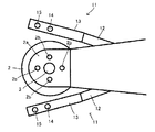
図1は1つの形態を説明するための図で、歯科用ハンドピース装置100の構成を模式的に表した図である。図1からわかるように、歯科用ハンドピース装置100は、歯科用ハンドピース本体1と歯科用ハンドピース撮像装置10とを有して構成されている。図2は歯科用ハンドピース本体1のヘッド2の周辺を拡大して示した図で、工具3が装着される側から平面視した図である。
FIG. 1 is a diagram for explaining one form, and is a diagram schematically showing a configuration of a
本形態では歯科用ハンドピース本体1は公知のものを用いることができる。すなわち、ヘッド2を有し、ヘッド2の1つの面側には工具装着部2aが設けられており、ここに歯科用ドリル等の工具3が装着される。工具3には、歯科用ハンドピース本体1内に設けられた流路に空気(エア)を流すことにより回転力が付与される。
また、図2に表れているように本形態ではヘッド2のうち、工具装着部2aが形成される面には4つの冷却水射出口2bが具備されている。冷却水射出口2bは、歯科ハンドピース本体1内に設けられた流路に通じており、該流路に水を流すことにより冷却水射出口2bから冷却水が射出される。
ここで1つの例として歯科ハンドピース本体1の形態を示したが、上記したようにこれに限定されることなく公知の歯科ハンドピース本体を適用することができる。
In this embodiment, a known dental handpiece main body 1 can be used. That is, it has a
Further, as shown in FIG. 2, in the present embodiment, four cooling
Here, the form of the dental handpiece main body 1 is shown as one example, but as described above, a known dental handpiece main body can be applied without being limited to this.
歯科用ハンドピース撮像装置10は、映像取得機器11、処理手段21、及び表示手段31を備えている。
The dental
映像取得機器11は、歯牙切削の場面の映像を取得して電気信号に変換して処理手段21へ信号を伝達する機器である。図2からわかるように本発明では複数の映像取得機器11が備えられている。ここでは2つの映像取得機器11を図示しているが、異なる位置にさらに映像取得機器11が設けられてもよい。図3には1つの映像取得機器11の先端部位を説明する図を表した。図3では、内部に含まれている部材を点線で表している。図3(a)は図2と同じ視点から見た図、図3(b)は図1と同じ視点から見た図である。
The
映像取得機器11は、導電手段12、入出光手段13、及び保持部材16を有して構成されている。
導電手段12は、後述する入出光手段13と処理手段21とを電気的に接続する導線を内側に有して構成された管状部材である。導電手段12はその管状の内側にいわゆる導線が含まれ、少なくとも2つの導線が配置されている。そのうちの一方がカメラモジュール15と処理手段21とを接続する導線12aであり、他方が光源14と処理手段21とを接続する導線12bである。
The
The
入出光手段13は、図1〜図3よりわかるように、導電手段12のうちの一方の先端に配置された管状の部材である。そして入出光手段13は、その管状である内側に、光源光出光部を含む光源14、及び、口腔内からの光を入射するための取込口を備える入光部を含むカメラモジュール15を有している。
As can be seen from FIGS. 1 to 3, the Idemitsu means 13 is a tubular member arranged at the tip of one of the
光源14は、処理手段21から導線12bを介して供給された電源を受けて照明光を出射する手段である。これにより口腔内を照明する。従って白色光であることが好ましい。光源14の具体的な形態は特に限定されることはないが、消費電力や寿命の観点からLEDを挙げることができる。
カメラモジュール15は、撮影すべき像である口腔内からの光を適切に入光させるとともに、これを電気信号に変換する手段である。そして変換された信号が導線12aにより処理手段21に送信される。カメラモジュール15の具体的な形態は特に限定されることはないが、レンズとCCDやCMOS等の光電変換センサと、を含む機器を挙げることができる。
The
The
保持部材16は、図1からわかるように、導電手段12から突出するように設けられる部材で、当該導電手段12、入出光手段13を歯科ハンドピース本体1に取り付けて保持することを可能とする手段である。保持部材16はこのような保持が可能であれば具体的な形態は特に限定されることなく、歯科ハンドピース本体1を挟むように構成されるものや、歯科ハンドピース本体1に吸着するような構成のもの等を挙げることができる。
ここで保持部材は、入出光手段を歯科ハンドピースに保持することができればよく、従って、保持手段が入出光手段に設けられても良い。
As can be seen from FIG. 1, the
Here, the holding member only needs to be able to hold the entrance / exit means to the dental handpiece, and therefore, the holding means may be provided in the entrance / exit means.
このような映像取得機器11は、歯科用ハンドピース本体1に対して次のように取り付け保持されて歯科ハンドピースとされる。すなわち、図1、図2からわかるように、保持部材16を歯科ハンドピース本体1に取り付ける。このとき、複数の映像取得機器11のカメラモジュール15が、それぞれ異なる方角から工具3の先端に焦点が合うように配置されている。
Such an
図1に戻り、歯科用ハンドピース撮像装置10の他の構成について説明する。
処理手段21は、映像取得機器11の光源14の電源22を有し、及び映像取得機器11の複数のカメラモジュール15から取得した映像信号を処理し、表示を制御する手段である。処理手段21は、電源22、受信手段24、中央演算子25、記憶手段26、RAM27、及び送信手段28を備えて構成されている。図4にも処理手段21、光源14、及びカメラモジュール15の関係を説明するブロック図を表した。
Returning to FIG. 1, another configuration of the dental
The processing means 21 is a means that has a
電源22は、光源14の電源である。従って、図1、図4からわかるように電源22は導電手段12の導線12bで光源14に接続される。
The
受信手段24は、カメラモジュール15からの、口腔内からの光に基づいた電気的信号を取り入れる機能を有する部材であり、複数のカメラモジュール15に接続される。いわゆる入力ポート、入力コネクタ等もこれに含まれる。接続の態様は有線、無線を問わない。
The receiving means 24 is a member having a function of taking in an electric signal based on light from the oral cavity from the
中央演算子25はいわゆるCPUであり、画像処理手段やその他の各種演算手段として機能する。すなわち、中央演算子25は、記憶媒体として機能する記憶手段26に記憶された各種プログラムを実行し、所定の結果を演算して出力し、歯科用ハンドピース撮像装置10を制御する。
中央演算子25が画像処理手段として機能するときには、受信手段24からの電気的信号を取り入れ、プログラムに基づいて演算をし、その結果としての映像信号を生成する。そのうちの演算のひとつとして、後で説明するように複数のカメラモジュール15から適切な映像となっているものを判断し、必要に応じて映像を切り替える演算が含まれる。これにより工具3による切削部分が死角により見えなくなる状態となることを防止する。具体的な態様については後で説明する。
この他、生成される映像信号としては、受信した信号を映像としてそのまま表示したり、複数のカメラモジュール15からの映像を画面内に同時に表示したり、映像の一部を拡大したり、一部を目立つように表示したり、画面上で採寸したり等、映像的な効果を加えることもできる。これにより施術者にとって利便性が向上する。このような画像処理のためのプログラムは公知のものを適用することができる。
また中央演算子25は、受信手段24、記憶手段26、RAM27、送信手段28等の処理手段21に備えられる他の部材に接続されており、プログラムに基づいてこれらを制御できるように構成されている。
The
When the
In addition, as the generated video signal, the received signal may be displayed as it is as a video, the video from a plurality of
Further, the
記憶手段26は、中央演算子25で行われる演算の根拠となる各種プログラムやデータが保存される記憶媒体として機能する部材である。さらに記憶手段26は、保管すべき映像や患者のデータ等を保管する保管手段として機能してもよい。
The storage means 26 is a member that functions as a storage medium for storing various programs and data that are the basis of operations performed by the
RAM27は、中央演算子25による演算の作業領域や一時的なデータの記憶手段として機能する部材である。RAM27は、SRAM、DRAM、フラッシュメモリ等で構成することができ、公知のRAMと同様である。
The
送信手段28は、得られた結果のうち表示手段31に送信すべき信号を送信する機能を有する部材である。いわゆる出力ポート、出力コネクタ等もこれに含まれる。送信の態様は有線、無線を問わない。 The transmission means 28 is a member having a function of transmitting a signal to be transmitted to the display means 31 among the obtained results. This includes so-called output ports, output connectors, and the like. The mode of transmission may be wired or wireless.
表示手段31は、処理手段21の送信手段28に接続され、ここから取得した情報に基づいて映像を表示する手段であり、各種モニター等が用いられる。 The display means 31 is connected to the transmission means 28 of the processing means 21 and is a means for displaying an image based on the information acquired from the display means 21, and various monitors and the like are used.
以上のような構成を具備する歯科用ハンドピース撮像装置10、及び歯科用ハンドピース装置100は次のように作用する。
The dental
歯科用ハンドピース本体1については、空気を送り込むことにより装着した工具3が回転し、併せて冷却水を流入させて冷却水射出口2bから冷却水が出射される。これにより、冷却をしつつ、通常に歯牙等の切削をすることが可能である。
With respect to the dental handpiece main body 1, the
本形態ではさらに処理手段21の電源22から電気を供給し光源14を点灯する。これにより光源14から光が出射されて口腔内が照明される。このように口腔内が照明されることにより、口腔内の映像を取得することができるようになる。すなわち、照明された口腔内からの反射光をカメラモジュール15で捉え、処理手段21により映像が生成され、表示手段31に表示される。
In this embodiment, electricity is further supplied from the
ここで、処理手段21は記憶手段26に記憶されたプログラムに基づいて、画像処理手段として機能する中央演算子により例えば次のように演算を行い、工具3の先端の切削状況を視認できるように維持する。必要に応じて映像を切り替える演算の1つの例を図5にフロー図で示した。このフローでは過程S11〜過程S17を含んでいる。
Here, the processing means 21 performs the following calculation by the central operator functioning as the image processing means based on the program stored in the storage means 26 so that the cutting state of the tip of the
初めに過程S11に示したように、複数のカメラモジュール15のうち最も優先度の高い優先度1のカメラモジュール15から映像を取得し、過程S12のように処理手段21によりカラー映像を生成する。なお、上記からわかるように複数のカメラモジュール15に対して優先順位を予め定めておく。
その後、過程S13で示したように、このカメラモジュール15で工具の先端が認識することができるかを判断する。この過程で工具の先端が認識できれば、歯牙切削の状況がこのカメラモジュールで視認することができることを意味するので、Yesが選択され、過程S14に移って映像を表示する。そして過程S12に戻り、繰り返し上記過程が行われる。
一方、このカメラモジュール15で工具の先端が認識することができなかった場合には、過程S13でNoが選択され、過程S15に移行してカウンタを開始する。この過程では予め決めた時間の間だけ猶予する。これは、歯牙の切削中は切削粉や冷却水の噴霧により付着した水滴等により切削工具先端が一時的に見えにくくなることが考えられる。そこで、切削工具が認識できなくなったらすぐにカメラモジュールの切り替えが行われるのではなく、カウンタによる時間制限を設けた上で隠れた状態の継続時間が設定時間を超えた場合にのみ切り替えが行われるようにする。
First, as shown in the process S11, an image is acquired from the
After that, as shown in the process S13, it is determined whether the tip of the tool can be recognized by the
On the other hand, when the tip of the tool cannot be recognized by the
過程15で所定の時間が経過した後、過程S16に進み、再びこのカメラモジュール15で工具の先端が認識することができるかを判断する。この過程で工具の先端が認識できるようになっていれば、歯牙切削の状況がこのカメラモジュールで視認することができることを意味するので、Yesが選択され、過程S14に移って映像を表示する。そして過程S12に戻り、繰り返し上記過程が行われる。
一方、この過程でも工具の先端を認識することができない場合には、この姿勢では当該カメラモジュール15では切削の状況を視認することができないと判断できる。そこで、過程S17に進み、次の優先度のカメラモジュール15からの映像を取得する。その後、過程S12に戻って、上記過程を繰り返す。
After a predetermined time has elapsed in the
On the other hand, if the tip of the tool cannot be recognized even in this process, it can be determined that the cutting status cannot be visually recognized by the
以上のように、歯科用ハンドピース撮像装置10を備える歯科用ハンドピース装置100によれば、工具3による歯牙等の切削の状況をより確実に表示手段31により視認しながら施術することができる。特に切削時において、切削部分が歯牙等により隠れて見えなくなってしまうことを防止することが可能となり、施術者の利便性が高められる。
As described above, according to the
以上は処理手段21による歯科用ハンドピース装置10の制御の一例であり、必要に応じて変更を加えることもできる。例えば、上記例では1つのカメラモジュールからの映像を表示するが、複数のカメラモジュールの映像を複数画面で同時に表示することができるように構成してもよい。これにより複数の視点から切削部分を視認することができ、さらなる利便性向上になる。
また、上記のように自動にカメラモジュールを切り替えるように構成する他、施術者が手動でカメラモジュールの切り替えをできるように構成してもよい。これによれば、施術者の好みに応じて映像を選択できる利便性がある。その際には、例えば歯科用ハンドピース装置100のいずれかにスイッチを設け、このスイッチの操作信号により複数のカメラモジュールを切り替えて表示するように処理手段21を構成することができる。例えば施術者がスイッチを押すごとに、表示されるカメラモジュールが切り替わるようにすれば施術者の利便性を高めることが可能である。
The above is an example of control of the
Further, in addition to being configured to automatically switch the camera module as described above, the practitioner may be configured to manually switch the camera module. According to this, there is a convenience that the image can be selected according to the preference of the practitioner. At that time, for example, a switch may be provided in any of the
また、上記形態では、ハンドピース本体1と映像取得機器11とを別体に着脱可能に構成したが、これに限られることはなく、ハンドピース本体1と映像取得機器11とを一体に構成してもよい。
Further, in the above embodiment, the handpiece main body 1 and the
1 歯科用ハンドピース本体
2 ヘッド
2a 工具装着部
2b 冷却水射出口
3 工具
10 歯科用ハンドピース撮像装置
11 映像取得機器
12 導電手段
13 入出光手段
14 光源
15 カメラモジュール
21 処理手段
22 電源
24 受信手段
25 中央演算子
26 記憶手段
27 RAM
28 送信手段
31 表示手段
100 歯科用ハンドピース装置
1
28 Transmission means 31 Display means 100 Dental handpiece device
Claims (4)
前記歯科用ハンドピース撮像装置は、
撮像して映像を電気信号に変換する複数のカメラモジュールと、
前記複数のカメラモジュールからの前記電気信号を受信して該電気信号に基づいて映像を生成する演算、前記複数のカメラモジュールによる前記映像の表示の切り替え、及び、生成された前記映像に基づいて前記歯科用ハンドピース本体に装着された工具の先端が視認できるか否かを判断する、演算を行う処理手段と、を有する、歯科用ハンドピース装置。 It has a dental handpiece main body and a dental handpiece imaging device provided in the dental handpiece main body.
The dental handpiece imaging device is
Multiple camera modules that capture images and convert video into electrical signals,
An operation of receiving the electric signals from the plurality of camera modules and generating an image based on the electric signals, switching the display of the images by the plurality of camera modules, and the said based on the generated images. A dental handpiece device having a processing means for performing an operation for determining whether or not the tip of a tool attached to the dental handpiece body can be visually recognized.
Priority Applications (1)
| Application Number | Priority Date | Filing Date | Title |
|---|---|---|---|
| JP2016063835A JP6912862B2 (en) | 2016-03-28 | 2016-03-28 | Dental handpiece device |
Applications Claiming Priority (1)
| Application Number | Priority Date | Filing Date | Title |
|---|---|---|---|
| JP2016063835A JP6912862B2 (en) | 2016-03-28 | 2016-03-28 | Dental handpiece device |
Publications (2)
| Publication Number | Publication Date |
|---|---|
| JP2017176229A JP2017176229A (en) | 2017-10-05 |
| JP6912862B2 true JP6912862B2 (en) | 2021-08-04 |
Family
ID=60004644
Family Applications (1)
| Application Number | Title | Priority Date | Filing Date |
|---|---|---|---|
| JP2016063835A Active JP6912862B2 (en) | 2016-03-28 | 2016-03-28 | Dental handpiece device |
Country Status (1)
| Country | Link |
|---|---|
| JP (1) | JP6912862B2 (en) |
Family Cites Families (6)
| Publication number | Priority date | Publication date | Assignee | Title |
|---|---|---|---|---|
| JP3687145B2 (en) * | 1995-08-22 | 2005-08-24 | 株式会社モリタ東京製作所 | Dental handpiece device with observation function |
| JP4521180B2 (en) * | 2003-12-05 | 2010-08-11 | 株式会社モリタ製作所 | Diagnostic camera |
| JP2009268614A (en) * | 2008-05-02 | 2009-11-19 | Advance Co Ltd | Depth measuring instrument of periodontal pocket and depth measuring system of periodontal pocket |
| WO2009148044A1 (en) * | 2008-06-06 | 2009-12-10 | 株式会社モリタ製作所 | Image pickup device used for dental treatment and instrument for dental treatment equipped with image pickup device |
| JP5711184B2 (en) * | 2012-02-17 | 2015-04-30 | 株式会社モリタ製作所 | Medical treatment equipment |
| JP5781667B1 (en) * | 2014-05-28 | 2015-09-24 | 株式会社モリタ製作所 | Root canal therapy device |
-
2016
- 2016-03-28 JP JP2016063835A patent/JP6912862B2/en active Active
Also Published As
| Publication number | Publication date |
|---|---|
| JP2017176229A (en) | 2017-10-05 |
Similar Documents
| Publication | Publication Date | Title |
|---|---|---|
| JP6509932B2 (en) | Method of operating imaging system | |
| CN108965653B (en) | Oral cavity speculum | |
| US10166090B2 (en) | Device for detecting the three-dimensional geometry of objects and method for the operation thereof | |
| JP2022130677A (en) | Dental mirror having integrated camera and applications thereof | |
| US10231810B2 (en) | Dental irradiation device and system | |
| JP2013169256A (en) | Video acquisition device for dental handpiece, imaging device for dental handpiece, dental handpiece, and dental handpiece system | |
| CN113727636A (en) | Scanner device with replaceable scanning tip | |
| US20180263483A1 (en) | Dental Mirror Device with Affixed Camera | |
| JP2014046016A (en) | Handpiece with built-in camera and dental treatment method using the handpiece | |
| JP4540015B1 (en) | Toothbrush with camera | |
| JP2006122335A (en) | Camera device | |
| JP2005168520A (en) | Diagnostic camera | |
| JP2008173143A (en) | Dental intraoral observation device | |
| KR101009617B1 (en) | Electric toothbrush with imaging function and imaging method | |
| KR20180104729A (en) | Air Injection Device and Dental Handpiece System | |
| JP6675348B2 (en) | Object imaging device having up and down buttons and method of operating object imaging device | |
| US20170171437A1 (en) | Multi-focal length range image capturing device | |
| EP3470007B1 (en) | Dental handpiece device | |
| JP6067625B2 (en) | Biological imaging device | |
| JPWO2018179610A1 (en) | Control device, endoscope system, processing method and program | |
| JP2013074929A (en) | Oral cavity interior observation device and oral cavity interior observation system | |
| JP2017176229A (en) | Dental handpiece device | |
| JP2008086554A (en) | Oral cavity internal observation device | |
| JP2025524553A (en) | Oral Scanner System | |
| JP4491316B2 (en) | Intraoral imaging device |
Legal Events
| Date | Code | Title | Description |
|---|---|---|---|
| A621 | Written request for application examination |
Free format text: JAPANESE INTERMEDIATE CODE: A621 Effective date: 20190225 |
|
| A131 | Notification of reasons for refusal |
Free format text: JAPANESE INTERMEDIATE CODE: A131 Effective date: 20200204 |
|
| A977 | Report on retrieval |
Free format text: JAPANESE INTERMEDIATE CODE: A971007 Effective date: 20200131 |
|
| A521 | Request for written amendment filed |
Free format text: JAPANESE INTERMEDIATE CODE: A523 Effective date: 20200225 |
|
| A131 | Notification of reasons for refusal |
Free format text: JAPANESE INTERMEDIATE CODE: A131 Effective date: 20200714 |
|
| A521 | Request for written amendment filed |
Free format text: JAPANESE INTERMEDIATE CODE: A523 Effective date: 20200720 |
|
| A131 | Notification of reasons for refusal |
Free format text: JAPANESE INTERMEDIATE CODE: A131 Effective date: 20201124 |
|
| A521 | Request for written amendment filed |
Free format text: JAPANESE INTERMEDIATE CODE: A523 Effective date: 20210114 |
|
| TRDD | Decision of grant or rejection written | ||
| A01 | Written decision to grant a patent or to grant a registration (utility model) |
Free format text: JAPANESE INTERMEDIATE CODE: A01 Effective date: 20210706 |
|
| A61 | First payment of annual fees (during grant procedure) |
Free format text: JAPANESE INTERMEDIATE CODE: A61 Effective date: 20210709 |
|
| R150 | Certificate of patent or registration of utility model |
Ref document number: 6912862 Country of ref document: JP Free format text: JAPANESE INTERMEDIATE CODE: R150 |
|
| R250 | Receipt of annual fees |
Free format text: JAPANESE INTERMEDIATE CODE: R250 |
|
| R250 | Receipt of annual fees |
Free format text: JAPANESE INTERMEDIATE CODE: R250 |
|
| R250 | Receipt of annual fees |
Free format text: JAPANESE INTERMEDIATE CODE: R250 |