JP6876435B2 - Systems and methods to form and maintain high performance FRC - Google Patents
Systems and methods to form and maintain high performance FRC Download PDFInfo
- Publication number
- JP6876435B2 JP6876435B2 JP2016544356A JP2016544356A JP6876435B2 JP 6876435 B2 JP6876435 B2 JP 6876435B2 JP 2016544356 A JP2016544356 A JP 2016544356A JP 2016544356 A JP2016544356 A JP 2016544356A JP 6876435 B2 JP6876435 B2 JP 6876435B2
- Authority
- JP
- Japan
- Prior art keywords
- frc
- confinement chamber
- formation
- chamber
- plasma
- Prior art date
- Legal status (The legal status is an assumption and is not a legal conclusion. Google has not performed a legal analysis and makes no representation as to the accuracy of the status listed.)
- Active
Links
Images


Classifications
-
- G—PHYSICS
- G21—NUCLEAR PHYSICS; NUCLEAR ENGINEERING
- G21B—FUSION REACTORS
- G21B1/00—Thermonuclear fusion reactors
- G21B1/05—Thermonuclear fusion reactors with magnetic or electric plasma confinement
- G21B1/052—Thermonuclear fusion reactors with magnetic or electric plasma confinement reversed field configuration
-
- G—PHYSICS
- G21—NUCLEAR PHYSICS; NUCLEAR ENGINEERING
- G21B—FUSION REACTORS
- G21B1/00—Thermonuclear fusion reactors
- G21B1/11—Details
- G21B1/15—Particle injectors for producing thermonuclear fusion reactions, e.g. pellet injectors
-
- H—ELECTRICITY
- H05—ELECTRIC TECHNIQUES NOT OTHERWISE PROVIDED FOR
- H05H—PLASMA TECHNIQUE; PRODUCTION OF ACCELERATED ELECTRICALLY-CHARGED PARTICLES OR OF NEUTRONS; PRODUCTION OR ACCELERATION OF NEUTRAL MOLECULAR OR ATOMIC BEAMS
- H05H1/00—Generating plasma; Handling plasma
- H05H1/02—Arrangements for confining plasma by electric or magnetic fields; Arrangements for heating plasma
- H05H1/10—Arrangements for confining plasma by electric or magnetic fields; Arrangements for heating plasma using externally-applied magnetic fields only, e.g. Q-machines, Yin-Yang, base-ball
- H05H1/14—Arrangements for confining plasma by electric or magnetic fields; Arrangements for heating plasma using externally-applied magnetic fields only, e.g. Q-machines, Yin-Yang, base-ball wherein the containment vessel is straight and has magnetic mirrors
-
- Y—GENERAL TAGGING OF NEW TECHNOLOGICAL DEVELOPMENTS; GENERAL TAGGING OF CROSS-SECTIONAL TECHNOLOGIES SPANNING OVER SEVERAL SECTIONS OF THE IPC; TECHNICAL SUBJECTS COVERED BY FORMER USPC CROSS-REFERENCE ART COLLECTIONS [XRACs] AND DIGESTS
- Y02—TECHNOLOGIES OR APPLICATIONS FOR MITIGATION OR ADAPTATION AGAINST CLIMATE CHANGE
- Y02E—REDUCTION OF GREENHOUSE GAS [GHG] EMISSIONS, RELATED TO ENERGY GENERATION, TRANSMISSION OR DISTRIBUTION
- Y02E30/00—Energy generation of nuclear origin
- Y02E30/10—Nuclear fusion reactors
Description
(分野)
本明細書に記載された実施形態は、一般に磁気プラズマ閉じ込めシステムに関し、より詳細には、優れた安定性ならびに粒子、エネルギーおよび磁束閉じ込めをもつ、磁場反転配位の形成および維持を促進するシステムおよび方法に関する。
(Field)
The embodiments described herein generally relate to magnetic plasma confinement systems, and more specifically to systems that facilitate the formation and maintenance of field reversed configuration with excellent stability and particle, energy and flux confinement. Regarding the method.
(背景情報)
磁場反転配位(FRC)は、コンパクト・トロイド(CT)として公知の磁気プラズマ閉じ込めトポロジーの分類に属する。FRCは、主にポロイダル磁場を示し、自然発生のトロイダル磁場がない、または少ない(M.Tuszewski、Nucl.Fusion 28、2033(1988)参照)。このような構造の魅力は、構築および維持が容易なその単純な形状、エネルギーの抽出および灰の除去を促進する無制限の自然ダイバータ、ならびに非常に高いβ(βはFRC内部の平均磁場圧力に対する平均プラズマ圧力の割合である)、すなわち、高出力密度である。高いβ特性は、経済運用、ならびにD−He3およびp−B11などの進化した非中性子燃料の使用に有利である。
(Background information)
Field-reversed configuration (FRC) belongs to the classification of magnetic plasma confinement topologies known as compact toroids (CT). The FRC mainly exhibits a poloidal magnetic field with no or little spontaneous toroidal magnetic field (see M. Tsuzewski, Nucl. Fusion 28, 2033 (1988)). The attractiveness of such structures is their simple shape, which is easy to build and maintain, unlimited natural divertors that facilitate energy extraction and ash removal, and very high β (β is the average relative to the average magnetic field pressure inside the FRC). It is the ratio of plasma pressure), that is, high output density. The high β-characteristics are advantageous for economic operation and the use of evolved non-neutron fuels such as D-He 3 and p-B 11.
FRCを形成する従来の方法は、磁場反転シータピンチ技術を使用し、高温高密度のプラズマを生成する(A.L.HoffmanおよびJ.T.Slough、Nucl.Fusion 33、27(1993)(非特許文献1)参照)。この変形形態は、シータピンチ「源」内に生成されたプラズマが、概ね即座に一端から出て閉じ込めチャンバの中に放出される移動トラッピング方法である。次いで移動するプラズモイドは、チャンバの端部で2つの強いミラーの間に閉じ込められる(例えば、H.Himura、S.Okada、S.Sugimoto、およびS.Goto、Phys.Plasmas 2、191(1995)(非特許文献2)参照)。一旦閉じ込めチャンバに入ると、ビーム入射(中性または中和された)、回転磁場、RFまたはオーム加熱などの様々な加熱および電流駆動方法を適用してもよい。源と閉じ込め機能のこの分離は、潜在的な将来の核融合炉に対して重要な工学的利点を提供する。FRCは、非常に堅固であり、動的形成、移動、および激しい捕捉事象に耐性があることが判明している。さらに、FRCは、好ましいプラズマ状態を担う傾向を示す(例えば、H.Y.Guo、A.L.Hoffman、K.E.Miller、およびL.C.Steinhauer、Phys.Rev.Lett.92、245001(2004)(非特許文献3)参照)。他のFRCの形成方法、すなわち、逆向きのヘリシティをもつスフェロマックの融合(例えば、Y.Ono、M.Inomoto、Y.Ueda、T.Matsuyama、およびT.Okazaki、Nucl.Fusion 39、2001(1999)(非特許文献4)参照)、ならびにこれもさらに安定性を提供する、回転磁場(RMF)を用いて電流を駆動することによる(例えば、I.R.Jones、Phys.Plasmas 6、1950(1999)(非特許文献5)参照)発展が過去10年に著しく進歩を遂げた。
Conventional methods of forming FRC use magnetic field reversal theta pinch technology to generate high temperature and high density plasmas (AL Hoffman and JT Slough, Nucl. Fusion 33, 27 (1993) (non-patent). See Document 1)). This variant is a mobile trapping method in which the plasma generated in the theta pinch "source" exits from one end almost immediately and is released into the confinement chamber. The moving plasmoids are then confined between two strong mirrors at the end of the chamber (eg, H. Himura, S. Okada, S. Sugimoto, and S. Goto, Phys.
最近、かなり昔に提案された衝突融合技法(例えば、D.R.Wells、Phys.Fluids 9、1010(1966)(非特許文献6)参照)がさらに著しく発展した。すなわち、閉じ込めチャンバの対向する端部で2つの個別のシータピンチが、同時に2つのプラズモイドを生成し、プラズモイドを互いに向かって高速度で加速させ、次いでプラズモイドは、閉じ込めチャンバの中央で衝突し、複合FRCを形成するために融合する。今までで最大のFRC実験の1つの構築および成功した作動において、従来の衝突融合法は、安定して長持ちし、高磁束、高温のFRCを生成することを示した(例えば、M.Binderbauer、H.Y.Guo、M.Tuszewskiら、Phys.Rev.Lett.105、045003(2010)(非特許文献7)参照)。 Recently, the collision fusion technique proposed long ago (see, eg, DR Wells, Phys. Fluids 9, 1010 (1966) (Non-Patent Document 6)) has been further developed. That is, two separate theta pinches at opposite ends of the confinement chamber simultaneously generate two plasmoids, accelerating the plasmoids towards each other at high speed, and then the plasmoids collide in the center of the confinement chamber and the composite FRC. Fuse to form. In the construction and successful operation of one of the largest FRC experiments to date, conventional collision fusion methods have been shown to produce stable, long-lasting, high flux, high temperature FRC (eg, M. Binderbauer, et al. HY Guo, M. Tsuzewski et al., Phys. Rev. Lett. 105, 045003 (2010) (see Non-Patent Document 7).
FRCは、セパラトリックスの内側の閉じた磁力線のトーラス、およびセパラトリックスのすぐ外側の開いた磁力線上の環状縁層からなる。縁層は、FRCの長さを超えて集結してジェットになり、自然ダイバータを提供する。FRCトポロジーは、磁場反転ミラープラズマのトポロジーと一致する。しかし、著しい違いは、FRCプラズマが約10のβを有することである。固有の低い内部磁場は、FRCの短半径に匹敵する、若干の生来の動的粒子集団、すなわち、大きいラーモア半径をもつ粒子を提供する。これは、衝突融合実験において生成された安定性などの過去および現在のFRCの安定性の合計に、少なくとも部分的に寄与すると思われるこれらの強い動的効果である。 The FRC consists of a torus of closed lines of magnetic force inside the Separatrix and an annular rim layer on the open lines of magnetic force just outside the Separatrix. The marginal layer aggregates beyond the length of the FRC into a jet, providing a natural divertor. The FRC topology is consistent with the topology of the magnetic field inversion mirror plasma. However, the significant difference is that the FRC plasma has about 10 β. The inherently low internal magnetic field provides a small innate dynamic particle population, ie, particles with a large Larmor radius, comparable to the FRC's short radius. This is these strong dynamic effects that appear to contribute, at least in part, to the sum of past and present FRC stability, such as the stability produced in collision fusion experiments.
典型的な過去のFRC実験は、主に粒子移動によって決まるエネルギー閉じ込めをもつ、対流損失によって支配されてきた。粒子は、セパラトリックス体積から主に径方向外方に拡散し、次いで縁層において軸方向に損失される。したがって、FRC閉じ込めは、閉じた磁力線領域と開いた磁力線領域の両方の特性に依存する。セパラトリックスから出た粒子の拡散時間は、τ⊥は約a2/D⊥(aは約rs/4であり、ここでrsは中心セパラトリックスの半径である)と見積もられ、D⊥は、特性FRC拡散率であり(例えば、D⊥は約12.5ρieであり、ρieはイオンジャイロ半径を表し)、外部印加磁場で評価される。縁層の粒子閉じ込め時間
![]()
![]()
![]()
![]()
![]()
![]()
先行のFRCシステム設計の別の短所は、急成長するn=2交換不安定性などの、回転不安定性を制御するために外部多極を使用する必要があったことである。このような方法で、通常の外部印加された四重極磁場は、これらの不安定モードの成長を抑えるために、必要な磁気を回復する圧力を提供した。この技法は熱バルクプラズマの安定制御に充分である一方で、高い動的大軌道の粒子集団が通常の熱プラズマと組み合わされる場合、この技法は、より動的なFRCまたは進化したハイブリッドのFRCに対して深刻な問題を有する。これらのシステムでは、このような多極磁場に起因する軸対称の磁場の歪みは、正準角運動量の保存を損失する結果、無衝突の確率的拡散を介して劇的に高速な粒子損失をもたらす。したがって、いかなる粒子の拡散も高めることなく、安定制御を提供する新規の解決策は、これらの今まで調査されなかった進歩したFRCの概念の、より高い潜在性能を利用するために重要である。 Another disadvantage of the previous FRC system design was the need to use external multipoles to control rotational instability, such as the fast-growing n = 2 exchange instability. In this way, the usual externally applied quadrupole magnetic field provided the necessary magnetic recovery pressure to suppress the growth of these unstable modes. While this technique is sufficient for stable control of thermal bulk plasmas, it can be used in more dynamic FRCs or evolved hybrid FRCs when high dynamic orbital particle populations are combined with conventional thermal plasmas. On the other hand, it has a serious problem. In these systems, the distortion of the axisymmetric magnetic field due to such a multipolar magnetic field loses the conservation of canonical momentum, resulting in dramatically faster particle loss through non-collision probabilistic diffusion. Bring. Therefore, new solutions that provide stable control without increasing the diffusion of any particles are important to take advantage of the higher potential of these previously unexplored advanced FRC concepts.
したがって、前述に照らして、コンパクト中性子源(医療用同位体生産、核廃棄物浄化、材料研究、中性子X線撮影、および断層撮影のため)、コンパクト光子源(化学生産および処理のため)、質量分離および濃縮システム、および将来のエネルギー生成のための軽核の融合用炉心を含む、あらゆる種々の用途への経路として定常状態FRCを使用するために、FRCの閉じ込めおよび安定性を改良することが望ましい。 Therefore, in light of the above, compact neutron sources (for medical isotope production, nuclear waste purification, material research, neutron X-ray photography, and tomography), compact photon sources (for chemical production and processing), mass. Improving FRC confinement and stability to use steady-state FRC as a route to any variety of applications, including separation and enrichment systems, and light nuclear fusion cores for future energy production. desirable.
本明細書に提供された本実施形態は、新しい高性能の磁場反転配位(FRC)の形成および維持を促進するシステムおよび方法を対象とする。この新しい高性能のFRCパラダイムによれば、本システムは、多くの新規の発想と、粒子、エネルギーおよび磁束のFRC閉じ込めを劇的に向上させ、かつ負の副作用のない安定制御を提供する手段を組み合わせる。 The embodiments provided herein are directed to systems and methods that facilitate the formation and maintenance of new high performance field reversed configuration (FRC). According to this new high-performance FRC paradigm, the system provides many new ideas and means to dramatically improve FRC confinement of particles, energies and magnetic fluxes, and to provide stable control without negative side effects. combine.
本明細書に提供されたFRCシステムは、2つの直径方向に対向する磁場反転シータピンチ形成部分、およびその形成部分を超えた、中性密度および不純物汚染を制御するための2つのダイバータ・チャンバによって包囲された中央閉じ込め容器を含む。磁気システムは、FRCシステムの構成要素に沿って軸方向位置にある一連の疑似直流コイル、閉じ込めチャンバのいずれかの端部と隣接した形成部分との間の疑似直流ミラー、ならびに、各形成部分と、ダイバータに向かって磁束表面の焦点を合わせるために、追加のガイド磁場を生成するダイバータとの間に小型の疑似直流ミラーコイルを備えるミラープラグを含む。形成部分は、FRCをその場で形成し、次いで加速し入射する(静的形成)、または形成し同時に加速する(動的形成)ことが可能な、モジュラーパルス電力形成システムを含む。 The FRC system provided herein is surrounded by two diametrically opposed magnetic field reversal theta pinch formations and two divertor chambers to control neutral density and impurity contamination beyond the formation. Includes a central confinement container. The magnetic system includes a series of pseudo DC coils located axially along the components of the FRC system, a pseudo DC mirror between any end of the confinement chamber and an adjacent formation, and each formation. Includes a mirror plug with a small pseudo-DC mirror coil between the diver and the diver to generate an additional guide magnetic field to focus the magnetic flux surface towards the diver. The forming portion includes a modular pulse power forming system capable of forming the FRC in-situ and then accelerating and incident (static formation) or forming and accelerating at the same time (dynamic formation).
FRCシステムは、中性原子ビーム注入器と、ペレット注入器とを含む。一実施形態では、ビーム注入器は、中性粒子を中央平面に向かって注入するように角度付けられる。ビーム注入器を中央平面に向かって角度付け、軸方向ビーム位置を中央平面に近接させることは、注入周期の間、FRCプラズマが収縮または別様に軸方向に縮小しても、ビーム−プラズマ結合を改良する。ゲッタリングシステムもまた、軸方向プラズマガンと同様に含まれる。バイアス電極もまた、開磁束面の電気バイアスのために提供される。 The FRC system includes a neutral atom beam injector and a pellet injector. In one embodiment, the beam injector is angled to inject neutral particles towards the central plane. Angle the beam injector towards the central plane and bring the axial beam position closer to the central plane, even if the FRC plasma contracts or otherwise shrinks axially during the injection cycle, beam-plasma coupling. To improve. A gettering system is also included as well as an axial plasma gun. Bias electrodes are also provided for electrical bias of open flux surfaces.
動作時、プラズマ熱エネルギー、総粒子数、プラズマ半径および長さ、ならびに磁束を含む、FRCの包括的プラズマパラメータは、中性ビームがプラズマの中に注入され、ペレットが、適切な粒子燃料補給を提供する間、減衰を伴わずに、実質的に持続可能である。 During operation, the FRC's comprehensive plasma parameters, including plasma thermal energy, total particle number, plasma radius and length, and magnetic flux, allow the neutral beam to be injected into the plasma and the pellets to provide proper particle refueling. While serving, it is substantially sustainable, with no attenuation.
本発明のシステム、方法、特徴および利点は、以下の図および詳述を検討すると、当業者には明らかであり、または明らかになろう。すべてのこのような追加の方法、特徴および利点は、本明細書に含まれ、本発明の範囲内であり、添付の特許請求の範囲によって保護されることが意図される。また、本発明は、例示的実施形態の詳細を必要とするように限定されないことも意図される。
本発明は、例えば、以下を提供する。
(項目1)
逆磁場構成(FRC)を伴う磁場を生成および維持するための方法であって、
閉じ込めチャンバ内にプラズマを中心としてFRCを形成するステップと、
前記閉じ込めチャンバの中央平面に向かってある角度において、高速中性原子のビームを中性ビーム注入器からFRCプラズマの中に注入することによって、減衰を伴わずに、前記FRCを一定またはほぼ一定値に維持するステップと、を含む、方法。
(項目2)
前記チャンバを中心として延在する準直流コイルを用いて、前記チャンバ内に磁場を生成するステップをさらに含む、項目1に記載の方法。
(項目3)
前記チャンバの対向する端部を中心として延在する準直流ミラーコイルを用いて、前記チャンバの対向する端部内にミラー磁場を生成するステップをさらに含む、項目1および2に記載の方法。
(項目4)
前記FRCを形成するステップは、前記閉じ込めチャンバの端部に結合される形成区分内に形成FRCを形成するステップと、前記形成FRCを前記チャンバの中央平面に向かって加速させ、前記FRCを形成するステップとを含む、項目1から3に記載の方法。
(項目5)
前記FRCを形成するステップは、前記閉じ込めチャンバの第2の端部に結合される第2の形成区分内に第2の形成FRCを形成するステップと、前記第2の形成FRCを前記チャンバの中央平面に向かって加速させるステップとを含み、2つの形成FRCは、前記FRCを形成するように融合する、項目4に記載の方法。
(項目6)
前記FRCを形成するステップは、前記形成FRCを前記チャンバの中央平面に向かって加速させながら、形成FRCを形成するステップと、形成FRCを形成し、次いで、前記形成FRCを前記チャンバの中央平面に向かって加速させるステップとのうちの1つを含む、項目4および5に記載の方法。
(項目7)
前記FRCの磁束面を前記形成区分の両端部に結合される複数のダイバータの中に誘導するステップをさらに含む、項目5に記載の方法。
(項目8)
前記FRCの磁束面を前記形成区分の一端に結合される1つのダイバータの中に誘導するステップをさらに含む、項目4に記載の方法。
(項目9)
前記FRCの磁束面を前記形成区分と反対の前記チャンバの端部に結合される第2のダイバータの中に誘導するステップをさらに含む、項目8に記載の方法。
(項目10)
前記形成区分およびダイバータを中心として延在する準直流コイルを用いて、前記形成区分およびダイバータ内に磁場を生成するステップをさらに含む、項目7から9に記載の方法。
(項目11)
準直流ミラーコイルを用いて、前記形成区分と前記ダイバータとの間にミラー磁場を生成するステップをさらに含む、項目7および10に記載の方法。
(項目12)
前記形成区分と前記ダイバータとの間の狭窄部を中心として延在する準直流ミラープラグコイルを用いて、前記形成区分と前記ダイバータとの間の狭窄部内にミラープラグ磁場を生成するステップをさらに含む、項目11に記載の方法。
(項目13)
前記FRCを維持するステップはさらに、中性原子のペレットを前記FRCの中に注入するステップを含む、項目1から12に記載の方法。
(項目14)
前記チャンバに結合される鞍形コイルを用いて、前記チャンバ内に磁気双極子場および磁気四重極場のうちの1つを生成するステップをさらに含む、項目1から13に記載の方法。
(項目15)
ゲッタリングシステムを用いて、前記チャンバの内部表面、形成区分、およびダイバータを調整するステップをさらに含む、項目1から14に記載の方法。
(項目16)
前記ゲッタリングシステムは、チタン堆積システムおよびリチウム堆積システムのうちの1つを含む、項目15に記載の方法。
(項目17)
プラズマを軸方向に搭載されるプラズマガンから前記FRCの中に軸方向に注入するステップをさらに含む、項目1から16に記載の方法。
(項目18)
前記FRCの縁層内の半径方向電場プロファイルを制御するステップをさらに含む、項目1から17に記載の方法。
(項目19)
前記FRCの縁層内の半径方向電場プロファイルを制御するステップは、バイアス電極を用いて、前記FRCの開磁束面群に電位分布を印加するステップを含む、項目18に記載の方法。
(項目20)
逆磁場構成(FRC)を伴う磁場を生成および維持するためのシステムであって、
閉じ込めチャンバと、
前記閉じ込めチャンバに結合される第1および第2の直径方向に対向するFRC形成区分であって、FRCを生成し、前記FRCを前記閉じ込めチャンバの中央平面に向かって平行移動させるためのモジュール式形成システムを備える、形成区分と、
前記第1および第2の形成区分に結合される第1および第2のダイバータと、
前記第1および第2のダイバータ、前記第1および第2の形成区分、および前記閉じ込めチャンバに動作可能に結合される、第1および第2の軸方向プラズマガンと、
前記閉じ込めチャンバに結合され、前記閉じ込めチャンバの縦軸に対して直角未満の角度において、中性原子ビームを前記閉じ込めチャンバの中央平面に向かって注入するように配向される、複数の中性原子ビーム注入器と、
前記閉じ込めチャンバ、前記第1および第2の形成区分、ならびに前記第1および第2のダイバータの周囲に位置付けられる、複数の準直流コイルと、前記閉じ込めチャンバと前記第1および第2の形成区分との間に位置付けられる、第1および第2の準直流ミラーコイルのセットと、前記第1および第2の形成区分と前記第1および第2のダイバータとの間に位置付けられる、第1および第2のミラープラグとを備える、磁気システムと、
前記閉じ込めチャンバならびに前記第1および第2のダイバータに結合される、ゲッタリングシステムと、
生成されたFRCの開磁束面を電気的にバイアスするための1つまたはそれを上回るバイアス電極であって、前記閉じ込めチャンバ、前記第1および第2の形成区分、ならびに前記第1および第2のダイバータのうちの1つまたはそれを上回るもの内に位置付けられる、前記1つまたはそれを上回るバイアス電極と、
前記閉じ込めチャンバに結合される、2つまたはそれを上回る鞍形コイルと、
前記閉じ込めチャンバに結合される、イオンペレット注入器と、
を備える、システム。
(項目21)
前記システムは、FRCを生成し、中性原子ビームが前記FRCの中に注入される間、減衰を伴わずに、前記FRCを一定またはほぼ一定値に維持するように構成される、項目20に記載のシステム。
(項目22)
前記ミラープラグは、前記第1および第2の形成区分のそれぞれと前記第1および第2のダイバータとの間に第3および第4のミラーコイルのセットを備える、項目20に記載のシステム。
(項目23)
前記ミラープラグはさらに、前記第1および第2の形成区分のそれぞれと前記第1および第2のダイバータとの間の通路内の狭窄部の周囲に巻着されたミラープラグコイルのセットを備える、項目20および21に記載のシステム。
(項目24)
前記伸長管は、石英ライナを伴う石英管である、項目20−23に記載のシステム。
(項目25)
前記形成システムは、パルス式パワー形成システムである、項目20−24に記載のシステム。
(項目26)
前記形成システムは、複数のストラップアセンブリの個々の1つに結合され、前記第1および第2の形成区分の伸長管の周囲に巻着された前記複数のストラップアセンブリの個々の1つのコイルのセットを励起する、複数のパワーおよび制御ユニットを備える、項目20−25に記載のシステム。
(項目27)
前記複数のパワーおよび制御ユニットの個々の1つは、トリガおよび制御システムを備える、項目26に記載のシステム。
(項目28)
前記複数のパワーおよび制御ユニットの個々の1つの前記トリガおよび制御システムは、前記FRCが、形成され、次いで、注入される、静的FRC形成、または前記FRCが、同時に、形成および平行移動される、動的FRC形成を可能にするように同期可能である、項目27に記載のシステム。
(項目29)
前記複数の中性原子ビーム注入器は、1つまたはそれを上回るRFプラズマ源中性原子ビーム注入器と、1つまたはそれを上回るアーク源中性原子ビーム注入器とを備える、項目20−28に記載のシステム。
(項目30)
前記複数の中性原子ビーム注入器は、前記FRCの区分線内に標的捕捉ゾーンを伴って、前記FRCに対して接線方向にある注入経路とともに配向される、項目20−29に記載のシステム。
(項目31)
前記ゲッタリングシステムは、前記閉じ込めチャンバならびに前記第1および第2のダイバータのプラズマに面した表面をコーティングする、チタン堆積システムおよびリチウム堆積システムのうちの1つまたはそれを上回るものを備える、項目20−30に記載のシステム。
(項目32)
バイアス電極は、開磁力線に接触するように前記閉じ込めチャンバ内に位置付けられる、1つまたはそれを上回る点電極、方位角的に対称方式において遠端磁束層を充電する、前記閉じ込めチャンバと前記第1および第2の形成区分との間の環状電極のセット、前記第1および第2のダイバータ内に位置付けられ、複数の同心磁束層を充電する、複数の同心積層電極、および開磁束を奪取する、前記プラズマガンのアノードのうちの1つまたはそれを上回るものを含む、項目20−31に記載のシステム。
(項目33)
逆磁場構成(FRC)を伴う磁場を生成および維持するためのシステムであって、
閉じ込めチャンバと、
前記閉じ込めチャンバに結合される第1および第2の直径方向に対向するFRC形成区分と、
前記第1および第2の形成区分に結合される第1および第2のダイバータと、
複数のプラズマガン、1つまたはそれを上回るバイアス電極、ならびに第1および第2のミラープラグのうちの1つまたはそれを上回るものであって、前記複数のプラズマガンは、前記第1および第2のダイバータ、前記第1および第2の形成区分、ならびに前記閉じ込めチャンバに動作可能に結合される、第1および第2の軸方向プラズマガンを含み、前記1つまたはそれを上回るバイアス電極は、前記閉じ込めチャンバ、前記第1および第2の形成区分、ならびに前記第1および第2のダイバータのうちの1つまたはそれを上回るもの内に位置付けられ、前記第1および第2のミラープラグは、前記第1および第2の形成区分と前記第1および第2のダイバータとの間に位置付けられる、複数のプラズマガン、1つまたはそれを上回るバイアス電極、ならびに第1および第2のミラープラグのうちの1つまたはそれを上回るものと、
前記閉じ込めチャンバならびに前記第1および第2のダイバータに結合される、ゲッタリングシステムと、
前記閉じ込めチャンバに結合され、前記閉じ込めチャンバの軸に対して直角に配向される、複数の中性原子ビーム注入器と、
前記閉じ込めチャンバ、前記第1および第2の形成区分、ならびに前記第1および第2のダイバータの周囲に位置付けられる、複数の準直流コイルと、前記閉じ込めチャンバと前記第1および第2の形成区分との間に位置付けられる、第1および第2の準直流ミラーコイルのセットとを備える、磁気システムと、
を備え、
前記システムは、FRCを生成し、中性ビームがプラズマの中に注入される間、減衰を伴わず前記FRCを維持するように構成される、システム。
(項目34)
前記システムは、FRCを生成し、中性原子ビームが、前記FRCの中に注入される間、減衰を伴わずに、前記FRCを一定またはほぼ一定値に維持するように構成される、項目33に記載のシステム。
(項目35)
前記ミラープラグは、前記第1および第2の形成区分のそれぞれと前記第1および第2のダイバータとの間に第3および第4のミラーコイルのセットを備える、項目33および34に記載のシステム。
(項目36)
前記ミラープラグはさらに、前記第1および第2の形成区分のそれぞれと前記第1および第2のダイバータとの間の通路内の狭窄部の周囲に巻着される、ミラープラグコイルのセットを備える、項目33−35に記載のシステム。
(項目37)
前記第1および第2のダイバータと、前記第1および第2の形成区分と、前記閉じ込めチャンバに動作可能に結合される、第1および第2の軸方向プラズマガンとをさらに備える、項目33−36に記載のシステム。
(項目38)
前記閉じ込めチャンバに結合される、2つまたはそれを上回る鞍形コイルをさらに備える、項目33−37に記載のシステム。
(項目39)
前記閉じ込めチャンバに結合される、イオンペレット注入器をさらに備える、項目33−38に記載のシステム。
(項目40)
前記形成区分は、FRCを生成し、それを前記閉じ込めチャンバの中央平面に向かって平行移動させるためのモジュール式形成システムを備える、項目33−39に記載のシステム。
(項目41)
バイアス電極は、開磁力線に接触するように前記閉じ込めチャンバ内に位置付けられる、1つまたはそれを上回る点電極、方位角的に対称方式において、遠端磁束層を充電する、前記閉じ込めチャンバと前記第1および第2の形成区分との間の環状電極のセット、複数の同心磁束層を充電するように前記第1および第2のダイバータ内に位置付けられる、複数の同心積層電極、および開磁束を奪取する、前記プラズマガンのアノードのうちの1つまたはそれを上回るものを含む、項目33−40に記載のシステム。
The systems, methods, features and advantages of the present invention will be apparent or will be apparent to those skilled in the art upon review of the figures and details below. All such additional methods, features and advantages are contained herein and are within the scope of the present invention and are intended to be protected by the appended claims. It is also intended that the invention is not limited to requiring the details of exemplary embodiments.
The present invention provides, for example,:
(Item 1)
A method for generating and maintaining a magnetic field with a reverse field configuration (FRC).
The step of forming an FRC centered on the plasma in the confinement chamber,
By injecting a beam of fast neutral atoms into the FRC plasma from a neutral beam injector at an angle towards the central plane of the confinement chamber, the FRC is constant or nearly constant without attenuation. To keep steps, including, how.
(Item 2)
The method of
(Item 3)
The method of
(Item 4)
The steps of forming the FRC include a step of forming the formed FRC in a forming section coupled to the end of the confinement chamber and accelerating the formed FRC toward the central plane of the chamber to form the FRC. The method according to
(Item 5)
The step of forming the FRC includes a step of forming a second forming FRC in a second forming section coupled to the second end of the confinement chamber and a step of forming the second forming FRC in the center of the chamber. The method of
(Item 6)
The steps of forming the FRC include a step of forming the forming FRC and a step of forming the forming FRC while accelerating the forming FRC toward the central plane of the chamber, and then placing the forming FRC on the central plane of the chamber. The method of
(Item 7)
5. The method of
(Item 8)
The method of
(Item 9)
8. The method of
(Item 10)
7. The method of items 7-9, further comprising the step of generating a magnetic field within the formation section and divertor using a quasi-DC coil extending around the formation section and divertor.
(Item 11)
The method of
(Item 12)
Further including a step of generating a mirror plug magnetic field in the constriction between the formation segment and the divertor using a quasi-DC mirror plug coil extending around the constriction between the formation segment and the divertor. , Item 11.
(Item 13)
The method of items 1-12, wherein the step of maintaining the FRC further comprises injecting pellets of neutral atoms into the FRC.
(Item 14)
The method of items 1-13, further comprising the step of creating one of a magnetic dipole field and a magnetic quadrupole field in the chamber using a saddle coil coupled to the chamber.
(Item 15)
The method of items 1-14, further comprising the step of adjusting the internal surface, formation division, and divertor of the chamber using a gettering system.
(Item 16)
The method of
(Item 17)
The method of items 1-16, further comprising the step of axially injecting plasma into the FRC from an axially mounted plasma gun.
(Item 18)
The method of items 1-17, further comprising controlling the radial electric field profile within the FRC marginal layer.
(Item 19)
The method according to item 18, wherein the step of controlling the radial electric field profile in the edge layer of the FRC includes a step of applying a potential distribution to the open magnetic flux surface group of the FRC using a bias electrode.
(Item 20)
A system for generating and maintaining a magnetic field with a reverse field configuration (FRC).
Confinement chamber and
Modular formation of first and second diametrically opposed FRC forming compartments coupled to the confinement chamber for generating the FRC and translating the FRC toward the central plane of the confinement chamber. With a system, formation divisions,
With the first and second divertors coupled to the first and second formation compartments,
The first and second divertors, the first and second formation compartments, and the first and second axial plasma guns operably coupled to the confinement chamber.
A plurality of neutral atom beams coupled to the confinement chamber and oriented to inject a neutral atom beam toward the central plane of the confinement chamber at an angle less than perpendicular to the vertical axis of the confinement chamber. Injector and
The confinement chamber, the first and second formation sections, and a plurality of quasi-DC coils located around the first and second divertors, and the confinement chamber and the first and second formation sections. The first and second sets of quasi-DC mirror coils positioned between the first and second quasi-DC mirror coils and the first and second diverters positioned between the first and second formation sections and the first and second divertors. With a magnetic system, with a mirror plug,
A gettering system coupled to the confinement chamber and the first and second divertors.
One or more bias electrodes for electrically biasing the open flux plane of the generated FRC, said confinement chamber, said first and second forming compartments, and said first and second. With one or more bias electrodes located within one or more of the divertors,
With two or more saddle-shaped coils coupled to the confinement chamber,
An ion pellet injector coupled to the confinement chamber and
The system.
(Item 21)
(Item 22)
20. The system of
(Item 23)
The mirror plug further comprises a set of mirror plug coils wound around a constriction in the passage between each of the first and second formation sections and the first and second divertors. The system according to
(Item 24)
The system according to item 20-23, wherein the extension tube is a quartz tube with a quartz liner.
(Item 25)
The system according to item 20-24, wherein the forming system is a pulsed power forming system.
(Item 26)
The forming system is a set of individual one coils of the plurality of strap assemblies that are coupled to each individual one of the plurality of strap assemblies and wound around an extension tube of the first and second formation compartments. 20-25. The system of item 20-25, comprising a plurality of power and control units to excite.
(Item 27)
26. The system of
(Item 28)
Each one of the trigger and control systems of the plurality of power and control units is formed and then injected with the FRC, or the FRC is formed and translated at the same time. 27. The system of item 27, which is synchronous to allow dynamic FRC formation.
(Item 29)
The plurality of neutral atom beam injectors include one or more RF plasma source neutral atom beam injectors and one or more arc source neutral atom beam injectors, items 20-28. The system described in.
(Item 30)
20-29. The system of item 20-29, wherein the plurality of neutral atom beam injectors are oriented with an injection path tangential to the FRC with a target capture zone within the FRC divider.
(Item 31)
The gettering system comprises one or more of a titanium deposition system and a lithium deposition system that coats the plasma facing surfaces of the confinement chamber and the first and second divertors,
(Item 32)
The bias electrode is a point electrode located in the confinement chamber that is in contact with the open magnetic field line, one or more point electrodes, the confinement chamber and the first, which charge the far-end magnetic flux layer in an azimuthally symmetrical manner. A set of annular electrodes between the and second forming compartments, a plurality of concentric laminated electrodes located within the first and second diverters, charging a plurality of concentric flux layers, and capturing open flux. 20-31. The system of item 20-31, comprising one or more of the anodes of the plasma gun.
(Item 33)
A system for generating and maintaining a magnetic field with a reverse field configuration (FRC).
Confinement chamber and
With the first and second diametrically opposed FRC forming compartments coupled to the confinement chamber,
With the first and second divertors coupled to the first and second formation compartments,
A plurality of plasma guns, one or more bias electrodes, and one or more of the first and second mirror plugs, wherein the plurality of plasma guns are the first and second. The bias electrode comprising the divertor, the first and second formation compartments, and the first and second axial plasma guns operably coupled to the confinement chamber, said one or more. Positioned within the confinement chamber, the first and second formation compartments, and one or more of the first and second divertors, the first and second mirror plugs are the first. A plurality of plasma guns, one or more bias electrodes, and one of the first and second mirror plugs, located between the first and second formation compartments and the first and second divertors. One or more,
A gettering system coupled to the confinement chamber and the first and second divertors.
A plurality of neutral atom beam injectors coupled to the confinement chamber and oriented at right angles to the axis of the confinement chamber.
The confinement chamber, the first and second formation sections, and a plurality of quasi-DC coils located around the first and second divertors, and the confinement chamber and the first and second formation sections. A magnetic system with a set of first and second quasi-DC mirror coils, located between
With
The system is configured to generate an FRC and maintain the FRC without attenuation while the neutral beam is injected into the plasma.
(Item 34)
Item 33, wherein the system produces an FRC and maintains the FRC at a constant or near constant value without attenuation while the neutral atom beam is injected into the FRC. The system described in.
(Item 35)
33 and 34. The system of item 33 and 34, wherein the mirror plug comprises a set of third and fourth mirror coils between the first and second formation sections, respectively, and the first and second divertors. ..
(Item 36)
The mirror plug further comprises a set of mirror plug coils wound around a constriction in the passage between each of the first and second formation sections and the first and second divertors. , Items 33-35.
(Item 37)
Item 33-, further comprising said first and second divertors, said first and second forming compartments, and first and second axial plasma guns operably coupled to said confinement chamber. 36.
(Item 38)
33-37. The system of item 33-37, further comprising two or more saddle-shaped coils coupled to the confinement chamber.
(Item 39)
33-38. The system of item 33-38, further comprising an ion pellet injector coupled to the confinement chamber.
(Item 40)
33-39. The system of item 33-39, wherein the formation compartment comprises a modular formation system for generating an FRC and translating it towards the central plane of the confinement chamber.
(Item 41)
The bias electrode is a point electrode located in the confinement chamber that is in contact with the open magnetic field line, one or more point electrodes, the confinement chamber and the first, which charge the far-end magnetic flux layer in an azimuthally symmetric manner. Takes a set of annular electrodes between the first and second formation compartments, a plurality of concentric laminated electrodes positioned within the first and second divers to charge the plurality of concentric flux layers, and an open flux. 33-40. The system of item 33-40, comprising one or more of the anodes of the plasma gun.
添付図面は本明細書の一部として含まれ、この好ましい実施形態を示し、上に提供された概要および以下に提供される好ましい実施形態の詳述と共に、本発明の原理を説明し教示する働きをする。 The accompanying drawings are included as part of the present specification and serve to illustrate and teach the principles of the invention, along with an overview provided above and a detailed description of the preferred embodiments provided below. do.
図は必ずしも一定の縮尺で描かれてはおらず、同様の構造または機能の要素は、説明のために図を通して同じ参照番号で概ね表されていることに留意されたい。また図は、本明細書に記載された様々な実施形態の説明を容易にすることを意図するに過ぎないことにも留意されたい。図は、必ずしも本明細書に開示された教示のすべての態様を説明せず、特許請求の範囲を限定するものではない。 Note that the figures are not necessarily drawn to a constant scale and elements of similar structure or function are generally represented by the same reference numbers throughout the figure for illustration. It should also be noted that the figures are only intended to facilitate the description of the various embodiments described herein. The figures do not necessarily illustrate all aspects of the teachings disclosed herein and do not limit the scope of the claims.
本明細書に提供される本実施形態は、従来のFRCより優れた安定性ならびに優れた粒子、エネルギーおよび磁束閉じ込めを伴って、高性能逆磁場構成(FRC)の形成および維持を促進する、システムおよび方法を対象とする。そのような高性能FRCは、コンパクト中性子源(医療用同位体生産、核廃棄物浄化、材料研究、中性子X線撮影、および断層撮影のため)、コンパクト光子源(化学生産および処理のため)、質量分離および濃縮システム、ならびに将来のエネルギー生成のための軽核の融合用炉心を含む、あらゆる種々の用途への経路を提供する。 The embodiments provided herein facilitate the formation and maintenance of a high performance reverse field configuration (FRC) with better stability and better particle, energy and flux confinement than conventional FRCs. And methods. Such high-performance FRCs include compact neutron sources (for medical isotope production, nuclear waste purification, material research, neutron radiography, and tomography), compact photon sources (for chemical production and processing), It provides a route to a wide variety of applications, including mass separation and enrichment systems, as well as light nuclear fusion cores for future energy production.
様々な付随システムおよび作動モードが、FRC内に優れた閉じ込めレジームが存在するかどうかを評価するために調査されてきた。これらの努力は、本明細書に説明された高性能のFRCパラダイムの画期的な発見および発展をもたらした。この新しいパラダイムによれば、本システムおよび方法は、多くの新規の発想と、図1に示したように、FRC閉じ込めを劇的に向上させ、かつ負の副作用のない安定制御を提供する手段を組み合わせる。以下により詳細に論じるように、図1は、以下に説明する(図2および3参照)FRCシステム10における粒子閉じ込めを示し、FRCを形成し維持するために従来のレジームCRによる作動に対して、また他の実施形態で使用されるFRCを形成し維持するために従来のレジームによる粒子閉じ込めに対して、FRCを形成し維持するための高性能のFRCレジーム(HPF)により作動する。本開示は、FRCシステム10の革新的な個々の構成要素および方法、ならびにそれらの集合効果の概要を説明し詳述する。
Various ancillary systems and modes of operation have been investigated to assess the presence of a good confinement regime within the FRC. These efforts have led to the breakthrough discoveries and developments of the high performance FRC paradigm described herein. According to this new paradigm, the systems and methods provide many new ideas and, as shown in Figure 1, a means of dramatically improving FRC confinement and providing stable control without negative side effects. combine. As discussed in more detail below, FIG. 1 shows particle confinement in the
(FRCシステムの説明)
真空システム
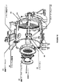
図2および3は、本FRCシステム10の概略を示す。FRCシステム10は、2つの直径方向に対向する磁場反転シータピンチ形成部分200、およびその形成部分200を超えた、中性密度および不純物汚染を制御するための2つのダイバータ・チャンバ300によって包囲された中央閉じ込め容器100を含む。本FRCシステム10は、超高真空を収容するように構築されており、一般的な基準圧10〜8トルで作動する。このような真空圧は、嵌合構成要素、金属Oリング、高純度の内壁の間のダブルポンプの嵌合フランジを使用し、ならびに物理的および化学的洗浄に続き、24時間250℃での真空焼成および水素グロー放電洗浄などの、組立て前にすべての部分を最初に慎重に表面調整する必要がある。
(Explanation of FRC system)
Vacuum system FIGS. 2 and 3 outline the
磁場反転シータピンチ形成部分200は、以下に詳しく論じる(図4〜6参照)進化したパルス電力形成システムを備えているが、標準磁場反転シータピンチ(FRTP)である。各形成部分200は、超高純度石英の2ミリメートルの内壁を特色とする、標準純度工業グレードの石英管から作成される。閉じ込めチャンバ100は、ステンレス鋼から作成されて、複数の径方向および接線方向のポートが可能になる。また閉じ込めチャンバ100は、以下に説明される実験の時間スケール上で磁束保存器として働き、高速過渡磁場を制限する。真空は、ドライスクロール粗引きポンプ、ターボ分子ポンプおよびクライオポンプのセットを備える、FRCシステム10内に生成され維持される。
The magnetic field reversal theta
磁気システム
磁気システム400は、図2および3に示されている。図2は、他の特徴の中でとりわけ、FRCシステム10によって生産可能なFRC450に関する、FRC磁束および密度等高線(径方向および軸方向座標の関数として)を示す。これらの等高線は、FRCシステム10に対応するシステムおよび方法をシミュレーションするために開発されたコードを使用して、二次元抵抗性Hall−MHD数値シミュレーションによって獲得されたものであり、測定された実験データとよく合致する。図2に見られるように、FRC450は、セパラトリックス451の内側のFRC450の内部453で、閉じた磁力線のトーラス、およびセパラトリックス451のすぐ外側の開いた磁力線452上の環状縁層456からなる。縁層456は、FRCの長さを超えて集結してジェット454になり、自然ダイバータを提供する。
Magnetic system The magnetic system 400 is shown in FIGS. 2 and 3. FIG. 2 shows FRC flux and density contour lines (as a function of radial and axial coordinates) for the FRC450 that can be produced by the
主磁気システム410は、構成要素に沿って、すなわち、FRCシステム10の閉じ込めチャンバ100、形成部分200およびダイバータ300に沿って、特に軸方向位置にある一連の疑似直流コイル412、414、および416を含む。疑似直流コイル412、414、および416は、疑似直流スイッチング電源によって供給され、閉じ込めチャンバ100、形成部分200およびダイバータ300内に約0.1Tの基本磁気バイアス磁場を生成する。疑似直流コイル412、414、および416に加えて、主磁気システム410は、閉じ込めチャンバ100のいずれかの端部と隣接した形成部分200との間に疑似直流ミラーコイル420(スイッチング電源によって供給される)を含む。疑似直流ミラーコイル420は、最高5までの磁気ミラー比を提供し、平衡形状制御のために単独で活性化されることが可能である。加えて、ミラープラグ440は、それぞれの形成部分200とダイバータ300との間に位置付けられる。ミラープラグ440は、小型の疑似直流ミラーコイル430およびミラープラグコイル444を備える。疑似直流ミラーコイル430は、ミラープラグコイル444を通過して短い直径の通路442に向かって磁束表面455の焦点を合わせるために、追加のガイド磁場を生成する3つのコイル432、434および436(スイッチング電源によって供給される)を含む。ミラープラグコイル444は、短い直径の通路442を中心に巻き付き、LCパルス電力回路によって供給され、最高4Tまでの強いミラー磁場を生成する。このコイル配置全体の目的は、堅く束ね、磁束表面455および端部に流れるプラズマジェット454を、ダイバータ300の遠隔チャンバ310に導くことである。最後に、サドルコイル「アンテナ」460のセット(図15参照)は、中央平面の各側面上に2つずつ、閉じ込めチャンバ100の外側に配置され、直流電源によって供給される。サドルコイル・アンテナ460を、回転不安定性の制御および/または電子電流制御のために、約0.01Tの準静的磁気双極子または四重極磁場を提供するように構成することができる。サドルコイル・アンテナ460は、印加電流の方向に依存して、中央平面に対して対称または反対称のいずれかである、磁場を柔軟に提供できる。
The main
パルス電力形成システム
パルス電力形成システム210は、修正シータピンチ原理に基づいて作動する。それぞれが形成部分200の1つに電力を供給する、2つのシステムが存在する。図4〜6は、形成システム210の主な構築ブロックおよび配置を示す。形成システム210は、個々のユニット(=スキッド)220からなるモジュラーパルス電力配置から構成され、スキッド220のそれぞれは、形成石英管240を中心に巻き付くストラップアセンブリ230(=ストラップ)のコイル232のサブセットを活性化する。各スキッド220は、コンデンサ221、インダクタ223、高速大電流スイッチ225および関連トリガー222ならびにダンプ回路224から構成される。全体で、各形成システム210は、350〜400kJの容量エネルギーを保存し、この容量エネルギーは、最高35GWまでの電力を提供してFRCを形成し加速する。これらの構成要素の協調された作動は、最先端のトリガーおよび制御システム222および224を介して達成され、それによって各形成部分200上の形成システム210間のタイミングを同期することが可能になり、スイッチングジッタを数十ナノ秒に最小化する。このモジュラー設計の利点は、その柔軟な作動である。すなわち、FRCをその場で形成でき、次いで加速し照射する(=静的形成)、または形成し同時に加速する(=動的形成)ことができる。
Pulse power forming system The pulse
中性ビーム注入器
中性原子ビーム600が、FRCシステム10上に展開され、加熱および電流駆動を提供し、高速粒子圧力を発生させる。図3A、3B、および8に示されるように、中性原子ビーム注入器システム610および640を構成する、個々のビーム線は、標的捕捉ゾーンが十分に区分線451(図2参照)の範囲内にあるように、衝突パラメータを用いて、中心閉じ込めチャンバ100の周囲に位置し、高速粒子をFRCプラズマに対して接線方向に(かつ、中心閉じ込め容器100内の対称長軸に対して垂直または直角である角度で)注入する。各注入器システム610および640は、20〜40keVの粒子エネルギーを用いて、最大1MWの中性ビームパワーをFRCプラズマの中に注入可能である。システム610および640は、正イオン多開口抽出源に基づき、幾何学的集束、イオン抽出グリッドの慣性冷却、および差動ポンプを利用する。異なるプラズマ源の使用は別として、システム610および640は、主に、側方および上方注入能力をもたらす、その個別の搭載場所を満たすようなその物理的設計によって区別される。これらの中性ビーム注入器の典型的構成要素は、側方注入器システム610に関する図7に具体的に図示される。図7に示されるように、各個々の中性ビームシステム610は、端部を被覆する磁気遮蔽614とともに、入力端部(これは、システム640内のアーク源で代用される)にRFプラズマ源612を含む。イオン光学源および加速グリッド616は、プラズマ源612に結合され、ゲート弁620は、イオン光学源および加速グリッド616と中和装置622との間に位置付けられる。偏向磁石624およびイオンダンプ628は、中和装置622と出口端部における照準デバイス630との間に位置する。冷却システムは、2つの低温冷凍機634と、2つのクライオパネル636と、LN2シュラウド638とを備える。本柔軟性のある設計は、広範囲のFRCパラメータにわたる動作を可能にする。
Neutral Beam Syringe A
中性原子ビーム注入器600のための代替構成は、高速粒子をFRCプラズマに対して接線方向に注入するが、角度Aは、中心閉じ込め容器100内の対称長軸に対して90°未満であるものである。ビーム注入器615のこれらのタイプの配向は、図3Cに示される。加えて、ビーム注入器615は、中心閉じ込め容器100の中央平面の両側のビーム注入器615が、その粒子を中央平面に向かって注入するように配向されてもよい。最後に、これらのビームシステム600の軸方向位置は、中央平面により近接するように選定されてもよい。これらの代替注入実施形態は、より中心における燃料補給選択肢を促進し、ビームのより優れた結合および注入される高速粒子のより高い捕捉効率を提供する。さらに、角度および軸方向位置に応じて、ビーム注入器615の本配列は、FRC450の軸方向伸長および他の特性のより直接的かつ独立した制御を可能にする。例えば、ビームを容器の対称長軸に対して浅角Aで注入することは、より長い軸方向伸展およびより低い温度を伴うFRCプラズマを作成するであろう一方、より垂直な角度Aで取り上げることは、軸方向により短いが、より高温のプラズマにつながるであろう。本方式では、ビーム注入器615の注入角度Aおよび場所は、異なる目的のために最適化されることができる。加えて、ビーム注入器615のそのような角度付けおよび位置付けは、より高いエネルギーのビーム(概して、より少ないビーム分散を伴う、より多くのパワーを堆積させるためにより好ましい)が、そうでなければ、そのようなビームを捕捉するために必要となるであろうものより低い磁場の中に注入されることを可能にすることができる。これは、高速イオン軌道スケールを判定するのが、エネルギーの方位角成分(容器の対称長軸に対する注入角度が一定ビームエネルギーで低減されるにつれて、徐々に小さくなる)という事実に起因する。さらに、中央平面に向かって角度付けられた注入および中央平面に近接する軸方向ビーム位置は、注入周期の間、FRCプラズマが収縮または別様に軸方向に縮小しても、ビーム−プラズマ結合を改良する。
An alternative configuration for the Neutral
ペレット照射装置
新しい粒子を照射し、FRCの粒子インベントリをより良好に制御する手段を提供するために、12バレルペレット照射装置700(例えば、I.Vinyarら、「Pellet Injectors Developed at PELIN for JET, TAE, and HL−2A(JET、TAE、およびHL−2Aに対してPELINで開発されたペレット照射装置)」第26回Fusion Science and Technology Symposium(核融合科学技術シンポジウム)の報告書、9月27日〜10月1日(2010)参照)がFRCシステム10上に利用される。図3は、FRCシステム10上のペレット照射装置700の配置を示す。円筒形ペレット(Dは約1mm、Lは約1〜2mm)は、FRCに速度150〜250km/sの範囲で照射される。個々のペレットはそれぞれ、約5×1019の水素原子を含み、これはFRCの粒子インベントリに匹敵する。
Pellet Irradiator To provide a means of irradiating new particles and better controlling the FRC particle inventory, a 12 barrel pellet irradiator 700 (eg, I. Vinyar et al., "Pellet Injectors Developed at PELIN for JET, TAE". , And HL-2A (Pellet Irradiator Developed by PELIN for JET, TAE, and HL-2A) ”26th Fusion Science and Technology Symposium (Nuclear Fusion Science and Technology Symposium) Report, September 27 -October 1 (2010)) will be used on the
ゲッタリング・システム
中性ハロガスは、すべての閉じ込めシステムにおいて深刻な問題であることは周知である。電荷交換および再利用(壁からの低温の不純物材料の放出)プロセスは、エネルギーおよび粒子閉じ込めに壊滅的な影響を与える可能性がある。加えて、縁部におけるまたは縁部付近のいかなる高濃度の中性ガスも、照射された大きい軌道(高エネルギー)の粒子(大きい軌道は、FRCトポロジーの規模の軌道、または少なくとも特性磁界勾配長さスケールよりはるかに大きい軌道半径を有する粒子を指す)の耐用期間を即座に喪失させる、または少なくとも大幅に短くする、すなわち、これは、補助ビーム加熱を介する融合を含め、すべてのエネルギープラズマの適用に弊害をもたらす。
Gettering Systems Neutral halogas is a well-known problem in all confinement systems. The charge exchange and reuse (release of cold impurity material from the wall) process can have devastating effects on energy and particle confinement. In addition, any high concentration of neutral gas at or near the edge is irradiated with large orbital (high energy) particles (large orbitals are orbitals of the magnitude of the FRC topology, or at least the characteristic magnetic field gradient length. Immediate loss of useful life (referring to particles with orbital radii much larger than the scale), or at least significantly shorter, i.e., for all energy plasma applications, including fusion through auxiliary beam heating. It causes harmful effects.
表面調整は、それによって中性ガスおよび不純物の悪影響を、閉じ込めシステムにおいて制御または低減できる手段である。この目的を達成するために、本明細書に提供されたFRCシステム10は、チタニウム(Ti)およびリチウム(Li)成膜システム810および820を利用し、閉じ込めチャンバ(または容器)100およびダイバータ300のプラズマ対向面をTiおよび/またはLiの薄膜(厚さ数十マイクロメートル)で被覆する。被覆は蒸着技法により達成される。中実のLiおよび/またはTiは、被覆を形成するために近傍表面上に蒸着され、かつ/または昇華されまた噴霧される。源は、ガイドノズル(Liの場合)822を備える原子炉、またはガイドシュラウド(Tiの場合)812を備える中実の加熱球である。Li蒸着システムは、通常、連続モードで作動するが、Ti昇華装置は、普通はプラズマ作動の間に断続的に作動される。これらのシステムの作動温度は、速い蒸着速度を得るために600℃を超える。良好な壁被覆を達成するために、複数の戦略的に配置された蒸着/昇華システムが必要とされる。図9は、FRCシステム10におけるゲッタリング蒸着システム810および820の好ましい配置を詳しく示す。被覆は、ゲッタリング表面ならびに有効なポンプの原子および分子の水素種(HおよびD)として作用する。また被覆は、炭素および酸素などの他の通常の不純物をかなりの水準で低減する。
Surface conditioning is a means by which the adverse effects of neutral gases and impurities can be controlled or reduced in confinement systems. To this end, the
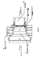
ミラープラグ
上述のように、FRCシステム10は、図2および3に示したように、ミラーコイル420、430、および444のセットを利用する。ミラーコイル420の第1のセットは、閉じ込めチャンバ100の2つの軸方向端部に配置され、主磁気システム410の閉じ込めコイル412、414および416から単独に活性化される。ミラーコイル420の第1のセットは、主に融合中にFRC450を進め軸方向に包含する助けとなり、持続している間に平衡成形制御を提供する。第1のミラーコイルセット420は、中央閉じ込めコイル412によって生成された中央閉じ込め磁場より名目上高い磁場(約0.4〜0.5T)を生成する。ミラーコイル430の第2のセットは、3つの小型の疑似直流ミラーコイル432、434および436を含み、形成部分200とダイバータ300との間に配置され、一般的なスイッチ電源によって駆動される。ミラーコイル432、434および436は、より小型のパルスミラープラグコイル444(容量電源によって供給される)および物理的収縮部442と一緒に、狭い低ガス伝導通路を非常に高い磁場(約10〜20msの立上り時間で2〜4T)で提供する、ミラープラグ440を形成する。最も小型のパルスミラーコイル444は、閉じ込めコイル412、414および416のメートルプラススケールの孔およびパンケーキ型設計に比べて、小型の径方向寸法、20cmの孔および同様の長さである。ミラープラグ440の目的は、以下のように多種多様である。(1)コイル432、434、436および444を堅く束ね、磁束表面452および端部に流れるプラズマジェット454を、遠隔ダイバータ・チャンバ300に導く。これは、排出粒子がダイバータ300に適切に到着し、中央FRC450の開いた磁力線452領域からダイバータ300までずっと追跡する、連続した磁束表面455が存在することを確実にする。(2)FRCシステム10における物理的収縮部442は、それを通ってコイル432、434、436および444が磁束表面452およびプラズマジェット454を通過することができ、ダイバータ300内に着座するプラズマガン350からの中性ガス流を妨げる。同じように、収縮部442は、形成部分200からダイバータ300へのガスの逆流を防止し、それによってFRCの起動を開始するときに、FRCシステム10全体に導入しなければならない中性粒子の数が低減する。(3)コイル432、434、436および444によって生成された強い軸方向のミラーは軸方向の粒子損失を低減し、それによって開いた磁力線上の平行な粒子拡散係数が低減する。
Mirror Plug As mentioned above, the
軸方向のプラズマガン
ダイバータ300のダイバータ・チャンバ310内に装着されたガン350からのプラズマ流は、安定性および中性ビーム性能を向上させることを意図する。ガン350は、図3および10に示したように、ダイバータ300のチャンバ310の内側の軸上に装着され、プラズマ流をダイバータ300内の開いた磁力線452に沿って、閉じ込めチャンバ100の中心に向かって生成する。ガン350は、ワッシャー積層チャネル内に高濃度ガス放出で作動し、5〜10msに完全にイオン化されたプラズマを数キロアンペア生成するように設計されている。ガン350は、出力プラズマ流を閉じ込めチャンバ100内の所望のサイズのプラズマに一致させる、パルス磁気コイルを含む。ガン350の技術パラメータは、5〜13cmの外径、および最高10cmまでの内径を有するチャネルを特徴とし、ガンの内部磁場は0.5〜2.3Tで、400〜600Vで10〜15kAの放電電流を提供する。
Axial Plasma Gun The plasma flow from the
ガンプラズマ流は、ミラープラグ440の磁場を貫通し、形成部分200および閉じ込めチャンバ100に流入することができる。ミラープラグ440を通るプラズマ移動の効率は、ガン350とプラグ440との間の距離を低減し、プラグ440をより広く短くすることによって高まる。妥当な条件下で、ガン350はそれぞれ、約150〜300eVおよび約40〜50eVの高いイオン温度および電子温度で、2〜4Tのミラープラグ440を通り約1022プロトン/sを送達する。ガン350は、FRCの縁層456の著しい燃料補給および改良されたFRC全体の粒子閉じ込めを提供する。
The gun plasma stream can penetrate the magnetic field of the
プラズマ密度をさらに高めるために、ガスボックスを利用して、追加のガスをガン350からプラズマ流に吹き入れることが可能である。この技法により、照射されたプラズマ密度を数倍に高めることができる。FRCシステム10では、ミラープラグ440の側部のダイバータ300上に搭載されたガスボックスは、FRCの縁層456の燃料補給、FRC450の形成、およびプラズマ磁力線短絡を向上させる。
To further increase the plasma density, a gas box can be utilized to blow additional gas from the
上に論じたすべての調整パラメータを所与とし、また、一方のみまたは両方のガンを備えた作動が可能であることを考慮すると、広いスペクトルの作動モードが利用可能であることがすぐにわかる。 Given all the adjustment parameters discussed above, and given that operation with only one or both guns is possible, it is immediately apparent that a wide spectrum of operation modes are available.
バイアス電極
開いた磁束表面の電気バイアスは、方位E×B運動を起こす径方向電位を提供することができ、方位E×B運動は、開いた磁力線プラズマの回転、ならびに速度シアを介して実際のFRCコア450を制御するための、ノブを回すのに類似した制御機構を提供する。この制御を達成させるために、FRCシステム10は、機械の様々な部分に配置された様々な電極を戦略的に利用する。図3は、FRCシステム10内の好ましい場所に位置付けられたバイアス電極を示す。
Bias Electrode The electrical bias of the open flux surface can provide a radial potential that causes directional ExB motion, which is the actual rotation of the open magnetic field line plasma, as well as through the velocity shear. It provides a control mechanism similar to turning a knob for controlling the
原則として、以下の4つの分類の電極がある。(1)局所電荷を提供するために、FRC450の縁部において特定の開いた磁力線452に接触させる、閉じ込めチャンバ100内の点電極905、(2)方位が対称的な形で遠端磁束層456に帯電させるための、閉じ込めチャンバ100と形成部分200との間の環状電極900、(3)複数の同心磁束層455(それによって層の選択は、ダイバータ磁場を調節するためにコイル416を調節することによって制御可能であり、その結果、適切な電極910上で所望の磁束層456を終了する)に帯電させるための、ダイバータ300内の同心電極910の積層、および最後に(4)プラズマガン350自体(これは、FRC450のセパラトリックス付近で内部の開いた磁束表面455を遮断する)の陽極920(図10参照)。図10および11は、これらの一部に対するいくつかの典型的な設計を示す。
In principle, there are the following four types of electrodes. (1) Point electrode 905 in the
すべての場合において、これらの電極は、最高約800Vまでの電圧でパルスまたは直流電源によって駆動される。電極のサイズおよびどの磁束表面が交差しているかに依存して、電流をキロアンペア範囲で引くことができる。 In all cases, these electrodes are driven by a pulsed or DC power supply at voltages up to about 800 V. Depending on the size of the electrodes and which flux surfaces intersect, the current can be drawn in the kiloamper range.
(FRCシステムの非持続作動−従来のレジーム)
良好に開発された磁場反転シータピンチ技法の後に、FRCシステム10上の標準プラズマ形成が続く。FRCを開始するための通常のプロセスは、定常状態作動のために疑似直流コイル412、414、416、420、432、434および436を駆動することにより開始する。次いでパルス電力形成システム210のRFTPパルス電力回路は、パルス高速磁場反転コイル232を駆動して、形成部分200内に約−0.05Tの一時的な逆バイアスを生成する。この点で、9〜20psiの所定の量の中性ガスを、形成部分200の外端上に配置されたフランジにおいて方位角に配向されたパフ弁のセットを介して、(北および南の)形成部分200の石英管チャンバ240によって画定された2つの形成容積の中に照射する。次に、小さいRF(約数百キロヘルツ)の磁場を、石英管240の表面上のアンテナのセットから生成して、中性ガス柱内に局所シードイオン化領域(local seed ionization region)の形でプレプレイオン化(pre−pre−ionization)を生成する。これに続いて、パルス高速磁場反転コイル232を駆動する電流上にシータリング変調を加え、これによりガス柱のより広範囲のプレイオン化がもたらされる。最後に、パルス電力形成システム210の主要パルスパワーバンクを燃やして、最高0.4Tまでの順方向バイアス磁場を生成するためにパルス高速磁場反転コイル232を駆動する。このステップは、順方向バイアス磁場が形成管240の全長に亘って均一に生成されるように(静的形成)、または連続蠕動磁場変調が、形成管240の軸に沿って達成されるように(動的形成)、時系列にすることができる。
(Non-sustainable operation of FRC system-conventional regime)
A well-developed magnetic field reversal theta pinch technique is followed by standard plasma formation on the
この形成プロセス全体で、プラズマ内の実際の磁場反転が約5μs内で急速に起きる。形成プラズマに容易に送達されたマルチギガワットのパルス電力は、高温のFRCを生成し、次いで高温のFRCは形成部分200から順方向磁場(磁場蠕動)の時系列の装着、または形成管210(閉じ込めチャンバ100に向かって軸方向を指す、軸方向の磁場勾配を形成する)の軸方向の外端近傍のコイルセット232の最後のコイル内の一時的に増加した電流のいずれかの適用によって、形成部分200から照射される。そのように形成され、加速された2つ(北および南)の形成FRCは、より大きい直径閉じ込めチャンバ100に拡大し、この場合、疑似直流コイル412は、順方向バイアス磁場を生成して、径方向の拡大を制御し平衡外部磁束を提供する。
Throughout this formation process, the actual magnetic field reversal in the plasma occurs rapidly within about 5 μs. The multi-gigawatt pulsed power easily delivered to the forming plasma produces a hot FRC, which is then fitted with a time series of forward magnetic fields (magnetic field perturbations) from the forming
一旦北および南の形成FRCが閉じ込めチャンバ100の中央平面近傍に到達すると、FRCは衝突する。衝突中、北および南の形成FRCの軸方向の運動エネルギーは、FRCが単一のFRC450に最終的に融合すると、大きく熱化される。プラズマ診断の大きいセットは、FRC450の平衡を調査するために閉じ込めチャンバ100の内で利用可能である。FRCシステム10内の通常の作動条件は、セパラトリックスの半径が約0.4mおよび軸方向に約3m延在する化合したFRCを生成する。さらなる特性は、約0.1Tの外部磁場、約5×10¹⁹m−3のプラズマ密度および最高1keVまでの合計プラズマ温度である。いかなる持続もなしに、すなわち中性ビーム照射または他の補助手段によって加熱および/または電流駆動なしに、これらのFRCの耐用期間は、本来の特性構成減衰時間の約1msに制限される。
Once the north and south forming FRCs reach near the central plane of the
(非持続作動の実験データ−従来のレジーム)
図12は、FRC450のシータピンチ融合プロセスの力学を示すために、セパラトリックスの半径rsに近づく、排除磁束半径rΔФの通常の時間発展を示す。2つ(北および南)の個々のプラズモイドは、同時に生成され、次いでそれぞれの形成部分200から出て超音速vz約250km/sで加速され、中央平面近傍でz=0で衝突する。衝突中、プラズモイドは軸方向に圧迫し、続いて即座に径方向および軸方向に拡大し、最後に融合してFRC450を形成する。融合するFRC450の径方向および軸方向の力学の両方は、詳しく示した密度プロファイルの測定およびボロメータに基づいた断層撮影によって証明される。
(Experimental data of non-sustained operation-conventional regime)
12, in order to show the dynamics of Shitapinchi fusion process FRC450, approaching the radius r s of the separatrix, shows a typical time evolution of eliminating flux radius r ΔФ. The two (north and south) individual plasmoids are generated simultaneously, then exit from their
FRCシステム10の代表的な非持続放出からのデータは、図13に時間関数として示されている。FRCは、t=0で開始される。機械の軸方向の中央平面における排除磁束半径は、図13(a)に示されている。このデータは、磁気プローブのアレイから得られ、閉じ込めチャンバのステンレス鋼壁のすぐ内側に配置され、これは軸方向磁場を測定する。鋼壁は、この放出の時間スケール上の良好な磁束保存器である。
Data from a representative non-sustained release of the
線集積密度は、z=0に配置された6つのコードのCO2/He−Ne干渉計から図13(b)に示されている。垂直(y)FRC変位を考慮すると、ボロメータの断層撮影によって測定されたように、アーベル逆変換は図13(c)の密度等高線をもたらす。初めの0.1ms間に一部の軸方向および径方向のスロッシング後、FRCは、中空密度プロファイルを有して定着する。このプロファイルは極めて平坦であり、必要に応じて通常の二次元FRC平衡により実質的な密度を軸上にもつ。 The line integration density is shown in FIG. 13 (b) from the 6-code CO 2 / He-Ne interferometers located at z = 0. Considering the vertical (y) FRC displacement, the Abel inverse transformation results in the density contours of FIG. 13 (c), as measured by bolometer tomography. After some axial and radial sloshing during the first 0.1 ms, the FRC settles with a hollow density profile. This profile is extremely flat and, if necessary, has substantial density on the axis by conventional 2D FRC equilibrium.
圧力平衡から得られ、トムソン散乱分光測定と完全に一致する、合計プラズマ温度が、図13(d)に示されている。 The total plasma temperature, obtained from pressure equilibrium and in perfect agreement with Thomson scattering spectroscopy, is shown in FIG. 13 (d).
排除磁束アレイ全体からの分析は、FRCのセパラトリックス(排除磁束軸方向プロファイルによって見積もられる)の形状が、レーストラック型から楕円形に次第に進化することを示す。図14に示されたこの進化は、2つのFRCから単一のFRCへの段階的な磁気再結合に一致する。実際に、概算は、この特定の場合では、最初の2つのFRC磁束の約10%が、衝突中に再結合すると示唆している。 Analysis from the entire exclusion flux array shows that the shape of the FRC's Separatrix (estimated by the exclusion flux axial profile) gradually evolves from racetrack to elliptical. This evolution shown in FIG. 14 is consistent with a gradual magnetic reconnection from two FRCs to a single FRC. In fact, estimates suggest that in this particular case, about 10% of the first two FRC fluxes recombine during a collision.
FRCの長さは、FRCの耐用期間中に3m〜約1mに確実に収縮する。この収縮は図14に見られ、ほとんどの対流エネルギー損失は、FRC閉じ込めより優先されることを示唆する。セパラトリックスの内側のプラズマ圧力は、外部磁気圧力より急速に低減するので、端部領域における磁力線張力は、FRCを軸方向に圧迫し、軸方向および径方向の平衡を回復する。図13および14に論じた放出に対して、FRCの磁束、粒子インベントリ、および熱エネルギー(それぞれ、約10mWb、7×10¹⁹粒子、および7kJ)は、FRC平衡が低下するように見えたとき、最初のミリ秒後におよそ1桁低減する。 The length of the FRC reliably shrinks from 3 m to about 1 m during the useful life of the FRC. This contraction is seen in FIG. 14, suggesting that most convective energy losses take precedence over FRC confinement. Since the plasma pressure inside the separatics decreases more rapidly than the external magnetic pressure, the magnetic field line tension in the end region compresses the FRC axially and restores axial and radial equilibrium. For the emissions discussed in FIGS. 13 and 14, the FRC magnetic flux, particle inventory, and thermal energy (about 10 mWb, 7 × 10 19 particles, and 7 kJ, respectively) appeared to reduce the FRC equilibrium. Reduce by approximately an order of magnitude after the first millisecond.
(持続作動−HPFレジーム)
図12〜14における例は、いかなる持続もなしにFRCを減衰する特性である。しかし、いくつかの技法は、FRCシステム10に展開されて、さらにFRC閉じ込め(内部コアおよび縁層)をHPFレジームに向上させ、閉じ込めを持続させる。
(Continuous operation-HPF regime)
The examples in FIGS. 12-14 are properties that attenuate the FRC without any persistence. However, some techniques have been deployed in the
中性ビーム
まず、高速(H)中性を8個の中性ビーム照射装置600からビーム内のBzに垂直に照射する。高速中性のビームは、北および南の形成FRCが閉じ込めチャンバ100内で融合した瞬間から1つのFRC450の中に照射される。高速イオンは電荷交換によって主に生成され、FRC450の方位電流に加えるベータトロン軌道(FRCトポロジーのスケール上または特性磁場勾配長さスケールよりはるかに長い主要半径を有する)を有する。放出のわずか後(照射の0.5〜0.8ms後)、充分に大きい高速イオン集団は、内部FRCの安定性および閉じ込め特性を著しく向上させる(例えば、M.W.BinderbauerおよびN.Rostoker、Plasma Phys.56、part 3、451(1996)参照)。さらに、持続の観点から、中性ビーム照射装置600からのビームも、電流を駆動しFRCプラズマを加熱する主な手段である。
Neutral beam First, high-speed (H) neutral is irradiated perpendicularly to B z in the beam from eight neutral beam irradiators 600. A fast neutral beam is emitted into one FRC450 from the moment the north and south forming FRCs fuse in the
FRCシステム10のプラズマレジームでは、高速イオンはプラズマ電子上で主に減速する。放出の初期の間、高速イオンの通常の軌道の平均減速時間は0.3〜0.5msであり、これは著しいFRCの主に電子の加熱をもたらす。高速イオンは、内部FRC磁場が本質的に低いので(0.1Tの外部軸方向磁場に対して平均約0.03T)、セパラトリックスの外側の径方向の偏位を大きくする。高速イオンは、中性ガス濃度がセパラトリックスの外側で高過ぎた場合、電荷交換損失に対して弱いはずである。したがって、FRCシステム10上に展開した壁ゲッタリングおよび他の技法(とりわけガス制御に寄与するプラズマガン350およびミラープラグ440など)は、端中性を最小にし、高速イオン電流の必要な構築を可能にする。
In the plasma regime of the
ペレット照射
電子がより高温でFRCの耐用期間がより長い、超高速イオン集団がFRC450内に構築される際、冷凍のHまたはDペレットは、ペレット照射装置700からFRC450の中に照射されて、FRC450のFRC粒子インベントリを持続させる。予想されるアブレーション時間スケールは充分に短いので、かなりのFRC粒子源を提供する。またこの速度は、個々のペレットをより小さい片に砕くことにより、照射された片の表面積を拡大することによって増大させることができるが、ペレット照射装置700のバレルまたは照射管内で、また閉じ込めチャンバ100に入る前に、閉じ込めチャンバ100の中に入る直前に照射管の最後の部分の曲げ半径を締め付けることにより、ペレットと照射管の壁との間の片を増加させることによってステップを達成できる。12バレル(照射管)の燃焼順序および速度、ならびに粉砕を変化させる恩恵により、ペレット照射システム700を調整して、まさに所望のレベルの粒子インベントリの持続を提供することができる。その結果、これはFRC450内の内部動圧ならびにFRC450の持続作動および耐用期間を維持する役に立つ。
Pellet irradiation Frozen H or D pellets are irradiated into the FRC450 from the pellet irradiation device 700 when an ultrafast ion population is constructed within the FRC450, where the electrons are hotter and the FRC has a longer life. Sustain FRC particle inventory. The expected ablation time scale is short enough to provide a significant FRC particle source. This rate can also be increased by increasing the surface area of the irradiated pieces by breaking the individual pellets into smaller pieces, but also within the barrel or irradiation tube of the pellet irradiation device 700 and in the
一旦、除去された原子がFRC450内で著しいプラズマに衝突すると、除去された原子は完全にイオン化される。次いで得られた低温のプラズマ構成要素は、本来のFRCプラズマにより衝突して加熱される。所望のFRC温度を維持するために必要なエネルギーは、ビーム照射装置600により最終的に供給される。この意味で、ペレット照射装置700は中性ビーム照射装置600と一緒に、定常状態を維持しFRC450を持続するシステムを形成する。
Once the removed atoms collide with a significant plasma within the FRC450, the removed atoms are completely ionized. The resulting low temperature plasma components are then collided and heated by the original FRC plasma. The energy required to maintain the desired FRC temperature is finally supplied by the
サドルコイル
定常状態の電流駆動を達成し、必要なイオン電流を維持するために、電子イオン摩擦力(衝突イオン電子運動量移動からもたらされる)に起因する電子スピンを防止するまたは著しく低減することが望ましい。FRCシステム10は、外部印加された静磁場双極子または四重極磁場を介して、電子遮断を提供する革新的な技法を利用する。これは、図15に示した外部サドルコイル460を介して実現される。サドルコイル460から横方向に印加された径方向の磁場は、回転するFRCプラズマ内の軸方向の電界を誘導する。得られる軸方向の電子電流は、径方向の磁場と相互作用して、電子上に方位遮断力Fθ=−σVeθ<|Br|2>を生成する。FRCシステム10における典型的な条件に対して、プラズマ内部に必要な印加された磁場双極子(または四重極磁場)は、適切な電子遮断を提供するために約0.001Tのみであることが必要である。約0.015Tの対応する外部磁場は充分に小さいので、多くの高速粒子損失あるいは閉じ込めに悪影響をもたらすことはない。事実、印加された磁場双極子(または四重極磁場)は、不安定性の抑制に寄与する。接線中性ビーム照射と軸方向プラズマ照射を組み合わせて、サドルコイル460は、電流の維持および安定性に関して追加レベルの制御を提供する。
Saddle coil In order to achieve steady-state current drive and maintain the required ionic current, it is desirable to prevent or significantly reduce electron spin due to electron-ion frictional forces (caused by collision ion electron momentum transfer). .. The
ミラープラグ
ミラープラグ440内のパルスコイル444の設計により、適度(約100kJ)の容量エネルギーで高磁場(2〜4T)の局所発生が可能になる。FRCシステム10のこの作動の通常の磁場形成に対して、形成容積内のすべての磁力線は、図2における磁力線によって示唆されたように、ミラープラグ440で収縮部442を通過し、プラズマ壁の接触は起きない。さらに、疑似直流ダイバータ磁気416と連動してミラープラグ440を、磁力線をダイバータ電極910の上に導く、または磁力線を端部カスプ配位(図示せず)内で燃焼させるように、調節することができる。後者は安定性を向上させ、平行な電子熱伝導を抑圧する。
Mirror plug The design of the pulse coil 444 in the
またミラープラグ440自体も、中性ガス制御に寄与する。ミラープラグ440は、ダイバータ300の中へのガス逆流が、プラグの少量のガスコンダクタンス(わずか500L/s)によって著しく低減するので、FRC形成中に石英管に吹き入れられる重水素ガスのより良好な利用が可能になる。形成管210内部の残りの吹き入れられたガスのほとんどは、急速にイオン化される。加えて、ミラープラグ440を通って流れる高密度プラズマは、有効な中性イオン化、ひいては有効なガス障壁を提供する。結果として、FRC縁層456からダイバータ300内に再利用されたほとんどの中性は、閉じ込めチャンバ100に戻らない。加えて、プラズマガン350の作動に関連した中性は(以下に論じるように)、ダイバータ300に大部分が閉じ込められることになる。
The
最後に、ミラープラグ440は、FRC縁層閉じ込めを向上する傾向がある。ミラー比(プラグ/閉じ込め磁場)が20〜40の範囲で、北と南のミラープラグ440の間の長さが15mで、縁層粒子閉じ込め時間
![]()
![]()
![]()
![]()
セパラトリックス容積453からの径方向の拡散(D)粒子損失が、縁層456からの軸方向損失
![]()

![]()
![]()
![]()
![]()
![]()
![]()
![]()
プラズマガン
プラズマガン350は、磁力線短絡によりFRC排除ジェット454の安定性を向上させる。プラズマガン350からのガンプラズマは、方位角運動量なしに生成され、これはFRC回転不安定性の制御に有用であることがわかる。したがって、ガン350は、より古い四重極の安定化技術を必要としない、FRCの安定性を制御する有効な手段である。結果として、プラズマガン350は、高速粒子の有益な効果を利用する、または本開示に概要を述べたように、進化したハイブリッド運動FRCレジームに近づくことを可能にする。したがって、プラズマガン350により、FRCシステム10がまさに電子遮断に適切だが、FRCの不安定性を引き起こす、かつ/または劇的な高速粒子拡散をもたらすはずである閾値より低い、サドルコイル電流で作動されることが可能になる。
Plasma gun The
上に論じたミラープラグで述べたように、
![]()
![]()
さらに、ガンプラズマ流を、約150〜200マイクロ秒後にオンすることができ、それによってFRCの起動、移動および閉じ込めチャンバ100への融合に使用可能になる。tが約0でオンする場合(FRC主要バンク開始)、ガンプラズマは、この動的に形成され融合されたFRC450を持続する役に立つ。形成FRCから、およびガンから組み合わせた粒子インベントリは、中性ビームの捕捉、プラズマの加熱、および長い持続に充分である。tが−1〜0msの範囲でオンする場合、ガンプラズマは、プラズマで石英管210を充填できる、または石英管の中に吹き入れたガスをイオン化でき、したがって、吹き入れたガスを低減する、または恐らく0でさえあるFRC形成が可能になる。後者は、逆バイアス磁場の高速拡散が可能になるために、充分に低温の形成プラズマが必要な場合がある。tが<−2msでオンする場合、プラズマ流は、形成の約1〜3m3の磁力線容積ならびに形成部分200の閉じ込め領域および目標プラズマ密度がわずか1013cm−3である閉じ込めチャンバ100を充填することができ、FRCの到達前に中性ビームの構築が充分に可能である。次いで形成FRCを形成し、得られる閉じ込め容器プラズマの中に移動できる。このような方法で、プラズマガン350は、広範囲の作動条件およびパラメータレジームが可能である。
In addition, the gun plasma stream can be turned on after about 150-200 microseconds, which makes it available for FRC activation, transfer and fusion to the
電気的バイアス
縁層456内の径方向電界の制御は、FRCの安定性および閉じ込めに様々な方法で有利である。FRCシステム10に展開した革新的なバイアス構成要素の恩恵により、電位の様々な意図的な分散を閉じ込めチャンバ100内の中央閉じ込め領域の充分に外側の領域から機械全体に亘って開いた磁束表面の群に印加することができる。このような方法で、径方向磁場を、FRC450のすぐ外側の縁層456を横切って生成することができる。次いでこれらの径方向電界は、縁層456の方位回転を修正し、E×B速度シアによってその閉じ込めをもたらす。次いで縁層456とFRCコア453との間のあらゆる差動回転を、シアによりFRCプラズマの内側に移動できる。結果として、縁層456を制御することは、FRCコア453に直接影響を与える。さらに、プラズマ回転における自由エネルギーも不安定性に関与できるので、この技法は、不安定性の開始および成長を制御する直接手段を提供する。FRCシステム10では、適切な縁バイアスは、開いた磁力線の移動および回転、ならびにFRCコア回転の有効な制御を提供する。様々な提供された電極900、905、910および920の場所および形状により、磁束表面455の異なる群の制御が異なる独立した電位で可能になる。このような方法で、多様な異なる電界構成および強度を認識でき、それぞれはプラズマ性能に対する異なる性質の影響をもつ。
Controlling the radial electric field within the electrical bias margin layer 456 is advantageous in various ways for FRC stability and confinement. Thanks to the innovative bias components deployed in the
すべてのこれらの革新的バイアス技法の主要な利点は、コアおよび縁部のプラズマ挙動が、FRCプラズマの充分に外側から影響を与えることができる、すなわち、いかなる物理的な構成要素も中央高温プラズマ(中央高温プラズマは、エネルギー、磁束および粒子の損失に深刻な影響をもつはずである)に接触させる必要がないという事実である。これは、HPFの概念の性能およびすべての潜在用途に対して主要な有利な影響を有する。 The main advantage of all these innovative biasing techniques is that the core and edge plasma behavior can influence the FRC plasma from the outside sufficiently, i.e. any physical component is a central hot plasma (1). The central hot plasma is the fact that it does not need to be in contact with energy, magnetic flux and particle loss). This has a major positive impact on the performance of the HPF concept and all potential applications.
(実験データ−HPF作動)
中性ビームガン600からのビームによる高速粒子の照射は、HPFレジームを可能にする重要な役割を果たす。図16はこの事実を示す。示されているのは、FRCの耐用期間がビームパルスの長さにどのように関連するかを示す曲線のセットである。すべての他の作動条件は、この研究を含むすべての放出に対して一定に保たれる。データは、多くの照射に亘って平均し、したがって、通常の挙動を表す。ビーム期間が長いほど、より長く存続するFRCを生成させることが極めて明白である。この証拠ならびにこの研究中の他の診断を見ると、ビームは安定性を高め、損失を低減することを実証している。ビームパルス長さとFRCの耐用期間との間の相互関係は、ビームトラッピングがある種のプラズマサイズ未満で効力がないので、すなわち、照射されたビームのすべての物理的サイズにおけるFRC450の収縮が、捕捉されるまたはトラッピングされるわけではないので、完全ではない。FRCの収縮は、主に、放電の間のFRCプラズマからの正味エネルギー損失(放電のほぼ中間で約4MW)が、特定の実験設定に関して、中性ビーム(約2.5MW)を介してFRCの中に給送される総パワーより幾分大きいという事実に起因する。ビームを容器100の中央平面により近接する場所に位置させることは、これらの損失を低減させ、FRC寿命時間を延長させる傾向となるであろう。
(Experimental data-HPF operation)
Irradiation of fast particles with a beam from the
図17は、HPFレジームを達成するための異なる構成要素の効果を示す。図17は、時間関数としてFRC450の耐用期間を示す典型的な曲線族を示す。すべての場合において、ビーム電力の一定の適度の量(約2.5MW)が、各放出の全期間照射される。各曲線は、構成要素の異なる組合せを表す。例えば、ミラープラグ440、プラズマガン350またはゲッタリング・システム800からのゲッタリングのいずれもなしにFRCシステム10を作動させると、回転の不安定性の急激な発生およびFRCトポロジーの損失をもたらす。ミラープラグ440のみを加えると、不安定性の発生を遅らせ、閉じ込めを増加させる。ミラープラグ440とプラズマガン350の組合せを利用すると、さらに不安定性を低減し、FRCの耐用期間を増加させる。最後にガン350およびプラグ440の上にゲッタリング(この場合Ti)を加えると、最良の結果を得る、すなわち、得られるFRCは、不安定性がなく、最長の耐用期間を示す。構成要素の完全な組合せが最良の効果を生み出し、最良の目標条件をもつビームを提供することが、この実験証明から明らかである。
FIG. 17 shows the effect of different components to achieve the HPF regime. FIG. 17 shows a typical curvilinear family showing the useful life of the FRC450 as a time function. In all cases, a constant modest amount of beam power (about 2.5 MW) is applied for the entire duration of each emission. Each curve represents a different combination of components. For example, operating the
図1に示したように、最近発見されたHPFレジームは、劇的に改良された移動挙動を示す。図1は、従来のレジームとHPFレジームとの間のFRCシステム10における粒子閉じ込め時間の変化を示す。見てわかるように、これは、HPFレジームにおいて5倍をはるかに超えて改良されている。加えて、図1は、従来のFRC実験前の粒子閉じ込め時間に対して、FRCシステム10における粒子閉じ込め時間を詳しく示す。これらの他の機械に関して、FRCシステム10のHPFレジームは、5倍〜ほぼ20倍に閉じ込めを改良してきた。最後に最も重要なことだが、HPFレジームにおけるFRCシステム10の閉じ込めスケーリングの本質は、すべての以前の測定とは劇的に異なる。FRCシステム10におけるHPFレジームの確立前に、様々な実証的スケーリング則が、以前のFRC実験における閉じ込め時間を予測するためにデータから導き出された。これらのすべてのスケーリング則は、割合R2/ρiに主に依存する。式中、Rは磁場のない半径(機械の物理的スケールの粗測)であり、ρiは外部印加磁場において評価されたイオン・ラーモア半径(印加磁場の粗測)である。従来のFRCにおける長い閉じ込めは、大型機械のサイズおよび/または高磁場のみで可能であることが図1から明らかである。従来のFRCレジームCRにおいてFRCシステム10を作動することは、図1に示したように、これらのスケーリング則に従う傾向がある。しかし、HPFレジームは非常に優れており、はるかに良好な閉じ込めが、大型機械のサイズまたは高磁場なしに達成可能である。より重要なことには、HPFレジームは、CRレジームに比べて低減したプラズマサイズをもつ、改良された閉じ込め時間をもたらすことも図1から明らかである。また、同様の傾向は、以下に説明するように磁束およびエネルギー閉じ込め時間にも見られ、その上、磁束およびエネルギー閉じ込め時間は、FRCシステム10において3〜8倍を超えて増加した。したがって、HPFレジームの進歩は、FRCシステム10におけるFRC平衡を持続し維持するために、わずかなビーム電力、より低い磁場およびより小さいサイズの使用、ならびに未来のより高エネルギーの機械の使用が可能になる。これらの改良に関連して、作動および構築費用を下げ、ならびに工学の複雑さを減らす。
As shown in FIG. 1, recently discovered HPF regimes exhibit dramatically improved locomotion behavior. FIG. 1 shows the change in particle confinement time in the
さらなる比較のために、図18は、FRCシステム10における代表的なHPFレジーム放出からのデータを時間関数として示す。図18(a)は、中央平面での排除磁束半径を示す。これらのより長い時間スケールに対して、誘導鋼鉄壁は、もはや磁束保存器のように良好ではなく、壁の内部にある磁気プローブは、鋼鉄を通る磁束拡散を適切に構成する壁の外側のプローブで増大される。図13に示したように、従来のレジームCRにおける通常の性能と比較して、HPFレジームの作動モードは、400%を超える長い耐用期間を示す。
For further comparison, FIG. 18 shows data from a representative HPF regime release in the
線集積密度追跡の代表的コードは、図18(c)におけるそのアーベル逆変換相補、密度等高線と共に、図18(b)に示されている。従来のFRCレジームCRと比較して、図13に示したように、プラズマは、非常に安定した作動を示し、パルス全体を通してより不活発である。またピーク濃度は、HPF照射においてわずかに低く、これは、図18(d)に示したように、より高い合計プラズマ温度(最高2倍まで)の結果である。 A representative code for line accumulation density tracking is shown in FIG. 18 (b), along with its Abel inverse transformation complement, density contour lines in FIG. 18 (c). Compared to the conventional FRC regime CR, as shown in FIG. 13, the plasma exhibits a very stable operation and is more inactive throughout the pulse. Also, the peak concentration was slightly lower with HPF irradiation, which is the result of higher total plasma temperature (up to 2x), as shown in FIG. 18 (d).
図18に示されたそれぞれの放出に対して、エネルギー、粒子および磁束閉じ込め時間はそれぞれ、0.5ms、1msおよび1msである。放出への基準時間1msで、保存されたプラズマエネルギーは2kJであるが、損失は約4MWであり、この目標を中性ビーム持続に非常に適合させる。 For each emission shown in FIG. 18, the energy, particle and flux confinement times are 0.5 ms, 1 ms and 1 ms, respectively. At a reference time of 1 ms to emission, the stored plasma energy is 2 kJ, but the loss is about 4 MW, which makes this target very well suited for neutral beam duration.
図19は、新しく確立された実験用HPF磁束閉じ込めスケーリングの形態における、HPF体系の全利点を要約する。図19から分かるように、t=0.5ms、すなわち、t≦0.5msおよびt>0.5msの前後で測定された測定値に基づいて、磁束閉じ込め(同様に、粒子閉じ込めおよびエネルギー閉じ込め)は、所与の区分線半径(rs)に対して電子温度(Te)のほぼ2乗に伴って変化する。Teの正の指数(負の指数ではない)に伴う本強スケーリングは、閉じ込めが、典型的には、電子温度のある指数に反比例する、従来のトカマクによって呈されるものと完全に反対である。本スケーリングの現れは、HPF状態および大軌道(すなわち、FRCトポロジのスケールおよび/または少なくとも特性磁場勾配長スケール上の軌道)イオン集団の直接的結果である。基本的には、本新しいスケーリングは、高動作温度に実質的に有利に働き、比較的に中程度のサイズの炉を可能にする。 FIG. 19 summarizes all the advantages of the HPF system in the newly established form of experimental HPF flux confinement scaling. As can be seen from FIG. 19, magnetic flux confinement (similarly, particle confinement and energy confinement) is based on measurements measured around t = 0.5 ms, i.e. t ≤ 0.5 ms and t> 0.5 ms. varies with approximately the square of the electron temperature (T e) for a given separation line radius (r s). This strong scaling due to positive index T e (non-negative exponent) is confined is typically inversely proportional to the index of electron temperature, completely opposite to that exhibited by conventional Tokamak is there. The manifestation of this scaling is a direct result of the HPF state and large orbital (ie, orbital on the FRC topology scale and / or at least the characteristic magnetic field gradient length scale) ion population. Basically, this new scaling works substantially in favor of high operating temperatures, allowing for relatively medium sized furnaces.
HPF体系が提示する利点によって、中性ビームによって駆動され、適切なペレット注入を使用する、FRC持続または定常状態が、達成可能であって、プラズマ熱エネルギー、総粒子数、プラズマ半径および長さ、ならびに磁束等の包括的プラズマパラメータが、実質的減衰を伴わずに、合理的レベルで持続可能であることを意味する。比較のために、図20は、プロットAには、時間の関数としてのFRCシステム10内の代表的HPF体系放電からのデータを、プロットBには、FRC450が、中性ビームパルスの持続時間を通して、減衰を伴わずに持続される、時間の関数としてのFRCシステム10内の投影された代表的HPF体系放電のデータを示す。プロットAに関しては、約2.5〜2.9MWの範囲内の総パワーを伴う中性ビームが、約6msの活性ビームパルス長のために、FRC450の中に注入された。プロットAに描写される反磁性寿命時間は、約5.2msであった。より最近のデータは、約7.2msのプラズマ反磁性寿命時間が、約7msの活性ビームパルス長を用いて達成可能であることを示す。
Due to the advantages presented by the HPF system, FRC persistence or steady state, driven by a neutral beam and using appropriate pellet injection, is achievable, plasma thermal energy, total particle number, plasma radius and length, It also means that comprehensive plasma parameters such as magnetic flux are sustainable at a reasonable level without substantial attenuation. For comparison, FIG. 20 shows data from a representative HPF system discharge in the
図16に関して前述のように、ビームパルス長とFRC寿命時間との間の相関は、ビーム捕捉が、あるプラズマサイズを下回ると非効率的となるため、完璧ではない、すなわち、FRC450の物理的サイズが収縮するにつれて、注入されるビーム全てが、奪取および捕捉されることはない。FRCの収縮または減衰は、主に、放電の間のFRCプラズマからの正味エネルギー損失(放電のほぼ中間で−4MW)が、特定の実験設定に関して、中性ビーム(約2.5MW)を介してFRCの中に給送される総パワーより幾分大きいという事実に起因する。図3Cに関して記載のように、ビーム注入が中性ビームガン600から中央平面に向かって角度付けられることによって、注入周期の間、FRCプラズマが収縮または別様に軸方向に縮小しても、ビーム−プラズマ結合を改良する。加えて、適切なペレット燃料補給は、必要プラズマ密度を維持するであろう。
As mentioned above with respect to FIG. 16, the correlation between beam pulse length and FRC lifetime is not perfect, as beam capture becomes inefficient below a certain plasma size, i.e. the physical size of the FRC450. As the plasma contracts, not all of the injected beams are captured and captured. The contraction or attenuation of the FRC is predominantly the net energy loss from the FRC plasma during the discharge (-4 MW approximately in the middle of the discharge), but for certain experimental settings, via a neutral beam (approximately 2.5 MW). Due to the fact that it is somewhat greater than the total power delivered into the FRC. As described with respect to FIG. 3C, the beam injection is angled from the
プロットBは、約6msの活性ビームパルス長および約10MWを若干上回る中性ビームガン600からの総ビームパワーを使用して行われたシミュレーションの結果であって、中性ビームは、約15keVの粒子エネルギーを伴うH(または、D)中性粒子を注入するものとする。ビームのそれぞれによって注入される等価電流は、約110Aである。プロットBに関して、デバイス軸に対するビーム注入角度は、約20°、標的半径0.19mであった。注入角度は、範囲15°〜25°内で変更されることができる。ビームは、方位角的に並流方向に注入されるものとする。中性ビーム運動量注入からの正味側方力ならびに正味軸方向力は、最小限にされるものとする。プロットAと同様に、高速(H)中性粒子が、北側および南側形成FRCが閉じ込めチャンバ100内で融合する瞬間から、中性ビーム注入器600から1つのFRC450の中に注入される。
Plot B is the result of a simulation performed using an active beam pulse length of about 6 ms and a total beam power from a
プロットBのための基礎となったシミュレーションは、背景プラズマおよび平衡のための多次元ホールMHDソルバ、エネルギー性ビーム成分および全散乱プロセスのための完全動態学的モンテカルロベースのソルバ、ならびに全プラズマ種に対して結合された輸送方程式集合を使用して、双方向損失プロセスをモデル化する。輸送成分は、実験的に較正され、実験データベースに対して広範囲にわたってベンチマークされる。 The underlying simulations for Plot B include a multidimensional Hall MHD solver for background plasma and equilibrium, a fully dynamic Monte Carlo-based solver for energetic beam components and total scattering processes, and all plasma species. A bidirectional loss process is modeled using a combined transport equation set. Transport components are experimentally calibrated and extensively benchmarked against an experimental database.
プロットBによって示されるように、FRC450の定常状態反磁性寿命時間は、ビームパルスの長さとなるであろう。しかしながら、重要となる相関プロットBは、ビームがオフにされると、プラズマまたはFRCが、その前ではなく、その時間において、減衰し始めることを示すことに留意することが重要である。減衰は、ビーム支援ではない(おそらく、ビームオフ時間を約1ms超える)、放電中に観察され、単に、固有の損失プロセスによって駆動されるプラズマの特性減衰時間の反映であるものと類似するであろう。 As shown by plot B, the steady-state diamagnetic lifetime of the FRC450 will be the length of the beam pulse. However, it is important to note that the important correlation plot B shows that when the beam is turned off, the plasma or FRC begins to decay at that time, not before. The decay is not beam assisted (perhaps more than about 1 ms of beam off time) and will be similar to that observed during discharge and simply a reflection of the characteristic decay time of the plasma driven by the inherent loss process. ..
本発明は様々な修正形態および代替形態の影響を受けやすいが、その具体例が図面に示され、本明細書に詳述された。しかし、本発明は開示された特定の形または方法に限定されないが、逆に、本発明は、添付の特許請求の範囲の精神および範囲に収まる、すべての修正形態、均等物および代替形態を網羅するものであることを理解されたい。 The present invention is susceptible to various modified and alternative forms, the specific examples of which are shown in the drawings and detailed herein. However, the invention is not limited to the particular form or method disclosed, but conversely, the invention covers all modifications, equivalents and alternative forms that fall within the spirit and scope of the appended claims. Please understand that it is something to do.
上述では、説明目的に過ぎず、具体的な用語は、本開示の完全な理解を提供するために説明されている。しかし、これらの具体的な詳述は、本開示の教示を実施するために必要とはされないことが、当業者には明らかになろう。 The above is for illustration purposes only, and specific terms are provided to provide a complete understanding of the present disclosure. However, it will be apparent to those skilled in the art that these specific details are not required to implement the teachings of the present disclosure.
代表的な例および従属請求項の様々な特徴は、本教示の追加の有益な実施形態を提供するために、具体的にかつ明確に列挙されていないようなやり方で組み合わされていることがある。エンティティの群のすべての階級区分または表示は、本来の開示目的のため、ならびに特許請求の範囲の主題を限定する目的のために、あらゆる可能な中間値または中間エンティティを開示することも明白に留意されたい。 Representative examples and various features of the dependent claims may be combined in a manner that is not specifically and explicitly listed to provide additional useful embodiments of the teaching. .. It is also clearly noted that all classes or representations of a group of entities disclose any possible intermediate value or intermediate entity for the purpose of original disclosure and for the purpose of limiting the subject matter of the claims. I want to be.
HPFレジームFRCを生成し維持するシステムおよび方法が開示されてきた。本明細書に記載された実施形態は、解明のためであり、本開示の主題を限定するとみなされるべきではないことを理解されたい。様々な修正形態、使用、置換、組合せ、改良、生産方法が、本発明の範囲または精神から逸脱することなく、当業者に明らかであるはずである。例えば、本明細書に記載されたプロセス行為の具体的な順序および組合せは、特定の指定がない限り例示に過ぎず、本発明を、異なるもしくは追加のプロセス行為、またはプロセス行為の異なる組合せもしくは順序を使用して実施することができることを、読者は理解するべきである。別の例として、一実施形態のそれぞれの特徴を、他の実施形態に示された他の特徴と混合または整合することができる。当業者に公知の特徴およびプロセスを、要望通りに同様に組み合わせてもよい。加えてまた明らかに、特徴を要望通りに加えてもよく、または差し引いてもよい。したがって、本発明は、添付された特許請求の範囲およびそれらの均等物を考慮する以外に限定されない。 Systems and methods for generating and maintaining the HPF regime FRC have been disclosed. It should be understood that the embodiments described herein are for elucidation and should not be considered as limiting the subject matter of the present disclosure. Various modifications, uses, substitutions, combinations, improvements and production methods should be apparent to those skilled in the art without departing from the scope or spirit of the invention. For example, the specific order and combination of process actions described herein is merely exemplary unless otherwise specified, and the present invention may be expressed in different or additional process actions, or in different combinations or sequences of process actions. The reader should understand that this can be done using. As another example, each feature of one embodiment can be mixed or matched with other features shown in other embodiments. Features and processes known to those of skill in the art may be similarly combined as desired. In addition, obviously, features may be added or subtracted as desired. Therefore, the present invention is not limited to taking into account the appended claims and their equivalents.
Claims (42)
前記閉じ込めチャンバ内にプラズマを中心としてFRCを形成するステップであって、FRCプラズマは、前記閉じ込めチャンバの壁に対して離間している、ステップと、
前記閉じ込めチャンバの縦軸に対して直角よりも15°〜25°小さい角度において、前記閉じ込めチャンバの中央平面に向かって、高速中性原子のビームを中性原子ビーム注入器から前記FRCプラズマの中に注入することによって、減衰を伴わずに、前記FRCを一定値またはほぼ一定値に維持するステップであって、前記中性原子ビーム注入器は、前記閉じ込めチャンバの中央平面の近くに近接して前記閉じ込めチャンバに結合され、前記閉じ込めチャンバの前記縦軸に対して直角よりも15°〜25°小さい角度で前記中央平面に向かって中性原子ビームを注入するように配向されている、ステップと
を含む、方法。 A method for generating and maintaining a magnetic field with field-reversed configuration (FRC) in a confinement chamber.
A step of forming an FRC centered on a plasma in the confinement chamber, wherein the FRC plasma is separated from the wall of the confinement chamber.
In 1 5 ° to 25 ° smaller than the right angle to the longitudinal axis of the containment chamber, said containment toward the center plane of the chamber, a beam of fast neutral atoms from neutral atom beam injectors of the FRC plasma The neutral atom beam injector is in close proximity to the central plane of the confinement chamber, a step that maintains the FRC at a constant or near constant value by injecting into it, without attenuation. It said containment coupled to the chamber Te, are oriented to inject the neutral atom beam toward the central plane at an angle 1 5 ° to 25 ° smaller than a right angle relative to the longitudinal axis of the containment chamber, Methods, including steps.
閉じ込めチャンバと、
前記閉じ込めチャンバに結合される第1および第2の直径方向に対向するFRC形成区分であって、FRCを生成し、前記FRCを前記閉じ込めチャンバの中央平面に向かって平行移動させるためのモジュール式形成システムを備える、形成区分と、
前記第1および第2の形成区分に結合される第1および第2のダイバータと、
前記第1および第2のダイバータ、前記第1および第2の形成区分、および前記閉じ込めチャンバに動作可能に結合される、第1および第2の軸方向プラズマガンと、
前記閉じ込めチャンバの中央平面の近くに近接して前記閉じ込めチャンバに結合され、前記閉じ込めチャンバの縦軸に対して直角よりも15°〜25°小さい角度において、中性原子ビームを前記閉じ込めチャンバの前記中央平面に向かって注入するように配向される、複数の中性原子ビーム注入器と、
前記閉じ込めチャンバ、前記第1および第2の形成区分、ならびに前記第1および第2のダイバータの周囲に位置付けられる、複数の準直流コイルと、前記閉じ込めチャンバと前記第1および第2の形成区分との間に位置付けられる、第1および第2の準直流ミラーコイルのセットと、前記第1および第2の形成区分と前記第1および第2のダイバータとの間に位置付けられる、第1および第2のミラープラグとを備える、磁気システムと、
前記閉じ込めチャンバならびに前記第1および第2のダイバータに結合される、ゲッタリングシステムと、
生成されたFRCの開磁束面を電気的にバイアスするための1つまたは複数のバイアス電極であって、前記閉じ込めチャンバ、前記第1および第2の形成区分、ならびに前記第1および第2のダイバータのうちの1つまたは複数のもの内に位置付けられる、1つまたは複数のバイアス電極と、
前記閉じ込めチャンバに結合される、2つまたはそれより多い鞍形コイルと、
前記閉じ込めチャンバに結合される、イオンペレット注入器と
を備える、システム。 A system for generating and maintaining a magnetic field with field-reversed configuration (FRC).
Confinement chamber and
Modular formation of first and second diametrically opposed FRC forming compartments coupled to the confinement chamber for generating the FRC and translating the FRC toward the central plane of the confinement chamber. With a system, formation divisions,
With the first and second divertors coupled to the first and second formation compartments,
The first and second divertors, the first and second formation compartments, and the first and second axial plasma guns operably coupled to the confinement chamber.
Said containment coupled to said containment chamber in close proximity to the central plane of the chamber, the containment in 1 5 ° to 25 ° smaller than the right angle to the longitudinal axis of the chamber, the chamber confining the neutral atomic beam A plurality of neutral atom beam injectors oriented to inject toward the central plane.
The confinement chamber, the first and second formation sections, and a plurality of quasi-DC coils located around the first and second divertors, and the confinement chamber and the first and second formation sections. The first and second sets of quasi-DC mirror coils positioned between the first and second quasi-DC mirror coils and the first and second diverters positioned between the first and second formation sections and the first and second divertors. With a magnetic system, with a mirror plug,
A gettering system coupled to the confinement chamber and the first and second divertors.
One or more bias electrodes for electrically biasing the open flux plane of the generated FRC, the confinement chamber, the first and second formation compartments, and the first and second divertors. With one or more bias electrodes positioned within one or more of the
With two or more saddle coils coupled to the confinement chamber,
A system comprising an ion pellet injector coupled to the confinement chamber.
閉じ込めチャンバと、
前記閉じ込めチャンバに結合される第1および第2の直径方向に対向するFRC形成区分と、
前記第1および第2の形成区分に結合される第1および第2のダイバータと、
複数のプラズマガン、1つまたは複数のバイアス電極、ならびに第1および第2のミラープラグのうちの1つまたは複数のものであって、前記複数のプラズマガンは、前記第1および第2のダイバータ、前記第1および第2の形成区分、ならびに前記閉じ込めチャンバに動作可能に結合される第1および第2の軸方向プラズマガンを含み、前記1つまたは複数のバイアス電極は、前記閉じ込めチャンバ、前記第1および第2の形成区分、ならびに前記第1および第2のダイバータのうちの1つまたは複数のもの内に位置付けられ、前記第1および第2のミラープラグは、前記第1および第2の形成区分と前記第1および第2のダイバータとの間に位置付けられる、複数のプラズマガン、1つまたは複数のバイアス電極、ならびに第1および第2のミラープラグのうちの1つまたは複数のものと、
前記閉じ込めチャンバならびに前記第1および第2のダイバータに結合される、ゲッタリングシステムと、
前記閉じ込めチャンバに結合された複数の中性原子ビーム注入器であって、前記複数の中性原子ビーム注入器は、前記閉じ込めチャンバの中央平面の近くに近接して配置され、前記閉じ込めチャンバの縦軸に対して直角よりも15°〜25°小さい角度において、前記閉じ込めチャンバの前記中央平面に向かって中性原子ビームを注入するように配向される、複数の中性原子ビーム注入器と、
前記閉じ込めチャンバ、前記第1および第2の形成区分、ならびに前記第1および第2のダイバータの周囲に位置付けられる、複数の準直流コイルと、前記閉じ込めチャンバと前記第1および第2の形成区分との間に位置付けられる、第1および第2の準直流ミラーコイルのセットとを備える、磁気システムと
を備え、
前記システムの前記閉じ込めチャンバ内での前記システムによるFRCの形成の際、前記FRCは、中性原子ビームが前記複数の中性原子ビーム注入器から前記閉じ込めチャンバの前記縦軸に対して直角よりも15°〜25°小さい角度で前記閉じ込めチャンバの前記中央平面に向かって前記FRCの中に注入される間、減衰を伴わずに、前記閉じ込めチャンバの壁に対して離間してかつ一定値またはほぼ一定値に前記システムによって維持可能である、システム。 A system for generating and maintaining a magnetic field with field-reversed configuration (FRC).
Confinement chamber and
With the first and second diametrically opposed FRC forming compartments coupled to the confinement chamber,
With the first and second divertors coupled to the first and second formation compartments,
A plurality of plasma guns, one or more bias electrodes, and one or more of the first and second mirror plugs, wherein the plurality of plasma guns are the first and second divertors. , The first and second formation compartments, and first and second axial plasma guns operably coupled to the confinement chamber, wherein the one or more bias electrodes are the confinement chamber, said. Positioned within the first and second formation compartments, and one or more of the first and second divertors, the first and second mirror plugs are the first and second. With a plurality of plasma guns, one or more bias electrodes, and one or more of the first and second mirror plugs, located between the formation section and the first and second divertors. ,
A gettering system coupled to the confinement chamber and the first and second divertors.
A plurality of neutral atom beam injectors coupled to the confinement chamber, wherein the plurality of neutral atom beam injectors are arranged close to the central plane of the confinement chamber and vertically in the confinement chamber. in 1 5 ° to 25 ° smaller than the right angle to the axis, said containment toward the center plane of the chamber are oriented so as to inject a neutral atomic beam, a plurality of neutral atom beam injectors,
The confinement chamber, the first and second formation sections, and a plurality of quasi-DC coils located around the first and second divertors, and the confinement chamber and the first and second formation sections. With a magnetic system, with a set of first and second quasi-DC mirror coils, positioned between
During the formation of the FRC by the system within the confinement chamber of the system, the FRC is such that the neutral atom beam is more than perpendicular to the vertical axis of the confinement chamber from the plurality of neutral atom beam injectors. 1 while the 5 ° confining said at to 25 ° smaller angle towards the central plane of the chamber are injected into the FRC, without attenuation, and spaced apart from the wall of the containment chamber and a constant value or A system that can be maintained by the system to a nearly constant value.
前記閉じ込めチャンバに結合される第1および第2の直径方向に対向するFRC形成区分と、
前記第1および第2の形成区分に結合される第1および第2のダイバータと、
複数のプラズマガン、1つまたは複数のバイアス電極、ならびに第1および第2のミラープラグのうちの1つまたは複数のものであって、前記複数のプラズマガンは、前記第1および第2のダイバータ、前記第1および第2の形成区分、ならびに前記閉じ込めチャンバに動作可能に結合される第1および第2の軸方向プラズマガンを含み、前記1つまたは複数のバイアス電極は、前記閉じ込めチャンバ、前記第1および第2の形成区分、ならびに前記第1および第2のダイバータのうちの1つまたは複数のもの内に位置付けられ、前記第1および第2のミラープラグは、前記第1および第2の形成区分と前記第1および第2のダイバータとの間に位置付けられる、複数のプラズマガン、1つまたは複数のバイアス電極、ならびに第1および第2のミラープラグのうちの1つまたは複数のものと、
前記閉じ込めチャンバならびに前記第1および第2のダイバータに結合されるゲッタリングシステムと、
前記閉じ込めチャンバに結合された複数の中性原子ビーム注入器であって、前記複数の中性原子ビーム注入器は、前記閉じ込めチャンバの中央平面の近くに近接して配置され、前記閉じ込めチャンバの前記縦軸に対して直角よりも15°〜25°小さい角度において、前記中央平面に向かって中性原子ビームを注入するように配向される、複数の中性原子ビーム注入器と、
前記閉じ込めチャンバ、前記第1および第2の形成区分、ならびに前記第1および第2のダイバータの周囲に位置付けられる複数の準直流コイルと、前記閉じ込めチャンバと前記第1および第2の形成区分との間に位置付けられる第1および第2の準直流ミラーコイルのセットとを備える、磁気システムと
を備え、前記FRCは、前記閉じ込めチャンバにおいてプラズマの周囲に形成され、前記FRCプラズマは、前記閉じ込めチャンバの壁に対して離間されている、請求項1〜19のいずれか一項に記載の方法。 The method is for generating and maintaining a magnetic field with field reversed configuration (FRC) in the confinement chamber of the system.
With the first and second diametrically opposed FRC forming compartments coupled to the confinement chamber,
With the first and second divertors coupled to the first and second formation compartments,
A plurality of plasma guns, one or more bias electrodes, and one or more of the first and second mirror plugs, wherein the plurality of plasma guns are the first and second divertors. , The first and second formation compartments, and first and second axial plasma guns operably coupled to the confinement chamber, wherein the one or more bias electrodes are the confinement chamber, said. Positioned within the first and second formation compartments, and one or more of the first and second divertors, the first and second mirror plugs are the first and second. With a plurality of plasma guns, one or more bias electrodes, and one or more of the first and second mirror plugs, located between the formation section and the first and second divertors. ,
A gettering system coupled to the confinement chamber and the first and second divertors,
A plurality of neutral atom beam injectors coupled to the confinement chamber, wherein the plurality of neutral atom beam injectors are arranged close to the central plane of the confinement chamber and said to the confinement chamber. A plurality of neutral atom beam injectors oriented to inject a neutral atom beam toward the central plane at an angle 15 ° to 25 ° smaller than a right angle to the vertical axis.
The confinement chamber, the first and second formation sections, and a plurality of quasi-DC coils located around the first and second divertors, and the confinement chamber and the first and second formation sections. It comprises a magnetic system with a set of first and second quasi-DC mirror coils located in between, the FRC is formed around the plasma in the confinement chamber, and the FRC plasma is in the confinement chamber. The method of any one of claims 1-19, which is isolated from the wall.
Applications Claiming Priority (5)
| Application Number | Priority Date | Filing Date | Title |
|---|---|---|---|
| US201361881874P | 2013-09-24 | 2013-09-24 | |
| US61/881,874 | 2013-09-24 | ||
| US201462001583P | 2014-05-21 | 2014-05-21 | |
| US62/001,583 | 2014-05-21 | ||
| PCT/US2014/057157 WO2015048092A1 (en) | 2013-09-24 | 2014-09-24 | Systems and methods for forming and maintaining a high performance frc |
Publications (2)
| Publication Number | Publication Date |
|---|---|
| JP2016537798A JP2016537798A (en) | 2016-12-01 |
| JP6876435B2 true JP6876435B2 (en) | 2021-05-26 |
Family
ID=51660677
Family Applications (1)
| Application Number | Title | Priority Date | Filing Date |
|---|---|---|---|
| JP2016544356A Active JP6876435B2 (en) | 2013-09-24 | 2014-09-24 | Systems and methods to form and maintain high performance FRC |
Country Status (27)
| Country | Link |
|---|---|
| US (4) | US10049774B2 (en) |
| EP (2) | EP3312843B1 (en) |
| JP (1) | JP6876435B2 (en) |
| KR (2) | KR102443312B1 (en) |
| CN (2) | CN109949948A (en) |
| AU (3) | AU2014326799A1 (en) |
| BR (1) | BR112016006680B1 (en) |
| CA (1) | CA2924205C (en) |
| CL (1) | CL2016000669A1 (en) |
| CY (2) | CY1119879T1 (en) |
| DK (2) | DK3312843T3 (en) |
| EA (1) | EA034678B1 (en) |
| ES (2) | ES2658084T3 (en) |
| HR (2) | HRP20180308T1 (en) |
| HU (2) | HUE047991T2 (en) |
| IL (2) | IL244565B (en) |
| LT (1) | LT3031051T (en) |
| MX (1) | MX360042B (en) |
| PE (1) | PE20160343A1 (en) |
| PH (2) | PH12016500549A1 (en) |
| PL (2) | PL3312843T3 (en) |
| PT (2) | PT3312843T (en) |
| RS (2) | RS59657B1 (en) |
| SG (2) | SG11201602160UA (en) |
| SI (2) | SI3031051T1 (en) |
| UA (1) | UA125164C2 (en) |
| WO (1) | WO2015048092A1 (en) |
Cited By (1)
| Publication number | Priority date | Publication date | Assignee | Title |
|---|---|---|---|---|
| JP2021100003A (en) * | 2014-10-30 | 2021-07-01 | ティーエーイー テクノロジーズ, インコーポレイテッド | System and method of forming and maintaining high performance frc |
Families Citing this family (27)
| Publication number | Priority date | Publication date | Assignee | Title |
|---|---|---|---|---|
| US11000705B2 (en) * | 2010-04-16 | 2021-05-11 | W. Davis Lee | Relativistic energy compensating cancer therapy apparatus and method of use thereof |
| DK2780913T3 (en) * | 2011-11-14 | 2017-07-10 | Univ California | SYSTEM FOR THE CREATION AND MAINTENANCE OF HIGH-POWER FRC |
| ES2658084T3 (en) * | 2013-09-24 | 2018-03-08 | Tae Technologies, Inc. | Method for forming and maintaining a high performance FRC |
| PT3633683T (en) | 2014-10-13 | 2021-06-03 | Tae Tech Inc | Systems and methods for merging and compressing compact tori |
| KR102598740B1 (en) | 2015-05-12 | 2023-11-03 | 티에이이 테크놀로지스, 인크. | Systems and methods for reducing unwanted eddy currents |
| EP3357067B1 (en) * | 2015-11-13 | 2021-09-29 | TAE Technologies, Inc. | Systems and methods for frc plasma position stability |
| EP3465694A4 (en) | 2016-06-03 | 2020-01-15 | TAE Technologies, Inc. | Non-pertubative measurements of low and null magnetic field in high temperature plasmas |
| GB201617173D0 (en) * | 2016-10-10 | 2016-11-23 | Univ Strathclyde | Plasma accelerator |
| BR112019008478B1 (en) * | 2016-10-28 | 2024-03-05 | Tae Technologies, Inc | METHOD FOR GENERATING AND MAINTAINING A MAGNETIC FIELD WITH A REVERSE FIELD CONFIGURATION (FRC) |
| SG11201903447WA (en) * | 2016-11-04 | 2019-05-30 | Tae Technologies Inc | Systems and methods for improved sustainment of a high performance frc with multi-scaled capture type vacuum pumping |
| EP3716286A1 (en) * | 2016-11-15 | 2020-09-30 | TAE Technologies, Inc. | Systems and methods for improved sustainment of a high performance frc and high harmonic fast wave electron heating in a high performance frc |
| WO2018096523A1 (en) | 2016-11-28 | 2018-05-31 | Magna Mirrors Of America, Inc. | Exterior illumination and icon projection module for vehicle |
| GB201702581D0 (en) * | 2017-02-17 | 2017-04-05 | Tokamak Energy Ltd | First wall conditioning in a fusion reactor vessel |
| CN107278010A (en) * | 2017-06-14 | 2017-10-20 | 中国科学院合肥物质科学研究院 | A kind of mirror machine in plasma high-intensity magnetic field position injection neutral beam |
| KR101886755B1 (en) * | 2017-11-17 | 2018-08-09 | 한국원자력연구원 | Systems and methods for continuously supplying negative ions using multi-pulsed plasma sources |
| US11404174B2 (en) * | 2018-02-28 | 2022-08-02 | General Fusion Inc. | System and method for generating plasma and sustaining plasma magnetic field |
| US11930582B2 (en) * | 2018-05-01 | 2024-03-12 | Sunbeam Technologies, Llc | Method and apparatus for torsional magnetic reconnection |
| US11164681B2 (en) * | 2019-03-05 | 2021-11-02 | The Trustees Of Princeton University | System and method for reducing heat loss from FRC bulk plasma |
| WO2020237380A1 (en) * | 2019-05-28 | 2020-12-03 | General Fusion Inc. | System and method for generating and accelerating magnetized plasma |
| CN110139459B (en) * | 2019-06-19 | 2022-01-18 | 哈尔滨工业大学 | High-density spherical plasma generating device based on rotating magnetic field |
| US10966310B1 (en) * | 2020-04-03 | 2021-03-30 | Wisconsin Alumni Research Foundation | High-energy plasma generator using radio-frequency and neutral beam power |
| US20210345476A1 (en) * | 2020-04-09 | 2021-11-04 | Tae Technologies, Inc. | Systems, devices, and methods for secondary particle suppression from a charge exchange device |
| CN113539524B (en) * | 2020-04-15 | 2023-05-02 | 新奥科技发展有限公司 | Apparatus and method for maintaining high performance plasma |
| IL281747B2 (en) | 2021-03-22 | 2024-04-01 | N T Tao Ltd | High efficiency plasma creation system and method |
| EP4298869A1 (en) * | 2021-04-08 | 2024-01-03 | TAE Technologies, Inc. | System and methods for forming and maintaining high energy and temperature frc plasma via neutral beam injection |
| US20230298771A1 (en) * | 2022-03-15 | 2023-09-21 | Wisconsin Alumni Research Foundation | Direct Energy Converter for Axisymmetric Mirror Fusion Reactor |
| WO2024049675A1 (en) * | 2022-08-29 | 2024-03-07 | Tae Technologies, Inc. | System and methods for flow and shear flow control of frc plasma |
Family Cites Families (134)
| Publication number | Priority date | Publication date | Assignee | Title |
|---|---|---|---|---|
| US3120470A (en) | 1954-04-13 | 1964-02-04 | Donald H Imhoff | Method of producing neutrons |
| US3170841A (en) | 1954-07-14 | 1965-02-23 | Richard F Post | Pyrotron thermonuclear reactor and process |
| US3071525A (en) | 1958-08-19 | 1963-01-01 | Nicholas C Christofilos | Method and apparatus for producing thermonuclear reactions |
| US3036963A (en) | 1960-01-25 | 1962-05-29 | Nicholas C Christofilos | Method and apparatus for injecting and trapping electrons in a magnetic field |
| BE627008A (en) | 1960-02-26 | |||
| US3182213A (en) | 1961-06-01 | 1965-05-04 | Avco Corp | Magnetohydrodynamic generator |
| US3132996A (en) | 1962-12-10 | 1964-05-12 | William R Baker | Contra-rotating plasma system |
| US3386883A (en) | 1966-05-13 | 1968-06-04 | Itt | Method and apparatus for producing nuclear-fusion reactions |
| US3530036A (en) | 1967-12-15 | 1970-09-22 | Itt | Apparatus for generating fusion reactions |
| US3530497A (en) | 1968-04-24 | 1970-09-22 | Itt | Apparatus for generating fusion reactions |
| US3527977A (en) | 1968-06-03 | 1970-09-08 | Atomic Energy Commission | Moving electrons as an aid to initiating reactions in thermonuclear devices |
| US3577317A (en) | 1969-05-01 | 1971-05-04 | Atomic Energy Commission | Controlled fusion reactor |
| US3621310A (en) | 1969-05-30 | 1971-11-16 | Hitachi Ltd | Duct for magnetohydrodynamic thermal to electrical energy conversion apparatus |
| US3664921A (en) | 1969-10-16 | 1972-05-23 | Atomic Energy Commission | Proton e-layer astron for producing controlled fusion reactions |
| AT340010B (en) | 1970-05-21 | 1977-11-25 | Nowak Karl Ing | DEVICE FOR ACHIEVING A NUCLEAR REACTION USING ARTIFICIAL PLASMA, PREFERABLY FOR THE CONTROLLED NUCLEAR FUSION |
| US3668065A (en) | 1970-09-15 | 1972-06-06 | Atomic Energy Commission | Apparatus for the conversion of high temperature plasma energy into electrical energy |
| US3663362A (en) | 1970-12-22 | 1972-05-16 | Atomic Energy Commission | Controlled fusion reactor |
| LU65432A1 (en) | 1972-05-29 | 1972-08-24 | ||
| US4233537A (en) | 1972-09-18 | 1980-11-11 | Rudolf Limpaecher | Multicusp plasma containment apparatus |
| US4182650A (en) | 1973-05-17 | 1980-01-08 | Fischer Albert G | Pulsed nuclear fusion reactor |
| US5041760A (en) | 1973-10-24 | 1991-08-20 | Koloc Paul M | Method and apparatus for generating and utilizing a compound plasma configuration |
| US5015432A (en) | 1973-10-24 | 1991-05-14 | Koloc Paul M | Method and apparatus for generating and utilizing a compound plasma configuration |
| US4010396A (en) | 1973-11-26 | 1977-03-01 | Kreidl Chemico Physical K.G. | Direct acting plasma accelerator |
| FR2270733A1 (en) | 1974-02-08 | 1975-12-05 | Thomson Csf | Magnetic field vehicle detector unit - receiver detects changes produced in an emitted magnetic field |
| US4098643A (en) | 1974-07-09 | 1978-07-04 | The United States Of America As Represented By The United States Department Of Energy | Dual-function magnetic structure for toroidal plasma devices |
| US4057462A (en) | 1975-02-26 | 1977-11-08 | The United States Of America As Represented By The United States Energy Research And Development Administration | Radio frequency sustained ion energy |
| US4054846A (en) | 1975-04-02 | 1977-10-18 | Bell Telephone Laboratories, Incorporated | Transverse-excitation laser with preionization |
| US4065351A (en) | 1976-03-25 | 1977-12-27 | The United States Of America As Represented By The United States Energy Research And Development Administration | Particle beam injection system |
| US4166760A (en) | 1977-10-04 | 1979-09-04 | The United States Of America As Represented By The United States Department Of Energy | Plasma confinement apparatus using solenoidal and mirror coils |
| US4347621A (en) | 1977-10-25 | 1982-08-31 | Environmental Institute Of Michigan | Trochoidal nuclear fusion reactor |
| US4303467A (en) | 1977-11-11 | 1981-12-01 | Branson International Plasma Corporation | Process and gas for treatment of semiconductor devices |
| US4274919A (en) | 1977-11-14 | 1981-06-23 | General Atomic Company | Systems for merging of toroidal plasmas |
| US4202725A (en) | 1978-03-08 | 1980-05-13 | Jarnagin William S | Converging beam fusion system |
| US4189346A (en) | 1978-03-16 | 1980-02-19 | Jarnagin William S | Operationally confined nuclear fusion system |
| US4246067A (en) | 1978-08-30 | 1981-01-20 | Linlor William I | Thermonuclear fusion system |
| US4267488A (en) | 1979-01-05 | 1981-05-12 | Trisops, Inc. | Containment of plasmas at thermonuclear temperatures |
| US4397810A (en) | 1979-03-16 | 1983-08-09 | Energy Profiles, Inc. | Compressed beam directed particle nuclear energy generator |
| US4314879A (en) | 1979-03-22 | 1982-02-09 | The United States Of America As Represented By The United States Department Of Energy | Production of field-reversed mirror plasma with a coaxial plasma gun |
| US4416845A (en) | 1979-08-02 | 1983-11-22 | Energy Profiles, Inc. | Control for orbiting charged particles |
| JPS5829568B2 (en) | 1979-12-07 | 1983-06-23 | 岩崎通信機株式会社 | 2 beam 1 electron gun cathode ray tube |
| US4548782A (en) | 1980-03-27 | 1985-10-22 | The United States Of America As Represented By The Secretary Of The Navy | Tokamak plasma heating with intense, pulsed ion beams |
| US4390494A (en) | 1980-04-07 | 1983-06-28 | Energy Profiles, Inc. | Directed beam fusion reaction with ion spin alignment |
| US4350927A (en) | 1980-05-23 | 1982-09-21 | The United States Of America As Represented By The United States Department Of Energy | Means for the focusing and acceleration of parallel beams of charged particles |
| US4317057A (en) | 1980-06-16 | 1982-02-23 | Bazarov Georgy P | Channel of series-type magnetohydrodynamic generator |
| US4434130A (en) | 1980-11-03 | 1984-02-28 | Energy Profiles, Inc. | Electron space charge channeling for focusing ion beams |
| US4584160A (en) | 1981-09-30 | 1986-04-22 | Tokyo Shibaura Denki Kabushiki Kaisha | Plasma devices |
| US4543231A (en) | 1981-12-14 | 1985-09-24 | Ga Technologies Inc. | Multiple pinch method and apparatus for producing average magnetic well in plasma confinement |
| US4560528A (en) | 1982-04-12 | 1985-12-24 | Ga Technologies Inc. | Method and apparatus for producing average magnetic well in a reversed field pinch |
| JPH06105597B2 (en) | 1982-08-30 | 1994-12-21 | 株式会社日立製作所 | Microwave plasma source |
| JPS5960899A (en) | 1982-09-29 | 1984-04-06 | 株式会社東芝 | Ion energy recovering device |
| US4618470A (en) | 1982-12-01 | 1986-10-21 | Austin N. Stanton | Magnetic confinement nuclear energy generator |
| US4483737A (en) | 1983-01-31 | 1984-11-20 | University Of Cincinnati | Method and apparatus for plasma etching a substrate |
| US4601871A (en) | 1983-05-17 | 1986-07-22 | The United States Of America As Represented By The United States Department Of Energy | Steady state compact toroidal plasma production |
| US4650631A (en) | 1984-05-14 | 1987-03-17 | The University Of Iowa Research Foundation | Injection, containment and heating device for fusion plasmas |
| US4639348A (en) | 1984-11-13 | 1987-01-27 | Jarnagin William S | Recyclotron III, a recirculating plasma fusion system |
| US4615755A (en) | 1985-08-07 | 1986-10-07 | The Perkin-Elmer Corporation | Wafer cooling and temperature control for a plasma etching system |
| US4826646A (en) | 1985-10-29 | 1989-05-02 | Energy/Matter Conversion Corporation, Inc. | Method and apparatus for controlling charged particles |
| US4630939A (en) | 1985-11-15 | 1986-12-23 | The Dow Chemical Company | Temperature measuring apparatus |
| SE450060B (en) | 1985-11-27 | 1987-06-01 | Rolf Lennart Stenbacka | PROCEDURE TO ASTAD MERGER REACTIONS, AND MERGER REACTOR DEVICE |
| US4687616A (en) | 1986-01-15 | 1987-08-18 | The United States Of America As Represented By The United States Department Of Energy | Method and apparatus for preventing cyclotron breakdown in partially evacuated waveguide |
| US4894199A (en) | 1986-06-11 | 1990-01-16 | Norman Rostoker | Beam fusion device and method |
| DK556887D0 (en) | 1987-10-23 | 1987-10-23 | Risoe Forskningscenter | PROCEDURE FOR PREPARING A PILL AND INJECTOR FOR INJECTING SUCH PILL |
| DE69026923T2 (en) | 1990-01-22 | 1996-11-14 | Werner K Steudtner | Nuclear fusion reactor |
| US5160695A (en) | 1990-02-08 | 1992-11-03 | Qed, Inc. | Method and apparatus for creating and controlling nuclear fusion reactions |
| US5311028A (en) | 1990-08-29 | 1994-05-10 | Nissin Electric Co., Ltd. | System and method for producing oscillating magnetic fields in working gaps useful for irradiating a surface with atomic and molecular ions |
| US5122662A (en) | 1990-10-16 | 1992-06-16 | Schlumberger Technology Corporation | Circular induction accelerator for borehole logging |
| US5206516A (en) | 1991-04-29 | 1993-04-27 | International Business Machines Corporation | Low energy, steered ion beam deposition system having high current at low pressure |
| US6488807B1 (en) | 1991-06-27 | 2002-12-03 | Applied Materials, Inc. | Magnetic confinement in a plasma reactor having an RF bias electrode |
| US5207760A (en) | 1991-07-23 | 1993-05-04 | Trw Inc. | Multi-megawatt pulsed inductive thruster |
| US5323442A (en) | 1992-02-28 | 1994-06-21 | Ruxam, Inc. | Microwave X-ray source and methods of use |
| US5502354A (en) | 1992-07-31 | 1996-03-26 | Correa; Paulo N. | Direct current energized pulse generator utilizing autogenous cyclical pulsed abnormal glow discharges |
| RU2056649C1 (en) | 1992-10-29 | 1996-03-20 | Сергей Николаевич Столбов | Controlled thermonuclear fusion process and controlled thermonuclear reactor implementing it |
| US5339336A (en) | 1993-02-17 | 1994-08-16 | Cornell Research Foundation, Inc. | High current ion ring accelerator |
| FR2705584B1 (en) | 1993-05-26 | 1995-06-30 | Commissariat Energie Atomique | Isotopic separation device by ion cyclotron resonance. |
| US5473165A (en) | 1993-11-16 | 1995-12-05 | Stinnett; Regan W. | Method and apparatus for altering material |
| EP0660372B1 (en) | 1993-12-21 | 1999-10-13 | Sumitomo Heavy Industries, Ltd. | Plasma beam generating method and apparatus which can generate a high-power plasma beam |
| US5537005A (en) | 1994-05-13 | 1996-07-16 | Hughes Aircraft | High-current, low-pressure plasma-cathode electron gun |
| US5420425A (en) | 1994-05-27 | 1995-05-30 | Finnigan Corporation | Ion trap mass spectrometer system and method |
| US5656519A (en) | 1995-02-14 | 1997-08-12 | Nec Corporation | Method for manufacturing salicide semiconductor device |
| US5653811A (en) | 1995-07-19 | 1997-08-05 | Chan; Chung | System for the plasma treatment of large area substrates |
| US20040213368A1 (en) | 1995-09-11 | 2004-10-28 | Norman Rostoker | Fusion reactor that produces net power from the p-b11 reaction |
| WO1997012372A1 (en) | 1995-09-25 | 1997-04-03 | Koloc Paul M | A compound plasma configuration, and method and apparatus for generating a compound plasma configuration |
| JP3385327B2 (en) | 1995-12-13 | 2003-03-10 | 株式会社日立製作所 | 3D quadrupole mass spectrometer |
| US5764715A (en) | 1996-02-20 | 1998-06-09 | Sandia Corporation | Method and apparatus for transmutation of atomic nuclei |
| KR100275597B1 (en) | 1996-02-23 | 2000-12-15 | 나카네 히사시 | Plasma processing apparatus |
| US6000360A (en) | 1996-07-03 | 1999-12-14 | Tokyo Electron Limited | Plasma processing apparatus |
| US5811201A (en) | 1996-08-16 | 1998-09-22 | Southern California Edison Company | Power generation system utilizing turbine and fuel cell |
| US5923716A (en) | 1996-11-07 | 1999-07-13 | Meacham; G. B. Kirby | Plasma extrusion dynamo and methods related thereto |
| JP3582287B2 (en) * | 1997-03-26 | 2004-10-27 | 株式会社日立製作所 | Etching equipment |
| JPH10335096A (en) | 1997-06-03 | 1998-12-18 | Hitachi Ltd | Plasma processing device |
| US6628740B2 (en) | 1997-10-17 | 2003-09-30 | The Regents Of The University Of California | Controlled fusion in a field reversed configuration and direct energy conversion |
| US6894446B2 (en) * | 1997-10-17 | 2005-05-17 | The Regents Of The University Of California | Controlled fusion in a field reversed configuration and direct energy conversion |
| US6271529B1 (en) | 1997-12-01 | 2001-08-07 | Ebara Corporation | Ion implantation with charge neutralization |
| US6390019B1 (en) | 1998-06-11 | 2002-05-21 | Applied Materials, Inc. | Chamber having improved process monitoring window |
| FR2780499B1 (en) | 1998-06-25 | 2000-08-18 | Schlumberger Services Petrol | DEVICES FOR CHARACTERIZING THE FLOW OF A POLYPHASIC FLUID |
| US6335535B1 (en) | 1998-06-26 | 2002-01-01 | Nissin Electric Co., Ltd | Method for implanting negative hydrogen ion and implanting apparatus |
| US6255648B1 (en) | 1998-10-16 | 2001-07-03 | Applied Automation, Inc. | Programmed electron flux |
| US6248251B1 (en) | 1999-02-19 | 2001-06-19 | Tokyo Electron Limited | Apparatus and method for electrostatically shielding an inductively coupled RF plasma source and facilitating ignition of a plasma |
| US6572935B1 (en) * | 1999-03-13 | 2003-06-03 | The Regents Of The University Of California | Optically transparent, scratch-resistant, diamond-like carbon coatings |
| US6755086B2 (en) | 1999-06-17 | 2004-06-29 | Schlumberger Technology Corporation | Flow meter for multi-phase mixtures |
| US6322706B1 (en) | 1999-07-14 | 2001-11-27 | Archimedes Technology Group, Inc. | Radial plasma mass filter |
| US6452168B1 (en) | 1999-09-15 | 2002-09-17 | Ut-Battelle, Llc | Apparatus and methods for continuous beam fourier transform mass spectrometry |
| DE10060002B4 (en) | 1999-12-07 | 2016-01-28 | Komatsu Ltd. | Device for surface treatment |
| US6593539B1 (en) | 2000-02-25 | 2003-07-15 | George Miley | Apparatus and methods for controlling charged particles |
| US6408052B1 (en) | 2000-04-06 | 2002-06-18 | Mcgeoch Malcolm W. | Z-pinch plasma X-ray source using surface discharge preionization |
| US6593570B2 (en) | 2000-05-24 | 2003-07-15 | Agilent Technologies, Inc. | Ion optic components for mass spectrometers |
| US6664740B2 (en) | 2001-02-01 | 2003-12-16 | The Regents Of The University Of California | Formation of a field reversed configuration for magnetic and electrostatic confinement of plasma |
| CN101018444B (en) * | 2001-02-01 | 2011-01-26 | 加州大学评议会 | Magnetic and electrostatic confinement of plasma in a field reversed configuration |
| US6611106B2 (en) | 2001-03-19 | 2003-08-26 | The Regents Of The University Of California | Controlled fusion in a field reversed configuration and direct energy conversion |
| KR100843283B1 (en) * | 2001-03-19 | 2008-07-03 | 더 리전츠 오브 더 유니버시티 오브 캘리포니아 | Plasma-electric power generation system |
| GB0131097D0 (en) | 2001-12-31 | 2002-02-13 | Applied Materials Inc | Ion sources |
| UA80532C2 (en) * | 2002-02-14 | 2007-10-10 | Univ California | System and apparatus for controlled fusion in a field reversed configuration magnetic topology and conversion of fusion product energies directly to electric power |
| WO2005028697A1 (en) | 2003-09-12 | 2005-03-31 | Applied Process Technologies, Inc. | Magnetic mirror plasma source and method using same |
| US8031824B2 (en) * | 2005-03-07 | 2011-10-04 | Regents Of The University Of California | Inductive plasma source for plasma electric generation system |
| SI1856702T1 (en) * | 2005-03-07 | 2012-11-30 | Univ California | Plasma electric generation system |
| EA013826B1 (en) * | 2005-03-07 | 2010-08-30 | Дзе Риджентс Оф Дзе Юниверсити Оф Калифорния | Plasma electric generation system |
| US7115887B1 (en) | 2005-03-15 | 2006-10-03 | The United States Of America As Represented By The United States Department Of Energy | Method for generating extreme ultraviolet with mather-type plasma accelerators for use in Extreme Ultraviolet Lithography |
| US20080226011A1 (en) | 2005-10-04 | 2008-09-18 | Barnes Daniel C | Plasma Centrifuge Heat Engine Beam Fusion Reactor |
| CN101320599A (en) | 2007-06-06 | 2008-12-10 | 高晓达 | Beam current continuous injection method through limit cycle helical sector injection section |
| CN102301832B (en) | 2009-02-04 | 2014-07-23 | 全面熔合有限公司 | Systems and methods for compressing plasma |
| EP3002761B1 (en) | 2009-02-12 | 2018-05-16 | Msnw, Llc | Method and apparatus for the generation, heating and/or compression of plasmoids and/or recovery of energy therefrom |
| US8017261B2 (en) | 2009-06-26 | 2011-09-13 | Global Energy Science, LLC (California) | Electrochemical cells utilizing Taylor Vortex Flows |
| US20110142185A1 (en) | 2009-12-16 | 2011-06-16 | Woodruff Scientific, Inc. | Device for compressing a compact toroidal plasma for use as a neutron source and fusion reactor |
| US9025717B2 (en) | 2010-03-18 | 2015-05-05 | Brent Freeze | Method and apparatus for compressing plasma to a high energy state |
| CA2854823C (en) | 2011-11-07 | 2020-04-14 | Msnw Llc | Apparatus, systems and methods for fusion based power generation and engine thrust generation |
| DK2780913T3 (en) * | 2011-11-14 | 2017-07-10 | Univ California | SYSTEM FOR THE CREATION AND MAINTENANCE OF HIGH-POWER FRC |
| CN104604338B (en) | 2012-08-29 | 2017-06-13 | 全面熔合有限公司 | For accelerating equipment and system with plasma compression |
| WO2014114986A1 (en) | 2013-01-25 | 2014-07-31 | L Ferreira Jr Moacir | Multiphase nuclear fusion reactor |
| JP6829937B2 (en) * | 2013-02-11 | 2021-02-17 | ザ リージェンツ オブ ザ ユニバーシティ オブ カリフォルニア | Fractional turns Coil winding |
| US9591740B2 (en) * | 2013-03-08 | 2017-03-07 | Tri Alpha Energy, Inc. | Negative ion-based neutral beam injector |
| ES2658084T3 (en) * | 2013-09-24 | 2018-03-08 | Tae Technologies, Inc. | Method for forming and maintaining a high performance FRC |
| WO2016026040A1 (en) | 2014-08-19 | 2016-02-25 | General Fusion Inc. | System and method for controlling plasma magnetic field |
| PT3633683T (en) * | 2014-10-13 | 2021-06-03 | Tae Tech Inc | Systems and methods for merging and compressing compact tori |
| NZ768700A (en) | 2014-10-30 | 2022-08-26 | Tae Tech Inc | Systems and methods for forming and maintaining a high performance frc |
-
2014
- 2014-09-24 ES ES14781012.1T patent/ES2658084T3/en active Active
- 2014-09-24 HU HUE17206509A patent/HUE047991T2/en unknown
- 2014-09-24 HU HUE14781012A patent/HUE038548T2/en unknown
- 2014-09-24 KR KR1020217022178A patent/KR102443312B1/en active IP Right Grant
- 2014-09-24 MX MX2016003859A patent/MX360042B/en active IP Right Grant
- 2014-09-24 AU AU2014326799A patent/AU2014326799A1/en not_active Abandoned
- 2014-09-24 PT PT172065096T patent/PT3312843T/en unknown
- 2014-09-24 SG SG11201602160UA patent/SG11201602160UA/en unknown
- 2014-09-24 CA CA2924205A patent/CA2924205C/en active Active
- 2014-09-24 DK DK17206509.6T patent/DK3312843T3/en active
- 2014-09-24 ES ES17206509T patent/ES2763802T3/en active Active
- 2014-09-24 CN CN201910131693.0A patent/CN109949948A/en active Pending
- 2014-09-24 LT LTEP14781012.1T patent/LT3031051T/en unknown
- 2014-09-24 UA UAA201604459A patent/UA125164C2/en unknown
- 2014-09-24 SI SI201430634T patent/SI3031051T1/en unknown
- 2014-09-24 RS RS20191564A patent/RS59657B1/en unknown
- 2014-09-24 KR KR1020167010505A patent/KR102280022B1/en active IP Right Grant
- 2014-09-24 WO PCT/US2014/057157 patent/WO2015048092A1/en active Application Filing
- 2014-09-24 RS RS20180277A patent/RS56945B1/en unknown
- 2014-09-24 SG SG10201709505YA patent/SG10201709505YA/en unknown
- 2014-09-24 CN CN201480064157.9A patent/CN105723464B/en active Active
- 2014-09-24 PT PT147810121T patent/PT3031051T/en unknown
- 2014-09-24 PL PL17206509T patent/PL3312843T3/en unknown
- 2014-09-24 DK DK14781012.1T patent/DK3031051T3/en active
- 2014-09-24 BR BR112016006680-4A patent/BR112016006680B1/en active IP Right Grant
- 2014-09-24 EP EP17206509.6A patent/EP3312843B1/en active Active
- 2014-09-24 JP JP2016544356A patent/JP6876435B2/en active Active
- 2014-09-24 PE PE2016000404A patent/PE20160343A1/en unknown
- 2014-09-24 SI SI201431452T patent/SI3312843T1/en unknown
- 2014-09-24 PL PL14781012T patent/PL3031051T3/en unknown
- 2014-09-24 EP EP14781012.1A patent/EP3031051B1/en active Active
- 2014-09-24 EA EA201690643A patent/EA034678B1/en unknown
-
2016
- 2016-03-13 IL IL244565A patent/IL244565B/en not_active IP Right Cessation
- 2016-03-22 PH PH12016500549A patent/PH12016500549A1/en unknown
- 2016-03-22 CL CL2016000669A patent/CL2016000669A1/en unknown
- 2016-03-23 US US15/078,918 patent/US10049774B2/en active Active
-
2018
- 2018-02-01 CY CY20181100129T patent/CY1119879T1/en unknown
- 2018-02-21 HR HRP20180308TT patent/HRP20180308T1/en unknown
- 2018-07-16 US US16/035,843 patent/US10438702B2/en active Active
-
2019
- 2019-02-13 PH PH12019500305A patent/PH12019500305A1/en unknown
- 2019-04-23 AU AU2019202825A patent/AU2019202825B2/en active Active
- 2019-08-26 US US16/551,046 patent/US10790064B2/en active Active
- 2019-12-30 HR HRP20192339TT patent/HRP20192339T1/en unknown
-
2020
- 2020-01-14 CY CY20201100030T patent/CY1122486T1/en unknown
- 2020-05-12 IL IL274594A patent/IL274594B/en active IP Right Grant
- 2020-09-09 US US17/015,856 patent/US11373763B2/en active Active
-
2021
- 2021-08-24 AU AU2021221522A patent/AU2021221522B2/en active Active
Cited By (2)
| Publication number | Priority date | Publication date | Assignee | Title |
|---|---|---|---|---|
| JP2021100003A (en) * | 2014-10-30 | 2021-07-01 | ティーエーイー テクノロジーズ, インコーポレイテッド | System and method of forming and maintaining high performance frc |
| JP7175037B2 (en) | 2014-10-30 | 2022-11-18 | ティーエーイー テクノロジーズ, インコーポレイテッド | System and method for forming and maintaining high performance FRC |
Also Published As
Similar Documents
| Publication | Publication Date | Title |
|---|---|---|
| JP6876435B2 (en) | Systems and methods to form and maintain high performance FRC | |
| JP6738109B2 (en) | Systems and methods for forming and maintaining high performance FRCs | |
| JP6855374B2 (en) | Systems and methods to form and maintain high performance FRC | |
| JP7007730B2 (en) | Systems and methods for FRC plasma position stability | |
| JP2022105221A (en) | System and method for improved sustainability of high-performance frc and harmonic high-speed wave electron heating in high-performance frc | |
| JP2022031482A (en) | System and method for improved sustainability of high performance frc ascending energy utilizing neutral beam injector with adjustable beam energy | |
| JP2019537001A (en) | System and method for improved persistence of high performance FRC using multi-scale capture type vacuum pumping | |
| NZ717865B2 (en) | Systems and methods for forming and maintaining a high performance frc | |
| NZ757525B2 (en) | Systems and methods for forming and maintaining a high performance frc |
Legal Events
| Date | Code | Title | Description |
|---|---|---|---|
| A621 | Written request for application examination |
Free format text: JAPANESE INTERMEDIATE CODE: A621 Effective date: 20170914 |
|
| A131 | Notification of reasons for refusal |
Free format text: JAPANESE INTERMEDIATE CODE: A131 Effective date: 20180926 |
|
| A601 | Written request for extension of time |
Free format text: JAPANESE INTERMEDIATE CODE: A601 Effective date: 20181225 |
|
| A521 | Request for written amendment filed |
Free format text: JAPANESE INTERMEDIATE CODE: A523 Effective date: 20190226 |
|
| A131 | Notification of reasons for refusal |
Free format text: JAPANESE INTERMEDIATE CODE: A131 Effective date: 20190717 |
|
| A521 | Request for written amendment filed |
Free format text: JAPANESE INTERMEDIATE CODE: A523 Effective date: 20190830 |
|
| A131 | Notification of reasons for refusal |
Free format text: JAPANESE INTERMEDIATE CODE: A131 Effective date: 20200127 |
|
| A601 | Written request for extension of time |
Free format text: JAPANESE INTERMEDIATE CODE: A601 Effective date: 20200422 |
|
| A521 | Request for written amendment filed |
Free format text: JAPANESE INTERMEDIATE CODE: A523 Effective date: 20200622 |
|
| A02 | Decision of refusal |
Free format text: JAPANESE INTERMEDIATE CODE: A02 Effective date: 20200902 |
|
| A521 | Request for written amendment filed |
Free format text: JAPANESE INTERMEDIATE CODE: A523 Effective date: 20210104 |
|
| C60 | Trial request (containing other claim documents, opposition documents) |
Free format text: JAPANESE INTERMEDIATE CODE: C60 Effective date: 20210104 |
|
| C11 | Written invitation by the commissioner to file amendments |
Free format text: JAPANESE INTERMEDIATE CODE: C11 Effective date: 20210119 |
|
| A911 | Transfer to examiner for re-examination before appeal (zenchi) |
Free format text: JAPANESE INTERMEDIATE CODE: A911 Effective date: 20210209 |
|
| C21 | Notice of transfer of a case for reconsideration by examiners before appeal proceedings |
Free format text: JAPANESE INTERMEDIATE CODE: C21 Effective date: 20210210 |
|
| TRDD | Decision of grant or rejection written | ||
| A01 | Written decision to grant a patent or to grant a registration (utility model) |
Free format text: JAPANESE INTERMEDIATE CODE: A01 Effective date: 20210331 |
|
| A61 | First payment of annual fees (during grant procedure) |
Free format text: JAPANESE INTERMEDIATE CODE: A61 Effective date: 20210426 |
|
| R150 | Certificate of patent or registration of utility model |
Ref document number: 6876435 Country of ref document: JP Free format text: JAPANESE INTERMEDIATE CODE: R150 |