JP6873144B2 - Hoisting system for installation of wind turbines - Google Patents
Hoisting system for installation of wind turbines Download PDFInfo
- Publication number
- JP6873144B2 JP6873144B2 JP2018536340A JP2018536340A JP6873144B2 JP 6873144 B2 JP6873144 B2 JP 6873144B2 JP 2018536340 A JP2018536340 A JP 2018536340A JP 2018536340 A JP2018536340 A JP 2018536340A JP 6873144 B2 JP6873144 B2 JP 6873144B2
- Authority
- JP
- Japan
- Prior art keywords
- tower
- wind turbine
- hoisting system
- hoisting
- coupling
- Prior art date
- Legal status (The legal status is an assumption and is not a legal conclusion. Google has not performed a legal analysis and makes no representation as to the accuracy of the status listed.)
- Active
Links
Images


Classifications
-
- B—PERFORMING OPERATIONS; TRANSPORTING
- B66—HOISTING; LIFTING; HAULING
- B66C—CRANES; LOAD-ENGAGING ELEMENTS OR DEVICES FOR CRANES, CAPSTANS, WINCHES, OR TACKLES
- B66C23/00—Cranes comprising essentially a beam, boom, or triangular structure acting as a cantilever and mounted for translatory of swinging movements in vertical or horizontal planes or a combination of such movements, e.g. jib-cranes, derricks, tower cranes
- B66C23/18—Cranes comprising essentially a beam, boom, or triangular structure acting as a cantilever and mounted for translatory of swinging movements in vertical or horizontal planes or a combination of such movements, e.g. jib-cranes, derricks, tower cranes specially adapted for use in particular purposes
- B66C23/20—Cranes comprising essentially a beam, boom, or triangular structure acting as a cantilever and mounted for translatory of swinging movements in vertical or horizontal planes or a combination of such movements, e.g. jib-cranes, derricks, tower cranes specially adapted for use in particular purposes with supporting couples provided by walls of buildings or like structures
- B66C23/207—Cranes comprising essentially a beam, boom, or triangular structure acting as a cantilever and mounted for translatory of swinging movements in vertical or horizontal planes or a combination of such movements, e.g. jib-cranes, derricks, tower cranes specially adapted for use in particular purposes with supporting couples provided by walls of buildings or like structures with supporting couples provided by wind turbines
-
- B—PERFORMING OPERATIONS; TRANSPORTING
- B66—HOISTING; LIFTING; HAULING
- B66C—CRANES; LOAD-ENGAGING ELEMENTS OR DEVICES FOR CRANES, CAPSTANS, WINCHES, OR TACKLES
- B66C23/00—Cranes comprising essentially a beam, boom, or triangular structure acting as a cantilever and mounted for translatory of swinging movements in vertical or horizontal planes or a combination of such movements, e.g. jib-cranes, derricks, tower cranes
- B66C23/18—Cranes comprising essentially a beam, boom, or triangular structure acting as a cantilever and mounted for translatory of swinging movements in vertical or horizontal planes or a combination of such movements, e.g. jib-cranes, derricks, tower cranes specially adapted for use in particular purposes
- B66C23/20—Cranes comprising essentially a beam, boom, or triangular structure acting as a cantilever and mounted for translatory of swinging movements in vertical or horizontal planes or a combination of such movements, e.g. jib-cranes, derricks, tower cranes specially adapted for use in particular purposes with supporting couples provided by walls of buildings or like structures
-
- B—PERFORMING OPERATIONS; TRANSPORTING
- B66—HOISTING; LIFTING; HAULING
- B66C—CRANES; LOAD-ENGAGING ELEMENTS OR DEVICES FOR CRANES, CAPSTANS, WINCHES, OR TACKLES
- B66C23/00—Cranes comprising essentially a beam, boom, or triangular structure acting as a cantilever and mounted for translatory of swinging movements in vertical or horizontal planes or a combination of such movements, e.g. jib-cranes, derricks, tower cranes
- B66C23/18—Cranes comprising essentially a beam, boom, or triangular structure acting as a cantilever and mounted for translatory of swinging movements in vertical or horizontal planes or a combination of such movements, e.g. jib-cranes, derricks, tower cranes specially adapted for use in particular purposes
- B66C23/185—Cranes comprising essentially a beam, boom, or triangular structure acting as a cantilever and mounted for translatory of swinging movements in vertical or horizontal planes or a combination of such movements, e.g. jib-cranes, derricks, tower cranes specially adapted for use in particular purposes for use erecting wind turbines
-
- B—PERFORMING OPERATIONS; TRANSPORTING
- B66—HOISTING; LIFTING; HAULING
- B66C—CRANES; LOAD-ENGAGING ELEMENTS OR DEVICES FOR CRANES, CAPSTANS, WINCHES, OR TACKLES
- B66C23/00—Cranes comprising essentially a beam, boom, or triangular structure acting as a cantilever and mounted for translatory of swinging movements in vertical or horizontal planes or a combination of such movements, e.g. jib-cranes, derricks, tower cranes
- B66C23/18—Cranes comprising essentially a beam, boom, or triangular structure acting as a cantilever and mounted for translatory of swinging movements in vertical or horizontal planes or a combination of such movements, e.g. jib-cranes, derricks, tower cranes specially adapted for use in particular purposes
- B66C23/26—Cranes comprising essentially a beam, boom, or triangular structure acting as a cantilever and mounted for translatory of swinging movements in vertical or horizontal planes or a combination of such movements, e.g. jib-cranes, derricks, tower cranes specially adapted for use in particular purposes for use on building sites; constructed, e.g. with separable parts, to facilitate rapid assembly or dismantling, for operation at successively higher levels, for transport by road or rail
- B66C23/28—Cranes comprising essentially a beam, boom, or triangular structure acting as a cantilever and mounted for translatory of swinging movements in vertical or horizontal planes or a combination of such movements, e.g. jib-cranes, derricks, tower cranes specially adapted for use in particular purposes for use on building sites; constructed, e.g. with separable parts, to facilitate rapid assembly or dismantling, for operation at successively higher levels, for transport by road or rail constructed to operate at successively higher levels
- B66C23/32—Self-hoisting cranes
-
- B—PERFORMING OPERATIONS; TRANSPORTING
- B66—HOISTING; LIFTING; HAULING
- B66C—CRANES; LOAD-ENGAGING ELEMENTS OR DEVICES FOR CRANES, CAPSTANS, WINCHES, OR TACKLES
- B66C23/00—Cranes comprising essentially a beam, boom, or triangular structure acting as a cantilever and mounted for translatory of swinging movements in vertical or horizontal planes or a combination of such movements, e.g. jib-cranes, derricks, tower cranes
- B66C23/54—Cranes comprising essentially a beam, boom, or triangular structure acting as a cantilever and mounted for translatory of swinging movements in vertical or horizontal planes or a combination of such movements, e.g. jib-cranes, derricks, tower cranes with pneumatic or hydraulic motors, e.g. for actuating jib-cranes on tractors
-
- B—PERFORMING OPERATIONS; TRANSPORTING
- B66—HOISTING; LIFTING; HAULING
- B66C—CRANES; LOAD-ENGAGING ELEMENTS OR DEVICES FOR CRANES, CAPSTANS, WINCHES, OR TACKLES
- B66C23/00—Cranes comprising essentially a beam, boom, or triangular structure acting as a cantilever and mounted for translatory of swinging movements in vertical or horizontal planes or a combination of such movements, e.g. jib-cranes, derricks, tower cranes
- B66C23/62—Constructional features or details
- B66C23/82—Luffing gear
-
- E—FIXED CONSTRUCTIONS
- E02—HYDRAULIC ENGINEERING; FOUNDATIONS; SOIL SHIFTING
- E02B—HYDRAULIC ENGINEERING
- E02B17/00—Artificial islands mounted on piles or like supports, e.g. platforms on raisable legs or offshore constructions; Construction methods therefor
- E02B17/02—Artificial islands mounted on piles or like supports, e.g. platforms on raisable legs or offshore constructions; Construction methods therefor placed by lowering the supporting construction to the bottom, e.g. with subsequent fixing thereto
- E02B17/027—Artificial islands mounted on piles or like supports, e.g. platforms on raisable legs or offshore constructions; Construction methods therefor placed by lowering the supporting construction to the bottom, e.g. with subsequent fixing thereto steel structures
-
- E—FIXED CONSTRUCTIONS
- E04—BUILDING
- E04H—BUILDINGS OR LIKE STRUCTURES FOR PARTICULAR PURPOSES; SWIMMING OR SPLASH BATHS OR POOLS; MASTS; FENCING; TENTS OR CANOPIES, IN GENERAL
- E04H12/00—Towers; Masts or poles; Chimney stacks; Water-towers; Methods of erecting such structures
- E04H12/34—Arrangements for erecting or lowering towers, masts, poles, chimney stacks, or the like
- E04H12/342—Arrangements for stacking tower sections on top of each other
-
- F—MECHANICAL ENGINEERING; LIGHTING; HEATING; WEAPONS; BLASTING
- F03—MACHINES OR ENGINES FOR LIQUIDS; WIND, SPRING, OR WEIGHT MOTORS; PRODUCING MECHANICAL POWER OR A REACTIVE PROPULSIVE THRUST, NOT OTHERWISE PROVIDED FOR
- F03D—WIND MOTORS
- F03D13/00—Assembly, mounting or commissioning of wind motors; Arrangements specially adapted for transporting wind motor components
- F03D13/10—Assembly of wind motors; Arrangements for erecting wind motors
-
- F—MECHANICAL ENGINEERING; LIGHTING; HEATING; WEAPONS; BLASTING
- F03—MACHINES OR ENGINES FOR LIQUIDS; WIND, SPRING, OR WEIGHT MOTORS; PRODUCING MECHANICAL POWER OR A REACTIVE PROPULSIVE THRUST, NOT OTHERWISE PROVIDED FOR
- F03D—WIND MOTORS
- F03D13/00—Assembly, mounting or commissioning of wind motors; Arrangements specially adapted for transporting wind motor components
- F03D13/20—Arrangements for mounting or supporting wind motors; Masts or towers for wind motors
-
- B—PERFORMING OPERATIONS; TRANSPORTING
- B66—HOISTING; LIFTING; HAULING
- B66C—CRANES; LOAD-ENGAGING ELEMENTS OR DEVICES FOR CRANES, CAPSTANS, WINCHES, OR TACKLES
- B66C2700/00—Cranes
- B66C2700/03—Cranes with arms or jibs; Multiple cranes
- B66C2700/0321—Travelling cranes
- B66C2700/0328—Cranes on rails or on rail vehicles
-
- E—FIXED CONSTRUCTIONS
- E02—HYDRAULIC ENGINEERING; FOUNDATIONS; SOIL SHIFTING
- E02B—HYDRAULIC ENGINEERING
- E02B17/00—Artificial islands mounted on piles or like supports, e.g. platforms on raisable legs or offshore constructions; Construction methods therefor
- E02B2017/0039—Methods for placing the offshore structure
- E02B2017/0043—Placing the offshore structure on a pre-installed foundation structure
-
- E—FIXED CONSTRUCTIONS
- E02—HYDRAULIC ENGINEERING; FOUNDATIONS; SOIL SHIFTING
- E02B—HYDRAULIC ENGINEERING
- E02B17/00—Artificial islands mounted on piles or like supports, e.g. platforms on raisable legs or offshore constructions; Construction methods therefor
- E02B2017/0039—Methods for placing the offshore structure
- E02B2017/0047—Methods for placing the offshore structure using a barge
-
- E—FIXED CONSTRUCTIONS
- E02—HYDRAULIC ENGINEERING; FOUNDATIONS; SOIL SHIFTING
- E02B—HYDRAULIC ENGINEERING
- E02B17/00—Artificial islands mounted on piles or like supports, e.g. platforms on raisable legs or offshore constructions; Construction methods therefor
- E02B2017/0091—Offshore structures for wind turbines
-
- F—MECHANICAL ENGINEERING; LIGHTING; HEATING; WEAPONS; BLASTING
- F05—INDEXING SCHEMES RELATING TO ENGINES OR PUMPS IN VARIOUS SUBCLASSES OF CLASSES F01-F04
- F05B—INDEXING SCHEME RELATING TO WIND, SPRING, WEIGHT, INERTIA OR LIKE MOTORS, TO MACHINES OR ENGINES FOR LIQUIDS COVERED BY SUBCLASSES F03B, F03D AND F03G
- F05B2230/00—Manufacture
- F05B2230/60—Assembly methods
- F05B2230/61—Assembly methods using auxiliary equipment for lifting or holding
-
- F—MECHANICAL ENGINEERING; LIGHTING; HEATING; WEAPONS; BLASTING
- F05—INDEXING SCHEMES RELATING TO ENGINES OR PUMPS IN VARIOUS SUBCLASSES OF CLASSES F01-F04
- F05B—INDEXING SCHEME RELATING TO WIND, SPRING, WEIGHT, INERTIA OR LIKE MOTORS, TO MACHINES OR ENGINES FOR LIQUIDS COVERED BY SUBCLASSES F03B, F03D AND F03G
- F05B2230/00—Manufacture
- F05B2230/70—Disassembly methods
-
- F—MECHANICAL ENGINEERING; LIGHTING; HEATING; WEAPONS; BLASTING
- F05—INDEXING SCHEMES RELATING TO ENGINES OR PUMPS IN VARIOUS SUBCLASSES OF CLASSES F01-F04
- F05B—INDEXING SCHEME RELATING TO WIND, SPRING, WEIGHT, INERTIA OR LIKE MOTORS, TO MACHINES OR ENGINES FOR LIQUIDS COVERED BY SUBCLASSES F03B, F03D AND F03G
- F05B2230/00—Manufacture
- F05B2230/80—Repairing, retrofitting or upgrading methods
-
- F—MECHANICAL ENGINEERING; LIGHTING; HEATING; WEAPONS; BLASTING
- F05—INDEXING SCHEMES RELATING TO ENGINES OR PUMPS IN VARIOUS SUBCLASSES OF CLASSES F01-F04
- F05B—INDEXING SCHEME RELATING TO WIND, SPRING, WEIGHT, INERTIA OR LIKE MOTORS, TO MACHINES OR ENGINES FOR LIQUIDS COVERED BY SUBCLASSES F03B, F03D AND F03G
- F05B2240/00—Components
- F05B2240/90—Mounting on supporting structures or systems
- F05B2240/91—Mounting on supporting structures or systems on a stationary structure
- F05B2240/912—Mounting on supporting structures or systems on a stationary structure on a tower
-
- F—MECHANICAL ENGINEERING; LIGHTING; HEATING; WEAPONS; BLASTING
- F05—INDEXING SCHEMES RELATING TO ENGINES OR PUMPS IN VARIOUS SUBCLASSES OF CLASSES F01-F04
- F05B—INDEXING SCHEME RELATING TO WIND, SPRING, WEIGHT, INERTIA OR LIKE MOTORS, TO MACHINES OR ENGINES FOR LIQUIDS COVERED BY SUBCLASSES F03B, F03D AND F03G
- F05B2240/00—Components
- F05B2240/90—Mounting on supporting structures or systems
- F05B2240/91—Mounting on supporting structures or systems on a stationary structure
- F05B2240/916—Mounting on supporting structures or systems on a stationary structure with provision for hoisting onto the structure
-
- F—MECHANICAL ENGINEERING; LIGHTING; HEATING; WEAPONS; BLASTING
- F05—INDEXING SCHEMES RELATING TO ENGINES OR PUMPS IN VARIOUS SUBCLASSES OF CLASSES F01-F04
- F05B—INDEXING SCHEME RELATING TO WIND, SPRING, WEIGHT, INERTIA OR LIKE MOTORS, TO MACHINES OR ENGINES FOR LIQUIDS COVERED BY SUBCLASSES F03B, F03D AND F03G
- F05B2240/00—Components
- F05B2240/90—Mounting on supporting structures or systems
- F05B2240/95—Mounting on supporting structures or systems offshore
-
- Y—GENERAL TAGGING OF NEW TECHNOLOGICAL DEVELOPMENTS; GENERAL TAGGING OF CROSS-SECTIONAL TECHNOLOGIES SPANNING OVER SEVERAL SECTIONS OF THE IPC; TECHNICAL SUBJECTS COVERED BY FORMER USPC CROSS-REFERENCE ART COLLECTIONS [XRACs] AND DIGESTS
- Y02—TECHNOLOGIES OR APPLICATIONS FOR MITIGATION OR ADAPTATION AGAINST CLIMATE CHANGE
- Y02B—CLIMATE CHANGE MITIGATION TECHNOLOGIES RELATED TO BUILDINGS, e.g. HOUSING, HOUSE APPLIANCES OR RELATED END-USER APPLICATIONS
- Y02B10/00—Integration of renewable energy sources in buildings
- Y02B10/30—Wind power
-
- Y—GENERAL TAGGING OF NEW TECHNOLOGICAL DEVELOPMENTS; GENERAL TAGGING OF CROSS-SECTIONAL TECHNOLOGIES SPANNING OVER SEVERAL SECTIONS OF THE IPC; TECHNICAL SUBJECTS COVERED BY FORMER USPC CROSS-REFERENCE ART COLLECTIONS [XRACs] AND DIGESTS
- Y02—TECHNOLOGIES OR APPLICATIONS FOR MITIGATION OR ADAPTATION AGAINST CLIMATE CHANGE
- Y02E—REDUCTION OF GREENHOUSE GAS [GHG] EMISSIONS, RELATED TO ENERGY GENERATION, TRANSMISSION OR DISTRIBUTION
- Y02E10/00—Energy generation through renewable energy sources
- Y02E10/70—Wind energy
- Y02E10/72—Wind turbines with rotation axis in wind direction
-
- Y—GENERAL TAGGING OF NEW TECHNOLOGICAL DEVELOPMENTS; GENERAL TAGGING OF CROSS-SECTIONAL TECHNOLOGIES SPANNING OVER SEVERAL SECTIONS OF THE IPC; TECHNICAL SUBJECTS COVERED BY FORMER USPC CROSS-REFERENCE ART COLLECTIONS [XRACs] AND DIGESTS
- Y02—TECHNOLOGIES OR APPLICATIONS FOR MITIGATION OR ADAPTATION AGAINST CLIMATE CHANGE
- Y02E—REDUCTION OF GREENHOUSE GAS [GHG] EMISSIONS, RELATED TO ENERGY GENERATION, TRANSMISSION OR DISTRIBUTION
- Y02E10/00—Energy generation through renewable energy sources
- Y02E10/70—Wind energy
- Y02E10/727—Offshore wind turbines
-
- Y—GENERAL TAGGING OF NEW TECHNOLOGICAL DEVELOPMENTS; GENERAL TAGGING OF CROSS-SECTIONAL TECHNOLOGIES SPANNING OVER SEVERAL SECTIONS OF THE IPC; TECHNICAL SUBJECTS COVERED BY FORMER USPC CROSS-REFERENCE ART COLLECTIONS [XRACs] AND DIGESTS
- Y02—TECHNOLOGIES OR APPLICATIONS FOR MITIGATION OR ADAPTATION AGAINST CLIMATE CHANGE
- Y02E—REDUCTION OF GREENHOUSE GAS [GHG] EMISSIONS, RELATED TO ENERGY GENERATION, TRANSMISSION OR DISTRIBUTION
- Y02E10/00—Energy generation through renewable energy sources
- Y02E10/70—Wind energy
- Y02E10/728—Onshore wind turbines
-
- Y—GENERAL TAGGING OF NEW TECHNOLOGICAL DEVELOPMENTS; GENERAL TAGGING OF CROSS-SECTIONAL TECHNOLOGIES SPANNING OVER SEVERAL SECTIONS OF THE IPC; TECHNICAL SUBJECTS COVERED BY FORMER USPC CROSS-REFERENCE ART COLLECTIONS [XRACs] AND DIGESTS
- Y02—TECHNOLOGIES OR APPLICATIONS FOR MITIGATION OR ADAPTATION AGAINST CLIMATE CHANGE
- Y02P—CLIMATE CHANGE MITIGATION TECHNOLOGIES IN THE PRODUCTION OR PROCESSING OF GOODS
- Y02P70/00—Climate change mitigation technologies in the production process for final industrial or consumer products
- Y02P70/50—Manufacturing or production processes characterised by the final manufactured product
Description
本発明は、風力タービンの設置のためのホイスティングシステム、該ホイスティングシステムの使用を容易化する手段を含む風力タービン、風力タービンのセグメント、風力タービンを設置する方法、ホイスティングシステムを風力タービンに結合する(取り付ける)方法、ホイスティングシステムを風力タービンから除去する方法、及び、既設の風力タービンを適合化する方法に関する。 The present invention provides a hoisting system for the installation of a wind turbine, a wind turbine including means for facilitating the use of the hoisting system, a segment of the wind turbine, a method of installing the wind turbine, a hoisting system for the wind turbine. It relates to a method of combining (installing), a method of removing a hoisting system from a wind turbine, and a method of adapting an existing wind turbine.
洋上ないし水上(オフショア)風力タービンの設置(建設)は極めて費用が嵩む作業である。大きな設置コストの大部分は風力タービンの部分を基部の上部に据え付けるためのホイスティング(吊上げ)に関連する。これらの部分は重量が大きく、また、互いに対し正確かつ綿密に据え付けられることが要求される正確に形状形成されたジョイント(複数)を有する。このため、いわゆるジャッキアップ(jack-ups)に取り付けられるクレーン、即ち、海面の上方に台船を持ち上げることが可能な可動脚を有する自己昇降式作業プラットフォーム、が必要となる。 Installation (construction) of offshore or offshore wind turbines is an extremely costly task. Most of the large installation costs are related to hoisting to install the part of the wind turbine on top of the base. These parts are heavy and have precisely shaped joints that are required to be installed accurately and closely with respect to each other. For this reason, a crane attached to so-called jack-ups, that is, a self-elevating work platform with movable legs capable of lifting the pontoon above sea level, is required.
ジャッキアップの既知の代替手段は幾つか存在し、例えばUS9022691B2に記載されたものがある。この場合、船舶(vessel)が風力タービン基部に結合され、次いで、該船舶はタワーの底部において当該船舶に結合された完全な風力タービンを該基部上に降下する。このシステムは依然として巨大な船舶を必要とする。更に、船舶によって基部に印加される力は、海の状態が激しい間又は中程度の間でさえも、莫大である。このことは、コストが依然として大きいこと、作業可能期間(operational windows)が極めて制限されていること、及び、例えばブレードの交換のための手段が依然として存在しないこと、を意味する。WO2016112929には他の設置方法の一例が記載されているが、この場合、船舶は、安定的な作業プラットフォームを提供するよう、海底に着座するまで降下される。この方策は伝統的なジャッキアップとほぼ同じ欠点を有する。WO2016000681A1に記載されているような浮遊式洋上風力タービンは、設置コストは削減するが、例えばブレード、ベアリング又は発電機のような比較的大きな部分が故障した場合、コスト的に効率的な手段は依然として提供しない。 There are several known alternatives to jacking up, such as those described in US9022691B2. In this case, the vessel is coupled to the base of the wind turbine, which then descends onto the base the complete wind turbine coupled to the vessel at the bottom of the tower. This system still requires a huge vessel. Moreover, the force applied by the vessel to the base is enormous, even during severe or moderate sea conditions. This means that the cost is still high, the operational windows are extremely limited, and there is still no means for, for example, blade replacement. WO2016112929 describes an example of another installation method, in which the vessel is lowered until seated on the seabed to provide a stable working platform. This strategy has almost the same drawbacks as traditional jack-ups. Floating offshore wind turbines such as those described in WO216000681A1 reduce installation costs, but cost-effective means remain in the event of a relatively large part failure, such as a blade, bearing or generator. Do not provide.
既存の方策の上記の欠点を克服することが求められている。 There is a need to overcome the above shortcomings of existing measures.
更に、労働及びメンテナンスのコストは風力タービンのサイズの増大と共に益々増大する一方であるが、コストを最小化するには、風力タービンは益々大型化している。サイズ及び高さの増大と共に、風力タービンの設置コストは緩やかに増大するのではなく、少なくともタービンサイズと共に直線的に増大する。利用可能な最大クラスの工業用クレーンは最大の陸上(オンショア)風力タービンの設置のために要求されている。このような重いモジュール式のクレーンユニットは高価であり、しばしば、道路の強化や特別な輸送許可を必要とする。これらの欠点に加えて、これらのクレーンは必ずしも利用できるとは限らない大きな空間を必要とし、そのようなクレーンがウインドファームの次の(次に設置される)風力タービンのために必要とされる場合、例えば地形が複雑であるとか又は道路が狭すぎるという理由で、当該クレーンをこの(次の)風力タービンへ移動させることができないということが起こり得る。このため、クレーンを撤去し、部分ごとに輸送し、再び利用可能な状態にする必要があるが、これは非効率的で時間のかかる作業である。 Moreover, while labor and maintenance costs continue to increase with increasing size of wind turbines, wind turbines are becoming larger and larger to minimize costs. With increasing size and height, the cost of installing a wind turbine does not increase moderately, but at least linearly with turbine size. The largest class of industrial cranes available are required for the installation of the largest onshore wind turbines. Such heavy modular crane units are expensive and often require road strengthening or special transport permits. In addition to these drawbacks, these cranes require a large amount of space that is not always available, and such cranes are needed for the next (next installed) wind turbine in the wind farm. In this case, it is possible that the crane cannot be moved to this (next) wind turbine, for example because of complex terrain or too narrow roads. For this reason, the crane must be removed, transported piece by piece, and made available again, which is an inefficient and time-consuming task.
従って、洋上型(オフショア)及び陸上型(オンショア)の両者タイプの風力タービンをより効率的に、とりわけ大型の一般用途のクレーンを必要とすることなく、設置(建設)可能にする必要がある。 Therefore, it is necessary to enable the installation (construction) of both offshore and onshore wind turbines more efficiently, especially without the need for large general purpose cranes.
本発明の第1の視点により、風力タービンの設置又はメンテナンスのためのホイスティングシステムが提供される。ホイスティングシステムは、風力タービンタワーの既設部分に荷重支持結合(load bearing connection)を形成する手段を含み、及び、当該ホイスティングシステムを風力タービンタワーの既設部分に沿って上下運動させる手段を含み、
ホイスティングシステムは、タワーセグメント、ナセル、発電機、ハブ及びブレードの何れかを1又は2以上のコンバインドホイスト又はシングルホイストで設置又は除去するよう構成されており、
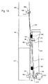
風力タービンはタワーを含み、ホイスティングシステムはカラムとブームとウィンチとを含み、
カラムは、1又は2以上の結合ポイントを用いて、タワーの部分に対し荷重支持結合を形成するよう構成されており、
結合ポイントは、タワーの長手方向に沿って位置付けられており、
カラムは、荷重支持結合が形成されたとき、ホイスティングシステムをタワーの前記部分に沿って実質的に垂直方向に運動させるよう構成されており、
カラムは、ホイスティングシステムを前記1又は2以上の結合ポイントを用いた荷重支持結合に沿って案内することを可能にするレールを更に用いて、荷重支持結合を形成するよう構成されており、
前記レールの第1セクションは結合ポイントに該レールを取り付けるために該レールを開くよう構成された手段を含み、該手段は、更に、レールを閉じ、その結果、該レールが結合ポイントにスライド可能に結合されることにより、ホイスティングシステムを該レールに対し実質的に平行な方向に前記タワーに対し相対的に運動させることを可能にするよう構成されている(形態1・第1基本構成)。
本発明の第2の視点により、陸上型又は洋上型の風力タービンが提供される。
該風力タービンは、タワー、ナセル、発電機、ハブ及び少なくとも1つのブレードを含み、
該タワーは、本発明に応じたホイスティングシステムの分離可能な結合及び案内のための1又は2以上の結合ポイントを含み、
前記結合ポイントは該タワーの長手方向に沿って位置付けられており、
ホイスティングシステムは、前記タワーの実質的に一方のサイドの外側に分離可能に結合されており、それによって、風力タービンとホイスティングシステムのコンビネーションを形成し、
ホイスティングシステムはカラムとレールを含み、
該カラムは該レールに結合されており、該レールは該タワーに沿ってホイスティングシステムを案内するよう構成されており、
該レールは前記結合ポイントの少なくとも1つに固定的に又はスライド可能に結合している(形態14・第2基本構成)。
本発明の第3の視点により、本発明に応じた風力タービンを建設するための方法が提供される。
該方法は、本発明に応じたホイスティングシステムを用いて基部の上部に1又は2以上のタワーセグメントを設置することにより風力タービンのタワーの少なくとも一部分を構築すること
前記ホイスティングシステムを用いて連続するタワーセグメントの1又は2以上の部分をホイストし、該セグメントを設置することにより、前記タワーの部分を形成すること、及び、
前記ホイスティングシステムを前記結合ポイントに沿って上方へ案内し、前記レールを前記連続するタワーセグメントの1又は2以上の結合ポイントに固定的に又は分離可能に結合すること
を含む(形態35・第3基本構成)。
本発明の第4の視点により、本発明に応じた風力タービンを建設するための方法が提供される。
該方法は、前記ホイスティングシステムを用いない伝統的な建設方法を用いて地平面の近くに設置される1又は2以上の底部タワーセグメントを建設すること、
前記ホイスティングシステムを用いて連続するタワーセグメントの1又は2以上の部分をホイストし、該セグメントを設置することにより、前記タワーの部分を形成すること、及び、
前記ホイスティングシステムを前記結合ポイントに沿って上方へ案内し、前記レールを前記連続するタワーセグメントの1又は2以上の結合ポイントに固定的に又は分離可能に結合すること
を含む(形態36・第4基本構成)。
本発明の第5の視点により、本発明に応じた風力タービン又は建設中の風力タービンから本発明に応じたホイスティングシステムを除去する方法が提供される。該方法において、
該ホイスティングシステムはカラムとレールを含み、該カラムは該レールに結合されており、該風力タービンは2又は3以上のタワーセグメントと1又は2以上の結合ポイントとを含むタワーを含み、
該方法は、結合ポイントに対する前記レールの固定的な結合を解除するステップ、結合ポイントに対する前記レールのスライド可能な結合を用いて前記ホイスティングシステムを下方に運動させるステップ、及び、該ホイスティングシステムを該風力タービンから取り去るステップを含む(形態44・第5基本構成)。
A first aspect of the invention provides a hoisting system for the installation or maintenance of wind turbines. The hoisting system includes means for forming a load bearing connection in the existing part of the wind turbine tower, and includes means for moving the hoisting system up and down along the existing part of the wind turbine tower.
The hoisting system is configured to install or remove any of the tower segments, nacelles, generators, hubs and blades with one or more combined hoists or single hoists .
Wind turbines include towers, hoisting systems include columns, booms and winches,
The column is configured to form a load-bearing bond to a portion of the tower using one or more coupling points.
The joining points are located along the longitudinal direction of the tower and
The column is configured to move the hoisting system substantially vertically along said portion of the tower when a load bearing coupling is formed.
The column is configured to form a load-bearing coupling with additional rails that allow the hoisting system to be guided along the load-bearing coupling with one or more coupling points.
The first section of the rail includes means configured to open the rail to attach the rail to the coupling point, which further closes the rail so that the rail is slidable to the coupling point. By being coupled, it is configured to allow the hoisting system to move relative to the tower in a direction substantially parallel to the rail (
A second aspect of the invention provides onshore or offshore wind turbines.
The wind turbine includes a tower, nacelle, generator, hub and at least one blade.
The tower comprises one or more coupling points for separable coupling and guidance of the hoisting system according to the present invention.
The coupling point is positioned along the longitudinal direction of the tower .
The hoisting system is separably coupled to the outside of substantially one side of the tower, thereby forming a combination of wind turbine and hoisting system.
The hoisting system includes columns and rails,
The column is coupled to the rail, which is configured to guide the hoisting system along the tower.
The rail is fixedly or slidably coupled to at least one of the coupling points (
A third aspect of the invention provides a method for constructing a wind turbine according to the invention.
The method constructs at least a portion of a wind turbine tower by installing one or more tower segments at the top of the base using a hoisting system according to the invention.
The tower portion is formed by hoisting one or more portions of a continuous tower segment using the hoisting system and installing the segment.
It comprises guiding the hoisting system upward along the coupling points and coupling the rails to one or more coupling points of the contiguous tower segment in a fixed or separable manner (
A fourth aspect of the invention provides a method for constructing a wind turbine according to the invention.
The method is to construct one or more bottom tower segments installed near the horizon using traditional construction methods that do not use the hoisting system .
The tower portion is formed by hoisting one or more portions of a continuous tower segment using the hoisting system and installing the segment.
The hoisting system is guided upward along the coupling points and the rails are fixedly or separably coupled to one or more coupling points of the contiguous tower segment (
A fifth aspect of the invention provides a method of removing a hoisting system according to the invention from a wind turbine according to the invention or a wind turbine under construction. In the method
The hoisting system includes a column and a rail, the column is coupled to the rail, and the wind turbine comprises a tower containing two or more tower segments and one or more coupling points.
The method includes a step of disengaging the fixed coupling of the rail to the coupling point, a step of moving the hoisting system downward using a slidable coupling of the rail to the coupling point, and the hoisting system. The step of removing from the wind turbine is included (
本発明の一側面に応じ、洋上風力タービンの設置のためのホイスティング(吊上げないし昇降)システムが提案される。該ホイスティングシステムは、風力タービンタワーに荷重支持結合(load bearing connection)を形成する手段を含み、及び、ホイスティングシステムをタワーに沿って上下運動(昇降)させる手段を含み、ホイスティングシステムは、当該ホイスティングシステムが該荷重支持結合によって風力タービンタワーの既設部分に結合されているとき、該荷重支持結合の上方にあるタワーセグメント、ナセル、発電機、ハブ及びブレードの何れかを設置又は除去するよう構成(配置)されている。 According to one aspect of the present invention, a hoisting (lifting or lifting) system for the installation of offshore wind turbines is proposed. The hoisting system includes means for forming a load bearing connection in the wind turbine tower and includes means for moving the hoisting system up and down (elevating) along the tower. When the hoisting system is coupled to an existing portion of the wind turbine tower by the load-bearing coupling, install or remove any of the tower segments, nacelles, generators, hubs and blades above the load-bearing coupling. It is configured (arranged) as follows.
好ましくは、ホイスティング作業中、荷重支持結合は、ホイスティングシステムの質量の実質的部分を、例えば質量の少なくとも40%又はより好ましくは質量の少なくとも80%を、風力タービンタワーの既設部分に移送する。 Preferably, during the hoisting operation, the load-bearing coupling transfers a substantial portion of the mass of the hoisting system, for example at least 40% of the mass, or more preferably at least 80% of the mass, to the existing portion of the wind turbine tower. ..
本発明の上記の側面に応じたホイスティングシステムは、風力タービンの既存部分の他の如何なる安定化手段を必要としないという顕著な利点を有する。かくして、洋上設置プロセスのコスト及び複雑性が大幅にカットされる。更に、そのクライミング(climbing)特性のために、ホイスティングシステムは従来の洋上型クレーンよりも遥かに小型かつ軽量である。更に、ホイスティングシステムは、例えば単独の(single)ブレード又は発電機のみを、ジャッキアップを必要とすることなく交換することもできる。これらの利点は実際に大きなものであり、洋上型についての大きな設置及びメンテナンスコストの頑固な問題に対する驚くべき解決策を提供する。 A hoisting system according to the above aspects of the invention has the significant advantage of not requiring any other stabilizing means of the existing portion of the wind turbine. Thus, the cost and complexity of the offshore installation process is significantly reduced. Moreover, due to its climbing properties, the hoisting system is much smaller and lighter than traditional offshore cranes. In addition, the hoisting system can replace, for example, only a single blade or generator without the need for jacking up. These advantages are really great and provide a surprising solution to the stubborn problem of large installation and maintenance costs for offshore models.
本発明の一側面に応じ、カラム、ブーム及びウィンチを含む、洋上又は陸上風力タービンの設置又はメンテナンスのためのホイスティングシステムが提案される。該カラムは風力タービンのタワーに対する荷重支持結合を達成するための手段を含み、及び、該カラムはホイスティングシステムをタワーに沿って上下運動させる手段を含む。タワーは1又は2以上の結合ポイントを含み、カラムは1又は2以上の結合ポイントを用いてタワーの(一)部分に対する荷重支持結合を生成するよう構成されている。カラムは、タワーの(一)部分に結合されたとき、タワーの前記(一)部分に沿って実質的に垂直方向にホイスティングシステムを運動させるよう構成されている。 According to one aspect of the invention, hoisting systems for the installation or maintenance of offshore or onshore wind turbines, including columns, booms and winches, have been proposed. The column includes means for achieving load bearing coupling of the wind turbine to the tower, and the column includes means for moving the hoisting system up and down along the tower. The tower contains one or more coupling points and the column is configured to use one or more coupling points to generate a load-bearing coupling to the (1) portion of the tower. The columns are configured to move the hoisting system substantially vertically along the (1) portion of the tower when coupled to the (1) portion of the tower.
そのようなシステムは、既設のタワーセグメントに沿って上方に運動する間に、連続するタワーセグメント(複数)を設置することができる。タワーの構築が完了した後、ナセル、発電機、ハブ及びロータブレードを設置することができる。有利なことに、そのようなシステムは、洋上型及び陸上型のいずれのタイプの風力タービンについても使用可能である。 Such a system can install contiguous tower segments while moving upward along the existing tower segments. After the tower construction is complete, nacelles, generators, hubs and rotor blades can be installed. Advantageously, such a system can be used for both offshore and onshore types of wind turbines.
有利なことに、本発明のホイスティングシステムは、風力タービンを設置するための従来の工業用大型クレーンの代わりに使用されることにより、より少ないコストでかつ道路の強化及び特別な輸送許可を必要とすることなく風力タービンを建設することができる。更に、風力タービンの建設地の面積は、従来のクレーンを用いた場合の3000m2から本発明のホイスティングシステムを用いた場合の凡そ200m2に縮小可能である。 Advantageously, the hoisting system of the present invention requires less cost, road strengthening and special transport permits by being used in place of conventional large industrial cranes for installing wind turbines. A wind turbine can be constructed without the need for. Furthermore, the area of the construction site of the wind turbine can be reduced to approximately 200 meters 2 in the case of using the hoisting system of the present invention from 3000 m 2 in the case of using a conventional crane.
ホイスティングシステムのカラムは、典型的には、タワーに結合されている(複数の)結合ポイントに沿って実質的に垂直方向にホイスティングシステムを案内するレールを含む。該レールの好都合な最大長さは60mであり、他方、好都合な最小長さは10m、好ましくは20m、より好ましくは34mである。相対的に長いレールは、力はアームによって分割される曲げモーメントに等しいためにタワーに対し大きな横方向の力を印加することなく、より下側のタワーセグメントやナセルのような質量が大きい部分のホイスティングを可能にする。 The columns of the hoisting system typically include rails that guide the hoisting system substantially vertically along the coupling points (s) that are coupled to the tower. The convenient maximum length of the rail is 60 m, while the convenient minimum length is 10 m, preferably 20 m, more preferably 34 m. For relatively long rails, the force is equal to the bending moment divided by the arm, so no large lateral force is applied to the tower, and the lower tower segment, nacelle, or other mass-massed part. Allows hoisting.
ホイスティングシステムは、タワー(の面)にある結合ポイント(複数)に沿った当該ホイスティングシステムの簡単かつ迅速な上下運動を可能にするため、効率的である。 The hoisting system is efficient because it allows for easy and quick vertical movement of the hoisting system along the coupling points (s) on the tower.
一実施形態において、ホイスティングシステムはレールを含み、該レールの1つのセクションは、該レールセクションが風力タービンタワーの1つの結合ポイントの上方に配置されることが可能な第1位置と、該レールがタワーに沿った上下運動のみが可能であるよう該レールセクションが当該結合ポイントを包囲する第2位置とに配置可能に構成されている。 In one embodiment, the hoisting system includes a rail, one section of the rail is a first position where the rail section can be located above one coupling point of the wind turbine tower, and the rail. The rail section is configured to be dispositionable with a second position surrounding the coupling point so that it can only move up and down along the tower.
一実施形態において、ホイスティングシステムのカラムは、該ホイスティングシステムをタワーに沿って上下運動させる手段を含む。そのような手段は、クライミング(climbing)アクチュエータ及び/又はコネクション(connection)アクチュエータを含むことができるが、これらは何れも液圧(ハイドロ)シリンダ又はエレクトロメカニカルリニアアクチュエータのタイプであり得る。これらのアクチュエータは固定部分と可動部分を有することができる。各アクチュエータの固定部分は一端部においてカラムに場合によっては蝶番式に固定されることができる。本発明に応じた一実施形態において、クライミングアクチュエータの固定部分の他端部はコネクションアクチュエータの可動部分の一端部に結合されており、そのため、コネクションアクチュエータはクライミングアクチュエータをカラム付近からカラムから更に離れる方向へ運動させることができる。クライミングアクチュエータの可動部分の端部は、(1つの)結合ポイントに結合するための手段を含む結合端部である。クライミングシステムは、ホイスティングシステムを上下運動させることが可能なクライミングアクチュエータを含み、クライミングアクチュエータの結合端部は、コネクションアクチュエータによって、自由位置から当該結合端が(1つの)結合ポイントに結合されている位置まで、制御されることができる。 In one embodiment, the columns of the hoisting system include means of moving the hoisting system up and down along the tower. Such means can include climbing actuators and / or connection actuators, both of which can be of the type of hydraulic (hydro) cylinders or electromechanical linear actuators. These actuators can have a fixed part and a moving part. The fixed portion of each actuator can be hinged to the column at one end. In one embodiment according to the present invention, the other end of the fixed portion of the climbing actuator is coupled to one end of the movable portion of the connection actuator, so that the connection actuator moves the climbing actuator further away from the column from the vicinity of the column. Can be exercised. The end of the moving part of the climbing actuator is a coupling end that includes means for coupling to (one) coupling point. The climbing system includes a climbing actuator capable of moving the hoisting system up and down, and the coupling end of the climbing actuator is coupled to (one) coupling point from a free position by a connection actuator. It can be controlled up to the position.
一実施形態において、クライミングシステムは、2セット(double set)のクライミングアクチュエータ及びコネクションアクチュエータを含み、このため、荷重を分散し、従って、システムのコストを低減するという利点、更には、一組のクライミングアクチュエータ及びコネクションアクチュエータが故障する場合にもクライミングアクチュエータが依然として作動可能であるよう冗長性を導入するという利点を有する。そのような故障が生じる場合、ホイスティングシステムは、この冗長性のために、少なくとも、地面(基部領域:ground)に向かって下方に運動することが依然として可能である。 In one embodiment, the climbing system includes two sets of climbing actuators and connection actuators, which has the advantage of distributing the load and thus reducing the cost of the system, as well as a set of climbing. It has the advantage of introducing redundancy so that the climbing actuator is still operational in the event of actuator and connection actuator failure. In the event of such a failure, the hoisting system is still capable of moving downwards, at least towards the ground, due to this redundancy.
一実施形態において、クライミングシステムは、レールに結合されておりかつ連続する(隣り合う)結合ポイント間の少なくとも最大距離にわたって運動するスピンドルを含むことができる。該スピンドルは、電気モータ又は液圧(ハイドロ)モータによって駆動され、かつ、当該スピンドルの回転によってレールに沿って運動するワゴンに結合されている。該ワゴンは、(1つの)結合ポイントと共に荷重支持結合を生成することができる。 In one embodiment, the climbing system can include a spindle that is coupled to the rail and moves over at least the maximum distance between consecutive (adjacent) coupling points. The spindle is coupled to a wagon that is driven by an electric or hydraulic (hydro) motor and that moves along rails due to the rotation of the spindle. The wagon can generate load-bearing couplings with (one) coupling points.
一実施形態において、ホイスティングシステムは、第1クライミングシステム及び第2クライミングシステムを含み、第1クライミングアクチュエータ(システム)とカラムとの結合の中心と第2クライミングシステムとカラムとの結合の中心との間の距離は、カラムの長さ方向において、とりわけ凡そ5.7m、少なくとも1.8mである。2つのクライミングシステムを有することの利点は、各クライミングアクチュエータが単一(単独)のクライミングシステムの場合と比べて凡そ半分の長さを有することができ、そのため、より良好な安定性及びコストのより大きな低減を提供することができる。2つのクライミングシステムが繰り返し使用されることにより、ホイスティングシステムはタワーに沿って実質的に垂直(鉛直)方向に運動する。例えば、まず、第1クライミングシステムが1つの結合ポイントに結合され、かつ、結合ポイント間の距離の凡そ50%にわたってホイスティング(システム)を引き上げ、次いで、第2クライミングシステムが別の(更なる)結合ポイントに結合し、そして、第1クライミングシステムが分離した後、次の結合ポイントに結合できるよう、第2クライミングシステムがホイスティングシステムを更に引き上げる。夫々結合ポイント間の距離の凡そ3分の1、4分の1、5分の1等にわたってホイスティングシステムを運動させることができる3つ、4つ、5つ等のクライミングシステムを使用することも可能であることは明らかであろう。なお、この結合ポイント間の距離は通常は6m〜26m、好ましくは10m〜18m、例えば凡そ11.5mである。 In one embodiment, the hoisting system includes a first climbing system and a second climbing system, with a center of coupling between the first climbing actuator (system) and the column and a center of coupling between the second climbing system and the column. The distance between them is, among other things, approximately 5.7 m, at least 1.8 m, in the length direction of the column. The advantage of having two climbing systems is that each climbing actuator can have approximately half the length compared to a single (single) climbing system, thus resulting in better stability and cost. Great reductions can be provided. Due to the repeated use of the two climbing systems, the hoisting system moves substantially vertically along the tower. For example, first the first climbing system is coupled to one coupling point and the hoisting (system) is pulled up over approximately 50% of the distance between the coupling points, and then the second climbing system is another (further). The second climbing system further pulls up the hoisting system so that it can be coupled to the coupling point and then coupled to the next coupling point after the first climbing system has separated. It is also possible to use a three, four, five, etc. climbing system that can exercise the hoisting system over approximately one-third, one-fourth, one-fifth, etc. of the distance between each coupling point. It will be clear that it is possible. The distance between the coupling points is usually 6 m to 26 m, preferably 10 m to 18 m, for example, about 11.5 m.
一実施形態において、ホイスティングシステムは、カラムに結合される(複数の)従動(被駆動)はめ歯歯車(driven cogwheels)の周りで運動するチェーンを含む。該チェーンを(1つの)結合ポイントに結合することにより、ホイスティングシステムを上下運動させることができる。ホイスティングシステムを運動させる他のオプションは、(1つの)ケーブルを一方のサイドにおいて(1つの)結合ポイントに結合し、他方のサイドにおいて、カラムに取り付けられているウィンチに結合することである。 In one embodiment, the hoisting system comprises a chain that moves around driven cogwheels that are coupled to the column. By coupling the chain to (one) coupling point, the hoisting system can be moved up and down. Another option to move the hoisting system is to connect the (one) cable to the (one) coupling point on one side and to the winch attached to the column on the other side.
一実施形態では、ホイスティングシステムは、該ホイスティングシステムを結合ポイントに固定的に結合することが可能な連結器(coupling)を含む。この固定的結合は、該連結器が該ホイスティングシステムの垂直(鉛直)力(複数)を該結合ポイントに伝達できるような、格別には(有利には)これらの垂直力の少なくとも30%を、より格別には(有利には)これらの垂直力の少なくとも90%を伝達できるような結合である。一実施形態では、カラムにおける連結器の高さ位置は、レールの長さの下側の65%以内であり、好ましくはレール長さの35%〜65%の間である。 In one embodiment, the hoisting system includes a coupling capable of fixing the hoisting system to a coupling point. This fixed coupling delivers at least 30% of these normal forces, exceptionally (favorably), so that the coupler can transmit the normal forces of the hoisting system to the coupling points. , More specifically (favorably) a coupling capable of transmitting at least 90% of these normal forces. In one embodiment, the height position of the coupler on the column is within 65% of the lower side of the rail length, preferably between 35% and 65% of the rail length.
一実施形態では、カラムと結合ポイントの間の連結器は、ホイスティング作業中、連結器によるパーツ間ジョイント(joint)の仮想水平軸線の周りでの少なくとも0.25°、好ましくは少なくとも0.5°、より好ましくは少なくとも1°、例えば2°の回転自由度が可能になるように構成されている。この自由度は、大きな曲げモーメントが結合ポイント(複数)に加えられることを回避し、従って、コストを低減する。 In one embodiment, the coupler between the column and the coupling point is at least 0.25 °, preferably at least 0.5 °, around the virtual horizontal axis of the coupler-to-part joint during the hoisting operation. It is configured to allow a degree of freedom of rotation of °, more preferably at least 1 °, eg 2 °. This degree of freedom avoids applying large bending moments to the coupling points and thus reduces costs.
ホイスティングシステムの好都合な一実施形態は、レールから少なくとも15m(離れた位置)に、好ましくはレールから少なくとも25m(離れた位置)に到達するブームを含む。ホイスティングシステムの一実施形態によれば、ブームの最大長さは60mである。更なる有利なホイスティングシステムにおいては、ブームはヨーベアリング(yaw bearing)を介してカラムに結合されており、とりわけ該ヨーベアリングの回転軸は、レールの長さ方向に対し0.5°超だけ、好ましくは1°超だけ、より好ましくは5°未満だけ傾いている。ホイスティングシステムの更なる好都合な一実施形態では、ブームは枢動ヒンジ(tilt hinge)を介してヨーベアリングに結合しているか又はブームは枢動ヒンジを含んでおり、枢動ヒンジは少なくとも20°にわたって、好ましくは200°未満にわたって調節可能である。枢動運動は、液圧(ハイドロ)アクチュエータ又はエレクトロメカニカルアクチュエータによって駆動可能である。 A convenient embodiment of the hoisting system includes a boom that reaches at least 15 m (away) from the rail, preferably at least 25 m (away) from the rail. According to one embodiment of the hoisting system, the maximum length of the boom is 60 m. In a further advantageous hoisting system, the boom is coupled to the column via a yaw bearing, in particular the axis of rotation of the yaw bearing is only more than 0.5 ° with respect to the length direction of the rail. It is tilted by more than 1 °, more preferably less than 5 °. In a more convenient embodiment of the hoisting system, the boom is coupled to the yaw bearing via a tilt hinge or the boom includes a pivot hinge, the pivot hinge being at least 20 °. It is adjustable over, preferably less than 200 °. The pivotal motion can be driven by a hydraulic (hydro) actuator or an electromechanical actuator.
一実施形態では、カラムは、レールの上方に15mを超えて、好ましくは25mを超えて延在し、及び、ヨーベアリングを含む。該ヨーベアリング(上)には、ブームに沿って移動可能なホイスティングポイントを含むほぼ水平なブームが取り付けられている。 In one embodiment, the column extends above the rail by more than 15 m, preferably more than 25 m, and includes a yaw bearing. The yaw bearing (top) is fitted with a nearly horizontal boom that includes a hoisting point that can be moved along the boom.
一実施形態では、ブームは、ホイスティングケーブルを駆動するウィンチを含み、とりわけ、ブームは、ホイスティングポイントに到達する夫々独立のホイスティングケーブルを有する複数のウィンチを含む。この場合、各ウィンチは負荷(荷重)全体の一部を受容する。 In one embodiment, the boom comprises a winch that drives the hoisting cable, and above all, the boom comprises a plurality of winches having independent hoisting cables that reach the hoisting point. In this case, each winch receives a portion of the entire load.
一実施形態では、ホイスティングシステムは屈曲又は湾曲されるブームを含み、このブームは、枢動ヒンジの中心からホイスティングポイントへの(枢動ヒンジの中心とホイスティングポイントを結ぶ)線分の当該ブームに対する距離が少なくとも1.5m、好ましくは少なくとも2.5m、より好ましくは凡そ4mに達するよう、屈曲又は湾曲される。 In one embodiment, the hoisting system comprises a boom that is bent or curved, and this boom is the line segment from the center of the pivot hinge to the hoisting point (connecting the center of the pivot hinge and the hoisting point). It is bent or curved so that the distance to the boom reaches at least 1.5 m, preferably at least 2.5 m, more preferably approximately 4 m.
ホイスティングシステムは、地面(ground)から、タービン基部から又は船舶から電気ケーブルによって電力の供給が可能である。一実施形態では、ホイスティングシステムは、ディーゼル発電機、燃料電池又は蓄電池のような化学反応に基づく電源を含むが、このような電源はホイスティングシステムに設置され、そのため、地面又は海面(水面)に至る長いケーブルは不要になる。これにより、ケーブルのコスト及び重量が省かれ、更に、ホイスティング作業のための好天期間(weather window)を短くしかつシステムの信頼性を低下させる風によるケーブルの揺動の問題が回避される。一実施形態では、電源は液圧(ハイドロ)ポンプに直接又は電気モータを介して間接的に接続される。他の一実施形態では、ホイスティングシステムは、例えばバックアップとして地上から電気ケーブルによって駆動可能な第2の液圧ポンプを含む。 The hoisting system can be powered by an electric cable from the ground, from the turbine base, or from a ship. In one embodiment, the hoisting system includes a power source based on a chemical reaction such as a diesel generator, a fuel cell or a storage battery, but such a power source is installed in the hoisting system and thus ground or sea surface (water surface). There is no need for a long cable to reach. This saves the cost and weight of the cable and also avoids the problem of wind-induced cable sway, which shortens the weather window for hoisting operations and reduces the reliability of the system. .. In one embodiment, the power supply is connected to the hydraulic (hydro) pump either directly or indirectly via an electric motor. In another embodiment, the hoisting system includes, for example, a second hydraulic pump that can be driven by an electrical cable from the ground as a backup.
風力タービンの陸上設置(建設)のために、従来の大型クレーンは、輸送のために、数ダースのトラック、例えば50台のトラックを必要とするのに対し、本発明に応じたホイスティングシステムは、5台未満の、例えば僅か2台の標準的トラックで輸送可能であり、これにより、(建設)現場におけるコスト及び空間上の要件に対する利点が得られる。 For onshore installation (construction) of wind turbines, conventional large cranes require dozens of trucks, for example 50 trucks, for transportation, whereas the hoisting system according to the present invention It can be transported by less than five, for example only two standard trucks, which provides advantages for cost and space requirements at the (construction) site.
陸上(オンショア)風力タービンについての更なる利点は、(従来の)大型クレーンの組立には数日を要するのに対し、本ホイスティングシステムは数時間で設置可能であることである。 A further advantage of onshore wind turbines is that the hoisting system can be installed in hours, whereas the assembly of a (traditional) large crane takes days.
陸上風力タービンについての一層更なる利点は、本ホイスティングシステムは、既知のリフティングシステムと比べて相対的に高速に風力タービンタワーに沿って上下運動(昇降)することができることである。 A further advantage of onshore wind turbines is that the hoisting system can move up and down (elevate) along the wind turbine tower at a relatively high speed compared to known lifting systems.
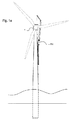
本発明の更なる一視点によれば、タワー、ナセル、発電機、ハブ及び少なくとも1つのブレードを含む風力タービンであって、該タワーがホイスティングシステムの、とりわけ本発明に応じたホイスティングシステムの結合及び案内のための結合ポイント(複数)を含むものが提案される。 According to a further aspect of the invention, a wind turbine comprising a tower, a nacelle, a generator, a hub and at least one blade, wherein the tower is a hoisting system, particularly a hoisting system according to the invention. Those containing a plurality of connection points for connection and guidance are proposed.
一実施形態では、風力タービンは、10mより大きく30mより小さい相対(相互)間隔で配される結合ポイント(複数)を含む。 In one embodiment, the wind turbine comprises coupling points that are located at relative (mutual) spacing greater than 10 m and less than 30 m.
一実施形態では、風力タービンのタワーはオーバーラップ(領域)において互いにボルトで結合されるオーバーラップする筒状のセグメント(複数)を含み、結合ポイントがこのオーバーラップ(領域)に設けられることにより、結合ポイント付近におけるタワーの補強の必要性はより小さくなる。なぜなら、オーバーラップにより二重層化した(2つの)パーツはそれら自体でより大きなスチフネスを有するからである。 In one embodiment, the towers of a wind turbine include overlapping tubular segments that are bolted together in an overlap (region), by providing coupling points in this overlap (region). The need for tower reinforcement near the junction point is lessened. This is because the overlapping (two) parts have greater stiffness on their own.
一実施形態では、結合ポイントは、タワーに結合されかつ結合ポイントの中心から少なくとも50cmだけ、好ましくは少なくとも100cmだけ延出する補強構造部材を含む。そのような補強構造体は、タワーの外(周)側に又は内(周)側に又はその両者に設けることが可能である。とりわけセグメント型タワーの第1又は第2タワーセグメントのために、補強構造部材は、結合ポイントからタワー基部に到達する構造的ビーム、又は、タワー中心軸の周りで回転したときタワー壁に沿って結合ポイントから10°を超える、好ましくは30°を超える位置のタワー壁までほぼ水平方向に延在する構造的ビームを含んでもよい。 In one embodiment, the coupling point comprises a reinforcing structural member that is coupled to the tower and extends at least 50 cm, preferably at least 100 cm, from the center of the coupling point. Such reinforcing structures can be provided on the outer (peripheral) side, the inner (peripheral) side, or both of the towers. Especially for the first or second tower segment of the segmented tower, the reinforcing structural members join along the tower wall when rotating around the structural beam from the joining point to the tower base or around the tower central axis. It may include a structural beam extending substantially horizontally from the point to the tower wall at a position greater than 10 °, preferably greater than 30 °.
一実施形態では、風力タービンは、タワーの長手方向(垂直方向)に対し最大の偏差(ずれ:deviation)を以って整列される複数の結合ポイントを含む。例えば、上方に向かって1〜Nの番号が付されたN個の結合ポイントがあり、結合ポイントMについてM=1〜N−2であるとすると、結合ポイントMと結合ポイントM+1の中心間のライン(線分)は、次の結合ポイントの中心に対し、最大で5cmの、好ましくは最大で10cmの、より好ましくは最大で20cmの距離に達する。 In one embodiment, the wind turbine comprises a plurality of coupling points aligned with a maximum deviation with respect to the longitudinal direction (vertical direction) of the tower. For example, if there are N coupling points numbered 1 to N upward and M = 1 to N-2 for the coupling point M, then between the centers of the coupling point M and the coupling point M + 1. The line reaches a distance of up to 5 cm, preferably up to 10 cm, more preferably up to 20 cm, with respect to the center of the next connection point.
一実施形態では、風力タービンは、荷重支持壁(load carrying wall;ラチス構造のタワーに配されるクラッディングとは異なり荷重の支持が可能な壁)を有するタワーを含み、とりわけ壁がタワー長さにわたって荷重支持するタワーを含み、本発明に応じた風力タービンは、タワーの全長にわって荷重支持壁を有する非構造型タワーを含む。 In one embodiment, the wind turbine comprises a tower having a load carrying wall (a wall capable of bearing a load, unlike the cladding placed on a lattice-structured tower), in particular the wall being tower length. Wind turbines according to the present invention include towers that are load-bearing over, and include unstructured towers that have load-bearing walls over the entire length of the tower.
一実施形態では、風力タービンは、水平面における外周の横断面が円形又は多角形の形状を有するタワーを含む。 In one embodiment, the wind turbine comprises a tower having a circular or polygonal cross section of the outer circumference in a horizontal plane.
一実施形態では、風力タービンは、複数の垂直セグメントを含む筒状のタワーを含み、該セグメントは当該セグメントの垂直長さにわたって延在する折り曲げないし折り畳みされたスチールプレート(複数)で作られている。 In one embodiment, the wind turbine comprises a tubular tower containing a plurality of vertical segments, the segments being made of bent or folded steel plates extending over the vertical length of the segments. ..
一実施形態では、風力タービンは、10m〜22mの長さの、好ましくは10m〜16mの長さの、複数の垂直セグメントを含むタワーを含む。 In one embodiment, the wind turbine comprises a tower comprising a plurality of vertical segments, having a length of 10 m to 22 m, preferably a length of 10 m to 16 m.
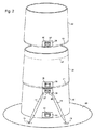
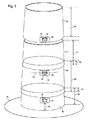
タワーは筒状タイプであり得かつプレテンション式コンクリート(pre tensioned concrete)製又は木製又はスチール製であり得る。その代わりに、タワーは構造的タワー、換言すれば、スチール製又は木製の格子型タワー(lattice tower)であり得る。タワーは、部分的に筒状でありかつ部分的に格子型であり得る。タワーの下側部分は、とりわけ洋上に建設される場合、3つの筒状脚を有する三脚構造(tripod)、ジャケット(jacket)又は浮遊構造体であり得る。 The tower can be of the tubular type and can be made of pre tensioned concrete or wood or steel. Instead, the tower can be a structural tower, in other words a steel or wooden lattice tower. The tower can be partially tubular and partially gridded. The lower part of the tower can be a tripod, jacket or floating structure with three tubular legs, especially if constructed offshore.
一実施形態では、風力タービンは、タワー長さの少なくとも50%にわたって、好ましくはタワー長さの少なくとも80%にわたってテーパー状に(先細形状に)形成されたタワーを含む。 In one embodiment, the wind turbine comprises a tower formed tapered (tapered) over at least 50% of the tower length, preferably at least 80% of the tower length.
一実施形態では、ホイスティングシステムは、クライミング中に少なくとも2つの結合ポイントにわたって案内されることが可能なストレート(直線的)レールを含み、従って、結合ポイント(複数)は、典型的には、風力タービンのタワーの長手方向における(1つの)直線に従って(沿って)整列されている。レールにおける結合ポイントの空間的及び寸法的許容誤差により、結合ポイント間に、ある程度の湾曲があってもよい。 In one embodiment, the hoisting system comprises a straight rail that can be guided over at least two coupling points during climbing, thus the coupling points are typically wind power. Aligned (along) along a (one) straight line in the longitudinal direction of the turbine tower. Due to the spatial and dimensional tolerances of the coupling points on the rail, there may be some curvature between the coupling points.
ホイスティングシステムのレールは直線的でなくてもよく、その代わりに、一定の湾曲部分を有するか有することができる。そのような場合、ホイスティングシステムは、垂直方向にタワー壁に一定の湾曲を有するタワーをクライミングする(登る)ことができる。 The rails of the hoisting system do not have to be straight and may instead have or have a constant curved portion. In such cases, the hoisting system can climb (climb) the tower with a constant curvature on the tower wall in the vertical direction.
ホイスティングシステムのレールは、そのトラック(軌道)の一部分において丁度1つの単独の結合ポイントに結合可能である。そして、ホイスティングシステムは、典型的には、クライミングシステムを介して第2の結合ポイントにも結合する。そのようなホイスティングシステムの利点は、当該ホイスティングシステムはテーパーの程度が変化するタワーに沿って、例えば円筒形から(頂部側)先細形状に変化するタワーに沿って移動できることである。 The rails of the hoisting system can be coupled to just one single coupling point on a portion of its track. The hoisting system also typically couples to a second coupling point via the climbing system. The advantage of such a hoisting system is that the hoisting system can move along a tower that varies in degree of taper, eg, along a tower that changes from cylindrical to (top) tapered.
一実施形態では、風力タービンは、タワーの任意の横方向から見て、その補強部材を含む結合ポイント(複数)が全部合わせて(タワーの長手方向におけるその長さの合計が)、タワー長さの10%未満、好ましくは20%未満をカバーする結合ポイントを有するタワーを含む。 In one embodiment, the wind turbine is the tower length, when viewed from any lateral direction of the tower, all of the coupling points, including its reinforcements, are combined (the sum of their lengths in the longitudinal direction of the tower). Includes towers with coupling points covering less than 10%, preferably less than 20% of.
一実施形態では、タワーの中心は、堤防(dike)の(横幅の)中央部から100m未満、好ましくは50m未満、より好ましくは20m未満の水平距離のところに設置される。 In one embodiment, the center of the tower is located at a horizontal distance of less than 100 m, preferably less than 50 m, more preferably less than 20 m from the (horizontal) center of the dike.
一実施形態では、2つのホイスティングシステムが同じ風力タービンに適用される。2つのホイスティングシステムは、結合ポイント(複数)の同じトラック(軌道ないし設置列)上において上下関係で取り付け可能であり、又は、タワー(中心)軸線を中心とする円筒座標系において異なる角度で取り付け可能である。タワーは、互いに対し異なる角度をなして夫々底部から頂部に至る結合ポイントの2つのトラックを含むことが可能であり、又は、第1角度の一条の(複数の結合ポイントの)トラックと第2角度の丁度1つ又は2以上の結合ポイント(の組み合わせ)を含むことも可能である。後者の場合、第1ホイスティングシステムは該第1角度の複数の結合ポイントの一条トラックに沿ってタワー頂部までの全行程をクライミングすることができ、そして、第2ホイスティングシステムを該第2角度の1又は2以上の結合ポイントに取り付けることができる。この円筒座標系におけるこれらの角度の間の差は、少なくとも20°、好ましくは少なくとも45°、より好ましくは少なくとも60°、例えば90°である。第2ホイスティングシステムは第1ホイスティングシステムと異なるものであってもよく、例えば、クライミングのために設けられるカラムを備えなくてもよく、異なる長さのブームを有してもよく、又はその他の態様で相違し得る。 In one embodiment, two hoisting systems are applied to the same wind turbine. The two hoisting systems can be mounted vertically on the same track (orbit or installation row) at the coupling points, or at different angles in a cylindrical coordinate system centered on the tower (center) axis. It is possible. The tower can contain two tracks of coupling points, each at a different angle to each other, from the bottom to the top, or a single track (of multiple coupling points) at a first angle and a second angle. It is also possible to include just one or more coupling points (combinations) of. In the latter case, the first hoisting system can climb the entire stroke to the top of the tower along a single track of multiple coupling points at the first angle, and the second hoisting system at the second angle. Can be attached to one or more coupling points of. The difference between these angles in this cylindrical coordinate system is at least 20 °, preferably at least 45 °, more preferably at least 60 °, eg 90 °. The second hoisting system may be different from the first hoisting system, eg, it may not have a column provided for climbing, may have booms of different lengths, or otherwise. Can differ in aspects of.
2つのホイスティングシステムの利用により、複数の利点が得られる。第1に、2つのホイスティングシステムは協働してより重いパーツをホイストすることができ、従って、より大きな風力タービンの設置に好適である。第2に、2つのクレーンによるパーツのホイスティングは風の影響がより小さく従ってより安定であるため、作業可能な好天期間は長くなる。第3に、2つのホイスティングシステムによってタワーに印加される荷重は、ただ1つのより重いホイスティングシステムを使用する状況と比べてより大きく分散される。荷重のこの分散は、ホイスティングシステムのコスト及び結合ポイントのコストを低減する。第4に、2つのホイスティングシステムはより効率的に使用することができる。なぜなら、同じシステムが中型及び大型風力タービンの設置に使用され、ウインドファームが設置される場合、各単独ホイスティングシステムが風力タービンタワーの建設に使用され、他方、ナセル、発電機、ハブ及びロータのホイスティングについてのみ、これらのホイスティングシステムが一緒に適用されるからである。 The use of two hoisting systems offers multiple benefits. First, the two hoisting systems can work together to hoist heavier parts and are therefore suitable for the installation of larger wind turbines. Second, the hoisting of parts by two cranes is less affected by the wind and is therefore more stable, resulting in a longer working sunny period. Third, the load applied to the tower by the two hoisting systems is more distributed than in the situation where only one heavier hoisting system is used. This distribution of load reduces the cost of the hoisting system and the cost of the coupling points. Fourth, the two hoisting systems can be used more efficiently. Because if the same system is used for the installation of medium and large wind turbines and a wind farm is installed, each independent hoisting system will be used for the construction of the wind turbine tower, while of the nacelle, generator, hub and rotor. This is because these hoisting systems apply together only for hoisting.
一実施形態では、風力タービンは洋上(オフショア)風力タービンであって、その海面(水面)から突出する部分が結合ポイントを含むことができるもの、例えば移行部分(transition piece)が(1つの)ホイスティングシステムのための結合ポイントを含むもの、を含む。 In one embodiment, the wind turbine is an offshore wind turbine whose portion protruding from the sea surface (water surface) can include a coupling point, eg, a transition piece is (one) hoi. Includes those that include a coupling point for the sting system.
洋上(オフショア)風力タービンの語には、湖沼や河川に設置される(即ち水上の)風力タービンも含まれる。 The term offshore wind turbines also includes wind turbines installed in lakes and rivers (ie, on the water).
一実施形態では、洋上風力タービンは水面下に結合ポイントを含む。 In one embodiment, the offshore wind turbine comprises a coupling point below the surface of the water.
一実施形態では、ホイスティングシステムは(1つの)タワーセグメントに予め取り付けられており、該ホイスティングシステムとタワーセグメントは、シングル(単体)ホイストで、既に設置されているより下側のタワーセグメントに設置される。 In one embodiment, the hoisting system is pre-mounted on the (one) tower segment, the hoisting system and the tower segment being a single hoist on the lower tower segment already installed. Will be installed.
一実施形態では、ホイスティングシステムは、洋上風力タービンの既に建設された部分(既設部分)にアンペルマン(Ampelmann;例えば洋上風力タービンへのアクセスのために作業船の揺動を補償する装置)を用いて又は小型ジャッキアップを用いて設置される。後者を用いる場合であっても、ホイスティングシステムはタービン高さよりも遥かに低い高さのところに設置されるため、利点は大きい。 In one embodiment, the hoisting system uses an Ampelmann (eg, a device that compensates for rocking of the workboat for access to the offshore wind turbine) in an already constructed part (existing part) of the offshore wind turbine. Or installed using a small jack-up. Even when the latter is used, the advantage is great because the hoisting system is installed at a height much lower than the turbine height.
一実施形態では、ホイスティングシステムは、それ自身を洋上風力タービンの既設部分に引き上げることによりそれ自身をそれ自身で取り付け(自己取り付けし)、それによって、該システムがタワーに対し荷重支持結合(load bearing connection)を生成することができるまで、船舶上のほぼ水平な位置から既設の風力タービンのそばのほぼ垂直な位置までそれ自身を移動することができる。 In one embodiment, the hoisting system mounts itself (self-mounting) by pulling itself up to an existing portion of the offshore wind turbine, thereby causing the system to load support coupling to the tower. It can move itself from a nearly horizontal position on the ship to a nearly vertical position near an existing wind turbine until a bearing connection) can be created.
洋上風力タービンに関係する一実施形態では、ホイスティングシステムは、船舶からパーツを持ち上げてそれらを設置することにより、完全な洋上風力タービンの設置を完成するために使用されることができる。この船舶は、高額なジャッキアップ船である必要はなく、従って、設置コストは大幅に低減される。選択的に、ホイスティングシステムは、メンテナンスツールとして使用するために又は後日の風力タービンの解体のために、風力タービンに残置される。 In one embodiment relating to offshore wind turbines, the hoisting system can be used to complete the complete offshore wind turbine installation by lifting parts from the ship and installing them. This vessel does not have to be an expensive jack-up vessel and therefore the installation cost is significantly reduced. Optionally, the hoisting system is left in the wind turbine for use as a maintenance tool or for later dismantling of the wind turbine.
一実施形態では、風力タービンは、80mを超える、好ましくは130mを超える、より好ましくは180mを超える(ロータ)軸高さを有し、一実施形態による最大軸高さは500mである。 In one embodiment, the wind turbine has a (rotor) shaft height of more than 80 m, preferably more than 130 m, more preferably more than 180 m, and the maximum shaft height according to one embodiment is 500 m.
一実施形態では、風力タービンは、風速12m/sにおける設計ロータ(回転)速度と風速6m/sにおける設計ロータ(回転)速度の比が1.3より大きく、好ましくは1.5より大きく、より好ましくは1.8より大きく、及び、3未満である設計(design)rpmを有する。可変速型のそのような風力タービンは、タワーが共振(resonance)を呈示すべきではないある範囲の励振振動数(excitation frequencies)を有する。そのような場合、有利には、結合ポイント(複数)の取り付けは、タワーの固有振動数に殆ど影響を及ぼさず、及び、タワーに対し、結合ポイントに直角かつタワー軸に平行な面におけるものと較べて、タワー軸及び結合ポイントの面において励振の異なる固有振動数を生じさせない。 In one embodiment, the wind turbine has a design rotor (rotational) speed at a wind speed of 12 m / s and a design rotor (rotational) speed at a wind speed of 6 m / s that is greater than 1.3, preferably greater than 1.5. It has a design rpm that is preferably greater than 1.8 and less than 3. Such variable speed wind turbines have a range of excitation frequencies in which the tower should not exhibit resonance. In such cases, it is advantageous to install the coupling points with little effect on the natural frequency of the tower and in a plane perpendicular to the coupling points and parallel to the tower axis with respect to the tower. In comparison, natural frequencies with different excitations are not generated in terms of tower shaft and coupling point.
本発明の一視点により、本発明に応じた風力タービンと本発明に応じたホイスティングシステムの組み合わせが提案される。 From one viewpoint of the present invention, a combination of a wind turbine according to the present invention and a hoisting system according to the present invention is proposed.
一実施形態では、ホイスティングシステムのレールは、ホイスティング作業中、スライド不能な固定的な態様で常時的にホイスティングシステムのカラムに結合され、他方、該レールは風力タービンのタワーの結合ポイント(複数)に固定的又はスライド可能に結合される。 In one embodiment, the rails of the hoisting system are constantly coupled to the columns of the hoisting system in a non-sliding, fixed manner during the hoisting operation, while the rails are the coupling points of the tower of the wind turbine ( Multiple) are fixedly or slidably combined.
一実施形態では、ホイスティングシステムのレールは、ホイスティング作業中、2つ又は3つの結合ポイントに少なくとも結合される。 In one embodiment, the rails of the hoisting system are coupled to at least two or three coupling points during the hoisting operation.
一実施形態では、タワーのパーツのホイスティング中にタワーに結合しているホイスティングシステムが結合する最も上に位置する結合ポイントは、既設のタワーセグメントのうち最も上に位置する2つのセグメントのオーバーラップ部分に対応する。 In one embodiment, during the hoisting of tower parts, the top-most coupling point to which the hoisting system coupled to the tower joins is over the top two of the existing tower segments. Corresponds to the wrap part.
本発明の一視点により、本発明に応じた陸上(オンショア)風力タービンの設置(建設)方法が提案される。該方法は、本発明のホイスティングシステムを用いて1又は2以上のタワーセグメントを設置することにより、風力タービンのタワーの少なくとも一部分を構築することを含む。 From one viewpoint of the present invention, a method for installing (constructing) an onshore wind turbine according to the present invention is proposed. The method comprises constructing at least a portion of a wind turbine tower by installing one or more tower segments using the hoisting system of the present invention.
一実施形態では、下側の1つ〜3つのタワーセグメントは、伝統的な(従来の)方法によって設置することが可能である。 In one embodiment, the lower one to three tower segments can be installed by traditional (conventional) methods.
一実施形態では、次に、1又は2以上の既設のタワーセグメントの結合ポイントにホイスティングシステムのレールを取り付けることを実行することができる。 In one embodiment, it can then be performed to attach the rails of the hoisting system to the coupling points of one or more existing tower segments.
ホイスティングシステムが最初の(基部側の)2つの既設のタワーセグメントに取り付けられている一実施形態では、ホイスティングシステムは、結合ポイントが設けられていない第3セグメントをホイストしかつ設置し、次に、結合ポイントを該第3セグメントに設ける。この方法の利点は、第3セグメントが降下される際、付加的な制約が回避されることであり、その結合点はホイスティングシステムのレールに同時に嵌め込まれることが望ましい。 In one embodiment in which the hoisting system is attached to the first two existing tower segments (on the base side), the hoisting system hoists and installs a third segment without coupling points, and then A coupling point is provided in the third segment. The advantage of this method is that when the third segment is lowered, additional constraints are circumvented, and it is desirable that the coupling points be simultaneously fitted to the rails of the hoisting system.
一実施形態では、1つ〜3つのより上側のセグメントの(分割を要するセグメントの)パーツ毎による又は(セグメント毎の)シングルホイスト(in single hoists)によるホイスティング及び該より上側のセグメントの設置を行うことができる。 In one embodiment, hoisting by parts (of segments requiring division) or by single hoists (in single hoists) of one to three higher segments and installation of the upper segments. It can be carried out.
より高い位置でのホイスティングシステムのロック解除、移動及び再ロック及び1つ又は2つのより上側のタワーセグメントのホイスト及び設置を繰り返すことにより、タワーは完全に構築される。 The tower is fully constructed by repeatedly unlocking, moving and relocking the hoisting system at a higher position and hoisting and installing one or two higher tower segments.
一実施形態では、ホイスティングシステムは、利用可能な最も高い位置においてロック解除、移動及び再ロックされることができ、及び、ナセル、発電機、ハブ及びロータブレードのホイストは、1又は2以上のコンバインドホイスト(1又は2以上のホイスト対象物又はホイスト対象物の1又は2以上の構成部分ないし部品を組み合わせとして同時にホイストすること)又はシングルホイスト(1又は2以上のホイスト対象物をその構成部分に分割することなくホイストすること)で実行することができる。 In one embodiment, the hoisting system can be unlocked, moved and relocked at the highest position available, and the hoist of the nacelle, generator, hub and rotor blades is one or more. Combined hoist (one or two or more hoist objects or one or two or more components or parts of the hoist object are hoisted at the same time as a combination) or single hoist (one or two or more hoist objects are used as the components). It can be done by hoisting without splitting).
単独の(1つの)ブレードのホイスティングの場合、ホイスティングシステムは、設置されたブレードをより下側の位置又はより上側の位置にホイストすることにより、次のブレードの設置のために好都合な位置へハブを回転するために使用可能である。 In the case of hoisting of a single (one) blade, the hoisting system hoists the installed blade to a lower or higher position, which is a convenient position for the installation of the next blade. Can be used to rotate the hub to.
本発明の一視点により、ホイスティングシステムをロック解除し、下方に運動させる(降下させる)ことにより、ホイスティングシステムを再びタワー底部に戻してロックすることができる。該底部において、ホイスティングシステムをタワーから除去することができる。 From one aspect of the invention, the hoisting system can be returned to the bottom of the tower and locked by unlocking and moving (lowering) the hoisting system downwards. At the bottom, the hoisting system can be removed from the tower.
ホイスティングシステムが第1タワーセグメント(の一部)も設置する陸上風力タービンの場合、暫定的な独立のサポート(支持体)が必要となり得るか、又は、結合ポイントを有する第1セグメントの部分を最初に伝統的な(従来の)クレーンによって設置することができ、その後、ホイスティングシステムを取り付けることができる。 For onshore wind turbines where the hoisting system also installs (part of) the first tower segment, provisional independent support may be required or the portion of the first segment that has a coupling point. It can be installed first with a traditional (traditional) crane, and then a hoisting system can be installed.
一実施形態では、ブームのホイスティングポイントと適用される(使用される)一番上の結合ポイントとの間の水平距離は、ホイストされるタワーセグメントの直径未満である。 In one embodiment, the horizontal distance between the hoisting point of the boom and the top coupling point applied (used) is less than the diameter of the tower segment to be hoisted.
ホイスティングシステムの一実施形態では、ホイスティングシステムはクライミングシステムを含まない。そのようなホイスティングシステムは既に設置(建設)された風力タービンにおけるメンテナンス作業のために好適である。即ち、そのようなホイスティングシステムは、風力タービンタワーの上端部のほぼ近くに結合されたケーブルによって引き上げられることが可能であり、結合ポイント(複数)上のレールによって滑動することができる。 In one embodiment of the hoisting system, the hoisting system does not include a climbing system. Such hoisting systems are suitable for maintenance work on wind turbines that have already been installed (constructed). That is, such a hoisting system can be pulled up by a cable coupled approximately near the top of the wind turbine tower and can be slid by rails on the coupling points.
ここに、本発明の好ましい実施の形態を示す。
(形態1)上記第1基本構成参照。
(形態2)形態1のホイスティングシステムにおいて、
カラムと結合ポイントとの間の荷重支持結合は、ホイスティング作業中、荷重支持結合によるパーツ間ジョイント(joint)の仮想水平軸線の周りにおける少なくとも0.25°の回転自由度又は少なくとも0.5°の回転自由度又は1°の回転自由度を可能にするよう形成されることが好ましい。
(形態3)形態1又は2のホイスティングシステムにおいて、
ブームは、レールから少なくとも15m又は少なくとも25mの距離に到達することが好ましい。
(形態4)形態3のホイスティングシステムにおいて、
前記ブームは、
ヨーベアリング、但し、該ヨーベアリングの軸と前記レールの長手方向との間の角度は少なくとも0.5°又は凡そ0.75°である、及び、
枢動ヒンジ、但し、該枢動ヒンジは、前記ブームを前記カラムに対し当該枢動ヒンジの周りで回動させて少なくとも20°の枢動角度の変化を可能にするための液圧シリンダ又はエレクトロメカニカルアクチュエータを含む、
の少なくとも1つを介して前記カラムに結合していることが好ましい。
(形態5)形態1〜4の何れかのホイスティングシステムにおいて、
前記ブームは、ホイスティングケーブルを操作するためのケーブルを含むことが好ましい。
(形態6)形態1〜5の何れかのホイスティングシステムにおいて、
前記ブームは、該ブームと該ブームのホイスティングポイントから枢動ヒンジの中心への仮想ラインセグメントとの間に、少なくとも1.5m又は少なくとも2.5m又は凡そ4mの距離が得られるよう、湾曲ないし屈曲されることが好ましい。
(形態7)形態1〜6の何れかのホイスティングシステムにおいて、
前記タワーは前記1又は2以上の結合ポイントを含み、前記レールは前記カラムに結合されており、該レールは10mの最小長さを有し、又は該レールは20mの最小長さを有し、又は該レールは34mの最小長さを有することが好ましい。
(形態8)形態1〜7の何れかのホイスティングシステムにおいて、
前記カラムは、好ましくは連続(ないし無端:going around)チェーン又はクライミングアクチュエータ又はワゴンを用いることにより、ホイスティングシステムを前記タワーに沿って実質的に垂直方向に運動させるよう構成されていることが好ましい。
(形態9)形態8のホイスティングシステムにおいて、
前記クライミングアクチュエータはコネクションアクチュエータを含み、該コネクションアクチュエータは該クライミングアクチュエータの一方の端部を前記カラムから離れる又は該カラムに向かう方向へ運動させるよう構成されていることが好ましい。
(形態10)形態8又は9のホイスティングシステムにおいて、
前記カラムは第1クライミングシステムと第2クライミングシステムを含み、各クライミングシステムは一方のサイドでは(1つの)結合ポイントにおいて結合(connection)を形成するよう構成されており、他方のサイドでは該カラムに結合されており、
各クライミングシステムは、ホイスティングシステムを実質的に垂直な配向で前記タワーに沿って運動させるよう構成されており、
該第1クライミングシステムと該第2クライミングシステムとの間のそれらの結合された端部間で測定される距離は、前記カラムの長手方向において少なくとも1.8mであることが好ましい。
(形態11)形態1〜10の何れかのホイスティングシステムにおいて、
前記荷重支持結合は、ホイスティングシステムを結合ポイントに結合するための荷重支持連結器(load bearing coupling)を含み、ホイスティング作業中、荷重支持連結器は、前記レールの長さの上側の65%のところ又は前記レールの長さの上側の35%のところ又は前記レールの長さの上側の10%のところに位置付けられた単独の(ただ1つの:single)結合ポイントを介して、垂直力の少なくとも90%を前記タワーに伝えるよう、構成されていることが好ましい。
(形態12)形態1〜11の何れかのホイスティングシステムは、更に、ディーゼル発電機、燃料電池又は蓄電池のような化学反応に基づく電源を含むことが好ましい。
(形態13)形態1〜12の何れかのホイスティングシステムは、タワー頂部セグメント及び風力タービンのナセル、発電機、ハブ及びブレード又はそれらの部分の1又は2以上をホイストしかつ設置するよう構成されていることが好ましい。
(形態14)上記第2基本構成参照。
(形態15)形態14の風力タービンにおいて、
前記タワーは、10m超の相互間隔で又は30m未満の相互間隔で又は15m未満の相互間隔で配された複数の結合ポイントを含むことが好ましい。
(形態16)形態14又は15の風力タービンにおいて、
前記タワーは、複数の積み重ねセグメントを含み、
少なくとも1つの結合ポイントは、2つの隣り合うタワーセグメントのオーバーラップ部分に位置付けられていることが好ましい。
(形態17)形態14〜16の何れかの風力タービンにおいて、
少なくとも1つの結合ポイントは、該結合ポイントの中心から該結合ポイントの中心から少なくとも50cm離れたところまでの又は該結合ポイントの中心から少なくとも100cm離れたところまでの距離に沿って前記タワーの外側において補強されている、
風力タービン。
(形態18)形態14〜17の何れかの風力タービンにおいて、
前記タワーの内部は、前記結合ポイントにおいて補強されていることが好ましい。
(形態19)形態14〜18の何れかの風力タービンにおいて、
3つの連続する結合ポイントの中心は、前記タワーの長手方向に対し前記タワーの半径方向に20cmの最大偏差を伴って又は前記タワーの半径方向に10cmの最大偏差を伴って又は前記タワーの半径方向に5cmの最大偏差を伴って整列していることが好ましい。
(形態20)形態14〜19の何れかの風力タービンにおいて、
前記タワーは、タワー長さの50%を超える又はタワー長さの80%を超える荷重支持壁(load bearing wall)を含むことが好ましい。
(形態21)形態20の風力タービンにおいて、
前記タワーの長手方向に対し直角な方向における前記荷重支持壁の横断面は、円状又は多角形状に形成されていることが好ましい。
(形態22)形態14〜21の何れかの風力タービンにおいて、
前記タワーは、チューブ状に形成され、かつ、複数の垂直セグメントから組み立てられ、
各セグメントは、1つのセグメントの長さにわたって延在する複数の湾曲又は屈曲プレートから組み立てられていることが好ましい。
(形態23)形態16〜22の何れかの風力タービンにおいて、
前記セグメントの1又は2以上は、10m〜16mの長さを有することが好ましい。
(形態24)形態14〜23の何れかの風力タービンにおいて、
前記タワーは、タワー長さの少なくとも50%にわたって又はタワー長さの少なくとも80%にわたってテーパー状に(先細形状に)形成されていることが好ましい。
(形態25)形態14〜24の何れかに記載の風力タービンにおいて、
全ての結合ポイントの高さの合計は、タワー長さの20%未満又はタワー長さの10%未満であることが好ましい。
(形態26)形態14〜25の何れかの風力タービンにおいて、
風力タービンは、堤防(dike)の中央部から100m未満又は50m未満又は20m未満の距離のところに設置されていることが好ましい。
(形態27)形態14〜26の何れかの風力タービンは、形態1〜13の何れかのホイスティングシステムに応じて構成された第2のホイスティングシステムの分離可能な結合のために、前記タワーの長手方向に沿って連続的にかつタワー中心軸を中心とする円筒座標系において前記1又は2以上の結合ポイントから少なくとも20°の角度差をなして位置付けられた1又は2以上の更なる結合ポイントを含むことが好ましい。
(形態28)形態27の風力タービンは、海面から突出する構造体を含み、
該構造体は、ホイスティングシステムの分離可能な結合かつ案内のための前記1又は2以上の結合ポイントの少なくとも1つを含む移行部分(transition piece)を含むことが好ましい。
(形態29)形態14〜28の何れかの風力タービンにおいて、
風力タービンは軸高さ(axis height)を有し、該軸高さは80m超又は130m超又は180m超であることが好ましい。
(形態30)形態14〜29の何れかの風力タービンにおいて、
風力タービンは設計(design)rpmを有し、
風速12m/sの場合の設計rpmと風速6m/sの場合の設計rpmとの比は、3未満かつ1.3超又は1.5超又は1.8超であることが好ましい。
(形態31)形態30の風力タービンにおいて、
前記レールは、少なくとも2つの結合ポイントに対しスライド可能に及び/又は固定的に結合されていることが好ましい。
(形態32)形態30又は31の風力タービンにおいて、
風力タービンの建設中にタワーのパーツのホイスティング作業のためにホイスティングシステムを前記タワーに分離可能に結合するために使用される地表面から測定して最も高い位置にある結合ポイントは、最上部の2つの既設のタワーセグメントのオーバーラップ部分に位置付けられていることが好ましい。
(形態33)形態29〜32の何れかの風力タービンにおいて、
ホイスティングシステムは、枢動ヒンジに対しホイスティングポイントのほぼ反対側においてカウンタウェート(釣り合い錘:contra weight)又はカウンタ(釣り合い)力を生成する手段なしで、前記タワーに分離可能に結合されていることが好ましい。
(形態34)形態14〜33の何れかの風力タービンの、頂部タワーセグメント以外の、タワーセグメントにおいて、
該セグメントは、当該セグメントが風力タービンの部分として設置されるとき、形態1〜13の何れかのホイスティングシステムを分離可能に結合するための結合ポイントを含む。
(形態35)上記第3基本構成参照。
(形態36)上記第4基本構成参照。
(形態37)形態35又は36の方法は、
最後のタワーセグメントが設置されたのち、風力タービンのナセル、発電機、ハブ及びブレード又はこれらの部分の1又は2以上をホイストしかつ設置するステップを更に含むことが好ましい。
(形態38)形態37の方法において、
複数のブレードを一度に1つずつホイストする場合、該方法は、他のブレードをホイストしかつ設置するために適切な位置にハブを位置付けることを可能にするために、設置されたブレードを前記ホイスティングシステムを用いて上下にホイスト(昇降)することにより設置されたハブを回転させるステップを含むことが好ましい。
(形態39)形態35〜38の何れかの方法において、
全体で4つの最下部タワーセグメントの何れか1つのホイスト中、前記ホイスティングシステムのブームのホイスティングポイントと、前記ホイスティングシステムと前記タワーの間の上側結合ポイントの中心との間の距離は、常に、該タワーセグメントの直径よりも小さいことが好ましい。
(形態40)形態35〜39の何れかの方法は、形態27に応じた第2のホイスティングシステムをホイストしかつ設置することを更に含み、該ホイスト及び設置は前記ホイスティングシステムを用いることが好ましい。
(形態41)形態14〜33の何れかの風力タービン又は建設中の風力タービンに形態1〜13の何れかのホイスティングシステムを分離可能に結合する方法において、
該ホイスティングシステムはカラムとレールを含み、該カラムは該レールに結合されており、該風力タービンは2又は3以上のタワーセグメントと1又は2以上の結合ポイントとを含むタワーを含み、
該方法は、前記レールを前記1又は2以上の結合ポイントに固定的に結合するステップを含む。
(形態42)形態35の方法において、
前記風力タービンは洋上風力タービンであり、
該方法は、1又は2以上のタワーセグメントに結合されたホイスティングシステムを船舶から該風力タービンの基部にホイストすることを更に含むことが好ましい。
(形態43)形態35の方法において、
前記風力タービンは洋上風力発電装置であり、
該方法は、該風力タービンの設置された部分に結合されたケーブルを用いて、前記ホイスティングシステムを台船(pontoon)から該風力タービンの設置された部分の1又は2以上の結合ポイントにホイストすることを更に含むことが好ましい。
(形態44)上記第5基本構成参照。
以下の図面は本発明の例示的実施形態を示す。なお、各図は寸法通りには記載されていないと理解されるべきである。
なお、特許請求の範囲に付記した図面参照符号は専ら発明の理解を助けるためのものであり、本発明を図示の態様に限定することは意図していない。
Here, a preferred embodiment of the present invention is shown.
(Form 1) See the first basic configuration above .
( Form 2 ) In the hoisting system of
The load-bearing coupling between the column and the coupling point has at least 0.25 ° degrees of freedom of rotation or at least 0.5 ° around the virtual horizontal axis of the joint between the parts due to the load-bearing coupling during the hoisting operation. It is preferably formed so as to allow a degree of freedom of rotation of 1 or 1 degree of freedom of rotation .
( Form 3 ) In the hoisting system of
The boom preferably reaches a distance of at least 15 m or at least 25 m from the rail.
(Form 4 ) In the hoisting system of Form 3,
The boom
Yaw bearings, provided that the angle between the yaw bearing axis and the longitudinal direction of the rail is at least 0.5 ° or approximately 0.75 °, and
Pivot hinges, provided that the pivot hinge is a hydraulic cylinder or electro that allows the boom to rotate around the column with respect to the column to allow a change in pivot angle of at least 20 °. Including mechanical actuators,
It is preferable that the column is bound to the column via at least one of the above.
(Form 5 ) In any of the hoisting systems of
The boom preferably includes a cable for operating the hoisting cable.
(Form 6 ) In any of the hoisting systems of
The boom is not curved or curved so that a distance of at least 1.5 m or at least 2.5 m or approximately 4 m is obtained between the boom and the virtual line segment from the hoisting point of the boom to the center of the pivot hinge. It is preferably bent.
(Form 7 ) In any of the hoisting systems of
The tower comprises one or more coupling points, the rail is coupled to the column, the rail has a minimum length of 10 m, or the rail has a minimum length of 20 m. Alternatively, the rail preferably has a minimum length of 34 m .
( Form 8 ) In any of the hoisting systems of
The column is preferably configured to move the hoisting system substantially vertically along the tower, preferably by using a continuous (or going around) chain or climbing actuator or wagon. ..
( Form 9 ) In the hoisting system of
The climbing actuator preferably includes a connection actuator, which is preferably configured to move one end of the climbing actuator away from or towards the column.
(Form 10 ) In the hoisting system of
The column comprises a first climbing system and a second climbing system, each climbing system being configured to form a connection at (one) connection point on one side and to the column on the other side. Combined and
Each climbing system is configured to move the hoisting system along the tower in a substantially vertical orientation.
The distance measured between their combined ends between the first climbing system and the second climbing system is preferably at least 1.8 m in the longitudinal direction of the column.
(Form 11 ) In any of the hoisting systems of
The load bearing coupling includes a load bearing coupling for coupling the hoisting system to the coupling point, and during the hoisting operation, the load bearing coupling is 65% above the length of the rail. Of vertical force via a single (single) coupling point located at 35% above the length of the rail or 10% above the length of the rail. It is preferably configured to convey at least 90% to the tower.
(Form 12 ) The hoisting system according to any one of
Either hoisting system (Embodiment 13)
(Form 14 ) See the second basic configuration above.
(Form 15 ) In the wind turbine of
The tower preferably includes a plurality of coupling points arranged at intervals greater than 10 m, at intervals less than 30 m, or at intervals less than 15 m.
(Form 16 ) In the wind turbine of
The tower contains multiple stacking segments.
At least one coupling point is preferably located at the overlap of two adjacent tower segments.
(Form 17 ) In any of the wind turbines of
At least one coupling point is reinforced outside the tower along a distance from the center of the coupling point to at least 50 cm from the center of the coupling point or at least 100 cm from the center of the coupling point. Has been
Wind turbine.
(Form 18 ) In any of the wind turbines of
The interior of the tower is preferably reinforced at the coupling points.
(Form 19 ) In any of the wind turbines of
The centers of the three consecutive coupling points are with a maximum deviation of 20 cm in the radial direction of the tower or with a maximum deviation of 10 cm in the radial direction of the tower or in the radial direction of the tower with respect to the longitudinal direction of the tower. Is preferably aligned with a maximum deviation of 5 cm.
(Form 20 ) In any of the wind turbines of
The tower preferably includes a load bearing wall that is greater than 50% of the tower length or greater than 80% of the tower length.
(Form 21 ) In the wind turbine of
The cross section of the load supporting wall in a direction perpendicular to the longitudinal direction of the tower is preferably formed in a circular or polygonal shape.
(Form 22 ) In any of the wind turbines of
The tower is formed in a tubular shape and is assembled from a plurality of vertical segments.
Each segment is preferably assembled from a plurality of curved or bent plates extending over the length of one segment.
(Form 23 ) In any of the wind turbines of Form 16 to 22,
One or more of the segments preferably have a length of 10 m to 16 m.
(Form 24 ) In any of the wind turbines of
The tower is preferably formed in a tapered shape over at least 50% of the tower length or at least 80% of the tower length.
(Form 25 ) In the wind turbine according to any one of
The total height of all coupling points is preferably less than 20% of the tower length or less than 10% of the tower length.
(Form 26 ) In any of the wind turbines of
The wind turbine is preferably installed at a distance of less than 100 m, less than 50 m or less than 20 m from the central part of the dike.
Any wind turbine (Embodiment 27)
(Form 28 ) The wind turbine of Form 27 includes a structure protruding from the sea surface.
The structure preferably comprises a transition piece containing at least one of the one or more coupling points for separable binding and guidance of the hoisting system.
(Form 29 ) In any of the wind turbines of
The wind turbine has an axis height, which is preferably more than 80 m, more than 130 m, or more than 180 m.
(Form 30 ) In any of the wind turbines of
The wind turbine has a design rpm and
The ratio of the design rpm at a wind speed of 12 m / s to the design rpm at a wind speed of 6 m / s is preferably less than 3 and more than 1.3 or more than 1.5 or more than 1.8.
(Form 31 ) In the wind turbine of
The rails are preferably slidably and / or fixedly coupled to at least two coupling points.
(Form 32 ) In the wind turbine of
The highest coupling point measured from the ground surface used to detachably couple the hoisting system to the tower for the hoisting work of tower parts during the construction of a wind turbine is at the top. It is preferably positioned at the overlapping portion of the two existing tower segments of.
(Form 33 ) In any of the wind turbines of Form 29 to 32,
The hoisting system is separably coupled to the tower without any means of generating a counter weight or counter force at approximately the opposite side of the hoisting point to the pivot hinge. Is preferable.
(Form 34 ) In the tower segment of any of the wind turbines of
The segments, when the segment is installed as part of the wind turbine, including a binding point for detachably coupling any of the hoisting system according 1-13.
(Form 35 ) See the third basic configuration above.
(Form 36 ) See the fourth basic configuration above .
( Form 37 ) The method of
It is preferred to further include the step of hoisting and installing one or more of the nacelles, generators, hubs and blades of the wind turbine or parts thereof after the last tower segment has been installed.
(Form 38 ) In the method of
When hoisting multiple blades one at a time, the method hoists the installed blades to allow the hub to be positioned appropriately for hoisting and installing the other blades. It is preferred to include a step of rotating the installed hub by hoisting up and down using a sting system.
(Form 39 ) In any of the
In the hoisting of any one of the four bottom tower segments in total, the distance between the hoisting point of the boom of the hoisting system and the center of the upper coupling point between the hoisting system and the tower is It is always preferable that it is smaller than the diameter of the tower segment.
The method of any one of (Embodiment 40) Embodiment 35-39, further comprising a second hoisting system according to Embodiment 27 is installed hoist vital, said hoist and installation be used the hoisting system preferable.
(Form 41 ) In a method of separably coupling any of the hoisting systems of any of
The hoisting system includes a column and a rail, the column is coupled to the rail, and the wind turbine comprises a tower containing two or more tower segments and one or more coupling points.
The method comprises the step of fixing the rail to the one or more coupling points.
(Form 42 ) In the method of
The wind turbine is an offshore wind turbine.
The method further preferably comprises hoisting a hoisting system coupled to one or more tower segments from the vessel to the base of the wind turbine.
(Form 43 ) In the method of
The wind turbine is an offshore wind power generator.
The method uses a cable coupled to the installed portion of the wind turbine to hoist the hoisting system from a pontoon to one or more coupling points of the installed portion of the wind turbine. It is preferable to further include the above.
(Form 44 ) See the fifth basic configuration above .
Drawing following illustrates an exemplary embodiment of the present invention. It should be understood that each figure is not shown according to the dimensions.
It should be noted that the drawing reference reference numerals added to the scope of claims are solely for the purpose of assisting the understanding of the invention, and the present invention is not intended to be limited to the illustrated embodiment.
図1aは、ホイスティング(吊上げないし昇降)システム255が配された洋上風力タービン1の一実施形態を示す。なお、風力タービンに取り付けられているアクセス用プラットフォーム(作業台船)は図示されていない。一実施形態では、そのようなプラットフォームはロータブレード又はその他の大型保守部材を一時的に保管するために配置されてもよい。
FIG. 1a shows an embodiment of an
図1bは、陸上風力タービンとホイスティングシステムの1つの例示的な組合わせを示す。地面/海面(水面)の部分以外については、図1aの風力タービンは図1bの風力タービンと同一であってもよい。図1aのホイスティングシステムは図1bのホイスティングシステムと同一であってもよい。風力タービンは、エリア(複数)8において夫々オーバーラップし(重なり合い)かつ夫々1つの結合ポイント7を有する複数のタワーセグメント2と、ナセル3と、発電機4と、ハブ5と、複数のブレード6とを含む。ホイスティングシステムは、カラム10と、枢動ヒンジ12を介してブーム14を支持するヨーイング(yawing)プラットフォーム11とを含む。ブームは液圧シリンダ13の活性化(作動)によって枢動することができる。ホイスティング(吊上げ)ケーブル18は複数のプーリ16、17を介してウィンチ15へ案内される。ホイスティングシステムはレール9に結合されており、該レール9は、その位置に依存して、結合ポイント7、19、20にスライド可能に取り付けられているため、タワーに沿って上下運動(昇降)することができる。ホイスティングの開始前に、ロックシステム21、22、23、24の何れかがレールを(1つの)結合ポイントにロック(固定)する。
FIG. 1b shows one exemplary combination of an onshore wind turbine and a hoisting system. The wind turbine of FIG. 1a may be the same as the wind turbine of FIG. 1b except for the ground / sea surface (water surface) portion. The hoisting system of FIG. 1a may be the same as the hoisting system of FIG. 1b. The wind turbine has a plurality of
有利なことに、ホイスティングシステムは、タワーの他方の側部においてカウンタウェート(釣り合い錘:contra weight)又はカウンタ(釣り合い)力(contra force)の生成手段を備える必要性なしに、タワーの一方の側部に分離可能に結合されることができる。 Advantageously, the hoisting system is one of the towers without the need to have a means of generating a counter weight or a counter force on the other side of the tower. Can be separably coupled to the sides.
そのようなホイスティングシステムは既知のホイスティングシステムとは異なる。例えば、WO2014/082176A1は、タワーに取り付けられているレールと、該レールにわたって上下運動可能なリフティング(lifting)プラットフォームとを記載している。このシステムは、タワーの全長にわたって延在するレールを必要とするが、これは質量を付加しかつ1つの方向におけるタワースチフネス(剛性:stiffness)を増大し、その結果、当該方向におけるタワーの固有振動数はその直交方向における固有振動数よりも大きくなるため、タワー固有振動数間の共振がロータ振動数及びブレード通過(passage)振動数のフルレンジにわたって回避されるべき場合、現代の可変速型風力タービンの設計自由度が低下するという欠点を有する。更に、リフティングプラットフォームが、1つのタワーセグメントのほぼ全長又はそれ未満の垂直距離にわたってレールに取り付けられているという他の欠点もある。この相対的に短い距離のために、ナセルのような重い部分が持ち上げられるとき、風力タービンタワーに大きな力が加わることになる。更に、リフティングプラットフォームはレールの全長にわたって運動するため、レールはその全長にわたって強くかつ重くある必要があり、そのため、高価になり、経済的に効率が悪い。 Such hoisting systems differ from known hoisting systems. For example, WO2014 / 082176A1 describes a rail mounted on a tower and a lifting platform capable of moving up and down across the rail. This system requires rails that extend over the entire length of the tower, which adds mass and increases tower stiffness in one direction, resulting in the natural vibration of the tower in that direction. Modern variable speed wind turbines should avoid resonance between tower natural frequencies over the full range of rotor and blade passage frequencies, as the number is greater than the natural frequency in its orthogonal direction. It has the disadvantage that the degree of freedom in designing is reduced. Further, there is another drawback that the lifting platform is mounted on the rail over a vertical distance of approximately the entire length or less of one tower segment. This relatively short distance puts a great deal of force on the wind turbine tower when heavy parts such as nacelles are lifted. Moreover, since the lifting platform moves over the entire length of the rail, the rail must be strong and heavy over its entire length, which makes it expensive and economically inefficient.
その代わりとなるリフティングプラットフォームがUS4311434、US6357549、US6614125及びUS6522025に記載されているが、これらは何れも同様の欠点を有する。 Alternative lifting platforms are described in US431134, US6357549, US6614125 and US652205, all of which have similar drawbacks.
US8069634は、第1クレーン(これは工業用大型クレーンであり得る)ないし一本クレーン(ginpole)型のクレーン(これは風力タービンの部分的に建設された構造的(structural)タワーに可動に取り付けられている)を記載している。第1クレーンは、構造的タワーを複数の部分毎にホイストし(吊上げ)かつ設置し、タワーが完成した後、第2リフティングシステムをリフトする(持ち上げる)ために使用される。なお、この第2リフティングシステムは該(完成した)タワーの頂部に設置され、ナセル及びロータをホイストするために使用される。2つのリフティングシステムを必要とするという欠点に加えて、この応用例は時間浪費的である。即ち、第1クレーンは第2リフティングシステムをタワー頂部にホイストしなければならず、また、この第2リフティングシステムは設置されかつ作動可能な状態にされなければならない。そして、第1クレーンは、第2リフティングシステムとの干渉を回避するために、離れた位置に位置付けられなければならない。その後、ナセルとロータをホイストすることができ、これが終了した後、全てのステップを逆の順序で繰り返さなければならない。更なる欠点は、この記載された一本クレーンは横方向の風の負荷に耐性でないことである。即ち、この縦長のクレーンは、タワーに対する1つ又は2つの細い桁状のジョイントを有するが、これは横方向の風負荷を受け止めることができず、その結果、クレーン全体が垂直軸(鉛直軸)の周りでスピンしてしまうこともある。上記の一本クレーン運動システムの更なる欠点は、該システムは、風力タービンタワーに対しスライド可能にジャンプラック(jump rack)を固定(結合)するために1又は2以上のスタンドオフブラケットを採用していることである。一本クレーンはジャンプラックにもスライド可能に結合している。一本クレーンの運動はステップ的処置(プロセス)であるが、この場合、各ステップは、風力タービンタワーに連続的スタンドオフブラケット(複数)を設置すること、ジャンプラックが連続的スタンドオフブラケットと重なり合うようジャンプラックをシフトすること、及び、その後に、ジャンプラックにわたって一本クレーンをスライドすることからなる。 The US8069634 is movably mounted on a first crane (which can be a large industrial crane) or a ginpole type crane (which is a partially constructed structural tower of a wind turbine). ) Is described. The first crane is used to hoist (lift) and install the structural tower in multiple parts and lift (lift) the second lifting system after the tower is completed. The second lifting system is installed at the top of the (completed) tower and is used to hoist the nacelle and rotor. In addition to the drawback of requiring two lifting systems, this application is time consuming. That is, the first crane must hoist the second lifting system to the top of the tower, and the second lifting system must be installed and operational. The first crane must then be positioned at a distance to avoid interference with the second lifting system. The nacelle and rotor can then be hoisted, after which all steps must be repeated in reverse order. A further drawback is that this single crane described is not resistant to lateral wind loads. That is, this vertically long crane has one or two thin girder joints to the tower, which cannot receive the lateral wind load, and as a result, the entire crane has a vertical axis (vertical axis). Sometimes it spins around. A further drawback of the single crane motion system described above is that the system employs one or more standoff brackets to slide (couple) the jump rack to the wind turbine tower. That is. The single crane is also slidably connected to the jump rack. The movement of a single crane is a step-by-step process, where each step involves installing multiple continuous standoff brackets on the wind turbine tower, with the jump rack overlapping the continuous standoff brackets. It consists of shifting the jump rack and then sliding a single crane across the jump rack.
同様の欠点を有する同様の一本クレーン解決策がDE−G9414643.8に記載されているが、その作業は時間浪費的でありかつコスト効率的でない(費用対効果がよくない)。 A similar single crane solution with similar drawbacks is described in DE-G94146643.8, but the work is time consuming and inefficient (not cost effective).
ここで留意すべきことは、風力タービンの建設には一定の期間にわたる穏やかな気候と、とりわけ低い風速が必要となることである。ホイスティングに多くの時間がかかるとすると、低い風(速)の期間中に作業が完了する可能性は小さくなり、その結果、効率は更に低下する。 It should be noted here that the construction of wind turbines requires a mild climate over a period of time, especially low wind speeds. If the hoisting takes a lot of time, the chances of the work being completed during periods of low wind (fast) are reduced, and as a result, efficiency is further reduced.
US2015/0048043A1には他の比較可能なリフティングシステムが記載されているが、この場合、タワーの完成後、タワー頂部にクレーンが設置され、これにより、ナセル及びロータをホイストする。このシステムは、カウンタウェイトとして作用するウィンチをタワー底部に配置するため、タワー頂部における下向き力が凡そ2倍になり、更に、長いケーブルも必要になるという欠点を有する。更に、このシステムは、タワーセグメントを持ち上げることができないため、従来の大型クレーンは依然として必要になる。 US2015 / 0048043A1 describes other comparable lifting systems, in which case a crane is installed at the top of the tower after the tower is completed, thereby hoisting the nacelle and rotor. This system has the disadvantage that the winch, which acts as a counterweight, is located at the bottom of the tower, which roughly doubles the downward force at the top of the tower and also requires a long cable. In addition, the system is unable to lift the tower segment, so traditional large cranes are still required.
風力タービンを設置するための代替的方法の1つは、例えばUS756216、DE2823525B1、DE2735298A1及びUS6408575に記載されているような、非テーパー型タワーを包囲する開口部を含むよう風力タービンのナセルを設計することによって行われる。いわゆるGrowian(Grosse Windenergieanlage:大型風力発電装置)即ち高さ100mの風力タービンがこの方法で作られたが、大型風力タービンに対しては効率的でないことが明らかになった。即ち、大型風力タービンは、大きな曲げモーメントに対し効率的に対処するためにテーパー型のタワーを必要としているのである。従って、非テーパー型のタワーは、凡そ80mを超える軸高さ(ロータ回転軸の高さ)を有する風力タービンに対しては(その使用が)廃止されている。 One alternative method for installing wind turbines is to design the wind turbine nacelle to include openings surrounding non-tapered towers, such as those described in US756216, DE2823525B1, DE2735298A1 and US6408575. It is done by. So-called Grosse (Grosse Windenergieanlage), a wind turbine with a height of 100 m, was made by this method, but it became clear that it was not efficient for large wind turbines. That is, large wind turbines require a tapered tower to efficiently cope with large bending moments. Therefore, non-tapered towers are obsolete for wind turbines with shaft heights (rotor rotary shaft heights) greater than approximately 80 m.
既知の風力タービンタワーは、典型的には、テーパー型構造的(structural)タイプ又はテーパー型筒状タイプであるが、時には、タワーの下方側が構造的であり、かつ、上方側が筒状であるものもある。構造的タワーは部分毎に輸送され、現場で組み立てられることが知られている。筒状タワーの外観は一般的には比較的良好に公的に受けられている。筒状タワーは、インバータ、変圧器及び制御器のような風力タービンの内部の装置を外部環境(気候)に対して保護する。従って、風力タービンの効率的な設置のための解決策の1つは、構造的タワーに対してよりも、筒状タワーに対してより適切である。 Known wind turbine towers are typically of a tapered structural or tapered tubular type, but sometimes the lower side of the tower is structural and the upper side is tubular. There is also. Structural towers are known to be transported piece by piece and assembled on-site. The appearance of tubular towers is generally relatively well received by the public. The tubular tower protects the internal equipment of the wind turbine, such as inverters, transformers and controllers, from the external environment (climate). Therefore, one of the solutions for the efficient installation of wind turbines is more suitable for tubular towers than for structural towers.
ここで、筒状タワーは水平面内における横断面が閉曲線(これは円形状、多角形状又はその他の任意の閉じた形状であり得る)であるタワーとして定義されていることに留意すべきである。 It should be noted here that a tubular tower is defined as a tower whose cross section in the horizontal plane is a closed curve (which can be circular, polygonal or any other closed shape).
DE19741988A1及びDE19647515A1には代替的なリフティングシステムが記載されているが、この場合、リフティングシステムは、タワーを取り囲むシステムでそれ自身を固定することにより筒状タワーをクライミングする(登る)ことができる。これらのシステムは、当該システムの滑落を回避するためにタワー壁面に十分な摩擦を得るために大きな保持力を必要とするため、タワーを損傷し易い。更に、これらのシステムは使用されなくなっている非テーパー型タワーに対して最も適切である。更に、これらのシステムは現代の大型風力タービンの重い部分(パーツ)を運搬するためには設計されていない。なぜなら、曲げモーメントがタワーに加わる垂直(鉛直)長さは、1つのタワーセグメントの長さより小さいか又は2つのタワー頂部径より小さく、このため、タワー壁面に容認できない大きな力が印加されるからである。 DE19741988A1 and DE19647515A1 describe alternative lifting systems, in which case the lifting system can climb (climb) the tubular tower by fixing itself with a system surrounding the tower. These systems are prone to damage to the tower because they require a large holding force to obtain sufficient friction on the tower wall to avoid slipping of the system. Moreover, these systems are most suitable for non-tapered towers that are no longer in use. Moreover, these systems are not designed to carry the heavy parts of modern large wind turbines. This is because the vertical length at which the bending moment is applied to the tower is less than the length of one tower segment or less than the diameter of the tops of the two towers, which exerts an unacceptably large force on the tower walls. is there.
風速は高度と共に大きくなるため、更に、風力タービンの平均ハブ高さは風力タービンの世代が進むに連れて大きくなるため、ホイスティングは、大きな風速によって益々妨げられるようになっている。とりわけ、このことは、ロータ全体のホイスティングに、即ち一回のシングルホイストによるハブ及び全てのブレードのホイスティングに当て嵌まる。即ち、空気力学的に形状形成された大型のブレードは突風ないし強風(gust)により損傷を受けやすい。上記の従来技術のリフティング装置は、典型的には、ロータのシングルホイストによる持ち上げ(リフティング)のために設計されており、単独の(1つの)ブレードのホイスティングには適切ではなく、とりわけ、ほぼ水平な位置(状態)での単独ブレードホイスティングには適切ではない。 Hoisting is increasingly hampered by high wind speeds, as wind speeds increase with altitude and, in addition, the average hub height of wind turbines increases with the generation of wind turbines. Above all, this applies to the hoisting of the entire rotor, i.e. the hoisting of the hub and all blades with a single single hoist. That is, large aerodynamically shaped blades are susceptible to damage from gusts or gusts. The prior art lifting devices described above are typically designed for single hoist lifting of rotors and are not suitable for hoisting a single (single) blade, among others, mostly. Not suitable for single blade hoisting in horizontal position (state).
図2は、本発明の例示的な風力タービンの最初の(基部側の)3つのタワーセグメント30、31、32を示す。セグメント32は、説明の目的のために、持ち上げられている。セグメント30は結合ポイント34、36を含み、これらは夫々補強構造部材33、35を有する。セグメント31、32は夫々補強構造部材38を有する結合ポイント39、40を含む。結合ポイント36、40は設置されたタワーセグメントにホイスティングシステムをロックするために使用される開口37を含む。支持ビーム44は補強部材(補強構造部材)35と、タワー基部46に固定されている固定手段45とに固定されている。破線41、42、43は、例えば互いにボルト結合可能なタワーセグメント間の結合の位置を表している。この例では、補強部材33、35、38もタワーセグメントにボルト結合されている。
FIG. 2 shows the first (base side) three
本発明に応じた設置方法の一例によれば、一般用途(汎用)のクレーンによって第1タワーセグメント30が設置される。次に、ホイスティングシステムが第1タワーセグメント30の結合ポイント34、36に取り付けられる(設置される)。ホイスティングシステムはロックシステム22を用いて、結合ポイント36の開口37にそれ自身をロックする。次に、ホイスティングシステムはタワーセグメント31をセグメント30の頂部にホイストし、このホイストの間に、結合ポイント39はレール9に配される。これらのセグメントは互いにボルト結合され、ホイスティングシステムはセグメント32を同様にセグメント31の頂部にホイストした後、第4のセグメントをホイストする。そして、ホイスティングシステムはロック解除し、上方に移動し、ロックシステム23によってセグメント32の結合ポイント37にロックすることにより、第5のセグメントをホイストすることができる。タワー全体が設置されるまでこの作業を続ける。次いで、ホイスティングシステムは、ナセル、発電機、ハブ及びブレード(複数)をホイストし、設置する(据え付ける)が、この場合、複数のコンバインドホイスティングオペレーション、例えば、ナセルと発電機の、又は、ハブとブレードを含むロータ全体の、又は、ナセルと発電機とロータの組み合わせの1回のシングルホイストでさえも、好都合であろう。
According to an example of the installation method according to the present invention, the
図3は、最初の(基部側の)2つのタワーセグメント55、56の他の一実施形態を示す。この場合、セグメント55は2つの結合ポイント34、62を有する。結合ポイント62は(破線で示されている)プレート59を介してタワー壁に配されている補強部材58に据え付けられている。プレート59はタワーセグメント56の壁と同じ厚みを有し、そのため、このセグメントはセグメント55と補強部材58との間に正確にフィットする。破線57、58はボルト結合部の位置を示す。実用上は、ボルトは(説明の都合上不図示の)結合当たり複数のライン上に配することも可能である。結合ポイント62は、タワーの内側にある支持部61に固定されているビーム60によって支持されている。図2の実施形態はタワーの内(周)側に支持ビームを備えるよう構成されてもよく、図3の実施形態はタワーの外(周)側に支持ビームを備えるよう構成されてもよい。図3の実施形態では、ロックシステム22は任意的構成要素である。
FIG. 3 shows another embodiment of the first two
図4は、風力タービンの最初の(基部側の)タワーセグメント70、71、32の他の一実施形態を示す。この例では、セグメント32と不図示のその上方のセグメントは、容易に輸送可能な標準長さ78、例えば12mのような例えば10m〜16mの間の長さを有する。タワーセグメントは例えば0.5mの距離(長さ)76にわたって重なり合い、そのため、タワー高さは標準セグメント毎に11.5mずつ大きくなる。ホイスティングシステムにとっては、結合ポイントが常に同じ垂直(鉛直ないし上下)間隔79を有すること、例えば11.5m毎に1つの結合ポイントを有すると、好都合である。第1タワーセグメント70の長さ75を大きくすることにより、該セグメントは11.5mの間隔で2つの結合ポイントを含むことができ、しかも、タワーセグメント71とのオーバーラップ76のために十分な長さが残っている。これにより、ホイスティングシステムをセグメント70に取り付け、次いで、セグメント71、32をホイストすることが、図3に示したプレート58、59を備えた特殊な構造を必要とすることなく、可能になる。その結果、セグメント70はより長い輸送長さを必要とする。セグメント71はより短い長さ77を有し、結合ポイントを備えていない。結合ポイント74はタワーの外(周)側に補強構造部材73を、タワーの内(周)側に補強構造部材80を有する。
FIG. 4 shows another embodiment of the first (base side)
図5は、最初の(基部側の)タワーセグメント(複数)の他の一実施形態を示す。この実施形態では、第1タワーセグメント85は、これはタワー基部46の一体的部分でもあり得るが、基部から距離94のところに補強部材91を有する第1結合ポイント90を含む。第2セグメント86は、補強部材93及び図4の場合と同様に内部補強部材79を備えた結合ポイント92を含む。この実施形態は、第1セグメント、第2セグメント及び第3セグメントが、第4セグメント32の長さ78(これは全てのセグメントの最大輸送長さであり得る)と比べて、夫々同じ又はより短い長さ88、89及び77を有することができる。
FIG. 5 shows another embodiment of the first (base side) tower segment. In this embodiment, the
図6は、図1と比べてより詳細に示された、例示的なホイスティングシステムと例示的な最初の(基部側の)タワーセグメントを示す。ホイスティングシステムのカラムはピストン96を備えた液圧シリンダ95とアクチュエータとを含み、アクチュエータは状態97では結合ポイント99を通り過ぎることが可能であり、状態98では結合ポイント99に結合する。ホイスティングシステムは、アクチュエータが状態98を取ってタワーセグメント103の結合ポイント99にロックされ、液圧シリンダ95がクレーンの質量が当該液圧シリンダによって支持されるまで作動された後、上方に運動する(上昇する)ことが可能になる。次に、ロックシステム21、23、24がロック解除される。なお、図6は3つのロックシステムを記載しているが、1つ以上の任意の数のロックシステムが使用可能であることに留意すべきである。次に、液圧シリンダ95が更に活性化(作動)されることにより、ピストン96はシリンダ95の中に引き込まれ、その結果、ホイスティングシステムは上方に運動する。この上方運動は、何れかのロックシステムが結合ポイントに到達し、そこでロック可能になり、ホイスティングシステムの質量(に基づく力)が液圧シリンダから該ロックシステムへ伝達可能になるまで続けられる。
FIG. 6 shows an exemplary hoisting system and an exemplary first (base side) tower segment, shown in more detail compared to FIG. The column of the hoisting system includes a
ここで、2つのシリンダ即ちカラムの2つのサイドに夫々1つ配されたシリンダが使用可能であること、更には、複式(multiple)シリンダ、例えばホイスティングシステムを引っ張り上げる代わりにホイスティングシステムを押し上げるシリンダが使用可能であることも明らかであろう。 Here, two cylinders, one cylinder on each of the two sides of the column, can be used, and moreover, a multiple cylinder, eg, a hoisting system, is pushed up instead of being pulled up. It will also be clear that the cylinder can be used.
図6は、ブームが屈曲構造をとることにより、該ブーム(の先端)が、枢動ヒンジの中心とホイスティングポイントとの間のラインセグメント(線分)101に対する距離102(をなす位置)に到達することも示している。
FIG. 6 shows that the boom has a bent structure so that the boom (tip) is at a distance 102 (position) with respect to the
図6は、更に、これからホイストされるべき更なるタワーセグメント105も示している。このセグメントは、アクチュエータ98をキャッチする(に係止する)するのに役立つエッジ106を有する結合ポイント107を含む。
FIG. 6 also shows an
図7は、建設中の例示的な風力タービンタワーであって、該タワーの対向する2つのサイドに夫々1つの例示的なホイスティングシステムが配された状態を示す。図7では、オーバーラップ部分8、結合ポイント7及び付加的結合ポイント120を備えた底部タワーセグメント2のみについて、説明のために図面参照符号が付記されている。その上方にあるタワーセグメントは底部タワーセグメントと同様に構成されている。タワーの紙面左側に図示した(第1)ホイスティングシステムはレール9、カラム10、ヨーベアリング11、枢動ヒンジ12、枢動アクチュエータ13、ブーム14及びホイスティングケーブル18を備えており、紙面右側に図示した第2ホイスティングシステムも同様に構成されている。これらのホイスティングシステムは、例えばナセル122のような重いパーツのホイスティングのために、両者合わせて有利に使用することができる。2つのホイスティングシステムの他の利点は、ブレード又はロータのようなある種のパーツのホイスティングは、2つのケーブル即ち各ホイスティングシステムの夫々1つのケーブルを使用する場合、突風(強風)による悪影響を受け難くなりかつ安定性もより大きくなることである。
FIG. 7 shows an exemplary wind turbine tower under construction with one exemplary hoisting system on each of the two opposing sides of the tower. In FIG. 7, only the
図7の実施形態の殆どのタワーセグメントは夫々2つの結合ポイント7及び120即ち各ホイスティングシステムにつき夫々1つの結合ポイントを有する。2つの結合ポイント7及び120は、タワー中心軸を中心とする円筒座標系において少なくとも20°の任意の角度差をなして位置付けられてもよい。図7では、2つの結合ポイント7及び120は、タワーセグメントの対向する2つのサイドに即ち180度の角度差をなして配されている。代替的な一実施形態では、第1ホイスティングシステムがタワーに取り付けられてクライミングし(登り)、その後、第2ホイスティングシステムを直ちに重いパーツをホイストするために好適な上昇位置に取り付ける。後者の代替的実施形態では、第2ホイスティングシステムは上昇できないか又は限定された範囲でしか上昇できないため、全てのタワーセグメントが第2結合ポイント120を必要とするわけではない。第2ホイスティングシステムは、第1ホイスティングシステムと同様に構成されてもよく、或いは異なって構成されてもよい。例えば、第2ホイスティングシステムはクライミングシステムを含まなくてもよく、また、異なるブームを有してもよい。
Most tower segments of the embodiment of FIG. 7 have two
図7は、更に、ブーム14がジョイント(関節)を有し得る2つの位置123、124と、カラム10が1つのジョイントを有し得る位置125も示している。これらのジョイントにおいて、ホイスティングシステムは、輸送の容易化のために、折り畳まれてもよく又は分解されてもよい。
FIG. 7 also shows two
図8は、建設中の例示的な洋上風力タービンを示す。クレーン131を有する船舶(作業船)130はケーブル132を用いて洋上風力タービンのタワーのセグメント135をホイストする。セグメント135は、例えば、ブーム136、レール137、カラム138及び結合ポイント(複数)139を有する例示的なホイスティングシステムが取り付けられる移行部分(transition piece)である。ホイスティングシステムは、上記の各種例示的実施形態ないし実施例と同様に、アクチュエータ141を有する枢動ヒンジ140を有するが、より良好な構造安定性を得るために、ブームの先端が位置144においてカラムに結合するようカラムに対してブームを折り畳むことができるように構成された第2枢動アクチュエータ143を有する第2枢動ヒンジ142を備えてもよい。かくして、タワーセグメントをこのようなホイスティングシステムによってシングルホイストで洋上風力タービンの基部133に設置するために、比較的低コストの船舶を使用することができる。
FIG. 8 shows an exemplary offshore wind turbine under construction. The vessel (working vessel) 130 having the
図8の例では、基部133は海面134から突出するモノパイル式(monopile)支持構造体である。ホイスティングシステムは、取り付けられた後、同じ船舶又は異なる船舶から次段以降のタワーセグメント及び風力タービンのその他のパーツを掴み取って、洋上風力タービンを建設する。次いで、ホイスティングシステムは除去されるか、又は、メンテナンス作業のために若しくは風力タービンのパーツの交換のために若しくは風力タービンの分解(解体)のために、当該風力タービンに残置される。洋上風力タービンに対し本ホイスティングシステムを使用する利点の1つは、風力タービンのパーツの設置が、当該パーツをジャッキアップ船(jack-up vessel)によって設置する従来法よりもより安価(低コスト)であることである。本ホイスティングシステムは、建設中のタワーに取り付けられるため、従って、その運動(建設作業)に従うため(従って運動するため)、一層より好都合である。
In the example of FIG. 8, the
図9は、洋上風力タービンとホイスティングシステムの例示的な組み合わせの代替的一例を示す。この実施形態では、ホイスティングシステムは台船150からケーブル157でホイストされる。ホイスティングシステムは、持ち上げられる前に、波による台船の動きに対し当該ホイスティングシステムを安定化するよう構成(配置)された脚部151に載せられてもよい。脚部151は、例えば、安定化のための及び支持システム(151と152)をデッキのレベル(上面)の完全に下方に下降するための液圧シリンダ152に配されており、そのため、ホイール156によって支持されているホイスティングシステムの他方のサイド(端部)はこれ(脚部151)を乗り越えて通過することができるよう構成される。ケーブル157がホイスティングシステムを上方にホイストする間、ケーブル155は支持部153上のウィンチ154によって繰り出される(緩められる)。これは、ホイスティングシステムがタワーに対しほぼ平行になるまで続けられる。ある時点で、ホイール156は(台船の)デッキから離れるが、ケーブル155は、ホイール156が風力タービンタワーに到達するまで更に繰り出される。その後、ホイスティングシステムは、結合ポイントに結合され、残りのパーツを設置することにより洋上風力タービンの完成作業を更に実行する。ケーブル157の引っ張り上げは、別の(独立の)ウィンチによって行うことができるが、例えばホイスティングケーブルをポイント144からカラム138を介してフック158にまで案内することによって、ホイスティングシステムのブームに組込まれたウィンチによっても行うことができる。
FIG. 9 shows an alternative example of an exemplary combination of an offshore wind turbine and a hoisting system. In this embodiment, the hoisting system is hoisted from the
図10は、例示的な結合ポイント160をより詳細に示す。突出部161によって、結合ポイントはボルト162で上側タワーセグメント169に設置されることができるため、このエレメント(セグメント)は結合ポイント(複数)と一緒にホイストされ、セグメント168の頂部に設置されることができ、そこで、更に、オーバーラップ範囲170においてボルト163で固定される。エレメント164はホイスティングシステムのレールに嵌り込むよう構成され、開口165は該レールにロックするために役立つ。リブ(複数)166はタワーの大部分にわたって荷重を分散するために使用されてもよい。なお、結合ポイントのボルトについては、その一部のみが図示されており、結合ポイントの外部のオーバーラップゾーン170における上側セグメントと下側セグメントの更なる結合のためのボルトは図示されていないことに留意すべきである。エレメント167は、ホイスティングシステムに結合し、ホイスティング作業中における垂直(鉛直)方向の荷重の大部分を受け止めるよう構成されている。これは、垂直(鉛直)力が小さな成分を有し、従って結合ポイントに対し比較的小さな曲げモーメントを与えるよう、タワー壁の近くに設置される。
FIG. 10 shows an
図11は、図10の結合ポイントの矢視I−I断面を示す。この側面から、(ハッチングで示す)補強プレート171も視認できる。 FIG. 11 shows an arrow I-I cross section of the coupling point of FIG. From this side, the reinforcing plate 171 (shown by hatching) can also be visually recognized.
図12は、例示的な風力タービンタワーと例示的なホイスティングシステムのカラムの組み合わせの一例を示す。タワーは、複数のセグメント180、181、182、183を含み、そのうち上側の3つのセグメントは夫々結合ポイント184、185、186及びフック187、188、189を有する。ホイスティングシステムのうち、カラム190、レール191、閉鎖されたレールドア193、開放されたレールドア194、結合システム192及び3つの液圧式(ハイドロ)クライミングシステムのみが図示されている。説明のために、ホイスティングシステムは、当該システムをタワーに向かって移動することによってレールに結合することが可能な位置に(ないし状態で)図示されている。上側レールドア194は開放されており、そのため、結合ポイント186はレールの内部に移動する(嵌り込む)ことができる。下側レールドア193は、説明のために、閉鎖された位置(ないし状態)で図示されているが、結合ポイント185に結合するために開放されることになる。結合ポイント185、186がレールに嵌り込むと、ホイスティングシステムは降下することができるため、結合ポイント184もレールに嵌り込む。次いで、ドア193、194が閉鎖され、ホイスティングシステムは1又は2以上の結合システム192によってロックされることができる。
FIG. 12 shows an example of a combination of an exemplary wind turbine tower and an exemplary hoisting system column. The tower comprises a plurality of
図6の例示的実施形態では、ホイスティングシステムは、ピストン96と、結合ポイント99に結合するための状態97及び状態98を取るアクチュエータとを有する液圧シリンダ95を有するクライミングシステムを含んでいる。図12の例示的なホイスティングシステムは、タワーをクライミングする(登る)ために結合ポイント(複数)に隣接配置されたフック(複数)を使用する代替的なクライミングシステムを含む。
In the exemplary embodiment of FIG. 6, the hoisting system includes a climbing system having a
図12の実施形態では、カラムは、3つの液圧式(ハイドロ)クライミングシステムを備えている。下側液圧式クライミングシステムは、その一方の端部(下端部)195がカラムに回動可能に結合しているメインシリンダ196を含む。その他方の端部(上端部)はアクチュエータ197によってレール198を貫通して案内される。図12では、ピストン199は完全に延伸しており、フック(複数)の何れかに、例えばフック188に嵌り込む(図示では)球状(に表示された)端部200を有する。カラムが結合ポイントからロック解除されかつ最下の液圧式クライミングシステムがフックで係止されると、該クライミングシステムは隣り合う結合ポイント間の距離の凡そ3分の1にわたってホイスティングシステムを引き上げることができる。次に、中央の液圧式クライミングシステムは、そのピストンを伸長し、これをフック189に結合し、ホイスティングシステムを更に引き上げることができるが、その前に、最下部液圧式クライミングシステムは結合解除される。最後の工程は、液圧シリンダ202を有する最上部液圧式クライミングシステムによって行われる。液圧シリンダ202はポイント201においてカラムに結合されており、その他方の端部は制御アクチュエータ203によってレール204を貫通して案内される。この最上部液圧式クライミングシステムは、(1つの)結合システムが(1つの)結合ポイントに再びロックできる位置へのストロークを完結する。図12では、中央液圧式クライミングシステムのパーツには図面参照符号は付記されていないが、最上部液圧式クライミングシステムのパーツに対応する。
In the embodiment of FIG. 12, the column comprises three hydraulic (hydro) climbing systems. The lower hydraulic climbing system includes a
1つのクライミングシステムの代わりに3つのクライミングシステムを有するホイスティングシステムは、この場合各クライミング毎に隣り合う結合ポイント間距離の3分の1ずつ上昇するが、より短い、従ってより安定的かつより安価な液圧シリンダを使用することができるという利点を有する。尤も、本発明はこの3つの液圧式クライミングシステムの形態に限定されるものではなく、原理的に、任意の数のクライミングシステムを使用することが可能であり、丁度1つの液圧式クライミングシステムを使用することも可能である。 A hoisting system with three climbing systems instead of one climbing system in this case increases by one-third of the distance between adjacent coupling points for each climb, but is shorter, and therefore more stable and cheaper. It has the advantage that a flexible hydraulic cylinder can be used. However, the present invention is not limited to the forms of the three hydraulic climbing systems, and in principle, any number of climbing systems can be used, and exactly one hydraulic climbing system is used. It is also possible to do.
図13は、ホイスティングシステムのカラム210の代替的一実施形態を示す。この実施形態では、カラムの長さは、隣り合う結合ポイント間距離の2倍未満にわたって延在する。そのようなより短いシステムの利点の1つは、より軽量かつより小型であること、従ってより安価であることである。更に、そのレールは、ホイスティングシステムのクライミングの一部の間にただ1つの結合ポイントによってスライド可能に結合されるため、該システムは、テーパー(先細形状)が長手方向において変化するタワーに沿って運動することができる。図13では、最下部タワーセグメント217は円筒状であり、他方、セグメント182、183はテーパー化されている。
FIG. 13 shows an alternative embodiment of
ホイスティングシステムの一実施形態において、カラムは、作業員によってアクセス可能なように構成されている。カラムは、作業員が修理及びメンテナンスを実行できるように、ドア、1又は2以上のプラットフォーム及び内部階段を有してもよい。カラムの内部からの、例えば結合システム及び/又はクライミングシステムの点検のための、点検用ハッチが設けられてもよい。 In one embodiment of the hoisting system, the columns are configured to be accessible by workers. The column may have doors, one or more platforms and internal stairs to allow workers to perform repairs and maintenance. An inspection hatch may be provided from inside the column, for example for inspection of coupling systems and / or climbing systems.
一実施形態において、ホイスティングシステムはただ1つの結合システムを有してもよく、例えば、図12の場合はカラムの中央にのみ、図13の場合はカラムの上端側にのみ結合システムを有してもよい。 In one embodiment, the hoisting system may have only one binding system, for example, in the case of FIG. 12, only in the center of the column, in the case of FIG. 13, only on the upper end side of the column. You may.
ホイスティングシステムの他の一実施形態では、該システムは結合システムを全く備えなくてもよい。例えば、図12のホイスティングシステムは何れか(ないしすべて)の結合システム192なしで構成されてもよく、クライミングシステム(複数)をクライミング及び結合の両方のために使用してもよい。クライミングシステム(複数)は、常に少なくとも1つのクライミングシステムがカラムをタワーに結合するよう、反復的に活性化(作動)される。そのような実施形態の利点は、より低いコスト及び一層の簡素化(単純化)である。
In another embodiment of the hoisting system, the system does not have to be equipped with a coupling system at all. For example, the hoisting system of FIG. 12 may be configured without any (or all)
図6、図12及び図13は、カラムの1つのサイドに配されるクライミングシステムを示す。これらの代替的実施形態としては、カラムの両サイド(2つのサイド)に配されるクライミングシステムを有してもよい。 6, 12 and 13 show a climbing system arranged on one side of the column. As an alternative embodiment of these, there may be a climbing system arranged on both sides (two sides) of the column.
図13の例示的なホイスティングシステムは、比較的長いシリンダ211を有するただ1つのクライミングシステムを含む。このシリンダは、(下)端部212において枢動可能な態様で結合されており、他方の端部はアクチュエータ214の制御によりレール213を貫通して案内される。ピストン215はその球状(に表示された)端部216によってフック189にロックされる。クライミング中、レール191が結合ポイント184から解放され、その後、カラムが結合ポイント185によってスライド可能に結合され、更に、クライミングシステムのピストンを介して結合ポイント186に結合されるまで、カラム210はクライミングシステムによって引き上げられる。上方ストロークのこの部分において、カラムは枢動角度を僅かに変化することができ、そのため、レールは次の結合ポイントに整列(位置合わせ)される。
The exemplary hoisting system of FIG. 13 includes only one climbing system with a relatively
図13は、例えばホイスティングシステムが独立して作動できるよう生成される電力及び液圧力ための発電機を含む例示的な任意的パワーシステム218も示している。パワーシステムはジョイント219によって結合されており、カラムとパワーシステムの間のパワーライン及び制御ラインはジョイント220を介して案内されている。ホイスティングシステムは、地面(基部領域)からの電気ケーブルを介して供給される電力によって駆動可能なバックアップ用の液圧ポンプを含むことができる。
FIG. 13 also shows an exemplary
図14は、例示的な結合システムを断面で示す。紙面の左側の2つのタワーセグメント168、169は、1つの結合ポイント230と共に図示されている。紙面右側のカラム210は、ホイスティングシステムのヨー(yaw)プラットフォーム221と共に図示されている。液圧シリンダ222はピストン223を制御してフック224を結合ポイントのエレメント226に嵌め込む。該フックの端部225とエレメント226は、両者合わせて、紙面に対しほぼ直角をなす枢動軸を有する円筒状ヒンジを形成し、従って、クレーンのカラムがある程度の傾動自由度を有するよう配置されている。このフックは、従ってクレーンのカラムも、ピストン223のほぼ水平な軸の周りでの運動のある程度の回転自由度も有する。ほぼ水平な軸(複数)の周りでのこれらの自由度は、大きな曲げモーメントが結合ポイントに加わることを回避する。結合プロセス中、カラムは、まず、ピストン223が延出できるよう、僅かに持ち上げられる。次に、カラムはフック224がエレメント226と結合するまで降下され、その後、液圧シリンダ227はピストン228を駆動して開口229に挿入する。このため、カラムは最早上下運動(昇降)することができない。レールは外側案内帯状部材(guiding strip)231と内側帯状部材232を有する。これらの帯状部材は相互間距離233を有する。
FIG. 14 shows an exemplary coupling system in cross section. The two
一実施形態では、レールの内部に配された結合ポイントのプレート234の厚みは、前記相互間距離233よりも、例えば15cm((だけ)より小さく)、好ましくは10cm(だけ)より小さく、例えば5cm(だけ)より小さく、少なくとも1mm(だけ)より大きい(より小さい)。例えば5cmの遊びを有することの利点は、カラムが凡そ0.25°の枢動自由度を有し、そのため、タワーのテーパーが各セクションにわたりほぼその大きさだけ変化することができることである。テーパー(の程度)が変化するタワーは構造的な利点を有し、従って、本発明に応じたホイスティングシステムを取り付けることができる。
In one embodiment, the thickness of the
結合ポイントの中心は、プレート234の中心によって定義されてもよい。
The center of the binding point may be defined by the center of the
図14に示したピストン223、228は液圧流体によって直接的に駆動される。代替的一実施形態では、これらのピストンは何れも独立の液圧シリンダによって駆動される被案内ピン(guided pins)であってもよい。そのような実施形態の利点は、被案内ピンは横方向の挿入(loading)により適切であり得ることである。
The
ホイスティングシステムの更なる一実施形態では、該システムはレールにドアを有しなくてもよい。例えば、図12又は図13のホイスティングシステムは、ドア193、194なしで作られてもよい。これらは、レールの結合ポイントのある程度の遊びによって支援されてレールに取り付けられることもなお可能である。例えば、図13の場合、まず、結合ポイント184は、ホイスティングシステムの下降によって、レールにスライドし、次いで、該システムを再び上昇することにより、レールは結合ポイント185の上方にスライドする。図12のホイスティングシステムも同様の方法で取り付けられてもよい。
In a further embodiment of the hoisting system, the system does not have to have a door on the rail. For example, the hoisting system of FIG. 12 or 13 may be made without
図15は、紙面左側に例示的な風力タービンタワーを、紙面右側にホイスティングシステムの一例の例示的なカラムを示す。説明のために、カラムの中央部分は図示されていない。カラムは、結合ポイント230のプレート234の開口に嵌り込むピストン246を有する液圧シリンダ245を含むワゴン(可動キャリア)242を含む。液圧モータ240によって駆動され、更にベアリング244によって位置決めされているスピンドル241は、ワゴン242を貫通してスライドし、該ワゴンをレールに対して平行に該レールの背面側を通過するよう駆動する。ワゴン242が結合ポイントにロックされかつフック224がロック解除されると、液圧モータは、スピンドルの回動により、ホイスティングシステムを上下運動(昇降)させることができる。スピンドルに結合されたワゴンを用いたクライミングの利点は、液圧シリンダを備えたクライミングシステムが不要になること、ピストン246による結合ポイントのロックはフック187、188、189への結合よりも単純であること、及び、ワゴンは相対的に安定な手段であることである。
FIG. 15 shows an exemplary wind turbine tower on the left side of the page and an exemplary column of an example hoisting system on the right side of the page. For illustration purposes, the central portion of the column is not shown. The column includes a wagon (movable carrier) 242 that includes a
図16は、ホイスティングシステム255が取り付けられた、ナセル252、ハブ253及びブレード(複数)254を備えた例示的な風力タービン250を示す。風力タービンは上記の実施形態の風力タービンの何れか1つであってもよい。ホイスティングシステムも上記の実施形態のホイスティングシステムの何れか1つであってもよい。図16は第2ホイスティングポイント260と、該ポイントからの第2ホイスティングケーブル261が負荷に結合されている様子を示している。そのような第2ホイスティングケーブルの利点は、負荷をより良好に制御できることである。代替的に、ブーム14は、ヨー(yaw)ベアリング257を有するブーム[257]に場合により取り付けられる補助ブーム256を含むことができる。この補助ブームは、ケーブル259によって負荷に結合される副(第2)ホイスティングポイント258も提供する。この負荷は例えばフレーム262であり、これはブレードを把持し(部分的に取り囲み)、そのブレードを損傷することのないホイスティングポイントを提供するよう設計されている。図16は、等距離間隔では配置されていない複数の結合ポイント7を示している(図面参照符号が付記されていないものもある)。更に、図16は、タワーの他方のサイドに複数の結合ポイント263を示しており、これらの結合ポイント263には、第2ホイスティングシステム(場合によってはクライミングシステムを備えない)が、第1ホイスティングシステムによって取り付けられることができる。
FIG. 16 shows an
上記の説明は、ホイスティングシステムを用いた風力タービンの設置(建設)にフォーカスしている。しかしながら、本発明は風力タービンの設置に限定されず、付加的に又は代替的に、ホイスティングシステムを用いた風力タービンのメンテナンス又は解体にも適用可能である。 The above description focuses on the installation (construction) of wind turbines using a hoisting system. However, the present invention is not limited to the installation of wind turbines, but is additionally or alternatively applicable to the maintenance or dismantling of wind turbines using a hoisting system.
結合ポイントは、風力タービンのタワーへのホイスティングシステムの固定的結合又はスライド可能な結合のために及び/又はクライミングシステムのための支持部として使用することができる。後者は、ホイスティングシステムの結合及び案内の形態でもある。従って、結合ポイントが参照(言及)される場合、該固定ポイントはホイスティングシステムの結合及び案内の何れか一方又はその両方として機能し得ると、理解されるべきである。勿論、これらの機能は、例えば少なくとも1つのポイントが結合機能のみを有する場合又は少なくとも1つのポイントが案内機能のみを有する場合、複数のポイントによって分担することも可能である。 The coupling points can be used for fixed or sliding coupling of the hoisting system to the tower of the wind turbine and / or as a support for the climbing system. The latter is also a form of coupling and guidance of the hoisting system. Therefore, it should be understood that when a coupling point is referenced (referenced), the fixation point can serve as one or both of the coupling and guidance of the hoisting system. Of course, these functions can be shared by a plurality of points, for example, when at least one point has only a connecting function or at least one point has only a guiding function.
ホイスティングシステムは、当該システムのオペレーションの範囲内におけるオペレーションのみを可能にするコンピュータによって制御することも可能である。ホイスティングシステムは、例えばグラウンド(基部領域)からの、クレーン内における及び建設中の風力タービン内における、遠隔操作コントローラ及び固定(据付け)型コントローラによって制御することも可能である。クレーンの操作者はカメラによって支援されることも可能である。 The hoisting system can also be controlled by a computer that allows only operations within the scope of the system's operation. The hoisting system can also be controlled by remote control controllers and fixed (installed) controllers, for example from the ground (base area), in cranes and in wind turbines under construction. The crane operator can also be assisted by a camera.
なお、本願において、用語「含む(comprising)」は他の要素又はステップを排除するものではないと理解されるべきである。更に、用語「1つの(a及びan)」は複数を排除するものではない。クレーム中の図面参照符号は何れもクレームの範囲を限定するものと理解されるべきではない。
ここに、本発明の態様を付記する。
(付記1)風力タービンの、好ましくは洋上風力タービンの、設置又はメンテナンスのためのホイスティングシステム。
ホイスティングシステムは、風力タービンタワーの既設部分に荷重支持結合(load bearing connection)を形成する手段を含み、及び、当該ホイスティングシステムを風力タービンタワーの既設部分に沿って上下運動させる手段を含む。
ホイスティングシステムは、タワーセグメント、ナセル、発電機、ハブ及びブレードの何れかを1又は2以上のコンバインドホイスト又はシングルホイストで設置又は除去するよう構成されている。
(付記2)洋上風力タービン又は陸上風力タービンの設置又はメンテナンスのための上記ホイスティングシステムにおいて、
風力タービンはタワーを含み、ホイスティングシステムはカラムとブームとウィンチとを含む。
カラムは、1又は2以上の結合ポイントを用いて、タワーの部分に対し荷重支持結合を形成するよう構成されている。
結合ポイントは、タワーの長手方向に沿ってとりわけ連続的に位置付けられている。
カラムは、荷重支持結合が形成されたとき、ホイスティングシステムをタワーの前記部分に沿って実質的に垂直方向に運動させるよう構成されている。
(付記3)上記のホイスティングシステムにおいて、
カラムと結合ポイントとの間の荷重支持結合は、ホイスティング作業中、荷重支持結合によるパーツ間ジョイント(joint)の仮想水平軸線の周りにおける少なくとも0.25°の回転自由度、好ましくは少なくとも0.5°の回転自由度、より好ましくは1°の回転自由度を可能にするよう形成される。
(付記4)上記のホイスティングシステムにおいて、
カラムは、ホイスティングシステムを前記1又は2以上の結合ポイントを用いた荷重支持結合に沿って案内することを可能にするレールを更に用いて、荷重支持結合を形成するよう構成されている。
(付記5)上記のホイスティングシステムにおいて、
ブームは、レールから少なくとも15m、好ましくは少なくとも25mの距離に到達する。
(付記6)上記のホイスティングシステムにおいて、
前記ブームは、
ヨーベアリング、但し、好ましくは、該ヨーベアリングの軸と前記レールの長手方向との間の角度は少なくとも0.5°、より好ましくは凡そ0.75°である、及び、
枢動ヒンジ、但し、該枢動ヒンジは、好ましくは、前記ブームを前記カラムに対し当該枢動ヒンジの周りで回動させて少なくとも20°の枢動角度の変化を可能にするための液圧シリンダ又はエレクトロメカニカルアクチュエータを含む、
の少なくとも1つを介して前記カラムに結合している。
(付記7)上記のホイスティングシステムにおいて、
前記ブームは、ホイスティングケーブルを操作するためのケーブルを含む。
(付記8)上記のホイスティングシステムにおいて、
前記ブームは、該ブームと該ブームのホイスティングポイントから枢動ヒンジの中心への仮想ラインセグメントとの間に、少なくとも1.5m、好ましくは少なくとも2.5m、より好ましくは凡そ4mの距離が得られるよう、湾曲ないし屈曲される。
(付記9)上記のホイスティングシステムにおいて、
前記タワーは前記1又は2以上の結合ポイントを含み、前記レールは前記カラムに結合されており、好ましくは該レールは10mの最小長さを有し、より好ましくは該レールは20mの最小長さを有し、一層より好ましくは該レールは34mの最小長さを有する。
(付記10)上記のホイスティングシステムにおいて、
前記レールの第1セクションは(1つの)結合ポイントに該レールを取り付けるために該レールを開く(open)よう構成された手段を含み、該手段は、更に、レールを閉じ、その結果、該レールが結合ポイントにスライド可能に結合されることにより、ホイスティングシステムを該レールに対し実質的に平行な方向に前記タワーに対し相対的に運動させることを可能にするよう構成されている。
(付記11)上記のホイスティングシステムにおいて、
前記カラムは、好ましくは連続(ないし無端:going around)チェーン又はクライミングアクチュエータ又はワゴンを用いることにより、ホイスティングシステムを前記タワーに沿って実質的に垂直方向に運動させるよう構成されている。
(付記12)上記のホイスティングシステムにおいて、
前記クライミングアクチュエータはコネクションアクチュエータを含み、該コネクションアクチュエータは該クライミングアクチュエータの一方の端部を前記カラムから離れる又は該カラムに向かう方向へ運動させるよう構成されている。
(付記13)上記のホイスティングシステムにおいて、
前記カラムは第1クライミングシステムと第2クライミングシステムを含み、各クライミングシステムは一方のサイドでは(1つの)結合ポイントにおいて結合(connection)を形成するよう構成されており、他方のサイドでは該カラムに結合されている。
各クライミングシステムは、ホイスティングシステムを実質的に垂直な配向で前記タワーに沿って運動させるよう構成されている。
好ましくは、該第1クライミングシステムと該第2クライミングシステムとの間のそれらの結合された端部間で測定される距離は、前記カラムの長手方向において少なくとも1.8mである。
(付記14)上記のホイスティングシステムにおいて、
前記荷重支持結合は、ホイスティングシステムを結合ポイントに結合するための荷重支持連結器(load bearing coupling)を含み、好ましくは、ホイスティング作業中、荷重支持連結器は、前記レールの長さの上側の65%のところ、より好ましくは前記レールの長さの上側の35%のところ、例えば前記レールの長さの上側の10%のところ、に位置付けられた単独の(ただ1つの:single)結合ポイントを介して、垂直力の少なくとも90%を前記タワーに伝えるよう、構成されている。
(付記15)上記のホイスティングシステムは、更に、ディーゼル発電機、燃料電池又は蓄電池のような化学反応に基づく電源を含む。
(付記16)上記のホイスティングシステムは、タワー頂部セグメント及び風力タービンのナセル、発電機、ハブ及びブレード又はそれらの部分の1又は2以上をホイストしかつ設置するよう構成されている。
(付記17)陸上型又は洋上型の風力タービン。
該風力タービンは、タワー、ナセル、発電機、ハブ及び少なくとも1つのブレードを含む。
該タワーは、上記のホイスティングシステムの分離可能な結合及び案内のための1又は2以上の結合ポイントを含む。
前記結合ポイントは該タワーの長手方向に沿ってとりわけ連続的に位置付けられている。
(付記18)上記の風力タービンにおいて、
前記タワーは、10m超の相互間隔で、好ましくは30m未満の相互間隔で、より好ましくは15m未満の相互間隔で配された複数の結合ポイントを含む。
(付記19)上記の風力タービンにおいて、
前記タワーは、複数の積み重ねセグメントを含み、
少なくとも1つの結合ポイントは、2つの隣り合うタワーセグメントのオーバーラップ部分に位置付けられている。
(付記20)上記の風力タービンにおいて、
少なくとも1つの結合ポイントは、該結合ポイントの中心から該結合ポイントの中心から少なくとも50cm離れたところまでの、好ましくは該結合ポイントの中心から少なくとも100cm離れたところまでの、距離に沿って前記タワーの外側において補強されている。
(付記21)上記の風力タービンにおいて、
前記タワーの内部は、前記結合ポイントにおいて補強されている。
(付記22)上記の風力タービンにおいて、
3つの連続する結合ポイントの中心は、前記タワーの長手方向に対し前記タワーの半径方向に20cmの最大偏差を伴って、好ましくは前記タワーの半径方向に10cmの最大偏差を伴って、より好ましくは前記タワーの半径方向に5cmの最大偏差を伴って、整列している。
(付記23)上記の風力タービンにおいて、
前記タワーは、タワー長さの50%を超える、好ましくはタワー長さの80%を超える、荷重支持壁(load bearing wall)を含む。
(付記24)上記の風力タービンにおいて、
前記タワーの長手方向に対し直角な方向における前記荷重支持壁の横断面は、円状又は多角形状に形成されている。
(付記25)上記の風力タービンにおいて、
前記タワーは、チューブ状に形成され、かつ、複数の垂直セグメントから組み立てられ、
各セグメントは、1つのセグメントの長さにわたって延在する複数の湾曲又は屈曲プレートから組み立てられている。
(付記26)上記の風力タービンにおいて、
前記セグメントの1又は2以上は、10m〜16mの長さを有する。
(付記27)上記の風力タービンにおいて、
前記タワーは、タワー長さの少なくとも50%にわたって、好ましくはタワー長さの少なくとも80%にわたって、テーパー状に(先細形状に)形成されている。
(付記28)上記の風力タービンにおいて、
全ての結合ポイントの高さの合計は、タワー長さの20%未満、好ましくはタワー長さの10%未満である。
(付記29)上記の風力タービンは、堤防(dike)の中央部から100m未満、好ましくは50m未満、より好ましくは20m未満の距離のところに設置されている。
(付記30)上記の風力タービンは、上記のホイスティングシステムに応じて構成された第2のホイスティングシステムの分離可能な結合のために、前記タワーの長手方向に沿って連続的にかつタワー中心軸を中心とする円筒座標系において前記1又は2以上の結合ポイントから少なくとも20°の角度差をなして位置付けられた1又は2以上の更なる結合ポイントを含む。
(付記31)上記の風力タービンは、海面から突出する構造体を含む。
該構造体は、ホイスティングシステムの分離可能な結合かつ案内のための前記1又は2以上の結合ポイントの少なくとも1つを含む移行部分(transition piece)を含む。
(付記32)上記の風力タービンは軸高さ(axis height)を有し、該軸高さは80m超、好ましくは130m超、より好ましくは180m超である。
(付記33)上記の風力タービンは設計(design)rpmを有し、
風速12m/sの場合の設計rpmと風速6m/sの場合の設計rpmとの比は、3未満かつ1.3超、好ましくは1.5超、より好ましくは1.8超である。
(付記34)上記の風力タービンにおいて、
ホイスティングシステムは、前記タワーの実質的に一方のサイドの外側に分離可能に結合されており、それによって、風力タービンとホイスティングシステムのコンビネーションを形成する。
(付記35)上記の風力タービンにおいて、
ホイスティングシステムはカラムとレールを含む。
該カラムは該レールに結合されており、該レールは該タワーに沿ってホイスティングシステムを案内するよう構成されている。
該レールは前記結合ポイントの少なくとも1つに固定的に又はスライド可能に結合している。
(付記36)上記の風力タービンにおいて、
前記レールは、少なくとも2つの結合ポイントに対しスライド可能に及び/又は固定的に結合されている。
(付記37)上記の風力タービンにおいて、
風力タービンの建設中にタワーのパーツのホイスティング作業のためにホイスティングシステムを前記タワーに分離可能に結合するために使用される地表面から測定して最も高い位置にある結合ポイントは、最上部の2つの既設のタワーセグメントのオーバーラップ部分に位置付けられている。
(付記38)上記の風力タービンにおいて、
ホイスティングシステムは、枢動ヒンジに対しホイスティングポイントのほぼ反対側においてカウンタウェート(釣り合い錘:contra weight)又はカウンタ(釣り合い)力を生成する手段なしで、前記タワーに分離可能に結合されている。
(付記39)上記の風力タービンの、頂部タワーセグメント以外の、タワーセグメント。
該セグメントは、当該セグメントが風力タービンの部分として設置されるとき、上記のホイスティングシステムを分離可能に結合するための結合ポイントを含む。
(付記40)上記の風力タービンを建設するための方法。
該方法は、上記のホイスティングシステムを用いて基部の上部に1又は2以上のタワーセグメントを設置することにより風力タービンのタワーの少なくとも一部分を構築することを含む。
(付記41)上記の風力タービンを建設するための方法。
該方法は、前記ホイスティングシステムを用いない伝統的な建設方法を用いて地平面の近くに設置される1又は2以上の底部タワーセグメントを建設することを含む。
(付記42)上記の方法は、
前記ホイスティングシステムを用いて連続するタワーセグメントの1又は2以上の部分をホイストし、該セグメントを設置することにより、前記タワーの部分を形成すること、及び、
前記ホイスティングシステムを前記結合ポイントに沿って上方へ案内し、前記レールを前記連続するタワーセグメントの1又は2以上の結合ポイントに固定的に又は分離可能に結合すること
を含む。
(付記43)上記の方法は、
最後のタワーセグメントが設置されたのち、風力タービンのナセル、発電機、ハブ及びブレード又はこれらの部分の1又は2以上をホイストしかつ設置するステップを更に含む。
(付記44)上記の方法は、
複数のブレードを一度に1つずつホイストする場合、他のブレードをホイストしかつ設置するために適切な位置にハブを位置付けることを可能にするために、設置されたブレードを前記ホイスティングシステムを用いて上下にホイスト(昇降)することにより設置されたハブを回転させるステップを含む。
(付記45)上記の方法において、
全体で4つの最下部タワーセグメントの何れか1つのホイスト中、前記ホイスティングシステムのブームのホイスティングポイントと、前記ホイスティングシステムと前記タワーの間の上側結合ポイントの中心との間の距離は、常に、該タワーセグメントの直径よりも小さい。
(付記46)上記の方法は、
付記30に応じた第2ホイスティングシステムをホイストしかつ設置することを更に含み、該ホイスト及び設置は前記ホイスティングシステムを用いる。
(付記47)上記の風力タービン又は建設中の風力タービンに上記のホイスティングシステムを分離可能に結合する方法。
該方法は、該ホイスティングシステムはカラムとレールを含み、該カラムは該レールに結合されており、該風力タービンは2又は3以上のタワーセグメントと1又は2以上の結合ポイントとを含むタワーを含む。
該方法は、前記レールを前記1又は2以上の結合ポイントに固定的に結合するステップを含む。
(付記48)上記の方法において、
前記風力タービンは洋上風力タービンである。
該方法は、1又は2以上のタワーセグメントに結合されたホイスティングシステムを船舶から該風力タービンの基部にホイストすることを更に含む。
(付記49)上記の方法において、
前記風力タービンは洋上風力発電装置である。
該方法は、該風力タービンの設置された部分に結合されたケーブルを用いて、前記ホイスティングシステムを台船(pontoon)から該風力タービンの設置された部分の1又は2以上の結合ポイントにホイストすることを更に含む。
(付記50)上記の風力タービン又は建設中の風力タービンから上記のホイスティングシステムを除去する方法。
該ホイスティングシステムはカラムとレールを含み、該カラムは該レールに結合されており、該風力タービンは2又は3以上のタワーセグメントと1又は2以上の結合ポイントとを含むタワーを含む。
該方法は、結合ポイントに対する前記レールの固定的な結合を解除するステップ、結合ポイントに対する前記レールのスライド可能な結合を用いて前記ホイスティングシステムを下方に運動させるステップ、及び、該ホイスティングシステムを該風力タービンから取り去るステップを含む。
(付記51)既設の風力タービンを適合化するための方法。
該方法は、1又は2以上の結合ポイントを該既設の風力タービンのタワーに適用し、それによって、上記のホイスティングシステムを該既設の風力タービンの当該1又は2以上の結合ポイントに分離可能に結合可能にすること、
を含む。
It should be understood in the present application that the term "comprising" does not exclude other elements or steps. Furthermore, the term "one (a and an)" does not exclude more than one. None of the drawing reference codes in the claims should be understood to limit the scope of the claims.
Here, the aspects of the present invention will be added.
(Appendix 1) A hoisting system for installation or maintenance of wind turbines, preferably offshore wind turbines.
The hoisting system includes means for forming a load bearing connection in the existing portion of the wind turbine tower, and includes means for moving the hoisting system up and down along the existing portion of the wind turbine tower.
The hoisting system is configured to install or remove any of the tower segments, nacelles, generators, hubs and blades with one or more combined hoists or single hoists.
(Appendix 2) In the above hoisting system for installation or maintenance of offshore wind turbines or onshore wind turbines.
Wind turbines include towers and hoisting systems include columns, booms and winches.
The column is configured to use one or more coupling points to form a load-bearing coupling to a portion of the tower.
The joining points are located particularly continuously along the longitudinal direction of the tower.
The column is configured to move the hoisting system substantially vertically along said portion of the tower when a load bearing coupling is formed.
(Appendix 3) In the above hoisting system,
The load-bearing coupling between the column and the coupling point has at least 0.25 ° degrees of freedom of rotation, preferably at least 0, around the virtual horizontal axis of the joint between the parts due to the load-bearing coupling during the hoisting operation. It is formed to allow 5 ° rotational freedom, more preferably 1 ° rotational freedom.
(Appendix 4) In the above hoisting system,
The column is configured to form a load-bearing coupling with additional rails that allow the hoisting system to be guided along the load-bearing coupling with one or more coupling points.
(Appendix 5) In the above hoisting system,
The boom reaches a distance of at least 15 m, preferably at least 25 m from the rail.
(Appendix 6) In the above hoisting system,
The boom
Yaw bearings, provided that the angle between the axis of the yaw bearing and the longitudinal direction of the rail is at least 0.5 °, more preferably approximately 0.75 °, and.
Pivot hinges, provided that the pivot hinge is preferably a hydraulic pressure for rotating the boom with respect to the column around the pivot hinge to allow a change in pivot angle of at least 20 °. Including cylinders or electromechanical actuators,
It is attached to the column via at least one of.
(Appendix 7) In the above hoisting system,
The boom includes a cable for operating the hoisting cable.
(Appendix 8) In the above hoisting system,
The boom obtains a distance of at least 1.5 m, preferably at least 2.5 m, more preferably approximately 4 m, between the boom and the virtual line segment from the hoisting point of the boom to the center of the pivot hinge. It is curved or bent so that it can be bent.
(Appendix 9) In the above hoisting system,
The tower comprises one or more coupling points, the rail is coupled to the column, preferably the rail has a minimum length of 10 m, and more preferably the rail has a minimum length of 20 m. More preferably, the rail has a minimum length of 34 m.
(Appendix 10) In the above hoisting system,
The first section of the rail includes means configured to open the rail to attach the rail to (one) coupling point, the means further closing the rail and thus the rail. Is slidably coupled to the coupling point to allow the hoisting system to move relative to the tower in a direction substantially parallel to the rail.
(Appendix 11) In the above hoisting system,
The column is configured to move the hoisting system substantially vertically along the tower, preferably by using a continuous (or going around) chain or climbing actuator or wagon.
(Appendix 12) In the above hoisting system,
The climbing actuator includes a connection actuator, which is configured to move one end of the climbing actuator away from or towards the column.
(Appendix 13) In the above hoisting system,
The column comprises a first climbing system and a second climbing system, each climbing system being configured to form a connection at (one) connection point on one side and to the column on the other side. It is combined.
Each climbing system is configured to move the hoisting system along the tower in a substantially vertical orientation.
Preferably, the distance measured between their combined ends between the first climbing system and the second climbing system is at least 1.8 m in the longitudinal direction of the column.
(Appendix 14) In the above hoisting system,
The load bearing coupling includes a load bearing coupling for coupling the hoisting system to the coupling point, preferably during the hoisting operation the load bearing coupling is above the length of the rail. 65%, more preferably 35% above the length of the rail, eg 10% above the length of the rail, a single (single) coupling located at It is configured to transmit at least 90% of the vertical force to the tower via points.
(Appendix 15) The hoisting system further includes a power source based on a chemical reaction such as a diesel generator, a fuel cell or a storage battery.
(Appendix 16) The hoisting system described above is configured to hoist and install one or more of the tower top segment and wind turbine nacelles, generators, hubs and blades or parts thereof.
(Appendix 17) Land-based or offshore-type wind turbines.
The wind turbine includes a tower, nacelle, generator, hub and at least one blade.
The tower includes one or more coupling points for separable coupling and guidance of the hoisting system described above.
The coupling points are positioned particularly continuously along the longitudinal direction of the tower.
(Appendix 18) In the above wind turbine,
The tower comprises a plurality of coupling points arranged at intervals greater than 10 m, preferably less than 30 m, more preferably less than 15 m.
(Appendix 19) In the above wind turbine,
The tower contains multiple stacking segments.
At least one coupling point is located at the overlap of two adjacent tower segments.
(Appendix 20) In the above wind turbine,
At least one coupling point of the tower along the distance from the center of the coupling point to at least 50 cm away from the center of the coupling point, preferably at least 100 cm away from the center of the coupling point. Reinforced on the outside.
(Appendix 21) In the above wind turbine
The interior of the tower is reinforced at the coupling points.
(Appendix 22) In the above wind turbine,
The centers of the three consecutive coupling points are more preferably with a maximum deviation of 20 cm in the radial direction of the tower and preferably a maximum deviation of 10 cm in the radial direction of the tower with respect to the longitudinal direction of the tower. They are aligned in the radial direction of the tower with a maximum deviation of 5 cm.
(Appendix 23) In the above wind turbine
The tower comprises a load bearing wall that is greater than 50% of the tower length, preferably greater than 80% of the tower length.
(Appendix 24) In the above wind turbine,
The cross section of the load supporting wall in a direction perpendicular to the longitudinal direction of the tower is formed in a circular or polygonal shape.
(Appendix 25) In the above wind turbine,
The tower is formed in a tubular shape and is assembled from a plurality of vertical segments.
Each segment is assembled from a plurality of curved or bent plates extending over the length of one segment.
(Appendix 26) In the above wind turbine,
One or more of the segments have a length of 10 m to 16 m.
(Appendix 27) In the above wind turbine
The tower is formed in a tapered shape over at least 50% of the tower length, preferably at least 80% of the tower length.
(Appendix 28) In the above wind turbine,
The sum of the heights of all coupling points is less than 20% of the tower length, preferably less than 10% of the tower length.
(Appendix 29) The wind turbine is installed at a distance of less than 100 m, preferably less than 50 m, more preferably less than 20 m from the central part of the dike.
(Appendix 30) The wind turbine is continuous and centered along the longitudinal direction of the tower due to the separable coupling of a second hoisting system configured in accordance with the hoisting system. Includes one or more additional coupling points positioned at least 20 ° apart from the one or more coupling points in a shaft-centered cylindrical coordinate system.
(Appendix 31) The above-mentioned wind turbine includes a structure protruding from the sea surface.
The structure comprises a transition piece containing at least one of the above one or more coupling points for separable coupling and guidance of the hoisting system.
(Appendix 32) The above-mentioned wind turbine has an axis height, and the shaft height is more than 80 m, preferably more than 130 m, and more preferably more than 180 m.
(Appendix 33) The above wind turbine has a design rpm and
The ratio of the design rpm at a wind speed of 12 m / s to the design rpm at a wind speed of 6 m / s is less than 3 and more than 1.3, preferably more than 1.5, more preferably more than 1.8.
(Appendix 34) In the above wind turbine,
The hoisting system is separably coupled to the outside of substantially one side of the tower, thereby forming a combination of wind turbine and hoisting system.
(Appendix 35) In the above wind turbine
The hoisting system includes columns and rails.
The column is coupled to the rail, which is configured to guide the hoisting system along the tower.
The rail is fixedly or slidably coupled to at least one of the coupling points.
(Appendix 36) In the above wind turbine,
The rails are slidably and / or fixedly coupled to at least two coupling points.
(Appendix 37) In the above wind turbine
The highest coupling point measured from the ground surface used to detachably couple the hoisting system to the tower for the hoisting work of tower parts during the construction of a wind turbine is at the top. It is located at the overlap of the two existing tower segments.
(Appendix 38) In the above wind turbine
The hoisting system is separably coupled to the tower without any means of generating a counter weight or counter force at approximately the opposite side of the hoisting point to the pivot hinge. ..
(Appendix 39) Tower segments of the above wind turbines other than the top tower segment.
The segment includes a coupling point for separably coupling the hoisting system described above when the segment is installed as part of a wind turbine.
(Appendix 40) A method for constructing the above-mentioned wind turbine.
The method comprises constructing at least a portion of a wind turbine tower by installing one or more tower segments on top of the base using the hoisting system described above.
(Appendix 41) A method for constructing the above-mentioned wind turbine.
The method involves constructing one or more bottom tower segments that are installed near the horizon using traditional construction methods that do not use the hoisting system.
(Appendix 42) The above method is
The tower portion is formed by hoisting one or more portions of a continuous tower segment using the hoisting system and installing the segment.
Guide the hoisting system upward along the coupling points and coupled the rails to one or more coupling points of the contiguous tower segment in a fixed or separable manner.
including.
(Appendix 43) The above method is
After the last tower segment is installed, it further includes the step of hoisting and installing one or more of the nacelles, generators, hubs and blades or parts of these parts of the wind turbine.
(Appendix 44) The above method is
When hoisting multiple blades one at a time, the installed blades are used with the hoisting system to allow the hub to be positioned in the proper position to hoist and install the other blades. Includes a step to rotate the installed hub by hoisting up and down.
(Appendix 45) In the above method,
In the hoisting of any one of the four bottom tower segments in total, the distance between the hoisting point of the boom of the hoisting system and the center of the upper coupling point between the hoisting system and the tower is Always smaller than the diameter of the tower segment.
(Appendix 46) The above method is
Further including hoisting and installing a second hoisting system according to
(Appendix 47) A method for separably coupling the above-mentioned hoisting system to the above-mentioned wind turbine or a wind turbine under construction.
In the method, the hoisting system includes a column and a rail, the column is coupled to the rail, and the wind turbine has a tower containing two or more tower segments and one or more coupling points. Including.
The method comprises the step of fixing the rail to the one or more coupling points.
(Appendix 48) In the above method,
The wind turbine is an offshore wind turbine.
The method further comprises hoisting a hoisting system coupled to one or more tower segments from a ship to the base of the wind turbine.
(Appendix 49) In the above method,
The wind turbine is an offshore wind power generator.
The method uses a cable coupled to the installed portion of the wind turbine to hoist the hoisting system from a pontoon to one or more coupling points of the installed portion of the wind turbine. Further includes doing.
(Appendix 50) A method for removing the hoisting system from the wind turbine or the wind turbine under construction.
The hoisting system includes a column and a rail, the column is coupled to the rail, and the wind turbine comprises a tower containing two or more tower segments and one or more coupling points.
The method includes a step of disengaging the fixed coupling of the rail to the coupling point, a step of moving the hoisting system downward using a slidable coupling of the rail to the coupling point, and the hoisting system. Includes the step of removing from the wind turbine.
(Appendix 51) A method for adapting an existing wind turbine.
The method applies one or more coupling points to the tower of the existing wind turbine, thereby allowing the hoisting system to be separated into the one or more coupling points of the existing wind turbine. To be able to combine,
including.
Claims (44)
ホイスティングシステムは、風力タービンタワーの既設部分に荷重支持結合を形成する手段を含み、及び、当該ホイスティングシステムを風力タービンタワーの既設部分に沿って上下運動させる手段を含み、
ホイスティングシステムは、タワーセグメント(31、32、56、71)、ナセル(3、122、252)、発電機(4)、ハブ(5、253)及びブレード(6、254)の何れかを1又は2以上のコンバインドホイスト又はシングルホイストで設置又は除去するよう構成されており、
風力タービンはタワーを含み、ホイスティングシステムはカラム(10、138、190、210)とブーム(14、136)とウィンチ(15)とを含み、
カラムは、1又は2以上の結合ポイント(7、19、20、34、36、49、40、62、74、90、92、99、107、139、160、184、185、186、230)を用いて、タワーの部分に対し荷重支持結合を形成するよう構成されており、
結合ポイントは、タワーの長手方向に沿って位置付けられており、
カラムは、荷重支持結合が形成されたとき、ホイスティングシステムをタワーの前記部分に沿って実質的に垂直方向に運動させるよう構成されており、
カラムは、ホイスティングシステムを前記1又は2以上の結合ポイントを用いた荷重支持結合に沿って案内することを可能にするレール(9、137、191、198、204、213)を更に用いて、荷重支持結合を形成するよう構成されており、
前記レールの第1セクションは結合ポイントに該レールを取り付けるために該レールを開くよう構成された手段を含み、該手段は、更に、レールを閉じ、その結果、該レールが結合ポイントにスライド可能に結合されることにより、ホイスティングシステムを該レールに対し実質的に平行な方向に前記タワーに対し相対的に運動させることを可能にするよう構成されている、
ホイスティングシステム。 A hoisting system (255) for the installation or maintenance of wind turbines.
Hoisting system comprises a means for forming a load bearing binding to the existing part of the wind turbine tower, and includes a means for vertical movement along the hoisting system to an existing part of the wind turbine tower,
The hoisting system includes one of a tower segment (31, 32, 56, 71), a nacelle (3, 122, 252), a generator (4), a hub (5, 253) and a blade (6, 254). Or it is configured to be installed or removed with two or more combined hoists or single hoists.
Wind turbines include towers, hoisting systems include columns (10, 138, 190, 210), booms (14, 136) and winches (15).
The column has one or more binding points (7, 19, 20, 34, 36, 49, 40, 62, 74, 90, 92, 99, 107, 139, 160, 184, 185, 186, 230). It is configured to form a load-bearing coupling with respect to the part of the tower.
The joining points are located along the longitudinal direction of the tower and
The column is configured to move the hoisting system substantially vertically along said portion of the tower when a load bearing coupling is formed.
The column further uses rails (9, 137, 191, 198, 204, 213) that allow the hoisting system to be guided along a load-bearing coupling with one or more coupling points. It is configured to form a load-bearing coupling and
The first section of the rail includes means configured to open the rail to attach the rail to the coupling point, which further closes the rail so that the rail is slidable to the coupling point. Combined, it is configured to allow the hoisting system to move relative to the tower in a direction substantially parallel to the rail.
Hoisting system.
カラムと結合ポイントとの間の荷重支持結合は、ホイスティング作業中、荷重支持結合によるパーツ間ジョイントの仮想水平軸線の周りにおける少なくとも0.25°の回転自由度又は少なくとも0.5°の回転自由度又は1°の回転自由度を可能にするよう形成される、
ホイスティングシステム。 The hoisting system according to claim 1.
Load bearing coupling between the coupling point and the column during hoisting operations, the rotation of at least 0.25 ° rotational degrees of freedom or at least 0.5 ° in about a virtual horizontal axis of the join preparative between parts due to the load supported bond Formed to allow degrees of freedom or 1 ° rotational freedom,
Hoisting system.
ブームは、レールから少なくとも15m又は少なくとも25mの距離に到達する、
ホイスティングシステム。 The hoisting system according to claim 1 or 2.
The boom reaches a distance of at least 15 m or at least 25 m from the rail,
Hoisting system.
前記ブームは、
ヨーベアリング、但し、該ヨーベアリングの軸と前記レールの長手方向との間の角度は少なくとも0.5°又は凡そ0.75°である、及び、
枢動ヒンジ、但し、該枢動ヒンジは、前記ブームを前記カラムに対し当該枢動ヒンジの周りで回動させて少なくとも20°の枢動角度の変化を可能にするための液圧シリンダ又はエレクトロメカニカルアクチュエータを含む、
の少なくとも1つを介して前記カラムに結合している、
ホイスティングシステム。 The hoisting system according to claim 3.
The boom
Yaw bearings, provided that the angle between the yaw bearing axis and the longitudinal direction of the rail is at least 0.5 ° or approximately 0.75 °, and
Pivot hinges, provided that the pivot hinge is a hydraulic cylinder or electro that allows the boom to rotate around the column with respect to the column to allow a change in pivot angle of at least 20 °. Including mechanical actuators,
Attached to the column via at least one of
Hoisting system.
前記ブームは、ホイスティングケーブルを操作するためのケーブルを含む、
ホイスティングシステム。 The hoisting system according to any one of claims 1 to 4.
The boom includes a cable for operating the hoisting cable.
Hoisting system.
前記ブームは、該ブームと該ブームのホイスティングポイントから枢動ヒンジの中心への仮想ラインセグメントとの間に、少なくとも1.5m又は少なくとも2.5m又は凡そ4mの距離が得られるよう、湾曲ないし屈曲される、
ホイスティングシステム。 The hoisting system according to any one of claims 1 to 5.
The boom is not curved or curved so that a distance of at least 1.5 m or at least 2.5 m or approximately 4 m is obtained between the boom and the virtual line segment from the hoisting point of the boom to the center of the pivot hinge. Be bent,
Hoisting system.
前記タワーは前記1又は2以上の結合ポイントを含み、前記レールは前記カラムに結合されており、該レールは10mの最小長さを有し、又は該レールは20mの最小長さを有し、又は該レールは34mの最小長さを有する、
ホイスティングシステム。 The hoisting system according to any one of claims 1 to 6.
The tower comprises one or more coupling points, the rail is coupled to the column, the rail has a minimum length of 10 m, or the rail has a minimum length of 20 m. Alternatively, the rail has a minimum length of 34 m.
Hoisting system.
前記カラムは、連続チェーン又はクライミングアクチュエータ又はワゴン(242)を用いることにより、ホイスティングシステムを前記タワーに沿って実質的に垂直方向に運動させるよう構成されている、
ホイスティングシステム。 The hoisting system according to any one of claims 1 to 7.
The column, by using a continuous Ji En or climbing actuator or wagon (242) is configured for moving in a substantially vertical direction along a hoisting system to said tower,
Hoisting system.
前記クライミングアクチュエータはコネクションアクチュエータ(97、98)を含み、該コネクションアクチュエータは該クライミングアクチュエータの一方の端部を前記カラムから離れる又は該カラムに向かう方向へ運動させるよう構成されている、
ホイスティングシステム。 The hoisting system according to claim 8.
The climbing actuator includes a connection actuator (97, 98), which is configured to move one end of the climbing actuator away from or towards the column.
Hoisting system.
前記カラムは第1クライミングシステムと第2クライミングシステムを含み、各クライミングシステムは一方のサイドでは結合ポイントにおいて結合を形成するよう構成されており、他方のサイドでは該カラムに結合されており、
各クライミングシステムは、ホイスティングシステムを実質的に垂直な配向で前記タワーに沿って運動させるよう構成されており、
該第1クライミングシステムと該第2クライミングシステムとの間のそれらの結合された端部間で測定される距離は、前記カラムの長手方向において少なくとも1.8mである、
ホイスティングシステム。 The hoisting system according to claim 8 or 9.
The column includes a first climbing system and a second climbing system, each climbing system of one side is configured to form a binding at binding points, on the other hand side is coupled to the column ,
Each climbing system is configured to move the hoisting system along the tower in a substantially vertical orientation.
The distance measured between their combined ends between the first climbing system and the second climbing system is at least 1.8 m in the longitudinal direction of the column.
Hoisting system.
前記荷重支持結合は、ホイスティングシステムを結合ポイントに結合するための荷重支持連結器を含み、ホイスティング作業中、荷重支持連結器は、前記レールの長さの上側の65%のところ又は前記レールの長さの上側の35%のところ又は前記レールの長さの上側の10%のところに位置付けられた単独の結合ポイントを介して、垂直力の少なくとも90%を前記タワーに伝えるよう、構成されている、
ホイスティングシステム。 The hoisting system according to any one of claims 1 to 10.
The load-bearing coupler includes a load-bearing coupler for coupling the hoisting system to the coupling point, and during the hoisting operation, the load-bearing coupler is located 65% above the length of the rail or the rail. through the length alone binding points positioned at the upper 10% of the length of the upper 35% of at or above rails, to convey at least 90% of the vertical force to the tower, structure Has been
Hoisting system.
更に、ディーゼル発電機、燃料電池又は蓄電池のような化学反応に基づく電源(218)を含む、
ホイスティングシステム。 The hoisting system according to any one of claims 1 to 11.
Further, it includes a power source (218) based on a chemical reaction such as a diesel generator, a fuel cell or a storage battery.
Hoisting system.
タワー頂部セグメント及び風力タービンのナセル(252)、発電機(216)、ハブ(253)及びブレード(254)又はそれらの部分の1又は2以上をホイストしかつ設置するよう構成されている、
ホイスティングシステム。 The hoisting system according to any one of claims 1 to 12.
It is configured to hoist and install one or more of the tower top segment and wind turbine nacelles (252), generators (216), hubs (253) and blades (254) or parts thereof.
Hoisting system.
該風力タービンは、タワー、ナセル(252)、発電機(218)、ハブ(253)及び少なくとも1つのブレード(254)を含み、
該タワーは、請求項1〜13の何れかに記載のホイスティングシステム(255)の分離可能な結合及び案内のための1又は2以上の結合ポイント(7、19、20、34、36、49、40、62、74、90、92、99、107、139、160、184、185、186、230)を含み、
前記結合ポイントは該タワーの長手方向に沿って位置付けられており、
ホイスティングシステムは、前記タワーの実質的に一方のサイドの外側に分離可能に結合されており、それによって、風力タービンとホイスティングシステムのコンビネーション(1)を形成し、
ホイスティングシステムはカラムとレールを含み、
該カラムは該レールに結合されており、該レールは該タワーに沿ってホイスティングシステムを案内するよう構成されており、
該レールは前記結合ポイントの少なくとも1つに固定的に又はスライド可能に結合している、
風力タービン。 A land-based (250) or offshore-type (1) wind turbine.
The wind turbine includes a tower, nacelle (252), generator (218), hub (253) and at least one blade (254).
The tower, according to claim 1 to 13 or to allow separation of the hoisting system according (255) coupling and guiding one or more binding points for the (7,19,20,34,36,49 , 40, 62, 74, 90, 92, 99, 107, 139, 160, 184, 185, 186, 230).
The coupling points are located along the longitudinal direction of the tower,
The hoisting system is separably coupled to the outside of substantially one side of the tower, thereby forming a combination (1) of wind turbine and hoisting system.
The hoisting system includes columns and rails,
The column is coupled to the rail, which is configured to guide the hoisting system along the tower.
The rail is fixedly or slidably coupled to at least one of the coupling points.
Wind turbine.
前記タワーは、10m超の相互間隔で又は30m未満の相互間隔で又は15m未満の相互間隔で配された複数の結合ポイントを含む、
風力タービン。 The wind turbine according to claim 14.
The tower comprises a plurality of coupling points arranged at intervals greater than 10 m, at intervals less than 30 m, or at intervals less than 15 m.
Wind turbine.
前記タワーは、複数の積み重ねセグメント(2)を含み、
少なくとも1つの結合ポイントは、2つの隣り合うタワーセグメントのオーバーラップ部分(8)に位置付けられている、
風力タービン。 The wind turbine according to claim 14 or 15.
The tower includes a plurality of stacking segments (2).
At least one coupling point is located at the overlap (8) of two adjacent tower segments.
Wind turbine.
少なくとも1つの結合ポイントは、該結合ポイントの中心から該結合ポイントの中心から少なくとも50cm離れたところまでの又は該結合ポイントの中心から少なくとも100cm離れたところまでの距離に沿って前記タワーの外側において補強されている、
風力タービン。 The wind turbine according to any one of claims 14 to 16.
At least one coupling point is reinforced outside the tower along a distance from the center of the coupling point to at least 50 cm from the center of the coupling point or at least 100 cm from the center of the coupling point. Has been
Wind turbine.
前記タワーの内部は、前記結合ポイントにおいて補強されている、
風力タービン。 The wind turbine according to any one of claims 14 to 17.
The interior of the tower is reinforced at the coupling points.
Wind turbine.
3つの連続する結合ポイントの中心は、前記タワーの長手方向に対し前記タワーの半径方向に20cmの最大偏差を伴って又は前記タワーの半径方向に10cmの最大偏差を伴って又は前記タワーの半径方向に5cmの最大偏差を伴って整列している、
風力タービン。 The wind turbine according to any one of claims 14 to 18.
The centers of the three consecutive coupling points are with a maximum deviation of 20 cm in the radial direction of the tower or with a maximum deviation of 10 cm in the radial direction of the tower or in the radial direction of the tower with respect to the longitudinal direction of the tower. Aligned with a maximum deviation of 5 cm,
Wind turbine.
前記タワーは、タワー長さの50%を超える又はタワー長さの80%を超える荷重支持壁を含む、
風力タービン。 The wind turbine according to any one of claims 14 to 19.
The tower comprises a load bearing wall that exceeds 50% of the tower length or more than 80% of the tower length.
Wind turbine.
前記タワーの長手方向に対し直角な方向における前記荷重支持壁の横断面は、円状又は多角形状に形成されている、
風力タービン。 The wind turbine according to claim 20.
The cross section of the load bearing wall in a direction perpendicular to the longitudinal direction of the tower is formed in a circular or polygonal shape.
Wind turbine.
前記タワーは、チューブ状に形成され、かつ、複数の垂直セグメントから組み立てられ、
各セグメントは、1つのセグメントの長さにわたって延在する複数の湾曲又は屈曲プレートから組み立てられている、
風力タービン。 The wind turbine according to any one of claims 14 to 21.
The tower is formed in a tubular shape and is assembled from a plurality of vertical segments.
Each segment is assembled from multiple curved or bent plates that extend over the length of one segment.
Wind turbine.
前記セグメントの1又は2以上は、10m〜16mの長さを有する、
風力タービン。 The wind turbine according to any one of claims 16 to 22.
One or more of the segments have a length of 10 m to 16 m.
Wind turbine.
前記タワーは、タワー長さの少なくとも50%にわたって又はタワー長さの少なくとも80%にわたってテーパー状に形成されている、
風力タービン。 The wind turbine according to any one of claims 14 to 23.
The tower is made form tapered over at least 80% of the tower length or tower length over at least 50%,
Wind turbine.
全ての結合ポイントの高さの合計は、タワー長さの20%未満又はタワー長さの10%未満である、
風力タービン。 The wind turbine according to any one of claims 14 to 24.
The sum of the heights of all joining points is less than 20% of the tower length or less than 10% of the tower length.
Wind turbine.
風力タービンは、堤防の中央部から100m未満又は50m未満又は20m未満の距離のところに設置されている、
風力タービン。 The wind turbine according to any one of claims 14 to 25.
Wind turbines are installed at the central portion of the dikes distance of less than 100m or less than 50m or less than 20 m,
Wind turbine.
請求項1〜13の何れかに記載のホイスティングシステムに応じて構成された第2のホイスティングシステムの分離可能な結合のために、前記タワーの長手方向に沿って連続的にかつタワー中心軸を中心とする円筒座標系において前記1又は2以上の結合ポイントから少なくとも20°の角度差をなして位置付けられた1又は2以上の更なる結合ポイントを含む、
風力タービン。 The wind turbine according to any one of claims 14 to 26.
For claims 1 second separable coupling hoisting system configured in accordance with the hoisting system according to any one of 13, continuously and tower central axis along the longitudinal direction of the tower Includes one or more additional coupling points positioned at least 20 ° apart from the one or more coupling points in a cylindrical coordinate system centered on.
Wind turbine.
海面(134)から突出する構造体(133)を含み、
該構造体は、ホイスティングシステムの分離可能な結合かつ案内のための前記1又は2以上の結合ポイントの少なくとも1つを含む移行部分を含む、
風力タービン。 The wind turbine according to claim 27.
Includes a structure (133) protruding from sea level (134)
The structure includes a transition component comprising at least one of said one or more binding points for the detachable coupling and guiding of the hoisting system,
Wind turbine.
風力タービンは軸高さを有し、該軸高さは80m超又は130m超又は180m超である、
風力タービン。 The wind turbine according to any one of claims 14 to 28.
Wind turbines have Jikudaka is, shaft height is 80m or greater than 130m or more than 180m, more than
Wind turbine.
風力タービンは設計rpmを有し、
風速12m/sの場合の設計rpmと風速6m/sの場合の設計rpmとの比は、3未満かつ1.3超又は1.5超又は1.8超である、
風力タービン。 The wind turbine according to any one of claims 14 to 29.
The wind turbine has a design r pm,
The ratio of the design rpm at a wind speed of 12 m / s to the design rpm at a wind speed of 6 m / s is less than 3 and more than 1.3 or more than 1.5 or more than 1.8.
Wind turbine.
前記レールは、少なくとも2つの結合ポイントに対しスライド可能に及び/又は固定的に結合されている、
風力タービン。 The wind turbine according to claim 30.
The rails are slidably and / or fixedly coupled to at least two coupling points.
Wind turbine.
風力タービンの建設中にタワーのパーツのホイスティング作業のためにホイスティングシステムを前記タワーに分離可能に結合するために使用される地表面から測定して最も高い位置にある結合ポイントは、最上部の2つの既設のタワーセグメントのオーバーラップ部分に位置付けられている、
風力タービン。 The wind turbine according to claim 30 or 31.
The highest coupling point measured from the ground surface used to detachably couple the hoisting system to the tower for the hoisting work of tower parts during the construction of a wind turbine is at the top. Located at the overlap of the two existing tower segments of
Wind turbine.
ホイスティングシステムは、枢動ヒンジに対しホイスティングポイントのほぼ反対側において釣り合い錘又は釣り合い力を生成する手段なしで、前記タワーに分離可能に結合されている、
風力タービン。 The wind turbine according to any one of claims 29 to 32.
Hoisting system, without means for generating a generally opposite smell Te mutual Ri fishing weight or fishing Rigo have force of hoisting points to the pivot hinge, and is detachably coupled to said tower,
Wind turbine.
該セグメントは、当該セグメントが風力タービンの部分として設置されるとき、請求項1〜13の何れかに記載のホイスティングシステムを分離可能に結合するための結合ポイントを含む、
タワーセグメント。 A tower segment (2) other than the top tower segment of the wind turbine according to any one of claims 14 to 33.
The segments, when the segment is installed as part of the wind turbine, including a binding point for detachably coupling the hoisting system according to any one of claims 1 to 13,
Tower segment.
該方法は、請求項1〜13の何れかに記載のホイスティングシステムを用いて基部の上部に1又は2以上のタワーセグメントを設置することにより風力タービンのタワーの少なくとも一部分を構築すること
前記ホイスティングシステムを用いて連続するタワーセグメントの1又は2以上の部分をホイストし、該セグメントを設置することにより、前記タワーの部分を形成すること、及び、
前記ホイスティングシステムを前記結合ポイントに沿って上方へ案内し、前記レールを前記連続するタワーセグメントの1又は2以上の結合ポイントに固定的に又は分離可能に結合すること
を含む、
方法。 A method for constructing a wind turbine according to any one of claims 14 to 33.
The method comprises constructing at least a portion of the tower of the wind turbine by installing one or more tower segments on top of the base with a hoisting system according to any one of claims 1 to 13
The tower portion is formed by hoisting one or more portions of a continuous tower segment using the hoisting system and installing the segment.
It comprises guiding the hoisting system upward along the coupling points and coupling the rails to one or more coupling points of the contiguous tower segment in a fixed or separable manner .
Method.
前記ホイスティングシステムを用いない伝統的な建設方法を用いて地平面の近くに設置される1又は2以上の底部タワーセグメントを建設すること、
前記ホイスティングシステムを用いて連続するタワーセグメントの1又は2以上の部分をホイストし、該セグメントを設置することにより、前記タワーの部分を形成すること、及び、
前記ホイスティングシステムを前記結合ポイントに沿って上方へ案内し、前記レールを前記連続するタワーセグメントの1又は2以上の結合ポイントに固定的に又は分離可能に結合すること
を含む、
方法。 A method for constructing a wind turbine according to any one of claims 14 to 33.
To construct one or more bottom tower segments installed near the horizon using traditional construction methods that do not use the hoisting system .
The tower portion is formed by hoisting one or more portions of a continuous tower segment using the hoisting system and installing the segment.
It comprises guiding the hoisting system upward along the coupling points and coupling the rails to one or more coupling points of the contiguous tower segment in a fixed or separable manner .
Method.
最後のタワーセグメントが設置されたのち、風力タービンのナセル、発電機、ハブ及びブレード又はこれらの部分の1又は2以上をホイストしかつ設置するステップを更に含む、
方法。 The method according to claim 35 or 36.
Further including the step of hoisting and installing one or more of the nacelles, generators, hubs and blades or parts of these parts of the wind turbine after the last tower segment is installed.
Method.
複数のブレードを一度に1つずつホイストする場合、該方法は、他のブレードをホイストしかつ設置するために適切な位置にハブを位置付けることを可能にするために、設置されたブレードを前記ホイスティングシステムを用いて上下にホイストすることにより設置されたハブを回転させるステップを含む、
方法。 37. The method according to claim 37.
When hoisting multiple blades one at a time, the method hoists the installed blades to allow the hub to be positioned appropriately for hoisting and installing the other blades. comprising rotating hub that is established by Royce toss Rukoto vertically with Sting system,
Method.
全体で4つの最下部タワーセグメントの何れか1つのホイスト中、前記ホイスティングシステムのブームのホイスティングポイントと、前記ホイスティングシステムと前記タワーの間の上側結合ポイントの中心との間の距離は、常に、該タワーセグメントの直径よりも小さい、
方法。 The method according to any one of claims 35 to 38.
In the hoisting of any one of the four bottom tower segments in total, the distance between the hoisting point of the boom of the hoisting system and the center of the upper coupling point between the hoisting system and the tower is Always smaller than the diameter of the tower segment,
Method.
請求項27に応じた第2のホイスティングシステムをホイストしかつ設置することを更に含み、該ホイスト及び設置は前記ホイスティングシステムを用いる、
方法。 The method according to any one of claims 35 to 39.
Further comprising a second hoisting system according to claim 27 is installed hoist vital, said hoist and installed using said hoisting system,
Method.
該ホイスティングシステムはカラムとレールを含み、該カラムは該レールに結合されており、該風力タービンは2又は3以上のタワーセグメントと1又は2以上の結合ポイントとを含むタワーを含み、
該方法は、前記レールを前記1又は2以上の結合ポイントに固定的に結合するステップを含む、
方法。 A method of separably coupling the hoisting system according to any one of claims 1 to 13 to the wind turbine according to any one of claims 14 to 33 or the wind turbine under construction.
The hoisting system includes a column and a rail, the column is coupled to the rail, and the wind turbine comprises a tower containing two or more tower segments and one or more coupling points.
The method comprises the step of fixing the rail to the one or more coupling points.
Method.
前記風力タービンは洋上風力タービンであり、
該方法は、1又は2以上のタワーセグメントに結合されたホイスティングシステムを船舶(130)から該風力タービンの基部(133)にホイストすることを更に含む、
方法。 The method according to claim 35.
The wind turbine is an offshore wind turbine.
The method further comprises hoisting a hoisting system coupled to one or more tower segments from a vessel (130) to the base (133) of the wind turbine.
Method.
前記風力タービンは洋上風力発電装置であり、
該方法は、該風力タービンの設置された部分に結合されたケーブル(157)を用いて、前記ホイスティングシステムを台船から該風力タービンの設置された部分の1又は2以上の結合ポイントにホイストすることを更に含む、
方法。 The method according to claim 35.
The wind turbine is an offshore wind power generator.
The method uses the cable (157) coupled to the installation portion of the wind turbine, the one or more binding points of the installed portions of the hoisting system barge or al the wind turbine Including further hoisting,
Method.
該ホイスティングシステムはカラムとレールを含み、該カラムは該レールに結合されており、該風力タービンは2又は3以上のタワーセグメントと1又は2以上の結合ポイントとを含むタワーを含み、
該方法は、結合ポイントに対する前記レールの固定的な結合を解除するステップ、結合ポイントに対する前記レールのスライド可能な結合を用いて前記ホイスティングシステムを下方に運動させるステップ、及び、該ホイスティングシステムを該風力タービンから取り去るステップを含む、
方法。 A method of removing the hoisting system according to any one of claims 1 to 13 from the wind turbine according to any one of claims 14 to 33 or the wind turbine under construction.
The hoisting system includes a column and a rail, the column is coupled to the rail, and the wind turbine comprises a tower containing two or more tower segments and one or more coupling points.
The method includes a step of disengaging the fixed coupling of the rail to the coupling point, a step of moving the hoisting system downward using a slidable coupling of the rail to the coupling point, and the hoisting system. Including the step of removing from the wind turbine,
Method.
Applications Claiming Priority (5)
| Application Number | Priority Date | Filing Date | Title |
|---|---|---|---|
| NL1041499 | 2015-10-01 | ||
| NL1041499A NL1041499B1 (en) | 2015-10-01 | 2015-10-01 | Crane for installing a Wind Turbine. |
| NL2016927 | 2016-06-09 | ||
| NL2016927A NL2016927B1 (en) | 2016-06-09 | 2016-06-09 | Hoisting system for installing a wind turbine |
| PCT/EP2016/073497 WO2017055598A1 (en) | 2015-10-01 | 2016-09-30 | Hoisting system for installing a wind turbine |
Publications (3)
| Publication Number | Publication Date |
|---|---|
| JP2018529890A JP2018529890A (en) | 2018-10-11 |
| JP2018529890A5 JP2018529890A5 (en) | 2019-11-07 |
| JP6873144B2 true JP6873144B2 (en) | 2021-05-19 |
Family
ID=57113313
Family Applications (1)
| Application Number | Title | Priority Date | Filing Date |
|---|---|---|---|
| JP2018536340A Active JP6873144B2 (en) | 2015-10-01 | 2016-09-30 | Hoisting system for installation of wind turbines |
Country Status (9)
| Country | Link |
|---|---|
| US (1) | US10843907B2 (en) |
| EP (1) | EP3356280B1 (en) |
| JP (1) | JP6873144B2 (en) |
| KR (1) | KR102640571B1 (en) |
| CN (1) | CN108349713B (en) |
| BR (1) | BR112018006373B1 (en) |
| CA (1) | CA2999938A1 (en) |
| RU (1) | RU2729342C1 (en) |
| WO (1) | WO2017055598A1 (en) |
Families Citing this family (40)
| Publication number | Priority date | Publication date | Assignee | Title |
|---|---|---|---|---|
| DE102013226536A1 (en) * | 2013-12-18 | 2015-06-18 | Wobben Properties Gmbh | Arrangement with a concrete foundation and a tower and method for erecting a tower |
| DE102014016607A1 (en) * | 2014-11-10 | 2016-05-12 | Liebherr-Werk Biberach Gmbh | Method for displacing a tower crane |
| SE1551143A1 (en) | 2015-09-07 | 2016-10-11 | Pålskog Teknik Ab | Pole |
| CN109690073B (en) * | 2016-09-02 | 2020-06-30 | 挪威国立奥伊威尔瓦克有限公司 | Method for building an offshore windmill |
| DK3517776T3 (en) * | 2016-09-23 | 2021-07-26 | Leunamme Tech S L | Method and equipment for replacing components for wind turbines |
| ES2665004B1 (en) * | 2016-10-24 | 2019-01-29 | Gamesa Innovation & Technology S L | Crane of a wind turbine |
| NL2018176B1 (en) | 2017-01-16 | 2018-07-26 | Mammoet Holding B V | Method for onshore or offshore erecting an upstanding construction |
| GB2561612B (en) * | 2017-04-21 | 2019-10-16 | Sense Wind Ltd | Method for assembling a wind turbine and a wind turbine system |
| ES2695626B2 (en) * | 2017-06-30 | 2020-05-19 | Hws Concrete Towers S L | Self-climbing device for vertical and quasi-vertical concrete surfaces and operating procedure. |
| KR102034164B1 (en) * | 2018-06-26 | 2019-10-18 | 두산중공업 주식회사 | Wind power generator of fixing on water |
| CN116857120A (en) | 2018-06-29 | 2023-10-10 | 维斯塔斯风力系统有限公司 | Method of erecting a wind turbine |
| DK201800521A1 (en) * | 2018-08-31 | 2020-04-01 | Maersk Supply Service A/S | A method of installing a crane on a portion of an offshore wind turbine generator and a vessel therefor |
| DK201800518A1 (en) * | 2018-08-31 | 2020-05-12 | Maersk Supply Service A/S | A method of installing a crane on a portion of an offshore wind turbine generator and a vessel therefor |
| WO2020043257A1 (en) * | 2018-08-31 | 2020-03-05 | Maersk Supply Service A/S | A crane system mountable on a section of an offshore wind turbine generator and a related method |
| WO2020065103A1 (en) * | 2018-09-28 | 2020-04-02 | Colino Llamas Carlos | Wind turbine maintenance system and method |
| CN109404223B (en) * | 2018-10-17 | 2020-07-03 | 合肥凌山新能源科技有限公司 | Aerogenerator structure convenient to maintenance |
| NL2021913B1 (en) * | 2018-11-01 | 2020-05-14 | Mammoet Holding B V | Method for onshore or offshore erecting an upstanding construction |
| US11725634B2 (en) * | 2018-12-05 | 2023-08-15 | Vestas Wind Systems A/S | Wind turbine tower transition piece |
| DE102019000055A1 (en) * | 2019-01-08 | 2020-07-09 | Senvion Gmbh | Wind energy installation and method for operating a wind energy installation |
| DK180818B1 (en) | 2019-05-21 | 2022-04-26 | Liftra Ip Aps | Wind turbine tower with crane connecting elements and a crane with tower flange connecting elements |
| ES2804038B2 (en) * | 2019-07-30 | 2021-11-18 | Hws Concrete Towers S L | ANCHOR FOR SELF-CLIMBING STRUCTURE |
| EP3792486A1 (en) * | 2019-09-16 | 2021-03-17 | Siemens Gamesa Renewable Energy A/S | Method of offshore mounting a wind turbine |
| EP3828121B1 (en) | 2019-11-26 | 2024-02-28 | General Electric Renovables España S.L. | Crane and method for erecting a tower |
| DE102019219722A1 (en) * | 2019-12-16 | 2021-06-17 | Thyssenkrupp Steel Europe Ag | Method for erecting a wind turbine |
| CN111003130A (en) * | 2019-12-17 | 2020-04-14 | 中船重工(上海)节能技术发展有限公司 | Wind power boosting rotor outer cylinder and manufacturing method thereof |
| NO346091B1 (en) * | 2020-02-07 | 2022-02-07 | Wind Spider As | Device for mounting floating wind turbines |
| WO2021164831A1 (en) * | 2020-02-17 | 2021-08-26 | Vestas Wind Systems A/S | A nacelle for a wind turbine and a method of making a wind turbine |
| NO346457B1 (en) * | 2020-12-04 | 2022-08-22 | Wind Spider As | Device and method for use when installing land-based and floating wind turbines |
| US11867148B2 (en) * | 2021-02-15 | 2024-01-09 | Trendsetter Vulcan Offshore, Inc. | Delivery of a high volume of floating systems for wind turbines |
| NO346593B1 (en) | 2021-03-23 | 2022-10-24 | Fred Olsen Ocean Ltd | Operations and maintenance arrangement and method |
| KR102542656B1 (en) | 2021-04-26 | 2023-06-12 | 주식회사 파워엠엔씨 | Self-Elevating Crane Apparatus for Installation and Maintenance of Wind Turbine System |
| KR102542655B1 (en) | 2021-04-26 | 2023-06-12 | 주식회사 파워엠엔씨 | Self-Elevating Crane Apparatus for Installation and Maintenance of Wind Turbine System |
| CN113104747B (en) * | 2021-05-24 | 2023-12-05 | 辽宁鑫丰矿业(集团)有限公司 | Windproof anti-fall automatic counterweight tower crane |
| EP4095086A1 (en) | 2021-05-26 | 2022-11-30 | General Electric Renovables España S.L. | Crane assemblies and methods for erecting towers and wind turbines |
| FR3125504A1 (en) * | 2021-07-22 | 2023-01-27 | Dolfines | Process for the assembly or disassembly of a blade on an offshore wind turbine and platform equipped for the implementation of such a process. |
| FR3134246A1 (en) * | 2022-04-01 | 2023-10-06 | Stations-E | Modular mast |
| WO2023200586A1 (en) * | 2022-04-11 | 2023-10-19 | Cls Wind Llc | Wind turbine tower detachable self erecting system for all wind turbine components |
| WO2024008663A1 (en) * | 2022-07-04 | 2024-01-11 | Dolfines | Method and system for mounting a blade on an offshore wind turbine |
| WO2024063655A1 (en) * | 2022-09-22 | 2024-03-28 | Wind Spider As | Arrangement and methods for installation, construction, replacement of parts, or maintenance of a wind turbine |
| EP4345294A1 (en) * | 2022-09-27 | 2024-04-03 | Nordex Energy Spain, S.A.U. | Concrete segment of a section of a tower of a wind turbine and adapter of a tower of a wind turbine tower |
Family Cites Families (33)
| Publication number | Priority date | Publication date | Assignee | Title |
|---|---|---|---|---|
| US756216A (en) | 1902-11-03 | 1904-04-05 | Alphonsus M Crunican | Air-motor or windmill. |
| US2720694A (en) | 1949-06-16 | 1955-10-18 | Chicago Bridge & Iron Co | Method for erecting elevated structures |
| JPS5435489Y2 (en) * | 1974-11-11 | 1979-10-27 | ||
| DE2735298A1 (en) | 1977-08-05 | 1979-02-15 | Ernst Rogge | Large wind powered generator - has bladed impeller assembled at ground level and raised on vertical shaft with counterweight |
| DE2823525C2 (en) | 1978-05-30 | 1985-05-09 | M.A.N. Maschinenfabrik Augsburg-Nuernberg Ag, 8000 Muenchen | Wind turbine and method for its construction |
| JPS56143369A (en) | 1980-04-07 | 1981-11-09 | Agency Of Ind Science & Technol | Wind force prime mover using propeller |
| JPS56155193A (en) * | 1980-05-01 | 1981-12-01 | Ishikawajima Harima Heavy Ind | Climbing method for climbing crane and its device |
| JPS59158794A (en) | 1983-02-25 | 1984-09-08 | 株式会社 巴組技研 | Crane for assembling steel tower |
| JP2515531B2 (en) * | 1987-02-02 | 1996-07-10 | 川崎重工業株式会社 | Boom swiveling crane |
| DE9414643U1 (en) * | 1994-09-09 | 1994-11-17 | Ernst Kroeger Gmbh | Device for assembling building sections on top of each other |
| DE19647515B4 (en) | 1996-11-16 | 2010-04-15 | Gerd-Albrecht Otto | Wind converter mounting device |
| DE19741988A1 (en) | 1997-09-23 | 1999-04-01 | Karin Peiter | Construction method for wind power plant |
| JP2000283018A (en) | 1999-03-30 | 2000-10-10 | Fuji Heavy Ind Ltd | Horizontal shaft windmill and construction method thereof |
| PT1057770E (en) | 1999-06-03 | 2005-11-30 | D H Blattner & Sons Inc | ASCENSIONAL ELEVATION PLATFORM IN A GUIDE AND METHOD |
| US20010038207A1 (en) | 2000-05-02 | 2001-11-08 | Willis Jeffrey O. | Method and means for mounting a wind turbine on a tower |
| US6505785B2 (en) | 2000-05-02 | 2003-01-14 | Valmont Industries, Inc. | Method and means for mounting a wind turbine on a tower |
| JP3950333B2 (en) | 2001-12-18 | 2007-08-01 | 株式会社巴技研 | Climbing device for building wind power generator and method for building wind power generator |
| CA2495596A1 (en) | 2005-02-07 | 2006-08-07 | Resin Systems Inc. | Method of modular pole construction and modular pole assembly |
| WO2007095940A1 (en) * | 2006-02-20 | 2007-08-30 | Vestas Wind Systems A/S | A wind turbine tower, a wind turbine and a method for assembling a wind turbine tower |
| US8069634B2 (en) | 2006-10-02 | 2011-12-06 | General Electric Company | Lifting system and apparatus for constructing and enclosing wind turbine towers |
| US20080240864A1 (en) * | 2007-04-02 | 2008-10-02 | Ups Wind Management , Llc | Assembly, transportation and installation of deepwater windpower plant |
| EP2003333B2 (en) * | 2007-06-15 | 2019-02-13 | Siemens Aktiengesellschaft | Method for mounting of at least two components of a wind turbine and use of a handling device |
| ES2382705T3 (en) | 2007-12-21 | 2012-06-12 | Vestas Wind Systems A/S | A procedure for the handling and / or maintenance of components of a wind turbine and a clamping device to perform the procedure |
| WO2009097858A1 (en) | 2008-02-06 | 2009-08-13 | Ib Andresen Industri A/S | Tower element |
| US20110206510A1 (en) * | 2010-12-20 | 2011-08-25 | Reinhard Langen | Modular rotor blade and method for mounting a wind turbine |
| DE102011102316A1 (en) * | 2011-05-25 | 2012-11-29 | Philipp Wagner | Multi-stage process for the erection and maintenance of wind turbines |
| BR112014018338A8 (en) | 2012-02-01 | 2017-07-11 | Vsl Int Ag | METHOD AND EQUIPMENT FOR LIFTING HEAVY MATERIALS |
| DK177683B1 (en) | 2012-08-30 | 2014-03-03 | Envision Energy Denmark Aps | Method of installing an offshore wind turbine and a transport vessel thereof |
| CA2892651A1 (en) | 2012-11-27 | 2014-06-05 | Marmen Inc. | Lifting system for wind turbine towers and method for erecting a wind turbine tower |
| US9238923B2 (en) * | 2012-12-21 | 2016-01-19 | Acciona Windpower, S.A. | Wind turbine assembly system |
| CN103145051B (en) * | 2013-03-13 | 2015-02-11 | 杭州国电大力机电工程有限公司 | Separated hoisting device of offshore wind turbine generator, and installation method |
| NO2776494T3 (en) | 2014-07-01 | 2018-09-29 | ||
| DE202015000062U1 (en) | 2015-01-13 | 2015-03-05 | Wai Cheong Marcel Lee | Stand, especially Aufstellfigur |
-
2016
- 2016-09-30 CA CA2999938A patent/CA2999938A1/en active Pending
- 2016-09-30 JP JP2018536340A patent/JP6873144B2/en active Active
- 2016-09-30 BR BR112018006373-8A patent/BR112018006373B1/en active IP Right Grant
- 2016-09-30 US US15/765,194 patent/US10843907B2/en active Active
- 2016-09-30 KR KR1020187012396A patent/KR102640571B1/en active IP Right Grant
- 2016-09-30 WO PCT/EP2016/073497 patent/WO2017055598A1/en active Application Filing
- 2016-09-30 CN CN201680057488.9A patent/CN108349713B/en active Active
- 2016-09-30 RU RU2018116000A patent/RU2729342C1/en active
- 2016-09-30 EP EP16778300.0A patent/EP3356280B1/en active Active
Also Published As
| Publication number | Publication date |
|---|---|
| EP3356280B1 (en) | 2023-09-06 |
| RU2729342C1 (en) | 2020-08-06 |
| CA2999938A1 (en) | 2017-04-06 |
| KR102640571B1 (en) | 2024-02-23 |
| US10843907B2 (en) | 2020-11-24 |
| BR112018006373B1 (en) | 2021-09-14 |
| CN108349713B (en) | 2020-04-17 |
| US20180282134A1 (en) | 2018-10-04 |
| KR20180067566A (en) | 2018-06-20 |
| EP3356280A1 (en) | 2018-08-08 |
| CN108349713A (en) | 2018-07-31 |
| EP3356280C0 (en) | 2023-09-06 |
| JP2018529890A (en) | 2018-10-11 |
| BR112018006373A2 (en) | 2018-10-09 |
| WO2017055598A1 (en) | 2017-04-06 |
Similar Documents
| Publication | Publication Date | Title |
|---|---|---|
| JP6873144B2 (en) | Hoisting system for installation of wind turbines | |
| US8042306B2 (en) | System and method for erecting a tower | |
| EP2926000B1 (en) | Method for moving wind turbine components and a transport system for moving wind turbine components | |
| EP2805048B1 (en) | Wind turbine tower erecting system | |
| CN101535582B (en) | Lifting system and appartus for constructing and enclosing wind turbine towers | |
| US20230003195A1 (en) | Method for assembling a wind turbine and a wind turbine system | |
| CA3055870C (en) | Hoisting system for installing a wind turbine | |
| US20120027523A1 (en) | Device and method for assembling a structure at sea | |
| EP2069591A2 (en) | Lifting system and appartus for constructing and enclosing wind turbine towers | |
| EP2574773A1 (en) | Wind turbine installation method and wind turbine assembly suitable for use in said method | |
| NL2016927B1 (en) | Hoisting system for installing a wind turbine | |
| CN114856922A (en) | Device for mounting wind power generation fan and tower drum and construction method thereof | |
| NL1041499B1 (en) | Crane for installing a Wind Turbine. | |
| CN214247575U (en) | Wind power tower cylinder and fan | |
| GB2577643A (en) | Method for assembling a wind turbine and a wind turbine system | |
| NL2029205B1 (en) | Installation and/or removal of a wind turbine component for a floating foundation wind turbine. | |
| CN112796955A (en) | Wind power tower barrel, fan and fan construction method | |
| WO2022119452A1 (en) | Systems and methods related to climbing and assembling tower structures | |
| BR112019019186B1 (en) | LIFTING SYSTEM FOR AT LEAST ONE OF AN INSTALLATION, A DECOMMISSION OR MAINTENANCE OF A WIND TURBINE, AND, METHODS FOR LIFTING OPERATION |
Legal Events
| Date | Code | Title | Description |
|---|---|---|---|
| A521 | Request for written amendment filed |
Free format text: JAPANESE INTERMEDIATE CODE: A523 Effective date: 20180717 |
|
| A521 | Request for written amendment filed |
Free format text: JAPANESE INTERMEDIATE CODE: A523 Effective date: 20190927 |
|
| A621 | Written request for application examination |
Free format text: JAPANESE INTERMEDIATE CODE: A621 Effective date: 20190927 |
|
| A131 | Notification of reasons for refusal |
Free format text: JAPANESE INTERMEDIATE CODE: A131 Effective date: 20200623 |
|
| A601 | Written request for extension of time |
Free format text: JAPANESE INTERMEDIATE CODE: A601 Effective date: 20200923 |
|
| A521 | Request for written amendment filed |
Free format text: JAPANESE INTERMEDIATE CODE: A523 Effective date: 20201112 |
|
| TRDD | Decision of grant or rejection written | ||
| A01 | Written decision to grant a patent or to grant a registration (utility model) |
Free format text: JAPANESE INTERMEDIATE CODE: A01 Effective date: 20210330 |
|
| A61 | First payment of annual fees (during grant procedure) |
Free format text: JAPANESE INTERMEDIATE CODE: A61 Effective date: 20210420 |
|
| R150 | Certificate of patent or registration of utility model |
Ref document number: 6873144 Country of ref document: JP Free format text: JAPANESE INTERMEDIATE CODE: R150 |