JP6863114B2 - Substrate processing equipment, substrate processing method and storage medium - Google Patents
Substrate processing equipment, substrate processing method and storage medium Download PDFInfo
- Publication number
- JP6863114B2 JP6863114B2 JP2017118807A JP2017118807A JP6863114B2 JP 6863114 B2 JP6863114 B2 JP 6863114B2 JP 2017118807 A JP2017118807 A JP 2017118807A JP 2017118807 A JP2017118807 A JP 2017118807A JP 6863114 B2 JP6863114 B2 JP 6863114B2
- Authority
- JP
- Japan
- Prior art keywords
- substrate
- load port
- transfer
- wafer
- transport
- Prior art date
- Legal status (The legal status is an assumption and is not a legal conclusion. Google has not performed a legal analysis and makes no representation as to the accuracy of the status listed.)
- Active
Links
- 239000000758 substrate Substances 0.000 title claims description 99
- 238000012545 processing Methods 0.000 title claims description 73
- 238000003672 processing method Methods 0.000 title claims description 5
- 238000003860 storage Methods 0.000 title claims description 5
- 238000007689 inspection Methods 0.000 claims description 166
- 238000012546 transfer Methods 0.000 claims description 130
- 230000032258 transport Effects 0.000 claims description 77
- 230000007246 mechanism Effects 0.000 claims description 76
- 230000007723 transport mechanism Effects 0.000 claims description 58
- 238000000034 method Methods 0.000 claims description 9
- 230000008569 process Effects 0.000 claims description 6
- 238000004590 computer program Methods 0.000 claims description 2
- 235000012431 wafers Nutrition 0.000 description 168
- 239000011248 coating agent Substances 0.000 description 21
- 238000000576 coating method Methods 0.000 description 21
- 230000003028 elevating effect Effects 0.000 description 11
- 239000000969 carrier Substances 0.000 description 9
- 101150075071 TRS1 gene Proteins 0.000 description 7
- 230000005856 abnormality Effects 0.000 description 7
- 238000012805 post-processing Methods 0.000 description 7
- 239000000126 substance Substances 0.000 description 7
- 238000010438 heat treatment Methods 0.000 description 5
- 238000012986 modification Methods 0.000 description 5
- 230000004048 modification Effects 0.000 description 5
- 238000003384 imaging method Methods 0.000 description 4
- 238000012423 maintenance Methods 0.000 description 4
- 238000007781 pre-processing Methods 0.000 description 4
- 238000004929 transmission Raman spectroscopy Methods 0.000 description 3
- 101000662805 Homo sapiens Trafficking protein particle complex subunit 5 Proteins 0.000 description 2
- 102100037497 Trafficking protein particle complex subunit 5 Human genes 0.000 description 2
- 230000008901 benefit Effects 0.000 description 2
- 238000004140 cleaning Methods 0.000 description 2
- 238000011161 development Methods 0.000 description 2
- 238000005286 illumination Methods 0.000 description 2
- 230000002093 peripheral effect Effects 0.000 description 2
- 238000002203 pretreatment Methods 0.000 description 2
- 239000004065 semiconductor Substances 0.000 description 2
- 239000000853 adhesive Substances 0.000 description 1
- 230000001070 adhesive effect Effects 0.000 description 1
- 230000001174 ascending effect Effects 0.000 description 1
- 238000013461 design Methods 0.000 description 1
- 238000005530 etching Methods 0.000 description 1
- 238000010030 laminating Methods 0.000 description 1
- 239000007788 liquid Substances 0.000 description 1
- 238000004519 manufacturing process Methods 0.000 description 1
- 238000000206 photolithography Methods 0.000 description 1
- 239000013589 supplement Substances 0.000 description 1
Images


Classifications
-
- H—ELECTRICITY
- H01—ELECTRIC ELEMENTS
- H01L—SEMICONDUCTOR DEVICES NOT COVERED BY CLASS H10
- H01L21/00—Processes or apparatus adapted for the manufacture or treatment of semiconductor or solid state devices or of parts thereof
- H01L21/67—Apparatus specially adapted for handling semiconductor or electric solid state devices during manufacture or treatment thereof; Apparatus specially adapted for handling wafers during manufacture or treatment of semiconductor or electric solid state devices or components ; Apparatus not specifically provided for elsewhere
- H01L21/67005—Apparatus not specifically provided for elsewhere
- H01L21/67011—Apparatus for manufacture or treatment
- H01L21/67155—Apparatus for manufacturing or treating in a plurality of work-stations
- H01L21/67161—Apparatus for manufacturing or treating in a plurality of work-stations characterized by the layout of the process chambers
- H01L21/67173—Apparatus for manufacturing or treating in a plurality of work-stations characterized by the layout of the process chambers in-line arrangement
-
- G—PHYSICS
- G03—PHOTOGRAPHY; CINEMATOGRAPHY; ANALOGOUS TECHNIQUES USING WAVES OTHER THAN OPTICAL WAVES; ELECTROGRAPHY; HOLOGRAPHY
- G03F—PHOTOMECHANICAL PRODUCTION OF TEXTURED OR PATTERNED SURFACES, e.g. FOR PRINTING, FOR PROCESSING OF SEMICONDUCTOR DEVICES; MATERIALS THEREFOR; ORIGINALS THEREFOR; APPARATUS SPECIALLY ADAPTED THEREFOR
- G03F7/00—Photomechanical, e.g. photolithographic, production of textured or patterned surfaces, e.g. printing surfaces; Materials therefor, e.g. comprising photoresists; Apparatus specially adapted therefor
- G03F7/16—Coating processes; Apparatus therefor
-
- G—PHYSICS
- G03—PHOTOGRAPHY; CINEMATOGRAPHY; ANALOGOUS TECHNIQUES USING WAVES OTHER THAN OPTICAL WAVES; ELECTROGRAPHY; HOLOGRAPHY
- G03F—PHOTOMECHANICAL PRODUCTION OF TEXTURED OR PATTERNED SURFACES, e.g. FOR PRINTING, FOR PROCESSING OF SEMICONDUCTOR DEVICES; MATERIALS THEREFOR; ORIGINALS THEREFOR; APPARATUS SPECIALLY ADAPTED THEREFOR
- G03F7/00—Photomechanical, e.g. photolithographic, production of textured or patterned surfaces, e.g. printing surfaces; Materials therefor, e.g. comprising photoresists; Apparatus specially adapted therefor
- G03F7/20—Exposure; Apparatus therefor
-
- H—ELECTRICITY
- H01—ELECTRIC ELEMENTS
- H01L—SEMICONDUCTOR DEVICES NOT COVERED BY CLASS H10
- H01L21/00—Processes or apparatus adapted for the manufacture or treatment of semiconductor or solid state devices or of parts thereof
- H01L21/67—Apparatus specially adapted for handling semiconductor or electric solid state devices during manufacture or treatment thereof; Apparatus specially adapted for handling wafers during manufacture or treatment of semiconductor or electric solid state devices or components ; Apparatus not specifically provided for elsewhere
- H01L21/67005—Apparatus not specifically provided for elsewhere
- H01L21/67011—Apparatus for manufacture or treatment
- H01L21/6715—Apparatus for applying a liquid, a resin, an ink or the like
-
- H—ELECTRICITY
- H01—ELECTRIC ELEMENTS
- H01L—SEMICONDUCTOR DEVICES NOT COVERED BY CLASS H10
- H01L21/00—Processes or apparatus adapted for the manufacture or treatment of semiconductor or solid state devices or of parts thereof
- H01L21/67—Apparatus specially adapted for handling semiconductor or electric solid state devices during manufacture or treatment thereof; Apparatus specially adapted for handling wafers during manufacture or treatment of semiconductor or electric solid state devices or components ; Apparatus not specifically provided for elsewhere
- H01L21/67005—Apparatus not specifically provided for elsewhere
- H01L21/67011—Apparatus for manufacture or treatment
- H01L21/67155—Apparatus for manufacturing or treating in a plurality of work-stations
- H01L21/67161—Apparatus for manufacturing or treating in a plurality of work-stations characterized by the layout of the process chambers
- H01L21/67178—Apparatus for manufacturing or treating in a plurality of work-stations characterized by the layout of the process chambers vertical arrangement
-
- H—ELECTRICITY
- H01—ELECTRIC ELEMENTS
- H01L—SEMICONDUCTOR DEVICES NOT COVERED BY CLASS H10
- H01L21/00—Processes or apparatus adapted for the manufacture or treatment of semiconductor or solid state devices or of parts thereof
- H01L21/67—Apparatus specially adapted for handling semiconductor or electric solid state devices during manufacture or treatment thereof; Apparatus specially adapted for handling wafers during manufacture or treatment of semiconductor or electric solid state devices or components ; Apparatus not specifically provided for elsewhere
- H01L21/67005—Apparatus not specifically provided for elsewhere
- H01L21/67011—Apparatus for manufacture or treatment
- H01L21/67155—Apparatus for manufacturing or treating in a plurality of work-stations
- H01L21/67196—Apparatus for manufacturing or treating in a plurality of work-stations characterized by the construction of the transfer chamber
-
- H—ELECTRICITY
- H01—ELECTRIC ELEMENTS
- H01L—SEMICONDUCTOR DEVICES NOT COVERED BY CLASS H10
- H01L21/00—Processes or apparatus adapted for the manufacture or treatment of semiconductor or solid state devices or of parts thereof
- H01L21/67—Apparatus specially adapted for handling semiconductor or electric solid state devices during manufacture or treatment thereof; Apparatus specially adapted for handling wafers during manufacture or treatment of semiconductor or electric solid state devices or components ; Apparatus not specifically provided for elsewhere
- H01L21/67005—Apparatus not specifically provided for elsewhere
- H01L21/67011—Apparatus for manufacture or treatment
- H01L21/67155—Apparatus for manufacturing or treating in a plurality of work-stations
- H01L21/67201—Apparatus for manufacturing or treating in a plurality of work-stations characterized by the construction of the load-lock chamber
-
- H—ELECTRICITY
- H01—ELECTRIC ELEMENTS
- H01L—SEMICONDUCTOR DEVICES NOT COVERED BY CLASS H10
- H01L21/00—Processes or apparatus adapted for the manufacture or treatment of semiconductor or solid state devices or of parts thereof
- H01L21/67—Apparatus specially adapted for handling semiconductor or electric solid state devices during manufacture or treatment thereof; Apparatus specially adapted for handling wafers during manufacture or treatment of semiconductor or electric solid state devices or components ; Apparatus not specifically provided for elsewhere
- H01L21/67005—Apparatus not specifically provided for elsewhere
- H01L21/67011—Apparatus for manufacture or treatment
- H01L21/67155—Apparatus for manufacturing or treating in a plurality of work-stations
- H01L21/67207—Apparatus for manufacturing or treating in a plurality of work-stations comprising a chamber adapted to a particular process
- H01L21/67225—Apparatus for manufacturing or treating in a plurality of work-stations comprising a chamber adapted to a particular process comprising at least one lithography chamber
-
- H—ELECTRICITY
- H01—ELECTRIC ELEMENTS
- H01L—SEMICONDUCTOR DEVICES NOT COVERED BY CLASS H10
- H01L21/00—Processes or apparatus adapted for the manufacture or treatment of semiconductor or solid state devices or of parts thereof
- H01L21/67—Apparatus specially adapted for handling semiconductor or electric solid state devices during manufacture or treatment thereof; Apparatus specially adapted for handling wafers during manufacture or treatment of semiconductor or electric solid state devices or components ; Apparatus not specifically provided for elsewhere
- H01L21/67005—Apparatus not specifically provided for elsewhere
- H01L21/67242—Apparatus for monitoring, sorting or marking
- H01L21/67288—Monitoring of warpage, curvature, damage, defects or the like
-
- H—ELECTRICITY
- H01—ELECTRIC ELEMENTS
- H01L—SEMICONDUCTOR DEVICES NOT COVERED BY CLASS H10
- H01L21/00—Processes or apparatus adapted for the manufacture or treatment of semiconductor or solid state devices or of parts thereof
- H01L21/67—Apparatus specially adapted for handling semiconductor or electric solid state devices during manufacture or treatment thereof; Apparatus specially adapted for handling wafers during manufacture or treatment of semiconductor or electric solid state devices or components ; Apparatus not specifically provided for elsewhere
- H01L21/677—Apparatus specially adapted for handling semiconductor or electric solid state devices during manufacture or treatment thereof; Apparatus specially adapted for handling wafers during manufacture or treatment of semiconductor or electric solid state devices or components ; Apparatus not specifically provided for elsewhere for conveying, e.g. between different workstations
- H01L21/67739—Apparatus specially adapted for handling semiconductor or electric solid state devices during manufacture or treatment thereof; Apparatus specially adapted for handling wafers during manufacture or treatment of semiconductor or electric solid state devices or components ; Apparatus not specifically provided for elsewhere for conveying, e.g. between different workstations into and out of processing chamber
- H01L21/67742—Mechanical parts of transfer devices
-
- H—ELECTRICITY
- H01—ELECTRIC ELEMENTS
- H01L—SEMICONDUCTOR DEVICES NOT COVERED BY CLASS H10
- H01L21/00—Processes or apparatus adapted for the manufacture or treatment of semiconductor or solid state devices or of parts thereof
- H01L21/67—Apparatus specially adapted for handling semiconductor or electric solid state devices during manufacture or treatment thereof; Apparatus specially adapted for handling wafers during manufacture or treatment of semiconductor or electric solid state devices or components ; Apparatus not specifically provided for elsewhere
- H01L21/677—Apparatus specially adapted for handling semiconductor or electric solid state devices during manufacture or treatment thereof; Apparatus specially adapted for handling wafers during manufacture or treatment of semiconductor or electric solid state devices or components ; Apparatus not specifically provided for elsewhere for conveying, e.g. between different workstations
- H01L21/67739—Apparatus specially adapted for handling semiconductor or electric solid state devices during manufacture or treatment thereof; Apparatus specially adapted for handling wafers during manufacture or treatment of semiconductor or electric solid state devices or components ; Apparatus not specifically provided for elsewhere for conveying, e.g. between different workstations into and out of processing chamber
- H01L21/67745—Apparatus specially adapted for handling semiconductor or electric solid state devices during manufacture or treatment thereof; Apparatus specially adapted for handling wafers during manufacture or treatment of semiconductor or electric solid state devices or components ; Apparatus not specifically provided for elsewhere for conveying, e.g. between different workstations into and out of processing chamber characterized by movements or sequence of movements of transfer devices
-
- H—ELECTRICITY
- H01—ELECTRIC ELEMENTS
- H01L—SEMICONDUCTOR DEVICES NOT COVERED BY CLASS H10
- H01L21/00—Processes or apparatus adapted for the manufacture or treatment of semiconductor or solid state devices or of parts thereof
- H01L21/67—Apparatus specially adapted for handling semiconductor or electric solid state devices during manufacture or treatment thereof; Apparatus specially adapted for handling wafers during manufacture or treatment of semiconductor or electric solid state devices or components ; Apparatus not specifically provided for elsewhere
- H01L21/677—Apparatus specially adapted for handling semiconductor or electric solid state devices during manufacture or treatment thereof; Apparatus specially adapted for handling wafers during manufacture or treatment of semiconductor or electric solid state devices or components ; Apparatus not specifically provided for elsewhere for conveying, e.g. between different workstations
- H01L21/67763—Apparatus specially adapted for handling semiconductor or electric solid state devices during manufacture or treatment thereof; Apparatus specially adapted for handling wafers during manufacture or treatment of semiconductor or electric solid state devices or components ; Apparatus not specifically provided for elsewhere for conveying, e.g. between different workstations the wafers being stored in a carrier, involving loading and unloading
- H01L21/67769—Storage means
-
- H—ELECTRICITY
- H01—ELECTRIC ELEMENTS
- H01L—SEMICONDUCTOR DEVICES NOT COVERED BY CLASS H10
- H01L21/00—Processes or apparatus adapted for the manufacture or treatment of semiconductor or solid state devices or of parts thereof
- H01L21/67—Apparatus specially adapted for handling semiconductor or electric solid state devices during manufacture or treatment thereof; Apparatus specially adapted for handling wafers during manufacture or treatment of semiconductor or electric solid state devices or components ; Apparatus not specifically provided for elsewhere
- H01L21/677—Apparatus specially adapted for handling semiconductor or electric solid state devices during manufacture or treatment thereof; Apparatus specially adapted for handling wafers during manufacture or treatment of semiconductor or electric solid state devices or components ; Apparatus not specifically provided for elsewhere for conveying, e.g. between different workstations
- H01L21/67763—Apparatus specially adapted for handling semiconductor or electric solid state devices during manufacture or treatment thereof; Apparatus specially adapted for handling wafers during manufacture or treatment of semiconductor or electric solid state devices or components ; Apparatus not specifically provided for elsewhere for conveying, e.g. between different workstations the wafers being stored in a carrier, involving loading and unloading
- H01L21/67778—Apparatus specially adapted for handling semiconductor or electric solid state devices during manufacture or treatment thereof; Apparatus specially adapted for handling wafers during manufacture or treatment of semiconductor or electric solid state devices or components ; Apparatus not specifically provided for elsewhere for conveying, e.g. between different workstations the wafers being stored in a carrier, involving loading and unloading involving loading and unloading of wafers
-
- H—ELECTRICITY
- H01—ELECTRIC ELEMENTS
- H01L—SEMICONDUCTOR DEVICES NOT COVERED BY CLASS H10
- H01L22/00—Testing or measuring during manufacture or treatment; Reliability measurements, i.e. testing of parts without further processing to modify the parts as such; Structural arrangements therefor
- H01L22/10—Measuring as part of the manufacturing process
- H01L22/12—Measuring as part of the manufacturing process for structural parameters, e.g. thickness, line width, refractive index, temperature, warp, bond strength, defects, optical inspection, electrical measurement of structural dimensions, metallurgic measurement of diffusions
Description
本発明は、基板を検査する検査モジュールを備えた基板処理装置における技術に関する。 The present invention relates to a technique in a substrate processing apparatus including an inspection module for inspecting a substrate.
半導体装置の製造プロセスにおけるフォトリソグラフィでは、基板である半導体ウエハ(以下、ウエハと記載する)の表面にレジストが塗布されることでレジスト膜が形成され、当該レジスト膜が露光された後に現像処理が行われてレジストパターンが形成される。そのようなレジスト膜の形成及び現像処理を行う塗布、現像装置において、当該塗布、現像装置における各処理を行う前あるいは各処理を行った後のウエハの表面状態の検査を行うための検査モジュールが設けられる場合が有る。 In photolithography in the manufacturing process of a semiconductor device, a resist film is formed by applying a resist to the surface of a semiconductor wafer (hereinafter referred to as a wafer) which is a substrate, and a development process is performed after the resist film is exposed. This is done to form a resist pattern. In a coating and developing apparatus that forms and develops such a resist film, an inspection module for inspecting the surface condition of the wafer before or after each processing in the coating and developing apparatus is provided. It may be provided.
しかしこの検査モジュールを設けることで、装置においてウエハを処理するモジュールを設置可能なスペースが削減されてしまうおそれが有る。つまり、スペースの都合で、塗布、現像装置内において検査モジュールを設置することや増設することが難しい場合が有る。さらにこの検査モジュールについては、精度高い検査を行うために例えば定期的なメンテナンスを行うことになる場合が有り、このメンテナンスを容易に行えるように検査モジュールを設置することが求められる場合が有る。従って、これらの問題が解決されるように検査モジュールを装置内に設置することができる技術が求められている。 However, by providing this inspection module, there is a risk that the space in which the module for processing the wafer can be installed in the apparatus may be reduced. That is, it may be difficult to install or add an inspection module in the coating / developing device due to space limitations. Further, regarding this inspection module, for example, regular maintenance may be performed in order to perform highly accurate inspection, and it may be required to install an inspection module so that this maintenance can be easily performed. Therefore, there is a demand for a technique capable of installing an inspection module in an apparatus so as to solve these problems.
また、特許文献1においては、ウエハを格納するキャリアが載置されるロードポートを備えるキャリアブロックと、ウエハを処理する処理モジュールを多数備える処理ブロックと、処理ブロックと露光装置とを接続するインターフェイスモジュールとを備えた塗布、現像装置について記載されており、上記のキャリアブロックに対して横並びに検査モジュールが設けられている。しかし、この装置の構成によれば検査モジュールによって装置のフットプリントが大きくなってしまうし、キャリアブロックに設けられるウエハの搬送機構は処理ブロックと検査モジュールとの各々にウエハを搬送するため、当該搬送機構の負荷が大きく、装置のスループットが低くなってしまう懸念が有る。従って、上記の検査モジュールを設けることによる装置のスループットの低下及び装置のフットプリントの増大を防ぐことについても求められている。
Further, in
本発明はこのような事情の下になされたものであり、その目的は、基板を検査する検査モジュールを備えた基板処理装置において、高いスループットが得られる技術を提供することである。 The present invention has been made under such circumstances, and an object of the present invention is to provide a technique for obtaining high throughput in a substrate processing apparatus provided with an inspection module for inspecting a substrate.
本発明の基板処理装置は、基板が格納される搬送容器が夫々載置されるように左右の一方、他方に夫々設けられた第1のロードポート、第2のロードポートと、
前記基板に対して処理を行う処理部と、
左右における前記第1のロードポートと前記第2のロードポートとの間に設けられ、前記処理部による処理前あるいは処理後の前記基板を検査する検査モジュールと、
前記検査モジュールの左右の一方に設けられ、前記処理部と前記第1のロードポートに載置された搬送容器とに前記基板を各々受け渡すための第1の基板搬送機構と、
前記検査モジュールの左右の他方に設けられ、前記検査モジュールと前記第2のロードポートに載置された搬送容器とに基板を各々受け渡すための第2の基板搬送機構と、
前記第1の基板搬送機構と前記第2の基板搬送機構との間で前記基板を受け渡すための受け渡し部と、
を備えたことを特徴とする。
In the substrate processing apparatus of the present invention, a first load port and a second load port are provided on one of the left and right sides so that the transport container in which the substrate is stored is placed, respectively.
A processing unit that processes the substrate and
An inspection module provided between the first load port and the second load port on the left and right to inspect the substrate before or after processing by the processing unit.
A first substrate transfer mechanism provided on one of the left and right sides of the inspection module for transferring the substrate to the processing unit and the transfer container mounted on the first load port, respectively.
A second substrate transfer mechanism provided on the left and right sides of the inspection module and for transferring the substrate to the inspection module and the transfer container mounted on the second load port, respectively.
A transfer unit for transferring the substrate between the first substrate transfer mechanism and the second substrate transfer mechanism, and a transfer unit.
It is characterized by being equipped with.
本発明の基板処理方法は、左右の一方、他方に夫々設けられた第1のロードポート、第2のロードポートに基板が格納される搬送容器を夫々載置する工程と、
処理部により前記基板に対して処理を行う工程と、
左右における前記第1のロードポートと前記第2のロードポートとの間に設けられる検査モジュールにより、前記処理部による処理前あるいは処理後に前記基板を検査する工程と、
前記検査モジュールの左右の一方に設けられる第1の基板搬送機構により、前記処理部と前記第1のロードポートに載置された搬送容器とに基板を各々受け渡す工程と、
前記検査モジュールの左右の他方に設けられる第2の基板搬送機構により、前記検査モジュールと前記第2のロードポートに載置された搬送容器とに基板を各々受け渡す工程と、
受け渡し部を介して前記第1の基板搬送機構と前記第2の基板搬送機構との間で前記基板を受け渡す工程と、
を備えたことを特徴とする。
The substrate processing method of the present invention includes a step of placing a transport container in which a substrate is stored in a first load port and a second load port, which are provided on one of the left and right sides, respectively.
The process of processing the substrate by the processing unit and
A step of inspecting the substrate before or after processing by the processing unit by an inspection module provided between the first load port and the second load port on the left and right.
A step of transferring a substrate to the processing unit and a transport container mounted on the first load port by a first substrate transport mechanism provided on one of the left and right sides of the inspection module.
A step of transferring a substrate to the inspection module and a transport container mounted on the second load port by a second substrate transport mechanism provided on the left and right sides of the inspection module.
A step of transferring the substrate between the first substrate transfer mechanism and the second substrate transfer mechanism via the transfer portion, and
It is characterized by being equipped with.
基板処理装置に用いられるコンピュータプログラムを格納した記憶媒体であって、
前記プログラムは本発明の基板処理方法を実行するためにステップが組まれていることを特徴とする。
A storage medium that stores computer programs used in substrate processing equipment.
The program is characterized in that steps are set up to execute the substrate processing method of the present invention.
本発明においては、左右に設けられた第1のロードポートと第2のロードポートとの間に検査モジュールが設けられる。そして、検査モジュールの左右の一方に基板の処理部と第1のロードポートの搬送容器とに基板を各々受け渡す第1の基板搬送機構が、検査モジュールの左右の他方に検査モジュールと第2のロードポートに載置された搬送容器とに基板を各々受け渡す第2の基板搬送機構が夫々設けられており、受け渡し部を介して各基板搬送機構の間で基板が受け渡される。このような構成によれば、一つの基板搬送機構の負荷が大きくなることを防ぐことができるため、装置のスループットの低下を抑制することができる。 In the present invention, an inspection module is provided between the first load port and the second load port provided on the left and right. Then, the first substrate transport mechanism that transfers the substrate to the processing unit of the substrate and the transport container of the first load port on one of the left and right sides of the inspection module, and the inspection module and the second A second substrate transfer mechanism for transferring the substrate to and from the transfer container placed on the load port is provided, respectively, and the substrate is transferred between the substrate transfer mechanisms via the transfer portion. According to such a configuration, it is possible to prevent the load of one substrate transport mechanism from becoming large, and thus it is possible to suppress a decrease in the throughput of the apparatus.
[第1の実施形態]
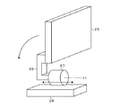
本発明の基板処理装置の第1の実施形態に係る塗布、現像装置1について、図1の横断平面図、図2の縦断側面図を夫々参照して説明する。塗布、現像装置1は、キャリアブロックD1と、処理ブロックD2と、インターフェイスブロックD3とが、この順で横方向に直線状に接続されて構成されている。インターフェイスブロックD3には、露光機D4が接続されている。
[First Embodiment]
The coating and developing
各ブロックD1〜D3について簡単に説明すると、キャリアブロックD1には、直径が例えば300mmの円形の基板であるウエハWを格納したキャリアCが搬送され、当該キャリアブロックD1は、キャリアC内のウエハWを装置内へ搬送する。キャリアCは、例えばFOUP(Front Opening Unified Pod)と呼ばれるウエハWの搬送容器であり、容器本体と、当該容器本体の前面に設けられた蓋とにより構成されている。また、上記の処理ブロックD2はウエハWに各種の薬液を供給し、反射防止膜の形成と、レジスト膜の形成と、レジスト膜を現像することによるレジストパターンの形成と、を行う。露光機D4は、上記の現像でレジストパターンが形成されるようにウエハWを露光し、インターフェイスブロックD3は、処理ブロックD2と露光機D4との間でウエハWを受け渡す。 Briefly explaining each block D1 to D3, a carrier C containing a wafer W which is a circular substrate having a diameter of, for example, 300 mm is conveyed to the carrier block D1, and the carrier block D1 is a wafer W in the carrier C. Is transported into the device. The carrier C is, for example, a wafer W transport container called FOUP (Front Opening Unified Pod), and is composed of a container main body and a lid provided on the front surface of the container main body. Further, the processing block D2 supplies various chemical solutions to the wafer W to form an antireflection film, a resist film, and a resist pattern by developing the resist film. The exposure machine D4 exposes the wafer W so that a resist pattern is formed by the above development, and the interface block D3 passes the wafer W between the processing block D2 and the exposure machine D4.
ウエハWは、キャリアC→キャリアブロックD1→処理ブロックD2→インターフェイスブロックD3→露光機D4→インターフェイスブロックD3→処理ブロックD2→キャリアブロックD1→キャリアCの順で搬送されて処理を受ける。この搬送中、ウエハWは処理ブロックD2に搬入前あるいは処理ブロックD2から搬出後に、キャリアブロックD1に設けられる検査モジュール4に搬送されて、その表面の状態について検査される。具体的には、例えば異物の有無やパターンの大きさの異常の有無について検査される。以降、処理ブロックD2への搬入前に行われる検査を処理前検査、処理ブロックD2からの搬出後に行われる検査を処理後検査と記載する。
The wafer W is conveyed and processed in the order of carrier C → carrier block D1 → processing block D2 → interface block D3 → exposure machine D4 → interface block D3 → processing block D2 → carrier block D1 → carrier C. During this transfer, the wafer W is transported to the
続いて、キャリアブロックD1について図3の正面図、図4の斜視図も参照しながら説明する。なお、図4ではキャリアブロックD1の正面の各部を示すために、キャリアブロックD1を上下に2分割して示している。また、以下の説明では、キャリアブロックD1側を前方側、インターフェイスブロックD3側を後方側として説明し、説明中の左側、右側とは特に説明が無い限り、前方から後方へ向かって見たときの左側、右側である。 Subsequently, the carrier block D1 will be described with reference to the front view of FIG. 3 and the perspective view of FIG. In FIG. 4, the carrier block D1 is divided into upper and lower parts in order to show each part on the front surface of the carrier block D1. Further, in the following description, the carrier block D1 side is referred to as the front side and the interface block D3 side is referred to as the rear side, and the left side and the right side in the explanation are when viewed from the front to the rear unless otherwise specified. Left side, right side.
キャリアブロックD1は角型の筐体11を備えており、筐体11の各側壁は垂直に形成されている。側壁の1つである正面壁12からは、上下方向に互いに離間した3箇所が前方側に突出して3段の棚を形成している。この3段の棚のうち下段の棚を支持台13、中段の棚を支持台14、上段の棚を支持台15とする。また、支持台13の下端部はさらに前方へと突出し、支持台16を形成している。これらの支持台13〜16は、台上にキャリアCを支持することができるように水平に形成されている。
The carrier block D1 includes a
筐体11の正面壁12において、支持台13と支持台14との間には、ウエハWの搬送口21、ウエハWの搬送口21、検査モジュール設置用の開口部22、ウエハWの搬送口21が左から右側に向けてこの順で一列に、互いに離間して設けられている。上記の開口部22は扁平な角型であり、垂直方向に2つ、互いに離間して設けられている。支持台13において各搬送口21の前方には、キャリアCが載置される移動ステージ23が設けられている。移動ステージ23は、当該移動ステージ23に対してキャリアCの受け渡しが行われる前方位置と、搬送口21を介してキャリアCと筐体11内との間でウエハWを受け渡すための後方位置との間で進退する。
In the
上記の各搬送口21には昇降ドア24が設けられている。この昇降ドア24の前面には図示しない、キャリアCの蓋を保持する保持機構が設けられており、後方位置における移動ステージ23上のキャリアCを構成する容器本体に対して、当該蓋の受け渡しが行えるように構成されている。また、昇降ドア24は搬送口21を塞ぐ閉鎖位置と、当該閉鎖位置から後退及び下降した、搬送口21を開放する開放位置との間で移動する。従って昇降ドア24は、搬送口21の開閉とキャリアCの蓋の開閉とを行う。なお、上記の開放位置は、図2、図3中に一点鎖線で表示している。従って、ウエハWを格納する搬送容器が載置されるステージ、当該ステージに載置された搬送容器に対してウエハWを搬入出する搬送口、及び当該搬送口の開閉及び搬送容器の蓋の開閉を行うドアを備える機器をロードポートとすると、支持台13上には3つのロードポートが設けられている。各図で、この3つのロードポートを互いに区別するために、左から右側に向かって順に2A、2B、2Cとして示す。
An elevating
正面壁12において支持台14と支持台15との間には、ウエハWの搬送口21が1つ、上記のロードポート2Cの搬送口21の垂直上方に開口している。支持台14において、そのように支持台14、15間に設けられた搬送口21の前方には、既述の移動ステージ23が設けられており、また当該搬送口21には回転ドア25が設けられている。図5は回転ドア25の斜視図であり、図5中26は、回転ドア25の縁部に一端が接続されたアームである。図5中27は、アーム26の他端が接続された回転機構である。前後に見たときに回転機構27は、回転ドア25を、搬送口21の下方に位置すると共に前後方向に沿った水平な回転軸R1のまわりに回転させる。また、図5中28は前後移動機構であり、回転機構27及びアーム26と共に回転ドア25を前後に移動させる。
On the
回転ドア25は、前後移動機構28及び回転機構27により、搬送口21を塞ぐ閉鎖位置と、当該閉鎖位置に対して後退且つ90°回転した位置である搬送口21を開放する開放位置との間で移動する。この開放位置は図2、図3に一点鎖線で示しており、図3に示すように前後に見て開放位置における回転ドア25は、搬送口21に対して横方向にずれると共に、開口部22の上方に位置する。また、回転ドア25の前面にも昇降ドア24の前面と同じく、キャリアCの蓋を保持する図示しない保持機構が設けられており、支持台14の後方位置における移動ステージ23に載置された容器本体に対して、当該蓋の受け渡しが行われる。即ち、回転ドア25も搬送口21の開閉とキャリアCの蓋の開閉とを行う。従って、回転ドア25、当該回転ドア25により開閉される搬送口21及び支持台14上の移動ステージ23もロードポートとして構成されており、図中に2Dとして示している。
The
また、支持台14においては上記のロードポート2Dの左側に、キャリアCが各々載置される3つの待機用ステージ29が左右に間隔をおいて一列に設けられている。前後方向に見て、この支持台14の待機用ステージ29は、開口部22の垂直上方、ロードポート2Aの移動ステージ23の垂直上方、ロードポート2Bの移動ステージ23の垂直上方に各々設けられている。続いて、支持台15、16について説明すると、支持台15には、キャリアCが各々載置される、搬入用ステージ31、待機用ステージ29、待機用ステージ29、搬出用ステージ32が左から右に向かってこの順に、間隔をおいて一列に設けられている。前後方向に見て、搬出用ステージ31及び支持台15に設けられる各待機用ステージ29は、上記の支持台14の各待機用ステージ29の垂直上方に、搬入用ステージ31は、支持台14の移動ステージ23の垂直上方に夫々位置している。支持台16には、例えば当該支持台16の左右の中央よりも右側に、左右に一列に2つの待機用ステージ29が設けられている。ただし、左右の中央よりも左側に待機用ステージ29を設けてもよい。
Further, in the
後述するキャリア搬送機構3により、キャリアCは搬入用ステージ31と搬出用ステージ32と待機用ステージ29との間
で搬送される。搬入用ステージ31は、図示しない外部搬送機構がキャリアブロックD1にキャリアCを搬入するために当該キャリアCを載置するステージである。この外部搬送機構は、搬出用ステージ32に載置されたキャリアCを受け取り、キャリアブロックD1から搬出する。また、各待機用ステージ29は、装置内にウエハWを搬入する前のキャリアC及び装置内にウエハWを搬入した後の空のキャリアCを待機させるためのステージである。従ってキャリアCは、搬入用ステージ31→待機用ステージ29→ロードポート2A〜2Dのいずれかの移動ステージ23の順で搬送されて、当該移動ステージ23上にてウエハWを払い出した後、待機用ステージ29→ロードポート2A〜2Dのいずれかの移動ステージ23の順で搬送されて当該移動ステージ23上にてウエハWを受け取る。その後、キャリアCは待機用ステージ29→搬出用ステージ32の順で搬送される。
The carrier C is transported between the carry-in
ところで待機用ステージ29について補足しておくと、上記のように支持台14の右端部にはロードポート2Dが設けられているため、支持台14に設置できる待機用ステージ29の数は限られる。しかし、支持台14、15の他に、ロードポート2A〜2Dの下方の支持台16にも待機用ステージ29が設けられているため、キャリアブロックD1には十分な数のキャリアCを搬入することができる。従って、高いスループットを確保することができる。
By the way, as a supplement to the
上記のキャリア搬送機構3について説明する。キャリア搬送機構3は、キャリアブロックD1の正面壁12の前方側に設けられ、キャリアCの上部に設けられた被保持部を保持することができる多関節アーム33と、多関節アーム33を昇降させる昇降機構34と、昇降機構34を左右に移動させる左右移動機構35とを備えており、上記の経路でキャリアCを搬送する。
The
キャリアブロックD1には、ウエハWの検査を行うための検査モジュール4が2つ設けられている。この検査モジュール4について、図6の縦断側面図も参照しながら説明する。検査モジュール4は例えば角型で前後に長い扁平な筐体41を備えており、筐体41は上記の開口部22を介して筐体11の外部から筐体11内へと差し込まれることにより、キャリアブロックD1に設けられている。開口部22は上下に垂直に配列されているため、検査モジュール4も上下に垂直に配列されている。筐体41の後部の左右の側壁にはウエハWの搬送口42が各々形成されており、筐体11内に開口している。筐体41の前方側は筐体11の正面壁12から突出している。
The carrier block D1 is provided with two
筐体41内には、ウエハWの裏面側中央部を吸着し、ウエハWを水平に保持する載置部43が設けられている。筐体41内において載置部43は、後方側の待機位置と前方側の撮像完了位置との間で移動することができる。図6中、待機位置を実線で、撮像完了位置を一点鎖線で夫々示している。また、図1では待機位置における載置部43を示している。待機位置は上記の搬送口42に臨む位置であり、搬送口42を介して筐体41内に進入した後述の搬送機構5A、5Bのフォーク56が昇降することで、当該搬送機構5A、5Bと載置部43との間でウエハWの受け渡しが行われる。なお、フォーク56が昇降する代わりに筐体41内に昇降自在なピンを設け、当該ピンにより搬送機構5A、5Bと待機位置における載置部43との間でウエハWの受け渡しが行われるようにしてもよい。図中44は、載置部43を前後に移動させるための移動機構である。
Inside the
筐体41内において載置部43によるウエハWの移動路の上方には、筐体41内を左右に伸びる横長のハーフミラー45が設けられており、このハーフミラー45はウエハWの移動方向に対して側面視斜めに設けられている。また、ハーフミラー45の上方には当該ハーフミラー45を介して下方に光を照射する照明46が設けられている。ハーフミラー45の奥側にはカメラ47が設けられている。照明46からの照射光がハーフミラー45を通過し、ハーフミラー45の下方の照射領域に当てられる。そして、この照射領域における物体の反射光がハーフミラー45で反射し、カメラ47に取り込まれる。即ちカメラ47は、ハーフミラー45の下方の撮像領域に位置する物体を撮像することができる。
A horizontally
待機位置で搬送機構5Aまたは5BからウエハWが受け渡された載置部43が撮像完了位置へ向けて移動している間にカメラ47が間欠的に撮像を行うことで、ウエハWの表面全体が撮像されて画像データが取得される。この画像データはカメラ47から後述の制御部10に送信され、制御部10によりこの画像データに基づいてウエハWの表面の検査が行われる。なお、撮像完了位置へ移動した載置部43は、搬送機構5Aまたは5BにウエハWを受け渡すために待機位置へ戻る。
The entire surface of the wafer W is captured by the
ところで、検査モジュール4は、キャリアブロックD1に対して着脱自在に構成されている。例えば図7に示すように、キャリアブロックD1の開口部22の縁部には、筐体11内に向けて開口部22の開口方向に沿って伸びるガイドレール48が係合部として設けられている。その一方で、検査モジュール4の筐体41には、当該筐体41の後端から前方に向かって伸びる溝49が被係合部として設けられている。上記のように検査モジュール4の筐体41の後部がキャリアブロックD1の筐体11内に差し込まれ、検査モジュール4がキャリアブロックD1に装着されているときには、図7の上段に示すように溝49とガイドレール48とが係合している。
By the way, the
例えば作業者が開口部22から突出した検査モジュール4の前部を前方に引っ張ることで、ガイドレール48に沿って筐体41の後部を、筐体11の外側に引き出し、図7の下段に示すように溝49はガイドレール48から外れ、検査モジュール4がキャリアブロックD1から取り外される。検査モジュール4を筐体41に取り付ける際には、この取り外しの際と逆の作業を行う。このように検査モジュール4がキャリアブロックD1に対して着脱自在であることにより、例えば照明46の交換などの検査モジュール4のメンテナンスを容易に行うことができる。なお、ガイドレール48及び溝49の表示は、図7以外の図では省略している。
For example, when the operator pulls the front part of the
続いて、図8のキャリアブロックD1の縦断正面図も参照しながら、筐体11内の構成について説明する。筐体11内においては、バッファモジュール51が設けられている。このバッファモジュール51は、複数枚のウエハWを上下方向に間隔をおいて載置するように構成されており、例えば、ウエハWの裏面を支持する3本のピンの組が、上下方向に複数設けられることにより構成されている。なお、バッファモジュール51としてはそのようなピンを備える構成には限られず、例えばウエハWの周縁部をガイドして所定の位置にウエハWを落とし込むように、椀状で当該周縁部を支持するように構成されていてもよい。このバッファモジュール51は検査モジュール4の上方に、平面で見て当該検査モジュール4の載置部43の待機位置に重なるように設けられている。当該バッファモジュール51は検査モジュール4が空いて(即ち、検査モジュール4で先に検査が行われたウエハWが搬出されて)、当該検査モジュール4に後続のウエハWを搬入可能になるまで、この後続のウエハWを載置して待機させる待機部をなす。
Subsequently, the configuration inside the
バッファモジュール51及び検査モジュール4の左側には搬送機構5Aが、右側には搬送機構5Bが夫々設けられている。搬送機構5Aは、起立したフレーム52と、フレーム52を左右に移動させる左右移動機構53と、フレーム52に垂直に昇降自在に設けられる昇降台54と、昇降台54上を鉛直軸回りに回転自在な基台55と、基台55上を進退自在でウエハWの裏面を支持するフォーク56とにより構成されている。なお、左右移動機構53によって上記のフレーム52が移動する領域は、バッファモジュール51及び検査モジュール4の左側に限られる。
A
第1の基板搬送機構である搬送機構5Aは、当該搬送機構5Aを構成する上記の各部の協働により、第1のロードポートであるロードポート2A、2Bに載置された各キャリアCと、検査モジュール4の待機位置における載置部43と、バッファモジュール51と、後述のタワーT1の受け渡しモジュールとの間でウエハWを受け渡すことができる。なお、図1中57は、そのようにタワーT1にウエハWを受け渡すために、筐体11の後方側に設けられたウエハWの搬送路である。第2の基板搬送機構である搬送機構5Bは、左右移動機構53が設けられていないことを除いて搬送機構5Aと同様に構成されている。搬送機構5Bは、当該搬送機構5Bを構成する各部の協働により、第2のロードポートであるロードポート2C、2Dに載置された各キャリアCと、検査モジュール4の待機位置における載置部43と、バッファモジュール51との間でウエハWを受け渡すことができる。このようにバッファモジュール51及び検査モジュール4の載置部43には、搬送機構5A、5Bの両方がウエハWを受け渡すことができ、当該バッファモジュール51及び載置部43は、これら搬送機構5A、5B間でウエハWを受け渡すために当該ウエハWが載置される受け渡し部として兼用される。
The
続いて、図1、図2を用いて処理ブロックD2について説明する。処理ブロックD2は、ウエハWに液処理を行う第1〜第6の単位ブロックE1〜E6が下から順に積層されて構成されている。E1とE2とが互いに同じ単位ブロックであり、E3とE4とが互いに同じ単位ブロックであり、E5とE6とが互いに同じ単位ブロックである。2つの同じ単位ブロックのうち、ウエハWは一方の単位ブロックに搬送される。ここでは単位ブロックのうち代表して、図1に示す単位ブロックE3を説明する。前後に伸びるようにウエハWの搬送領域61が形成されており、搬送領域61の右側には、ウエハWの表面に薬液としてレジストを塗布してレジスト膜を形成するレジスト膜形成モジュール62が2つ、前後方向に配置されている。搬送領域61の左側には、ウエハWを加熱する加熱モジュール63が、搬送領域61に沿って前後に複数設けられている。また、上記の搬送領域61には、単位ブロックE3内でウエハWを搬送する搬送機構F3が設けられている。
Subsequently, the processing block D2 will be described with reference to FIGS. 1 and 2. The processing block D2 is configured by laminating the first to sixth unit blocks E1 to E6 that perform liquid treatment on the wafer W in order from the bottom. E1 and E2 are the same unit blocks, E3 and E4 are the same unit blocks, and E5 and E6 are the same unit blocks. Of the two same unit blocks, the wafer W is transported to one unit block. Here, the unit block E3 shown in FIG. 1 will be described as a representative of the unit blocks. A
単位ブロックE1、E2、E5、E6について、単位ブロックE3、E4との差異点を説明すると、単位ブロックE1、E2は、レジスト膜形成モジュール62の代わりに反射防止膜形成モジュールを備えている。反射防止膜形成モジュールは、ウエハWに反射防止膜を形成するために、レジストの代わりに反射防止膜形成用の薬液を塗布して反射防止膜を形成する。単位ブロックE5、E6は、レジスト膜形成モジュール62の代わりに現像モジュールを備えている。現像モジュールは、薬液としてウエハWに現像液を供給する。このように薬液の供給を行うモジュールについて、当該薬液の種類が異なることを除いて、単位ブロックE1〜E6は互いに同様に構成されている。また、図2では、搬送機構F3に相当する各単位ブロックE1、E2、E4〜E6の搬送機構について、F1、F2、F4〜F6として示している。
Explaining the differences between the unit blocks E1, E2, E5, and E6 from the unit blocks E3 and E4, the unit blocks E1 and E2 include an antireflection film forming module instead of the resist
処理ブロックD2におけるキャリアブロックD1側には、各単位ブロックE1〜E6に跨って上下に伸び、互いに積層された多数の受け渡しモジュールからなるタワーT1と、タワーT1を構成する各モジュール間でウエハWの受け渡しを行うための搬送機構64と、が設けられている。タワーT1において、例えば単位ブロックE1〜E6が設けられる各高さには、ウエハWが載置される受け渡しモジュールTRS1〜TRS6が設けられている。また、タワーT1には上記のように搬送機構5Aとの間でウエハWを受け渡すために、ウエハWが載置される受け渡しモジュールが設けられており、当該受け渡しモジュールをTRS0、TRS10とする。
On the carrier block D1 side of the processing block D2, a tower T1 composed of a large number of transfer modules extending vertically across the unit blocks E1 to E6 and laminated to each other, and a wafer W between the modules constituting the tower T1
インターフェイスブロックD3は、単位ブロックE1〜E6に跨って上下に伸びるタワーT2、T3、T4を備えており、タワーT2とタワーT3とに対してウエハWの受け渡しを行うための搬送機構65と、タワーT2とタワーT4とに対してウエハWの受け渡しを行うための搬送機構66と、タワーT2と露光機D4との間でウエハWの受け渡しを行うための搬送機構67と、が設けられている。タワーT2は、各単位ブロックに対してウエハWを受け渡すための受け渡しモジュールTRSが積層されて設けられている。タワーT3、T4にもモジュールが設けられているが、このモジュールについては説明を省略する。
The interface block D3 includes towers T2, T3, and T4 extending vertically across the unit blocks E1 to E6, and a
図1に示すように、塗布、現像装置1には、コンピュータからなる制御部10が設けられている。制御部10は、プログラムを備えた不図示のプログラム格納部を有している。制御部10が塗布、現像装置1の各部に制御信号を出力し、各搬送機構によるウエハWの搬送、キャリア搬送機構3によるキャリアCの搬送、及び各モジュールにおけるウエハの処理が制御され、後述のようにウエハWに対してレジストパターンの形成及び検査が行われるように、上記のプログラムについては命令が組まれている。このプログラムは、例えばハードディスク、コンパクトディスク、DVDまたはメモリーカードなどの記憶媒体に収納された状態でプログラム格納部に格納される。
As shown in FIG. 1, the coating / developing
次に、図9、図10を参照しながら、上記のレジストパターンの形成と処理前検査とを行うときのキャリアブロックD1におけるウエハWの搬送経路を説明する。この図9、図10及び後述の図11、図12では、図示の便宜上、ロードポート2C、2Dを横に並べて示すと共に、検査モジュール4とバッファモジュール51とを互いにずらして示している。
Next, the transfer path of the wafer W in the carrier block D1 when forming the resist pattern and performing the pretreatment inspection will be described with reference to FIGS. 9 and 10. In FIGS. 9 and 10 and FIGS. 11 and 12 described later, the
処理前検査を行う場合、例えばロードポート2C、2Dが装置内へウエハWを搬入するための搬入用ロードポートとして用いられ、ロードポート2A、2Bが装置内からウエハWを搬出するための搬出用ロードポートとして用いられる。先ず、ロードポート2C、2Dに各々載置されたキャリアCから、搬送機構5BによりウエハWがバッファモジュール51に搬送される(図9中、矢印A1)。
When performing pre-processing inspection, for example,
続いて検査モジュール4にウエハWが搬送可能になると、搬送機構5Bにより検査モジュール4にウエハWが搬入されて(図9中、矢印A2)、ウエハWの表面の画像データが取得されて検査が行われる。然る後、搬送機構5Aにより検査モジュール4からウエハWが搬出されて、タワーT1の受け渡しモジュールTRS0に搬送される(図9中、矢印A3)。受け渡しモジュールTRS0に搬送されたウエハWは、既述のように処理ブロックD2、インターフェイスブロックD3、露光機D4に搬送されてレジストパターンが形成された後、タワーT1の受け渡しモジュールTRS10に搬送される。そして、搬送機構5Aにより当該ウエハWは、ロードポート2Aまたは2BのキャリアCに搬送される(図10中、矢印A4)。
Subsequently, when the wafer W can be conveyed to the
次に、図11、図12を参照しながら、上記のレジストパターンの形成と処理後検査とを行うときのキャリアブロックD1におけるウエハWの搬送経路を説明する。処理後検査を行う場合、例えばロードポート2A、2Bが搬入用ロードポートとして用いられ、ロードポート2C、2Dが搬出用ロードポートとして用いられる。先ず、ロードポート2A、2Bに各々載置されたキャリアCからウエハWが、搬送機構5AによりタワーT1の受け渡しモジュールTRS0に搬送される(図11中、矢印B1)。このウエハWが、既述のように処理ブロックD2、インターフェイスブロックD3、露光機D4に搬送されてレジストパターンが形成された後、タワーT1の受け渡しモジュールTRS10に搬送される。
Next, the transfer path of the wafer W in the carrier block D1 when forming the resist pattern and performing the post-treatment inspection will be described with reference to FIGS. 11 and 12. When performing post-processing inspection, for example,
続いて、搬送機構5AによりウエハWは、受け渡しモジュールTRS10からバッファモジュール51に搬送され(図12中、矢印B2)、検査モジュール4にウエハWが搬送可能になると搬送機構5Bにより検査モジュール4にウエハWが搬入されて(図12中、矢印B3)、ウエハWの表面の画像データが取得されて検査が行われる。そして、搬送機構5Bにより検査モジュール4からウエハWが搬出されて、ロードポート2Cまたは2DのキャリアCに搬送される(図12中、矢印B4)。
Subsequently, the wafer W is transferred from the transfer module TRS10 to the
上記のウエハWの各搬送で、受け渡しモジュールTRS0から受け渡しモジュールTRS10までのウエハWの搬送経路について説明しておく。受け渡しモジュールTRS0に搬送されたウエハWは、搬送機構64によって、単位ブロックE1、E2に振り分けられて搬送される。例えばウエハWを単位ブロックE1に受け渡す場合には、タワーT1の受け渡しモジュールTRSのうち、単位ブロックE1に対応する受け渡しモジュールTRS1(搬送機構F1によりウエハWの受け渡しが可能な受け渡しモジュール)に対してウエハWが受け渡される。また、ウエハWを単位ブロックE2に受け渡す場合には、タワーT1の受け渡しモジュールTRSのうち、単位ブロックE2に対応する受け渡しモジュールTRS2に対して、ウエハWが受け渡される。
In each transfer of the wafer W described above, the transfer path of the wafer W from the transfer module TRS0 to the transfer module TRS10 will be described. The wafer W transported to the delivery module TRS0 is distributed to the unit blocks E1 and E2 by the
このように振り分けられたウエハWは搬送機構F1(F2)によって、TRS1(TRS2)→反射防止膜形成モジュール→加熱モジュール63→TRS1(TRS2)の順に搬送され、搬送機構64により単位ブロックE3に対応する受け渡しモジュールTRS3と、単位ブロックE4に対応する受け渡しモジュールTRS4とに振り分けられる。このようにTRS3、TRS4に振り分けられたウエハWは搬送機構F3(F4)によって、TRS3(TRS4)→レジスト膜形成モジュール62→加熱モジュール63→タワーT2の受け渡しモジュールTRS31(TRS41)の順で搬送される。然る後、このウエハWは、搬送機構65、67により露光機D4へ搬送され、ウエハWの表面に形成されたレジスト膜が所定のパターンに沿って露光される。
The wafers W distributed in this way are conveyed in the order of TRS1 (TRS2) → antireflection film forming module →
露光後のウエハWは、搬送機構66、67によりタワーT2、T4間を搬送されて、単位ブロックE5、E6に対応するタワーT2の受け渡しモジュールTRS51、TRS61に夫々搬送される。然る後、ウエハWは搬送機構F5、F6によって加熱モジュール63→現像モジュールの順で搬送され、露光機D4で露光されたパターンに沿ってレジスト膜が溶解してレジストパターンが形成された後、受け渡しモジュールTRS10に搬送される。
The exposed wafer W is conveyed between the towers T2 and T4 by the
上記の塗布、現像装置1によれば、キャリアブロックD1の左側に配置されたロードポート2A、2Bと、キャリアブロックD1の右側に配置されたロードポート2C、2Dとの間に検査モジュール4が設けられている。そして、検査モジュール4の左側に配置された搬送機構5Aがロードポート2A、2Bに各々載置されたキャリアC及び処理ブロックD2に対する受け渡しを行い、検査モジュール4の右側に配置された搬送機構5Bがロードポート2C、2Dに各々載置されたキャリアCに対して受け渡しを行い、検査モジュール4またはバッファモジュール51を介して搬送機構5A、5B間でウエハWが受け渡される。このような構成によれば、検査モジュール4をロードポート2A〜2Dの近傍に配置することができるので、塗布、現像装置1に搬入された直後のウエハW、塗布、現像装置1から搬出される直前のウエハWを夫々検査することができる。それ故に、塗布、現像装置1への搬入前にウエハWに異常が起きている場合には塗布、現像装置1の外部で発生した異常であることを精度高く特定することができるし、塗布、現像装置1内の処理及び搬送で異常が発生した場合には、当該異常を確実に検出することができる。
According to the coating and developing
そのような検査を行うことが可能になる上に、上記のキャリアブロックD1の構成によれば、搬送機構5A、5Bの各々がアクセスするロードポートの数が抑えられ、且つ処理ブロックD2に対するウエハWの搬送を搬送機構5Aにより行う一方で、検査モジュール4へのウエハWの搬送については処理ブロックD2に対して搬送を行わない搬送機構5Bを用いて行うことができる。つまり、搬送機構5A、5Bで役割が分担されるので、キャリアCと処理ブロックD2との間でウエハWを搬送し且つこの搬送中に検査を行うために、搬送機構5A、5Bの各々がウエハWの受け渡しを行う回数を抑えることができる。即ち、搬送機構5A、5Bの各々の負荷が大きくなることが抑制されるため、装置のスループットを高くすることができる。
In addition to being able to perform such inspections, according to the configuration of the carrier block D1 described above, the number of load ports accessed by each of the
そして、上記のように左右のロードポート間に設ける検査モジュール4については、ロードポート2A〜2Cの搬送口21と同じ高さに設けられている。つまり、検査モジュール4とロードポート2A〜2Cとが左右に列をなすように設けられている。それにより、ロードポート2A〜2CのキャリアCと検査モジュール4との間の距離を比較的短くすることができ、これらのロードポート2A〜2CとキャリアCとの間で速やかにウエハWを搬送することができるため、より確実に装置のスループットを高くすることができる。なお、上記のようにバッファモジュール51を介してキャリアCと検査モジュール4との間で搬送を行う場合であっても、検査モジュール4とロードポート2A〜2Cとを一列に配置していれば、検査モジュール4の近傍にバッファモジュール51を配置することで、搬送機構5A、5Bの移動距離が長くなることを抑えることができるので、速やかなウエハWの搬送を行える。
The
さらに、上記のようにロードポート2A〜2Cを設けつつ、ロードポート2Dを設けることで、ロードポートの数が不足することによるスループットの低下が起らないようにしているが、このロードポート2Dについてはロードポート2Cの上方に配置することで、上記の位置に検査モジュール4を設け且つ4つのロードポートを設けることによる、キャリアブロックD1のフットプリントの増大を防いでいる。さらに、ロードポート2A〜2Cについては、昇降ドア24により搬送口21が各々開閉されることで、搬送口21を開閉するために必要な左右のスペースを抑え、検査モジュール4とロードポートとの間隔が大きくなることを防ぎ、キャリアブロックD1の左右の幅の増大が防がれている。その一方で、ロードポート2Dについては、回転ドア25により搬送口21が開閉されることで、搬送口21を開閉するために必要な上下のスペースが抑えられており、それによってロードポート2C、2D間の距離が短くなるように構成されている。つまり、ロードポート2C、2Dが上下に配置されていても、搬送機構5Bが各ロードポート2C、2Dに各々アクセスするために昇降する長さが抑えられるため、スループットをより確実に高くすることができるように構成されている。
Further, while providing
なお検査モジュール4は、スループットの低下を防ぐために2つ設けられているが、1つのみ設けてもよい。また、3つ以上の検査モジュール4を設けてもよく、その場合も装置のフットプリントを抑制しつつ、搬送機構5A、5Bの各々がウエハWを受け渡せるようにするために、各検査モジュール4は互いに積層して設けることが好ましい。
Although two
なお、検査モジュール4はロードポート2A〜2Cの搬送口21と同じ高さに設けられることには限られず、例えばバッファモジュール51をロードポート2A〜2Cの搬送口21と同じ高さに配置し、このバッファモジュール51よりも高い位置に検査モジュール4を設けてもよい。ただし、ロードポート2Dの回転ドア25と検査モジュール4との干渉を避けるために、ロードポート2Cに対するロードポート2Dの高さがより大きくなることで、上記の搬送機構5Bがロードポート2C、2Dに各々アクセスするために昇降する長さが大きくなってしまう懸念が有るし、上記のようにロードポート2A〜2CのキャリアCと検査モジュール4との間の搬送を速やかに行う観点からも、検査モジュール4はロードポート2A〜2Cの搬送口21と同じ高さに設けることが好ましい。
The
また、平面で見てバッファモジュール51は、検査モジュール4の待機位置における載置部43と重なるように設けられているので、搬送機構5A、5Bにおいてフォーク56が設けられる基台55は左右に移動することなく、昇降動作のみでバッファモジュール51で待機させたウエハWを検査モジュール4に搬送することができる。従って、バッファモジュール51と検査モジュール4との間のウエハWの搬送に要する時間が抑制され、スループットをより確実に高くすることができる。なお、キャリアブロックD1にバッファモジュール51を設けず、搬送機構5A、5B間でのウエハWの搬送は検査モジュール4のみを介して行うようにし、例えばウエハWを検査モジュール4に搬入する際には、検査モジュール4が空くまで搬送機構5A、5BがウエハWを保持して待機するようにしてもよい。しかし、そのようにウエハWを保持している間、搬送機構5A、5Bは他のウエハWの搬送を行えないので、スループットの低下を防ぐためにバッファモジュール51を設けることが有効である。
Further, since the
さらに、上記のキャリアブロックD1においては検査モジュール4の載置部43及びバッファモジュール51が、搬送機構5A、5B間でウエハWの受け渡しを行うためにウエハWを載置する受け渡し部として構成されているが、検査モジュール4及びバッファモジュール51とは別個に受け渡し部を設けてもよい。しかし、検査モジュール4が受け渡し部を兼用することで、図9に示したように検査済みのウエハWを搬送機構5Aが直接受け取り、タワーT1に搬送することができる。また、バッファモジュール51が受け渡し部を兼用することで、図12に示したようにタワーT1のウエハWを直接バッファモジュール51に搬送して待機させることができる。つまり、検査モジュール4及びバッファモジュール51が各々受け渡し部として兼用されることで、搬送機構5A、5Bの負荷を抑制し、スループットの向上を図ることができる。
Further, in the carrier block D1, the mounting
また、キャリアCから搬出されたウエハWが再びキャリアCに格納されるまでに、上記の処理前検査及び処理後検査のうちの一方のみが行われることには限られない。処理前検査及び処理後検査を行う搬送の一例を示すと、先ず、図9の矢印A1〜A3で示すように、ロードポート2C、2Dから搬出されたウエハWについて、バッファモジュール51、検査モジュール4、受け渡しモジュールTRS0の順で搬送することで、当該ウエハWに処理前検査を行い、処理ブロックD2へ搬送する。そして、レジストパターンが形成され、受け渡しモジュールTRS10に搬送された当該ウエハWを、図12の矢印B2〜B3で示すようにバッファモジュール51、検査モジュール4の順で搬送し、処理後検査を行った後、ロードポート2A、2BのキャリアCに搬送する。このように処理前検査及び処理後検査を行うことで、ウエハWに異常が検出された場合、当該異常が塗布、現像装置1に起因するものか、塗布、現像装置1の外部に起因するものかをより確実に特定することができる。
Further, it is not always limited that only one of the above pre-treatment inspection and post-treatment inspection is performed before the wafer W carried out from the carrier C is stored in the carrier C again. To show an example of transport for performing pre-processing inspection and post-processing inspection, first, as shown by arrows A1 to A3 in FIG. 9, the wafer W carried out from the
処理前検査を行う他の搬送例について説明する。図9の矢印A1〜A3で示したようにロードポート2C、2DのキャリアCから搬出したウエハWをバッファモジュール51、検査モジュール4、受け渡しモジュールTRS0の順で搬送する。そして、レジストパターンが形成されて受け渡しモジュールTRS10に搬送されたウエハWを搬送機構5Aによりバッファモジュール51に搬送し、続いて搬送機構5Bによりロードポート2C、2DのキャリアCに搬送する。つまり、この一連の搬送を第1の搬入出搬送とすると、第1の搬入出搬送ではロードポート2C、2Dが搬入用ロードポート及び搬出用ロードポートをなす。
Another transport example for performing pretreatment inspection will be described. As shown by arrows A1 to A3 in FIG. 9, the wafer W carried out from the carrier C of the
処理後検査を行う他の搬送例について説明する。図11で説明したようにロードポート2A、2BのキャリアCから受け渡しモジュールTRS0に搬送され、然る後、レジストパターンが形成されて受け渡しモジュールTRS10に搬送されたウエハWについて、図12の矢印B2、B3で示すようにバッファモジュール51、検査モジュール4の順で搬送する。然る後、当該ウエハWを搬送機構5Aにより検査モジュール4からロードポート2A、2BのキャリアCに搬送する。つまり、この一連の搬送を第2の搬入出搬送とすると、第2の搬入出搬送ではロードポート2A、2Bが搬入用ロードポート及び搬出用ロードポートをなす。
Other transport examples for post-processing inspection will be described. As described with reference to FIG. 11, the wafer W transported from the carrier C of the
例えば、通常は図9〜図12で説明したようにウエハWの搬送を行い、ロードポート2A、2Bの両方が使用不可となったときは第1の搬入出搬送を行い、ロードポート2C、2Dの両方が使用不可となったときは第2の搬入出搬送を行うように搬送を制御してもよい。また、例えば2つの検査モジュール4のうちの一方を第1の搬入出搬送に専用に用いられるモジュール、他方を第2の搬入出搬送に専用に用いられるモジュールとして、第1の搬入出搬送と第2の搬入出搬送とを並行して行ってもよい。つまり、図9〜図12に示した例のように、搬送機構5A、5Bのうちの一方が、キャリアCからのウエハWの受け取りのみを行い、搬送機構5A、5Bのうちの他方がキャリアCへのウエハWの搬送のみを行うように各搬送機構5A、5Bの動作を制御することには限られない。
For example, normally, the wafer W is transported as described with reference to FIGS. 9 to 12, and when both the
[第1の実施形態の第1の変形例]
続いて、第1の実施形態の第1の変形例に係るキャリアブロックD11について、図13を参照しながらキャリアブロックD1との差異点を中心に説明する。このキャリアブロックD11では、ロードポート2Aが、ロードポート2Dと同じ高さに、且つロードポート2Bと左右の位置が揃うように設けられている。このロードポート2Aの搬送口21を開閉するドアとしては、ロードポート2Bに干渉しないように、ロードポート2Dと同様に回転ドア25が設けられている。また、このキャリアブロックD11において、ロードポート2Bの左側には、右側と同様に2つの検査モジュール4が上下に設けられている。説明の便宜上、ロードポート2Bの右側の2つの検査モジュールを4A、左側の2つの検査モジュールを4Bとする。検査モジュール4B及びロードポート2Aに対しては、検査モジュール4Aの左側に位置していることにより、搬送機構5AがウエハWの受け渡しを行う。
[First Modified Example of First Embodiment]
Subsequently, the carrier block D11 according to the first modification of the first embodiment will be described focusing on the differences from the carrier block D1 with reference to FIG. In the carrier block D11, the
キャリアブロックD11における搬送の一例を示しておくと、例えば、図9で述べたようにロードポート2C、2DのキャリアCから取り出されてバッファモジュール51に搬送されたウエハWは、搬送機構5Bにより検査モジュール4Aに搬送されるか、あるいは搬送機構5Aにより検査モジュール4Bに搬送されて処理前検査を受ける。検査後の各ウエハWは、搬送機構5AによりタワーT1の受け渡しモジュールTRS0に搬送される。また、他の搬送例として、受け渡しモジュールTRS10からバッファモジュール51に搬送されたウエハWを、処理後検査を行うために検査モジュール4A、4Bに搬送し、然る後、所定のロードポートのキャリアCに戻すようにしてもよい。このキャリアブロックD11によれば第1の実施形態に比べて検査モジュール4の数が多いため、バッファモジュール51においてウエハWが待機する時間を抑えることができる。ただし、キャリアブロックD1よりも多くの数の検査モジュール4にアクセスすることで、搬送機構5A、5Bの負荷が大きくなるため、より高いスループットを得るためにはキャリアブロックD1の構成とすることがより好ましい。
To show an example of transfer in the carrier block D11, for example, as described in FIG. 9, the wafer W taken out from the carrier C of the
[第1の実施形態における第2の変形例]
次に第2の変形例に係るキャリアブロックD12について、図14を参照しながらキャリアブロックD1との差異点を中心に説明する。このキャリアブロックD12では、ロードポート2A〜2Dに加えてロードポート2Eが設けられている。このロードポート2Eは、ロードポート2Dと同じ高さに、且つロードポート2Aと左右の位置が揃うように設けられている。ロードポート2Eは、ロードポート2Aに干渉しないようにロードポート2Dと同様に回転ドア25が設けられている。ただし、キャリアブロックD1の筐体11の側壁と干渉しないように、このロードポート2Eの回転ドア25は、ロードポート2Dの回転ドア25とは逆に、閉鎖位置から右回りに回転する。ロードポート2Eは検査モジュール4の左側に位置するので、当該ロードポート2Eに載置されたキャリアCに対しては、搬送機構5BがウエハWを受け渡す。
[Second modification in the first embodiment]
Next, the carrier block D12 according to the second modification will be described focusing on the differences from the carrier block D1 with reference to FIG. In this carrier block D12, a
このキャリアブロックD12では例えば、図9〜図12で説明したようにウエハWの搬送が行われ、ロードポート2A、2Bが搬入用ロードポートとなるときには、例えばロードポート2Eも搬入用ロードポートとなり、ロードポート2A、2Bが搬出用ロードポートとなるときには例えばロードポート2Eも搬出用ロードポートとなる。
In this carrier block D12, for example, when the wafer W is conveyed as described with reference to FIGS. 9 to 12 and the
以上の第1の実施形態及び各変形例に示されるように、本発明によれば、2つの搬送機構5A、5Bが設けられ、これらのうちのいずれかの搬送機構によってウエハWの搬送を行うことができる領域に検査モジュール4及びロードポートを設置することができる。従って、これら検査モジュール4及びロードポート2についての配置の自由度が高く、必要なスループットや検査モジュール4で検査に要する時間などに応じて装置の設計を行いやすいという利点が有る。
As shown in the above first embodiment and each modification, according to the present invention, two
[第2の実施形態]
第2の実施形態の塗布、現像装置について、第1の実施形態との差異点を中心に説明する。図15、図16は、第2の実施形態の塗布、現像装置に設けられるキャリアブロックD5の正面図、横断平面図を夫々示している。キャリアブロックD5には、ロードポート2A〜2C及び2つの検査モジュール4が設けられているが、ロードポート2A〜2Cは各検査モジュール4の左側に位置している。また、キャリアブロックD5には支持台15、16、17が設けられておらず、キャリアブロックD5に対してキャリアCを受け渡す外部搬送機構は、ロードポート2A〜2Cの移動ステージ23にキャリアCを受け渡す。そして、キャリアCの待機用ステージ29と搬入用ステージ31と搬出用ステージ32との間での搬送は行われない。また、筐体11内においては搬送機構5A、5Bのうち、搬送機構5Aのみが設けられており、ロードポート2A〜2Cに載置された各キャリアCに対してウエハWの受け渡しを行えるように、当該搬送機構5Aのフレーム52は左右方向に移動する。
[Second Embodiment]
The coating and developing apparatus of the second embodiment will be described focusing on the differences from the first embodiment. 15 and 16 show a front view and a cross-sectional plan view of the carrier block D5 provided in the coating and developing apparatus of the second embodiment, respectively. The carrier block D5 is provided with
搬送機構5Aはロードポート2A〜2CのキャリアCからウエハWを取り出してタワーT1の受け渡しモジュールTRS0に搬送し、タワーT1の受け渡しモジュールTRS10に搬送されたレジストパターン形成済みのウエハWをロードポート2A〜2CのキャリアCに搬送する。処理前検査を行う場合、ウエハWは受け渡しモジュールTRS0に搬送される前に検査モジュール4に搬送されて検査される。処理後検査を行う場合、ウエハWはキャリアCに戻される前に検査モジュール4に搬送されて検査される。
The
図17は、上記のキャリアブロックD5の変形例であり、前後に見て第1の実施形態でロードポート2Dの搬送口21が形成されている領域に、2つの検査モジュール4を上下に間隔をおいて設けた例を示している。従って図17に示すキャリアブロックD5では、4つの検査モジュール4が上下方向に設けられている。以上、説明した第2の実施形態においても検査モジュール4は、第1の実施形態と同様にキャリアブロックD5の筐体11に対して着脱自在に構成されているので、容易にメンテナンスを行うことができる。
FIG. 17 is a modification of the carrier block D5, in which the two
また、検査モジュール4については、このように筐体41の外側から当該筐体41の開口部22に差し込まれる構成であるため、当該検査モジュール4は、その一部がキャリアブロックの筐体41から突出するように設けることができる。つまり、装置内における検査モジュール4の占有スペースが抑えられるため、装置内に他のモジュールを設けたり、増設することで当該検査モジュール4を設置できなくなることを防ぐことができる。また、このように占有スペースが小さいこと及び筐体41に対して着脱自在であることから、基板搬送機構の動作や他のモジュールの配置を妨げずに検査モジュール4を増設することが容易であるという利点が有る。なお、第1の実施形態、第2の実施形態から明かなように、検査モジュール4を筐体41に着脱自在な構成とするにあたり、左右に列をなすロードポートと検査モジュール4とについて、検査モジュール4は列の端部に位置してもよいし、列の中央部に位置してもよい。
Further, since the
ところで、キャリアブロックD1からウエハWが搬送され、当該ウエハWに処理を行う処理モジュールとしては上記の例に限られない。例えば、絶縁膜形成用の薬液をウエハWに塗布するモジュールであってもよいし、ウエハWに洗浄液を供給する洗浄モジュールであってもよいし、ウエハWを互いに貼り合わせるための接着剤を供給するモジュールであってもよい。また、例えば常圧雰囲気と真空雰囲気を切り替え可能なロードロックモジュールを介して真空雰囲気を形成する処理モジュールを設けてもよく、その場合、処理ガスをウエハWに供給することによるCVD、ALDまたはエッチングなどの処理を行うことができる。なお、本発明は、既述した各例に限られず、各例は適宜変更したり、互いに組み合わせたりすることができる。 By the way, the processing module in which the wafer W is conveyed from the carrier block D1 and the wafer W is processed is not limited to the above example. For example, it may be a module that applies a chemical solution for forming an insulating film to the wafer W, a cleaning module that supplies a cleaning solution to the wafer W, or an adhesive for bonding the wafers W to each other. It may be a module to be used. Further, for example, a processing module that forms a vacuum atmosphere via a load lock module that can switch between a normal pressure atmosphere and a vacuum atmosphere may be provided. In that case, CVD, ALD, or etching by supplying the processing gas to the wafer W may be provided. Etc. can be performed. The present invention is not limited to the above-described examples, and the examples can be appropriately modified or combined with each other.
C キャリア
D1 キャリアブロック
D2 処理部
1 塗布、現像装置
2A〜2D ロードポート
21 搬送口
23 移動ステージ
24 昇降ドア
25 回転ドア
4 検査モジュール
5A、5B 搬送機構
51 バッファモジュール
C Carrier D1 Carrier block
Claims (13)
前記基板に対して処理を行う処理部と、
左右における前記第1のロードポートと前記第2のロードポートとの間に設けられ、前記処理部による処理前あるいは処理後の前記基板を検査する検査モジュールと、
前記検査モジュールの左右の一方に設けられ、前記処理部と前記第1のロードポートに載置された搬送容器とに前記基板を各々受け渡すための第1の基板搬送機構と、
前記検査モジュールの左右の他方に設けられ、前記検査モジュールと前記第2のロードポートに載置された搬送容器とに基板を各々受け渡すための第2の基板搬送機構と、
前記第1の基板搬送機構と前記第2の基板搬送機構との間で前記基板を受け渡すための受け渡し部と、
を備えたことを特徴とする基板処理装置。 A first load port and a second load port, which are provided on one of the left and right sides so that the transport container in which the substrate is stored can be placed, respectively.
A processing unit that processes the substrate and
An inspection module provided between the first load port and the second load port on the left and right to inspect the substrate before or after processing by the processing unit.
A first substrate transfer mechanism provided on one of the left and right sides of the inspection module for transferring the substrate to the processing unit and the transfer container mounted on the first load port, respectively.
A second substrate transfer mechanism provided on the left and right sides of the inspection module and for transferring the substrate to the inspection module and the transfer container mounted on the second load port, respectively.
A transfer unit for transferring the substrate between the first substrate transfer mechanism and the second substrate transfer mechanism, and a transfer unit.
A substrate processing apparatus characterized by being equipped with.
当該複数のロードポートは、上下に夫々設けられた上側のロードポートと、下側のロードポートとを含むことを特徴とする請求項1または2記載の基板処理装置。 At least one of the first load port and the second load port is composed of a plurality of load ports.
The substrate processing apparatus according to claim 1 or 2, wherein the plurality of load ports include an upper load port provided on the upper and lower sides and a lower load port, respectively.
前記第1の基板搬送機構及び第2の基板搬送機構のうちの他方は、前記搬送容器からの基板の受け取りと前記搬送容器への基板の搬送のうち、前記搬送容器への基板の搬送のみを行うように制御信号を出力する制御部が設けられることを特徴とする請求項1ないし6のいずれか一つに記載の基板処理装置。 One of the first substrate transfer mechanism and the second substrate transfer mechanism receives only the substrate from the transfer container among the receipt of the substrate from the transfer container and the transfer of the substrate to the transfer container. Do,
The other of the first substrate transfer mechanism and the second substrate transfer mechanism receives only the substrate from the transfer container and transfers the substrate to the transfer container, and only transfers the substrate to the transfer container. The substrate processing apparatus according to any one of claims 1 to 6, wherein a control unit for outputting a control signal is provided so as to perform the operation.
前記検査モジュールは、前記基板を検査するために収納する第2の筐体を備え、当該第2の筐体は、前記第1の筐体の外側から当該第1の筐体の側壁に設けられた開口部に着脱自在に差し込まれることを特徴とする請求項1ないし7のいずれか一つに記載の基板処理装置。 A first substrate transport mechanism, a second substrate transport mechanism, and a transfer portion are stored, and a transport port of a substrate constituting the first load port and the second load port is opened on a side wall. A housing is provided,
The inspection module includes a second housing for inspecting the substrate, and the second housing is provided on the side wall of the first housing from the outside of the first housing. The substrate processing apparatus according to any one of claims 1 to 7, wherein the substrate processing apparatus is detachably inserted into the opening.
前記受け渡し部と前記載置部とは、上下に互いに重なるように設けられることを特徴とする請求項1ないし8のいずれか一つに記載の基板処理装置。 The inspection module includes a mounting portion on which the board transported by the second substrate transport mechanism is mounted.
The substrate processing apparatus according to any one of claims 1 to 8, wherein the delivery portion and the previously described placing portion are provided so as to overlap each other in the vertical direction.
前記第1のロードポートまたは前記第2のロードポートと、前記搬送容器用の載置部との間で前記搬送容器を搬送する搬送用器用の搬送機構と、
が設けられることを特徴とする請求項1ないし10のいずれか一つに記載の基板処理装置。 A loading portion for a transport container provided below the first load port and the second load port for making the transport container stand by, and a mounting portion for the transport container.
A transport mechanism for a transport device that transports the transport container between the first load port or the second load port and a mounting portion for the transport container.
The substrate processing apparatus according to any one of claims 1 to 10, wherein the substrate processing apparatus is provided.
処理部により前記基板に対して処理を行う工程と、
左右における前記第1のロードポートと前記第2のロードポートとの間に設けられる検査モジュールにより、前記処理部による処理前あるいは処理後に前記基板を検査する工程と、
前記検査モジュールの左右の一方に設けられる第1の基板搬送機構により、前記処理部と前記第1のロードポートに載置された搬送容器とに基板を各々受け渡す工程と、
前記検査モジュールの左右の他方に設けられる第2の基板搬送機構により、前記検査モジュールと前記第2のロードポートに載置された搬送容器とに基板を各々受け渡す工程と、
受け渡し部を介して前記第1の基板搬送機構と前記第2の基板搬送機構との間で前記基板を受け渡す工程と、
を備えたことを特徴とする基板処理方法。 The process of placing the transport container in which the substrate is stored in the first load port and the second load port, which are provided on one of the left and right sides, respectively, and
The process of processing the substrate by the processing unit and
A step of inspecting the substrate before or after processing by the processing unit by an inspection module provided between the first load port and the second load port on the left and right.
A step of transferring a substrate to the processing unit and a transport container mounted on the first load port by a first substrate transport mechanism provided on one of the left and right sides of the inspection module.
A step of transferring a substrate to the inspection module and a transport container mounted on the second load port by a second substrate transport mechanism provided on the left and right sides of the inspection module.
A step of transferring the substrate between the first substrate transfer mechanism and the second substrate transfer mechanism via the transfer portion, and
A substrate processing method characterized by being provided with.
前記プログラムは請求項12記載の基板処理方法を実行するためにステップが組まれていることを特徴とする記憶媒体。 A storage medium that stores computer programs used in substrate processing equipment.
The storage medium, wherein the program includes steps for executing the substrate processing method according to claim 12.
Priority Applications (12)
| Application Number | Priority Date | Filing Date | Title |
|---|---|---|---|
| JP2017118807A JP6863114B2 (en) | 2017-06-16 | 2017-06-16 | Substrate processing equipment, substrate processing method and storage medium |
| TW107118879A TWI773764B (en) | 2017-06-16 | 2018-06-01 | Substrate processing apparatus, substrate processing method, and storage medium |
| TW111126817A TWI790981B (en) | 2017-06-16 | 2018-06-01 | Substrate processing equipment |
| KR1020180066761A KR102451387B1 (en) | 2017-06-16 | 2018-06-11 | Substrate processing apparatus, substrate processing method and recording medium |
| US16/006,007 US10615065B2 (en) | 2017-06-16 | 2018-06-12 | Substrate processing apparatus, substrate processing method and recording medium |
| CN201810632233.1A CN109148329A (en) | 2017-06-16 | 2018-06-19 | Substrate board treatment, substrate processing method using same and storage medium |
| CN201820944150.1U CN208589418U (en) | 2017-06-16 | 2018-06-19 | Substrate board treatment |
| US16/802,796 US10916463B2 (en) | 2017-06-16 | 2020-02-27 | Substrate processing apparatus, substrate processing method and recording medium |
| US17/136,134 US11545377B2 (en) | 2017-06-16 | 2020-12-29 | Substrate processing apparatus, substrate processing method and recording medium |
| JP2021050585A JP7070748B2 (en) | 2017-06-16 | 2021-03-24 | Board processing equipment, board processing method and storage medium |
| JP2022070977A JP7251673B2 (en) | 2017-06-16 | 2022-04-22 | SUBSTRATE PROCESSING APPARATUS, SUBSTRATE PROCESSING METHOD, AND STORAGE MEDIUM |
| KR1020220124977A KR102552935B1 (en) | 2017-06-16 | 2022-09-30 | Substrate processing apparatus |
Applications Claiming Priority (1)
| Application Number | Priority Date | Filing Date | Title |
|---|---|---|---|
| JP2017118807A JP6863114B2 (en) | 2017-06-16 | 2017-06-16 | Substrate processing equipment, substrate processing method and storage medium |
Related Child Applications (1)
| Application Number | Title | Priority Date | Filing Date |
|---|---|---|---|
| JP2021050585A Division JP7070748B2 (en) | 2017-06-16 | 2021-03-24 | Board processing equipment, board processing method and storage medium |
Publications (2)
| Publication Number | Publication Date |
|---|---|
| JP2019004072A JP2019004072A (en) | 2019-01-10 |
| JP6863114B2 true JP6863114B2 (en) | 2021-04-21 |
Family
ID=64658413
Family Applications (2)
| Application Number | Title | Priority Date | Filing Date |
|---|---|---|---|
| JP2017118807A Active JP6863114B2 (en) | 2017-06-16 | 2017-06-16 | Substrate processing equipment, substrate processing method and storage medium |
| JP2021050585A Active JP7070748B2 (en) | 2017-06-16 | 2021-03-24 | Board processing equipment, board processing method and storage medium |
Family Applications After (1)
| Application Number | Title | Priority Date | Filing Date |
|---|---|---|---|
| JP2021050585A Active JP7070748B2 (en) | 2017-06-16 | 2021-03-24 | Board processing equipment, board processing method and storage medium |
Country Status (5)
| Country | Link |
|---|---|
| US (3) | US10615065B2 (en) |
| JP (2) | JP6863114B2 (en) |
| KR (2) | KR102451387B1 (en) |
| CN (2) | CN208589418U (en) |
| TW (2) | TWI790981B (en) |
Families Citing this family (4)
| Publication number | Priority date | Publication date | Assignee | Title |
|---|---|---|---|---|
| JP7437599B2 (en) | 2020-05-12 | 2024-02-26 | 東京エレクトロン株式会社 | Substrate processing equipment and substrate processing method |
| JP7419966B2 (en) | 2020-05-25 | 2024-01-23 | 東京エレクトロン株式会社 | Substrate processing equipment and substrate processing method |
| JP2022011348A (en) * | 2020-06-30 | 2022-01-17 | 東京エレクトロン株式会社 | Substrate processing device and substrate processing method |
| TWI764851B (en) * | 2021-02-05 | 2022-05-11 | 矽碁科技股份有限公司 | Miniaturized semiconductor manufacturing system |
Family Cites Families (22)
| Publication number | Priority date | Publication date | Assignee | Title |
|---|---|---|---|---|
| JP3237401B2 (en) * | 1994-06-14 | 2001-12-10 | 株式会社日立製作所 | Vacuum processing equipment |
| JP3878441B2 (en) * | 2001-07-18 | 2007-02-07 | 大日本スクリーン製造株式会社 | Substrate processing equipment |
| JP3761081B2 (en) | 2001-11-09 | 2006-03-29 | 東京エレクトロン株式会社 | Substrate processing equipment |
| JP4291096B2 (en) * | 2003-09-22 | 2009-07-08 | 大日本スクリーン製造株式会社 | Substrate processing apparatus and functional block combination system for substrate processing apparatus |
| JP4069081B2 (en) * | 2004-01-13 | 2008-03-26 | 東京エレクトロン株式会社 | Position adjustment method and substrate processing system |
| JP4252935B2 (en) * | 2004-06-22 | 2009-04-08 | 東京エレクトロン株式会社 | Substrate processing equipment |
| US8078311B2 (en) * | 2004-12-06 | 2011-12-13 | Tokyo Electron Limited | Substrate processing apparatus and substrate transfer method adopted in substrate processing apparatus |
| JP4414921B2 (en) * | 2005-03-23 | 2010-02-17 | 東京エレクトロン株式会社 | Coating and developing apparatus and coating and developing method |
| EP1995771B1 (en) * | 2006-03-22 | 2013-02-13 | Ebara Corporation | Substrate processing apparatus and substrate processing method |
| JP2009231627A (en) * | 2008-03-24 | 2009-10-08 | Sokudo Co Ltd | Substrate treatment device |
| JP2011003819A (en) * | 2009-06-22 | 2011-01-06 | Tokyo Electron Ltd | Method of processing substrate, program, computer storage medium, and substrate processing system |
| JP5392190B2 (en) * | 2010-06-01 | 2014-01-22 | 東京エレクトロン株式会社 | Substrate processing system and substrate processing method |
| JP5482500B2 (en) * | 2010-06-21 | 2014-05-07 | 東京エレクトロン株式会社 | Substrate processing equipment |
| JP5713081B2 (en) * | 2010-07-09 | 2015-05-07 | 東京エレクトロン株式会社 | Coating and developing equipment |
| JP5338757B2 (en) * | 2010-07-09 | 2013-11-13 | 東京エレクトロン株式会社 | Coating, developing device, coating, developing method and storage medium |
| JP5408059B2 (en) * | 2010-07-09 | 2014-02-05 | 東京エレクトロン株式会社 | Coating, developing device, coating, developing method and storage medium |
| JP2012080077A (en) * | 2010-09-06 | 2012-04-19 | Tokyo Electron Ltd | Device and method for substrate processing |
| JP5702263B2 (en) * | 2011-11-04 | 2015-04-15 | 東京エレクトロン株式会社 | Substrate processing system, substrate transfer method, program, and computer storage medium |
| JP5978728B2 (en) * | 2012-04-12 | 2016-08-24 | 東京エレクトロン株式会社 | Substrate delivery apparatus, substrate delivery method and storage medium |
| JP6040883B2 (en) * | 2012-12-25 | 2016-12-07 | 東京エレクトロン株式会社 | Substrate transport apparatus, substrate transport method, and storage medium |
| JP6121832B2 (en) * | 2013-07-29 | 2017-04-26 | 株式会社Screenホールディングス | Substrate processing apparatus, substrate processing method, and substrate processing system |
| CN106856664B (en) * | 2014-09-05 | 2019-11-19 | 日商乐华股份有限公司 | The atmosphere method of replacing of load port and load port |
-
2017
- 2017-06-16 JP JP2017118807A patent/JP6863114B2/en active Active
-
2018
- 2018-06-01 TW TW111126817A patent/TWI790981B/en active
- 2018-06-01 TW TW107118879A patent/TWI773764B/en active
- 2018-06-11 KR KR1020180066761A patent/KR102451387B1/en active IP Right Grant
- 2018-06-12 US US16/006,007 patent/US10615065B2/en active Active
- 2018-06-19 CN CN201820944150.1U patent/CN208589418U/en active Active
- 2018-06-19 CN CN201810632233.1A patent/CN109148329A/en active Pending
-
2020
- 2020-02-27 US US16/802,796 patent/US10916463B2/en active Active
- 2020-12-29 US US17/136,134 patent/US11545377B2/en active Active
-
2021
- 2021-03-24 JP JP2021050585A patent/JP7070748B2/en active Active
-
2022
- 2022-09-30 KR KR1020220124977A patent/KR102552935B1/en active IP Right Grant
Also Published As
| Publication number | Publication date |
|---|---|
| TW201921122A (en) | 2019-06-01 |
| TW202242553A (en) | 2022-11-01 |
| JP7070748B2 (en) | 2022-05-18 |
| KR20180137409A (en) | 2018-12-27 |
| JP2021106279A (en) | 2021-07-26 |
| US11545377B2 (en) | 2023-01-03 |
| KR102552935B1 (en) | 2023-07-07 |
| TWI773764B (en) | 2022-08-11 |
| KR20220137858A (en) | 2022-10-12 |
| JP2019004072A (en) | 2019-01-10 |
| CN208589418U (en) | 2019-03-08 |
| US10615065B2 (en) | 2020-04-07 |
| KR102451387B1 (en) | 2022-10-06 |
| CN109148329A (en) | 2019-01-04 |
| US20210118711A1 (en) | 2021-04-22 |
| US20180366356A1 (en) | 2018-12-20 |
| US20200203202A1 (en) | 2020-06-25 |
| TWI790981B (en) | 2023-01-21 |
| US10916463B2 (en) | 2021-02-09 |
Similar Documents
| Publication | Publication Date | Title |
|---|---|---|
| JP7070748B2 (en) | Board processing equipment, board processing method and storage medium | |
| CN107180775B (en) | Substrate processing system and substrate transfer method | |
| KR101022959B1 (en) | Substrate processing apparatus | |
| JP7349240B2 (en) | Board warehouse and board inspection method | |
| KR20130118236A (en) | Substrate treatment apparatus, substrate treatment method and storage medium | |
| US8480319B2 (en) | Coating and developing apparatus, coating and developing method and non-transitory tangible medium | |
| JP2013098476A (en) | Substrate processing system, substrate transfer method, program, and computer storage medium | |
| JP7251673B2 (en) | SUBSTRATE PROCESSING APPARATUS, SUBSTRATE PROCESSING METHOD, AND STORAGE MEDIUM | |
| CN217544546U (en) | Substrate processing apparatus | |
| JP7190979B2 (en) | Substrate processing equipment | |
| CN112596351B (en) | Coating and developing apparatus and coating and developing method | |
| CN215576096U (en) | Substrate processing apparatus | |
| JP7437599B2 (en) | Substrate processing equipment and substrate processing method | |
| JP7211142B2 (en) | SUBSTRATE PROCESSING APPARATUS AND SUBSTRATE PROCESSING METHOD | |
| JP2023054675A (en) | Substrate processing apparatus and substrate processing method |
Legal Events
| Date | Code | Title | Description |
|---|---|---|---|
| RD02 | Notification of acceptance of power of attorney |
Free format text: JAPANESE INTERMEDIATE CODE: A7422 Effective date: 20180509 |
|
| A621 | Written request for application examination |
Free format text: JAPANESE INTERMEDIATE CODE: A621 Effective date: 20200327 |
|
| A977 | Report on retrieval |
Free format text: JAPANESE INTERMEDIATE CODE: A971007 Effective date: 20210209 |
|
| TRDD | Decision of grant or rejection written | ||
| A01 | Written decision to grant a patent or to grant a registration (utility model) |
Free format text: JAPANESE INTERMEDIATE CODE: A01 Effective date: 20210302 |
|
| A61 | First payment of annual fees (during grant procedure) |
Free format text: JAPANESE INTERMEDIATE CODE: A61 Effective date: 20210315 |
|
| R150 | Certificate of patent or registration of utility model |
Ref document number: 6863114 Country of ref document: JP Free format text: JAPANESE INTERMEDIATE CODE: R150 |
|
| R250 | Receipt of annual fees |
Free format text: JAPANESE INTERMEDIATE CODE: R250 |