JP6851775B2 - Diffractive optical element and optical system having it, imaging device - Google Patents
Diffractive optical element and optical system having it, imaging device Download PDFInfo
- Publication number
- JP6851775B2 JP6851775B2 JP2016213545A JP2016213545A JP6851775B2 JP 6851775 B2 JP6851775 B2 JP 6851775B2 JP 2016213545 A JP2016213545 A JP 2016213545A JP 2016213545 A JP2016213545 A JP 2016213545A JP 6851775 B2 JP6851775 B2 JP 6851775B2
- Authority
- JP
- Japan
- Prior art keywords
- lens
- diffraction grating
- optical system
- optical
- diffraction
- Prior art date
- Legal status (The legal status is an assumption and is not a legal conclusion. Google has not performed a legal analysis and makes no representation as to the accuracy of the status listed.)
- Active
Links
Images


Classifications
-
- G—PHYSICS
- G02—OPTICS
- G02B—OPTICAL ELEMENTS, SYSTEMS OR APPARATUS
- G02B27/00—Optical systems or apparatus not provided for by any of the groups G02B1/00 - G02B26/00, G02B30/00
- G02B27/42—Diffraction optics, i.e. systems including a diffractive element being designed for providing a diffractive effect
- G02B27/4205—Diffraction optics, i.e. systems including a diffractive element being designed for providing a diffractive effect having a diffractive optical element [DOE] contributing to image formation, e.g. whereby modulation transfer function MTF or optical aberrations are relevant
- G02B27/4211—Diffraction optics, i.e. systems including a diffractive element being designed for providing a diffractive effect having a diffractive optical element [DOE] contributing to image formation, e.g. whereby modulation transfer function MTF or optical aberrations are relevant correcting chromatic aberrations
-
- G—PHYSICS
- G02—OPTICS
- G02B—OPTICAL ELEMENTS, SYSTEMS OR APPARATUS
- G02B13/00—Optical objectives specially designed for the purposes specified below
- G02B13/001—Miniaturised objectives for electronic devices, e.g. portable telephones, webcams, PDAs, small digital cameras
- G02B13/0015—Miniaturised objectives for electronic devices, e.g. portable telephones, webcams, PDAs, small digital cameras characterised by the lens design
- G02B13/002—Miniaturised objectives for electronic devices, e.g. portable telephones, webcams, PDAs, small digital cameras characterised by the lens design having at least one aspherical surface
- G02B13/003—Miniaturised objectives for electronic devices, e.g. portable telephones, webcams, PDAs, small digital cameras characterised by the lens design having at least one aspherical surface having two lenses
-
- G—PHYSICS
- G02—OPTICS
- G02B—OPTICAL ELEMENTS, SYSTEMS OR APPARATUS
- G02B27/00—Optical systems or apparatus not provided for by any of the groups G02B1/00 - G02B26/00, G02B30/00
- G02B27/0025—Optical systems or apparatus not provided for by any of the groups G02B1/00 - G02B26/00, G02B30/00 for optical correction, e.g. distorsion, aberration
- G02B27/0037—Optical systems or apparatus not provided for by any of the groups G02B1/00 - G02B26/00, G02B30/00 for optical correction, e.g. distorsion, aberration with diffracting elements
-
- G—PHYSICS
- G02—OPTICS
- G02B—OPTICAL ELEMENTS, SYSTEMS OR APPARATUS
- G02B15/00—Optical objectives with means for varying the magnification
- G02B15/14—Optical objectives with means for varying the magnification by axial movement of one or more lenses or groups of lenses relative to the image plane for continuously varying the equivalent focal length of the objective
- G02B15/16—Optical objectives with means for varying the magnification by axial movement of one or more lenses or groups of lenses relative to the image plane for continuously varying the equivalent focal length of the objective with interdependent non-linearly related movements between one lens or lens group, and another lens or lens group
- G02B15/163—Optical objectives with means for varying the magnification by axial movement of one or more lenses or groups of lenses relative to the image plane for continuously varying the equivalent focal length of the objective with interdependent non-linearly related movements between one lens or lens group, and another lens or lens group having a first movable lens or lens group and a second movable lens or lens group, both in front of a fixed lens or lens group
- G02B15/167—Optical objectives with means for varying the magnification by axial movement of one or more lenses or groups of lenses relative to the image plane for continuously varying the equivalent focal length of the objective with interdependent non-linearly related movements between one lens or lens group, and another lens or lens group having a first movable lens or lens group and a second movable lens or lens group, both in front of a fixed lens or lens group having an additional fixed front lens or group of lenses
- G02B15/17—Optical objectives with means for varying the magnification by axial movement of one or more lenses or groups of lenses relative to the image plane for continuously varying the equivalent focal length of the objective with interdependent non-linearly related movements between one lens or lens group, and another lens or lens group having a first movable lens or lens group and a second movable lens or lens group, both in front of a fixed lens or lens group having an additional fixed front lens or group of lenses arranged +--
-
- H—ELECTRICITY
- H04—ELECTRIC COMMUNICATION TECHNIQUE
- H04N—PICTORIAL COMMUNICATION, e.g. TELEVISION
- H04N23/00—Cameras or camera modules comprising electronic image sensors; Control thereof
- H04N23/50—Constructional details
- H04N23/55—Optical parts specially adapted for electronic image sensors; Mounting thereof
Description
本発明は、デジタルカメラ等の光学系に用いられる回折光学素子に関する。 The present invention relates to a diffractive optical element used in an optical system such as a digital camera.
光学系の色収差を低減するために用いられる光学素子として、鋸刃状の回折格子を有する回折光学素子が知られている。回折光学素子を光学系に用いる場合、回折格子の壁面部おいて光が反射または屈折することによって生じるフレアを低減することが重要となる。 As an optical element used for reducing chromatic aberration of an optical system, a diffraction optical element having a saw blade-shaped diffraction grating is known. When a diffractive optical element is used in an optical system, it is important to reduce flare caused by reflection or refraction of light on the wall surface of the diffraction grating.
特許文献1には、回折光学素子の格子壁面と入射光線が平行となるように回折光学素子を形成することでフレアを低減することができることが記載されている。
一般に、回折格子は型を用いて樹脂等を基板上に成形することで形成される。しかしながら、特許文献1のように、格子壁面を光軸に対して傾ける場合、型を離型する際に回折格子と型が干渉してしまう形状となったり、格子面と格子壁面の成す角度が小さくなりすぎたりするおそれがある。この場合、回折光学素子の製造が困難となってしまう。
Generally, a diffraction grating is formed by molding a resin or the like on a substrate using a mold. However, as in
本発明の一側面としての光学系は、回折光学素子を有し、前記回折光学素子は、物体側から像側へ順に配置された、凸面を有する第1のレンズと、回折による光学的パワーが正である回折格子部と、前記凸面と対向する凹面を有する第2のレンズとを備え、前記回折格子部は、物体側から像側へ順に配置された、第1の回折格子と、該第1の回折格子よりも高い屈折率を有する第2の回折格子とを含み、前記回折格子部の格子壁面の内径は、物体側から像側へ向かうにつれて小さくなっていることを特徴とする。 Optical system according to one aspect of the present invention includes a diffractive optical element, the diffractive optical element is disposed in order from the object side to the image side, a first lens having a convex surface, the optical power by diffraction The first diffraction grating is provided with a diffraction grating portion having a positive value and a second lens having a concave surface facing the convex surface, and the diffraction grating portion is arranged in order from the object side to the image side. It includes a second diffraction grating having a higher refractive index than the first diffraction grating, and is characterized in that the inner diameter of the lattice wall surface of the diffraction grating portion decreases from the object side toward the image side.
また、本発明の他の側面としての光学系は、回折光学素子を有し、前記回折光学素子は、物体側から像側へ順に配置された、凸面を有する第1のレンズと、回折による光学的パワーが正である回折格子部と、前記凸面と対向する凹面を有する第2のレンズとを備え、前記回折格子部は、物体側から像側へ順に配置された、第1の回折格子と、該第1の回折格子よりも高い屈折率を有する第2の回折格子とを含み、光軸を含む断面において、前記回折格子部の格子壁面と光軸とが成す角度をθH、前記第1の回折格子の頂部を通る包絡面と前記格子壁面との交点での前記包絡面の法線と光軸とが成す角度をθMとしたとき、θH×θM<0なる条件式を満たすことを特徴とする。 The optical system as another aspect of the present invention includes a diffractive optical element, the diffractive optical element is disposed in order from the object side to the image side, a first lens having a convex surface, due to diffraction A first diffraction grating including a diffraction grating portion having a positive optical power and a second lens having a concave surface facing the convex surface, and the diffraction grating portion is arranged in order from the object side to the image side. The angle formed by the lattice wall surface of the diffraction grating portion and the optical axis in the cross section including the first diffraction grating and the second diffraction grating having a higher refractive index than the first diffraction grating is θ H. A conditional expression of θ H × θ M <0, where θ M is the angle formed by the normal line of the encapsulation surface and the optical axis at the intersection of the encapsulation surface passing through the top of the first diffraction grating and the wall surface of the grating. It is characterized by satisfying.
本発明によれば、フレアの発生を低減しつつ製造が容易な回折光学素子を実現することができる。 According to the present invention, it is possible to realize a diffractive optical element that is easy to manufacture while reducing the occurrence of flare.
以下、本発明の実施例について説明する。 Hereinafter, examples of the present invention will be described.
[実施例1]
図1に本実施例の回折光学素子(以下、DOEと称する)の概略図を示す。
[Example 1]
FIG. 1 shows a schematic view of the diffractive optical element (hereinafter referred to as DOE) of this embodiment.
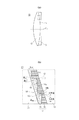
図1(a)は本実施例のDOE10の断面図である。図1(a)に示すように、本実施例のDOE10は、第1のレンズ12と第2のレンズ13を有する。第1のレンズ12は凸面を有しており、第2のレンズ13は凹面を有している。第2のレンズ13は、第1のレンズ12の凸面に第2のレンズ13の凹面が対向するように配置されている。OLは第1のレンズ12の光軸である。
FIG. 1A is a cross-sectional view of DOE10 of this embodiment. As shown in FIG. 1A, the DOE10 of this embodiment has a
第1のレンズ12と第2のレンズ13の間には、回折格子部14が設けられている。DOE10を光学系に用いる場合、第2のレンズ12に対して第1のレンズ12が物体側に配置されるように、DOE10が配置される。すなわち、入射光は第1のレンズ12側からDOE10に入射する。
A
図1(b)は、図1(a)において点線で囲んだ部分を拡大して表示した図である。本実施例のDOE10において、回折格子部14は第1のレンズ12に近い側から順に密着して積層された第1の回折格子15および第2の回折格子16で構成されている。第1の回折格子15と第2の回折格子16の界面は鋸刃状となっており、格子面14aと格子壁面14bが交互に形成されている。
FIG. 1B is an enlarged view of a portion surrounded by a dotted line in FIG. 1A. In the
なお、第1の回折格子15および第2の回折格子16は共に光軸OLを中心とした同心円状の格子形状となっている。また第1の回折格子15および第2の回折格子16の格子ピッチ(隣接する格子壁面14b同士の間隔)を変化させることで回折格子部14にレンズ作用を付与することができる。本実施例のDOE10では、回折格子部14の回折による光学的パワーは正となっている。
Both the first diffraction grating 15 and the second diffraction grating 16 have a concentric lattice shape centered on the optical axis OL. Further, the lens action can be imparted to the diffraction grating
ここで、回折格子部14の格子壁面14bについて説明する。図1(b)に示すように、格子壁面14bは光軸OLに平行な直線17に対して傾いた形状となっている。具体的には、格子壁面14bは第1のレンズ12から第2のレンズ13へ近づくにつれて格子壁面14bの内径が小さくなるように傾いている。別の観点としては、格子壁面14bと光軸OLが成す角度をθH、該格子壁面が第1の回折格子15の頂部を結んだ包絡面19に接する位置での包絡面19の面法線12と光軸OLが成す角度をθMとしたとき、格子壁面14bは以下の式(1)を満足する。
θH×θM<0 (1)
Here, the
θ H × θ M <0 (1)
式(1)において角度は光軸に対して時計回りを負、反時計回りを正としており、式(1)はθHとθMの符号が異なることを表わしている。 In the equation (1), the angle is negative in the clockwise direction and positive in the counterclockwise direction with respect to the optical axis, and the equation (1) shows that the signs of θ H and θ M are different.
このように格子壁面14bを傾けることで、入射光18が第1のレンズ12側から収斂光として回折格子部14に入射する際に、入射光18と格子壁面14bの成す角度を小さくすることができる。これにより入射光のうち格子壁面14bに入射する光の量を減らすことができ、格子壁面14bに起因するフレアの発生を低減することができる。
By tilting the
次に、DOE10の回折格子部14における光の回折効率について説明する。
Next, the diffraction efficiency of light in the diffraction
DOE10における、第m次の回折光の回折効率が最大となる条件は、波長λにおける第1の回折格子15の屈折率をNL(λ)、第2の回折格子16の屈折率をNR(λ)としたとき、次の式(2)で与えられる。
Φ(λ)=(NR(λ)−NL(λ))×d=mλ (2)
In DOE10, the condition that the diffraction efficiency of the m-th order diffraction light is maximized is that the refractive index of the
Φ (λ) = (N R (λ) -N L (λ)) × d = mλ (2)
Φ(λ)は回折格子部14における光路長差を表している。また、dは第1の回折格子15の頂部の包絡面と第2の回折格子16の頂部の包絡面の距離であり、回折格子部14の格子高さに相当する。式(2)におけるmは回折次数であり、任意の整数値をとる。なお、0次の回折光に対して光軸に近づく方向に回折する回折光の回折次数を正とし、0次の回折光に対して光軸から離れる方向に回折する回折光の回折次数を負としている。
Φ (λ) represents the optical path length difference in the diffraction
式(2)より、第1の回折格子15と第2の回折格子16を互いに屈折率の異なる材料を用いて形成し、格子高さdを適切に設計することで任意の波長での回折効率を高めることができる。なお、より広い波長帯域において回折効率を向上するためには、相対的に高屈折率かつ低分散な材料と、相対的に低屈折率かつ高分散な材料を組み合わせて回折格子部14を形成すれば良い。
From the formula (2), the
ここで回折効率を向上する観点からは、回折格子部14において第1の回折格子15と第2の回折格子16のうちのどちらを相対的に高屈折率にしても良い。しかしながら、本実施例のDOE10では、フレアの発生を低減しつつ容易に製造することができるようにするために、第2の回折格子16の屈折率を第1の回折格子15の屈折率よりも大きくしている。以下に、本発明の構成について比較例を用いながら説明する。
Here, from the viewpoint of improving the diffraction efficiency, either the
回折格子部14に正の光学的パワーを与える場合、格子面14aの傾斜は第1の回折格子15および第2の回折格子16の屈折率の大小関係によって定まる。第1の回折格子15の屈折率よりも第2の回折格子16の屈折率を大きくする場合には、正の光学的パワーを有する回折格子部14の格子面14aは図1(b)に示すような形状となる。
When a positive optical power is applied to the diffraction
また、回折格子部14の格子壁面14bは、フレアを低減するために前述のように光軸に対して傾いた形状としている。このため、図1(b)に示すように、格子壁面4bと格子面4aの成す角度θtopを大きくすることができ、第1の回折格子15および第2の回折格子16の成形を容易にすることができる。
Further, the
また、一般に回折格子は型を用いて樹脂等を成形することにより製造されるが、図1(b)に示す本実施例のDOE10では、型を光軸に平行な方向に離型する際に型と回折格子が干渉しにくい形状となっている。このため、DOE10を製造する際の離型工程を容易に行うことができる。 Further, a diffraction grating is generally manufactured by molding a resin or the like using a mold, but in DOE10 of the present embodiment shown in FIG. 1 (b), when the mold is released in a direction parallel to the optical axis. The shape is such that the mold and the diffraction grating do not easily interfere with each other. Therefore, the mold release step when manufacturing DOE10 can be easily performed.
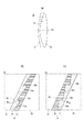
図2に、比較例1として第1の回折格子25の屈折率よりも第2の回折格子26の屈折率を小さくした場合のDOE20の概略図を示す。比較例1のDOE20は、実施例1のDOE10と同様に、凸面を有する第1のレンズ22と第1のレンズ22の凸面に凹面を向けた第2のレンズ23と、第1のレンズ22と第2のレンズ23の間に設けられた回折格子部24と、を有する。
FIG. 2 shows a schematic view of the
図2(a)は比較例1のDOE20の断面図である。図2(b)は、図2(a)に破線で示した領域の拡大図である。比較例1のDOE20では、回折格子部24は、第1のレンズ22に近い側から順に積層された第1の回折格子25と第2の回折格子26により形成されている。DOE20の回折格子部24は実施例1のDOE10と同様に正の光学的パワーを有するが、第1の回折格子25の屈折率よりも第2の回折格子26の屈折率は小さくなっている点で実施例1のDOE10とは異なる。このため比較例1のDOE20における格子面24aの傾斜は、実施例1のDOE10の格子面4aとは反対方向に傾斜している。
FIG. 2A is a cross-sectional view of DOE20 of Comparative Example 1. FIG. 2B is an enlarged view of the region shown by the broken line in FIG. 2A. In the
比較例1のDOE20では、実施例1のDOE10と同様に、入射光18と格子壁面24bの成す角度を小さくするように格子壁面24bを傾斜させているため、フレアの発生を低減することができる。しかし、図2(b)に示すように、DOE20の格子面24aと格子壁面24bの成す角度θtopは、実施例1のDOE10と比較して小さくなっている。さらに、図2(b)より、型を用いてDOE20の第1の回折格子25または第2の回折格子26を成形する場合、光軸に平行な方向に型を離型する際に回折格子と型が干渉してしまう形状となっていることがわかる。すなわち、DOE20はDOE10と比較して製造が困難となってしまう。
In the
一方、比較例1のDOE20において、型と回折格子が干渉しないように格子壁面24bの傾斜を図2(c)のようにした場合、離形性を向上することはできるが、入射光18と格子壁面24bの成す角度が大きくなってしまう。その結果、格子壁面24bに入射する光の量が増加してしまい、フレアが顕著に発生してしまう。
On the other hand, in the
次に、第1のレンズおよび第2のレンズの形状がDOE10と異なる場合について、比較例2を用いて説明する。図3(a)に比較例2のDOE30の断面図を示す。比較例2のDOE30は、凹面を有する第1のレンズ32と、第1のレンズ32の凹面に凸面を向けた第2のレンズ33と、第1のレンズ32と第2のレンズ33の間に設けられた回折格子部34と、を有している。回折格子部34は、第1のレンズ32から近い側から順に積層された第1の回折格子35と第2の回折格子36により構成されている。実施例1のDOE10と同様に、DOE30の回折格子部34は正の光学的パワーを有する。
Next, a case where the shapes of the first lens and the second lens are different from those of DOE10 will be described with reference to Comparative Example 2. FIG. 3A shows a cross-sectional view of DOE30 of Comparative Example 2. The
DOE30において第2の回折格子36の屈折率を第1の回折格子35の屈折率よりも大きくした場合の図3(a)に点線で囲んだ領域の拡大図を図3(b)に示す。実施例1のDOE10と同様に、比較例2のDOE30においても入射光18と格子壁面34bの成す角度を小さくするように格子壁面34bを傾斜させている。このため、DOE30においても格子壁面34bに起因するフレアを低減することができる。
FIG. 3 (b) shows an enlarged view of the region surrounded by the dotted line in FIG. 3 (a) when the refractive index of the
しかし、図3(b)に示すようにDOE30の格子面34aと格子壁面34bの成す角度θtopは実施例1のDOE10と比較して小さくなっている。そのため、DOE10と比較して製造が困難となってしまう。
However, as shown in FIG. 3B, the angle θ top formed by the
一方、DOE30において第1の回折格子35の屈折率を第2の回折格子36の屈折率よりも大きくした場合の図3(a)に点線で囲んだ領域の拡大図を図3(c)に示す。この場合、格子面34aと格子壁面34bの成す角度θtopは図3(b)に示す場合よりも大きくすることができる。しかしながら図3(c)に示す構成の場合、第1の回折格子35または第2の回折格子36を成形するための型を光軸に平行な方向に離型しようとする際に、回折格子と型が干渉してしまう形状となっている。したがってDOE10と比較して製造が困難となってしまう。
On the other hand, FIG. 3 (c) shows an enlarged view of the region surrounded by the dotted line in FIG. 3 (a) when the refractive index of the
以上説明したように、比較例1のDOE20や比較例2のDOE30と異なり、実施例1のDOE10はフレアを低減しつつ容易に製造することができる。これは曲率中心が光入射側にある曲面上に形成された正の光学的パワーの回折格子部14において、第2の回折格子16の屈折率を第1の回折格子15よりも大きくし、格子壁面4bと入射光の成す角度が小さくなるように格子壁面14bを傾斜させたためである。
As described above, unlike the DOE20 of Comparative Example 1 and the DOE30 of Comparative Example 2, the DOE10 of Example 1 can be easily manufactured while reducing flare. This is because the refractive index of the
なお、フレアを低減しつつDOE10の製造を容易にするためには、回折格子部14の全輪帯のうち5割以上の輪帯で格子壁面14bが第1のレンズ12から第2のレンズ13に近づくにつれて内径が小さくなるように傾斜していることが好ましい。より好ましくは全輪帯のうち7割以上の輪帯で、さらに好ましくは全輪体で格子壁面14bが第1のレンズ12から第2のレンズ13に近づくにつれて内径が小さくなるように傾斜していると良い。
In order to facilitate the production of DOE10 while reducing flare, the
また別の観点として、フレアを低減しつつDOE10の製造を容易にするためには、回折格子部14の全輪帯のうち5割以上の輪帯で格子壁面14bが式(1)を満たすように傾斜していることが好ましい。より好ましくは全輪帯のうち7割以上の輪帯で、さらに好ましくは全輪体で格子壁面14bが式(1)を満たすように傾斜していると良い。
From another viewpoint, in order to facilitate the production of DOE10 while reducing flare, the
なお、DOE10において第1のレンズ12は正レンズとすることが好ましい。ここで、正レンズとは、光軸から離れるにつれて肉厚が薄くなる凸レンズを言う。上述したように、第1のレンズ12は凸面を有している。ゆえに、第1のレンズ12を負レンズにする場合、第1のレンズ12のレンズ面のうち回折格子部14が設けられていない側のレンズ面の曲率の絶対値が大きくなりすぎてしまう。この場合、第1のレンズ12のレンズ面のうち回折格子部14が設けられていない側のレンズ面での収差の発生量が増大してしまう。
In DOE10, the
また、DOE10において第2のレンズ13は負レンズとすることが好ましい。ここで、負レンズとは、光軸から離れるにつれて肉厚が厚くなる凹レンズを言う。上述したように、第2のレンズ13は凹面を有している。ゆえに、第2のレンズ13を正レンズにする場合、第2のレンズ13のレンズ面のうち回折格子部14が設けられていない側のレンズ面の曲率の絶対値が大きくなりすぎてしまう。この場合、第2のレンズ13のレンズ面のうち回折格子部14が設けられていない側のレンズ面での収差の発生量が増大してしまう。
Further, in DOE10, the
さらに、第1のレンズ12のアッベ数をνLL、第2のレンズ13のアッベ数をνLRとしたとき、以下の条件式(3)を満足することが好ましい。
20<νLL−νLR<60 (3)
Further, when the Abbe number of the
20 <ν LL −ν LR <60 (3)
フラウンホーファー線のg線(435.8nm)、F線(486.1nm)、d線(587.6nm)、C線(656.3nm)に対する屈折率をそれぞれNg,NF,Nd,NCとするとき、アッベ数νdはνd=(Nd−1)/(NF−NC)で与えられる。 Fraunhofer lines g-line (435.8 nm), F line (486.1 nm), d line (587.6 nm), the refractive index respectively for the C line (656.3nm) N g, N F , N d, N when C, the Abbe number [nu d is given by ν d = (N d -1) / (N F -N C).
νLLとνLRの差が小さい場合、DOE10を用いて色収差を十分に補正するためには第1のレンズ12および第2のレンズ13の回折格子部14が形成されている側のレンズ面の曲率の絶対値を大きくする必要がある。式(3)の下限値を下回る場合、第1のレンズ12および第2のレンズ13の回折格子部14が形成されている側のレンズ面の曲率の絶対値が大きくなりすぎてしまい、回折格子部14に光が入射する際の入射角度が大きくなりすぎてしまう。この場合、格子壁面14bに入射する光量が多くなるため、フレアを十分に低減することが難しくなる。
When the difference between ν LL and ν LR is small, in order to sufficiently correct chromatic aberration using DOE10, the lens surface on the side where the diffraction
一方、式(3)の上限値を超えるほどにνLLとνLRの差が大きくなると、第1のレンズ12および第2のレンズ13の回折格子部14が形成されている側のレンズ面の曲率が緩くなりすぎてしまい、球面収差等を補正することが困難となってしまう。
On the other hand, when the difference between ν LL and ν LR becomes large enough to exceed the upper limit of the equation (3), the lens surface of the
式(3)は次の式(3a)の範囲とすることが好ましく、式(3b)の範囲とすることがより好ましい。
27<νLL−νLR<55 (3a)
30<νLL−νLR<53 (3b)
The formula (3) is preferably in the range of the following formula (3a), and more preferably in the range of the formula (3b).
27 <ν LL −ν LR <55 (3a)
30 <ν LL −ν LR <53 (3b)
また、第1のレンズ12のd線における屈折率をNLL、第1の回折格子15のd線における屈折率をNLとしたとき、以下の式(4)を満たすことが好ましい。
0.8<NL/NLL<1.2 (4)
Further, when the refractive index of the
0.8 <N L / N LL <1.2 (4)
NLがNLLよりも小さい場合、第1のレンズ12と第1の回折格子15の界面は正の屈折力を有することになる。式(4)の下限値を下回るほどにNLLに対してNLが小さくなると、DOE10に入射した光が第1のレンズ12と第1の回折格子15の界面において大きく屈折する結果、回折格子部14に光が入射する際の入射角度が大きくなりすぎてしまう。この場合、格子壁面14bに入射する光量が多くなるため、フレアを十分に低減することが難しくなる。
When N L is smaller than N LL , the interface between the
一方、式(4)の上限値を上回るほどに第1のレンズ12に対して第1の回折格子15の屈折率が大きくなる場合、第1の回折格子15と第2の回折格子16に用いる材料の選択肢が狭くなってしまう。その結果、広い波長範囲で高い回折効率を得ることが困難となってしまう。
On the other hand, when the refractive index of the
なお、式(4)は次の式(4a)の範囲とすることが好ましい。
0.9<NL/NLL<1.1 (4a)
The formula (4) is preferably in the range of the following formula (4a).
0.9 <N L / N LL <1.1 (4a)
また、任意の格子壁面14bが第1の回折格子15の頂部を連ねた包絡面に接する位置における該包絡面の面法線と該格子壁面14bが成す角度の絶対値をθHMとする。このとき、回折格子部14におけるθHMの最大値と最小値の差の絶対値であるΔθHMは以下の条件式(5)を満足することが好ましい。
5°<ΔθHM<45° (5)
Further, the absolute value of the angle formed by the surface normal line of the envelope surface and the
5 ° <Δθ HM <45 ° (5)
式(5)の値が小さくなることは、第1のレンズ12および第2のレンズ13の回折格子部14が形成されている側のレンズ面の曲率半径が大きくなることに相当する。式(5)の下限値を下回る程に第1のレンズ12および第2のレンズ13の回折格子部14が形成されている側のレンズ面の曲率半径が大きくなる場合、球面収差等の諸収差の補正が困難となってしまう。
A smaller value in equation (5) corresponds to a larger radius of curvature of the lens surface of the
一方、式(5)の上限値を上回る程に第1のレンズ12および第2のレンズ13の回折格子部14が形成されている側のレンズ面の曲率半径が小さくなりすぎる場合、回折格子部14に光が入射する際の入射角度が大きくなりすぎてしまう。この場合、回折格子部14におけるフレアの発生を低減することが難しくなる。
On the other hand, when the radius of curvature of the lens surface on the side where the diffraction
なお、式(5)は次の式(5a)の範囲とすることが好ましい。
10°<ΔθHM<40° (5a)
The formula (5) is preferably in the range of the following formula (5a).
10 ° <Δθ HM <40 ° (5a)
また、第1の回折格子15と第2の回折格子16のうち少なくとも一方は樹脂を用いて形成されていることが好ましい。樹脂は型を用いて成形しやすいため、第1の回折格子15と第2の回折格子16のうち少なくとも一方を、樹脂を用いて形成することで回折格子部14の成形を容易に行うことができる。
Further, it is preferable that at least one of the
なお、図1に示したDOE10では、回折格子部14において第1の回折格子15と第2の回折格子16が密着して接合されているが、第1の回折格子15と第2の回折格子16の間に薄膜を設けても良い。例えば格子壁面14bのみに薄膜を設けても良いし、格子面14aと格子壁面14bのいずれにも薄膜を設けても良い。なお、図1(b)における格子面14aに相当する部分に薄膜が設けられている場合、第1の回折格子15と薄膜の界面を格子面14aとする。また、図1(b)における格子壁面14bに相当する部分に薄膜が設けられている場合、第1の回折格子15と薄膜の界面を格子壁面14bとする。
In the
次に、本発明の光学系の実施例として実施例2から6について説明する。 Next, Examples 2 to 6 will be described as examples of the optical system of the present invention.
各実施例の光学系は、ビデオカメラ、デジタルスチルカメラ、銀塩フィルムカメラ等の撮像装置に用いられる撮影光学系である。 The optical system of each embodiment is a photographing optical system used in an imaging device such as a video camera, a digital still camera, and a silver halide film camera.
[実施例2]
次に、実施例2の光学系について説明する。図4に無限遠合焦時の本実施例の光学系100の断面図を示す。図4において左方が物体側であり右方が像側である。光学系100は、物体側から像側へ順に配置された正の屈折力の第1レンズ群L1、負の屈折力の第2レンズ群L2、開口絞りSP、負の屈折力の第3レンズ群L3で構成されている。無限遠から最至近距離へのフォーカシングに際して、第2レンズ群L2は像側に移動する。なお、第1レンズ群L1および第3レンズ群L3はフォーカシングに際して不動である。
[Example 2]
Next, the optical system of the second embodiment will be described. FIG. 4 shows a cross-sectional view of the
図4においてIPは像面である。光学系100をデジタルカメラの撮影光学系に用いる場合、像面IPにはCMOSセンサやCCDなどの固体撮像素子が配置される。また、光学系100を銀塩フィルムカメラの撮影光学系に用いる場合、像面IPはフィルム面に相当する。
In FIG. 4, IP is an image plane. When the
第1レンズ群L1はDOE110を有している。DOEを光学系に用いることによって、色収差をはじめとした諸収差を良好に補正することができる。
The first lens group L1 has a
図4に示すように、DOE110は像側に凸面を有する第1のレンズ112と、物体側に凹面を有する第2のレンズ113を備えており、第1のレンズ112と第2のレンズ113の間には回折格子部114が設けられている。光学系100において、第2のレンズ113に対して第1のレンズ112が物体側に配置されるようにDOE110が配置されている。
As shown in FIG. 4, the
回折格子部114の構成は実施例1のDOE10と同様である。すなわち、回折格子部114は第1のレンズ112から順に第1の回折格子と第1の回折格子よりも屈折率の大きな第2の回折格子を有し、回折格子部114の回折による光学的パワーは正である。
The configuration of the diffraction grating portion 114 is the same as that of DOE10 of Example 1. That is, the diffraction grating portion 114 has a first diffraction grating and a second diffraction grating having a higher refractive index than the first diffraction grating in order from the
また、回折格子部114の格子壁面は、第1のレンズ112から第2のレンズ113へ近づくにつれて格子壁面の内径が小さくなるように光軸に対して傾斜している。別の観点としては、回折格子部114の格子壁面は式(1)を満たすように傾斜している。
Further, the lattice wall surface of the diffraction grating portion 114 is inclined with respect to the optical axis so that the inner diameter of the lattice wall surface becomes smaller as the
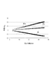
DOE110の回折格子部114における各格子壁面について、格子壁面から光軸までの距離とθH(°)、θM(°)、θHM(°)の関係を図5に示す。図4に示す光学系100の断面図において回折格子部114の形状は光軸に対して対称であるが、図5は光軸よりも上側についてのみ示している。なお、θHおよびθMは光軸から反時計回りを正、時計回りを負としている。また、θHMはθHM=|θH−θM|により算出される。
FIG. 5 shows the relationship between the distance from the lattice wall surface to the optical axis and θ H (°), θ M (°), and θ HM (°) for each lattice wall surface in the diffraction grating portion 114 of the
図5に示すとおり、DOE110では全ての格子壁面が光軸に対して負の傾きとなっており、第1のレンズ112から第2のレンズ113へ近づくにつれて格子壁面の内径が小さくなるように光軸に対して傾斜している。また、DOE110は式(1)を満たしている。したがって、実施例1で説明したように、DOE110はフレアの発生を低減しつつ製造が容易な形状となっている。さらに、図5に示すようにDOE110は式(5)を満足する形状となっている。
As shown in FIG. 5, in DOE110, all the lattice wall surfaces have a negative inclination with respect to the optical axis, and light is applied so that the inner diameter of the lattice wall surface becomes smaller as the
なお、本実施例のDOE110において、第1の回折格子はアクリル系樹脂にITO微粒子を混合させた樹脂(Nd=1.566、νd=19.0、θgF=0.418)により形成されている。θgFは部分分散比であり、フラウンホーファー線のg線、F線、d線、C線に対する屈折率をNg,NF,Nd,NCとしたとき次の式(6)で与えられる値である。
θgF=(Ng−NF)/(NF−NC) (6)
In the DOE110 of this example, the first diffraction grating is formed of a resin (N d = 1.566, ν d = 19.0, θ gF = 0.418) in which ITO fine particles are mixed with an acrylic resin. Has been done. theta gF is a relative partial dispersion, given by the g-line of Fraunhofer line, F-line, d line, the refractive index for the C line N g, N F, N d, the following equation when the N C (6) Is the value to be.
θ gF = (N g -N F ) / (N F -N C) (6)
また、第2の回折格子はアクリル系樹脂にZrO2微粒子を混合させた樹脂(Nd=1.619、νd=43.2、θgF=0.564)により形成されている。また、格子高さdは10.79μmとしている。 The second diffraction grating are formed of a resin obtained by mixing ZrO 2 fine particles in acrylic resin (N d = 1.619, ν d = 43.2, θ gF = 0.564). The lattice height d is 10.79 μm.
このような材料を用いて第1の回折格子および第2の回折格子を形成することにより、広い波長範囲で高い回折効率を得ている。 By forming the first diffraction grating and the second diffraction grating using such a material, high diffraction efficiency is obtained in a wide wavelength range.
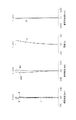
図6に無限遠合焦時の光学系100の収差図を示す。図6におけるd、g、Cはフラウンホーファー線のd線、g線、C線に対する収差曲線を表わしている。非点収差図においてΔMはメリディオナル像面、ΔSはサジタル像面である。また、Yは像高(mm)であり、FnはFナンバーである。
FIG. 6 shows an aberration diagram of the
図6に示すように、光学系100は色収差をはじめとした諸収差が良好に補正されている。
As shown in FIG. 6, various aberrations including chromatic aberration are satisfactorily corrected in the
なお、DOE110による色収差を補正する効果をより高めるためには、軸上光束の光束径が大きくなる位置にDOE110を配置することが好ましい。一般に、望遠レンズにおける軸上光束の光束径は開口絞りSPの像側と比較して開口絞りSPの物体側の方が大きい。そのため、開口絞りSPよりも物体側にDOE110を配置することが好ましい。
In order to further enhance the effect of correcting the chromatic aberration by the
また、DOE110よりも物体側に配置されている全てのレンズからなる部分光学系は正の屈折力を有する。DOE110よりも物体側に配置されている部分光学系の屈折力を正とすると、軸上光束は収斂光としてDOE110に入射することになる。このため、DOE110の格子壁面と入射光の成す角度を小さくすることができ、効果的にフレアを低減することができる。なお、DOE110よりも物体側に配置されているレンズが1枚のみである場合、該レンズがDOE110よりも物体側に配置されている部分光学系となる。
Further, the partial optical system composed of all the lenses arranged on the object side of the DOE110 has a positive refractive power. Assuming that the refractive power of the partial optical system arranged on the object side of the DOE110 is positive, the axial luminous flux is incident on the DOE110 as convergent light. Therefore, the angle formed by the lattice wall surface of the
また、光学系の最も物体側のレンズ面から第1のレンズ112の回折格子部114が設けられている側のレンズ面までの光軸上の距離をLd、光学系の全長をLtとしたとき、以下の条件式(7)を満たすことが好ましい。なお、Ltは光学系における最も物体側のレンズ面から像面までの光軸上の距離である。
0.10<Ld/Lt<0.50 (7)
Further, the distance on the optical axis from the lens surface on the most object side of the optical system to the lens surface on the side where the diffraction grating portion 114 of the
0.10 <L d / L t <0.50 (7)
前述のようにDOE110を開口絞りSPよりも物体側に配置することでより効果的に色収差を補正することができるが、撮影画角外からの光等の本来像面に到達しない光(不要光)がDOE110に入射しやすくなってしまう。DOE110に入射した不要光が格子壁面で反射されると不要光が像面に到達してフレアを生じてしまう。式(7)の下限値を下回る程にLdが小さくなる場合、DOE110に対して撮影光以外の不要な光が入射しやすくなり、フレアが生じやすくなってしまう。一方、式(7)の上限値を上回る場合、DOE110に入射する軸上光束の光束径が小さくなってしまう結果、色収差を十分に補正することが難しくなる。また、式(7)の上限値を上回る場合、光学系が大型化してしまう。
As described above, chromatic aberration can be corrected more effectively by arranging the
なお、式(7)は以下の式(7a)の範囲とすることが好ましい。
0.20<Ld/Lt<0.45 (7a)
The formula (7) is preferably in the range of the following formula (7a).
0.20 <L d / L t <0.45 (7a)
また、第1のレンズ112の回折格子部114が設けられている側のレンズ面の曲率半径をRd、光学系の全系の焦点距離をf、FナンバーをFnとしたとき、以下の条件式(8)を満たすことが好ましい。
−2.0<f/(Rd×Fn)<−0.20 (8)
Further, when the radius of curvature of the lens surface of the
-2.0 <f / (R d x Fn) <-0.20 (8)
式(8)の下限値を下回る程に第1のレンズの回折格子部114が設けられている側のレンズ面の曲率の絶対値が大きくなる場合、光が回折格子部114に入射する際の入射角度が大きくなってしまう。その結果、格子壁面へ入射する光量が増大してしまい、フレアを低減することが困難となってしまう。 When the absolute value of the curvature of the lens surface on the side where the diffraction grating portion 114 of the first lens is provided becomes larger than the lower limit of the equation (8), when light is incident on the diffraction grating portion 114. The angle of incidence becomes large. As a result, the amount of light incident on the lattice wall surface increases, and it becomes difficult to reduce flare.
一方、式(8)の上限値を上回る程に第1のレンズの回折格子部114が設けられている側のレンズ面の曲率の絶対値が小さくなると、球面収差等の諸収差の補正が困難となってしまう。 On the other hand, if the absolute value of the curvature of the lens surface on the side where the diffraction grating portion 114 of the first lens is provided becomes smaller than the upper limit of the equation (8), it is difficult to correct various aberrations such as spherical aberration. Will be.
なお、式(8)の範囲は以下の式(8a)の範囲とすることが好ましく、式(8b)の範囲とすることがより好ましい。
−1.9<f/(Rd×Fn)<−0.30 (8a)
−1.8<f/(Rd×Fn)<−0.41 (8b)
The range of the formula (8) is preferably the range of the following formula (8a), and more preferably the range of the formula (8b).
-1.9 <f / (R d x Fn) <-0.30 (8a)
-1.8 <f / (R d x Fn) <-0.41 (8b)
さらに、光学系において最も物体側のレンズ面の有効径をE1、第1のレンズ112の回折格子部114が形成されている側のレンズ面の有効径をEdとする。また、第1のレンズ112の物体側のレンズ面(第1のレンズ112の回折格子部114が形成されていない側のレンズ面)の屈折力をPfとする。このとき、以下の条件式(9)を満たすことが好ましい。
0.6<(E1−Ed)/Ld+Ed×Pf−Ed/Rd<2.0 (9)
Further, let E 1 be the effective diameter of the lens surface on the most object side in the optical system, and Ed be the effective diameter of the lens surface on the side where the diffraction grating portion 114 of the
0.6 <(E 1- E d ) / L d + E d x P f- E d / R d <2.0 (9)
ここで、第1のレンズ112の物体側のレンズ面の屈折力Pfは、第1のレンズ112の物体側のレンズ面の曲率半径をRLLとしたとき、以下の式(10)で与えられる。
Pf=(NLL−1)/RLL (10)
Here, power P f of the lens surface on the object side of the
P f = (N LL -1) / R LL (10)
光学系100に入射した軸上マージナル光線が第1のレンズ112に入射する際の軸上マージナル光線と光軸の成す角度は、近似的に(E1−Ed)/(2Ld)で表わすことができる。また、軸上マージナル光線が第1のレンズ112の物体側のレンズ面に入射する前後の光線の進行方向が成す角度は、近似的にEd×Pf/2で表わすことができる。
The angle formed by the axial marginal ray and the optical axis when the axial marginal ray incident on the
また、軸上マージナル光線が入射する位置における第1のレンズ112の回折格子部114が形成されている側のレンズ面の面法線が光軸と成す角度は、Ed/(2Rd)で表わすことができる。すなわち、式(9)の値は軸上マージナル光線が回折格子部114に入射する際の入射角度に対応した値となっている。
The angle of the surface normal makes with the optical axis of the lens surface on the side where the diffraction grating portion 114 is formed of a
式(9)の上限値を上回ると、軸上マージナル光線が回折格子部114に入射する際の入射角度が大きくなりすぎてしまう。その結果、格子壁面へ入射する光量が増大してしまい、フレアを低減することが困難となってしまう。 If the upper limit of the equation (9) is exceeded, the angle of incidence when the axial marginal ray is incident on the diffraction grating portion 114 becomes too large. As a result, the amount of light incident on the lattice wall surface increases, and it becomes difficult to reduce flare.
式(9)の下限値を下回ると、回折格子部114よりも物体側における屈折力が小さくなりすぎたり、DOE110よる収差補正効果を十分に得ることができなかったりする結果、光学系全体の収差補正が困難となってしまう。 If it is less than the lower limit of the equation (9), the refractive power on the object side of the diffraction grating portion 114 becomes too small, or the aberration correction effect of DOE110 cannot be sufficiently obtained. As a result, the aberration of the entire optical system is reduced. Correction becomes difficult.
式(9)式は以下の式(9a)範囲とすることが好ましく、式(9b)の範囲とすることがより好ましい。
0.70<(E1−Ed)/Ld+Ed×Pf−Ed/Rd<1.8 (9a)
0.75<(E1−Ed)/Ld+Ed×Pf−Ed/Rd<1.7 (9b)
The formula (9) is preferably in the range of the following formula (9a), and more preferably in the range of the formula (9b).
0.70 <(E 1 -E d) / L d + E d × P f -E d / R d <1.8 (9a)
0.75 <(E 1- E d ) / L d + E d x P f- E d / R d <1.7 (9b)
また、無限遠合焦時に軸上マージナル光線が回折格子部114に入射する際の入射角度をθDとしたとき、以下の式(11)を満たすことが好ましい。なお入射角度θDとは、回折格子部114に軸上マージナル光線が入射する位置における第1のレンズ112の像側のレンズ面の面法線と軸上マージナル光線が成す角度である。
10°<|θD|<57° (11)
Further, when the angle of incidence when the axial marginal ray is incident on the diffraction grating portion 114 at the time of focusing at infinity is θ D , it is preferable to satisfy the following equation (11). The incident angle θ D is an angle formed by the surface normal of the lens surface on the image side of the
10 ° << | θ D | <57 ° (11)
式(11)の上限値を上回ると、軸上マージナル光線が回折格子部114に入射する際の入射角度が大きくなりすぎてしまう。その結果、格子壁面へ入射する光量が増大してしまい、フレアを低減することが困難となってしまう。 If the upper limit of the equation (11) is exceeded, the angle of incidence when the axial marginal ray is incident on the diffraction grating portion 114 becomes too large. As a result, the amount of light incident on the lattice wall surface increases, and it becomes difficult to reduce flare.
式(11)の下限値を下回ると、回折格子部114よりも物体側における屈折力が小さくなりすぎたり、DOE110よる収差補正効果を十分に得ることができなかったりする結果、光学系全体の収差補正が困難となってしまう。 If it is less than the lower limit of the equation (11), the refractive power on the object side of the diffraction grating portion 114 becomes too small, or the aberration correction effect of DOE110 cannot be sufficiently obtained. As a result, the aberration of the entire optical system is reduced. Correction becomes difficult.
なお、式(11)は以下の式(11a)の範囲とすることが好ましく、式(11b)の範囲とすることがより好ましい。
15°<|θD|<51° (11a)
20°<|θD|<45° (11b)
The formula (11) is preferably in the range of the following formula (11a), and more preferably in the range of the formula (11b).
15 ° << | θ D | <51 ° (11a)
20 ° << | θ D | <45 ° (11b)
[実施例3]
次に、実施例3の光学系について説明する。図7に無限遠合焦時の本実施例の光学系200の断面図を示す。光学系200は、物体側から像側へ順に配置された正の屈折力の第1レンズ群L1、負の屈折力の第2レンズ群L2、開口絞りSP、負の屈折力の第3レンズ群L3で構成されている。無限遠から最至近距離へのフォーカシングに際して、第2レンズ群L2は像側に移動する。なお、第1レンズ群L1および第3レンズ群L3はフォーカシングに際して不動である。
[Example 3]
Next, the optical system of Example 3 will be described. FIG. 7 shows a cross-sectional view of the
第1レンズ群L1はDOE210を有している。図7に示すように、DOE210は像側に凸面を有する第1のレンズ212と、物体側に凹面を有する第2のレンズ213を備えており、第1のレンズ212と第2のレンズ213の間には回折格子部214が設けられている。光学系200において、第2のレンズ213に対して第1のレンズ212が物体側に配置されるようにDOE210が配置されている。
The first lens group L1 has a DOE210. As shown in FIG. 7, the
回折格子部214の構成は実施例1のDOE10と同様である。すなわち、回折格子部214は第1のレンズ212から順に第1の回折格子と第1の回折格子よりも屈折率の大きな第2の回折格子を有し、回折格子部214の回折による光学的パワーは正である。
The configuration of the diffraction
また、回折格子部214の格子壁面は、第1のレンズ212から第2のレンズ213へ近づくにつれて格子壁面の内径が小さくなるように光軸に対して傾斜している。別の観点としては、回折格子部214の格子壁面は式(1)を満たすように傾斜している。
Further, the lattice wall surface of the diffraction
DOE210の回折格子部214における各格子壁面について、格子壁面から光軸までの距離とθH(°)、θM(°)、θHM(°)の関係を図8に示す。図7に示す光学系200の断面図において回折格子部214の形状は光軸に対して対称であるが、図8は光軸よりも上側についてのみ示している。
FIG. 8 shows the relationship between the distance from the lattice wall surface to the optical axis and θ H (°), θ M (°), and θ HM (°) for each lattice wall surface in the diffraction
図8に示すとおり、DOE210では全ての格子壁面が光軸に対して負の傾きとなっており、第1のレンズ212から第2のレンズ213へ近づくにつれて格子壁面の内径が小さくなるように光軸に対して傾斜している。また、DOE210は式(1)を満たしている。したがって、実施例1で説明したように、DOE210はフレアの発生を低減しつつ製造が容易な形状となっている。さらに、図8に示すようにDOE210は式(5)を満足する形状となっている。
As shown in FIG. 8, in DOE210, all the lattice wall surfaces have a negative inclination with respect to the optical axis, and light is applied so that the inner diameter of the lattice wall surface becomes smaller as the
なお、本実施例のDOE210において、第1の回折格子は樹脂材料(Nd=1.528、νd=34.7、θgF=0.605)により形成されている。 In the DOE210 of this example, the first diffraction grating is formed of a resin material (N d = 1.528, ν d = 34.7, θ gF = 0.605).
また、第2の回折格子は樹脂材料(Nd=1.557、νd=50.2、θgF=0.568)により形成されている。また、格子高さdは19.9μmである。 The second diffraction grating is made of a resin material (N d = 1.557, ν d = 50.2, θ gF = 0.568). The lattice height d is 19.9 μm.
このような材料を用いて第1の回折格子および第2の回折格子を形成することにより、広い波長範囲で高い回折効率を得ている。 By forming the first diffraction grating and the second diffraction grating using such a material, high diffraction efficiency is obtained in a wide wavelength range.
図9に無限遠合焦時の光学系200の収差図を示す。図9に示すように、光学系200は色収差をはじめとした諸収差が良好に補正されている。
FIG. 9 shows an aberration diagram of the
[実施例4]
次に、実施例4の光学系について説明する。図10に無限遠合焦時の本実施例の光学系300の断面図を示す。光学系300は、物体側から像側へ順に配置された正の屈折力の第1レンズ群L1、負の屈折力の第2レンズ群L2、開口絞りSP、正の屈折力の第3レンズ群L3で構成されている。無限遠から最至近距離へのフォーカシングに際して、第2レンズ群L2は像側に移動する。なお、第1レンズ群L1および第3レンズ群L3はフォーカシングに際して不動である。
[Example 4]
Next, the optical system of Example 4 will be described. FIG. 10 shows a cross-sectional view of the
第1レンズ群L1はDOE310を有している。図10に示すように、DOE310は像側に凸面を有する第1のレンズ312と、物体側に凹面を有する第2のレンズ313を備えており、第1のレンズ312と第2のレンズ313の間には回折格子部314が設けられている。光学系300において、第2のレンズ313に対して第1のレンズ312が物体側に配置されるようにDOE310が配置されている。
The first lens group L1 has a DOE310. As shown in FIG. 10, the
回折格子部314の構成は実施例1のDOE10と同様である。すなわち、回折格子部314は第1のレンズ312から順に第1の回折格子と第1の回折格子よりも屈折率の大きな第2の回折格子を有し、回折格子部314の回折による光学的パワーは正である。
The configuration of the diffraction
また、回折格子部314の格子壁面は、第1のレンズ312から第2のレンズ313へ近づくにつれて格子壁面の内径が小さくなるように光軸に対して傾斜している。別の観点としては、回折格子部314の格子壁面は式(1)を満たすように傾斜している。
Further, the lattice wall surface of the diffraction
DOE310の回折格子部314における各格子壁面について、格子壁面から光軸までの距離とθH(°)、θM(°)、θHM(°)の関係を図11に示す。図10に示す光学系300の断面図において回折格子部314の形状は光軸に対して対称であるが、図11は光軸よりも上側についてのみ示している。
FIG. 11 shows the relationship between the distance from the lattice wall surface to the optical axis and θ H (°), θ M (°), and θ HM (°) for each lattice wall surface in the diffraction
図11に示すとおり、DOE310では全ての格子壁面が光軸に対して負の傾きとなっており、第1のレンズ312から第2のレンズ313へ近づくにつれて格子壁面の内径が小さくなるように光軸に対して傾斜している。また、別の観点としては、DOE310は式(1)を満たしている。したがって、実施例1で説明したように、DOE310はフレアの発生を低減しつつ製造が容易な形状となっている。さらに、図11に示すようにDOE310は式(5)を満足する形状となっている。
As shown in FIG. 11, in DOE310, all the lattice wall surfaces have a negative inclination with respect to the optical axis, and light is applied so that the inner diameter of the lattice wall surface becomes smaller as the
なお、本実施例のDOE310において、第1の回折格子は樹脂材料(Nd=1.615、νd=26.5、θgF=0.612)により形成されている。 In the DOE310 of this example, the first diffraction grating is formed of a resin material (N d = 1.615, ν d = 26.5, θ gF = 0.612).
また、第2の回折格子は樹脂材料(Nd=1.643、νd=38.8、θgF=0.578)により形成されている。また、格子高さdは21.5μmである。 The second diffraction grating is made of a resin material (N d = 1.634, ν d = 38.8, θ gF = 0.578). The lattice height d is 21.5 μm.
このような材料を用いて第1の回折格子および第2の回折格子を形成することにより、広い波長範囲で高い回折効率を得ている。 By forming the first diffraction grating and the second diffraction grating using such a material, high diffraction efficiency is obtained in a wide wavelength range.
図12に無限遠合焦時の光学系300の収差図を示す。図12に示すように、光学系300は色収差をはじめとした諸収差が良好に補正されている。
FIG. 12 shows an aberration diagram of the
[実施例5]
次に、実施例5の光学系について説明する。図13に無限遠合焦時の本実施例の光学系400の断面図を示す。光学系400は、物体側から像側へ順に配置された正の屈折力の第1レンズ群L1、負の屈折力の第2レンズ群L2、開口絞りSP、正の屈折力の第3レンズ群L3で構成されている。無限遠から最至近距離へのフォーカシングに際して、第2レンズ群L2は像側に移動する。なお、第1レンズ群L1および第3レンズ群L3はフォーカシングに際して不動である。
[Example 5]
Next, the optical system of Example 5 will be described. FIG. 13 shows a cross-sectional view of the
第1レンズ群L1はDOE410を有している。図13に示すように、DOE410は像側に凸面を有する第1のレンズ412と、物体側に凹面を有する第2のレンズ413を備えており、第1のレンズ412と第2のレンズ413の間には回折格子部414が設けられている。光学系400において、第2のレンズ413に対して第1のレンズ412が物体側に配置されるようにDOE410が配置されている。
The first lens group L1 has a DOE410. As shown in FIG. 13, the
回折格子部414の構成は実施例1のDOE10と同様である。すなわち、回折格子部414は第1のレンズ412から順に第1の回折格子と第1の回折格子よりも屈折率の大きな第2の回折格子を有しており、回折格子部414の回折による光学的パワーは正である。
The configuration of the diffraction
また、回折格子部414の格子壁面は、第1のレンズ412から第2のレンズ413へ近づくにつれて格子壁面の内径が小さくなるように光軸に対して傾斜している。別の観点としては、回折格子部414の格子壁面は式(1)を満たすように傾斜している。
Further, the lattice wall surface of the diffraction
DOE410の回折格子部414における各格子壁面について、格子壁面から光軸までの距離とθH(°)、θM(°)、θHM(°)の関係を図14に示す。図13に示す光学系400の断面図において回折格子部414の形状は光軸に対して対称であるが、図14は光軸よりも上側についてのみ示している。
FIG. 14 shows the relationship between the distance from the lattice wall surface to the optical axis and θ H (°), θ M (°), and θ HM (°) for each lattice wall surface in the diffraction
図14に示すとおり、DOE410では全ての格子壁面が光軸に対して負の傾きとなっており、第1のレンズ412から第2のレンズ413へ近づくにつれて格子壁面の内径が小さくなるように光軸に対して傾斜している。また、DOE410は式(1)を満たしている。したがって、実施例1で説明したように、DOE410はフレアの発生を低減しつつ製造が容易な形状となっている。さらに、図14に示すようにDOE410は式(5)を満足する形状となっている。
As shown in FIG. 14, in DOE410, all the lattice wall surfaces have a negative inclination with respect to the optical axis, and light is applied so that the inner diameter of the lattice wall surface becomes smaller as the
なお、本実施例のDOE410において、第1の回折格子はアクリル系樹脂にITO微粒子を混合させた樹脂(Nd=1.566、νd=19.0、θgF=0.418)により形成されている。 In the DOE410 of this example, the first diffraction grating is formed of a resin (N d = 1.566, ν d = 19.0, θ gF = 0.418) in which ITO fine particles are mixed with an acrylic resin. Has been done.
また、第2の回折格子はアクリル系樹脂にZrO2微粒子を混合させた樹脂(Nd=1.619、νd=43.2、θgF=0.564)により形成されている。また、格子高さdは10.79μmである。 The second diffraction grating are formed of a resin obtained by mixing ZrO 2 fine particles in acrylic resin (N d = 1.619, ν d = 43.2, θ gF = 0.564). The lattice height d is 10.79 μm.
このような材料を用いて第1の回折格子および第2の回折格子を形成することにより、広い波長範囲で高い回折効率を得ている。 By forming the first diffraction grating and the second diffraction grating using such a material, high diffraction efficiency is obtained in a wide wavelength range.
図15に無限遠合焦時の光学系400の収差図を示す。図15に示すように、光学系400は色収差をはじめとした諸収差が良好に補正されている。
FIG. 15 shows an aberration diagram of the
[実施例6]
次に、実施例6の光学系について説明する。図16に無限遠合焦時の本実施例の光学系500の断面図を示す。光学系500は、物体側から像側へ順に配置された正の屈折力の第1レンズ群L1、負の屈折力の第2レンズ群L2、開口絞りSP、正の屈折力の第3レンズ群L3で構成されている。無限遠から最至近距離へのフォーカシングに際して、第2レンズ群L2は像側に移動する。なお、第1レンズ群L1および第3レンズ群L3はフォーカシングに際して不動である。
[Example 6]
Next, the optical system of Example 6 will be described. FIG. 16 shows a cross-sectional view of the
第1レンズ群L1はDOE510を有している。図16に示すように、DOE510は像側に凸面を有する第1のレンズ512と、物体側に凹面を有する第2のレンズ513を備えており、第1のレンズ512と第2のレンズ513の間には回折格子部514が設けられている。光学系500において、第2のレンズ513に対して第1のレンズ512が物体側に配置されるようにDOE510が配置されている。
The first lens group L1 has a DOE 510. As shown in FIG. 16, the DOE 510 includes a
回折格子部514の構成は実施例1のDOE10と同様である。すなわち、回折格子部514は第1のレンズ512から順に第1の回折格子と第1の回折格子よりも屈折率の大きな第2の回折格子を有し、回折格子部514の回折による光学的パワーは正である。
The configuration of the diffraction
また、回折格子部514の格子壁面は、第1のレンズ512から第2のレンズ513へ近づくにつれて格子壁面の内径が小さくなるように光軸に対して傾斜している。別の観点としては、回折格子部514の格子壁面は式(1)を満たすように傾斜している。
Further, the lattice wall surface of the diffraction
DOE510の回折格子部514における各格子壁面について、格子壁面から光軸までの距離とθH(°)、θM(°)、θHM(°)の関係を図17に示す。図16に示す光学系500の断面図において回折格子部514の形状は光軸に対して対称であるが、図17は光軸よりも上側についてのみ示している。
FIG. 17 shows the relationship between the distance from the lattice wall surface to the optical axis and θ H (°), θ M (°), and θ HM (°) for each lattice wall surface in the diffraction
図17に示すとおり、DOE510では全ての格子壁面が光軸に対して負の傾きとなっており、第1のレンズ512から第2のレンズ513へ近づくにつれて格子壁面の内径が小さくなるように光軸に対して傾斜している。また、DOE510は式(1)を満たしている。したがって、実施例1で説明したように、DOE510はフレアの発生を低減しつつ製造が容易な形状となっている。さらに、図17に示すようにDOE510は式(5)を満足する形状となっている。
As shown in FIG. 17, in DOE510, all the lattice wall surfaces have a negative inclination with respect to the optical axis, and light is applied so that the inner diameter of the lattice wall surface becomes smaller as the
なお、本実施例のDOE510において、第1の回折格子はフッ素系樹脂にITO微粒子を混合させた樹脂(Nd=1.480、νd=21.7、θgF=0.383)により形成されている。 In the DOE510 of this example, the first diffraction grating is formed of a resin (N d = 1.480, ν d = 21.7, θ gF = 0.383) in which ITO fine particles are mixed with a fluororesin. Has been done.
また、第2の回折格子は樹脂材料(Nd=1.524、νd=51.6、θgF=0.562)により形成されている。また、格子高さdは12.95μmである。 The second diffraction grating is made of a resin material (N d = 1.524, ν d = 51.6, θ gF = 0.562). The lattice height d is 12.95 μm.
このような材料を用いて第1の回折格子および第2の回折格子を形成することにより、広い波長範囲で高い回折効率を得ている。 By forming the first diffraction grating and the second diffraction grating using such a material, high diffraction efficiency is obtained in a wide wavelength range.
図18に無限遠合焦時の光学系500の収差図を示す。図18に示すように、光学系500は色収差をはじめとした諸収差が良好に補正されている。
FIG. 18 shows an aberration diagram of the
以下に、実施例2から6で説明した光学系100から光学系500に対応する数値実施例1から5を示す。
Hereinafter, numerical examples 1 to 5 corresponding to the
各数値実施例の面データにおいて、rは各光学面の曲率半径、d(mm)は第m面と第(m+1)面との間の軸上間隔(光軸上の距離)を表わしている。ただし、mは光学系の面を光入射側から数えた時の番号である。また、ndは各光学部材のd線に対する屈折率、νdは光学部材のd線に対するアッベ数を表わしている。 In the surface data of each numerical example, r represents the radius of curvature of each optical surface, and d (mm) represents the axial distance (distance on the optical axis) between the mth plane and the (m + 1) th plane. .. However, m is a number when the surface of the optical system is counted from the light incident side. Further, nd represents the refractive index of each optical member with respect to the d-line, and νd represents the Abbe number of the optical member with respect to the d-line.
非球面データおよび回折面データにおける「e±B」は「×10±B」を意味している。光学面の非球面形状は、光軸方向における面頂点からの変位量をX、光軸方向に垂直な方向における光軸からの高さをH、近軸曲率半径をR、円錐定数をk、非球面係数をA4,A6,A8,A10、A12,A14とするとき、以下の式(18)により表される。 “E ± B” in the aspherical surface data and the diffractive surface data means “× 10 ± B ”. For the aspherical shape of the optical surface, the amount of displacement from the surface apex in the optical axis direction is X, the height from the optical axis in the direction perpendicular to the optical axis is H, the paraxial radius of curvature is R, and the conical constant is k. When the aspherical coefficient is A 4 , A 6 , A 8 , A 10 , A 12 , A 14 , it is expressed by the following equation (18).

なお、各数値実施例において、d、焦点距離(mm)、Fナンバー、半画角(°)は全て各実施例の光学系が無限遠物体に焦点を合わせた時の値である。バックフォーカスBFは最終レンズ面から像面までの距離である。レンズ全長は第1レンズ面から最終レンズ面までの距離にバックフォーカスを加えた値である。 In each numerical example, d, focal length (mm), F number, and half angle of view (°) are all values when the optical system of each example focuses on an infinity object. The back focus BF is the distance from the final lens surface to the image surface. The total length of the lens is a value obtained by adding back focus to the distance from the first lens surface to the final lens surface.
また、各数値実施例の回折光学素子の回折面の位相形状ψは、次の式(12)によって表される。
ψ(h,m)=(2π/mλ0)(C2h2+C4h4+C6h6…) (12)
Further, the phase shape ψ of the diffraction surface of the diffraction optical element of each numerical example is expressed by the following equation (12).
ψ (h, m) = (2π / mλ0) (C 2 h 2 + C 4 h 4 + C 6 h 6 …) (12)
式(12)において、hは光軸からの高さ、λ0は設計波長、mは回折次数、Ci(i=2,4,6・・・)は位相係数である。 In the formula (12), h is a height from the optical axis, .lambda.0 design wavelength, m is the diffraction order, C i (i = 2,4,6 ··· ) is the phase coefficient.
このとき、任意の波長λ、任意の回折次数mに対する回折格子のパワーφDは、最も低次の位相係数C2を用いて次の式(13)によって表すことができる。
φD(λ,m)=−2C2mλ/λ0 (13)
At this time, the power φ D of the diffraction grating with respect to an arbitrary wavelength λ and an arbitrary diffraction order m can be expressed by the following equation (13) using the lowest-order phase coefficient C 2.
φ D (λ, m) = -2C 2 m λ / λ 0 (13)
各数値実施例において、回折光学素子を構成する各回折格子の回折次数mは全て1であり、設計波長λ0は全てd線の波長(587.56nm)である。 In each numerical example, the diffraction order m of each diffraction grating constituting the diffraction optical element is all 1, and the design wavelength λ0 is all the wavelength of the d line (587.56 nm).
[数値実施例1]
単位(mm)
面データ
面番号 r d nd νd 有効径
1(非球面) 139.485 16.40 1.4875 70.2 134.48
2 600.728 144.94 133.46
3(非球面) 85.670 13.09 1.4970 81.5 72.94
4 -320.403 0.002 1.5660 19.0 71.19
5(回折面) -320.403 0.05 1.6199 43.2 71.18
6 -320.403 3.50 2.0033 28.3 71.16
7 648.053 2.88 68.88
8 679.319 2.34 1.8081 22.8 67.15
9 584.762 3.20 1.8348 42.7 66.22
10(非球面) 134.826 86.48 63.93
11(絞り) ∞ 34.82 40.14
12 76.077 4.06 1.8081 22.8 29.69
13 -67.737 1.50 1.8348 42.7 29.36
14 69.304 9.24 27.89
15 142.465 3.69 1.8467 23.9 27.97
16 -94.529 2.50 1.6056 43.7 27.80
17 64.379 2.50 27.11
18 -132.204 2.00 1.8040 46.6 27.12
19 78.220 5.70 27.56
20(非球面) 44.962 6.66 1.7380 32.3 31.33
21 -65.436 0.40 31.24
22 -57.768 3.00 1.8929 20.4 31.17
23 40.092 7.40 1.6134 44.3 31.43
24 -80.410 9.15 31.92
25 62.000 11.57 1.5673 42.8 32.68
26 -22.748 2.00 1.5952 67.7 32.26
27 61.925 25.00 30.99
28 ∞ 4.40 1.5163 64.1 33.73
29 ∞ 77.59 34.07
30 ∞
非球面データ
第1面
k = -1.42907E-02
A4 = -2.35660E-09
A6 = -2.78502E-13
A8 = -3.73974E-18
A10 = -1.71054E-21
A12 = -1.71054E-21
第3面
k = -1.88438E+00
A4 = 3.08070E-07
A6 = -9.77306E-13
A8 = -3.56770E-15
A10 = 1.58909E-18
A12 = -4.86078E-22
第10面
k = -2.05982E+00
A4 = 8.09083E-08
A6 = 5.54689E-12
A8 = -3.18893E-15
A10 = 4.15591E-19
第20面
k = 1.19638E+00
A4 = -1.76591E-06
A6 = -8.99919E-10
A8 = 7.80397E-13
A10 = 8.35620E-17
回折面データ
第5面
C2 = -4.03065E-05
C4 = 2.26824E-09
C6 = -9.56622E-13
各種データ
焦点距離 780.0
Fナンバー 5.80
半画角(°) 1.6
像高 21.6
レンズ全長 486.06
BF 77.59
レンズ群データ
群 始面 焦点距離
1 1 224.5
2 8 -202.7
3 12 -200.0
[Numerical Example 1]
Unit (mm)
Surface data Surface number rd nd νd Effective diameter
1 (Aspherical surface) 139.485 16.40 1.4875 70.2 134.48
2 600.728 144.94 133.46
3 (Aspherical surface) 85.670 13.09 1.4970 81.5 72.94
4-320.403 0.002 1.5660 19.0 71.19
5 (Diffractive surface) -320.403 0.05 1.6199 43.2 71.18
6 -320.403 3.50 2.0033 28.3 71.16
7 648.053 2.88 68.88
8 679.319 2.34 1.8081 22.8 67.15
9 584.762 3.20 1.8348 42.7 66.22
10 (aspherical surface) 134.826 86.48 63.93
11 (Aperture) ∞ 34.82 40.14
12 76.077 4.06 1.8081 22.8 29.69
13 -67.737 1.50 1.8348 42.7 29.36
14 69.304 9.24 27.89
15 142.465 3.69 1.8467 23.9 27.97
16 -94.529 2.50 1.6056 43.7 27.80
17 64.379 2.50 27.11
18 -132.204 2.00 1.8040 46.6 27.12
19 78.220 5.70 27.56
20 (Aspherical surface) 44.962 6.66 1.7380 32.3 31.33
21 -65.436 0.40 31.24
22 -57.768 3.00 1.8929 20.4 31.17
23 40.092 7.40 1.6134 44.3 31.43
24 -80.410 9.15 31.92
25 62.000 11.57 1.5673 42.8 32.68
26 -22.748 2.00 1.5952 67.7 32.26
27 61.925 25.00 30.99
28 ∞ 4.40 1.5163 64.1 33.73
29 ∞ 77.59 34.07
30 ∞
Aspherical data first surface
k = -1.42907E-02
A4 = -2.35660E-09
A6 = -2.78502E-13
A8 = -3.73974E-18
A10 = -1.71054E-21
A12 = -1.71054E-21
Third side
k = -1.88438E + 00
A4 = 3.08070E-07
A6 = -9.77306E-13
A8 = -3.56770E-15
A10 = 1.58909E-18
A12 = -4.86078E-22
10th page
k = -2.05982E + 00
A4 = 8.09083E-08
A6 = 5.54689E-12
A8 = -3.18893E-15
A10 = 4.15591E-19
20th page
k = 1.19638E + 00
A4 = -1.76591E-06
A6 = -8.99919E-10
A8 = 7.80397E-13
A10 = 8.35620E-17
Diffraction surface data 5th surface
C2 = -4.03065E-05
C4 = 2.26824E-09
C6 = -9.56622E-13
Various data focal length 780.0
F number 5.80
Half angle of view (°) 1.6
Image height 21.6
Lens overall length 486.06
BF 77.59
Lens group data group Start surface focal length
1 1 224.5
2 8 -202.7
3 12 -200.0
[数値実施例2]
単位(mm)
面番号 r d nd νd 有効径
1(非球面) 125.499 16.25 1.4875 70.2 134.48
2 371.022 143.96 133.34
3(非球面) 87.614 14.70 1.4970 81.5 74.01
4 -190.068 0.05 1.5276 34.7 72.22
5(回折面) -190.068 0.05 1.5569 50.2 72.19
6 -190.068 3.50 1.9108 35.3 72.17
7 427.093 11.90 69.30
8 344.680 8.00 1.8830 40.8 63.16
9(非球面) 140.097 84.85 59.69
10(絞り) ∞ 31.74 36.31
11 98.207 3.53 1.8081 22.8 28.10
12 -64.390 1.50 1.8348 42.7 27.96
13 76.509 9.24 27.39
14 3660.189 3.67 1.8467 23.9 27.88
15 -59.545 2.50 1.6056 43.7 27.94
16 140.542 1.77 27.75
17 -133.850 2.00 1.8040 46.6 27.77
18 78.158 5.70 28.27
19(非球面) 47.721 6.64 1.7380 32.3 32.25
20 -69.436 0.40 32.23
21 -58.607 3.00 1.8929 20.4 32.21
22 48.545 7.61 1.6134 44.3 32.80
23 -65.327 10.00 33.35
24 64.850 11.75 1.5673 42.8 33.70
25 -23.631 2.00 1.5952 67.7 33.23
26 57.876 25.00 31.71
27 ∞ 4.40 1.5163 64.1 34.46
28 ∞ 70.34 34.81
29(像面) ∞
非球面データ
第1面
k = -1.42907E-02
A4 = -2.35660E-09
A6 = -2.78502E-13
A8 = -3.73974E-18
A10 = -1.71054E-21
A12 = -1.71054E-21
第3面
k = -1.88438E+00
A4 = 3.08070E-07
A6 = -9.77306E-13
A8 = -3.56770E-15
A10 = 1.58909E-18
A12 = -4.86078E-22
第9面
k = -2.05982E+00
A4 = 8.09083E-08
A6 = 5.54689E-12
A8 = -3.18893E-15
A10 = 4.15591E-19
第19面
k = 1.19638E+00
A4 = -1.76591E-06
A6 = -8.99919E-10
A8 = 7.80397E-13
A10 = 8.35620E-17
回折面データ
第5面
C2 = -4.03065E-05
C4 = 2.26824E-09
C6 = -9.56622E-13
各種データ
焦点距離 780.0
Fナンバー 5.80
半画角(°) 1.6
像高 21.6
レンズ全長 486.05
BF 70.34
レンズ群データ
群 始面 焦点距離
1 1 268.4
2 8 -272.3
3 11 -204.5
[Numerical Example 2]
Unit (mm)
Surface number rd nd νd Effective diameter
1 (Aspherical surface) 125.499 16.25 1.4875 70.2 134.48
2 371.022 143.96 133.34
3 (Aspherical surface) 87.614 14.70 1.4970 81.5 74.01
4 -190.068 0.05 1.5276 34.7 72.22
5 (Diffractive surface) -190.068 0.05 1.5569 50.2 72.19
6 -190.068 3.50 1.9108 35.3 72.17
7 427.093 11.90 69.30
8 344.680 8.00 1.8830 40.8 63.16
9 (Aspherical surface) 140.097 84.85 59.69
10 (Aperture) ∞ 31.74 36.31
11 98.207 3.53 1.8081 22.8 28.10
12 -64.390 1.50 1.8348 42.7 27.96
13 76.509 9.24 27.39
14 3660.189 3.67 1.8467 23.9 27.88
15 -59.545 2.50 1.6056 43.7 27.94
16 140.542 1.77 27.75
17 -133.850 2.00 1.8040 46.6 27.77
18 78.158 5.70 28.27
19 (Aspherical surface) 47.721 6.64 1.7380 32.3 32.25
20 -69.436 0.40 32.23
21 -58.607 3.00 1.8929 20.4 32.21
22 48.545 7.61 1.6134 44.3 32.80
23 -65.327 10.00 33.35
24 64.850 11.75 1.5673 42.8 33.70
25 -23.631 2.00 1.5952 67.7 33.23
26 57.876 25.00 31.71
27 ∞ 4.40 1.5163 64.1 34.46
28 ∞ 70.34 34.81
29 (image plane) ∞
Aspherical data first surface
k = -1.42907E-02
A4 = -2.35660E-09
A6 = -2.78502E-13
A8 = -3.73974E-18
A10 = -1.71054E-21
A12 = -1.71054E-21
Third side
k = -1.88438E + 00
A4 = 3.08070E-07
A6 = -9.77306E-13
A8 = -3.56770E-15
A10 = 1.58909E-18
A12 = -4.86078E-22
k = -2.05982E + 00
A4 = 8.09083E-08
A6 = 5.54689E-12
A8 = -3.18893E-15
A10 = 4.15591E-19
k = 1.19638E + 00
A4 = -1.76591E-06
A6 = -8.99919E-10
A8 = 7.80397E-13
A10 = 8.35620E-17
Diffraction surface data 5th surface
C2 = -4.03065E-05
C4 = 2.26824E-09
C6 = -9.56622E-13
Various data focal length 780.0
F number 5.80
Half angle of view (°) 1.6
Image height 21.6
Lens overall length 486.05
BF 70.34
Lens group data group Start surface focal length
1 1 268.4
2 8 -272.3
3 11 -204.5
[数値実施例3]
単位(mm)
面番号 r d nd νd 有効径
1(非球面) 119.357 22.64 1.4875 70.2 134.48
2 763.342 83.12 132.44
3(非球面) 92.232 17.81 1.4970 81.5 82.94
4 -179.273 0.05 1.6151 26.5 80.36
5(回折面) -179.273 0.05 1.6431 38.8 80.35
6 -179.273 2.95 1.8503 32.3 80.32
7 -2248.283 11.49 77.26
8 515.704 5.13 1.8081 22.8 65.99
9 -509.658 3.20 1.8830 40.8 64.40
10(非球面) 78.038 69.22 59.43
11(絞り) ∞ 26.48 46.26
12 461.982 1.80 1.8081 22.8 40.66
13 57.130 7.10 1.7570 47.8 40.40
14 -148.092 4.62 40.54
15 84.730 6.11 1.8467 23.9 39.79
16 -105.171 1.70 1.6056 43.7 39.28
17 39.636 7.85 36.33
18 -90.783 1.80 1.8040 46.6 36.34
19 69.793 2.85 37.50
20(非球面) 72.730 7.03 1.7380 32.3 40.31
21 -225.107 0.20 41.03
22 55.025 3.00 1.8467 23.9 42.35
23 40.048 5.86 1.6134 44.3 41.24
24 115.63 15.00 41.01
25 ∞ 2.20 1.5163 64.1 41.41
26 ∞ 59.79 41.45
27(像面) ∞
非球面データ
第1面
k = -3.23271E-01
A4 = 2.49708E-08
A6 = 1.09496E-12
A8 = 3.71896E-17
A10 = 7.60080E-21
第3面
k = -3.13925E+00
A4 = 3.75224E-07
A6 = -5.06005E-11
A8 = 4.11091E-15
A10 = -8.01472E-19
A12 = -1.03023E-22
第10面
k = -9.30267E-02
A4 = 4.40544E-08
A6 = 1.08005E-11
A8 = 3.85360E-15
A10 = -1.69391E-18
第20面
k = 8.04214E-01
A4 = -5.78950E-07
A6 = -1.51948E-10
A8 = -9.75920E-14
A10 = 5.87507E-17
回折面データ
第5面
C2 = -4.81608E-05
C4 = 2.48823E-09
C6 = -7.84815E-13
各種データ
焦点距離 390.0
Fナンバー 2.90
半画角(°) 3.2
像高 21.6
レンズ全長 369.07
BF 59.79
レンズ群データ
群 始面 焦点距離
1 1 163.2
2 8 -101.9
3 12 345.2
[Numerical Example 3]
Unit (mm)
Surface number rd nd νd Effective diameter
1 (Aspherical surface) 119.357 22.64 1.4875 70.2 134.48
2 763.342 83.12 132.44
3 (Aspherical surface) 92.232 17.81 1.4970 81.5 82.94
4-179.273 0.05 1.6151 26.5 80.36
5 (Diffractive surface) -179.273 0.05 1.6431 38.8 80.35
6 -179.273 2.95 1.8503 32.3 80.32
7 -2248.283 11.49 77.26
8 515.704 5.13 1.8081 22.8 65.99
9 -509.658 3.20 1.8830 40.8 64.40
10 (Aspherical surface) 78.038 69.22 59.43
11 (Aperture) ∞ 26.48 46.26
12 461.982 1.80 1.8081 22.8 40.66
13 57.130 7.10 1.7570 47.8 40.40
14 -148.092 4.62 40.54
15 84.730 6.11 1.8467 23.9 39.79
16 -105.171 1.70 1.6056 43.7 39.28
17 39.636 7.85 36.33
18 -90.783 1.80 1.8040 46.6 36.34
19 69.793 2.85 37.50
20 (Aspherical surface) 72.730 7.03 1.7380 32.3 40.31
21 -225.107 0.20 41.03
22 55.025 3.00 1.8467 23.9 42.35
23 40.048 5.86 1.6134 44.3 41.24
24 115.63 15.00 41.01
25 ∞ 2.20 1.5163 64.1 41.41
26 ∞ 59.79 41.45
27 (image plane) ∞
Aspherical data first surface
k = -3.23271E-01
A4 = 2.49708E-08
A6 = 1.09496E-12
A8 = 3.71896E-17
A10 = 7.60080E-21
Third side
k = -3.13925E + 00
A4 = 3.75224E-07
A6 = -5.06005E-11
A8 = 4.11091E-15
A10 = -8.01472E-19
A12 = -1.03023E-22
10th page
k = -9.30267E-02
A4 = 4.40544E-08
A6 = 1.08005E-11
A8 = 3.85360E-15
A10 = -1.69391E-18
20th page
k = 8.04214E-01
A4 = -5.78950E-07
A6 = -1.51948E-10
A8 = -9.75920E-14
A10 = 5.87507E-17
Diffraction surface data 5th surface
C2 = -4.81608E-05
C4 = 2.48823E-09
C6 = -7.84815E-13
Various data focal length 390.0
F number 2.90
Half angle of view (°) 3.2
Image height 21.6
Lens overall length 369.07
BF 59.79
Lens group data group Start surface focal length
1 1 163.2
2 8 -101.9
3 12 345.2
[数値実施例4]
単位(mm)
面番号 r d nd νd 有効径
1(非球面) 79.068 20.71 1.4875 70.2 102.86
2 643.847 37.00 100.65
3(非球面) 64.836 16.86 1.4875 70.2 63.99
4 -106.833 0.002 1.5660 19.0 60.48
5(回折面) -106.833 0.05 1.6199 43.2 60.47
6 -106.833 3.95 1.6727 32.1 60.43
7 267.129 7.51 54.81
8 3209.381 5.34 1.8081 22.8 49.50
9 -251.490 3.00 1.7292 54.7 47.63
10 52.944 25.10 43.36
11(絞り) ∞ 4.44 39.22
12(非球面) 100.674 2.10 1.8081 22.8 37.93
13 47.692 8.03 1.7725 49.6 36.74
14 -577.611 2.89 35.51
15 -160.477 1.75 1.6968 55.5 34.15
16 50.108 2.99 32.80
17 195.498 4.88 1.8467 23.8 32.84
18 -122.150 1.80 1.5407 47.2 32.69
19 71.436 3.12 32.16
20 81.909 4.69 1.7200 43.7 34.92
21 -246.705 2.00 1.8081 22.8 35.50
22 188.446 0.20 36.42
23 70.535 5.76 1.8830 40.8 37.67
24 -1243.51 3.40 37.86
25 ∞ 2.20 1.5163 64.1 38.18
26 ∞ 56.05 38.30
27(像面) ∞
非球面データ
第1面
k = 2.94671E-01
A4 = -2.65433E-08
A6 = -1.12941E-11
A8 = -1.23216E-15
A10 = -9.03682E-19
A12 = 2.64633E-22
A14 = -8.68831E-26
第3面
k = 0.00000E+00
A4 = -4.13485E-07
A6 = -1.01773E-10
A8 = -4.09820E-14
A10 = -1.35393E-16
A12 = 1.46462E-19
第12面
k = 2.40879E+00
A4 = 8.23477E-07
A6 = -1.07278E-09
A8 = 7.33823E-12
A10 = -1.88191E-14
A12 = 1.75521E-17
回折面データ
第5面
C2 = -1.13342E-04
C4 = 3.23399E-08
C6 = -1.50255E-11
各種データ
焦点距離 195.9
Fナンバー 2.05
半画角(°) 6.3
像高 21.6
レンズ全長 225.84
BF 56.05
レンズ群データ
群 始面 焦点距離
1 1 117.5
2 8 -75.9
3 12 122.8
[Numerical Example 4]
Unit (mm)
Surface number rd nd νd Effective diameter
1 (Aspherical surface) 79.068 20.71 1.4875 70.2 102.86
2 643.847 37.00 100.65
3 (Aspherical surface) 64.836 16.86 1.4875 70.2 63.99
4-106.833 0.002 1.5660 19.0 60.48
5 (Diffractive surface) -106.833 0.05 1.6199 43.2 60.47
6 -106.833 3.95 1.6727 32.1 60.43
7 267.129 7.51 54.81
8 3209.381 5.34 1.8081 22.8 49.50
9 -251.490 3.00 1.7292 54.7 47.63
10 52.944 25.10 43.36
11 (Aperture) ∞ 4.44 39.22
12 (Aspherical surface) 100.674 2.10 1.8081 22.8 37.93
13 47.692 8.03 1.7725 49.6 36.74
14 -577.611 2.89 35.51
15 -160.477 1.75 1.6968 55.5 34.15
16 50.108 2.99 32.80
17 195.498 4.88 1.8467 23.8 32.84
18 -122.150 1.80 1.5407 47.2 32.69
19 71.436 3.12 32.16
20 81.909 4.69 1.7200 43.7 34.92
21 -246.705 2.00 1.8081 22.8 35.50
22 188.446 0.20 36.42
23 70.535 5.76 1.8830 40.8 37.67
24-1243.51 3.40 37.86
25 ∞ 2.20 1.5163 64.1 38.18
26 ∞ 56.05 38.30
27 (image plane) ∞
Aspherical data first surface
k = 2.94671E-01
A4 = -2.65433E-08
A6 = -1.12941E-11
A8 = -1.23216E-15
A10 = -9.03682E-19
A12 = 2.64633E-22
A14 = -8.68831E-26
Third side
k = 0.00000E + 00
A4 = -4.13485E-07
A6 = -1.01773E-10
A8 = -4.09820E-14
A10 = -1.35393E-16
A12 = 1.46462E-19
12th page
k = 2.40879E + 00
A4 = 8.23477E-07
A6 = -1.07278E-09
A8 = 7.33823E-12
A10 = -1.88191E-14
A12 = 1.75521E-17
Diffraction surface data 5th surface
C2 = -1.13342E-04
C4 = 3.23399E-08
C6 = -1.50255E-11
Various data focal length 195.9
F number 2.05
Half angle of view (°) 6.3
Image height 21.6
Lens overall length 225.84
BF 56.05
Lens group data group Start surface focal length
1 1 117.5
2 8 -75.9
3 12 122.8
[数値実施例5]
単位(mm)
面番号 r d nd νd 有効径
1(非球面) 76.590 22.07 1.4875 70.2 103.11
2 577.345 37.00 100.30
3(非球面) 68.307 16.10 1.5378 74.7 63.32
4 -104.952 0.005 1.4799 21.7 59.94
5(回折面) -104.952 0.05 1.5242 51.6 59.93
6 -104.952 3.95 1.7380 32.3 59.88
7 261.364 7.51 54.37
8 4389.915 3.76 1.8929 20.4 49.07
9 -357.754 3.00 1.7292 54.7 47.81
10 52.588 26.13 43.63
11(絞り) ∞ 4.44 39.33
12(非球面) 81.722 2.10 1.8081 22.8 37.97
13 47.021 7.57 1.7725 49.6 36.76
14 1282.624 2.89 35.41
15 -386.649 1.75 1.6968 55.5 33.98
16 47.511 2.97 32.47
17 230.898 4.72 1.8467 23.8 32.46
18 -120.061 1.80 1.5407 47.2 32.24
19 62.398 3.12 31.54
20 71.396 5.78 1.7200 43.7 34.36
21 -260.885 2.00 1.8081 22.8 35.11
22 187.059 0.20 35.93
23 67.544 5.42 1.8830 40.8 37.13
24 745.89 3.40 37.22
25 ∞ 2.20 1.5163 64.1 37.55
26 ∞ 54.00 37.70
27(像面) ∞
非球面データ
第1面
k = 2.62030E-01
A4 = -3.96383E-08
A6 = -1.15385E-11
A8 = -1.45058E-15
A10 = -1.53259E-18
A12 = 5.53728E-22
A14 = -1.45712E-25
第3面
k = 0.00000E+00
A4 = -3.77246E-07
A6 = -1.31037E-10
A8 = 5.75632E-14
A10 = -2.71228E-16
A12 = 2.43543E-19
A14 = -8.48835E-23
第12面
k = 7.32909E-01
A4 = 9.05629E-07
A6 = -1.17485E-09
A8 = 7.56204E-12
A10 = -1.88342E-14
A12 = 1.72746E-17
回折面データ
第5面
C2 = -8.84624E-05
C4 = 3.09506E-08
C6 = -1.63650E-11
各種データ
焦点距離 196.4
Fナンバー 2.05
半画角(°) 6.3
像高 21.6
レンズ全長 223.96
BF 54.00
レンズ群データ
群 始面 焦点距離
1 1 117.5
2 8 -75.9
3 12 125.6
[Numerical Example 5]
Unit (mm)
Surface number rd nd νd Effective diameter
1 (Aspherical surface) 76.590 22.07 1.4875 70.2 103.11
2 577.345 37.00 100.30
3 (Aspherical surface) 68.307 16.10 1.5378 74.7 63.32
4-104.952 0.005 1.4799 21.7 59.94
5 (Diffractive surface) -104.952 0.05 1.5242 51.6 59.93
6 -104.952 3.95 1.7380 32.3 59.88
7 261.364 7.51 54.37
8 4389.915 3.76 1.8929 20.4 49.07
9 -357.754 3.00 1.7292 54.7 47.81
10 52.588 26.13 43.63
11 (Aperture) ∞ 4.44 39.33
12 (Aspherical surface) 81.722 2.10 1.8081 22.8 37.97
13 47.021 7.57 1.7725 49.6 36.76
14 1282.624 2.89 35.41
15 -386.649 1.75 1.6968 55.5 33.98
16 47.511 2.97 32.47
17 230.898 4.72 1.8467 23.8 32.46
18 -120.061 1.80 1.5407 47.2 32.24
19 62.398 3.12 31.54
20 71.396 5.78 1.7200 43.7 34.36
21 -260.885 2.00 1.8081 22.8 35.11
22 187.059 0.20 35.93
23 67.544 5.42 1.8830 40.8 37.13
24 745.89 3.40 37.22
25 ∞ 2.20 1.5163 64.1 37.55
26 ∞ 54.00 37.70
27 (image plane) ∞
Aspherical data first surface
k = 2.62030E-01
A4 = -3.96383E-08
A6 = -1.15385E-11
A8 = -1.45058E-15
A10 = -1.53259E-18
A12 = 5.53728E-22
A14 = -1.45712E-25
Third side
k = 0.00000E + 00
A4 = -3.77246E-07
A6 = -1.31037E-10
A8 = 5.75632E-14
A10 = -2.71228E-16
A12 = 2.43543E-19
A14 = -8.48835E-23
12th page
k = 7.32909E-01
A4 = 9.05629E-07
A6 = -1.17485E-09
A8 = 7.56204E-12
A10 = -1.88342E-14
A12 = 1.72746E-17
Diffraction surface data 5th surface
C2 = -8.84624E-05
C4 = 3.09506E-08
C6 = -1.63650E-11
Various data focal length 196.4
F number 2.05
Half angle of view (°) 6.3
Image height 21.6
Lens overall length 223.96
BF 54.00
Lens group data group Start surface focal length
1 1 117.5
2 8 -75.9
3 12 125.6
実施例2から6の光学系における種々の数値を表1にまとめて示す。 Table 1 summarizes various numerical values in the optical systems of Examples 2 to 6.
[光学機器]
図19は、本発明の一実施例としての撮像装置(デジタルスチルカメラ)600の概略図である。本実施形態の撮像装置600は、カメラ本体601と、上述した実施例2から6のいずれかと同様である光学系602と、光学系602によって形成される像を光電変換する受光素子(撮像素子)603を備える。
[Optical equipment]
FIG. 19 is a schematic view of an image pickup device (digital still camera) 600 as an embodiment of the present invention. The
本実施形態の撮像装置600は、実施例2から6のいずれかと同様である光学系602を有するため、DOEの格子壁面に起因するフレアが低減された高品位な画像を得ることができる。なお、受光素子603としては、CCDセンサやCMOSセンサ等の撮像素子を用いることができる。
Since the
なお、上述した各実施例の光学系は、図19に示したデジタルスチルカメラに限らず、銀塩フィルム用カメラやビデオカメラ、望遠鏡等の種々の光学機器に適用することができる。 The optical system of each of the above-described embodiments can be applied not only to the digital still camera shown in FIG. 19 but also to various optical devices such as a silver halide film camera, a video camera, and a telescope.
以上、本発明の好ましい実施形態及び実施例について説明したが、本発明はこれらの実施形態及び実施例に限定されず、その要旨の範囲内で種々の組合せ、変形及び変更が可能である。 Although the preferred embodiments and examples of the present invention have been described above, the present invention is not limited to these embodiments and examples, and various combinations, modifications and modifications can be made within the scope of the gist thereof.
10,110,210,310,410,510 回折光学素子
12,112,212,312,412,512 第1のレンズ
13,113,213,313,413,513 第2のレンズ
14,114,214,314,414,514 回折格子部
15 第1の回折格子
16 第2の回折格子
10,110,210,310,410,510 Diffractive optical element 12,112,212,312,421,512 First lens 13,113,213,313,413,513 Second lens 14,114,214, 314,414,514
Claims (16)
前記回折光学素子は、物体側から像側へ順に配置された、凸面を有する第1のレンズと、回折による光学的パワーが正である回折格子部と、前記凸面と対向する凹面を有する第2のレンズとを備え、
前記回折格子部は、物体側から像側へ順に配置された、第1の回折格子と、該第1の回折格子よりも高い屈折率を有する第2の回折格子とを含み、
前記回折格子部の格子壁面の内径は、物体側から像側へ向かうにつれて小さくなっていることを特徴とする光学系。 An optical system having a diffractive optical element
The diffractive optical element are disposed in order from the object side to the image side, the has a first lens having a convex surface, a diffraction grating portion optical power is positive by diffraction, a concave surface facing the convex surface Equipped with 2 lenses
The diffraction grating portion includes a first diffraction grating arranged in order from the object side to the image side, and a second diffraction grating having a refractive index higher than that of the first diffraction grating.
An optical system characterized in that the inner diameter of the lattice wall surface of the diffraction grating portion decreases from the object side toward the image side .
前記回折光学素子は、物体側から像側へ順に配置された、凸面を有する第1のレンズと、回折による光学的パワーが正である回折格子部と、前記凸面と対向する凹面を有する第2のレンズとを備え、
前記回折格子部は、物体側から像側へ順に配置された、第1の回折格子と、該第1の回折格子よりも高い屈折率を有する第2の回折格子とを含み、
光軸を含む断面において、前記回折格子部の格子壁面と光軸とが成す角度をθH、前記第1の回折格子の頂部を通る包絡面と前記格子壁面との交点での前記包絡面の法線と光軸とが成す角度をθMとしたとき、
θH×θM<0
なる条件式を満たすことを特徴とする光学系。 An optical system having a diffractive optical element
The diffractive optical element are disposed in order from the object side to the image side, the has a first lens having a convex surface, a diffraction grating portion optical power is positive by diffraction, a concave surface facing the convex surface Equipped with 2 lenses
The diffraction grating portion includes a first diffraction grating arranged in order from the object side to the image side, and a second diffraction grating having a refractive index higher than that of the first diffraction grating.
In the cross section including the optical axis, the angle formed by the lattice wall surface of the diffraction grating portion and the optical axis is θ H , and the envelope surface at the intersection of the envelopment surface passing through the top of the first diffraction grating and the lattice wall surface. When the angle between the normal and the optical axis is θ M ,
θ H × θ M <0
An optical system characterized by satisfying the conditional expression.
20<νLL−νLR<60
なる条件式を満たすことを特徴とする請求項1乃至4の何れか一項に記載の光学系。 When the Abbe number of the first lens is ν LL and the Abbe number of the second lens is ν LR ,
20 <ν LL −ν LR <60
The optical system according to any one of claims 1 to 4, wherein the optical system satisfies the conditional expression.
なる条件式を満たすことを特徴とする請求項1乃至5の何れか一項に記載の光学系。 When the refractive index of the first lens is N LL and the refractive index of the first diffraction grating is N L , 0.8 <N L / N LL <1.2.
The optical system according to any one of claims 1 to 5, wherein the optical system satisfies the conditional expression.
5°<ΔθHM<45°
なる条件式を満たすこと特徴とする請求項1乃至6の何れか一項に記載の光学系。 In the cross section including the optical axis, the absolute value of the angle formed by the normal line of the envelope surface and the lattice wall surface at the intersection of the envelope surface passing through the top of the first diffraction grating and the lattice wall surface is θ HM . when the absolute value of the difference between the maximum value and the minimum value of theta HM was [Delta] [theta] HM,
5 ° <Δθ HM <45 °
The optical system according to any one of claims 1 to 6, wherein the optical system satisfies the above conditional expression.
0.10<Ld/Lt<0.50
なる条件式を満たすことを特徴とする請求項1乃至11の何れか一項に記載の光学系。 When the distance on the optical axis from the lens surface on the image side of the first lens to the lens surface on the most object side of the optical system is L d , and the total length of the optical system is L t .
0.10 <L d / L t <0.50
The optical system according to any one of claims 1 to 11, wherein the optical system satisfies the conditional expression.
−2.0<f/(Rd×Fn)<−0.20
なる条件式を満たすことを特徴とする請求項1乃至12の何れか一項に記載の光学系。 When the focal length of the optical system is f, the F number is Fn, and the radius of curvature of the lens surface on the image side of the first lens is R d.
-2.0 <f / (R d x Fn) <-0.20
The optical system according to any one of claims 1 to 12, wherein the optical system satisfies the conditional expression.
0.6<(E1−Ed)/Ld+Ed×Pf−Ed/Rd<2.0
なる条件式を満たすことを特徴とする請求項1乃至13の何れか一項に記載の光学系。 Wherein E 1 the effective diameter of the most object side lens surface of the optical system, the first lens E the effective diameter of the lens surface on the image side of d, the optical system from the lens surface on the image side of the first lens The distance on the optical axis to the lens surface on the most object side is L d , the radius of curvature of the lens surface on the image side of the first lens is R d , and the refractive force of the lens surface on the object side of the first lens. When is P f ,
0.6 <(E 1- E d ) / L d + E d x P f- E d / R d <2.0
The optical system according to any one of claims 1 to 13, wherein the optical system satisfies the conditional expression.
10°<|θD|<57°
なる条件式を満たすことを特徴とする請求項1乃至14の何れか一項に記載の光学系。 When the angle of incidence when the axial marginal ray is incident on the diffraction grating portion during infinity focusing is θ D ,
10 ° << | θ D | <57 °
The optical system according to any one of claims 1 to 14, wherein the optical system satisfies the conditional expression.
Priority Applications (2)
| Application Number | Priority Date | Filing Date | Title |
|---|---|---|---|
| JP2016213545A JP6851775B2 (en) | 2016-10-31 | 2016-10-31 | Diffractive optical element and optical system having it, imaging device |
| US15/730,513 US11249321B2 (en) | 2016-10-31 | 2017-10-11 | Diffractive optical element, optical system having the same, and imaging apparatus |
Applications Claiming Priority (1)
| Application Number | Priority Date | Filing Date | Title |
|---|---|---|---|
| JP2016213545A JP6851775B2 (en) | 2016-10-31 | 2016-10-31 | Diffractive optical element and optical system having it, imaging device |
Publications (3)
| Publication Number | Publication Date |
|---|---|
| JP2018072623A JP2018072623A (en) | 2018-05-10 |
| JP2018072623A5 JP2018072623A5 (en) | 2019-12-12 |
| JP6851775B2 true JP6851775B2 (en) | 2021-03-31 |
Family
ID=62021227
Family Applications (1)
| Application Number | Title | Priority Date | Filing Date |
|---|---|---|---|
| JP2016213545A Active JP6851775B2 (en) | 2016-10-31 | 2016-10-31 | Diffractive optical element and optical system having it, imaging device |
Country Status (2)
| Country | Link |
|---|---|
| US (1) | US11249321B2 (en) |
| JP (1) | JP6851775B2 (en) |
Families Citing this family (2)
| Publication number | Priority date | Publication date | Assignee | Title |
|---|---|---|---|---|
| CN109031592B (en) * | 2018-07-26 | 2020-12-08 | 华为技术有限公司 | Camera lens, camera module and terminal |
| JP7043439B2 (en) | 2019-02-12 | 2022-03-29 | 富士フイルム株式会社 | Imaging lens and imaging device |
Family Cites Families (12)
| Publication number | Priority date | Publication date | Assignee | Title |
|---|---|---|---|---|
| JP2000321429A (en) | 1999-05-14 | 2000-11-24 | Minolta Co Ltd | Polarized light separating element and projection type display device |
| JP3530776B2 (en) * | 1999-07-28 | 2004-05-24 | キヤノン株式会社 | Diffractive optical element and optical system using the same |
| US6473232B2 (en) * | 2000-03-08 | 2002-10-29 | Canon Kabushiki Kaisha | Optical system having a diffractive optical element, and optical apparatus |
| JP4387855B2 (en) * | 2004-04-01 | 2009-12-24 | キヤノン株式会社 | Optical system |
| CN101300286B (en) * | 2005-11-10 | 2011-03-30 | 帝人化成株式会社 | Optical device and achromatic lens |
| JP4995525B2 (en) | 2006-09-25 | 2012-08-08 | 株式会社 ニコンビジョン | Achromatic lens system, optical device |
| JP2008170594A (en) | 2007-01-10 | 2008-07-24 | Nikon Corp | Projector optical system, projector, and projecting method |
| JP2011022255A (en) * | 2009-07-14 | 2011-02-03 | Canon Inc | Diffraction optical element and optical system having the same |
| JP2011170028A (en) | 2010-02-17 | 2011-09-01 | Canon Inc | Diffractive optical element and imaging optical system having the same |
| JP5787508B2 (en) * | 2010-11-11 | 2015-09-30 | キヤノン株式会社 | Diffractive optical element and optical system |
| JP5587225B2 (en) | 2011-03-09 | 2014-09-10 | キヤノン株式会社 | Imaging optical system and imaging apparatus having the same |
| JP2013064858A (en) | 2011-09-16 | 2013-04-11 | Canon Inc | Optical system and optical element |
-
2016
- 2016-10-31 JP JP2016213545A patent/JP6851775B2/en active Active
-
2017
- 2017-10-11 US US15/730,513 patent/US11249321B2/en active Active
Also Published As
| Publication number | Publication date |
|---|---|
| US11249321B2 (en) | 2022-02-15 |
| US20180120582A1 (en) | 2018-05-03 |
| JP2018072623A (en) | 2018-05-10 |
Similar Documents
| Publication | Publication Date | Title |
|---|---|---|
| JP4587418B2 (en) | Diffractive optical element and optical system having the diffractive optical element | |
| JP4898379B2 (en) | Imaging optical system and imaging apparatus having the same | |
| JP4776988B2 (en) | Optical system and optical apparatus having the same | |
| CN110208932B (en) | Optical system and imaging device | |
| US7612941B2 (en) | Diffractive optical element and optical system including the same | |
| JP6366347B2 (en) | Imaging optical system and imaging apparatus having the same | |
| JP2007086485A (en) | Imaging lens | |
| JP2000258685A (en) | Photographing optical system | |
| JP2002244044A (en) | Zoom lens and optical instrument using it | |
| JP6971654B2 (en) | Optical system and an image pickup device having it | |
| JP6012349B2 (en) | Imaging optical system and imaging apparatus having the same | |
| JP2004205813A (en) | Zoom lens | |
| JP2008164989A (en) | Imaging optical system | |
| JP4932508B2 (en) | Wide-angle lens system | |
| JP6851775B2 (en) | Diffractive optical element and optical system having it, imaging device | |
| JP2009145479A (en) | Imaging lens unit and camera module | |
| JP7146451B2 (en) | Zoom lens and imaging device | |
| JP6961366B2 (en) | Optical system and imaging device with it | |
| JP6868424B2 (en) | Imaging lens | |
| JP2010039261A (en) | Wide-angle lens | |
| JP6949608B2 (en) | Optical system and imaging device with it | |
| JP6971760B2 (en) | Imaging optical system and an imaging device having it | |
| JP4641339B2 (en) | Optical system and optical instrument using the same | |
| JPH1073706A (en) | Diffraction type optical element having both surfaces consisting of diffraction surface | |
| JPH10206726A (en) | Single focus lens system |
Legal Events
| Date | Code | Title | Description |
|---|---|---|---|
| A521 | Request for written amendment filed |
Free format text: JAPANESE INTERMEDIATE CODE: A523 Effective date: 20191029 |
|
| A621 | Written request for application examination |
Free format text: JAPANESE INTERMEDIATE CODE: A621 Effective date: 20191029 |
|
| A977 | Report on retrieval |
Free format text: JAPANESE INTERMEDIATE CODE: A971007 Effective date: 20200728 |
|
| A131 | Notification of reasons for refusal |
Free format text: JAPANESE INTERMEDIATE CODE: A131 Effective date: 20201117 |
|
| A521 | Request for written amendment filed |
Free format text: JAPANESE INTERMEDIATE CODE: A523 Effective date: 20210113 |
|
| TRDD | Decision of grant or rejection written | ||
| A01 | Written decision to grant a patent or to grant a registration (utility model) |
Free format text: JAPANESE INTERMEDIATE CODE: A01 Effective date: 20210209 |
|
| A61 | First payment of annual fees (during grant procedure) |
Free format text: JAPANESE INTERMEDIATE CODE: A61 Effective date: 20210310 |
|
| R151 | Written notification of patent or utility model registration |
Ref document number: 6851775 Country of ref document: JP Free format text: JAPANESE INTERMEDIATE CODE: R151 |