JP6846054B2 - Submersible operation type vitrification cryopreservation method - Google Patents
Submersible operation type vitrification cryopreservation method Download PDFInfo
- Publication number
- JP6846054B2 JP6846054B2 JP2018514010A JP2018514010A JP6846054B2 JP 6846054 B2 JP6846054 B2 JP 6846054B2 JP 2018514010 A JP2018514010 A JP 2018514010A JP 2018514010 A JP2018514010 A JP 2018514010A JP 6846054 B2 JP6846054 B2 JP 6846054B2
- Authority
- JP
- Japan
- Prior art keywords
- cells
- vitrified
- vitrification
- recess
- embryos
- Prior art date
- Legal status (The legal status is an assumption and is not a legal conclusion. Google has not performed a legal analysis and makes no representation as to the accuracy of the status listed.)
- Active
Links
Images




Classifications
-
- A—HUMAN NECESSITIES
- A01—AGRICULTURE; FORESTRY; ANIMAL HUSBANDRY; HUNTING; TRAPPING; FISHING
- A01N—PRESERVATION OF BODIES OF HUMANS OR ANIMALS OR PLANTS OR PARTS THEREOF; BIOCIDES, e.g. AS DISINFECTANTS, AS PESTICIDES OR AS HERBICIDES; PEST REPELLANTS OR ATTRACTANTS; PLANT GROWTH REGULATORS
- A01N1/00—Preservation of bodies of humans or animals, or parts thereof
- A01N1/10—Preservation of living parts
- A01N1/12—Chemical aspects of preservation
- A01N1/122—Preservation or perfusion media
- A01N1/125—Freeze protecting agents, e.g. cryoprotectants or osmolarity regulators
-
- B—PERFORMING OPERATIONS; TRANSPORTING
- B01—PHYSICAL OR CHEMICAL PROCESSES OR APPARATUS IN GENERAL
- B01L—CHEMICAL OR PHYSICAL LABORATORY APPARATUS FOR GENERAL USE
- B01L7/00—Heating or cooling apparatus; Heat insulating devices
- B01L7/50—Cryostats
-
- A—HUMAN NECESSITIES
- A01—AGRICULTURE; FORESTRY; ANIMAL HUSBANDRY; HUNTING; TRAPPING; FISHING
- A01N—PRESERVATION OF BODIES OF HUMANS OR ANIMALS OR PLANTS OR PARTS THEREOF; BIOCIDES, e.g. AS DISINFECTANTS, AS PESTICIDES OR AS HERBICIDES; PEST REPELLANTS OR ATTRACTANTS; PLANT GROWTH REGULATORS
- A01N1/00—Preservation of bodies of humans or animals, or parts thereof
- A01N1/10—Preservation of living parts
- A01N1/14—Mechanical aspects of preservation; Apparatus or containers therefor
- A01N1/146—Non-refrigerated containers specially adapted for transporting or storing living parts whilst preserving
- A01N1/147—Carriers for immersion in cryogenic fluid for slow freezing or vitrification
-
- A—HUMAN NECESSITIES
- A01—AGRICULTURE; FORESTRY; ANIMAL HUSBANDRY; HUNTING; TRAPPING; FISHING
- A01N—PRESERVATION OF BODIES OF HUMANS OR ANIMALS OR PLANTS OR PARTS THEREOF; BIOCIDES, e.g. AS DISINFECTANTS, AS PESTICIDES OR AS HERBICIDES; PEST REPELLANTS OR ATTRACTANTS; PLANT GROWTH REGULATORS
- A01N1/00—Preservation of bodies of humans or animals, or parts thereof
- A01N1/10—Preservation of living parts
- A01N1/16—Physical preservation processes
- A01N1/162—Temperature processes, e.g. following predefined temperature changes over time
-
- A—HUMAN NECESSITIES
- A61—MEDICAL OR VETERINARY SCIENCE; HYGIENE
- A61J—CONTAINERS SPECIALLY ADAPTED FOR MEDICAL OR PHARMACEUTICAL PURPOSES; DEVICES OR METHODS SPECIALLY ADAPTED FOR BRINGING PHARMACEUTICAL PRODUCTS INTO PARTICULAR PHYSICAL OR ADMINISTERING FORMS; DEVICES FOR ADMINISTERING FOOD OR MEDICINES ORALLY; BABY COMFORTERS; DEVICES FOR RECEIVING SPITTLE
- A61J3/00—Devices or methods specially adapted for bringing pharmaceutical products into particular physical or administering forms
-
- B—PERFORMING OPERATIONS; TRANSPORTING
- B01—PHYSICAL OR CHEMICAL PROCESSES OR APPARATUS IN GENERAL
- B01L—CHEMICAL OR PHYSICAL LABORATORY APPARATUS FOR GENERAL USE
- B01L3/00—Containers or dishes for laboratory use, e.g. laboratory glassware; Droppers
- B01L3/50—Containers for the purpose of retaining a material to be analysed, e.g. test tubes
-
- B—PERFORMING OPERATIONS; TRANSPORTING
- B01—PHYSICAL OR CHEMICAL PROCESSES OR APPARATUS IN GENERAL
- B01L—CHEMICAL OR PHYSICAL LABORATORY APPARATUS FOR GENERAL USE
- B01L3/00—Containers or dishes for laboratory use, e.g. laboratory glassware; Droppers
- B01L3/50—Containers for the purpose of retaining a material to be analysed, e.g. test tubes
- B01L3/502—Containers for the purpose of retaining a material to be analysed, e.g. test tubes with fluid transport, e.g. in multi-compartment structures
- B01L3/5027—Containers for the purpose of retaining a material to be analysed, e.g. test tubes with fluid transport, e.g. in multi-compartment structures by integrated microfluidic structures, i.e. dimensions of channels and chambers are such that surface tension forces are important, e.g. lab-on-a-chip
- B01L3/502761—Containers for the purpose of retaining a material to be analysed, e.g. test tubes with fluid transport, e.g. in multi-compartment structures by integrated microfluidic structures, i.e. dimensions of channels and chambers are such that surface tension forces are important, e.g. lab-on-a-chip specially adapted for handling suspended solids or molecules independently from the bulk fluid flow, e.g. for trapping or sorting beads or physically stretching molecules
-
- C—CHEMISTRY; METALLURGY
- C12—BIOCHEMISTRY; BEER; SPIRITS; WINE; VINEGAR; MICROBIOLOGY; ENZYMOLOGY; MUTATION OR GENETIC ENGINEERING
- C12M—APPARATUS FOR ENZYMOLOGY OR MICROBIOLOGY; APPARATUS FOR CULTURING MICROORGANISMS FOR PRODUCING BIOMASS, FOR GROWING CELLS OR FOR OBTAINING FERMENTATION OR METABOLIC PRODUCTS, i.e. BIOREACTORS OR FERMENTERS
- C12M21/00—Bioreactors or fermenters specially adapted for specific uses
- C12M21/06—Bioreactors or fermenters specially adapted for specific uses for in vitro fertilization
-
- C—CHEMISTRY; METALLURGY
- C12—BIOCHEMISTRY; BEER; SPIRITS; WINE; VINEGAR; MICROBIOLOGY; ENZYMOLOGY; MUTATION OR GENETIC ENGINEERING
- C12M—APPARATUS FOR ENZYMOLOGY OR MICROBIOLOGY; APPARATUS FOR CULTURING MICROORGANISMS FOR PRODUCING BIOMASS, FOR GROWING CELLS OR FOR OBTAINING FERMENTATION OR METABOLIC PRODUCTS, i.e. BIOREACTORS OR FERMENTERS
- C12M45/00—Means for pre-treatment of biological substances
- C12M45/22—Means for packing or storing viable microorganisms
-
- B—PERFORMING OPERATIONS; TRANSPORTING
- B01—PHYSICAL OR CHEMICAL PROCESSES OR APPARATUS IN GENERAL
- B01L—CHEMICAL OR PHYSICAL LABORATORY APPARATUS FOR GENERAL USE
- B01L2300/00—Additional constructional details
- B01L2300/04—Closures and closing means
- B01L2300/046—Function or devices integrated in the closure
- B01L2300/049—Valves integrated in closure
-
- B—PERFORMING OPERATIONS; TRANSPORTING
- B01—PHYSICAL OR CHEMICAL PROCESSES OR APPARATUS IN GENERAL
- B01L—CHEMICAL OR PHYSICAL LABORATORY APPARATUS FOR GENERAL USE
- B01L2300/00—Additional constructional details
- B01L2300/08—Geometry, shape and general structure
- B01L2300/0809—Geometry, shape and general structure rectangular shaped
- B01L2300/0829—Multi-well plates; Microtitration plates
-
- B—PERFORMING OPERATIONS; TRANSPORTING
- B01—PHYSICAL OR CHEMICAL PROCESSES OR APPARATUS IN GENERAL
- B01L—CHEMICAL OR PHYSICAL LABORATORY APPARATUS FOR GENERAL USE
- B01L2300/00—Additional constructional details
- B01L2300/08—Geometry, shape and general structure
- B01L2300/0848—Specific forms of parts of containers
- B01L2300/0854—Double walls
-
- B—PERFORMING OPERATIONS; TRANSPORTING
- B01—PHYSICAL OR CHEMICAL PROCESSES OR APPARATUS IN GENERAL
- B01L—CHEMICAL OR PHYSICAL LABORATORY APPARATUS FOR GENERAL USE
- B01L2300/00—Additional constructional details
- B01L2300/08—Geometry, shape and general structure
- B01L2300/0887—Laminated structure
-
- B—PERFORMING OPERATIONS; TRANSPORTING
- B01—PHYSICAL OR CHEMICAL PROCESSES OR APPARATUS IN GENERAL
- B01L—CHEMICAL OR PHYSICAL LABORATORY APPARATUS FOR GENERAL USE
- B01L2300/00—Additional constructional details
- B01L2300/18—Means for temperature control
- B01L2300/1894—Cooling means; Cryo cooling
Landscapes
- Health & Medical Sciences (AREA)
- Life Sciences & Earth Sciences (AREA)
- Chemical & Material Sciences (AREA)
- General Health & Medical Sciences (AREA)
- Zoology (AREA)
- Engineering & Computer Science (AREA)
- Wood Science & Technology (AREA)
- Organic Chemistry (AREA)
- Bioinformatics & Cheminformatics (AREA)
- Genetics & Genomics (AREA)
- Chemical Kinetics & Catalysis (AREA)
- Clinical Laboratory Science (AREA)
- Biochemistry (AREA)
- Microbiology (AREA)
- Biotechnology (AREA)
- Environmental Sciences (AREA)
- Molecular Biology (AREA)
- Dentistry (AREA)
- Biomedical Technology (AREA)
- Sustainable Development (AREA)
- General Engineering & Computer Science (AREA)
- Hematology (AREA)
- Analytical Chemistry (AREA)
- Fluid Mechanics (AREA)
- Dispersion Chemistry (AREA)
- Physics & Mathematics (AREA)
- Veterinary Medicine (AREA)
- Animal Behavior & Ethology (AREA)
- Medicinal Chemistry (AREA)
- Public Health (AREA)
- Pharmacology & Pharmacy (AREA)
- Apparatus Associated With Microorganisms And Enzymes (AREA)
- Micro-Organisms Or Cultivation Processes Thereof (AREA)
- Medical Preparation Storing Or Oral Administration Devices (AREA)
- Agricultural Chemicals And Associated Chemicals (AREA)
Description
本願において引用した特許、特許出願及び文献に記載された内容は、本明細書に援用する。 The contents described in the patents, patent applications and documents cited in the present application are incorporated herein by reference.
本発明は、細胞または胚等の生体材料をガラス化凍結保存するために使用される液中操作型ガラス化凍結保存方法に関する。 The present invention, cells or biomaterials such as embryo relates to a liquid during operation type vitrification cryopreservation method that is used to store vitrification freezing.
従来から、細胞または胚(総称するときには、適宜、「細胞等」という)を、その性質が損なわれない状況下に長期間保存することが行われている。例えば、哺乳動物の胚を凍結保存し、当該哺乳動物の発情期に合わせて、凍結していた胚を融解して、哺乳動物に移植する方法が知られている。また、ヒトの不妊治療の一つとして、卵子あるいは各段階の胚(未成熟卵、成熟未受精卵、前核期胚、初期胚、胚盤胞、透明帯脱出胚盤胞など)を凍結保存しておき、妊娠を希望する時期に、凍結していた卵子あるいは胚を融解して用いる方法が知られている。 Conventionally, cells or embryos (collectively referred to as "cells and the like" as appropriate) have been stored for a long period of time under a condition in which their properties are not impaired. For example, there is known a method in which a mammalian embryo is cryopreserved, the frozen embryo is thawed according to the estrous period of the mammal, and the embryo is transplanted into the mammal. In addition, as one of the treatments for human fertility, ova or embryos at each stage (immature eggs, mature unfertilized eggs, pronuclear stage embryos, early embryos, blastocysts, zona pellucida prolapsed blastocysts, etc.) are cryopreserved. A method is known in which a frozen egg or embryo is thawed and used at the desired time of pregnancy.
緩慢凍結法は、哺乳動物の初期胚の凍結保存法として周知の凍結保存法の一つである。緩慢凍結法は、所定濃度のジメチルスルホキシド(DMSO)やグリセロールを添加した溶液に胚を漬けて、ゆっくり冷却して凍結する方法である。緩慢凍結法は、ヒトを含む哺乳動物の初期胚の凍結には適しているが、未受精卵および特定の胚の凍結保存に対しては、生存率が低いという課題を有していた。この主な原因には、未受精卵や胚の内外の水分の氷晶化によって未受精卵や胚が損傷することにあると考えられている。その後、このような課題を解決する新しい凍結保存法として、ガラス化保存法という技術が開発された(非特許文献1を参照)。ガラス化保存法は、一般的に、次のような工程を有する。まず、DMSO、エチレングリコール、プロピレングリコールやグリセロールなどに代表される分子量が小さく細胞内に浸透する耐凍結剤とスクロースやトレハロースなどに代表される細胞内に浸透せず細胞外で自由水の脱水により凍結保護作用を示す高分子二糖類を高濃度にて培養液に混合させてガラス化液を作製する。次に、細胞等をガラス化液に浮遊または浸漬して、細胞等の内部及び外部における水分をガラス化液と置換させる。次に、細胞等を凍結保存容器に保持する。最後に、細胞等を保持した凍結保存容器を、液体窒素中に入れて凍結保存する。高濃度の耐凍結剤の使用と液体窒素を用いた急速凍結は、細胞等を傷つける原因となっていた氷晶形成の低減に寄与する。 The slow freezing method is one of the well-known cryopreservation methods for early mammalian embryos. The slow freezing method is a method in which embryos are immersed in a solution containing a predetermined concentration of dimethyl sulfoxide (DMSO) or glycerol, and the embryos are slowly cooled and frozen. Although the slow freezing method is suitable for freezing early embryos of mammals including humans, it has a problem of low survival rate for cryopreservation of unfertilized eggs and specific embryos. It is believed that the main cause of this is damage to unfertilized eggs and embryos due to ice crystallization of water inside and outside the embryos. Later, as a new cryopreservation method to solve such problems, a technique called vitrification preservation method was developed (see Non-Patent Document 1). The vitrification preservation method generally has the following steps. First, a freezing agent having a small molecular weight such as DMSO, ethylene glycol, propylene glycol and glycerol that permeates into the cell and a free water dehydration outside the cell that does not permeate into the cell such as sucrose and trehalose. A vitrified solution is prepared by mixing a high-concentration high-molecular-weight disaccharide exhibiting a freeze-protective effect with the culture solution. Next, the cells or the like are suspended or immersed in the vitrification solution to replace the water inside and outside the cells or the like with the vitrification solution. Next, the cells and the like are held in a cryopreservation container. Finally, a cryopreservation container holding cells and the like is placed in liquid nitrogen and cryopreserved. The use of a high concentration of antifreezing agent and quick freezing using liquid nitrogen contribute to the reduction of ice crystal formation that has been a cause of damaging cells and the like.
ガラス化保存法としては、例えば、VSED法、GL−Tip法およびクライオトップ法等の手法が知られている。VSED法は、細胞等の保存容器にストローを用い、ストロー内部にガラス化液を満たし、その中で細胞等を凍結保存しておく方法である(特許文献1を参照)。GL−Tip法は、細胞等の保存容器にGL−Tipを用い、ピペット等によりチップ内にガラス化液と共に細胞等を吸引して、凍結を行う方法である。クライオトップ法は、クライオトップ(登録商標)と称する液体窒素耐性シートの先端に、ガラス化液と共に細胞等を載せて、そのまま液体窒素中に投入して凍結する方法である(特許文献2を参照)。これらの方法の内、クライオトップ法は、現在、実用化のレベルとなっている。 As the vitrification preservation method, for example, a VSED method, a GL-Tip method, a cryotop method and the like are known. The VSED method is a method in which a straw is used in a storage container for cells or the like, the inside of the straw is filled with a vitrifying solution, and the cells or the like are cryopreserved in the straw (see Patent Document 1). The GL-Tip method is a method in which GL-Tip is used as a storage container for cells or the like, and cells or the like are sucked into the tip together with a vitrifying solution by a pipette or the like to freeze the cells. The cryotop method is a method in which cells or the like are placed on the tip of a liquid nitrogen resistant sheet called cryotop (registered trademark) together with a vitrifying solution, and the cells or the like are placed in liquid nitrogen as they are and frozen (see Patent Document 2). ). Of these methods, the cryotop method is currently at the level of practical application.
図14は、クライオトップ法にて、細胞の一例としての卵子を凍結保存する典型的な手法を示す。(14A)は操作の全体像を、(14B)は(14A)の一部Xにおける段階的な操作を、それぞれ示す。(14A)に示すように、操作に先立ち、シャーレ100中のガラス化液101に複数の卵子102が浸漬されている。次に、先端部分の細いガラス製のピペット110を使用して、シャーレ100から、1個の卵子102を含むガラス化液101を吸引する。次に、(14B)に示すように、クライオトップと称する凍結保存容器120のシート121の先端部に、ピペット110内の卵子102とガラス化液101を吐出する。その後、ガラス化液101が多すぎた場合には余分なガラス化液101をピペット110にて吸引する操作を行う。その後、液体窒素中に、卵子102を載せた凍結保存容器120を入れて、卵子102を急速に凍結させる。余分なガラス化液101を吸引するのは、過量のガラス化液101が卵子102の周囲に存在すると冷却速度が遅くなり、卵子102の生存率が低下するからである。しかし、シート121上のガラス化液101を吸引して適量に調整する操作は、熟練を要し、卵子が乾燥し障害を受けるという問題がある。
FIG. 14 shows a typical method of cryopreserving an egg as an example of a cell by the cryotop method. (14A) shows the whole picture of the operation, and (14B) shows the stepwise operation in the part X of (14A). As shown in (14A), a plurality of
かかる問題を解決すべく凍結保存操作を容易にする治具として、例えば、余分なガラス化液を吸収可能な吸収層を備えたガラス化凍結保存用治具が知られている(特許文献3を参照)。このような治具を用いると、治具のシート上に供したガラス化液が多すぎても、ガラス化液をピペットで吸い取る作業を必要としない。加えて、卵子等に傷をつけることもなく、かつ卵子等を保持したガラス化凍結保存用治具を液体窒素中に迅速に投入できる。 As a jig for facilitating the cryopreservation operation in order to solve such a problem, for example, a vitrification cryopreservation jig provided with an absorbing layer capable of absorbing excess vitrification liquid is known (Patent Document 3). reference). When such a jig is used, even if too much vitrifying liquid is provided on the jig sheet, the work of sucking the vitrifying liquid with a pipette is not required. In addition, the vitrification cryopreservation jig holding the egg or the like can be quickly put into liquid nitrogen without damaging the egg or the like.
また、本発明者が開発した別の治具も知られている(特許文献4を参照)。図15は、本発明者が先に開発した凍結保存容器を用いた手法を示す。(15A)はその全体像を、(15B)は(15A)中の一部Xの拡大図を、(15C)は(15B)のY−Y線断面図を、それぞれ示す。当該凍結保存容器130は、50nL以下の容積を持つ複数の貫通孔140を備える。この容器130を用いると、ピペット110から供されたガラス化液101の表面張力によって、貫通孔140内に卵子102を含む一定量のガラス化液101を保持できる。このため、貫通孔140の大きさを予め決めておくと(直径:Z)、誰が作業を行っても、一定量のガラス化液101をシート131に保持できる。したがって、凍結前に、ガラス化液101の増減調整を行う必要がない。
Further, another jig developed by the present inventor is also known (see Patent Document 4). FIG. 15 shows a method using a cryopreservation container previously developed by the present inventor. (15A) shows the whole picture, (15B) shows an enlarged view of a part X in (15A), and (15C) shows a sectional view taken along line YY of (15B). The
しかし、細胞等の生存率をより高めるには、さらなる改良を要する。上記の従来の凍結保存操作は、全て、空気中にて、凍結保存容器の薄いシート上若しくはシートに形成された貫通孔に、細胞等を含むごく微量のガラス化液を供するものである。このため、ガラス化液中に浸漬していた状態から急速凍結に至るまでの過程において、細胞等は、空気に触れる時間が長くなり乾燥してしまい、pH、温度および/または浸透圧の大きな変化に晒される。このようなpH等の大きな変化は、細胞等に対してダメージを与える大きな要因となる。また、従来の方法では、シート上に細胞等を保持する途中あるいは保持した後に、細胞等がシートから落下する可能性がある。この結果、細胞等が卵子や胚の場合には、採卵対象者に対して、採卵を再び行うことによる身体的及び精神的な負担を強いることになる。このような細胞等の落下は、凍結保存の処理を行う術者のスキルが低い場合には、より高くなる。 However, further improvement is required to further increase the survival rate of cells and the like. In all of the above-mentioned conventional cryopreservation operations, a very small amount of vitrified liquid containing cells and the like is provided on a thin sheet of the cryopreservation container or through holes formed in the sheet in air. For this reason, in the process from the state of being immersed in the vitrifying solution to the quick freezing, the cells and the like are exposed to the air for a long time and become dry, and the pH, temperature and / or osmotic pressure change significantly. Be exposed to. Such a large change in pH or the like is a major factor in causing damage to cells or the like. Further, in the conventional method, there is a possibility that the cells or the like may fall from the sheet during or after the cells or the like are held on the sheet. As a result, when the cells or the like are eggs or embryos, the subject is forced to bear the physical and mental burden of re-collecting the eggs. Such drops of cells and the like are higher when the skill of the surgeon performing the cryopreservation process is low.
また、上記のような細胞等に対するダメージを低減することおよび失敗による再操作を低減することは、不妊治療に限られず、哺乳動物の遺伝資源の保存若しくは交配、あるいは再生医療にとって重要なES細胞やiPS細胞等を扱う際にも、極めて重要である。 In addition, reducing damage to cells and the like as described above and reducing reoperation due to failure are not limited to infertility treatment, but are important for conservation or mating of genetic resources of mammals, or for regenerative medicine. It is also extremely important when handling iPS cells and the like.
本発明は、上記課題を解決するためになされたものであり、細胞または胚に対するダメージを減らし、かつ作業効率を高めることのできる液中操作型ガラス化凍結保存容器、当該容器とそれを収容するためのチューブとを備えるキット、および液中操作型ガラス化凍結保存方法を提供することを目的とする。 The present invention has been made to solve the above problems, and contains a submerged-operated vitrified cryopreservation container capable of reducing damage to cells or embryos and increasing work efficiency, the container and the container. It is an object of the present invention to provide a kit provided with a tube for, and a method for submerged operation type vitrification cryopreservation.
本発明者は、細胞等へのダメージのさらなる低減とガラス化凍結保存処理の作業効率のさらなる向上を目的として鋭意努力した結果、細胞等を凍結直前まで空気に触れさせないことにより、細胞等の乾燥を可能な限り防ぐことができ、もって細胞等に対してpH、温度および/または浸透圧の大きな変化を与えることを防ぐことができるという知見を得た。本発明者は、具体的には、次のような手段により目的を達成するに至った。 As a result of diligent efforts aimed at further reducing damage to cells and the like and further improving the work efficiency of the vitrification cryopreservation treatment, the present inventor dried the cells and the like by keeping the cells and the like out of contact with air until just before freezing. It has been found that it is possible to prevent the cells and the like from being subjected to a large change in pH, temperature and / or osmotic pressure as much as possible. Specifically, the present inventor has achieved the object by the following means.
(1)一実施形態に係る液中操作型ガラス化凍結保存容器は、細胞または胚(細胞等と称する)を保持したままガラス化凍結保存するためのガラス化凍結保存容器であって、当該容器に、細胞または胚を保持するための保持部を備え、前記保持部に、細胞または胚を入れるための凹部を備え、前記凹部を構成する壁面に、細胞または胚を通過させずにガラス化液を通過可能な貫通孔を備える。
(2)別の実施形態に係る液中操作型ガラス化凍結保存容器において、さらに、前記凹部は、前記保持部の一つの面に開口し、当該一つの面の反対側の面から外方向に突出して形成されていても良い。
(3)別の実施形態に係る液中操作型ガラス化凍結保存容器において、さらに、前記凹部は前記底部に十字帯を備え、前記貫通孔は前記底部と前記十字帯との隙間に形成されていても良い。
(4)別の実施形態に係る液中操作型ガラス化凍結保存容器において、さらに、前記貫通孔を閉塞した状態の前記凹部の内容積が30nL以下であっても良い。
(5)別の実施形態に係る液中操作型ガラス化凍結保存容器において、さらに、前記保持部の前記凹部よりも先端側に、前記保持部に加わる衝撃を和らげるための衝撃緩和部を備えても良い。
(6)別の実施形態に係る液中操作型ガラス化凍結保存容器において、さらに、一端側に把持部を備えても良い。
(7)別の実施形態に係る液中操作型ガラス化凍結保存容器において、さらに、前記凹部の開口部を開閉自在な蓋部を備えても良い。
(8)一実施形態に係るキットは、上述の少なくともいずれか1つの液中操作型ガラス化凍結保存容器と、前記液中操作型ガラス化凍結保存容器に備えられる部分であって細胞または胚を保持するための保持部を少なくとも収容可能なチューブと、を含む。
(9)別の実施形態に係るキットにおいて、さらに、前記チューブは、使用前において、その密閉状態の内部を滅菌処理された状態にあり、前記保持部に細胞または胚を保持した前記液中操作型ガラス化凍結保存容器を収容する際に、一方向を開封し、前記保持部の先端から前記チューブに前記液中操作型ガラス化凍結保存容器を入れて、前記保持部を通過した所定位置にて密閉して使用されるものでも良い。
(10)別の実施形態に係るキットにおいて、さらに、前記液中操作型ガラス化凍結保存容器は、その一端側に把持部を備え、前記チューブは、その内部に前記液中操作型ガラス化凍結保存容器を入れて、前記把持部の長さの途中位置を前記所定位置として密閉可能であっても良い。
(11)別の実施形態に係るキットにおいて、さらに、前記液中操作型ガラス化凍結保存容器は、前記保持部よりも径を拡張した拡径部を備え、前記チューブは、その内部に前記液中操作型ガラス化凍結保存容器を入れて、前記拡径部を前記所定位置として密閉可能であっても良い。
(12)別の実施形態に係るキットにおいて、さらに、前記チューブは、使用時に開封する位置を表示してなるものでも良い。
(13)一実施形態に係る細胞または胚のガラス化保存方法は、ガラス化液中で上述のいずれかの液中操作型ガラス化凍結保存容器の凹部に細胞または胚を入れることを含む。
(14)別の実施形態に係る細胞または胚のガラス化保存方法において、さらに、細胞または胚を含む前記ガラス化液中に上述のいずれかの液中操作型ガラス化凍結保存容器を挿入し、当該ガラス化液中で前記ガラス化凍結保存容器の凹部に細胞または胚を入れるようにしても良い。
(15)別の実施形態に係る細胞または胚のガラス化保存方法において、さらに、細胞または胚を前記凹部に保持した前記液中操作型ガラス化凍結保存容器を、ガラス化液から取り出し、直接、凍結剤中に投入し、又は一端が凍結剤中に沈められたチューブに投入することを含んでも良い。
(16)別の実施形態に係る細胞または胚のガラス化保存方法において、さらに、細胞または胚を前記凹部に保持した前記液中操作型ガラス化凍結保存容器を前記ガラス化液から取り出した後、1〜90秒以内に、直接、凍結剤中に投入し、又は一端が凍結剤中に沈められたチューブに投入するようにしても良い。
(17)別の実施形態に係る細胞または胚のガラス化保存方法において、さらに、一方向を開口したディッシュの内底面に、ディッシュの内容積の深さと同一若しくは該深さよりも低い高さを持つウェルを少なくとも3個配置し、1または2以上の第一ウェルに平衡液を入れ、1または2以上の第二ウェルにガラス化液を入れ、1または2以上の第三ウェルにガラス化液を入れると共に液中操作型ガラス化凍結保存容器の凹部をガラス化液中に浸漬させておき、細胞または胚を、第一ウェル、第二ウェル、第三ウェルの順に移動させ、第三ウェルにおいて凹部に細胞または胚を収納した状態で液中操作型ガラス化凍結保存容器を第三ウェルのガラス化液から引き上げ、細胞または卵子を凹部に収納した状態の液中操作型ガラス化凍結保存容器を凍結剤中に浸漬するようにしても良い。(1) The submerged-operated vitrified cryopreservation container according to the embodiment is a vitrified cryopreservation container for vitrifying and cryopreserving while holding cells or embryos (referred to as cells or the like). Is provided with a holding portion for holding cells or embryos, the holding portion is provided with a recess for containing cells or embryos, and a vitrification solution is provided on the wall surface constituting the recess without allowing cells or embryos to pass through. It has a through hole through which it can pass.
(2) In the submerged operation type vitrified cryopreservation container according to another embodiment, the recess is further opened to one surface of the holding portion and outwards from the surface opposite to the one surface. It may be formed so as to protrude.
(3) In the submerged operation type vitrified cryopreservation container according to another embodiment, the recess is further provided with a cross band at the bottom, and the through hole is formed in the gap between the bottom and the cross band. You may.
(4) In the submerged operation type vitrified cryopreservation container according to another embodiment, the internal volume of the recess in the state where the through hole is closed may be 30 nL or less.
(5) In the submerged operation type vitrified cryopreservation container according to another embodiment, an impact absorbing portion for softening the impact applied to the holding portion is further provided on the tip side of the holding portion with respect to the recess. Is also good.
(6) In the submerged operation type vitrified cryopreservation container according to another embodiment, a grip portion may be further provided on one end side.
(7) In the submerged operation type vitrified cryopreservation container according to another embodiment, a lid portion that can open and close the opening of the recess may be further provided.
(8) The kit according to one embodiment comprises at least one of the above-mentioned submerged-operated vitrified cryopreservation containers and a portion provided in the submerged-operated vitrified cryopreservation container, which comprises cells or embryos. Includes a tube that can accommodate at least a retainer for holding.
(9) In the kit according to another embodiment, further, the tube is in a state where the inside of the sealed state is sterilized before use, and the submerged operation in which cells or embryos are held in the holding portion. When accommodating the mold vitrification cryopreservation container, the container is opened in one direction, the submerged operation type vitrification cryopreservation container is put into the tube from the tip of the holding portion, and the container is placed at a predetermined position passing through the holding portion. It may be used in a sealed manner.
(10) In the kit according to another embodiment, the submerged operation type vitrification cryopreservation container further includes a grip portion on one end side thereof, and the tube has the submersible operation type vitrification freeze inside the grip portion. A storage container may be placed and the grip portion may be hermetically sealed with an intermediate position in the length of the grip portion as the predetermined position.
(11) In the kit according to another embodiment, the submerged operation type vitrified cryopreservation container further includes a diameter-expanded portion having a diameter larger than that of the holding portion, and the tube has the liquid inside. A medium-operated vitrified cryopreservation container may be placed and the enlarged diameter portion may be sealed at the predetermined position.
(12) In the kit according to another embodiment, the tube may further indicate a position to be opened at the time of use.
(13) The method for vitrifying and preserving cells or embryos according to an embodiment includes placing cells or embryos in a recess of any of the above-mentioned submerged-operated vitrified cryopreservation containers in a vitrified solution.
(14) In the method for vitrifying and preserving cells or embryos according to another embodiment, further, any of the above-mentioned submerged-operated vitrified cryopreservation containers is inserted into the vitrified liquid containing cells or embryos. Cells or embryos may be placed in the recesses of the vitrified cryopreservation container in the vitrified solution.
(15) In the method for vitrifying and preserving cells or embryos according to another embodiment, further, the submerged operation type vitrification cryopreservation container in which the cells or embryos are held in the recesses is taken out from the vitrification solution and directly. It may include pouring into a freezing agent or pouring into a tube whose end is submerged in the freezing agent.
(16) In the method for vitrifying and preserving cells or embryos according to another embodiment, further, after taking out the submerged operation type vitrification cryopreservation container in which the cells or embryos are held in the recesses from the vitrification solution, Within 1 to 90 seconds, it may be poured directly into the freezing agent or into a tube whose end is submerged in the freezing agent.
(17) In the method for vitrifying and preserving cells or embryos according to another embodiment, the inner bottom surface of the dish opened in one direction has a height equal to or lower than the depth of the internal volume of the dish. At least three wells are arranged, the equilibrium solution is placed in one or more first wells, the vitrification solution is placed in one or more second wells, and the vitrification solution is placed in one or more third wells. The recesses of the submerged-operated vitrification cryopreservation container are immersed in the vitrification solution, and the cells or embryos are moved in the order of the first well, the second well, and the third well, and the recesses in the third well. With the cells or embryos stored in the container, pull up the liquid-operated vitrified cryopreservation container from the vitrified solution in the third well, and freeze the submerged-operated vitrified cryopreservation container with the cells or eggs stored in the recesses. It may be immersed in the agent.
本願において、「ガラス化凍結保存」、「ガラス化」あるいは「ガラス化凍結」は、細胞または胚の内部(外部も含んでも良い)の水分の氷晶化を低減し、細胞または胚の内部を非晶質状態で凍結させることをいう。 In the present application, "vitrification cryopreservation", "vitrification" or "vitrification freezing" reduces the ice crystallization of water inside the cell or embryo (which may also include the outside), and the inside of the cell or embryo. Freezing in an amorphous state.
本願において、耐凍結剤(凍結抑制剤ともいう)を含む「ガラス化液」は、好ましくは、以下の手順で作製したものを用いることができる。まず、塩化ナトリウム、リン酸二水素カリウム、塩化カリウム、塩化カルシウム、硫酸マグネシウム七水和物、19種のアミノ酸、炭酸水素ナトリウム、エチレンジアミン四酢酸二ナトリウム二水和物、ゲンタマイシン硫酸塩、ポリビニルアルコール、アラニル−L−グルタミン、エネルギー源としてD−グルコースDL−乳酸ナトリウム等の乳酸塩、ピルビン酸ナトリウム等のピルビン酸塩を含む(4−(2−ヒドロキシエチル)−1−ピペラジンエタンスルホン酸(HEPES)含有培地)を作製する。次に、当該基本培養液にエチレングリコール及びジメチルスルホキシド(DMSO)を、それぞれ、終濃度が15%となるように加え、耐凍結剤の濃度が30%のガラス化液を作製する。同様に、エチレングリコール及びジメチルスルホキシド(DMSO)を、それぞれ、終濃度が7.5%、6%、4.5%、又は、3%となるように加え、耐凍結剤の濃度が15%、12%、9%又は6%のガラス化液を作製しても良い。さらに、上記全てのガラス化液に、ショ糖、ポリビニルアルコール、フィコール及びヒアルロナンをそれぞれ終濃度が0.5M、0.1%、1%となるように加え、ガラス化液(耐凍結剤の濃度が30%、15%、12%、9%および6%)としても良い。耐凍結剤には、ジメチルスルホキシド(DMSO)あるいはエチレングリコール以外に、グリセロール、プロピレングリコール、ブタンジオール、ポリリジンなどから選択される1種または2種以上でも良い。ポリリジンとしては、例えば、ε−ポリ−L−リジン、ε−ポリ−D−リジン、α−ポリ−L−リジン、α−ポリ−D−リジンを例示できる。また、ポリリジンのアミノ基に結合する水素原子の少なくとも一部をカルボキシル基にて置換したもの、例えば、カルボキシル化ポリ−L−リジン(COOH−PLL)を用いることもできる。また、ガラス化液は、上記耐凍結剤に加えて、スクロース、グルコース、トレハロース、デキストラン、パーコール、ポリエチレングリコール、ポリビニルアルコール、ヒアルロナン、フィブロネクチン、ポリビニルピロリドン、ウシ血清アルブミン、フィコール血清などから選択される1種または2種以上を含んでも良い。耐凍結剤は、それを含むガラス化液全体の質量に対して、好ましくは1〜40質量%、より好ましくは2〜20質量%、さらにより好ましくは3〜9質量%の比率にて含まれる。 In the present application, as the "vitrification solution" containing a freeze-resistant agent (also referred to as a freeze-suppressing agent), a solution prepared by the following procedure can be preferably used. First, sodium chloride, potassium dihydrogen phosphate, potassium chloride, calcium chloride, magnesium sulfate heptahydrate, 19 kinds of amino acids, sodium hydrogen carbonate, ethylenediamine tetraacetate disodium dihydrate, gentamycin sulfate, polyvinyl alcohol, It contains alanyl-L-glutamine, lactate such as D-glucose DL-sodium lactate as an energy source, and pyruvate such as sodium pyruvate (4- (2-hydroxyethyl) -1-piperazine ethanesulfonic acid (HEEPS)). Containing medium) is prepared. Next, ethylene glycol and dimethyl sulfoxide (DMSO) are added to the basic culture solution so that the final concentration is 15%, respectively, to prepare a vitrified solution having a freezing agent concentration of 30%. Similarly, ethylene glycol and dimethyl sulfoxide (DMSO) were added so that the final concentrations were 7.5%, 6%, 4.5%, or 3%, respectively, and the antifreeze concentration was 15%. A 12%, 9% or 6% vitrification solution may be prepared. Further, sucrose, polyvinyl alcohol, Ficoll and hyaluronic acid were added to all the above vitrification solutions so that the final concentrations were 0.5M, 0.1% and 1%, respectively, and the vitrification solution (concentration of antifreeze agent) was added. 30%, 15%, 12%, 9% and 6%). The antifreezing agent may be one or more selected from glycerol, propylene glycol, butanediol, polylysine and the like, in addition to dimethyl sulfoxide (DMSO) or ethylene glycol. Examples of polylysine include ε-poly-L-lysine, ε-poly-D-lysine, α-poly-L-lysine, and α-poly-D-lysine. Further, at least a part of the hydrogen atom bonded to the amino group of polylysine is substituted with a carboxyl group, for example, carboxylated poly-L-lysine (COOH-PLL) can also be used. The vitrification solution is selected from sucrose, glucose, trehalose, dextran, Percoll, polyethylene glycol, polyvinyl alcohol, hyaluronan, fibronectin, polyvinylpyrrolidone, bovine serum albumin, Ficoll serum and the like in addition to the above antifreeze agent. Species or two or more species may be included. The antifreeze agent is contained in a ratio of preferably 1 to 40% by mass, more preferably 2 to 20% by mass, and even more preferably 3 to 9% by mass with respect to the total mass of the vitrification solution containing the agent. ..
本願において凍結保存対象となる細胞は、ガラス化凍結保存可能なものであれば特に限定されないが、好ましくは、真核細胞であり、より好ましくは、哺乳類、昆虫等の動物細胞及び植物細胞であり、更に好ましくは、哺乳類細胞である。また、細胞または胚は、例えば、ヒト; ウシ、ブタ、ヤギ、ヒツジ等の家畜; 実験動物(マウス、ラット、ウサギ等); 野生動物から好適に採取可能である。細胞としては、例えば、精子、卵母細胞、羊膜間葉細胞、未受精卵細胞、受精卵細胞、胚細胞、胚性幹細胞(ES細胞)、造血幹細胞、間葉系幹細胞、神経幹細胞、がん幹細胞、又は、人工多能性幹細胞(iPS細胞)等の未分化細胞;並びに、子宮内膜細胞等の内膜細胞、卵管上皮細胞、羊膜上皮細胞、胆管上皮細胞等の上皮細胞、繊維芽細胞、類洞内皮細胞、血管内皮細胞等の内皮細胞、肝細胞等の分化細胞を挙げることができ、好ましくは、未分化細胞であり、より好ましくは、精子、卵母細胞、羊膜間葉細胞、未受精卵細胞、受精卵細胞、胚細胞、又は、胚性幹細胞(ES細胞)等の生殖系未分化細胞である。また、本願において凍結保存対象となる胚としては、前核期胚、初期胚、胚盤胞を例示できる。 The cells to be cryopreserved in the present application are not particularly limited as long as they can be cryopreserved in vitrification, but are preferably eukaryotic cells, and more preferably animal cells such as mammals and insects and plant cells. , More preferably, mammalian cells. In addition, cells or embryos can be suitably collected from, for example, humans; domestic animals such as cows, pigs, goats, and sheep; experimental animals (mouse, rat, rabbit, etc.); and wild animals. Examples of cells include sperm, egg mother cells, sheep membrane mesenchymal cells, unfertilized egg cells, fertilized egg cells, embryonic cells, embryonic stem cells (ES cells), hematopoietic stem cells, mesenchymal stem cells, nerve stem cells, cancer stem cells, and the like. Alternatively, undifferentiated cells such as artificial pluripotent stem cells (iPS cells); and intimal cells such as endometrial cells, epithelial cells such as oviductal epithelial cells, sheep membrane epithelial cells, biliary epithelial cells, fibroblasts, etc. Examples thereof include endothelial cells such as sinus endothelial cells and vascular endothelial cells, and differentiated cells such as hepatocytes, preferably undifferentiated cells, and more preferably sperm, egg mother cells, sheep membrane mesenchymal cells, and undifferentiated cells. It is an undifferentiated germline cell such as a fertilized egg cell, a fertilized egg cell, an embryo cell, or an embryonic stem cell (ES cell). In addition, examples of embryos to be cryopreserved in the present application include pronuclear stage embryos, early embryos, and blastocysts.
本願において用いられる凍結剤(冷凍剤ともいう)は、細胞または胚をガラス化状態にて凍結できるものであれば特に限定されず、好ましくは、安全性の高い材料である。凍結剤としては、例えば、液体窒素、スラッシュ窒素(Slush Nitrogen)、液体ヘリウム、液体プロパン、エタンスラッシュを挙げることができ、好ましくは、液体窒素又はスラッシュ窒素である。スラッシュ窒素は、液体窒素を減圧下で保持することにより液体窒素温度を常圧の−196℃より低い−205〜−210℃に下げた窒素を意味する(Huangら、Human Reproduction,Vol.20,No.1,pp.122−128(2005))。凍結剤としてスラッシュ窒素を用いる場合には、例えば、Vit−MasterTM(IMT、Nes Ziona、イスラエル)等の装置により、ガラス化凍結保存を行うことができる。The freezing agent (also referred to as a freezing agent) used in the present application is not particularly limited as long as it can freeze cells or embryos in a vitrified state, and is preferably a highly safe material. Examples of the freezing agent include liquid nitrogen, slush nitrogen, liquid helium, liquid propane, and ethane slush, and liquid nitrogen or slush nitrogen is preferable. Slash nitrogen means nitrogen in which the temperature of liquid nitrogen is lowered to -205-210 ° C., which is lower than the normal pressure of -196 ° C., by holding the liquid nitrogen under reduced pressure (Huang et al., Human Reproduction, Vol. 20, Vol. 20). No. 1, pp. 122-128 (2005)). When slush nitrogen is used as the freezing agent, vitrification cryopreservation can be performed by an apparatus such as Vit-Master TM (IMT, Ness Ziona, Israel).
本発明によれば、細胞等に対するダメージを減らし、かつ作業効率を高めることができる。 According to the present invention, damage to cells and the like can be reduced and work efficiency can be improved.
1,1a,1b,1c,1d ガラス化凍結保存容器(液中操作型ガラス化凍結保存容器)
12 薄板部(保持部)
13 先端部(衝撃緩和部)
15,15b,15c 凹部
17,62 把持部
20 十字帯
21,71 貫通孔
25 受精卵(細胞または胚の一例)
26,72 底部
30,30a チューブ
40,40a キット
46 ガラス化液
51 凍結剤(一例として液体窒素)
60 拡径部
80 蓋部
90a,90b 専用ディッシュ(ディッシュ)
91 第一ウェル(ウェルの1つ)
92,93 第二ウェル(ウェルの一つ)
94a,94b 第三ウェル(ウェルの一つ)1,1a, 1b, 1c, 1d vitrified cryopreservation container (in-liquid operation type vitrified cryopreservation container)
12 Thin plate part (holding part)
13 Tip (impact mitigation)
15, 15b, 15c Recesses 17, 62
26,72
60
91 First well (one of the wells)
92,93 Second well (one of the wells)
94a, 94b Third well (one of the wells)
次に、本発明の液中操作型ガラス化凍結保存容器、当該容器とそれを収容するためのチューブとを備えるキット、および液中操作型ガラス化凍結保存方法の各実施形態について、図面を参照しながら説明する。なお、以下に説明する各実施形態は、請求の範囲に係る発明を限定するものではなく、また、各実施形態の中で説明されている諸要素及びその組み合わせの全てが本発明の解決手段に必須であるとは限らない。 Next, refer to the drawings for each embodiment of the submerged operation type vitrified cryopreservation container of the present invention, the kit including the container and the tube for accommodating the container, and the submerged operation type vitrification cryopreservation method. I will explain while. It should be noted that each of the embodiments described below does not limit the invention according to the claims, and all of the elements and combinations thereof described in each embodiment are the means for solving the present invention. It is not always required.
<第一実施形態>
図1は、本発明の第一実施形態に係る液中操作型ガラス化凍結保存容器の平面図(1A)、側面図(1B)および斜視図(1C)をそれぞれ示す。<First Embodiment>
FIG. 1 shows a plan view (1A), a side view (1B), and a perspective view (1C) of the submerged operation type vitrified cryopreservation container according to the first embodiment of the present invention.
第一実施形態に係る液中操作型ガラス化凍結保存容器(以後、実施の形態の説明において、単に、「ガラス化凍結保存容器」という)1は、一方向に長い形状を有する容器である。ガラス化凍結保存容器1は、その長さ方向の一端に近い部位に、受精卵(細胞または胚の一例)を保持可能な構造を有する。なお、ガラス化凍結保存容器1は、受精卵以外の細胞または胚(細胞または胚を、以後、適宜、「細胞等」という)を保持しても良い。以下の実施形態では、主として、細胞等を代表して受精卵をガラス化凍結保存する例にて説明する。ガラス化凍結保存容器1は、受精卵を保持したままガラス化凍結保存するための器具である。図1(1A)に示すように、ガラス化凍結保存容器1は、受精卵を保持する部位に近い側から、ガラス化凍結保存容器1を把持する側に向かって順に、先端部13、薄板部12、接続部11、グリップ本体10、把持部17を連接して構成されている。
The submerged operation type vitrified cryopreservation container (hereinafter, simply referred to as “vitrified cryopreservation container” in the description of the embodiment) 1 according to the first embodiment is a container having a long shape in one direction. The vitrified
グリップ本体10は、好ましくは、ガラス化凍結保存容器1の内で最も大径に構成される部位であり、術者がガラス化凍結保存容器1を支持するための主要支持部である。グリップ本体10は、この実施形態では、六角形の断面を有するので、滑りにくい構成となっている。なお、グリップ本体10の断面形状は、六角形に限定されず、三角形、四角形、五角形あるいは七角以上の多角形の他、円形でも良い。グリップ本体10の長さ(L1)は、特に制約されるものではないが、好ましくは10〜200mm、より好ましくは40〜120mm、さらにより好ましくは60〜100mmの範囲内である。また、グリップ本体10の幅(または高さ)は、術者が支持しやすい大きさであれば特に制約されず、好ましくは1〜5mm、より好ましくは1.5〜2.5mmの範囲内である。
The
接続部11は、薄板部12からグリップ本体10に向かって徐々に径を大きくする略円錐台形状の部位である。接続部11は、薄板部12とグリップ本体10とを接続する役割を有する。接続部11の長さ(L2)は、特に制約されるものではないが、好ましくは0.5〜5mm、より好ましくは1〜3mm、さらにより好ましくは1.5〜2.5mmの範囲内である。また、接続部11のグリップ本体10側の直径は、グリップ本体10の幅(または高さ)より小さく、かつ好ましくは0.8〜4mm、より好ましくは1.2〜2mmの範囲内である。また、接続部11の薄板部12側の直径は、グリップ本体10側の直径より小さく、好ましくは0.4〜2mm、より好ましくは0.8〜1.4mmの範囲内である。
The connecting
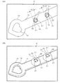
薄板部12は、ガラス化凍結保存容器1の長さ方向の好ましくは一端側近傍にあって、受精卵を保持するための保持部に相当する部位である。薄板部12は、好ましくは、接続部11の最小直径より小さな厚さを持つ扁平体である。薄板部12の先端部13に近い部位には、薄板部12の長さ方向に沿って、受精卵を入れるための2つの凹部15を備える。ただし、凹部15は、1つのみ、あるいは3つ以上でも良い。また、凹部15を薄板部12の幅方向に並んで形成しても良い。凹部15は、好ましくは、薄板部12の一方の板面に開口し、その開口から板厚を超える深さを持つ。すなわち、凹部15は、薄板部12の一つの面に開口し、当該一つの面の反対側の面から外方向に突出して形成されている。
The
薄板部12の長さ(L3)は、特に制約されるものではないが、好ましくは3〜50mm、より好ましくは10〜30mm、さらにより好ましくは15〜25mmの範囲内である。また、薄板部12の幅は、好ましくは0.1〜2mm、より好ましくは0.3〜1.5mm、さらにより好ましくは0.5〜1mmの範囲内である。薄板部12の厚さ(T1)は、好ましくは0.02〜1mm、より好ましくは0.05〜0.3mm、さらにより好ましくは0.07〜0.12mmの範囲内である。薄板部12の長さ(L3)と厚さ(T1)とは、薄板部12の構成材料をも考慮して、十分に撓みやすい組み合わせとするのが好ましい。可撓性に富む大きさに設計するのは、受精卵を含むガラス化液を入れたシャーレ等の浅い容器に、ガラス化凍結保存容器1の凹部15を漬けたときに、薄板部12を撓ませて水平に近い状態にした方が、凹部15に受精卵を入れやすいからである。凹部15の深さは、好ましくは0.06〜3mm、より好ましくは0.1〜0.8mm、さらにより好ましくは0.15〜0.5mmの範囲内である。凹部15の深さは、保持対象である受精卵等の大きさを考慮して、受精卵等を保持しやすく、解凍後に取り出しやすい大きさとするのが好ましい。
The length (L3) of the
2つの凹部15の距離(開口部の中心間距離: L6)は、薄板部12の長さに2つの凹部15が収まる限り、特に制約されないが、好ましくは0.4〜2mm、より好ましくは0.8〜1.4mmの範囲内である。距離L6は、好ましくは、薄板部12をシャーレ等に入れて撓ませた際に、ガラス化液中に2つの凹部15が漬かった状態にできるのに十分小さい距離であって、かつ製造若しくは使用において凹部15同士が連通せずに独立した形態を維持可能な距離である。凹部15の外径(L7)は、1個の受精卵を収納可能な大きさであって、隣り合う凹部15と重ならない大きさであれば良く、好ましくは0.3〜2mm、より好ましくは0.4〜1.5mm、さらにより好ましくは0.5〜1mmの範囲内である。
The distance between the two recesses 15 (distance between the centers of the openings: L6) is not particularly limited as long as the two
先端部13は、薄板部12における凹部15よりも先端側にあって、その先端側から薄板部12に加わる衝撃を和らげるための衝撃緩和部に相当する部位である。先端部13は、その厚さ方向に貫通する貫通孔14を備えた略環状の板である。この実施形態では、貫通孔14の形状は、ハート形状であるが、ハート以外の形状でも良い。また、貫通孔14に代えて、2本の弧状の板状体から構成される開口部位を採用しても良い。また、先端部13は、ハニカム構造の部位でも良い。
The
先端部13の長さ(L4)は、凹部15への受精卵の収納時に邪魔にならず、かつ凍結保存時に凹部15内の受精卵に与える衝撃を和らげるのに十分な長さであれば特に制約されるものではないが、好ましくは0.5〜5mm、より好ましくは0.7〜3mm、さらにより好ましくは1〜2mmの範囲内である。先端部13の幅は、好ましくは0.5〜5mm、より好ましくは0.7〜3mm、さらにより好ましくは1〜2mmの範囲内である。この実施形態では、先端部13の幅は、薄板部12の幅よりも大きい。先端部13の厚さは、好ましくは0.02〜1mm、より好ましくは0.05〜0.3mm、さらにより好ましくは0.07〜0.12mmの範囲内である。この実施形態では、先端部13の厚さは、薄板部12の厚さと略同一である。
Especially, the length (L4) of the
把持部17は、ガラス化凍結保存容器1の操作時に常に把持する部分ではなく、液体窒素中等の凍結剤中に入れた後述のチューブ内に、ガラス化凍結保存容器1を挿入する際に把持する部位である。把持部17は、ガラス化凍結保存容器1の一端側にある先端部13と反対側に位置する端部に形成されている。把持部17は、グリップ本体10より小さな厚さを持つ扁平体である。把持部17は、好ましくは、グリップ体10側に底面を向けた円錐部16を介して、グリップ体10に固定されている。円錐部16は、グリップ体10から把持部17への急激な厚みの変化を緩和することにより、製造を容易にし、かつ使用時に把持部17がその根元から折れるのを防止するのに寄与する。
The
把持部17の長さ(L5)は、特に制約されるものではないが、好ましくは5〜90mm、より好ましくは10〜60mm、さらにより好ましくは20〜40mmの範囲内である。また、把持部17の幅は、好ましくは0.5〜5mm、より好ましくは0.7〜3mm、さらにより好ましくは1〜2mmの範囲内である。把持部17の厚さ(T3)は、好ましくは0.02〜1mm、より好ましくは0.05〜0.3mm、さらにより好ましくは0.07〜0.12mmの範囲内である。この実施形態では、把持部17は、薄板部12と同一の厚さを有する。
The length (L5) of the
図2は、図1(1C)の一部Aの拡大図(2A)および当該一部Aを裏返した状態A’の拡大図(2B)をそれぞれ示す。図3は、図2(2A)に示す凹部に受精卵を入れた状態(3A)および当該状態(3A)において2つの凹部を含む領域のC−C線断面図(3B)をそれぞれ示す。 FIG. 2 shows an enlarged view (2A) of a part A of FIG. 1 (1C) and an enlarged view (2B) of a state A'with the part A turned inside out. FIG. 3 shows a CC line sectional view (3B) of a state (3A) in which the fertilized egg is placed in the recess shown in FIG. 2 (2A) and a region including the two recesses in the state (3A).
凹部15は、薄板部12における開口部側から見ると、直径D1の円筒状の穴である。直径D1は、受精卵25を容易に収納可能であって、より好ましくは径方向に並んでたくさんの受精卵25が入らない程度の大きさであるのが好ましい。受精卵25は、おおよそ0.1mmであることを考慮すると、凹部15の直径D1は、好ましくは0.15〜0.6mm、より好ましくは0.2〜0.4mmの範囲である。ただし、直径D1は、凹部15に入れる対象となる細胞等の大きさによって適宜変更可能である。直径D1は、先に説明した外径L7よりも小さい。すなわち、凹部15は、直径D1の方向に十分に厚い側壁22を有する。側壁22の最も好適なサイズは、凹部15の直径D1を0.25mm、外径L7を0.7mmとしたときに、0.225mmとなる。側壁22を厚くすると、金型にてガラス化凍結保存容器1を成形する際に、凹部15の形状を設計通りに保持しやすい。すなわち、凹部15が潰れあるいは変形する確率を低減できる。
The
凹部15は、この実施形態では、略カップ形状を有し、その底部26に、細胞または胚を通過させずにガラス化液を通過可能な開口面積を有する4つの貫通孔21を備える。より具体的には、凹部15は、その底部26に十字帯20を備える。貫通孔21は、底部26と十字帯20との隙間に形成されている。貫通孔21は、受精卵25を通さずに、ガラス化液を通すことのできる大きさであれば、特に制約されない。この実施形態では、扇形の貫通孔21の直線部分の長さは、好ましくは0.01〜0.1mm、より好ましくは0.02〜0.07mmである。凹部15の底部26に形成される十字帯20は、受精卵25を落下させずに凹部15内に保持し、余分なガラス化液を凹部15の底部26から外に排出する機能を有する。十字帯20の帯幅は、例えば0.1mmである。凹部15は、好ましくは、貫通孔21を閉塞した状態にて30nL以下の内容積を有する。一例を挙げると、この実施形態において、凹部15の内径(上記の直径D1)を0.25mm、凹部15の深さを0.2mmとすると、凹部15の内容積は約10nLとなる。なお、凹部15の内容積は、貫通孔21等を仮想的に閉塞した状態の内容積を意味する。他の実施形態でも同様である。
In this embodiment, the
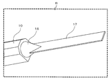
図4は、図1(1C)の一部Bの拡大図を示す。 FIG. 4 shows an enlarged view of a part B of FIG. 1 (1C).
把持部17は、その一部を円錐部16の先端側に埋設した形態で、円錐部16に固定されている。把持部17は、円錐部16と別体で、円錐部16に接着若しくは嵌め込まれていても良いが、好ましくは円錐部16と一体で形成される。前述のように、液体窒素中等の凍結剤中に入れたチューブ内にガラス化凍結保存容器1を挿入する際に、把持部17は、術者が把持する部位となる。これに加えて、この実施形態では、把持部17は、その長さ方向の途中までガラス化凍結保存容器1をチューブに挿入した状態でチューブを閉鎖する部位となる。この詳細については、後述する。
The
ガラス化凍結保存容器1は、ポリアミド; ポリイミド; 環状オレフィンコポリマー; ポリエチレン、ポリプロピレン、エチレン−プロピレン共重合体、エチレン−酢酸ビニル共重合体等のポリオレフィン; ポリエチレンテレフタレート、ポリブチレンテレフタレート、ポリエチレンナフタレート、ポリブチレンナフタレート等のポリエステル; ポリスチレン、メタクリレート−スチレン共重合体等のポリスチレンに代表される合成樹脂にて好適に形成される。ガラス化凍結保存容器1の材料としては、特に、極めて低い温度環境下で使用可能な環状オレフィンコポリマーあるいはポリアミドを挙げることができる。また、ガラス化凍結保存容器1は、上記樹脂以外に、例えば、アルミニウム、アルミニウム合金、ステンレススチール等の金属; 酸化アルミニウム、窒化珪素等のセラミックス; あるいはガラスにて製造しても良い。ガラス化凍結保存容器1は、金型内に樹脂等を射出して成形する射出成形にて好適に製造できる。また、射出成型の際に、金型の内部から外部に通じる通気口を通じて減圧しながら溶融樹脂を金型内に供給するようにしても良い。射出成形とは別の製造方法として、軟化した樹脂を金型に入れて成形する真空成形あるいは圧空成形にてガラス化凍結保存容器1を製造しても良い。また、ガラス化凍結保存容器1は、3Dプリンタを用いて製造しても良い。
The vitrified
図5は、図1のガラス化凍結保存容器と当該容器の薄板部を収容するチューブとを含むキットの斜視図を示す。 FIG. 5 shows a perspective view of a kit including the vitrified cryopreservation container of FIG. 1 and a tube for accommodating a thin plate portion of the container.
この実施形態に係るキット40は、先に説明したガラス化凍結保存容器1と、それを収容するためのチューブ30と、を備える。チューブ30は、使用時に、ガラス化凍結保存容器1において細胞等を保持するための薄板部12を少なくとも収容可能である。チューブ30は、キット40において、その少なくとも内部33を滅菌処理して、チューブ30の長さ方向端部31,32をシールした状態の袋体である。チューブ30を使用する際には、チューブ30は、その一方の端部32の所定位置Dにあるライン34から端部を切り取られ、端部32側が開口される。すなわち、チューブ30は、使用時に開封する位置(ライン34)を表示してなる。開口されたチューブ30は、開口側を外に出した状態で、液体窒素等に代表される凍結剤中に入れられる。
The
一方、術者は、受精卵25を含むガラス化液を入れたシャーレにガラス化凍結保存容器1の凹部15を漬けて保持し、ピペット等を用いて受精卵25を含むガラス化液を吸引し、ガラス化液内の凹部15に向けてピペット等から受精卵25を吐出する。ガラス化凍結保存容器1をシャーレ内のガラス化液から引き上げる際、余分のガラス化液は、凹部15の底部26にある貫通孔21から落ち、受精卵25とわずかなガラス化液だけが凹部15内に残る。その後、術者は、ガラス化凍結保存容器1を、先端部13側から、凍結剤中のチューブ30にすばやく入れる。その後、チューブ30の開口部を、把持部17の長さ方向所定位置に固定する。当該開口部を把持部17に固定する方法は、公知の如何なる固定方法でも良い。固定方法としては、熱融着を利用した固定、接着剤による固定などを例示できる。チューブ30を開けてガラス化凍結保存容器1を取り出す際には、チューブ30の所定位置Eのライン35の位置でチューブ30を開封する。なお、ライン35は、把持部17とチューブ30の開口部との固定位置よりも端部31方向にある。ここで、ライン34,35は、いずれも視認可能にチューブ30の表面に印刷されているのが好ましいが、必ずしも視認可能であることを要しない。また、印刷以外の方法、例えば、エンボス加工等にてライン34,35を形成しても良い。さらには、所定位置D,Eは、ライン34,35以外の方法、例えば、矢印などで示されていても良い。
On the other hand, the surgeon holds the
チューブ30は、ポリアミド; ポリイミド; 環状オレフィンコポリマー; ポリエチレン、ポリプロピレン、エチレン−プロピレン共重合体、エチレン−酢酸ビニル共重合体等のポリオレフィン; ポリエチレンテレフタレート、ポリブチレンテレフタレート、ポリエチレンナフタレート、ポリブチレンナフタレート等のポリエステル; ポリスチレン、メタクリレート−スチレン共重合体等のポリスチレンに代表される合成樹脂にて好適に形成される。チューブ30の材料としては、特に、極めて低い温度環境下で使用可能な環状オレフィンコポリマーあるいはポリアミドを挙げることができる。また、チューブ30は、上記樹脂以外に、例えば、シリコーンゴム等のゴム状弾性体; アルミニウム、アルミニウム合金、ステンレススチール等の金属; 酸化アルミニウム、窒化珪素等のセラミックス; あるいはガラスにて製造されても良い。
The
以上のように、チューブ30は、使用前において、その密閉状態の内部を滅菌処理された状態にあり、薄板部12に受精卵25を保持したガラス化凍結保存容器1を被覆する際に、一方向にある端部32を開封し、薄板部12の先端(この実施形態では、先端部13)からチューブ30にガラス化凍結保存容器1を入れて、薄板部12を通過した所定位置にて密閉して使用される。この実施形態において、チューブ30は、その内部にガラス化凍結保存容器1を入れて、把持部17の長さの途中位置を前記所定位置として密閉可能である。
As described above, the
図6は、この実施形態に係るガラス化凍結保存容器を用いて受精卵をガラス化凍結保存する方法(液中操作型ガラス化凍結保存方法)を説明するための概略工程図を示す。なお、以後、実施の形態において、液中操作型ガラス化凍結保存方法を、単に、「ガラス化凍結保存方法」という。 FIG. 6 shows a schematic process diagram for explaining a method of vitrifying and cryopreserving a fertilized egg using the vitrified cryopreservation container according to this embodiment (in-liquid operation type vitrification cryopreservation method). Hereinafter, in the embodiment, the submerged operation type vitrification cryopreservation method is simply referred to as "vitrification cryopreservation method".
(1)凍結保護物質の平衡
まず、平衡液に受精卵を入れる。平衡液としては、例えば、耐凍結剤を含む液(耐凍結剤の濃度: 5〜15%v/v)を用いることができる。平衡液としては、先に例示したガラス化液よりも耐凍結剤の濃度が低い液を使用するのが好ましい。そのような平衡液の一例としては、塩化ナトリウム、リン酸二水素カリウム、塩化カリウム、塩化カルシウム、硫酸マグネシウム七水和物、19種のアミノ酸、炭酸水素ナトリウム、エチレンジアミン四酢酸二ナトリウム二水和物、ゲンタマイシン硫酸塩、ポリビニルアルコール、アラニル−L−グルタミン、エネルギー源としてD−グルコースDL−乳酸ナトリウム等の乳酸塩、ピルビン酸ナトリウム等のピルビン酸塩を含むHEPES含有培地に、低分子で細胞内に浸透し凍結保護作用を示すエチレングリコール、プロピレングリコール、グリセロール及びジメチルスルホキシド(DMSO)を、それぞれ、終濃度がガラス化液の50%v/vに調製した液を挙げることができる。この結果、受精卵25に悪影響のない濃度の耐凍結剤が受精卵25の内部に浸透する。なお、耐凍結剤としては、細胞等に対して毒性等が懸念されるDMSOを含まないもの、例えばエチレングリコール、プロピレングリコール等を単独あるいは混合して用いても良い。(1) Equilibrium of cryoprotectant substance First, put the fertilized egg in the equilibrium solution. As the equilibrium solution, for example, a solution containing a freezing agent (freezing agent concentration: 5 to 15% v / v) can be used. As the equilibrium liquid, it is preferable to use a liquid having a lower concentration of the freezing agent than the vitrification liquid exemplified above. Examples of such equilibrium solutions include sodium chloride, potassium dihydrogen phosphate, potassium chloride, calcium chloride, magnesium sulfate heptahydrate, 19 amino acids, sodium hydrogen carbonate, ethylenediamine disodium tetraacetate dihydrate. In a HEPES-containing medium containing gentamycin sulfate, polyvinyl alcohol, alanyl-L-glutamine, lactate such as D-glucose DL-sodium lactate as an energy source, and pyruvate such as sodium pyruvate, in cells with small molecules. Examples thereof include solutions prepared by adjusting the final concentration of ethylene glycol, propylene glycol, glycerol and dimethyl sulfoxide (DMSO), which permeate and exhibit freeze-protection action, to 50% v / v of the vitrification solution. As a result, the antifreeze agent having a concentration that does not adversely affect the fertilized
(2)受精卵へのガラス化液の浸透
次に、ガラス化液46を用意し、前工程の受精卵25を、シャーレ45内のガラス化液46に移す。ガラス化液46は、上記平衡液に比べて、耐凍結剤の濃度が高い液(例えば、濃度: 15〜30%v/v)である。この結果、受精卵25の内外の平衡液とガラス化液46との浸透圧差が生じ、受精卵25内部の自由水あるいは結合水(以後、「自由水等」という)の脱水が生じる。こうして、受精卵25内において自由水等と耐凍結剤との置換が行われ、受精卵25内部に高濃度の耐凍結剤が存在するようになる。なお、受精卵25の内部の自由水等をガラス化液46に置換させるステップは、耐凍結剤の濃度を徐々に変化させるように、2段階以上(例えば、3段階)としても良い。なお、ガラス化液46中の耐凍結剤の濃度は、上記濃度の範囲に限定されるものではなく、急速冷却に際してガラス化液46をアモルファス状に固化できる濃度であり、かつ受精卵25に著しく悪影響を与えないような濃度であれば良い。なお、ガラス化に必須の耐凍結剤の総添加濃度は、冷却速度に依存し、冷却速度はガラス化時の体積により決まる。このため、可能な限り少ないガラス化液と共に保存できる凍結保存容器を用いるのが好ましい。(2) Permeation of vitrified liquid into fertilized egg Next, a
(3)ガラス化凍結保存容器への受精卵の収納
次に、図6に示すように、シャーレ45のガラス化液46内に、ガラス化凍結保存容器1の先端部13から薄板部12の途中まで浸す。この結果、2つの凹部15は、完全に、ガラス化液46の液面より下方に位置する。一方、もう一方の手を使って、ピペット47内に受精卵25を含むガラス化液46を吸引し、ピペット47の先端を凹部15に近づけ、凹部15内に受精卵25を吐出する(図6中の一部Fの拡大図を参照)。この操作は、凹部15の数だけ繰り返される。薄板部12は、可撓性に富む材料あるいは形態である。このため、凹部15をガラス化液46の液面に略平行となるようにして、受精卵25を凹部15に入れやすくできる。(3) Storage of fertilized eggs in a vitrified cryopreservation container Next, as shown in FIG. 6, in the vitrified
この実施形態のガラス化凍結保存容器1の長所の一つは、受精卵25を、空気に触れさせずに、ガラス化液46の中でガラス化凍結保存容器1に保持可能なことである。当該長所は、薄板部12に、板厚方向に貫通する貫通孔を形成してガラス化液46の表面張力を利用して受精卵25を保持する技術、および薄板部12に相当するシートにガラス化液46を吸収させる層を形成してその層の表面にて受精卵25を保持する技術では得られない。このように、ガラス化凍結保存の処理において、ガラス化液46中の受精卵25が空気に触れる時間をできるだけ短くできることは、受精卵25の乾燥を防ぎ、もって、受精卵25に対するpH、温度あるいは浸透圧の各変化を低く抑えることにつながる。この結果、受精卵25の生存率を向上させることができる。
One of the advantages of the vitrified
(4)超急速冷却
凍結剤51の一例である液体窒素を入れた容器50を用意し、凍結剤51中に、チューブ30を漬ける。このとき、チューブ30は、開口部を凍結剤51よりも上方に位置するように維持される。次に、受精卵25を入れたガラス化凍結保存容器1を、ガラス化液46から取り出し、一端側を凍結剤51中に沈められたチューブ30に投入する。このとき、ガラス化凍結保存容器1は、ガラス化液46から取り出した後、1〜90秒以内、より好ましくは1〜60秒以内、さらにより好ましくは1〜30秒以内に、直接、凍結剤51中のチューブ30に投入されるのが好ましい。液体窒素を凍結剤51に用いた場合には、凹部15内の受精卵25は、約−196℃の極低温にて急速に凍結する。(4) Ultra-rapid cooling A
ガラス化凍結保存容器1の別の長所は、ガラス化凍結保存容器1に受精卵25を容易に保持でき、その技術に熟練を要しないことである。空気中で受精卵25を従来型のガラス化凍結保存容器に保持する場合、受精卵25を正常に保持できずに、あるいは正常に保持した後に落下して、何度も保持操作のやり直しが生じていた。しかし、この実施形態に係るガラス化凍結保存容器1を用いて受精卵25を保持する場合、凹部15に受精卵25を収納するだけで良く、保持操作のやり直しがほとんど生じない。また、このような簡易な操作は、熟練者養成の軽減につながることから、ガラス化凍結保存の低コスト化につながる。
Another advantage of the vitrified
また、この実施形態に係るガラス化凍結保存容器1は、直接、凍結剤51中に投入可能であるが、より好ましくは凍結剤51中に斜めに立てておいたチューブ30に入れられる。ガラス化凍結保存容器1と凍結剤51とを接触させないことにより、凹部15から受精卵25が脱落するリスクを減らすことができる。受精卵25を保持したガラス化凍結保存容器1をチューブ30に入れて、その後、凍結剤51中に投入することも可能である。しかし、その場合には、受精卵25の凍結速度が低下しやすい。この実施形態では、予め、凍結剤51中に例えばアルミニウム製のコンテナを入れ、当該コンテナにチューブ30を配置し、極低温に維持させておく。これにより、チューブ30内の空気の温度が凍結剤51とほぼ同じ温度となる。その後、受精卵25を保持したガラス化凍結保存容器1をチューブ30内に入れるだけの操作で凍結保存を完了できる。このような操作によって受精卵25を急速に凍結させることができる。さらに、チューブ30を、その使用前に、滅菌処理を行い密封状態としている。このため、無菌環境下で受精卵25を凍結保存できる。また、術者は、把持部17を持ちながら、ガラス化凍結保存容器1の先端部13がチューブ30の開口部と反対側の端部31に到達するまで、ガラス化凍結保存容器1をチューブ30内にゆっくり挿入できる。このため、受精卵25の脱落リスクをより低減できる。
Further, the vitrified
(5)チューブの封鎖
次に、チューブ30の開口部若しくはその近傍の所定位置Dを、把持部17の長さの任意の位置にて封鎖する(図6中の一部Gの拡大図を参照)。ガラス化凍結保存容器1は、仮に、チューブ30内に勢いよく投入されたとしても、先端部13が衝撃緩和部として機能するため、受精卵25が凹部15から落下し、あるいは受精卵25に悪影響が生じる危険性が低い。なお、先端部13をチューブ30の開口部と反対側の端部31に接触させないように、チューブ30の所定位置Dと把持部17とを固定しても良い。これにより、受精卵25の脱落リスクや、受精卵25に悪影響を与えるリスクを、さらに低減できる。(5) Blockade of the tube Next, the predetermined position D at or near the opening of the
(6)その後の処理
ガラス化凍結保存容器1に、微小ICタグ(例えば、SKエレクトロニクス社製)をプリントラベルシール(例えば、Brady社)と共に貼り付けるのが好ましい。微小ICタグとプリントラベルシールの貼り付けによって、ガラス化凍結保存容器1の管理が正確かつ容易となる。また、凍結状態にあるガラス化凍結保存容器1をチューブ30から取り外す際には、ストローカッター等を用いてチューブ30の所定位置E(図6中の拡大図Gを参照)をカットし、把持部17を持ってガラス化凍結保存容器1をチューブ30から引き上げる。この操作によって、ガラス化凍結保存容器1をチューブ30から安全に取り出すことができる。(6) Subsequent Treatment It is preferable to attach a micro IC tag (for example, manufactured by SK Electronics) to the vitrified
<第二実施形態>
次に、本発明の第二実施形態について説明する。第二実施形態において、第一実施形態と共通する部分については、構造物に関しては同じ符号および/または名称を付し、重複した説明を省略する。第二実施形態において説明していない部分については、第一実施形態に記載された内容を代用する。<Second embodiment>
Next, the second embodiment of the present invention will be described. In the second embodiment, the same reference numerals and / or names are given to the structures in common with the first embodiment, and duplicate description will be omitted. For the parts not explained in the second embodiment, the contents described in the first embodiment are substituted.
図7は、本発明の第二実施形態に係るガラス化凍結保存容器の平面図(7A)、側面図(7B)、斜視図(7C)および当該(7C)中の一部Hの拡大図(7D)をそれぞれ示す。 FIG. 7 is a plan view (7A), a side view (7B), a perspective view (7C), and an enlarged view of a part H in the vitrified cryopreservation container according to the second embodiment of the present invention (7A). 7D) are shown respectively.
第二実施形態に係るガラス化凍結保存容器1aは、一方向に長い形状を有する容器である。ガラス化凍結保存容器1aは、好ましくは、その長さ方向の一端に近い部位に、受精卵(細胞または胚の一例)を保持可能な構造を有する。図7(7A)に示すように、ガラス化凍結保存容器1aは、受精卵25を保持する部位に近い一端側から、ガラス化凍結保存容器1aを把持する他端側に向かって順に、先端部13、薄板部12、接続部11、グリップ本体10、拡径部60、鍔部61、把持部62を連接して構成されている。先端部13、薄板部12および接続部11は、第一実施形態と共通するので、それらの説明を省略する。
The vitrified
グリップ本体10は、術者がガラス化凍結保存容器1aを支持するための主要支持部である。グリップ本体10は、この実施形態では、四角形の断面を有するので、滑りにくい構成となっている。なお、グリップ本体10の断面形状は、四角形に限定されず、三角形あるいは五角以上の多角形の他、円形でも良い。グリップ本体10の長さ(L8)は、特に制約されるものではないが、好ましくは10〜200mm、より好ましくは20〜100mm、さらにより好ましくは35〜60mmの範囲内である。また、グリップ本体10の幅(または高さ)は、術者が支持しやすい大きさであれば特に制約されず、好ましくは1〜5mm、より好ましくは1.5〜2.5mmの範囲内である。
The
拡径部60は、把持部62に近い側にあって、薄板部12よりも太い。拡径部60は、好ましくは、グリップ本体10から鍔部61に向かって徐々に径を大きくする略円錐台形状の部位である。拡径部60は、グリップ本体10と鍔部61とを接続する役割を有すると共に、後述するチューブを固定する役割をも有する。拡径部60の長さ(L9)は、特に制約されるものではないが、好ましくは1〜30mm、より好ましくは2〜15mm、さらにより好ましくは4〜10mmの範囲内である。また、拡径部60のグリップ本体10側の直径は、グリップ本体10の幅(または高さ)より小さいか若しくは同一であるのが好ましく、より具体的には、好ましくは0.7〜5mm、より好ましくは1〜2.5mmの範囲内である。また、拡径部60の鍔部61側の直径(L12)は、鍔部61の幅(または高さ)より小さいか若しくは同一であるのが好ましく、より具体的には、好ましくは1〜6mm、より好ましくは2〜4mmの範囲内である。
The
鍔部61は、拡径部60の鍔部61側の直径(L12)より大きな幅(または高さ: L13)を有する。鍔部61は、後述するチューブを把持部62側に進むのを防止するストッパーとして機能する部位である。したがって、鍔部61は、好ましくは、チューブの開口部より大きい。鍔部61の幅(または高さ: L13)は、好ましくは、好ましくは1.5〜10mm、より好ましくは2〜6mmの範囲内である。鍔部61の厚さ(L10)は、好ましくは、0.7〜5mm、より好ましくは1〜3mmの範囲内である。
The
把持部62は、ガラス化凍結保存容器1aの操作時に常に把持しても良いが、通常、液体窒素等の凍結剤51中に予め入れてある後述のチューブ内に、ガラス化凍結保存容器1aを挿入する際に把持する部位である。把持部62は、ガラス化凍結保存容器1aの先端部13と反対側に位置する。把持部62の長さ(L11)は、特に制約されるものではないが、好ましくは5〜90mm、より好ましくは10〜60mm、さらにより好ましくは20〜40mmの範囲内である。また、把持部62の幅は、特に制約されないが、好ましくは、グリップ本体10の幅とほぼ同じ大きさである。把持部62の幅は、好ましくは0.5〜5mm、より好ましくは0.7〜4mm、さらにより好ましくは1〜3mmの範囲内である。
The
ガラス化凍結保存容器1aは、第一実施形態に係るガラス化凍結保存容器1と同様の合成樹脂、金属、セラミックスあるいはガラスにて好適に構成される。また、ガラス化凍結保存容器1aは、第一実施形態に係るガラス化凍結保存容器1と同様、射出成形、真空成形、圧空成形あるいは3Dプリンタを用いた製造法によって好適に製造できる。
The vitrified
図8は、図7のガラス化凍結保存容器と当該容器の薄板部を収容するチューブとを含むキットの斜視図を示す。 FIG. 8 shows a perspective view of a kit including the vitrified cryopreservation container of FIG. 7 and a tube for accommodating a thin plate portion of the container.
この実施形態に係るキット40aは、先に説明したガラス化凍結保存容器1aと、それを収容するためのチューブ30aとを備える。チューブ30aは、使用時に、ガラス化凍結保存容器1aの薄板部12を少なくとも収容可能である。チューブ30aは、キット40aにおいて、その少なくとも内部33aを滅菌処理して、チューブ30aの長さ方向端部31a,32aをシールした状態の袋体である。チューブ30aを使用する際には、チューブ30aは、その一方の端部32aに近い所定位置Iにあるライン34aから端部を切り取られ、端部32a側が開口される。チューブ30aは、この実施形態では、使用時に開封する位置(ライン34a)を表示してなる。開口されたチューブ30aは、開口側を外に出した状態で、液体窒素等の凍結剤51中に入れられる。
The
術者は、受精卵25を凹部15に保持した状態のガラス化凍結保存容器1を、先端部13側から、凍結剤51中に立てられたチューブ30aにすばやく入れる。その後、術者は、チューブ30aの開口部を拡径部60の長さ方向の所定位置に固定する。この結果、鍔部61より先端部13側は、チューブ30a内に密封される。チューブ30aからガラス化凍結保存容器1を取り出す際には、術者は、把持部62を持って、チューブ30aからガラス化凍結保存容器1を引き抜けば良い。ライン34aは、視認可能にチューブ30aの表面に印刷されているのが好ましいが、必ずしも視認可能であることを要しない。また、印刷以外の方法、例えば、エンボス加工等にてライン34aを形成しても良い。さらに、所定位置Iは、ライン34a以外の方法、例えば、矢印などで示されても良い。チューブ30aは、第一実施形態と同様の合成樹脂、ゴム状弾性体、金属、セラミックスあるいはガラスなどから製造可能である。
The operator quickly puts the vitrified
このように、チューブ30aは、その内部にガラス化凍結保存容器1aを収容して、薄板部12を通過した所定位置となる拡径部60にて固定可能である。この実施形態では、チューブ30aは、使用時に開封する位置(所定位置I)を表示して成る。このため、開封位置を、チューブ30aが拡径部60にて固定される位置になるように設計することにより、ガラス化凍結保存容器1aの拡径部60から先端部13の部位を、チューブ30a内に確実に収容できる。
In this way, the
この実施形態に係るガラス化凍結保存容器1aを用いて受精卵25をガラス化凍結保存する方法の大部分は、第一実施形態における同方法と共通するので、異なる部分のみを以下に説明する。
Since most of the method for vitrifying and cryopreserving the fertilized
第一実施形態におけるガラス化凍結保存方法の(1)凍結保護物質の平衡、(2)受精卵へのガラス化液の浸透、(3)ガラス化凍結保存容器への受精卵の収納および(4)超急速冷却の各ステップは、第二実施形態でも共通する。 (1) Equilibrium of cryoprotectant, (2) Permeation of vitrified solution into fertilized egg, (3) Storage of fertilized egg in vitrified cryopreservation container and (4) ) Each step of ultra-rapid cooling is also common to the second embodiment.
(5)チューブの封鎖
チューブ30aの開口部(所定位置I)を、拡径部60の長さの途中位置若しくは鍔部61に接触する位置まで引き上げる。この結果、凍結剤中に配置されたチューブ30aへのガラス化凍結保存容器1aの装着が完了する。(5) Blocking the tube The opening (predetermined position I) of the
(6)その後の処理
ガラス化凍結保存容器1aは、第一実施形態に係るガラス化凍結保存容器1と同様、微小ICタグおよびプリントラベルシールを貼り付けて保存するのが好ましい。凍結状態にあるガラス化凍結保存容器1aをチューブ30aから取り外す際には、ストローカッター等を用いることなく、チューブ30aを拡径部60から先端部13の方向に引き抜くだけで良い。(6) Subsequent Treatment The vitrified
<第三〜第五実施形態>
次に、本発明の第三〜第五実施形態について説明する。第三〜第五実施形態において、先に説明した各実施形態と共通する部分については、構造物に関しては同じ符号および/または名称を付し、重複した説明を省略する。第三〜第五実施形態において説明していない部分については、先に説明した各実施形態に記載された内容を代用する。<Third to fifth embodiments>
Next, the third to fifth embodiments of the present invention will be described. In the third to fifth embodiments, with respect to the parts common to each of the above-described embodiments, the same reference numerals and / or names are given to the structures, and duplicate description is omitted. For the parts not explained in the third to fifth embodiments, the contents described in each of the above-described embodiments are substituted.
図9は、第三実施形態に係るガラス化凍結保存容器の凹部近傍を当該凹部の底部側から見た拡大斜視図(9A)および当該凹部の図3(3B)と同様の断面図(9B)をそれぞれ示す。 FIG. 9 is an enlarged perspective view (9A) of the vicinity of the recess of the vitrified cryopreservation container according to the third embodiment as viewed from the bottom side of the recess, and a cross-sectional view (9B) similar to FIG. 3 (3B) of the recess. Are shown respectively.
第三実施形態に係るガラス化凍結保存容器1bは、第一実施形態に係るガラス化凍結保存容器1と異なる形態の凹部15bを備え、かつ先端部13に相当する衝撃緩和部を備えていない。これら2点以外の構成は、ガラス化凍結保存容器1と共通する。
The vitrified
凹部15bの形状は、薄板部12の厚さ方向片側に突出する略カップ形状である。凹部15bは、その底部に、複数個(この実施形態では7個)の貫通孔71を備える。貫通孔71は、好ましくは円形であるが、多角形でも良い。貫通孔71は、受精卵25を通さずに、ガラス化液46を通すことのできる大きさであれば、特に制約されない。この実施形態では、貫通孔71の径は、好ましくは0.01〜0.08mm、より好ましくは0.03〜0.06mmである。また、凹部15bの側壁22は、第一実施形態のそれに比べて過度に厚くはない。凹部15bは、図9に示す形態であっても、先に説明した凹部15と同様、ガラス化液46中で受精卵25を収納でき、かつガラス化液46からガラス化凍結保存容器1bを離した際に余分のガラス化液46を貫通孔71から外に排出可能である。
The shape of the
図10は、第四実施形態に係るガラス化凍結保存容器の凹部近傍を当該凹部の開口面側から見た拡大斜視図(10A)、当該凹部の底部側から見た拡大斜視図(10B)および当該凹部の図3(3B)と同様の断面図(10C)をそれぞれ示す。 10A is an enlarged perspective view (10A) of the vicinity of the recess of the vitrified cryopreservation container according to the fourth embodiment as viewed from the opening surface side of the recess, and an enlarged perspective view (10B) of the vicinity of the recess as viewed from the bottom side of the recess. A cross-sectional view (10C) similar to that of FIG. 3 (3B) of the recess is shown.
第四実施形態に係るガラス化凍結保存容器1cは、第一実施形態に係るガラス化凍結保存容器1と異なる形態の凹部15cを備え、かつ先端部13に相当する衝撃緩和部を備えていない。これら2点以外の構成は、ガラス化凍結保存容器1と共通する。
The vitrified
凹部15cの形状は、薄板部12の厚さ方向のいずれの側にも突出せずに、薄板部12の厚さの範囲内でへこむ形状である。薄板部12は、凹部15cの深さ以上の厚さとする必要から、好ましくは、前述の各実施形態の薄板部12に比べて厚い。凹部15cは、薄板部12と略面一の底部72に、複数個(この実施形態では7個)の貫通孔71を備える。貫通孔71の好ましい形状および大きさは、第三実施形態と同様である。また、凹部15cの側壁は、薄板部12と共有の構成となっている。このように、凹部15cを薄板部12の一方に突出させずに薄板部12の厚さ内におさまるように形成しても、先に説明した凹部15と同様、ガラス化液46中で受精卵25を収納でき、かつガラス化液46からガラス化凍結保存容器1bを離した際に余分のガラス化液46を貫通孔71から外に排出可能である。
The shape of the
図11は、第五実施形態に係るガラス化凍結保存容器の凹部近傍を当該凹部の開口面側から見た拡大斜視図(11A)および当該凹部の図3(3B)と同様の断面図(11B)をそれぞれ示す。 FIG. 11 is an enlarged perspective view (11A) of the vicinity of the recess of the vitrified cryopreservation container according to the fifth embodiment as viewed from the opening surface side of the recess, and a cross-sectional view (11B) similar to FIG. 3 (3B) of the recess. ) Are shown respectively.
第五実施形態に係るガラス化凍結保存容器1dは、第四実施形態に係るガラス化凍結保存容器1cと異なり、凹部15cの開口部を開閉自在な蓋部80を備える。この点以外の構成は、ガラス化凍結保存容器1cと共通する。蓋部80は、その縁に近い部分を薄板部12の一部に重ね、蓋部80の厚さ方向をピン81により貫通されている。ピン81は、ピン81を中心に蓋部80を回転できるように、薄板部12に固定されている。図11(11A)に示すように、両矢印Jで示す両方向に蓋部80を回転することによって、凹部15cの開口面は開閉自在となる。凹部15cの開口部を蓋部80によって開閉自在とすることにより、受精卵25を凹部15cに入れた直後に蓋部80にて開口部を閉鎖すれば、受精卵25を凍結剤51まで運ぶ間、受精卵25と空気との接触をより確実に防止でき、かつ受精卵25が凹部15cの開口部からこぼれ落ちる危険性もない。
Unlike the vitrified
この実施形態では、薄板部12は、薄板部12の長さ方向に2つの凹部15cを隣接配置する。このため、2つの蓋部80は、開閉時に互いに衝突する可能性がある。これを可能な限り回避するように、2つのピン81をできるだけ離している。これによって、2つの蓋部80が各ピン81を中心に回転しても、蓋部80同士が衝突するのを防止できる。なお、凹部15c同士の間隔が十分に長い場合には、ピン81の位置を必ずしも図11の位置としなくとも良い。
In this embodiment, the
<ガラス化凍結保存容器の好適な使用方法>
図12は、ガラス化凍結保存処理を安定かつ迅速に行うために有益な専用ディッシュにガラス化凍結保存容器を保持した状態の斜視図(12A)および専用ディッシュの平面図(12B)をそれぞれ示す。専用ディッシュはガラス化保存容器を手で保持することなく、先端の収納室をガラス化保存液中に安定設置でき、かつ顕微鏡下での焦点を変えることなく全ての操作と観察を安全迅速に行える構造(形状、サイズ、高さ等)とする。<Preferable usage of vitrified cryopreservation container>
FIG. 12 shows a perspective view (12A) and a plan view (12B) of the dedicated dish in which the vitrified cryopreservation container is held in a dedicated dish, which is useful for stably and quickly performing the vitrification cryopreservation treatment. The dedicated dish allows the storage chamber at the tip to be stably installed in the vitrified storage solution without holding the vitrified storage container by hand, and all operations and observations can be performed safely and quickly without changing the focus under the microscope. The structure (shape, size, height, etc.).
図12に示すディッシュ(ここでは、「専用ディッシュ」という)90aは、好ましくは透明性の高い樹脂あるいはガラスから構成され、一方向(図12(B)では紙面表方向)に開口する部材である。専用ディッシュ90aは、略半球殻形状のウェル91,92,93を各2組と、開口側をハート形状とする略半球殻形状のウェル94aを2組との合計8個のウェルを配置可能である。ウェル91を、以後、第一ウェル91と称する。ウェル92およびウェル93を、それぞれ、以後、第二ウェル92および第二ウェル93と称する。ウェル94aを、以後、第三ウェル94aと称する。専用ディッシュ90aの好適な大きさは、横(W)85mm×縦(D)65mm×高さ(H)10mmである。第一ウェル91、第二ウェル92,93および第三ウェル94aは、専用ディッシュ90aと同様、好ましくは透明性の高い樹脂あるいはガラスから構成される。半球殻形状の第一ウェル91および第二ウェル92,93は、好ましくは、同じ大きさであって、直径15mmである。半球殻形状の第一ウェル91および第二ウェル92,93の高さは、専用ディッシュ90aの深さと同一若しくは該深さより低い方が好ましく、この実施形態では5〜9mmの範囲にある。この実施形態では、開口側をハート形状とする略半球殻形状の第三ウェル94aは、そのハート形状の開口面を内接させる円の直径を15mmとする。ただし、当該円の直径は、15mmより大きくても良く、例えば、16〜18mmの範囲としても良い。また、当該円の直径は、15mmより小さくても良く、例えば、12〜14mmの範囲としても良い。開口側をハート形状とする半球殻形状の第三ウェル94aの高さは、専用ディッシュ90aの深さと同一若しくは該深さより低い方が好ましく、この実施形態では5〜9mmの範囲にある。
The
図12(12B)に示すように、専用ディッシュ90aには、その縦(D)方向の長さの半分ずつの領域に、第一ウェル91、第二ウェル92,93および第三ウェル94aを1組とするウェル集合体をそれぞれ配置可能である。すなわち、専用ディッシュ90aは、図12(12B)の紙面上下に分かれて2つの操作ラインを持つ。このため、同時に2個の卵子(未受精卵、受精卵のいずれでも良い)の凍結保存操作ができる。第一ウェル91は、この実施形態では、平衡液を入れるためのものである。第二ウェル92,93および第三ウェル94aは、この実施形態では、ガラス化液を入れるためのものである。第三ウェル94aの開口面はハート形状であり、ガラス化凍結保存容器1aの先端部の形状と共通の形状とするのが好ましい。この結果、第三ウェル94aが最終浸漬部位であることが明確になると共に、ガラス化凍結保存処理を行う術者の多くが女性であることにも配慮可能である。
As shown in FIG. 12 (12B), the
専用ディッシュ90aを用いた卵子のガラス化凍結保存処理の手順は、一例を挙げると、以下のとおりである。
The procedure for the vitrification cryopreservation treatment of an egg using the
2個の第一ウェル91に平衡液を、4個の第二ウェル92,93および2個の第三ウェル94aに約300μlのガラス化液を分注する。第三ウェル94aへのガラス化液の分注は、ガラス化凍結保存容器1aの収納室(凹部15)に空気が入るのを防ぐべく第三ウェル94aから空気を押し出すため、ガラス化液を吸い込んだピペッターチップを空の第三ウェル94aの内底面に設置した収納室(凹部15)にめがけて吐き出すように行われるのが好ましい。そのような分注の後、第三ウェル94a内にガラス化液を満たしておくのが好ましい。
Dispense about 300 μl of the equilibrium solution into the two
卵子を微量の培養液とともに移動用のピペットで移動し、第一ウェル91内の平衡液表面に吐き出すと、吐き出された卵子は、平衡液添加の保護剤の浸透圧と粘性の差により収縮し、徐々になじみながら、第一ウェル91の内底面に沈む。その後、卵子が平衡液に入れる前の大きさに戻ったことを確認し、基本的な処理時間を10〜15分として、第二ウェル92のガラス化液に移す。第二ウェル92内のガラス化液は比較的高濃度であり、卵子に悪影響を及ぼす可能性があることから、これ以降、凍結操作までの処理時間を90秒以内とするのが好ましい。卵子を第二ウェル92内のガラス化液に入れただけでは、凍結保護剤が細胞になじまず、細胞内に浸透しにくいため、ピペットにて強制的に卵子を吸引および排出を繰り返し、第二ウェル92内底面で6箇所以上の場所に素早く卵子を移動させる。加えて、卵子を第二ウェル93内のガラス化液に移し、ピペットにて強制的に卵子を吸引および排出を繰り返し、第二ウェル93の内底面で6箇所以上の場所に素早く卵子を移動させるのが好ましい。この結果、卵子はほぼ完全にガラス化液になじむ。完全にガラス化液の平衡を終えた卵子を移動用ピペットで吸引して、予めガラス化凍結保存容器1aの収納室(凹部15)をガラス化液で満たしている第三ウェル94aまで移動する。続いて、収納室内にピペットの先端を近づけて、ガラス化液中で卵子を排出する。
When the egg is moved with a small amount of culture solution with a moving pipette and discharged to the surface of the equilibrium solution in the
次に、卵子が収納室から出ないように、第三ウェル94aからガラス化凍結保存容器1aを静かに引き上げ、液体窒素内にて予め冷やしてあるチューブ30aに、ガラス化凍結保存容器1aの先端に衝撃が加わらないように静かに挿入する。ガラス化凍結保存容器1を用いて同様の操作を行った場合、ガラス化凍結保存容器1を、液体窒素内にて予め冷やしてあるチューブ30に挿入する。また、チューブ30,30aを使用しない場合には、ガラス化凍結保存容器1a,1をそのまま液体窒素中に静かに浸漬するのが好ましい。
Next, the vitrified
図13は、ガラス化凍結保存処理を安定かつ迅速に行うために有益な専用ディッシュであって、図12に示す専用ディッシュの変形例にガラス化凍結保存容器を保持した状態の斜視図(13A)および当該変形例に係る専用ディッシュの平面図(13B)をそれぞれ示す。 FIG. 13 is a dedicated dish useful for performing the vitrification cryopreservation process stably and quickly, and is a perspective view (13A) of a state in which the vitrified cryopreservation container is held in a modified example of the dedicated dish shown in FIG. A plan view (13B) of the dedicated dish according to the modified example is shown.
図13(13A)は、専用ディッシュ90aとほぼ同形状のディッシュ(「専用ディッシュ」という)90bにおいて、図12の第三ウェル94aに代えて、第一ウェル91および第二ウェル92,93とほぼ同形状の第三ウェル94bを配置した例を示す。開口面をハート形状とした第三ウェル94aに代えて、開口面を略円形とする第三ウェル94bを用いた場合でも、上記と同様の操作が可能である。
FIG. 13 (13A) shows a dish (referred to as “dedicated dish”) 90b having substantially the same shape as the
以上のように、この実施形態に係る細胞または胚のガラス化保存方法では、まず、一方向を開口した専用ディッシュ90a,90bの内底面に、専用ディッシュ90a,90bの内容積の深さと同一若しくは該深さよりも低い高さを持つ第一ウェル91、第二ウェル92,93および第三ウェル94a(若しくは94b)を少なくとも3個配置する。1または2以上の第一ウェル91には平衡液が入れられている。また、1または2以上の第二ウェル92,93にはガラス化液が入れられている。さらに、1または2以上の第三ウェル94a(若しくは94b)には、ガラス化液が入れられると共に、ガラス化凍結保存容器1a,1の凹部15がガラス化液中に浸漬させられる。次に、細胞または胚を、第一ウェル91、第二ウェル92,93、第三ウェル94a(若しくは94b)の順に移動させる。次に、第三ウェル94a(若しくは94b)において凹部15に細胞または胚を収納した状態でガラス化凍結保存容器1a,1を第三ウェル94a(若しくは94b)のガラス化液から引き上げる。最後に、細胞または卵子を凹部15に収納した状態のガラス化凍結保存容器1a,1を凍結剤中に浸漬する。このように、専用ディッシュ90a,90bを用いると、手でガラス化凍結保存容器1a,1を継続して保持する必要が無く、正確かつ迅速に細胞または胚を凹部15に収納する操作が可能となる。なお、専用ディッシュ90a,90bを用いたガラス化凍結保存の操作において、上述の例は、ガラス化凍結保存容器1a,1を用いた例であるが、ガラス化凍結保存容器1b,1c,1dを用いる場合でも同様の操作を行うことができる。
As described above, in the method for vitrifying and preserving cells or embryos according to this embodiment, first, the inner bottom surface of the
<その他の実施形態>
上述の各実施形態は、本発明の好適な実施形態に過ぎず、本発明は、本発明の目的を逸脱しない限り、種々の変形を施して実施可能である。<Other Embodiments>
Each of the above-described embodiments is merely a preferred embodiment of the present invention, and the present invention can be implemented with various modifications as long as the object of the present invention is not deviated.
例えば、ガラス化凍結保存容器1,1a,1b,1c,1d(以後、「ガラス化凍結保存容器1等」という)は、受精卵25以外の細胞(例えば、未受精卵)、あるいは胚を保存するものでも良い。また、凹部15,15bの底部26,72に加えて若しくは底部26,72に代えて、側壁22に貫通孔21,71を形成しても良い。すなわち、貫通孔21,71は、凹部15,15bを構成する壁面であれば、その形成位置を制約されない。十字帯20は、凹部15に備えるのみならず、凹部15b,15cにも備えることができる。貫通孔21,71を閉塞した状態の凹部15,15b,15cの内容積は、好ましくは30nL以下であるが、30nLより大きく、かつ50nLより小さくても良い。さらには、凹部15,15b,15cの内容積を50nL以上としても良い。細胞等を保持する保持部は、薄板部12の形態以外の構成部でも良い。例えば、保持部の形状を、棒形状あるいはブロック形状といった非扁平形状とすることもできる。
For example, the vitrified
上述の各実施形態では、凹部15,15b,15cにガラス化液46と受精卵25とを吐出する場合、ガラス化凍結保存容器1等は、当該吐出されるガラス化液46と同じ液中に薄板部12の一部若しくは全部が沈められている。しかし、吐出されるガラス化液は、ガラス化凍結保存容器1等の薄板部12を沈めているガラス化液46と必ずしも同一であることを要しない。例えば、シャーレを2つ用意し、一方のシャーレのガラス化液46内にガラス化凍結保存容器1等の薄板部12を沈め、他方のシャーレ内のガラス化液と受精卵25とをピペット47等で吸引し、薄板部12の凹部15,15b,15cに向けて受精卵25とガラス化液とを吐出し、受精卵25を凹部15,15b,15c内に収納しても良い。
In each of the above-described embodiments, when the vitrified liquid 46 and the fertilized
また、本発明は、上述のガラス化凍結保存容器1等、キット40,40aおよびガラス化凍結保存方法を構成する複数の構成要素を、互いに組み合わせても良い。一例ではあるが、第一実施形態若しくは第二実施形態と第五実施形態とを組み合わせて、蓋部80を凹部15の開口面側に備えても良い。また、第二実施形態と第三実施形態とを組み合わせて、凹部15bを第二実施形態に係るガラス化凍結保存容器1aに備えても良い。また、第二実施形態に係るガラス化凍結保存容器1aの拡径部60を、第三〜第五実施形態のガラス化凍結保存容器1b,1c,1dに設けても良い。さらに、キット40またはキット40aは、第三〜第五実施形態に係るガラス化凍結保存容器1b,1c,1dを含むものでも良い。なお、上記ガラス化凍結保存容器1,1a,1b,1c,1dは、凍結保存液中のみならず、空気中にて使用することもできる。
Further, in the present invention, the above-mentioned
本発明は、細胞または胚のガラス化凍結保存に利用できる。
The present invention can be used for vitrification cryopreservation of cells or embryos.
Claims (10)
当該ガラス化液中で前記液中操作型ガラス化凍結保存容器の前記凹部に細胞または胚を入れることを特徴とする、細胞または胚の液中操作型ガラス化凍結保存方法。 A method for submerged operation-type vitrification cryopreservation of cells or embryos, which comprises placing cells or embryos in the recesses of the submerged-operated vitrification cryopreservation container in the vitrification solution.
前記貫通孔は前記底部と前記十字帯との隙間に形成されている請求項1または請求項2に記載の細胞または胚の液中操作型ガラス化凍結保存方法。 The recess has a cross band at the bottom and
The method for submerged operation-type vitrification cryopreservation of cells or embryos according to claim 1 or 2, wherein the through hole is formed in a gap between the bottom and the cross band.
1または2以上の第一ウェルに平衡液を入れ、1または2以上の第二ウェルにガラス化液を入れ、1または2以上の第三ウェルにガラス化液を入れると共に前記液中操作型ガラス化凍結保存容器の前記凹部を前記ガラス化液中に浸漬させておき、 The equilibrium solution is placed in one or more first wells, the vitrification solution is placed in one or more second wells, and the vitrification solution is placed in one or more third wells. The recess of the cryopreservation container is immersed in the vitrification solution.
細胞または胚を、前記第一ウェル、前記第二ウェル、前記第三ウェルの順に移動させ、 The cells or embryos are moved in the order of the first well, the second well, and the third well.
前記第三ウェルにおいて前記凹部に細胞または胚を収納した状態で前記液中操作型ガラス化凍結保存容器を前記第三ウェルの前記ガラス化液から引き上げ、 With the cells or embryos housed in the recesses in the third well, the submerged-operated vitrified cryopreservation container is pulled up from the vitrified solution in the third well.
細胞または卵子を前記凹部に収納した状態の前記液中操作型ガラス化凍結保存容器を凍結剤中に浸漬する請求項1から請求項9のいずれか1項に記載の細胞または胚の液中操作型ガラス化凍結保存方法。 The submerged operation of cells or embryos according to any one of claims 1 to 9, wherein the submerged operation type vitrified cryopreservation container in which the cells or eggs are stored in the recess is immersed in a freezing agent. Mold vitrification cryopreservation method.
Applications Claiming Priority (1)
| Application Number | Priority Date | Filing Date | Title |
|---|---|---|---|
| PCT/JP2016/063147 WO2017187543A1 (en) | 2016-04-27 | 2016-04-27 | Vessel for vitrification-cryopreservation in liquid, kit provided with vessel and tube for receiving same, and method for vitrification-cryopreservation in liquid |
Publications (2)
| Publication Number | Publication Date |
|---|---|
| JPWO2017187543A1 JPWO2017187543A1 (en) | 2019-03-14 |
| JP6846054B2 true JP6846054B2 (en) | 2021-03-24 |
Family
ID=60161294
Family Applications (1)
| Application Number | Title | Priority Date | Filing Date |
|---|---|---|---|
| JP2018514010A Active JP6846054B2 (en) | 2016-04-27 | 2016-04-27 | Submersible operation type vitrification cryopreservation method |
Country Status (3)
| Country | Link |
|---|---|
| US (1) | US20190141986A1 (en) |
| JP (1) | JP6846054B2 (en) |
| WO (1) | WO2017187543A1 (en) |
Families Citing this family (17)
| Publication number | Priority date | Publication date | Assignee | Title |
|---|---|---|---|---|
| JP2018082677A (en) * | 2016-11-25 | 2018-05-31 | 正成 桑山 | Egg cryopreservation container |
| USD918707S1 (en) * | 2018-12-04 | 2021-05-11 | Jun Tao | Vitrification and storage device |
| ES2713800B2 (en) * | 2019-04-16 | 2020-06-24 | Univ Valencia Politecnica | DEVICE FOR THE CRYOPRESERVATION OF A SAMPLE OF OVULES AND EMBRYOS BY VITRIFICATION |
| JP6636202B1 (en) * | 2019-06-19 | 2020-01-29 | リプロサポートメディカルリサーチセンター株式会社 | Equipment used before cell freezing |
| US20230011300A1 (en) * | 2019-12-02 | 2023-01-12 | Shen Zhen Biorocks Biotechnology Company Limited | A chemical delivery system, device and method thereof |
| CN113016776A (en) * | 2019-12-24 | 2021-06-25 | 上海明悦医疗科技有限公司 | Carrier, vacuumizing device and tissue cryopreservation system |
| CN111700064B (en) * | 2020-07-22 | 2024-03-08 | 明日加科技(深圳)有限公司 | A kind of cell freezing auxiliary device |
| CN114836291B (en) * | 2021-02-01 | 2025-11-21 | 深圳拜尔洛克生物技术有限公司 | System and method for thawing and resuscitating biological material |
| KR102278277B1 (en) * | 2021-02-10 | 2021-07-15 | 의료법인마리아의료재단 | The development of vitrification container for cryopreservation and vitrification method using the same |
| CN215775135U (en) | 2021-03-03 | 2022-02-11 | 深圳拜尔洛克生物技术有限公司 | Chip for cryopreservation or thawing recovery of biological tissue |
| CN216315104U (en) * | 2021-03-03 | 2022-04-19 | 深圳拜尔洛克生物技术有限公司 | Carrier for cryopreservation or thawing recovery of biological tissue |
| CN115486437B (en) * | 2021-06-18 | 2024-01-23 | 上海明悦医疗科技有限公司 | Assisted reproduction carrier components |
| CN117980460A (en) * | 2021-08-23 | 2024-05-03 | Cstec株式会社 | Devices for freezing and preserving ovum or fertilized egg |
| WO2023036223A1 (en) * | 2021-09-10 | 2023-03-16 | 深圳拜尔洛克生物技术有限公司 | Device for freezing preservation or unfreezing resuscitation of biological tissue |
| JP7898850B2 (en) * | 2021-12-15 | 2026-08-03 | 株式会社77Kc | Cryopreservation equipment |
| EP4502132A4 (en) * | 2022-03-30 | 2025-05-21 | Advanced Institute of Reproductive Technologies | Cryopreservation container |
| JP2025075380A (en) * | 2023-10-31 | 2025-05-15 | 医療法人浅田レディースクリニック | Dish with plurality of wells |
Family Cites Families (7)
| Publication number | Priority date | Publication date | Assignee | Title |
|---|---|---|---|---|
| JP4431754B2 (en) * | 2006-03-28 | 2010-03-17 | 独立行政法人家畜改良センター | Vitrification preservation tool of embryo and vitrification preservation method of embryo using the same |
| WO2010046949A1 (en) * | 2008-10-22 | 2010-04-29 | Inui Hiroaki | Method for vitrification of cell, and container for vitrification of cell |
| JP5525280B2 (en) * | 2009-02-19 | 2014-06-18 | 裕昭 乾 | Method of vitrifying and preserving cells and container for vitrification and preservation of cells |
| GB0909923D0 (en) * | 2009-06-09 | 2009-07-22 | Oxford Gene Tech Ip Ltd | Picowell capture devices for analysing single cells or other particles |
| WO2011070973A1 (en) * | 2009-12-08 | 2011-06-16 | 学校法人北里研究所 | Narrow tube for vitrification preservation of animal embryo or ovum |
| JP5929595B2 (en) * | 2012-07-31 | 2016-06-08 | マツダ株式会社 | Car luggage compartment structure |
| EP3196290B1 (en) * | 2014-08-29 | 2020-07-08 | Kitazato Corporation | Tool for cryopreserving collected biological tissue, and method for cryopreserving tissue fragment |
-
2016
- 2016-04-27 WO PCT/JP2016/063147 patent/WO2017187543A1/en not_active Ceased
- 2016-04-27 JP JP2018514010A patent/JP6846054B2/en active Active
- 2016-04-27 US US16/097,144 patent/US20190141986A1/en not_active Abandoned
Also Published As
| Publication number | Publication date |
|---|---|
| WO2017187543A1 (en) | 2017-11-02 |
| US20190141986A1 (en) | 2019-05-16 |
| JPWO2017187543A1 (en) | 2019-03-14 |
Similar Documents
| Publication | Publication Date | Title |
|---|---|---|
| JPWO2017187543A1 (en) | A submerged operation type vitrification cryopreservation container, a kit comprising the container and a tube for accommodating the same, and a submerged operation type vitrification cryopreservation method | |
| JP5278978B2 (en) | Tubular for vitrification preservation of animal embryos or eggs | |
| Liebermann et al. | Recent developments in human oocyte, embryo and blastocyst vitrification: where are we now? | |
| JP6114185B2 (en) | Improved micromanipulation and storage apparatus and method | |
| Mukaida et al. | Vitrification of oocytes, embryos and blastocysts | |
| Parmegiani et al. | Rapid warming increases survival of slow-frozen sibling oocytes: a step towards a single warming procedure irrespective of the freezing protocol? | |
| JP5525280B2 (en) | Method of vitrifying and preserving cells and container for vitrification and preservation of cells | |
| AU2011291993B2 (en) | Method of liquid nitrogen surface vitrification | |
| US20150313211A1 (en) | A Method of Vitrification | |
| US20060046243A1 (en) | Method for vitrification of mammalian cells | |
| US20220151223A1 (en) | Cell cryopreservation pretreatment operation plate | |
| US20220287297A1 (en) | Jig for cell or tissue cryopreservation | |
| Hunt et al. | Cryopreservation of human embryonic stem cell lines | |
| Cho et al. | Improvement in post-thaw viability of in vitro-produced bovine blastocysts vitrified by glass micropipette (GMP) | |
| US6132952A (en) | Storage system comprising an emptied zona pellucida and spermatozoa placed therein and a method of cryopreservation | |
| WO2020250766A1 (en) | Fixture of cryopreservation jig and freezing and thawing method using said fixture | |
| Vajta et al. | Disadvantages and benefits of vitrification | |
| Hiraoka et al. | Zona pellucida removal and vitrified blastocyst transfer outcome: a preliminary study | |
| JP7341847B2 (en) | Fixture for cryopreservation jig | |
| Herrera | Vitrification of equine in vivo-derived embryos after blastocoel aspiration | |
| RU141452U1 (en) | DEVICE FOR VITRIFICATION OF MAMMAL OOCYtes AND EMBRYOS | |
| JP7133514B2 (en) | Cell or tissue freeze-thaw method | |
| JP7423412B2 (en) | Fixture for cryopreservation jig | |
| JP7471836B2 (en) | Fixture for cryopreservation jig | |
| Schiewe | Microsecure vitrification (µS-VTF) procedure: optimum simplicity, security, cost-saving and effectiveness combining FDA-approved products |
Legal Events
| Date | Code | Title | Description |
|---|---|---|---|
| A621 | Written request for application examination |
Free format text: JAPANESE INTERMEDIATE CODE: A621 Effective date: 20190410 |
|
| A131 | Notification of reasons for refusal |
Free format text: JAPANESE INTERMEDIATE CODE: A131 Effective date: 20200407 |
|
| A02 | Decision of refusal |
Free format text: JAPANESE INTERMEDIATE CODE: A02 Effective date: 20201020 |
|
| A711 | Notification of change in applicant |
Free format text: JAPANESE INTERMEDIATE CODE: A711 Effective date: 20201221 |
|
| RD02 | Notification of acceptance of power of attorney |
Free format text: JAPANESE INTERMEDIATE CODE: A7422 Effective date: 20210107 |
|
| A521 | Request for written amendment filed |
Free format text: JAPANESE INTERMEDIATE CODE: A523 Effective date: 20210108 |
|
| C60 | Trial request (containing other claim documents, opposition documents) |
Free format text: JAPANESE INTERMEDIATE CODE: C60 Effective date: 20210108 |
|
| A521 | Request for written amendment filed |
Free format text: JAPANESE INTERMEDIATE CODE: A821 Effective date: 20201221 |
|
| A911 | Transfer to examiner for re-examination before appeal (zenchi) |
Free format text: JAPANESE INTERMEDIATE CODE: A911 Effective date: 20210121 |
|
| C21 | Notice of transfer of a case for reconsideration by examiners before appeal proceedings |
Free format text: JAPANESE INTERMEDIATE CODE: C21 Effective date: 20210126 |
|
| TRDD | Decision of grant or rejection written | ||
| A01 | Written decision to grant a patent or to grant a registration (utility model) |
Free format text: JAPANESE INTERMEDIATE CODE: A01 Effective date: 20210216 |
|
| A61 | First payment of annual fees (during grant procedure) |
Free format text: JAPANESE INTERMEDIATE CODE: A61 Effective date: 20210219 |
|
| R150 | Certificate of patent or registration of utility model |
Ref document number: 6846054 Country of ref document: JP Free format text: JAPANESE INTERMEDIATE CODE: R150 |
|
| R250 | Receipt of annual fees |
Free format text: JAPANESE INTERMEDIATE CODE: R250 |
|
| S111 | Request for change of ownership or part of ownership |
Free format text: JAPANESE INTERMEDIATE CODE: R313111 |
|
| R350 | Written notification of registration of transfer |
Free format text: JAPANESE INTERMEDIATE CODE: R350 |
|
| R250 | Receipt of annual fees |
Free format text: JAPANESE INTERMEDIATE CODE: R250 |
|
| R250 | Receipt of annual fees |
Free format text: JAPANESE INTERMEDIATE CODE: R250 |