JP6844523B2 - Drawing method - Google Patents
Drawing method Download PDFInfo
- Publication number
- JP6844523B2 JP6844523B2 JP2017241738A JP2017241738A JP6844523B2 JP 6844523 B2 JP6844523 B2 JP 6844523B2 JP 2017241738 A JP2017241738 A JP 2017241738A JP 2017241738 A JP2017241738 A JP 2017241738A JP 6844523 B2 JP6844523 B2 JP 6844523B2
- Authority
- JP
- Japan
- Prior art keywords
- cushion ring
- molding
- mold
- cam
- lower mold
- Prior art date
- Legal status (The legal status is an assumption and is not a legal conclusion. Google has not performed a legal analysis and makes no representation as to the accuracy of the status listed.)
- Active
Links
Images


Description
本発明は、ワークパネルを絞り成形加工する絞り成形方法に関する。 The present invention relates to a draw forming method for drawing a work panel.
自動車ボディ等の製造工程においては、鋼板等のワークパネルを、成形金型を用いたプレス成形加工によって所定形状の成形体とすることが広く行われている。例えば、かかる成形体として、図10(a)および図10(b)に示す形状のものが挙げられる。図示するように、成形体10は中央部が山形状に膨出され、その一方の面に、急傾斜の上方壁部101と、これに連続する緩傾斜の下方壁部102とを含む立ち壁形状部103を有している。
In the manufacturing process of an automobile body or the like, it is widely practiced that a work panel such as a steel plate is formed into a molded body having a predetermined shape by press molding using a molding die. For example, examples of such a molded product include those having the shapes shown in FIGS. 10 (a) and 10 (b). As shown in the figure, the central portion of the molded
従来、このような成形体10を得るには、例えば図11に示す上型91と下型92とを有する絞り成形装置9が用いられていた。上型91は昇降可能に支持されており、下型92の外周部に配置された下型クッションリング93を押し下げることで、ワークパネル100を絞り成形加工する。
Conventionally, in order to obtain such a molded
図12に示すように、従来の絞り成形方法では、ワークパネル100に対して上型91が矢印にて示されるプレス方向に作用する。1回のプレス操作で成形体10を成形しようとすると、上型91の下降にともなって、ワークパネル100は初期状態W0から第一変形状態W1となり、さらに第二変形状態W2へと変形していく。この場合、図10(b)に示した、上方壁部101と下方壁部102との立ち壁形状部103においては変形量が多くなる。そのためワークパネル100には、大きい張力が作用して、ワークパネル100の断面長さL01が最終的に長さL11まで引き延ばされることとなる。その結果、立ち壁形状部103は薄肉化し、絞りしわや傷が発生しやすいという問題点があった。また、絞りしわの発生を抑制するべく立ち壁形状部103でのしわ押さえ力を増大すると、材料破断による絞りわれを生じるという問題点もあった。
As shown in FIG. 12, in the conventional draw forming method, the
この種の問題点に対応するため、例えば特許文献1に記載されているように、ワークパネルにおける変形量の少ない側から変形量の多い側に向かって加工部材を当接させることで最終的な成形体の形状に仕上げる成形方法も提案されている。
In order to deal with this kind of problem, for example, as described in
前記従来の絞り成形方法にあっては、変形量の多い立ち壁形状部の成形加工が開始されるときに、この立ち壁形状部以外の部分の成形加工も一部連動して進行する。そのため、立ち壁形状部には大きい張力が作用しやすく、未だ改善の余地があり、より一層確実に立ち壁形状部の薄肉化を防ぎ、絞りしわや傷の発生を抑制しうる成形方法の開発が望まれた。 In the conventional drawing forming method, when the forming process of the standing wall-shaped portion having a large amount of deformation is started, the forming process of the portion other than the standing wall-shaped portion also proceeds in conjunction with a part. Therefore, a large tension is likely to act on the standing wall shape, and there is still room for improvement. Development of a molding method that can prevent the standing wall shape from becoming thinner and suppress the occurrence of squeezing wrinkles and scratches. Was desired.
本発明では、立ち壁形状部を含む形状の絞り成形加工において、立ち壁形状部の薄肉化を防ぎ、絞り割れを生じさせることなく成形することのできる絞り成形方法を提供することを目的としている。 An object of the present invention is to provide a draw forming method capable of preventing thinning of the standing wall shape portion and forming the shape without causing drawing cracks in the draw forming process of the shape including the standing wall shape portion. ..
前記の目的を達成するための本発明の解決手段は、絞り成形装置を用いて、緩傾斜面とこれに連続する急傾斜面とを含む成形加工をワークパネルに施す絞り成形方法を前提とする。前記絞り成形装置には、シリンダを備えた上型と、前記緩傾斜面および急傾斜面に対応する凹状成形面を備えた下型と、傾斜状の案内面を備えて前記シリンダを介して上下方向に変位可能な上型クッションリングと、前記上型または前記上型クッションリングに当接し、制限区域内で上下方向に変位可能な下型クッションリングと、前記上型クッションリングの内側に配設し、前記凹状成形面に対応する凸状成形面、および前記案内面に摺接するカム面を備えた寄せカムとを備えさせる。そして、前記絞り成形方法として、前記シリンダを介して前記上型クッションリングを付勢しつつ前記上型を下降させ、前記下型クッションリングを押し下げるとともに、前記上型クッションリングを前記下型クッションリングに圧接する第一の成形加工と、前記上型をさらに下降させ、前記シリンダを収縮させて前記寄せカムを前記案内面に沿って摺動させ、前記寄せカムの凸状成形面を前記下型の凹状成形面に圧接する第二の成形加工とを含む構成としている。 The solution of the present invention for achieving the above object is premised on a draw forming method in which a work panel is subjected to a forming process including a gently inclined surface and a steeply inclined surface continuous thereto by using a drawing forming apparatus. .. The draw molding apparatus includes an upper mold having a cylinder, a lower mold having a concave molding surface corresponding to the gently inclined surface and a steeply inclined surface, and an inclined guide surface provided up and down via the cylinder. An upper cushion ring that can be displaced in the direction, a lower cushion ring that abuts on the upper mold or the upper cushion ring and can be displaced in the vertical direction within a restricted area, and an arrangement inside the upper cushion ring. Then, a convex molding surface corresponding to the concave molding surface and a close-up cam provided with a cam surface that is in sliding contact with the guide surface are provided. Then, as the drawing forming method, the upper mold is lowered while urging the upper mold cushion ring via the cylinder, the lower mold cushion ring is pushed down, and the upper mold cushion ring is used as the lower mold cushion ring. In the first molding process of pressure contacting with, the upper mold is further lowered, the cylinder is contracted, the gather cam is slid along the guide surface, and the convex molding surface of the gather cam is the lower mold. The configuration includes a second molding process of pressure contacting the concave molding surface of the above.
この特定事項により、ワークパネルにおいて変形量が多くなりやすい、緩傾斜面とこれに連続する急傾斜面とを含む部分を、第一の成形加工で下型になつかせておき、第二の成形加工で寄せカムを摺動させて絞り成形加工するので、薄肉化することを防ぎつつ、絞り割れを生じさせることなく成形することが可能となる。 Due to this specific matter, the portion of the work panel including the gently sloping surface and the steeply sloping surface that is continuous with the gently sloping surface, which tends to be deformed more, is kept in the lower mold in the first molding process, and the second molding Since the drawing cam is slid in the processing to perform drawing forming, it is possible to form without causing drawing cracks while preventing thinning.
本発明では、立ち壁形状部を含む形状の絞り成形加工において、上型を下降させて下型クッションリングを押し下げるとともに、上型クッションリングを前記下型クッションリングに圧接する第一の成形加工と、前記上型をさらに下降させ、シリンダを収縮させつつ寄せカムを摺動させ、前記寄せカムを前記下型に圧接する第二の成形加工とを含む構成としたことから、立ち壁形状部の薄肉化を防ぎ、絞り割れを生じさせることなく成形することが可能となる。 In the present invention, in the drawing forming process of the shape including the standing wall shape portion, the upper die is lowered to push down the lower die cushion ring, and the upper die cushion ring is pressed against the lower die cushion ring. , The upper mold is further lowered, the pulling cam is slid while contracting the cylinder, and the pulling cam is pressed against the lower mold in a second molding process. It is possible to prevent thinning and to mold without causing squeezing cracks.
以下、本発明の実施形態に係る絞り成形方法について、図面を参照しつつ説明する。 Hereinafter, the draw forming method according to the embodiment of the present invention will be described with reference to the drawings.
図1〜図9は、本発明の実施形態に係る絞り成形方法、およびこの方法に用いる絞り成形装置の構造を模式的に示す図である。以下に説明する各実施形態に係る絞り成形方法では、絞り成形装置1を用いてワークパネル100に成形加工を施し、所定の形状を有する成形体10を得る。
1 to 9 are diagrams schematically showing a drawing molding method according to an embodiment of the present invention and a structure of a drawing molding apparatus used in this method. In the draw forming method according to each embodiment described below, the
成形体10の完成形は、例えば図10(a)および図10(b)に示すように、中央部が山形状に膨出され、その一方の面に、急傾斜の上方壁部101と、これに連続する緩傾斜の下方壁部102とを含む立ち壁形状部103を有している。上方壁部101と下方壁部102とは、アール状の屈曲部を介して繋がっている。緩傾斜の下方壁部102は、成形体10における上下方向軸Bに対する傾斜角度θ2が、急傾斜の上方壁部101の傾斜角度θ1よりも大きく形成されている。
As shown in FIGS. 10 (a) and 10 (b), for example, the completed molded
ワークパネル100は、絞り成形装置1によって立ち壁形状部103を含む所定の形状に成形され、例えば自動車等の車体の一部を構成する部材となされる。なお、成形体10の形状は、急傾斜の上方壁部101と、これに連続する緩傾斜の下方壁部102とを含む立ち壁形状部103を有するものであれば、図10に示される成形体10の形状に限定されるものではない。
The
(実施形態1)
図1〜図3は、実施形態1に係る絞り成形方法、およびこの方法に用いる絞り成形装置の構造を模式的に示す断面図である。
(Embodiment 1)
1 to 3 are cross-sectional views schematically showing the structure of the draw forming method according to the first embodiment and the draw forming apparatus used in this method.
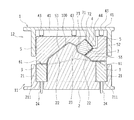
まず、実施形態1に係る絞り成形方法に用いる絞り成形装置1の構造について説明する。図1は、絞り成形装置1における絞り成形加工の初期状態を示している。この絞り成形装置1は、固定側の下型ユニット11と、この下型ユニット11の上方に対向して配設される上型ユニット12とを備えている。
First, the structure of the
下型ユニット11には、図示しないプレス機構のボルスタに下型2が設けられている。下型2は、下型ユニット11の中心部に配置され、その外側に環状の溝空間21が設けられている。溝空間21には下型クッションリング3が囲撓配置されている。下型クッションリング3は、上面にワークパネル100を挟持するための凹部を有する。
The
下型2は、成形体10を構成するワークパネル100の下面形状に対応する凸状のパネル成形面22を、その上面に有している。また、下型2は、成形体10の立ち壁形状部103に対応する凹状成形面23を有している。凹状成形面23は、急傾斜の上部成形面231と、緩傾斜の下部成形面232とを有する。
The
上型ユニット12には、図示しないプレス機構のラムに上型4が設けられている。上型4は上型ユニット12の中心部に配置され、下型2のパネル成形面22に対応する凹状のパネル成形面42を有する。上型4のパネル成形面42の外側には、環状の溝空間41が設けられ、上型クッションリング5が囲撓配置されている。
The
上型クッションリング5は、上型4の溝空間41内に下方に向けて延設されたシリンダ43を介して上型4に取り付けられている。シリンダ43には、上下方向に伸張および収縮可能なエアシリンダ等を適用することができる。これにより、上型クッションリング5は、上型4と連動して昇降動作可能であるとともに、上型4に対してシリンダ43を介して独立に昇降動作可能とされている。
The
上型クッションリング5は、下面にワークパネル100を挟持するための凸部を有する。上型クッションリング5の下面の凸部と、下型クッションリング3の上面の凹部とで、ワークパネル100を挟持する挟持部61を構成している。また、上型クッションリング5の内側には、下型2のパネル成形面22に対応するパネル成形面51と、下型2が配置された内側方向へ傾斜した案内面52とが設けられている。
The
上型クッションリング5の内側には、上型4と、上型クッションリング5との間に介在される寄せカム7が備えられている。寄せカム7は、上型クッションリング5の案内面52に摺接する第一のカム面71と、上型4の案内面44に摺接する第二のカム面72とを備えている。第一のカム面71と上型クッションリング5との間、および第二のカム面72と上型4との間には、高潤滑性および摺動特性を有するスライドプレート62が介装されている。
Inside the
また、寄せカム7には、下型2に対向する面に、凸状成形面73が設けられている。寄せカム7の凸状成形面73は、下型2の凹状成形面23に対応して設けられており、緩傾斜の下部成形面232と急傾斜の上部成形面231に対応して、その斜め上方に位置されている。
Further, the
これにより、寄せカム7は、上型4の下降と上型クッションリング5の下降とに連動して、第一のカム面71および第二のカム面72においてスライドプレート62を介して斜め下方に摺動する。寄せカム7が摺動すると、凸状成形面73が下型2の凹状成形面23に接近し、圧接される。
As a result, the close-up
下型クッションリング3は、溝空間21の底面211に貫通して設けられたクッションピン24に支持されている。クッションピン24の下端は、前記ボルスタの下方に設けられた図示しないクッション機構に接続されている。下型クッションリング3は、溝空間21内において、底面211に下型クッションリング3の下端が当接するまでの制限区域内で上下方向に変位可能とされている。
The
(絞り成形方法)
次に、絞り成形装置1を用いて行う実施形態1に係る絞り成形方法について、図1〜3を参照しつつ説明する。
(Drawing method)
Next, the draw forming method according to the first embodiment using the
絞り成形加工に際しては、予め上型ユニット12を上昇させて型開きした状態で、ワークパネル100を下型クッションリング3の上面に載置する。次いで、上型ユニット12のうち、ラムと一体に上型4が下降することによって、ワークパネル100の端部が挟持部61に固定される。これによりワークパネル100を絞り成形装置1にセットする。
In the draw forming process, the
図1は、絞り成形加工の初期状態を示しており、上型クッションリング5と下型クッションリング3との間にワークパネル100の辺縁部が挟持されている。上型4と上型クッションリング5との間に介在されたシリンダ43は、伸張されて上型クッションリング5を下方に付勢している。上型4の下降によって、上型クッションリング5は下型クッションリング3に圧接される。寄せカム7は、上型クッションリング5の案内面52の上方に退避した状態にある。また、下型クッションリング3はクッションピン24に支持されて、下型2の溝空間21の上方に位置している。
FIG. 1 shows an initial state of the draw forming process, in which the edge portion of the
さらに、上型4を成形位置に向かって下降させる。これにより、シリンダ43によって下方に付勢されたまま上型クッションリング5が下降する。下型クッションリング3は上型クッションリング5に押し下げられて、図示しないクッション機構による所定のクッション力を維持しながら、クッションピン24とともに溝空間21内を次第に下降する。
Further, the
図2は、図1に続く成形途上の絞り成形装置1を示している。下型クッションリング3が押し下げられるにともなって、下型2のパネル成形面22にワークパネル100が接近し、部分的に当接しはじめる。ワークパネル100は下型2のパネル成形面22になつかされ、徐々に所定の形状に絞り成形加工されていく。
FIG. 2 shows a
さらに上型クッションリング5が下降することで、上型クッションリング5のパネル成形面51は、下型2のパネル成形面22との間にワークパネル100を圧接する。ワークパネル100は、下型2の凹状成形面23を除く範囲で下型2に当接し、概ねパネル成形面22に沿った形状となる(第一の成形加工)。
As the
ここで、上型クッションリング5と下型クッションリング3との間の挟持部61において、ワークパネル100は押圧状態に保持されている。また、上型クッションリング5のパネル成形面51と下型2との間でも、ワークパネル100は、上方から押圧状態に保持されている。この押圧力は、ワークパネル100に対して、絞りしわの発生を防止するしわ押さえとして機能する。
Here, the
また、このとき、図2に示すように、寄せカム7は上方に退避した状態にあり、ワークパネル100は下型2の凹状成形面23上では浮き上がった状態にある。下型クッションリング3の下端は溝空間21の底面211に当接している。
Further, at this time, as shown in FIG. 2, the
このように、下型クッションリング3が溝空間21の底面211に当接することによって、下型クッションリング3の下降変位は停止する。上型4の下降は継続状態にあるので、下型クッションリング3の下降変位が停止すると、すぐさまシリンダ43は収縮作動に転じる。
In this way, when the
シリンダ43が収縮を開始することで、上型クッションリング5を溝空間41に収容しつつ上型4が下降することとなり、ワークパネル100の絞り成形加工が進行する。寄せカム7は、上型4の案内面44と上型クッションリング5の案内面52に沿って摺動し、斜め下方に前進移動する。寄せカム7の凸状成形面73は、ワークパネル100に当接しはじめる。
When the
図4は、寄せカム7による立ち壁形状部103の絞り成形過程を段階的に示した説明図である。寄せカム7は、ワークパネル100に対して図中の矢印にて示すプレス方向に作用し、斜め上方から押圧力を付与していく。ワークパネル100は、寄せカム7の前進にともなって、凸状成形面73に当接する初期状態W0から徐々に変形し、凸状成形面73になついた第一変形状態W1となり、さらに変形が進行した第二変形状態W2へと変化する。
FIG. 4 is an explanatory view showing stepwise the drawing forming process of the standing
図3に示すように、最終的に、ワークパネル100は寄せカム7の凸状成形面73と下型2の凹状成形面23との間に挟まれて圧接される(第二の成形加工)。ワークパネル100は、急傾斜の上部成形面231と、緩傾斜の下部成形面232とに沿う形状となる。これにより、ワークパネル100には立ち壁形状部103が形成され、完成形の成形体10が得られる。
As shown in FIG. 3, finally, the
例示の形態では、前記第一の成形加工によって立ち壁形状部103を除く部分を成形し、続く第二の成形加工によって最終的な成形体10の形状に成形する。前記第一の成形加工において、ワークパネル100は、立ち壁形状部103を除く部分が成形済みであり、上型クッションリング5と、下型クッションリング3および下型2との間で押圧されてしわ押さえされている。また、ワークパネル100において立ち壁形状部103に成形される部分は、下型2の凹状成形面23に接近して下型2になつかされている。
In the exemplary embodiment, the portion excluding the standing
この状態から、前記第二の成形加工を開始し、寄せカム7を摺動させ、ワークパネル100に立ち壁形状部103を成形する。そのため、ワークパネル100の変形量を抑えることが可能となり、立ち壁形状部103の薄肉化を防ぐとともに、絞りしわ等の発生を抑制することが可能となる。
From this state, the second molding process is started, the
図11および図12にて示した従来の絞り成形方法では、立ち壁形状部103において変形量が多くなり、ワークパネル100の断面長さL01は最終的に長さL11まで引き延ばされていた。ワークパネル100の伸び率を、(L11−L01)/L01とすると、この場合の伸び率は例えば121%であった。
In the conventional draw forming method shown in FIGS. 11 and 12, the amount of deformation increases in the standing
これに対し、実施形態1に係る絞り成形方法によれば、図4に示すように、ワークパネル100の立ち壁形状部103における急傾斜の上方壁部101は、断面長さL1に引き延ばされている。ところが、絞り成形加工前のワークパネル100(W0)における上方壁部101に対応する部分は、断面長さL0であった。
On the other hand, according to the drawing forming method according to the first embodiment, as shown in FIG. 4, the steeply inclined
この場合、ワークパネル100の伸び率を、(L1−L0)/L0とすると、絞り成形加工を完了した時点でのワークパネル100の伸び率は例えば8%であり、従来の成形方法と比較して格段に小さい値となる。すなわち、立ち壁形状部103における変形量を少なく抑えつつも精度よく絞り成形加工を行うことが可能となる。
In this case, assuming that the elongation rate of the
以上のように、この形態に係る絞り成形方法によって、変形量が多くなりやすいものであったワークパネル100の立ち壁形状部103を、第一の成形加工では下型2になつかせておき、第二の成形加工で寄せカム7を摺動させて絞り成形加工する構成としているので、薄肉化することを防ぎつつ絞りしわ等の発生を抑えて、良好な成形体10を得ることが可能となる。
As described above, the standing
(実施形態2)
図5は、実施形態2に係る絞り成形方法、およびこの方法に用いる絞り成形装置の構造を模式的に示す断面図である。なお、以下に説明する実施形態2〜4に係る絞り成形方法は、用いる絞り成形装置1の基本構成が実施形態1と共通するものであることから、その共通する構成については実施形態1と共通の符号を用いて詳細な説明を省略する。
(Embodiment 2)
FIG. 5 is a cross-sectional view schematically showing the structure of the draw forming method according to the second embodiment and the draw forming apparatus used in this method. Since the drawing molding method according to the second to fourth embodiments described below has the same basic configuration as that of the first embodiment, the common configuration is the same as that of the first embodiment. A detailed description will be omitted using the reference numerals of.
図5に示す形態では、絞り成形装置1における下型ユニット11の構成は実施形態1と共通しており、この下型ユニット11の上方に配設される上型ユニット12の上型4および上型クッションリング5の構成に特徴を有している。
In the embodiment shown in FIG. 5, the configuration of the
上型ユニット12の中心部には、上型クッションリング5が設けられている。上型クッションリング5は、上型4の溝空間41に設けられた複数のシリンダ43を介して上型4に取り付けられている。
An
上型クッションリング5には、挟持部61を構成する面に連続して、下型2のパネル成形面22に対応するパネル成形面53が備えられている。上型4には、パネル成形面42が設けられておらず、寄せカム7が摺接する案内面44を備えた構成とされている。上型クッションリング5は、上型4と連動して昇降動作可能であるとともに、上型4に対してシリンダ43を介して独立に昇降動作可能とされている。
The
絞り成形方法としては、実施形態1と同様に進められ、上型4を下降させることで、シリンダ43を介して上型クッションリング5が下降する。上型クッションリング5は、下型クッションリング3を押し下げる。上型クッションリング5は下型クッションリング3に圧接する。ワークパネル100は下型2のパネル成形面22になつかされ、徐々に絞り成形加工されていく(第一の成形加工)。
The draw forming method proceeds in the same manner as in the first embodiment, and by lowering the
下型クッションリング3は、溝空間21の制限区域内で上下方向に変位可能であり、溝空間21の底面211に当接することにより、その下降変位が停止する。下型クッションリング3の下降変位が停止すると、すぐさまシリンダ43は収縮作動に転じ、第二の成形加工を開始する。
The
さらに上型4を下降させ、シリンダ43を収縮させつつ上型シリンダ43を下型2のパネル成形面22に圧接する。寄せカム7は案内面52に沿って摺動し、凸状成形面73を下型2の凹状成形面23に圧接する。ワークパネル100は、寄せカム7の凸状成形面73と下型2の凹状成形面23との間に挟まれて圧接される(第二の成形加工)。これにより、ワークパネル100には立ち壁形状部103が形成され、完成形の成形体10が得られる。
Further, the
この形態に係る絞り成形方法では、上型ユニット12において上型クッションリング5と寄せカム7とが下型2に作用して絞り成形加工を施すものとなる。これにより、上型4に備えられたシリンダ43の荷重設定によって、ワークパネル100への押圧力を制御することが可能となる。
In the draw forming method according to this form, in the
(実施形態3)
図6〜図8は、実施形態3に係る絞り成形方法、およびこの方法に用いる絞り成形装置の構造を模式的に示す断面図である。
(Embodiment 3)
6 to 8 are cross-sectional views schematically showing the structure of the draw forming method according to the third embodiment and the draw forming apparatus used in this method.
この形態では、上型ユニット12においては、上型4および上型クッションリング5の構成に特徴を有し、下型ユニット11においては下型クッションリング3の構成に特徴を有している。絞り成形装置1におけるその他の構成は実施形態1と共通する。
In this form, the
図6に示すように、上型4は、下型2のパネル成形面22に対応する凹状のパネル成形面42と、寄せカム7が摺接する案内面44を備える点では、実施形態1と共通している。上型4は、さらに、上型クッションリング5の外側に、下型クッションリング3の上面に対応する押さえ面45を備えて構成されている。上型クッションリング5は、寄せカム7が摺接する案内面52と、下型2の凹状成形面23の下方に対応するパネル成形面54とを備えている。
As shown in FIG. 6, the
一方、下型クッションリング3は、クッションピン24に支持され、ストロークの異なる第一下型クッションリング31と第二下型クッションリング32とに分割されて、溝空間21に囲撓配置されている。第二下型クッションリング32は、第一下型クッションリング31より内側に設けられている。例えば、第一下型クッションリング31はワークパネル100の一辺に対応して配設され、第二下型クッションリング32はワークパネル100の他の三辺に対応して配設されている。
On the other hand, the
図6の左側に示されるように、第一下型クッションリング31と第二下型クッションリング32との異なるストロークに対応させて、溝空間21の底面211には段差が設けられている。第二下型クッションリング32の下端は溝空間21の底面211の上段に当接し、第一下型クッションリング31の下端は底面211の下段に当接する。
As shown on the left side of FIG. 6, a step is provided on the
すなわち、第二下型クッションリング32は、第一下型クッションリング31よりも短い制限区域内で上下方向に変位可能とされている。第一下型クッションリング31の下端が底面211の下段に当接するまでの制限区域内で、第二下型クッションリング32は第一下型クッションリング31よりも先に下降変位が停止するように構成されている。
That is, the second
第一下型クッションリング31の上面は、上型4の外周部の押さえ面45に対応して配設されている。ワークパネル100は、一辺が上型4の押さえ面45と第一下型クッションリング31との間の挟持部61に保持され(図6中右側)、ワークパネル100の残る三辺が上型クッションリング5と第二下型クッションリング32との間の挟持部61に保持される(図6中左側)。
The upper surface of the first lower
図7は、図6における絞り成形装置1の右側半部を示す断面図である。絞り成形加工の初期状態では、上型4の押さえ面45と第一下型クッションリング31の上面との間にワークパネル100の辺縁部が挟持されている。上型4が下降することで、第一下型クッションリング31が溝空間21内に押し下げられる。上型4と上型クッションリング5との間のシリンダ43は、伸張されて上型クッションリング5を下方に付勢しており、上型クッションリング5は上型4と一体に下降する。
FIG. 7 is a cross-sectional view showing the right half of the
図8に示すように、第一下型クッションリング31が押し下げられるにともなって、下型2のパネル成形面22にワークパネル100が接近し、部分的に当接しはじめる。ワークパネル100は下型2のパネル成形面22になつかされ、徐々に絞り成形加工されていく。さらに上型4が下降することで、第二下型クッションリング32の下端は溝空間21の底面211の上段に当接する(図6参照)。ワークパネル100は、下型2の凹状成形面23を除く範囲で下型2に当接し、概ねパネル成形面22に沿った形状となる(第一の成形加工)。
As shown in FIG. 8, as the first lower
第二下型クッションリング32の下端が溝空間21の底面211の上段に当接することにより、第二下型クッションリング32の下降変位は停止する。上型4の下降は継続状態にあるので、第二下型クッションリング32の下降変位が停止すると、すぐさまシリンダ43が収縮作動に転じる。
When the lower end of the second
図8に示すように、第一下型クッションリング31は、溝空間21の下段側の底面211に当接するまでの制限区域内で下降変位を継続する。その間、上型4は、上型クッションリング5を溝空間41に収容しつつ下降し、引き続き第一下型クッションリング31を押し下げる。これにより、ワークパネル100の絞り成形加工が進行する。
As shown in FIG. 8, the first lower
また、寄せカム7は、上型4の案内面44と上型クッションリング5の案内面52に沿って、斜め下方に前進移動し、立ち壁形状部103を成形する。最終的に、図6に示すように、ワークパネル100は寄せカム7の凸状成形面73と下型2の凹状成形面23との間に挟まれて圧接される(第二の成形加工)。これにより、ワークパネル100は立ち壁形状部103を含む成形体10に成形される。
Further, the
この形態に係る絞り成形方法では、図示しないプレス機構のラムに設けられた上型4が、第一下型クッションリング31を押し下げる。そのため、実施形態1のように下型クッションリング3を押し下げるための押圧力を、上型4に設けたシリンダ43によって制御せずともよく、より一層円滑に効率よく絞り成形加工を進めることが可能となる。
In the draw forming method according to this embodiment, the
なお、絞り成形装置1において、第一下型クッションリング31と第二下型クッションリング32との配置形態は、実施形態3に示したものに限られず、例えば下型2の溝空間21の全周にわたり、第一下型クッションリング31と第二下型クッションリング32との両方が囲撓配置されていてもよい。
In the
(実施形態4)
図9は、実施形態4に係る絞り成形方法、およびこの方法に用いる絞り成形装置の構造を模式的に示す断面図である。
(Embodiment 4)
FIG. 9 is a cross-sectional view schematically showing the structure of the draw forming method according to the fourth embodiment and the draw forming apparatus used in this method.
図9に示す形態では、絞り成形装置1における上型ユニット12は実施形態3のものと共通し、下型ユニット11の下型2の構成に特徴を有している。図示するように、下型2は、寄せカム7に対応して配置された案内カム8が備えて構成されている。
In the embodiment shown in FIG. 9, the
案内カム8は、成形体10の立ち壁形状部103に対応する凹状成形面81を有し、急傾斜の上部成形面811と、緩傾斜の下部成形面812とを備えて構成されている。下型2において、案内カム8は、図中の矢印にて示すプレス方向に摺動可能に備えられている。案内カム8は、下型2とは独立に昇降動作可能とされている。
The
この場合、絞り成形方法として、第一の成形加工および第二の成形加工を実施形態3と同様に効率よく円滑に進めることができる。加えて、成形体10が立ち壁形状部103に負角部を含む形状であるとき、下型2に案内カム8が摺動可能に備えられていることで、第二の成形加工における立ち壁形状部103の成形を無理なく行うことができ、また、成形したワークパネル100を下型2から簡単に離脱させることが可能となる。
In this case, as the draw forming method, the first forming process and the second forming process can be efficiently and smoothly carried out in the same manner as in the third embodiment. In addition, when the molded
なお、案内カム8を下型2に対して摺動可能に支持する手段は特に限定されるものではなく、エアシリンダ、スプリング機構等の各種の支持手段を適用することができる。
The means for slidably supporting the
以上、説明した各実施形態に係る絞り成形方法によれば、成形体10における立ち壁形状部103の薄肉化を防ぎ、絞りしわや絞り割れを生じさせることなく精度よく成形することが可能となる。
According to the drawing molding method according to each of the above-described embodiments, it is possible to prevent the standing
なお、前記実施形態に係る絞り成形方法は、すべての点で例示であって、限定的な解釈の根拠となるものではない。本発明の技術的範囲は、前記実施形態のみによって解釈されるものではなく、特許請求の範囲に基づくものとされる。また、本発明の技術的範囲には、特許請求の範囲と均等の意味および範囲内でのすべての変更が含まれる。 It should be noted that the draw forming method according to the above embodiment is an example in all respects and does not serve as a basis for a limited interpretation. The technical scope of the present invention is not to be construed solely by the above-described embodiment, but is based on the scope of claims. In addition, the technical scope of the present invention includes all modifications within the meaning and scope equivalent to the claims.
前記各実施形態では、上型ユニット12として上型4、上型クッションリング5および寄せカム7を備え、下型ユニット11として下型2および下型クッションリング3を備えた絞り成形装置1を用いて絞り成形加工する構成を示したが、絞り成形装置1の各部の構成は、これに限定されるものではなく、各部の構成、配置、形状等について他の形態を含む構成であってもよい。例えば上型ユニット12に設けられるシリンダ43はエアシリンダであるに限られない。また、前記各実施形態においては、図10に示される最終形状の成形体10を絞り成形加工する場合について説明したが、その他の形状の成形品にも適用することができ、これに限定されるものではない。
In each of the above embodiments, a
本発明は、ワークパネルの絞り成形加工に好適に利用可能である。 The present invention can be suitably used for draw forming of work panels.
1 絞り成形装置
11 下型ユニット
12 上型ユニット
2 下型
21 溝空間
211 底面
22 パネル成形面
23、81 凹状成形面
24 クッションピン
3 下型クッションリング
31 第一下型クッションリング
32 第二下型クッションリング
4 上型
41 溝空間
42 パネル成形面
43 シリンダ
44 案内面
5 上型クッションリング
51、53 パネル成形面
52 案内面
62 スライドプレート
7 寄せカム
71 第一のカム面
72 第二のカム面
73 凸状成形面
8 案内カム
10 成形体
100 ワークパネル
101 上方壁部
102 下方壁部
103 立ち壁形状部
1 Draw forming
Claims (1)
前記絞り成形装置は、
シリンダが備えられた上型と、
前記緩傾斜面および急傾斜面に対応する凹状成形面が備えられた下型と、
傾斜状の案内面が備えられ、前記シリンダを介して上下方向に変位可能な上型クッションリングと、
前記上型または前記上型クッションリングに当接し、制限区域内で上下方向に変位可能な下型クッションリングと、
前記上型クッションリングの内側に配設され、前記凹状成形面に対応する凸状成形面、および前記案内面に摺接するカム面が備えられた寄せカムとを有しており、
前記シリンダを介して前記上型クッションリングを付勢しつつ前記上型を下降させ、前記下型クッションリングを押し下げるとともに、前記上型クッションリングを前記下型クッションリングに圧接する第一の成形加工と、
前記上型をさらに下降させ、前記シリンダを収縮させて前記寄せカムを前記案内面に沿って摺動させ、前記寄せカムの凸状成形面を前記下型の凹状成形面に圧接する第二の成形加工とを含むことを特徴とする絞り成形方法。 A draw forming method in which a work panel is subjected to a forming process including a gently inclined surface and a steeply inclined surface continuous thereto by using a draw forming apparatus.
The draw forming apparatus is
The upper mold equipped with a cylinder and
A lower mold provided with a concave molded surface corresponding to the gently inclined surface and the steeply inclined surface, and
An upper cushion ring that is provided with an inclined guide surface and can be displaced in the vertical direction via the cylinder.
A lower cushion ring that abuts on the upper mold or the upper cushion ring and can be displaced in the vertical direction within the restricted area.
It has a convex molding surface that is disposed inside the upper cushion ring and corresponds to the concave molding surface, and a gathering cam provided with a cam surface that is in sliding contact with the guide surface.
The first molding process in which the upper mold is lowered while urging the upper mold cushion ring via the cylinder, the lower mold cushion ring is pushed down, and the upper mold cushion ring is pressed against the lower mold cushion ring. When,
A second, in which the upper mold is further lowered, the cylinder is contracted, the gathering cam is slid along the guide surface, and the convex molding surface of the gathering cam is pressed against the concave molding surface of the lower mold. A drawing molding method including molding processing.
Priority Applications (1)
| Application Number | Priority Date | Filing Date | Title |
|---|---|---|---|
| JP2017241738A JP6844523B2 (en) | 2017-12-18 | 2017-12-18 | Drawing method |
Applications Claiming Priority (1)
| Application Number | Priority Date | Filing Date | Title |
|---|---|---|---|
| JP2017241738A JP6844523B2 (en) | 2017-12-18 | 2017-12-18 | Drawing method |
Publications (2)
| Publication Number | Publication Date |
|---|---|
| JP2019107663A JP2019107663A (en) | 2019-07-04 |
| JP6844523B2 true JP6844523B2 (en) | 2021-03-17 |
Family
ID=67178557
Family Applications (1)
| Application Number | Title | Priority Date | Filing Date |
|---|---|---|---|
| JP2017241738A Active JP6844523B2 (en) | 2017-12-18 | 2017-12-18 | Drawing method |
Country Status (1)
| Country | Link |
|---|---|
| JP (1) | JP6844523B2 (en) |
Families Citing this family (1)
| Publication number | Priority date | Publication date | Assignee | Title |
|---|---|---|---|---|
| CN113020447B (en) * | 2021-03-02 | 2022-10-14 | 深圳市亿和精密科技集团有限公司 | Side shaping device for progressive die |
-
2017
- 2017-12-18 JP JP2017241738A patent/JP6844523B2/en active Active
Also Published As
| Publication number | Publication date |
|---|---|
| JP2019107663A (en) | 2019-07-04 |
Similar Documents
| Publication | Publication Date | Title |
|---|---|---|
| JP4483933B2 (en) | Press molding method and press molding apparatus | |
| US10688551B2 (en) | Hat-shaped cross-section component manufacturing method | |
| US10022763B2 (en) | Hat shaped cross-section component manufacturing method | |
| JPH0929349A (en) | Drawing method and its device using variable bead | |
| JP2015066584A (en) | Press molding method and press mold | |
| CN106216521A (en) | Continuous bending mould up and down | |
| JP6844523B2 (en) | Drawing method | |
| AU2015256527B2 (en) | Method and apparatus for forming a can end with controlled thinning of formed portions of the can end | |
| US10946432B2 (en) | Method and apparatus for forming a beaded can end | |
| US11198168B2 (en) | Bending method and apparatus for the same | |
| JP5938074B2 (en) | Drawing method and apparatus | |
| JPH11267768A (en) | Press die | |
| KR102051626B1 (en) | Forming apparatus for reducing springback | |
| KR102062228B1 (en) | A drawing apparatus for thicken-drawing a bending portion and a method for operating the same | |
| JP6767063B2 (en) | Draw molding equipment | |
| CN206122506U (en) | Mould of bending in succession from top to bottom | |
| KR102062229B1 (en) | A complex thicken-drawing apparatus for thicken-drawing a plural bending portion and a method for operating the same | |
| JP4598297B2 (en) | Press-type pressure intensifier and mold structure using the same | |
| JP2017136624A (en) | Press apparatus, method for manufacturing pressed article using the same, and die | |
| JPH0618655Y2 (en) | Press molding equipment | |
| JPH0428421A (en) | Device for forming corrugated sheet | |
| JPH0751896A (en) | Press forming machine | |
| JP5843712B2 (en) | Mold and trim processing method | |
| CN212884499U (en) | Progressive die for bending complex parts | |
| JPH06181Y2 (en) | Material inflow control device in press die |
Legal Events
| Date | Code | Title | Description |
|---|---|---|---|
| A621 | Written request for application examination |
Free format text: JAPANESE INTERMEDIATE CODE: A621 Effective date: 20200526 |
|
| TRDD | Decision of grant or rejection written | ||
| A01 | Written decision to grant a patent or to grant a registration (utility model) |
Free format text: JAPANESE INTERMEDIATE CODE: A01 Effective date: 20210126 |
|
| A61 | First payment of annual fees (during grant procedure) |
Free format text: JAPANESE INTERMEDIATE CODE: A61 Effective date: 20210208 |
|
| R151 | Written notification of patent or utility model registration |
Ref document number: 6844523 Country of ref document: JP Free format text: JAPANESE INTERMEDIATE CODE: R151 |