JP6836769B2 - Fluid machinery and power generators - Google Patents
Fluid machinery and power generators Download PDFInfo
- Publication number
- JP6836769B2 JP6836769B2 JP2016162074A JP2016162074A JP6836769B2 JP 6836769 B2 JP6836769 B2 JP 6836769B2 JP 2016162074 A JP2016162074 A JP 2016162074A JP 2016162074 A JP2016162074 A JP 2016162074A JP 6836769 B2 JP6836769 B2 JP 6836769B2
- Authority
- JP
- Japan
- Prior art keywords
- power generation
- rotors
- pair
- rotor
- fluid machine
- Prior art date
- Legal status (The legal status is an assumption and is not a legal conclusion. Google has not performed a legal analysis and makes no representation as to the accuracy of the status listed.)
- Active
Links
- 239000012530 fluid Substances 0.000 title claims description 69
- 238000010248 power generation Methods 0.000 claims description 105
- 230000005540 biological transmission Effects 0.000 claims description 32
- 238000011144 upstream manufacturing Methods 0.000 claims description 2
- 230000000052 comparative effect Effects 0.000 description 7
- 230000000694 effects Effects 0.000 description 5
- 238000012795 verification Methods 0.000 description 5
- 238000005259 measurement Methods 0.000 description 3
- 230000004048 modification Effects 0.000 description 3
- 238000012986 modification Methods 0.000 description 3
- 239000007788 liquid Substances 0.000 description 2
- 238000009420 retrofitting Methods 0.000 description 2
- XLYOFNOQVPJJNP-UHFFFAOYSA-N water Substances O XLYOFNOQVPJJNP-UHFFFAOYSA-N 0.000 description 1
Images


Classifications
-
- F—MECHANICAL ENGINEERING; LIGHTING; HEATING; WEAPONS; BLASTING
- F03—MACHINES OR ENGINES FOR LIQUIDS; WIND, SPRING, OR WEIGHT MOTORS; PRODUCING MECHANICAL POWER OR A REACTIVE PROPULSIVE THRUST, NOT OTHERWISE PROVIDED FOR
- F03B—MACHINES OR ENGINES FOR LIQUIDS
- F03B17/00—Other machines or engines
- F03B17/06—Other machines or engines using liquid flow with predominantly kinetic energy conversion, e.g. of swinging-flap type, "run-of-river", "ultra-low head"
- F03B17/061—Other machines or engines using liquid flow with predominantly kinetic energy conversion, e.g. of swinging-flap type, "run-of-river", "ultra-low head" with rotation axis substantially in flow direction
-
- F—MECHANICAL ENGINEERING; LIGHTING; HEATING; WEAPONS; BLASTING
- F03—MACHINES OR ENGINES FOR LIQUIDS; WIND, SPRING, OR WEIGHT MOTORS; PRODUCING MECHANICAL POWER OR A REACTIVE PROPULSIVE THRUST, NOT OTHERWISE PROVIDED FOR
- F03D—WIND MOTORS
- F03D1/00—Wind motors with rotation axis substantially parallel to the air flow entering the rotor
- F03D1/02—Wind motors with rotation axis substantially parallel to the air flow entering the rotor having a plurality of rotors
- F03D1/025—Wind motors with rotation axis substantially parallel to the air flow entering the rotor having a plurality of rotors coaxially arranged
-
- F—MECHANICAL ENGINEERING; LIGHTING; HEATING; WEAPONS; BLASTING
- F03—MACHINES OR ENGINES FOR LIQUIDS; WIND, SPRING, OR WEIGHT MOTORS; PRODUCING MECHANICAL POWER OR A REACTIVE PROPULSIVE THRUST, NOT OTHERWISE PROVIDED FOR
- F03D—WIND MOTORS
- F03D1/00—Wind motors with rotation axis substantially parallel to the air flow entering the rotor
- F03D1/06—Rotors
- F03D1/065—Rotors characterised by their construction elements
- F03D1/0691—Rotors characterised by their construction elements of the hub
-
- F—MECHANICAL ENGINEERING; LIGHTING; HEATING; WEAPONS; BLASTING
- F03—MACHINES OR ENGINES FOR LIQUIDS; WIND, SPRING, OR WEIGHT MOTORS; PRODUCING MECHANICAL POWER OR A REACTIVE PROPULSIVE THRUST, NOT OTHERWISE PROVIDED FOR
- F03D—WIND MOTORS
- F03D15/00—Transmission of mechanical power
-
- F—MECHANICAL ENGINEERING; LIGHTING; HEATING; WEAPONS; BLASTING
- F16—ENGINEERING ELEMENTS AND UNITS; GENERAL MEASURES FOR PRODUCING AND MAINTAINING EFFECTIVE FUNCTIONING OF MACHINES OR INSTALLATIONS; THERMAL INSULATION IN GENERAL
- F16H—GEARING
- F16H48/00—Differential gearings
- F16H48/06—Differential gearings with gears having orbital motion
- F16H48/08—Differential gearings with gears having orbital motion comprising bevel gears
-
- F—MECHANICAL ENGINEERING; LIGHTING; HEATING; WEAPONS; BLASTING
- F05—INDEXING SCHEMES RELATING TO ENGINES OR PUMPS IN VARIOUS SUBCLASSES OF CLASSES F01-F04
- F05B—INDEXING SCHEME RELATING TO WIND, SPRING, WEIGHT, INERTIA OR LIKE MOTORS, TO MACHINES OR ENGINES FOR LIQUIDS COVERED BY SUBCLASSES F03B, F03D AND F03G
- F05B2210/00—Working fluid
- F05B2210/16—Air or water being indistinctly used as working fluid, i.e. the machine can work equally with air or water without any modification
-
- F—MECHANICAL ENGINEERING; LIGHTING; HEATING; WEAPONS; BLASTING
- F05—INDEXING SCHEMES RELATING TO ENGINES OR PUMPS IN VARIOUS SUBCLASSES OF CLASSES F01-F04
- F05B—INDEXING SCHEME RELATING TO WIND, SPRING, WEIGHT, INERTIA OR LIKE MOTORS, TO MACHINES OR ENGINES FOR LIQUIDS COVERED BY SUBCLASSES F03B, F03D AND F03G
- F05B2240/00—Components
- F05B2240/20—Rotors
- F05B2240/21—Rotors for wind turbines
- F05B2240/221—Rotors for wind turbines with horizontal axis
- F05B2240/2213—Rotors for wind turbines with horizontal axis and with the rotor downwind from the yaw pivot axis
-
- F—MECHANICAL ENGINEERING; LIGHTING; HEATING; WEAPONS; BLASTING
- F05—INDEXING SCHEMES RELATING TO ENGINES OR PUMPS IN VARIOUS SUBCLASSES OF CLASSES F01-F04
- F05B—INDEXING SCHEME RELATING TO WIND, SPRING, WEIGHT, INERTIA OR LIKE MOTORS, TO MACHINES OR ENGINES FOR LIQUIDS COVERED BY SUBCLASSES F03B, F03D AND F03G
- F05B2260/00—Function
- F05B2260/40—Transmission of power
- F05B2260/403—Transmission of power through the shape of the drive components
- F05B2260/4031—Transmission of power through the shape of the drive components as in toothed gearing
- F05B2260/40311—Transmission of power through the shape of the drive components as in toothed gearing of the epicyclic, planetary or differential type
-
- Y—GENERAL TAGGING OF NEW TECHNOLOGICAL DEVELOPMENTS; GENERAL TAGGING OF CROSS-SECTIONAL TECHNOLOGIES SPANNING OVER SEVERAL SECTIONS OF THE IPC; TECHNICAL SUBJECTS COVERED BY FORMER USPC CROSS-REFERENCE ART COLLECTIONS [XRACs] AND DIGESTS
- Y02—TECHNOLOGIES OR APPLICATIONS FOR MITIGATION OR ADAPTATION AGAINST CLIMATE CHANGE
- Y02E—REDUCTION OF GREENHOUSE GAS [GHG] EMISSIONS, RELATED TO ENERGY GENERATION, TRANSMISSION OR DISTRIBUTION
- Y02E10/00—Energy generation through renewable energy sources
- Y02E10/20—Hydro energy
-
- Y—GENERAL TAGGING OF NEW TECHNOLOGICAL DEVELOPMENTS; GENERAL TAGGING OF CROSS-SECTIONAL TECHNOLOGIES SPANNING OVER SEVERAL SECTIONS OF THE IPC; TECHNICAL SUBJECTS COVERED BY FORMER USPC CROSS-REFERENCE ART COLLECTIONS [XRACs] AND DIGESTS
- Y02—TECHNOLOGIES OR APPLICATIONS FOR MITIGATION OR ADAPTATION AGAINST CLIMATE CHANGE
- Y02E—REDUCTION OF GREENHOUSE GAS [GHG] EMISSIONS, RELATED TO ENERGY GENERATION, TRANSMISSION OR DISTRIBUTION
- Y02E10/00—Energy generation through renewable energy sources
- Y02E10/70—Wind energy
- Y02E10/72—Wind turbines with rotation axis in wind direction
Description
本発明は、流体機械および発電装置に関する。 The present invention relates to fluid machinery and power generation equipment.
従来から、下記特許文献1に記載の風力発電部が知られている。この風力発電部は、風上に位置して風力により回転する複数の前方翼と、風下に位置して残りの風力により回転する複数の後方翼と、前方翼から伝達される回転動力および後方翼から伝達される回転動力を集合して発電機を回す差動装置と、を備えている。この風力発電部は、タワーと、タワーに支持された風車架台と、を更に備えている。差動装置および発電機は、風車架台上に配置されている。
Conventionally, the wind power generation unit described in
しかしながら、前記従来の風力発電装置では、差動装置が、前方翼と後方翼との間に配置されてタワーの真上に位置し、発電機が、タワーの真上から水平方向にずらされて位置している。そのため、例えば、風の向きに応じて翼の向きを受動的に変更する(首ふり運動する)いわゆるパッシブヨー型の風力発電部への適用が難しい。 However, in the conventional wind turbine generator, the differential is arranged between the front wing and the rear wing and is located directly above the tower, and the generator is laterally displaced from directly above the tower. positioned. Therefore, for example, it is difficult to apply it to a so-called passive yaw type wind power generation unit that passively changes the direction of the wing according to the direction of the wind (swings the head).
本発明は、前述した事情に鑑みてなされたものであって、多様な発電装置に採用することができる流体機械を提供することを目的とする。 The present invention has been made in view of the above circumstances, and an object of the present invention is to provide a fluid machine that can be used in various power generation devices.
前記課題を解決するために、本発明は以下の手段を提案している。
本発明に係る流体機械は、発電部の発電主軸に沿って延び、端部が前記発電主軸に連結される回転軸と、前記回転軸に、前記回転軸の周方向に回転自在に設けられ、前記回転軸の軸線に沿う回転軸線方向に間隔をあけて配置された複数のローターと、前記回転軸線方向に隣り合う一対のローターの間に配置され、前記一対のローターそれぞれの回転力を集約して前記回転軸に伝達する差動機構と、を備えている。
In order to solve the above problems, the present invention proposes the following means.
The fluid machine according to the present invention has a rotary shaft extending along the power generation spindle of the power generation unit and having an end connected to the power generation spindle, and the rotary shaft is rotatably provided in the circumferential direction of the rotary shaft. It is arranged between a plurality of rotors arranged at intervals in the direction of the rotation axis along the axis of the rotation axis and a pair of rotors adjacent to each other in the direction of the rotation axis, and aggregates the rotational forces of each of the pair of rotors. It is provided with a differential mechanism that transmits to the rotating shaft.
この場合、一対のローターそれぞれの回転力を、各ローターの回転速度(回転数)によらず、差動機構および回転軸を介して発電主軸に効率的に伝達することができる。このとき、共通した発電部の発電主軸に各ローターからの回転力を伝達することで、ローター1つあたりに作用する発電主軸からの負荷(回転抵抗)を小さく抑えることができる。これにより、発電部による効率的な発電を実現することができる。
また、差動機構が一対のローターの間に配置され、回転軸が発電主軸に沿って延び、回転軸の端部が発電主軸に連結される。したがって、例えば、流体からの運動エネルギーを受けた流体機械が、流体の向きに応じて受動的に首ふり運動するいわゆるパッシブヨー型の発電装置に、この流体機械を採用すること等ができる。さらに例えば、既存の発電装置における発電主軸に、流体機械の全体を後付けするいわゆるアタッチメントとして、この流体機械を採用すること等もできる。このように、この流体機械を多様な発電装置に採用することができる。
In this case, the rotational force of each of the pair of rotors can be efficiently transmitted to the power generation spindle via the differential mechanism and the rotation shaft regardless of the rotation speed (rotation speed) of each rotor. At this time, by transmitting the rotational force from each rotor to the power generation spindle of the common power generation unit, the load (rotational resistance) from the power generation spindle acting on each rotor can be suppressed to a small value. As a result, efficient power generation by the power generation unit can be realized.
Further, a differential mechanism is arranged between the pair of rotors, the rotating shaft extends along the power generation spindle, and the end of the rotating shaft is connected to the power generation spindle. Therefore, for example, this fluid machine can be adopted in a so-called passive yaw type power generation device in which a fluid machine that receives kinetic energy from a fluid passively swings its head according to the direction of the fluid. Further, for example, this fluid machine can be adopted as a so-called attachment for retrofitting the entire fluid machine to the power generation spindle in an existing power generation device. In this way, this fluid machine can be adopted in various power generation devices.
前記差動機構は、前記回転軸から、前記回転軸の径方向に突出する伝達軸と、前記伝達軸に、前記伝達軸の周方向に回転自在に設けられた第1歯車と、前記伝達軸を前記回転軸線方向に挟んで配置されて前記一対のローターそれぞれに固定され、前記第1歯車に噛み合うことで前記一対のローターそれぞれの回転力を前記伝達軸に伝達する一対の第2歯車と、を備えている。 The differential mechanism includes a transmission shaft protruding from the rotation shaft in the radial direction of the rotation shaft, a first gear rotatably provided on the transmission shaft in the circumferential direction of the transmission shaft, and the transmission shaft. A pair of second gears, which are arranged so as to be sandwiched in the direction of the rotation axis and fixed to each of the pair of rotors, and mesh with the first gear to transmit the rotational force of each of the pair of rotors to the transmission shaft. It has.
この場合、ローターが回転すると、ローターの回転力が、第2歯車、第1歯車および伝達軸を介して回転軸に伝達される。
ここで、例えば起動時など、一対のローターの回転速度(回転数)が同等である場合、第1歯車が回転することなく、伝達軸が回転軸に回転力を伝達する。したがって、ローターが一対ではなく1つのみである場合に比べて、回転軸に倍近くの大きさの回転力を伝達させることができる。これにより、ローターが受ける流体の運動エネルギーが低いときにも、ローターを回転し始め易くし、この流体機械に高い起動性を具備させことができる。
一方、例えば、高速回転時など、一対のローターの回転速度(回転数)が異なっている場合、第1歯車が伝達軸の周方向に回転しながら、伝達軸が回転軸に回転力を伝達する。したがって、一対のローターが、互いに回転速度(回転数)に影響を及ぼし合うことを抑えることができる。つまり一対のローターを、各ローターが流体から受けた運動エネルギーに応じた異なる回転速度(回転数)で、エネルギーロス少なく回転させることができる。これにより、回転軸に大きな回転力を伝達させることができる。
In this case, when the rotor rotates, the rotational force of the rotor is transmitted to the rotating shaft via the second gear, the first gear, and the transmission shaft.
Here, when the rotation speeds (rotation speeds) of the pair of rotors are the same, for example, at the time of starting, the transmission shaft transmits the rotational force to the rotation shaft without rotating the first gear. Therefore, as compared with the case where there is only one rotor instead of a pair, it is possible to transmit a rotational force having a magnitude nearly double to the rotating shaft. As a result, even when the kinetic energy of the fluid received by the rotor is low, the rotor can be easily started to rotate, and the fluid machine can be provided with high startability.
On the other hand, when the rotation speeds (rotational speeds) of the pair of rotors are different, for example, during high-speed rotation, the transmission shaft transmits the rotational force to the rotation shaft while the first gear rotates in the circumferential direction of the transmission shaft. .. Therefore, it is possible to prevent the pair of rotors from affecting each other's rotation speed (rotation speed). That is, the pair of rotors can be rotated at different rotation speeds (rotation speeds) according to the kinetic energy received from the fluid by each rotor with less energy loss. As a result, a large rotational force can be transmitted to the rotating shaft.
前記複数のローターは、流体から運動エネルギーを受けたときに同一方向に回転する。 The plurality of rotors rotate in the same direction when receiving kinetic energy from the fluid.
この場合、複数のローターを逆回転させる場合に比べて、例えば、逆回転用の更なる機構を設ける必要がないために構造の簡素化を図ることができたり、複数のローターに同等の形状でかつ同等の大きさの構成(例えば、一般的な時計回りするローター)を採用したりすること等ができる。これにより、コストの低減を図るとともに、メンテナンス性を向上させることができる。 In this case, as compared with the case where a plurality of rotors are rotated in the reverse direction, for example, the structure can be simplified because it is not necessary to provide a further mechanism for the reverse rotation, or the shape is equivalent to that of the plurality of rotors. Moreover, a configuration of the same size (for example, a general clockwise rotor) can be adopted. As a result, it is possible to reduce the cost and improve the maintainability.
前記複数のローターはそれぞれ、流体からの運動エネルギーを受けるブレードと、前記ブレードが固定されたハブと、を備え、前記一対のローターでは、互いの前記ブレード同士が、互いの前記ハブを前記回転軸線方向に挟んでいる。 Each of the plurality of rotors includes a blade that receives kinetic energy from a fluid and a hub to which the blade is fixed. In the pair of rotors, the blades of each other rotate the hub of each other. It is sandwiched in the direction.
この場合、複数のローターがそれぞれ、ブレードおよびハブを備えている。したがって、この流体機械の全体では、ブレードの総数を確保しつつ、各ローターにおいては、ブレードの数を少なくすることができる。したがって、複数のローターそれぞれの回転力が、差動機構を介して発電主軸に伝達されることと相俟って、この流体機械に、高い起動性を具備させること(流体機械の全体で、ブレードの総数を確保することによる効果)ができる。さらに、ローターの高速回転時に、回転速度を高め易くすること(各ローターにおけるブレードの数を少なくすることによる効果)もできる。
また、一対のローターでは、互いのブレード同士が、互いのハブを回転軸線方向に挟んでいる。したがって、一対のローター間で、ブレードを回転軸線方向に大きく離間させることができる。これにより、例えば、ブレード同士の接触を抑制し易くすること等ができる。
In this case, the rotors have blades and hubs, respectively. Therefore, it is possible to reduce the number of blades in each rotor while ensuring the total number of blades in the entire fluid machine. Therefore, in combination with the rotational force of each of the plurality of rotors being transmitted to the power generation spindle via the differential mechanism, this fluid machine is provided with high startability (the blade in the whole fluid machine). The effect of securing the total number of Further, it is possible to easily increase the rotation speed (effect of reducing the number of blades in each rotor) when the rotor rotates at high speed.
Further, in the pair of rotors, the blades of each other sandwich the hubs of each other in the direction of the rotation axis. Therefore, the blades can be largely separated in the rotation axis direction between the pair of rotors. Thereby, for example, it is possible to easily suppress the contact between the blades.
前記一対のローターのうちの一方に固定されて他方からは分離され、前記差動機構を覆うカバーを更に備えている。 It is further provided with a cover that is fixed to one of the pair of rotors and separated from the other to cover the differential mechanism.
この場合、カバーが、一対のローターのうちの一方に固定されて他方からは分離されている。したがって、例えば、カバーとローターとの予期せぬ干渉を抑えつつ、カバーが差動機構を保護すること等ができる。 In this case, the cover is fixed to one of the pair of rotors and separated from the other. Therefore, for example, the cover can protect the differential mechanism while suppressing unexpected interference between the cover and the rotor.
本発明に係る発電装置は、前記流体機械と、前記回転軸の端部が連結された発電主軸を備える発電部と、を備えている。 The power generation device according to the present invention includes the fluid machine and a power generation unit including a power generation spindle to which the ends of the rotating shafts are connected.
この場合、発電装置が前記流体機械を備えているので、高効率に発電することができる。 In this case, since the power generation device includes the fluid machine, it is possible to generate power with high efficiency.
前記発電部を、前記発電主軸の軸線に交差する方向に延びるヨー軸回りに回転自在に支持する支持部を更に備え、流体からの運動エネルギーを受けた前記流体機械が、流体の向きに応じて受動的に首ふり運動する。 The fluid machine, which further includes a support portion that rotatably supports the power generation unit around a yaw axis extending in a direction intersecting the axis of the power generation spindle and receives kinetic energy from the fluid, responds to the direction of the fluid. Passively swing your head.
この場合、発電装置が、前記支持部を備えるいわゆるパッシブヨー型の構成なので、前記流体機械を採用し、いわゆるアクティブヨー型の構成に比べて、コストやメンテナンス性、耐久性の利点を確保することができる。 In this case, since the power generation device has a so-called passive yaw type configuration including the support portion, the fluid machine can be adopted to secure advantages of cost, maintainability, and durability as compared with the so-called active yaw type configuration. it can.
本発明によれば、多様な発電装置に採用することができる流体機械を提供することができる。 According to the present invention, it is possible to provide a fluid machine that can be used in various power generation devices.
以下、図面を参照し、本発明の一実施形態に係る発電装置を説明する。
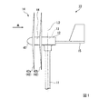
図1および図2に示すように、発電装置10は、流体(気体や液体)の運動エネルギーを電気エネルギーに変換する。本実施形態では、発電装置10は、いわゆる風力発電機であり、風(空気)の運動エネルギーを電気エネルギーに変換する。前記風力発電機としては、例えば、小型、中型、大型のいずれの構成にも採用することができる。
Hereinafter, the power generation device according to the embodiment of the present invention will be described with reference to the drawings.
As shown in FIGS. 1 and 2, the
発電装置10は、支持部11と、収容部12と、発電部13と、流体機械14と、調整部15と、を備えている。
The
支持部11は、風力発電機におけるタワー(支柱)であり、柱状に形成されて地表から起立している。支持部11は、発電部13をヨー軸L0回りに回転自在に支持する。ヨー軸L0は、後述する回転軸線L1に直交(交差)する方向に延びている。本実施形態では、ヨー軸L0が支持部11の軸線上に位置しており、鉛直方向に延びている。
収容部12は、風力発電機におけるナセル(ケーシング、ハウジング)である。収容部12は、支持部11に、ヨー軸L0回りに回転自在に支持されている。
The
The
発電部13は、収容部12に収容されてヨー軸L0上に位置している。発電部13が、収容部12に収容されることにより、支持部11が、収容部12を介して発電部13をヨー軸L0回りに回転自在に支持する。発電部13は、発電主軸31を備えている。発電部13は、発電主軸31を回転させる運動エネルギーを電気エネルギーに変換する。本実施形態では、発電部13が、発電機32を備えていて、前記発電主軸31は、発電機32の一部となっている。なお発電部13は、更に増速機を備えていてもよく、この場合、前記発電主軸31が増速機の一部となっている構成を採用することができる。
The
流体機械14は、風の運動エネルギーを発電主軸31の回転力に変換して発電主軸31に伝達する。流体機械14は、回転軸41と、一対のローター42と、差動機構43と、カバー44と、ノーズコーン45と、を備えている。
The
回転軸41は、発電主軸31に沿って延びている。本実施形態では、回転軸41は、発電主軸31と同軸に配置されている。以下では、発電主軸31の軸線および回転軸41の軸線が位置する共通軸を、回転軸線L1という。本実施形態では、回転軸線L1は、水平方向に延びている。
回転軸41の端部は、発電主軸31に連結されている。回転軸41の端部には、発電主軸31の端部が取り付けられる取付け部46が設けられている。本実施形態では、取付け部46は、発電主軸31が螺合される雌ねじ部(凹部)である。
The rotating shaft 41 extends along the power generation
The end of the rotating shaft 41 is connected to the power generation
なお流体機械14は、風の運動エネルギーのうち、この流体機械14に対して回転軸線L1方向に沿う成分を主に発電主軸31に伝達する。以下では、このときの風上側(上流側)を前側といい、風下側(下流側)を後側という場合がある。この発電装置10は、風からの運動エネルギーを受けた流体機械14が、流体の向きに応じて受動的に首ふり運動するいわゆるパッシブヨー型である。またこの発電装置10は、流体機械14(ローター42)がヨー軸L0に対して風上側に位置するアップウィンド型である。回転軸41は、発電主軸31に対して風上側に位置し、取付け部46は、回転軸41の風下側の端部に位置する。
The
一対のローター42は、回転軸線L1方向に間隔をあけて配置されている。各ローター42は、回転軸41に、回転軸41の周方向(回転軸線L1回りに周回する方向)に回転自在に設けられている。回転軸41と各ローター42との間には、第1軸受47が設けられている。第1軸受47は、回転軸41に対するローター42の回転を許容する。
The pair of
一対のローター42はそれぞれ、流体からの運動エネルギーを受けるブレード48と、ブレード48が固定されたハブ49と、を備えている。
ハブ49は、回転軸線L1と同軸に配置された環状に形成されている。ハブ49内には回転軸41が挿通されていて、回転軸41とハブ49との間に前記第1軸受47が配置されている。ブレード48は、回転軸41の周方向に間隔をあけて複数配置されている。ブレード48は、1つのローター42に3つずつ設けられていて、流体機械14の全体では6つ設けられている。なお、図1および後述する図3では、ブレード48を簡略化して示している。
Each of the pair of
The
一対のローター42のうち、風上側(回転軸線L1方向の一方側)に位置する前段ローター42a(第1ローター)では、ブレード48が、ハブ49に対して風上側に配置されている。一対のローター42のうち、風下側(回転軸線L1方向の他方側)に位置する後段ローター42b(第2ローター)では、ブレード48が、ハブ49に対して風下側に配置されている。一対のローター42では、互いのブレード48同士が、互いのハブ49を回転軸線L1方向に挟んでいる。
Of the pair of
一対のローター42は、風から運動エネルギーを受けたときに同一方向に回転する。一対のローター42は、この発電装置10を風上側から見た正面視において、いずれも例えば時計回りに回転する構成を採用することができる。一対のローター42は、各ローター42のブレード48の形状に基づいて、風から運動エネルギーを受けたときに同一方向に回転するように構成されている。なお図示の例では、一対のローター42は、互いに同等の形状でかつ同等の大きさに形成されている。
The pair of
なお、風の運動エネルギーは、風下側に位置する後段ローター42bよりも風上側に位置する前段ローター42aに多く作用し易い。そのため、前段ローター42aが後段ローター42bよりも高速に回転し、一対のローター42に回転速度(回転数)の差が生じ易い。
The kinetic energy of the wind tends to act more on the
差動機構43は、一対のローター42の間に配置され、一対のローター42それぞれの回転力を集約して回転軸41に伝達する。差動機構43は、伝達軸50と、一対の第1歯車51と、一対の第2歯車52と、を備えている。
伝達軸50は、回転軸41から、回転軸41の径方向(回転軸線L1の径方向)に突出する。伝達軸50は、回転軸41において、回転軸線L1方向に沿って一対のローター42の間に位置する部分に配置されている。本実施形態では、伝達軸50が、回転軸41を前記径方向に貫通している。
The
The
一対の第1歯車51および一対の第2歯車52は、図示の例ではいずれも傘歯車であるが、動力を90度変換することが可能な他の構造を採用することもできる。一対の第1歯車51は、伝達軸50の両端部に、伝達軸50の周方向(伝達軸50の軸線L2回りに周回する方向)に回転自在に設けられている。一対の第2歯車52は、伝達軸50を回転軸線L1方向に挟んで配置されて一対のローター42それぞれに固定されている。一対の第2歯車52は、一対の第1歯車51それぞれに噛み合うことで一対のローター42それぞれの回転力を伝達軸50に伝達する。なお第2歯車52は、ローター42と別体に形成され、例えば、ローター42に固着される等することによってローター42に固定されてもよく、ローター42と一体成型され、例えば、ローター42に第2歯車52が彫り込まれる等することによってローター42に固定されてもよい。
The pair of
カバー44は、一対のローター42のうちの一方に固定されて他方からは分離され、差動機構43を覆う。カバー44は、回転軸線L1方向に延びる筒状に形成され、差動機構43を、回転軸41の径方向の外側から覆っている。カバー44は、前段ローター42aに固定されて後段ローター42bからは分離されている。カバー44の風上側の端部は、前段ローター42aのブレード48に風下側から突き当たり、前段ローター42aのハブ49に前記径方向の外側から嵌合されている。カバー44の風下側の端部は、後段ローター42bのブレード48から風上側に離間していて、後段ローター42bのハブ49から前記径方向に離間している。
The
ノーズコーン45は、回転軸41を覆う。ノーズコーン45は、回転軸41を、回転軸線L1方向の風上側から覆う。ノーズコーン45は、前段ローター42aに固定され、前段ローター42aから前方に向けて突となる円錐状に形成されている。
The
調整部15は、風から運動エネルギーを受けたときに、流体機械14の向きが風の向きに対応するように発電部13をヨー軸L0回りに回転させる。このとき調整部15は、風が流れる方向に回転軸線L1が沿うように、かつ、流体機械14がヨー軸L0よりも風上に位置するように、発電部13を回動させる。調整部15は、風からの運動エネルギーをヨー軸L0回りの回転エネルギーに変換する。調整部15は、アップウィンド型の風力発電機における尾翼である。
When the adjusting
以上説明したように、本実施形態に係る流体機械14によれば、流体機械14が差動機構43を備えている。したがって、一対のローター42それぞれの回転力を、各ローター42の回転速度(回転数)によらず、差動機構43および回転軸41を介して発電主軸31に効率的に伝達することができる。このとき、共通した発電部13の発電主軸31に各ローター42からの回転力を伝達することで、ローター42、1つあたりに作用する発電主軸31からの負荷(回転抵抗)を小さく抑えることができる。これにより、発電部13による効率的な発電を実現することができる。
As described above, according to the
なお、ローター42が回転すると、ローター42の回転力が、第2歯車52、第1歯車51および伝達軸50を介して回転軸41に伝達される。
ここで、例えば起動時など、一対のローター42の回転速度(回転数)が同等である場合、第1歯車51が回転することなく、伝達軸50が回転軸41に回転力を伝達する。したがって、ローター42が一対ではなく1つのみである場合に比べて、回転軸41に倍近くの大きさの回転力を伝達させることができる。これにより、ローター42が受ける風の運動エネルギーが低いときにも、ローター42を回転し始め易くし、この流体機械14に高い起動性を具備させことができる。
一方、例えば、高速回転時など、一対のローター42の回転速度(回転数)が異なっている場合、第1歯車51が伝達軸50の周方向に回転しながら、伝達軸50が回転軸41に回転力を伝達する。したがって、一対のローター42が、互いに回転速度(回転数)に影響を及ぼし合うことを抑えることができる。つまり一対のローター42を、各ローター42が風から受けた運動エネルギーに応じた異なる回転速度(回転数)で、エネルギーロス少なく回転させることができる。これにより、回転軸41に大きな回転力を伝達させることができる。
When the
Here, when the rotation speeds (rotation speeds) of the pair of
On the other hand, when the rotation speeds (rotation speeds) of the pair of
また、差動機構43が一対のローター42の間に配置され、回転軸41が発電主軸31に沿って延び、回転軸41の端部が発電主軸31に連結される。したがって、例えば、風からの運動エネルギーを受けた流体機械14が、風の向きに応じて受動的に首ふり運動するいわゆるパッシブヨー型の発電装置10に、この流体機械14を採用すること等ができる。さらに例えば、既存の発電装置10における発電主軸31に、流体機械14の全体を後付けするいわゆるアタッチメントとして、この流体機械14を採用すること等もできる。このように、この流体機械14を多様な発電装置10に採用することができる。
Further, the
また、一対のローター42が、風から運動エネルギーを受けたときに同一方向に回転する。したがって、一対のローター42を逆回転させる場合に比べて、例えば、逆回転用の更なる機構を設ける必要がないために構造の簡素化を図ることができたり、一対のローター42に同等の形状でかつ同等の大きさの構成(例えば、一般的な時計回りするローター42)を採用したりすること等ができる。これにより、コストの低減を図るとともに、メンテナンス性を向上させることができる。
Further, the pair of
また、一対のローター42がそれぞれ、ブレード48およびハブ49を備えている。したがって、この流体機械14の全体では、ブレード48の総数を確保しつつ、各ローター42においては、ブレード48の数を少なくすることができる。したがって、一対のローター42それぞれの回転力が、差動機構43を介して発電主軸31に伝達されることと相俟って、この流体機械14に、高い起動性を具備させること(流体機械14の全体で、ブレード48の総数を確保することによる効果)ができる。さらに、ローター42の高速回転時に、回転速度を高め易くすること(各ローター42におけるブレード48の数を少なくすることによる効果)もできる。
Further, the pair of
また、一対のローター42では、互いのブレード48同士が、互いのハブ49を回転軸線L1方向に挟んでいる。したがって、一対のローター42間で、ブレード48を回転軸線L1方向に大きく離間させることができる。これにより、例えば、ブレード48同士の接触を抑制し易くすること等ができる。
Further, in the pair of
また、カバー44が、一対のローター42のうちの一方に固定されて他方からは分離されている。したがって、例えば、カバー44とローター42との予期せぬ干渉を抑えつつ、カバー44が差動機構43を保護すること等ができる。
Further, the
また、本実施形態に係る発電装置10によれば、前記流体機械14を備えているので、高効率に発電することができる。
さらに、発電装置10が、前記支持部11を備えるいわゆるパッシブヨー型の構成なので、前記流体機械14を採用し、いわゆるアクティブヨー型の構成に比べて、コストやメンテナンス性、耐久性の利点を確保することができる。
Further, according to the
Further, since the
なお、本発明の技術的範囲は前記実施形態に限定されるものではなく、本発明の趣旨を逸脱しない範囲において種々の変更を加えることが可能である。 The technical scope of the present invention is not limited to the above-described embodiment, and various modifications can be made without departing from the spirit of the present invention.
例えば、ノーズコーン45やカバー44が無くてもよい。
前記実施形態では、前段ローター42aで、ブレード48が、ハブ49に対して風上側に配置され、後段ローター42bで、ブレード48が、ハブ49に対して風下側に配置されているが、本発明はこれに限られない。
一対のローター42が、流体から運動エネルギーを受けたときに逆方向に回転してもよい。
ローター42を、3つ以上設け、回転軸線L1方向に隣り合う一対のローター42の間に、差動機構43を設けてもよい。
For example, the
In the above embodiment, the
The pair of
Three or
伝達軸50は、回転軸41と一体に形成されていてもよく、回転軸41と別部材で形成されていてもよい。
前記実施形態では、伝達軸50が、回転軸41を、回転軸41の径方向に貫通しているが、本発明はこれに限られない。例えば、伝達軸50を、回転軸41の周方向に間隔をあけて複数設け、第1歯車51を、複数の伝達軸50それぞれに設けてもよい。
前記実施形態では、回転軸41の端部に取付け部46が設けられているが、本発明はこれに限られず、回転軸41の端部が、発電主軸31に連結された他の形態を適宜採用することができる。例えば、回転軸41と発電主軸31とが一体に形成されていてもよい。
The
In the above embodiment, the
In the above embodiment, the mounting
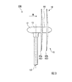
発電装置10はアップウィンド型に限られず、図3に示すようなダウンウィンド型であってもよい。この発電装置10Aでは、流体機械14が、ヨー軸L0に対して風下側に位置し、この流体機械14が、前記調整部15を兼ねている。つまり、ローター42(ブレード48)が風からの運動エネルギーを受けたときに、風からの運動エネルギーをヨー軸L0回りの回転エネルギーに変換し、流体機械14の向きが風の向きに対応するように発電部13をヨー軸L0回りに回転させる。
発電装置10はパッシブヨー型に限られず、電力に基づいて流体機械14の向きを制御する制御部を備えるいわゆるアクティブヨー型であってもよい。
The
The
前記実施形態では、発電装置10が風の運動エネルギーを電気エネルギーに変換するが、本発明はこれに限られない。例えば図4に示す発電装置10Bのように、水流(液体)の運動エネルギーを電気エネルギーに変換してもよい。
In the above embodiment, the
次に、上記作用効果の検証試験を実施した。
検証試験では、実施例および比較例の2つの発電装置を準備した。実施例には、図1および図2に示す発電装置10を採用した。比較例には、図1および図2に示す発電装置10における流体機械14に代えて、風の運動エネルギーを受けたときに発電主軸を回転させるローターと、を備える構成を採用した。実施例および比較例のいずれにおいても、ローターの直径は1.8m、定格出力は600Wとした。
Next, a verification test of the above-mentioned action and effect was carried out.
In the verification test, two power generation devices, an example and a comparative example, were prepared. In the examples, the
そして、実施例および比較例の発電装置を自動車上に設置し、この自動車を走行させてローターが受ける風速と、発電装置が発電する電力(電流、電圧)と、を計測した。
結果を表1および図5から図7に示す。表1および図5から図7それぞれにおいて、「Double−rotor system」が実施例を示し、「Original」が比較例を示す。
Then, the power generation devices of Examples and Comparative Examples were installed on the automobile, and the wind speed received by the rotor when the automobile was driven and the electric power (current, voltage) generated by the power generation device were measured.
The results are shown in Table 1 and FIGS. 5 to 7. In Table 1 and FIGS. 5 to 7, "Double-rotor system" shows an example, and "Original" shows a comparative example.
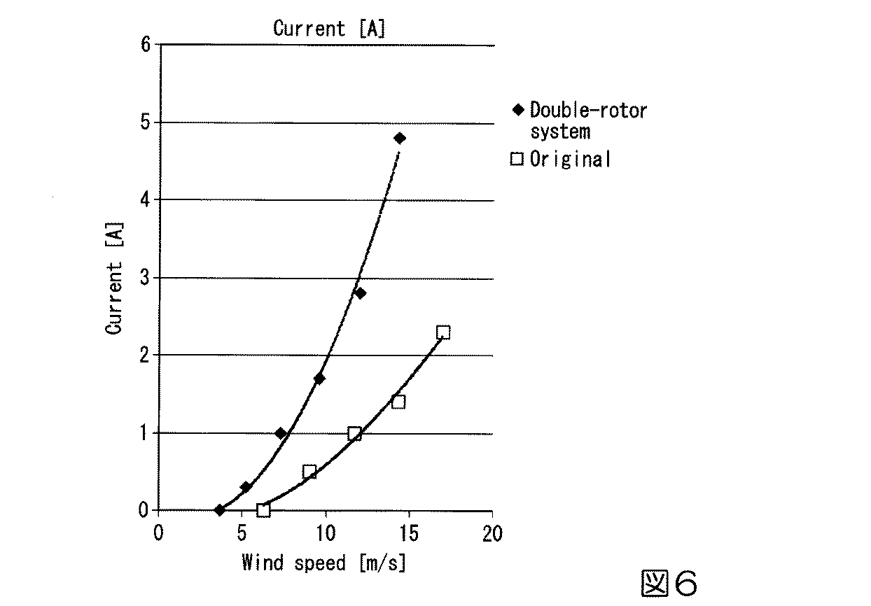
この結果から、実施例では、比較例に比べて、風速が低いときから発電されることが確認された。また同等の風速のときに、実施例では、比較例に比べて出力が高いことも確認された。 From this result, it was confirmed that in the example, power was generated from a time when the wind speed was lower than that in the comparative example. It was also confirmed that when the wind speed was the same, the output was higher in the examples than in the comparative examples.
10、10A、10B 発電装置
11 支持部
13 発電部
14 流体機械
31 発電主軸
32 発電機
41 回転軸
42 ローター
43 差動機構
44 カバー
48 ブレード
49 ハブ
50 伝達軸
51 第1歯車
52 第2歯車
L0 ヨー軸
L1 回転軸線
10, 10A, 10B
Claims (6)
前記回転軸に、前記回転軸の周方向に回転自在に設けられ、前記回転軸の軸線に沿う回転軸線方向に間隔をあけて配置された複数のローターと、
前記回転軸線方向に隣り合う一対のローターの間に配置され、前記一対のローターそれぞれの回転力を集約して前記回転軸に伝達する差動機構と、
前記一対のローターのうちの上流側の前段ローターに固定されて下流側の後段ローターからは分離され、前記差動機構を覆うカバーと、を備え、
前記カバーの下流側の端部は、前記後段ローターから離間している流体機械。 A rotating shaft that extends along the power generation spindle of the power generation unit and whose end is connected to the power generation spindle.
A plurality of rotors rotatably provided on the rotation axis in the circumferential direction of the rotation axis and arranged at intervals in the rotation axis direction along the axis of the rotation axis.
A differential mechanism that is arranged between a pair of rotors adjacent to each other in the direction of the rotation axis, aggregates the rotational force of each of the pair of rotors, and transmits the rotational force to the rotation axis.
A cover that is fixed to the upstream front rotor of the pair of rotors, separated from the downstream rear rotor, and covers the differential mechanism is provided .
A fluid machine whose downstream end of the cover is separated from the rear rotor.
前記回転軸から、前記回転軸の径方向に突出する伝達軸と、
前記伝達軸に、前記伝達軸の周方向に回転自在に設けられた第1歯車と、
前記伝達軸を前記回転軸線方向に挟んで配置されて前記一対のローターそれぞれに固定され、前記第1歯車に噛み合うことで前記一対のローターそれぞれの回転力を前記伝達軸に伝達する一対の第2歯車と、を備えている請求項1に記載の流体機械。 The differential mechanism is
A transmission shaft protruding from the rotating shaft in the radial direction of the rotating shaft,
A first gear rotatably provided on the transmission shaft in the circumferential direction of the transmission shaft,
The transmission shaft is arranged so as to be sandwiched in the direction of the rotation axis, fixed to each of the pair of rotors, and meshes with the first gear to transmit the rotational force of each of the pair of rotors to the transmission shaft. The fluid machine according to claim 1, further comprising gears.
前記一対のローターでは、互いの前記ブレード同士が、互いの前記ハブを前記回転軸線方向に挟んでいる請求項1から3のいずれか1項に記載の流体機械。 Each of the plurality of rotors includes a blade that receives kinetic energy from the fluid and a hub to which the blade is fixed.
The fluid machine according to any one of claims 1 to 3, wherein in the pair of rotors, the blades of each other sandwich the hub of each other in the direction of the rotation axis.
前記回転軸の端部が連結された発電主軸を備える発電部と、を備えている発電装置。 The fluid machine according to any one of claims 1 to 4,
A power generation device including a power generation unit including a power generation spindle to which the ends of the rotating shafts are connected.
流体からの運動エネルギーを受けた前記流体機械が、流体の向きに応じて受動的に首ふり運動する請求項5に記載の発電装置。 A support portion that rotatably supports the power generation unit around a yaw axis extending in a direction intersecting the axis of the power generation spindle is further provided.
The power generation device according to claim 5 , wherein the fluid machine that receives kinetic energy from the fluid passively swings its head according to the direction of the fluid.
Priority Applications (5)
| Application Number | Priority Date | Filing Date | Title |
|---|---|---|---|
| JP2016162074A JP6836769B2 (en) | 2016-08-22 | 2016-08-22 | Fluid machinery and power generators |
| GB1820335.6A GB2567969B (en) | 2016-08-22 | 2017-10-19 | Fluid machine and power generation device |
| PCT/IB2017/056494 WO2018037394A1 (en) | 2016-08-22 | 2017-10-19 | Fluid machine and power generation device |
| US16/307,229 US10876516B2 (en) | 2016-08-22 | 2017-10-19 | Fluid machine and power generation device |
| CA3028133A CA3028133A1 (en) | 2016-08-22 | 2017-10-19 | Fluid machine and power generation device |
Applications Claiming Priority (1)
| Application Number | Priority Date | Filing Date | Title |
|---|---|---|---|
| JP2016162074A JP6836769B2 (en) | 2016-08-22 | 2016-08-22 | Fluid machinery and power generators |
Publications (2)
| Publication Number | Publication Date |
|---|---|
| JP2018031266A JP2018031266A (en) | 2018-03-01 |
| JP6836769B2 true JP6836769B2 (en) | 2021-03-03 |
Family
ID=61245639
Family Applications (1)
| Application Number | Title | Priority Date | Filing Date |
|---|---|---|---|
| JP2016162074A Active JP6836769B2 (en) | 2016-08-22 | 2016-08-22 | Fluid machinery and power generators |
Country Status (5)
| Country | Link |
|---|---|
| US (1) | US10876516B2 (en) |
| JP (1) | JP6836769B2 (en) |
| CA (1) | CA3028133A1 (en) |
| GB (1) | GB2567969B (en) |
| WO (1) | WO2018037394A1 (en) |
Families Citing this family (1)
| Publication number | Priority date | Publication date | Assignee | Title |
|---|---|---|---|---|
| NO345863B1 (en) * | 2020-02-19 | 2021-09-13 | Wind Spider As | Gear unit for use in wind turbines |
Family Cites Families (9)
| Publication number | Priority date | Publication date | Assignee | Title |
|---|---|---|---|---|
| JPH05231297A (en) * | 1992-02-19 | 1993-09-07 | Mitsubishi Heavy Ind Ltd | Wind power generating device |
| US20060153672A1 (en) * | 2003-04-24 | 2006-07-13 | Davis Dean A | Furling wind turbine |
| JP2007321659A (en) * | 2006-06-01 | 2007-12-13 | Kubota Denki:Kk | Wind power generator |
| US20080056897A1 (en) * | 2006-09-06 | 2008-03-06 | Thomas Anderson | Counter rotating rotor head |
| US8742608B2 (en) * | 2009-03-05 | 2014-06-03 | Tarfin Micu | Drive system for use with flowing fluids |
| WO2010141347A2 (en) * | 2009-06-01 | 2010-12-09 | Synkinetics, Inc. | Multi-rotor fluid turbine drive with speed converter |
| KR101205329B1 (en) | 2010-06-11 | 2012-11-28 | 신익 | Wind Power Generator Having Triple Rotors Integrated System |
| JP5150751B2 (en) * | 2011-06-16 | 2013-02-27 | 株式会社ユニバンス | Fluid power generator |
| CN103216387B (en) * | 2012-01-18 | 2016-12-14 | 苏卫星 | Two to rotary electrification equipment |
-
2016
- 2016-08-22 JP JP2016162074A patent/JP6836769B2/en active Active
-
2017
- 2017-10-19 WO PCT/IB2017/056494 patent/WO2018037394A1/en active Application Filing
- 2017-10-19 CA CA3028133A patent/CA3028133A1/en not_active Abandoned
- 2017-10-19 GB GB1820335.6A patent/GB2567969B/en active Active
- 2017-10-19 US US16/307,229 patent/US10876516B2/en active Active
Also Published As
| Publication number | Publication date |
|---|---|
| US10876516B2 (en) | 2020-12-29 |
| GB201820335D0 (en) | 2019-01-30 |
| CA3028133A1 (en) | 2018-03-01 |
| WO2018037394A1 (en) | 2018-03-01 |
| GB2567969B (en) | 2021-12-15 |
| US20190293047A1 (en) | 2019-09-26 |
| JP2018031266A (en) | 2018-03-01 |
| GB2567969A (en) | 2019-05-01 |
Similar Documents
| Publication | Publication Date | Title |
|---|---|---|
| DK2334931T3 (en) | WIND-DRIVED DEVICE WITH CONTROLLATIVE WINGS | |
| US20100111697A1 (en) | Wind energy generation device | |
| RU2010147370A (en) | SURFACE WIND GENERATOR SYSTEM USING A FLYING BODY | |
| JP2012505332A5 (en) | ||
| WO2015036806A4 (en) | Wind turbine of low wind speeds | |
| US9243614B2 (en) | Wind powered apparatus having counter rotating blades | |
| EP2653720A3 (en) | Wind turbine with a primary and a secondary generator and method of operating such wind turbine | |
| JP2003129935A (en) | Wind power generator | |
| US9080551B2 (en) | System for generating electrical powerfrom aircraft exhaust | |
| CN104912749A (en) | Wind generator adaptive adjustment hub device | |
| JP6836769B2 (en) | Fluid machinery and power generators | |
| JP2012092651A (en) | Wind power generation apparatus | |
| CN103470450B (en) | The energy multiplex device for wind of wind-power electricity generation | |
| CN203412696U (en) | Wind collection axial-flow type wind power generation device | |
| JP2002339852A (en) | Wind power generation device | |
| CN110345000B (en) | Double-impeller contra-rotating horizontal shaft wind turbine | |
| JP2014218975A (en) | Wind-force power generator | |
| JPH05231297A (en) | Wind power generating device | |
| JP2005194918A (en) | Wind mill power generation device | |
| CN202673561U (en) | Novel wind pressure variable-pitch wind driven generator | |
| KR101505435B1 (en) | Wind power generator | |
| JP2019082135A (en) | Wind power generator | |
| TW201544686A (en) | Wind power generation device | |
| RU91602U1 (en) | WIND UNIT "MAKSAN" | |
| SE0900212A1 (en) | Power plant |
Legal Events
| Date | Code | Title | Description |
|---|---|---|---|
| A521 | Request for written amendment filed |
Free format text: JAPANESE INTERMEDIATE CODE: A523 Effective date: 20161117 |
|
| A621 | Written request for application examination |
Free format text: JAPANESE INTERMEDIATE CODE: A621 Effective date: 20190809 |
|
| A711 | Notification of change in applicant |
Free format text: JAPANESE INTERMEDIATE CODE: A711 Effective date: 20190809 |
|
| A521 | Request for written amendment filed |
Free format text: JAPANESE INTERMEDIATE CODE: A821 Effective date: 20190809 |
|
| A131 | Notification of reasons for refusal |
Free format text: JAPANESE INTERMEDIATE CODE: A131 Effective date: 20200428 |
|
| A02 | Decision of refusal |
Free format text: JAPANESE INTERMEDIATE CODE: A02 Effective date: 20200923 |
|
| A521 | Request for written amendment filed |
Free format text: JAPANESE INTERMEDIATE CODE: A523 Effective date: 20201118 |
|
| C60 | Trial request (containing other claim documents, opposition documents) |
Free format text: JAPANESE INTERMEDIATE CODE: C60 Effective date: 20201118 |
|
| A911 | Transfer to examiner for re-examination before appeal (zenchi) |
Free format text: JAPANESE INTERMEDIATE CODE: A911 Effective date: 20201130 |
|
| C21 | Notice of transfer of a case for reconsideration by examiners before appeal proceedings |
Free format text: JAPANESE INTERMEDIATE CODE: C21 Effective date: 20201201 |
|
| TRDD | Decision of grant or rejection written | ||
| A01 | Written decision to grant a patent or to grant a registration (utility model) |
Free format text: JAPANESE INTERMEDIATE CODE: A01 Effective date: 20210112 |
|
| A61 | First payment of annual fees (during grant procedure) |
Free format text: JAPANESE INTERMEDIATE CODE: A61 Effective date: 20210125 |
|
| R150 | Certificate of patent or registration of utility model |
Ref document number: 6836769 Country of ref document: JP Free format text: JAPANESE INTERMEDIATE CODE: R150 |
|
| R250 | Receipt of annual fees |
Free format text: JAPANESE INTERMEDIATE CODE: R250 |