JP6836397B2 - Glass laminated structure with improved edge strength - Google Patents
Glass laminated structure with improved edge strength Download PDFInfo
- Publication number
- JP6836397B2 JP6836397B2 JP2016520636A JP2016520636A JP6836397B2 JP 6836397 B2 JP6836397 B2 JP 6836397B2 JP 2016520636 A JP2016520636 A JP 2016520636A JP 2016520636 A JP2016520636 A JP 2016520636A JP 6836397 B2 JP6836397 B2 JP 6836397B2
- Authority
- JP
- Japan
- Prior art keywords
- glass
- mol
- region
- mpa
- laminated structure
- Prior art date
- Legal status (The legal status is an assumption and is not a legal conclusion. Google has not performed a legal analysis and makes no representation as to the accuracy of the status listed.)
- Active
Links
- 239000011521 glass Substances 0.000 title claims description 217
- 239000000463 material Substances 0.000 claims description 53
- 230000002093 peripheral effect Effects 0.000 claims description 32
- 239000010410 layer Substances 0.000 description 114
- 229920000642 polymer Polymers 0.000 description 69
- 239000005340 laminated glass Substances 0.000 description 40
- 239000005345 chemically strengthened glass Substances 0.000 description 32
- 239000005357 flat glass Substances 0.000 description 20
- 229920002037 poly(vinyl butyral) polymer Polymers 0.000 description 20
- 239000004593 Epoxy Substances 0.000 description 18
- 239000011229 interlayer Substances 0.000 description 18
- 239000011734 sodium Substances 0.000 description 17
- 238000000576 coating method Methods 0.000 description 14
- 229920001187 thermosetting polymer Polymers 0.000 description 14
- 241000282575 Gorilla Species 0.000 description 13
- 229910004298 SiO 2 Inorganic materials 0.000 description 13
- 239000000203 mixture Substances 0.000 description 13
- 238000013001 point bending Methods 0.000 description 13
- 238000000034 method Methods 0.000 description 12
- 238000002474 experimental method Methods 0.000 description 11
- 229910018072 Al 2 O 3 Inorganic materials 0.000 description 10
- 229920000877 Melamine resin Polymers 0.000 description 10
- 239000004642 Polyimide Substances 0.000 description 10
- 239000011248 coating agent Substances 0.000 description 10
- 150000002148 esters Chemical class 0.000 description 10
- 229920001721 polyimide Polymers 0.000 description 10
- 230000008901 benefit Effects 0.000 description 9
- 239000006060 molten glass Substances 0.000 description 9
- 229920000647 polyepoxide Polymers 0.000 description 9
- 238000005452 bending Methods 0.000 description 8
- 239000002131 composite material Substances 0.000 description 8
- 150000002500 ions Chemical class 0.000 description 8
- 229920001568 phenolic resin Polymers 0.000 description 8
- 239000005361 soda-lime glass Substances 0.000 description 8
- 229920001807 Urea-formaldehyde Polymers 0.000 description 7
- 238000010894 electron beam technology Methods 0.000 description 7
- 239000004814 polyurethane Substances 0.000 description 7
- 229920002635 polyurethane Polymers 0.000 description 7
- 230000008569 process Effects 0.000 description 7
- 229920005989 resin Polymers 0.000 description 7
- 239000011347 resin Substances 0.000 description 7
- 229910052708 sodium Inorganic materials 0.000 description 7
- JOYRKODLDBILNP-UHFFFAOYSA-N Ethyl urethane Chemical compound CCOC(N)=O JOYRKODLDBILNP-UHFFFAOYSA-N 0.000 description 6
- 229910018068 Li 2 O Inorganic materials 0.000 description 6
- SLGWESQGEUXWJQ-UHFFFAOYSA-N formaldehyde;phenol Chemical compound O=C.OC1=CC=CC=C1 SLGWESQGEUXWJQ-UHFFFAOYSA-N 0.000 description 6
- ODGAOXROABLFNM-UHFFFAOYSA-N polynoxylin Chemical compound O=C.NC(N)=O ODGAOXROABLFNM-UHFFFAOYSA-N 0.000 description 6
- 239000004925 Acrylic resin Substances 0.000 description 5
- 229920000178 Acrylic resin Polymers 0.000 description 5
- 239000004952 Polyamide Substances 0.000 description 5
- 229910006404 SnO 2 Inorganic materials 0.000 description 5
- ATJFFYVFTNAWJD-UHFFFAOYSA-N Tin Chemical compound [Sn] ATJFFYVFTNAWJD-UHFFFAOYSA-N 0.000 description 5
- 238000010276 construction Methods 0.000 description 5
- 229920006037 cross link polymer Polymers 0.000 description 5
- 229920001971 elastomer Polymers 0.000 description 5
- 239000003822 epoxy resin Substances 0.000 description 5
- IVJISJACKSSFGE-UHFFFAOYSA-N formaldehyde;1,3,5-triazine-2,4,6-triamine Chemical compound O=C.NC1=NC(N)=NC(N)=N1 IVJISJACKSSFGE-UHFFFAOYSA-N 0.000 description 5
- 238000003286 fusion draw glass process Methods 0.000 description 5
- 229920000554 ionomer Polymers 0.000 description 5
- 229920002647 polyamide Polymers 0.000 description 5
- 229920000728 polyester Polymers 0.000 description 5
- 229920001296 polysiloxane Polymers 0.000 description 5
- 239000005060 rubber Substances 0.000 description 5
- 229920006305 unsaturated polyester Polymers 0.000 description 5
- 239000004433 Thermoplastic polyurethane Substances 0.000 description 4
- 239000000853 adhesive Substances 0.000 description 4
- 230000001070 adhesive effect Effects 0.000 description 4
- 230000005540 biological transmission Effects 0.000 description 4
- 150000001768 cations Chemical class 0.000 description 4
- 125000003700 epoxy group Chemical group 0.000 description 4
- 238000012986 modification Methods 0.000 description 4
- 230000004048 modification Effects 0.000 description 4
- 229920003986 novolac Polymers 0.000 description 4
- 239000004644 polycyanurate Substances 0.000 description 4
- 239000002861 polymer material Substances 0.000 description 4
- 150000003254 radicals Chemical class 0.000 description 4
- 238000012360 testing method Methods 0.000 description 4
- 239000012815 thermoplastic material Substances 0.000 description 4
- 229920002803 thermoplastic polyurethane Polymers 0.000 description 4
- 150000003673 urethanes Chemical class 0.000 description 4
- 239000004640 Melamine resin Substances 0.000 description 3
- 239000005358 alkali aluminosilicate glass Substances 0.000 description 3
- 229910001413 alkali metal ion Inorganic materials 0.000 description 3
- 229920000180 alkyd Polymers 0.000 description 3
- -1 and Inorganic materials 0.000 description 3
- 230000008859 change Effects 0.000 description 3
- 239000002019 doping agent Substances 0.000 description 3
- 239000000835 fiber Substances 0.000 description 3
- GCFDVEHYSAUQGL-UHFFFAOYSA-J fluoro-dioxido-oxo-$l^{5}-phosphane;tin(4+) Chemical compound [Sn+4].[O-]P([O-])(F)=O.[O-]P([O-])(F)=O GCFDVEHYSAUQGL-UHFFFAOYSA-J 0.000 description 3
- 238000005342 ion exchange Methods 0.000 description 3
- 238000010030 laminating Methods 0.000 description 3
- 239000007788 liquid Substances 0.000 description 3
- 230000003287 optical effect Effects 0.000 description 3
- 239000005011 phenolic resin Substances 0.000 description 3
- 150000003839 salts Chemical class 0.000 description 3
- 238000003283 slot draw process Methods 0.000 description 3
- 238000005728 strengthening Methods 0.000 description 3
- 239000000126 substance Substances 0.000 description 3
- 239000004634 thermosetting polymer Substances 0.000 description 3
- 239000005341 toughened glass Substances 0.000 description 3
- XLYOFNOQVPJJNP-UHFFFAOYSA-N water Substances O XLYOFNOQVPJJNP-UHFFFAOYSA-N 0.000 description 3
- NIXOWILDQLNWCW-UHFFFAOYSA-M Acrylate Chemical compound [O-]C(=O)C=C NIXOWILDQLNWCW-UHFFFAOYSA-M 0.000 description 2
- 229920001342 Bakelite® Polymers 0.000 description 2
- NBIIXXVUZAFLBC-UHFFFAOYSA-N Phosphoric acid Chemical compound OP(O)(O)=O NBIIXXVUZAFLBC-UHFFFAOYSA-N 0.000 description 2
- 238000006124 Pilkington process Methods 0.000 description 2
- 229910008449 SnF 2 Inorganic materials 0.000 description 2
- FAPWRFPIFSIZLT-UHFFFAOYSA-M Sodium chloride Chemical compound [Na+].[Cl-] FAPWRFPIFSIZLT-UHFFFAOYSA-M 0.000 description 2
- NIXOWILDQLNWCW-UHFFFAOYSA-N acrylic acid group Chemical group C(C=C)(=O)O NIXOWILDQLNWCW-UHFFFAOYSA-N 0.000 description 2
- 239000002313 adhesive film Substances 0.000 description 2
- 229910052783 alkali metal Inorganic materials 0.000 description 2
- 229910000287 alkaline earth metal oxide Inorganic materials 0.000 description 2
- 239000005354 aluminosilicate glass Substances 0.000 description 2
- 230000004888 barrier function Effects 0.000 description 2
- 230000009286 beneficial effect Effects 0.000 description 2
- 230000015572 biosynthetic process Effects 0.000 description 2
- 239000008199 coating composition Substances 0.000 description 2
- 230000007423 decrease Effects 0.000 description 2
- 238000010586 diagram Methods 0.000 description 2
- 238000003280 down draw process Methods 0.000 description 2
- 239000005038 ethylene vinyl acetate Substances 0.000 description 2
- 239000005303 fluorophosphate glass Substances 0.000 description 2
- LNEPOXFFQSENCJ-UHFFFAOYSA-N haloperidol Chemical compound C1CC(O)(C=2C=CC(Cl)=CC=2)CCN1CCCC(=O)C1=CC=C(F)C=C1 LNEPOXFFQSENCJ-UHFFFAOYSA-N 0.000 description 2
- 238000010438 heat treatment Methods 0.000 description 2
- 238000007654 immersion Methods 0.000 description 2
- 238000002844 melting Methods 0.000 description 2
- 230000008018 melting Effects 0.000 description 2
- 229920000515 polycarbonate Polymers 0.000 description 2
- 239000004417 polycarbonate Substances 0.000 description 2
- 238000007342 radical addition reaction Methods 0.000 description 2
- 239000002994 raw material Substances 0.000 description 2
- 238000005096 rolling process Methods 0.000 description 2
- JHJLBTNAGRQEKS-UHFFFAOYSA-M sodium bromide Chemical compound [Na+].[Br-] JHJLBTNAGRQEKS-UHFFFAOYSA-M 0.000 description 2
- PUZPDOWCWNUUKD-UHFFFAOYSA-M sodium fluoride Chemical compound [F-].[Na+] PUZPDOWCWNUUKD-UHFFFAOYSA-M 0.000 description 2
- 239000002904 solvent Substances 0.000 description 2
- 238000007155 step growth polymerization reaction Methods 0.000 description 2
- 125000000391 vinyl group Chemical group [H]C([*])=C([H])[H] 0.000 description 2
- 229920002554 vinyl polymer Polymers 0.000 description 2
- KXGFMDJXCMQABM-UHFFFAOYSA-N 2-methoxy-6-methylphenol Chemical compound [CH]OC1=CC=CC([CH])=C1O KXGFMDJXCMQABM-UHFFFAOYSA-N 0.000 description 1
- BXVSAYBZSGIURM-UHFFFAOYSA-N 2-phenoxy-4h-1,3,2$l^{5}-benzodioxaphosphinine 2-oxide Chemical compound O1CC2=CC=CC=C2OP1(=O)OC1=CC=CC=C1 BXVSAYBZSGIURM-UHFFFAOYSA-N 0.000 description 1
- 229910052684 Cerium Inorganic materials 0.000 description 1
- 241000124033 Salix Species 0.000 description 1
- 229910010413 TiO 2 Inorganic materials 0.000 description 1
- 239000002253 acid Substances 0.000 description 1
- 230000005534 acoustic noise Effects 0.000 description 1
- 230000006978 adaptation Effects 0.000 description 1
- 239000002318 adhesion promoter Substances 0.000 description 1
- 238000004026 adhesive bonding Methods 0.000 description 1
- 229910000272 alkali metal oxide Inorganic materials 0.000 description 1
- 150000001340 alkali metals Chemical class 0.000 description 1
- PNEYBMLMFCGWSK-UHFFFAOYSA-N aluminium oxide Inorganic materials [O-2].[O-2].[O-2].[Al+3].[Al+3] PNEYBMLMFCGWSK-UHFFFAOYSA-N 0.000 description 1
- 229910000147 aluminium phosphate Inorganic materials 0.000 description 1
- 239000005407 aluminoborosilicate glass Substances 0.000 description 1
- 239000005347 annealed glass Substances 0.000 description 1
- 238000000137 annealing Methods 0.000 description 1
- 239000005388 borosilicate glass Substances 0.000 description 1
- 229910052792 caesium Inorganic materials 0.000 description 1
- TVFDJXOCXUVLDH-UHFFFAOYSA-N caesium atom Chemical compound [Cs] TVFDJXOCXUVLDH-UHFFFAOYSA-N 0.000 description 1
- GWXLDORMOJMVQZ-UHFFFAOYSA-N cerium Chemical compound [Ce] GWXLDORMOJMVQZ-UHFFFAOYSA-N 0.000 description 1
- 238000003426 chemical strengthening reaction Methods 0.000 description 1
- 239000003795 chemical substances by application Substances 0.000 description 1
- 239000008395 clarifying agent Substances 0.000 description 1
- 238000004040 coloring Methods 0.000 description 1
- 230000000295 complement effect Effects 0.000 description 1
- 230000006835 compression Effects 0.000 description 1
- 238000007906 compression Methods 0.000 description 1
- 238000013016 damping Methods 0.000 description 1
- 230000007547 defect Effects 0.000 description 1
- 210000003298 dental enamel Anatomy 0.000 description 1
- 238000009792 diffusion process Methods 0.000 description 1
- 238000009826 distribution Methods 0.000 description 1
- 230000007613 environmental effect Effects 0.000 description 1
- 238000007667 floating Methods 0.000 description 1
- DWYMPOCYEZONEA-UHFFFAOYSA-L fluoridophosphate Chemical group [O-]P([O-])(F)=O DWYMPOCYEZONEA-UHFFFAOYSA-L 0.000 description 1
- 239000000446 fuel Substances 0.000 description 1
- 230000004927 fusion Effects 0.000 description 1
- 230000005484 gravity Effects 0.000 description 1
- 238000000227 grinding Methods 0.000 description 1
- 150000004820 halides Chemical class 0.000 description 1
- 230000003116 impacting effect Effects 0.000 description 1
- 238000010348 incorporation Methods 0.000 description 1
- 238000009434 installation Methods 0.000 description 1
- 238000003475 lamination Methods 0.000 description 1
- 230000003137 locomotive effect Effects 0.000 description 1
- 238000004519 manufacturing process Methods 0.000 description 1
- 150000007974 melamines Chemical class 0.000 description 1
- 229910052751 metal Inorganic materials 0.000 description 1
- 239000002184 metal Substances 0.000 description 1
- 229910021645 metal ion Inorganic materials 0.000 description 1
- 239000012768 molten material Substances 0.000 description 1
- 229910052758 niobium Inorganic materials 0.000 description 1
- 239000010955 niobium Substances 0.000 description 1
- GUCVJGMIXFAOAE-UHFFFAOYSA-N niobium atom Chemical compound [Nb] GUCVJGMIXFAOAE-UHFFFAOYSA-N 0.000 description 1
- TWNQGVIAIRXVLR-UHFFFAOYSA-N oxo(oxoalumanyloxy)alumane Chemical compound O=[Al]O[Al]=O TWNQGVIAIRXVLR-UHFFFAOYSA-N 0.000 description 1
- 230000035699 permeability Effects 0.000 description 1
- 238000010587 phase diagram Methods 0.000 description 1
- 238000005498 polishing Methods 0.000 description 1
- 229910001414 potassium ion Inorganic materials 0.000 description 1
- 230000001681 protective effect Effects 0.000 description 1
- 230000008707 rearrangement Effects 0.000 description 1
- 229910052701 rubidium Inorganic materials 0.000 description 1
- IGLNJRXAVVLDKE-UHFFFAOYSA-N rubidium atom Chemical compound [Rb] IGLNJRXAVVLDKE-UHFFFAOYSA-N 0.000 description 1
- 238000007650 screen-printing Methods 0.000 description 1
- 239000011780 sodium chloride Substances 0.000 description 1
- 229910001415 sodium ion Inorganic materials 0.000 description 1
- 239000007787 solid Substances 0.000 description 1
- 239000011343 solid material Substances 0.000 description 1
- 238000001228 spectrum Methods 0.000 description 1
- 239000004575 stone Substances 0.000 description 1
- 239000000758 substrate Substances 0.000 description 1
- 150000003467 sulfuric acid derivatives Chemical class 0.000 description 1
- 230000003746 surface roughness Effects 0.000 description 1
- 229920001169 thermoplastic Polymers 0.000 description 1
- 239000004416 thermosoftening plastic Substances 0.000 description 1
- QUBMWJKTLKIJNN-UHFFFAOYSA-B tin(4+);tetraphosphate Chemical compound [Sn+4].[Sn+4].[Sn+4].[O-]P([O-])([O-])=O.[O-]P([O-])([O-])=O.[O-]P([O-])([O-])=O.[O-]P([O-])([O-])=O QUBMWJKTLKIJNN-UHFFFAOYSA-B 0.000 description 1
- 230000001960 triggered effect Effects 0.000 description 1
- 238000009966 trimming Methods 0.000 description 1
- ZRQNRTRXAVFCMB-UHFFFAOYSA-N tris(2,4,5-trioxa-1-stanna-3-borabicyclo[1.1.1]pentan-1-yl) borate Chemical compound [Sn+4].[Sn+4].[Sn+4].[O-]B([O-])[O-].[O-]B([O-])[O-].[O-]B([O-])[O-].[O-]B([O-])[O-] ZRQNRTRXAVFCMB-UHFFFAOYSA-N 0.000 description 1
- WFKWXMTUELFFGS-UHFFFAOYSA-N tungsten Chemical compound [W] WFKWXMTUELFFGS-UHFFFAOYSA-N 0.000 description 1
- 229910052721 tungsten Inorganic materials 0.000 description 1
- 239000010937 tungsten Substances 0.000 description 1
- 239000013585 weight reducing agent Substances 0.000 description 1
- XLOMVQKBTHCTTD-UHFFFAOYSA-N zinc oxide Inorganic materials [Zn]=O XLOMVQKBTHCTTD-UHFFFAOYSA-N 0.000 description 1
Images


Classifications
-
- B—PERFORMING OPERATIONS; TRANSPORTING
- B32—LAYERED PRODUCTS
- B32B—LAYERED PRODUCTS, i.e. PRODUCTS BUILT-UP OF STRATA OF FLAT OR NON-FLAT, e.g. CELLULAR OR HONEYCOMB, FORM
- B32B17/00—Layered products essentially comprising sheet glass, or glass, slag, or like fibres
- B32B17/06—Layered products essentially comprising sheet glass, or glass, slag, or like fibres comprising glass as the main or only constituent of a layer, next to another layer of a specific material
- B32B17/10—Layered products essentially comprising sheet glass, or glass, slag, or like fibres comprising glass as the main or only constituent of a layer, next to another layer of a specific material of synthetic resin
- B32B17/10005—Layered products essentially comprising sheet glass, or glass, slag, or like fibres comprising glass as the main or only constituent of a layer, next to another layer of a specific material of synthetic resin laminated safety glass or glazing
- B32B17/10165—Functional features of the laminated safety glass or glazing
- B32B17/10293—Edge features, e.g. inserts or holes
-
- B—PERFORMING OPERATIONS; TRANSPORTING
- B32—LAYERED PRODUCTS
- B32B—LAYERED PRODUCTS, i.e. PRODUCTS BUILT-UP OF STRATA OF FLAT OR NON-FLAT, e.g. CELLULAR OR HONEYCOMB, FORM
- B32B1/00—Layered products having a general shape other than plane
-
- B—PERFORMING OPERATIONS; TRANSPORTING
- B32—LAYERED PRODUCTS
- B32B—LAYERED PRODUCTS, i.e. PRODUCTS BUILT-UP OF STRATA OF FLAT OR NON-FLAT, e.g. CELLULAR OR HONEYCOMB, FORM
- B32B17/00—Layered products essentially comprising sheet glass, or glass, slag, or like fibres
- B32B17/06—Layered products essentially comprising sheet glass, or glass, slag, or like fibres comprising glass as the main or only constituent of a layer, next to another layer of a specific material
- B32B17/10—Layered products essentially comprising sheet glass, or glass, slag, or like fibres comprising glass as the main or only constituent of a layer, next to another layer of a specific material of synthetic resin
- B32B17/10005—Layered products essentially comprising sheet glass, or glass, slag, or like fibres comprising glass as the main or only constituent of a layer, next to another layer of a specific material of synthetic resin laminated safety glass or glazing
- B32B17/10009—Layered products essentially comprising sheet glass, or glass, slag, or like fibres comprising glass as the main or only constituent of a layer, next to another layer of a specific material of synthetic resin laminated safety glass or glazing characterized by the number, the constitution or treatment of glass sheets
- B32B17/10036—Layered products essentially comprising sheet glass, or glass, slag, or like fibres comprising glass as the main or only constituent of a layer, next to another layer of a specific material of synthetic resin laminated safety glass or glazing characterized by the number, the constitution or treatment of glass sheets comprising two outer glass sheets
-
- B—PERFORMING OPERATIONS; TRANSPORTING
- B32—LAYERED PRODUCTS
- B32B—LAYERED PRODUCTS, i.e. PRODUCTS BUILT-UP OF STRATA OF FLAT OR NON-FLAT, e.g. CELLULAR OR HONEYCOMB, FORM
- B32B17/00—Layered products essentially comprising sheet glass, or glass, slag, or like fibres
- B32B17/06—Layered products essentially comprising sheet glass, or glass, slag, or like fibres comprising glass as the main or only constituent of a layer, next to another layer of a specific material
- B32B17/10—Layered products essentially comprising sheet glass, or glass, slag, or like fibres comprising glass as the main or only constituent of a layer, next to another layer of a specific material of synthetic resin
- B32B17/10005—Layered products essentially comprising sheet glass, or glass, slag, or like fibres comprising glass as the main or only constituent of a layer, next to another layer of a specific material of synthetic resin laminated safety glass or glazing
- B32B17/10009—Layered products essentially comprising sheet glass, or glass, slag, or like fibres comprising glass as the main or only constituent of a layer, next to another layer of a specific material of synthetic resin laminated safety glass or glazing characterized by the number, the constitution or treatment of glass sheets
- B32B17/10082—Properties of the bulk of a glass sheet
- B32B17/10119—Properties of the bulk of a glass sheet having a composition deviating from the basic composition of soda-lime glass, e.g. borosilicate
-
- B—PERFORMING OPERATIONS; TRANSPORTING
- B32—LAYERED PRODUCTS
- B32B—LAYERED PRODUCTS, i.e. PRODUCTS BUILT-UP OF STRATA OF FLAT OR NON-FLAT, e.g. CELLULAR OR HONEYCOMB, FORM
- B32B17/00—Layered products essentially comprising sheet glass, or glass, slag, or like fibres
- B32B17/06—Layered products essentially comprising sheet glass, or glass, slag, or like fibres comprising glass as the main or only constituent of a layer, next to another layer of a specific material
- B32B17/10—Layered products essentially comprising sheet glass, or glass, slag, or like fibres comprising glass as the main or only constituent of a layer, next to another layer of a specific material of synthetic resin
- B32B17/10005—Layered products essentially comprising sheet glass, or glass, slag, or like fibres comprising glass as the main or only constituent of a layer, next to another layer of a specific material of synthetic resin laminated safety glass or glazing
- B32B17/10009—Layered products essentially comprising sheet glass, or glass, slag, or like fibres comprising glass as the main or only constituent of a layer, next to another layer of a specific material of synthetic resin laminated safety glass or glazing characterized by the number, the constitution or treatment of glass sheets
- B32B17/10128—Treatment of at least one glass sheet
- B32B17/10137—Chemical strengthening
-
- B—PERFORMING OPERATIONS; TRANSPORTING
- B32—LAYERED PRODUCTS
- B32B—LAYERED PRODUCTS, i.e. PRODUCTS BUILT-UP OF STRATA OF FLAT OR NON-FLAT, e.g. CELLULAR OR HONEYCOMB, FORM
- B32B17/00—Layered products essentially comprising sheet glass, or glass, slag, or like fibres
- B32B17/06—Layered products essentially comprising sheet glass, or glass, slag, or like fibres comprising glass as the main or only constituent of a layer, next to another layer of a specific material
- B32B17/10—Layered products essentially comprising sheet glass, or glass, slag, or like fibres comprising glass as the main or only constituent of a layer, next to another layer of a specific material of synthetic resin
- B32B17/10005—Layered products essentially comprising sheet glass, or glass, slag, or like fibres comprising glass as the main or only constituent of a layer, next to another layer of a specific material of synthetic resin laminated safety glass or glazing
- B32B17/1055—Layered products essentially comprising sheet glass, or glass, slag, or like fibres comprising glass as the main or only constituent of a layer, next to another layer of a specific material of synthetic resin laminated safety glass or glazing characterized by the resin layer, i.e. interlayer
- B32B17/10761—Layered products essentially comprising sheet glass, or glass, slag, or like fibres comprising glass as the main or only constituent of a layer, next to another layer of a specific material of synthetic resin laminated safety glass or glazing characterized by the resin layer, i.e. interlayer containing vinyl acetal
-
- C—CHEMISTRY; METALLURGY
- C03—GLASS; MINERAL OR SLAG WOOL
- C03C—CHEMICAL COMPOSITION OF GLASSES, GLAZES OR VITREOUS ENAMELS; SURFACE TREATMENT OF GLASS; SURFACE TREATMENT OF FIBRES OR FILAMENTS MADE FROM GLASS, MINERALS OR SLAGS; JOINING GLASS TO GLASS OR OTHER MATERIALS
- C03C15/00—Surface treatment of glass, not in the form of fibres or filaments, by etching
-
- C—CHEMISTRY; METALLURGY
- C03—GLASS; MINERAL OR SLAG WOOL
- C03C—CHEMICAL COMPOSITION OF GLASSES, GLAZES OR VITREOUS ENAMELS; SURFACE TREATMENT OF GLASS; SURFACE TREATMENT OF FIBRES OR FILAMENTS MADE FROM GLASS, MINERALS OR SLAGS; JOINING GLASS TO GLASS OR OTHER MATERIALS
- C03C21/00—Treatment of glass, not in the form of fibres or filaments, by diffusing ions or metals in the surface
-
- C—CHEMISTRY; METALLURGY
- C03—GLASS; MINERAL OR SLAG WOOL
- C03C—CHEMICAL COMPOSITION OF GLASSES, GLAZES OR VITREOUS ENAMELS; SURFACE TREATMENT OF GLASS; SURFACE TREATMENT OF FIBRES OR FILAMENTS MADE FROM GLASS, MINERALS OR SLAGS; JOINING GLASS TO GLASS OR OTHER MATERIALS
- C03C23/00—Other surface treatment of glass not in the form of fibres or filaments
- C03C23/007—Other surface treatment of glass not in the form of fibres or filaments by thermal treatment
-
- B—PERFORMING OPERATIONS; TRANSPORTING
- B32—LAYERED PRODUCTS
- B32B—LAYERED PRODUCTS, i.e. PRODUCTS BUILT-UP OF STRATA OF FLAT OR NON-FLAT, e.g. CELLULAR OR HONEYCOMB, FORM
- B32B2250/00—Layers arrangement
- B32B2250/03—3 layers
-
- B—PERFORMING OPERATIONS; TRANSPORTING
- B32—LAYERED PRODUCTS
- B32B—LAYERED PRODUCTS, i.e. PRODUCTS BUILT-UP OF STRATA OF FLAT OR NON-FLAT, e.g. CELLULAR OR HONEYCOMB, FORM
- B32B2307/00—Properties of the layers or laminate
- B32B2307/50—Properties of the layers or laminate having particular mechanical properties
- B32B2307/51—Elastic
-
- B—PERFORMING OPERATIONS; TRANSPORTING
- B32—LAYERED PRODUCTS
- B32B—LAYERED PRODUCTS, i.e. PRODUCTS BUILT-UP OF STRATA OF FLAT OR NON-FLAT, e.g. CELLULAR OR HONEYCOMB, FORM
- B32B2605/00—Vehicles
- B32B2605/006—Transparent parts other than made from inorganic glass, e.g. polycarbonate glazings
-
- B—PERFORMING OPERATIONS; TRANSPORTING
- B32—LAYERED PRODUCTS
- B32B—LAYERED PRODUCTS, i.e. PRODUCTS BUILT-UP OF STRATA OF FLAT OR NON-FLAT, e.g. CELLULAR OR HONEYCOMB, FORM
- B32B2605/00—Vehicles
- B32B2605/08—Cars
Description
本出願は、2013年10月7日に出願された米国特許出願第61/887646号明細書の優先権の恩典を主張するものであり、なお、当該特許出願の内容は、参照によりその全体が本明細書に組み入れられる。 This application claims the benefit of priority in U.S. Patent Application No. 61/878646 filed on October 7, 2013, and the content of the patent application is in its entirety by reference. Incorporated herein.
ガラスラミネートは、建築において、ならびに車両または輸送用途(例えば、自動車、鉄道車両、機関車、航空機など)において、窓及び窓ガラスとして使用することができる。ガラスラミネートは、手摺りおよび階段におけるガラスパネルとして、ならびに化粧パネルまたは壁、柱、エレベーターのカゴ室、および台所用家電のための被覆材として、ならびに他の用途において使用することもできる。本明細書において使用される場合、窓ガラスまたは積層化ガラス構造体は、窓、パネル、壁、筐体、印、または他の構造体における透明、準透明、半透明、または不透明部品であり得る。建築および/または車両用途において使用される一般的なタイプの窓ガラスは、透き通って着色された積層化ガラス構造体を含む。 Glass laminates can be used as windows and glazing in construction and in rolling stock or transportation applications (eg, automobiles, rolling stock, locomotives, aircraft, etc.). Glass laminates can also be used as glass panels in handrails and stairs, and as coverings for decorative panels or walls, pillars, elevator baskets, and kitchen appliances, and in other applications. As used herein, a glazing or laminated glass structure can be a transparent, translucent, translucent, or opaque component in windows, panels, walls, housings, markings, or other structures. .. Common types of glazing used in architectural and / or vehicle applications include clear colored laminated glass structures.
従来の自動車用窓ガラス構築物は、ポリビニルブチラール(PVB)中間層を有する2mm厚のソーダ石灰ガラスの2つの層を含む。これらのラミネート構築物は、低コストならびに自動車および他の用途のための十分な耐衝撃性など、ある特定の利点を有する。しかしながら、これらのラミネートは、それらの限られた耐衝撃性および重い重量により、道路脇の土石、いたずら、および衝撃を生じる他の物体による衝撃を受けた場合に破壊する可能性が高いこと、ならびにそれぞれの車両での低い燃料効率など、不十分な性能特性を示す。 Conventional automotive window glass constructs include two layers of 2 mm thick soda-lime glass with a polyvinyl butyral (PVB) intermediate layer. These laminated structures have certain advantages, such as low cost as well as sufficient impact resistance for automotive and other applications. However, due to their limited impact resistance and heavy weight, these laminates are likely to break when impacted by roadside earth and stone, mischief, and other impacting objects, as well as It exhibits inadequate performance characteristics such as low fuel efficiency in each vehicle.
強度が重要な用途(例えば、上記の自動車用途など)において、従来のガラスの強度は、コーティング、熱強化、および化学強化(イオン交換)など、いくつかの方法によって高めることができる。熱強化は、そのような用途において、厚い一体化されたガラスシートに対して慣習的に用いられ、ならびにガラス表面中(典型的にはガラスの厚さ全体の20%から25%まで)に厚い圧縮層を生成するという利点を有する。しかしながら、この場合の圧縮応力の大きさは比較的小さく、典型的には100MPa未満である。その上、熱強化は、比較的薄いガラス(例えば、約2mm未満)では、さらにいっそう効果的ではなくなる。 In strength-critical applications (eg, automotive applications described above), the strength of conventional glass can be increased by several methods, including coating, thermal strengthening, and chemical strengthening (ion exchange). Thermal strengthening is customarily used for thick integrated glass sheets in such applications, as well as being thick in the glass surface (typically 20% to 25% of the total thickness of the glass). It has the advantage of producing a compressed layer. However, the magnitude of the compressive stress in this case is relatively small, typically less than 100 MPa. Moreover, thermal strengthening is even less effective with relatively thin glass (eg, less than about 2 mm).
自動車用の窓ガラスラミネートの破壊モードは、製造時、出荷時、設置時、ならびに使用時の屈曲により、エッジ部分から破壊し得る。破砕を開始するために必要な荷重は、一般的に、厚さの二乗の関数であるため、従来の窓ガラスラミネートは、一般的に、ラミネート構造体での比較的厚いガラス片(例えば、各ガラスシートに対しておよそ1.6mmから2.0mmまで)の使用に限定される。 The breaking mode of window glass laminates for automobiles can be broken from the edge portion due to bending during manufacturing, shipping, installation, and use. Since the load required to initiate crushing is generally a function of the square of the thickness, conventional glazing laminates are generally made of relatively thick pieces of glass in the laminate structure (eg, each). Limited to use (from approximately 1.6 mm to 2.0 mm with respect to the glass sheet).
しかしながら、優れた特性(例えば、軽量、高強度など)を有し、ならびに従来のガラスラミネート構造体よりも向上したエッジ強度性能を有する、より薄くより軽いガラスラミネート構造体を提供することが、産業界において必要とされている。 However, it is an industry to provide thinner and lighter glass laminate structures with excellent properties (eg, light weight, high strength, etc.) and improved edge strength performance over traditional glass laminate structures. Needed in the world.
本明細書において開示される実施形態は、概して、イオン交換ガラス(例えば、中程度の圧縮応力、深い圧縮層の深さ、および/または望ましい中心張力といった特性を有するガラス)を製造する方法に関する。追加の実施形態は、積層化された強化ガラスを有する自動車用窓ガラスまたはラミネートを提供する。 The embodiments disclosed herein generally relate to methods of making ion-exchanged glass, such as glass having properties such as moderate compressive stress, deep compression layer depth, and / or desirable central tension. Additional embodiments provide automotive glazing or laminates with laminated tempered glass.
本明細書において開示されるガラスラミネート構造体は、1つまたは複数の化学強化された板ガラスを含むように構成することができる。本開示におけるいくつかの実施形態は、化学強化された外側板ガラスおよび化学強化されていない内側板ガラスを含む。本開示における他の実施形態は、化学強化された内側板ガラスおよび化学強化されていない外側板ガラスを含む。本開示におけるさらなる実施形態は、化学強化された外側および内側板ガラスを含み得る。当然のことながら、いくつかの実施形態は、化学強化されていない外側および内側板ガラスを含み得る。本明細書において定義されるように、ガラスラミネートが使用されると、外部ガラスシートは、環境に最も近いかまたは接触しており、その一方で、内部ガラスシートは、当該構造体の、または当該ガラスラミネート構造体を組み込んだ車両(例えば、自動車)の内部(例えば、キャビン)に最も近いかまたは接触しているであろう。いくつかの実施形態は、ガラスラミネート構造体の周辺部の周りでのラミネートの有効弾性率の局所的増加の関数として高い屈曲強度を有するガラスラミネート構造体を提供する。 The glass laminate structure disclosed herein can be configured to include one or more chemically strengthened flat glasses. Some embodiments in the present disclosure include chemically strengthened outer glass and non-chemically strengthened inner glass. Other embodiments in the present disclosure include chemically strengthened inner glass and non-chemically strengthened outer glass. Further embodiments in the present disclosure may include chemically strengthened outer and inner glass plates. Of course, some embodiments may include outer and inner glass sheets that are not chemically strengthened. As defined herein, when a glass laminate is used, the outer glass sheet is closest to or in contact with the environment, while the inner glass sheet is of the structure or of said. It will be closest to or in contact with the interior (eg cabin) of a vehicle (eg automobile) incorporating a glass laminate structure. Some embodiments provide a glass laminate structure with high flexural strength as a function of a local increase in the effective modulus of the laminate around the periphery of the glass laminate structure.
いくつかの実施形態において、第一ガラス層と、第二ガラス層と、当該第一ガラス層および第二ガラス層の間に挟設された少なくとも1つのポリマー中間層とを有するラミネート構造体が提供される。当該ポリマー中間層は、第一弾性率を有する第一領域と、第二弾性率を有する第二領域とを含み得る。 In some embodiments, a laminated structure comprising a first glass layer, a second glass layer, and at least one polymer intermediate layer sandwiched between the first glass layer and the second glass layer is provided. Will be done. The polymer intermediate layer may include a first region having a first elastic modulus and a second region having a second elastic modulus.
上述の全般的な説明および以下の詳細な説明は両方とも、本開示の実施形態を提示し、権利請求される主題の性質および特徴を理解するための概説または枠組みを提供することを意図することは理解されるべきである。添付の図面は、本開示のさらなる理解を提供するために含まれており、本明細書に組み込まれ、本明細書の一部をなすものである。当該図面は、様々な実施形態を例示し、説明と共に、権利請求される主題の原理および動作の説明に役立つ。 Both the general description above and the detailed description below are intended to present embodiments of the present disclosure and provide an overview or framework for understanding the nature and characteristics of the subject matter claimed. Should be understood. The accompanying drawings are included to provide a further understanding of the present disclosure, are incorporated herein by reference, and form part of this specification. The drawings exemplify various embodiments and, along with explanations, serve to explain the principles and operations of the subject matter claimed.
例示目的のために、現時点での好ましい形態が図面に示されているが、本明細書において開示され説明される実施形態は、当該図に示されるところの正確な構成および手段に限定されるわけではない。 Although preferred embodiments at this time are shown in the drawings for illustrative purposes, the embodiments disclosed and described herein are limited to the exact configurations and means as shown in the drawings. is not it.
以下の説明において、同様の参照文字は、図面に示される幾つかの図全体を通じて、同様のまたは対応する部分を示す。特に明記されない限り、「上部」、「底部」、「外側」、「内側」などの用語は、便宜のための言葉であって、限定的な用語として解釈されるべきではないことも理解されたい。さらに、ある群が、複数の要素およびそれらの組み合わせの群のうちの少なくとも1つを含むと記載される場合には常に、当該群は、個別にまたはお互いとの組み合わせのいずれかにおいて、任意の数のこれらの列挙される要素を含み得るか、から実質的になり得るか、またはからなり得ることは理解されたい。 In the following description, similar reference characters refer to similar or corresponding parts throughout some of the figures shown in the drawings. It should also be understood that terms such as "top", "bottom", "outside", and "inside" are for convenience only and should not be construed as limiting terms, unless otherwise stated. .. Further, whenever a group is described as containing at least one of a group of elements and combinations thereof, the group is optional, either individually or in combination with each other. It should be understood that a number of these enumerated elements can be included, can be substantially, or can consist of.
同様に、ある群が、複数の要素およびその組み合わせの群の少なくとも1つからなると記載されている場合は常に、当該群は、個々にまたはお互いとの組み合わせのいずれかにおいて、任意の数のこれらの列記された要素からなり得ることは理解されたい。特に明記されない限り、数値の範囲は、列記される場合、当該範囲の上限および下限の両方を含む。本明細書において使用される場合、特に明記されない限り、不定冠詞「a」および「an」、ならびに対応する定冠詞「the」は、「少なくとも1つ」または「1つまたは複数」を意味する。 Similarly, whenever a group is described as consisting of at least one of a group of elements and combinations thereof, the group may be any number of these, either individually or in combination with each other. It should be understood that it can consist of the listed elements of. Unless otherwise stated, the range of numbers, when listed, includes both the upper and lower limits of the range. As used herein, unless otherwise stated, the indefinite articles "a" and "an" and the corresponding definite articles "the" mean "at least one" or "one or more".
可能な教示および現時点で分かっているその最良の実施形態として、本開示の以下の説明を提供する。当業者は、本明細書において説明される実施形態に対して、本開示の有益な結果を依然として得つつ多くの変更を為すことができるということを認めるであろう。本開示の所望の利点のいくつかは、本開示の特徴のいくつかを選択して他の特徴を利用しないことによって得ることができるということも明かであろう。したがって、当業者は、本開示に対する多くの変更および適合が可能であり、ある特定の状況においてはそれは望ましくさえあり得、ならびにそれも本開示の一部であるということを認めるであろう。したがって、本開示の原理の例証として以下の説明を提供するが、これは本開示の限定ではない。 As possible teachings and best embodiments thereof known at this time, the following description of the present disclosure is provided. Those skilled in the art will recognize that many changes can be made to the embodiments described herein, while still obtaining the beneficial results of the present disclosure. It will also be apparent that some of the desired benefits of the present disclosure can be obtained by selecting some of the features of the present disclosure and not utilizing the other features. Thus, one of ordinary skill in the art will recognize that many modifications and adaptations to this disclosure are possible, and in certain circumstances it may even be desirable, and that it is also part of this disclosure. Therefore, the following description is provided as an illustration of the principles of the present disclosure, but this is not a limitation of the present disclosure.
当業者は、本開示の趣旨および範囲から逸脱することなく、本明細書において説明される例示的実施形態に対して多くの変更が可能であることを理解するであろう。したがって、当該説明は、提示された例に限定されることを意図するものではなく、ならびに限定されると解釈されるべきではないが、添付の請求項およびその同等物によって与えられる保護の全範囲が認められるべきである。さらに、本開示の特徴のいくつかを使用し、それに対応する他の特徴を使用しないことも可能である。したがって、例示的または例証的実施形態の上述の説明は、本開示の原理を例証することを目的として提供されるのであって、それらを限定するものではなく、ならびにそれらに対する変更およびそれらの並び替えを含むことができる。 Those skilled in the art will appreciate that many modifications can be made to the exemplary embodiments described herein without departing from the spirit and scope of this disclosure. Therefore, the description is not intended to be limited to the examples presented and should not be construed as limiting, but the full scope of protection provided by the appended claims and their equivalents. Should be acknowledged. In addition, it is possible to use some of the features of the present disclosure and not the corresponding other features. Accordingly, the above description of exemplary or exemplary embodiments is provided for the purpose of exemplifying the principles of the present disclosure and is not intended to limit them, as well as modifications to them and their rearrangement. Can be included.
本開示の実施形態は、概して、1つまたは複数の化学強化された板ガラスを含むガラスラミネート構造体に関する。本開示のいくつかの実施形態は、化学強化された外側板ガラスおよび化学強化されていない内側板ガラスを含む。本開示における他の実施形態は、化学強化された内側板ガラスおよび化学強化されていない外側板ガラスを含む。本開示におけるさらなる実施形態は、化学強化された外側および内側板ガラスを含み得る。当然のことながら、いくつかの実施形態は、化学強化されていない外側および内側板ガラスを含むことができる。本明細書において定義されるように、ガラスラミネートが使用されると、外部ガラスシートは、環境に最も近いかまたは接触しており、その一方で、内部ガラスシートは、当該構造体の、または当該ガラスラミネート構造体を組み込んだ車両(例えば、自動車)の内部(例えば、キャビン)に最も近いかまたは接触しているであろう。本明細書において説明されるような例示的実施形態は、ガラスラミネート構造体の周辺部の周りでのラミネートの有効弾性率の局所的増加の関数としての高い屈曲強度を有するガラスラミネート構造体を提供する。 The embodiments of the present disclosure generally relate to glass laminated structures comprising one or more chemically strengthened flat glass. Some embodiments of the present disclosure include chemically strengthened outer glass and non-chemically strengthened inner glass. Other embodiments in the present disclosure include chemically strengthened inner glass and non-chemically strengthened outer glass. Further embodiments in the present disclosure may include chemically strengthened outer and inner glass plates. Of course, some embodiments can include outer and inner glass sheets that are not chemically strengthened. As defined herein, when a glass laminate is used, the outer glass sheet is closest to or in contact with the environment, while the inner glass sheet is of the structure or of said. It will be closest to or in contact with the interior (eg cabin) of a vehicle (eg automobile) incorporating a glass laminate structure. An exemplary embodiment as described herein provides a glass laminate structure with high flexural strength as a function of a local increase in the effective modulus of the laminate around the periphery of the glass laminate structure. To do.
ガラス積層化のために慣習的に利用可能なフィルムは、典型的には、熱可塑性材料であり、これは、高温において軟化し流動することにより、ガラスラミネート構造体の板ガラスの間の隙間を満たして、それぞれの積層化プロセスの間に接着を確立する。コストを最小限に抑え、積層化プロセスを促進するために、これらのフィルムは、典型的には、適切な流動が板ガラスの接着を支援するように約100℃から150℃において積層されるように設計される。しかしながら、当該熱可塑性材料の軟化および進路変更は、応力下においては、はるかに低い温度において生じ得るため、それにより、結果としてそれぞれのガラスラミネート構造体の形状変形を生じる。上記において述べられているように、従来のガラスラミネート構造体は、例えば、接着フィルムが高温において進路変更し得る場合でさえ、重量または中程度の応力によってラミネート構造体が曲がるのを防ぐために、ガラスラミネート構造体に対して機械的強度を提供するために約1.6mmを超える厚さのソーダ石灰ガラスを採用する。そのような従来の厚いガラスは、従来のラミネート構造体に対して剛性を提供することができるが、しかしながら、薄く柔軟なガラスシートもしくは板ガラスが用いられる場合、当該ラミネート構造体は、典型的には、必要な剛性を欠いており、ならびにある特定の温度下において変形し得る。薄いガラスラミネート構造体が変形する場合、当該ガラスおよび接着フィルムは、概して、移動もしくは滑動して最終形状となる。しかしながら、本開示の実施形態は、当該薄いガラスラミネート構造体の境界を固定するために固定具を使用するのと同様にそれらの剛性を増加させることによって、当該構造体の動きを制限する。このために、例示的実施形態は、ガラスラミネート構造体の境界の周りに硬い接着材料を用いる。そのような材料は、それぞれのガラスラミネート構造体における薄いガラスシートを高い接着力において一緒に接着することができ、ならびにより高い温度において安定でかつ硬い状態を維持することができる。非限定的な材料としては、これらに限定されるわけではないが、より高い温度で軟化し難い熱硬化性プラスチックが挙げられる。熱硬化性材料は、通常、硬化させる前は液体であるかまたは展性であり、接着剤として用いることができ、および/またはそれらの最終形態へと成形されるように設計することができる。熱硬化性材料は、硬化によって不融性で不溶性の高分子網目構造へと不可逆的に変化し得、それによって、当該熱硬化性材料は、より高い温度でも剛性を維持する硬い固体材料となる。例示的実施形態は、ガラスラミネート構造体における中間層の一部において、高弾性率の熱硬化性材料も使用することができ、これは、ラミネート構造体においてガラスシートがお互いに離れることを効果的に防ぎ、結果として当該構造体の剛性を増加させる。 The films customarily available for glass lamination are typically thermoplastics, which soften and flow at high temperatures to fill the gaps between the glass sheets of the glass laminate structure. Adhesion is established during each laminating process. To minimize costs and facilitate the laminating process, these films are typically laminated at about 100 ° C to 150 ° C so that proper flow aids in the adhesion of the plate glass. Designed. However, softening and diversion of the thermoplastic material can occur at much lower temperatures under stress, resulting in shape deformation of the respective glass laminated structures. As mentioned above, conventional glass laminated structures are made of glass, for example, to prevent the laminated structure from bending due to weight or moderate stress, even if the adhesive film can divert at high temperatures. Soda-lime glass with a thickness of more than about 1.6 mm is employed to provide mechanical strength to the laminated structure. Such conventional thick glass can provide rigidity to the conventional laminated structure, however, when a thin and flexible glass sheet or flat glass is used, the laminated structure is typically. It lacks the required stiffness and can deform under certain temperatures. When the thin glass laminate structure is deformed, the glass and the adhesive film generally move or slide to the final shape. However, embodiments of the present disclosure limit the movement of the thin glass laminated structure by increasing its stiffness similar to the use of fixtures to secure the boundaries of the thin glass laminated structure. To this end, exemplary embodiments use a hard adhesive material around the boundaries of the glass laminated structure. Such materials can bond thin glass sheets in their respective glass laminated structures together with high adhesive strength, as well as maintain a stable and rigid state at higher temperatures. Non-limiting materials include, but are not limited to, thermosetting plastics that are difficult to soften at higher temperatures. Thermosetting materials are usually liquid or malleable before curing, can be used as adhesives, and / or can be designed to be molded into their final form. The thermosetting material can irreversibly change into an insoluble and insoluble polymer network structure upon curing, whereby the thermosetting material becomes a hard solid material that maintains rigidity even at higher temperatures. .. In an exemplary embodiment, a thermosetting material with a high modulus of elasticity can also be used in some of the intermediate layers in the glass laminated structure, which is effective in separating the glass sheets from each other in the laminated structure. As a result, the rigidity of the structure is increased.
本開示の実施形態において使用される好適なガラスシートは、イオン交換前プロセスまたはイオン交換後プロセスによって強化または化学強化することができる。このプロセスにおいて、典型的には、所定の期間における溶融塩浴中へのガラスシートの浸漬によって、当該ガラスシートの表面または表面付近のイオンが、当該塩浴のより大きい金属イオンと交換される。一実施形態において、溶融塩浴の温度は約430℃であり、浸漬時間は約8時間である。ガラス中へのより大きいイオンの組み込みは、表面付近の領域に圧縮応力を生じさせることによって当該シートを強化する。当該圧縮応力とのバランスを保つために、対応する引張応力もガラスの中央領域内に誘起され得る。 Suitable glass sheets used in the embodiments of the present disclosure can be strengthened or chemically strengthened by a pre-ion or post-ion exchange process. In this process, typically, immersion of the glass sheet in a molten salt bath for a predetermined period of time exchanges ions on or near the surface of the glass sheet with larger metal ions in the salt bath. In one embodiment, the temperature of the molten salt bath is about 430 ° C. and the immersion time is about 8 hours. The incorporation of larger ions into the glass reinforces the sheet by creating compressive stresses in the area near the surface. In order to balance the compressive stress, the corresponding tensile stress can also be induced in the central region of the glass.
ガラスシートまたはガラスラミネートを形成するために好適な、例示的なイオン交換可能なガラスは、アルカリアルミノケイ酸ガラスまたはアルカリアルミノホウケイ酸ガラスであり得るが、他のガラス組成物も想到される。本明細書において使用される場合、「イオン交換可能な」は、ガラスが、ガラスの表面または表面付近に位置されるカチオンを、より大きいサイズまたはより小さいサイズの同じ結合価のカチオンと交換することができるということを意味する。例示的ガラス組成物の1つは、SiO2、B2O3、およびNa2Oを含み、この場合、(SiO2+B2O3)≧66mol%およびNa2O≧9mol%である。ある実施形態において、当該ガラスシートは、少なくとも6重量%の酸化アルミニウムを含む。さらなる実施形態において、ガラスシートは、アルカリ土類酸化物の含有量が少なくとも5重量%であるように、1種または複数種のアルカリ土類酸化物を含んでいる。いくつかの実施形態において、好適なガラス組成物は、K2O、MgO、およびCaOのうちの少なくとも1つを含む。特定の実施形態において、当該ガラスは、61〜75mol%のSiO2;7〜15mol%のAl2O3;0〜12mol%のB2O3;9〜21mol%のNa2O;0〜4mol%のK2O;0〜7mol%のMgO;および0〜3mol%のCaOを含む。 An exemplary ion-exchangeable glass suitable for forming a glass sheet or glass laminate can be alkaline aluminosilicate glass or alkaline aluminoborosilicate glass, but other glass compositions are also conceivable. As used herein, "ion-exchangeable" means that the glass exchanges cations located on or near the surface of the glass with cations of the same valency of larger or smaller size. It means that you can do it. One of the exemplary glass compositions comprises SiO 2 , B 2 O 3 , and Na 2 O, in which case (SiO 2 + B 2 O 3 ) ≥ 66 mol% and Na 2 O ≥ 9 mol%. In certain embodiments, the glass sheet comprises at least 6% by weight of aluminum oxide. In a further embodiment, the glass sheet contains one or more alkaline earth oxides such that the content of the alkaline earth oxides is at least 5% by weight. In some embodiments, suitable glass compositions, K 2 O, comprises at least one of MgO, and CaO. In certain embodiments, the glass is 61-75 mol% SiO 2 ; 7-15 mol% Al 2 O 3 ; 0-12 mol% B 2 O 3 ; 9-21 mol% Na 2 O; 0-4 mol. % K 2 O; 0-7 mol% MgO; and 0-3 mol% CaO.
ハイブリッドガラスラミネートを形成するために好適なさらなる例示的ガラス組成物は、60〜70mol%のSiO2;6〜14mol%のAl2O3;0〜15mol%のB2O3;0〜15mol%のLi2O;0〜20mol%のNa2O;0〜10mol%のK2O;0〜8mol%のMgO;0〜10mol%のCaO;0〜5mol%のZrO2;0〜1mol%のSnO2;0〜1mol%のCeO2;50ppm未満のAs2O3;および50ppm未満のSb2O3を含み;この場合、12mol%≦(Li2O+Na2O+K2O)≦20mol%および0mol%≦(MgO+CaO)≦10mol%である。さらなる例示的ガラス組成物は、63.5〜66.5mol%のSiO2;8〜12mol%のAl2O3;0〜3mol%のB2O3;0〜5mol%のLi2O;8〜18mol%のNa2O;0〜5mol%のK2O;1〜7mol%のMgO;0〜2.5mol%のCaO;0〜3mol%のZrO2;0.05〜0.25mol%のSnO2;0.05〜0.5mol%のCeO2;50ppm未満のAs2O3;および50ppm未満のSb2O3を含み;この場合、14mol%≦(Li2O+Na2O+K2O)≦18mol%および2mol%≦(MgO+CaO)≦7mol%である。
Further exemplary glass compositions suitable for forming hybrid glass laminates are 60-70 mol% SiO 2 ; 6-14 mol% Al 2 O 3 ; 0-15 mol% B 2 O 3 ; 0-15 mol%. Li 2 O; 0 to 20 mol% Na 2 O; 0 to 10 mol% K 2 O; 0 to 8 mol% Mg O; 0 to 10 mol% CaO; 0 to 5 mol% ZrO 2 ; 0 to 1 mol% SnO 2 ; 0 to 1 mol% CeO 2 ; less than 50 ppm As 2 O 3 ; and less than 50 ppm Sb 2 O 3 ; in this
特定の実施形態において、アルカリアルミノケイ酸ガラスは、アルミナ、少なくとも1種のアルカリ金属、および、いくつかの実施形態では50mol%を超えるSiO2、他の実施形態では少なくとも58mol%のSiO2、並びにさらなる他の実施形態では少なくとも60mol%のSiO2を含み、この場合、

であり、ここで、当該比率において、成分はmol%で表され、調整剤はアルカリ金属酸化物である。このガラスは、特定の実施形態において、58〜72mol%のSiO2;9〜17mol%のAl2O3;2〜12mol%のB2O3;8〜16mol%のNa2O;および0〜4mol%のK2Oを含むか、それらから実質的になるか、またはそれらからなり、この場合、
である。 Is.
別の実施形態において、アルカリアルミノケイ酸ガラスは、61〜75mol%のSiO2;7〜15mol%のAl2O3;0〜12mol%のB2O3;9〜21mol%のNa2O;0〜4mol%のK2O;0〜7mol%のMgO;および0〜3mol%のCaOを含むか、それらから実質的になるか、またはそれらからなる。さらなる別の実施形態において、アルカリアルミノケイ酸ガラス基板は、60〜70mol%のSiO2;6〜14mol%のAl2O3;0〜15mol%のB2O3;0〜15mol%のLi2O;0〜20mol%のNa2O;0〜10mol%のK2O;0〜8mol%のMgO;0〜10mol%のCaO;0〜5mol%のZrO2;0〜1mol%のSnO2;0〜1mol%のCeO2;50ppm未満のAs2O3;および50ppm未満のSb2O3を含むか、それらから実質的になるか、またはそれらからなり;この場合、12mol%≦Li2O+Na2O+K2O≦20mol%および0mol%≦MgO+CaO≦10mol%である。さらなる別の実施形態において、アルカリアルミノケイ酸ガラスは、64〜68mol%のSiO2;12〜16mol%のNa2O;8〜12mol%のAl2O3;0〜3mol%のB2O3;2〜5mol%のK2O;4〜6mol%のMgO;および0〜5mol%のCaOを含むか、それらから実質的になるか、またはそれらからなり、この場合、66mol%≦SiO2+B2O3+CaO≦69mol%;Na2O+K2O+B2O3+MgO+CaO+SrO>10mol%;5mol%≦MgO+CaO+SrO≦8mol%;(Na2O+B2O3)−Al2O3≦2mol%;2mol%≦Na2O−Al2O3≦6mol%;および4mol%≦(Na2O+K2O)−Al2O3≦10mol%である。
In another embodiment, the alkaline aluminosilicate glass is 61-75 mol% SiO 2 ; 7-15 mol% Al 2 O 3 ; 0-12 mol% B 2 O 3 ; 9-21 mol% Na 2 O; 0. It contains, consists of, or consists of ~ 4 mol% K 2 O; 0-7 mol% Mg O; and 0-3 mol% Ca O. In yet another embodiment, the alkali aluminosilicate glass substrate is 60-70 mol% SiO 2 ; 6-14 mol% Al 2 O 3 ; 0-15 mol% B 2 O 3 ; 0-15 mol% Li 2 O. ; 0 to 20 mol% of Na 2 O; 0~10mol% of K 2 O; 0~8mol% of MgO; 0-10 mol% of CaO; 0 to 5 mol% of ZrO 2; 0 to 1 mol% of SnO 2; 0 ~ 1 mol% CeO 2 ; contains or consists of less than 50 ppm As 2 O 3 ; and less than 50 ppm Sb 2 O 3 ; in this
例示的な化学強化されたガラスおよび化学強化されていないガラスは、いくつかの実施形態において、0〜2mol%の、Na2SO4、NaCl、NaF、NaBr、K2SO4、KCl、KF、KBr、およびSnO2を含む群より選択される少なくとも1種の清澄剤と共にバッチ処理され得る。一例示的実施形態において、例示的な化学強化されたガラスのナトリウムイオンは、溶融浴由来のカリウムイオンによって置き換えることができるが、より大きい原子半径を有する他のアルカリ金属イオン(例えば、ルビジウムまたはセシウムなど)も、ガラス中のより小さいアルカリ金属イオンと置き換わることができる。特定の実施形態により、ガラス中のより小さいアルカリ金属イオンは、Ag+イオンで置き換えることができる。同様に、他のアルカリ金属塩(例えば、これらに限定されるわけではないが、サルフェート、ハライドなど)は、当該イオン交換プロセスにおいて使用することができる。ガラスネットワークが緩むことができる温度よりも低い温度での、より大きいイオンによるより小さいイオンとの置き換えは、ガラス表面に渡ってイオンの分配を生じ得、それは、結果として応力プロファイルを生じる。入ってきたイオンのより大きい体積は、ガラスの表面において圧縮応力(CS)を生じ、ガラスの中心部分において張力(中央張力、もしくはCT)を生じる。当該圧縮応力は、下記の関係:
によって中央張力に関連し、式中、tは、ガラスシートの総厚さを表し、DOLは交換の深さである(圧縮応力層深さとも呼ばれる)。 In relation to the central tension by, in the equation, t represents the total thickness of the glass sheet and DOL is the depth of exchange (also called compressive stress layer depth).
様々な実施形態により、イオン交換されたガラスを含むガラスシートおよび/またはガラスラミネート構造体は、軽量、高い耐衝撃性、および向上した音響減衰性など、多くの所望の特性を有し得る。一実施形態において、化学強化されたガラスシートは、少なくとも250MPa(例えば、少なくとも250、300、400、450、500、550、600、650、700、750、または800MPa)の表面圧縮応力、少なくとも約20μm(例えば、少なくとも約20、25、30、35、40、45、または50μm)の圧縮応力層の深さ、および/または40MPaを超える(例えば、40、45、または50MPaを超える)が100MPa未満(例えば、100、95、90、85、80、75、70、65、60、または55MPa未満)である中央張力を有し得る。化学強化されたガラスシートの弾性率は、約60GPaから85GPaまでの範囲(例えば、60、65、70、75、80、または85GPa)である。ガラスシートおよびポリマー中間層の弾性率は、結果として得られるガラスラミネートの機械的特性(例えば、撓みおよび強度など)および音響性能(例えば、透過損失)の両方に影響を及ぼし得る。 In various embodiments, the glass sheet and / or glass laminate structure containing the ion-exchanged glass may have many desired properties such as light weight, high impact resistance, and improved acoustic damping. In one embodiment, the chemically strengthened glass sheet has a surface compressive stress of at least 250 MPa (eg, at least 250, 300, 400, 450, 500, 550, 600, 650, 700, 750, or 800 MPa), at least about 20 μm. The depth of the compressive stress layer (eg, at least about 20, 25, 30, 35, 40, 45, or 50 μm) and / or greater than 40 MPa (eg, greater than 40, 45, or 50 MPa) is less than 100 MPa (eg, greater than 40, 45, or 50 MPa). For example, it can have a central tension of less than 100, 95, 90, 85, 80, 75, 70, 65, 60, or 55 MPa). The elastic modulus of the chemically strengthened glass sheet ranges from about 60 GPa to 85 GPa (eg, 60, 65, 70, 75, 80, or 85 GPa). The modulus of elasticity of the glass sheet and polymer interlayer can affect both the mechanical properties of the resulting glass laminate (eg, deflection and strength) and the acoustic performance (eg, transmission loss).
例示的ガラスシート形成法としては、フュージョンドロー法およびスロットドロー法が挙げられ、これらは、ダウン−ドロー法ならびにフロート法のそれぞれの例である。これらの方法は、化学強化されたガラスシートと化学強化されていないガラスシートの両方を形成するために使用することができる。フュージョンドロー法は、一般的に、溶融したガラス原材料を受け入れるための経路を有するドロータンクを使用する。当該経路は、当該その両側に、経路の長さに沿って上部が開放された堰を有している。当該経路が溶融材料で満たされると、溶融ガラスは堰からオーバーフローする。重力により、溶融ガラスは、ドロータンクの外側表面を下方へと流れる。これらの外側表面は、下方へとそして内部方向へと延びており、そのため、溶融ガラスは、ドロータンクの下方の端部において合流する。当該2つの流動ガラスの表面がこの端部において合わさることにより、融合して単一の流動するシートを形成する。フュージョンドロー法は、経路を越えて流れる2つのガラスフィルムが一緒に融合するため、結果として生じるガラスシートのどちらの外側表面も、当該設備のいかなる部分にも接触していないという利点を提供する。したがって、フュージョンドローによるガラスシートの表面特性は、そのような接触による影響を受けない。 Illustrative glass sheet forming methods include the fusion draw method and the slot draw method, which are examples of the down-draw method and the float method, respectively. These methods can be used to form both chemically strengthened and non-chemically strengthened glass sheets. The fusion draw method generally uses a draw tank that has a path for receiving the molten glass raw material. The route has weirs on both sides of the route that are open at the top along the length of the route. When the path is filled with molten material, the molten glass overflows from the weir. Due to gravity, the molten glass flows downward on the outer surface of the draw tank. These outer surfaces extend downwards and inwardly, so that the molten glass merges at the lower end of the draw tank. The surfaces of the two fluidized glasses meet at this end to fuse to form a single fluidized sheet. The fusion draw method offers the advantage that neither outer surface of the resulting glass sheet is in contact with any part of the equipment because the two glass films flowing across the path are fused together. Therefore, the surface properties of the glass sheet due to the fusion draw are unaffected by such contact.
スロットドロー法は、フュージョンドロー法とは異なっている。まず、溶融した原材料ガラスが、ドロータンクに提供される。ドロータンクの底には、スロットの長さに延びるノズルを備えた開口スロットがある。溶融ガラスは、当該スロット/ノズルを通って流れ、連続シートとして下方のアニール処理領域へと引かれる。スロットドロー法では、2つのシートが一緒に融合されるのではなく単一のシートがスロットを通って引かれるため、当該方法は、フュージョンドロー法より薄いシートを提供することができる。 The slot draw method is different from the fusion draw method. First, the molten raw material glass is provided to the draw tank. At the bottom of the draw tank is an opening slot with a nozzle that extends to the length of the slot. The molten glass flows through the slot / nozzle and is drawn as a continuous sheet to the lower annealing region. The slot draw method can provide thinner sheets than the fusion draw method because a single sheet is drawn through the slots rather than the two sheets being fused together.
ダウンドロー法は、比較的無傷なままの表面を有する均一な厚さを有するガラスシートを製造する。ガラス表面の強度は、表面欠陥の量およびサイズによって制御されるため、最小限しか接触していない無傷なままの表面は、より高い初期強度を有する。次いでこの高強度ガラスが化学強化されると、結果として得られる強度は、粗研磨および艶だし研磨された表面の強度より高くなり得る。ダウンドローガラスは、約2mm未満の厚さに引き出され得る。さらに、ダウンドローガラスは、コスト高な研削および艶だし研磨を行うことなく最終用途において使用することができる、非常に平坦で滑らかな表面を有する。 The down draw method produces a glass sheet of uniform thickness with a surface that remains relatively intact. Since the strength of the glass surface is controlled by the amount and size of surface defects, an intact surface with minimal contact has a higher initial strength. When the high-strength glass is then chemically strengthened, the resulting strength can be higher than the strength of the rough-polished and polished surface. The down draw glass can be pulled out to a thickness of less than about 2 mm. In addition, down draw glass has a very flat and smooth surface that can be used in end applications without costly grinding and polishing.
フロートガラス法では、溶融ガラスを溶融金属(典型的にはスズ)の床の上に流すことによって、滑らかな表面および均一な厚さによって特徴付けられ得るガラスシートが作製される。例示的プロセスにおいて、溶融スズ床の表面上に供給される溶融ガラスは、浮遊リボンを形成する。当該ガラスリボンはスズ床に沿って流れるため、固体ガラスシートがスズからローラー上へと持ち上げられるまでに温度は徐々に下がる。当該床から持ち上げられると、当該ガラスシートはさらに冷やされ得て、内部応力を減らすためにアニール処理され得る。 In the float glass method, molten glass is poured onto a floor of molten metal (typically tin) to produce a glass sheet that can be characterized by a smooth surface and uniform thickness. In an exemplary process, the molten glass fed onto the surface of the molten tin bed forms a floating ribbon. As the glass ribbon flows along the tin floor, the temperature gradually drops before the solid glass sheet is lifted from the tin onto the rollers. When lifted from the floor, the glass sheet can be further cooled and annealed to reduce internal stress.
上記において述べられているように、例示的ガラスシートは、ガラスラミネートまたはガラスラミネート構造体を形成するために使用することができる。用語「薄い」は、本明細書において使用される場合、約1.5mmまで、約1.0mmまで、約0.7mmまで、あるいは約0.5mmから約1.0mmまでの範囲または約0.5mmから約0.7mmまでの範囲、の厚さを意味する。用語「シート」、「構造体」、「ガラス構造体」、「ラミネート構造体」、および「ガラスラミネート構造体」は、本開示において相互互換的に使用され得、そのような使用は、本明細書に添付されるクレームの範囲を限定しない。いくつかの実施形態において、ガラスラミネートは、外部および/または内部に面する化学強化されたガラスシート、内部および/または外部に面する化学的強化されていないガラスシート、ならびに当該ガラスシートの間に形成されるポリマー中間層も含み得る。当該ポリマー中間層は、一体型ポリマーシート、多層ポリマーシート、または複合ポリマーシート(すなわち、弾性率の異なる領域を有するポリマーシート)を含み得る。 As mentioned above, exemplary glass sheets can be used to form glass laminates or glass laminate structures. The term "thin" as used herein is up to about 1.5 mm, up to about 1.0 mm, up to about 0.7 mm, or in the range of about 0.5 mm to about 1.0 mm or about 0. It means a thickness in the range of 5 mm to about 0.7 mm. The terms "sheet", "structure", "glass structure", "laminated structure", and "glass laminated structure" may be used interchangeably in the present disclosure, and such use is described herein. It does not limit the scope of claims attached to the document. In some embodiments, the glass laminate is between a chemically strengthened glass sheet facing the outside and / or inside, a chemically strengthened glass sheet facing the inside and / or the outside, and the glass sheet. The polymer intermediate layer formed may also be included. The polymer intermediate layer may include an integral polymer sheet, a multilayer polymer sheet, or a composite polymer sheet (that is, a polymer sheet having regions having different elastic moduli).
図1は、本開示のいくつかの実施形態によるガラスラミネート構造体の断面図である。図2は、図1に表された実施形態の平面図である。図1および2を参照すると、例示的ガラスラミネート構造体100は、外部ガラスシート110、内部ガラスシート120、およびポリマー中間層130を含んでいる。当該ポリマー中間層130は、第一弾性率を有する第一領域と第二弾性率を有する第二領域とを含み得る。いくつかの実施形態において、第一領域は、ポリマー中間層130の中央領域132であり得、ならびに第二領域は、中央領域132の周辺に沿って位置され得、すなわち、ポリマー中間層130の周辺領域134である。第一領域および第二領域は、対応する環形の形状において長方形または正方形として描かれているが、本明細書に添付されるクレームは、それに限定されるべきではなく、中央領域132は任意の幾何学的形状(例えば、楕円形、円形、矩形、台形、対称形、非対称形など)であってもよく、ならびにそれぞれのガラスラミネート構造体において、形成された空間または開口部に一致し得る。同様に、周辺領域134は、中央領域132を環状に包含し得、環状楕円形、環状円形などを形成し得る。その上、周辺領域134の横方向寸法(すなわち、X、Y)、またはガラスラミネート構造体100の端部101から中央領域132の端部131までの横方向距離は、それぞれの周辺領域134の長さに沿って変わり得、または実質的に一定であり得る。例示的ポリマー中間層内の中央領域および周辺領域の弾性率は、約1MPaから90MPaまでの範囲(例えば、約1、2、5、10、15、20、25、30、40、50、60、75、80、90MPa)であり得る。いくつかの実施形態において、第一もしくは中央領域132の弾性率は、約15MPa、約1MPaから約20MPaまでの間、または2から約15MPaまでの間、であり得る。これらの実施形態において、第二もしくは周辺領域134の弾性率は、第一もしくは中央領域132の弾性率より高くあり得、約25MPaを超え得、25MPaと90MPaとの間であり得、約30MPaを超え得、約50MPaを超え得、約75MPaであり得る。
FIG. 1 is a cross-sectional view of a glass laminated structure according to some embodiments of the present disclosure. FIG. 2 is a plan view of the embodiment shown in FIG. Referring to FIGS. 1 and 2, the exemplary glass
いくつかの実施形態において、周辺領域134は、熱硬化性ポリマーまたは熱硬化性樹脂から形成することができる。例示的熱硬化性ポリマー性材料としては、これらに限定されるわけではないが、ポリウレタン、加硫ゴム、ベークライト、ポリエステル材料、イオノマー(SentryGlass)フェノール−ホルムアルデヒド材料、尿素−ホルムアルデヒド材料、エポキシ樹脂、ポリイミド、メラミン樹脂、エステル、ポリシアヌレート、Duroplast、ならびに他の好適なエステル、樹脂、エポキシ、架橋ポリマーおよび/または強化ポリマー性材料が挙げられる。さらに、これらに限定されるわけではないが、化学的に反応してポリマー性コーティングを形成することができる液体プレポリマー性材料としてポリマーコーティングシステムによって適用されたコーティングも、周辺領域132のための例示的材料であり得る。これらのポリマーコーティング組成物は、存在する場合、最小限(例えば、<10%)の溶媒または水を含有し得る。いくつかの実施形態において、プレポリマー性材料は、とりわけ、硬化したコーティング材料の最小限のクリープまたは流れ抵抗が必要な場合に、熱硬化性ポリマーへと硬化させることができる。このカテゴリにおける使用可能なポリマーコーティングの化学ファミリーの非限定的な例は、これらに限定されるわけではないが、2成分エポキシ、2成分ウレタン、2成分アクリル樹脂、2成分シリコーン、湿気硬化型ウレタンまたはエポキシ、フェノール樹脂、ノボラック、尿素ホルムアルデヒド、メラミンホルムアルデヒド、架橋アクリルまたはビニル、アルキド、不飽和ポリエステル、ポリイミド、ポリアミド、ならびに光硬化性または電子ビーム硬化性ポリマーである。例示的光硬化性または電子ビーム硬化性プレポリマーは、このタイプの化学の3つの主要なファミリーのいずれか、例えば、フリーラジカル付加タイプ(例えば、アクリレート)、フリーラジカル逐次成長タイプ(例えば、チオール−エン)、カチオン付加タイプ(例えば、エポキシ単独重合)、およびそれらの組み合わせ、に由来し得る。
In some embodiments, the
いくつかの実施形態において、熱可塑性材料(例えば、PVBなど)は、中央領域および/または周辺領域のために、前もって形成されたポリマー中間層として適用することができる。この複合ポリマー層は、ある特定の実施形態において、少なくとも0.125mm(例えば、0.125、0.25、0.38、0.5、0.7、0.76、0.81、1、1.14、1.19、または1.2mm)の厚さを有し得る。当該複合ポリマー層は、1.6mm以下(例えば、0.4mmから1.2mm、例えば、約0.4、0.5、0.6、0.7、0.8、0.9、1.0、1.1、または1.2mmなど)の厚さを有し得る。当該複合ポリマー層は、ガラスの2つの両側の主要面のほとんどまたは実質的にすべてを覆うことができ、ならびに、同じポリマー性材料またはより高い弾性率を有する異なるポリマー性材料を有する周辺部分も含み得る。当該複合ポリマー層に接触するガラスシートは、それぞれのガラスシートに対するポリマー性材料の接着を促進するために、それらの軟化点より高い温度(例えば、軟化点より少なくとも5℃または10℃高い温度など)に加熱することができる。当該加熱工程は、圧力下において、当該複合層に接触したガラスによって実施することができる。1つまたは複数のポリマー中間層を、例示的ガラスラミネート構造体中に組み入れてもよい。複数の中間層は、接着促進、音響制御、紫外線透過制御、着色加工(tinting)、色づけ、および/または赤外線透過制御などの、相補的機能または異なる機能を提供し得る。 In some embodiments, the thermoplastic material (eg, PVB, etc.) can be applied as a preformed polymer intermediate layer for the central and / or peripheral regions. This composite polymer layer, in certain embodiments, has a thickness of at least 0.125 mm (eg, 0.125, 0.25, 0.38, 0.5, 0.7, 0.76, 0.81, 1, 1, It can have a thickness of 1.14, 1.19, or 1.2 mm). The composite polymer layer is 1.6 mm or less (eg, 0.4 mm to 1.2 mm, eg, about 0.4, 0.5, 0.6, 0.7, 0.8, 0.9, 1. It can have a thickness of 0, 1.1, or 1.2 mm). The composite polymer layer can cover almost or substantially all of the two major surfaces on either side of the glass, as well as peripheral portions with the same polymeric material or different polymeric materials with higher modulus. obtain. The glass sheets in contact with the composite polymer layer are at a temperature higher than their softening point (eg, at least 5 ° C or 10 ° C higher than their softening point) to facilitate adhesion of the polymeric material to each glass sheet. Can be heated to. The heating step can be carried out under pressure with glass in contact with the composite layer. One or more polymer intermediate layers may be incorporated into the exemplary glass laminated structure. The plurality of intermediate layers may provide complementary or different functions such as adhesion promotion, acoustic control, UV transmission control, tinting, coloring, and / or infrared transmission control.
ポリマー中間層130は、それぞれの外部および内部ガラスシートのそれぞれに直接的に物理接触し得る(例えば、それらに積層され得る)。外部ガラスシート110は、外側表面112および内側表面114を有する。同様に、内部ガラスシート120は、外側表面122および内側表面124を有する。例示される実施形態に示されるように、外部ガラスシート110の内側表面114および内部ガラスシート120の内側表面124は、それぞれ、ポリマー中間層130に接触する。ガラスシート110、120のどちらかまたは両方とも化学強化ガラスであってもよく、あるいはどちらも化学強化ガラスでなくてもよい。
The
本開示の実施形態によるガラスラミネートは、建築および自動車の開口部(例えば、自動車の窓ガラス)において光学的に透明なバリアを提供するように適合させることができる。ガラスラミネートは、さまざまなプロセスを使用して形成することができる。例示的実施形態において、当該組み立ては、ガラスの第一シートを横たえるステップと、当該第一シートの第一部分上にポリマー中間層を重ねるステップと、当該第一シートの第二部分上に別のポリマー中間層を重ねるステップと、ガラスの第二シートを横たえるステップと、次いで過剰なPVBをガラスシートの端部までトリミングするステップとを伴う。貼り付けステップは、中間層からほとんどの空気を追い出すステップとPVBをガラスシートに部分的に接着させるステップとを含み得る。仕上げステップは、典型的には高温高圧において実施され、各ガラスシートをポリマー中間層に一致させるステップを完了する。前述の実施形態において、第一シートは、化学強化されたガラスシートであり得、ならびに第二シートは、化学強化されていないガラスシートであり得、逆もまたしかりである。 Glass laminates according to embodiments of the present disclosure can be adapted to provide an optically transparent barrier in architectural and automotive openings (eg, automotive windows). Glass laminates can be formed using a variety of processes. In an exemplary embodiment, the assembly involves laying a first sheet of glass, overlaying a polymer interlayer on the first portion of the first sheet, and another polymer on the second portion of the first sheet. It involves stacking intermediate layers, laying down a second sheet of glass, and then trimming excess PVB to the edges of the glass sheet. The sticking step may include expelling most of the air from the intermediate layer and partially adhering the PVB to the glass sheet. The finishing step is typically performed at high temperature and high pressure to complete the step of matching each glass sheet to the polymer interlayer. In the aforementioned embodiments, the first sheet can be a chemically strengthened glass sheet, and the second sheet can be a non-chemically strengthened glass sheet and vice versa.
積層化プロセスの間、中間層は、典型的には、中間層を軟化させるのに有効な温度まで加熱され得、これは、ガラスシートのそれぞれの表面への中間層のコンフォーマルな一致を容易にする。通常、PVBの場合、積層化温度は、約140℃であり得る。中間層材料内の可動性のポリマー鎖は、ガラス表面との接着を発展させ、これが接着を促進する。高温も、ガラスポリマー界面からの残留空気および/または湿気の拡散を加速させる。圧力の適用は両方とも、中間層材料の流動を促進し、ならびに、さもなければ界面に捉えられた水および空気の組み合わされた蒸気圧によって誘発され得るであろう泡の形成を抑制する。泡の形成を抑制するために、オートクレーブにおいて、当該アセンブリに対して熱および圧力が同時に適用される。 During the laminating process, the intermediate layer can typically be heated to a temperature effective to soften the intermediate layer, which facilitates conformal matching of the intermediate layer to the respective surface of the glass sheet. To. Generally, in the case of PVB, the stacking temperature can be about 140 ° C. The mobile polymer chains in the interlayer material develop adhesion to the glass surface, which facilitates adhesion. High temperatures also accelerate the diffusion of residual air and / or moisture from the glass polymer interface. Both application of pressure facilitate the flow of the interlayer material and also suppress the formation of bubbles that would otherwise be triggered by the combined vapor pressure of water and air trapped at the interface. In the autoclave, heat and pressure are applied simultaneously to the assembly in order to suppress the formation of bubbles.
いくつかの非限定的な実施形態において、好適な内部ガラスシートは、化学強化されていないガラスシート(例えば、ソーダ石灰ガラスなど)であり得、または、いくつかの実施形態においては、化学強化されたガラスシートであり得る。場合により、内部ガラスシートは、熱強化することができる。化学強化されていないガラスシートとしてソーダ石灰ガラスが使用される実施形態において、従来の装飾用材料および方法(例えば、ガラスフリットエナメルおよびスクリーン印刷)も使用することができ、これらは、ガラスラミネートの製造プロセスを簡素化することができる。着色加工された(tinted)ソーダ石灰ガラスシートをガラスラミネート構造体中に組み入れることにより、電磁気スペクトルに対して所望の透過度および減衰を達成することができる。 In some non-limiting embodiments, a suitable internal glass sheet can be a non-chemically strengthened glass sheet (eg, soda-lime glass), or in some embodiments, chemically strengthened. It can be a glass sheet. In some cases, the internal glass sheet can be heat strengthened. In embodiments where soda-lime glass is used as a non-chemically strengthened glass sheet, conventional decorative materials and methods (eg, glass frit enamel and screen printing) can also be used, which are used to make glass laminates. The process can be simplified. By incorporating a tinted soda-lime glass sheet into the glass-laminated structure, the desired permeability and attenuation for the electromagnetic spectrum can be achieved.
したがって、本明細書において説明されるようなガラスラミネート構造体は、音響雑音の減衰、UV光および/またはIR光透過の減少、増加したエッジ強度、および/または窓開口部の審美的魅力の増強などの有益効果を提供することができる。開示されるガラスラミネート構造体を含む個々のガラスシートは、形成されたラミネート構造体と同様に、組成、密度、厚さ、表面粗さなどの1つまたは複数の属性、ならびに光学特性、音響減衰特性、および機械的特性(例えば、耐衝撃性など)などの様々な特性によって特徴付けることができる。開示されるガラスラミネート構造体、ハイブリッド、またはそれ以外のものの様々な態様について、本明細書において説明する。 Thus, glass-laminated structures as described herein have reduced acoustic noise attenuation, reduced UV and / or IR light transmission, increased edge strength, and / or enhanced aesthetic appeal of window openings. It can provide beneficial effects such as. Each glass sheet, including the disclosed glass laminate structure,, like the formed laminate structure, has one or more attributes such as composition, density, thickness, surface roughness, as well as optical properties, acoustic attenuation. It can be characterized by a variety of properties, such as properties and mechanical properties (eg, impact resistance, etc.). Various aspects of the disclosed glass-laminated structures, hybrids, or the like are described herein.
例示的ガラスラミネート構造体は、例えば窓または窓ガラスなどとしての使用のために適合させることができ、任意の好適なサイズおよび寸法に構成することができる。実施形態において、ガラスラミネート構造体は、独立して、10cmから1mまたはそれ以上(例えば、0.1、0.2、0.5、1、2、または5m)において変わる長さおよび幅を有する。独立して、当該ガラスラミネート構造体は、0.1m2を超える面積、例えば、0.1、0.2、0.5、1、2、5、10、または25m2を超える面積を有し得る。 The exemplary glass laminated structure can be adapted for use, for example as a window or glazing, and can be configured in any suitable size and size. In embodiments, the glass laminated structure independently has a length and width that varies from 10 cm to 1 m or more (eg, 0.1, 0.2, 0.5, 1, 2, or 5 m). .. Independently, the glass laminated structure has an area greater than 0.1 m 2 , eg, an area greater than 0.1, 0.2, 0.5, 1, 2, 5, 10, or 25 m 2. obtain.
当該ガラスラミネート構造体は、実質的に平面であり得るか、またはある特定の用途のために成形され得る。例えば、当該ガラスラミネート構造体は、図3に示されるような風防またはカバープレートとして使用するための屈曲部分または成形部分として形成することができる。例示的な成形されたガラスラミネート構造体200が図3に示されている。成形されたラミネート構造体200は、当該ラミネートの凸面において形成された外部(化学強化された)ガラスシート110を含み、その一方で、内部(化学強化されていない)ガラスシート120は、当該ラミネートの凹面に形成される。しかしながら、図示されていない実施形態の凸面は、化学強化されていないガラスシートを含み得、その一方で、反対側の凹面は、化学強化されたガラスシートを含み得る。当然のことながら、凸面および凹面は、両方とも化学強化されたガラスシートまたは化学強化されていないガラスシートを含んでもよい。ポリマー中間層130は、外部および内部ガラスシート110、120の間に提供され得る。上記において述べられているように、ポリマー中間層130は、第一弾性率を有する第一領域と、第二弾性率を有する第二領域とを含み得る。いくつかの実施形態において、当該第一領域は、ポリマー中間層130の中央領域132であり得、当該第二領域は、中央領域132の周辺部に沿って位置され得る(すなわち、ポリマー中間層130の周辺領域134)。当該中央領域132は、任意の幾何学的形状(例えば、楕円形、円形、矩形、台形、対称形、非対称形など)であり得、ならびにそれぞれのガラスラミネート構造体において、形成された空間または開口部に一致し得る。同様に、周辺領域134は、中央領域132を環状に包含し得、環状楕円形、環状円形などを形成し得る。その上、周辺領域134の横方向寸法(すなわち、X、Y)、またはガラスラミネート構造体100の端部101から中央領域132の端部131までの横方向距離は、それぞれの周辺領域134の長さに沿って変わり得、または実質的に一定であり得る。例示的ポリマー中間層内の中央領域および周辺領域の弾性率は、約1MPaから75MPaまでの範囲(例えば、約1、2、5、10、15、20、25、30、40、50、60、75、80、90MPa)であり得る。いくつかの実施形態において、第一もしくは中央領域132の弾性率は、約15MPa、約1MPaから約20MPaまでの間、または2から約15MPaまでの間、であり得る。これらの実施形態において、第二もしくは周辺領域134の弾性率は、第一もしくは中央領域132の弾性率より高くあり得、約25MPaを超え得、25MPaと90MPaとの間であり得、約30MPaを超え得、約50MPaを超え得、約75MPaであり得る。追加の実施形態において、第二もしくは周辺領域134の弾性率は、90MPaを超え、例えば、100MPaを超え、500MPaを超え、1GPaを超え、2GPaを超え、1GPaと4GPaとの間、4GPaを超え、100MPaと1GPaとの間などであり得る。いくつかの実施形態において、例示的熱硬化性ポリマー材料は、周辺領域134のために用いることができ、そのようなものとして、これらに限定されるわけではないが、ポリウレタン、加硫ゴム、ベークライト、ポリエステル材料、イオノマー(SentryGlass)フェノール−ホルムアルデヒド材料、尿素−ホルムアルデヒド材料、エポキシ樹脂、ポリイミド、メラミン樹脂、エステル、ポリシアヌレート、Duroplast、ならびに他の好適なエステル、樹脂、エポキシ、架橋ポリマーおよび/または強化ポリマー性材料が挙げられる。さらに、周辺領域132のための例示的材料は、これらに限定されるわけではないが、化学的に反応してポリマー性コーティングを形成することができる液体プレポリマー性材料としてポリマーコーティングシステムによって適用されたコーティングでもあり得る。これらのポリマーコーティング組成物は、存在する場合、最小限(例えば、<10%)の溶媒または水を含有し得る。いくつかの実施形態において、プレポリマー性材料は、とりわけ、硬化したコーティング材料の最小限のクリープまたは流れ抵抗が必要な場合において、熱硬化性ポリマーへと硬化することができる。このカテゴリにおける使用可能なポリマーコーティングの化学ファミリーの非限定的な例は、これらに限定されるわけではないが、2成分エポキシ、2成分ウレタン、2成分アクリル樹脂、2成分シリコーン、湿気硬化型ウレタンまたはエポキシ、フェノール樹脂、ノボラック、尿素ホルムアルデヒド、メラミンホルムアルデヒド、架橋アクリルまたはビニル、アルキド、不飽和ポリエステル、ポリイミド、ポリアミド、ならびに光硬化性または電子ビーム硬化性ポリマーである。例示的光硬化性または電子ビーム硬化性プレポリマーは、このタイプの化学の3つの主要なファミリーのいずれか、例えば、フリーラジカル付加タイプ(例えば、アクリレート)、フリーラジカル逐次成長タイプ(例えば、チオール−エン)、カチオン付加タイプ(例えば、エポキシ単独重合)、およびそれらの組み合わせ、に由来し得る。
The glass laminate structure can be substantially flat or can be molded for a particular application. For example, the glass laminated structure can be formed as a bent or molded portion for use as a windshield or cover plate as shown in FIG. An exemplary molded
例示的な成形されたガラスラミネート構造体の構造は、単純な場合もあれば複雑な場合もある。ある特定の実施形態において、成形されたガラスラミネート構造体は、ガラスシートが2つの独立した方向において異なる曲率半径を有するような複雑な曲率を有し得る。したがって、そのような成形されたガラスシートは、「交差曲率」を有するとして特徴付けられ、この場合、当該ガラスは、所定の寸法に対して平行な軸に沿って湾曲しかつ同じ次元に対して垂直な軸に沿っても湾曲する。例えば、自動車のサンルーフは、通常、約0.5m×1.0mのサイズであり、短径に沿って2から2.5mの曲率半径と、長径に沿って4から5mの曲率半径とを有する。 The structure of an exemplary molded glass laminate structure can be simple or complex. In certain embodiments, the molded glass laminate structure can have a complex curvature such that the glass sheet has different radii of curvature in two independent directions. Thus, such molded glass sheets are characterized as having a "cross-curvature", in which case the glass is curved along an axis parallel to a given dimension and for the same dimension. It also curves along a vertical axis. For example, an automobile sunroof is typically about 0.5 m x 1.0 m in size and has a radius of curvature of 2 to 2.5 m along the minor axis and a radius of curvature of 4 to 5 m along the major axis. ..
ある特定の実施形態による成形されたガラスラミネート構造体は、曲げ係数(bend factor)によって定義することができ、この場合、所定の部分に対する曲げ係数は、所定の軸に沿った曲率半径をその軸の長さで割ったものに等しい。したがって、0.5mおよび1.0mのそれぞれの軸に沿って2mおよび4mの曲率半径を有する例示的な自動車のサンルーフの場合、各軸に沿った曲げ係数は4である。成形されたガラスラミネートは、2から8までの範囲(例えば、2、3、4、5、6、7、または8)の曲げ係数を有することができる。 A glass laminated structure formed according to a particular embodiment can be defined by a bend factor, in which case the bending factor for a given portion has a radius of curvature along a given axis. Equal to the length divided by. Therefore, in the case of an exemplary automotive sunroof having radii of curvature of 2 m and 4 m along the respective axes of 0.5 m and 1.0 m, the bending factor along each axis is 4. The molded glass laminate can have bending coefficients in the range of 2 to 8 (eg, 2, 3, 4, 5, 6, 7, or 8).
図4は、本開示の追加の実施形態の斜視図である。図4を参照すると、前の段落において説明されるように、例示的ラミネート構造体10は、化学強化されたガラス(例えば、Gorilla(登録商標)ガラス)の内側層16を含み得る。この内側層16は、熱処理、イオン交換処理、および/またはアニール処理することができる。外側層12は、化学強化されていないガラスシート(例えば、従来のソーダ石灰ガラス、アニール処理ガラスなど)であり得る。ラミネート10は、外側層と内側層との間に挟設されたポリマー性中間層14も含み得る。当然のことながら、追加の実施形態において、内側層16は、化学強化されていないガラスで構成することができ、ならびに外側層12は、化学強化されたガラスで構成することができる。さらなる実施形態において、外側および内側層12、16の両方は、化学強化されたガラスで構成することができるし、あるいは外側および内側層12、16の両方を化学強化されていないガラスで構成することもできる。ガラスの内側層16は、1.0mm以下の厚さを有し得、ならびに60マイクロメートルを超えるDOLにおいて約250MPaから350MPaまでの間の残留表面CSレベルを有し得る。別の実施形態において、内側層16のCSレベルは、約300MPaであり得る。一実施形態において、中間層14は、およそ0.8mmの厚さを有し得る。例示的中間層14は、上記において説明されるような複合ポリマー性中間層であり得、ならびに、これらに限定されるわけではないが、ポリビニル−ブチラールまたは、本明細書において説明されるような他の好適なポリマー性材料を含み得る。追加の実施形態において、外側および/または内側層12、16の表面のいずれも、外部衝撃事象に対する耐久性を向上させるために酸エッチングすることができる。例えば、一実施形態において、外側層12の第一表面13は酸エッチングすることができ、および/または内側層の別の表面17も酸エッチングすることができる。別の実施形態において、外側層の第一表面15は、酸エッチングすることができ、および/または内側層の別の表面19も酸エッチングすることができる。したがって、そのような実施形態は、高い光学的透明性において従来のラミネート構造体より実質的に軽くかつ規定の衝撃要件を満たすラミネート構築物を提供することができる。外側および/または内側層12、16の例示的な厚さは、0.5mmから、1.5mmまで、2.0mmまたはそれ以上までの範囲の厚さであり得る。
FIG. 4 is a perspective view of an additional embodiment of the present disclosure. With reference to FIG. 4, as described in the previous paragraph, the exemplary
一実験において、2つのガラスラミネート構造体を構築した。ポリマー中間層の周辺部の周りに熱硬化性材料を有する第一ラミネート構造体50(例えば、図1〜4を参照されたい)と、標準的なポリマー中間層を有する第二ラミネート構造体52である。当該熱硬化性材料は、中央ポリマー中間層の周辺部の周りに約15〜17mmの帯材において提供した。各構造体は、環境室内に位置され、100℃に加熱され、ならびに約2時間ソークさせた。第二構造体52は、熱処理後に著しい変形を示したが、その一方で、熱硬化性材料を有する第一構造体50は、いかなる変形も示さなかった。図5Aおよび5Bは、この実験の前後の図を提供する。
In one experiment, two glass laminated structures were constructed. In a
図6は、本開示のいくつかの実施形態の3点曲げ実験における破壊(ポンド−力)のボックスプロットである。図6を参照すると、構築物60の第一群は、2.0mmの熱強化ソーダ石灰ガラスの2つの板ガラスを有するガラスラミネート構造体を含み、構築物62の第二群は、1.6mmの熱強化ソーダ石灰ガラスの2つの板ガラスを有するガラスラミネート構造体を有し、ならびに構築物64の第三群は、0.7mmの化学強化されたガラス(例えば、「Gorilla」ガラス)の2つの板ガラスを有するガラスラミネート構造体を有する。例示される実施形態のいずれも、より高い弾性率を有する周辺部分134によって囲まれる中央部分132を有する上記において説明される例示的ポリマー中間層を含んでいなかった。むしろ、各構築物は、従来のPVB中間層を含んでいた。荷重破壊は、厚さの二乗に正比例するため、より薄い厚さの材料を利用する場合、固有のペナルティを観察することができる。
FIG. 6 is a box plot of fracture (pound-force) in a three-point bending experiment of some embodiments of the present disclosure. Referring to FIG. 6, the first group of structures 60 includes a glass laminated structure having two flat glasses of 2.0 mm heat-strengthened soda lime glass, and the second group of structures 62 is 1.6 mm heat-strengthened. A glass having a glass laminate structure with two plates of soda lime glass, and a third group of structures 64 is a glass with two plates of 0.7 mm chemically strengthened glass (eg, "Gorilla" glass). It has a laminated structure. None of the illustrated embodiments contained the exemplary polymer intermediate layer described above having a
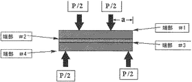
図7は、ラミネート構造体の4点曲げ試験の概略図である。図7を参照すると、破砕(P)を作り出すために必要な荷重はガラスの厚さの二乗(t2)に正比例し得るため、ガラスラミネート構造体におけるより薄いガラスの使用は、製品の信頼性に対して深刻な影響を及ぼす。これは、ガラス棒に対する4点曲げ破壊応力(σF)を特定するための以下の式: FIG. 7 is a schematic view of a four-point bending test of a laminated structure. With reference to FIG. 7, the use of thinner glass in the glass laminate structure is product reliability because the load required to produce crush (P) can be directly proportional to the square of the glass thickness (t 2). Has a serious impact on. This is the following equation for specifying the 4-point bending fracture stress (σ F) for a glass rod:
によって実証され、式中、bは棒の幅を表し、Lは支持部分の長さを表し、ならびにSは荷重をかけた部分の長さを表す。したがって、ガラスの厚さ(t)が減少すると、破砕(P)を作り出すための荷重が二次関数的に減少する、ということになる。ラミネート構造体が屈曲される場合、2枚のガラスが受ける応力は複雑であり、中間層の特性およびガラスの厚さの関数である。 In the equation, b represents the width of the rod, L represents the length of the support portion, and S represents the length of the loaded portion. Therefore, as the thickness (t) of the glass decreases, the load for producing crushing (P) decreases quadratically. When the laminated structure is bent, the stress applied to the two pieces of glass is complex and is a function of the properties of the intermediate layer and the thickness of the glass.
荷重が、中間層によって第二板ガラスもしくはシートに直接伝達されると仮定すると、最大曲げモーメント(M)は、2つの層によって共有されるので、効果的に半分に分割され得る。しがたって、図7の端部2および4において生じる最大破壊応力は、以下の関係:
Assuming that the load is transmitted directly to the second glass or sheet by the intermediate layer, the maximum bending moment (M) can be effectively split in half because it is shared by the two layers. Therefore, the maximum fracture stress generated at the
![]()
![]()
に示されるように、式(1)を修正することによって見出すことができ、式中、厚さの値(t)は、個々の板ガラスの厚さを表す。 As shown in, it can be found by modifying the equation (1), in which the thickness value (t) represents the thickness of the individual flat glass.
本開示の実施形態の恩恵および利点は、いくつかの実施例および実験によって観察することができる。例えば、1mm厚の2枚の板ガラスおよび0.5厚の中間層を有する10mm幅のラミネート構造体において、応力が中間層によって直接伝えられると仮定される場合(すなわち、あたかも中間層が存在しないように、あたかもお互いに重ねられた2枚の板ガラスを有するかのように、当該ラミネートが振る舞う場合)、式(2)が適用される。20単位の力の荷重がこの構造体に適用される場合、両層の端部にかかる応力は以下: The benefits and benefits of the embodiments of the present disclosure can be observed by several examples and experiments. For example, in a 10 mm wide laminated structure with two 1 mm thick glass sheets and a 0.5 thick intermediate layer, it is assumed that stress is directly transmitted by the intermediate layer (ie, as if there were no intermediate layer). When the laminate behaves as if it had two glass plates stacked on top of each other), equation (2) is applied. When a load of 20 units of force is applied to this structure, the stresses on the ends of both layers are:
のようになり、式中、Kは、荷重部分および支持部分を説明するための幾何学的定数を表す。受ける応力は、両層において等しく共有され得るため、結果として、そのような構造体における破壊の可能性は2倍となる。 In the equation, K represents a geometric constant for explaining the load portion and the support portion. As a result, the potential for failure in such structures is doubled because the stresses they receive can be shared equally between the two layers.
さらなる実施例として、同じ寸法を有するラミネート構造体において、中間層が、あたかも板ガラスにしっかりと取り付けられて板ガラスと同じ弾性率を有するように処理される場合、適用するための関連方程式は(1)であり、その場合、tは、板ガラスと中間層の厚さの合計=1+1+0.5=2.5mmとなる。同じ荷重において端部が受ける応力は以下: As a further embodiment, in a laminated structure of the same dimensions, if the intermediate layer is treated as if it were tightly attached to the plate glass and had the same modulus of elasticity as the plate glass, the relevant equations to apply are (1). In that case, t is the total thickness of the flat glass and the intermediate layer = 1 + 1 + 0.5 = 2.5 mm. The stress applied to the end under the same load is as follows:
のようになり、ここで、受ける応力は前の実施例の場合よりおよそ3倍小さく、これは、ラミネート構造体が、破砕前に実質的により大きな荷重に耐えることができることを意味することに留意されたい。ここで、端部2において受ける応力は、それらが曲げモーメントの中央平面の上にあるので圧縮応力であるため、最大張力応力は端部4のみにおいて受ける。
Note that the stress received here is about three times less than in the previous embodiment, which means that the laminated structure can withstand a substantially larger load before crushing. I want to be. Here, the stress received at the
しかしながら、実際に受ける応力はより複雑であり、これら2つの実施例の間のどこかに存する。概して、当該応力は、ポリマー中間層の弾性率を変える温度の関数である(例えば、より冷たい温度は、結果として、硬いPVB中間層を生じることができ、その場合、それぞれのラミネート構造体は、よりいっそう、一体型の場合(すなわち、第二実施例)のように振る舞い;より熱い温度は、結果として、柔軟なPVB中間層を生じることができ、その場合、それぞれのラミネート構造体は、よりいっそう、第一実施例のように振る舞う)。しかしながら、本開示の実施形態は、従来の中間層材料(例えば、PVBなど)を利用することができるポリマー中間層の中央領域と比べて高い弾性率を有する周辺境界を有する複合ポリマー中間層を提供する。したがって、本開示の実施形態は、優れたエッジ強度性能を示しつつ(例えば、屈曲の際に、当該ラミネート構造体が、実質的に一体として振る舞う)、中央領域が、ポリマー中間層の従来の機能を維持する(例えば、衝突および破砕事象の際の、ガラスおよび搭乗者の保持)という恩恵を享受することができる。本開示の代替の実施形態において、ラミネート構造体の周辺部の周りにおいて当該ラミネート構造体における2枚の板ガラスの間のギャップの橋渡しをするために、ガラスを用いることができる。このガラスは、熱接着によって、または上記において説明した接着剤によって取り付けることができ、それにより、ガラスの周辺部は、端部の周りのラミネートの剛性をかなり増加させるのに十分厚くなるであろうし、より軽量の中間層(例えば、PVBなど)を、重量を増やすことなく、より厚くできるであろう(すなわち、PVBは、ガラスのおよそ1/2の密度を有する)。そのような実施形態において利用される例示的ガラス材料は、これらに限定されるわけではないが、低溶融温度ガラスであり得る。 However, the stress actually applied is more complex and lies somewhere between these two examples. In general, the stress is a function of the temperature that alters the modulus of elasticity of the polymer interlayer (eg, colder temperatures can result in a hard PVB interlayer, in which case each laminated structure Even more, it behaves as in the case of the integral type (ie, the second embodiment); hotter temperatures can result in a flexible PVB intermediate layer, in which case each laminated structure is more Better, behave like the first embodiment). However, embodiments of the present disclosure provide a composite polymer intermediate layer with a peripheral boundary that has a higher elastic modulus than the central region of the polymer intermediate layer in which conventional interlayer materials (eg, PVB, etc.) can be utilized. To do. Accordingly, embodiments of the present disclosure exhibit excellent edge strength performance (eg, the laminated structure behaves substantially integrally during bending), while the central region is the conventional function of the polymer interlayer. You can enjoy the benefits of maintaining (eg, holding the glass and occupants in the event of a collision and crushing event). In an alternative embodiment of the present disclosure, glass can be used to bridge the gap between two plate glasses in the laminated structure around the periphery of the laminated structure. The glass can be attached by thermal gluing or by the adhesives described above, whereby the periphery of the glass will be thick enough to significantly increase the stiffness of the laminate around the edges. , A lighter intermediate layer (eg, PVB, etc.) could be made thicker without increasing weight (ie, PVB has a density of approximately half that of glass). The exemplary glass material utilized in such embodiments may be, but is not limited to, low melt temperature glass.
例示的な低溶融温度ガラスとしては、これらに限定されるわけではないが、ホウ酸ガラスおよびリン酸ガラス(例えば、リン酸スズ、フルオロリン酸スズ、およびホウ酸スズなど)が挙げられる。これらのガラスは、これらに限定されるわけではないが、タングステン、セリウム、およびニオブなどの1種または複数種のドーパントも含み得る。そのようなドーパントが含まれている場合、そのようなドーパントは、例えば、ガラス層の光学特性に影響を及ぼし得る。例示的フルオロリン酸スズガラス組成物は、対応する三元相図においてSnO、SnF2、およびP2O5のそれぞれの組成物に関して表すことができる。好適な低溶融温度ガラスは、SnO2、ZnO、TiO2、ITO、および他の低溶融ガラス組成物を含み得る。好適なフルオロリン酸スズガラスは、20〜100mol%のSnO、0〜50mol%のSnF2、および0〜30mol%のP2O5を含む。これらのフルオロリン酸スズガラス組成物は、任意選択により、0〜10mol%のWO3、0〜10mol%のCeO2、および/または0〜5mol%のNb2O5を含んでもよい。低溶融温度ガラスのための追加の組成物としては、本発明の譲受人に譲渡された米国特許第5,089,446号明細書および米国特許出願第11/207,691号明細書、同第11/544,262号明細書、同第11/820,855号明細書、同第12/072,784号明細書、同第12/362,063号明細書、同第12/763,541号明細書、同第12/879,578号明細書、および同第13/841,391号明細書に記載される組成物が挙げられ、なお、これらの内容全体は、参照により本明細書に組み入れられる。当然のことながら、他の実施形態において、これらの低温溶融ガラスに代わって、高温溶融ガラスを用いることができる。 Exemplary low melting temperature glasses include, but are not limited to, borosilicate glass and phosphoric acid glass (eg, tin phosphate, tin fluorophosphate, tin borate, etc.). These glasses may also include, but are not limited to, one or more dopants such as tungsten, cerium, and niobium. When such dopants are included, such dopants can affect, for example, the optical properties of the glass layer. An exemplary tin glass composition of fluorophosphate can be represented in the corresponding ternary phase diagram for each of the SnO, SnF 2 , and P 2 O 5 compositions. Suitable low melt temperature glasses may include SnO 2 , ZnO, TiO 2 , ITO, and other low melt glass compositions. Suitable tin fluorophosphate glasses contain 20-100 mol% SnO, 0-50 mol% SnF 2 , and 0-30 mol% P 2 O 5 . These tin fluorophosphate glass compositions may optionally contain 0-10 mol% WO 3 , 0-10 mol% CeO 2 , and / or 0-5 mol% Nb 2 O 5 . Additional compositions for low melt temperature glasses include US Pat. No. 5,089,446 and US Patent Application No. 11 / 207,691, which have been transferred to the transferee of the invention. 11 / 544,262, 11 / 820,855, 12 / 072,784, 12 / 362,063, 12 / 763,541. The compositions described in the specification, the same No. 12 / 879,578, and the same No. 13 / 841,391 are mentioned, and the entire contents thereof are incorporated in the present specification by reference. Be done. Of course, in other embodiments, high temperature molten glass can be used instead of these low temperature molten glasses.
本開示の実施形態に対して、追加の実験を実施した。一つの実験において、第一ガラスラミネート構造体80は、およそ0.7mmの化学強化されたガラス(例えば、「Gorilla」ガラス)の2枚の板ガラスとその間に挟設されたLoctiteエポキシ(Loctite 3491)の5mmの周辺領域を有するポリマー中間層とを含み、ならびに第二ガラスラミネート構造体82は、およそ0.7mmの化学強化されたガラス(例えば、「Gorilla」ガラス)の2枚の板ガラスとその間に挟設された例示的ファイバーコーティングの5mmの周辺領域を有するポリマー中間層とを含んでいた。図8は、様々な荷重でのこれらの実施形態の3点曲げ試験のワイブルプロットである。図示されているように、第一ガラスラミネート構造体に対し荷重を増加させたときのシフトを観察することができる。
Additional experiments were performed on the embodiments of the present disclosure. In one experiment, the first
図9は、本開示のいくつかの実施形態の4点曲げ実験における破壊荷重(kgs)のボックスプロットである。図9を参照すると、対照ラミネート構築物90は、およそ0.7mmの化学強化されたガラス(例えば、「Gorilla」ガラス)の2枚の板ガラスとその間に挟設されたポリマー中間層とを含み(周辺領域はない)、別のラミネート構築物91は、およそ0.7mmの化学強化されたガラス(例えば、「Gorilla」ガラス)の2枚の板ガラスとその間に挟設されたEastman Chemical DGグレードのPVB材料(DG材料)の5mmの周辺領域を有する好適なポリマー中間層とを含んでいた。図示されているように、この例示的実施形態は、対照と比較して、破壊荷重において著しい増加(例えば、端部破壊荷重におけるおよそ30パーセントの増加)を示した。 FIG. 9 is a box plot of breaking loads (kgs) in a four-point bending experiment of some embodiments of the present disclosure. Referring to FIG. 9, the control laminate construct 90 includes two flat glass sheets of approximately 0.7 mm chemically strengthened glass (eg, “Gorilla” glass) and a polymer intermediate layer sandwiched between them (periphery). Another laminate construction 91 (no area) is an Eastman Chemical DG grade PVB material (e.g., "Gorilla" glass) sandwiched between two plates of approximately 0.7 mm chemically strengthened glass (eg, "Gorilla" glass). DG material) included a suitable polymer intermediate layer with a peripheral area of 5 mm. As illustrated, this exemplary embodiment showed a significant increase in fracture load (eg, approximately 30 percent increase in edge fracture load) compared to controls.
図10は、本開示のいくつかの実施形態の4点曲げ実験における破壊荷重(kgs)のボックスプロットである。図11は、図10に表された実施形態での4点曲げ破壊荷重プロットである。図10および11を参照すると、対照ラミネート構築物90は、およそ0.7mmの化学強化されたガラス(例えば、「Gorilla」ガラス)の2枚の板ガラスとその間に挟設されたポリマー中間層とを含み(周辺領域はない)、別のラミネート構築物92は、およそ0.7mmの化学強化されたガラス(例えば、「Gorilla」ガラス)の2枚の板ガラスとその間に挟設されたDG材料の5mmの周辺領域を有する好適なポリマー中間層とを含み、第二ラミネート構築物93は、およそ0.7mmの化学強化されたガラス(例えば、「Gorilla」ガラス)の2枚の板ガラスとその間に挟設された例示的ファイバーコーティングの5mmの周辺領域を有する好適なポリマー中間層とを含み、第三ラミネート構築物94は、およそ0.7mmの化学強化されたガラス(例えば、「Gorilla」ガラス)の2枚の板ガラスとその間に挟設されたLoctiteブラックボーダー材料の5mmの周辺領域を有する好適なポリマー中間層とを含み、第四ラミネート構築物95は、およそ0.7mmの化学強化されたガラス(例えば、「Gorilla」ガラス)の2枚の板ガラスとその間に挟設されたLoctiteクリアボーダー材料の5mmの周辺領域を有する好適なポリマー中間層とを含んでいた。図示されるように、各実施形態は、対照と比較して、破壊荷重における増加を示したが、しかしながら、DG材料およびLoctiteクリア材料を含有する周辺領域を有する実施形態は、端部破壊荷重において30パーセント以上の増加を提供する。例示的ファイバーコーティングを用いる実施形態の性能を高めるために、例示的接着促進剤を用いることができ、その結果として、端部の破壊荷重において匹敵する増加を生じる。実験および理論を通じて容易に分かるように、本開示の実施形態は、高いエッジ強度を有する優れた軽量のガラスラミネート構造体を提供することができる。
FIG. 10 is a box plot of breaking loads (kgs) in a four-point bending experiment of some embodiments of the present disclosure. FIG. 11 is a four-point bending fracture load plot according to the embodiment shown in FIG. Referring to FIGS. 10 and 11, the control laminate construct 90 includes two flat glass sheets of approximately 0.7 mm chemically strengthened glass (eg, “Gorilla” glass) and a polymer interlayer sandwiched between them. Another laminate construction 92 (no peripheral area) is a 5 mm periphery of DG material sandwiched between two flat glass sheets of approximately 0.7 mm chemically strengthened glass (eg, "Gorilla" glass). Including a suitable polymer intermediate layer having a region, the second
本開示の実施形態の端部領域の弾性率における増加により、それぞれのラミネート構造体は、曲げられたときに端部領域においてより低い引張応力を効果的に受けることができ、その結果、破壊することなくより高い端部荷重に耐えることができる。さらに、当該ポリマーは、ガラスの露出した端部の周りを包んだ場合、端部における衝突および破砕に対する防護壁として機能することができる。本明細書において説明されるそのような特徴および利点は、産業において以前に用いられた材料より薄い材料の使用を可能にすることができ、ガラスラミネート構造体の剛性を向上させることができ、ならびにそのような構造がそのような用途(例えば、これらに限定されるわけではないが、滑動式の窓、サンルーフ、テーブルトップなど)の剛性要件を満たすことを可能にする。例示的実施形態は、より高い温度でも変形せず、したがって、それらの作業条件を様々な用途に合うように拡張する。化学強化されたガラスの利用により、実施形態は、「Gorilla」ガラスまたはWillow(登録商標)ガラスによって提供される耐久性、軽量化、耐スクラッチ性なども実現することができる。 The increase in modulus of elasticity of the end regions of the embodiments of the present disclosure allows each laminated structure to effectively receive lower tensile stresses at the end regions when bent, resulting in fracture. Can withstand higher end loads without. In addition, the polymer can act as a protective barrier against collisions and crushing at the edges when wrapped around the exposed edges of the glass. Such features and advantages described herein can allow the use of thinner materials than those previously used in the industry, can improve the rigidity of glass laminated structures, and can also be used. Such structures make it possible to meet the stiffness requirements of such applications (eg, but not limited to sliding windows, sunroofs, table tops, etc.). The exemplary embodiments do not deform at higher temperatures and therefore extend their working conditions to suit a variety of applications. By utilizing chemically strengthened glass, embodiments can also realize the durability, weight reduction, scratch resistance, etc. provided by "Gorilla" glass or Willow® glass.
いくつかの実施形態において、第一ガラス層と、第二ガラス層と、当該第一ガラス層および第二ガラス層の間に挟設された少なくとも1つのポリマー中間層とを有するラミネート構造体が提供される。当該ポリマー中間層は、第一弾性率を有する第一領域と、第二弾性率を有する第二領域とを含み得る。第二弾性率は、第一弾性率より大きくあり得る。いくつかの実施形態において、当該第一領域は、ポリマー中間層の中央領域であり得、並びに当該第二領域は、第一領域の周りを囲む、ポリマー中間層の周辺領域であり得る。第一領域の例示的弾性率は、約15MPa、約1MPaから約20MPaまでの間、または2から約15MPaまでの間、であり得る。第二領域の例示的弾性率は、約25MPaを超え、25MPaと90MPaとの間、約30MPaを超え、約50MPaを超え、または約75MPaであり得る。追加の実施形態において、第二もしくは周辺領域の弾性率は、90MPaを超え、例えば、100MPaを超え、500MPaを超え、1GPaを超え、2GPaを超え、1GPaと4GPaとの間、4GPaを超え、100MPaと1GPaとの間であり得る。いくつかの実施形態において、第二領域の幅は、可変であり得、または実質的に一定であり得る。他の実施形態において、第一ガラス層は、化学強化されたガラスであり得、ならびに第二ガラス層は、化学強化されていないガラスであり得、それにより、第一層は、第二層に対して外部または内部である。当然のことながら、両層とも、化学強化されたガラスであってもよく、または両層とも、化学強化されていないガラスであってもよい。第一および第二ガラス層の厚さは、これらに限定されるわけではないが、1.5mmを超えない厚さ、1.0mmを超えない厚さ、0.7mmを超えない厚さ、0.5mmを超えない厚さ、約0.5mmから約1.0mmまでの範囲内の厚さ、約0.5mmから約0.7mmまでの厚さ、であり得る。当然のことながら、第一および第二ガラス層の厚さは、異なっていてもよい。いくつかの実施形態において、第一および第二ガラス層の組成は、異なっていてもよい。ポリマー中間層の第一領域のための例示的材料は、これらに限定されるわけではないが、ポリビニルブチラール(PVB)、ポリカーボネート、防音性PVB、エチレン酢酸ビニル(EVA)、熱可塑性ポリウレタン(TPU)、イオノマー、熱可塑性材料、およびそれらの組み合わせを含み得る。ポリマー中間層の第二領域のための例示的材料は、これらに限定されるわけではないが、ポリウレタン、加硫ゴム、ポリエステル材料、イオノマー、フェノール−ホルムアルデヒド、尿素−ホルムアルデヒド、エポキシ樹脂、ポリイミド、メラミン樹脂、エステル、ポリシアヌレート、エステル、樹脂、エポキシ、架橋ポリマー、強化ポリマー性材料、2成分エポキシ、2成分ウレタン、2成分アクリル樹脂、2成分シリコーン、湿気硬化型ウレタンおよびエポキシ、フェノール樹脂、ノボラック、メラミンホルムアルデヒド、アルキド、不飽和ポリエステル、ポリイミド、ポリアミド、光硬化性または電子ビーム硬化性ポリマー、ならびにそれらの組み合わせであり得る。例示的ポリマー中間層は、約0.4mmから約1.2mmまでの間の厚さを有し得る。いくつかの中間層は、およそ0.8mmの厚さを有し得る。例示的ラミネート構造体は、1m2を超える面積を有し得、ならびに自動車用風防、サンルーフ、カバープレートなどであり得る。いくつかの実施形態において、第一および第二ガラス層の1つまたは複数の表面は、酸エッチングすることができる。 In some embodiments, a laminated structure comprising a first glass layer, a second glass layer, and at least one polymer intermediate layer sandwiched between the first glass layer and the second glass layer is provided. Will be done. The polymer intermediate layer may include a first region having a first elastic modulus and a second region having a second elastic modulus. The second elastic modulus can be greater than the first elastic modulus. In some embodiments, the first region can be the central region of the polymer intermediate layer, and the second region can be the peripheral region of the polymer intermediate layer that surrounds the first region. The exemplary elastic modulus of the first region can be between about 15 MPa, about 1 MPa to about 20 MPa, or between 2 and about 15 MPa. The exemplary elastic modulus of the second region can be greater than about 25 MPa, between 25 MPa and 90 MPa, greater than about 30 MPa, greater than about 50 MPa, or about 75 MPa. In additional embodiments, the modulus of elasticity of the second or peripheral region is greater than 90 MPa, for example greater than 100 MPa, greater than 500 MPa, greater than 1 GPa, greater than 2 GPa, between 1 GPa and 4 GPa, greater than 4 GPa, 100 MPa. And 1 GPa. In some embodiments, the width of the second region can be variable or substantially constant. In other embodiments, the first glass layer can be chemically strengthened glass, and the second glass layer can be non-chemically strengthened glass, whereby the first layer becomes the second layer. On the other hand, it is external or internal. Of course, both layers may be chemically strengthened glass, or both layers may be non-chemically strengthened glass. The thickness of the first and second glass layers is not limited to these, but is not more than 1.5 mm, not more than 1.0 mm, not more than 0.7 mm, 0. It can be a thickness not exceeding .5 mm, a thickness in the range of about 0.5 mm to about 1.0 mm, a thickness of about 0.5 mm to about 0.7 mm. As a matter of course, the thicknesses of the first and second glass layers may be different. In some embodiments, the composition of the first and second glass layers may be different. Exemplary materials for the first region of the polymer interlayer are, but are not limited to, polyvinyl butyral (PVB), polycarbonate, soundproof PVB, ethylene vinyl acetate (EVA), thermoplastic polyurethane (TPU). , Ionomers, thermoplastic materials, and combinations thereof. Exemplary materials for the second region of the polymer interlayer are, but are not limited to, polyurethanes, vulverable rubbers, polyester materials, ionomers, phenol-formaldehydes, urea-formaldehydes, epoxy resins, polyimides, melamines. Resin, ester, polycyanurate, ester, resin, epoxy, crosslinked polymer, reinforced polymer material, 2-component epoxy, 2-component urethane, 2-component acrylic resin, 2-component silicone, moisture-curable urethane and epoxy, phenol resin, Novorak , Melamine formaldehyde, alkides, unsaturated polyesters, polyimides, polyamides, photocurable or electron beam curable polymers, and combinations thereof. The exemplary polymer interlayer can have a thickness between about 0.4 mm and about 1.2 mm. Some intermediate layers can have a thickness of approximately 0.8 mm. An exemplary laminated structure can have an area of more than 1 m 2 and can be an automotive windshield, sunroof, cover plate, and the like. In some embodiments, one or more surfaces of the first and second glass layers can be acid etched.
別の実施形態において、第一ガラス層、第二ガラス層、および当該第一ガラス層と第二ガラス層との間に挟設された中間層を有するラミネート構造体が提供され、この場合、当該中間層は、第一弾性率を有する第一領域および第二弾性率を有する第二領域を含む。この第二弾性率は、第一弾性率より大きくあり得る。いくつかの実施形態において、当該第一領域は、中間層の中央領域であり得、並びに当該第二領域は、第一領域の周りを囲む、中間層の周辺領域であり得る。第一領域のための例示的材料は、これらに限定されるわけではないが、ポリビニルブチラール(PVB)、ポリカーボネート、防音性PVB、エチレン酢酸ビニル(EVA)、熱可塑性ポリウレタン(TPU)、イオノマー、熱可塑性材料、ポリウレタン、加硫ゴム、ポリエステル材料、イオノマー、フェノール−ホルムアルデヒド、尿素−ホルムアルデヒド、エポキシ樹脂、ポリイミド、メラミン樹脂、エステル、ポリシアヌレート、エステル、樹脂、エポキシ、架橋ポリマー、強化ポリマー性材料、2成分エポキシ、2成分ウレタン、2成分アクリル樹脂、2成分シリコーン、湿気硬化型ウレタンおよびエポキシ、フェノール樹脂、ノボラック、メラミンホルムアルデヒド、アルキド、不飽和ポリエステル、ポリイミド、ポリアミド、光硬化性または電子ビーム硬化性ポリマー、ならびにそれらの組み合わせを含み得る。いくつかの実施形態において、第二領域は、これらに限定されるわけではないが、ポリウレタン、加硫ゴム、ポリエステル材料、イオノマー、フェノール−ホルムアルデヒド、尿素−ホルムアルデヒド、エポキシ樹脂、ポリイミド、メラミン樹脂、エステル、ポリシアヌレート、エステル、樹脂、エポキシ、架橋ポリマー、強化ポリマー性材料、2成分エポキシ、2成分ウレタン、2成分アクリル樹脂、2成分シリコーン、湿気硬化型ウレタンおよびエポキシ、フェノール樹脂、ノボラック、メラミンホルムアルデヒド、アルキド、不飽和ポリエステル、ポリイミド、ポリアミド、光硬化性または電子ビーム硬化性ポリマー、ならびにそれらの組み合わせなどの材料を含み得る。代替の実施形態において、中間層の第二領域は、ガラス材料であり得る。 In another embodiment, a laminated structure having a first glass layer, a second glass layer, and an intermediate layer sandwiched between the first glass layer and the second glass layer is provided, in this case. The intermediate layer includes a first region having a first elastic modulus and a second region having a second elastic modulus. This second elastic modulus can be greater than the first elastic modulus. In some embodiments, the first region can be the central region of the intermediate layer, and the second region can be the peripheral region of the intermediate layer that surrounds the first region. Exemplary materials for the first region are, but are not limited to, polyvinyl butyral (PVB), polycarbonate, soundproof PVB, ethylene vinyl acetate (EVA), thermoplastic polyurethane (TPU), ionomer, thermal. Thermoplastic material, polyurethane, vulture rubber, polyester material, ionomer, phenol-formaldehyde, urea-formaldehyde, epoxy resin, polyimide, melamine resin, ester, polycyanurate, ester, resin, epoxy, crosslinked polymer, reinforced polymer material, Two-component epoxy, two-component urethane, two-component acrylic resin, two-component silicone, moisture-curable urethane and epoxy, phenol resin, novolak, melamine formaldehyde, alkyd, unsaturated polyester, polyimide, polyamide, photocurable or electron beam curable It may include polymers, as well as combinations thereof. In some embodiments, the second region is, but is not limited to, polyurethane, vulverable rubber, polyester material, ionomer, phenol-formaldehyde, urea-formaldehyde, epoxy resin, polyimide, melamine resin, ester. , Polycyanulate, ester, resin, epoxy, crosslinked polymer, reinforced polymer material, 2-component epoxy, 2-component urethane, 2-component acrylic resin, 2-component silicone, moisture-curable urethane and epoxy, phenolic resin, novolak, melamine formaldehyde , Epoxy, unsaturated polyesters, polyimides, polyamides, photocurable or electron beam curable polymers, and combinations thereof. In an alternative embodiment, the second region of the intermediate layer can be a glass material.
この説明は多くの詳細を含み得るが、その一方で、これらは、それらの範囲の限定として解釈されるべきではなく、むしろ、特定の実施形態に特異的であり得る特徴の説明として解釈されるべきである。個別の実施形態との関連においてこれまで説明してきたある特定の特徴も、単一の実施形態における組み合わせにおいて実践することもできる。これとは逆に、単一の実施形態との関連において説明した様々な特徴も、複数の実施形態においてまたは任意の好適な部分的組み合わせにおいて実践することができる。さらに、特徴は、ある特定の組み合わせにおいて機能するように上記において説明され得、ならびにそのようなものとして最初に権利請求され得るが、場合によって、権利請求された組み合わせのうちの1つまたは複数の特徴を当該組み合わせから削除してもよく、ならびに権利請求された組み合わせは、部分的組み合わせまたは部分的組み合わせの変形を対象とし得る。 While this description may include many details, on the other hand, they should not be construed as a limitation of their scope, but rather as a description of features that may be specific to a particular embodiment. Should be. Certain features previously described in the context of individual embodiments can also be practiced in combination in a single embodiment. Conversely, the various features described in the context of a single embodiment can also be practiced in multiple embodiments or in any suitable partial combination. In addition, the features may be described above to function in a particular combination, and may be initially claimed as such, but in some cases one or more of the claimed combinations. Features may be removed from the combination, and the claimed combination may be subject to partial combinations or variants of partial combinations.
同様に、作業は、特定の順序において図面に表されているが、これは、望ましい結果を達成するために、そのような作業が、図示された特定の順序または連続する順序において実施されること、または示された全ての作業が実施されることが必要であると理解されるべきではない。ある特定の状況において、マルチタスク処理および並列処理が有利であり得る。 Similarly, the work is shown in the drawings in a particular order, which means that such work is performed in the specific order shown or in a contiguous order in order to achieve the desired result. , Or it should not be understood that all indicated work needs to be performed. In certain situations, multitasking and parallelism can be advantageous.
図1〜11に例示される様々な構成および実施形態によって示されるように、向上したエッジ強度を有するガラスラミネート構造体において様々な実施形態について説明してきた。 Various embodiments have been described for glass laminated structures with improved edge strength, as shown by the various configurations and embodiments exemplified in FIGS. 1-11.
本開示の好ましい実施形態について説明してきたが、説明した実施形態は単なる例示であって、本発明の範囲は、等価物の全範囲が一致する場合に添付の特許請求の範囲によってのみ定義されるべきであることは理解されたく、本明細書を熟読することにより、当業者には多くの変形および変更が自然と思い浮かぶであろう。 Although preferred embodiments of the present disclosure have been described, the embodiments described are merely exemplary and the scope of the invention is defined only by the appended claims if the full scope of the equivalent is consistent. It should be understood that by perusing this specification, many modifications and changes will naturally come to mind to those skilled in the art.
2、4、101、131 端部
10 ラミネート構造体
12 外側層
13、15 第一表面
14 ポリマー性中間層
16 内側層
17、19 別の表面
50 第一ラミネート構造体
52 第二ラミネート構造体
60、62 構築物
80 第一ガラスラミネート構造体
82 第二ガラスラミネート構造体
90 対照ラミネート構築物
91、92、93、94、95 ラミネート構築物
100、200 ガラスラミネート構造体
110 外部ガラスシート
112、122 外側表面
114、124 内側表面
120 内部ガラスシート
130 ポリマー中間層
132 中央領域
134 周辺領域
2, 4, 101, 131
Claims (3)
1.0mm未満の厚さを有する第二ガラス層と;
該第一ガラス層と該第二ガラス層との間に挟設された中間層と;
を含み、
該中間層は、第一弾性率を有する第一領域と、第二弾性率を有する第二領域とを含み、該第一領域の弾性率が、1MPaから20MPaまでの間であり、
前記第一領域が、前記中間層の中央領域であり、かつ前記第二領域が、該第一領域の周りを囲む前記中間層の周辺領域であり、
前記第二弾性率が、前記第一弾性率より大きく、
前記中間層の第二領域は、ガラス材料であり、かつ、前記第二領域の弾性率が100MPa以上である、
ラミネート構造体。 With the first glass layer;
With a second glass layer having a thickness of less than 1.0 mm;
With an intermediate layer sandwiched between the first glass layer and the second glass layer;
Including
The intermediate layer includes a first region having a first elastic modulus and a second region having a second elastic modulus, and the elastic modulus of the first region is between 1 MPa and 20 MPa.
The first region is the central region of the intermediate layer, and the second region is the peripheral region of the intermediate layer surrounding the first region.
The second elastic modulus is larger than the first elastic modulus,
The second region of the intermediate layer is a glass material der is, and the elastic modulus of the second region is not less than 100 MPa,
Laminated structure.
Priority Applications (1)
| Application Number | Priority Date | Filing Date | Title |
|---|---|---|---|
| JP2019207944A JP6977015B2 (en) | 2013-10-07 | 2019-11-18 | Glass laminated structure with improved edge strength |
Applications Claiming Priority (3)
| Application Number | Priority Date | Filing Date | Title |
|---|---|---|---|
| US201361887646P | 2013-10-07 | 2013-10-07 | |
| US61/887,646 | 2013-10-07 | ||
| PCT/US2014/059262 WO2015054112A1 (en) | 2013-10-07 | 2014-10-06 | Glass laminate structures having improved edge strength |
Related Child Applications (1)
| Application Number | Title | Priority Date | Filing Date |
|---|---|---|---|
| JP2019207944A Division JP6977015B2 (en) | 2013-10-07 | 2019-11-18 | Glass laminated structure with improved edge strength |
Publications (2)
| Publication Number | Publication Date |
|---|---|
| JP2016539890A JP2016539890A (en) | 2016-12-22 |
| JP6836397B2 true JP6836397B2 (en) | 2021-03-03 |
Family
ID=51844850
Family Applications (2)
| Application Number | Title | Priority Date | Filing Date |
|---|---|---|---|
| JP2016520636A Active JP6836397B2 (en) | 2013-10-07 | 2014-10-06 | Glass laminated structure with improved edge strength |
| JP2019207944A Active JP6977015B2 (en) | 2013-10-07 | 2019-11-18 | Glass laminated structure with improved edge strength |
Family Applications After (1)
| Application Number | Title | Priority Date | Filing Date |
|---|---|---|---|
| JP2019207944A Active JP6977015B2 (en) | 2013-10-07 | 2019-11-18 | Glass laminated structure with improved edge strength |
Country Status (6)
| Country | Link |
|---|---|
| US (1) | US20160250825A1 (en) |
| EP (1) | EP3055129A1 (en) |
| JP (2) | JP6836397B2 (en) |
| KR (1) | KR20160067153A (en) |
| CN (1) | CN105813840B (en) |
| WO (1) | WO2015054112A1 (en) |
Families Citing this family (50)
| Publication number | Priority date | Publication date | Assignee | Title |
|---|---|---|---|---|
| US9616641B2 (en) | 2011-06-24 | 2017-04-11 | Corning Incorporated | Light-weight hybrid glass laminates |
| US10035331B2 (en) | 2011-06-24 | 2018-07-31 | Corning Incorporated | Light-weight hybrid glass laminates |
| WO2013181484A1 (en) | 2012-05-31 | 2013-12-05 | Corning Incorporated | Stiff interlayers for laminated glass structures |
| CN104703793B (en) | 2012-06-01 | 2018-09-18 | 康宁股份有限公司 | The glass laminate of crushing performance for optimization constructs |
| JP5981648B2 (en) | 2012-06-14 | 2016-08-31 | コーニング インコーポレイテッド | Process for laminating thin glass laminates |
| EP2679551A1 (en) | 2012-06-28 | 2014-01-01 | Corning Incorporated | Process and system for fine tuning precision glass sheet bending |
| EP2958864B1 (en) | 2013-02-25 | 2018-03-21 | Corning Incorporated | Method of manufacturing a thin glass pane |
| US9908805B2 (en) | 2013-08-26 | 2018-03-06 | Corning Incorporated | Method for localized annealing of chemically strengthened glass |
| CN109334171B (en) | 2013-08-30 | 2022-03-29 | 康宁股份有限公司 | Lightweight, high stiffness glass laminate structure |
| US10800143B2 (en) | 2014-03-07 | 2020-10-13 | Corning Incorporated | Glass laminate structures for head-up display system |
| US9573833B2 (en) | 2014-03-31 | 2017-02-21 | Corning Incorporated | Method and lift jet floatation system for shaping thin glass |
| EP3166799B1 (en) | 2014-07-10 | 2021-09-29 | Corning Incorporated | Cold formed glass applique |
| US11097974B2 (en) | 2014-07-31 | 2021-08-24 | Corning Incorporated | Thermally strengthened consumer electronic glass and related systems and methods |
| JP6701168B2 (en) | 2014-07-31 | 2020-05-27 | コーニング インコーポレイテッド | Heat strengthened glass, and method and apparatus for heat strengthening glass |
| US10611664B2 (en) | 2014-07-31 | 2020-04-07 | Corning Incorporated | Thermally strengthened architectural glass and related systems and methods |
| EP3174836B1 (en) | 2014-08-01 | 2020-08-19 | Corning Incorporated | Glass shaping apparatus and method |
| JP2017537048A (en) | 2014-10-29 | 2017-12-14 | コーニング インコーポレイテッド | Apparatus and method for forming or forming a heated glass sheet |
| CN107108319A (en) | 2014-11-07 | 2017-08-29 | 康宁股份有限公司 | For the induction heating method and equipment that thin glass is formed |
| EP3295241A1 (en) | 2015-05-11 | 2018-03-21 | Corning Incorporated | Surface display units with opaque screen |
| WO2016196531A1 (en) | 2015-06-02 | 2016-12-08 | Corning Incorporated | Light-responsive thin glass laminates |
| CN107683425B (en) | 2015-06-02 | 2020-04-10 | 康宁股份有限公司 | Multifunctional material system for surface display unit |
| US10286631B2 (en) * | 2015-06-03 | 2019-05-14 | Precision Glass Bending Corporation | Bent, veneer-encapsulated heat-treated safety glass panels and methods of manufacture |
| MX2018000350A (en) | 2015-07-10 | 2018-11-12 | Corning Inc | Cold formed laminates. |
| US10350861B2 (en) | 2015-07-31 | 2019-07-16 | Corning Incorporated | Laminate structures with enhanced damping properties |
| WO2017106085A1 (en) * | 2015-12-16 | 2017-06-22 | Corning Incorporated | Decorative non-porous layers for ion-exchangeable glass substrates |
| KR102492060B1 (en) | 2016-01-12 | 2023-01-26 | 코닝 인코포레이티드 | Thin thermally and chemically strengthened glass-based articles |
| US10525675B2 (en) | 2016-03-04 | 2020-01-07 | Solutia Inc. | Polymeric interlayers and multiple layer panels made therefrom exhibiting enhanced properties and performance |
| US10343379B2 (en) | 2016-03-04 | 2019-07-09 | Solutia Inc. | Polymeric interlayers and multiple layer panels made therefrom exhibiting enhanced properties and performance |
| CN109562992B (en) * | 2016-08-03 | 2022-06-21 | Agc株式会社 | Cover member and display device |
| US10011159B1 (en) | 2017-01-03 | 2018-07-03 | Ford Global Technologies, Llc | Sliding vehicle window having minimal perimeter seal |
| MX2019009037A (en) | 2017-02-03 | 2019-09-19 | Sekisui Chemical Co Ltd | Laminated glass intermediate film and laminated glass. |
| EP3936482A1 (en) | 2017-02-20 | 2022-01-12 | Corning Incorporated | Method for forming shaped glass laminate |
| US11554982B2 (en) | 2017-05-17 | 2023-01-17 | Corning Incorporated | Process for forming curved glass laminate article formed using separation material |
| US11440295B2 (en) | 2017-09-27 | 2022-09-13 | Sekisui Chemical Co., Ltd. | Laminated glass |
| EP3692003A1 (en) * | 2017-10-06 | 2020-08-12 | Corning Incorporated | System and process for forming curved glass laminate article utilizing glass viscosity differential for improved shape matching |
| JP7308189B2 (en) | 2017-10-18 | 2023-07-13 | コーニング インコーポレイテッド | How to control separation between glasses during simultaneous droop to reduce final shape mismatch between glasses |
| US11078103B2 (en) | 2017-11-30 | 2021-08-03 | Corning Incorporated | Glass articles made from laminated glass tubing and systems and methods for converting laminated glass tubing into the glass articles |
| EP3727847A1 (en) * | 2017-12-21 | 2020-10-28 | Corning Incorporated | Method for laser cutting bent glass for shape and optics match |
| CN110218004B (en) * | 2018-03-02 | 2022-07-12 | 努比亚技术有限公司 | Glass assembly and terminal |
| TW201938410A (en) * | 2018-03-16 | 2019-10-01 | 美商康寧公司 | Thin thermally strengthened glass cover panel for vehicle frame assembly and related method |
| EP3787894A1 (en) * | 2018-05-03 | 2021-03-10 | Central Glass Company, Limited | Laminated vehicle glazing having a stiff interlayer |
| WO2020012783A1 (en) * | 2018-07-13 | 2020-01-16 | セントラル硝子株式会社 | Laminated glass for automotive windshields, and method for producing same |
| PE20201457A1 (en) | 2018-08-29 | 2020-12-15 | Saint Gobain | COMPOSITE GLASS CRYSTAL |
| WO2021025981A1 (en) | 2019-08-06 | 2021-02-11 | Corning Incorporated | Glass laminate with buried stress spikes to arrest cracks and methods of making the same |
| US20220402337A1 (en) * | 2019-11-06 | 2022-12-22 | Central Glass Company, Limited | Vehicle Window Glass |
| WO2021102069A1 (en) * | 2019-11-21 | 2021-05-27 | Corning Incorporated | Asymmetrical glass laminates having a tpu interlayer and related methods |
| CN112571892A (en) * | 2020-11-19 | 2021-03-30 | 河北光兴半导体技术有限公司 | Laminated glass plate and method for manufacturing laminated glass plate |
| CN112721355B (en) * | 2020-12-21 | 2022-03-01 | 福耀玻璃工业集团股份有限公司 | Laminated glass for vehicle window and preparation method thereof |
| WO2023018515A1 (en) * | 2021-08-12 | 2023-02-16 | Apple Inc. | Windows with molded layers of polished glass |
| CN116409929A (en) * | 2023-02-15 | 2023-07-11 | 清远南玻节能新材料有限公司 | Composite glass, preparation method and application thereof and automobile window |
Family Cites Families (17)
| Publication number | Priority date | Publication date | Assignee | Title |
|---|---|---|---|---|
| DE2758581C2 (en) * | 1977-12-29 | 1980-01-03 | Bfg Glassgroup, Paris | Windshields, in particular for motor vehicles, with an inner pane made of chemically toughened silicate glass |
| JPS58199752A (en) * | 1982-05-14 | 1983-11-21 | Asahi Glass Co Ltd | Production of laminated glass |
| JPS6356230U (en) * | 1986-09-25 | 1988-04-15 | ||
| JPH03232748A (en) * | 1990-02-09 | 1991-10-16 | Sadao Oki | Multiple glass laminate and production thereof |
| FR2673619B1 (en) * | 1991-03-08 | 1993-10-01 | Saint Gobain Vitrage Internal | SHEET GLASS. |
| FR2706884B1 (en) * | 1993-06-22 | 1995-08-25 | Saint Gobain Vitrage Int | |
| GB9316821D0 (en) * | 1993-08-12 | 1993-09-29 | Glaverbel | Glazing assemblies and processes for the formation thereof |
| JP4316061B2 (en) * | 1999-08-25 | 2009-08-19 | 株式会社ブリヂストン | Laminated glass for automobile crime prevention |
| US7334371B2 (en) * | 2003-04-04 | 2008-02-26 | E.I. Du Pont De Nemours And Company | Glass laminates having improved structural integrity against severe stresses for use in external pressure plate glazing applications |
| FR2899631B1 (en) * | 2006-04-10 | 2010-02-26 | Saint Gobain | LAMINATED GLAZING AND ITS MEANS FOR SEALING AND PERIPHERAL REINFORCEMENT |
| JP4844362B2 (en) * | 2006-11-27 | 2011-12-28 | 旭硝子株式会社 | Laminated glass |
| GB0910295D0 (en) * | 2009-06-16 | 2009-07-29 | Pilkington Group Ltd | Laminated structure |
| US20120094084A1 (en) * | 2010-10-15 | 2012-04-19 | William Keith Fisher | Chemically-strengthened glass laminates |
| RU2600946C2 (en) * | 2011-04-01 | 2016-10-27 | Асахи Гласс Компани, Лимитед | Multilayer glass and method for production thereof |
| US10035331B2 (en) * | 2011-06-24 | 2018-07-31 | Corning Incorporated | Light-weight hybrid glass laminates |
| WO2013051717A1 (en) * | 2011-10-07 | 2013-04-11 | 旭硝子株式会社 | Multilayer body manufacturing method |
| WO2013094567A1 (en) * | 2011-12-22 | 2013-06-27 | 旭硝子株式会社 | Method for producing laminated glass, laminated glass and windowpane |
-
2014
- 2014-10-06 KR KR1020167011699A patent/KR20160067153A/en not_active Application Discontinuation
- 2014-10-06 WO PCT/US2014/059262 patent/WO2015054112A1/en active Application Filing
- 2014-10-06 JP JP2016520636A patent/JP6836397B2/en active Active
- 2014-10-06 US US15/027,728 patent/US20160250825A1/en not_active Abandoned
- 2014-10-06 EP EP14792660.4A patent/EP3055129A1/en active Pending
- 2014-10-06 CN CN201480066586.XA patent/CN105813840B/en active Active
-
2019
- 2019-11-18 JP JP2019207944A patent/JP6977015B2/en active Active
Also Published As
| Publication number | Publication date |
|---|---|
| JP6977015B2 (en) | 2021-12-08 |
| KR20160067153A (en) | 2016-06-13 |
| JP2016539890A (en) | 2016-12-22 |
| CN105813840B (en) | 2018-11-27 |
| JP2020045280A (en) | 2020-03-26 |
| WO2015054112A1 (en) | 2015-04-16 |
| US20160250825A1 (en) | 2016-09-01 |
| CN105813840A (en) | 2016-07-27 |
| EP3055129A1 (en) | 2016-08-17 |
Similar Documents
| Publication | Publication Date | Title |
|---|---|---|
| JP6977015B2 (en) | Glass laminated structure with improved edge strength | |
| JP6532874B2 (en) | Method of forming a pattern on a thin glass laminate structure | |
| JP6343640B2 (en) | Rigid interlayer for laminated glass structures | |
| JP6328619B2 (en) | Laminated glass structure with high adhesion of glass to polymer interlayer | |
| JP6466917B2 (en) | Laminated glass structure with strong glass / polymer interlayer adhesion | |
| KR102043438B1 (en) | Glass laminate construction for optimized breakage performance | |
| CN105377551B (en) | Lightweight hybrid glass laminated body | |
| JP5890518B2 (en) | Lightweight composite laminated glass | |
| US20150158275A1 (en) | Non-yellowing glass laminate structure | |
| JP2019503963A (en) | Asymmetric glass laminate | |
| TW201231264A (en) | Chemically-strengthened glass laminates |
Legal Events
| Date | Code | Title | Description |
|---|---|---|---|
| A621 | Written request for application examination |
Free format text: JAPANESE INTERMEDIATE CODE: A621 Effective date: 20171005 |
|
| A977 | Report on retrieval |
Free format text: JAPANESE INTERMEDIATE CODE: A971007 Effective date: 20180427 |
|
| A131 | Notification of reasons for refusal |
Free format text: JAPANESE INTERMEDIATE CODE: A131 Effective date: 20180508 |
|
| A521 | Request for written amendment filed |
Free format text: JAPANESE INTERMEDIATE CODE: A523 Effective date: 20180807 |
|
| A131 | Notification of reasons for refusal |
Free format text: JAPANESE INTERMEDIATE CODE: A131 Effective date: 20180821 |
|
| A521 | Request for written amendment filed |
Free format text: JAPANESE INTERMEDIATE CODE: A523 Effective date: 20181121 |
|
| A131 | Notification of reasons for refusal |
Free format text: JAPANESE INTERMEDIATE CODE: A131 Effective date: 20181219 |
|
| A521 | Request for written amendment filed |
Free format text: JAPANESE INTERMEDIATE CODE: A523 Effective date: 20190308 |
|
| A131 | Notification of reasons for refusal |
Free format text: JAPANESE INTERMEDIATE CODE: A131 Effective date: 20190403 |
|
| A521 | Request for written amendment filed |
Free format text: JAPANESE INTERMEDIATE CODE: A523 Effective date: 20190703 |
|
| A02 | Decision of refusal |
Free format text: JAPANESE INTERMEDIATE CODE: A02 Effective date: 20190717 |
|
| A521 | Request for written amendment filed |
Free format text: JAPANESE INTERMEDIATE CODE: A523 Effective date: 20191118 |
|
| C60 | Trial request (containing other claim documents, opposition documents) |
Free format text: JAPANESE INTERMEDIATE CODE: C60 Effective date: 20191118 |
|
| C11 | Written invitation by the commissioner to file amendments |
Free format text: JAPANESE INTERMEDIATE CODE: C11 Effective date: 20191127 |
|
| A911 | Transfer to examiner for re-examination before appeal (zenchi) |
Free format text: JAPANESE INTERMEDIATE CODE: A911 Effective date: 20200220 |
|
| C21 | Notice of transfer of a case for reconsideration by examiners before appeal proceedings |
Free format text: JAPANESE INTERMEDIATE CODE: C21 Effective date: 20200226 |
|
| A912 | Re-examination (zenchi) completed and case transferred to appeal board |
Free format text: JAPANESE INTERMEDIATE CODE: A912 Effective date: 20200306 |
|
| C211 | Notice of termination of reconsideration by examiners before appeal proceedings |
Free format text: JAPANESE INTERMEDIATE CODE: C211 Effective date: 20200311 |
|
| C22 | Notice of designation (change) of administrative judge |
Free format text: JAPANESE INTERMEDIATE CODE: C22 Effective date: 20200916 |
|
| C23 | Notice of termination of proceedings |
Free format text: JAPANESE INTERMEDIATE CODE: C23 Effective date: 20201202 |
|
| C03 | Trial/appeal decision taken |
Free format text: JAPANESE INTERMEDIATE CODE: C03 Effective date: 20210106 |
|
| C30A | Notification sent |
Free format text: JAPANESE INTERMEDIATE CODE: C3012 Effective date: 20210106 |
|
| A61 | First payment of annual fees (during grant procedure) |
Free format text: JAPANESE INTERMEDIATE CODE: A61 Effective date: 20210205 |
|
| R150 | Certificate of patent or registration of utility model |
Ref document number: 6836397 Country of ref document: JP Free format text: JAPANESE INTERMEDIATE CODE: R150 |
|
| R250 | Receipt of annual fees |
Free format text: JAPANESE INTERMEDIATE CODE: R250 |