JP6835838B2 - Humidifier purifier - Google Patents
Humidifier purifier Download PDFInfo
- Publication number
- JP6835838B2 JP6835838B2 JP2018521939A JP2018521939A JP6835838B2 JP 6835838 B2 JP6835838 B2 JP 6835838B2 JP 2018521939 A JP2018521939 A JP 2018521939A JP 2018521939 A JP2018521939 A JP 2018521939A JP 6835838 B2 JP6835838 B2 JP 6835838B2
- Authority
- JP
- Japan
- Prior art keywords
- water
- air
- watering
- humidifying
- housing
- Prior art date
- Legal status (The legal status is an assumption and is not a legal conclusion. Google has not performed a legal analysis and makes no representation as to the accuracy of the status listed.)
- Active
Links
- XLYOFNOQVPJJNP-UHFFFAOYSA-N water Substances O XLYOFNOQVPJJNP-UHFFFAOYSA-N 0.000 claims description 692
- 238000002347 injection Methods 0.000 claims description 185
- 239000007924 injection Substances 0.000 claims description 185
- 230000000007 visual effect Effects 0.000 claims description 154
- 238000004140 cleaning Methods 0.000 claims description 46
- 238000005086 pumping Methods 0.000 claims description 27
- 239000000463 material Substances 0.000 claims description 13
- 230000002093 peripheral effect Effects 0.000 claims description 9
- 238000000746 purification Methods 0.000 claims 6
- 238000004587 chromatography analysis Methods 0.000 claims 1
- 230000005540 biological transmission Effects 0.000 description 50
- 230000008878 coupling Effects 0.000 description 30
- 238000010168 coupling process Methods 0.000 description 30
- 238000005859 coupling reaction Methods 0.000 description 30
- 230000000694 effects Effects 0.000 description 30
- 238000001914 filtration Methods 0.000 description 22
- 238000009434 installation Methods 0.000 description 21
- 238000000034 method Methods 0.000 description 19
- 230000006870 function Effects 0.000 description 18
- 238000012856 packing Methods 0.000 description 17
- 150000001450 anions Chemical class 0.000 description 10
- 230000008569 process Effects 0.000 description 10
- 230000005484 gravity Effects 0.000 description 9
- 239000007769 metal material Substances 0.000 description 8
- 239000008186 active pharmaceutical agent Substances 0.000 description 7
- 230000008901 benefit Effects 0.000 description 7
- 238000009792 diffusion process Methods 0.000 description 7
- 238000001704 evaporation Methods 0.000 description 7
- 230000008020 evaporation Effects 0.000 description 7
- 230000004888 barrier function Effects 0.000 description 6
- 238000010586 diagram Methods 0.000 description 4
- 238000003780 insertion Methods 0.000 description 4
- 230000037431 insertion Effects 0.000 description 4
- 239000002245 particle Substances 0.000 description 3
- 239000011248 coating agent Substances 0.000 description 2
- 238000000576 coating method Methods 0.000 description 2
- 238000007599 discharging Methods 0.000 description 2
- 235000012489 doughnuts Nutrition 0.000 description 2
- 238000004519 manufacturing process Methods 0.000 description 2
- 238000012986 modification Methods 0.000 description 2
- 230000004048 modification Effects 0.000 description 2
- 230000000149 penetrating effect Effects 0.000 description 2
- 239000005871 repellent Substances 0.000 description 2
- 239000008400 supply water Substances 0.000 description 2
- 238000005406 washing Methods 0.000 description 2
- 238000009736 wetting Methods 0.000 description 2
- 208000010415 Low Vision Diseases 0.000 description 1
- 230000008859 change Effects 0.000 description 1
- 230000003749 cleanliness Effects 0.000 description 1
- 230000007423 decrease Effects 0.000 description 1
- 238000013461 design Methods 0.000 description 1
- 239000013013 elastic material Substances 0.000 description 1
- 230000005611 electricity Effects 0.000 description 1
- 239000012717 electrostatic precipitator Substances 0.000 description 1
- 230000002996 emotional effect Effects 0.000 description 1
- 208000016354 hearing loss disease Diseases 0.000 description 1
- 230000002452 interceptive effect Effects 0.000 description 1
- 230000001788 irregular Effects 0.000 description 1
- 239000007788 liquid Substances 0.000 description 1
- 230000004303 low vision Effects 0.000 description 1
- 239000003595 mist Substances 0.000 description 1
- 230000001151 other effect Effects 0.000 description 1
- 230000003014 reinforcing effect Effects 0.000 description 1
- 239000007921 spray Substances 0.000 description 1
- 230000007480 spreading Effects 0.000 description 1
- 238000003892 spreading Methods 0.000 description 1
- 239000000126 substance Substances 0.000 description 1
- 238000009834 vaporization Methods 0.000 description 1
- 230000008016 vaporization Effects 0.000 description 1
Images


Classifications
-
- F—MECHANICAL ENGINEERING; LIGHTING; HEATING; WEAPONS; BLASTING
- F24—HEATING; RANGES; VENTILATING
- F24F—AIR-CONDITIONING; AIR-HUMIDIFICATION; VENTILATION; USE OF AIR CURRENTS FOR SCREENING
- F24F6/00—Air-humidification, e.g. cooling by humidification
- F24F6/02—Air-humidification, e.g. cooling by humidification by evaporation of water in the air
- F24F6/06—Air-humidification, e.g. cooling by humidification by evaporation of water in the air using moving unheated wet elements
-
- F—MECHANICAL ENGINEERING; LIGHTING; HEATING; WEAPONS; BLASTING
- F24—HEATING; RANGES; VENTILATING
- F24F—AIR-CONDITIONING; AIR-HUMIDIFICATION; VENTILATION; USE OF AIR CURRENTS FOR SCREENING
- F24F8/00—Treatment, e.g. purification, of air supplied to human living or working spaces otherwise than by heating, cooling, humidifying or drying
- F24F8/10—Treatment, e.g. purification, of air supplied to human living or working spaces otherwise than by heating, cooling, humidifying or drying by separation, e.g. by filtering
-
- F—MECHANICAL ENGINEERING; LIGHTING; HEATING; WEAPONS; BLASTING
- F04—POSITIVE - DISPLACEMENT MACHINES FOR LIQUIDS; PUMPS FOR LIQUIDS OR ELASTIC FLUIDS
- F04D—NON-POSITIVE-DISPLACEMENT PUMPS
- F04D25/00—Pumping installations or systems
- F04D25/02—Units comprising pumps and their driving means
- F04D25/08—Units comprising pumps and their driving means the working fluid being air, e.g. for ventilation
-
- F—MECHANICAL ENGINEERING; LIGHTING; HEATING; WEAPONS; BLASTING
- F04—POSITIVE - DISPLACEMENT MACHINES FOR LIQUIDS; PUMPS FOR LIQUIDS OR ELASTIC FLUIDS
- F04D—NON-POSITIVE-DISPLACEMENT PUMPS
- F04D29/00—Details, component parts, or accessories
- F04D29/40—Casings; Connections of working fluid
- F04D29/42—Casings; Connections of working fluid for radial or helico-centrifugal pumps
- F04D29/4206—Casings; Connections of working fluid for radial or helico-centrifugal pumps especially adapted for elastic fluid pumps
-
- F—MECHANICAL ENGINEERING; LIGHTING; HEATING; WEAPONS; BLASTING
- F24—HEATING; RANGES; VENTILATING
- F24F—AIR-CONDITIONING; AIR-HUMIDIFICATION; VENTILATION; USE OF AIR CURRENTS FOR SCREENING
- F24F11/00—Control or safety arrangements
- F24F11/50—Control or safety arrangements characterised by user interfaces or communication
- F24F11/52—Indication arrangements, e.g. displays
-
- F—MECHANICAL ENGINEERING; LIGHTING; HEATING; WEAPONS; BLASTING
- F24—HEATING; RANGES; VENTILATING
- F24F—AIR-CONDITIONING; AIR-HUMIDIFICATION; VENTILATION; USE OF AIR CURRENTS FOR SCREENING
- F24F13/00—Details common to, or for air-conditioning, air-humidification, ventilation or use of air currents for screening
- F24F13/28—Arrangement or mounting of filters
-
- F—MECHANICAL ENGINEERING; LIGHTING; HEATING; WEAPONS; BLASTING
- F24—HEATING; RANGES; VENTILATING
- F24F—AIR-CONDITIONING; AIR-HUMIDIFICATION; VENTILATION; USE OF AIR CURRENTS FOR SCREENING
- F24F3/00—Air-conditioning systems in which conditioned primary air is supplied from one or more central stations to distributing units in the rooms or spaces where it may receive secondary treatment; Apparatus specially designed for such systems
- F24F3/12—Air-conditioning systems in which conditioned primary air is supplied from one or more central stations to distributing units in the rooms or spaces where it may receive secondary treatment; Apparatus specially designed for such systems characterised by the treatment of the air otherwise than by heating and cooling
- F24F3/16—Air-conditioning systems in which conditioned primary air is supplied from one or more central stations to distributing units in the rooms or spaces where it may receive secondary treatment; Apparatus specially designed for such systems characterised by the treatment of the air otherwise than by heating and cooling by purification, e.g. by filtering; by sterilisation; by ozonisation
- F24F3/163—Clean air work stations, i.e. selected areas within a space which filtered air is passed
-
- F—MECHANICAL ENGINEERING; LIGHTING; HEATING; WEAPONS; BLASTING
- F24—HEATING; RANGES; VENTILATING
- F24F—AIR-CONDITIONING; AIR-HUMIDIFICATION; VENTILATION; USE OF AIR CURRENTS FOR SCREENING
- F24F6/00—Air-humidification, e.g. cooling by humidification
- F24F6/02—Air-humidification, e.g. cooling by humidification by evaporation of water in the air
-
- F—MECHANICAL ENGINEERING; LIGHTING; HEATING; WEAPONS; BLASTING
- F24—HEATING; RANGES; VENTILATING
- F24F—AIR-CONDITIONING; AIR-HUMIDIFICATION; VENTILATION; USE OF AIR CURRENTS FOR SCREENING
- F24F6/00—Air-humidification, e.g. cooling by humidification
- F24F6/12—Air-humidification, e.g. cooling by humidification by forming water dispersions in the air
- F24F6/16—Air-humidification, e.g. cooling by humidification by forming water dispersions in the air using rotating elements
-
- F—MECHANICAL ENGINEERING; LIGHTING; HEATING; WEAPONS; BLASTING
- F24—HEATING; RANGES; VENTILATING
- F24F—AIR-CONDITIONING; AIR-HUMIDIFICATION; VENTILATION; USE OF AIR CURRENTS FOR SCREENING
- F24F8/00—Treatment, e.g. purification, of air supplied to human living or working spaces otherwise than by heating, cooling, humidifying or drying
- F24F8/10—Treatment, e.g. purification, of air supplied to human living or working spaces otherwise than by heating, cooling, humidifying or drying by separation, e.g. by filtering
- F24F8/117—Treatment, e.g. purification, of air supplied to human living or working spaces otherwise than by heating, cooling, humidifying or drying by separation, e.g. by filtering using wet filtering
-
- F—MECHANICAL ENGINEERING; LIGHTING; HEATING; WEAPONS; BLASTING
- F24—HEATING; RANGES; VENTILATING
- F24F—AIR-CONDITIONING; AIR-HUMIDIFICATION; VENTILATION; USE OF AIR CURRENTS FOR SCREENING
- F24F8/00—Treatment, e.g. purification, of air supplied to human living or working spaces otherwise than by heating, cooling, humidifying or drying
- F24F8/80—Self-contained air purifiers
-
- F—MECHANICAL ENGINEERING; LIGHTING; HEATING; WEAPONS; BLASTING
- F24—HEATING; RANGES; VENTILATING
- F24F—AIR-CONDITIONING; AIR-HUMIDIFICATION; VENTILATION; USE OF AIR CURRENTS FOR SCREENING
- F24F6/00—Air-humidification, e.g. cooling by humidification
- F24F2006/008—Air-humidifier with water reservoir
-
- F—MECHANICAL ENGINEERING; LIGHTING; HEATING; WEAPONS; BLASTING
- F24—HEATING; RANGES; VENTILATING
- F24F—AIR-CONDITIONING; AIR-HUMIDIFICATION; VENTILATION; USE OF AIR CURRENTS FOR SCREENING
- F24F6/00—Air-humidification, e.g. cooling by humidification
- F24F6/02—Air-humidification, e.g. cooling by humidification by evaporation of water in the air
- F24F6/06—Air-humidification, e.g. cooling by humidification by evaporation of water in the air using moving unheated wet elements
- F24F2006/065—Air-humidification, e.g. cooling by humidification by evaporation of water in the air using moving unheated wet elements using slowly rotating discs for evaporation
-
- F—MECHANICAL ENGINEERING; LIGHTING; HEATING; WEAPONS; BLASTING
- F24—HEATING; RANGES; VENTILATING
- F24F—AIR-CONDITIONING; AIR-HUMIDIFICATION; VENTILATION; USE OF AIR CURRENTS FOR SCREENING
- F24F13/00—Details common to, or for air-conditioning, air-humidification, ventilation or use of air currents for screening
- F24F13/20—Casings or covers
- F24F2013/205—Mounting a ventilator fan therein
-
- Y—GENERAL TAGGING OF NEW TECHNOLOGICAL DEVELOPMENTS; GENERAL TAGGING OF CROSS-SECTIONAL TECHNOLOGIES SPANNING OVER SEVERAL SECTIONS OF THE IPC; TECHNICAL SUBJECTS COVERED BY FORMER USPC CROSS-REFERENCE ART COLLECTIONS [XRACs] AND DIGESTS
- Y02—TECHNOLOGIES OR APPLICATIONS FOR MITIGATION OR ADAPTATION AGAINST CLIMATE CHANGE
- Y02B—CLIMATE CHANGE MITIGATION TECHNOLOGIES RELATED TO BUILDINGS, e.g. HOUSING, HOUSE APPLIANCES OR RELATED END-USER APPLICATIONS
- Y02B30/00—Energy efficient heating, ventilation or air conditioning [HVAC]
- Y02B30/54—Free-cooling systems
Description
本発明は、加湿清浄装置に関するものである。 The present invention relates to a humidifying and cleaning device.
空気調和装置は、空気の温度を制御するエアコン、空気の異物を除去して清浄度を維持させる空気清浄器、空気中に水分を提供する加湿器、空気中の水分を除去する除湿機などがある。 Air conditioners include air conditioners that control the temperature of the air, air purifiers that remove foreign matter from the air to maintain cleanliness, humidifiers that provide moisture in the air, and dehumidifiers that remove moisture in the air. is there.
従来の加湿器は、振動板で水を霧化させて空気中に吐出する振動式及び加湿フィルタで自然蒸発させる自然蒸発式に区分される。 The conventional humidifier is classified into a vibration type in which water is atomized by a diaphragm and discharged into the air, and a natural evaporation type in which water is naturally evaporated by a humidifying filter.
前記自然蒸発式加湿器は、駆動力を利用してディスクを回転させ、空気中のディスク表面で水が自然蒸発されるディスク式加湿器と、水で濡らした加湿媒体において流動する空気により自然蒸発される加湿フィルタ式加湿器とに区分される。 The natural evaporation type humidifier uses a driving force to rotate a disk, and water is naturally evaporated on the surface of the disk in the air. The natural evaporation type humidifier is naturally evaporated by the air flowing in a humidifying medium wet with water. It is classified into a humidifying filter type humidifier.
従来の加湿器は、加湿過程で流動する空気のうちの一部がフィルタでろ過された。 In a conventional humidifier, a part of the air flowing in the humidification process is filtered by a filter.
しかし、従来の加湿器は、湿度の低い季節にのみ使用され、空気清浄器は、加湿機能がないため、2つの製品を備えなければならないという問題点があった。 However, the conventional humidifier is used only in the low humidity season, and the air purifier does not have a humidifying function, so that there is a problem that two products must be provided.
また、従来の加湿器は、加湿機能が主な機能であり、空気を浄化する空気清浄機能は、付加的な機能であるため、空気清浄機能が微弱な問題点があった。 Further, the conventional humidifier has a problem that the air purifying function is weak because the humidifying function is the main function and the air purifying function for purifying the air is an additional function.
また、従来の加湿器または空気清浄器は、加湿または空気清浄を区分して別に作動させることができないという問題点があった。 Further, the conventional humidifier or air purifier has a problem that the humidification or the air purifier cannot be separately operated.
本発明は、加湿機能及び空気清浄機能を独立的に作動させることができる加湿清浄装置を提供することにその目的がある。 An object of the present invention is to provide a humidifying and cleaning device capable of independently operating a humidifying function and an air cleaning function.
本発明は、加湿流路に結ばれた水滴をユーザが目で確認し、加湿がなされる状態を直観的に確認できる加湿清浄装置を提供することにその目的がある。 An object of the present invention is to provide a humidifying and cleaning device that allows a user to visually confirm water droplets connected to a humidifying flow path and intuitively confirm a state in which humidification is performed.
本発明は、様々な方法でレインビューを演出できる加湿清浄装置を提供することにその目的がある。 An object of the present invention is to provide a humidifying and purifying device capable of producing a rain view by various methods.
本発明は、ウォータリングのために供給される水のうちの一部を飛散させてレインビューを演出できる加湿清浄装置を提供することにその目的がある。 An object of the present invention is to provide a humidifying and purifying device capable of producing a rain view by scattering a part of water supplied for watering.
本発明は、ウォータリングの際、噴射された水のうちの一部を、回転されるウォータリング羽根を介して再度飛散させてレインビューを演出できる加湿清浄装置を提供することにその目的がある。 An object of the present invention is to provide a humidifying and purifying device capable of producing a rain view by re-scattering a part of the jetted water through a rotating watering blade during watering. ..
本発明は、レインビューを演出する過程で陰イオンを生成させることができる加湿清浄装置を提供することにその目的がある。 An object of the present invention is to provide a humidifying and cleaning device capable of generating anions in the process of producing a rain view.
本発明は、エアーウォッシュモジュール内部でウォータリングまたはレインビューが作動されるとき、空気流動を最適化できる加湿清浄装置を提供することにその目的がある。 It is an object of the present invention to provide a humidifying and cleaning device capable of optimizing air flow when watering or rainview is activated inside an air wash module.
本発明は、ウォータリング、加湿、レインビュー、上部給水が効果的に実現され得る加湿清浄装置を提供することにその目的がある。 An object of the present invention is to provide a humidifying and cleaning device capable of effectively realizing watering, humidification, rain view, and upper water supply.
本発明の課題は、以上で言及した課題に制限されず、言及されていないさらに他の課題は、下記の記載から当業者に明確に理解され得るであろう。 The subject matter of the present invention is not limited to the subject matter mentioned above, and other issues not mentioned above will be clearly understood by those skilled in the art from the following description.
本発明に係る加湿清浄装置は、ウォータリング−加湿−レインビュー−上部給水のための効率的な配置構造を提供する。 The humidifying and cleaning device according to the present invention provides an efficient arrangement structure for watering-humidification-rain view-upper water supply.
本発明に係る加湿清浄装置は、水が保存される水槽と、前記水槽のうち、少なくとも一部を形成し、外部から内部を透視して見ることができる材質で形成されたビジュアルボディと、前記水槽に配置され、前記水槽に保存された水を内部に吸入した後、上側に揚水し、前記揚水された水を噴射するウォータリングハウジングと、前記ウォータリングハウジングを回転させるウォータリングモータと、前記ウォータリングハウジングに配置され、前記揚水された水が噴射される噴射口と、前記水槽に配置され、前記水槽外部の空気が内部に流動するエアーウォッシュ流入口と、前記水槽に配置され、前記水槽内部の空気が外部に流動する吐出口とを備え、前記ウォータリングハウジングが回転されるとき、前記噴射口から噴射された水は、所定の軌跡を形成し、前記ビジュアルボディ内側面に当たり、前記エアーウォッシュ流入口を通過する前に前記水槽の外側で流動する空気は、アウターメインストリームを形成し、前記エアーウォッシュ流入口を通過した空気は、前記水槽の内部でインナーメインストリームを形成し、前記インナーメインストリームは、前記噴射された水の軌跡を通過して前記吐出口に流動する。 The humidifying and cleaning device according to the present invention includes a water tank in which water is stored, a visual body formed of a material that forms at least a part of the water tank and allows the inside to be seen through from the outside, and the above. A watering housing arranged in a water tank, after sucking water stored in the water tank inside, pumping water upward and injecting the pumped water, a watering motor for rotating the watering housing, and the above. An injection port arranged in the watering housing and ejected from the pumped water, an air wash inlet arranged in the water tank and in which air outside the water tank flows inside, and an air wash inlet arranged in the water tank and arranged in the water tank. It is provided with a discharge port through which the air inside flows to the outside, and when the watering housing is rotated, the water jetted from the injection port forms a predetermined trajectory, hits the inner surface of the visual body, and hits the air. The air flowing outside the water tank before passing through the wash inlet forms the outer mainstream, and the air passing through the air wash inlet forms the inner mainstream inside the water tank, and the inner The main stream passes through the trajectory of the injected water and flows to the discharge port.
前記インナーメインストリームは、前記噴射された水の軌跡と交差するように形成されることができる。 The inner main stream can be formed so as to intersect the trajectory of the jetted water.
前記水の軌跡は、水平方向に形成され、前記インナーメインストリームは、上下方向に形成されることができる。 The locus of water can be formed in the horizontal direction, and the inner main stream can be formed in the vertical direction.
前記アウターメインストリームは、上下方向に形成されることができる。 The outer main stream can be formed in the vertical direction.
前記アウターメインストリームとインナーメインストリームとの流動方向は、同じ方向に向かうように形成されることができる。 The flow directions of the outer mainstream and the inner mainstream can be formed so as to go in the same direction.
前記エアーウォッシュ流入口は、前記アウターメインストリーム及びインナーメインストリームを連結するコネクトストリームを形成し、前記コネクトストリームは、前記アウターメインストリームの流動方向に対して0度〜90度の夾角を形成できる。 The air wash inlet forms a connect stream that connects the outer main stream and the inner main stream, and the connect stream can form a right angle of 0 to 90 degrees with respect to the flow direction of the outer main stream.
前記水槽の内部に配置され、前記エアーウォッシュ流入口をカバーする水槽加湿媒体をさらに備え、前記水槽加湿媒体は、前記水槽に保存された水と離間し、前記噴射口から噴射された水は、前記ビジュアルボディに当たった後、下方へ流れ落ちて前記水槽加湿媒体を濡らし、前記コネクトストリームは、前記水槽加湿媒体を通過しながら加湿されることができる。 A water tank humidifying medium that is arranged inside the water tank and covers the air wash inlet is further provided. The water tank humidifying medium is separated from the water stored in the water tank, and the water jetted from the injection port is separated from the water. After hitting the visual body, it flows downward to wet the aquarium humidifying medium, and the connect stream can be humidified while passing through the aquarium humidifying medium.
前記水の軌跡は、前記エアーウォッシュ流入口より高く位置し得る。 The water trajectory may be located higher than the air wash inlet.
前記噴射口は、前記ビジュアルボディを介して見ることができる位置に配置されることができる。 The injection port can be arranged at a position that can be seen through the visual body.
前記ビジュアルボディは、前記エアーウォッシュ流入口より高く位置し得る。 The visual body may be located higher than the air wash inlet.
前記吐出口は、前記エアーウォッシュ流入口の上部に配置され、前記メインストリームは、下側から上側に流動した後、前記吐出口に吐出されることができる。 The discharge port is arranged above the air wash inlet, and the main stream can flow from the lower side to the upper side and then be discharged to the discharge port.
前記メインストリームは、前記ビジュアルボディの内側面に沿って流動することができる。 The mainstream can flow along the inner surface of the visual body.
前記ウォータリングハウジングが回転されるとき、前記噴射口から噴射された水は、前記ビジュアルボディの内側面に噴射ラインを形成できる。 When the watering housing is rotated, the water ejected from the injection port can form an injection line on the inner surface of the visual body.
前記噴射口から噴射された水の軌跡は、前記水槽の内側から外側に向かうように形成され、前記エアーウォッシュ流入口を通過する空気の流動方向は、前記水槽の外側から内側に向かうように形成されることができる。 The locus of water jetted from the injection port is formed so as to go from the inside to the outside of the water tank, and the flow direction of the air passing through the air wash inlet is formed to go from the outside to the inside of the water tank. Can be done.
前記水槽の上部に配置されるトップカバーアセンブリをさらに備え、前記トップカバーアセンブリは、前記水槽に水を提供する給水流路と、前記メインストリームに沿って流動した空気を吐出させる吐出流路とを備え、前記給水流路を介して供給された水の流動方向と前記メインストリームの流動方向とは反対に形成されることができる。 The top cover assembly further comprises a top cover assembly located above the water tank, which comprises a water supply flow path for supplying water to the water tank and a discharge flow path for discharging air flowing along the main stream. It can be formed so that the flow direction of the water supplied through the water supply flow path is opposite to the flow direction of the main stream.
前記給水流路を介して供給された水は、前記ウォータリングハウジングの上部に落下し、前記ウォータリングハウジングが回転されるとき、前記落下した水は、所定の軌跡を形成し、前記ビジュアルボディの内側面に当たり、前記メインストリームは、前記落下した水の軌跡を通過して前記吐出口に流動することができる。 The water supplied through the water supply flow path falls on the upper part of the watering housing, and when the watering housing is rotated, the dropped water forms a predetermined locus and forms a predetermined trajectory of the visual body. On the inner surface, the main stream can flow through the locus of the dropped water to the discharge port.
前記落下した水の軌跡は、前記噴射された水の軌跡より高く位置し得る。 The locus of the dropped water may be located higher than the locus of the jetted water.
前記ウォータリングハウジングの外側に配置されたウォータリング羽根をさらに備え、前記ウォータリングハウジングが回転されるとき、前記噴射された水または前記落下した水のうち、少なくともいずれか1つは、前記ウォータリング羽根に当たって飛散することができる。 Further provided with watering blades arranged outside the watering housing, when the watering housing is rotated, at least one of the jetted water or the dropped water is said to be the watering. It can hit the blades and scatter.
前記飛散した水の軌跡は、前記インナーメインストリームと交差されることができる。 The trajectory of the scattered water can intersect the inner mainstream.
前記水槽の内部に配置され、前記エアーウォッシュ流入口をカバーする水槽加湿媒体をさらに備え、前記水槽加湿媒体は、前記水槽に保存された水と離間し、前記噴射口から噴射された水は、前記ビジュアルボディに当たった後、下方へ流れ落ちて前記水槽加湿媒体を濡らすことができる。 A water tank humidifying medium arranged inside the water tank and covering the air wash inlet is further provided, the water tank humidifying medium is separated from the water stored in the water tank, and the water jetted from the injection port is separated from the water. After hitting the visual body, it can flow down and wet the aquarium humidifying medium.
本発明に係る加湿清浄装置は、次のような効果が1つあるいはそれ以上ある。 The humidifying and cleaning device according to the present invention has one or more of the following effects.
第1に、様々な方法でレインビューを演出できるという長所がある。 First, it has the advantage of being able to produce a rain view in various ways.
第2に、ウォータリングまたはレインビューが作動されるとき、エアーウォッシュモジュールの周りの空気流動を最適化して、空気の流動抵抗を最小化できるという長所がある。 Second, when watering or rainview is activated, it has the advantage of optimizing the air flow around the air wash module and minimizing the air flow resistance.
第3に、ウォータリングのための構成、加湿のための構成、レインビューのための構成、及び上部給水のための構成が順次積層されるので、各機能等が有機的に連結されて作動されるという長所がある。 Thirdly, since the configuration for watering, the configuration for humidification, the configuration for rain view, and the configuration for upper water supply are sequentially laminated, each function and the like are organically connected and operated. It has the advantage of being humidified.
第4に、コネクタストリームの方向切換を最小化して、エアーウォッシュ流入口に流入する空気の流動抵抗を最小化できるという長所がある。 Fourth, there is an advantage that the direction switching of the connector stream can be minimized to minimize the flow resistance of the air flowing into the air wash inlet.
第5に、吐出ストリームの方向切換を最小化して、吐出流路に吐出される空気の流動抵抗を最小化できるという長所がある。 Fifth, there is an advantage that the flow resistance of the air discharged to the discharge flow path can be minimized by minimizing the direction switching of the discharge stream.
本発明の効果は、以上で言及した効果に制限されず、言及されていないさらに他の効果は、請求の範囲の記載から当業者に明確に理解され得るであろう。 The effects of the present invention are not limited to the effects mentioned above, and other effects not mentioned above will be clearly understood by those skilled in the art from the claims.
本発明の利点及び特徴、そして、それらを達成する方法は、添付される図面とともに詳細に後述されている実施形態を参照すれば明確になるであろう。しかし、本発明は、以下において開示される実施形態等に限定されるものではなく、互いに異なる様々な形態で実現されることができ、ただし、本実施形態等は、本発明の開示が完全なようにし、本発明の属する技術分野における通常の知識を有する者に発明の範疇を完全に知らせるために提供されるものであり、本発明は、請求項の範疇により定義されるだけである。明細書全体にわたって同一参照符号は、同一構成要素を指す。 The advantages and features of the present invention, and the methods for achieving them, will become clear with reference to the embodiments described in detail below with the accompanying drawings. However, the present invention is not limited to the embodiments disclosed below, and can be realized in various forms different from each other. However, in the present embodiments and the like, the disclosure of the present invention is complete. Thus, it is provided to fully inform a person having ordinary knowledge in the technical field to which the present invention belongs the scope of the invention, and the present invention is only defined by the claims. The same reference numerals throughout the specification refer to the same components.
以下、本発明の実施形態を添付された図面を参照して詳細に説明する。 Hereinafter, embodiments of the present invention will be described in detail with reference to the accompanying drawings.
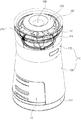
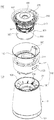
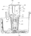
図1は、本発明の第1の実施形態に係る加湿清浄装置の斜視図であり、図2は、図1の分解斜視図であり、図3は、図1の分解正面図であり、図4は、図3の分解断面図であり、図5は、本発明の第1の実施形態に係る加湿清浄装置の空気流れが示された例示図である。 1 is a perspective view of the humidifying and cleaning device according to the first embodiment of the present invention, FIG. 2 is an exploded perspective view of FIG. 1, and FIG. 3 is an exploded front view of FIG. 4 is an exploded cross-sectional view of FIG. 3, and FIG. 5 is an exemplary view showing the air flow of the humidifying and cleaning device according to the first embodiment of the present invention.
本実施形態に係る加湿清浄装置は、エアークリーンモジュール100及び前記エアークリーンモジュール100上側に据え置かれるエアーウォッシュモジュール200を備える。
The humidifying and cleaning device according to the present embodiment includes an air
前記エアークリーンモジュール100は、外部空気を吸入した後にろ過し、ろ過空気を前記エアーウォッシュモジュール200に提供する。前記エアーウォッシュモジュール200は、前記ろ過空気の供給を受けて水分を提供する加湿を行い、加湿空気を外部に吐出する。
The air
前記エアーウォッシュモジュール200は、水が保存される水槽300を備える。前記水槽300は、前記エアーウォッシュモジュール200が分離されるとき、前記エアークリーンモジュール100から分離可能である。前記エアーウォッシュモジュール200は、エアークリーンモジュール100上に据え置かれる。
The
ユーザは、前記エアーウォッシュモジュール200をエアークリーンモジュール100から分離することができ、分離されたエアーウォッシュモジュール200を掃除することができる。ユーザは、エアーウォッシュモジュール200が分離されたエアークリーンモジュール100内部を掃除することもできる。前記エアーウォッシュモジュール200が分離された場合、前記エアークリーンモジュール100の上面がユーザに開放される。
The user can separate the
前記エアークリーンモジュール100は、後述するフィルタアセンブリ10を備え、ベースボディ110からフィルタアセンブリ10を分離した後、掃除することができる。
The air
ユーザは、前記エアーウォッシュモジュール200に水を供給できる。前記エアーウォッシュモジュール200には、外部から前記水槽300へ水を供給できる給水流路109が形成される。
The user can supply water to the
前記給水流路109は、空気が吐出される吐出流路107と分離されて構成される。前記給水流路109は、いつでも前記水槽に水を供給できるように構成される。例えば、前記エアーウォッシュモジュール200が作動中であるときにも給水流路を介して水を供給できる。例えば、前記エアーウォッシュモジュール200がエアークリーンモジュール100に結合された状態でも給水流路を介して水を供給できる。例えば、前記エアーウォッシュモジュール200がエアークリーンモジュール100から分離される状態であるときにも給水流路を介して水を供給できる。
The water
前記エアークリーンモジュール100及びエアーウォッシュモジュール200は、連結流路103を介して連結される。前記エアーウォッシュモジュール200が分離可能であるため、前記連結流路103は、エアークリーンモジュール100及びエアーウォッシュモジュール200に分散されて配置される。前記エアーウォッシュモジュール200がエアークリーンモジュール100に据え置かれるとき、初めてエアーウォッシュモジュール200の流路とエアークリーンモジュール100の流路とが連結流路103を介して互いに連通される。
The air
前記エアークリーンモジュール100に形成された連結流路をクリーン連結流路104と定義し、前記エアーウォッシュモジュール200に形成された連結流路を加湿連結流路105と定義する。
The connecting flow path formed in the air
前記エアークリーンモジュール100及びエアーウォッシュモジュール200を通過する空気の流動は、より詳細に後述する。
The flow of air passing through the air
以下、エアークリーンモジュール100及びエアーウォッシュモジュール200についてより詳細に説明する。
Hereinafter, the air
前記エアークリーンモジュール100は、ベースボディ110と、前記ベースボディ110に配置され、空気をろ過させるフィルタアセンブリ10と、前記ベースボディ110に配置され、空気を流動させる送風ユニット20とを備える。
The air
前記エアーウォッシュモジュール200は、加湿のための水が保存され、前記エアークリーンモジュール100に分離可能に据え置かれる水槽300と、前記水槽300に配置され、前記水槽300内部に配置され、前記水槽の水を噴射するウォータリングユニット400と、前記ウォータリングユニット400から噴射された水により濡らされ、流動する空気に水分を提供する加湿媒体50と、前記水槽300に結合され、内部を見ることができる材質で形成されたビジュアルボディ210と、前記ビジュアルボディ210に分離可能に据え置かれ、空気が吐出される吐出流路107及び水が供給される給水流路109が形成されたトップカバーアセンブリ230とを備える。
The
前記エアークリーンモジュール100には、吸入流路101、ろ過流路102、送風流路108、クリーン連結流路104が配置される。前記吸入流路101を介して吸入された空気は、ろ過流路102、送風流路108を経てクリーン流路104に流動する。
In the air
前記エアーウォッシュモジュール200は、加湿連結流路105、加湿流路106、吐出流路107、及び給水流路109が配置される。
In the
前記エアークリーンモジュール100のクリーン連結流路104及びエアーウォッシュモジュール200の加湿連結流路105は、エアーウォッシュモジュール200がエアークリーンモジュール100に据え置かれるとき、初めて連結される。
The clean connection flow path 104 of the air
前記エアーウォッシュモジュール200の加湿連結流路105を介して供給されたろ過空気は、加湿流路106及び吐出流路107を経て室内に吐出される。前記給水流路109は、加湿流路106と連通されるが、空気は吐出させず、水のみ給水され得る構造で製作される。
The filtered air supplied through the humidifying connecting
まず、エアークリーンモジュール100の各構成について説明する。
First, each configuration of the air
前記ベースボディ110は、アッパーボディ120及びロアボディ130で構成される。前記ロアボディ130上側に前記アッパーボディ120が積層され、前記アッパーボディ120及びロアボディ130は組み立てられる。
The
前記ベースボディ110内部に空気が流動する。
Air flows inside the
前記ロアボディ130に吸入流路101、ろ過流路102、及び送風流路108が配置され、前記吸入流路101、ろ過流路102、及び送風流路108を形成させる構造物等が配置される。
The
前記アッパーボディ120に連結流路103の一部が配置され、ろ過された空気を前記エアーウォッシュモジュール200に案内するための構造物等及びエアーウォッシュモジュール200を据え置くための構造物等が配置される。
A part of the connecting
前記ベースボディ110は、外形を形成し、下側面に吸入口111が形成されたロアボディ130と、外形を形成し、前記ロアボディ130上側に結合されるアッパーボディ120とを備える。
The
前記フィルタアセンブリ10は、前記ベースボディ110から脱着可能に組み立てられる。
The
前記フィルタアセンブリ10は、ろ過流路102を提供し、外部空気に対してフィルタリングを行う。前記フィルタアセンブリ10は、前記ベースボディ110に対して水平方向に脱着可能な構造である。前記フィルタアセンブリ10は、垂直方向を逆らって流動する空気の流動方向に対して交差するように配置される。前記フィルタアセンブリ10は、水平方向にスライド移動され、垂直方向上側に流動する空気に対してろ過を行う。前記フィルタアセンブリ10は、水平に配置され、上下方向にろ過流路102を形成する。
The
前記フィルタアセンブリ10は、前記ベースボディ110に対して水平方向に摺動されることができる。
The
前記フィルタアセンブリ10は、前記ロアボディ130内部に配置され、ろ過流路102を形成するフィルタハウジング11と、前記フィルタハウジング11に分離可能に結合され、前記ろ過流路102を通過する空気に対してろ過を行うフィルタ14とを備える。
The
前記フィルタハウジング12は、下側が吸入流路101と連通され、上側が送風流路108と連通される。前記吸入流路101を介して吸入された空気は、ろ過流路102を経て送風流路108に流動する。
The lower side of the
前記フィルタハウジング12は、前記ろ過流路102と交差する方向に一側が開口する。前記フィルタハウジング12の開口面を介して前記フィルタ14が分離可能に結合され得る。前記フィルタハウジング12の開口面は、側方向に形成される。前記フィルタハウジング12の開口面は、ロアボディ130の外側面に配置される。これにより、前記フィルタ14は、前記ロアボディ130の側面を介して挿入され、フィルタハウジング12内部に位置する。前記フィルタ14は、前記ろ過流路102と交差するように配置され、前記ろ過流路102を通過する空気に対してろ過を行う。
One side of the
前記フィルタ14は、印加された電源を帯電させて空気中の異物を捕集する電気集塵フィルタでありうる。前記フィルタ14は、ろ過材を介して空気中の異物を捕集する材質で形成されることができる。前記フィルタ14は、様々な構造が配置され得る。前記フィルタ14のろ過方式またはフィルタのろ過材によって本発明の権利が制限されない。
The
前記ろ過流路102は、加湿清浄装置の主な流動方向と同じ方向に配置される。本実施形態において前記ろ過流路102は、上下方向に配置され、重力反対方向に空気を流動させる。すなわち、前記加湿清浄装置の主な流動方向は、下側から上側に向かうように形成される。
The
前記フィルタハウジング12の上側に送風ユニット20が配置される。
The
前記フィルタハウジング12の上側面は、開口して形成され、前記ろ過流路102を通過した空気は、前記送風ユニット20に流動する。
The upper side surface of the
前記送風ユニット20は、空気の流動を生成させる。前記送風ユニット20は、前記ベースボディ110内部に配置され、下側から上側に空気を流動させる。
The
前記送風ユニット20は、送風ハウジング150、送風モータ22、及び送風ファン24で構成される。本実施形態において前記送風モータ22が上側に配置され、送風ファン24が下側に配置される。前記送風モータ22のモータ軸が下方に向かって設けられ、前記送風ファン24と組み立てられる。
The
前記送風ハウジング150は、前記ベースボディ110内部に配置される。前記送風ハウジング150は、流動する空気の流路を提供する。前記送風ハウジング150に前記送風モータ22及び送風ファン24が配置される。
The
前記送風ハウジング150は、前記フィルタアセンブリ10上側に配置され、前記アッパーボディ120下側に配置される。
The
前記送風ハウジング150は、内部に送風流路108を形成させる。前記送風流路108に前記送風ファン24が配置される。前記送風流路108は、ろ過流路102及びクリーン連結流路104を連結させる。
The
前記送風ファン24は、遠心ファンであって、下側で空気を吸入した後、半径方向外側に空気を吐出させる。前記送風ファン24は、半径方向外側及び上側に空気を吐出させる。前記送風ファン24は、外側端が半径方向上側に向かうように形成される。
The
前記送風モータ22は、流動する空気との接触を最小化させるために、前記送風ファン24の上側に配置される。前記送風モータ22は、送風ファン24により囲まれて設けられる。前記送風モータ22は、前記送風ファン24による空気流路上に位置せず、送風ファン24により流動する空気と抵抗を発生させない。
The
前記アッパーボディ120は、ベースボディ110の外形を形成し、ロアボディ130と結合されるアッパーアウターボディ128と、前記アッパーアウターボディ128の内側に配置され、前記水槽300が挿入され、連結流路103を提供するアッパーインナーボディ140と、前記アッパーインナーボディ140及びアッパーアウターボディ128を結合させ、空気を前記水槽300に案内するエアーガイド170とを備える。
The
前記アッパーボディ120は、連結流路及び水槽挿入空間を分離して配置するので、水槽300の水が連結流路に流入することを最小化できる。特に、アッパーインナーボディを介して仕切られて連結流路が水が保存される空間の外側に配置されるので、水が連結流路に流入することを抑制できる。
Since the
前記アッパーインナーボディ140は、上側が開口して形成され、前記水槽300が挿入される。前記アッパーインナーボディ140は、ろ過空気が流入するクリーン連結流路104のうちの一部を形成する。
The upper
前記アッパーインナーボディ140は、エアーウォッシュ流入口31と対応するアッパー流入口121が形成される。前記アッパー流入口121は、必須構成要素ではない。アッパーボディ120が前記エアーウォッシュ流入口31を連結流路103に露出させる形状であれば、それで十分である。
In the upper
前記エアーガイド170は、クリーン連結流路104を介して供給された空気を前記アッパー流入口121に案内する。前記エアーガイド170は、ベースボディ110の外側に沿って上昇された空気を内側に集める。前記エアーガイド170は、下側から上側に流動する空気の流動方向を切り換える。ただし、前記エアーガイド170は、空気の流動方向を切り換えるものの、その角度を最小化させて空気の流動抵抗を最小化させる。
The
前記エアーガイド170は、アッパーインナーボディ140の外側を360度囲むように形成される。前記エアーガイド170は、360度全方向に対して空気を前記水槽300に案内する。前記エアーガイド170は、ロアボディ130の外側に沿って案内された空気を内側に集めて水槽300に供給する。このような構造により前記水槽300に供給される空気の流量を十分確保できる。
The
これにより、前記エアーガイド170は、空気の流動方向に形成された案内部172と、前記案内部172と連結され、案内された空気の流動方向を切り換える切換部174とを備える。
As a result, the
前記エアーガイド170は、連結流路103を形成する。
The
前記案内部172は、ろ過流路102と略同じ方向に形成され、本実施形態では、上下方向に形成される。前記切換部174は、前記ろ過流路102と交差する方向に形成され、本実施形態では、略水平方向に形成される。
The guide portion 172 is formed in substantially the same direction as the
前記切換部174は、エアーガイド170の上側に形成される。前記切換部172は、案内部172と曲面に連結されることが好ましい。
The switching portion 174 is formed on the upper side of the
前記切換部174が水平方向に形成されても、前記連結流路103を通過する空気は、略傾斜した上側方向に流動する。前記連結流路103及びろ過流路102の転流角を直進方向と類似して形成し、空気の流動抵抗を低減できる。
Even if the switching portion 174 is formed in the horizontal direction, the air passing through the connecting
前記案内部172の下端が前記アッパーアウターボディ128に固定される。前記切換部174の上側端が前記アッパーインナーボディ140に固定される。
The lower end of the guide portion 172 is fixed to the upper
前記アッパーインナーボディ140外側に前記クリーン連結流路104のうちの一部が形成される。前記エアーガイド170がクリーン連結流路104のうちの一部を形成する。前記クリーン連結流路104を通過した空気は、アッパー流入口121及びエアーウォッシュ流入口31を介して水槽300内部に流動する。
A part of the clean connecting flow path 104 is formed on the outside of the upper
前記アッパーインナーボディ140は、全体的にバスケット状である。前記アッパーインナーボディ140は、平断面が円形に形成され、前記クリーン連結流路104は、360度全方向に形成される。
The upper
前記エアーガイド170は、ろ過空気を前記クリーン連結流路104に案内するための構成であり、実施形態によって含まれないこともある。前記エアーガイド170は、アッパーインナーボディ140またはアッパーアウターボディ128を結合させる。
The
前記エアーガイド170は、前記アッパーインナーボディ140を囲むように形成される。特に、前記エアーガイド170は、アッパー流入口121を囲むように形成され、前記アッパー流入口121にろ過空気を案内する。平面から見るとき、前記エアーガイド170は、ドーナッツ状である。
The
本実施形態において前記エアーガイド170の上端は、前記アッパーインナーボディ140の上端に密着される。
In the present embodiment, the upper end of the
平面から見るとき、前記エアーガイド170の上側面と前記アッパーインナーボディ140の上側面とが一致する。本実施形態において前記アッパーインナーボディ140の上端には、前記エアーガイド170と結合または密着されるアッパーインナーボディリング126が形成される。
When viewed from a plane, the upper side surface of the
前記アッパーインナーボディ140及びアッパーインナーボディリング126を連結するインナーボディ延長部148が形成される。前記インナーボディ延長部148は、複数個が配置される。前記インナーボディ延長部148及びアッパーインナーボディリング126間にアッパー流入口121が形成される。
An inner
前記インナーボディ延長部148は、水槽ボディ延長部380と対応する。前記水槽300の据え置きの際、前記インナーボディ延長部148の内側に水槽ボディ延長部380が位置する。前記インナーボディ延長部148及び水槽ボディ延長部380は、内外に重なる。
The inner
前記エアーガイド170の上端は、前記アッパーインナーボディリング126と密着または結合される。前記エアーガイド170の下端は、アッパーアウターボディ128と密着または結合される。
The upper end of the
これにより、前記アッパーインナーボディ140及びアッパーアウターボディ128間のクリーン連結流路104を介して流動する空気は、アッパー流入口121に案内される。
As a result, the air flowing through the clean connecting flow path 104 between the upper
前記アッパーインナーボディリング126の直径と前記エアーガイド170上端の直径とが一致するか、類似している。前記エアーガイド170及びアッパーインナーボディリング126が密着されてろ過空気の漏れを防止する。前記アッパーインナーボディリング126は、エアーガイド170の内側に配置される。
The diameter of the upper inner body ring 126 and the diameter of the upper end of the
前記アッパーアウターボディ128に取っ手129が形成され得る。前記アッパーボディ120にエアーウォッシュモジュール200が据え置かれるところ、前記取っ手129を介して加湿清浄装置全体を持ち上げることができる。
A handle 129 may be formed on the upper
前記アッパーインナーボディ140は、水槽300が挿入され得るように内部に水槽挿入空間125が形成される。
In the upper
前記アッパー流入口121を基準に外側にクリーン連結流路104が配置され、内側に水槽挿入空間125が配置される。前記クリーン連結流路104に沿って流動した空気は、アッパー流入口121を通過する。前記水槽300が水槽挿入空間125に据え置かれた場合、前記アッパー流入口121を通過したろ過空気は、水槽300内部に流入する。
A clean connecting flow path 104 is arranged on the outside and a water
一方、アッパーボディ120の上側にアウタービジュアルボディ214が結合される。
On the other hand, the outer
前記アウタービジュアルボディ214は、ビジュアルボディ210の構成であるが、本実施形態では、アッパーボディ120に固定される。本実施形態とは異なり、前記アウタービジュアルボディ214は、エアーウォッシュモジュール200に固定されても構わない。本実施形態とは異なり、前記アウタービジュアルボディ214は、削除可能な構成である。
The outer
前記アウタービジュアルボディ214は、アッパーボディ120に固定される。本実施形態において前記アウタービジュアルボディ214は、アッパーアウターボディ128に結合される。前記アウタービジュアルボディ214は、アッパーアウターボディ128の外側面が連続した面を形成する。
The outer
アウタービジュアルボディ214は、内部を透視できる材質で形成される。前記アウタービジュアルボディ214は、透明であるか、半透明な材質で形成され得る。
The outer
前記エアークリーンモジュール100またはエアーウォッシュモジュール200のうち、少なくともいずれか1つに作動状態をユーザに表示するディスプレイモジュール160が配置され得る。本実施形態では、前記ベースボディ110に加湿清浄装置の作動状態をユーザに表示するディスプレイモジュール160が設けられる。
A
前記アウタービジュアルボディ214内側にディスプレイモジュール160が配置される。前記ディスプレイモジュール160は、アウタービジュアルボディ214の内側面に密着されるように配置される。前記ディスプレイモジュール160は、平面から見るとき、ドーナッツ状である。前記ディスプレイモジュール160の内側に前記水槽300が挿入される。
The
前記ディスプレイモジュール160は、アウタービジュアルボディ214に支持される。前記ディスプレイモジュール160の内側縁は、アッパーインナーボディリング126に支持される。前記ディスプレイモジュール160は、エアーガイド170上側に位置する。前記ディスプレイモジュール160は、コネクタ260と一体に製作されることができる。
The
前記ディスプレイモジュール160は、エアーガイド170上側に位置する。前記ディスプレイモジュール160は、アッパーアウターボディ128及びアッパーインナーボディ140間に配置されることができる。前記ディスプレイモジュール160は、ユーザがアッパーアウターボディ128及びアッパーインナーボディ140間を見ることができないようにカバーする。特に、前記アッパーアウターボディ128及びアッパーインナーボディ140間に水が浸透することを遮断するために、前記ディスプレイモジュール160の内側及び外側はシーリングされることが好ましい。
The
前記ディスプレイモジュール160の内側は、アッパーインナーボディ140に支持され、外側は、アウタービジュアルボディ218に支持される。
The inside of the
本実施形態において前記ディスプレイモジュール160はリング形状に形成される。本実施形態とは異なり、前記ディスプレイモジュール160は、弧形状に形成されることができる。前記ディスプレイモジュール160の表面は、光を反射できる材質で形成されるか、光を反射できる材質がコーティングされる。
In this embodiment, the
これにより、前記ビジュアルボディ210に水が結ばれる場合、ビジュアルボディ210に結ばれた水がディスプレイモジュール160表面に投影されたり、反射されることができる。前記ビジュアルボディ210で結ばれた水が流れ落ちる場合、前記ディスプレイモジュール160にも同じ効果が表れる。
As a result, when water is bound to the
このような効果は、ユーザに視覚的な刺激を与え、加湿がなされていることをユーザが直観的に認知できる。前記ディスプレイモジュール160に投影された水滴イメージは、ユーザに清涼感を与える感性的効果だけでなく、加湿状態を分かることができる機能的効果もある。
Such an effect gives a visual stimulus to the user, and the user can intuitively recognize that the humidification is performed. The water droplet image projected on the
前記ディスプレイモジュール160の上側面は、傾斜して形成される。前記ディスプレイモジュール160は、ユーザ側に傾斜して形成される。これにより、内側が高く、外側が低く形成される。
The upper side surface of the
次に、エアーウォッシュモジュール200の各構成について説明する。
Next, each configuration of the
前記エアーウォッシュモジュール200は、ろ過空気に対して加湿を提供する。前記エアーウォッシュモジュール200は、加湿流路106でレインビューを実現することができる。前記エアーウォッシュモジュール200は、水槽300の水を噴射し、これを循環させる。前記エアーウォッシュモジュール200は、水を小さな大きさの液滴に変換させ、飛散した液滴を介してろ過空気を再度洗い落とす。飛散した水滴を介してろ過空気をウォッシング(washing)するとき、加湿及びろ過が再度なされる。
The
前記エアーウォッシュモジュール200は、加湿連結流路105、加湿流路106、吐出流路107、及び給水流路109を備える。
The
前記エアーウォッシュモジュール200は、水槽300、ウォータリングユニット400、加湿媒体50、ビジュアルボディ210、トップカバーアセンブリ230、及びハンドル180を備える。
The
前記ハンドル180は、ビジュアルボディ210に結合され、前記ビジュアルボディ210で回転され、前記ビジュアルボディ210に収納される。前記ハンドル180を介してエアーウォッシュモジュール200のみを簡便に持ち上げることができ、前記エアークリーンモジュール100から分離することができる。
The
前記加湿連結流路105は、水槽300の外側に配置され、前記水槽300の内部に空気を案内することができる。前記加湿連結流路105は、ビジュアルボディ210の外側に配置され、前記ビジュアルボディ210の内部に空気を案内することができる。
The humidifying
前記加湿連結流路105は、水槽300またはビジュアルボディ210のうち、少なくともいずれか1つの外側に配置され、水槽300またはビジュアルボディ210のうち、いずれか1つの内部に空気を案内することができる。
The humidification connecting
前記吐出流路107は、トップカバーアセンブリ230及びビジュアルボディ210の間に配置されることができる。前記吐出流路107は、トップカバーアセンブリ230またはビジュアルボディ210のうち、少なくともいずれか1つに配置されることができる。
The
本実施形態では、トップカバーアセンブリ230の外側縁に吐出流路107が形成され、前記トップカバーアセンブリ230の内側中央に給水流路109が配置される。
In the present embodiment, the
本実施形態に係る加湿清浄装置は、前記エアークリーンモジュール100に電源が連結され、前記エアーウォッシュモジュール200は、前記エアークリーンモジュール100を介して電源の供給を受ける。
In the humidifying and cleaning device according to the present embodiment, a power source is connected to the air
前記エアーウォッシュモジュール200が前記エアークリーンモジュール100に対して分離可能な構造であるから、前記エアークリーンモジュール100及びエアーウォッシュモジュール200は、分離可能な電源供給構造が備えられる。
Since the
前記エアークリーンモジュール100及びエアーウォッシュモジュール200は、前記アッパーボディ120を介して分離可能に組み立てられるので、前記アッパーボディ120には、前記エアーウォッシュモジュール200に電源を提供するコネクタ260が配置される。
Since the air
前記エアーウォッシュモジュール200のトップカバーアセンブリ230は、電源を必要とする操作部及びディスプレイが配置される。前記エアーウォッシュモジュール200には、前記コネクタ260と分離可能に連結されるトップコネクタ270が配置される。前記トップコネクタ270は、トップカバーアセンブリ230に配置される。
The
本実施形態では、前記トップカバーアセンブリ230を分離できるので、ビジュアルボディ210の内側面または水槽300の内側面を簡便に掃除することができる。
In the present embodiment, since the
前記トップカバーアセンブリ230は、内側に給水流路109が形成され、ビジュアルボディ210との間に吐出流路107を形成させる。前記トップカバーアセンブリ230は、前記ビジュアルボディ210に対して分離可能に設けられる。前記トップカバーアセンブリ230は、コネクタ260と電気的に連結されるトップコネクタ270が配置される。
The
前記トップカバーアセンブリ230が据え置かれるとき、トップコネクタ270がコネクタ260上側に据え置かれる。前記トップカバーアセンブリ230は、前記トップコネクタ270を介して前記コネクタ260から電気の供給を受ける。
When the
前記給水流路109の周りには、前記水槽300の水位を表示する水位表示部(図示せず)が配置される。これにより、ユーザは、水を給水するとき、見えない水槽300の水位がある程度満たされたかを確認することができる。このように、ユーザが水を給水する動線上に水位表示部を配置することにより、ユーザが水を過度に供給することを防止でき、水槽300から水が溢れることを防止できる。
A water level display unit (not shown) that displays the water level of the
前記水位表示部は、前記トップカバーアセンブリ230に配置される。前記トップコネクタ270及びコネクタ260の分離可能な電源供給構造は、上部給水を効果的に構成できるようにする。
The water level display unit is arranged on the
前記水槽300は、前記アッパーボディ120に分離可能に据え置かれる。前記ウォータリングユニット400は、前記水槽300内部に配置され、前記水槽300内部で回転される。
The
前記水槽300は、水が保存される水槽ボディ320と、前記水槽ボディ320の側面に形成されたエアーウォッシュ流入口31と、前記水槽ボディ320から上側へ延びて形成され、前記ビジュアルボディ210に結合される水槽ボディ延長部380とを備える。
The
本実施形態において前記水槽ボディ320は、上側が開口した円筒形に形成される。本実施形態とは異なり、前記水槽ボディ320は、様々な形状に形成されることができる。
In the present embodiment, the
前記水槽ボディ延長部380は、前記水槽300から上側へ延びて形成される。前記水槽ボディ延長部380は、前記エアーウォッシュ流入口31を形成させる。前記水槽ボディ延長部380間に前記エアーウォッシュ流入口31が形成される。
The water tank
前記エアーウォッシュ流入口31は、水槽ボディ320の側面に形成される。前記エアーウォッシュ流入口31は、水槽ボディ320に対して360度全方向に形成される。前記エアーウォッシュ流入口31は、加湿連結流路105と連通される。
The air wash
前記水槽ボディ延長部380は、前記ビジュアルボディ210の内側面から流れ落ちる水を前記水槽300内部に案内する。前記ビジュアルボディ210から流れ落ちる水を案内することによって落水騷音を最小化することができる。
The water tank
前記水槽ボディ延長部380は、ビジュアルボディ210の下端に締め付けられる。
The water tank
本実施形態では、前記水槽ボディ320の構成を介してエアーウォッシュ流入口31が形成される。本実施形態とは異なり、前記ビジュアルボディ210に水槽ボディ延長部380を配置してエアーウォッシュ流入口31を形成させることもできる。また、本実施形態とは異なり、複数個の水槽ボディ延長部380のうちの一部は水槽300に配置し、複数個の水槽ボディ延長部380のうちの残りはビジュアルボディ210に配置して、エアーウォッシュ流入口31を構成することができる。また、本実施形態とは異なり、ビジュアルボディ210及び水槽300と区分される別の構成にエアーウォッシュ流入口31を形成させることができる。また、本実施形態とは異なり、ビジュアルボディ210に開口面を形成し、エアーウォッシュ流入口31を形成させ、水槽300にも開口面を形成し、エアーウォッシュ流入口31を形成させることができる。
In the present embodiment, the
すなわち、前記エアーウォッシュ流入口31は、水槽300またはビジュアルボディ210のうち、少なくともいずれか1つに配置されることができる。前記エアーウォッシュ流入口31は、水槽300及びビジュアルボディ210の結合によって形成されることができる。前記エアーウォッシュ流入口31を水槽300及びビジュアルボディ210と区分される別の構成に配置した後、これを水槽300及びビジュアルボディ210間に配置することができる。前記エアーウォッシュ流入口31は、前記水槽300及びビジュアルボディ210の結合によって形成されることができる。
That is, the
前記エアーウォッシュ流入口31は、エアーウォッシュモジュール200の側部に配置され、加湿流路106と連結される。前記エアーウォッシュ流入口31は、加湿連結流路105と連通または連結されることができる。
The air wash
前記ウォータリングユニット400は、加湿媒体50に水を供給する機能がある。前記ウォータリングユニット400は、加湿過程を視角化する機能がある。前記ウォータリングユニット400は、エアーウォッシュモジュール200内部にレインビューを実現する機能がある。
The watering
前記ウォータリングユニット400は、ウォータリングハウジング800を回転させて前記水槽内部の水を吸入し、吸入された水を上側に揚水し、揚水された水を半径方向外側に噴射する。前記ウォータリングユニット400は、水を内部に吸入し、吸入された水を上側に揚水した後、半径方向外側に噴射させるウォータリングハウジング800を備える。
The watering
本実施形態では、水を噴射させるために、ウォータリングハウジング800を回転させる。本実施形態とは異なり、前記ウォータリングハウジング800の代わりに、ノズルを使用して水を噴射しても構わない。ノズルで水を噴射して加湿媒体50に水を供給でき、レインビューも同様に実現することができる。実施形態によって、ノズルで水を噴射し、ノズルを回転させることもできる。
In this embodiment, the watering
前記ウォータリングハウジング800から噴射された水が前記加湿媒体50を濡らす。前記ウォータリングハウジング800から噴射された水は、前記ビジュアルボディ210または加湿媒体50のうち、少なくともいずれか1つに向かって噴射されることができる。
The water sprayed from the watering
ビジュアルボディ210に向かって噴射される水は、レインビューを実現することができる。加湿媒体50に向かって噴射される水は、ろ過空気を加湿するのに用いられる。ビジュアルボディ210に向かって水を噴射してレインビューを実現した後、ビジュアルボディ210から流れ落ちた水が加湿媒体50を濡らすように実現することができる。
The water sprayed toward the
本実施形態では、ウォータリングハウジング800に高さの異なる複数個の噴射口を配置する。いずれか1つの噴射口から吐出された水がビジュアルボディ210の内側面に液滴を形成し、レインビューを実現し、残りの1つの噴射口から吐出された水が加湿媒体50を濡らして加湿に用いられる。
In the present embodiment, a plurality of injection ports having different heights are arranged in the watering
前記ウォータリングハウジング800は、前記ビジュアルボディ210の内側面に向かって水を噴射し、噴射された水は、前記ビジュアルボディ210の内側面に沿って下方へ流れ落ちる。前記ビジュアルボディ210の内側面には、水滴形態で結ばれた液滴が形成され、ユーザは、前記ビジュアルボディ210を介して前記液滴を見ることができる。
The watering
特に、ビジュアルボディ210から流れ落ちた水は、加湿媒体50を濡らして加湿に用いられる。前記加湿媒体50は、ウォータリングハウジング800から噴射された水及びビジュアルボディから流れ落ちた水により濡らされることができる。
In particular, the water that has flowed down from the
前記ビジュアルボディ210は、前記水槽300と結合され、前記水槽300の上側に位置する。前記ビジュアルボディ210の少なくとも一部は、内部を透視できる材質で形成される。
The
前記ビジュアルボディ210の外側にディスプレイモジュール160が配置され得る。前記ディスプレイモジュール160は、ビジュアルボディ210またはアッパーボディ120のうち、いずれか1つに結合されることができる。
The
前記ディスプレイモジュール160は、レインビューを観察できる視線上に配置される。本実施形態において前記ディスプレイモジュール160は、前記アッパーボディ120に配置される。
The
前記エアーウォッシュモジュール200が据え置かれるとき、前記ビジュアルボディ210の外側面が前記ディスプレイモジュール160に密着される。前記ディスプレイモジュール160の表面のうち、少なくとも一部は、光を反射する材質で形成されるか、コーティングされることができる。
When the
前記ビジュアルボディ210に結ばれた液滴は、前記ディスプレイモジュール160の表面にも投影される。これにより、ユーザは、前記ビジュアルボディ210及びディスプレイモジュール160の2ヶ所で液滴の動きを観察できる。
The droplets bound to the
前記水槽300には、空気が通じるエアーウォッシュ流入口31が形成される。前記エアーウォッシュ流入口31は、連結流路103及び加湿流路106間に位置する。前記エアーウォッシュ流入口31は、連結流路103の出口であり、加湿流路106の入口である。
An air wash
前記エアークリーンモジュール100から供給されたろ過空気は、前記エアーウォッシュ流入口31を介して前記エアーウォッシュモジュール200内部に流動する。
The filtered air supplied from the air
前記加湿媒体50は、加湿流路106入口に配置される水槽加湿媒体51及び加湿流路106出口に配置される吐出加湿媒体55を備える。前記加湿流路106の出口と吐出流路107の入口とは、互いに連結される。これにより、前記吐出加湿媒体55が吐出流路107に配置されても構わない。
The humidifying medium 50 includes a water
前記連結流路103、加湿流路106、及び吐出流路107はダクトなどのような構造物を介して形成されるものではないため、その境界を明確に区分し難い。ただし、加湿がなされる加湿流路106を水槽加湿媒体51及び吐出加湿媒体55間と定義する場合、連結流路103及び吐出流路107が自然に定義される。
Since the connecting
前記連結流路103は、送風ハウジング150及び水槽加湿媒体51間と定義される。前記吐出流路107は、吐出加湿媒体55以後と定義される。
The connecting
本実施形態において前記水槽加湿媒体51は、水槽300のエアーウォッシュ流入口31に配置される。
In the present embodiment, the water
前記水槽加湿媒体51は、エアーウォッシュ流入口31と同一平面上、外側、または内側のうち、少なくともいずれか1つに位置し得る。前記水槽加湿媒体51は、加湿のために水が濡らされるので、前記エアーウォッシュ流入口31の内側に位置することが好ましい。
The water
前記水槽加湿媒体51を濡らした後、流れ落ちた水は、前記水槽300に保存されることが好ましい。前記水槽加湿媒体51を濡らした後、流れ落ちた水が前記水槽300外部に流れ落ちないように配置されることが好ましい。
After wetting the water
これにより、前記水槽加湿媒体51は、前記エアーウォッシュ流入口31を通過するろ過空気に対して加湿を提供する。
As a result, the water
前記加湿媒体50で自然蒸発された水によりろ過空気が加湿される。前記自然蒸発は、別の熱を加えなかった状態で水が蒸発されることをいう。空気との接触が増加するほど、空気の流速が速くなるほど、空気中の圧力が低くなるほど、自然蒸発が促進される。前記自然蒸発を自然気化と指すこともある。 The filtered air is humidified by the water naturally evaporated in the humidifying medium 50. The natural evaporation means that water is evaporated without applying another heat. As the contact with air increases, the flow velocity of air increases, and the pressure in the air decreases, natural evaporation is promoted. The natural evaporation may be referred to as natural vaporization.
前記加湿媒体50は、水の自然蒸発を促進させる。本実施形態において前記加湿媒体50は、水に濡らされるが、水槽300には浸らない。
The humidifying medium 50 promotes the natural evaporation of water. In the present embodiment, the humidifying medium 50 is wetted with water, but is not immersed in the
前記水槽300に保存された水と離間し、分離されて配置されるので、水槽300に保存された水があっても水槽加湿媒体51及び吐出加湿媒体55は、常に濡らされた状態ではない。すなわち、加湿モードで作動されるときにのみ水槽加湿媒体51及び吐出加湿媒体55が濡らされた状態であり、空気清浄モードで作動されるときには、水槽加湿媒体51及び吐出加湿媒体55が乾燥された状態で維持されることができる。
Since the water stored in the
前記水槽加湿媒体51は、前記エアーウォッシュ流入口31をカバーし、空気は、前記水槽加湿媒体51を貫介して前記水槽300内部に流動する。
The water
前記吐出加湿媒体55は、加湿流路106の出口または吐出流路107入口に配置されることができる。
The
本実施形態において前記吐出加湿媒体55は、ビジュアルボディ210の上部をカバーするように配置される。前記吐出加湿媒体55は、ビジュアルボディ210に据え置かれる。本実施形態とは異なり、吐出加湿媒体55は、トップカバーアセンブリ230の底面に結合されることができる。
In the present embodiment, the
前記吐出加湿媒体55は、前記吐出流路107をカバーし、加湿空気は、前記吐出加湿媒体55を貫介しての後、吐出流路107に流動する。
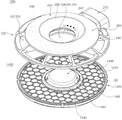
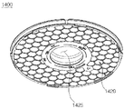
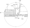
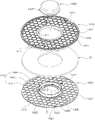
図6は、図2に示されたエアーウォッシュモジュールからトップカバーアセンブリが分離された斜視図であり、図7は、図6に示されたトップカバーアセンブリ及び吐出加湿媒体ハウジングの分離斜視図である。
The
FIG. 6 is a perspective view of the top cover assembly separated from the air wash module shown in FIG. 2, and FIG. 7 is a perspective view of the top cover assembly and the discharge humidifying medium housing shown in FIG. ..
本実施形態において前記トップカバーアセンブリ230は、ビジュアルボディ210に分離可能に据え置かれるという特徴がある。前記トップカバーアセンブリ230は、吐出流路107を提供するだけでなく、給水のための給水流路109も提供する。
In the present embodiment, the
本実施形態において前記トップカバーアセンブリ230は、吐出加湿媒体55の上側に位置する。本実施形態では、前記吐出加湿媒体55が配置された吐出加湿媒体ハウジング1400が配置され、前記吐出加湿媒体ハウジング1400の上部に前記トップカバーアセンブリ230が配置される。前記吐出加湿媒体ハウジング1400は、ビジュアルボディ230の上部に据え置かれる。前記トップカバーアセンブリ230は、吐出加湿媒体ハウジング1400の上部に据え置かれる。前記トップカバーアセンブリ230は、吐出加湿媒体ハウジング1400と一体に組み立てられることができる。本実施形態では、トップカバーアセンブリ230及び吐出加湿媒体ハウジング1400が各々製作される。
In the present embodiment, the
前記トップカバーアセンブリ230は、ビジュアルボディ210に据え置かれて支持され、前記吐出加湿媒体ハウジング1400には荷重を加えない。
The
前記吐出加湿媒体ハウジング1400は、吐出加湿媒体55が内部に配置され、ビジュアルボディ210の上部をカバーする。給水流路109は、前記吐出加湿媒体ハウジング1400を通過するように構成される。吐出流路107は、前記吐出加湿媒体ハウジング1400を通過するように構成される。
In the discharge
前記トップカバーアセンブリ230は、吐出流路107及び給水流路109を形成するトップカバーグリル232と、前記トップカバーグリル232に設けられる操作モジュール240と、前記操作モジュール240に電源または信号を提供するトップコネクタ270とを備える。
The
前記トップカバーグリル232は、吐出流路107のうち、少なくとも一部を形成するグリル吐出口231と、給水流路109のうち、少なくとも一部を形成するグリル給水口233とを備える。前記グリル吐出口231及びグリル給水口233は、上下方向に開口して形成される。前記グリル給水口233は、トップカバーグリル232の内側中央に配置され、前記グリル吐出口231は、前記グリル給水口233の外側に配置される。
The
前記トップカバーグリル232は、ビジュアルボディ210に分離可能に据え置かれる。前記トップカバーグリル232は、ビジュアルボディ210の内側に据え置かれる。
The
前記操作モジュール240は、トップカバーグリル232に結合される。前記操作モジュール240は、ユーザの操作信号を受信することができる。前記操作モジュールは、ユーザに水位情報を伝達する。前記操作モジュール240に給水流路109が配置される。前記操作モジュール240は、トップコネクタ270と電気的に連結され、前記トップコネクタ270から電源の提供を受ける。
The
前記操作モジュール(240、operation module)は、吐出グリル232と結合され、内側に給水流路109のうち、少なくとも一部が形成された操作ハウジング250と、前記操作ハウジング250に配置された入力部245と、前記操作ハウジング250に配置された水位表示部247と、前記入力部245及び水位表示部247を制御する操作制御部(図示せず)とを備える。
The operation module (240, operation module) is coupled to the
前記操作ハウジング250は、上部操作ハウジング242及び下部操作ハウジング244を備える。
The
前記操作モジュール240には、給水流路109が形成される。前記操作モジュール240の中央に上下方向に給水流路109の一部が形成される。前記操作モジュール240には、給水流路109のうち、少なくとも一部を形成する操作給水口241が配置され得る。前記操作給水口241は、操作ハウジングの内側に配置され、上下方向に開口して形成される。
A water
前記操作モジュール240は、上部給水ガイド236をさらに備える。前記上部給水ガイド236は、上部給水された水を前記操作給水口241に案内する。前記操作ハウジング250のうちの一部面を傾斜して形成し、前記上部給水ガイド236を形成する。
The
上部給水の際、ユーザは、水槽300内部の水位を見ることができないが、操作給水口241の周りに配置された水位表示部247を介して上昇された水位を直ちに確認することができる。ユーザは、上部給水中に水位表示部247を介して水位を確認できるので、上部給水流量を調節できる。
At the time of upper water supply, the user cannot see the water level inside the
上部給水された水は、吐出加湿媒体ハウジング1400を通過して加湿流路106に落下する。特に、上部給水された水は、水槽300の水面にすぐ落下せず、ウォータリングハウジング800の上部に落下する。
The water supplied to the upper part passes through the discharge humidifying
上部給水の際、前記ウォータリングハウジング800が回転中である場合、上部給水された水がウォータリングハウジング800の上部に飛散し、これを介して別のレインビューを形成させる。
When the watering
すなわち、ウォータリングユニット400から噴射された水を介してレインビューを形成させることができるだけでなく、上部給水された水を介してもレインビューを形成させることができる。
That is, not only can the rain view be formed through the water jetted from the watering
図8は、図4に示されたエアーウォッシュモジュールの断面図であり、図9は、図8に示されたGの拡大図であり、図10は、図4に示されたウォータリングハウジングの設置状態が示された斜視図であり、図11は、図10の正面図であり、図12は、図11のM−Mに沿って切断された断面図であり、図13は、図12の平面図であり、図14は、図10に示されたウォータリングハウジングの分解斜視図であり、図15は、図14の下側から見た斜視図であり、図16は、図14の正面図であり、図17は、図14のN−Nに沿って切断された断面図である。 8 is a cross-sectional view of the air wash module shown in FIG. 4, FIG. 9 is an enlarged view of G shown in FIG. 8, and FIG. 10 is the watering housing shown in FIG. It is a perspective view which showed the installation state, FIG. 11 is a front view of FIG. 10, FIG. 12 is a cross-sectional view cut along MM of FIG. 11, and FIG. 13 is a sectional view of FIG. 14 is an exploded perspective view of the watering housing shown in FIG. 10, FIG. 15 is a perspective view seen from the lower side of FIG. 14, and FIG. 16 is a perspective view of FIG. It is a front view, and FIG. 17 is a cross-sectional view cut along the NN of FIG.
前記ウォータリングハウジング800は、水槽300に保存された水を噴射するための構成である。前記ウォータリングハウジング800は、水槽300に保存された水を効率的に揚水するための構造が配置される。
The watering
前記ウォータリングハウジング800は、ウォータリングモータ42の回転力が伝達されて回転され、回転の際、水槽300に保存された水を内部に吸入した後、上側に揚水することができる。前記ウォータリングハウジング800内部に揚水された水は、噴射口410を介して吐出される。
The watering
前記ウォータリングハウジング800には、揚水手段が配置される。前記揚水手段は、前記水槽300の水を上側に揚水(pumping)する。水槽の水を揚水する方法は、様々に実現されることができる。
A pumping means is arranged in the watering
例えば、前記揚水ポンプを介して水を揚水した後、噴射させることができる。 For example, water can be pumped after being pumped through the pump.
例えば、ウォータリングハウジングを回転させ、回転の際、水と摩擦または相互干渉を形成させて水を揚水できる。 For example, the watering housing can be rotated to pump water by forming friction or mutual interference with the water during rotation.
本実施形態では、ウォータリングハウジング800の回転によって水を揚水する構造が提案される。本実施形態において揚水手段は、水との摩擦または相互干渉を介して水を上側に押し上げる揚水グルーブ810である。
In the present embodiment, a structure is proposed in which water is pumped by the rotation of the watering
前記ウォータリングハウジング800の内側面に揚水手段である揚水グルーブ810が形成される。前記揚水グルーブ810は、揚水効率を向上させる。前記揚水グルーブ810は、前記ウォータリングハウジング800内側面から突出されて形成される。前記揚水グルーブ810は、上下方向に長く延びて形成される。前記揚水グルーブ810は、ウォータリングモータ軸43または動力伝達軸640に対して放射状に配置される。
A pumping
前記ウォータリングハウジング800の下端は、水槽300の底面と所定間隔離間して吸入間隔(801、H1)を形成する。前記吸入間隔801を介して水槽300の水がウォータリングハウジング800内部に吸入される。
The lower end of the watering
前記ウォータリングハウジング800が水を噴射できる水槽300の水位H2は、吸入間隔H1より高く、噴射口410より低く形成される。前記水位H2は、満水位を含む。
水位H2が吸入間隔H1より低い場合、水が吸入されないため、揚水が不可能である。前記水位H2が噴射口410より高い場合、噴射口410に揚水された水が噴射されない。
The water level H2 of the
When the water level H2 is lower than the suction interval H1, water is not sucked and pumping is impossible. When the water level H2 is higher than the injection port 410, the pumped water is not injected into the injection port 410.
前記ウォータリングハウジング800は、下側が開放されるように形成される。前記ウォータリングハウジング800は、カップ形状である。前記ウォータリングハウジング800は、カップを逆に置いた形状である。前記ウォータリングハウジング800内部には、ハウジング空間805が形成される。
The watering
前記ウォータリングハウジング800内部に水槽300のコラム35が位置し、前記コラム35内部に動力伝達モジュール600が配置される。前記ウォータリングハウジング800は、コラム35を囲むように配置される。
The
前記ウォータリングハウジング800は、上側へ行くほど、平断面が拡張されるように形成される。前記コラム35は、上側へ行くほど、平断面が縮小されるように形成される。前記ウォータリングハウジング800及びコラム35の形状は、水を効果的に揚水するための形状である。前記ハウジング空間805の容積は、上側へ行くほど増加される。
The watering
前記ウォータリングハウジング800が回転されるとき、内部に吸入された水は、遠心力によりウォータリングハウジング800内周面に密着される。前記ウォータリングハウジング800内周面に形成された揚水グルーブ810は、内部に吸入された水に回転力を提供する。
When the watering
前記ウォータリングハウジング800には、吸入された水を外部に吐出する噴射口410が形成される。本実施形態において前記噴射口410は、水平方向に水を吐出させるように配置される。前記噴射口410を介して揚水された水が外部に吐出される。
The watering
本実施形態において前記噴射口410から吐出された水は、ビジュアルボディ210に噴射されることができる。
In the present embodiment, the water discharged from the injection port 410 can be injected into the
前記噴射口410は、設計条件によってその個数が調整され得る。本実施形態において前記噴射口410は、高さの差をおいてウォータリングハウジング800に複数個が配置される。前記ウォータリングハウジング800の上側に配置された噴射口を第2の噴射口と定義し、ウォータリングハウジングの中間に配置された噴射口を第1の噴射口と定義する。
The number of the injection ports 410 can be adjusted according to the design conditions. In the present embodiment, a plurality of the injection ports 410 are arranged in the watering
前記第1の噴射口から噴射された水は、加湿に用いられる。前記第2の噴射口から噴射された水は、加湿、ウォータリング、及びレインビューに用いられる。 The water jetted from the first injection port is used for humidification. The water jetted from the second injection port is used for humidification, watering, and rain view.
前記第2の噴射口から噴射された水が流れ落ちて水槽加湿媒体を濡らすことができる。 The water jetted from the second injection port can flow down to wet the aquarium humidifying medium.
前記第2の噴射口から噴射された水がビジュアルボディに当たった後、飛散してレインビューを形成できる。前記第2の噴射口から噴射された水がビジュアルボディに当たった後、微細な液滴に変換され、この液滴等がろ過空気を洗い落とすウォータリングに用いられ得る。 After the water jetted from the second injection port hits the visual body, it can be scattered to form a rain view. After the water jetted from the second injection port hits the visual body, it is converted into fine droplets, which can be used for watering to wash off the filtered air.
前記ウォータリングハウジング800が第1の回転速度以上に回転されるとき、前記第1の噴射口から水が噴射され得る。前記ウォータリングハウジング800が第2の回転速度以上に回転されるとき、前記第2の噴射口から水が噴射され得る。
When the watering
前記第2の回転速度は、前記第1の回転速度に比べて高速である。 The second rotation speed is higher than the first rotation speed.
前記ウォータリングハウジング800が高速で回転されるときにのみ、前記第2の噴射口から水が吐出される。前記ウォータリングハウジング800が通常的に回転される速度には、前記第2の噴射口を介して水が吐出されないように配置することができる。前記第1の噴射口は、ウォータリングハウジングが常に作動される全ての段階で水を吐出する。
Water is discharged from the second injection port only when the watering
前記第2の噴射口は、複数個が配置され得る。前記第1の噴射口は、複数個が配置され得る。 A plurality of the second injection ports may be arranged. A plurality of the first injection ports may be arranged.
ウォータリングハウジング800が通常回転速度で回転されれば、揚水された水は、少なくとも第1の噴射口より高く上昇される。前記ウォータリングハウジング800が高速で回転されれば、揚水された水は、第2の噴射口の高さ以上に上昇される。
If the watering
前記第2の噴射口は、ウォータリングハウジング800の円周方向に複数個が配置され得る。前記第1の噴射口もウォータリングハウジング800の円周方向に複数個が配置され得る。
A plurality of the second injection ports may be arranged in the circumferential direction of the watering
前記ウォータリングハウジング800が回転されなければ、噴射口410を介して水が吐出されない。ユーザが清浄モード(エアークリーンモジュールは作動され、エアーウォッシュモジュールは停止されるモード)にのみ作動させれば、ウォータリングユニット40が作動されず、送風ユニット20だけが作動される。ユーザが加湿モードのみで作動させるとき、前記ウォータリングハウジング800が回転され、前記噴射口410を介して水が吐出される。ユーザが清浄モード及び加湿モードを同時作動させるとき、前記噴射口410から吐出される水は、ビジュアルボディ210の内側面に噴射されることができる。
If the watering
ウォータリングハウジング800が回転されるので、前記噴射口410から吐出された水は、前記ビジュアルボディ210の内側面を打撃し、前記ビジュアルボディ210の内側面に沿って移動される。
Since the watering
ユーザは、ビジュアルボディ210を介して水が噴射されることを視覚的に確認することができる。このような水の噴射は、加湿モードで作動中であることを意味する。ユーザは、水の噴射を介して加湿モードが作動中であることを直観的に確認することができる。
The user can visually confirm that the water is sprayed through the
前記ビジュアルボディ210には、噴射された水により液滴が結ばれ、前記液滴は、下方へ流れ落ちるようになる。
Droplets are bound to the
本実施形態において前記ウォータリングハウジング800は、3個のパートで構成される。本実施形態とは異なり、前記ウォータリングハウジング800は、1個または2個の部品で製作されることができる。
In the present embodiment, the watering
前記ウォータリングハウジング800の下端は、水槽300の底面から所定間隔離間して配置される。
The lower ends of the watering
前記ウォータリングハウジング800は、第1のウォータリングハウジング820、第2のウォータリングハウジング840、ウォータリングハウジングカバー860、及びウォータリング動力伝達部880を備える。
The watering
前記ウォータリングハウジング800は、動力伝達軸640と組み立てられ、前記動力伝達軸640から回転力が伝達される構造が配置される。本実施形態において前記ウォータリングハウジング800は、ウォータリング動力伝達部880及びウォータリングハウジングカバー860が動力伝達軸640と組み立てられる。前記ウォータリングハウジング800は、動力伝達軸640と2ヶ所で結合され、2ヶ所から回転力が伝達される。
The watering
本実施形態とは異なり、前記ウォータリングハウジング800は、動力伝達軸640と1ヶ所で結合され、結合された1ヶ所で回転力が伝達されることができる。
Unlike the present embodiment, the watering
また、本実施形態とは異なり、前記ウォータリングハウジング800は、動力伝達軸でない、他の方式で回転力が伝達されることができる。例えば、ベルト−プーリ方式でウォータリングモータの回転力が伝達されることができる。例えば、ギア噛合い方式でウォータリングモータの回転力が伝達されることができる。例えば、チェーン方式でウォータリングモータの回転力が伝達されることができる。例えば、クラッチ方式でウォータリングモータの回転力が伝達されることができる。
Further, unlike the present embodiment, the watering
前記動力伝達軸640は、上端及び下端に各々ねじ山643が形成される。
The
上端ねじ山643は、ウォータリングハウジングカバー860と組み立てられる。下端ねじ山は、第2のカプラ620と組み立てられる。前記アッパーボディ120には、前記第2のカプラ620と結合される第1のカプラ610が配置される。
The
前記アッパーボディ120には、ウォータリングモータ42が配置される。前記ウォータリングモータ42は、ウォータリングハウジング800に回転力を提供する。
A watering motor 42 is arranged on the
前記エアークリーンモジュール100に配置され、前記ウォータリングモータ42に結合されたカプラを第1のカプラ610と定義する。前記エアーウォッシュモジュール200に配置され、前記第1のカプラ610と分離可能に結合されるカプラを第2のカプラ620と定義する。
A coupler arranged in the air
前記第1のカプラ610または第2のカプラ620のうち、いずれか1つは、雄状で、他の1つは、雌状である。本実施形態では、第1のカプラ610が雄状であり、第2のカプラ620が雌状で製作される。本実施形態では、前記第1のカプラ610が第2のカプラ620に挿入される形態で分離可能に結合される。本実施形態とは異なり、前記第2のカプラ620が前記第1のカプラ610に挿入される形態で結合されることができる。
Of the first coupler 610 or the
前記ウォータリングモータ42は、アッパーボディ120に設けられる。前記ウォータリングモータ42は、前記送風モータ22の上側に位置し、前記送風モータ22と離間して位置する。前記アッパーボディ120内部に前記水槽300が据え置かれる。前記水槽300がアッパーボディ120に据え置かれるとき、前記第1、2のカプラ610、620が動力伝達可能に連結される。前記ウォータリングモータ42のウォータリングモータ軸43は、上側に向かうように配置される。前記ウォータリングモータ軸43の上端に第1のカプラ610が設けられる。
The watering motor 42 is provided on the
前記ウォータリングハウジング800の各構成について説明すれば、次のとおりである。
Each configuration of the watering
前記第1のウォータリングハウジング820は、上側及び下側が各々開口して形成され、内側面に揚水グルーブ810が形成される。前記第1のウォータリングハウジング820の下端が水槽300の底面と所定間隔離間して吸入間隔801を形成する。
The
第2のウォータリングハウジング840は、上側及び下側が各々開口して形成され、前記第1のウォータリングハウジング820の上端に組み立てられる。
The
前記ウォータリングハウジングカバー860は、前記第2のウォータリングハウジング840の上端に結合され、前記第2のウォータリングハウジング840の上面をカバーする。
The watering
前記ウォータリング動力伝達部880は、前記第1のウォータリングハウジング820または第2のウォータリングハウジング840のうち、少なくともいずれか1つと連結されて動力伝達モジュール600の回転力が伝達される。本実施形態において前記ウォータリング動力伝達部880は、前記第1のウォータリングハウジング820に連結される。
The watering
本実施形態とは異なり、前記第1のウォータリングハウジング820及び第2のウォータリングハウジング840は、一体に製作されることができる。また、本実施形態とは異なり、前記第1のウォータリングハウジング820及びウォータリングハウジングカバー860が一体に製作されることができる。
Unlike the present embodiment, the first watering
前記第1のウォータリングハウジング820の上側断面が下側断面より広く形成される。前記第1のウォータリングハウジング820は、上下方向に傾斜を形成する。前記第1のウォータリングハウジング820は、下側断面が狭い円錐形態でありうる。
The upper cross section of the first watering
前記第1のウォータリングハウジング820内部に揚水グルーブ810が形成される。前記揚水株部810は、上下方向に形成される。前記揚水グルーブ810は、ウォータリングモータ軸43を中心に放射状に配置される。前記揚水グルーブ810は、複数個が配置され得るし、前記ウォータリングハウジング800の軸中心に向かって突出される。
A pumping
前記第1のウォータリングハウジング820の下端は、水槽300の内部底面と離間して吸入間隔801を形成する。第1のウォータリングハウジング820の上端は、第2のウォータリングハウジング840の下端と結合される。
The lower end of the first watering
前記第1のウォータリングハウジング820及び第2のウォータリングハウジング840は、組立及び分解が可能である。本実施形態において前記第1のウォータリングハウジング820及び第2のウォータリングハウジング840は、ねじ結合によって組み立てられる。第1のウォータリングハウジング820の上側外周面にねじ山822が形成され、第2のウォータリングハウジング840の下側内周面にねじ山842が形成される。
The
前記第1のウォータリングハウジング820に形成されたねじ山822を第1のねじ山822と定義し、前記第2のウォータリングハウジング840に形成されたねじ山842を第2のねじ山842と定義する。
The
前記第1のねじ山822の下側に前記第2のウォータリングハウジング840の移動を制限する第1のバリア823が形成される。前記第1のバリア823は、前記第1のウォータリングハウジング820の円周方向に形成される。前記第1のバリア823は、帯形態で形成され、前記第1のウォータリングハウジング820の外側に突出されて形成される。
A
第1のウォータリングハウジング820及び第2のウォータリングハウジング840の組立の際、前記第1のバリア823は、前記第2のウォータリングハウジング840の下端に密着される。前記第1のバリア823は、前記第1のねじ山822より外側にさらに突出されて形成される。
When assembling the first watering
前記第1のねじ山822及び第1のバリア823間に第1のパッキング825が配置される。前記第1のパッキング825は、第1のウォータリングハウジング820及び第2のウォータリングハウジング840間に水が漏れることを遮断する。前記第1のパッキング825は、弾性材質で形成される。前記第1のパッキング825は、リング形態で形成される。
A
前記第1のパッキング825の位置を固定させるために、パッキング設置リブ824が配置される。前記パッキング設置リブ824は、第1のねじ山822の延長線上に配置されることができる。前記パッキング設置リブ824は、第1のねじ山822の一部でありうる。
A packing
これにより、前記第1のねじ山822は複数個で形成され、不連続に分散されて配置されることができ、そのうちの1つが前記パッキング設置リブ824でありうる。
As a result, the
前記第1のウォータリングハウジング820には、第1の噴射口411が配置される。本実施形態において前記第1の噴射口411は、2個が配置される。2個の第1の噴射口411は、互いに反対方向に向かうように形成される。
A first injection port 411 is arranged in the first watering
前記第1の噴射口411は、第1のウォータリングハウジング820の内外側を連通させる。本実施形態では、前記第1の噴射口411の内側開口面積が外側開口面積より広く形成される。前記第1の噴射口411は、水槽加湿媒体51に水を供給し、前記水槽加湿媒体51を濡らす。前記第1の噴射口411は、水槽加湿媒体51に向かって噴射されることができる。
The first injection port 411 communicates the inside and outside of the first watering
前記第2のウォータリングハウジング840の外周面には、ウォータリング羽根850が形成される。前記ウォータリング羽根850は、加湿空気を流動させることができる。前記ウォータリングハウジング800の回転の際、前記ウォータリング羽根850は、周りの空気を引き込むことができる。前記ウォータリング羽根850は、空気を流動させる機能だけでなく、液滴を微細化させるレインビュー演出手段としての機能もある。
Watering
前記ウォータリングハウジング800が配置された加湿流路106の空気は、送風ファン24の流動によりほとんど吐出流路107側に流動するが、前記ウォータリング羽根850の周りの空気はこれと反対に流動し得る。前記ウォータリング羽根850は、局所的に送風ファン24による空気流動と反対に空気流動を形成させることができる。前記ウォータリング羽根850の形状によって送風ファン24による流動と同じ方向に空気を流動させることもできる。このときにも、ウォータリング羽根850の回転によりウォータリングハウジング800の周りの空気がウォータリングハウジング800表面に集まるようにすることができる。
The air in the humidifying flow path 106 in which the watering
前記ウォータリング羽根850による空気流動は、前記ウォータリングハウジング800の周りの水粒子を水槽300に流動させる効果がある。前記ウォータリング羽根850の回転は、風量を生成し、ウォータリングハウジング800の周りの水粒子を引き込むという効果がある。
The air flow by the watering
これにより、前記ウォータリング羽根850による空気流動は、給水流路109からウォータリングハウジング800の上部に水が落下するとき、落下する水をウォータリングハウジング800側に集める役割を果たす。
As a result, the air flow by the watering
前記ウォータリングハウジング800が回転されるとき、給水流路109を介して水が供給される場合、水が前記ウォータリングハウジング800表面に当たって不規則に飛散することがある。前記ウォータリング羽根850による空気流動は、給水の際、飛散する水粒子をウォータリングハウジング800表面側に集めることができる。
When the watering
前記第2のウォータリングハウジング840は、第2の噴射口412、413が形成される。前記第2の噴射口412、413は、ビジュアルボディ210に向かって水を噴射する。本実施形態において前記第2の噴射口412、413は、2個が配置される。前記第2の噴射口のうちの1つを第2−1の噴射口412といい、残りの1つを第2−2の噴射口413と定義する。
前記第2−1の噴射口412及び第2−2の噴射口413は、互いに異なる方向に向かうように配置される。本実施形態において前記第2−1の噴射口412及び第2−2の噴射口413は、互いに反対方向に向かうように配置される。前記第2−1の噴射口412及び第2−2の噴射口413は、動力伝達軸640を基準に対称して配置されることができる。
平面上から見たとき、前記第2−1の噴射口412及び第2−2の噴射口413は、180度の夾角を形成する。平面上から見たとき、前記第2−1の噴射口412は、ウォータリング羽根850の間に配置される。前記第2−2の噴射口413もウォータリング羽根850の間に配置される。
正面から見たとき、前記第2−1の噴射口412及び第2−2の噴射口413の高さは、ウォータリング羽根850と同じであるか、高く位置する。前記第2−1の噴射口412及び第2−2の噴射口413から噴射された水の軌跡S3、S4のうちの一部が前記ウォータリング羽根850の回転半径内に位置する。
これにより、前記ウォータリングハウジング800が回転されるとき、前記第2−1の噴射口412及び第2−2の噴射口413から噴射された水のうちの一部は、前記ウォータリング羽根850と当たって飛散する。
本実施形態において前記第2−1の噴射口412及び第2−2の噴射口413は、所定の高低差を形成する。前記第2−1の噴射口412及び第2−2の噴射口413は、同じ高さに配置されない。
In the
The 2-1
When viewed from a plane, the 2-1
When viewed from the front, the heights of the 2-1
As a result, when the watering
In the present embodiment, the
前記第2−1の噴射口412及び第2−2の噴射口413が高低差を形成させることにより、ビジュアルボディ210に当たる水の位置を異なるように設定できる。これにより、前記ウォータリングハウジング800が回転されるとき、第2−1の噴射口412から噴射された水と第2−2の噴射口413から噴射された水とが互いに異なる経路に通るようになる。
By forming a height difference between the
前記第2の噴射口412、413からビジュアルボディ210の内側面に当たる水の軌跡S3を噴射ラインと定義する。
The locus S3 of water that hits the inner surface of the
前記第2−1の噴射口412が形成する噴射ラインを第1の噴射ラインL1と定義し、前記第2−2の噴射口413が形成される噴射ラインを第2の噴射ラインL2と定義する。
The injection line formed by the 2-1
前記ビジュアルボディ210に形成される前記噴射ラインは、直線のみを意味してはいない。前記噴射ラインは、前記噴射口から吐出される角度によって曲線を形成することもできる。
The injection line formed on the
また、前記噴射ラインの厚さは、噴射口の直径によって各々異なるように形成されることができる。すなわち、噴射口の直径が大きければ、噴射ラインが厚く形成され、直径が小さければ、薄く形成されることができる。 Further, the thickness of the injection line can be formed to be different depending on the diameter of the injection port. That is, if the diameter of the injection port is large, the injection line can be formed thick, and if the diameter is small, the injection line can be formed thin.
本実施形態では、前記ビジュアルボディ210のいずれか1ヶ所を基準に第2−1の噴射口412から噴射された水が通った後、所定時間後に異なる高さに第2−2の噴射口413から噴射された水が通るようになる。すなわち、前記ビジュアルボディ210の内側面には、2個の噴射ラインL1、L2が形成され、このような視覚的演出を介して水が噴射されていることをユーザにより効果的に認知させることができる。
In the present embodiment, after the water injected from the
一定の高さに配置された2個の第2の噴射口から水が吐出される場合、1個の噴射ラインのみが形成される。ウォータリングハウジング800が高速で回転されれば、第1、2の噴射口142、143が反対方向に位置しても位相差が極めて短く形成され得る。この場合、1個の噴射ラインから水が流れ落ちることと錯視を起こすことができる。
When water is discharged from two second injection ports arranged at a constant height, only one injection line is formed. If the watering
一方、2個の噴射ラインを形成する場合、水が当たる位置が異なるので、当たって発生される音も異なるように形成される。すなわち、第1の噴射ラインから発生される音と第2の噴射ラインから発生される音とが異なるように形成される。このような音響差を介してユーザは、ウォータリングハウジング800が回転されていることを聴覚的にも確認することができる。
On the other hand, when the two injection lines are formed, the positions where the water hits are different, so that the sounds generated by the hits are also formed differently. That is, the sound generated from the first injection line and the sound generated from the second injection line are formed so as to be different. Through such an acoustic difference, the user can also audibly confirm that the watering
1個の噴射ラインだけが形成される場合、同じ音が持続的に生成されるので、ユーザがこれを認知できないか、単純騷音と誤認することができる。 If only one injection line is formed, the same sound is continuously generated, which the user cannot perceive or can be mistaken for a simple humming sound.
前記複数個の噴射ラインを介した音響差は、低視力者または聴覚障害者らに作動状況を効果的に伝達する効果がある。また、光がない状況でも加湿清浄装置が作動中であることを容易に確認することができる。 The acoustic difference through the plurality of injection lines has an effect of effectively transmitting the operating state to people with low vision or hearing impairment. In addition, it can be easily confirmed that the humidifying and cleaning device is operating even in the absence of light.
前記第2の噴射口412、413のうち、少なくとも1つは、ウォータリングハウジングカバー860に一部が遮られるように配置されることができる。本実施形態では、前記第2−1の噴射口412は、完全開放された状態で配置され、第2−2の噴射口413は、ウォータリングハウジングカバー860に一部がオーバーラップされて遮られる。
At least one of the
前記ウォータリングハウジングカバー860は、前記第2−2の噴射口413の前に位置する。前記ウォータリングハウジングカバー860は、前記第2−2の噴射口413の上側を一部遮る。
The watering
本実施形態では、ウォータリングハウジングカバー860が第2のウォータリングハウジング840と結合されるとき、第2−2の噴射口413の一部とオーバーラップされる。本実施形態では、前記ウォータリングハウジングカバー860が拡散部材として使用される。本実施形態とは異なり、前記噴射口から噴射される水を広く拡散させる別の拡散部材が配置され得る。
In this embodiment, when the watering
例えば、前記ウォータリングハウジングを射出するとき、意図的にバー(burr)を形成させ、前記バーを介して噴射される水を拡散させることができる。 For example, when ejecting the watering housing, a bar can be intentionally formed to diffuse the water ejected through the bar.
前記第2−2の噴射口413から噴射された水は、前記拡散部材と干渉されて、噴射角及び幅が変更され得る。前記拡散部材と干渉された水は、表面張力により拡散部材側へ引っ張られる。
The water injected from the
拡散部材とのオーバーラップが形成されていない第2−1の噴射口412では、噴射口の直径と吐出された水の直径とが類似して形成される。前記ウォータリングハウジングカバー860とオーバーラップが形成された第2−2の噴射口413では、噴射口の直径よりさらに広い範囲に水が噴射される。
In the
前記第2−1の噴射口412から噴射される水の軌跡をS3と定義し、前記第2−2の噴射口413から噴射される水の軌跡をS4と定義する。
The locus of water jetted from the
前記第2−2の噴射口413は、前記第2−1の噴射口412より少し高く位置する。前記第2−2の噴射口413は、拡散部材であるウォータリングハウジングカバー860のカバーボディボーダー863と一部がオーバーラップされる。
The 2-2
前記第2−2の噴射口413を介して噴射された水は、前記カバーボディボーダー863と干渉されながら噴射されるので、噴射される水がより微細化されて噴射される。
Since the water injected through the
前記第2−2の噴射口413から噴射された液滴は、第2−1の噴射口412から噴射された液滴より小さく形成される。前記第2−2の噴射口413から噴射された液滴の軌跡S4は、第2−1の噴射口412から噴射された軌跡S3より上側に形成される。前記第2−2の噴射口413から噴射された液滴は、第2−1の噴射口412から噴射された液滴より広く噴射される。これにより、前記第2−1の噴射口412が形成する噴射ラインL1に比べて、オーバーラップされた前記第2−2の噴射口413が形成する噴射ラインL2の幅がより広く形成される。
The droplets ejected from the
一方、前記ウォータリング羽根850は、ウォータリングハウジング800の周りの空気を流動させるだけでなく、噴射口410から噴射された水を微細化させることができる。
On the other hand, the watering
本実施形態では、前記第2の噴射口412、413から噴射された水がウォータリング羽根850と当たって微細化される。前記ウォータリング羽根850は、水をミスト形態で微細化させることができる。
In the present embodiment, the water injected from the
前記ウォータリング羽根850は、前記第2の噴射口412、413から噴射される全ての水を微細化させてはいない。前記第2の噴射口412、413から噴射された水のうちの一部が前記ウォータリング羽根850と当たる。
The watering
前記第2の噴射口412、413から噴射された水は、所定の軌跡S3を形成し、回転されるウォータリング羽根850が前記軌跡S3上の水と当たる。すなわち、前記第2の噴射口412、413から噴射された水の中で、一部はウォータリング羽根850と当たって飛散し、残りはウォータリング羽根850と当たらずにビジュアルボディ210の内側面に当たる。
The water jetted from the
前記ウォータリング羽根850に当たった水は、特定方向でない加湿流路106で広く飛散する。例えば、ウォータリング羽根850から飛散した水は、吐出加湿媒体55を濡らすことができる。ウォータリング羽根850から飛散した水は、ビジュアルボディ210に結ばれることができる。ウォータリング羽根850から飛散した水は、加湿流路106上で浮遊されることができる。
The water that hits the watering
前記ウォータリング羽根850により微細化された水は、レインビューを演出するのに効果的である。微細化された液滴は、ビジュアルボディ210の内側面に小さな液滴形態で結ばれる。
The water refined by the watering
前記ウォータリング羽根850の代わりに、ウォータリングハウジング800及びビジュアルボディ210間にレインビュー演出手段を配置することができる。前記噴射口410から噴射された水がレインビュー演出手段に当たって飛散することができる。例えば、前記ビジュアルボディ210及びウォータリングハウジング800間にレインビュー演出手段としてメッシュ(mesh)を配置することができる。前記ウォータリングハウジング800から噴射された水がメッシュを通過しながらより小さな液滴に粉砕された後、飛散することができる。
Instead of the watering
一方、前記加湿流路106で発生されるレインビューは、レナード効果(Lenard effect)により陰イオンを生成させることができる。 On the other hand, the rain view generated in the humidification flow path 106 can generate anions by the Lenard effect.
レナード効果は、水が大きい外力を受けて粉砕されるとき、多量の陰イオンが発生される現象である。 The Lenard effect is a phenomenon in which a large amount of anions are generated when water is crushed by receiving a large external force.
レインビューを演出する過程で液滴等が飛散し、当たり、この過程で多量の陰イオンが生成される。 In the process of producing a rain view, droplets and the like are scattered and hit, and a large amount of anions are generated in this process.
第1の噴射口411から噴射された水が構造物と当たるとき、レナード効果により陰イオンが生成され得る。 When the water jetted from the first injection port 411 hits the structure, anions can be generated by the Lenard effect.
また、第2の噴射口412、413から噴射された水がビジュアルボディ210に当たるとき、レナード効果により陰イオンが生成され得る。
Further, when the water jetted from the
また、第2の噴射口412、413から噴射された水がウォータリング羽根850と当たるとき、レナード効果により陰イオンが生成され得る。
Further, when the water jetted from the
また、上部給水の際、ウォータリングハウジングカバー860から飛散した液滴が様々な構造物に当たるとき、レナード効果により陰イオンが生成され得る。
Further, when the droplets scattered from the watering
このように、本実施形態においてレインビューを演出するための様々な大きさの液滴等は、生成過程で陰イオンを生成させる効果がある。前記生成された陰イオン等は、吐出流路107を介して室内に吐出される。
As described above, in the present embodiment, droplets of various sizes for producing a rain view and the like have an effect of generating anions in the generation process. The generated anions and the like are discharged into the room via the
一方、前記第2のウォータリングハウジング840の内部には、水膜回転流動を抑制する水膜抑制リブ870が形成される。前記水膜回転流動は、ウォータリングハウジング800の内側面に沿って回転される流動を意味する。
On the other hand, inside the
前記第1のウォータリングハウジング820の揚水グルーブ810は、前記水膜回転流動を形成させるためのものであり、前記水膜抑制リブ870は、前記水膜回転流動を抑制させるためのものである。
The pumping
前記第1のウォータリングハウジング820では、水を揚水して第2のウォータリングハウジング840まで上昇させなければならないので、水膜回転流動を積極的に発生させるが、前記第2のウォータリングハウジング840まで上昇した水は、水膜回転流動が形成されないほど、第2の噴射口412、413を介しての噴射が容易である。
In the first watering
前記第2のウォータリングハウジング840内部で高速の水膜回転流動が形成される場合、水が第2の噴射口を介して吐出されず、内部に沿って流動するようになる。
When a high-speed water film rotational flow is formed inside the
また、前記第2のウォータリングハウジング840に多量の水が留まるほど、ウォータリングハウジング800の振動が大きく形成される。前記第2のウォータリングハウジング840まで揚水された水が第2の噴射口412、413を介して迅速に噴射されてはじめてウォータリングハウジング800の偏心を最小化でき、これによる振動も最小化させることができる。
Further, the larger the amount of water staying in the
前記水膜抑制リブ870は、水膜回転流動を最小化させ、これを介してウォータリングハウジング800の偏心及び振動を最小化させる機能を果たす。
The water
前記水膜抑制リブ870は、第2のウォータリングハウジング840の内側面から突出されて形成される。本実施形態において前記水膜抑制リブ870は、動力伝達軸640に向かって突出されて形成される。前記水膜抑制リブ870は、水膜回転流動と交差する方向に形成される。
The water
前記水膜回転流動は、第2のウォータリングハウジング840の内側面に沿って螺旋形または円形で流動するところ、前記水膜抑制リブ870は、上下方向に形成されることが好ましい。
Where the water film rotational flow flows spirally or circularly along the inner surface of the
本実施形態において前記水膜抑制リブ870は、垂直方向に形成される。前記水膜抑制リブ870は、複数個が形成され得る。本実施形態において前記水膜抑制リブ870は、3個が配置される。複数個の前記水膜抑制リブ870は、ウォータリングハウジング内周面に対して等間隔に配置される。
In the present embodiment, the water
本実施形態において前記水膜抑制リブ870の突出長さは5mmである。前記水膜抑制リブ870の突出長さは、水膜回転流動の厚さと連関したものであって、実施形態によって様々に変更されることができる。
In the present embodiment, the protruding length of the water
本実施形態において前記水膜抑制リブ870は、ウォータリング動力伝達部880と連結されて形成される。本実施形態とは異なり、水膜抑制リブ870及びウォータリング動力伝達部880を分離して配置することができる。
In the present embodiment, the water
本実施形態では、前記水膜抑制リブ870をウォータリング動力伝達部880と連結されるように製作することにより、金型を簡素化できる。
In the present embodiment, the mold can be simplified by manufacturing the water
前記ウォータリング動力伝達部880は、動力伝達軸640の回転力をウォータリングハウジング800に伝達するための構成である。
The watering
本実施形態において前記ウォータリング動力伝達部880は、第2のウォータリングハウジング840と連結される。本実施形態とは異なり、前記ウォータリング動力伝達部880は、第1のウォータリングハウジング820と連結されることもできる。
In the present embodiment, the watering
本実施形態において前記ウォータリング動力伝達部880は、第2のウォータリングハウジング840と一体に製作される。本実施形態とは異なり、前記ウォータリング動力伝達部880は、別に製作された後、第2のウォータリングハウジング840に組み立てられることができる。
In the present embodiment, the watering
前記ウォータリング動力伝達部880は、ウォータリングハウジング800の軸中心に位置するブッシュ設置部882と、前記ブッシュ設置部882及びウォータリングハウジング800を連結するウォータリング連結部884とを備える。本実施形態において前記ブッシュ設置部882、ウォータリング連結部884、及び第2のウォータリングハウジング820は、射出されて一体に製作される。
The watering
前記ウォータリング連結部884は、リブ形態で製作される。前記ウォータリング連結部884は、軸中心を基準に放射状に配置され、複数個が形成される。
The watering connecting
本実施形態において前記ウォータリング連結部884は、水膜抑制リブ870と一体に製作される。前記ウォータリング連結部884及び水膜抑制リブ870は、連結されて形成される。
In the present embodiment, the watering connecting
前記動力伝達軸640は、前記ブッシュ設置部882を貫通するように設けられる。
The
前記ブッシュ設置部882の下側は、開口して形成される。前記ブッシュ設置部882の開口した下側を介してブッシュ90が挿入される。
The lower side of the
前記ブッシュ設置部882及びブッシュ90は、上下方向には分離されることができる。前記ブッシュ設置部882及びブッシュ90は、回転方向には相互係止を形成する。
The
このために、前記ブッシュ設置部882またはブッシュ90のうち、いずれか1つにブッシュ係止部93が形成され、他の1つにブッシュ係止溝883が形成される。本実施形態では、ブッシュ90にブッシュ係止部93が形成され、ブッシュ設置部882にブッシュ係止溝883が形成される。
For this purpose, the
前記ブッシュ係止溝883は、ブッシュ設置部882の内側面に形成され、窪んだ形状である。前記ブッシュ係止部93は、ブッシュ90の外側面に形成され、膨らんだ形状である。
The
前記ブッシュ係止部93は、ブッシュ係止溝883に挿入されて挟まれる。
The
本実施形態とは異なり、ブッシュ設置部882及びブッシュ90を一体に製作することができる。前記ブッシュ90が金属材質で形成されるので、第2のウォータリングハウジング840を製作するとき、金型内にブッシュ90を配置した後、第2のウォータリングハウジング材質を射出して一体に製作することができる。
Unlike the present embodiment, the
前記ブッシュ90は、動力伝達モジュール600の動力伝達軸640と結合される。
The
前記ブッシュ90は、前記動力伝達軸640と結合されて回転力が伝達される。前記ブッシュ90は、金属材質で形成されることが好ましい。硬い金属材質でない場合、摩耗が発生する可能性があり、これは、振動の原因となる。
The
前記ブッシュ90は、上下方向に貫通されたブッシュ軸中空が形成される。前記ブッシュ軸中空に前記動力伝達軸640が挿入される。
The
前記ブッシュ90は、前記ウォータリングハウジング800が回転されるとき、振動を低減させる。前記ブッシュ90は、動力伝達軸640上に位置する。本実施形態において前記ブッシュ90は、前記ウォータリングハウジング800の重心に位置する。前記ブッシュ90が、ウォータリングハウジング800の重心が位置するので、回転の際、ウォータリングハウジング800の振動を大幅低減することができる。
The
前記ブッシュ90と動力伝達軸640とは、嵌合により組み立てられる。前記ブッシュ90は、前記動力伝達軸640に支持される。
The
前記ブッシュ90を支持するために、動力伝達軸640は軸支持端642が形成される。前記軸支持端642を基準に上側の直径が小さく、下側の直径が大きい。
In order to support the
前記ブッシュ90は、前記動力伝達軸640の上側端を介して挿入される。
The
前記軸支持端642は、摩耗を最小化するために、テーパ、チャンパ、またはラウンド状に形成されることができる。前記軸支持端642を直角に形成する場合、組立過程または作動過程で摩耗が発生し得る。
The
前記軸支持端642が摩耗される場合、ブッシュ90が動きながら振動を発生させる原因となる。また、軸支持端642が摩耗される場合、ブッシュ90が傾いたり、移動されることができ、このため、動力伝達軸640と整列不良を発生させることができる。また、ブッシュ90及び動力伝達軸640の整列不良が発生される場合、回転の際、偏心が発生し、これによる振動が発生される。
When the
前記ウォータリングハウジングカバー860は、第2のウォータリングハウジング840の上側に結合され、前記第2のウォータリングハウジング840の上側を密閉させる。前記ウォータリングハウジングカバー860は、第2のウォータリングハウジング840とねじ結合される。
The watering
本実施形態において前記ウォータリングハウジングカバー860は、動力伝達モジュール600と組み立てられる。本実施形態とは異なり、前記ウォータリングハウジングカバー860は、動力伝達モジュール600と分離された状態を形成しても構わない。
In this embodiment, the watering
前記ウォータリングハウジングカバー860が動力伝達軸640と結合される場合、ウォータリングハウジング800の偏心及び振動をより効果的に低減させることができる。
When the watering
前記ウォータリングハウジングカバー860は、前記第2のウォータリングハウジング840の上側開口部をカバーするカバーボディ862と、前記カバーボディ862から下側へ延びて形成され、前記第2のウォータリングハウジング840の上端を囲むカバーボディボーダー863と、前記カバーボディ862の下側に形成され、前記カバーボディボーダー863と所定間隔離間して形成されたパッキング設置リブ864と、前記動力伝達軸640に固定される軸固定部866と、前記軸固定部866及びパッキング設置リブ864を連結する補強リブ868とを備える。
The watering
前記カバーボディ862は、平面から見たとき、円形に形成される。前記カバーボディ862の直径は、第2のウォータリングハウジング840の直径より大きく形成される。
The
本実施形態とは異なり、前記カバーボディ862の平面形状は円形でなくても構わない。また、前記ウォータリングハウジング800の平面形状も特定形状に制限されない。
Unlike the present embodiment, the planar shape of the
前記カバーボディボーダー863は、前記カバーボディ862の枠を形成する。前記カバーボディボーダー863は、リング形状に形成され、前記カバーボディ862と一体に製作される。前記カバーボディボーダー863は、外側面に複数個の突起861が形成され、前記突起861は、円周方向に沿って360度形成される。前記突起861は、ウォータリングハウジングカバー860を分離するとき、ユーザにグリップ感を提供する。
The
また、前記突起861は、上部給水の際、落下する水を効果的に飛散させることができる。上部給水を介して落下する水は、ウォータリングハウジングカバー860に落下し、ウォータリングハウジング800の回転により前記カバーボディボーダー863に流動する。その後、前記突起861から水滴形態に分離された後、ビジュアルボディ210内側面に撒かれる。前記突起861は、上部給水された水を効果的に飛散させることができる。
Further, the
前記パッキング設置リブ864は、前記カバーボディボーダー863の内側に位置し、前記カバーボディボーダー863と所定距離離間する。前記カバーボディボーダー863及びパッキング設置リブ864間に第2のパッキング865が設けられる。
The packing
前記第2のパッキング865を介してウォータリングハウジングカバー860及び第2のウォータリングハウジング840間を密閉させることができる。前記第1のパッキング825及び第2のパッキング865を介してハウジング空間805の水の漏水を遮断するので、噴射口410を介して吐出される水の圧力を一定に維持することができる。
The watering
前記第1のウォータリングハウジング820及び第2のウォータリングハウジング840間で水が漏水したり、または第2のウォータリングハウジング840及びウォータリングハウジングカバー860間で水が漏水する場合、噴射口410から吐出される水の圧力を一定に維持し難い。
If water leaks between the first watering
すなわち、ウォータリングハウジング800で水の漏水が発生される場合、ウォータリングハウジング800を回転させても噴射口410から水が噴射されないことがある。
That is, when water leaks in the watering
前記カバーボディボーダー863及び第2のウォータリングハウジング840は、ねじ結合されることができる。本実施形態において前記ウォータリングハウジングカバー860及び第2のウォータリングハウジング840は、抑止嵌込されて組み立てられる。
The
前記軸固定部866は、動力伝達軸640と組み立てられ、前記動力伝達軸640から回転力が伝達される。
The
前記軸固定部866及び動力伝達軸640は、ねじ結合されることができる。このために、前記動力伝達軸640の上端外周面には、前記ウォータリングハウジングカバー860とのねじ結合のためのねじ山643が形成される。
The
前記軸固定部866には、前記動力伝達軸640と組み立てられるためのねじ山が形成され得る。本実施形態では、前記軸固定部866に軸固定部材867が配置され、前記軸固定部材867は、前記軸固定部866に二重射出されて一体化する。本実施形態において前記軸固定部材867は、ナットが使用される。
A screw thread for assembling with the
前記ウォータリングハウジングカバー860とは異なり、前記軸固定部材867は、金属材質が使用される。動力伝達軸640が金属材質で形成されるところ、前記動力伝達軸640とねじ結合される部分も金属材質で形成されてはじめて締結時の摩耗や損傷を防止できる。前記ウォータリングハウジングカバー860全体が金属材質で形成される場合、または前記軸固定部866が金属材質で形成される場合、前記軸固定部866自体にねじ山を形成させることが好ましい。
Unlike the watering
前記ウォータリングハウジングカバー860は、第2のウォータリングハウジング840の直径より大きく形成される。上側から見たとき、前記ウォータリングハウジングカバー860のみ露出し、第2のウォータリングハウジング840及び第1のウォータリングハウジング820は露出しない。
The watering
これにより、前記給水流路109に供給された水のうち、少なくとも一部は、前記ウォータリングハウジングカバー860に落下し得る。前記ウォータリングハウジング800が回転される場合、前記ウォータリングハウジングカバー860に落下した水は、前記ウォータリングハウジングカバー860表面から半径方向外側に噴射される。
As a result, at least a part of the water supplied to the water
回転されるウォータリングハウジングカバー860は、給水された水を回転方向に沿って噴射させ、傘から水が落ちるような効果を実現できる。特に、前記ウォータリングハウジングカバー860の円周方向に配置された複数個の突起861から水滴が剥離され得る。
The rotated watering
前記ウォータリングハウジングカバー860から回転方向に噴射される水等は、ビジュアルボディ210の内側面に当たり、レインビューを演出できる。
The water or the like jetted from the watering
前記レインビューは、前記ビジュアルボディ210の内側面に結ばれた液滴等が雨粒が流れ落ちるように現れる状況を意味する。
The rain view means a situation in which droplets or the like tied to the inner surface of the
本実施形態において前記ウォータリンググルーブ810は、水槽300の水を効果的に揚水できる形態で設計される。本実施形態において前記ウォータリンググルーブ810は、噴射口410より低く位置する。特に、前記ウォータリンググルーブ810は、第1の噴射口411より低く形成される。
In the present embodiment, the watering
前記ウォータリンググルーブ810は、水に対して水平方向回転力を垂直方向に切り換える。前記ウォータリンググルーブ810が形成される場合、垂直方向に水がより効果的に揚水され得る。
The watering
本実施形態において前記ウォータリンググルーブ810は、ウォータリングハウジング800の内側面に形成され、内側に向かって突出される。前記ウォータリンググルーブ810は、上下方向に長く延びて形成される。本実施形態とは異なり、前記ウォータリンググルーブ810は、ジグザグ形態で形成されることもできる。本実施形態では、第1のウォータリングハウジング820を射出で製作するので、前記ウォータリンググルーブ810を上下方向に配置して金型を容易に引き出すことができる。
In the present embodiment, the watering
図18は、図7に示された吐出加湿媒体ハウジングの斜視図であり、図19は、図18の下側から見た斜視図であり、図20は、図18の正面図であり、図21は、図20のA−Aに沿って切断された断面図であり、図22は、図21のBが示された拡大図であり、図23は、図18のCが示された拡大図であり、図24は、図18の分解斜視図であり、図25は、図24の下側から見た斜視図であり、図26は、図24の正面図であり、図27は、図26のE−Eに沿って切断された断面図であり、図28は、図24のDが示された拡大図であり、図29は、図27のFが示された拡大図である。 18 is a perspective view of the discharge humidification medium housing shown in FIG. 7, FIG. 19 is a perspective view seen from the lower side of FIG. 18, and FIG. 20 is a front view of FIG. 21 is a cross-sectional view cut along AA of FIG. 20, FIG. 22 is an enlarged view showing B of FIG. 21, and FIG. 23 is an enlarged view showing C of FIG. FIG. 24 is an exploded perspective view of FIG. 18, FIG. 25 is a perspective view seen from the lower side of FIG. 24, FIG. 26 is a front view of FIG. 24, and FIG. 27 is a front view. It is a cross-sectional view cut along EE of FIG. 26, FIG. 28 is an enlarged view showing D of FIG. 24, and FIG. 29 is an enlarged view showing F of FIG. 27. ..
図面を参照して吐出加湿媒体ハウジングについてより詳細に説明する。 The discharge humidifying medium housing will be described in more detail with reference to the drawings.
本実施形態では、加湿媒体50の中で吐出加湿媒体55が設けられるハウジングを吐出加湿媒体ハウジング1400と定義する。
In the present embodiment, the housing in which the
本実施形態において前記吐出加湿媒体ハウジング1400は、吐出流路107上に配置される。前記吐出加湿媒体ハウジング1400は、トップカバーアセンブリ230に設けられることができる。前記吐出加湿媒体ハウジング1400は、トップカバーアセンブリ230と一体に製作されることができる。
In the present embodiment, the discharge
本実施形態において前記吐出加湿媒体ハウジング1400は、トップカバーアセンブリ230と別個の構造物で製作される。前記吐出加湿媒体ハウジング1400は、トップカバーアセンブリ230の下側に配置される。前記吐出加湿媒体ハウジング1400は、トップカバーアセンブリ230に脱着可能に組み立てられることができる。本実施形態において前記吐出加湿媒体ハウジング1400は、ビジュアルボディ210に据え置かれる。
In this embodiment, the discharge
前記トップカバーアセンブリ230は、給水流路109のうちの一部を形成し、後述する給水キャップ1430をユーザに露出させる。
The
前記吐出加湿媒体ハウジング1400は、外側に空気が通過され、内側には水が通過され得る。空気は、下側から上側に通過され、水は、上側から下側に通過される。
Air can pass through the discharge humidifying
前記吐出加湿媒体ハウジング1400は、外側に空気が通過される吐出流路107を提供し、内側に水が通過される給水流路109を提供する。
The discharge /
前記吐出加湿媒体ハウジング1400は、アッパーハウジング1410、ロアハウジング1420、及び給水キャップ1430を備える。前記アッパーハウジング1410及びロアハウジング1420間に前記吐出加湿媒体55が配置される。
The discharge humidifying
前記アッパーハウジング1410及びロアハウジング1420は、複数個の空隙が形成される。
A plurality of voids are formed in the
前記アッパーハウジング1410は、全体的にドーナッツ状で形成される。
The
前記アッパーハウジング1410は、中央に配置されたアッパーインナーフレーム1412と、前記アッパーインナーフレーム1412の中央に形成され、給水流路109を提供するアッパーハウジング開口部1415と、前記アッパーインナーフレーム1412と離間し、外郭に配置されるアッパーアウターフレーム1414と、前記アッパーインナーフレーム1412及びアッパーアウターフレーム1414を連結させるアッパーメッシュフレーム1416とを備える。
The
前記ロアハウジング1420は、全体的にドーナッツ状で形成される。
The
前記ロアハウジング1420は、中央に配置されたロアインナーフレーム1422、前記ロアインナーフレーム1422の中央に形成され、給水流路109を提供するロアハウジング開口部1425と、前記ロアインナーフレーム1422と離間し、外郭に配置されるロアアウターフレーム1424と、前記ロアインナーフレーム1422及びロアアウターフレーム1424を連結させるロアメッシュフレーム1426とを備える。
The
前記アッパーハウジング1410及びロアハウジング1420の形状は、互いに対応する。
The shapes of the
前記アッパーハウジング開口部1415及びロアハウジング開口部1425は、互いに連通される。
The
前記アッパーハウジング1410及びロアハウジング1420は、互いに組み立てられる。本実施形態において前記アッパーハウジング1410及びロアハウジング1420は、嵌合される。このために、前記アッパーハウジング1410またはロアハウジング1420のうち、いずれか1つには、嵌入突起1411、1413が形成され、他の1つには嵌入溝1421、1423が形成される。
The
本実施形態において嵌入突起1411、1413は、アッパーハウジング1410に形成され、嵌入溝1421は、ロアハウジング1420に形成される。前記嵌入突起は、アッパーインナーフレーム1412及びアッパーアウターフレーム1414に各々形成される。前記嵌入溝は、ロアインナーフレーム1422及びロアアウターフレーム1424に各々形成される。
In the present embodiment, the
前記給水キャップ1430は、前記アッパーハウジング1410またはロアハウジング1420のうち、少なくともいずれか1つと結合されることができる。本実施形態において前記給水キャップ1430は、ロアハウジング1420と分離可能に嵌合される。本実施形態とは異なり、前記給水キャップ1430は、アッパーハウジング1410に分離可能に設けられることもできる。
The
前記給水キャップ1430及びロアハウジング1420の分離可能な結合のために、結合突起1437及び結合溝1427が形成される。
A
前記給水キャップ1430またはロアハウジング1420のうち、いずれか1つには、結合突起1437が形成され、他の1つには、結合溝1427が形成される。本実施形態では、給水キャップ1430に結合突起1437が形成され、ロアハウジング1420に結合溝1427が形成される。
One of the
前記結合突起1437及び結合溝1427は、水平方向に対して嵌合される。
The
前記結合突起1437は、給水キャップ1430の半径方向外側に突出されて形成される。前記結合溝1427は、ロアハウジング1420の中央側に開放されて形成される。
The
前記結合突起1437は、3個が等間隔に配置され、結合溝1427は、これに対応して形成される。また、前記結合溝1427には、前記結合突起1437と相互係止する結合突起係止部1428が形成される。前記結合突起係止部1428は、ロアハウジング1420の半径方向に対して相互係止する。
Three of the
前記結合突起係止部1428は、ロアハウジング1420の半径方向内側に突出されて形成されることができる。
The coupling
ユーザは、前記給水キャップ1430をロアハウジング開口部1425に挿入した後、時計方向に回転させて前記結合突起1437及び結合溝1427を結合させることができる。前記結合突起1437が前記結合溝1427に結合される過程で前記結合突起1437が前記結合突起係止部1428を乗り越えながら「カチッ」という操作音及び操作感を形成させる。
After inserting the
一方、前記吐出加湿媒体ハウジング1400には、給水される水を一時保存し、保存された水を下側に排水する給水構造1440が形成される。
On the other hand, the discharge /
前記給水構造1440は、前記給水流路109上に配置され、水が一時保存されるリザーバ(1441、reservoir)と、前記給水リザーバ1441から前記水槽300に水を排水させる給水口1445とを備える。
The
前記リザーバ1441は、いずれか1つの構造物に形成されることもできる。本実施形態では、複数個の構造物の結合によって前記給水リザーバ1441を形成させる。
The
前記給水リザーバ1441は、給水流路109上に配置されたアッパーハウジング1410、ロアハウジング1420、給水キャップ1430のうち、少なくともいずれか1つに形成されることができる。前記リザーバ1441は、給水流路109上に配置されたアッパーハウジング1410、ロアハウジング1420、給水キャップ1430のうち、少なくともいずれか1つとの結合によって形成されることができる。
The
本実施形態では、ロアハウジング1420及び給水キャップ1430の結合によって前記給水リザーバ1441が形成される。
In the present embodiment, the
前記ロアハウジング1420は、リザーバベース1442及びリザーバウォール1444を備える。
The
前記リザーバベース1442及びリザーバウォール1444は、ロアインナーフレーム1422に形成される。
The
前記リザーバベース1442は、水平に配置され、吐出加湿媒体55は、前記リザーバベース1442の上側に位置する。前記リザーバベース1442とロアメッシュフレーム1426とが連結される。
The
前記リザーバウォール1444は、前記リザーバベース1442から上側に突出されて形成される。前記リザーバウォール1444の内側に前記ロアハウジング開口部1425が配置され、外側に吐出加湿媒体55が配置される。前記給水キャップ1430は、前記リザーバウォール1444の内側に位置する。
前記給水リザーバ1441は、リザーバウォール1444の内側、リザーバベース1442の上側、及び給水キャップ1430の外側の間に形成される。
The
The
前記リザーバベース1442には、給水口1445、嵌入溝1423、結合溝1427が形成される。前記給水口1445及び嵌入溝1423は、リザーバウォール1444の内側に配置され、結合溝1427は、リザーバウォール1444の外側に配置される。
A
前記給水口1445は、スリット形態で形成される。前記給水口1445は、上下方向に開口して形成される。前記給水口1445は、平面から見たとき、円弧形状に形成される。前記給水口1445は、前記リザーバウォール1444の内側境界に沿って形成される。
The
前記給水口1445を形成するスリットの幅は、0.7〜0.8mmに形成され、長さは制限がない。
The width of the slit forming the
前記給水口1445は、上下方向断面から見たとき、上側断面が広く、下側断面が狭く形成される。前記給水口1445の断面は、上下方向から見たとき、下方が尖ったホッパー形状に形成される。
The
前記給水口1445は、このような断面形状を介して空気の流動を遮断し、水は、下側に排水されるようにすることができる。
The
加湿清浄装置が作動されるとき、空気は、加湿流路106から吐出流路107に流動するところ、前記給水口1445を介しても一部吐出されることができる。しかし、前記給水リザーバ1441に水が保存されれば、前記給水口1445を介して空気が吐出されない。前記給水リザーバ1441に保存された水の自重が空気の圧力より大きいためである。
When the humidifying and cleaning device is operated, air flows from the humidifying flow path 106 to the
前記給水口1445の断面を広く形成する場合、空気が吐出され得るし、この過程で給水リザーバ1441に保存された水が上側に飛び散るという問題点が生じる。
When the cross section of the
本実施形態に係る給水構造1440は、加湿清浄装置が作動されるとき、給水をしても給水リザーバ1441で水が給水反対方向に飛び散ることを防止できる。
The
前記給水リザーバ1441の容量を調節して、給水口1445から空気が吐出されることを防止できる。例えば、給水口1445を介して吐出可能な風圧より給水リザーバ1441に保存された水の自重による圧力がより大きいように製作することができる。
The capacity of the
合わせて、スリット形態で製作された前記給水口1445の幅を狭く形成する場合、抵抗により空気が前記吐出加湿媒体55に流動するようにすることができる。前記吐出加湿媒体55の空隙が給水口1445の断面積より大きい場合、空気は、抵抗が小さい吐出加湿媒体55の方に流動する。それに対し、前記給水リザーバ1441に水が保存される場合、自重により水は給水口1445を介して排水される。
In addition, when the width of the
このように、様々な方法により前記給水口1445を介して空気が吐出されることを防止できる。
In this way, it is possible to prevent air from being discharged through the
ユーザが給水キャップ1430の上に水を供給すれば、供給された水は、給水リザーバ1441に一時保存される。前記給水リザーバ1441に保存された水は、給水口1445を介して下側に排水される。前記給水リザーバ1441の水は、リザーバベース1442に形成された結合溝1427を介しても排水されることができる。前記給水リザーバ1441の水は、ロアハウジング開口部1425を介しても排水されることができる。
When the user supplies water on the
前記給水リザーバ1441の容量より多い水が供給される場合、リザーバウォール1444を越えて外へ溢れることができる。前記リザーバウォール1444の外へ水が溢れても、給水された水は、ビジュアルボディ210に落下したり、流れ落ちる。前記ビジュアルボディ210に沿って流れ落ちた水も前記水槽300の内部に案内される。
When more water than the capacity of the
本実施形態に係る加湿清浄装置は、作動と関係なく、水槽300に水を供給できるという長所がある。
The humidifying and cleaning device according to the present embodiment has an advantage that water can be supplied to the
本実施形態では、トップカバーアセンブリ230の下側に吐出加湿媒体ハウジング1400が配置されたが、本実施形態とは異なり、トップカバーアセンブリ230の構成無しでも加湿清浄装置を構成できる。すなわち、給水キャップ1430が配置された吐出加湿媒体ハウジング1400が外部に露出し、前記給水キャップ1430に水を注いで上部給水を実現できる。
In the present embodiment, the discharge humidifying
以下、上部給水の際、水の流動についてより詳細に説明する。 Hereinafter, the flow of water during the upper water supply will be described in more detail.
上部給水された水は、前記トップカバーアセンブリ230を通過して下方に落下する。
The water supplied to the upper part passes through the
本実施形態において前記トップカバーアセンブリ230から落下した水は、水槽300の水面にすぐ落下せず、少なくとも一部が前記ウォータリングハウジング800の上部に落下する。
In the present embodiment, the water that has fallen from the
前記加湿清浄装置が加湿モードで作動中である場合(ウォータリングハウジングが回転される場合)、上部給水された水は、前記ウォータリングハウジング800に落ちた後、飛散しつつレインビューを形成する。
When the humidifying cleaning device is operating in the humidifying mode (when the watering housing is rotated), the water supplied to the upper part falls on the watering
前記加湿清浄装置が停止中である場合または清浄モードで作動中である場合(ウォータリングハウジングが停止された場合)、上部給水された水は、ウォータリングハウジング800に乗って水槽300に流動する。
When the humidifying cleaning device is stopped or operating in the cleaning mode (when the watering housing is stopped), the water supplied to the upper part flows on the watering
すなわち、加湿清浄装置の作動と関係なく、上部給水された水が水槽300の水面に直接落下することを最小化させることができ、これを介して落水騷音を最小化させることができる。
That is, regardless of the operation of the humidifying and purifying device, it is possible to minimize the direct drop of the water supplied from the upper part to the water surface of the
水の特性上、上部給水された水の中で、吐出加湿媒体ハウジング1400の底面に沿って流れる水は、水面に直接落下することができる。しかし、これは少量であるため、全体騷音に比べて一部のみを形成する。特に、吐出加湿媒体ハウジング1400の底面に結ばれた水が、ある程度水が落下した後には加湿流路106の空気流動により吐出加湿媒体55に吸収されることができる。
Due to the characteristics of water, the water flowing along the bottom surface of the discharge humidifying
前記上部給水された水は、ウォータリングハウジング800のウォータリングハウジングカバー860に落下する。
The water supplied to the upper part falls on the watering
前記ウォータリングハウジングカバー860に上部給水された水が落下し得るように、給水口1445などが形成する直径に比べてウォータリングハウジングカバー860の直径がより大きく形成される。
The diameter of the watering
前記給水口1445の下側に前記ウォータリングハウジングカバー860が配置される。また、前記アッパーハウジング開口部1415及びロアハウジング開口部1425の下側に前記ウォータリングハウジングカバー860が配置される。
The watering
すなわち、上部給水を介して供給されるほとんどの水は、ウォータリングハウジングカバー860に落下する。
That is, most of the water supplied through the upper water supply falls onto the watering
前記ウォータリングハウジング800が回転中である場合、上部給水された水は、ウォータリングハウジングカバー860から半径方向外側に飛散する。上部給水された水を効果的に飛散させるために、ウォータリングハウジングカバー860に突起861が形成される。前記突起861は、ウォータリングハウジングカバー860の縁に沿って複数個が配置される。前記突起861は、ウォータリングハウジングカバー860の半径方向外側に突出される。
When the watering
前記ウォータリングハウジング800の回転の際、上部給水された水は、前記突起861から液滴に分離される。
When the watering
前記突起861から分離された液滴は、ビジュアルボディ210の内側面に当たる。このために、前記ウォータリングハウジングカバー860は、前記ビジュアルボディ210の少なくとも一部と同一水平線上に配置されることが好ましい。飛散する液滴が重力により落下することを考慮するとき、前記ビジュアルボディ210の中間高さに位置することが好ましい。
The droplet separated from the
前記突起861は、第2の噴射口412、413より高く位置する。
The
前記突起861から飛散した液滴によりレインビューが演出される。上部給水の際に形成されるレインビューを介してユーザは、給水が正常になされていることを確認できる。上部給水は、レインビューのような視覚的な効果だけでなく、飛散した液滴がビジュアルボディ210に当たって発生される音を介しても確認することができる。
A rain view is produced by the droplets scattered from the
上部給水の際に発生されるレインビューサウンドは、噴射口410を介してのサウンドとは差がある。上部給水の際に発生されたレインビューサウンドは、揚水を介して発生されたレインビューサウンドより大きく形成され、不規則に形成される。 The rain view sound generated when the upper water is supplied is different from the sound generated through the injection port 410. The rain view sound generated during the upper water supply is formed larger than the rain view sound generated through pumping, and is formed irregularly.
一方、上部給水の際、前記ウォータリングハウジングカバー860では、様々な大きさの液滴等が飛散する。
On the other hand, when the upper water is supplied, droplets of various sizes and the like are scattered on the watering
大きい液滴の場合、自重により突起861からビジュアルボディ210の内側に飛んでいく。大きい液滴の場合、自重により比較的一定の軌跡S1を形成する。
In the case of a large droplet, it flies from the
前記軌跡S1は、噴射口410から噴射される水の軌跡S3と相違する。 The locus S1 is different from the locus S3 of water injected from the injection port 410.
前記第2の噴射口412、413から噴射された水の軌跡S3は、突起861から飛散した軌跡S1と相違する。前記S1軌跡がS3軌跡より高く形成される。
The locus S3 of the water jetted from the
小さい液滴の場合、自重による影響よりは、加湿流路106に形成された空気流動により大きい影響を受ける。 In the case of small droplets, the air flow formed in the humidification flow path 106 is more affected than the influence of its own weight.
これにより、小さい液滴の場合、加湿流路106内で浮遊されることができる。送風ファン24の風圧及び重力の影響を同時に受けるので、軌跡が不規則でありうる。
This allows small droplets to be suspended in the humidification flow path 106. Since it is affected by the wind pressure and gravity of the
小さい液滴の場合、加湿流路106で浮遊し、ウォータリングハウジング800の近傍で引っ張られる現象を演出する。
In the case of a small droplet, it floats in the humidifying flow path 106 and creates a phenomenon of being pulled in the vicinity of the watering
前記ウォータリングハウジング800のウォータリング羽根850は、浮遊される液滴を引っ張ることができる。前記ウォータリング羽根850による空気流動は、浮遊または飛散した液滴等をウォータリングハウジング800表面側に引っ張る。
The watering
前記ウォータリング羽根850は、ウォータリングハウジングカバー860から飛散する液滴等を引張って水膜S2を形成させることができる。上部給水の際、ウォータリングハウジング800の周りで発生される水膜は、上部給水される水の量によってそれぞれ異なるように表れることができる。
The watering
ただし、前記水膜は、前記ウォータリングハウジング800を基準に対称して形成される特徴がある。
However, the water film is characterized in that it is formed symmetrically with respect to the watering
図30は、噴射口を介しての噴射ラインが表示された例示図であり、図31は、エアーウォッシュモジュールの空気流動が示された例示図であり、図32は、第2−1の噴射口を介して噴射された水の軌跡が示された例示図であり、図33は、第2−2の噴射口を介して噴射された水の軌跡が示された例示図であり、図34は、上部給水の際、ウォータリングハウジングによる水の軌跡が示された例示図であり、図35は、上部給水の際、ウォータリング羽根による水の軌跡が示された例示図である。 FIG. 30 is an exemplary view showing an injection line through the injection port, FIG. 31 is an exemplary view showing the air flow of the air wash module, and FIG. 32 is the injection of the second 2-1. FIG. 33 is an exemplary diagram showing the locus of water jetted through the mouth, and FIG. 33 is an exemplary diagram showing the locus of water jetted through the injection port 2-2. Is an exemplary diagram showing the locus of water by the watering housing during upper water supply, and FIG. 35 is an exemplary diagram showing the locus of water by the watering blades during upper water supply.
前記エアーウォッシュモジュール200で演出されるレインビューについてより詳細に説明する。前記レインビューは、種々の方法で演出することができる。
The rain view produced by the
第1に、噴射口から噴射される水を用いてビジュアルボディ内部にレインビューを演出できる。 First, a rain view can be produced inside the visual body by using the water jetted from the injection port.
第2に、上部給水の際、給水される水を用いてビジュアルボディ内部にレインビューを演出できる。 Secondly, when the upper water is supplied, the water supplied can be used to produce a rain view inside the visual body.
レインビューは、窓の外に雨が降るような効果を意味する。レインビューは、雨水が結ばれた効果を意味する。本実施形態では、ビジュアルボディ210内部に雨が降るような効果または雨が結ばれた効果が演出される。
Rain view means the effect of raining outside the window. Rain view means the effect of rainwater being tied together. In the present embodiment, the effect of raining or the effect of rain is produced inside the
前記レインビューが演出されるとき、様々な大きさの液滴等が形成される。前記ウォータリング羽根850、第1の噴射口411、第2−1の噴射口412、第2−2の噴射口413、ウォータリングハウジングカバー860、突起861、及び送風ファン24の空気流動は、液滴等を生成するためのレインビュー演出手段である。
When the rain view is produced, droplets of various sizes and the like are formed. The air flow of the watering
前記第1の噴射口411、第2−1の噴射口412、及び第2−2の噴射口413は、ウォータリングユニット400で揚水された水を噴射するときに使用される。前記第1の噴射口411、第2−1の噴射口412、第2−2の噴射口413から噴射された水によりレインビューが演出される。
The first injection port 411, the 2-1
前記ウォータリングハウジングカバー860または突起861は、上部給水の際、落下する水を飛散させてレインビューを演出する。
The watering
前記送風ファン24による風圧または風量は、噴射または飛散した液滴を一層小さい大きさに粉砕することができる。送風ユニット20により流動した空気は、水槽加湿媒体51を通過しながら液滴等を一層微細化させることができる。
The air pressure or air volume generated by the
前記送風ユニット20により流動した空気は、加湿流路106から落下する空気を微細化させることができる。送風ユニット20による空気は、重力反対方向に移動されるので、自重により落下する空気と落下する液滴とが当たって微細化されることができる。
The air flowed by the
上述したレインビュー演出手段により生成された液滴等は、加湿流路106で流動したり浮遊されることができる。前記加湿流路106の液滴等は、流動する空気を加湿でき、ビジュアルボディ210の内側面に水滴形態で結ばれることができる。
The droplets and the like generated by the rain view effect means described above can flow or float in the humidification flow path 106. The droplets and the like in the humidification flow path 106 can humidify the flowing air and can be tied to the inner surface of the
前記ビジュアルボディ210の内側面に結ばれた水滴は、ビジュアルボディ210の内側面の傾斜に沿って移動されることができる。
The water droplets bound to the inner surface of the
前記ビジュアルボディ210は、水槽300に向かって傾斜して形成される。前記ビジュアルボディ210は、上側の広く、下側が狭く形成される。これにより、ビジュアルボディ210に沿って流れる液滴の滞留時間を延長でき、これを介してレインビュー演出時間を延長できる。また、ビジュアルボディ210の傾斜を介して結ばれた液滴が下側に流れ落ちることを抑制できる。液滴の表面張力により液滴は、ビジュアルボディ210に結ばれた状態で維持されることができる。また、送風ユニット20の空気流動は、液滴が下側に流れ落ちることを抑制できる。
The
また、前記ビジュアルボディ210の内側面に撥水コーティングが形成され得る。前記撥水コーティングが形成される場合、液滴が広く広がることを防止でき、液滴の形状をより丸く形成させることができる。
In addition, a water-repellent coating may be formed on the inner surface of the
前記ビジュアルボディ210に水が結ばれる場合、ビジュアルボディ210に結ばれた水がディスプレイモジュール160の表面に投影されたり、反射されることができる。前記ビジュアルボディ210で結ばれた水が流れ落ちる場合、前記ディスプレイモジュール160にも同じ効果が表れる。
When water is bound to the
前記ビジュアルボディ210において実際液滴は、傾斜に沿って上側から下側に、外側から内側に移動される。前記ディスプレイモジュール160の表面で反射された液滴は、ディスプレイ傾斜と反対に下側から上側に、外側から内側に移動される。
In the
これにより、ビジュアルボディ210及びディスプレイモジュール160が会う境界で実際液滴と反射された液滴とが合わせられる現象が演出される。このような演出は、ユーザにレインビューをより効果的に認知させることができる。
As a result, a phenomenon is produced in which the actual droplet and the reflected droplet are combined at the boundary where the
前記レインビューが演出されるとき、エアーウォッシュモジュール200の周りの空気流動についてより詳細に説明すれば、次のとおりである。
The air flow around the
まず、水槽300外で流動する空気は、連結流路103を介してエアーウォッシュ流入口31に案内される。前記連結流路103を介して流動する空気の流れをアウターメインストリームOSと定義する。前記アウターメインストリームOSは、連結流路103での空気流動であり、水槽300外の空気の主な流動方向を意味する。
First, the air flowing outside the
前記水槽300の中から吐出口(231、本実施形態では、グリル吐出口)に向かって流動する空気の流れをインナーメインストリームISと定義する。前記インナーメインストリームISは、加湿流路106内での空気流動であり、水槽300内の空気の主な流動方向を意味する。
The flow of air flowing from the
前記アウターメインストリームOSは、下側から上側に形成される。前記インナーメインストリームISも下側から上側に形成される。前記アウターメインストリームOS及びインナーメインストリームISの方向は、同じように形成される。前記アウターメインストリームOS及びインナーメインストリームISを同じ方向に形成させることにより、空気の流動抵抗を最小化させることができる。 The outer mainstream OS is formed from the lower side to the upper side. The inner mainstream IS is also formed from the lower side to the upper side. The directions of the outer mainstream OS and the inner mainstream IS are formed in the same manner. By forming the outer mainstream OS and the inner mainstream IS in the same direction, the flow resistance of air can be minimized.
前記アウターメインストリームOS及びインナーメインストリームIS間に前記エアーウォッシュ流入口31が配置され、前記エアーウォッシュ流入口31は、前記アウターメインストリームOS及びインナーメインストリームISを連結する。
The air wash
前記アウターメインストリームOSがエアーウォッシュ流入口31を通過するとき、空気の流動方向が変更される。前記エアーウォッシュ流入口31を通過する空気の流れをコネクトストリームCSと定義する。前記コネクトストリームCSは、水槽300外から水槽300内に流動する空気の主な流動方向を意味する。
When the outer mainstream OS passes through the
前記インナーメインストリームISが吐出流路107を通過するとき、空気の流動方向が変更される。前記吐出流路107を通過する空気の流れを吐出ストリームDSと定義する。前記吐出ストリームDSは、水槽300内からトップカバーアセンブリ230外に流動する空気の主な流動方向を意味する。
When the inner mainstream IS passes through the
前記コネクトストリームCSは、前記アウターメインストリームOS及びインナーメインストリームISに対して各々夾角を形成する。 The connect stream CS forms an angle with respect to the outer mainstream OS and the inner mainstream IS, respectively.
前記アウターメインストリームOS及びインナーメインストリームISは、下側から上側に流動する。前記アウターメインストリームOS及びインナーメインストリームISは、重力反対方向に流動する。 The outer mainstream OS and the inner mainstream IS flow from the lower side to the upper side. The outer mainstream OS and the inner mainstream IS flow in the direction opposite to gravity.
前記コネクトストリームCSは、水槽300外から内側に流動する。前記コネクトストリームCSは、前記アウターメインストリームOSの流動方向に対して0度〜90度以下の夾角aを形成する。また、前記コネクトストリームCSは、前記インナーメインストリームISの流動方向に対して90度以上180度以下の夾角bを形成する。
The connect stream CS flows from the outside of the
前記吐出ストリームDSは、水槽300内から外側に流動する。前記吐出ストリームDSは、水槽300の上側に向かい、半径方向外側に傾斜して形成される。
The discharge stream DS flows from the inside of the
前記吐出ストリームDSは、前記インナーメインストリームISの流動方向に対して90度以上180度以下の夾角cを形成する。 The discharge stream DS forms a right angle c of 90 degrees or more and 180 degrees or less with respect to the flow direction of the inner main stream IS.
前記夾角a、b、c等は、直線に近く形成させることにより、空気の流動抵抗を最小化できる。 The air flow resistance can be minimized by forming the angles a, b, c and the like close to a straight line.
特に、前記コネクトストリームCSは、エアーウォッシュ流入口31を通過するとき、水槽加湿媒体51を貫通する。前記水槽加湿媒体51を貫通するとき、コネクトストリームを形成する空気に加湿が提供される。
In particular, the Connect Stream CS penetrates the water
また、前記吐出ストリームDSは、吐出流路107を通過するとき、吐出加湿媒体55を貫通する。前記吐出加湿媒体55を貫通するとき、前記吐出ストリームを形成する空気に加湿が提供される。
Further, when the discharge stream DS passes through the
前記インナーメインストリームISは、噴射口411、412、413等から噴射された水の軌跡と交差する。前記インナーメインストリームISと前記噴射された水との軌跡は、直交することができる。
The inner mainstream IS intersects the locus of water injected from the
前記インナーメインストリームISは、ウォータリングハウジングカバー860から飛散した水の軌跡とも交差する。前記インナーメインストリームISと飛散した水との軌跡は、直交することができる。
The inner mainstream IS also intersects the locus of water scattered from the watering
前記インナーメインストリームISは、ウォータリング羽根850から飛散した水の軌跡とも交差する。
The inner mainstream IS also intersects the locus of water scattered from the watering
前記インナーメインストリームISとレインビューを演出する各軌跡等が交差するので、加湿された空気を効果的にワッシングすることができる。前記水の軌跡等とインナーメインストリームISとが同じ方向に配置される場合、加湿空気のワッシングが効果的に実現されない。 Since the inner mainstream IS and each locus that produces a rain view intersect, the humidified air can be effectively washed. When the locus of water and the like and the inner mainstream IS are arranged in the same direction, washing of humidified air is not effectively realized.
特に、ビジュアルボディ210に当たった後、微細化された液滴等は、重力方向に落下し、前記インナーメインストリームISは、重力反対方向に移動されるので、加湿空気をより効果的にワッシングすることができる。前記ワッシング過程で追加的な加湿がなされることもできる。
In particular, after hitting the
また、微細化された液滴等が前記インナーメインストリームISにより浮遊されるので、ビジュアルボディ210の高さで微細化された液滴等の滞留時間を増加させることができる。
Further, since the finely divided droplets and the like are suspended by the inner mainstream IS, the residence time of the finely divided droplets and the like can be increased at the height of the
前記エアーウォッシュモジュール200の構成を位置として区分するとき、前記エアーウォッシュモジュール200の下部には水が保存され、前記水を循環させるための構成が配置される。
When the configuration of the
これにより、エアーウォッシュモジュール200の下部にウォータリングハウジング800が結合され、前記ウォータリングハウジング800に回転力を伝達するための動力伝達モジュール600が配置される。
As a result, the watering
前記エアーウォッシュモジュール200の中部には加湿のための構成が配置される。これにより、前記エアーウォッシュモジュール200の中部にはエアーウォッシュ流入口31、水槽加湿媒体51が配置される。
A configuration for humidification is arranged in the center of the
前記エアーウォッシュモジュール200の上部には、レインビューのための構成及び吐出/給水のための構成が配置される。これにより、前記エアーウォッシュモジュール200の上部には、レインビューを演出できる噴射口412、413、ビジュアルボディ210、ウォータリングハウジングカバー860などが配置される。特に、前記エアーウォッシュモジュール200の上部で演出されたレインビューを介して、空気が吐出される前に加湿空気を再度ワッシングすることができる。
A configuration for rain view and a configuration for discharge / water supply are arranged on the upper portion of the
また、前記エアーウォッシュモジュール200の上部には、空気吐出及び上部給水のためのトップカバーアセンブリ230が配置される。
Further, a
これにより、前記エアーウォッシュモジュール200の下部では、保存された水をウォータリングし、中部では、ウォータリングされた水を用いて加湿を提供し、上部では、ウォータリングされた水のうちの一部を用いてレインビューを演出し、加湿空気をワッシングすることができる。
Thereby, in the lower part of the
すなわち、ウォータリング構成の上側に加湿構成を配置し、加湿構成の上側にレインビュー構成を配置し、レインビュー構成の上側に上部給水構成を配置することにより、エアーウォッシュモジュール200の各機能が効率的に機能することができる。
That is, by arranging the humidifying configuration on the upper side of the watering configuration, arranging the rain view configuration on the upper side of the humidifying configuration, and arranging the upper water supply configuration on the upper side of the rain view configuration, each function of the
ウォータリング−加湿−レインビュー−上部給水の順次配置または積層構造を介してエアーウォッシュモジュール200の各機能が効率的に作動される。
Each function of the
以上では、本発明の好ましい実施形態について図示し説明したが、本発明は、上述した特定の実施形態に限定されず、特許請求の範囲で請求する本発明の要旨を逸脱せず、当該発明の属する技術分野における通常の知識を有する者により様々な変形実施が可能であることはもちろんであり、このような変形実施等は、本発明の技術的思想や展望から個別的に理解されてはならないであろう。 Although the preferred embodiments of the present invention have been illustrated and described above, the present invention is not limited to the specific embodiments described above, and does not deviate from the gist of the present invention claimed within the scope of the claims. It goes without saying that various modifications can be carried out by a person having ordinary knowledge in the technical field to which the invention belongs, and such modifications and the like must not be individually understood from the technical idea and perspective of the present invention. Will.
Claims (21)
水を保存するように構成された水槽と、
前記水槽は、水を保存する水槽ボディと、ビジュアルボディとを備えてなり、
前記ビジュアルボディは、外部から内部を透視して見ることができる材質で形成されてなり、かつ、前記水槽ボディの上方に離間して配置されてなり、
前記水槽ボディの下方に配置されたウォータリングモータと、
前記水槽に回転可能に配置され、前記ウォータリングモータと接続された、ウォータリングハウジングと、
前記ウォータリングハウジングは、前記水槽に保存された水を上方へ汲み上げ又はポンプ(揚げ水)するものであり、
前記ビジュアルボディの内側面の方向に汲上水又は揚水を噴射するように構成されてなり、前記ウォータリングハウジングの側面に配置された、ノズルと、
前記水槽ボディと前記ビジュアルボディとの間に形成され、前記ビジュアルボディ内に外部空気を流動する、エアーウォッシュ流入口と、及び、
前記ビジュアルボディの上側に配置され、内部の空気を前記ビジュアルボディの外部に吐出するエアー吐出口と、を備えてなり、
前記エアーウォッシュ流入口を通過した空気は、前記ビジュアルボディの内側でインナーストリームを形成し、
前記インナーストリームは、前記噴射された水と交差し、前記エアー吐出口を介して吐出される、加湿清浄装置。 It is a humidifying and cleaning device
With an aquarium configured to store water,
The aquarium comprises a water tank body for storing water and a visual body.
The visual body is made of a material that can be seen through the inside from the outside, and is arranged at a distance above the water tank body.
A watering motor located below the water tank body and
A watering housing rotatably arranged in the water tank and connected to the watering motor.
The watering housing pumps or pumps (lifts) water stored in the water tank upward .
The constructed to become to inject direction pumping water or pumping of the inner side surface of the visual body, disposed on the side of the water ring housing, a nozzle,
An air wash inlet, which is formed between the water tank body and the visual body and flows external air into the visual body, and
It is provided with an air discharge port which is arranged on the upper side of the visual body and discharges the internal air to the outside of the visual body.
The air passing through the air wash inlet is an inner stream formed inside said visual body,
The inner stream intersects with the injected water is discharged through the air discharge port, humidifier cleaning apparatus.
前記インナーストリームは、前記エアーウォッシュ流入口から前記エアー吐出口の上方方向に形成される、請求項1に記載の加湿清浄装置。 The water locus is formed from the nozzle to the outside of the inner surface of the visual body , and
The inner stream, said formed from the air wash inlet over direction of the air discharge port, humidifier cleaning apparatus according to claim 1.
前記コネクトストリームは、前記アウターストリームの前記流動方向に対して0度〜90度の夾角を形成する、請求項5に記載の加湿清浄装置。 The air wash inlet forms a connect stream for connecting the outer streams and the inner stream,
The connect stream forms an included angle of 0 degrees to 90 degrees with respect to the flow direction of the outer stream, the humidifying purification apparatus according to claim 5.
前記水槽加湿媒体は、前記水槽に保存された水から離間して配置され、
前記ウォータリングハウジングから噴射された水は、前記ビジュアルボディに当たった後、下方へ流れ落ちて前記水槽加湿媒体を濡らす、請求項6に記載の加湿清浄装置。 Wherein at the inner side of the air wash inlet, further comprising becomes in the water tank humidifying medium,
The aquarium humidifying medium is arranged away from the water stored in the aquarium.
The humidifying and cleaning device according to claim 6, wherein the water jetted from the watering housing hits the visual body and then flows downward to wet the aquarium humidifying medium.
前記水槽加湿媒体の下端は、前記水槽ボディの上端より低い、請求項7に記載の加湿清浄装置。The humidifying and cleaning device according to claim 7, wherein the lower end of the water tank humidifying medium is lower than the upper end of the water tank body.
前記インナーストリームは、前記ビジュアルボディの下側から上側に流動した後、前記エアー吐出口に吐出される、請求項1に記載の加湿清浄装置。 The air discharge port is arranged on the upper side of the visual body.
The inner stream, after flowing from the lower side to the upper side of the visual body, the discharged to the air discharge port, humidifier cleaning apparatus according to claim 1.
前記インナーストリームは、前記エアーウォッシュ流入口から前記エアー吐出口の上下(垂直)方向に形成される、請求項1に記載の加湿清浄装置。 Water trails are formed horizontally from the nozzle to the inner surface of the visual body, and
The humidifying and cleaning device according to claim 1, wherein the inner stream is formed in the vertical (vertical) direction of the air discharge port from the air wash inlet.
前記トップカバーアセンブリは、
前記水槽に水を提供する給水流路と、
前記エアー吐出口と前記ビジュアルボディとを連通する吐出流路と、を備えてなり、
前記給水流路を介して供給された水の流動方向は、前記インナーストリームの流動方向とは反対である、請求項1に記載の加湿清浄装置。 Further provided with a top cover assembly located on top of the aquarium
The top cover assembly
A water supply channel that supplies water to the aquarium,
It is provided with a discharge flow path that communicates the air discharge port and the visual body.
Wherein the flow direction of the water supply channel supplied through the water, the it is opposite to the flow direction of the inner stream, humidifying purification apparatus according to claim 1.
前記複数の突起は、前記ウォータリングハウジングの側面の上部に配置されてなり、
前記ウォータリングハウジングは、前記給水流路の下方に配置される、請求項16に記載の加湿清浄装置。 With multiple protrusions,
The plurality of protrusions are arranged on the upper part of the side surface of the watering housing.
The humidifying and cleaning device according to claim 16 , wherein the watering housing is arranged below the water supply flow path.
前記ウォータリング羽根は、前記ウォータリングハウジングの外周面に突出し、かつ、底面から上面に長く延びて、形成され、
前記ウォータリング羽根は、前記ウォータリングの外周方向に傾斜してなる、請求項1に記載の加湿清浄装置。 With more watering wings,
The watering blades are formed so as to project from the outer peripheral surface of the watering housing and extend from the bottom surface to the upper surface.
The water ring blade becomes inclined in the outer peripheral direction of the water ring, humidifier cleaning apparatus according to claim 1.
前記水槽加湿媒体は、前記水槽に保存された水と離間して配置され、及び、
前記ウォータリングハウジングから噴射された水は、前記ビジュアルボディに当たった後、下方へ流れ落ちて前記水槽加湿媒体を濡らす、請求項1に記載の加湿清浄装置。 Wherein arranged in the air wash inlet, further comprising becomes in the water tank humidifying medium,
The aquarium humidifying medium is arranged apart from the water stored in the aquarium, and
The humidifying and cleaning device according to claim 1, wherein the water jetted from the watering housing hits the visual body and then flows downward to wet the aquarium humidifying medium.
Applications Claiming Priority (17)
| Application Number | Priority Date | Filing Date | Title |
|---|---|---|---|
| US201562248463P | 2015-10-30 | 2015-10-30 | |
| US62/248,463 | 2015-10-30 | ||
| KR10-2015-0156254 | 2015-11-07 | ||
| KR20150156254 | 2015-11-07 | ||
| KR10-2015-0185854 | 2015-12-24 | ||
| KR10-2015-0185876 | 2015-12-24 | ||
| KR20150185876 | 2015-12-24 | ||
| KR20150185854 | 2015-12-24 | ||
| KR10-2016-0037235 | 2016-03-28 | ||
| KR1020160037235A KR20170051142A (en) | 2015-10-30 | 2016-03-28 | apparatus for both humidification and air cleaning |
| US201662355118P | 2016-06-27 | 2016-06-27 | |
| US62/355,118 | 2016-06-27 | ||
| KR10-2016-0083066 | 2016-06-30 | ||
| KR20160083066 | 2016-06-30 | ||
| KR1020160129321A KR101939088B1 (en) | 2015-10-30 | 2016-10-06 | apparatus for both humidification and air cleaning |
| KR10-2016-0129321 | 2016-10-06 | ||
| PCT/KR2016/012329 WO2017074143A1 (en) | 2015-10-30 | 2016-10-29 | Humidifying and cleaning device |
Publications (3)
| Publication Number | Publication Date |
|---|---|
| JP2018532096A JP2018532096A (en) | 2018-11-01 |
| JP2018532096A5 JP2018532096A5 (en) | 2020-11-19 |
| JP6835838B2 true JP6835838B2 (en) | 2021-02-24 |
Family
ID=58742090
Family Applications (1)
| Application Number | Title | Priority Date | Filing Date |
|---|---|---|---|
| JP2018521939A Active JP6835838B2 (en) | 2015-10-30 | 2016-10-29 | Humidifier purifier |
Country Status (3)
| Country | Link |
|---|---|
| JP (1) | JP6835838B2 (en) |
| KR (7) | KR101939088B1 (en) |
| CN (1) | CN106871305B (en) |
Families Citing this family (16)
| Publication number | Priority date | Publication date | Assignee | Title |
|---|---|---|---|---|
| CN107388461A (en) * | 2017-07-14 | 2017-11-24 | 席光凤 | A kind of automatic humidity adjustable type humidifier |
| CN107421043A (en) * | 2017-07-14 | 2017-12-01 | 席光凤 | A kind of humidifier spray ring |
| CN107449089A (en) * | 2017-07-14 | 2017-12-08 | 席光凤 | A kind of humidifier with spray ring |
| CN107421042A (en) * | 2017-07-14 | 2017-12-01 | 席光凤 | A kind of humidifier |
| CN107449086A (en) * | 2017-07-14 | 2017-12-08 | 席光凤 | A kind of spill spin block for humidifier |
| CN107327940B (en) * | 2017-08-18 | 2023-05-26 | 广东美的制冷设备有限公司 | Air treatment device for air conditioner indoor unit, air conditioner indoor unit and air conditioner |
| KR102011743B1 (en) * | 2017-10-11 | 2019-08-19 | 대영전자 주식회사 | Indoor air conditioning apparatus with variable volume structure |
| CN108105891A (en) * | 2018-01-30 | 2018-06-01 | 广东美的制冷设备有限公司 | Air processing machine |
| WO2019182375A1 (en) * | 2018-03-21 | 2019-09-26 | 엘지전자 주식회사 | Humidification cleaner |
| CN110107979A (en) * | 2019-06-17 | 2019-08-09 | 南京林业大学 | A kind of smart home air humidifying device with dedusting function |
| KR102264454B1 (en) * | 2019-11-21 | 2021-06-14 | 서용호 | Airwasher |
| CN111023382B (en) * | 2019-12-28 | 2020-09-04 | 浙江创基电子有限公司 | Telescopic automatic induction humidifier |
| CN110925925A (en) * | 2020-01-07 | 2020-03-27 | 兰溪市慧洁日用品有限公司 | Air compression atomizing humidifier |
| CN113338531B (en) * | 2021-05-28 | 2022-08-30 | 四川大洋建工集团有限公司 | House building wall structure and construction method thereof |
| KR102488365B1 (en) * | 2022-04-26 | 2023-01-13 | 남민정 | Indoor air sterilizing device with air purification and perfume diffusion function |
| CN116147108B (en) * | 2023-04-18 | 2023-06-16 | 深圳市乐乐多科技有限公司 | Humidifier with controllable flow rate |
Family Cites Families (30)
| Publication number | Priority date | Publication date | Assignee | Title |
|---|---|---|---|---|
| JPS58195727A (en) * | 1982-05-08 | 1983-11-15 | Matsushita Seiko Co Ltd | Ventilating humidifier |
| KR950000275Y1 (en) * | 1991-07-27 | 1995-01-16 | 김남섭 | Air cleaner and water spout |
| JP3930760B2 (en) * | 2002-04-17 | 2007-06-13 | 株式会社ラビ | Anion generator |
| JP4170709B2 (en) * | 2002-08-30 | 2008-10-22 | 九州日立マクセル株式会社 | Negative ion generator |
| JP2004101123A (en) * | 2002-09-12 | 2004-04-02 | Mitsubishi Electric Corp | Humidifier |
| JP2005274041A (en) * | 2004-03-25 | 2005-10-06 | Seiichi Futaboshi | Humidifying device |
| KR100671844B1 (en) * | 2004-11-17 | 2007-01-22 | 주식회사 대우일렉트로닉스 | Water tank for liquid air-cleaner |
| DE102006001693A1 (en) * | 2005-01-13 | 2006-07-27 | Köpf, Johann | Room humidifier has function unit with drive motor and air suction device removably inserted in operationally ready position in container of water |
| KR100704147B1 (en) * | 2005-06-22 | 2007-04-06 | 이바도 | Humidifier with sterilization ability |
| JP2008082683A (en) * | 2006-09-29 | 2008-04-10 | Mitsubishi Heavy Ind Ltd | Humidifier |
| KR100928457B1 (en) * | 2007-10-18 | 2009-11-25 | 주식회사 부방테크론 | Spray nozzle assembly for humidifier with limited rotation angle and humidifier |
| KR20100078915A (en) * | 2008-12-30 | 2010-07-08 | 위니아만도 주식회사 | Air washer |
| KR101003912B1 (en) * | 2009-02-23 | 2010-12-30 | 용 준 권 | Air purifier by water jet type fan system and purification method thereof |
| JP5335624B2 (en) * | 2009-09-01 | 2013-11-06 | 株式会社コロナ | Sauna equipment |
| JP2011242026A (en) * | 2010-05-17 | 2011-12-01 | Nanbu Plastics Co Ltd | Water crushing type negative ion generator |
| KR20120076284A (en) * | 2010-12-29 | 2012-07-09 | 웅진코웨이주식회사 | Humidification apparatus |
| KR20120095489A (en) * | 2011-02-19 | 2012-08-29 | 윤장식 | Centrifugal wet type sweeper |
| CN202149561U (en) * | 2011-07-15 | 2012-02-22 | 中山泰坦工艺品有限公司 | Fragrance-added humidifier with player |
| KR101928821B1 (en) * | 2011-12-08 | 2018-12-14 | 주식회사 대유위니아 | The air washer of vehicle |
| KR101223903B1 (en) * | 2012-03-19 | 2013-01-17 | 윤장식 | Centrifugal wet type air cleaner |
| JP6078778B2 (en) * | 2012-07-20 | 2017-02-15 | パナソニックIpマネジメント株式会社 | Humidifier |
| KR101977028B1 (en) * | 2012-11-02 | 2019-05-10 | 웅진코웨이 주식회사 | Humidification apparatus provided waterwheel |
| KR102054286B1 (en) * | 2013-07-19 | 2019-12-10 | 웅진코웨이 주식회사 | Humidification apparatus having the rotating humidification filter |
| JP6068304B2 (en) * | 2013-09-17 | 2017-01-25 | 株式会社コロナ | Mist generator |
| JP6179948B2 (en) * | 2013-10-09 | 2017-08-16 | バルミューダ株式会社 | Vaporizing humidifier |
| KR102068669B1 (en) * | 2013-10-24 | 2020-01-22 | 엘지전자 주식회사 | Humidifier |
| JP5842962B2 (en) * | 2013-12-27 | 2016-01-13 | ダイキン工業株式会社 | Air cleaner |
| KR101515153B1 (en) * | 2014-03-07 | 2015-04-24 | 주식회사 그렌텍 | A airwasher of sterilized water having transparent window |
| WO2016039050A1 (en) * | 2014-09-11 | 2016-03-17 | 株式会社コロナ | Rotator structure for nanomist-generating device |
| CN204555163U (en) * | 2015-03-17 | 2015-08-12 | 艾美特电器(深圳)有限公司 | A kind of gasifying type humidifier |
-
2016
- 2016-10-06 KR KR1020160129321A patent/KR101939088B1/en active IP Right Grant
- 2016-10-06 KR KR1020160129310A patent/KR102105072B1/en active IP Right Grant
- 2016-10-29 JP JP2018521939A patent/JP6835838B2/en active Active
- 2016-10-31 CN CN201611018930.5A patent/CN106871305B/en active Active
-
2018
- 2018-12-19 KR KR1020180165262A patent/KR101969035B1/en active IP Right Grant
-
2020
- 2020-10-08 KR KR1020200130493A patent/KR102494674B1/en active IP Right Grant
-
2022
- 2022-04-06 KR KR1020220043090A patent/KR102510631B1/en active IP Right Grant
- 2022-04-06 KR KR1020220043083A patent/KR102437005B1/en active IP Right Grant
- 2022-08-23 KR KR1020220105488A patent/KR102477459B1/en active IP Right Grant
Also Published As
| Publication number | Publication date |
|---|---|
| KR102477459B1 (en) | 2022-12-14 |
| KR20170051231A (en) | 2017-05-11 |
| KR102105072B1 (en) | 2020-04-27 |
| KR20220119592A (en) | 2022-08-30 |
| KR101939088B1 (en) | 2019-04-11 |
| KR20180137469A (en) | 2018-12-27 |
| KR20200119768A (en) | 2020-10-20 |
| KR20220047246A (en) | 2022-04-15 |
| CN106871305A (en) | 2017-06-20 |
| KR20170051242A (en) | 2017-05-11 |
| JP2018532096A (en) | 2018-11-01 |
| KR20220047245A (en) | 2022-04-15 |
| KR102494674B1 (en) | 2023-02-06 |
| KR102437005B1 (en) | 2022-08-26 |
| KR102510631B1 (en) | 2023-03-16 |
| KR101969035B1 (en) | 2019-04-15 |
| CN106871305B (en) | 2020-01-14 |
Similar Documents
| Publication | Publication Date | Title |
|---|---|---|
| JP6835838B2 (en) | Humidifier purifier | |
| EP3179174B1 (en) | Apparatus for both humidification and air cleaning | |
| EP3163199B1 (en) | Apparatus for both humidification and air cleaning | |
| JP7408718B2 (en) | humidification cleaning device | |
| US10072858B2 (en) | Apparatus for both humidification and air cleaning | |
| KR101951325B1 (en) | apparatus for both humidification and air cleaning | |
| KR20210072440A (en) | apparatus for both humidification and air cleaning | |
| KR102385460B1 (en) | apparatus for both humidification and air cleaning | |
| KR101942524B1 (en) | apparatus for both humidification and air cleaning | |
| US10072857B2 (en) | Apparatus for both humidification and air cleaning | |
| KR101992180B1 (en) | apparatus for both humidification and air cleaning | |
| CN111912049B (en) | Humidifying and purifying device | |
| CN111306666A (en) | Humidifying and purifying device |
Legal Events
| Date | Code | Title | Description |
|---|---|---|---|
| A621 | Written request for application examination |
Free format text: JAPANESE INTERMEDIATE CODE: A621 Effective date: 20191023 |
|
| A521 | Request for written amendment filed |
Free format text: JAPANESE INTERMEDIATE CODE: A523 Effective date: 20201008 |
|
| TRDD | Decision of grant or rejection written | ||
| A01 | Written decision to grant a patent or to grant a registration (utility model) |
Free format text: JAPANESE INTERMEDIATE CODE: A01 Effective date: 20210105 |
|
| A61 | First payment of annual fees (during grant procedure) |
Free format text: JAPANESE INTERMEDIATE CODE: A61 Effective date: 20210204 |
|
| R150 | Certificate of patent or registration of utility model |
Ref document number: 6835838 Country of ref document: JP Free format text: JAPANESE INTERMEDIATE CODE: R150 |
|
| R250 | Receipt of annual fees |
Free format text: JAPANESE INTERMEDIATE CODE: R250 |