JP6803503B2 - Game machine - Google Patents
Game machine Download PDFInfo
- Publication number
- JP6803503B2 JP6803503B2 JP2015202680A JP2015202680A JP6803503B2 JP 6803503 B2 JP6803503 B2 JP 6803503B2 JP 2015202680 A JP2015202680 A JP 2015202680A JP 2015202680 A JP2015202680 A JP 2015202680A JP 6803503 B2 JP6803503 B2 JP 6803503B2
- Authority
- JP
- Japan
- Prior art keywords
- special
- game
- random number
- value
- state
- Prior art date
- Legal status (The legal status is an assumption and is not a legal conclusion. Google has not performed a legal analysis and makes no representation as to the accuracy of the status listed.)
- Active
Links
- 238000009795 derivation Methods 0.000 claims description 36
- 239000003086 colorant Substances 0.000 claims description 30
- 238000000034 method Methods 0.000 description 1399
- 230000008569 process Effects 0.000 description 1393
- 230000000694 effects Effects 0.000 description 904
- 238000012545 processing Methods 0.000 description 578
- 238000005034 decoration Methods 0.000 description 523
- 238000012544 monitoring process Methods 0.000 description 254
- 238000010586 diagram Methods 0.000 description 213
- 230000007704 transition Effects 0.000 description 209
- OMFRMAHOUUJSGP-IRHGGOMRSA-N bifenthrin Chemical compound C1=CC=C(C=2C=CC=CC=2)C(C)=C1COC(=O)[C@@H]1[C@H](\C=C(/Cl)C(F)(F)F)C1(C)C OMFRMAHOUUJSGP-IRHGGOMRSA-N 0.000 description 193
- 230000005856 abnormality Effects 0.000 description 174
- 230000004048 modification Effects 0.000 description 143
- 238000012986 modification Methods 0.000 description 143
- 238000011084 recovery Methods 0.000 description 100
- 238000012360 testing method Methods 0.000 description 87
- 238000001514 detection method Methods 0.000 description 84
- 238000004519 manufacturing process Methods 0.000 description 78
- 230000008859 change Effects 0.000 description 75
- 238000003860 storage Methods 0.000 description 72
- 238000009826 distribution Methods 0.000 description 70
- 230000015654 memory Effects 0.000 description 64
- 230000002159 abnormal effect Effects 0.000 description 56
- 230000005540 biological transmission Effects 0.000 description 49
- 230000004397 blinking Effects 0.000 description 48
- 230000006870 function Effects 0.000 description 45
- FFBHFFJDDLITSX-UHFFFAOYSA-N benzyl N-[2-hydroxy-4-(3-oxomorpholin-4-yl)phenyl]carbamate Chemical compound OC1=C(NC(=O)OCC2=CC=CC=C2)C=CC(=C1)N1CCOCC1=O FFBHFFJDDLITSX-UHFFFAOYSA-N 0.000 description 42
- 239000011521 glass Substances 0.000 description 41
- 230000009467 reduction Effects 0.000 description 28
- 238000010304 firing Methods 0.000 description 27
- 238000012790 confirmation Methods 0.000 description 26
- 230000012447 hatching Effects 0.000 description 22
- 230000001360 synchronised effect Effects 0.000 description 22
- 230000000737 periodic effect Effects 0.000 description 20
- 238000004458 analytical method Methods 0.000 description 18
- 238000004891 communication Methods 0.000 description 17
- 230000005389 magnetism Effects 0.000 description 17
- 238000004364 calculation method Methods 0.000 description 14
- 238000007689 inspection Methods 0.000 description 14
- 238000002360 preparation method Methods 0.000 description 14
- 238000006243 chemical reaction Methods 0.000 description 11
- 238000013461 design Methods 0.000 description 11
- 230000001788 irregular Effects 0.000 description 11
- 238000003825 pressing Methods 0.000 description 11
- 230000009471 action Effects 0.000 description 10
- 239000000470 constituent Substances 0.000 description 9
- 230000002441 reversible effect Effects 0.000 description 9
- 238000003384 imaging method Methods 0.000 description 8
- 230000000052 comparative effect Effects 0.000 description 7
- 230000001965 increasing effect Effects 0.000 description 7
- 230000009286 beneficial effect Effects 0.000 description 6
- 230000029087 digestion Effects 0.000 description 6
- 230000001976 improved effect Effects 0.000 description 6
- 230000036961 partial effect Effects 0.000 description 6
- MCSOAHVAIJXNDN-ZTFGCOKTSA-N ram-322 Chemical compound C1C(=O)CC[C@@]2(O)[C@H]3CC4=CC=C(OC)C(O)=C4[C@]21CCN3C MCSOAHVAIJXNDN-ZTFGCOKTSA-N 0.000 description 6
- 230000017105 transposition Effects 0.000 description 6
- 102100023927 Asparagine synthetase [glutamine-hydrolyzing] Human genes 0.000 description 5
- 101100380329 Homo sapiens ASNS gene Proteins 0.000 description 5
- 235000000177 Indigofera tinctoria Nutrition 0.000 description 5
- 230000007274 generation of a signal involved in cell-cell signaling Effects 0.000 description 5
- 229940097275 indigo Drugs 0.000 description 5
- COHYTHOBJLSHDF-UHFFFAOYSA-N indigo powder Natural products N1C2=CC=CC=C2C(=O)C1=C1C(=O)C2=CC=CC=C2N1 COHYTHOBJLSHDF-UHFFFAOYSA-N 0.000 description 5
- 230000010355 oscillation Effects 0.000 description 5
- 238000004904 shortening Methods 0.000 description 5
- 238000001994 activation Methods 0.000 description 4
- 230000007423 decrease Effects 0.000 description 4
- 230000003111 delayed effect Effects 0.000 description 4
- 230000001419 dependent effect Effects 0.000 description 4
- 230000002093 peripheral effect Effects 0.000 description 4
- 230000002829 reductive effect Effects 0.000 description 4
- 102220503469 Superoxide dismutase [Cu-Zn]_D84A_mutation Human genes 0.000 description 3
- 230000003213 activating effect Effects 0.000 description 3
- 230000004913 activation Effects 0.000 description 3
- 238000001816 cooling Methods 0.000 description 3
- 230000014759 maintenance of location Effects 0.000 description 3
- 230000003287 optical effect Effects 0.000 description 3
- 230000002265 prevention Effects 0.000 description 3
- 230000004044 response Effects 0.000 description 3
- 102220165777 rs534539796 Human genes 0.000 description 3
- 238000012546 transfer Methods 0.000 description 3
- 230000008901 benefit Effects 0.000 description 2
- 239000003990 capacitor Substances 0.000 description 2
- 239000013078 crystal Substances 0.000 description 2
- 230000001934 delay Effects 0.000 description 2
- 239000000284 extract Substances 0.000 description 2
- 230000006872 improvement Effects 0.000 description 2
- 239000004973 liquid crystal related substance Substances 0.000 description 2
- 230000007257 malfunction Effects 0.000 description 2
- 230000000873 masking effect Effects 0.000 description 2
- 239000000463 material Substances 0.000 description 2
- 239000011347 resin Substances 0.000 description 2
- 229920005989 resin Polymers 0.000 description 2
- 230000000717 retained effect Effects 0.000 description 2
- 102200131628 rs80265967 Human genes 0.000 description 2
- 239000004065 semiconductor Substances 0.000 description 2
- 230000008093 supporting effect Effects 0.000 description 2
- 239000002699 waste material Substances 0.000 description 2
- 241000287127 Passeridae Species 0.000 description 1
- 238000013459 approach Methods 0.000 description 1
- 230000037007 arousal Effects 0.000 description 1
- 230000000903 blocking effect Effects 0.000 description 1
- 244000145845 chattering Species 0.000 description 1
- 230000000295 complement effect Effects 0.000 description 1
- 239000006059 cover glass Substances 0.000 description 1
- 238000011161 development Methods 0.000 description 1
- 230000018109 developmental process Effects 0.000 description 1
- 238000007599 discharging Methods 0.000 description 1
- 230000002708 enhancing effect Effects 0.000 description 1
- 230000007717 exclusion Effects 0.000 description 1
- 230000001771 impaired effect Effects 0.000 description 1
- 230000002452 interceptive effect Effects 0.000 description 1
- 230000001678 irradiating effect Effects 0.000 description 1
- 230000007774 longterm Effects 0.000 description 1
- 238000005259 measurement Methods 0.000 description 1
- 230000007246 mechanism Effects 0.000 description 1
- 229910044991 metal oxide Inorganic materials 0.000 description 1
- 150000004706 metal oxides Chemical class 0.000 description 1
- 230000005012 migration Effects 0.000 description 1
- 238000013508 migration Methods 0.000 description 1
- 230000001846 repelling effect Effects 0.000 description 1
- 230000000630 rising effect Effects 0.000 description 1
- 238000000926 separation method Methods 0.000 description 1
- 230000011664 signaling Effects 0.000 description 1
- 239000000758 substrate Substances 0.000 description 1
- 230000009466 transformation Effects 0.000 description 1
- 230000001960 triggered effect Effects 0.000 description 1
- 230000000007 visual effect Effects 0.000 description 1
Images


Description
本発明は、遊技機に関する。 The present invention relates to a game machine.
遊技盤面上に備えた一括表示装置に複数の遊技状態や各種情報を報知する遊技機がある。 There is a game machine that notifies a plurality of game states and various information on a batch display device provided on the surface of the game board .
しかしながら、一括表示装置は、遊技状態を一括して報知することから必ずしも遊技者にとって遊技進行の理解を容易にさせるものではない。 However, since the batch display device collectively notifies the game state, it does not necessarily make it easier for the player to understand the progress of the game .
1つの側面では、本発明は、遊技者にとって理解容易な遊技進行を報知できる遊技機を提供することを目的とする。 In one aspect, it is an object of the present invention to provide a game machine capable of notifying a game progress that is easy for a player to understand .
上記目的を達成するために、以下に示すような、遊技機が提供される。遊技機は、前面側に一括表示装置と、第1の発光部と、第2の発光部と、を備える。一括表示装置は、複数の表示灯を有し、変動表示ゲームの結果導出中表示と結果表示とを所定数の表示灯により報知可能とする。制御部は、第1の発光部と第2の発光部とが同期して複数の発光色を順次切り替えて発光する第1の表示態様と、第1の発光部と第2の発光部とが所定の時間差を設けて複数の発光色を順次切り替えて発光する第2の表示態様と、に第1の発光部と第2の発光部とを制御可能であり、第1の遊技を実行する特別遊技状態が発生した場合、第1の表示態様で特別遊技状態を報知した後に、第2の表示態様で特別遊技状態および第1の遊技を報知する。 In order to achieve the above object, a game machine as shown below is provided. The game machine includes a batch display device, a first light emitting unit, and a second light emitting unit on the front side. The batch display device has a plurality of indicator lights, and can notify the result derivation display and the result display of the variable display game by a predetermined number of indicator lights. The control unit has a first display mode in which the first light emitting unit and the second light emitting unit synchronize with each other to sequentially switch a plurality of emission colors to emit light, and the first light emitting unit and the second light emitting unit have a control unit. A second display mode in which a plurality of emission colors are sequentially switched to emit light with a predetermined time difference, and a first light emitting unit and a second light emitting unit can be controlled, and the first game is executed. When a game state occurs, the special game state is notified in the first display mode, and then the special game state and the first game are notified in the second display mode .
1態様によれば、遊技機において、遊技者にとって理解容易な遊技進行を報知できる。 According to one aspect, the game machine can notify the game progress that is easy for the player to understand .
以下、図面を参照して実施形態を詳細に説明する。
[第1の実施形態]
まず、第1の実施形態を図面にもとづいて説明する。図1は、第1の実施形態の遊技機の一例を示す斜視図である。
Hereinafter, embodiments will be described in detail with reference to the drawings.
[First Embodiment]
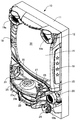
First, the first embodiment will be described with reference to the drawings. FIG. 1 is a perspective view showing an example of the gaming machine of the first embodiment.
第1の実施形態の遊技機10は、前面枠12を備え、該前面枠12は、外枠(支持枠)11に開閉回動可能に組み付けられている。遊技盤30(図2参照)は、前面枠12の表側に形成された収納部(図示省略)に収納されている。また、前面枠(本体枠)12には、遊技盤30の前面を覆うカバーガラス(透明部材)14を備えたガラス枠(透明板(透明部材)保持枠)15が取り付けられている。
The
また、ガラス枠15の左右には、内部にランプやLED(Light Emitting Diode)等を内蔵し装飾や演出、および異常発生時の報知(たとえば、払出異常が発生した場合はランプやLED等を異常報知色(たとえば、赤色)で点灯(点滅)させる)のために発光する枠装飾装置18や、音響(たとえば、効果音)を発するスピーカ(上スピーカ)19aが設けられている。さらに、前面枠12の下部にもスピーカ(下スピーカ)19bが設けられている。また、異常発生時はスピーカ19a,19bから音声で異常内容が報知されるようになっている。なお、ガラス枠15の所定部位に払出異常報知用のランプを設けるようにしてもよい。
In addition, lamps, LEDs (Light Emitting Diodes), etc. are built into the left and right sides of the
また、前面枠12の下部には、図示しない打球発射装置に遊技球を供給する上皿(貯留皿)21、遊技機10の裏面側に設けられている払出ユニットから払い出された遊技球が流出する上皿球出口22、上皿21が一杯になった状態で払い出された遊技球を貯留する下皿(受皿)23および打球発射装置の操作部24等が設けられている。さらに、上皿21の上縁部には、遊技者が各種オプションの設定をおこなうオプション設定部25が設けられている。このオプション設定部25の上面の周囲には複数の選択ボタンスイッチ25aが設けられ、オプション設定部25の上面の中央には決定ボタンスイッチ25bが設けられている。なお、オプション設定部25は、遊技者が演出態様を設定する演出設定部として機能する。この場合、選択ボタンスイッチ25aは、演出態様を選択する演出ボタンスイッチとして機能し、決定ボタンスイッチ25bは、演出態様を決定する決定ボタンスイッチとして機能する。さらに、前面枠12下部右側には、前面枠12やガラス枠15を開放したり施錠したりする鍵を挿入するための鍵穴26が設けられている。
Further, in the lower part of the
なお、選択ボタンスイッチ25aが演出ボタンスイッチとして機能する場合、遊技機10は、選択ボタンスイッチ25aと決定ボタンスイッチ25bとから受け付けた遊技者の操作にもとづいて、遊技者の操作を介入させた演出をおこなうことができる。たとえば、遊技者の操作を介入させた演出は、表示装置(変動表示装置)41(図2参照)における変動表示ゲーム(飾り特図変動表示ゲーム)における演出があり、遊技機10は、表示装置41に表示するキャラクタを動作させたり、表示装置41に表示される飾り特図変動表示ゲームにおける識別情報を停止させたりすることができる。
When the
また、オプション設定部25の右方には、遊技者が隣接する球貸機から球貸しを受ける場合に操作する球貸ボタン27、球貸機のカードユニットからプリペイドカードを排出させるために操作する排出ボタン28、プリペイドカードの残高を表示する残高表示部(図示省略)等が設けられている。この第1の実施形態の遊技機10においては、遊技者が上記操作部24を回動操作することによって、打球発射装置が上皿21から供給される遊技球を遊技盤30前面の遊技領域32(図2参照)に向かって発射する。また、遊技者が選択ボタンスイッチ25aおよび決定ボタンスイッチ25bを操作することによって、たとえば、スピーカ19a,19bから放射される音量を設定したり、遊技盤30の明るさを設定したりすることができる。
Further, on the right side of the
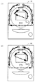
次に、遊技盤30について図2を用いて説明する。図2は、第1の実施形態の遊技盤の一例を示す正面図である。
遊技盤30の表面には、ガイドレール31で囲われた略円形状の遊技領域32が形成されている。遊技領域32は、遊技盤30の四隅に各々設けられた樹脂製のサイドケース33およびガイドレール31に囲繞されて構成される。遊技領域32には、ほぼ中央に表示装置(変動表示装置)41を備えたセンターケース(遊技演出構成体)40が配置されている。表示装置41は、センターケース40に設けられた凹部に、センターケース40の前面より奥まった位置に取り付けられている。すなわち、センターケース40は表示装置41の表示領域の周囲を囲い、表示装置41の表示面よりも前方へ突出し、周囲の遊技領域32から遊技球が飛び込みにくくなるように形成されている。
Next, the
On the surface of the
表示装置41は、たとえば、LCD(Liquid Crystal Display:液晶表示器)、CRT(Cathode Ray Tube:ブラウン管)等の表示画面を有する装置で構成されている。表示画面の画像を表示可能な領域(表示領域)には、複数の識別情報(特別図柄)や特図変動表示ゲームを演出するキャラクタや演出効果を高める背景画像等の遊技に関する情報が表示される。表示装置41の表示画面においては、識別情報として割り当てられた複数の特別図柄が変動表示(可変表示)されて、特図変動表示ゲームに対応した飾り特図変動表示ゲームがおこなわれる。また、表示画面には、遊技の進行にもとづく演出のための画像(たとえば、大当り表示画像、ファンファーレ表示画像、エンディング表示画像等)が表示される。
The
また、センターケース40の左部および右部には、動作することによって遊技の演出をおこなう盤演出装置44が備えられている。この盤演出装置44は、図2に示す状態から表示装置41の中央へ向けて動作可能となっている。
Further, the left portion and the right portion of the
遊技領域32におけるセンターケース40の下方右側には、普図変動表示ゲームの開始条件を与える普通図柄始動ゲート(普図始動ゲート)34が設けられている。普図始動ゲート34に入賞した遊技球は、ゲートスイッチ34a(図3参照)により検出される。
On the lower right side of the
また、遊技領域32におけるセンターケース40の下方左側には、三つの一般入賞口35が配置され、センターケース40の下方右側であって普図始動ゲート34よりも下側には、一つの一般入賞口35が配置されている。これら一般入賞口35に入賞した遊技球は、入賞口スイッチ35a(図3参照)により検出される。
Further, three general winning
また、遊技領域32におけるセンターケース40の下方には、特図変動表示ゲームの開始条件を与える始動入賞口36(第1始動入賞口、始動入賞領域)が設けられている。始動入賞口36に入賞した遊技球は、始動口1スイッチ36a(図3参照)により検出される。
Further, below the
また、始動入賞口36の直下には、特図変動表示ゲームの開始条件を与える普通変動入賞装置37(第2始動入賞口、始動入賞領域)が設けられている。
普通変動入賞装置37は、上端側が手前側に倒れる方向に回動することで開放して遊技球が流入し易い状態に変換可能な可動部材37bを備えており、この可動部材37bは、常時は遊技球が流入できない閉じた閉状態(遊技者にとって不利な状態)を保持している。そして、普図変動表示ゲームの結果が所定の停止表示態様となった場合には、駆動装置としての普電ソレノイド37c(図3参照)によって、普通変動入賞装置37に遊技球が流入し易い開状態(遊技者にとって有利な状態)に変化させられるようになっている。普通変動入賞装置37に入賞した遊技球は、始動口2スイッチ37a(図3参照)により検出される。
Further, immediately below the
The ordinary variable winning
また、普通変動入賞装置37の下方には、入賞口等に入賞しなかった遊技球を回収するアウト口30aが設けられている。
さらに、遊技領域32におけるセンターケース40の下方であって、始動入賞口36よりも右側には、特図変動表示ゲームの結果によって遊技球を受け入れない状態と受け入れ易い状態とに変換可能な特別変動入賞装置(大入賞口)38が配設されている。
Further, below the normal
Further, below the
特別変動入賞装置38は、上端側が手前側に倒れる方向に回動して開放可能になっているアタッカ形式の開閉扉38cを有しており、補助遊技としての特図変動表示ゲームの結果如何によって大入賞口を閉じた閉塞状態(遊技者にとって不利な状態)から開放状態(遊技者にとって有利な状態)に変換する。すなわち、特別変動入賞装置38は、たとえば、駆動装置としての大入賞口ソレノイド38b(図3参照)により駆動される開閉扉38cによって開閉される大入賞口を備え、特別遊技状態中や小当り遊技状態中は、大入賞口を閉じた状態から開いた状態に変換することにより大入賞口内への遊技球の流入を容易にさせ、遊技者に所定の遊技価値(賞球)を付与するようになっている。これら特別変動入賞装置38に入賞した遊技球は、大入賞口スイッチ38a(図3参照)により検出される。
The special variable winning
第1の実施形態の遊技機10においては、遊技球が流下する遊技領域32のうち、センターケース40の左方の領域が左側遊技領域とされ、センターケース40の右方の領域が右側遊技領域とされている。そして、遊技者が発射勢を調節して左側遊技領域へ遊技球を発射(いわゆる左打ち)することで始動入賞口36への入賞を狙うことができ、右側遊技領域へ遊技球を発射(いわゆる右打ち)することで普図始動ゲート34や普通変動入賞装置37や特別変動入賞装置38への入賞を狙うことができるようになっている。
In the
ここで、第1の実施形態の遊技機10において、右側遊技領域に対応する位置には、センターケース40の右端部に取り付けられた流路形成部材42が配設されており、右側遊技領域へと発射された遊技球は、流路形成部材42によって形成される流路を通過するよう構成されている。なお、流路形成部材42の少なくとも前面の材質は、流路形成部材42によって形成される流路を通過する遊技球を外部から視認可能な材質になっているので、遊技者等は、流路形成部材42によって形成される流路を通過する遊技球(すなわち、右側遊技領域を流下する遊技球)を、流路形成部材42の前方から流路形成部材42を透して視認することができる。
Here, in the
また、遊技領域32の外側(ここでは遊技盤30の右下部)には、特図変動表示ゲームをなす第1特図変動表示ゲームや第2特図変動表示ゲームおよび普図始動ゲート34への入賞をトリガとする普図変動表示ゲームの表示や、各種情報を表示する一括表示装置50が設けられている。
Further, on the outside of the game area 32 (here, the lower right of the game board 30), the first special figure fluctuation display game, the second special figure fluctuation display game, and the normal
一括表示装置50は、LED等で構成されたラウンド表示部51と、特図1保留表示部52と、特図1図柄表示部53と、特図2図柄表示部54と、普図図柄表示部55と、普図保留表示部56と状態表示部57とを備える。
The
次に、遊技機の制御システムについて図3を用いて説明する。図3は、第1の実施形態の遊技機の制御システムの一例を示すブロック図である。
遊技機10は、遊技制御装置100を備え、遊技制御装置100は、遊技を統括的に制御する主制御装置(主基板)であって、遊技用マイクロコンピュータ(以下、遊技用マイコンと称する)111を有するCPU(Central Processing Unit)部110と、入力ポートを有する入力部120と、出力ポートやドライバ等を有する出力部130と、CPU部110と入力部120と出力部130との間を接続するデータバス140等からなる。
Next, the control system of the game machine will be described with reference to FIG. FIG. 3 is a block diagram showing an example of the control system of the gaming machine of the first embodiment.
The
CPU部110は、アミューズメントチップ(IC(Integrated Circuit))と呼ばれる遊技用マイコン111と、水晶振動子のような発振子を備え、遊技用マイコン111の動作クロックやタイマ割込み、乱数生成回路の基準となるクロックを生成する発振回路(水晶発振器)113等を有する。遊技制御装置100および該遊技制御装置100によって駆動されるソレノイドやモータ等の電子部品には、電源装置400で生成されたDC(Direct Current)32V、DC12V、DC5V等所定のレベルの直流電圧が供給されて動作可能にされる。
The
電源装置400は、24Vの交流電源から上記DC32Vの直流電圧を生成するAC(Alternating Current)−DCコンバータやDC32Vの電圧からDC12V、DC5V等のより低いレベルの直流電圧を生成するDC−DCコンバータ等を有する通常電源部410と、遊技用マイコン111の内部のRAM(Random Access Memory)に対して停電時に電源電圧を供給するバックアップ電源部420と、停電監視回路を有し、遊技制御装置100に停電の発生、回復を知らせる停電監視信号やリセット信号等の制御信号を生成して出力する制御信号生成部430等を備える。
The
第1の実施形態では、電源装置400は、遊技制御装置100と別個に構成されているが、バックアップ電源部420および制御信号生成部430は、別個の基板上または遊技制御装置100と一体、すなわち、主基板上に設けるように構成してもよい。遊技盤30および遊技制御装置100は、機種変更の際に交換の対象となるので、第1の実施形態のように、電源装置400または主基板とは別の基板にバックアップ電源部420および制御信号生成部430を設けることにより、交換の対象から外しコストダウンを図ることができる。
In the first embodiment, the
バックアップ電源部420は、電解コンデンサのような大容量のコンデンサ1つで構成することができる。バックアップ電源は、遊技制御装置100の遊技用マイコン111(特に内蔵RAM)に供給され、停電中または電源遮断後もRAMに記憶されたデータが保持されるようになっている。制御信号生成部430は、たとえば通常電源部410で生成された32Vの電圧を監視してそれがたとえば17V以下に下がると停電発生を検出して停電監視信号を変化させるとともに、所定時間後にリセット信号を出力する。また、電源投入時や停電回復時にもその時点から所定時間経過後にリセット信号を出力する。
The backup
また、遊技制御装置100にはRAM初期化スイッチ112が設けられている。このRAM初期化スイッチ112が操作されると初期化スイッチ信号が生成され、これにもとづき遊技用マイコン111内のRAM111Cおよび払出制御装置200内のRAMに記憶されている情報を強制的に初期化する処理がおこなわれる。特に限定されるわけではないが、初期化スイッチ信号は、電源投入時に読み込まれ、停電監視信号は遊技用マイコン111が実行するメインプログラムのメインループの中で繰り返し読み込まれる。リセット信号は強制割込み信号の一種であり、制御システム全体をリセットさせる。
Further, the
遊技用マイコン111は、CPU(中央処理ユニット:マイクロプロセッサ)111A、読出し専用のROM(Read Only Memory)111Bおよび随時読出し書込み可能なRAM111Cを備える。
The
ROM111Bは、遊技制御のための不変の情報(プログラム、固定データ、各種乱数の判定値等)を不揮発的に記憶し、RAM111Cは、遊技制御時にCPU111Aの作業領域や各種信号や乱数値の記憶領域として利用される。ROM111BまたはRAM111Cとして、EEPROM(Electrically Erasable Programmable Read-Only Memory)のような電気的に書換え可能な不揮発性メモリを用いてもよい。 The ROM 111B non-volatilely stores invariant information (program, fixed data, determination values of various random numbers, etc.) for game control, and the RAM 111C stores the work area of the CPU 111A and various signals and random number values during game control. It is used as. As the ROM 111B or the RAM 111C, an electrically rewritable non-volatile memory such as EEPROM (Electrically Erasable Programmable Read-Only Memory) may be used.
また、ROM111Bは、たとえば、特図変動表示ゲームの実行時間、演出内容、リーチ状態の発生の有無等を規定する変動パターン(変動態様)を決定するための変動パターンテーブルを記憶している。変動パターンテーブルとは、始動記憶として記憶されている変動パターン乱数1〜3をCPU111Aが参照して変動パターンを決定するためのテーブルである。また、変動パターンテーブルには、結果がはずれとなる場合に選択されるはずれ変動パターンテーブル、結果が大当りとなる場合に選択される大当り変動パターンテーブル等が含まれる。さらに、これらのパターンテーブルには、リーチ状態となった後の変動パターンである後半変動パターンを決定するためのテーブル(後半変動グループテーブルや後半変動パターン選択テーブル等)、リーチ状態となる前の変動パターンである前半変動パターンを決定するためのテーブル(前半変動グループテーブルや前半変動パターン選択テーブル等)が含まれている。
Further, the ROM 111B stores, for example, a variation pattern table for determining a variation pattern (variation mode) that defines the execution time of the special figure variation display game, the effect content, the presence / absence of the occurrence of the reach state, and the like. The variation pattern table is a table for the CPU 111A to refer to the variation pattern
ここで、リーチ(リーチ状態)とは、表示状態が変化可能な表示装置を有し、該表示装置が時期を異ならせて複数の表示結果を導出表示し、該複数の表示結果があらかじめ定められた特別結果態様となった場合に、遊技状態が遊技者にとって有利な遊技状態(特別遊技状態)となる遊技機10において、複数の表示結果の一部がまだ導出表示されていない段階で、既に導出表示されている表示結果が特別結果態様となる条件を満たしている表示状態をいう。また、別の表現をすれば、リーチ状態とは、表示装置の変動表示制御が進行して表示結果が導出表示される前段階にまで達した時点でも、特別結果態様となる表示条件からはずれていない表示態様をいう。そして、たとえば、特別結果態様が揃った状態を維持しながら複数の変動表示領域による変動表示をおこなう状態(いわゆる全回転リーチ)もリーチ状態に含まれる。また、リーチ状態とは、表示装置の表示制御が進行して表示結果が導出表示される前段階にまで達した時点での表示状態であって、表示結果が導出表示される以前に決定されている複数の変動表示領域の表示結果の少なくとも一部が特別結果態様となる条件を満たしている場合の表示状態をいう。
Here, the reach (reach state) has a display device whose display state can be changed, and the display device derives and displays a plurality of display results at different times, and the plurality of display results are predetermined. In the
よって、たとえば、特図変動表示ゲームに対応して表示装置に表示される飾り特図変動表示ゲームが、表示装置における左、中、右の変動表示領域の各々で所定時間複数の識別情報を変動表示した後、左、右、中の順で変動表示を停止して結果態様を表示するものである場合、左、右の変動表示領域で、特別結果態様となる条件を満たした状態(たとえば、同一の識別情報)で変動表示が停止した状態がリーチ状態となる。またこの他に、すべての変動表示領域の変動表示を一旦停止した時点で、左、中、右のうちいずれか二つの変動表示領域で特別結果態様となる条件を満たした状態(たとえば、同一の識別情報となった状態、ただし特別結果態様は除く)をリーチ状態とし、このリーチ状態から残りの一つの変動表示領域を変動表示するようにしてもよい。 Therefore, for example, the decorative special figure variation display game displayed on the display device corresponding to the special figure variation display game changes a plurality of identification information for a predetermined time in each of the left, middle, and right variation display areas on the display device. After the display, when the variation display is stopped in the order of left, right, and middle to display the result mode, the left and right variation display areas satisfy the conditions for the special result mode (for example,). The state in which the variable display is stopped with the same identification information) is the reach state. In addition to this, when the fluctuation display of all the fluctuation display areas is temporarily stopped, the condition of the special result mode in any two of the left, middle, and right fluctuation display areas is satisfied (for example, the same). The state that has become the identification information, except for the special result mode) may be set as the reach state, and the remaining one variable display area may be variablely displayed from this reach state.
そして、このリーチ状態には複数のリーチ演出が含まれ、特別結果態様が導出される可能性が異なる(期待値が異なる)リーチ演出として、ノーマルリーチ(Nリーチ)、スペシャル1リーチ(SP1リーチ)、スペシャル2リーチ(SP2リーチ)、スペシャル3リーチ(SP3リーチ)、プレミアリーチが設定されている。なお、期待値は、「リーチなし」<「ノーマルリーチ」<「スペシャル1リーチ」<「スペシャル2リーチ」<「スペシャル3リーチ」<「プレミアリーチ」の順に高くなるようになっている。また、このリーチ状態は、少なくとも特図変動表示ゲームで特別結果態様が導出される場合(大当りとなる場合)における変動表示態様に含まれるようになっている。すなわち、特図変動表示ゲームで特別結果態様が導出されないと判定する場合(はずれとなる場合)における変動表示態様に含まれることもある。よって、リーチ状態が発生した状態は、リーチ状態が発生しない場合に比べて大当りとなる可能性の高い状態である。 The reach state includes a plurality of reach effects, and as reach effects in which the possibility of deriving a special result mode is different (expected value is different), normal reach (N reach), special 1 reach (SP1 reach), and so on. Special 2 reach (SP2 reach), special 3 reach (SP3 reach), and premier reach are set. The expected value increases in the order of "no reach" <"normal reach" <"special 1 reach" <"special 2 reach" <"special 3 reach" <"premier reach". In addition, this reach state is included in the variation display mode at least when the special result mode is derived (when it becomes a big hit) in the special figure variation display game. That is, it may be included in the variation display mode when it is determined that the special result mode is not derived in the special figure variation display game (when it is out of order). Therefore, the state in which the reach state occurs is more likely to be a big hit than the case in which the reach state does not occur.
CPU111Aは、ROM111B内の遊技制御用プログラムを実行して、払出制御装置200や演出制御装置300に対する制御信号(コマンド)を生成したりソレノイドや表示装置の駆動信号を生成し出力して遊技機10全体の制御をおこなう。また、図示しないが、遊技用マイコン111は、特図変動表示ゲームの当りを判定するための大当り乱数や大当りの図柄を決定するための大当り図柄乱数、特図変動表示ゲームでの変動パターン(各種リーチやリーチなしの変動表示における変動表示ゲームの実行時間等を含む)を決定するための変動パターン乱数、普図変動表示ゲームの当りを判定するための当り乱数等を生成するための乱数生成回路と、発振回路113からの発振信号(原クロック信号)にもとづいてCPU111Aに対する所定周期(たとえば、4m秒(ms))のタイマ割込み信号や乱数生成回路の更新タイミングを与えるクロックを生成するクロックジェネレータを備えている。
The CPU 111A executes a game control program in the ROM 111B to generate a control signal (command) for the
また、CPU111Aは、特図変動表示ゲームに関する処理において、ROM111Bに記憶されている複数の変動パターンテーブルの中から、いずれか一の変動パターンテーブルを取得する。具体的には、CPU111Aは、特図変動表示ゲームの遊技結果(当り(大当りまたは小当り)またははずれ)や、現在の遊技状態としての特図変動表示ゲームの確率状態(通常確率状態または高確率状態)、現在の遊技状態としての普通変動入賞装置37の動作状態(時短動作状態)、始動記憶数等にもとづいて、複数の変動パターンテーブルの中から、いずれか一の変動パターンテーブルを選択して取得する。ここで、CPU111Aは、特図変動表示ゲームを実行する場合に、ROM111Bに記憶された複数の変動パターンテーブルのうち、いずれか一の変動パターンテーブルを取得する変動振り分け情報取得手段をなす。
Further, the CPU 111A acquires any one of the fluctuation pattern tables stored in the ROM 111B in the process related to the special figure fluctuation display game. Specifically, the CPU 111A determines the game result of the special figure variation display game (hit (big hit or small hit) or miss) and the probability state (normal probability state or high probability) of the special figure variation display game as the current game state. State), the normal
払出制御装置200は、CPU、ROM、RAM、入力インタフェース、出力インタフェース等を備え、遊技制御装置100からの賞球払出し指令(コマンドやデータ)にしたがって、払出ユニットの払出モータを駆動させ、賞球を払い出させるための制御をおこなう。また、払出制御装置200は、カードユニットからの貸球要求信号にもとづいて払出ユニットの払出モータを駆動させ、貸球を払い出させるための制御をおこなう。
The
遊技用マイコン111の入力部120には、遊技機10に対する電波の発射を検出する盤電波センサ62、始動入賞口36内の始動口1スイッチ36a、普通変動入賞装置37内の始動口2スイッチ37a、普図始動ゲート34内のゲートスイッチ34a、入賞口スイッチ35a、特別変動入賞装置38の大入賞口スイッチ38aに接続され、これらのスイッチから供給されるハイレベルが11Vでロウレベルが7Vのような負論理の信号が入力され、0V−5Vの正論理の信号に変換するインタフェースチップ(近接I/F)121が設けられている。近接I/F121は、入力の範囲が7V−11Vとされることで、センサや近接スイッチのリード線が不正にショートされたり、センサやスイッチがコネクタから外されたり、リード線が切断されてフローティングになったような異常な状態を検出することができ、異常検知信号を出力するように構成されている。
The
近接I/F121の出力は、第2入力ポート123または第3入力ポート124へ供給されデータバス140を介して遊技用マイコン111に読み込まれる。なお、近接I/F121の出力のうち、始動口1スイッチ36a、始動口2スイッチ37a、ゲートスイッチ34a、入賞口スイッチ35a、大入賞口スイッチ38aの検出信号およびセンサやスイッチの異常を検出した際に出力される異常検知信号1は、第2入力ポート123へ入力される。また、近接I/F121の出力のうち、盤電波センサ62の検出信号およびセンサやスイッチの異常を検出した際に出力される異常検知信号2は、第3入力ポート124に入力される。また、第3入力ポート124には、遊技機10の前面枠12等に設けられた不正検出用の磁気センサ61の検出信号や、遊技機10のガラス枠15等に設けられたガラス枠開放検出スイッチ63の検出信号、遊技機10の前面枠(本体枠)12等に設けられた本体枠開放検出スイッチ64の検出信号も入力されるようになっている。なお、振動を検出する振動センサスイッチを遊技機に設け、検出信号が第3入力ポート124に入力されるようにしてもよい。
The output of the proximity I /
また、近接I/F121の出力のうち、第2入力ポート123への出力は、遊技制御装置100から中継基板70を介して図示しない試射試験装置へも供給されるようになっている。さらに、近接I/F121の出力のうち、始動口1スイッチ36aと始動口2スイッチ37aの検出信号は、第2入力ポート123の他、遊技用マイコン111へ入力されるように構成されている。
Further, among the outputs of the proximity I /
上記のように近接I/F121は、信号のレベル変換機能を有する。このようなレベル変換機能を可能にするため、近接I/F121には、電源装置400から通常のICの動作に必要なたとえば5Vのような電圧の他に、12Vの電圧が供給されるようになっている。
As described above, the proximity I /
第2入力ポート123が保持しているデータは、遊技用マイコン111が第2入力ポート123に割り当てられているアドレスをデコードすることによってイネーブル信号CE(Chip Enable)2をアサート(有効レベルに変化)することよって、読出すことができる。第3入力ポート124や後述の第1入力ポート122も同様である。
The data held by the
また、入力部120には、払出制御装置200からの枠電波不正信号(前面枠12に設けられた枠電波センサが電波を検出することにもとづき出力される信号)、払出ビジー信号(払出制御装置200がコマンドを受付可能な状態か否かを示す信号)、払出異常ステータス信号(払出異常を示すステータス信号)、シュート球切れスイッチ信号(払出し前の遊技球の不足を示す信号)、オーバーフロースイッチ信号(下皿23に遊技球が所定量以上貯留されていること(満杯になったこと)を検出したときに出力される信号)、タッチスイッチ信号(操作部24に設けられたタッチスイッチの入力にもとづく信号)を取り込んでデータバス140を介して遊技用マイコン111に供給する第1入力ポート122が設けられている。
Further, the
また、遊技制御装置100には、電源装置400からの停電監視信号やリセット信号等の信号を遊技用マイコン111等に入力するためのシュミットバッファ125が設けられており、シュミットバッファ125はこれらの入力信号からノイズを除去する機能を有する。電源装置400からの停電監視信号や、RAM初期化スイッチ112からの初期化スイッチ信号は、一旦、第1入力ポート122に入力され、データバス140を介して遊技用マイコン111に取り込まれる。つまり、前述の各種スイッチからの信号と同等の信号として扱われる。遊技用マイコン111に設けられている外部からの信号を受ける端子の数には制約があるためである。
Further, the
一方、シュミットバッファ125によりノイズ除去されたリセット信号RESETは、遊技用マイコン111に設けられているリセット端子に直接入力されるとともに、出力部130の各ポートに供給される。また、リセット信号RESETは、出力部130を介さずに直接中継基板70に出力することで、試射試験装置へ出力するために中継基板70のポート(図示省略)に保持される試射試験信号をオフするように構成されている。また、リセット信号RESETは、中継基板70を介して試射試験装置へ出力可能に構成されるようにしてもよい。なお、リセット信号RESETは、入力部120の第1乃至第3ポート122,123,124には供給されない。リセット信号RESETが入る直前に遊技用マイコン111によって出力部130の各ポートに設定されたデータは、システムの誤動作を防止するためリセットする必要があるが、リセット信号RESETが入る直前に入力部120の各ポートから遊技用マイコン111が読み込んだデータは、遊技用マイコン111のリセットによって廃棄されるためである。
On the other hand, the reset signal RESET whose noise has been removed by the Schmidt buffer 125 is directly input to the reset terminal provided in the
出力部130には、遊技用マイコン111から演出制御装置300への通信経路および遊技用マイコン111から払出制御装置200への通信経路に配されるシュミットバッファ132が設けられている。遊技制御装置100から演出制御装置300および払出制御装置200へは、シリアル通信でデータが送信される。なお、演出制御装置300の側から遊技制御装置100へ信号を入力できないようにした片方向通信とされている。
The
さらに、出力部130には、データバス140に接続され図示しない認定機関の試射試験装置へ変動表示ゲームの特図図柄情報を知らせるデータや大当りの確率状態を示す信号等を中継基板70を介して出力するバッファ133が実装可能に構成されている。このバッファ133は遊技店に設置される実機(量産販売品)としてのパチンコ遊技機の遊技制御装置(主基板)には実装されない部品である。なお、近接I/F121から出力される始動口スイッチ等加工の必要のないスイッチの検出信号は、バッファ133を通さずに中継基板70を介して試射試験装置へ供給される。
Further, the
一方、磁気センサ61や盤電波センサ62のようにそのままでは試射試験装置へ供給できない検出信号は、一旦、遊技用マイコン111に取り込まれて他の信号または情報に加工されて、たとえば遊技機が遊技制御できない状態であることを示すエラー信号としてデータバス140からバッファ133、中継基板70を介して試射試験装置へ供給される。なお、中継基板70には、上記バッファ133から出力された信号を取り込んで試射試験装置へ供給するポートや、バッファを介さないスイッチの検出信号の信号線を中継して伝達するコネクタ等が設けられている。中継基板70上のポートには、遊技用マイコン111から出力されるチップイネーブル信号CEも供給され、このチップイネーブル信号CEにより選択制御されたポートの信号が試射試験装置へ供給されるようになっている。
On the other hand, a detection signal that cannot be supplied to the test firing test device as it is, such as the
また、出力部130には、データバス140に接続され、特別変動入賞装置38の開閉扉38cを開成させる大入賞口ソレノイド38bおよび普通変動入賞装置37の可動部材37bを開成させる普電ソレノイド37cの開閉データを出力するための第2出力ポート134が設けられている。また、出力部130には、一括表示装置50に表示する内容に応じてLEDのアノード端子が接続されているセグメント線のオン/オフデータを出力するための第3出力ポート135、一括表示装置50のLEDのカソード端子が接続されているデジット線のオン/オフデータを出力するための第4出力ポート136が設けられている。
Further, the
また、出力部130には、大当り情報等遊技機10に関する情報を外部情報端子板71へ出力するための第5出力ポート137が設けられている。外部情報端子板71には、フォトリレーが備えられ、たとえば遊技店に設置された外部装置(情報収集端末や遊技場内部管理装置(ホールコンピュータ)等)に接続可能であり、遊技機10に関する情報を外部装置に供給することができるようになっている。また、第5出力ポート137からは、シュミットバッファ132を介して払出制御装置200に発射許可信号も出力される。
Further, the
さらに、出力部130には、第2出力ポート134から出力される大入賞口ソレノイド38b、普電ソレノイド37cの開閉データ信号を受けてソレノイド駆動信号を生成し出力する第1ドライバ(駆動回路)138a、第3出力ポート135から出力される一括表示装置50の電流供給側のセグメント線のオン/オフ駆動信号を出力する第2ドライバ138b、第4出力ポート136から出力される一括表示装置50の電流引き込み側のデジット線のオン/オフ駆動信号を出力する第3ドライバ138c、第5出力ポート137から管理装置等の外部装置へ供給する外部情報信号を外部情報端子板71へ出力する第4ドライバ138dが設けられている。
Further, the
上記第1ドライバ138aには、32Vで動作するソレノイドを駆動できるようにするため、電源電圧としてDC32Vが電源装置400から供給される。また、一括表示装置50のセグメント線を駆動する第2ドライバ138bには、DC12Vが供給される。デジット線を駆動する第3ドライバ138cは、表示データに応じたデジット線を電流で引き抜くためのものであるため、電源電圧は12Vまたは5Vのいずれであってもよい。
DC32V is supplied from the
12Vを出力する第2ドライバ138bによりセグメント線を介してLEDのアノード端子に電流を流し込み、接地電位を出力する第3ドライバ138cによりカソード端子よりセグメント線を介して電流を引き抜くことで、ダイナミック駆動方式で順次選択されたLEDに電源電圧が流れて点灯される。外部情報信号を外部情報端子板71へ出力する第4ドライバ138dは、外部情報信号に12Vのレベルを与えるため、DC12Vが供給される。なお、バッファ133や第2出力ポート134、第1ドライバ138a等は、遊技制御装置100の出力部130、すなわち、主基板ではなく、中継基板70側に設けるようにしてもよい。
A dynamic drive system in which a
さらに、出力部130には、外部の検査装置500へ各遊技機の識別コードやプログラム等の情報を送信するためのフォトカプラ139が設けられている。フォトカプラ139は、遊技用マイコン111が検査装置500との間でシリアル通信によってデータの送受信をおこなえるように双方通信可能に構成されている。なお、かかるデータの送受信は、通常の汎用マイクロプロセッサと同様に遊技用マイコン111が有するシリアル通信端子を利用しておこなわれるため、第1乃至第3入力ポート122,123,124のようなポートは設けられていない。
Further, the
次に、演出制御装置300の構成について図4を用いて説明する。図4は、第1の実施形態の演出制御装置の構成の一例を示すブロック図である。
演出制御装置300は、遊技用マイコン111と同様にアミューズメントチップ(IC)からなる主制御用マイコン(CPU)311と、主制御用マイコン311からのコマンドやデータにしたがって表示装置41への映像表示のための画像処理をおこなうグラフィックプロセッサとしてのVDP(Video Display Processor)312と、各種のメロディや効果音等をスピーカ19a,19bから再生させるため音の出力を制御する音源LSI314を備えている。
Next, the configuration of the
The
主制御用マイコン311には、CPUが実行するプログラムや各種データを格納したPROM(プログラマブルリードオンリメモリ)からなるPROM321、作業領域を提供するRAM322、停電時に電力が供給されなくとも記憶内容を保持可能なFeRAM(Ferroelectric RAM)323、現在の日時(年月日や曜日、時刻等)を示す情報を生成する計時手段をなすRTC(リアルタイムクロック)338が接続されている。なお、主制御用マイコン311の内部にも作業領域を提供するRAMが設けられている。また、主制御用マイコン311には、WDT(ウォッチドッグ・タイマ)回路324が接続されている。主制御用マイコン311は、遊技用マイコン111からのコマンドを解析し、演出内容を決定してVDP312へ出力映像の内容を指示したり、音源LSI314への再生音の指示、装飾ランプの点灯、モータやソレノイドの駆動制御、演出時間の管理等の処理を実行したりする。
The
VDP312には、作業領域を提供するRAM312aや、画像を拡大、縮小処理するためのスケーラ312bが設けられている。また、VDP312には、キャラクタ画像や映像データが記憶された画像ROM325や、画像ROM325から読出されたキャラクタ等の画像データを展開したり加工したりするのに使用される超高速なVRAM(Video RAM)326が接続されている。
The
特に限定されるわけではないが、主制御用マイコン311とVDP312との間は、パラレル方式でデータの送受信がおこなわれるように構成されている。パラレル方式でデータを送受信することで、シリアルの場合よりも短時間にコマンドやデータを送信することができる。
Although not particularly limited, the
VDP312から主制御用マイコン311へは、表示装置41の映像とガラス枠15や遊技盤30に設けられている装飾ランプの点灯を同期させるための垂直同期信号VSYNC、データの送信タイミングを与える同期信号STSが入力される。なお、VDP312から主制御用マイコン311へは、VRAMへの描画の終了等処理状況を知らせるため割込み信号INT0〜nおよび主制御用マイコン311からのコマンドやデータの受信待ちの状態にあることを知らせるためのウェイト信号WAIT等も入力される。
From the
演出制御装置300には、LVDS(Low Voltage Differential Signaling:小振幅信号伝送)方式で表示装置41へ送信する映像信号を生成する信号変換回路313が設けられている。VDP312から信号変換回路313へは、映像データ、水平同期信号HSYNCおよび垂直同期信号VSYNCが入力されるようになっており、VDP312で生成された映像は、信号変換回路313を介して表示装置41に表示される。
The
音源LSI314には、音声データが記憶された音声ROM327が接続されている。主制御用マイコン311と音源LSI314は、アドレスバス/データバス340を介して接続されている。また、音源LSI314から主制御用マイコン311へは、割込み信号INTが入力されるようになっている。演出制御装置300には、ガラス枠15に設けられた上スピーカ19aおよび前面枠12に設けられた下スピーカ19bを駆動するオーディオパワーアンプ等からなるアンプ回路337が設けられており、音源LSI314で生成された音声はアンプ回路337を介して上スピーカ19aおよび下スピーカ19bから出力される。
An
また、演出制御装置300には、遊技制御装置100から送信されてくるコマンドを受信するインタフェースチップ(コマンドI/F)331が設けられている。このコマンドI/F331を介して、遊技制御装置100から演出制御装置300へ送信された飾り特図保留数コマンド、飾り特図コマンド、変動コマンド、停止情報コマンド等を、演出制御指令信号(演出コマンド)として受信する。遊技制御装置100の遊技用マイコン111はDC5Vで動作し、演出制御装置300の主制御用マイコン311はDC3.3Vで動作するため、コマンドI/F331には信号のレベル変換の機能が設けられている。
Further, the
また、演出制御装置300には、遊技盤30(センターケース40を含む)に設けられているLED(発光ダイオード)を有する盤装飾装置46を駆動制御する盤装飾LED制御回路332、ガラス枠15に設けられているLED(発光ダイオード)を有する枠装飾装置(たとえば枠装飾装置18等)を駆動制御する枠装飾LED制御回路333、遊技盤30(センターケース40を含む)に設けられている盤演出装置44(たとえば表示装置41における演出表示と協働して演出効果を高める可動役物等)を駆動制御する盤演出可動体制御回路334が設けられている。ランプやモータおよびソレノイド等を駆動制御するこれらの制御回路332〜334は、アドレスバス/データバス340を介して主制御用マイコン311と接続されている。なお、ガラス枠15にモータ(たとえば演出用の装置を動作させるモータ)等の駆動源を備えた枠演出装置を設け、この枠演出装置を駆動制御する枠演出可動体制御回路を備えていてもよい。
Further, the
さらに、演出制御装置300には、ガラス枠15に設けられたオプション設定部25の選択ボタンスイッチ25aおよび決定ボタンスイッチ25b、盤演出装置44内のモータの初期位置等を検出する演出役物スイッチ47(演出モータスイッチ)のオン/オフ状態を検出して主制御用マイコン311へ検出信号を入力する機能や、演出制御装置300に設けられた音量調節スイッチ335の状態を検出して主制御用マイコン311へ検出信号を入力するスイッチ入力回路336が設けられている。
Further, the
電源装置400の通常電源部410は、上記のような構成を有する演出制御装置300やそれによって制御される電子部品に対して所望のレベルの直流電圧を供給するため、モータやソレノイドを駆動するためのDC32V、液晶パネルからなる表示装置41、モータやLEDを駆動するためのDC12V、コマンドI/F331の電源電圧となるDC5Vの他に、モータやLED、スピーカを駆動するためのDC15Vの電圧を生成するように構成されている。さらに、主制御用マイコン311として、3.3Vまたは1.2Vのような低電圧で動作するLSIを使用する場合には、DC5VにもとづいてDC3.3VやDC1.2Vを生成するためのDC−DCコンバータが演出制御装置300に設けられる。なお、DC−DCコンバータは通常電源部410に設けるようにしてもよい。
The normal
電源装置400の制御信号生成部430により生成されたリセット信号は、主制御用マイコン311に供給され、当該デバイスをリセット状態にする。また、主制御用マイコン311から出力される形で、VDP312(VDPRESET信号)、音源LSI314およびアンプ回路337(SNDRESET信号)、ランプやモータ等を駆動制御する制御回路332〜334(IORESET信号)に供給され、これらをリセット状態にする。また、演出制御装置300には遊技機10の各所を冷却する冷却FAN45が接続され、演出制御装置300の電源が投入された状態では冷却FAN45が駆動するようにされている。
The reset signal generated by the control
次に、これらの制御回路においておこなわれる遊技制御について説明する。
遊技制御装置100の遊技用マイコン111のCPU111Aでは、普図始動ゲート34に備えられたゲートスイッチ34aからの遊技球の検出信号の入力にもとづき、普図の当り判定用乱数値を抽出してROM111Bに記憶されている判定値と比較し、普図変動表示ゲームの当りはずれを判定する処理をおこなう。そして、普図図柄表示部55に、識別図柄(識別情報)を所定時間変動表示した後、停止表示する普図変動表示ゲームを表示する処理をおこなう。この普図変動表示ゲームの結果が当りの場合は、普図図柄表示部55に第1当り停止図柄〜第3当り停止図柄の各々に対応した特別の結果態様を表示するとともに、普電ソレノイド37cを動作させ、普通変動入賞装置37の可動部材37bを所定時間(たとえば、0.5秒間または1.7秒間)上述のように開放する制御をおこなう。すなわち、遊技制御装置100が、変換部材(可動部材37b)の変換制御をおこなう変換制御実行手段をなす。なお、普図変動表示ゲームの結果がはずれの場合は、普図図柄表示部55にはずれの結果態様を表示する制御をおこなう。
Next, the game control performed in these control circuits will be described.
In the CPU 111A of the
また、始動入賞口36に備えられた始動口1スイッチ36aからの遊技球の検出信号の入力にもとづき始動入賞(始動記憶)を記憶し、この始動記憶にもとづき、第1特図変動表示ゲームの大当り判定用乱数値を抽出してROM111Bに記憶されている判定値と比較し、第1特図変動表示ゲームの当りはずれを判定する処理をおこなう。また、普通変動入賞装置37に備えられた始動口2スイッチ37aからの遊技球の検出信号の入力にもとづき始動記憶を記憶し、この始動記憶にもとづき、第2特図変動表示ゲームの大当り判定用乱数値を抽出してROM111Bに記憶されている判定値と比較し、第2特図変動表示ゲームの当りはずれを判定する処理をおこなう。
Further, the starting prize (starting memory) is memorized based on the input of the detection signal of the game ball from the starting
そして、遊技制御装置100のCPU111Aは、上記の第1特図変動表示ゲームや第2特図変動表示ゲームの判定結果を含む制御信号(演出制御コマンド)を、演出制御装置300に出力する。そして、特図1図柄表示部53や特図2図柄表示部54に、識別図柄(識別情報)を所定時間変動表示した後、停止表示する特図変動表示ゲームを表示する処理をおこなう。すなわち、遊技制御装置100が、遊技領域32を流下する遊技球の始動入賞領域(始動入賞口36、普通変動入賞装置37)への入賞にもとづき変動表示ゲームの進行制御をおこなう遊技制御手段をなす。
Then, the CPU 111A of the
また、演出制御装置300では、遊技制御装置100からの制御信号にもとづき、表示装置41で特図変動表示ゲームに対応した飾り特図変動表示ゲームを表示する処理をおこなう。さらに、演出制御装置300では、遊技制御装置100からの制御信号にもとづき、演出状態の設定や、スピーカ19a,19bからの音の出力、各種LEDの発光を制御する処理等をおこなう。すなわち、演出制御装置300が、遊技(変動表示ゲーム等)に関する演出を制御する演出制御手段をなす。
Further, the
そして、遊技制御装置100のCPU111Aは、特図変動表示ゲームの結果が大当りや小当りの場合は、特図1図柄表示部53や特図2図柄表示部54に特別結果態様や小当り結果態様を表示するとともに、特別遊技状態や小当り遊技状態を発生させる処理(すなわち、特別遊技や小当り遊技を実行する処理)をおこなう。特別遊技状態や小当り遊技状態を発生させる処理においては、CPU111Aは、たとえば、大入賞口ソレノイド38bにより特別変動入賞装置38の開閉扉38cを開放させ、大入賞口内への遊技球の流入を可能とする制御をおこなう。そして、大入賞口に所定個数(たとえば、9個)の遊技球が入賞するか、大入賞口の開放から所定の開放可能時間が経過するかのいずれかの条件が達成されるまで大入賞口を開放することを1ラウンドとし、これを所定ラウンド回数継続する(繰り返す)制御(サイクル遊技)をおこなう。すなわち、遊技制御装置100が、停止結果態様が特別結果態様となった場合に、大入賞口を開閉する制御をおこなう大入賞口開閉制御手段をなす。また、特図変動表示ゲームの結果がはずれの場合は、特図1図柄表示部53や特図2図柄表示部54にはずれの結果態様を表示する制御をおこなう。
Then, when the result of the special figure variation display game is a big hit or a small hit, the CPU 111A of the
また、遊技制御装置100は、特図変動表示ゲームの結果態様にもとづき、特別遊技状態の終了後に、遊技状態として高確率状態を発生可能となっている。この高確率状態は、特図変動表示ゲームにて当り結果となる確率が、通常確率状態に比べて高い状態である。また、第1特図変動表示ゲームおよび第2特図変動表示ゲームのどちらの特図変動表示ゲームの結果態様にもとづき高確率状態となっても、第1特図変動表示ゲームおよび第2特図変動表示ゲームの両方が高確率状態となる。
Further, the
また、遊技制御装置100は、特図変動表示ゲームの結果態様にもとづき、特別遊技状態の終了後に、遊技状態として時短状態(特定遊技状態、普図高確率状態)を発生可能となっている。この時短状態においては、普図変動表示ゲームの当り結果となる確率(普図確率)を通常確率(普図低確率状態)である0よりも高い高確率(普図高確率状態)とすることが可能である。これにより、普通変動入賞装置37が普図低確率状態である場合よりも、単位時間当りの普通変動入賞装置37の開放時間が多くなるように制御するようになっている。ここで、本実施形態における普通変動入賞装置37は、通常遊技状態においては可動部材37bを開放しないように普図確率が「0」に設定されている。
Further, the
また、時短状態において、普図変動表示ゲームの実行時間(普図変動時間)は、たとえば、500m秒となり、普図変動表示ゲームの結果を表示する普図停止時間は、たとえば、600m秒となり、普図変動表示ゲームが当り結果となって普通変動入賞装置37が開放される場合に、第1当り停止図柄の開放時間(普電開放時間)と開放回数(たとえば、500m秒×1回)、第2当り停止図柄の開放時間(普電開放時間)と開放回数(たとえば、1700m秒×2回)、第3当り停止図柄の開放時間(普電開放時間)と開放回数(たとえば、1700m秒×3回)、となるように設定することが可能である。
Further, in the time saving state, the execution time of the normal map fluctuation display game (normal map fluctuation time) is, for example, 500 msec, and the normal map stop time for displaying the result of the normal map fluctuation display game is, for example, 600 msec. When the normal
なお、普図変動表示ゲームおよび普通変動入賞装置37を時短動作状態とする制御をおこなうよう適宜普図変動表示ゲームの実行時間、普図停止時間、普電開放回数、普電開放時間を設定してもよく、たとえば、時短状態においては、上述の普図変動表示ゲームの実行時間(普図変動時間)を第1変動表示時間よりも短い第2変動表示時間となるように制御することが可能である(たとえば、10000m秒が1000m秒)。また、時短状態においては、普図変動表示ゲームの結果を表示する普図停止時間を第1停止時間よりも短い第2停止時間となるように制御することが可能である(たとえば、1604m秒が704m秒)。また、時短状態においては、普図変動表示ゲームが当り結果となって普通変動入賞装置37が開放される場合に、開放時間(普電開放時間)を通常状態(普図低確率状態)の第1開放時間よりも長い第2開放時間となるように制御することが可能である(たとえば、100m秒が1352m秒)。また、時短状態においては、普図変動表示ゲームの1回の当り結果に対して、普通変動入賞装置37の開放回数(普電開放回数)を第1開放回数(たとえば、2回)よりも多い回数(たとえば、4回)の第2開放回数に設定することが可能である。また、時短状態においては、普図変動表示ゲームの当り結果となる確率(普図確率)を通常動作状態である場合の通常確率(普図低確率状態、たとえば、1/251)よりも高い高確率(普図高確率状態、たとえば、250/251)とすることが可能である。
It should be noted that the execution time, the normal figure stop time, the normal power release number, and the normal power release time of the normal figure fluctuation display game are appropriately set so as to control the normal fluctuation display game and the normal
時短状態においては、普図変動時間、普図停止時間、普電開放回数、普電開放時間、普図確率のいずれか一つまたは複数を変化させることで普通変動入賞装置37を開状態に状態変換する時間を通常よりも延長するようにする。また、変化させるものが異なる複数種類の時短状態を設定することも可能である。また、当りとなった場合に第1開放態様と第2開放態様のいずれかを選択するようにしてもよい。この場合、第1開放態様と第2開放態様の選択確率を異ならせてもよい。また、高確率状態と時短状態は、それぞれ独立して発生可能であり、両方を同時に発生することも可能であるし、一方のみを発生させることも可能である。
In the time saving state, the normal
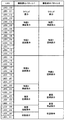
次に、一括表示装置の構成について図5を用いて説明する。図5は、第1の実施形態の一括表示装置の一例を示す図である。一括表示装置50は、LED_00からLED_31までの32個のLEDを備える。一括表示装置50は、LED_00からLED_31の点灯態様により各種状態表示をおこなう。
Next, the configuration of the batch display device will be described with reference to FIG. FIG. 5 is a diagram showing an example of the batch display device of the first embodiment. The
一括表示装置50は、LED_00からLED_31に各種状態表示機能を振り分けることで、ラウンド表示部51と、特図1保留表示部52と、特図1図柄表示部53と、特図2図柄表示部54と、普図図柄表示部55と、普図保留表示部56と、状態表示部57とを備える。ラウンド表示部51は、LED_00からLED_03の4個のLEDの点灯態様により、特図ゲームにおけるラウンド数を表示する。特図1保留表示部52は、LED_04とLED_05の2個のLEDの点灯態様により、特図1ゲームにおける保留数を表示する。特図1図柄表示部53は、LED_06からLED_13の8個のLEDの点灯態様により、特図1ゲームにおける図柄を表示する。特図2図柄表示部54は、LED_14からLED_21の8個のLEDの点灯態様により、特図2ゲームにおける図柄を表示する。普図図柄表示部55は、LED_24からLED_27の4個のLEDの点灯態様により、普図ゲームにおける図柄を表示する。普図保留表示部56は、LED_28とLED_29の2個のLEDの点灯態様により、普図ゲームにおける保留数を表示する。状態表示部57は、LED_30とLED_31の2個のLEDの点灯態様により、特図ゲームにおける遊技状態を表示する。特図2保留表示部58は、LED_22とLED_23の2個のLEDの点灯態様により、特図2ゲームにおける保留数を表示する。
By allocating various status display functions from LED_00 to LED_31, the
以下、このような遊技をおこなう遊技機の制御について説明する。まず、遊技制御装置100の遊技用マイコン111によって実行される制御について説明する。遊技用マイコン111による制御処理は、主に図6および図7に示すメイン処理と、所定時間周期(たとえば4m秒)でおこなわれる図10に示すタイマ割込み処理とからなる。
Hereinafter, control of a game machine that performs such a game will be described. First, the control executed by the
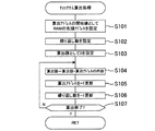
〔メイン処理〕
まず、メイン処理について説明する。図6は、第1の実施形態のメイン処理のフローチャートを示す図(その1)であり、図7は、第1の実施形態のメイン処理のフローチャートを示す図(その2)である。メイン処理は、CPU111Aが実行する処理である。
[Main processing]
First, the main process will be described. FIG. 6 is a diagram (No. 1) showing a flowchart of the main process of the first embodiment, and FIG. 7 is a diagram (No. 2) showing a flowchart of the main process of the first embodiment. The main process is a process executed by the CPU 111A.
メイン処理は、電源が投入されることで開始される。このメイン処理においては、図6および図7に示すように、まず、割込みを禁止する処理(ステップS1)をおこなってから、割込みが発生したときにレジスタ等の値を退避する領域の先頭アドレスであるスタックポインタを設定するスタックポインタ設定処理(ステップS2)をおこなう。次に、レジスタバンク0を指定し(ステップS3)、所定のレジスタ(たとえばDレジスタ)にRAM先頭アドレスの上位アドレスをセットする(ステップS4)。第1の実施形態の場合、RAM111Cのアドレスの範囲は、0000h〜01FFhで、上位としては00hか01hをとる。ステップS4ではRAM111Cのアドレスの範囲のうち先頭側にある00hをセットする。
The main process is started when the power is turned on. In this main process, as shown in FIGS. 6 and 7, first, the process of disabling interrupts (step S1) is performed, and then the start address of the area for saving the value of the register or the like when an interrupt occurs is used. The stack pointer setting process (step S2) for setting a certain stack pointer is performed. Next, register
次に、発射停止の信号を出力して発射許可信号を禁止状態に設定する(ステップS5)。発射許可信号は、遊技制御装置100と払出制御装置200の少なくとも一方が発射停止の信号を出力している場合に禁止状態に設定され、遊技球の発射が禁止されるようになっている。
Next, the launch stop signal is output and the launch permission signal is set to the prohibited state (step S5). The launch permission signal is set to a prohibited state when at least one of the
その後、入力ポート1(第1入力ポート122)の状態を読み込み(ステップS6)、電源投入ディレイタイマを設定する処理をおこなう(ステップS7)。この処理では、所定の初期値を設定することにより、主制御手段をなす遊技制御装置100からの指示にしたがい種々の制御をおこなう従制御手段(たとえば、払出制御装置200や演出制御装置300)のプログラムが正常に起動するのを待つための待機時間(たとえば3秒)が設定される。これにより、電源投入の際に仮に遊技制御装置100が先に立ち上がって従制御装置(たとえば払出制御装置200や演出制御装置300)が立ち上がる前にコマンドを従制御装置へ送ってしまい、従制御装置がコマンドを取りこぼすのを回避することができる。すなわち、遊技制御装置100が、電源投入時において、主制御手段(遊技制御装置100)の起動を遅らせて従制御装置(払出制御装置200、演出制御装置300等)の起動を待つための所定の待機時間を設定する待機手段をなす。
After that, the state of the input port 1 (first input port 122) is read (step S6), and the process of setting the power-on delay timer is performed (step S7). In this process, by setting a predetermined initial value, a slave control means (for example, a
また、電源投入ディレイタイマの計時は、RAM領域が保持するデータの正当性判定(チェックサム算出)の対象とならない記憶領域(正当性判定対象外のRAM領域またはレジスタ等)を用いておこなわれる。これにより、RAM領域のチェックサム等のチェックデータを算出する際に、一部のRAM領域を除外して算出する必要がないため電源投入時の制御が複雑になることを防止することができる。 Further, the power-on delay timer is timed by using a storage area (RAM area or register, etc. that is not subject to validity determination) that is not subject to validity determination (checksum calculation) of the data held in the RAM area. As a result, when calculating check data such as a checksum of a RAM area, it is not necessary to exclude a part of the RAM area for calculation, so that it is possible to prevent the control at the time of power-on from becoming complicated.
なお、第1入力ポート122には、初期化スイッチ信号が入力されるようになっており、待機時間の開始前に第1入力ポート122の状態を読み込むことで、RAM初期化スイッチ112の操作を確実に検出できる。すなわち、待機時間の経過後にRAM初期化スイッチ112の状態を読み込むようにすると、待機時間の経過を待ってからRAM初期化スイッチ112を操作したり、電源投入から待機時間の経過までRAM初期化スイッチ112を操作し続けたりする必要がある。しかし、待機時間の開始前に状態を読み込むことで、このような煩わしい操作をおこなわなくても電源投入後すぐに操作をおこなうことで検出されるようになり、電源投入時におこなった初期化の操作が受け付けられないような事態を防止できる。
An initialization switch signal is input to the
次に、電源投入ディレイタイマ(たとえば、約3秒)を設定する処理(ステップS7)をおこなった後、待機時間の計時と、待機時間中における停電の発生を監視する処理(ステップS8からS12)をおこなう。まず、電源装置400から入力されている停電監視信号をポートおよびデータバスを介して読み込んでチェックする回数(たとえば2回)を設定し(ステップS8)、停電監視信号がオンであるか否かの判定をおこなう(ステップS9)。
Next, after performing the process of setting the power-on delay timer (for example, about 3 seconds) (step S7), the process of timing the standby time and monitoring the occurrence of a power failure during the standby time (steps S8 to S12). To do. First, the number of times (for example, twice) to read and check the power failure monitoring signal input from the
停電監視信号がオンである場合(ステップS9;Y)は、ステップS8で設定したチェック回数分停電監視信号のオン状態が継続しているか否かを判定する(ステップS10)。そして、チェック回数分停電監視信号のオン状態が継続していない場合(ステップS10;N)は、停電監視信号がオンであるか否かの判定(ステップS9)に戻される。また、チェック回数分停電監視信号のオン状態が継続している場合(ステップS10;Y)、すなわち、停電が発生していると判定した場合は、遊技機10の電源が遮断されるのを待つ。このように、所定期間にわたり停電監視信号を受信し続けた場合に停電が発生したと判定することで、ノイズ等により停電を誤検知することを防止でき、電源投入時における不具合に適切に対処することができる。
When the power failure monitoring signal is on (step S9; Y), it is determined whether or not the power failure monitoring signal is continuously on for the number of checks set in step S8 (step S10). Then, when the power failure monitoring signal has not been turned on for the number of checks (step S10; N), the process returns to the determination of whether or not the power failure monitoring signal is on (step S9). Further, when the power failure monitoring signal is continuously turned on for the number of checks (step S10; Y), that is, when it is determined that a power failure has occurred, the power of the
すなわち、遊技制御装置100が、所定の待機時間において停電の発生を監視する停電監視手段をなす。これにより、主制御手段をなす遊技制御装置100の起動を遅らせている期間において発生した停電に対応することが可能となり、電源投入時における不具合に適切に対処することができる。なお、待機時間の終了まではRAM111Cへのアクセスが許可されておらず、前回の電源遮断時の記憶内容が保持されたままとなっているため、ここでの停電発生時にはバックアップの処理等はおこなう必要がない。このため、待機時間中に停電が発生してもRAM111Cのバックアップを取る必要がなく、制御の負担を軽減することができる。
That is, the
一方、停電監視信号がオンでない場合(ステップS9;N)、すなわち、停電が発生していない場合には、電源投入ディレイタイマを「−1」更新し(ステップS11)、タイマの値が「0」であるか否かを判定する(ステップS12)。タイマの値が0でない場合(ステップS12;N)、すなわち、待機時間が終了していない場合は、停電監視信号のチェック回数を設定する処理(ステップS8)に戻される。また、タイマの値が「0」である場合(ステップS12;Y)、すなわち、待機時間が終了した場合、RAM111CやEEPROM等の読出し書込み可能なRWM(Read Write Memory)のアクセス許可をし(ステップS13)、全出力ポートにオフデータを出力(出力がない状態に設定)する(ステップS14)。 On the other hand, when the power failure monitoring signal is not on (step S9; N), that is, when a power failure has not occurred, the power-on delay timer is updated to "-1" (step S11), and the timer value is "0". It is determined whether or not it is (step S12). If the value of the timer is not 0 (step S12; N), that is, if the standby time has not ended, the process returns to the process of setting the check count of the power failure monitoring signal (step S8). Further, when the value of the timer is "0" (step S12; Y), that is, when the waiting time ends, access permission of RWM (Read Write Memory) such as RAM111C or EEPROM that can be read and written is granted (step). S13), off-data is output to all output ports (set to a state where there is no output) (step S14).
次に、シリアルポート(遊技用マイコン111にあらかじめ搭載されているポートで、この第1の実施形態では、演出制御装置300や払出制御装置200との通信に使用)を設定し(ステップS15)、先に読み込んだ第1入力ポート122の状態からRAM初期化スイッチ112がオンにされたか否かを判定する(ステップS16)。
Next, a serial port (a port previously mounted on the
RAM初期化スイッチ112がオフである場合(ステップS16;N)は、RWM内の停電検査領域1の値が正常な停電検査領域チェックデータ1(たとえば5Ah)であるか否かを判定し(ステップS17)、正常であれば(ステップS17;Y)、RWM内の停電検査領域2の値が正常な停電検査領域チェックデータ2(たとえばA5h)であるか否かを判定する(ステップS18)。そして、停電検査領域2の値が正常であれば(ステップS18;Y)、RWM内の所定領域のチェックサムを算出するチェックサム算出処理をおこない(ステップS19)、算出したチェックサムと電源断時のチェックサムが一致するか否かを判定する(ステップS20)。チェックサムが一致する場合(ステップS20;Y)は、ステップS21(図7)へ移行し、停電から正常に復旧した場合の処理をおこなう。
When the
また、RAM初期化スイッチ112がオンである(ステップS16;Y)と判定された場合や、停電検査領域のチェックデータが正常なデータでないと判定された場合(ステップS17;NまたはステップS18;N)、チェックサムが正常でない(ステップS20;N)と判定された場合は、ステップS26(図7)へ移行して初期化の処理をおこなう。すなわち、RAM初期化スイッチ112が外部からの操作が可能な初期化操作部をなし、遊技制御装置100が、初期化操作部が操作されたことにもとづきRAM111Cに記憶されたデータを初期化する初期化手段をなす。
Further, when it is determined that the
ステップS21(図7)では、初期化すべき領域に停電復旧時の初期値をセーブする(ステップS21)。ここでの初期化すべき領域とは、停電検査領域、チェックサム領域およびエラー不正監視に係る領域である。なお、払出制御装置200がコマンドを受付可能な状態か否かを示す信号である払出ビジー信号の状態を記憶するビジー信号ステータス領域もクリアされ、払出ビジー信号の状態を確定していないことを示す不定状態とされる。同様にタッチスイッチ信号の状態を記憶するタッチスイッチ信号状態監視領域もクリアされ、タッチスイッチ信号の状態を確定していないことを示す不定状態とされる。その後、RWM内の遊技状態を記憶する領域を調べて特図の高確率中(特図変動表示ゲームの確率状態が高確率状態)であるか否かを判定する(ステップS22)。ここで、特図の高確率中でない場合(ステップS22;N)は、ステップS23、S24をスキップしてステップS25へ移行する。また、特図の高確率中である場合(ステップS22;Y)は、高確率報知フラグ領域にオン情報をセーブし(ステップS23)、たとえば一括表示装置50に設けられる高確率報知LED(エラー表示器)のオン(点灯)データをセグメント領域にセーブする(ステップS24)。そして、後述の特図ゲーム処理を合理的に実行するために用意されている処理番号に対応する停電復旧時のコマンドを演出制御基板(演出制御装置300)へ送信し(ステップS25)、ステップS31へ進む。第1の実施形態の場合、ステップS25では、機種指定コマンド、特図1保留数コマンド、特図2保留数コマンド、確率情報コマンド、画面指定のコマンド(客待ち中なら客待ちデモ画面のコマンド、それ以外なら復旧画面のコマンド)等の複数のコマンドを送信する。また、機種によっては、これらのコマンドに加えて、演出回数情報や高確率回数情報を送信する。
In step S21 (FIG. 7), the initial value at the time of power failure recovery is saved in the area to be initialized (step S21). The areas to be initialized here are a power failure inspection area, a checksum area, and an area related to error fraud monitoring. The busy signal status area for storing the state of the payout busy signal, which is a signal indicating whether or not the
一方、ステップS16、S17、S18、S20からステップS26へ移行した場合には、RAMアクセス禁止領域をアクセス許可に設定し(ステップS26)、ビジー信号ステータス領域やタッチスイッチ信号状態監視領域を含むすべてのRAM領域をゼロクリアして(ステップS27)、RAMアクセス禁止領域をアクセス禁止に設定する(ステップS28)。そして、初期化すべき領域にRAM初期化時の初期値をセーブする(ステップS29)。ここでの初期化すべき領域とは、客待ちデモ領域および演出モードの設定に係る領域である。そして、RAM初期化時のコマンドを演出制御基板(演出制御装置300)へ送信して(ステップS30)、ステップS31へ移行する。第1の実施形態の場合、ステップS30では、機種指定コマンド、特図1保留数コマンド、特図2保留数コマンド、確率情報コマンド、RAM初期化のコマンド(客待ちデモ画面を表示させるとともに、所定時間(たとえば30秒間)光と音でRAM初期化の報知をおこなわせるためのコマンド)等の複数のコマンドを送信する。また、機種によっては、これらのコマンドに加えて、演出回数情報や高確率回数情報を送信する。 On the other hand, when the transition from steps S16, S17, S18, and S20 to step S26, the RAM access prohibited area is set to the access permission (step S26), and all the areas including the busy signal status area and the touch switch signal status monitoring area are set. The RAM area is cleared to zero (step S27), and the RAM access prohibited area is set to access prohibited (step S28). Then, the initial value at the time of RAM initialization is saved in the area to be initialized (step S29). The area to be initialized here is a customer waiting demo area and an area related to the setting of the production mode. Then, the command at the time of RAM initialization is transmitted to the effect control board (effect control device 300) (step S30), and the process proceeds to step S31. In the case of the first embodiment, in step S30, a model designation command, a special figure 1 hold number command, a special figure 2 hold number command, a probability information command, and a RAM initialization command (a customer waiting demo screen is displayed and a predetermined value is set. A plurality of commands such as time (for example, a command for notifying RAM initialization by light and sound) are transmitted. In addition to these commands, depending on the model, information on the number of times of production and information on the number of times of high probability are transmitted.
ステップS31では、遊技用マイコン111(クロックジェネレータ)内のタイマ割込み信号および乱数更新トリガ信号(CTC(Counter/Timer Circuit))を発生するCTC回路を起動する処理をおこなう。なお、CTC回路は、遊技用マイコン111内のクロックジェネレータに設けられている。クロックジェネレータは、発振回路113からの発振信号(原クロック信号)を分周する分周回路と、分周された信号にもとづいてCPU111Aに対して所定周期(たとえば、4m秒)のタイマ割込み信号および乱数生成回路へ供給する乱数更新のトリガを与える信号CTCを発生するCTC回路とを備えている。
In step S31, a process of activating a CTC circuit that generates a timer interrupt signal and a random number update trigger signal (CTC (Counter / Timer Circuit)) in the gaming microcomputer 111 (clock generator) is performed. The CTC circuit is provided in the clock generator in the
上記ステップS31のCTC起動処理の後、乱数生成回路を起動設定する処理をおこなう(ステップS32)。具体的には、乱数生成回路内の所定のレジスタ(CTC更新許可レジスタ)へ乱数生成回路を起動させるためのコード(指定値)の設定等がCPU111Aによっておこなわれる。また、乱数生成回路のハードウェアで生成されるハード乱数(ここでは大当り乱数)のビット転置パターンの設定もおこなわれる。ビット転置パターンとは、抽出した乱数のビット配置(上段のビット転置前の配置)を、あらかじめ定められた順で入れ替えて異なるビット配置(下段のビット転置後の配置)として格納する際の入れ替え方を定めるパターンである。このビット転置パターンにしたがい乱数のビットを入れ替えることで、乱数の規則性を崩すことができるとともに、乱数の秘匿性を高めることができる。なお、ビット転置パターンは、固定された単一のパターンであってもよいし、あらかじめ用意された複数のパターンから選択するようにしてもよい。また、ユーザーが任意に設定できるようにしてもよい。 After the CTC activation process in step S31, a process for activating and setting the random number generation circuit is performed (step S32). Specifically, the CPU 111A sets a code (designated value) for activating the random number generation circuit in a predetermined register (CTC update permission register) in the random number generation circuit. In addition, the bit transposition pattern of the hard random number (here, the jackpot random number) generated by the hardware of the random number generation circuit is also set. The bit transposition pattern is a method of exchanging the extracted random number bits (arrangement before bit transposition in the upper row) when they are exchanged in a predetermined order and stored as different bit arrangements (arrangement after bit transposition in the lower row). It is a pattern that determines. By exchanging the bits of the random number according to this bit transposition pattern, the regularity of the random number can be broken and the confidentiality of the random number can be improved. The bit transposition pattern may be a fixed single pattern, or may be selected from a plurality of patterns prepared in advance. In addition, the user may be able to set it arbitrarily.
その後、電源投入時の乱数生成回路内の所定のレジスタ(ソフト乱数レジスタ1〜n)の値を抽出し、対応する各種初期値乱数(第1の実施形態の場合、特図の当り図柄を決定する乱数(大当り図柄乱数、小当り図柄乱数)、普図の当りを決定する乱数(当り乱数)、普図の当り図柄を決定する乱数(当り図柄乱数))の初期値(スタート値)としてRWMの所定領域にセーブしてから(ステップS33)、割込みを許可する(ステップS34)。第1の実施形態で使用するCPU111A内の乱数生成回路においては、電源投入ごとにソフト乱数レジスタの初期値が変わるように構成されているため、この値を各種初期値乱数の初期値(スタート値)とすることで、ソフトウェアで生成される乱数の規則性を崩すことができ、遊技者による不正な乱数の取得を困難にすることができる。 After that, the values of predetermined registers (soft random number registers 1 to n) in the random number generation circuit at the time of turning on the power are extracted, and the corresponding initial value random numbers (in the case of the first embodiment, the winning symbol of the special figure is determined. RWM as the initial value (start value) of the random number to be performed (big hit symbol random number, small hit symbol random number), random number to determine the hit of the normal figure (hit random number), random number to determine the hit symbol of the normal figure (win symbol random number) After saving in the predetermined area of (step S33), the interrupt is permitted (step S34). In the random number generation circuit in the CPU 111A used in the first embodiment, the initial value of the soft random number register is configured to change each time the power is turned on. Therefore, this value is used as the initial value (start value) of various initial random numbers. ), The regularity of the random numbers generated by the software can be broken, and it is possible to make it difficult for the player to acquire an illegal random number.
続いて、各種初期値乱数の値を更新して乱数の規則性を崩すための初期値乱数更新処理(ステップS35)をおこなう。なお、特に限定されるわけではないが、第1の実施形態においては、大当り乱数、大当り図柄乱数、小当り図柄乱数、当り乱数、当り図柄乱数は乱数生成回路において生成される乱数を使用して生成するように構成されている。ただし、大当り乱数は、CPUの動作クロックと同等以上の速度のクロックを基にして更新されるいわゆる「高速カウンタ」であり、大当り図柄乱数、小当り図柄乱数、当り乱数、当り図柄乱数はプログラムの処理単位であるタイマ割込み処理と同周期となるCTC出力(タイマ割込み処理のCTC(CTC0)とは別のCTC(CTC2))をもとにして更新される「低速カウンタ」である。また、大当り図柄乱数、小当り図柄乱数、当り乱数、当り図柄乱数においては、乱数が一巡するごとに各々の初期値乱数(ソフトウェアで生成)を用いてスタート値を変更するいわゆる「初期値変更方式」を採用している。なお、上記各乱数は、「+1」または「−1」によるカウンタ式更新でもよいし、一巡するまで範囲内のすべての値が重複なくバラバラに出現するランダム式更新でもよい。つまり、大当り乱数はハードウェアのみで更新される乱数であり、大当り図柄乱数、小当り図柄乱数、当り乱数、当り図柄乱数はハードウェアおよびソフトウェアで更新される乱数である。 Subsequently, the initial value random number update process (step S35) for updating the values of various initial value random numbers and breaking the regularity of the random numbers is performed. Although not particularly limited, in the first embodiment, the big hit random number, the big hit symbol random number, the small hit symbol random number, the hit random number, and the hit symbol random number use the random numbers generated in the random number generation circuit. It is configured to generate. However, the jackpot random number is a so-called "high-speed counter" that is updated based on a clock whose speed is equal to or higher than the operating clock of the CPU, and the jackpot symbol random number, the small hit symbol random number, the hit random number, and the hit symbol random number are the program's. It is a "low-speed counter" that is updated based on a CTC output (CTC (CTC2) different from CTC (CTC0) of timer interrupt processing) that has the same cycle as timer interrupt processing, which is a processing unit. In addition, for big hit symbol random numbers, small hit symbol random numbers, hit random numbers, and hit symbol random numbers, the so-called "initial value change method" is used to change the start value using each initial value random number (generated by software) each time the random number goes around. "Is adopted. It should be noted that each of the above random numbers may be a counter-type update by "+1" or "-1", or a random-type update in which all the values in the range appear separately without duplication until one cycle is completed. That is, the jackpot random number is a random number updated only by the hardware, and the jackpot symbol random number, the small hit symbol random number, the hit random number, and the hit symbol random number are random numbers updated by the hardware and software.
ステップS35の初期値乱数更新処理の後、電源装置400から入力されている停電監視信号をポートおよびデータバスを介して読み込んでチェックする回数(たとえば2回)を設定し(ステップS36)、停電監視信号がオンであるかの判定をおこなう(ステップS37)。停電監視信号がオンでない場合(ステップS37;N)、初期値乱数更新処理(ステップS35)に戻される。すなわち、停電が発生していない場合には、初期値乱数更新処理と停電監視信号のチェック(ループ処理)を繰り返しおこなう。初期値乱数更新処理(ステップS35)の前に割込みを許可する(ステップS34)ことによって、初期値乱数更新処理中にタイマ割込みが発生すると割込み処理が優先して実行されるようになり、タイマ割込みが初期値乱数更新処理によって待たされることで割込み処理が圧迫されるのを回避することができる。
After the initial value random number update process in step S35, the number of times (for example, twice) to read and check the power failure monitoring signal input from the
なお、上記ステップS35での初期値乱数更新処理は、メイン処理の他、タイマ割込み処理の中においても初期値乱数更新処理をおこなう方法もあり、そのような方法を採用した場合には、両方で初期値乱数更新処理が実行されるのを回避するため、メイン処理で初期値乱数更新処理をおこなう場合には、割込みを禁止してから更新して割込みを解除する必要があるが、第1の実施形態のようにタイマ割込み処理の中での初期値乱数更新処理はせず、メイン処理内のみにした場合には、初期値乱数更新処理の前に割込みを解除しても何ら問題はなく、それによってメイン処理が簡素化されるという利点がある。 In addition to the main process, the initial value random number update process in step S35 also includes a method of performing the initial value random number update process in the timer interrupt process. If such a method is adopted, both of them are used. In order to avoid the initial value random number update process being executed, when the initial value random number update process is performed in the main process, it is necessary to disable the interrupt and then update to release the interrupt. When the initial value random number update process is not performed in the timer interrupt process as in the embodiment and only in the main process, there is no problem even if the interrupt is canceled before the initial value random number update process. This has the advantage of simplifying the main process.
停電監視信号がオンである場合(ステップS37;Y)、ステップS36で設定したチェック回数分停電監視信号のオン状態が継続しているか否かを判定する(ステップS38)。そして、チェック回数分停電監視信号のオン状態が継続していない場合(ステップS38;N)には、停電監視信号がオンであるか否かの判定(ステップS37)に戻される。また、チェック回数分停電監視信号のオン状態が継続している場合(ステップS38;Y)、すなわち、停電が発生していると判定した場合、一旦、割込みを禁止する処理(ステップS39)、全出力ポートにオフデータを出力する処理(ステップS40)をおこなう。 When the power failure monitoring signal is on (step S37; Y), it is determined whether or not the power failure monitoring signal is continuously on for the number of checks set in step S36 (step S38). Then, when the power failure monitoring signal has not been turned on for the number of checks (step S38; N), the process returns to the determination of whether or not the power failure monitoring signal is on (step S37). Further, when the power failure monitoring signal continues to be on for the number of checks (step S38; Y), that is, when it is determined that a power failure has occurred, the process of temporarily disabling interrupts (step S39) The process of outputting off-data to the output port (step S40) is performed.
その後、停電検査領域1に停電検査領域チェックデータ1をセーブし(ステップS41)、停電検査領域2に停電検査領域チェックデータ2をセーブする(ステップS42)。さらに、RWMの電源遮断時のチェックサムを算出するチェックサム算出処理(ステップS43)、算出したチェックサムをチェックサム領域にセーブする処理(ステップS44)をおこなった後、RAMへのアクセスを禁止する処理(ステップS45)をおこなってから、遊技機の電源が遮断されるのを待つ。このように、停電検査領域にチェックデータをセーブするとともに、電源遮断時のチェックサムを算出することで、電源の遮断の前にRWMに記憶されていた情報が正しくバックアップされているか否かを電源再投入時に判定することができる。
After that, the power failure inspection
以上のことから、遊技を統括的に制御する主制御手段(遊技制御装置100)と、該主制御手段からの指示にしたがい種々の制御をおこなう従制御手段(払出制御装置200、演出制御装置300等)と、を備える遊技機において、主制御手段は、電源投入時において、当該主制御手段の起動を遅らせて従制御装置の起動を待つための所定の待機時間を設定する待機手段(遊技制御装置100)と、当該所定の待機時間において停電の発生を監視する停電監視手段(遊技制御装置100)と、を備えていることとなる。
From the above, a main control means (game control device 100) that comprehensively controls the game and a subordinate control means (
また、各種装置に電力を供給する電源装置400を備え、当該電源装置400は、停電の発生を検出した際に停電監視信号を出力するように構成され、停電監視手段(遊技制御装置100)は、所定期間にわたり停電監視信号を受信し続けた場合に停電が発生したと判定するようにしていることとなる。
Further, a
また、主制御手段(遊技制御装置100)は、データを記憶可能なRAM111Cと、外部からの操作が可能な初期化操作部(RAM初期化スイッチ112)と、初期化操作部が操作されたことにもとづきRAM111Cに記憶されたデータを初期化する初期化手段(遊技制御装置100)と、を備え、当該初期化手段の操作状態を待機時間の開始前に読み込むようにしていることとなる。 Further, in the main control means (game control device 100), the RAM 111C capable of storing data, the initialization operation unit (RAM initialization switch 112) capable of being operated from the outside, and the initialization operation unit are operated. An initialization means (game control device 100) for initializing the data stored in the RAM 111C based on the above is provided, and the operation state of the initialization means is read before the start of the standby time.
また、主制御手段(遊技制御装置100)は、待機時間の経過後にRAM111Cへのアクセスを許可するようにしていることとなる。
〔チェックサム算出処理〕
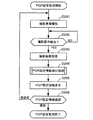
図8は、第1の実施形態のチェックサム算出処理のフローチャートを示す図である。このチェックサム算出処理は、上述のメイン処理におけるチェックサム算出処理(ステップS19、S43)である。このチェックサム算出処理では、まず、算出アドレスの開始値としてRAMの先頭アドレスを設定し(ステップS101)、繰り返し数を設定する(ステップS102)。ここで、繰り返し数は、使用しているRAMのバイト数である。次に、算出値として「0」を設定する(ステップS103)。
Further, the main control means (game control device 100) is configured to allow access to the RAM 111C after the standby time has elapsed.
[Checksum calculation process]
FIG. 8 is a diagram showing a flowchart of the checksum calculation process of the first embodiment. This checksum calculation process is the checksum calculation process (steps S19, S43) in the above-mentioned main process. In this checksum calculation process, first, the start address of the RAM is set as the start value of the calculated address (step S101), and the number of repetitions is set (step S102). Here, the number of repetitions is the number of bytes of the RAM used. Next, "0" is set as the calculated value (step S103).
その後、算出アドレスの内容に算出値を加算した値を新たな算出値とし(ステップS104)、算出アドレスを「+1」更新して(ステップS105)、繰り返し数を「−1」更新し(ステップS106)、チェックサムの算出が終了したか否かを判定する(ステップS107)。算出が終了していない場合(ステップS107;N)は、ステップS104へ戻って上記処理を繰り返す。また、算出が終了した場合(ステップS107;Y)は、チェックサム算出処理を終了する。 After that, the value obtained by adding the calculated value to the content of the calculated address is used as a new calculated value (step S104), the calculated address is updated by "+1" (step S105), and the number of repetitions is updated by "-1" (step S106). ), It is determined whether or not the checksum calculation is completed (step S107). If the calculation is not completed (step S107; N), the process returns to step S104 and the above process is repeated. When the calculation is completed (step S107; Y), the checksum calculation process is completed.
〔初期値乱数更新処理〕
図9は、第1の実施形態の初期値乱数更新処理のフローチャートを示す図である。この初期値乱数更新処理は、上述のメイン処理における初期値乱数更新処理(ステップS35)である。この初期値乱数更新処理では、まず、大当り図柄初期値乱数を「+1」更新し(ステップS111)、小当り図柄初期値乱数を「+1」更新し(ステップS112)、当り初期値乱数を「+1」更新し(ステップS113)、そして、当り図柄初期値乱数を「+1」更新して(ステップS114)、初期値乱数更新処理を終了する。ここで、「大当り図柄初期値乱数」は、特図の大当り停止図柄を決定する乱数の初期値となる乱数、「小当り図柄初期値乱数」は、特図の小当り停止図柄を決定する乱数の初期値となる乱数のことである。また、「当り初期値乱数」は、普図変動ゲームの当りを決定する乱数の初期値となる乱数、「当り図柄初期値乱数」は、普図変動ゲームの当り図柄を決定する乱数の初期値となる乱数のことである。なお、小当り図柄乱数は、小当りのない機種では存在せず、当り図柄初期値乱数も機種により存在しない場合がある。このように、メイン処理の中で時間が許す限り初期値乱数をインクリメントし続けることによって、乱数のランダム性を高めることができるようにしている。
[Initial value random number update process]
FIG. 9 is a diagram showing a flowchart of the initial value random number update process of the first embodiment. This initial value random number update process is the initial value random number update process (step S35) in the above-mentioned main process. In this initial value random number update process, first, the big hit symbol initial value random number is updated by "+1" (step S111), the small hit symbol initial value random number is updated by "+1" (step S112), and the hit initial value random number is "+1". (Step S113), and the winning symbol initial value random number is updated by "+1" (step S114), and the initial value random number update process is completed. Here, the "big hit symbol initial value random number" is a random number that is the initial value of the random number that determines the big hit stop symbol of the special symbol, and the "small hit symbol initial value random number" is the random number that determines the small hit stop symbol of the special symbol. It is a random number that is the initial value of. In addition, the "hit initial value random number" is a random number that is the initial value of the random number that determines the hit of the normal figure fluctuation game, and the "hit symbol initial value random number" is the initial value of the random number that determines the hit symbol of the normal figure fluctuation game. It is a random number that becomes. It should be noted that the small hit symbol random number does not exist in the model without the small hit, and the hit symbol initial value random number may not exist depending on the model. In this way, the randomness of the random numbers can be increased by continuing to increment the initial value random numbers as long as time allows in the main processing.
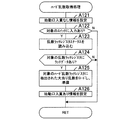
〔タイマ割込み処理〕
次に、上述のメイン処理におけるタイマ割込み処理について説明する。図10は、第1の実施形態のタイマ割込み処理のフローチャートを示す図である。このタイマ割込み処理は、上述のメイン処理において、割込み許可が出てから割込みが禁止されるまでの間(ステップS34からS39)に生じる割込み処理である。タイマ割込み処理は、CPU111Aが実行する処理である。
[Timer interrupt processing]
Next, the timer interrupt processing in the above-mentioned main processing will be described. FIG. 10 is a diagram showing a flowchart of timer interrupt processing of the first embodiment. This timer interrupt process is an interrupt process that occurs between the time when the interrupt is enabled and the time when the interrupt is disabled (steps S34 to S39) in the above-mentioned main process. The timer interrupt process is a process executed by the CPU 111A.
タイマ割込み処理は、クロックジェネレータ内のCTC回路で生成される周期的なタイマ割込み信号がCPU111Aに入力されることで開始される。遊技用マイコン111において、タイマ割込みが発生すると、自動的に割込み禁止状態になって、タイマ割込み処理が開始される。
The timer interrupt process is started by inputting a periodic timer interrupt signal generated by the CTC circuit in the clock generator to the CPU 111A. When a timer interrupt occurs in the
タイマ割込み処理が開始されると、まず、レジスタバンク1を指定する(ステップS121)。レジスタバンク1に切り替えたことで、所定のレジスタ(たとえば、メイン処理で使っているレジスタ)に保持されている値をRWMに移すレジスタ退避の処理をおこなったのと同等になる。次に、所定のレジスタ(たとえばDレジスタ)にRAM先頭アドレスの上位アドレスをセットする(ステップS122)。ステップS122では、メイン処理におけるステップS4と同じ処理をおこなっているが、レジスタバンクが異なる。次に、各種センサやスイッチからの入力や、信号の取り込み、すなわち、各入力ポートの状態を読み込む入力処理(ステップS123)をおこなう。それから、各種処理でセットされた出力データにもとづき、ソレノイド(大入賞口ソレノイド38b、普電ソレノイド37c)等のアクチュエータの駆動制御等をおこなうための出力処理(ステップS124)をおこなう。なお、メイン処理におけるステップS5で発射停止の信号を出力すると、この出力処理がおこなわれることで発射許可の信号が出力され、発射許可信号を許可状態に設定可能な状態とされる。この発射許可信号は、払出制御装置を経由して発射制御装置に出力される。その際、信号の加工等はおこなわれない。また、当該発射許可信号は、遊技制御装置100から見た発射許可の状態を示す第1の信号であり、払出制御装置200から見た発射許可の状態を示す第2の信号(発射許可信号)も払出制御装置200内で生成され、発射制御装置に出力される。つまり、2つの発射許可信号が発射制御装置に出力されており、両者がともに発射許可となっている場合に、遊技球が発射可能な状態となるよう構成されている。
When the timer interrupt processing is started, first, the
次に、各種処理で送信バッファにセットされたコマンドを払出制御装置200に出力する払出コマンド送信処理(ステップS125)、乱数更新処理1(ステップS126)、乱数更新処理2(ステップS127)をおこなう。その後、始動口1スイッチ36a、始動口2スイッチ37a、普図のゲートスイッチ34a、入賞口スイッチ35a、大入賞口スイッチ38aから正常な信号の入力があるか否かの監視や、エラーの監視(前面枠12やガラス枠15が開放されていないか等)をおこなう入賞口スイッチ/状態監視処理(ステップS128)をおこなう。また、特図変動表示ゲームに関する処理をおこなう特図ゲーム処理(ステップS129)、普図変動表示ゲームに関する処理をおこなう普図ゲーム処理(ステップS130)をおこなう。
Next, the payout command transmission process (step S125), the random number update process 1 (step S126), and the random number update process 2 (step S127) for outputting the commands set in the transmission buffer in various processes to the
次に、遊技機10に設けられ、特図変動表示ゲームの表示や遊技に関する各種情報を表示するセグメントLEDを所望の内容を表示するように駆動するセグメントLED編集処理(ステップS131)、磁気センサ61からの検出信号をチェックして異常がないか判定する処理をおこなう磁石不正監視処理(ステップS132)、盤電波センサ62からの検出信号をチェックして異常がないか判定する処理をおこなう盤電波不正監視処理(ステップS133)をおこなう。それから、外部の各種装置に出力する信号を出力バッファにセットする外部情報編集処理(ステップS134)をおこなって、タイマ割込み処理を終了する。
Next, a segment LED editing process (step S131), which is provided in the
ここで、第1の実施形態では、割込み禁止状態を復元する処理(すなわち、割込みを許可する処理)や、レジスタバンクの指定を復元する処理(すなわち、レジスタバンク0を指定する処理)は、割込みリターンの際(タイマ割込み処理の終了時)に自動的におこなわれる。なお、使用するCPUによっては、割込み禁止状態を復元する処理やレジスタバンクの指定を復元する処理の実行を命令する必要がある遊技機もある。 Here, in the first embodiment, the process of restoring the interrupt disabled state (that is, the process of permitting interrupts) and the process of restoring the register bank designation (that is, the process of designating register bank 0) are interrupts. It is automatically performed at the time of return (at the end of timer interrupt processing). Depending on the CPU used, some gaming machines need to be instructed to execute a process for restoring the interrupt disabled state or a process for restoring the register bank designation.
〔入力処理〕
次に、上述のタイマ割込み処理における入力処理(ステップS123)の詳細について説明する。図11は、第1の実施形態の入力処理のフローチャートを示す図である。
[Input processing]
Next, the details of the input process (step S123) in the timer interrupt process described above will be described. FIG. 11 is a diagram showing a flowchart of the input process of the first embodiment.
この入力処理においては、まず、入力ポート1、すなわち、第1入力ポート122に取り込まれたスイッチの検出信号の状態を読み込む(ステップS141)。そして、8ビットのポートのうち未使用ビットがあればそのビットの状態をクリアし(ステップS142)、読み込まれた入力ポート1の状態をRWM内のスイッチ制御領域1にセーブ(格納)する(ステップS143)。次に、入力ポート2、すなわち、第2入力ポート123のアドレスを準備し(ステップS144)、RWM内のスイッチ制御領域2のアドレスを準備し(ステップS145)、未使用のビットデータを準備(ステップS146)する。未使用のビットデータおよび反転するビットデータは、入力ポートごとに準備されている。次に、反転するビットデータを準備し(ステップS147)、スイッチ読み込み処理(ステップS148)をおこなう。ここで、第1の実施形態において「準備」とは、レジスタに値をセットすることを意味するが、これに限らず、RWM、その他のメモリに値をセットするようにしてもよい。
In this input process, first, the state of the detection signal of the switch captured in the
次に、入力ポート3、すなわち、第3入力ポート124のアドレスを準備し(ステップS149)、RWM内のスイッチ制御領域3のアドレスを準備し(ステップS150)、未使用のビットデータを準備し(ステップS151)、反転するビットデータを準備する(ステップS152)。そして、スイッチ読み込み処理(ステップS153)をおこない、入力処理を終了する。
Next, the address of the
なお、第1入力ポート122で監視するスイッチとしては、図3に示したように、ガラス枠開放検出スイッチ63、本体枠開放検出スイッチ64、RAM初期化スイッチ112(この処理では未使用扱い)、電源装置400の制御信号生成部430で生成された停電監視信号(この処理では未使用扱い)、払出異常ステータス信号、シュート球切れスイッチ信号、オーバーフロースイッチ信号およびタッチスイッチがある。第2入力ポート123で監視するスイッチとしては、始動口1スイッチ36a(「始動口1入賞信号」)、始動口2スイッチ37a(パターン分岐により、「始動口2入賞信号」「普通電動役物1入賞信号1」としても出力)、入賞口スイッチ35a(「普通入賞口入賞信号」)、大入賞口スイッチ38a(「特別電動役物1入賞信号」)およびゲートスイッチ34a(「普通図柄1に係るゲート通過信号1」)がある。そして、第3入力ポート124で監視するスイッチとしては、盤電波センサ62、スイッチ異常検知信号、磁気センサ61、枠電波不正信号および払出ビジー信号がある。
As the switches to be monitored by the
〔スイッチ読み込み処理〕
次に、上述の入力処理におけるスイッチ読み込み処理(ステップS148、S153)の詳細について説明する。図12は、第1の実施形態のスイッチ読み込み処理のフローチャートを示す図である。このスイッチ読み込み処理においては、まず、対象の入力ポートに取り込まれた信号の状態を読み込む(ステップS161)。そして、8ビットのポートのうち未使用ビットがあればそのビットの状態をクリアし(ステップS162)、反転の必要なビットを反転(ステップS163)した後、対象のスイッチ制御領域のポート入力状態1にセーブ(格納)する(ステップS164)。その後、2回目の読み込みまでのディレイ時間(約100μs)が経過するのを待つ(ステップS165)。
[Switch reading process]
Next, the details of the switch reading process (steps S148, S153) in the above-mentioned input process will be described. FIG. 12 is a diagram showing a flowchart of the switch reading process of the first embodiment. In this switch reading process, first, the state of the signal captured in the target input port is read (step S161). Then, if there is an unused bit among the 8-bit ports, the state of that bit is cleared (step S162), the bit that needs to be inverted is inverted (step S163), and then the
ディレイ時間(約100μs)が経過すると、対象の入力ポートに取り込まれた信号の状態の2回目の読み込みをおこなう(ステップS166)。そして、8ビットのポートのうち未使用ビットがあればそのビットの状態をクリアし(ステップS167)、反転の必要なビットを反転(ステップS168)した後、対象のスイッチ制御領域のポート入力状態2にセーブ(格納)する(ステップS169)。その後、1回目と2回目の読み込みで状態が同じビットを1、違うビットを0とした確定ビットパターンを作成し(ステップS170)、確定ビットパターンとポート入力状態2との論理積をとり、今回確定ビットとする(ステップS171)。
When the delay time (about 100 μs) has elapsed, the state of the signal captured in the target input port is read a second time (step S166). Then, if there is an unused bit among the 8-bit ports, the state of that bit is cleared (step S167), the bit that needs to be inverted is inverted (step S168), and then the
次に、1回目と2回目の読み込みで状態が同じビットを0、違うビットを1とした未確定ビットパターンを作成し(ステップS172)、未確定ビットパターンと前回割込み時の確定状態との論理積をとり、前回保持ビットとする(ステップS173)。これにより、スイッチのチャタリング等によるノイズを除去した信号の状態を得ることができる。そして、今回確定ビットと前回保持ビットを合成し、今回確定状態としてセーブし(ステップS174)、前回と今回の確定状態との排他的論理和をとり、立上りエッジとしてセーブして(ステップS175)、スイッチ読み込み処理を終了する。 Next, an undetermined bit pattern is created in which the bits having the same state are 0 and the bits having different states are 1 in the first and second readings (step S172), and the logic between the undetermined bit pattern and the confirmed state at the time of the previous interrupt. The product is taken and used as the last holding bit (step S173). As a result, it is possible to obtain a signal state in which noise due to switch chattering or the like is removed. Then, the fixed bit this time and the held bit last time are combined and saved as the fixed state this time (step S174), the exclusive OR of the fixed state of the previous time and the fixed state this time is taken, and saved as the rising edge (step S175). The switch reading process ends.
なお、スイッチの読み込みは、タイマ割込みの周期が短い場合(たとえば2ms)には、各割込みの処理ごとにそれぞれ1回ずつスイッチの読み込みをおこなって前回の読み込みの結果と比較することで信号が変化したか否か判定する方法があるが、そのようにすると次の割込み処理までに前回の割込みで読み込んだスイッチの状態が失われた場合、正しい判定がおこなえないおそれがある。これに対し、第1の実施形態のように、所定の時間差をおいて1回の割込み処理の中で2回のスイッチ読み込み処理をおこなうことで、上記のような不具合を回避することが可能となる。 When the timer interrupt cycle is short (for example, 2 ms), the switch is read once for each interrupt process and the signal is changed by comparing with the result of the previous read. There is a method of determining whether or not the switch has been executed, but if this is done, the correct determination may not be made if the state of the switch read by the previous interrupt is lost before the next interrupt processing. On the other hand, as in the first embodiment, it is possible to avoid the above-mentioned problems by performing the switch reading process twice in one interrupt process with a predetermined time difference. Become.
〔出力処理〕
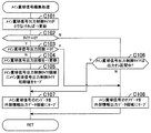
次に、前述のタイマ割込み処理における出力処理(ステップS124)の詳細について説明する。図13は、第1の実施形態の出力処理のフローチャートを示す図である。この出力処理では、まず、一括表示装置50のセグメントのデータを出力する第3出力ポート135(図3参照)にオフデータを出力(リセット)する(ステップS181)。次に、普電ソレノイド37cや大入賞口ソレノイド38bのデータを出力する第2出力ポート134に出力するデータを合成して出力する(ステップS182)。
[Output processing]
Next, the details of the output process (step S124) in the timer interrupt process described above will be described. FIG. 13 is a diagram showing a flowchart of the output process of the first embodiment. In this output process, first, off-data is output (reset) to the third output port 135 (see FIG. 3) that outputs the segment data of the batch display device 50 (step S181). Next, the data to be output to the
そして、一括表示装置50のデジット線を順次スキャンするためのデジットカウンタの値を「0」〜「3」の範囲で「+1」更新し(ステップS183)、デジットカウンタの値に対応するLEDのデジット線の出力データを取得する(ステップS184)。ここで、一括表示装置50のLED_00からLED_31をダイナミック点灯させる例として、ラウンド表示、特図1保留表示、特図1図柄表示、特図2図柄表示、普図図柄表示、普図保留表示、および状態表示(時短状態や高確率状態等の遊技状態表示)がある。
Then, the value of the digit counter for sequentially scanning the digit lines of the
次に、取得したデータと外部情報データを合成し(ステップS185)、合成したデータをデジット出力用の第4出力ポート136および外部情報出力用の第5出力ポート137に出力する(ステップS186)。ステップS185で合成される外部情報は、「扉・枠開放」および「セキュリティ信号」である。
Next, the acquired data and the external information data are combined (step S185), and the combined data is output to the
その後、デジットカウンタの値に対応するRWM内のセグメント領域からセグメント線の出力データをロードし(ステップS187)、ロードしたデータをセグメント出力用の第3出力ポート135に出力する(ステップS188)。
After that, the output data of the segment line is loaded from the segment area in the RWM corresponding to the value of the digit counter (step S187), and the loaded data is output to the
続いて、外部情報端子板71へ出力する外部情報の各種出力データをロードして合成する(ステップS189)。ここで合成する外部情報としては、「大当り信号1」、「大当り信号2」、「大当り信号3」、「大当り信号4」、「図柄確定回数信号」、「始動口信号」、「メイン賞球信号」等である。次に、合成したデータと発射許可の出力データを合成し(ステップS190)、合成したデータを外部情報出力用および発射許可信号出力用の第5出力ポート137に出力する(ステップS191)。
Subsequently, various output data of the external information to be output to the external
次に、試射試験装置への試験信号を出力する中継基板70上の試験信号出力ポート1に出力するデータをロードして合成し、中継基板70上の試験信号出力ポート1へ合成したデータを出力する(ステップS192)。その後、試射試験装置への試験信号を出力する中継基板70上の試験信号出力ポート2に出力するデータをロードして合成し、中継基板70上の試験信号出力ポート2へ合成したデータを出力する(ステップS193)。
Next, the data to be output to the test
次に、試射試験装置への試験信号を出力する中継基板70上の試験信号出力ポート3に出力するデータをロードして合成し、中継基板70上の試験信号出力ポート3へ合成したデータを出力する(ステップS194)。さらに、試射試験装置の試験信号を出力する中継基板70上の試験信号出力ポート4に出力するデータをロードして合成し、中継基板70上の試験信号出力ポート4へ合成したデータを出力する(ステップS195)。そして、試射試験装置への試験信号を出力する中継基板70上の試験信号出力ポート5に出力するデータをロードして合成し、中継基板70上の試験信号出力ポート5へ合成したデータを出力し(ステップS196)し、出力処理を終了する。
Next, the data to be output to the test
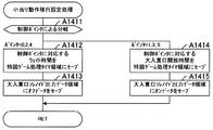
〔払出コマンド送信処理〕
次に、前述のタイマ割込み処理における払出コマンド送信処理(ステップS125)の詳細について説明する。図14は、第1の実施形態の払出コマンド送信処理のフローチャートを示す図である。この図において、左列はメイン賞球信号の出力回数を更新する(増やす)処理であり、右列は払出コマンドを送信する処理である。
[Payout command transmission process]
Next, the details of the payout command transmission process (step S125) in the timer interrupt process described above will be described. FIG. 14 is a diagram showing a flowchart of the payout command transmission process of the first embodiment. In this figure, the left column is the process of updating (increasing) the number of times the main prize ball signal is output, and the right column is the process of transmitting the payout command.
払出コマンド送信処理では、まず、賞球数別(たとえば、3個賞球、10個賞球、14個賞球)に設けられた複数の入賞数カウンタ領域のうち、チェック対象とされた、各々、255入賞まで記憶する入賞数カウンタ領域2に「0」でないカウント数があるか否かを判定する(ステップS201)。そして、カウント数がない場合(ステップS201;N)、チェック対象となる入賞数カウンタ領域2のアドレスを更新し(ステップS202)、すべての入賞数カウンタ領域のカウント数のチェックが終了したか否かを判定する(ステップS203)。
In the payout command transmission process, first, among a plurality of prize number counter areas provided for each prize ball number (for example, 3 prize balls, 10 prize balls, 14 prize balls), each of them is checked. , It is determined whether or not there is a count number other than "0" in the prize
ステップS201で、カウント数がある(ステップS201;Y)と判定された場合、対象の入賞数カウンタ領域のカウント数を減算(「−1」更新)し(ステップS204)、入賞数カウンタ領域2のアドレスに対応する払出数を取得する(ステップS205)。次に、賞球残数領域の値と払出数を加算し(ステップS206)、加算結果を賞球残数領域にセーブし(ステップS207)、加算結果から10を減算し(ステップS208)、その減算結果が「0」以上かを判定する(ステップS209)。ステップS209で、減算結果が「0」以上(ステップS209;Y)と判定された場合、メイン賞球信号出力回数を「+1」更新し(ステップS210)、減算結果を賞球残数領域にセーブする(ステップS211)。ここで、賞球信号(メイン賞球信号)としては、主基板(遊技制御装置100)からは10個払出予定ごとに1パルスが出力され、払出基板(払出制御装置200)からは10個払出ごとに1パルスが出力される。
When it is determined in step S201 that there is a count number (step S201; Y), the count number of the target winning number counter area is subtracted (updated to "-1") (step S204), and the winning
次に、ステップS203の判定で、すべてのチェックが終了した(ステップS203;Y)と判定、または、ステップS209の判定で、減算結果が「0」以上でない(ステップS209;N)と判定された場合、払出コマンド送信タイマの値が「0」でなければ払出コマンド送信タイマの値を「−1」更新する(ステップS212)。この払出コマンド送信処理が最初のタイマ割込み処理であれば、この払出コマンド送信処理の最後のステップS221で設定される初期値が設定されていないので、払出コマンド送信タイマの値は「0」であるから、減算はおこなわれないことになる。このように、払出コマンドは、タイマ割込みごとに送信するのではなく、所定時間経過してから送っている。また、払出コマンドの送信は、払出制御基板側が賞球を払い出せる状態であることも条件である。 Next, in the determination of step S203, it is determined that all the checks have been completed (step S203; Y), or in the determination of step S209, it is determined that the subtraction result is not "0" or more (step S209; N). In this case, if the value of the payout command transmission timer is not "0", the value of the payout command transmission timer is updated to "-1" (step S212). If this payout command transmission process is the first timer interrupt process, the value of the payout command transmission timer is "0" because the initial value set in the final step S221 of this payout command transmission process is not set. Therefore, the subtraction will not be performed. In this way, the payout command is not sent for each timer interrupt, but is sent after a predetermined time has elapsed. Further, the transmission of the payout command is also a condition that the payout control board side is in a state where the prize ball can be paid out.
次に、払出コマンド送信タイマの値が「0」であるか否かを判定し(ステップS213)、払出コマンド送信タイマの値が「0」である(ステップS213;Y)と判定された場合、払出ビジー信号がビジー中か否かを判定する(ステップS214)。なお、払出ビジー信号がビジー中か否かは、ポートの状態の参照ではなく、払出ビジー信号フラグの参照により判定している。ここで、払出ビジー信号がオン(ビジー中)となる条件としては、「払出動作中」、「球貸し動作中」、「シュート球切れエラー中」、「オーバーフローエラー中」、「枠電波不正発生中」、「払出球検出スイッチの異常中(払い出された球を監視するスイッチ)」、「払出不足エラー中」、「払出過剰エラー中」、「払出制御基板のメモリ内に払い出すべき賞球数のカウント(未払い出しの賞球数=獲得遊技球数残)があるとき(=0でないとき)」等である。 Next, when it is determined whether or not the value of the payout command transmission timer is "0" (step S213), and when it is determined that the value of the payout command transmission timer is "0" (step S213; Y), It is determined whether or not the payout busy signal is busy (step S214). Whether or not the payout busy signal is busy is determined not by referring to the state of the port but by referring to the payout busy signal flag. Here, the conditions for turning on the payout busy signal are "payout operation", "ball lending operation", "shoot ball out error", "overflow error", and "frame radio wave fraud occurrence". "Medium", "Abnormality of payout ball detection switch (switch to monitor payout balls)", "Payout insufficient error", "Payout excess error", "Award to be paid out in the memory of the payout control board" When there is a count of the number of balls (the number of unpaid prize balls = the remaining number of acquired game balls) (when it is not 0) "and the like.
次に、払出ビジー信号がビジー中でない(ステップS214;N)場合、入賞数カウンタ領域1にカウントありか否かを判定し(ステップS215)、入賞数カウンタ領域1にカウントがなければ(ステップS215;N)、チェックする入賞数カウンタ領域1のアドレスを更新し(ステップS216)、全領域のチェックが終了したか否かを判定する(ステップS217)。全領域のチェックが終了していない(ステップS217;N)場合、ステップS215に戻される。
Next, when the payout busy signal is not busy (step S214; N), it is determined whether or not there is a count in the winning number counter area 1 (step S215), and if there is no count in the winning number counter area 1 (step S215). ; N), the address of the winning
ステップS215において、入賞数カウンタ領域1にカウントがある(ステップS215;Y)場合、対象の入賞数カウンタを「−1」更新し(ステップS218)、入賞数カウンタ領域1のアドレスに対応する払出数コマンドを取得し(ステップS219)、取得したコマンドを払出用シリアル送信バッファに書き込む(ステップS220)。そして、払出コマンド送信タイマ領域に初期値(たとえば、200ms)をセーブする(ステップS221)。
In step S215, when there is a count in the winning number counter area 1 (step S215; Y), the target winning number counter is updated to "-1" (step S218), and the number of payouts corresponding to the address of the winning
ステップS213において、払出コマンド送信タイマの値が「0」でない(ステップS213;N)と判定された場合、ステップS214において、払出ビジー信号がビジー中である(ステップS214;Y)と判定された場合、ステップS217において、全領域のチェックが終了している(ステップS217;Y)と判定された場合、または、ステップS221の処理が終了した場合に、この払出コマンド送信処理を終了する。 When it is determined in step S213 that the value of the payout command transmission timer is not "0" (step S213; N), and in step S214, it is determined that the payout busy signal is busy (step S214; Y). , When it is determined in step S217 that the check of all areas is completed (step S217; Y), or when the process of step S221 is completed, this payout command transmission process is terminated.
〔乱数更新処理1〕
次に、タイマ割込み処理(図10参照)における乱数更新処理1(ステップS126)について説明する。図15は、第1の実施形態の乱数更新処理1のフローチャートを示す図である。この乱数更新処理1は、初期値乱数更新処理の対象となっている大当り図柄乱数、小当り図柄乱数、当り乱数、当り図柄乱数の初期値(スタート値)を更新するための処理である。
[Random number update process 1]
Next, the random number update process 1 (step S126) in the timer interrupt process (see FIG. 10) will be described. FIG. 15 is a diagram showing a flowchart of the random
この乱数更新処理1では、まず、普図の大当り図柄乱数が次回の初期値(スタート値)設定待ちであるか否かを判定する(ステップS231)。普図の大当り図柄乱数が初期値設定待ちでない場合(ステップS231;N)、小当り図柄乱数が次回の初期値(スタート値)設定待ちであるかを判定する(ステップS234)。また、普図の大当り図柄乱数が初期値設定待ちである場合(ステップS231;Y)、次回初期値として大当り図柄初期値乱数をロードし(ステップS232)、ロードした普図の大当り図柄乱数の次回の初期値を対応する乱数カウンタ(乱数領域)のスタート値を保持するレジスタ(スタート値設定レジスタ)に設定する(ステップS233)。その後、小当り図柄乱数が次回の初期値(スタート値)設定待ちであるか否かを判定する(ステップS234)。
In the random
小当り図柄乱数が初期値設定待ちでない場合(ステップS234;N)、当り乱数が次回の初期値(スタート値)設定待ちであるかを判定する(ステップS237)。また、小当り図柄乱数が初期値設定待ちである場合(ステップS234;Y)、次回初期値として小当り図柄初期値乱数をロードし(ステップS235)、ロードした小当り図柄乱数の次回の初期値を対応する乱数カウンタ(乱数領域)のスタート値を保持するレジスタ(スタート値設定レジスタ)に設定する(ステップS236)。その後、当り乱数が次回の初期値(スタート値)設定待ちであるか否かを判定する(ステップS237)。 When the small hit symbol random number is not waiting for the initial value setting (step S234; N), it is determined whether the hit random number is waiting for the next initial value (start value) setting (step S237). When the small hit symbol random number is waiting for the initial value setting (step S234; Y), the small hit symbol initial value random number is loaded as the next initial value (step S235), and the next initial value of the loaded small hit symbol random number is loaded. Is set in the register (start value setting register) that holds the start value of the corresponding random number counter (random number region) (step S236). After that, it is determined whether or not the hit random number is waiting for the next initial value (start value) setting (step S237).
当り乱数が初期値設定待ちでない場合(ステップS237;N)、当り図柄乱数が次回の初期値(スタート値)設定待ちであるか否かを判定する(ステップS240)。また、当り乱数が初期値設定待ちである場合(ステップS237;Y)、次回初期値として当り初期値乱数をロードし(ステップS238)、ロードした当り乱数の次回の初期値を対応する乱数カウンタ(乱数領域)のスタート値を保持するレジスタ(スタート値設定レジスタ)に設定する(ステップS239)。その後、当り図柄乱数が次回の初期値(スタート値)設定待ちであるか否かを判定する(ステップS240)。 When the hit random number is not waiting for the initial value setting (step S237; N), it is determined whether or not the hit symbol random number is waiting for the next initial value (start value) setting (step S240). When the hit random number is waiting for the initial value setting (step S237; Y), the hit initial value random number is loaded as the next initial value (step S238), and the random number counter corresponding to the next initial value of the loaded hit random number (step S238). It is set in the register (start value setting register) that holds the start value of the random number area) (step S239). After that, it is determined whether or not the winning symbol random number is waiting for the next initial value (start value) setting (step S240).
当り図柄乱数が初期値設定待ちでない場合(ステップS240;N)は、乱数更新処理1を終了する。また、当り図柄乱数が初期値設定待ちである場合(ステップS240;Y)、次回初期値として当り図柄初期値乱数をロードし(ステップS241)、ロードした当り図柄乱数の次回の初期値を対応する乱数カウンタ(乱数領域)のスタート値を保持するレジスタ(スタート値設定レジスタ)に設定し(ステップS242)、乱数更新処理1を終了する。
If the winning symbol random number is not waiting for the initial value setting (step S240; N), the random
〔乱数更新処理2〕
次に、タイマ割込み処理(図10参照)における乱数更新処理2(ステップS127)について説明する。図16は、第1の実施形態の乱数更新処理2のフローチャートを示す図である。この乱数更新処理2は、特図1,特図2の変動表示ゲームにおける変動パターンを決定するための変動パターン乱数を更新する処理である。なお、第1の実施形態の遊技機10では、変動パターン乱数として1バイトの乱数(変動パターン乱数2、3)と、2バイトの乱数(変動パターン乱数1)があり、乱数更新処理2は両方を更新対象とし、割込みが発生するごとに更新対象を切り替えて処理する。しかも、更新対象の乱数が2バイトの場合には、上位のバイトと下位のバイトに対して異なる割込み時に更新処理をおこなうようになっている。すなわち、メイン処理に対する一の割込み処理において実行される乱数更新処理2による2バイトの変動パターン乱数1(リーチ変動態様決定用乱数)の更新は、上位1バイトまたは下位1バイトのいずれかについて実行されるように構成されている。
[Random number update process 2]
Next, the random number update process 2 (step S127) in the timer interrupt process (see FIG. 10) will be described. FIG. 16 is a diagram showing a flowchart of the random
この乱数更新処理2では、まず、更新すべき複数の乱数のうちいずれの乱数を今回の更新処理の対象とするかを順番に指定するための乱数更新スキャンカウンタを「0」から「3」の範囲で更新する(ステップS251)。次に、乱数更新スキャンカウンタの値に対応する演出乱数更新テーブルのアドレスを算出する(ステップS252)。そして、算出されたアドレスにもとづいて参照したテーブルから乱数の上限判定値を取得する(ステップS253)。このとき参照するテーブルには、乱数の種類ごとに上限判定値、すなわち、乱数が一巡したか否かを判定するための値が格納されている。
In the random
続いて、たとえば第1の実施形態において遊技用マイコン111として使用しているZ80系のマイコンに設けられているDRAMのリフレッシュ等のため使用されるカウンタ(以下、M1カウンタと称する)のようなランダムな値が設定されるカウンタの値をロードする(ステップS254)。M1カウンタの値を使用することで、乱数にランダム性を付与することができる。次に、M1カウンタの値をマスクするためのマスク値を取得して、M1カウンタの値をマスクする(ステップS255)。なお、マスク値は、更新対象の乱数によって異なるビット数、たとえば、変動パターン乱数1の下位1バイトを更新する場合には、M1カウンタの下位3ビットに、また、変動パターン乱数1の上位1バイトを更新する場合には、M1カウンタの下位4ビットに設定されている。乱数の種類によって上限値が異なるためである。なお、マスク値として、変動パターン乱数1の下位1バイトを更新する場合には、M1カウンタの下位3ビットを、また、変動パターン乱数1の上位1バイトを更新する場合には、M1カウンタの下位4ビットを例示したが、数値は一例であってこれに限られるものではない。
Subsequently, for example, a random counter (hereinafter, referred to as an M1 counter) used for refreshing the DRAM provided in the Z80 series microcomputer used as the
次に、更新する乱数領域(乱数カウンタ)が2バイト乱数の上位1バイトであるか否かを判定する(ステップS256)。そして、乱数領域が2バイト乱数の上位1バイトである場合(ステップS256;Y)、加算値として上位1バイトをマスク値によってM1カウンタの値をマスクすることによって残った値(以下、これをマスクした値と称する)に「1」を加算したマスク更新値に設定し、下位1バイトを「0」に設定して(ステップS257)、ステップS259に移行する。また、乱数領域が2バイト乱数の上位1バイトでない場合(ステップS256;N)、加算値として上位1バイトを「0」に設定し、下位1バイトを上記マスク更新値に設定して(ステップS258)、ステップS259に移行する。なお、マスクした値に「1」を加算するのは、マスクした値が「0」になる場合があり、「0」を後に加算すると加算する前の値から変化しないので、それを避けるためである。 Next, it is determined whether or not the random number region (random number counter) to be updated is the upper 1 byte of the 2-byte random number (step S256). Then, when the random number region is the upper 1 byte of the 2-byte random number (step S256; Y), the value remaining by masking the value of the M1 counter with the mask value of the upper 1 byte as the addition value (hereinafter, this is masked). The mask update value is set by adding "1" to the value obtained), the lower 1 byte is set to "0" (step S257), and the process proceeds to step S259. If the random number area is not the upper 1 byte of the 2-byte random number (step S256; N), the upper 1 byte is set to "0" and the lower 1 byte is set to the mask update value as the addition value (step S258). ), The process proceeds to step S259. The reason for adding "1" to the masked value is to avoid that the masked value may become "0", and if "0" is added later, it does not change from the value before addition. is there.
そして、更新する乱数が2バイト乱数であるか否かを判定し(ステップS259)、2バイト乱数である場合(ステップS259;Y)、更新する乱数領域の値(2バイト)を設定して(ステップS260)、ステップS262に移行する。また、更新する乱数が2バイト乱数でない場合(ステップS259;N)、乱数値の上位1バイトとして「0」を設定し、乱数値の下位1バイトとして、更新する乱数領域の値(1バイト)を設定し(ステップS261)、ステップS262に移行する。 Then, it is determined whether or not the random number to be updated is a 2-byte random number (step S259), and if it is a 2-byte random number (step S259; Y), the value (2 bytes) of the random number area to be updated is set (2 bytes). Step S260) and step S262. If the random number to be updated is not a 2-byte random number (step S259; N), "0" is set as the upper 1 byte of the random number value, and the value of the random number area to be updated (1 byte) is set as the lower 1 byte of the random number value. Is set (step S261), and the process proceeds to step S262.
ステップS262では、乱数値にステップS257またはS258で決定した加算値を加算した値を新たな乱数値とし、この新たな乱数値がステップS253で取得した上限判定値よりも大きいか否かを判定する(ステップS263)。そして、新たな乱数値が上限判定値より大きくない場合(ステップS263;N)、新たな乱数値を1バイト乱数または2バイト乱数の下位の乱数領域にセーブする(ステップS265)。また、新たな乱数値が上限判定値より大きい場合(ステップS263;Y)、新たな乱数値から上限判定値を減算した値を再度の新たな乱数値とし(ステップS264)、この値を1バイト乱数または2バイト乱数の下位の乱数領域にセーブする(ステップS265)。 In step S262, a value obtained by adding the added value determined in step S257 or S258 to the random number value is used as a new random number value, and it is determined whether or not the new random number value is larger than the upper limit determination value acquired in step S253. (Step S263). Then, when the new random number value is not larger than the upper limit determination value (step S263; N), the new random number value is saved in the random number area lower than the 1-byte random number or the 2-byte random number (step S265). If the new random number value is larger than the upper limit determination value (step S263; Y), the value obtained by subtracting the upper limit determination value from the new random number value is used as the new random number value again (step S264), and this value is 1 byte. It is saved in the random number area lower than the random number or the 2-byte random number (step S265).
次に、更新した乱数が2バイト乱数であるか否かを判定し(ステップS266)、2バイト乱数でない場合(ステップS266;N)は、乱数更新処理2を終了する。また、2バイト乱数である場合(ステップS266;Y)、新たな乱数値(再度の新たな乱数値を算出した場合はその値)を2バイト乱数の上位の乱数領域にセーブし(ステップS267)、乱数更新処理2を終了する。
Next, it is determined whether or not the updated random number is a 2-byte random number (step S266), and if it is not a 2-byte random number (step S266; N), the random
このように、CPU111Aは、特図1,特図2の変動表示ゲームにおける変動パターンを決定するための変動パターン乱数を更新する。したがって、CPU111Aは、始動入賞口36や普通変動入賞装置37の始動領域への遊技球の流入にもとづいて抽出される各種乱数のうち、特図変動表示ゲームの変動態様(変動パターン)を決定するための変動パターン乱数を更新する乱数更新手段をなす。
In this way, the CPU 111A updates the variation pattern random number for determining the variation pattern in the variation display game of the special figures 1 and 2. Therefore, the CPU 111A determines the variation mode (variation pattern) of the special figure variation display game among various random numbers extracted based on the inflow of the game ball into the
〔入賞口スイッチ/状態監視処理〕
次に、タイマ割込み処理(図10参照)における入賞口スイッチ/状態監視処理(ステップS128)について説明する。図17は、第1の実施形態の入賞口スイッチ/状態監視処理のフローチャートを示す図である。この入賞口スイッチ/状態監視処理では、まず、大入賞口(特別変動入賞装置38)内の大入賞口スイッチ38aに対応する入賞口監視テーブル(たとえば、カウントスイッチからの検出信号が入力されるポートの番号や該信号のポート内でのビット位置等を示すデータが格納されている)を準備する(ステップS271)。次に、大入賞口が開いていないにもかかわらず大入賞口に入賞する不正(不正な入賞)がないか監視するとともに正常な入賞を検出する不正&入賞監視処理(ステップS272)を実行する。
[Winning opening switch / status monitoring process]
Next, the winning opening switch / status monitoring process (step S128) in the timer interrupt process (see FIG. 10) will be described. FIG. 17 is a diagram showing a flowchart of the winning opening switch / state monitoring process of the first embodiment. In this winning port switch / status monitoring process, first, the winning opening monitoring table (for example, the port to which the detection signal from the count switch is input) corresponding to the winning
その後、大入賞口(特別変動入賞装置38)内の他方の大入賞口スイッチ38aに対応する入賞口監視テーブル2を準備し(ステップS273)、不正な入賞がないか監視するとともに正常な入賞を検出する不正&入賞監視処理(ステップS274)を実行する。そして、普電内の入賞口スイッチ(始動口2スイッチ37a)の入賞口監視テーブルを準備し(ステップS275)、不正な入賞がないか監視するとともに正常な入賞を検出する不正&入賞監視処理(ステップS276)を実行する。
After that, the winning opening monitoring table 2 corresponding to the other large winning
次に、不正監視処理が不要な入賞口スイッチ(ここでは始動口1スイッチ36a、一般入賞口35の入賞口スイッチ35a)の入賞口監視テーブルを準備し(ステップS277)、入賞数を更新する入賞数カウンタ更新処理(ステップS278)をおこなう。
Next, the winning opening monitoring table of the winning opening switch (here, the starting
次に、遊技機10のエラー状態を監視すべき複数のスイッチおよび信号のうちいずれのスイッチまたは信号を今回の監視の対象とするかを順番に指定するための状態スキャンカウンタの値を「0」から「3」の範囲で更新する(ステップS279)。その後、状態スキャンカウンタの値に応じて、スイッチのコネクタ抜け等の発生により出力されるスイッチ異常1エラー、払出制御装置200からのシュート玉切れエラー、オーバーフロースイッチからのオーバーフローエラーおよび払出異常エラーのいずれかにもとづくエラーの監視を対象として設定するための遊技機状態監視テーブル1を準備する(ステップS280)。そして、エラーが発生しているか否かを判定する遊技機状態チェック処理(ステップS281)をおこなう。
Next, the value of the status scan counter for sequentially designating which of the plurality of switches and signals for which the error status of the
次に、状態スキャンカウンタの値に応じて、ガラス枠開放、本体枠開放、枠電波不正およびタッチスイッチのいずれかにもとづくエラーの監視を対象として設定するための遊技機状態監視テーブル2を準備する(ステップS282)。そして、エラーが発生しているか否かを判定する遊技機状態チェック処理(ステップS283)をおこなう。 Next, a game machine status monitoring table 2 is prepared for setting the monitoring of errors based on any of the glass frame opening, the main body frame opening, the frame radio wave fraud, and the touch switch according to the value of the status scan counter. (Step S282). Then, a game machine state check process (step S283) for determining whether or not an error has occurred is performed.
次に、状態スキャンカウンタの値が「0」であるか否かを判定し(ステップS284)、状態スキャンカウンタの値が「0」でない場合(ステップS284;N)は、入賞口スイッチ/状態監視処理を終了する。この場合は、次に参照する遊技機状態監視テーブル3に遊技機状態の監視対象がない場合である。また、状態スキャンカウンタの値が「0」である場合(ステップS284;Y)、状態スキャンカウンタの値に応じて、スイッチのコネクタ抜け等の発生により出力されるスイッチ異常2エラーにもとづく遊技機状態の監視を対象として設定するための遊技機状態監視テーブル3を準備する(ステップS285)。そして、エラーが発生しているか否かを判定する遊技機状態チェック処理(ステップS286)をおこない、払出ビジー信号チェック処理(ステップS287)をおこない、入賞口スイッチ/状態監視処理を終了する。なお、払出ビジー信号チェック処理は、毎回おこなわれるのではなく、4回に1回実行されるようにしてあり、残りの3回がパスされるので、16ms周期の監視となっている。
Next, it is determined whether or not the value of the status scan counter is "0" (step S284), and if the value of the status scan counter is not "0" (step S284; N), the winning opening switch / status monitoring End the process. In this case, there is no monitoring target of the game machine state in the game machine state monitoring table 3 to be referred to next. Further, when the value of the state scan counter is "0" (step S284; Y), the game machine state based on the
〔不正&入賞監視処理〕
次に、入賞口スイッチ/状態監視処理(図17参照)における不正&入賞監視処理(ステップS272,S274,S276)について説明する。図18は、第1の実施形態の不正&入賞監視処理のフローチャートを示す図である。なお、入賞口スイッチ/エラー監視処理にて準備された各入賞口監視テーブルには、「入力があるかを判定するデータ(監視スイッチビット)」、「不正監視情報の下位アドレス」、「不正入賞数領域の下位アドレス」、「不正入賞エラー報知コマンド」、「不正入賞数上限値(不正発生判定個数)」、「入賞口スイッチテーブルのアドレス」および「報知タイマ更新情報(許可/更新)」の情報が定義されているものとする。
[Illegal & winning monitoring process]
Next, fraud & winning monitoring processing (steps S272, S274, S276) in the winning opening switch / status monitoring processing (see FIG. 17) will be described. FIG. 18 is a diagram showing a flowchart of fraud & winning monitoring processing of the first embodiment. In addition, in each winning opening monitoring table prepared by the winning opening switch / error monitoring process, "data for determining whether or not there is an input (monitoring switch bit)", "lower address of fraudulent monitoring information", and "illegal winning""Lower address of several areas", "Illegal winning error notification command", "Illegal winning number upper limit (number of illegal winning judgments)", "Winning opening switch table address" and "Notification timer update information (permission / update)" It is assumed that the information is defined.
この不正&入賞監視処理は、特別変動入賞装置38の大入賞口スイッチ38aおよび普通変動入賞装置37の始動口2スイッチ37aに対しておこなわれる処理である。大入賞口(特別変動入賞装置38)や普電(普通変動入賞装置37)については、無理やり開閉部材を開いて遊技球を入れて賞球を払い出させる不正がおこなわれ易いため、入賞の検出の他に不正の監視をする。
This fraud & winning monitoring process is a process performed on the large winning
この不正&入賞監視処理においては、まず、遊技機状態監視対象の入賞口スイッチの不正監視期間フラグをチェックし(ステップS291)、不正監視期間中であるかを判定する(ステップS292)。不正監視期間とは、遊技機状態監視対象の入賞口スイッチが大入賞口スイッチ38aである場合は、特別変動入賞装置38を開放する特別遊技状態中以外の期間である。また、遊技機状態監視対象の入賞口スイッチが始動口2スイッチ37aである場合は、普図の当りにもとづき普通変動入賞装置37の開放制御を実行している状態以外の期間である。
In this fraud & prize monitoring process, first, the fraud monitoring period flag of the winning port switch for which the game machine status is monitored is checked (step S291), and it is determined whether or not the fraud monitoring period is in progress (step S292). The fraud monitoring period is a period other than during the special gaming state in which the special variable winning
そして、不正監視期間である場合(ステップS292;Y)、対象の入賞口スイッチに入力があるか否かを判定する(ステップS293)。対象の入賞口スイッチに入力がない場合(ステップS293;N)は、対象の報知タイマ更新情報をロードする(ステップS302)。また、対象の入賞口スイッチに入力がある場合(ステップS293;Y)、対象の不正入賞数を「+1」更新し(ステップS294)、加算後の不正入賞数が監視対象の不正発生判定個数(たとえば5個)以上であるか否かを判定する(ステップS295)。 Then, in the case of the fraud monitoring period (step S292; Y), it is determined whether or not there is an input in the target winning opening switch (step S293). When there is no input to the target winning opening switch (step S293; N), the target notification timer update information is loaded (step S302). Further, when there is an input to the target winning opening switch (step S293; Y), the number of illegal winnings of the target is updated by "+1" (step S294), and the number of illegal winnings after addition is the number of fraud occurrence determinations to be monitored (step S293). For example, it is determined whether or not the number is 5 or more (step S295).
なお、判定個数を5個としているのは、たとえば、開状態にある大入賞口が閉状態に変換した際に遊技球が大入賞口の扉部材に挟まり、その遊技球がカウントスイッチの有効期間を過ぎて入賞した場合や信号にノイズが乗った場合にそれを直ちに不正と判定しないようにするためである。これにより、必ずしも不正でない場合まで、簡単に不正と判定してしまうことを抑止できる。 The number of judgments is set to 5, for example, when the large winning opening in the open state is converted to the closed state, the game ball is sandwiched between the door members of the large winning opening, and the game ball is the valid period of the count switch. This is to prevent the immediate judgment of fraud when a prize is won after passing the mark or when noise is added to the signal. As a result, it is possible to prevent a simple determination of fraud even when it is not necessarily fraudulent.
そして、判定個数以上でない場合(ステップS295;N)、対象の入賞口スイッチの入賞監視テーブルを準備する(ステップS300)。また、判定個数以上の場合(ステップS295;Y)、不正入賞数を不正発生判定個数に留め(ステップS296)、対象の不正入賞報知タイマ領域に初期値をセーブする(ステップS297)。次に、対象の不正発生コマンドを準備し(ステップS298)、不正フラグとして不正入賞発生フラグを準備して(ステップS299)、準備した不正フラグを対象の不正フラグ領域の値と比較する(ステップS310)。 Then, when the number is not equal to or more than the determined number (step S295; N), the winning monitoring table of the target winning opening switch is prepared (step S300). If the number is equal to or greater than the number of determinations (step S295; Y), the number of illegal winnings is limited to the number of illegal winnings (step S296), and the initial value is saved in the target illegal winning notification timer area (step S297). Next, the target fraud occurrence command is prepared (step S298), the fraudulent winning occurrence flag is prepared as the fraud flag (step S299), and the prepared fraud flag is compared with the value of the target fraud flag area (step S310). ).
一方、不正監視期間でない場合(ステップS292;N)、対象の入賞口スイッチの入賞監視テーブルを準備し(ステップS300)、賞球の設定をおこなう入賞数カウンタ更新処理(ステップS301)をおこなう。そして、対象の報知タイマ更新情報をロードし(ステップS302)、報知タイマの更新許可の有無を判定する(ステップS303)。そして、報知タイマの更新が許可されない場合(ステップS303;N)、この不正&入賞監視処理は、終了する。なお、報知タイマの更新が許可されない情報としては、大入賞口スイッチ38aがある。これは、1つの大入賞口に対しスイッチ2個で監視をおこなっていることによる。双方のスイッチの監視でタイマを更新すると、倍速でタイマ更新がおこなわれることとなり、結果的に規定時間の半分で不正タイマがタイムアップしてしまう。このようなタイマ更新を避けるため、先に監視処理をおこなう大入賞口スイッチのタイミングでの更新を禁止している。また、後に監視処理をおこなう大入賞口スイッチおよび普通変動入賞装置37の始動口2スイッチ37aのように報知タイマの更新が許可される場合(ステップS303;Y)、対象の報知タイマが「0」でなければ「−1」更新する(ステップS304)。なお、報知タイマの最小値は、「0」に設定されている。
On the other hand, when it is not the fraud monitoring period (step S292; N), the winning monitoring table of the target winning opening switch is prepared (step S300), and the winning number counter update process (step S301) for setting the winning ball is performed. Then, the target notification timer update information is loaded (step S302), and whether or not the notification timer update permission is permitted is determined (step S303). Then, when the update of the notification timer is not permitted (step S303; N), this fraud & winning monitoring process ends. As information for which the update of the notification timer is not permitted, there is a large winning
報知タイマの更新は、遊技機状態監視対象の入賞口スイッチが一方の大入賞口スイッチ38aである場合は許可され、遊技機状態監視対象の入賞口スイッチが他方の大入賞口スイッチ38aである場合は許可されない。これにより、特別変動入賞装置38についての不正報知について、報知タイマの更新が倍の頻度でおこなわれてしまい、規定時間(たとえば60000ms)の半分でタイムアップしてしまうことを防止している。なお、遊技機状態監視対象の入賞口スイッチが大入賞口スイッチ38aである場合や始動口2スイッチ37aである場合は報知タイマの更新は常に許可される。
The update of the notification timer is permitted when the winning opening switch for the game machine status monitoring target is one of the large winning
その後、報知タイマの値が「0」であるか否かを判定し(ステップS305)、値が「0」でない場合(ステップS305;N)、すなわちタイムアップしていない場合は、不正&入賞監視処理を終了する。また、値が「0」である場合(ステップS305;Y)、すなわちタイムアップしたまたはすでにタイムアップしていた場合、対象の不正解除コマンドを準備し(ステップS306)、不正フラグとして不正入賞解除フラグを準備する(ステップS307)。そして、CPU111Aは、報知タイマの値が「0」になった瞬間であるか否かを判定する(ステップS308)。 After that, it is determined whether or not the value of the notification timer is "0" (step S305), and if the value is not "0" (step S305; N), that is, if the time is not up, fraud & winning monitoring End the process. Further, when the value is "0" (step S305; Y), that is, when the time is up or the time has already been up, the target illegal release command is prepared (step S306), and the illegal prize release flag is prepared as the illegal flag. Is prepared (step S307). Then, the CPU 111A determines whether or not it is the moment when the value of the notification timer becomes "0" (step S308).
報知タイマの値が「0」になった瞬間である場合(ステップS308;Y)、すなわち今回の不正&入賞監視処理で報知タイマの値が「0」になった場合、対象の不正入賞数をクリアし(ステップS309)、準備した不正フラグを対象の不正フラグ領域の値と比較する(ステップS310)。また、報知タイマの値が「0」になった瞬間でない場合(ステップS308;N)、すなわち前回以前の不正&入賞監視処理で報知タイマの値が「0」になった場合、準備した不正フラグを対象の不正フラグ領域の値と比較する(ステップS310)。 When the value of the notification timer becomes "0" (step S308; Y), that is, when the value of the notification timer becomes "0" in the current fraud & winning monitoring process, the target number of fraudulent winnings is set. It is cleared (step S309), and the prepared invalid flag is compared with the value of the target invalid flag area (step S310). Further, when the value of the notification timer is not the moment when the value becomes "0" (step S308; N), that is, when the value of the notification timer becomes "0" in the fraud & winning monitoring process before the previous time, the prepared fraud flag Is compared with the value of the target invalid flag area (step S310).
そして、準備した不正フラグと対象の不正フラグ領域の値が一致した場合(ステップS310;Y)、不正&入賞監視処理は、終了される。また、準備した不正フラグと対象の不正フラグ領域の値が一致しない場合(ステップS310;N)、準備した不正フラグを対象の不正フラグ領域にセーブし(ステップS311)、演出コマンド設定処理をおこない(ステップS312)、不正&入賞監視処理を終了する。以上の処理により、不正の発生に伴い不正報知コマンドが演出制御装置300に送信され、不正の解除に伴い不正入賞不正解除コマンドが演出制御装置300に送信されて、不正報知の開始、終了が設定されることとなる。
Then, when the prepared fraud flag and the value of the target fraud flag area match (step S310; Y), the fraud & winning monitoring process is terminated. If the prepared invalid flag and the value of the target invalid flag area do not match (step S310; N), the prepared invalid flag is saved in the target invalid flag area (step S311), and the effect command setting process is performed (step S311). Step S312), the fraud & winning monitoring process is terminated. By the above processing, the fraudulent notification command is transmitted to the
〔入賞数カウンタ更新処理〕
次に、上述の入賞口スイッチ/状態監視処理および不正&入賞監視処理における入賞数カウンタ更新処理(ステップS278,S301)について説明する。図19は、第1の実施形態の入賞数カウンタ更新処理のフローチャートを示す図である。なお、入賞口スイッチ/状態監視処理で準備された入賞口監視テーブルのうちの入賞テーブルには、「繰り返し回数」の情報と、スイッチごとに定義された「入力があるか否かを判定するデータ(監視スイッチビット)」、「入賞数カウンタ領域1の下位アドレス」および「入賞数カウンタ領域2の下位アドレス」の情報が定義されている。
[Winning counter update process]
Next, the winning number counter update processing (steps S278 and S301) in the above-mentioned winning opening switch / status monitoring processing and fraud & winning monitoring processing will be described. FIG. 19 is a diagram showing a flowchart of the winning number counter update processing of the first embodiment. In addition, in the winning table of the winning opening monitoring table prepared by the winning opening switch / status monitoring process, the information of the "repetition count" and the "data for determining whether or not there is an input" defined for each switch (Monitoring switch bit) ”,“ lower address of the winning
この入賞数カウンタ更新処理においては、まず、入賞口監視テーブルから監視する入賞口スイッチの個数を取得し(ステップS321)、対象の入賞口スイッチに入力(正確には入力の変化)があるか否かを判定する(ステップS322)。 In this winning number counter update process, first, the number of winning opening switches to be monitored is acquired from the winning opening monitoring table (step S321), and whether or not there is an input (correctly, a change in input) to the target winning opening switch. (Step S322).
入力がない場合(ステップS322;N)、テーブルアドレスを次レコードのアドレスに更新する(ステップS331)。また、入力がある場合(ステップS322;Y)、対象の入賞数カウンタ領域1の値をロードし(ステップS323)、ロードした値を「+1」更新して(ステップS324)、オーバーフローするか判定する(ステップS325)。そして、オーバーフローが発生していない場合(ステップS325;N)、更新後の値を入賞数カウンタ領域1にセーブする(ステップS326)。これにより、賞球(払出コマンド送信)のための入賞数カウンタが更新される。このときのカウンタサイズは2バイトであり、「0」から「65535」の範囲で更新される。また、オーバーフローが発生した場合(ステップS325;Y)は、ステップS326の処理がパスされる。
If there is no input (step S322; N), the table address is updated to the address of the next record (step S331). If there is an input (step S322; Y), the value of the target winning
次に、対象の入賞数カウンタ領域2の値をロードし(ステップS327)、ロードした値を「+1」更新し(ステップS328)、オーバーフローするか否かを判定する(ステップS329)。そして、オーバーフローが発生していない場合(ステップS329;N)は、更新後の値を入賞数カウンタ領域2にセーブする(ステップS330)。これにより、メイン賞球信号のための入賞数カウンタが更新される。このときのカウンタサイズは1バイトであり、「0」から「255」の範囲で更新される。また、オーバーフローが発生した場合(ステップS329;Y)は、ステップS330の処理がパスされる。
Next, the value of the target winning
ステップS331において、テーブルアドレスを次レコードのアドレスに更新すると、全スイッチの監視が終了したか否かを判定する(ステップS332)。全スイッチの監視が終了していない場合(ステップS332;N)は、対象の入賞口スイッチに入力があるかを判定する処理(ステップS322)に戻る。また、全スイッチの監視が終了した場合(ステップS332;Y)、入賞数カウンタ更新処理は、終了される。以上の処理により、入賞に応じた賞球が設定されることとなる。 When the table address is updated to the address of the next record in step S331, it is determined whether or not the monitoring of all switches has been completed (step S332). When the monitoring of all the switches is not completed (step S332; N), the process returns to the process of determining whether or not there is an input in the target winning opening switch (step S322). When the monitoring of all the switches is completed (step S332; Y), the winning number counter update process is terminated. By the above processing, a prize ball is set according to the winning.
〔遊技機状態チェック処理〕
次に、上述の入賞口スイッチ/状態監視処理における遊技機状態チェック処理(ステップS286)について説明する。図20は、第1の実施形態の遊技機状態チェック処理のフローチャートを示す図である。なお、入賞口スイッチ/状態監視処理にて準備された各遊技機状態監視テーブルには、「状態監視領域の先頭アドレスの下位アドレス」、「対象の信号情報が保存されているスイッチ制御領域のポート入力状態領域の下位アドレス」、「対象の信号のビットだけを取り出すマスクデータ」、「信号オンの判定データ」、「状態オフコマンド(エラー系の場合は、エラー報知終了のコマンドの意味)」、「状態オンコマンド(エラー系の場合は、エラー報知開始のコマンドの意味)」、「状態オフ監視タイマ比較値」および「状態オン監視タイマ比較値」の情報がそれぞれ定義されている。
[Game machine status check process]
Next, the game machine state check process (step S286) in the above-mentioned winning opening switch / state monitoring process will be described. FIG. 20 is a diagram showing a flowchart of the gaming machine state check process of the first embodiment. In addition, in each game machine state monitoring table prepared by the winning port switch / state monitoring process, "lower address of the start address of the state monitoring area" and "port of the switch control area in which the target signal information is stored""Lower address of input state area", "Mask data to extract only the bits of the target signal", "Signal on judgment data", "Status off command (in the case of an error system, the meaning of the command to end error notification)", Information of "status on command (in the case of an error system, the meaning of the command to start error notification)", "status off monitoring timer comparison value", and "status on monitoring timer comparison value" is defined, respectively.
この遊技機状態チェック処理では、まず、状態スキャンカウンタに対応する状態監視テーブルを取得し(ステップS341)、監視対象の信号がオンであるか否か、すなわちエラーを示す状態であるか否かを判定する(ステップS342)。なお、監視対象の信号がオンでない場合とは、エラー系に関しては、エラーではない正常の状態をいい、タッチスイッチに関しては、タッチしていない状態をいう。また、監視対象の信号がオンである場合とは、エラー系に関しては、エラー(異常、不正)の状態をいい、タッチスイッチに関しては、タッチしている状態をいう。 In this game machine state check process, first, a state monitoring table corresponding to the state scan counter is acquired (step S341), and whether or not the signal to be monitored is on, that is, whether or not it is in a state indicating an error. Determine (step S342). The case where the signal to be monitored is not on means a normal state in which the error system is not an error, and the touch switch means a non-touched state. Further, when the signal to be monitored is on, it means an error (abnormal, invalid) state for an error system, and a touched state for a touch switch.
ステップS342において、信号がオンでない場合(ステップS342;N)、状態フラグとして状態オフフラグを準備し(ステップS343)し、対象の状態オフコマンドを取得して準備する(ステップS344)。その後、対象の状態オフ監視タイマ比較値を取得して(ステップS345)、対象の信号制御領域の値と今回の信号の状態を比較する(ステップS349)。 In step S342, when the signal is not on (step S342; N), the state off flag is prepared as the state flag (step S343), and the target state off command is acquired and prepared (step S344). After that, the target state-off monitoring timer comparison value is acquired (step S345), and the value of the target signal control area is compared with the current signal state (step S349).
一方、信号がオンである場合(ステップS342;Y)、状態フラグとして状態オンフラグを準備し(ステップS346)、対象の状態オンコマンドを取得して準備する(ステップS347)。その後、対象の状態オン監視タイマ比較値を取得して(ステップS348)、対象の信号制御領域の値と今回の信号の状態を比較する(ステップS349)。 On the other hand, when the signal is on (step S342; Y), the state on flag is prepared as the state flag (step S346), and the target state on command is acquired and prepared (step S347). After that, the target state-on monitoring timer comparison value is acquired (step S348), and the value of the target signal control area is compared with the current signal state (step S349).
対象の信号制御領域の値と今回の信号の状態が一致した場合(ステップS349;Y)、すなわち信号の状態が変化していない場合、対象の状態監視タイマを「+1」更新して(ステップS352)、対象の状態監視タイマの値が監視タイマ比較値以上か否かを判定する(ステップS353)。また、対象の信号制御領域の値と今回の信号の状態が一致しない場合(ステップS349;N)、すなわち信号の状態が変化した場合には、対象の信号制御領域に今回の信号の状態をセーブする(ステップS350)。そして、対象の状態監視タイマをクリアし(ステップS351)、対象の状態監視タイマを「+1」更新して(ステップS352)、対象の状態監視タイマの値が監視タイマ比較値以上か否かを判定する(ステップS353)。 When the value of the target signal control area and the current signal state match (step S349; Y), that is, when the signal state has not changed, the target state monitoring timer is updated by "+1" (step S352). ), It is determined whether or not the value of the target state monitoring timer is equal to or greater than the monitoring timer comparison value (step S353). Further, when the value of the target signal control area and the state of the current signal do not match (step S349; N), that is, when the state of the signal changes, the state of the current signal is saved in the target signal control area. (Step S350). Then, the target status monitoring timer is cleared (step S351), the target status monitoring timer is updated by "+1" (step S352), and it is determined whether or not the value of the target status monitoring timer is equal to or greater than the monitoring timer comparison value. (Step S353).
対象の状態監視タイマの値が監視タイマ比較値に達していない場合(ステップS353;N)、この遊技機状態チェック処理は、終了される。また、対象の状態監視タイマの値が監視タイマ比較値以上となった場合(ステップS353;Y)、状態監視タイマを「−1」更新して「比較値−1」の値に留め(ステップS354)、準備した状態フラグを対象の状態フラグ領域の値と比較する(ステップS355)。 When the value of the target status monitoring timer has not reached the monitoring timer comparison value (step S353; N), this game machine status check process is terminated. When the value of the target status monitoring timer becomes equal to or greater than the monitoring timer comparison value (step S353; Y), the status monitoring timer is updated to "-1" and kept at the value of "comparison value -1" (step S354). ), The prepared state flag is compared with the value of the target state flag area (step S355).
そして、準備した状態フラグと対象の状態フラグ領域の値とが一致する場合(ステップS355;Y)、この遊技機状態チェック処理は、終了される。また、準備した状態フラグと対象の状態フラグ領域の値とが一致しない場合(ステップS355;N)、準備した状態フラグを対象の状態フラグ領域にセーブし(ステップS356)、上で準備した状態オフコマンドか状態オンコマンドのいずれかを送信する演出コマンド設定処理をおこなって(ステップS357)、遊技機状態チェック処理を終了する。 Then, when the prepared state flag and the value of the target state flag area match (step S355; Y), this game machine state check process is terminated. If the prepared state flag and the value of the target state flag area do not match (step S355; N), the prepared state flag is saved in the target state flag area (step S356), and the state prepared above is turned off. The effect command setting process for transmitting either the command or the status on command is performed (step S357), and the game machine status check process is completed.
〔払出ビジー信号チェック処理〕
次に、上述の入賞口スイッチ/状態監視処理における払出ビジー信号チェック処理(ステップS287)について説明する。図21は、第1の実施形態の払出ビジー信号チェック処理のフローチャートを示す図である。
[Payout busy signal check processing]
Next, the payout busy signal check process (step S287) in the above-mentioned winning opening switch / state monitoring process will be described. FIG. 21 is a diagram showing a flowchart of the payout busy signal check process of the first embodiment.
この払出ビジー信号チェック処理では、まず、払出ビジー信号がオンか否かを判定し(ステップS361)、払出ビジー信号がオンでない場合(ステップS361;N)、状態フラグとしてアイドル状態フラグを準備し(ステップS362)、オフ確定監視タイマ比較値を設定する(ステップS363)。ここで設定されるオフ確定監視タイマ比較値は、たとえば、32msが設定される。 In this payout busy signal check process, first, it is determined whether or not the payout busy signal is on (step S361), and if the payout busy signal is not on (step S361; N), an idle state flag is prepared as a state flag (step S361). Step S362), the off confirmation monitoring timer comparison value is set (step S363). For example, 32 ms is set as the off confirmation monitoring timer comparison value set here.
ステップS361において、払出ビジー信号がオンである場合(ステップS361;Y)、状態フラグとしてビジー状態フラグを準備し(ステップS364)、オン確定監視タイマ比較値を設定する(ステップS365)。ここで設定されるオン確定監視タイマ比較値は、たとえば、32msが設定される。 In step S361, when the payout busy signal is on (step S361; Y), a busy state flag is prepared as a state flag (step S364), and an on confirmation monitoring timer comparison value is set (step S365). For example, 32 ms is set as the on-determination monitoring timer comparison value set here.
次に、ビジー信号状態領域の値を今回の信号の状態と比較する(ステップS366)。ビジー信号状態領域の値と今回の信号の状態が一致した場合(ステップS366;Y)、すなわち信号の状態が変化していない場合、ビジー信号監視タイマを「+1」更新して(ステップS369)、ビジー信号監視タイマの値がタイマ比較値以上か否かを判定する(ステップS370)。また、ビジー信号状態領域の値と今回の信号の状態が一致しない場合(ステップS366;N)、すなわち信号の状態が変化した場合には、ビジー信号状態領域に今回の信号の状態をセーブする(ステップS367)。そして、ビジー信号監視タイマをゼロクリアし(ステップS368)、ビジー信号監視タイマを「+1」更新して(ステップS369)、ビジー信号監視タイマの値がタイマ比較値以上か否かを判定する(ステップS370)。 Next, the value in the busy signal state region is compared with the state of the current signal (step S366). When the value in the busy signal state region and the current signal state match (step S366; Y), that is, when the signal state has not changed, the busy signal monitoring timer is updated by "+1" (step S369). It is determined whether or not the value of the busy signal monitoring timer is equal to or greater than the timer comparison value (step S370). Further, when the value in the busy signal state region and the state of the current signal do not match (step S366; N), that is, when the state of the signal changes, the state of the current signal is saved in the busy signal state region (step S366; N). Step S367). Then, the busy signal monitoring timer is cleared to zero (step S368), the busy signal monitoring timer is updated by "+1" (step S369), and it is determined whether or not the value of the busy signal monitoring timer is equal to or greater than the timer comparison value (step S370). ).
ビジー信号監視タイマの値がタイマ比較値に達していない場合(ステップS370;N)、この払出ビジー信号チェック処理は、終了される。また、ビジー信号監視タイマの値がタイマ比較値以上となった場合(ステップS370;Y)、ビジー信号監視タイマを「−1」更新して「比較値−1」の値に留め(ステップS371)、準備した状態フラグを払出ビジー信号フラグ領域にセーブし(ステップS372)、この払出ビジー信号チェック処理は、終了される。 If the value of the busy signal monitoring timer has not reached the timer comparison value (step S370; N), this payout busy signal check process is terminated. When the value of the busy signal monitoring timer becomes equal to or higher than the timer comparison value (step S370; Y), the busy signal monitoring timer is updated to "-1" and kept at the value of "comparison value -1" (step S371). , The prepared state flag is saved in the payout busy signal flag area (step S372), and the payout busy signal check process is terminated.
〔特図ゲーム処理〕
次に、上述のタイマ割込み処理における特図ゲーム処理(ステップS129)の詳細について図22を用いて説明する。図22は、第1の実施形態の特図ゲーム処理のフローチャートを示す図である。
[Special figure game processing]
Next, the details of the special figure game processing (step S129) in the above-mentioned timer interrupt processing will be described with reference to FIG. 22. FIG. 22 is a diagram showing a flowchart of the special figure game processing of the first embodiment.
特図ゲーム処理では、始動口1スイッチ36aおよび始動口2スイッチ37aの入力の監視と、特図変動表示ゲームに関する処理全体の制御、特図の表示の設定をおこなう。特図ゲーム処理では、まず、始動口1スイッチ36aおよび始動口2スイッチ37aの入賞を監視する始動口スイッチ監視処理(ステップA1)をおこなう。始動口スイッチ監視処理では、第1始動入賞口をなす始動入賞口36、第2始動入賞口をなす普通変動入賞装置37に遊技球の入賞があると、各種乱数(大当り乱数等)の抽出をおこない、当該入賞にもとづく特図変動表示ゲームの開始前の段階で入賞にもとづく遊技結果を事前に判定する遊技結果事前判定をおこなう。
In the special figure game process, the inputs of the
次に、大入賞口スイッチ監視処理(ステップA2)をおこなう。この大入賞口スイッチ監視処理では、特別変動入賞装置38内に設けられた大入賞口スイッチ38a(大入賞口スイッチ1、大入賞口スイッチ2)での遊技球の検出を監視する処理をおこなう。
Next, the large winning opening switch monitoring process (step A2) is performed. In this large winning opening switch monitoring process, a process of monitoring the detection of a game ball by the large winning
次に、特図ゲーム処理タイマが「0」でなければ「−1」更新する(ステップA3)。なお、特図ゲーム処理タイマの最小値は「0」に設定されている。そして、特図ゲーム処理タイマの値が「0」であるか否かを判定する(ステップA4)。特図ゲーム処理タイマの値が「0」である場合(ステップA4;Y)、すなわちタイムアップしたまたはすでにタイムアップしていた場合は、特図ゲーム処理番号に対応する処理に分岐させるために参照する特図ゲームシーケンス分岐テーブルをレジスタに設定し(ステップA5)、当該テーブルを用いて特図ゲーム処理番号に対応する処理の分岐先アドレスを取得する(ステップA6)。そして、特図ゲーム処理番号に応じてサブルーチンコールをおこなう(ステップA7)。 Next, if the special figure game processing timer is not "0", "-1" is updated (step A3). The minimum value of the special figure game processing timer is set to "0". Then, it is determined whether or not the value of the special figure game processing timer is "0" (step A4). If the value of the special figure game processing timer is "0" (step A4; Y), that is, if the time has been up or has already been up, refer to it in order to branch to the processing corresponding to the special figure game processing number. The special figure game sequence branch table to be used is set in the register (step A5), and the branch destination address of the process corresponding to the special figure game process number is acquired using the table (step A6). Then, a subroutine call is made according to the special figure game processing number (step A7).
ステップA7にて、特図ゲーム処理番号が「0」の場合は、特図変動表示ゲームの変動開始を監視し、特図変動表示ゲームの変動開始の設定や演出の設定や、特図変動中処理をおこなうために必要な情報の設定等をおこなう特図普段処理(ステップA8)をおこなう。 In step A7, when the special figure game processing number is "0", the change start of the special figure change display game is monitored, the change start setting and effect setting of the special figure change display game, and the special figure change is in progress. A special figure that sets information necessary for processing, etc., is performed normally (step A8).
ステップA7にて、特図ゲーム処理番号が「1」の場合は、特図の停止表示時間の設定や、特図表示中処理をおこなうために必要な情報の設定等をおこなう特図変動中処理(ステップA9)をおこなう。 In step A7, when the special figure game processing number is "1", the special figure changing process for setting the stop display time of the special figure, setting the information necessary for performing the special figure display processing, and the like. (Step A9) is performed.
ステップA7にて、特図ゲーム処理番号が「2」の場合は、特図変動表示ゲームの遊技結果が大当りであれば、大当りの種類に応じたファンファーレコマンドの設定や、各大当りの大入賞口開放パターンに応じたファンファーレ時間の設定や、ファンファーレ/インターバル中処理をおこなうために必要な情報の設定等をおこなう特図表示中処理(ステップA10)をおこなう。 In step A7, when the special figure game processing number is "2", if the game result of the special figure variation display game is a big hit, the fanfare command is set according to the type of big hit, and the big winning opening of each big hit. The special figure display processing (step A10) for setting the fanfare time according to the opening pattern, setting the information necessary for performing the fanfare / interval processing, and the like is performed.
ステップA7にて、特図ゲーム処理番号が「3」の場合は、大入賞口の開放時間の設定や開放回数の更新、大入賞口開放中処理をおこなうために必要な情報の設定等をおこなうファンファーレ/インターバル中処理(ステップA11)をおこなう。 In step A7, when the special figure game processing number is "3", the opening time of the large winning opening is set, the number of opening times is updated, and the information necessary for performing the processing during the opening of the large winning opening is set. Perform fanfare / interval processing (step A11).
ステップA7にて、特図ゲーム処理番号が「4」の場合は、大当りラウンドが最終ラウンドでなければインターバルコマンドを設定する一方で最終ラウンドであればエンディングコマンドを設定する処理や、大入賞口残存球処理をおこなうために必要な情報を設定する処理等をおこなう大入賞口開放中処理(ステップA12)をおこなう。 In step A7, when the special figure game processing number is "4", the process of setting the interval command if the jackpot round is not the final round, while setting the ending command if it is the final round, or the remaining big winning opening Performs the large winning opening opening processing (step A12), which performs processing such as setting information necessary for performing ball processing.
ステップA7にて、特図ゲーム処理番号が「5」の場合は、大当りラウンドが最終ラウンドでなければファンファーレ/インターバル中処理をおこなうために必要な情報の設定等をおこなう一方で最終ラウンドであれば大入賞口内にある残存球が排出されるための時間を設定する処理や、大当り終了処理をおこなうために必要な情報の設定等をおこなう大入賞口残存球処理(ステップA13)をおこなう。 In step A7, if the special figure game processing number is "5", if the jackpot round is not the final round, the information necessary for performing fanfare / interval processing is set, but if it is the final round. The large winning opening residual ball processing (step A13) is performed to set the time for discharging the remaining balls in the big winning opening, set the information necessary for performing the big hit end processing, and the like.
ステップA7にて、特図ゲーム処理番号が「6」の場合は、特図普段処理をおこなうために必要な情報の設定等をおこなう大当り終了処理(ステップA14)をおこなう。
ステップA7にて、特図ゲーム処理番号が「7」の場合は、小当りが発生した際の大入賞口の開放時間・開放パターンの設定、ファンファーレコマンドの設定、小当り中処理をおこなうために必要な情報の設定等をおこなう小当りファンファーレ中処理(ステップA15)をおこなう。
In step A7, when the special figure game processing number is "6", the jackpot end process (step A14) for setting the information necessary for performing the special figure normal processing is performed.
In step A7, when the special figure game processing number is "7", in order to set the opening time / opening pattern of the big winning opening when a small hit occurs, set the fanfare command, and perform the small hit medium processing. Perform the small hit fanfare intermediate process (step A15) for setting necessary information and the like.
ステップA7にて、特図ゲーム処理番号が「8」の場合は、小当り中動作移行処理や小当り終了画面のコマンドの設定や小当り残存球処理をおこなうために必要な情報の設定等をおこなう小当り中処理(ステップA16)をおこなう。 In step A7, when the special figure game processing number is "8", set the command for the small hit middle operation transition process, the small hit end screen, and set the information necessary for performing the small hit remaining ball processing. The small hit medium processing (step A16) to be performed is performed.
ステップA7にて、特図ゲーム処理番号が「9」の場合は、小当り終了処理をおこなうために必要な情報の設定等をおこなう小当り残存球処理(ステップA17)をおこなう。
ステップA7にて、特図ゲーム処理番号が「10」の場合は、特図普段処理をおこなうために必要な情報の設定等をおこなう小当り終了処理(ステップA18)をおこなう。
In step A7, when the special figure game processing number is "9", the small hit remaining ball processing (step A17) for setting the information necessary for performing the small hit end processing is performed.
In step A7, when the special figure game processing number is "10", the small hit end process (step A18) for setting the information necessary for performing the special figure normal processing is performed.
その後、特図1図柄表示部53の変動を制御するためのテーブルを準備した後(ステップA19)、特図1図柄表示部53に係る図柄変動制御処理(ステップA20)をおこなう。そして、特図2図柄表示部54の変動を制御するためのテーブルを準備した後(ステップA21)、特図2図柄表示部54に係る図柄変動制御処理(ステップA22)をおこない、特図ゲーム処理を終了する。一方、ステップA4にて、特図ゲーム処理タイマの値が「0」でない場合(ステップA4;N)、すなわちタイムアップしていない場合は、ステップA19の処理に移行して、それ以降の処理をおこなう。 After that, after preparing a table for controlling the fluctuation of the special figure 1 symbol display unit 53 (step A19), the symbol fluctuation control process (step A20) related to the special figure 1 symbol display unit 53 is performed. Then, after preparing a table for controlling the fluctuation of the special figure 2 symbol display unit 54 (step A21), the symbol fluctuation control process (step A22) related to the special figure 2 symbol display unit 54 is performed, and the special symbol game process is performed. To finish. On the other hand, in step A4, if the value of the special figure game processing timer is not "0" (step A4; N), that is, if the time is not up, the process proceeds to step A19, and the subsequent processing is performed. Do it.
なお、小当りは条件装置の作動を伴わない結果態様であり、大当りとは条件装置の作動を伴う特別結果である。条件装置とは、特図変動表示ゲームで大当りが発生(大当り図柄の停止表示)した場合に作動するもので、条件装置が作動するとは、たとえば大当り状態が発生して特別電動役物としての特別変動入賞装置38を連続して作動させるための特定のフラグがセットされる(役物連続作動装置が作動される)ことを意味する。条件装置が作動しないとは、たとえば小当り抽選に当選したような場合のように前述のフラグはセットされないことを意味する。なお、「条件装置」は上記のようなソフトウェア的にオンオフされるフラグのようなソフトウェア手段であってもよいし、電気的にオンオフされるスイッチのようなハードウェア手段であってもよい。また、「条件装置」は、その作動が電動役物の連続作動に必要条件とされる装置として、パチンコ遊技機の分野においては一般的に使用されている用語であり、本明細書においても同様な意味を有する用語として使用している。
The small hit is a result mode that does not involve the operation of the condition device, and the big hit is a special result that involves the operation of the condition device. The condition device operates when a big hit occurs (stop display of the big hit symbol) in the special figure fluctuation display game, and when the condition device operates, for example, a big hit state occurs and it is special as a special electric accessory. It means that a specific flag for continuously operating the variable winning
〔始動口スイッチ監視処理〕
次に、上述の特図ゲーム処理における始動口スイッチ監視処理(ステップA1)の詳細について図23を用いて説明する。図23は、第1の実施形態の始動口スイッチ監視処理のフローチャートを示す図である。
[Starting port switch monitoring process]
Next, the details of the start port switch monitoring process (step A1) in the above-mentioned special figure game process will be described with reference to FIG. 23. FIG. 23 is a diagram showing a flowchart of the start port switch monitoring process of the first embodiment.
始動口スイッチ監視処理では、まず、始動口1(始動入賞口36)入賞監視テーブルを準備し(ステップA101)、ハード乱数取得処理(ステップA102)をおこなって、始動口1への入賞があるか否かを判定する(ステップA103)。
In the start port switch monitoring process, first, the start port 1 (start winning port 36) winning monitoring table is prepared (step A101), and the hard random number acquisition process (step A102) is performed to see if the starting
ステップA103にて、始動口1への入賞がないと判定した場合(ステップA103;N)には、ステップA109の処理に移行して、それ以降の処理をおこなう。
一方、ステップA103にて、始動口1への入賞があると判定した場合(ステップA103;Y)には、特図時短中(普電サポート中)であるか否かを判定する(ステップA104)。なお、ステップA104における判定は、遊技状態が普電サポート中であるか否かを判定対象とし、確率状態の高低を判定対象に含めるものではない。
If it is determined in step A103 that there is no winning in the starting port 1 (step A103; N), the process proceeds to step A109, and subsequent processes are performed.
On the other hand, when it is determined in step A103 that the starting
ステップA104にて、特図時短中でないと判定した場合(ステップA104;N)には、ステップA107の処理に移行して、それ以降の処理をおこなう。
一方、ステップA104にて、特図時短中であると判定した場合(ステップA104;Y)には、右打ち指示報知コマンドを準備して(ステップA105)、演出コマンド設定処理(ステップA106)をおこなう。すなわち、時短状態であれば、特図変動表示ゲームの確率状態にかかわらず、右打ち指示報知コマンドを準備して(ステップA105)、演出コマンド設定処理(ステップA106)をおこなう。第1の実施形態の遊技機10の場合、始動口1(始動入賞口36)へは左打ちでないと入賞せず、普通変動入賞装置37へは右打ちでないと入賞しない。したがって、時短状態は、左打ちよりも右打ちの方が有利な遊技状態となるが、時短状態中に始動口1に入賞があった場合(すなわち、時短状態中に左打ちされた場合)には、右打ち指示報知コマンドを演出制御装置300に送信して、右打ちするよう指示する報知(警告)を演出制御装置300によっておこなうよう構成されている。
If it is determined in step A104 that the special figure time is not shortened (step A104; N), the process proceeds to step A107, and subsequent processes are performed.
On the other hand, when it is determined in step A104 that the special figure time is being shortened (step A104; Y), a right-handed instruction notification command is prepared (step A105), and an effect command setting process (step A106) is performed. .. That is, in the time saving state, the right-handed instruction notification command is prepared (step A105) and the effect command setting process (step A106) is performed regardless of the probability state of the special figure variation display game. In the case of the
次いで、始動口1(始動入賞口36)による保留の情報を設定するテーブルを準備した後(ステップA107)、特図始動口スイッチ共通処理(ステップA108)をおこなう。 Next, after preparing a table for setting the information of holding by the starting port 1 (starting winning opening 36) (step A107), the special figure starting port switch common process (step A108) is performed.
次に、始動口2(普通変動入賞装置37)入賞監視テーブルを準備し(ステップA109)、ハード乱数取得処理(ステップA110)をおこなって、始動口2への入賞があるか否かを判定する(ステップA111)。
Next, the starting port 2 (normal variable winning device 37) winning monitoring table is prepared (step A109), and the hard random number acquisition process (step A110) is performed to determine whether or not there is a winning in the starting
ステップA111にて、始動口2への入賞がないと判定した場合(ステップA111;N)には、始動口スイッチ監視処理を終了する。
一方、ステップA111にて、始動口2への入賞があると判定した場合(ステップA111;Y)には、普通電動役物(普通変動入賞装置37)が作動中である、すなわち、普通変動入賞装置37が作動して遊技球の入賞が可能な開状態となっているか否かを判定し(ステップA112)、普通電動役物が作動中である(ステップA112;Y)と判定すると、ステップA114の処理に移行して、それ以降の処理をおこなう。一方、ステップA112にて、普通電動役物が作動中でない(ステップA112;N)と判定すると、普電不正発生中であるか否かを判定する(ステップA113)。
If it is determined in step A111 that there is no winning in the starting port 2 (step A111; N), the starting port switch monitoring process is terminated.
On the other hand, when it is determined in step A111 that there is a prize for the starting port 2 (step A111; Y), the ordinary electric accessory (ordinary variable winning device 37) is operating, that is, the ordinary variable winning
普電不正発生中であるかの判定では、普通変動入賞装置37への不正入賞数が不正発生判定個数(たとえば5個)以上である場合に不正発生中であると判定する。普通変動入賞装置37は、閉状態では遊技球が入賞不可能であり、開状態でのみ遊技球が入賞可能である。よって、閉状態で遊技球が入賞した場合は何らかの異常や不正が発生した場合であり、このような閉状態で入賞した遊技球があった場合はその数を不正入賞数として計数する。そして、このように計数された不正入賞数が所定の不正発生判定個数(上限値)以上である場合に不正発生中と判定する。
In the determination of whether or not a fraudulent occurrence is occurring, it is determined that fraudulent occurrence is occurring when the number of fraudulent prizes in the ordinary variable winning
ステップA113にて、普電不正発生中でない(ステップA113;N)と判定すると、始動口2(普通変動入賞装置37)による保留の情報を設定するテーブルを準備した後(ステップA114)、特図始動口スイッチ共通処理(ステップA115)をおこなって、始動口スイッチ監視処理を終了する。また、ステップA113にて、普電不正発生中である(ステップA113;Y)と判定した場合は、始動口スイッチ監視処理を終了する。すなわち、第2始動記憶をそれ以上発生させないようにする。 In step A113, if it is determined that the electric power fraud has not occurred (step A113; N), after preparing a table for setting the information on hold by the starting port 2 (normal variable winning device 37) (step A114), a special figure The start port switch common process (step A115) is performed to end the start port switch monitoring process. If it is determined in step A113 that an illegal electric power is being generated (step A113; Y), the start port switch monitoring process is terminated. That is, the second start memory is prevented from being generated any more.
〔ハード乱数取得処理〕
次に、上述の始動口スイッチ監視処理におけるハード乱数取得処理(ステップA102、A110)の詳細について図24を用いて説明する。図24は、第1の実施形態のハード乱数取得処理のフローチャートを示す図である。
[Hard random number acquisition process]
Next, the details of the hard random number acquisition process (steps A102, A110) in the above-mentioned start port switch monitoring process will be described with reference to FIG. 24. FIG. 24 is a diagram showing a flowchart of the hard random number acquisition process of the first embodiment.
ハード乱数取得処理では、まず、始動口1(始動入賞口36)および始動口2(普通変動入賞装置37)のうち、監視対象の始動口の入賞なし情報を設定して(ステップA121)、始動口1スイッチ36aおよび始動口2スイッチ37aのうち、監視対象の始動口スイッチに入力があるか否かを判定する(ステップA122)。そして、監視対象の始動口スイッチに入力がない場合(ステップA122;N)は、ハード乱数取得処理を終了する。一方、監視対象の始動口スイッチに入力がある場合(ステップA122;Y)は、乱数ラッチレジスタステータスを読み込み(ステップA123)、対象の乱数ラッチレジスタにラッチデータがあるか否かを判定する(ステップA124)。
In the hard random number acquisition process, first, among the starting port 1 (starting winning opening 36) and the starting opening 2 (normal variable winning device 37), the non-winning information of the starting port to be monitored is set (step A121) to start. It is determined whether or not there is an input in the start port switch to be monitored among the
対象の乱数ラッチレジスタにラッチデータがない場合(ステップA124;N)、すなわち乱数が抽出されていない場合は、ハード乱数取得処理を終了する。また、対象の乱数ラッチレジスタにラッチデータがある場合(ステップA124;Y)は、監視対象のハード乱数ラッチレジスタに抽出された大当り乱数をロードし、準備する(ステップA125)。そして、始動口1(始動入賞口36)および始動口2(普通変動入賞装置37)のうち、監視対象の始動口の入賞あり情報を設定して(ステップA126)、ハード乱数取得処理を終了する。 If there is no latch data in the target random number latch register (step A124; N), that is, if no random number has been extracted, the hard random number acquisition process ends. If there is latch data in the target random number latch register (step A124; Y), the jackpot random number extracted in the monitored hard random number latch register is loaded and prepared (step A125). Then, among the starting port 1 (starting winning opening 36) and the starting opening 2 (normal variable winning device 37), the winning information of the starting port to be monitored is set (step A126), and the hard random number acquisition process is completed. ..
〔特図始動口スイッチ共通処理〕
次に、上述の始動口スイッチ監視処理における特図始動口スイッチ共通処理(ステップA108、A115)の詳細について図25を用いて説明する。図25は、第1の実施形態の特図始動口スイッチ共通処理のフローチャートを示す図である。
[Special figure start port switch common processing]
Next, the details of the special figure start port switch common process (steps A108 and A115) in the above-mentioned start port switch monitoring process will be described with reference to FIG. 25. FIG. 25 is a diagram showing a flowchart of a special figure start port switch common process of the first embodiment.
特図始動口スイッチ共通処理は、始動口1スイッチ36aや始動口2スイッチ37aの入力があった場合に、各々の入力について共通しておこなわれる処理である。
特図始動口スイッチ共通処理では、まず、始動口1スイッチ36aおよび始動口2スイッチ37aのうち、監視対象の始動口スイッチへの入賞の回数に関する情報を遊技機10の外部の管理装置に対して出力する回数である始動口信号出力回数をロードし(ステップA131)、ロードした値を「+1」更新して(ステップA132)、出力回数がオーバーフローするか否かを判定する(ステップA133)。出力回数がオーバーフローしない場合(ステップA133;N)は、更新後の値をRWMの始動口信号出力回数領域にセーブして(ステップA134)、ステップA135の処理に移行する。一方、出力回数がオーバーフローする場合(ステップA133;Y)は、ステップA134をパスしてステップA135の処理に移行する。第1の実施形態では、始動口信号出力回数領域に「0」から「255」までの値を記憶することができる。そして、ロードした値が「255」である場合には「+1」更新されると更新後の値は「0」になり、出力回数がオーバーフローすると判定するよう構成されている。
The special figure start port switch common process is a process that is commonly performed for each input when the
In the special figure start port switch common process, first, among the
次に、始動口1スイッチ36aおよび始動口2スイッチ37aのうち、監視対象の始動口スイッチに対応する更新対象の特図保留(始動記憶)数が上限値未満であるか否かを判定する(ステップA135)。更新対象の特図保留数が上限値未満でない場合(ステップA135;N)は、特図始動口スイッチ共通処理を終了する。更新対象の特図保留数が上限値未満である場合(ステップA135;Y)は、更新対象の特図保留数(特図1保留数または特図2保留数)を「+1」更新して(ステップA136)、監視対象の始動口入賞フラグをセーブする(ステップA137)。続けて、監視対象の始動口スイッチおよび特図保留数に対応する乱数格納領域のアドレスを算出して(ステップA138)、ステップA125にて準備した大当り乱数をRWMの大当り乱数格納領域にセーブする(ステップA139)。次に、監視対象の始動口スイッチの大当り図柄乱数を抽出し、準備して(ステップA140)、RWMの大当り図柄乱数格納領域にセーブする(ステップA141)。
Next, among the
次いで、始動口1(始動入賞口36)への入賞であるか否かを判定する(ステップA142)。
ステップA142にて、始動口1への入賞でないと判定した場合(ステップA142;N)には、ステップA145の処理に移行する。
Next, it is determined whether or not the starting port 1 (starting winning opening 36) has won a prize (step A142).
If it is determined in step A142 that the starting
一方、ステップA142にて、始動口1への入賞であると判定した場合(ステップA142;Y)には、小当り図柄乱数を抽出し、準備して(ステップA143)、RWMの小当り図柄乱数格納領域にセーブする(ステップA144)。
On the other hand, when it is determined in step A142 that the starting
次いで、変動パターン乱数1から3を対応するRWMの変動パターン乱数格納領域にセーブして(ステップA145)、特図保留情報判定処理(ステップA146)をおこなう。
Next, the fluctuation pattern
次いで、監視対象の始動口スイッチおよび特図保留数に対応する飾り特図保留数コマンドを準備し(ステップA147)、演出コマンド設定処理(ステップA148)をおこなって、特図始動口スイッチ共通処理を終了する。 Next, the start port switch to be monitored and the decorative special figure hold number command corresponding to the special figure hold number are prepared (step A147), the effect command setting process (step A148) is performed, and the special figure start port switch common process is performed. finish.
ここで、遊技制御装置100の遊技用マイコン111のRAM111Cは、始動入賞口36や普通変動入賞装置37の始動入賞領域への遊技球の流入にもとづき、所定の乱数を抽出し特図変動表示ゲームの実行権利となる始動記憶として所定数を上限に記憶する始動入賞記憶手段をなす。また、始動入賞記憶手段(RAM111C)は、始動口1(始動入賞口36)への遊技球の入賞にもとづき抽出した各種の乱数値を、所定数を上限に第1始動記憶として記憶し、始動口2(普通変動入賞装置37)への遊技球の入賞にもとづき抽出した各種の乱数値を、所定数を上限に第2始動記憶として記憶する。
Here, the RAM 111C of the
〔特図保留情報判定処理〕
次に、上述の始動口スイッチ共通処理における特図保留情報判定処理(ステップA146)の詳細について図26を用いて説明する。図26は、第1の実施形態の特図保留情報判定処理のフローチャートを示す図である。
[Special figure reservation information judgment processing]
Next, the details of the special figure hold information determination process (step A146) in the above-mentioned start port switch common process will be described with reference to FIG. 26. FIG. 26 is a diagram showing a flowchart of the special figure reservation information determination process of the first embodiment.
特図保留情報判定処理は、対応する始動記憶にもとづく特図変動表示ゲームの開始タイミングより前に当該始動記憶に対応した結果関連情報の判定をおこなう先読み処理である。 The special figure hold information determination process is a look-ahead process in which the result-related information corresponding to the start memory is determined before the start timing of the special figure variation display game based on the corresponding start memory.
特図保留情報判定処理では、まず、ステップA137にてセーブした始動口入賞フラグをチェックして、始動口1(始動入賞口36)への入賞であるか否かを判定する(ステップA151)。 In the special figure reservation information determination process, first, the start opening winning flag saved in step A137 is checked, and it is determined whether or not the starting opening 1 (starting winning opening 36) has been won (step A151).
ステップA151にて、始動口1への入賞でないと判定した場合(ステップA151;N)には、ステップA154の処理に移行して、それ以降の処理をおこなう。
一方、ステップA151にて、始動口1への入賞であると判定した場合(ステップA151;Y)には、特図時短中であるか否かを判定する(ステップA152)。
If it is determined in step A151 that the starting
On the other hand, when it is determined in step A151 that the starting
ステップA152にて、特図時短中であると判定した場合(ステップA152;Y)には、特図保留情報判定処理を終了する。
一方、ステップA152にて、特図時短中でないと判定した場合(ステップA152;N)には、大当り中または小当り中であるか否かを判定する(ステップA153)。
If it is determined in step A152 that the special figure time is being shortened (step A152; Y), the special figure reservation information determination process is terminated.
On the other hand, in step A152, when it is determined that the special figure time is not shortened (step A152; N), it is determined whether or not the big hit or the small hit is in progress (step A153).
ステップA153にて、大当り中または小当り中であると判定した場合(ステップA153;Y)には、特図保留情報判定処理を終了する。
一方、ステップA153にて、大当り中または小当り中でないと判定した場合(ステップA153;N)には、大当り乱数値が大当り判定値と一致するか否かにより大当りであるか否かを判定する大当り判定処理(ステップA154)をおこなう。
If it is determined in step A153 that a big hit or a small hit is in progress (step A153; Y), the special figure reservation information determination process ends.
On the other hand, when it is determined in step A153 that the jackpot is not being hit or the small hit is not being made (step A153; N), it is determined whether or not the jackpot is a jackpot based on whether or not the jackpot random number value matches the jackpot determination value. The jackpot determination process (step A154) is performed.
その後、大当り判定処理の判定結果が大当りであるか否かを判定する(ステップA155)。そして、判定結果が大当りである場合(ステップA155;Y)は、対象の始動口スイッチに対応する大当り図柄乱数チェックテーブルを設定し(ステップA156)、ステップA140にて準備した大当り図柄乱数に対応する停止図柄情報を取得して(ステップA157)、ステップA164の処理に移行して、それ以降の処理をおこなう。 After that, it is determined whether or not the determination result of the jackpot determination process is a jackpot (step A155). Then, when the determination result is a big hit (step A155; Y), a big hit symbol random number check table corresponding to the target start port switch is set (step A156), and the big hit symbol random number prepared in step A140 is supported. The stop symbol information is acquired (step A157), the process proceeds to the process of step A164, and the subsequent processes are performed.
一方、判定結果が大当りでない場合(ステップA155;N)は、始動口1(始動入賞口36)への入賞であるか否かを判定する(ステップA158)。
ステップA158にて、始動口1への入賞でないと判定した場合(ステップA158;N)には、はずれの停止図柄情報を設定して(ステップA163)、ステップA164の処理に移行して、それ以降の処理をおこなう。
On the other hand, when the determination result is not a big hit (step A155; N), it is determined whether or not the starting port 1 (starting winning opening 36) has won a prize (step A158).
If it is determined in step A158 that the starting
一方、ステップA158にて、始動口1への入賞であると判定した場合(ステップA158;Y)には、大当り乱数値が小当り判定値と一致するか否かにより小当りであるか否かを判定する小当り判定処理(ステップA159)をおこなう。
On the other hand, when it is determined in step A158 that the starting
その後、小当り判定処理の判定結果が小当りであるか否かを判定する(ステップA160)。そして、判定結果が小当りでない場合(ステップA160;N)は、はずれの停止図柄情報を設定して(ステップA163)、ステップA164の処理に移行して、それ以降の処理をおこなう。 After that, it is determined whether or not the determination result of the small hit determination process is a small hit (step A160). Then, when the determination result is not a small hit (step A160; N), the stop symbol information of the loss is set (step A163), the process proceeds to the process of step A164, and the subsequent processes are performed.
一方、判定結果が小当りである場合(ステップA160;Y)には、小当り図柄乱数チェックテーブルを設定し(ステップA161)、ステップA143にて準備した小当り図柄乱数に対応する停止図柄情報を取得して(ステップA162)、ステップA164の処理に移行して、それ以降の処理をおこなう。 On the other hand, when the determination result is a small hit (step A160; Y), the small hit symbol random number check table is set (step A161), and the stop symbol information corresponding to the small hit symbol random number prepared in step A143 is provided. It is acquired (step A162), the process proceeds to the process of step A164, and the subsequent processes are performed.
そして、対象の始動口スイッチおよび停止図柄情報に対応する先読み停止図柄コマンドを準備し(ステップA164)、演出コマンド設定処理(ステップA165)をおこなう。次に、変動パターンを設定するためのパラメータである特図情報を設定する特図情報設定処理(ステップA166)をおこない、特図変動表示ゲームの変動態様を設定する変動パターン設定処理(ステップA167)をおこなう。 Then, a look-ahead stop symbol command corresponding to the target start port switch and stop symbol information is prepared (step A164), and the effect command setting process (step A165) is performed. Next, the special figure information setting process (step A166) for setting the special figure information which is a parameter for setting the fluctuation pattern is performed, and the variation pattern setting process (step A167) for setting the variation mode of the special figure variation display game is performed. To do.
その後、特図変動表示ゲームの変動態様における前半変動パターンを示す前半変動番号および後半変動パターンを示す後半変動番号に対応する先読み変動パターンコマンドを準備して(ステップA168)、演出コマンド設定処理(ステップA169)をおこない、特図保留情報判定処理を終了する。なお、ステップA166における特図情報設定処理、ステップA167における変動パターン設定処理は、特図普段処理で特図変動表示ゲームの開始時に実行される処理と同様である。 After that, a look-ahead variation pattern command corresponding to the first half variation number indicating the first half variation pattern and the second half variation number indicating the second half variation pattern in the variation mode of the special figure variation display game is prepared (step A168), and the effect command setting process (step). Perform A169) and end the special figure reservation information determination process. The special figure information setting process in step A166 and the variation pattern setting process in step A167 are the same as the processes executed at the start of the special figure variation display game in the special figure normal processing.
以上の処理により、先読み対象の始動記憶にもとづく特図変動表示ゲームの結果を含む先読み図柄コマンドと、当該始動記憶にもとづく特図変動表示ゲームでの変動パターンの情報を含む先読み変動パターンコマンドが準備され、演出制御装置300に送信される。これにより、始動記憶に対応した結果関連情報(大当りか否かや変動パターンの種類)の判定結果(先読み結果)を、対応する始動記憶にもとづく特図変動表示ゲームの開始タイミングより前に演出制御装置300に対して知らせることができ、特に表示装置41に表示される飾り特図始動記憶表示を変化させる等して、その特図変動表示ゲームの開始タイミングより前に遊技者に結果関連情報を報知することが可能となる。
By the above processing, a look-ahead symbol command including the result of the special figure variation display game based on the start memory of the look-ahead target and a look-ahead variation pattern command including information on the variation pattern in the special figure variation display game based on the start memory are prepared. Is transmitted to the
すなわち、遊技制御装置100が、始動入賞記憶手段(RAM111C)に始動記憶として記憶される乱数を、当該始動記憶にもとづく変動表示ゲームの実行前に判定する(たとえば特別結果となるか否か等を判定)事前判定手段をなす。なお、始動記憶に対応して記憶された乱数値を事前に判定する時期は、当該始動記憶が発生した始動入賞時だけではなく、当該始動記憶にもとづく変動表示ゲームがおこなわれる前であればいつでもよい。
That is, the
〔大入賞口スイッチ監視処理〕
次に、上述の特図ゲーム処理における大入賞口スイッチ監視処理(ステップA2)の詳細について図27を用いて説明する。図27は、第1の実施形態の大入賞口スイッチ監視処理のフローチャートを示す図である。
[Great winning opening switch monitoring process]
Next, the details of the large winning opening switch monitoring process (step A2) in the above-mentioned special figure game process will be described with reference to FIG. 27. FIG. 27 is a diagram showing a flowchart of the large winning opening switch monitoring process of the first embodiment.
大入賞口スイッチ監視処理では、まず、大入賞口(特別変動入賞装置38)開放中処理中であるか、すなわち特別遊技状態であるか否かを判定する(ステップA201)。大入賞口開放中処理中である場合(ステップA201;Y)には、ステップA205の処理に移行して、それ以降の処理をおこなう。大入賞口開放中処理中でない場合(ステップA201;N)には、大入賞口残存球処理中であるか否かを判定する(ステップA202)。 In the large winning opening switch monitoring process, first, it is determined whether or not the large winning opening (special variable winning device 38) is being opened, that is, whether or not it is in a special gaming state (step A201). If the process during the opening of the large winning opening is in progress (step A201; Y), the process proceeds to the process of step A205, and the subsequent processes are performed. When the process during the opening of the large winning opening is not being performed (step A201; N), it is determined whether or not the processing for the remaining balls of the large winning opening is being performed (step A202).
大入賞口残存球処理中である場合(ステップA202;Y)には、ステップA205の処理に移行する。大入賞口残存球処理中でない場合(ステップA202;N)には、小当り中(小当り遊技状態中)処理中であるか否かを判定する(ステップA203)。 If the processing of the remaining balls in the large winning opening is in progress (step A202; Y), the process proceeds to step A205. When the processing of the remaining balls in the large winning opening is not in progress (step A202; N), it is determined whether or not the processing is in progress during the small hit (in the small hit game state) (step A203).
小当り中処理中である場合(ステップA203;Y)には、ステップA205の処理に移行する。小当り中処理中でない場合(ステップA203;N)には、小当り残存球処理中であるか否かを判定する(ステップA204)。 If the small hit middle process is in progress (step A203; Y), the process proceeds to step A205. When the small hit middle processing is not in progress (step A203; N), it is determined whether or not the small hit remaining ball processing is in progress (step A204).
小当り残存球処理中でない場合(ステップA204;N)には、大入賞口スイッチ監視処理を終了する。小当り残存球処理中である場合(ステップA204;Y)には、ステップA205の処理に移行する。 If the small hit remaining ball processing is not in progress (step A204; N), the large winning opening switch monitoring process is terminated. If the small hit remaining sphere processing is in progress (step A204; Y), the process proceeds to step A205.
なお、特図ゲーム処理番号は、特図ゲーム処理タイマが「0」になるまで、特図ゲーム処理番号の値は移行しないため、特図ゲーム処理番号の値をチェックすることで遊技の進行状態をチェックできる。したがって、大入賞口開放中処理中、大入賞口残存球処理中、小当り中処理中、および小当り残存球処理中であるか否かの判定は、特図ゲーム処理番号の値をチェックしておこなう。 Since the value of the special figure game processing number does not shift until the special figure game processing timer reaches "0", the progress state of the game is checked by checking the value of the special figure game processing number. Can be checked. Therefore, the value of the special figure game processing number is checked to determine whether or not the large winning opening is being processed, the large winning opening remaining ball is being processed, the small hit is being processed, and the small hit remaining ball is being processed. I will do it.
そして、今回の大入賞口スイッチ監視処理において加算される大入賞口への入賞数をカウントするための入賞カウンタに「0」をセットし(ステップA205)、大入賞口スイッチ1に入力があるかを判定する(ステップA206)。
Then, "0" is set in the winning counter for counting the number of winnings to the winning opening that is added in the large winning opening switch monitoring process this time (step A205), and is there an input to the large winning
大入賞口スイッチ1に入力がない場合(ステップA206;N)には、ステップA210の処理に移行して、それ以降の処理をおこなう。大入賞口スイッチ1に入力がある場合(ステップA206;Y)には、大入賞口カウントコマンドを準備して(ステップA207)、演出コマンド設定処理(ステップA208)をおこない、入賞カウンタの値を「+1」更新する(ステップA209)。 If there is no input to the grand prize opening switch 1 (step A206; N), the process proceeds to step A210, and subsequent processes are performed. When there is an input to the big winning opening switch 1 (step A206; Y), the big winning opening count command is prepared (step A207), the effect command setting process (step A208) is performed, and the value of the winning counter is set to ". +1 ”update (step A209).
そして、大入賞口スイッチ2に入力があるか否かを判定し(ステップA210)、大入賞口スイッチ2に入力がない場合(ステップA210;N)には、ステップA214の処理に移行して、それ以降の処理をおこなう。大入賞口スイッチ2に入力がある場合(ステップA210;Y)には、大入賞口カウントコマンドを準備して(ステップA211)、演出コマンド設定処理(ステップA212)をおこない、入賞カウンタの値を「+1」更新する(ステップA213)。 Then, it is determined whether or not there is an input in the big winning opening switch 2 (step A210), and if there is no input in the big winning opening switch 2 (step A210; N), the process proceeds to step A214. Subsequent processing is performed. When there is an input to the big winning opening switch 2 (step A210; Y), the big winning opening count command is prepared (step A211), the effect command setting process (step A212) is performed, and the value of the winning counter is set to ". +1 ”update (step A213).
そして、入賞カウンタの値が「0」であるか否かを判定し(ステップA214)、入賞カウンタの値が「0」である場合(ステップA214;Y)には、大入賞口スイッチ監視処理を終了する。入賞カウンタの値が「0」でない場合(ステップA214;N)には、大入賞口残存球処理中であるか否かを判定し(ステップA215)、大入賞口残存球処理中である場合(ステップA215;Y)には、大入賞口スイッチ監視処理を終了する。 Then, it is determined whether or not the value of the winning counter is "0" (step A214), and when the value of the winning counter is "0" (step A214; Y), the large winning opening switch monitoring process is performed. finish. When the value of the winning counter is not "0" (step A214; N), it is determined whether or not the large winning opening remaining ball processing is in progress (step A215), and when the large winning opening remaining ball processing is in progress (step A215). In step A215; Y), the large winning opening switch monitoring process is completed.
大入賞口残存球処理中でない場合(ステップA215;N)には、小当り残存球処理中であるか否かを判定し(ステップA216)、小当り残存球処理中である場合(ステップA216;Y)には、大入賞口スイッチ監視処理を終了する。 When the large winning opening remaining ball processing is not in progress (step A215; N), it is determined whether or not the small hit remaining ball processing is in progress (step A216), and when the small hit remaining ball processing is in progress (step A216; At Y), the large winning opening switch monitoring process is completed.
小当り残存球処理中でない場合(ステップA216;N)には、入賞カウンタの値(「1」または「2」)を大入賞口カウント数に加算し(ステップA217)、大入賞口カウント数が上限値(一のラウンドで入賞可能な遊技球数(9個))以上であるか否かを判定する(ステップA218)。 When the small hit remaining ball processing is not in progress (step A216; N), the value of the winning counter (“1” or “2”) is added to the number of large winning openings (step A217), and the number of large winning openings is increased. It is determined whether or not it is equal to or higher than the upper limit value (the number of game balls that can be won in one round (9)) (step A218).
大入賞口カウント数が上限値以上でない場合(ステップA218;N)には、大入賞口スイッチ監視処理を終了する。大入賞口カウント数が上限値以上である場合(ステップA218;Y)には、大入賞口カウント数を上限値に留め(ステップA219)、特図ゲーム処理タイマ領域の情報をゼロクリアし(ステップA220)、小当り中処理中であるか否かを判定する(ステップA221)。 If the number of winning openings is not equal to or greater than the upper limit (step A218; N), the winning opening switch monitoring process is terminated. When the number of large winning openings is equal to or greater than the upper limit (step A218; Y), the number of large winning openings is kept at the upper limit (step A219), and the information in the special figure game processing timer area is cleared to zero (step A220). ), It is determined whether or not the processing during the small hit is in progress (step A221).
小当り中処理中でない場合(ステップA221;N)には、大入賞口スイッチ監視処理を終了する。小当り中処理中である場合(ステップA221;Y)には、大入賞口制御ポインタ領域に小当り開放動作終了の値をセーブして(ステップA222)、大入賞口スイッチ監視処理を終了する。これにより大入賞口が閉鎖されて一のラウンドが終了することとなる。 If the small hit middle process is not in progress (step A221; N), the large winning opening switch monitoring process ends. When the small hit middle processing is in progress (step A221; Y), the value of the end of the small hit opening operation is saved in the large winning opening control pointer area (step A222), and the large winning opening switch monitoring process is ended. As a result, the big prize opening will be closed and one round will end.
〔特図普段処理〕
次に、上述の特図ゲーム処理における特図普段処理(ステップA8)の詳細について図28を用いて説明する。図28は、第1の実施形態の特図普段処理のフローチャートを示す図である。
[Special figure normal processing]
Next, the details of the special figure normal processing (step A8) in the above-mentioned special figure game processing will be described with reference to FIG. 28. FIG. 28 is a diagram showing a flowchart of the special figure normal processing of the first embodiment.
特図普段処理では、まず、特図2保留数(第2始動記憶数)が「0」であるか否かを判定する(ステップA301)。特図2保留数が「0」である(ステップA301;Y)と判定すると、特図1保留数(第1始動記憶数)が「0」であるか否かを判定する(ステップA306)。そして、特図1保留数が「0」である(ステップA306;Y)と判定すると、客待ちデモが開始済みであるか否かを判定し(ステップA311)、客待ちデモが開始済みでない場合(ステップA311;N)は、客待ちデモフラグ領域に客待ちデモ中フラグをセットする(ステップA312)。 In the special figure normal processing, first, it is determined whether or not the special figure 2 hold number (second start storage number) is “0” (step A301). When it is determined that the special figure 2 hold number is “0” (step A301; Y), it is determined whether or not the special figure 1 hold number (first start storage number) is “0” (step A306). Then, when it is determined that the number of reserved special figures 1 is "0" (step A306; Y), it is determined whether or not the customer waiting demo has been started (step A311), and the customer waiting demo has not been started. (Step A311; N) sets the customer waiting demo flag area in the customer waiting demo flag area (step A312).
続けて、客待ちデモコマンドを準備して(ステップA313)、演出コマンド設定処理(ステップA314)をおこない、特図普段処理移行設定処理1(ステップA315)をおこなって、特図普段処理を終了する。一方、ステップA311にて、客待ちデモが開始済みである場合(ステップA311;Y)は、特図普段処理移行設定処理1(ステップA315)をおこなって、特図普段処理を終了する。 Subsequently, the customer waiting demo command is prepared (step A313), the effect command setting process (step A314) is performed, the special figure normal processing transition setting process 1 (step A315) is performed, and the special figure normal processing is completed. .. On the other hand, if the customer waiting demo has already started in step A311 (step A311; Y), the special figure normal processing transition setting process 1 (step A315) is performed to end the special figure normal processing.
また、ステップA301にて、特図2保留数が「0」でない場合(ステップA301;N)は、特図2変動開始処理(ステップA302)をおこない、特図2保留数に対応する飾り特図保留数コマンドを準備して(ステップA303)、演出コマンド設定処理(ステップA304)をおこなう。そして、特図2の特図変動中処理移行設定処理(ステップA305)をおこなって、特図普段処理を終了する。 Further, in step A301, when the special figure 2 hold number is not "0" (step A301; N), the special figure 2 fluctuation start process (step A302) is performed, and the decorative special figure corresponding to the special figure 2 hold number is performed. The hold number command is prepared (step A303), and the effect command setting process (step A304) is performed. Then, the special figure changing process transition setting process (step A305) of the special figure 2 is performed, and the special figure normal processing is ended.
また、ステップA306にて、特図1保留数が「0」でない場合(ステップA306;N)は、特図1変動開始処理(ステップA307)をおこない、特図1保留数に対応する飾り特図保留数コマンドを準備して(ステップA308)、演出コマンド設定処理(ステップA309)をおこなう。そして、特図1の特図変動中処理移行設定処理(ステップA310)をおこなって、特図普段処理を終了する。 Further, in step A306, when the special figure 1 reserved number is not "0" (step A306; N), the special figure 1 fluctuation start process (step A307) is performed, and the decorative special figure corresponding to the special figure 1 reserved number is performed. The hold number command is prepared (step A308), and the effect command setting process (step A309) is performed. Then, the special figure changing process transition setting process (step A310) of the special figure 1 is performed, and the special figure normal processing is ended.
このように、特図2保留数のチェックを特図1保留数のチェックよりも先におこなうことで、特図2保留数が「0」でない場合には特図2変動開始処理(ステップA302)が実行されることとなる。すなわち、第2特図変動表示ゲームが第1特図変動表示ゲームに優先して実行されることとなる。つまり、遊技制御装置100が、第2始動記憶手段(遊技制御装置100)に第2始動記憶がある場合には、当該第2始動記憶にもとづく変動表示ゲームを、第1始動記憶にもとづく変動表示ゲームよりも優先的に実行する優先制御手段をなす。
In this way, by checking the number of special figures 2 held before checking the number of special figures 1 held, if the number of special figures 2 held is not "0", the special figure 2 fluctuation start process (step A302). Will be executed. That is, the second special figure variation display game is executed in preference to the first special figure variation display game. That is, when the
〔特図普段処理移行設定処理1〕
次に、上述の特図普段処理における特図普段処理移行設定処理1(ステップA315)の詳細について図29を用いて説明する。図29は、第1の実施形態の特図普段処理移行設定処理1のフローチャートを示す図である。
[Special figure Normal processing Transition setting processing 1]
Next, the details of the special figure normal processing transition setting process 1 (step A315) in the above-mentioned special figure normal processing will be described with reference to FIG. 29. FIG. 29 is a diagram showing a flowchart of the special figure normal process
特図普段処理移行設定処理1では、まず、特図普段処理に係る処理番号である「0」を処理番号として設定し(ステップA321)、特図ゲーム処理番号領域に処理番号をセーブする(ステップA322)。
In the special figure normal processing
そして、変動図柄判別フラグ領域の情報をクリアし(ステップA323)、大入賞口不正監視期間フラグ領域に不正監視期間中フラグをセーブして(ステップA324)、特図普段処理移行設定処理1を終了する。
Then, the information in the variable symbol discrimination flag area is cleared (step A323), the flag during the fraud monitoring period is saved in the large winning opening fraud monitoring period flag area (step A324), and the special figure normal processing
〔特図1変動開始処理〕
次に、上述の特図普段処理における特図1変動開始処理(ステップA307)の詳細について図30を用いて説明する。図30は、第1の実施形態の特図1変動開始処理のフローチャートを示す図である。
[Special Figure 1 Fluctuation Start Processing]
Next, the details of the special figure 1 fluctuation start processing (step A307) in the above-mentioned special figure normal processing will be described with reference to FIG. FIG. 30 is a diagram showing a flowchart of the special figure 1 fluctuation start processing of the first embodiment.
特図1変動開始処理は、第1特図変動表示ゲームの開始時におこなう処理である。特図1変動開始処理では、まず、実行する特図変動表示ゲームの種別(ここでは特図1)を示す特図1変動フラグを変動図柄判別フラグ領域にセーブし(ステップA331)、第1特図変動表示ゲームが大当りであるか否かを判別するための大当りフラグ1にはずれ情報や大当り情報を設定する大当りフラグ1設定処理(ステップA332)をおこなう。
The special figure 1 variation start process is a process performed at the start of the first special figure variation display game. In the special figure 1 fluctuation start process, first, the special figure 1 fluctuation flag indicating the type of the special figure fluctuation display game to be executed (here, special figure 1) is saved in the fluctuation symbol discrimination flag area (step A331), and the first special figure 1 Figure The
次に、特図1停止図柄(図柄情報)の設定に係る特図1停止図柄設定処理(ステップA333)をおこなった後、変動パターンを設定するためのパラメータである特図情報を設定する特図情報設定処理(ステップA334)をおこない、第1特図変動表示ゲームの変動パターンの設定に関する種々の情報を参照するための情報が設定されたテーブルである特図1変動パターン設定情報テーブルを準備する(ステップA335)。その後、第1特図変動表示ゲームにおける変動態様である変動パターンを設定する変動パターン設定処理(ステップA336)をおこない、第1特図変動表示ゲームの変動開始の情報を設定する変動開始情報設定処理(ステップA337)をおこなって、特図1変動開始処理を終了する。 Next, after performing the special figure 1 stop symbol setting process (step A333) related to the setting of the special figure 1 stop symbol (symbol information), the special figure for setting the special figure information which is a parameter for setting the fluctuation pattern is set. The information setting process (step A334) is performed to prepare the special figure 1 variation pattern setting information table, which is a table in which information for referring to various information regarding the setting of the variation pattern of the first special figure variation display game is set. (Step A335). After that, the variation pattern setting process (step A336) for setting the variation pattern, which is the variation mode in the first special figure variation display game, is performed, and the variation start information setting process for setting the variation start information of the first special figure variation display game is performed. (Step A337) is performed to end the special figure 1 fluctuation start process.
〔特図2変動開始処理〕
次に、上述の特図普段処理における特図2変動開始処理(ステップA302)の詳細について図31を用いて説明する。図31は、第1の実施形態の特図2変動開始処理のフローチャートを示す図である。
[Special figure 2 fluctuation start processing]
Next, the details of the special figure 2 fluctuation start processing (step A302) in the above-mentioned special figure normal processing will be described with reference to FIG. 31. FIG. 31 is a diagram showing a flowchart of the special figure 2 fluctuation start processing of the first embodiment.
特図2変動開始処理は、第2特図変動表示ゲームの開始時におこなう処理であって、図30に示した特図1変動開始処理での処理と同様の処理を、第2始動記憶を対象としておこなうものである。 The special figure 2 variation start process is a process performed at the start of the second special figure variation display game, and is the same process as the process in the special figure 1 variation start process shown in FIG. 30 for the second start memory. It is done as.
特図2変動開始処理では、まず、実行する特図変動表示ゲームの種別(ここでは特図2)を示す特図2変動フラグを変動図柄判別フラグ領域にセーブし(ステップA341)、第2特図変動表示ゲームが大当りであるか否かを判別するための大当りフラグ2にはずれ情報や大当り情報を設定する大当りフラグ2設定処理(ステップA342)をおこなう。
In the special figure 2 fluctuation start process, first, the special figure 2 fluctuation flag indicating the type of the special figure fluctuation display game to be executed (here, special figure 2) is saved in the fluctuation symbol discrimination flag area (step A341), and the second special figure 2 Figure The
次に、特図2停止図柄(図柄情報)の設定に係る特図2停止図柄設定処理(ステップA343)をおこなった後、変動パターンを設定するためのパラメータである特図情報を設定する特図情報設定処理(ステップA344)をおこない、第2特図変動表示ゲームの変動パターンの設定に関する種々の情報を参照するための情報が設定されたテーブルである特図2変動パターン設定情報テーブルを準備する(ステップA345)。その後、第2特図変動表示ゲームにおける変動態様である変動パターンを設定する変動パターン設定処理(ステップA346)をおこない、第2特図変動表示ゲームの変動開始の情報を設定する変動開始情報設定処理(ステップA347)をおこなって、特図2変動開始処理を終了する。 Next, after performing the special figure 2 stop symbol setting process (step A343) related to the setting of the special figure 2 stop symbol (symbol information), the special figure for setting the special figure information which is a parameter for setting the fluctuation pattern is set. The information setting process (step A344) is performed to prepare the special figure 2 variation pattern setting information table, which is a table in which information for referring to various information regarding the setting of the variation pattern of the second special figure variation display game is set. (Step A345). After that, the variation pattern setting process (step A346) for setting the variation pattern, which is the variation mode in the second special figure variation display game, is performed, and the variation start information setting process for setting the variation start information of the second special figure variation display game is performed. (Step A347) is performed to end the special figure 2 fluctuation start process.
〔大当りフラグ1設定処理〕
次に、上述の特図1変動開始処理における大当りフラグ1設定処理(ステップA332)の詳細について図32を用いて説明する。図32は、第1の実施形態の大当りフラグ1設定処理のフローチャートを示す図である。
[Big hit
Next, the details of the
大当りフラグ1設定処理では、まず、小当りフラグ領域にはずれ情報をセーブして(ステップA351)、大当りフラグ1領域にはずれ情報をセーブする(ステップA352)。次に、RWMの特図1大当り乱数格納領域(保留数1用)から大当り乱数をロードし、準備して(ステップA353)、当該特図1大当り乱数格納領域(保留数1用)の情報を「0」クリアする(ステップA354)。なお、保留数1用とは、消化順序が最先(ここでは特図1のうちで最先)の特図始動記憶についての情報(乱数等)を格納する領域である。その後、準備した大当り乱数値が大当り判定値と一致するか否かに応じて大当りであるか否かを判定する大当り判定処理(ステップA355)をおこない、大当り判定処理の判定結果が大当りであるか否かを判定する(ステップSA356)。
In the
そして、大当り判定処理(ステップA355)の判定結果が大当りである場合(ステップA356;Y)は、ステップA352にてはずれ情報をセーブした大当りフラグ1領域に大当り情報を上書きしてセーブし(ステップA357)、大当りフラグ1設定処理を終了する。一方、大当り判定処理(ステップA355)の判定結果が大当りでない場合(ステップA356;N)は、準備した大当り乱数値が小当り判定値と一致するか否かに応じて小当りであるか否かを判定する小当り判定処理(ステップA358)をおこない、小当り判定処理の判定結果が小当りであるか否かを判定する(ステップSA359)。
Then, when the determination result of the jackpot determination process (step A355) is a jackpot (step A356; Y), the jackpot information is overwritten and saved in the
そして、小当り判定処理(ステップA358)の判定結果が小当りである場合(ステップA359;Y)は、ステップA351にてはずれ情報をセーブした小当りフラグ領域に小当り情報を上書きしてセーブし(ステップA360)、大当りフラグ1設定処理を終了する。一方、小当り判定処理(ステップA358)の判定結果が小当りでない場合(ステップA359;N)は、大当りフラグ1領域にも小当りフラグ領域にもはずれ情報をセーブしたまま大当りフラグ1設定処理を終了する。このように、第1の実施形態において、第1特図変動表示ゲームの結果は、「大当り」、「小当り」、および「はずれ」のうちのいずれかとなる。
Then, when the determination result of the small hit determination process (step A358) is a small hit (step A359; Y), the small hit information is overwritten and saved in the small hit flag area where the loss information was saved in step A351. (Step A360), the
〔大当りフラグ2設定処理〕
次に、上述の特図2変動開始処理における大当りフラグ2設定処理(ステップA342)の詳細について図33を用いて説明する。図33は、第1の実施形態の大当りフラグ2設定処理のフローチャートを示す図である。
[Big hit
Next, the details of the
大当りフラグ2設定処理では、まず、大当りフラグ2領域にはずれ情報をセーブする(ステップA371)。次に、RWMの特図2大当り乱数格納領域(保留数1用)から大当り乱数をロードし、準備して(ステップA372)、当該特図2大当り乱数格納領域(保留数1用)の情報を「0」クリアする(ステップA373)。なお、保留数1用とは、消化順序が最先(ここでは特図2のうちで最先)の特図始動記憶についての情報(乱数等)を格納する領域である。その後、準備した大当り乱数値が大当り判定値と一致するか否かに応じて大当りであるか否かを判定する大当り判定処理(ステップA374)をおこない、大当り判定処理の判定結果が大当りであるか否かを判定する(ステップSA375)。
In the
そして、大当り判定処理(ステップA374)の判定結果が大当りである場合(ステップA375;Y)は、ステップA371にてはずれ情報をセーブした大当りフラグ2領域に大当り情報を上書きしてセーブし(ステップA376)、大当りフラグ2設定処理を終了する。一方、大当り判定処理(ステップA374)の判定結果が大当りでない場合(ステップA375;N)は、大当りフラグ2にはずれ情報をセーブしたまま大当りフラグ2設定処理を終了する。このように、第1の実施形態において、第2特図変動表示ゲームの結果は、「大当り」および「はずれ」のうちのいずれかとなる。
Then, when the determination result of the jackpot determination process (step A374) is a jackpot (step A375; Y), the jackpot information is overwritten and saved in the
〔大当り判定処理〕
次に、上述の特図保留情報判定処理、大当りフラグ1設定処理および大当りフラグ2設定処理における大当り判定処理(ステップA154、A355、A374)の詳細について図34を用いて説明する。図34は、第1の実施形態の大当り判定処理のフローチャートを示す図である。
[Big hit judgment process]
Next, the details of the jackpot determination processing (steps A154, A355, A374) in the above-mentioned special figure reservation information determination processing,
大当り判定処理では、まず、大当り判定値の下限判定値を設定し(ステップA381)、対象の大当り乱数の値が下限判定値未満か否かを判定する(ステップA382)。なお、大当りであるとは大当り乱数が大当り判定値と一致することである。大当り判定値は連続する複数の値であり、大当り乱数が、大当り判定値の下限の値である下限判定値以上で、かつ、大当り判定値の上限の値である上限判定値以下である場合に、大当りであると判定される。 In the jackpot determination process, first, the lower limit determination value of the jackpot determination value is set (step A381), and it is determined whether or not the value of the target jackpot random number is less than the lower limit determination value (step A382). The big hit means that the big hit random number matches the big hit determination value. The jackpot judgment value is a plurality of consecutive values, and the jackpot random number is equal to or higher than the lower limit judgment value which is the lower limit value of the jackpot judgment value and is equal to or less than the upper limit judgment value which is the upper limit value of the jackpot judgment value. , It is judged to be a big hit.
大当り乱数の値が下限判定値未満である場合(ステップA382;Y)は、判定結果としてはずれを設定し(ステップA387)、大当り判定処理を終了する。具体的には、当該大当り判定処理が、大当りフラグ1設定処理における大当り判定処理(ステップA355)である場合には、大当り乱数の値が下限判定値未満である場合(ステップA382;Y)は、小当りまたははずれであるので、判定結果として「大当り以外(小当りまたははずれ)」を設定する(ステップA387)。一方、当該大当り判定処理が、大当りフラグ2設定処理における大当り判定処理(ステップA374)である場合には、大当り乱数の値が下限判定値未満である場合(ステップA382;Y)は、はずれであるので、判定結果として「大当り以外(はずれ)」を設定する(ステップA387)。
When the value of the jackpot random number is less than the lower limit determination value (step A382; Y), a deviation is set as the determination result (step A387), and the jackpot determination process ends. Specifically, when the jackpot determination process is the jackpot determination process (step A355) in the
また、大当り乱数の値が下限判定値未満でない場合(ステップA382;N)は、高確率中(特図変動表示ゲームの確率状態が高確率状態)であるか否かを判定する(ステップA383)。 When the value of the jackpot random number is not less than the lower limit determination value (step A382; N), it is determined whether or not the probability is high (the probability state of the special figure variation display game is the high probability state) (step A383). ..
そして、高確率中である場合(ステップA383;Y)は、高確率中の上限判定値を設定し(ステップA384)、対象の大当り乱数の値が上限判定値より大きいか否かを判定する(ステップA386)。また、高確率状態でない場合(ステップA383;N)は、低確率中の上限判定値を設定し(ステップA385)、対象の大当り乱数の値が上限判定値より大きいか否かを判定する(ステップA386)。 Then, in the case of high probability (step A383; Y), the upper limit determination value in high probability is set (step A384), and it is determined whether or not the value of the target jackpot random number is larger than the upper limit determination value (step A384). Step A386). If the probability is not high (step A383; N), the upper limit determination value in the low probability is set (step A385), and it is determined whether or not the value of the target jackpot random number is larger than the upper limit determination value (step). A386).
大当り乱数の値が上限判定値より大きい場合(ステップA386;Y)は、判定結果としてはずれを設定し(ステップA387)、大当り判定処理を終了する。具体的には、当該大当り判定処理が、大当りフラグ1設定処理における大当り判定処理(ステップA355)である場合には、大当り乱数の値が上限判定値より大きい場合(ステップA386;Y)は、小当りまたははずれであるので、判定結果として「大当り以外(小当りまたははずれ)」を設定する(ステップA387)。一方、当該大当り判定処理が、大当りフラグ2設定処理における大当り判定処理(ステップA374)である場合には、大当り乱数の値が上限判定値より大きい場合(ステップA386;Y)は、はずれであるので、判定結果として「大当り以外(はずれ)」を設定する(ステップA387)。
When the value of the jackpot random number is larger than the upper limit determination value (step A386; Y), a deviation is set as the determination result (step A387), and the jackpot determination process ends. Specifically, when the jackpot determination process is the jackpot determination process (step A355) in the
また、大当り乱数の値が上限判定値より大きくない場合(ステップA386;N)、すなわち大当りである場合は、判定結果として大当りを設定し(ステップA388)、大当り判定処理を終了する。 If the value of the jackpot random number is not larger than the upper limit determination value (step A386; N), that is, if it is a jackpot, a jackpot is set as the determination result (step A388), and the jackpot determination process is terminated.
〔小当り判定処理〕
次に、上述の特図保留情報判定処理および大当りフラグ1設定処理における小当り判定処理(ステップA159、A358)の詳細について図35を用いて説明する。図35は、第1の実施形態の小当り判定処理のフローチャートを示す図である。
[Small hit judgment processing]
Next, the details of the small hit determination process (steps A159 and A358) in the above-mentioned special figure hold information determination process and the
図35に示すように、小当り判定処理では、まず、小当り下限判定値を設定し、対象の大当り乱数の値が小当り下限判定値未満か否かを判定する(ステップA391)。なお、大当り判定と同一の乱数(大当り乱数)を用いて小当り判定をおこなう。すなわち、小当りであるとは大当り乱数が小当り判定値と一致することである。小当り判定値は連続する複数の値であり、大当り乱数が、小当り判定値の下限の値である小当り下限判定値以上で、かつ、小当り判定値の上限の値である小当り上限判定値以下である場合に、小当りであると判定される。無論、大当り判定値の範囲と小当り判定値の範囲は被らないよう設定されている。 As shown in FIG. 35, in the small hit determination process, first, the small hit lower limit determination value is set, and it is determined whether or not the value of the target big hit random number is less than the small hit lower limit determination value (step A391). In addition, the small hit judgment is performed using the same random number (big hit random number) as the big hit judgment. That is, a small hit means that the big hit random number matches the small hit determination value. The small hit judgment value is a plurality of consecutive values, and the big hit random number is equal to or higher than the small hit lower limit judgment value which is the lower limit value of the small hit judgment value and is the upper limit value of the small hit judgment value. If it is less than or equal to the judgment value, it is judged to be a small hit. Of course, the range of the big hit judgment value and the range of the small hit judgment value are set so as not to be covered.
大当り乱数の値が小当り下限判定値未満である場合(ステップA391;Y)、すなわちはずれである場合は、判定結果としてはずれを設定し(ステップA393)、小当り判定処理を終了する。 When the value of the big hit random number is less than the small hit lower limit determination value (step A391; Y), that is, when it is out of order, the outlier is set as the determination result (step A393), and the small hit determination process is terminated.
また、大当り乱数の値が小当り下限判定値未満でない場合(ステップA391;N)は、小当り上限判定値を設定し、対象の大当り乱数の値が小当り上限判定値より大きいか否かを判定する(ステップA392)。 If the value of the big hit random number is not less than the small hit lower limit judgment value (step A391; N), the small hit upper limit judgment value is set, and whether or not the target big hit random number value is larger than the small hit upper limit judgment value is determined. Determine (step A392).
大当り乱数の値が小当り上限判定値より大きい場合(ステップA392;Y)、すなわちはずれである場合は、判定結果としてはずれを設定し(ステップA393)、小当り判定処理を終了する。 If the value of the big hit random number is larger than the small hit upper limit determination value (step A392; Y), that is, if it is out of order, the outlier is set as the determination result (step A393), and the small hit determination process is terminated.
また、大当り乱数の値が小当り上限判定値より大きくない場合(ステップA392;N)、すなわち小当りである場合は、判定結果として小当りを設定し(ステップA394)、小当り判定処理を終了する。 If the value of the big hit random number is not larger than the small hit upper limit determination value (step A392; N), that is, if it is a small hit, a small hit is set as the determination result (step A394), and the small hit determination process is completed. To do.
〔特図1停止図柄設定処理〕
次に、上述の特図1変動開始処理における特図1停止図柄設定処理(ステップA333)の詳細について図36を用いて説明する。図36は、第1の実施形態の特図1停止図柄設定処理のフローチャートを示す図である。
[Special figure 1 stop symbol setting process]
Next, the details of the special figure 1 stop symbol setting process (step A333) in the above-mentioned special figure 1 fluctuation start process will be described with reference to FIG. 36. FIG. 36 is a diagram showing a flowchart of the special figure 1 stop symbol setting process of the first embodiment.
特図1停止図柄設定処理では、まず、大当りフラグ1が大当りか否かを判定し(ステップA401)、大当りである場合(ステップA401;Y)は、特図1大当り図柄乱数格納領域(保留数1用)から大当り図柄乱数をロードする(ステップA402)。次に、特図1大当り図柄テーブルを設定して(ステップA403)、ロードした大当り図柄乱数に対応する停止図柄番号を取得し、特図1停止図柄番号領域にセーブする(ステップA404)。この処理により特別結果の種類が選択される。
In the special figure 1 stop symbol setting process, first, it is determined whether or not the
その後、特図1大当り停止図柄情報テーブルを設定して(ステップA405)、停止図柄番号に対応する停止図柄パターンを取得し、停止図柄パターン領域にセーブする(ステップA406)。停止図柄パターンとは、特図1図柄表示部53での停止図柄や表示装置41での停止図柄を設定するためのものである。次に、停止図柄番号に対応するラウンド数上限値情報を取得し、ラウンド数上限値情報領域にセーブして(ステップA407)、停止図柄番号に対応する時間短縮判定データを取得し、時間短縮判定データ領域にセーブして(ステップA408)、停止図柄パターンおよび確率状態に対応する演出モード移行情報をセーブする(ステップA409)。これらの情報は、特別遊技状態の実行態様、および特別遊技状態の終了後の演出モードを設定するためのものである。第1の実施形態の場合、当りを契機に演出モードが移行し、当り図柄の種類(大当り図柄の種類、または小当り)に応じて当り終了後に移行する演出モードの移行先が変化する。また、特図1における大当りのうち特定の大当り図柄(たとえば、4R確変図柄)となる場合は、遊技状態が確変中であるか否かに応じて、移行先の演出モードが確変確定となる専用の演出モードとなるのか、確変であるか否か区別が困難な演出モードに移行するかが決定される。そして、停止図柄パターンに対応する飾り特図コマンドを準備する(ステップA418)。
After that, the special figure 1 jackpot stop symbol information table is set (step A405), the stop symbol pattern corresponding to the stop symbol number is acquired, and the stop symbol pattern is saved in the stop symbol pattern area (step A406). The stop symbol pattern is for setting a stop symbol on the special figure 1 symbol display unit 53 and a stop symbol on the
一方、大当りフラグ1が大当りでない場合(ステップA401;N)は、小当りフラグが小当りか否かを判定し(ステップA410)、小当りである場合(ステップA410;Y)は、特図1小当り図柄乱数格納領域(保留数1用)から小当り図柄乱数をロードする(ステップA411)。次に、特図1小当り図柄テーブルを設定し(ステップA412)、ロードした小当り図柄乱数に対応する停止図柄番号を取得し、特図1停止図柄番号領域にセーブする(ステップA413)。
On the other hand, when the
その後、停止図柄番号に対応する停止図柄パターンを取得し、停止図柄パターン領域にセーブして(ステップA414)、停止図柄パターンに対応する演出モード移行情報をセーブする(ステップA415)。そして、停止図柄パターンに対応する飾り特図コマンドを準備する(ステップA418)。 After that, the stop symbol pattern corresponding to the stop symbol number is acquired, saved in the stop symbol pattern area (step A414), and the effect mode transition information corresponding to the stop symbol pattern is saved (step A415). Then, a decorative special symbol command corresponding to the stop symbol pattern is prepared (step A418).
また、小当りフラグが小当りでない場合(ステップA410;N)は、はずれ時の停止図柄番号を特図1停止図柄番号領域にセーブし(ステップA416)、はずれ停止図柄パターンを停止図柄パターン領域にセーブして(ステップA417)、停止図柄パターンに対応する飾り特図コマンドを準備する(ステップA418)。以上の処理により、特図変動表示ゲームの結果に対応した停止図柄が設定される。 If the small hit flag is not a small hit (step A410; N), the stop symbol number at the time of loss is saved in the special figure 1 stop symbol number area (step A416), and the missed stop symbol pattern is set in the stop symbol pattern area. Save (step A417) and prepare a decorative special symbol command corresponding to the stop symbol pattern (step A418). By the above processing, the stop symbol corresponding to the result of the special figure variation display game is set.
その後、飾り特図コマンドを飾り特図コマンド領域にセーブし(ステップA419)、演出コマンド設定処理(ステップA420)をおこなう。この飾り特図コマンドは、後に演出制御装置300に送信される。そして、停止図柄番号に対応する図柄データを試験信号出力データ領域にセーブし(ステップA421)、特図1大当り図柄乱数格納領域(保留数1用)の情報を「0」クリアし(ステップA422)、特図1小当り図柄乱数格納領域(保留数1用)の情報を「0」クリアして(ステップA423)、特図1停止図柄設定処理を終了する。
After that, the decoration special drawing command is saved in the decoration special drawing command area (step A419), and the effect command setting process (step A420) is performed. This decorative special drawing command is later transmitted to the
〔特図2停止図柄設定処理〕
次に、上述の特図2変動開始処理における特図2停止図柄設定処理(ステップA343)の詳細について図37を用いて説明する。図37は、第1の実施形態の特図2停止図柄設定処理のフローチャートを示す図である。
[Special figure 2 stop symbol setting process]
Next, the details of the special figure 2 stop symbol setting process (step A343) in the above-mentioned special figure 2 fluctuation start process will be described with reference to FIG. 37. FIG. 37 is a diagram showing a flowchart of the special figure 2 stop symbol setting process of the first embodiment.
特図2停止図柄設定処理では、まず、大当りフラグ2が大当りであるか否かを判定し(ステップA431)、大当りである場合(ステップA431;Y)は、特図2大当り図柄乱数格納領域(保留数1用)から大当り図柄乱数をロードする(ステップA432)。次に、特図2大当り図柄テーブルを設定して(ステップA433)、ロードした大当り図柄乱数に対応する停止図柄番号を取得し、特図2停止図柄番号領域にセーブする(ステップA434)。この処理により特別結果の種類が選択される。
In the special figure 2 stop symbol setting process, first, it is determined whether or not the
その後、特図2大当り停止図柄情報テーブルを設定して(ステップA435)、停止図柄番号に対応する停止図柄パターンを取得し、停止図柄パターン領域にセーブする(ステップA436)。停止図柄パターンとは、特図2図柄表示部54での停止図柄や表示装置41での停止図柄を設定するためのものである。次に、停止図柄番号に対応するラウンド数上限値情報を取得し、ラウンド数上限値情報領域にセーブして(ステップA437)、停止図柄番号に対応する時間短縮判定データを取得し、時間短縮判定データ領域にセーブして(ステップA438)、停止図柄パターンおよび確率状態に対応する演出モード移行情報をセーブする(ステップA439)。これらの情報は、特別遊技状態の実行態様、および特別遊技状態の終了後の演出モードを設定するためのものである。また、第1の実施形態の場合、特図2における大当りにおいては、いずれの大当り図柄であっても移行先の演出モードが確変確定となる専用の演出モードとなる。そして、停止図柄パターンに対応する飾り特図コマンドを準備する(ステップA442)。
After that, the special figure 2 jackpot stop symbol information table is set (step A435), the stop symbol pattern corresponding to the stop symbol number is acquired, and the stop symbol pattern is saved in the stop symbol pattern area (step A436). The stop symbol pattern is for setting a stop symbol on the special figure 2 symbol display unit 54 and a stop symbol on the
一方、大当りフラグ2が大当りでない場合(ステップA431;N)は、はずれ時の停止図柄番号を特図2停止図柄番号領域にセーブし(ステップA440)、はずれ停止図柄パターンを停止図柄パターン領域にセーブして(ステップA441)、停止図柄パターンに対応する飾り特図コマンドを準備する(ステップA442)。以上の処理により、特図変動表示ゲームの結果に対応した停止図柄が設定される。
On the other hand, when the
その後、飾り特図コマンドを飾り特図コマンド領域にセーブし(ステップA443)、演出コマンド設定処理(ステップA444)をおこなう。この飾り特図コマンドは、後に演出制御装置300に送信される。そして、停止図柄番号に対応する図柄データを試験信号出力データ領域にセーブし(ステップA445)、特図2大当り図柄乱数格納領域(保留数1用)の情報を「0」クリアして(ステップA446)、特図2停止図柄設定処理を終了する。
After that, the decorative special figure command is saved in the decorative special figure command area (step A443), and the effect command setting process (step A444) is performed. This decorative special drawing command is later transmitted to the
すなわち、遊技制御装置100が、始動口1(始動入賞口36)での遊技球の検出にもとづいて変動表示ゲームとして第1変動表示ゲームを実行し、始動口2(普通変動入賞装置37)での遊技球の検出にもとづいて変動表示ゲームとして第2変動表示ゲームを実行する変動表示ゲーム実行手段をなす。また、遊技制御装置100が、判定手段(遊技制御装置100)による判定結果にもとづき変動表示ゲームの実行を制御する変動表示ゲーム実行制御手段をなす。
That is, the
〔特図情報設定処理〕
次に、上述の特図保留情報判定処理、特図1変動開始処理および特図2変動開始処理における特図情報設定処理(ステップA166、A334、A344)の詳細について図38を用いて説明する。図38は、第1の実施形態の特図情報設定処理のフローチャートを示す図である。
[Special figure information setting process]
Next, the details of the special figure information setting processing (steps A166, A334, A344) in the special figure reservation information determination process, the special figure 1 fluctuation start process, and the special figure 2 variation start process will be described with reference to FIG. 38. FIG. 38 is a diagram showing a flowchart of the special figure information setting process of the first embodiment.
第1の実施形態の場合、確率状態(低/高確率、時短あり/なし)は変動の振り分けに影響せず、遊技制御装置100が管理している演出モードが変動の振り分けに影響する。演出モードは、確率状態、時短状態の有無、特図変動表示ゲームの進行状況等に応じて、複数の演出モードから一の演出モードが設定されるようになっている。
In the case of the first embodiment, the probability state (low / high probability, with / without time reduction) does not affect the distribution of fluctuations, and the effect mode managed by the
特図情報設定処理では、まず、前半変動グループ選択ポインタテーブルを設定して(ステップA451)、演出モード情報に対応する前半変動グループ選択ポインタを取得する(ステップA452)。 In the special figure information setting process, first, the first half variation group selection pointer table is set (step A451), and the first half variation group selection pointer corresponding to the effect mode information is acquired (step A452).
次いで、前半変動グループ選択オフセットテーブルを設定して(ステップA453)、対象の特図保留数と停止図柄パターンに対応するオフセットデータを取得する(ステップA454)。 Next, the first half variable group selection offset table is set (step A453), and the offset data corresponding to the target special figure hold number and the stop symbol pattern is acquired (step A454).
次いで、前半変動グループ選択ポインタとオフセットデータを加算して(ステップA455)、加算して得た値を変動振分情報1領域にセーブする(ステップA456)。これにより変動振分情報1領域には、停止図柄の種類、保留数、および演出モードにもとづいて生成された変動振分情報1がセーブされる。この変動振分情報1は、前半変動(リーチ開始前までの変動態様)を振り分けるためのテーブルポインタであり、後に変動グループを選択するために用いられる。ただし、機種の仕様次第であるが、保留数が多い時に変動時間を短くするのははずれの場合のみであるため、はずれ以外の場合には、結果として保留数は前半変動の振り分けに影響しない。なお、変動グループとは複数の変動パターンが含まれたもので、変動パターンを決定する際には、まず変動グループを選択し、さらにこの変動グループの中から一の変動パターンを選択するようになっている。
Next, the first half variable group selection pointer and the offset data are added (step A455), and the value obtained by the addition is saved in the
次いで、後半変動グループ選択ポインタテーブルを設定して(ステップA457)、演出モード情報に対応する後半変動グループ選択ポインタを取得する(ステップA458)。 Next, the latter half variation group selection pointer table is set (step A457), and the latter half variation group selection pointer corresponding to the effect mode information is acquired (step A458).
次いで、後半変動グループ選択オフセットテーブルを設定して(ステップA459)、対象の特図保留数と停止図柄パターンに対応するオフセットデータを取得する(ステップA460)。 Next, the latter half variable group selection offset table is set (step A459), and the offset data corresponding to the target special figure hold number and the stop symbol pattern is acquired (step A460).
次いで、後半変動グループ選択ポインタとオフセットデータを加算して(ステップA461)、加算して得た値を変動振分情報2領域にセーブして(ステップA462)、特図情報設定処理を終了する。これにより変動振分情報2領域には、停止図柄の種類、保留数、および演出モードにもとづいて生成された変動振分情報2がセーブされる。この変動振分情報2は、後半変動(リーチの種類(リーチなしも含む。))を振り分けるためのテーブルポインタであり、後に変動グループを選択するために用いられる。ただし、はずれの場合のみ保留数に応じてリーチの発生率が変化する(保留数が多い時にリーチの発生率が低くなる)ため、はずれ以外の場合には、結果として保留数は後半変動の振り分けに影響しない。
Next, the latter half fluctuation group selection pointer and the offset data are added (step A461), the value obtained by the addition is saved in the
〔変動パターン設定処理〕
次に、上述の特図保留情報判定処理、特図1変動開始処理、および特図2変動開始における変動パターン設定処理(ステップA167、A336、A346)の詳細について図39を用いて説明する。図39は、第1の実施形態の変動パターン設定処理のフローチャートを示す図である。
[Variation pattern setting process]
Next, the details of the above-mentioned special figure reservation information determination process, special figure 1 change start process, and special figure 2 change pattern setting process (steps A167, A336, A346) at the start of change will be described with reference to FIG. 39. FIG. 39 is a diagram showing a flowchart of the fluctuation pattern setting process of the first embodiment.
なお、変動パターンは、特図変動表示ゲームの開始からリーチ状態となるまでの変動態様である前半変動パターンと、リーチ状態となってから特図変動表示ゲームの終了までの変動態様である後半変動パターンとからなり、先に後半変動パターンを設定してから前半変動パターンを設定する。 The fluctuation patterns are the first half fluctuation pattern, which is the fluctuation mode from the start of the special figure fluctuation display game to the reach state, and the second half fluctuation pattern, which is the fluctuation mode from the reach state to the end of the special figure fluctuation display game. It consists of a pattern, and the latter half fluctuation pattern is set first, and then the first half fluctuation pattern is set.
変動パターン設定処理では、まず、変動グループアドレステーブルを設定し(ステップA471)、変動振分情報2に対応する後半変動グループテーブルのアドレスを取得し、準備して(ステップA472)、対象の変動パターン乱数1格納領域(保留数1用)から変動パターン乱数1をロードし、準備する(ステップA473)。第1の実施形態において、後半変動グループテーブルの構造は、当り用とはずれ用とで構造が異なる。具体的には、当り用は1バイトサイズ、はずれ用は2バイトサイズとなっている。はずれの発生率よりも当りの発生率が低く、1バイトでも足りるため、データ容量の節約の観点から、当り用は1バイトサイズになっている。したがって、当り時は、2バイトの変動パターン乱数1の下位の値だけを使用している。また、当りの発生率よりもはずれの発生率は高く、より多様な演出を出現させたいため、はずれ用は2バイトサイズになっている。
In the variation pattern setting process, first, the variation group address table is set (step A471), the address of the latter half variation group table corresponding to the
そして、特図変動表示ゲームの結果がはずれであるか否かを判定し(ステップA474)、はずれである場合(ステップA474;Y)には、2バイト振り分け処理(ステップA475)をおこなって、ステップA477の処理に移行し、それ以降の処理をおこなう。また、はずれでない場合(ステップA474;N)には、振り分け処理(ステップA476)をおこなって、ステップA477の処理に移行し、それ以降の処理をおこなう。 Then, it is determined whether or not the result of the special figure variation display game is out of alignment (step A474), and if it is out of alignment (step A474; Y), a 2-byte distribution process (step A475) is performed to perform a step. The process shifts to the A477 process, and the subsequent processes are performed. If it is not out of alignment (step A474; N), the distribution process (step A476) is performed, the process proceeds to the process of step A477, and the subsequent processes are performed.
そして、振り分けられた結果得られた後半変動選択テーブルのアドレスを取得し、準備して(ステップA477)、対象の変動パターン乱数2格納領域(保留数1用)から変動パターン乱数2をロードし、準備する(ステップA478)。そして、振り分け処理(ステップA479)をおこない、振り分けられた結果得られた後半変動番号を取得し、後半変動番号領域にセーブする(ステップA480)。この処理により、後半変動パターンが設定されることとなる。
Then, the address of the latter half variation selection table obtained as a result of distribution is acquired, prepared (step A477), and the variation pattern
次に、前半変動グループテーブルを設定し(ステップA481)、変動振分情報1と後半変動番号を基にテーブル選択ポインタを算出する(ステップA482)。そして、算出したポインタに対応する前半変動選択テーブルのアドレスを取得し、準備して(ステップA483)、対象の変動パターン乱数3格納領域(保留数1用)から変動パターン乱数3をロードし、準備する(ステップA484)。その後、振り分け処理(ステップA485)をおこない、振り分けられた結果得られた前半変動番号を取得し、前半変動番号領域にセーブして(ステップA486)、変動パターン設定処理を終了する。この処理により、前半変動パターンが設定され、特図変動表示ゲームの変動パターンが設定されることとなる。すなわち、遊技制御装置100が、ゲームの実行態様である変動パターンを複数のうちから設定する変動パターン設定手段をなす。
Next, the first half fluctuation group table is set (step A481), and the table selection pointer is calculated based on the
〔変動開始情報設定処理〕
次に、上述の特図1変動開始処理および特図2変動開始処理における変動開始情報設定処理(ステップA337、A347)の詳細について図40を用いて説明する。図40は、第1の実施形態の変動開始情報設定処理のフローチャートを示す図である。
[Variation start information setting process]
Next, the details of the fluctuation start information setting processing (steps A337 and A347) in the above-mentioned special figure 1 fluctuation start processing and
変動開始情報設定処理では、まず、対象の変動パターン乱数1〜3の乱数格納領域の情報をクリアする(ステップA491)。次に、前半変動時間値テーブルを設定し(ステップA492)、前半変動番号に対応する前半変動時間値を取得する(ステップA493)。さらに、後半変動時間値テーブルを設定し(ステップA494)、後半変動番号に対応する後半変動時間値を取得する(ステップA495)。
In the fluctuation start information setting process, first, the information in the random number storage area of the target fluctuation pattern
そして、前半変動時間値と後半変動時間値を加算し(ステップA496)、加算値を特図ゲーム処理タイマ領域にセーブする(ステップA497)。その後、前半変動番号に対応する変動コマンド(MODE)を準備し(ステップA498)、後半変動番号に対応する変動コマンド(ACTION)を準備して(ステップA499)、演出コマンド設定処理をおこなう(ステップA500)。次に、変動図柄判別フラグに対応する特図保留数を「−1」更新して(ステップA501)、変動図柄判別フラグに対応する乱数格納領域のアドレスを設定する(ステップA502)。次いで、乱数格納領域をシフトし(ステップA503)、シフト後の空き領域の情報をクリアして(ステップA504)、変動開始情報設定処理を終了する。 Then, the first half fluctuation time value and the second half fluctuation time value are added (step A496), and the added value is saved in the special figure game processing timer area (step A497). After that, the variation command (MODE) corresponding to the first half variation number is prepared (step A498), the variation command (ACTION) corresponding to the second half variation number is prepared (step A499), and the effect command setting process is performed (step A500). ). Next, the number of special symbols held corresponding to the variable symbol discrimination flag is updated by "-1" (step A501), and the address of the random number storage area corresponding to the variable symbol discrimination flag is set (step A502). Next, the random number storage area is shifted (step A503), the information of the free area after the shift is cleared (step A504), and the fluctuation start information setting process is completed.
以上の処理により、特図変動表示ゲームの開始に関する情報が設定される。すなわち、遊技制御装置100が、始動記憶手段(RAM111C)に記憶された各種の乱数値の判定をおこなう判定手段をなす。また、遊技制御装置100が、始動記憶の判定情報にもとづいて、変動表示ゲームで実行する識別情報の変動パターンを決定することが可能な変動パターン決定手段をなす。
By the above processing, the information regarding the start of the special figure variation display game is set. That is, the
そして、これらの特図変動表示ゲームの開始に関する情報は後に演出制御装置300に送信され、演出制御装置300では、特図変動表示ゲームの開始に関する情報の受信にもとづき、決定された変動パターンに応じて飾り特図変動表示ゲームでの詳細な演出内容を設定する。これらの特図変動表示ゲームの開始に関する情報としては、始動記憶数(保留数)に関する情報を含む飾り特図保留数コマンド、停止図柄に関する情報を含む飾り特図コマンド、特図変動表示ゲームの変動パターンに関する情報を含む変動コマンド、停止時間の延長に関する情報を含む停止情報コマンドが挙げられ、この順でコマンドが演出制御装置300に送信される。特に、飾り特図コマンドを変動コマンドよりも先に送信することで、演出制御装置300での処理を効率よく進めることができる。
Then, the information regarding the start of the special figure variation display game is later transmitted to the
〔特図変動中処理移行設定処理(特図1)〕
次に、上述の特図普段処理における特図変動中処理移行設定処理(特図1)(ステップA310)の詳細について図41を用いて説明する。図41は、第1の実施形態の特図変動中処理移行設定処理(特図1)のフローチャートを示す図である。
[Processing transition setting process during special figure change (Special figure 1)]
Next, the details of the special figure changing process transition setting process (special figure 1) (step A310) in the above-mentioned special figure normal processing will be described with reference to FIG. 41. FIG. 41 is a diagram showing a flowchart of the special figure changing process transition setting process (special figure 1) of the first embodiment.
特図変動中処理移行設定処理(特図1)では、まず、特図変動中処理に係る処理番号である「1」を処理番号として設定し(ステップA511)、特図ゲーム処理番号領域に処理番号をセーブする(ステップA512)。 In the special figure changing process transition setting process (special figure 1), first, "1", which is a processing number related to the special figure changing process, is set as a processing number (step A511), and processing is performed in the special figure game processing number area. Save the number (step A512).
そして、客待ちデモフラグ領域の情報をクリアし(ステップA513)、特図1の変動開始に関する信号を試験信号出力データ領域にセーブする(ステップA514)。なお、特図1の変動開始に関する信号は、特別図柄1変動中信号をオンにする信号である。その後、特図1変動制御フラグ領域に変動中フラグをセーブし(ステップA515)、特図1点滅制御タイマ領域に点滅制御タイマ(特図1図柄表示部53の点滅の周期のタイマ)の初期値(たとえば100ms)をセーブ(設定)して(ステップA516)、特図変動中処理移行設定処理(特図1)を終了する。
Then, the information in the customer waiting demo flag area is cleared (step A513), and the signal relating to the start of fluctuation in FIG. 1 is saved in the test signal output data area (step A514). The signal relating to the start of fluctuation in Special Figure 1 is a signal for turning on the signal during fluctuation of
〔特図変動中処理移行設定処理(特図2)〕
次に、上述の特図普段処理における特図変動中処理移行設定処理(特図2)(ステップA305)の詳細について図42を用いて説明する。図42は、第1の実施形態の特図変動中処理移行設定処理(特図2)のフローチャートを示す図である。
[Processing transition setting process during special figure change (Special figure 2)]
Next, the details of the special figure changing process transition setting process (special figure 2) (step A305) in the above-mentioned special figure normal processing will be described with reference to FIG. 42. FIG. 42 is a diagram showing a flowchart of the special figure changing process transition setting process (special figure 2) of the first embodiment.
特図変動中処理移行設定処理(特図2)では、まず、特図変動中処理に係る処理番号である「1」を処理番号として設定し(ステップA521)、特図ゲーム処理番号領域に処理番号をセーブする(ステップA522)。 In the special figure changing process transition setting process (special figure 2), first, "1", which is a processing number related to the special figure changing process, is set as a processing number (step A521), and processing is performed in the special figure game processing number area. Save the number (step A522).
そして、客待ちデモフラグ領域の情報をクリアし(ステップA523)、特図2の変動開始に関する信号(特別図柄2変動中信号をオン)を試験信号出力データ領域にセーブする(ステップA524)。その後、特図2変動制御フラグ領域に変動中フラグをセーブし(ステップA525)、特図2点滅制御タイマ領域に点滅制御タイマ(特図2図柄表示部54の点滅の周期のタイマ)の初期値をセーブ(設定)して(ステップA526)、特図変動中処理移行設定処理(特図2)を終了する。
Then, the information in the customer waiting demo flag area is cleared (step A523), and the signal relating to the start of fluctuation in special figure 2 (the signal during change in
〔特図変動中処理〕
次に、上述の特図ゲーム処理における特図変動中処理(ステップA9)の詳細について図43を用いて説明する。図43は、第1の実施形態の特図変動中処理のフローチャートを示す図である。
[Processing during special figure fluctuation]
Next, the details of the special figure changing process (step A9) in the special figure game process described above will be described with reference to FIG. 43. FIG. 43 is a diagram showing a flowchart of the special figure changing process of the first embodiment.
特図変動中処理では、まず、停止図柄パターンに対応する表示時間を設定して(ステップA601)、設定した表示時間を特図ゲーム処理タイマ領域にセーブする(ステップA602)。第1の実施形態の場合、停止図柄パターンがはずれ図柄パターンである場合には表示時間として600msを設定し、停止図柄パターンが大当り図柄パターンである場合には表示時間として600msを設定し、停止図柄パターンが小当り図柄パターンである場合には表示時間として600msを設定する。なお、第1の実施形態の場合、停止図柄パターンがはずれ図柄パターン、大当り図柄パターン、および小当り図柄パターンで同じ表示時間を設定するが、それぞれ異なる表示時間を設定するものであってもよい。 In the special figure changing process, first, the display time corresponding to the stop symbol pattern is set (step A601), and the set display time is saved in the special figure game processing timer area (step A602). In the case of the first embodiment, when the stop symbol pattern is an out-of-order symbol pattern, the display time is set to 600 ms, and when the stop symbol pattern is the jackpot symbol pattern, the display time is set to 600 ms, and the stop symbol is set. When the pattern is a small hit symbol pattern, 600 ms is set as the display time. In the case of the first embodiment, the stop symbol pattern is out of alignment, and the same display time is set for the big hit symbol pattern, the big hit symbol pattern, and the small hit symbol pattern, but different display times may be set for each.
次いで、特図表示中処理移行設定処理(ステップA603)をおこなって、特図表示中処理を終了する。すなわち、遊技制御装置100が、変動表示ゲームの停止結果態様を表示する停止時間を設定する停止時間設定手段をなす。
Next, the special figure display process transition setting process (step A603) is performed to end the special figure display process. That is, the
〔特図表示中処理移行設定処理〕
次に、上述の特図変動中処理における特図表示中処理移行設定処理(ステップA603)の詳細について図44を用いて説明する。図44は、第1の実施形態の特図表示中処理移行設定処理のフローチャートを示す図である。
[Process display transition setting process]
Next, the details of the special figure display process transition setting process (step A603) in the above-mentioned special figure changing process will be described with reference to FIG. 44. FIG. 44 is a diagram showing a flowchart of the process transition setting process during special figure display of the first embodiment.
特図表示中処理移行設定処理では、まず、特図表示中処理に係る処理番号である「2」を処理番号として設定し(ステップA611)、特図ゲーム処理番号領域に処理番号をセーブする(ステップA612)。 In the special figure display process transition setting process, first, the process number "2" related to the special figure display process is set as the process number (step A611), and the process number is saved in the special figure game process number area (step A611). Step A612).
次に、特図1変動終了に関する信号を試験信号出力データ領域にセーブし(ステップA613)、特図2変動終了に関する信号を試験信号出力データ領域にセーブする(ステップA614)。なお、特図1変動終了に関する信号は、特別図柄1変動中信号をオフにする信号である。また、特図2変動終了に関する信号は、特別図柄2変動中信号をオフにする信号である。
Next, the signal relating to the end of the variation in FIG. 1 is saved in the test signal output data area (step A613), and the signal relating to the end of the variation in FIG. 2 is saved in the test signal output data area (step A614). The signal relating to the end of the
そして、外部情報端子に出力用の特図変動表示ゲームの実行回数に係る図柄確定回数信号制御タイマ領域に制御タイマ初期値(たとえば256ms)をセーブする(ステップA615)。その後、特図1図柄表示部53における特図1変動表示ゲームの制御用の情報として、特図1図柄表示部53での変動停止に係る停止フラグを特図1変動制御フラグ領域にセーブし(ステップA616)、特図2図柄表示部54における特図2変動表示ゲームの制御用の情報として、特図2図柄表示部54での変動停止に係る停止フラグを特図2変動制御フラグ領域にセーブして(ステップA617)、特図表示中処理移行設定処理を終了する。 Then, the control timer initial value (for example, 256 ms) is saved in the symbol fixed number signal control timer area related to the number of times the special figure variation display game for output is executed in the external information terminal (step A615). After that, as information for controlling the special figure 1 fluctuation display game in the special figure 1 symbol display unit 53, the stop flag related to the fluctuation stop in the special figure 1 symbol display unit 53 is saved in the special figure 1 fluctuation control flag area ( Step A616), as information for controlling the special figure 2 fluctuation display game in the special figure 2 symbol display unit 54, the stop flag related to the fluctuation stop in the special figure 2 symbol display unit 54 is saved in the special figure 2 fluctuation control flag area. Then (step A617), the process transition setting process during display of the special figure is terminated.
〔特図表示中処理〕
次に、上述の特図ゲーム処理における特図表示中処理(ステップA10)の詳細について図45、46を用いて説明する。図45は、第1の実施形態の特図表示中処理のフローチャートを示す図(その1)である。図46は、第1の実施形態の特図表示中処理のフローチャートを示す図(その2)である。
[Processing during special figure display]
Next, the details of the special figure display process (step A10) in the special figure game process described above will be described with reference to FIGS. 45 and 46. FIG. 45 is a diagram (No. 1) showing a flowchart of the process during display of the special figure of the first embodiment. FIG. 46 is a diagram (No. 2) showing a flowchart of the process during display of the special figure of the first embodiment.
特図表示中処理では、まず、特図1変動開始処理における大当りフラグ1設定処理にて設定された小当りフラグをロードして(ステップA701)、RWMの小当りフラグ領域の情報をクリアする(ステップA702)。
In the special figure display processing, first, the small hit flag set in the
次いで、特図1変動開始処理における大当りフラグ1設定処理にて設定された大当りフラグ1と、特図2変動開始処理における大当りフラグ2設定処理にて設定された大当りフラグ2と、をロードして(ステップA703)、RWMの大当りフラグ1領域および大当りフラグ2領域の情報をクリアする(ステップA704)。そして、ロードされた大当りフラグ2が大当りであるか否かを判定して(ステップA705)、大当りである(ステップA705;Y)と判定すると、第2特図変動表示ゲームの大当り(特図2大当り)の開始に関する信号をRWMの試験信号出力データ領域にセーブし(ステップA708)、ラウンド数上限値テーブルを設定する(ステップA709)。なお、特図2大当りの開始に関する信号は、条件装置作動中信号をオンにする信号と、役物連続作動装置作動中信号をオンにする信号と、特別図柄2当り信号をオンにする信号を含む。
Next, the
一方、ステップA705にて、大当りフラグ2のチェックの結果、大当りでない(ステップA705;N)と判定すると、ロードされた大当りフラグ1が大当りであるか否かを判定して(ステップA706)、大当りである(ステップA706;Y)と判定すると、第1特図変動表示ゲームの大当り(特図1大当り)の開始に関する試験信号をRWMの試験信号出力データ領域にセーブし、(ステップA707)、ラウンド数上限値テーブルを設定する(ステップA709)。なお、特図1大当りの開始に関する信号は、条件装置作動中信号をオンにする信号と、役物連続作動装置作動中信号をオンにする信号と、特別図柄1当り信号をオンにする信号を含む。
On the other hand, if it is determined in step A705 that the
次に、ラウンド数上限値テーブルを設定した(ステップA709)後、ラウンド数上限値情報に対応するラウンド数上限値(第1の実施形態の場合、「16」または「4」)を取得し、RWMのラウンド数上限値領域にセーブする(ステップA710)。続けて、ラウンド数上限値情報に対応するラウンドLEDポインタを取得し、RWMのラウンドLEDポインタ領域にセーブする(ステップA711)。 Next, after setting the round number upper limit value table (step A709), the round number upper limit value (“16” or “4” in the case of the first embodiment) corresponding to the round number upper limit value information is acquired. Save in the RWM round number upper limit area (step A710). Subsequently, the round LED pointer corresponding to the round number upper limit value information is acquired and saved in the round LED pointer area of the RWM (step A711).
次に、停止図柄パターンに対応した飾り特図コマンドをRWMの飾り特図コマンド領域からロードし、準備して(ステップA712)、演出コマンド設定処理(ステップA713)をおこなう。その後、普図変動表示ゲームおよび特図変動表示ゲームにて当り結果となる確率を通常確率状態(低確率状態)とする情報に係る確率情報コマンドを準備して(ステップA714)、演出コマンド設定処理(ステップA715)をおこなう。続けて、特図1または特図2停止図柄設定処理にて設定された図柄情報(停止図柄番号または停止図柄パターン)に対応するファンファーレコマンドを準備して(ステップA716)、演出コマンド設定処理(ステップA717)をおこなう。 Next, the decorative special figure command corresponding to the stop symbol pattern is loaded from the decorative special figure command area of the RWM, prepared (step A712), and the effect command setting process (step A713) is performed. After that, a probability information command related to the information that sets the probability of a hit result in the normal figure fluctuation display game and the special figure fluctuation display game to the normal probability state (low probability state) is prepared (step A714), and the effect command setting process is performed. (Step A715) is performed. Subsequently, a fanfare command corresponding to the symbol information (stop symbol number or stop symbol pattern) set in the special figure 1 or special figure 2 stop symbol setting process is prepared (step A716), and the effect command setting process (step). Perform A717).
次に、大入賞口開放情報と、普図変動表示ゲームおよび特図変動表示ゲームにて当り結果となる確率の状態に対応する信号をRWMの外部情報出力データ領域にセーブする(ステップA718)。第1の実施形態の場合、ステップA718において、大入賞口開放情報と確率の状態に対応する信号として、大当り2信号と大当り3信号をセーブする。なお、それぞれのオン/オフは大入賞口開放情報と確率の状態とで決まる。たとえば、大当り2信号は、出玉のある大当り(大入賞口開放情報が大入賞口開放情報1以外)である場合にはオン、出玉のない大当り(いわゆる、突確大当り等。大入賞口開放情報が大入賞口開放情報1)である場合には、時短状態中での大当り時であればオン、それ以外ではオフとなる。また、大当り3信号は、出玉のある大当りである場合にはオン、出玉のない大当りである場合にはオフとなる。
Next, the large winning opening opening information and the signal corresponding to the state of the probability of winning in the normal figure fluctuation display game and the special figure fluctuation display game are saved in the external information output data area of the RWM (step A718). In the case of the first embodiment, in step A718, two big hit signals and three big hit signals are saved as signals corresponding to the big winning opening opening information and the state of probability. In addition, each on / off is determined by the big winning opening opening information and the state of the probability. For example, the
その後、大入賞口開放情報と、普図変動表示ゲームおよび特図変動表示ゲームにて当り結果となる確率の状態に対応する大当りファンファーレ時間(たとえば5000ms、4700ms、7700ms、または300ms)を設定して(ステップA719)、設定した大当りファンファーレ時間を特図ゲーム処理タイマ領域にセーブする(ステップA720)。そして、特図ゲームモードフラグをロードし、ロードしたフラグを特図ゲームモードフラグ退避領域にセーブする(ステップA721)。これにより特別結果が発生した際における特図の確率状態、時短状態の情報が記憶される。そして、後に記憶した情報にもとづき特別遊技状態の終了後の演出モードが決定される。 After that, the big hit fanfare time (for example, 5000 ms, 4700 ms, 7700 ms, or 300 ms) corresponding to the big winning opening opening information and the state of the probability of winning in the normal figure fluctuation display game and the special figure fluctuation display game is set. (Step A719), the set jackpot fanfare time is saved in the special figure game processing timer area (step A720). Then, the special figure game mode flag is loaded, and the loaded flag is saved in the special figure game mode flag save area (step A721). As a result, information on the probability state and time saving state of the special figure when a special result occurs is stored. Then, the effect mode after the end of the special game state is determined based on the information stored later.
そして、大入賞口開放情報に対応する大入賞口(特別変動入賞装置38)の大入賞口不正入賞数領域の情報をクリアし(ステップA722)、大入賞口開放情報に対応する大入賞口の大入賞口不正監視期間フラグ領域に不正監視期間外フラグをセーブする(ステップA723)。その後、ファンファーレ/インターバル中処理移行設定処理1(ステップA724)をおこない、特図表示中処理を終了する。 Then, the information of the large winning opening illegal winning number area of the large winning opening (special variable winning device 38) corresponding to the large winning opening opening information is cleared (step A722), and the large winning opening corresponding to the large winning opening opening information The flag outside the fraudulent monitoring period is saved in the large winning opening fraud monitoring period flag area (step A723). After that, the fanfare / interval processing transition setting processing 1 (step A724) is performed, and the special figure display processing is terminated.
一方、ステップA706にて、大当りフラグ1が大当りでない場合(ステップA706;N)は、ロードした小当りフラグが小当りであるか否かを判定する(ステップA725)。
On the other hand, in step A706, when the
ステップA725にて、小当りフラグが小当りであると判定した場合(ステップA725;Y)には、高確率変動回数更新処理(ステップA726)、演出モードの設定に関する演出モード情報チェック処理(ステップA727)をおこなって、特図高確率中(特図変動表示ゲームの確率状態が高確率状態)であるか否かを判定する(ステップA728)。 When it is determined in step A725 that the small hit flag is a small hit (step A725; Y), the high probability fluctuation number update process (step A726) and the effect mode information check process related to the effect mode setting (step A727). ) Is performed to determine whether or not the special figure has a high probability (the probability state of the special figure variation display game is a high probability state) (step A728).
ステップA728にて、特図高確率中でないと判定した場合(ステップA728;N)には、飾り特図コマンド領域から飾り特図コマンドをロードし、準備して(ステップA729)、演出コマンド設定処理(ステップA730)をおこなう。次いで、小当りファンファーレコマンドを準備し(ステップA731)、演出コマンド設定処理(ステップA732)をおこなって、ステップA733の処理に移行して、それ以降の処理をおこなう。 If it is determined in step A728 that the special figure is not in high probability (step A728; N), the decorative special figure command is loaded from the decorative special figure command area, prepared (step A729), and the effect command setting process is performed. (Step A730) is performed. Next, a small hit fanfare command is prepared (step A731), an effect command setting process (step A732) is performed, the process proceeds to step A733, and subsequent processes are performed.
また、ステップA728にて、特図高確率中であると判定した場合(ステップA728;Y)には、ステップA733の処理に移行して、それ以降の処理をおこなう。このように、第1の実施形態の遊技機10においては、特図変動表示ゲームの確率状態が高確率状態である場合には、小当りの発生で大入賞口は開くが、小当りの発生を遊技者に意識させないようにするために、表示装置41に表示される画面を変化させないようになっている。
If it is determined in step A728 that the special figure is in high probability (step A728; Y), the process proceeds to step A733, and subsequent processes are performed. As described above, in the
そして、特図ゲームモードフラグをロードし、ロードしたフラグを特図ゲームモードフラグ退避領域にセーブする(ステップA733)。その後、小当りファンファーレ中処理移行設定処理1(ステップA734)をおこない、特図表示中処理を終了する。 Then, the special figure game mode flag is loaded, and the loaded flag is saved in the special figure game mode flag save area (step A733). After that, the process transition setting process 1 (step A734) during the small hit fanfare is performed, and the process during the special figure display is completed.
一方、ステップA725にて、小当りフラグが小当りでないと判定した場合(ステップA725;N)には、高確率変動回数更新処理(ステップA735)、演出モードの設定に関する演出モード情報チェック処理(ステップA736)をおこない、演出モード番号に対応する切替準備残り回転数を設定して(ステップA737)、演出残り回転数と切替準備残り回転数とが一致するか否かを判定する(ステップA738)。なお、切替準備残り回転数は、複数の演出モードのうちのすべての演出モードにおいて異なる値(回転数:たとえば、モードAが4回、モードBが3回、モードCが8回等)であってもよいし、複数の演出モードのうちのいずれかの演出モードにおいて同一の値(回転数)であってもよいし、複数の演出モードのうちのすべての演出モードにおいて同一の値(回転数)であってもよい。 On the other hand, when it is determined in step A725 that the small hit flag is not a small hit (step A725; N), the high probability variation number update process (step A735), the effect mode information check process (step) related to the setting of the effect mode. A736) is performed to set the switching preparation remaining rotation speed corresponding to the effect mode number (step A737), and it is determined whether or not the effect remaining rotation speed and the switching preparation remaining rotation speed match (step A738). The remaining rotation speed for switching preparation is a different value in all the production modes among the plurality of production modes (rotation speed: for example, mode A is 4 times, mode B is 3 times, mode C is 8 times, etc.). It may be the same value (rotation speed) in any one of the plurality of production modes, or the same value (rotation speed) in all the production modes among the plurality of production modes. ) May be.
ステップA738にて、演出残り回転数と切替準備残り回転数とが一致しないと判定した場合(ステップA738;N)には、特図普段処理移行設定処理1(ステップA741)をおこない、特図表示中処理を終了する。 If it is determined in step A738 that the remaining rotation speed for effect and the remaining rotation speed for switching preparation do not match (step A738; N), the special figure normal processing transition setting process 1 (step A741) is performed to display the special figure. End the middle process.
一方、ステップA738にて、演出残り回転数と切替準備残り回転数とが一致すると判定した場合(ステップA738;Y)には、演出モード切替準備コマンドを準備して(ステップA739)、演出コマンド設定処理(ステップA740)をおこなった後に、特図普段処理移行設定処理1(ステップA741)をおこない、特図表示中処理を終了する。演出モード切替準備コマンドは、演出モードが切り替わる数回転前から先読み演出をおこなわないようにするためのコマンドであり、演出モード切替準備コマンドを演出制御装置300に送信することによって、モードをまたいで演出に矛盾等が生じないようにすることができる。
On the other hand, if it is determined in step A738 that the remaining rotation speed for effect and the remaining rotation speed for switching preparation match (step A738; Y), a production mode switching preparation command is prepared (step A739), and the production command is set. After performing the process (step A740), the special figure normal process transition setting process 1 (step A741) is performed, and the process during display of the special figure is terminated. The effect mode switching preparation command is a command for preventing the pre-reading effect from being performed several rotations before the effect mode is switched. By transmitting the effect mode switching preparation command to the
〔高確率変動回数更新処理〕
次に、特図表示中処理における高確率変動回数更新処理(ステップA726、A735)の詳細について図47を用いて説明する。図47は、第1の実施形態の高確率変動回数更新処理のフローチャートを示す図である。
[High probability fluctuation frequency update process]
Next, the details of the high probability fluctuation number update process (steps A726, A735) in the process during display of the special figure will be described with reference to FIG. 47. FIG. 47 is a diagram showing a flowchart of the high probability fluctuation number update process of the first embodiment.
高確率変動回数更新処理では、まず、特図高確率中であるか否かを判定し(ステップA751)、特図高確率中でない場合(ステップA751;N)には、高確率変動回数更新処理を終了する。 In the high probability fluctuation number update process, first, it is determined whether or not the special figure is in high probability (step A751), and if it is not in the special figure high probability (step A751; N), the high probability fluctuation number update process is performed. To finish.
特図高確率中である場合(ステップA751;Y)には、高確率状態とする特図変動表示ゲームの実行回数を管理する高確率変動回数を「−1」更新し(ステップA752)、高確率変動回数が「0」であるか否かを判定する(ステップA753)。 When the special figure high probability is in progress (step A751; Y), the high probability fluctuation number of times for managing the number of executions of the special figure change display game in the high probability state is updated by "-1" (step A752), and is high. It is determined whether or not the number of probability fluctuations is "0" (step A753).
高確率変動回数が「0」でない場合(ステップA753;N)には、高確率変動回数更新処理を終了する。高確率変動回数が「0」である場合(ステップA753;Y)には、高確率報知フラグ領域の情報をクリアし(ステップA754)、高確率終了に関する信号を外部情報出力データ領域にセーブする(ステップA755)。なお、高確率終了に関する信号は、大当り2信号をオフにする信号である。
If the number of high-probability fluctuations is not "0" (step A753; N), the high-probability fluctuation number update process is terminated. When the number of high-probability fluctuations is "0" (step A753; Y), the information in the high-probability notification flag area is cleared (step A754), and the signal relating to the high-probability end is saved in the external information output data area (step A753; Y). Step A755). The signal relating to the high probability end is a signal that turns off the
そして、高確率&時短(高確率&時短なし、または高確率&時短あり)の終了に関する信号を試験信号出力データ領域にセーブする(ステップA756)。なお、高確率&時短の終了に関する信号は、特別図柄1高確率状態信号をオフにする信号と、特別図柄2高確率状態信号をオフにする信号と、特別図柄1変動時間短縮状態信号をオフにする信号と、特別図柄2変動時間短縮状態信号をオフにする信号と、普通図柄1高確率状態信号をオフにする信号を含む。また、特図高確率中でも、普図は確率状態しか変化しないので、普通図柄1変動時間短縮状態信号および普通電動役物1開放延長状態信号は常時オフされている。
Then, the signal relating to the end of the high probability & time reduction (high probability & no time reduction, or high probability & time reduction) is saved in the test signal output data area (step A756). The signals related to the end of high probability & time saving are the signal for turning off the
そして、遊技状態表示番号領域に時短なしの番号をセーブし(ステップA757)、普図ゲームモードフラグ領域に普図低確率フラグをセーブする(ステップA758)。
そして、特図ゲームモードフラグ領域に特図低確率&時短なしフラグをセーブし(ステップA759)、左打ち指示に関する信号を試験信号出力データ領域にセーブする(ステップA760)。なお、左打ち指示に関する信号は、発射位置指定信号1をオフにする信号である。そして、右打ち中の表示LEDを消灯させるため、遊技状態表示番号2領域に左打ち状態中の番号をセーブし(ステップA761)、高確率変動回数更新処理を終了する。
Then, the number without time reduction is saved in the game state display number area (step A757), and the normal figure low probability flag is saved in the normal figure game mode flag area (step A758).
Then, the special figure low probability & no time saving flag is saved in the special figure game mode flag area (step A759), and the signal related to the left-handed instruction is saved in the test signal output data area (step A760). The signal related to the left-handed instruction is a signal for turning off the launch
〔演出モード情報チェック処理〕
次に、特図表示中処理における演出モード情報チェック処理(ステップA727、A736)の詳細について図48を用いて説明する。図48は、第1の実施形態の演出モード情報チェック処理のフローチャートを示す図である。
[Production mode information check processing]
Next, the details of the effect mode information check process (steps A727, A736) in the process of displaying the special figure will be described with reference to FIG. 48. FIG. 48 is a diagram showing a flowchart of the effect mode information check process of the first embodiment.
演出モード情報チェック処理では、まず、次モード移行情報が更新なしコードであるか否かを判定し(ステップA771)、次モード移行情報が更新なしコードである場合(ステップA771;Y)には、演出モード情報チェック処理を終了する。この場合は、実行した特図変動表示ゲームの回数に応じた演出モードの変更がおこなわれない場合であって、たとえば、高確率状態において次回の大当りまで継続する演出モードが選択されている場合等である。 In the effect mode information check process, first, it is determined whether or not the next mode transition information is a non-update code (step A771), and when the next mode transition information is a non-update code (step A771; Y), The production mode information check process ends. In this case, the effect mode is not changed according to the number of times the special figure variation display game is executed. For example, when the effect mode that continues until the next big hit is selected in a high probability state, etc. Is.
次モード移行情報が更新なしコードでない場合(ステップA771;N)には、演出モードの変更までの特図変動表示ゲームの実行可能回数である演出残り回転数を「−1」更新し(ステップA772)、演出残り回転数が「0」であるか否かを判定する(ステップA773)。ステップA772の処理は、第1特図変動表示ゲームおよび第2特図変動表示ゲームの実行回数を計数する計数手段となる。 If the next mode transition information is not a non-update code (step A771; N), the remaining rotation speed of the effect, which is the number of times the special figure variation display game can be executed until the effect mode is changed, is updated by "-1" (step A772). ), It is determined whether or not the remaining rotation speed of the effect is "0" (step A773). The process of step A772 serves as a counting means for counting the number of executions of the first special figure variation display game and the second special figure variation display game.
演出残り回転数が「0」でない場合(ステップA773;N)には、演出モード情報チェック処理を終了する。演出残り回転数が「0」である場合(ステップA773;Y)、すなわち、次の特図変動表示ゲームから演出モードを変更する場合には、演出モード情報アドレステーブルを設定し(ステップA774)、次モード移行情報に対応するテーブルのアドレスを取得する(ステップA775)。 If the remaining rotation speed of the effect is not "0" (step A773; N), the effect mode information check process ends. When the remaining number of rotations of the effect is "0" (step A773; Y), that is, when the effect mode is changed from the next special figure variation display game, the effect mode information address table is set (step A774). The address of the table corresponding to the next mode transition information is acquired (step A775).
移行する演出モードの演出モード番号を取得して演出モード番号領域にセーブし(ステップA776)、移行する演出モードの演出残り回転数を取得して演出残り回転数領域にセーブする(ステップA777)。移行する演出モード(移行先の演出モード)は、ステップA776より前に既にセーブされている次モード移行情報からわかる。移行する演出モードの次の演出モードに関する次モード移行情報を取得して次モード移行情報領域にセーブする(ステップA778)。なお、ステップA776の処理は、計数手段(ステップA772)による計数結果に対応して複数の演出モード(遊技モード)のうちいずれかの演出モード(遊技モード)の実行制御をおこなう演出モード実行制御手段(遊技モード実行制御手段)となる。 The effect mode number of the effect mode to be shifted is acquired and saved in the effect mode number area (step A776), and the effect remaining rotation speed of the effect mode to be transferred is acquired and saved in the effect remaining rotation speed area (step A777). The effect mode to be shifted (the effect mode of the transfer destination) can be known from the next mode transition information already saved before step A776. The next mode transition information regarding the next effect mode of the effect mode to be shifted is acquired and saved in the next mode transition information area (step A778). The process of step A776 is an effect mode execution control means that controls execution of one of a plurality of effect modes (game modes) according to the counting result by the counting means (step A772). (Game mode execution control means).
ステップA776で取得した演出モード番号に対応する確率情報コマンドを準備し(ステップA779)、準備した確率情報コマンドが停電復旧時送信コマンド領域の値と一致するか否かを判定する(ステップA780)。準備した確率情報コマンドが停電復旧時送信コマンド領域の値と一致する場合、すなわち、確率の状態が変化しない場合(ステップA780;Y)には、コマンドを演出制御装置300に送信することなく演出モード情報チェック処理を終了する。準備した確率情報コマンドが停電復旧時送信コマンド領域の値と一致しない場合(ステップA780;N)には、準備した確率情報コマンドを停電復旧時送信コマンド領域にセーブし(ステップA781)、演出コマンド設定処理(ステップA782)をおこなう。
A probability information command corresponding to the effect mode number acquired in step A776 is prepared (step A779), and it is determined whether or not the prepared probability information command matches the value of the transmission command area at the time of power failure recovery (step A780). When the prepared probability information command matches the value of the transmission command area at the time of power failure recovery, that is, when the probability state does not change (step A780; Y), the effect mode is performed without transmitting the command to the
そして、ステップA777で取得した演出残り回転数に対応する演出回転数コマンドを準備し(ステップA783)、演出コマンド設定処理(ステップA784)をおこなう。そして、高確率変動回数に対応する高確率変動回数コマンドを準備し(ステップA785)、演出コマンド設定処理(ステップA786)をおこない、新たな演出モードが左打ちするモードであるか否かを判定する(ステップA787)。 Then, the effect rotation speed command corresponding to the effect remaining rotation speed acquired in step A777 is prepared (step A783), and the effect command setting process (step A784) is performed. Then, a high-probability fluctuation count command corresponding to the high-probability fluctuation count is prepared (step A785), an effect command setting process (step A786) is performed, and it is determined whether or not the new effect mode is a left-handed mode. (Step A787).
新たな演出モードが左打ちするモードでない場合(ステップA787;N)には、演出モード情報チェック処理を終了する。新たな演出モードが左打ちをするモードである場合(ステップA787;Y)には、左打ち指示報知コマンドを準備し(ステップA788)、演出コマンド設定処理(ステップA789)をおこない、演出モード情報チェック処理を終了する。 If the new effect mode is not a left-handed mode (step A787; N), the effect mode information check process ends. When the new effect mode is a left-handed mode (step A787; Y), a left-handed instruction notification command is prepared (step A788), an effect command setting process (step A789) is performed, and the effect mode information is checked. End the process.
〔ファンファーレ/インターバル中処理移行設定処理1〕
次に、上述の特図表示中処理におけるファンファーレ/インターバル中処理移行設定処理1(ステップA724)の詳細について図49を用いて説明する。図49は、第1の実施形態のファンファーレ/インターバル中処理移行設定処理のフローチャートを示す図である。
[Fanfare / In-interval processing Transition setting processing 1]
Next, the details of the fanfare / inter-interval process transition setting process 1 (step A724) in the above-mentioned special figure display process will be described with reference to FIG. 49. FIG. 49 is a diagram showing a flowchart of the fanfare / in-interval processing transition setting processing of the first embodiment.
ファンファーレ/インターバル中処理移行設定処理1では、まず、ファンファーレ/インターバル中処理に係る処理番号である「3」を処理番号として設定し(ステップA791)、特図ゲーム処理番号領域に処理番号をセーブする(ステップA792)。
In the fanfare / interval processing
次に、大当り(特別遊技状態)の開始に関する信号を外部情報出力データ領域にセーブする(ステップA793)。大当りの開始に関する信号は、たとえば、大当り1信号をオン(大当り+小当りで出力)にする信号と、大当り4信号をオン(大当りで出力)にする信号を含む。 Next, the signal relating to the start of the jackpot (special game state) is saved in the external information output data area (step A793). The signal relating to the start of the big hit includes, for example, a signal for turning on one big hit signal (output by big hit + small hit) and a signal for turning on four big hit signals (output by big hit).
次に、高確率&時短の終了に関する信号を試験信号出力データ領域にセーブする(ステップA794)。高確率&時短の終了に関する信号は、たとえば、特別図柄1高確率状態信号をオフにする信号と、特別図柄2高確率状態信号をオフにする信号と、特別図柄1変動時間短縮状態信号をオフにする信号と、特別図柄2変動時間短縮状態信号をオフにする信号と、普通図柄1高確率状態信号をオフにする信号を含む。
Next, the signal relating to the end of high probability & time saving is saved in the test signal output data area (step A794). The signals related to the end of high probability & time saving are, for example, a signal for turning off the
その後、特別遊技状態で実行したラウンド数を管理するラウンド数領域の情報をクリアし(ステップA795)、遊技状態表示番号領域に時短なしの番号をセーブして(ステップA796)、普図ゲームモードフラグ領域に普図低確率フラグをセーブする(ステップA797)。 After that, the information of the number of rounds area for managing the number of rounds executed in the special game state is cleared (step A795), the number without time reduction is saved in the game state display number area (step A796), and the normal game mode flag is set. Save the low probability flag in the area (step A797).
そして、変動図柄判別フラグ領域の情報をクリアし(ステップA798)、高確率状態の表示に係る遊技状態表示LEDを消灯させるために高確率報知フラグ領域の情報をクリアして(ステップA799)、特図ゲームモードフラグ領域に特図低確率&時短なしフラグをセーブする(ステップA800)。次に、停電復旧時に演出制御装置300に出力されるコマンドをセーブする停電復旧時送信コマンド領域に確率情報コマンド(低確率)をセーブし(ステップA801)、高確率状態で実行可能な特図変動表示ゲームの回数を管理する高確率変動回数領域の情報をクリアする(ステップA802)。これにより高確率状態および時短状態が終了し、通常確率状態かつ通常状態となる。
Then, the information in the variable symbol discrimination flag area is cleared (step A798), and the information in the high probability notification flag area is cleared in order to turn off the game state display LED related to the display of the high probability state (step A799). Figure Save the special figure low probability & no time saving flag in the game mode flag area (step A800). Next, the probability information command (low probability) is saved in the transmission command area at the time of power failure recovery, which saves the command output to the
その後、演出モード番号領域に演出モード1の番号をセーブし(ステップA803)、遊技制御装置100が演出モードの管理をしているため、演出残り回転数領域の情報をクリアして(ステップA804)、次モード移行情報領域に更新なしコードをセーブする(ステップA805)。そして、右打ち指示に関する信号(発射位置指定信号1をオン)を試験信号出力データ領域にセーブし(ステップA806)、右打ち中の表示LEDを点灯させるため、遊技状態表示番号2領域に右打ち状態中の番号をセーブして(ステップA807)、ファンファーレ/インターバル中処理移行設定処理1を終了する。これにより、特別遊技状態の発生に伴い演出モードの情報が一旦クリアされることとなる。
After that, the number of the
〔小当りファンファーレ中処理移行設定処理1〕
次に、上述の特図表示中処理における小当りファンファーレ中処理移行設定処理1(ステップA734)の詳細について図50を用いて説明する。図50は、第1の実施形態の小当りファンファーレ中処理移行設定処理1のフローチャートを示す図である。
[Small hit fanfare middle processing transition setting processing 1]
Next, the details of the small hit fanfare process transition setting process 1 (step A734) in the above-mentioned special figure display process will be described with reference to FIG. 50. FIG. 50 is a diagram showing a flowchart of the process
小当りファンファーレ中処理移行設定処理1では、まず、小当りファンファーレ中処理に係る処理番号である「7」を処理番号として設定し(ステップA811)、特図ゲーム処理番号領域に処理番号をセーブする(ステップA812)。そして、小当りファンファーレ時間(たとえば、300ms)を特図ゲーム処理タイマ領域にセーブし(ステップA813)、小当りの開始に関する信号を外部情報出力データ領域にセーブする(ステップA814)。小当りの開始に関する信号は、たとえば、大当り1信号をオン(大当り+小当りで出力)する信号である。
In the small hit fanfare intermediate processing
そして、小当りの開始に関する信号を試験信号出力データ領域にセーブする(ステップA815)。小当りの開始に関する信号は、たとえば、特別図柄1小当り信号をオンにする信号である。
Then, the signal relating to the start of the small hit is saved in the test signal output data area (step A815). The signal relating to the start of the small hit is, for example, a signal for turning on the
そして、大入賞口不正入賞数領域の情報をクリアし(ステップA816)、大入賞口不正監視期間フラグ領域に不正監視期間外フラグをセーブする(ステップA817)。そして、右打ち指示に関する信号を試験信号出力データ領域にセーブする(ステップA818)。右打ち指示に関する信号は、たとえば、発射位置指定信号1をオンにする信号である。
Then, the information in the area of the number of illegal winnings of the large winning opening is cleared (step A816), and the flag outside the illegal monitoring period is saved in the illegal monitoring period flag area of the large winning opening (step A817). Then, the signal related to the right-handed instruction is saved in the test signal output data area (step A818). The signal related to the right-handed instruction is, for example, a signal for turning on the launch
そして、右打ち中の表示LEDを点灯させるため、遊技状態表示番号2領域に右打ち状態中の番号をセーブして(ステップA819)、小当りファンファーレ中処理移行設定処理1を終了する。
Then, in order to turn on the right-handed display LED, the number in the right-handed state is saved in the game
〔ファンファーレ/インターバル中処理〕
次に、上述の特図ゲーム処理におけるファンファーレ/インターバル中処理(ステップA11)の詳細について図51を用いて説明する。図51は、第1の実施形態のファンファーレ/インターバル中処理のフローチャートを示す図である。
[Fanfare / Processing during interval]
Next, the details of the fanfare / interval processing (step A11) in the above-mentioned special figure game processing will be described with reference to FIG. 51. FIG. 51 is a diagram showing a flowchart of fanfare / in-interval processing of the first embodiment.
ファンファーレ/インターバル中処理では、まず、特別遊技状態のラウンド数を「+1」更新し(ステップA901)、特別遊技状態のラウンド数に対応するラウンドコマンドを準備して(ステップA902)、演出コマンド設定処理(ステップA903)をおこなう。 In the fanfare / interval processing, first, the number of rounds in the special game state is updated by "+1" (step A901), a round command corresponding to the number of rounds in the special game state is prepared (step A902), and the effect command setting process is performed. (Step A903) is performed.
その後、大入賞口動作判定テーブルを設定し(ステップA904)、大入賞口開放情報に対応する開放切替判定値を取得して(ステップA905)、特別遊技状態のラウンド数が、取得した開放切替判定値よりも大きいか否かを判定する(ステップA906)。 After that, the large winning opening operation determination table is set (step A904), the opening switching determination value corresponding to the large winning opening opening information is acquired (step A905), and the number of rounds in the special gaming state is the acquired open switching determination. It is determined whether or not it is larger than the value (step A906).
ラウンド数が開放切替判定値よりも大きい場合(ステップA906;Y)は、短開放用の大入賞口の開放時間(第1の実施形態の場合、0.2s)を特図ゲーム処理タイマ領域にセーブして(ステップA907)、大入賞口を開放させるために大入賞口開放中処理移行設定処理(ステップA909)をおこなって、ファンファーレ/インターバル中処理を終了する。 When the number of rounds is larger than the opening switching determination value (step A906; Y), the opening time of the large winning opening for short opening (0.2s in the case of the first embodiment) is set to the special figure game processing timer area. After saving (step A907), the process transition setting process (step A909) during the opening of the large winning opening is performed in order to open the large winning opening, and the fanfare / interval processing is completed.
また、ラウンド数が開放切替判定値よりも大きくない場合(ステップA906;N)は、長開放用の大入賞口の開放時間(第1の実施形態の場合、29s)を特図ゲーム処理タイマ領域にセーブして(ステップA908)、大入賞口を開放させるために大入賞口開放中処理移行設定処理(ステップA909)をおこなって、ファンファーレ/インターバル中処理を終了する。 When the number of rounds is not larger than the opening switching determination value (step A906; N), the opening time of the large winning opening for long opening (29s in the case of the first embodiment) is set to the special figure game processing timer area. (Step A908), the process transition setting process (step A909) during the opening of the large winning opening is performed in order to open the large winning opening, and the fanfare / interval processing is completed.
ここで、第1の実施形態においては、大当りパターンとして、(1)4R、大入賞口開放情報1(すべて短開放)、(2)16R、大入賞口開放情報2(すべて長開放)、(3)16R、大入賞口開放情報3(1〜4Rは長開放、5〜16Rは短開放)、(4)4R、大入賞口開放情報4(すべて長開放)、(5)16R、大入賞口開放情報5(すべて長開放)、(6)16R、大入賞口開放情報6(1〜8Rは長開放、9〜16Rは短開放)、(7)16R、大入賞口開放情報7(1〜4Rは長開放、5〜16Rは短開放)が設定されている。 Here, in the first embodiment, as the jackpot pattern, (1) 4R, big winning opening opening information 1 (all short opening), (2) 16R, big winning opening opening information 2 (all long opening), ( 3) 16R, large winning opening opening information 3 (1 to 4R is long opening, 5 to 16R is short opening), (4) 4R, large winning opening opening information 4 (all long opening), (5) 16R, large winning Mouth opening information 5 (all long open), (6) 16R, big prize opening information 6 (1-8R is long open, 9-16R is short open), (7) 16R, big prize opening information 7 (1) ~ 4R is set to long opening, and 5 to 16R is set to short opening).
したがって、大入賞口動作判定テーブルには、大入賞口開放情報1データと開放切替判定値「0」とが、大入賞口開放情報2データと開放切替判定値「16」とが、大入賞口開放情報3データと開放切替判定値「4」とが、大入賞口開放情報4データと開放切替判定値「4」とが、大入賞口開放情報5データと開放切替判定値「16」とが、大入賞口開放情報6データと開放切替判定値「8」とが、大入賞口開放情報7データと開放切替判定値「4」とが対応付けて記憶されている。そして、ラウンド数が開放切替判定値以下である間は長開放、ラウンド数が開放切替判定値を上回ると短開放となる開放動作をおこなうようになっている。
Therefore, in the large winning opening operation judgment table, the large winning
〔大入賞口開放中処理移行設定処理〕
次に、上述のファンファーレ/インターバル中処理における大入賞口開放中処理移行設定処理(ステップA909)の詳細について図52を用いて説明する。図52は、第1の実施形態の大入賞口開放中処理移行設定処理のフローチャートを示す図である。
[Processing while opening the big prize opening Transition setting processing]
Next, the details of the processing transition setting processing (step A909) during the opening of the large winning opening in the above-mentioned fanfare / interval processing will be described with reference to FIG. 52. FIG. 52 is a diagram showing a flowchart of the process transition setting process during the opening of the large winning opening of the first embodiment.
大入賞口開放中処理移行設定処理では、まず、大入賞口開放中処理に係る処理番号である「4」を処理番号として設定し(ステップA911)、処理番号を特図ゲーム処理番号領域にセーブする(ステップA912)。その後、大入賞口(特別変動入賞装置38)開放開始に関する信号を試験信号出力データ領域にセーブする(ステップA913)。大入賞口開放開始に関する信号は、たとえば、特別電動役物1作動中信号をオンにする信号である。
In the process transition setting process during the opening of the large winning opening, first, "4", which is the processing number related to the processing during opening of the large winning opening, is set as the processing number (step A911), and the processing number is saved in the special figure game processing number area. (Step A912). After that, the signal relating to the opening start of the large winning opening (special variable winning device 38) is saved in the test signal output data area (step A913). The signal relating to the start of opening the large winning opening is, for example, a signal for turning on the signal during operation of the special
次に、大入賞口への入賞数を記憶する大入賞口カウント数領域の情報をクリアする(ステップA914)。そして、大入賞口ソレノイド出力データ領域に大入賞口(特別変動入賞装置38)のオンデータをセーブして(ステップA915)、大入賞口開放中処理移行設定処理を終了する。 Next, the information in the large winning opening count area for storing the number of winnings in the large winning opening is cleared (step A914). Then, the on-data of the large winning opening (special variable winning device 38) is saved in the large winning opening solenoid output data area (step A915), and the processing transition setting process during the opening of the large winning opening is completed.
〔大入賞口開放中処理〕
次に、上述の特図ゲーム処理における大入賞口開放中処理(ステップA12)の詳細について図53を用いて説明する。図53は、第1の実施形態の大入賞口開放中処理のフローチャートを示す図である。
[Processing while opening the big prize opening]
Next, the details of the process during opening of the large winning opening (step A12) in the above-mentioned special figure game process will be described with reference to FIG. 53. FIG. 53 is a diagram showing a flowchart of the process during opening of the large winning opening of the first embodiment.
大入賞口開放中処理では、まず、実行中の特別遊技状態における現在のラウンド数とRWMのラウンド数上限値領域のラウンド数上限値とを比較して現在のラウンドが最終ラウンドであるか否かを判定する(ステップA1001)。 In the process of opening the large winning opening, first, whether or not the current round is the final round is compared with the current number of rounds in the running special game state and the upper limit of the number of rounds in the RWM round number upper limit area. Is determined (step A1001).
最終ラウンドである場合(ステップA1001;Y)には、最終用の残存球処理時間(たとえば、1.9s)を特図ゲーム処理タイマ領域にセーブし(ステップA1008)、エンディングコマンドを準備し(ステップA1009)、ステップA1010の処理に移行して、それ以降の処理をおこなう。 In the case of the final round (step A1001; Y), the remaining ball processing time for the final (for example, 1.9s) is saved in the special figure game processing timer area (step A1008), and the ending command is prepared (step). A1009), the process proceeds to the process of step A1010, and the subsequent processes are performed.
最終ラウンドでない場合(ステップA1001;N)には、大入賞口動作判定テーブルを設定し(ステップA1002)、大入賞口開放情報に対応する開放切替判定値を取得し(ステップA1003)、ラウンド数が開放切替判定値を超えているか否かを判定する(A1004)。 If it is not the final round (step A1001; N), the large winning opening operation determination table is set (step A1002), the opening switching determination value corresponding to the large winning opening opening information is acquired (step A1003), and the number of rounds is increased. It is determined whether or not the open switching determination value is exceeded (A1004).
ラウンド数が開放切替判定値を超えている場合(ステップA1004;Y)には、短閉鎖用の残存球処理時間(たとえば、1.4s)を特図ゲーム処理タイマ領域にセーブし(ステップA1005)、インターバルコマンドを準備し(ステップA1007)、ステップA1010の処理に移行して、それ以降の処理をおこなう。 When the number of rounds exceeds the open switching determination value (step A1004; Y), the remaining ball processing time for short closing (for example, 1.4s) is saved in the special figure game processing timer area (step A1005). , The interval command is prepared (step A1007), the process proceeds to step A1010, and the subsequent processes are performed.
ラウンド数が開放切替判定値を超えていない場合(ステップA1004;N)には、長閉鎖用の残存球処理時間(たとえば、1.9s)を特図ゲーム処理タイマ領域にセーブし(ステップA1006)、インターバルコマンドを準備し(ステップA1007)、ステップA1010の処理に移行して、それ以降の処理をおこなう。 When the number of rounds does not exceed the open switching determination value (step A1004; N), the remaining ball processing time for long closing (for example, 1.9 s) is saved in the special figure game processing timer area (step A1006). , The interval command is prepared (step A1007), the process proceeds to step A1010, and the subsequent processes are performed.
その後、演出コマンド設定処理(ステップA1010)をおこない、大入賞口残存球処理移行設定処理(ステップA1011)をおこない、大入賞口開放中処理を終了する。
〔大入賞口残存球処理移行設定処理〕
次に、上述の大入賞口開放中処理における大入賞口残存球処理移行設定処理(ステップA1011)の詳細について図54を用いて説明する。図54は、第1の実施形態の大入賞口残存球処理移行設定処理のフローチャートを示す図である。
After that, the effect command setting process (step A1010) is performed, the large winning opening remaining ball processing transition setting process (step A1011) is performed, and the processing during the opening of the large winning opening is completed.
[Large winning opening remaining ball processing transition setting processing]
Next, the details of the large winning opening remaining ball processing transition setting process (step A1011) in the above-mentioned large winning opening opening processing will be described with reference to FIG. 54. FIG. 54 is a diagram showing a flowchart of the large winning opening remaining ball processing transition setting processing of the first embodiment.
大入賞口残存球処理移行設定処理では、まず、大入賞口残存球処理に係る処理番号である「5」を処理番号として設定し(ステップA1021)、処理番号を特図ゲーム処理番号領域にセーブする(ステップA1022)。そして、大入賞口ソレノイド出力データ領域に大入賞口(特別変動入賞装置38)のオフデータをセーブして(ステップA1023)、大入賞口残存球処理移行設定処理を終了する。 In the large winning opening remaining ball processing transition setting processing, first, the processing number "5" related to the large winning opening remaining ball processing is set as the processing number (step A1021), and the processing number is saved in the special figure game processing number area. (Step A1022). Then, the off-data of the large winning opening (special variable winning device 38) is saved in the large winning opening solenoid output data area (step A1023), and the large winning opening remaining ball processing transition setting process is completed.
〔大入賞口残存球処理〕
次に、上述の特図ゲーム処理における大入賞口残存球処理(ステップA13)の詳細について図55を用いて説明する。図55は、第1の実施形態の大入賞口残存球処理のフローチャートを示す図である。
[Treatment of remaining balls in the winning opening]
Next, the details of the large winning opening remaining ball processing (step A13) in the above-mentioned special figure game processing will be described with reference to FIG. 55. FIG. 55 is a diagram showing a flowchart of the large winning opening remaining ball processing of the first embodiment.
大入賞口残存球処理では、まず、実行中の特別遊技状態における現在のラウンド数とRWMのラウンド数上限値領域のラウンド数上限値とを比較して現在のラウンドが最終ラウンドであるか否かを判定する(ステップA1101)。 In the large winning opening remaining ball processing, first, whether or not the current round is the final round by comparing the current number of rounds in the running special game state with the round number upper limit value in the round number upper limit value area of RWM. Is determined (step A1101).
最終ラウンドである場合(ステップA1101;Y)には、特図ゲームモードフラグ退避領域からフラグをロードし(ステップA1111)、ロードしたフラグ、大入賞口開放情報、停止図柄パターンに対応するエンディング時間(たとえば、1.9s)を設定する(ステップA1112)。そして、エンディング時間を特図ゲーム処理タイマ領域にセーブし(ステップA1113)、大当り終了処理移行設定処理(ステップA1114)をおこない、大入賞口残存球処理を終了する。 In the case of the final round (step A1101; Y), the flag is loaded from the special figure game mode flag save area (step A1111), the loaded flag, the large winning opening opening information, and the ending time corresponding to the stop symbol pattern (step A1111). For example, 1.9s) is set (step A1112). Then, the ending time is saved in the special figure game processing timer area (step A1113), the jackpot end processing transition setting processing (step A1114) is performed, and the jackpot remaining ball processing is completed.
最終ラウンドでない場合(ステップA1101;N)には、大入賞口動作判定テーブルを設定し(ステップA1102)、大入賞口開放情報に対応する開放切替判定値を取得する(ステップA1103)。そして、通常のインターバル時間(たとえば、0.1s)を設定し(ステップA1104)、ラウンド数が開放切替判定値より大きいか否かを判定し(ステップA1105)、ラウンド数が開放切替判定値より大きい場合(ステップA1105;Y)には、ステップA1109の処理に移行して、それ以降の処理をおこなう。 If it is not the final round (step A1101; N), the large winning opening operation determination table is set (step A1102), and the opening switching determination value corresponding to the large winning opening opening information is acquired (step A1103). Then, a normal interval time (for example, 0.1 s) is set (step A1104), it is determined whether or not the number of rounds is larger than the open switching determination value (step A1105), and the number of rounds is larger than the open switching determination value. In the case (step A1105; Y), the process proceeds to the process of step A1109, and the subsequent processes are performed.
ラウンド数が開放切替値より大きくない場合(ステップA1105;N)には、大入賞口開放情報がランクダウン演出系の値であるか否かを判定し(ステップA1106)、大入賞口開放情報がランクダウン演出系の値でない場合(ステップA1106;N)には、ステップA1109の処理に移行して、それ以降の処理をおこなう。 When the number of rounds is not larger than the opening switching value (step A1105; N), it is determined whether or not the large winning opening opening information is the value of the rank down effect system (step A1106), and the large winning opening opening information is displayed. If it is not the value of the rank-down effect system (step A1106; N), the process proceeds to the process of step A1109, and the subsequent processes are performed.
大入賞口開放情報がランクダウン演出系の値である場合(ステップA1106;Y)には、ラウンド数が特殊演出ラウンドの値(たとえば、2R、4R、8R)であるか否かを判定し(ステップA1107)、ラウンド数が特殊演出ラウンドの値でない場合(ステップA1107;N)には、ステップA1109の処理に移行して、それ以降の処理をおこなう。 When the large winning opening opening information is the value of the rank-down effect system (step A1106; Y), it is determined whether or not the number of rounds is the value of the special effect round (for example, 2R, 4R, 8R) (step A1106; Y). In step A1107), if the number of rounds is not the value of the special effect round (step A1107; N), the process proceeds to step A1109, and subsequent processes are performed.
ラウンド数が特殊演出ラウンドの値である場合(ステップA1107;Y)には、ランクダウン演出用のインターバル時間(たとえば、3.6s)を設定し(ステップA1108)、ステップA1109の処理に移行して、それ以降の処理をおこなう。 When the number of rounds is the value of the special effect round (step A1107; Y), the interval time (for example, 3.6 s) for the rank-down effect is set (step A1108), and the process proceeds to step A1109. , Perform the subsequent processing.
そして、インターバル時間を特図ゲーム処理タイマ領域にセーブし(ステップA1109)、ファンファーレ/インターバル中処理移行設定処理2(ステップA1110)をおこない、大入賞口残存球処理を終了する。 Then, the interval time is saved in the special figure game processing timer area (step A1109), the fanfare / interval processing transition setting processing 2 (step A1110) is performed, and the large winning opening remaining ball processing is completed.
〔ファンファーレ/インターバル中処理移行設定処理2〕
次に、上述の大入賞口残存球処理におけるファンファーレ/インターバル中処理移行設定処理2(ステップA1110)の詳細について図56を用いて説明する。図56は、第1の実施形態のファンファーレ/インターバル中処理移行設定処理2のフローチャートを示す図である。
[Fanfare / In-interval processing Transition setting processing 2]
Next, the details of the fanfare / inter-interval processing transition setting processing 2 (step A1110) in the above-mentioned large winning opening remaining ball processing will be described with reference to FIG. 56. FIG. 56 is a diagram showing a flowchart of the fanfare / in-interval process
ファンファーレ/インターバル中処理移行設定処理2では、まず、ファンファーレ/インターバル中処理に係る処理番号である「3」を処理番号として設定し(ステップA1121)、処理番号を特図ゲーム処理番号領域にセーブする(ステップA1122)。そして、大入賞口(特別変動入賞装置38)開放終了に関する信号を試験信号出力データ領域にセーブする(ステップA1123)。なお、大入賞口開放終了に関する信号は、たとえば、特別電動役物1作動中信号をオフにする信号である。
In the fanfare / interval processing
そして、ファンファーレ/インターバル中処理移行設定処理2を終了する。
〔大当り終了処理移行設定処理〕
次に、上述の大入賞口残存球処理における大当り終了処理移行設定処理(ステップA1114)の詳細について図57を用いて説明する。図57は、第1の実施形態の大当り終了処理移行設定処理のフローチャートを示す図である。
Then, the fanfare / interval processing
[Big hit end processing transition setting processing]
Next, the details of the jackpot end processing transition setting processing (step A1114) in the above-mentioned jackpot remaining ball processing will be described with reference to FIG. 57. FIG. 57 is a diagram showing a flowchart of the jackpot end processing transition setting processing of the first embodiment.
大当り終了処理移行設定処理では、まず、大当り終了処理に係る処理番号である「6」を処理番号として設定し(ステップA1131)、処理番号を特図ゲーム処理番号領域にセーブする(ステップA1132)。 In the jackpot end processing transition setting process, first, the process number “6” related to the jackpot end process is set as the process number (step A1131), and the process number is saved in the special figure game process number area (step A1132).
そして、大入賞口(特別変動入賞装置38)開放終了に関する信号を試験信号出力データ領域にセーブする(ステップA1133)。なお、大入賞口開放終了に関する信号は、たとえば、特別電動役物1作動中信号をオフにする信号である。
Then, the signal regarding the end of opening of the large winning opening (special variable winning device 38) is saved in the test signal output data area (step A1133). The signal regarding the end of opening the large winning opening is, for example, a signal for turning off the signal during operation of the special
次に、大入賞口への入賞数を記憶する大入賞口カウント数領域の情報をクリアし(ステップA1134)、特別遊技状態のラウンド数を記憶するラウンド数領域の情報をクリアする(ステップA1135)。そして、特別遊技状態のラウンド数の上限値を記憶するラウンド数上限値領域の情報をクリアし(ステップA1136)、ラウンド数の上限値判定用のフラグを記憶するラウンド数上限値情報領域の情報をクリアする(ステップA1137)。そして、大入賞口の開放情報判定用のフラグを記憶する大入賞口開放情報領域の情報をクリアし(ステップA1138)、大当り終了移行設定処理を終了する。 Next, the information in the large winning opening count area for storing the number of winnings in the large winning opening is cleared (step A1134), and the information in the round number area for storing the number of rounds in the special gaming state is cleared (step A1135). .. Then, the information of the round number upper limit value area for storing the upper limit value of the number of rounds in the special game state is cleared (step A1136), and the information of the round number upper limit value information area for storing the flag for determining the upper limit value of the round number is stored. Clear (step A1137). Then, the information in the large winning opening opening information area for storing the flag for determining the opening information of the large winning opening is cleared (step A1138), and the big hit end transition setting process is completed.
〔大当り終了処理〕
次に、上述の特図ゲーム処理における大当り終了処理(ステップA14)の詳細について図58を用いて説明する。図58は、第1の実施形態の大当り終了処理のフローチャートを示す図である。
[Big hit end processing]
Next, the details of the jackpot end processing (step A14) in the above-mentioned special figure game processing will be described with reference to FIG. 58. FIG. 58 is a diagram showing a flowchart of the jackpot end processing of the first embodiment.
この大当り終了処理では、まず、時間短縮判定データが、時短作動データであるか否かを判定する(ステップA1201)。時短作動データでない場合(ステップA1201;N)は、大当り終了設定処理1(ステップA1202)をおこない、時短作動データである場合(ステップA1201;Y)は、大当り終了設定処理2(ステップA1203)をおこなう。 In this jackpot end process, first, it is determined whether or not the time reduction determination data is the time reduction operation data (step A1201). If it is not the time saving operation data (step A1201; N), the jackpot end setting process 1 (step A1202) is performed, and if it is the time saving operation data (step A1201; Y), the jackpot end setting process 2 (step A1203) is performed. ..
そして、演出モード情報アドレステーブルを設定して(ステップA1204)、変動開始時(停止図柄設定時)に設定された演出モード移行情報に対応するテーブルのアドレスを取得する(ステップA1205)。 Then, the effect mode information address table is set (step A1204), and the address of the table corresponding to the effect mode transition information set at the start of fluctuation (when the stop symbol is set) is acquired (step A1205).
次に、遊技制御装置100での演出モードの管理に必要な情報をセーブする処理として、まず、特別遊技状態の終了後に設定される演出モードの演出モード番号を取得し、演出モード番号領域にセーブする(ステップA1206)。さらに、特別遊技状態の終了後に設定される演出モードの演出残り回転数を取得し、演出残り回転数領域にセーブして(ステップA1207)、特別遊技状態の終了後に設定される演出モードの次モード移行情報を取得し、次モード移行情報領域にセーブする(ステップA1208)。
Next, as a process of saving the information necessary for managing the effect mode in the
その後、演出モード番号に対応する確率情報コマンドを準備し(ステップA1209)、コマンドを停電復旧時送信コマンド領域にセーブして(ステップA1210)、演出コマンド設定処理(ステップA1211)をおこなう。 After that, the probability information command corresponding to the effect mode number is prepared (step A1209), the command is saved in the transmission command area at the time of power failure recovery (step A1210), and the effect command setting process (step A1211) is performed.
なお、確率情報コマンドとして、「高確率・時短あり」、「高確率・時短なし」のいずれかに、さらに演出モードの情報が含まれた複数のコマンドがある。第1の実施形態の場合、大当りが終了すると必ず確変状態(いわゆる、ST状態)になるので、確率情報コマンドとして、「高確率・時短あり・演出モードA」、「高確率・時短あり・演出モードB」、「高確率・時短あり・演出モードC」、「高確率・時短なし・演出モードA」があり、この処理では使われないが、他に「低確率・時短なし・演出モードA」、「低確率・時短なし・演出モードB」、「低確率・時短なし・演出モードC」がある。 In addition, as the probability information command, there are a plurality of commands in which information on the production mode is further included in either "high probability / with time reduction" or "high probability / without time reduction". In the case of the first embodiment, since the probability change state (so-called ST state) is always reached when the big hit ends, the probability information commands include "high probability / time saving / effect mode A" and "high probability / time reduction / effect". There are "Mode B", "High probability / No time saving / Production mode C", and "High probability / No time reduction / Production mode A", which are not used in this process, but "Low probability / No time reduction / Production mode A" , "Low probability, no time reduction, production mode B", "Low probability, no time reduction, production mode C".
次いで、演出残り回転数に対応する演出回転数コマンドを準備して(ステップA1212)、演出コマンド設定処理(ステップA1213)をおこなう。
次いで、高確率変動回数に対応する高確率変動回数コマンドを準備し(ステップA1214)、演出コマンド設定処理(ステップA1215)をおこなって、大当り終了後に時短状態が発生するか否かを判定する(ステップA1216)。
Next, the effect rotation speed command corresponding to the effect remaining rotation speed is prepared (step A1212), and the effect command setting process (step A1213) is performed.
Next, a high-probability fluctuation count command corresponding to the high-probability fluctuation count is prepared (step A1214), an effect command setting process (step A1215) is performed, and it is determined whether or not a time saving state occurs after the jackpot ends (step). A1216).
大当り終了後に時短状態が発生する場合(ステップA1216;Y)は、特図普段処理移行設定処理2(ステップA1219)をおこない、大当り終了処理を終了する。
また、大当り終了後に時短状態が発生しない場合(ステップA1216;N)は、左打ち指示報知コマンドを準備し(ステップA1217)、演出コマンド設定処理(ステップA1218)をおこなった後に、特図普段処理移行設定処理2(ステップA1219)をおこない、大当り終了処理を終了する。
When the time saving state occurs after the big hit ends (step A1216; Y), the special figure normal process transition setting process 2 (step A1219) is performed, and the big hit end process ends.
If the time saving state does not occur after the jackpot ends (step A1216; N), the left-handed instruction notification command is prepared (step A1217), the effect command setting process (step A1218) is performed, and then the special figure normal processing shifts. The setting process 2 (step A1219) is performed to end the jackpot end process.
〔大当り終了設定処理1〕
次に、上述の大当り終了処理における大当り終了設定処理1(ステップA1202)の詳細について図59を用いて説明する。図59は、第1の実施形態の大当り終了設定処理1のフローチャートを示す図である。
[Big hit end setting process 1]
Next, the details of the jackpot end setting process 1 (step A1202) in the jackpot end process described above will be described with reference to FIG. 59. FIG. 59 is a diagram showing a flowchart of the jackpot
大当り終了設定処理1では、まず、時短状態なしに関する信号を外部情報出力データ領域にセーブする(ステップA1221)。時短状態なしに関する信号は、たとえば、大当り2信号をオフにする信号である。
In the jackpot
次に、高確率状態と時短状態なしの開始に関する信号を試験信号出力データ領域にセーブする(ステップA1222)。なお、高確率状態と時短状態なしの開始に関する信号は、たとえば、特別図柄1高確率状態信号をオンにする信号と、特別図柄2高確率状態信号をオンにする信号と、特別図柄1変動時間短縮状態信号をオフにする信号と、特別図柄2変動時間短縮状態信号をオフにする信号と、普通図柄1高確率状態信号をオフにする信号を含む。
Next, the signal relating to the start without the high probability state and the time saving state is saved in the test signal output data area (step A1222). The signals related to the start of the high probability state and the time saving state are, for example, a signal for turning on the
次に、遊技状態表示番号領域に時短状態なしの番号をセーブし(ステップA1223)、普図ゲームモードフラグ領域に普図低確率フラグをセーブして(ステップA1224)、特図ゲームモードフラグ領域に特図高確率&時短なしフラグをセーブする(ステップA1225)。その後、高確率変動回数領域に初期値(たとえば100回)をセーブし(ステップA1226)、左打ち指示に関する信号を試験信号出力データ領域にセーブする(ステップA1227)。なお、左打ち指示に関する信号は、たとえば、発射位置指定信号1をオフにする信号である。
Next, the number without the time saving state is saved in the game state display number area (step A1223), the normal figure low probability flag is saved in the normal figure game mode flag area (step A1224), and the special figure game mode flag area is saved. Save the special figure high probability & no time saving flag (step A1225). After that, the initial value (for example, 100 times) is saved in the high probability fluctuation frequency region (step A1226), and the signal related to the left-handed instruction is saved in the test signal output data region (step A1227). The signal related to the left-handed instruction is, for example, a signal for turning off the launch
次に、右打ち中の表示LEDを消灯させるため、遊技状態表示番号2領域に左打ち状態中の番号をセーブして(ステップA1228)、大当り終了設定処理1を終了する。
〔大当り終了設定処理2〕
次に、上述の大当り終了処理における大当り終了設定処理2(ステップA1203)の詳細について図60を用いて説明する。図60は、第1の実施形態の大当り終了設定処理2のフローチャートを示す図である。
Next, in order to turn off the right-handed display LED, the number in the left-handed state is saved in the game
[Big hit end setting process 2]
Next, the details of the jackpot end setting process 2 (step A1203) in the jackpot end process described above will be described with reference to FIG. 60. FIG. 60 is a diagram showing a flowchart of the jackpot
大当り終了設定処理2では、まず、時短状態の開始に関する信号を外部情報出力データ領域にセーブする(ステップA1231)。時短状態の開始に関する信号は、たとえば、大当り2信号をオンにする信号である。時短状態の開始に関する信号は、大当り中から出力されているので継続する形で、外部情報出力データ領域にセーブされる。
In the jackpot
次いで、高確率状態と時短状態の開始に関する信号を試験信号出力データ領域にセーブする(ステップA1232)。高確率状態と時短状態の開始に関する信号は、たとえば、特別図柄1高確率状態信号をオンにする信号と、特別図柄2高確率状態信号をオンにする信号と、特別図柄1変動時間短縮状態信号をオンにする信号と、特別図柄2変動時間短縮状態信号をオンにする信号と、普通図柄1高確率状態信号をオンにする信号を含む。
The signal relating to the start of the high probability state and the time saving state is then saved in the test signal output data area (step A1232). The signals related to the start of the high probability state and the time saving state are, for example, a signal for turning on the
次に、遊技状態表示番号領域に時短状態ありの番号をセーブし(ステップA1233)、普図ゲームモードフラグ領域に普図高確率フラグをセーブして(ステップA1234)、特図ゲームモードフラグ領域に特図高確率&時短ありフラグをセーブする(ステップA1235)。その後、高確率変動回数領域に初期値(たとえば、100回)をセーブして(ステップA1236)、大当り終了設定処理2を終了する。なお、第1の実施形態の場合、時短状態中は右打ちモードであるが、大当り中から右打ちモードが設定されているので、大当り終了設定処理2では右打ちに関する設定をおこなわない。
Next, the number with the time saving state is saved in the game state display number area (step A1233), the normal figure high probability flag is saved in the normal figure game mode flag area (step A1234), and the special figure game mode flag area is saved. Special figure High probability & time saving flag is saved (step A1235). After that, the initial value (for example, 100 times) is saved in the high probability fluctuation number region (step A1236), and the jackpot
〔特図普段処理移行設定処理2〕
次に、上述の大当り終了処理における特図普段処理移行設定処理2(ステップA1219)の詳細について図61を用いて説明する。図61は、第1の実施形態の特図普段処理移行設定処理2のフローチャートを示す図である。
[Special figure normal processing transition setting processing 2]
Next, the details of the special figure normal process transition setting process 2 (step A1219) in the above-mentioned jackpot end process will be described with reference to FIG. 61. FIG. 61 is a diagram showing a flowchart of the special figure normal process
特図普段処理移行設定処理2では、まず、特図普段処理に係る処理番号である「0」を処理番号として設定し(ステップA1241)、処理番号を特図ゲーム処理番号領域にセーブする(ステップA1242)。
In the special figure normal processing
その後、大当りの終了に関する信号を外部情報出力データ領域にセーブする(ステップA1243)。大当りの終了に関する信号は、たとえば、大当り1信号をオフにする信号と、大当り3信号をオフにする信号と、大当り4信号をオフにする信号を含む。
After that, the signal regarding the end of the jackpot is saved in the external information output data area (step A1243). The signal relating to the end of the jackpot includes, for example, a signal for turning off the
次に、大当りの終了に関する信号を試験信号出力データ領域にセーブする(ステップA1244)。大当りの終了に関する信号は、条件装置作動中信号をオフにする信号と、役物連続作動装置作動中信号をオフにする信号と、特別図柄1当り信号をオフにする信号と、特別図柄2当り信号をオフにする信号を含む。
Next, the signal regarding the end of the jackpot is saved in the test signal output data area (step A1244). The signals related to the end of the jackpot are a signal for turning off the signal for operating the condition device, a signal for turning off the signal for operating the continuous operation device for the accessory, a signal for turning off the signal for hitting the
続いて、時間短縮判定フラグ領域の情報をクリアし(ステップA1245)、大当りのラウンド回数を示すラウンドLEDのポインタ領域の情報をクリアして(ステップA1246)、演出モード移行情報領域の情報をクリアする(ステップA1247)。そして、特図ゲームモードフラグ退避領域の情報をクリアし(ステップA1248)、大入賞口不正監視期間フラグ領域に不正監視期間中フラグをセーブして(ステップA1249)、特図普段処理移行設定処理2を終了する。
Subsequently, the information in the time reduction determination flag area is cleared (step A1245), the information in the pointer area of the round LED indicating the number of jackpot rounds is cleared (step A1246), and the information in the effect mode transition information area is cleared. (Step A1247). Then, the information in the special figure game mode flag evacuation area is cleared (step A1248), the flag during the fraud monitoring period is saved in the large winning opening fraud monitoring period flag area (step A1249), and the special figure normal processing
〔小当りファンファーレ中処理〕
次に、上述の特図ゲーム処理における小当りファンファーレ中処理(ステップA15)の詳細について図62を用いて説明する。図62は、第1の実施形態の小当りファンファーレ中処理のフローチャートを示す図である。
[Small hit fanfare middle processing]
Next, the details of the small hit fanfare middle processing (step A15) in the above-mentioned special figure game processing will be described with reference to FIG. 62. FIG. 62 is a diagram showing a flowchart of the small hit fanfare processing during the first embodiment.
小当りファンファーレ中処理では、小当り中処理移行設定処理(ステップA1301)をおこない、小当りファンファーレ中処理を終了する。
〔小当り中処理移行設定処理〕
次に、上述の小当りファンファーレ中処理における小当り中処理移行設定処理(ステップA1301)の詳細について図63を用いて説明する。図63は、第1の実施形態の小当り中処理移行設定処理のフローチャートを示す図である。
In the small hit fanfare middle processing, the small hit middle processing transition setting process (step A1301) is performed, and the small hit fanfare middle processing is completed.
[Small hit medium processing transition setting processing]
Next, the details of the small hit medium processing transition setting processing (step A1301) in the small hit medium processing described above will be described with reference to FIG. 63. FIG. 63 is a diagram showing a flowchart of the small hit medium processing transition setting processing of the first embodiment.
小当り中処理移行設定処理では、まず、小当り中処理に係る処理番号である「8」を処理番号として設定し(ステップA1311)、特図ゲーム処理番号領域に処理番号をセーブする(ステップA1312)。 In the small hit medium processing transition setting processing, first, "8", which is the processing number related to the small hit medium processing, is set as the processing number (step A1311), and the processing number is saved in the special figure game processing number area (step A1312). ).
そして、小当り開放時間(たとえば、0.2s)を特図ゲーム処理タイマ領域に設定し(ステップA1313)、小当り動作の開始に関する信号を試験信号出力データ領域にセーブする(ステップA1314)。小当り動作の開始に関する信号は、たとえば、特別電動役物1作動中信号をオンにする信号である。
Then, the small hit opening time (for example, 0.2 s) is set in the special figure game processing timer area (step A1313), and the signal relating to the start of the small hit operation is saved in the test signal output data area (step A1314). The signal relating to the start of the small hit operation is, for example, a signal for turning on the signal during operation of the special
そして、大入賞口ソレノイド出力データ領域に大入賞口(特別変動入賞装置38)のオンデータをセーブし(ステップA1315)、大入賞口への入賞数を記憶する大入賞口カウント数領域の情報をクリアする(ステップA1316)。 Then, the on-data of the large winning opening (special variable winning device 38) is saved in the large winning opening solenoid output data area (step A1315), and the information of the large winning opening count area for storing the number of winnings in the large winning opening is stored. Clear (step A1316).
そして、小当り中制御ポインタ領域に小当り動作初期値(たとえば、「0」)をセーブし(ステップA1317)、小当り中処理移行設定処理を終了する。
〔小当り中処理〕
次に、上述の特図ゲーム処理における小当り中処理(ステップA16)の詳細について図64を用いて説明する。図64は、第1の実施形態の小当り中処理のフローチャートを示す図である。
Then, the small hit operation initial value (for example, "0") is saved in the small hit medium control pointer area (step A1317), and the small hit medium processing transition setting process is terminated.
[Small hit medium processing]
Next, the details of the small hit medium processing (step A16) in the above-mentioned special figure game processing will be described with reference to FIG. 64. FIG. 64 is a diagram showing a flowchart of the small hit medium processing of the first embodiment.
小当り中処理では、まず、小当り中制御ポインタ領域から小当り中制御ポインタをロードし(ステップA1401)、ロードした小当り中制御ポインタの値が小当り動作終了値(たとえば、「6」)以上であるか否かを判定する(ステップA1402)。 In the small hit medium processing, first, the small hit medium control pointer is loaded from the small hit medium control pointer area (step A1401), and the value of the loaded small hit medium control pointer is the small hit operation end value (for example, “6”). It is determined whether or not the above is the case (step A1402).
ロードした小当り中制御ポインタの値が小当り動作終了値以上でない場合(ステップA1402;N)には、小当り中制御ポインタ領域の小当り中制御ポインタの値を「+1」更新し(ステップA1403)、小当り動作移行設定処理(ステップA1404)をおこない、小当り中処理を終了する。ロードした小当り中制御ポインタの値が小当り動作終了値以上である場合(ステップA1402;Y)には、特図ゲームモードフラグ退避領域からフラグをロードし(ステップA1405)、ロードしたフラグが特図高確率中であるか否かを判定する(ステップA1406)。なお、ステップA1406における判定は、確率状態を判定対象とし、時短状態を判定対象としない。 When the value of the loaded small hit medium control pointer is not equal to or greater than the small hit operation end value (step A1402; N), the value of the small hit medium control pointer in the small hit medium control pointer area is updated by "+1" (step A1403). ), The small hit operation transition setting process (step A1404) is performed, and the small hit middle process is completed. When the value of the loaded small hit middle control pointer is equal to or greater than the small hit operation end value (step A1402; Y), the flag is loaded from the special figure game mode flag save area (step A1405), and the loaded flag is special. Figure It is determined whether or not the probability is high (step A1406). In the determination in step A1406, the probability state is the determination target, and the time saving state is not the determination target.
ロードしたフラグが特図高確率中である場合(ステップA1406;Y)には、ステップA1409の処理に移行して、それ以降の処理をおこなう。ロードしたフラグが特図高確率中でない場合(ステップA1406;N)には、小当り終了画面のコマンドを準備して(ステップA1407)、演出コマンド設定処理(ステップA1408)をおこなう。そして、小当り残存球処理移行設定処理(ステップ1409)をおこない、小当り中処理を終了する。 When the loaded flag is in the special figure high probability (step A1406; Y), the process proceeds to the process of step A1409, and the subsequent processes are performed. When the loaded flag is not in the special figure high probability (step A1406; N), the command of the small hit end screen is prepared (step A1407), and the effect command setting process (step A1408) is performed. Then, the small hit remaining ball processing transition setting process (step 1409) is performed, and the small hit middle process is completed.
〔小当り動作移行設定処理〕
次に、上述の小当り中処理における小当り動作移行設定処理(ステップA1404)の詳細について図65を用いて説明する。図65は、第1の実施形態の小当り動作移行設定処理のフローチャートを示す図である。
[Small hit operation transition setting process]
Next, the details of the small hit operation transition setting process (step A1404) in the above-mentioned small hit medium process will be described with reference to FIG. 65. FIG. 65 is a diagram showing a flowchart of the small hit operation transition setting process of the first embodiment.
小当り動作移行設定処理では、まず、ステップA1401でロードした小当り中制御ポインタの値を判定する(ステップA1411)。ステップA1401でロードした小当り中制御ポインタの値が「0」、「2」、「4」である場合(ステップA1411;ポインタ=0,2,4)には、小当り中制御ポインタの値に対応するウェイト時間(1500ms)を特図ゲーム処理タイマ領域にセーブする(ステップA1412)。そして、大入賞口ソレノイド出力データ領域に大入賞口(特別変動入賞装置38)のオフデータをセーブし(ステップA1413)、小当り動作移行設定処理を終了する。 In the small hit operation transition setting process, first, the value of the small hit middle control pointer loaded in step A1401 is determined (step A1411). When the value of the small hit medium control pointer loaded in step A1401 is "0", "2", "4" (step A1411; pointer = 0,2,4), the value of the small hit medium control pointer is set. The corresponding wait time (1500 ms) is saved in the special figure game processing timer area (step A1412). Then, the off-data of the large winning opening (special variable winning device 38) is saved in the large winning opening solenoid output data area (step A1413), and the small hit operation transition setting process is completed.
ステップA1401でロードした小当り中制御ポインタの値が「1」、「3」、「5」である場合(ステップA1411;ポインタ=1,3,5)には、小当り中制御ポインタの値に対応する大入賞口の開放時間(200ms)を特図ゲーム処理タイマ領域にセーブする(ステップA1414)。そして、大入賞口ソレノイド出力データ領域に大入賞口(特別変動入賞装置38)のオンデータをセーブし(ステップA1415)、小当り動作移行設定処理を終了する。 When the values of the small hit medium control pointer loaded in step A1401 are "1", "3", and "5" (step A1411; pointer = 1, 3, 5), the value of the small hit medium control pointer is set. The opening time (200 ms) of the corresponding large winning opening is saved in the special figure game processing timer area (step A1414). Then, the on-data of the large winning opening (special variable winning device 38) is saved in the large winning opening solenoid output data area (step A1415), and the small hit operation transition setting process is completed.
ここで、小当り動作について図66を用いて説明する。図66は、第1の実施形態の小当り動作のタイミングチャートを示す図である。なお、図中における四角内の数字は、制御ポインタの値を示している。 Here, the small hit operation will be described with reference to FIG. FIG. 66 is a diagram showing a timing chart of the small hit operation of the first embodiment. The numbers in the squares in the figure indicate the values of the control pointers.
小当り動作は、小当りファンファーレ時間(300ms)と、その後の大入賞口開放時間(200ms)と、その後のウェイト時間(1500ms)と、その後の大入賞口開放時間(200ms)と、その後のウェイト時間(1500ms)と、その後の大入賞口開放時間(200ms)と、その後のウェイト時間(1500ms)と、その後の大入賞口開放時間(200ms)と、その後の残存球処理時間(1900ms)と、小当りエンディング時間(100ms)からなる合計7600msの一連の動作である。 The small hit operation includes a small hit fanfare time (300 ms), a subsequent large winning opening opening time (200 ms), a subsequent wait time (1500 ms), a subsequent large winning opening opening time (200 ms), and a subsequent wait. The time (1500 ms), the subsequent large winning opening opening time (200 ms), the subsequent wait time (1500 ms), the subsequent large winning opening opening time (200 ms), and the subsequent remaining ball processing time (1900 ms). It is a series of operations of a total of 7600 ms consisting of a small hit ending time (100 ms).
なお、小当り動作の場合は、1回目の大入賞口開放時間経過後に制御ポインタの値が「0」となり、制御ポインタの値が「0」から「5」に対応するそれぞれの処理を経て、制御ポインタの値が「6」となる。このようにして、小当り動作の場合は、特別変動入賞装置38の4回の開放動作の後に、小当り残存球処理がおこなわれる。なお、小当り動作は、残存球処理時間の後に小当りエンディング時間を設定することで、制御上の小当りエンディング時間100msに残存球処理時間1900msを加えた2000msを見かけ上のエンディング時間としている。
In the case of the small hit operation, the value of the control pointer becomes "0" after the first large winning opening opening time elapses, and the value of the control pointer goes through the respective processes corresponding to "0" to "5". The value of the control pointer is "6". In this way, in the case of the small hit operation, the small hit remaining ball processing is performed after the four opening operations of the special variable winning
なお、小当りファンファーレ時間とウェイト時間と残存球処理時間と小当りエンディング時間の間、特別変動入賞装置38は、大入賞口ソレノイド38bのオフ制御により閉塞する。また、大入賞口開放時間の間、特別変動入賞装置38は、大入賞口ソレノイド38bのオン制御により開放する。
During the small hit fanfare time, the wait time, the remaining ball processing time, and the small hit ending time, the special variable winning
〔小当り残存球処理移行設定処理〕
次に、上述の小当り中処理における小当り残存球処理移行設定処理(ステップA1409)の詳細について図67を用いて説明する。図67は、第1の実施形態の小当り残存球処理移行設定処理のフローチャートを示す図である。
[Small hit remaining ball processing transition setting processing]
Next, the details of the small hit remaining ball processing transition setting process (step A1409) in the above-mentioned small hit middle process will be described with reference to FIG. 67. FIG. 67 is a diagram showing a flowchart of the small hit remaining ball processing transition setting processing of the first embodiment.
小当り残存球処理移行設定処理では、まず、小当り残存球処理に係る処理番号である「9」を処理番号として設定し(ステップA1421)、特図ゲーム処理番号領域に処理番号をセーブする(ステップA1422)。 In the small hit remaining ball processing transition setting process, first, the processing number "9" related to the small hit remaining ball processing is set as the processing number (step A1421), and the processing number is saved in the special figure game processing number area (step A1421). Step A1422).
そして、小当り残存球処理時間(たとえば、1.9s)を特図ゲーム処理タイマ領域にセーブし(ステップA1423)、大入賞口ソレノイド出力データ領域に大入賞口(特別変動入賞装置38)のオフデータをセーブし(ステップA1424)、小当り残存球処理移行設定処理を終了する。 Then, the small hit remaining ball processing time (for example, 1.9 s) is saved in the special figure game processing timer area (step A1423), and the large winning opening (special variable winning device 38) is turned off in the large winning opening solenoid output data area. The data is saved (step A1424), and the small hit remaining ball processing transition setting processing is completed.
〔小当り残存球処理〕
次に、上述の特図ゲーム処理における小当り残存球処理(ステップA17)の詳細について図68を用いて説明する。図68は、第1の実施形態の小当り残存球処理のフローチャートを示す図である。
[Small hit residual ball processing]
Next, the details of the small hit remaining ball processing (step A17) in the above-mentioned special figure game processing will be described with reference to FIG. 68. FIG. 68 is a diagram showing a flowchart of the small hit remaining sphere processing of the first embodiment.
小当り残存球処理では、小当り終了処理移行設定処理(ステップA1501)をおこない、小当り残存球処理を終了する。
〔小当り終了処理移行設定処理〕
次に、上述の小当り残存球処理における小当り終了処理移行設定処理(ステップA1501)の詳細について図69を用いて説明する。図69は、第1の実施形態の小当り終了処理移行設定処理のフローチャートを示す図である。
In the small hit remaining ball processing, the small hit end processing transition setting process (step A1501) is performed to end the small hit remaining ball processing.
[Small hit end processing transition setting processing]
Next, the details of the small hit end processing transition setting process (step A1501) in the small hit remaining ball processing described above will be described with reference to FIG. 69. FIG. 69 is a diagram showing a flowchart of the small hit end processing transition setting processing of the first embodiment.
小当り終了処理移行設定処理では、まず、小当り終了処理に係る処理番号である「10」を処理番号として設定し(ステップA1511)、特図ゲーム処理番号領域に処理番号をセーブする(ステップA1512)。 In the small hit end processing transition setting process, first, "10", which is the processing number related to the small hit end processing, is set as the processing number (step A1511), and the processing number is saved in the special figure game processing number area (step A1512). ).
そして、小当りエンディング時間(たとえば、0.1s)を特図ゲーム処理タイマ領域にセーブし(ステップA1513)、小当り動作の終了に関する信号を試験信号出力データ領域にセーブする(ステップA1514)。なお、小当り動作の終了に関する信号は、たとえば、特別電動役物1作動中信号をオフにする信号である。
Then, the small hit ending time (for example, 0.1 s) is saved in the special figure game processing timer area (step A1513), and the signal relating to the end of the small hit operation is saved in the test signal output data area (step A1514). The signal relating to the end of the small hit operation is, for example, a signal for turning off the signal during operation of the special
そして、大入賞口への入賞数を記憶する大入賞口カウント数領域の情報をクリアし(ステップA1515)、小当り中制御ポインタ領域の情報をゼロクリアし(ステップA1516)、小当り終了移行設定処理を終了する。 Then, the information in the large winning opening count area for storing the number of winnings in the large winning opening is cleared (step A1515), the information in the small hit medium control pointer area is cleared to zero (step A1516), and the small hit end transition setting process is performed. To finish.
〔小当り終了処理〕
次に、上述の特図ゲーム処理における小当り終了処理(ステップA18)の詳細について図70を用いて説明する。図70は、第1の実施形態の小当り終了処理のフローチャートを示す図である。
[Small hit end processing]
Next, the details of the small hit end processing (step A18) in the above-mentioned special figure game processing will be described with reference to FIG. 70. FIG. 70 is a diagram showing a flowchart of the small hit end processing of the first embodiment.
小当り終了処理では、まず、特図ゲームモードフラグ退避領域から確率状態に関するフラグをロードし(ステップA1601)、ステップA1601でロードしたフラグが特図高確率中であるか否かを判定する(ステップA1602)。ステップA1601でロードしたフラグが特図高確率中である場合(ステップA1602;Y)には、ステップA1619の処理に移行して、それ以降の処理をおこなう。 In the small hit end process, first, the flag related to the probability state is loaded from the special figure game mode flag save area (step A1601), and it is determined whether or not the flag loaded in step A1601 is in the special figure high probability (step). A1602). When the flag loaded in step A1601 is in the special figure high probability (step A1602; Y), the process proceeds to step A1619, and the subsequent processes are performed.
ステップA1601でロードしたフラグが特図高確率中でない場合(ステップA1602;N)には、演出モード情報アドレステーブルを設定し(ステップA1603)、変動開始時(停止図柄設定時)に設定された演出モード移行情報に対応するテーブルのアドレスを取得する(ステップA1604)。 When the flag loaded in step A1601 is not in the special figure high probability (step A1602; N), the effect mode information address table is set (step A1603), and the effect set at the start of fluctuation (when the stop symbol is set) is set. Acquire the address of the table corresponding to the mode transition information (step A1604).
そして、演出モード番号を取得して演出モード番号領域にセーブし(ステップA1605)、演出残り回転数を取得して演出残り回転数領域にセーブし(ステップA1606)、次モード移行情報を取得して次モード移行情報領域にセーブする(ステップA1607)。 Then, the effect mode number is acquired and saved in the effect mode number area (step A1605), the effect remaining rotation speed is acquired and saved in the effect remaining rotation speed area (step A1606), and the next mode transition information is acquired. Save in the next mode transition information area (step A1607).
そして、ステップA1606で取得した演出モード番号に対応する確率情報コマンドを準備し(ステップA1608)、準備した確率情報コマンドが停電復旧送信コマンド領域の値と一致するか否かを判定する(ステップA1609)。 Then, the probability information command corresponding to the effect mode number acquired in step A1606 is prepared (step A1608), and it is determined whether or not the prepared probability information command matches the value in the power failure recovery transmission command area (step A1609). ..
準備した確率情報コマンドが停電復旧送信コマンド領域の値と一致する場合(ステップA1609;Y)には、ステップA1619の処理に移行して、それ以降の処理をおこなう。準備した確率情報コマンドが停電復旧送信コマンド領域の値と一致しない場合(ステップA1609;N)には、確率情報コマンドを停電復旧時送信コマンド領域にセーブし(ステップA1610)、演出コマンド設定処理(ステップA1611)をおこなう。 If the prepared probability information command matches the value in the power failure recovery transmission command area (step A1609; Y), the process proceeds to step A1619, and subsequent processes are performed. If the prepared probability information command does not match the value in the power failure recovery transmission command area (step A1609; N), the probability information command is saved in the power failure recovery transmission command area (step A1610), and the effect command setting process (step A1610) is performed. Perform A1611).
そして、ステップA1606で取得した演出残り回転数に対応する演出回転数コマンドを準備し(ステップA1612)、演出コマンド設定処理(ステップA1613)をおこなう。また、高確率変動回数に対応する高確率変動回数コマンドを準備し(ステップA1614)、演出コマンド設定処理(ステップA1615)をおこない、新たな演出モードが左打ちするモードであるか否かを判定する(ステップA1616)。 Then, the effect rotation speed command corresponding to the effect remaining rotation speed acquired in step A1606 is prepared (step A1612), and the effect command setting process (step A1613) is performed. In addition, a high probability fluctuation number command corresponding to the high probability fluctuation number is prepared (step A1614), an effect command setting process (step A1615) is performed, and it is determined whether or not the new effect mode is a left-handed mode. (Step A1616).
新たな演出モードが左打ちするモードでない場合(ステップA1616;N)には、ステップA1619の処理に移行する。新たな演出モードが左打ちするモードである場合(ステップA1616;Y)には、左打ち指示報知コマンドを準備し(ステップA1617)、演出コマンド設定処理(ステップA1618)をおこなう。 If the new effect mode is not a left-handed mode (step A1616; N), the process proceeds to step A1619. When the new effect mode is the left-handed mode (step A1616; Y), the left-handed instruction notification command is prepared (step A1617), and the effect command setting process (step A1618) is performed.
そして、特図ゲームモードフラグ退避領域から時短状態に関するフラグをロードし(ステップA1619)、ステップA1619でロードしたフラグが特図時短中であるか否かを判定する(ステップA1620)。ステップA1619でロードしたフラグが特図時短中である場合(ステップA1620;Y)には、特図普段処理移行設定処理3(ステップA1623)をおこない、小当り終了処理を終了する。 Then, the flag related to the time saving state is loaded from the special figure game mode flag saving area (step A1619), and it is determined whether or not the flag loaded in step A1619 is in the special figure time saving (step A1620). When the flag loaded in step A1619 is in the special figure time reduction (step A1620; Y), the special figure normal process transition setting process 3 (step A1623) is performed to end the small hit end process.
ステップA1619でロードしたフラグが特図時短中でない場合(ステップA1620;N)には、左打ち指示に関する信号を試験信号出力データ領域にセーブする(ステップA1621)。なお、左打ち指示に関する信号は、たとえば、発射位置指定信号1をオフにする信号である。
When the flag loaded in step A1619 is not in the special time reduction (step A1620; N), the signal related to the left-handed instruction is saved in the test signal output data area (step A1621). The signal related to the left-handed instruction is, for example, a signal for turning off the launch
そして、右打ち中の表示LEDを消灯させるため、遊技状態表示番号2領域に左打ち状態中の番号をセーブし(ステップA1622)、特図普段処理移行設定処理3(ステップA1623)をおこない、小当り終了処理を終了する。
Then, in order to turn off the right-handed display LED, the number in the left-handed state is saved in the game
〔特図普段処理移行設定処理3〕
次に、上述の小当り終了処理における特図普段処理移行設定処理3(ステップA1623)の詳細について図71を用いて説明する。図71は、第1の実施形態の特図普段処理移行設定処理3のフローチャートを示す図である。
[Special figure normal processing transition setting processing 3]
Next, the details of the special figure normal process transition setting process 3 (step A1623) in the above-mentioned small hit end process will be described with reference to FIG. 71. FIG. 71 is a diagram showing a flowchart of the special figure normal process
特図普段処理移行設定処理3では、まず、特図普段処理に係る処理番号である「0」を処理番号として設定し(ステップA1631)、処理番号を特図ゲーム処理番号領域にセーブする(ステップA1632)。
In the special figure normal processing
そして、小当りの終了に関する信号を外部情報出力データ領域にセーブし(ステップA1633)、小当りの終了に関する信号を試験信号出力データ領域にセーブする(ステップA1634)。なお、小当りの終了に関する信号は、たとえば、大当り1信号をオフにする信号である。また、小当りの終了に関する信号は、たとえば、特別図柄1小当り信号をオフにする信号である。
Then, the signal relating to the end of the small hit is saved in the external information output data area (step A1633), and the signal relating to the end of the small hit is saved in the test signal output data area (step A1634). The signal relating to the end of the small hit is, for example, a signal for turning off one big hit signal. Further, the signal relating to the end of the small hit is, for example, a signal for turning off the
そして、変動図柄判別フラグ領域の情報をクリアし(ステップA1635)、演出モード移行情報領域の情報をクリアする(ステップA1636)。そして、特図ゲームモードフラグ退避領域の情報をクリアし(ステップA1637)、大入賞口不正監視期間フラグ領域に不正監視期間中フラグをセーブし(ステップA1638)、特図普段処理移行設定処理3を終了する。
Then, the information in the variable symbol discrimination flag area is cleared (step A1635), and the information in the effect mode transition information area is cleared (step A1636). Then, the information of the special figure game mode flag evacuation area is cleared (step A1637), the flag during the fraud monitoring period is saved in the large winning opening fraud monitoring period flag area (step A1638), and the special figure normal processing
〔演出コマンド設定処理〕
次に、上述の特図ゲーム処理のサブルーチンにおける演出コマンド設定処理の詳細について図72を用いて説明する。図72は、第1の実施形態の演出コマンド設定処理のフローチャートを示す図である。
[Direction command setting process]
Next, the details of the effect command setting process in the above-mentioned special figure game processing subroutine will be described with reference to FIG. 72. FIG. 72 is a diagram showing a flowchart of the effect command setting process of the first embodiment.
演出コマンド設定処理では、まず、演出用シリアル送信バッファのステータスを読み込み(ステップA1701)、演出用シリアル送信バッファが満杯であるか否かを判定する(ステップA1702)。演出用シリアル送信バッファが満杯である場合(ステップA1702;Y)には、ステップA1701の処理に戻る。演出用シリアル送信バッファが満杯でない場合(ステップA1702;N)には、コマンドデータ(MODE)を演出用シリアル送信バッファに書き込む(ステップA1703)。 In the effect command setting process, first, the status of the effect serial transmission buffer is read (step A1701), and it is determined whether or not the effect serial transmission buffer is full (step A1702). If the effect serial transmission buffer is full (step A1702; Y), the process returns to step A1701. If the effect serial transmission buffer is not full (step A1702; N), the command data (MODE) is written to the effect serial transmission buffer (step A1703).
これにより、遊技制御装置100におけるCPU111Aのシリアル通信機能を用いてシリアル通信により、演出コマンド(MODE)が遊技制御装置100から演出制御装置300へ送信されることになる。なお、本フローチャートの場合、コマンドは演出コマンドのように、「MODE」、「ACTION」といった2バイト構成で送信しているが、それ以上のバイト構成にしてもよい。それらの場合、複数バイト構成に対応したフローチャートにすればよい。
As a result, the effect command (MODE) is transmitted from the
そして、演出用シリアル送信バッファのステータスを読み込み(ステップA1704)、演出用シリアル送信バッファが満杯であるか否かを判定する(ステップA1705)。
演出用シリアル送信バッファが満杯である場合(ステップA1705;Y)には、ステップA1704の処理に戻る。演出用シリアル送信バッファが満杯でない場合(ステップA1705;N)には、コマンドデータ(ACTION)を演出用シリアル送信バッファに書き込み(ステップA1706)、演出コマンド設定処理を終了する。
Then, the status of the production serial transmission buffer is read (step A1704), and it is determined whether or not the production serial transmission buffer is full (step A1705).
If the effect serial transmission buffer is full (step A1705; Y), the process returns to step A1704. If the effect serial transmission buffer is not full (step A1705; N), the command data (ACTION) is written to the effect serial transmission buffer (step A1706), and the effect command setting process ends.
コマンドデータ(ACTION)を演出用シリアル送信バッファに書き込むことで、遊技制御装置100におけるCPU111Aのシリアル通信機能を用いてシリアル通信により、演出コマンド(ACTION)が遊技制御装置100から演出制御装置300へ送信されることになる。
By writing the command data (ACTION) to the effect serial transmission buffer, the effect command (ACTION) is transmitted from the
このようにして、遊技制御装置100から演出制御装置300へシリアル通信で演出コマンド(MODE)および演出コマンド(ACTION)が送信される。演出制御装置300では、これらの各コマンドを受けて表示装置41の画面等で演出制御をおこなう。シリアル通信は、遊技制御装置100におけるCPU111Aのシリアル通信機能を用いておこなうので、構成が簡単という利点がある。
In this way, the effect command (MODE) and the effect command (ACTION) are transmitted from the
〔図柄変動制御処理〕
次に、上述の特図ゲーム処理における図柄変動制御処理(ステップA22)の詳細について図73を用いて説明する。図73は、第1の実施形態の図柄変動制御処理のフローチャートを示す図である。
[Design fluctuation control process]
Next, the details of the symbol variation control process (step A22) in the above-mentioned special figure game process will be described with reference to FIG. 73. FIG. 73 is a diagram showing a flowchart of the symbol variation control process of the first embodiment.
図柄変動制御処理では、まず、対象の変動制御フラグがセットされ当該図柄が変動中であるかをチェックし(ステップA1801)、チェックの結果、変動中であるか否かを判断する(ステップA1802)。 In the symbol variation control process, first, the target variation control flag is set and it is checked whether or not the symbol is changing (step A1801), and as a result of the check, it is determined whether or not it is changing (step A1802). ..
変動中である場合(ステップA1802;Y)には、対象の図柄に対応する図柄表示テーブル(変動用)を取得する(ステップA1803)。そして、対象の図柄の変動時間を計測する点滅制御タイマを「−1」更新し(ステップA1804)、点滅制御タイマが「0」であるか否かを判定する(ステップA1805)。 When it is changing (step A1802; Y), the symbol display table (for variation) corresponding to the target symbol is acquired (step A1803). Then, the blinking control timer for measuring the fluctuation time of the target symbol is updated by "-1" (step A1804), and it is determined whether or not the blinking control timer is "0" (step A1805).
点滅制御タイマが「0」である場合(ステップA1805;Y)には、対象の図柄、状態に対応する点滅制御タイマ初期値を取得し(ステップA1806)、点滅制御タイマ初期値を対象の図柄の点滅制御タイマ領域にセーブ(ステップA1807)する。なお、点滅制御タイマ初期値については、図74を用いて後で説明する。 When the blinking control timer is "0" (step A1805; Y), the blinking control timer initial value corresponding to the target symbol and state is acquired (step A1806), and the blinking control timer initial value is used for the target symbol. Save to the blinking control timer area (step A1807). The initial value of the blinking control timer will be described later with reference to FIG. 74.
そして、対象の図柄の変動図柄番号を「+1」更新し(ステップA1808)、ステップA1809の処理に移行する。点滅制御タイマが「0」でない場合(ステップA1805;N)には、ステップA1809の処理に移行する。 Then, the variable symbol number of the target symbol is updated by "+1" (step A1808), and the process proceeds to step A1809. If the blinking control timer is not "0" (step A1805; N), the process proceeds to step A1809.
そして、対象の図柄の変動図柄番号領域の値に対応する表示データを取得し(ステップA1809)、取得した表示データを対象の図柄のセグメント領域にセーブし(ステップA1812)、図柄変動制御処理を終了する。 Then, the display data corresponding to the value of the fluctuation symbol number area of the target symbol is acquired (step A1809), the acquired display data is saved in the segment area of the target symbol (step A1812), and the symbol variation control process is completed. To do.
ステップA1802において、変動中でない場合(ステップA1802;N)には、対象の図柄に対応する図柄表示テーブル(停止用)を取得する(ステップA1810)。そして、対象の図柄の停止図柄番号領域の値に対応する表示データを取得し(ステップA1811)、取得した表示データを対象の図柄のセグメント領域にセーブし(ステップA1812)、図柄変動制御処理を終了する。 In step A1802, when it is not changing (step A1802; N), the symbol display table (for stopping) corresponding to the target symbol is acquired (step A1810). Then, the display data corresponding to the value of the stop symbol number area of the target symbol is acquired (step A1811), the acquired display data is saved in the segment area of the target symbol (step A1812), and the symbol variation control process is completed. To do.
なお、特図ゲーム処理にて準備された変動制御テーブル上には、変動制御領域の下位アドレス、表示テーブル2(停止用)のアドレスおよび表示テーブル1(変動用)のアドレスの情報が定義されている。 Information on the lower address of the fluctuation control area, the address of the display table 2 (for stopping), and the address of the display table 1 (for fluctuation) is defined on the fluctuation control table prepared in the special figure game processing. There is.
〔点滅制御タイマ初期値テーブル〕
次に、上述の図柄変動制御処理で取得する点滅制御タイマ初期値(ステップA1806)の詳細について図74を用いて説明する、図74は、第1の実施形態の点滅制御タイマ初期値テーブルの一例を示す図である。
[Flash control timer initial value table]
Next, the details of the blinking control timer initial value (step A1806) acquired in the above-mentioned symbol fluctuation control process will be described with reference to FIG. 74. FIG. 74 is an example of the blinking control timer initial value table of the first embodiment. It is a figure which shows.
点滅制御タイマ初期値は、対象の図柄(特図1、特図2、普図)とその状態(状態1、状態2)ごとに設定されている。
点滅制御タイマ初期値は、特図1が状態1である場合には80msであり、特図1が状態2である場合には60msである。また、点滅制御タイマ初期値は、特図2が状態1である場合には80msであり、特図2が状態2である場合には60msである。また、点滅制御タイマ初期値は、普図が状態1である場合には160msであり、普図が状態2である場合には120msである。
The blinking control timer initial value is set for each target symbol (special figure 1, special figure 2, normal figure) and its state (
The initial value of the blinking control timer is 80 ms when the special figure 1 is in the
なお、点滅制御タイマ初期値は、状態1の値と比較して状態2の値が小さいがこれに限らない。点滅制御タイマ初期値は、状態1の値と比較して状態2の値が大きいものであってもよい。たとえば、点滅制御タイマ初期値は、特図1が状態1である場合に60msであり、特図1が状態2である場合に80msであり、特図2が状態1である場合に60msであり、特図2が状態2である場合に80msであり、普図が状態1である場合に120msであり、普図が状態2である場合に160msであってもよい。
The blinking control timer initial value is not limited to the value of the
なお、状態2は、状態1と比較して遊技者に有利な遊技状態であり、遊技機ごとに具体的な遊技状態を設定可能である。たとえば、第1の実施形態の遊技機は、特図1または特図2が確率変動状態でないときが状態1に相当し、特図1または特図2が確率変動状態であるときが状態2に相当する。
Note that
これにより、遊技機10は、一括表示装置50において、状態表示部57に加えて特図1図柄表示部53と特図2図柄表示部54と普図図柄表示部55とで遊技機10の遊技状態を表示可能である。
As a result, in the
また、遊技機10は、一括表示装置50において、状態表示部57に代えて特図1図柄表示部53と特図2図柄表示部54と普図図柄表示部55とで遊技機10の遊技状態を表示することもできる。たとえば、遊技機10は、状態表示部57において第1の期間に第1の状態表示をおこない、その後の第2の期間で状態表示部57において第2の状態表示をおこない、特図1図柄表示部53と特図2図柄表示部54と普図図柄表示部55とで第1の状態表示をおこなうことができる。より具体的には、遊技機10は、通常状態から確率変動状態等の遊技状態遷移時に状態表示部57において遊技状態遷移の報知(トリガ報知)をおこなう。また、遊技機10は、通常状態あるいは確率変動状態等の遊技状態が定常状態であるときに特図1図柄表示部53と特図2図柄表示部54と普図図柄表示部55とにおいて遊技状態が定常状態であることの報知(定常報知)をおこなう。なお、遊技機10は、必ずしも特図1図柄表示部53と特図2図柄表示部54と普図図柄表示部55とで遊技状態の報知をおこなうことを要しない。遊技機10は、特図1図柄表示部53と特図2図柄表示部54と普図図柄表示部55のうちの1つ、または2つで遊技状態の報知をおこなうものであってもよい。また、遊技機10は、特図1図柄表示部53と特図2図柄表示部54と普図図柄表示部55の表示態様の組み合わせにより、より複雑な遊技状態を報知するものであってもよい。さらに、遊技機10は、状態表示部57と特図1図柄表示部53と特図2図柄表示部54と普図図柄表示部55の表示態様の組み合わせにより、より複雑な遊技状態を報知するものであってもよい。したがって、遊技機10は、遊技者にとって理解容易な遊技進行を報知できる。
Further, in the
〔振り分け処理〕
次に、上述の変動パターン設定処理における振り分け処理(ステップA476、A479、A485)の詳細について図75を用いて説明する。図75は、第1の実施形態の振り分け処理のフローチャートを示す図である。
[Distribution processing]
Next, the details of the distribution processing (steps A476, A479, A485) in the above-mentioned fluctuation pattern setting processing will be described with reference to FIG. 75. FIG. 75 is a diagram showing a flowchart of the sorting process of the first embodiment.
振り分け処理は、変動パターン乱数1にもとづいて後半変動グループテーブルから特図変動表示ゲームの後半変動選択テーブルを選択したり、変動パターン乱数2にもとづいて、後半変動選択テーブル(後半変動パターングループ)から特図変動表示ゲームの後半変動パターンを選択したり、変動パターン乱数3にもとづいて、前半変動選択テーブル(前半変動パターングループ)から特図変動表示ゲームの前半変動パターンを選択したりするための処理である。
In the distribution process, the second half fluctuation selection table of the special figure fluctuation display game is selected from the second half fluctuation group table based on the fluctuation pattern
振り分け処理では、まず、準備された後半変動グループテーブル(選択テーブル)や後半変動選択テーブル(選択テーブル)や前半変動選択テーブル(選択テーブル)の先頭のデータが振り分けなしのコード(すなわち、「0」)であるかをチェックし(ステップA1901)、そのチェックの結果、先頭のデータが振り分けなしのコードであるか否かを判定する(ステップA1902)。ここで、後半変動グループテーブルや後半変動選択テーブルや前半変動選択テーブルは、少なくとも一の後半変動パターングループや後半変動パターンや前半変動パターンと対応付けて所定の振り分け値を記憶しているが、振り分けの必要がない選択テーブルの場合、振り分け値「0」、すなわち、振り分けなしのコードが先頭に規定されている。 In the sorting process, first, the first data of the prepared second half fluctuation group table (selection table), second half fluctuation selection table (selection table), and first half fluctuation selection table (selection table) is a code without sorting (that is, "0"). ) (Step A1901), and as a result of the check, it is determined whether or not the first data is a code without distribution (step A1902). Here, the latter half fluctuation group table, the second half fluctuation selection table, and the first half fluctuation selection table store a predetermined distribution value in association with at least one second half fluctuation pattern group, the second half fluctuation pattern, and the first half fluctuation pattern. In the case of a selection table that does not require, the distribution value "0", that is, the code without distribution is specified at the beginning.
そして、後半変動グループテーブルや後半変動選択テーブルや前半変動選択テーブルの先頭のデータが振り分けなしのコードである場合(ステップA1902;Y)は、振り分けた結果に対応するデータのアドレスに更新して(ステップA1907)、振り分け処理を終了する。一方、後半変動グループテーブルや後半変動選択テーブルや前半変動選択テーブルの先頭のデータが振り分けなしのコードでない場合(ステップA1902;N)は、後半変動グループテーブルや後半変動選択テーブルや前半変動選択テーブルに最初に規定されている一の振り分け値を取得する(ステップA1903)。 Then, when the first data of the second half fluctuation group table, the second half fluctuation selection table, or the first half fluctuation selection table is a code without distribution (step A1902; Y), the data is updated to the address of the data corresponding to the distribution result (step A1902; Y). Step A1907), the sorting process is completed. On the other hand, when the data at the beginning of the second half fluctuation group table, the second half fluctuation selection table, or the first half fluctuation selection table is not a code without distribution (step A1902; N), the second half fluctuation group table, the second half fluctuation selection table, or the first half fluctuation selection table is displayed. The first specified distribution value is acquired (step A1903).
続けて、変動パターン設定処理のステップA473、A478、A484にてロードされた乱数値(変動パターン乱数1や変動パターン乱数2や変動パターン乱数3の値)からステップA1903にて取得された振り分け値を減算して新たな乱数値を算出した後(ステップA1904)、当該算出された新たな乱数値が「0」よりも小さいか否かを判定する(ステップA1905)。そして、新たな乱数値が「0」よりも小さくない場合(ステップA1905;N)は、次の振り分け値のアドレスに更新した後(ステップA1906)、ステップA1903の処理に戻る。
Subsequently, the distribution value acquired in step A1903 is obtained from the random number values (values of the fluctuation pattern
すなわち、ステップA1903にて、後半変動グループテーブルや後半変動選択テーブルや前半変動選択テーブルに次に規定されている振り分け値を取得した後、ステップA1905にて判定済みの乱数値を新たな乱数値として振り分け値を減算し、さらに新たな乱数値を算出する(ステップA1904)。そして、算出された新たな乱数値が「0」よりも小さいか否かを判定する(ステップA1905)。上記の処理をステップA1905にて、新たな乱数値が「0」よりも小さい(ステップA1905;Y)と判定するまで実行する。これにより、後半変動グループテーブルや後半変動選択テーブルや前半変動選択テーブルに規定されている少なくとも一の後半変動選択テーブルや後半変動パターンや前半変動パターンの中からいずれか一の後半変動選択テーブルや後半変動番号や前半変動番号を選択する。そして、ステップA1905にて、新たな乱数値が「0」よりも小さい(ステップA1905;Y)と判定すると、振り分けた結果に対応するデータのアドレスに更新して(ステップA1907)、振り分け処理を終了する。 That is, in step A1903, after acquiring the distribution values specified next in the second half fluctuation group table, the second half fluctuation selection table, and the first half fluctuation selection table, the random number value determined in step A1905 is used as a new random number value. The distribution value is subtracted, and a new random number value is calculated (step A1904). Then, it is determined whether or not the calculated new random number value is smaller than "0" (step A1905). The above process is executed in step A1905 until it is determined that the new random number value is smaller than "0" (step A1905; Y). As a result, at least one of the second half fluctuation selection table, the second half fluctuation pattern, and the first half fluctuation pattern specified in the second half fluctuation group table, the second half fluctuation selection table, and the first half fluctuation selection table, any one of the second half fluctuation selection table and the second half Select the variable number or the first half variable number. Then, in step A1905, when it is determined that the new random number value is smaller than "0" (step A1905; Y), the data is updated to the address of the data corresponding to the distribution result (step A1907), and the distribution process is completed. To do.
〔2バイト振り分け処理〕
次に、上述の変動パターン設定処理における2バイト振り分け処理(ステップA475)の詳細について図76を用いて説明する。図76は、第1の実施形態の2バイト振り分け処理のフローチャートを示す図である。
[2-byte distribution processing]
Next, the details of the 2-byte distribution process (step A475) in the above-mentioned fluctuation pattern setting process will be described with reference to FIG. 76. FIG. 76 is a diagram showing a flowchart of the 2-byte distribution process of the first embodiment.
2バイト振り分け処理は、変動パターン乱数1にもとづいて後半変動グループテーブルから特図変動表示ゲームの後半変動選択テーブルを選択するための処理である。図76に示すように、2バイト振り分け処理では、まず、変動パターン設定処理にて準備した後半変動グループテーブル(選択テーブル)の先頭のデータが振り分けなしのコード(すなわち、「0」)であるかをチェックし(ステップA2001)、そのチェックの結果、先頭のデータが振り分けなしのコードであるか否かを判定する(ステップA2002)。ここで、後半変動グループテーブルは、少なくとも一の後半変動パターングループと対応付けて所定の振り分け値を記憶しているが、後半変動パターンが「リーチなし」となる後半変動パターングループのみを規定する後半変動グループテーブル(たとえば、結果がはずれの場合の一部の変動グループテーブル)にあっては、振り分けの必要がないため、振り分け値「0」、すなわち、振り分けなしのコードが先頭に規定されている。
The 2-byte distribution process is a process for selecting the latter half variation selection table of the special figure variation display game from the latter half variation group table based on the variation pattern
そして、後半変動グループテーブルの先頭のデータが振り分けなしのコードである場合(ステップA2002;Y)は、振り分けた結果に対応するデータのアドレスに更新して(ステップA2007)、2バイト振り分け処理を終了する。一方、後半変動グループテーブルの先頭のデータが振り分けなしのコードでない場合(ステップA2002;N)は、後半変動グループテーブルに最初に規定されている一の振り分け値を取得する(ステップA2003)。 Then, when the first data of the latter half variable group table is a code without distribution (step A2002; Y), the data is updated to the address of the data corresponding to the distribution result (step A2007), and the 2-byte distribution process is completed. To do. On the other hand, when the first data of the latter half variable group table is not a code without distribution (step A2002; N), one distribution value first specified in the latter half variable group table is acquired (step A2003).
続けて、変動パターン設定処理のステップA473にてロードされた乱数値(変動パターン乱数1の値)からステップA2003にて取得された振り分け値を減算して新たな乱数値を算出し(ステップA2004)、当該算出された新たな乱数値が「0」よりも小さいか否かを判定する(ステップA2005)。新たな乱数値が「0」よりも小さくない場合(ステップA2005;N)は、次の振り分け値のアドレスに更新した後(ステップA2006)、ステップA2003の処理に戻る。すなわち、ステップA2003にて、変動グループ選択テーブルに次に規定されている振り分け値を取得した後、ステップA2005にて判定済みの乱数値を新たな乱数値として振り分け値を減算し、さらに新たな乱数値を算出する(ステップA2004)。そして、算出された新たな乱数値が「0」よりも小さいか否かを判定する(ステップA2005)。 Subsequently, a new random number value is calculated by subtracting the distribution value acquired in step A2003 from the random number value (value of the fluctuation pattern random number 1) loaded in step A473 of the fluctuation pattern setting process (step A2004). , It is determined whether or not the calculated new random number value is smaller than "0" (step A2005). If the new random number value is not smaller than "0" (step A2005; N), the process returns to the process of step A2003 after updating to the address of the next distribution value (step A2006). That is, in step A2003, after acquiring the distribution value specified next in the variable group selection table, the distribution value is subtracted by using the random number value determined in step A2005 as a new random number value, and further new disturbance. Calculate the numerical value (step A2004). Then, it is determined whether or not the calculated new random number value is smaller than "0" (step A2005).
上記の処理をステップA2005にて、新たな乱数値が「0」よりも小さい(ステップA2005;Y)と判定するまで実行する。これにより、後半変動グループテーブルに規定されている少なくとも一の後半変動選択テーブルの中からいずれか一の後半変動選択テーブルが選択される。そして、ステップA2005にて、新たな乱数値が「0」よりも小さい(ステップA2005;Y)と判定すると、振り分けた結果に対応するデータのアドレスに更新して(ステップA2007)、2バイト振り分け処理を終了する。 The above process is executed in step A2005 until it is determined that the new random number value is smaller than "0" (step A2005; Y). As a result, any one of the latter half variable selection tables is selected from at least one latter half variable selection table defined in the latter half variable group table. Then, in step A2005, when it is determined that the new random number value is smaller than "0" (step A2005; Y), the data is updated to the address of the data corresponding to the distribution result (step A2007), and the 2-byte distribution process is performed. To finish.
〔普図ゲーム処理〕
次に、上述のタイマ割込み処理における普図ゲーム処理(ステップS130)の詳細について説明する。図77は、第1の実施形態の普図ゲーム処理のフローチャートを示す図である。普図ゲーム処理では、ゲートスイッチ34aの入力の監視と、普図変動表示ゲームに関する処理全体の制御、普図の表示の設定等をおこなう。
[Public map game processing]
Next, the details of the normal figure game processing (step S130) in the above-mentioned timer interrupt processing will be described. FIG. 77 is a diagram showing a flowchart of the normal diagram game processing of the first embodiment. In the normal map game process, the input of the
この普図ゲーム処理では、まず、ゲートスイッチ34aからの入力を監視するゲートスイッチ監視処理(ステップB1)をおこない、始動口2スイッチ37aからの入力を監視する普電入賞スイッチ監視処理(ステップB2)をおこなう。次に、普図ゲーム処理タイマが「0」でなければ「−1」更新する(ステップB3)。なお、普図ゲーム処理タイマの最小値は「0」に設定されている。そして、普図ゲーム処理タイマの値が「0」となったか否かを判定する(ステップB4)。
In this normal map game processing, first, a gate switch monitoring process (step B1) for monitoring the input from the
普図ゲーム処理タイマの値が「0」である(ステップB4;Y)、すなわちタイムアップしたまたはすでにタイムアップしていたと判定されると、普図ゲーム処理番号に対応する処理に分岐させるために参照する普図ゲームシーケンス分岐テーブルをレジスタに設定する処理(ステップB5)をおこなって、当該テーブルを用いて普図ゲーム処理番号に対応する処理の分岐先アドレスを取得する処理(ステップB6)をおこなう。そして、ゲーム処理番号によるサブルーチンコール(ステップB7)をおこなう。 When the value of the normal figure game processing timer is "0" (step B4; Y), that is, when it is determined that the time has been up or has already been timed up, in order to branch to the processing corresponding to the normal figure game processing number. Performs the process of setting the reference normal figure game sequence branch table in the register (step B5), and performs the process of acquiring the branch destination address of the process corresponding to the normal figure game process number (step B6) using the table. .. Then, a subroutine call (step B7) is performed using the game processing number.
ステップB7にて、ゲーム処理番号が「0」の場合、普図変動表示ゲームの変動開始を監視し、普図変動表示ゲームの変動開始の設定や演出の設定や、普図変動中処理をおこなうために必要な情報の設定等をおこなう普図普段処理(ステップB8)をおこなう。また、ステップB7にて、ゲーム処理番号が「1」の場合、普図表示中処理をおこなうために必要な情報の設定等をおこなう普図変動中処理(ステップB9)をおこなう。 In step B7, when the game processing number is "0", the fluctuation start of the normal map fluctuation display game is monitored, the fluctuation start setting and the effect setting of the normal map fluctuation display game, and the processing during the normal map fluctuation are performed. Perform the normal processing (step B8) for setting the necessary information for the purpose. Further, in step B7, when the game processing number is "1", the normal map changing process (step B9) for setting the information necessary for performing the normal map display processing is performed.
また、ステップB7にて、ゲーム処理番号が「2」の場合、普図変動表示ゲームの結果が当りであれば、時短状態中であるか否かに応じた普電開放時間の設定や、普図当り中処理をおこなうために必要な情報の設定等をおこなう普図表示中処理(ステップB10)をおこなう。また、ステップB7にて、ゲーム処理番号が「3」の場合、普図当り中処理の継続、または普電残存球処理をおこなうために必要な情報の設定等をおこなう普図当り中処理(ステップB11)をおこなう。 Further, in step B7, when the game processing number is "2", if the result of the normal map fluctuation display game is a hit, the normal electric opening time can be set according to whether or not the time is shortened, or the normal. Performs the normal map display process (step B10), which sets the information necessary for performing the figure hit process. Further, in step B7, when the game processing number is "3", the normal drawing hitting process (step) for continuing the normal drawing hitting process or setting the information necessary for performing the normal power remaining ball processing. Perform B11).
また、ステップB7にて、ゲーム処理番号が「4」の場合、普図当り終了処理をおこなうために必要な情報の設定等をおこなう普電残存球処理(ステップB12)をおこなう。また、ステップB7にて、ゲーム処理番号が「5」の場合、普図普段処理(ステップB8)をおこなうために必要な情報の設定等をおこなう普図当り終了処理(ステップB13)をおこなう。 Further, in step B7, when the game processing number is "4", the normal electric remaining ball processing (step B12) for setting the information necessary for performing the normal drawing end processing is performed. Further, in step B7, when the game processing number is "5", the normal drawing end processing (step B13) for setting the information necessary for performing the normal drawing normal processing (step B8) is performed.
その後、普図表示器による普通図柄の変動を制御するための普図変動制御テーブルを準備し(ステップB14)、普図表示器による普通図柄の変動の制御に係る図柄変動制御処理(ステップB15)をおこなって、普図ゲーム処理を終了する。一方、ステップB4にて、普図ゲーム処理タイマの値が0でない(ステップB4;N)、すなわちタイムアップしていないと判定すると、処理をステップB14に移行して、それ以降の処理をおこなう。 After that, a normal symbol fluctuation control table for controlling the fluctuation of the normal symbol by the normal symbol display is prepared (step B14), and the symbol fluctuation control process related to the control of the fluctuation of the normal symbol by the normal symbol display (step B15). To end the normal map game processing. On the other hand, if it is determined in step B4 that the value of the normal figure game processing timer is not 0 (step B4; N), that is, the time is not up, the process is shifted to step B14, and the subsequent processes are performed.
〔ゲートスイッチ監視処理〕
次に、上述の普図ゲーム処理におけるゲートスイッチ監視処理(ステップB1)の詳細について説明する。図78は、第1の実施形態のゲートスイッチ監視処理のフローチャートを示す図である。このゲートスイッチ監視処理では、まず、ゲートスイッチ34aに入力があるか否かを判定する(ステップB101)。そして、ゲートスイッチ34aに入力がある場合(ステップB101;Y)、右打ちする遊技状態か否かを判定する(ステップB102)。ここで、右打ちする遊技状態とは、大当り中、小当り中または特図時短中(普電サポート中)のことである。右打ちする遊技状態の場合(ステップB102;Y)、処理をステップB105に移行する。右打ちする遊技状態でない場合(ステップB102;N)、左打ち指示コマンドを準備し(ステップB103)、演出コマンド設定処理(ステップB104)をおこない、普図保留数を取得して当該普図保留数が上限値(たとえば「4」)未満であるか否かを判定する(ステップB105)。
[Gate switch monitoring process]
Next, the details of the gate switch monitoring process (step B1) in the above-mentioned normal map game process will be described. FIG. 78 is a diagram showing a flowchart of the gate switch monitoring process of the first embodiment. In this gate switch monitoring process, first, it is determined whether or not there is an input to the
普図保留数が上限値未満である場合(ステップB105;Y)、普図保留数を「+1」更新し(ステップB106)、更新後の普図保留数に対応する当り乱数格納領域のアドレスを算出する(ステップB107)。そして、当り乱数を抽出してRWMの当り乱数格納領域にセーブし(ステップB108)、当り図柄乱数を抽出し、当り図柄乱数格納領域にセーブし(ステップB109)、ゲートスイッチ監視処理を終了する。 When the number of reserved normal figures is less than the upper limit (step B105; Y), the number of reserved normal figures is updated by "+1" (step B106), and the address of the random number storage area corresponding to the updated number of reserved normal figures is changed. Calculate (step B107). Then, the hit random number is extracted and saved in the hit random number storage area of the RWM (step B108), the hit symbol random number is extracted and saved in the hit symbol random number storage area (step B109), and the gate switch monitoring process is completed.
また、ステップB101にてゲートスイッチ34aに入力がないと判定された場合(ステップB101;N)や、ステップB105にて普図保留数が上限値未満でないと判定された場合(ステップB105;N)、ゲートスイッチ監視処理は、終了される。
Further, when it is determined in step B101 that there is no input to the
〔普電入賞スイッチ監視処理〕
次に、上述の普図ゲーム処理における普電入賞スイッチ監視処理(ステップB2)の詳細について説明する。図79は、第1の実施形態の普電入賞スイッチ監視処理のフローチャートを示す図である。この普電入賞スイッチ監視処理では、まず、普図当り中か否か、すなわち普図変動表示ゲームが当り状態となって普通変動入賞装置37が所定回数の開放動作を実行中であるか否かを判定する(ステップB111)。そして、普図当り中である場合(ステップB111;Y)、始動口2スイッチ37aに入力があるかを判定し(ステップB112)、始動口2スイッチ37aに入力がある(ステップB112;Y)と判定すると、普電カウンタのカウント数を「+1」更新する(ステップB113)。
[Public winning switch monitoring process]
Next, the details of the Fuden winning switch monitoring process (step B2) in the above-mentioned Fuzu game process will be described. FIG. 79 is a diagram showing a flowchart of the universal power winning switch monitoring process of the first embodiment. In this general-purpose winning switch monitoring process, first, whether or not the normal-figure winning switch is hit, that is, whether or not the normal-figure fluctuation display game is in the hit state and the normal
次に、更新後の普電カウンタのカウント数が上限値(たとえば「6」)に達したか否かを判定し(ステップB114)、カウント数が上限値に達した(ステップB114;Y)と判定すると、普電カウンタのカウント数が上限となったことにもとづき、普電を閉じるための処理として、普図当り中制御ポインタ領域に当り動作終了の値(たとえば「4」)をセーブし(ステップB115)、普図ゲーム処理タイマをゼロクリアして(ステップB116)、普電入賞スイッチ監視処理を終了する。すなわち、普図の当り状態中に上限値以上の普電入賞があった場合は、その時点で普図当り中処理制御ポインタ領域に当り終了の値をセーブし、普図の当り状態が途中で終了するようにする。 Next, it is determined whether or not the count number of the updated normal electric counter has reached the upper limit value (for example, "6") (step B114), and the count number has reached the upper limit value (step B114; Y). When it is determined, based on the fact that the count number of the normal power counter has reached the upper limit, as a process for closing the normal power, the value of the end of operation (for example, "4") is saved by hitting the control pointer area during the normal drawing (for example, "4"). Step B115), the general figure game processing timer is cleared to zero (step B116), and the general electric winning switch monitoring process is completed. That is, if there is a winning prize of the normal power above the upper limit value during the hitting state of the normal drawing, the value of the hitting end is saved in the processing control pointer area during the normal drawing at that time, and the hitting state of the normal figure is in the middle. Try to finish.
また、ステップB111にて普図当り中でないと判定された場合(ステップB111;N)、ステップB112にて始動口2スイッチ37aに入力がないと判定された場合(ステップB112;N)またはステップB114にてカウント数が上限値に達していないと判定された場合(ステップB114;N)、この普電入賞スイッチ監視処理は、終了される。
Further, when it is determined in step B111 that the normal drawing is not hit (step B111; N), when it is determined in step B112 that there is no input to the
〔普図普段処理〕
次に、上述の普図ゲーム処理における普図普段処理(ステップB8)の詳細について説明する。図80は、第1の実施形態の普図普段処理のフローチャートを示す図である。この普図普段処理では、まず、普図保留数が「0」であるか否かを判定し(ステップB121)、普図保留数が「0」である場合(ステップB121;Y)は、普図普段処理移行設定処理1(ステップB141)をおこない、普図普段処理を終了する。また、普図保留数が「0」でない場合(ステップB121;N)、当り乱数格納領域(保留数1用)、当り図柄乱数格納領域(保留数1用)から乱数をロードし(ステップB122)、当り乱数格納領域(保留数1用)、当り図柄乱数格納領域(保留数1用)をゼロクリアする(ステップB123)。
[Usually processing]
Next, the details of the normal drawing normal processing (step B8) in the above-mentioned normal drawing game processing will be described. FIG. 80 is a diagram showing a flowchart of a normal process of the first embodiment. In this normal drawing normal processing, first, it is determined whether or not the normal figure holding number is "0" (step B121), and when the normal figure holding number is "0" (step B121; Y), it is normal. Figure Normal process Transition setting process 1 (step B141) is performed, and the normal figure normal process ends. If the number of reserved figures is not "0" (step B121; N), a random number is loaded from the winning random number storage area (for the number of holdings 1) and the winning symbol random number storage area (for the number of holdings 1) (step B122). , The hit random number storage area (for 1 hold number) and the hit symbol random number storage area (for 1 hold number) are cleared to zero (step B123).
次に、普図変動表示ゲームにて当り結果となる確率が通常よりも高くされた普図高確率中であるか、すなわち時短状態であるかを判定する(ステップB124)。普図高確率中でない場合(ステップB124;N)、低確率下限判定値を設定し(ステップB125)、普図高確率中である場合(ステップB124;Y)には、高確率下限判定値を設定する(ステップB126)。なお、低確率上限判定値と高確率上限判定値とは、共通の値(たとえば「251」)である。また、低確率下限判定値と高確率下限判定値とは、異なる値(たとえば、低確率下限判定値が「251」、高確率下限判定値が「1」)であり、低確率下限判定値と比較して高確率下限判定値が小さな値である。これにより、当り確率は、低確率と比較して高確率において大きくなり、たとえば、低確率の場合0/251となり、高確率の場合250/251となる。 Next, it is determined whether or not the probability of a hit result in the normal map fluctuation display game is higher than usual, that is, the time is shortened (step B124). When the normal figure is not in high probability (step B124; N), the low probability lower limit judgment value is set (step B125), and when the normal figure is in high probability (step B124; Y), the high probability lower limit judgment value is set. Set (step B126). The low probability upper limit determination value and the high probability upper limit determination value are common values (for example, "251"). Further, the low probability lower limit judgment value and the high probability lower limit judgment value are different values (for example, the low probability lower limit judgment value is "251" and the high probability lower limit judgment value is "1"). Compared, the high probability lower limit judgment value is a small value. As a result, the hit probability becomes larger in the high probability than in the low probability, for example, 0/251 in the low probability and 250/251 in the high probability.
次に、当り乱数が上限判定値以上であるか否かを判定し(ステップB127)、当り乱数が上限判定値以上でない場合(ステップB127;N)、当り乱数が下限判定値未満であるか否かを判定する(ステップB128)。ステップB127において、当り乱数が上限判定値以上の場合(ステップB127;Y)またはステップB127、B128において、当り乱数が下限判定値未満である場合(ステップB127;N、ステップB128;Y)、すなわち、はずれの場合は、当りフラグ領域にはずれ情報をセーブし(ステップB129)、はずれ停止図柄番号を設定し(ステップB130)、はずれ図柄情報を普図停止図柄情報領域にセーブする(ステップB131)。また、ステップB127、B128において、当り乱数が上限判定値未満で下限判定値以上の場合、すなわち、当りの場合(ステップB127;N、ステップB128;N)、当りフラグ領域に当り情報をセーブし(ステップB132)、ロードした当り図柄乱数に対応する当り停止図柄番号を設定し(ステップB133)、停止図柄番号に対応する停止図柄情報を普図停止図柄情報領域にセーブする(ステップB134)。なお、第1の実施形態では、当り図柄は、3種類としている。 Next, it is determined whether or not the hit random number is equal to or greater than the upper limit determination value (step B127), and when the hit random number is not equal to or greater than the upper limit determination value (step B127; N), whether or not the hit random number is less than the lower limit determination value. (Step B128). In step B127, when the hit random number is equal to or greater than the upper limit determination value (step B127; Y), or in steps B127 and B128, the hit random number is less than the lower limit determination value (step B127; N, step B128; Y), that is. In the case of a miss, the miss information is saved in the hit flag area (step B129), the miss stop symbol number is set (step B130), and the miss symbol information is saved in the normal symbol stop symbol information area (step B131). Further, in steps B127 and B128, when the hit random number is less than the upper limit judgment value and equal to or more than the lower limit judgment value, that is, in the case of hit (step B127; N, step B128; N), the hit information is saved in the hit flag area (step B127; N, step B128; N). Step B132), the hit stop symbol number corresponding to the loaded hit symbol random number is set (step B133), and the stop symbol information corresponding to the stop symbol number is saved in the normal symbol stop symbol information area (step B134). In the first embodiment, there are three types of hit symbols.
次に、停止図柄番号を普図停止図柄領域にセーブし(ステップB135)、停止図柄番号を試験信号出力データ領域にセーブする(ステップB136)。その後、普図当り乱数格納領域をシフトし(ステップB137)、シフト後の空き領域をゼロクリアして(ステップB138)、普図保留数を「−1」更新する(ステップB139)。すなわち、最も古い普図保留数1に関する普図変動表示ゲームが実行されることに伴い、普図保留数「1」以降に保留となっている普図保留数「2」から「4」の順位を1つずつ繰り上げる処理をおこなう。この処理により、普図当り乱数格納領域の普図保留数2用から普図保留数4用の値が、普図当り乱数格納領域の普図保留数1用から普図保留数3用に移動することとなる。そして、普図当り乱数格納領域の普図保留数4用の値がクリアされて、普図保留数が「1」だけデクリメントされる。
Next, the stop symbol number is saved in the normal symbol stop symbol area (step B135), and the stop symbol number is saved in the test signal output data area (step B136). After that, the random number storage area per normal figure is shifted (step B137), the free area after the shift is cleared to zero (step B138), and the number of reserved normal figures is updated by "-1" (step B139). That is, as the oldest normal
そして、普図変動中処理移行設定処理(ステップB140)をおこなって、この普図普段処理を終了する。
〔普図普段処理移行設定処理1〕
次に、上述の普図普段処理での普図普段処理移行設定処理1(ステップB141)の詳細について説明する。図81は、第1の実施形態の普図普段処理移行設定処理1のフローチャートを示す図である。この普図普段処理移行設定処理1では、まず、普図普段処理に移行するための処理番号として「0」を設定し(ステップB151)、処理番号を普図ゲーム処理番号領域にセーブする(ステップB152)。その後、普電不正監視期間フラグ領域に不正監視期間中フラグをセーブして(ステップB153)、普図普段処理移行設定処理1を終了する。
Then, the process transition setting process (step B140) during the change of the normal map is performed, and the normal process of the normal map is terminated.
[Usually process transition setting process 1]
Next, the details of the normal figure normal process transition setting process 1 (step B141) in the above-mentioned normal figure normal process will be described. FIG. 81 is a diagram showing a flowchart of the normal process
〔普図変動中処理移行設定処理〕
次に、上述の普図普段処理での普図変動中処理移行設定処理(ステップB140)の詳細について説明する。図82は、第1の実施形態の普図変動中処理移行設定処理のフローチャートを示す図である。この普図変動中処理移行設定処理では、まず、普図変動中処理に移行するための処理番号として「1」を設定し(ステップB161)、処理番号を普図ゲーム処理番号領域にセーブし(ステップB162)、普図変動時間(低確率および高確率とで共通(たとえば、500ms))を普図ゲーム処理タイマ領域にセーブする(ステップB163)。その後、普図変動表示ゲームの開始に関する信号を試験信号出力データ領域にセーブする(ステップB164)。なお、普図変動表示ゲームの開始に関する信号は、普通図柄1変動中信号をオンにする信号である。
[Processing during fluctuation of general map Transition setting processing]
Next, the details of the process transition setting process (step B140) during the change of the normal map in the above-mentioned normal process of the normal figure will be described. FIG. 82 is a diagram showing a flowchart of the process transition setting process during the fluctuation of the normal map of the first embodiment. In this process transition setting process during fluctuation of the normal map, first, "1" is set as the process number for shifting to the process during the change of the normal map (step B161), and the process number is saved in the normal map game process number area (step B161). Step B162), the normal map fluctuation time (common to both low probability and high probability (for example, 500 ms)) is saved in the normal map game processing timer area (step B163). After that, the signal relating to the start of the normal map variation display game is saved in the test signal output data area (step B164). The signal relating to the start of the normal symbol variation display game is a signal for turning on the signal during the fluctuation of the
次に、普図変動表示ゲームが変動中であることを示す変動中フラグを普図変動制御フラグ領域にセーブする(ステップB165)。そして、普図表示器の点滅周期のタイマの初期値である点滅制御タイマ初期値(たとえば100ms)を普図点滅制御タイマ領域にセーブして(ステップB166)、普図変動中処理移行設定処理を終了する。 Next, the changing flag indicating that the normal map fluctuation display game is changing is saved in the normal map fluctuation control flag area (step B165). Then, the blinking control timer initial value (for example, 100 ms), which is the initial value of the timer of the blinking cycle of the ordinary figure display, is saved in the ordinary figure blinking control timer area (step B166), and the process transition setting process during the ordinary figure change is performed. finish.
〔普図変動中処理〕
次に、上述の普図ゲーム処理における普図変動中処理(ステップB9)について説明する。図83は、第1の実施形態の普図変動中処理のフローチャートを示す図である。この普図変動中処理では、普図表示中処理移行設定処理(ステップB171)をおこない、普図変動中処理を終了する。
[Processing during fluctuation of general map]
Next, the process during fluctuation of the normal map (step B9) in the above-mentioned normal map game process will be described. FIG. 83 is a diagram showing a flowchart of the processing during the fluctuation of the normal map of the first embodiment. In this normal map changing process, the normal map display process transition setting process (step B171) is performed, and the normal map changing process is terminated.
〔普図表示中処理移行設定処理〕
次に、上述の普図変動中処理における普図表示中処理移行設定処理(ステップB171)の詳細について説明する。図84は、第1の実施形態の普図表示中処理移行設定処理のフローチャートを示す図である。この普図表示中処理移行設定処理では、まず、普図表示中処理に移行するための設定処理として処理番号を「2」に設定し(ステップB181)、処理番号を普図ゲーム処理番号領域にセーブする(ステップB182)。その後、その普図表示時間(たとえば、600ms)を普図ゲーム処理タイマ領域にセーブする(ステップB183)。さらに、普図の変動終了に関する信号を試験信号出力データ領域にセーブする(ステップB184)。なお、普図の変動終了に関する信号は、普通図柄1変動中信号をオフにする信号である。
[Processing during display of general map Transition setting processing]
Next, the details of the process transition setting process (step B171) during the process of displaying the normal map in the above-mentioned process during the change of the normal map will be described. FIG. 84 is a diagram showing a flowchart of the process transition setting process during the display of the normal map of the first embodiment. In this process transition setting process during display of the normal map, first, the process number is set to "2" (step B181) as the setting process for shifting to the process during display of the normal map, and the process number is set to the normal map game process number area. Save (step B182). After that, the normal map display time (for example, 600 ms) is saved in the normal map game processing timer area (step B183). Further, the signal relating to the end of the fluctuation of the normal figure is saved in the test signal output data area (step B184). It should be noted that the signal relating to the end of the fluctuation of the normal figure is a signal for turning off the signal during the fluctuation of the
次に、普図変動表示ゲームが停止中であることを示す停止フラグを普図変動制御フラグ領域にセーブして(ステップB185)、普図表示中処理移行設定処理を終了する。
〔普図表示中処理〕
次に、上述の普図ゲーム処理における普図表示中処理(ステップB10)の詳細について説明する。図85は、第1の実施形態の普図表示中処理のフローチャートを示す図である。この普図表示中処理では、まず、普図普段処理にて設定された当りフラグ(当り情報またははずれ情報)をロードして(ステップB191)、RWMの当りフラグ領域の情報をクリアし(ステップB192)、ロードされた当りフラグが当り情報であるか否かを判定する(ステップB193)。
Next, the stop flag indicating that the normal map fluctuation display game is stopped is saved in the normal map fluctuation control flag area (step B185), and the normal map display process transition setting process is terminated.
[Processing during display of general map]
Next, the details of the normal map display processing (step B10) in the above-mentioned normal map game process will be described. FIG. 85 is a diagram showing a flowchart of the process during display of the normal map of the first embodiment. In this normal map display processing, first, the hit flag (hit information or miss information) set in the normal map normal process is loaded (step B191), and the information in the hit flag area of the RWM is cleared (step B192). ), It is determined whether or not the loaded hit flag is hit information (step B193).
当りフラグが当り情報でない場合(ステップB193;N)、普図普段処理に移行するための普図普段処理移行設定処理1(ステップB198)をおこなって、普図表示中処理を終了する。この普図普段処理移行設定処理1は、図81に示した処理である。一方、当りフラグが当り情報である場合(ステップB193;Y)、当り中処理設定テーブルを設定する(ステップB194)。
If the hit flag is not hit information (step B193; N), the normal figure normal process transition setting process 1 (step B198) for shifting to the normal figure normal process is performed, and the normal figure display process is terminated. The normal process
そして、普図停止図柄情報に対応する当り開始ポインタ値(制御ポインタ「0」,「2」,「4」のいずれか)を取得し、普図当り中制御ポインタ領域にセーブ(ステップB195)、普図停止図柄情報に対応する普電開放時間(500msまたは1700ms)を取得し、普図ゲーム処理タイマ領域にセーブする(ステップB196)。これにより時短状態中での普通変動入賞装置37の開放態様が設定され、たとえば4回の開放が可能となる。その後、普図当り中処理移行設定処理(ステップB197)をおこなって、普図表示中処理を終了する。
Then, the hit start pointer value (any of the control pointers "0", "2", and "4") corresponding to the normal figure stop symbol information is acquired and saved in the normal figure hit middle control pointer area (step B195). The normal power release time (500 ms or 1700 ms) corresponding to the normal figure stop symbol information is acquired and saved in the normal figure game processing timer area (step B196). As a result, the opening mode of the normal
〔普図当り中処理移行設定処理〕
次に、上述の普図表示中処理における普図当り中処理移行設定処理(ステップB197)の詳細について説明する。図86は、第1の実施形態の普図当り中処理移行設定処理のフローチャートを示す図である。この普図当り中処理移行設定処理では、まず、普図当り中処理に移行するための処理番号として「3」を設定し(ステップB201)、その処理番号を普図ゲーム処理番号領域にセーブする(ステップB202)。その後、普図変動表示ゲームの当りの開始(普図変動表示ゲームの当りに関する信号)に関する信号と、普電作動開始に関する信号を試験信号出力データ領域にセーブする(ステップB203)。なお、普図変動表示ゲームの当りの開始に関する信号は、普通図柄1当り中信号をオンにする信号であり、普電作動開始に関する信号は、普通電動役物1作動中信号をオンにする信号である。
[Middle processing transition setting processing per normal figure]
Next, the details of the normal map hitting process transition setting process (step B197) in the above-mentioned normal map display process will be described. FIG. 86 is a diagram showing a flowchart of the intermediate processing transition setting processing per normal diagram of the first embodiment. In this normal figure hitting process transition setting process, first, "3" is set as the processing number for shifting to the normal figure hitting process (step B201), and the processing number is saved in the normal figure game processing number area. (Step B202). After that, the signal relating to the start of the hit of the normal map variation display game (the signal relating to the hit of the normal map variation display game) and the signal relating to the start of the normal electric operation are saved in the test signal output data area (step B203). The signal related to the start of hitting the normal symbol variation display game is a signal for turning on the middle signal per normal symbol, and the signal related to the start of normal electric operation is a signal for turning on the normal
次に、普電ソレノイドを駆動(オン)する信号を出力するために普電ソレノイド出力データ領域にオンデータをセーブする(ステップB204)。
さらに、普通変動入賞装置37への入賞数を記憶する普電カウント数領域の情報をクリアし(ステップB205)、普電不正監視期間における普通変動入賞装置37への入賞数を記憶する普電不正入賞数領域の情報をクリアする(ステップB206)。そして、普通変動入賞装置37の不正監視期間外を規定するフラグを普電不正監視期間フラグ領域にセーブして(ステップB207)、普図当り中処理移行設定処理を終了する。
Next, on-data is saved in the Fuden solenoid output data area in order to output a signal for driving (ON) the Fuden solenoid (step B204).
Further, the information in the normal
〔普図当り中処理〕
次に、上述の普図ゲーム処理における普図当り中処理(ステップB11)の詳細について説明する。図87は、第1の実施形態の普図当り中処理のフローチャートを示す図である。この普図当り中処理では、まず、普図当り中制御ポインタをロードして準備し(ステップB211)、ロードされた普図当り中制御ポインタの値が普図当り中制御ポインタ上限値領域の値(当り終了の値)に達したか否かを判定する(ステップB212)。
[Processing during normal drawing]
Next, the details of the normal map hitting process (step B11) in the above-mentioned normal map game process will be described. FIG. 87 is a diagram showing a flowchart of the processing during the normal drawing of the first embodiment. In this normal drawing hitting process, first, the normal drawing hitting control pointer is loaded and prepared (step B211), and the value of the loaded normal figure hitting control pointer is the value in the normal drawing hitting control pointer upper limit area. It is determined whether or not (the value at the end of winning) has been reached (step B212).
そして、普図当り中制御ポインタの値が普図当り中制御ポインタ上限値領域の値に達していない場合(ステップB212;N)、普図当り中制御ポインタを「+1」更新し(ステップB213)、普電作動移行設定処理(ステップB214)をおこなって、普図当り中処理を終了する。また、普図当り中制御ポインタの値が普図当り中制御ポインタ上限値領域の値(当り終了の値)に達した場合(ステップB212;Y)、ステップB213をパスして普電作動移行設定処理(ステップB214)をおこない、普図当り中処理を終了する。 Then, when the value of the control pointer per normal figure does not reach the value in the upper limit value region of the control pointer per normal figure (step B212; N), the control pointer per normal figure is updated by "+1" (step B213). , The normal electric operation transition setting process (step B214) is performed, and the normal process is completed. Further, when the value of the control pointer hitting the normal figure reaches the value in the upper limit value area of the control pointer hitting the normal figure (value at the end of hitting) (step B212; Y), step B213 is passed and the normal electric operation transition setting is set. The process (step B214) is performed, and the process during normal drawing is completed.
〔普電作動移行設定処理〕
次に、上述の普図当り中処理における普電作動移行設定処理(ステップB214)の詳細について説明する。図88は、第1の実施形態の普電作動移行設定処理のフローチャートを示す図である。この普電作動移行設定処理は、普通変動入賞装置37を開閉するための普電ソレノイド37cの駆動制御をおこなう処理であり、制御ポインタの値に応じて処理を分岐するようにしている。この普電作動移行設定処理では、まず、制御ポインタの値に応じた分岐処理をおこなう(ステップB221)。
[Public operation transition setting process]
Next, the details of the normal electric operation transition setting process (step B214) in the above-mentioned normal process per drawing will be described. FIG. 88 is a diagram showing a flowchart of the normal electric operation transition setting process of the first embodiment. This normal electric operation transition setting process is a process of driving and controlling the general
制御ポインタの値が「0」,「2」のいずれかであった場合、ステップB222へ移行する。すなわち、普通変動入賞装置37の閉塞を制御するため、制御ポインタに対応する普通変動入賞装置37の閉塞後のウェイト時間(たとえば、200ms)を普図ゲーム処理タイマ領域にセーブし(ステップB222)、普電ソレノイド37cをオフさせるために普電ソレノイド出力データ領域にオフデータをセーブして(ステップB223)、普電作動移行設定処理を終了する。
If the value of the control pointer is either "0" or "2", the process proceeds to step B222. That is, in order to control the blockage of the normal
また、制御ポインタの値が「1」,「3」のいずれかであった場合、ステップB224へ移行する。すなわち、普通変動入賞装置37の開放を制御するため、制御ポインタに対応する普通変動入賞装置37の開放時間である普電開放時間(たとえば、1700ms)を普図ゲーム処理タイマ領域にセーブし(ステップB224)、普電ソレノイド37cをオンさせるために普電ソレノイド出力データ領域にオンデータをセーブして(ステップB225)、普電作動移行設定処理を終了する。
If the value of the control pointer is either "1" or "3", the process proceeds to step B224. That is, in order to control the opening of the normal
また、制御ポインタの値が「4」であった場合、ステップB226へ移行する。すなわち、普通変動入賞装置37の開放制御を終了して普電残存球処理(ステップB12)をおこなうために、処理番号として「4」を設定する(ステップB226)。そして、この処理番号を普図ゲーム処理番号領域にセーブし(ステップB227)、普電残存球処理時間(たとえば、600ms)を普図ゲーム処理タイマ領域にセーブする(ステップB228)。その後、普電ソレノイド37cをオフさせるために普電ソレノイド出力データ領域にオフデータをセーブし(ステップB229)、普電作動移行設定処理を終了する。
If the value of the control pointer is "4", the process proceeds to step B226. That is, "4" is set as the processing number in order to end the opening control of the normal
次に、第1の実施形態の普通変動入賞装置37における普電作動について図89を用いて説明する。図89は、第1の実施形態の普通変動入賞装置の普電作動タイミングチャートを示す図である。なお、図中における四角内の数字は、制御ポインタの値を示している。
Next, the normal electric operation in the ordinary variable winning
普通変動入賞装置37における当り図柄1の場合の普電作動は、普図表示時間(600ms)と、その後の普電開放時間(500ms)と、その後の残存球処理時間(600ms)からなる合計1200msの一連の動作である。なお、当り図柄1の場合は、普電開放時間経過後に制御ポインタの値が「4」となり、普通変動入賞装置37の1回の開放動作の後に普電残存球処理がおこなわれる。
The normal electric operation in the case of the winning
また、普通変動入賞装置37における当り図柄2の場合の普電作動は、普図表示時間(600ms)と、その後の普電開放時間(1700ms)と、その後のウェイト時間(200ms)と、その後の普電開放時間(1700ms)と、その後の残存球処理時間(600ms)からなる合計4800msの一連の動作である。なお、当り図柄2の場合は、1回目の普電開放時間経過後に制御ポインタの値が「2」となり、制御ポインタの値が「2」,「3」に対応するそれぞれの処理を経て、制御ポインタの値が「4」となる。このようにして、当り図柄2の場合は、普通変動入賞装置37の2回の開放動作の後に普電残存球処理がおこなわれる。
Further, in the case of the winning
また、普通変動入賞装置37における当り図柄3の場合の普電作動は、普図表示時間(600ms)と、その後の普電開放時間(1700ms)と、その後のウェイト時間(200ms)と、その後の普電開放時間(1700ms)と、その後のウェイト時間(200ms)と、その後の普電開放時間(1700ms)と、その後の残存球処理時間(600ms)からなる合計6700msの一連の動作である。なお、当り図柄3の場合は、1回目の普電開放時間経過後に制御ポインタの値が「0」となり、制御ポインタの値が「0」,「1」,「2」,「3」に対応するそれぞれの処理を経て、制御ポインタの値が「4」となる。このようにして、当り図柄3の場合は、普通変動入賞装置37の3回の開放動作の後に普電残存球処理がおこなわれる。
Further, in the case of the winning
なお、普図表示時間とウェイト時間と残存球処理時間の間、普通変動入賞装置37は、普電ソレノイド37cのオフ制御により閉塞する。また、普電開放時間の間、普通変動入賞装置37は、普電ソレノイド37cのオン制御により開放する。
During the normal figure display time, the wait time, and the remaining ball processing time, the normal
〔普電残存球処理〕
次に、上述の普図ゲーム処理における普電残存球処理(ステップB12)について説明する。図90は、第1の実施形態の普電残存球処理のフローチャートを示す図である。この普電残存球処理では、普図当り終了処理移行設定処理(ステップB231)をおこない、普電残存球処理を終了する。
[Public electric residual ball processing]
Next, the normal electric remaining ball processing (step B12) in the above-mentioned normal figure game processing will be described. FIG. 90 is a diagram showing a flowchart of the normal electric remaining ball processing of the first embodiment. In this normal power remaining ball processing, the normal power remaining ball processing is completed by performing the normal drawing end processing transition setting process (step B231).
〔普図当り終了処理移行設定処理〕
次に、上述の普電残存球処理における普図当り終了処理移行設定処理(ステップB231)の詳細について説明する。図91は、第1の実施形態の普図当り終了処理移行設定処理のフローチャートを示す図である。この普図当り終了処理移行設定処理では、まず、普図当り終了処理に係る処理番号「5」を設定して(ステップB241)、その処理番号を普図ゲーム処理番号領域にセーブする(ステップB242)。
[End processing per normal figure Transition setting processing]
Next, the details of the end process transition setting process (step B231) per normal figure in the above-mentioned ordinary electric remaining ball processing will be described. FIG. 91 is a diagram showing a flowchart of the end processing transition setting processing per normal drawing of the first embodiment. In this per-figure end processing transition setting process, first, the process number "5" related to the per-figure end process is set (step B241), and the process number is saved in the normal figure game process number area (step B242). ).
その後、普図エンディング時間(たとえば、100ms)を普図ゲーム処理タイマ領域にセーブし(ステップB243)、普通変動入賞装置37の作動終了に関する信号を試験信号出力データ領域にセーブする(ステップB244)。なお、普通変動入賞装置37の作動終了に関する信号は、普通電動役物1作動中信号をオフにする信号である。
After that, the normal figure ending time (for example, 100 ms) is saved in the normal figure game processing timer area (step B243), and the signal relating to the end of operation of the normal
次に、普通変動入賞装置37への入賞数を計数する普電カウント数領域の情報をクリアする(ステップB245)。そして、普図当り中制御ポインタ領域の値をクリアして(ステップB246)、普図当り終了処理移行設定処理を終了する。
Next, the information in the normal electric count number area for counting the number of prizes won in the ordinary variable winning
〔普図当り終了処理〕
次に、上述の普図ゲーム処理における普図当り終了処理(ステップB13)について説明する。図92は、第1の実施形態の普図当り終了処理のフローチャートを示す図である。この普図当り終了処理では、普図普段処理移行設定処理2(ステップB251)をおこない、普図当り終了処理を終了する。
[End processing per drawing]
Next, the end process per normal figure (step B13) in the above-mentioned normal figure game process will be described. FIG. 92 is a diagram showing a flowchart of the end processing per normal drawing of the first embodiment. In this normal figure hit end process, the normal figure normal process transition setting process 2 (step B251) is performed to end the normal figure hit end process.
〔普図普段処理移行設定処理2〕
次に、上述の普図当り終了処理における普図普段処理移行設定処理2(ステップB251)の詳細について説明する。図93は、第1の実施形態の普図普段処理移行設定処理2のフローチャートを示す図である。この普図普段処理移行設定処理2では、まず、普図普段処理に係る処理番号「0」を設定して(ステップB261)、その処理番号を普図ゲーム処理番号領域にセーブする(ステップB262)。
[Usually process transition setting process 2]
Next, the details of the normal figure normal process transition setting process 2 (step B251) in the above-mentioned normal figure per end process will be described. FIG. 93 is a diagram showing a flowchart of the normal process
その後、普図変動ゲームの当り終了に関する信号を試験信号出力データ領域にセーブする(ステップB263)。なお、普図変動ゲームの当り終了に関する信号は、普通図柄1変動中信号をオフにする信号である。
After that, the signal relating to the end of the hit of the normal figure fluctuation game is saved in the test signal output data area (step B263). The signal relating to the end of the hit of the normal symbol fluctuation game is a signal for turning off the signal during the fluctuation of the
その後、普通変動入賞装置37の不正監視期間を規定するフラグ(不正監視期間中フラグ)を普電不正監視期間フラグ領域にセーブして(ステップB264)、普図普段処理移行設定処理2を終了する。
After that, the flag (flag during the fraud monitoring period) that defines the fraud monitoring period of the normal
〔セグメントLED編集処理〕
次に、上述のタイマ割込み処理におけるセグメントLED編集処理(ステップS131)の詳細について図94を用いて説明する。図94は、第1の実施形態のセグメントLED編集処理のフローチャートを示す図である。セグメントLED編集処理では、一括表示装置50に設けられたラウンド表示部51と、特図1保留表示部52と、普図保留表示部56と、状態表示部57を構成するLEDの駆動に関する設定等をおこなう。
[Segment LED editing process]
Next, the details of the segment LED editing process (step S131) in the above-mentioned timer interrupt process will be described with reference to FIG. 94. FIG. 94 is a diagram showing a flowchart of the segment LED editing process of the first embodiment. In the segment LED editing process, settings related to driving of the
セグメントLED編集処理では、まず、点滅制御タイマに「1」を加算して更新する(ステップC11)。点滅制御タイマは、たとえば、8ビットのカウンタタイマである。
次に、普図保留表示の出力オンタイミングを判定し(ステップC12)、出力オンタイミングである場合(ステップC12;Y)に普図保留数表示テーブル1を設定し(ステップC13)、出力オンタイミングでない場合(ステップC12;N)に普図保留数表示テーブル2を設定する(ステップC14)。なお、普図保留表示の出力オンタイミングの判定は、タイマの特定ビットを参照することによっておこなうことができる。たとえば、4msごとに1インクリメントされるタイマの第5ビットを参照することで、128msの点滅周期を設定できる。
In the segment LED editing process, first, "1" is added to the blinking control timer to update it (step C11). The blinking control timer is, for example, an 8-bit counter timer.
Next, the output on-timing of the normal figure hold display is determined (step C12), and when the output is on timing (step C12; Y), the normal figure hold number display table 1 is set (step C13), and the output on timing is set. If not (step C12; N), the normal figure hold number display table 2 is set (step C14). It should be noted that the output on-timing of the normal figure hold display can be determined by referring to a specific bit of the timer. For example, the blinking cycle of 128 ms can be set by referring to the fifth bit of the timer which is incremented by 1 every 4 ms.
その後、設定した普図保留数表示テーブル1または普図保留数表示テーブル2から普図保留数に対応する表示データを取得し、セグメント領域にセーブする(ステップC15)。なお、セグメント領域は、LED_00からLED_31の表示データを記憶する記憶領域である。 After that, the display data corresponding to the number of reserved numbers of the normal figure is acquired from the set number of reserved normal figures display table 1 or the number of reserved normal figures display table 2 and saved in the segment area (step C15). The segment area is a storage area for storing the display data of LEDs_00 to LED_31.
たとえば、普図保留数表示テーブル1と普図保留数表示テーブル2は、普図保留数「0」から「2」について同じ値であり、普図保留数「3」と「4」について異なる値である。これにより、普図保留表示部56において、普図保留数「0」で対応するLEDの消灯、普図保留数「1」、「2」で対応するLEDの点灯、普図保留数「3」、「4」で対応するLEDの点滅を実現している。 For example, the normal figure hold number display table 1 and the normal figure hold number display table 2 have the same value for the normal figure hold numbers "0" to "2", but different values for the normal figure hold numbers "3" and "4". Is. As a result, in the normal figure hold display unit 56, the corresponding LED is turned off when the normal figure hold number is "0", the corresponding LED is turned on when the normal figure hold number is "1", and the normal figure hold number is "3". , "4" realizes the blinking of the corresponding LED.
次に、特図1保留表示の出力オンタイミングを判定し(ステップC16)、出力オンタイミングである場合(ステップC16;Y)に特図1保留数表示テーブル1を設定し(ステップC17)、出力オンタイミングでない場合(ステップC16;N)に特図1保留数表示テーブル2を設定する(ステップC18)。なお、特図1保留表示の出力オンタイミングの判定についても普図保留表示の出力オンタイミングの判定と同様とすることができる。このとき、たとえば、4msごとに1インクリメントされるタイマの参照ビットを、普図保留表示と違えることで、普図保留表示と異なる点滅周期を設定できる。 Next, the output on-timing of the special figure 1 hold display is determined (step C16), and when the output is on timing (step C16; Y), the special figure 1 hold number display table 1 is set (step C17), and the output is performed. When it is not on-timing (step C16; N), the special figure 1 hold number display table 2 is set (step C18). It should be noted that the determination of the output on-timing of the special figure 1 hold display can be the same as the determination of the output on-timing of the normal figure hold display. At this time, for example, by setting the reference bit of the timer, which is incremented by 1 every 4 ms, from the normal figure hold display, a blinking cycle different from the normal figure hold display can be set.
その後、設定した特図1保留数表示テーブル1または特図1保留数表示テーブル2から特図1保留数に対応する表示データを取得し、セグメント領域にセーブする(ステップC19)。なお、特図1保留表示部52についても、普図保留表示部56と同様にしてLEDの点灯態様を実現している。 After that, the display data corresponding to the special figure 1 hold number is acquired from the set special figure 1 hold number display table 1 or the special figure 1 hold number display table 2, and is saved in the segment area (step C19). It should be noted that the special figure 1 hold display unit 52 also realizes the LED lighting mode in the same manner as the normal figure hold display unit 56.
次に、特図2保留表示の出力オンタイミングを判定し(ステップC20)、出力オンタイミングである場合(ステップC20;Y)に特図2保留数表示テーブル1を設定し(ステップC21)、出力オンタイミングでない場合(ステップC20;N)に特図2保留数表示テーブル2を設定する(ステップC22)。なお、特図2保留表示の出力オンタイミングの判定についても普図保留表示の出力オンタイミングの判定と同様とすることができる。このとき、たとえば、4msごとに1インクリメントされるタイマの参照ビットを、普図保留表示と違えることで、普図保留表示と異なる点滅周期を設定できる。 Next, the output on-timing of the special figure 2 hold display is determined (step C20), and when the output is on timing (step C20; Y), the special figure 2 hold number display table 1 is set (step C21), and the output is performed. When it is not on-timing (step C20; N), the special figure 2 hold number display table 2 is set (step C22). It should be noted that the determination of the output on-timing of the special figure 2 hold display can be the same as the determination of the output on-timing of the normal figure hold display. At this time, for example, by setting the reference bit of the timer, which is incremented by 1 every 4 ms, from the normal figure hold display, a blinking cycle different from the normal figure hold display can be set.
その後、設定した特図2保留数表示テーブル1または特図2保留数表示テーブル2から特図2保留数に対応する表示データを取得し、セグメント領域にセーブする(ステップC23)。なお、特図2保留表示部58についても、普図保留表示部56と同様にしてLEDの点灯態様を実現している。 After that, the display data corresponding to the special figure 2 hold number is acquired from the set special figure 2 hold number display table 1 or the special figure 2 hold number display table 2, and is saved in the segment area (step C23). It should be noted that the special figure 2 hold display unit 58 also realizes the LED lighting mode in the same manner as the normal figure hold display unit 56.
さらに、ラウンド表示部51での表示態様が規定されたラウンド表示LED表示テーブルを設定し(ステップC24)、ラウンド表示LED出力ポインタに対応する表示データを取得し、セグメント領域にセーブする(ステップC25)。
Further, a round display LED display table in which the display mode of the
次に、遊技状態表示テーブル1を設定し(ステップC26)、遊技状態表示番号1に対応する表示データを取得し、セグメント領域にセーブする(ステップC27)。
なお、遊技状態表示テーブル1は、特図ゲームの遊技状態が時短中(普電サポート中)であるか否か、言い換えれば遊技者に有利な遊技状態の1つであるか否かを、状態表示部57が報知するための表示態様を規定する。たとえば、状態表示部57のうちのLED_29が消灯することにより「通常中」を報知し、LED_29が点灯することにより「特図時短中(普電サポート中)」を報知する。
Next, the game status display table 1 is set (step C26), the display data corresponding to the game
In addition, the game state display table 1 indicates whether or not the game state of the special figure game is during the time saving (during the support of the public train), in other words, whether or not it is one of the game states that is advantageous to the player. A display mode for the
その後、遊技状態表示テーブル2を設定し(ステップC28)、遊技状態表示番号2に対応する表示データを取得し、セグメント領域にセーブして(ステップC29)、セグメントLED編集処理を終了する。
After that, the game status display table 2 is set (step C28), the display data corresponding to the game
なお、遊技状態表示テーブル2は、特図ゲームの遊技状態が右打ちするゲーム状態であるか否か、言い換えれば遊技者に有利なもう1つの遊技状態であるか否かを、状態表示部57が報知するための表示態様を規定する。たとえば、状態表示部57のうちのLED_30が消灯することにより「通常打ち(左打ち)」を報知し、LED_30が点灯することにより「右打ち」を報知する。なお、「右打ち」を報知する期間は、大当り中、小当り中、および普電サポート中等の遊技状態に相当する期間がある。
The game state display table 2 indicates whether or not the game state of the special figure game is a right-handed game state, in other words, whether or not the game state is another game state that is advantageous to the player. Defines the display mode for notifying. For example, when the LED_30 in the
これにより、セグメントLED編集処理は、設定した表示態様により、遊技者に遊技進行を報知することができる。したがって、セグメントLED編集処理により表示態様の設定対象となる、ラウンド表示部51と、特図1保留表示部52と、特図2保留表示部58と、普図保留表示部56と、状態表示部57とは、遊技進行報知部としての機能を有する。
As a result, the segment LED editing process can notify the player of the progress of the game according to the set display mode. Therefore, the
次に、不正行為を監視するための磁石不正監視処理および盤電波不正監視処理について説明する。遊技の結果に応じて所定の遊技価値を遊技者に付与する遊技機に対しては、不正に遊技価値を得ようとする不正行為がおこなわれることがある。このような不正行為のうち、磁石を用いた不正行為を検出するための機構を備えた遊技機が従来から知られている。不正行為には様々な種類があり、それぞれの種類に応じた検出方法や条件が必要である。しかし、異常状態の発生を正確に検出することができなかった。 Next, the magnet fraud monitoring process and the panel radio wave fraud monitoring process for monitoring fraudulent activity will be described. A fraudulent act of illegally obtaining a game value may be performed on a game machine that gives a player a predetermined game value according to the result of the game. Among such fraudulent acts, a game machine provided with a mechanism for detecting fraudulent acts using magnets has been conventionally known. There are various types of fraudulent activity, and detection methods and conditions are required according to each type. However, the occurrence of an abnormal condition could not be detected accurately.
特に、不正行為につながる異常状態が発生していないにもかかわらず異常状態が発生したと誤判定し、報知等をおこなうことは遊技者の不信感を招き、当該遊技機における遊技の忌避要因となるため、このような異常状態の誤検出をおこなわないようにすることが重要である。 In particular, erroneously determining that an abnormal condition has occurred even though no abnormal condition leading to fraudulent activity has occurred and giving a notification, etc., causes distrust of the player and is a factor of repelling the game in the game machine. Therefore, it is important to prevent such false detection of abnormal conditions.
そこで遊技機10は、異常な磁気を検出する磁気検出器と、異常な電波を検出する電波検出器と、磁気検出器および電波検出器での検出結果にもとづき、異常状態の発生を正確に検出すること、たとえば異常状態の誤検出をおこなわないようにすることを目的として、下記の磁石不正監視処理および盤電波不正監視処理をおこなうようにしている。
Therefore, the
〔磁石不正監視処理〕
まず、上述のタイマ割込み処理における磁石不正監視処理(ステップS132)について図95を用いて説明する。図95は、第1の実施形態の磁石不正監視処理のフローチャートを示す図である。磁石不正監視処理では、異常な磁気を検出する磁気検出器をなす磁気センサ61からの検出信号にもとづき異常の有無を判定し不正報知の開始や終了の設定等をおこなう。なお、磁気検出器は、磁石の接近を検出する磁石検出器として機能することから、磁気センサは磁石センサと言い換えることができる。
[Magnet fraud monitoring process]
First, the magnet fraud monitoring process (step S132) in the timer interrupt process described above will be described with reference to FIG. 95. FIG. 95 is a diagram showing a flowchart of the magnet fraud monitoring process of the first embodiment. In the magnet fraud monitoring process, the presence or absence of an abnormality is determined based on the detection signal from the
磁石不正監視処理では、まず、磁気センサ61から出力されて第3入力ポート124(入力ポート3)に取り込まれる検出信号の状態から、磁気センサがオン、すなわち異常な磁気を検出した状態であるか否かを判定する(ステップC31)。磁気センサがオンである場合(ステップC31;Y)、すなわち異常な磁気を検出した場合は、異常な磁気の検出期間を計時する磁石不正監視タイマに「1」を加算して更新し(ステップC32)、磁石不正監視タイマがタイムアップしたか否かを判定する(ステップC33)。
In the magnet fraud monitoring process, first, from the state of the detection signal output from the
磁石不正監視タイマがタイムアップした場合(ステップC33;Y)、すなわち異常な磁気を一定期間(たとえば、32ms)継続して検出した場合に異常を判定する。異常を判定した場合に磁石不正監視タイマをクリアし(ステップC34)、磁石不正報知タイマ初期値(たとえば、60000ms)を磁石不正報知タイマ領域にセーブする(ステップC35)。そして、磁石不正報知のコマンドを準備し(ステップC36)、磁石不正フラグとして磁石不正発生フラグを準備し(ステップC37)、準備した磁石不正フラグが磁石不正フラグ領域の値と一致するか否かを判定する(ステップC43)。 The abnormality is determined when the magnet fraud monitoring timer times out (step C33; Y), that is, when abnormal magnetism is continuously detected for a certain period (for example, 32 ms). When an abnormality is determined, the magnet fraud monitoring timer is cleared (step C34), and the initial value of the magnet fraud notification timer (for example, 60000 ms) is saved in the magnet fraud notification timer area (step C35). Then, a magnet fraud notification command is prepared (step C36), a magnet fraud generation flag is prepared as a magnet fraud flag (step C37), and whether or not the prepared magnet fraud flag matches the value in the magnet fraud flag region is determined. Determine (step C43).
すなわち、遊技制御装置100は、磁気センサの検出結果にもとづいて異常状態を検出する異常状態検出制御手段としての機能を有する。そして、遊技制御装置100は、磁気センサが所定期間にわたり継続して異常な磁気を検出した場合に、異常状態が発生したと判定するようにしている。
That is, the
一方、磁気センサがオンでない場合(ステップC31;N)、すなわち異常な磁気を検出していない場合は、磁石不正監視タイマをクリアし(ステップC38)、磁石不正の報知時間を規定する磁石不正報知タイマが「0」でなければ、磁石不正報知タイマから「1」を減算して更新する(ステップC39)。なお、磁石不正報知タイマの最小値は「0」に設定されている。そして、磁石不正報知タイマの値が「0」であるか否かを判定する(ステップC40)。なお、磁石不正監視タイマがタイムアップしていない場合(ステップC33;N)もステップC39の処理に移行する。 On the other hand, when the magnetic sensor is not on (step C31; N), that is, when abnormal magnetism is not detected, the magnet fraud monitoring timer is cleared (step C38), and the magnet fraud notification that defines the magnet fraud notification time is specified. If the timer is not "0", "1" is subtracted from the magnet fraud notification timer to update (step C39). The minimum value of the magnet fraud notification timer is set to "0". Then, it is determined whether or not the value of the magnet fraud notification timer is "0" (step C40). Even when the magnet fraud monitoring timer has not timed up (step C33; N), the process proceeds to step C39.
そして、磁石不正報知タイマの値が「0」でない場合(ステップC40;N)、すなわちタイムアップしていない場合は、磁石不正監視処理を終了する。また、磁石不正報知タイマの値が「0」である場合(ステップC40;Y)、すなわちタイムアップした、またはすでにタイムアップしていた場合であって、不正報知の期間が終了した場合、または当初から不正報知がおこなわれていない場合は、磁石不正報知終了のコマンドを準備する(ステップC41)。さらに、磁石不正フラグとして磁石不正解除フラグを準備して(ステップC42)、準備した磁石不正フラグが磁石不正フラグ領域の値と一致するか否かを判定する(ステップC43)。 Then, when the value of the magnet fraud notification timer is not "0" (step C40; N), that is, when the time is not up, the magnet fraud monitoring process is terminated. Further, when the value of the magnet fraud notification timer is "0" (step C40; Y), that is, when the time is up or the time has already been up and the fraud notification period ends, or initially. If the fraudulent notification has not been performed from, prepare a command to end the magnet fraud notification (step C41). Further, a magnet fraud release flag is prepared as a magnet fraud flag (step C42), and it is determined whether or not the prepared magnet fraud flag matches the value in the magnet fraud flag region (step C43).
そして、準備した磁石不正フラグが磁石不正フラグ領域の値と一致する場合(ステップC43;Y)は、磁石不正監視処理を終了する。また、値が一致しない場合(ステップC43;N)は、準備した磁石不正フラグを磁石不正フラグ領域にセーブし(ステップC44)、演出コマンド設定処理をおこない(ステップC45)、磁石不正監視処理を終了する。 Then, when the prepared magnet fraud flag matches the value of the magnet fraud flag region (step C43; Y), the magnet fraud monitoring process ends. If the values do not match (step C43; N), the prepared magnet invalid flag is saved in the magnet invalid flag area (step C44), the effect command setting process is performed (step C45), and the magnet illegal monitoring process is completed. To do.
〔盤電波不正監視処理〕
次に、上述のタイマ割込み処理における盤電波不正監視処理(ステップS133)の詳細について図96を用いて説明する。図96は、第1の実施形態の盤電波不正監視処理のフローチャートを示す図である。盤電波不正監視処理では、異常な電波を検出する電波検出器をなす盤電波センサ62からの検出信号にもとづき異常の有無を判定し不正報知の開始や終了の設定等をおこなう。
[Screen radio wave fraud monitoring process]
Next, the details of the panel radio wave fraud monitoring process (step S133) in the timer interrupt process described above will be described with reference to FIG. 96. FIG. 96 is a diagram showing a flowchart of the panel radio wave fraud monitoring process of the first embodiment. In the panel radio wave fraud monitoring process, the presence or absence of an abnormality is determined based on the detection signal from the panel
盤電波不正監視処理では、まず、盤電波センサ62から出力されて近接I/F121を経由して第3入力ポート124(入力ポート3)に取り込まれる検出信号の状態から、盤電波センサがオン、すなわち異常な電波を検出した状態であるか否かを判定する(ステップC51)。盤電波センサがオンである場合(ステップC51;Y)、すなわち異常な電波を検出した場合は、電波不正報知タイマ初期値(たとえば、60000ms)を電波不正報知タイマ領域にセーブする(ステップC52)。
In the panel radio wave fraud monitoring process, first, the panel radio wave sensor is turned on from the state of the detection signal output from the panel
そして、盤電波不正報知のコマンドを準備し(ステップC53)、盤電波不正フラグとして盤電波不正発生フラグを準備して(ステップC54)、準備した盤電波不正フラグが盤電波不正フラグ領域の値と一致するかを判定する(ステップC59)。すなわち、電波不正の場合は磁気不正の場合と違い、異常な電波を検出した時点で異常が発生していると判定するようにしている。 Then, a command for illegally notifying the board radio wave is prepared (step C53), a board radio wave fraud occurrence flag is prepared as a board radio wave fraud flag (step C54), and the prepared board radio wave fraud flag is the value of the board radio wave fraud flag area. It is determined whether they match (step C59). That is, in the case of radio wave fraud, unlike the case of magnetic fraud, it is determined that an abnormality has occurred when an abnormal radio wave is detected.
すなわち、遊技制御装置100は、盤電波センサの検出結果にもとづいて異常状態の発生を検出する異常状態検出制御手段としての機能を有する。そして、遊技制御装置100は、盤電波センサが一度の異常な電波を検出しただけで、異常状態が発生したと判定するようにしている。
That is, the
一方、盤電波センサがオンでない場合(ステップC51;N)、すなわち異常な電波を検出していない場合は、電波不正の報知時間を規定する電波不正報知タイマが「0」でなければ電波不正報知タイマから「1」を減算して更新する(ステップC55)。なお、電波不正報知タイマの最小値は「0」に設定されている。そして、電波不正報知タイマの値が「0」であるか否かを判定する(ステップC56)。 On the other hand, when the panel radio wave sensor is not on (step C51; N), that is, when an abnormal radio wave is not detected, the radio wave fraud notification timer that defines the radio wave fraud notification time is not "0". "1" is subtracted from the timer to update (step C55). The minimum value of the radio wave fraud notification timer is set to "0". Then, it is determined whether or not the value of the radio wave fraud notification timer is "0" (step C56).
電波不正報知タイマの値が「0」でない場合(ステップC56;N)、すなわちタイムアップしていない場合は、盤電波不正監視処理を終了する。また、電波不正報知タイマの値が「0」である場合(ステップC56;Y)、すなわちタイムアップした、またはすでにタイムアップしていた場合であって、不正報知の期間が終了した場合、または当初から不正報知がおこなわれていない場合は、盤電波不正報知終了のコマンドを準備し(ステップC57)、盤電波不正フラグとして盤電波不正解除フラグを準備して(ステップC58)、準備した盤電波不正フラグが盤電波不正フラグ領域の値と一致するか否かを判定する(ステップC59)。 If the value of the radio wave fraud notification timer is not "0" (step C56; N), that is, if the time is not up, the board radio wave fraud monitoring process is terminated. Further, when the value of the radio wave fraud notification timer is "0" (step C56; Y), that is, when the time is up or the time has already been up and the fraudulent notification period is over, or initially. If the fraudulent notification has not been sent from, prepare a command to end the board radio wave fraud notification (step C57), prepare a board radio wave fraud release flag as a board radio wave fraud flag (step C58), and prepare the board radio wave fraud. It is determined whether or not the flag matches the value in the radio wave invalid flag area (step C59).
そして、準備した盤電波不正フラグが盤電波不正フラグ領域の値と一致する場合(ステップC59;Y)は、盤電波不正監視処理を終了する。また、値が一致しない場合(ステップC59;N)は、準備した盤電波不正フラグを盤電波不正フラグ領域にセーブし(ステップC60)、演出コマンド設定処理をおこない(ステップC61)、盤電波不正監視処理を終了する。 Then, when the prepared board radio wave fraud flag matches the value of the board radio wave fraud flag area (step C59; Y), the board radio wave fraud monitoring process ends. If the values do not match (step C59; N), the prepared board radio wave fraud flag is saved in the board radio wave fraud flag area (step C60), the effect command setting process is performed (step C61), and the board radio wave fraud monitoring is performed. End the process.
以上のような磁石不正監視処理および盤電波不正監視処理をおこなうことで、異常状態の発生を正確に検出することができる。すなわち、遊技機にはソレノイドのように磁気を発生する部品が備えられているが、所定期間にわたり継続して磁気を検出した場合に異常状態と判定するようにしたことで、ソレノイド等による磁気の発生を異常状態として誤検出しないようにすることができる。これに対し、遊技機には電波を発する部品は備えられていないことから、異常な電波の検出に対しては即座に異常状態と判定することで、被害を最小限に抑えることができる。 By performing the magnet fraud monitoring process and the panel radio wave fraud monitoring process as described above, the occurrence of an abnormal state can be accurately detected. That is, the game machine is equipped with a component that generates magnetism, such as a solenoid, but by determining that it is in an abnormal state when magnetism is continuously detected for a predetermined period of time, the magnetism of the solenoid or the like is determined. It is possible to prevent erroneous detection of the occurrence as an abnormal state. On the other hand, since the game machine is not equipped with a component that emits radio waves, damage can be minimized by immediately determining an abnormal state when an abnormal radio wave is detected.
なお、第1の実施形態では異常な磁気の検出を単に磁気を検出した状態としたが、異常状態でない状態での磁気状態よりも強い磁気を検出した状態としてもよいし、所定の閾値以上の磁気を検出した状態を異常としてもよい。また、第1の実施形態では異常な電波の検出を単に電波を受けた状態としたが、異常状態でない状態では受けることのない強度の電波を受けた状態や、異常状態でない状態では受けることのない周波数の電波を受けた状態としてもよい。また、強度が所定の閾値以上の電波や特定の周波数の電波を検出した状態を異常としてもよい。磁気の強度や電波の強度、周波数で閾値を設定する場合は、磁気センサ61や盤電波センサ62側で閾値を超えた場合に信号を出力するようにしてもよいし、制御装置側で閾値を超えたかを監視するようにしてもよい。
In the first embodiment, the detection of abnormal magnetism is simply a state in which magnetism is detected, but a state in which magnetism stronger than the magnetic state in a non-abnormal state may be detected, and is equal to or higher than a predetermined threshold value. The state in which magnetism is detected may be regarded as abnormal. Further, in the first embodiment, the detection of abnormal radio waves is simply set to the state of receiving radio waves, but it is possible to receive radio waves of a strength that is not received in a non-abnormal state or in a non-abnormal state. It may be in a state of receiving radio waves of a frequency that does not exist. Further, a state in which a radio wave having an intensity equal to or higher than a predetermined threshold value or a radio wave having a specific frequency may be detected may be regarded as an abnormality. When setting the threshold value by the magnetic strength, the radio wave strength, and the frequency, the
以上のことから、異常な磁気を検出する磁気検出器(磁気センサ61)と、異常な電波を検出する電波検出器(盤電波センサ62)と、磁気検出器および電波検出器での検出結果にもとづき、異常状態の発生を検出する異常状態検出制御手段(遊技制御装置100)と、を備え、異常状態検出制御手段は、磁気検出器の場合、所定期間にわたり継続して異常な磁気を検出した場合に異常状態が発生したと判定するが、電波検出器の場合一度異常な電波を検出しただけで異常状態が発生したと判定するようにしていることとなる。 From the above, the detection results of the magnetic detector (magnetic sensor 61) that detects abnormal magnetism, the radio detector (panel radio sensor 62) that detects abnormal radio waves, and the magnetic detector and radio wave detector Originally, an abnormal state detection control means (game control device 100) for detecting the occurrence of an abnormal state is provided, and in the case of a magnetic detector, the abnormal state detection control means continuously detects abnormal magnetism for a predetermined period of time. In some cases, it is determined that an abnormal state has occurred, but in the case of a radio detector, it is determined that an abnormal state has occurred only once an abnormal radio wave is detected.
〔外部情報編集処理〕
次に、上述のタイマ割込み処理における外部情報編集処理(ステップS134)の詳細について図97と図98を用いて説明する。図97は、第1の実施形態の外部情報編集処理のフローチャートを示す図(その1)である。図98は、第1の実施形態の外部情報編集処理のフローチャートを示す図(その2)である。
[External information editing process]
Next, the details of the external information editing process (step S134) in the timer interrupt process described above will be described with reference to FIGS. 97 and 98. FIG. 97 is a diagram (No. 1) showing a flowchart of the external information editing process of the first embodiment. FIG. 98 is a diagram (No. 2) showing a flowchart of the external information editing process of the first embodiment.
外部情報編集処理では、払出コマンド送信処理(ステップS125)、入賞口スイッチ/状態監視処理(ステップS128)、磁石不正監視処理(ステップS132)および盤電波不正監視処理(ステップS133)での監視結果にもとづいて、情報収集端末や遊技場内部管理装置等の外部装置や試射試験装置に出力する情報を作成して出力バッファにセットする処理等をおこなう。 In the external information editing process, the monitoring results of the payout command transmission process (step S125), the winning opening switch / status monitoring process (step S128), the magnet fraud monitoring process (step S132), and the panel radio wave fraud monitoring process (step S133) are used. Based on this, information to be output to an external device such as an information collection terminal or a game hall internal management device or a test firing test device is created and set in an output buffer.
外部情報編集処理では、まず、エラー状態やセキュリティ状態に応じて情報を設定する処理をおこなう。エラー状態やセキュリティ状態に応じて情報を設定する処理では、ガラス枠開放エラーの発生中(ステップC71;Y)、本体枠開放エラーの発生中(ステップC72;Y)である場合に、扉・枠開放信号のオンデータを外部情報出力データ領域にセーブし(ステップC73)、遊技機エラー状態信号のオンデータを試験信号出力データ領域にセーブする(ステップC74)。すなわち、ガラス枠開放エラーと本体枠開放エラーの発生が、外部情報および試験信号として出力される。 In the external information editing process, first, a process of setting information according to an error state or a security state is performed. In the process of setting information according to the error state and security state, when a glass frame opening error is occurring (step C71; Y) and a main body frame opening error is occurring (step C72; Y), the door / frame The on-data of the open signal is saved in the external information output data area (step C73), and the on-data of the game machine error status signal is saved in the test signal output data area (step C74). That is, the occurrence of the glass frame opening error and the main body frame opening error is output as external information and a test signal.
一方、ガラス枠開放エラーと本体枠開放エラーのいずれのエラーも発生していない場合(ステップC71からC72;N)は、扉・枠開放信号のオフデータを外部情報出力データ領域にセーブし(ステップC75)、セキュリティ信号のオフデータを外部情報出力データ領域にセーブする(ステップC76)。 On the other hand, when neither the glass frame opening error nor the main body frame opening error has occurred (steps C71 to C72; N), the off data of the door / frame opening signal is saved in the external information output data area (step). C75), the off-data of the security signal is saved in the external information output data area (step C76).
次に、初期化スイッチの操作等によりRAMに記憶されたデータの初期化がおこなわれた時から所定時間(たとえば256ms)を計時するセキュリティ信号制御タイマが「0」でなければ「−1」更新する(ステップC77)。なお、セキュリティ信号制御タイマの最小値は「0」に設定されている。そして、セキュリティ信号制御タイマの値が「0」であるか否かを判定する(ステップC78)。 Next, if the security signal control timer that measures a predetermined time (for example, 256 ms) from the time when the data stored in the RAM is initialized by operating the initialization switch or the like is not "0", "-1" is updated. (Step C77). The minimum value of the security signal control timer is set to "0". Then, it is determined whether or not the value of the security signal control timer is "0" (step C78).
セキュリティ信号制御タイマの値が「0」でない場合(ステップC78;N)、すなわちタイムアップしていない場合は、セキュリティ信号のオンデータを外部情報出力データ領域にセーブし(ステップC79)する。一方、セキュリティ信号制御タイマの値が「0」の場合(ステップC78;Y)、すなわちタイムアップしている場合は、ステップC79の処理がパスされる。すなわち、RAMに記憶されたデータの初期化がおこなわれたことがセキュリティ信号制御タイマがタイムアップするまでの間、外部情報として出力される。 If the value of the security signal control timer is not "0" (step C78; N), that is, if the time is not up, the on-data of the security signal is saved in the external information output data area (step C79). On the other hand, when the value of the security signal control timer is "0" (step C78; Y), that is, when the time is up, the process of step C79 is passed. That is, the fact that the data stored in the RAM has been initialized is output as external information until the security signal control timer times out.
磁石不正発生中(ステップC80;Y)、盤電波不正発生中(ステップC81;Y)、枠電波不正発生中(ステップC82;Y)、普電不正発生中(ステップC83;Y)、または大入賞口不正発生中(ステップC84;Y)である場合にセキュリティ信号のオンデータを外部情報出力データ領域にセーブし(ステップC85)、遊技機エラー状態信号のオンデータを試験信号出力データ領域にセーブする(ステップC86)。 Magnet fraud is occurring (step C80; Y), panel radio fraud is occurring (step C81; Y), frame radio fraud is occurring (step C82; Y), general power fraud is occurring (step C83; Y), or a big prize is awarded. When the mouth fraud is occurring (step C84; Y), the on-data of the security signal is saved in the external information output data area (step C85), and the on-data of the game machine error status signal is saved in the test signal output data area. (Step C86).
一方、磁石不正、盤電波不正、枠電波不正、普電不正、または大入賞口不正のいずれも発生していない場合(ステップC80からC84;N)は、遊技機エラー状態信号のオフデータを試験信号出力データ領域にセーブする(ステップC87)。 On the other hand, if none of the magnet fraud, board radio wave fraud, frame radio wave fraud, general electric wave fraud, or grand prize opening fraud has occurred (steps C80 to C84; N), the off-data of the game machine error status signal is tested. Save to the signal output data area (step C87).
次に、外部情報編集処理では、払出予定の賞球数に関する情報を設定するメイン賞球信号編集処理(ステップC88)をおこない、始動口の入賞信号を編集する始動口信号編集処理(ステップC89)をおこなう。次に、特図変動表示ゲームの実行回数に係る情報の出力時間を制御するための図柄確定回数制御タイマが「0」でなければ「−1」更新する(ステップC90)。なお、図柄確定回数制御タイマの最小値は「0」に設定されている。そして、図柄確定回数制御タイマの値が「0」であるか否かを判定する(ステップC91)。 Next, in the external information editing process, the main prize ball signal editing process (step C88) for setting the information regarding the number of prize balls to be paid out is performed, and the starting port signal editing process (step C89) for editing the winning signal of the starting port is performed. To do. Next, if the symbol confirmation count control timer for controlling the output time of the information related to the execution count of the special figure variation display game is not "0", it is updated by "-1" (step C90). The minimum value of the symbol confirmation count control timer is set to "0". Then, it is determined whether or not the value of the symbol confirmation number control timer is "0" (step C91).
図柄確定回数制御タイマの値が「0」である場合(ステップC91;Y)、すなわちタイムアップした、またはすでにタイムアップしていた場合は、図柄確定回数信号のオフデータを外部情報出力データ領域にセーブして(ステップC92)、外部情報編集処理を終了する。また、図柄確定回数制御タイマの値が「0」でない場合(ステップC91;N)、すなわちタイムアップしていない場合は、図柄確定回数信号のオンデータを外部情報出力データ領域にセーブして(ステップC93)、外部情報編集処理を終了する。 When the value of the symbol confirmation count control timer is "0" (step C91; Y), that is, when the time is up or has already been up, the off data of the symbol confirmation count signal is set to the external information output data area. Save (step C92) and end the external information editing process. If the value of the symbol confirmation count control timer is not "0" (step C91; N), that is, if the time is not up, the on-data of the symbol confirmation count signal is saved in the external information output data area (step). C93), the external information editing process is terminated.
〔メイン賞球信号編集処理〕
次に、上述の外部情報編集処理におけるメイン賞球信号編集処理(ステップC88)の詳細について図99を用いて説明する。図99は、第1の実施形態のメイン賞球信号編集処理のフローチャートを示す図である。メイン賞球信号編集処理は、入賞口への入賞により発生した賞球数(払出予定数、予定遊技媒体払出数)が所定数(ここでは10個)になるごとに生成されるメイン賞球信号を外部装置へ出力する処理である。
[Main prize ball signal editing process]
Next, the details of the main prize ball signal editing process (step C88) in the above-mentioned external information editing process will be described with reference to FIG. 99. FIG. 99 is a diagram showing a flowchart of the main prize ball signal editing process of the first embodiment. The main prize ball signal editing process is generated every time the number of prize balls (planned payout number, planned game medium payout number) generated by winning a prize in the winning opening reaches a predetermined number (10 in this case). Is a process to output to an external device.
メイン賞球信号編集処理では、まず、メイン賞球信号出力制御タイマが「0」でなければ「−1」更新する(ステップC101)。なお、メイン賞球信号出力制御タイマの最小値は「0」に設定されている。そして、メイン賞球信号出力制御タイマの値が「0」であるか否かを判定する(ステップC102)。メイン賞球信号出力制御タイマの値が「0」である場合(ステップC102;Y)は、メイン賞球信号出力回数が「0」であるか否かを判定する(ステップC103)。 In the main prize ball signal editing process, first, if the main prize ball signal output control timer is not "0", "-1" is updated (step C101). The minimum value of the main prize ball signal output control timer is set to "0". Then, it is determined whether or not the value of the main prize ball signal output control timer is "0" (step C102). When the value of the main prize ball signal output control timer is "0" (step C102; Y), it is determined whether or not the number of times the main prize ball signal is output is "0" (step C103).
そして、メイン賞球信号出力回数が「0」でない場合(ステップC103;N)は、メイン賞球信号出力回数を「−1」更新し(ステップC104)、メイン賞球信号出力制御タイマ領域にメイン賞球信号出力制御タイマ初期値をセーブする(ステップC105)。このメイン賞球信号出力制御タイマ初期値は、メイン賞球信号のオン状態(たとえば、ハイレベル)の時間(たとえば、128ms)とオフ状態(たとえば、ロウレベル)の時間(たとえば、64ms)を加算した時間(たとえば、192ms)となっている。その後、メイン賞球信号をオン状態にするオンデータをRWMの外部情報出力データ領域にセーブして(ステップC107)、メイン賞球信号編集処理を終了する。また、メイン賞球信号出力回数が0である場合(ステップC103;Y)は、外部装置用のメイン賞球信号をオフ状態にするオフデータをRWMの外部情報出力データ領域にセーブして(ステップC108)、メイン賞球信号編集処理を終了する。 When the number of times the main prize ball signal is output is not "0" (step C103; N), the number of times the main prize ball signal is output is updated by "-1" (step C104), and the main prize ball signal output control timer area is set to the main. The initial value of the prize ball signal output control timer is saved (step C105). The initial value of the main prize ball signal output control timer is the sum of the on state (for example, high level) time (for example, 128 ms) and the off state (for example, low level) time (for example, 64 ms) of the main prize ball signal. It is the time (for example, 192 ms). After that, the on-data that turns on the main prize ball signal is saved in the external information output data area of the RWM (step C107), and the main prize ball signal editing process is completed. When the number of times the main prize ball signal is output is 0 (step C103; Y), the off data for turning off the main prize ball signal for the external device is saved in the external information output data area of the RWM (step). C108), the main prize ball signal editing process is completed.
一方、メイン賞球信号出力制御タイマの値が0でない場合(ステップC102;N)は、メイン賞球信号出力制御タイマが出力オン区間中であるかを判定する(ステップC106)。なお、メイン賞球信号出力制御タイマが出力オン区間中であるとは、メイン賞球信号出力制御タイマの値が所定時間(たとえば64ms)以上であることである。メイン賞球信号出力制御タイマが出力オン区間中である場合(ステップC106;Y)は、処理をステップC107に移行する。また、メイン賞球信号出力制御タイマが出力オン区間中でない場合(ステップC106;N)は、外部装置用のメイン賞球信号をオフ状態にするオフデータをRWMの外部情報出力データ領域にセーブして(ステップC108)、メイン賞球信号編集処理を終了する。 On the other hand, when the value of the main prize ball signal output control timer is not 0 (step C102; N), it is determined whether the main prize ball signal output control timer is in the output on section (step C106). The fact that the main prize ball signal output control timer is in the output on section means that the value of the main prize ball signal output control timer is a predetermined time (for example, 64 ms) or more. When the main prize ball signal output control timer is in the output on section (step C106; Y), the process shifts to step C107. When the main prize ball signal output control timer is not in the output on section (step C106; N), the off data for turning off the main prize ball signal for the external device is saved in the external information output data area of the RWM. (Step C108), the main prize ball signal editing process is completed.
以上の処理により、予定遊技媒体払出数に関する情報が外部に送信される。なお、遊技球の入賞にもとづく払出条件の成立後、払出装置を動作させて遊技球の払い出しを完了するよりも、メイン賞球信号を生成して送信する方が早いため、基本的には、払出条件が成立してから、払出数の遊技媒体を払い出すまでの間に、払い出す予定の遊技媒体数である予定遊技媒体払出数に関する情報が外部に出力されることとなる。 By the above processing, the information regarding the planned number of game media payouts is transmitted to the outside. It should be noted that, after the payout condition based on the winning of the game ball is satisfied, it is faster to generate and transmit the main prize ball signal than to operate the payout device to complete the payout of the game ball. From the time when the payout condition is satisfied to the time when the payout number of game media is paid out, the information regarding the planned number of game media payouts, which is the number of game media to be paid out, is output to the outside.
すなわち、遊技制御装置100が、払出条件が成立してから、払出数の遊技媒体を払い出すまでの間に、払い出す予定の遊技媒体数である予定遊技媒体払出数に関する情報を外部に出力可能な外部出力手段をなす。
That is, the
ただし、発生した賞球数が少なく、これを賞球残数領域の値に加算しても所定数(たとえば10)に満たない場合は、実際の払い出しが完了した後に予定遊技媒体払出数に関する情報が出力されることもある。なお、一回のメイン賞球信号に対応する予定遊技媒体払出数の単位を小さく(たとえば「1」)することで、常に払出条件が成立してから、払出数の遊技媒体を払い出すまでの間に、払い出す予定の遊技媒体数である予定遊技媒体払出数に関する情報を外部に出力することも可能となる。 However, if the number of prize balls generated is small and the number is less than the predetermined number (for example, 10) even if this is added to the value of the remaining number of prize balls area, information on the planned number of game media payouts after the actual payout is completed. May be output. By reducing the unit of the number of scheduled game media payouts corresponding to one main prize ball signal (for example, "1"), the payout condition is always satisfied until the payout number of game media is paid out. In the meantime, it is also possible to output information regarding the number of planned game media to be paid out, which is the number of game media to be paid out.
以上のことから、遊技媒体を払出可能な払出装置(払出ユニット)と、所定の払出条件の成立にもとづき、払出装置に所定の払出数の遊技媒体を払い出させる制御をおこなう制御手段(遊技制御装置100、払出制御装置200)と、を備える遊技機において、制御手段は、払出条件が成立してから、払出数の遊技媒体を払い出すまでの間に、払い出す予定の遊技媒体数である予定遊技媒体払出数に関する情報を外部に出力可能な外部出力手段(遊技制御装置100)を備えていることとなる。なお、遊技媒体をメダルとして、この構成をスロットマシンに適用することも可能である。
From the above, a payout device (payout unit) capable of paying out game media and a control means (game control) for controlling the payout device to pay out a predetermined number of game media based on the establishment of a predetermined payout condition. In the game machine including the
また、外部出力手段(遊技制御装置100)は、外部に未出力の予定遊技媒体払出数を記憶する遊技媒体記憶領域を備えた記憶手段(遊技制御装置100)と、払出条件の成立にもとづき、当該成立した払出条件に対応する予定遊技媒体払出数を遊技媒体記憶領域に加算する加算手段(遊技制御装置100)と、遊技媒体記憶領域に記憶された予定遊技媒体払出数が所定数に達したことにもとづき、当該所定数の予定遊技媒体払出数を外部に送信する送信手段(遊技制御装置100)と、送信手段により送信される所定数の予定遊技媒体払出数を遊技媒体記憶領域から減算する減算手段(遊技制御装置100)と、を備えていることとなる。 Further, the external output means (game control device 100) is based on the storage means (game control device 100) provided with a game medium storage area for storing the number of scheduled game media payouts that have not been output to the outside, and the establishment of the payout conditions. The addition means (game control device 100) for adding the number of scheduled game media payouts corresponding to the established payout conditions to the game medium storage area and the number of scheduled game media payouts stored in the game medium storage area have reached a predetermined number. Based on this, the transmission means (game control device 100) for transmitting the predetermined number of scheduled game media payouts to the outside and the predetermined number of scheduled game media payouts transmitted by the transmission means are subtracted from the game medium storage area. It is provided with a subtraction means (game control device 100).
ここで、メイン賞球信号の送信タイミングについて図100を用いて説明する。図100は、第1の実施形態のメイン賞球信号の送信タイミングチャートを示す図である。
たとえば、遊技制御装置100は、所定単位数(たとえば、10個)の遊技媒体の払出予定ごとに1パルス(メイン賞球信号)を出力する。メイン賞球信号の出力信号は、出力制御タイマの値が「48」のときに「OFF」から「ON」に立ち上がり、出力制御タイマの値が「16」のときに「ON」から「OFF」に立ち下がり、出力制御タイマの値が「0」になるまで「OFF」を維持する。すなわち、メイン賞球信号の出力信号は、128msの「ON」時間と、64msの「OFF」時間とからなる192msのパルス信号である。
Here, the transmission timing of the main prize ball signal will be described with reference to FIG. 100. FIG. 100 is a diagram showing a transmission timing chart of the main prize ball signal of the first embodiment.
For example, the
なお、払出制御装置200は、遊技制御装置100と異なり、所定単位数(たとえば、10個)の遊技媒体の払出ごとに1パルス(賞球信号)を出力する。これにより、遊技機10は、外部装置に遊技媒体の払出予定と遊技媒体の払出結果との整合を確認させて、不正な払出に対応させることができる。
Unlike the
また、大当り期間中の入賞において、球切れ等で遊技媒体の払出が遅れ、大当り終了後に遊技媒体が払い出された場合に、外部装置は、払出制御装置200が出力する賞球信号だけでは、大当り期間中の入賞にもとづく払出であるか否かを判断できなかった。しかしながら、遊技制御装置100は、メイン賞球信号を出力することで、外部装置(たとえば、ホールコンピュータ)が正確に情報収集(判断)をおこなえるようにした。
Further, in the winning during the big hit period, when the payout of the game medium is delayed due to the ball running out or the like and the game medium is paid out after the big hit is completed, the external device may use only the prize ball signal output by the
〔始動口信号編集処理〕
次に、上述の外部情報編集処理における始動口信号編集処理(ステップC89)の詳細について図101を用いて説明する。図101は、第1の実施形態の始動口信号編集処理のフローチャートを示す図である。始動口信号編集処理は、始動口1スイッチ36aや始動口2スイッチ37aの入力があった場合に、各々の入力について共通しておこなわれる処理である。
[Starting port signal editing process]
Next, the details of the start port signal editing process (step C89) in the above-mentioned external information editing process will be described with reference to FIG. 101. FIG. 101 is a diagram showing a flowchart of a start port signal editing process according to the first embodiment. The start port signal editing process is a process that is commonly performed for each of the inputs when the
始動口信号編集処理では、まず、始動口信号出力制御タイマが「0」でなければ「−1」更新する(ステップC111)。なお、始動口信号出力制御タイマの最小値は「0」に設定されている。そして、始動口信号出力制御タイマの値が「0」であるか否かを判定する(ステップC112)。始動口信号出力制御タイマの値が「0」である場合(ステップC112;Y)は、始動口信号出力回数が「0」であるか否かを判定する(ステップC113)。 In the start port signal editing process, first, if the start port signal output control timer is not "0", it is updated by "-1" (step C111). The minimum value of the start port signal output control timer is set to "0". Then, it is determined whether or not the value of the start port signal output control timer is "0" (step C112). When the value of the start port signal output control timer is "0" (step C112; Y), it is determined whether or not the number of start port signal outputs is "0" (step C113).
そして、始動口信号出力回数が「0」でない場合(ステップC113;N)は、始動口信号出力回数を「−1」更新し(ステップC114)、始動口信号出力制御タイマ領域に始動口信号出力制御タイマ初期値をセーブする(ステップC115)。この始動口信号出力制御タイマ初期値は、始動口信号のオン状態(たとえば、ハイレベル)の時間(たとえば、128ms)とオフ状態(たとえば、ロウレベル)の時間(たとえば、64ms)を加算した時間(たとえば、192ms)となっている。その後、始動口信号をオン状態にするオンデータをRWMの外部情報出力データ領域にセーブして(ステップC117)、始動口信号編集処理を終了する。また、始動口信号出力回数が「0」である場合(ステップC113;Y)は、外部装置用の始動口信号をオフ状態にするオフデータをRWMの外部情報出力データ領域にセーブして(ステップC118)、始動口信号編集処理を終了する。 When the number of start port signal outputs is not "0" (step C113; N), the number of start port signal outputs is updated by "-1" (step C114), and the start port signal is output to the start port signal output control timer area. The initial value of the control timer is saved (step C115). The initial value of the start port signal output control timer is the sum of the on state (for example, high level) time (for example, 128 ms) and the off state (for example, low level) time (for example, 64 ms) of the start port signal (for example, 64 ms). For example, 192 ms). After that, the on-data that turns on the start port signal is saved in the external information output data area of the RWM (step C117), and the start port signal editing process is completed. When the number of start port signal outputs is "0" (step C113; Y), the off data for turning off the start port signal for the external device is saved in the external information output data area of the RWM (step). C118), the start port signal editing process is terminated.
一方、始動口信号出力制御タイマの値が「0」でない場合(ステップC112;N)は、始動口信号出力制御タイマが出力オン区間中であるか否かを判定する(ステップC116)。なお、始動口信号出力制御タイマが出力オン区間中であるとは、始動口信号出力制御タイマの値が所定時間(たとえば64ms)以上であることである。始動口信号出力制御タイマが出力オン区間中である場合(ステップC116;Y)は、処理をステップC117に移行する。また、始動口信号出力制御タイマが出力オン区間中でない場合(ステップC116;N)は、外部装置用の始動口信号をオフ状態にするオフデータをRWMの外部情報出力データ領域にセーブして(ステップC118)、始動口信号編集処理を終了する。 On the other hand, when the value of the start port signal output control timer is not "0" (step C112; N), it is determined whether or not the start port signal output control timer is in the output on section (step C116). The fact that the start port signal output control timer is in the output on section means that the value of the start port signal output control timer is a predetermined time (for example, 64 ms) or more. When the start port signal output control timer is in the output on section (step C116; Y), the process shifts to step C117. When the start port signal output control timer is not in the output on section (step C116; N), the off data for turning off the start port signal for the external device is saved in the external information output data area of the RWM (step C116; N). Step C118), the start port signal editing process is completed.
次に、特図1と普図の変動表示態様について図102から図106を用いて説明する。一括表示装置50は、図5を用いて説明したように、LED_00からLED_31までの32個のLEDを有し、LED_06からLED_13までの8個のLEDで特図1図柄表示部53を構成し、LED_24からLED_27までの4個のLEDで普図図柄表示部55を構成している。したがって、特図1図柄表示部53のLEDの数は、普図図柄表示部55のLEDの数より大きい関係にある。
Next, the variation display modes of the special figure 1 and the normal figure will be described with reference to FIGS. 102 to 106. As described with reference to FIG. 5, the
ここで、特図1図柄表示部53で表示する特図1の表示態様について図102を用いて説明する。図102は、第1の実施形態の状態1における特図1の変動中表示の一例を示す図である。
Here, the display mode of the special figure 1 displayed by the special figure 1 symbol display unit 53 will be described with reference to FIG. 102. FIG. 102 is a diagram showing an example of a changing display of the special figure 1 in the
特図1は、点灯パターンと停止パターンとを備える。点灯パターンは、特図1の変動中の表示態様であり、LED_06からLED_13の8個のLEDの点灯態様により表される。状態1における特図1の点灯パターンは、点灯パターン1から点灯パターン8まである。停止パターンは、特図1の変動結果の表示態様であり、複数(最大256通り)ある。
FIG. 1 includes a lighting pattern and a stop pattern. The lighting pattern is a display mode during the fluctuation of FIG. 1, and is represented by a lighting mode of eight LEDs from LED_06 to LED_13. The lighting patterns of the special figure 1 in the
特図1の変動中の表示態様は、点灯パターン1から点灯パターン2、点灯パターン3、点灯パターン4、点灯パターン5、点灯パターン6、点灯パターン7、点灯パターン8の順に、80msごとの更新間隔で遷移する。すなわち、状態1における特図1の点灯パターンの1周期は、640ms(=80ms×8)である。
The display mode during the fluctuation of the special figure 1 is an update interval every 80 ms in the order of
点灯パターン1におけるLEDの点灯態様は、LED_06からLED_13の順に「OFF、OFF、OFF、ON、ON、OFF、OFF、OFF」である。そして、点灯パターン2におけるLEDの点灯態様は、LED_06からLED_13の順に「OFF、OFF、ON、OFF、OFF、ON、OFF、OFF」である。そして、点灯パターン3におけるLEDの点灯態様は、LED_06からLED_13の順に「OFF、ON、OFF、OFF、OFF、OFF、ON、OFF」である。そして、点灯パターン4におけるLEDの点灯態様は、LED_06からLED_13の順に「ON、OFF、OFF、OFF、OFF、OFF、OFF、ON」である。そして、点灯パターン5におけるLEDの点灯態様は、点灯パターン3と同様である。そして、点灯パターン6におけるLEDの点灯態様は、点灯パターン2と同様である。そして、点灯パターン7におけるLEDの点灯態様は、点灯パターン1と同様である。そして、点灯パターン8におけるLEDの点灯態様は、LED_06からLED_13のすべてが「OFF」である。
The lighting mode of the LED in the
すなわち、特図1の変動中の表示態様は、一部の変動中表示において他の変動中表示と重複する点灯態様を有する。たとえば、点灯パターン1と点灯パターン7、点灯パターン2と点灯パターン6、点灯パターン3と点灯パターン5は、それぞれ重複する点灯態様を有する。一方、特図1の変動中の表示態様は、時系列で連続する変動中表示においては異なる点灯態様を有する。たとえば、点灯パターン2は、直前の点灯パターン1と点灯態様が異なり、直後の点灯パターン3とも点灯態様が異なる。
That is, the changing display mode of FIG. 1 has a lighting mode that overlaps with other changing displays in some of the changing displays. For example, the
このような、特図1の変動中の表示態様は、LED_06からLED_09が点灯パターン1から点灯パターン4において、点灯するLEDが右から左に移動するようにして特図1の変動中を報知する。また、特図1の変動中の表示態様は、LED_06からLED_09が点灯パターン4から点灯パターン7において、点灯するLEDが左から右に移動するようにして特図1の変動中を報知する。特図1の変動中の表示態様は、LED_10からLED_13が点灯パターン1から点灯パターン4において、点灯するLEDが左から右に移動するようにして特図1の変動中を報知する。また、特図1の変動中の表示態様は、LED_06からLED_09が点灯パターン4から点灯パターン7において、点灯するLEDが右から左に移動するようにして特図1の変動中を報知する。
In such a display mode during the fluctuation of the special figure 1, the LED_06 to the LED_09 are in the
これにより、遊技機10は、特図1図柄表示部53の領域を遊技者に明示することができる。たとえば、特図1図柄表示部53は、特図1の停止パターンを600msの間、表示するが、停止パターンから特図1図柄表示部53の領域を把握することは遊技者にとって容易でない。しかしながら、遊技機10は、上述したように特図1図柄表示部53の領域を特図1の変動中の表示態様により遊技者に明示するため、遊技者は、特図1の変動中の表示態様を観察することで、特図1図柄表示部53の領域における停止パターンの把握が容易になる。
As a result, the
次に、普図図柄表示部55で表示する普図の表示態様について図103を用いて説明する。図103は、第1の実施形態の状態1における普図の変動中表示の一例を示す図である。
Next, the display mode of the normal figure displayed by the normal symbol display unit 55 will be described with reference to FIG. 103. FIG. 103 is a diagram showing an example of a changing display of a normal diagram in the
普図は、点灯パターンと停止パターンとを備える。点灯パターンは、普図の変動中の表示態様であり、LED_24からLED_27までの4個のLEDの点灯態様により表される。点灯パターンは、点灯パターン1から点灯パターン4まである。停止パターンは、普図の変動結果の表示態様であり、複数(最大16通り)ある。
The normal drawing includes a lighting pattern and a stop pattern. The lighting pattern is a display mode during the fluctuation of the normal drawing, and is represented by the lighting mode of the four LEDs from LED_24 to LED_27. The lighting patterns are from
普図の変動中の表示態様は、点灯パターン1から点灯パターン2、点灯パターン3、点灯パターン4の順に、160msごとの更新間隔で遷移する。すなわち、普図の点灯パターンの1周期は、640ms(=160ms×4)である。
The display mode during the fluctuation of the normal diagram changes in the order of
点灯パターン1におけるLEDの点灯態様は、LED_24からLED_27の順に「OFF、OFF、OFF、ON」である。そして、点灯パターン2におけるLEDの点灯態様は、LED_24からLED_27の順に「OFF、OFF、ON、OFF」である。そして、点灯パターン3におけるLEDの点灯態様は、LED_24からLED_27の順に「OFF、ON、OFF、OFF」である。そして、点灯パターン4におけるLEDの点灯態様は、LED_24からLED_27の順に「ON、OFF、OFF、OFF」である。
The lighting mode of the LED in the
すなわち、普図の変動中の表示態様は、一部の変動中表示が他の変動中表示と重複することのない点灯態様を有する。当然、普図の変動中の表示態様は、時系列で連続する変動中表示において異なる点灯態様を有する。たとえば、点灯パターン2は、直前の点灯パターン1と点灯態様が異なり、直後の点灯パターン3とも点灯態様が異なる。
That is, the changing display mode of the normal drawing has a lighting mode in which a part of the changing display does not overlap with the other changing display. As a matter of course, the changing display mode of the normal figure has a different lighting mode in the continuous changing display mode in time series. For example, the
このような、普図の変動中の表示態様は、LED_24からLED_27が点灯パターン1から点灯パターン4において、点灯するLEDが右から左に移動するようにして普図の変動中を報知する。
In such a display mode during the fluctuation of the normal map, LEDs_24 to LED_27 notify the changing of the normal map by moving the lit LED from right to left in the
これにより、遊技機10は、普図図柄表示部55の領域を遊技者に明示することができる。たとえば、普図図柄表示部55は、普図の停止パターンを600msの間、表示するが、停止パターンから普図図柄表示部55の領域を把握することは遊技者にとって容易でない。しかしながら、遊技機10は、上述したように普図図柄表示部55の領域を普図の変動中の表示態様により遊技者に明示するため、遊技者は、普図の変動中の表示態様を観察することで、普図図柄表示部55の領域における停止パターンの把握が容易になる。
As a result, the
次に、状態1における特図1の変動中表示と普図の変動中表示との一致点と相違点について図104を用いて説明する。図104は、第1の実施形態の状態1における特図1の変動中表示と普図の変動中表示との比較例を示す図である。
Next, the coincidences and differences between the changing display of the special figure 1 and the changing display of the normal figure in the
特図1の変動中表示と普図の変動中表示との比較例は、LED_06からLED_13とLED_24からLED_27を横方向に並べ、変動中の各LEDの点灯態様を時系列に縦方向に並べている。 In the comparative example of the changing display of the special figure 1 and the changing display of the normal drawing, LEDs_06 to LED_13 and LEDs_24 to LED_27 are arranged in the horizontal direction, and the lighting modes of the changing LEDs are arranged in the vertical direction in chronological order. ..
これによると、特図1の変動中表示は、LED_06からLED_09の前半部と、LED_06からLED_09の後半部と、LED_10からLED_13の前半部と、LED_10からLED_13の後半部とに分割できる。これら分割された特図1変動中表示を1点鎖線で囲われる4つの範囲に示す。このうち、LED_06からLED_09の前半部は、普図の変動中表示と対比可能な特図1変動中表示(一部)となる。 According to this, the variable display of FIG. 1 can be divided into the first half of LED_06 to LED_09, the second half of LED_06 to LED_09, the first half of LED_10 to LED_13, and the second half of LED_10 to LED_13. These divided special figure 1 fluctuation indications are shown in the four ranges surrounded by the alternate long and short dash line. Of these, the first half of LEDs_06 to LED_09 is a special figure 1 changing display (part) that can be compared with the changing display of the normal drawing.
また、普図の変動中表示は、特図1の変動中表示と更新タイミングが異なるものの、LED_24とLED_27の変動中表示は、LED_06からLED_09の前半部と同様である。普図変動中表示を2点鎖線で囲われる1つの範囲に示す。 Further, although the changing display of the normal drawing has a different update timing from the changing display of the special figure 1, the changing display of LED_24 and LED_27 is the same as the first half of LED_06 to LED_09. The display during fluctuation of the normal map is shown in one range surrounded by the two-dot chain line.
すなわち、普図の変動中表示と特図1変動中表示(一部)とは、共通の変動中表示(特定変動中表示)を有する。なお、言い換えれば、普図の変動中表示は、すべてが特定変動中表示によって構成され、特図1の変動中表示は、一部が特定変動中表示によって構成される。このような構成により、普図の変動中表示と特図1変動中表示(一部)とは、遊技者にとって比較対照が容易となっている。 That is, the changing display of the normal map and the changing display of the special figure 1 (part) have a common changing display (specific changing display). In other words, the changing display of the normal map is entirely composed of the specified changing display, and the changing display of the special figure 1 is partially composed of the specified changing display. With such a configuration, it is easy for the player to compare and contrast the changing display of the normal map and the changing display of the special figure 1 (part).
このとき、遊技機10は、特図1と普図とで更新タイミングが異なる(特図1が80ms、普図が160ms)ことから、それぞれが異なる図柄であることを遊技者に明示できる。また、特図1の更新周期と普図の更新周期とが一致(ともに640ms)することから、遊技機10は、普図の点灯パターン1周期の範囲が特図1の点灯パターン1周期の範囲であることを遊技者に明示できる。このように、遊技機10は、特図1と普図とでLEDの数と更新間隔とを違えることにより、特図1と普図との区分明示を実現できる。
At this time, since the update timings of the special figure 1 and the normal figure are different (the special figure 1 is 80 ms and the normal figure is 160 ms), the
なお、遊技機10は、このような特図1と普図との区分明示により、遊技者による遊技進行の理解を助けることができるだけでなく、遊技者が遊技進行を確認する際の視認性を向上する。また、遊技機10は、雑然としがちな一括表示装置50の表示態様を整然とさせることができ、遊技機10の美観や意匠性の向上を図ることができる。また、遊技機10は、一括表示装置50の表示態様を整然とさせることから、遊技者が遊技進行を確認する際の疲労を軽減する。
It should be noted that the
次に、状態2における特図1の変動中表示について図105を用いて説明する。図105は、第1の実施形態の状態2における特図1の変動中表示の一例を示す図である。
状態2における特図1の点灯パターンは、点灯パターン11から点灯パターン18まである。停止パターンは、複数(最大256通り)ある。
Next, the changing display of the special figure 1 in the
The lighting patterns of the special figure 1 in the
特図1の変動中の表示態様は、点灯パターン11から点灯パターン12、点灯パターン13、点灯パターン14、点灯パターン15、点灯パターン16、点灯パターン17、点灯パターン18の順に、60msごとの更新間隔で遷移する。すなわち、状態2における特図1の点灯パターンの1周期は、480ms(=60ms×8)である。
The display mode during the fluctuation of the special figure 1 is an update interval every 60 ms in the order of
点灯パターン11におけるLEDの点灯態様は、LED_06からLED_13の順に「ON、ON、ON、OFF、OFF、ON、ON、ON」である。そして、点灯パターン12におけるLEDの点灯態様は、LED_06からLED_13の順に「ON、ON、OFF、ON、ON、OFF、ON、ON」である。そして、点灯パターン13におけるLEDの点灯態様は、LED_06からLED_13の順に「ON、OFF、ON、ON、ON、ON、OFF、ON」である。そして、点灯パターン14におけるLEDの点灯態様は、LED_06からLED_13の順に「OFF、ON、ON、ON、ON、ON、ON、OFF」である。そして、点灯パターン15におけるLEDの点灯態様は、点灯パターン13と同様である。そして、点灯パターン16におけるLEDの点灯態様は、点灯パターン12と同様である。そして、点灯パターン17におけるLEDの点灯態様は、点灯パターン11と同様である。そして、点灯パターン18におけるLEDの点灯態様は、LED_06からLED_13のすべてが「ON」である。
The lighting mode of the LED in the
すなわち、状態2における特図1の変動中の表示態様は、状態1における特図1の変動中の表示態様と比較して、LEDの点灯態様と、点灯パターンの更新タイミングとが異なる。これにより、遊技機10は、状態表示部57に代えて、あるいは状態表示部57に加えて特図1図柄表示部53で遊技機10の遊技状態を表示することができる。
That is, the display mode during the change of the special figure 1 in the
このような、特図2の変動中の表示態様は、LED_06からLED_09が点灯パターン11から点灯パターン14において、消灯するLEDが右から左に移動するようにして特図1の変動中を報知する。また、特図1の変動中の表示態様は、LED_06からLED_09が点灯パターン14から点灯パターン17において、消灯するLEDが左から右に移動するようにして特図1の変動中を報知する。特図1の変動中の表示態様は、LED_10からLED_13が点灯パターン11から点灯パターン14において、消灯するLEDが左から右に移動するようにして特図1の変動中を報知する。また、特図1の変動中の表示態様は、LED_06からLED_09が点灯パターン14から点灯パターン17において、消灯するLEDが右から左に移動するようにして特図1の変動中を報知する。
In such a display mode during the fluctuation of the special figure 2, the LED_06 to the LED_09 are in the
これにより、遊技機10は、状態2においても特図1図柄表示部53の領域を遊技者に明示することができる。たとえば、特図1図柄表示部53は、特図1の停止パターンを600msの間、表示するが、停止パターンから特図1図柄表示部53の領域を把握することは遊技者にとって容易でない。しかしながら、遊技機10は、上述したように特図1図柄表示部53の領域を特図1の変動中の表示態様により遊技者に明示するため、遊技者は、特図1の変動中の表示態様を観察することで、特図1図柄表示部53の領域における停止パターンの把握が容易になる。
As a result, the
なお、第1の実施形態では、特図1の変動中のLEDの点灯態様と点灯パターンの更新タイミングとを違えて、状態1と状態2とを区別可能に明示したが、特図1の変動中のLEDの点灯態様と点灯パターンの更新タイミングとのうちいずれか一方によって状態1と状態2とを区別可能に明示するものであってもよい。
In the first embodiment, the lighting mode of the LED during the fluctuation of the special figure 1 and the update timing of the lighting pattern are different, and the
次に、普図図柄表示部55で表示する状態2における普図の表示態様について図106を用いて説明する。図106は、第1の実施形態の状態2における普図の変動中表示の一例を示す図である。
Next, the display mode of the normal figure in the
状態2における普図の点灯パターンは、点灯パターン11から点灯パターン14まである。停止パターンは、複数(最大16通り)ある。
状態2における普図の変動中の表示態様は、点灯パターン11から点灯パターン12、点灯パターン13、点灯パターン14の順に、120msごとの更新間隔で遷移する。すなわち、普図の点灯パターンの1周期は、480ms(=120ms×4)である。
The lighting patterns in the normal drawing in the
The display mode during the fluctuation of the normal diagram in the
点灯パターン11におけるLEDの点灯態様は、LED_24からLED_27の順に「ON、ON、ON、OFF」である。そして、点灯パターン12におけるLEDの点灯態様は、LED_24からLED_27の順に「ON、ON、OFF、ON」である。そして、点灯パターン13におけるLEDの点灯態様は、LED_24からLED_27の順に「ON、OFF、ON、ON」である。そして、点灯パターン14におけるLEDの点灯態様は、LED_24からLED_27の順に「OFF、ON、ON、ON」である。
The lighting mode of the LED in the
すなわち、状態2における普図の変動中の表示態様は、状態1における普図の変動中の表示態様と比較して、LEDの点灯態様と、点灯パターンの更新タイミングとが異なる。これにより、遊技機10は、状態表示部57に代えて、あるいは状態表示部57に加えて普図図柄表示部55で遊技機10の遊技状態を表示することができる。
That is, the display mode during the fluctuation of the normal map in the
このような、普図の変動中の表示態様は、LED_24からLED_27が点灯パターン11から点灯パターン14において、消灯するLEDが右から左に移動するようにして普図の変動中を報知する。
In such a display mode during the fluctuation of the normal map, the LEDs _24 to LED_27 are in the
これにより、遊技機10は、普図図柄表示部55の領域を遊技者に明示することができる。たとえば、普図図柄表示部55は、普図の停止パターンを600msの間、表示するが、停止パターンから普図図柄表示部55の領域を把握することは遊技者にとって容易でない。しかしながら、遊技機10は、上述したように普図図柄表示部55の領域を普図の変動中の表示態様により遊技者に明示するため、遊技者は、普図の変動中の表示態様を観察することで、普図図柄表示部55の領域における停止パターンの把握が容易になる。
As a result, the
なお、第1の実施形態では、普図の変動中のLEDの点灯態様と点灯パターンの更新タイミングとを違えて、状態1と状態2とを区別可能に明示したが、普図の変動中のLEDの点灯態様と点灯パターンの更新タイミングとのうちいずれか一方によって状態1と状態2とを区別可能に明示するものであってもよい。
In the first embodiment, the lighting mode of the LED during the fluctuation of the normal diagram and the update timing of the lighting pattern are differently specified so that the
[第1の実施形態の変形例]
次に、第1の実施形態の変形例における特図1の変動中表示と普図の変動中表示との一致点と相違点について図107を用いて説明する。図107は、第1の実施形態の特図1の変動中表示(変形例)と普図の変動中表示(変形例)との比較例を示す図である。
[Modified example of the first embodiment]
Next, the coincidences and differences between the changing display of the special figure 1 and the changing display of the normal figure in the modified example of the first embodiment will be described with reference to FIG. 107. FIG. 107 is a diagram showing a comparative example of the changing display (variation example) of the special figure 1 of the first embodiment and the changing display (variation example) of the normal drawing.
第1の実施形態の変形例の一括表示装置50は、第1の実施形態の一括表示装置50と異なり、LED_06とLED_07の2個のLEDで特図1図柄表示部53を構成し、LED_24の1個のLEDで普図図柄表示部55を構成している。したがって、第1の実施形態の変形例においても、特図1図柄表示部53のLEDの数は、普図図柄表示部55のLEDの数より大きい関係にある。
Unlike the
特図1の変動中表示(変形例)と普図の変動中表示(変形例)との比較例は、LED_06とLED_07とLED_24を横方向に並べ、変動中の各LEDの点灯態様を時系列に縦方向に並べている。 In a comparative example of the changing display (transformed example) of the special figure 1 and the changing display (transformed example) of the normal drawing, LEDs_06, LED_07, and LED_24 are arranged in the horizontal direction, and the lighting modes of the changing LEDs are arranged in time series. They are arranged vertically.
これによると、特図1の変動中表示(変形例)は、LED_06の変動中表示と、LED_07の変動中表示とに分割できる。これら分割された特図1変動中表示を1点鎖線で囲われる2つの範囲に示す。このうち、LED_06の変動中表示は、普図の変動中表示と対比可能な特図1変動中表示(一部)となる。 According to this, the changing display (modification example) of the special figure 1 can be divided into a changing display of LED_06 and a changing display of LED_07. These divided special figure 1 fluctuation indications are shown in the two ranges surrounded by the alternate long and short dash line. Of these, the changing display of LED_06 is a special figure 1 changing display (part) that can be compared with the changing display of the normal map.
また、LED_24の変動中表示は、LED_06の変動中表示と同様であり、かつ変動中表示の更新タイミングも同一(たとえば、128msごとに変動中表示更新)である。普図変動中表示を2点鎖線で囲われる1つの範囲に示す。 Further, the changing display of LED_24 is the same as the changing display of LED_06, and the update timing of the changing display is also the same (for example, the changing display is updated every 128 ms). The display during fluctuation of the normal map is shown in one range surrounded by the two-dot chain line.
すなわち、普図の変動中表示と特図1変動中表示(一部)とは、共通の変動中表示(特定変動中表示)を有する。なお、言い換えれば、普図の変動中表示は、すべてが特定変動中表示によって構成され、特図1の変動中表示は、一部が特定変動中表示によって構成される。このような構成により、普図の変動中表示と特図1変動中表示(一部)とは、遊技者にとって比較対照が容易となっている。このように特図1のLEDの数が2個、普図のLEDの数が1個のような場合であっても、普図の変動中表示と特図1変動中表示(一部)とで共通の変動中表示を設定できる。 That is, the changing display of the normal map and the changing display of the special figure 1 (part) have a common changing display (specific changing display). In other words, the changing display of the normal map is entirely composed of the specified changing display, and the changing display of the special figure 1 is partially composed of the specified changing display. With such a configuration, it is easy for the player to compare and contrast the changing display of the normal map and the changing display of the special figure 1 (part). In this way, even when the number of LEDs in the special figure 1 is two and the number of LEDs in the normal figure is one, the display during the fluctuation of the normal figure and the display during the change of the special figure 1 (part) You can set a common variable display with.
なお、遊技機10は、このような特図1と普図との共通の変動中表示の設定により、遊技者が遊技進行を確認する際の視認性を向上する。また、遊技機10は、雑然としがちな一括表示装置50の表示態様を整然とさせることができ、遊技機10の美観や意匠性の向上を図ることができる。また、遊技機10は、一括表示装置50の表示態様を整然とさせることから、遊技者が遊技進行を確認する際の疲労を軽減する。
In addition, the
上述した第1の実施形態の遊技機10は、一側面において以下のような特徴を有する。
(1)遊技機10は、前面側に一括表示装置50を備える。一括表示装置50は、特図1図柄表示部53(第1変動表示ゲーム表示部)と普図図柄表示部55(第2変動表示ゲーム表示部)とを備える。特図1図柄表示部53は、第1特図変動表示ゲーム(第1変動表示ゲーム)の点灯パターン表示(結果導出中表示)と停止パターン表示(結果表示)とを8個(第1の数)のLED(表示灯)により表示する。また、普図図柄表示部55は、普図変動表示ゲーム(第2変動表示ゲーム)の結果導出中表示と結果表示とを、点灯パターン表示(結果導出中表示)と停止パターン表示(結果表示)とを4個(第2の数)のLED(表示灯)により表示する。
The
(1) The
なお、第1変動表示ゲームと第2変動表示ゲームの組み合わせは、第1特図変動表示ゲームと普図変動表示ゲームに限らない。たとえば、第1変動表示ゲームと第2変動表示ゲームの組み合わせは、第1特図変動表示ゲームと第2特図変動表示ゲーム、第2特図変動表示ゲームと普図変動表示ゲーム、あるいはその他の変動表示ゲームの組み合わせであってもよい。 The combination of the first variable display game and the second variable display game is not limited to the first special figure variable display game and the normal figure variable display game. For example, the combination of the first variable display game and the second variable display game includes the first special figure variable display game and the second special figure variable display game, the second special figure variable display game and the general figure variable display game, or other. It may be a combination of variable display games.
(2)第1変動表示ゲーム表示部は、第1変動表示ゲームの結果導出中表示(変動中の表示)を第1の更新間隔(たとえば、80ms)で表示態様を更新し、第2変動表示ゲーム表示部は、第2変動表示ゲームの結果導出中表示を、第1の更新間隔と異なる第2の更新間隔(たとえば、160ms)で表示態様を更新する。 (2) The first variable display game display unit updates the display mode of the result derivation of the first variable display game (display during fluctuation) at the first update interval (for example, 80 ms), and the second variable display. The game display unit updates the display mode of the result-deriving display of the second variable display game at a second update interval (for example, 160 ms) different from the first update interval.
(3)第1変動表示ゲーム表示部は、第1変動表示ゲームの結果導出中表示を第3の数(たとえば、8パターン)の表示態様を順次更新し、第2変動表示ゲーム表示部は、第2変動表示ゲームの結果導出中表示を、第3の数と異なる第4の数(たとえば、4パターン)で表示態様を順次更新する。 (3) The first variable display game display unit sequentially updates the display mode of the third number (for example, eight patterns) of the result derivation of the first variable display game, and the second variable display game display unit displays the result. The display mode of the result-deriving display of the second variable display game is sequentially updated with a fourth number (for example, four patterns) different from the third number.
(4)第1変動表示ゲームの表示態様更新の1周期と、第2変動表示ゲームの表示態様更新の1周期とが同じである。
(5)第1変動表示ゲームの結果導出中表示と、第2変動表示ゲームの結果導出中表示とは、共通の変動中表示を含む。
(4) One cycle of updating the display mode of the first variable display game and one cycle of updating the display mode of the second variable display game are the same.
(5) The result derivation display of the first variable display game and the result derivation display of the second variable display game include a common variable display.
(6)第1変動表示ゲームの結果導出中表示と、第2変動表示ゲームの結果導出中表示とは、いずれか一方の変動中表示が他方の変動中表示を包含する関係にある。
[第2の実施形態]
次に、第2の実施形態の遊技機10について図108から図111を用いて説明する。第2の実施形態の遊技機10は、一括表示装置50の機能振分が第1の実施形態と相違する。
(6) The result derivation display of the first variable display game and the result derivation display of the second variable display game have a relationship in which one of the variable display includes the other variable display.
[Second Embodiment]
Next, the
まず、第2の実施形態の一括表示装置50の機能振分について図108を用いて説明する。図108は、第1の実施形態の一括表示装置の機能振分の一例を示す図である。
第1の実施形態において一括表示装置50は、LED_00からLED_31の報知機能を、機能振分パターン1にしたがい振り分けていた。第2の実施形態において一括表示装置50は、LED_00からLED_31の報知機能を、機能振分パターン2にしたがい振り分けている。たとえば、第1の実施形態の遊技機10は機種「AAA」であり、第2の実施形態の遊技機10は機種「BBB」である。このように、一括表示装置50は、複数の機種で共通に使用され、機種ごとにLED_00からLED_31の報知機能の振り分けがなされる。
First, the functional distribution of the
In the first embodiment, the
なお、第2の実施形態の遊技機10は、いわゆる1種+2種というゲーム性を有する機種であり、特図1によって1種のゲーム性を有し、特図2によって2種のゲーム性を有している。このような遊技機10において、特図2は、一般に変動表示ゲームの保留記憶を有しない。
The
機能振分パターン2にしたがう一括表示装置50について図109を用いて説明する。図109は、第2の実施形態の一括表示装置の一例を示す図である。
一括表示装置50は、LED_00からLED_31までの32個のLEDを備える。一括表示装置50は、LED_00からLED_31の点灯態様により各種状態表示をおこなう。
The
The
一括表示装置50は、LED_00からLED_31に各種状態表示機能を振り分けることで、ラウンド表示部51と、特図1保留表示部52と、特図1図柄表示部53と、特図2図柄表示部54aと、普図図柄表示部55aと、普図保留表示部56aと、状態表示部57aとを備える。ラウンド表示部51は、LED_00からLED_03の4個のLEDの点灯態様により、特図ゲームにおけるラウンド数を表示する。特図1保留表示部52は、LED_04とLED_05の2個のLEDの点灯態様により、特図1ゲームにおける保留数を表示する。特図1図柄表示部53は、LED_06からLED_13の8個のLEDの点灯態様により、特図1ゲームにおける図柄を表示する。特図2図柄表示部54aは、LED_14からLED_23の10個のLEDの点灯態様により、特図2ゲームにおける図柄を表示する。普図図柄表示部55aは、LED_24からLED_26の3個のLEDの点灯態様により、普図ゲームにおける図柄を表示する。普図保留表示部56aは、LED_27とLED_28の2個のLEDの点灯態様により、普図ゲームにおける保留数を表示する。状態表示部57aは、LED_29からLED_31の3個のLEDの点灯態様により、特図ゲームにおける遊技状態を表示する。
By allocating various status display functions from LED_00 to LED_31, the
次に第2の実施形態の一括表示装置50が表示する特図1の表示態様と特図2の表示態様とを図110と図111を用いて説明する。一括表示装置50は、図109を用いて説明したように、LED_00からLED_31までの32個のLEDを有し、LED_06からLED_13までの8個のLEDで特図1図柄表示部53を構成し、LED_14からLED_23までの10個のLEDで特図2図柄表示部54aを構成している。したがって、特図1図柄表示部53のLEDの数は、特図2図柄表示部54aのLEDの数より小さい関係にある。言い換えれば、保留記憶がない特図2は、保留記憶がある特図1と比較してより多いLEDを用いて点灯パターンと停止パターンとを報知する。
Next, the display mode of the special figure 1 and the display mode of the special figure 2 displayed by the
まず、特図1図柄表示部53で表示する特図1の表示態様について図110を用いて説明する。図110は、第2の実施形態の特図1の変動中表示の一例を示す図である。
特図1は、点灯パターンと停止パターンとを備える。点灯パターンは、特図1の変動中の表示態様であり、LED_06からLED_13の8個のLEDの点灯態様により表される。特図1の点灯パターンは、点灯パターン21から点灯パターン28まである。停止パターンは、複数(最大256通り)ある。
First, the display mode of the special figure 1 displayed by the special figure 1 symbol display unit 53 will be described with reference to FIG. 110. FIG. 110 is a diagram showing an example of a changing display of the special figure 1 of the second embodiment.
FIG. 1 includes a lighting pattern and a stop pattern. The lighting pattern is a display mode during the fluctuation of FIG. 1, and is represented by a lighting mode of eight LEDs from LED_06 to LED_13. The lighting patterns of the special figure 1 are from the
特図1の変動中の表示態様は、点灯パターン21から点灯パターン22、点灯パターン23、点灯パターン24、点灯パターン25、点灯パターン26、点灯パターン27、点灯パターン28の順に、80msごとの更新間隔で遷移する。すなわち、特図1の点灯パターンの1周期は、640ms(=80ms×8)である。
The display mode during the fluctuation of the special figure 1 is an update interval every 80 ms in the order of
点灯パターン21におけるLEDの点灯態様は、LED_06からLED_13の順に「OFF、OFF、OFF、OFF、OFF、OFF、OFF、ON」である。そして、点灯パターン22におけるLEDの点灯態様は、LED_06からLED_13の順に「OFF、OFF、OFF、OFF、OFF、OFF、ON、OFF」である。そして、点灯パターン23におけるLEDの点灯態様は、LED_06からLED_13の順に「OFF、OFF、OFF、OFF、OFF、ON、OFF、OFF」である。そして、点灯パターン24におけるLEDの点灯態様は、LED_06からLED_13の順に「OFF、OFF、OFF、OFF、ON、OFF、OFF、OFF」である。そして、点灯パターン25におけるLEDの点灯態様は、LED_06からLED_13の順に「OFF、OFF、OFF、ON、OFF、OFF、OFF、OFF」である。そして、点灯パターン26におけるLEDの点灯態様は、LED_06からLED_13の順に「OFF、OFF、ON、OFF、OFF、OFF、OFF、OFF」である。そして、点灯パターン27におけるLEDの点灯態様は、LED_06からLED_13の順に「OFF、ON、OFF、OFF、OFF、OFF、OFF、OFF」である。そして、点灯パターン28におけるLEDの点灯態様は、LED_06からLED_13の順に「ON、OFF、OFF、OFF、OFF、OFF、OFF、OFF」である。
The lighting mode of the LED in the
すなわち、特図1の変動中の表示態様は、すべての変動中表示において他の変動中表示と重複しない点灯態様を有する。
このような、特図1の変動中の表示態様は、LED_06からLED_13が点灯パターン1から点灯パターン8において、点灯するLEDが右から左に移動するようにして特図1の変動中を報知する。このような変動態様は、1周期(点灯パターン21から点灯パターン28)のなかですべてのLEDが1回以上点灯と消灯とをおこなう。これにより、遊技機10は、特図1図柄表示部53におけるLEDの故障や不具合の検出が容易である。
That is, the changing display mode of FIG. 1 has a lighting mode that does not overlap with other changing displays in all the changing displays.
In such a display mode during the change of FIG. 1, the LED_06 to LED_13 notify the change of the special figure 1 in the
また、点灯パターン21から点灯パターン28は、それぞれ点灯するLEDが1個かつ消灯するLEDが7個の関係にあり、変動表示中にこの割合は一定である。したがって、特図1図柄表示部53は、変動表示中のLEDの点灯割合により、特図1図柄表示部53が特図1を表示することを明示する。
Further, the
また、遊技機10は、特図1図柄表示部53の領域を遊技者に明示することができる。たとえば、特図1図柄表示部53は、特図1の停止パターンを600msの間、表示するが、停止パターンから特図1図柄表示部53の領域を把握することは遊技者にとって容易でない。しかしながら、遊技機10は、上述したように特図1図柄表示部53の領域を特図1の変動中の表示態様により遊技者に明示するため、遊技者は、特図1の変動中の表示態様を観察することで、特図1図柄表示部53の領域における停止パターンの把握が容易になる。
Further, the
次に、特図2図柄表示部54aで表示する特図2の表示態様について図111を用いて説明する。図111は、第2の実施形態の特図2の変動中表示の一例を示す図である。
特図2は、点灯パターンと停止パターンとを備える。点灯パターンは、特図2の変動中の表示態様であり、LED_14からLED_23までの4個のLEDの点灯態様により表される。点灯パターンは、点灯パターン21から点灯パターン24まである。停止パターンは、複数(最大1024通り)ある。
Next, the display mode of the special figure 2 displayed by the special figure 2 symbol display unit 54a will be described with reference to FIG. 111. FIG. 111 is a diagram showing an example of a changing display of the special figure 2 of the second embodiment.
Special figure 2 includes a lighting pattern and a stop pattern. The lighting pattern is a display mode during the fluctuation of FIG. 2, and is represented by the lighting mode of the four LEDs from LED_14 to LED_23. The lighting patterns range from the
特図2の変動中の表示態様は、点灯パターン21と点灯パターン22とを交互に、160msごとの更新間隔で遷移する。すなわち、特図2の点灯パターンの1周期は、320ms(=160ms×2)である。
The display mode during the fluctuation of FIG. 2 alternates between the
点灯パターン21におけるLEDの点灯態様は、LED_14からLED_23の順に「OFF、OFF、OFF、OFF、OFF、ON、ON、ON、ON、ON」である。そして、点灯パターン22におけるLEDの点灯態様は、LED_24からLED_27の順に「ON、ON、ON、ON、ON、OFF、OFF、OFF、OFF、OFF」である。
The lighting mode of the LED in the
また、点灯パターン21と点灯パターン22とは、それぞれ点灯するLEDが5個かつ消灯するLEDが5個の関係にあり、変動表示中にこの割合は一定である。したがって、特図2図柄表示部54aは、変動表示中のLEDの点灯割合により、特図2図柄表示部54aが特図2を表示することを明示する。
Further, the
すなわち、特図2の変動中の表示態様は、一部の変動中表示が他の変動中表示と重複することのない点灯態様を有する。当然、特図2の変動中の表示態様は、時系列で連続する変動中表示において異なる点灯態様を有する。また、特図2の変動中の表示態様は、点灯パターン21と点灯パターン22において、LED_14からLED_23が交互点灯する関係にある。
That is, the changing display mode of FIG. 2 has a lighting mode in which a part of the changing display does not overlap with the other changing display. As a matter of course, the changing display mode of FIG. 2 has different lighting modes in the continuous changing display mode in time series. Further, the display mode during the fluctuation of FIG. 2 is such that the LED_14 to the LED_23 are alternately lit in the
このような、特図2の変動中の表示態様は、LED_14からLED_23が点灯パターン21と点灯パターン22を繰り返すことで、特図2の変動中を報知する。
また、特図2は、特図1と比較して、報知に用いるLEDの数が多いことから、LEDの数に応じて多くの点灯パターンを用意(たとえば、特図1のように点灯するLEDを一巡させるような点灯パターン)すると1周期が過大になる。過大な周期は、速やかなゲーム進行と遊技者への報知との両立を困難にする。そのため、特図2は、特図1に比べて少ない点灯パターンにより1周期を短くするとともに、特図1に比べて点灯パターンの更新間隔を大きくすることで、速やかなゲーム進行と遊技者への報知との両立を図っている。また、特図2は、停止パターンの数を、特図1よりも多くすることができる(特図1が最大256通り、特図2が最大1024通り)ことから、遊技機10は、多様な遊技結果を遊技者に提示して興趣向上を図ることができる。また、別観点においては、遊技機10は、多様な遊技結果を遊技者に提示することから、不公正な手段による遊技結果の狙い撃ち等を困難にして、善良な遊技者に対する遊技価値を得る機会の均等化を図ることができる。
In such a display mode during the change of the special figure 2, the LED_14 to the LED_23 repeat the
Further, since the number of LEDs used for notification is larger in the special figure 2 than in the special figure 1, many lighting patterns are prepared according to the number of LEDs (for example, the LED that lights as in the special figure 1). If the lighting pattern is such that one cycle is completed, one cycle becomes excessive. An excessive cycle makes it difficult to achieve both rapid game progress and notification to the player. Therefore, in the special figure 2, one cycle is shortened by a smaller lighting pattern than in the special figure 1, and the update interval of the lighting pattern is increased as compared with the special figure 1, so that the game progresses quickly and the player is notified. We are trying to be compatible with notification. Further, since the number of stop patterns in the special figure 2 can be larger than that in the special figure 1 (the maximum number of the special figure 1 is 256 and the maximum number of the special figure 2 is 1024), the
また、遊技機10は、特図2図柄表示部54aの領域を遊技者に明示することができる。たとえば、特図2図柄表示部54aは、特図2の停止パターンを600msの間、表示するが、停止パターンから特図2図柄表示部54aの領域を把握することは遊技者にとって容易でない。しかしながら、遊技機10は、上述したように特図2図柄表示部54aの領域を特図2の変動中の表示態様により遊技者に明示するため、遊技者は、特図2の変動中の表示態様を観察することで、特図2図柄表示部54aの領域における停止パターンの把握が容易になる。
Further, the
上述した第2の実施形態の遊技機10は、一側面において以下のような特徴を有する。
(1)遊技機10は、前面側に一括表示装置50を備える。一括表示装置50は、特図1図柄表示部53(第1変動表示ゲーム表示部)と特図2図柄表示部54a(第2変動表示ゲーム表示部)とを備える。特図1図柄表示部53は、第1特図変動表示ゲーム(第1変動表示ゲーム)の点灯パターン表示(結果導出中表示)と停止パターン表示(結果表示)とを8個(第1の数)のLED(表示灯)により表示する。また、特図2図柄表示部54aは、特図2変動表示ゲーム(第2変動表示ゲーム)の結果導出中表示と結果表示とを、点灯パターン表示(結果導出中表示)と停止パターン表示(結果表示)とを10個(第2の数)のLED(表示灯)により表示する。
The
(1) The
なお、第1変動表示ゲームと第2変動表示ゲームの組み合わせは、第1特図変動表示ゲームと第2特図変動表示ゲームに限らない。たとえば、第1変動表示ゲームと第2変動表示ゲームの組み合わせは、第1特図変動表示ゲームと普図変動表示ゲーム、第2特図変動表示ゲームと普図変動表示ゲーム、あるいはその他の変動表示ゲームの組み合わせであってもよい。 The combination of the first variable display game and the second variable display game is not limited to the first special figure variable display game and the second special figure variable display game. For example, the combination of the first variable display game and the second variable display game is the first special figure variable display game and the normal figure variable display game, the second special figure variable display game and the general figure variable display game, or other variable display. It may be a combination of games.
(2)第1変動表示ゲーム表示部は、第1変動表示ゲームの結果導出中表示(変動中の表示)を第1の更新間隔(たとえば、80ms)で表示態様を更新し、第2変動表示ゲーム表示部は、第2変動表示ゲームの結果導出中表示を、第1の更新間隔と異なる第2の更新間隔(たとえば、160ms)で表示態様を更新する。 (2) The first variable display game display unit updates the display mode of the result derivation of the first variable display game (display during fluctuation) at the first update interval (for example, 80 ms), and the second variable display. The game display unit updates the display mode of the result-deriving display of the second variable display game at a second update interval (for example, 160 ms) different from the first update interval.
(3)第1変動表示ゲーム表示部は、第1変動表示ゲームの結果導出中表示を第3の数(たとえば、8パターン)の表示態様を順次更新し、第2変動表示ゲーム表示部は、第2変動表示ゲームの結果導出中表示を、第3の数と異なる第4の数(たとえば、2パターン)で表示態様を順次更新する。 (3) The first variable display game display unit sequentially updates the display mode of the third number (for example, eight patterns) of the result derivation of the first variable display game, and the second variable display game display unit displays the result. The display mode of the result-deriving display of the second variable display game is sequentially updated with a fourth number (for example, two patterns) different from the third number.
(4)第1変動表示ゲームの表示態様更新の1周期と、第2変動表示ゲームの表示態様更新の1周期とが異なる。
(5)第1変動表示ゲームは、保留記憶を有する変動表示ゲームであり、第2変動表示ゲームは、保留記憶を有しない変動表示ゲームである。
(4) One cycle of updating the display mode of the first variable display game and one cycle of updating the display mode of the second variable display game are different.
(5) The first variable display game is a variable display game having a hold memory, and the second variable display game is a variable display game having no hold memory.
(6)第2変動表示ゲームは、第1変動表示ゲームと比較して、停止パターン表示(結果表示)の数が多い。
(7)第2の更新間隔は、第1の更新間隔より大きい。
(6) The second variable display game has a larger number of stop pattern displays (result display) than the first variable display game.
(7) The second update interval is larger than the first update interval.
(8)第1変動表示ゲームは、3以上の点灯パターンを用意したシーケンシャルな点灯パターン表示(結果導出中表示)であり、第2変動表示ゲームは、2つの点灯パターンを用意した交互切り替えによる点灯パターン表示(結果導出中表示)である。 (8) The first variation display game is a sequential lighting pattern display (display during result derivation) in which three or more lighting patterns are prepared, and the second variation display game is lighting by alternating switching in which two lighting patterns are prepared. It is a pattern display (display during result derivation).
(9)第1変動表示ゲームの結果導出中表示と第2変動表示ゲームの結果導出中表示は、それぞれLEDの点灯数と消灯数の割合(点灯割合)が一定であり、第1変動表示ゲームの結果導出中表示における点灯割合と、第2変動表示ゲームの結果導出中表示における点灯割合とはそれぞれ異なる。 (9) In the first variable display game result derivation display and the second variable display game result derivation display, the ratio of the number of LED lights to the number of lights off (lighting ratio) is constant, respectively, and the first variable display game The lighting ratio in the result derivation in-progress display and the lighting ratio in the result derivation in-progress display of the second variable display game are different from each other.
[第2の実施形態の変形例1]
次に、第2の実施形態の変形例1の遊技機10について図112と図113を用いて説明する。第2の実施形態の変形例1の遊技機10は、一括表示装置50の機能振分が第1の実施形態と相違する。
[
Next, the
まず、第2の実施形態の変形例1の一括表示装置50について図112を用いて説明する。図112は、第2の実施形態の変形例1の一括表示装置の一例を示す図である。
一括表示装置50は、LED_00からLED_31までの32個のLEDを備える。一括表示装置50は、LED_00からLED_31の点灯態様により各種状態表示をおこなう。
First, the
The
一括表示装置50は、LED_00からLED_31に各種状態表示機能を振り分けることで、特図1図柄表示部53bと、特図2図柄表示部54bと、その表示部とを備える。特図1図柄表示部53bは、LED_02からLED_04と、LED_10からLED_12と、LED_20と、LED_21との8個のLEDの点灯態様により、特図1ゲームにおける図柄を表示する。特図2図柄表示部54aは、LED_07からLED_09と、LED_17からLED_19と、LED_27と、LED_28との8個のLEDの点灯態様により、特図2ゲームにおける図柄を表示する。
The
次に、特図1の変動中表示と特図2の変動中表示について図113を用いて説明する。図113は、第2の実施形態の変形例1の特図1の変動中表示および特図2の変動中表示の一例を示す図である。 Next, the changing display of the special figure 1 and the changing display of the special figure 2 will be described with reference to FIG. 113. FIG. 113 is a diagram showing an example of the changing display of the special figure 1 and the changing display of the special figure 2 of the modified example 1 of the second embodiment.
特図1図柄表示部53bは、特図1の変動中の表示態様を表示する。特図1の変動中の表示態様は、点灯態様Aと点灯態様Bとを交互に、80msごとの更新間隔で遷移する。すなわち、特図1の点灯パターンの1周期は、160ms(=80ms×2)である。 The special figure 1 symbol display unit 53b displays the display mode during the change of the special figure 1. The display mode during the change of FIG. 1 alternates between the lighting mode A and the lighting mode B at an update interval of every 80 ms. That is, one cycle of the lighting pattern of the special figure 1 is 160 ms (= 80 ms × 2).
点灯態様AにおけるLEDの点灯態様は、LED_02からLED_04と、LED_10からLED_12と、LED_20と、LED_21について、それぞれ「ON、OFF、OFF、ON、OFF、OFF、ON、OFF」である。そして、点灯態様BにおけるLEDの点灯態様は、LED_02からLED_04と、LED_10からLED_12と、LED_20と、LED_21について、それぞれ「OFF、OFF、ON、OFF、OFF、ON、OFF、ON」である。 The lighting mode of the LED in the lighting mode A is "ON, OFF, OFF, ON, OFF, OFF, ON, OFF" for LED_02 to LED_04, LED_10 to LED_12, LED_20, and LED_21, respectively. The LED lighting mode in the lighting mode B is "OFF, OFF, ON, OFF, OFF, ON, OFF, ON" for LEDs_02 to LED_04, LEDs_10 to LED_12, LED_20, and LED_21, respectively.
このように、特図1図柄表示部53bにおいて点灯態様Aと点灯態様Bとは、それぞれ点灯するLEDが3個かつ消灯するLEDが5個の関係にあり、変動表示中にこの割合は一定である。したがって、特図1図柄表示部53bは、変動表示中のLEDの点灯割合により、特図1図柄表示部53bが特図1を表示することを明示する。 As described above, in the special figure 1 symbol display unit 53b, the lighting mode A and the lighting mode B have a relationship of three LEDs that are turned on and five LEDs that are turned off, and this ratio is constant during the variable display. is there. Therefore, the special figure 1 symbol display unit 53b clearly indicates that the special figure 1 symbol display unit 53b displays the special figure 1 according to the lighting ratio of the LED during the variable display.
また、特図2図柄表示部54bは、特図1の変動中の表示態様を表示する。特図2の変動中の表示態様は、点灯態様Aと点灯態様Bとを交互に、80msごとの更新間隔で遷移する。すなわち、特図2の点灯パターンの1周期は、160ms(=80ms×2)である。 In addition, the special figure 2 symbol display unit 54b displays the display mode during the change of the special figure 1. The display mode during the change of FIG. 2 alternates between the lighting mode A and the lighting mode B at an update interval of every 80 ms. That is, one cycle of the lighting pattern of the special figure 2 is 160 ms (= 80 ms × 2).
点灯態様AにおけるLEDの点灯態様は、LED_07からLED_09と、LED_17からLED_19と、LED_27と、LED_28について、それぞれ「OFF、OFF、OFF、ON、OFF、OFF、ON、OFF」である。そして、点灯態様BにおけるLEDの点灯態様は、LED_07からLED_09と、LED_17からLED_19と、LED_27と、LED_28について、それぞれ「OFF、OFF、ON、OFF、OFF、ON、OFF、OFF」である。 The lighting mode of the LED in the lighting mode A is "OFF, OFF, OFF, ON, OFF, OFF, ON, OFF" for LED_07 to LED_09, LED_17 to LED_19, LED_27, and LED_28, respectively. The LED lighting mode in the lighting mode B is "OFF, OFF, ON, OFF, OFF, ON, OFF, OFF" for LEDs_07 to LED_09, LEDs_17 to LED_19, LED_27, and LED_28, respectively.
このように、点灯態様Aと点灯態様Bとは、それぞれ点灯するLEDが2個かつ消灯するLEDが6個の関係にある。
このように、特図2図柄表示部54bにおいて点灯態様Aと点灯態様Bとは、それぞれ点灯するLEDが2個かつ消灯するLEDが6個の関係にあり、変動表示中にこの割合は一定である。したがって、特図2図柄表示部54bは、変動表示中のLEDの点灯割合により、特図2図柄表示部54bが特図2を表示することを明示する。
As described above, the lighting mode A and the lighting mode B have a relationship of two LEDs that are turned on and six LEDs that are turned off.
As described above, in the special figure 2 symbol display unit 54b, the lighting mode A and the lighting mode B have a relationship of two LEDs that are turned on and six LEDs that are turned off, and this ratio is constant during the variable display. is there. Therefore, the special figure 2 symbol display unit 54b clearly indicates that the special figure 2 symbol display unit 54b displays the special figure 2 according to the lighting ratio of the LED during the variable display.
また、特図1図柄表示部53bと特図2図柄表示部54bは、特図1図柄表示部53bと特図2図柄表示部54bの境界部で双方が交互点灯をおこなうことで、その境界を明示する。たとえば、LED_02と、LED_10と、LED_20は、特図1図柄表示部53bにあって特図2図柄表示部54bと隣接する位置にあり、LED_09と、LED_19は、特図2図柄表示部54bにあって特図1図柄表示部53bと隣接する位置にある。 Further, the special figure 1 symbol display unit 53b and the special figure 2 symbol display unit 54b are alternately lit at the boundary between the special figure 1 symbol display unit 53b and the special figure 2 symbol display unit 54b, thereby forming the boundary between them. Clarify. For example, LED_02, LED_10, and LED_20 are located in the special figure 1 symbol display unit 53b and adjacent to the special figure 2 symbol display unit 54b, and LED_09 and LED_19 are located in the special figure 2 symbol display unit 54b. It is located adjacent to the special figure 1 symbol display unit 53b.
そして、LED_02と、LED_10と、LED_20がそれぞれ「ON」するとき、LED_09と、LED_19は、それぞれ「OFF」する(点灯態様A)。また、LED_02と、LED_10と、LED_20がそれぞれ「OFF」するとき、LED_09と、LED_19は、それぞれ「ON」する(点灯態様B)。これにより、特図1図柄表示部53bと特図2図柄表示部54bは、変動表示中のLEDの点灯態様により、特図1図柄表示部53bが特図1を表示することを明示し、特図2図柄表示部54bが特図2を表示することを明示する。 Then, when LED_02, LED_10, and LED_20 are each "ON", LED_09 and LED_19 are "OFF", respectively (lighting mode A). Further, when LED_02, LED_10, and LED_20 are each "OFF", LED_09 and LED_19 are "ON", respectively (lighting mode B). As a result, the special figure 1 symbol display unit 53b and the special figure 2 symbol display unit 54b clearly indicate that the special figure 1 symbol display unit 53b displays the special figure 1 depending on the lighting mode of the LED during the variable display. FIG. 2 It is clearly indicated that the symbol display unit 54b displays the special figure 2.
また、このような遊技機10は、雑然としがちな一括表示装置50の表示態様を整然とさせることができ、遊技機10の美観や意匠性の向上を図ることができる。また、遊技機10は、一括表示装置50の表示態様を整然とさせることから、遊技者が遊技進行を確認する際の疲労を軽減する。
In addition, such a
上述した第2の実施形態の変形例1の遊技機10は、一側面において以下のような特徴を有する。
(1)遊技機10は、前面側に一括表示装置50を備える。一括表示装置50は、特図1図柄表示部53b(第1変動表示ゲーム表示部)と特図2図柄表示部54b(第2変動表示ゲーム表示部)とを備える。特図1図柄表示部53は、第1特図変動表示ゲーム(第1変動表示ゲーム)の点灯パターン表示(結果導出中表示)と停止パターン表示(結果表示)とを8個(第1の数)のLED(表示灯)により表示する。また、特図2図柄表示部54bは、特図2変動表示ゲーム(第2変動表示ゲーム)の結果導出中表示と結果表示とを、点灯パターン表示(結果導出中表示)と停止パターン表示(結果表示)とを8個(第2の数)のLED(表示灯)により表示する。
The
(1) The
なお、第1変動表示ゲームと第2変動表示ゲームの組み合わせは、第1特図変動表示ゲームと第2特図変動表示ゲームに限らない。たとえば、第1変動表示ゲームと第2変動表示ゲームの組み合わせは、第1特図変動表示ゲームと普図変動表示ゲーム、第2特図変動表示ゲームと普図変動表示ゲーム、あるいはその他の変動表示ゲームの組み合わせであってもよい。 The combination of the first variable display game and the second variable display game is not limited to the first special figure variable display game and the second special figure variable display game. For example, the combination of the first variable display game and the second variable display game is the first special figure variable display game and the normal figure variable display game, the second special figure variable display game and the general figure variable display game, or other variable display. It may be a combination of games.
(2)第1変動表示ゲーム表示部は、第1変動表示ゲームの結果導出中表示(変動中の表示)を第1の更新間隔(たとえば、80ms)で表示態様を更新し、第2変動表示ゲーム表示部は、第2変動表示ゲームの結果導出中表示を、第1の更新間隔と同じ更新間隔で表示態様を更新する。 (2) The first variable display game display unit updates the display mode of the result derivation of the first variable display game (display during fluctuation) at the first update interval (for example, 80 ms), and the second variable display. The game display unit updates the display mode of the result-deriving display of the second variable display game at the same update interval as the first update interval.
(3)第1変動表示ゲーム表示部は、第1変動表示ゲームの結果導出中表示を第3の数(たとえば、2パターン)の表示態様を順次更新し、第2変動表示ゲーム表示部は、第2変動表示ゲームの結果導出中表示を、第3の数で表示態様を順次更新する。 (3) The first variable display game display unit sequentially updates the display mode of the third number (for example, two patterns) in the result derivation of the first variable display game, and the second variable display game display unit The display mode of the result-deriving display of the second variable display game is sequentially updated by the third number.
(4)第1変動表示ゲームの表示態様更新の1周期と、第2変動表示ゲームの表示態様更新の1周期とが同じである。
(5)第1変動表示ゲームの結果導出中表示と第2変動表示ゲームの結果導出中表示は、それぞれLEDの点灯数と消灯数の割合(点灯割合)が一定であり、第1変動表示ゲームの結果導出中表示における点灯割合と、第2変動表示ゲームの結果導出中表示における点灯割合とはそれぞれ異なる。
(4) One cycle of updating the display mode of the first variable display game and one cycle of updating the display mode of the second variable display game are the same.
(5) In the first variable display game result derivation display and the second variable display game result derivation display, the ratio of the number of LED lights to the number of lights off (lighting ratio) is constant, respectively, and the first variable display game The lighting ratio in the result derivation in-progress display and the lighting ratio in the result derivation in-progress display of the second variable display game are different from each other.
(6)第1変動表示ゲーム表示部と第2変動表示ゲーム表示部はそれぞれの境界領域で隣接し、第1変動表示ゲームの境界領域における結果導出中表示と第2変動表示ゲームの境界領域における結果導出中表示は、交互点灯する関係にある。 (6) The first variable display game display unit and the second variable display game display unit are adjacent to each other at their respective boundary areas, and are in the boundary area between the result derivation display and the second variable display game in the boundary area of the first variable display game. The display during the derivation of the result is in a relationship of alternately lighting.
[第2の実施形態の変形例2]
次に、第2の実施形態の変形例2の遊技機10について説明する。第2の実施形態の変形例2の遊技機10は、特図1図柄表示部53における点灯パターンが第1の実施形態と相違する。特図1図柄表示部53で表示する特図1の表示態様について図114を用いて説明する。図114は、第2の実施形態の変形例2の特図1の変動中表示の一例を示す図である。
[
Next, the
特図1は、点灯パターンと停止パターンとを備える。点灯パターンは、特図1の変動中の表示態様であり、LED_06からLED_13の8個のLEDの点灯態様により表される。特図1の点灯パターンは、点灯パターン31から点灯パターン38まである。停止パターンは、複数(最大256通り)あり、1つの停止パターン(はずれ)とその余の停止パターン(はずれ以外)とを含む。停止パターン(はずれ)の点灯態様は、LED_06からLED_13の順に「OFF、OFF、OFF、OFF、OFF、OFF、OFF、ON」である。
FIG. 1 includes a lighting pattern and a stop pattern. The lighting pattern is a display mode during the fluctuation of FIG. 1, and is represented by a lighting mode of eight LEDs from LED_06 to LED_13. The lighting patterns of the special figure 1 are from a
特図1の変動中の表示態様は、点灯パターン31から点灯パターン32、点灯パターン33、点灯パターン34、点灯パターン35、点灯パターン36、点灯パターン37、点灯パターン38の順に、80msごとの更新間隔で遷移する。すなわち、特図1の点灯パターンの1周期は、640ms(=80ms×8)である。
The display mode during the fluctuation of the special figure 1 is an update interval every 80 ms in the order of
点灯パターン31におけるLEDの点灯態様は、LED_06からLED_13の順に「OFF、OFF、OFF、OFF、OFF、OFF、OFF、ON」である。そして、点灯パターン32におけるLEDの点灯態様は、LED_06からLED_13の順に「OFF、OFF、OFF、OFF、OFF、OFF、ON、OFF」である。そして、点灯パターン33におけるLEDの点灯態様は、LED_06からLED_13の順に「OFF、OFF、OFF、OFF、OFF、ON、OFF、OFF」である。そして、点灯パターン34におけるLEDの点灯態様は、LED_06からLED_13の順に「OFF、OFF、OFF、OFF、ON、OFF、OFF、OFF」である。そして、点灯パターン35におけるLEDの点灯態様は、LED_06からLED_13の順に「OFF、OFF、OFF、ON、OFF、OFF、OFF、OFF」である。そして、点灯パターン36におけるLEDの点灯態様は、LED_06からLED_13の順に「OFF、OFF、ON、OFF、OFF、OFF、OFF、OFF」である。そして、点灯パターン37におけるLEDの点灯態様は、LED_06からLED_13の順に「OFF、ON、OFF、OFF、OFF、OFF、OFF、OFF」である。そして、点灯パターン38におけるLEDの点灯態様は、LED_06からLED_13の順に「ON、OFF、OFF、OFF、OFF、OFF、OFF、OFF」である。
The lighting mode of the LED in the
すなわち、特図1の変動中の表示態様は、すべての変動中表示において他の変動中表示と重複しない点灯態様を有する。また、点灯パターン31は、シーケンシャルな点灯パターン表示における変動開始時の点灯態様であり、停止パターン(はずれ)の点灯態様と共通する。
That is, the changing display mode of FIG. 1 has a lighting mode that does not overlap with other changing displays in all the changing displays. Further, the
このように、停止パターン(はずれ)の点灯態様と共通する点灯パターン31を、変動開始時の点灯態様とすることで、遊技機10は、頻回に発生する停止パターン(はずれ)から連続性のある点灯態様で変動表示をおこなうことができる。また、遊技機10は、停止パターン(はずれ)の遊技者への周知を容易にする。
In this way, by setting the
また、シーケンシャルな点灯パターン表示において変動開始時の点灯態様は、もっとも使用頻度の高い点灯態様である。また、一般に、停止パターン(はずれ)の点灯態様も停止パターンのうちでもっとも使用頻度の高い点灯態様である。このような使用頻度の高い点灯態様は、故障頻度の高い点灯態様であることが見込める。したがって、遊技機10は、停止パターン(はずれ)を表示するLEDの故障や不具合の発見を容易におこなえるようにできる。
Further, in the sequential lighting pattern display, the lighting mode at the start of fluctuation is the lighting mode most frequently used. Further, in general, the lighting mode of the stop pattern (off) is also the most frequently used lighting mode among the stop patterns. Such a frequently used lighting mode is expected to be a lighting mode with a high failure frequency. Therefore, the
上述した第2の実施形態の変形例2の遊技機10は、一側面において以下のような特徴を有する。
(1)遊技機10は、前面側に一括表示装置50を備える。一括表示装置50は、特図1図柄表示部53(変動表示ゲーム表示部)を備える。特図1図柄表示部53は、第1特図変動表示ゲーム(第1変動表示ゲーム)の所定数の点灯パターン表示(結果導出中表示)を、シーケンシャルに更新しながら表示する。特図1図柄表示部53は、点灯パターン表示における変動開始時の点灯態様を、最も使用頻度の高い停止パターン表示(結果表示)と共通の点灯態様とする。
The
(1) The
[第2の実施形態の変形例3]
次に、第2の実施形態の変形例3の遊技機10について説明する。第2の実施形態の変形例3の遊技機10は、停止パターン(はずれ)の点灯態様が第4の実施形態と相違する。特図1図柄表示部53で表示する特図1の表示態様について図115を用いて説明する。図115は、第2の実施形態の変形例3の特図1の変動中表示の一例を示す図である。
[
Next, the
特図1は、点灯パターンと停止パターンとを備える。点灯パターンは、特図1の変動中の表示態様であり、LED_06からLED_13の8個のLEDの点灯態様により表される。特図1の点灯パターンは、点灯パターン41から点灯パターン48まである。停止パターンは、複数(最大256通り)あり、1つの停止パターン(はずれ)とその余の停止パターン(はずれ以外)とを含む。停止パターン(はずれ)の点灯態様は、LED_06からLED_13の順に「ON、OFF、OFF、OFF、OFF、OFF、OFF、OFF」である。
FIG. 1 includes a lighting pattern and a stop pattern. The lighting pattern is a display mode during the fluctuation of FIG. 1, and is represented by a lighting mode of eight LEDs from LED_06 to LED_13. The lighting patterns of the special figure 1 are from a
特図1の変動中の表示態様は、点灯パターン41から点灯パターン42、点灯パターン43、点灯パターン44、点灯パターン45、点灯パターン46、点灯パターン47、点灯パターン48の順に、80msごとの更新間隔で遷移する。すなわち、特図1の点灯パターンの1周期は、640ms(=80ms×8)である。
The display mode during the fluctuation of the special figure 1 is an update interval every 80 ms in the order of
点灯パターン41におけるLEDの点灯態様は、LED_06からLED_13の順に「OFF、OFF、OFF、OFF、OFF、OFF、OFF、ON」である。そして、点灯パターン42におけるLEDの点灯態様は、LED_06からLED_13の順に「OFF、OFF、OFF、OFF、OFF、OFF、ON、OFF」である。そして、点灯パターン43におけるLEDの点灯態様は、LED_06からLED_13の順に「OFF、OFF、OFF、OFF、OFF、ON、OFF、OFF」である。そして、点灯パターン44におけるLEDの点灯態様は、LED_06からLED_13の順に「OFF、OFF、OFF、OFF、ON、OFF、OFF、OFF」である。そして、点灯パターン45におけるLEDの点灯態様は、LED_06からLED_13の順に「OFF、OFF、OFF、ON、OFF、OFF、OFF、OFF」である。そして、点灯パターン46におけるLEDの点灯態様は、LED_06からLED_13の順に「OFF、OFF、ON、OFF、OFF、OFF、OFF、OFF」である。そして、点灯パターン47におけるLEDの点灯態様は、LED_06からLED_13の順に「OFF、ON、OFF、OFF、OFF、OFF、OFF、OFF」である。そして、点灯パターン48におけるLEDの点灯態様は、LED_06からLED_13の順に「ON、OFF、OFF、OFF、OFF、OFF、OFF、OFF」である。
The lighting mode of the LED in the
すなわち、特図1の変動中の表示態様は、すべての変動中表示において他の変動中表示と重複しない点灯態様を有する。また、点灯パターン48は、シーケンシャルな点灯パターン表示における変動開始時の点灯態様であり、停止パターン(はずれ)の点灯態様と共通する。
That is, the changing display mode of FIG. 1 has a lighting mode that does not overlap with other changing displays in all the changing displays. Further, the
このように、停止パターン(はずれ)の点灯態様と共通する点灯パターン48を、変動開始時以外の点灯態様とし、望ましくは変動開始時から最も遠いタイミングで更新される点灯態様とする。
As described above, the
シーケンシャルな点灯パターン表示において変動開始時の点灯態様は、変動中においてもっとも使用頻度の高い点灯態様である。また、一般に、停止パターン(はずれ)の点灯態様は、停止パターンのうちでもっとも使用頻度の高い点灯態様である。このような変動中においてもっとも使用頻度の高い点灯態様と停止パターンのうちでもっとも使用頻度の高い点灯態様とを違えることで、遊技機10は、特定のLEDに過度の負荷がかかり早期に故障することを防止する。
In the sequential lighting pattern display, the lighting mode at the start of fluctuation is the lighting mode most frequently used during fluctuation. Further, in general, the lighting mode of the stop pattern (off) is the most frequently used lighting mode among the stop patterns. By differentiating the most frequently used lighting mode and the most frequently used lighting mode among the stop patterns during such fluctuations, the
上述した第2の実施形態の変形例3の遊技機10は、一側面において以下のような特徴を有する。
(1)遊技機10は、前面側に一括表示装置50を備える。一括表示装置50は、特図1図柄表示部53(変動表示ゲーム表示部)を備える。特図1図柄表示部53は、第1特図変動表示ゲーム(第1変動表示ゲーム)の所定数の点灯パターン表示(結果導出中表示)を、シーケンシャルに更新しながら表示する。特図1図柄表示部53は、点灯パターン表示における変動開始時の点灯態様を、最も使用頻度の高い停止パターン表示(結果表示)と異なる点灯態様とする。
The
(1) The
(2)遊技機10は、最も使用頻度の高い停止パターン表示(結果表示)を、点灯パターン表示において変動開始時から最も遠いタイミングで更新される点灯態様とする。
[第3の実施形態]
次に、第3の実施形態の遊技機10について図116から図131を用いて説明する。第3の実施形態の遊技機10は、遊技者への注意喚起と、遊技演出とを発光部によりおこなう。まず、遊技機10の前面側における発光部の配置について図116を用いて説明する。図116は、第3の実施形態の遊技機における発光部の配置の一例を示す図である。
(2) The
[Third Embodiment]
Next, the
遊技機10は、前面枠12に発光部L00〜L0Bを備える。発光部L00〜L0Bは、遊技盤30を囲むようにして前面枠12に弧状配置される。すなわち、発光部L00〜L0Bは、遊技盤30の外縁側に弧状配置された第1の弧状発光群を構成する。
The
発光部L00〜L05は、前面枠12に設けられる。詳しくは、発光部L00〜L0Bは、ガラス枠(透明部材保持枠)15の左側の枠装飾装置18に設けられ、発光部L06〜L0Bは、前面枠12の右側の枠装飾装置18に設けられる。発光部L00〜L0Bは、複数の発光色を順次切り替えて発光可能であり、たとえば、フルカラーLEDである。また、発光部L00〜L0Bは、所定部位に配設された報知用(たとえば払出異常報知用)のランプを含むものであってもよい。すなわち、発光部L00〜L0Bは、異なる遊技機種の遊技盤30に対応可能な前面枠(本体枠)12の構成要素である。したがって、遊技機10は、遊技機種に依存しない共通の発光態様で発光部L00〜L0Bを制御し、発光部L00〜L0Bを用いて異なる遊技機種で共通の報知態様を実現する。
The light emitting units L00 to L05 are provided on the
遊技機10は、遊技盤30に発光部L10〜L17を備える。発光部L10〜L17は、表示装置41を囲むようにして遊技盤30に弧状配置される。すなわち、発光部L10〜L17は、遊技盤30の内縁側に弧状配置された第2の弧状発光群を構成する。発光部L10〜L17は、たとえば、センターケース40や盤演出装置44、普通変動入賞装置37や特別変動入賞装置38等の遊技盤構成部材のうちの1つまたは2つ以上に設けられる。発光部L10〜L17は、複数の発光色を順次切り替えて発光可能であり、たとえば、フルカラーLEDである。
The
すなわち、発光部L10〜L17は、遊技機種に依存する遊技盤30の構成要素である。したがって、遊技機10は、遊技機種に固有の発光態様で発光部L10〜L17を制御し、発光部L10〜L17を用いて遊技機種に固有の報知態様を実現する。
That is, the light emitting units L10 to L17 are components of the
遊技機10は、上皿21に位置するオプション設定部25を備え、オプション設定部25もまた複数の発光部を備える。これら複数の発光部は、オプション設定部25に弧状配置される。すなわち、オプション設定部25に弧状配置された複数の発光部は、第3の弧状発光群を構成する。オプション設定部25の発光部については、図117を用いて後で説明する。
The
また、遊技機10は、表示装置41を挟んで左側を遊技球が流下可能な左遊技領域と、表示装置41を挟んで右側を遊技球が流下可能な右遊技領域とを含んで遊技領域を形成する。遊技機10は、左遊技領域を遊技球が流下したときにより大きな入賞機会が期待できる普通変動入賞装置37と、右遊技領域を遊技球が流下したときにより大きな入賞機会が期待できる特別変動入賞装置38を有する。したがって、遊技機10は、遊技状態に応じて遊技球を左遊技領域に打ち込む左打ちと、遊技球を右遊技領域に打ち込む右打ちとの打ち分けを遊技者に求める場合がある。第1の弧状発光群と第2の弧状発光群と第3の弧状発光群は、前面側から見て弧状配置されることで、発光態様による打ち分け案内を可能にしている。発光態様による打ち分け案内については、後で説明する。
Further, the
また、遊技機10は、操作部24の回動量の調整により打ち分け操作をおこなうことができる。第1の弧状発光群と第2の弧状発光群と第3の弧状発光群は、操作部24の回動方向に対応して発光部を弧状に配置することで、打ち分け案内に対する遊技者の感得効果を向上させている。なお、発光部の弧状配置は、発光部の環状配置や螺旋状配置を含むものとする。
Further, the
なお、オプション設定部25は、遊技者操作を受け付ける操作受付部の一例であって、第3の弧状発光群を有する操作受付部は、オプション設定部25に限らず、操作部24等であってもよい。
The
次に、オプション設定部25の発光部について図117を用いて説明する。図117は、第3の実施形態のオプション設定部における発光部の配置の一例を示す図である。
オプション設定部25は、プッシュボタンLED250〜258と、タッチセンサTSW1〜TSW8と、プッシュボタンSWを含む。プッシュボタンLED250〜258は、それぞれフルカラーLEDである。タッチセンサTSW1〜TSW8は、遊技者のタッチ操作を検出できる。プッシュボタンSWは、オプション設定部25の押下操作を検出できる。
Next, the light emitting unit of the
The
ここで、図4を用いて説明した選択ボタンスイッチ25aと決定ボタンスイッチ25bについてあらためて説明する。選択ボタンスイッチ25aと決定ボタンスイッチ25bとは、タッチセンサTSW1〜TSW8の検出信号とプッシュボタンSWの検出信号との組み合わせにより検出される信号である。たとえば、選択操作に対応する左右位置のタッチ操作をタッチセンサTSW1またはタッチセンサTSW6が検出し、かつオプション設定部25の押下操作をプッシュボタンSWが検出した状態が、選択ボタンスイッチ25aのON状態に相当する。また、決定操作に対応する中央位置のタッチ操作をタッチセンサTSW4が検出し、かつオプション設定部25の押下操作をプッシュボタンSWが検出した状態が、決定ボタンスイッチ25bのON状態に相当する。以下、第3の実施形態においてオプション設定部25をプッシュボタンあるいはPB(Push Button)と称する。
Here, the
プッシュボタン25は、遊技者が俯瞰した際に上面となる面の概形を略円形とする円柱形状である。プッシュボタン25は、その上面に指先程度の大きさの9つの小円部を有し、各小円部にプッシュボタンLEDを配置する。プッシュボタン25は、上面の中央部に位置する小円部にプッシュボタンLED250を配置し、中央部に位置する小円部を囲む円周上に位置する8つの小円部にプッシュボタンLED251〜258を配置する。すなわち、プッシュボタンLED251〜258は、プッシュボタン25の内縁側に弧状配置された第3の弧状発光群を構成する。なお、第3の弧状発光群は、プッシュボタンLED251〜258を環状に配置した環状発光群の一形態である。
The
なお、プッシュボタンLED258を配置する小円部は、タッチセンサを配置しないことから、遊技者が8つのタッチセンサTSW1〜TSW8を操作する際のホームポジションとなり得る。このプッシュボタンLED258を配置する小円部は、プッシュボタン25が遊技機10の中央部にあって操作部24が右側にあるときに、遊技者側からみると手前左側に位置し、遊技者が小円部258をホームポジションとして扱うことを容易にしている。
Since the small circle portion on which the
また、プッシュボタンLED258を配置する小円部は、タッチセンサを配置しないことから、タッチセンサを配置する小円部と区別容易にするために星型多角形の意匠を有する。
Further, since the small circle portion on which the
次に、第1の弧状発光群から第3の弧状発光群の発光態様について図118から図124を用いて説明する。まず、各発光部における発光色について図118を用いて説明する。図118は、第3の実施形態の発光部における発光色の一例を示す図である。 Next, the light emitting modes of the first arc-shaped light emitting group to the third arc-shaped light emitting group will be described with reference to FIGS. 118 to 124. First, the emission color in each light emitting unit will be described with reference to FIG. 118. FIG. 118 is a diagram showing an example of the emission color in the light emitting unit of the third embodiment.
各発光部(発光部L00〜L0B,L10〜L17、プッシュボタンLED251〜258)は、7つのカラーパターンCP1〜CP7に切替表示可能である。たとえば、カラーパターンCP1〜CP7には、それぞれ発光色「赤」、「橙」、「黄」、「緑」、「青」、「藍」、「紫」が割り当てられる。各発光部は、カラーパターンCP1〜CP7を順次切り替えることで、いわゆる虹色表示演出をおこなうことができる。虹色表示演出は、発光色「赤」、「橙」、「黄」、「緑」、「青」、「藍」、「紫」を順次切り替える発光態様であり、大当りや、大当りの予告報知等、相対的に極めて大きな期待感を演出する場面で用いられる。すなわち、遊技機10は、虹色表示演出により、大当りの報知、または大当りの予告報知をおこなうことができる。
Each light emitting unit (light emitting units L00 to L0B, L10 to L17,
なお、虹色表示演出の一例として7色を順次切り替えるとしたが、6色あるいはそれ以下の色数、また8色あるいはそれ以上の色数を順次切り替えるものであってもよい。また、虹色表示演出の一例として発光色「赤」、「橙」、「黄」、「緑」、「青」、「藍」、「紫」の7色を順次切り替えるとしたが、「藍」に代えて「水色」を用いる等例示した色以外の組み合わせであってもよい。 In addition, although 7 colors are sequentially switched as an example of the rainbow color display effect, the number of colors of 6 colors or less, or the number of colors of 8 colors or more may be sequentially switched. In addition, as an example of the rainbow color display effect, the seven colors of emission colors "red", "orange", "yellow", "green", "blue", "indigo", and "purple" are sequentially switched. A combination other than the illustrated colors may be used, such as using "light blue" instead of "".
次に、虹色の表示演出について図119を用いて説明する。図119は、第3の実施形態の第1の弧状発光群における虹色表示演出の一例を示す図である。
遊技機10は、各発光部L00〜L0B(第1の弧状発光群)について発光色「赤」、「橙」、「黄」、「緑」、「青」、「藍」、「紫」の7色を順次切り替えるとともに、発光部L00〜L0Bの位置に応じて発光色を違えることで、虹色表示が移動するように演出することができる。遊技機10は、上側に配置された発光部から下側に配置された発光部に向かって虹色表示が移動するように、発光部L00〜L0Bの表示色を切り替える。このような表示により、遊技機10は、遊技者に対して相対的に極めて大きな期待感を演出できる。
Next, the rainbow-colored display effect will be described with reference to FIG. 119. FIG. 119 is a diagram showing an example of a rainbow-colored display effect in the first arc-shaped light emitting group of the third embodiment.
The
次に、図119に示した虹色の表示演出の表示色切替タイミングについて図120を用いて説明する。図120は、第3の実施形態の第1の弧状発光群における虹色表示演出の表示色切替タイミングの一例を示す図である。 Next, the display color switching timing of the rainbow-colored display effect shown in FIG. 119 will be described with reference to FIG. 120. FIG. 120 is a diagram showing an example of the display color switching timing of the rainbow color display effect in the first arc-shaped light emitting group of the third embodiment.
発光部L00〜L0B(第1の弧状発光群)は、所定時間ごとにカラーパターンCP1〜CP7を切替表示することで、虹色表示演出をおこなう。たとえば、発光部L05,L06は、タイミングt0でカラーパターンCP1を表示し、タイミングt1でカラーパターンCP2に切替表示し、タイミングt2でカラーパターンCP3に切替表示し、タイミングt3でカラーパターンCP4に切替表示し、タイミングt4でカラーパターンCP5に切替表示し、タイミングt5でカラーパターンCP6に切替表示し、タイミングt6でカラーパターンCP7に切替表示する。以降、発光部L05,L06は、タイミングt0に戻り、カラーパターンCP1を切替表示する。このようにして、発光部L00〜L0Bは、所定時間ごとにカラーパターンCP1〜CP7を循環するようにして切替表示する。 The light emitting units L00 to L0B (first arc-shaped light emitting group) perform a rainbow-colored display effect by switching and displaying the color patterns CP1 to CP7 at predetermined time intervals. For example, the light emitting units L05 and L06 display the color pattern CP1 at the timing t0, switch to the color pattern CP2 at the timing t1, switch to the color pattern CP3 at the timing t2, and switch to the color pattern CP4 at the timing t3. Then, the color pattern CP5 is switched and displayed at the timing t4, the color pattern CP6 is switched and displayed at the timing t5, and the color pattern CP7 is switched and displayed at the timing t6. After that, the light emitting units L05 and L06 return to the timing t0 and switch and display the color pattern CP1. In this way, the light emitting units L00 to L0B switch and display the color patterns CP1 to CP7 so as to circulate at predetermined time intervals.
また、タイミングt0において、発光部L05,L06はカラーパターンCP1を表示し、発光部L04,L07はカラーパターンCP7を表示し、発光部L03,L08はカラーパターンCP6を表示し、発光部L02,L09はカラーパターンCP5を表示し、発光部L01,L0AはカラーパターンCP4を表示し、発光部L00,L0BはカラーパターンCP3を表示する。このようにして、発光部L00〜L0B(第1の弧状発光群)は、上側に配置された発光部L05,L06から下側に配置された発光部L00,L0Bに向かって虹色表示が移動するように表示色を切り替えることができる。 Further, at timing t0, the light emitting units L05 and L06 display the color pattern CP1, the light emitting units L04 and L07 display the color pattern CP7, the light emitting units L03 and L08 display the color pattern CP6, and the light emitting units L02 and L09. Displays the color pattern CP5, the light emitting units L01 and L0A display the color pattern CP4, and the light emitting units L00 and L0B display the color pattern CP3. In this way, the rainbow-colored display of the light emitting units L00 to L0B (first arc-shaped light emitting group) moves from the light emitting units L05 and L06 arranged on the upper side to the light emitting units L00 and L0B arranged on the lower side. You can switch the display color as you like.
なお、上側に配置された発光部から下側に配置された発光部に向かって移動する虹色表示を一例として挙げたが、下側に配置された発光部から上側に配置された発光部に向かって移動する虹色表示、あるいは移動のない虹色表示等であってもよい。 As an example, a rainbow-colored display that moves from the light emitting unit arranged on the upper side toward the light emitting part arranged on the lower side is given, but from the light emitting part arranged on the lower side to the light emitting part arranged on the upper side. It may be a rainbow-colored display that moves toward, a rainbow-colored display that does not move, or the like.
次に、虹色の表示演出中の状態報知について図121を用いて説明する。図121は、第3の実施形態の第1の弧状発光群における虹色表示演出中の状態報知の一例を示す図である。 Next, the state notification during the rainbow-colored display effect will be described with reference to FIG. 121. FIG. 121 is a diagram showing an example of state notification during the rainbow color display effect in the first arc-shaped light emitting group of the third embodiment.
遊技機10は、発光部L00〜L0B(第1の弧状発光群)の発光色と発光色の切替タイミングとにより、弧状配置された発光部L00〜L0Bの一側から他側に向かって虹色表示が移動するように表示色を切り替えることができる。
The
たとえば、遊技機10は、(1)に示すように、弧状配置された発光部L00〜L0Bの一側に位置する発光部L00から発光部L01、発光部L02の順に他側に位置する発光部L0Bまで時計回りに虹色表示が移動するように表示色を切り替えることができる。このような虹色表示を便宜的に時計回り虹色表示と称する。
For example, as shown in (1), the
また、遊技機10は、(2)に示すように、弧状配置された発光部L00〜L0Bの一側に位置する発光部L0Bから発光部L0A、発光部L09の順に他側に位置する発光部L00まで反時計回りに虹色表示が移動するように表示色を切り替えることができる。このような虹色表示を便宜的に反時計回り虹色表示と称する。
Further, as shown in (2), the
このような遊技機10は、虹色表示演出による大当りの報知、または大当りの予告報知をおこないながら、時計回り虹色表示または反時計回り虹色表示による状態報知をおこなうことができる。たとえば、遊技機10は、時計回り虹色表示と右打ちの案内とを対応させることで、大当り報知と、右打ちの案内とを同時におこなうことができる。また、遊技機10は、反時計回り虹色表示と左打ちの案内とを対応させることで、大当り報知と、左打ちの案内とを同時におこなうことができる。
Such a
次に、図121に示した時計回り虹色表示の表示色切替タイミングと反時計回り虹色表示の表示色切替タイミングについて図122を用いて説明する。図122は、第3の実施形態の第1の弧状発光群における時計回り虹色表示の表示色切替タイミングと反時計回り虹色表示の表示色切替タイミングの一例を示す図である。 Next, the display color switching timing of the clockwise rainbow color display and the display color switching timing of the counterclockwise rainbow color display shown in FIG. 121 will be described with reference to FIG. 122. FIG. 122 is a diagram showing an example of the display color switching timing of the clockwise rainbow color display and the display color switching timing of the counterclockwise rainbow color display in the first arc-shaped light emitting group of the third embodiment.
遊技機10は、発光部L00〜L0B(第1の弧状発光群)が所定時間ごとに(1)に示すようにカラーパターンCP1〜CP7を切替表示することで、時計回り虹色表示を実現する。
The
各発光部L00〜L0B(第1の弧状発光群)は、図120を用いて説明したように、所定時間ごとにカラーパターンCP1〜CP7を循環するようにして切替表示する。これにより、各発光部L00〜L0Bは、虹色表示演出による大当りの報知、または大当りの予告報知をおこなう。 As described with reference to FIG. 120, the light emitting units L00 to L0B (first arc-shaped light emitting group) are switched and displayed so as to circulate the color patterns CP1 to CP7 at predetermined time intervals. As a result, each of the light emitting units L00 to L0B performs a big hit notification by a rainbow-colored display effect or a big hit notice notification.
さらに、タイミングt0において、発光部L00がカラーパターンCP1を表示し、発光部L00の右方向に隣接する発光部L01がカラーパターンCP7を表示する。また、タイミングt1において、発光部L00がカラーパターンCP2を表示し、発光部L00の右方向に隣接する発光部L01がカラーパターンCP1を表示する。このように、発光部L00の右方向に隣接する発光部L01は、発光部L00が1つ前のタイミングで表示していたカラーパターンを表示する。同様にして、遊技機10は、発光部L00〜L0Bにおける虹色表示演出が時計回りに移動するように見える時計回り虹色表示を実現する。
Further, at the timing t0, the light emitting unit L00 displays the color pattern CP1, and the light emitting unit L01 adjacent to the right side of the light emitting unit L00 displays the color pattern CP7. Further, at the timing t1, the light emitting unit L00 displays the color pattern CP2, and the light emitting unit L01 adjacent to the right side of the light emitting unit L00 displays the color pattern CP1. In this way, the light emitting unit L01 adjacent to the right side of the light emitting unit L00 displays the color pattern displayed by the light emitting unit L00 at the timing immediately before. Similarly, the
また、遊技機10は、発光部L00〜L0B(第1の弧状発光群)が所定時間ごとに(2)に示すようにカラーパターンCP1〜CP7を切替表示することで、反時計回り虹色表示を実現する。
Further, in the
各発光部L00〜L0B(第1の弧状発光群)は、図120を用いて説明したように、所定時間ごとにカラーパターンCP1〜CP7を循環するようにして切替表示する。これにより、各発光部L00〜L0Bは、虹色表示演出による大当りの報知、または大当りの予告報知をおこなう。 As described with reference to FIG. 120, the light emitting units L00 to L0B (first arc-shaped light emitting group) are switched and displayed so as to circulate the color patterns CP1 to CP7 at predetermined time intervals. As a result, each of the light emitting units L00 to L0B performs a big hit notification by a rainbow-colored display effect or a big hit notice notification.
さらに、タイミングt0において、発光部L00がカラーパターンCP1を表示し、発光部L00の右方向に隣接する発光部L01がカラーパターンCP2を表示する。また、タイミングt1において、発光部L00がカラーパターンCP2を表示し、発光部L00の右方向に隣接する発光部L01がカラーパターンCP3を表示する。このように、発光部L00の右方向に隣接する発光部L01は、発光部L00が1つ後のタイミングで表示することとなるカラーパターンを先に表示する。同様にして、遊技機10は、発光部L00〜L0Bにおける虹色表示演出が反時計回りに移動するように見える反時計回り虹色表示を実現する。
Further, at the timing t0, the light emitting unit L00 displays the color pattern CP1, and the light emitting unit L01 adjacent to the right side of the light emitting unit L00 displays the color pattern CP2. Further, at the timing t1, the light emitting unit L00 displays the color pattern CP2, and the light emitting unit L01 adjacent to the right side of the light emitting unit L00 displays the color pattern CP3. In this way, the light emitting unit L01 adjacent to the right side of the light emitting unit L00 first displays the color pattern that the light emitting unit L00 will display at the timing one after. Similarly, the
ここまで、発光部L00〜L0B(第1の弧状発光群)による時計回り虹色表示と反時計回り虹色表示について説明した。次に、発光部L10〜L17(第2の弧状発光群)による時計回り虹色表示と反時計回り虹色表示について図123を用いて説明する。図123は、第3の実施形態の第2の弧状発光群における虹色表示演出中の状態報知の一例を示す図である。 Up to this point, the clockwise rainbow color display and the counterclockwise rainbow color display by the light emitting units L00 to L0B (first arc-shaped light emitting group) have been described. Next, the clockwise rainbow color display and the counterclockwise rainbow color display by the light emitting units L10 to L17 (second arc-shaped light emitting group) will be described with reference to FIG. 123. FIG. 123 is a diagram showing an example of state notification during the rainbow color display effect in the second arc-shaped light emitting group of the third embodiment.
遊技機10は、発光部L10〜L17(第2の弧状発光群)の発光色と発光色の切替タイミングとにより、弧状配置された発光部L10〜L17の一側から他側に向かって虹色表示が移動するように表示色を切り替えることができる。
The
たとえば、遊技機10は、(1)に示すように、弧状配置された発光部L10〜L17の一側に位置する発光部L10から発光部L11、発光部L12の順に他側に位置する発光部L17まで時計回りに虹色表示が移動するように表示色を切り替えることができる(時計回り虹色表示)。
For example, as shown in (1), the
また、遊技機10は、(2)に示すように、弧状配置された発光部L10〜L17の一側に位置する発光部L17から発光部L16、発光部L15の順に他側に位置する発光部L10まで反時計回りに虹色表示が移動するように表示色を切り替えることができる(反時計回り虹色表示)。
Further, as shown in (2), the
このような遊技機10は、虹色表示演出による大当りの報知、または大当りの予告報知をおこないながら、時計回り虹色表示または反時計回り虹色表示による状態報知をおこなうことができる。たとえば、遊技機10は、時計回り虹色表示と右打ちの案内とを対応させることで、大当り報知と、右打ちの案内とを同時におこなうことができる。また、遊技機10は、反時計回り虹色表示と左打ちの案内とを対応させることで、大当り報知と、左打ちの案内とを同時におこなうことができる。
Such a
また、遊技機10は、プッシュボタン25を用いて虹色表示演出をおこなうことができる。次に、プッシュボタンLED251〜258(第3の弧状発光群)による時計回り虹色表示と反時計回り虹色表示について図124を用いて説明する。図124は、第3の実施形態の第3の弧状発光群における虹色表示演出中の状態報知の一例を示す図である。
Further, the
遊技機10は、(1)に示すように、プッシュボタンLED251〜258(第3の弧状発光群)の発光色と発光色の切替タイミングとにより、環状配置されたプッシュボタンLED251〜258において虹色表示が時計回りに移動するように表示色を切り替えることができる(時計回り虹色表示)。
As shown in (1), the
また、遊技機10は、(2)に示すように、プッシュボタンLED251〜258(第3の弧状発光群)の発光色と発光色の切替タイミングとにより、環状配置されたプッシュボタンLED251〜258において虹色表示が反時計回りに移動するように表示色を切り替えることができる(反時計回り虹色表示)。
Further, as shown in (2), the
このような遊技機10は、虹色表示演出による大当りの報知、または大当りの予告報知をおこないながら、時計回り虹色表示または反時計回り虹色表示による状態報知をおこなうことができる。たとえば、遊技機10は、時計回り虹色表示と右打ちの案内とを対応させることで、大当り報知と、右打ちの案内とを同時におこなうことができる。また、遊技機10は、反時計回り虹色表示と左打ちの案内とを対応させることで、大当り報知と、左打ちの案内とを同時におこなうことができる。
Such a
また、第1の弧状発光群と第2の弧状発光群と第3の弧状発光群のうち2以上の弧状発光群は、同期して、時計回り虹色表示または反時計回り虹色表示による状態報知をおこなうことができる。たとえば、第1の弧状発光群と第2の弧状発光群とは、同じタイミングで一側に位置する発光部L00,L10から虹色表示が移動するように表示色を切り替えることができる。これにより、遊技機10は、1つの弧状発光群で報知するよりも大きな報知効果を得ることができる。この場合、遊技機10は、第1の弧状発光群と第2の弧状発光群の虹色表示の移動周期を揃えるために、第1の弧状発光群と第2の弧状発光群とで各発光部における発光色を切り替えるタイミングを違えてもよい。
In addition, two or more arc-shaped light emitting groups of the first arc-shaped light emitting group, the second arc-shaped light emitting group, and the third arc-shaped light emitting group are in a state of being displayed in a clockwise rainbow color or a counterclockwise rainbow color display in synchronization. Notification can be performed. For example, the display colors of the first arc-shaped light emitting group and the second arc-shaped light emitting group can be switched so that the rainbow-colored display moves from the light emitting units L00 and L10 located on one side at the same timing. As a result, the
なお、第1の弧状発光群と第2の弧状発光群と第3の弧状発光群とは、独立して時計回り虹色表示または反時計回り虹色表示による状態報知をおこなうものであってもよい。たとえば、第1の弧状発光群と第2の弧状発光群と第3の弧状発光群とは、時計回り虹色表示または反時計回り虹色表示により大当りの価値報知をおこなうものであってもよい。たとえば、第1の弧状発光群がラウンド数を報知し、第2の弧状発光群が確率変動の有無を報知し、第3の弧状発光群が普電サポートの有無を報知する。このように、遊技機10は、第1の弧状発光群と第2の弧状発光群と第3の弧状発光群との表示態様の組み合わせにより遊技状態を報知することで、報知効果の向上を図るとともに遊技者の興趣向上を図ることができる。
Even if the first arc-shaped light emitting group, the second arc-shaped light emitting group, and the third arc-shaped light emitting group independently perform status notification by clockwise rainbow color display or counterclockwise rainbow color display. Good. For example, the first arc-shaped light emitting group, the second arc-shaped light emitting group, and the third arc-shaped light emitting group may be used to notify the value of the jackpot by displaying a clockwise rainbow color or a counterclockwise rainbow color display. .. For example, the first arc-shaped light emitting group notifies the number of rounds, the second arc-shaped light emitting group notifies the presence or absence of probability fluctuation, and the third arc-shaped light emitting group notifies the presence or absence of normal electric support. As described above, the
次に、演出制御装置300の制御について説明する。なお、演出制御装置300が制御する特図は、表示装置41に表示される演出用の特図であり、以下の演出制御装置300の制御処理の説明における特図は、この演出用の特図(本特図ではない飾り図柄)を意味する。また、演出制御装置300の制御は、第3の実施形態として説明するが、第1の実施形態および第2の実施形態についても同様である。
Next, the control of the
〔メイン処理〕
まず、演出制御装置300のメイン処理を図125を用いて説明する。図125は、第3の実施形態の演出制御装置におけるメイン処理のフローチャートを示す図である。
[Main processing]
First, the main processing of the
メイン処理は、パチンコ機1の電源供給が開始された時点で演出制御装置300の制御部(CPU311)によって実行される処理である。
[ステップD11]制御部は、割込みを禁止する。
The main process is a process executed by the control unit (CPU311) of the
[Step D11] The control unit disables interrupts.
[ステップD12]制御部は、CPU311の初期設定をおこなう。
[ステップD13]制御部は、VDP312の初期設定をおこなう。
[ステップD14]制御部は、割込みを許可する。
[Step D12] The control unit performs initial settings of the
[Step D13] The control unit performs the initial setting of
[Step D14] The control unit allows interrupts.
[ステップD15]制御部は、表示用データ生成を許可する。すなわち、制御部は、VDP312内の表示回路(図示省略)がVDP312内のVRAM(図示省略)へアクセスをおこない、表示データを生成することを許可する。
[Step D15] The control unit permits the generation of display data. That is, the control unit permits the display circuit (not shown) in the
[ステップD16]制御部は、乱数シードを設定する。これは、たとえばsrand関数を用いて擬似乱数の発生系列を設定する処理である。ここで、制御部は、srand関数に与える引数として0(ゼロ)等の固定値を使用してもよいし、遊技機ごとに異なるようにCPU等のID値等を基に作成した値を使用してもよい。 [Step D16] The control unit sets a random number seed. This is a process of setting a pseudo-random number generation sequence using, for example, the sland function. Here, the control unit may use a fixed value such as 0 (zero) as an argument given to the sland function, or use a value created based on the ID value of the CPU or the like so as to be different for each game machine. You may.
[ステップD17]制御部は、演出制御装置300のRWM(たとえばRAM322)における初期化すべき領域(たとえば、演出用フラグ領域(当該演出制御装置300の制御処理において後述する各種のフラグとして使う記憶領域))に電源投入時の初期値をセーブする。 [Step D17] The control unit is an area to be initialized in the RWM (for example, RAM 322) of the effect control device 300 (for example, an effect flag area (a storage area used as various flags described later in the control process of the effect control device 300)). ) Saves the initial value when the power is turned on.
[ステップD18]制御部は、WDTをクリアする。
[ステップD19]制御部は、演出ボタン入力処理を実行する。演出ボタン入力処理は、演出ボタン(選択ボタンスイッチ25aおよび決定ボタンスイッチ25b)が有効時に操作された場合の編集をおこなう処理である。なお、演出ボタンは高速でオンオフしないので、制御部は、演出ボタンの入力を感知する処理を演出ボタン入力処理内でおこなってもよいし、図示していない短周期のタイマ割込み内でおこなってもよい。
[Step D18] The control unit clears the WDT.
[Step D19] The control unit executes the effect button input process. The effect button input process is a process for editing when the effect buttons (
[ステップD20]制御部は、ホール・遊技者設定モード処理を実行する。ホール・遊技者設定モード処理は、LEDや表示装置41の輝度、音量等の変更可能範囲の設定や、遊技者によるLEDや表示装置41の輝度、音量の変更等の操作を受け付ける処理である。
[Step D20] The control unit executes the hall / player setting mode process. The hall / player setting mode process is a process for accepting operations such as setting a changeable range of the brightness and volume of the LED and the
[ステップD21]制御部は、乱数更新処理を実行する。乱数更新処理は、たとえばrand関数を用いてメイン処理の制御周期ごとに少なくとも1回の擬似乱数の更新をおこなう処理である。rand関数は、再計算がおこなわれる度に指定の生成系列にもとづいて乱数を生成するので、制御部は、rand関数を実行するだけで乱数を得ることができる。なお、主基板(遊技制御装置100)のように「1」ずつインクリメントするカウンタを乱数として用いてもよい。 [Step D21] The control unit executes the random number update process. The random number update process is a process of updating the pseudo-random number at least once in each control cycle of the main process by using, for example, the land function. Since the random function generates a random number based on the designated generation sequence each time the recalculation is performed, the control unit can obtain the random number only by executing the random function. A counter that increments by "1", such as the main board (game control device 100), may be used as a random number.
[ステップD22]制御部は、受信コマンドチェック処理を実行する。受信コマンドチェック処理については、後で図126を用いて説明する。
[ステップD23]制御部は、演出表示編集処理を実行する。演出表示編集処理は、VDP312に表示装置41での描画内容を指示するための各種コマンドとそのパラメータの設定をおこなう処理である。たとえば、制御部は、演出表示編集処理においてコマンドをテーブル状に設定する。
[Step D22] The control unit executes the received command check process. The reception command check process will be described later with reference to FIG. 126.
[Step D23] The control unit executes the effect display editing process. The effect display editing process is a process of setting various commands and their parameters for instructing the
[ステップD24]制御部は、描画コマンド準備終了設定を実行する。描画コマンド準備終了設定は、演出表示編集処理で設定されるVDP312へのすべてのコマンドの準備が終了したことを設定する処理である。
[Step D24] The control unit executes the drawing command preparation end setting. The drawing command preparation end setting is a process of setting that the preparation of all commands to the
[ステップD25]制御部は、フレーム切替タイミングであるか否かを判定し、フレーム切替タイミングであればステップD26に進み、フレーム切替タイミングでなければフレーム切替タイミングを待つ。ここで、フレーム切替タイミングは、Vブランク割込み(Vシンク割込みともいう)の周期(たとえば1/60秒)を基に作成された処理周期(たとえば1/30秒≒33.333ms)に相当する時間的間隔で到来するタイミングである。なお、Vブランク割込みは、VDP312によって描画のための画面全体の1回の走査が終了する度に発生する。このVブランク割込みの発生周期は、前述したように、たとえば1/60秒である。本実施例の場合、同じ描画が2回繰り返されてVブランク割込みが2回発生するとフレーム切替がおこなわれ、フレーム切替タイミングの周期は、Vブランク割込みの周期(たとえば1/60秒)の2倍(たとえば1/30秒≒33.33ms)になる。但し、この態様に限られず、フレーム切替タイミングは適宜任意に変更可能であり、たとえば、1/30秒以上の周期でフレーム切替(画像の更新)をおこなってもよいし、1/30秒以下の周期でフレーム切替をおこなってもよい。
[Step D25] The control unit determines whether or not it is the frame switching timing, proceeds to step D26 if it is the frame switching timing, and waits for the frame switching timing if it is not the frame switching timing. Here, the frame switching timing is a time corresponding to a processing cycle (for example, 1/30 second ≈ 33.333 ms) created based on the cycle (for example, 1/60 second) of the V blank interrupt (also referred to as V sink interrupt). It is the timing to arrive at the target interval. The V blank interrupt is generated every time the
フレーム切替タイミングの判定処理によって、これより後の処理(ステップD26乃至ステップD31、およびその後のステップD18乃至ステップD24)は、このフレーム切替タイミングで上記処理周期ごとに実行される。なお、演出内容と同期する必要のある時間管理は、このフレーム単位(すなわち、上記処理周期単位)でおこなわれる。上記処理周期が、1/30秒の場合、たとえば3フレームでは100msになる。このことは、主基板(遊技制御装置)がタイマ割込み周期の4ms単位で時間値管理しているのと同様である。 By the frame switching timing determination processing, the subsequent processing (steps D26 to D31, and subsequent steps D18 to D24) is executed at this frame switching timing for each of the above processing cycles. The time management that needs to be synchronized with the effect content is performed in this frame unit (that is, the processing cycle unit). When the processing cycle is 1/30 second, for example, 3 frames have 100 ms. This is the same as the main board (game control device) managing the time value in units of 4 ms of the timer interrupt cycle.
[ステップD26]制御部は、ステップD23で設定したコマンドにしたがいVDP312に画面描画を指示する。たとえば、制御部は、テーブル状に設定したコマンドを順次送信して、VDP312に画面描画を指示する。
[Step D26] The control unit instructs
[ステップD27]制御部は、サウンド制御処理を実行する。サウンド制御処理は、スピーカ(上スピーカ19a、下スピーカ19b)からの音声の音量制御に関する処理である。
[Step D27] The control unit executes the sound control process. The sound control process is a process related to volume control of voice from speakers (
[ステップD28]制御部は、装飾制御処理を実行する。装飾制御処理は、盤装飾装置46や枠装飾装置18等の各種LED等を制御する処理である。
[ステップD29]制御部は、可動体制御処理を実行する。可動体制御処理は、各種モータやSOL(ソレノイド)を含む可動体(たとえば、盤演出装置44)を制御する処理である。
[Step D28] The control unit executes the decoration control process. The decoration control process is a process of controlling various LEDs such as the
[Step D29] The control unit executes the movable body control process. The movable body control process is a process for controlling a movable body (for example, a board effect device 44) including various motors and SOLs (solenoids).
[ステップD30]制御部は、発射情報制御処理を実行する。発射情報制御処理は、発射状態フラグにもとづいて、発射関連情報を設定するとともに、特図回転状態(所定金額分(すなわち、所定貸球数分)の遊技あたりの特図変動回数)に応じた演出のモード補正をおこなう処理である。 [Step D30] The control unit executes the launch information control process. The launch information control process sets launch-related information based on the launch status flag, and also responds to the special map rotation state (the number of special map fluctuations per game for a predetermined amount of money (that is, the number of balls rented)). This is a process that corrects the mode of the effect.
制御部は、ステップD30を実行した後にステップD18に戻り、以降、ステップD18乃至ステップD30の処理を繰り返し実行する。すなわち、ステップD18乃至ステップD30は、演出制御装置300の起動後に上記処理周期で繰り返し実行されるループ処理(場合によりメインループ処理という)を構成している。
After executing step D30, the control unit returns to step D18, and thereafter repeatedly executes the processes of steps D18 to D30. That is, steps D18 to D30 constitute a loop process (sometimes referred to as a main loop process) that is repeatedly executed in the above process cycle after the
なお、制御部は、画面の演出に合わせるためメインループ処理内でステップD27乃至ステップD29の処理を実行しているが、これら制御処理で生成または設定された信号やデータ(特に各種LEDやモータを駆動制御する信号等)を実際にポートに出力する処理は、図示していない短周期のタイマ割込み内でおこなわれる。ただし、各種デバイスの制御に特化したICを使用している場合は、シリアル通信等で指示するだけで、タイマ割込みで信号等の出力をおこなわない場合もある。 The control unit executes the processes of steps D27 to D29 in the main loop process in order to match the effect of the screen, and signals and data (particularly various LEDs and motors) generated or set by these control processes are used. The process of actually outputting the drive control signal or the like to the port is performed in a short-cycle timer interrupt (not shown). However, when an IC specialized for controlling various devices is used, there are cases where a signal or the like is not output by a timer interrupt only by instructing by serial communication or the like.
〔受信コマンドチェック処理〕
次に、受信コマンドチェック処理について図126を用いて説明する。図126は、第3の実施形態の演出制御装置における受信コマンドチェック処理のフローチャートを示す図である。受信コマンドチェック処理は、メイン処理のステップD22で制御部によって実行される処理である。
[Receive command check process]
Next, the received command check process will be described with reference to FIG. 126. FIG. 126 is a diagram showing a flowchart of a received command check process in the effect control device of the third embodiment. The reception command check process is a process executed by the control unit in step D22 of the main process.
なお、受信コマンド(演出コマンド)は、MODEのデータ(1バイト)とACTIONのデータ(1バイト)とを含む構成となっており、遊技制御装置(主基板)100から演出制御装置300に演出コマンドが順次送信される。以下では、コマンドを構成するこのようなデータを、コマンドのデータあるいはコマンドデータという。
The reception command (effect command) has a configuration including MODE data (1 byte) and ACTION data (1 byte), and the game control device (main board) 100 sends the effect command to the
また、主基板からのコマンド受信の処理は、図示省略した「コマンド受信割込み処理」によっておこなわれる。すなわち、本例のシリアル通信では、ハード的に(CPU自身の機能により)自動で送受信がおこなわれ、コマンドを受信完了すると割込み(コマンド受信割込み)が発生して知らせてくれるので、あとはシリアル受信バッファから取り出すだけでよいが、上記「コマンド受信割込み処理」では、コマンド受信割込みがあるごとに、シリアル受信バッファからコマンドをロードし、ロードしたコマンドデータに異常がないかチェックした上で、当該コマンドデータ(MODEとACTIONのデータ)をコマンドバッファに格納し、格納した分だけコマンド受信カウンタの値を「1」だけ増やす更新をおこなう。なお、制御処理の説明において、単に「格納する」というときは、後の制御処理に使用するために所定の記憶領域に読出し可能に記憶保存することを意味する(以下同様)。また、コマンドバッファは、たとえばリングバッファである。このコマンドバッファは、たとえばCPU311のRAM311a(あるいはRAM322)内の記憶領域によって構成される。コマンドバッファの容量は、システム制御周期(前述の処理周期;たとえば1/30秒)で主基板から送信される可能性のあるコマンド数以上になっていればよい。
Further, the command reception process from the main board is performed by the "command reception interrupt process" (not shown). That is, in the serial communication of this example, transmission / reception is automatically performed by hardware (by the function of the CPU itself), and when the command reception is completed, an interrupt (command reception interrupt) is generated to notify the user. All you have to do is take it out of the buffer, but in the above "command reception interrupt processing", every time there is a command reception interrupt, the command is loaded from the serial reception buffer, and after checking whether the loaded command data is normal, the command is concerned. The data (MODE and ACTION data) is stored in the command buffer, and the value of the command reception counter is increased by "1" by the stored amount. In the description of the control process, the term "store" simply means that the device is readable and stored in a predetermined storage area for use in the subsequent control process (the same applies hereinafter). The command buffer is, for example, a ring buffer. This command buffer is composed of, for example, a storage area in the
[ステップD41]制御部は、コマンド受信カウンタの値をコマンド受信数としてロードする。なお、コマンド受信カウンタは、RWM(RAM322またはRAM311a)に設定される。コマンド受信カウンタは、ステップD43において原則として「0」クリアされるので、1フレーム(1/30秒間)の間(前述の処理周期の1周期分の時間)に受信したコマンド数を記憶する。
[Step D41] The control unit loads the value of the command reception counter as the number of command receptions. The command reception counter is set in the RWM (
[ステップD42]制御部は、コマンド受信数が「0(ゼロ)」であるか否かを判定し、コマンド受信数が「0」でなければステップD43に進み、コマンド受信数が「0」であれば受信コマンドチェック処理を終了する。なお本願では、上記ステップD41のように、制御処理においてデータを「ロードする」とは、RAM(本例の演出制御装置300ではRAM322またはRAM311a)からデータを取り出すことを意味する。
[Step D42] The control unit determines whether or not the number of command receptions is "0 (zero)", and if the number of command receptions is not "0", the process proceeds to step D43, and the number of command receptions is "0". If there is, the received command check process is terminated. In the present application, as in step D41, “loading” data in the control process means extracting data from the RAM (
[ステップD43]制御部は、コマンド受信カウンタ領域の内容(すなわち、コマンド受信カウンタの値)をコマンド受信数分減算する。
なお、A:コマンド受信カウンタの値、B:コマンド受信数とすると、ステップD41の実行直後で「A=B」である。そして、ステップD43の実行直後では「A=A−B=0」となるのが通常の動きだが、本例の態様では、演出制御装置300は遊技制御装置(主基板)100からのコマンド受信割込みを割込み禁止にせず最優先にしているので、ステップD41の処理からステップD43の処理までの間にAの値が増えている可能性がある。よって、ステップD43の処理を「A←0」(すなわち、コマンド受信カウンタの値をゼロとする処理)としてしまうとコマンドのカウントがずれてしまうので、ステップD43では「A−B」という減算処理をおこなっている。但し、本実施例のように主基板からのコマンドの送受信にシリアル通信を使用した場合は、割込み禁止にしてステップD41の処理からステップD153までの処理の間にAの値が増えることがないようして、ステップD43の処理内容を「A←0」としてもよい。
[Step D43] The control unit subtracts the contents of the command reception counter area (that is, the value of the command reception counter) by the number of command receptions.
If A: the value of the command reception counter and B: the number of command receptions, "A = B" immediately after the execution of step D41. Immediately after the execution of step D43, the normal movement is "A = AB = 0", but in the embodiment of this example, the
[ステップD44]制御部は、受信コマンドバッファ(コマンドバッファに相当、以下単にコマンドバッファという場合もある)の内容(すなわち、コマンドバッファの読出用ポインタに対応するアドレスに記憶されているコマンドデータ)をコマンド領域(場合により、コマンド格納領域という)にコピーする。コマンド領域は、たとえばRAM322またはRAM311a内の記憶領域にあって、いわゆるFIFO形式(先入れ先出し形式)のバッファである。
[Step D44] The control unit sets the contents of the received command buffer (corresponding to the command buffer, hereinafter may be simply referred to as the command buffer) (that is, the command data stored in the address corresponding to the read pointer of the command buffer). Copy to the command area (sometimes called the command storage area). The command area is, for example, a storage area in
[ステップD45]制御部は、コマンドバッファのデータを読出したので、コマンドバッファの読出用ポインタであるコマンド読出インデックスの値を、たとえば「0」乃至「31」の範囲で「1」だけ増やす更新をおこなう。なお、ここでの「0」乃至「31」の範囲は、コマンドバッファの容量(たとえば、「32」)に対応している。 [Step D45] Since the control unit has read the data in the command buffer, the control unit updates the value of the command read index, which is a pointer for reading the command buffer, by "1" in the range of "0" to "31", for example. Do it. The range of "0" to "31" here corresponds to the capacity of the command buffer (for example, "32").
[ステップD46]制御部は、コマンド受信数分のコマンドをコピー完了したか否か(すなわち、コマンド受信数分だけステップD44およびステップD45を繰り返し実行したか否か)を判定する。制御部は、コマンド受信数分のコマンドをコピー完了した場合にステップD47に進み、コピー完了していない場合にステップD44に進む。 [Step D46] The control unit determines whether or not the copy of the command for the number of command receptions has been completed (that is, whether or not steps D44 and D45 have been repeatedly executed for the number of command receptions). The control unit proceeds to step D47 when the copy of the command for the number of received commands is completed, and proceeds to step D44 when the copy is not completed.
[ステップD47]制御部は、コマンド領域の内容(コマンド領域の未だ読出されていないデータのうちで一番先に格納されたデータ、すなわち、次に読出すべきデータ)をロード(すなわち、読出し)する。 [Step D47] The control unit loads (that is, reads) the contents of the command area (data stored first among the data not yet read in the command area, that is, data to be read next). To do.
[ステップD48]制御部は、受信コマンド解析処理を実行する。受信コマンド解析処理は、ロードしたコマンド(以下、今回のコマンドという)のデータを解析する処理である。受信コマンド解析処理については、図127を用いて後で説明する。 [Step D48] The control unit executes the received command analysis process. The received command analysis process is a process for analyzing the data of the loaded command (hereinafter referred to as the command this time). The received command analysis process will be described later with reference to FIG. 127.
[ステップD49]制御部は、コマンド領域のアドレス(次に読出すべきデータのアドレス)を更新する。
[ステップD50]制御部は、コマンド受信数分のコマンドを解析完了したか否か(すなわち、コマンド受信数分だけステップD47乃至ステップD49を繰り返し実行したか否か)を判定する。制御部は、コマンド受信数分のコマンドを解析完了していない場合にステップD47に進み、解析完了した場合に受信コマンドチェック処理を終了する。
[Step D49] The control unit updates the address of the command area (the address of the data to be read next).
[Step D50] The control unit determines whether or not the analysis of the commands for the number of command receptions has been completed (that is, whether or not steps D47 to D49 have been repeatedly executed for the number of command receptions). The control unit proceeds to step D47 when the analysis of the commands corresponding to the number of received commands has not been completed, and ends the received command check process when the analysis is completed.
〔受信コマンド解析処理〕
次に、受信コマンド解析処理について図127を用いて説明する。図127は、第3の実施形態の演出制御装置における受信コマンド解析処理のフローチャートを示す図である。受信コマンド解析処理は、受信コマンドチェック処理のステップD48で制御部によって実行される処理である。
[Received command analysis processing]
Next, the received command analysis process will be described with reference to FIG. 127. FIG. 127 is a diagram showing a flowchart of a received command analysis process in the effect control device of the third embodiment. The received command analysis process is a process executed by the control unit in step D48 of the received command check process.
[ステップD51]制御部は、受信コマンドチェック処理のステップD47においてロードした今回のコマンドのデータのうちの上位バイトをMODEに、下位バイトをACTにそれぞれ分離して記憶する。なお、特図の変動パターンを指令する変動系のコマンドの場合、MODEとして記憶される上位バイトのデータは前半変動パターンを指令し、ACTとして記憶される下位バイトのデータは後半変動パターンを指令するものである。 [Step D51] The control unit separates and stores the upper byte of the data of the current command loaded in step D47 of the received command check process in MODE and the lower byte in ACT. In the case of a fluctuation system command that commands the fluctuation pattern of the special figure, the upper byte data stored as MODE commands the first half fluctuation pattern, and the lower byte data stored as ACT commands the second half fluctuation pattern. It is a thing.
[ステップD52]制御部は、ステップD51で分離されたMODEの値が正常範囲にあるか否かを判定する。制御部は、MODEの値が正常範囲にある場合にステップD53に進み、MODEの値が正常範囲にない場合に受信コマンド解析処理を終了する。なお、MODEの値は定義されずに使用されていない値もあり、このような使用されていない値である場合には、ステップD52の判定で正常範囲でないと判定される。 [Step D52] The control unit determines whether or not the value of MODE separated in step D51 is within the normal range. The control unit proceeds to step D53 when the MODE value is in the normal range, and ends the received command analysis process when the MODE value is not in the normal range. It should be noted that the value of MODE may not be defined and may not be used, and if it is such an unused value, it is determined in step D52 that it is not in the normal range.
[ステップD53]制御部は、ステップD51で分離されたACTの値が正常範囲にあるか否かを判定する。制御部は、ACTの値が正常範囲にある場合にステップD54に進み、ACTの値が正常範囲にない場合に受信コマンド解析処理を終了する。 [Step D53] The control unit determines whether or not the ACT value separated in step D51 is within the normal range. The control unit proceeds to step D54 when the ACT value is in the normal range, and ends the received command analysis process when the ACT value is not in the normal range.
また、上記ステップD53における、ステップD51で分離されたACTの値が正常範囲か否かの判定は、たとえば次のようにおこなう。すなわち、MODEごとに有効なACTの値は異なり、このACTの有効値の上限〜下限は所定のACTIONチェックテーブル(図示省略)に定義されており、ステップD53ではこの上限〜下限の範囲内に分離されたACTの値が収まっているかをチェックし、収まっていれば正常範囲と判定する(この時点では後述する歯抜けチェックができていない)。 Further, in step D53, it is determined whether or not the value of ACT separated in step D51 is within the normal range, for example, as follows. That is, the effective ACT value differs for each MODE, and the upper limit to the lower limit of the effective value of the ACT are defined in a predetermined ACTION check table (not shown), and in step D53, they are separated within the range of the upper limit to the lower limit. It is checked whether the ACT value is within the range, and if it is within the range, it is determined to be in the normal range (at this point, the toothlessness check described later has not been performed).
[ステップD54]制御部は、分離されたMODEの値に対する分離されたACTの値が正しい組み合わせであるか否かを判定する。制御部は、ACTの値が正しい組み合わせである場合にステップD55に進み、正しい組み合わせでない場合に受信コマンド解析処理を終了する。ACTの値が正しい組み合わせであるか否かの判定は、たとえば一致チェックテーブルを使っておこなうことができる。一致チェックテーブルは、MODEの値に対して有効なすべてのACTの値(ACTIONの値)が先頭アドレスから順に登録されたものであり、MODEの値ごとに設けられている。そして、MODEの値に対応するこの一致チェックテーブルの中に、分離されたACTの値が有れば正しい組み合わせであると判定でき、一致チェックテーブルの中に分離されたACTの値が無ければ正しい組み合わせでないと判定できる。 [Step D54] The control unit determines whether or not the value of the separated ACT is the correct combination with respect to the value of the separated MODE. The control unit proceeds to step D55 when the ACT values are the correct combination, and ends the received command analysis process when the ACT values are not the correct combination. Whether or not the ACT values are the correct combination can be determined using, for example, a match check table. In the match check table, all ACT values (ACTION values) valid for the MODE value are registered in order from the start address, and are provided for each MODE value. Then, if there is a separated ACT value in this match check table corresponding to the MODE value, it can be determined that the combination is correct, and if there is no separated ACT value in the match check table, it is correct. It can be determined that it is not a combination.
なお、ACTの値が正しい組み合わせであるか否かの判定は、MODEに対して正常なACTの組み合わせになっているか否かの歯抜けチェックを含めて実行している。1つのMODEに対し、有効なACTは複数あるがそれらの値が連続しているとは限らない(すなわち、不連続に存在していない値、歯抜けになっている値がある)ので、コマンドが有効値であるかを比較確認している。そして、一致チェックテーブル中には有効値のみ定義されているので、それらのいずれかと一致するかを1つ1つ比較確認している。 It should be noted that the determination of whether or not the ACT value is the correct combination is executed including the check for missing teeth whether or not the combination of ACT is normal for MODE. For one MODE, there are multiple valid ACTs, but their values are not always continuous (that is, there are values that do not exist discontinuously and values that are missing teeth), so the command We are comparing and confirming whether is a valid value. Then, since only valid values are defined in the match check table, it is compared and confirmed one by one to see if they match any of them.
[ステップD55]制御部は、MODEのデータが変動系コマンド範囲内にあるか否かを判定する。制御部は、MODEの値が変動系コマンド範囲内にある場合に変動系コマンド処理(詳細省略)を実行し(ステップD56)、MODEのデータが変動系コマンド範囲内にない場合にステップD57に進む。 [Step D55] The control unit determines whether or not the MODE data is within the variable command range. The control unit executes variable command processing (details omitted) when the MODE value is within the variable command range (step D56), and proceeds to step D57 when the MODE data is not within the variable command range. ..
ここで、MODEのデータとは、ステップD51で分離されて記憶されたMODEのデータである(後述のステップD57等でも同様)。また、変動系コマンド(変動コマンドあるいは変動パターンコマンドという場合もある)は、特図の変動パターンを指令するコマンドであり、この変動コマンドのデータがとり得る範囲が変動系コマンド範囲である。 Here, the MODE data is the MODE data separated and stored in step D51 (the same applies to step D57 and the like described later). Further, the variable command (sometimes referred to as a variable command or a variable pattern command) is a command for instructing a variable pattern of a special figure, and the range that the data of this variable command can take is the variable command range.
[ステップD57]制御部は、MODEのデータが大当り系コマンド範囲内にあるか否かを判定する。制御部は、MODEのデータが大当り系コマンド範囲内にある場合に大当り系コマンド処理(詳細省略)を実行し(ステップD58)、MODEのデータが大当り系コマンド範囲内にない場合にステップD59に進む。大当り系コマンドは、大当り中演出に関する動作(ファンファーレ画面やラウンド画面の表示等)を指令するコマンドであり、この大当り系コマンドのデータがとり得る範囲が大当り系コマンド範囲である。 [Step D57] The control unit determines whether or not the MODE data is within the jackpot command range. The control unit executes the jackpot command processing (details omitted) when the MODE data is within the jackpot command range (step D58), and proceeds to step D59 when the MODE data is not within the jackpot command range. .. The jackpot command is a command for commanding an operation (display of a fanfare screen, a round screen, etc.) related to the jackpot production, and the range in which the data of the jackpot command can be obtained is the jackpot command range.
[ステップD59]制御部は、MODEのデータが図柄系コマンド範囲内にあるか否かを判定する。制御部は、MODEの値が図柄系コマンド範囲内にある場合に図柄系コマンド処理(詳細省略)を実行し(ステップD60)、MODEのデータが図柄系コマンド範囲内にない場合にステップD61に進む。図柄系コマンド(図柄コマンド、あるいは飾り特図コマンドという場合もある)は、特図の図柄に関する情報(たとえば、特図の停止図柄を何にするか等)を指令するコマンドであり、この図柄コマンドのデータがとり得る範囲が図柄系コマンド範囲である。 [Step D59] The control unit determines whether or not the MODE data is within the symbol system command range. The control unit executes symbol-based command processing (details omitted) when the MODE value is within the symbol-based command range (step D60), and proceeds to step D61 when the MODE data is not within the symbol-based command range. .. A symbol command (sometimes called a symbol command or a decorative special symbol command) is a command for commanding information about a special symbol (for example, what the stop symbol of the special symbol should be), and this symbol command. The range that can be taken by the data is the design command range.
[ステップD61]制御部は、MODEのデータが単発系コマンド範囲内にあるか否かを判定する。制御部は、MODEの値が単発系コマンド範囲内にある場合に単発系コマンド処理(詳細省略)を実行し(ステップD62)、MODEのデータが単発系コマンド範囲内にない場合にステップD63に進む。なお、図柄コマンドと変動系コマンドのように組み合わせで意味をなすコマンドと違い、単独で成立するコマンドを単発系コマンドという。単発系コマンド(単発コマンドという場合もある)には、客待ちデモコマンド、保留数コマンド、図柄停止コマンド、確率情報系コマンド、エラー/不正系コマンド、機種指定コマンド等がある。この単発コマンドのデータがとり得る範囲が単発系コマンド範囲である。 [Step D61] The control unit determines whether or not the MODE data is within the single-shot command range. The control unit executes single-shot command processing (details omitted) when the MODE value is within the single-shot command range (step D62), and proceeds to step D63 when the MODE data is not within the single-shot command range. .. Note that, unlike commands that make sense in combination, such as symbol commands and variable commands, commands that are established independently are called single-shot commands. Single-shot commands (sometimes called single-shot commands) include customer waiting demo commands, hold count commands, symbol stop commands, probability information commands, error / illegal commands, model specification commands, and the like. The range that the data of this one-shot command can take is the one-shot command range.
[ステップD63]制御部は、MODEのデータが先読み図柄系コマンド範囲内にあるか否かを判定する。制御部は、MODEのデータが先読み図柄系コマンド範囲内にある場合に先読み図柄系コマンド処理(詳細省略)を実行し(ステップD64)、MODEのデータが先読み図柄系コマンド範囲内にない場合にステップD65に進む。 [Step D63] The control unit determines whether or not the MODE data is within the look-ahead symbol command range. The control unit executes look-ahead symbol command processing (details omitted) when the MODE data is within the look-ahead symbol command range (step D64), and steps when the MODE data is not within the look-ahead symbol command range. Proceed to D65.
[ステップD65]制御部は、MODEのデータが先読み変動系コマンド範囲内にあるか否かを判定する。制御部は、MODEのデータが先読み変動系コマンド範囲内にある場合に先読み変動系コマンド処理(詳細省略)を実行し(ステップD66)、MODEのデータが先読み変動系コマンド範囲内にない場合に受信コマンド解析処理を終了する。なお、先読み図柄系コマンドおよび先読み変動系コマンドは、先読み演出のためのコマンドである。 [Step D65] The control unit determines whether or not the MODE data is within the read-ahead variable command range. The control unit executes look-ahead variable command processing (details omitted) when the MODE data is within the look-ahead variable command range (step D66), and receives it when the MODE data is not within the look-ahead variable command range. End the command analysis process. The look-ahead symbol command and the look-ahead variable command are commands for the look-ahead effect.
ここで、先読み演出(先読み予告、あるいは先読み予告演出ともいう)とは、特図の変動表示ゲームが未実行の始動入賞記憶(始動入賞記憶の保留、あるいは単に保留という)に対応する変動表示ゲームがその後実行された時に大当りになるか否か(あるいはどんな変動パターンになるか)を、所定の信頼度で遊技者に事前報知すべく、始動入賞記憶の保留表示等を通常と異なる態様でおこなう等の演出である。そして、先読み系コマンド(先読み変動系コマンド、および先読み図柄系コマンド)は、先読み演出の対象となる始動入賞記憶の保留に対応する変動パターンや停止図柄を事前に知らせるコマンドであり、始動入賞時に遊技制御装置100から演出制御装置300に送信される。なお、先読みでない通常の変動系コマンドや図柄系コマンドは、変動表示開始時に遊技制御装置100から演出制御装置300に送信される。
Here, the pre-reading effect (also referred to as pre-reading notice or pre-reading notice effect) is a variable display game corresponding to the start winning memory (holding of the starting winning memory, or simply holding) in which the variable display game of the special figure has not been executed. In order to notify the player in advance whether or not the game will be a big hit (or what kind of fluctuation pattern it will be) when it is executed after that, the start winning memory is held and displayed in an unusual manner. Etc. The look-ahead command (look-ahead variable command and look-ahead symbol command) is a command that informs in advance the fluctuation pattern and the stop symbol corresponding to the hold of the start winning memory that is the target of the look-ahead effect, and is a game at the time of the start winning. It is transmitted from the
〔装飾制御処理〕
次に、装飾制御処理について図128を用いて説明する。図128は、第3の実施形態の演出制御装置における装飾制御処理のフローチャートを示す図である。装飾制御処理は、メイン処理のステップD28で制御部によって実行される処理である。
[Decoration control processing]
Next, the decoration control process will be described with reference to FIG. 128. FIG. 128 is a diagram showing a flowchart of decoration control processing in the effect control device of the third embodiment. The decoration control process is a process executed by the control unit in step D28 of the main process.
[ステップD71]制御部は、テストモード装飾処理を実行する。テストモード装飾処理は、あらかじめ設定された装飾パターンで遊技機10に備えられたLED等の装飾装置が正常に点灯するかをチェックするための装飾パターンを設定する処理である。制御部は、遊技機10がテストモードで起動された場合にテストモード装飾処理を実行し、遊技機10が通常モードで起動された場合にテストモード装飾処理を実行しない。
[Step D71] The control unit executes the test mode decoration process. The test mode decoration process is a process of setting a decoration pattern for checking whether or not a decoration device such as an LED provided in the
[ステップD72]制御部は、エラー時装飾処理を実行する。制御部は、演出制御装置300が遊技制御装置100からエラー関連のコマンドを受信した場合にエラー時装飾処理を実行し、エラー関連のコマンドを受信しない場合にエラー時装飾処理を実行しない。エラー時装飾処理は、遊技者や遊技場の従業員にエラーが発生したことを報知するための装飾パターンを設定する処理である。
[Step D72] The control unit executes an error-time decoration process. The control unit executes the error-related decoration process when the
[ステップD73]制御部は、装飾設定処理を実行する。装飾設定処理は、遊技状態に応じた装飾パターンを設定する処理である。装飾設定処理は、図129を用いて後で説明する。 [Step D73] The control unit executes the decoration setting process. The decoration setting process is a process of setting a decoration pattern according to the game state. The decoration setting process will be described later with reference to FIG. 129.
[ステップD74]制御部は、イベント装飾設定処理を実行する。イベント装飾設定処理は、所定のイベントが発生した場合に当該イベントに応じた装飾パターンを設定する処理である。所定のイベントとは、たとえば、プッシュボタン25が操作された場合等である。イベント装飾設定処理は、図131を用いて後で説明する。
[Step D74] The control unit executes the event decoration setting process. The event decoration setting process is a process of setting a decoration pattern according to a predetermined event when a predetermined event occurs. The predetermined event is, for example, when the
[ステップD75]制御部は、装飾パターン制御データ設定処理を実行する。装飾パターン制御データ設定処理は、各演出装置(盤装飾装置46、枠装飾装置18)に送信する制御データを設定する処理であり、ステップD71からステップD74で設定した装飾パターンにしたがう制御データを設定する。制御部は、装飾パターン制御データ設定処理を実行した後、装飾制御処理を終了する。
[Step D75] The control unit executes the decoration pattern control data setting process. The decoration pattern control data setting process is a process of setting control data to be transmitted to each effect device (
〔装飾設定処理〕
次に、装飾設定処理について図129を用いて説明する。図129は、第3の実施形態の演出制御装置における装飾設定処理のフローチャートを示す図である。装飾設定処理は、装飾制御処理のステップD73で制御部によって実行される処理である。
[Decoration setting process]
Next, the decoration setting process will be described with reference to FIG. 129. FIG. 129 is a diagram showing a flowchart of decoration setting processing in the effect control device of the third embodiment. The decoration setting process is a process executed by the control unit in step D73 of the decoration control process.
[ステップD81]制御部は、遊技状態に応じて処理を分岐する。制御部は、遊技状態が「電源投入」の場合にステップD82に進み、遊技状態が「停電復旧」の場合にステップD84に進み、遊技状態が「客待ち中」の場合にステップD86に進み、遊技状態が「変動中」の場合にステップD88に進み、遊技状態が「図柄停止中」の場合にステップD89に進み、遊技状態が「ファンファーレ中」の場合にステップD90に進み、遊技状態が「ラウンド中」の場合にステップD91に進み、遊技状態が「エンディング」の場合にステップD92に進む。 [Step D81] The control unit branches the process according to the gaming state. The control unit proceeds to step D82 when the game state is "power on", proceeds to step D84 when the game state is "power failure recovery", and proceeds to step D86 when the game state is "waiting for customers". When the game state is "changing", the process proceeds to step D88, when the game state is "symbol stopped", the process proceeds to step D89, when the game state is "fanfare", the process proceeds to step D90, and the game state is "fanfare". If "in the round", the process proceeds to step D91, and if the game state is "ending", the process proceeds to step D92.
[ステップD82]制御部は、装飾パターンをループ設定にする。なお、ループ設定とは、所定の装飾パターンを繰り返すことである。
[ステップD83]制御部は、電源投入から遊技可能な状態(客待ち中(状態))まで電源投入装飾パターンを設定する。これにより、遊技機10は、遊技可能な状態になるまで、電源投入に対応する装飾表示を繰り返しおこなう。制御部は、電源投入装飾パターンを設定した後、装飾設定処理を終了する。
[Step D82] The control unit sets the decoration pattern to a loop setting. The loop setting is to repeat a predetermined decoration pattern.
[Step D83] The control unit sets the power-on decoration pattern from the power-on to the game-playable state (waiting for customers (state)). As a result, the
[ステップD84]制御部は、装飾パターンをループ設定にする。
[ステップD85]制御部は、停電から復旧してから遊技可能な状態(客待ち中(状態))まで停電復旧装飾パターンを設定する。これにより、遊技機10は、遊技可能な状態になるまで、停電復旧に対応する装飾表示を繰り返しおこなう。制御部は、停電復旧装飾パターンを設定した後、装飾設定処理を終了する。
[Step D84] The control unit sets the decoration pattern to a loop setting.
[Step D85] The control unit sets the power failure recovery decoration pattern from the recovery from the power failure to the playable state (waiting for customers (state)). As a result, the
[ステップD86]制御部は、装飾パターンをループ設定にする。
[ステップD87]制御部は、客待ち中(状態)に客待ちデモ装飾設定処理を実行する。制御部は、客待ちデモ装飾設定処理において、客待ちデモに対応する装飾パターンを設定する。これにより、遊技機10は、客待ち中の間、客待ちデモに対応する装飾表示をおこなう。制御部は、客待ちデモ装飾設定処理を実行した後、装飾設定処理を終了する。
[Step D86] The control unit sets the decoration pattern to a loop setting.
[Step D87] The control unit executes the customer waiting demo decoration setting process while waiting for customers (state). The control unit sets a decoration pattern corresponding to the customer waiting demo in the customer waiting demo decoration setting process. As a result, the
[ステップD88]制御部は、遊技状態が「変動中」、すなわち変動表示ゲームが実行中に変動中装飾設定処理を実行する。制御部は、変動中装飾設定処理において、実行中の変動表示ゲームの演出態様に対応する装飾パターン(たとえば、大当り予告を含む場合に、時計回り虹色表示や反時計回り虹色表示を含む虹色表示)を設定する。これにより、遊技機10は、変動表示ゲームを実行中の間、実行中の変動表示ゲームの演出態様に対応する装飾表示をおこなう。制御部は、変動中装飾設定処理を実行した後、装飾設定処理を終了する。
[Step D88] The control unit executes the decoration setting process while the game state is "changing", that is, the changing display game is being executed. In the changing decoration setting process, the control unit uses a decoration pattern corresponding to the effect mode of the changing display game being executed (for example, a rainbow including a clockwise rainbow color display and a counterclockwise rainbow color display when a jackpot notice is included). Color display) is set. As a result, the
[ステップD89]制御部は、遊技状態が「図柄停止中」、すなわち変動表示ゲームにおける識別図柄が停止している場合に図柄停止中装飾設定処理を実行する。制御部は、図柄停止中装飾設定処理において、識別図柄が停止中であることを示す装飾パターンを設定する。これにより、遊技機10は、識別図柄が停止中の間、識別図柄が停止中であることを示す装飾表示をおこなう。制御部は、図柄停止中装飾設定処理を実行した後、装飾設定処理を終了する。
[Step D89] The control unit executes the decoration setting process while the symbol is stopped when the game state is "stopped symbol", that is, when the identification symbol in the variable display game is stopped. The control unit sets a decoration pattern indicating that the identification symbol is stopped in the symbol stop decoration setting process. As a result, the
[ステップD90]制御部は、遊技状態が「ファンファーレ中」、すなわち変動表示ゲームの結果が大当りとなった場合にファンファーレ中装飾設定処理を実行する。制御部は、ファンファーレ中装飾設定処理において、変動表示ゲームの結果が大当りとなったことを示す装飾パターン(たとえば、時計回り虹色表示や反時計回り虹色表示を含む虹色表示)を設定する。これにより、遊技機10は、ファンファーレ中の間、変動表示ゲームの結果が大当りとなったことを示す装飾表示をおこなう。制御部は、ファンファーレ中装飾設定処理を実行した後、装飾設定処理を終了する。なお、遊技機10は、大当り状態が開始されるまでの間、ファンファーレ中装飾設定処理で設定される装飾パターンで装飾表示をおこなう。また、ファンファーレ中装飾設定処理の詳細について、図130を用いて後で説明する。
[Step D90] The control unit executes the fanfare middle decoration setting process when the game state is "fanfare in progress", that is, when the result of the variable display game is a big hit. The control unit sets a decoration pattern (for example, a rainbow color display including a clockwise rainbow color display and a counterclockwise rainbow color display) indicating that the result of the variable display game is a big hit in the fanfare medium decoration setting process. .. As a result, the
[ステップD91]制御部は、遊技状態が「ラウンド中」、すなわち大当り状態における各ラウンドが実行されている場合にラウンド中装飾設定処理を実行する。制御部は、ラウンド中装飾設定処理において、ラウンド中であることを示す装飾パターン(たとえば、時計回り虹色表示や反時計回り虹色表示を含む虹色表示)を設定する。これにより、遊技機10は、ラウンド中の間、ラウンド中であることを示す装飾表示をおこなう。制御部は、ラウンド中装飾設定処理を実行した後、装飾設定処理を終了する。
[Step D91] The control unit executes the decoration setting process during the round when the game state is "during the round", that is, when each round in the jackpot state is executed. In the decoration setting process during the round, the control unit sets a decoration pattern (for example, a rainbow color display including a clockwise rainbow color display and a counterclockwise rainbow color display) indicating that the round is in progress. As a result, the
[ステップD92]制御部は、遊技状態が「エンディング」、すなわち大当り状態が終了したことを示すエンディング処理が実行されている場合にエンディング中装飾設定処理を実行する。制御部は、エンディング中装飾設定処理において、エンディング中であることを示す装飾パターン(たとえば、時計回り虹色表示や反時計回り虹色表示を含む虹色表示)を設定する。これにより、遊技機10は、エンディング中の間、エンディング中であることを示す装飾表示をおこなう。制御部は、エンディング中装飾設定処理を実行した後、装飾設定処理を終了する。
[Step D92] The control unit executes the decoration setting process during ending when the game state is "ending", that is, the ending process indicating that the jackpot state has ended is executed. In the ending decoration setting process, the control unit sets a decoration pattern (for example, a rainbow color display including a clockwise rainbow color display and a counterclockwise rainbow color display) indicating that the ending is in progress. As a result, the
〔ファンファーレ中装飾設定処理〕
次に、ファンファーレ中装飾設定処理について図130を用いて説明する。図130は、第3の実施形態の演出制御装置におけるファンファーレ中装飾設定処理のフローチャートを示す図である。ファンファーレ中装飾設定処理は、装飾設定処理のステップD90で制御部によって実行される処理である。ファンファーレ中の装飾パターンは、前半部が虹色表示、後半部が時計回り虹色表示または反時計回り虹色表示となる。
[Fanfare medium decoration setting process]
Next, the decoration setting process in the fanfare will be described with reference to FIG. 130. FIG. 130 is a diagram showing a flowchart of the decoration setting process during fanfare in the effect control device of the third embodiment. The decoration setting process during fanfare is a process executed by the control unit in step D90 of the decoration setting process. The decorative pattern in the fanfare is a rainbow-colored display in the first half and a clockwise rainbow-colored display or a counterclockwise rainbow-colored display in the second half.
[ステップD101]制御部は、ファンファーレ中の時間経過を示すタイマ値に応じて処理を分岐する。制御部は、タイマ値が「ファンファーレ前半」を示す場合にステップD102に進み、タイマ値が「ファンファーレ後半」を示す場合にステップD103に進む。 [Step D101] The control unit branches processing according to a timer value indicating the passage of time during fanfare. The control unit proceeds to step D102 when the timer value indicates "first half of fanfare", and proceeds to step D103 when the timer value indicates "second half of fanfare".
[ステップD102]制御部は、タイマ値が「ファンファーレ前半」を示す場合にファンファーレ前半装飾設定処理を実行する。制御部は、ファンファーレ前半装飾設定処理において、変動表示ゲームの結果が大当りとなったことを示す装飾パターンとして虹色表示(たとえば、図118に示す虹色表示演出)を設定する。これにより、遊技機10は、変動表示ゲームの結果が大当りとなったことを示す装飾表示をファンファーレ前半におこなう。制御部は、ファンファーレ前半装飾設定処理を実行した後、ファンファーレ中装飾設定処理を終了する。
[Step D102] The control unit executes the fanfare first half decoration setting process when the timer value indicates "fanfare first half". In the fanfare first half decoration setting process, the control unit sets a rainbow color display (for example, the rainbow color display effect shown in FIG. 118) as a decoration pattern indicating that the result of the variable display game is a big hit. As a result, the
[ステップD103]制御部は、大当り状態が開始された後の打方向案内が左か否か、すなわち左か右かを判定する。制御部は、大当り状態が開始された後の打方向案内が左の場合にステップD104に進み、大当り状態が開始された後の打方向案内が左でない場合にステップD105に進む。なお、打方向案内は、遊技状態に応じた左打ちと右打ちとの打ち分け案内であり、遊技機10は、大当り状態が開始後の遊技状態に応じて打方向案内が左か否かを判定できる。
[Step D103] The control unit determines whether or not the hitting direction guidance after the jackpot state is started is left, that is, left or right. The control unit proceeds to step D104 when the striking direction guidance after the jackpot state is started is left, and proceeds to step D105 when the striking direction guidance after the jackpot state is started is not left. The hitting direction guidance is a guidance for separating left-handed and right-handed hits according to the game state, and the
[ステップD104]制御部は、タイマ値が「ファンファーレ後半」かつ「左打方向案内」を示す場合に左打方向案内装飾設定処理を実行する。制御部は、左打方向案内装飾設定処理において、変動表示ゲームの結果が大当りとなったことと、大当り状態が開始された後の打方向が左であることとを示す装飾パターンとして反時計回り虹色表示(たとえば、図121(2)に示す反時計回り虹色表示演出)を設定する。これにより、遊技機10は、変動表示ゲームの結果が大当りとなったことと、大当り状態が開始された後の打方向が左であることとを示す装飾表示をファンファーレ後半におこなう。制御部は、左打方向案内装飾設定処理を実行した後、ファンファーレ中装飾設定処理を終了する。
[Step D104] The control unit executes the left-handed direction guidance decoration setting process when the timer value indicates "the latter half of the fanfare" and "left-handed direction guidance". In the left-handed direction guidance decoration setting process, the control unit counterclockwise as a decorative pattern indicating that the result of the variable display game is a big hit and that the hitting direction is left after the big hit state is started. The rainbow color display (for example, the counterclockwise rainbow color display effect shown in FIG. 121 (2)) is set. As a result, the
[ステップD105]制御部は、タイマ値が「ファンファーレ後半」かつ「右打方向案内」を示す場合に右打方向案内装飾設定処理を実行する。制御部は、右打方向案内装飾設定処理において、変動表示ゲームの結果が大当りとなったことと、大当り状態が開始された後の打方向が右であることとを示す装飾パターンとして時計回り虹色表示(たとえば、図121(1)に示す時計回り虹色表示演出)を設定する。これにより、遊技機10は、変動表示ゲームの結果が大当りとなったことと、大当り状態が開始された後の打方向が右であることとを示す装飾表示をファンファーレ後半におこなう。制御部は、右打方向案内装飾設定処理を実行した後、ファンファーレ中装飾設定処理を終了する。
[Step D105] The control unit executes the right-handed direction guidance decoration setting process when the timer value indicates "the latter half of the fanfare" and "the right-handed direction guidance". In the right-handed direction guidance decoration setting process, the control unit uses a clockwise rainbow as a decorative pattern indicating that the result of the variable display game is a big hit and that the hitting direction is right after the big hit state is started. A color display (for example, a clockwise rainbow color display effect shown in FIG. 121 (1)) is set. As a result, the
このように、遊技機10は、虹色表示演出により変動表示ゲームの結果が大当りとなったことに伴う遊技演出をおこなうことができる。また、遊技機10は、虹色表示演出を継続しながら、虹色表示演出の一形態として、時計回り虹色表示演出または反時計回り虹色表示演出をおこなうことができる。これにより、遊技機10は、変動表示ゲームの結果が大当りとなったことに伴う遊技演出を継続しながら、大当り状態が開始された後の打方向案内(遊技者への注意喚起)を遊技者に対しておこなうことができる。すなわち、遊技機10は、遊技者への注意喚起と、遊技演出との両立を図ることができる。
In this way, the
なお、虹色表示演出の一例としてファンファーレ中の遊技演出を示したが、ラウンド中やエンディング中、変動中等であってもよい。たとえば、遊技機10は、虹色表示演出により大当り中の演出をおこなうとともに、当該ラウンドの打方向を時計回り虹色表示演出または反時計回り虹色表示演出により報知できる。また、遊技機10は、虹色表示演出によりインターバル中の演出をおこなうとともに、次のラウンドの打方向を時計回り虹色表示演出または反時計回り虹色表示演出により報知できる。このようなラウンド中、またはインターバル中の打方向の案内は、ラウンドごとに打方向を違える場合に、遊技演出との両立を図りながら好適に遊技者に打方向を案内できる。
Although the game effect during the fanfare is shown as an example of the rainbow color display effect, it may be during the round, the ending, the fluctuation, or the like. For example, the
また、遊技機10は、虹色表示演出により変動中の大当り予告報知をおこなうとともに、時計回り虹色表示演出または反時計回り虹色表示演出により大当り後の打方向を報知できる。また、遊技機10は、時計回り虹色表示演出または反時計回り虹色表示演出により、打方向に限らず大当りの価値(確率変動の有無、普電サポートの有無、ラウンド数等)を報知することができる。
In addition, the
また、虹色表示演出の適用例としてラウンド中やエンディング、変動中等のその他の遊技状態を挙げたが、これらの遊技状態においてもファンファーレ中装飾設定処理と同様に、装飾パターンを前半部と後半部とに分けることができる。その場合、遊技機10は、いずれか一方で時計回り虹色表示演出または反時計回り虹色表示演出をおこなうことができる。すなわち、遊技機10は、前半部において時計回り虹色表示演出または反時計回り虹色表示演出をおこない、後半部で虹色表示演出をおこなうことができる。
In addition, as an application example of the rainbow color display effect, other game states such as during a round, ending, and fluctuation are mentioned, but even in these game states, the decoration pattern is set in the first half and the second half as in the fanfare middle decoration setting process. It can be divided into. In that case, the
また、ファンファーレ中装飾設定処理は、前半部と後半部をタイマ値により分割したが、所定の入力部からの入力検出等のイベントトリガで分割するものであってもよい。
[第3の実施形態の変形例1]
次に、時計回り虹色表示演出または反時計回り虹色表示演出の始期あるいは終期を、イベントトリガで設定する第3の実施形態の変形例1について説明する。
Further, in the fanfare middle decoration setting process, the first half portion and the second half portion are divided by the timer value, but may be divided by an event trigger such as input detection from a predetermined input portion.
[
Next, a
〔イベント装飾設定処理〕
イベント装飾設定処理について図131を用いて説明する。図131は、第3の実施形態の変形例1の演出制御装置におけるイベント装飾設定処理のフローチャートを示す図である。イベント装飾設定処理は、装飾制御処理のステップD74で制御部によって実行される処理である。
[Event decoration setting process]
The event decoration setting process will be described with reference to FIG. 131. FIG. 131 is a diagram showing a flowchart of the event decoration setting process in the effect control device of the first modification of the third embodiment. The event decoration setting process is a process executed by the control unit in step D74 of the decoration control process.
[ステップD111]制御部は、イベント状態に応じて処理を分岐する。制御部は、イベント状態が「決定ボタン装飾フラグがオン」の場合にステップD112に進み、イベント状態が「選択ボタン装飾フラグがオン」の場合にステップD114に進み、イベント状態が「始動口スイッチがオン」の場合にステップD116に進み、イベント状態が「大入賞口スイッチがオン」の場合にステップD117に進む。 [Step D111] The control unit branches the process according to the event state. The control unit proceeds to step D112 when the event state is "decision button decoration flag is on", proceeds to step D114 when the event state is "selection button decoration flag is on", and the event state is "start port switch is on". If it is "on", the process proceeds to step D116, and if the event state is "the large winning opening switch is on", the process proceeds to step D117.
[ステップD112]制御部は、決定ボタン装飾フラグをクリアする。なお、決定ボタン装飾フラグは、決定ボタンスイッチ25bが有効な状態で決定ボタンスイッチ25bのオンが検出された場合にセットされるフラグである。
[Step D112] The control unit clears the enter button decoration flag. The decision button decoration flag is a flag that is set when the
[ステップD113]制御部は、決定ボタン装飾設定処理を実行する。決定ボタン装飾設定処理は、決定ボタンスイッチ25bの操作によって実行される演出に対応する装飾パターンを設定する処理である。たとえば、遊技機10は、所定の演出中の決定ボタンスイッチ25bの操作によって、時計回り虹色表示演出または反時計回り虹色表示演出を開始し、あるいは終了する。制御部は、決定ボタン装飾設定処理を実行後にイベント装飾設定処理を終了する。
[Step D113] The control unit executes the decision button decoration setting process. The decision button decoration setting process is a process of setting a decoration pattern corresponding to the effect executed by the operation of the
[ステップD114]制御部は、選択ボタン装飾フラグをクリアする。なお、選択ボタン装飾フラグは、選択ボタンスイッチ25aが有効な状態で選択ボタンスイッチ25aのオンが検出された場合にセットされるフラグである。
[Step D114] The control unit clears the selection button decoration flag. The selection button decoration flag is a flag that is set when the
[ステップD115]制御部は、選択ボタン装飾設定処理を実行する。選択ボタン装飾設定処理は、選択ボタンスイッチ25aの操作によって実行される演出に対応する装飾パターンを設定する処理である。たとえば、遊技機10は、所定の演出中の選択ボタンスイッチ25aの操作によって、時計回り虹色表示演出または反時計回り虹色表示演出を開始し、あるいは終了する。制御部は、選択ボタン装飾設定処理を実行後にイベント装飾設定処理を終了する。
[Step D115] The control unit executes the selection button decoration setting process. The selection button decoration setting process is a process of setting a decoration pattern corresponding to the effect executed by the operation of the
[ステップD116]制御部は、始動入賞用装飾設定処理を実行する。始動入賞用装飾設定処理は、始動口スイッチがオンに設定されている場合、すなわち始動入賞口に遊技球が入賞した場合に、始動入賞口に遊技球が入賞したことによって実行される演出に対応する装飾パターンを設定する処理である。たとえば、遊技機10は、所定の演出中の始動入賞口への遊技球の入賞によって、時計回り虹色表示演出または反時計回り虹色表示演出を開始し、あるいは終了する。制御部は、始動入賞用装飾設定処理を実行後にイベント装飾設定処理を終了する。
[Step D116] The control unit executes the start winning decoration setting process. The decoration setting process for the start winning prize corresponds to the effect executed by winning the game ball in the starting winning opening when the starting opening switch is set to on, that is, when the game ball wins in the starting winning opening. This is the process of setting the decoration pattern to be used. For example, the
なお、対象とする始動入賞口は、始動口1スイッチ36aと始動口2スイッチのうちいずれか一方、またはその両方であってもよい。たとえば、遊技機10は、対象とする始動入賞口を始動口2スイッチとすることで、普通変動入賞装置37への遊技球の入賞を検知できる。この場合、遊技機10は、普通変動入賞装置37が左打ちの場合に入賞しやすい位置にあって左打ち案内中であれば、始動口スイッチのオンを左打ち案内の終了契機とすることができる。また、遊技機10は、普通変動入賞装置37が左打ちの場合に入賞しやすい位置にあって右打ちをすべきときに、始動口スイッチのオンを右打ち案内の開始契機とすることができる。
The target starting winning opening may be either one or both of the starting
[ステップD117]制御部は、特別変動入賞装置用装飾設定処理を実行する。特別変動入賞装置用装飾設定処理は、大入賞口スイッチ38aがオンに設定されている場合、すなわち大入賞口(特別変動入賞装置38)に遊技球が入賞した場合に、大入賞口に遊技球が入賞したことによって実行される演出に対応する装飾パターンを設定する処理である。たとえば、遊技機10は、所定の演出中の大入賞口への遊技球の入賞によって、時計回り虹色表示演出または反時計回り虹色表示演出を開始し、あるいは終了する。制御部は、特別変動入賞装置用装飾設定処理を実行後にイベント装飾設定処理を終了する。
[Step D117] The control unit executes the decoration setting process for the special variable winning device. In the decoration setting process for the special variable winning device, when the large winning
なお、遊技機10は、特別変動入賞装置38が左打ちの場合に入賞しやすい位置にあって左打ち案内中であれば、大入賞口スイッチ38aのオンを左打ち案内の終了契機とすることができる。また、遊技機10は、特別変動入賞装置38が右打ちの場合に入賞しやすい位置にあって右打ち案内中であれば、大入賞口スイッチ38aのオンを右打ち案内の終了契機とすることができる。
If the special variable winning
このように、遊技機10は、必要な期間に限って時計回り虹色表示演出または反時計回り虹色表示演出をおこなうことができる。
[第3の実施形態の変形例2]
次に、第1の弧状発光群から第3の弧状発光群の発光態様の変形例について図132を用いて説明する。まず、各発光部における発光色について図132を用いて説明する。図132は、第3の実施形態の変形例2の発光部における発光色の一例を示す図である。
As described above, the
[
Next, a modified example of the light emitting mode from the first arc-shaped light emitting group to the third arc-shaped light emitting group will be described with reference to FIG. 132. First, the emission color in each light emitting unit will be described with reference to FIG. 132. FIG. 132 is a diagram showing an example of the emission color in the light emitting portion of the second modification of the third embodiment.
各発光部(発光部L00〜L0B,L10〜L17、プッシュボタンLED251〜258)は、8つのカラーパターンCP1〜CP8に切替表示可能である。このうち、カラーパターンCP1〜CP7は、所定の発光色の割り当てがあり、カラーパターンCP8は、発光色の割り当てがなく消灯に対応する。各発光部は、カラーパターンCP1〜CP8を順次切り替えることで、いわゆる虹色表示演出をおこなうことができるとともに、一周期の区切りを消灯により明示できる。
Each light emitting unit (light emitting units L00 to L0B, L10 to L17,
このように、遊技機10は、虹色表示演出の周期中に消灯タイミングを含むため、時計回り虹色表示演出または反時計回り虹色表示演出をおこなうときに、遊技者に対して虹色表示演出が回る方向をより明確に感得させることができる。
As described above, since the
[第3の実施形態の変形例3]
次に、時計回り虹色表示演出または反時計回り虹色表示演出をプッシュボタン25の操作案内に適用する変形例について図133を用いて説明する。図133は、第3の実施形態の変形例3の表示装置における変動表示中画面の一例を示す図である。
[
Next, a modified example of applying the clockwise rainbow color display effect or the counterclockwise rainbow color display effect to the operation guidance of the
変動表示中画面600は、表示装置41の表示内容である。変動表示中画面600は、表示内容に、特図ゲーム遊技表示601と、保留表示602と、保留消化表示603と、特図1保留数表示604と、特図2保留数表示605と、演出参加案内表示606を含む。特図ゲーム遊技表示601は、特図ゲームの遊技状態に関する表示内容の少なくとも一部情報を含む表示である。たとえば、特図ゲーム遊技表示601は、飾り図柄が変動中であることを示す。
The variable display in-
保留表示602は、その表示態様により、特図変動表示ゲームの保留記憶数を明示するとともに、保留記憶ごとのゲーム結果に対する期待度を報知できる。たとえば、保留表示602は、1番から6番と8番の保留記憶について白丸状のアイコン表示とし、7番の保留記憶について黒丸状のアイコン表示とすることで、7番の保留記憶のゲーム結果に対する期待度が相対的に大きいことを報知する。保留消化表示603は、その表示態様により、特図変動表示ゲームが変動表示状態にあることを示すとともにゲーム結果に対する期待度を報知できる。
The hold display 602 can clearly indicate the number of hold memories of the special figure variation display game and notify the degree of expectation for the game result for each hold memory depending on the display mode. For example, the hold display 602 displays a white circle icon display for the
特図1保留数表示604は、特図1ゲームの保留記憶数(始動記憶数)を表示する。特図2保留数表示605は、特図2ゲームの保留記憶数を表示する。保留表示602が表示する保留記憶数は、特図1保留数表示604が表示する保留記憶数と特図2保留数表示605が表示する保留記憶数の和に相当する。たとえば、特図1保留数表示604が「4」を表示し、特図2保留数表示605が「4」を表示するとき、保留表示602は、8つの丸状のアイコン表示により保留記憶数が「8」であることを示す。
The special figure 1 hold number display 604 displays the hold storage number (starting memory number) of the special figure 1 game. The special figure 2 hold number display 605 displays the hold storage number of the special figure 2 game. The number of held storages displayed by the holding display 602 corresponds to the sum of the number of holding storages displayed by the special figure 1 holding number display 604 and the number of holding storages displayed by the
演出参加案内表示606は、プッシュボタン25における遊技者の演出参加を案内する表示である。たとえば、遊技機10は、表示装置41において「時間を巻き戻せ!」というメッセージとともに時計のイメージを表示する。また、遊技機10は、表示装置41においてプッシュボタン25のイメージを表示し、遊技者の操作対象がプッシュボタン25であることを案内する。
The production
このとき、遊技機10は、プッシュボタンLED251〜258(第3の弧状発光群)において反時計回り虹色表示演出をおこなうことで、遊技者に対して演出参加を案内することができる。なお、遊技機10は、タッチセンサTSW1〜TSW8により遊技者のタッチ操作を検出できる。
At this time, the
変動表示中画面600は、「時間を巻き戻せ!」というメッセージを表示したが、たとえば「時間を早送りせよ!」というメッセージを表示して、プッシュボタンLED251〜258(第3の弧状発光群)において時計回り虹色表示演出をおこなうこともできる。
The
プッシュボタン25は、プッシュボタンLED251〜258とタッチセンサTSW1〜TSW8を重畳して配置するため、遊技機10は、時計回り虹色表示演出または反時計回り虹色表示演出による操作案内により、遊技者に対して操作案内を直接的かつ理解容易におこなうことができる。
Since the
このように、遊技機10は、虹色表示演出により期待感の高い遊技演出をおこなうことができるとともに、虹色表示演出を継続しながら、虹色表示演出の一形態として、時計回り虹色表示演出または反時計回り虹色表示演出による操作案内をおこなうことができる。すなわち、遊技機10は、遊技者への注意喚起(操作案内)と、遊技演出との両立を図ることができる。
In this way, the
[第3の実施形態の変形例4]
次に、複数の発光部を直線状に配置した遊技機における虹色の表示演出中の状態報知について図134を用いて説明する。図134は、第3の実施形態の変形例4の直線状発光群における虹色表示演出中の状態報知の一例を示す図である。
[
Next, a state notification during a rainbow-colored display effect in a game machine in which a plurality of light emitting units are linearly arranged will be described with reference to FIG. 134. FIG. 134 is a diagram showing an example of state notification during the rainbow color display effect in the linear light emitting group of the modified example 4 of the third embodiment.
遊技機10は、発光部L20〜L25(直線状発光群)の発光色と発光色の切替タイミングとにより、直線状配置された発光部L20〜L25の一側から他側に向かって虹色表示が移動するように表示色を切り替えることができる。
The
たとえば、遊技機10は、(1)に示すように、直線状配置された発光部L20〜L25の一側に位置する発光部L20から発光部L21、発光部L22の順に他側に位置する発光部L25まで右方向に虹色表示が移動するように表示色を切り替えることができる。このような虹色表示を便宜的に右方向虹色表示と称する。
For example, as shown in (1), the
また、遊技機10は、(2)に示すように、直線状配置された発光部L20〜L25の一側に位置する発光部L25から発光部L24、発光部L23の順に他側に位置する発光部L20まで左方向に虹色表示が移動するように表示色を切り替えることができる。このような虹色表示を便宜的に左方向虹色表示と称する。
Further, as shown in (2), the
このような遊技機10は、虹色表示演出による大当りの報知、または大当りの予告報知をおこないながら、右方向虹色表示または左方向虹色表示による状態報知をおこなうことができる。たとえば、遊技機10は、右方向虹色表示と右打ちの案内とを対応させることで、大当り報知と、右打ちの案内とを同時におこなうことができる。また、遊技機10は、左方向虹色表示と左打ちの案内とを対応させることで、大当り報知と、左打ちの案内とを同時におこなうことができる。
Such a
なお、変形例を含む第3の実施形態で説明した複数の発光部の弧状配置や直線状配置は、方向性のある発光部配置の一形態である。複数の発光部は、方向性のある発光部配置として列状に配置(列状配置)される。また、列状配置は、1列に限らず2列以上が並ぶものであってもよい(たとえば、帯状配置)。また、列状配置は、一直線上に限らず、任意の曲線あるいは折れ線であってもよい(弧状配置、環状配置、曲線状配置、折れ線状配置)。 The arcuate arrangement and the linear arrangement of the plurality of light emitting parts described in the third embodiment including the modified example are one form of the directional light emitting part arrangement. The plurality of light emitting units are arranged in a row (arranged in a row) as a directional light emitting unit arrangement. Further, the row arrangement is not limited to one row, and two or more rows may be arranged (for example, a strip arrangement). Further, the row arrangement is not limited to a straight line, and may be any curved line or a polygonal line (arc arrangement, annular arrangement, curved arrangement, polygonal arrangement).
[第3の実施形態の変形例5]
次に、複数の発光部を塊状に配置した遊技機における虹色の表示演出中の状態報知について図135を用いて説明する。図135は、第3の実施形態の変形例5の塊状発光群における虹色表示演出中の状態報知の一例を示す図である。
[
Next, a state notification during a rainbow-colored display effect in a game machine in which a plurality of light emitting units are arranged in a lump will be described with reference to FIG. 135. FIG. 135 is a diagram showing an example of a state notification during the rainbow color display effect in the massive light emitting group of the modified example 5 of the third embodiment.
遊技機10は、発光部L30〜L3A(塊状発光群)の発光色と発光色の切替タイミングとにより、塊状配置された発光部L30〜L3Aについて、あらかじめ設定した順序で虹色表示が移動するように表示色を切り替えることができる。
The
たとえば、遊技機10は、(1)に示すように、塊状配置された発光部L30〜L3Aについて、発光部L30から発光部L30に隣接する発光部L31、発光部L31に隣接する発光部L32、発光部L32に隣接する発光部L33、発光部L33に隣接する発光部L34、発光部L34に隣接する発光部L35、発光部L35に隣接する発光部L36、発光部L36に隣接する発光部L37、発光部L37に隣接する発光部L38、発光部L38に隣接する発光部L39、発光部L39に隣接する発光部L3Aの順に、虹色表示が移動するように表示色を切り替えることができる。このような虹色表示を便宜的に正順序虹色表示と称する。
For example, in the
また、遊技機10は、(2)に示すように、塊状配置された発光部L30〜L3Aについて、正順序虹色表示と逆順序で、虹色表示が移動するように表示色を切り替えることができる。このような虹色表示を便宜的に逆順序虹色表示と称する。
Further, as shown in (2), the
このような遊技機10は、虹色表示演出による大当りの報知、または大当りの予告報知をおこないながら、正順序虹色表示または逆順序虹色表示による状態報知をおこなうことができる。たとえば、遊技機10は、正順序虹色表示と右打ちの案内とを対応させることで、大当り報知と、右打ちの案内とを同時におこなうことができる。また、遊技機10は、逆順序虹色表示と左打ちの案内とを対応させることで、大当り報知と、左打ちの案内とを同時におこなうことができる。
Such a
また、遊技機10は、発光部L30〜L3Aについて隣接する発光部が並ぶ順序を表示色の切替順序として設定することにより、正順序虹色表示と逆順序虹色表示の区別を容易にできる。なお、遊技機10は、発光部L30〜L3Aについて隣接する発光部が並ぶ順序を表示色の切替順序として設定したが、たとえば配置位置と関係しないランダムな順序を表示色の切替順序として設定してもよい。また、遊技機10は、最初となる発光部と、最後となる発光部を固定して、2以上の中間切替経路から1の中間切替経路を選択して設定してもよい。たとえば、最初となる発光部L30と、最後となる発光部L3Aを固定して、第1の中間切替経路(L31,L32,L33,L34,L35,L36,L37,L38,L39)と、第2の中間切替経路(L36,L31,L32,L33,L34,L35,L38,L37,L39)のうちから一方を選択して設定してもよい。
Further, the
このように、切替経路に複数の選択肢がある場合、遊技機10は、正順序虹色表示や逆順序虹色表示の他に、切替経路に応じた遊技状態の報知をおこなうことができる。
また、遊技機10は、発光部L30〜L3Aについて正順序となる表示色の切替順序の最初を塊状発光群の周縁部に位置する発光部L30に設定し、最後を同じく塊状発光群の周縁部に位置する発光部L3Aに設定することにより、正順序虹色表示と逆順序虹色表示の区別を容易にできる。なお、遊技機10は、発光部L30〜L3Aについて正順序となる表示色の切替順序の最初を塊状発光群の周縁部に位置する発光部L30に設定し、最後を同じく塊状発光群の周縁部に位置する発光部L3Aに設定したが、塊状発光群の任意の位置にある発光部を最初の発光部としてもよいし、最後の発光部としてもよい。
In this way, when there are a plurality of options for the switching route, the
Further, the
上述した第3の実施形態(変形例1から変形例5を含む)の遊技機10は、一側面において以下のような特徴を有する。
(1)遊技機10は、前面側に配置された複数の発光部(第1の弧状発光群:発光部L00〜L0B、第2の弧状発光群:L10〜L17、第3の弧状発光群:プッシュボタンLED251〜258)を備える。遊技機10は、制御部(遊技制御装置100、演出制御装置300)を備える。制御部は、複数の発光色を順次切り替える発光態様(虹色表示演出)で複数の発光部を発光させて第1の状態(大当り、大当り予告等)を報知する(第1の状態報知)。制御部は、複数の発光部について、第1の遊技(右打ち)を実行する第1の遊技状態(大当り、普電サポート)の発生に関連して所定順序の時間差を設けて発光色を切り替える第1の表示態様(たとえば、時計回り虹色表示演出)、または第2の遊技(左打ち)を実行する第2の遊技状態(通常遊技状態)の発生に関連して所定順序の逆順の時間差を設けて発光色を切り替える第2の表示態様(たとえば、反時計回り虹色表示演出)で第2の状態(遊技球の発射)を報知する第2の状態報知と、(操作案内報知)をおこなう。
The
(1) The
(2)複数の発光部は、前面側に列状配置され、第1の表示態様において一側から他側に向かって虹色表示が移動するように表示色を切り替え、第2の表示態様において他側から一側に向かって虹色表示が移動するように表示色を切り替える。 (2) The plurality of light emitting units are arranged in a row on the front side, and in the first display mode, the display colors are switched so that the rainbow color display moves from one side to the other side, and in the second display mode. Switch the display color so that the rainbow color display moves from the other side to one side.
(3)列状配置された複数の発光部は、遊技盤の外縁側に列状配置された第1の列状発光群を含む。
(4)列状配置された複数の発光部は、遊技盤の内縁側に列状配置された第2の列状発光群を含む。
(3) The plurality of light emitting units arranged in a row include a first row of light emitting groups arranged in a row on the outer edge side of the game board.
(4) The plurality of light emitting units arranged in a row include a second row of light emitting groups arranged in a row on the inner edge side of the game board.
(5)列状配置された複数の発光部は、遊技者操作を受け付ける操作受付部(プッシュボタン25、操作部24)に列状配置された第3の列状発光群を含む。
(6)(5)において、操作受付部は、遊技者のタッチ操作を受け付けるタッチセンサと、発光部とを重畳配置する。
(5) The plurality of light emitting units arranged in a row include a third row of light emitting groups arranged in a row in the operation reception unit (push
(6) In (5), the operation receiving unit superimposes the touch sensor that receives the player's touch operation and the light emitting unit.
(7)列状配置は、直線状配置、弧状配置、環状配置、曲線状配置、または折れ線状配置である。
(8)列状配置は、複数の発光部を一列に配置した一直線上配置、または複数の発光部を二列以上に配置した帯状配置である。
(7) The row arrangement is a linear arrangement, an arc arrangement, an annular arrangement, a curved arrangement, or a polygonal line arrangement.
(8) The row arrangement is a linear arrangement in which a plurality of light emitting parts are arranged in a row, or a strip arrangement in which a plurality of light emitting parts are arranged in two or more rows.
(9)複数の発光部は、前面側に塊状配置され、第1の表示態様においてあらかじめ設定した順序で虹色表示が移動するように表示色を切り替え、第2の表示態様においてあらかじめ設定した順序と逆順序で表示色を切り替える。 (9) The plurality of light emitting units are arranged in a lump on the front side, and the display colors are switched so that the rainbow-colored display moves in the order preset in the first display mode, and the display colors are switched in the preset order in the second display mode. The display color is switched in the reverse order of.
(10)制御部は、7つのカラーパターン(「赤」、「橙」、「黄」、「緑」、「青」、「藍」、「紫」)を順次切り替える。
(11)制御部は、複数の発光色を順次切り替える発光態様の周期中に消灯タイミングを含む。
(10) The control unit sequentially switches between seven color patterns (“red”, “orange”, “yellow”, “green”, “blue”, “indigo”, and “purple”).
(11) The control unit includes a turn-off timing during the cycle of the light emission mode in which the plurality of light emission colors are sequentially switched.
(12)制御部は、第1の表示態様または第2の表示態様により、遊技状態に応じた遊技球の打方向を案内する。
(13)制御部は、第1の表示態様または第2の表示態様により、遊技状態に応じた遊技球の打方向を案内する。
(12) The control unit guides the hitting direction of the game ball according to the game state by the first display mode or the second display mode.
(13) The control unit guides the hitting direction of the game ball according to the game state by the first display mode or the second display mode.
(14)制御部は、第1の表示態様または第2の表示態様により、遊技者に付与する遊技価値を案内する。
(15)制御部は、2以上の列状発光群または塊状発光群が表示する第1の表示態様または第2の表示態様の組み合わせにより、遊技状態の報知または遊技者に付与する遊技価値を案内する。
(14) The control unit guides the game value to be given to the player by the first display mode or the second display mode.
(15) The control unit guides the game state notification or the game value to be given to the player by the combination of the first display mode or the second display mode displayed by the two or more row-shaped light emitting groups or the massive light emitting groups. To do.
(16)制御部は、第1の表示態様または第2の表示態様の始期を、所定の遊技状態移行後のタイマトリガとする。
(17)制御部は、第1の表示態様または第2の表示態様の終期を、所定の遊技状態移行後のイベントトリガとする。
(16) The control unit sets the start of the first display mode or the second display mode as a timer trigger after a predetermined game state transition.
(17) The control unit sets the end of the first display mode or the second display mode as an event trigger after the transition to a predetermined gaming state.
また、上述した第3の実施形態(変形例1から変形例5を含む)の遊技機10は、一側面において、さらに以下のような特徴を有する。
(1)遊技機10は、前面側に配置された複数の発光部(第1の弧状発光群:発光部L00〜L0B、第2の弧状発光群:L10〜L17、第3の弧状発光群:プッシュボタンLED251〜258)を備える。遊技機10は、制御部(遊技制御装置100、演出制御装置300)を備える。制御部は、複数の発光色を順次切り替える発光態様(虹色表示演出)で複数の発光部を発光させて第1の状態(大当り、大当り予告等)を報知する(第1の状態報知)。制御部は、複数の発光部について、第1の遊技(右打ち)を実行する第1の遊技状態(大当り、普電サポート)の発生に関連して所定順序の時間差を設けて発光色を切り替える第1の表示態様(たとえば、時計回り虹色表示演出)、または第2の遊技(左打ち)を実行する第2の遊技状態(通常遊技状態)の発生に関連して所定順序の逆順の時間差を設けて発光色を切り替える第2の表示態様(たとえば、反時計回り虹色表示演出)で第2の状態(遊技球の発射)を報知する第2の状態報知と、(操作案内報知)をおこなう。
Further, the
(1) The
(2)(1)において、遊技機10は、本体枠に対して着脱可能に取り付けられる遊技盤と、前面側に配置された複数の発光部を有し、本体枠に対して回動可能に軸着される透明部材保持枠と、を備え、遊技盤に設けた変動表示装置(たとえば、表示装置41、一括表示装置50)において変動表示ゲームを実行し、該変動表示ゲームの実行結果が特別結果となった場合に特別遊技状態を発生可能とする。制御部は、変動表示ゲームの実行結果が特別結果となり得る状態(3つの図柄が揃った状態、たとえば、3つの図柄が揃って揺れているとき、全回転、再抽選、ファンファーレ等)となった場合に、第1の状態報知を実行し、特別遊技状態を発生させた場合は、第1の表示態様によって第2の状態報知を実行する。
(2) In (1), the
(3)(2)において、遊技盤に遊技領域を形成し、遊技領域は、第1の遊技状態において遊技球の発射位置(発射勢)が設定される第1遊技領域と、第2の遊技状態において遊技球の発射位置(発射勢)が設定される第2遊技領域と、から構成され、第1の遊技状態は、特別遊技状態を含む。 (3) In (2), a game area is formed on the game board, and the game area is a first game area in which the launch position (launch force) of the game ball is set in the first game state, and a second game. It is composed of a second game area in which the launch position (launch force) of the game ball is set in the state, and the first game state includes a special game state.
(4)(1)において、本体枠に対して着脱可能に取り付けられる遊技盤と、前面側に配置された複数の発光部を有し、本体枠に対して回動可能に軸着される透明部材保持枠と、遊技盤に設けた変動表示装置において変動表示ゲームを実行し、変動表示ゲームの実行結果が特別結果となった場合に特別遊技状態を発生させる遊技制御部と、を備える。制御部は、変動表示ゲームの実行結果が特別結果となった場合に、第1の状態報知を実行し、特別遊技状態を発生させた場合は、第2の表示態様によって第2の状態報知を実行する。 (4) In (1), it has a game board that is detachably attached to the main body frame and a plurality of light emitting parts arranged on the front side, and is rotatably attached to the main body frame. It includes a member holding frame and a game control unit that executes a variable display game on a variable display device provided on a game board and generates a special game state when the execution result of the variable display game becomes a special result. The control unit executes the first state notification when the execution result of the variable display game becomes a special result, and when the special game state is generated, the control unit notifies the second state by the second display mode. Execute.
(5)(4)において、遊技盤に遊技領域を形成し、遊技領域は、第1の遊技状態および第2の遊技状態において遊技球の発射位置が設定される第1遊技領域から構成され、第1の遊技状態は、特別遊技状態を含む。 (5) In (4), a game area is formed on the game board, and the game area is composed of a first game area in which the launch position of the game ball is set in the first game state and the second game state. The first gaming state includes a special gaming state.
(6)(3)または(5)において、本体枠に対して取り付けられる遊技盤が、(2)または(3)の遊技盤、あるいは(4)または(5)の遊技盤のいずれであっても、第1の状態報知における複数の発光部の発光態様を共通とする。 (6) In (3) or (5), the game board attached to the main body frame is either the game board of (2) or (3) or the game board of (4) or (5). Also, the light emitting mode of the plurality of light emitting units in the first state notification is common.
[第4の実施形態]
次に、第4の実施形態の遊技機10について図136から図141を用いて説明する。第4の実施形態の遊技機10は、遊技盤30に配した注意喚起表示により、遊技者への注意喚起をおこなう。また、第4の実施形態の遊技機10は、遊技演出を発光部によりおこなう。まず、遊技機10の前面側における注意喚起表示と発光部の配置について図136を用いて説明する。図136は、第4の実施形態の遊技機における注意喚起表示と発光部の配置の一例を示す図である。
[Fourth Embodiment]
Next, the
遊技機10は、第3の実施形態で説明したのと同様に、前面枠12に発光部L00〜L0B(第1の弧状発光群)と、発光部L10〜L17(第2の弧状発光群)を備える。また、遊技機10は、注意喚起表示610を備える。注意喚起表示610は、遊技機10の前面に位置し、より具体的には遊技盤30の遊技領域内にあって、遊技領域内の最上部に位置する。注意喚起表示610は、遊技者に向けて注意を喚起する表示であり、文字やピクトグラム等の視覚情報を含む。
In the
注意喚起表示610は、遊技盤30のセルの意匠の一部として形成される。なお、注意喚起表示610は、遊技機10の前面に位置すればよく、必ずしも遊技盤上に位置することを要しない。また、注意喚起表示610は、セルと独立して設けられてもよく、たとえばサイドケース33等に設けられてもよい。注意喚起表示610は、遊技盤30に設けられれば遊技盤30に対応する機種依存の注意喚起をおこなう表示として機能し、前面枠12に設けられれば複数の機種に共通の注意喚起をおこなう表示として機能する。
The
注意喚起表示610は、略円形の遊技領域の内縁部に沿うようにして、略弧状の表示領域を有する。すなわち、注意喚起表示610もまた、発光部L00〜L0B(第1の弧状発光群)と、発光部L10〜L17(第2の弧状発光群)と同様にして、弧状に形成されている。
The
次に、注意喚起表示610の表示内容について図137を用いて説明する。図137は、第4の実施形態の注意喚起表示の表示内容例を示す図である。
(1)に示す表示内容は、遊技者に注意を促すピクトグラム(三角形状の枠内に感嘆符「!」を表示)と、具体的注意内容を示す文字列「長時間同じ光を近距離から凝視しないように注意して下さい」を含む。このような表示内容は、所定の態様(たとえば、所定の発光強度や発光継続時間、所定周期の明滅等)で発光する発光部を有する遊技機に付され、安心かつ安全な遊技環境の提供に貢献する。
Next, the display content of the
The display contents shown in (1) are a pictogram (displaying an exclamation mark "!" In a triangular frame) that calls attention to the player, and a character string "the same light for a long time from a short distance" indicating the specific caution content. Be careful not to stare at it. " Such display contents are attached to a game machine having a light emitting unit that emits light in a predetermined mode (for example, a predetermined light emission intensity, a light emission duration, a predetermined cycle blinking, etc.) to provide a safe and secure game environment. To contribute.
(2)に示す表示内容は、具体的注意内容を示す文字列「不正監視システム搭載」を含む。このような表示内容は、不正監視システム(たとえば、磁気センサ61や盤電波センサ62等による不正監視)を搭載した遊技機に付され、不正な遊技者による不正遊技を牽制する。
The display content shown in (2) includes the character string "equipped with a fraud monitoring system" indicating specific caution content. Such display contents are attached to a game machine equipped with a fraud monitoring system (for example, fraud monitoring by a
(3)に示す表示内容は、遊技者に注意を促すピクトグラム(三角形状の枠内に感嘆符「!」を表示)と、具体的注意内容を示す文字列「遊技機を叩いたり、押したり、引いたりしないで下さい」を含む。このような表示内容は、複数機種に共通して遊技機に付され、安心かつ安全な遊技環境の提供に貢献する。 The display contents shown in (3) are a pictogram (displaying an exclamation mark "!" In a triangular frame) that calls attention to the player, and a character string "striking or pushing the game machine" indicating specific caution contents. , Please do not pull. " Such display contents are attached to the game machine in common to a plurality of models, and contribute to the provision of a safe and secure game environment.
(4)に示す表示内容は、遊技者に注意を促すピクトグラム(三角形状の枠内に感嘆符「!」を表示)と、具体的注意内容を示す文字列「磁石を近付けないで下さい」を含む。このような表示内容は、複数機種に共通して遊技機に付され、安心かつ安全な遊技環境の提供に貢献する。 The display contents shown in (4) are a pictogram (displaying an exclamation mark "!" In a triangular frame) that calls attention to the player, and a character string "Keep away magnets" that indicates specific caution contents. Including. Such display contents are attached to the game machine in common to a plurality of models, and contribute to the provision of a safe and secure game environment.
(5)に示す表示内容は、遊技者に注意を促すピクトグラム(三角形状の枠内に感嘆符「!」を表示)と、具体的注意内容を示す文字列「長時間の遊技には、適度に休憩時間を設けましょう」を含む。このような表示内容は、複数機種に共通して遊技機に付され、安心かつ安全な遊技環境の提供に貢献する。 The display contents shown in (5) are a pictogram (displaying an exclamation mark "!" In a triangular frame) that calls attention to the player, and a character string "appropriate for long-term games" indicating specific caution contents. Let's set a break time in. " Such display contents are attached to the game machine in common to a plurality of models, and contribute to the provision of a safe and secure game environment.
なお、上記(1)から(5)に示す表示内容は一例であって、表示内容は遊技者への注意内容に限らない。表示内容は、遊技者に対して注意喚起をおこなう表示内容であれば、遊技案内や遊技性能表示等であってもよい。 The display contents shown in (1) to (5) above are examples, and the display contents are not limited to the contents of caution to the player. The display content may be a game guide, a game performance display, or the like, as long as it is a display content that calls attention to the player.
次に、発光部L00〜L0B(第1の弧状発光群)と発光部L10〜L17(第2の弧状発光群)との表示演出について図138を用いて説明する。図138は、第4の実施形態の注意喚起表示を始点とする移動表示演出の一例を示す図である。 Next, the display effect of the light emitting units L00 to L0B (first arc-shaped light emitting group) and the light emitting units L10 to L17 (second arc-shaped light emitting group) will be described with reference to FIG. 138. FIG. 138 is a diagram showing an example of a movement display effect starting from the alert display of the fourth embodiment.
遊技機10は、各発光部L00〜L0B(第1の弧状発光群)と発光部L10〜L17(第2の弧状発光群)について、所定の発光色(たとえば、「赤」)の点灯と消灯を発光部の位置に応じて切り替えることで、点灯表示が移動するように演出することができる。
The
遊技機10は、注意喚起表示610を始点にして、上側に配置された発光部から下側に配置された発光部に向かって点灯表示が移動するように発光部L00〜L0Bおよび発光部L10〜L17の点灯と消灯を切り替える。このような表示(注意喚起始点移動表示)により、遊技機10は、遊技者に対して注意喚起表示610への注目を仕向けることができる。なお、遊技機10は、注意喚起表示610を常時掲出していることから、注意喚起始点移動表示により注意喚起表示610に注目すべき時期、あるいは注目することが望ましい時期を案内する役割を有する。
The
なお、注意喚起表示610は、発光部L00〜L0B(第1の弧状発光群)が形成する弧と、発光部L10〜L17(第2の弧状発光群)が形成する弧との間に挟まる位置にある。これにより、一方の弧状発光群によっては注意喚起表示610を明確に注目させることができない場合があっても、遊技機10は、2つの弧状発光群によって注意喚起表示610を明確に注目させることができる。
The
また、注意喚起表示610は、発光部L00〜L0B(第1の弧状発光群)を発光部L00〜L05と発光部L06〜L0Bに左右に二分する位置にあり、発光部L10〜L17(第2の弧状発光群)を発光部L10〜L12と発光部L13〜L17に左右に二分する位置にある。すなわち、発光部L00〜L05は第1の列状発光群として機能し、発光部L06〜L0Bは第2の列状発光群として機能し、発光部L10〜L12は第3の列状発光群として機能し、発光部L13〜L17は第4の列状発光群として機能する。これにより、4つの列状発光群は、一端部を注意喚起表示610に向けて並ぶことになり、遊技機10は、4つの列状発光群によって注意喚起表示610を一層明確に注目させることができる。
Further, the
次に、図138に示した注意喚起始点移動表示における発光部L00〜L0Bおよび発光部L10〜L17の点灯と消灯の切替タイミングについて図139を用いて説明する。図139は、第4の実施形態の第1の弧状発光群と第2の弧状発光群における移動表示演出の表示態様切替タイミングの一例を示す図である。 Next, the switching timing of lighting and extinguishing of the light emitting units L00 to L0B and the light emitting units L10 to L17 in the attention alerting start point movement display shown in FIG. 138 will be described with reference to FIG. 139. FIG. 139 is a diagram showing an example of the display mode switching timing of the movement display effect in the first arc-shaped light emitting group and the second arc-shaped light emitting group of the fourth embodiment.
遊技機10は、発光部L00〜L0B(第1の弧状発光群)と発光部L10〜L17(第2の弧状発光群)について所定時間ごとに点灯(ON)と消灯(OFF)を切り替えることで注意喚起始点移動表示をおこなう。
The
まず、遊技機10は、発光部L00〜L0B(第1の弧状発光群)と発光部L10〜L17(第2の弧状発光群)の全灯をタイミングt0で消灯する。これにより、遊技機10は、遊技者の注意をリセットする。次に、遊技機10は、タイミングt1で発光部L05,L06,L12,L13を点灯し、その余の消灯を継続する。これにより、遊技機10は、発光部L05,L06,L12,L13に遊技者の注意を向けることができる。また、遊技機10は、発光部L05,L06,L12,L13の近傍に位置する注意喚起表示610に遊技者の注意を向けることができる。
First, the
次に、遊技機10は、タイミングt2で発光部L05,L06,L12,L13を点灯から消灯に切り替え、発光部L04,L07,L11,L14を消灯から点灯に切り替える。これにより、遊技機10は、注意喚起表示610を始点とする注意喚起始点移動表示をおこなう。また、遊技機10は、タイミングt2で発光部L05,L06,L12,L13を消灯することで注意喚起表示610に対する遊技者の注目後の視認性を高めることができる。
Next, the
以降、遊技機10は、タイミングt3で発光部L04,L07,L11,L14を点灯から消灯に切り替え、発光部L03,L08,L10,L15を消灯から点灯に切り替える。遊技機10は、タイミングt4で発光部L03,L08,L10,L15を点灯から消灯に切り替え、発光部L02,L09,L16を消灯から点灯に切り替える。遊技機10は、タイミングt5で発光部L02,L09,L16を点灯から消灯に切り替え、発光部L01,L0A,L17を消灯から点灯に切り替える。遊技機10は、タイミングt6で発光部L01,L0A,L17を点灯から消灯に切り替え、発光部L00,L0Bを消灯から点灯に切り替える。なお、遊技機10は、タイミングt0に戻り全灯を消灯してタイミングt0〜t6の表示態様切替をループしてもよいし、タイミングt0〜t6を一巡した後その他の変動パターンに移行してもよい。また、注意喚起始点移動表示を含む移動表示演出は、複数の発光部が形成する列の一端から他端に向かって点灯態様が移動する表示演出であればよく、単色の点灯と消灯の切替に限らず、表示色の切替、点滅周期の切替、点灯強度の切替、第3の実施形態で説明したような虹色表示のタイミング切替を含め、その他の表示態様を適用可能である。
After that, the
このような遊技機10は、注意喚起表示610を常に掲出していることから、注意喚起始点移動表示によって注意喚起表示610に対する注目度を十分に向上させることができる。また、遊技機10は、表示装置等により新たに注意喚起をおこなうものでないことから、遊技の興趣低下を限定的にできる。したがって、遊技機10は、発光部L00〜L0B(第1の弧状発光群)と発光部L10〜L17(第2の弧状発光群)において、注意喚起表示610に対する注目度向上と演出表示とを両立する。
Since such a
次に、発光部L00〜L0B(第1の弧状発光群)と発光部L10〜L17(第2の弧状発光群)とのもう1つの表示演出について図140を用いて説明する。図140は、第4の実施形態の注意喚起表示を終点とする移動表示演出の一例を示す図である。 Next, another display effect of the light emitting units L00 to L0B (first arc-shaped light emitting group) and the light emitting units L10 to L17 (second arc-shaped light emitting group) will be described with reference to FIG. 140. FIG. 140 is a diagram showing an example of a movement display effect ending at the attention display of the fourth embodiment.
遊技機10は、各発光部L00〜L0B(第1の弧状発光群)と発光部L10〜L17(第2の弧状発光群)について、所定の発光色(たとえば、「赤」)の点灯と消灯を発光部の位置に応じて切り替えることで、点灯表示が移動するように演出することができる。遊技機10は、注意喚起表示610を終点にして、下側に配置された発光部から上側に配置された発光部に向かって点灯表示が移動するように発光部L00〜L0Bおよび発光部L10〜L17の点灯と消灯を切り替える。このような表示(注意喚起終点移動表示)により、遊技機10は、遊技者に対して注意喚起表示610への注目を仕向けることができる。なお、遊技機10は、注意喚起表示610を常時掲出していることから、注意喚起終点移動表示により注意喚起表示610に注目すべき時期、あるいは注目することが望ましい時期を案内する役割を有する。
The
なお、遊技機10は、図139に示した発光部L00〜L0Bおよび発光部L10〜L17の点灯と消灯の切替タイミングについて、タイミングt0の後、タイミングt1〜t6を逆順に切り替えることで注意喚起終点移動表示を実現できる。
The
遊技機10は、このような注意喚起始点移動表示または注意喚起終点移動表示をファンファーレ中におこなう。
〔ファンファーレ中装飾設定処理〕
次に、ファンファーレ中装飾設定処理について図141を用いて説明する。図141は、第4の実施形態の演出制御装置におけるファンファーレ中装飾設定処理のフローチャートを示す図である。ファンファーレ中装飾設定処理は、装飾設定処理のステップD90で制御部(演出制御装置300の制御部(CPU311))によって実行される処理である。ファンファーレ中装飾設定処理が設定する装飾パターンは、前半部を注意喚起始点移動表示として後半部を通常のファンファーレ表示とする場合と、前半部を通常のファンファーレ表示として後半部を注意喚起終点移動表示とする場合とがある。
The
[Fanfare medium decoration setting process]
Next, the decoration setting process in the fanfare will be described with reference to FIG. 141. FIG. 141 is a diagram showing a flowchart of a fanfare intermediate decoration setting process in the effect control device of the fourth embodiment. The decoration setting process during fanfare is a process executed by the control unit (control unit (CPU311) of the effect control device 300) in step D90 of the decoration setting process. The decoration pattern set by the fanfare middle decoration setting process is as follows: the first half is the warning start point movement display and the second half is the normal fanfare display, and the first half is the normal fanfare display and the second half is the warning end point movement display. There are cases where it is done.
[ステップD1010]制御部は、注意喚起始点移動表示または注意喚起終点移動表示のいずれを含むファンファーレ表示とするか否かを決定する。制御部は、注意喚起始点移動表示を含むファンファーレ表示とする場合にステップD1011に進み、注意喚起始点移動表示を含むファンファーレ表示としない場合にステップD1014に進む。 [Step D1010] The control unit determines whether or not the fanfare display includes either the attention alert start point movement display or the attention alert end point movement display. The control unit proceeds to step D1011 when the fanfare display includes the attention alert start point movement display, and proceeds to step D1014 when the fanfare display including the attention alert start point movement display is not displayed.
たとえば、制御部は、遊技制御装置100から機種に依存する情報を取得し、当該情報にもとづいて移動表示演出の態様を決定することができる。すなわち、遊技機10は、遊技盤30の構成や演出態様から注意喚起始点移動表示が望ましい機種である場合に遊技制御装置100から制御部に対して注意喚起始点移動表示を指示する。また、遊技機10は、遊技盤30の構成や演出態様から注意喚起終点移動表示が望ましい機種である場合に遊技制御装置100から制御部に対して注意喚起終点移動表示を指示する。
For example, the control unit can acquire model-dependent information from the
[ステップD1011]制御部は、ファンファーレ中の時間経過を示すタイマ値に応じて処理を分岐する。制御部は、タイマ値が「ファンファーレ前半」を示す場合にステップD1012に進み、タイマ値が「ファンファーレ後半」を示す場合にステップD1013に進む。 [Step D1011] The control unit branches processing according to a timer value indicating the passage of time during fanfare. The control unit proceeds to step D1012 when the timer value indicates "first half of fanfare", and proceeds to step D1013 when the timer value indicates "second half of fanfare".
[ステップD1012]制御部は、タイマ値が「ファンファーレ前半」を示す場合に注意喚起始点装飾設定処理を実行する。遊技機10は、注意喚起始点装飾設定処理により注意喚起始点移動表示をおこなう。これにより、遊技機10は、ファンファーレ開始時点で、遊技者に対して注意喚起表示610への注目を仕向ける。制御部は、注意喚起始点装飾設定処理を実行した後、ファンファーレ中装飾設定処理を終了する。
[Step D1012] The control unit executes the attention alert start point decoration setting process when the timer value indicates "the first half of the fanfare". The
[ステップD1013]制御部は、タイマ値が「ファンファーレ後半」を示す場合にファンファーレ後半装飾設定処理を実行する。制御部は、ファンファーレ後半装飾設定処理において、変動表示ゲームの結果が大当りとなったことを示す装飾パターンとして虹色表示演出を設定する。これにより、遊技機10は、変動表示ゲームの結果が大当りとなったことを示す装飾表示をファンファーレ後半におこなう。制御部は、ファンファーレ後半装飾設定処理を実行した後、ファンファーレ中装飾設定処理を終了する。
[Step D1013] The control unit executes the fanfare second half decoration setting process when the timer value indicates "fanfare second half". In the fanfare second half decoration setting process, the control unit sets a rainbow-colored display effect as a decoration pattern indicating that the result of the variable display game is a big hit. As a result, the
[ステップD1014]制御部は、ファンファーレ中の時間経過を示すタイマ値に応じて処理を分岐する。制御部は、タイマ値が「ファンファーレ前半」を示す場合にステップD1015に進み、タイマ値が「ファンファーレ後半」を示す場合にステップD1016に進む。 [Step D1014] The control unit branches processing according to a timer value indicating the passage of time during fanfare. The control unit proceeds to step D1015 when the timer value indicates "first half of fanfare", and proceeds to step D1016 when the timer value indicates "second half of fanfare".
[ステップD1015]制御部は、タイマ値が「ファンファーレ前半」を示す場合にファンファーレ前半装飾設定処理を実行する。制御部は、ファンファーレ前半装飾設定処理において、変動表示ゲームの結果が大当りとなったことを示す装飾パターンとして虹色表示演出を設定する。これにより、遊技機10は、変動表示ゲームの結果が大当りとなったことを示す装飾表示をファンファーレ前半におこなう。制御部は、ファンファーレ前半装飾設定処理を実行した後、ファンファーレ中装飾設定処理を終了する。
[Step D1015] The control unit executes the fanfare first half decoration setting process when the timer value indicates "fanfare first half". In the fanfare first half decoration setting process, the control unit sets a rainbow-colored display effect as a decoration pattern indicating that the result of the variable display game is a big hit. As a result, the
[ステップD1016]制御部は、タイマ値が「ファンファーレ後半」を示す場合に注意喚起終点装飾設定処理を実行する。遊技機10は、注意喚起終点装飾設定処理により注意喚起終点移動表示をおこなう。これにより、遊技機10は、ファンファーレ終了時点で、遊技者に対して注意喚起表示610への注目を仕向ける。制御部は、注意喚起終点装飾設定処理を実行した後、ファンファーレ中装飾設定処理を終了する。
[Step D1016] The control unit executes the warning end point decoration setting process when the timer value indicates "the latter half of the fanfare". The
このように、遊技機10は、虹色表示演出により変動表示ゲームの結果が大当りとなったことに伴う遊技演出をおこなうことができる。また、遊技機10は、虹色表示演出と協調しながら注意喚起始点移動表示または注意喚起終点移動表示をおこなうことができる。これにより、遊技機10は、変動表示ゲームの結果が大当りとなったことに伴う遊技演出を継続しながら、注意喚起表示610に対する注目度を向上させることができる。すなわち、遊技機10は、遊技者への注意喚起と、遊技演出との両立を図ることができる。
In this way, the
なお、注意喚起始点移動表示または注意喚起終点移動表示の一例としてファンファーレ中の遊技演出を示したが、ラウンド中やエンディング、変動中等であってもよい。また、遊技機10は、所定時間経過ごとに注意喚起始点移動表示または注意喚起終点移動表示をおこなうものであってもよく、さらに所定時間経過時の遊技状態に対応させて注意喚起始点移動表示または注意喚起終点移動表示をおこなうものであってもよい。
Although the game effect during the fanfare is shown as an example of the attention alert start point movement display or the attention alert end point movement display, it may be during a round, ending, or during fluctuation. Further, the
また、遊技機10は、機種に依存して注意喚起始点移動表示または注意喚起終点移動表示を決定したが遊技状態に応じて決定するものであってもよい。たとえば、遊技機10は、ファンファーレ演出をおこなう場合に注意喚起始点移動表示として、エンディング演出をおこなう場合に注意喚起終点移動表示とすることができる。
Further, although the
また、遊技機10は、遊技状態の報知に関連して移動表示演出の態様(たとえば、注意喚起始点移動表示または注意喚起終点移動表示)を決定するものであってもよい。たとえば、遊技機10は、大当りの価値(確率変動の有無、普電サポートの有無、ラウンド数等)を注意喚起始点移動表示または注意喚起終点移動表示に関連付けて報知してもよい。これによれば、遊技機10は、遊技者に対して注意喚起表示610への一層大きな注目を仕向けることができる。
Further, the
また、ファンファーレ中装飾設定処理は、前半部と後半部をタイマ値により分割したが、所定の入力部からの入力検出等のイベントトリガで分割するものであってもよい。
[第4の実施形態の変形例1]
遊技機10は、第4の実施形態において注意喚起始点移動表示または注意喚起終点移動表示を選択的におこなった。第4の実施形態の変形例1は、注意喚起表示610を始点かつ終点とする注意喚起時計回り移動表示または注意喚起反時計回り移動表示を選択的におこなう。まず、注意喚起表示610を始点かつ終点とする移動表示演出について図142を用いて説明する。図142は、第4の実施形態の変形例1の注意喚起表示を始点かつ終点とする移動表示演出の一例を示す図である。
Further, in the fanfare middle decoration setting process, the first half portion and the second half portion are divided by the timer value, but may be divided by an event trigger such as input detection from a predetermined input portion.
[
The
図142(1)は、注意喚起時計回り移動表示を示し、図142(2)は、注意喚起反時計回り移動表示を示す。(1)に示す遊技機10は、発光部L00〜L0B(第1の弧状発光群)と発光部L10〜L17(第2の弧状発光群)の点灯と消灯の切替タイミングにより、点灯する発光部が時計回りに移動するように表示態様を切り替えることができる。このとき、遊技機10は、注意喚起表示610の近傍に位置する発光部L06を始点とし、注意喚起表示610の近傍に位置するもう一つの発光部L05を終点として、第1の弧状発光群について注意喚起時計回り移動表示をおこなう。さらに、遊技機10は、注意喚起表示610の近傍に位置する発光部L13を始点とし、注意喚起表示610の近傍に位置するもう一つの発光部L12を終点として、第2の弧状発光群について注意喚起時計回り移動表示をおこなう。
FIG. 142 (1) shows the alert clockwise movement display, and FIG. 142 (2) shows the alert counterclockwise movement display. The
また、(2)に示す遊技機10は、発光部L00〜L0B(第1の弧状発光群)と発光部L10〜L17(第2の弧状発光群)の点灯と消灯の切替タイミングにより、点灯する発光部が反時計回りに移動するように表示態様を切り替えることができる。このとき、遊技機10は、注意喚起表示610の近傍に位置する発光部L05を始点とし、注意喚起表示610の近傍に位置するもう一つの発光部L06を終点として、第1の弧状発光群について注意喚起反時計回り移動表示をおこなう。さらに、遊技機10は、注意喚起表示610の近傍に位置する発光部L12を始点とし、注意喚起表示610の近傍に位置するもう一つの発光部L13を終点として、第2の弧状発光群について注意喚起反時計回り移動表示をおこなう。
Further, the
このような遊技機10は、注意喚起時計回り移動表示または注意喚起反時計回り移動表示の開始時と終了時とで、注意喚起表示610に対する注目度を向上させることができる。
Such a
なお、遊技機10は、機種に依存して注意喚起時計回り移動表示または注意喚起反時計回り移動表示を決定してもよいし、遊技状態に応じて決定するものであってもよい。たとえば、遊技機10は、ファンファーレ演出をおこなう場合に注意喚起時計回り移動表示として、エンディング演出をおこなう場合に注意喚起反時計回り移動表示とすることができる。
The
また、遊技機10は、遊技状態の報知に関連して移動表示演出の態様(たとえば、注意喚起時計回り移動表示または注意喚起反時計回り移動表示)をおこなうものであってもよい。たとえば、遊技機10は、大当りの価値(確率変動の有無、普電サポートの有無、ラウンド数等)を注意喚起時計回り移動表示または注意喚起反時計回り移動表示に関連付けて報知してもよい。これによれば、遊技機10は、遊技者に対して注意喚起表示610への一層大きな注目を仕向けることができる。
In addition, the
次に、図142に示した注意喚起時計回り移動表示における発光部L00〜L0Bおよび発光部L10〜L17の点灯と消灯の切替タイミングについて図143を用いて説明する。図143は、第4の実施形態の変形例1の第1の弧状発光群と第2の弧状発光群における移動表示演出の表示態様切替タイミングの一例を示す図である。
Next, the switching timing of turning on / off of the light emitting units L00 to L0B and the light emitting units L10 to L17 in the caution clockwise movement display shown in FIG. 142 will be described with reference to FIG. 143. FIG. 143 is a diagram showing an example of the display mode switching timing of the movement display effect in the first arc-shaped light emitting group and the second arc-shaped light emitting group of the
遊技機10は、発光部L00〜L0B(第1の弧状発光群)と発光部L10〜L17(第2の弧状発光群)について所定時間ごとに点灯(ON)と消灯(OFF)を切り替えることで注意喚起時計回り移動表示をおこなう。
The
まず、遊技機10は、発光部L00〜L0B(第1の弧状発光群)と発光部L10〜L17(第2の弧状発光群)の全灯をタイミングt10で消灯する。これにより、遊技機10は、遊技者の注意をリセットする。次に、遊技機10は、タイミングt11で発光部L06,L13を点灯し、その余の消灯を継続する。これにより、遊技機10は、発光部L06,L13に遊技者の注意を向けることができる。また、遊技機10は、発光部L06,L13の近傍に位置する注意喚起表示610に遊技者の注意を向けることができる。
First, the
次に、遊技機10は、タイミングt12で発光部L06,L13を点灯から消灯に切り替え、発光部L07,L14を消灯から点灯に切り替える。これにより、遊技機10は、注意喚起表示610を始点とする注意喚起時計回り移動表示をおこなう。また、遊技機10は、タイミングt12で発光部L06,L13を消灯することで注意喚起表示610に対する遊技者の注目後の視認性を高めることができる。
Next, the
以降、遊技機10は、発光部L00〜L0B(第1の弧状発光群)と発光部L10〜L17(第2の弧状発光群)についてタイミング更新ごとに発光部を時計回りに順次切り替え、タイミングt22で発光部L05,L12を点灯し、その余を消灯する。これにより、遊技機10は、発光部L05,L12に遊技者の注意を向けることができる。また、遊技機10は、発光部L05,L12の近傍に位置する注意喚起表示610に遊技者の注意を向けることができる。
After that, the
なお、遊技機10は、タイミングt0に戻り全灯を消灯してタイミングt10〜t22の表示態様切替をループしてもよいし、タイミングt10〜t22を一巡した後その他の変動パターンに移行してもよい。また、注意喚起時計回り移動表示を含む移動表示演出は、複数の発光部が形成する列の一端から他端に向かって点灯態様が移動する表示演出であればよく、単色の点灯と消灯の切替に限らず、表示色の切替、点滅周期の切替、点灯強度の切替、第3の実施形態で説明したような虹色表示のタイミング切替を含め、その他の表示態様を適用可能である。
The
このような遊技機10は、注意喚起表示610を常に掲出していることから、注意喚起時計回り移動表示によって注意喚起表示610に対する注目度を十分に向上させることができる。また、遊技機10は、表示装置等により新たに注意喚起をおこなうものでないことから、遊技の興趣低下を限定的にできる。したがって、遊技機10は、発光部L00〜L0B(第1の弧状発光群)と発光部L10〜L17(第2の弧状発光群)において、注意喚起表示610に対する注目度向上と演出表示とを両立する。
Since such a
なお、遊技機10は、図143に示した発光部L00〜L0Bおよび発光部L10〜L17の点灯と消灯の切替タイミングについて、タイミングt10の後、タイミングt11〜t22を逆順に切り替えることで注意喚起時反計回り移動表示を実現できる。
The
[第4の実施形態の変形例2]
第4の実施形態において遊技機10は、遊技領域内の上部に注意喚起表示610を備えた。第4の実施形態の変形例2は、遊技者が遊技球の発射勢を確認可能な位置に注意喚起表示を設ける点で第4の実施形態と相違する。
[
In the fourth embodiment, the
第4の実施形態の変形例2の注意喚起表示を設ける位置について図144を用いて説明する。図144は、第4の実施形態の変形例2の注意喚起表示の配置例を示す図である。
遊技盤30は、ガイドレール31として円弧状に形成された内レール611と外レール612とを含む。図示しない打球発射装置から発射される遊技球は、内レール611と外レール612の間を通り、戻り防止弁613を通過して遊技領域内に進入する。大きな発射勢を有する遊技球は、返しゴム614により減勢される。したがって、遊技者は、遊技球が打球発射装置から発射されて視認可能となる位置から返しゴム614までの円弧状の範囲(発射勢確認範囲615)で遊技球の発射勢を確認し、遊技球の発射勢を調整する。
The position where the warning display of the second modification of the fourth embodiment is provided will be described with reference to FIG. 144. FIG. 144 is a diagram showing an arrangement example of a warning display according to a
The
注意喚起表示616は、発射勢確認範囲615のうち遊技球が打球発射装置から発射されて視認可能となる位置に設けられる。また、注意喚起表示617は、発射勢確認範囲615のうち遊技球が戻り防止弁613を通過する前の位置に設けられる。また、注意喚起表示618は、発射勢確認範囲615のうち遊技球が戻り防止弁613を通過した後の位置に設けられる。また、注意喚起表示619は、発射勢確認範囲615のうち返しゴム614に隣接する位置に設けられる。
The attention alert display 616 is provided at a position within the firing force confirmation range 615 where the game ball is launched from the hitting ball launching device and can be visually recognized. Further, the caution display 617 is provided at a position in the firing force confirmation range 615 before the game ball passes through the
このように、第4の実施形態の変形例2の遊技機10は、発射勢確認範囲615に注意喚起表示を設ける。遊技者の多くが遊技開始時に遊技球の発射勢を確認することから、遊技機10は、注意喚起表示を発射勢確認範囲615に設けることで、遊技開始時に遊技者に注意喚起表示を注目させることができる。また、発射勢確認範囲615は、遊技者の多くが遊技開始時に遊技球の発射勢を確認すると、遊技中において遊技者の注目範囲外となる。そのため、発射勢確認範囲615は、常時掲出されていながら遊技演出上の障害となりにくい。その一方で、発射勢確認範囲615は、遊技中において遊技者に注意喚起表示を注目させるという本来の目的を十分に果たしにくい位置にある。しかしながら、遊技機10は、移動表示演出をおこなうことで遊技演出と注意喚起とを両立する。
As described above, the
なお、遊技機10は、注意喚起表示616〜619のうち1または2以上を設けることができる。遊技機10は、機種に依存する情報を遊技制御装置100から演出制御装置300に通知することで、注意喚起表示616〜619のうちいずれが設けられていても対応する移動表示演出をおこなうことができる。
The
また、遊技盤30は、樹脂等の透明部材を基板として所要の発光部により注意喚起表示616〜619を裏面から照射可能にしてもよい。この場合、遊技機10は、移動表示演出と連動して注意喚起表示616〜619を発光させることができ、注意喚起表示616〜619の一層の注目度向上を図ることができる。
Further, the
次に、遊技機10が注意喚起表示619を設ける場合の移動表示演出について図145を用いて説明する。図145は、第4の実施形態の変形例2の注意喚起表示を始点または終点とする移動表示演出の一例を示す図である。
Next, a movement display effect when the
図145(1)は、注意喚起始点移動表示を示し、図145(2)は、注意喚起終点移動表示を示す。(1)および(2)に示す遊技機10は、各発光部L00〜L0B(第1の弧状発光群)と発光部L10〜L17(第2の弧状発光群)について、所定の発光色(たとえば、「赤」)の点灯と消灯を発光部の位置に応じて切り替えることで、点灯表示が移動するように演出することができる。
FIG. 145 (1) shows the attention alert start point movement display, and FIG. 145 (2) shows the attention alert end point movement display. The
(1)に示す遊技機10は、注意喚起表示619を始点にして、注意喚起表示619の近くに配置された発光部L06,L07,L13,L14から遠くに配置された発光部L00,L0B,L10,L17に向かって点灯表示が移動するように発光部L00〜L0Bおよび発光部L10〜L17の点灯と消灯を切り替える。このような表示(注意喚起始点移動表示)により、遊技機10は、遊技者に対して注意喚起表示619への注目を仕向けることができる。
The
また、(2)に示す遊技機10は、注意喚起表示619を終点にして、注意喚起表示619の近くに配置された発光部L00,L0B,L10,L17から遠くに配置された発光部L06,L07,L13,L14に向かって点灯表示が移動するように発光部L00〜L0Bおよび発光部L10〜L17の点灯と消灯を切り替える。このような表示(注意喚起終点移動表示)により、遊技機10は、遊技者に対して注意喚起表示619への注目を仕向けることができる。
Further, the
このように、遊技機10は、注意喚起表示619の位置に対応して移動表示演出をおこなうことができる。
なお、注意喚起表示619は、発光部L00〜L0B(第1の弧状発光群)を発光部L00〜L06と発光部L07〜L0Bに左右に二分する位置にあり、発光部L10〜L17(第2の弧状発光群)を発光部L10〜L13と発光部L14〜L17に左右に二分する位置にある。すなわち、発光部L00〜L06は注意喚起表示619に関して第1の列状発光群として機能し、発光部L07〜L0Bは注意喚起表示619に関して第2の列状発光群として機能し、発光部L10〜L13は注意喚起表示619に関して第3の列状発光群として機能し、発光部L14〜L17は注意喚起表示619に関して第4の列状発光群として機能する。これにより、4つの列状発光群は、一端部を注意喚起表示619に向けて並ぶことになり、遊技機10は、4つの列状発光群によって注意喚起表示619を一層明確に注目させることができる。
In this way, the
The
〔ファンファーレ中装飾設定処理〕
ここで、注意喚起表示619の位置に対応しておこなう移動表示演出を実現するファンファーレ中装飾設定処理について図146を用いて説明する。図146は、第4の実施形態の変形例2の演出制御装置におけるファンファーレ中装飾設定処理のフローチャートを示す図である。ファンファーレ中装飾設定処理は、装飾設定処理のステップD90で制御部(演出制御装置300の制御部(CPU311))によって実行される処理である。ファンファーレ中装飾設定処理が設定する装飾パターンは、前半部を注意喚起表示の位置に対応した注意喚起始点移動表示として後半部を通常のファンファーレ表示とする。
[Fanfare medium decoration setting process]
Here, the fanfare intermediate decoration setting process that realizes the movement display effect performed corresponding to the position of the
[ステップD1011]制御部は、ファンファーレ中の時間経過を示すタイマ値に応じて処理を分岐する。制御部は、タイマ値が「ファンファーレ前半」を示す場合にステップD1031に進み、タイマ値が「ファンファーレ後半」を示す場合にステップD1021に進む。 [Step D1011] The control unit branches processing according to a timer value indicating the passage of time during fanfare. The control unit proceeds to step D1031 when the timer value indicates "first half of fanfare", and proceeds to step D1021 when the timer value indicates "second half of fanfare".
[ステップD1021]制御部は、タイマ値が「ファンファーレ後半」を示す場合にファンファーレ後半装飾設定処理を実行する。制御部は、ファンファーレ後半装飾設定処理において、変動表示ゲームの結果が大当りとなったことを示す装飾パターン(たとえば、図118に示す虹色表示演出)を設定する。これにより、遊技機10は、変動表示ゲームの結果が大当りとなったことを示す装飾表示をファンファーレ後半におこなう。制御部は、ファンファーレ後半装飾設定処理を実行した後、ファンファーレ中装飾設定処理を終了する。
[Step D1021] The control unit executes the fanfare second half decoration setting process when the timer value indicates "fanfare second half". In the fanfare second half decoration setting process, the control unit sets a decoration pattern (for example, the rainbow color display effect shown in FIG. 118) indicating that the result of the variable display game is a big hit. As a result, the
[ステップD1031]制御部は、遊技者に注目させたい注意喚起表示の位置を判定する。たとえば、制御部は、遊技機10がただ1つの注意喚起表示を掲出する場合、当該注意喚起表示の位置を遊技者に注目させたい注意喚起表示の位置として判定する。また、制御部は、遊技機10が2以上の注意喚起表示を掲出する場合、掲出している注意喚起表示のうち遊技状態に応じて選択した注意喚起表示の位置を遊技者に注目させたい注意喚起表示の位置として判定する。
[Step D1031] The control unit determines the position of the alert display that the player wants to pay attention to. For example, when the
制御部は、遊技者に注目させたい注意喚起表示の位置が、位置A(たとえば、注意喚起表示616に対応する位置)の場合にステップD1041に進み、位置B(たとえば、注意喚起表示617に対応する位置)の場合にステップD1051に進み、位置C(たとえば、注意喚起表示618に対応する位置)の場合にステップD1061に進み、位置D(たとえば、注意喚起表示619に対応する位置)の場合にステップD1071に進む。 When the position of the attention alert display that the player wants to pay attention to is the position A (for example, the position corresponding to the alert display 616), the control unit proceeds to step D1041 and corresponds to the position B (for example, the attention alert display 617). In the case of position (for example), the process proceeds to step D1051, in the case of position C (for example, the position corresponding to the alert display 618), the process proceeds to step D1061, and in the case of position D (for example, the position corresponding to the alert display 619). Step D1071 proceeds.
[ステップD1041]制御部は、注意喚起A始点装飾設定処理を実行する。遊技機10は、注意喚起A始点装飾設定処理により位置Aに対応した注意喚起始点移動表示をおこなう。これにより、遊技機10は、遊技者に対して位置A(たとえば、注意喚起表示616に対応する位置)への注目を仕向ける。制御部は、注意喚起A始点装飾設定処理を実行した後、ファンファーレ中装飾設定処理を終了する。
[Step D1041] The control unit executes the attention A start point decoration setting process. The
[ステップD1051]制御部は、注意喚起B始点装飾設定処理を実行する。遊技機10は、注意喚起B始点装飾設定処理により位置Bに対応した注意喚起始点移動表示をおこなう。これにより、遊技機10は、遊技者に対して位置B(たとえば、注意喚起表示617に対応する位置)への注目を仕向ける。制御部は、注意喚起B始点装飾設定処理を実行した後、ファンファーレ中装飾設定処理を終了する。
[Step D1051] The control unit executes the attention alert B start point decoration setting process. The
[ステップD1061]制御部は、注意喚起C始点装飾設定処理を実行する。遊技機10は、注意喚起C始点装飾設定処理により位置Cに対応した注意喚起始点移動表示をおこなう。これにより、遊技機10は、遊技者に対して位置C(たとえば、注意喚起表示618に対応する位置)への注目を仕向ける。制御部は、注意喚起C始点装飾設定処理を実行した後、ファンファーレ中装飾設定処理を終了する。
[Step D1061] The control unit executes the alert C start point decoration setting process. The
[ステップD1071]制御部は、注意喚起D始点装飾設定処理を実行する。遊技機10は、注意喚起D始点装飾設定処理により位置Dに対応した注意喚起始点移動表示をおこなう。これにより、遊技機10は、遊技者に対して位置D(たとえば、注意喚起表示619に対応する位置)への注目を仕向ける。制御部は、注意喚起D始点装飾設定処理を実行した後、ファンファーレ中装飾設定処理を終了する。
[Step D1071] The control unit executes the alert D start point decoration setting process. The
このように、遊技機10は、虹色表示演出により変動表示ゲームの結果が大当りとなったことに伴う遊技演出をおこなうことができる。また、遊技機10は、虹色表示演出と協調しながら注意喚起表示の位置に対応した注意喚起始点移動表示をおこなうことができる。これにより、遊技機10は、変動表示ゲームの結果が大当りとなったことに伴う遊技演出を継続しながら、注意喚起表示に対する注目度を向上させることができる。すなわち、遊技機10は、遊技者への注意喚起と、遊技演出との両立を図ることができる。
In this way, the
なお、注意喚起始点移動表示の一例としてファンファーレ中の遊技演出を示したが、ラウンド中やエンディング、変動中等であってもよい。また、遊技機10は、所定時間経過ごとに注意喚起始点移動表示をおこなうものであってもよく、さらに所定時間経過時の遊技状態に対応させて注意喚起始点移動表示をおこなうものであってもよい。
In addition, although the game production during the fanfare is shown as an example of the attention alert start point movement display, it may be during the round, the ending, the fluctuation, or the like. Further, the
また、遊技機10は、遊技状態の報知に関連して注意喚起表示位置を決定するものであってもよい。たとえば、遊技機10は、大当りの価値(確率変動の有無、普電サポートの有無、ラウンド数等)を注意喚起表示の位置に関連付けて報知してもよい。これによれば、遊技機10は、遊技者に対して注意喚起表示への一層大きな注目を仕向けることができる。
Further, the
また、ファンファーレ中装飾設定処理は、前半部と後半部をタイマ値により分割したが、所定の入力部からの入力検出等のイベントトリガで分割するものであってもよい。
また、ファンファーレ中装飾設定処理は、移動表示演出として注意喚起始点移動表示をおこなったが、注意喚起終点移動表示や、注意喚起時計回り移動表示、注意喚起反時計回り移動表示等であってもよい。
Further, in the fanfare middle decoration setting process, the first half portion and the second half portion are divided by the timer value, but may be divided by an event trigger such as input detection from a predetermined input portion.
Further, in the fanfare middle decoration setting process, the attention alert start point movement display is performed as a movement display effect, but the attention alert end point movement display, the alert alert clockwise movement display, the alert alert counterclockwise movement display, and the like may be used. ..
上述した第4の実施形態(変形例1、変形例2を含む)の遊技機10は、一側面において以下のような特徴を有する。
(1)遊技機10は、前面側に列状に配置された複数の発光部(列状発光群)を備える。遊技機10は、列状発光群の一端側に注意喚起表示(注意喚起表示610,616〜619)を掲出する。遊技機10は、制御部(遊技制御装置100、演出制御装置300)を備える。制御部は、複数の発光部が列の一端から他端、または他端から一端に向かって点灯態様が移動する表示態様の切替(移動表示演出)をおこなう。
The
(1) The
(2)注意喚起表示(注意喚起表示610)は、第1の列状発光群(発光部L00〜L0B)が形成する列と、第2の列状発光群(発光部L10〜L17)が形成する列との間に挟まる位置にある。 (2) The attention alert display (attention alert display 610) is formed by a row formed by the first row light emitting group (light emitting unit L00 to L0B) and a second row light emitting group (light emitting unit L10 to L17). It is in a position to be sandwiched between the rows.
(3)第1の列状発光群(発光部L00〜L0B)は、注意喚起表示(注意喚起表示610)の近傍で、第1の分割列状発光群(発光部L00〜L05)と第2の分割列状発光群(発光部L06〜L0B)に分割され、第1の分割列状発光群と第2の分割列状発光群の一方または両方で点灯態様が移動する表示態様の切替(移動表示演出)をおこなう。 (3) The first row-shaped light emitting group (light emitting unit L00 to L0B) is in the vicinity of the caution display (warning display 610), and the first divided row-shaped light emitting group (light emitting unit L00 to L05) and the second. Switching (movement) of the display mode, which is divided into the divided row light emitting groups (light emitting units L06 to L0B), and the lighting mode moves in one or both of the first divided row light emitting group and the second divided row light emitting group. Display production).
(4)第2の列状発光群(発光部L10〜L17)は、注意喚起表示(注意喚起表示610)の近傍で、第3の分割列状発光群(発光部L10〜L13)と第4の分割列状発光群(発光部L14〜L17)に分割され、第3の分割列状発光群と第4の分割列状発光群の一方または両方で点灯態様が移動する表示態様の切替(移動表示演出)をおこなう。 (4) The second row-shaped light emitting group (light emitting units L10 to L17) is in the vicinity of the caution display (warning display 610), and the third divided row-shaped light emitting group (light emitting units L10 to L13) and the fourth. Switching (movement) of the display mode, which is divided into the divided row-shaped light emitting groups (light emitting units L14 to L17), and the lighting mode moves in one or both of the third divided row-shaped light emitting group and the fourth divided row-shaped light emitting group. Display production).
(5)注意喚起表示(注意喚起表示610)は、遊技盤上にあって遊技球の発射勢を確認可能な範囲(発射勢確認範囲615)に掲出される。
(6)(3),(4)において、制御部は、注意喚起表示(注意喚起表示610,616〜619)の位置に応じて第1の列状発光群または第2の列状発光群を分割列状発光群に分割する分割位置を選択する。
(5) The alert display (attention display 610) is posted on the game board in a range where the launch force of the game ball can be confirmed (launch force confirmation range 615).
(6) In (3) and (4), the control unit sets the first row light emitting group or the second row light emitting group according to the position of the warning display (
(7)制御部は、機種に依存する情報にもとづいて移動表示演出の態様を決定する。
(8)制御部は、ファンファーレ開始時に一端を始点とする移動表示をおこなう。
(9)制御部は、ファンファーレ終了時に一端を終点とする移動表示をおこなう。
(7) The control unit determines the mode of the movement display effect based on the model-dependent information.
(8) The control unit performs a movement display starting from one end at the start of fanfare.
(9) The control unit displays a movement with one end as the end point at the end of the fanfare.
(10)制御部は、第1の分割列状発光群の一端を始点とする移動表示をおこなったのち、第2の分割列状発光群の他端を始点とする移動表示をおこなう(注意喚起時計回り移動表示または注意喚起反時計回り移動表示)。 (10) The control unit performs a movement display starting from one end of the first split row light emitting group, and then performs a movement display starting from the other end of the second divided row light emitting group (caution). Clockwise movement display or alert counterclockwise movement display).
(11)制御部は、遊技状態の報知に関連して移動表示演出の態様を決定する。
(12)制御部は、遊技状態の報知に関連して注意喚起表示位置を決定する。
(13)(11)、(12)において、遊技状態の報知は、大当りの価値(確率変動の有無、普電サポートの有無、ラウンド数等)を含む。
(11) The control unit determines the mode of the movement display effect in relation to the notification of the gaming state.
(12) The control unit determines the alert display position in relation to the notification of the game state.
(13) In (11) and (12), the notification of the gaming state includes the value of the jackpot (whether or not there is a probability fluctuation, whether or not there is support for a general electric train, the number of rounds, etc.).
(14)移動対象となる点灯態様は、点灯と消灯の切替、表示色の切替、点滅周期の切替、点灯強度の切替、虹色表示のタイミング切替を含む。
[第5の実施形態]
次に、第5の実施形態の遊技機10について図147から図150を用いて説明する。第5の実施形態の遊技機10は、所定の装飾部の発光態様を強調して遊技者への注意喚起をおこなう。まず、第5の実施形態の遊技機10の装飾部の構成と、発光態様について図147を用いて説明する。図147は、第5の実施形態の遊技機における装飾部の構成と発光態様の一例を示す図である。
(14) The lighting mode to be moved includes switching between lighting and extinguishing, switching of display color, switching of blinking cycle, switching of lighting intensity, and switching of timing of rainbow color display.
[Fifth Embodiment]
Next, the
遊技機10は、枠装飾装置18を前面枠12に備える。枠装飾装置18は、複数の発光部からなる外縁発光群18Lを有する。外縁発光群18Lは、遊技盤30を囲むようにして遊技盤30の外縁側に列状配置される。外縁発光群18Lは、列状発光群の一形態である。
The
また、遊技機10は、表示装置41を囲むようにしてセンターケース40を備える。センターケース40は、複数の発光部からなる内縁発光群40Lを有する。内縁発光群40Lは、遊技盤30の内縁側に列状配置される。内縁発光群40Lは、列状発光群の一形態である。
Further, the
なお、前面枠12やセンターケース40は、一観点では、遊技進行に関係しない非遊技進行関係部とすることができる。また、外縁発光群18Lと内縁発光群40Lは、非遊技進行関係部を装飾する非遊技進行関係装飾部とすることができる。なお、外縁発光群18Lと内縁発光群40Lは、非遊技進行関係装飾部の一例であり、非遊技進行関係装飾部は、非遊技進行関係部を装飾するものであればよい。たとえば、オプション設定部25の発光部は、非遊技進行関係装飾部である。
From one point of view, the
また、遊技盤30は、始動入賞口36や普通変動入賞装置37、特別変動入賞装置38等の遊技盤構成部材を備える。さらに遊技盤30は、始動入賞口36を発光態様で装飾する始動入賞口発光部36Lと、普通変動入賞装置37を発光態様で装飾する普通変動入賞装置発光部37Lと、特別変動入賞装置38を発光態様で装飾する特別変動入賞装置発光部38Lを備える。
Further, the
なお、始動入賞口36や普通変動入賞装置37、特別変動入賞装置38は、一観点では、所定の遊技状態に応じて遊技進行に関係する遊技進行関係部とすることができる。すなわち、始動入賞口36や普通変動入賞装置37、特別変動入賞装置38は、遊技状態次第で遊技進行関係部と非遊技進行関係部のいずれにもなり得る。また、始動入賞口発光部36L、普通変動入賞装置発光部37L、および特別変動入賞装置発光部38Lは、遊技進行関係部を装飾する遊技進行関係装飾部とすることができる。
The
なお、始動入賞口発光部36L、普通変動入賞装置発光部37L、および特別変動入賞装置発光部38Lは、ただ1つの発光部であってもよいし、2つ以上の発光部からなる発光群であってもよい。また、始動入賞口発光部36L、普通変動入賞装置発光部37L、および特別変動入賞装置発光部38Lは、これら遊技盤構成部材と一体に構成されて遊技盤構成部材を直接照射するものであってもよいし、遊技盤構成部材から遊技者を照射するものであってもよい。また、始動入賞口発光部36L、普通変動入賞装置発光部37L、および特別変動入賞装置発光部38Lは、遊技盤構成部材と別体に構成されて遊技盤構成部材を間接照射するものであってもよいし、遊技盤構成部材近傍から遊技者を照射するものであってもよい。
The starting winning opening
たとえば、外縁発光群18L、内縁発光群40L、始動入賞口発光部36L、普通変動入賞装置発光部37L、および特別変動入賞装置発光部38Lは、複数の発光色を切り替えて発光可能なフルカラーLEDであるが、単色LEDやランプ等、その他の発光手段であってもよい。
For example, the outer edge
外縁発光群18Lと内縁発光群40Lは、同期した発光態様で遊技機10を装飾する。たとえば、外縁発光群18Lと内縁発光群40Lは、単色点灯や虹色表示演出で同方向(たとえば、400ms周期で点灯位置を反時計回りに切り替え)の移動表示をおこなう。このように、遊技機10は、外縁発光群18Lと内縁発光群40Lの発光態様の切替を同期させた協調演出をおこなうことで、遊技状態に応じた興趣向上を図ることができる。
The outer edge
一方、遊技機10は、始動入賞口発光部36L、普通変動入賞装置発光部37L、または特別変動入賞装置発光部38Lについて、外縁発光群18Lや内縁発光群40Lと非同期の発光態様(たとえば、100ms周期の白色点滅)とする。これにより、遊技機10は、遊技者に対して、外縁発光群18Lや内縁発光群40Lから、始動入賞口発光部36L、普通変動入賞装置発光部37L、または特別変動入賞装置発光部38Lを区別させることができる。これにより、遊技機10は、外縁発光群18Lや内縁発光群40Lが協調演出をおこなっても、大当り中の特別変動入賞装置38を遊技者に容易に認識させたり、普電サポート中の普通変動入賞装置37を遊技者に容易に認識させたり、通常状態中の始動入賞口36を容易に認識させたりすることができる。
On the other hand, the
次に、特図ゲームの進行と遊技演出との対応関係について図148を用いて説明する。図148は、第5の実施形態の特図ゲームの進行と遊技演出との対応関係を示すタイミングチャートの一例を示す図である。ここで、特図ゲームの遊技状態遷移を示し、各遊技状態における非遊技進行関係装飾部と遊技進行関係装飾部の遊技演出について説明する。 Next, the correspondence between the progress of the special figure game and the game production will be described with reference to FIG. 148. FIG. 148 is a diagram showing an example of a timing chart showing a correspondence relationship between the progress of the special figure game and the game effect of the fifth embodiment. Here, the game state transition of the special figure game is shown, and the game effects of the non-game progress-related decoration unit and the game progress-related decoration unit in each game state will be described.
図示する特図ゲームの遊技状態遷移過程は、普電サポートなしの特図変動(電サポなし変動中)を経てタイミングT11でファンファーレ、タイミングT12で大当り(ラウンド中)、タイミングT13でエンディング、タイミングT14で普電サポートありの特図変動(電サポあり変動中)を示す。 The game state transition process of the special figure game shown is a fanfare at timing T11, a big hit at timing T12 (during a round), an ending at timing T13, and a timing T14 through special figure fluctuations without electric support (during fluctuations without electric support). Shows the special figure fluctuation with general electric support (during change with electric support).
ハッチングなしの遊技演出は、他のハッチングなしの遊技演出と同期する同期遊技演出を示し、ハッチングありの遊技演出は、他の遊技演出と同期しない遊技演出、すなわち非同期遊技演出を示す。 A game effect without hatching indicates a synchronous game effect that is synchronized with another game effect without hatching, and a game effect with hatching indicates a game effect that is not synchronized with other game effects, that is, an asynchronous game effect.
たとえば、電サポなし変動中の遊技状態において、外縁発光群18Lと内縁発光群40Lは、同期遊技演出をおこない、普通変動入賞装置発光部37Lと特別変動入賞装置発光部38Lもまた非遊技進行関係装飾部と同期した同期遊技演出をおこなう。外縁発光群18L、内縁発光群40L、普通変動入賞装置発光部37L、および特別変動入賞装置発光部38Lは、ファンファーレ中やエンディング中においても同期遊技演出をおこなう。これにより、遊技機10は、全体として一体感のある遊技演出をおこなうことができる。
For example, in the gaming state during fluctuation without electric support, the outer edge
一方、大当りの遊技状態において、遊技進行関係装飾部の1つである特別変動入賞装置発光部38Lは、他と同期しない非同期遊技演出をおこなう。これにより、遊技機10は、遊技者に対して特別変動入賞装置38に対する注意喚起を図ることができる。すなわち、大当りの遊技状態において特別変動入賞装置38が遊技者の遊技進行上の利益に大きく関係することから、遊技機10は、遊技演出の一体性の一部を犠牲にして遊技者の利益保護を図っている。
On the other hand, in the big hit game state, the special variable winning device
また、電サポあり変動中の遊技状態において、遊技進行関係装飾部の1つである普通変動入賞装置発光部37Lは、他と同期しない遊技演出である非同期遊技演出をおこなう。これにより、遊技機10は、遊技者に対して普通変動入賞装置37に対する注意喚起を図ることができる。すなわち、電サポあり変動中の遊技状態において普通変動入賞装置37が遊技者の遊技進行上の利益に大きく関係することから、遊技機10は、遊技演出の一体性の一部を犠牲にして遊技者の利益保護を図っている。
Further, in the changing game state with electric support, the normal variable winning device
このように、遊技機10は、遊技状態に応じた遊技進行関係装飾部について他の装飾部と同期しない非同期遊技演出をおこなうことで、遊技者への注意喚起と、遊技演出との両立を図る。
In this way, the
なお、発光部(発光群を含む)は、発光態様により遊技演出をおこない、音声出力部は、音楽や効果音、声等の音声態様により遊技演出をおこなう。また、遊技演出は、これに限らず盤演出装置44による動作態様や、バイブレータ等の振動発生装置による振動態様等を含むものであってもよい。
The light emitting unit (including the light emitting group) performs a game effect according to a light emitting mode, and the voice output unit performs a game effect according to a voice mode such as music, sound effects, and voice. Further, the game effect is not limited to this, and may include an operation mode by the
なお、遊技進行関係装飾部における非同期遊技演出は、他の発光部と非同期であるばかりでなく、音声出力ともまた非同期である。これにより、遊技機10は、非同期遊技演出をおこなう遊技進行関係装飾部に対する一層の注目度向上を図っている。
It should be noted that the asynchronous game effect in the game progress-related decoration unit is not only asynchronous with the other light emitting units, but also asynchronous with the audio output. As a result, the
次に、非同期遊技演出について図149を用いて説明する。図149は、第5の実施形態の大当りの遊技状態における同期遊技演出と非同期遊技演出との対応関係を示すタイミングチャートの一例を示す図である。 Next, the asynchronous game effect will be described with reference to FIG. 149. FIG. 149 is a diagram showing an example of a timing chart showing the correspondence relationship between the synchronous game effect and the asynchronous game effect in the jackpot game state of the fifth embodiment.
遊技機10は、タイミングT12で遊技状態が大当りとなった後、内縁発光群40Lについて発光態様P1で遊技演出をおこない、外縁発光群18Lについて発光態様P2で遊技演出をおこない、普通変動入賞装置発光部37Lについて発光態様P4で遊技演出をおこなう。発光態様P1,P2,P4は、いずれも周期TS1であり、タイミングT12から1周期目の遊技演出を開始し、タイミングT123で1周期目の遊技演出を終了すると、2周期目の遊技演出を開始する。このようにして、遊技機10は、大当りの遊技状態の間、内縁発光群40Lと外縁発光群18Lと普通変動入賞装置発光部37Lについて発光態様P1,P2,P4を繰り返し実行する。
After the gaming state becomes a big hit at the timing T12, the
一方、遊技機10は、タイミングT12で遊技状態が大当りとなった後、特別変動入賞装置発光部38Lについて発光態様P3で遊技演出をおこなう。発光態様P3は、周期TS1と異なる周期TS2である。遊技機10は、タイミングT12の後にタイムラグTL1を設けて、タイミングT121から1周期目の遊技演出を開始し、タイミングT122で1周期目の遊技演出を終了すると、2周期目の遊技演出を開始する。このようにして、遊技機10は、大当りの遊技状態の間、特別変動入賞装置発光部38Lについて発光態様P3を繰り返し実行する。
On the other hand, after the game state becomes a big hit at the timing T12, the
このように、遊技機10は、発光態様P3の開始契機を発光態様P1,P2,P4の開始契機とタイミングを違えることで、遊技者に対して特別変動入賞装置発光部38Lへの注意喚起を一層強調できる。また、遊技機10は、発光態様P3の繰り返し契機を発光態様P1,P2,P4の繰り返し契機とタイミングを違えることで、遊技者に対して特別変動入賞装置発光部38Lへの注意喚起を一層強調できる。また、遊技機10は、発光態様P3の繰り返し周期を発光態様P1,P2,P4の繰り返し周期と違えることで、遊技者に対して特別変動入賞装置発光部38Lへの注意喚起を一層強調できる。なお、遊技機10は、周期TS2を周期TS1より短周期としてもよく、これにより遊技機10は、遊技者に対して特別変動入賞装置発光部38Lへの注意喚起を一層強調できる。
In this way, the
なお、遊技進行関係装飾部における非同期遊技演出は、他の発光部と非同期であるばかりでなく、音声出力ともまた非同期である。したがって、発光態様P3と音声出力態様P5は、開始契機、繰り返し契機、あるいは繰り返し周期が異なる。したがって、遊技機10は、音声を傾聴している遊技者に対しても特別変動入賞装置発光部38Lへの注意喚起を一層強調できる。
It should be noted that the asynchronous game effect in the game progress-related decoration unit is not only asynchronous with the other light emitting units, but also asynchronous with the audio output. Therefore, the light emitting mode P3 and the voice output mode P5 have different start triggers, repeat triggers, or repeat cycles. Therefore, the
〔ラウンド中装飾設定処理〕
次に、装飾部に対する同期遊技演出と非同期遊技演出の切替制御について図150を用いて説明する。図150は、第5の実施形態の演出制御装置におけるラウンド中装飾設定処理のフローチャートを示す図である。ラウンド中装飾設定処理は、第3の実施形態で説明した装飾設定処理のステップD91で制御部によって実行される処理である。
[Decoration setting process during round]
Next, the switching control between the synchronous game effect and the asynchronous game effect for the decorative portion will be described with reference to FIG. 150. FIG. 150 is a diagram showing a flowchart of the decoration setting process during the round in the effect control device of the fifth embodiment. The decoration setting process during the round is a process executed by the control unit in step D91 of the decoration setting process described in the third embodiment.
[ステップD121]制御部は、特別変動入賞装置発光部38Lを遊技進行関係装飾部に設定する。特別変動入賞装置発光部38Lの遊技進行関係装飾部への設定は、ラウンド中(大当り中)において特別変動入賞装置38が遊技進行に関係することから遊技進行関係部に相当することによる。
[Step D121] The control unit sets the special variable winning device
[ステップD122]制御部は、特別変動入賞装置発光部38L以外の発光部を非遊技進行関係装飾部に設定する。特別変動入賞装置発光部38L以外の発光部の非遊技進行関係装飾部への設定は、ラウンド中(大当り中)においてその余の装飾対象部位が遊技進行に関係しないことから非遊技進行関係部に相当することによる。
[Step D122] The control unit sets a light emitting unit other than the special variable winning device
[ステップD123]制御部は、装飾パターンをAループ設定にする。なお、Aループ設定とは、周期Aで所定の装飾パターンを繰り返すことである。
[ステップD124]制御部は、遊技進行関係装飾部についてラウンド中装飾パターンを設定する。これにより、遊技機10は、遊技進行関係装飾部についてラウンド中装飾パターンによる装飾表示を周期Aで繰り返しおこなう。
[Step D123] The control unit sets the decoration pattern to the A loop setting. The A loop setting is to repeat a predetermined decoration pattern in the cycle A.
[Step D124] The control unit sets a decoration pattern during the round for the game progress-related decoration unit. As a result, the
[ステップD125]制御部は、装飾パターンをBループ設定にする。なお、Bループ設定とは、周期Aと異なる周期Bで所定の装飾パターンを繰り返すことである。
[ステップD126]制御部は、非遊技進行関係装飾部についてラウンド中装飾パターンを設定する。これにより、遊技機10は、非遊技進行関係装飾部についてラウンド中装飾パターンによる装飾表示を周期Bで繰り返しおこなう。制御部は、非遊技進行関係装飾部についてラウンド中装飾パターンを設定した後、ラウンド中装飾設定処理を終了する。
[Step D125] The control unit sets the decoration pattern to the B loop setting. The B loop setting is to repeat a predetermined decoration pattern in a cycle B different from the cycle A.
[Step D126] The control unit sets a decoration pattern during the round for the non-game progress related decoration unit. As a result, the
このようにして、遊技機10は、遊技状態に応じて装飾部に対する同期遊技演出と非同期遊技演出の切替をおこなうことができる。
[第5の実施形態の変形例1]
次に、第5の実施形態の変形例1の遊技機10について図151から図154を用いて説明する。第5の実施形態の変形例1の遊技機10は、電源投入時の状態に応じて所定の装飾部の発光態様を強調して遊技者への注意喚起をおこなう。まず、第5の実施形態の変形例1の遊技機10の装飾部の発光態様について図151を用いて説明する。図151は、第5の実施形態の変形例1の遊技機における装飾部の構成と発光態様の一例を示す図である。
In this way, the
[
Next, the
遊技機10は、電源投入(停電復旧を含む)時の状態に応じて遊技進行関係装飾部を決定し、遊技進行関係装飾部を非遊技進行関係装飾部と非同期の発光態様で制御する。
たとえば、遊技機10は、電源投入時の状態が大当り中の電源遮断からの復旧の場合、(1)に示すように、特別変動入賞装置発光部38Lを遊技進行関係装飾部として決定し、特別変動入賞装置発光部38Lを他の発光部と非同期の発光態様(たとえば、100ms周期の白色点滅)とする。これにより、電源遮断からの復旧時に表示装置41が電源遮断前の表示内容を表示できない場合であっても、遊技機10は、遊技者に対して特別変動入賞装置38に対する注意喚起を図り、遊技者の利益保護を図ることができる。
The
For example, in the case of the
また、遊技機10は、電源投入時の状態が普電サポート中の電源遮断からの復旧の場合、(2)に示すように、普通変動入賞装置発光部37Lを遊技進行関係装飾部として決定し、普通変動入賞装置発光部37Lを他の発光部と非同期の発光態様(たとえば、100ms周期の白色点滅)とする。これにより、電源遮断からの復旧時に表示装置41が電源遮断前の表示内容を表示できない場合であっても、遊技機10は、遊技者に対して普通変動入賞装置37に対する注意喚起を図り、遊技者の利益保護を図ることができる。
Further, in the
また、遊技機10は、電源投入時にRAMクリアされた場合、あるいは通常遊技状態からの復旧の場合、図示しないが、始動入賞口発光部36Lを遊技進行関係装飾部として決定し、始動入賞口発光部36Lを他の発光部と非同期の発光態様(たとえば、100ms周期の白色点滅)とする。これにより、RAMクリアからの起動を他の発光部により報知する場合や、電源遮断からの復旧時に表示装置41が電源遮断前の表示内容を表示できない場合であっても、遊技機10は、遊技者に対して始動入賞口36に対する注意喚起を図り、遊技者の利益保護を図ることができる。
Further, in the case of the
次に、このような電源投入(停電復旧を含む)時の状態に応じた遊技進行関係装飾部の決定と、発光態様の制御について図152から図154を用いて説明する。まず、第5の実施形態の変形例1の装飾設定処理について図152を用いて説明する。図152は、第5の実施形態の変形例1の演出制御装置における装飾設定処理のフローチャートを示す図である。 Next, the determination of the game progress-related decoration unit according to the state at the time of turning on the power (including the recovery from the power failure) and the control of the light emitting mode will be described with reference to FIGS. 152 to 154. First, the decoration setting process of the first modification of the fifth embodiment will be described with reference to FIG. 152. FIG. 152 is a diagram showing a flowchart of decoration setting processing in the effect control device of the first modification of the fifth embodiment.
〔装飾設定処理〕
装飾設定処理は、第3の実施形態で説明した装飾制御処理のステップD73で制御部によって実行される処理である。
[Decoration setting process]
The decoration setting process is a process executed by the control unit in step D73 of the decoration control process described in the third embodiment.
[ステップD81]制御部は、遊技状態に応じて処理を分岐する。制御部は、遊技状態が「電源投入」の場合にステップD82Aに進み、遊技状態が「停電復旧」の場合にステップD84Aに進み、遊技状態が「客待ち中」の場合にステップD86に進み、遊技状態が「変動中」の場合にステップD88に進み、遊技状態が「図柄停止中」の場合にステップD89に進み、遊技状態が「ファンファーレ中」の場合にステップD90に進み、遊技状態が「ラウンド中」の場合にステップD91Aに進み、遊技状態が「エンディング」の場合にステップD92に進む。 [Step D81] The control unit branches the process according to the gaming state. The control unit proceeds to step D82A when the game state is "power on", proceeds to step D84A when the game state is "power failure recovery", and proceeds to step D86 when the game state is "waiting for customers". When the game state is "changing", the process proceeds to step D88, when the game state is "symbol stopped", the process proceeds to step D89, when the game state is "fanfare", the process proceeds to step D90, and the game state is "fanfare". If "in the round", the process proceeds to step D91A, and if the game state is "ending", the process proceeds to step D92.
[ステップD82A]制御部は、電源投入装飾設定処理を実行する。電源投入装飾設定処理については、図153を用いて後で説明する。制御部は、変動中装飾設定処理を実行した後、装飾設定処理を終了する。なお、「電源投入」は、電源遮断時の状態を保持せずに起動した状態であり、たとえばRAMクリアを伴う。 [Step D82A] The control unit executes the power-on decoration setting process. The power-on decoration setting process will be described later with reference to FIG. 153. The control unit ends the decoration setting process after executing the changing decoration setting process. Note that "power on" is a state in which the power is started without maintaining the state when the power is cut off, and is accompanied by, for example, RAM clearing.
[ステップD84A]制御部は、停電復旧装飾設定処理を実行する。停電復旧装飾設定処理については、図154を用いて後で説明する。制御部は、停電復旧装飾設定処理を実行した後、装飾設定処理を終了する。なお、「停電復旧」は、電源遮断時の状態を保持して起動した状態である。 [Step D84A] The control unit executes the power failure recovery decoration setting process. The power failure recovery decoration setting process will be described later with reference to FIG. 154. The control unit ends the decoration setting process after executing the power failure recovery decoration setting process. In addition, "power failure recovery" is a state in which the state when the power is cut off is maintained and started.
[ステップD86]制御部は、装飾パターンをループ設定にする。
[ステップD87]制御部は、客待ち中(状態)に客待ちデモ装飾設定処理を実行する。制御部は、客待ちデモ装飾設定処理を実行した後、装飾設定処理を終了する。
[Step D86] The control unit sets the decoration pattern to a loop setting.
[Step D87] The control unit executes the customer waiting demo decoration setting process while waiting for customers (state). The control unit ends the decoration setting process after executing the customer waiting demo decoration setting process.
[ステップD88]制御部は、遊技状態が「変動中」、すなわち変動表示ゲームが実行中に変動中装飾設定処理を実行する。制御部は、変動中装飾設定処理を実行した後、装飾設定処理を終了する。 [Step D88] The control unit executes the decoration setting process while the game state is "changing", that is, the changing display game is being executed. The control unit ends the decoration setting process after executing the changing decoration setting process.
[ステップD89]制御部は、遊技状態が「図柄停止中」、すなわち変動表示ゲームにおける識別図柄が停止している場合に図柄停止中装飾設定処理を実行する。制御部は、図柄停止中装飾設定処理を実行した後、装飾設定処理を終了する。 [Step D89] The control unit executes the decoration setting process while the symbol is stopped when the game state is "stopped symbol", that is, when the identification symbol in the variable display game is stopped. The control unit ends the decoration setting process after executing the decoration setting process while the symbol is stopped.
[ステップD90]制御部は、遊技状態が「ファンファーレ中」、すなわち変動表示ゲームの結果が大当りとなった場合にファンファーレ中装飾設定処理を実行する。制御部は、ファンファーレ中装飾設定処理を実行した後、装飾設定処理を終了する。 [Step D90] The control unit executes the fanfare middle decoration setting process when the game state is "fanfare in progress", that is, when the result of the variable display game is a big hit. The control unit ends the decoration setting process after executing the decoration setting process during fanfare.
[ステップD91A]制御部は、遊技状態が「ラウンド中」、すなわち大当り状態における各ラウンドが実行されている場合にラウンド中装飾設定処理を実行する。制御部は、ラウンド中装飾設定処理を実行した後、装飾設定処理を終了する。なお、ラウンド中装飾設定処理は、図150を用いて説明した第5の実施形態のラウンド中装飾設定処理とすることができる。 [Step D91A] The control unit executes the decoration setting process during the round when the game state is "during the round", that is, when each round in the jackpot state is executed. The control unit finishes the decoration setting process after executing the decoration setting process during the round. The decoration setting process during the round can be the decoration setting process during the round of the fifth embodiment described with reference to FIG. 150.
[ステップD92]制御部は、遊技状態が「エンディング」、すなわち大当り状態が終了したことを示すエンディング処理が実行されている場合にエンディング中装飾設定処理を実行する。制御部は、エンディング中装飾設定処理を実行した後、装飾設定処理を終了する。 [Step D92] The control unit executes the decoration setting process during ending when the game state is "ending", that is, the ending process indicating that the jackpot state has ended is executed. The control unit ends the decoration setting process after executing the decoration setting process during the ending.
〔電源投入装飾設定処理〕
次に、電源投入装飾設定処理について図153を用いて説明する。図153は、第5の実施形態の変形例1の演出制御装置における電源投入装飾設定処理のフローチャートを示す図である。電源投入装飾設定処理は、装飾設定処理のステップD82Aで制御部によって実行される処理である。
[Power-on decoration setting process]
Next, the power-on decoration setting process will be described with reference to FIG. 153. FIG. 153 is a diagram showing a flowchart of a power-on decoration setting process in the effect control device of the first modification of the fifth embodiment. The power-on decoration setting process is a process executed by the control unit in step D82A of the decoration setting process.
[ステップD131]制御部は、始動入賞口発光部36Lを遊技進行関係装飾部に設定する。始動入賞口発光部36Lの遊技進行関係装飾部への設定は、電源投入時において始動入賞口36が遊技進行に関係することから遊技進行関係部に相当することによる。
[Step D131] The control unit sets the start winning opening
[ステップD132]制御部は、始動入賞口発光部36L以外の発光部を非遊技進行関係装飾部に設定する。始動入賞口発光部36L以外の発光部の非遊技進行関係装飾部への設定は、電源投入時においてその余の装飾対象部位が遊技進行に関係しないことから非遊技進行関係部に相当することによる。
[Step D132] The control unit sets the light emitting unit other than the start winning opening
[ステップD133]制御部は、装飾パターンをAループ設定にする。なお、Aループ設定とは、周期Aで所定の装飾パターンを繰り返すことである。
[ステップD134]制御部は、遊技進行関係装飾部について電源投入装飾パターンを設定する。これにより、遊技機10は、遊技進行関係装飾部について電源投入装飾パターンによる装飾表示を周期Aで繰り返しおこなう。
[Step D133] The control unit sets the decoration pattern to the A loop setting. The A loop setting is to repeat a predetermined decoration pattern in the cycle A.
[Step D134] The control unit sets a power-on decoration pattern for the game progress-related decoration unit. As a result, the
[ステップD135]制御部は、装飾パターンをBループ設定にする。なお、Bループ設定とは、周期Aと異なる周期Bで所定の装飾パターンを繰り返すことである。
[ステップD136]制御部は、非遊技進行関係装飾部について電源投入装飾パターンを設定する。これにより、遊技機10は、非遊技進行関係装飾部について電源投入装飾パターンによる装飾表示を周期Bで繰り返しおこなう。制御部は、非遊技進行関係装飾部について電源投入装飾パターンを設定した後、電源投入装飾設定処理を終了する。
[Step D135] The control unit sets the decoration pattern to the B loop setting. The B loop setting is to repeat a predetermined decoration pattern in a cycle B different from the cycle A.
[Step D136] The control unit sets a power-on decoration pattern for the non-game progress-related decoration unit. As a result, the
これにより、遊技機10は、電源投入時の装飾と、始動入賞口36に対する注意喚起を両立できる。たとえば、遊技機10は、RAMクリアを伴う電源投入時に、不正な電源投入操作に対する注意喚起を遊技場係員に働きかけるための発光態様で非遊技進行関係装飾部を制御する。このとき、遊技機10は、始動入賞口発光部36Lを非遊技進行関係装飾部と非同期に制御することから、善意の遊技者の利益保護を担保できる。したがって、一側面において遊技機10は、遊技場係員に対する注意喚起と遊技者に対する注意喚起とを両立できる。
As a result, the
〔停電復旧装飾設定処理〕
次に、停電復旧装飾設定処理について図154を用いて説明する。図154は、第5の実施形態の変形例1の演出制御装置における停電復旧装飾設定処理のフローチャートを示す図である。停電復旧装飾設定処理は、装飾設定処理のステップD84Aで制御部によって実行される処理である。
[Power failure recovery decoration setting process]
Next, the power failure recovery decoration setting process will be described with reference to FIG. 154. FIG. 154 is a diagram showing a flowchart of a power failure recovery decoration setting process in the effect control device of the first modification of the fifth embodiment. The power failure recovery decoration setting process is a process executed by the control unit in step D84A of the decoration setting process.
[ステップD141]制御部は、装飾パターンをBループ設定にする。なお、Bループ設定とは、周期Bで所定の装飾パターンを繰り返すことである。
[ステップD142]制御部は、電源遮断時遊技状態に応じて処理を分岐する。制御部は、電源遮断時遊技状態が「電サポ中(普電サポート中)」の場合にステップD143に進み、電源遮断時遊技状態が「大当り中」の場合にステップD145に進み、遊技状態が「その他(電サポ中と大当り中のいずれでもない)」の場合にステップD147に進む。
[Step D141] The control unit sets the decoration pattern to the B loop setting. The B loop setting is to repeat a predetermined decoration pattern in the cycle B.
[Step D142] The control unit branches the process according to the gaming state when the power is cut off. The control unit proceeds to step D143 when the game state when the power is cut off is "during electric support (during normal power support)", and proceeds to step D145 when the game state when the power is cut off is "during big hit", and the game state is changed. In the case of "Other (neither during electric support nor during jackpot)", the process proceeds to step D147.
なお、制御部(演出制御装置300)は、電源遮断時遊技状態を遊技制御装置100から取得することができる。演出制御装置300は、電源投入後に遊技制御装置100から電源投入時コマンドを受信する。電源投入時コマンドは、機種指定、飾り特図1保留数、飾り特図2保留数、確率情報等の各種情報を含む。また、電源投入時コマンドは、電源投入が電源遮断前の状態に復旧する停電復旧であるか否かを判別するための電源投入情報を含む。演出制御装置300は、電源投入情報が停電復旧を示す場合に停電復旧に伴う処理を実行し、電源投入情報が停電復旧を示さない場合に電源投入を伴う処理を実行する。また、電源投入時コマンドは、電源遮断前の状態に関する情報を含む。これにより、演出制御装置300は、電源遮断前の状態にもとづいて遊技進行関係装飾部を決定できる。電源投入時コマンドは、単発系コマンドの1つであり、受信コマンド解析処理のステップD62で単発系コマンド処理(図127参照)によって処理される。
The control unit (effect control device 300) can acquire the game state when the power is cut off from the
[ステップD143]制御部は、「電サポ中」の場合に普通変動入賞装置発光部37Lを遊技進行関係装飾部に設定する。普通変動入賞装置発光部37Lの遊技進行関係装飾部への設定は、普電サポート中において普通変動入賞装置37が遊技進行に関係することから遊技進行関係部に相当することによる。
[Step D143] The control unit sets the normal variable winning device
[ステップD144]制御部は、普通変動入賞装置発光部37L以外の発光部を非遊技進行関係装飾部に設定する。普通変動入賞装置発光部37L以外の発光部の非遊技進行関係装飾部への設定は、普電サポート中においてその余の装飾対象部位が遊技進行に関係しないことから非遊技進行関係部に相当することによる。
[Step D144] The control unit sets a light emitting unit other than the
[ステップD145]制御部は、「大当り中」の場合に特別変動入賞装置発光部38Lを遊技進行関係装飾部に設定する。特別変動入賞装置発光部38Lの遊技進行関係装飾部への設定は、大当り中において特別変動入賞装置38が遊技進行に関係することから遊技進行関係部に相当することによる。
[Step D145] The control unit sets the special variable winning device
[ステップD146]制御部は、特別変動入賞装置発光部38L以外の発光部を非遊技進行関係装飾部に設定する。特別変動入賞装置発光部38L以外の発光部の非遊技進行関係装飾部への設定は、大当り中においてその余の装飾対象部位が遊技進行に関係しないことから非遊技進行関係部に相当することによる。
[Step D146] The control unit sets a light emitting unit other than the special variable winning device
[ステップD147]制御部は、「その他」の場合にすべての発光部を非遊技進行関係装飾部に設定する。すべての発光部の非遊技進行関係装飾部への設定は、普電サポート中と大当り中を除く停電復旧時の遊技状態においてすべての装飾対象部位が遊技進行に関係しないことから非遊技進行関係部に相当することによる。 [Step D147] In the case of "Other", the control unit sets all the light emitting units to the non-game progress related decoration unit. All light emitting parts are set to the non-game progress related decoration part because all the decoration target parts are not related to the game progress in the game state at the time of power failure recovery except during normal power support and big hit. By corresponding to.
なお、各遊技状態における遊技進行関係装飾部と非遊技進行関係装飾部の設定は、遊技性の異なる機種によって異なるものであってよい。
[ステップD148]制御部は、非遊技進行関係装飾部について停電復旧装飾パターンを設定する。これにより、遊技機10は、非遊技進行関係装飾部について停電復旧装飾パターンによる装飾表示を周期Bで繰り返しおこなう。
The settings of the game progress-related decoration unit and the non-game progress-related decoration unit in each game state may differ depending on the models having different game characteristics.
[Step D148] The control unit sets a power failure recovery decoration pattern for the non-game progress related decoration unit. As a result, the
[ステップD149]制御部は、装飾パターンをAループ設定にする。なお、Aループ設定とは、周期Bと異なる周期Aで所定の装飾パターンを繰り返すことである。
[ステップD150]制御部は、遊技進行関係装飾部について停電復旧装飾パターンを設定する。これにより、遊技機10は、遊技進行関係装飾部について停電復旧装飾パターンによる装飾表示を周期Aで繰り返しおこなう。制御部は、遊技進行関係装飾部について停電復旧装飾パターンを設定した後、停電復旧装飾設定処理を終了する。たとえば、遊技進行関係装飾部に設定される停電復旧装飾パターンは、100msの白色点滅や、白色点灯がある。また、遊技進行関係装飾部に設定される停電復旧装飾パターンは、非遊技進行関係装飾部設定される停電復旧装飾パターンよりも発光態様が強調された強調発光態様であってもよい。たとえば、遊技進行関係装飾部に設定される停電復旧装飾パターンは、非遊技進行関係装飾部設定される停電復旧装飾パターンと比較して明度が大きくてもよいし、明度や色彩の切替周期が短いもの等であってもよい。
[Step D149] The control unit sets the decoration pattern to the A loop setting. The A loop setting is to repeat a predetermined decoration pattern in a cycle A different from the cycle B.
[Step D150] The control unit sets a power failure recovery decoration pattern for the game progress-related decoration unit. As a result, the
なお、このような強調発光態様は、継続時間を所定時間(たとえば、周期Aより十分に長いあらかじめ設定した時間や、遊技進行関係部における入賞検出等のイベントトリガ)に限るものであってもよい。 In addition, such an enhanced light emitting mode may be limited to a predetermined time (for example, a preset time sufficiently longer than the cycle A or an event trigger such as winning detection in the game progress related portion). ..
これにより、遊技機10は、停電復旧時の装飾と、普通変動入賞装置37または特別変動入賞装置38に対する注意喚起を両立できる。たとえば、遊技機10は、停電復旧時に、表示装置41の表示内容を復旧できずに遊技者に現在の遊技状態を十分に案内できない場合があっても、現在の遊技状態に対応する発光態様で非遊技進行関係装飾部を制御する。このとき、遊技機10は、普通変動入賞装置発光部37Lまたは特別変動入賞装置発光部38Lを非遊技進行関係装飾部と非同期に制御することから、遊技者の利益保護を担保できる。したがって、一側面において遊技機10は、遊技状態に応じた遊技演出と遊技者に対する注意喚起とを両立できる。
As a result, the
上述した第5の実施形態(変形例1を含む)の遊技機10は、一側面において以下のような特徴を有する。
(1)遊技機10は、遊技進行関係装飾部と、非遊技進行関係装飾部と、制御部(遊技制御装置100、演出制御装置300)と、を含む。遊技進行関係装飾部(たとえば、特別変動入賞装置発光部38L)は、遊技進行に関係する遊技進行関係部(たとえば、特別変動入賞装置38)を発光態様により装飾する。非遊技進行関係装飾部(たとえば、外縁発光群18L、内縁発光群40L)は、遊技進行に関係しない非遊技進行関係部(たとえば、前面枠12やセンターケース40)を発光態様により装飾する。制御部は、遊技者が有利に遊技進行可能な特定遊技状態(たとえば、大当り)において遊技進行関係装飾部の発光態様と非遊技進行関係装飾部の発光態様とを非同期制御する。
The
(1) The
(2)(1)の遊技機10は、遊技進行関係装飾部として第1の遊技進行関係装飾部(たとえば、特別変動入賞装置発光部38L)と第2の遊技進行関係装飾部(たとえば、普通変動入賞装置発光部37L)を備える。第1の遊技進行関係装飾部と第2の遊技進行関係装飾部とは、それぞれ異なる遊技状態において遊技進行関係部を装飾する(たとえば、特別変動入賞装置発光部38Lは、大当り中に特別変動入賞装置38を装飾し、普通変動入賞装置発光部37Lは、普電サポート中に普通変動入賞装置37を装飾する)。
(2) The
制御部は、非同期制御における第1の遊技進行関係装飾部の発光態様と第2の遊技進行関係装飾部の発光態様とを共通発光態様(たとえば、100ms周期の白色点滅)とする。 The control unit sets the light emitting mode of the first game progress-related decoration unit and the light emitting mode of the second game progress-related decoration unit in the asynchronous control as a common light emitting mode (for example, white blinking in a cycle of 100 ms).
(3)遊技機10は、遊技進行関係装飾部と、非遊技進行関係装飾部と、制御部(遊技制御装置100、演出制御装置300)と、を含む。遊技進行関係装飾部(たとえば、特別変動入賞装置発光部38L)は、遊技進行に関係する遊技進行関係部(たとえば、特別変動入賞装置38)を発光態様により装飾する。非遊技進行関係装飾部(たとえば、外縁発光群18L、内縁発光群40L)は、遊技進行に関係しない非遊技進行関係部(たとえば、前面枠12やセンターケース40)を発光態様により装飾する。制御部は、第1の遊技状態(たとえば、通常状態)において遊技進行関係装飾部の発光態様と非遊技進行関係装飾部の発光態様とを同期制御し、第1の遊技状態よりも遊技者が有利に遊技進行可能な第2の遊技状態(たとえば、大当り)において遊技進行関係装飾部の発光態様と非遊技進行関係装飾部の発光態様とを非同期制御する。
(3) The
(4)(3)の遊技機10において、制御部は、同期制御において遊技進行関係装飾部の発光態様の開始契機と非遊技進行関係装飾部の発光態様の開始契機とを一致するタイミングとし、非同期制御において遊技進行関係装飾部の発光態様の開始契機と非遊技進行関係装飾部の発光態様の開始契機とを一致しないタイミング(たとえば、図149中のタイミングT12とタイミングT121)とする。
(4) In the
(5)(3)の遊技機10において、制御部は、同期制御において遊技進行関係装飾部の発光態様の繰り返し契機と非遊技進行関係装飾部の発光態様の繰り返し契機とを一致するタイミングとし、非同期制御において遊技進行関係装飾部の発光態様の繰り返し契機と非遊技進行関係装飾部の発光態様の繰り返し契機とを一致しないタイミング(たとえば、図149中のタイミングT122とタイミングT123)とする。
(5) In the
(6)(3)の遊技機10において、制御部は、同期制御において遊技進行関係装飾部の発光態様の繰り返し周期と非遊技進行関係装飾部の発光態様の繰り返し周期とを一致とし、非同期制御において遊技進行関係装飾部の発光態様の繰り返し周期と非遊技進行関係装飾部の発光態様の繰り返し周期とを不一致(たとえば、図149中の周期TS1と周期TS2)とする。
(6) In the
(7)(3)の遊技機10において、制御部は、非同期制御において遊技進行関係装飾部の発光態様の繰り返し周期を同期制御と比較して短周期(たとえば、図149中の周期TS1に対する周期TS2)とする。
(7) In the
(8)(7)の遊技機10において、短周期の発光態様は、点灯を含む。
(9)遊技機10は、遊技進行関係装飾部と、非遊技進行関係装飾部と、音声演出部と、制御部(遊技制御装置100、演出制御装置300)と、を含む。遊技進行関係装飾部(たとえば、特別変動入賞装置発光部38L)は、遊技進行に関係する遊技進行関係部(たとえば、特別変動入賞装置38)を発光態様により装飾する。非遊技進行関係装飾部(たとえば、外縁発光群18L、内縁発光群40L)は、遊技進行に関係しない非遊技進行関係部(たとえば、前面枠12やセンターケース40)を発光態様により装飾する。音声演出部(たとえば、上スピーカ19a、下スピーカ19b)は、音声出力により演出をおこなう。制御部は、遊技者が有利に遊技進行可能な遊技状態(たとえば、大当り)において遊技進行関係装飾部の発光態様を音声出力と非同期制御し、非遊技進行関係装飾部の発光態様を音声出力と同期制御する(たとえば、図148中のタイミングT12からタイミングT13の期間)。
(8) In the
(9) The
(10)(9)の遊技機10において、制御部は、音声演出部による所定の音声出力の開始契機と遊技進行関係装飾部の発光態様の開始契機とを一致しないタイミングとし、音声演出部による所定の音声出力の開始契機と非遊技進行関係装飾部の発光態様の開始契機とを一致するタイミング(たとえば、図149中のタイミングT12とタイミングT121)とする。
(10) In the
(11)(9)の遊技機10において、制御部は、音声演出部による所定の音声出力の繰り返し契機と遊技進行関係装飾部の発光態様の繰り返し契機とを一致しないタイミングとし、音声演出部による所定の音声出力の繰り返し契機と非遊技進行関係装飾部の発光態様の繰り返し契機とを一致するタイミング(たとえば、図149中のタイミングT122とタイミングT123)とする。
(11) In the
(12)(9)の遊技機10において、制御部は、音声演出部による所定の音声出力の繰り返し周期と遊技進行関係装飾部の発光態様の繰り返し周期とを不一致とし、音声演出部による所定の音声出力の繰り返し周期と非遊技進行関係装飾部の発光態様の繰り返し周期とを一致(たとえば、図149中の周期TS1と周期TS2)とする。
(12) In the
(13)遊技機10は、遊技進行関係装飾部と、非遊技進行関係装飾部と、制御部(遊技制御装置100、演出制御装置300)と、を含む。遊技進行関係装飾部(たとえば、特別変動入賞装置発光部38L)は、遊技進行に関係する遊技進行関係部(たとえば、特別変動入賞装置38)を発光態様により装飾する。非遊技進行関係装飾部(たとえば、外縁発光群18L、内縁発光群40L)は、遊技進行に関係しない非遊技進行関係部(たとえば、前面枠12やセンターケース40)を発光態様により装飾する。制御部は、電源投入を検出した場合に、遊技進行関係装飾部を非遊技進行関係装飾部よりも強調された強調発光態様で装飾制御する。
(13) The
(14)(13)の遊技機10は、遊技進行関係装飾部として第1の遊技進行関係装飾部(たとえば、特別変動入賞装置発光部38L)と第2の遊技進行関係装飾部(たとえば、普通変動入賞装置発光部37L)を備える。制御部は、電源投入後に復旧する電源遮断時の遊技状態にもとづいて強調発光態様の装飾制御対象として第1の遊技進行関係装飾部または第2の遊技進行関係装飾部を選択する。
(14) The
(15)(13)の遊技機10において、第1の遊技進行関係装飾部は、特別遊技状態(たとえば、大当り)において入賞可能となる特別入賞口(たとえば、特別変動入賞装置38)を装飾し、制御部は、電源遮断時の遊技状態が特別遊技状態である場合に、強調発光態様の装飾制御対象として第1の遊技進行関係装飾部を選択する。
(15) In the
(16)(13)の遊技機10において、第2の遊技進行関係装飾部は、特定入賞口(たとえば、普通変動入賞装置37)を装飾し、制御部は、電源遮断時の遊技状態が特定入賞口への入賞に関して遊技者にとって有利な遊技状態(たとえば、普電サポート中)である場合に、強調発光態様の装飾制御対象として第2の遊技進行関係装飾部を選択する。
(16) In the
(17)(13)の遊技機10において、第2の遊技進行関係装飾部(たとえば、始動入賞口発光部36L)は、変動表示装置において実行される変動表示ゲームの始動契機となる入賞口(たとえば、始動入賞口36)を装飾し、制御部は、電源遮断時の遊技状態のリセットを検出した場合に、強調発光態様の装飾制御対象として第2の遊技進行関係装飾部を選択する。
(17) In the
(18)(13)から(17)の遊技機10において、制御部は、強調発光態様を所定時間継続する。
(19)(13)から(17)の遊技機10において、制御部は、新たな装飾態様の指示を受けるまでの間、強調発光態様を継続する。
(18) In the
(19) In the
[第6の実施形態]
次に、第6の実施形態の遊技機10について図155から図159を用いて説明する。第6の実施形態の遊技機10は、異常報知の発光態様(異常報知態様)と遊技演出の発光態様(遊技演出態様)との区別を容易にして、遊技演出と異常報知との両立を図る。まず、第6の実施形態の遊技機10の装飾部の構成と、通常時(異常なしと異常あり)における発光態様について図155を用いて説明する。図155は、第6の実施形態の遊技機の装飾部の構成と通常時(異常なしと異常あり)における発光態様の一例を示す図である。(1)に示す遊技機10は、通常時(異常なし)における発光態様を示し、(2)に示す遊技機10は、通常時(異常あり)における発光態様を示す。
[Sixth Embodiment]
Next, the
まず、遊技機10の装飾部(発光部)の構成について説明する。遊技機10は、枠装飾装置18と、プッシュボタン発光部25Lと、ハンドル発光部24Lを含む複数の発光部を前面枠12に備える。これら前面枠(本体枠)12に備えられる発光部は、本体枠発光部の一形態である。枠装飾装置18は、複数の発光部からなる外縁発光群18Lを有する。外縁発光群18Lは、遊技盤30を囲むようにして遊技盤30の外縁側に列状配置される。外縁発光群18Lは、列状発光群の一形態である。プッシュボタン発光部25Lは、プッシュボタン(オプション設定部)25を所定の発光態様により装飾する。たとえば、プッシュボタン発光部25Lは、図117を用いて説明したプッシュボタンLED250〜258であってもよいし、別途備えられる発光部であってもよい。ハンドル発光部24Lは、ハンドル24を所定の発光態様により装飾する。
First, the configuration of the decorative portion (light emitting portion) of the
これら本体枠発光部は、複数の遊技機種で共通の発光態様で遊技演出をおこなうとともに、複数の遊技機種で共通の発光態様で異常報知をおこなう。
遊技機10は、内縁発光群40Lと、始動入賞口発光部36Lと、普通変動入賞装置発光部37Lと、特別変動入賞装置発光部38Lを含む複数の発光部を遊技盤30に備える。これら遊技盤30に備えられる発光部は、遊技盤発光部の一形態である。内縁発光群40Lは、複数の発光部からなり、表示装置41を囲むようにしてセンターケース40に備えられる。内縁発光群40Lは、遊技盤30の内縁側に列状配置される。内縁発光群40Lは、列状発光群の一形態である。始動入賞口発光部36Lは、所定の発光態様により始動入賞口36を装飾する。普通変動入賞装置発光部37Lは、所定の発光態様により普通変動入賞装置37を装飾する。特別変動入賞装置発光部38Lは、所定の発光態様により特別変動入賞装置38を装飾する。
These main body frame light emitting units perform a game effect in a common light emitting mode in a plurality of game models, and also perform an abnormality notification in a common light emitting mode in a plurality of game models.
The
これら遊技盤発光部は、当該遊技機種に対応する発光態様で遊技演出をおこなう。遊技機10は、異常報知を本体枠発光部に委ねることで、遊技盤発光部において異常報知をおこなわない。なお、遊技機10は、遊技盤発光部において異常報知を当該遊技機種に対応する発光態様で異常報知をおこなうことで本体枠発光部と協調して異常報知をおこなうようにしてもよい。
These game board light emitting units perform game production in a light emitting mode corresponding to the game model. The
次に、遊技機10の通常時における異常報知について説明する。なお、ここでいう通常時は、大当りしていない時(遊技状態)をいう。(1)に示す遊技機10は、異常が発生していない状態において、本体枠発光部と遊技盤発光部がそれぞれ遊技状態に応じた発光態様である。たとえば、(1)に示す遊技機10は、外縁発光群18Lと内縁発光群40Lがそれぞれ遊技状態に応じた発光態様であることを同一のハッチングパターン(平行斜線)で示す。なお、本体枠発光部と遊技盤発光部は、必ずしもすべての発光部を発光することを要しない。たとえば、(1)に示す遊技機10は、プッシュボタン発光部25Lと、ハンドル発光部24Lと、始動入賞口発光部36Lと、普通変動入賞装置発光部37Lと、特別変動入賞装置発光部38Lとが消灯していること、あるいはイベント発生により遊技状態と独立した発光態様をとり得ることを白抜きで示す。
Next, the abnormality notification in the normal time of the
(2)に示す遊技機10は、異常が発生している状態において、遊技盤発光部が遊技状態に応じた発光態様であり、本体発光部が異常に対応する発光態様である。たとえば、(2)に示す遊技機10は、内縁発光群40Lが遊技状態に応じた発光態様であることをハッチングパターン(平行斜線)で示し、外縁発光群18Lが異常に対応する発光態様であることをハッチングパターン(交差斜線)で示す。
In the
このように、遊技機10は、通常時において、異常が発生していなければ本体枠発光部と遊技盤発光部が協調して遊技演出をおこない、異常が発生していれば遊技盤発光部が遊技演出を担当し、本体枠発光部が異常報知を担当する。これにより、遊技機10は、通常時における異常報知の発光態様と遊技演出の発光態様とを区別容易にして、遊技機の異常を遊技場係員に認識させる。したがって、遊技機10は、通常時において遊技演出と異常報知を両立する。
In this way, in the
次に、第6の実施形態の遊技機10の装飾部の構成と、大当り時(異常なしと異常あり)における発光態様について図156を用いて説明する。図156は、第6の実施形態の遊技機の装飾部の構成と大当り時(異常なしと異常あり)における発光態様の一例を示す図である。(1)に示す遊技機10は、大当り時(異常なし)における発光態様を示し、(2)に示す遊技機10は、大当り時(異常あり)における発光態様を示す。
Next, the configuration of the decorative portion of the
(1)に示す遊技機10は、異常が発生していない状態において、本体枠発光部と遊技盤発光部がそれぞれ遊技状態(大当り)に応じた発光態様である。たとえば、(1)に示す遊技機10は、外縁発光群18Lと内縁発光群40Lがそれぞれ遊技状態(大当り)に応じた発光態様であることを同一のハッチングパターン(平行斜線)で示す。また、(1)に示す遊技機10は、外縁発光群18Lの発光態様と内縁発光群40Lの発光態様がそれぞれ時計回り虹色表示であることを時計回りの矢印で示す。
The
(2)に示す遊技機10は、異常が発生している状態において、遊技盤発光部が遊技状態(大当り)に応じた発光態様であり、本体発光部が大当り中の異常に対応する発光態様である。たとえば、(2)に示す遊技機10は、内縁発光群40Lが遊技状態(大当り)に応じた発光態様であることをハッチングパターン(平行斜線)で示し、外縁発光群18Lが大当り中の異常に対応する発光態様であることをハッチングパターン(横線)で示す。また、(2)に示す遊技機10は、内縁発光群40Lの発光態様が時計回り虹色表示であることを時計回りの矢印で示し、外縁発光群18Lの発光態様が反時計回り虹色表示であることを反時計回りの矢印で示す。
The
このように、遊技機10は、大当り中において、異常が発生していなければ本体枠発光部と遊技盤発光部が協調して遊技演出をおこない、異常が発生していれば遊技盤発光部が遊技演出を担当し、本体枠発光部が異常報知を担当する。このとき、遊技機10は、本体枠発光部の異常報知態様を通常時の異常報知態様と異ならせる。これにより、遊技機10は、大当り中における異常報知の発光態様と遊技演出の発光態様とを区別容易にして、遊技機の異常を遊技場係員に認識させることができる。したがって、遊技機10は、大当り中において遊技演出と異常報知を両立する。
In this way, in the
このような大当り中における異常報知の発光態様は、内縁発光群40Lの発光態様が時計回り虹色表示であるときに、外縁発光群18Lの発光態様が内縁発光群40Lと逆方向回転となる反時計回り虹色表示である。このような異常報知の発光態様は、異常が発生していない時の遊技演出との比較観察により、観察者(たとえば、遊技場係員)に違和感を与える発光態様である。したがって、このような遊技機10は、観察者に違和感を与えることで、異常状態を報知できる。
The light emitting mode of the abnormality notification during such a big hit is that when the light emitting mode of the inner edge
また、このような遊技機10は、遊技状態に応じて発光態様を変える遊技盤発光部に対応して異常報知の発光態様を変えることができる。したがって、遊技機10は、異常報知の発光態様をすべての遊技状態に対して共通の発光態様とするよりも大きな注意喚起力を設定することができる。たとえば、大当り中における遊技盤発光部の発光態様と、通常時における本体枠発光部の異常報知の発光態様とが類似していても、遊技機10は、大当り中の本体枠発光部の異常報知の発光態様を通常時と違えることで大当り中の注意喚起力を設定できる。すなわち、従来であれば、本体枠発光部の異常報知の発光態様の注意喚起力を弱めるような遊技盤発光部の発光態様は忌避されるところであるが、このような遊技機10は、大当り中における遊技盤発光部の発光態様の自由度を拡張する。
Further, such a
ここで、本体枠発光部と遊技盤発光部の遊技状態別の発光態様について図157を用いて説明する。図157は、第6の実施形態の本体枠発光部と遊技盤発光部の遊技状態別発光態様の一例を示す図である。 Here, a light emitting mode for each game state of the main body frame light emitting unit and the game board light emitting unit will be described with reference to FIG. 157. FIG. 157 is a diagram showing an example of a light emitting mode according to a game state of the main body frame light emitting unit and the game board light emitting unit according to the sixth embodiment.
遊技盤発光部は、異常発生の有無に関係なく、遊技状態が通常状態であるときに通常状態発光態様であり、遊技状態が大当り状態であるときに大当り状態発光態様である。本体枠発光部は、異常発生がない場合において、遊技状態が通常状態であるときに通常状態発光態様であり、遊技状態が大当り状態であるときに大当り状態発光態様である。 The game board light emitting unit is in the normal state light emitting mode when the gaming state is in the normal state, and is in the big hit state light emitting mode when the game state is in the big hit state, regardless of whether or not an abnormality has occurred. The main body frame light emitting unit is in the normal state light emitting mode when the gaming state is in the normal state, and is in the big hit state light emitting mode when the gaming state is in the big hit state, when there is no abnormality occurrence.
一方、本体枠発光部は、異常発生がある場合において、遊技状態が通常状態であるときに異常報知態様であり、遊技状態が大当り状態であるときに特別異常報知態様である。これにより、遊技機10は、遊技状態に応じて本体枠発光部の異常報知態様を異ならせることで、遊技盤発光部の発光態様の対照となる本体枠発光部の異常報知態様による注意喚起力を向上させることができる。
On the other hand, the main body frame light emitting unit is an abnormality notification mode when the gaming state is a normal state, and a special abnormality notification mode when the gaming state is a big hit state when an abnormality occurs. As a result, the
なお、第6の実施形態において本体枠発光部が異常報知態様を異ならせる遊技状態を通常状態と大当り状態としたが、異なる2つの遊技状態(第1の遊技状態と第2の遊技状態)において本体枠発光部が異常報知態様を異ならせるものであればよい。また、本体枠発光部が異ならせる異常報知態様は、2つに限らず3つ以上であってもよい。 In the sixth embodiment, the game state in which the light emitting unit of the main body frame differs in the abnormality notification mode is set to the normal state and the big hit state, but in two different game states (first game state and second game state). The light emitting unit of the main body frame may have a different abnormality notification mode. Further, the abnormality notification mode in which the light emitting unit of the main body frame is different is not limited to two, and may be three or more.
〔変動中装飾設定処理〕
次に、通常状態の1つである特図ゲームの変動中において本体枠発光部および遊技盤発光部に装飾パターンを設定する変動中装飾設定処理について図158を用いて説明する。図158は、第6の実施形態の演出制御装置における変動中装飾設定処理のフローチャートを示す図である。変動中装飾設定処理は、図129あるいは図152に示した装飾設定処理のステップD88で制御部によって実行される処理である。
[Fluctuating decoration setting process]
Next, a changing decoration setting process for setting a decoration pattern on the main body frame light emitting portion and the game board light emitting portion during the fluctuation of the special figure game, which is one of the normal states, will be described with reference to FIG. 158. FIG. 158 is a diagram showing a flowchart of the changing decoration setting process in the effect control device of the sixth embodiment. The changing decoration setting process is a process executed by the control unit in step D88 of the decoration setting process shown in FIG. 129 or FIG. 152.
[ステップD151]制御部は、遊技機10におけるエラー発生(異常発生)の有無を判定する。制御部は、遊技機10におけるエラーがない場合にステップD152に進み、遊技機10におけるエラーがある場合にステップD153に進む。
[Step D151] The control unit determines whether or not an error has occurred (abnormality has occurred) in the
なお、遊技制御装置100は、エラーの発生と終了を検出すると、エラー報知系コマンドにより制御部(演出制御装置300)に通知する。これにより、演出制御装置300は、遊技機10におけるエラーの発生と終了を検出できる。制御部が検出できるエラーは、たとえば、前枠開放エラー、遊技枠開放エラー、シュート球切れエラー、オーバーフローエラー、払い出し異常エラー、スイッチ異常エラー、大入賞口不正入賞エラー、残存球エラー、磁気エラー、振動エラー、普電不正入賞エラー、盤電波エラー、枠電波エラー、その他エラー等がある。なお、制御部は、ステップD151においてエラー発生の有無の判定対象となるエラーを、遊技制御装置100が通知するエラーのすべてとすることを要せず、一部のエラーに限ってもよい。
When the
なお、エラー報知系コマンドは、単発系コマンドの1つであり、受信コマンド解析処理のステップD62で単発系コマンド処理(図127参照)によって処理される。
[ステップD152]制御部は、本体枠発光部が報知対象とするエラーが発生していないことから、本体枠発光部に変動中装飾パターンを設定する。
The error notification system command is one of the single-shot system commands, and is processed by the single-shot system command processing (see FIG. 127) in step D62 of the received command analysis processing.
[Step D152] Since the error that the main body frame light emitting unit targets for notification has not occurred, the control unit sets the changing decorative pattern in the main body frame light emitting unit.
[ステップD153]制御部は、本体枠発光部が報知対象とするエラーが発生していることから、本体枠発光部にエラー報知パターンを設定する。
[ステップD154]制御部は、エラー発生の有無に関係なく、遊技盤発光部に変動中装飾パターンを設定する。制御部は、遊技盤発光部に変動中装飾パターンを設定した後に変動中装飾設定処理を終了する。
[Step D153] Since an error that the main body frame light emitting unit targets for notification has occurred, the control unit sets an error notification pattern in the main body frame light emitting unit.
[Step D154] The control unit sets a changing decorative pattern on the light emitting unit of the game board regardless of the presence or absence of an error. The control unit ends the changing decoration setting process after setting the changing decoration pattern in the light emitting unit of the game board.
〔ラウンド中装飾設定処理〕
次に、大当り状態である特図ゲームのラウンド中において本体枠発光部および遊技盤発光部に装飾パターンを設定するラウンド中装飾設定処理について図159を用いて説明する。図159は、第6の実施形態の演出制御装置におけるラウンド中装飾設定処理のフローチャートを示す図である。ラウンド中装飾設定処理は、図129に示した装飾設定処理のステップD91で制御部によって実行される処理である。
[Decoration setting process during round]
Next, a decoration setting process during the round for setting a decoration pattern on the main body frame light emitting portion and the game board light emitting portion during the round of the special figure game in the big hit state will be described with reference to FIG. 159. FIG. 159 is a diagram showing a flowchart of the decoration setting process during the round in the effect control device of the sixth embodiment. The decoration setting process during the round is a process executed by the control unit in step D91 of the decoration setting process shown in FIG. 129.
[ステップD161]制御部は、遊技機10におけるエラー発生(異常発生)の有無を判定する。制御部は、遊技機10におけるエラーがない場合にステップD162に進み、遊技機10におけるエラーがある場合にステップD163に進む。なお、制御部は、ステップD161においてエラー発生の有無の判定対象となるエラーを、遊技制御装置100が通知するエラーのすべてとすることを要せず、一部のエラーに限ってもよい。
[Step D161] The control unit determines whether or not an error has occurred (abnormality has occurred) in the
[ステップD162]制御部は、本体枠発光部が報知対象とするエラーが発生していないことから、本体枠発光部にラウンド中装飾パターンを設定する。
[ステップD163]制御部は、本体枠発光部が報知対象とするエラーが発生していることから、本体枠発光部にラウンド中エラー報知パターンを設定する。ラウンド中エラー報知パターンは、変動中装飾設定処理のステップD153で制御部が本体枠発光部に設定したエラー報知パターンと異なる。
[Step D162] Since the error that the main body frame light emitting unit targets for notification has not occurred, the control unit sets the decoration pattern during the round in the main body frame light emitting unit.
[Step D163] Since an error that the main body frame light emitting unit targets for notification has occurred, the control unit sets an error notification pattern during the round in the main body frame light emitting unit. The error notification pattern during the round is different from the error notification pattern set by the control unit in the main body frame light emitting unit in step D153 of the changing decoration setting process.
[ステップD164]制御部は、エラー発生の有無に関係なく、遊技盤発光部にラウンド中装飾パターンを設定する。制御部は、遊技盤発光部にラウンド中装飾パターンを設定した後にラウンド中装飾設定処理を終了する。 [Step D164] The control unit sets a decorative pattern during the round in the game board light emitting unit regardless of whether or not an error has occurred. The control unit ends the decoration setting process during the round after setting the decoration pattern during the round on the light emitting unit of the game board.
このように、制御部は、本体枠発光部が報知対象とするエラーが発生している場合、遊技状態に応じた装飾(エラー報知)パターンで本体枠発光部を制御する。これにより、遊技機10は、遊技状態にかかわらず異常報知の発光態様と遊技演出の発光態様との区別を容易にし、遊技演出と異常報知との両立を図ることができる。
In this way, when an error that the main body frame light emitting unit targets for notification has occurred, the control unit controls the main body frame light emitting unit with a decoration (error notification) pattern according to the game state. As a result, the
[第6の実施形態の変形例1]
次に、第6の実施形態の変形例1の遊技機10について図160と図161を用いて説明する。第6の実施形態の変形例1の遊技機10は、特定の遊技状態(大当り中)において、装飾発光装置18(外縁発光群18L)に代わってプッシュボタン発光部25Lが異常報知をおこなう点で、第6の実施形態と相違する。
[
Next, the
まず、第6の実施形態の変形例1の遊技機10の装飾部の構成と、異常時(通常状態と大当り状態)における発光態様について図160を用いて説明する。図160は、第6の実施形態の遊技機の装飾部の構成と異常時(通常状態と大当り状態)における発光態様の一例を示す図である。(1)に示す遊技機10は、異常時(通常状態)における発光態様を示し、(2)に示す遊技機10は、異常時(大当り状態)における発光態様を示す。
First, the configuration of the decorative portion of the
(1)に示す遊技機10は、通常状態における異常時において、遊技盤発光部が通常状態に応じた発光態様であることをハッチングパターン(平行斜線)で示す。また、(1)に示す遊技機10は、本体枠発光部のうち装飾発光装置18(外縁発光群18L)とハンドル発光部24Lがそれぞれ異常に対応する発光態様であることをハッチングパターン(交差斜線)で示す。
The
(2)に示す遊技機10は、異常時(大当り状態)において、遊技盤発光部と装飾発光装置18(外縁発光群18L)が大当り状態に応じた発光態様であることをハッチングパターン(平行斜線)で示す。また、(2)に示す遊技機10は、本体枠発光部のうちプッシュボタン発光部25Lが異常に対応する発光態様であることをハッチングパターン(交差斜線)で示す。
The
また、(2)に示す遊技機10は、外縁発光群18Lの発光態様と内縁発光群40Lの発光態様がそれぞれ時計回り虹色表示であることを時計回りの矢印で示す。したがって、遊技機10は、異常時であっても本体枠発光部と遊技盤発光部とで協調して大当り中の遊技演出をおこなうことができる。
Further, in the
このように、遊技機10は、通常状態では外縁発光群18Lとハンドル発光部24Lとで異常報知をおこない、大当り状態ではプッシュボタン発光部25Lで異常報知をおこなう。すなわち、遊技機10は、本体枠発光部のうちから遊技状態に応じた発光部で異常報知をおこなう。これにより、遊技機10は、遊技状態ごとに効果的な異常報知をおこなうことができる。また、遊技機10は、遊技状態ごとに効果的な異常報知をおこなうことができることから、異常時であっても遊技盤発光部とその余の本体枠発光部とで協調した遊技演出をおこなうことができる。したがって、遊技機10は、遊技演出と異常報知との両立を図ることができる。
As described above, in the normal state, the
また、遊技機10は、大当り状態においてプッシュボタン発光部25Lにより異常報知をおこなうことで、外縁発光群18Lと内縁発光群40Lがおこなう遊技演出を異常報知が邪魔しない。また、プッシュボタン発光部25Lは、上皿21の上縁部にあって上皿球出口22に近接することから、大当り中の賞球を確認する遊技者にとっても異常報知の確認が容易である。また、プッシュボタン発光部25Lによる異常報知は、不正行為をおこなう遊技者に対する牽制効果を期待できる。
Further, the
ここで、外縁発光群18Lとプッシュボタン発光部25Lとハンドル発光部24Lと内縁発光群40Lの遊技状態別の発光態様について図161を用いて説明する。図161は、第6の実施形態の変形例1の外縁発光群とプッシュボタン発光部とハンドル発光部と内縁発光群の遊技状態別発光態様の一例を示す図である。
Here, the light emitting modes of the outer edge
内縁発光群40Lは、遊技盤発光部であり、異常発生の有無に関係なく、遊技状態が通常状態であるときに通常状態発光態様であり、遊技状態が大当り状態であるときに大当り状態発光態様である。
The inner edge
外縁発光群18Lとプッシュボタン発光部25Lとハンドル発光部24Lは、本体枠発光部である。外縁発光群18Lは、異常発生がない場合において、遊技状態が通常状態であるときに通常状態発光態様であり、遊技状態が大当り状態であるときに大当り状態発光態様である。一方、外縁発光群18Lは、異常発生がある場合において、遊技状態が通常状態であるときに異常報知態様であり、遊技状態が大当り状態であるときに大当り状態発光態様である。このように、外縁発光群18Lは、通常状態における異常報知を担当し、大当り状態における異常報知を担当しない。
The outer edge
また、プッシュボタン発光部25Lは、異常発生がない場合および異常発生があっても遊技状態が通常状態である場合において、特定の発光態様が設定されていない。これにより、プッシュボタン発光部25Lは、当該状態において、変動表示中の遊技演出や客待ちデモ中の設定操作等、イベントトリガによる遊技演出を担当できる。一方、プッシュボタン発光部25Lは、遊技状態が大当り状態であるときの異常発生において、異常報知態様である。このように、プッシュボタン発光部25Lは、通常状態における異常報知を担当せず、大当り状態における異常報知を担当する。
Further, the push button
また、ハンドル発光部24Lは、遊技状態が通常状態であるときの異常発生において、異常報知態様である。一方、ハンドル発光部24Lは、異常発生がない場合および異常発生があっても遊技状態が大当り状態である場合において、特定の発光態様が設定されていない。これにより、ハンドル発光部24Lは、発光機会を限定して異常報知態様を強調できる。このように、ハンドル発光部24Lは、通常状態における異常報知を担当し、大当り状態における異常報知を担当しない。
Further, the handle
これにより、遊技機10は、異常報知を担当する本体枠発光部を、異常発生時の遊技状態に応じて変更できる。したがって、遊技機10は、遊技状態ごとの遊技演出にかかわらず注意喚起力の高い異常報知をおこなうことができる。このような、遊技機10は、異常報知の発光態様と遊技演出の発光態様との区別を容易にし、遊技演出と異常報知との両立を図ることができる。
As a result, the
なお、異常報知の発光態様(異常報知態様)と遊技演出の発光態様(遊技演出態様)とをおこなう発光部の組み合わせは、本体枠発光部と遊技盤発光部の組み合わせに限らず、その他の任意の発光部を組み合わせるものであってもよい。 The combination of the light emitting unit for performing the light emitting mode of the abnormality notification (abnormality notification mode) and the light emitting mode of the game effect (game effect mode) is not limited to the combination of the main body frame light emitting unit and the game board light emitting unit, and is not limited to any other combination. It may be a combination of light emitting parts of.
[第6の実施形態の変形例2]
次に、第6の実施形態の変形例2の遊技機10について図162と図163を用いて説明する。第6の実施形態の変形例2の遊技機10は、遊技機種に応じて本体枠発光部の異常報知態様を変更可能な点で、第6の実施形態と相違する。
[
Next, the
ここで、本体枠発光部と遊技盤発光部の遊技状態別の発光態様について図162を用いて説明する。図162は、第6の実施形態の変形例2の本体枠発光部と遊技盤発光部の遊技機種別発光態様の一例を示す図である。 Here, a light emitting mode for each game state of the main body frame light emitting unit and the game board light emitting unit will be described with reference to FIG. 162. FIG. 162 is a diagram showing an example of a game machine-specific light emitting mode of the main body frame light emitting unit and the game board light emitting unit of the second modification of the sixth embodiment.
遊技盤発光部は、異常発生の有無に関係なく遊技機種に対応する発光態様である。たとえば、遊技機種Aの発光態様は、異常発生の有無に関係なく発光態様Aであり、遊技機種Bの発光態様は、異常発生の有無に関係なく発光態様Bである。 The game board light emitting unit is a light emitting mode corresponding to the game model regardless of the presence or absence of an abnormality. For example, the light emitting mode of the game model A is the light emitting mode A regardless of the presence or absence of an abnormality, and the light emitting mode of the game model B is the light emitting mode B regardless of the presence or absence of an abnormality.
一方、本体枠発光部は、異常発生がない場合において、遊技機種に関係なく共通発光態様であり、異常発生がある場合に遊技機種に対応する異常報知態様である。たとえば、遊技機種Aの異常報知態様は、異常報知態様Aであり、遊技機種Bの異常報知態様は、異常報知態様Bである。 On the other hand, the main body frame light emitting unit has a common light emitting mode regardless of the game model when there is no abnormality, and is an abnormality notification mode corresponding to the game model when an abnormality occurs. For example, the abnormality notification mode of the game model A is the abnormality notification mode A, and the abnormality notification mode of the game model B is the abnormality notification mode B.
これにより、遊技機10は、遊技機種に応じて本体枠発光部の異常報知態様を異ならせることで、遊技機種に依存する遊技盤発光部の発光態様の対照となる本体枠発光部の異常報知態様による注意喚起力を向上させることができる。
As a result, the
なお、遊技機10は、異常発生時において、通常の遊技状態では遊技機種に関係なく共通の異常報知態様とし、大当り中等の特定の遊技状態では遊技機種に対応する異常報知態様としてもよい。このような遊技機10は、遊技演出の効果を最大化するような大当り中の遊技機種ごとの発光態様の自由度を優先し、その余の遊技状態においては共通の異常報知態様によるわかりやすさを優先することができる。
In addition, when an abnormality occurs, the
〔ラウンド中装飾設定処理〕
次に、大当り状態である特図ゲームのラウンド中において本体枠発光部および遊技盤発光部に装飾パターンを設定するラウンド中装飾設定処理について図163を用いて説明する。図163は、第6の実施形態の変形例2の演出制御装置におけるラウンド中装飾設定処理のフローチャートを示す図である。ラウンド中装飾設定処理は、図129に示した装飾設定処理のステップD91で制御部によって実行される処理である。
[Decoration setting process during round]
Next, a decoration setting process during the round for setting a decoration pattern on the main body frame light emitting portion and the game board light emitting portion during the round of the special figure game in the big hit state will be described with reference to FIG. 163. FIG. 163 is a diagram showing a flowchart of the decoration setting process during the round in the effect control device of the second modification of the sixth embodiment. The decoration setting process during the round is a process executed by the control unit in step D91 of the decoration setting process shown in FIG. 129.
[ステップD171]制御部は、遊技機10におけるエラー発生(異常発生)の有無を判定する。制御部は、遊技機10におけるエラーがない場合にステップD172に進み、遊技機10におけるエラーがある場合にステップD173に進む。なお、制御部は、ステップD171においてエラー発生の有無の判定対象となるエラーを、遊技制御装置100が通知するエラーのすべてとすることを要せず、一部のエラーに限ってもよい。
[Step D171] The control unit determines whether or not an error has occurred (abnormality has occurred) in the
[ステップD172]制御部は、本体枠発光部が報知対象とするエラーが発生していないことから、本体枠発光部にラウンド中装飾パターンを設定する。
[ステップD173]制御部は、遊技機10における遊技機種を判定し、遊技機種に応じて分岐する。
[Step D172] Since the error that the main body frame light emitting unit targets for notification has not occurred, the control unit sets the decoration pattern during the round in the main body frame light emitting unit.
[Step D173] The control unit determines the game model in the
なお、遊技制御装置100は、電源投入コマンドや停電復旧コマンドにより制御部(演出制御装置300)に遊技機種を通知する。これにより、演出制御装置300は、遊技機10における遊技機種を検出できる。なお、制御部は、必ずしも具体的な遊技機種を特定した遊技機種の判定までを要せず、異常報知態様を分別するための機種区分を特定できればよい。
The
なお、電源投入コマンドや停電復旧コマンドは、単発系コマンドの1つであり、受信コマンド解析処理のステップD62で単発系コマンド処理(図127参照)によって処理される。 The power-on command and the power failure recovery command are one of the single-shot commands, and are processed by the single-shot command processing (see FIG. 127) in step D62 of the receiving command analysis processing.
[ステップD174]制御部は、遊技機種の判定結果が遊技機種Aであることから、本体枠発光部にラウンド中エラー報知パターンA(異常報知態様A)を設定する。
[ステップD175]制御部は、遊技機種の判定結果が遊技機種Bであることから、本体枠発光部にラウンド中エラー報知パターンB(異常報知態様B)を設定する。
[Step D174] Since the determination result of the game model is the game model A, the control unit sets the error notification pattern A (abnormality notification mode A) during the round in the light emitting unit of the main body frame.
[Step D175] Since the determination result of the game model is the game model B, the control unit sets the error notification pattern B (abnormality notification mode B) during the round in the light emitting unit of the main body frame.
[ステップD176]制御部は、エラー発生の有無に関係なく、遊技盤発光部にラウンド中装飾パターンを設定する。制御部は、遊技盤発光部にラウンド中装飾パターンを設定した後にラウンド中装飾設定処理を終了する。 [Step D176] The control unit sets a decorative pattern during the round on the light emitting unit of the game board regardless of the presence or absence of an error. The control unit ends the decoration setting process during the round after setting the decoration pattern during the round on the light emitting unit of the game board.
このように、制御部は、本体枠発光部が報知対象とするエラーが発生している場合、遊技機種に応じた装飾(エラー報知)パターンで本体枠発光部を制御する。これにより、遊技機10は、遊技機種に応じて異常報知の発光態様と遊技演出の発光態様との区別を容易にし、遊技演出と異常報知との両立を図ることができる。
In this way, when an error that the main body frame light emitting unit targets for notification has occurred, the control unit controls the main body frame light emitting unit with a decoration (error notification) pattern according to the game model. As a result, the
上述した第6の実施形態(変形例1および変形例2を含む)の遊技機10は、一側面において以下のような特徴を有する。
(1)遊技機10は、本体枠発光部(外縁発光群18L、プッシュボタン発光部25L、ハンドル発光部24L等)と、遊技盤発光部(内縁発光群40L)と、制御部(遊技制御装置100、演出制御装置300)と、を含む。本体枠発光部は、列状に複数の発光部を配置して、本体枠(前面枠12)に備えられる。遊技盤発光部は、本体枠発光部と並行する列状に複数の発光部を配置して、本体枠に対して着脱可能に取り付けられる遊技盤(遊技盤30)に備えられる。制御部は、異常を検出していない場合に、本体枠発光部と遊技盤発光部とを所定の発光態様が同じ方向に移動する第1の移動発光態様(たとえば、時計回り虹色表示)で制御し、異常を検出した場合に、本体枠発光部と遊技盤発光部とを所定の発光態様が異なる方向に移動する第2の移動発光態様(たとえば、遊技盤発光部が時計回り虹色表示、本体枠発光部が反時計回り虹色表示)で制御する。
The
(1) The
(2)(1)の遊技機10は、本体枠発光部を有し、本体枠に対して回動可能に軸着される透明部材保持枠と、を備える。
(3)制御部は、第1の移動発光態様と第2の移動発光態様とで、本体枠発光部における所定の発光態様の移動方向を切り替える。
(2) The
(3) The control unit switches the moving direction of the predetermined light emitting mode in the main body frame light emitting unit between the first moving light emitting mode and the second moving light emitting mode.
(4)制御部は、第1の移動発光態様と第2の移動発光態様とで、遊技盤発光部における所定の発光態様の移動方向を切り替える。
(5)遊技機10は、本体枠発光部(外縁発光群18L、プッシュボタン発光部25L、ハンドル発光部24L等)と、遊技盤発光部(内縁発光群40L)と、制御部(遊技制御装置100、演出制御装置300)と、を含む。本体枠発光部は、環状に複数の発光部を配置して、本体枠(前面枠12)に備えられる。遊技盤発光部は、本体枠発光部と独立する環状に複数の発光部を配置して、本体枠に対して着脱可能に取り付けられる遊技盤(遊技盤30)に備えられる。制御部は、異常を検出していない場合に、本体枠発光部と遊技盤発光部とを所定の発光態様が同じ方向に移動する第1の移動発光態様(たとえば、時計回り虹色表示)で制御し、異常を検出した場合に、本体枠発光部と遊技盤発光部とを所定の発光態様が異なる方向に移動する第2の移動発光態様(たとえば、遊技盤発光部が時計回り虹色表示、本体枠発光部が反時計回り虹色表示)で制御する。
(4) The control unit switches the moving direction of the predetermined light emitting mode in the game board light emitting unit between the first moving light emitting mode and the second moving light emitting mode.
(5) The
(6)(5)の遊技機10は、本体枠に対して回動可能に軸着される透明部材保持枠と、を備え、透明部材保持枠に本体枠発光部を備える。
(7)(5)の遊技機10は、遊技者の操作を受け付け可能な操作部を本体枠に備え、操作部に本体枠発光部を備える。
(6) The
(7) The
(8)(7)の操作部は、打球発射装置の操作部(操作部24)である。
(9)(7)の操作部は、各種オプションの設定操作を受け付けるオプション設定部(オプション設定部25)である。
(8) The operation unit of (7) is an operation unit (operation unit 24) of the ball striking device.
(9) The operation unit of (7) is an option setting unit (option setting unit 25) that accepts setting operations of various options.
(10)(5)の制御部は、第1の移動発光態様と第2の移動発光態様とで、本体枠発光部における所定の発光態様の移動方向を切り替える。
(11)(5)の制御部は、第1の移動発光態様と第2の移動発光態様とで、遊技盤発光部における所定の発光態様の移動方向を切り替える。
(10) The control unit of (5) switches the moving direction of the predetermined light emitting mode in the main body frame light emitting unit between the first moving light emitting mode and the second moving light emitting mode.
(11) The control unit of (5) switches the moving direction of the predetermined light emitting mode in the game board light emitting unit between the first moving light emitting mode and the second moving light emitting mode.
また、上述した第6の実施形態(変形例1および変形例2を含む)の遊技機10は、一側面において以下のような特徴を有する。
(1)遊技機10は、本体枠発光部(外縁発光群18L、プッシュボタン発光部25L、ハンドル発光部24L等)と、制御部(遊技制御装置100、演出制御装置300)と、を含む。本体枠発光部は、本体枠(前面枠12)に備えられる。制御部は、第1の遊技状態(たとえば、通常状態)において異常を検出した場合に本体枠発光部を第1の発光態様(異常報知態様)で制御し、第1の遊技状態と異なる第2の遊技状態(大当り状態)において異常を検出した場合に本体枠発光部を第1の発光態様と異なる第2の発光態様(特別異常報知態様)で制御する。
In addition, the
(1) The
(2)(1)の遊技機10は、本体枠に対して着脱可能に取り付けられるとともに遊技盤発光部(内縁発光群40L)を有する遊技盤(遊技盤30)と、本体枠発光部を有し、本体枠に対して回動可能に軸着される透明部材保持枠と、を備える。
(2) The
(3)(2)の遊技機10は、第2の遊技状態において、異常検出の有無に関係なく遊技盤発光部の発光態様を共通とする。
(4)(1)の制御部は、第2の遊技状態において、外縁発光群18Lを第2の発光態様で制御する。
(3) The
(4) The control unit of (1) controls the outer edge
(5)(1)の制御部は、第1の遊技状態において外縁発光群18Lを第1の発光態様で制御し、第2の遊技状態においてプッシュボタン発光部25Lまたはハンドル発光部24Lを第2の発光態様で制御する。
(5) The control unit of (1) controls the outer edge
(6)遊技機10は、本体枠発光部と、遊技盤発光部と、制御部(遊技制御装置100、演出制御装置300)と、を含む。本体枠発光部(外縁発光群18L、プッシュボタン発光部25L、ハンドル発光部24L等)は、本体枠(前面枠12)に備えられる。遊技盤発光部(内縁発光群40L)は、本体枠に対して着脱可能に取り付けられる遊技盤(遊技盤30)に備えられる。制御部は、遊技盤が第1の種別(遊技機種、遊技機タイプ等)である場合に異常検出時の本体枠発光部の発光態様を第1の発光態様で制御し、遊技盤が第1の種別と異なる第2の種別である場合に、異常検出時の本体枠発光部の発光態様を第1の発光態様と異なる第2の発光態様で制御する。
(6) The
(7)(6)の制御部は、第1の遊技状態(通常状態)における異常検出時には、本体枠発光部の発光態様を遊技盤が第1の種別である場合と遊技盤が第2の種別である場合とで共通の発光態様とし、第2の遊技状態(大当り状態)における異常検出時には、遊技盤が第1の種別である場合の本体枠発光部の発光態様を第1の発光態様とし、遊技盤が第2の種別である場合の本体枠発光部の発光態様を第2の発光態様とする。 (7) When an abnormality is detected in the first gaming state (normal state), the control unit of (6) determines the light emitting mode of the main body frame light emitting unit when the game board is the first type and when the game board is the second type. The light emitting mode is common to the case of the type, and when an abnormality is detected in the second gaming state (big hit state), the light emitting mode of the main body frame light emitting portion when the game board is the first type is the first light emitting mode. The light emitting mode of the main body frame light emitting unit when the game board is of the second type is defined as the second light emitting mode.
(8)(7)の遊技機10は、第2の遊技状態において、異常検出の有無に関係なく遊技盤発光部の発光態様を共通とする。
[第7の実施形態]
次に、第7の実施形態の遊技機10について図164から図167を用いて説明する。第7の実施形態の遊技機10は、所定の遊技状態において遊技盤30に設けられた発光部の発光態様により、遊技者に遊技球の狙いどころを案内することができる。まず、第7の実施形態の遊技機10の装飾部の構成と、通常時における発光態様について図164を用いて説明する。図164は、第7の実施形態の遊技機における装飾部の構成と発光態様の一例を示す図である。(1)に示す遊技機10は、通常時(停電発生前)における発光態様を示し、(2)に示す遊技機10は、停電復旧時における発光態様を示す。
(8) The
[7th Embodiment]
Next, the
まず、遊技機10の装飾部(発光部)の構成について説明する。遊技機10は、枠装飾装置18を含む複数の発光部を前面枠12に備える。前面枠(本体枠)12に備えられる発光部は、本体枠発光部の一形態である。枠装飾装置18は、複数の発光部からなる外縁発光群18Lを有する。外縁発光群18Lは、遊技盤30を囲むようにして遊技盤30の外縁側に列状配置される。外縁発光群18Lは、列状発光群の一形態である。
First, the configuration of the decorative portion (light emitting portion) of the
これら本体枠発光部は、複数の遊技機種で共通の発光態様で遊技演出をおこなうとともに、複数の遊技機種で共通の発光態様で異常報知をおこなう。
遊技機10は、内縁発光群40Lと、ゲート発光部34Lと、始動入賞口発光部36Lと、普通変動入賞装置発光部37Lと、特別変動入賞装置発光部38Lを含む複数の発光部を遊技盤30に備える。遊技盤30に備えられる発光部は、遊技盤発光部の一形態である。内縁発光群40Lは、複数の発光部からなり、表示装置41を囲むようにしてセンターケース40に備えられる。内縁発光群40Lは、遊技盤30の内縁側に列状配置される。内縁発光群40Lは、列状発光群の一形態である。
These main body frame light emitting units perform a game effect in a common light emitting mode in a plurality of game models, and also perform an abnormality notification in a common light emitting mode in a plurality of game models.
The
ゲート発光部34Lは、所定の発光態様により普通図柄始動ゲート(普図始動ゲート)34を装飾する。始動入賞口発光部36Lは、所定の発光態様により始動入賞口36を装飾する。普通変動入賞装置発光部37Lは、所定の発光態様により普通変動入賞装置37を装飾する。特別変動入賞装置発光部38Lは、所定の発光態様により特別変動入賞装置38を装飾する。遊技盤発光部は、当該遊技機種に対応する発光態様で遊技演出をおこなう。
The gate
遊技機10は、所定の遊技状態において遊技者に遊技球の狙いどころを案内する。(1)に示す遊技機10は、特図時短中(普電サポート中)であり、遊技者に遊技球の狙いどころを普通変動入賞装置37とするように発光部の発光態様により案内している。
The
遊技機10は、普通変動入賞装置発光部37Lを案内態様(たとえば、白色点灯や100ms周期の白色点滅等)で発光し、その他の遊技盤発光部を消灯する。また、遊技機10は、本体枠発光部を消灯する。たとえば、(1)に示す遊技機10は、普通変動入賞装置発光部37Lが案内態様で発光することをハッチングパターン(交差斜線)で示し、その余の発光部が消灯であることを白抜き表示で示す。
The
このような、遊技機10は、遊技者に遊技球の狙いどころとして普通変動入賞装置37を案内できる。これにより、遊技機10は、遊技者に対して好適に遊技球の狙いどころを注目させることができることから、不案内の遊技者に対して遊技案内効果が高い。
Such a
なお、遊技機10は、案内対象候補となる普図始動ゲート34、始動入賞口36、普通変動入賞装置37、および特別変動入賞装置38のうちから、遊技者に遊技球の狙いどころとして案内する対象(案内対象部)を遊技状態に応じて1つ選択することができる。また、遊技機10は、案内対象候補から案内対象部を遊技状態に応じて1つ選択するとしたが2以上選択するものであってもよい。また、案内対象部は、上記に例示した範囲に限るものではなく、遊技機10の機種に応じて所要のゲートや入賞口等を設定できる。
In addition, the
なお、説明の便宜のため、案内対象部に対応する発光部を案内発光部と称し、案内発光部に対して対照となる発光部を対照発光部と称する。対照発光部の範囲は、案内発光部を除くすべての装飾に関する発光部としてもよいし、案内発光部に対して所定の関係(たとえば、案内発光部の近傍に位置する位置関係等)にある発光部に限定してもよい。この場合、遊技機10は、案内発光部ごとに対照発光部を設定する。
For convenience of explanation, the light emitting unit corresponding to the guide target unit is referred to as a guide light emitting unit, and the light emitting unit that is a control with respect to the guide light emitting unit is referred to as a control light emitting unit. The range of the control light emitting unit may be a light emitting unit for all decorations except the guide light emitting unit, or a light emitting unit having a predetermined relationship with the guide light emitting unit (for example, a positional relationship located in the vicinity of the guide light emitting unit). It may be limited to a part. In this case, the
また、遊技機10は、遊技者に遊技球の狙いどころを案内中の電源遮断からの停電復旧の場合、(2)に示すように、案内発光部について案内態様で発光し、その余の発光部を復旧時の遊技状態に応じた復旧時遊技状態態様で発光する。復旧時遊技状態態様は、遊技状態ごとにあらかじめ設定する発光態様であり、たとえば、通常状態(図柄変動中)を赤色点滅とし、通常状態(図柄停止中)を緑色点滅等とする。たとえば、(2)に示す遊技機10は、普通変動入賞装置発光部37Lが案内態様で発光することをハッチングパターン(交差斜線)で示し、その余の発光部が復旧時遊技状態態様であることをハッチングパターン(平行斜線)で示す。
Further, in the case of recovery from a power failure when the power is cut off while guiding the player to the aim of the game ball, the
このような、遊技機10は、停電からの復旧であっても、遊技者に遊技球の狙いどころとして普通変動入賞装置37を案内できる。また、遊技機10は、電源遮断からの停電復旧により必ずしも表示装置41における表示内容が復旧していない状態で、遊技者に遊技状態を案内できる。
Such a
なお、遊技機10は、停電前と比較すると遊技者への案内効果が低い発光態様となるが、遊技球の狙いどころと併せて遊技状態を案内することで遊技者の遊技再開を支援する。遊技機10は、停電時間によって停電前状態を失念する遊技者に対して、遊技案内効果を向上できる。
The
次に、遊技機10の停電前後の表示状態について図165を用いて説明する。図165は、第7の実施形態の遊技機の停電前後の表示状態を示すタイミングチャートの一例を示す図である。
Next, the display state of the
遊技機10は、タイミングT10で停電により電源供給が停止され、タイミングT10からタイミングT11の間で電源供給がなされず、タイミングT11で電源供給が再開されている。
The power supply of the
遊技機10は、停電発生前(タイミングT10以前)の遊技状態が普電サポート中である。遊技機10は、案内発光部(普通変動入賞装置発光部37L)を点灯し、対照発光部(普通変動入賞装置発光部37L以外の発光部)を消灯する。また、遊技機10は、表示装置41において普電サポート中の遊技状態に対応した演出態様で表示をおこなう(図164(1)参照)。
The
遊技機10は、タイミングT10で電源供給が停止された後にタイミングT11で電源供給が再開されると、遊技制御装置100と演出制御装置300とでそれぞれ初期化処理を実行する。遊技制御装置100は、電源喪失中にバックアップ電源部420が遊技用マイコン111の内部のRAM111Cのデータを保持することから、電源遮断時の遊技状態で復帰する。遊技制御装置100は、停電復旧コマンドを演出制御装置300に送信する。演出制御装置300は、停電復旧コマンドを受けて演出制御を復旧する。ただし、演出制御装置300は、停電前の演出に関する情報を喪失しているため停電前の演出を継続して復旧することができない。
When the power supply is restarted at the timing T11 after the power supply is stopped at the timing T10, the
演出制御装置300は、停電復旧コマンドにもとづいて遊技状態が普電サポート中であることを特定し、案内発光部を点灯し、対照発光部を消灯する。また、演出制御装置300は、表示装置41に初期化表示態様(たとえば、「しばらくお待ち下さい。」等のメッセージ)を表示する。なお、停電復旧コマンドは、遊技状態を特定可能な情報を含む。たとえば、停電復旧コマンドは、確率変動の有無や普電サポートの有無を特定可能な情報を含む。
The
これにより、遊技機10は、停電復旧後であっても速やかに遊技球の狙いどころを案内することができる。なお、演出制御装置300は、VDP312で実行する初期化処理(たとえば、画像データの展開等)に時間を要することから、表示装置41は、VDP312が初期化処理を終了するまでの間、遊技状態に対応する表示をおこなうことができない。
As a result, the
演出制御装置300は、タイミングT13でVDP312が初期化処理を終了すると、表示装置41に復旧表示態様(たとえば、「もうしばらくお待ち下さい。」あるいは「コマンド受信待ち」等のメッセージ)を表示する。演出制御装置300は、案内発光部の点灯を継続し、対照発光部を復旧時発光態様で発光する。復旧時発光態様は、復旧時の遊技状態に対応した表示であり、あらかじめ設定される。演出制御装置300は、たとえば、遊技状態が普電サポート中のとき、対照発光部を復旧時発光態様として所定色で点滅させる。
When the
これにより、遊技機10は、停電復旧後であっても速やかに遊技球の狙いどころを案内することができる。なお、演出制御装置300は、遊技制御装置100から停電復旧コマンドに続けてコマンドを受信するまでは遊技状態に応じた演出態様で演出をおこなうことができない場合がある。しかしながら、遊技状態の更新がない場合、遊技制御装置100は、必ずしも停電復旧コマンドに続くコマンドを送信しない。このような場合であっても、遊技機10は、停電復旧コマンドにもとづいて対照発光部を復旧時発光態様で発光させることができる(図164(2)参照)。
As a result, the
これにより、遊技機10は、遊技球の狙いどころと併せて遊技状態を案内することで遊技者の遊技再開を支援することができる。したがって、遊技機10は、停電時間によって停電前状態を失念する遊技者に対して、遊技案内効果を向上できる。
As a result, the
演出制御装置300がタイミングT14において遊技制御装置100からコマンドを受信すると、遊技機10は、遊技状態に応じた演出をおこなうことができる。たとえば、遊技機10は、案内発光部を点灯し、対照発光部を消灯する。また、遊技機10は、表示装置41において普電サポート中の遊技状態に対応した演出態様で表示をおこなう。
When the
なお、遊技機10は、タイミングT12からタイミングT13において対照発光部を消灯したが、タイミングT13からタイミングT14と同様に復旧時発光態様で発光させてもよい。
Although the control light emitting unit is turned off from the timing T12 to the timing T13, the
次に、遊技状態別の復旧時発光態様について図166を用いて説明する。図166は、第7の実施形態の特定発光部と非特定発光部の遊技状態別発光態様の一例を示す図である。 Next, the mode of light emission at the time of restoration for each game state will be described with reference to FIG. 166. FIG. 166 is a diagram showing an example of a light emitting mode according to a game state of the specific light emitting unit and the non-specific light emitting unit of the seventh embodiment.
演出制御装置300は、停電復旧コマンドに含まれる遊技状態を特定可能な情報にもとづいて、遊技状態「低確率状態(普電サポートなし)」と、遊技状態「低確率状態(普電サポートあり)」と、遊技状態「高確率状態(普電サポートなし)」と、遊技状態「高確率状態(普電サポートあり)」とを判別できる。
The
遊技状態「低確率状態(普電サポートあり)」と遊技状態「高確率状態(普電サポートあり)」は、普通変動入賞装置37を装飾する普通変動入賞装置発光部37Lを案内発光部とし、その余の発光部を対照発光部とする。遊技状態「高確率状態(普電サポートなし)」は、始動入賞口36を装飾する始動入賞口発光部36Lを案内発光部とし、その余の発光部を対照発光部とする。
In the game state "low probability state (with normal electric support)" and the game state "high probability state (with general electric support)", the normal variable winning device
遊技状態「低確率状態(普電サポートあり)」と遊技状態「高確率状態(普電サポートなし)」と遊技状態「高確率状態(普電サポートあり)」は、遊技球の狙いどころを案内する案内発光態様として、案内発光部を点灯し、対照発光部を消灯する。 The game state "low probability state (with Fuden support)", the game state "high probability state (without Fuden support)", and the game state "high probability state (with Fuden support)" guide the aim of the game ball. As a guide light emitting mode, the guide light emitting unit is turned on and the control light emitting unit is turned off.
遊技状態「低確率状態(普電サポートあり)」は、復旧時発光態様として、案内発光部を点灯し、対照発光部を高速点滅(たとえば、200ms周期の点滅)する。遊技状態「高確率状態(普電サポートなし)」は、復旧時発光態様として、案内発光部を点灯し、対照発光部を低速交互点灯(たとえば、点灯と消灯のタイミングを違えた2系統で500ms周期の点滅)する。遊技状態「高確率状態(普電サポートあり)」は、復旧時発光態様として、案内発光部を点灯し、対照発光部を高速交互点灯(たとえば、点灯と消灯のタイミングを違えた2系統で200ms周期の点滅)する。 In the game state "low probability state (with normal electric support)", the guide light emitting unit is turned on and the control light emitting unit is blinked at high speed (for example, blinking at a cycle of 200 ms) as a light emitting mode at the time of restoration. In the game state "high probability state (without Fukuden support)", the guide light emitting part is turned on and the control light emitting part is turned on at low speed alternately (for example, 500 ms in two systems with different lighting and extinguishing timings) as a light emitting mode at the time of restoration. (Blinking cycle). In the game state "high probability state (with normal electric support)", the guide light emitting part is turned on and the control light emitting part is turned on at high speed alternately (for example, 200 ms in two systems with different lighting and extinguishing timings) as a light emitting mode at the time of restoration. (Blinking cycle).
これにより、遊技機10は、停電復旧後に、遊技球の狙いどころと併せて遊技状態を案内して遊技者の遊技再開を支援することができる。なお、遊技機10は、必ずしもすべての遊技状態において遊技球の狙いどころを案内するものではなく、たとえば、遊技状態「低確率状態(普電サポートなし)」においては遊技球の狙いどころを案内しない。
As a result, after the power failure is restored, the
また、遊技機10は、例示した遊技状態以外の遊技状態にもとづいて遊技球の狙いどころを案内するものであってもよい。たとえば、遊技機10が所定のゲートの遊技球通過を大当り開始条件(遊技状態遷移条件)の1つとする場合、遊技機10は、所定のゲートの遊技球通過を待つ状態を遊技球の狙いどころを案内する遊技状態とすることができる。このとき、遊技制御装置100は、当該遊技状態を特定可能な情報を停電復旧コマンドに含めることができる。
Further, the
〔停電復旧装飾設定処理〕
次に、停電復旧装飾設定処理について図167を用いて説明する。図167は、第7の実施形態の演出制御装置における停電復旧装飾設定処理のフローチャートを示す図である。第7の実施形態の停電復旧装飾設定処理は、装飾設定処理(図129)のステップD85で実行する処理に代えて制御部(演出制御装置300の制御部(CPU311))によって実行される処理である。
[Power failure recovery decoration setting process]
Next, the power failure recovery decoration setting process will be described with reference to FIG. 167. FIG. 167 is a diagram showing a flowchart of a power failure recovery decoration setting process in the effect control device of the seventh embodiment. The power failure recovery decoration setting process of the seventh embodiment is a process executed by the control unit (control unit (CPU311) of the effect control device 300) instead of the process executed in step D85 of the decoration setting process (FIG. 129). is there.
[ステップD181]制御部は、遊技状態が要案内遊技状態であるか否かを判定する。要案内遊技状態は、遊技球の狙いどころを案内する遊技状態であり、たとえば図166に示した遊技状態がある。制御部は、遊技状態が要案内遊技状態である場合にステップD182に進み、遊技状態が要案内遊技状態でない場合にステップD185に進む。 [Step D181] The control unit determines whether or not the gaming state is a guided gaming state. The guide-required game state is a game state that guides the aim of the game ball, and is, for example, the game state shown in FIG. 166. The control unit proceeds to step D182 when the gaming state is the guided gaming state, and proceeds to step D185 when the gaming state is not the guided gaming state.
[ステップD182]制御部は、VDP312の初期化が終了したか否かを判定する。制御部は、VDP312の初期化が終了していない場合にステップD183に進み、VDP312の初期化が終了した場合にステップD184に進む。
[Step D182] The control unit determines whether or not the initialization of the
[ステップD183]制御部は、案内発光部を点灯設定とし、対照発光部を消灯設定とし、停電復旧装飾設定処理を終了する。
[ステップD184]制御部は、案内発光部を点灯設定とし、非特定発光部を復旧時発光態様設定とし、停電復旧装飾設定処理を終了する。
[Step D183] The control unit sets the guide light emitting unit to turn on, sets the control light emitting unit to turn off, and ends the power failure recovery decoration setting process.
[Step D184] The control unit sets the guidance light emitting unit to the lighting setting, sets the non-specific light emitting unit to the recovery light emitting mode setting, and ends the power failure recovery decoration setting process.
[ステップD185]制御部は、発光部について停電復旧装飾パターンを設定し、停電復旧装飾設定処理を終了する。
このようにして設定された装飾パターンは、演出制御装置300が遊技制御装置100から演出内容を正常復帰可能なコマンドを受信するまで継続する。これにより、遊技機10は、停電前の遊技状態が要案内遊技状態であれば、停電復旧時から遊技案内を継続することができる。また、遊技機10は、停電前の遊技状態に応じた装飾パターンを設定することで、遊技者や遊技場係員に停電前の遊技状態を案内できる。
[Step D185] The control unit sets the power failure recovery decoration pattern for the light emitting unit, and ends the power failure recovery decoration setting process.
The decoration pattern set in this way continues until the
上述した第7の実施形態の遊技機10は、一側面において以下のような特徴を有する。
(1)遊技機10は、遊技盤30と、制御部(遊技制御装置100、演出制御装置300)と、を含む。遊技盤30は、第1の発光部(たとえば、普通変動入賞装置発光部37L)と第2の発光部(たとえば、外縁発光群18L、内縁発光群40L)を有する。制御部は、第1の発光部を第1の発光態様(案内発光態様:点灯)とし、第2の発光部を第1の発光態様と異なる第2の発光態様(案内発光態様:消灯)とする第1の発光制御状態(案内発光態様制御状態)で停電した場合、停電復旧後に、第1の発光部を第1の発光態様とし、第2の発光部を第2の発光態様と異なる第3の発光態様(復旧時発光態様)とする第2の発光制御状態(復旧時発光態様制御状態)で制御する。
The
(1) The
(2)(1)の遊技機10は、本体枠(前面枠12)に対して着脱可能に取り付けられるとともに遊技盤発光部(内縁発光群40L)を有する遊技盤(遊技盤30)と、本体枠発光部(外縁発光群18L)を有し、本体枠に対して回動可能に軸着される透明部材保持枠と、を備える。
(2) The
(3)遊技機10は、案内対象部(たとえば、普通変動入賞装置37)と、第1の発光部(たとえば、普通変動入賞装置発光部37L)と、第2の発光部(たとえば、外縁発光群18L、内縁発光群40L)と、制御部(遊技制御装置100、演出制御装置300)と、を含む。案内対象部は、遊技案内の対象となる。第1の発光部は、案内対象部に対応する位置に配設される。第2の発光部は、案内対象部に対応しない位置に配設される。制御部は、第1の発光部を案内対象部を案内する第1の発光態様(案内発光態様:点灯)とし、第2の発光部を消灯とする第1の発光制御状態(案内発光態様制御状態)で停電した場合、停電復旧後に、第1の発光部を第1の発光態様とし、第2の発光部を停電復旧時の遊技状態に応じた第2の発光態様(復旧時発光態様)とする第2の発光制御状態(復旧時発光態様制御状態)で制御する。
(3) The
(4)(3)の遊技機10は、2以上の案内対象候補のうちから遊技状態に応じて案内対象部を選択する。
(5)(4)の遊技機10は、停電復旧時に遊技制御装置が演出制御装置に送信するコマンドに停電復旧時の遊技状態を含み、演出制御装置は、コマンドに含まれる停電復旧時の遊技状態にもとづいて案内対象部を選択する。
(4) The
(5) In the
(6)(5)の停電復旧時の遊技状態は、確率変動のある状態、または確率変動のない状態を含む。
(7)(5)の停電復旧時の遊技状態は、普電サポートのある状態、または普電サポートのない状態を含む。
(6) The gaming state at the time of power failure recovery in (5) includes a state with a probability fluctuation or a state without a probability fluctuation.
(7) The gaming state at the time of recovery from the power failure in (5) includes a state with or without power support.
(8)(5)の停電復旧時の遊技状態は、遊技状態遷移条件の成立を待つ状態を含む。
[第7の実施形態の変形例1]
次に、第7の実施形態の変形例1の遊技機10について図168から図172を用いて説明する。第7の実施形態の変形例1の遊技機10は、停電復旧時の盤演出装置44の初期化動作中において発光部を消灯する。まず、第7の実施形態の変形例1の遊技機10の遊技盤における盤演出装置の初期化動作について図168と図169とを用いて説明する。図168は、第7の実施形態の変形例1の遊技盤における盤演出装置の初期化動作の一例を示す図(その1)である。図169は、第7の実施形態の変形例1の遊技盤における盤演出装置の初期化動作の一例を示す図(その2)である。
(8) The gaming state at the time of power failure recovery in (5) includes a state of waiting for the establishment of the gaming state transition condition.
[
Next, the
盤演出装置44(44a、44b、44c)は、停電復旧時に(1)から(5)に示す順で、一連の初期化動作をおこなう。初期化動作は、盤演出装置44が正常に動作するかを確認するための動作である。たとえば、遊技機10(演出制御装置300)は、盤演出装置44の初期化動作を、盤演出装置44ごとに備えられる演出役物スイッチ47を監視しておこなう。演出役物スイッチ47は、たとえば、盤演出装置44を駆動する演出モータの初期位置等を検出する演出モータスイッチであって、盤演出装置44によってオン/オフ状態が監視される。
The board effect device 44 (44a, 44b, 44c) performs a series of initialization operations in the order shown in (1) to (5) when the power failure is restored. The initialization operation is an operation for confirming whether the
(1)に示す遊技盤30は、初期化動作開始時の盤演出装置44と、表示装置41と、内縁発光群40Lの様子を示す。このとき、盤演出装置44(44a、44b、44c)は未だ初期位置にある。すなわち、盤演出装置44は、表示装置41の表示領域と干渉しない位置にある。なお、ここでいう盤演出装置44が表示装置41の表示領域と干渉しないとは、表示装置41における表示内容の視認性を盤演出装置44が妨げないことをいう。また、内縁発光群40Lは消灯(発光部が消灯であることを白抜き表示で示す)である。なお、(1)に示す遊技盤30は、内縁発光群40Lを消灯するとしたが、これに限らず遊技盤発光部と本体枠発光部を消灯してもよい。
The
(2)に示す遊技盤30は、初期化動作開始後であって、(1)に示した遊技盤30の後の盤演出装置44と、表示装置41と、内縁発光群40Lの様子を示す。このとき、盤演出装置44のうち盤演出装置44aは盤演出中位置まで動作し、盤演出装置44b,44cは未だ初期位置にある。すなわち、盤演出装置44aは、表示装置41の表示領域と干渉し得る位置にある。ただし、表示装置41が表示する表示内容が初期化表示態様である場合、初期化表示態様が正常復帰するまでの暫定的な表示内容であることから、盤演出装置44aは、必ずしも表示装置41における表示内容の視認性を妨げない。
The
(3)に示す遊技盤30は、初期化動作開始後であって、(2)に示した遊技盤30の後の盤演出装置44と、表示装置41と、内縁発光群40Lの様子を示す。このとき、盤演出装置44のうち盤演出装置44b,44cは盤演出中位置まで動作し、盤演出装置44のすべてが盤演出中位置にある。すなわち、盤演出装置44a,44b,44cは、表示装置41の表示領域と干渉し得る位置にある。また、内縁発光群40Lは消灯である。
The
(4)に示す遊技盤30は、初期化動作開始後であって、(3)に示した遊技盤30の後の盤演出装置44と、表示装置41と、内縁発光群40Lの様子を示す。このとき、盤演出装置44のうち盤演出装置44b,44cは盤演出中位置から初期位置まで動作し、盤演出装置44aだけが盤演出中位置にある。すなわち、盤演出装置44aは、表示装置41の表示領域と干渉し得る位置にある。また、内縁発光群40Lは消灯である。
The
(5)に示す遊技盤30は、初期化動作開始後であって、(4)に示した遊技盤30の後の盤演出装置44と、表示装置41と、内縁発光群40Lの様子を示す。このとき、盤演出装置44aは盤演出中位置から初期位置まで動作し、盤演出装置44のすべてを初期位置にして初期化動作を終了する。すなわち、盤演出装置44は、表示装置41の表示領域と干渉し得ない位置にある。盤演出装置44の初期化動作終了により、内縁発光群40Lは、消灯を終了して所要の点灯態様(発光部が所要の点灯態様であることをハッチングパターン(交差斜線)で示す)となる。
The
このようにして、遊技機10は、盤演出装置44の初期化動作中において内縁発光群40Lを消灯することで遊技者に正常な遊技状態でないことを示す。すなわち、遊技機10は、停電復旧後の盤演出装置44の初期化動作と、遊技演出における動作とを明確に区別することができる。これにより、遊技機10は、遊技進行上の誤解を遊技者に与える可能性を低減することができ、停電復旧後の盤演出装置44の初期化動作中の遊技者による遊技開始を牽制できる。すなわち、遊技機10は、停電復旧後の盤演出装置44の初期化動作中の遊技開始牽制機能を有する。
In this way, the
次に、盤演出装置44が初期化動作中の表示装置41の表示について、図170を用いて説明する。図170は、第7の実施形態の変形例1の遊技盤における盤演出装置が初期化動作中の表示装置の表示例を示す図である。
Next, the display of the
遊技盤30は、停電復旧後の盤演出装置44の初期化動作中であって、始動入賞口36への入賞により表示装置41において図柄変動表示がおこなわれている様子を示す。盤演出装置44aは、表示装置41の表示領域と干渉し得る盤演出中位置(図168(2)または図169(4)参照)にあり、表示装置41の表示領域と干渉し図柄変動の視認性を損ねている。通常時であれば、表示装置41は、盤演出装置44が動作しても盤演出装置44の動作と協調した表示をおこなうことで、盤演出装置44aは、表示装置41の表示領域と干渉しても問題ない。しかしながら、停電復旧後の盤演出装置44の初期化動作中の図柄変動は、盤演出装置44の動作と協調していない動作(非協調動作)であることから遊技者の視認性を損ねかねない。
The
遊技機10は、上述した遊技開始牽制機能により非協調動作の発生機会の抑制を図り、遊技者に不測の不利益を与えることを防止する。なお、遊技機10は、停電復旧後の盤演出装置44の初期化動作中であっても表示装置41において図柄変動表示を実行するが、これは変動表示ゲームの結果が遊技者の利益に直接的に関係することから、より高度の利益保護を図るものである。
The
次に、遊技機10の停電復旧後の表示状態について図171を用いて説明する。図171は、第7の実施形態の変形例1の遊技機の停電復旧後の表示状態を示すタイミングチャートの一例を示す図である。
Next, the display state of the
遊技機10は、電源供給が停止された停電状態から、タイミングT20で電源供給が再開されている。遊技制御装置100と演出制御装置300は、電源供給再開後にそれぞれ初期化処理を実行する。遊技制御装置100は、停電復旧コマンドを演出制御装置300に送信する。タイミングT21で、演出制御装置300は、停電復旧コマンドを受けて演出制御を復旧する。
The power supply of the
演出制御装置300は、盤演出装置44の初期化動作を開始し、発光部を消灯し、表示装置41の表示を初期化表示態様(たとえば、「しばらくお待ち下さい。」等のメッセージ)とする。これにより、遊技機10は、停電復旧後の盤演出装置44の初期化動作を発光部を消灯することにより明示する。
The
また、たとえば、タイミングT22において始動入賞口36への入賞により表示装置41において図柄変動が開始されても、演出制御装置300は、盤演出装置44の初期化動作と発光部の消灯とを継続する。これにより、遊技機10は、表示装置41において図柄変動が開始されても、停電復旧後の盤演出装置44の初期化動作を継続する。また、遊技機10は、発光部の消灯を継続して、盤演出装置44の初期化動作を明示する。
Further, for example, even if the
また、タイミングT23において、演出制御装置300は、VDP312の初期化が終了すると、表示装置41の表示を復旧表示態様(たとえば、「もうしばらくお待ち下さい。」あるいは「コマンド受信待ち」等のメッセージ)とする。演出制御装置300は、表示装置41の表示を復旧表示態様としながら、停電復旧後の盤演出装置44の初期化動作が完了するまで初期化動作を継続する。また、遊技機10は、発光部の消灯を継続して、盤演出装置44の初期化動作を明示する。
Further, at the timing T23, when the initialization of the
遊技機10は、タイミングT24において停電復旧後の盤演出装置44の初期化動作が完了すると、発光部の表示態様を復旧時発光態様に切り替える。これにより、遊技機10は、停電復旧後の盤演出装置44の初期化動作の完了を明示できる。
When the initialization operation of the
演出制御装置300は、タイミングT25において遊技制御装置100からコマンドを受信すると、遊技状態に応じた遊技状態発光態様で発光部を発光制御し、遊技状態に応じた遊技状態表示態様で表示装置41を表示制御する。
When the
〔停電復旧装飾設定処理〕
次に、停電復旧装飾設定処理について図172を用いて説明する。図172は、第7の実施形態の変形例1の演出制御装置における停電復旧装飾設定処理のフローチャートを示す図である。第7の実施形態の変形例1の停電復旧装飾設定処理は、装飾設定処理(図129)のステップD85で実行する処理に代えて制御部(演出制御装置300の制御部(CPU311))によって実行される処理である。
[Power failure recovery decoration setting process]
Next, the power failure recovery decoration setting process will be described with reference to FIG. 172. FIG. 172 is a diagram showing a flowchart of a power failure recovery decoration setting process in the effect control device of the first modification of the seventh embodiment. The power failure recovery decoration setting process of the first modification of the seventh embodiment is executed by the control unit (control unit (CPU311) of the effect control device 300) instead of the process executed in step D85 of the decoration setting process (FIG. 129). It is a process to be performed.
[ステップD191]制御部は、盤演出装置44の初期化動作が終了したか否かを判定する。制御部は、盤演出装置44の初期化動作が終了した場合にステップD192に進み、盤演出装置44の初期化動作が終了していない場合にステップD193に進む。
[Step D191] The control unit determines whether or not the initialization operation of the
[ステップD192]制御部は、発光部を消灯設定とし、停電復旧装飾設定処理を終了する。
[ステップD193]制御部は、発光部について停電復旧装飾パターンを設定し、停電復旧装飾設定処理を終了する。
[Step D192] The control unit sets the light emitting unit to turn off and ends the power failure recovery decoration setting process.
[Step D193] The control unit sets the power failure recovery decoration pattern for the light emitting unit, and ends the power failure recovery decoration setting process.
このようにして設定された装飾パターンは、演出制御装置300が遊技制御装置100から演出内容を正常復帰可能なコマンドを受信するまで継続する。これにより、遊技機10は、停電復旧後の盤演出装置44の初期化動作を明示できる。
The decoration pattern set in this way continues until the
上述した第7の実施形態の変形例1の遊技機10は、一側面において以下のような特徴を有する。
(1)遊技機10は、遊技盤30と、制御部(遊技制御装置100、演出制御装置300)と、を含む。遊技盤30は、発光部(たとえば、内縁発光群40L)と、演出装置(盤演出装置44)とを含む。演出装置は、第1の状態(初期状態)と第2の状態(演出中状態)とに変換可能な可動部を有する。制御部は、演出装置について可動部を第1の状態および第2の状態とする初期化制御をおこなう。制御部は、初期化制御中において発光部を消灯する。
The
(1) The
(2)(1)の遊技機10は、本体枠(前面枠12)に対して着脱可能に取り付けられるとともに遊技盤発光部(内縁発光群40L)を有する遊技盤(遊技盤30)と、本体枠発光部(外縁発光群18L)を有し、本体枠に対して回動可能に軸着される透明部材保持枠と、を備える。
(2) The
(3)(1)の遊技機10は、遊技盤30に表示装置(表示装置41)を備える。可動部は、第1の状態と比較して第2の状態において表示装置の表示領域に大きく干渉する。
(4)(1)の制御部は、初期化制御中において遊技進行に応じた表示を表示装置でおこなう。
(3) The
(4) The control unit of (1) displays on the display device according to the progress of the game during the initialization control.
(5)(4)の遊技機は、変動表示ゲームを実行可能であって、制御部は、図柄変動表示を表示装置でおこなう。
[第8の実施形態]
次に、第8の実施形態の遊技機10について説明する。第8の実施形態の遊技機10は、遊技案内と、表示装置41における演出表示との両立とを図る。第8の実施形態の遊技機10は、表示装置41の表示内容に対応して発光部の表示態様を切り替える。
(5) The game machine of (4) can execute the variable display game, and the control unit displays the symbol variation on the display device.
[8th Embodiment]
Next, the
まず、表示装置41が通常表示中の発光部の発光態様と、表示装置41が特別表示中の発光部の発光態様とを、図173を用いて説明する。図173は、第8の実施形態の遊技機における装飾部の構成と発光態様の一例を示す図である。
First, a light emitting mode of the light emitting unit during normal display by the
(1)に示す遊技機10は、表示装置41が通常表示中の発光部の発光態様を示し、(2)に示す遊技機10は、表示装置41が特別表示中の発光部の発光態様を示す。
まず、遊技機10の装飾部(発光部)の構成について説明する。遊技機10は、枠装飾装置18を含む複数の発光部を前面枠12に備える。これら前面枠(本体枠)12に備えられる発光部は、本体枠発光部の一形態である。枠装飾装置18は、複数の発光部からなる外縁発光群18Lを有する。外縁発光群18Lは、遊技盤30を囲むようにして遊技盤30の外縁側に列状配置される。外縁発光群18Lは、列状発光群の一形態である。
The
First, the configuration of the decorative portion (light emitting portion) of the
遊技機10は、内縁発光群40Lと、普通変動入賞装置発光部37Lとを含む複数の発光部を遊技盤30に備える。これら遊技盤30に備えられる発光部は、遊技盤発光部の一形態である。内縁発光群40Lは、複数の発光部からなり、表示装置41を囲むようにしてセンターケース40に備えられる。内縁発光群40Lは、遊技盤30の内縁側に列状配置される。内縁発光群40Lは、列状発光群の一形態である。普通変動入賞装置発光部37Lは、所定の発光態様により普通変動入賞装置37を装飾する。普通変動入賞装置発光部37Lは、内縁発光群40Lの一側の延長方向に位置する。
The
次に、表示装置41が通常表示中の発光部の発光態様について説明する。なお、ここでいう通常表示は、あらかじめ定める表示状態であり、たとえば、通常変動中(所定のリーチ変動や予告動作を除く)や図柄停止中の表示状態である。なお、特別表示は、あらかじめ定める通常表示と異なる表示状態であり、たとえば、所定のリーチ変動や予告動作中の表示状態である。
Next, a light emitting mode of the light emitting unit during normal display by the
(1)に示す遊技機10は、通常表示中において遊技盤発光部(内縁発光群40L)が時計回り虹色表示の発光態様であることを、ハッチングパターン(交差斜線)と時計回りの矢印とで示す。時計回り虹色表示の発光態様は、普通変動入賞装置37への狙い打ち(右打ち)を案内する発光態様である。
In the
このように、遊技機10は、内縁発光群40Lによる時計回り、すなわち右回りの移動表示(循環表示を含む)により、遊技者に右打ちを案内する。このとき、普通変動入賞装置37を装飾する普通変動入賞装置発光部37Lは、内縁発光群40Lの一側の延長方向に位置することで、時計回り虹色表示の終点となる。このような内縁発光群40Lと案内対象となる普通変動入賞装置37との配置により、遊技機10は、遊技者への右打ち案内効果を向上する。
In this way, the
なお、普通変動入賞装置発光部37Lは、内縁発光群40Lとともに一群の列状発光群を構成して、内縁発光群40Lとともに時計回り虹色表示をおこなうものであってもよいし、時計回り虹色表示の終点として特別な表示態様(たとえば、白色点灯)であってもよい。これら遊技案内をおこなう発光部は、案内発光部として捉えることができる。また、案内発光部が遊技案内としておこなう発光態様は、案内発光態様として捉えることができる。
The
また、(1)に示す遊技機10は、通常表示中において枠装飾発光装置18(外縁発光群18L)が時計回り虹色表示の発光態様であることを、ハッチングパターン(交差斜線)と時計回りの矢印とで示す。時計回り虹色表示の発光態様は、普通変動入賞装置37への狙い打ち(右打ち)を案内する発光態様である。このとき、外縁発光群18Lのうち、普通変動入賞装置37を超えて下方に位置する外縁発光部18L2は、時計回り虹色表示の対象から除外する。外縁発光部18L2は、たとえば、時計回り虹色表示と区別可能な、遊技状態に応じた発光態様(たとえば、100msの点滅(ハッチングパターン(平行斜線)で示す))で発光する。なお、遊技機10は、時計回り虹色表示と区別可能な、遊技状態に応じた発光態様で発光する発光部を外縁発光部18L2に限らず、たとえば、普通変動入賞装置37より下方にある発光部のすべてとしてもよい。たとえば、遊技機10は、始動入賞口36を装飾する始動入賞口発光部36Lや、特別変動入賞装置38を装飾する特別変動入賞装置発光部38L等を時計回り虹色表示と区別可能な発光態様で発光する。また、遊技機10は、普通変動入賞装置発光部37Lの周辺に位置する発光部、たとえば、始動入賞口発光部36Lや装飾する特別変動入賞装置発光部38L、さらに普通図柄始動ゲート(普図始動ゲート)34を装飾するゲート発光部34L等を消灯としてもよい。
Further, the
これにより、遊技機10は、遊技者への右打ち案内とともに、狙いどころが普通変動入賞装置37であることを明示できる。なお、遊技機10は、右打ち案内中に表示装置41において変動表示ゲームに関する表示をおこなうことができる。しかしながら、遊技機10は、遊技機全体の演出のなかで、発光部の発光態様を強調すると相対的に表示装置41の表示態様を埋没させてしまう場合がある。このような遊技機は、遊技者の興趣低下を惹起しかねない。
As a result, the
そこで、遊技機10は、表示装置41における表示内容に応じて右打ち案内を中断する。すなわち、遊技機10は、通常表示中と区別される特別表示中において右打ち案内を中断する案内中断機能を有する。(2)に示す遊技機10は、表示装置41において特別表示中(たとえば、リーチ表示中)であり、内縁発光群40Lと外縁発光群18Lとが遊技状態に応じた発光態様である。(2)に示す遊技機10は、内縁発光群40Lと外縁発光群18Lとが遊技状態に応じた発光態様であることを、ハッチングパターン(平行斜線)で示す。
Therefore, the
このように、遊技機10は、表示装置41において特別表示中に、右打ち案内を中断することで特別表示中の表示装置41の表示内容を遊技者に注目させることができる。したがって、遊技機は、発光部の発光態様と表示装置41の表示態様との競合機会を低減し、遊技状態に応じた遊技演出により遊技者の興趣向上を図ることができる。
In this way, the
なお、遊技機10は、特別表示とするタイミングを、変動表示パターンごとにあらかじめ設定し、当該設定内容にもとづいて表示装置41における表示内容を通常表示と特別表示とに区別することができる。また、遊技機10は、遊技案内の一例として右打ちを例示したが、左打ちやその他の位置を狙う遊技案内をおこなうものであってもよい。また、遊技機10は、遊技案内の対象として普通変動入賞装置37を例示したが、その他の部位であってもよく、たとえば始動入賞口36や特別変動入賞装置38、普図始動ゲート34等であってもよい。
The
また、遊技機10は、右打ち案内の対象として普通変動入賞装置37より上方の普図始動ゲート34を設定する場合、普図始動ゲート34を超えて下方に位置する内縁発光群40Lと外縁発光群18Lについて時計回り虹色表示の対象から除外してもよい。
Further, when the
[第8の実施形態の変形例1]
次に、第8の実施形態の変形例1の遊技機10について説明する。第8の実施形態の変形例1の遊技機10は、発光部において遊技案内をおこなっていないときに限り、表示装置41の表示内容を通常表示から特別表示に切替可能にしている。
[
Next, the
遊技機10の普電サポート中の表示状態について図174を用いて説明する。図174は、第8の実施形態の変形例1の遊技機の普電サポート中の表示状態を示すタイミングチャートの一例を示す図である。
The display state of the
遊技機10は、遊技状態が普電サポート中である。なお、普電サポート中は、遊技案内をおこなう遊技状態の一例である。遊技機10は、遊技案内をおこなう案内発光部(たとえば、内縁発光群40Lと外縁発光群18L)の発光態様を所定周期で切り替える。たとえば、遊技機10は、案内発光部の発光態様を、タイミングT32で遊技演出発光態様から案内発光態様に切り替え、タイミングT33で案内発光態様から遊技演出発光態様に切り替える。すなわち、遊技機10は、タイミングT32からタイミングT33までの発光期間TS11の間を案内発光態様で発光し、タイミングT33からタイミングT34までの発光期間TS12の間を遊技演出発光態様で発光する、周期TS1の発光パターンを繰り返す。このように、遊技機10は、遊技案内をおこなう遊技案内期間と遊技演出をおこなう遊技演出期間とを並置することで、周期TS1の間で遊技案内がおこなわれる機会を確保している。これにより、遊技機10は、遊技案内と遊技演出の両立を図っている。
The
一方で、遊技機10は、表示装置41について、案内発光部が案内発光態様で発光する期間の特別表示を制限し、案内発光部が遊技演出発光態様で発光する期間において特別表示を許可している。たとえば、遊技機10は、案内発光部が遊技演出発光態様で発光するタイミングT32までの期間で、表示装置41についてタイミングT30からタイミングT31までの間で特別表示をおこなっている。なお、遊技機10は、案内発光部が遊技演出発光態様で発光する期間であっても表示装置41について必ずしも特別表示をおこなうものではない。また、遊技機10は、案内発光部が案内発光態様で発光する期間であっても、特別の結果を導出する場合(たとえば、大当り)には、表示装置41における特別表示をおこなうものであってもよい。これにより、遊技機10は、表示装置41における特別表示が遊技案内に埋没することを抑制し、案内発光部における遊技演出発光態様との協調動作を実現する。
On the other hand, the
なお、発光期間TS11と発光期間TS12を固定された期間として説明したが、たとえば、BGMや音声等の音声出力と協調する可変期間としてもよい。たとえば、遊技機10は、タイミングT32で音声パターンAから音声パターンBに切り替わるときに、音声パターンBの出力期間を発光期間TS11とすることができる。そして、遊技機10は、タイミングT33で音声パターンBから音声パターンCに切り替わるときに、音声パターンCの出力期間を発光期間TS12としてもよい。なお、遊技機10は、音声出力期間の異なる複数の音声パターンを任意に選択して繰り返してもよく、その場合に周期TS1は可変期間となる。また、遊技機10は、1つの音声パターンを繰り返したり、音声出力期間の同じ複数の音声パターンを任意に選択して繰り返したりしてもよく、その場合に周期TS1は固定期間となる。また、遊技機10は、発光期間TS11と発光期間TS12のうちいずれか一方を固定期間とし、他方を不定期間としてもよい。
Although the light emitting period TS11 and the light emitting period TS12 have been described as fixed periods, for example, they may be variable periods that cooperate with voice output such as BGM and voice. For example, when the
これにより、遊技機10は、案内発光部が案内発光態様で発光する期間での遊技案内効果を有するとともに、案内発光部が遊技演出発光態様で発光する期間の表示装置41における表示内容への注目度を高めることができる。
As a result, the
上述した第8の実施形態(変形例1を含む)の遊技機10は、一側面において以下のような特徴を有する。
(1)遊技機10は、遊技盤30と、制御部(遊技制御装置100、演出制御装置300)と、を含む。遊技盤30は、発光部(たとえば、内縁発光群40L)と表示装置41を含む。制御部は、表示装置41において通常表示と、通常表示と区別可能な特別表示を表示できる。制御部は、発光部において第1の発光態様で発光して遊技案内をおこなう第1の発光制御と、発光部において第2の発光態様で発光して遊技演出をおこなう第2の発光制御とをおこなうことができる。制御部は、表示装置41において通常表示から特別表示に切り替えるとき、第1の発光制御から第2の発光制御に切り替える。
The
(1) The
(2)(1)の遊技機10は、本体枠(前面枠12)に対して着脱可能に取り付けられるとともに遊技盤発光部(内縁発光群40L)を有する遊技盤(遊技盤30)と、本体枠発光部(外縁発光群18L)を有し、本体枠に対して回動可能に軸着される透明部材保持枠と、を備える。
(2) The
(3)(2)の発光部は、遊技盤発光部と本体枠発光部とを含む。
(4)(1)の遊技機10は、複数の発光部を含む列状発光群を有し、制御部は、列状発光群の一側側に位置する案内対象部(普通変動入賞装置37)に向けて他側から一側に向かう移動表示態様を第1の発光態様とする。
(3) The light emitting unit of (2) includes a game board light emitting unit and a main body frame light emitting unit.
(4) The
(5)(4)の遊技機10は、列状発光群の一側側に案内対象部を装飾する案内対象発光部(普通変動入賞装置発光部37L)を備える。
(6)(1)の制御部は、通常表示から特別表示に切り替えるタイミングを、変動表示パターンごとにあらかじめ設定する。
(5) The
(6) The control unit of (1) sets in advance the timing for switching from the normal display to the special display for each variable display pattern.
(7)遊技機10は、遊技盤30と、制御部(遊技制御装置100、演出制御装置300)と、を含む。遊技盤30は、発光部(たとえば、内縁発光群40L)と表示装置41を含む。制御部は、表示装置41において通常表示と、通常表示と区別可能な特別表示を表示できる。制御部は、発光部において第1の発光態様で発光して遊技案内をおこなう第1の発光制御と、発光部において第2の発光態様で発光して遊技演出をおこなう第2の発光制御とをおこなうことができる。制御部は、第1の発光制御期間中、表示装置41において通常表示から特別表示への切替を制限する。
(7) The
(8)(7)の制御部は、第2の発光制御期間中、表示装置41において通常表示から特別表示への切替を許可する。
(9)(7)の制御部は、第1の発光制御と第2の発光制御とを所定契機で切り替える。
(8) The control unit of (7) permits the
(9) The control unit of (7) switches between the first light emission control and the second light emission control at a predetermined opportunity.
(10)(9)の制御部は、第1の発光制御期間と第2の発光制御期間とのうち、いずれか一方を固定期間とし、他方を不定期間とする。
(11)(9)の制御部は、第1の発光制御と第2の発光制御とを、音声出力の切替契機と同期して切り替える。
(10) The control unit of (9) sets either one of the first light emission control period and the second light emission control period as a fixed period and the other as an indefinite period.
(11) The control unit of (9) switches between the first light emission control and the second light emission control in synchronization with the switching trigger of the audio output.
[第9の実施形態]
次に、第9の実施形態の遊技機10について図175から図177を用いて説明する。第9の実施形態の遊技機10は、大入賞口の開放態様に対応して大入賞口を装飾する発光部の発光態様を変更する。第9の実施形態の遊技機10は、大入賞口が長時間開放する長開放と、大入賞口が短時間開放する短開放の2つの開放態様を有する。
[9th Embodiment]
Next, the
まず、第9の実施形態の遊技機10の装飾部の構成と、通常時における発光態様について図175を用いて説明する。図175は、第9の実施形態の遊技機における装飾部の構成と発光態様の一例を示す図である。(1)に示す遊技機10は、大入賞口を長時間開放するときの発光態様を示し、(2)に示す遊技機10は、大入賞口を短時間開放するときの発光態様を示す。
First, the configuration of the decorative portion of the
まず、遊技機10の装飾部(発光部)の構成について説明する。遊技機10は、枠装飾装置18を含む複数の発光部を前面枠12に備える。前面枠(本体枠)12に備えられる発光部は、本体枠発光部の一形態である。枠装飾装置18は、複数の発光部からなる外縁発光群18Lを有する。外縁発光群18Lは、遊技盤30を囲むようにして遊技盤30の外縁側に列状配置される。外縁発光群18Lは、列状発光群の一形態である。
First, the configuration of the decorative portion (light emitting portion) of the
遊技機10は、内縁発光群40Lと、ゲート発光部34Lと、始動入賞口発光部36Lと、普通変動入賞装置発光部37Lと、特別変動入賞装置発光部38Lを含む複数の発光部を遊技盤30に備える。遊技盤30に備えられる発光部は、遊技盤発光部の一形態である。内縁発光群40Lは、複数の発光部からなり、表示装置41を囲むようにしてセンターケース40に備えられる。内縁発光群40Lは、遊技盤30の内縁側に列状配置される。内縁発光群40Lは、列状発光群の一形態である。
The
ゲート発光部34Lは、所定の発光態様により普通図柄始動ゲート(普図始動ゲート)34を装飾する。始動入賞口発光部36Lは、所定の発光態様により始動入賞口36を装飾する。普通変動入賞装置発光部37Lは、所定の発光態様により普通変動入賞装置37を装飾する。特別変動入賞装置発光部38Lは、所定の発光態様により特別変動入賞装置38を装飾する。遊技盤発光部は、当該遊技機種に対応する発光態様で遊技演出をおこなう。
The gate
なお、特別変動入賞装置38は、遊技機10の大入賞口に相当し、特別変動入賞装置発光部38Lは、大入賞口を装飾する発光部に相当する。(1)に示す遊技機10は、特別変動入賞装置38を長時間開放している状態である。長時間開放とは、特別変動入賞装置38において複数ある開放態様の1つであり他の開放態様と比較して開放時間が長い(たとえば、30秒)。また、長時間開放は、特別変動入賞装置38への入賞機会の大きな開放態様である。なお、長時間開放は、必ずしも開放時間により定義されるものではなく、入賞可能数(たとえば、10個)により定義されるものであってもよい。
The special variable winning
遊技機10は、特別変動入賞装置発光部38Lを特別な発光態様で発光させる。たとえば、遊技機10は、遊技者に狙いどころを明示する強調発光態様(たとえば、所定の7色を循環して切り替える虹色発光態様)で特別変動入賞装置発光部38Lを発光させる。このとき、遊技機10は、遊技状態(たとえば、大当り状態)に応じた発光態様(たとえば、時計回り虹色表示や反時計回り虹色表示)で外縁発光群18Lと内縁発光群40Lとを発光させる。外縁発光群18Lと内縁発光群40Lが遊技状態に応じた発光態様であることをハッチングパターン(平行斜線)で示す。
The
また、普図始動ゲート34と始動入賞口36と普通変動入賞装置37は、特別変動入賞装置38とともに遊技者にとって狙いどころとなる。そのため、遊技機10は、狙いどころとして特別変動入賞装置38を明示するために、ゲート発光部34Lと始動入賞口発光部36Lと普通変動入賞装置発光部37Lとを、特別変動入賞装置発光部38Lと比較して目立たない非強調発光態様(たとえば、消灯)とする。たとえば、(1)に示す遊技機10は、特別変動入賞装置発光部38Lが強調発光態様であることをハッチングパターン(交差斜線)で示し、ゲート発光部34Lと始動入賞口発光部36Lと普通変動入賞装置発光部37Lが非強調発光態様であることを白抜き表示で示す。
In addition, the starting
(2)に示す遊技機10は、特別変動入賞装置38を短時間開放している状態である。短時間開放とは、特別変動入賞装置38において複数ある開放態様の1つであり他の開放態様と比較して開放時間が短い(たとえば、0.5秒)。また、短時間開放は、特別変動入賞装置38への入賞機会の小さな開放態様である。
The
遊技機10は、特別変動入賞装置発光部38Lを非強調発光態様(たとえば、消灯)とする。これにより、遊技機10は、遊技者に対して特別変動入賞装置38を狙う価値がないことを明示する。したがって、遊技機10は、遊技者が無駄に遊技球を消費する機会の低減に寄与する。
In the
また、遊技機10は、特別変動入賞装置発光部38Lと同様に、ゲート発光部34Lと始動入賞口発光部36Lと普通変動入賞装置発光部37Lとを、非強調発光態様とする。(2)に示す遊技機10は、特別変動入賞装置発光部38Lとゲート発光部34Lと始動入賞口発光部36Lと普通変動入賞装置発光部37Lが非強調発光態様であることを白抜き表示で示す。なお、このとき、遊技機10は、遊技状態(たとえば、大当り状態)に応じた発光態様(たとえば、時計回り虹色表示や反時計回り虹色表示)で外縁発光群18Lと内縁発光群40Lとを発光させる。外縁発光群18Lと内縁発光群40Lが遊技状態に応じた発光態様であることをハッチングパターン(平行斜線)で示す。
Further, in the
このように、遊技機10は、遊技者にとって有利な特別変動入賞装置38の長時間開放を特別変動入賞装置発光部38Lの強調発光態様で明示し、遊技者にとって不利な特別変動入賞装置38の短時間開放を特別変動入賞装置発光部38Lの非強調発光態様で明示することで、遊技者にとって利益となる遊技案内をおこなうことができる。
As described above, the
なお、遊技機10は、遊技者にとって有利な普電サポートありの遊技状態をゲート発光部34Lや普通変動入賞装置発光部37Lの強調発光態様で明示し、遊技者にとって不利な普電サポートなしの遊技状態をゲート発光部34Lや普通変動入賞装置発光部37Lの非強調発光態様で明示することで、遊技者にとって利益となる遊技案内をおこなうようにしてもよい。
In addition, the
次に、遊技機10の大当り中の大入賞口(特別変動入賞装置38)の開放態様と大入賞口発光部(特別変動入賞装置発光部38L)の発光態様について図176を用いて説明する。図176は、第9の実施形態の遊技機の大当り中の大入賞口の開放態様と大入賞口発光部の発光態様を示すタイミングチャートの一例を示す図である。
Next, the opening mode of the large winning opening (special variable winning device 38) during the big hit of the
遊技機10は、遊技状態が大当り状態である。遊技機10は、大当り状態において、ファンファーレから始まりエンディングに至るまでの間、インターバルによって区切られるラウンドごとに大入賞口を開放する。遊技機10は、大当りを複数ラウンドとし、各ラウンドごとに開放時間を設定する。たとえば、遊技機10は、16ラウンドのうち前半10ラウンドについて大入賞口を長時間開放として、後半6ラウンドについて大入賞口を短時間開放とすることができる。
The
タイミングT40からタイミングT41は、特別変動入賞装置38の開放前のファンファーレ時間TS21を示す。特別変動入賞装置38は、タイミングT41において閉塞状態から開放状態となり、タイミングT42において開放状態から閉塞状態となる。したがって、タイミングT41からタイミングT42は、特別変動入賞装置38の長時間開放時間TS22を示す。また、特別変動入賞装置38は、タイミングT43において閉塞状態から開放状態となり、長時間開放となる。したがって、タイミングT42からタイミングT43は、特別変動入賞装置38の長時間開放前のインターバル時間TS23を示す。
The timings T40 to T41 indicate the fanfare time TS21 before the opening of the special variable winning
また、特別変動入賞装置38は、タイミングT44において開放状態から閉塞状態となり、タイミングT45において閉塞状態から開放状態となり、タイミングT46において開放状態から閉塞状態となる。したがって、したがって、タイミングT45からタイミングT46は、特別変動入賞装置38の短時間開放時間TS25を示し、タイミングT44からタイミングT45は、特別変動入賞装置38の短時間開放前のインターバル時間TS24を示す。
Further, the special variable winning
なお、長時間開放時間TS22は、短時間開放時間TS25と比較して長い時間である。また、インターバル時間TS24は、ファンファーレ時間TS21やインターバル時間TS23と同じ時間である。これにより、遊技機10は、特別変動入賞装置38に入賞した遊技球の検出時間を確保する。なお、遊技機10は、短時間開放時間TS25における入賞機会が小さいことから、ファンファーレ時間TS21やインターバル時間TS23と比較してインターバル時間TS24を短い時間としてもよい。
The long-time open time TS22 is longer than the short-time open time TS25. Further, the interval time TS24 is the same time as the fanfare time TS21 and the interval time TS23. As a result, the
遊技機10は、特別変動入賞装置38の開放時間がラウンドごとに長時間であったり短時間であったりするため、特別変動入賞装置発光部38Lを、長時間開放時間において虹色発光態様とし、短時間開放において消灯とする。
In the
これにより、遊技機10は、虹色発光態様時の特別変動入賞装置38、すなわち長時間開放をおこなう特別変動入賞装置38を狙いどころとすることを遊技者に対して案内できる。また、遊技機10は、消灯時の特別変動入賞装置38、すなわち短時間開放をおこなう特別変動入賞装置38を狙いどころとしないことを遊技者に対して案内できる。
As a result, the
このような遊技機10は、ラウンドごとに開放時間を設定する大当りにおいて遊技者が無駄に遊技球を消費することを抑制し、遊技者に対して大当り中の獲得賞球数を増大させることができる。したがって、遊技機10は、遊技者にとって出玉感を演出して、遊技者の満足度向上を図ることができる。
Such a
なお、遊技機10は、特別変動入賞装置38が長時間開放であるときに特別変動入賞装置発光部38Lの発光態様を虹色発光態様としたが、特別変動入賞装置38が短時間開放であるときの発光態様と区別できるものであればこれに限らない。また、遊技機10は、特別変動入賞装置38が短時間開放であるときに特別変動入賞装置発光部38Lの発光態様を消灯としたが、特別変動入賞装置38が長時間開放であるときの発光態様と区別できるものであればこれに限らない。
In the
〔ラウンド中装飾設定処理〕
次に、大当り状態である特図ゲームのラウンド中において本体枠発光部および遊技盤発光部に装飾パターンを設定するラウンド中装飾設定処理について図177を用いて説明する。図177は、第9の実施形態の演出制御装置におけるラウンド中装飾設定処理のフローチャートを示す図である。ラウンド中装飾設定処理は、図129に示した装飾設定処理のステップD91で制御部によって実行される処理である。
[Decoration setting process during round]
Next, a decoration setting process during the round for setting a decoration pattern on the main body frame light emitting portion and the game board light emitting portion during the round of the special figure game in the big hit state will be described with reference to FIG. 177. FIG. 177 is a diagram showing a flowchart of the decoration setting process during the round in the effect control device of the ninth embodiment. The decoration setting process during the round is a process executed by the control unit in step D91 of the decoration setting process shown in FIG. 129.
[ステップD201]制御部は、大入賞口(特別変動入賞装置38)以外の発光部にラウンド中装飾パターンを設定する。
[ステップD202]制御部は、大入賞口のラウンド中の開放時間を判定する。制御部は、ラウンド中の開放時間が長時間に相当する場合にステップD203に進み、ラウンド中の開放時間が短時間に相当する場合にステップD204に進む。なお、制御部は、ラウンド中の開放時間が長時間に相当するか短時間に相当するかを、あらかじめ設定する閾値とラウンド中の開放時間との比較により判定することができる。また、制御部は、ラウンドごとにあらかじめ設定された情報を参照して、ラウンド中の開放時間が長時間に相当するか短時間に相当するかを判定してもよい。
[Step D201] The control unit sets a decorative pattern during the round in the light emitting unit other than the large winning opening (special variable winning device 38).
[Step D202] The control unit determines the opening time during the round of the big winning opening. The control unit proceeds to step D203 when the opening time during the round corresponds to a long time, and proceeds to step D204 when the opening time during the round corresponds to a short time. The control unit can determine whether the opening time during the round corresponds to a long time or a short time by comparing a preset threshold value with the opening time during the round. Further, the control unit may refer to the information preset for each round and determine whether the opening time during the round corresponds to a long time or a short time.
[ステップD203]制御部は、大入賞口のラウンド中の開放時間が長時間に相当することから大入賞口が狙いどころとなることを遊技者に明示するため、大入賞口発光部(特別変動入賞装置発光部38L)に虹色発光態様を設定する。制御部は、大入賞口発光部に虹色発光態様を設定した後、ラウンド中装飾設定処理を終了する。
[Step D203] The control unit indicates to the player that the opening time of the large winning opening during the round corresponds to a long time, so that the large winning opening is the target, so that the large winning opening light emitting unit (special variation) A rainbow-colored light emitting mode is set in the winning device
[ステップD204]制御部は、大入賞口のラウンド中の開放時間が短時間に相当することから大入賞口が狙いどころとならないことを遊技者に明示するため、大入賞口発光部(特別変動入賞装置発光部38L)に消灯を設定する。制御部は、大入賞口発光部に消灯を設定した後、ラウンド中装飾設定処理を終了する。
[Step D204] The control unit indicates to the player that the opening time of the large winning opening during the round corresponds to a short time, so that the large winning opening is not the target, so that the large winning opening light emitting unit (special variation) Turn off the
このように、制御部は、大入賞口のラウンド中の開放時間に応じて大入賞口を装飾する大入賞口発光部を制御する。これにより、遊技機10は、遊技者にとって利益となる遊技案内をおこなうことができる。
In this way, the control unit controls the large winning opening light emitting unit that decorates the large winning opening according to the opening time during the round of the large winning opening. As a result, the
[第9の実施形態の変形例1]
次に、第9の実施形態の変形例1の遊技機10について図178と図179を用いて説明する。第9の実施形態の変形例1の遊技機10は、大入賞口の開放態様に対応して大入賞口を装飾する発光部の発光態様を変更する点で一致するが、変更タイミングをファンファーレまたはインターバル中とする点で相違する。
[
Next, the
まず、遊技機10の大当り中の大入賞口(特別変動入賞装置38)の開放態様と大入賞口発光部(特別変動入賞装置発光部38L)の発光態様について図178を用いて説明する。図178は、第9の実施形態の変形例1の遊技機の大当り中の大入賞口の開放状態と大入賞口発光部の発光態様を示すタイミングチャートの一例を示す図である。
First, the opening mode of the large winning opening (special variable winning device 38) during the big hit of the
遊技機10は、遊技状態が大当り状態である。遊技機10は、大当り状態において、ファンファーレから始まりエンディングに至るまでの間、インターバルによって区切られるラウンドごとに大入賞口を開放する。遊技機10は、大当りを複数ラウンドとし、各ラウンドごとに開放時間を設定する。たとえば、遊技機10は、16ラウンドのうち前半10ラウンドについて大入賞口を長時間開放として、後半6ラウンドについて大入賞口を短時間開放とすることができる。
The
タイミングT40からタイミングT41は、特別変動入賞装置38の開放前のファンファーレ時間TS21を示す。タイミングT41からタイミングT42は、特別変動入賞装置38の長時間開放時間TS22を示す。タイミングT42からタイミングT43は、特別変動入賞装置38の長時間開放前のインターバル時間TS23を示す。また、タイミングT45からタイミングT46は、特別変動入賞装置38の短時間開放時間TS25を示し、タイミングT44からタイミングT45は、特別変動入賞装置38の短時間開放前のインターバル時間TS24を示す。
The timings T40 to T41 indicate the fanfare time TS21 before the opening of the special variable winning
遊技機10は、特別変動入賞装置38の長時間開放前のファンファーレ時間TS21において特別変動入賞装置発光部38Lを白色発光態様とする。これにより、遊技機10は、ファンファーレ後の第1ラウンドにおいて特別変動入賞装置38が長時間開放であることを明示する。なお、ファンファーレ後の第1ラウンドにおいて特別変動入賞装置38が短時間開放である場合、遊技機10は、特別変動入賞装置発光部38Lを消灯とする。これにより、遊技機10は、ファンファーレ後の第1ラウンドにおいて特別変動入賞装置38が短時間開放であることを明示する。
In the
また、遊技機10は、特別変動入賞装置38の長時間開放前のインターバル時間TS23において特別変動入賞装置発光部38Lを白色発光態様とする。これにより、遊技機10は、インターバル後のラウンドにおいて特別変動入賞装置38が長時間開放であることを明示する。また、遊技機10は、特別変動入賞装置38の短時間開放前のインターバル時間TS24において特別変動入賞装置発光部38Lを消灯とする。これにより、遊技機10は、インターバル後のラウンドにおいて特別変動入賞装置38が短時間開放であることを明示する。
Further, in the
このように、遊技機10は、特別変動入賞装置38を開放するラウンドに先立ち、ファンファーレまたはインターバルにおいて特別変動入賞装置38の開放態様を案内する。これにより、遊技機10は、白色発光態様時の特別変動入賞装置38、すなわち長時間開放をおこなう特別変動入賞装置38を狙いどころとすることを遊技者に対して時間的余裕をもって案内できる。また、遊技機10は、消灯時の特別変動入賞装置38、すなわち短時間開放をおこなう特別変動入賞装置38を狙いどころとしないことを遊技者に対して時間的余裕をもって案内できる。
In this way, the
このような遊技機10は、ラウンドごとに開放時間を設定する大当りにおいて遊技者が無駄に遊技球を消費することを一層抑制し、遊技者に対して大当り中の獲得賞球数を一層増大させることができる。したがって、遊技機10は、遊技者にとって一層の出玉感を演出して、遊技者の一層の満足度向上を図ることができる。
Such a
なお、遊技機10は、特別変動入賞装置38が長時間開放であるときに特別変動入賞装置発光部38Lの発光態様を白色発光態様としたが、特別変動入賞装置38が短時間開放であるときの発光態様と区別できるものであればこれに限らない。また、遊技機10は、特別変動入賞装置38が短時間開放であるときに特別変動入賞装置発光部38Lの発光態様を消灯としたが、特別変動入賞装置38が長時間開放であるときの発光態様と区別できるものであればこれに限らない。
In the
〔ファンファーレ中装飾設定処理〕
次に、大当り状態である特図ゲームのラウンド前のファンファーレまたはインターバルにおいて本体枠発光部および遊技盤発光部に装飾パターンを設定するファンファーレ中装飾設定処理について図179を用いて説明する。図179は、第9の実施形態の変形例1の演出制御装置におけるファンファーレ中装飾設定処理のフローチャートを示す図である。ファンファーレ中装飾設定処理は、図129に示した装飾設定処理のステップD90で制御部によって実行される処理である。
[Fanfare medium decoration setting process]
Next, a fanfare intermediate decoration setting process for setting a decorative pattern on the main body frame light emitting portion and the game board light emitting portion in the fanfare or interval before the round of the special figure game in the jackpot state will be described with reference to FIG. 179. FIG. 179 is a diagram showing a flowchart of a fanfare intermediate decoration setting process in the effect control device of the first modification of the ninth embodiment. The decoration setting process during fanfare is a process executed by the control unit in step D90 of the decoration setting process shown in FIG. 129.
[ステップD211]制御部は、大入賞口(特別変動入賞装置38)以外の発光部にファンファーレ中装飾パターンを設定する。
[ステップD212]制御部は、大入賞口のラウンド中の開放時間を判定する。制御部は、ラウンド中の開放時間が長時間に相当する場合にステップD213に進み、ラウンド中の開放時間が短時間に相当する場合にステップD214に進む。
[Step D211] The control unit sets a fanfare intermediate decoration pattern on the light emitting unit other than the large winning opening (special variable winning device 38).
[Step D212] The control unit determines the opening time during the round of the big winning opening. The control unit proceeds to step D213 when the opening time during the round corresponds to a long time, and proceeds to step D214 when the opening time during the round corresponds to a short time.
[ステップD213]制御部は、大入賞口のラウンド中の開放時間が長時間に相当することから大入賞口が狙いどころとなることを遊技者に明示するため、大入賞口発光部(特別変動入賞装置発光部38L)に白色発光態様を設定する。制御部は、大入賞口発光部に白色発光態様を設定した後、ファンファーレ中装飾設定処理を終了する。
[Step D213] The control unit indicates to the player that the opening time of the large winning opening during the round corresponds to a long time, so that the large winning opening is the target, so that the large winning opening light emitting unit (special variation) The white light emitting mode is set in the winning device
[ステップD214]制御部は、大入賞口のラウンド中の開放時間が短時間に相当することから大入賞口が狙いどころとならないことを遊技者に明示するため、大入賞口発光部(特別変動入賞装置発光部38L)に消灯を設定する。制御部は、大入賞口発光部に消灯を設定した後、ファンファーレ中装飾設定処理を終了する。
[Step D214] The control unit indicates to the player that the opening time of the large winning opening during the round corresponds to a short time, so that the large winning opening is not the target, so that the large winning opening light emitting unit (special variation) Turn off the
このように、制御部は、大入賞口のラウンド中の開放時間に応じて大入賞口を装飾する大入賞口発光部を、ファンファーレ中またはインターバル中において制御する。これにより、遊技機10は、大入賞口の開放前に、遊技者にとって利益となる遊技案内をおこなうことができる。
In this way, the control unit controls the large winning opening light emitting unit that decorates the large winning opening according to the opening time during the round of the large winning opening during the fanfare or during the interval. As a result, the
[第9の実施形態の変形例2]
次に、第9の実施形態の変形例2の遊技機10について図180と図181を用いて説明する。第9の実施形態の変形例2の遊技機10は、ファンファーレまたはインターバル中に開始した大入賞口の開放態様案内の終了契機を大入賞口のラウンド中とする点で、第9の実施形態の遊技機10および第9の実施形態の変形例1の遊技機10と相違する。
[
Next, the
まず、遊技機10の大当り中の大入賞口(特別変動入賞装置38)の開放態様と大入賞口発光部(特別変動入賞装置発光部38L)の発光態様について図180を用いて説明する。図180は、第9の実施形態の変形例2の遊技機の大当り中の大入賞口の開放状態と大入賞口発光部の発光態様を示すタイミングチャートの一例を示す図である。
First, the opening mode of the large winning opening (special variable winning device 38) during the big hit of the
遊技機10は、遊技状態が大当り状態である。遊技機10は、大当り状態において、ファンファーレから始まりエンディングに至るまでの間、インターバルによって区切られるラウンドごとに大入賞口を開放する。遊技機10は、大当りを複数ラウンドとし、各ラウンドごとに開放時間を設定する。たとえば、遊技機10は、16ラウンドのうち前半10ラウンドについて大入賞口を長時間開放として、後半6ラウンドについて大入賞口を短時間開放とすることができる。
The
タイミングT50からタイミングT51は、特別変動入賞装置38の開放前のファンファーレ時間TS31を示す。遊技機10は、特別変動入賞装置38の長時間開放前のファンファーレ時間TS31において特別変動入賞装置発光部38Lを白色発光態様とする。また、遊技機10は、特別変動入賞装置発光部38Lの白色発光態様を第1ラウンド開始後においても、特別変動入賞装置38の入賞を検出するタイミングT52まで継続する。これにより、遊技機10は、ファンファーレ後の第1ラウンドにおいて特別変動入賞装置38が長時間開放であることを、狙いどころの正しさを確認するまで遊技者に明示することができる。さらに、遊技機10は、特別変動入賞装置38の入賞を検出したことにより、特別変動入賞装置発光部38Lの発光態様を白色発光態様から虹色発光態様に変更することにより、狙いどころが正しいことを遊技者に報知することができる。
The timings T50 to T51 indicate the fanfare time TS31 before the opening of the special variable winning
また、タイミングT53からタイミングT54は、特別変動入賞装置38の長時間開放前のインターバル時間TS32を示す。遊技機10は、特別変動入賞装置38の長時間開放前のインターバル時間TS32において特別変動入賞装置発光部38Lを白色発光態様とする。また、遊技機10は、特別変動入賞装置発光部38Lの白色発光態様をラウンド開始後においても、特別変動入賞装置38の入賞を検出するタイミングT55まで継続する。これにより、遊技機10は、インターバル後のラウンドにおいて特別変動入賞装置38が長時間開放であることを、狙いどころの正しさを確認するまで遊技者に明示することができる。さらに、遊技機10は、特別変動入賞装置38の入賞を検出したことにより、特別変動入賞装置発光部38Lの発光態様を白色発光態様から虹色発光態様に変更することにより、狙いどころが正しいことを遊技者に報知することができる。
Further, the timings T53 to T54 indicate the interval time TS32 before the special variable winning
また、タイミングT56からタイミングT57は、特別変動入賞装置38の短時間開放前のインターバル時間TS33を示し、タイミングT57からタイミングT58は、特別変動入賞装置38の短時間開放時間を示す。遊技機10は、特別変動入賞装置38の短時間開放前のインターバル時間TS33において特別変動入賞装置発光部38Lを消灯とする。これにより、遊技機10は、インターバル後のラウンドにおいて特別変動入賞装置38が短時間開放であることを明示する。また、遊技機10は、特別変動入賞装置38の短時間開放時間において特別変動入賞装置発光部38Lを青色発光態様とする。これにより、遊技機10は、インターバル後のラウンドにおいて特別変動入賞装置38が短時間開放であることを明示する。
Further, the timings T56 to T57 indicate the interval time TS33 before the special
このように、遊技機10は、特別変動入賞装置38を開放するラウンドに先立ち、ファンファーレまたはインターバルにおいて特別変動入賞装置38の開放態様を案内し、特別変動入賞装置38の開放態様案内の終了をもって狙いどころの正しさを遊技者に報知する。
In this way, the
このような遊技機10は、ラウンドごとに開放時間を設定する大当りにおいて遊技者が無駄に遊技球を消費することを一層抑制し、遊技者に対して大当り中の獲得賞球数を一層増大させることができる。したがって、遊技機10は、遊技者にとって一層の出玉感を演出して、遊技者の一層の満足度向上を図ることができる。
Such a
〔ラウンド中装飾設定処理〕
次に、大当り状態である特図ゲームのラウンド中において本体枠発光部および遊技盤発光部に装飾パターンを設定するラウンド中装飾設定処理について図181を用いて説明する。図181は、第9の実施形態の変形例2の演出制御装置におけるラウンド中装飾設定処理のフローチャートを示す図である。ラウンド中装飾設定処理は、図129に示した装飾設定処理のステップD91で制御部によって実行される処理である。
[Decoration setting process during round]
Next, a decoration setting process during the round for setting a decoration pattern on the main body frame light emitting portion and the game board light emitting portion during the round of the special figure game in the jackpot state will be described with reference to FIG. 181. FIG. 181 is a diagram showing a flowchart of the decoration setting process during the round in the effect control device of the second modification of the ninth embodiment. The decoration setting process during the round is a process executed by the control unit in step D91 of the decoration setting process shown in FIG. 129.
[ステップD221]制御部は、大入賞口(特別変動入賞装置38)以外の発光部にラウンド中装飾パターンを設定する。
[ステップD222]制御部は、大入賞口のラウンド中の開放時間を判定する。制御部は、ラウンド中の開放時間が長時間に相当する場合にステップD224に進み、ラウンド中の開放時間が短時間に相当する場合にステップD223に進む。
[Step D221] The control unit sets a decorative pattern during the round in the light emitting unit other than the large winning opening (special variable winning device 38).
[Step D222] The control unit determines the opening time during the round of the big winning opening. The control unit proceeds to step D224 when the opening time during the round corresponds to a long time, and proceeds to step D223 when the opening time during the round corresponds to a short time.
[ステップD223]制御部は、大入賞口のラウンド中の開放時間が短時間に相当することから大入賞口が狙いどころとならないことを遊技者に明示するため、大入賞口発光部(特別変動入賞装置発光部38L)に青色発光態様を設定する。制御部は、大入賞口発光部に青色発光態様を設定した後、ラウンド中装飾設定処理を終了する。
[Step D223] The control unit indicates to the player that the opening time during the round of the large winning opening corresponds to a short time, so that the large winning opening is not the target, so that the large winning opening light emitting unit (special variation) A blue light emitting mode is set in the winning device
[ステップD224]制御部は、大入賞口における入賞検出の有無を判定する。制御部は、大入賞口における入賞検出がない場合にステップD225に進み、大入賞口における入賞検出がある場合にステップD226に進む。 [Step D224] The control unit determines whether or not a prize is detected at the large prize opening. The control unit proceeds to step D225 when there is no winning detection at the large winning opening, and proceeds to step D226 when there is winning detection at the large winning opening.
[ステップD225]制御部は、大入賞口のラウンド中の開放時間が長時間に相当することから大入賞口が狙いどころとなることをファンファーレまたはインターバルから継続して遊技者に明示するため、大入賞口発光部(特別変動入賞装置発光部38L)に白色発光態様を設定する。制御部は、大入賞口発光部に白色発光態様を設定した後、ラウンド中装飾設定処理を終了する。
[Step D225] The control unit is large because the opening time during the round of the big winning opening corresponds to a long time, so that the player is continuously shown from the fanfare or the interval that the big winning opening is the target. A white light emitting mode is set in the winning port light emitting unit (special variable winning device
[ステップD226]制御部は、大入賞口における入賞検出により大入賞口が狙いどころとなっていることを確認し、狙いどころの正しさを遊技者に報知するため、大入賞口発光部(特別変動入賞装置発光部38L)に虹色発光態様を設定する。制御部は、大入賞口発光部に虹色発光態様を設定した後、ラウンド中装飾設定処理を終了する。
[Step D226] The control unit confirms that the large winning opening is the target by detecting the winning in the large winning opening, and notifies the player of the correctness of the target, so that the large winning opening light emitting unit (special) A rainbow-colored light emitting mode is set in the variable winning device
このように、制御部は、大入賞口のラウンド中の開放時間に応じて大入賞口を装飾する大入賞口発光部を、ファンファーレ中またはインターバル中から継続して制御する。なお、ファンファーレ中またはインターバル中において実行するファンファーレ中装飾設定処理については、第9の実施形態の変形例1で説明したファンファーレ中装飾設定処理と同様であるために説明を省略する。これにより、遊技機10は、大入賞口の開放前に、遊技者にとって利益となる遊技案内をおこなうことができるとともに、大入賞口における入賞検出まで遊技案内を継続できる。さらに、遊技機10は、狙いどころの正しさを遊技者に報知することができる。
In this way, the control unit continuously controls the large winning opening light emitting unit that decorates the large winning opening according to the opening time during the round of the large winning opening during the fanfare or the interval. The fanfare decoration setting process executed during the fanfare or during the interval is the same as the fanfare decoration setting process described in the first modification of the ninth embodiment, and thus the description thereof will be omitted. As a result, the
[第9の実施形態の変形例3]
第9の実施形態の変形例3の遊技機10は、複数種類の大当りを有する。各大当りは、大当りごとのラウンド継続数(最大ラウンド数)や、各ラウンドの開放時間の長短の組み合わせが異なる。
[
The
第9の実施形態の変形例3の遊技機10の大当りについて図182を用いて説明する。図182は、第9の実施形態の変形例3の遊技機の大当り種類別の大入賞口の開放態様の一例を示す図である。
The jackpot of the
第9の実施形態の変形例3の遊技機10は、図182に示すように複数種類の大当りを有する。たとえば、大当り種類1の大当りは、ラウンド継続数が16(16R)であり、すべてのラウンドが長時間開放態様(L)である。また、大当り種類2の大当りは、ラウンド継続数が16(16R)であり、1Rから15Rのラウンドが長時間開放態様(L)であり、16Rのラウンドが短時間開放態様(S)である。また、大当り種類3の大当りは、ラウンド継続数が15(15R)であり、1Rから14Rのラウンドが長時間開放態様(L)である。
As shown in FIG. 182, the
このようにして、遊技機10は、遊技価値の異なる大当りを複数種類設定して、大当りに対する期待感を演出している。このような遊技機10は、大入賞口(特別変動入賞装置38)の開放態様がラウンドごとに変化するため、遊技者に無駄玉を消費させることとなりやすい。しかしながら、第9の実施形態(変形例1、変形例2を含む)で説明したように、大入賞口発光部(特別変動入賞装置発光部38L)の発光態様で遊技案内をおこなうことで、遊技機10は、遊技者が無駄に遊技球を消費することを抑制することができる。また、遊技機10は、遊技者に対して大当り中の獲得賞球数を増大させることができる。したがって、遊技機10は、遊技者にとって出玉感を演出して、遊技者の満足度向上を図ることができる。
In this way, the
上述した第9の実施形態(変形例1から変形例3を含む)の遊技機10は、一側面において以下のような特徴を有する。
(1)遊技機10は、入賞装置(特別変動入賞装置38)と、入賞装置発光部(特別変動入賞装置発光部38L)と、制御部(遊技制御装置100、演出制御装置300)と、を含む。入賞装置は、第1状態(閉塞状態)と、第1状態と比較して遊技球が入賞容易な第2状態(開放状態)とに変換可能である。入賞装置発光部は、入賞装置を発光態様で装飾する。制御部は、入賞装置を第1時間の範囲内で第2状態とする第1制御状態(短時間開放)とするとき、第1の発光態様(消灯、青色発光態様)で入賞装置発光部を制御し、入賞装置を第1時間より長い第2時間の範囲内で第2状態とする第2制御状態(長時間開放)とするとき、第1の発光態様と異なる第2の発光態様(消灯に対する虹色発光態様、青色発光態様に対する虹色発光態様)で入賞装置発光部を制御する。
The
(1) The
(2)(1)の制御部は、第1制御状態において第1の発光態様で入賞装置発光部を制御し、第2制御状態において第2の発光態様で入賞装置発光部を制御する。
(3)(1)の制御部は、第1の発光態様で入賞装置発光部を制御した後に第1制御状態とし、第2の発光態様で入賞装置発光部を制御した後に第2制御状態とする。
(2) The control unit of (1) controls the winning device light emitting unit in the first light emitting mode in the first control state, and controls the winning device light emitting unit in the second light emitting mode in the second control state.
(3) The control unit of (1) is set to the first control state after controlling the winning device light emitting unit in the first light emitting mode, and is set to the second control state after controlling the winning device light emitting unit in the second light emitting mode. To do.
(4)(3)の制御部は、第1制御状態において第1の発光態様で入賞装置発光部を制御することを継続する。
(5)(3)の制御部は、第2制御状態において第2の発光態様で入賞装置発光部を制御することを継続する。
(4) The control unit of (3) continues to control the light emitting unit of the winning device in the first light emitting mode in the first control state.
(5) The control unit of (3) continues to control the light emitting unit of the winning device in the second light emitting mode in the second control state.
(6)(5)の制御部は、第2制御状態において入賞装置における入賞を検出した場合、第2の発光態様で入賞装置発光部を制御することを終了する。
(7)(1)の制御部は、所定条件の成立(大当り判定結果が大当り)にもとづいて第1制御状態と第2制御状態とを含む遊技状態(大当り)を実行制御する。
(6) When the control unit of (5) detects a winning in the winning device in the second control state, the control unit ends controlling the winning device light emitting unit in the second light emitting mode.
(7) The control unit of (1) executes and controls a gaming state (big hit) including a first control state and a second control state based on the establishment of a predetermined condition (the big hit determination result is a big hit).
(8)(7)の制御部は、第1制御状態と第2制御状態との組み合わせが異なる2以上の大当りを実行制御する。
(9)(1)の遊技機10は、入賞装置(第1の入賞装置:特別変動入賞装置38)と異なる第2の入賞装置(始動入賞口36、普通変動入賞装置37)を含み、入賞装置を第2の発光態様(強調発光態様)で装飾するとき、第2の入賞装置を第1の発光態様(非強調発光態様)で装飾する。
(8) The control unit of (7) executes and controls two or more jackpots in which the combination of the first control state and the second control state is different.
(9) The
[第10の実施形態]
次に、第10の実施形態の遊技機10について図183から図186を用いて説明する。第10の実施形態の遊技機10は、2つの大入賞口と、盤演出装置とを有し、盤演出装置により2つの大入賞口の作動状態を案内する。まず、第10の実施形態の遊技機10における遊技盤30について図183を用いて説明する。図183は、第10の実施形態の遊技盤の一例を示す正面図である。
[10th Embodiment]
Next, the
遊技盤30は、特別変動入賞装置(第1の大入賞口)381と、特別変動入賞装置(第2の大入賞口)382を備える。特別変動入賞装置381,382は、いずれも特図ゲームが導出する結果に関連して開放状態と閉塞状態とを切替可能な入賞装置である。また、特別変動入賞装置381,382は、いずれも遊技制御装置100の制御対象であって、同時に開放状態とすることがなく排他的に開放状態となるように遊技制御装置100によって制御される。また、特別変動入賞装置381,382は、遊技者にとって等価値の入賞口ではなく、たとえば、特別変動入賞装置382は、特別変動入賞装置381よりも遊技者にとって価値の高い入賞口である。このような価値の相違は、特別変動入賞装置382が遊技盤30の右側領域に配設され、右打ちによって無駄玉が少ない状態で遊技球の入賞を可能とするところ、特別変動入賞装置381が遊技盤30の左側領域に配設され、左打ちによっても無駄玉が少ない状態で遊技球の入賞を可能としていないことによる。なお、特別変動入賞装置381の価値と特別変動入賞装置382の価値の相違は、特別変動入賞装置381,382構造の差異(たとえば、開放口の大きさ)や、制御上の差異(たとえば、開放時間や、最大入賞球数)によって設定されるものであってもよい。
The
遊技盤30は、盤演出装置(第1の盤演出装置)441と盤演出装置(第2の盤演出装置)442を備える。盤演出装置441,442は、遊技球と干渉することなく、初期位置と盤演出中位置との間で移動可能である。図示する盤演出装置441,442は、いずれも初期位置にあり、表示装置41の表示領域と干渉しない位置にある。盤演出装置441は、表示装置41の表示領域に対して左側、すなわち特別変動入賞装置381に対応する位置にあり、盤演出装置442は、表示装置41の表示領域に対して右側、すなわち特別変動入賞装置382に対応する位置にある。
The
次に、盤演出装置441,442の作動状態と、特別変動入賞装置381,382の作動状態との関係について図184と図185とを用いて説明する。図184は、第10の実施形態の遊技盤における開放対象となる大入賞口報知の一例を示す図(その1)である。図185は、第10の実施形態の遊技盤における開放対象となる大入賞口報知の一例を示す図(その2)である。
Next, the relationship between the operating state of the
(1)に示す遊技盤30は、特別変動入賞装置381が作動状態(平行斜線で示す)となるときの盤演出装置441,442の作動状態を示す。盤演出装置441は、初期位置から盤演出中位置まで移動し、盤演出装置442は、初期位置を維持する。これにより、遊技機10は、特別変動入賞装置381が作動状態となることを遊技者に案内することができる。
The
(2)に示す遊技盤30は、特別変動入賞装置382が作動状態(平行斜線で示す)となるときの盤演出装置441,442の作動状態を示す。盤演出装置442は、初期位置から盤演出中位置まで移動し、盤演出装置441は、初期位置を維持する。これにより、遊技機10は、特別変動入賞装置382が作動状態となることを遊技者に案内することができる。
The
このように、遊技機10は、特別変動入賞装置381,382のいずれかの開放を盤演出装置441,442の作動状態で明示することで、遊技者にとって利益となる遊技案内をおこなうことができる。すなわち、遊技者は、遊技機10の案内にしたがい遊技球を打ち分けることで特別変動入賞装置381,382に入賞しない無駄玉を低減することができる。また、遊技者は、遊技機10の案内にしたがい遊技球を打ち分けることで特別変動入賞装置381,382に入賞する機会増大を図ることができる。
In this way, the
また、(3)に示す遊技盤30は、特別変動入賞装置381が作動状態(平行斜線で示す)となるときの盤演出装置441,442のもう1つの作動状態を示す。盤演出装置441,442は、初期位置から盤演出中位置まで移動する。これにより、遊技機10は、特別変動入賞装置381,382のいずれかが作動状態となることを遊技者に案内することができる。さらに、遊技機10は、特別変動入賞装置381を装飾する発光部を、たとえば青色発光態様とすることにより、特別変動入賞装置381が作動状態となることを明示する。
Further, the
また、(4)に示す遊技盤30は、特別変動入賞装置382が作動状態(平行斜線で示す)となるときの盤演出装置441,442のもう1つの作動状態を示す。盤演出装置441,442は、初期位置から盤演出中位置まで移動する。これにより、遊技機10は、特別変動入賞装置381,382のいずれかが作動状態となることを遊技者に案内することができる。さらに、遊技機10は、特別変動入賞装置382を装飾する発光部を、たとえば虹色発光態様とすることにより、特別変動入賞装置382が作動状態となることを明示する。
Further, the
このように、遊技機10は、盤演出装置441,442の作動状態と、発光部の発光態様の組み合わせにより、特別変動入賞装置381,382のいずれが作動状態となることを遊技者に案内することができる。なお、遊技機10は、盤演出装置441,442の作動状態との組み合わせで遊技案内をおこなう発光部を、特別変動入賞装置382を装飾する発光部に代えて盤演出装置441,442を装飾する発光部であってもよい。また、遊技機10は、発光部の発光態様を切り替えるタイミングを、盤演出装置441,442の作動状態の切替タイミングと同じとしてもよいし、遅延させて発光態様に対する期待感向上を図るものであってもよい。
In this way, the
次に、盤演出装置441,442の作動状態と、特別変動入賞装置381,382の作動状態と、特別変動入賞装置381,382を装飾する発光部の発光態様について図186を用いて説明する。図186は、第10の実施形態の遊技機の大当り中の盤演出装置作動状態と大入賞口発光状態を示すタイミングチャートの一例を示す図である。図186に示すタイミングチャートでは、便宜上、盤演出装置441を盤演出装置(左)、盤演出装置442を盤演出装置(右)、特別変動入賞装置381を大入賞口(左)、特別変動入賞装置382を大入賞口(右)、大入賞口(左)を装飾する発光部を大入賞口発光部(左)、大入賞口(右)を装飾する発光部を大入賞口発光部(右)と称する。
Next, the operating state of the
まず、図184(1)に示した案内状態を、タイミングT10からタイミングT11に示す。タイミングT10において、遊技機10は、盤演出装置(左)を初期位置から演出中位置まで作動させ、盤演出装置(右)を初期位置のままとする。また、遊技機10は、大入賞口(左)を閉塞状態から開放状態に切り替え、大入賞口(右)を閉塞状態のままとする。また、遊技機10は、大入賞口発光部(左)を青色発光態様とし、大入賞口発光部(右)を消灯とする。これにより、遊技機10は、大入賞口(左)の開放を、遊技者に案内することができる。タイミングT11において、遊技機10は、盤演出装置(左)を初期位置に復帰させ、大入賞口(左)を開放状態から閉塞状態に切り替え、大入賞口発光部(左)を消灯とし、インターバル中(タイミングT11からタイミングT12)において当該状態を維持する。
First, the guidance state shown in FIG. 184 (1) is shown from timing T10 to timing T11. At the timing T10, the
次に、図184(2)に示した案内状態を、タイミングT12からタイミングT13に示す。タイミングT12において、遊技機10は、盤演出装置(右)を初期位置から演出中位置まで作動させ、盤演出装置(左)を初期位置のままとする。また、遊技機10は、大入賞口(右)を閉塞状態から開放状態に切り替え、大入賞口(左)を閉塞状態のままとする。また、遊技機10は、大入賞口発光部(右)を虹色発光態様とし、大入賞口発光部(左)を消灯とする。これにより、遊技機10は、大入賞口(右)の開放を、遊技者に案内することができる。また、遊技機10は、大入賞口(右)の価値が大入賞口(左)に対して高いことを、大入賞口発光部(右)の発光態様により案内することができる。タイミングT13において、遊技機10は、盤演出装置(右)を初期位置に復帰させ、大入賞口(右)を開放状態から閉塞状態に切り替え、大入賞口発光部(右)を消灯とし、インターバル中(タイミングT13からタイミングT14)において当該状態を維持する。
Next, the guidance state shown in FIG. 184 (2) is shown from timing T12 to timing T13. At the timing T12, the
次に、図185(4)に示した案内状態を、タイミングT14からタイミングT15に示す。タイミングT14において、遊技機10は、盤演出装置(左)と盤演出装置(右)を初期位置から演出中位置まで作動させる。また、遊技機10は、大入賞口(右)を閉塞状態から開放状態に切り替え、大入賞口(左)を閉塞状態のままとする。また、遊技機10は、大入賞口発光部(右)を虹色発光態様とし、大入賞口発光部(左)を消灯とする。これにより、遊技機10は、大入賞口(右)の開放を、遊技者に案内することができる。また、遊技機10は、大入賞口(右)の価値が大入賞口(左)に対して高いことを、大入賞口発光部(右)の発光態様により案内することができる。タイミングT15において、遊技機10は、盤演出装置(左)と盤演出装置(右)を初期位置に復帰させ、大入賞口(右)を開放状態から閉塞状態に切り替え、大入賞口発光部(右)を消灯とする。なお、図185(3)に示した案内状態についてタイミングチャートを用いた説明を省略するが、図185(4)に示した案内状態と同様とすることができる。
Next, the guidance state shown in FIG. 185 (4) is shown from timing T14 to timing T15. At the timing T14, the
[第10の実施形態の変形例1]
次に、第10の実施形態の変形例1の遊技機10について図187を用いて説明する。図187は、第10の実施形態の変形例1の遊技機の大当り中の盤演出装置作動状態と大入賞口発光状態を示すタイミングチャートの一例を示す図である。第10の実施形態の変形例1の遊技機10は、盤演出装置441,442の作動状態の切替に時間を要する場合があることから、盤演出装置441,442の作動後の次のラウンド開始までに初期位置に復帰する点で、第10の実施形態と相違する。第10の実施形態の変形例1の遊技機10については相違点について説明するため、盤演出装置(右)の作動状態と、大入賞口(右)の作動状態と、大入賞口発光部(右)の発光態様とを説明の範囲とする。
[
Next, the
まず、図184(2)に示した案内状態を、タイミングT20からタイミングT21に示す。タイミングT20において、遊技機10は、盤演出装置(右)を初期位置から演出中位置まで作動させる。また、遊技機10は、大入賞口(右)を閉塞状態から開放状態に切り替える。また、遊技機10は、大入賞口発光部(右)を虹色発光態様とする。これにより、遊技機10は、大入賞口(右)の開放を、遊技者に案内することができる。
First, the guidance state shown in FIG. 184 (2) is shown from timing T20 to timing T21. At the timing T20, the
タイミングT21は、大入賞口(右)における所定数の入賞球検出タイミングである。たとえば、タイミングT21は、大入賞口(右)において3個の入賞球を検出したタイミングである。このとき、大入賞口(右)において閉塞条件となる入賞球検出数が10個であるとすると、残り7個の入賞球の検出に要する時間を盤演出装置(右)の初期位置復帰時間として確保できる。なお、大入賞口(右)への入賞がないときにも盤演出装置(右)の初期位置復帰時間を確保するため、遊技機10は、タイミングT20から所定時間(たとえば、7秒)が経過したタイミング、または大入賞口(右)における所定数の入賞球検出タイミングのうちいずれか早い方をタイミングT21とする。
The timing T21 is a predetermined number of winning ball detection timings at the large winning opening (right). For example, the timing T21 is the timing at which three winning balls are detected at the large winning opening (right). At this time, assuming that the number of winning balls detected, which is a blocking condition at the large winning opening (right), is 10, the time required to detect the remaining 7 winning balls is used as the initial position return time of the board effect device (right). Can be secured. In addition, in order to secure the initial position return time of the board effect device (right) even when there is no prize in the large winning opening (right), a predetermined time (for example, 7 seconds) has elapsed from the timing T20 in the
遊技機10は、タイミングT22で大入賞口(右)の閉塞条件が成立すると、大入賞口(右)を開放状態から閉塞状態に切り替えるとともに、大入賞口発光部(右)を消灯する。このように、遊技機10は、盤演出装置(右)の作動時間を時間TS11に限り、盤演出装置(右)の初期位置復帰時間TS12を確保することで、タイミング22までに盤演出装置(右)を初期位置に復帰する。
When the closing condition of the big winning opening (right) is satisfied at the timing T22, the
なお、遊技機10は、インターバル時間TS13(タイミングT22からタイミングT23)を、初期位置復帰時間TS12に含めてもよい。これによれば、遊技機10は、盤演出装置(右)の復帰時間に長時間を要する場合であっても、次のラウンドまでに盤演出装置(右)を初期位置に復帰させることができる。
The
なお、盤演出装置(右)の復帰時間確保について説明したが、盤演出装置(左)についても盤演出装置(右)の復帰時間確保と同様とすることができる。
[第10の実施形態の変形例2]
次に、第10の実施形態の変形例2の遊技機10について図188を用いて説明する。図188は、第10の実施形態の変形例2の遊技機の大当り中の盤演出装置作動状態と大入賞口発光状態を示すタイミングチャートの一例を示す図である。第10の実施形態の変形例2の遊技機10は、盤演出装置441,442の作動状態が盤演出装置441,442の作動後の次のラウンドの遊技を案内する点で、第10の実施形態(変形例1を含む)と相違する。第10の実施形態の変形例2の遊技機10については相違点について説明するため、盤演出装置(右)の作動状態と、大入賞口(右)の作動状態と、大入賞口発光部(右)の発光態様とを説明の範囲とする。
Although the securing of the return time of the board effect device (right) has been described, the same can be applied to the board effect device (left) as well as the return time of the board effect device (right).
[
Next, the
大入賞口(右)は、タイミングT30で閉塞状態から開放状態に切り替え、タイミングT32で開放状態から閉塞状態に切り替える。タイミングT30からタイミングT31において、盤演出装置(右)は初期位置にあり、大入賞口発光部(右)は消灯している。遊技機10は、タイミングT31で盤演出装置(右)を初期位置から演出中位置まで作動させ、大入賞口発光部(右)を虹色発光態様とする。これにより、遊技機10は、タイミングT30からタイミングT31の現ラウンドではなく、タイミングT34以降の次のラウンドを対象とした遊技案内をおこなうことができる。したがって、遊技機10は、遊技者に対して次のラウンドで大入賞口(右)を狙うのに十分に準備時間を用意することができる。
The big winning opening (right) switches from the closed state to the open state at the timing T30, and switches from the open state to the closed state at the timing T32. From timing T30 to timing T31, the board effect device (right) is in the initial position, and the large winning opening light emitting unit (right) is turned off. At the timing T31, the
なお、盤演出装置(右)は、タイミングT30における大入賞口(右)の開放状態切替に、遅延時間TS21だけ遅れて初期位置から演出中位置まで作動する。これにより、遊技機10は、盤演出装置(右)の報知対象が現ラウンドでないことを明示することができる。遅延時間TS21は、報知対象が現ラウンドでないことを明示するのに十分な時間が確保される。たとえば、遊技機10は、タイミングT30から所定時間(たとえば、7秒)が経過したタイミング、または大入賞口(右)における所定数の入賞球検出タイミングのうちいずれか早い方をタイミングT30とする。これにより、遊技機10は、遅延時間TS21を確保するだけでなく、現ラウンド中で次のラウンドの遊技案内をおこなうのに十分なラウンド中遊技案内時間TS22を確保する。
The board effect device (right) operates from the initial position to the stage during production with a delay time TS21 delayed from the switching of the open state of the large winning opening (right) at the timing T30. As a result, the
また、遊技機10は、ラウンド中遊技案内時間TS22が不十分な場合に備え、インターバル中に遊技案内をおこなうインターバル中遊技案内時間TS23を確保してもよい。これにより、遊技機10は、ラウンド中遊技案内時間TS22からインターバル中遊技案内時間TS23の間、すなわちタイミングT31からタイミングT33までの間、遊技案内をおこなうことができる。また、遊技機10は、盤演出装置(右)の作動時間と初期位置復帰時間とを確保できる。
Further, the
[第10の実施形態の変形例3]
次に、第10の実施形態の変形例3の遊技機10について図189を用いて説明する。図189は、第10の実施形態の変形例3の遊技盤の一例を示す正面図である。第10の実施形態の変形例3の遊技機10は、盤演出装置441,442に代えて盤演出装置443が遊技案内をおこなう点で相違する。
[
Next, the
遊技盤30は、盤演出装置443を備える。盤演出装置443は、2つの作動状態として、演習中位置(左)443aと演習中位置(右)443bとを有する。遊技機10は、大入賞口(左)(特別変動入賞装置381)が作動状態となるときに、盤演出装置443を演習中位置(左)443aに移動して、特別変動入賞装置381が作動状態となることを遊技者に案内する。
The
また、遊技機10は、大入賞口(右)(特別変動入賞装置382)が作動状態となるときに、盤演出装置443を演習中位置(右)443bに移動して、特別変動入賞装置382が作動状態となることを遊技者に案内する。
In addition, the
このように遊技機10は、1つの盤演出装置443が2つの作動状態を有することで、特別変動入賞装置381,382のうちいずれが作動状態となるかを案内することができる。
In this way, the
上述した第10の実施形態(変形例1から変形例3を含む)の遊技機10は、一側面において以下のような特徴を有する。
(1)遊技機10は、第1の入賞装置(特別変動入賞装置381)と、第2の入賞装置(特別変動入賞装置382)と、案内装置(盤演出装置441,442)と、制御部(遊技制御装置100、演出制御装置300)と、を含む。第1の入賞装置および第2の入賞装置は、第1状態(閉塞状態)と、第1状態と比較して遊技球が入賞容易な第2状態(開放状態)とに変換可能である。案内装置は、第1の案内状態と第2の案内状態とに変換可能である。制御部は、第1の入賞装置が第2状態となるとき、案内装置を第1の案内状態とし、第2の入賞装置が第2状態となるとき、案内装置を第2の案内状態となるように制御する。
The
(1) The
(2)(1)の案内装置は、第1の案内装置(盤演出装置441)と第2の案内装置(盤演出装置442)とを含む。制御部は、第1の入賞装置が第2状態となるとき、第1の案内状態として第1の案内装置を初期位置から案内中位置(演出中位置)に変換し、第2の入賞装置が第2状態となるとき、第2の案内状態として第2の案内装置を初期位置から案内中位置(演出中位置)に変換する。 (2) The guide device of (1) includes a first guide device (board effect device 441) and a second guide device (board effect device 442). When the first winning device is in the second state, the control unit converts the first guiding device from the initial position to the guiding middle position (directing position) as the first guiding state, and the second winning device moves. When the second state is reached, the second guide device is converted from the initial position to the guiding position (directing position) as the second guiding state.
(3)(1)の案内装置(盤演出装置443)は、初期位置と、第1の案内中位置(443a)と、第2の案内中位置(443b)とに変換可能である。制御部は、第1の入賞装置が第2状態となるとき、第1の案内状態として案内装置を第1の案内中位置に変換し、第2の入賞装置が第2状態となるとき、第2の案内状態として案内装置を第2の案内中位置に変換する。 (3) The guide device (board effect device 443) of (1) can be converted into an initial position, a first guide middle position (443a), and a second guide middle position (443b). When the first winning device is in the second state, the control unit converts the guiding device into the first guiding position as the first guiding state, and when the second winning device is in the second state, the second The guidance device is converted to the second guidance position as the guidance state of 2.
(4)(1)の制御部は、所定条件の成立(大当り判定結果が大当り)にもとづいて第1の入賞装置が第2状態となる第1制御状態と、第2の入賞装置が第2状態となる第2制御状態とを含む遊技状態(大当り)を実行制御する。 (4) The control unit of (1) has a first control state in which the first winning device is in the second state and a second winning device is in the second state based on the establishment of a predetermined condition (the big hit determination result is a big hit). The game state (big hit) including the second control state that becomes the state is executed and controlled.
(5)(1)の制御部は、第1の入賞装置が第2状態であるときに第1の案内状態とし、第2の入賞装置が第2状態であるとき第2の案内状態とする。
(6)(1)の制御部は、第1の入賞装置または第2の入賞装置が第2状態であるときに、第1の入賞装置が第2状態となるとき、案内装置を第1の案内状態とし、第2状態である第1の入賞装置または第2の入賞装置が閉塞した後に第1の入賞装置が第2状態となるとき案内装置を第1の案内状態とし、第2状態である第1の入賞装置または第2の入賞装置が閉塞した後に第2の入賞装置が第2状態となるとき案内装置を第2の案内状態とする。
(5) The control unit of (1) is in the first guidance state when the first winning device is in the second state, and is in the second guidance state when the second winning device is in the second state. ..
(6) The control unit of (1) sets the guide device to the first when the first winning device or the second winning device is in the second state and the first winning device is in the second state. When the first winning device or the second winning device, which is the second state, is in the guiding state and the first winning device is in the second state after the second winning device is closed, the guiding device is set to the first guiding state, and in the second state. When the second winning device is in the second state after the first winning device or the second winning device is closed, the guiding device is set in the second guiding state.
(7)(6)の制御部は、第1の入賞装置または第2の入賞装置が第2状態となってから所定の時間経過した後に案内装置を第2の案内状態とする。
[第11の実施形態]
次に、第11の実施形態の遊技機10について図190から図200を用いて説明する。第11の実施形態の遊技機10は、遊技場において作成されたPOP(Point Of Purchase)を撮影し、POPの撮影画像を表示することができる。
(7) The control unit of (6) sets the guide device in the second guide state after a predetermined time has elapsed after the first prize device or the second prize device is in the second state.
[11th Embodiment]
Next, the
まず、第11の実施形態の遊技機10における遊技盤30について図190を用いて説明する。図190は、第11の実施形態の遊技盤の一例を示す正面図である。第11の実施形態の遊技機10は、図2を用いて説明した第1の実施形態の遊技盤30とほぼ同様の構成を有するため、相違点について説明する。
First, the
遊技盤30は、CMOS(Complementary Metal Oxide Semiconductor)センサ650と表示装置41を含む。CMOSセンサ650は、遊技盤30の正面に正対する遊技者を撮影可能な向きで備えられる。CMOSセンサ650は、撮影手段の一形態をなすイメージセンサであり、たとえばCCD(Charge Coupled Device)等で置換することができる。CMOSセンサ650は、レンズやフィルタ等の所要の光学装置を含むものであってもよい。表示装置41は、CMOSセンサ650が撮影した画像を表示する。表示装置41は、撮影画像表示手段の一形態である。たとえば、遊技機10は、表示装置41に代えて、あるいは表示装置41に加えて図示しないサブ表示装置にCMOSセンサ650が撮影した画像を表示するものであってもよい。サブ表示装置は、遊技盤30に備えられるものであってもよいし、前面枠12等遊技盤30の他に備えられるものであってもよい。
The
遊技盤30は、センターケース40の上部に、動作することによって遊技の演出をおこなう盤演出装置443が備えられている。この盤演出装置443は、図190に示す状態から表示装置41の中央へ向けて動作可能となっている。CMOSセンサ650は、盤演出装置443に備えられ、盤演出装置443の動作に伴い撮影位置を変更可能になっている。これにより、遊技機10は、撮影対象(たとえば、表示装置41に正対する遊技者やPOP)をより好適なアングルで撮影することができる。また、遊技機10は、1つのCMOSセンサ650により複数のアングルで撮影対象を撮影することができる。
The
なお、CMOSセンサ650は、演出制御装置300と接続する。演出制御装置300は、CMOSセンサ650から撮影画像を入力する。
次に、CMOSセンサ650によるPOP撮影の様子について図191を用いて説明する。図191は、第11の実施形態の遊技機におけるPOP撮影の様子の一例を示す図である。
The
Next, the state of POP imaging by the
第11の実施形態の遊技機10は、ガラス枠(透明板保持枠)15が前面枠12を介して開閉回動可能に外枠(支持枠)11に組み付けられている。CMOSセンサ650は、前面枠12の表側に形成された収納部から遊技機10の正面を臨む。
In the
遊技機10は、ガラス枠15を開放した状態においてPOP撮影を許可する。遊技機10は、前面枠12やガラス枠15を開放できないように施錠しているため、ガラス枠15の開放をPOP撮影の条件とすることで遊技者による自由な撮影を排除する。
The
遊技機10は、プッシュボタン25による撮影操作を受け付けてPOP撮影をおこなう。このとき、撮影対象(被写体)となるPOP660は、遊技場の係員によって撮影範囲に保持される。遊技機10は、CMOSセンサ650が撮影した画像を表示装置41に表示するライブビュー機能を有し、保存対象となる撮影画像の撮影タイミングや、撮影結果の確認を容易にしている。
The
次に、POP660について図192を用いて説明する。図192は、第11の実施形態のPOPの一例を示す図である。POP660は、広告媒体の一形態である。POP660は、POP領域661と、設定領域662を含む。POP領域は、遊技場からの告知や広告(たとえば、「新装開店」等の文字情報や、キャラクタ等のイメージ)を表示する領域であり、表示装置41におけるPOP表示の対象となる領域である。設定領域662は、POP領域661の表示タイミングの設定に用いる設定情報を表示する領域であり、表示装置41におけるPOP表示の対象とならない領域である。
Next, POP660 will be described with reference to FIG. 192. FIG. 192 is a diagram showing an example of the POP of the eleventh embodiment. POP660 is a form of advertising medium. The
すなわち、POP660は、表示装置41においてPOP表示の対象となるPOP表示対象領域と、表示装置41においてPOP表示の対象とならないPOP表示対象外領域とを含む。POP表示対象外領域は、設定情報の一形態である二次元バーコード663によって範囲が規定され、POP表示対象領域は、全領域のうちから表示対象外領域を除いた範囲で規定される。
That is, the
二次元バーコード663は、設定情報として、表示タイミングを指定可能な指定情報、またはあらかじめ遊技機10が保持する指定情報を特定可能な特定情報を含む。たとえば、二次元バーコード663は、QR(Quick Response)コード(登録商標)等がある。なお、二次元バーコード663は、光学的に読み取り可能な情報の一例であって、JAN(Japanese Article Number)コード等であってもよいし、文字列等であってもよい。二次元バーコード663は、POP660に印刷されたものであってもよいし、POP660にシールとして貼付されたものであってもよい。設定領域662は、二次元バーコード663の表示位置にしたがい、POP660内の任意の位置とすることができる。
The two-dimensional bar code 663 includes, as the setting information, the designated information that can specify the display timing, or the specific information that can specify the designated information that the
次に、POP660の撮影結果にもとづく表示装置41における表示内容について図193を用いて説明する。図193は、第11の実施形態の表示装置におけるPOP表示の一例を示す図である。
Next, the display contents on the
遊技機10は、CMOSセンサ650で撮影したPOP660を表示装置41に表示する。遊技機10は、二次元バーコード663にもとづいて設定した表示タイミングで表示装置41にPOP表示する。
The
表示装置41は、POP表示と、特図ゲームに関する表示とを表示領域670に表示する。これにより、遊技機10は、特図ゲームを実行しながらPOP表示をおこなうことができる。
The
表示領域670は、POP表示領域671と特図ゲーム表示領域672とを含む。表示装置41は、POP表示領域671にPOP表示を表示し、特図ゲーム表示領域672に特図ゲームに関する表示を表示する。特図ゲーム表示領域672は、たとえば、特図ゲーム遊技表示673や、保留消化表示674、特図1保留数表示675、特図2保留数表示676を含む。
The display area 670 includes a
表示領域670におけるPOP表示領域671と特図ゲーム表示領域672の位置は、POP660における設定領域662によって決まる。特図ゲーム表示領域672は、POP660における設定領域662の位置に対応する表示領域670内の位置に決定され、POP表示領域671は、表示領域670内のその余の位置として決定される。このように、遊技機10は、POP660を撮影するだけで、POP表示の位置と表示タイミングとを設定することができる。また、遊技機10は、POP660における設定領域662によって特図ゲーム表示領域672の位置を確認可能にするため、POP表示と特図ゲームに関する表示との干渉を予防できる。
The positions of the
次に、遊技機10が実行するPOP設定に関する処理について図194から図197を用いて説明する。
〔POP設定条件監視処理〕
まず、POP設定をおこなうための条件を監視するPOP設定条件監視処理について図194を用いて説明する。図194は、第11の実施形態の演出制御装置におけるPOP設定条件監視処理のフローチャートを示す図である。POP設定条件監視処理は、メイン処理(図125参照)のホール・遊技者設定モード処理(ステップD20)中で制御部(演出制御装置300の制御部(CPU311))によって実行される処理である。
Next, the processing related to the POP setting executed by the
[POP setting condition monitoring process]
First, the POP setting condition monitoring process for monitoring the conditions for performing the POP setting will be described with reference to FIG. 194. FIG. 194 is a diagram showing a flowchart of the POP setting condition monitoring process in the effect control device of the eleventh embodiment. The POP setting condition monitoring process is a process executed by the control unit (control unit (CPU311) of the effect control device 300) in the hall / player setting mode process (step D20) of the main process (see FIG. 125).
[ステップD231]制御部は、遊技状態が客待ち中か否かを判定する。制御部は、遊技状態が客待ち中であればステップD232に進み、客待ち中でなければPOP設定条件監視処理を終了する。なお、本ステップにおける遊技状態が客待ち中か否かの判定は、遊技状態に関するPOP設定開始条件の一例である。これにより、遊技機10は、遊技進行の障害とならないタイミングに限定してPOP設定をおこなうことができる。
[Step D231] The control unit determines whether or not the game state is waiting for a customer. If the game state is waiting for a customer, the control unit proceeds to step D232, and if it is not waiting for a customer, the control unit ends the POP setting condition monitoring process. The determination of whether or not the game state in this step is waiting for a customer is an example of the POP setting start condition related to the game state. As a result, the
[ステップD232]制御部は、ガラス枠開放中か否かを判定する。制御部は、ガラス枠開放中であればステップD233に進み、ガラス枠開放中でなければPOP設定条件監視処理を終了する。なお、本ステップにおけるガラス枠開放中か否かの判定は、遊技者による操作排除に関するPOP設定開始条件の一例である。これにより、遊技機10は、遊技場の係員に限定してPOP設定をおこなうことができる。
[Step D232] The control unit determines whether or not the glass frame is open. The control unit proceeds to step D233 if the glass frame is open, and ends the POP setting condition monitoring process if the glass frame is not open. The determination of whether or not the glass frame is being opened in this step is an example of the POP setting start condition regarding the exclusion of operations by the player. As a result, the
[ステップD233]制御部は、プッシュボタン25による所要の操作(PB操作)を検出したか否かを判定する。制御部は、PB操作を検出した場合にステップD234に進み、PB操作を検出しない場合にPOP設定条件監視処理を終了する。なお、本ステップにおけるPB操作検出の判定は、POP設定の意思確認に関するPOP設定開始条件の一例である。これにより、遊技機10は、POP設定の意思を確認してPOP設定をおこなうことができる。
[Step D233] The control unit determines whether or not a required operation (PB operation) by the
[ステップD234]制御部は、POP設定処理をおこなう。POP設定処理は、POP表示に関する設定をおこなう処理である。POP設定処理については、後で図195を用いて説明する。制御部は、POP設定処理の実行後にPOP設定条件監視処理を終了する。 [Step D234] The control unit performs the POP setting process. The POP setting process is a process for setting the POP display. The POP setting process will be described later with reference to FIG. 195. The control unit ends the POP setting condition monitoring process after executing the POP setting process.
〔POP設定処理〕
POP設定処理について図195を用いて説明する。図195は、第11の実施形態の演出制御装置におけるPOP設定処理のフローチャートを示す図である。POP設定処理は、POP設定条件監視処理のステップD234で制御部によって実行される処理である。
[POP setting process]
The POP setting process will be described with reference to FIG. 195. FIG. 195 is a diagram showing a flowchart of the POP setting process in the effect control device of the eleventh embodiment. The POP setting process is a process executed by the control unit in step D234 of the POP setting condition monitoring process.
[ステップD241]制御部は、CMOSセンサ650による撮影を開始するとともに、ライブビュー機能により撮影画像を表示装置41に表示し、POP撮影の準備が整ったことを文字表示あるいは音声により報知する。これにより、遊技機10は、遊技場の係員に対して、POP660をCMOSセンサ650の前方に掲示させ、表示装置41におけるPOP660の表示を確認させながら掲示位置の調整をおこなわせることができる。
[Step D241] The control unit starts shooting with the
[ステップD242]制御部は、撮影操作の検出を待ち受け、撮影操作を検出した場合にステップD243に進む。たとえば、制御部は、係員によるプッシュボタン25の押下操作を撮影操作として検出する。
[Step D242] The control unit waits for the detection of the shooting operation, and proceeds to step D243 when the shooting operation is detected. For example, the control unit detects a
[ステップD243]制御部は、撮影操作の検出にもとづいてPOP660の撮影結果を取得する。
[ステップD244]制御部は、POP設定情報検出処理を実行する。POP設定情報検出処理は、POP660の撮影結果からPOP表示に関する設定情報(POP設定情報)を検出する処理である。POP設定情報検出処理については、後で図196を用いて説明する。
[Step D243] The control unit acquires the shooting result of POP660 based on the detection of the shooting operation.
[Step D244] The control unit executes the POP setting information detection process. The POP setting information detection process is a process of detecting setting information (POP setting information) related to POP display from the shooting result of POP660. The POP setting information detection process will be described later with reference to FIG. 196.
[ステップD245]制御部は、POP設定情報検出処理で検出したPOP設定情報を表示装置41に表示する。これにより、遊技機10は、遊技場の係員に対してPOP設定情報を確認させることができる。
[Step D245] The control unit displays the POP setting information detected by the POP setting information detection process on the
[ステップD246]制御部は、POP設定情報の確認をおこなう。制御部は、遊技場の係員からPOP設定情報の再設定を受け付けた場合にステップD241に進む。制御部は、遊技場の係員からPOP設定情報の確認を受け付けた場合にPOP設定処理を終了する。 [Step D246] The control unit confirms the POP setting information. The control unit proceeds to step D241 when it receives the resetting of the POP setting information from the staff of the game hall. The control unit ends the POP setting process when it receives confirmation of the POP setting information from the staff of the game hall.
〔POP設定情報検出処理〕
POP設定情報検出処理について図196を用いて説明する。図196は、第11の実施形態の演出制御装置におけるPOP設定情報検出処理のフローチャートを示す図である。POP設定処理は、POP設定処理のステップD244で制御部によって実行される処理である。
[POP setting information detection process]
The POP setting information detection process will be described with reference to FIG. 196. FIG. 196 is a diagram showing a flowchart of POP setting information detection processing in the effect control device of the eleventh embodiment. The POP setting process is a process executed by the control unit in step D244 of the POP setting process.
[ステップD251]制御部は、POP660の撮影結果からPOP660の設定領域を検出する。制御部は、POP660の撮影結果から二次元バーコード663を抽出し、抽出した二次元バーコード663の表示位置と大きさとから設定領域を検出できる。
[Step D251] The control unit detects the setting area of POP660 from the shooting result of POP660. The control unit can extract the two-dimensional bar code 663 from the shooting result of the
[ステップD252]制御部は、検出した設定領域にもとづいて表示領域670における特図ゲーム表示領域672を設定する。
[ステップD253]制御部は、表示領域670のうちから特図ゲーム表示領域672を除外してPOP表示領域671を設定する。
[Step D252] The control unit sets the special figure
[Step D253] The control unit sets the
[ステップD254]制御部は、二次元バーコード663から設定情報を取得して、POP設定情報検出処理を終了する。
なお、演出制御装置300は、CMOSセンサ650から入力した情報をFeRAM323に保持することができる。これにより、遊技機10は、電源遮断があってもCMOSセンサ650から入力した情報にアクセスすることができ、電源投入ごとにPOP表示に関する作業を遊技場の係員に要求することを要しない。なお、CPU311は、電源投入後に、FeRAM323からPOP表示に関する画像情報をVDP312に転送する。これにより、VDP312は、POP表示に関する画像情報を用いて表示装置41に表示する画像を生成できる。
[Step D254] The control unit acquires the setting information from the two-dimensional bar code 663 and ends the POP setting information detection process.
The
次に、二次元バーコード663から取得した設定情報について図197を用いて説明する。図197は、第11の実施形態の二次元バーコードから取得した設定情報の一例を示す図である。 Next, the setting information acquired from the two-dimensional bar code 663 will be described with reference to FIG. 197. FIG. 197 is a diagram showing an example of setting information acquired from the two-dimensional bar code of the eleventh embodiment.
制御部は、二次元バーコード663から設定情報を取得する。設定情報は、表示領域670に占める特図ゲーム表示領域に関する設定情報と、POP表示をおこなうタイミングに関する設定情報とを含む。特図ゲーム表示領域に関する設定情報は、二次元バーコード663の表示位置と大きさにもとづいて検出される。制御部は、たとえば、特図ゲーム表示領域に関する設定情報として、特図ゲーム表示領域の位置として基準点のx座標(Xa)とy座標(Ya)を検出し、特図ゲーム表示領域の大きさ(サイズ)としてx方向の大きさ(Xb)とy方向の大きさ(Yb)を検出する。 The control unit acquires setting information from the two-dimensional bar code 663. The setting information includes setting information regarding the special figure game display area occupying the display area 670 and setting information regarding the timing of performing POP display. The setting information regarding the special figure game display area is detected based on the display position and size of the two-dimensional bar code 663. For example, the control unit detects the x-coordinate (Xa) and y-coordinate (Ya) of the reference point as the position of the special figure game display area as the setting information regarding the special figure game display area, and the size of the special figure game display area. As (size), the size in the x direction (Xb) and the size in the y direction (Yb) are detected.
POP表示をおこなうタイミングに関する設定情報は、定期表示に関する設定(定期表示設定)と、不定期表示に関する設定(不定期表示設定)とを設定項目として含む。定期表示設定は、タイマトリガとなるPOP表示をおこなうタイミングに関する設定であり、不定期表示設定は、イベントトリガとなるPOP表示をおこなうタイミングに関する設定である。 The setting information regarding the timing of performing the POP display includes a setting related to the periodic display (regular display setting) and a setting related to the irregular display (irregular display setting) as setting items. The periodic display setting is a setting relating to the timing of performing the POP display serving as a timer trigger, and the irregular display setting is a setting relating to the timing of performing the POP display serving as an event trigger.
定期表示設定は、POP表示の開始タイミング(定期表示開始タイミング)とPOP表示の終了タイミング(定期表示終了タイミング)とを設定項目として含む。定期表示開始タイミングは、表示日と、表示時刻と、表示可能状態と、タイミング調整有無を含む。表示日は、POP表示をおこなう日であり、一意に特定可能にされてもよいし、曜日や、稼働開始からの経過日数等で指定されてもよいし、期間として指定されてもよいし、所定条件を満足する日(たとえば、毎月20日から30日の間の土曜日または日曜日等)として指定されてもよい。なお、遊技機10における現在日時は、RTC338を用いて特定できる。
The periodic display setting includes a POP display start timing (regular display start timing) and a POP display end timing (periodic display end timing) as setting items. The periodic display start timing includes the display date, the display time, the displayable state, and the presence / absence of timing adjustment. The display date is the date on which the POP is displayed, and may be uniquely identifiable, may be specified by the day of the week, the number of days elapsed since the start of operation, or may be specified as a period. It may be designated as a day that satisfies the predetermined conditions (for example, Saturday or Sunday between the 20th and 30th of each month). The current date and time in the
表示時刻は、POP表示の開始時刻であり、一意に特定可能にされてもよいし、所定条件を満足する時刻(たとえば、毎時15分等)として指定されてもよい。表示可能状態は、POP表示を許可する遊技状態であり、あらかじめ用意される選択肢のうちから指定される。タイミング調整有無は、定期表示開始タイミングのタイミング調整の有無であり、あらかじめ用意される選択肢のうちから指定される。制御部は、定期表示開始タイミングのタイミング調整がない場合には速やかにPOP表示を開始し、定期表示開始タイミングのタイミング調整がある場合には定期表示開始タイミングを選択肢に応じて調整(遅延)してPOP表示を開始する。たとえば、タイミング調整有の選択肢が次回変動開始であるとき、定期表示開始タイミングは、特図ゲームの次回変動開始時点に調整される。 The display time is the start time of the POP display, and may be uniquely identifiable, or may be specified as a time (for example, 15 minutes per hour) that satisfies a predetermined condition. The displayable state is a game state that allows POP display, and is designated from among the options prepared in advance. The presence / absence of timing adjustment is the presence / absence of timing adjustment of the periodic display start timing, and is specified from the options prepared in advance. The control unit promptly starts the POP display when there is no timing adjustment of the periodic display start timing, and adjusts (delays) the periodic display start timing according to the options when there is a timing adjustment of the periodic display start timing. And start POP display. For example, when the option with timing adjustment is the next fluctuation start, the periodic display start timing is adjusted to the next fluctuation start time of the special figure game.
また、図示する定期表示開始タイミングは、たとえば、表示日を「10月1日〜10月7日」、表示時刻を「毎正時」、表示可能状態を「特図変動表示中」、タイミング調整有無を「あり(次回変動開始)」のように設定される。 The periodic display start timing shown in the figure is, for example, the display date is "October 1st to October 7th", the display time is "every hour", the displayable state is "special figure variation display", and the timing is adjusted. The presence / absence is set as "Yes (next fluctuation start)".
定期表示終了タイミングは、POP表示を終了するタイミングであり、あらかじめ用意される選択肢のうちから指定される。また、図示する定期表示終了タイミングは、たとえば、「図柄停止」をPOP表示の終了タイミングとする。なお、定期表示終了タイミングは、イベントトリガとするほかに、「POP表示の開始から15秒経過」のようにタイマトリガとしてもよい。また、定期表示終了タイミングをイベントトリガとする場合、定期表示終了タイミングを変動表示ゲームが特定の結果態様を導出することと関連させてもよい。これによれば、遊技機10は、長時間の間、POP表示をおこなっても遊技者から不興を買う虞を低減でき、むしろPOP表示を興趣向上の一要素とすることができる。
The periodic display end timing is the timing at which the POP display ends, and is specified from among the options prepared in advance. Further, as the periodic display end timing shown in the figure, for example, "design stop" is set as the end timing of the POP display. In addition to the event trigger, the periodic display end timing may be a timer trigger such as "15 seconds have passed from the start of the POP display". Further, when the periodic display end timing is used as an event trigger, the periodic display end timing may be related to the variable display game deriving a specific result mode. According to this, the
不定期表示設定は、POP表示の表示タイミング(不定期表示タイミング)を設定項目として含む。不定期表示タイミングは、表示条件を含む。表示条件は、POP表示の開始条件であり、あらかじめ用意される選択肢のうちから指定される。また、図示する不定期表示タイミングは、たとえば、期間「10月1日〜10月7日」、かつ時刻「18:00〜19:00」に、特定演出(たとえば、期待度を演出するカットイン)が発生する場合にこれを差し替えておこなう。これによれば、遊技機10は、特定演出に代えてPOP表示をおこなっても遊技者から不興を買う虞を低減でき、むしろPOP表示を興趣向上の一要素とすることができる。
The irregular display setting includes the display timing of the POP display (irregular display timing) as a setting item. The irregular display timing includes display conditions. The display condition is a start condition for POP display, and is specified from among the options prepared in advance. In addition, the irregular display timing shown in the figure is, for example, a specific effect (for example, a cut-in that produces an expectation degree) during the period "October 1st to October 7th" and the time "18:00 to 19:00". ) Occurs, replace it. According to this, the
〔POP表示処理〕
次に、POP表示処理について図198を用いて説明する。図198は、第11の実施形態の演出制御装置におけるPOP表示処理のフローチャートを示す図である。POP表示処理は、設定情報にもとづいてPOP表示をおこなう処理である。POP設定条件監視処理は、メイン処理(図125参照)の演出表示編集処理(ステップD23)中で制御部によって実行される処理である。
[POP display processing]
Next, the POP display process will be described with reference to FIG. 198. FIG. 198 is a diagram showing a flowchart of POP display processing in the effect control device of the eleventh embodiment. The POP display process is a process for displaying POP based on the setting information. The POP setting condition monitoring process is a process executed by the control unit in the effect display editing process (step D23) of the main process (see FIG. 125).
[ステップD261]制御部は、表示装置41においてPOP表示中か否かを判定する。制御部は、表示装置41においてPOP表示中でない場合にステップD262に進み、POP表示中である場合にステップD266に進む。
[Step D261] The control unit determines whether or not the POP is being displayed on the
[ステップD262]制御部は、表示装置41においてPOP表示中でないことから、POP表示開始条件(定期表示開始タイミングおよび不定期表示タイミング)を取得する。
[Step D262] Since the
[ステップD263]制御部は、POP表示開始条件が成立しているか否かを判定し、POP表示開始条件が成立している場合にステップD264に進み、POP表示開始条件が成立していない場合にPOP表示処理を終了する。 [Step D263] The control unit determines whether or not the POP display start condition is satisfied, proceeds to step D264 when the POP display start condition is satisfied, and proceeds to step D264 when the POP display start condition is not satisfied. The POP display process is terminated.
[ステップD264]制御部は、POP表示領域671にPOP表示をセットする。
[ステップD265]制御部は、特図ゲーム表示領域672に特図ゲーム表示をセットして、POP表示処理を終了する。
[Step D264] The control unit sets the POP display in the
[Step D265] The control unit sets the special figure game display in the special figure
[ステップD266]制御部は、表示装置41においてPOP表示中であることから、POP表示終了条件(定期表示終了タイミングおよび不定期表示タイミング)を取得する。なお、POP表示終了条件は、遊技者によるPOP表示のキャンセル操作の受付を含む。制御部は、図199を用いて後で説明するPOP表示キャンセル処理により、遊技者によるPOP表示のキャンセル操作を受け付ける。
[Step D266] Since the POP display is being performed on the
[ステップD267]制御部は、POP表示終了条件が成立しているか否かを判定し、POP表示終了条件が成立している場合にステップD268に進み、POP表示終了条件が成立していない場合にPOP表示処理を終了する。 [Step D267] The control unit determines whether or not the POP display end condition is satisfied, proceeds to step D268 when the POP display end condition is satisfied, and proceeds to step D268 when the POP display end condition is not satisfied. The POP display process is terminated.
[ステップD268]制御部は、POP表示領域671をリセットする。
[ステップD269]制御部は、特図ゲーム表示領域672をリセット、すなわちPOP表示前の状態に復帰して、POP表示処理を終了する。
[Step D268] The control unit resets the
[Step D269] The control unit resets the special figure
〔POP表示キャンセル処理〕
次に、POP表示キャンセル処理について図199を用いて説明する。図199は、第11の実施形態の演出制御装置におけるPOP表示キャンセル処理のフローチャートを示す図である。POP表示キャンセル処理は、設定情報にもとづいてPOP表示をおこなう処理である。POP設定条件監視処理は、メイン処理(図125参照)の演出ボタン入力処理(ステップD19)中で制御部によって実行される処理である。
[POP display cancellation process]
Next, the POP display cancellation process will be described with reference to FIG. 199. FIG. 199 is a diagram showing a flowchart of the POP display cancellation process in the effect control device of the eleventh embodiment. The POP display cancel process is a process of performing a POP display based on the setting information. The POP setting condition monitoring process is a process executed by the control unit in the effect button input process (step D19) of the main process (see FIG. 125).
[ステップD271]制御部は、遊技者によるPOP表示のキャンセル操作の有無を判定する。たとえば、制御部は、POP表示中のプッシュボタン25の押下操作をキャンセル操作として受け付けることができる。制御部は、遊技者によるPOP表示のキャンセル操作を検出した場合にステップD272に進み、キャンセル操作を検出しない場合にPOP表示キャンセル処理を終了する。
[Step D271] The control unit determines whether or not the player has canceled the POP display. For example, the control unit can accept the
[ステップD272]制御部は、特図ゲームが特定結果(たとえば大当り)を導出中であるか否かを判定する。制御部は、特図ゲームが特定結果を導出中である場合にステップD273に進み、特定結果を導出中でない場合にステップD274に進む。 [Step D272] The control unit determines whether or not the special figure game is deriving a specific result (for example, a big hit). The control unit proceeds to step D273 when the special figure game is deriving the specific result, and proceeds to step D274 when the specific result is not being derived.
[ステップD273]制御部は、POP表示領域671におけるPOP表示の表示態様の変更をセットし、POP表示キャンセル処理を終了する。POP表示の表示態様の変更は、遊技者に認識可能な態様であればよく、たとえば、色彩の変更や、拡大、縮小等がある。なお、制御部は、表示態様の変更がセットされたことにもとづいて、演出表示編集処理(ステップD23)中で、変更後のPOP表示の表示態様を編集する。
[Step D273] The control unit sets a change in the display mode of the POP display in the
[ステップD274]制御部は、POP表示の終了をセットする。すなわち、制御部は、POP表示処理におけるPOP表示終了条件として、遊技者によるPOP表示のキャンセル操作を受け付ける。制御部は、POP表示の終了をセットした後、POP表示キャンセル処理を終了する。 [Step D274] The control unit sets the end of the POP display. That is, the control unit accepts the POP display cancellation operation by the player as a POP display end condition in the POP display process. After setting the end of the POP display, the control unit ends the POP display cancel process.
このように、遊技機10は、特図ゲームで導出される特定結果に対する予告報知と、POP表示のキャンセル操作とを関連付ける。これにより、遊技機10は、POP表示のキャンセル操作に対する遊技者の期待感を演出することができる。すなわち、遊技機10は、POP表示のキャンセル操作の前提となるPOP表示に対する期待感を遊技者に与えることができる。このような遊技機10は、遊技者がPOP表示に対して感じる煩わしさを減殺することができ、遊技場が期待する告知効果の向上を図ることができる。
In this way, the
次に、POP表示キャンセル処理のステップD273でセットされたPOP表示の表示態様の変更にもとづく表示装置41における表示内容について図200を用いて説明する。図200は、第11の実施形態の表示装置におけるPOP表示の表示態様の変更の一例を示す図である。
Next, the display contents in the
表示領域670aは、POP表示領域671aと特図ゲーム表示領域672aとを含む。表示装置41は、POP表示領域671aに表示態様を変更したPOP表示を表示し、特図ゲーム表示領域672aに特図ゲームに関する表示を表示する。POP表示領域671aは、たとえば、青色等の特定色が設定されている領域について青色表示を虹色表示に差し替える。
The display area 670a includes a
なお、遊技機10は、縮小、拡大、色彩の変更等の画像処理によりPOP表示の表示態様の変更をおこなうことができる。また、遊技機10は、2以上のPOP表示を関連付けて記憶部に記憶し、第1のPOP表示を第2のPOP表示に差し替えることでPOP表示の表示態様の変更としてもよい。この場合、遊技機10は、盤演出装置443に設けられたCMOSセンサ650が、1つのPOP表示を盤演出装置443の位置を違えて撮影した2つの撮影画像を第1のPOP表示と第2のPOP表示として用いることができる。
The
このように、遊技機10は、POP表示の表示態様を変更することでPOP表示を用いた遊技演出をおこなうことができる。また、遊技機10は、特図ゲーム表示領域672aについてPOP表示中のため領域を縮小中であり、特図ゲーム表示領域672aにおいて演出をおこなうのに十分な領域を確保できない。しかしながら、遊技機10は、POP表示領域671aに一部の演出を分担させることで、特図ゲーム表示領域672aにおける演出機能の一部を代替することができる。
In this way, the
[第11の実施形態の変形例1]
次に、第11の実施形態の変形例1のPOPについて図201を用いて説明する。図201は、第11の実施形態の変形例1のPOPの一例を示す図である。
[
Next, the POP of the modified example 1 of the eleventh embodiment will be described with reference to FIG. 201. FIG. 201 is a diagram showing an example of the POP of the modified example 1 of the eleventh embodiment.
(1)に示すPOP660aは、2つの二次元バーコード663a,663bによって設定領域662aを規定する。設定領域662aは、二次元バーコード663a,663bを領域内に含む矩形状の領域である。このように、POP660aは、2つの二次元バーコード663a,663bの表示位置により設定領域662aの位置や大きさを自由に設定できる。たとえば、POP660aは、2つの二次元バーコード663a,663bを扇状に並ぶ文字列と干渉しない下方向中央部に表示することで、扇状に並ぶ文字列と干渉しない設定領域662aを設定できる。また、2つの二次元バーコード663a,663bは、設定領域662aを規定することで、その余の領域となるPOP領域661aを規定する。
The POP660a shown in (1) defines the setting area 662a by two two-dimensional bar codes 663a and 663b. The setting area 662a is a rectangular area including the two-dimensional bar codes 663a and 663b in the area. In this way, the POP660a can freely set the position and size of the setting area 662a according to the display positions of the two two-dimensional bar codes 663a and 663b. For example, the
(2)に示すPOP660bは、2つの二次元バーコード663c,663dによって設定領域662bを規定する。設定領域662bは、二次元バーコード663c,663dを領域内に含む矩形状の領域である。このように、POP660bは、2つの二次元バーコード663c,663dの表示位置により設定領域662bの位置や大きさを自由に設定できる。たとえば、POP660bは、2つの二次元バーコード663c,663dを右上がりに並ぶ文字列と干渉しない下方向右側部に表示することで、右上がりに並ぶ文字列と干渉しない設定領域662bを設定できる。また、2つの二次元バーコード663c,663dは、設定領域662bを規定することで、その余の領域となるPOP領域661bを規定する。
The POP660b shown in (2) defines the
[第11の実施形態の変形例2]
次に、第11の実施形態の変形例2のCMOSセンサによるPOP撮影の様子について図202を用いて説明する。図202は、第11の実施形態の変形例2の遊技機におけるPOP撮影の様子の一例を示す図である。
[
Next, the state of POP imaging by the CMOS sensor of the second modification of the eleventh embodiment will be described with reference to FIG. 202. FIG. 202 is a diagram showing an example of a state of POP shooting in the game machine of the second modification of the eleventh embodiment.
(1)に示す遊技機10は、ガラス枠(透明板保持枠)15が前面枠12を介して開閉回動可能に外枠(支持枠)11に組み付けられている。CMOSセンサ650aは、前面枠12の表側に形成された収納部に、角度αだけ開いたガラス枠15の平面方向を臨むようにして設けられる。遊技機10は、ガラス枠15を角度αだけ開放した状態においてPOP撮影を許可する。遊技機10は、POP660aをガラス枠15で支持可能になっており、ガラス枠15を角度αだけ開放したときPOP660aをCMOSセンサ650aの正面とすることができる。
In the
遊技機10は、プッシュボタン25による撮影操作を受け付けてPOP撮影をおこなう。このとき、撮影対象(被写体)となるPOP660aは、ガラス枠15によって撮影範囲に保持される。遊技機10は、CMOSセンサ650aが撮影した画像を表示装置41に表示するライブビュー機能を有し、保存対象となる撮影画像の撮影タイミングや、撮影結果の確認を容易にしている。
The
これにより、遊技機10は、遊技場の係員がPOP660aを支持することなく、POP撮影をおこなうことができる。また、遊技機10は、撮影中において表示装置41の表示面がPOP660aにより遮蔽されないことから、撮影内容の確認を容易にする。
As a result, the
(2)に示す遊技機10は、ガラス枠(透明板保持枠)15が前面枠12を介して開閉回動可能に外枠(支持枠)11に組み付けられている。CMOSセンサ650bは、ガラス枠15を角度βだけ開放した状態において前面枠12の正面側を臨むようにして、ガラス枠15の裏面側に設けられる。遊技機10は、ガラス枠15を角度βだけ開放した状態においてPOP撮影を許可する。遊技機10は、POP660bを前面枠12(または遊技盤30)で支持可能になっており、ガラス枠15を角度βだけ開放したときPOP660bをCMOSセンサ650bの正面とすることができる。
In the
遊技機10は、プッシュボタン25による撮影操作を受け付けてPOP撮影をおこなう。このとき、撮影対象(被写体)となるPOP660bは、前面枠12によって撮影範囲に保持される。これにより、遊技機10は、遊技場の係員がPOP660bを支持することなく、POP撮影をおこなうことができる。
The
[第11の実施形態の変形例3]
次に、第11の実施形態の変形例3の遊技機10について説明する。第11の実施形態の変形例3の遊技機10は、CMOSセンサ650を用いて不正状況を記録することができる。
[
Next, the
〔不正状況記録処理〕
次に、不正状況記録処理について図203を用いて説明する。図203は、第11の実施形態の変形例3の演出制御装置における不正状況記録処理のフローチャートを示す図である。不正状況記録処理は、遊技制御装置100からの指示にしたがいCMOSセンサ650で撮影した不正状況を記録する処理である。不正状況記録処理は、たとえば、メイン処理(図125参照)の発射情報制御処理(ステップD30)の後に、制御部(演出制御装置300の制御部(CPU311))によって実行される処理とすることができる。
[Illegal status record processing]
Next, the fraud situation recording process will be described with reference to FIG. 203. FIG. 203 is a diagram showing a flowchart of fraudulent situation recording processing in the effect control device of the third modification of the eleventh embodiment. The fraud situation recording process is a process of recording the fraud situation taken by the
[ステップD281]制御部は、特別不正を検出したか否かを判定する。制御部は、特別不正を検出した場合にステップD282に進み、特別不正を検出しない場合に不正状況記録処理を終了する。特別不正は、遊技機10が検出するエラーのうち不正状況の記録対象となるエラーである。たとえば、特別不正は、遊技者の不正行為に関するエラーであり、磁石不正や電波不正等がある。制御部(演出制御装置300)は、遊技制御装置100より特別不正の通知を受けることができる。なお、制御部は、遊技制御装置100から独立して特別不正を検出するものであってもよい。また、遊技機10は、当該遊技機で検出しているすべての不正を特別不正の対象としてもよい。
[Step D281] The control unit determines whether or not a special fraud has been detected. The control unit proceeds to step D282 when the special fraud is detected, and ends the fraud status recording process when the special fraud is not detected. The special fraud is an error for which the fraud status is recorded among the errors detected by the
[ステップD282]制御部は、CMOSセンサ650で不正状況を撮影する。たとえば、CMOSセンサ650は、不正行為の実行者を正面から撮影することができる。また、第11の実施形態の変形例2に示したCMOSセンサ650bは、入賞口等への不正行為を撮影することができる。なお、制御部は、CMOSセンサ650により1枚以上の静止画を撮影するものであってもよいし、動画撮影をおこなうものであってもよい。また、制御部は、盤演出装置443の位置を違えた2以上のタイミングで、盤演出装置443に設けられたCMOSセンサ650により撮影するものであってもよい。
[Step D282] The control unit captures the fraudulent situation with the
[ステップD283]制御部は、不正情報を取得する。不正情報は、エラーの種別と、エラーの発生時刻を含み、エラー発生時の遊技状態等エラー発生時の状況把握に役立つ情報を含むものであってもよい。 [Step D283] The control unit acquires fraudulent information. The fraudulent information includes the type of error and the time when the error occurs, and may include information useful for grasping the situation when the error occurs, such as the game state when the error occurs.
[ステップD284]制御部は、不正状況の撮影データと不正情報とを対にした不正状況データをメモリ(たとえば、FeRAM323)に記録する。なお、メモリに記録された不正状況データは、メイン処理(図125参照)のホール・遊技者設定モード処理(ステップD20)からアクセス可能であり、遊技機10は、表示装置41に不正状況を表示することができる。なお、遊技機10は、演出制御装置300に接続可能な外部メモリ(たとえば、USB(Universal Serial Bus)メモリ)に不正状況データを記録するものであってもよい。
[Step D284] The control unit records the fraudulent status data, which is a pair of the fraudulent status shooting data and the fraudulent information, in the memory (for example, FeRAM 323). The fraudulent status data recorded in the memory can be accessed from the hall / player setting mode process (step D20) of the main process (see FIG. 125), and the
このような遊技機10は、遊技場における不正行為を抑止し、健全な遊技環境の保持に貢献する。
上述した第11の実施形態(変形例1から変形例3を含む)の遊技機10は、一側面において以下のような特徴を有する。
Such a
The
(1)遊技機10は、撮影装置(CMOSセンサ650)と表示装置(表示装置41)とを備え、画像設定手段と、表示制御手段とを含む。画像設定手段は、非遊技状態(たとえば、客待ち中)における所定の撮影条件(たとえば、ガラス枠15の開放、プッシュボタン25の押下操作)が成立した場合に、撮影装置により撮影した画像(POP660を被写体とする画像)を記憶部(FeRAM323)に格納するとともに、画像の表示条件(定期表示設定、不定期表示設定)を設定する。表示制御手段は、表示条件が成立した場合に、記憶部に格納されている画像を表示装置に表示する。なお、画像設定手段は、制御部が所定のプログラムを実行することにより実現できる。また、表示制御手段は、制御部が所定のプログラムを実行することにより実現できる。
(1) The
(2)(1)の遊技機10は、リアルタイムクロック(RTC338)を備え、画像設定手段は、画像の表示条件としてリアルタイムクロックの出力値が所定値(定期表示設定における表示日、表示時刻、または不定期表示設定における表示条件のうちの表示日、表示時刻)であることを設定する。
(2) The
(3)(1)または(2)の表示制御手段は、表示装置における表示領域(表示領域670)を第1の部分表示領域(POP表示領域671)と第2の部分表示領域(特図ゲーム表示領域672)とに分割し、第1の部分表示領域において記憶部に格納されている画像を表示し、第2の部分表示領域において変動表示ゲームを表示する。 (3) In the display control means of (1) or (2), the display area (display area 670) in the display device is divided into a first partial display area (POP display area 671) and a second partial display area (special figure game). It is divided into a display area 672), an image stored in the storage unit is displayed in the first partial display area, and a variable display game is displayed in the second partial display area.
(4)(1)から(3)の画像設定手段は、画像に含まれる識別情報(二次元バーコード663)から画像の表示条件を特定する。
(5)(1)から(4)の画像設定手段は、画像に含まれる識別情報の表示位置にもとづいて表示領域を第1の部分表示領域と第2の部分表示領域とに分割する。
(4) The image setting means of (1) to (3) specifies the display condition of the image from the identification information (two-dimensional bar code 663) included in the image.
(5) The image setting means of (1) to (4) divides the display area into a first partial display area and a second partial display area based on the display position of the identification information included in the image.
(6)(1)から(5)の遊技機10は、本体枠(前面枠12)に対して着脱可能に取り付けられる遊技盤(遊技盤30)を有し、本体枠に対して回動可能に軸着される透明部材保持枠(ガラス枠15)と、を備える。
(6) The
(7)(1)から(6)の遊技機10は、透明部材保持枠を裏面側から臨むようにして本体枠または遊技盤に撮影装置を備える。
(8)(1)から(6)の遊技機10は、本体枠または遊技盤を正面側から臨むようにして透明部材保持枠に撮影装置を備える。
(7) The
(8) The
(9)(7)または(8)の画像設定手段は、本体枠に対して透明部材保持枠が開放していることを撮影条件の1つとする。
(10)(9)の画像設定手段は、本体枠に対して透明部材保持枠が所定角度を有して開放していることを撮影条件の1つとする。
(9) One of the imaging conditions of the image setting means of (7) or (8) is that the transparent member holding frame is open with respect to the main body frame.
(10) One of the imaging conditions of the image setting means of (9) is that the transparent member holding frame is open at a predetermined angle with respect to the main body frame.
(11)(1)から(10)の遊技機10は、キャンセル操作(プッシュボタン25の押下操作)を受け付けて画像の表示をキャンセルするキャンセル手段を備える。
(12)(11)のキャンセル手段は、変動表示ゲームが導出する結果に関連して受け付けたキャンセル操作をキャンセルする。
(11) The
(12) The canceling means of (11) cancels the canceling operation received in relation to the result derived by the variable display game.
(13)(12)の表示制御手段は、キャンセル手段が受け付けたキャンセル操作をキャンセルしたとき、画像の表示態様を変更する。
(14)(1)の遊技機10は、遊技盤上に可動部(盤演出装置)を有し、撮影装置は、可動部に設けられる。
(13) The display control means of (12) changes the display mode of the image when the cancel operation accepted by the cancel means is cancelled.
(14) The
(15)(14)の遊技機10は、可動部が第1の位置(たとえば、初期位置)にあるときに撮影した第1の撮影データと、可動部が第2の位置(たとえば、演出中位置)にあるときに撮影した第2の撮影データとを記憶部に格納する。
(15) In the
(16)(15)の遊技機10は、不正を検出した場合に撮影装置により撮影をおこなう。
[第12の実施形態]
次に、第12の実施形態の遊技機10について図204から図207を用いて説明する。第12の実施形態に示す遊技機は、プッシュボタン(オプション設定部)25を用いて変動表示ゲームにおける演出表示をおこなうことができる。まず、第12の実施形態の演出制御装置とプッシュボタン25の接続について図204を用いて説明する。図204は、第12の実施形態の演出制御装置とプッシュボタンの接続例を示す図である。
(16) When the
[Twelfth Embodiment]
Next, the
プッシュボタン25は、プッシュボタンLED25cと、タッチセンサ25dと、プッシュボタンSW25eを含む。プッシュボタンLED25cは、9系統のフルカラーLEDである。タッチセンサ25dは、遊技者のタッチ操作を8か所で検出できる。プッシュボタンSW25eは、プッシュボタン25の押下操作を検出できる。
The
演出制御装置300とプッシュボタン25とは電気的に接続する。演出制御装置300は、プッシュボタンLED25cの制御信号をプッシュボタン25に出力し、タッチセンサ25dの検出信号およびプッシュボタンSW25eの検出信号をプッシュボタン25から入力する。
The
ここで、図4を用いて説明した選択ボタンスイッチ25aと決定ボタンスイッチ25bについてあらためて説明する。選択ボタンスイッチ25aと決定ボタンスイッチ25bとは、タッチセンサ25dの検出信号とプッシュボタンSW25eの検出信号との組み合わせにより検出される信号である。たとえば、選択操作に対応する左右位置のタッチ操作をタッチセンサ25dが検出し、かつプッシュボタン25の押下操作をプッシュボタンSW25eが検出した状態が、選択ボタンスイッチ25aのON状態に相当する。また、決定操作に対応する中央位置のタッチ操作をタッチセンサ25dが検出し、かつプッシュボタン25の押下操作をプッシュボタンSW25eが検出した状態が、決定ボタンスイッチ25bのON状態に相当する。
Here, the
次に、第12の実施形態のプッシュボタン25におけるプッシュボタンLED25cおよびタッチセンサ25dの配置について図205を用いて説明する。図205は、第12の実施形態のプッシュボタンにおけるプッシュボタンLEDおよびタッチセンサの配置例を示す図である。
Next, the arrangement of the
プッシュボタン25は、遊技者が俯瞰した際に上面となる面の概形を略円形とする円柱形状である。プッシュボタン25は、その上面に指先程度の大きさの9つの小円部250〜258を有し、上面の中央部に小円部250を配置し、小円部250を囲む円周上に8つの小円部251〜258を配置する。
The
小円部250は、1系統のプッシュボタンLED25cと1つのタッチセンサ25d(TSW4)とをその円周内に配置する。小円部251は、小円部250の左方向に位置し、1系統のプッシュボタンLED25cと1つのタッチセンサ25d(TSW1)とをその円周内に配置する。小円部252は、小円部250の左斜め上方向に位置し、1系統のプッシュボタンLED25cと1つのタッチセンサ25d(TSW2)とをその円周内に配置する。小円部253は、小円部250の上方向に位置し、1系統のプッシュボタンLED25cと1つのタッチセンサ25d(TSW3)とをその円周内に配置する。小円部254は、小円部250の右斜め上方向に位置し、1系統のプッシュボタンLED25cと1つのタッチセンサ25d(TSW5)とをその円周内に配置する。小円部255は、小円部250の右方向に位置し、1系統のプッシュボタンLED25cと1つのタッチセンサ25d(TSW6)とをその円周内に配置する。小円部256は、小円部250の右斜め下方向に位置し、1系統のプッシュボタンLED25cと1つのタッチセンサ25d(TSW7)とをその円周内に配置する。小円部257は、小円部250の下方向に位置し、1系統のプッシュボタンLED25cと1つのタッチセンサ25d(TSW8)とをその円周内に配置する。小円部258は、小円部250の左斜め下方向に位置し、1系統のプッシュボタンLED25cをその円周内に配置する。小円部258は、タッチセンサ25dを配置しないことから、タッチセンサ25dを配置する小円部250〜257と区別容易にするために星型多角形の意匠を有する。また、小円部258は、タッチセンサ25dを配置しないことから、遊技者が8つのタッチセンサ25dを操作する際のホームポジションとなり得る。この小円部258は、プッシュボタン25が遊技機10の中央部にあって操作部24が右側にあるときに、遊技者側からみると小円部251〜258のうちで手前左側に位置し、遊技者が小円部258をホームポジションと扱うことを容易にしている。
In the
なお、プッシュボタン25は、小円部258にタッチセンサ25dを配置しないとしたが、小円部250〜257と同様にタッチセンサ25dを配置してもよい。また、プッシュボタン25は、タッチセンサ25dに代えて、遊技者のタッチ操作の位置座標を検出可能なタッチパネルを備えるものであってもよい。その場合、演出制御装置300は、小円部250〜258に対応する座標と、タッチパネルで検出した位置座標とから、小円部250〜258のタッチ操作を検出できる。
Although the
次に、プッシュボタン25を用いた変動表示ゲームにおける演出表示について図206を用いて説明する。図206は、第12の実施形態の第12の実施形態のプッシュボタンを用いた変動表示ゲームにおける演出表示の一例を示す図である。
Next, the effect display in the variable display game using the
遊技機10は、演出制御装置300にRTC338を有する。演出制御装置300は、RTC338の出力を監視し、所定時間(たとえば、30分)ごと、または所定時刻(たとえば、12時)にプッシュボタン25のプッシュボタンLED25cを用いてルーレット表示演出をおこなう。ルーレット表示演出は、変動表示ゲーム(特図ゲーム)が導出する結果態様に関連して実行される予告報知演出の一形態である。演出制御装置300は、変動表示ゲームにおいて変動表示中であることと、RTC338からの出力が所定値であることとをルーレット表示演出の実行条件とする。
The
(1)に示すプッシュボタン25は、ルーレット表示演出開始後のプッシュボタンLED25cの発光態様を示す。プッシュボタン25は、9系統のプッシュボタンLED25cの点灯と消灯を順次切り替える。これにより、遊技機10は、プッシュボタンLED25cにおいて点灯個所が時計回りに移動するようなルーレット表示をおこなうことができる。なお、遊技機10は、所定時間のルーレット表示(移動表示)の後に、ルーレット表示演出の結果を示す表示態様を導出する。また、遊技機10は、プッシュボタン25の押下操作を検出して、ルーレット表示演出の結果を示す表示態様を導出することもできる。
The
(2)に示すプッシュボタン25は、星型多角形の意匠を有する小円部258に対応するプッシュボタンLED25cが白色点灯し、その余のプッシュボタンLED25cが消灯している様子を示す。このような表示態様は、ルーレット表示演出が導出する表示態様の1つであり、変動表示ゲームが特別の結果態様を導出すること(たとえば、大当り)、あるいは特別の結果態様を導出する期待値が大きいこと(たとえば、激熱リーチ)を報知する。なお、小円部258に対応するプッシュボタンLED25cを虹色点灯し、変動表示ゲームが特別の結果態様を導出すること(たとえば、大当り当確)を報知するものであってもよい。
The
(3)に示すプッシュボタン25は、星型多角形の意匠を有しない小円部252に対応するプッシュボタンLED25cが白色点灯し、その余のプッシュボタンLED25cが消灯している様子を示す。このような表示態様は、ルーレット表示演出が導出する表示態様の1つであり、変動表示ゲームが特別の結果態様を導出しないこと(たとえば、はずれ)を報知する。
The
プッシュボタン25は、図1に示したように遊技者の手元に位置し、遊技者に対して表示態様の確認が容易である。一方、プッシュボタン25は、遊技者以外の第三者にとっては、表示態様の確認が容易とはならない。これにより、遊技機10は、RTC338を用いて遊技演出の実行契機が決定されることで、複数の遊技機においてルーレット表示演出の実行タイミングが一致することがあっても、遊技演出の範囲を遊技者に限ることができる。
As shown in FIG. 1, the
次に、プッシュボタン25から表示装置41へのルーレット表示演出の結果のフィードバックについて図207を用いて説明する。図207は、第12の実施形態のプッシュボタンから表示装置へのルーレット表示演出の結果のフィードバックの一例を示す図である。
Next, the feedback of the result of the roulette display effect from the
変動表示中画面680は、プッシュボタン25からルーレット表示演出の結果をフィードバックするときの表示装置41の表示内容である。変動表示中画面680は、保留消化表示664と、特図1保留数表示667と、特図2保留数表示668と、特図ゲーム遊技表示671と、フィードバック表示682と、保留記憶毎表示6851〜6858を含む。フィードバック表示682は、プッシュボタン25で導出したルーレット表示演出の結果をフィードバックすることを案内する表示である。保留記憶毎表示6851〜6858は、各保留記憶の表示欄である。保留記憶毎表示6851〜6858は、ルーレット表示演出の結果にもとづいて表示態様を更新された保留記憶を表示する。たとえば、小円部258が発光色が虹色を導出したルーレット表示演出の結果が、保留記憶毎表示6857に対応することを表示する。
The variable display in-
なお、プッシュボタン25は、ルーレット表示演出の結果をフィードバックしたことで、小円部250〜258の表示を初期化(たとえば、消灯)する。
このように、遊技機10は、プッシュボタン25で導出したルーレット表示演出の結果を表示装置41において明示できる。このような遊技機は、遊技者に対して斬新な演出を提供できるとともに、遊技性向上を図ることができる。
The
In this way, the
上述した第12の実施形態の遊技機10は、一側面において以下のような特徴を有する。
(1)遊技機10は、第1表示装置(表示装置41)と、第2表示装置(プッシュボタンLED25c)と、制御部(演出制御装置300)と、を含む。第1表示装置は、変動表示ゲームを表示できる。制御部は、所定条件成立時に第2表示装置にて変動表示ゲーム(特図ゲーム)が導出する結果態様を表示態様により予告報知する。
The
(1) The
(2)(1)の制御部は、リアルタイムクロック(RTC338)を備え、リアルタイムクロックの出力値が所定値であることを所定条件の1つとする。
(3)(2)の制御部は、変動表示ゲームが実行中であることを所定条件の1つとする。
(2) The control unit of (1) includes a real-time clock (RTC338), and one of the predetermined conditions is that the output value of the real-time clock is a predetermined value.
(3) The control unit of (2) has one of the predetermined conditions that the variable display game is being executed.
(4)(1)の第2表示装置は、本体枠(前面枠12)が有する操作部(プッシュボタン25)に設けられる。
(5)(1)から(3)の制御部は、第2表示装置が導出した結果を第1表示装置にフィードバックする。
(4) The second display device of (1) is provided on the operation unit (push button 25) of the main body frame (front frame 12).
(5) The control units of (1) to (3) feed back the results derived by the second display device to the first display device.
(6)(5)の制御部は、第1表示装置が表示する始動記憶の表示態様を変更する。
なお、上記の処理機能は、コンピュータによって実現することができる。その場合、実施形態の遊技機が有すべき機能の処理内容を記述したプログラムが提供される。そのプログラムをコンピュータで実行することにより、上記処理機能がコンピュータ上で実現される。処理内容を記述したプログラムは、コンピュータで読み取り可能な記録媒体に記録しておくことができる。コンピュータで読み取り可能な記録媒体としては、磁気記憶装置、光ディスク、光磁気記録媒体、半導体メモリ等がある。磁気記憶装置には、ハードディスク装置(HDD)、フレキシブルディスク(FD)、磁気テープ等がある。光ディスクには、DVD(Digital Versatile Disk)、DVD−RAM、CD(Compact Disk)−ROM/RW(ReWritable)等がある。光磁気記録媒体には、MO(Magneto-Optical disk)等がある。
(6) The control unit of (5) changes the display mode of the start memory displayed by the first display device.
The above processing function can be realized by a computer. In that case, a program that describes the processing content of the function that the gaming machine of the embodiment should have is provided. By executing the program on a computer, the above processing function is realized on the computer. The program describing the processing content can be recorded on a computer-readable recording medium. Computer-readable recording media include magnetic storage devices, optical disks, opto-magnetic recording media, semiconductor memories, and the like. Magnetic storage devices include hard disk devices (HDD), flexible disks (FD), magnetic tapes, and the like. Optical discs include DVD (Digital Versatile Disk), DVD-RAM, CD (Compact Disk) -ROM / RW (ReWritable), and the like. The magneto-optical recording medium includes MO (Magneto-Optical disk) and the like.
プログラムを流通させる場合には、たとえば、そのプログラムが記録されたDVD、CD−ROM等の可搬型記録媒体が販売される。また、プログラムをサーバコンピュータの記憶装置に格納しておき、ネットワークを介して、サーバコンピュータから他のコンピュータにそのプログラムを転送することもできる。 When a program is distributed, for example, a portable recording medium such as a DVD or a CD-ROM on which the program is recorded is sold. It is also possible to store the program in the storage device of the server computer and transfer the program from the server computer to another computer via the network.
プログラムを実行するコンピュータは、たとえば、可搬型記録媒体に記録されたプログラムもしくはサーバコンピュータから転送されたプログラムを、自己の記憶装置に格納する。そして、コンピュータは、自己の記憶装置からプログラムを読み取り、プログラムにしたがった処理を実行する。なお、コンピュータは、可搬型記録媒体から直接プログラムを読み取り、そのプログラムにしたがった処理を実行することもできる。また、コンピュータは、ネットワークを介して接続されたサーバコンピュータからプログラムが転送されるごとに、逐次、受け取ったプログラムにしたがった処理を実行することもできる。 The computer that executes the program stores, for example, the program recorded on the portable recording medium or the program transferred from the server computer in its own storage device. Then, the computer reads the program from its own storage device and executes the processing according to the program. The computer can also read the program directly from the portable recording medium and execute the processing according to the program. In addition, the computer can sequentially execute processing according to the received program each time the program is transferred from the server computer connected via the network.
また、上記の処理機能の少なくとも一部を、DSP(Digital Signal Processor)、ASIC(Application Specific Integrated Circuit)、PLD(Programmable Logic Device)等の電子回路で実現することもできる。 Further, at least a part of the above processing functions can be realized by an electronic circuit such as a DSP (Digital Signal Processor), an ASIC (Application Specific Integrated Circuit), or a PLD (Programmable Logic Device).
なお、本発明の遊技機は、遊技機として、開示した実施形態に示されるようなパチンコ遊技機に限られるものではなく、たとえば、その他のパチンコ遊技機、アレンジボール遊技機、雀球遊技機等の遊技球を使用するすべての遊技機、およびメダルを使用する遊技機であるスロットマシンに適用可能である。 The gaming machine of the present invention is not limited to the pachinko gaming machine as shown in the disclosed embodiment as a gaming machine, for example, other pachinko gaming machines, arrange ball gaming machines, sparrow ball gaming machines, and the like. It is applicable to all gaming machines that use the above-mentioned gaming balls and slot machines that are gaming machines that use medals.
また、開示した実施形態はすべての点で例示されるものであって制限的なものではないと考えられるべきである。また、上述の実施形態および変形例の各構成を組み合わせて適用してもよい。本発明の範囲は上記した説明ではなくて特許請求の範囲によって示され、特許請求の範囲と均等の意味および範囲内でのすべての変更が含まれることが意図される。 It should also be considered that the disclosed embodiments are exemplary in all respects and are not restrictive. Further, each configuration of the above-described embodiment and modification may be applied in combination. The scope of the present invention is shown not by the above description but by the scope of claims, and it is intended that all modifications within the meaning and scope equivalent to the scope of claims are included.
10 遊技機
11 外枠
12 前面枠
15 ガラス枠
25 プッシュボタン
30 遊技盤
41 表示装置
650 CMOSセンサ
660 POP
10
Claims (1)
前面側に一括表示装置と、第1の発光部と、第2の発光部と、を備えた遊技機において、
前記一括表示装置は、複数の表示灯を有し、変動表示ゲームの結果導出中表示と結果表示とを所定数の表示灯により報知可能とし、
制御部は、
前記第1の発光部と前記第2の発光部とが同期して複数の発光色を順次切り替えて発光する第1の表示態様と、前記第1の発光部と前記第2の発光部とが所定の時間差を設けて前記複数の発光色を順次切り替えて発光する第2の表示態様と、に前記第1の発光部と前記第2の発光部とを制御可能であり、
第1の遊技を実行する特別遊技状態が発生した場合、前記第1の表示態様で前記特別遊技状態を報知した後に、前記第2の表示態様で前記特別遊技状態および前記第1の遊技を報知する、
ことを特徴とする遊技機。
In a game machine provided with a batch display device, a first light emitting unit, and a second light emitting unit on the front side.
The batch display device has a plurality of indicator lights, and can notify the result derivation display and the result display of the variable display game by a predetermined number of indicator lights.
The control unit
A first display mode before and Symbol first light emitting portion and the second light emitting section emits light by sequentially switching a plurality of emission colors in synchronization, and the first light emitting portion and the second light-emitting portion Is capable of controlling the first light emitting unit and the second light emitting unit in a second display mode in which the plurality of emission colors are sequentially switched to emit light by providing a predetermined time difference.
When a special game state for executing the first game occurs, the special game state and the first game are notified in the second display mode after the special game state is notified in the first display mode. To do
A game machine characterized by that.
Priority Applications (1)
| Application Number | Priority Date | Filing Date | Title |
|---|---|---|---|
| JP2015202680A JP6803503B2 (en) | 2015-10-14 | 2015-10-14 | Game machine |
Applications Claiming Priority (1)
| Application Number | Priority Date | Filing Date | Title |
|---|---|---|---|
| JP2015202680A JP6803503B2 (en) | 2015-10-14 | 2015-10-14 | Game machine |
Publications (3)
| Publication Number | Publication Date |
|---|---|
| JP2017074171A JP2017074171A (en) | 2017-04-20 |
| JP2017074171A5 JP2017074171A5 (en) | 2018-06-14 |
| JP6803503B2 true JP6803503B2 (en) | 2020-12-23 |
Family
ID=58550539
Family Applications (1)
| Application Number | Title | Priority Date | Filing Date |
|---|---|---|---|
| JP2015202680A Active JP6803503B2 (en) | 2015-10-14 | 2015-10-14 | Game machine |
Country Status (1)
| Country | Link |
|---|---|
| JP (1) | JP6803503B2 (en) |
Family Cites Families (6)
| Publication number | Priority date | Publication date | Assignee | Title |
|---|---|---|---|---|
| JPH067540A (en) * | 1992-06-26 | 1994-01-18 | Sophia Co Ltd | Game machine |
| JP2006043205A (en) * | 2004-08-05 | 2006-02-16 | Aruze Corp | Game machine |
| JP5727262B2 (en) * | 2011-02-28 | 2015-06-03 | 京楽産業.株式会社 | Pachinko machine |
| JP5560476B1 (en) * | 2013-02-01 | 2014-07-30 | 株式会社大都技研 | Amusement stand |
| JP6288927B2 (en) * | 2013-03-25 | 2018-03-07 | 株式会社平和 | Game machine |
| JP6514845B2 (en) * | 2013-09-11 | 2019-05-15 | 株式会社三共 | Gaming machine |
-
2015
- 2015-10-14 JP JP2015202680A patent/JP6803503B2/en active Active
Also Published As
| Publication number | Publication date |
|---|---|
| JP2017074171A (en) | 2017-04-20 |
Similar Documents
| Publication | Publication Date | Title |
|---|---|---|
| JP6334487B2 (en) | Game machine | |
| JP6159439B1 (en) | Game machine | |
| JP6621175B2 (en) | Game machine | |
| JP2017109013A (en) | Game machine | |
| JP2017153502A (en) | Game machine | |
| JP6643570B2 (en) | Gaming machine | |
| JP6523118B2 (en) | Gaming machine | |
| JP2017153503A (en) | Game machine | |
| JP2021142402A (en) | Game machine | |
| JP6393704B2 (en) | Game machine | |
| JP2018086054A (en) | Game machine | |
| JP2017109041A (en) | Game machine | |
| JP2018086057A (en) | Game machine | |
| JP6897994B2 (en) | Pachinko machine | |
| JP6314323B1 (en) | Game machine | |
| JP6175112B2 (en) | Game machine | |
| JP6343264B2 (en) | Game machine | |
| JP2018086061A (en) | Game machine | |
| JP6600784B2 (en) | Game machine | |
| JP6876341B2 (en) | Pachinko machine | |
| JP6844078B2 (en) | Game machine | |
| JP6993708B2 (en) | Pachinko machine | |
| JP6803503B2 (en) | Game machine | |
| JP6464392B2 (en) | Game machine | |
| JP7024150B2 (en) | Pachinko machine |
Legal Events
| Date | Code | Title | Description |
|---|---|---|---|
| A521 | Request for written amendment filed |
Free format text: JAPANESE INTERMEDIATE CODE: A523 Effective date: 20180425 |
|
| A621 | Written request for application examination |
Free format text: JAPANESE INTERMEDIATE CODE: A621 Effective date: 20180425 |
|
| A131 | Notification of reasons for refusal |
Free format text: JAPANESE INTERMEDIATE CODE: A131 Effective date: 20181218 |
|
| A977 | Report on retrieval |
Free format text: JAPANESE INTERMEDIATE CODE: A971007 Effective date: 20181214 |
|
| A521 | Request for written amendment filed |
Free format text: JAPANESE INTERMEDIATE CODE: A523 Effective date: 20190215 |
|
| A131 | Notification of reasons for refusal |
Free format text: JAPANESE INTERMEDIATE CODE: A131 Effective date: 20190514 |
|
| A521 | Request for written amendment filed |
Free format text: JAPANESE INTERMEDIATE CODE: A523 Effective date: 20190709 |
|
| RD02 | Notification of acceptance of power of attorney |
Free format text: JAPANESE INTERMEDIATE CODE: A7422 Effective date: 20190709 |
|
| A131 | Notification of reasons for refusal |
Free format text: JAPANESE INTERMEDIATE CODE: A131 Effective date: 20191210 |
|
| A521 | Request for written amendment filed |
Free format text: JAPANESE INTERMEDIATE CODE: A523 Effective date: 20200207 |
|
| A02 | Decision of refusal |
Free format text: JAPANESE INTERMEDIATE CODE: A02 Effective date: 20200526 |
|
| A521 | Request for written amendment filed |
Free format text: JAPANESE INTERMEDIATE CODE: A523 Effective date: 20200819 |
|
| C60 | Trial request (containing other claim documents, opposition documents) |
Free format text: JAPANESE INTERMEDIATE CODE: C60 Effective date: 20200819 |
|
| A911 | Transfer to examiner for re-examination before appeal (zenchi) |
Free format text: JAPANESE INTERMEDIATE CODE: A911 Effective date: 20200828 |
|
| C21 | Notice of transfer of a case for reconsideration by examiners before appeal proceedings |
Free format text: JAPANESE INTERMEDIATE CODE: C21 Effective date: 20200901 |
|
| TRDD | Decision of grant or rejection written | ||
| A01 | Written decision to grant a patent or to grant a registration (utility model) |
Free format text: JAPANESE INTERMEDIATE CODE: A01 Effective date: 20200929 |
|
| A61 | First payment of annual fees (during grant procedure) |
Free format text: JAPANESE INTERMEDIATE CODE: A61 Effective date: 20201002 |
|
| R150 | Certificate of patent or registration of utility model |
Ref document number: 6803503 Country of ref document: JP Free format text: JAPANESE INTERMEDIATE CODE: R150 |
|
| R250 | Receipt of annual fees |
Free format text: JAPANESE INTERMEDIATE CODE: R250 |