JP6721487B2 - Water treatment equipment - Google Patents
Water treatment equipment Download PDFInfo
- Publication number
- JP6721487B2 JP6721487B2 JP2016212121A JP2016212121A JP6721487B2 JP 6721487 B2 JP6721487 B2 JP 6721487B2 JP 2016212121 A JP2016212121 A JP 2016212121A JP 2016212121 A JP2016212121 A JP 2016212121A JP 6721487 B2 JP6721487 B2 JP 6721487B2
- Authority
- JP
- Japan
- Prior art keywords
- water
- treated
- window
- water treatment
- diameter portion
- Prior art date
- Legal status (The legal status is an assumption and is not a legal conclusion. Google has not performed a legal analysis and makes no representation as to the accuracy of the status listed.)
- Active
Links
Images


Classifications
-
- C—CHEMISTRY; METALLURGY
- C02—TREATMENT OF WATER, WASTE WATER, SEWAGE, OR SLUDGE
- C02F—TREATMENT OF WATER, WASTE WATER, SEWAGE, OR SLUDGE
- C02F1/00—Treatment of water, waste water, or sewage
- C02F1/30—Treatment of water, waste water, or sewage by irradiation
- C02F1/32—Treatment of water, waste water, or sewage by irradiation with ultraviolet light
- C02F1/325—Irradiation devices or lamp constructions
-
- B—PERFORMING OPERATIONS; TRANSPORTING
- B08—CLEANING
- B08B—CLEANING IN GENERAL; PREVENTION OF FOULING IN GENERAL
- B08B3/00—Cleaning by methods involving the use or presence of liquid or steam
- B08B3/04—Cleaning involving contact with liquid
- B08B3/10—Cleaning involving contact with liquid with additional treatment of the liquid or of the object being cleaned, e.g. by heat, by electricity or by vibration
- B08B3/12—Cleaning involving contact with liquid with additional treatment of the liquid or of the object being cleaned, e.g. by heat, by electricity or by vibration by sonic or ultrasonic vibrations
-
- C—CHEMISTRY; METALLURGY
- C02—TREATMENT OF WATER, WASTE WATER, SEWAGE, OR SLUDGE
- C02F—TREATMENT OF WATER, WASTE WATER, SEWAGE, OR SLUDGE
- C02F1/00—Treatment of water, waste water, or sewage
- C02F1/34—Treatment of water, waste water, or sewage with mechanical oscillations
- C02F1/36—Treatment of water, waste water, or sewage with mechanical oscillations ultrasonic vibrations
-
- C—CHEMISTRY; METALLURGY
- C09—DYES; PAINTS; POLISHES; NATURAL RESINS; ADHESIVES; COMPOSITIONS NOT OTHERWISE PROVIDED FOR; APPLICATIONS OF MATERIALS NOT OTHERWISE PROVIDED FOR
- C09D—COATING COMPOSITIONS, e.g. PAINTS, VARNISHES OR LACQUERS; FILLING PASTES; CHEMICAL PAINT OR INK REMOVERS; INKS; CORRECTING FLUIDS; WOODSTAINS; PASTES OR SOLIDS FOR COLOURING OR PRINTING; USE OF MATERIALS THEREFOR
- C09D127/00—Coating compositions based on homopolymers or copolymers of compounds having one or more unsaturated aliphatic radicals, each having only one carbon-to-carbon double bond, and at least one being terminated by a halogen; Coating compositions based on derivatives of such polymers
- C09D127/02—Coating compositions based on homopolymers or copolymers of compounds having one or more unsaturated aliphatic radicals, each having only one carbon-to-carbon double bond, and at least one being terminated by a halogen; Coating compositions based on derivatives of such polymers not modified by chemical after-treatment
- C09D127/12—Coating compositions based on homopolymers or copolymers of compounds having one or more unsaturated aliphatic radicals, each having only one carbon-to-carbon double bond, and at least one being terminated by a halogen; Coating compositions based on derivatives of such polymers not modified by chemical after-treatment containing fluorine atoms
- C09D127/18—Homopolymers or copolymers of tetrafluoroethene
-
- C—CHEMISTRY; METALLURGY
- C02—TREATMENT OF WATER, WASTE WATER, SEWAGE, OR SLUDGE
- C02F—TREATMENT OF WATER, WASTE WATER, SEWAGE, OR SLUDGE
- C02F2201/00—Apparatus for treatment of water, waste water or sewage
- C02F2201/32—Details relating to UV-irradiation devices
- C02F2201/322—Lamp arrangement
- C02F2201/3222—Units using UV-light emitting diodes [LED]
-
- C—CHEMISTRY; METALLURGY
- C02—TREATMENT OF WATER, WASTE WATER, SEWAGE, OR SLUDGE
- C02F—TREATMENT OF WATER, WASTE WATER, SEWAGE, OR SLUDGE
- C02F2201/00—Apparatus for treatment of water, waste water or sewage
- C02F2201/32—Details relating to UV-irradiation devices
- C02F2201/322—Lamp arrangement
- C02F2201/3228—Units having reflectors, e.g. coatings, baffles, plates, mirrors
-
- C—CHEMISTRY; METALLURGY
- C02—TREATMENT OF WATER, WASTE WATER, SEWAGE, OR SLUDGE
- C02F—TREATMENT OF WATER, WASTE WATER, SEWAGE, OR SLUDGE
- C02F2201/00—Apparatus for treatment of water, waste water or sewage
- C02F2201/32—Details relating to UV-irradiation devices
- C02F2201/324—Lamp cleaning installations, e.g. brushes
-
- C—CHEMISTRY; METALLURGY
- C02—TREATMENT OF WATER, WASTE WATER, SEWAGE, OR SLUDGE
- C02F—TREATMENT OF WATER, WASTE WATER, SEWAGE, OR SLUDGE
- C02F2303/00—Specific treatment goals
- C02F2303/22—Eliminating or preventing deposits, scale removal, scale prevention
Landscapes
- Engineering & Computer Science (AREA)
- Chemical & Material Sciences (AREA)
- Organic Chemistry (AREA)
- Life Sciences & Earth Sciences (AREA)
- Water Supply & Treatment (AREA)
- Environmental & Geological Engineering (AREA)
- Hydrology & Water Resources (AREA)
- Mechanical Engineering (AREA)
- Health & Medical Sciences (AREA)
- Toxicology (AREA)
- Materials Engineering (AREA)
- Wood Science & Technology (AREA)
- Physical Water Treatments (AREA)
- Cleaning By Liquid Or Steam (AREA)
Description
本発明は、水処理装置に関し、特には、紫外線を用いて被処理水を紫外線処理する水処理装置に関するものである。 TECHNICAL FIELD The present invention relates to a water treatment device, and more particularly to a water treatment device that treats water to be treated with ultraviolet rays by using ultraviolet rays.
近年、飲料水等の被処理水を殺菌する技術として、紫外線照射を用いる技術(紫外線処理)が検討されている。そして、被処理水の紫外線処理には、被処理水が流れる流路と、流路内を流れる被処理水に紫外線を照射する光源とを備える水処理装置が用いられている。 In recent years, a technique using ultraviolet irradiation (ultraviolet treatment) has been studied as a technique for sterilizing water to be treated such as drinking water. Then, for the ultraviolet treatment of the water to be treated, a water treatment device including a flow path through which the water to be treated flows and a light source for irradiating the water to be treated flowing through the flow path with ultraviolet rays is used.
ここで、紫外線処理に用いられる水処理装置においては、使用中に光源に汚れが付着し、処理性能が低下することがある。そこで、例えば特許文献1では、下水管内に設置された光源としての紫外線ランプに対して超音波発振器を直接取り付け、超音波発振器を用いて紫外線ランプを超音波洗浄することにより、水処理装置の処理性能の低下を抑制している。また、例えば特許文献2では、被処理水が流入する装置本体の底面に取り付けた超音波発振器を用いて装置本体内に設置した紫外線ランプを超音波洗浄することにより、水処理装置の処理性能の低下を抑制している。
Here, in the water treatment device used for the ultraviolet ray treatment, the light source may be contaminated during use and the treatment performance may be deteriorated. Therefore, for example, in Patent Document 1, an ultrasonic oscillator is directly attached to an ultraviolet lamp as a light source installed in a sewer pipe, and the ultraviolet lamp is ultrasonically cleaned by using the ultrasonic oscillator to treat the water treatment device. It suppresses the deterioration of performance. In addition, for example, in
ところで、紫外線照射を用いた水処理装置においては、得られる処理水の水質の向上および均一化の観点から、被処理水に対して紫外線を十分な照射量で均一に照射することが求められている。しかし、一般に光源からの距離が大きくなるほど紫外線の強度は低下するため、被処理水の流れ方向に交差する方向(例えば、被処理水の流れ方向に直交する方向)から紫外線を照射した場合には、被処理水に対して紫外線を十分な照射量で均一に照射することが困難である。 By the way, in a water treatment apparatus using ultraviolet irradiation, from the viewpoint of improving and uniforming the quality of the treated water obtained, it is required to uniformly irradiate the water to be treated with ultraviolet rays at a sufficient irradiation amount. There is. However, in general, the greater the distance from the light source, the lower the intensity of ultraviolet rays. Therefore, when ultraviolet rays are irradiated from a direction intersecting the flow direction of the treated water (for example, a direction orthogonal to the flow direction of the treated water). However, it is difficult to uniformly irradiate water to be treated with a sufficient amount of ultraviolet rays.
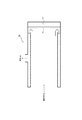
このような問題に対し、例えば図3に示すような、被処理水の流入方向に対向する方向(図3では左方向)に窓部21を介して紫外線を照射する紫外線照射部22を設けた水処理装置20を使用することにより、被処理水の流れ方向の広い範囲に亘って均一な紫外線処理を可能にし、十分な照射量を確保することが考えられる。しかし、上述したような構成を有する水処理装置には、被処理水の流路が邪魔になって窓部を洗浄する機器や窓部の状態などを検知するセンサを取り付け難いという問題があった。
In order to cope with such a problem, for example, as shown in FIG. 3, an ultraviolet ray irradiating section 22 for irradiating ultraviolet ray through the
そこで、本発明は、被処理水に対して紫外線を十分な照射量で均一に照射することが可能であると共に洗浄機器などの取り付けが容易な水処理装置を提供することを目的とする。 Therefore, it is an object of the present invention to provide a water treatment device that can uniformly irradiate water to be treated with a sufficient amount of ultraviolet rays and can be easily attached with a cleaning device or the like.
この発明は、上記課題を有利に解決することを目的とするものであり、本発明の水処理装置は、紫外線を用いて被処理水を紫外線処理する水処理装置であって、被処理水が流れる流路と、前記流路の流入口側とは反対側に設けられ、前記流路内を流れる被処理水に対し、透明部材からなる窓部を介して前記流入口側に紫外線を照射する紫外線照射部とを備え、前記流路は拡径部を有し、前記拡径部に、前記窓部の洗浄に用いられる洗浄機器およびセンサの少なくとも一方が設けられていることを特徴とする。このように、流路の流入口側とは反対側に紫外線照射部を設け、流路内を流れる被処理水に対して流入口側に向かう方向に紫外線を照射すれば、被処理水の流れ方向の広い範囲に亘って被処理水を均一に紫外線処理することができる。また、流路に拡径部を設ければ、流路、窓部および紫外線照射部を上述した配置にした場合であっても、窓部の洗浄に用いられる洗浄機器やセンサを容易に取り付けることができる。 The present invention is intended to advantageously solve the above problems, the water treatment device of the present invention is a water treatment device for ultraviolet treatment of the water to be treated using ultraviolet rays, the water to be treated is The flow path and the inlet side of the flow path, which are provided on the opposite side of the flow path, irradiate the water to be treated flowing through the flow path with ultraviolet rays through the window made of a transparent member. An ultraviolet irradiation unit is provided, the flow path has an enlarged diameter portion, and the enlarged diameter portion is provided with at least one of a cleaning device and a sensor used for cleaning the window portion. In this way, by providing the ultraviolet irradiation unit on the side opposite to the inlet side of the flow path and irradiating the treated water flowing in the flow path with ultraviolet rays in the direction toward the inlet side, the flow of the treated water It is possible to uniformly subject the water to be treated to ultraviolet light over a wide range of directions. In addition, if the flow passage is provided with the expanded diameter portion, it is possible to easily attach the cleaning equipment and the sensor used for cleaning the window portion even when the flow passage, the window portion and the ultraviolet irradiation portion are arranged as described above. You can
ここで、本発明の水処理装置において、前記拡径部は、前記被処理水の流れ方向に向かって内径が漸増する逆テーパー形状を有していることが好ましい。拡径部が逆テーパー形状を有していれば、洗浄機器やセンサを窓部の中心に指向させて取り付けることが容易になるからである。 Here, in the water treatment device of the present invention, it is preferable that the diameter-expanded portion has an inverse taper shape in which the inner diameter gradually increases in the flow direction of the water to be treated. This is because if the expanded diameter portion has an inversely tapered shape, it becomes easy to orient and attach the cleaning device or the sensor to the center of the window.
また、本発明の水処理装置は、前記拡径部には、超音波発振器を備える洗浄機器が少なくとも設けられており、前記流路は、内周面がポリテトラフルオロエチレンでライニングされていることが好ましい。流路の内周面がポリテトラフルオロエチレン(PTFE)でライニングされていれば、内周面における紫外線の反射を利用して被処理水を更に良好に紫外線処理することができるからである。なお、PTFEのライニングは超音波を伝達させ難いが、拡径部に洗浄機器を設ければ、超音波発振器を備える洗浄機器を用いる場合であっても、超音波発振器を窓部に指向させて配置して窓部を良好に洗浄することができる。 Further, in the water treatment device of the present invention, at least the cleaning device including an ultrasonic oscillator is provided in the expanded diameter portion, and the flow passage has an inner peripheral surface lined with polytetrafluoroethylene. Is preferred. This is because if the inner peripheral surface of the flow path is lined with polytetrafluoroethylene (PTFE), the water to be treated can be more favorably subjected to the ultraviolet treatment by utilizing the reflection of the ultraviolet rays on the inner peripheral surface. Note that the PTFE lining is difficult to transmit ultrasonic waves, but if a cleaning device is provided in the expanded diameter portion, even if a cleaning device equipped with an ultrasonic oscillator is used, the ultrasonic oscillator can be directed toward the window. It can be arranged and the window can be cleaned well.
そして、本発明の水処理装置は、前記拡径部には、超音波発振器を備える洗浄機器が少なくとも設けられており、前記超音波発振器の超音波発振面が前記窓部の中心に指向していることが好ましい。超音波発振器を窓部の中心に指向させて設置することで、窓部を効果的に洗浄することができるからである。 Then, in the water treatment device of the present invention, the expanded diameter portion is provided with at least a cleaning device including an ultrasonic oscillator, and the ultrasonic wave oscillating surface of the ultrasonic wave oscillator is directed toward the center of the window portion. Is preferred. This is because the window portion can be effectively cleaned by installing the ultrasonic oscillator so as to be oriented toward the center of the window portion.
本発明の水処理装置によれば、被処理水に対して紫外線を十分な照射量で均一に照射することができると共に、洗浄機器などを容易に取り付けることができる。 According to the water treatment apparatus of the present invention, it is possible to uniformly irradiate the water to be treated with a sufficient amount of ultraviolet rays, and it is possible to easily attach a cleaning device or the like.
以下、本発明の実施の形態を、図面に基づき詳細に説明する。なお、各図において、同一の符号を付したものは、同一の構成要素を示すものとする。 Hereinafter, embodiments of the present invention will be described in detail with reference to the drawings. In addition, in each figure, the same reference numerals denote the same constituent elements.
ここで、本発明の水処理装置は、特に限定されることなく、例えば、浄水場等の大型設備、小型のウォーターサーバー、下水処理場および超純水製造設備等において被処理水を殺菌する際に用いることができる。中でも、本発明の水処理装置は、浄水場において飲用水を製造する際の殺菌処理などに好適に用いることができる。 Here, the water treatment apparatus of the present invention is not particularly limited, for example, when sterilizing the water to be treated in large facilities such as water purification plants, small water servers, sewage treatment plants and ultrapure water production facilities. Can be used for. Among them, the water treatment device of the present invention can be suitably used for sterilization treatment when producing drinking water in a water purification plant.
(水処理装置)
図1に、本発明の水処理装置の一例の概略構成を、被処理水の流れ方向に沿う断面で示す。図1に示す水処理装置10は、流入した被処理水に対して紫外線を照射し、被処理水を紫外線処理して処理水を得る装置である。
そして、水処理装置10は、被処理水が流れる流路1と、流路1の流入口2側(図1では左側)とは反対側に設けられた窓部5および紫外線照射部6と、被処理水を紫外線処理して得た処理水が流れる処理水流路3と、処理水流路3から処理水が流出する流出口4とを備えている。また、流路1には、流入口2側から窓部5および紫外線照射部6側に向かって内径が拡大する拡径部7が設けられている。更に、流路1の拡径部7には、窓部5の洗浄に用いられる洗浄機器としての超音波発振器8と、窓部5の汚れの状態を検知するセンサ9とが設けられている。
(Water treatment device)
FIG. 1 shows a schematic configuration of an example of the water treatment apparatus of the present invention in a cross section along the flow direction of the water to be treated. The
The
<被処理水の流路>
流路1は、特に限定されることなく、例えばSUS配管などの配管を用いて形成することができる。なお、流路1は、複数の配管をフランジ等の既知の接続手段を用いて接続することにより形成してもよい。
<Flow path of treated water>
The flow path 1 is not particularly limited and can be formed by using a pipe such as a SUS pipe. The flow path 1 may be formed by connecting a plurality of pipes using a known connecting means such as a flange.
そして、水処理装置10の流路1は、流入口2側から被処理水の流れ方向に沿って、小径部と、拡径部7と、小径部よりも内径が大きい大径部とをこの順に有している。ここで、流路1の拡径部7は、小径部側から大径部側へと向かって(即ち、被処理水の流れ方向に向かって)内径が漸増する逆テーパー形状を有している。また、流路1の大径部は、後に詳細に説明する処理水流路3を形成する配管と二重管構造を形成しており、被処理水の流れ方向(図1では左右方向)に見て大径部の流入口2側とは反対側の端縁(図1では右側の端縁)は、窓部5と接触することなく終端している。即ち、被処理水が流れる流路1は、窓部5との間に隙間を空けた状態で終端している。
The flow path 1 of the
なお、特に限定されるものではないが、紫外線照射部6から照射された紫外線を流路1の内周面で良好に反射させて被処理水を更に良好に紫外線処理する観点からは、流路1の内周面、特に大径部の内周面は、ポリテトラフルオロエチレンでライニングされていることが好ましい。
It should be noted that, although not particularly limited, from the viewpoint that the ultraviolet rays radiated from the ultraviolet
<窓部>
窓部5は、紫外線照射部6から照射された紫外線を透過可能な透明部材からなり、流路1の流入口2側とは反対側(図1では右側)に水密に設けられて被処理水が紫外線照射部6へと流入するのを防止している。また、窓部5は、流路1の大径部の内径よりも直径が大きく、紫外線照射部6から照射された紫外線が流路1内を流れる被処理水全体に照射されるように構成されている。
なお、窓部5を形成する透明部材としては、特に限定されることなく、石英ガラス、サファイアガラス、フッ素系樹脂等が挙げられる。中でも、耐久性および紫外線の透過性の観点から、石英ガラスが好ましい。また、窓部5を水密に設置する方法としては、特に限定されることなく、例えば処理水流路3を形成する配管と紫外線照射部6とを接続するフランジ(図示せず)に窓部5を構成する透明部材を設置する窪みを設けると共に、O−リングやパッキン等を用いてフランジ接続部を水密に封止する方法などが挙げられる。
<window part>
The
The transparent member forming the
<紫外線照射部>
紫外線照射部6は、紫外線の光源を備えており、窓部5を介して流入口2側へと紫外線を照射する。具体的には、紫外線照射部6は、例えば、所望の紫外線強度を確保可能な個数の光源を収容室内に収容して形成されている。そして、紫外線照射部6は、流路1の大径部内を流れる被処理水に対して略均一な強度の紫外線を照射する。
なお、紫外線の光源としては、特に限定されることなく、例えば、水銀ランプ、キセノンランプ、紫外線LEDなどの任意の光源を用いることができる。中でも、安全性およびコストの観点からは、紫外線LEDが好ましい。また、光源が照射する紫外線の波長は、特に限定されることなく、好ましくは200nm以上、より好ましくは240nm以上であり、好ましくは300nm以下、より好ましくは285nm以下である。上記波長域の紫外線は殺菌力が高いからである。
<UV irradiation part>
The ultraviolet
The ultraviolet light source is not particularly limited, and any light source such as a mercury lamp, a xenon lamp, and an ultraviolet LED can be used. Among them, the ultraviolet LED is preferable from the viewpoint of safety and cost. The wavelength of the ultraviolet light emitted by the light source is not particularly limited and is preferably 200 nm or more, more preferably 240 nm or more, preferably 300 nm or less, more preferably 285 nm or less. This is because ultraviolet rays in the above wavelength range have high bactericidal activity.
<処理水流路>
処理水流路3は、特に限定されることなく、例えばSUS配管などの配管を用いて形成することができる。具体的には、処理水流路3は、流路1の大径部の外側に配置されて流路1の大径部と二重管構造を形成する配管(以下、「外管」と称することがある。)を用いて、流路1の大径部の外周面と外管の内周面との間に形成することができる。
<Treatment water flow path>
The treated
なお、水処理装置10では、外管は流路1と同軸上に配置されている。そして、外管の軸線方向一方(図1では左側)の端部は流路1の大径部を形成する配管の流入口2側の端縁と水密に接続されている。また、外管の軸線方向他方(図1では右側)の端部は窓部5と水密に接続されている。
In the
<超音波発振器>
窓部5の洗浄機器としての超音波発振器8は、流路1の拡径部7に、超音波発振面を窓部5に指向させて設けられている。具体的には、超音波発振器8は、特に限定されることなく、溶接等の手段を用いて拡径部7に水密に取り付けられた筒状体よりなるケースの内側に、超音波発振面が窓部5の中心を指向するように設置されている。なお、ケースへの超音波発振器8の固定は、特に限定されることなく、クランプなどの既知の手段を用いて行うことができる。また、ケースの流路1側とは反対側の端部は蓋などの手段を用いて水密に封止することができる。更に、ケースおよび超音波発振器8の一部は、流路1内まで延出していてもよい。
<Ultrasonic oscillator>
An ultrasonic oscillator 8 as a cleaning device for the
<センサ>
また、窓部5の汚れの状態を検知するセンサ9は、流路1の拡径部7に窓部5に指向させて設けられている。具体的には、センサ9は、特に限定されることなく、溶接等の手段を用いて拡径部7に水密に取り付けられた筒状体よりなるケースの内側に、検出面が窓部5を指向するように設置されている。なお、ケースへのセンサの固定は、特に限定されることなく、クランプなどの既知の手段を用いて行うことができる。また、ケースの流路1側とは反対側の端部は蓋などの手段を用いて水密に封止することができる。更に、ケースおよびセンサ9の一部は、流路1内まで延出していてもよい。
<Sensor>
Further, the
ここで、センサ9としては、特に限定されることなく、窓部5を透過した紫外線の強度の変化から窓部5の汚れの状態を把握し得る紫外線センサなどの既知のセンサを用いることができる。また、センサ9の検出面の向きは、窓部5の任意の位置に指向させることができるが、センサ9で検出した汚れに基づいて適切なタイミングで窓部5を洗浄する観点からは、洗浄機器としての超音波発振器8の超音波発振面と同じ位置に指向させることが好ましい。
Here, the
<紫外線処理>
そして、上述した構成を有する水処理装置10によれば、流入口2から窓部5側へと(図1では右側に)向かって流れてくる被処理水に対し、紫外線照射部6から窓部5を介して流入口2側(図1では左側)へと紫外線を照射することができる。従って、被処理水の流れ方向の長い範囲に亘って十分な量の紫外線を均一に照射し、被処理水を良好に紫外線処理することができる。また、水処理装置10によれば、流路1の内周面がポリテトラフルオロエチレンでライニングされているので、流路1の内周面において紫外線を良好に反射させ、被処理水を更に良好に紫外線処理することができる。
<UV treatment>
Further, according to the
なお、水処理装置10では、被処理水を紫外線処理して得た処理水は、流路1と窓部5との間の隙間を介して処理水流路3へと流入させ、流出口4から取り出すことができる。
In the
<窓部の洗浄>
また、水処理装置10によれば、流路1が拡径部7を有しているので、超音波発振器8およびセンサ9を所望の方向に指向させた状態で容易に取り付けることができる。そして、水処理装置10は、超音波発振器8およびセンサ9を備えているので、センサ9で窓部5の汚れの状態を検知し、超音波発振器8を用いて窓部5を洗浄することで、窓部5の汚れにより被処理水に対する紫外線照射量が低下するのを抑制することができる。特に、水処理装置10では、超音波発振器8の超音波発振面を窓部5の中心に指向させているので、被処理水中を伝播させた超音波を用いて窓部5を均等に洗浄することができる。また、水処理装置10では、超音波発振器8の超音波発振面を窓部5に指向させているので、流路1の内周面が超音波を伝達し難い材料(例えば、ポリテトラフルオロエチレン)でライニングされている場合であっても、窓部5を良好に洗浄することができる。
<Washing of windows>
Further, according to the
なお、窓部5を均等に洗浄する観点からは、水処理装置10の拡径部7に複数の超音波発振器8を配置する場合には、各超音波発振器8は拡径部7の周方向に等間隔で設置することが好ましい。また、窓部5にスケールが析出すると超音波の照射のみでは除去し難く、また、窓部5から除去されたスケールが流路1と窓部5との間の隙間に詰まる虞があるため、超音波発振器8による洗浄は短い間隔で実施することが好ましい。
From the viewpoint of uniformly cleaning the
以上、一例を用いて本発明の水処理装置について説明したが、本発明の水処理装置は、上記一例に限定されることはなく、本発明の水処理装置には、適宜変更を加えることができる。
具体的には、例えば、上記一例の水処理装置10では、洗浄機器としての超音波発振器8およびセンサ9の両方を拡径部7に取り付けたが、本発明の水処理装置では、センサを設けることなく洗浄機器のみを拡径部に取り付けて所定間隔で洗浄を実施してもよいし、センサのみを拡径部に取り付けて汚れが検知されたタイミングで分解洗浄または窓部の交換を実施するようにしてもよい。
また、上記一例の水処理装置10では、被処理水の流れ方向に向かって内径が漸増する逆テーパー形状の拡径部7を用いたが、拡径部7の形状は逆テーパー形状に限定されるものではない。具体的には、例えば、図2に示す水処理装置10Aのように、拡径部は水の流れ方向に対して直交する方向に延在する(即ち、流路1の内径がステップ状に拡大する)拡径部7Aであってもよい。但し、洗浄機器やセンサを窓部の所望の位置に指向させた状態で取り付け易くする観点からは、拡径部は、被処理水の流れ方向に向かって内径が漸増する逆テーパー形状であることが好ましい。
更に、上記一例の水処理装置10では、拡径部7に窓部5の洗浄に用いる超音波発振器8およびセンサ9のみを設けたが、拡径部7には、窓部5の洗浄に使用する超音波発振器8およびセンサ9の汚れの状態を検知するセンサや、窓部の洗浄に使用する超音波発振器8の超音波発振面およびセンサ9の検出面に汚れが付着した場合に当該汚れを洗浄する洗浄機器が更に設けられていてもよい。
Although the water treatment apparatus of the present invention has been described above by using an example, the water treatment apparatus of the present invention is not limited to the above example, and the water treatment apparatus of the present invention may be appropriately modified. it can.
Specifically, for example, in the
Further, in the
Further, in the
本発明によれば、被処理水に対して紫外線を十分な照射量で均一に照射することが可能であると共に洗浄機器などの取り付けが容易な水処理装置を提供することができる。 According to the present invention, it is possible to provide a water treatment device that can uniformly irradiate water to be treated with a sufficient amount of ultraviolet rays and can be easily attached with a cleaning device or the like.
1 流路
2 流入口
3 処理水流路
4 流出口
5,21 窓部
6,22 紫外線照射部
7 拡径部
8 超音波発振器
9 センサ
10,20 水処理装置
1 flow
Claims (4)
被処理水が流れる流路と、
前記流路の流入口側とは反対側に設けられ、前記流路内を流れる被処理水に対し、透明部材からなる窓部を介して前記流入口側に紫外線を照射する紫外線照射部と、
を備え、
前記流路は拡径部を有し、
前記拡径部に、前記窓部の洗浄に用いられる洗浄機器およびセンサの少なくとも一方が設けられている、水処理装置。 A water treatment device for treating water to be treated with ultraviolet rays using ultraviolet rays,
A flow path for the water to be treated,
An ultraviolet irradiation unit provided on the side opposite to the inlet side of the flow channel, for the water to be treated flowing in the flow channel, for irradiating the inlet side with ultraviolet rays through a window made of a transparent member,
Equipped with
The flow path has an enlarged diameter portion,
A water treatment device in which at least one of a cleaning device and a sensor used for cleaning the window is provided in the expanded diameter portion.
前記流路は、内周面がポリテトラフルオロエチレンでライニングされている、請求項1または2に記載の水処理装置。 The enlarged diameter portion is provided with at least a cleaning device including an ultrasonic oscillator,
The water treatment device according to claim 1 or 2, wherein the flow passage has an inner peripheral surface lined with polytetrafluoroethylene.
前記超音波発振器の超音波発振面が前記窓部の中心に指向している、請求項1〜3の何れかに記載の水処理装置。 The enlarged diameter portion is provided with at least a cleaning device including an ultrasonic oscillator,
The water treatment device according to claim 1, wherein an ultrasonic wave oscillating surface of the ultrasonic wave oscillator is directed toward the center of the window portion.
Priority Applications (7)
| Application Number | Priority Date | Filing Date | Title |
|---|---|---|---|
| JP2016212121A JP6721487B2 (en) | 2016-10-28 | 2016-10-28 | Water treatment equipment |
| PCT/JP2017/036887 WO2018079266A1 (en) | 2016-10-28 | 2017-10-11 | Water treatment device |
| EP17863543.9A EP3533765B1 (en) | 2016-10-28 | 2017-10-11 | Water treatment device |
| CN201780066887.6A CN109890763B (en) | 2016-10-28 | 2017-10-11 | Water treatment device |
| CA3041642A CA3041642C (en) | 2016-10-28 | 2017-10-11 | A water treatment apparatus using ultraviolet irradiation |
| US16/344,913 US11142469B2 (en) | 2016-10-28 | 2017-10-11 | Water treatment apparatus |
| TW106137016A TWI709537B (en) | 2016-10-28 | 2017-10-27 | Water treatment device |
Applications Claiming Priority (1)
| Application Number | Priority Date | Filing Date | Title |
|---|---|---|---|
| JP2016212121A JP6721487B2 (en) | 2016-10-28 | 2016-10-28 | Water treatment equipment |
Publications (2)
| Publication Number | Publication Date |
|---|---|
| JP2018069158A JP2018069158A (en) | 2018-05-10 |
| JP6721487B2 true JP6721487B2 (en) | 2020-07-15 |
Family
ID=62023442
Family Applications (1)
| Application Number | Title | Priority Date | Filing Date |
|---|---|---|---|
| JP2016212121A Active JP6721487B2 (en) | 2016-10-28 | 2016-10-28 | Water treatment equipment |
Country Status (7)
| Country | Link |
|---|---|
| US (1) | US11142469B2 (en) |
| EP (1) | EP3533765B1 (en) |
| JP (1) | JP6721487B2 (en) |
| CN (1) | CN109890763B (en) |
| CA (1) | CA3041642C (en) |
| TW (1) | TWI709537B (en) |
| WO (1) | WO2018079266A1 (en) |
Families Citing this family (6)
| Publication number | Priority date | Publication date | Assignee | Title |
|---|---|---|---|---|
| CN110540263A (en) * | 2018-05-28 | 2019-12-06 | 宁波方太厨具有限公司 | Ultraviolet ray running water sterilizer |
| CN113811376B (en) * | 2019-05-13 | 2023-04-07 | 美得华水务株式会社 | Mixing and turbidity removing device |
| US11365134B2 (en) | 2019-07-31 | 2022-06-21 | Access Business Group International Llc | Water treatment system |
| CN111689650A (en) * | 2020-06-22 | 2020-09-22 | 陈昌超 | Sewage treatment device with ultrasonic self-cleaning structure |
| DE202022100924U1 (en) | 2022-02-17 | 2022-04-13 | MAXI-PRESS Elastomertechnik GmbH | Trolley for a transport rail for transporting laundry |
| JP2023135894A (en) * | 2022-03-16 | 2023-09-29 | 千代田工販株式会社 | Ultraviolet irradiation device |
Family Cites Families (27)
| Publication number | Priority date | Publication date | Assignee | Title |
|---|---|---|---|---|
| DE2904242A1 (en) * | 1979-02-05 | 1980-08-14 | Guenther O Prof Dr Schenck | METHOD AND DEVICE FOR CLEANING, IN PARTICULAR FOR DISINFECTING AND DISINFECTING |
| EP0407495B1 (en) * | 1988-10-26 | 1993-05-12 | Wedeco Umwelttechnologie Wasser-Boden-Luft Gmbh | A device for irradiating flowing liquids and/or gases with ultraviolet light |
| DE4340406C1 (en) * | 1993-11-26 | 1995-04-20 | Gruenbeck Josef Wasseraufb | Water disinfection reactor |
| DE10101816A1 (en) | 2001-01-17 | 2002-07-18 | Peter Ueberall | Flat diffuser for altering cross section of flow in a flow channel has multiple single diffusers as divergent rectangular channels fitted alongside each other over the cross section of flow. |
| US7169311B2 (en) * | 2001-10-17 | 2007-01-30 | Honeywell International, Inc. | Apparatus for disinfecting water using ultraviolet radiation |
| ATE327776T1 (en) * | 2001-11-02 | 2006-06-15 | Honeywell Int Inc | UV DISINFECTANT |
| CN2618913Y (en) | 2003-05-09 | 2004-06-02 | 吕业利 | Ultraviolet water processor |
| JP4275464B2 (en) | 2003-06-09 | 2009-06-10 | 本多電子株式会社 | UV sterilization equipment |
| IL157229A (en) * | 2003-08-04 | 2006-08-20 | Zamir Tribelsky | Method for energy coupling especially useful for disinfecting and various systems using it |
| JP2005052760A (en) * | 2003-08-05 | 2005-03-03 | Nishihara:Kk | UV irradiation equipment |
| US7763177B2 (en) * | 2006-10-26 | 2010-07-27 | Atlantium Technologies Ltd. | System and method for ultrasonic cleaning of ultraviolet disinfection system |
| JP5265431B2 (en) | 2009-03-27 | 2013-08-14 | 株式会社 オノモリ | Water purification device |
| CN201442894U (en) * | 2009-08-03 | 2010-04-28 | 大连宏博水科技有限公司 | Novel ultraviolet disinfection device |
| WO2012041360A1 (en) * | 2010-09-27 | 2012-04-05 | Rahul Kashinathrao Dahule | Device for purifying water |
| DE102010047782B3 (en) | 2010-10-08 | 2012-01-12 | Itt Manufacturing Enterprises, Inc. | Flow rectifier for closed pipes |
| JP2013034979A (en) * | 2011-08-11 | 2013-02-21 | Harison Toshiba Lighting Corp | Ultraviolet irradiation apparatus |
| WO2013155283A1 (en) * | 2012-04-11 | 2013-10-17 | Arana Holdings, Llc | Reactor for water treatment and method thereof |
| KR101409972B1 (en) | 2012-09-03 | 2014-06-20 | 주식회사 파나시아 | One-Body Type Ballast Water UV-rays Processing Device |
| EP3461793B1 (en) * | 2013-01-24 | 2022-03-02 | Atlantium Technologies Ltd. | Method and apparatus for liquid disinfection by light emitted from light emitting diodes |
| EP2999669B1 (en) * | 2013-05-22 | 2017-02-08 | Merck Patent GmbH | Apparatus for the disinfection of fluids by ultraviolet radiation |
| JP2014233646A (en) * | 2013-05-30 | 2014-12-15 | 日機装株式会社 | Water purifier |
| JP5649703B1 (en) * | 2013-09-12 | 2015-01-07 | 株式会社東芝 | UV irradiation equipment |
| WO2015069680A1 (en) * | 2013-11-08 | 2015-05-14 | Mag Aerospace Industries, Llc | Point of use water treatment device |
| EP3169369A1 (en) * | 2014-07-18 | 2017-05-24 | Nestec S.A. | Method and apparatus for purifying liquid |
| JP6080937B1 (en) * | 2015-12-08 | 2017-02-15 | 日機装株式会社 | Fluid sterilizer |
| CN109195638A (en) * | 2016-05-31 | 2019-01-11 | 株式会社日本光电科技 | UV irradiation device |
| US20180250723A1 (en) * | 2017-03-01 | 2018-09-06 | Goodrich Corporation | Targeted cleaning in water system components |
-
2016
- 2016-10-28 JP JP2016212121A patent/JP6721487B2/en active Active
-
2017
- 2017-10-11 WO PCT/JP2017/036887 patent/WO2018079266A1/en not_active Ceased
- 2017-10-11 CA CA3041642A patent/CA3041642C/en active Active
- 2017-10-11 CN CN201780066887.6A patent/CN109890763B/en active Active
- 2017-10-11 EP EP17863543.9A patent/EP3533765B1/en active Active
- 2017-10-11 US US16/344,913 patent/US11142469B2/en active Active
- 2017-10-27 TW TW106137016A patent/TWI709537B/en active
Also Published As
| Publication number | Publication date |
|---|---|
| EP3533765A4 (en) | 2020-06-03 |
| CN109890763B (en) | 2022-02-25 |
| EP3533765B1 (en) | 2023-03-01 |
| WO2018079266A1 (en) | 2018-05-03 |
| US11142469B2 (en) | 2021-10-12 |
| TW201815693A (en) | 2018-05-01 |
| US20190256378A1 (en) | 2019-08-22 |
| CA3041642C (en) | 2020-07-14 |
| JP2018069158A (en) | 2018-05-10 |
| CA3041642A1 (en) | 2018-05-03 |
| TWI709537B (en) | 2020-11-11 |
| EP3533765A1 (en) | 2019-09-04 |
| CN109890763A (en) | 2019-06-14 |
Similar Documents
| Publication | Publication Date | Title |
|---|---|---|
| TWI709537B (en) | Water treatment device | |
| US7763177B2 (en) | System and method for ultrasonic cleaning of ultraviolet disinfection system | |
| JP2011255365A (en) | Ballast water treating system having back pressure forming part, and method therefor | |
| KR101922404B1 (en) | Tubular Ultraviolet Disinfection Device Using Vortex Generation | |
| WO2017208810A1 (en) | Uv irradiation apparatus | |
| KR101318604B1 (en) | Micro bubble sterilizer | |
| JP2011189289A (en) | Ultraviolet water treatment device | |
| JP6726090B2 (en) | UV irradiation device | |
| RU2332358C1 (en) | Device for reagentless liquid desinfection | |
| JP2011072901A (en) | Ultraviolet irradiation apparatus | |
| KR102256064B1 (en) | Ultraviolet purifying device using ozone gas | |
| JP2011189282A (en) | Ultraviolet irradiation device and method for measuring temperature | |
| JP4438248B2 (en) | UV irradiation equipment | |
| KR100732503B1 (en) | Non-heated Fluid Sterilizer | |
| KR20090123721A (en) | Lamp cleaning device with no power using cleaning particles and fluid flow of UV sterilizer | |
| JP2009066478A (en) | UV irradiation water treatment equipment | |
| RU197423U1 (en) | Ballast water disinfection device | |
| JP6817021B2 (en) | Fluid sterilizer | |
| KR100955301B1 (en) | Water sterilizer using ultraviolet lamp | |
| RU2727125C1 (en) | Ultrasonic waste water treatment device | |
| JP5355312B2 (en) | UV irradiation equipment inspection equipment | |
| RU2403209C2 (en) | Complex module for treating liquid medium in stream | |
| WO2018147769A1 (en) | Device for treating aqueous media in a flow | |
| KR20090027073A (en) | Ultraviolet lamp cleaning device for wastewater treatment water | |
| KR101501819B1 (en) | UV reactor having easy maintenance structure |
Legal Events
| Date | Code | Title | Description |
|---|---|---|---|
| A621 | Written request for application examination |
Free format text: JAPANESE INTERMEDIATE CODE: A621 Effective date: 20190617 |
|
| TRDD | Decision of grant or rejection written | ||
| A01 | Written decision to grant a patent or to grant a registration (utility model) |
Free format text: JAPANESE INTERMEDIATE CODE: A01 Effective date: 20200526 |
|
| A61 | First payment of annual fees (during grant procedure) |
Free format text: JAPANESE INTERMEDIATE CODE: A61 Effective date: 20200618 |
|
| R150 | Certificate of patent or registration of utility model |
Ref document number: 6721487 Country of ref document: JP Free format text: JAPANESE INTERMEDIATE CODE: R150 |
|
| R250 | Receipt of annual fees |
Free format text: JAPANESE INTERMEDIATE CODE: R250 |
|
| R250 | Receipt of annual fees |
Free format text: JAPANESE INTERMEDIATE CODE: R250 |
|
| R250 | Receipt of annual fees |
Free format text: JAPANESE INTERMEDIATE CODE: R250 |