JP6714076B2 - Stackable connectors and devices for wireless transmission of power - Google Patents
Stackable connectors and devices for wireless transmission of power Download PDFInfo
- Publication number
- JP6714076B2 JP6714076B2 JP2018511460A JP2018511460A JP6714076B2 JP 6714076 B2 JP6714076 B2 JP 6714076B2 JP 2018511460 A JP2018511460 A JP 2018511460A JP 2018511460 A JP2018511460 A JP 2018511460A JP 6714076 B2 JP6714076 B2 JP 6714076B2
- Authority
- JP
- Japan
- Prior art keywords
- connector
- coil
- power
- unit
- housing
- Prior art date
- Legal status (The legal status is an assumption and is not a legal conclusion. Google has not performed a legal analysis and makes no representation as to the accuracy of the status listed.)
- Active
Links
- 230000005540 biological transmission Effects 0.000 title claims description 75
- 230000005291 magnetic effect Effects 0.000 claims description 152
- 230000008878 coupling Effects 0.000 claims description 109
- 238000010168 coupling process Methods 0.000 claims description 109
- 238000005859 coupling reaction Methods 0.000 claims description 109
- 230000004907 flux Effects 0.000 claims description 78
- 238000012546 transfer Methods 0.000 claims description 27
- 230000001939 inductive effect Effects 0.000 claims description 15
- 238000012544 monitoring process Methods 0.000 claims description 14
- 238000005259 measurement Methods 0.000 description 81
- 238000012545 processing Methods 0.000 description 41
- 238000001514 detection method Methods 0.000 description 17
- 238000010586 diagram Methods 0.000 description 17
- 238000000034 method Methods 0.000 description 13
- 230000007246 mechanism Effects 0.000 description 11
- 230000003287 optical effect Effects 0.000 description 10
- 238000003860 storage Methods 0.000 description 10
- 238000004891 communication Methods 0.000 description 8
- 239000000463 material Substances 0.000 description 8
- 230000013011 mating Effects 0.000 description 8
- 238000003032 molecular docking Methods 0.000 description 7
- 238000013459 approach Methods 0.000 description 6
- 230000008901 benefit Effects 0.000 description 6
- 238000005516 engineering process Methods 0.000 description 6
- 230000036541 health Effects 0.000 description 6
- 238000009413 insulation Methods 0.000 description 6
- 238000006243 chemical reaction Methods 0.000 description 5
- 238000013461 design Methods 0.000 description 5
- 230000000694 effects Effects 0.000 description 5
- 238000002955 isolation Methods 0.000 description 5
- 238000007726 management method Methods 0.000 description 5
- 238000004804 winding Methods 0.000 description 5
- 238000004140 cleaning Methods 0.000 description 4
- 230000001419 dependent effect Effects 0.000 description 4
- 230000008569 process Effects 0.000 description 4
- 230000002829 reductive effect Effects 0.000 description 4
- 238000012384 transportation and delivery Methods 0.000 description 4
- 230000000007 visual effect Effects 0.000 description 4
- 229910000859 α-Fe Inorganic materials 0.000 description 4
- BWWVXHRLMPBDCK-UHFFFAOYSA-N 1,2,4-trichloro-5-(2,6-dichlorophenyl)benzene Chemical compound C1=C(Cl)C(Cl)=CC(Cl)=C1C1=C(Cl)C=CC=C1Cl BWWVXHRLMPBDCK-UHFFFAOYSA-N 0.000 description 3
- 239000004020 conductor Substances 0.000 description 3
- 238000012806 monitoring device Methods 0.000 description 3
- 230000003071 parasitic effect Effects 0.000 description 3
- 230000035699 permeability Effects 0.000 description 3
- 150000003071 polychlorinated biphenyls Chemical class 0.000 description 3
- 235000014676 Phragmites communis Nutrition 0.000 description 2
- 230000003213 activating effect Effects 0.000 description 2
- 230000004888 barrier function Effects 0.000 description 2
- 230000015556 catabolic process Effects 0.000 description 2
- 239000002131 composite material Substances 0.000 description 2
- 238000004146 energy storage Methods 0.000 description 2
- 239000011888 foil Substances 0.000 description 2
- 230000006870 function Effects 0.000 description 2
- 238000009434 installation Methods 0.000 description 2
- 229910001416 lithium ion Inorganic materials 0.000 description 2
- 230000004807 localization Effects 0.000 description 2
- 239000000696 magnetic material Substances 0.000 description 2
- 230000005855 radiation Effects 0.000 description 2
- 230000009467 reduction Effects 0.000 description 2
- 230000002441 reversible effect Effects 0.000 description 2
- 230000007704 transition Effects 0.000 description 2
- LJQOBQLZTUSEJA-UHFFFAOYSA-N 1,2,3,5-tetrachloro-4-(2,3,5,6-tetrachlorophenyl)benzene Chemical compound ClC1=C(Cl)C(Cl)=CC(Cl)=C1C1=C(Cl)C(Cl)=CC(Cl)=C1Cl LJQOBQLZTUSEJA-UHFFFAOYSA-N 0.000 description 1
- JPOPEORRMSDUIP-UHFFFAOYSA-N 1,2,4,5-tetrachloro-3-(2,3,5,6-tetrachlorophenyl)benzene Chemical compound ClC1=CC(Cl)=C(Cl)C(C=2C(=C(Cl)C=C(Cl)C=2Cl)Cl)=C1Cl JPOPEORRMSDUIP-UHFFFAOYSA-N 0.000 description 1
- NTKSJAPQYKCFPP-UHFFFAOYSA-N 1,2,4,5-tetrachloro-3-(3-chlorophenyl)benzene Chemical compound ClC1=CC=CC(C=2C(=C(Cl)C=C(Cl)C=2Cl)Cl)=C1 NTKSJAPQYKCFPP-UHFFFAOYSA-N 0.000 description 1
- 241000283690 Bos taurus Species 0.000 description 1
- 241000723353 Chrysanthemum Species 0.000 description 1
- 235000005633 Chrysanthemum balsamita Nutrition 0.000 description 1
- HBBGRARXTFLTSG-UHFFFAOYSA-N Lithium ion Chemical compound [Li+] HBBGRARXTFLTSG-UHFFFAOYSA-N 0.000 description 1
- 238000010521 absorption reaction Methods 0.000 description 1
- 230000002411 adverse Effects 0.000 description 1
- 230000009286 beneficial effect Effects 0.000 description 1
- 230000002457 bidirectional effect Effects 0.000 description 1
- 239000011248 coating agent Substances 0.000 description 1
- 238000000576 coating method Methods 0.000 description 1
- 230000001010 compromised effect Effects 0.000 description 1
- 238000010276 construction Methods 0.000 description 1
- 230000001276 controlling effect Effects 0.000 description 1
- 230000007797 corrosion Effects 0.000 description 1
- 238000005260 corrosion Methods 0.000 description 1
- 230000001351 cycling effect Effects 0.000 description 1
- 238000013523 data management Methods 0.000 description 1
- 238000013500 data storage Methods 0.000 description 1
- 230000002950 deficient Effects 0.000 description 1
- 238000006731 degradation reaction Methods 0.000 description 1
- 238000006073 displacement reaction Methods 0.000 description 1
- 230000005294 ferromagnetic effect Effects 0.000 description 1
- 238000001914 filtration Methods 0.000 description 1
- 239000012530 fluid Substances 0.000 description 1
- 230000006872 improvement Effects 0.000 description 1
- 230000000977 initiatory effect Effects 0.000 description 1
- 239000011810 insulating material Substances 0.000 description 1
- 239000012212 insulator Substances 0.000 description 1
- 238000012432 intermediate storage Methods 0.000 description 1
- 230000000670 limiting effect Effects 0.000 description 1
- 244000144972 livestock Species 0.000 description 1
- 239000002184 metal Substances 0.000 description 1
- 230000008520 organization Effects 0.000 description 1
- 238000013021 overheating Methods 0.000 description 1
- 230000002093 peripheral effect Effects 0.000 description 1
- 229920000642 polymer Polymers 0.000 description 1
- 230000001681 protective effect Effects 0.000 description 1
- 238000002106 pulse oximetry Methods 0.000 description 1
- 230000001105 regulatory effect Effects 0.000 description 1
- 230000036387 respiratory rate Effects 0.000 description 1
- 238000007789 sealing Methods 0.000 description 1
- 238000004092 self-diagnosis Methods 0.000 description 1
- 238000004088 simulation Methods 0.000 description 1
- 238000001228 spectrum Methods 0.000 description 1
- 238000012360 testing method Methods 0.000 description 1
- 230000007723 transport mechanism Effects 0.000 description 1
- 230000001960 triggered effect Effects 0.000 description 1
- 238000002604 ultrasonography Methods 0.000 description 1
Images


Classifications
-
- H04B5/79—
-
- H—ELECTRICITY
- H01—ELECTRIC ELEMENTS
- H01F—MAGNETS; INDUCTANCES; TRANSFORMERS; SELECTION OF MATERIALS FOR THEIR MAGNETIC PROPERTIES
- H01F38/00—Adaptations of transformers or inductances for specific applications or functions
- H01F38/14—Inductive couplings
-
- H04B5/22—
-
- H04B5/266—
-
- H04B5/72—
-
- H—ELECTRICITY
- H01—ELECTRIC ELEMENTS
- H01F—MAGNETS; INDUCTANCES; TRANSFORMERS; SELECTION OF MATERIALS FOR THEIR MAGNETIC PROPERTIES
- H01F38/00—Adaptations of transformers or inductances for specific applications or functions
- H01F38/14—Inductive couplings
- H01F2038/143—Inductive couplings for signals
-
- H—ELECTRICITY
- H01—ELECTRIC ELEMENTS
- H01F—MAGNETS; INDUCTANCES; TRANSFORMERS; SELECTION OF MATERIALS FOR THEIR MAGNETIC PROPERTIES
- H01F38/00—Adaptations of transformers or inductances for specific applications or functions
- H01F38/14—Inductive couplings
- H01F2038/146—Inductive couplings in combination with capacitive coupling
-
- H04B5/24—
Description
本発明は、システム、特に患者監視システムの個別のデバイス間の電力のワイヤレス伝送のための積み重ね可能なコネクタであって、前記個別のデバイスがそのようなコネクタを備える、積み重ね可能なコネクタに関する。さらに、本発明は、自らと別のデバイスとの間の電力のワイヤレス伝送のためのデバイスに関する。 The present invention relates to a stackable connector for wireless transmission of power between individual devices of a system, in particular a patient monitoring system, said individual device comprising such a connector. Further, the invention relates to a device for wireless transmission of power between itself and another device.
一般に、デバイスのワイヤレス充電又は電力供給は、ユーザにとって便利な確立された技術である。ワイヤレス電力供給は、ガルバニック接触が使用されるときに腐食又は湿気が機能性又は安全性を危うくする厳しい環境においても使用することができる。ワイヤレス電力供給には、Qi、PMA、Rezense、及びWi電力などのいくつかの規格が存在し、市場は急速に成長している。これらの技術は、多くの場合、バッテリ駆動のデバイス(例えば、携帯電話、タブレットコンピュータなど)の充電に使用される。複数のデバイスの充電が可能である。例えば、Qi規格では、多数の小コイルを用いた電源プレートが利用可能であるが、デバイスは、互いに隣接して(水平面に)正確に位置付けられる必要がある。 In general, wireless charging or powering of devices is an established technology that is convenient for users. Wireless power supplies can also be used in harsh environments where corrosion or moisture compromises functionality or safety when galvanic contacts are used. There are several standards for wireless power delivery, such as Qi, PMA, Rezense, and Wi power, and the market is growing rapidly. These techniques are often used to charge battery-powered devices (eg, cell phones, tablet computers, etc.). It is possible to charge multiple devices. For example, in the Qi standard, power plates with a large number of small coils are available, but the devices need to be precisely positioned next to each other (in the horizontal plane).
高性能の患者監視は、救命救急の場(ICU、OR)でのその従来の用途から、一般病棟、在宅医療、連携した初期診療などより緊急性の低い環境へと拡大している。既存の高性能製品の成功は、測定の質、製品のモジュール性、システム全体の接続性、ユーザインターフェース、及び全製品ラインにわたるその一貫性(過去との互換性)によるものである。同時に、低費用が最大の関心事である発展途上国及び緊急性のより低い環境に対応するために、バリューセグメント市場が急速に拡大している。これらの市場では、モジュール性、接続性、及び(時には)測定品質については妥協する場合がある。 High performance patient surveillance is expanding from its traditional use in critical care settings (ICU, OR) to less urgent environments such as general wards, home care, coordinated initial care. The success of existing high performance products is due to measurement quality, product modularity, overall system connectivity, user interface, and its consistency across the product line (compatible with the past). At the same time, the value segment market is expanding rapidly to accommodate developing countries and lower-urgency environments where low cost is of prime concern. In these markets, modularity, connectivity, and (sometimes) measurement quality may be compromised.
また、ライフスタイル及びスポーツの場では、生理学的測定がますます多く使用される(心拍数、呼吸数、SpO2など)。 Also, in the lifestyle and sports arena, more and more physiological measurements are used (heart rate, respiratory rate, SpO2, etc.).
これらのような新たなアプリケーション空間では、装着型(コードレス)センサ、小型化、及び低電力が必要不可欠である。これらすべてのセグメントにわたる基本的要件、とりわけ妥協できない電気的な患者安全基準と比較した優れた測定装置品質は、同じである。後者は、IEC60601規格において厳しく規制されており、最悪のシナリオ(心臓への直接接続)においては、10μAの最大漏れ電流、4kVの地面に対する絶縁、及び測定装置の各々の間の1.5kV絶縁をリクエストしている。加えて、患者モニタは、除細動器によってもたらされる高い差動電圧、及び医療用ナイフからの高いRF電圧に耐えることができなければならない。 In new application spaces like these, wearable (cordless) sensors, miniaturization, and low power are essential. The basic requirements across all these segments are the same, in particular the excellent measuring device quality compared to uncompromising electrical patient safety standards. The latter is tightly regulated in the IEC 60601 standard, and in the worst case scenario (direct connection to the heart) a maximum leakage current of 10 μA, a 4 kV isolation to ground and a 1.5 kV isolation between each of the measuring devices. Making a request. In addition, the patient monitor must be able to withstand the high differential voltage provided by the defibrillator and the high RF voltage from the medical knife.
従来の絶縁及び保護の概念は、PCBとコネクタピンとの間の十分な沿面距離及びクリアランスを維持することを別にして、誘導電力カプラ(変圧器)及びデータ輸送用の光学データカプラに基づく。 Conventional isolation and protection concepts are based on inductive power couplers (transformers) and optical data couplers for data transport, apart from maintaining sufficient creepage distance and clearance between the PCB and connector pins.
米国第6,819,013B2号は、患者接続デバイス用の電気的に絶縁された、電力及び信号複合型カプラについて開示している。ドッキングステーション、及びドッキングステーションとドッキングすることができるポータブルデバイスはそれぞれ、電力カプラ及び電気的に絶縁されたデータトランスデューサを含む。それぞれの電力カプラは、中心磁極及び周辺磁極を含む透磁性要素と、中心磁極が突き出る開口部を有するプリント回路基板とを含む。プリント回路基板は、ドッキングステーション内の一次巻線及びポータブルデバイス内の二次巻線を含む、中心磁極の開口部を包囲する巻線を含む。ポータブルデバイスがドッキングステーションとドッキングされるとき、ポータブルデバイス内の透磁性要素及びドッキングステーション内の透磁性要素は、磁気回路を形成するように配置され、ポータブルデバイス内のデータトランスデューサ及びドッキングステーション内のデータトランスデューサは、データを交換するように配置される。 US Pat. No. 6,819,013B2 discloses an electrically isolated hybrid power and signal coupler for a patient connection device. The docking station and the portable device capable of docking with the docking station each include a power coupler and an electrically isolated data transducer. Each power coupler includes a magnetically permeable element including a center pole and a peripheral pole, and a printed circuit board having an opening through which the center pole projects. The printed circuit board includes windings surrounding the center pole opening, including the primary winding in the docking station and the secondary winding in the portable device. When the portable device is docked with the docking station, the magnetically permeable element in the portable device and the magnetically permeable element in the docking station are arranged to form a magnetic circuit, the data transducer in the portable device and the data in the docking station. The transducers are arranged to exchange data.
本発明の目的は、2つ以上の(同一又は異なる)デバイスを互いの上に容易に積み重ねることを可能にし、それらの間でワイヤレス電力(及び好ましくはデータ)を伝達することを可能にする、(少なくとも)電力(及び好ましくはデータ)のワイヤレス伝送のための積み重ね可能なコネクタ及びデバイスを提供することである。 An object of the invention is to allow two or more (same or different) devices to be easily stacked on top of each other and to transfer wireless power (and preferably data) between them, It is to provide stackable connectors and devices for (at least) wireless transmission of power (and preferably data).
本発明の第1の態様において、電力のワイヤレス伝送のための積み重ね可能なコネクタが提供され、この積み重ね可能なコネクタは、
ハウジングと、
誘導結合の使用により対となる他方のコネクタを有するシステムの別のデバイスへ電力を伝送する及び/又は別のデバイスから電力を受信するための、ハウジング内に配置された磁気結合ユニットとを備え、前記磁気結合ユニットが、
磁束濃縮器の少なくとも部分が、U字状の脚部の間に凹所を形成するU字状の断面を有する、磁束濃縮器と、
磁束濃縮器の凹所内に配置された第1のコイルと、
第1のコイルが配置される凹所の外側に配置された第2のコイルと、を備え、
ハウジングが、コネクタを互いに積み重ねることを可能にするように配置され、その結果、コネクタの第1のコイル及びコネクタ上に積み重ねられた(別のモジュールの)別のコネクタの第2のコイルが、それらの間の誘導電力伝送のための変圧器を一緒に形成し、並びに/又はコネクタの第2のコイル及びコネクタ上に積み重ねられた(別のモジュールの)別のコネクタの第1のコイルが、それらの間の誘導電力伝送のための変圧器を一緒に形成する。
In a first aspect of the invention, a stackable connector for wireless transmission of power is provided, the stackable connector comprising:
Housing,
A magnetic coupling unit disposed within the housing for transmitting power to and/or receiving power from another device of the system having the other connector mating by use of inductive coupling, The magnetic coupling unit,
A magnetic flux concentrator, wherein at least a portion of the magnetic flux concentrator has a U-shaped cross section that forms a recess between the U-shaped legs.
A first coil disposed in the recess of the magnetic flux concentrator,
A second coil arranged outside the recess in which the first coil is arranged,
A housing is arranged to allow the connectors to be stacked on top of each other such that the first coil of the connector and the second coil of another connector (of another module) stacked on the connector Together forming a transformer for inductive power transfer between and/or a second coil of the connector and a first coil of another connector (of another module) stacked on the connector Together they form a transformer for inductive power transmission between.
本発明のさらなる態様において、当該デバイスと別のデバイスとの間の電力のワイヤレス伝送のための当該デバイスが提供され、当該デバイスは、
電力を供給及び/又は消費するための電力ユニットと、
電力ユニットによって供給された電力を別のデバイスへ伝送するため、及び/又は別のデバイスによって供給された電力を受信するための、本明細書に記載のコネクタとを備える。
In a further aspect of the invention there is provided a device for wireless transmission of power between the device and another device, the device comprising:
A power unit for supplying and/or consuming electric power,
A connector as described herein for transmitting the power provided by the power unit to another device and/or for receiving the power provided by another device.
本発明の好ましい実施形態は、従属請求項において規定される。特許請求されるデバイスは、特許請求されるコネクタ及び従属請求項において規定されるものと同様及び/又は同一の好ましい実施形態を有するということを理解されたい。 Preferred embodiments of the invention are defined in the dependent claims. It is to be understood that the claimed device has similar and/or identical preferred embodiments to those defined in the claimed connector and the dependent claims.
本発明は、複数のデバイスが互いに積み重なることができるように、ワイヤレス電力供給型デバイス(時にモジュールとも呼ばれる)のためのモジュール方式を提供するという考えに基づく。磁束濃縮器、例えば変圧器で使用されるようなコア、コイル、及び特にコネクタのハウジングは、コネクタのうちの2つ以上(2つの個別の(同一又は異なる)モジュールで提供される)が容易に積み重ねられて、積み重ねられたコネクタ間のコードレス電力伝達(及び、任意選択的に、ワイヤレスデータ伝達も)を高効率で実施するための所望のワイヤレス結合を可能にするように構成される。 The present invention is based on the idea of providing a modular scheme for wirelessly powered devices (sometimes also referred to as modules) so that multiple devices can be stacked on top of each other. Flux concentrators, such as cores, coils, and especially connector housings such as those used in transformers, facilitate two or more of the connectors (provided in two separate (same or different) modules). Stacked and configured to allow the desired wireless coupling for highly efficient cordless power transfer (and optionally also wireless data transfer) between the stacked connectors.
積み重ねられたとき、第1のコイル及び第2のコイル(即ち、第1のモジュールの第1のコネクタの第1のコイル、及び別のモジュールの別のコネクタの第2のコイル)はどちらも、それぞれのコネクタの磁束濃縮器の磁気材料に囲まれ、即ち、異なるコネクタの2つの磁束濃縮器のこれらの部分は、閉磁気ループを形成する(例えば、スプリット変圧器に匹敵する)。これにより、2つのコイルを密接に磁気結合させる。一実施形態によると、積み重ねられたコネクタの凹所内に適合するハウジング内に隆起が形成され、これが、コネクタを容易に積み重ね可能にする。 When stacked, both the first coil and the second coil (ie, the first coil of the first connector of the first module and the second coil of another connector of another module) are Surrounded by the magnetic material of the magnetic flux concentrator of each connector, ie these parts of the two magnetic flux concentrators of different connectors form a closed magnetic loop (eg comparable to a split transformer). As a result, the two coils are closely magnetically coupled. According to one embodiment, a ridge is formed in the housing that fits within the recess of the stacked connectors, which allows the connectors to be easily stacked.
概して、コネクタの磁束濃縮器及びコイルについて可能な2つの配置が存在する。一方の配置において、コイルは、互いに垂直方向に配置され、他方の配置において、コイルは、互いに対して横方向に配置される。提案された積み重ね可能なコネクタのこれら2つの配置の根底にある共通の手法によって達成される主な利点は、柔軟性、及びガルバニック接触がないことであり、これにより、十分な信頼性を提供し、容易な清掃、並びにそのようなコネクタを有するデバイス間の電気的絶縁を可能にする。 In general, there are two possible arrangements for the connector flux concentrator and coil. In one arrangement the coils are arranged perpendicular to one another and in the other arrangement the coils are arranged transverse to one another. The main advantages achieved by the common approach underlying these two arrangements of the proposed stackable connector are flexibility and lack of galvanic contact, which provides sufficient reliability. , Easy cleaning, as well as electrical isolation between devices with such connectors.
より詳細には、以下の問題又は欠点が、本発明によって克服される。例えば、測定モジュール、バッテリモジュール、中央処理ユニット、ケーブルユニットなどの様々なワイヤレス電力供給デバイスの垂直の積み重ねが、高効率の磁気結合を維持しながら可能であり、それは現況のワイヤレス電力供給技術では不可能である。測定装置、RFチャネル、及び磁気電力供給回路の間のクロストークは最小限にされる。これは、低漂遊磁場、低RF放射、並びに接続モードにおけるEMI及びEMC互換性によって達成される。任意選択のRFアンテナは、好ましくは、近距離モードにおいて効果的な範囲を保証するのに十分な大きさである。磁気電力結合のために、十分に大きいコイル面積が使用されて、効率的な電力伝達を可能にする。ケーブルの固定された配向は、概して不便であり、そのため、提案されたコネクタは好ましくは、特に、例えば、患者の身体に配置されたセンサが接続される測定モジュールなど、装着型デバイスにおいて使用される場合は、回転対称に構成される。 More specifically, the following problems or drawbacks are overcome by the present invention. For example, vertical stacking of various wireless power delivery devices such as measurement modules, battery modules, central processing units, cable units, etc., while maintaining highly efficient magnetic coupling, is not possible with current wireless power delivery technology. It is possible. Crosstalk between the measurement device, the RF channel and the magnetic power supply circuit is minimized. This is achieved by low stray magnetic fields, low RF emissions, and EMI and EMC compatibility in connected mode. The optional RF antenna is preferably large enough to ensure an effective range in short range mode. For magnetic power coupling, a sufficiently large coil area is used to allow efficient power transfer. The fixed orientation of the cable is generally inconvenient, so the proposed connector is preferably used especially in wearable devices, for example measurement modules to which sensors located in the patient's body are connected. In the case, it is configured to be rotationally symmetrical.
ハウジングは、円形対称の皿サイズのプラスチック製密閉ボックスとして構成される。これによって、円形対称の幾何学的形状は、多角形(三角形、正方形など)及び究極的には円形形状の皿を含む。磁束濃縮器は、高透磁率材料製の逆U字状の磁束濃縮器である。好ましくは、磁束濃縮器が、RFに対して低透過性を有するか、壁が、RF磁場を遮蔽及び誘導するための導電材料で被覆される。電力制御手段は、コイルとエネルギーを交換するために提供される。RFアンテナ及び無線手段は、コードレスデータ伝送を可能にするために提供される。 The housing is configured as a circularly symmetric dish-sized plastic enclosure. Thereby, circularly symmetric geometries include polygons (triangles, squares, etc.) and ultimately circular shaped dishes. The magnetic flux concentrator is an inverted U-shaped magnetic flux concentrator made of a high magnetic permeability material. Preferably, the flux concentrator has low permeability to RF or the walls are coated with a conductive material for shielding and guiding the RF magnetic field. Power control means are provided to exchange energy with the coil. RF antennas and wireless means are provided to enable cordless data transmission.
以下の利点が、本発明によって達成される。
効率的な磁気結合、及び任意選択的に、複数のデバイス間の効率的な電力伝達。
低漂遊磁束、並びに電力及び測定装置及びRF間の低クロストーク。
ハウジングのデザイン(例えば、隆起及び起伏構造を含む)に起因する容易な機械的固定及びプルリリーフ。
容易なケーブル処理を確実にするために好まれる回転対称接続技術。
ケーブルの散乱を回避する、デイジーチェーン及び星状構成。
The following advantages are achieved by the present invention.
Efficient magnetic coupling and, optionally, efficient power transfer between multiple devices.
Low stray flux, and low crosstalk between power and measurement equipment and RF.
Easy mechanical fixation and pull relief due to the housing design (including, for example, raised and undulating structures).
Rotationally symmetrical connection technology preferred to ensure easy cable handling.
Daisy chain and star configuration to avoid cable clutter.
多くのバリエーションが可能である。1つのバリエーションにおいて、磁気電力伝送及びRF伝送のための手段は、個別の場所に配置される。例えば、RF伝送のための手段が中央に配置され、電力伝送のための手段が外径に配置されるか、又は2つの円形接続がスマートカード様の形状因子上に提供される。ボード接触面積は、例えば、(例えば患者モニタの)中央処理ユニットのメインボードの総ボード面積のほんの一部であり得る。測定ユニット又はバッテリは、非占有PCBボード空間に位置する。 Many variations are possible. In one variation, the means for magnetic power transfer and RF transfer are located at separate locations. For example, the means for RF transmission may be centrally located, the means for power transmission may be externally located, or two circular connections may be provided on a smart card-like form factor. The board contact area can be, for example, only a fraction of the total board area of the main board of the central processing unit (eg of the patient monitor). The measurement unit or battery is located in the unoccupied PCB board space.
既に述べたように、好ましい実施形態によると、前記磁気結合ユニットは、対称、特に回転対称に配置される。これが、積み重ねをより容易にし、2つのデバイスを結合するための正確な回転位置付けの必要性を回避する。好ましくは、ハウジング全部、又は少なくとも結合ユニットの周りの部分も同様に回転対称に配置される。 As already mentioned, according to a preferred embodiment, the magnetic coupling units are arranged symmetrically, in particular rotationally symmetrical. This makes stacking easier and avoids the need for precise rotational positioning to couple the two devices. Preferably, the entire housing, or at least the part around the coupling unit, is likewise arranged rotationally symmetrically.
別の実施形態によると、前記磁束濃縮器は、U字状の脚部の間に、第1のコイルが配置される1つの凹所を形成するU字状の断面を有する。好ましくは、前記第2のコイルは、前記第1のコイルの反対側に、例えば、ハウジングの第1の表面上に形成されたハウジング突出部(隆起部とも呼ばれる)内に配置され、前記ハウジング突出部は、第1の表面の反対側のハウジングの第2の表面内に形成された、ハウジング溝、好ましくは第1のコイルが配置される凹所内に前記ハウジング突出部が挿入されることを可能にする幅を有する。これが、容易で機械的に安定しかつ空間節約の積み重ねを可能にする。 According to another embodiment, the magnetic flux concentrator has a U-shaped cross section between the U-shaped legs forming one recess in which the first coil is located. Preferably, said second coil is arranged on the opposite side of said first coil, for example in a housing projection (also called a ridge) formed on the first surface of the housing, said housing projection The part allows the housing protrusion to be inserted into a housing groove, preferably a recess in which the first coil is located, formed in the second surface of the housing opposite the first surface. Have a width to This allows easy, mechanically stable and space-saving stacking.
さらに、一実施形態において、前記磁束濃縮器は、H字状の脚部の第1の端の間に、第1のコイルが配置される第1の凹所と、H字状の脚部の他方の端の間に、第2のコイルが配置される第2の凹所とを形成するH字状の断面を有する。これは、さらなる実施形態において提供されるように、前記ハウジングが、第1の主表面、及び第1の主表面の反対側に第1の主表面と平行して配置された第2の主表面を有するプレートの形態で配置されること、並びに第1のコイルが第1の主表面に隣接して配置され、第2のコイルが第2の主表面に隣接して配置されることを可能にする。故に、ハウジングは、平坦表面を有するように構成される。 Further, in one embodiment, the magnetic flux concentrator comprises: a first recess in which the first coil is arranged between the first ends of the H-shaped legs and the H-shaped legs. Between the other ends, it has an H-shaped cross section forming a second recess in which the second coil is arranged. This is as provided in a further embodiment, wherein the housing has a first major surface and a second major surface disposed opposite the first major surface and parallel to the first major surface. Being arranged in the form of a plate having, as well as being able to arrange the first coil adjacent to the first major surface and the second coil adjacent to the second major surface. To do. Therefore, the housing is configured to have a flat surface.
H字状の磁束濃縮器の2つの脚部は、互いと隣接して配置されるか、又は一体形成される。さらに、Hの脚部間の横方向の接合部は、2つの接合要素に分割されていて、これら前記接合要素の間でH字状の脚部に垂直に、遮蔽体が配置されている。したがって、2つのコイル及び結合状態にあるH字状の磁束濃縮器の異なる部分を通る磁束は、互いから安全に分離される。 The two legs of the H-shaped magnetic flux concentrator are arranged adjacent to each other or are integrally formed. Furthermore, the lateral joint between the legs of the H is divided into two joining elements, the shield being arranged perpendicular to the H-shaped legs between these joining elements. Therefore, the magnetic fluxes through the two coils and the different parts of the combined H-shaped magnetic flux concentrator are safely separated from each other.
好ましい実施形態において、結合ユニットは、2つの磁束濃縮器を備え、各磁束濃縮器が、U字状の脚部間に凹所を形成する少なくとも部分的にU字状の断面を有し、第1のコイルが第1の磁束濃縮器の凹所内に配置され、第2のコイルが第2の磁束濃縮器の凹所内に配置される。磁束濃縮器及び第2の磁束濃縮器が、互いに反対の領域に、ハウジングの同じ表面に隣接して配置されるように、磁束濃縮器は好ましくは、互いに対して横方向に変位して配置される。 In a preferred embodiment, the coupling unit comprises two flux concentrators, each flux concentrator having an at least partially U-shaped cross section forming a recess between the U-shaped legs, One coil is located in the recess of the first magnetic flux concentrator and a second coil is located in the recess of the second magnetic flux concentrator. The magnetic flux concentrators are preferably arranged laterally displaced with respect to each other such that the magnetic flux concentrator and the second magnetic flux concentrator are arranged in mutually opposite regions and adjacent the same surface of the housing. It
別の実施形態において、積み重ね可能なコネクタは、特にRF伝送、光学伝送、容量結合、又は近接場通信の使用により、対となる他方のコネクタを有するシステムの別のデバイスへデータを伝送する及び/又は別のデバイスからデータを受信するために配置されたデータ伝送ユニットをさらに備える。前記データ伝送ユニットは、RFアンテナと、RFアンテナを駆動する及び/又はRFアンテナによって受信されたRF信号を取得するためのRF回路とを備える。 In another embodiment, the stackable connector transmits data to another device in the system having the other connector in the pair, and/or by use of RF transmission, optical transmission, capacitive coupling, or near field communication, among others, and/or Or a data transmission unit arranged to receive data from another device. The data transmission unit comprises an RF antenna and an RF circuit for driving the RF antenna and/or acquiring an RF signal received by the RF antenna.
一実施形態において、前記RFアンテナは、ストライプ状の、リング状の、板状逆F字状の、又は板状折返し状のダイポールの形態、特に互いに接続された2つの開放リングの形態にある板状折返し状のダイポールの形態で形作られる。 In one embodiment, the RF antenna is in the form of a striped, ring-shaped, plate-shaped inverted F-shaped or plate-folded dipole, in particular a plate in the form of two open rings connected to each other. Shaped in the form of a folded dipole.
RFアンテナは、磁束濃縮器ごとに提供され、前記RFアンテナは、それぞれの磁束濃縮器の外部前面の周り、又はそれぞれの磁束濃縮器の内部前面の内側に配置される。 An RF antenna is provided for each flux concentrator, said RF antenna being located around the outer front surface of each flux concentrator or inside the inner front surface of each flux concentrator.
本発明のこれらの態様及び他の態様は、以後説明される実施形態より明らかになり、それを参照して解明されるものとする。 These and other aspects of the invention will be apparent from, and elucidated with reference to, the embodiments described below.
図1は、複数のデバイス2、3、4、5を含む既知のシステム1の模式図を示し、これら複数のデバイスは、電力及びデータをこれらのデバイス間で伝送するように構成される。慣例的には、モジュール方式が使用され、これに従って、測定モジュール3、4(一種類のデバイスを表す)は、高価な金めっきのメインボードコネクタ8を介して(即ち、ガルバニック接続を介して)中央処理ユニット2(別の種類のデバイスを表す)、例えば、患者モニタのメインボード上の中央プロセッサに接続される。さらに、メインボード上の絶縁された測定モジュール5(別の種類のデバイスを表す)が、メインの処理ユニット2に同じように接続される。
FIG. 1 shows a schematic diagram of a known
いくつかの測定装置は、メインボード自体に直接実装される。測定装置は、例えば、データ伝送のためのオプトカプラ6及び電力伝送のための変圧器7を使用して、互いから絶縁される。すべての金属部品は、同じ(保護された)アース接続を共有し、測定装置自体はアースから絶縁される。各測定モジュール3、4、5は、一般的にはケーブルを介して、患者の身体に置かれる、1つ又は複数のセンサ(図示されない)、例えば、パルスオキシメトリセンサ、加速度計、ECG電極に接続される。
Some measuring devices are directly mounted on the main board itself. The measuring devices are isolated from each other, for example using an optocoupler 6 for data transmission and a
そのようなシステムにおいて、電気的絶縁は、測定コストの大部分(少なくとも30%)に関与する。さらに、メインボードコネクタは、高価で機械的に複雑であり、清掃が困難である。コストを下げることは、バリューセグメント及び緊急性の低い環境における強い要望である。モジュール性は、ハイエンド市場における強い要望であり、低緊急性及びバリューセグメント市場においてはいくらか下がる。装着型(コードレス)センサ及び低電力が、緊急性の低い医療環境においては重要である。さらに、測定概念を一企業の商品範囲にわたって揃えることが、コストを下げ、すべての市場セグメントに対して同じ品質を維持する。 In such systems, electrical isolation accounts for the majority (at least 30%) of the measurement cost. Moreover, mainboard connectors are expensive, mechanically complex, and difficult to clean. Lowering costs is a strong desire in the value segment and in less urgent environments. Modularity is a strong desire in the high-end market, with some diminution in the low urgency and value segment markets. Wearable (cordless) sensors and low power are important in less urgent medical environments. In addition, aligning measurement concepts across a company's product range reduces costs and maintains the same quality for all market segments.
したがって、すべての患者監視環境に、より一般的には、電力及び/又はデータが上記制約の一部又はすべての下で伝送される必要がある複数のデバイス(異なる及び/又は同一のデバイス)を備えるすべてのシステムに広く適用可能である、低コスト低電力で柔軟性のあるモジュール式の構造が強く必要とされている。 Therefore, all patient monitoring environments, and more generally, multiple devices (different and/or identical devices) where power and/or data need to be transmitted under some or all of the above constraints. There is a strong need for a low cost, low power, flexible, modular structure that is universally applicable to all systems that comprise it.
図2は、本発明に従う複数のデバイス20、30、40、50を含むシステム10の第1の実施形態の模式図を示す。本実施形態によると、デバイス30、40、50(例えば、測定モジュール30、40、50を表す)はそれぞれ、ワイヤレス方式で、中央処理ユニット20、例えば、患者モニタに接続される。測定モジュール、例えば患者監視システム内の測定モジュールは、個々の磁気結合型電力伝達及び近接場非接触型データ伝達によって(それにより、磁気結合型電力伝達又は近接場非接触型データ伝達のいずれかのための手段のみを提供するデバイスも存在する)中央処理ユニット20に接続される。この柔軟な構造は、生理学的測定装置の以下のアプリケーション、メインボード上(即ち、中央処理ユニット10内)に位置する測定モジュール、モジュラ「プラグイン」測定モジュール、中央処理ユニット10に接続されたモバイル測定サーバ内に位置する測定モジュール、及びコードレス測定モジュールに適合する。一般に、そのような測定モジュールは、互いからガルバニック絶縁される。測定モジュールはまた、1つの単一機械的エンクロージャ内で組み合わされ、測定モジュールは、それら独自のコイルによって完全にガルバニック絶縁される。
FIG. 2 shows a schematic diagram of a first embodiment of a
磁気電力結合は、例えば、(メインボード)PCBのトラック内で統合されるか、又は2つのデバイスを接続するためのコネクタの2つの異なる部分の各々において磁気コイルとして実装される。 The magnetic power coupling is integrated, for example, in a track of the (mainboard) PCB or implemented as a magnetic coil in each of two different parts of the connector for connecting the two devices.
2つのデバイス間の非接触型データ伝達は、好ましくは、例えば、Bluetooth(登録商標)4.0(低エネルギー)、Wi−Fi(登録商標)、ZigBee(登録商標)、容量性(例えば、磁気結合の寄生容量を介して)、又は光学などの、近接場通信手段を介して達成され、ここでは無線伝達が好ましい選択肢である。好ましくは、(例えば、標準化された)無線プロトコルは、記載した4つすべての用途、例えば、商用オフザシェルフ(COTS)コンポーネント内で既に統合されているBLEに準拠するために使用される。基本的に、放射線場が特定の容積に限られる場合(例えば、モニタのハウジングの内側)、任意の規定外の無線プロトコルを使用することができる。 Contactless data transfer between two devices is preferably for example Bluetooth® 4.0 (low energy), Wi-Fi®, ZigBee®, capacitive (eg magnetic). Achieved via near field communication means, such as via coupling parasitic capacitance) or via optics, where wireless transmission is the preferred option. Preferably, the (eg standardized) wireless protocol is used to comply with all four described applications, eg BLE already integrated in commercial off-the-shelf (COTS) components. Basically, if the radiation field is limited to a certain volume (eg inside the housing of the monitor) any out-of-specification wireless protocol can be used.
一般に、データ及び電力をコードレス様式で伝送することができる各デバイスは、ハウジングと、誘導結合の使用により対となる他方のコネクタを有するシステムの別のデバイスへ電力を伝送するため及び/又は別のデバイスから電力を受信するためにハウジング内に配置された磁気結合ユニットと、特にRF伝送、光学伝送、容量結合、又は近接場通信の使用により対となる他方のコネクタを有するシステムの別のデバイスへデータを伝送するため及び/又は別のデバイスからデータを受信するために配置されたデータ伝送ユニットとを備える。 In general, each device capable of transmitting data and power in a cordless manner is for transmitting power to and/or to another device in the system having a housing and the other connector mated by the use of inductive coupling. To another device in the system that has a magnetic coupling unit located in the housing to receive power from the device and the other connector paired by the use of RF transmission, optical transmission, capacitive coupling, or near field communication, among others. A data transmission unit arranged for transmitting data and/or receiving data from another device.
測定モジュール30、40はそれぞれ、ハウジング31、41と、磁気結合ユニット32、42と、データ伝送ユニット33、43とを備える。さらに、それらの各々が、センサ若しくは電極からのデータ信号を受信するため、及び/又は制御信号をセンサ若しくは電極に伝送するために、それぞれの測定モジュール30、40をセンサ又は電極(図示されない)に(一般的にはガルバニック様式で)接続するための患者側接続ユニット(PSC)34、44を備える。任意選択的に、アナログ処理及び/又はデジタル処理のためのさらなる手段が提供され、測定モジュールは、有線シナリオとワイヤレスシナリオとの間の遷移時間並びにバッテリ交換中に橋渡しをするために小型エネルギー緩衝器(例えば、バッテリ又はスーパーキャパシタ)を含むことができる。
The
絶縁された測定モジュール50、即ち、患者監視デバイスのメインボード上に統合された測定モジュールは、ハウジング51と、磁気結合ユニット52と、データ伝送ユニット53とを備える。さらに、絶縁された測定モジュール50は、患者側接続ユニット(PSC)54も備える。
The
中央処理ユニット20は、ハウジング21と、いくつかの磁気結合ユニット22、22a、22cと、単一のデータ伝送ユニット内に組み合わされる場合もあるいくつかのデータ伝送ユニット23、23a、23bとを備え、ここでは磁気結合ユニット及びデータ結合ユニットが、1つの(外部)デバイスを中央処理ユニット20に接続するための接続モジュールを形成する。さらに、中央処理ユニット20は、中央処理ユニット20を外部電力供給装置60に接続するための、絶縁バリアを備える供給端子24を備える。さらには、中央処理ユニット20は、一般に、電力及び電圧発生、測定装置からのデータの制御、入力/出力、表示、及び中央処理、並びに警報発生に必要とされるすべてのハードウェアを含む。
The
データ及び電力をシステム10の2つのデバイス間で伝送する能力は、ブロック61、62、63によって示される。システム10はまた、データ及び電力を伝送しかつ受信するために構成されるのではなく、データ及び/若しくは電力を伝送するためだけに構成されるか、又はデータ及び/若しくは電力を受信するためだけに構成されるデバイスを含む場合があることに留意されたい。
The ability to transfer data and power between the two devices of
個別のデバイス間のデータ及び/又は電力のワイヤレス伝送のための、個別のデバイスが備えるコネクタ100、110の第1の実施形態は、図3の上面図に模式的に示される。これらのコネクタ100(例えば、中央処理ユニットのコネクタ)及び110(例えば、測定モジュールのコネクタ)は、低コストソリューションを表し、オンボードで実装することができる。PCB102、112のトラックは、水平及び/又は垂直方向に分離された変圧器巻線(即ち、コイル)101(例えば、一次コイルを表す)、111(例えば、二次コイルを表す)として使用される。磁気結合は、磁束濃縮器103、例えば、2つの脚部(それぞれがコイル101、111のうちの1つを担持する)及び2つの脚部を接続してリングを形成する(必ずしも円形である必要はなく、矩形、楕円形などの他の形状を有してもよい)2つのヨークを有する強磁性コアを追加することによって高められる。RFアンテナ104、114もまた、PCB102、112上で統合される。コネクタ100と110との間の間隙105が、絶縁バリアを提供する。メインボードプロセッサ106は、中央処理ユニット内に提供され、測定ユニット116は、測定モジュール上に提供される。
A first embodiment of the individual device-equipped
図4は、中央処理ユニットのメインボード上に絶縁された測定装置を提供する、本発明に従うシステム内での使用のためのコネクタ120、130の第2の実施形態の断面図を模式的に示す。コイル101、111は、それぞれのPCB102、112の異なる表面上に位置し、磁束濃縮器103により磁気結合される。
FIG. 4 schematically shows a cross-sectional view of a second embodiment of
当然ながら、この手法には多くのバリエーションが実現可能である。図5は、本発明に従うシステム内での使用のためのコネクタ140、150の第3の実施形態の断面図を模式的に示す。この実施形態では、第3の中間層107が提供され、それは、PCB102内に、垂直方向に、コイル101とコイル111との間の高さレベルに配置される。第3の中間層107は、コイル101と111との間の漂遊容量結合を低減するために地面に接続される。本発明に従うシステム内での使用のためのコネクタ160、170の第4の実施形態を描写する図6に示されるように、別の下地層108などのさらなる層が、EMCの理由から追加される。
Of course, many variations of this approach are feasible. FIG. 5 schematically shows a cross-sectional view of a third embodiment of
図7は、本発明に従うシステム内での使用のためのコネクタ180、190の第5の実施形態の断面図を模式的に示す。この実施形態では、測定装置PCB112は、絶縁ホイル109を間に挟んでメインボードPCB102の上に位置し、磁束濃縮器103により磁気結合している。
FIG. 7 schematically shows a cross-sectional view of a fifth embodiment of
上に説明される実施形態のうちの1つのさらに別のバリエーションにおいて、二次コイルは、測定装置の電気回路を備える、ダイ上又はASICのパッケージ内に統合される。 In yet another variation of one of the embodiments described above, the secondary coil is integrated on the die or in the package of the ASIC, which comprises the electrical circuitry of the measuring device.
好ましくは、中央処理ユニット上のメインマイクロプロセッサが、変圧器の一時コイルを制御又は駆動する。二次コイルのAC電圧は、測定モジュールに供給するために整流化及び安定化される。この手法は、ワイヤレス充電のQi規格(又は他の規格)を利用し、コンポーネントの配置及び構築は、これらの規格のうちの1つ又は複数の要件(例えば、コイルは表面に近くなければならない)を満たすように概して行うことができる。 Preferably, the main microprocessor on the central processing unit controls or drives the temporary coil of the transformer. The AC voltage of the secondary coil is rectified and stabilized to supply the measurement module. This approach utilizes the Qi standard (or other standard) for wireless charging, where component placement and construction requires one or more of these standards (eg, the coil must be close to the surface). Can generally be done to meet.
データ通信のため、中央処理ユニットは、例えば、Bluetooth(登録商標) Low Energy、ZigBee(登録商標)、又は任意の他の好適な方式により絶縁された測定装置と通信する近接場無線スタックを備える。すべての規格外プロトコルは、放射が限られたハウジングに制限される場合は許容される。 For data communication, the central processing unit comprises, for example, a near-field wireless stack that communicates with an isolated measuring device by Bluetooth® Low Energy, ZigBee®, or any other suitable method. All non-standard protocols are acceptable when radiation is limited to a limited housing.
RF伝送は、個別のアンテナにより、容量結合パッドにより、又は変圧器コイルの寄生容量により達成される。前記寄生容量は、IEC60601−2−49規格の絶縁要件に準拠するには非常に小さく維持されなければならないが、この制約は、例えば、2.4GHz以上のUHF無線帯域内での伝送で達成可能である。 RF transmission is accomplished by a separate antenna, by capacitively coupled pads, or by the parasitic capacitance of the transformer coil. The parasitic capacitance has to be kept very small in order to comply with the insulation requirements of the IEC 60601-2-49 standard, but this constraint can be achieved, for example, for transmission in the UHF radio band above 2.4 GHz. Is.
図8は、本発明に従う複数のデバイス20、30、40を含むシステム11の第2の実施形態の模式図を示す。この実施形態では、1つ又は複数の測定モジュール30、40は、例えば、測定装置ラック20’に適合され、二次コイル111に極めて近接して中央処理ユニット20の一次コイル101及びモジュール30、40のRFアンテナ114を備える磁気コネクタ25、35(モジュール30用)及び26、46(モジュール40用)によって中央処理ユニット20に結合される。データ伝送のため、RFアンテナ104が、中央処理ユニット20内に提供され、対応するRFアンテナ114が、測定モジュール30、50内に提供される(例えば、BT、ZigBee(登録商標)など、近距離を橋渡しするための近接場モードで使用されるアンテナ)。
FIG. 8 shows a schematic diagram of a second embodiment of a
ピンがないため、清掃が簡単である。したがって、これらのコネクタ25、35、26、46は、従来使用されるような、及び図1に示されるような高価で清掃が煩雑なガルバニックコネクタに取って代わる。さらに、PSCユニット34、44が、それぞれのセンサ、例えば、温度センサ又はSpO2センサへの接続のために提供される。
Easy cleaning due to no pins. Therefore, these
本システムは、例えば、1つ又は複数のディスプレイ、ボタン、スイッチなどを備える、中央処理ユニット20に連結されたユーザインターフェース70をさらに備える。さらに、主電力変圧器71が、主電力供給装置60への接続のために提供される。
The system further comprises a
測定装置は、患者の近くにある測定サーバとも呼ばれる着脱式小型ボックス(図示されない)内に位置し、この着脱式小型ボックスは、ハイブリッドモード(即ち、有線方式又はワイヤレス方式)で動作され得るように、本明細書に開示されるようなコネクタを備えるケーブルによって、又はワイヤレスリンクによって患者モニタに接続される。そのような測定サーバ内では、すべての測定装置のバッテリは、通常使用中に充電されることになる。患者を移動させる必要があるときはいつも、患者モニタへのリンクがある程度の時間にわたって失われる可能性があるが、それにもかかわらず、個々の測定装置は、すべてのバイタルサインを測定、記録、及び処理し続ける。したがって、患者の健康状態に関する重要なデータが失われることはない。ここでも、患者モニタの近くでは、データは、中央サーバと再び同期される可能性がある。 The measuring device is located near the patient in a detachable mini-box (not shown), also called the measurement server, so that the detachable mini-box can be operated in hybrid mode (ie wired or wireless). , Connected to a patient monitor by a cable with a connector as disclosed herein, or by a wireless link. In such a measurement server, the batteries of all measuring devices will be charged during normal use. Whenever the patient needs to be moved, the link to the patient monitor may be lost for some time, but nevertheless the individual measuring devices measure, record, and record all vital signs. Continue processing. Therefore, no important data about the patient's health is lost. Again, near the patient monitor, the data may be resynchronized with the central server.
本発明に従うシステム12の別の実施形態を示す図9に示されるように、追加の再充電可能バッテリ37、47を測定モジュール30、40に入れることによって、前記測定モジュールの自律動作が可能である。測定装置ラックに再度適合されると、バッテリは磁気結合により充電される。バッテリ管理は、測定モジュール側であり、(任意選択であって、好ましいわけではないが)ワイヤレス充電のQi規格に従って行われる。
Autonomous operation of the measurement module is possible by inserting additional
データ伝達は、好ましくは、既存の接続性規格に準拠する。例えば、Bluetooth(登録商標) LE4.0無線を使用するとき、患者モニタは、個人医療の質を改善するために連携して集まった医療及び技術企業の非営利のオープンな産業組織であるコンティニュアヘルスアライアンスに直接適用可能になる。コンティニュアヘルスアライアンスは、相互運用可能な個人の接続されたヘルスソリューションを家庭にまで広げることが自立を促し、個々に力を与え、真にパーソナライズされた健康及びウェルネス管理の機会を提供するという知識を持ってして、そのようなソリューションのシステムを確立することに力を尽くしている。これらの取り組みは、本発明によって支持される。 Data transfer preferably complies with existing connectivity standards. For example, when using the Bluetooth® LE 4.0 radio, Patient Monitor is a non-profit open industrial organization of medical and technology companies that work together to improve the quality of personal care, Continua. Can be applied directly to the Health Alliance. The Continuum Health Alliance has the knowledge that extending interoperable, personal, and connected health solutions to the home promotes independence, empowers individuals, and provides truly personalized health and wellness management opportunities. And is committed to establishing a system of such solutions. These approaches are supported by the present invention.
図10〜図15は、本発明に従うコネクタのさらなる実施形態を示す。 10 to 15 show a further embodiment of the connector according to the invention.
図10は、未接続状態にある、本発明に従うシステム内での使用のためのコネクタ200の第6の実施形態の断面図(図10A)及び上面図(図10B)を模式的に示す。コネクタ200はPCB202を備え、PCB202は、トラック290内に統合されたデータ伝送ユニットの部分として1/4波長板状逆Fアンテナ(PIFA)204を備える。RFアンテナ204は、RF信号線205及び地板206によって形成される。目的の周波数に対して高透磁率を有する材料で作製されたC状(U状とも呼ばれる)の磁束濃縮器203の周りに巻かれたコイル201a、201bによって、磁場が発生する。追加の導電性シート材料が、渦電流による電極内の残りの漂遊磁場を短絡させるために(カバーとして)追加される。コア203の追加の被覆は、近距離無線場209であるRF信号を遮蔽するのに役立つ。他のコネクタが取り付けられていない(即ち、未接続状態にある)場合、RFアンテナ204は、遠方場モードで動作し、ここではその指向性は、図10Aに示されるような外界に向けられる。
FIG. 10 schematically shows a cross-sectional view (FIG. 10A) and a top view (FIG. 10B) of a sixth embodiment of a
電力ユニット207は、コイル201への電力供給及び/又はコイル201からの電力受信のためにコイル201に結合される。RFユニット208は、RFアンテナ204へのデータ供給及び/又はRFアンテナ204からのデータ受信のためにRFアンテナ204に結合される。
The
接続状態においては、対となる他方のコネクタ210に結合されたコネクタ200を示す図10Cにおいて例示されるように、C状の磁束濃縮器203、213及びアンテナ204、214の両方の磁極がほぼ完全に整列され、その結果、RF場及び磁場は、最適に結合され、外界から遮蔽される。
In the connected state, the magnetic poles of both the C-shaped
接続は、2つの効果を誘導する。 The connection induces two effects.
i)まず、磁気結合が、例えば、k=0.5からk>0.95へと、劇的に増加し、それは直接的に(例えば、誘導電圧により)又は間接的に(例えば、近接性検出を使用して)検出される。ポーリング機構により、この効果は、変化したコイルインピーダンス、共鳴周波数、又は誘導電圧を通して磁気電力供給電子装置(例えば、Qi、PowerMat、又はカスタム製品)によって認識される。未接続状態では、磁気電力供給は無効にされ、したがって無線チャネル又は測定装置内に干渉は誘導されない。接続状態では、磁束は磁束濃縮器203、213内へと非常にうまく限定され、そのことがまた干渉を防ぐ。断線は、逆の効果をポーリングすることによって(コイルを単にオフにして、結果として生じる効果を観察することによって)検出される。
i) First, the magnetic coupling increases dramatically, for example from k=0.5 to k>0.95, which is either directly (eg by induced voltage) or indirectly (eg proximity). Detected). Due to the poling mechanism, this effect is perceived by the magnetic power supply electronics (eg Qi, PowerMat, or custom products) through altered coil impedance, resonant frequency, or induced voltage. In the unconnected state, the magnetic power supply is disabled and thus no interference is induced in the radio channel or measuring device. In the connected state, the magnetic flux is very well confined into the
ii)次に、2つのアンテナ204、214間の超近距離に起因して、受信したRF信号の振幅及びSNRが著しく増加する。無線送信機はここで、一定のデータ通信を維持しながら無線送信機の出力電力を下げることによって、無事に近接場モードに切り替わることができる。結果として、近隣における放射RF電力が著しく減少され、それが電波スペクトルを解放するのに役立つ。さらには、効率的なRF結合に起因して、無線の電力消費が低減される。
ii) Then, due to the very short distance between the two
距離が波長の一部である近接場モードでのRF結合は、容量結合に起因して、遠方場EM波より多いことに留意されたい。両方の効果は、ポーリング機構により定期的に検証されるか、追加の近接性検出(光学、磁気)によって、又は簡単な機械的スイッチ若しくはリードスイッチによってトリガされる。 Note that RF coupling in the near-field mode, where distance is part of the wavelength, is more than far-field EM waves due to capacitive coupling. Both effects are regularly verified by a polling mechanism, triggered by additional proximity detection (optical, magnetic) or by simple mechanical or reed switches.
漂遊磁束を回避するために、コイルは、好ましくは、逆のコアの存在なしでは完全には(継続して)電力供給されない。しかしながら、ポーリング機構は、磁気結合を測定するために1秒おきに短時間(例えば、10ミリ秒)にわたって電力を発生させる。 To avoid stray magnetic flux, the coil is preferably not fully (continuously) powered without the presence of the reverse core. However, the polling mechanism produces power every 1 second for a short period of time (eg, 10 milliseconds) to measure magnetic coupling.
磁気結合(例えば、Qi規格で実施される)又は光学結合によるRF通信及び/又はデータ伝達は、公称電力伝達を開始することを決定する前に、ID、必要な電力、信号の質、充電状況などを更新及び評定するために使用される。 RF communication and/or data transfer via magnetic coupling (e.g., implemented in the Qi standard) or optical coupling may include ID, required power, signal quality, charging status before deciding to initiate nominal power transfer. Used to update and rate, etc.
以下では、実際の接続/断線プロセスがどのように患者ネットワーク内の関連付けをトリガするか、及び安全性がどのように実装されるかについてより詳細に説明される。 In the following, more details will be given on how the actual connect/disconnect process triggers the association in the patient network and how safety is implemented.
ガルバニック絶縁は、PCB層材料及びC字状コアによって保証される。代替的に、PCB202、212の上の追加の絶縁層及びC字状コア203、213の磁極端を追加することができる。PCBの非占有エリアは、測定電子装置及びPSCに使用される。フェライトコアは、良好な導体であり得るが、高抵抗(複合)フェライトも利用可能である。
Galvanic insulation is ensured by the PCB layer material and the C-shaped core. Alternatively, additional insulating layers on the
例えば、本発明に従うシステム内での使用のためのコネクタ220の第7の実施形態の上面図を描写する図11に示されるようなリング状アンテナ224など、代替のアンテナ構成が可能である。
Alternative antenna configurations are possible, for example a
図10及び図11に示される実施形態において、コネクタ200、210、220の機械的配列は、アンテナ及びC字状コアが整列される2つの回転配向に制限される。これは、装着型測定装置及びデイジーチェーン構成においてケーブルを使用するときには重大な欠点である。この問題は、本発明に従うシステム内での使用のためのコネクタ230の第8の実施形態の断面図(図12A)及び上面図(図12B)を示す図12に示されるように、回転対称のコネクタ230を使用することによって解決される。
In the embodiment shown in FIGS. 10 and 11, the mechanical alignment of the
E字状コア231(即ち、Eを形成する断面を有するコア)の内側脚部232は、磁気電力供給のためのコイル巻線201を担持する。RFアンテナ204は、PCB201内に内側脚部232と外側脚部233との間に配置される(図12Bに示されるように実際には単一のリングである)。脚部232、233は、ヨーク236によって接続される。コア231の内壁又は外壁はまた、干渉をさらに低減するために導電性材料で被覆される。そのようなコネクタのうちの2つが接続されるとき、2つの半片がポットコアを形成し、ここでは磁場及び無線信号は、非常に良好に結合及び遮蔽される。加えて、測定ユニット234及びPCSユニット235が提供される。
The
代替的に、RFアンテナ204は、磁気コア231の外側、即ち、外側脚部233の周りに位置し、それが、RF及び磁気信号間のさらに小さいクロストーク及び干渉に貢献する。これは、本発明に従うシステム内での使用のためのコネクタ240の第9の実施形態の断面図(図13A)及び上面図(図13B)を示す図13に例証される。
Alternatively, the
図14は、ヨーク254によって接続された2つの脚部252、253によって形成されたC字状断面を有するリングを形成する回転対称のC字状コア251を備える、本発明に従うシステム内での使用のためのコネクタ250の第10の実施形態の断面図(図14A)及び上面図(図14B)を示す。コイル201によって発生する磁束は、矢印255によって示される。RFアンテナ204は、C字状コア251の内側脚部252間に配置される。
FIG. 14 shows the use in a system according to the invention comprising a rotationally symmetric C-shaped
図15は、図14に示される第10の実施形態に類似しているが、RFアンテナ204がC字状コア251の外側脚部252の周りに配置される、本発明に従うシステム内での使用のためのコネクタ260の第11の実施形態の断面図を示す。
FIG. 15 is similar to the tenth embodiment shown in FIG. 14, but for use in a system according to the invention in which the
図10〜図15に示されるコネクタは、それらが回転対称であること、及び接続状態では、コネクタとその対となる他方のコネクタとの間に非常に小さい間隙が存在するという利点を提供する。 The connectors shown in FIGS. 10 to 15 offer the advantage that they are rotationally symmetric and that in the connected state there is a very small gap between the connector and the other of its mating connector.
図16は、個別のデバイス間のデータ及び/又は電力のワイヤレス伝送のための、個別のデバイスが備えるコネクタ270(図10〜図15に示されるようなコネクタ)のレイアウトを模式的に描写する。コネクタ270は、好ましくはRF伝送の使用により対となる他方のコネクタを有するシステムの別のデバイスへデータを伝送する及び/又は別のデバイスからデータを受信するために配置されたデータ伝送ユニット271(例えば、RFアンテナ204を備える)を備える。コネクタは、誘導結合の使用により対となる他方のコネクタを有するシステムの別のデバイスへ電力を伝送する及び/又は別のデバイスから電力を受信するための(例えば、コイル201及びコア203を備える)磁気結合ユニット272をさらに備える。(例えば、電力ユニット207を備える)検出ユニット273が、磁気結合ユニット272と対となる他方のコネクタの磁気結合ユニットとの間の磁気結合の強度を検出するために提供される。制御ユニット274は、検出された磁気結合が第1のしきい値を上回る場合及び/又はその増加が第2のしきい値を上回る場合、データ伝送ユニット201を低電力モードに切り替え、及び/又は磁気結合ユニット272を有効にする。さらに、制御ユニット274は、検出された磁気結合が第3のしきい値を下回る場合及び/又はその減少が第4のしきい値を上回る場合、データ伝送ユニット271を高電力モードに切り替え、及び/又は磁気結合ユニット272を無効にする。しきい値は、予め定められ、例えば、シミュレーションから、又は測定から算出される。この実施形態は、電力消費、クロストーク、及びRF帯域幅の使用を特に最小限にする、コネクタの適切なモードの自動設定を可能にする。
FIG. 16 schematically depicts the layout of a connector 270 (connector as shown in FIGS. 10-15) included in an individual device for wireless transmission of data and/or power between the individual devices. The
図16に開示される検出ユニット273及び制御ユニット274は、概して、本明細書に開示される他のすべてのコネクタにおいて使用されることに留意されたい。
It should be noted that the
図17〜図28は、本発明に従う積み重ね可能なコネクタの複数の実施形態を、そのような積み重ね可能なコネクタの詳細を説明するために示す。 17-28 show several embodiments of stackable connectors according to the present invention to illustrate details of such stackable connectors.
図17は、本発明に従うシステム内での使用のための単一の積み重ね可能なコネクタ300の第1の実施形態を模式的に示すものであり、図17Aは断面図を示し、図17Bは上面図を示し、図17Cは第1の斜視図を示し、図17Dは第2の斜視図を示す。図18は、互いの上に積み重ねられる図17に示されるような種類の2つの積み重ね可能なコネクタ300、300aを模式的に示すものであり、図18Aは断面図を示し、図18Bは第1の斜視図を示し、図18Cは第2の斜視図を示す。コネクタ300は、ハウジング301と、誘導結合の使用により対となる他方のコネクタを有するシステムの別のデバイスへ電力を伝送する及び/又は別のデバイスから電力を受信するための、ハウジング301内に配置された磁気結合ユニット302とを備える。前記磁気結合ユニット302は、磁束濃縮器303(好ましくは、回転対称、例えば、リング状であり、高透過性材料製である)を含み、磁束濃縮器303の少なくとも部分が、U字状の脚部の間に凹所304を形成するU字状(又はC字状)の断面を有する。第1のコイル305は、磁束濃縮器303の凹所304内に配置される。第2のコイル306は、第1のコイル305の反対側、及び第1のコイル305が配置される凹所304の外側に配置される。磁束濃縮器303は、リング状形態、円形対称形態、正方形、三角形、長方形などの形態など、可能性のある異なる形態のうちの1つである。
17 schematically shows a first embodiment of a single
さらに、磁束濃縮器の内側に配置されたリング状のRFアンテナ307(データ伝送ユニットの部分として)、(無線電子機器を備える)RFユニット308、電力ユニット309(磁気電力電子機器など)、及び測定ユニット310が、PCB312内又はPCB312上に提供される。第2のコネクタ300a内には、測定ユニット310の代わりにバッテリ311が提供される。さらに、PSCユニット313は、図18Cに示されるように、センサとの結合のためにコネクタ内に提供される。ハウジングの外側表面は、好ましくは、ガルバニック絶縁、耐水密閉、及び機械的安定性のために絶縁材料(例えば、プラスチック材料)により完全に覆われる。
In addition, a ring-shaped RF antenna 307 (as part of the data transmission unit) arranged inside the magnetic flux concentrator, an RF unit 308 (comprising wireless electronics), a power unit 309 (such as magnetic power electronics), and measurements. A
ハウジング301は、例えば、図18に示されるように、そのようなコネクタ300、300aのうちの2つ以上が互いの上に積み重なることを可能にするように配置され、その結果、コネクタ300の第2のコイル306、及びコネクタ300の上に積み重ねられた第2のコネクタ300aの第1のコイル305a(又は、コネクタ300、300aが互いの上に積み重ねられる順番によっては逆)が、それらの間の誘導電力伝送のための第1の変圧器を一緒に形成する。
The
コネクタの上表面に形成された円形隆起314、314aは、次のコネクタの底の円形凹所304、304aに適合する。コネクタ300aの下方コイル305aと一緒になったコネクタ300の上方コイル306は、磁束濃縮器303、303aの高透過性磁気材料によって囲まれる。結果として、これで前記コイルは密接に結合され、それが効率的な電力伝達を可能にする。矢印315は、前記コイルが示されるように作動されるときの磁束線を示す。この方式では、漂遊磁束が最小限にされ、それが測定装置及び無線信号への/からのクロストークを回避する。必要な場合、任意の残りの磁束コンポーネントを短絡させるために導線性シート材料を追加することができる。
The
測定ユニット、バッテリ、ケーブルコネクタ(PSCユニット)を含む、コネクタ300、300aのすべてのコンポーネントは、好ましくは、ハウジングを表す円形状の密閉ボックス301、301a内に適合される。回転対称デザインに起因して、2つのコネクタの径方向への特定の位置付けが、積み重ねのために必要とされることがなく、この方式では、コネクタを互いの上に容易に積み重ねることができる。円形状以外の他の形状、例えば、低減された回転角度を有するもの、正方形状、4方向に延長した形状などが可能である。
All components of the
好ましくは、逆U字状コアの磁極端は、(厚い)プラスチックで覆われておらず、それは、これが効率に悪影響を及ぼし、漂遊磁束をもたらすことになるためである。絶縁は、プラスチックの厚さを、例えば、10分の数mmにまで減少させることによって保証することができる。代替的に、ガルバニック絶縁を保証することができるが、それは、(複合)フェライト材料が高真性抵抗率を有し、内部でコイル及び磁気コアを絶縁することができるためである。 Preferably, the pole tips of the inverted U-shaped core are not covered with (thick) plastic, as this will adversely affect efficiency and lead to stray magnetic flux. Insulation can be ensured by reducing the thickness of the plastic, for example to a few tenths of a millimeter. Alternatively, galvanic insulation can be guaranteed, because the (composite) ferrite material has a high intrinsic resistivity, which can insulate the coil and magnetic core internally.
磁気電力の伝達は、好ましくは、図10〜図16に関して上に説明されるように、コイルとRFとの間の大きな結合が検出された後に開始する。図18に示される例では、下方コイル305a及び上方コイル306のみが使用され、他のコイルは全く作動されない。
The transfer of magnetic power preferably begins after a large coupling between the coil and the RF has been detected, as described above with respect to FIGS. In the example shown in FIG. 18, only the
効率的な電力伝達及び高無線SNRの理由から、結合面積は十分に大きいはずである。したがって、好ましくは、コイル305、306、305a、305b、及びRFアンテナ307、307aは、それぞれのコネクタ300、300aの外側の領域に位置する。
The coupling area should be large enough for reasons of efficient power transfer and high wireless SNR. Therefore, preferably, the
1つ又は複数のセンサを、測定ユニット310を備えるコネクタ300に接続するためのPSCユニット313は、好ましくは、積み重ねの完全な自由度を有するためにコネクタ300の側に位置する。しかし、PSCユニット313は、スタックの一番上に測定ユニット310を含むコネクタ300を常に有するように制限されているとき、例えば、コネクタ300の上方部に位置する場合もある。
The
図19は、互いの上に積み重ねられた3つのコネクタ300、300a、300bを示し、ここではコネクタ300、300bは同一であり、図17に示されるように構成され、各々が測定ユニット310、310aを備え、一方でコネクタ300aは、図18に示されるように構成され、バッテリ311を備える。したがって、測定ユニット310、310bは、コネクタ300aの同じバッテリ311によって供給される(これによって、バッテリ311はまた、異なる位置、例えば、底又は一番上の位置に位置する)。この場合、コネクタ300aのコイル305a、306aの両方が、測定ユニット310、310bにエネルギーを供給するために使用される。このスキームの様々なバリエーションが可能であり、例えば、1つのコイルを介して1つのコネクタから電力を受信し、同時に別のコイルを介して別のコネクタに電力を供給する。
FIG. 19 shows three
本発明は、例えば、図2に示されるようなシステム内、例えば、患者監視システム内で使用されるあらゆる種類のデバイスを含む積み重ねられたコネクタの事実上のあらゆる組み合わせに適用可能である。故に、1つ又は複数の測定モジュール、バッテリユニット、ケーブルユニット、及び処理ユニットは、電力及び/又はデータのコードレス伝達のために容易に結合される。それは、デバイスを互いにチェーニングすることさえ可能にする。デイジーチェーンは、例えば、デバイス(例えば、測定モジュール)を1つの単一接続又は(本発明に従うコネクタを備える)ケーブルを介して患者モニタ、電力供給デバイス、又はハブに接続することによってケーブルの散乱を回避するための装着型センシングに役立つ。この概念は、デイジーチェーンの形態にあるいくつかのデバイスの配置を示し、各デバイスが本発明に従うコネクタのうちの1つ又は複数を含む図20に例示される。 The present invention is applicable, for example, to virtually any combination of stacked connectors including any type of device used in a system such as that shown in FIG. 2, eg, a patient monitoring system. Therefore, the one or more measurement modules, the battery unit, the cable unit, and the processing unit are easily combined for cordless transmission of power and/or data. It even allows the devices to be chained together. A daisy chain can be used to prevent cable clutter by connecting a device (eg, a measurement module) to a patient monitor, power delivery device, or hub via one single connection or cable (comprising a connector according to the invention). Useful for wearable sensing to avoid. This concept illustrates the arrangement of several devices in the form of a daisy chain, each device illustrated in FIG. 20, which includes one or more of the connectors according to the invention.
図20Aは、直列に結合された、及び(例えば、図2に示されるような種類の)中央処理ユニット20に結合された(例えば、図2に示されるような種類の)3つの測定モジュール30、40、80の直列結合を示す。図20Bは、図17に示されるような種類の3つのコネクタ381、352、361のスタック320の断面図を示し、ここでは、コネクタ381は測定モジュール80の部分であり、コネクタ351は第1のケーブルユニット350の部分であり、コネクタ361は第2のケーブルユニット360の部分である。第1のケーブルユニット350は、その端の各々において、コネクタ351、352を備え、測定モジュール80を同じ種類のコネクタ341を有する測定モジュール40と接続する。第2のケーブルユニット360は、その端の各々において、コネクタ361、362を備え、測定モジュール80を同じ種類のコネクタ321を有する中央処理ユニット20と接続する。第3のケーブルユニット370は、その端の各々において、コネクタ371、372を備え、測定モジュール40を同じ種類のコネクタ331を有する測定モジュール30と接続する。
FIG. 20A shows three
故に、この例では、測定モジュール80は、2つのケーブルユニット350、360に接続される。したがって、ケーブルユニット360は、中央処理ユニット20から及び/又は中央処理ユニット20へ3つの測定モジュール30、40、80の複合体のための電力及びデータを輸送することができる。データ及び電力は、積み重ねられたコネクタ間で中継され、伝達され、及び/又は交換される。電力伝達は、追加の整流器及び送信電子機器(例えば、DC/AC変換)を使用することによって実施されるか、又は、単純にコイル間でAC電流を共有することによって実施され、これがハードウェアの観点からは最も効率的な選択肢である。
Therefore, in this example, the
図20Aに示されるコネクタの他のスタックの配置、例えば、コネクタ321及び362のスタックの配置又はコネクタ341、351、及び372のスタックの配置は、図20Bに示されるスタック320の配置と類似しているか又は同一であるということに留意されたい。
Other stack arrangements of the connectors shown in FIG. 20A, such as stack arrangements of
同じ原理に従って、図20Aに示される直列構成の代わりに、図20Cに示されるように星状構成が可能である。 Following the same principles, a star configuration as shown in FIG. 20C is possible instead of the series configuration shown in FIG. 20A.
同じケーブルを介した電力及びデータ複合輸送が好ましいが、代替的に、近距離無線ケーブル及びローカルバッテリの任意の組み合わせも実現可能であることに留意されたい。 It should be noted that combined power and data transport over the same cable is preferred, but alternatively any combination of near field wireless cable and local battery is feasible.
図21〜図23は、図17に示されるコネクタ幾何学的形状に対して代替のコネクタ幾何学的形状を有する積み重ね可能なコネクタのさらなる実施形態を示す。図21Aは、円形コネクタ390の断面図を示し、磁束発生器303の外側の領域は、測定電子機器310及び/又はバッテリによって占有されている。図21Bは、前記コネクタ390の上面図を示す。図22Aは、長方形コネクタ391の断面図を示し、図22Bは、長方形コネクタ391の上面図を示す。図23は、スマートカードサイズのコネクタ392を断面図(図23A)、上面図(図23B)、及び簡略化した断面図(図23C)で示し、このコネクタ392は、患者モニタスロット27の壁の間に挟むことができる。結合ユニット321、393によって、中央処理ユニット20及びコネクタ392が結合される。
21-23 show further embodiments of stackable connectors having alternative connector geometries to the connector geometry shown in FIG. FIG. 21A shows a cross-sectional view of the
一実施形態において、本発明に従うコネクタの上方及び/又は下方表面は、完全に扁平である。これが、例えば、清掃を容易にする。コネクタ400、410の対応する実施形態は、図24及び図25に示される。異なるコネクタの磁束濃縮器間の積み重ねられたときの正確な位置付け及び厳密な整列(好ましくは<1mm)を確実にするために、他の整列構造及び特徴を用いてさらなる実施形態が可能である。例えば、磁束濃縮器(高μを有し、ハウジングのプラスチック絶縁体を含む)間の間隙(低μを有する)は、特定の用途においては<0.5mm+/−0.1mmでなければならない。横変位は、磁極の幾何学的形状と比較して小さくなければならない(例えば、<0.5mm)。
In one embodiment, the upper and/or lower surface of the connector according to the invention is completely flat. This facilitates cleaning, for example. Corresponding embodiments of
図24は、H字状の形態にある断面を有する磁束濃縮器401、401aを使用した、平坦な主表面408、409、408a、409aのある、ハウジング407、407aを有するコネクタ400(測定モジュール310を含む)、400a(バッテリ311を含む)の断面図を示す。各磁束濃縮器401、401aは、中に第1の(下方)コイル305、305aが配置される第1の(下方)凹所402、402aと、中に第2の(上方)コイル306、306aが配置される第2の(上方)凹所403、403aとを備える。コネクタ400aの下方コイル305a及びコネクタ300の上方コイル306は、磁束濃縮器401aの下方部分及び磁束濃縮器401の上方部分と一緒に、矢印404によって示されるように、変圧器を形成する。
FIG. 24 shows a
図25Aは、平坦表面を有するコネクタ410(測定ユニット310を有する)の断面図を示す。コネクタの上面図は図25Bに示される。コネクタ410は、各々がU状の断面を有し、各々が凹所412及び422を形成する2つの磁束濃縮器411、421を備え、各凹所は、それぞれのU字状の2つの隣接する脚部414、415と424、425との間に、即ち、それぞれの外リング414、424とそれぞれの内リング415、425(この実施形態では中央の指形片である)との間に形成される。第1のコイル417は、第1の磁束濃縮器411の凹所412内に配置され、第2のコイル427は、第2の磁束濃縮器421の凹所422内に配置される。
FIG. 25A shows a cross-sectional view of a connector 410 (having a measurement unit 310) having a flat surface. A top view of the connector is shown in Figure 25B. The
2つの磁束濃縮器411、421はまた、共通のH状磁束濃縮器としても見られ、そこではH字状の磁束濃縮器421の2つの脚部414、415、424、425が互いと隣接して配置されるか、又は一体形成され、またH字状の脚部間の横方向の接合は、2つの接合要素419、429に分割され、それらの接合要素の間に、及びH字状の脚部414、415、424、425に垂直に、遮蔽体18が配置されている。
The two
積み重ねの概念はまた、横方向幾何学的形状に変換することができる。これは、構造物高さを減少させるのに有益である。横方向幾何学的形状を有するコネクタ430の実施形態の断面図は、図26Aに示され、コネクタ430の上面図は、図26Bに示される。コネクタ430は、その左側及び右側に個別に、それぞれの磁束濃縮器432、442(各々が、図25Aに示される磁束濃縮器411、421のようなU字状断面を有する)の凹所437、447に配置されたコイル431、441を備える。磁束濃縮器432、442の周りには、リング状のRFアンテナ433、443が配置される。さらに、2つの電力ユニット434、444、2つのRFユニット435、445、2つのPSCユニット436、446、及び測定ユニット310が提供される。したがって、第1の磁束濃縮器432及び第2の磁束濃縮器442が、反対の領域に、ハウジングの同じ表面に隣接して配置されるように、磁束濃縮器432、442は、互いに対して横方向に変位して配置される。ハウジング439は、好ましくは、平坦であるか、又は平坦表面を有する。
The concept of stacking can also be transformed into lateral geometry. This is beneficial in reducing structure height. A cross-sectional view of an embodiment of
図27は、図26に示されるようにコネクタ430c、430dを備えるケーブルユニット450の使用によって、各々が図26に示されるようにコネクタ430a、430bを備える測定モジュール30、40間に形成されたデイジーチェーン440を示す。図27Aは、デイジーチェーンの断面図を示し、図27Bは、上面図を示す。そのようなケーブルユニット450は、そのようなコネクタのうちの2つ以上を好ましくは各端に1つ備えるが、任意選択的に追加のコネクタを端の間に備える。
27 shows a daisy formed between
図28は、装着型センサ配置460を断面図(図28A)及び上面図(図28B)で示す。装着型センサ配置460は、コネクタ430c、430dのようなコネクタ452、453を備えるか、又は図28Aに示されるように単一の結合ユニットだけを有する、図27に示されるケーブルユニット450に類似しているか又は同一のケーブルユニット451を担持する積み重ね可能な支持層461を備える。前記ケーブルユニット上に、1つ又は複数の測定モジュール30及び/又はバッテリモジュール90(バッテリを備える)が配置され、各々がコネクタ430a、430bを備える。
28 shows a
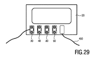
測定モジュール30、40、80、バッテリモジュール90、及びケーブルユニット450はまた、図29に模式的に示されるのと同じ横方向幾何学形状概念を使用して、例えば、患者モニタ又は中央処理ユニット20に接続することができる。さらに、垂直の積み重ね及び横方向の接続の任意の組み合わせは、概して、本発明により提案されるようなコネクタを用いて可能である。例えば、測定モジュールは、垂直の積み重ね手段及び横方向の積み重ね手段の両方を有する。
The
以下において、本発明に従うコネクタを備えるバッテリモジュールが、より詳細に説明される。 In the following, a battery module comprising a connector according to the invention will be described in more detail.
上に説明されるように、プラグイン測定モジュールは、磁気電力供給及びRFデータ通信を使用する提案されたコネクタを介して中央処理ユニットに結合される。加えて、そのRFチャネルにより、バッテリ(又は任意の他のエネルギー格納要素)は、ネットワーク、例えば、患者ネットワークの部分として備わっており、測定モジュール及び中央処理ユニットなどの他のデバイスに同じ様式で結合される。これは、本発明に従う、測定モジュール30、中央処理ユニット20、及びバッテリモジュール90を含むシステム13の別の実施形態の模式図を示す図30に模式的に例示される。
As explained above, the plug-in measurement module is coupled to the central processing unit via the proposed connector using magnetic power supply and RF data communication. In addition, due to its RF channel, the battery (or any other energy storage element) is provided as part of a network, eg a patient network, and is coupled in the same manner to other devices such as measurement modules and central processing units. To be done. This is schematically illustrated in FIG. 30, which shows a schematic diagram of another embodiment of a
ワイヤレス測定シナリオにおいて、双方向バッテリモジュール90は、提案されたコネクタを介してエネルギーを磁気的に供給するために、測定モジュール30上にスナップ嵌めされる。任意選択的に、測定モジュール30自体が、有線シナリオとワイヤレスシナリオとの間の遷移時間を一時的に橋渡しするための小型緩衝バッテリ37(又は任意の他のエネルギー格納要素)を備える。
In a wireless measurement scenario, the
バッテリモジュール90は、好ましくは、バッテリ91(バッテリユニットとも呼ばれる)と、バッテリモジュールと他のデバイスとの間の磁気電力伝送のための結合ユニット92とを備え、例えば、バッテリモジュール90が中央処理ユニット20に結合されるときバッテリを装填し、バッテリモジュールが測定モジュール30に結合されるとき測定モジュール30のバッテリ37を装填する。任意選択的に、データ伝送のための手段もバッテリモジュール90内に提供される。
The
バッテリモジュールと、システムの、具体的には、患者監視システムの、前記バッテリモジュールが連結される別のデバイスとの間のデータ及び電力のワイヤレス交換のためのバッテリモジュール90’のより詳細な模式図が図35に示される。前記バッテリモジュール90’は、密閉ハウジング93と、電気エネルギーを格納するためのバッテリユニット91と、データを記憶するためのデータ記憶ユニット94と、コネクタ95とを備える。コネクタは、対となる他方のコネクタを有するシステムの別のデバイスへデータを伝送する及び/又は別のデバイスからデータを受信するためのデータ伝送ユニット96、並びに誘導結合の使用により対となる他方のコネクタを有するシステムの別のデバイスへ電力を伝送する及び/又は別のデバイスから電力を受信するための磁気結合ユニット92を備える。
A more detailed schematic diagram of a battery module 90' for wireless exchange of data and power between a battery module and another device of the system, in particular of a patient monitoring system, to which the battery module is coupled. Is shown in FIG. The
任意選択的に、第2のコネクタ97が、システムの2つの他のデバイスにデータを同時伝送する及び/若しくはそれらからデータを同時受信するため、並びに/又は2つの他のデバイスに電力を同時伝送する及び/若しくはそれらから電力を同時受信するために、提供される。
Optionally, a
コネクタ及びその要素は、他のデバイス及び他の実施形態に関して上に説明されるように構成される。これは、特に、例えば、図10〜図15又は図17〜図28のいずれかに示されるような、本明細書に開示されるように構成される磁気結合ユニット92及びデータ伝送ユニット96に当てはまる。
The connector and its elements are configured as described above with respect to other devices and other embodiments. This is especially true for
バッテリ91は、例えば、再充電可能なバッテリ、使い捨てバッテリ、又はスーパーキャパシタであり、滑らかな密閉プラスチックボックス内に適合され、機械的損傷及び流体に対して十分に保護される。バッテリ91は、例えば、使い易いスナップ又はスライドイン機構によって、提案されたコネクタを有する別のデバイス(例えば、測定モジュール、ケーブルユニット、又は患者モニタ)に物理的に取り付ける(即ち、密接に接触させる)ことができる。永久磁石又は整列構造体を使用して、最適な電力及び無線伝達のためにその位置を整列及び固着させる。バッテリ91が空のとき、バッテリモジュール90は、互換性のあるコネクタを有し、充電することができるシステム内の任意のデバイス、例えば、患者モニタ、ハブ、又は専用バッテリ充電器に(任意選択的に、ケーブルを介して)取り付けることができる。好ましくは、同じインダクティブ/データコネクタトポロジーが、すべての要素を互いに結合するために構造全体にわたって使用される。これにより、バッテリをどこででも充電することができ、バッテリ管理に対する大きな改善を提供する。
The
再充電可能なバッテリ寿命は、ほとんどの場合、製造業者及びテスタによって満充電−放電サイクルの数と定義される。サイクルに加えて、リチウムイオンバッテリの劣化速度は、非常に温度依存であり、それらは、高温で保管又は使用される場合、例えば、人体に適用されるとき、はるかに速く劣化する。 Rechargeable battery life is most often defined by the manufacturer and tester as the number of full charge-discharge cycles. In addition to cycling, the degradation rate of lithium-ion batteries is very temperature dependent and they degrade much faster when stored or used at elevated temperatures, for example when applied to the human body.
したがって、バッテリの健康及び充電状態は、図35のセンサユニット98によって概して表される電圧及び/又は電流センサを使用することによって、温度センサ、絶対時間、並びに充電及び放電プロファイルから絶えず決定される。この情報及び過去データに基づいて、自己診断が実施され、この自己診断は、再充電の必要性、交換の必要性、又は任意の欠陥状態を示すために患者ネットワーク内で通信される。過去データは、ネットワーク内で共有されると同時にローカルに(例えば、バッテリモジュール内)記憶される。この目的においては多くのシナリオが可能である。
Therefore, the health and state of charge of the battery is constantly determined from the temperature sensor, absolute time, and charge and discharge profiles by using the voltage and/or current sensor generally represented by the
バッテリモジュール90’は、受信データのデータ処理、時間管理、自己診断、及び安全性のために処理ユニット99をさらに備える。前記処理ユニットは、測定モジュール30に適用されるとき予測される動作時間を計算するようにさらに構成される。
The battery module 90' further includes a processing unit 99 for data processing of received data, time management, self-diagnosis, and safety. The processing unit is further configured to calculate an expected operating time when applied to the
またさらに、バッテリモジュール90’は、図16に例示されるように、磁気結合ユニットと別のデバイスの磁気結合ユニットとの間の磁気結合の強度を検出するための検出ユニット273と、検出された磁気結合が第1のしきい値を上回る場合及び/又はその増加が第2のしきい値を上回る場合、データ伝送ユニットを低電力モードに切り替えるため及び/又は磁気結合ユニットを有効にするための、並びに検出された磁気結合が第3のしきい値を下回る場合及び/又はその減少が第4のしきい値を上回る場合、データ伝送ユニットを高電力モードに切り替えるため及び/又は磁気結合ユニットを無効にするための制御ユニット274とを備える。
Still further, the
ワイヤレス電力伝達における主な規格は、Qi規格及びPower Matters Technology(PowerMat)規格である。それらの主な用途は、ワイヤレス充電の分野にある。Qiはまた、デバイスのための基本のローカライゼーション及び認識機構、低電力スタンバイモード、並びに電力制御を含む。 The main standards in wireless power transfer are the Qi standard and the Power Matters Technology (PowerMat) standard. Their main application is in the field of wireless charging. Qi also includes basic localization and recognition mechanisms for the device, a low power standby mode, and power control.
リード接点及び永久磁石を使用した追加のオン−オフスイッチ(例えば、クリックオン固着機構の部分として存在するもの)は、安全性及びバッテリ漏洩保護をさらに高めるものとして有用であるが、例えば、光学手段、容量性手段、又は超音波手段など、積み重ね検出のための他の手段も存在する。 Additional on-off switches using reed contacts and permanent magnets (e.g., those that are present as part of the click-on sticking mechanism) are useful as further enhancements to safety and battery leakage protection, such as optical means. There are also other means for stack detection, such as capacitive, capacitive, or ultrasonic means.
Liイオン及びLiポリマーバッテリは、それらの質量単位あたりの高エネルギー密度及び消費者ドメインにおけるその大規模使用が理由で好ましい候補である。それらのバッテリは、その充電状態を見て過熱から保護するために電子機器手段を適所に有する。また、Qi規格は、有効な負荷を認識するために既にいくつかの基本的手段を適所に有する。これらは、本発明に従って使用される。これらの基本的な保護及び監視手段は、本発明に従って、通信手段として磁気及びRF結合を組み合わせること、ローカルインテリジェント安全監視、及び患者ネットワークへの接続によって、完全な構造に統合される。例えば、有効な識別子がない及び/又は局所破壊状態があるということが、磁気電力伝達を中断する、又はそれを開始しない理由である。 Li-ion and Li-polymer batteries are preferred candidates because of their high energy density per mass unit and their large scale use in the consumer domain. The batteries have electronics in place to see their state of charge and protect them from overheating. Also, the Qi standard already has some basic means in place to recognize the effective load. These are used according to the invention. These basic protection and monitoring means are, according to the invention, integrated into the complete structure by combining magnetic and RF coupling as communication means, local intelligent safety monitoring and connection to the patient network. For example, the lack of a valid identifier and/or the presence of a local breakdown condition are reasons for interrupting or not initiating magnetic power transfer.
充電状況は、バッテリを特定の測定にどれくらいの時間適用することができるかを決定するために使用される。これは、例えば、患者モニタディスプレイ上に示すことができる。任意選択的に、測定モジュールに取り付けられるとき、バッテリ自体の視覚又は可聴インジケータは、例えば、交換又は充電を必要とするまでの利用可能な測定時間が1時間未満であるときを示す。 The charge status is used to determine how long the battery can be applied to a particular measurement. This can be shown, for example, on the patient monitor display. Optionally, when attached to the measurement module, a visual or audible indicator on the battery itself indicates, for example, when the available measurement time is less than one hour before needing replacement or charging.
バッテリを上記のように医療環境に統合することは、安全性、使用事例、及びワークフローに重大な結果をもたらす。制約は、絶対的な安全、可能な形状、重量及びサイズの低減、看護師による容易な置換性/交換性、容易な清掃性、大容量、及び装着中の充電性を含む。バッテリモジュールは、充電及びエネルギー供給の両方のために完全にワイヤレス接続された閉じられたボックスである。提案された構造は、容易に清掃可能な機械的接続をもたらす。さらには、バッテリは、測定デバイスを適所に保持したまま数秒以内に交換することができる。 Integrating batteries into the medical environment as described above has serious consequences for safety, use cases, and workflow. Constraints include absolute safety, possible shapes, reduced weight and size, easy replacement/replaceability by nurses, easy cleaning, high capacity, and rechargeability during wear. The battery module is a completely box with a completely wireless connection for both charging and energy supply. The proposed structure provides an easily cleanable mechanical connection. Furthermore, the battery can be replaced within seconds with the measuring device held in place.
以下では、ネットワーク/システムの他のデバイスを接続するための、本発明に従うコネクタを備えるケーブルユニットがより詳細に説明される。 In the following, a cable unit with a connector according to the invention for connecting other devices of a network/system will be described in more detail.
ケーブルユニット500の一般的なレイアウトが図31に示される。ケーブルユニット500は、ケーブル510と、ケーブル510の各端にコネクタ520、530とを備える。各コネクタ520、530は、磁気結合ユニット521、531及びデータ伝送ユニット522、532を備える。ケーブル510は、磁気結合ユニット521、531を接続する第1のワイヤ対511(例えば、撚線)と、データ伝送ユニット522、532を接続する第2のワイヤ対512(例えば、撚線)とを備える。
The general layout of the
図32は、この例では測定モジュール30及び中央処理ユニット20を接続するための、緊急性の高い環境におけるケーブルユニット500の使用を例示する。そのようなケーブルユニット500は、OR(手術室)又はICU(集中治療室)環境で使用されて、測定のためのデータ完全性及び電力一貫性を保証する。2つのワイヤ対511、512は、好ましくは、カテーテル技術で使用されるように薄くて可撓性である。超導電性遮蔽体又はフェライトコモンモードコイルが、さらなるロバスト性及び性能のために追加される。この手法は、その低いRF減衰及び遮蔽特性に起因して、無線信号に対して十分に高い信号対雑音比を保証する。非接触型電力供給(100〜200kHz)及び無線(2.4GHz)の周波数間の大きな比率に起因して、内部クロストークは管理可能である。
FIG. 32 illustrates the use of the
このケーブルユニット500の主な機能を実施して無線信号及び電力信号のための保護パイプを形成するのには、多くの選択肢が可能である。
Many options are possible for implementing the main functions of this
1つの選択肢は、(図31、図32に示されるように)2つのワイヤ対を備える完全受動のケーブルユニットである。基本的に、RFデータ及び電力は、ケーブルユニットを通じて2つの方向に伝達することができる。電力用の撚線、及びRFデータ用の同軸又は平衡伝送線が使用される。加えて、受動コンポーネントがコネクタに追加されて、例えばフィルタリング及びインピーダンスマッチングによってRF伝送をさらに向上させ、例えば磁束濃縮器による又は受動識別(光学タグ)のための(電力)伝達を向上させる。 One option is a fully passive cable unit with two wire pairs (as shown in Figures 31 and 32). Basically, RF data and power can be transmitted in two directions through the cable unit. Twisted wires for power and coaxial or balanced transmission lines for RF data are used. In addition, passive components are added to the connector to further improve RF transmission, for example by filtering and impedance matching, for example (power) transmission by a flux concentrator or for passive identification (optical tags).
任意選択的に、電力及び無線信号は、1つの単一ワイヤ対(又は同軸ケーブル)内で組み合わされる。完全受動ケーブルのコネクタを1つだけ、例えば、測定モジュールに取り付けることは、磁気結合を増加させることもRF結合を増加させることもない。ペアリングが開始されるまでは、2つの接続が作られる。 Optionally, the power and wireless signals are combined in one single wire pair (or coaxial cable). Attaching only one connector of a fully passive cable, eg to a measurement module, does not increase magnetic coupling or RF coupling. Two connections are made until pairing is initiated.
別の選択肢は、能動ケーブルである。能動コンポーネントは、磁気電力信号を、それらをケーブルを通して送信する前に、クリーンな/安定したDC又は正弦波ACに変換するために(一方又は両方のコネクタ内に)存在する。これが、電力信号から無線チャネルへのクロストーク及び妨害を制限する。前記コンポーネントの最も論理的な場所は、コネクタ内であるが、それらを、ケーブルユニット(の一部分)を通じて、例えば、ケーブルスリーブに統合された可撓性ホイル上に分散させることもできる。 Another option is an active cable. Active components are present (in one or both connectors) to convert the magnetic power signals into clean/stable DC or sinusoidal AC before transmitting them through the cable. This limits crosstalk and interference from the power signal to the radio channel. The most logical place for the components is in the connector, but they can also be distributed through (a part of) the cable unit, for example on a flexible foil integrated into a cable sleeve.
データ無線信号は、RFケーブル特性にマッチするように増幅、再変調(トランスポンダ)、バッファリング、又は(活発に)インピーダンス変換される。代替的に、別の周波数帯域又はベースバンドへの変換は、例えば、USB、RS232、又はTCP/IPのようなシリアルバス形式への変換によって信号完全性をさらに高める。磁気電力の一部は、前記能動コンポーネントに電力供給するために使用される。 The data radio signal is amplified, remodulated (transponder), buffered, or (actively) impedance transformed to match the RF cable characteristics. Alternatively, conversion to another frequency band or baseband further enhances signal integrity by conversion to a serial bus format such as USB, RS232, or TCP/IP. A portion of the magnetic power is used to power the active components.
各コネクタは、ノードとして配置されてそのようなものとして作用し、固有識別子、無線、及びペアリング並びに磁気電力供給のためのネットワークスタックを含む、患者ネットワークの一部である。追加の無線が、無線信号を中継する(例えば、デイジーチェーン内)ため、又は患者ネットワーク管理用の個別のチャネルを実装するために追加される。能動ケーブルは、データ又は電力を一方向にのみ輸送する。したがって、ケーブルあたりより多くのワイヤ対、又はより多くのケーブルが二方向に輸送するためには必要とされる。 Each connector is arranged as a node and acts as such, and is part of a patient network that includes a network stack for unique identifiers, wireless, and pairing and magnetic power supply. Additional radios are added to relay radio signals (eg, in a daisy chain) or to implement a separate channel for patient network management. Active cables carry data or power in only one direction. Therefore, more wire pairs per cable, or more cables, are needed to transport in two directions.
別の選択肢によると、RF信号の光学ドメインへの変換が提供され、そのことがデータ完全性において最高水準をもたらし、潜在的にはより薄いケーブルも可能にする。 According to another option, the conversion of the RF signal into the optical domain is provided, which leads to the highest levels of data integrity and potentially even thinner cables.
当然ながら、ケーブルユニットは、電力又はデータチャネルだけを備える場合がある。 Of course, the cable unit may only comprise a power or data channel.
識別タグ(RFID)又は無線ユニットが、識別及びデータ管理のためにケーブルユニット又はコネクタに追加される。 An identification tag (RFID) or radio unit is added to the cable unit or connector for identification and data management.
好ましくは、ユーザの観点から、ケーブルユニットは、RFデータ及び電力を二方向に輸送することができるべきである。これは、例えば、能動コンポーネントが適用される場合においては、より多くのワイヤ対を使用することが必要である。 Preferably, from the user's perspective, the cable unit should be able to transport RF data and power in two directions. This requires the use of more wire pairs, for example when active components are applied.
図33は、この例では、RF性能(例えば、混雑したエリアにおいて)を改善すること、又は電力供給若しくは充電の理由(即ち、モバイル使用のためにバッテリ容量を節約すること)のために必要とされるときのみ、測定モジュール30(又はバッテリモジュール90)及び中央処理ユニット20を接続するための、緊急性の低い環境におけるケーブルユニット500の使用を例示する。測定モジュールは、ケーブルの散乱を回避するためにチェーン接続される。
FIG. 33 shows that in this example, it may be necessary for improving RF performance (eg in crowded areas) or for powering or charging reasons (ie saving battery capacity for mobile use). When used, it illustrates the use of the
システム内、特に患者監視システム内のデバイスを接続して、デバイス間のデータ及び/又は電力のワイヤレス交換を可能にするためのケーブルユニット500’のより詳細な模式図は、図36に模式的に示される。上に説明されるように、ケーブルユニット500’は、ケーブル510と、前記ケーブルの各端に配置されたコネクタ520、530とを備える。前記コネクタの各々が、対となる他方のコネクタを有する別のデバイスへデータを伝送する及び/又は別のデバイスからデータを受信するためのデータ伝送ユニット522、532、並びに誘導結合の使用により対となる他方のコネクタを有するシステムの別のデバイスへ電力を伝送する及び/又は別のデバイスから電力を受信するための磁気結合ユニット521、531を備える。
A more detailed schematic diagram of a cable unit 500' for connecting devices in the system, and in particular in a patient monitoring system, to enable wireless exchange of data and/or power between the devices is shown schematically in FIG. Shown. As explained above, the cable unit 500' comprises a
ケーブルユニット500’は、ケーブル510の各端に配置された(密閉)ハウジング523、533をさらに備え、ハウジング内にはケーブルのそれぞれの端に配置された1つ又は複数のコネクタ520、530が配置される。密閉ハウジングは、好ましくは、他のデバイスの観点から本明細書内で開示されるように、対となる他方のコネクタを有する他のデバイスへのケーブルユニット500’の積み重ねを可能にするように構成される。
The
コネクタ及びその要素は、他のデバイス及び他の実施形態に関して上に説明されるように構成される。これは、特に、例えば、図10〜図15又は図17〜図28のいずれかに示されるような、本明細書に開示されるように構成される磁気結合ユニット521、531及びデータ伝送ユニット522、532に当てはまる。
The connector and its elements are configured as described above with respect to other devices and other embodiments. This is especially true for
ケーブルユニット500’は、受信データのデータ処理、変換、及び/又は記憶のための電気回路501をさらに備える。
The cable unit 500' further comprises an
さらに、ケーブルユニット500’、具体的には各コネクタ520、530は、図16に例示されるように、(それぞれのコネクタの)磁気結合ユニットと別のデバイスの磁気結合ユニットとの間の磁気結合の強度を検出するための検出ユニット524、534と、検出された磁気結合が第1のしきい値を上回る場合及び/又はその増加が第2のしきい値を上回る場合、(それぞれのコネクタの)データ伝送ユニットを低電力モードに切り替えるため及び/又は(それぞれのコネクタの)磁気結合ユニットを有効にするための、並びに検出された磁気結合が第3のしきい値を下回る場合及び/又はその減少が第4のしきい値を上回る場合、(それぞれのコネクタの)データ伝送ユニットを高電力モードに切り替えるため及び/又は(それぞれのコネクタの)磁気結合ユニットを無効にするための制御ユニット525、535とを備える。
Further, the cable unit 500', and specifically each
代替的な選択肢として、ケーブルユニット500’、具体的には各コネクタ520、530は、ケーブルユニットの別のデバイスに対する近接性を検出するための(即ち、それらの間に小さな空隙のみが存在するかどうかを検出するための)近接検出装置526、536と、デバイスがケーブルユニットに近接していることが検出された場合、(それぞれのコネクタの)それぞれのデータ伝送ユニット522、532を低電力モードに切り替えるため及び/又は(それぞれのコネクタの)磁気結合ユニットを有効にするための、並びにケーブルユニットに近接していると検出されるデバイスがない場合、(それぞれのコネクタの)データ伝送ユニットを高電力モードに切り替えるため及び/又は(それぞれのコネクタの)磁気結合ユニットを無効にするための制御ユニット527、537とを備える。そのような近接検出装置及び制御ユニットはまた、コネクタの他の実施形態及び本明細書に開示される他のデバイスにおいて使用される。
Alternatively, the cable unit 500', and in particular each
近接性検出の様々な方法、例えば、標準Bluetooth(登録商標)、Bluetooth(登録商標) Low Energy(BTLE)、及びWi−Fi(登録商標)などの受信信号強度インジケーション(RSSI)法が使用される。近接性検出の他の方法例としては、超広帯域(UWB)などの差動法、例えば赤外(IR)波長超音波を使用した光学法、及びNFCが挙げられる。IRDA、UWB、及びNFCなどの近接性検出法は、典型的には、標準及び非標準両方のデータ輸送機構を使用する。例においては、近接性検出は、2つのデバイスが、例えば、互いの0.5mm+/−0.1mmの範囲内にあるときに発生するが、他の距離が使用されてもよい。 Various methods of proximity detection are used, for example the Received Signal Strength Indication (RSSI) method such as standard Bluetooth®, Bluetooth® Low Energy (BTLE), and Wi-Fi®. It Other examples of proximity detection methods include differential methods such as ultra wide band (UWB), for example optical methods using infrared (IR) wavelength ultrasound, and NFC. Proximity detection methods such as IRDA, UWB, and NFC typically use both standard and non-standard data transport mechanisms. In the example, proximity detection occurs when the two devices are within 0.5 mm +/- 0.1 mm of each other, but other distances may be used.
一般には、別のデバイスに対するデバイスの近接性を検出するための直接又は間接的な手段が使用される。「近接」と検出され得る2つのデバイスの実際の距離は、例えば、磁気デザインにより決まり、1つの基準は、磁気結合が90%より大きいかどうか、又は好ましくは95%より大きいかどうか、又は究極的には99%より大きいかどうかである。例示的なデザインでは、約0.5mm+100μm(2*0.25mmのプラスチックハウジングに起因する)の磁気距離が使用され、それは「極めて近接」と理解される。しかしながら、特定のデザイン及び/又は用途によっては、代わりに他の距離が使用されてもよい。 Generally, direct or indirect means for detecting the proximity of a device to another device are used. The actual distance between two devices that can be detected as “proximity” depends, for example, on the magnetic design and one criterion is whether the magnetic coupling is greater than 90%, or preferably greater than 95%, or the ultimate. Specifically, whether it is greater than 99%. In the exemplary design, a magnetic distance of about 0.5 mm+100 μm (due to a plastic housing of 2*0.25 mm) is used, which is understood to be “very close”. However, other distances may be used instead, depending on the particular design and/or application.
最後に、各ハウジング523、533内に、第2のコネクタ540、550が、2つのデバイスにデータを同時伝送する及び/若しくはそれらからデータを同時受信するため、並びに/又は2つのデバイスに電力を同時伝送する及び/若しくはそれらから電力を同時受信するために配置される。前記第2のコネクタ540、550は、第1のコネクタ520、530と同じ方式で全体的に構成される。
Finally, within each
提案されたケーブルユニットは、測定モジュール及び監視デバイスを相互接続するために使用される。図20A及び図20Cに示されるように、デイジーチェーン並びに星状構成が可能である。ケーブルユニットは、互いの上に、又はその間に第3のコンポーネントを有して、横方向又は垂直方向に結合される。代替的に、分散ケーブルユニットは、コンポーネントを物理的に接続するために複数の分岐を有する。 The proposed cable unit is used to interconnect measurement modules and monitoring devices. Daisy chain and star configurations are possible, as shown in FIGS. 20A and 20C. The cable units are laterally or vertically coupled with the third component on top of or between each other. Alternatively, the distributed cable unit has multiple branches to physically connect the components.
以下において、デバイスのペアリングが、本発明により提案されるように説明される。 In the following, device pairing is described as proposed by the present invention.
ペアリングの第1の選択肢は、例えば、測定モジュールを人の身体に取り付けている最中に、ペアリングを手動で実施することである。デバイスを物理的に別のデバイスに極めて近接させることによって、識別子が交換され、それは、前記デバイスがデバイスのネットワーク、例えば、患者ネットワークに追加されることを事実上意味する。これは、測定モジュールの初回の取り付け中に、及び動く患者に対して、達成するのが容易である。 The first pairing option is to perform the pairing manually, for example while the measurement module is being attached to the human body. By bringing the device in close physical proximity to another device, the identifiers are exchanged, which effectively means that the device is added to the device's network, eg the patient network. This is easy to achieve during the initial installation of the measurement module and for moving patients.
接続の順番は、一般的には重要ではない。ネットワークのすべての構成要素が、例えば、Bluetooth(登録商標)−LEのような特定の規格でマスタデバイスを介して、ネットワーク状況を通信及び更新することができる。デバイスに関する視覚及び可聴情報が、その接続状況を示す。それは、例えば、どのデバイスが患者ネットワークにペアリングされるかを示し、またそれは、例えば動く患者の病院ネットワーク又は患者モニタへのRF接続性の損失を示す。そのような場合、患者ネットワークは、(自動的に又は手動で)別の無線リンクに再接続する必要がある。 The order of connections is generally unimportant. All components of the network are able to communicate and update the network status via the master device in a specific standard, eg Bluetooth®-LE. Visual and audible information about the device indicates its connection status. It indicates, for example, which device is paired to the patient network, and it indicates, for example, loss of RF connectivity to the moving patient's hospital network or patient monitor. In such cases, the patient network needs to reconnect (automatically or manually) to another wireless link.
関連付け機構は、2つの条件が満たされるときに開始する:
1.二次コイル内の誘導電圧並びに一次コイル内の電流、又はアセンブリの共鳴周波数から検出することができる、増大した磁気結合レベル。この条件が満たされると、RF無線は互いとの通信を開始する(おそらくマスタデバイスを介して)。
2.受信したRF信号の強度が所定のレベルも上回るとき、関連付けが開始される。代替的に、送信信号のRF吸収を示す、逸脱した送信機アンテナインピーダンス(電圧定在波比VSWR、反射波)を、追加チェックとして含むことができる。
The association mechanism starts when two conditions are met:
1. Increased magnetic coupling level that can be detected from the induced voltage in the secondary coil as well as the current in the primary coil or the resonant frequency of the assembly. When this condition is met, the RF radios will begin communicating with each other (possibly via the master device).
2. Association is initiated when the strength of the received RF signal is above a predetermined level. Alternatively, the deviated transmitter antenna impedance (voltage standing wave ratio VSWR, reflected wave), which indicates RF absorption of the transmitted signal, can be included as an additional check.
この機構を繰り返すことは、患者ネットワークのメンバーシップをトグルし、即ち、マスタデバイスは、特定の患者のネットワーク内のすべてのデバイスを把握しており、マスタデバイスが加入と離脱とを切り替える。ネットワークメンバーシップは、視覚、触覚、又は可聴アクチュエータ(例えば、LED、ディスプレイ、ブザー、ポケットベル、バイブレータなど)によって示される。加えて、機械的スイッチ又はキーボードコードが、ネットワークを強制的に離脱するために使用される。 Repeating this mechanism toggles the membership of the patient network, that is, the master device knows all the devices in the network for a particular patient, and the master device switches between joining and leaving. Network membership is indicated by visual, tactile, or audible actuators (eg, LEDs, displays, buzzers, pagers, vibrators, etc.). In addition, mechanical switches or keyboard codes are used to force the network to leave.
患者は、測定装置(又はセンサ)が適切な患者の適切な位置に取り付けられることを強化するために、さらなる識別として患者−ネットワーク機能性を備えるギプス、及び局在化手段を有する。 The patient has a cast with patient-network functionality as an additional identification, and localization means to enhance that the measuring device (or sensor) is attached to the appropriate position of the appropriate patient.
ペアリングの第2の選択肢は、図31に示されるようなケーブルユニット500の使用により、不動の(例えば、OR又はICU)患者を患者ネットワークに接続することである。測定モジュールと監視デバイスとの間にケーブルユニットを短い間接続することによって、磁気結合及びRF振幅が、特定のレベルを超えて増加し、それがペアリング機構をトリガする。
The second pairing option is to connect an immobile (eg, OR or ICU) patient to the patient network through the use of a
ぺアリングの第3の選択肢は、非接触型記憶モジュールを使用することであり、それは、患者ネットワーク内のコンポーネント間で識別子を伝達するために中間記憶コンテナとして使用される。これは、記憶モジュール95を備える本発明に従うシステム14の第5の実施形態の模式図を示す図34に例示される。非接触型記憶モジュール95を、対となる他方のコネクタを有する別のコンポーネント20又は30に極めて近接させることによって、識別子は、相互交換され、患者ネットワークを更新するために使用される。追加の機械的プッシュボタン又は近接検出装置が、交換をトリガするために使用される。好ましくは、一意を回避するために1つの識別子のみが記憶及び伝達され得る。
A third pairing option is to use a contactless storage module, which is used as an intermediate storage container to convey identifiers between components within the patient network. This is illustrated in FIG. 34 which shows a schematic diagram of a fifth embodiment of the
非接触型記憶モジュール95は、ペンシル、スマートカード、又は測定モジュールのような小型ボックスの形状因子を有することができる。本発明に従うコネクタを備える他のデバイスのように、非接触型記憶モジュール95は、記憶要素98以外に、対となる他方のコネクタを有する他のデバイスに結合するために磁気結合ユニット96及びデータ伝送ユニット97(例えば、無線ハードウェア)を備える。
The
ペアリングの第4の選択肢は、追加のトリガ手段を使用することである。プッシュボタン又は近接検出装置(例えば、光学、磁気、超音波技術を使用した)は、ペアリングプロセスを開始するための条件として追加される。追加のトリガ手段は、結合のレベルを検出するためのコンポーネントを省く(例えば、RF又は磁気結合測定装置がない)ためにロバスト性をさらに高めるものとして有益である。さらに、ペンシル様のデバイスの場合、RFアンテナ及びコイルは、先端に位置し、最大結合は、関連付けプロセスをトリガするための所定のしきい値を下回る。 A fourth pairing option is to use additional triggering means. A push button or proximity detection device (using, for example, optical, magnetic, ultrasonic techniques) is added as a condition to initiate the pairing process. The additional triggering means is useful as a further robustness because it eliminates components for detecting the level of coupling (eg, no RF or magnetic coupling measuring device). Furthermore, for a pencil-like device, the RF antenna and coil are located at the tip and the maximum coupling is below a certain threshold to trigger the association process.
デバイスと、システムの、具体的には患者監視システムの別のデバイスとの間でのデータ及び/又は電力のワイヤレス伝送のためのデバイス600のより詳細な模式図は、図37に示される。前記デバイス600は、ペアリングのための上記手法を適用するように構成され、デバイス及びコネクタ602の固有識別子を記憶するための識別ユニット601を備える。前記コネクタ602は、対となる他方のコネクタを有するシステムの別のデバイスへデータを伝送する及び/又は別のデバイスからデータを受信するために配置されたデータ伝送ユニット603と、誘導結合の使用により対となる他方のコネクタを有するシステムの別のデバイスへ電力を伝送する及び/又は別のデバイスから電力を受信するための磁気結合ユニット604と、磁気結合ユニットと別のデバイスの対となる他方のコネクタの磁気結合ユニットとの間の磁気結合の強度を検出するため、及びデータ伝送ユニットによって他のデバイスのデータ伝送ユニットから受信されたデータの強度を検出するための検出ユニット605とを備える。
A more detailed schematic diagram of a
デバイス600は、a)受信データの検出された強度がデータ強度しきい値を上回る場合及び/又はその増加がデータ強度増加しきい値を上回る場合、並びにb)検出された磁気結合が磁気結合しきい値を上回る場合及び/又はその増加が磁気結合増大しきい値を上回る場合、デバイスの固有識別子を他のデバイスに伝送するように及び/又は他のデバイスの固有識別子を受信するようにデータ伝送ユニット603を制御するための制御ユニット606をさらに備える。
The
デバイス600は、データ伝送ユニットによって受信された他のデバイスの固有識別子を記憶するための記憶ユニット607をさらに備える。
The
制御ユニット606は、a)受信データの検出された強度がデータ強度しきい値を上回る場合及び/又はその増加がデータ強度増加しきい値を上回る場合、並びにb)検出された磁気結合が磁気結合しきい値を上回る場合及び/又はその増加が磁気結合増加しきい値を上回る場合、記憶ユニットに記憶された他のデバイスの固有識別子をさらに伝送するように及び/又は他のデバイスの固有識別子を受信するようにデータ伝送ユニットを制御するように構成される。 The control unit 606 a) if a) the detected strength of the received data exceeds a data strength threshold and/or its increase exceeds a data strength increase threshold, and b) the detected magnetic coupling is magnetic coupling. If the threshold value is exceeded and/or if the increase exceeds the magnetic coupling increase threshold value, further transmission of the unique identifier of the other device stored in the storage unit and/or the unique identifier of the other device may be performed. It is configured to control the data transmission unit to receive.
検出ユニット605は、磁気結合の強度を検出するためにインピーダンス、共鳴周波数、及び/若しくは誘導電圧を検出するように、並びに/又は受信データの強度を検出するためにデータ伝送ユニットのアンテナの信号強度及び/若しくはアンテナインピーダンスを検出するように構成される。磁気結合の強度は、多くの場合、磁気結合係数k(0<=k<=1)と称される。
The
コンポーネントが既に接続されている場合、これは電力の可用性及び強いRF信号から明らかである。新しいコンポーネントの取り付けは、磁気結合(及び、任意選択的に、データ伝送のために使用されるRF信号)の増加をチェックするためにポーリング機構を使用することによって検出される。コンポーネント断線の検出が、逆のプロセス、即ち、例えば、インピーダンス、共鳴周波数、及び/又は誘導電圧の使用によって、磁気結合の(及び任意選択的に、RF信号の)強度の低下を測定するためのポーリング機構によって実施される場合がある。任意選択的に、RF信号強度が加えて測定される。 If the components are already connected, this is evident from the power availability and the strong RF signal. Installation of new components is detected by using a polling mechanism to check for an increase in magnetic coupling (and, optionally, the RF signal used for data transmission). Component disconnection detection is for measuring the reduction in strength of the magnetic coupling (and optionally of the RF signal) by the reverse process, ie, use of impedance, resonant frequency, and/or induced voltage, for example. It may be implemented by a polling mechanism. Optionally, the RF signal strength is additionally measured.
一般に、固有識別子の第1の伝送は、デバイスをシステムと結合するためのリクエストとして解釈され、固有識別子の第2の伝送は、デバイスをシステムから分離するためのリクエストとして解釈される。 Generally, the first transmission of the unique identifier is interpreted as a request to couple the device to the system, and the second transmission of the unique identifier is interpreted as a request to separate the device from the system.
デバイスは、デバイスのシステムとの結合の結合状況を示すための、インジケータ608、具体的には視覚、触覚、又は可聴インジケータをさらに備える。
The device further comprises an
またさらに、デバイスは、ユーザが固有識別子、又は結合するための若しくは分離するためのリクエストメッセージの伝送を開始することを可能にするためのユーザインターフェース609を備える。
Still further, the device comprises a
またさらに、デバイスは、デバイスの他のデバイスに対する近接性を検出するための近接検出装置610を備え、ここでは前記制御ユニットが、追加でデバイスの他のデバイスへの近接性が検出された場合には、デバイスの固有識別子を他のデバイスに伝送するように及び/又は他のデバイスの固有識別子を受信するようにデータ伝送ユニットを制御する。近接検出装置は、他の実施形態に関して上に説明されたように構成される。
Still further, the device comprises a
コネクタ602及びその要素は、他のデバイス及び他の実施形態に関して上に説明されるように構成される。これは、特に、例えば、図10〜図15又は図17〜図28に示されるような、本明細書に開示されるように構成される磁気結合ユニット604及びデータ伝送ユニット603に当てはまる。
The
最後に、デバイス600は、データを生成及び/若しくは受信するためのデータユニット611、並びに/又は電力を供給及び/若しくは消費するための電力ユニット612をさらに備える。
Finally, the
本発明の1つの主な利点は、すべての患者監視用途に概して役立つ普遍的手法が提供されることであり、これは、コストを削減する取り組みにおいて達成されるべき重要な因子である。さらなる利点は、モジュール性、及びワイヤレス測定装置の既存の接続規格に対する直接的な準拠である。 One major advantage of the present invention is that it provides a universal approach that is generally useful for all patient monitoring applications, which is an important factor to be achieved in cost reduction efforts. A further advantage is the modularity and direct compliance of the wireless measuring device with existing connection standards.
本発明の用途は、患者監視に限定されることなく、例えば、自動車又は牧畜(複数の牛に接続された中央搾乳機)における、共通のエンティティに接続された相互絶縁モジュール(センサ、アクチュエータ)にまで拡大することができる。さらに、本発明は、例示的に開示されたアンテナ又はコイルの種類、形態、及び数に限定されることなく、それらは単に例であると理解されるものとする。開示された実施形態で使用されるコンポーネントはまた、Qi規格又は他のワイヤレス電力規格に準拠するものとして構成され、また、Qi規格に準拠する標準コンポーネントは、技術的観点から可能であれば、本発明に従う単一コンポーネントに使用される。さらに、デバイスは、垂直及び水平の積み重ねのための手段を備え、それぞれの方向に結合するための対応する結合手段を含み、即ち、デバイスは、例えば、図25A及び図26Aに示されるようなコネクタの組み合わせを備える。 The application of the present invention is not limited to patient monitoring, but for example in mutual insulation modules (sensors, actuators) connected to a common entity, eg in motor vehicles or livestock (central milking machines connected to multiple cows). Can be expanded to. Further, the present invention is not limited to the type, form, and number of illustratively disclosed antennas or coils, and they are to be understood as merely exemplary. The components used in the disclosed embodiments are also configured as compliant with the Qi standard or other wireless power standards, and standard components that are compliant with the Qi standard are Used for a single component according to the invention. Further, the device comprises means for vertical and horizontal stacking and includes corresponding coupling means for coupling in each direction, ie the device is a connector as shown for example in Figures 25A and 26A. With a combination of.
本発明は、図面及び先述の説明において詳細に例示及び説明されてきたが、そのような例示及び説明は、例示的又は例証であって制限的でないと見なされるべきである。本発明は、開示された実施形態に限定されない。開示された実施形態に対する他のバリエーションは、図面、本開示、及び添付の特許請求の範囲を読むことにより、特許請求された発明を実践するにあたって、当業者により理解及び達成され得る。さらに、要素及び構成のうちのいくつかを他の構成物及び他のデバイスにおいても使用することができる。 While the present invention has been illustrated and described in detail in the drawings and foregoing description, such illustration and description are to be considered illustrative or exemplary and not restrictive. The invention is not limited to the disclosed embodiments. Other variations to the disclosed embodiments can be understood and effected by those skilled in the art in practicing the claimed invention, by reading the drawings, the disclosure, and the appended claims. In addition, some of the elements and configurations can be used in other configurations and other devices.
特許請求の範囲において、「備える(comprising)」という言葉は、他の要素又はステップを排除するものではなく、不定冠詞「a」又は「an」は複数を除外するものではない。単一要素又は他のユニットが、特許請求の範囲内に列挙されたいくつかのアイテムの機能を履行する場合がある。特定の方策が相互に異なる従属請求項内に列挙されるからといって、それらの方策の組み合わせを有利に使用することができないということは意味しない。 In the claims, the word "comprising" does not exclude other elements or steps, and the indefinite article "a" or "an" does not exclude a plurality. A single element or other unit may fulfill the functions of several items recited in the claims. The mere fact that certain measures are recited in mutually different dependent claims does not indicate that a combination of these measures cannot be used to advantage.
特許請求項内のいかなる参照番号も、範囲を制限するものとして解釈されるべきではない。 Any reference signs in the claims shall not be construed as limiting the scope.
Claims (15)
ハウジングと、
誘導結合の使用により対となる他方のコネクタを有する前記患者監視システムの別のデバイスへ電力を伝送する及び/又は別のデバイスから電力を受信する、前記ハウジング内に配置された磁気結合ユニットとを備え、前記磁気結合ユニットが、
U字状の断面の脚部の間に凹所を形成する当該U字状の断面を有する、磁束濃縮器と、
前記磁束濃縮器の前記凹所内に配置された第1のコイルと、
前記第1のコイルが配置される前記凹所の外側に配置された第2のコイルと、を備え、
前記ハウジングが、コネクタを互いに積み重ねることを可能にするように配置され、その結果、前記コネクタの前記第1のコイル及び前記コネクタ上に積み重ねられた別のコネクタの第2のコイルが、それらの間の誘導電力伝送のための変圧器を一緒に形成し、並びに/又は前記コネクタの前記第2のコイル及び前記コネクタ上に積み重ねられた別のコネクタの第1のコイルが、それらの間の誘導電力伝送のための変圧器を一緒に形成する、積み重ね可能なコネクタ。 A stackable connector for wireless transmission of power between individual devices of a patient monitoring system, said individual device comprising such a connector, said connector comprising:
Housing,
Receive another device to transmit power and / or power from another device of the patient monitoring system having a second connector forming a pair by the use of inductive coupling, a magnetic coupling unit arranged in the housing And the magnetic coupling unit,
Having the U-shaped cross section forming a recess between the legs of the U-shaped cross section, and the flux concentrator,
A first coil disposed in the recess of the magnetic flux concentrator;
A second coil arranged outside the recess in which the first coil is arranged,
The housing is arranged to allow the connectors to be stacked on top of each other so that the first coil of the connector and the second coil of another connector stacked on the connector are between them . Forming a transformer together for inductive power transfer of, and/or the second coil of the connector and the first coil of another connector stacked on the connector with an inductive power between them. A stackable connector that together forms a transformer for transmission.
前記第1のコイルが第1の磁束濃縮器の前記凹所内に配置され、前記第2のコイルが第2の磁束濃縮器の前記凹所内に配置される、請求項1に記載の積み重ね可能なコネクタ。 The magnetic coupling unit further comprises two magnetic flux concentrators, each magnetic flux concentrator having a U-shaped cross section forming a recess between legs of the U- shaped cross section,
The stackable according to claim 1, wherein the first coil is located within the recess of a first flux concentrator and the second coil is located within the recess of a second flux concentrator. connector.
RFアンテナを駆動する、及び、前記RFアンテナによって受信されたRF信号を取得する、RF回路と
をさらに備え、
前記データ伝送ユニットが、前記RFアンテナを備える、請求項11に記載の積み重ね可能なコネクタ。 With a career ,
Driving the RF antenna, and acquires the RF signal received by the RF antenna, an RF circuit
Further equipped with,
The stackable connector according to claim 11, wherein the data transmission unit comprises the RF antenna .
電力を別のデバイスへ伝送するか、又は別のデバイスによって供給された電力を受信するかのいずれかである、請求項1に記載の積み重ね可能なコネクタと
を備えるデバイスであって、当該デバイスと別のデバイスとの間の電力のワイヤレス伝送のための、デバイス。 A power unit that either supplies or consumes power ,
A stackable connector according to claim 1 which either transfers power to another device or receives power provided by another device. A device for wireless transmission of power to and from another device.
Applications Claiming Priority (3)
| Application Number | Priority Date | Filing Date | Title |
|---|---|---|---|
| EP15183609 | 2015-09-03 | ||
| EP15183609.5 | 2015-09-03 | ||
| PCT/EP2016/070269 WO2017036995A1 (en) | 2015-09-03 | 2016-08-29 | Stackable connector and device for wireless transmission of power |
Publications (3)
| Publication Number | Publication Date |
|---|---|
| JP2018534895A JP2018534895A (en) | 2018-11-22 |
| JP2018534895A5 JP2018534895A5 (en) | 2020-04-23 |
| JP6714076B2 true JP6714076B2 (en) | 2020-06-24 |
Family
ID=54064167
Family Applications (1)
| Application Number | Title | Priority Date | Filing Date |
|---|---|---|---|
| JP2018511460A Active JP6714076B2 (en) | 2015-09-03 | 2016-08-29 | Stackable connectors and devices for wireless transmission of power |
Country Status (6)
| Country | Link |
|---|---|
| US (1) | US10623061B2 (en) |
| EP (1) | EP3345200A1 (en) |
| JP (1) | JP6714076B2 (en) |
| CN (1) | CN108140477B (en) |
| MX (1) | MX2018002453A (en) |
| WO (1) | WO2017036995A1 (en) |
Families Citing this family (6)
| Publication number | Priority date | Publication date | Assignee | Title |
|---|---|---|---|---|
| EP3176954B1 (en) * | 2015-12-02 | 2018-09-26 | etatronix GmbH | Method for the transmission of analog and digital information in the transmission of energy |
| DE102017109499A1 (en) * | 2017-05-03 | 2018-11-08 | Valeo Siemens Eautomotive Germany Gmbh | inverter |
| MX2018013888A (en) * | 2017-11-13 | 2019-06-06 | Ortronics Inc | Hybridized cable assembly. |
| JP7118532B2 (en) * | 2018-04-27 | 2022-08-16 | 矢崎総業株式会社 | Connector and power supply system |
| CN113302090B (en) * | 2019-01-12 | 2024-01-02 | 奥托立夫开发公司 | Integrated electromagnetic and optical device for wireless power transfer and data communication |
| CN110060860B (en) * | 2019-05-23 | 2023-07-21 | 合肥有感科技有限责任公司 | Wireless coil structure that charges of electric automobile |
Family Cites Families (16)
| Publication number | Priority date | Publication date | Assignee | Title |
|---|---|---|---|---|
| WO1995011545A1 (en) | 1993-10-21 | 1995-04-27 | Auckland Uniservices Limited | Inductive power pick-up coils |
| DE19532296A1 (en) | 1995-09-01 | 1997-03-06 | Bosch Gmbh Robert | Arrangement for the contactless transmission of signals between two mutually rotatably mounted vehicle parts |
| ATE289490T1 (en) | 2000-11-20 | 2005-03-15 | Draeger Medical Systems Inc | AN ELECTRICALLY ISOLATED POWER AND SIGNAL COUPLER FOR A DEVICE CONNECTED TO A PATIENT |
| DE10106173C1 (en) | 2001-02-10 | 2002-04-18 | Bosch Gmbh Robert | Arrangement for transferring energy/data between vehicle body and removable part has first core half with pin protruding into second core half, ring with spring pressing it against second half |
| DE102005029599B3 (en) | 2005-06-23 | 2006-12-28 | Sew-Eurodrive Gmbh & Co. Kg | System for contactless power transmission, has coil core provided on secondary-side winding formed from cuboids |
| JP4852970B2 (en) * | 2005-10-26 | 2012-01-11 | パナソニック電工株式会社 | Power supply system |
| US7825544B2 (en) | 2005-12-02 | 2010-11-02 | Koninklijke Philips Electronics N.V. | Coupling system |
| KR101390746B1 (en) * | 2006-08-04 | 2014-05-02 | 에스케이케미칼주식회사 | Induction coil for cordless energy charging and data transfer |
| JP2009135843A (en) * | 2007-11-30 | 2009-06-18 | Mie Denshi Kk | Indicator |
| JP2009207511A (en) * | 2008-02-29 | 2009-09-17 | Takao Hayashi | Shoe charge system |
| WO2010134006A2 (en) * | 2009-05-18 | 2010-11-25 | Koninklijke Philips Electronics N.V. | Arrangement and method for influencing and/or detecting magnetic particles |
| US20110115429A1 (en) | 2009-11-13 | 2011-05-19 | Nokia Corporation | Wireless Charging Adapter Compatible With Wall Charger And Wireless Charging Plate |
| EP3185263A1 (en) * | 2011-01-19 | 2017-06-28 | Technova Inc. | Contactless power transfer apparatus |
| US20130046197A1 (en) | 2011-08-16 | 2013-02-21 | Daniel F. Dlugos, Jr. | Docking station for patient bedside monitoring units |
| JP5738744B2 (en) * | 2011-11-15 | 2015-06-24 | 株式会社東芝 | Resonator and wireless power transmission device |
| EP2870675A4 (en) * | 2012-07-09 | 2016-04-27 | Auckland Uniservices Ltd | Flux coupling device and magnetic structures therefor |
-
2016
- 2016-08-29 CN CN201680057477.0A patent/CN108140477B/en active Active
- 2016-08-29 MX MX2018002453A patent/MX2018002453A/en unknown
- 2016-08-29 US US15/752,003 patent/US10623061B2/en active Active
- 2016-08-29 JP JP2018511460A patent/JP6714076B2/en active Active
- 2016-08-29 EP EP16757661.0A patent/EP3345200A1/en active Pending
- 2016-08-29 WO PCT/EP2016/070269 patent/WO2017036995A1/en active Application Filing
Also Published As
| Publication number | Publication date |
|---|---|
| JP2018534895A (en) | 2018-11-22 |
| US20180241436A1 (en) | 2018-08-23 |
| MX2018002453A (en) | 2018-06-15 |
| CN108140477A (en) | 2018-06-08 |
| EP3345200A1 (en) | 2018-07-11 |
| US10623061B2 (en) | 2020-04-14 |
| CN108140477B (en) | 2020-05-19 |
| WO2017036995A1 (en) | 2017-03-09 |
Similar Documents
| Publication | Publication Date | Title |
|---|---|---|
| JP6975136B2 (en) | Battery module for wireless exchange of data and power | |
| JP6466624B2 (en) | Cable unit for connecting devices and enabling wireless exchange of data and / or power between devices | |
| JP6684897B2 (en) | Connector and device for wireless transmission of data and / or power | |
| JP6714076B2 (en) | Stackable connectors and devices for wireless transmission of power | |
| JP6684896B2 (en) | Device for wireless transmission of data and / or power | |
| CN110168941B (en) | Device for wireless transmission of data and/or power |
Legal Events
| Date | Code | Title | Description |
|---|---|---|---|
| A521 | Request for written amendment filed |
Free format text: JAPANESE INTERMEDIATE CODE: A523 Effective date: 20190828 |
|
| A621 | Written request for application examination |
Free format text: JAPANESE INTERMEDIATE CODE: A621 Effective date: 20190828 |
|
| A521 | Request for written amendment filed |
Free format text: JAPANESE INTERMEDIATE CODE: A523 Effective date: 20200310 |
|
| A871 | Explanation of circumstances concerning accelerated examination |
Free format text: JAPANESE INTERMEDIATE CODE: A871 Effective date: 20200310 |
|
| A975 | Report on accelerated examination |
Free format text: JAPANESE INTERMEDIATE CODE: A971005 Effective date: 20200423 |
|
| TRDD | Decision of grant or rejection written | ||
| A01 | Written decision to grant a patent or to grant a registration (utility model) |
Free format text: JAPANESE INTERMEDIATE CODE: A01 Effective date: 20200508 |
|
| A61 | First payment of annual fees (during grant procedure) |
Free format text: JAPANESE INTERMEDIATE CODE: A61 Effective date: 20200604 |
|
| R150 | Certificate of patent or registration of utility model |
Ref document number: 6714076 Country of ref document: JP Free format text: JAPANESE INTERMEDIATE CODE: R150 |
|
| R250 | Receipt of annual fees |
Free format text: JAPANESE INTERMEDIATE CODE: R250 |