JP6709665B2 - grill - Google Patents
grill Download PDFInfo
- Publication number
- JP6709665B2 JP6709665B2 JP2016079364A JP2016079364A JP6709665B2 JP 6709665 B2 JP6709665 B2 JP 6709665B2 JP 2016079364 A JP2016079364 A JP 2016079364A JP 2016079364 A JP2016079364 A JP 2016079364A JP 6709665 B2 JP6709665 B2 JP 6709665B2
- Authority
- JP
- Japan
- Prior art keywords
- grill
- plate
- hot air
- burner
- heating chamber
- Prior art date
- Legal status (The legal status is an assumption and is not a legal conclusion. Google has not performed a legal analysis and makes no representation as to the accuracy of the status listed.)
- Active
Links
Images




Landscapes
- Baking, Grill, Roasting (AREA)
Description
本発明は、グリル、特に、グリルプレート上に載置された食材を上下両面から同時に加熱するように構成されたグリルに関する。 TECHNICAL FIELD The present invention relates to a grill, and particularly to a grill configured to simultaneously heat foods placed on a grill plate from both upper and lower surfaces.
従来、加熱庫内の上壁および左右の側壁にそれぞれバーナ(上火バーナ、下火バーナ)が配設され、加熱庫内に収容されたグリルプレートを、下火バーナからグリルプレートの下面側に放出されるガスの燃焼排気により下方から加熱すると共に、グリルプレート上に載置された食材を、上火バーナの輻射熱によって上方から加熱するように構成された所謂両面焼きのグリルが知られている(例えば、特許文献1から3参照)。
Conventionally, burners (upper-burner burner, lower-burner burner) are installed on the upper wall and left and right side walls of the heating cabinet, and the grill plate housed in the heating cabinet is moved from the lower-burner burner to the lower surface side of the grill plate. A so-called double-sided grill is known, which is configured to be heated from below by the combustion and exhaust of emitted gas and to heat food placed on a grill plate from above by radiant heat of a top-burning burner. (For example, see
しかしながら、上記従来のグリルでは、食材の厚みによっては、食材が上火バーナに近接し過ぎて、上面が過剰に熱せられる虞があった。また、このものでは、上下両バーナからそれぞれガスの燃焼排気を放出して食材を加熱するように構成されているため、必要以上にガスを消費する問題もあった。しかも、このものでは、加熱庫内の上壁および左右の側壁にそれぞれバーナが設けられている分、部品点数や組立工数が多く、製造コストが高くなる問題もある。 However, in the above-mentioned conventional grill, depending on the thickness of the food material, the food material may be too close to the top-burning burner and the upper surface may be excessively heated. Further, in this product, the combustion exhaust of gas is discharged from each of the upper and lower burners to heat the food, so that there is a problem that the gas is consumed more than necessary. In addition, in this structure, burners are provided on the upper wall and the left and right side walls of the heating chamber, respectively, so that the number of parts and the number of assembling steps are large and the manufacturing cost is high.
本発明は、上記課題を鑑みてなされたものであり、その目的は、グリルプレート上の食材を上下両面から同時に加熱可能なグリルにおいて、安定した加熱性能を発揮しつつ、省エネ性の向上および製造コストの低廉化を図ることにある。 The present invention has been made in view of the above problems, and an object of the present invention is to improve energy-saving performance and manufacture while exhibiting stable heating performance in a grill that can simultaneously heat food on a grill plate from both upper and lower sides. It is to reduce the cost.
本発明は、加熱庫内にグリルプレートおよびバーナが配設されたグリルであって、
グリルプレート上に載置された食材を、バーナによって加熱されるグリルプレートからの伝導熱により下方から加熱し、且つ、バーナから放出される熱気の対流熱により上方から加熱する構成とし、
加熱庫の後壁は、前記熱気が加熱庫の後壁側から外部に排出されないよう閉塞形成され、
加熱庫の内側上部は、加熱庫の上壁と前記上壁を下方から覆う集熱板とからなる二重構造をなしており、
集熱板の略中央部に、下方へ凸の膨出部が設けられ、且つ、前記熱気を加熱庫の外部に導出するための熱気導出孔が設けられ、
熱気導出孔は、前記集熱板における前後方向の中央より前方位置および後方位置にそれぞれ設けられ、
前記熱気は、熱気導出孔から前記上壁と前記集熱板との相互間に画成された排気通路を通じて加熱庫の後方へ導かれ、器具外部に排出される構成としたものである。
The present invention is a grill in which a grill plate and a burner are arranged in a heating chamber,
The food placed on the grill plate is heated from below by conduction heat from the grill plate heated by the burner, and is heated from above by convective heat of hot air emitted from the burner ,
The rear wall of the heating chamber is formed so as to be closed so that the hot air is not discharged to the outside from the rear wall side of the heating chamber,
The inner upper part of the heating chamber has a double structure consisting of an upper wall of the heating chamber and a heat collecting plate that covers the upper wall from below,
At a substantially central portion of the heat collecting plate, a downwardly protruding bulging portion is provided, and a hot air outlet hole for leading out the hot air to the outside of the heating chamber is provided,
The hot air lead-out holes are provided at front and rear positions from the center of the heat collecting plate in the front-rear direction,
The hot air is guided to the rear of the heating chamber through an exhaust passage defined between the upper wall and the heat collecting plate from the hot air outlet, and is discharged to the outside of the appliance .
このものでは、食材の下面側がグリルプレートからの伝導熱によって加熱される一方、食材の上面側は、バーナから放出される熱気の対流熱によって加熱されるから、食材の厚みが異なっても、上面側のみが過剰に熱せられるのを抑制できる。よって、食材の上下面で焼き加減にばらつきが生じ難い。しかも、上記のような構成を採用することで、一箇所に設けられたバーナによって食材を上下両面から加熱することができるから、ガスの消費量も低減できるし、グリル全体の部品点数や組立工数も削減できる。 In this product, the lower surface side of the food is heated by the conduction heat from the grill plate, while the upper surface of the food is heated by the convective heat of the hot air emitted from the burner. Only the side can be prevented from being excessively heated. Therefore, variations in baking amount are unlikely to occur between the upper and lower surfaces of the food. Moreover, by adopting the above-mentioned configuration, the food can be heated from both the upper and lower sides by the burner provided at one place, so the gas consumption can be reduced and the number of parts and the number of assembly steps of the entire grill can be reduced. Can also be reduced.
本発明において、加熱庫の後壁は、前記熱気が加熱庫の後壁側から外部に排出されないよう閉塞形成される。In the present invention, the rear wall of the heating chamber is closed so that the hot air is not discharged to the outside from the rear wall side of the heating chamber.
加熱庫の後壁に熱気導出部が設けられている場合、バーナから放出された熱気が食材の上面側に流れないで、直接加熱庫の後壁側から外部へ排出されてしまう虞がある。しかしながら、上記のような構成を採用すれば、バーナから放出された熱気がグリルプレート上へ集中的に導かれるから、食材を対流熱によってより適切に加熱することができる。また、バーナから放出された熱気が食材の上面側に流れないで直接外部へ排出されるのを防止できるから、ガスの消費量も一層低減できる。When the hot air outlet is provided on the rear wall of the heating cabinet, the hot air emitted from the burner may not flow to the upper surface side of the food and may be directly discharged to the outside from the rear wall side of the heating cabinet. However, if the above-mentioned configuration is adopted, the hot air emitted from the burner is intensively guided onto the grill plate, so that the food can be heated more appropriately by convection heat. Further, the hot air emitted from the burner can be prevented from being directly discharged to the outside without flowing to the upper surface side of the food material, so that the gas consumption can be further reduced.
本発明において、加熱庫の内側上部は、加熱庫の上壁と前記上壁を下方から覆う集熱板とからなる二重構造をなしており、前記熱気は、熱気導出孔から前記上壁と集熱板との相互間に画成された排気通路を通じて加熱庫の後方へ導かれ、器具外部に排出される構成とする。In the present invention, the inner upper part of the heating chamber has a double structure composed of an upper wall of the heating chamber and a heat collecting plate that covers the upper wall from below, and the hot air flows from the hot air outlet to the upper wall. It is configured to be guided to the rear of the heating chamber through an exhaust passage defined between the heat collecting plate and the heat collecting plate and discharged to the outside of the appliance.
これにより、熱気導出孔から加熱庫の上壁と集熱板との間の排気通路に導出された熱気中の熱が、排気通路を通って加熱庫の後方へ導かれる間に集熱板によって回収され、グリルプレートの上面側へ向けて輻射されるから、グリルプレート上の食材を対流熱および輻射熱によってより適切に加熱することができる。また、バーナから放出される熱気中の熱を集熱板にて効率良く回収することができるから、ガスの消費量も一層低減できる。As a result, the heat in the hot air led out from the hot air outlet to the exhaust passage between the upper wall of the heating chamber and the heat collecting plate is guided by the heat collecting plate while being guided to the rear of the heating chamber through the exhaust passage. Since it is collected and radiated toward the upper surface of the grill plate, the food on the grill plate can be heated more appropriately by convective heat and radiant heat. Further, since the heat in the hot air released from the burner can be efficiently recovered by the heat collecting plate, the gas consumption can be further reduced.
本発明において、集熱板の略中央部に、下方へ凸の膨出部が設けられる。 In the present invention, a bulging portion projecting downward is provided at a substantially central portion of the heat collecting plate .
これにより、バーナから放出され、集熱板に達した熱気が、さらにその略中央部に設けられた膨出部に沿って下方、即ち、グリルプレート上へ向かって導かれるから、食材を対流熱によって上方からより適切に加熱することができる。また、食材を効率良く加熱することができるから、ガスの消費量も一層低減できる。 As a result , the hot air discharged from the burner and reaching the heat collecting plate is guided further downward along the bulging portion provided in the substantially central portion thereof, that is, toward the grill plate, so that the convective heat of the food is generated. Can be heated more appropriately from above. Further, since the food material can be efficiently heated, the gas consumption can be further reduced.
本発明において、集熱板の略中央部に、前記熱気を加熱庫の外部に導出するための熱気導出孔が設けられる。In the present invention, a hot air lead-out hole for leading out the hot air to the outside of the heating chamber is provided at a substantially central portion of the heat collecting plate.
これにより、バーナから放出された熱気が、加熱庫の内側上部の中央へより集中的に導かれるから、グリルプレート上の食材を対流熱によってより適切に加熱することができる。また、食材を効率良く加熱することができるから、ガスの消費量も一層低減できる。Thereby, the hot air discharged from the burner is more intensively guided to the center of the upper inside of the heating chamber, so that the food on the grill plate can be more appropriately heated by the convective heat. Further, since the food material can be efficiently heated, the gas consumption can be further reduced.
本発明において、熱気導出孔は、前記集熱板における前後方向の中央より前方位置および後方位置にそれぞれ設けられる。In the present invention, the hot air outlet holes are provided at a position forward and rearward of the center of the heat collecting plate in the front-rear direction.
これにより、バーナから放出され、加熱庫の内側上部に達した熱気が、加熱庫の前方および後方へ導かれ、熱気導出孔を通じて外部に排出されるから、グリルプレートの上方を流れる熱気によって食材の上面側をより適切に加熱することができる。また、食材を効率良く加熱することができるから、ガスの消費量も一層低減できる。As a result, the hot air discharged from the burner and reaching the inside upper part of the heating cabinet is guided to the front and rear of the heating cabinet and discharged to the outside through the hot air outlet, so that the hot air flowing above the grill plate causes the food to The upper surface side can be heated more appropriately. Further, since the food material can be efficiently heated, the gas consumption can be further reduced.
本発明において、好ましくは、前記対流熱は、グリルプレートの周端部外側から中央上方へ向かって流れる構成とする。In the present invention, preferably, the convection heat flows from the outside of the peripheral end portion of the grill plate toward the upper center.
このものでは、バーナから放出された熱気の対流熱が、グリルプレート上の食材に集中して導かれるから、食材をより適切に加熱することができる。また、食材を効率良く加熱することができるから、ガスの消費量も低減できる。With this, the convective heat of the hot air emitted from the burner is concentrated and guided to the food on the grill plate, so that the food can be heated more appropriately. Further, since the food material can be efficiently heated, the gas consumption amount can be reduced.
本発明において、好ましくは、グリルプレートは、周端部がバーナにより加熱される構成とする。In the present invention, preferably, the grill plate has a peripheral end portion heated by a burner.
このものでは、一つのバーナによってグリルプレートおよびその中央上部に載置された食材を共に効率良く加熱することができるから、食材を上下両面からより適切に加熱することができるし、ガスの消費量も低減できる。With this product, both the food placed on the grill plate and the center upper part can be efficiently heated by one burner, so that the food can be heated more appropriately from both upper and lower sides, and gas consumption Can also be reduced.
本発明において、好ましくは、集熱板は、加熱庫の側壁に対向する側板を有し、前記側板は、加熱庫の上壁に対向する上板から少なくともグリルプレートの側端縁近傍の高さまで延設される。 In the present invention, preferably, the heat collecting plate has a side plate facing the side wall of the heating chamber, and the side plate is at least from the upper plate facing the upper wall of the heating chamber to a height near the side edge of the grill plate. It will be extended.
このものでは、グリルプレートの側端縁周辺の熱気が、集熱板の側板の内側面に沿って上昇し、グリルプレートの上方へ導かれるから、熱気中の熱が加熱庫の側壁や上壁を伝って外部に放出され難い。しかも、グリルプレート上の食材は、集熱板からの輻射熱によって上方および側方から加熱されるから、食材をより適切に加熱することができる。また、バーナから放出される熱気中の熱を集熱板にてより効率良く回収することができるから、ガスの消費量も一層低減できる。 In this case, the hot air around the side edges of the grill plate rises along the inner surface of the side plate of the heat collecting plate and is guided to the upper side of the grill plate, so that the heat in the hot air is the side wall or the upper wall of the heating chamber. It is difficult to be released to the outside through the. Moreover, since the food on the grill plate is heated from above and sideways by the radiant heat from the heat collecting plate, the food can be heated more appropriately. Further, since the heat in the hot air released from the burner can be more efficiently recovered by the heat collecting plate, the gas consumption can be further reduced.
本発明において、好ましくは、バーナは、グリルプレートの下方に配設される。
このものでは、加熱庫の左右の側壁にそれぞれバーナを配したものより加熱庫およびグリルプレートの横幅を大きくすることができる。また、油が比較的付着し易い加熱庫の内側上部から両側部に至る範囲の構造を簡素化することができるから、清掃性も向上する。
In the present invention, preferably, the burner is arranged below the grill plate.
In this case, the width of the heating cabinet and the grill plate can be made larger than that of the heating cabinet in which burners are arranged on the left and right side walls, respectively. Further, since the structure in the range from the upper inside to the both sides of the heating chamber where oil is relatively likely to adhere can be simplified, the cleanability is also improved.
本発明において、好ましくは、グリルプレートは、アルミニウム系材料で形成される。
このものでは、グリルプレートの熱伝導性が高いから、冷凍の食材を加熱調理する場合や寒冷期、使用開始初期など、加熱庫内やグリルプレートの温度が低い条件下においても、バーナから放出された熱気中の熱がグリルプレートを介して食材へ速やかに伝達される。よって、食材をグリルプレートからの伝導熱によってより適切に加熱することができる。また、食材を効率良く加熱することができるから、ガスの消費量も一層低減できる。さらに、このものでは、グリルプレートの軽量化を図ることができるから、清掃性および調理時の使い勝手も向上する。
In the present invention, the grill plate is preferably made of an aluminum-based material.
With this product, since the grill plate has high thermal conductivity, it is released from the burner even when the temperature of the heating cabinet or the grill plate is low, such as when cooking frozen foods, the cold season, and the beginning of use. The heat in the hot air is quickly transferred to the food through the grill plate. Therefore, the food material can be more appropriately heated by the conductive heat from the grill plate. Further, since the food material can be efficiently heated, the gas consumption can be further reduced. Further, in this structure, the weight of the grill plate can be reduced, so that the cleanability and the usability during cooking are improved.
以上のように、本発明によれば、食材の上下面で焼き加減にばらつきが生じ難いから、安定した加熱性能を発揮できる。また、ガスの消費量を低減できるから、省エネ性も向上する。さらに、グリル全体の部品点数や組立工数を削減できるから、製造コストの低廉化を図ることも可能である。 As described above, according to the present invention, variations in baking amount are unlikely to occur on the upper and lower surfaces of food, so that stable heating performance can be exhibited. Moreover, since the gas consumption can be reduced, the energy saving property is also improved. Further, since the number of parts and the number of assembling steps of the entire grill can be reduced, it is possible to reduce the manufacturing cost.
次に、上記した本発明を実施するための形態について、添付図面を参照しながら詳述する。 Next, modes for carrying out the present invention described above will be described in detail with reference to the accompanying drawings.
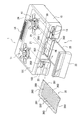
図1および図2に示すように、本発明の実施の形態に係るグリル2は、天板101の上面に単数或いは複数のコンロバーナ11を有するガスコンロ1のコンロ本体10に一体的に構成されており、コンロ本体10がグリル2の外郭を構成している。尚、本明細書では、コンロ本体10を前面(以下、「本体前面」という)103側から見たときの奥行き方向を前後方向、幅方向を左右方向、高さ方向を上下方向という。
As shown in FIGS. 1 and 2, a
グリル2は、肉や魚等の食材を収容する略矩形箱状の加熱庫20と、加熱庫20内の食材を加熱するグリルバーナ21とを備えている。加熱庫20は、本体前面103からコンロ本体10の内部後方へ向かって延設されており、加熱庫20内への食材の出し入れ口となる開口部200は、本体前面103に開設されている。
The
開口部200は、前方からグリル扉22により被閉されている。本体前面103におけるグリル扉22の左右位置には、コンロバーナ11の点火および消火を行うための単数或いは複数のコンロ点消火操作子13と、グリルバーナ21の点火および消火を行うためのグリル点消火操作子23とが配設されている。
The
尚、図示しないが、コンロ本体10の内部には、コンロ点消火操作子13の点火操作や消火操作に連動して開閉するコンロバーナ11用のバルブユニットや、グリル点消火操作子23の点火操作や消火操作に連動して開閉するグリルバーナ21用のバルブユニット、ガス供給元管から上記各バルブユニットへガスを導くガス配管等が組み込まれている。
Although not shown, a valve unit for the
コンロ本体10内における加熱庫20の後方には、グリルバーナ21から加熱庫20内に放出されたガスの燃焼排気(熱気)や食材から発生した油煙、臭気成分等を、天板101に開設された排気口14へ導く排気筒24が配設されている。排気筒24は、加熱庫20の上壁201と後壁204の上端縁との間に設けられた間隙(以下、「排気筒入口」という)240から後上方へ向かって略L字状に延設されており、上端の排気筒出口241を排気口14に下方から臨ませている。
Behind the
グリル扉22の後面には、グリル扉22をコンロ本体10に支持する支持枠25が連結されている。支持枠25は、グリル扉22の後面から加熱庫20の底壁202の上面に沿って、後壁204側へ向かって略水平に延出しており、加熱庫20内に設けられた図示しない係合部に前後摺動可能な状態で係合支持されている。即ち、グリル扉22は、本体前面103から前方へ引き出すようにして開くように構成されている(図1参照)。
A
支持枠25の前後端の上部にはそれぞれ、左右方向に長い略平板状の板枠部251が設けられており、上記板枠部251の上面に、グリルプレート26が取り外し可能な状態で載置されている。従って、グリルプレート26は、グリル扉22を開くことで加熱庫20内から前方へ引き出され、グリル扉22を閉じることで加熱庫20の内部に収容される。尚、上記グリル2では、グリルプレート26に代えて、焼き網を支持枠25に載置して使用することもできる。
A substantially flat
板枠部251の左右方向の中央には、左右方向に延在する上方へ凸の起立片250が形成されている。一方、グリルプレート26の前後の側端中央部には、起立片250と左右幅が略同一の切欠260が形成されており、切欠260に起立片250を嵌入させることで、グリルプレート26が板枠部251の上面に位置決め状態で支持される。従って、この状態でグリル扉22を閉じれば、グリルプレート26が加熱庫20内の定位置に収容される。
An upright protruding
グリルプレート26は、アルミニウム系金属製の板材を平皿状にプレス成形したものであり、表面には、フッ素樹脂加工等の仕上げ塗装が施されている。尚、グリルプレート26は、鋳造や鍛造により成形されたものであってもよい。また、グリルプレート26は、上面26Aに載置される食材に対して適切な熱量を伝導可能な素材であれば、鉄系や銅系、ステンレス系などの金属で形成されたものであってもよいし、セラミック系材料で形成されたものであってもよい。
The
グリルプレート26の左右の側端部261は、外側斜め上方に向かって屈曲形成されている。グリルプレート26の上面26Aには、食材との接触面積が小さくなるよう、左右方向に延在する上方へ凸の細幅のリブ262が前後方向に略等間隔で複数並設されている。上記リブ262の形成部周囲には、食材から滲出した油や焼き汁を回収するための溝部263が形成されている。
The left and right
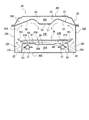
図2および図3に示すように、加熱庫20の内側上部は、加熱庫20の上壁201と、上壁201を下方から覆う集熱板27とからなる二重構造をなしている。集熱板27は、両側縁部が加熱庫20の左右の側壁205に支持固定されており、上壁201との間に、排気筒入口240を通じて排気筒24に繋がる排気通路20Cを画成している。
As shown in FIGS. 2 and 3, the inner upper portion of the
集熱板27は、鉄系金属製の板材を前方視略M字状に折曲形成したものであり、表面には、セラミック塗装や琺瑯等の仕上げ塗装が施されている。尚、集熱板27は、プレート上面26Aの食材に対して適切な熱量を輻射可能な素材であれば、銅系やアルミニウム系、ステンレス系などの金属で形成されたものであってもよい。
The
集熱板27は、加熱庫20の左右方向の中央、即ち、縦中心線上に配設される下向きに凸の前方視略逆台形状の膨出部51と、側壁205から膨出部51の外側端縁へ向かって斜め上方に延出する傾斜部52とを備えている。これら膨出部51および傾斜部52は、何れも集熱板27の前端から後端に亘って形成されている。従って、加熱庫20内の側壁205に沿って上昇する熱気は、上記傾斜部52の下面に沿って膨出部51の周辺に導かれ、さらに膨出部51の下面に沿って下方、即ち、プレート上面26A側へ導かれる。このように、加熱庫20内を外側から上方を回って中央下方へ流れる熱気(対流熱)によってグリルプレート26上の食材が上方から加熱される。
The
膨出部51の前後方向の中央よりも前寄りの位置、および、後寄りの位置にはそれぞれ、グリルプレート26の上方の空間20Eと排気通路20Cとを連通する複数の熱気導出孔53が開設されている(図2参照)。また、集熱板27は、後端が後壁204の上端縁に沿って当接した状態で設けられており、上記プレート上方の空間20Eと排気筒入口240とを分離している。後壁204は、プレート上方の空間20Eの熱気が加熱庫20内の後方から排気筒入口204へ直接流出しないよう閉塞形成されている。即ち、後壁204には、空気の流通可能な孔は設けられておらず、プレート上方の空間20Eは、熱気導出孔53から排気通路20Cを通じて排気筒入口204に繋がっている。
A plurality of hot air lead-out
従って、加熱庫20内の側壁205に沿ってプレート上方の空間20Eへ導かれる熱気や食材から発生した油煙、臭気成分は、加熱庫20の内側上部の中央へ向かって導かれ、熱気導出孔53から排気通路20Cに導出された後、排気通路20Cを通って排気筒入口240へ導かれ、さらに排気筒24を通って排気筒出口241からコンロ本体10の外部に排出される。また、集熱板27の前寄りの位置に設けられた熱気導出孔53から排気通路20Cへ導出された熱気中の熱は、排気通路20Cを流れる間に集熱板27によって回収され、グリルプレート26の上面側へ向けて輻射される。このように、グリルプレート26上の食材は、集熱板27からの輻射熱によっても加熱される。
Therefore, the hot air guided to the
グリルバーナ21は、二つの樋状体を上下に重ね合わせて形成された直管状のバーナであり、グリルプレート26の下方の空間(以下、「バーナ収容部」という)20Aにおける加熱庫20の縦中心線を挟んで左右対称位置にそれぞれ配設され、加熱庫20の後壁204から前方へ向かって略水平に延出している。
The
炎孔210は、グリルバーナ21の外側端面に沿って設けられており(図3参照)、グリルバーナ21に供給されたガスを外側方(側壁205側)へ向けて略水平に噴出させるように構成されている。尚、図示しないが、各グリルバーナ21の炎孔210の近傍にはそれぞれ、点火プラグが配設されており、グリル点消火操作子23の点火操作に連動して上記各点火プラグから特定の炎孔210の周辺で火花放電させ、炎孔210から噴出されるガスを着火させる。
The flame holes 210 are provided along the outer end surface of the grill burner 21 (see FIG. 3), and are configured to eject the gas supplied to the
グリルバーナ21は、上方から前方視略コ字状のバーナカバー28で覆われており、グリルプレート26の配設部とグリルバーナ21の配設部とを分離している。グリルプレート26は、バーナカバー28の上板61の上方に所定の間隔20Bを存して配設される。
The
バーナカバー28の側板62には、グリルバーナ21の炎孔210に対向してガス導出口63が開設されている。上記側板62の外側には、プレート上方の空間20Eに繋がる空間20Fが画成されており(図3参照)、バーナ収容部20Aにてグリルバーナ21から放出された熱気は、ガス導出口63を通って上記カバー側方の空間20Fに導出される。そしてさらに、グリルプレート26の側端部261の外側を通り、側壁205に沿って上昇する。これにより、グリルプレート26が側端部261側から加熱され、グリルプレート26からの伝導熱によってグリルプレート26上の食材が下方から加熱される。
A
底壁202における左右方向の中央には、コンロ本体10の内部空間とバーナ収容部20Aとを連通する複数の空気取込口280が開設されており、グリルバーナ21を点火した際のドラフト作用によって、加熱庫20外部の空気がグリルバーナ21の燃焼用の二次空気として空気取込口280からバーナ収容部20Aに導入される。
In the center of the
上記グリル2によれば、食材の下面側がグリルプレート26からの伝導熱によって加熱される一方、食材の上面側がグリルバーナ21から放出された熱気の対流熱によって加熱されるから、食材の厚みが異なっても、上面側のみが過剰に熱せられるのを抑制できる。よって、食材の上下面で焼き加減にばらつきが生じ難く、安定した加熱性能を発揮できる。
According to the
しかも、このものでは、グリルバーナ21から放出される熱気がグリルプレート26の左右の側端部261を加熱しつつ、対流熱としてグリルプレート26上へ導かれるから、グリルプレート26の下面側に設けられたグリルバーナ21のみによって食材を上下両面から適切に加熱できる。よって、その分、ガスの消費量を低減することができ、省エネ性が向上する。また、このような構成とすることで、加熱庫20内の上部に、食材を上方から加熱するためのバーナを別途設ける必要がないから、グリル2全体の部品点数や組立工数を削減することも可能である。よって、製造コストを低廉できる。
Moreover, in this structure, the hot air emitted from the
また、集熱板27の左右方向の中央部に下方へ凸の膨出部51を設け、且つ、膨出部51に熱気導出孔53を設けたことで、グリルバーナ21から放出された熱気の対流熱がグリルプレート26上へより集中的に導かれるから、食材を対流熱によってより適切且つ効率良く加熱することができる。よって、一層安定した加熱性能を発揮できるし、省エネ性も一層向上する。
Further, by providing the downwardly convex bulging
さらに、後壁204を閉塞形成したことで、グリルバーナ21から放出された熱気の対流熱がグリルプレート26上へより集中的に導かれるから、食材を対流熱によってより適切且つ効率良く加熱することができる。よって、一層安定した加熱性能を発揮できるし、省エネ性も一層向上する。また、グリルバーナ21から放出された熱気が食材の上面側に流れないで加熱庫20の後壁204側から外部へ直接排出されるのを防止できるから、ガスの消費量を一層低減できる。よって、省エネ性が一層向上する。
Further, since the
また、集熱板27の前寄りの位置および後寄りの位置に熱気導出孔53を設け、膨出部51の前後方向の中央に比較的広い非開口面を確保したことで、プレート上方の空間20Eへ導かれた熱気が、膨出部51に沿ってグリルプレート26上へより確実に導かれるから、食材を対流熱によってより適切且つ効率良く加熱することができる。よって、一層安定した加熱性能を発揮できるし、省エネ性も一層向上する。
Further, the hot air outlet holes 53 are provided at the front and rear positions of the
また、このものでは、集熱板27の前寄りの位置に設けられた熱気導出孔53から排気通路20Cに導出された熱気中の熱が、排気通路20Cを流れる間に、集熱板27によって回収され、グリルプレート26の上面側へ向けて輻射されるから、グリルプレート26上の食材を対流熱および輻射熱によってより適切且つ効率良く加熱することができる。よって、一層安定した加熱性能を発揮できるし、省エネ性も一層向上する。
Further, in this configuration, the heat in the hot air led to the
しかも、このものでは、グリルプレート26を熱伝導性の高いアルミニウム系材料で形成したことで、冷凍の食材を加熱調理する場合や寒冷期、使用開始初期など、加熱庫20内やグリルプレート26の温度が低い条件下においても、グリルバーナ21から放出された熱気中の熱がグリルプレート26を介して食材へ速やかに伝達されるから、食材を伝導熱によってより適切且つ効率良く加熱することができる。よって、一層安定した加熱性能を発揮できるし、省エネ性も一層向上する。また、グリルプレート26を軽量なアルミニウム系材料で形成したことで、清掃時や調理時に取り扱い易いから、清掃性および調理時の使い勝手も向上する。
Moreover, in this one, since the
さらに、このものでは、グリルバーナ21をグリルプレート26の下方に配設したことで、既述従来のグリルのように加熱庫の左右の側壁にそれぞれバーナを配したものより加熱庫20およびグリルプレート26の横幅を大きく設定することができるから、その分、調理可能な食材の種類も多くなり、汎用性が向上する。また、油が比較的付着し易い加熱庫20の内側上部から両側部に至る範囲の構造を簡素化することができるから、清掃性も向上する。しかも、グリルバーナ21をバーナカバー28で上方から覆ったことで、グリルプレート26上から漏下した油や焼き汁がグリルバーナ21に直接付着するのを防止できるから、清掃性が一層向上する。
Further, in this one, since the
図4に示すグリル2Aでは、集熱板27が、加熱庫20の上壁201に対向する上板271と、側壁205に対向する側板275とで構成されており、側板275は、上板271の両側縁部から側壁205と略平行に、グリルプレート26の側端部261の側方位置まで延設されている。
In the
また、加熱庫20の左右の側壁205の内側面にはそれぞれ、前後方向に長いリブ状のレール部31が上下に複数列(ここでは、二列)形成されており、集熱板27は、左右の側板275の下縁部がそれぞれレール部31の上面に当接し、前後方向に摺動可能な状態で下方から支持されている。
Further, a plurality of rows (here, two rows) of rib-shaped
このものでは、グリルバーナ21からカバー側方の空間20Fに放出された熱気が、集熱板27の側板275の内側面に沿ってプレート上方の空間20Eへ導かれるから、熱気中の熱が側壁205や上壁201を伝って外部に放出され難い。しかも、熱気中の熱は、側板275の内側面に沿ってプレート上方の空間20Eへ導かれる間に集熱板27によって回収されるから、集熱板27からの輻射熱によってグリルプレート26上の食材をより適切且つ効率良く加熱することができる。よって、一層安定した加熱性能を発揮できるし、省エネ性も一層向上する。
In this structure, the hot air released from the
また、熱気中の熱が加熱庫20の外部に伝わり難いことで、コンロ本体10の内部に組み込まれたバルブユニットや制御回路など、他の構成部品に対する熱的負荷を軽減できるから、過熱による機器の動作不良や故障、変形などの不具合も防止できる。
In addition, since the heat in the hot air is difficult to be transferred to the outside of the
さらに、集熱板27は、側壁205の内側面に設けられたレール部31の上面に前後摺動可能な状態で支持されているから、グリル扉22を開いた状態で開口部200の前方へ引き出せば、加熱庫20内から取り外すことができる。よって、清掃性が一層向上する。
Further, since the
また、側板275の下縁部を下列側のレール部31に支持させ、加熱庫20内における集熱板27の取り付け高さを低く設定すれば、上板271とグリルプレート26との離間距離を小さくすることができるから、比較的厚みの小さい食材であっても、集熱板27から食材への輻射熱量をより適切に保つことができるし、対流熱も確実に食材に到達する。よって、一層安定した加熱性能を発揮できる。
Further, if the lower edge of the
図5に示すグリル2Bでは、グリルバーナ21の外側端面に加え、上面にも炎孔210が設けられており、グリルバーナ21に供給されたガスを外側方および上方(グリルプレート26の下面26B側)へ向けて噴出させるように構成されている。また、バーナカバー28の上板61には、グリルバーナ21の上面側の炎孔210に対向してガス導出口64が開設されている。
In the
このものでは、上記上面側の炎孔210から放出された熱気は、上板61側のガス導出口64を通ってグリルプレート26の下面26B側の空間20Bに導出される。そしてさらに、グリルバーナ21の外側端面側の炎孔210からカバー側方の空間20Fへ導出される熱気のドラフト作用によってグリルプレート26の側端部261の外側、即ち、カバー側方の空間20Fへ導かれる。これにより、グリルプレート26がより確実に加熱されるから、グリルプレート26からの伝導熱によって食材を下面側からより適切に加熱することができる。よって、一層安定した加熱性能を発揮できる。
In this case, the hot air discharged from the flame holes 210 on the upper surface side is led out to the
図6に示すグリル2Cでは、一つの直管状のグリルバーナ21が、バーナ収容部20Aにおける加熱庫20の縦中心線上に配設されている。また、炎孔210は、グリルバーナ21の左右の外側端面に沿って設けられており、グリルバーナ21に供給されたガスを左右外側方へ向けて噴出させるように構成されている。これにより、上記実施の形態と同様、グリルプレート26が側端部261側から加熱され、グリルプレート26からの伝導熱によって食材が下方から加熱される。さらに、グリルプレート26上の食材は、加熱庫20内の外側から上方を回って中央下方へ流れる対流熱によって上方から加熱される。よって、上記実施の形態と同様の作用効果を奏する。
In the grill 2C shown in FIG. 6, one straight-tube-shaped
図7に示すグリル2Dでは、上記グリル2Cと同様、一つの直管状のグリルバーナ21が、バーナ収容部20Aにおける加熱庫20の縦中心線上に配設されている。また、炎孔210は、グリルバーナ21の左右の外側端面に加え、上面にも設けられており、バーナカバー28の上板61には、グリルバーナ21の上面側の炎孔210に対向してガス導出口64が開設されている。これにより、グリルプレート26は、グリルバーナ21から左右外側方および上方に放出された熱気によって下面26Bの略全体が加熱され、グリルプレート26からの伝導熱によって食材をより適切に加熱することができる。よって、一層安定した加熱性能を発揮できる。
In the
図8に示すグリル2Eでは、二つの直管状のグリルバーナ21が、加熱庫20の左右の側壁205におけるグリルプレート26の左右側方位置にそれぞれ配設されている。また、炎孔210は、グリルバーナ21の内側端面に沿って設けられており、グリルバーナ21に供給されたガスを加熱庫20の中央側へ向けて噴出させるように構成されている。これにより、上記実施形態と同様、グリルプレート26が側端部261側から加熱され、グリルプレート26からの伝導熱によって食材が下方から加熱され、さらに加熱庫20内の外側から上方を回って中央下方へ流れる対流熱によって食材が上方から加熱される。よって、上記実施の形態と同様の作用効果を奏する。
In the
図9に示すグリル2Fでは、上記グリル2Eと同様、二つの直管状のグリルバーナ21が、加熱庫20の左右の側壁205におけるグリルプレート26の左右側方位置にそれぞれ配設されている。また、炎孔210は、グリルバーナ21の内側端面に加え、上面にも設けられており、グリルバーナ21から加熱庫20の内側方へ向けて放出された熱気によってグリルプレート26の側端部261が加熱されると共に、グリルバーナ21から上方へ放出された熱気が対流熱としてグリルプレート26上へ導かれる。よって、上記実施の形態と同様の作用効果を奏する。
In the
図10に示すグリル2Gでは、グリルバーナ21の上面および下面に炎孔210が設けられており、グリルバーナ21に供給されたガスを側壁205に沿って上下に噴出させるように構成されている。このものでは、グリルバーナ21から下方へ放出された熱気によってグリルプレート26の側端部261が加熱されると共に、グリルバーナ21から上方へ放出された熱気が対流熱としてグリルプレート26上へ導かれるから、上記実施の形態と同様の作用効果を奏する。
In the
図11に示すグリル2Hでは、二つの直管状のグリルバーナ21が、加熱庫20の左右の側壁205の上方位置に、炎孔210を加熱庫20の中央側斜め下方へ向けた姿勢でそれぞれ配設されており、グリルバーナ21に供給されたガスをプレート上面26Aの側端部261寄りの位置へ向けて噴出させるように構成されている。尚、上記グリルバーナ21は、集熱板27の左右の側縁部に、炎孔210を加熱庫20の中央側斜め下方へ向けた姿勢で設けられたものとしてもよい。
In the
このものでは、グリルバーナ21から放出される熱気がグリルプレート26の左右の側端部261を加熱した後、プレート上面26Aに沿って中央側へ集められ、対流熱としてグリルプレート26の上方へ導かれるから、上記実施の形態と同様の作用効果を奏する。
In this structure, the hot air emitted from the
また、図12に示すグリル2Kのように、上記グリル2Hにおいて、集熱板27が、加熱庫20の縦中心線上に配設される上向きに凹の前方視略台形状の凹部71と、側壁205から凹部71の外側端縁へ向かって斜め下方に延出する傾斜部72とを備えており、上記凹部71に熱気導出孔53が開設されたものとしてもよい。
Further, as in the
このものでは、プレート上面26Aの中央部から上昇する熱気が上記凹部71の下面側中央に集められ、熱気導出孔53を通じて排気通路20Cへ導出されるから、プレート上面26Aの中央上方に安定した上昇流が形成される。これにより、グリルプレート26上の食材を対流熱によってより適切に加熱することができるから、一層安定した加熱性能を発揮できる。
In this structure, the hot air rising from the central portion of the plate
尚、上記実施の形態では、グリルバーナ21から放出された熱気が、グリルプレート26の側端部261の外側を通って側壁205の上方へ流れるように構成されたものを説明したが、グリルバーナ21から放出された熱気が、グリルプレート26の外側全周を通って開口部200や後壁204、側壁205の上方へ流れるように構成されたものとしてもよい。
In the above embodiment, the hot air emitted from the
また、上記実施の形態では、集熱板27の前後方向の中央よりも前寄りの位置および後寄りの位置にそれぞれ熱気導出孔53が設けられたものを説明したが、集熱板27からの輻射熱によって食材を適切に加熱可能で、且つ、プレート上方の空間20Eにて熱気の対流が安定して形成され、プレート上方の空間20Eへ導かれた熱気や食材から発生した油煙等を円滑に排気通路20Cへ導出可能な位置および形状であれば、集熱板27の前後方向の中央よりも前寄りの位置にのみ熱気導出孔53が設けられたものとしてもよいし、集熱板27における膨出部51の前後間の略全域に亘って複数の熱気導出孔53が設けられたものとしてもよい。
Further, in the above-described embodiment, the hot air outlet holes 53 are provided at the positions closer to the front and rear than the center of the
上記のように集熱板27の前後方向の中央より前方位置にのみ熱気導出孔53が設けられたものでは、グリルバーナ21から放出され、集熱板27の下面に達した熱気が、集熱板27の下面に沿って加熱庫20の前方へ導かれた後、熱気導出孔53を通じて排気通路20Cに導出されるから、グリルプレート26の上方を流れる熱気によって食材の上面側をより適切且つ効率良く加熱することができる。よって、一層安定した加熱性能を発揮できるし、省エネ性も一層向上する。
As described above, in the case where the
また、上記実施の形態では、二つの直管状のグリルバーナ21が加熱庫20の縦中心線を挟んで左右対称位置にそれぞれ延設されたものを説明したが、上方視略U字状に形成された一つのグリルバーナであって、その左右両側の直管部が上記グリルバーナ21と同様、加熱庫20の縦中心線を挟んで左右対称位置にそれぞれ延設されたものとしてもよい。
Further, in the above-described embodiment, the description has been given of the two straight
本発明は、キッチンのテーブルに載置して使用されるテーブルコンロや、キッチンのカウンタトップに開設されたコンロ取付孔に落としこみ状態で装着されるビルトインコンロの他、天板101の上面にコンロバーナ11を有しないグリル装置にも適用できる。
INDUSTRIAL APPLICABILITY The present invention is applicable to a table stove used by being placed on a kitchen table, a built-in stove installed in a stove mounting hole provided in a kitchen countertop in a dropped state, and a stove on the top surface of a
2 グリル
20 加熱庫
201 上壁
204 後壁
20C 排気通路
21 グリルバーナ
26 グリルプレート
261 側端部(周端部)
27 集熱板
51 膨出部
53 熱気導出孔
2 grill 20
27
Claims (6)
グリルプレート上に載置された食材を、バーナによって加熱されるグリルプレートからの伝導熱により下方から加熱し、且つ、バーナから放出される熱気の対流熱により上方から加熱する構成とし、
加熱庫の後壁は、前記熱気が加熱庫の後壁側から外部に排出されないよう閉塞形成され、
加熱庫の内側上部は、加熱庫の上壁と前記上壁を下方から覆う集熱板とからなる二重構造をなしており、
集熱板の略中央部に、下方へ凸の膨出部が設けられ、且つ、前記熱気を加熱庫の外部に導出するための熱気導出孔が設けられ、
熱気導出孔は、前記集熱板における前後方向の中央より前方位置および後方位置にそれぞれ設けられ、
前記熱気は、熱気導出孔から前記上壁と前記集熱板との相互間に画成された排気通路を通じて加熱庫の後方へ導かれ、器具外部に排出される構成とした、グリル。 A grill in which a grill plate and a burner are arranged in a heating chamber,
The food placed on the grill plate is heated from below by conduction heat from the grill plate heated by the burner, and is heated from above by convective heat of hot air emitted from the burner ,
The rear wall of the heating chamber is formed so as to be closed so that the hot air is not discharged to the outside from the rear wall side of the heating chamber,
The inner upper part of the heating chamber has a double structure consisting of an upper wall of the heating chamber and a heat collecting plate that covers the upper wall from below,
At a substantially central portion of the heat collecting plate, a downwardly protruding bulging portion is provided, and a hot air outlet hole for leading out the hot air to the outside of the heating chamber is provided,
The hot air lead-out holes are provided at front and rear positions from the center of the heat collecting plate in the front-rear direction,
The grill having a structure in which the hot air is guided to the rear of the heating chamber through an exhaust passage defined between the upper wall and the heat collecting plate from the hot air outlet and is discharged to the outside of the appliance .
前記対流熱は、グリルプレートの周端部外側から中央上方へ向かって流れる構成とした、グリル。 The grill according to claim 1,
The convection heat is configured to flow from the outside of the peripheral end of the grill plate toward the upper center of the grill.
グリルプレートは、周端部がバーナにより加熱される構成とした、グリル。 The grill according to claim 1 or 2,
The grill plate is a grill whose peripheral edge is heated by a burner.
集熱板は、加熱庫の側壁に対向する側板を有し、
前記側板は、加熱庫の上壁に対向する上板から少なくともグリルプレートの側端縁近傍の高さまで延設された、グリル。 The grill according to any one of claims 1 to 3 ,
The heat collecting plate has a side plate facing the side wall of the heating chamber,
The side plate is a grill extending from an upper plate facing the upper wall of the heating chamber to at least a height near a side edge of the grill plate.
バーナは、グリルプレートの下方に配設された、グリル。 The grill according to any one of claims 1 to 4 ,
The burner is a grill arranged below the grill plate.
グリルプレートは、アルミニウム系材料で形成された、グリル。 The grill according to any one of claims 1 to 5 ,
The grill plate is a grill made of aluminum-based material.
Priority Applications (1)
| Application Number | Priority Date | Filing Date | Title |
|---|---|---|---|
| JP2016079364A JP6709665B2 (en) | 2016-04-12 | 2016-04-12 | grill |
Applications Claiming Priority (1)
| Application Number | Priority Date | Filing Date | Title |
|---|---|---|---|
| JP2016079364A JP6709665B2 (en) | 2016-04-12 | 2016-04-12 | grill |
Publications (2)
| Publication Number | Publication Date |
|---|---|
| JP2017189281A JP2017189281A (en) | 2017-10-19 |
| JP6709665B2 true JP6709665B2 (en) | 2020-06-17 |
Family
ID=60085434
Family Applications (1)
| Application Number | Title | Priority Date | Filing Date |
|---|---|---|---|
| JP2016079364A Active JP6709665B2 (en) | 2016-04-12 | 2016-04-12 | grill |
Country Status (1)
| Country | Link |
|---|---|
| JP (1) | JP6709665B2 (en) |
Families Citing this family (3)
| Publication number | Priority date | Publication date | Assignee | Title |
|---|---|---|---|---|
| JP7048302B2 (en) * | 2017-12-22 | 2022-04-05 | リンナイ株式会社 | Cooker |
| JP7265937B2 (en) * | 2019-06-13 | 2023-04-27 | リンナイ株式会社 | heating cooker |
| JP7526612B2 (en) | 2020-08-17 | 2024-08-01 | リンナイ株式会社 | Grill burners and cooking appliances |
Family Cites Families (4)
| Publication number | Priority date | Publication date | Assignee | Title |
|---|---|---|---|---|
| JPS5819212A (en) * | 1981-07-28 | 1983-02-04 | 松下電器産業株式会社 | Electric cooker |
| JP3018527B2 (en) * | 1991-03-13 | 2000-03-13 | 松下電器産業株式会社 | Gas cooker |
| JP2000232945A (en) * | 1999-02-15 | 2000-08-29 | Paloma Ind Ltd | Both-side roasting grill |
| JP6021849B2 (en) * | 2014-04-08 | 2016-11-09 | リンナイ株式会社 | Cooker |
-
2016
- 2016-04-12 JP JP2016079364A patent/JP6709665B2/en active Active
Also Published As
| Publication number | Publication date |
|---|---|
| JP2017189281A (en) | 2017-10-19 |
Similar Documents
| Publication | Publication Date | Title |
|---|---|---|
| EP2663216B1 (en) | Outdoor cooker and lid therefor | |
| JP5973488B2 (en) | grill | |
| JP6626312B2 (en) | grill | |
| JP2017189281A (en) | Grille | |
| JP2018023448A (en) | grill | |
| JP2014212840A (en) | Cooking container | |
| JP6796397B2 (en) | grill | |
| JP4929259B2 (en) | grill | |
| JP6594751B2 (en) | grill | |
| JP7137879B2 (en) | heating cooker | |
| JP7265940B2 (en) | heating cooker | |
| JP6857507B2 (en) | Cooker | |
| JP7048302B2 (en) | Cooker | |
| JP7048309B2 (en) | Cookware and cookers | |
| KR200459206Y1 (en) | Grill of gas range | |
| JP6715509B2 (en) | Stove with grill | |
| JP2018019942A (en) | grill | |
| JP6770883B2 (en) | grill | |
| JP6850594B2 (en) | grill | |
| JP6807198B2 (en) | grill | |
| JP2017060595A (en) | grill | |
| JP6478797B2 (en) | grill | |
| JP6465702B2 (en) | Cooker | |
| JP2017136159A (en) | Gas Grill | |
| JP6719221B2 (en) | Gas grill |
Legal Events
| Date | Code | Title | Description |
|---|---|---|---|
| A621 | Written request for application examination |
Free format text: JAPANESE INTERMEDIATE CODE: A621 Effective date: 20181220 |
|
| A131 | Notification of reasons for refusal |
Free format text: JAPANESE INTERMEDIATE CODE: A131 Effective date: 20191119 |
|
| A977 | Report on retrieval |
Free format text: JAPANESE INTERMEDIATE CODE: A971007 Effective date: 20191120 |
|
| A521 | Request for written amendment filed |
Free format text: JAPANESE INTERMEDIATE CODE: A523 Effective date: 20191225 |
|
| TRDD | Decision of grant or rejection written | ||
| A01 | Written decision to grant a patent or to grant a registration (utility model) |
Free format text: JAPANESE INTERMEDIATE CODE: A01 Effective date: 20200428 |
|
| A61 | First payment of annual fees (during grant procedure) |
Free format text: JAPANESE INTERMEDIATE CODE: A61 Effective date: 20200525 |
|
| R150 | Certificate of patent or registration of utility model |
Ref document number: 6709665 Country of ref document: JP Free format text: JAPANESE INTERMEDIATE CODE: R150 |
|
| R250 | Receipt of annual fees |
Free format text: JAPANESE INTERMEDIATE CODE: R250 |
|
| R250 | Receipt of annual fees |
Free format text: JAPANESE INTERMEDIATE CODE: R250 |
|
| R250 | Receipt of annual fees |
Free format text: JAPANESE INTERMEDIATE CODE: R250 |
|
| R250 | Receipt of annual fees |
Free format text: JAPANESE INTERMEDIATE CODE: R250 |