JP6673260B2 - Gear member and method of manufacturing the same - Google Patents
Gear member and method of manufacturing the same Download PDFInfo
- Publication number
- JP6673260B2 JP6673260B2 JP2017033252A JP2017033252A JP6673260B2 JP 6673260 B2 JP6673260 B2 JP 6673260B2 JP 2017033252 A JP2017033252 A JP 2017033252A JP 2017033252 A JP2017033252 A JP 2017033252A JP 6673260 B2 JP6673260 B2 JP 6673260B2
- Authority
- JP
- Japan
- Prior art keywords
- diameter
- bearing holding
- gear
- holding portion
- internal gear
- Prior art date
- Legal status (The legal status is an assumption and is not a legal conclusion. Google has not performed a legal analysis and makes no representation as to the accuracy of the status listed.)
- Active
Links
Images


Classifications
-
- F—MECHANICAL ENGINEERING; LIGHTING; HEATING; WEAPONS; BLASTING
- F16—ENGINEERING ELEMENTS AND UNITS; GENERAL MEASURES FOR PRODUCING AND MAINTAINING EFFECTIVE FUNCTIONING OF MACHINES OR INSTALLATIONS; THERMAL INSULATION IN GENERAL
- F16H—GEARING
- F16H55/00—Elements with teeth or friction surfaces for conveying motion; Worms, pulleys or sheaves for gearing mechanisms
- F16H55/02—Toothed members; Worms
- F16H55/08—Profiling
- F16H55/0873—Profiling for improving axial engagement, e.g. a chamfer at the end of the tooth flank
-
- B—PERFORMING OPERATIONS; TRANSPORTING
- B23—MACHINE TOOLS; METAL-WORKING NOT OTHERWISE PROVIDED FOR
- B23F—MAKING GEARS OR TOOTHED RACKS
- B23F5/00—Making straight gear teeth involving moving a tool relatively to a workpiece with a rolling-off or an enveloping motion with respect to the gear teeth to be made
- B23F5/12—Making straight gear teeth involving moving a tool relatively to a workpiece with a rolling-off or an enveloping motion with respect to the gear teeth to be made by planing or slotting
- B23F5/16—Making straight gear teeth involving moving a tool relatively to a workpiece with a rolling-off or an enveloping motion with respect to the gear teeth to be made by planing or slotting the tool having a shape similar to that of a spur wheel or part thereof
- B23F5/163—Making straight gear teeth involving moving a tool relatively to a workpiece with a rolling-off or an enveloping motion with respect to the gear teeth to be made by planing or slotting the tool having a shape similar to that of a spur wheel or part thereof the tool and workpiece being in crossed axis arrangement, e.g. skiving, i.e. "Waelzschaelen"
-
- F—MECHANICAL ENGINEERING; LIGHTING; HEATING; WEAPONS; BLASTING
- F16—ENGINEERING ELEMENTS AND UNITS; GENERAL MEASURES FOR PRODUCING AND MAINTAINING EFFECTIVE FUNCTIONING OF MACHINES OR INSTALLATIONS; THERMAL INSULATION IN GENERAL
- F16H—GEARING
- F16H57/00—General details of gearing
- F16H57/04—Features relating to lubrication or cooling or heating
- F16H57/048—Type of gearings to be lubricated, cooled or heated
- F16H57/0482—Gearings with gears having orbital motion
-
- F—MECHANICAL ENGINEERING; LIGHTING; HEATING; WEAPONS; BLASTING
- F16—ENGINEERING ELEMENTS AND UNITS; GENERAL MEASURES FOR PRODUCING AND MAINTAINING EFFECTIVE FUNCTIONING OF MACHINES OR INSTALLATIONS; THERMAL INSULATION IN GENERAL
- F16H—GEARING
- F16H57/00—General details of gearing
- F16H57/08—General details of gearing of gearings with members having orbital motion
- F16H57/082—Planet carriers
-
- F—MECHANICAL ENGINEERING; LIGHTING; HEATING; WEAPONS; BLASTING
- F16—ENGINEERING ELEMENTS AND UNITS; GENERAL MEASURES FOR PRODUCING AND MAINTAINING EFFECTIVE FUNCTIONING OF MACHINES OR INSTALLATIONS; THERMAL INSULATION IN GENERAL
- F16H—GEARING
- F16H1/00—Toothed gearings for conveying rotary motion
- F16H1/28—Toothed gearings for conveying rotary motion with gears having orbital motion
-
- F—MECHANICAL ENGINEERING; LIGHTING; HEATING; WEAPONS; BLASTING
- F16—ENGINEERING ELEMENTS AND UNITS; GENERAL MEASURES FOR PRODUCING AND MAINTAINING EFFECTIVE FUNCTIONING OF MACHINES OR INSTALLATIONS; THERMAL INSULATION IN GENERAL
- F16H—GEARING
- F16H57/00—General details of gearing
- F16H57/08—General details of gearing of gearings with members having orbital motion
- F16H2057/085—Bearings for orbital gears
Description
本発明は内歯歯車を有する歯車部材に係り、特に、軸方向の一端部に設けられる軸受保持部を小径化できるようにする技術に関するものである。
BACKGROUND OF THE
円筒形状を成しているとともに、内周面における軸方向の一端部に内径が拡大された段差状の軸受保持部が設けられ、軸方向においてその軸受保持部と重複することなく内歯歯車が設けられた歯車部材が知られている。特許文献1に記載の出力部材Oはその一例で、軸方向の両端部の内周側にボールベアリングが配設され、軸心まわりに回転可能に支持されているとともに、内歯歯車として遊星歯車装置のリングギヤRが設けられている。このような歯車部材の内歯歯車の創成技術としては、一般にブローチ加工(特許文献2参照)やシェーパ加工(特許文献3参照)が広く知られている。また、近年、スカイビング加工を用いた歯創成技術も提案されている(特許文献4参照)。
While having a cylindrical shape, a stepped bearing holding portion having an enlarged inner diameter is provided at one end in the axial direction on the inner peripheral surface, and the internal gear can be rotated without overlapping the bearing holding portion in the axial direction. Provided gear members are known. The output member O described in
ところで、上記歯車部材のうち内歯歯車が設けられる部分には内周側へ突き出すように小径円筒部が設けられ、その小径円筒部の全長に亘ってブローチ加工やシェーパ加工等により内歯歯車が形成される。このため、軸受保持部は、その内歯歯車の歯底径よりも大径の部分に設けられることになり、軸受や歯車部材を小径化(ダウンサイジング)する際の妨げとなっていた。軸受保持部は、軸方向のスラスト荷重を受け止めるため、径方向に所定の段差を有するとともに、軸方向において内歯歯車から所定の距離を隔てて設けられる。図8の歯車部材100は、このような従来の歯車部材の一例で、内歯歯車であるリングギヤ102の両側に、リングギヤ102の歯底径よりも大径の内周面104、106を備えており、その内周面104、106の端部に一対の軸受保持部108、110が設けられている。図8は、歯車部材100の中心線O1よりも上半分を示した断面図である。
By the way, a small-diameter cylindrical portion is provided in a portion of the gear member where the internal gear is provided so as to protrude toward the inner peripheral side, and the internal gear is formed by broaching, shaper processing, or the like over the entire length of the small-diameter cylindrical portion. It is formed. For this reason, the bearing holding portion is provided at a portion having a larger diameter than the root diameter of the internal gear, which hinders downsizing of the bearing and the gear member. The bearing holding portion has a predetermined step in the radial direction to receive a thrust load in the axial direction, and is provided at a predetermined distance from the internal gear in the axial direction. The
これに対し、図9の歯車部材120のように、リングギヤ102から環状溝122を隔てて小径部124を設け、その小径部124の端部に一方の軸受保持部108を設けるようにすれば、軸受保持部108の小径化を図ることができる。シェーパ加工の場合、小径部124と反対側(図9における右側)からピニオンカッターを挿入して軸方向へ往復移動させることで、環状溝122から切屑を排出しつつリングギヤ102を創成することができる。しかしながら、リングギヤ102の創成に先立って中ぐり加工等により環状溝122を設ける必要があり、加工工数が増えて製造コストが高くなる。
On the other hand, as in the case of the
本発明は以上の事情を背景として為されたもので、その目的とするところは、内歯歯車および軸受保持部を有する歯車部材の加工工数を増加させることなく軸受保持部を小径化できるようにすることにある。 The present invention has been made in view of the above circumstances, and an object thereof is to reduce the diameter of the bearing holding portion without increasing the number of processing steps of the gear member having the internal gear and the bearing holding portion. Is to do.
かかる目的を達成するために、第1発明は、円筒形状を成しているとともに、内周面における軸方向の一端部に内径が拡大された段差状の軸受保持部が設けられ、軸方向においてその軸受保持部と重複することなく内歯歯車が設けられた歯車部材の製造方法において、(a) 前記内歯歯車の歯幅領域に、その内歯歯車の歯先径に対応する内径の小径円筒部を有するとともに、その小径円筒部が前記軸受保持部に達するように前記歯幅領域から前記一端部側へ延長して設けられた円筒状素材を用意する素材準備工程と、(b) 前記円筒状素材の前記一端部と反対の他端部側からスカイビングカッターを挿入し、スカイビング加工により前記小径円筒部の前記歯幅領域に前記内歯歯車を形成するとともに、その歯幅領域を越えて前記軸受保持部に達する前の途中位置で、歯溝の深さが前記軸受保持部側へ向かうに従って徐々に浅くなる徐変部を設けるようにそのスカイビング加工を終了する歯創成工程と、を有することを特徴とする。 In order to achieve this object, the first invention has a cylindrical shape, and a step-shaped bearing holding portion having an enlarged inner diameter is provided at one end in the axial direction on the inner peripheral surface, and is provided in the axial direction. In the method of manufacturing a gear member provided with an internal gear without overlapping with the bearing holding portion, (a) in the tooth width region of the internal gear, a small diameter of an inner diameter corresponding to a tip diameter of the internal gear. A material preparing step of preparing a cylindrical material having a cylindrical portion and extending from the face width region to the one end side so that the small-diameter cylindrical portion reaches the bearing holding portion; A skiving cutter is inserted from the other end side opposite to the one end of the cylindrical material, and the internal gear is formed in the tooth width region of the small-diameter cylindrical portion by skiving, and the tooth width region is formed. To reach the bearing holder In the middle position, the tooth groove of depth and having a teeth creating step for ending the skiving so as to provide a gradual change portion gradually becomes shallower toward to the bearing holding portion.
第2発明は、円筒形状を成しているとともに、内周面における軸方向の一端部に内径が拡大された段差状の軸受保持部が設けられ、軸方向においてその軸受保持部と重複することなく内歯歯車が設けられた歯車部材において、(a) 前記内歯歯車の歯幅領域に、その内歯歯車の歯先径に対応する内径の小径部を有するとともに、その小径部は前記軸受保持部に達するように前記一端部側へ延長して設けられている一方、(b) 前記小径部のうち軸方向において前記一端部と反対の他端部側から、前記歯幅領域を越えて前記軸受保持部に達する前の途中位置まで、前記内歯歯車が設けられており、(c) 前記内歯歯車の前記軸受保持部側の端末部分には、歯溝の深さがその軸受保持部側へ向かうに従って徐々に浅くなる徐変部が設けられていることを特徴とする。 In the second invention, a step-shaped bearing holding portion having an enlarged inner diameter is provided at one end in the axial direction on the inner peripheral surface while having a cylindrical shape, and overlaps with the bearing holding portion in the axial direction. In the gear member provided with the internal gear, there is provided (a) a small-diameter portion having an inner diameter corresponding to a tip diameter of the internal gear in a tooth width region of the internal gear, and the small-diameter portion is the bearing. (B) of the small diameter portion, from the other end side opposite to the one end portion in the axial direction, so as to reach the holding portion, and beyond the face width region. The internal gear is provided up to a halfway position before reaching the bearing holding portion, and (c) the end portion of the internal gear on the bearing holding portion side has a tooth groove having a depth corresponding to the bearing holding. characterized in that the gradually changing portion gradually becomes shallower toward the parts side is provided To.
第1発明の歯車部材の製造方法によれば、小径円筒部が内歯歯車の歯幅領域から軸受保持部に達するように設けられた円筒状素材に対し、他端部側からスカイビングカッターを挿入してスカイビング加工により小径円筒部の歯幅領域に内歯歯車を形成するとともに、軸受保持部に達する前の途中位置でそのスカイビング加工を終了することにより、軸受保持部との間に所定の肉厚(軸方向長さ)を残した状態で内歯歯車を創成できる。この場合、軸受保持部は、内歯歯車の歯先径に対応する内径の小径円筒部から径方向に所定の段差を有するように設けられるため、その軸受保持部を小径に構成することが可能で、軸受の小径化等でコストダウンを図ることができる。また、シェーパ加工で内歯歯車を創成する場合のように、内歯歯車に隣接する位置(工具の抜け出し側)に環状溝を設ける必要がないため、加工工数が低減されるとともに、内歯歯車の端末部分ではスカイビング加工の特性で歯溝の深さが徐々に小さくなるように切り上がる徐変部が設けられるため環状溝よりも強度的に有利である。 According to the manufacturing method of the gear member of the first invention, the skiving cutter is provided from the other end side to the cylindrical material provided so that the small-diameter cylindrical portion reaches the bearing holding portion from the tooth width region of the internal gear. By inserting and skiving to form an internal gear in the tooth width region of the small diameter cylindrical part, and by ending the skiving at an intermediate position before reaching the bearing holding part, between the bearing holding part An internal gear can be created with a predetermined thickness (length in the axial direction) left. In this case, since the bearing holding portion is provided so as to have a predetermined step in the radial direction from the small-diameter cylindrical portion having an inner diameter corresponding to the tip diameter of the internal gear, the bearing holding portion can be configured to have a small diameter. Thus, cost can be reduced by reducing the diameter of the bearing. Further, unlike the case where an internal gear is created by shaper processing, there is no need to provide an annular groove at a position adjacent to the internal gear (the side where the tool comes out), so that the number of processing steps is reduced and the internal gear is reduced. In the terminal portion, a gradually changing portion that is cut up so as to gradually reduce the depth of the tooth groove due to the characteristics of the skiving process is provided , which is more advantageous in strength than the annular groove.
第2発明の歯車部材は、内歯歯車の歯幅領域から軸受保持部に達するように小径部が設けられており、その小径部の他端部側から歯幅領域を越えて軸受保持部に達する前の途中位置まで内歯歯車が設けられているとともに、その内歯歯車の端末部分には歯溝の深さが徐々に浅くなる徐変部が設けられている。このような歯車部材は、第1発明の製造方法を用いて好適に製造されるもので、第1発明と同様の効果が得られる。すなわち、軸受保持部は小径部から径方向に所定の段差を有するように設けられるため、その軸受保持部を小径に構成することが可能で、軸受の小径化等でコストダウンを図ることができる。また、内歯歯車に隣接する位置に環状溝が存在しないため、加工工数が低減されるとともに、内歯歯車の端末部分は歯溝の深さが徐々に小さくなる徐変部とされているため環状溝よりも強度的に有利である。 In the gear member of the second invention, a small-diameter portion is provided to reach the bearing holding portion from the tooth width region of the internal gear, and the other end portion of the small-diameter portion extends beyond the tooth width region to the bearing holding portion. The internal gear is provided up to an intermediate position before reaching, and a terminal portion of the internal gear is provided with a gradually changing portion in which the depth of the tooth groove gradually decreases . Such a gear member is suitably manufactured using the manufacturing method of the first invention, and the same effects as those of the first invention are obtained. That is, since the bearing holding portion is provided so as to have a predetermined step in the radial direction from the small-diameter portion, the bearing holding portion can be configured to have a small diameter, and the cost can be reduced by reducing the diameter of the bearing. . In addition, since there is no annular groove at a position adjacent to the internal gear, the number of processing steps is reduced, and the terminal portion of the internal gear is a gradually changing portion in which the depth of the tooth groove gradually decreases. It is more advantageous in strength than the annular groove.
歯車部材は、少なくとも内周面における軸方向の一端部に軸受保持部が設けられるが、内周面における軸方向の両端部に軸受保持部が設けられても良い。その場合に、例えば内歯歯車の軸方向の両側に歯溝の底が徐々に浅くなる徐変部が設けられるようにスカイビング加工で内歯歯車を加工することにより、両端部の軸受保持部を共に小径に構成することができるが、一端部の軸受保持部だけ小径に構成し、他端部の軸受保持部については内歯歯車の歯底径よりも大径の内周面部分に設けられても良い。また、他端部の軸受保持部については、歯車部材が外周側から軸受によって支持されるように設けることも可能である。 In the gear member, the bearing holding portions are provided at least at one end in the axial direction on the inner peripheral surface, but the bearing holding portions may be provided at both ends in the axial direction on the inner peripheral surface. In this case, for example, by processing the internal gear by skiving so that a gradually changing portion in which the bottom of the tooth groove gradually becomes shallow is provided on both axial sides of the internal gear, the bearing holding portions at both ends are provided. Can be configured to have a small diameter, but only the bearing holding portion at one end is configured to have a small diameter, and the bearing holding portion at the other end is provided on the inner peripheral surface portion having a diameter larger than the root diameter of the internal gear. You may be. Further, the bearing holding portion at the other end can be provided so that the gear member is supported by the bearing from the outer peripheral side.
歯車部材は、内周面に内歯歯車が設けられるが、必要に応じて外周面に外歯歯車が設けられても良い。内歯歯車は、例えば車両用動力伝達装置に用いられる遊星歯車装置のリングギヤであるが、車両以外の動力伝達経路に用いられる遊星歯車装置のリングギヤでも良いし、遊星歯車装置のリングギヤ以外の内歯歯車が設けられても良い。この内歯歯車は、歯すじが中心線と平行な平歯車でも良いし、歯すじが中心線まわりに捩じれているはすば歯車でも良い。 The gear member is provided with the internal gear on the inner peripheral surface, but may be provided with the external gear on the outer peripheral surface as needed. The internal gear is, for example, a ring gear of a planetary gear device used for a vehicle power transmission device, but may be a ring gear of a planetary gear device used for a power transmission path other than a vehicle, or may be an internal gear other than the ring gear of the planetary gear device. A gear may be provided. The internal gear may be a spur gear having a tooth line parallel to the center line or a helical gear having the tooth line twisted around the center line.
円筒状素材の小径円筒部は、例えば内歯歯車の歯先径と等しい内径寸法で設けられ、スカイビングカッターによって内歯歯車の歯溝部分が切削加工されることによって内歯歯車が創成されるが、歯先径よりも小さい内径寸法で歯車被加工部を設け、内歯歯車の噛合歯の歯先を含めてスカイビングカッターにより噛合歯を総形切削することも可能である。小径円筒部は、例えば円筒状素材の一端部まで設けられ、スカイビングカッターによる内歯歯車の創成の前または後にその一端部に軸受保持部が設けられるが、小径円筒部を設ける前に軸受保持部を形成することも可能で、その場合は、その軸受保持部に達するように小径円筒部を設ければ良い。 The small-diameter cylindrical portion of the cylindrical material is provided, for example, with an inner diameter dimension equal to the tip diameter of the internal gear, and the internal gear is created by cutting the tooth groove portion of the internal gear with a skiving cutter. However, it is also possible to provide a gear processing portion with an inner diameter smaller than the tooth tip diameter, and to form the meshing teeth by skiving cutter including the tooth tips of the meshing teeth of the internal gear. The small diameter cylindrical portion is provided, for example, to one end of the cylindrical material, and a bearing holding portion is provided at one end thereof before or after creation of the internal gear by the skiving cutter, but before the small diameter cylindrical portion is provided, the bearing holding portion is provided. Alternatively, a small-diameter cylindrical portion may be provided so as to reach the bearing holding portion.
第2発明の歯車部材は、第1発明の製造方法によって好適に製造され、小径部は第1発明の小径円筒部に対応する。なお、第2発明の歯車部材を第1発明の製造方法以外の方法で製造することもできる。例えば、第1発明では、円筒状素材の他端部側からスカイビングカッターを挿入して内歯歯車を切削加工しているが、円筒状部材の一端部側からスカイビングカッターを挿入して内歯歯車を切削加工することもできるし、スカイビング加工以外の加工技術を用いて内歯歯車を加工することも可能である。 The gear member of the second invention is suitably manufactured by the manufacturing method of the first invention, and the small-diameter portion corresponds to the small-diameter cylindrical portion of the first invention. The gear member of the second invention can be manufactured by a method other than the manufacturing method of the first invention. For example, in the first invention, the skiving cutter is inserted from the other end side of the cylindrical material to cut the internal gear, but the skiving cutter is inserted from one end side of the cylindrical member to cut the internal gear. The tooth gear can be cut, or the internal gear can be processed using a processing technique other than skiving.
以下、本発明の実施例を、図面を参照して詳細に説明する。なお、以下の実施例において、図は説明のために適宜簡略化或いは変形されており、各部の寸法比および形状等は必ずしも正確に描かれていない。 Hereinafter, embodiments of the present invention will be described in detail with reference to the drawings. In the following examples, the drawings are simplified or modified as appropriate for explanation, and the dimensional ratios, shapes, and the like of the respective parts are not necessarily drawn accurately.
図1は、本発明方法に従って製造された歯車部材40を備えている車両用の動力伝達装置10を説明する骨子図で、その動力伝達装置10を構成している複数の軸が共通の平面内に位置するように展開して示した展開図である。動力伝達装置10は、複数の軸が車両幅方向に沿って配置されるFF車両等の横置き型のハイブリッド車両用トランスアクスルで、車両幅方向と略平行な第1軸線S1〜第4軸線S4を備えている。第1軸線S1上には、エンジン20に連結された入力軸22が設けられているとともに、その第1軸線S1と同心にシングルピニオン型の遊星歯車装置24および第1モータジェネレータMG1が配設されている。遊星歯車装置24および第1モータジェネレータMG1は電気式差動部26として機能するもので、差動機構である遊星歯車装置24のキャリア24cに入力軸22が連結され、サンギヤ24sに第1モータジェネレータMG1が連結され、リングギヤ24rにエンジン出力歯車Geが設けられている。サンギヤ24sおよびリングギヤ24rは、キャリア24cに回転自在に配設された複数のピニオン24pと噛み合わされている。また、リングギヤ24rおよび出力歯車Geを備えて歯車部材40が構成されている。
FIG. 1 is a skeleton diagram illustrating a
第1モータジェネレータMG1は電動モータおよび発電機として択一的に用いられるもので、発電機として機能する回生制御などでサンギヤ24sの回転速度が連続的に制御されることにより、エンジン20の回転速度が連続的に変化させられてエンジン出力歯車Geから出力される。また、第1モータジェネレータMG1のトルクが0とされてサンギヤ24sが空転させられることにより、エンジン20からの出力が遮断されるとともに、車両走行時におけるエンジン20の連れ廻りが防止される。入力軸22は、遊星歯車装置24および第1モータジェネレータMG1の中心部を挿通させられ、その先端部にオイルポンプOPが連結されている。エンジン20は、燃料の燃焼によって動力を発生するガソリンエンジン、ディーゼルエンジン等の内燃機関である。
The first motor generator MG1 is alternatively used as an electric motor and a generator, and the rotation speed of the
第2軸線S2上には、シャフト28の両端に減速大歯車Gr1および減速小歯車Gr2が設けられた減速歯車装置30が配設されており、減速大歯車Gr1は前記エンジン出力歯車Geと噛み合わされている。減速大歯車Gr1はまた、第3軸線S3上に配設された第2モータジェネレータMG2のモータ出力歯車Gmと噛み合わされている。第2モータジェネレータMG2は電動モータおよび発電機として択一的に用いられるもので、電動モータとして機能するように力行制御されることにより走行用駆動力源として用いられる。上記減速小歯車Gr2は、第4軸線S4上に配設されたディファレンシャル装置32のデフリングギヤGdと噛み合わされており、エンジン20および第2モータジェネレータMG2からの駆動力がディファレンシャル装置32を介して左右のドライブシャフト36に分配され、左右の駆動輪38に伝達される。
On the second axis S2, a
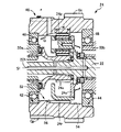
図2は、図1の動力伝達装置10の遊星歯車装置24付近の配置状態を具体的に示した断面図であり、図3は、遊星歯車装置24のリングギヤ24rおよびエンジン出力歯車Geが設けられた歯車部材40を単独で示した断面図で、中心線O1よりも上半分を示した図である。図2に示す歯車部材40の符号Gpはパーキングギヤである。歯車部材40は、円筒形状を成しているとともに、内周面における軸方向の両端部に一対の軸受保持部42、44が設けられ、一対の軸受(図2ではボールベアリング)46、48を介してケース部材50a、50bによって第1軸線S1まわりに回転可能に支持されている。ケース部材50a、50bは、動力伝達装置10を収容しているトランスアクスルケースの構成部品で、複数のボルト等により互いに一体的に固設されている。軸受保持部42、44は、何れも内径が拡大された段差形状を成しており、その段差部分の端面によって軸受46、48から加えられるスラスト方向の荷重を受け止めるようになっている。すなわち、リングギヤ24rおよびエンジン出力歯車Geは、何れも噛合歯が中心線O1まわりに捩じれたはすば歯車であり、噛合い反力が歯車部材40に加えられることによってスラスト荷重が発生し、そのスラスト荷重が軸受46、48によって受け止められることにより、スラスト荷重の反力が軸受46、48から軸受保持部42、44に加えられる。このため、軸受保持部42、44は、径方向に所定の段差d1、d2が必要であるとともに、軸方向に所定の肉厚が必要で、リングギヤ24rから軸方向に所定の肉厚寸法t1、t2を隔てて設けられる。リングギヤ24rは内歯歯車に相当し、軸方向において一対の軸受保持部42、44と重複しないようにそれ等の内側の中間位置に設けられている。
FIG. 2 is a sectional view specifically showing an arrangement state of the
歯車部材40の内周部には、一方の軸受保持部42が設けられた一端部側の小径部52と、他方の軸受保持部44が設けられた他端部側の大径部54とが設けられている。小径部52は大径部54よりも内径寸法が小さく、前記リングギヤ24rを形成するために大径部54から内周側へ所定寸法だけ突き出すように設けられた部分である。すなわち、小径部52の内径D1はリングギヤ24rの歯先径と一致しており、大径部54の内径D2はリングギヤ24rの溝底径よりも大きい。小径部52は、大径部54に隣接する歯幅領域Wを含んで設けられているとともに、軸受保持部42に達するように歯幅領域Wを越えて一端部側へ延長して設けられており、一方の軸受保持部42は小径部52の軸方向の端部に連続して設けられている。他方の軸受保持部44は、大径部54の軸方向の端部に連続して設けられている。
The inner peripheral portion of the
歯幅領域Wは、ピニオン24pと噛み合わされるリングギヤ24rが設けられる部分で、所定の噛合い強度が得られる長さ寸法を備えている。リングギヤ24rは、小径部52のうち軸方向の他端部側、すなわち大径部54側から、歯幅領域Wを含むように設けられており、本実施例では歯幅領域Wを越えて前記軸受保持部42に達する前の途中位置、具体的には肉厚寸法t1を残す位置まで設けられている。また、このリングギヤ24rの軸受保持部42側の端末部分、すなわち歯幅領域Wよりも軸受保持部42側の部分には、歯溝の深さが軸受保持部42側へ向かうに従って滑らかに円弧状に浅くなる徐変部56が設けられている。歯幅領域Wでは、略一定の溝底径でリングギヤ24rの歯溝が設けられている。
The tooth width region W is a portion where the
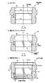
図4は、徐変部56を備えるリングギヤ24rの加工方法の一例を説明する概略断面図である。(a) は、内周面の中のリングギヤ24rの歯幅領域Wに小径円筒部62を有するとともに、その小径円筒部62が軸受保持部42に達するように歯幅領域Wから一端部側(図の下方)へ延長して設けられた円筒状素材60を用意する素材準備工程である。本実施例では、小径円筒部62が、軸受保持部42が設けられる部分を含んで一端部に達するように設けられているが、少なくとも軸受保持部42が設けられる部分に達するように設けられれば良い。この小径円筒部62の内径は、前記小径部52の内径D1すなわちリングギヤ24rの歯先径と等しい径寸法とされている。本実施例ではまた、前記内径D2と等しい大径円筒部64が、歯幅領域Wよりも他端部側(図の上方)に軸受保持部42が設けられる部分を含んで他端部に達するように設けられている。
FIG. 4 is a schematic cross-sectional view illustrating an example of a method of processing the
図4の(b) は、上記小径円筒部62にリングギヤ24rを形成する歯創成工程で、本実施例ではスカイビング加工によってリングギヤ24rが設けられる。図5はスカイビング加工を説明する概略正面図で、図6は図5における上方から見た平面図であり、スカイビングカッター70により円筒状ワーク72の内周面72fに内歯歯車を加工する場合である。円筒状ワーク72は、前記円筒状素材60に対応するものである。スカイビングカッター70は、先端側ほど大径になるテーパ形状の刃部74を備えており、その刃部74の外周面には加工すべき内歯歯車の歯溝に対応する断面形状の多数の加工歯76が設けられているとともに、その加工歯76の先端に切れ刃78が設けられている。この切れ刃78の外径寸法は円筒状ワーク72の内径寸法よりも十分に小さく、円筒状ワーク72の内部へスカイビングカッター70を挿入することができる。
FIG. 4B shows a tooth forming process for forming the
スカイビング加工に際しては、先ず、円筒状ワーク72の中心線O1に対して、スカイビングカッター70の中心線(回転軸線)O2が所定の傾斜角θで円筒状ワーク72の周方向(図6では左方向)へ傾斜させられるとともに、切れ刃78が円筒状ワーク72の径方向へ所定の切込み深さaで切り込むように配置する。切込み深さaは、加工すべき内歯歯車(本実施例ではリングギヤ24r)の噛合歯の歯たけと一致する。そして、それ等の円筒状ワーク72およびスカイビングカッター70をそれぞれ中心線O1、O2まわりに同期回転させつつ、スカイビングカッター70を矢印Cで示すように円筒状ワーク72の中心線O1と平行な方向へ送り移動させることにより、目的とする内歯歯車を内周面72fに連続して加工することができる。円筒状ワーク72の回転方向Aおよびスカイビングカッター70の回転方向Bは同じ方向で、本実施例では図6の平面図において左まわり方向であり、スカイビングカッター70が左方向へ傾斜角θで傾斜していることにより、そのスカイビングカッター70の回転に伴って切れ刃78が円筒状ワーク72の軸方向(図5における下方)へ切り込んで内周面72fに切削加工が行なわれる。傾斜角θは、切れ刃78の切削性能に影響し、所定の切削性能が得られるように適宜定められる。図6に「+」で示したスカイビングカッター70の中心点O2は、刃部74の先端位置における中心、すなわち切れ刃78の中心位置であり、円筒状ワーク72の中心線O1と中心点O2とを結ぶ直線上で切込み深さaになる。この切込み深さaは加工歯76の高さ寸法よりも小さく、内周面72fがそのまま内歯歯車の歯先になり、内周面72fの内径が内歯歯車の歯先径になる。
In the skiving process, first, the center line (rotation axis) O2 of the
加工すべき内歯歯車は、噛合歯が中心線O1まわりにねじれ角β1でねじれたねじれ歯でも、ねじれ角β1=0°の中心線O1と平行な平行歯でも良い。スカイビングカッター70の加工歯76についても、中心線O2まわりにねじれ角β2でねじれたねじれ歯でも、ねじれ角β2=0°の中心線O2と平行な平行歯でも良い。これ等のねじれ角β1、β2は、例えば右まわり方向のねじれを正(+)とした場合、次式(1) を満足するように定められる。例えば、加工すべき内歯歯車のねじれ角β1が17°の場合、傾斜角θを22°に設定すると、加工歯76のねじれ角β2=−5°となり、加工歯76は左まわりに5°で捩じれたねじれ歯になる。円筒状ワーク72とスカイビングカッター70との同期回転は、スカイビングカッター70の切れ刃78が円筒状ワーク72に対してねじれ角β1で切り込む回転で、両者の回転速度が互いに関連して設定される。なお、同期回転は相対的なもので、例えば円筒状ワーク72を位置固定に配置し、スカイビングカッター70を中心線O2まわりに自転させつつ、円筒状ワーク72の中心線O2まわりに内周面72fに沿って逆まわり(右まわり)に公転させるようにしても良い。要するに、前記特許文献4など従来から知られているスカイビング加工技術を適用して内歯歯車を加工することができる。
θ=β1−β2 ・・・(1)
The internal gear to be processed may be a twisted tooth whose meshing tooth is twisted around the center line O1 at a twist angle β1, or a parallel tooth parallel to the center line O1 having a twist angle β1 = 0 °. The processing
θ = β1−β2 (1)
図4に戻って、(b) の歯創成工程では、小径円筒部62が設けられた円筒状素材60の他端部側、すなわち図4(b) における上方側からスカイビングカッター70を挿入し、スカイビング加工により小径円筒部62の歯幅領域Wにリングギヤ24rを形成するとともに、その歯幅領域Wを越えて軸受保持部42に達する前の途中位置でスカイビング加工を終了する。具体的には、軸受保持部42との間に前記肉厚寸法t1を残す位置でスカイビング加工を終了し、スカイビングカッター70を円筒状素材60の中心側(すなわち前記図6の場合は下方側)へずらすことにより、そのスカイビングカッター70を円筒状素材60から軸方向へ抜き出すことができる。これにより、小径円筒部62にリングギヤ24rが創成される。この場合、例えば前記図9に示すシェーパ加工に比較して、リングギヤ24rに隣接する位置(工具の抜け出し側)に環状溝を設ける必要がないため、加工工数が低減されるとともに、リングギヤ24rの端末部分では、スカイビング加工の特性で歯溝の深さが滑らかに小さくなるように円弧状に切り上がり、前記徐変部56が自動的に形成される。すなわち、スカイビング加工を小径円筒部62の途中で中止すると、その端末部分には、スカイビングカッター70の切れ刃78の回転軌跡(径寸法に対応する湾曲形状)の徐変部56が形成される。
Returning to FIG. 4, in the tooth creation step (b), the
図4の(c) は軸受保持部加工工程で、リングギヤ24rが設けられた円筒状素材60に対して前記一対の軸受保持部42、44を切削加工等により加工する。また、前記エンジン出力歯車GeやパーキングギヤGp、油穴等を切削加工などで加工することにより、目的とする歯車部材40が製造される。なお、一対の軸受保持部42、44の何れか一方或いは両方を、(b) の歯創成工程の前に設けることもできる。例えば、(a) の素材準備工程と(b) の歯創成工程との間で設けたり、或いは(a) の素材準備工程の過程で設けたりすることができる。エンジン出力歯車GeやパーキングギヤGpについても同様に、(b) の歯創成工程の前に設けることが可能である。
FIG. 4C shows a bearing holding portion machining step in which the pair of bearing holding
このように本実施例の歯車部材40の製造方法によれば、小径円筒部62がリングギヤ24rの歯幅領域Wから軸受保持部42側の一端部に達するように設けられた円筒状素材60に対し、他端部側からスカイビングカッター70を挿入してスカイビング加工により小径円筒部62の歯幅領域Wにリングギヤ24rを形成するとともに、軸受保持部42に達する前の途中位置でそのスカイビング加工を終了することにより、軸受保持部42との間に所定の肉厚寸法t1を残した状態でリングギヤ24rを創成できる。この場合、軸受保持部42は、リングギヤ24rの歯先径と等しい内径の小径円筒部62(小径部52)から径方向に所定の段差d1を有するように設けられるため、その軸受保持部42を小径に構成することが可能で、軸受46の小径化等でコストダウンを図ることができるとともに、1回転当たりの転がり長さが短くなって回転抵抗が低減され、燃費が向上する。
As described above, according to the method for manufacturing the
また、図9に示すシェーパ加工に比較して、リングギヤ24rに隣接する位置(工具の抜け出し側)に環状溝を設ける必要がないため、加工工数が低減されるとともに、リングギヤ24rの端末部分では、スカイビング加工の特性で歯溝の深さが滑らかに小さくなる徐変部56が形成されるため、環状溝よりも強度的に有利であり、例えば肉厚寸法t1を短くすることができる。
Further, as compared with the shaper processing shown in FIG. 9, there is no need to provide an annular groove at a position adjacent to the
また、歯車部材40についても、上記製造方法と同様の効果が得られる。すなわち、軸受保持部42は、リングギヤ24rの歯先径と等しい内径の小径部52から径方向に所定の段差d1を有するように設けられるため、その軸受保持部42を小径に構成することができる。また、リングギヤ24rに隣接する位置(工具の抜け出し側)に環状溝が存在しないため、加工工数が低減されるとともに、リングギヤ24rの端末部分は歯溝の深さが滑らかに小さくなる徐変部56とされているため、環状溝よりも強度的に有利である。
Further, the same effect as in the above-described manufacturing method can be obtained for the
また、本実施例の歯車部材40は、リングギヤ24rよりも他端部側、すなわち他方の軸受保持部44側は、リングギヤ24rの溝底径よりも大径の大径部54とされているため、ピニオン24pをキャリア24cに組み付けた状態でその他端部側から歯車部材40の内部に挿入してリングギヤ24rと噛み合わせることが可能で、遊星歯車装置24の組付作業が容易である。
In the
また、図2に示すように入力軸22に設けられた油供給穴22h等を流通して遊星歯車装置24へ供給され、更に遠心力等によりリングギヤ24rへ供給された潤滑油が、そのリングギヤ24rの端末部分に設けられた徐変部56の傾斜に沿って矢印Qで示すように軸受46に向かって適切に流動させられ、軸受46等に対する潤滑効率が向上する。
Further, as shown in FIG. 2, the lubricating oil which is supplied to the
なお、上記実施例ではリングギヤ24rよりも他端部側、すなわち他方の軸受保持部44側は、リングギヤ24rの溝底径よりも大径の大径部54とされていたが、例えば図7に示す歯車部材80のように、軸方向において一対の軸受保持部42、44の内側に位置する全域を小径部82とし、その小径部82の中間位置の歯幅領域Wに、歯先径が小径部82の内径と等しいリングギヤ84を設けることもできる。このリングギヤ84もスカイビングカッター70を用いて加工することが可能で、軸受保持部42側の徐変部86については、前記徐変部56と同様にスカイビングカッター70による加工を途中で終了することによって形成される。軸受保持部44側の徐変部88については、例えば図5および図6に示すようにスカイビングカッター70および円筒状ワーク72を同期回転させるとともに、スカイビングカッター70を矢印C方向へ送り移動する際に、切込み深さaが0から徐々に大きくなるようにスカイビングカッター70を円筒状ワーク72の径方向外側へ移動させることによって形成される。したがって、徐変部88の傾斜形状については、切込み深さaを大きくする径方向の送り速度に応じて定められる。
In the above embodiment, the other end side of the
このような歯車部材80においても、前記実施例と同様の効果が得られる他、一対の軸受保持部42、44が何れも小径部82の端部に設けられているため、それ等の軸受保持部42、44を何れも小径に構成することが可能で、軸受46、48の小径化等で更なるコストダウンを図ることができるとともに、1回転当たりの転がり長さが短くなって回転抵抗が低減される。
In such a
上記各実施例では、歯車部材40、80の他端部側(軸受保持部44が設けられる側)からスカイビングカッター70を挿入してリングギヤ24r、84を加工する場合について説明したが、何れの歯車部材40、80についても、逆にスカイビングカッター70を一端部側(軸受保持部42が設けられる側)から挿入してリングギヤ24r、84を加工することもできる。すなわち、徐変部88と同様に、図5、図6において切込み深さaが0から徐々に大きくなるようにスカイビングカッター70を円筒状ワーク72の径方向外側へ移動させることにより、徐変部56、86を形成してリングギヤ24r、84を加工することができる。
In each of the above embodiments, the case where the
以上、本発明の実施例を図面に基づいて詳細に説明したが、これ等はあくまでも一実施形態であり、本発明は当業者の知識に基づいて種々の変更、改良を加えた態様で実施することができる。 As described above, the embodiments of the present invention have been described in detail with reference to the drawings. However, these are merely examples, and the present invention is implemented in various modified and improved forms based on the knowledge of those skilled in the art. be able to.
24r、84:リングギヤ(内歯歯車) 40、80:歯車部材 42:軸受保持部 52、82:小径部 56、86:徐変部 60:円筒状素材 62:小径円筒部 70:スカイビングカッター W:歯幅領域 D1:小径部の内径(小径円筒部の内径、内歯歯車の歯先径) d1:段差
24r, 84: Ring gear (internal gear) 40, 80: Gear member 42:
Claims (2)
前記内歯歯車の歯幅領域に、該内歯歯車の歯先径に対応する内径の小径円筒部を有するとともに、該小径円筒部が前記軸受保持部に達するように前記歯幅領域から前記一端部側へ延長して設けられた円筒状素材を用意する素材準備工程と、
前記円筒状素材の前記一端部と反対の他端部側からスカイビングカッターを挿入し、スカイビング加工により前記小径円筒部の前記歯幅領域に前記内歯歯車を形成するとともに、該歯幅領域を越えて前記軸受保持部に達する前の途中位置で、歯溝の深さが前記軸受保持部側へ向かうに従って徐々に浅くなる徐変部を設けるように該スカイビング加工を終了する歯創成工程と、
を有することを特徴とする歯車部材の製造方法。 While having a cylindrical shape, a step-shaped bearing holding portion having an enlarged inner diameter is provided at one end in the axial direction on the inner peripheral surface, and the internal gear is provided without overlapping with the bearing holding portion in the axial direction. In the manufacturing method of the provided gear member,
In the tooth width region of the internal gear, a small-diameter cylindrical portion having an inner diameter corresponding to the tip diameter of the internal gear is provided, and the one end from the tooth width region such that the small-diameter cylindrical portion reaches the bearing holding portion. Material preparation step of preparing a cylindrical material provided to extend to the part side,
A skiving cutter is inserted from the other end of the cylindrical material opposite to the one end, and the internal gear is formed in the tooth width region of the small-diameter cylindrical portion by skiving, and the tooth width region is formed. A tooth forming step of ending the skiving process so as to provide a gradually changing portion in which the depth of the tooth groove gradually becomes shallower toward the bearing holding portion at an intermediate position before reaching the bearing holding portion beyond When,
A method for manufacturing a gear member, comprising:
前記内歯歯車の歯幅領域に、その内歯歯車の歯先径に対応する内径の小径部を有するとともに、該小径部は前記軸受保持部に達するように前記一端部側へ延長して設けられている一方、
前記小径部のうち軸方向において前記一端部と反対の他端部側から、前記歯幅領域を越えて前記軸受保持部に達する前の途中位置まで、前記内歯歯車が設けられており、
前記内歯歯車の前記軸受保持部側の端末部分には、歯溝の深さが該軸受保持部側へ向かうに従って徐々に浅くなる徐変部が設けられている
ことを特徴とする歯車部材。 While having a cylindrical shape, a step-shaped bearing holding portion having an enlarged inner diameter is provided at one end in the axial direction on the inner peripheral surface, and the internal gear is provided without overlapping with the bearing holding portion in the axial direction. In the provided gear member,
In the tooth width region of the internal gear, a small-diameter portion having an inner diameter corresponding to the tip diameter of the internal gear is provided, and the small-diameter portion is provided to extend to the one end portion side to reach the bearing holding portion. While
The internal gear is provided from the other end portion side opposite to the one end portion in the axial direction of the small diameter portion to an intermediate position before reaching the bearing holding portion beyond the tooth width region,
A gear member, characterized in that a terminal portion of the internal gear on the bearing holding portion side is provided with a gradually changing portion in which the depth of the tooth groove gradually becomes shallower toward the bearing holding portion side.
Priority Applications (3)
| Application Number | Priority Date | Filing Date | Title |
|---|---|---|---|
| JP2017033252A JP6673260B2 (en) | 2017-02-24 | 2017-02-24 | Gear member and method of manufacturing the same |
| US15/896,821 US10914367B2 (en) | 2017-02-24 | 2018-02-14 | Gear member and method of manufacturing the same |
| DE102018202632.7A DE102018202632A1 (en) | 2017-02-24 | 2018-02-21 | GEAR COMPONENT AND METHOD FOR MANUFACTURING THEREOF |
Applications Claiming Priority (1)
| Application Number | Priority Date | Filing Date | Title |
|---|---|---|---|
| JP2017033252A JP6673260B2 (en) | 2017-02-24 | 2017-02-24 | Gear member and method of manufacturing the same |
Publications (2)
| Publication Number | Publication Date |
|---|---|
| JP2018138319A JP2018138319A (en) | 2018-09-06 |
| JP6673260B2 true JP6673260B2 (en) | 2020-03-25 |
Family
ID=63112355
Family Applications (1)
| Application Number | Title | Priority Date | Filing Date |
|---|---|---|---|
| JP2017033252A Active JP6673260B2 (en) | 2017-02-24 | 2017-02-24 | Gear member and method of manufacturing the same |
Country Status (3)
| Country | Link |
|---|---|
| US (1) | US10914367B2 (en) |
| JP (1) | JP6673260B2 (en) |
| DE (1) | DE102018202632A1 (en) |
Families Citing this family (2)
| Publication number | Priority date | Publication date | Assignee | Title |
|---|---|---|---|---|
| JP2020019096A (en) * | 2018-08-01 | 2020-02-06 | 株式会社不二越 | Gear processing method |
| US11215122B2 (en) * | 2019-11-20 | 2022-01-04 | Raytheon Technologies Corporation | Geared architecture for gas turbine engine |
Family Cites Families (16)
| Publication number | Priority date | Publication date | Assignee | Title |
|---|---|---|---|---|
| JPH01153840A (en) * | 1987-12-08 | 1989-06-16 | Hitachi Constr Mach Co Ltd | Reduction gear device using planetary gear |
| DE10144803B4 (en) * | 2001-09-12 | 2006-03-09 | Zf Friedrichshafen Ag | planetary gear |
| JP4247760B2 (en) * | 2005-11-09 | 2009-04-02 | 株式会社ニイガタマシンテクノ | Gear processing method by machining center |
| DE102008037514A1 (en) * | 2008-11-03 | 2010-05-06 | Profilator Gmbh & Co. Kg | Skiving device and method |
| DE102011009027A1 (en) * | 2011-01-20 | 2012-07-26 | Gleason-Pfauter Maschinenfabrik Gmbh | Method for machining a workpiece and machine tool designed for this purpose |
| JP5741930B2 (en) * | 2011-05-24 | 2015-07-01 | 株式会社不二越 | Internal tooth processing brooch |
| DE102011121784A1 (en) * | 2011-12-21 | 2013-06-27 | LÖSOMAT-Schraubtechnik Neef GmbH | Method for producing a toothing |
| CN103373383B (en) * | 2012-04-17 | 2018-06-19 | 德昌电机(深圳)有限公司 | Electrically driven truck and its gear motor component |
| JP2014100725A (en) * | 2012-11-20 | 2014-06-05 | Daido Steel Co Ltd | Tooth taking-out forging metal mold, manufacturing method thereof and manufacturing method of helical gear |
| JP2014161972A (en) * | 2013-02-26 | 2014-09-08 | Kashifuji:Kk | Skiving cutter and creating method of internal gear |
| BR112015026236A2 (en) * | 2013-04-22 | 2017-07-25 | The Gleason Works | trimming of cylindrical gears |
| JP6244677B2 (en) | 2013-06-07 | 2017-12-13 | 株式会社ジェイテクト | Gear machining simulation device |
| JP2015075139A (en) * | 2013-10-07 | 2015-04-20 | Thk株式会社 | Gear mechanism |
| JP6182438B2 (en) | 2013-11-26 | 2017-08-16 | アイシン・エィ・ダブリュ株式会社 | Vehicle drive transmission device |
| JP6330443B2 (en) * | 2014-04-16 | 2018-05-30 | アイシン精機株式会社 | Skiving cutter and gear |
| JP2018122425A (en) * | 2017-02-03 | 2018-08-09 | 株式会社ジェイテクト | Gear-cutting tool processing device, processing method, tool shape simulation device and tool shape simulation method |
-
2017
- 2017-02-24 JP JP2017033252A patent/JP6673260B2/en active Active
-
2018
- 2018-02-14 US US15/896,821 patent/US10914367B2/en active Active
- 2018-02-21 DE DE102018202632.7A patent/DE102018202632A1/en active Pending
Also Published As
| Publication number | Publication date |
|---|---|
| JP2018138319A (en) | 2018-09-06 |
| DE102018202632A1 (en) | 2018-08-30 |
| US10914367B2 (en) | 2021-02-09 |
| US20180245679A1 (en) | 2018-08-30 |
Similar Documents
| Publication | Publication Date | Title |
|---|---|---|
| DE112009000080B4 (en) | driving device | |
| CN100537098C (en) | Broaching apparatus and method for producing a gear member with tapered gear teeth | |
| JP4947884B2 (en) | Method for manufacturing pin of planetary rotating member of planetary reduction mechanism | |
| JP5671829B2 (en) | Rotor shaft support structure | |
| CN101085482B (en) | Broaching apparatus and method for producing a gear member with tapered gear teeth | |
| JP4981694B2 (en) | Power transmission device | |
| JP6673260B2 (en) | Gear member and method of manufacturing the same | |
| CN106457432A (en) | Method for incorporating undercuts in tooth flanks of teeth of toothed wheels | |
| JP2002147580A (en) | Lubricating structure for differential case and its machining method | |
| WO2012176304A1 (en) | Helical gear and power transmission device | |
| CN107042753A (en) | Power transmission for vehicle | |
| CN110154752A (en) | Vehicle propulsion system | |
| US20220268346A1 (en) | Differential device | |
| CN107791820A (en) | Hybrid power transaxle | |
| JP2020153421A (en) | Gear shaft and manufacturing method of gear shaft | |
| JP2015034593A (en) | Transaxle | |
| JP2004324736A (en) | Differential gearing device for vehicle equipped with planetary gearing mechanism and its manufacturing method | |
| JP2016148371A (en) | Vehicular shaft | |
| JP2011122661A (en) | Conical friction ring type continuously-variable transmission | |
| JP5035067B2 (en) | Vehicle differential gear device having planetary gear mechanism and manufacturing method thereof | |
| JP6101426B2 (en) | Hypoid gear device | |
| JP7240851B2 (en) | Differential mechanism lubrication structure | |
| KR102033853B1 (en) | Twin coupling clutch apparatus | |
| JP6705345B2 (en) | Vehicle power transmission device support structure | |
| JP2017035929A (en) | Power transmission device |
Legal Events
| Date | Code | Title | Description |
|---|---|---|---|
| A621 | Written request for application examination |
Free format text: JAPANESE INTERMEDIATE CODE: A621 Effective date: 20180913 |
|
| A131 | Notification of reasons for refusal |
Free format text: JAPANESE INTERMEDIATE CODE: A131 Effective date: 20190625 |
|
| A977 | Report on retrieval |
Free format text: JAPANESE INTERMEDIATE CODE: A971007 Effective date: 20190628 |
|
| A521 | Request for written amendment filed |
Free format text: JAPANESE INTERMEDIATE CODE: A523 Effective date: 20190807 |
|
| TRDD | Decision of grant or rejection written | ||
| A01 | Written decision to grant a patent or to grant a registration (utility model) |
Free format text: JAPANESE INTERMEDIATE CODE: A01 Effective date: 20200204 |
|
| A61 | First payment of annual fees (during grant procedure) |
Free format text: JAPANESE INTERMEDIATE CODE: A61 Effective date: 20200217 |
|
| R151 | Written notification of patent or utility model registration |
Ref document number: 6673260 Country of ref document: JP Free format text: JAPANESE INTERMEDIATE CODE: R151 |