JP6636010B2 - Magnetically driven arteriovenous access valve system and related methods - Google Patents
Magnetically driven arteriovenous access valve system and related methods Download PDFInfo
- Publication number
- JP6636010B2 JP6636010B2 JP2017507922A JP2017507922A JP6636010B2 JP 6636010 B2 JP6636010 B2 JP 6636010B2 JP 2017507922 A JP2017507922 A JP 2017507922A JP 2017507922 A JP2017507922 A JP 2017507922A JP 6636010 B2 JP6636010 B2 JP 6636010B2
- Authority
- JP
- Japan
- Prior art keywords
- valve
- actuator assembly
- fluid
- valves
- drive
- Prior art date
- Legal status (The legal status is an assumption and is not a legal conclusion. Google has not performed a legal analysis and makes no representation as to the accuracy of the status listed.)
- Active
Links
- 238000000034 method Methods 0.000 title description 13
- 239000012530 fluid Substances 0.000 claims description 178
- 238000004891 communication Methods 0.000 claims description 84
- 230000003111 delayed effect Effects 0.000 claims description 2
- 230000004913 activation Effects 0.000 description 134
- 230000002441 reversible effect Effects 0.000 description 39
- 239000008280 blood Substances 0.000 description 25
- 210000004369 blood Anatomy 0.000 description 25
- 238000009530 blood pressure measurement Methods 0.000 description 19
- 230000000712 assembly Effects 0.000 description 18
- 238000000429 assembly Methods 0.000 description 18
- 238000001631 haemodialysis Methods 0.000 description 18
- 230000000322 hemodialysis Effects 0.000 description 18
- 239000000463 material Substances 0.000 description 13
- 230000000875 corresponding effect Effects 0.000 description 12
- 210000003462 vein Anatomy 0.000 description 12
- 239000007788 liquid Substances 0.000 description 11
- 210000002073 venous valve Anatomy 0.000 description 10
- 210000001367 artery Anatomy 0.000 description 9
- 238000005259 measurement Methods 0.000 description 9
- 230000000007 visual effect Effects 0.000 description 9
- 238000000502 dialysis Methods 0.000 description 8
- 238000002560 therapeutic procedure Methods 0.000 description 7
- 230000017531 blood circulation Effects 0.000 description 6
- 239000002699 waste material Substances 0.000 description 6
- 239000004020 conductor Substances 0.000 description 5
- 238000003466 welding Methods 0.000 description 5
- 239000012190 activator Substances 0.000 description 4
- 238000002347 injection Methods 0.000 description 4
- 239000007924 injection Substances 0.000 description 4
- FAPWRFPIFSIZLT-UHFFFAOYSA-M Sodium chloride Chemical compound [Na+].[Cl-] FAPWRFPIFSIZLT-UHFFFAOYSA-M 0.000 description 3
- 230000008859 change Effects 0.000 description 3
- 230000001276 controlling effect Effects 0.000 description 3
- 230000006870 function Effects 0.000 description 3
- 239000003999 initiator Substances 0.000 description 3
- 210000003734 kidney Anatomy 0.000 description 3
- 230000007246 mechanism Effects 0.000 description 3
- 239000011780 sodium chloride Substances 0.000 description 3
- RTAQQCXQSZGOHL-UHFFFAOYSA-N Titanium Chemical compound [Ti] RTAQQCXQSZGOHL-UHFFFAOYSA-N 0.000 description 2
- 239000000853 adhesive Substances 0.000 description 2
- 230000001070 adhesive effect Effects 0.000 description 2
- 238000013459 approach Methods 0.000 description 2
- 239000000560 biocompatible material Substances 0.000 description 2
- 230000005540 biological transmission Effects 0.000 description 2
- 239000003086 colorant Substances 0.000 description 2
- 230000008878 coupling Effects 0.000 description 2
- 238000010168 coupling process Methods 0.000 description 2
- 238000005859 coupling reaction Methods 0.000 description 2
- 230000007423 decrease Effects 0.000 description 2
- 238000010586 diagram Methods 0.000 description 2
- 230000005672 electromagnetic field Effects 0.000 description 2
- 238000012986 modification Methods 0.000 description 2
- 230000004048 modification Effects 0.000 description 2
- 238000012544 monitoring process Methods 0.000 description 2
- 230000007935 neutral effect Effects 0.000 description 2
- 230000002093 peripheral effect Effects 0.000 description 2
- 229920001721 polyimide Polymers 0.000 description 2
- 230000004044 response Effects 0.000 description 2
- 238000007789 sealing Methods 0.000 description 2
- 229920006268 silicone film Polymers 0.000 description 2
- 229910052719 titanium Inorganic materials 0.000 description 2
- 239000010936 titanium Substances 0.000 description 2
- 238000012546 transfer Methods 0.000 description 2
- 208000001647 Renal Insufficiency Diseases 0.000 description 1
- 208000007536 Thrombosis Diseases 0.000 description 1
- 241000251539 Vertebrata <Metazoa> Species 0.000 description 1
- 210000002302 brachial artery Anatomy 0.000 description 1
- 208000020832 chronic kidney disease Diseases 0.000 description 1
- 208000022831 chronic renal failure syndrome Diseases 0.000 description 1
- 239000011248 coating agent Substances 0.000 description 1
- 238000000576 coating method Methods 0.000 description 1
- 230000000295 complement effect Effects 0.000 description 1
- 230000002596 correlated effect Effects 0.000 description 1
- 239000003814 drug Substances 0.000 description 1
- 238000005516 engineering process Methods 0.000 description 1
- 229920002313 fluoropolymer Polymers 0.000 description 1
- 239000004811 fluoropolymer Substances 0.000 description 1
- 230000000762 glandular Effects 0.000 description 1
- 230000001771 impaired effect Effects 0.000 description 1
- 238000002513 implantation Methods 0.000 description 1
- 208000017169 kidney disease Diseases 0.000 description 1
- 201000006370 kidney failure Diseases 0.000 description 1
- 231100000518 lethal Toxicity 0.000 description 1
- 230000001665 lethal effect Effects 0.000 description 1
- 238000004519 manufacturing process Methods 0.000 description 1
- 230000002503 metabolic effect Effects 0.000 description 1
- 230000003287 optical effect Effects 0.000 description 1
- 210000000056 organ Anatomy 0.000 description 1
- -1 polytetrafluoroethylene Polymers 0.000 description 1
- 229920001343 polytetrafluoroethylene Polymers 0.000 description 1
- 239000004810 polytetrafluoroethylene Substances 0.000 description 1
- 238000003918 potentiometric titration Methods 0.000 description 1
- 238000010248 power generation Methods 0.000 description 1
- 238000003825 pressing Methods 0.000 description 1
- 238000012545 processing Methods 0.000 description 1
- 238000004549 pulsed laser deposition Methods 0.000 description 1
- 239000000126 substance Substances 0.000 description 1
- 239000003053 toxin Substances 0.000 description 1
- 231100000765 toxin Toxicity 0.000 description 1
- 108700012359 toxins Proteins 0.000 description 1
- 230000001960 triggered effect Effects 0.000 description 1
- 210000004887 upper abdominal cavity Anatomy 0.000 description 1
- 210000002700 urine Anatomy 0.000 description 1
- 230000002792 vascular Effects 0.000 description 1
- XLYOFNOQVPJJNP-UHFFFAOYSA-N water Substances O XLYOFNOQVPJJNP-UHFFFAOYSA-N 0.000 description 1
Images


Classifications
-
- A—HUMAN NECESSITIES
- A61—MEDICAL OR VETERINARY SCIENCE; HYGIENE
- A61B—DIAGNOSIS; SURGERY; IDENTIFICATION
- A61B17/00—Surgical instruments, devices or methods, e.g. tourniquets
- A61B17/11—Surgical instruments, devices or methods, e.g. tourniquets for performing anastomosis; Buttons for anastomosis
-
- A—HUMAN NECESSITIES
- A61—MEDICAL OR VETERINARY SCIENCE; HYGIENE
- A61B—DIAGNOSIS; SURGERY; IDENTIFICATION
- A61B17/00—Surgical instruments, devices or methods, e.g. tourniquets
- A61B17/12—Surgical instruments, devices or methods, e.g. tourniquets for ligaturing or otherwise compressing tubular parts of the body, e.g. blood vessels, umbilical cord
- A61B17/12022—Occluding by internal devices, e.g. balloons or releasable wires
- A61B17/12027—Type of occlusion
- A61B17/1204—Type of occlusion temporary occlusion
- A61B17/12045—Type of occlusion temporary occlusion double occlusion, e.g. during anastomosis
-
- A—HUMAN NECESSITIES
- A61—MEDICAL OR VETERINARY SCIENCE; HYGIENE
- A61B—DIAGNOSIS; SURGERY; IDENTIFICATION
- A61B17/00—Surgical instruments, devices or methods, e.g. tourniquets
- A61B17/12—Surgical instruments, devices or methods, e.g. tourniquets for ligaturing or otherwise compressing tubular parts of the body, e.g. blood vessels, umbilical cord
- A61B17/12022—Occluding by internal devices, e.g. balloons or releasable wires
- A61B17/12131—Occluding by internal devices, e.g. balloons or releasable wires characterised by the type of occluding device
- A61B17/12136—Balloons
-
- A—HUMAN NECESSITIES
- A61—MEDICAL OR VETERINARY SCIENCE; HYGIENE
- A61F—FILTERS IMPLANTABLE INTO BLOOD VESSELS; PROSTHESES; DEVICES PROVIDING PATENCY TO, OR PREVENTING COLLAPSING OF, TUBULAR STRUCTURES OF THE BODY, e.g. STENTS; ORTHOPAEDIC, NURSING OR CONTRACEPTIVE DEVICES; FOMENTATION; TREATMENT OR PROTECTION OF EYES OR EARS; BANDAGES, DRESSINGS OR ABSORBENT PADS; FIRST-AID KITS
- A61F2/00—Filters implantable into blood vessels; Prostheses, i.e. artificial substitutes or replacements for parts of the body; Appliances for connecting them with the body; Devices providing patency to, or preventing collapsing of, tubular structures of the body, e.g. stents
- A61F2/02—Prostheses implantable into the body
- A61F2/04—Hollow or tubular parts of organs, e.g. bladders, tracheae, bronchi or bile ducts
- A61F2/06—Blood vessels
- A61F2/064—Blood vessels with special features to facilitate anastomotic coupling
-
- A—HUMAN NECESSITIES
- A61—MEDICAL OR VETERINARY SCIENCE; HYGIENE
- A61M—DEVICES FOR INTRODUCING MEDIA INTO, OR ONTO, THE BODY; DEVICES FOR TRANSDUCING BODY MEDIA OR FOR TAKING MEDIA FROM THE BODY; DEVICES FOR PRODUCING OR ENDING SLEEP OR STUPOR
- A61M1/00—Suction or pumping devices for medical purposes; Devices for carrying-off, for treatment of, or for carrying-over, body-liquids; Drainage systems
- A61M1/36—Other treatment of blood in a by-pass of the natural circulatory system, e.g. temperature adaptation, irradiation ; Extra-corporeal blood circuits
- A61M1/3621—Extra-corporeal blood circuits
- A61M1/3653—Interfaces between patient blood circulation and extra-corporal blood circuit
- A61M1/3655—Arterio-venous shunts or fistulae
-
- A—HUMAN NECESSITIES
- A61—MEDICAL OR VETERINARY SCIENCE; HYGIENE
- A61M—DEVICES FOR INTRODUCING MEDIA INTO, OR ONTO, THE BODY; DEVICES FOR TRANSDUCING BODY MEDIA OR FOR TAKING MEDIA FROM THE BODY; DEVICES FOR PRODUCING OR ENDING SLEEP OR STUPOR
- A61M39/00—Tubes, tube connectors, tube couplings, valves, access sites or the like, specially adapted for medical use
- A61M39/22—Valves or arrangement of valves
- A61M39/227—Valves actuated by a secondary fluid, e.g. hydraulically or pneumatically actuated valves
-
- A—HUMAN NECESSITIES
- A61—MEDICAL OR VETERINARY SCIENCE; HYGIENE
- A61B—DIAGNOSIS; SURGERY; IDENTIFICATION
- A61B17/00—Surgical instruments, devices or methods, e.g. tourniquets
- A61B2017/00017—Electrical control of surgical instruments
- A61B2017/00115—Electrical control of surgical instruments with audible or visual output
-
- A—HUMAN NECESSITIES
- A61—MEDICAL OR VETERINARY SCIENCE; HYGIENE
- A61B—DIAGNOSIS; SURGERY; IDENTIFICATION
- A61B17/00—Surgical instruments, devices or methods, e.g. tourniquets
- A61B2017/00367—Details of actuation of instruments, e.g. relations between pushing buttons, or the like, and activation of the tool, working tip, or the like
- A61B2017/00411—Details of actuation of instruments, e.g. relations between pushing buttons, or the like, and activation of the tool, working tip, or the like actuated by application of energy from an energy source outside the body
-
- A—HUMAN NECESSITIES
- A61—MEDICAL OR VETERINARY SCIENCE; HYGIENE
- A61B—DIAGNOSIS; SURGERY; IDENTIFICATION
- A61B17/00—Surgical instruments, devices or methods, e.g. tourniquets
- A61B2017/00535—Surgical instruments, devices or methods, e.g. tourniquets pneumatically or hydraulically operated
- A61B2017/00539—Surgical instruments, devices or methods, e.g. tourniquets pneumatically or hydraulically operated hydraulically
-
- A—HUMAN NECESSITIES
- A61—MEDICAL OR VETERINARY SCIENCE; HYGIENE
- A61B—DIAGNOSIS; SURGERY; IDENTIFICATION
- A61B17/00—Surgical instruments, devices or methods, e.g. tourniquets
- A61B2017/00831—Material properties
- A61B2017/00876—Material properties magnetic
-
- A—HUMAN NECESSITIES
- A61—MEDICAL OR VETERINARY SCIENCE; HYGIENE
- A61B—DIAGNOSIS; SURGERY; IDENTIFICATION
- A61B17/00—Surgical instruments, devices or methods, e.g. tourniquets
- A61B17/11—Surgical instruments, devices or methods, e.g. tourniquets for performing anastomosis; Buttons for anastomosis
- A61B2017/1107—Surgical instruments, devices or methods, e.g. tourniquets for performing anastomosis; Buttons for anastomosis for blood vessels
-
- A—HUMAN NECESSITIES
- A61—MEDICAL OR VETERINARY SCIENCE; HYGIENE
- A61B—DIAGNOSIS; SURGERY; IDENTIFICATION
- A61B17/00—Surgical instruments, devices or methods, e.g. tourniquets
- A61B17/11—Surgical instruments, devices or methods, e.g. tourniquets for performing anastomosis; Buttons for anastomosis
- A61B2017/1139—Side-to-side connections, e.g. shunt or X-connections
-
- A—HUMAN NECESSITIES
- A61—MEDICAL OR VETERINARY SCIENCE; HYGIENE
- A61B—DIAGNOSIS; SURGERY; IDENTIFICATION
- A61B90/00—Instruments, implements or accessories specially adapted for surgery or diagnosis and not covered by any of the groups A61B1/00 - A61B50/00, e.g. for luxation treatment or for protecting wound edges
- A61B90/08—Accessories or related features not otherwise provided for
- A61B2090/0807—Indication means
-
- A—HUMAN NECESSITIES
- A61—MEDICAL OR VETERINARY SCIENCE; HYGIENE
- A61F—FILTERS IMPLANTABLE INTO BLOOD VESSELS; PROSTHESES; DEVICES PROVIDING PATENCY TO, OR PREVENTING COLLAPSING OF, TUBULAR STRUCTURES OF THE BODY, e.g. STENTS; ORTHOPAEDIC, NURSING OR CONTRACEPTIVE DEVICES; FOMENTATION; TREATMENT OR PROTECTION OF EYES OR EARS; BANDAGES, DRESSINGS OR ABSORBENT PADS; FIRST-AID KITS
- A61F2/00—Filters implantable into blood vessels; Prostheses, i.e. artificial substitutes or replacements for parts of the body; Appliances for connecting them with the body; Devices providing patency to, or preventing collapsing of, tubular structures of the body, e.g. stents
- A61F2/02—Prostheses implantable into the body
- A61F2/04—Hollow or tubular parts of organs, e.g. bladders, tracheae, bronchi or bile ducts
- A61F2/06—Blood vessels
- A61F2002/068—Modifying the blood flow model, e.g. by diffuser or deflector
-
- A—HUMAN NECESSITIES
- A61—MEDICAL OR VETERINARY SCIENCE; HYGIENE
- A61M—DEVICES FOR INTRODUCING MEDIA INTO, OR ONTO, THE BODY; DEVICES FOR TRANSDUCING BODY MEDIA OR FOR TAKING MEDIA FROM THE BODY; DEVICES FOR PRODUCING OR ENDING SLEEP OR STUPOR
- A61M39/00—Tubes, tube connectors, tube couplings, valves, access sites or the like, specially adapted for medical use
- A61M39/22—Valves or arrangement of valves
- A61M2039/226—Spindles or actuating means
-
- A—HUMAN NECESSITIES
- A61—MEDICAL OR VETERINARY SCIENCE; HYGIENE
- A61M—DEVICES FOR INTRODUCING MEDIA INTO, OR ONTO, THE BODY; DEVICES FOR TRANSDUCING BODY MEDIA OR FOR TAKING MEDIA FROM THE BODY; DEVICES FOR PRODUCING OR ENDING SLEEP OR STUPOR
- A61M2205/00—General characteristics of the apparatus
- A61M2205/33—Controlling, regulating or measuring
- A61M2205/3331—Pressure; Flow
-
- A—HUMAN NECESSITIES
- A61—MEDICAL OR VETERINARY SCIENCE; HYGIENE
- A61M—DEVICES FOR INTRODUCING MEDIA INTO, OR ONTO, THE BODY; DEVICES FOR TRANSDUCING BODY MEDIA OR FOR TAKING MEDIA FROM THE BODY; DEVICES FOR PRODUCING OR ENDING SLEEP OR STUPOR
- A61M2205/00—General characteristics of the apparatus
- A61M2205/35—Communication
- A61M2205/3507—Communication with implanted devices, e.g. external control
- A61M2205/3523—Communication with implanted devices, e.g. external control using telemetric means
Description
(関連出願の参照)
本出願は、2014年4月25日出願の「磁力駆動型動静脈アクセスバルブシステム及びそれに関連する方法(Magnetically-activated Ateriovenous Access Valve System and Related Methods)」なる標題の米国特許仮出願第61/984,550号に基づく優先権を主張するものである。上記特許出願の開示内容の全体は、参照により本明細書に援用される。
(Refer to related applications)
This application is related to US Provisional Patent Application No. 61/984, filed April 25, 2014, entitled "Magnetically-activated Ateriovenous Access Valve System and Related Methods." No. 550. The entire disclosure of the above-mentioned patent application is incorporated herein by reference.
(技術分野)
本発明は、概して、動静脈アクセスバルブシステムに関し、より詳細には、動静脈グラフトの端部またはその近傍に設けられたバルブを開閉するための、針を使用しない磁力駆動型バルブシステムに関する。
(Technical field)
The present invention relates generally to arteriovenous access valve systems and, more particularly, to a needleless magnetically actuated valve system for opening and closing valves provided at or near the end of an arteriovenous graft.
脊椎動物の腹腔上部に位置する腺器官である腎臓の機能は、血液をろ過して老廃物を除去することである。具体的には、腎臓は、血液から水や新陳代謝の老廃物を分離し、それらを尿として膀胱から排泄する。慢性腎不全は、腎臓の機能が低下し、血液をろ過して老廃物を除去することができなくなる腎臓病である。もし、有害な老廃物が血液から除去されなければ、その有害物質は体内で致死濃度まで増加することになるであろう。 The function of the kidney, a glandular organ located in the upper abdominal cavity of vertebrates, is to filter blood to remove waste products. Specifically, the kidney separates water and metabolic waste products from the blood and excretes them as urine from the bladder. Chronic renal failure is a kidney disease in which the function of the kidneys is impaired and the blood cannot be filtered to remove waste products. If harmful waste products are not removed from the blood, the harmful substances will increase to lethal levels in the body.
血液透析は、腎不全を有する患者のための生命維持医療である。血液透析は、体外の透析装置を使用して患者の血液をろ過し、毒素を除去する療法である。血液透析を効率的に行うためには、患者の身体から大量の血液を迅速に取り出し、透析装置に通し、患者に戻す必要がある。患者を透析装置に接続すべく患者の循環系にアクセスするための様々な手法が開発されている。 Hemodialysis is a life support medicine for patients with renal failure. Hemodialysis is a therapy that uses an extracorporeal dialysis machine to filter a patient's blood and remove toxins. In order to perform hemodialysis efficiently, it is necessary to rapidly remove a large amount of blood from the patient's body, pass it through a dialysis machine, and return it to the patient. Various approaches have been developed to access a patient's circulatory system to connect the patient to a dialysis machine.
例えば、一般的に行われている血液透析アクセス方法は、生体適合性チューブから作製された動静脈グラフトを患者の皮下に配置することである。生体適合性チューブは、例えば、ポリテトラフルオロエチレンなどのフッ素ポリマーから製造することができる。動静脈グラフトの一端は動脈に接続され、他端は静脈に接続される。動静脈グラフトは、一般的に、患者の脚または腕に配置される。 For example, a commonly practiced hemodialysis access method is to place an arteriovenous graft made from biocompatible tubing subcutaneously in a patient. Biocompatible tubing can be made, for example, from a fluoropolymer such as polytetrafluoroethylene. One end of the arteriovenous graft is connected to an artery and the other end is connected to a vein. Arteriovenous grafts are typically placed on a patient's leg or arm.
血液は、動脈からグラフトを通って静脈に流れる。患者を透析装置に接続するために、2つの大きな皮下注射針が、皮膚を貫いてグラフトに挿入される。血液は、一方の針を通じて患者から取り出され、透析装置に通した後、他方の針を通じて患者に戻される。一般的に、患者は血液透析を、1日約4時間、週3日受ける。 Blood flows from the arteries through the graft to the veins. To connect the patient to the dialysis machine, two large hypodermic needles are inserted through the skin and into the graft. Blood is drawn from the patient through one needle, passed through a dialysis machine, and returned to the patient through the other needle. Generally, patients receive hemodialysis about four hours a day, three days a week.
しかしながら、動静脈グラフトを使用すると、様々な問題が生じる。例えば、過度の血液が動静脈グラフトを通って流れた場合、遠位動脈床から血液が「盗まれる」動脈盗血が発生する。動脈盗血は、患者の四肢への血液の適切な供給を妨げる。 However, the use of arteriovenous grafts poses various problems. For example, if excessive blood flows through the arteriovenous graft, arterial thieves occur where blood is "stolen" from the distal arterial bed. Arterial stealing interferes with the proper supply of blood to the patient's limbs.
上記の問題を解決するために、血液透析を行わないときに動静脈グラフトを閉じることにより合併症を最小限に抑えるかまたは防止することができるシステム及び方法が開発されてきた。このようなシステムの一例が、「動静脈アクセスバルブシステム(Arteriovenous access valve system)」なる標題の米国特許第7,025,741号明細書(特許文献1)に開示されている(この特許文献は、全ての目的のために、その全文を引用することを以って本明細書の一部となす)。上記のシステム及び方法は、例えばバルーン型バルブなどのバルブを使用し、バルーンを動静脈グラフトの壁部を押し当てることにより、動静脈グラフトの1つまたは複数の部分を閉じている。 To solve the above problems, systems and methods have been developed that can minimize or prevent complications by closing the arteriovenous graft when hemodialysis is not performed. One example of such a system is disclosed in U.S. Pat. No. 7,025,741 entitled "Arteriovenous access valve system", which is hereby incorporated by reference. , Incorporated herein by reference in its entirety for all purposes). The systems and methods described above use one or more valves, such as a balloon-type valve, to close one or more portions of the arteriovenous graft by pressing the balloon against the wall of the arteriovenous graft.
しかしながら、このような植込み型バルブシステムは、バルブを駆動する際に、1つまたは複数の皮下注射針を使用する必要があった。例えば、2つのバルーン型バルブ(例えば、動静脈グラフトの両端にそれぞれ配置されたバルブ)を含むシステムの場合、2つの別個の針を使用し、針を患者の皮膚を貫いてバルブに関連する注入ポートに挿入してバルーンを膨張または収縮させる必要があった。このような針の使用は、血液透析療法のオンゴーイングコストを著しく増大させる。加えて、針の使用は、血液透析療法を実施する際に患者に不快感を与える。 However, such implantable valve systems required the use of one or more hypodermic needles when driving the valve. For example, in a system that includes two balloon-type valves (eg, valves located at each end of an arteriovenous graft), two separate needles may be used and the needle penetrated through the patient's skin and associated with the valve. The balloon had to be inserted and inflated or deflated. The use of such a needle significantly increases the on-going cost of hemodialysis therapy. In addition, the use of a needle causes discomfort to the patient when performing hemodialysis therapy.
したがって、針を使用しない動静脈アクセスバルブシステムがあれば、当技術分野で歓迎されるであろう。 Therefore, any arteriovenous access valve system that does not use a needle would be welcome in the art.
本発明の態様及び利点は、以下の説明において部分的に記載され、あるいはその説明から明らかになり、あるいは本発明の実施を通じて理解することができる。 Aspects and advantages of the invention will be set forth in part in the following description, or may be obvious from the description, or may be learned through practice of the invention.
一態様では、本発明は、動静脈アクセスバルブシステムに関する。本システムは、概して、動静脈グラフトの一方の端部またはその近傍に配置されるように構成された第1のバルブと、動静脈グラフトの他方の端部またはその近傍に配置されるように構成された第2のバルブとを含む。加えて、本システムは、第1及び第2のバルブに流体連通されたアクチュエータアセンブリを含む。アクチュエータアセンブリは、ハウジングと、ハウジング内に配置された駆動アセンブリと、ハウジング内に配置された駆動磁石とを含む。駆動磁石は、該駆動磁石の回転により駆動アセンブリを回転駆動させることができるように駆動アセンブリに回転駆動可能に結合されている。駆動アセンブリは、その回転駆動時の回転方向に応じて、第1及び第2のバルブに流体を供給するか、または第1及び第2のバルブから流体を引き出すように構成されている。 In one aspect, the invention relates to an arteriovenous access valve system. The system generally includes a first valve configured to be positioned at or near one end of an arteriovenous graft, and a valve configured to be positioned at or near the other end of the arteriovenous graft. A second valve provided. In addition, the system includes an actuator assembly in fluid communication with the first and second valves. The actuator assembly includes a housing, a drive assembly disposed within the housing, and a drive magnet disposed within the housing. The drive magnet is rotatably coupled to the drive assembly such that rotation of the drive magnet allows the drive assembly to be rotationally driven. The drive assembly is configured to supply fluid to the first and second valves or to draw fluid from the first and second valves depending on the direction of rotation when the drive assembly is rotated.
別の態様では、本発明は、動静脈アクセスバルブシステムに関する。本システムは、概して、動静脈グラフトの一方の端部またはその近傍に配置されるように構成された第1のバルブと、動静脈グラフトの他方の端部またはその近傍に配置されるように構成された第2のバルブとを含む。また、本システムは、第1及び第2のバルブに流体連通されたアクチュエータアセンブリを含む。アクチュエータアセンブリは、ハウジングと、ハウジング内に配置された駆動アセンブリと、ハウジング内に配置された駆動磁石とを含む。加えて、本システムは、起動磁石を有する起動装置を含む。起動装置は、起動磁石を回転させることにより駆動アセンブリを回転駆動させることができるように構成されている。さらに、駆動アセンブリは、その回転駆動時の回転方向に応じて、第1及び第2のバルブに流体を供給するか、または第1及び第2のバルブから流体を引き出すように構成されている。 In another aspect, the invention relates to an arteriovenous access valve system. The system generally includes a first valve configured to be positioned at or near one end of an arteriovenous graft, and a valve configured to be positioned at or near the other end of the arteriovenous graft. A second valve provided. The system also includes an actuator assembly in fluid communication with the first and second valves. The actuator assembly includes a housing, a drive assembly disposed within the housing, and a drive magnet disposed within the housing. In addition, the system includes an activation device having an activation magnet. The activation device is configured to be able to rotationally drive the drive assembly by rotating the activation magnet. Further, the drive assembly is configured to supply fluid to the first and second valves or to draw fluid from the first and second valves depending on the rotation direction at the time of the rotation drive.
さらなる態様では、本発明は、第1のバルブ及び第2のバルブと、第1のバルブ及び第2のバルブに流体連通された植込み型アクチュエータアセンブリとを含む動静脈アクセスバルブシステムを駆動する方法に関する。本方法は、概して、回転駆動可能な磁石を有する外部駆動装置を植込み型アクチュエータアセンブリの近傍に配置するステップを有する。加えて、本方法は、植込み型アクチュエータアセンブリの駆動アセンブリを回転駆動させるべく、外部駆動装置を植込み型アクチュエータアセンブリの近傍に配置した状態で前記磁石を回転させるステップを有する。駆動アセンブリは、その回転駆動時の回転方向に応じて、第1及び第2のバルブに流体を供給するか、または第1及び第2のバルブから流体を引き出すように構成されている。 In a further aspect, the invention is directed to a method of driving an arteriovenous access valve system that includes a first valve and a second valve, and an implantable actuator assembly in fluid communication with the first valve and the second valve. . The method generally comprises disposing an external drive having a rotatable magnet near the implantable actuator assembly. In addition, the method includes rotating the magnet with an external drive positioned proximate to the implantable actuator assembly to rotationally drive the drive assembly of the implantable actuator assembly. The drive assembly is configured to supply fluid to the first and second valves or to draw fluid from the first and second valves depending on the direction of rotation when the drive assembly is rotated.
本発明の上記及び他の特徴、態様、及び利点は、以下の説明及び添付の特許請求の範囲を参照することにより良く理解できるであろう。添付図面は、本明細書に組み込まれてその一部を構成し、本発明の実施形態を図示し、本明細書とともに本発明の原理を説明する役割を果たす。 The above and other features, aspects, and advantages of the present invention will be better understood with reference to the following description and appended claims. The accompanying drawings, which are incorporated in and constitute a part of this specification, illustrate embodiments of the invention and, together with the description, serve to explain the principles of the invention.
当業者を対象にした本開示の完全かつ実現可能な開示(ベストモードを含む)は、添付図面を参照して本明細書の残りの部分により詳細に説明される。 The complete and feasible disclosure of the present disclosure, including the best mode, directed to one of ordinary skill in the art, is set forth in greater detail in the remainder of the specification with reference to the accompanying drawings.
以下、本発明の実施形態について詳細に説明し、添付図面に図示した1以上の実施例を以下に示す。各実施例は、本発明の説明のために与えられるものであり、本発明を限定するためのものではない。実際には、本発明の範囲及び要旨から逸脱しない範囲で本発明の様々な変更及び変形が可能であることは、当業者には明らかであろう。例えば、ある実施形態の一部として図示または説明された特徴を他の実施形態に用いることにより、さらなる実施形態を創出できることを理解されたい。したがって、本発明は、添付した特許請求の範囲及びその均等物の範囲に含まれる限りは、そのような変更及び変形を包含することを意図している。 Hereinafter, embodiments of the present invention will be described in detail, and one or more embodiments illustrated in the accompanying drawings will be described below. Each example is provided by way of explanation of the invention, not limitation of the invention. In fact, it will be apparent to those skilled in the art that various modifications and variations can be made in the present invention without departing from the scope or spirit of the invention. For example, it is to be understood that features illustrated or described as part of one embodiment, can be used on another embodiment to yield a still further embodiment. Thus, it is intended that the present invention covers such modifications and variations as come within the scope of the appended claims and their equivalents.
概して、本発明は、磁力駆動型動静脈アクセスバルブシステムに関する。具体的には、いくつかの実施形態では、本システムは、動静脈グラフトの両端部に配置された流体駆動式バルブ(例えばバルーン型バルブ)に流体連通された皮下植込み型アクチュエータアセンブリを含む。加えて、本システムは、磁力を用いてアクチュエータアセンブリを駆動するように構成された外部起動装置を含む。例えば、詳細については後述するが、起動装置は、該起動装置内に設けられた1つまたは複数の磁石と、前記磁石を時計方向及び反時計方向の両方向に回転させることができるように構成されたモータを含むことができる。起動装置を植込み型アクチュエータアセンブリの位置の近傍に配置することにより、磁石の回転によりアクチュエータアセンブリの駆動アセンブリ(例えば、スクリュードライブまたは歯車ポンプ)を駆動することができ、これにより、流体をバルーン型バルブに送達するかまたはバルーン型バルブから引き出すことができる。例えば、駆動アセンブリは、磁石を第1の方向に回転させたときに、グラフトを通って血液が流れるのを防ぐべくバルブを閉じるために、バルブに設けられたバルーンに流体を供給するように構成されている。同様に、駆動アセンブリは、磁石を第1の方向とは反対の第2の方向に回転させたときに、グラフトを通って血液が流れることを可能にすべくバルブを開くために、バルーンから流体を引き出すように構成されている。 Generally, the present invention relates to magnetically driven arteriovenous access valve systems. Specifically, in some embodiments, the system includes a subcutaneously implantable actuator assembly in fluid communication with a fluid-operated valve (eg, a balloon-type valve) located at each end of the arteriovenous graft. In addition, the system includes an external activation device configured to drive the actuator assembly using the magnetic force. For example, although the details will be described later, the activation device is configured such that one or more magnets provided in the activation device and the magnet can be rotated in both clockwise and counterclockwise directions. Motor. By positioning the actuation device near the location of the implantable actuator assembly, rotation of the magnet can drive a drive assembly (eg, a screw drive or gear pump) of the actuator assembly, thereby allowing fluid to flow through the balloon-type valve. Or withdrawn from a balloon-type valve. For example, the drive assembly is configured to supply fluid to a balloon provided on the valve when the magnet is rotated in the first direction to close the valve to prevent blood from flowing through the graft. Have been. Similarly, the drive assembly may be configured to open the valve to allow blood to flow through the graft when the magnet is rotated in a second direction, opposite the first direction, to move fluid from the balloon. Is configured to draw out.
加えて、いくつかの実施形態では、例えば、圧力センサをアクチュエータアセンブリ内に配置するか、または圧力センサをバルブ、及び/またはアクチュエータアセンブリをバルブに接続するチューブに設けることにより、1つまたは複数の圧力センサが本開示のシステムに組み込まれる。圧力センサは、概して、本システム内において駆動アセンブリとバルブとの間に収容された流体の圧力を測定するように構成されており、これにより、各バルーンの膨張/収縮レベルの表示を提供する。例えば、詳細については後述するが、本システムは一実施形態では2つの圧力センサを含み、各圧力センサは、各バルブに供給される流体の圧力をそれぞれモニタするように構成されている。このようにして、各バルーン型バルブの膨張/収縮レベルを個別にモニタすることを可能にする圧力測定値が得られる。 Additionally, in some embodiments, one or more of the pressure sensors may be located within the actuator assembly, or the pressure sensor may be provided on the valve and / or on the tube connecting the actuator assembly to the valve, for example. A pressure sensor is incorporated into the system of the present disclosure. The pressure sensor is generally configured to measure the pressure of the fluid contained between the drive assembly and the valve in the system, thereby providing an indication of the inflation / deflation level of each balloon. For example, as described in more detail below, the system includes two pressure sensors in one embodiment, each configured to monitor the pressure of the fluid supplied to each valve. In this way, pressure measurements are obtained that allow the inflation / deflation levels of each balloon-type valve to be monitored individually.
さらに、詳細については後述するが、アクチュエータアセンブリは、圧力センサで測定された圧力測定値を患者の体外に配置された別個の装置に無線通信するためのセンサ通信装置をさらに含むことができる。例えば、いくつかの実施形態では、外部起動装置は、本システム内の流体の圧力に関する無線通信を受信するためのアンテナまたは他の適切な構成要素を含む。このような実施形態では、アクチュエータアセンブリから受信した圧力測定値は、起動装置の操作者(ユーザ)にバルーン型バルブの膨張/収縮レベルの表示を提供するのに用いられる。例えば、起動装置は、流体の供給または排出を調整する目的で、バルーン型バルブが完全に閉じた/開いたことを示す表示、またはバルーンが部分的に膨張した状態を示す表示をユーザに提供する適切な表示手段(例えば、表示ランプ、表示バー、ディスプレイパネルなど)を含むことができる。したがって、起動装置を使用してアクチュエータアセンブリを駆動させるときは、バルーンが完全に膨張または収縮したことを示す表示が表示手段により提供されるまで駆動アセンブリを回転駆動させるために、ユーザは起動装置を植込み型アクチュエータアセンブリの位置の近傍(例えば、患者の皮膚に隣接するかまたは接触する位置)に維持しなければならない。バルーンが完全に膨張または収縮したことを示す表示が表示手段により提供されると、ユーザは、起動装置の動作をオフにするか、または起動装置をアクチュエータアセンブリの位置から離間させる。ユーザにバルーン型バルブの膨張/収縮レベルの表示を提供することに加えて(あるいは、その代わりに)、圧力測定値は、起動装置の動作を自動的に制御するのに用いることができる。例えば、一実施形態では、バルーン型バルブが完全に膨張または収縮したと判断されたときに、起動装置の動作を自動的にオフにするように構成することができる。 Further, as will be described in more detail below, the actuator assembly may further include a sensor communication device for wirelessly communicating the pressure measurement measured by the pressure sensor to a separate device located outside the patient. For example, in some embodiments, the external activation device includes an antenna or other suitable component for receiving wireless communications regarding the pressure of the fluid in the system. In such an embodiment, the pressure measurement received from the actuator assembly is used to provide an indication of the balloon-type valve inflation / deflation level to the activator operator (user). For example, the activation device may provide the user with an indication that the balloon-type valve is completely closed / open, or an indication that the balloon is partially inflated, in order to regulate the supply or drainage of the fluid. Suitable display means (eg, display lamps, display bars, display panels, etc.) can be included. Thus, when using the actuating device to drive the actuator assembly, the user turns the actuating device to rotate the drive assembly until an indication is provided by the display means that the balloon has been fully inflated or deflated. Must be maintained near the location of the implantable actuator assembly (eg, adjacent or in contact with the patient's skin). When an indication is provided by the display means that the balloon has been fully inflated or deflated, the user turns off the activation device or moves the activation device away from the position of the actuator assembly. In addition to (or instead of) providing the user with an indication of the inflation / deflation level of the balloon valve, the pressure measurements can be used to automatically control operation of the activation device. For example, in one embodiment, the activation of the activation device can be automatically turned off when it is determined that the balloon-type valve has been completely inflated or deflated.
加えて、いくつかの実施形態では、アクチュエータアセンブリ内に設けられたセンサ通信装置は遠隔給電可能に構成され、これにより、植込み型アセンブリ内にバッテリを設ける必要がなくなる。例えば、詳細については後述するが、起動装置は、一実施形態では、無線周波数(RF)磁界を生成してセンサ通信装置に給電するように構成された、近距離無線通信(NFC)用のイニシエータ装置(initiator device)として使用される。したがって、起動装置を植込み型アクチュエータアセンブリの位置の近傍に配置して駆動アセンブリを磁力により駆動するときには、起動装置は、センサ通信装置に給電するための適切なRF磁界も生成する。したがって、バルーン型バルブを膨張または収縮させるために起動装置を使用したときに、センサ通信装置は起動装置に圧力測定値を無線通信することができる。これにより、バルーン型バルブが適切に膨張または収縮したことを示す可視表示(可視情報)の提供、及び/または起動装置の動作の自動制御に用いられる圧力測定値を起動装置にリアルタイムで提供することができる。 In addition, in some embodiments, the sensor communication device provided in the actuator assembly is configured to be remotely powered, thereby eliminating the need for a battery in the implantable assembly. For example, as will be described in greater detail below, the activation device, in one embodiment, is a near field communication (NFC) initiator configured to generate a radio frequency (RF) magnetic field to power the sensor communication device. Used as an initiator device. Thus, when the activation device is positioned near the location of the implantable actuator assembly to magnetically drive the drive assembly, the activation device also generates an appropriate RF magnetic field for powering the sensor communication device. Thus, when the activation device is used to inflate or deflate the balloon valve, the sensor communication device can wirelessly communicate the pressure measurement to the activation device. This provides a visual indication (visual information) indicating that the balloon-type valve has been properly inflated or deflated, and / or provides a real-time pressure measurement to the activation device for use in automatically controlling the operation of the activation device. Can be.
本開示のアクチュエータアセンブリ及びそれに関連するシステムは、概して、患者に血液透析を実施するための様々な利点を提供することを理解されたい。例えば、本開示による磁力駆動型装置は、再使用可能な手で持てるサイズの起動装置を使用してバルブを駆動することを可能にする。したがって、使用後に廃棄する必要がある皮下注射針は不要となり、これにより、血液透析を実施するためのオンゴーイングコストを大幅に削減することができる。加えて、本開示のシステムにより提供される針を使用しない外部駆動は、患者の快適感を向上させる。また、本開示のシステムの様々な構成要素は、比較的安価であり、かつ製造が容易である。さらに、本システム内の流体の圧力を無線でモニタできるので、血液透析療法の実施中にバルブが適切に開閉したことを確認するための効率的かつ効果的な手段を提供することができる。 It should be understood that the actuator assemblies and associated systems of the present disclosure generally provide various advantages for performing hemodialysis on a patient. For example, a magnetically driven device according to the present disclosure allows a valve to be driven using a reusable hand-held actuation device. Therefore, there is no need for a hypodermic injection needle that needs to be discarded after use, and thereby the on-going cost for performing hemodialysis can be significantly reduced. In addition, the needleless external drive provided by the system of the present disclosure enhances patient comfort. Also, the various components of the system of the present disclosure are relatively inexpensive and easy to manufacture. In addition, the ability to wirelessly monitor the pressure of the fluid in the system provides an efficient and effective means for verifying that the valves have been properly opened and closed during the course of hemodialysis therapy.
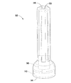
図1を参照すると、説明の目的のために、患者の右腕10が示されている。選択された動脈(破線の経路として示されている)が、選択された静脈(黒色の経路として示されている)と共に示されている。一方の端部が動脈に接続され、他方の端部が静脈に接続された動静脈グラフト12が示されている。具体的には、動静脈グラフト12は、上腕動脈14及び橈側皮静脈16に接続されている。
Referring to FIG. 1, for purposes of illustration, a
図2を参照して、動静脈アクセスバルブシステム50の一実施形態が、本発明の態様に従って示されている。図示のように、システム50は、動脈14及び静脈16間に結合された動静脈グラフト12を含む。血液透析を実施するために、第1の皮下注射針18が、皮膚を貫通して動静脈グラフト12に挿入される。第1の皮下注射針18を通じて動静脈グラフト12から血液が取り出され、透析装置20に送られる。透析装置20では、血液から老廃物が除去される。透析装置20を通した後、血液は、第2の皮下注射針22を通じて動静脈グラフト12に戻される。
Referring to FIG. 2, one embodiment of an arteriovenous
加えて、システム50は、動静脈グラフト12の動脈側端部またはその近傍に配置された第1のバルブ装置24(以降、単に、第1のバルブ24またはバルブ24と称する)と、動静脈グラフト12の静脈側端部またはその近傍に配置された第2のバルブ装置26(以降、単に、第2のバルブ26またはバルブ26と称する)とを含む。これに関して、バルブ24または26の1つまたは複数の構成要素(例えば、バルブ24、26のスリーブ)は、動脈及び/または静脈に対して相補的な形状を有する。また、該構成要素には、結合をさらに補強するため、かつ各バルブ24、26が意図する位置から変位するのを防止するために、該構成要素と動脈及び/または静脈との間の直接的な縫合を可能にする孔(図示せず)が形成されている。バルブ24、26は、図2に示すような通常の血液透析中は開位置にある。しかし、血液透析が終わると、動静脈グラフト12を通って血液が流れるのを防ぐために、バルブ24、26は閉位置に移動する。このようにして、動脈盗血を排除または軽減することができる。さらに、動静脈グラフト12を通る血液の乱流を低減させることにより、人工血管血栓も防止できる。
In addition, the
いくつかの実施形態では、バルブ24、26はバルーン駆動型バルブであり、各バルブは膨張可能バルーン(図示せず)を有する。バルーンを膨張させたときには、バルーンはバルブ24、26を閉じ、グラフト12を通って流れる血液を減少させるかまたは排除する。一方、バルーンを収縮させたときには、バルブ24、26は開かれ、血液は、動静脈グラフト12を通って流れる。具体的には、図示した実施形態に示すように、アクチュエータアセンブリ100、200は、第1のバルブチューブ40を介して第1のバルブ装置24に流体連通されるとともに、第2のバルブチューブ42を介して第2のバルブ装置26に流体連通されている。
In some embodiments,
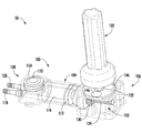
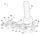
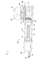
図3−9を参照して、本開示のシステム50での使用に適した一実施形態に係るアクチュエータアセンブリ100の様々な図が本発明の態様に従って示されている。具体的には、図3は、アクチュエータアセンブリ100と、アクチュエータアセンブリ100と共に使用される一実施形態に係る起動装置102との斜視図を本発明の態様に従って示している。図4及び5は、アクチュエータアセンブリ100と、それに関連する起動装置102との別の斜視図であり、非駆動位置(図4)及び駆動位置(図5)におけるアクチュエータアセンブリ100の構成要素を具体的に示す。図6は、図3−5に示したアクチュエータアセンブリ100の断面図である。図7は、アクチュエータアセンブリ100の線画であり、アクチュエータアセンブリ100の様々な内部構成要素を具体的に示す(なお、アクチュエータアセンブリ100の内部構成要素のフィーチャを示す目的で、アクチュエータアセンブリ100の1つまたは複数の内部構成要素の図示は省略されている)。図8は、アクチュエータアセンブリ100の別の斜視図である。図9は、起動装置102の側面図である。図3−8のいくつかまたは全てでは、本発明を説明する目的でアセンブリ100の様々な内部構成要素を図示するために、アクチュエータアセンブリ100の様々な外面及び/または壁部は、透明または半透明(例えば破線により)で図示されていることを理解されたい。
Referring to FIGS. 3-9, various views of an
図示した実施形態に示すように、アクチュエータアセンブリ100は、該アセンブリ100の様々な内部構成要素のための外側ケースまたはシェルの役割を果たすように構成されたハウジング104を含む。上述したように、アクチュエータアセンブリ100は、患者の例えば腕や脚の皮下に植え込まれるように構成されている。したがって、当然ながら、ハウジング104は、任意の適切な生体適合性材料、例えば、剛性及び生体適合性を有する適切な材料(例えばチタン)から作製される。
As shown in the illustrated embodiment, the
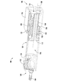
概して、ハウジング104は、第1の端部106及び第2の端部108間で長手方向に延在するように構成されている。図示した実施形態に示すように、アクチュエータアセンブリ100の駆動アセンブリ110は、ハウジング104内に収容され、ハウジング104の第1の端部またはその近傍に配置されている。詳細については後述するが、駆動アセンブリ110は、その駆動時に、プランジャ112を前後方向(図3において矢印114で示した方向)に移動させ、これにより、適切な流体(例えば食塩水)をハウジング104内に画定された流体チャンバ116から排出するか、または流体チャンバ116内に引き戻すように構成されている。加えて、図示した実施形態に示すように、アクチュエータアセンブリ100は、ハウジング104の第2の端部108から延出して及び/または第2の端部108を貫通して形成された第1の出口ポート118及び第2の出口ポート120を有する。詳細については後述するが、出口ポート118、120は、流体チャンバ116及びバルブ24、26の両方に(例えば、バルブチューブ40、42を介して)流体連通されている。したがって、プランジャ112を出口ポート118、120の方向に移動させることにより流体チャンバ116から流体を排出すると、その流体は出口ポート118、120を通じてそれに対応するバルブ24、26に導入され、これにより、各バルブ24、26を閉じることができる(例えば、関連するバルーンを膨張させることにより)。同様に、バルブ24、26を開くときは、プランジャ112を反対側に移動させ、これにより流体を吸引して流体チャンバ116に戻す。
Generally,
いくつかの実施形態では、ハウジング104は、互いに異なる複数のハウジング構成要素から構成されることを理解されたい。このような実施形態では、様々なハウジング構成要素は、機械的ファスナ、ブラケット、ねじ部品、シーリング機構、接着剤などの当分野で公知の任意の適切な取り付け手段、及び/または、溶接(例えばレーザ溶接)などの当分野で公知の任意の適切な取り付け方法を用いて互いに結合される。
It should be understood that in some embodiments, the
いくつかの実施形態では、駆動アセンブリ110は、プランジャ112に結合されたねじ部材124(例えばスクリュー)を直線的に駆動させるように構成された回転駆動可能なドライバ122を含む。例えば、図示した実施形態に示すように、回転駆動可能なドライバ122は、ハウジング104内に、ハウジング104の第1の端部106またはその近傍に画定されたハウジング104の外面126に隣接して配置された回転駆動可能な駆動ディスク122であり得る。駆動ディスク122は、駆動ディスク122の回転運動をねじ部材124の直線運動に変換する1つまたは複数の中間駆動部材128、130を介して、ねじ部材124に結合されている。例えば、図6に具体的に示すように、駆動ディスク122は、駆動ディスク122と一体に形成されるかまたは駆動ディスク122に結合され、駆動ディスク122が回転したときにその回転と共に回転する駆動ホイールまたは歯車128を含む。加えて、図6に示すように、駆動歯車128は、ねじ部材124を受容するように構成された、ねじが切られた開口部132を有するリニアドライバ130に回転駆動可能に結合されている。例えば、特定の実施形態では、リニアドライバ130の端面136(図6)に、駆動歯車128の歯に回転駆動可能に噛合するように構成された複数の歯134(図7)が形成されている。したがって、駆動歯車128が回転駆動可能なディスク122と共に回転すると、駆動歯車128とリニアドライバ130との間の回転係合により、リニアドライバ130はねじ部材124の長手方向軸138(図6)を中心にして回転する。
In some embodiments,
さらに、リニアドライバ130のねじが切られた開口部132とねじ部材124との間のねじ係合により、ねじ部材124の長手方向軸138を中心にしたリニアドライバ130の回転運動は、流体チャンバ116内でのねじ部材124及び該ねじ部材124に結合されたプランジャ112の非駆動位置(図4及び6)及び駆動位置(図3、5及び7)間の直線運動に変換される。流体チャンバ116内でのプランジャ112のこのような直線運動により、バルブ24、26を開閉するときに、液体をチャンバ116から排出またはチャンバ116内に引き戻すことが可能となる。
Further, due to the threaded engagement between the threaded
例えば、特に図6を参照して、プランジャ112が非駆動位置に位置するときは、バルブ24、26の駆動に用いられる液体の大部分は、流体チャンバ116内に収容されている。回転駆動可能なドライバ122を第1の方向(例えば時計方向)に回転させることにより、プランジャ112を非駆動位置(図6参照)から駆動方向(図5参照)に移動させることができ、これにより、流体チャンバ116から流体を押し出すことができる。この結果、流体は出口ポート118、120を通じて(例えば、バルブチューブ40、42を介して)バルブ24、26に送られ、これにより、関連するバルーンを膨張させてバルブ24、26を閉じることができる。その後にバルブ24、26を開くときは、回転駆動可能なドライバ122を反対方向(例えば反時計方向)に回転させ、プランジャ112を駆動位置から非駆動位置に移動させる。プランジャ112のこの移動によって流体を流体チャンバ116内に引き戻すことができ、これにより、バルーンを収縮させてバルブ24、26を開くことができる。
For example, with particular reference to FIG. 6, when the
本開示の構成では、プランジャ112は、ニードルまたは注射器に含まれるプランジャと同様に動作することを理解されたい。例えば、プランジャ112の外周縁と流体チャンバ116の内壁との間に画定される界面にはシールが形成される。したがって、プランジャ112を駆動位置に移動させると、流体をチャンバ116から効率的に押し出すことができる。同様に、プランジャ112を非駆動位置に引き戻すと、流体チャンバ116内に真空が生成され、これにより、流体をバルーンからチャンバ116に引き戻すことができる。
It should be understood that in the configuration of the present disclosure, the
本発明のいくつかの態様によれば、駆動アセンブリ110は、本開示の起動装置102を使用して、磁力により駆動させることができるように構成されている。具体的には、いくつかの実施形態では、回転駆動可能な駆動ディスク122は、起動装置102内に設けられた1つまたは複数の回転磁石により回転駆動させることができるように構成されている。したがって、起動装置102を駆動アセンブリ110の位置の近傍に配置することにより、起動装置102を使用して駆動アセンブリ110を外部から駆動させることができ、これにより、バルブ24、26を容易かつ効率的に開閉することが可能となる。例えば、一実施形態では、起動装置102は、駆動アセンブリ110を磁力により駆動すべく、ハウジング104の外面126(図3及び8参照)に形成された適切な凹部に隣接するように、駆動アセンブリ110の位置の真上の位置で患者の皮膚に接触または隣接させて配置される。
According to some aspects of the invention, the
概して、起動装置102は、手で持てるサイズの小型な装置であり得る。図7及び9に具体的に示すように、いくつかの実施形態では、起動装置102は、該起動装置102の接触側端部144またはその近傍に配置された1つまたは複数の起動磁石142と、その起動磁石142に回転駆動可能に結合された可逆モータ140とを含む。起動磁石142は、回転駆動可能な駆動ディスク122の全体または一部と磁力的に反応するように構成されている。例えば、図4及び5に示すように、駆動ディスク122は、該駆動ディスク122に組み込まれるか結合された、起動磁石142と反応する1つまたは複数の円板状磁石146を含む。このような実施形態では、起動磁石142と円板状磁石146との間の磁力を用いて、起動磁石142の回転によって駆動ディスク122を回転させることができ、これにより、プランジャ112を直線的に駆動させて、流体を流体チャンバ116から排出するか、または流体チャンバ116に引き込むことができる。
In general, the
可逆モータ140は、起動磁石142を時計方向及び反時計方向の両方向に回転させることができるように構成されていることを理解されたい。したがって、可逆モータ140を第1の方向に回転させることにより、駆動ディスク122を、プランジャ112を駆動位置に移動させる方向に回転させることができる。同様に、可逆モータ140を第1の方向とは反対側の第2の方向に回転させることにより、駆動ディスク122を、プランジャ112を非駆動位置に移動させる方向に回転させることができる。図9に示すように、一実施形態では、起動装置102は、操作者(ユーザ)が可逆モータ140の所望の回転方向を選択することを可能にする適切なユーザ制御ボタン148、150を含む。例えば、第1のボタン148は、可逆モータ140を、プランジャ112を駆動位置に移動させる方向に回転させ、これによりバルブ24、26を閉じるために設けられている。同様に、第2のボタン150は、可逆モータ140を、プランジャ112を非駆動位置に移動させる方向に回転させ、これによりバルブ24、26を開くために設けられている。
It should be understood that the
起動装置102は、他の様々な構成要素及びフィーチャも含み得ることを理解されたい。例えば、一実施形態では、起動装置102は、図12、20及び21を参照して後述する起動装置202の様々な構成要素及びフィーチャの全てまたは一部を含み得る。
It should be understood that the
引き続き図3−9を参照して、いくつかの実施形態では、アクチュエータアセンブリ100は、該アセンブリ100内にバルブ24、26を開閉するための適切な量の流体が含まれることを確実にするために、アセンブリ100に流体を追加するかまたはアセンブリ100から流体を除去する手段を提供するバックアップ隔膜152をさらに含む。例えば、図示した実施形態に示すように、隔膜152は、流体チャンバ116と出口ポート118、120との間に画定されたハウジング104の外面154に設けられる。したがって、必要に応じて、皮下注射針を患者の皮膚を貫いて隔膜152に挿入して、アクチュエータアセンブリ100に液体を追加するかまたはアクチュエータアセンブリ100から液体を除去することができる。例えば、駆動アセンブリ110が適切に動作しない場合には、隔膜152を介してアクチュエータアセンブリ100から液体を除去することにより、バルブ24、26を開くことができる。同様に、隔膜152を介してアクチュエータアセンブリ100に液体を追加することにより、バルブ24、26を閉じることができる。
With continued reference to FIGS. 3-9, in some embodiments, the
隔膜152は、皮下注射針の先端を挿入可能な任意の適切な材料から作製されることを理解されたい。例えば、一実施形態では、隔膜152は、例えばシリコーン膜などのエラストマー性フィルムから作製される。
It should be understood that the
加えて、いくつかの実施形態では、アクチュエータアセンブリ100は、ハウジング104内に配置された蓄圧器156をさらに含む。例えば、図8に示すように、一実施形態では、蓄圧器156は、ハウジング104内における隔膜152の真下の位置に配置される。蓄圧器156が、アセンブリ100内に含まれる液体の圧力を一定の圧力に維持するように構成されていることは容易に理解できるであろう。
Additionally, in some embodiments,
追加的に、いくつかの実施形態では、本開示のシステム50は、バルブ24、26を順次に閉じるための適切な手段を含む。具体的には、一実施形態では、動静脈グラフト12の静脈側端部に配置されたバルブ(例えば第2のバルブ装置26)を閉じる前に、動静脈グラフト12の動脈側端部に配置されたバルブ(例えば第1のバルブ装置24)を閉じることが望ましい。例えば、グラフト12の静脈側端部に配置されたバルブを閉じるタイミングを所定の時間間隔で遅らせることにより、グラフト12内から血液を追い出すことができる(例えば、透析用針を使用してグラフト12内に血液適合性流体を注入することにより)。その後、静脈からグラフト12内に血液が逆流するのを防止するために、グラフト12の静脈側端部に配置されたバルブを閉じる。
Additionally, in some embodiments, the
いくつかの実施形態では、バルブ24、26を順次に閉じることは、アクチュエータアセンブリ100の出口ポート118、120の内径が互いに異なるようにすることにより実現できる。例えば、特定の実施形態では、グラフト12の動脈側端部に配置されたバルブ(動脈側バルブ)に流体連通された出口ポートの内径を、グラフト12の静脈側端部に配置されたバルブ(静脈側バルブ)に流体連通された出口ポートの内径よりも大きくする。このことによりに、流体チャンバ116内に収容されている流体は、静脈側バルブよりも動脈側バルブの方に先に到達し、これにより、動脈側バルブを静脈側バルブよりも先に閉じることができる。出口ポート118、120の内径のサイズは、バルブ24、26を順次に閉じることができる適切な内径差となるように設定されることを理解されたい。例えば、特定の実施形態では、動脈側バルブに流体連通された出力ポートの内径は、グラフト12の静脈側バルブに流体連通された出口ポートの内径よりも、少なくとも5%、例えば少なくとも25%、または少なくとも50%、または少なくとも75%、または少なくとも90%大きいサイズに設定される。
In some embodiments, closing
出口ポート118、120の内径を互いに異なるサイズにすることに加えて、またはその代わりに、出口ポート118、120をバルブ24、26に接続するバルブチューブ40、42の長さ及び/または内径を互いに異なるサイズにすることにより、バルブ24、26を順次に閉じるようにしてもよい。例えば、静脈側バルブをそれに対応する出口ポートに接続するバルブチューブの内径及び/または長さを、動脈側バルブをそれに対応する出口ポートに接続するバルブチューブの内径及び/または長さよりも小さくまたは長くすることにより、動脈側バルブを静脈側バルブよりも先に閉じることできる。
In addition to, or instead of, making the inner diameters of the
別の実施形態では、アクチュエータアセンブリ100、及び/またはシステム50の任意の他の関連する構成要素は、バルブ24、26が互いに同時に開閉するように構成することができる。
In another embodiment,
また、図3−8に示したアクチュエータアセンブリ100及び/またはシステム50は、様々な他の構成要素及び/またはフィーチャを追加的に含み得ることを理解されたい。例えば、一実施形態では、アクチュエータアセンブリ100及び/またはシステム50は、図12−25を参照して後述するアクチュエータアセンブリ200及び/またはシステム50の構成要素及び/またはフィーチャの全てまたは一部を含み得る。
It should also be understood that
加えて、本明細書で説明したバルブ24、26は、当分野で公知の任意の適切な流体駆動バルブであり得ることを理解されたい。例えば、上述したように、いくつかの実施形態では、バルブ24、26は、流体駆動式のバルーン型バルブであり得る。このような実施形態では、バルーン型バルブは、任意の適切な流体を使用してバルーンを膨張または収縮させることによりバルブ24、26をそれぞれ開閉するための当分野で公知の任意の適切な構成を有する。例えば、一実施形態では、各バルーンは環状の形状を有し、グラフト12の周りを周方向に取り囲むように構成される。これにより、バルーンは、膨張時に径方向内側に向かって拡張して、血液がグラフトを流れるのを防止する。このようなバルーンは、例えば、特許文献1に開示されている。この特許文献1は、全ての目的のために、その全文を引用することを以って本明細書の一部となす。
In addition, it should be understood that the
別の実施形態では、バルーンは、グラフト12(または、グラフト12と流体連通された他の任意の適切な結合器、例えば、グラフト12内に配置されるかまたはグラフト12の端部に結合された1つまたは複数のスリーブ)と直列に配置されるように構成される。例えば、図10及び11は、本開示のシステム50に使用することができる適切な直列式のバルーン型バルブ24、26の一例を本発明の態様に従って示す。具体的には、図10は、バルブ24、26の閉状態を示し、図11は、バルブ24、26の開状態を示す。
In another embodiment, the balloon is the graft 12 (or any other suitable coupler in fluid communication with the
図示のように、バルブ24、26は、第1の端部176及び第2の端部178間に延在する円筒状のハウジングまたはスリーブ174を含む。スリーブ174の第1の端部176は、任意の適切な結合手段(例えば縫合糸(図示せず))を用いて、動静脈グラフト12の対応する端部(グラフト12の動脈側端部または静脈側端部)に結合されるように構成されている。また、スリーブ174の第2の端部178は、任意の適切な結合手段(例えば縫合糸)を用いて、患者の動脈14または静脈16に結合されるように構成されている。あるいは、スリーブ174は、グラフト12の一体部分として構成することができ、この場合、スリーブ172の第2の端部178は、グラフト12の動脈側端部または静脈側端部に相当する。
As shown, the
加えて、バルブ24、26は、スリーブ174と少なくとも部分的には直列に配置されるように構成されたバルーン180を含む。例えば、いくつかの実施形態では、スリーブ174は、該スリーブ174から径方向外側に延出するように構成された突出部分182を含み、突出部分182の真下(径方向内側)に、バルーン180と、バルーン180及びアクチュエータアセンブリ100間に延在するバルブチューブ40、42との両方を受容するための凹部184が形成されている。したがって、バルーン180の収縮時(図11参照)は、バルーン180は凹部184内に格納され、これにより、バルーン180はグラフト12及びスリーブ174を通る血液の流れを全くまたはほとんど妨げない。例えば、図11に示すように、一実施形態では、バルーン180は、凹部184に格納されたときに、バルーン180の内面(径方向内側の面)がスリーブ174及び/またはグラフト12の内面186と面一となるように構成される。加えて、図10に示すように、バルーン180は、バルブ24、26を閉じるべくバルーン180に流体が提供されたときに、凹部184からスリーブ174の内側に向かって拡張し、これにより、スリーブ174を通る血液の流れを完全に遮断するように構成される。
In addition,
図12−21を参照すると、本開示のシステム50での使用に適した別の実施形態に係るアクチュエータアセンブリ200の様々な図が本発明の態様に従って示されている。具体的には、図12は、本発明の態様によるアクチュエータアセンブリ200及び該アセンブリ200と共に使用される一実施形態に係る起動装置202を示す斜視図である。加えて、図12は、本発明の態様によるアクチュエータアセンブリ200と共に使用される様々な他のシステム構成要素を示す。図13及び図14は、図12に示したアクチュエータアセンブリ200の第1の端部及びその反対側の第2の端部をそれぞれ示す斜視図である(図12に示したチューブの図示は省略している)。図15は、図13及び14に示したアクチュエータアセンブリ200の上面図である。図16は、図13−15に示したアクチュエータアセンブリ200の分解図であり、図17は、図16示したアクチュエータアセンブリ200の様々な構成要素の分解図である。図18及び図19は、アクチュエータアセンブリ200のハウジング構成要素の底面斜視図であり、図18は、ハウジング構成要素内に適切な歯車が収容されている状態を示し、図19は、ハウジング構成要素内から歯車を除去した状態を示す。加えて、図20は、図12に示した起動装置202の正面図であり、図21は、図20に示した起動装置202の斜視図である。図21では、起動装置202の様々な内部構成要素を図示するために、起動装置202の少なくとも外側ケースまたはシェルの部分は除去されている。
Referring to FIGS. 12-21, various views of another embodiment of an
図示した実施形態に示すように、アクチュエータアセンブリ200は、該アセンブリ200の様々な内部構成要素のための外側ケースまたはシェルとしての役割を果たすハウジング204を含む。上述したように、アクチュエータアセンブリ200は、患者の例えば腕または脚の皮下に植え込むことができるように構成されている。したがって、当然ながら、ハウジング204は、任意の適切な生体適合性材料、例えば、剛性及び生体適合性を有する適切な材料(例えばチタン)から作製される。
As shown in the illustrated embodiment, the
概して、ハウジング204は、第1の端部206及び第2の端部208間で長手方向に延在するように構成されている。図示した実施形態に示すように(例えば図16及び17)、アクチュエータアセンブリ200の磁力駆動型駆動アセンブリ210は、ハウジング204内に収容され、ハウジング204の第1の端部206及び第2の端部208間に配置されている。詳細については後述するが、駆動アセンブリ210は、その駆動時に、ハウジング204の外部に配置された流体チャンバまたは流体タンク212と、バルブチューブ40、42を介してアクチュエータアセンブリ200に流体連通されたバルブ24、26との間で、適切な流体(例えば食塩水)を送出または送達することができるように構成されている。加えて、図示した実施形態に示すように、アクチュエータアセンブリ200は、ハウジング204の或る部分(例えば、ハウジング204の第1の端部206)に貫通して形成された入口ポート214と、ハウジング204の別の部分(例えば、ハウジング204の第2の端部208)に貫通して形成された第1の出口ポート216及び第2の出口ポート218とを有する。詳細については後述するが、入口ポート214は、(例えば、適切なタンクチューブ220を介して)流体チャンバまたは流体タンク212に流体連通されている。同様に、第1及び第2の出口ポート216、218は、(例えば、バルブチューブ40、42を介して)第1及び第2のバルブ24、26にそれぞれ流体連通されている。したがって、駆動アセンブリ210の駆動により流体タンク212からハウジング204に流体を送出すると、その流体はハウジング204から出口ポート216、218を通じてそれに対応するバルブ24、26に導入され、これにより(例えば、関連するバルーンを膨張させることにより)バルブ24、26を閉じることができる。同様に、バルブ24、26を開くときは、駆動アセンブリ210を反対方向に回転駆動させ、これにより流体をバルーンから引き出し、ハウジング204を通じて流体タンク212に戻す。
Generally,
いくつかの実施形態では、ハウジング204は、互いに異なる複数のハウジング構成要素から構成されることを理解されたい。例えば、図13、14及び16に図示するように、ハウジング204は、上側ハウジング構成要素222、下側ハウジング構成要素224、及び中央ハウジング構成要素226から構成される。このような実施形態では、様々なハウジング構成要素222、224及び226は、機械的ファスナ、ブラケット、ねじ部品、シーリング機構、接着剤などの当分野で公知の任意の適切な取り付け手段、及び/または、溶接(例えばレーザ溶接)などの当分野で公知の任意の適切な取り付け方法を用いて互いに結合される。
It should be understood that in some embodiments, the
いくつかの実施形態では、中央ハウジング構成要素226は、ハウジング204を通じて入口ポート214と出口ポート216、218との間で流体を送達するための流路を画定するように構成されている。例えば、図18及び図19に示すように、中央ハウジング構成要素226は、入口ポート214と駆動アセンブリ210(後述する)の歯車ポンプとの間に延在する入口側流路228と、歯車ポンプと出口ポート216、218との間に延在する出口側流路230とを画定する。したがって、ハウジング204を通じて流体タンク212からバルブ24、26に流体を導入するとき、入口ポート214を介してハウジング204に流入した流体は、入口側流路228を通って歯車ポンプに送達される。その後、流体は、出口側流路230を通り、出口ポート216、218を介してハウジング204から排出される。
In some embodiments,
加えて、図12に示すように、流体タンク212は、一般的に、タンクチューブ220を介してアクチュエータアセンブリ200に流体連通されるように構成された別個の構成要素であり得る。このような別個の流体タンク212を設けることにより、バルブ装置24、26の駆動に必要な流体をアクチュエータアセンブリ200内に完全に収容する場合と比べて、アクチュエータアセンブリ200の全体サイズを大幅に小さくすることができる。流体タンク212をアクチュエータアセンブリ200の植え込み位置の近傍に患者に不快感をほとんどまたは全く与えることなく配置することができるように、流体タンク212は一般的に柔軟なまたはフレキシブルな材料から作製されることを理解されたい。
In addition, as shown in FIG. 12, the
別の実施形態では、アクチュエータアセンブリ200は、流体タンク212の代わりに、ハウジング204内に画定された流体タンクまたはチャンバを含むことを理解されたい。具体的には、図3−9を参照して説明した流体チャンバ116と同様に、ハウジング204内に、バルブ24、26に供給する流体を収容するための内部空間を画定してもよい。例えば、図19に破線で示すように、中央ハウジング構成要素226内に、流体を収容するための内部空間232が画定される。この場合、システム50は別個の流体タンク212を備える必要はなく、また、流体は内部空間232からバルブ24、26に直接供給されるので、アクチュエータアセンブリ200は入口ポート214を有する必要はない。
It should be appreciated that in another embodiment,
図16−18に具体的に示すように、いくつかの実施形態では、駆動アセンブリ210は、流体タンク212とバルブ24、26と間で流体を移動させるための歯車ポンプとして働くように構成された2つの別個の歯車234、236(例えば平歯車)を含む。具体的には、図示した実施形態に示すように、駆動アセンブリ210は、駆動歯車234及び遊び歯車236を含む。各歯車234、236は、中央ハウジング構成要素226内に画定された歯車空間238(図18及び19参照)内に配置されるように構成される。駆動歯車234は、駆動アセンブリ210の駆動シャフト240に回転駆動可能に結合されている。また、遊び歯車236は、中央ハウジング構成要素226から歯車空間238内に延出する歯車ポスト242(図19参照)を介して、歯車空間238内に回転駆動可能に支持されるように構成されている。概して、歯車234、236は、互いに噛合し、駆動シャフト240の回転により駆動歯車234が回転し、遊び歯車236は歯車ポスト242を中心にして回転するように構成されている。歯車234、236のこのような噛合は、歯車ポンプにより流体を能動的に移動させることを可能にする。したがって、歯車234、236を第1の方向に回転させることにより、歯車ポンプは、流体を流体タンク212からバルブ24、26の方向に送出することができる。同様に、歯車234、236を第1の方向とは反対の第2の方法に回転させることにより、歯車ポンプは、流体をバルブ24、26から流体タンク212の方向に引き戻すことができる。
16-18, in some embodiments, the
ハウジング204を通じて、入口ポート214と出口ポート216、218との間で流体を送出するための流路の一例が、図18に矢印で示されている。図示のように、歯車234、236を回転させると、流体は入口ポート214を介してハウジング204内に流入し、入口側流路228を通って歯車ポンプに送達される。その後、流体は、各歯車234、236の外周縁と歯車空間238の内周縁との間に画定された別個の2つの流路に沿って流れ、出口側流路230に送達される。図18に示すように、流体が2つの別個の流路に分かれて入るのを容易にするために、歯車ポンプの入口側及び出口側の両端には、分流器(flow diverter)がそれぞれ設けられている。出口側流路230に到達した流体は、その後、出口ポート216、218を介してハウジング204から排出される。
One example of a flow path for delivering fluid between the
本発明のいくつかの態様によれば、駆動アセンブリ210は、本開示の起動装置202を使用して、磁力により駆動させることができるように構成されている。具体的には、いくつかの実施形態では、駆動シャフト240は、ハウジング204内に該ハウジング204の外面248(例えば、上側ハウジング構成要素222により画定された外面248)に隣接して配置された1つまたは複数の回転磁石246により回転駆動させることができるように構成されている。例えば、図16及び17に示すように、円板状の駆動磁石246が、ハウジング204内に設けられた磁石カップ250内に収容され、互いに結合されている。これにより、磁石カップ250が駆動磁石246と互いに一体的に回転するように構成されている。このような実施形態では、駆動シャフト240は、磁石カップ250と一体的に形成されるか、または磁石カップ250に結合されており、磁石カップ250から外向きに突出して駆動歯車234に結合されている。これにより、駆動歯車234が駆動シャフト240と互いに一体的に回転するように構成されている。例えば、図17に示すように、駆動シャフト240は、駆動歯車234に該歯車を回転駆動可能に結合することができるように、中央ハウジング構成要素226の上側壁部に形成された開口部225を貫通して延在するように構成されている。したがって、駆動磁石246及びそれに対応する磁石カップ250の両方の回転により、駆動シャフト240を回転駆動させることができ、これにより、駆動歯車234を回転させることができる。そのため、起動装置202を、駆動アセンブリ210の位置の近傍に配置することにより、起動装置202を使用して駆動アセンブリ210を外部から駆動させることができ、これにより、バルブ24、26を容易かつ効率的に開閉することが可能となる。例えば、一実施形態では、起動装置202は、駆動アセンブリ210を磁力により駆動すべく、ハウジング204の外面248の真上の位置で患者の皮膚に接触または隣接させて配置される。
According to some aspects of the invention, the
いくつかの実施形態では、アクチュエータアセンブリ200は、ハウジング204内での磁石カップ250の回転を促進または向上させるために、1つまたは複数の適切なベアリングまたはベアリング要素を含むことを理解されたい。例えば、図16に示すように、磁石カップ250とハウジング204(例えば、上側ハウジング構成要素222)との間に配置された環状ボールアセンブリ254を含むことができる。このような実施形態では、環状ボールアセンブリ254は、磁石カップ250から外向きに延出した環状フランジ256(図16、17参照)により、ハウジング204内に垂直方向に支持される。
It should be understood that in some embodiments, the
特に図12、20及び21を参照して、起動装置202は、上述した起動装置102よりも小さく構成されている。具体的には、いくつかの実施形態では、起動装置202は、手で持てるサイズの小型な装置であり、該起動装置202の接触側端部262またはその近傍に配置された1つまたは複数の起動磁石260と、その起動磁石260に結合された起動磁石260を回転させるための可逆モータ258を含む。起動磁石260は、ハウジング204内に設けられた駆動磁石246と磁力的に反応するように構成されている。これにより、歯車ポンプを磁力により駆動して、流体を流体タンク212から送出するかまたは流体タンク212に引き戻すことができる。また、上述した実施形態と同様に、可逆モータ258は、起動磁石260を時計方向及び反時計方向の両方向に回転させることができるように構成されていることを理解されたい。したがって、可逆モータ258を第1の方向に回転させることにより、駆動アセンブリ210の駆動歯車234及び遊び歯車236によって流体タンク212からバルブ24、26に流体を移動させる方向に、駆動磁石246を回転させることができる。同様に、可逆モータ258を第1の方向とは反対側の第2の方向に回転させることにより、駆動歯車234及び遊び歯車236によってバルブ24、26から流体タンク212に流体を移動させる方向に、駆動磁石246を回転させることができる。
With particular reference to FIGS. 12, 20, and 21, the
いくつかの実施形態では、起動装置202は、操作者(ユーザ)が可逆モータ258の所望の回転方向を選択することを可能にする1つまたは複数のユーザインターフェース要素を含む。例えば、図20に示すように、起動装置202の外面にトグルスイッチ264が設けられている。トグルスイッチ264は、ニュートラルまたはオフ位置(例えば、可逆モータ258をスイッチオフにする位置)から正転または「膨張」位置に切り替えることができるように構成されており、これにより、可逆モータ258を第1の方向に回転させることができる。また、トグルスイッチ264は、オフ位置から逆転または「収縮」位置に切り替えることができるように構成されており、これにより、可逆モータ258を第1の方向とは反対の第2の方向に回転させることができる。加えて、起動装置202は、表示ランプ266をさらに含む。表示ランプ266は、トグルスイッチ264をオフ位置から膨張または収縮位置に移動させたときに光を発するように構成されており、これにより、可逆モータ258が回転していることを示す表示をユーザに提供することが可能となる。このような実施形態では、表示ランプ266は、可逆モータ258の回転方向(正転方向または逆転方向)をそれぞれ異なる色で表示するように構成するとよい。例えば、表示ランプ266は、可逆モータ258が正転方向に回転するときは緑色を発し、逆転方向に回転するときは赤色を発するように構成するとよい。あるいは、起動装置202は、可逆モータ258の回転方向を示すために、複数の表示ランプを含み得る。例えば、特定の実施形態では、起動装置202は、可逆モータ258が正転方向に回転していることを示す第1の表示ランプと、可逆モータ258が逆転方向に回転していることを示す第2の表示ランプとを含み得る。
In some embodiments, the
起動装置202は、トグルスイッチ264の代わりに、ユーザが可逆モータ258の所望の回転方向を選択することを可能にする任意の他の適切なユーザインターフェース要素を含み得ることを理解されたい。例えば、図9を参照して上述した実施形態と同様に、起動装置202は、可逆モータ258を正転方向または逆転方向に回転させるための別個のボタンを含み得る。加えて、起動装置202は、表示ランプ266の代わりに、可逆モータ258が駆動していること及び/または可逆モータ258の回転方向を示すための任意の他の適切な表示または出力手段を含み得ることを理解されたい。例えば、別の実施形態では、起動装置202は、可逆モータ258の動作状態に関する可視表示(可視情報)を表示するための適切なディスプレイ(例えばLCDディスプレイパネル)を含み得る。
It should be appreciated that the
図21を特に参照して、起動装置202は、該起動装置202の動作を容易にするための様々な内部構成要素も含み得る。例えば、図21に示すように、起動装置202は、該起動装置202の様々な構成要素に電力を提供するためのバッテリ268を含み得る。いくつかの実施形態では、バッテリ268は、再充電式バッテリであり得る。このような実施形態では、起動装置202は、バッテリ268を再充電するために、適切な再充電スタンド(ステーション)に置くこと及び/または適切な電源コードに接続することができるように構成され得る。
With particular reference to FIG. 21,
加えて、起動装置202は、該起動装置202の様々な構成要素の動作を制御するための制御部270を含み得る。概して、制御部270は、当分野で公知の任意の適切な処理装置であり得る。したがって、制御部270は、例えば、1つまたは複数のプロセッサ272及びメモリ274を有する回路基板276であり得る。本明細書で用いる場合、用語「プロセッサ」は、当分野でコンピュータに含まれる集積回路だけではなく、コントローラ、マイクロコントローラ、マイクロコンピュータ、プログラマブルロジックコントローラ(PLD)、特定用途向け集積回路、及び他のプログラム可能な回路も指す。加えて、制御部270のメモリ274は、これらに限定されないが、例えば、コンピュータ読み取り可能な媒体(例えばランダムアクセスメモリ(RAM))、コンピュータ読み取り可能な不揮発性媒体(例えばフラッシュメモリ)、及び/または他の適切なメモリ要素などのメモリ要素を含む。このようなメモリ274は、様々なコンピュータ実施機能、例えば、ユーザからの入力の受信(例えば、トグルスイッチ264を介した)、モータ258の動作の制御、表示ランプ266の点灯などを実行するための適切なコンピュータ読み取り可能な命令を格納するように構成されている。
In addition, the
さらに、いくつかの実施形態では、起動装置202は、アクチュエータアセンブリ200の1つまたは複数の構成要素との間で無線通信の送信及び/または受信を行うための無線通信装置278を含む。例えば、一実施形態では、無線通信装置278は、適切なプロセッサ280(例えば集積回路)と、無線通信の送信及び/または受信のためのアンテナ282とを含む。このような実施形態では、プロセッサ280は、制御装置170のプロセッサ272、または起動装置202内に収容された(例えば、別個の回路基板上に設けられた)別個のプロセッサであり得る。あるいは、無線通信装置278は、起動装置202との間での無線通信の送信及び/または受信を可能にする任意の他の適切な構成要素を含み得る。
Further, in some embodiments, the
本発明の特定の実施形態では、無線通信装置278は、無線周波数(RF)磁界を能動的に生成することによりアクチュエータアセンブリ200内に設けられた通信装置284(図15参照)に給電する、近距離無線通信(NFC)用のイニシエータ装置(initiator device)として使用されるように構成することができる。詳細については後述するが、アクチュエータアセンブリ200のNFC給電型の通信装置284は、システム50内に収容される流体の圧力のセンサ測定値を受信し、そのセンサ測定値を、起動装置202内に設置された無線通信装置278に送信するように構成される。無線通信装置278が受信したセンサ測定値は、その後、制御部270のメモリ274に格納されるか、あるいは起動装置202と通信可能な別個の装置に送信される。加えて、センサ測定値は、システム50が適切に動作していることをユーザに表示するのにも使用することができる、例えば、詳細については後述するが、起動装置202は、無線通信装置278が受信した圧力測定値に基づくバルブ24、26の膨張/収縮レベルの可視表示をユーザに表示するための表示バーまたは他の適切な出力装置を含み得る。
In certain embodiments of the present invention,
引き続き図12−21を参照して、いくつかの実施形態では、アクチュエータアセンブリ200は、該アセンブリ200内にバルブ24、26を開閉するための適切な量の流体が含まれることを確実にするために、アセンブリ200に流体を追加するかまたはアセンブリ200から流体を除去する手段を提供するバックアップ隔膜286をさらに含む。例えば、図示した実施形態に示すように、隔膜286は、ハウジング204の外面における、ハウジング204により画定された流路にアクセスを提供する適切な位置に設けられる。したがって、必要に応じて、皮下注射針を患者の皮膚を貫いて隔膜286に挿入し、アクチュエータアセンブリ200に液体を追加するかまたはアクチュエータアセンブリ200から液体を除去することができる。例えば、駆動アセンブリ210が適切に動作しない場合には、隔膜286を介してアクチュエータアセンブリ200から液体を除去することにより、バルブ24、26を開くことができる。同様に、隔膜286を介してアクチュエータアセンブリ200に液体を追加することにより、バルブ24、26を閉じることができる。
With continued reference to FIGS. 12-21, in some embodiments, the
隔膜286は、図3−8を参照して上述した実施形態と同様に、皮下注射針の先端を挿入可能な任意の適切な材料から作製されることを理解されたい。例えば、一実施形態では、隔膜286は、例えばシリコーン膜などのエラストマー性フィルムから作製される。
It should be understood that the
加えて、いくつかの実施形態では、本開示のシステム50は、システム50内に含まれる液体の圧力を一定の圧力に維持するように構成された蓄圧器287をさらに含む。例えば、図12に示すように、一実施形態では、蓄圧器287は、アクチュエータアセンブリ200とバルブ24、26との間に延在するバルブチューブ40、42の一方に流体連通されている。このような実施形態では、液体の圧力を一定の圧力に維持するのに加えて、蓄圧器287は、バルブチューブ40、42を通じて供給される流体のための流量制限器としての役割を果たすように構成されている。これにより、蓄圧器287は、バルブ24、26を順次に閉じるための手段を提供する。例えば、上述したように、動静脈グラフト12の静脈側端部に配置されたバルブ(静脈側バルブ)を閉じる前に、動静脈グラフト12の動脈側端部に配置されたバルブ(動脈側バルブ)を閉じることが望ましい。このような場合、蓄圧器287は、静脈側バルブに流体を提供するバルブチューブに流体連通して設けられ、これにより、静脈側バルブへの流体の供給を制限する。この結果、グラフト12の静脈側バルブを閉じるタイミングを、蓄圧器287により提供される流量制限に比例する時定数だけ遅らせることができ、これにより、動脈側バルブを静脈側バルブよりも先に閉じることができる。
In addition, in some embodiments, the
別の実施形態では、蓄圧器287は、任意の他の適切な位置、例えばハウジング204内に配置され得ることを理解されたい。さらに、別の実施形態では、システム50は、バルブ24、26を順次に閉じるための任意の他の適切な手段(例えば、出口ポート216、218、及び/または出口ポート216、218をバルブ24、26に接続するバルブチューブ40、42の内径を互いに異なるように設定する)を含み得ることを理解されたい。
It should be appreciated that in other embodiments, the
さらに、本発明の態様によれは、本開示のシステム50は、システム50内の供給される流体の圧力を検出するための1つまたは複数の圧力センサ288、289をさらに含む。例えば、図15に具体的に示すように、一実施形態では、アクチュエータアセンブリ200は、ハウジング204を通じて供給される流体の圧力をモニタするためにハウジング204内に配置された2つの圧力センサ(例えば、第1の圧力センサ288及び第2の圧力センサ289)を含む。具体的には、第1の圧力センサ288は、第1のバルブ24の開閉時に第1の出口ポート216を通じて供給される流体の圧力をモニタするために、第1の出口ポート216に流体連通して設けられている。同様に、第2の圧力センサ289は、第2のバルブ26の開閉時に第2の出口ポート218を通じて供給される流体の圧力をモニタするために、第2の出口ポート218に流体連通して設けられている。上述したように、各バルブ24、26に供給される流体の圧力をモニタすることにより、流体を各バルブ24、26に送出または各バルブ24、26から引き戻したときに、バルーンが完全に膨張/収縮したか否かを示す表示(情報)をユーザに提供することができる。これにより、ユーザが、各バルブ24、26が適切に閉じた/開いたか否かを判断することが可能となる。
Further, according to aspects of the present invention,
各圧力センサ288、289は、システム50内の流体圧力を直接的または間接的に検出するように構成された任意の適切なセンサであり得ることを理解されたい。例えば、いくつかの実施形態では、各圧力センサ288、289は、該圧力センサ288、289がその近傍及び/または該センサ288、289を通過した流体に起因する圧力を受けたときに、その負荷を示す出力信号(例えば電流信号)を提供するように構成された感圧フィルムであり得る。本発明の態様による圧力センサとして使用するのに適した感圧フィルムの一例は、2012年10月5日に出願された「Contact Sensors, Force/Pressure Sensors and Methods for Making Same」なる標題の米国特許公開第2013/0204157号(米国特許出願第13/636,345号、WO2011/127306としても公開されている)。上記特許の開示内容の全体は、参照により本明細書に援用される。
It should be understood that each
本発明の特定の実施形態では、圧力センサ288、289は、部分的に導電性のセンサ材料と、気密/防湿コーティング内に封入された少なくとも1つの導体を含み、センサ材料及び導体をシステム50内に含まれた流体から流体的に隔離するように構成した感圧フィルムであり得る。このような実施形態では、センサ材料は、圧力センサ288、289に露出された流体の圧力変化に応答して検出可能な変化を示す任意の他の適切な材料であり得る。例えば、センサ材料は、センサ材料の変形に起因して流体圧力の変化に応答してセンサ材料及び導体間の接触面積が変化するように導体に隣接して配置された導電性ポリイミドフィルム(例えば、DUPONT社製のKAPTON XC)であり得る。具体的には、一実施形態では、圧力が増加すると接触面積は増加する。センサ材料及び導体間の接触面積が増加すると、圧力センサ288、289の導電性が増加し、これにより、圧力センサ288、289内の電気抵抗が減少する。この電気抵抗の減少を検出し、システム50内の流体圧力に関連付ける。
In certain embodiments of the present invention, the
各圧力センサ288、289が感圧フィルムである実施形態では、感圧フィルムは、システム50を通じて供給される流体の圧力を直接的または間接的にモニタすることができる任意の他の適切な位置に配置され得ることを理解されたい。例えば、一実施形態では、感圧フィルムは、ハウジング204内に、各出口ポート216、218により画定される流路内に直接的に突出するように配置され得る。例えば、図22は、図15に示したハウジング204の22,23−22,23線で切った断面図であり、出口ポート216、218を通じて流れる流体の流路内に感圧センサを配置するための適切な構成の一例を具体的に示している。図示のように、各センサ288、289は、感圧センサがその両端に沿って流体に露出するように(すなわち、感圧センサが流体の流れ方向に沿って延在するように)、出口ポート216、218の内面290から径方向内側に向かって延出するように構成されている。あるいは、感圧フィルムは、ハウジング204を通る流体の流路の内部及び/またはその近傍の任意の他の適切な位置に配置される。例えば、図23は、図15に示したハウジング204の22,23−22,23線で切った別の断面図であり、出口ポート216、218を通じて流れる流体の流路内に感圧センサを配置するための適切な構成の一例を具体的に示している。図示のように、各センサ288、289は、出口ポート216、218を流れる流体が該センサの内周縁に沿って接触するように、出口ポート216、218の内周面に沿って周方向に延在するように構成されている。
In embodiments where each
別の実施形態では、圧力センサ288、289は、システム50内の流体の圧力をモニタすることを可能にする、流体の流路に沿った任意の他の適切な位置に配置される。例えば、別の実施形態では、圧力センサ(図12において破線291で示す)は、アクチュエータアセンブリ200とバルブ24、26との間に延在する各バルブチューブ40、42に流体連通して設けられ、各バルブチューブ40、42内の圧力をモニタする。別の実施形態では、圧力センサは、各バルブ24、26と動作的に関連して設けられる。例えば、図24は、圧力センサ29を各バルブ24、26に関連して設けるための適切な構成の一実施形態の断面図である。図示のように、バルブ24、26は、図10及び11に示したバルブ24、26と同様に構成されている。例えば、バルブ24、26は、(例えば、バルブチューブ40、42を介して流体を供給することにより)円筒状のハウジングまたはスリーブ174内で膨張させることができるように構成されたバルーン180を含む。加えて、バルブ24、26は、内側スリーブ174の少なくとも一部を取り囲むように、内側スリーブ174の周りに周方向に延在する外側スリーブ190を含む。このような実施形態では、圧力センサ292(例えば感圧フィルム)は、バルーン180の膨張時に内側スリーブ174が径方向外向きの力を受ける領域の少なくとも一部の周りに周方向に延在するように、内側スリーブ174と外側スリーブ190との間に配置される。したがって、バルーン180が膨張して、径方向外向きの力が内側スリーブ174に加えられたときに、その力は圧力センサ292により検出され、これにより、バルーン180の圧力を示す表示(情報)が提供される。
In another embodiment, the
感圧フィルムの代わりに、圧力センサ288、289として、本開示のシステム50内の任意の位置で供給される流体の圧力を検出または測定可能な任意の他の適切なセンサを使用することができることを理解されたい。例えば、本開示のシステム50での使用に適した圧力センサとしては、これに限定しないが、ピエゾ抵抗ひずみゲージを用いた圧力センサや、電気容量、電磁気、ピエゾ圧電、光学及び/または電位差滴定の各センシング技術を利用した圧力センサが挙げられる。
Instead of a pressure sensitive film, any other suitable sensor capable of detecting or measuring the pressure of a fluid supplied at any location within the
図12−21を再び参照して、上述したように、アクチュエータアセンブリ200は、圧力センサ288、289に通信可能に接続されたセンサ通信装置284をさらに含む。センサ通信装置284は、圧力センサ288、289から送信されたセンサ測定値を受信/格納するように、及び/または、センサ測定値を、患者の身体の外部に配置された別個の無線通信装置に無線送信するように構成されている。例えば、上述したように、起動装置202は、該起動装置202内に組み込まれた無線通信を受信及び/または送信するための無線通信装置278を有する。このようにして、センサ通信装置284が圧力センサ288、289から受信した圧力測定値に関する無線通信を、センサ通信装置284から起動装置202に送信することができる。
Referring again to FIGS. 12-21, as described above, the
いくつかの実施形態では、センサ通信装置284は、適切なプロセッサ293(例えば集積回路)と、無線通信を受信及び/または送信するためのアンテナ294とを含む(図15)。このような実施形態では、センサ通信装置284は、起動装置202のオンボード型バッテリから電力供給を受け、圧力センサ測定値のデータロギングを行う。あるいは、センサ通信装置284は、遠隔給電されるように構成され、これにより、植込み型アクチュエータアセンブリ200内にバッテリを配置する必要がなくなる。例えば、上述したように、センサ通信装置284は、起動装置202のNFC搭載無線通信装置278により生成される無線周波数(RF)磁界を介して給電されるように構成される。このような場合、無線通信装置278により生成された電磁界を介してプロセッサ293に電力が供給される間は、センサ通信装置284は、圧力センサ288、289からセンサ測定値を受信し、そのセンサ測定値を、アンテナ294を介して無線送信することができる。このようにして、NFC給電型のセンサ通信装置284は、システム50内の現在の流体圧力に関連する圧力測定値を、即時にまたはリアルタイムで、起動装置202(または、患者の体外に配置された任意の他の適切な装置)に無線送信することができる。
In some embodiments, the
センサ通信装置284に関連するアンテナ294は、任意の適切な無線通信プロトコルを介して無線通信を提供するように構成されていることを理解されたい。例えば、一実施形態では、アンテナ294は、NFCに基づく通信をセンサ通信装置284から送信することができる。あるいは、例えばBluetooth(登録商標)などの、任意の他の適切な無線通信プロトコルを用いることができる。
It should be understood that the
上述したように、駆動アセンブリ210を磁力により駆動するために起動装置202をアクチュエータアセンブリ200の真上の位置で患者の皮膚に接触または(所定の間隔を隔てて)隣接させて配置したとき、起動装置202の無線通信装置278は、センサ通信装置284への給電を可能にする電磁界を同時に生成するのにも使用される。したがって、駆動アセンブリ210の磁力駆動によりバルブ24、26を膨張させるとき、NFC給電型のセンサ通信装置284は、圧力センサ288、289から圧力測定値を即時に受信するとともに、その圧力測定値を無線通信装置278に送信することができる。上述したように、無線通信装置278が受信した圧力測定値は、その後、バルブ24、26の膨張/収縮レベルの可視表示をユーザに提供するのに用いられる。
As described above, when the
例えば、図20に示すように、起動装置202は、システム50内の流体圧力が増加するにしたがって順次点灯するように構成された複数のランプ295を含む表示バー285を有する。これにより、表示バー285は、バルブ24、26の膨張/収縮レベルの表示を提供することができる。例えば、起動装置202の制御部270は、モニタした流体圧力が、バルーン型バルブ24、26が完全に膨張したことを示したときは、表示バー285の全てのランプ295を点灯し、モニタした流体圧力が、バルーン型バルブ24、26が完全に収縮したことを示したときは、表示バー285の全てのランプ295を消すように構成されている。ユーザが起動装置202を使用してバルーンを膨張させる(すなわち、バルブ24、26を閉じる)とき、ユーザは表示バー285を見て、流体圧力の増加にしたがってランプ295の点灯が順次増加するのを見ることができる。全てのランプ295が点灯したとき(すなわち、バルーンが完全に膨張したことが示されたとき)、ユーザは、起動装置202をスイッチオフにするか、または起動装置202を患者から離間させる。同様に、ユーザが起動装置202を使用してバルーンを収縮させる(すなわち、バルブ24、26を開ける)とき、ユーザは表示バー285を見て、流体圧力の低下にしたがってランプ295の点灯が順次減少するのを見ることができる。全てのランプ295がオフ(消灯)になったとき(すなわち、バルーンが完全に収縮したことが示されたとき)、ユーザは、起動装置202をスイッチオフにするか、または起動装置202を患者から離間させる。
For example, as shown in FIG. 20, the
別の実施形態では、起動装置202は、バルーン型バルブ24、26の膨張/収縮レベルの表示(情報)をユーザに提供するための任意の他の適切な手段を含み得ることを理解されたい。例えば、一実施形態では、起動装置202は、バルーン型バルブ24、26の膨張/収縮レベルの可視表示(可視情報)をユーザに提供するための英数字データ、グラフ、及び/または任意の他の適切なデータを表示するための適切なディスプレイ(例えばLCDディスプレイパネル)を含む。また、可視表示に加えて(またはその代わりに)、起動装置202は、バルーン型バルブ24、26の膨張/収縮レベルの可聴表示(可聴情報)をユーザに提供するための1つまたは複数のスピーカを含み得る。
It should be understood that in another embodiment, the
さらに、一実施形態では、制御部270は、圧力センサ288、289から受信した圧力測定値に基づいて、起動装置202の動作を自動的に制御するように構成されている。例えば、制御部270は、制御部270は、バルブ24、26が完全に収縮したこと(すなわち、血液透析療法を開始するためにバルブ24、26が完全に開いたこと)及び/またはバルブ24、26が完全に膨張したこと(すなわち、血液透析療法を完了するためにバルブ24、26が完全に閉じたこと)を示す圧力測定値を圧力センサ288、289から受信したときに、可逆モータ258を自動的にスイッチオフにするように構成されている。
Further, in one embodiment, the
次に、図25を参照すると、別の実施形態に係る動静脈アクセスバルブシステム350が本発明の態様に従って示されている。システム350は、図2を参照して説明したシステム50と概ね同様に構成されている。例えば、システム350は、動脈14及び静脈16間に結合された動静脈グラフト12を含む。血液透析を実施するために、第1の皮下注射針18が、皮膚を貫通して動静脈グラフト12に挿入される。第1の皮下注射針18を通じて動静脈グラフト12から血液が取り出され、透析装置20に送られる。透析装置20では、血液から老廃物が除去される。透析装置20を通した後、血液は、第2の皮下注射針22を通じて動静脈グラフト12に戻される。
Referring now to FIG. 25, another embodiment of an arteriovenous
加えて、システム350は、動静脈グラフト12の動脈側端部またはその近傍に配置された第1のバルブ24と、動静脈グラフト12の静脈側端部またはその近傍に配置された第2のバルブ26とを含む。上述したように、いくつかの実施形態では、バルブ24、26はバルーン駆動型バルブであり、各バルブは膨張可能バルーン(図示せず)を有する。バルーンを膨張させたときは、バルーンはバルブ24、26を閉じ、グラフト12を通る血液の流れを減少させるかまたは排除する。一方、バルーンを収縮させたときは、バルブ24、26は開かれ、血液は動静脈グラフト12を通って流れる。
In addition, the
しかし、上述したシステム50とは異なり、各バルブ24、26は、そのバルーンを膨張/収縮させるために、それぞれ別々のアクチュエータアセンブリ300A、300Bに流体連通されるように構成されている。具体的には、図示した実施形態に示すように、システム350は、(例えば、第1のバルブチューブ40を介して)第1のバルブ24に流体連通されたアクチュエータアセンブリ300Aを含む。加えて、システム350は、(例えば、第2のバルブチューブ42を介して)第2のバルブ26に流体連通されたアクチュエータアセンブリ300Bを含む。互いに別個のアクチュエータアセンブリ300A、300Bを、バルブ24、26と動作的に関連して設けることにより、バルブ24、26を互いに独立的に開閉することができる。例えば、血液透析療法を完了したとき、動静脈グラフト12の動脈側端部に配置されたバルブ(例えば第1のバルブ24)は、アクチュエータアセンブリ300Aを駆動することにより先に閉鎖される。その後、動静脈グラフト12の静脈側端部に配置されたバルブ(例えば第2のバルブ26)が、アクチュエータアセンブリ300Bを別個に駆動することにより閉鎖される。
However, unlike the
いくつかの実施形態では、アクチュエータアセンブリ300A、300Bは、磁力駆動型のアクチュエータアセンブリであり得る。例えば、一実施形態では、各アクチュエータアセンブリ300A、300Bは、図3−8を参照して上述したアクチュエータアセンブリ100及び/または図12−19を参照して上述したアクチュエータアセンブリ200と同一または同様に構成され得る。
In some embodiments,
別の実施形態では、システム350は、バルブ24、26を互いに独立的に開閉するための任意の他の適切な手段を含み得ることを理解されたい。例えば、2つの互いに別個のアクチュエータアセンブリを含む代わりに、システム350は、各バルブ24、26を互いに独立的に開閉するように構成された単一のアクチュエータアセンブリを含むことができる。このような実施形態では、上記の単一のアクチュエータアセンブリは、例えば、流体をバルブ24、26に供給するかまたはバルブ24、26から引き出すために該アクチュエータアセンブリ内に収容された、2つの互いに別個のスクリュー/プランジャドライブ、及び/または2つの互いに別個の歯車ポンプを含み得る。あるいは、上記の単一のアクチュエータアセンブリは、流体の流れを各バルブ24、26に別々に、または各バルブ24、26の両方に分配する分流器(例えば、流れ方向制御バルブ(directional flow valve)、または他の同様の種類の機構)を含み得る。
It should be understood that in another embodiment, the
図26を参照して、バルブ24、26を互いに独立的に駆動するためにシステム350と共に使用される一実施形態に係る起動装置302の正面図が本発明の態様に従って示されている。概して、起動装置302は、図12、20及び21を参照して上述した起動装置202と同一または同様に構成されている。例えば、図示のように、起動装置302は、該起動装置302の接触側端部262またはその近傍に配置された1つまたは複数の起動磁石260と、その起動磁石260に該磁石を回転駆動可能に結合された可逆モータ258を含む。上述した実施形態と同様に、起動磁石260は、各アクチュエータアセンブリ300A、300Bの駆動磁石と磁力的に反応するように構成されており、これにより、流体をバルブ24、26に供給するか、またはバルブ24、26から引き出すことが可能となる。加えて、起動装置302は、該起動装置302の所望の動作を容易にするための1つまたは複数の内部構成要素(図示せず)を含み得る。このような内部構成要素としては、例えば、バッテリ(例えば、図21に示したバッテリ268)、制御部(例えば、図21に示した制御部270)、無線通信装置(例えば、図21に示した無線通信装置278)、及び/または任意の他の適切な内部構成要素が挙げられる。
Referring to FIG. 26, a front view of an
さらに、上述した起動装置202と同様に、起動装置302の外面にトグルスイッチ264が設けられている。トグルスイッチ264は、ニュートラルまたはオフ位置(例えば、可逆モータ258をスイッチオフにする位置)から正転または「膨張」位置に切り替えることができるように構成されており、これにより、可逆モータ258を第1の方向に回転させることができる。また、トグルスイッチ264は、オフ位置から逆転または「収縮」位置に切り替えることができるように構成されており、これにより、可逆モータ258を第1の方向とは反対の第2の方向に回転させることができる。加えて、起動装置302は、表示ランプ266をさらに含む。表示ランプ266は、トグルスイッチ264をオフ位置から膨張または収縮位置に移動させたときに1または複数の色で光を発するように構成されており、これにより、可逆モータ258の動作状態及び/または回転方向の表示をユーザに提供することが可能となる。
Further, a
図26に示すように、図12、20及び21を参照して上述した実施形態とは異なり、起動装置302は、アクチュエータアセンブリ300A、300Bのどちらが起動装置302により現在制御されているかを示す表示をユーザに提供するためのバルブ表示ランプ263、265をさらに含む。具体的には、図示した実施形態に示すように、起動装置302は、(例えば、起動装置302をアクチュエータアセンブリ300Aの真上の位置で患者の皮膚に接触または隣接させることにより)該起動装置302を第1のアクチュエータアセンブリ300Aの近傍に配置したときに点灯するように構成された第1のバルブ表示ランプ263を含む。同様に、起動装置302は、(例えば、起動装置302をアクチュエータアセンブリ300Bの真上の位置で患者の皮膚に接触または隣接させることにより)該起動装置302を第2のアクチュエータアセンブリ300Bの近傍に配置したときに点灯するように構成された第2のバルブ表示ランプ265を含む。したがって、第1のバルブ表示ランプ263が点灯したとき、起動装置302が、第1のバルブ24を開閉すべく第1のアクチュエータアセンブリ300Aを駆動するための適切な位置に位置したことを示す表示をユーザに提供することが可能となる。同様に、第2のバルブ表示ランプ265が点灯したとき、起動装置302が、第2のバルブ26を開閉すべく第2のアクチュエータアセンブリ300Bを駆動するための適切な位置に位置したことを示す表示をユーザに提供することが可能となる。
As shown in FIG. 26, unlike the embodiments described above with reference to FIGS. 12, 20, and 21, the
バルブ表示ランプ263、265は、当分野で公知の任意の他の適切な手段を用いてトリガできることを理解されたい。例えば、一実施形態では、適切なバルブ表示ランプ263、265は、起動装置302がアクチュエータアセンブリ300A、300Bの一方に十分に接近して配置され、起動装置302とアクチュエータアセンブリ300A、300Bとの間のNFCに基づく接続が達成されたときに点灯する。具体的には、アクチュエータアセンブリ300A、300Bが上述したアクチュエータアセンブリ200と同一または同様に構成された一実施形態では、起動装置302は、該起動装置302に圧力測定値を現在送信しているアクチュエータアセンブリ300A、300Bに対応するバルブ表示ランプ263、265が点灯するように構成される。これにより、起動装置302が、オンボード型のセンサ通信装置284(図15参照)にNFCを介して給電するためにアクチュエータアセンブリ300A、300Bに十分に接近して配置されたことを表示することができる。例えば、起動装置302が第1のアクチュエータアセンブリ300Aの近傍に配置されたとき、両者が互いに接近することにより第1のアクチュエータアセンブリのオンボード型のセンサ通信装置284に給電し、起動装置302への圧力測定値の無線通信を開始させることができる。起動装置302は、最初の圧力測定値を受け取ると第1のバルブ表示ランプ263を点灯させ、これにより、起動装置302が第1のバルブ24の開閉に使用されていることをユーザに表示することが可能となる。
It should be understood that the
加えて、起動装置302は、各バルブ24、26の膨張/収縮レベルの表示をユーザに提供するための適切な手段を含み得る。例えば、図26に示すように、起動装置302は、第1のバルブ24の膨張/収縮レベルの表示を提供するための第1のディスプレイパネル267と、第2のバルブ26の膨張/収縮レベルの表示を提供するための第2のディスプレイパネル269とを含む。このようなディスプレイパネル267、269を含むことにより、バルブ24、26の膨張/収縮レベルを個別にユーザに表示することができ、これにより、アクチュエータアセンブリ300A、300Bの駆動時に、それに対応するバルブ24、26の個々の状態をユーザがチェックすることが可能となる。
In addition, the
ディスプレイパネル267、269は、英数字、画像及び/または任意の他の適切な表示可能情報をユーザに提示することができる任意の他の適切なディスプレイパネルであり得ることを理解されたい。例えば、一実施形態では、ディスプレイパネル267、269は、グラフ、記号、画像等をユーザに表示することができるLEDディスプレイパネルであり得る。あるいは、各ディスプレイパネル267、269は、各バルブ24、26の膨張/収縮レベルに対応するデジタル読み出し(例えば数値)を表示するようにシンプルに構成された装置であり得る。
It should be understood that the
ディスプレイパネル267、269の代わりに、起動装置302は、各バルブ24、26の膨張/収縮レベルの表示をユーザに提供するための任意の他の適切な手段を含み得ることを理解されたい。例えば、図20を参照して上述した実施形態と同様に、起動装置302は、バルブ24、26の膨張/収縮レベルの可視表示を提供するように構成された複数のランプを各々含む、2つの互いに別個の表示バーを含み得る。
It should be appreciated that instead of the
次に、図27を参照すると、動静脈アクセスバルブシステム50、350に使用することができる、別の実施形態に係るアクチュエータアセンブリ400の概略図が本発明の態様に従って示されている。詳細については後述するが、アクチュエータアセンブリ400は、それに関連する駆動アセンブリ410を回転駆動させるための様々な異なる手段を含み、これにより、アセンブリ400に流体連通されたバルブ24、26に流体を供給するかまたはバルブ24、26から流体を引き出すことができる。
27, a schematic diagram of another embodiment of an
概して、アクチュエータアセンブリ400は、図12−19を参照して上述したアクチュエータアセンブリ200と同様に構成されている。例えば、アクチュエータアセンブリ400は、ハウジング404と、ハウジング404の長手方向の第1の端部406及び第2の端部408間に配置された駆動アセンブリ410との両方を含む。上述した実施形態と同様に、駆動アセンブリ410は、その駆動時に、流体タンク(図示せず)と、アクチュエータアセンブリ400に流体連通されたバルブ24、26と間で適切な流体(例えば食塩水)を送出または移送するように構成された歯車ポンプであり得る。加えて、図示した実施形態に示すように、アクチュエータアセンブリ400は、ハウジング404の或る部分(例えば、ハウジング404の第1の端部406)に貫通して形成された入口ポート414と、ハウジング404の別の部分(例えば、ハウジング404の第2の端部408)に貫通して形成された1つまたは複数の出口416、416とを含む。さらに、図27に示すように、アクチュエータアセンブリ400は、(例えば、ハウジング404の第1の端部406に配置された)バックアック隔膜486をさらに含む。バックアック隔膜486は、アクチュエータアセンブリ400に流体を追加するか、またはアクチュエータアセンブリ400から流体を排出する手段を提供する。
In general,
いくつかの実施形態では、駆動アセンブリ410は、アクチュエータアセンブリ400に関連する1つまたは複数の駆動手段を用いて回転駆動されるように構成することができる。例えば、図12−19を参照して説明した実施形態と同様に、駆動アセンブリ410は、ハウジング404内に配置された駆動磁石446を介して回転駆動されるように構成される。具体的には、図27に示すように、駆動磁石446は、1つまたは複数の駆動シャフト447を介して、駆動アセンブリ410に該アセンブリを回転駆動可能に結合されている。したがって、回転している起動磁石(例えば、図12に示した起動装置202の起動磁石260)をアクチュエータアセンブリ400の近傍に配置したとき、駆動磁石466は起動磁石と共に回転する。これにより、駆動アセンブリ410は回転駆動され、(例えば、出口416、418を介して)ハウジング404からバルブ24、26に流体を供給するか、またはバルブ24、26からハウジング404内に流体を引き出す。
In some embodiments, the
加えて、図27に示すように、アクチュエータアセンブリ400は、駆動アセンブリ410に該アセンブリを回転駆動可能に結合されたモータ449を含む。モータ449は、駆動磁石446と駆動アセンブリ410との間に、駆動シャフト447を介して回転駆動可能に結合されている。概して、モータ449は、駆動アセンブリ410のための別の駆動手段としての役割を果たすように構成されている。具体的には、外部の起動磁石を介して駆動磁石446を回転駆動させる代わりに、モータ449により駆動アセンブリ410を回転駆動させることができる。
In addition, as shown in FIG. 27, the
モータ449の動作の制御を可能にするために、アクチュエータアセンブリ400は、ハウジング404内に配置された適切な制御部453をさらに含む。いくつかの実施形態では、制御部453は、外部装置(例えば起動装置202)から受信した無線制御信号に基づいてモータ449の動作を制御するように構成されている。例えば、図27に示すように、制御部453は、無線制御信号の受信に適したアンテナ455に通信可能に接続されている。このような場合、制御部453は、バルブ24、26を閉じることを指示する無線制御信号を受け取ると、バルブ24、26に流体を供給する方向に回転するようにモータ449を制御する。同様に、制御部453は、バルブ24、26を開くことを指示する無線制御信号を受け取ると、バルブ24、26に流体を供給する方向とは反対の方向に回転するようにモータ449を制御する。
To enable control of the operation of
図27に示すように、一実施形態では、モータ449は、オンボード型バッテリ451から給電される。このような実施形態では、バッテリ451は、駆動磁石446を介して駆動アセンブリ410が回転駆動されたときに再充電される再充電可能なバッテリであり得る。具体的には、外部の起動磁石を使用して駆動磁石446を回転させたとき、モータ449は、バッテリ551を再充電するための電力を生成する電力生成装置としての役割を果たす。
As shown in FIG. 27, in one embodiment, the
バッテリ451を介してモータ449に給電することに加えて(またはその代わりに)、モータ449は、遠隔電源から間接的に給電されるように構成することもできる。例えば、上述したセンサ通信装置284と同様に、制御部453は、遠隔NFC搭載装置(例えば起動装置202)を介して給電されるように構成される。このような場合、NFC給電型制御部453は、駆動アセンブリ410を回転駆動するのに十分な量の電力をモータ449に供給するように構成される。
In addition to (or instead of) powering
動静脈アクセスバルブシステム50、350に使用されるように構成された構成要素の様々な実施形態を、本発明の態様に従って説明したことを理解されたい。これに関して、システムの構成要素の様々な異なる組み合わせが、任意の与えられたシステムの構成において使用できることは、当業者であれば容易に理解することができるであろう。例えば、圧力センサ288、289は、図3−9を参照して上述したシステム50に使用することもできる。例えば、圧力センサ288、289は、アクチュエータアセンブリ100のハウジング104内(例えば、出口ポート118、120またはその近傍)に配置されるか、または、バルブチューブ40、42及び/またはバルブ24、26に動作的に関連して設けられる。このような実施形態では、アクチュエータアセンブリ100は、圧力センサ288、289から受信した圧力測定値を患者の体外に配置された別個の装置に無線通信するためのセンサ通信装置をさらに含み得る。例えば、図12、20及び21に示した起動装置202と同様に、起動装置102は、植込み型アクチュエータアセンブリ100から圧力測定値を受信するための無線通信装置を含み得る。
It should be understood that various embodiments of the components configured for use in the arteriovenous
加えて、上述したように、本発明は、動静脈アクセスバルブシステム50、350を動作させる方法に関することを理解されたい。例えば、一実施形態では、本発明の方法は、外部起動装置102、202、302を、システム50、350の植込み型アクチュエータアセンブリ100、200、300A、300B、400の近傍に配置するステップと、植込み型アクチュエータアセンブリ100、200、300A、300B、400の駆動アセンブリ110、210、410を回転駆動させるべく、起動装置102、202、302を植込み型アクチュエータアセンブリ100、200、300A、300B、400の近傍に配置した状態で、起動装置102、202、302の起動磁石を回転させるステップと、駆動アセンブリ110、210、410を所定期間回転駆動させた後で、起動装置102、202、302を植込み型アクチュエータアセンブリ100、200、300A、300B、400から離間させるステップとを有する。例えば、駆動アセンブリ110、210、410は、バルブ24、26を開閉するのに要する時間期間に対応する所定期間回転駆動させることができる。
In addition, it should be understood that, as described above, the present invention relates to a method of operating the arteriovenous
この明細書は、本発明を開示するために実施例を用いており、最良の形態(ベストモード)を含んでいる。また、いかなる当業者も本発明を実施することができるように実施例を用いており、任意の装置またはシステムを製作し使用し、任意の組み込まれた方法を実行することを含んでいる。本発明の特許可能な範囲は、特許請求の範囲によって定義され、当業者が想到する他の実施例を含むことができる。このような他の実施例は、特許請求の範囲の文言との差異がない構造要素を有する場合、または特許請求の範囲の文言との実質的な差異がない等価の構造要素を含む場合、特許請求の範囲内に含まれるものとする。 This specification uses embodiments to disclose the invention and includes the best mode (best mode). In addition, the examples are used to enable any person skilled in the art to practice the invention, including making and using any device or system and performing any incorporated method. The patentable scope of the invention is defined by the claims, and may include other examples that occur to those skilled in the art. Such other embodiments may have a structural element that does not differ from the claim language, or include an equivalent structural element that does not have a substantial difference from the claim language. It shall fall within the scope of the claims.
Claims (12)
動静脈グラフトの動脈側端部またはその近傍に配置されるように構成され、閉位置と開位置との間で移動可能な第1のバルブと、
動静脈グラフトの静脈側端部またはその近傍に配置されるように構成され、閉位置と開位置との間で移動可能な第2のバルブと、
第1及び第2の流路をそれぞれ介して前記第1及び第2のバルブに流体連通されたアクチュエータアセンブリとを含み、
前記アクチュエータアセンブリは、前記第1及び第2のバルブを開位置から閉位置に作動させるために前記第1及び第2の流路を介して前記第1及び第2のバルブの両方に対して同時に流体を供給するように構成されており、かつ、
前記アクチュエータアセンブリと前記第1及び第2の流路との少なくとも一方は、前記アクチュエータアセンブリが前記第1及び第2の流路を介して前記第1及び第2のバルブの両方に対して同時に流体を提供するときに、前記第1のバルブが前記第2のバルブに先だって閉位置に移動するように、前記第1及び第2のバルブに対して供給される前記流体の流量、または前記第1及び第2のバルブに対して予め定められた量の前記流体を供給するのに要する時間が、前記第1及び第2のバルブとで互いに異なるように構成されていることを特徴とするシステム。 An arteriovenous access valve system,
A first valve configured to be positioned at or near the arterial end of the arteriovenous graft and movable between a closed position and an open position;
A second valve configured to be positioned at or near the venous end of the arteriovenous graft and movable between a closed position and an open position;
An actuator assembly in fluid communication with the first and second valves via first and second flow paths, respectively.
The actuator assembly simultaneously controls both the first and second valves via the first and second flow paths to operate the first and second valves from an open position to a closed position. Configured to supply a fluid ; and
At least one of the actuator assembly and the first and second flow paths may be configured such that the actuator assembly simultaneously fluidizes both the first and second valves via the first and second flow paths. The flow rate of the fluid supplied to the first and second valves such that the first valve moves to a closed position prior to the second valve, or And a time required to supply a predetermined amount of the fluid to the second valve is different from the first valve and the second valve .
前記アクチュエータアセンブリは、単一のアクチュエータアセンブリであることを特徴とするシステム。 The system according to claim 1, wherein
The system wherein the actuator assembly is a single actuator assembly .
前記アクチュエータアセンブリは、第1の出口及び第2の出口を画定するハウジングを含み、前記第1の出口は前記第1の流路の一部を形成し、前記第2の出口は前記第2の流路の一部を形成し、
前記第2の出口は内径を画定し、前記第2の出口の内径は、前記アクチュエータアセンブリが前記第1及び第2の流路を通して同時に流体を供給するときに前記第1のバルブが前記第2のバルブに先立って閉位置に移動するように、前記第1の出口の対応する内径よりも小さいことを特徴とするシステム。 The system according to claim 1, wherein
The actuator assembly includes a housing defining a first outlet and a second outlet, wherein the first outlet forms part of the first flow path, and wherein the second outlet is connected to the second outlet. Forming part of the flow path,
The second outlet defines an inner diameter, and the inner diameter of the second outlet is such that the first valve is configured to provide the second valve when the actuator assembly supplies fluid through the first and second flow paths simultaneously. A system that is smaller than a corresponding inner diameter of said first outlet so as to move to a closed position prior to said valve.
前記第2の出口の内径は、前記第1の出口の内径より少なくとも5%小さいことを特徴とするシステム。 The system according to claim 3, wherein
The system of claim 2, wherein the inner diameter of the second outlet is at least 5% less than the inner diameter of the first outlet.
前記第2の出口の内径は、前記第1の出口の内径より少なくとも50%小さいことを特徴とするシステム。 The system according to claim 4, wherein
The system of claim 2, wherein the inner diameter of the second outlet is at least 50% smaller than the inner diameter of the first outlet.
前記第1の流路は、少なくとも部分的に、前記アクチュエータアセンブリと前記第1のバルブとの間に流体的に接続された第1のバルブチューブによって画定され、
前記第2の流路は、少なくとも部分的に、前記アクチュエータアセンブリと前記第2のバルブとの間に流体的に接続された第2のバルブチューブによって画定され、
前記第1のバルブチューブの長さまたは内径の少なくとも1つは、前記第2のバルブチューブの長さまたは内径の少なくとも1つと異なり、それにより前記アクチュエータアセンブリが前記第1及び第2の流路を通して流体を同時に供給するときに前記第1のバルブが前記第2のバルブに先立って閉位置に移動されることを特徴とするシステム。 The system according to claim 1, wherein
The first flow path is at least partially defined by a first valve tube fluidly connected between the actuator assembly and the first valve;
The second flow path is defined at least in part by a second valve tube fluidly connected between the actuator assembly and the second valve;
At least one of the length or inner diameter of the first valve tube is different from at least one of the length or inner diameter of the second valve tube such that the actuator assembly passes through the first and second flow paths. The system wherein the first valve is moved to a closed position prior to the second valve when supplying fluid simultaneously.
前記第1のバルブチューブの内径は、前記第2のバルブチューブの直径よりも大きいことを特徴とするシステム。 The system according to claim 6, wherein
The system of claim 1, wherein an inner diameter of the first valve tube is greater than a diameter of the second valve tube.
前記第1のバルブチューブの長さは、前記第2のバルブチューブの長さよりも短いことを特徴とするシステム。 The system according to claim 6, wherein
The system of claim 1, wherein a length of the first valve tube is less than a length of the second valve tube.
前記アクチュエータアセンブリは、前記第1の流路の一部を形成する第1のチャンネルと、前記第2の流路の一部を形成する第2のチャンネルとを画定するハウジングを含み、
前記アクチュエータアセンブリは、少なくとも1つの分流器を備え、前記分流器は、前記アクチュエータアセンブリが前記第1及び第2の流路を通して同時に流体を供給するときに前記第1のバルブが前記第2のバルブに先立って閉位置に移動するように流体を前記ハウジングの前記第1及び第2のチャンネルに分流させるように構成されることを特徴とするシステム。 The system according to claim 1, wherein
The actuator assembly includes a housing defining a first channel forming a part of the first flow path and a second channel forming a part of the second flow path;
The actuator assembly includes at least one flow divider, wherein the first valve is connected to the second valve when the actuator assembly supplies fluid simultaneously through the first and second flow paths. Prior to moving the fluid to the closed position, the fluid is diverted to the first and second channels of the housing.
前記アクチュエータアセンブリが、前記第1及び第2の流路を通して同時に流体を供給するときに前記第1のバルブが前記第2のバルブに先立って閉位置に移動するように、前記第2の流路と関連して作動するように設けられた流量制限器を更に含むことを特徴とするシステム。 The system according to claim 1, wherein
The second flow path such that the first valve moves to a closed position prior to the second valve when the actuator assembly simultaneously supplies fluid through the first and second flow paths. The system further comprising a flow restrictor provided to operate in conjunction with the flow restrictor.
前記第2のバルブの閉鎖は、前記第1及び第2の流路を流れる流体の流量制限に存在する差に正比例する時定数だけ遅延されることを特徴とするシステム。 The system according to claim 1, wherein
The system of claim 2, wherein closing of the second valve is delayed by a time constant that is directly proportional to a difference present in a flow restriction of the fluid flowing through the first and second flow paths.
動静脈グラフトの動脈側端部またはその近傍に配置されるように構成され、閉位置と開位置との間で移動可能な第1のバルブと、
動静脈グラフトの静脈側端部またはその近傍に配置されるように構成され、閉位置と開位置との間で移動可能な第2のバルブと、
第1及び第2の流路をそれぞれ介して前記第1及び第2のバルブに流体連通されたアクチュエータアセンブリとを含み、
前記アクチュエータアセンブリは、前記第1及び第2のバルブを閉位置から開位置に作動させるために前記第1及び第2の流路を介して前記第1及び第2のバルブの両方から同時に流体を引き出すように構成されており、かつ、
前記アクチュエータアセンブリと前記第1及び第2の流路との少なくとも一方は、前記アクチュエータアセンブリが前記第1及び第2の流路を介して前記第1及び第2のバルブの両方から同時に流体を引き出すときに、前記第1のバルブが前記第2のバルブに先だって開位置に移動するように、前記第1及び第2のバルブから引き出される前記流体の流量、または前記第1及び第2のバルブから予め定められた量の前記流体を引き出すのに要する時間が、前記第1及び第2のバルブとで互いに異なるように構成されていることを特徴とするシステム。 An arteriovenous access valve system,
A first valve configured to be positioned at or near the arterial end of the arteriovenous graft and movable between a closed position and an open position;
A second valve configured to be positioned at or near the venous end of the arteriovenous graft and movable between a closed position and an open position;
An actuator assembly in fluid communication with the first and second valves via first and second flow paths, respectively.
The actuator assembly simultaneously receives fluid from both the first and second valves via the first and second flow paths to operate the first and second valves from a closed position to an open position. Withdrawal , and
At least one of the actuator assembly and the first and second flow paths, wherein the actuator assembly draws fluid from both the first and second valves simultaneously through the first and second flow paths Sometimes, the flow rate of the fluid drawn from the first and second valves, or from the first and second valves, such that the first valve moves to the open position prior to the second valve. A system wherein the time required to withdraw a predetermined amount of the fluid is different for the first and second valves .
Priority Applications (1)
| Application Number | Priority Date | Filing Date | Title |
|---|---|---|---|
| JP2019227517A JP6929926B2 (en) | 2014-04-25 | 2019-12-17 | Magnetically driven arteriovenous access valve system and related methods |
Applications Claiming Priority (3)
| Application Number | Priority Date | Filing Date | Title |
|---|---|---|---|
| US201461984550P | 2014-04-25 | 2014-04-25 | |
| US61/984,550 | 2014-04-25 | ||
| PCT/US2015/027418 WO2015164683A1 (en) | 2014-04-25 | 2015-04-24 | Magnetically activated arteriovenous access valve system and related methods |
Related Child Applications (1)
| Application Number | Title | Priority Date | Filing Date |
|---|---|---|---|
| JP2019227517A Division JP6929926B2 (en) | 2014-04-25 | 2019-12-17 | Magnetically driven arteriovenous access valve system and related methods |
Publications (3)
| Publication Number | Publication Date |
|---|---|
| JP2017513687A JP2017513687A (en) | 2017-06-01 |
| JP2017513687A5 JP2017513687A5 (en) | 2018-05-31 |
| JP6636010B2 true JP6636010B2 (en) | 2020-01-29 |
Family
ID=54333230
Family Applications (3)
| Application Number | Title | Priority Date | Filing Date |
|---|---|---|---|
| JP2017507922A Active JP6636010B2 (en) | 2014-04-25 | 2015-04-24 | Magnetically driven arteriovenous access valve system and related methods |
| JP2019227517A Active JP6929926B2 (en) | 2014-04-25 | 2019-12-17 | Magnetically driven arteriovenous access valve system and related methods |
| JP2021131321A Active JP7383671B2 (en) | 2014-04-25 | 2021-08-11 | Magnetically actuated arteriovenous access valve system |
Family Applications After (2)
| Application Number | Title | Priority Date | Filing Date |
|---|---|---|---|
| JP2019227517A Active JP6929926B2 (en) | 2014-04-25 | 2019-12-17 | Magnetically driven arteriovenous access valve system and related methods |
| JP2021131321A Active JP7383671B2 (en) | 2014-04-25 | 2021-08-11 | Magnetically actuated arteriovenous access valve system |
Country Status (9)
| Country | Link |
|---|---|
| US (5) | US9895149B2 (en) |
| EP (1) | EP3134029B1 (en) |
| JP (3) | JP6636010B2 (en) |
| CN (1) | CN106456312A (en) |
| AU (1) | AU2015249561B2 (en) |
| BR (1) | BR112016024688A8 (en) |
| CA (2) | CA2946856C (en) |
| MX (1) | MX2016013907A (en) |
| WO (1) | WO2015164683A1 (en) |
Families Citing this family (7)
| Publication number | Priority date | Publication date | Assignee | Title |
|---|---|---|---|---|
| US9895149B2 (en) * | 2014-04-25 | 2018-02-20 | Diaxamed, Llc | Magnetically activated arteriovenous access valve system and related methods |
| US10610633B2 (en) * | 2017-01-23 | 2020-04-07 | Mohammed Ibn khayat Zougari | Contactless actuation for valve implant |
| WO2018224351A1 (en) * | 2017-06-09 | 2018-12-13 | Centre Hospitalier Universitaire Vaudois (C.H.U.V.) | Implantable internal drainage device and system for edemas |
| EP3813922B1 (en) * | 2018-07-06 | 2023-12-20 | Allurion Technologies, Inc. | Binary fluid control valve system |
| GB201811402D0 (en) * | 2018-07-12 | 2018-08-29 | Alconbury Weston Ltd | Liquid process assembly |
| DE102018133404A1 (en) * | 2018-12-21 | 2020-06-25 | B.Braun Avitum Ag | Vascular access implant and access implant system |
| CN112827009B (en) * | 2021-02-20 | 2022-11-25 | 山东第一医科大学附属省立医院(山东省立医院) | Embedded nutrition input port for gastrointestinal fistulization |
Family Cites Families (53)
| Publication number | Priority date | Publication date | Assignee | Title |
|---|---|---|---|---|
| US3730186A (en) | 1971-03-05 | 1973-05-01 | Univ California | Adjustable implantable artery-constricting device |
| US3998222A (en) | 1974-04-15 | 1976-12-21 | Shihata Alfred A | Subcutaneous arterio-venous shunt with valve |
| US4486189A (en) | 1982-09-24 | 1984-12-04 | Extracorporeal Medical Specialties, Inc. | Dual mode hemodialysis system |
| US4464164A (en) | 1982-09-24 | 1984-08-07 | Extracorporeal Medical Specialties, Inc. | Flowrate control for a blood flow system |
| US5034265A (en) | 1983-08-01 | 1991-07-23 | Washington Research Foundation | Plasma gas discharge treatment for improving the compatibility of biomaterials |
| US4828544A (en) | 1984-09-05 | 1989-05-09 | Quotidian No. 100 Pty Limited | Control of blood flow |
| US5024668A (en) | 1987-01-20 | 1991-06-18 | Rocky Mountain Research, Inc. | Retrograde perfusion system, components and method |
| US4822341A (en) | 1987-11-20 | 1989-04-18 | Impra, Inc. | Vascular access fistula |
| US5919369A (en) | 1992-02-06 | 1999-07-06 | Hemocleanse, Inc. | Hemofiltration and plasmafiltration devices and methods |
| US5195967A (en) | 1992-02-18 | 1993-03-23 | Nakao Naomi L | Anticlotting device and method for use with IV catheters |
| US6156007A (en) | 1992-09-04 | 2000-12-05 | Hemotherm, Inc. | Apparatus for whole-body hyperthermia |
| JPH06245939A (en) * | 1993-02-26 | 1994-09-06 | Shinsuke Ueda | Temporary clip |
| US5487649A (en) | 1993-09-29 | 1996-01-30 | American Hydro-Surgical Instruments, Inc. | Infinitely variable pneumatic pulsatile pump |
| US5562617A (en) | 1994-01-18 | 1996-10-08 | Finch, Jr.; Charles D. | Implantable vascular device |
| US6053901A (en) | 1994-01-18 | 2000-04-25 | Vasca, Inc. | Subcutaneously implanted cannula and method for arterial access |
| US5954691A (en) | 1995-06-07 | 1999-09-21 | Biolink Corporation | Hemodialysis access apparatus |
| US5662608A (en) | 1995-07-26 | 1997-09-02 | Intelliwire, Inc. | Low profile balloon catheter and method |
| DE29513195U1 (en) * | 1995-08-17 | 1996-12-19 | Schreiber Hans | Arteriovenous shunt |
| US5797879A (en) * | 1996-08-26 | 1998-08-25 | Decampli; William M. | Apparatus and methods for providing selectively adjustable blood flow through a vascular graft |
| US5976178A (en) | 1996-11-07 | 1999-11-02 | Vascular Science Inc. | Medical grafting methods |
| US6019788A (en) | 1996-11-08 | 2000-02-01 | Gore Enterprise Holdings, Inc. | Vascular shunt graft and junction for same |
| US5879320A (en) | 1996-12-23 | 1999-03-09 | Cazenave; Craig Richard | Implantable vascular device |
| US6102884A (en) | 1997-02-07 | 2000-08-15 | Squitieri; Rafael | Squitieri hemodialysis and vascular access systems |
| US6090067A (en) | 1998-02-19 | 2000-07-18 | Carter; Bruce C. | Surface access hemostatic valve |
| US6726647B1 (en) | 1998-10-23 | 2004-04-27 | Gambro Ab | Method and device for measuring access flow |
| US6319465B1 (en) | 1999-06-03 | 2001-11-20 | Dsu Medical Corporation | Reversing flow blood processing system having reduced clotting potential |
| US6086553A (en) | 1999-07-01 | 2000-07-11 | Akbik; Mohamad J. | Arteriovenous shunt |
| EP1072282A1 (en) | 1999-07-19 | 2001-01-31 | EndoArt S.A. | Flow control device |
| US6595941B1 (en) | 2000-01-11 | 2003-07-22 | Integrated Vascular Interventional Technologies, L.C. | Methods for external treatment of blood |
| US6656151B1 (en) | 2000-01-11 | 2003-12-02 | Integrated Vascular Interventional Technologies, L.C. (Ivit, Lc) | Vascular access devices and systems |
| US6988983B2 (en) | 2000-04-14 | 2006-01-24 | Solace Therapeutics, Inc. | Implantable self-inflating attenuation device |
| US6682473B1 (en) | 2000-04-14 | 2004-01-27 | Solace Therapeutics, Inc. | Devices and methods for attenuation of pressure waves in the body |
| CN1376523A (en) * | 2001-03-26 | 2002-10-30 | 张大幕 | Rotary magnetic field driven auxiliary circulating equipment |
| WO2003000314A2 (en) | 2001-06-20 | 2003-01-03 | The Regents Of The University Of California | Hemodialysis system and method |
| US6648873B2 (en) | 2001-09-21 | 2003-11-18 | Durect Corp. | Aural catheter system including anchor balloon and balloon inflation device |
| US8114044B2 (en) | 2003-06-06 | 2012-02-14 | Creativasc Medical, Llc | Arteriovenous access valve system and process |
| US7025741B2 (en) * | 2003-06-06 | 2006-04-11 | Creativasc Medical Llc | Arteriovenous access valve system and process |
| US7833186B1 (en) | 2003-07-07 | 2010-11-16 | Stanley Batiste | A-V dialysis graft |
| US7762977B2 (en) | 2003-10-08 | 2010-07-27 | Hemosphere, Inc. | Device and method for vascular access |
| US7223257B2 (en) | 2004-08-31 | 2007-05-29 | Igor Shubayev | Percutaneous vascular access device |
| CN101048191B (en) | 2004-10-07 | 2010-07-21 | 弗雷泽纽斯医疗保健控股有限公司 | Blood flow reversal valves |
| US7699770B2 (en) * | 2005-02-24 | 2010-04-20 | Ethicon Endo-Surgery, Inc. | Device for non-invasive measurement of fluid pressure in an adjustable restriction device |
| GB0603037D0 (en) | 2006-02-15 | 2006-03-29 | Renishaw Plc | Implantable fluid distribution device and a method of drug delivery |
| US20080300528A1 (en) | 2007-05-29 | 2008-12-04 | Creativasc Medical Llc | Arteriovenous access valve system and process |
| US20090030498A1 (en) * | 2007-05-29 | 2009-01-29 | Creativasc Medical | Arteriovenous Access Valve System and Process |
| WO2009021241A1 (en) * | 2007-08-09 | 2009-02-12 | George Akingba | Modular arteriovenous shunt device and methods for establishing hemodialytic angioaccess |
| US20110040262A1 (en) | 2007-10-04 | 2011-02-17 | Cull David L | Device and methods to facilitate cannulation and prevent needle puncture bleeding of an arteriovenous fistula |
| WO2011127306A1 (en) | 2010-04-07 | 2011-10-13 | Sensortech Corporation | Contact sensors, force/pressure sensors, and methods for making same |
| CN102028980B (en) * | 2010-11-23 | 2013-03-13 | 中国科学院电工研究所 | Bionic artificial heart blood pump linearly driven by permanent magnetic field in vitro |
| US8460253B2 (en) * | 2011-01-03 | 2013-06-11 | Manuel Dugrot | Magnetically sealed intravenous access valve |
| US20140236063A1 (en) | 2011-09-23 | 2014-08-21 | Creativasc Medical, Llc | Arteriovenous access valve system and process |
| KR101460570B1 (en) | 2013-10-14 | 2014-11-13 | 현대모비스(주) | Camera Position Recognition System |
| US9895149B2 (en) * | 2014-04-25 | 2018-02-20 | Diaxamed, Llc | Magnetically activated arteriovenous access valve system and related methods |
-
2015
- 2015-04-24 US US14/695,241 patent/US9895149B2/en active Active
- 2015-04-24 WO PCT/US2015/027418 patent/WO2015164683A1/en active Application Filing
- 2015-04-24 CA CA2946856A patent/CA2946856C/en active Active
- 2015-04-24 CA CA3169426A patent/CA3169426A1/en active Pending
- 2015-04-24 JP JP2017507922A patent/JP6636010B2/en active Active
- 2015-04-24 MX MX2016013907A patent/MX2016013907A/en unknown
- 2015-04-24 AU AU2015249561A patent/AU2015249561B2/en active Active
- 2015-04-24 BR BR112016024688A patent/BR112016024688A8/en active Search and Examination
- 2015-04-24 CN CN201580033988.4A patent/CN106456312A/en active Pending
- 2015-04-24 EP EP15783203.1A patent/EP3134029B1/en active Active
-
2018
- 2018-02-19 US US15/898,917 patent/US10219806B2/en active Active
- 2018-02-19 US US15/898,902 patent/US10085755B2/en active Active
- 2018-10-02 US US16/149,865 patent/US10737010B2/en active Active
-
2019
- 2019-12-17 JP JP2019227517A patent/JP6929926B2/en active Active
-
2020
- 2020-08-10 US US16/988,998 patent/US20200368422A1/en active Pending
-
2021
- 2021-08-11 JP JP2021131321A patent/JP7383671B2/en active Active
Also Published As
| Publication number | Publication date |
|---|---|
| US20150305746A1 (en) | 2015-10-29 |
| WO2015164683A1 (en) | 2015-10-29 |
| AU2015249561A1 (en) | 2016-11-10 |
| US20180168657A1 (en) | 2018-06-21 |
| CN106456312A8 (en) | 2017-07-07 |
| EP3134029B1 (en) | 2023-06-07 |
| JP7383671B2 (en) | 2023-11-20 |
| JP2021184813A (en) | 2021-12-09 |
| AU2015249561B2 (en) | 2019-08-15 |
| CA3169426A1 (en) | 2015-10-29 |
| US20200368422A1 (en) | 2020-11-26 |
| US10737010B2 (en) | 2020-08-11 |
| EP3134029A1 (en) | 2017-03-01 |
| US9895149B2 (en) | 2018-02-20 |
| JP2017513687A (en) | 2017-06-01 |
| CA2946856C (en) | 2022-10-04 |
| US20190038289A1 (en) | 2019-02-07 |
| JP2020039955A (en) | 2020-03-19 |
| CN106456312A (en) | 2017-02-22 |
| BR112016024688A8 (en) | 2021-05-11 |
| CA2946856A1 (en) | 2015-10-29 |
| EP3134029A4 (en) | 2017-12-27 |
| US10219806B2 (en) | 2019-03-05 |
| US20180168656A1 (en) | 2018-06-21 |
| JP6929926B2 (en) | 2021-09-01 |
| US10085755B2 (en) | 2018-10-02 |
| MX2016013907A (en) | 2017-04-10 |
| BR112016024688A2 (en) | 2017-08-15 |
Similar Documents
| Publication | Publication Date | Title |
|---|---|---|
| JP7383671B2 (en) | Magnetically actuated arteriovenous access valve system | |
| US11383021B2 (en) | Wireless electronic pump design for a body cavity irrigation device | |
| US11406483B2 (en) | Artificial sphincter system and method | |
| US5024668A (en) | Retrograde perfusion system, components and method | |
| US11642450B2 (en) | Negative pressure wound therapy apparatuses and methods for using the same | |
| BR112016007139A2 (en) | reduced pressure system, method for regulating a therapeutic pressure in a reduced pressure therapy system, and feedback system for monitoring the application of reduced pressure therapy by a reduced pressure therapy system | |
| KR102556877B1 (en) | Motorized catheter system with improved inflation control | |
| WO2017184777A1 (en) | Rapid assist device for iv fluid infusion | |
| WO2018183886A1 (en) | Arteriovenous graft for minimizing arterial steal and graft thrombosis | |
| US20210212697A1 (en) | A fault-tolerant endovascular inflation device | |
| WO2023225110A1 (en) | Control and method for partial occlusion of a vessel | |
| JP2015128550A (en) | Mixer food automatic injection device |
Legal Events
| Date | Code | Title | Description |
|---|---|---|---|
| A521 | Request for written amendment filed |
Free format text: JAPANESE INTERMEDIATE CODE: A523 Effective date: 20161227 Free format text: JAPANESE INTERMEDIATE CODE: A821 Effective date: 20161215 Free format text: JAPANESE INTERMEDIATE CODE: A523 Effective date: 20161215 |
|
| A521 | Request for written amendment filed |
Free format text: JAPANESE INTERMEDIATE CODE: A523 Effective date: 20180410 |
|
| A621 | Written request for application examination |
Free format text: JAPANESE INTERMEDIATE CODE: A621 Effective date: 20180410 |
|
| A977 | Report on retrieval |
Free format text: JAPANESE INTERMEDIATE CODE: A971007 Effective date: 20190130 |
|
| A131 | Notification of reasons for refusal |
Free format text: JAPANESE INTERMEDIATE CODE: A131 Effective date: 20190226 |
|
| A601 | Written request for extension of time |
Free format text: JAPANESE INTERMEDIATE CODE: A601 Effective date: 20190524 |
|
| A521 | Request for written amendment filed |
Free format text: JAPANESE INTERMEDIATE CODE: A523 Effective date: 20190718 |
|
| TRDD | Decision of grant or rejection written | ||
| A01 | Written decision to grant a patent or to grant a registration (utility model) |
Free format text: JAPANESE INTERMEDIATE CODE: A01 Effective date: 20191119 |
|
| A61 | First payment of annual fees (during grant procedure) |
Free format text: JAPANESE INTERMEDIATE CODE: A61 Effective date: 20191217 |
|
| R150 | Certificate of patent or registration of utility model |
Ref document number: 6636010 Country of ref document: JP Free format text: JAPANESE INTERMEDIATE CODE: R150 |
|
| R250 | Receipt of annual fees |
Free format text: JAPANESE INTERMEDIATE CODE: R250 |
|
| R250 | Receipt of annual fees |
Free format text: JAPANESE INTERMEDIATE CODE: R250 |