JP6629506B2 - Sorting system and related methods - Google Patents
Sorting system and related methods Download PDFInfo
- Publication number
- JP6629506B2 JP6629506B2 JP2014555808A JP2014555808A JP6629506B2 JP 6629506 B2 JP6629506 B2 JP 6629506B2 JP 2014555808 A JP2014555808 A JP 2014555808A JP 2014555808 A JP2014555808 A JP 2014555808A JP 6629506 B2 JP6629506 B2 JP 6629506B2
- Authority
- JP
- Japan
- Prior art keywords
- conveyor
- article
- articles
- conveyors
- transposer
- Prior art date
- Legal status (The legal status is an assumption and is not a legal conclusion. Google has not performed a legal analysis and makes no representation as to the accuracy of the status listed.)
- Expired - Fee Related
Links
Images


Classifications
-
- B—PERFORMING OPERATIONS; TRANSPORTING
- B07—SEPARATING SOLIDS FROM SOLIDS; SORTING
- B07C—POSTAL SORTING; SORTING INDIVIDUAL ARTICLES, OR BULK MATERIAL FIT TO BE SORTED PIECE-MEAL, e.g. BY PICKING
- B07C5/00—Sorting according to a characteristic or feature of the articles or material being sorted, e.g. by control effected by devices which detect or measure such characteristic or feature; Sorting by manually actuated devices, e.g. switches
- B07C5/36—Sorting apparatus characterised by the means used for distribution
-
- B—PERFORMING OPERATIONS; TRANSPORTING
- B65—CONVEYING; PACKING; STORING; HANDLING THIN OR FILAMENTARY MATERIAL
- B65G—TRANSPORT OR STORAGE DEVICES, e.g. CONVEYORS FOR LOADING OR TIPPING, SHOP CONVEYOR SYSTEMS OR PNEUMATIC TUBE CONVEYORS
- B65G21/00—Supporting or protective framework or housings for endless load-carriers or traction elements of belt or chain conveyors
- B65G21/10—Supporting or protective framework or housings for endless load-carriers or traction elements of belt or chain conveyors movable, or having interchangeable or relatively movable parts; Devices for moving framework or parts thereof
- B65G21/14—Supporting or protective framework or housings for endless load-carriers or traction elements of belt or chain conveyors movable, or having interchangeable or relatively movable parts; Devices for moving framework or parts thereof to allow adjustment of length or configuration of load-carrier or traction element
-
- B—PERFORMING OPERATIONS; TRANSPORTING
- B65—CONVEYING; PACKING; STORING; HANDLING THIN OR FILAMENTARY MATERIAL
- B65G—TRANSPORT OR STORAGE DEVICES, e.g. CONVEYORS FOR LOADING OR TIPPING, SHOP CONVEYOR SYSTEMS OR PNEUMATIC TUBE CONVEYORS
- B65G37/00—Combinations of mechanical conveyors of the same kind, or of different kinds, of interest apart from their application in particular machines or use in particular manufacturing processes
-
- B—PERFORMING OPERATIONS; TRANSPORTING
- B65—CONVEYING; PACKING; STORING; HANDLING THIN OR FILAMENTARY MATERIAL
- B65G—TRANSPORT OR STORAGE DEVICES, e.g. CONVEYORS FOR LOADING OR TIPPING, SHOP CONVEYOR SYSTEMS OR PNEUMATIC TUBE CONVEYORS
- B65G47/00—Article or material-handling devices associated with conveyors; Methods employing such devices
- B65G47/34—Devices for discharging articles or materials from conveyor
- B65G47/46—Devices for discharging articles or materials from conveyor and distributing, e.g. automatically, to desired points
-
- B—PERFORMING OPERATIONS; TRANSPORTING
- B65—CONVEYING; PACKING; STORING; HANDLING THIN OR FILAMENTARY MATERIAL
- B65G—TRANSPORT OR STORAGE DEVICES, e.g. CONVEYORS FOR LOADING OR TIPPING, SHOP CONVEYOR SYSTEMS OR PNEUMATIC TUBE CONVEYORS
- B65G47/00—Article or material-handling devices associated with conveyors; Methods employing such devices
- B65G47/52—Devices for transferring articles or materials between conveyors i.e. discharging or feeding devices
- B65G47/53—Devices for transferring articles or materials between conveyors i.e. discharging or feeding devices between conveyors which cross one another
-
- B—PERFORMING OPERATIONS; TRANSPORTING
- B65—CONVEYING; PACKING; STORING; HANDLING THIN OR FILAMENTARY MATERIAL
- B65G—TRANSPORT OR STORAGE DEVICES, e.g. CONVEYORS FOR LOADING OR TIPPING, SHOP CONVEYOR SYSTEMS OR PNEUMATIC TUBE CONVEYORS
- B65G47/00—Article or material-handling devices associated with conveyors; Methods employing such devices
- B65G47/52—Devices for transferring articles or materials between conveyors i.e. discharging or feeding devices
- B65G47/64—Switching conveyors
-
- B—PERFORMING OPERATIONS; TRANSPORTING
- B65—CONVEYING; PACKING; STORING; HANDLING THIN OR FILAMENTARY MATERIAL
- B65G—TRANSPORT OR STORAGE DEVICES, e.g. CONVEYORS FOR LOADING OR TIPPING, SHOP CONVEYOR SYSTEMS OR PNEUMATIC TUBE CONVEYORS
- B65G2207/00—Indexing codes relating to constructional details, configuration and additional features of a handling device, e.g. Conveyors
- B65G2207/18—Crossing conveyors
-
- B—PERFORMING OPERATIONS; TRANSPORTING
- B65—CONVEYING; PACKING; STORING; HANDLING THIN OR FILAMENTARY MATERIAL
- B65G—TRANSPORT OR STORAGE DEVICES, e.g. CONVEYORS FOR LOADING OR TIPPING, SHOP CONVEYOR SYSTEMS OR PNEUMATIC TUBE CONVEYORS
- B65G47/00—Article or material-handling devices associated with conveyors; Methods employing such devices
- B65G47/52—Devices for transferring articles or materials between conveyors i.e. discharging or feeding devices
- B65G47/64—Switching conveyors
- B65G47/644—Switching conveyors by a pivoting displacement of the switching conveyor
- B65G47/645—Switching conveyors by a pivoting displacement of the switching conveyor about a horizontal axis
- B65G47/647—Switching conveyors by a pivoting displacement of the switching conveyor about a horizontal axis the axis being perpendicular to the conveying direction
-
- B—PERFORMING OPERATIONS; TRANSPORTING
- B65—CONVEYING; PACKING; STORING; HANDLING THIN OR FILAMENTARY MATERIAL
- B65G—TRANSPORT OR STORAGE DEVICES, e.g. CONVEYORS FOR LOADING OR TIPPING, SHOP CONVEYOR SYSTEMS OR PNEUMATIC TUBE CONVEYORS
- B65G47/00—Article or material-handling devices associated with conveyors; Methods employing such devices
- B65G47/74—Feeding, transfer, or discharging devices of particular kinds or types
- B65G47/94—Devices for flexing or tilting travelling structures; Throw-off carriages
- B65G47/96—Devices for tilting links or platform
- B65G47/962—Devices for tilting links or platform tilting about an axis substantially parallel to the conveying direction
Description
本願は米国仮特許出願第61/680,444号、同第61/594,821号、同第61/059,523号、米国特許出願第11/568,478号、国際出願PCT/US05/14970号、および米国仮特許出願第60/567,411号および同第60/618,853号を援用する出願である。 This application is related to US Provisional Patent Applications Nos. 61 / 680,444, 61 / 594,821, 61 / 059,523, 11 / 568,478, and International Application PCT / US05 / 14970. And U.S. Provisional Patent Application Nos. 60 / 567,411 and 60 / 618,853.
本発明は物品運搬技術、特に物品を運搬または選別するコンベヤを有するシステムに関する。 The present invention relates to article transport technology, and more particularly to a system having a conveyor for transporting or sorting articles.
過去数年にわたって、小型から中型の小包、小荷物や書信などの物品を翌日までに、即ち一晩で配達することに対する需要がビジネス、個人の両者において着実に増えている。この需要が増えている一つの理由は、インターネットおよび通販の普及であり、この普及によって商品を運輸業者に都合よく配送する効率が高く、かつ効果的な配送システムに対する需要も同様に高くなっている。従って、この増加し続ける量の物品を迅速に輸送し、選別し、かつ配達する方法およびシステムに対する需要も同様に高くなっている。 Over the past few years, the demand for delivering goods, such as small to medium sized parcels, parcels and correspondence, by the next day, or overnight, has been steadily increasing for both businesses and individuals. One reason for this increasing demand is the widespread use of the Internet and mail order, which has also increased the demand for efficient and effective delivery systems for convenient delivery of goods to carriers. . Accordingly, the demand for methods and systems for rapidly transporting, sorting, and delivering this ever-increasing amount of goods is increasing as well.
実際、運輸業者が小型から中型の小荷物などの形態の物品を中央選別ターミナルまたはハブに輸送することが一般的な業務形態であり、このターミナルやハブにおいて、目的の配送地域等の所定のパラメータに従って選別を行い、一つのグループとして配達を行う。これらの目的の配送地域に届いた後は、グループ内の物品を再度選別し、最終目的先に配送する。翌日配達を確保するために必要な時間量内でこれらタスクを完了するために、中央だけでなく、地域の選別ターミナルまたはハブにおいて毎日数十万のコード化された小荷物を受け取り、選別し、配送する必要がある。配達側だけなく、配送側でも同様なことが必要である。というのは、購入者側も注文した品物を遅滞なく受け取ることに慣れているからである。 Indeed, it is a common business practice for transporters to transport goods in the form of small to medium parcels to a central sorting terminal or hub, where certain parameters such as the intended delivery area are used. According to, and deliver as a group. After arriving at these destination delivery areas, the items in the group are sorted again and delivered to the final destination. To complete these tasks within the amount of time required to ensure overnight delivery, receive and sort hundreds of thousands of coded parcels every day at the central as well as regional sorting terminals or hubs, Need to be delivered. The same is required not only on the delivery side but also on the delivery side. This is because the buyer is accustomed to receiving the ordered goods without delay.
必然的に、選別システムは、これらの所定時間パラメータ内で小荷物を処理できる能力をもつ必要がある。実際、ますます個数が増加している翌日配送が必要な小荷物に対処するために、選別システムは数年前の処理速度および効率よりも高くなければならない。また、このシステムの場合、需要変動(accommodate fluctuations)への対処能力が高く、構成が簡単で、コストも低いことも望まれている。 Inevitably, the sorting system must be capable of handling parcels within these predetermined time parameters. In fact, in order to cope with an increasing number of parcels requiring overnight delivery, the sorting system must be faster than the processing speed and efficiency several years ago. It is also desired that this system has a high ability to cope with demand fluctuations (accommodate fluctuations), has a simple configuration, and has a low cost.
1960年代の初頭以来、各種の小荷物選別システムがあり、いずれも所定の配送ステーションにおいて小荷物を受け取り、輸送し、かつ保管するモバイルユニット(mobile unit)を備えたエンドレス“ループ”型コンベヤを有する原初的な“誘導”(induction)型システムを利用している。具体的には、Harrisonなどを発明者とするUSP3,167,192およびBurtを発明者とするUSP3,327,836があり、それぞれエンドレスコンベヤチェーンによって駆動されるティルトトレー体を使用する小荷物選別システムが開示されている。タイマーおよび信頼性がやや劣る磁気読み取り機がチップソレノイドを付勢し、トレーを片側に傾け、従って理論的には選別先に到達した時点で重力作用によってトレー上部から小荷物を受動的に引っ張りだす。なお、特に物品が選別先に到達する前に潜在的にループ全体を横断する必要があるため、このシステムの物品処理速度については改善の余地がある。 Since the early 1960's, there has been a variety of parcel sorting systems, all having endless "loop" type conveyors with mobile units for receiving, transporting and storing parcels at a given delivery station. It utilizes an original "induction" type system. Specifically, there are USP 3,167,192 by Harrison or the like and USP 3,327,836 by Burt, each of which is a parcel sorting system using a tilt tray body driven by an endless conveyor chain. Is disclosed. A timer and a somewhat unreliable magnetic reader actuate the tip solenoid, tilt the tray to one side, and thus passively pull the parcel from the top of the tray by gravity when it reaches the sorter, theoretically . It should be noted that there is room for improvement in the article processing speed of this system, especially since the article potentially has to traverse the entire loop before reaching the destination.
Handyなどを発明者とするUSP4,832,204にはより現代的な選別システムが開示されている。このシステムの場合、公知のティルトトレー選別システムにより複雑な走査装置およびコンピュータ制御を組み込み、システム全体の速度および効率を改善することを試みている。より現代的と考えられる技術にこれら部品を巧く組み込んでいるにもかかわらず、複雑さが増し、コストも高いため、上記公報のシステムには依然として基本的な選別装置および方法を改善できていない。本質的に、小荷物配達カスタマーの場合、上記公報のように主に重力転移に頼る複雑な上にコストの高いティルトトレーシステムへの拘りから離れる傾向があり、同時に選別システム全体の速度、効率および適応性の大幅な改善を要求されている。 US Pat. No. 4,832,204 to Handy et al. Discloses a more modern sorting system. In this system, known tilt tray sorting systems incorporate complex scanning equipment and computer controls to attempt to improve overall system speed and efficiency. Despite the successful incorporation of these components into technologies considered more modern, the increased complexity and cost have not yet allowed the system of the above publication to improve upon basic sorting equipment and methods. . In essence, parcel delivery customers tend to move away from the complex and costly tilt tray systems that rely primarily on gravity transfer as described in the above publication, while at the same time increasing the speed, efficiency and overall efficiency of the sorting system. Significant improvements in adaptability are required.
近年、“ティルトトレー“選別機の代わりにより効率のよいと考えられている“クロスベルト”選別機("cross belt" sorters)が使用されるようになってきている。このタイプの選別システムの一つのバージョンでは、一つの物品を配送してループの周囲に輸送するために使用されるオペレーター制御式送りコンベヤを通過する従動カーのエンドレストレインを設ける。このカーが物品の所望の目的先に到達すると、搭載コンベヤが付勢して、物品を取り出しコンベヤに射出する。このタイプのシステムの初期実例は、Rushforthを発明者とするUSP3,977,513に示され、より現代的な実例は、Modern Material Handling誌の2003年9月号に示されている。いずれもここに援用するものとする。 In recent years, "cross belt" sorters, which are considered more efficient, have replaced "tilt tray" sorters. One version of this type of sorting system provides a driven car end restraint that passes through an operator controlled feed conveyor that is used to deliver and transport one item around the loop. When the car reaches the desired destination for the article, the loading conveyor is energized to remove the article and eject it onto the conveyor. An early example of this type of system is given in US Pat. No. 3,977,513 to Rushforth, and a more modern example is given in the September 2003 issue of Modern Material Handling . Both are incorporated herein.
このタイプの選別システムに対して広まる産業界の趨勢にも関わらず、このシステムには効率問題が付き纏う。ティルトトレーシステムと全く同様に、選択されたカーに一回で載貨できる物品の個数は一つに過ぎない。このため、考えられる処理量全体がかなり制限され、需要に対処するためには、多数のこのようなシステムを同時に操作する必要がある。構成が一般的に複雑なクロスベルトを備えたカーが個々に使用されているが、この場合も信頼性およびメンテナンス上の問題がある。 Despite the prevailing industry trends for this type of sorting system, there are still efficiency issues with this system. Just like the tilt tray system, only one item can be loaded into the selected car at one time. This considerably limits the overall throughput that can be considered, and requires that many such systems be operated simultaneously to meet demand. Cars with cross belts, which are generally complex in construction, are used individually, but again have reliability and maintenance issues.
さらに、従来の選別システムの場合、各種の事情に応じて中断時間が必要なため、物品を連続選別できない。例えば、システム内に物品が誤って導入されることがあるが、この場合物品を取り出し、回収する必要がある。同様に、ある選別操作を終了してから次のグループの物品を導入するさい、この選別操作から紛れ込んだ物品がある場合これも導入する必要があり、中断せざるを得なくなり、コスト的に不利である。この問題は、2つの誘導タイプの選別システムを平行稼働すると、緩和できる問題であるが、必ずしもコスト削減につながるものではない。また、既存のシステムはかなりの床スペースを占める傾向があり、これは所定の施設では実現不可能である。 Furthermore, in the case of the conventional sorting system, since an interruption time is required according to various circumstances, articles cannot be continuously sorted. For example, an article may be accidentally introduced into the system, in which case the article must be removed and collected. Similarly, when a certain sorting operation is completed and then the next group of articles is introduced, if there is an article that has been lost from this sorting operation, it must be introduced as well, which has to be interrupted, which is disadvantageous in terms of cost. It is. This problem can be mitigated by operating two guidance-type sorting systems in parallel, but does not necessarily lead to cost reduction. Also, existing systems tend to occupy significant floor space, which is not feasible in certain facilities.
このように、上記技術を改良する試みの重要な態様は、処理量が増加傾向にあるこのような物品をより効率的に輸送、選別、配送できる選別装置および関連する方法を提供することにある。使用効率および適応性が高くなり、低コストになり、メンテナンスが向上するが、複雑になることがないため、有利である。 Thus, an important aspect of an attempt to improve upon the above technology is to provide a sorting apparatus and associated method that can more efficiently transport, sort, and deliver such articles with increasing throughput. . Higher efficiency and adaptability, lower costs and improved maintenance are advantageous because they do not add complexity.
本発明は、物品の選別(仕訳)(sorting)に使用することを意図したコンベヤシステムを提供するものである。一つの態様では、このシステムは、トランスポジター(transpositor)を備えた第1コンベヤを有する。複数のコンベヤレーンを設け、それぞれをトランスポジターから移された一つかそれ以上の物品を受け取るように配設する。隣接コンベヤレーンは仕切りによって、あるいは空間か間隙によって形成することができる。第1コンベヤレーンは第1コンベヤによって、そして第2コンベヤレーンは第2コンベヤによって形成することができる。第1コンベヤおよび第2コンベヤは、同じ方向か、あるいは異なる方向に物品を運搬することができるように構成し、そして複数のレーンは一つのコンベヤに形成することができる。コントローラーを設けると、少なくとも一つの物品を上記コンベヤレーンの選択された一つのレーンを配送するトランスポジターの動きを制御することも可能になる。上記レーンの少なくとも一つを有する少なくとも一つのコンベヤは、トランスポジターに対して高さを調節できる。また、第1コンベヤは、第2のトランスポジターを備えることも可能である。 The present invention provides a conveyor system intended for use in the sorting of articles. In one aspect, the system has a first conveyor with a transposer. A plurality of conveyor lanes are provided, each arranged to receive one or more articles transferred from the transposer. Adjacent conveyor lanes can be formed by partitions or by spaces or gaps. The first conveyor lane can be formed by a first conveyor and the second conveyor lane can be formed by a second conveyor. The first and second conveyors can be configured to convey articles in the same direction or different directions, and multiple lanes can be formed on one conveyor. The provision of a controller also allows the movement of the transposer to deliver at least one item to a selected one of the conveyor lanes to be controlled. At least one conveyor having at least one of the lanes is adjustable in height relative to the transposer. Also, the first conveyor can include a second transposer.
本発明の別な態様は、物品の選別(仕訳)に使用することを意図したコンベヤシステムであって、トランスポジターを備えた第1コンベヤおよびこのトランスポジターから少なくとも一つの物品を受け取る第2コンベヤを有するコンベヤシステムに関する。第2コンベヤは物品を第1方向か、あるいは第2方向に運搬するようになっている。第1コンベヤに対して第2コンベヤを上下動させる付勢装置(アクチュエータ)を設けることができる。第2コンベヤはティルトトレー、エンドレスベルトか、あるいはエンドレスチェーンのうちの一つから構成することができる。 Another aspect of the invention is a conveyor system intended for use in sorting (journaling) articles, a first conveyor having a transposer and a second conveyor receiving at least one article from the transposer. The present invention relates to a conveyor system having a conveyor. The second conveyor is adapted to convey articles in a first direction or a second direction. An urging device (actuator) for moving the second conveyor up and down with respect to the first conveyor can be provided. The second conveyor may be comprised of one of a tilt tray, an endless belt, or an endless chain.
本発明のさらに別な態様は、物品の選別(仕訳)に使用することを意図したコンベヤシステムに関する。このシステムは、トランスポジターから少なくとも一つの物品を受け取る第1コンベヤおよび第2コンベヤから構成する。第1コンベヤに対して第2コンベヤを上下動させる付勢装置(アクチュエータ)を設け、また物品の特徴に基づいて第2コンベヤを上下動させる付勢装置を制御するコントローラーを設ける。この態様のシステムには大きさおよび/または重量および/または長さまたはこれらの組み合わせにより物品の特徴を検出するセンサを設けることも可能である。 Yet another aspect of the present invention relates to a conveyor system intended for use in sorting (journaling) of articles. The system comprises a first conveyor and a second conveyor that receive at least one article from a transposer. An urging device (actuator) that moves the second conveyor up and down with respect to the first conveyor is provided, and a controller that controls the urging device that moves the second conveyor up and down based on the characteristics of the article is provided. The system of this embodiment can also be provided with sensors that detect features of the article by size and / or weight and / or length or a combination thereof.
本発明のさらに別な態様は、物品の運搬装置に関する。この運搬装置は物品を完全繰り延べ(前進)位置において支持するとともに、後退位置に後退できるトランスポジターを有するコンベヤから構成する。また、完全繰り延べ位置と完全後退位置との間にある位置にトランスポジターを付勢する付勢装置を設ける。 Still another embodiment of the present invention relates to an apparatus for transporting articles. The conveyor comprises a conveyor having a transposer that supports the articles in a fully extended (advanced) position and can be retracted to a retracted position. Further, an urging device for urging the transposer is provided at a position between the fully extended position and the completely retracted position.
本発明のさらに別な態様は、トランスポジターの複数の後退位置への後退を制御して、これら複数の後退位置の一つに対応する選択された位置へ物品を移すコントローラーを備えたトランスポジターに関する。 Yet another aspect of the invention is a transposer having a controller that controls retraction of a transposer to a plurality of retracted positions and transfers an article to a selected position corresponding to one of the plurality of retracted positions. About
本発明のさらに別な態様は、物品を運搬するエンドレスベルトまたはチェーンコンベヤであって、このベルトまたはチェーンから運搬されている物品を滑り運搬する少なくとも一つのスライドをもつコンベヤである。 Yet another aspect of the invention is an endless belt or chain conveyor for transporting articles, the conveyor having at least one slide for slidingly transporting articles being conveyed from the belt or chain.
本発明の一つの関連する態様は、物品を第1方向かあるいは第2方向に運搬するように駆動され、コンベヤを上下動させる付勢装置(アクチュエータ)に接続されたコンベヤである。 One related aspect of the invention is a conveyor connected to a biasing device (actuator) that is driven to convey articles in a first direction or a second direction and moves the conveyor up and down.
別な態様は、一つかそれ以上のモーターを備えた駆動ローラーを有するトランスポジターコンベヤに関する。 Another aspect relates to a transposer conveyor having a drive roller with one or more motors.
別な態様は、物品を選別するシステムに関する。このシステムは物品を運搬方向に運搬し、かつトランスポジターを有する第1コンベヤ、トランスポジターから第1物品を受け取り、上記の運搬方向に対して横断方向である第1方向に第1物品を運搬する第2コンベヤ、および第1コンベヤから第2物品を受け取る第3コンベヤから構成する。第3コンベヤは、第1方向に対して全体的に逆方向である第2方向に第2物品を運搬するように構成する。第2コンベヤおよび第3コンベヤの一方または両方は、ティルトトレーで構成してもよく、あるいは2方向に駆動可能なエンドレスベルトまたはチェーンで構成してもよい。第1コンベヤも第2トランスポジターを有していてもよく、また第3コンベヤは第2トランスポジターの下に位置させることができる。 Another aspect relates to a system for sorting articles. The system conveys an article in a transport direction and receives a first article from a first conveyor having a transposer, the transposer, and transfers the first article in a first direction transverse to the transport direction. It comprises a second conveyor for transport and a third conveyor for receiving a second article from the first conveyor. The third conveyor is configured to convey the second article in a second direction that is generally opposite to the first direction. One or both of the second and third conveyors may be comprised of a tilt tray or may be comprised of an endless belt or chain that can be driven in two directions. The first conveyor may also have a second transposer, and the third conveyor may be located below the second transposer.
関連する方法も本明細書に開示する。一例として、物品を運搬する方法はトランスポジターを第1位置に後退させて第1コンベヤに第1物品を移し、トランスポジターを第2位置に後退させて第1コンベヤに第2物品を移すことからなる。これら後退ステップはほぼ同時に行うことができる。 Related methods are also disclosed herein. As an example, a method of transporting an article includes retreating a transposer to a first location to transfer a first article to a first conveyor, and retreating a transposer to a second location to transfer a second article to a first conveyor. Consisting of These retraction steps can be performed almost simultaneously.
別な物品運搬方法の場合、物品を第2コンベヤに落とすトランスポジターを有する第1コンベヤを用意し、次にトランスポジターに対して第2コンベヤを上下動させて物品の落下高さを制御する。 In the case of another article transportation method, a first conveyor having a transposer for dropping an article on a second conveyor is prepared, and then the second conveyor is moved up and down with respect to the transposer to control the drop height of the article. I do.
別な物品選別方法の場合、トランスポジターを有する第1コンベヤに沿う運搬方向に少なくとも一つの物品を運搬し、トランスポジターを付勢することによって物品を第2コンベヤに搬送し、第2コンベヤを選択的に付勢して運搬方向に対して全体的に横断方向である第1方向に、あるいは第1方向に対して全体的に逆方向である第2方向に物品を運搬することからなる。 In another article sorting method, at least one article is conveyed in a conveying direction along a first conveyor having a transposer, and the article is conveyed to a second conveyor by biasing the transposer. Selectively transporting the article in a first direction that is generally transverse to the transport direction or in a second direction that is generally opposite to the first direction. .
さらに別な物品選別方法の場合、トランスポジターを有する第1コンベヤに沿う運搬方向に第1物品を運搬し、トランスポジターから物品を第2コンベヤに搬送して運搬方向に対して横断方向の第1方向に物品を運搬し、そして第1方向に対して全体的に逆方向である第2方向に延在する第3コンベヤに運搬方向にある第2物品を搬送することからなる。第2物品を搬送するステップでは、物品を第2トランスポジターから第3コンベヤに移す。 In still another method of sorting articles, the first article is transported in a transport direction along a first conveyor having a transposer, and the articles are transported from the transposer to a second conveyor, and are transported in a direction transverse to the transport direction. Transporting the article in the first direction and transporting the second article in the transport direction to a third conveyor extending in a second direction that is generally opposite to the first direction. In the step of transporting the second article, the article is transferred from the second transposer to a third conveyor.
さらに別な態様は、一緒にコンベヤベルトを支持し、かつベッド部を支持する基部、およびベッド部またはコンベヤベルトのうちのひとつを移動させる少なくとも一つのモーター駆動ローラーから構成したトランスポジターコンベヤである。このコンベヤは、さらに、ベッド部を移動させる第1モーター駆動ローラーおよびコンベヤベルトを移動させる第2モーター駆動ローラーを有することができる。コンベヤはコンベヤベルトを支持する複数のアイドラーを有することも可能であり、これらアイドラーのうちの少なくとも一つは、ベッド部に接続する。歯付きベルトを使用して、基部に対して繰り延べ位置と後退位置との間でベッド部を移動させることができ、ベッド部はベルトに接続すればよい。 Yet another aspect is a transposer conveyor that comprises a base that supports a conveyor belt together and supports a bed, and at least one motor-driven roller that moves one of the bed or the conveyor belt. . The conveyor may further include a first motor drive roller for moving the bed and a second motor drive roller for moving the conveyor belt. The conveyor can also have a plurality of idlers supporting a conveyor belt, at least one of the idlers being connected to a bed. Using the toothed belt, the bed can be moved between the extended position and the retracted position relative to the base, and the bed can be connected to the belt.
さらに別な態様は、運搬されている物体を支持するエンドレスベルトまたはチェーンを備えたコンベヤ、このコンベヤを支持する基部、およびコンベヤを基部に接続する少なくとも一つのヒンジからなる物体運搬装置に関する。このコンベヤはベルトを支持するフレームから構成することができ、このフレームはコンベヤに接続する。コンベヤはトランスポジターコンベヤから構成することができ、さらに基部に対して傾いた状態でコンベヤを支持する少なくとも一つの支持体を有することができる。この支持体をコンベヤに解放自在に結合するためにカップラーを設けることも可能である。上記ヒンジは、コンベヤの運搬方向と全体として整合した長手軸線をもつピンを有することができ、装置は複数のヒンジを備えることができる。 Yet another aspect relates to an object carrier comprising a conveyor having an endless belt or chain for supporting an object being conveyed, a base for supporting the conveyor, and at least one hinge connecting the conveyor to the base. The conveyor may consist of a frame that supports the belt, which frame connects to the conveyor. The conveyor may comprise a transposer conveyor, and may further comprise at least one support for supporting the conveyor at an angle to the base. A coupler may be provided to releasably couple the support to the conveyor. The hinge may have a pin with a longitudinal axis generally aligned with the conveying direction of the conveyor, and the device may include a plurality of hinges.
本発明のさらに別な態様は、物体の運搬装置に関する。この運搬装置は運搬されている物体を支持するエンドレスベルトまたはチェーンを備えたコンベヤ、およびこのコンベヤを支持する基部から構成する。コンベヤを基部の第1側部に接続する第1ヒンジを設けるとともに、コンベヤを基部の第2側部に接続する第2ヒンジを設ける。第1ヒンジは全体として第2ヒンジに対向配置することができる。 Yet another embodiment of the present invention relates to a device for transporting an object. The conveyor comprises a conveyor with an endless belt or chain for supporting the object being conveyed, and a base for supporting the conveyor. A first hinge is provided for connecting the conveyor to a first side of the base, and a second hinge is provided for connecting the conveyor to a second side of the base. The first hinge may be generally opposed to the second hinge.
また、本発明は、運搬されている物体を支持するエンドレスベルトまたはチェーンを備えたコンベヤからなる物体運搬装置を提供するものでもある。コンベヤを支持する基部を設ける。基部に対して傾斜状態でコンベヤを支持する支持体も設ける。この支持体は、一端においてコンベヤのフレームにピボット式に取り付けるとともに、他端において基部に形成されたチャネルに取りこまれる。この物体運搬装置は、コンベヤを基部に結合するヒンジおよび/または磁石などのカップラーを有することも可能である。基部に対してコンベヤの折りたたまれた状態で支持体に係合する後退可能なストリッパーを設けることも可能である。 The present invention also provides an object carrying device comprising a conveyor having an endless belt or chain for supporting the object being carried. A base is provided to support the conveyor. A support is also provided for supporting the conveyor in an inclined condition relative to the base. The support is pivotally mounted at one end to the conveyor frame and is loaded at the other end into a channel formed in the base. The object carrier may also have a coupler, such as a hinge and / or a magnet, connecting the conveyor to the base. It is also possible to provide a retractable stripper which engages the support in the folded state of the conveyor relative to the base.
コンベヤベルトを少なくとも部分的に支持する後退可能なベッド部を有するトランスポジターコンベヤを操作する関連方法では、モーター駆動ローラーを使用してベッド部またはベルトを駆動する。この移動ステップでは、第1モーター駆動ローラーでコンベヤベルトを駆動し、第2モーター駆動ローラーを使用して後退可能なベッド部を駆動する。 A related method of operating a transposer conveyor having a retractable bed that at least partially supports the conveyor belt uses a motorized roller to drive the bed or belt. In this moving step, the conveyor belt is driven by the first motor driven roller, and the retreatable bed is driven by using the second motor driven roller.
本発明に従って、少なくとも一つの物品を運搬するか、あるいは物品を取り出しコンベヤに移すエンドレスベルトまたはチェーンを備えたトランスポジターを操作する方法では、基部からトランスポジターを切り離し、基部に対してトランスポジターを引き上げる。切り離しステップでは、コンベヤの第1側部に沿って第1ヒンジを解放し、引き上げステップでは、コンベヤの第2側部に沿って第2ヒンジを中心にしてトランスポジターをピボット回転すればよい。この操作方法は、さらに、基部に対して傾斜状態でトランスポジターを保持する支持脚を設けるだけでなく、この支持脚をトランスポジターに一時的に結合するステップを有することができる。 In accordance with the present invention, a method of operating a transposer with an endless belt or chain for transporting at least one article or for removing articles to a conveyor comprises disconnecting the transposer from the base and transposing the transposer against the base. Raise the tar. In the disconnecting step, the first hinge may be released along the first side of the conveyor, and in the raising step, the transposer may be pivoted about the second hinge along the second side of the conveyor. The method of operation can further include the step of temporarily coupling the support leg to the transposer, as well as providing a support leg that holds the transposer in an inclined state with respect to the base.
本発明のさらに別な態様は、運搬方向に運搬されている少なくとも一つの物品の寸法を確認し、この確認された被運搬物品の寸法に基づいてコンベヤを後退させ、物品を運搬方向に所定量運搬することからなる物品運搬方法である。この方法では、さらに、コンベヤを繰り延べ駆動して、第2物品を下流側コンベヤに運搬する。 Still another aspect of the present invention is to confirm the dimensions of at least one article being transported in the transport direction, retreat the conveyor based on the confirmed dimensions of the transported articles, and move the articles by a predetermined amount in the transport direction. This is a method of transporting articles that includes transporting. In this method, the conveyor is further extended and driven to convey the second article to the downstream conveyor.
関連する方法は、後退可能なベッド部を有するトランスポジターを操作する方法であり、この方法では、運搬方向に運搬されている物品の寸法を検出し、付勢装置によって後退可能なベッド部を付勢して、検出された物品の寸法に基づいてベッド部を運搬方向に所定量駆動する。 A related method is to operate a transposer having a retractable bed, in which the dimensions of the article being transported in the transport direction are detected and the retractable bed is moved by the biasing device. The bed is driven by a predetermined amount in the transport direction based on the detected size of the article.
さらに別な方法は、寸法をもつ少なくとも一つの物品を運搬する運搬システムに関し、このシステムは少なくとも一つの物品を運搬するトランスポジター、少なくとも一つの物品の寸法を検出するセンサ、および検出された物品の寸法に基づいてトランスポジターを付勢する付勢装置からなる。この付勢装置は、トランスポジターの後退可能なベッド部を駆動して、少なくとも一つの物品を取り出すコンベヤに搬送することができる。 Yet another method relates to a transport system for transporting at least one article having a dimension, the system including a transposer for transporting at least one article, a sensor for detecting a dimension of the at least one article, and a detected article. And a biasing device for biasing the transposer based on the size of the transposer. The biasing device can drive a retractable bed portion of the transposer to convey at least one article to a conveyor for removal.
本発明は、少なくとも一つの物品を運搬する運搬システムに関し、このシステムは少なくとも一つの物品を運搬するトランスポジター、トランスポジターを付勢する付勢装置、および操作状態を検出し、予期しない状態を検出した場合にトランスポジターを止めるセンサからなる。付勢装置がパルス列を発生し、センサがこのパルス列を操作状態として受け取る。予期しない状態は、トランスポジターの後退可能なベッド部の前進時におけるパルス列の乱れとして現れる。センサによって検出された付勢装置への電流増加も予期しない状態である。この運搬システムは、さらに、緊急時停止手段も備えているが、この緊急時停止も予期しない状態である。緊急時停止手段は、運搬システムの周辺に隣接するプルコードで構成することができる。 The present invention relates to a transport system for transporting at least one article, the system comprising a transposer for transporting at least one article, a biasing device for biasing the transposer, and an operating condition. It consists of a sensor that stops the transposer when it detects The biasing device generates a pulse train, and the sensor receives the pulse train as an operating state. The unexpected condition manifests itself as a pulse train disturbance when the transposer retracts the bed. The current increase to the biasing device detected by the sensor is also an unexpected state. The transport system also includes emergency stop means, but the emergency stop is also unexpected. The emergency stop means may be constituted by a pull cord adjacent to the periphery of the transport system.
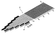
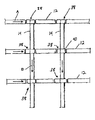
図1について説明すると、図1には本発明の一態様を構成する選別システム10の一つの考えられる実施態様を示す。図示のように、選別システム10は異なる方向に延在する複数の交差ベルトまたはチェーンコンベヤ12、14からなる“マトリクス”から構成することができる。各コンベヤ12、14はエンドレスベルト型コンベヤまたはエンドレスチェーン型コンベヤであり、従って物品に対してほぼ連続的な運搬面を与えるものである(これは、エンドレスベルト型またはエンドレスチェーン型コンベヤとは異なり、実質的に断続的な運搬面を構成するティルトトレー選別機とは対照的である)。必要要件ではないが、Span Tech,LLCによって製造され、THE DESIGNER SYSTEMの商標で市販されているエンドレスベルト型コンベヤまたはエンドレスチェーン型コンベヤが好ましい。なお、これらコンベヤの細部はUSP4,953,693およびUSP5,031,757に記載があり、これらの記載はここに援用するものである。
Referring to FIG. 1, FIG. 1 illustrates one possible embodiment of a
このように構成した結果、各交差点が、対応するコンベヤ12、14間において物品を移し換えるための、一つの、考え得る、あるいは潜在的な位置、即ち点Tになる。一つの方向に延在する、異なる送り込みコンベヤ12に沿って運搬される二つかそれ以上の選択された物品が同時に選別を受け、上記とは異なる方向に延在し、かつ具体的な目的位置(例えば配送トラック、受け取り体(receiver)、あるいは選別サブシステム(sortation subsystem)など)に対応する一つかそれ以上の取り出しコンベヤ14に搬送される。上記両方向に延在し、かつ所望の交差点においてコンベヤ間で物品を選択的に移す多数の送り込みコンベヤ12および取り出しコンベヤ14を備えたシステム10を実現することによって、高い効率でかつ効果的な方法で物品を選別できる。即ち、従来型式のエンドレスループ誘導システムを使用する分野では知られていないシステムである。
As a result of this configuration, each intersection is a single, conceivable or potential location, or point T, for transferring articles between the corresponding
図1に示す実施態様では、システム10の送り込みコンベヤ12および取り出しコンベヤ14は離間した状態で相互に全体として垂直に延在するため(第1および第2の直交方向D1およびD2)、“規則的な”格子(例えば4×4)が形成するが、不規則な格子(2×3、4×5、40×50など)も容易に使用することができる。この図示した具体的な実施態様では、マトリクスシステム10は、(1)第1長手方向に延在する第1組(set or series)の供給ベルトまたはチェーンコンベヤ12a〜12n(図には4つのコンベヤ12a〜12dが図示されている)、および(2)第1方向に対して横断方向である第2長手軸方向に延在する第2組の取り出しベルトまたはチェーンコンベヤ14a〜14n(図には4つのコンベヤ14a〜14dが図示されている)から構成する。これら送り込みおよび取り出しコンベヤ12、14には、それぞれ対応する開始点Sおよび終了点Eがあるのが好ましい。(即ち、これらコンベヤは、選別を行う連続列のリモートカーを備えたエンドレスループコンベヤを使用する公知の誘導システムとは対照的に、線形状または直線状であり、相互に独立している)。また、各組のコンベヤ12、14は、システム10を構成する部分において相互に全体として平行に延在し、エンドレスパス(endless path)に沿って同じ方向に移動するのが好ましい(図1の矢印AおよびBを参照)。
In the embodiment shown in FIG. 1, the
恐らく図2から明瞭に理解できるように、送り込みコンベヤ12a〜12dは第2の取り出しコンベヤ14a〜14dより上にある第1水平面内に延在し、これら第2のコンベヤは第2の異なる水平面内に延在する。これによってシステム10は、コンベヤ12、14を複数の層、複数のレベル、または複数の段で設けることによって構成できる。一つの考えられる実施態様では、送り込みコンベヤ12a〜12dはすべて取り出しコンベヤ14a〜14dより上に延在する。なお、以下の説明において指摘するように、この構成は逆にすることも可能である、交差コンベヤを3以上の層で使用してもよく、この場合一部を上に、そして一部を下にする(図7を参照)。また、図示は省略するが、USP4,953,693およびUSP5,031,757に開示されているように、コンベヤ12、14はすべて地面より高く支持するのが好ましい。
As can be clearly seen from FIG. 2, the
本発明の別な態様では、コンベヤ間で少なくとも一つの選択された物品を移し換える手段を送り込みコンベヤ12と取り出しコンベヤ14との各交差部に、あるいはこの付近に設けることができる。図1の実施態様の場合、移し換え手段は移し換えコンベヤ16から構成する。移し換えコンベヤ16は全体としてL字形の受動的なエンドレスベルトまたはチェーンコンベヤから構成することができ、その向きは、移し換えられる物品が対応する送り込みコンベヤ、即ちコンベヤ12aなどの第1コンベヤの面から対応する取り出しコンベヤ、即ちコンベヤ14aなどの第2コンベヤに移るように設定する。図示のようなL字形移し換えコンベヤ16は、物品がある所定の繰り出し方向をもつ場合に使用するのが望ましい。取り出しコンベヤ16への移し換え時、通常、物品が送り込みコンベヤ12上にある時と全く同じ向き(作業員が、バーコードなどの表示が正確に読み取られる位置に確実に位置するように物品を位置決めすることによって選択することができる)を取ることになるからである。直線状のエンドレスコンベヤまたは受動的なスライド/シュートなどの直線状か、あるいは受動的な移し換えコンベヤ16を使用することも可能である。
In another aspect of the invention, means for transferring at least one selected article between conveyors may be provided at or near each intersection of the
コンベヤ16に移し換えるために選択された物品のうち一つかそれ以上を移し換えるために、ダイバーター(diverter)18を使用することができる。このダイバーター18は、選択された物品を移し換えコンベヤ16に移し換える機能をもつため、この機能を実現する構成を取ることができる。例えば、ダイバーター18は後退可能なアーム、ゲート、ラグ(lug)またはガイドから構成することができ、このダイバーター18が対応する送り込みコンベヤ12上にある選択された物品の進路に入り込み、これを移し換えコンベヤ16の方に向ける。ダイバーター18はピッカー(picker)、キッカー(kicker)、プッシャー(pusher)や同等な動作を行う装置から構成することができる。
A
以上の説明から理解できるように、任意の選択された物品をコンベヤ12、14間で移し換えるために使用する具体的な手段は、使用する構成および(書籍と比較して取り扱いにくい物品を運搬する必要性などの)任意の特別な必要性に応じて選択することができる。同様に、能動的な移し換えコンベヤ16のかわりに、移し換え手段としてプッシャー、キッカー、エジェクター、リフター(lifter)、エレベーター、アクチュエーターやこれらを組み合わせた装置を使用して物品を一つのコンベヤから他のコンベヤに移し換えることも可能であり、さらにこれら装置をシュート(chute)やコンベヤと組み合わせて使用することも可能である。好ましいものではないが、各交差点で手動の“ピックアンドプレース(pick and place)”操作を行うことも可能である。この操作は、取り出しコンベヤのうち一つかそれ以上が送り込みコンベヤよりも上にある場合に特に役立つ。いずれの場合も、選択された物品を送り込みコンベヤ12から信頼性高く取り出しコンベヤ14の少なくとも一つに進めることができ、これによって目的の選別を実行することができる。
As can be seen from the above description, the specific means used to transfer any selected article between the
図2に戻って説明を続けると、取り出しコンベヤ14aに隣接し、かつこれに全体として整合するL字形移し換えコンベヤ16の部分、即ち脚部は、水平面に対して傾けることができる。この傾斜は、移し換えコンベヤ16に沿って運搬されている物品が、対応する取り出しコンベヤ14に自動的に滑り作用によって移り、能動的な係合作用が必要ないため有利である。また、固定されたゲートなどの受動的なダイバーター(図示省略)を移し換えコンベヤ16の上記脚部の端部に、あるいはその付近に設けると、滑り移動しない物品がある場合に、これの向きを変えることができる。ただし、受動的なダイバーターを使用してこの傾斜構成を取るかわりに、能動的なダイバーターを使用して、コンベヤ16の傾いていない部分から物品を移すことも可能である。
Returning to FIG. 2, the portion of the L-shaped
移し換えのための選択(従って選別)の適正化を確保するためには、送り込みコンベヤ12に載って近づいてくる物品は、作業員によってか、あるいは公知タイプの“マシンビジョン(machine vision)操作技術を使用して(例えば、隣接配置の(オーバーヘッド型などの)読み取り機20を使用してバーコードやその他のコードを読み取る)視認することができる。各送り込みコンベヤ12上の物品間隔については、一回にただ一つの選択された物品の移し換えが起きるように設定する。ただ一つの物品を時間的に所定の瞬間に処理することができるエンドレスループのティルトトレーを使用する従来システムとは違って、共通の目的位置に向かう物品を異なる送り込みコンベヤ12a〜12dから取り出しコンベヤ14a〜14dのうちの一つかそれ以上に同時に移し換えることができる。この結果、選別効率がより高くなり、また処理量も潜在的に数倍大きくなるが、運搬速度を高くする必要はない。
In order to ensure that the selection (and thus the sorting) for the transfer is appropriate, the approaching articles on the
すべての物品の向きをかえ、これらを取り出しコンベヤ14a〜14nに移し換える場合には、送り込みコンベヤ12a〜12nを止めるだけでよい。ただし代替的な方法もあり、移し換えられていない物品が最後に下流側位置に到達し、これらを処理できるように送り込みコンベヤ12a〜12nのうち一つかそれ以上を延在させる。例えば、不注意な載貨のためなどを原因として一つの送り込みコンベヤ12aに残り、かつ実際には注文に応じる必要のない(従って移し換えコンベヤ14a〜14nのいずれにも移し返されない)物品は“不良品ビン”(図示省略)に出すことができる。あるいは、このような物品は、対応する保管エリアに戻る一つの戻りコンベヤ(図示省略)に集めてもよい。
When all the articles are turned around and they are taken out and transferred to the
さらに別な代替策では、送り込みコンベヤ12a〜12nに残った物品を、場合によっては別なマトリクスシステム(図示省略)を有する別な選別システムに搬送する。後者の場合、“単独列”のマトリクスは、連続運搬面をもつ単独のエンドレスベルトまたはチェーン送り込みコンベヤ、およびこの送り込みコンベヤと交差する複数の取り出しコンベヤから構成することができる。この構成は、物品がすべて同一の市域またはジップコードに属する異なる住所、あるいは物品が共通な特徴を持つ場合に良好な作用効果を示す。
In yet another alternative, the articles remaining on the
図3を参照して説明すると、システム10の各取り出しコンベヤ14a〜14nもまた、移し換え点か、あるいは下流側位置のいずれかで、運搬方向に対して横断方向においてある角度で配向している。即ち、傾いている。このような傾きによって移し換えられる物品は対応する運搬面にそって、対応する取り出しコンベヤ14に隣接する側部ガード部(図示省略)によって形成することができる既知のエッジ(a known edge)まで滑り落ちる。なお、この傾きによって物品全体が回転して、目的の操作(例えば、隣接配置の読み取り機20の使用などによってバーコードを読み取る操作)に好適な向き(例えば、長尺物品の場合には、短い端部リード)になる。操作の完了後、図3の場合は、コンベヤ14の一部に、物品を水平面と平行な位置に戻し、これをさらに処理する“ツイスト(twist)”部分22を設けることが望ましい。
Referring to FIG. 3, each of the take-out
上記のマトリクス選別システム10の例示的な使用例は無数にある。このような使用例の一つでは、倉庫内の保管場所から書籍などの物品を具体的な目的先(例えば、小売店に運送するための包装エリアまたは積み込みドックなど)に搬送する設備を利用する。具体的には、各送り込みコンベヤ12が倉庫内での書籍のグループ分けを行う。“ピック ツー ライト(pick to light)”システムが“ピッカー”に至るまでに(隣接棚またはパレットなどの)倉庫内の保管場所にあり、送り込みコンベヤ12に載貨すべき書籍を視認する。ピッカーが従って平行走行の異なる送り込みコンベヤ12に、あるいはシステム10に対応していくつかの送り込みコンベヤに最終的に分割される単独のコンベヤに個々の書籍を載貨する。
There are countless example uses of the
いずれの場合も、各送り込みコンベヤ12a〜12nの書籍はシステム10に至ると、確認が行われる。この確認はオペレーターか、あるいはマシン走査(この場合には、走査位置の上流側にいる作業員が、書籍が適正に配向しているか、そして運搬方向においてある最小距離で分離されているかを確認することができる)によって行う。各取り出しコンベヤ14は、一部の書籍によって共有されている共通パラメータまたは特徴(例えば、具体的な目的先、会社/個人、配送センター、書店、選別場所など)に対応させることができる。確認後、複数の送り込みコンベヤ12上にある対応する書籍が確認され、次に正しい取り出しコンベヤ14に移し換えられて、上記の移し換え技術(自動化されているのが好ましいが、手動でもよく、あるいは半自動化でもよい)を使用する所望の方法で選別を行う。
In either case, the books on each of the
取り出しコンベヤ14に沿う下流側で、必要な場合には(例えば、目的先が異なる書籍を移し換える場合には)さらに書籍の選別を行うことができる。書籍を確認し、これらを包装体、ビン、バッグ、担体などに移動させるためにコンベヤ14に沿って人員を配置することはこの目的に適うことはもちろんである。あるいは、また以下に詳しく説明するように、この“サブ(事前)”選別は、各書籍を検出し、適正な取り出しコンベヤに回し、受け取り側(例えばバック、ボックスまたはビンなど)に送る自動化システムを利用することができる。
On the downstream side along the take-out
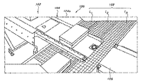
本質的に上記に説明した通りであるマトリクス選別システム10に有用な具体的なサブ選別構成の実施例を図4〜図6に示す。図4は、システム10の全体が第1方向に延在する複数(20)の送り込みコンベヤ12および第2方向に延在する複数(10)の取り出しコンベヤ14から構成したことを示す図である。取り出しコンベヤ14は全体として共通水平面内にあるが、位置は送り込みコンベヤ12より低い。10個ある取り出しコンベヤ14それぞれは一つかそれ以上の選別“ステーション”24に対応する。図示の実施態様では、このような3つのステーション24a、24b、24cが運搬方向において、かつ共通取り出しコンベヤ14の同じ側において相互に間隔をおいて存在する。(なお、この共通取り出しコンベヤは、基本システム10の要部を構成するコンベヤとは異なるコンベヤである)。
Examples of specific sub-sorting configurations useful for the
図5および図6から見ることができるように、各ステーション24は少なくとも一つの、好ましくは複数の横断コンベヤ26からなり、これら横断コンベヤ26は対応する取り出しコンベヤ14から物品を共通の特徴を共有する物品(例えば、具体的な指示をもつ物品、または具体的な国、地域、州、ジップコード、市、町、村、住所を届け先とする物品)に対応する一時保管場所に送る。図示の実施態様では、6つのこのようなほぼ連続的なコンベヤ26a〜26fが平行に延在する。各コンベヤ26a〜26fは“割り出し(indexing)”コンベヤから構成することができ、この割り出しコンベヤは直列に配設した複数の個々のコンベヤセグメント(例示のみを目的として6つのセグメント28a〜28fを図示する)を有し、これらセグメントが各連続コンベヤを構成する。共通の電動モーター(図示省略)によってこれらセグメント28a〜28fを同じ速度でかつ同じ方向に駆動してもよく、あるいは個別に付勢されたモーターによって相互に独立して駆動してもよい。図5に示すように、対応するダイバーター18を使用して、取り出しコンベヤ14から各割り出しコンベヤ26a〜26fの先頭のセグメント28fに選択された物品を移すことができる。
As can be seen from FIGS. 5 and 6, each station 24 comprises at least one, and preferably a plurality, of crossing
各コンベヤセグメント28a〜28fに対応するセンサー(図示省略)によってこれらの上に載っている物品の存在を検出することができる。このためには、通常の“フォトアイ(photoeye)”センサや機械式センサ(例えば重量センサ、物理的な接触スイッチなど)が役に立つ。取り出しコンベヤ14から割り出しコンベヤ26a〜26fのうちの一つに移し換えられると、保管場所即ちビン30に最も近いセグメント28aに対応するセンサが物品を検出するまで対応するセグメント28a〜28fが走行する。
Sensors (not shown) corresponding to each of the
第2の場所即ちビン30に送られる第2の物品が同じ割り出しコンベヤ26a〜26fに到達した場合、この物品が同じように移し換えられる。第2の物品は、静止状態で保持される第1の物品を保持するセグメント28aの上流にあるセグメント28bに到達するまで移動する。このシーケンスが、物品が各割り出しコンベヤ26a〜26fの各セグメント28a〜28fに対応するまで繰り返される。
When a second item sent to the second location or
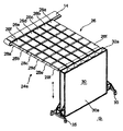
割り出しコンベヤ26a〜26fのうちの一つかそれ以上に載貨されると、物品が適切な保管場所に移動する。図示の実施態様では、これは、割り出しコンベヤ26a〜26fの個数に対応する列で配設された複数のビン32を有する構造(構造体)30をもつ。列数は最小で一列である(この場合、上記の割り出しコンベヤの代わりに、選択された物品を取り出しコンベヤ14から適切なビンに移し換えるために単純な連続走行コンベヤを使用できる)。ただし、処理量を最大化するためには、ビンの個数は、対応する割り出しコンベヤのセグメントの個数に少なくとも対応すべきで、例えばセグメント28の個数はコンベヤ26の個数に合わせるべきである。従って、6つの割り出しコンベヤがそれぞれ6つのセグメントからなる実施例では、上記構造30は6つのビン×6つのビンからなる。
When loaded on one or more of the
各割り出しコンベヤ26a〜26fの送り出し端部は、名目上は、ビン32の一列のみに隣接して存在する。最も下流側の割り出しコンベヤ26a〜26f上の任意の物品が、(スポット検出(手動または自動)あるいは制御手段のいずれかを使用して知ることができる)ビンのうちの一つに存在する場合には、物品が所望のビンに移し換えられるように対応する割り出しコンベヤを付勢する。最下流側セグメント(本実施例ではセグメント28a)に対応するセンサが物品を検出するまで列内の次の物品が進む。この物品が先行する物品と同じビンにある場合には(例えば両者が共通の目的先に届けられるか、さもなければ共通の特徴を共有している場合には)、これも移し換えられる。
The feed end of each
基準列にあるビンに予定されている物品すべてが移し換えられると、上記構造体30が移動し、別な列のビンを割り出しコンベヤ26a〜26fの送り出し端部に対応させることができ、上記のシーケンスを繰り返す。ビン32が水平方向および垂直方向の両方向において相互に離間する場合、リフターを使用して、上記構造体30を上下させ、適正なビンに隣接して位置する各割り出しコンベヤ26a〜26fの最下流側のセグメント28aから物品を移し換えるとよく、この時点でセグメント28aが付勢を受け、搬送を行う。あるいは、横断コンベヤ26を移動させて、適正なビン32に対応させてもよい。
When all the articles scheduled to be transferred to the bins in the reference row are transferred, the
図示のように、上記構造体30は、車輪34を設けるなどによって走行できる。選別が所定の選別または作業時間で終了すると、物品をさらに処理(例えば包装処理など)する場所に上記構造体30を移動させることができる。この間、代替構造をステーション24に対応させておけばよく、ビンをチェックし、ビンから物品を空けるために必要な時間があるため、選別効率に支障は出ない。
As shown, the
上述したように、図4〜図6に示す構成における各構造体30は、従って36個のビンを備える。この例示的な構成では、3つの構造体30が各取り出しコンベヤ14に対応し、10の取り出しコンベヤが存在する。考えられる選別送り先の総数は1,080に等しい。6列の代わりに12列のビンが存在する場合、この数値は倍増し、2,160になる。6つのステーションを各取り出しコンベヤに対応させた場合には、同様に倍増し4,320になる。取り出しコンベヤの個数を(第3レベルのコンベヤを付設するなどによって、以下の説明を参照)を倍増して20にすると、考えられる住所数は8,640になり、この数字は、任意の合理的なサイズの従来の単独誘導ループでは聞かれたことのない数字である。
As mentioned above, each
垂直構成の一つの代替構成は、ビンの入り口32aが割り出しコンベヤ26a〜26fの下に位置するように、図6に示した構造体30の背部30aを地面に対して平行に設定した構成である。必要に応じて、線形の動作装置によって構造体30を前後に動作させて、セグメントから移し換えられた物品が確実に適正なビンに落下するように構成する。同様に、割り出しコンベヤの個数よりも少ない数の列を設けることによって、構造体30を2つの異なる方向に移動させて、列内の次の物品を対応するビンにマッチさせることができる。
One alternative to the vertical configuration is that the back 30a of the
図5および図6に示した構成の代わりに使用する別な実施態様では、流れを複数の“列(lines)に分離することによって、例えば一連の平行に走行するコンベヤおよびダイバーター(図示省略)を使用して物品を案内することによってマトリクスの下流側でさらに選別を行う。この場合、これらの列の個々のコンベヤが第2マトリクスシステム(図示省略)の送り込みコンベヤを構成し、物品をさらに小さいサブグループに選別することができる。必要に応じて、このプロセスを繰り返して、所望程度の、即ち所望“レベル”の選別を行い、特定の作業を行う。 In an alternative embodiment to be used instead of the arrangement shown in FIGS. 5 and 6, by separating the flow into a plurality of "lines", for example, a series of parallel running conveyors and diverters (not shown) A further sorting is performed downstream of the matrix by guiding the articles using, where the individual conveyors of these rows constitute the infeed conveyor of the second matrix system (not shown) and the articles are made smaller. If necessary, the process can be repeated to provide a desired degree, ie, a desired "level" of screening, to perform a particular task.
保管場所から物品を搬送するためにマトリクスシステム10を使用するよりは、逆構成の場合に作用効果を発揮することができる。例えば、物品を受け取ると、選別が必要な物品(ボックス、包装体)は、マトリクスシステム10の複数の送り込みコンベヤ12に最終的に分割されることになる倉庫の送り込みコンベヤに移し換えることができる。上記のように物品を選別した後、共通のパラメータまたは特徴を有する物品すべてを特定の取り出しコンベヤ14に載貨し、倉庫内の(例えば、あるトピックに関する書籍用保管場所やアルファベットのうちの特定の文字から始まるタイトルをもつ書籍用保管場所などの)特定の保管場所に搬送する。次に、取り出しコンベヤ14が送り込みコンベヤ12に切り換わり、物品をマトリクス10に送り返し、ここで共通の特徴をもつ物品を選別し、取り出しコンベヤ(前の送り込みコンベヤ)に移し返す。
Rather than using the
本発明のさらに別な態様では、マトリクスシステム10も3つかそれ以上のレベルのコンベヤを有する。例えば、このレベルの第3コンベヤが第2取り出しコンベヤから選択された物品を受け取り、異なる目的先に搬送する。あるいは、これら第3コンベヤは、第1送り込みコンベヤ12と共通な取り出しコンベヤ14に物品を搬送する第2送り込みコンベヤとして作用してもよく、あるいは送り込みコンベヤから物品を受け取り、取り出しコンベヤとして機能してもよい。
In yet another aspect of the invention, the
後者の場合、第3コンベヤは第2取り出しコンベヤ14に対して平行に延在してもよく、かつ送り込みコンベヤ12より高い位置に、あるいは低い位置に存在する((シュートまた動力式エレベーターなどの対応する手段を使用して、使用する向きに応じて物品の移し換えを行う)。ただし、第3コンベヤは取り出しコンベヤ14の方向とは反対方向に走行することができ、下流側のサブ選別ステーション(ここでは個々の作業員が物体をビンに入れてもよく、あるいは自動化選別機を使用して物体をビンにいれてもよい)に対応する。これについては、それぞれ取り出しコンベヤ14および第3コンベヤ34に同伴する逆向きの矢印BおよびCによって図7に示す(矢印AおよびDは、送り込みコンベヤ12も異なる方向に走行することを示す)。物品を移し換える手段は、上記の移し換え手段と同様な移し換え手段16を有することができるが、(例えば高摩擦面、バケット(scoop)、クリート(cleat)、“楔”コンベヤあるいは重力に逆らって物品を信頼性高く運搬するために知られている同種タイプの構成体を使用する)信頼性の高い方法で物品を昇降できる手段である。図8に考えられる最良の図示を与えるように、移し換えコンベヤ16の場合、対応する第3コンベヤ34より高い面で終了するのが好ましく、こうすると、移し換えられた物品が運搬面に簡単に落下するからである。
In the latter case, the third conveyor may extend parallel to the second take-out
なお、二組かそれ以上の組の取り出しコンベヤを備えたマトリクスシステム10は、使用にあたってはいくつかの作用効果を発揮する。例えば、二段の取り出しコンベヤ14、34の場合、一回の走行時に送り込みコンベヤ12から物品を第2取り出しコンベヤ14または第3取り出しコンベヤ34のいずれかに移し換えることができるため、システム10の潜在的な処理量(potential throughput)が大幅に増加する。処理量が増加しても、これに対応して走行速度が高くならないため、従来の方法よりも操作条件全体を緩和でき、操作効果が高くなる。
It should be noted that a
マトリクス選別システム10の場合、二段の取り出しコンベヤ14、34を交替できる可能性もある。例えば、送り込みコンベヤ12に対応して使用する下部取り出しコンベヤ14で、システム10に運び込まれた初回分の、あるいは初回グループの物品を選別することができる。初回分の物品(a first batch or group of articles)が送り込みコンベヤ12から移動した後、二回目の物品(a second group of articles)(同種でもよく、異種でもよい)グループをシステム10に送り込み、かつ上部取り出しコンベヤ34に移し換えると同時に、初回分グループを下部取り出しコンベヤ14に運搬し、下流側で選別することができる。このような構成を使用すると、システム10の連続操作が可能になるが、ある段の取り出しコンベヤ14又は34については、一回分の処理量の物品の選別後に定期的な中断時間(periodic downtime)が必要なことが考えられる(選別の誤りに対処し、あるいは一つかそれ以上の物品が間違ってシステム内に送り込まれ、特定の注文を満たすためにこれらを交換する必要がある状態に対処するためなどを目的として)。
In the case of the
マトリクスシステムのさらに別な考えられる使用例では、所定の時点で送り込みコンベヤ12の一部のみを走行操作する。例えば、図4に示す構成の場合、5つの送り込みコンベヤ12の4つのグループG1、G2、G3、G4のうちの一つのみが、一回の処理時に、物品を取り出しコンベヤ14に搬送する(または物品を倉庫内の一定の保管場所から搬送する)ことができ、残りのグループは異なる処理時に使用することができる。このようにすると、各グループのコンベヤの摩耗を一定に維持でき、可使時間を延長できる。多数の物品の選別が必要になる(クリスマス時期などの)時期には、存在するすべての対応する送り込みコンベヤ12を同時に走行させることができる。
In yet another possible use of the matrix system, only a portion of the
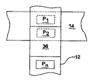
コンベヤ12、14間で物品を移し換える別な手段は、対応する送り込みコンベヤ12の部分36を別に付勢可能にすることである(図9および図10だけでなくUSP4,426,074を参照。なお、この公報の内容は本明細書に援用するものとする)。これら付勢可能な降下部分36は、実行可能なあるいは潜在的な移し換え点を表す、取り出しコンベヤ14との交差点に、あるいは交差点付近に設けられることはもちろんである。
Another means of transferring articles between the
移動可能な部分36の場合、システム10を構成する取り出しコンベヤ14a〜14dの横方向に沿って移し換え点を“互い違い配列”(offsetting)にするか、あるいは“ジグザグ配列”(staggering)にすると、上流側送り込みコンベヤ(例えば4つの場合における送り込みコンベヤ12a〜12cなど)から移し換えられた物品間の衝突がなくなる。図9に、この実施態様を示す。図示のように、各第2の取り出しコンベヤ14を対応する第1の送り込みコンベヤ12よりも広くする(点線部分)か、および/または降下部分36の端部を選択的に設定すればよい。このように構成すると、取り出しコンベヤ14の幅にそって異なる位置に物品を載貨することが容易になるとともに効率がよくなり、同時に、異なる送り込みコンベヤ12に対応する上流側移し換え点から搬送される物品との衝突がなくなる。換言すると、移し換え時の各物品の初期位置が、対応する取り出しコンベヤ14の横寸法に沿ってジグザグ配列することができる。このためには、図10に示すように、包装体または小荷物P1およびP2を並列構成にすればよい(図10には、“ジグザグ配列”の降下部分36の搬送端部を介して第2包装体または小荷物P2を実際に取り出しコンベヤ14に移し換えた状態を示す)。
In the case of the
さらに別な態様では、第2コンベヤのうちの交差コンベヤに少なくとも一つの物品を移し換える手段は、第1の、即ち送り込みコンベヤ12の一つかそれ以上の要部を構成することができるトランスポジターコンベヤ38の形を取る移し換えコンベヤから構成することができる。図11および図12を参照して説明すると、トランスポジターコンベヤ38は各接合部または交差部において、取り出しコンベヤ14の上に被さる後退可能な部分40を有することができる(例えば図18を参照)。図11に、この部分40の移動端部とコンベヤ12の上流側部分の対応する端部との間にあるサイズの大きい間隙を示すが、この間隙は、繰り出たトランスポジターコンベヤ38がほぼ連続的な運搬面を形成する時には、通常は実質的に閉じる。
In yet another aspect, the means for transferring at least one article to a cross conveyor of the second conveyor comprises a first, i.e., a transposer, which can constitute one or more parts of the
従って、物が送り込みコンベヤ12を通過し、これが形成する運搬路に沿って連続移動している場合、トランスポジターコンベヤ38の後退可能な部分40は正常な状態、即ち繰り出し状態にあり、ほぼ連続路を形成する。ただし、近づいてくる物を隣接の取り出しコンベヤ14に搬送することが望ましい場合には(この物の状態は光検出器などのセンサによって検出することができる)、トランスポジターコンベヤ38の後退可能な部分40を運搬方向に後退させて、取り出しコンベヤ14の面や移し換えコンベヤ16の面などの第2運搬面を露出すると、この物を第2運搬面に搬送することができる。このようにすると、トランスポジターコンベヤ38が連続走行するため、上流側の物が移動し続け、目的の物の搬送の信頼性が高くなり、取り出しコンベヤ14によって物をさらに運搬することが可能になる。
Thus, when an object passes through the
図13〜図17を参照して説明すると、好ましい一つの実施態様によるトランスポジターコンベヤ38の一例が図示されている。具体的には、後退可能な部分40は一対の側部レール42を有する移動支持ベッド部から構成する。これらレール42は、後退状態にある後退可能な部分40を伸縮自在に受け取るハウジング46に対応するガイド部44に滑り作用によって受け取られる。これらガイド部44は、ハウジングの垂下している側部フレーム部材46a、46bにそって離間されている個別構造であり、これら側部フレームは運搬されている物品や物の支持面を形成するベッド部46cによって相互接続されている。なお、連続ガイド部も使用可能である。
Referring to FIGS. 13-17, an example of a
後退可能な部分40をハウジング46に対して前後に動かすためには、一つかそれ以上のピニオン48を回転可能な駆動シャフト50に対応させればよく、このシャフトはハウジング46の側部フレーム部材46a、46bによって支持することができる。ピニオン48は、後退可能な部分40によって支持された長尺のラック52に対してインターフェースを形成する。サーボモーター54などの原動装置によって駆動シャフト50を回転し、後退可能な部分40を前進または後進させて、ハウジング46内で入れ子状態にする。
To move the
トランスポジターコンベヤ38にそって物品を運搬するエンドレスベルト56を設ける。恐らく図15から明瞭に理解できるように、ベルト56はコンベヤ38の前部および後部の案内構造全体に延在し、エンドレスな走行路を形成する。これらガイド構造は、それぞれ上記部分40およびハウジング46の端部に設けられた固定ノーズバー(nose bar)58、60から構成することができるが、アイドラーローラーなども使用可能である。
An
運搬走行路に対向して、ベルト56が、上記部分40に接続され、これとともに移動する第1アイドラー62全体に延在するため、前方のノーズバー58と固定関係を維持する。また、ベルト56は、側部フレーム部材46a、46bによって支持された第1アイドラー64全体、そしてベルト56を駆動する駆動シャフト66全体に延在する。駆動シャフト66は、スプロケットなどのベルト係合要素を有することができ、トランスポジターコンベヤ38の後退可能な部分40を後退させ、かつ繰り出す第1原動装置とは独立して動作するサーボモーター68などの第2原動装置に対して回転自在に対応する。また、ピンチローラ70、72を設けて、駆動シャフト66の駆動要素とベルト56の係合状態を保持する。あるいは、内部に動力源をもつか、あるいは動力化した駆動ローラーを使用して、(スプロケットなどによって)ベルト56を係合してもよく、この駆動ローラーは第2原動装置として働くため、外部サーボモーターの必要がなくなる。このようなローラーの各種実例は公知(例えば、米国特許出願第2005/0119098号を参照。なお、この公報の開示は本明細書に援用するもので、以下に説明する)である。
Opposed to the transport path, a
図16を参照して説明すると、図16には、通常の繰り出し状態にある後退可能な部分40を示す。この位置では、ピニオン48はラック52の後部に隣接する。システム10に使用した場合、ベルト56の駆動によって、運搬方向にコンベヤ12に沿って、また形成するほぼ連続的な経路に沿って物品を移動させることができる。
Referring to FIG. 16, FIG. 16 shows the
トランスポジターコンベヤ38に対応する送り込みコンベヤ12から物品を移し換えコンベヤ16などに移し換えて、物品を取り出しコンベヤ14に搬送することが望ましい場合には、モーター54を起動してピニオン48を対応する方向に回転させることによって後退可能な部分40を後退させる。この後退動作が終了すると、トランスポジターコンベヤ38とコンベヤ12の上流側端部との間に間隙Gが十分に開くため、運搬されている物品をこの間隙に通すことができる。この動作が、ベルト56の前進、物品の慣性および重力の結合した作用と相まって、移し換えコンベヤ16の表面16aに物品を移す(このコンベヤ16は、図示のように、取り出しコンベヤ14に至るローラーシュート型のコンベヤと組み合わせた間隔の狭い、全体として平坦なベルトコンベヤから構成できるが、物品を運び出すことができる他の構成も利用可能である)。
When it is desired to transfer the articles from the
なお、図18に示すように、移し換え機能は、送り込みコンベヤ12に対応するトランスポジターコンベヤ38を取り出しコンベヤ14との各交差部に単に設けるだけでも実現可能である。換言すると、取り出しコンベヤ14の運搬面の上に直接後退可能な部分40を位置させ、これに被せると、物品をこの上に直接移し、第2方向に運搬でき、従って選別を効率化することができる。
As shown in FIG. 18, the transfer function can be realized by simply taking out the
なお、アイドラー62、64については、後退可能な部分40より下のベルト56の長さを先頭の縁部(即ちノーズバー58)に対して一定の距離に維持した状態で、この部分40が後退するような関係に設定する。この部分40がこのように後退するにも拘わらず、第2原動装置68によって駆動力が与えられる結果、ベルト56が運搬方向に移動し続ける。
Note that the idlers 62 and 64 are retracted while the length of the
時間に基づいて、あるいは適当なセンサによって物品がコンベヤからなくなったと判断した後、後退可能な部分40を繰り出し、対応するコンベヤ12に沿って上流側に物品がある場合には、これを下流側に運搬する。物品を取り出しコンベヤ14に搬送することによってさらに選別を行う場合には、後退可能な部分40を再度後退させればよい。また、必要に応じてこの操作を繰り返すと、物品の選別を所望の方法で行うことができる。
Based on time or after a suitable sensor determines that the article has been removed from the conveyor, the
トランスポジターコンベヤ38については、薄くなるように(low profile)設計すればよく、このためにはUSP7,314,132に開示されているように、本出願人のMICROSPANコンベヤチェーン技術を利用すればよい。なお、この公報の開示を本明細書に援用するものとする。
The
図19に別な実施態様である選別システム100を示し、これについて説明する。この実施態様のシステム100は第1コンベヤからなり、第1コンベヤは、このコンベヤの相対的な位置(例えば繰り出しまたは後退位置)に対応する別な位置に物品を移し換えるトランスポジター104を有する送り込みコンベヤ102からなる。図示の実施態様では、トランスポジター104が送り出しコンベヤ106に架橋する(このコンベヤ106も選別システムの第1コンベヤの要部を形成するものである)。トランスポジター104が第2コンベヤ108の上に被さり、この第2コンベヤ108は横断方向に延在し、複数の別個のレーンLからなる。図示のように、これらレーンLは、別個のチェーンまたはベルト、あるいはデバイダー(divider)110によって構成することができる。図示の実施態様には、3本のレーンL1、L2、L3を示すが、レーン数は2以上であればよい。取り出しコンベヤ108については、第1および第2のコンベヤ102、106上の物品の走行路と完全に交差するように図示してあるが、物品の落下位置で終了してもよく、またいずれか方向に駆動して、物品を所望の下流側位置に運搬することも可能である。 FIG. 19 shows a sorting system 100 as another embodiment, which will be described. The system 100 in this embodiment comprises a first conveyor, which has a transposer 104 for transferring articles to another position corresponding to a relative position of the conveyor (e.g., an unwind or retract position). It comprises a conveyor 102. In the embodiment shown, the transposer 104 bridges the delivery conveyor 106 (which also forms the main part of the first conveyor of the sorting system). A transposer 104 overlies a second conveyor 108, which extends transversely and comprises a plurality of separate lanes L. As shown, these lanes L can be constituted by separate chains or belts, or by dividers 110. In the illustrated embodiment, three lanes L 1 , L 2 , and L 3 are shown, but the number of lanes may be two or more. Although the take-out conveyor 108 is illustrated as completely intersecting the travel path of the articles on the first and second conveyors 102, 106, it may end at the article drop position, To transport the article to the desired downstream location.
このように、トランスポジター104の後退可能な部分104aを後退させると、主に重力の結果として、取り出しコンベヤ108の下側の運搬面に物品が落下する。なお、(例えば、コントローラーによってサーボモーター68または同様な原動装置を制御するなどによって)複数の後退位置間の後退量を制御することによって、物品が取り出しコンベヤ108上の複数のレーンの一つに落下し、選別の一つの目安になる。例えば、物品が後退可能な部分104aの近位端に存在する全量後退の場合、物品が第1レーンに移り、中間位置までの後退の場合、物品が第2レーンに移り、物品が後退可能な部分104aの端部付近にある後退の場合、物品が第3レーンに移る(後退がない場合、物品(複数の場合もある)が送り出しコンベヤ106に載り続け、場合によっては図示を省略した、異なる取り出しコンベヤと交差する下流側トランスポジターまで進むことはもちろんである)。従って、この比較的な単純な構成で、2つのみのコンベヤを使用して少なくとも4つの選別結果を得ることができる。 Thus, when the retractable portion 104a of the transposer 104 is retracted, the article falls onto the lower transport surface of the take-out conveyor 108, primarily as a result of gravity. Note that by controlling the amount of retraction between the plurality of retraction positions (e.g., by controlling a servomotor 68 or similar prime mover by a controller), the article may fall into one of a plurality of lanes on the pick-up conveyor 108. Then, it becomes one guide of selection. For example, in the case of full retraction at the proximal end of the retractable portion 104a, the article moves to the first lane, and when retreating to an intermediate position, the article moves to the second lane and the article is retractable. In the case of retreat near the end of the portion 104a, the article moves to the third lane (if there is no retreat, the article (s) continue to rest on the delivery conveyor 106, which is not shown in some cases. Of course, proceed to the downstream transposer where it intersects the take-out conveyor). Thus, with this relatively simple configuration, at least four sorting results can be obtained using only two conveyors.
後退については、(サイズ、形状、または特定の目的先などの他の特徴によって)物品を確認し、所望の選別結果に対応する取り出しコンベヤ108上の位置を判定することによって公知の方法で制御すればよい。また、一回の後退動作時、取り出しコンベヤ108の異なるレーンにトランスポジター104から複数の物品をほぼ同時に移すことも可能である。この取り出しコンベヤ108は、複数のコンベヤユニットとして構成することも可能であり、これらユニットのうちの一つかそれ以上を(逆方向などの)異なる方向に進めることができる。 Retraction is controlled in a known manner by verifying the article (by size, shape, or other characteristics such as a particular destination) and determining the location on the pick-up conveyor 108 that corresponds to the desired sorting result. Just fine. It is also possible to transfer a plurality of articles from the transposer 104 to different lanes of the take-out conveyor 108 almost simultaneously during one retreat operation. The take-out conveyor 108 can also be configured as a plurality of conveyor units, one or more of which can be advanced in different directions (eg, in the reverse direction).
図20〜図24に、一つかそれ以上のトランスポジターを有するコンベヤを利用した別な実施態様である選別システム200を示す。図20において、第1の直線方向に延在する第1コンベヤ202は、例えば3つの整合配列のトランスポジターコンベヤ204a、204b、204cなどの一つかそれ以上のトランスポジターを有する。各トランスポジター204a、204b、204cの下に、第1方向である横断方向か、あるいは第2横断方向に移された物品を運搬するコンベヤを設け、各トランスポジター位置において少なくとも3つの考えられる物品目的先を設定する(図19の実施態様を使用する場合には、7つも考えられ、そのうち一つから三つは両側に与え、それぞれは一時的な保管場所(例えばビン208に対応させることができる)。
FIGS. 20-24 show another embodiment of a
トランスポジター204a、204b、204cからの物品の移し換え時に行う選択的な二方向運搬については、物品をいずれかの方向に移動させるように付勢することができる運搬面をもつコンベヤ206を使用すると実現することができる。例えば、図20〜図24において、コンベヤ206は、いずれかの方向(時計方向か反時計方向)にエンドレス経路にそって駆動され、物品の例えば選別位置(例えばビン208)への移動を行うベルトまたはチェーンからなるコンベヤとして図示してある。コンベヤ206のベルトまたはチェーンは、(必要に応じて逆作動するだけで所望の物品運搬を行うことができる、モーターに接続されたモーター駆動式スプロケットまたは摩擦ローラーなどを使用する)任意の通常の方法で駆動することができる。2つのコンベヤ206は並置することができ、それぞれ異なる方向に走行させ、物品を所望の目的先に応じていずれかに移す。あるいは、図25に示すように、コンベヤ206としては、(例えば滑り作用によって)所望方向に物品を運搬するように傾斜する運搬面をもつピボット作用のティルトトレー210を使用することも可能である。
For selective bi-directional transport during transfer of goods from the transposers 204a, 204b, 204c, use a
図26〜図28に、システム200が容易に選別を拡張できることを示す。図26に、比較的小さな予定地のために、17の別個な選別目的先を設定することができることを示す。同様に、それ自体がトランスポジターを備えることができる(図27)共通の送り込みコンベヤ302を使用して、これらシステム200のうち2つを結合することによって、さらに能力の高い別なシステム300を実現することができる。このシステムは3つに過ぎない直線状コンベヤを使用して、34の別個の選別位置を確保でき、トランスポジターを追加配設することによって(例えば2つの異なる選別システム200に交互に運搬を行うためにトランスポジター304の下に二方向性のコンベヤを配設することによって)、無限に拡張することができる。図28に、それぞれが17の選別位置をもち、2つの異なる物品流れに対して合計で51の選別位置を備えたトランスポジターを有する3つのコンベヤに共通な2つの別個の送り込みコンベヤを示す。いずれの場合も、物品の送りは、物品の送りを行う複数の異なるゾーンをもつゾーン化コンベヤZによって行う。センサSなどを設けると、物品の特徴を確認でき、選別位置を決定することも可能である。
FIGS. 26-28 illustrate that the
図29〜図30に、さらに別な実施態様である、トランスポジター404を有する第1コンベヤ402、およびこのトランスポジター404から一つかそれ以上の物品を受け取り、運び出す第2コンベヤ406を有する選別システム400を示す。一つの方向に、あるいは2つの方向に物品の運搬を行う(例えばエンドレスベルトコンベヤまたはティルトトレーなどの)ベルトコンベヤを使用することができる第2コンベヤ406が、トランスポジター404に対して上下動することができる。これは、コントローラーによって制御することができるか、あるいは望む場合には手動制御が可能な線形付勢装置408などの原動装置によって実現することができる。
29-30, a further embodiment, a sorter having a first conveyor 402 having a
この相対的な上下動を使用して、取り出しコンベヤ406を上下動させると、特定の高さの物品を処理することが可能になるため、有利である。例えば、靴箱あるいは比較的高い物品の場合、トランスポジター404の落下前に高さを低くすることができるが(図29のh)、例えば、ガムの箱などの小型の物品の場合、高さを高くすることができる。付勢装置408などの原動装置に対応するコントローラーによって、(光検出器などの一つかそれ以上のセンサによって測定した高さ、あるいはバーコードなどの走査によって確認した高さなどの)物品の既知特徴に基づいてリアルタイムで相対的な高さを調節することができる。コンベヤ406への落下の結果としての物品損傷の防止に役立つだけでなく、この上下動は、処理量の最大化に望ましい、トランスポジター404の後退およびその後の繰り出しを目的として物品を取り除くためにも役立つ。また、これらから、シュートCなどの静的な角度の付いたスライドをコンベヤ406の一端または両端に結合して物品を選別位置(例えばビン208)に搬送する方法を理解することができる。
It is advantageous to use this relative vertical movement to raise and lower the pick-up
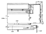
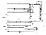
図31〜図33に、トランスポジターコンベヤを有する選別システムに対応するいくつかの技術思想を説明する。例えば、上述したように、トランスポジターコンベヤ500は一つかそれ以上のモーター駆動ローラーからなる(本明細書では、ローラーを回転させる独立式駆動機構、即ちモーターを利用したローラー(ケンタッキー州アーランガーのInsight Automation Inc.製のローラー)を使用する)。例えば、第1モーター駆動ローラー502は、ベッド部などの任意の支持構造に対してコンベヤチェーン501を前に進めるために設けることができ、また第2モーター駆動ローラー504は、コンベヤ500の基部508に対してベッド部506を繰り出しかつ後退させるために設けることができる。そして、コネクター512などによって歯付きベルト510をベッド部506に結合し、アイドラー514に全体にわたって(図示しない同様なアイドラーを有することができる)モーター駆動ローラー504によって駆動すればよい。即ち、第1ローラー502がスプロケット502aによってチェーン501を駆動し、基部508の繰り出し状態または後退状態において、運搬されている物品を前に進めればよい。
Some technical ideas corresponding to a sorting system having a transposer conveyor will be described with reference to FIGS. For example, as described above, the
これらの図から理解できるように、このように独立モーター駆動ローラーを使用すると、トランスポジターコンベヤ500をかなり低く(low profile)構成できるため、スペースに必要な条件が緩和するだけでなく、(ベッド部506および基部508を別個なユニットとして引き上げる能力(以下に詳しく説明する)を含めて)メンテナンスが容易になり、いずれも有利な作用効果である。
As can be seen from these figures, the use of independent motor driven rollers in this manner allows the
図34に、(明瞭にするため図示を省略した)チェーンをコンベヤ500に支持する方法を示す。具体的には、このチェーンは可動ベッド部506にそってノーズローラー506a上に延在する。ベッド部506の下では、チェーンは、ベッド部506に接続され、従ってこれとともに移動する第1アイドラー516に係合する。アイドラー516はチェーンをモーター駆動ローラー502に案内し、そして別なアイドラー518がチェーンを基部508によって支持されたアイドラー520に案内する。次に、チェーンは別なアイドラー522に係合し、これがチェーンを案内し、運搬面を形成する。
FIG. 34 shows how the chain (not shown for clarity) is supported on the
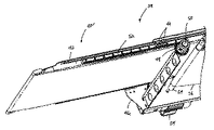
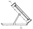
図30に示すように、そして図35および図36により明瞭に示すように、基部508は、下部508bに取り外し可能に接続した上部508aなどのように、2つの部分に分割することができる。図37および図38に考えられる最良の図示を与えるように、この接続は、運搬方向に対する横断方向において基部508の両側に複数対のヒンジ524を使用して行うことができる。各ヒンジ524は、例えば取り外し可能なピン526を設けるなどによって解除可能なため、基部508の上部508aは、下部508bに対していずれの方向にも傾けることが可能である。
As shown in FIG. 30, and as more clearly shown in FIGS. 35 and 36, the base 508 can be divided into two parts, such as an
ハンドル528を設けると、下部508bに対して上部508aの上下動をより簡単に行うことができる。なお、実際には、すべてのヒンジ524を解除することによって、上部508aを完全に切り離すことができ、下部508bから一体としてこれを引き上げることができる。こうすると、メンテナンスがより容易になるか、あるいは上部508aを新しいユニットと交換することができる。
When the
上記下部508bは、トランスポジターコンベヤ500の操作に対応する各種のコントローラー529、構成成分またはワイヤなど受け取るトレーを構成することができる。メンテナンスまたは修理を目的としてこれら構成成分へのアクセスを容易にするために、下部508bに対して上部508aを支持する一つかそれ以上の支持体を設けることができる。例えば、支持体は、一端において基部508の上部508aの下側にピボット自在に取り付け、そして他端において下部508bに形成したチャネル532に沿って滑る脚部530から構成することができ、(また支持体は、図39に示すような中間の上部開口532aなどを介して解除可能である)。このように構成すると、ピボット作用が所望の方法で生じるため、基部508の上部508aを、図35に示すように前から、あるいは後ろから傾ける方向から無関係に支持体を設置することができる。
The
また、場合に応じて、引き上げ時に基部508の上部508aに対して脚部530を保持することができる。このためには、図40に示すように、チャネル532の一端または両端に設けることができる解除可能ストリッパー(stripper)540を使用すればよい。図41に示すようにストリッパー540を調節すると、チャネル532内を進め脚部530の通常は取り込まれている端部を露出することができる。例えば、磁石544を使用するなどによって、脚部530と基部508の上部508aとを解除可能に結合することができる。従って、図42に示すように、基部508の上部508aをそのまま垂直方向Vに引き上げた場合、磁石544と脚部530の強磁性材料との結合などの接続の結果として、脚部530は非繰り延べ状態または非後退状態に保持されることになる。
In addition, if necessary, the
図43について説明すると、図43から理解できるように、ストリッパー540がその本来の状態、即ち後退状態にある時には、脚部530は初期に垂直方向Vにチャネル532から持ち上がることはない。このような初期の保持状態のため、基部の上部508aと脚部530との接続は維持されず、磁石544とは結合しない。従って、脚部530はチャネル532との接続状態を維持し続けるため、所望の方法で支持を確保できる。
Referring to FIG. 43, as can be seen from FIG. 43, when the
図44および図45を参照して、一つの考えられる制御構成を説明する。選別すべき物は、上流側誘導コンベヤ602によって図示のシステム600内に導入することができる。次に、この物が誘導スキャナ604を通り、このスキャナが(バーコード、RFID、マシンビジョン、物の寸法などによって)この物を確認する。この確認情報に基づいて、対応するコントローラー(図示省略)が物の配送位置を判断する。
One possible control configuration is described with reference to FIGS. 44 and 45. Objects to be sorted can be introduced into the illustrated
上記物は誘導コンベヤ602に沿って進み、光センサなどのセンサを通過する。物の長さは、センサによって検出されている間、トランスポジターのモーター駆動ローラーに対応するセンサが発生するパルス数によって確認することができる。次に、上記物は第1ゾーンコンベヤ606に進み、その位置は送り込み端部にあるセンサによって確認する。この物は、システム全体を通して各ゾーンコンベヤまたはトランスポジターの送り込み端部に設けられたいくつかの光センサによって追跡される。
The object travels along
これらの物は、誘導コンベヤ602の端部において行われる物の長さ計算によって決められる間隔で最後のゾーンコンベヤ608によって放出することができる。各物の長さによって各物に必要なピッチを決定するため、目的先トランスポジター610a、610b、610cが後退し、物を適正な位置に移すために十分なスペースを確保することができ、またトランスポジターの正面にあるエリアから物を取り除き、これを繰り出し位置に戻すことができるため、次の物を次のトランスポジターに移し換える時間的な準備が整う。物が目的先トランスポジター610a、610b、610cに到達すると、送り込みセンサが、モーター駆動ローラーの内部近接スイッチを使用して、位置追跡をトリガーする。物をティルトトレー612に搬送する場合には、対応するトレーが予め位置決めされ、物を所望の(例えば左か右の)位置に案内することができる。
These objects can be ejected by the
目的先トランスポジター610a、610b、610cが一つの位置装置の場合には、ものがノーズ後退トリガー位置まで追跡され、モーター駆動ローラーがノーズを後退させるため、物を取り出しコンベヤ614に落下させることができる。また、後退トリガーが適正な方向における両方向コンベヤの走行を開始するため、物を所望の(例えば左か右の)位置に搬送することができる。
If the
物が複数(例えば2または3)の位置トランスポジターへの搬送状態にある場合には、ノーズ後退モーター駆動ローラーが、ノーズを目的先位置の遠位縁部に予め位置決めすることになる。この予め行う位置決めによって、目的先をもつ連続的な物が同じトランスポジターによって配送される場合には、処理速度が増加する。 If the object is in transport to multiple (e.g., two or three) position transposers, the nose retraction motor drive roller will pre-position the nose at the distal edge of the destination location. This pre-positioning increases the processing speed when successive objects with destinations are delivered by the same transposer.
図46に示すように、システムには、コンベヤの両側に沿って走行する“E−Stop”プルコードシステム650を設けることができる。さらに別な安全対策を取ることができ、(1)トランスポジターノーズが前進状態にある時に物センサがカバーを付けている場合には、制御システムがノーズの前進を止め、詰まりが発生していることを表示する;(2)ノーズの前進時にモーター電流が急激に増加することは、詰まりが生じていることを示し、制御システムを停止する;および(3)ノーズの前進を追跡しているパルス列に乱れが生じることは、詰まり生じていることを示し、制御システムを停止することを含む。 As shown in FIG. 46, the system can be provided with an “E-Stop” pull cord system 650 running along both sides of the conveyor. Additional safety measures can be taken: (1) If the object sensor covers while the transposer nose is in the forward state, the control system will stop the nose from advancing and clogging will occur. (2) A sudden increase in motor current during nose advance indicates a clogging has occurred and shuts down the control system; and (3) tracks nose advance. Disturbances in the pulse train indicate clogging and include shutting down the control system.
各種実施態様の選別システムおよび関連方法に関する説明は、本発明の技術思想を説明するものである。説明は、徹底的であることを意図せず、また本発明を開示した正確な形態に制限することも意図していない。本明細書に開示した記載に照らして改変や修正が可能である。例えば、コンベヤ12、14、16、34がモジュラー式のリンクからなる場合には、これらに専用のリンクまたはローラーを設けると、物品の移し換えが容易になる(例えば、Layneを発明者とするUSP6,874,617を参照。なお、当該公報の内容はここに援用するものとする)。なお、書籍などに言及しているが、これは、本発明を適用して運搬または選別することができる物品の一つの可能なタイプを示すに過ぎない。以上の実施態様は、最良の用途を与えるもので、これによって当業者ならば、本発明を各種の実施態様で利用できるはずであり、また具体的な用途(例えば書籍以外の物品を運搬または選別する用途など)に合うように各種の変更を加えることができるはずである。これら修正および変更はいずれも発明の範囲に包摂されるものである。
The description of the sorting system and the related methods of the various embodiments explains the technical idea of the present invention. The description is not intended to be exhaustive, nor is it intended to limit the invention to the precise form disclosed. Modifications and modifications are possible in light of the description disclosed herein. For example, if the
10,100,200,300,400:システム
12,14,16,26,34,38,64,602,608:コンベヤ
18:ダイバーター
20:読み取り機
24:ステーション
28:セグメント
30:構造体
32:ビン
38,500:トランスポジターコンベヤ
40:後退可能な部分
42:レール
44:ガイド部
46:ハウジング
46a、46b:側部フレーム部材
48:ピニオン
50:駆動シャフト
52:ラック
54:モーター
56:ベルト
62,64,514,516:アイドラー
104,404:トランスポジター
524:ヒンジ
540:ストリッパー
612:ティルトトレー
10, 100, 200, 300, 400:
Claims (3)
第1コンベヤの上流側部位と前記第1コンベヤの下流側部位とを架橋するための繰り出し状態およびその反対の戻り状態にもなる一つの架橋部位が、前記第1コンベヤの一部に備えられており、
一方、複数のコンベヤで構成した複数のコンベヤレーンが在って、
この複数の全ての前記コンベヤレーンの夫々の一部は、前記第1コンベヤにおける前記繰り出し状態の前記一つの架橋部位の下側に配置されており、
前記一つの架橋部位が前記戻り状態の時に、前記第1コンベヤの前記一つの架橋部位から移される一つかそれ以上の物品を、前記夫々の前記コンベヤレーンが受け取る構成であることを特徴とするコンベヤシステム。
In a conveyor system intended for use in sorting goods,
A part of the first conveyor is provided with one cross-linking part which is also in a feeding state for cross-linking an upstream part of the first conveyor and a downstream part of the first conveyor and a return state opposite thereto. Yes,
On the other hand, there are multiple conveyor lanes composed of multiple conveyors,
A part of each of the plurality of all the conveyor lanes is disposed below the one cross-linking portion in the unreeling state on the first conveyor,
A conveyor wherein each of the conveyor lanes receives one or more articles transferred from the one crosslink site of the first conveyor when the one crosslink site is in the return condition. system.
第1コンベヤの上流側部位と前記第1コンベヤの下流側部位とを架橋するための繰り出し状態およびその反対の戻り状態にもなる後退可能な架橋部位に第1の運搬面を設けた第1コンベヤ、
前記第1コンベヤに備えた後退可能な前記架橋部位から少なくとも一つの物品を受け取る第2コンベヤ、
前記第1コンベヤに対して前記第2コンベヤを上下動させる付勢装置、および
前記物品の特徴に基づいて前記第2コンベヤを上下動させる前記付勢装置を制御するコントローラーからなることを特徴とするコンベヤシステム。
In a conveyor system intended for use in sorting goods,
A first conveyor provided with a first conveying surface at a retractable cross-linking portion which is also in a fed-out state for bridging an upstream portion of the first conveyor and a downstream portion of the first conveyor and a return state opposite thereto. ,
A second conveyor for receiving at least one article from the retractable cross-linking site provided on the first conveyor;
An urging device for vertically moving the second conveyor with respect to the first conveyor, and a controller for controlling the urging device for vertically moving the second conveyor based on characteristics of the article. Conveyor system.
前記物品を運搬方向に運搬する第1コンベヤ、
この第1コンベヤには、前記第1コンベヤの上流側部位と前記第1コンベヤの下流側部位とを架橋するための繰り出し状態およびその反対の戻り状態を起こす架橋部位を備えており、
前記戻り状態の時に前記第1コンベヤの前記架橋部位から第1物品を受け取り、前記運搬方向に対して横断方向である第1方向にこの第1物品を運搬する第2コンベヤ、および
前記戻り状態の時に前記第1コンベヤの前記架橋部位から第2物品を受け取り、前記第1方向に対して全体として逆方向である第2方向にこの第2物品を運搬する第3コンベヤからなることを特徴とする物品の選別システム。 In the goods sorting system,
A first conveyor for transporting the article in a transport direction,
The first conveyor includes a cross-linking portion that causes a feed-out state for cross-linking an upstream portion of the first conveyor and a downstream portion of the first conveyor and a return state opposite thereto,
A second conveyor that receives the first article from the cross-linking portion of the first conveyor in the return state and transports the first article in a first direction that is transverse to the transport direction; and A third conveyor that sometimes receives a second article from the cross-linking site of the first conveyor and transports the second article in a second direction that is generally opposite to the first direction. Item sorting system.
Applications Claiming Priority (5)
| Application Number | Priority Date | Filing Date | Title |
|---|---|---|---|
| US201261594821P | 2012-02-03 | 2012-02-03 | |
| US61/594,821 | 2012-02-03 | ||
| US201261680444P | 2012-08-07 | 2012-08-07 | |
| US61/680,444 | 2012-08-07 | ||
| PCT/US2013/024531 WO2013116801A1 (en) | 2012-02-03 | 2013-02-02 | Sortation systems and related methods |
Related Child Applications (1)
| Application Number | Title | Priority Date | Filing Date |
|---|---|---|---|
| JP2017212521A Division JP2018020911A (en) | 2012-02-03 | 2017-11-02 | Selection system and related method |
Publications (3)
| Publication Number | Publication Date |
|---|---|
| JP2015511916A JP2015511916A (en) | 2015-04-23 |
| JP2015511916A5 JP2015511916A5 (en) | 2016-03-03 |
| JP6629506B2 true JP6629506B2 (en) | 2020-01-15 |
Family
ID=48905932
Family Applications (2)
| Application Number | Title | Priority Date | Filing Date |
|---|---|---|---|
| JP2014555808A Expired - Fee Related JP6629506B2 (en) | 2012-02-03 | 2013-02-02 | Sorting system and related methods |
| JP2017212521A Ceased JP2018020911A (en) | 2012-02-03 | 2017-11-02 | Selection system and related method |
Family Applications After (1)
| Application Number | Title | Priority Date | Filing Date |
|---|---|---|---|
| JP2017212521A Ceased JP2018020911A (en) | 2012-02-03 | 2017-11-02 | Selection system and related method |
Country Status (6)
| Country | Link |
|---|---|
| US (2) | US9604258B2 (en) |
| EP (1) | EP2809597A4 (en) |
| JP (2) | JP6629506B2 (en) |
| CA (1) | CA2862368C (en) |
| MX (1) | MX364365B (en) |
| WO (1) | WO2013116801A1 (en) |
Families Citing this family (39)
| Publication number | Priority date | Publication date | Assignee | Title |
|---|---|---|---|---|
| CA2916894A1 (en) * | 2013-07-17 | 2015-01-22 | Laitram, L.L.C. | Sorter with double runout lanes in each bullpen and method for sorting |
| US9277833B1 (en) | 2014-02-07 | 2016-03-08 | Pan Oston Holding Company | Multi-destination checkout system and related methods |
| US9399557B1 (en) | 2014-06-13 | 2016-07-26 | Amazon Technologies, Inc. | Sensing conveyor for object characteristic determination |
| US9233799B1 (en) * | 2014-06-13 | 2016-01-12 | Amazon Technologies, Inc. | Sensing conveyor for object characteristic determination |
| CH709921B1 (en) * | 2014-07-24 | 2019-09-30 | Rotzinger Ag | Produktaustrageeinheit. |
| US11059185B2 (en) | 2014-10-03 | 2021-07-13 | Frito-Lay North America, Inc. | Apparatus and method for transferring a pattern from a universal surface to an ultimate package |
| US9802720B2 (en) | 2014-10-03 | 2017-10-31 | Frito-Lay North America, Inc. | Apparatus and method for maintaining a pattern of non-rigid objects in a desired position and orientation |
| US9346170B2 (en) | 2014-10-03 | 2016-05-24 | Frito-Lay North America, Inc. | Apparatus and method for universal, flexible pillow bag pattern creation |
| US9346169B2 (en) | 2014-10-03 | 2016-05-24 | Frito-Lay North America, Inc. | Apparatus and method for universal, flexible pillow bag pattern creation |
| CA2976316A1 (en) * | 2015-02-27 | 2016-09-01 | Pulsar S.R.L. | A plant for processing products including a unit for detecting defective products |
| ES2910704T3 (en) * | 2015-04-23 | 2022-05-13 | Laitram Llc | Input and output assemblies for a conveyor |
| US9422116B1 (en) * | 2015-06-10 | 2016-08-23 | Karl E. Hase | Tiered communication scheme to embed conveyor ZPA and routing control |
| CA3020409A1 (en) | 2016-04-14 | 2017-10-19 | Walmart Apollo, Llc | Conveyors for sorting products |
| FR3063987A1 (en) * | 2017-03-17 | 2018-09-21 | Solystic | SORTING OF OBJECTS WITH A PIVOTING SHUTTER SORTING CONVEYOR |
| CN107377425B (en) * | 2017-07-11 | 2023-04-21 | 苏州艾隆科技股份有限公司 | Sorting apparatus and method thereof |
| US10226794B2 (en) | 2017-07-18 | 2019-03-12 | Intelligrated Headquarters, Llc | Dynamic tray spacing |
| CN109420617B (en) * | 2017-08-30 | 2024-02-02 | 杭州海康机器人股份有限公司 | Parcel sorting platform, parcel sorting system, robot scheduling method and device |
| US11144873B2 (en) | 2017-10-16 | 2021-10-12 | Florence Corporation | Package management system with accelerated delivery |
| US10643415B2 (en) | 2017-10-16 | 2020-05-05 | Florence Corporation | Package management system with accelerated delivery |
| US10915856B2 (en) | 2017-10-16 | 2021-02-09 | Florence Corporation | Package management system with accelerated delivery |
| US11270251B2 (en) | 2017-10-16 | 2022-03-08 | Florence Corporation | Package management system with accelerated delivery |
| LU100590B1 (en) * | 2017-12-21 | 2019-07-25 | Soremartec Sa | Method for packaging products and corresponding packaging line |
| CN108313705A (en) * | 2018-03-19 | 2018-07-24 | 无锡市锡东橡塑机械有限公司 | A kind of quick automatic separation device |
| US11410118B2 (en) | 2018-06-01 | 2022-08-09 | Florence Corporation | Package management system |
| MX2021002066A (en) | 2018-08-21 | 2021-08-11 | Florence Corp | Purchased item management and promotional system. |
| US10800609B2 (en) | 2018-10-22 | 2020-10-13 | Walmart Apollo, Llc | Folding wing for a conveyor |
| US11548734B2 (en) | 2018-10-22 | 2023-01-10 | Laitram, L.L.C. | Grid sorter |
| WO2020086352A1 (en) | 2018-10-22 | 2020-04-30 | Laitram, L.L.C. | Multi-angle sorter |
| CN109499889B (en) * | 2018-11-20 | 2021-03-26 | 漯河医学高等专科学校 | Automatic book identification and sorting equipment for campus library |
| WO2020190842A1 (en) * | 2019-03-18 | 2020-09-24 | W.H. Leary Co. | System and method for zero defect carton rejection |
| WO2020242695A1 (en) * | 2019-05-24 | 2020-12-03 | Laitram, L.L.C. | Compact sorter |
| USD954481S1 (en) | 2019-12-13 | 2022-06-14 | Florence Corporation | Double walled locker door |
| US11529011B2 (en) | 2019-06-11 | 2022-12-20 | Florence Corporation | Package delivery receptacle and method of use |
| US10625952B1 (en) * | 2019-10-18 | 2020-04-21 | Grey Orange Pte. Ltd. | Induction station for conveying packages in storage facility |
| EP3848308A1 (en) * | 2020-01-09 | 2021-07-14 | Siemens Aktiengesellschaft | System for sorting items in matrix arrangement logically linked to their target destination |
| CN112264313B (en) * | 2020-08-13 | 2022-09-27 | 华测检测认证集团股份有限公司 | Food detection device and food detection method |
| KR102443480B1 (en) * | 2020-09-02 | 2022-09-15 | 씨제이대한통운 (주) | Modular sorting system and product sorting method using the conveyor extension |
| US20220185597A1 (en) * | 2020-12-15 | 2022-06-16 | Express Scripts Strategic Development, Inc. | Dynamic package sortation device |
| CN114161619B (en) * | 2021-11-30 | 2024-01-30 | 天津绿展环保科技有限公司 | Feeding control system for waste plastic bucket treatment line |
Family Cites Families (42)
| Publication number | Priority date | Publication date | Assignee | Title |
|---|---|---|---|---|
| DE1009550B (en) | 1955-05-31 | 1957-05-29 | Hauni Werke Koerber & Co Kg | Device for conveying and distributing cut tobacco |
| DE1917062C3 (en) | 1969-04-02 | 1978-10-19 | Maschinenfabrik Loesch Gmbh, 8550 Forchheim | Device for the automatic distribution of objects |
| US3690435A (en) * | 1970-04-16 | 1972-09-12 | John W King | Article conveyor system |
| DE2160708B2 (en) * | 1971-12-07 | 1974-05-30 | Windmoeller & Hoelscher, 4540 Lengerich | Conveyor device for plants for the production of sacks from paper or plastic film |
| US3917050A (en) | 1974-02-28 | 1975-11-04 | Vaughn Gregor | Distributor with discharge conveyors |
| FR2370664A1 (en) * | 1976-11-12 | 1978-06-09 | Faiveley Sa | Palletiser for sacks or boxes - uses pallets with sides allowing rows to be staggered within preset base size |
| IT1082516B (en) | 1977-01-25 | 1985-05-21 | Bruno & Co Alisyncro | PLANT FOR THE DISTRIBUTION OF FOOD PRODUCTS PARTICULARLY SWEET TO A MULTIPLE OF PACKAGING STATIONS PLACED IN SERIES |
| JPS5725806U (en) * | 1980-12-11 | 1982-02-10 | ||
| US4815582A (en) * | 1981-12-24 | 1989-03-28 | Francesco Canziani | Feeding apparatus particularly for machines for the conveyance and sorting of objects |
| JPS58135026A (en) | 1982-02-02 | 1983-08-11 | Maki Seisakusho:Kk | Conveyer device |
| US4593806A (en) * | 1983-10-07 | 1986-06-10 | Doboy Packaging Machinery, Inc. | Multiple transpositor conveyor system |
| US4832204A (en) | 1986-07-11 | 1989-05-23 | Roadway Package System, Inc. | Package handling and sorting system |
| US5154260A (en) | 1991-04-08 | 1992-10-13 | Ncr Corporation | Method and system for automated processing of articles |
| IT1258194B (en) * | 1992-08-26 | 1996-02-21 | Mopa Srl | STATION OF DISTRIBUTION OF PRODUCTS ON A SUPPLY LINE OF PACKAGING MACHINES OR POSSIBLE STORAGE |
| DE4342534C1 (en) | 1993-12-14 | 1995-01-26 | Caljan Loading Systems | Telescopic conveying path for conveying and measuring piece goods |
| DE4438207C2 (en) | 1994-10-26 | 2002-07-18 | Wilhelm Hogenkamp Verpackungst | Transfer device for objects arriving on a revolving endless feed belt in transverse rows |
| US5839566A (en) * | 1996-08-30 | 1998-11-24 | United Parcel Service Of America, Inc. | Belt-carried tilt tray sorter |
| US5755308A (en) | 1996-10-07 | 1998-05-26 | Reynolds Corporation | Check out stand with telescoping take-away conveyor |
| US5901830A (en) | 1997-01-22 | 1999-05-11 | Electrocom Automation, L.P. | Bi-directional belt sorter |
| US5984078A (en) | 1997-08-04 | 1999-11-16 | United Parcel Service Of America, Inc. | Automated shuttle sorter for conveyors |
| US6227377B1 (en) * | 1997-09-09 | 2001-05-08 | United Parcel Service Of America, Inc. | Automated array sorter for conveyors |
| US6513641B1 (en) | 1999-10-12 | 2003-02-04 | Rapistan Systems Advertising Corp. | High rate induction system |
| US6213395B1 (en) | 1999-11-02 | 2001-04-10 | Ncr Corporation | Apparatus and method for operating a checkout system having a scanner which is rotatable between an assisted scanner position and a self-service scanner position |
| US6296185B1 (en) | 1999-11-02 | 2001-10-02 | Ncr Corporation | Apparatus and method for operating a checkout system having a display monitor which displays both transaction information and customer-specific messages during a checkout transaction |
| FR2816223B1 (en) * | 2000-11-08 | 2004-11-26 | Chronopost | METHOD AND DEVICE FOR SORTING OBJECTS BY MEANS OF LINEAR CROSS-CONVEYORS |
| US7386472B1 (en) | 2001-12-10 | 2008-06-10 | Ncr Corporation | Self-checkout terminal |
| US6668979B2 (en) | 2001-12-17 | 2003-12-30 | Selkirk Industries, Llc | Extension/retraction mechanism for checkstand with telescoping take-away conveyor |
| US6871116B2 (en) * | 2002-10-17 | 2005-03-22 | Vertique, Inc. | Determining pallet case configurations for placement by a robot |
| US6772575B2 (en) * | 2002-12-30 | 2004-08-10 | Lantech Management Corp. And Lantech Holding Corp. | Shrink wrap apparatus and method of shrink wrapping products |
| US6883659B2 (en) * | 2003-06-30 | 2005-04-26 | Ivan Muchalov | Conveyor transfer assembly |
| PL1559668T3 (en) | 2004-01-30 | 2007-12-31 | Caljan Rite Hite Aps | Telescopic belt conveyor |
| US8479912B2 (en) * | 2004-04-29 | 2013-07-09 | Span Tech Llc | Matrix sorter system with transpositor conveyor |
| JP2007535456A (en) * | 2004-04-29 | 2007-12-06 | スパン テック エルエルシー | Matrix type sorting system |
| WO2007136403A2 (en) * | 2005-10-24 | 2007-11-29 | Mtd America Ltd | Dissimilar materials sorting process, system and apparatus |
| US7395918B2 (en) | 2005-11-14 | 2008-07-08 | Thompson Charles P | Extendible conveyor |
| NL1031861C2 (en) | 2006-05-23 | 2007-11-26 | Buhrs Zaandam Bv | Conveyor assembly with ejection provision, a document processing line provided with such a conveyor assembly, as well as a method for ejecting products. |
| US7967112B2 (en) | 2006-12-02 | 2011-06-28 | Royston, LLC. | Check stand with a two belted input and a slidable scanner |
| US7921982B2 (en) * | 2007-07-24 | 2011-04-12 | Douglas Machine, Inc. | Methods and apparatus for handling products |
| DE102010005267A1 (en) | 2010-01-20 | 2011-07-21 | nobab gmbh, 70825 | Conveying device for use with attachment device for packaged goods distribution system for packaged goods, has conveying head which has receiving area for manual placing of packaged goods |
| US20130062159A1 (en) | 2011-09-14 | 2013-03-14 | Karl Fischer | High speed checkstand having multiple product pathways |
| US8783438B2 (en) | 2012-11-30 | 2014-07-22 | Heb Grocery Company, L.P. | Diverter arm for retail checkstand and retail checkstands and methods incorporating same |
| US9277833B1 (en) * | 2014-02-07 | 2016-03-08 | Pan Oston Holding Company | Multi-destination checkout system and related methods |
-
2013
- 2013-02-02 EP EP13743770.3A patent/EP2809597A4/en not_active Withdrawn
- 2013-02-02 CA CA2862368A patent/CA2862368C/en not_active Expired - Fee Related
- 2013-02-02 MX MX2014009175A patent/MX364365B/en active IP Right Grant
- 2013-02-02 JP JP2014555808A patent/JP6629506B2/en not_active Expired - Fee Related
- 2013-02-02 US US14/376,480 patent/US9604258B2/en active Active
- 2013-02-02 WO PCT/US2013/024531 patent/WO2013116801A1/en active Application Filing
-
2017
- 2017-02-14 US US15/432,475 patent/US20180154398A1/en not_active Abandoned
- 2017-11-02 JP JP2017212521A patent/JP2018020911A/en not_active Ceased
Also Published As
| Publication number | Publication date |
|---|---|
| MX364365B (en) | 2019-04-24 |
| MX2014009175A (en) | 2014-11-25 |
| US20180154398A1 (en) | 2018-06-07 |
| CA2862368A1 (en) | 2013-08-08 |
| WO2013116801A1 (en) | 2013-08-08 |
| JP2018020911A (en) | 2018-02-08 |
| CA2862368C (en) | 2021-01-19 |
| US9604258B2 (en) | 2017-03-28 |
| JP2015511916A (en) | 2015-04-23 |
| US20150001137A1 (en) | 2015-01-01 |
| EP2809597A4 (en) | 2015-12-23 |
| EP2809597A1 (en) | 2014-12-10 |
Similar Documents
| Publication | Publication Date | Title |
|---|---|---|
| JP6629506B2 (en) | Sorting system and related methods | |
| US8479912B2 (en) | Matrix sorter system with transpositor conveyor | |
| US8113334B2 (en) | Matrix sorter system | |
| JP3142585B2 (en) | High-speed automatic cog sorter | |
| CA2792086C (en) | Package-culling conveyor system and method | |
| US6201203B1 (en) | Robotic containerization system | |
| JP3142584B2 (en) | High-speed smart diverter for conveyor sorting machines | |
| CN1146188A (en) | Installation for sorting of individually conveyed objects | |
| JP3142578B2 (en) | Method and apparatus for sorting articles using a conveyor cell matrix | |
| AU2018265596A2 (en) | Goods output buffer for a commissioning facility | |
| JPH10236642A (en) | Feed-merging device for pans on which agricultural products are placed | |
| JP3660791B2 (en) | Agricultural product sorting device and method of operating this device | |
| JPH10278905A (en) | Agricultural product selecting and packaging equipment | |
| JP2006068744A (en) | Agricultural product sorting device | |
| WO1993014008A1 (en) | Indexing, bi-directional vertical sorter with buffer conveyors | |
| JP3978291B2 (en) | Agricultural product sorting and sorting method and sorting and sorting apparatus operation method | |
| JPH1129116A (en) | Feeder or tray pack used for stacking agricultural product |
Legal Events
| Date | Code | Title | Description |
|---|---|---|---|
| A521 | Request for written amendment filed |
Free format text: JAPANESE INTERMEDIATE CODE: A523 Effective date: 20160113 |
|
| A621 | Written request for application examination |
Free format text: JAPANESE INTERMEDIATE CODE: A621 Effective date: 20160113 |
|
| A977 | Report on retrieval |
Free format text: JAPANESE INTERMEDIATE CODE: A971007 Effective date: 20161028 |
|
| A131 | Notification of reasons for refusal |
Free format text: JAPANESE INTERMEDIATE CODE: A131 Effective date: 20161101 |
|
| A521 | Request for written amendment filed |
Free format text: JAPANESE INTERMEDIATE CODE: A523 Effective date: 20170130 |
|
| A02 | Decision of refusal |
Free format text: JAPANESE INTERMEDIATE CODE: A02 Effective date: 20170704 |
|
| A521 | Request for written amendment filed |
Free format text: JAPANESE INTERMEDIATE CODE: A523 Effective date: 20181214 |
|
| A521 | Request for written amendment filed |
Free format text: JAPANESE INTERMEDIATE CODE: A523 Effective date: 20190418 |
|
| A521 | Request for written amendment filed |
Free format text: JAPANESE INTERMEDIATE CODE: A523 Effective date: 20190821 |
|
| A61 | First payment of annual fees (during grant procedure) |
Free format text: JAPANESE INTERMEDIATE CODE: A61 Effective date: 20191205 |
|
| R150 | Certificate of patent or registration of utility model |
Ref document number: 6629506 Country of ref document: JP Free format text: JAPANESE INTERMEDIATE CODE: R150 |
|
| LAPS | Cancellation because of no payment of annual fees |