JP6593452B2 - Laser processing machine and workpiece processing method - Google Patents
Laser processing machine and workpiece processing method Download PDFInfo
- Publication number
- JP6593452B2 JP6593452B2 JP2017553713A JP2017553713A JP6593452B2 JP 6593452 B2 JP6593452 B2 JP 6593452B2 JP 2017553713 A JP2017553713 A JP 2017553713A JP 2017553713 A JP2017553713 A JP 2017553713A JP 6593452 B2 JP6593452 B2 JP 6593452B2
- Authority
- JP
- Japan
- Prior art keywords
- workpiece
- contact
- hole
- laser
- lowering
- Prior art date
- Legal status (The legal status is an assumption and is not a legal conclusion. Google has not performed a legal analysis and makes no representation as to the accuracy of the status listed.)
- Active
Links
Images


Classifications
-
- B—PERFORMING OPERATIONS; TRANSPORTING
- B23—MACHINE TOOLS; METAL-WORKING NOT OTHERWISE PROVIDED FOR
- B23K—SOLDERING OR UNSOLDERING; WELDING; CLADDING OR PLATING BY SOLDERING OR WELDING; CUTTING BY APPLYING HEAT LOCALLY, e.g. FLAME CUTTING; WORKING BY LASER BEAM
- B23K26/00—Working by laser beam, e.g. welding, cutting or boring
- B23K26/02—Positioning or observing the workpiece, e.g. with respect to the point of impact; Aligning, aiming or focusing the laser beam
Description
本発明は、レーザ加工機、算出装置、及びワークの加工方法に関する。 The present invention relates to a laser beam machine, a calculation device, and a workpiece machining method.
板状のワークに対してレーザヘッドからレーザ光を照射して切断加工等を行うレーザ加工機が知られている。このレーザ加工機は、例えばパンチプレス等の他の加工機によって孔開けまたは成形加工された後のワークに対して切断加工等を行う場合がある。この場合、パンチプレス等からレーザ加工機にワークが搬入されるが、このワークをレーザ加工機のレーザ加工位置(レーザ加工座標系)に合わせる必要がある。そのため、パンチプレス等によって形成される孔部を検出してレーザ加工座標系に対するワークのずれ量を算出し、この算出結果に基づいてワークとレーザ加工位置とを位置合わせすることが行われている。この孔部の検出に際して、孔部の画像等から孔部の位置を取得することも可能であるが、照明または光学素子の汚れの影響があることから、これに代えて、孔部に挿入する接触棒を持つプローブを用いることが提案されている(特許文献1参照)。特許文献1に記載のプローブは、昇降可能な接触棒を有しており、この接触棒を下降させてワークの孔部に挿入し、この状態で接触棒を水平方向に移動させて孔部の内面に接触させることにより孔部の位置を計測している。 2. Description of the Related Art A laser processing machine that performs cutting processing by irradiating a plate-shaped workpiece with laser light from a laser head is known. This laser processing machine may perform a cutting process or the like on a workpiece after being punched or formed by another processing machine such as a punch press. In this case, the work is carried into the laser processing machine from a punch press or the like, and it is necessary to match this work with the laser processing position (laser processing coordinate system) of the laser processing machine. For this reason, a hole formed by a punch press or the like is detected to calculate a shift amount of the workpiece with respect to the laser processing coordinate system, and the workpiece and the laser processing position are aligned based on the calculation result. . When detecting the hole, it is possible to obtain the position of the hole from an image of the hole or the like. However, there is an influence of illumination or dirt on the optical element. Instead, it is inserted into the hole. It has been proposed to use a probe having a contact bar (see Patent Document 1). The probe described in Patent Document 1 has a contact bar that can be raised and lowered, and the contact bar is lowered and inserted into the hole of the workpiece, and in this state, the contact bar is moved in the horizontal direction to move the hole. The position of the hole is measured by contacting the inner surface.
特許文献1に記載のプローブは、接触棒を下降させて下端の高さを孔部内に配置させることが必要となる。例えば、接触棒を深く挿入すると、接触棒の下端がワークの下面から突出することになり、この状態で接触棒を水平方向に移動させても、ワークの下面を支持するワーク支持部に接触棒が接触して誤検出を招くといった問題がある。特に、ワークの板厚が薄い場合に、接触棒の下端がワークの下面から突出しやすいので、接触棒の下端を孔部内の適切な高さに配置させることが求められている。 In the probe described in Patent Document 1, it is necessary to lower the contact rod and arrange the height of the lower end in the hole. For example, when the contact rod is inserted deeply, the lower end of the contact rod protrudes from the lower surface of the workpiece. Even if the contact rod is moved in the horizontal direction in this state, the contact rod is attached to the workpiece support portion that supports the lower surface of the workpiece. There is a problem that touches and causes false detection. In particular, when the workpiece is thin, the lower end of the contact bar easily protrudes from the lower surface of the workpiece. Therefore, it is required to arrange the lower end of the contact rod at an appropriate height in the hole.
以上のような事情に鑑み、本発明は、接触棒の下端を孔部内の適切な高さに配置させることにより、レーザヘッドによるレーザ加工位置とワークとの相対位置を高精度に取得することが可能なレーザ加工機、算出装置、及びワークの加工方法を提供することを目的とする。 In view of the circumstances as described above, the present invention can obtain the relative position between the laser machining position by the laser head and the workpiece with high accuracy by arranging the lower end of the contact rod at an appropriate height in the hole. It is an object of the present invention to provide a possible laser processing machine, a calculation device, and a workpiece processing method.
本発明に係るレーザ加工機は、所定の孔部が形成された板状のワークを加工するレーザヘッドと、ワークの上面の高さを計測する計測部と、ワークに対して昇降可能な接触棒を有し、接触棒を下降させて孔部に挿入することによりレーザヘッドによるレーザ加工位置とワークとの相対位置を取得可能なプローブと、計測部の計測結果に基づいて接触棒の目標下降位置または下降量を算出する算出装置と、算出装置により算出された目標下降位置または下降量に応じて接触棒を下降させる駆動部と、を備える。 Laser processing machine according to the present invention includes a laser head for machining a predetermined hole is formed plate-shaped workpiece, a total measuring unit for measuring the height of the upper surface of the workpiece, elevatable contact with the workpiece It has a rod, a probe capable of obtaining the relative position of the laser processing position and the work by the laser head by inserting into the hole by lowering a contact rod, a target of the contact bar on the basis of the total measurement of the measurement result A calculation device that calculates the lowering position or the lowering amount, and a drive unit that lowers the contact bar in accordance with the target lowering position or lowering amount calculated by the calculation device.
また、計測部は、孔部の周りにおけるワークの上面の高さを計測してもよい。また、プローブは、レーザヘッドに設けられ、接触棒は、レーザヘッドに対して昇降可能に形成されてもよい。また、計測部は、レーザヘッドに備える非接触センサであってもよい。また、算出装置は、計測部の計測結果と、ワークの板厚とに基づいて、接触棒の下端部の側面が孔部の垂直面と当接可能な目標下降位置または下降量を算出してもよい。また、駆動部は、レーザヘッドを駆動するためのヘッド駆動部が用いられてもよい。また、プローブは、接触棒が上昇した際に接触棒の下方を閉じ、かつ、接触棒が下降する際に接触棒の下方を開くシャッタを備えてもよい。また、接触棒は、孔部に挿入される下端部が円筒状に形成され、かつ、下端面が球面状に形成されてもよい。 Further, the measuring unit may measure the height of the upper surface of the work around the hole. The probe may be provided on the laser head, and the contact rod may be formed so as to be movable up and down with respect to the laser head. Further, the measurement unit may be a non-contact sensor provided in the laser head. Also, calculating device includes a measurement result of the total measurement unit, based on the thickness of the workpiece, the side surface of the lower end of the contact rod calculates the vertical plane and can abut target lowering position or lowered amount of the hole May be. Further, a head drive unit for driving the laser head may be used as the drive unit. Further, the probe may include a shutter that closes the lower portion of the contact bar when the contact rod is raised and opens the lower portion of the contact rod when the contact rod is lowered. In addition, the lower end of the contact rod inserted into the hole may be formed in a cylindrical shape, and the lower end surface may be formed in a spherical shape.
本発明に係る算出装置は、所定の孔部が形成された板状のワークの上面の高さに関する計測結果が入力され、計測結果に基づいて、孔部に向けて下降して孔部に挿入される接触棒の目標下降位置または下降量を算出する。 The calculation device according to the present invention receives a measurement result related to the height of the upper surface of a plate-like workpiece on which a predetermined hole is formed, and descends toward the hole based on the measurement result and inserts it into the hole. The target lowering position or lowering amount of the contact bar to be operated is calculated.
本発明に係るワークの加工方法は、所定の孔部が形成された板状のワークの上面の高さを計測することと、計測された高さに基づいて孔部に挿入する接触棒の目標下降位置または下降量を算出することと、目標下降位置または下降量に応じて接触棒を下降させ、孔部に挿入した接触棒によりワークとレーザヘッドによるレーザ加工位置との相対位置を取得することと、相対位置に基づいてレーザヘッドによりワークを加工することと、を含む。 The workpiece processing method according to the present invention measures the height of the upper surface of a plate-like workpiece on which a predetermined hole is formed, and a target for a contact rod to be inserted into the hole based on the measured height. Calculating the descent position or descent amount, lowering the contact bar according to the target descent position or descent amount, and acquiring the relative position between the workpiece and the laser machining position by the laser head with the contact bar inserted in the hole And processing a workpiece with a laser head based on the relative position.
本発明のレーザ加工機によれば、算出装置により接触棒の目標下降位置又は下降量を算出し、算出結果に基づいて接触棒を下降させるため、接触棒を孔部の適切な位置に確実に挿入することができる。これにより、レーザ加工位置とワークとの相対位置を高精度に取得することが可能となる。また、ワークの板厚が薄い場合であっても、接触棒の下端を孔部内の適切な高さに容易に配置させることができる。 According to the laser processing machine of the present invention, the target lowering position or the lowering amount of the contact bar is calculated by the calculation device, and the contact bar is lowered based on the calculation result, so that the contact bar is surely placed at an appropriate position of the hole. Can be inserted. Thereby, the relative position between the laser processing position and the workpiece can be obtained with high accuracy. Further, even when the workpiece is thin, the lower end of the contact bar can be easily arranged at an appropriate height in the hole.
また、計測部が孔部の周りにおけるワークの上面の高さを計測する場合、挿入対象である孔部の周りの高さを計測するため、接触棒の目標下降位置または下降量を高精度に得ることができる。また、プローブがレーザヘッドに設けられ、接触棒がレーザヘッドに対して昇降可能に形成される場合、接触棒とレーザヘッドとの位置関係が規定された状態で接触棒を下降させるため、レーザ加工位置とワークとの相対位置を高精度に取得することができる。 In addition, when the measurement unit measures the height of the upper surface of the workpiece around the hole, the target descent position or the descent amount of the contact bar is accurately measured in order to measure the height around the hole to be inserted. Obtainable. In addition, when the probe is provided on the laser head and the contact rod is formed so as to be movable up and down with respect to the laser head, the laser processing is performed to lower the contact rod in a state where the positional relationship between the contact rod and the laser head is defined. The relative position between the position and the workpiece can be obtained with high accuracy.
また、計測部がレーザヘッドに備える非接触センサである場合、レーザヘッドに備える非接触センサを用いてワークの上面の高さを取得するため、効率的に計測を行うことが可能であり、別途センサ等を設ける必要がないためコストの増加を抑制できる。算出装置が、計測部の計測結果と、ワークの板厚とに基づいて、接触棒の下端部の側面が孔部の垂直面と当接可能な目標下降位置または下降量を算出する場合、接触棒の下端部の側面を孔部の垂直面に確実に当接させるので、孔部の正確な位置が取得でき、ワークとレーザ加工位置との相対位置を高精度に取得できる。 In addition, when the measurement unit is a non-contact sensor provided in the laser head, the height of the upper surface of the workpiece is obtained using the non-contact sensor provided in the laser head, so that the measurement can be performed efficiently and separately. Since there is no need to provide a sensor or the like, an increase in cost can be suppressed. Calculation device, a measurement result of the total measurement unit, if based on the thickness of the workpiece, the side surface of the lower end of the contact rod calculates the vertical plane and can abut target lowering position or lowered amount of the hole, Since the side surface of the lower end portion of the contact bar is surely brought into contact with the vertical surface of the hole portion, the accurate position of the hole portion can be acquired, and the relative position between the workpiece and the laser processing position can be acquired with high accuracy.
また、駆動部としてレーザヘッドを駆動するためのヘッド駆動部が用いられる場合、レーザヘッドと接触棒の駆動源を共有化させることで、接触棒の駆動源を別途設ける必要がなく、コストの増加を抑制できる。また、接触棒が上昇した際に接触棒の下方を閉じ、かつ、接触棒が下降する際に接触棒の下方を開くシャッタをプローブが備える場合、レーザ加工時等において非使用時の接触棒に異物等が付着することを抑制できる。また、接触棒のうち孔部に挿入される下端部が円筒状に形成されることにより、孔部の内面に対して均一に当接させることができ、また、下端面が球面状に形成されることにより、接触棒が孔部から外れて下降した場合でもワークに対する損傷を抑制できる。 Further, when a head drive unit for driving a laser head is used as the drive unit, it is not necessary to provide a separate drive source for the contact rod by sharing the drive source for the laser head and the contact rod, resulting in an increase in cost. Can be suppressed. In addition, when the probe has a shutter that closes the bottom of the contact bar when the contact bar is raised and opens the bottom of the contact bar when the contact bar is lowered, it can be used as a non-use contact bar during laser processing. It can suppress that a foreign material etc. adhere. In addition, the bottom end of the contact rod that is inserted into the hole is formed in a cylindrical shape, so that it can be uniformly abutted against the inner surface of the hole, and the bottom end is formed in a spherical shape. Thus, even when the contact rod is detached from the hole and lowered, damage to the workpiece can be suppressed.
本発明の算出装置によれば、接触棒が孔部に挿入される場合の接触棒の目標下降位置または下降量を容易かつ正確に算出するので、接触棒を孔部内の適切な高さに容易に配置させることができる。 According to the calculation device of the present invention, since the target lowering position or the lowering amount of the contact bar when the contact bar is inserted into the hole is easily and accurately calculated, the contact bar can be easily adjusted to an appropriate height in the hole. Can be arranged.
本発明のワークの加工方法によれば、ワークとレーザ加工位置との相対位置を高精度に取得することができ、レーザヘッドによるワークの加工を高精度に行うことができる。 According to the workpiece machining method of the present invention, the relative position between the workpiece and the laser machining position can be obtained with high accuracy, and the workpiece machining with the laser head can be performed with high accuracy.
以下、本発明の実施形態について図面を参照しながら説明する。ただし、本発明は以下説明する実施形態に限定されない。また、図面においては、実施形態を説明するため、一部または全部を模式的に記載するとともに、一部分を大きくまたは強調して記載するなど適宜縮尺を変更して表している。以下の各図において、XYZ座標系を用いて図中の方向を説明する。このXYZ座標系においては、水平面に平行な平面をXY平面とする。X方向と直交する方向をY方向とし、XY平面に垂直な上下方向をZ方向とする。X方向、Y方向及びZ方向のそれぞれは、図中の矢印の方向が+方向であり、矢印の方向とは反対の方向が−方向であるとして説明する。 Hereinafter, embodiments of the present invention will be described with reference to the drawings. However, the present invention is not limited to the embodiments described below. In the drawings, some or all of the elements are schematically described in order to describe the embodiment, and the scale is appropriately changed, for example, partly enlarged or emphasized. In the following drawings, directions in the drawings will be described using an XYZ coordinate system. In this XYZ coordinate system, a plane parallel to the horizontal plane is defined as an XY plane. The direction orthogonal to the X direction is defined as the Y direction, and the vertical direction perpendicular to the XY plane is defined as the Z direction. In each of the X direction, the Y direction, and the Z direction, the direction of the arrow in the figure is the + direction, and the direction opposite to the arrow direction is the − direction.
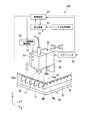
図1は、本実施形態に係るレーザ加工機100の一例を示す斜視図である。なお、図1ではレーザ加工機100の要部を示している。図1に示すように、レーザ加工機100は、レーザヘッド10と、ヘッド駆動部(駆動部)20と、プローブ30と、算出装置40と、制御装置50と、を備える。レーザ加工機100は、板状のワークWに対してレーザ光を照射することにより、例えば、所望の孔開け加工、または製品形状に切断する加工装置である。レーザ加工機100は、加工領域に搬入されたワークWに対して加工を行う。ワークWの搬入出は、後述する加工パレット60により行うが、他のローダ装置等により行ってもよい。本実施形態では、レーザ加工機100は、例えばパンチプレスなどの他の加工装置によって孔部が形成されたワークWに対してレーザ加工を行う。レーザ加工機100の各部の動作は、制御装置50によって統括的に制御される。
FIG. 1 is a perspective view showing an example of a
レーザ加工機100は、ワークWを支持する加工パレット60を有する。加工パレット60は、例えばワークWを加工する加工位置に配置される。加工パレット60は、例えば、不図示の駆動装置により、ワークWを載置した状態でX方向等に移動可能形成されてもよい。加工パレット60は、ベースプレート61及び支持プレート62を有している。ベースプレート61は、例えば矩形状に形成されている。支持プレート62は、ワークWの下面(−Z側の面)を支持する。支持プレート62は、ベースプレート61の上面(+Z側の面)に複数設けられている。
The
複数の支持プレート62は、ベースプレート61に対して立った状態で設けられ、X方向に並んで配置されている。各支持プレート62は、例えば鋸歯状に形成された複数の上端部62aを有している。各上端部62aは、ベースプレート61からの高さ(Z方向の位置)が同一となるように形成されている。
The plurality of
複数の上端部62aには、ワークWが載置される。複数の上端部62aの高さが不均一な場合、あるいはワークWの反り等の変形がある場合、ワークWが載置された状態で、ワークWの上面Waの高さは面方向にばらついた状態となっている。また、上端部62aが鋸歯状に形成されているため、上端部62aとワークWとの間の接触面積が小さくなる。なお、上端部62aは、鋸歯状とすることに限定されず、例えば、剣山状または波形状としてもよい。また、加工パレット60は、複数の支持プレート62を用いることに限定されず、例えば、複数のピンがベースプレート61上に配置されてもよい。
The workpiece W is placed on the plurality of
レーザヘッド10は、レーザ光を射出するノズル11を有している。ノズル11は、−Z方向に向けられており、レーザ光を−Z方向に射出する。ノズル11は、光ファイバ12等の光伝送体を介して不図示のレーザ光源に接続されている。レーザ光源としては、例えば炭酸ガスレーザ光源または固体レーザ光源等が用いられる。
The
ノズル11の先端(−Z側の端部)には、非接触センサ(計測部)13が設けられている。非接触センサ13は、ノズル11の先端と、加工パレット60に支持されたワークWとの間隔dを非接触で検出する。非接触センサ13は、ノズル11の先端に設けられた電極を有する。非接触センサ13は、当該電極とワークWとの間の静電容量に応じた電圧を算出装置40に出力する。当該電極とワークWとの間隔dが変化すると、両者の間の静電容量が変化し、出力電圧が変化する。したがって、電極とワークWとの間隔dと出力電圧との対応関係をデータテーブルとして予め算出装置40等に記憶させておくことで、算出装置40等において、出力電圧に応じた間隔dを取得することができる。なお、非接触センサ13としては、上記のように静電容量方式のセンサに限定されない。例えば、非接触センサ13として、渦電流方式のセンサまたは光学式のセンサ等を用いてもよい。
At the tip of the nozzle 11 (the end on the -Z side), the non-contact sensor (total measuring section) 13 is provided. The
また、ノズル11とワークWとの間隔dを計測するセンサとして非接触式に限定されず、接触式のセンサが用いられてもよい。また、非接触センサ13は、ノズル11に配置されることに限定されず、ノズル11から離れた箇所に設置されてもよい。制御装置50は、非接触センサ13によりノズル11とワークWとの間隔dを計測することにより、ワークWの上面Waの高さがばらついている場合でも、レーザ加工に際して間隔dが一定となるように、後述するヘッド駆動部20を制御する。
The sensor for measuring the distance d between the
ヘッド駆動部20は、レーザヘッド10をX方向、Y方向及びZ方向に移動させる。ヘッド駆動部20は、例えばボールネジ機構またはリニアモータ機構など、レーザヘッド10を移動させる不図示の駆動機構を有している。なお、レーザヘッド10は、X方向、Y方向及びZ方向のそれぞれの移動を案内するガイドを有し、各方向に駆動するための駆動機構を備えてもよいし、また、ロボットアームまたはマニュピレータ等によりレーザヘッド10をX方向、Y方向及びZ方向に移動させてもよい。
The
プローブ30は、レーザヘッド10とワークWとの相対位置を取得する。プローブ30は、例えば連結板21によってレーザヘッド10に連結されている。これにより、プローブ30は、レーザヘッド10と一体でX方向、Y方向及びZ方向に移動可能に設けられる。
The
図2(A)及び(B)は、プローブ30の一例を示す図である。プローブ30は、筐体31と、シャッタ32と、スライダ33と、エアシリンダ34と、ベース35と、接触棒36と、接触検出センサ37と、を有している。なお、接触検出センサ37については、図2においては省略しており、図3(A)において表記している。筐体31は、スライダ33、ベース35(接触検出センサ37を含む)、及び接触棒36を収容可能であり、下側(−Z側)端部に開口部31aが形成されている。
2A and 2B are diagrams showing an example of the
スライダ33は、筐体31の内面に取り付けられ、筐体31の内面に設けられた不図示のガイドに沿って上下方向(Z方向)に移動可能に設けられる。スライダ33は、ガイドにより規定された上限位置と下限位置との間を移動する。スライダ33は、ベース35及び接触棒36を一体で支持する。エアシリンダ34は、スライダ33をZ方向に駆動する駆動源である。エアシリンダ34を駆動することにより、スライダ33が昇降し、このスライダ33とともにベース35及び接触棒36も一体となって上下方向に移動する。なお、スライダ33の駆動をエアシリンダ34で行うことに限定されず、例えばボールねじ機構等が用いられてもよい。
The
シャッタ32は、開口部31aを開閉可能に設けられる。シャッタ32の開閉は、スライダ33とシャッタ32とを不図示のリンク機構により接続し、スライダ33の動作に連動して行われる。スライダ33が上方位置にある場合は、リンク機構によりシャッタ32を動作して開口部31aを閉じ、また、スライダ33が下方位置にある場合は、リンク機構によりシャッタ32を動作して開口部31aを開放する。なお、シャッタ32の動作をリンク機構で行うことに限定されず、電気モータ等の駆動源により行ってもよい。
The
ベース35は、スライダ33に支持される。接触棒36は、ベース35の下方(−Z側)の支持部35aに取り付けられる。接触棒36は、支持部35aを支点として下端部が揺動可能に設けられる。接触棒36は、スライダ33が上下方向に移動することにより、ベース35と一体でワークWに対して昇降可能である。接触棒36は、ワークWに設けられた孔部Wbに挿入可能な挿入部36aを下端部に有する。挿入部36aは、円筒状(または円柱状)に形成され、下端面36bが球面状に形成される。挿入部36aの径は、孔部Wbに挿入可能となるように設定される。例えば、孔部Wbの径が10mm〜20mm程度の場合、挿入部36aの径は例えば2mm程度に設定される。
The
図2(A)に示すように、エアシリンダ34によりスライダ33が筐体31の上方位置に配置される場合、ベース35及び接触棒36が筐体31に収容される。なお、接触棒36が筐体31に収容された状態において、接触棒36は開口部31aの上方に配置される。また、接触棒36が筐体31に収容される状態では、接触棒36は、レーザヘッド10のノズル11よりも上方に配置された状態となる。
As shown in FIG. 2A, when the
また、図2(B)に示すように、エアシリンダ34によりスライダ33が筐体31の下方位置に配置される場合、シャッタ32が開き、接触棒36が開口部31aから下方に突出した状態となる。また、接触棒36が開口部31aから下方に突出した状態では、接触棒36の挿入部36aは、レーザヘッド10のノズル11よりも下方に配置された状態となる。なお、開口部31aにシャッタ32を設けるか否かは任意であり、シャッタ32を設けなくてもよい。
Further, as shown in FIG. 2B, when the
接触検出センサ37は、接触棒36が孔部Wbの内面Wcに接触した場合に当該接触を検出する。接触検出センサ37としては、例えば図3(A)に示すように、ベース35の支持部35aに設けられ、接触棒36の傾きを検出する傾き検出センサが用いられる。この構成では、接触棒36が孔部Wbの内面Wc(図6(B)及び図7参照)に接触して傾いた場合、接触検出センサ37から例えば制御装置50に対して電気信号が出力される。制御装置50は、この電気信号を検出することにより、接触棒36が内面Wcに接触したことを検出する。
The
また、接触検出センサとしては、例えば図3(B)に示すように、接触棒36の挿入部36aの側面にタッチセンサ37Aを配置した構成であってもよい。この構成では、タッチセンサ37Aが孔部Wbの内面Wcに接触した場合、タッチセンサ37Aから制御装置50に対して電気信号が出力される。制御装置50は、この電気信号を検出することにより、接触棒36が内面Wcに接触したことを検出する。
Moreover, as a contact detection sensor, as shown, for example in FIG.3 (B), the structure which has arrange | positioned the
また、図3(A)に示すように、接触棒36の下端面36bは球面状に形成されるが、その直径は、接触棒36の円筒部分の径より大きな直径の球体の一部として形成される。これにより、球面状の下端面の上下高さを短くすることができ、接触棒36がワークWの表面に当たってもワークWの損傷を抑制しつつ、接触棒36の円筒部分の周面を下方まで延ばすことができる。
Further, as shown in FIG. 3A, the
算出装置40は、非接触センサ13の計測結果に基づいて、接触棒36の目標下降位置または下降量を算出する。また、算出装置40は、外部装置からワークWの板厚情報を取得可能である。例えば、制御装置50は、ワークWをレーザ加工するためにワークWの材質、板厚に関する情報が提供されており、算出装置40は制御装置50からワークWの板厚情報を取得してもよい。また、算出装置40は制御装置50と異なる外部装置(例えば、ワークWの加工データを作成する装置など)からワークWの板厚情報を取得してもよい。算出装置40は、ワークWの上面の高さと、ワークWの板厚情報とに基づいて、接触棒36の目標下降位置又は下降量を算出する。
The
次に、図4〜図10を参照して、上記のように構成されたレーザ加工機100の動作を説明する。図4は、レーザ加工機100の動作の手順を示すフローチャートである。また、図5〜図10は、動作の要部に関する部分について表している。以下に説明する各部の動作は、制御装置50からの指示に基づいて行われる。
Next, the operation of the
レーザ加工機100には、パンチプレスなどの加工装置によって孔部Wbが形成されたワークWが、加工パレット60(図1参照)に載置されて、レーザ加工機100の加工領域まで搬送される。孔部Wbとしては、例えばワークWのアライメントのため、ワークWの角部近傍に設けられる孔部、またはレーザ加工によって切断する製品ごとに設けられる孔部などが挙げられる。以下の例では、ワークWの角部近傍に設けられる孔部Wbを用いて説明する。各孔部Wbの大きさは、ほぼ同一に形成されるが、互いに異なる大きさでもよい。ワークWは、加工パレット60上に単に載置された状態で支持されており、レーザ加工機100のレーザヘッド10によるレーザ加工位置(レーザ加工機100に設定されているレーザ加工座標系)からずれている場合がある。
In the
制御装置50は、まず、図4に示すステップS01に先だって、ワークWの粗い位置合わせ(ラフアライメント)を行う。制御装置50は、ヘッド駆動部20を駆動して、非接触センサ13を水平方向に移動させる。このとき、制御装置50は、図5に示すように、ワークWの四辺のうち直交する二辺を選択し、非接触センサ13がこの辺を跨いでワークWの上方から外れるようにレーザヘッド10を移動させる。この場合、非接触センサ13がワークWの一辺を跨ぐときに、非接触センサ13で発生する出力電圧の値が変化する。制御装置50は、出力電圧の値が変化した位置をワークWの一辺上の位置であるとして検出する。
The
このような動作を、ワークWのうち直交する二辺の一辺に対して1カ所、他の一辺に対して2か所行う。これにより、ワークWの直交する二辺について異なる3点の位置座標を検出できるため、当該位置座標に基づいてワークWの位置を算出することができる。この位置座標から、レーザヘッド10によるレーザ加工位置との相対位置が算出される。図5に示すように、X方向及びY方向がレーザ加工機100に設定されているレーザ加工座標系である場合、このレーザ加工座標系から、ワークWのX方向のずれ量、Y方向のずれ量、Z方向を軸とした回転量が確認され、これらによってレーザ加工座標系を補正することにより、レーザヘッド10によるレーザ加工位置とワークWとの粗い位置合わせが完了する。
Such an operation is performed on one side of two orthogonal sides of the workpiece W and on two other sides. Thereby, since the position coordinates of three different points can be detected for two orthogonal sides of the work W, the position of the work W can be calculated based on the position coordinates. From this position coordinate, a relative position to the laser processing position by the
なお、上記のような粗い位置合わせを行うか否かは任意である。また、粗い位置合わせの手法として上記に限定されず、例えば、レーザ加工機100に設けられた固定部材等にワークWの直交する二辺を突き当てることにより粗い位置合わせを行ってもよい。
Note that whether or not to perform rough alignment as described above is arbitrary. Further, the rough alignment method is not limited to the above. For example, the rough alignment may be performed by abutting two orthogonal sides of the workpiece W against a fixing member or the like provided in the
続いて、図4に示すように、非接触センサ13によってワークWの上面Waの高さを計測する(ステップS01)。制御装置50は、粗い位置合わせにより補正された値を用いてレーザヘッド10を駆動し、図6(A)に示すように、レーザヘッド10のノズル11に備える非接触センサ13をワークWに対向させ、非接触センサ13とワークWとの間の静電容量に応じて発生する出力電圧を検出し、検出した出力電圧の大きさに対応した間隔dを求めることによりワークWの上面Waの高さを計測する。
Subsequently, as shown in FIG. 4, the height of the upper surface Wa of the workpiece W is measured by the non-contact sensor 13 (step S01). The
このとき、制御装置50は、粗い位置合わせにより孔部Wbの位置(だいたいの位置)が取得されるので、図6(B)に示すように、孔部Wbの周りの領域WdにおけるワークWの上面Waの高さを計測させてもよい。例えば、制御装置50は、非接触センサ13を孔部Wbの周りの1か所に対向させ、続いて、非接触センサ13を矢印に示すように孔部Wbの周りの領域Wdに沿って回動させながら間隔dを求めてもよい。これにより、接触棒36の挿入対象となる孔部Wb近傍におけるワークWの高さを求めることができ、算出装置40によって精度よく目標下降位置又は下降量を算出することができる。
At this time, since the position (approximately position) of the hole Wb is acquired by rough alignment, as shown in FIG. 6B, the
次に、算出装置40は、接触棒36の目標下降位置又は下降量を算出する(ステップS02)。ステップS02において、算出装置40は、非接触センサ13で求めたワークWの上面Waの高さ(間隔d)と、外部装置等から得られるワークWの板厚情報とに基づいて、接触棒36の目標下降位置又は下降量を算出する。接触棒36の目標下降位置は、例えば、接触棒36の下端の座標値として算出される。また、接触棒36の下降量は、接触棒36が突出した状態(図2(B)に示す状態)から下方に移動させる距離として算出される。上記した目標下降位置及び下降量はいずれか一方が算出されてもよく、双方が算出されてもよい。
Next, the
また、算出装置40は、接触棒36の挿入部36aが孔部Wbの垂直面(せん断面)Weと当接可能な目標下降位置又は下降量を算出する。ワークWをパンチプレス等により孔部Wbを形成した場合、図7(A)に示すように、孔部Wbの内面Wcは、上面Wa側にダレWfが生じており、ほぼ中央部分に垂直面(せん断面)Weが形成され、垂直面Weの下方に傾斜した破断面Wgが形成される。挿入部36aが孔部Wbの内面Wcのうち垂直面Weと当接することにより孔部Wbの位置を正確に計測することができる。算出装置40は、例えば、接触棒36の下端面36bの高さがワークWの下面Whよりも0.1mm程度上側に位置するように目標下降位置DP又は下降量DQを算出する。これにより、接触棒36が孔部WbのダレWf、または下方の支持プレート62に接触することが抑制される。
Further, the
次に、制御装置50は、接触棒36を孔部Wbに挿入する(ステップS03)。ステップS03において、先ず、制御装置50は、ヘッド駆動部20を駆動して、プローブ30(接触棒36)をX方向及びY方向に移動させ、孔部Wbの上方にプローブ30を配置させる。続いて、制御装置50は、エアシリンダ34を駆動してスライダ33を下方に移動させる。この動作により、シャッタ32が開き、接触棒36が筐体31から下方に突出する。続いて、制御装置50は、図7(B)に示すように、ヘッド駆動部20を駆動してレーザヘッド10とプローブ30とを一体で下方に移動させる。この動作により、接触棒36が下降(−Z方向に移動)し、挿入部36aが孔部Wbに挿入される。
Next, the
このとき、制御装置50は、先に算出された目標下降位置DP又は下降量DQに応じて接触棒36を下降(−Z方向に移動)させる。ここで、接触棒36の目標下降位置DP又は下降量DQとしては、上記のように下端面36bの高さがワークWの下面Whよりも上側に位置するように算出されている。このため、接触棒36の挿入部36aが孔部Wbに浅く挿入されること、または下端面36bが孔部Wbから突き抜けてワークWの支持プレート62の上端部62a等に当接することが防止される。
At this time, the
次に、制御装置50は、ワークWとレーザヘッド10のレーザ加工位置との相対位置を取得する(ステップS04)。ステップS04において、制御装置50は、ヘッド駆動部20によってレーザヘッド10とプローブ30とを一体でX方向又はY方向に移動させ、挿入部36aの側面を孔部Wbの内面Wc(垂直面We)に当接させる。挿入部36aの側面が孔部Wbの内面Wcに当接した場合、接触検出センサ37から制御装置50に電気信号が出力される。制御装置50は、電気信号を検出したタイミングで、レーザヘッド10のX方向及びY方向への駆動量を求め、この位置を検出することにより、レーザヘッド10のレーザ加工位置とワークWとの相対位置を取得する。
Next, the
図8(A)〜(C)は、レーザヘッド10のレーザ加工位置とワークWとの相対位置を取得する動作の一例を示す図である。まず、図8(A)に示すように、制御装置50は、接触棒36の挿入部36aを孔部Wbの内部で−X方向に移動させて内面Wcに接触させる。その後、制御装置50は、接触棒36を+X方向に移動させて挿入部36aを内面Wcに接触させる。制御装置50は、−X側の接触位置と+X側の接触位置との距離を計測した後に、その中点C1の位置(座標値)を算出し、中点C1に挿入部36aを移動させる。
8A to 8C are diagrams illustrating an example of an operation for acquiring the relative position between the laser machining position of the
続いて、図8(B)に示すように、制御装置50は、中点C1を通るように接触棒36の挿入部36aを+Y方向に移動させて内面Wcに接触させる。その後、制御装置50は、接触棒36を−Y方向に移動させて挿入部36aを内面Wcに接触させる。制御装置50は、+Y側の接触位置と−Y側の接触位置との距離を計測した後に、その中点C2の位置(座標値)を算出し、中点C2に挿入部36aを移動させる。
Subsequently, as shown in FIG. 8B, the
次に、図8(C)に示すように、制御装置50は、中点C2を通るように接触棒36の挿入部36aを−X方向に移動させて内面Wcに接触させる。その後、制御装置50は、接触棒36を+X方向に移動させて挿入部36aを内面Wcに接触させる。制御装置50は、−X側の接触位置と+X側の接触位置との距離を計測した後に、その中点C3の位置座標を求める。この中点C3の位置座標を求めることにより、孔部Wbの中心の位置座標を求めることができる。
Next, as shown in FIG. 8C, the
上記のように、先ず孔部Wb内においてX方向の中点C1を算出し、続いて中点C1を通るY方向の中点C2を算出し、続いて中点C2を通るX方向の中点C3を孔部Wbの中心とするので、例えば中点C1の算出時にX方向の距離が短く、中点C1の算出に誤差を含む場合であっても、その後の中点C2の算出を経て改めてX方向の中点C3を算出することにより、孔部Wbの中心の位置座標を正確に算出することができる。なお、上記した孔部Wbの中心の位置座標の算出手法は任意であり、例えば、孔部Wbの内面Wcの3点に挿入部36aを接触させ、この3点の各座標値から孔部Wbの中心の位置座標を求めてもよい。
As described above, first, the midpoint C1 in the X direction is calculated in the hole Wb, then the midpoint C2 in the Y direction passing through the midpoint C1, and then the midpoint in the X direction passing through the midpoint C2. Since C3 is the center of the hole Wb, for example, even when the distance in the X direction is short when the midpoint C1 is calculated and an error is included in the calculation of the midpoint C1, the calculation of the midpoint C2 is performed again. By calculating the midpoint C3 in the X direction, the position coordinates of the center of the hole Wb can be accurately calculated. The calculation method of the position coordinates of the center of the hole Wb is arbitrary. For example, the
制御装置50は、ワークWに設けられた3つの孔部Wbに対して、上記ステップS01からステップS04の動作を繰り返して行う。これにより、3つの孔部Wbの中心の位置座標が求められる。制御装置50は、これら3つの孔部Wbの位置が基準として、先に行った粗い位置合わせからさらにレーザ加工座標系におけるワークWの位置を更新する。これにより、レーザヘッド10のレーザ加工位置とワークWとの相対位置(位置合わせ)が正確に取得される。すなわち、前工程機械(パンチプレス等)の前工程加工座標系とレーザ加工座標系とを合わせることとなる。従って、レーザ加工機100に搬入された状態のワークWに対してレーザヘッド10の加工開始位置、駆動方向等が正確に設定される。
The
次に、制御装置50は、更新された相対位置に基づいてレーザヘッド10によりワークWを加工する(ステップS05)。ステップS05において、制御装置50は、図9に示すように、ヘッド駆動部20によってレーザヘッド10を移動させつつ、ノズル11からワークWに対してレーザ光Lを射出する。レーザ加工では、ワークWのうち予め設定された領域が切断される。制御装置50は、ステップS04で取得したワークWとレーザ加工位置との相対位置に基づいてレーザヘッド10を移動させる。したがって、ワークWがX方向及びY方向にずれている場合または傾いて配置されている場合(図5参照)であっても、レーザヘッド10がX方向及びY方向のずれまたは傾きを考慮して移動する。なお、非接触センサ13は、レーザ加工時においてもワークWの上面Waの高さを検出している。制御装置50は、非接触センサ13の検出結果に応じてワークWとノズル11との間隔d(図6(A)参照)を一定に維持するようにヘッド駆動部20の駆動を制御している。
Next, the
このように、本実施形態に係るレーザ加工機100によれば、算出装置40により接触棒36の目標下降位置DP又は下降量DQを算出し、算出結果に基づいて接触棒36を下降させるため、接触棒36を孔部Wbの所望の位置に確実に挿入することができる。これにより、レーザヘッド10のレーザ加工位置とワークWとの相対位置を高精度に取得することが可能となるため、ワークWの加工精度を高めることができる。
Thus, according to the
なお、上記した実施形態では、ワークWの角部近傍に形成された孔部Wbに接触棒36を挿入することにより、ワークWとレーザヘッド10との相対位置を求めることを記載しているが、1枚のワークWにおいて複数の製品を作成する場合は、製品ごとにレーザヘッド10のレーザ加工位置との位置合わせを行ってもよい。
In the above-described embodiment, it is described that the relative position between the workpiece W and the
図10は、レーザ加工によって切断する領域(製品)Wiごとに孔部Wjが形成されたワークWの例を示す図である。図10に示すように、領域Wiごとに孔部Wjが形成される場合、孔部Wjごとに図4に示すステップS01〜S04の動作を行う。これにより、ワークWの全体の位置合わせとともに、各切断領域Wiについてもレーザヘッド10のレーザ加工位置との位置合わせを行うことができ、1枚のワークWから複数の製品を作成する場合、各製品を正確にレーザ加工することができる。なお、複数の孔部Wjの全てを計測することに限定されず、例えば、複数の孔部Wjの1つについて上記のステップS01〜S04を行ってもよい。
FIG. 10 is a diagram illustrating an example of a workpiece W in which a hole Wj is formed for each region (product) Wi to be cut by laser processing. As shown in FIG. 10, when the hole Wj is formed for each region Wi, the operations of steps S01 to S04 shown in FIG. 4 are performed for each hole Wj. Thereby, in addition to the overall alignment of the workpiece W, each cutting area Wi can also be aligned with the laser processing position of the
また、孔部Wb及び孔部Wjは、レーザ加工される製品とは別に設けられることに限定されない。例えば図10に示すように、パンチプレス等により予め製品中に孔部Wkが形成されている場合は、この孔部Wkを用いてレーザヘッド10との位置合わせを行ってもよい。このとき、孔部Wkのみを用いる場合、または孔部Wbまたは孔部Wjと孔部Wkを組み合わせて用いる場合のいずれであってもよい。
Moreover, the hole Wb and the hole Wj are not limited to being provided separately from the product to be laser processed. For example, as shown in FIG. 10, when a hole Wk is formed in the product in advance by a punch press or the like, alignment with the
以上、実施形態について説明したが、本発明は、上述した説明に限定されず、本発明の要旨を逸脱しない範囲において種々の変更が可能である。例えば、上記した実施形態では、接触棒36の挿入部36aが円筒状(円柱状)に形成された構成を例に挙げて説明したが、これに限定されず、例えば楕円柱状、長円形状、多角柱状など、他の形状であってもよい。また、接触棒36の下端面36bが球面状に形成された構成を例に挙げて説明したが、これに限定されず、平面状等、他の形状であってもよい。
Although the embodiment has been described above, the present invention is not limited to the above description, and various modifications can be made without departing from the gist of the present invention. For example, in the above-described embodiment, the configuration in which the
また、上記した実施形態では、プローブ30において筐体31の下方に開閉可能なシャッタ32が設けられた構成を例に挙げて説明したが、シャッタ32の開閉機構としては上記した実施形態の構成に限定されず、例えばスライド型の構成であってもよい。
Further, in the above-described embodiment, the configuration in which the
また、上記した実施形態では、接触棒36を昇降させる駆動部として、レーザヘッド10を駆動するヘッド駆動部20が用いられる構成を例に挙げて説明したが、これに限定されず、接触棒36を昇降させる駆動部がヘッド駆動部20とは別に設けられてもよい。また、上記した実施形態では、プローブ30がレーザヘッド10と一体で移動する構成を例に挙げて説明したが、これに限定されず、プローブ30とレーザヘッド10とが独立して別個に移動する構成であってもよい。また、プローブ30とレーザヘッド10とが別々に設けられてもよい。
In the above-described embodiment, the configuration in which the
また、上記した実施形態では、非接触センサ13の計測結果とワークWの板厚情報とに基づいて目標下降位置DP又は下降量DQを算出する場合を例に挙げて説明したが、これに限定されない。例えば、ワークWの板厚情報を用いることなく、非接触センサ13の計測結果のみを用いて目標下降位置DP又は下降量DQを算出してもよい。
In the above-described embodiment, the case where the target lowering position DP or the lowering amount DQ is calculated based on the measurement result of the
また、上記した実施形態では、非接触センサ13を用いてワークWの上面Waの高さを計測しているが、これに限定されない。例えば、プローブ30に備える接触棒36を用いてワークWの上面Waの高さを計測してもよい。この場合、先ずプローブ30の接触棒36を下方に突出させ、この状態でヘッド駆動部20を駆動して接触棒36を下降させ、下端面36bがワークWの上面Waに当接させることで、当接するまでに下降した距離に基づいてワークWの上面Waの高さを検出してもよい。また、算出装置40は、接触棒36がワークWに当接するまでに下降した距離に、孔部Wbに挿入する所定量の長さを加えた量を接触棒36の下降量DQとして算出してもよい。また、法令で許容される限りにおいて、日本特許出願である特願2015−236568、及び本明細書で引用した全ての文献、の内容を援用して本文の記載の一部とする。
In the above-described embodiment, the height of the upper surface Wa of the workpiece W is measured using the
W…ワーク
Wa…上面
Wb、Wj…孔部
Wc…内面
Wd…領域
We…垂直面
C1…中点
C2…中点
C3…中点
DP…目標下降位置
DQ…下降量
10…レーザヘッド
11…ノズル
13…非接触センサ(計測部)
20…ヘッド駆動部(駆動部)
30…プローブ
32…シャッタ
34…エアシリンダ
36…接触棒
36a…挿入部
36b…下端面
37…接触検出センサ
37A…タッチセンサ
40…算出装置
50…制御装置
100…レーザ加工機W ... Workpiece Wa ... Upper surface Wb, Wj ... Hole portion Wc ... Inner surface Wd ... Area We ... Vertical surface C1 ... Middle point C2 ... Middle point C3 ... Middle point DP ... Target lowered position DQ ... Lowering
20: Head drive unit (drive unit)
DESCRIPTION OF
Claims (9)
前記ワークの上面の高さを計測する計測部と、
前記ワークに対して昇降可能な接触棒を有し、前記接触棒を下降させて前記孔部に挿入することにより前記レーザヘッドによるレーザ加工位置と前記ワークとの相対位置を取得可能なプローブと、
前記計測部の計測結果に基づいて前記接触棒の目標下降位置または下降量を算出する算出装置と、
前記算出装置により算出された目標下降位置または下降量に応じて前記接触棒を下降させる駆動部と、を備えるレーザ加工機。 A laser head for processing a plate-like workpiece in which a predetermined hole is formed;
A meter measuring unit for measuring the height of the upper surface of the workpiece,
A probe that can move up and down relative to the workpiece, and that can obtain the relative position between the laser machining position by the laser head and the workpiece by lowering the contact rod and inserting it into the hole;
A calculating device for calculating a target lowering position or lowering the amount of the contact bar on the basis of the measurement result of the meter measuring unit,
A laser processing machine comprising: a drive unit that lowers the contact bar in accordance with a target lowering position or a lowering amount calculated by the calculating device.
前記接触棒は、前記レーザヘッドに対して昇降可能に形成される、請求項1または請求項2に記載のレーザ加工機。 The probe is provided in the laser head,
The laser processing machine according to claim 1, wherein the contact bar is formed to be movable up and down with respect to the laser head.
前記計測された高さに基づいて前記孔部に挿入する接触棒の目標下降位置または下降量を算出することと、
前記目標下降位置または下降量に応じて前記接触棒を下降させ、前記孔部に挿入した前記接触棒により前記ワークとレーザヘッドによるレーザ加工位置との相対位置を取得することと、
前記相対位置に基づいて前記レーザヘッドにより前記ワークを加工することと、を含むワークの加工方法。 Measuring the height of the upper surface of the plate-like workpiece in which the predetermined hole is formed;
Calculating a target lowering position or a lowering amount of the contact rod to be inserted into the hole based on the measured height;
Lowering the contact bar according to the target lowering position or lowering amount, and obtaining the relative position between the workpiece and a laser processing position by a laser head by the contact bar inserted into the hole;
Machining the workpiece by the laser head based on the relative position.
Applications Claiming Priority (3)
| Application Number | Priority Date | Filing Date | Title |
|---|---|---|---|
| JP2015236568 | 2015-12-03 | ||
| JP2015236568 | 2015-12-03 | ||
| PCT/JP2016/081857 WO2017094408A1 (en) | 2015-12-03 | 2016-10-27 | Laser processing machine, calculating device, and processing method for workpiece |
Publications (2)
| Publication Number | Publication Date |
|---|---|
| JPWO2017094408A1 JPWO2017094408A1 (en) | 2018-09-13 |
| JP6593452B2 true JP6593452B2 (en) | 2019-10-23 |
Family
ID=58796950
Family Applications (1)
| Application Number | Title | Priority Date | Filing Date |
|---|---|---|---|
| JP2017553713A Active JP6593452B2 (en) | 2015-12-03 | 2016-10-27 | Laser processing machine and workpiece processing method |
Country Status (2)
| Country | Link |
|---|---|
| JP (1) | JP6593452B2 (en) |
| WO (1) | WO2017094408A1 (en) |
Families Citing this family (2)
| Publication number | Priority date | Publication date | Assignee | Title |
|---|---|---|---|---|
| CN111707359A (en) * | 2020-05-12 | 2020-09-25 | 固高科技(深圳)有限公司 | Laser processing detection system and method |
| JP2022126471A (en) * | 2021-02-18 | 2022-08-30 | 株式会社アマダ | Laser processing system and laser processing method |
Family Cites Families (4)
| Publication number | Priority date | Publication date | Assignee | Title |
|---|---|---|---|---|
| JPH02147183A (en) * | 1988-11-29 | 1990-06-06 | Yamazaki Mazak Corp | Controller and method for linear working |
| JPH03128186A (en) * | 1989-10-13 | 1991-05-31 | Toshiba Corp | Laser processing device |
| JPH06262383A (en) * | 1993-03-15 | 1994-09-20 | Nippon Steel Corp | Laser beam machine |
| JP5865753B2 (en) * | 2012-03-28 | 2016-02-17 | コマツ産機株式会社 | Combined processing method and combined processing apparatus |
-
2016
- 2016-10-27 JP JP2017553713A patent/JP6593452B2/en active Active
- 2016-10-27 WO PCT/JP2016/081857 patent/WO2017094408A1/en active Application Filing
Also Published As
| Publication number | Publication date |
|---|---|
| WO2017094408A1 (en) | 2017-06-08 |
| JPWO2017094408A1 (en) | 2018-09-13 |
Similar Documents
| Publication | Publication Date | Title |
|---|---|---|
| US8455787B2 (en) | Laser processing apparatus, process control apparatus, and processing apparatus | |
| JP6019149B2 (en) | Bending robot and workpiece detection method | |
| JP6679427B2 (en) | Hardness tester | |
| KR20060105616A (en) | Method and device for measuring and adjusting the electrode for taper machining on an electrical discharge machine | |
| JP6593452B2 (en) | Laser processing machine and workpiece processing method | |
| JP2017053732A (en) | Hardness tester | |
| JP6900290B2 (en) | Robot system | |
| JP2001518606A (en) | Device for detecting the position of two objects | |
| CN109661292A (en) | Work measuring | |
| JP4919334B2 (en) | Measuring method and measuring jig for setting inclination angle of wire electrode | |
| JP6087483B1 (en) | Laser processing machine, correction value calculation device, and program | |
| JP6316070B2 (en) | Bending system, V-groove position measuring device and bending method | |
| EP3736527B1 (en) | Surface shape measurement device | |
| JP2017223574A (en) | Industrial machine | |
| JP2013088190A (en) | Touch probe | |
| JP6800421B1 (en) | Measuring device and measuring method | |
| JP5064725B2 (en) | Shape measurement method | |
| US20120243956A1 (en) | Machine tool | |
| JP5267158B2 (en) | Ultrasonic measuring device | |
| JP2630378B2 (en) | Vertical wire placement method by two-point contact method | |
| JP2017072500A (en) | Work dimension checking device | |
| JP2005181023A (en) | Measuring device and method of height difference and tilt angle between planes | |
| KR20190080741A (en) | Break apparatus | |
| KR102404980B1 (en) | Product Measuring Apparatus Having Stable Product Seating Structure | |
| JP6341693B2 (en) | Substrate holding device and substrate inspection device |
Legal Events
| Date | Code | Title | Description |
|---|---|---|---|
| A621 | Written request for application examination |
Free format text: JAPANESE INTERMEDIATE CODE: A621 Effective date: 20180510 |
|
| A131 | Notification of reasons for refusal |
Free format text: JAPANESE INTERMEDIATE CODE: A131 Effective date: 20190702 |
|
| A521 | Request for written amendment filed |
Free format text: JAPANESE INTERMEDIATE CODE: A523 Effective date: 20190806 |
|
| TRDD | Decision of grant or rejection written | ||
| A01 | Written decision to grant a patent or to grant a registration (utility model) |
Free format text: JAPANESE INTERMEDIATE CODE: A01 Effective date: 20190827 |
|
| A61 | First payment of annual fees (during grant procedure) |
Free format text: JAPANESE INTERMEDIATE CODE: A61 Effective date: 20190909 |
|
| R150 | Certificate of patent or registration of utility model |
Ref document number: 6593452 Country of ref document: JP Free format text: JAPANESE INTERMEDIATE CODE: R150 |
|
| R250 | Receipt of annual fees |
Free format text: JAPANESE INTERMEDIATE CODE: R250 |
|
| R250 | Receipt of annual fees |
Free format text: JAPANESE INTERMEDIATE CODE: R250 |