JP6584932B2 - Bicycle gearshift derailleur and bicycle gearshift electronic control method - Google Patents
Bicycle gearshift derailleur and bicycle gearshift electronic control method Download PDFInfo
- Publication number
- JP6584932B2 JP6584932B2 JP2015233111A JP2015233111A JP6584932B2 JP 6584932 B2 JP6584932 B2 JP 6584932B2 JP 2015233111 A JP2015233111 A JP 2015233111A JP 2015233111 A JP2015233111 A JP 2015233111A JP 6584932 B2 JP6584932 B2 JP 6584932B2
- Authority
- JP
- Japan
- Prior art keywords
- gear
- derailleur
- primary
- chain
- chain guide
- Prior art date
- Legal status (The legal status is an assumption and is not a legal conclusion. Google has not performed a legal analysis and makes no representation as to the accuracy of the status listed.)
- Active
Links
Images


Classifications
-
- B—PERFORMING OPERATIONS; TRANSPORTING
- B62—LAND VEHICLES FOR TRAVELLING OTHERWISE THAN ON RAILS
- B62M—RIDER PROPULSION OF WHEELED VEHICLES OR SLEDGES; POWERED PROPULSION OF SLEDGES OR SINGLE-TRACK CYCLES; TRANSMISSIONS SPECIALLY ADAPTED FOR SUCH VEHICLES
- B62M9/00—Transmissions characterised by use of an endless chain, belt, or the like
- B62M9/04—Transmissions characterised by use of an endless chain, belt, or the like of changeable ratio
- B62M9/06—Transmissions characterised by use of an endless chain, belt, or the like of changeable ratio using a single chain, belt, or the like
- B62M9/10—Transmissions characterised by use of an endless chain, belt, or the like of changeable ratio using a single chain, belt, or the like involving different-sized wheels, e.g. rear sprocket chain wheels selectively engaged by the chain, belt, or the like
- B62M9/12—Transmissions characterised by use of an endless chain, belt, or the like of changeable ratio using a single chain, belt, or the like involving different-sized wheels, e.g. rear sprocket chain wheels selectively engaged by the chain, belt, or the like the chain, belt, or the like being laterally shiftable, e.g. using a rear derailleur
- B62M9/121—Rear derailleurs
- B62M9/122—Rear derailleurs electrically or fluid actuated; Controls thereof
-
- B—PERFORMING OPERATIONS; TRANSPORTING
- B62—LAND VEHICLES FOR TRAVELLING OTHERWISE THAN ON RAILS
- B62M—RIDER PROPULSION OF WHEELED VEHICLES OR SLEDGES; POWERED PROPULSION OF SLEDGES OR SINGLE-TRACK CYCLES; TRANSMISSIONS SPECIALLY ADAPTED FOR SUCH VEHICLES
- B62M9/00—Transmissions characterised by use of an endless chain, belt, or the like
- B62M9/04—Transmissions characterised by use of an endless chain, belt, or the like of changeable ratio
- B62M9/06—Transmissions characterised by use of an endless chain, belt, or the like of changeable ratio using a single chain, belt, or the like
- B62M9/10—Transmissions characterised by use of an endless chain, belt, or the like of changeable ratio using a single chain, belt, or the like involving different-sized wheels, e.g. rear sprocket chain wheels selectively engaged by the chain, belt, or the like
- B62M9/12—Transmissions characterised by use of an endless chain, belt, or the like of changeable ratio using a single chain, belt, or the like involving different-sized wheels, e.g. rear sprocket chain wheels selectively engaged by the chain, belt, or the like the chain, belt, or the like being laterally shiftable, e.g. using a rear derailleur
- B62M9/121—Rear derailleurs
- B62M9/124—Mechanisms for shifting laterally
- B62M9/1242—Mechanisms for shifting laterally characterised by the linkage mechanisms
-
- B—PERFORMING OPERATIONS; TRANSPORTING
- B62—LAND VEHICLES FOR TRAVELLING OTHERWISE THAN ON RAILS
- B62M—RIDER PROPULSION OF WHEELED VEHICLES OR SLEDGES; POWERED PROPULSION OF SLEDGES OR SINGLE-TRACK CYCLES; TRANSMISSIONS SPECIALLY ADAPTED FOR SUCH VEHICLES
- B62M9/00—Transmissions characterised by use of an endless chain, belt, or the like
- B62M9/04—Transmissions characterised by use of an endless chain, belt, or the like of changeable ratio
- B62M9/06—Transmissions characterised by use of an endless chain, belt, or the like of changeable ratio using a single chain, belt, or the like
- B62M9/10—Transmissions characterised by use of an endless chain, belt, or the like of changeable ratio using a single chain, belt, or the like involving different-sized wheels, e.g. rear sprocket chain wheels selectively engaged by the chain, belt, or the like
- B62M9/12—Transmissions characterised by use of an endless chain, belt, or the like of changeable ratio using a single chain, belt, or the like involving different-sized wheels, e.g. rear sprocket chain wheels selectively engaged by the chain, belt, or the like the chain, belt, or the like being laterally shiftable, e.g. using a rear derailleur
- B62M9/131—Front derailleurs
- B62M9/132—Front derailleurs electrically or fluid actuated; Controls thereof
-
- B—PERFORMING OPERATIONS; TRANSPORTING
- B62—LAND VEHICLES FOR TRAVELLING OTHERWISE THAN ON RAILS
- B62M—RIDER PROPULSION OF WHEELED VEHICLES OR SLEDGES; POWERED PROPULSION OF SLEDGES OR SINGLE-TRACK CYCLES; TRANSMISSIONS SPECIALLY ADAPTED FOR SUCH VEHICLES
- B62M9/00—Transmissions characterised by use of an endless chain, belt, or the like
- B62M9/04—Transmissions characterised by use of an endless chain, belt, or the like of changeable ratio
- B62M9/06—Transmissions characterised by use of an endless chain, belt, or the like of changeable ratio using a single chain, belt, or the like
- B62M9/10—Transmissions characterised by use of an endless chain, belt, or the like of changeable ratio using a single chain, belt, or the like involving different-sized wheels, e.g. rear sprocket chain wheels selectively engaged by the chain, belt, or the like
- B62M9/12—Transmissions characterised by use of an endless chain, belt, or the like of changeable ratio using a single chain, belt, or the like involving different-sized wheels, e.g. rear sprocket chain wheels selectively engaged by the chain, belt, or the like the chain, belt, or the like being laterally shiftable, e.g. using a rear derailleur
- B62M9/131—Front derailleurs
- B62M9/134—Mechanisms for shifting laterally
-
- B—PERFORMING OPERATIONS; TRANSPORTING
- B62—LAND VEHICLES FOR TRAVELLING OTHERWISE THAN ON RAILS
- B62M—RIDER PROPULSION OF WHEELED VEHICLES OR SLEDGES; POWERED PROPULSION OF SLEDGES OR SINGLE-TRACK CYCLES; TRANSMISSIONS SPECIALLY ADAPTED FOR SUCH VEHICLES
- B62M9/00—Transmissions characterised by use of an endless chain, belt, or the like
- B62M9/04—Transmissions characterised by use of an endless chain, belt, or the like of changeable ratio
- B62M9/06—Transmissions characterised by use of an endless chain, belt, or the like of changeable ratio using a single chain, belt, or the like
- B62M9/10—Transmissions characterised by use of an endless chain, belt, or the like of changeable ratio using a single chain, belt, or the like involving different-sized wheels, e.g. rear sprocket chain wheels selectively engaged by the chain, belt, or the like
- B62M9/12—Transmissions characterised by use of an endless chain, belt, or the like of changeable ratio using a single chain, belt, or the like involving different-sized wheels, e.g. rear sprocket chain wheels selectively engaged by the chain, belt, or the like the chain, belt, or the like being laterally shiftable, e.g. using a rear derailleur
- B62M9/121—Rear derailleurs
- B62M9/124—Mechanisms for shifting laterally
- B62M2009/12413—Rear derailleur comprising telescoping mechanisms
Description
本発明は、自転車ギアシフト、好ましくは電子サーボ支援型自転車ギアシフト、のディレイラ、および自転車ギアシフトの電子制御方法に関する。 The present invention relates to a derailleur of a bicycle gear shift, preferably an electronic servo assisted bicycle gear shift, and an electronic control method of the bicycle gear shift.
自転車の伝動システムは、ペダルクランクの軸に連結された歯車と後輪のハブに連結された歯車との間に延びるチェーンを含む。ペダルクランクの軸および後輪のハブの少なくとも一方に、複数の歯車を含む歯車のアセンブリがあり、それ故に伝動システムがギアシフトを備える場合、前側ディレイラおよび/または後側ディレイラが設けられる。 The bicycle transmission system includes a chain extending between a gear connected to the pedal crankshaft and a gear connected to the rear hub. There is a gear assembly including a plurality of gears on at least one of the pedal crankshaft and the rear wheel hub, and therefore if the transmission system comprises a gear shift, a front derailleur and / or a rear derailleur is provided.
高性能自転車、特にスポーツ競技に使用される自転車において、運転者にとって非常に重要な特性は、ギアシフト実行の速度および精度である。特にこの理由で、所謂電子ギアシフト、またはさらに具体的には、電子サーボ支援型ギアシフトが普及している。 In high performance bicycles, especially those used in sports competitions, a very important characteristic for the driver is the speed and accuracy of the gear shift execution. In particular, for this reason, so-called electronic gear shifts, or more specifically, electronic servo assisted gear shifts have become widespread.
電子サーボ支援型ギアシフトの場合、各ディレイラは、変速比(gear ratio)を変えるために歯車間でチェーンを変位させる可動の(チェーンガイドもしくはケージとして、または後側ディレイラの場合はロッカアーム要素としても知られる)ガイド要素と、チェーンガイドを変位させるための電気機械式アクチュエータとを含む。典型的には、このアクチュエータは、関節型の平行四辺形作動機構(articulated parallelogram)などのリンク機構を介してチェーンガイドに結合されたモータ(典型的には電気モータ)と、ラックシステムまたはウォームねじシステムと、ロータまたはロータからチェーンガイド自体に至るまでの下流にある可動部品の回転の、位置、速度、加速度および/または方向を検出するセンサまたはそれらを変換するトランスデューサと、を含む。また、この文脈で使用される用語とは少し異なる用語も使用されることを理解されたい。 In the case of electronic servo-assisted gearshifts, each derailleur is also known as a movable (chain guide or cage) that shifts the chain between gears to change the gear ratio, or as a rocker arm element in the case of a rear derailleur. A guide element and an electromechanical actuator for displacing the chain guide. Typically, the actuator includes a motor (typically an electric motor) coupled to a chain guide via a linkage such as an articulated parallelogram, a rack system or a worm screw. A system and sensors for detecting the position, velocity, acceleration and / or direction of the rotation of the moving parts downstream from the rotor or the rotor to the chain guide itself, or transducers for converting them. It should also be understood that terms that are slightly different from those used in this context are also used.
制御エレクトロニクスは、例えば、走行速度、ペダルクランクの回転リズム、ペダルクランクにかけられたトルク、走行地形の傾斜、運転者の心拍数などの1つ以上の検出された変数に基づいて、変速比を自動的に変更し、ならびに/または、変速比は、例えばレバーおよび/もしくはボタンなどの適切な制御部材を介して運転者によって手動で入力された命令に基づいて、変更される。 The control electronics automatically adjusts the gear ratio based on one or more detected variables such as, for example, travel speed, pedal crank rotation rhythm, pedal crank torque, travel terrain slope, driver heart rate, etc. And / or the gear ratio is changed based on a command manually entered by the driver via a suitable control member such as a lever and / or a button.
前側ディレイラ制御用の装置またはユニット、および後側ディレイラ制御用の装置またはユニット(またはより簡素なギアシフトの場合はこれらのうちの一方)が、運転者が容易に操縦できるように、通常はバンドルバーに、そしてハンドグリップの近くに、装着される。該ハンドグリップには、前輪および後輪をそれぞれブレーキ制御するためにブレーキレバーも位置づけられている。ディレイラの2方向への駆動とブレーキ駆動とを可能にする制御装置は、一般に集中制御(integrated control)と呼ばれる。 The front derailleur control device or unit and the rear derailleur control device or unit (or one of these for a simpler gearshift) are usually bundled bars so that the driver can easily steer. And near the handgrip. The handgrip is also positioned with a brake lever for brake control of the front wheel and the rear wheel, respectively. A control device that enables driving the derailleur in two directions and driving the brake is generally called integrated control.
命令値(command values)のテーブルの値を参照して自転車ギアシフトのディレイラを駆動することは、一般に知られている。これらの値はそれぞれ、チェーンが特定の歯車と係合するまたは係合しているディレイラの位置に相関している。換言すれば、制御エレクトロニクスまたはコントローラは、この命令値のテーブルを使用して、チェーンを所望の歯車に係合するように位置づけるためにディレイラの変数が取らなければならない値を得る。そのような値は、隣接する歯車との差分値であってもよく、または参照対象に対する絶対値であってもよい。この参照対象とは、例えば参照歯車、ストロークの終了状態、またはモータが励磁されていない状態などであってよい。 It is generally known to drive a bicycle gear shift derailleur with reference to the values in the command values table. Each of these values correlates to the position of the derailleur where the chain engages or engages a particular gear. In other words, the control electronics or controller uses this command value table to obtain the value that the derailleur variable must take to position the chain to engage the desired gear. Such a value may be a difference value from an adjacent gear, or may be an absolute value with respect to a reference object. The reference object may be, for example, a reference gear, a stroke end state, or a state where the motor is not excited.
重要性の観点からは、値のテーブルのアクチュエータ命令値は、例えば、ディレイラにおけるある可動点を参照点としてその可動点が移動する距離、モータが実行すべきステップ数または回転数、モータの励磁時間の長さ、電圧に比例する駆動量を有するモータへの供給電圧の値などであってもよく、さらには、モータに関連付けられたセンサまたはトランスデューサが出す値、レジスタに記憶され、上述した数量のうちの1つを表す数値などであってもよい。 From the standpoint of importance, the actuator command value in the value table is, for example, the distance that the movable point moves with reference to a certain movable point in the derailleur, the number of steps or the number of rotations that the motor should perform, Or the value of the supply voltage to the motor having a driving amount proportional to the voltage, and the value output by the sensor or transducer associated with the motor, the value stored in the register, and the quantity described above. A numerical value representing one of them may be used.
特に、アクチュエータのモータは、一定数のステップの間、ある長さの励磁時間の間、または、各アップギアシフトもしくはダウンギアシフトに適した電圧で、駆動することができ、そして、自動的に止まることができる。その一方で、センサを使用してフィードバック信号を制御エレクトロニクスに提供し、意図した位置に到達しなかった場合、すなわちディレイラの上述の変数が当該テーブルの値にならなかった場合に、制御エレクトロニクスがアクチュエータのモータを再度作動できるようにする。これは、例えば、ディレイラにより与えられる抵抗トルク(これはある程度運転者のペダルの漕ぎ方に依存するが)が高すぎ、モータがリンク機構を介して送ることのできる最大トルクより大きかった、という事実によるものであってもよい。 In particular, the actuator motor can be driven for a certain number of steps, for a certain length of excitation time, or at a voltage suitable for each up- or down-gear shift, and automatically shut off. Can do. On the other hand, if the sensor is used to provide a feedback signal to the control electronics and the intended position is not reached, i.e. if the above derailleur variable does not reach the value in the table, the control electronics The motor can be operated again. This is, for example, the fact that the resistance torque provided by the derailleur (which depends to some extent on the driver's pedaling) is too high and is greater than the maximum torque that the motor can send through the linkage. It may be due to.
命令値の上記テーブルの値は、(前側または後側の)ディレイラの歯車の数ならびに歯車それぞれの厚さおよびピッチを考慮して工場で設定されるノミナル(nominal)値である。典型的には、このようなノミナル値は、アクチュエータ駆動信号がない場合、すなわち命令値がゼロの場合にチェーンが最小径を有する歯車と係合する、と仮定したものである。しかし、上述の例から分かるように、この条件は必須ではない。 The values in the above table of command values are nominal values set at the factory considering the number of derailleur gears (front or rear) and the thickness and pitch of each gear. Typically, such a nominal value assumes that the chain engages a gear having the smallest diameter when there is no actuator drive signal, ie, when the command value is zero. However, as can be seen from the above example, this condition is not essential.
電子サーボ支援型ギアシフトによりギアシフトの精度および速度の改善が可能となったが、運転者が競技でより良い結果を達成するのを支援し、機械を保護するためには、依然としてこれらの性能を改善する必要がある。 Electronic servo-assisted gearshifts have enabled improvements in gearshift accuracy and speed, but these performances are still improved to help drivers achieve better results in competitions and protect machines There is a need to.
この要求は、ギアシフトが高度な自転車競技において益々使用されることが意図されるにつれ、明らかに益々重要となる。 This requirement is clearly becoming more and more important as gearshifts are intended to be used more and more in advanced cycling competitions.
既知の自転車ギアシフトの制御を高精度とするためには、自転車の初期調整を行う。それによって、ペダルクランクの軸に関連付けられた前側の歯車のアセンブリ(クラウン)と後輪に関連付けられた後側の歯車のアセンブリ(スプロケット)との両方の、歯車のアセンブリおよびフレームのコンフィギュレーション(configuration)および構造に依存するチェーンのテンションを最適化する。 In order to make the control of the known bicycle gear shift highly accurate, initial adjustment of the bicycle is performed. Thereby, the gear assembly and frame configuration, both the front gear assembly (crown) associated with the pedal crankshaft and the rear gear assembly (sprocket) associated with the rear wheel. ) And optimize chain tension depending on the structure.
テーブルの命令値を特定のギアシフトの電気機械的コンポーネント要素に正確に対応するように調整することが可能である。特に、歯車のピッチに、ならびに/または、固定参照対象および可動参照対象としてのリンク機構もしくはモータの各要素の相互位置に、そしておそらくは、モータの駆動電圧の推移(progress)に、モータの回転の速度、加速度および/もしくは方向などに、対応するように調整することが可能である。 It is possible to adjust the table command values to accurately correspond to the electromechanical component elements of a particular gear shift. In particular, the rotation of the motor in the pitch of the gear and / or in the mutual position of the components of the linkage or motor as a fixed reference object and in the movable reference object and possibly in the progress of the motor drive voltage. Adjustments can be made to accommodate speed, acceleration, and / or direction.
さらに、典型的には、初期調整は、トランスミッション内におそらくはプリロードをかけて設けられた少なくとも1つのばねに作用して、異なる走行状態において伝動チェーンの正しいテンションが維持されるようにする。 In addition, the initial adjustment typically acts on at least one spring, presumably preloaded in the transmission, so that the correct tension of the transmission chain is maintained in different driving conditions.
特にロード用自転車(road bicycle)に使用されるいくつかのギアシフトにおいては、2つのチェーンテンション調整ばねがあり、それらが相互作用して、伝動チェーンと係合する際のチェーンガイドのセットアップを定めている。これによりシステムの多様性が高められ、より高い融通性をもたらしている。他方、他のギアシフトでは、1つのチェーンテンション調整ばねのみを備えることができる。 In some gear shifts, especially used on road bicycles, there are two chain tension adjustment springs that define the chain guide setup when they interact to engage the transmission chain. Yes. This increases the diversity of the system and provides greater flexibility. On the other hand, in other gear shifts, only one chain tension adjusting spring can be provided.
先行技術によれば、チェーンテンション調整ばね(複数可)の初期のプリロード設定は、チェーンガイドを歯車に半径方向にできるだけ近づけるように行われる。 According to the prior art, the initial preload setting of the chain tension adjusting spring (s) is performed so that the chain guide is as close as possible to the gear in the radial direction.
実際、チェーンガイドと歯車との間の距離が短いため、制御が非常に敏感なものとなる。なぜならば、そのような状態では、歯車の軸心に平行なチェーンガイド変位コンポーネントは、1つの歯車から他の歯車への変位をトリガするのに十分なチェーンへの傾斜に対応するからである。 In fact, the control is very sensitive because the distance between the chain guide and the gear is short. This is because in such a situation, the chain guide displacement component parallel to the gear axis corresponds to a tilt in the chain sufficient to trigger a displacement from one gear to the other.
しかし、チェーンガイドを歯車に近づけることは、最大径の歯車によって制限される。実際、最大径の歯車に近づけすぎると、そのような歯車と次の歯車との間の変速比のギアシフトが雑に感じたり、最大径の歯車にチェーンが係合している場合にペダルを逆向きに漕ぐと、チェーンとチェーンガイドがこすれたりするような欠点をもたらす。そのような状態では、トランスミッションは不快なまでにうるさくなり得る。 However, bringing the chain guide closer to the gear is limited by the largest diameter gear. In fact, if you get too close to the largest diameter gear, the gear shift of the gear ratio between such gear and the next gear will feel messy, or the pedal will be reversed if the chain is engaged with the largest diameter gear. If it is turned in the direction, the chain and chain guide will be rubbed. Under such conditions, the transmission can become unpleasantly noisy.
ギアシフトの精度を改善するために、出願人は、特許文献1として公開された特許出願1において、歯車アセンブリの軸方向におけるチェーンガイドのプライマリ変位に応じてチェーンテンション調整ばねのプリロードを調整すること、特に、プリロードをチェーンガイドのプライマリ変位により機械的にもたらすことを最近提案した。このように、歯車アセンブリの軸心からのチェーンガイドの半径方向距離は、どの歯車がチェーンと係合しているかに依存して変化する。特に、当該軸心からの距離は、チェーンと係合している歯車の直径が大きくなるにつれて大きくなる。
In order to improve the accuracy of the gear shift, the applicant adjusts the preload of the chain tension adjusting spring according to the primary displacement of the chain guide in the axial direction of the gear assembly in
本発明の基礎となる課題は、自転車ギアシフトのディレイラにおいてギアシフトの精度および速度をさらに改善することである。 The problem underlying the present invention is to further improve the accuracy and speed of the gear shift in a bicycle gear shift derailleur.
本発明の1つの構成は、
自転車ギアシフトのディレイラであって、
前記ギアシフトの同軸歯車のアセンブリ(assembly)において自転車フレームに装着されるように構成された支持ユニットと、
チェーンガイドを備える可動ユニット(mobile unit)と、
前記支持ユニットに対して前記可動ユニットを移動させて、前記歯車のアセンブリの軸心に関して軸方向に少なくとも1つのコンポーネント(component)を有するプライマリ変位(primary displacement)を前記チェーンガイドに付与するように構成された、プライマリ作動手段(primary actuation means)と、を備えたディレイラにおいて、
前記支持ユニットに対して前記可動ユニットを移動させて、前記歯車のアセンブリの前記軸心に関して半径方向に少なくとも1つのコンポーネントを有するセカンダリ変位(secondary displacement)を前記チェーンガイドに付与するように構成されたセカンダリ作動手段(secondary actuation means)であって、前記セカンダリ作動手段は、前記プライマリ作動手段とは独立して前記可動ユニットを移動させることが可能である、セカンダリ作動手段を、さらに備えることを特徴とする、ディレイラに、関する。
One configuration of the present invention is:
Bicycle gear shift derailleur
A support unit configured to be attached to a bicycle frame in an assembly of the gearshift coaxial gear;
A mobile unit with a chain guide;
Configured to move the movable unit relative to the support unit to impart a primary displacement to the chain guide having at least one component axially with respect to an axis of the gear assembly. A derailleur comprising primary actuation means,
Configured to move the movable unit relative to the support unit to impart a secondary displacement to the chain guide having at least one component in a radial direction with respect to the axis of the gear assembly. Secondary actuation means, wherein the secondary actuation means further comprises secondary actuation means capable of moving the movable unit independently of the primary actuation means, To do with the derailleur.
プライマリ変位とは独立したセカンダリ変位のおかげで、可動ユニット、特にチェーンガイドは、歯車のアセンブリに対して理想的な位置に常にあることができる。典型的には、ギアシフト中は、可動ユニットは、歯車に対して半径方向に相対的に近い位置にあり、その一方で、通常走行中は、半径方向に相対的に遠い位置にある。さらに、(近い位置と遠い位置の両方における)半径方向距離は、チェーンが係合する歯車の直径に従って適切に選択でき、したがって、常にその時の状況に最も適した距離となり得る。さらに一般的には、通常走行中および/またはギアシフト中に半径方向距離を変更できる。 Thanks to the secondary displacement independent of the primary displacement, the movable unit, in particular the chain guide, can always be in an ideal position with respect to the gear assembly. Typically, during gear shifting, the movable unit is in a position that is relatively close to the gear in the radial direction, while during normal travel, it is in a position that is relatively far in the radial direction. Furthermore, the radial distance (both near and far) can be selected appropriately according to the diameter of the gear with which the chain engages and can therefore always be the most suitable distance for the current situation. More generally, the radial distance can be changed during normal driving and / or during gear shifting.
このように、プライマリ作動手段のモータの速度を必ずしも上げる必要なく、ギアシフトを加速できる。なぜならば、ギアシフト中にチェーンを歯車に対して可能な限り近くに維持できるからである。 Thus, the gear shift can be accelerated without necessarily increasing the motor speed of the primary operating means. This is because the chain can be kept as close as possible to the gear during the gear shift.
典型的には、プライマリ作動手段により付与されるプライマリ変位はまた、歯車のアセンブリの軸心に関して半径方向のコンポーネントおよび/または周方向のコンポーネントを有する。 Typically, the primary displacement imparted by the primary actuating means also has radial and / or circumferential components with respect to the axis of the gear assembly.
セカンダリ作動手段により付与されるセカンダリ変位は、周方向のコンポーネントを有してもよいが、軸方向のコンポーネントは有しない。 The secondary displacement applied by the secondary actuating means may have a circumferential component, but does not have an axial component.
好ましくは、ディレイラは後側ディレイラである。 Preferably, the derailleur is a rear derailleur.
好ましくは、
前記支持ユニットは、支持体と、前記支持体を前記フレームに装着するための第1の固定ユニット(fixing unit)とを備え、
前記可動ユニットは、可動体と、前記チェーンガイドを前記可動体に装着するための第2の固定ユニットとを備え、
チェーンテンション調整ばね(chain tensioning spring)が、前記第1の固定ユニットおよび前記第2の固定ユニットの少なくとも一方に設けられており、前記チェーンテンション調整ばねは、自転車伝動チェーンに係合されると、前記チェーンガイドのセットアップ(setup)を決定し、
前記セカンダリ作動手段は、前記チェーンガイドの前記セカンダリ変位を引き起こす前記チェーンガイドの前記セットアップの変化を決定するように、前記チェーンテンション調整ばねのプリロード(preload)を調整するためのリンク機構(linkage)を備える。
Preferably,
The support unit includes a support and a first fixing unit for mounting the support to the frame;
The movable unit includes a movable body and a second fixed unit for mounting the chain guide to the movable body,
A chain tensioning spring is provided on at least one of the first fixing unit and the second fixing unit, and the chain tension adjusting spring is engaged with a bicycle transmission chain; Determine the chain guide setup,
The secondary actuating means includes a linkage for adjusting a preload of the chain tension adjustment spring to determine a change in the setup of the chain guide that causes the secondary displacement of the chain guide. Prepare.
上述したように、チェーンテンション調整ばね(または複数のばね)は、チェーンガイドのセットアップを決定し、最終的にはチェーンのセットアップを決定する、力学的平衡を達成するためのものである。セットアップには、チェーンガイドの歯車のアセンブリの軸心からの半径方向距離も含まれる。したがって、このばね(または複数のばねがある場合にはこれらのばねのうちの少なくとも1つ)のプリロードを変更することにより、歯車のアセンブリの軸心に対するチェーンガイドの位置を所望通り変更できる。 As described above, the chain tension adjustment spring (or springs) is for achieving a mechanical balance that determines the chain guide setup and ultimately the chain setup. The setup also includes the radial distance from the axis of the chain guide gear assembly. Thus, by changing the preload of this spring (or at least one of these springs if there are multiple springs), the position of the chain guide relative to the axis of the gear assembly can be changed as desired.
好ましくは、前記ディレイラは、関節型の平行四辺形作動機構タイプであり、1つの固定側と、前記固定側に対向し、等しい長さの2つの接続ロッドにより前記固定側に接続される1つの可動側を有し、前記固定側は前記支持体により形成され、前記可動側は前記可動体により形成される。しかし、本発明はまた異なる構成を有するディレイラにも適用可能である。 Preferably, the derailleur is an articulated parallelogram operating mechanism type, one fixed side and one fixed side facing the fixed side and connected to the fixed side by two connecting rods of equal length. There is a movable side, the fixed side is formed by the support, and the movable side is formed by the movable body. However, the present invention is also applicable to derailleur having different configurations.
好ましい実施形態において、
前記第1の固定ユニットは、
前記フレームに装着固定されるように意図されたピボットであって、前記支持体および前記チェーンテンション調整ばねは前記ピボットに回転可能に装着されるピボットと、
第1のリングであって、前記ピボットに回転可能に装着され、フレームに載置されるための歯と、前記チェーンテンション調整ばねの第1の端部に係合する座部とを備える、第1のリングと、を備え、
前記チェーンテンション調整ばねの前記プリロードを調整するための前記リンク機構は、第2のリングであって、前記支持体内かつ前記ピボット上に回転可能に装着され、前記チェーンテンション調整ばねの第2の端部に係合する座部を備える、第2のリングと、
前記第2のリングに形成された歯付きセクタと、
前記歯付きセクタに係合するウォームねじと、を備える。
In a preferred embodiment,
The first fixing unit is:
A pivot intended to be fixedly attached to the frame, wherein the support and the chain tension adjusting spring are rotatably attached to the pivot;
A first ring comprising a tooth rotatably mounted on the pivot and mounted on a frame; and a seat engaged with a first end of the chain tension adjustment spring. 1 ring, and
The link mechanism for adjusting the preload of the chain tension adjusting spring is a second ring, which is rotatably mounted in the support and on the pivot, and a second end of the chain tension adjusting spring. A second ring comprising a seat that engages the part;
A toothed sector formed in the second ring;
A worm screw engaging the toothed sector.
よって、この実施形態では、プリロードを調整するためのリンク機構が作用するチェーンテンション調整ばねは、第1の固定ユニット内に、したがって支持ユニット内に配置される。この状態では、本発明を実施するためにディレイラにおいて必要な更なる構成要素は実質的に全て支持ユニットに設けられる。すなわち、自転車のフレームに直接装着され、限定された動きおよび変形を受けるユニット内に設けられる。したがって、このように、ディレイラの嵩が実質的に増加せず、セカンダリ作動手段が自転車の使用中に起こりうる衝撃から相対的に守られた位置にある、という点で二重に有利である。 Therefore, in this embodiment, the chain tension adjusting spring on which the link mechanism for adjusting the preload acts is arranged in the first fixed unit and thus in the support unit. In this state, substantially all further components required in the derailleur to implement the present invention are provided in the support unit. That is, it is installed in a unit that is mounted directly on the frame of the bicycle and undergoes limited movement and deformation. Thus, this is doubly advantageous in that the bulk of the derailleur does not increase substantially and the secondary actuating means is in a position that is relatively protected from possible impacts during use of the bicycle.
代替実施形態では、
第2の固定ユニットは、
前記可動体に装着されたピボットであって、前記チェーンガイドと前記チェーンテンション調整ばねとが前記ピボットに回転可能に装着されている、ピボットと、
前記チェーンガイド内に形成され前記ばねの第1の端部に係合する座部と、を
備え、
前記チェーンテンション調整ばねの前記プリロードを調整する前記リンク機構は、
前記可動体内に回転可能に装着され、かつ前記チェーンテンション調整ばねの第2の端部に係合する座部を備える、リングと、
前記リングに形成される歯付きセクタと、
前記歯付きセクタに係合するウォームねじと、を備える。
In an alternative embodiment,
The second fixed unit is
A pivot mounted on the movable body, wherein the chain guide and the chain tension adjustment spring are rotatably mounted on the pivot;
A seat formed in the chain guide and engaged with a first end of the spring;
The link mechanism for adjusting the preload of the chain tension adjustment spring is:
A ring comprising a seat that is rotatably mounted in the movable body and engages a second end of the chain tension adjustment spring;
A toothed sector formed in the ring;
A worm screw engaging the toothed sector.
よって、この実施形態では、プリロードを調整するためのリンク機構が作用するチェーンテンション調整ばねは、第2の固定ユニット内に、したがって可動ユニット内に配置される。この状態では、本発明を実施するためにディレイラにおいて必要な更なる構成要素は実質的に全て可動ユニットに設けられる。すなわち、自転車のフレームに対して有意に突出する位置に装着されたユニット内に設けられる。したがって、このように、調整、キャリブレーション(calibration)、メンテナンス、清掃などのためにそれらの構成要素にアクセスし易い。 Therefore, in this embodiment, the chain tension adjusting spring on which the link mechanism for adjusting the preload acts is arranged in the second fixed unit and hence in the movable unit. In this state, substantially all further components necessary in the derailleur to implement the present invention are provided in the movable unit. That is, it is provided in a unit mounted at a position that significantly protrudes from the bicycle frame. Thus, it is thus easy to access those components for adjustment, calibration, maintenance, cleaning, etc.
好ましい実施形態において、プライマリ作動手段は第1の電気モータを備え、セカンダリ作動手段は第2の電気モータを備える。 In a preferred embodiment, the primary actuation means comprises a first electric motor and the secondary actuation means comprises a second electric motor.
第1の作動手段および第2の作動手段とは独立して駆動され得る別々のモータを使用することにより、特定の使用状態に最適なモータを最大限に自由に選択できる。特に、モータを含めて、プライマリ作動手段用の従来のコンフィギュレーションを維持できる。また、プライマリ変位およびセカンダリ変位の独立性も容易に得ることができる。 By using separate motors that can be driven independently of the first actuating means and the second actuating means, it is possible to freely select the motor most suitable for a particular use state. In particular, the conventional configuration for primary actuation means, including the motor, can be maintained. Also, the independence of the primary displacement and the secondary displacement can be easily obtained.
この実施形態では、必要な場合にはプライマリ作動手段およびセカンダリ作動手段の同時作動が可能である。 In this embodiment, the primary operating means and the secondary operating means can be operated simultaneously if necessary.
代替実施形態において、前記プライマリ作動手段および前記セカンダリ作動手段は単一の共有電気モータを備え、前記プライマリ作動手段と前記セカンダリ作動手段とにそれぞれに関連付けられた、プライマリ出力とセカンダリ出力とを有するトランスミッションが設けられる。この実施形態においても、より複雑にはなるものの、プライマリ作動手段およびセカンダリ作動手段の同時作動が可能になる。 In an alternative embodiment, the primary actuating means and the secondary actuating means comprise a single shared electric motor and have a primary output and a secondary output respectively associated with the primary actuating means and the secondary actuating means. Is provided. Even in this embodiment, although it becomes more complicated, the primary operation means and the secondary operation means can be operated simultaneously.
プライマリ作動手段およびセカンダリ作動手段の両方のために単一のモータを使用することにより、第2のモータおよび関係制御システムの重量、嵩、およびコストを回避することができる。実際、適切なパワーを有する電気モータの重量、嵩、およびコストは、トランスミッションの重量、嵩、およびコストよりも大きい。 By using a single motor for both the primary and secondary actuation means, the weight, bulk, and cost of the second motor and related control system can be avoided. In fact, the weight, bulk, and cost of an electric motor with adequate power is greater than the weight, bulk, and cost of a transmission.
好ましくは、前記トランスミッションは、
前記単一の電気モータによって回転されるプライマリシャフトと、
前記プライマリシャフトに固定的に嵌められたプライマリ歯車と、
互いに平行でありかつ前記プライマリシャフトに平行である、第1のセカンダリシャフトおよび第2のセカンダリシャフトと、
前記第1のセカンダリシャフトに固定的に嵌められた第1のセカンダリ歯車と、
前記第2のセカンダリシャフトに固定的に嵌められた第2のセカンダリ歯車と、
前記プライマリシャフトと前記セカンダリシャフトとに平行な副軸心に沿って軸方向に可動に装着され、前記プライマリ歯車と取り外せないように(permanently)噛み合い係合し、前記セカンダリ歯車の一方および/または他方と選択的に噛み合い係合する、副(auxiliary)歯車と、を備える。
Preferably, the transmission is
A primary shaft rotated by the single electric motor;
A primary gear fixedly fitted to the primary shaft;
A first secondary shaft and a second secondary shaft that are parallel to each other and parallel to the primary shaft;
A first secondary gear fixedly fitted to the first secondary shaft;
A second secondary gear fixedly fitted to the second secondary shaft;
One of the secondary gears and / or the other is mounted so as to be movable in an axial direction along a sub-axis parallel to the primary shaft and the secondary shaft, and in meshing engagement with the primary gear so as not to be removed. And an auxiliary gear that selectively meshes with and engages.
このコンフィギュレーションは容易に実施でき、また、簡素で信頼性が高く、非常にコンパクトなトランスミッションが得られる。 This configuration is easy to implement and provides a simple, reliable and very compact transmission.
好ましくは、減速段が電気モータとプライマリシャフトとの間に配置されており、2つのプライマリ出力およびセカンダリ出力では非常に低い角速度が必要であるものの、(相対的に高い回転速度で作動する)普通の電気モータを使用できる。 Preferably, the speed reduction stage is located between the electric motor and the primary shaft and the two primary and secondary outputs require a very low angular speed, but normally (operate at a relatively high rotational speed) The electric motor can be used.
好ましくは、前記副歯車は副シャフト(auxiliary shaft)に固定的に嵌められており、副シャフトは、副軸心に沿って可動なように案内されるスライド(摺動体)によって回転可能に担持される。 Preferably, the auxiliary gear is fixedly fitted to an auxiliary shaft, and the auxiliary shaft is rotatably supported by a slide (sliding body) guided so as to be movable along the auxiliary axis. The
より好ましくは、前記スライドは電磁式アクチュエータによって作動される。 More preferably, the slide is actuated by an electromagnetic actuator.
好ましくは、前記電磁式アクチュエータはプッシュプル(push-pull)電磁石を備える。 Preferably, the electromagnetic actuator includes a push-pull electromagnet.
あるいは、副歯車は、副軸心に沿って延びる非スライド副シャフトに軸方向にスライド可能に嵌められており、この目的のために、適切なアクチュエータによって作動される。 Alternatively, the secondary gear is fitted axially slidably on a non-sliding secondary shaft extending along the secondary axis and is actuated by a suitable actuator for this purpose.
本発明の他の構成は、以下の方法に関する。すなわち、自転車ギアシフトの同軸歯車のアセンブリにおいて、自転車フレームに装着されるように構成された支持ユニットとチェーンガイドを備える可動ユニットとを備える自転車ギアシフトの電子制御方法であって、
前記支持ユニットに対して前記可動ユニットを移動させて、前記歯車のアセンブリの軸心に関して軸方向に少なくとも1つのコンポーネントを有するプライマリ変位を前記チェーンガイドに付与するステップを含む、自転車ギアシフトの電子制御方法において、
前記支持ユニットに対して前記可動ユニットを移動させて、前記歯車のアセンブリの前記軸心に関して半径方向に少なくとも1つのコンポーネントを有するセカンダリ変位を前記チェーンガイドに付与するステップをさらに備え、前記支持ユニットに対して前記可動ユニットを移動させるセカンダリ変位を前記チェーンガイドに付与する前記ステップは、前記支持ユニットに対して前記可動ユニットを移動させるプライマリ変位を前記チェーンガイドに付与する前記ステップとは独立して行われることを特徴とする方法。
Another configuration of the present invention relates to the following method. That is, in the bicycle gear shift coaxial gear assembly, a bicycle gear shift electronic control method comprising a support unit configured to be mounted on a bicycle frame and a movable unit including a chain guide,
A method for electronic control of a bicycle gearshift comprising: moving the movable unit relative to the support unit to impart a primary displacement to the chain guide having at least one component axially with respect to an axis of the gear assembly. In
Further comprising: moving the movable unit relative to the support unit to impart a secondary displacement to the chain guide having at least one component radially with respect to the axis of the gear assembly; The step of giving the chain guide a secondary displacement that moves the movable unit relative to the chain guide is performed independently of the step of giving the chain guide a primary displacement that moves the movable unit relative to the support unit. A method characterized by the above.
好ましくは、この方法は、ギアシフトを行うために、
a)前記プライマリ作動手段を駆動して、前記歯車アセンブリの出発元歯車の係合位置と、前記歯車アセンブリの到達先歯車の係合位置との間に前記可動ユニットを変位させるステップと、
b)前記セカンダリ作動手段を駆動して、前記歯車アセンブリの軸心に関して半径方向に前記可動ユニットを変位させるステップと、を含む。
Preferably, the method is for performing a gear shift.
a) driving the primary actuating means to displace the movable unit between an engagement position of a starting gear of the gear assembly and an engagement position of a destination gear of the gear assembly;
b) driving the secondary actuating means to displace the movable unit in a radial direction with respect to an axis of the gear assembly.
より特定的には、この方法は、ギアシフトを行うために、
a)前記プライマリ作動手段を駆動して、前記歯車のアセンブリの出発元歯車の係合位置と、前記歯車アセンブリの到達先歯車の係合位置との間に、前記可動ユニットを変位させるステップを含み、
b1)前記セカンダリ作動手段を駆動して、前記可動ユニットを半径方向において前記歯車アセンブリに近づけるステップと、
b2)前記セカンダリ作動手段を駆動して、前記可動ユニットを半径方向において前記歯車のアセンブリから遠ざけるステップと、のうちの少なくとも1つを含む。
More specifically, this method is used to perform a gear shift.
a) driving the primary actuating means to displace the movable unit between an engagement position of a starting gear of the gear assembly and an engagement position of a destination gear of the gear assembly; ,
b1) driving the secondary actuating means to bring the movable unit closer to the gear assembly in the radial direction;
b2) driving the secondary actuating means to move the movable unit away from the gear assembly in the radial direction.
好ましい実施形態において、上記3つのステップa)、b1)、b2)が全て設けられる。しかし、歯車がそれぞれ異なる直径を有することを考慮すると、ギアシフトのうちのいくつかまたは全部について、ステップb1)およびb2)の半径方向の2つの変位のうち一方を省略できる。特に、大径を有する歯車から小径を有する歯車へギアシフトが行なわれるダウンギアシフトの場合、ステップa)で得られるプライマリ変位は、到達先歯車から適切に半径方向に遠ざけることを既に伴っているので、ステップb2)は省略できる。逆もまた同様に、小径を有する歯車から大径を有する歯車へギアシフトが行われるアップギアシフトの場合、ステップa)で得られるプライマリ変位は、到達先歯車に適切に半径方向に近づけることを既に伴っているので、ステップb1)は省略できる。 In a preferred embodiment, all three steps a), b1), b2) are provided. However, considering that the gears have different diameters, one of the two radial displacements of steps b1) and b2) can be omitted for some or all of the gear shifts. In particular, in the case of a down gear shift in which a gear shift is performed from a gear having a large diameter to a gear having a small diameter, the primary displacement obtained in step a) is already accompanied by an appropriate radial distance from the destination gear. Step b2) can be omitted. Vice versa, in the case of an up-gear shift in which a gear shift is performed from a gear with a small diameter to a gear with a large diameter, the primary displacement obtained in step a) already involves appropriately approaching the destination gear in the radial direction. Therefore, step b1) can be omitted.
実施形態において、ステップb1)が設けられた場合、a)およびb2)が設けられた場合は、互いに連続する。 In the embodiment, when step b1) is provided, when a) and b2) are provided, they are continuous with each other.
実施形態において、ステップb1)はステップa)と少なくとも部分的に同時に行われ、ステップb2)はステップa)およびb1)に連続する。 In an embodiment, step b1) is performed at least partly simultaneously with step a), and step b2) is continuous with steps a) and b1).
実施形態において、ステップb1)はステップa)と少なくとも部分的に同時に行われ、および/またはステップb2)はステップa)と少なくとも部分的に同時に行われる。 In an embodiment, step b1) is performed at least partially simultaneously with step a) and / or step b2) is performed at least partially simultaneously with step a).
ステップa)は、前記プライマリ作動手段を駆動して、前記歯車のアセンブリの出発元歯車の係合位置と、前記歯車のアセンブリの到達先歯車の係合位置とは異なる一時的な位置との間に、前記可動ユニットを変位させるステップを含むことができる。 Step a) drives the primary actuating means between an engagement position of a starting gear of the gear assembly and a temporary position different from an engagement position of a destination gear of the gear assembly. The step of displacing the movable unit may be included.
より好ましくは、前記可動ユニットを前記一時的な位置に所定の期間留まらせるステップが、さらに含まれる。 More preferably, the method further includes the step of allowing the movable unit to remain in the temporary position for a predetermined period.
さらにより好ましくは、前記プライマリ作動手段を駆動して、前記一時的な位置から前記到達先歯車の係合位置へ前記可動ユニットを変位させるステップが、さらに含まれる。 Even more preferably, the step of driving the primary actuating means to displace the movable unit from the temporary position to the engagement position of the destination gear is further included.
このようにして、例えば、チェーンを一定時間、到達先歯車を超えて持って行き、次いで実際に係合するときには到達先歯車に戻す、という所謂「オーバーストローク」によるギアシフトを行うことができる。 In this way, for example, a so-called “overstroke” gear shift can be performed in which the chain is moved beyond the destination gear for a certain time and then returned to the destination gear when actually engaged.
一時的な位置に留めることは、所定の期間、慎重に行われる。すなわち、所定の期間を超えたか否か監視するのに適切な方策が取られるまたは手段が実施される。 The temporary position is carefully taken for a predetermined period. That is, appropriate measures or measures are taken to monitor whether a predetermined period has been exceeded.
代替的にまたは加えて、ステップa)は、前記プライマリ作動手段を駆動して、直接に、または前記出発元歯車と前記到達先歯車との間の当該/各中間歯車において1回/複数回停止させて、前記歯車のアセンブリの出発元歯車の係合位置と、前記歯車のアセンブリにおける前記出発元歯車のすぐ隣のものではない前記歯車のアセンブリの到達先歯車の係合位置との間に、前記可動ユニットを変位させることを含むことができる。 Alternatively or additionally, step a) drives the primary actuating means and stops once / multiple times directly or at the / each intermediate gear between the starting gear and the destination gear. Between the engagement position of the starting gear of the gear assembly and the engagement position of the destination gear of the gear assembly that is not immediately adjacent to the starting gear in the gear assembly, It may include displacing the movable unit.
このようにして、半径方向のセカンダリ変位が多段ギアシフトの開始時および/または終了時にのみ行われる、多段ギアシフトが得られる。 In this way, a multi-stage gear shift is obtained in which the radial secondary displacement is only performed at the start and / or end of the multi-stage gear shift.
あるいは、一連の個々のギアシフトを時間的に近接させて行う多段ギアシフトが得られる。すなわち、出発元歯車および/または到達先歯車におけるだけでなく、当該または各中間歯車においても半径方向に近づけるおよび/または遠ざけるセカンダリ変位を行う。 Alternatively, a multi-stage gear shift in which a series of individual gear shifts are made close to each other in time can be obtained. That is, the secondary displacement is made to approach and / or move away from the radial direction not only in the starting gear and / or the destination gear but also in the or each intermediate gear.
特に、ステップa)は、
a1)前記プライマリ作動手段を駆動して、前記出発元歯車の係合位置と、前記出発元歯車と前記到達先歯車との中間にある第1の歯車の係合位置と、の間に前記可動ユニットを変位させるステップと、
a2)前記プライマリ作動手段を駆動して、前記第1の中間歯車の前記係合位置と、前記到達先歯車の前記係合位置との間に前記可動ユニットを変位させるステップと、を含んでよく、
前記ステップa1)と前記ステップa2)との間に、
b11)前記セカンダリ作動手段を駆動して、前記可動ユニットを半径方向において前記第1の中間歯車に近づけるステップと、
b21)前記セカンダリ作動手段を駆動して、前記可動ユニットを半径方向において前記第1の中間歯車から遠ざけるステップと、のうちの少なくとも1つがある。
In particular, step a)
a1) The primary actuating means is driven to move the movable between an engagement position of the starting source gear and an engaging position of a first gear that is intermediate between the starting source gear and the destination gear. Displacing the unit;
a2) driving the primary actuating means to displace the movable unit between the engagement position of the first intermediate gear and the engagement position of the destination gear. ,
Between step a1) and step a2),
b11) driving the secondary actuating means to bring the movable unit closer to the first intermediate gear in the radial direction;
b21) driving the secondary operating means to move the movable unit away from the first intermediate gear in the radial direction.
3段ギアシフトの場合、ステップa2)は、
a21)前記プライマリ作動手段を駆動して、前記第1の中間歯車の前記係合位置と、前記歯車のアセンブリの第2の中間歯車の係合位置との間に前記可動ユニットを変位させ、前記第2の中間歯車は前記第1の中間歯車と前記到達先歯車との中間にある、ステップと、
a22)前記プライマリ作動手段を駆動して、前記第2の中間歯車の前記係合位置と前記到達先歯車の前記係合位置との間に前記可動ユニットを変位させるステップとを含み、
前記ステップa21)と前記ステップa22)との間に、好ましくは、
b12)前記セカンダリ作動手段を駆動して、前記可動ユニットを半径方向において前記第2の中間歯車に近づけるステップと、
b22)前記セカンダリ作動手段を駆動して、前記可動ユニットを半径方向において前記第2の中間歯車から遠ざけるステップと、のうちの少なくとも1つがある。
In the case of a three-stage gear shift, step a2)
a21) driving the primary actuating means to displace the movable unit between the engagement position of the first intermediate gear and the engagement position of the second intermediate gear of the gear assembly; A second intermediate gear is intermediate the first intermediate gear and the destination gear; and
a22) driving the primary actuating means to displace the movable unit between the engagement position of the second intermediate gear and the engagement position of the destination gear;
Between step a21) and step a22), preferably
b12) driving the secondary actuating means to bring the movable unit closer to the second intermediate gear in the radial direction;
b22) driving the secondary actuating means to move the movable unit away from the second intermediate gear in the radial direction.
同様に、再帰的に、4段、5段ギアシフトなどを行うことができる。 Similarly, it is possible to recursively perform 4-step, 5-step gear shift and the like.
上述したギアシフトを行うことに替えてまたは加えて、本方法は、好ましくは、通常走行中に、
c)前記歯車のアセンブリに対する前記可動ユニットの現在位置が、伝動チェーンの、予め選択された歯車とのノミナル係合位置に対応するか否かをチェックするステップとを含み、対応しない場合には、
d)前記プライマリ作動手段を駆動して、前記現在位置と前記ノミナル係合位置との間に前記可動ユニットを変位させるステップと、
e)前記セカンダリ作動手段を駆動して、前記現在位置と前記ノミナル係合位置との間に前記可動ユニットを変位させるステップと、のうちの少なくとも1つを行う。
Instead of or in addition to performing the gear shift described above, the method is preferably performed during normal driving,
c) checking whether the current position of the movable unit relative to the gear assembly corresponds to a nominal engagement position of the transmission chain with a preselected gear, and if not,
d) driving the primary actuation means to displace the movable unit between the current position and the nominal engagement position;
e) driving the secondary actuating means to displace the movable unit between the current position and the nominal engagement position.
前記チェック・ステップc)は、少なくとも1つのセンサ、好ましくは少なくとも1つの角度位置センサ、より好ましくは、絶対角度タイプの角度位置センサ、さらにより好ましくは少なくとも1つのホール効果エンコーダを介して行われる。 Said checking step c) is performed via at least one sensor, preferably at least one angular position sensor, more preferably an absolute angular type angular position sensor, and even more preferably at least one Hall effect encoder.
前記チェック・ステップc)は、所定の頻度で周期的行われてよく、および/または、出発元歯車から到達先歯車としての前記予め選択された歯車へのギアシフトから所定時間後に行われてよく、および/または運転者からの要求があると行われてよい。 The checking step c) may be performed periodically at a predetermined frequency and / or after a predetermined time from a gear shift from a starting gear to the preselected gear as a destination gear, And / or upon request from the driver.
本発明のさらに1つの構成は、少なくとも1つのディレイラ(好ましくは上述したディレイラ)と、上記に概説したステップを行うように構成されたコントローラとを含む、自転車電子ギアシフトに関する。 Yet another configuration of the invention relates to a bicycle electronic gearshift that includes at least one derailleur (preferably the derailleur described above) and a controller configured to perform the steps outlined above.
コントローラは、ディレイラの内部にあってもよいし、ディレイラの外部にあってもよい。 The controller may be inside the derailleur or outside the derailleur.
コントローラは、適切な手順および/またはハードウエアモジュール、ソフトウエアおよび/またはファームウエアを提供する、本方法の1つ以上のステップを実施するのに適切な、少なくとも1つのプロセッサ(典型的にはマイクロプロセッサまたはマイクロコントローラ)から構成される。 The controller comprises at least one processor (typically a micro-controller) suitable for performing one or more steps of the method, providing appropriate procedures and / or hardware modules, software and / or firmware. Processor or microcontroller).
つまり、本明細書および添付の特許請求の範囲において、コントローラとは、論理的なユニットを指す。しかし、この論理的なユニットは、複数の物理的なユニット、特には、1つ以上の分散したマイクロプロセッサで構成されたものであってもよい。この1つ以上の分散したマイクロプロセッサは、自転車ギアシフトの1つ以上の他の構成要素とともに1つ以上のケーシング内に含まれていてもよい。 That is, in this specification and the appended claims, a controller refers to a logical unit. However, this logical unit may be composed of a plurality of physical units, particularly one or more distributed microprocessors. The one or more distributed microprocessors may be included in one or more casings along with one or more other components of the bicycle gearshift.
本発明のさらなる特徴および利点が、添付の図面を参照して行う本発明のいくつかの好ましい実施形態についての以下の詳細な記述から更に明らかになるであろう。単一のコンフィギュレーションにおける異なる特徴は、適宜組み合わせることができる。 Further features and advantages of the present invention will become more apparent from the following detailed description of several preferred embodiments of the present invention with reference to the accompanying drawings. Different features in a single configuration can be combined as appropriate.
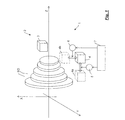
本発明の全体の概略図を図1に示す。 An overall schematic view of the present invention is shown in FIG.
まず始めに、自転車トランスミッションの歯車RDのアセンブリを示す。歯車RDは、自転車フレームT(例えば図20を参照)に、典型的には、前側ギアシフトアセンブリ内のペダルクランクの軸に、または後側ギアシフトアセンブリ内の後輪の軸に、それ自体は既知の方法で装着されるように構成される。歯車RDの数は一例にすぎない。 First, an assembly of a bicycle transmission gear RD is shown. The gear RD is known per se on the bicycle frame T (see eg FIG. 20), typically on the pedal crankshaft in the front gearshift assembly or on the rear wheel shaft in the rear gearshift assembly. Configured to be mounted in a manner. The number of gears RD is only an example.
歯車RDは互いに同軸であり、歯車RDのアセンブリの軸心はZで示される。歯車RDは異なる直径を有し、特に、図1では左から右に減少している。しかし、これは厳密には必要ではない。歯車RDは、軸心に沿って間隙(ピッチとしても知られる)を有し、その間隙は一定であるが、これは厳密には必要ではない。 The gears RD are coaxial with each other and the axis of the assembly of the gear RD is indicated by Z. The gear RD has a different diameter, in particular decreasing from left to right in FIG. However, this is not strictly necessary. The gear RD has a gap (also known as pitch) along its axis, which is constant, but this is not strictly necessary.
トランスミッションのチェーン(図示せず)は、走行中には所望の変速比に従って1つの歯車RDに係合している。この変速比は、係合する歯車RDの歯数、したがって直径と、通常はトランスミッションの歯車の第2のアセンブリの歯の数、したがって係合する歯車の直径とによって与えられる。 A transmission chain (not shown) is engaged with one gear RD according to a desired gear ratio during travel. This gear ratio is given by the number of teeth of the gear RD engaged, and hence the diameter, and the number of teeth of the second assembly of the gear of the transmission gear, usually the diameter of the gear engaged.
ギアシフト1により歯車RDの間でチェーンを変位させることによって、変速比が変更できる。ギアシフトを介して、チェーンは出発元歯車RDとの係合から外れ、到達先歯車RDとの係合へ移り、ギアシフト中は一時的に2つの隣接する歯車RDと係合することもできる。
The gear ratio can be changed by displacing the chain between the gears RD by the
ギアシフト1は、歯車RDのアセンブリに関連するディレイラ2を含み、トランスミッションの歯車の第2のアセンブリに関連する第2のディレイラ(図示せず)を含むこともできる。
The
ディレイラ2は、歯車RDのアセンブリに向かって、フレームT上にそれ自体は既知の方法で固定されて装着されるように構成された支持ユニット3を含む。
The
ディレイラ2は、可動ユニット(mobile unit)4をさらに含む。可動ユニット4は、支持ユニット3に対して可動であるように、したがってフレームTに対して可動であり、特に、歯車RDのアセンブリに対して可動であるように装着される。
The
可動ユニット4は、チェーンガイド(図1に図示せず)を含む。このチェーンガイドは、歯車RDのアセンブリに対して、したがってチェーンが係合している歯車RDに対して、チェーンの位置を決定する。
The
ディレイラ2は、プライマリ作動手段5をさらに含む。プライマリ作動手段5は、支持ユニット3に対して可動ユニット4を移動して、歯車RDのアセンブリの軸心Zに関し軸方向のプライマリ変位、すなわち軸心Zに沿ったプライマリ変位を、支持ユニット3に付与し、したがってチェーンガイドに付与し、そして最終的にチェーンに付与するように構成される。以下の説明では、歯車RDに対する可動ユニット4の位置および変位を参照することもあり、軸心Zに対するチェーンガイドの位置および変位を参照することもあり、また他の部分を参照することもある。
The
可動ユニット4のプライマリ変位は、実線で示した可動ユニット4の例示的出発元位置と、破線で4aとして示した可動ユニット4の例示的到達先位置との間の二重線矢印によって、概略的に示される。
The primary displacement of the
より一般的には、可動ユニット4のプライマリ変位は、軸方向のコンポーネントの他に、半径方向のコンポーネントおよび/または周方向のコンポーネントを有してよい。つまり、可動ユニット4は歯車RDの周りを回転する。換言すれば、可動ユニット4のプライマリ変位は、図1のX軸およびY軸にも沿うコンポーネントを有してよい。
More generally, the primary displacement of the
ディレイラ2はセカンダリ作動手段6をさらに含む。セカンダリ作動手段6は、支持ユニット3に対して可動ユニット4を移動して、歯車RDのアセンブリの軸心Zに関し半径方向のセカンダリ変位、すなわち軸心Zに近づく又は遠ざかる方向の、したがって歯車RDの外周に向かって近づく/外周から遠ざかる方向のセカンダリ変位を、チェーンガイドに付与し、最終的にチェーンに付与するように、構成される。
The
可動ユニット4のセカンダリ変位は、実線で示した可動ユニット4の例示的出発元位置と、一点鎖線で4bとして示した可動ユニット4の例示的到達先位置との間の二重線矢印によって、概略に示される。
The secondary displacement of the
セカンダリ作動手段6によって付与されるセカンダリ変位は、周方向のコンポーネントを有してもよいが、軸心Z方向のコンポーネントは有しない。 The secondary displacement applied by the secondary actuating means 6 may have a circumferential component, but does not have a component in the axial center Z direction.
本発明によれば、セカンダリ作動手段6は、プライマリ作動手段5とは独立して可動ユニット4を移動させることができる。
According to the present invention, the secondary actuating means 6 can move the
プライマリ作動手段5により付与されるプライマリ変位とセカンダリ作動手段6により付与されるセカンダリ変位のうちから適切なものを選ぶ、またはこれらを適切に組合せると、可動ユニット4を、歯車RDのアセンブリに対し、事実上いかなる位置にもいつでも持っていくことができる。
When an appropriate one is selected from the primary displacement given by the primary actuating means 5 and the secondary displacement given by the secondary actuating means 6, or when these are appropriately combined, the
当業者ならば、以下の記述により、可動ユニット4のプライマリ変位が、アセンブリの2つの両端の歯車の間に延びるストロークまたはそれより少し超えたストロークに、限定されることを理解するであろう。可動ユニット4のセカンダリ変位は、最小径を有する歯車RDの外周に近接した位置と、最大径を有する歯車RDの外周から相対的に遠いが、それでもなおそのような最大径を有する歯車RDにチェーンを係合させておきチェーンを落下させないでおくには十分に近い位置と、の間に延びるストロークに限定される。
The person skilled in the art will understand from the following description that the primary displacement of the
ギアシフト1の電子サーボ支援型実施形態において、プライマリ作動手段5およびセカンダリ作動手段6は自転車ギアシフト1のコントローラ7によって、協調的であったとしても、独立して駆動される。
In the electronic servo assisted embodiment of the
コントローラ7は、適切な手順ならびに/または(ハードウエア、ソフトウエアおよび/もしくはファームウエア)モジュールを提供する、本明細書で記述するステップの1つ以上を実施するのに適切な、少なくとも1つのプロセッサ(典型的にはマイクロプロセッサまたはマイクロコントローラ)によって具現化される。 The controller 7 comprises at least one processor suitable for performing one or more of the steps described herein, providing appropriate procedures and / or modules (hardware, software and / or firmware). (Typically a microprocessor or microcontroller).
つまり、本明細書および添付の特許請求の範囲において、コントローラ7とは、論理的なユニットのことを指す。しかし、この論理的なユニットは、複数の物理的なユニット、特には、1つ以上の分散したマイクロプロセッサ(distributed microprocessor)で構成されたものであってもよい。このような1つ以上の分散したマイクロプロセッサは、自転車ギアシフトの1つ以上の他の構成要素とともに1つ以上のケーシング内に含まれていてもよい。 In other words, in this specification and the appended claims, the controller 7 refers to a logical unit. However, this logical unit may be composed of a plurality of physical units, in particular one or more distributed microprocessors. Such one or more distributed microprocessors may be included in one or more casings along with one or more other components of the bicycle gearshift.
したがって、コントローラ7は、ディレイラ2の内部にあってもよいし、ディレイラ2の外部にあってもよいし、部分的にディレイラ2の内部および外部にあってもよい。
Therefore, the controller 7 may be inside the
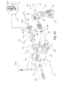
図2を参照すると、本発明による第1のギアシフトモードが示されている。図2に示されたギアシフトモードは、以下に説明する図28〜40に示す種類のディレイラにおいて実施するのに特に適している。当該ディレイラにおいて、プライマリ作動手段5およびセカンダリ作動手段6は単一の電気モータを共有する。しかし上記ギアシフトモードは、以下に説明する図20〜23および図24〜27で示すタイプのディレイラにおいて実施することもできる。当該ディレイラでは、プライマリ作動手段5およびセカンダリ作動手段6はそれぞれの電気モータを有する。 Referring to FIG. 2, a first gear shift mode according to the present invention is shown. The gear shift mode shown in FIG. 2 is particularly suitable for implementation in a derailleur of the type shown in FIGS. In the derailleur, the primary operating means 5 and the secondary operating means 6 share a single electric motor. However, the gear shift mode can also be implemented in a derailleur of the type shown in FIGS. 20 to 23 and FIGS. In the derailleur, the primary operating means 5 and the secondary operating means 6 have respective electric motors.
ステップ1000において、コントローラ7はセカンダリ作動手段6を駆動して、可動ユニット4を支持ユニット3に対して、したがって歯車RDのアセンブリに対して、半径方向に近づける。
In
特に、このステップ1000では、可動ユニット4は、チェーンが係合している出発元歯車RDから半径方向に相対的に遠い位置(図3はアップギアシフトの場合、図8はダウンギアシフトの場合)から出発して、出発元歯車RDに半径方向に相対的に近い位置へもたらされる(図4および図9)。
In particular, in this
相対的に遠い、ステップ1000の初期位置(図3および図8)は、チェーンに過度に応力がかからず、したがって、通常走行が可能な限り円滑に生じるような位置である。相対的に近い、ステップ1000の最終位置(図4および図9)は、(アップギアシフトまたはダウンギアシフトの場合、出発元歯車RDよりもそれぞれ大きいまたは小さい直径を有する)到達先歯車RDの歯にチェーンが係合し易くなるような位置である。 The initial position of the step 1000 (FIGS. 3 and 8), which is relatively far away, is such that the chain is not overstressed and therefore normal travel occurs as smoothly as possible. The final position of the step 1000 (FIGS. 4 and 9), which is relatively close, is chained to the teeth of the destination gear RD (having a larger or smaller diameter than the starting gear RD, respectively, in the case of an up gear shift or a down gear shift). It is a position which becomes easy to engage.
ステップ1000の間、可動ユニット4は出発元歯車RDの周りに周方向変位してもよい。しかし、可動ユニット4は軸心Z方向には移動せず、すなわち、チェーンは出発元歯車RDに係合したままである。
During
次のステップ1002では、コントローラ7は、プライマリ作動手段5を駆動して、可動ユニット4を歯車RDのアセンブリに沿って軸方向に動かす(図5および図10)。特に、このステップ1002では、可動ユニット4は、チェーンが係合している出発元歯車RDにおける位置から軸方向に出発して、チェーンを係合させたい到達先歯車RDにおける位置へ軸方向にもたらされる。
In the
ステップ1002の間、可動ユニット4は周方向に変位してもよく、(図5および図10から分かるように)半径方向に変位してもよいが、ステップ1002の主たる機能は、可動ユニット4に到達先歯車RDまでの軸方向変位を実行させることである。
During
最後にステップ1004において、コントローラ7はセカンダリ作動手段6を駆動して可動ユニット4を歯車RDのアセンブリから半径方向に遠ざける(図6および図11)。特にこのステップ1004では、可動ユニット4は、チェーンが現在係合している到達先歯車RDに半径方向に相対的に近い位置から出発して、到達先歯車RDから半径方向に相対的に遠い位置へもたらされる(図7および図12)。
Finally, in
ステップ1000とデュアルマナー(dual manner)で、相対的に近いステップ1004の初期位置は、到達先歯車RDの歯にチェーンが係合し易くなるような位置であり、一方、相対的に遠いステップ1004の最終位置は、チェーンに過度に応力がかからず、したがって通常走行が可能な限り円滑に生じるような位置である。
The initial position of
ステップ1004の間、可動ユニット4は到達先歯車RDの周りに周方向に変位してもよい。しかし、可動ユニット4は軸心Z方向には移動せず、すなわち、チェーンは到達先歯車RDに係合したままである。
During
以下に説明する図の類似のものにおけるのと同様に、プライマリ変位によって可動ユニット4を移動させるステップ1002において、プライマリ作動手段5の電気モータは、導入部で説明した命令値のテーブルの値に基づいて駆動される。すなわち、コントローラ7は、到達先歯車に関連付けられた値を命令値のテーブルから読み出し、そのような値が到達されるまで電気モータを駆動する。この駆動は、適切な速度および/または加速度プロフィールで行われてよい。
In the
以下に説明する図の類似のものにおけるのと同様に、セカンダリ変位によって可動ユニット4を移動させるステップ1000およびステップ1004において、セカンダリ作動手段6の電気モータは、命令値の類似テーブル(analogous table)の値に基づいて駆動され、適切な速度および/または加速度プロフィールで動作され得る。
In
命令値のテーブルは、各歯車RDについて、1つ、2つ、または3つの軸方向位置の値(この理由は以下に明らかにされる)と、2つの半径方向位置の値とを有する、命令値の単一のテーブルにおいて組み合わされてもよい。上記2つの半径方向位置の値のうちの一方は、歯車RDの外周に相対的に近い位置に相当し、もう一方は歯車RDの外周から相対的に遠い位置に相当するものである。 The command value table has, for each gear RD, a command having one, two or three axial position values (the reason will be clarified below) and two radial position values. May be combined in a single table of values. One of the two radial position values corresponds to a position relatively close to the outer periphery of the gear RD, and the other corresponds to a position relatively far from the outer periphery of the gear RD.
歯車RDがそれぞれ異なる直径を有することを考慮すると、ギアシフトのうちのいくつかまたは全部について、半径方向の2つの変位のうちの一方が省略でき、すなわち、ステップ1000またはステップ1004が省略できる。
Considering that the gears RD have different diameters, one or two of the two radial displacements can be omitted for some or all of the gear shifts, ie,
特にダウンギアシフトの場合、変位は大径を有する出発元歯車RDから小径を有する到達先歯車RDへ生じるので、ステップ1000で得られた、半径方向において出発元歯車RDに近い位置は、一旦、プライマリ変位のステップ1002が実行されると、半径方向において到達先歯車RDから既に十分に遠いものとなることができ、その結果、チェーンは、通常走行のための最適な状態になる。この場合、ステップ1004は省略できる。
Particularly in the case of down gear shift, the displacement occurs from the starting gear RD having a large diameter to the reaching gear RD having a small diameter. Therefore, the position close to the starting gear RD in the radial direction obtained in
逆もまた同様に、アップギアシフトの場合、変位は小径を有する出発元歯車RDから大径を有する到達先歯車RDへ生じるので、ステップ1000が省略できる。この場合、プライマリ変位のステップ1002は、出発元歯車RDから半径方向に遠い位置から行われる。この位置は、半径方向において到達先歯車RDに十分に近いチェーンがそのような到達先歯車RDと正しく係合できる位置である。
Conversely, in the case of up-gear shifting, the displacement occurs from the starting source gear RD having a small diameter to the destination gear RD having a large diameter, so that
図13を参照すると、第2のギアシフトモードが示されている。図13に示されたギアシフトモードは、図20〜23および図24〜27に示す種類のディレイラにおいて実施するのに特に適している。当該ディレイラにおいて、プライマリ作動手段5およびセカンダリ作動手段6はそれぞれ電気モータを有する。しかし、上記ギアシフトモードは、図28〜40に示す種類のディレイラにおいて実施することもできる。 Referring to FIG. 13, the second gear shift mode is shown. The gear shift mode shown in FIG. 13 is particularly suitable for implementation in a derailleur of the type shown in FIGS. 20-23 and 24-27. In the derailleur, the primary operating means 5 and the secondary operating means 6 each have an electric motor. However, the gear shift mode can also be implemented in the type of derailleur shown in FIGS.
図13のギアシフトモードは、図2のギアシフトモードとは次の点で異なる。すなわち、セカンダリ作動手段6を駆動して可動ユニット4を歯車RDのアセンブリに半径方向において近づけるステップ1010は、プライマリ作動手段5を駆動して可動ユニット4を出発元歯車RDから到達先歯車RDへと軸方向に変位させるステップ1012と、並行して、少なくとも部分的に同時に、行われる。
The gear shift mode of FIG. 13 differs from the gear shift mode of FIG. 2 in the following points. In other words, the
他方で、セカンダリ作動手段6を駆動して可動ユニット4を歯車RDのアセンブリから半径方向に遠ざけるステップ1014は、並行して行われるそのようなステップ1010および1012が終了すると行われる。
On the other hand, the
このように、実際のギアシフト、すなわち出発元歯車RDとの係合から到達先歯車RDとの係合へとチェーンが変位することは、チェーンが歯車RDから正確に一定の距離を維持しつつ歯車RDに対して斜めに変位できるという点で、極めて高い精度および速度で行われ得る。 Thus, the actual gear shift, that is, the displacement of the chain from the engagement with the starter gear RD to the engagement with the destination gear RD, means that the chain maintains an accurate constant distance from the gear RD. It can be performed with very high accuracy and speed in that it can be displaced obliquely with respect to RD.
図14を参照すると、第3のギアシフトモードが示されている。図14のギアシフトモードは、図2および図13のギアシフトモードとは次の点で異なる。すなわち、可動ユニット4を半径方向において歯車RDのアセンブリに近づけ、可動ユニット4を半径方向において歯車RDのアセンブリから遠ざけるという、ステップ1020およびステップ1024におけるセカンダリ作動手段6の駆動は、プライマリ作動手段5を駆動して可動ユニット4を出発元歯車RDから到達先歯車RDへと軸方向に変位させるステップ1022と、並行して、少なくとも部分的に同時に行われる。
Referring to FIG. 14, a third gear shift mode is shown. The gear shift mode of FIG. 14 differs from the gear shift mode of FIGS. 2 and 13 in the following points. That is, the driving of the secondary operating means 6 in
このモードでも、ギアシフトは、可動ユニットの移動の各瞬間で可動ユニットの半径方向位置および軸方向位置を制御しつつ、極めて高い精度および速度で行われ得る。 Even in this mode, gear shifting can be performed with extremely high accuracy and speed while controlling the radial and axial position of the movable unit at each moment of movement of the movable unit.
軸方向におけるプライマリ変位のステップ1002、1012、1022において、同一の到達先歯車RDに関連付けられた命令値は、出発元歯車RDが到達先歯車RDよりも小さい直径を有するアップギアシフトの場合と、出発元歯車RDが到達先歯車RDよりも大きい直径を有するダウンギアシフトの場合とで、異なってよい。このようにして、所謂「オーバーストローク」ギアシフトを実施することができる。すなわち、チェーンを、軸方向において到達先歯車RDを僅かに超えるところまで持って行く、または軸方向において到達先歯車RDの僅かに手前に持って来ることによって、チェーンの機械的係合を容易にする。勿論、アセンブリの両端の歯車RDは単一の関連づけられた命令値を有する。
In the
図15に示した実施形態では、軸方向におけるプライマリ変位のステップ1002、1012、1022において、可動ユニット4は最初、(ステップ1030において)上述の一時的な軸方向またはオーバーストローク位置に置かれ、(ステップ1032において)そこに一時的に維持され、そして(ステップ1034において)到達先歯車RDの軸方向位置にもたらされる。
In the embodiment shown in FIG. 15, in the axial
好ましくは、図14の実施形態の軸方向におけるプライマリ変位のステップ1022が行われる際に、オーバーストローク位置における軸方向位置づけのステップ1030が、半径方向に近づけるステップ1020と好ましくは並行して、少なくとも部分的に同時に、行われる。続いて、オーバーストローク位置で待機するステップ1032および最終の軸方向変位のステップ1034が行われ、同時にまたはそれに続いて、半径方向に遠ざけるステップ1024が行われる。
Preferably, when the
軸方向におけるプライマリ変位のステップ1002、1012、1022において、多段ギアシフト(multi-gearshifting)を行うために、可動ユニット4を、出発元歯車RDから、出発元歯車RDのすぐ隣のものではない到達先歯車RDへ、変位させることができる。
In
そのようなプライマリ変位は、図16のステップ1040に示すように直接行うことができる、または複数のステップで行うことができる。複数のステップで行う際には、図17に示すように、出発元歯車RDと到達先歯車RDとの間の当該または各中間歯車RDにおいて(そしておそらくはそこで停止する)中間変位を伴って行われる。図17では、プライマリ作動手段5を介して可動ユニット4の3つの軸方向変位1042、1044、1046を有する例として、3段ギアシフトが示されている。すなわち、ステップ1042では、出発元歯車RDから(好ましくはすぐ隣の)第1の中間歯車RDへプライマリ変位が起こり、ステップ1044では、第1の中間歯車RDから(好ましくはすぐ隣の)第2の中間歯車RDへプライマリ変位が起こり、ステップ1046では、第2の中間歯車RDから到達先歯車RDへプライマリ変位が起こる。
Such primary displacement can be done directly, as shown in
これらのモードの両方において、多段ギアシフトの間、半径方向のセカンダリ変位は、多段ギアシフトの開始時および/または終了時にのみ行われる。 In both of these modes, during a multi-stage gearshift, a radial secondary displacement is only made at the beginning and / or end of the multi-stage gearshift.
あるいは、多段ギアシフトは、本発明による一連の単一のギアシフトを時間的に近接させて行ってもよい。すなわち、(出発元歯車RDと到達先歯車RDとの間に1つ以上の中間歯車RDがあるか否かに従って)プライマリ作動手段5による2つ以上のプライマリ変位と、当該または各中間歯車RDにおけるセカンダリ作動手段6による1つ以上のセカンダリ変位と、により行ってもよい。 Alternatively, a multi-stage gear shift may be performed with a series of single gear shifts according to the invention in close proximity in time. That is, two or more primary displacements by the primary actuating means 5 (according to whether or not there are one or more intermediate gears RD between the departure source gear RD and the destination gear RD), and the or each intermediate gear RD It may be performed by one or more secondary displacements by the secondary operating means 6.
セカンダリ作動手段6によるセカンダリ変位は、半径方向に近づけるおよび/または遠ざける変位であってよい。 The secondary displacement by the secondary actuating means 6 may be a displacement that approaches and / or moves away from the radial direction.
例えば、3段ギアシフトの場合についての図18に示すように、出発元歯車RDから(好ましくはすぐ隣の)第1の中間歯車RDへのプライマリ変位の初期ステップ1050と、第1の中間歯車RDにおける半径方向のセカンダリ変位のステップ1052と、第1の中間歯車RDから(好ましくはすぐ隣の)第2の中間歯車RDへのプライマリ変位のステップ1054と、第2の中間歯車RDにおける半径方向のセカンダリ変位のステップ1056と、第2の中間歯車RDから到達先歯車RDへのプライマリ変位の最終ステップ1058と、があってよい。
For example, as shown in FIG. 18 for the case of a three-stage gear shift, an
上述したように、ステップ1052、1056の中間歯車RDにおけるセカンダリ変位は、半径方向に近づける変位、半径方向に遠ざける変位、または半径方向に遠ざけて続いて半径方向に近づける変位、であってよい。
As described above, the secondary displacement in the intermediate gear RD in
ステップ1050、1054、1058のプライマリ変位が専ら軸方向だけのものである場合、または半径方向のコンポーネントが無視できる場合には、多段アップギアシフトでは、ステップ1052、1056の中間歯車RDにおけるセカンダリ変位は、半径方向に遠ざける変位であってよく、また、多段ダウンギアシフトでは、ステップ1052、1056の中間歯車RDにおけるセカンダリ変位は半径方向に近づける変位であってよい。
If the primary displacement of
図18では、軸方向および半径方向の変位のステップが続けて示されており、したがって、ギアシフトは図2と同様に行われるが、図13および図14に示したものと同様に、これらのステップは少なくとも部分的に同時に行われてよい。 In FIG. 18, the axial and radial displacement steps are shown in succession, and thus the gear shift is performed as in FIG. 2, but these steps are similar to those shown in FIGS. May be performed at least partially simultaneously.
全ての場合において、多段ギアシフトにおいても、図15を参照して説明したように、好ましくは当該歯車または各中間歯車RDとの係合位置において一時的かつ決定的な変位を有して、オーバーストローク位置での可動ユニット4の位置づけが行われてよい。
In all cases, even in a multi-stage gear shift, as explained with reference to FIG. 15, it is preferable to have an overstroke with a temporary and decisive displacement at the engagement position with the gear or each intermediate gear RD. The
図19を参照して、走行中の可動ユニット4の最適な位置を維持するモードが示されている。このモードは本発明により達成可能である。
Referring to FIG. 19, a mode for maintaining the optimum position of the
ステップ1100において、コントローラ7は、可動ユニット4の現在位置が現在の変速比に対応するノミナル位置(nominal position)に相当するか否かをチェックする。特に上記で説明したように、ノミナル位置は、現在係合している歯車RDから半径方向に相対的に遠い。
In
そうである場合(in the positive case)、本手順は終了する。 If so (in the positive case), the procedure ends.
そうでない場合(in the negative case)、コントローラ7は、ステップ1102においてプライマリ作動手段5を駆動するか、ステップ1104においてセカンダリ作動手段6を駆動するか、またはステップ1106においてプライマリ作動手段5およびセカンダリ作動手段6を駆動して、可動ユニット4を歯車RDのアセンブリの軸心Zに関して軸方向および/または半径方向に変位し、可動ユニット4をノミナル位置へ戻す。ステップ1102、ステップ1104、またはステップ1106は可動ユニット4の現在位置とノミナル位置との間のオフセットに従って行われる。
In the negative case, the controller 7 drives the primary actuating means 5 in
チェックをステップ1100は、少なくとも1つのセンサ、好ましくは少なくとも1つの角度位置センサ(angular position sensor)、より好ましくは絶対角度タイプ(absolute
type)の角度位置センサ、さらにより好ましくは少なくとも1つのホール効果エンコーダ(Hall effect encoder)を介して行われる。
Check
type) angular position sensor, even more preferably via at least one Hall effect encoder.
所定の軸心を中心とした相対回転運動が可能な第1の部分と第2の部分との間のそのような角度位置センサは、例えばそれ自体は既知であり例えばEP1,279,929A2において記述される方法で、前記第1の部分および第2の部分の一方に固定的に接続された磁化要素(magnetized element)と、前記所定の軸心に対して相互に角度的にずれて配置されかつ前記第1の部分および第2の部分の他方に固定的に接続された、少なくとも1対のホール効果センサと、を含む。前記ホール効果センサは、前記磁化要素の存在を感知して、連続する領域で変化する値を有するそれぞれの出力信号を発生し、前記それぞれの出力信号の値が前記所定の軸心に対する前記第1の部分と第2の部分との相対位置を明確に特定する。出力信号の値もまた、当該軸心に対する第1の部分および第2の部分の回転方向を、軸、角回転速度および/または加速度について明確に特定する。 Such an angular position sensor between a first part and a second part capable of relative rotational movement about a predetermined axis is known per se, for example as described in EP 1,279,929 A2, for example. And a magnetized element fixedly connected to one of the first part and the second part and arranged angularly offset from each other with respect to the predetermined axis and And at least one pair of Hall effect sensors fixedly connected to the other of the first part and the second part. The Hall effect sensor senses the presence of the magnetizing element and generates a respective output signal having a value that varies in a continuous region, and the value of the respective output signal is the first with respect to the predetermined axis. The relative position of the part and the second part is clearly specified. The value of the output signal also clearly identifies the direction of rotation of the first part and the second part relative to the axis in terms of axis, angular rotation speed and / or acceleration.
チェックを行うステップ1100は、所定の頻度、例えば4秒ごとに、周期的に行われ得る。
The checking
あるいは、チェックを行うステップ1100は、本出願人のUS2014/0032067で公開された特許出願に記述されるように、可動ユニット4の強制的変位が起こりそうな場合、ギアシフトからの所定の時間後、例えば1秒後に、行われ得る。
Alternatively, the checking
あるいはまたはこれに加えて、チェックを行うステップ1100は、例えば運転者がチェーンの係合が円滑でないと感じているという理由で運転者の要請に基づき行われ得る。
Alternatively or additionally, the checking
ステップ1102、1104および1106を行うためにも、コントローラ7は、上述した命令値のテーブル(複数可)を参照する。
In order to perform
ここで、上述したことを実施するのに適したディレイラのいくつかの実施形態を説明する。参照するディレイラは後側ディレイラである。以下において、特定の参照番号を各実施形態で使用する。 Several embodiments of derailleurs suitable for implementing the above will now be described. The reference derailleur is the rear derailleur. In the following, specific reference numbers are used in each embodiment.
図20〜23を参照して、本発明の第1の実施形態によるディレイラ13は、歯車RDのアセンブリにおいて自転車のフレームTに装着されるように構成された支持ユニット20と、チェーンガイド52を含む可動ユニット50と、を含む。
Referring to FIGS. 20 to 23, the
ディレイラ13はまた、プライマリ作動手段70を含む。プライマリ作動手段70は、可動ユニット50を支持ユニット20に対して移動させて、歯車RDのアセンブリの軸心Zに関して軸方向に少なくとも1つのコンポーネントを有するプライマリ変位をチェーンガイド52に付与するように構成されている。
The
ディレイラ13はまた、セカンダリ作動手段80を含む。セカンダリ作動手段80は、可動ユニット50を支持ユニット20対して移動させて、歯車RDのアセンブリの軸心Zに関して半径方向に少なくとも1つのコンポーネントを有するセカンダリ変位をチェーンガイド52に付与するように構成されている。以下に説明するように、セカンダリ作動手段80は可動ユニット50をプライマリ作動手段70とは独立して移動させることができる。
The
支持ユニット20は、支持体21と、支持ユニット21を自転車のフレームTに装着するための第1の固定ユニット23とを含む。可動ユニット50は、チェーンガイド52に加えて、可動体51と、チェーンガイド52を可動体51に装着するための第2の固定ユニット53とを含む。
The
第1の固定ユニット23に、チェーンテンション調整ばね25が設けられている。
A chain
プライマリ作動手段70は、支持体21と可動体51との間に関節型の四辺形状リンク機構を備える。支持体21と可動体51は、一対の平行接続ロッド71、72を介して互いに接続されている。平行接続ロッド71、72は、ピボット73、74において支持体21に対して関節型に接続され、ピボット75、76において可動体51に対して関節型に接続されている。電気モータ77が、ピボット73[クレードル状(cradle shaped)、モータ77受け入れ用]に装着されており、シャフト78を有する。シャフト78は、ピボット73に対して対角線反対側のピボット76に装着されたブッシュ79に係合している。参照番号77aは、モータ77の制御信号および電源用のケーブルを示す。
The primary operating means 70 includes an articulated quadrilateral link mechanism between the
したがって、モータ77は、ブッシュ79を、モータ77に対して近づけ/遠ざけ、結果的に、2つの対抗するピボット73とピボット76との間の関節型の四辺形状リンク機構の対角線を伸ばし/縮め、したがって、関節型の四辺形状リンク機構自体を変形させるのに適している。この変形は、今度は、支持体21に対する可動体51の変位を決定し、したがって、歯車RDのアセンブリの軸心Zに対するチェーンガイド52のプライマリ変位を決定する。
Accordingly, the
第1の固定ユニット23はピボットを含む。このピボットは、フレームTに装着固定されるよう意図された、互いに同軸の2つのねじ要素26a、26bから構成されている。支持体21およびチェーンテンション調整ばね25は、スライド軸受27を介在させて、ピボット26a、26bに回転可能に装着されている。第1の固定ユニット23はまた、ピボット26a、26bに回転可能に装着された第1のリング28を含む。第1のリング28は、フレームTに載置されるための歯29と、チェーンテンション調整ばね25の第1の端部に係合する座部30とを備える。
The
セカンダリ作動手段80は、第2のリング81を含む。第2のリング81は、支持体21内かつピボット26a、26b上に回転可能に装着されており、チェーンテンション調整ばね25の第2の端部に係合する座部82を備える。セカンダリ作動手段80はまた、第2のリング81に形成された歯付きセクタ83と、歯付きセクタ83に係合するウォームねじ84とを含む。
Secondary operating means 80 includes a
ウォームねじ84は、減速段(reduction stage)86を介して電気モータ85によって回転される。減速段86は、連続して互いに係合した異なる直径の歯車を含み、それによって、モータ85とウォームねじ84との間の所望の変速比を決定する。
The
チェーンガイド52は、アーム56に空回り装着(idle mounted)された一対のホイール(wheel)54、55を含む。第2の固定ユニット53は、チェーンガイド52のアーム56に固定的に接続され、かつ可動体51内に回転可能に装着された、ピボット57を含む。ねじりばね(torsion spring)58がピボット57に装着されおり、第1の端部が、可動体51に固着されたインサート63内に形成された座部59に挿入され、第2の端部が、アーム56に形成された座部60に挿入されている。
The
ばね58は、ばね25と同様に、チェーンのテンションを加えることに寄与する。より特定的には、2つのばね25および58は、互いに相互作用する。ばね25は、可動体51を、角度をつけて押すことによりチェーンの軌道(path)を長くするように働き、すなわち可動体51を方向Mの方向にピボット26a、26bを中心に回転させ、それによって、チェーンガイド52を歯車RDのアセンブリから半径方向に離れるように押す。他方、ばね58は、チェーンガイド52を方向Nの方向に角度をつけて押すことによりチェーンの軌道を長くするように働き、それによって、ホイール54を歯車RDのアセンブリに向かって半径方向に押す。これにより、チェーンのセットアップは、これらのばね25の推力とばね58の推力との間で平衡がとれたものとなり、このセットアップによると、チェーンガイド52は、歯車RDのアセンブリの軸心Zに対し、多少半径方向に近くなっている。
The
セカンダリ作動手段80のモータ85に作用することにより、ばね25の第2の端部の座部82を角度的に変位させることができ、したがって、ばね25自体の予荷重(preload)を変更することができる。よって、第2のリング81、座部82、歯付きセクタ83、およびウォームねじ84は、チェーンテンション調整ばね25の予荷重を調整するためのリンク機構を形成し、チェーンテンション調整ばね25は、歯車RDのアセンブリの軸心Zに関して半径方向に少なくとも1つのコンポーネント(component)を有する、チェーンガイド52のセカンダリ変位を伴うチェーンガイド52のセットアップにおける変更を決定できる。
By acting on the
他方、先に説明したように、プライマリ作動手段70のモータ77に作用することにより、歯車RDのアセンブリの軸心Zに関するチェーンガイド52のプライマリ変位(すなわちギアシフトを得るために必要な変位)が、歯車RDのうちの1つから他の歯車RDへチェーンを変位させることにより得られる。
On the other hand, as described above, by acting on the
プライマリ作動手段70およびセカンダリ作動手段80のおかげで、チェーンガイド52の2つの変位が、すなわちプライマリ変位(ギアシフト用)およびセカンダリ変位(チェーンガイドの軸心Zからの半径方向距離用)が、このように互いに完全に独立して得られる。したがって、走行またはギアシフトのあらゆる状況における、チェーンガイド52の軸心Zからの最適な距離を決定できるようになる。
Thanks to the primary actuating means 70 and the secondary actuating means 80, two displacements of the
この結果は、モータ85を介して第1の固定ユニット23のばね25に作用するセカンダリ作動手段80を設けることによって、図20〜23に示し上述した第1の実施形態に従って得られたものである。
This result is obtained according to the first embodiment shown in FIGS. 20 to 23 and described above by providing the secondary actuating means 80 acting on the
本発明の第2の実施形態を図24〜27に示す。 A second embodiment of the present invention is shown in FIGS.
これらの図を参照して、ディレイラ113は、ギアシフト1の歯車RDのアセンブリにおいて自転車のフレームTに装着されるように構成された支持ユニット120と、チェーンガイド152を含む可動ユニット150と、を含む。
Referring to these drawings, the
ディレイラ113はまた、プライマリ作動手段170を含む。プライマリ作動手段170は、可動ユニット150を支持ユニット120に対して移動させて、歯車RDのアセンブリの軸心Zに関して軸方向に少なくとも1つのコンポーネントを有するプライマリ変位をチェーンガイド152に付与するように、構成されている。
The
ディレイラ113はまた、セカンダリ作動手段180を含む。セカンダリ作動手段180は、可動ユニット150を支持ユニット120に対して移動させて、歯車RDのアセンブリの軸心Zに関して半径方向に少なくとも1つのコンポーネントを有するセカンダリ変位をチェーンガイド152に付与するように構成されている。以下に説明するように、セカンダリ作動手段180は、可動ユニット150をプライマリ作動手段170とは独立して移動させることができる。
The
支持ユニット120は、支持体121と、支持ユニット121をフレームTに装着するための第1の固定ユニット123とを含む。可動ユニット150は、チェーンガイド152に加えて、可動体151と、可動体151にチェーンガイド152を装着するための第2の固定ユニット153とを含む。
The
第1の固定ユニット123に、チェーンテンション調整ばね125が設けられている。
A chain
プライマリ作動手段170は、支持体121と可動体151との間に関節型の四辺形状リンク機構を備える。支持体121と可動体151は、一対の平行接続ロッド171、172を介して互いに接続されている。平行接続ロッド171、172は、ピボット173、174において支持体121に対して関節型に接続され、ピボット175、176において可動体151に対して関節型に接続されている。電気モータ177が、ピボット173(クレードル状、モータ177受け入れ用)に装着されており、シャフト178を有する。シャフト178は、ピボット173に対して対角線反対側のピボット176に装着されたブッシュ179に係合している。参照番号177aは、モータ177の制御信号および電源用のケーブルを示す。したがって、モータ177は、ブッシュ179をモータ177に対して近づけ/遠ざけ、結果的に、2つの対向するピボット173とピボット176との間の関節型の四辺形状リンク機構の対角線を伸ばし/縮め、したがって、関節型の四辺形状リンク機構自体を変形させるのに適している。この変形は、今度は、支持体121に対する可動体151の変位を決定し、したがって、歯車RDのアセンブリの軸心Zに対するチェーンガイド152のプライマリ変位を決定する。
The primary actuating means 170 includes an articulated quadrilateral link mechanism between the
第1の固定ユニット123はピボットを含む。このピボットは、フレームTに装着固定されるよう意図された、互いに同軸の2つのねじ要素126a、126bから構成されている。支持体121およびチェーンテンション調整ばね125は、スライド軸受127を介在させて、ピボット126a、126bに回転可能に装着されている。第1の固定ユニット123はまた、ピボット126a、126bに回転可能に装着された第1のリング128を含む。第1のリング128は、フレームTに載置されるための歯129と、チェーンテンション調整ばね125の第1の端部に係合する座部130とを備える。
The
ディレイラ13とは異なり、ディレイラ113では、ばね125の第2の端部は、支持体121内に形成された座部131に係合している。
Unlike the
チェーンガイド152は、アーム156に空回り装着(idle mounted)された一対のホイール154、155を含む。第2の固定ユニット153は、可動体151に固定的に接続されたピボット157を含む。このピボット157に、チェーンガイド152のアーム156が回転可能に装着されている。ねじりばね158が、第2の端部をアーム156に形成された座部160に挿入した状態で、ピボット157に装着されている。
The
セカンダリ作動手段180は、第2のリング191を含む。第2のリング191は、可動体151内かつピボット157上に回転可能に装着されており、ばね158の第2の端部に係合する座部192を備える。セカンダリ作動手段180はまた、第2のリング191に形成された歯付きセクタ193と、歯付きセクタ193に係合するウォームねじ194とを含む。
Secondary operating means 180 includes a
ウォームねじ194は、減速段196を介して電気モータ195によって回転される。減速段196は、連続して互いに係合した異なる直径の歯車を含み、それによって、モータ195とウォームねじ194との間の所望の変速比を決定する。参照番号195aは、モータ195の制御信号および電源用のケーブルを示す。
The
ばね158は、ばね125と同様に、チェーンのテンション調整に寄与する。より特定的には、2つのばね125および158は、互いに相互作用する。ばね125は、角度をつけて可動体151を押す(angularly pushing)ことによりチェーンの軌道を長くするように働き、すなわち、可動体151を方向Mの方向にピボット126a、126bを中心に回転させ、それによって、チェーンガイド152が歯車RDのアセンブリから半径方向に離れるように押す。他方、ばね158は、チェーンガイド152を方向Nの方向に角度をつけて押すことによりチェーンの軌道を長くするように働き、それによって、ホイール154を歯車RDのアセンブリに向かって半径方向に押す。これにより、チェーンのセットアップは、これらのばね125の推力(thrust)とばね158の推力との間で平衡がとれたものとなり、このセットアップによると、チェーンガイド152は、歯車RDのアセンブリの軸心Zに対し、多少半径方向に近くなっている。
Like the
セカンダリ作動手段180のモータ195に作用することにより、ばね158の第2の端部の座部192を角度的に変位させることができ、したがって、ばね158自体のプリロードを変更することができる。よって、第2のリング191、座部192、歯付きセクタ193、およびウォームねじ194は、チェーンテンション調整ばね158のプリロードを調整するためのリンク機構を形成し、チェーンテンション調整ばね158は、歯車RDのアセンブリの軸心Zに関して半径方向に少なくとも1つのコンポーネントを有する、チェーンガイド152のセカンダリ変位を伴うチェーンガイド152のセットアップにおける変更を決定できる。
By acting on the
他方、先に説明したように、プライマリ作動手段170のモータ177に作用することにより、歯車RDのアセンブリの軸心Zに関するチェーンガイド152のプライマリ変位(すなわちギアシフトを得るために必要な変位)が、歯車RDのうちの1つから他の歯車RDへチェーンを変位させることにより得られる。
On the other hand, as described above, by acting on the
プライマリ作動手段170およびセカンダリ作動手段180のおかげで、チェーンガイド152の2つの変位が、すなわちプライマリ変位(ギアシフト用)およびセカンダリ変位(チェーンガイドの軸心Zからの半径方向距離用)が、このように互いに完全に独立して得られる。したがって、走行またはギアシフトのあらゆる状況における、チェーンガイド152の軸心Zからの最適な距離を決定できるようになる。
Thanks to the primary actuating means 170 and the secondary actuating means 180, two displacements of the
この結果は、モータ195を介して第2の固定ユニットのばね158に作用するセカンダリ作動手段180を設けることによって、図24〜27に示し上述した第2の実施形態に従って得られたものである。
This result was obtained according to the second embodiment shown in FIGS. 24-27 and described above by providing secondary actuating means 180 acting on the
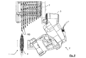
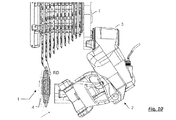
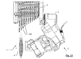
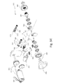
本発明の第3の実施形態を図28〜40に示す。 A third embodiment of the present invention is shown in FIGS.
これらの図を参照して、ディレイラ213は、ギアシフト1の歯車RDのアセンブリにおいて自転車のフレームTに装着されるように構成された支持ユニット220と、チェーンガイド252を含む可動ユニット250と、を含む。
Referring to these drawings, the
ディレイラ213はまた、プライマリ作動手段270を含む。プライマリ作動手段270は、可動ユニット250を支持ユニット220に対して移動させて、歯車RDのアセンブリの軸心Zに関して軸方向に少なくとも1つのコンポーネントを有するプライマリ変位をチェーンガイド252に付与するように、構成されている。
The
ディレイラ213はまた、セカンダリ作動手段280を含む。セカンダリ作動手段280は、可動ユニット250を支持ユニット220に対して移動させて、歯車RDのアセンブリの軸心Zに関して半径方向に少なくとも1つのコンポーネントを有するセカンダリ変位をチェーンガイド252に付与するように構成されている。以下に説明するように、セカンダリ作動手段280は、可動ユニット250をプライマリ作動手段270とは独立して移動させることができる。
The
支持ユニット220は、支持体221と、支持ユニット221をフレームTに装着するための第1の固定ユニット223とを含む。可動ユニット250は、チェーンガイド252に加えて、可動体251と、可動体251にチェーンガイド252を装着するための第2の固定ユニット253とを含む。
The
第1の固定ユニット223に、チェーンテンション調整ばね225が設けられている。
A chain
プライマリ作動手段270は、支持体221と可動体251との間に関節型の四辺形状リンク機構を備える。支持体221と可動体251は、一対の平行接続ロッド271、272を介して互いに接続されている。平行接続ロッド271、272は、ピボット273、274において支持体221に対して関節型に接続され、ピボット275、276において可動体251に対して関節型に接続されている。
The primary actuating means 270 includes an articulated quadrilateral link mechanism between the
ディレイラ13および113とは異なり、ディレイラ213では、回転する接続ロッド271のおかげで、関節型の四辺形状リンク機構の変形が得られる。この目的のために接続ロッド271は、以下に説明するような様式で、電動歯付きセクタ262と係合した歯付きセクタ261を備える。歯付きセクタ262は、例えば角度70°をカバーするように延びている。
Unlike the
関節型の四辺形状リンク機構が変形されることにより、今度は、支持体221に対する可動体251の変位を、したがって、歯車RDのアセンブリの軸心Zに対するチェーンガイド252のプライマリ変位が決定される。
The deformation of the articulated quadrilateral link mechanism in turn determines the displacement of the
第1の固定ユニット223は、(取り外し可能な種類の)止め座金(lock washer)226bを介してフレームTに装着固定するよう意図されたピボット226aを含む。支持体221およびチェーンテンション調整ばね225は、スライド軸受227を介在させて、ピボット226aに回転可能に装着されている。第1の固定ユニット223はまた、ピボット226aに回転可能に装着された第1のリング228を含む。第1のリング228は、フレームTに載置されるための歯229と、チェーンテンション調整ばね225の第1の端部に係合する座部230とを備える。
The
セカンダリ作動手段280は、第2のリング281を含む。第2のリング281は、支持体221内かつピボット226a、226b上に回転可能に装着されており、チェーンテンション調整ばね225の第2の端部に係合する座部282を備える。セカンダリ作動手段280はまた、第2のリング281に形成された歯付きセクタ283と、歯付きセクタ283に係合する(以下に説明するように電動で作動する)歯車284を含む。歯車284は、例えば角度35°〜40°回転する。
Secondary operating means 280 includes a
歯付きセクタ262および歯車284は、単一の共有電気モータ301によって回転され、歯付きセクタ262によって形成されたプライマリ出力と歯車284によって形成されたセカンダリ出力とを有するトランスミッション310が設けられている。プライマリ出力はプライマリ作動手段270に、セカンダリ出力はセカンダリ作動手段280に、それぞれ関連付けられている。参照番号301aは、モータ301の制御信号および電源用のケーブルを示す。
チェーンガイド252は、アーム256に空回り装着された一対のホイール254、255を含む。第2の固定ユニット253は、可動体251に固定的に接続されたピボット257を含む。このピボット257に、チェーンガイド252のアーム256が回転可能に装着されている。ねじりばね258がピボット257に装着されており、第1の端部が、可動体251に固着されたインサート263内に形成された座部259に挿入され、第2の端部が、アーム256に形成された座部260に挿入されている。
The
ばね258は、ばね225と同様に、チェーンのテンション調整に寄与する。より特定的には、2つのばね225および258は、互いに相互作用する。ばね225は、角度をつけて可動体251を押すことによりチェーンの軌道を長くするように働き、すなわち、
可動体251を方向Mの方向にピボット226a、226bを中心に回転させ、それによって、チェーンガイド252を歯車RDのアセンブリから半径方向に離れるように押す。他方、ばね258は、チェーンガイド252を方向Nの方向に角度をつけて押すことによりチェーンの軌道を長くするように働き、それによって、ホイール254を歯車RDのアセンブリに向かって半径方向に押す。これにより、チェーンのセットアップは、これらのばね225の推力とばね258の推力との間で平衡がとれたものとなり、このセットアップによると、チェーンガイド252は、歯車RDのアセンブリの軸心Zに対し、多少半径方向に近くなっている。
Like the
The
トランスミッション310は、モータ301が収容されるケーシング311を含む。ケーシング311には、プライマリシャフト312もまた回転可能に収容されており、軸心Aの方向に延び、減速段313を介してモータ301によって回転される。減速段313は、連続して互いに係合した、異なる直径と様々なコンフィギュレーションを有する歯車を含み、それによって、モータ301とプライマリシャフト312との間の所望の変速比を決定する。プライマリシャフト312に、プライマリ歯車314が固定的に嵌められている。ケーシング311には、2つのセカンダリシャフトがまた収容されている。すなわち、互いに平行でありかつプライマリシャフト312に平行である、第1のセカンダリシャフト315と第2のセカンダリシャフト316である。第1のセカンダリ歯車317が第1のセカンダリシャフト315に固定的に嵌められており、第2のセカンダリ歯車318が第2のセカンダリシャフト316に固定的に嵌められている。
トランスミッション310はさらに、ケーシング311内に、第1の出力シャフト320と第2の出力シャフト321とを含む。第1の出力シャフト320と第2の出力シャフト321はともに、軸心Aに実質的に垂直である軸心Bに従って延びている。ケーシング311内において、第1の出力シャフト320上に、歯車322が(限定された角度幅の歯付きセクタを備えたリングの形で)固定的に嵌められている。歯車322は、第1のセカンダリシャフト315に固定的に嵌められたウォームねじ324と噛み合い係合している。第1の出力シャフト320は、ケーシング311から突出しており、ケーシング311に(ケーシング311の外側で)、歯付きセクタ262が嵌合されている。ケーシング311内において、第2の出力シャフト321上に、歯車323が(限定された角度幅の歯付きセクタを備えたリングの形で)固定的に嵌められている。歯車323は、第2のセカンダリシャフト316に固定的に嵌められたウォームねじ325と噛み合い係合している。第2の出力シャフト321は、ケーシング311から突出しており、ケーシング311に(ケーシング311の外側で)、歯車284が嵌合されている。
The
トランスミッション310はさらに、再度、ケーシング311内に副歯車(auxiliary
toothed wheel)330を含む。副歯車330は、プライマリおよびセカンダリシャフト312、315、316の軸心Aに平行に、副軸心(auxiliary axis)Cに沿ってケーシング311内を軸方向に可動であるように装着されている。副歯車330は、プライマリ歯車314と取外せないように(permanently)噛み合い係合しており、セカンダリ歯車317、318のいずれかと選択的に噛み合い係合している。この目的のために、副歯車330は副シャフト331に固定的に嵌められており、副シャフト331は、副軸心Cに沿って可動なように案内されるスライド332によって回転可能に担持され、スライド332はこの目的のために電気機械式アクチュエータ333によって作動される。このアクチュエータ333に作用することによって、副歯車330を、軸心Cに沿って、あるいはセカンダリ歯車317、318のいずれかに向かって、そして係合して(ギアシフト制御状態または半径方向距離調整状態)、次のように変位させることができる:すなわち、モータ301が、(減速段313、プライマリシャフト312、プライマリ歯車314、副歯車330、セカンダリ歯車317、第1のセカンダリシャフト315、ウォームねじ324、歯車322、第1の出力シャフト320を介して)歯付きセクタ262と結合するか、あるいは、(減速段313、プライマリシャフト312、プライマリ歯車314、副歯車330、セカンダリ歯車318、第2のセカンダリシャフト316、ウォームねじ325、歯車323、第2の出力シャフト321を介して)歯車284と結合するように。
The
toothed wheel) 330. The
アクチュエータ333がギアシフト制御状態にあるときにモータ301にこのように作用することによって、歯付きセクタ262の回転が得られ、それとともに歯付きセクタ261の回転が得られ、その結果、関節型の四辺形状リンク機構の変形と軸心Zに沿ったチェーンガイド252のプライマリ変位とが達成される。
By acting on the
他方、アクチュエータ333が半径方向距離調整状態にあるときにモータ301に作用することによって、歯車284の回転が得られ、それとともに歯付きセクタ283の回転と、リング281の回転と、したがって座部282の回転と、が得られ、したがって、ばね225自体のプリロードが変更される。よって、第2のリング281、座部282、歯付きセクタ283、および歯車284は、チェーンテンション調整ばね225のプリロードを調整するためのリンク機構を形成し、チェーンテンション調整ばね225は、歯車RDのアセンブリの軸心Zに関して半径方向に少なくとも1つのコンポーネントを有する、チェーンガイド252のセカンダリ変位を伴うチェーンガイド252のセットアップにおける変更を、決定できる。
On the other hand, by acting on the
プライマリ作動手段270およびセカンダリ作動手段280のおかげで、チェーンガイド252の2つの変位が、すなわちプライマリ変位(ギアシフト用)およびセカンダリ変位(チェーンガイド252の軸心Zからの距離用)が、このように互いに完全に独立して得られる。したがって、走行またはギアシフトのあらゆる状況におけるチェーンガイドの軸心Zからの最適な半径方向距離を決定できるようになる。
Thanks to the primary actuating means 270 and the secondary actuating means 280, two displacements of the
この結果は、単一のモータ301である場合でも、モータ301を選択的にプライマリ作動手段270またはセカンダリ作動手段280に接続するトランスミッション310を備える、図28〜40に示し上述した第3の実施形態に従って、得られたものである。
The result is a third embodiment shown in FIGS. 28-40 and described above, comprising a
なお、この第3の実施形態では、ディレイラ213は、第1の固定ユニット223のばね225に作用するセカンダリ作動手段280と、支持ユニット220上に収容されるトランスミッション310のケーシング311とを備える。他の実施形態(示しておらず、また詳述もしていない)では、上述したトランスミッション310に類似のトランスミッションを有するが、第2の固定ユニットのばねに作用する、単一のモータを使用できる。この場合、トランスミッションのケーシングは可動ユニット上に収容される。
In the third embodiment, the
発明の構成に係る複数の実施形態を記述してきたが、本発明の範囲を逸脱することなくさらなる変更を加えることができる。様々な構成要素の形状および/もしくは大きさおよび/もしくは位置および/もしくは向き、ならびに/または、一連の様々なステップを変更できる。1つの要素またはステップの複数の機能を2つ以上の構成要素またはステップにより行うことができ、逆も同様である。互いに直接接続されたまたは互いに接触しているように示された構成要素は、それらの間に中間構造物を配置してもよい。連続するように示されたステップは、それらの間に中間ステップを挟んで行ってもよい。図に示したおよび/または図もしくは実施形態を参照して説明した詳細事項は、他の図または他の実施形態にも適用できる。図に示したまたは同じ文脈で説明した詳細事項の全てが、必ずしも同一の実施形態になくてもよい。先行技術に対して革新的となる特徴または構成は、それ自体または他の特徴と組合せて、革新的であると明示的に記述された内容にかかわらず、そのように記述されたとみなされるべきである。 Although a plurality of embodiments according to the configuration of the invention have been described, further modifications can be made without departing from the scope of the invention. The shape and / or size and / or position and / or orientation of various components and / or a series of various steps can be varied. Multiple functions of a single element or step can be performed by more than one component or step, and vice versa. Components shown as being directly connected to or in contact with each other may have intermediate structures disposed between them. The steps shown to be continuous may be performed with an intermediate step between them. The details shown in the figures and / or described with reference to the figures or embodiments can also be applied to other figures or other embodiments. All of the details shown in the figures or described in the same context need not necessarily be in the same embodiment. A feature or composition that is innovative with respect to the prior art should be considered as such, regardless of what is explicitly stated as innovative, either by itself or in combination with other features. is there.
例えば、プライマリ作動手段5は、図28〜40の実施形態にもある関節型の平行四辺形作動機構の対角線に作用するモータを含んでよく、逆も同様に、図20〜23および24〜27の実施形態にもある接続ロッドの一方に作用するモータを含んでよい。 For example, the primary actuating means 5 may include a motor acting on the diagonal of the articulated parallelogram actuating mechanism also in the embodiment of FIGS. 28-40, and vice versa. The embodiment may also include a motor acting on one of the connecting rods.
図28〜40の実施形態において、2つの出力は同じ回転速度を有するが、これは厳密には必要ではない。 In the embodiment of FIGS. 28-40, the two outputs have the same rotational speed, but this is not strictly necessary.
図28〜40の実施形態において、駆動シャフトに関連付けられた角度位置センサもしくはエンコーダ、および/または副シャフト331に関連付けられた角度位置センサがあってもよい。
In the embodiment of FIGS. 28-40, there may be an angular position sensor or encoder associated with the drive shaft and / or an angular position sensor associated with the
図28〜40の実施形態において、駆動シャフトに関連付けられたまたは副シャフト331に関連づけられた角度位置センサの代替としてまたはこれに加えて、一対の角度位置センサを設けることができる。一対のうちの一方は、第1の出力シャフト320に関連付けられ、他方は、第2の出力シャフト321に関連付けられる。
In the embodiment of FIGS. 28-40, a pair of angular position sensors can be provided as an alternative to or in addition to the angular position sensor associated with the drive shaft or associated with the
ホール効果タイプの1つ以上の角度位置センサの代わりに、1つ以上の異なる種類のセンサを使用することができる。その例としては、他の種類の角度位置センサ、図28〜40の実施形態における副歯車330の縦方向位置を検出するセンサ、角度センサまたは線速度センサ、角加速度センサまたは線加速度センサなどが挙げられる。
Instead of one or more angular position sensors of the Hall effect type, one or more different types of sensors can be used. Examples include other types of angular position sensors, sensors that detect the longitudinal position of the
セカンダリ作動手段6が第1の固定ユニットに作用する実施形態は、セカンダリ作動手段6が第2の固定ユニットに作用する実施形態に対して、信号ケーブルおよび/またはデータケーブルを可動コンポーネントにつなげる必要がないという点でより有利である。さらに、チェーンと係合するためメンテナンスが最も頻繁に行われるコンポーネントであるチェーンガイドが、より自由でよりアクセスし易い。 The embodiment in which the secondary actuating means 6 acts on the first fixed unit requires that the signal cable and / or the data cable be connected to a movable component as compared to the embodiment in which the secondary actuating means 6 acts on the second fixed unit. It is more advantageous in that it is not. In addition, the chain guide, which is the most frequently maintained component for engaging the chain, is more free and more accessible.
第1の実施形態および第2の実施形態において、ねじ要素26a、26bおよび126a、126bによって形成されるピボットは、第3の実施形態のピボット226aおよびワッシャ226bに類似の、ロックワッシャつきピボットで置き換えることができる。逆も同様に、第3の実施形態において、ピボット226aおよびロックワッシャ226bは、第1の実施形態および第2の実施形態のねじ要素26a、26bおよび126a、126bに類似の、2つのねじ要素によって形成されたピボットで置き換えることができる。
In the first and second embodiments, the pivot formed by the
本発明は後側ディレイラの場合に特に有用であるが、前側ディレイラにも適用できる。 The present invention is particularly useful in the case of a rear derailleur, but can also be applied to a front derailleur.
本発明は、軸方向に歯車のアセンブリを移動する電気モータを有するディレイラの場合に特に有用であるが、歯車のアセンブリの軸方向への移動が機械的に、例えばボーデンケーブルを介して、行われるディレイラにも適用できる。 The invention is particularly useful in the case of a derailleur with an electric motor that moves the assembly of gears in the axial direction, but the axial movement of the gear assembly is performed mechanically, for example via a Bowden cable. Also applicable to derailleur.
図28〜40に示した実施形態において、円錐状の歯車284がセカンダリ作動手段用に使用され、円柱状の歯付きセクタ262がプライマリ作動手段用に使用された。プライマリ作動手段用に円錐状の歯車を使用し、セカンダリ作動手段用に円柱状の歯付きセクタを使用することも可能であり、または、2つの円錐状の歯車もしくは2つの円柱状の歯付きセクタを使用することも可能である。
In the embodiment shown in FIGS. 28-40, a
図28〜40に示した実施形態において、プッシュプル(push-pull)電磁式アクチュエータが使用された。このプッシュプル電磁式アクチュエータは、副歯車330の位置に作用して、プライマリ作動手段の歯車317部分との係合と、セカンダリ作動手段の歯車318部分との係合との間で、副歯車330を変位させるものである。副歯車330がプライマリ作動手段の歯車317部分とセカンダリ作動手段の歯車318部分との両方に係合する中間位置をとる、副歯車330を設けてもよい。このようにして、プライマリ変位とセカンダリ変位が同時に作動されるモードが利用可能となる。勿論、この場合、静止位置は2つの歯車317と318との間の中間にはならないので、作動手段のうちの一方との係合が他方との係合より速く達成される。
In the embodiment shown in FIGS. 28-40, a push-pull electromagnetic actuator was used. This push-pull electromagnetic actuator acts on the position of the sub-gear 330 and between the engagement with the
図28〜40に示した実施形態では、軸方向に変位されて前方で歯車317と歯車318とに係合する副歯車330が使用され、この3つの歯車は平行な軸を有し、プライマリおよびセカンダリ作動手段の2つの歯車317および318は互いに軸方向にずれている。2つの歯車317および318の軸心に対して横断方向へ移動することにより副歯車330が歯車317と318に係合される、他の実施形態も考えられる。この場合、これらの歯車を互いに軸方向にずらす必要はない。
In the embodiment shown in FIGS. 28-40, a
電磁式アクチュエータの代わりに、特にプッシュプルタイプの電磁式アクチュエータの代わりに、副歯車330を変位させる異なるアクチュエータを使用できる。代替的にまたは加えて、他の構造および/またはコンポーネントを使用してトランスミッション310を構成してもよい。
Instead of an electromagnetic actuator, in particular a push-pull type electromagnetic actuator, a different actuator that displaces the sub-gear 330 can be used. Alternatively or additionally, the
固定アセンブリのばねのうちの一方のプリロードに作用する代わりに、セカンダリ作動手段が両方に作用してもよく、同時に両方に作用してもよく、または一方および/もしくは他方に選択的に作用してもよい。 Instead of acting on the preload of one of the springs of the fixed assembly, the secondary actuating means may act on both, act on both at the same time, or act selectively on one and / or the other Also good.
示した実施形態において、セカンダリ作動手段はばねのプリロードに常に作用する。しかし、これは厳密には必要でない。例えば、垂直な軸心を有する2つのカスケードピストンまたは2つの電気モータを含む可動ユニットを移動させるシステムがあってよい。 In the embodiment shown, the secondary actuating means always act on the spring preload. However, this is not strictly necessary. For example, there may be a system for moving a movable unit that includes two cascaded pistons or two electric motors having vertical axes.
実際、可動ユニットを2つの垂直方向に独立して移動させることが可能な2つの作動手段を設けることにより、チェーンガイドのプライマリ変位が、歯車自体のエンベロープにできるだけ従うように歯車のアセンブリの軸心に対して斜めになる必要がなくなることは、強調に値する。したがって、関節型の平行四辺形作動機構を設けることも、厳密には必要ではない。
以下、本発明に含まれる態様を記す。
[態様1] 自転車のギアシフト(1)のディレイラ(2、13、113、213)であって、
前記ギアシフト(1)の同軸歯車(RD)アセンブリにおいて自転車フレーム(T)に装着されるように構成された支持ユニット(3、20、120、220)と、
チェーンガイド(52、152、252)を備える可動ユニット(4、50、150、250)と、
前記支持ユニット(3、20、120、220)に対して前記可動ユニット(4、50、150、250)を移動させて、前記同軸歯車(RD)アセンブリの軸心(Z)に関して軸方向に少なくとも1つのコンポーネントを有するプライマリ変位を前記チェーンガイド(52、152、252)に付与するように構成された、プライマリ作動手段(5、70、170、270)と、を備えたディレイラ(2、13、113、213)において、
前記支持ユニット(3、20、120、220)に対して前記可動ユニット(4、50、150、250)を移動させて、前記同軸歯車(RD)アセンブリの前記軸心(Z)に関して半径方向に少なくとも1つのコンポーネントを有するセカンダリ変位を前記チェーンガイド(52、152、252)に付与するように構成されたセカンダリ作動手段(6、80、180、280)であって、前記セカンダリ作動手段(6、80、180、280)は、前記プライマリ作動手段(5、70、170、270)とは独立して前記可動ユニット(4、50、150、250)を移動させることが可能である、セカンダリ作動手段(6、80、180、280)を、さらに備えることを特徴とする、ディレイラ(2、13、113、213)。
[態様2] 態様1に記載のディレイラ(2、13、113、213)において、
前記支持ユニット(3、20、120、220)は、支持体(21、121、221)と、前記支持体(21、121、221)を前記フレーム(T)に組み付けるための第1の固定ユニット(23、123、223)とを備え、
前記可動ユニット(4、50、150、250)は、可動体(51、151、251)と、前記チェーンガイド(52、152、252)を前記可動体(51、151、251)に組み付けるための第2の固定ユニット(53、153、253)とを備え、
チェーンテンション調整ばね(25、158、225)が、前記第1の固定ユニット(23、123、223)および前記第2の固定ユニット(53、153、253)のうちの少なくとも一方に設けられており、前記チェーンテンション調整ばね(25、158、225)は、自転車伝動チェーンに係合して、前記チェーンガイド(52、152、252)のコンフィギュレーションを決定し、
前記セカンダリ作動手段(80、180、280)は、前記チェーンガイド(52、152、252)の前記セカンダリ変位を引き起こす前記チェーンガイド(52、152、252)の前記コンフィギュレーションの変化を決定するように、前記チェーンテンション調整ばね(25、158、225)のプリロードを調整するためのリンク機構(81、82、83、84、191、192、193、194、281、282、283、284)を備える、ディレイラ(2、13、113、213)。
[態様3] 態様2に記載のディレイラ(2、13、113、213)において、前記ディレイラ
(2、13、113、213)は、関節型の平行四辺形作動機構タイプであり、1つの固定側と、前記固定側に対向し、等しい長さの2つの接続ロッドにより前記固定側に接続される1つの可動側を有し、前記固定側は前記支持体により形成され、前記可動側は前記可動体により形成される、ディレイラ(2、13、113、213)。
[態様4] 態様2または3に記載のディレイラ(2、13)において、
前記第1の固定ユニット(23)は、
前記フレーム(T)に装着固定されるように意図されたピボット(26a、26b)
であって、前記支持体(21)および前記チェーンテンション調整ばね(25)が回転可能に組み付けられるピボット(26a、26b)と、
前記ピボット(26a、26b)に回転可能に装着され、フレーム(T)に載置されるための歯(29)と、前記チェーンテンション調整ばね(25)の第1の端部に係合する座部(30)とを備える、第1のリング(28)と、を備え、
前記チェーンテンション調整ばね(25)の前記プリロードを調整するための前記リンク機構は、
前記支持体(21)内かつ前記ピボット(26a、26b)上に回転可能に組み付けられ、前記チェーンテンション調整ばね(25)の第2の端部に係合する座部(82)を備える、第2のリング(81)と、
前記第2のリング(81)に形成された歯付きセクタ(83)と、
前記歯付きセクタ(83)に係合するウォームねじ(84)と、を備える、ディレイラ(2、13)。
[態様5] 態様2または3に記載のディレイラ(2、113)において、
前記第2の固定ユニット(153)は、
前記可動体(151)に組み付けられ、前記チェーンガイド(152)と前記チェーンテンション調整ばね(158)とが回転可能に組み付けられている、ピボット(157)と、
前記チェーンガイド(152)内に形成され前記チェーンテンション調整ばね(158)の第1の端部に係合する座部(160)と、を備え、
前記チェーンテンション調整ばね(158)の前記プリロードを調整するための前記リンク機構は、
前記可動体(151)内に回転可能に組み付けられ、かつ前記チェーンテンション調整ばね(158)の第2の端部に係合する座部(192)を備えるリング(191)と、
前記リング(191)に形成される歯付きセクタ(193)と、
前記歯付きセクタ(193)に係合するウォームねじ(194)と、を備える、
ディレイラ(2、113)。
[態様6] 態様1〜5のいずれか一項に記載のディレイラ(2、13、113)において、前記プライマリ作動手段は第1の電気モータ(77、177)を備え、前記セカンダリ作動手段は第2の電気モータ(85、195)を備える、ディレイラ(2、13、113)。
[態様7] 態様1〜5のいずれか一項に記載のディレイラ(2、213)において、前記プライマリ作動手段(270)および前記セカンダリ作動手段(280)は単一の共有電気モータ(301)を備え、前記プライマリ作動手段(270)と前記セカンダリ作動手段(280)とにそれぞれに関連付けられた、プライマリ出力(262)とセカンダリ出力(284)とを有するトランスミッション(310)が設けられる、ディレイラ(2、213)。
[態様8] 態様7に記載のディレイラ(2、213)において、
前記トランスミッション(310)は、
前記単一の共有電気モータ(301)によって回転されるプライマリシャフト(312)と、
前記プライマリシャフト(312)に固定的に嵌められたプライマリ歯車(314)と、
互いに平行でありかつ前記プライマリシャフト(312)に平行である、第1のセカンダリシャフト(315)および第2のセカンダリシャフト(316)と、
前記第1のセカンダリシャフト(315)に、固定的に嵌められた第1のセカンダリ歯車(317)と、 前記第2のセカンダリシャフト(316)に、固定的に嵌められた第2のセカンダリ歯車(318)と、
前記プライマリシャフト(312)と前記第1および第2のセカンダリシャフト(315、316)とに平行な副軸心(A)に沿って軸方向に可動に組み付けられ、前記プライマリ歯車(314)と取り外せないように噛み合い係合し、前記第1および第2のセカンダリ歯車(317、318)の一方および/または他方と選択的に噛み合い係合する、副歯車(330)と、を備える、ディレイラ(2、213)。
[態様9] 態様8に記載のディレイラにおいて、減速段(313)が前記電気モータ(301)と前記プライマリシャフト(312)との間に配置されている、態様8に記載のディレイラ(2、213)。
[態様10] 態様8または9に記載のディレイラ(2、213)において、前記副歯車(330)は副シャフト(331)に固定的に嵌められており、前記副シャフト(331)は、副軸心(C)に沿って可動なように案内されるスライド(332)によって回転可能に担持される、ディレイラ(2、213)。
[態様11] 態様10に記載のディレイラ(2、213)において、前記スライド(332)は電磁式アクチュエータ(333)によって作動される、ディレイラ(2、213)。
[態様12] 態様11に記載のディレイラ(2、213)において、前記電磁式アクチュエータ(333)はプッシュプル電磁石を備える、ディレイラ(2、213)。
In fact, by providing two actuating means capable of moving the movable unit independently in two vertical directions, the axial center of the gear assembly is such that the primary displacement of the chain guide follows as closely as possible the envelope of the gear itself. It is worth emphasizing that it is not necessary to be inclined with respect to. Accordingly, it is not strictly necessary to provide an articulated parallelogram operating mechanism.
Hereinafter, embodiments included in the present invention will be described.
[Aspect 1] A derailleur (2, 13, 113, 213) of a bicycle gear shift (1),
A support unit (3, 20, 120, 220) configured to be attached to a bicycle frame (T) in the coaxial gear (RD) assembly of the gear shift (1);
A movable unit (4, 50, 150, 250) comprising a chain guide (52, 152, 252);
The movable unit (4, 50, 150, 250) is moved relative to the support unit (3, 20, 120, 220) to at least axially with respect to the axis (Z) of the coaxial gear (RD) assembly. A derailleur (2, 13, ...) comprising primary actuating means (5, 70, 170, 270) configured to impart a primary displacement with one component to said chain guide (52, 152, 252) 113, 213)
Moving the movable unit (4, 50, 150, 250) relative to the support unit (3, 20, 120, 220) in a radial direction with respect to the axis (Z) of the coaxial gear (RD) assembly Secondary actuation means (6, 80, 180, 280) configured to impart a secondary displacement having at least one component to the chain guide (52, 152, 252), the secondary actuation means (6, 80, 180, 280) can move the movable unit (4, 50, 150, 250) independently of the primary operating means (5, 70, 170, 270), secondary operating means A derailleur (2, 13, 113, 213), further comprising (6, 80, 180, 280).
[Aspect 2] In the derailleur (2, 13, 113, 213) according to
The support unit (3, 20, 120, 220) includes a support (21, 121, 221) and a first fixing unit for assembling the support (21, 121, 221) to the frame (T). (23, 123, 223),
The movable unit (4, 50, 150, 250) is for assembling the movable body (51, 151, 251) and the chain guide (52, 152, 252) to the movable body (51, 151, 251). A second fixing unit (53, 153, 253),
Chain tension adjusting springs (25, 158, 225) are provided on at least one of the first fixing unit (23, 123, 223) and the second fixing unit (53, 153, 253). The chain tension adjusting spring (25, 158, 225) engages a bicycle transmission chain to determine the configuration of the chain guide (52, 152, 252);
The secondary actuating means (80, 180, 280) may determine a change in the configuration of the chain guide (52, 152, 252) that causes the secondary displacement of the chain guide (52, 152, 252). A link mechanism (81, 82, 83, 84, 191, 192, 193, 194, 281, 282, 283, 284) for adjusting the preload of the chain tension adjusting spring (25, 158, 225). Derailleur (2, 13, 113, 213).
[Aspect 3] In the derailleur (2, 13, 113, 213) according to
(2, 13, 113, 213) is an articulated parallelogram actuating mechanism type, one fixed side, facing the fixed side, and connected to the fixed side by two connecting rods of equal length A derailleur (2, 13, 113, 213) having one movable side, wherein the fixed side is formed by the support and the movable side is formed by the movable body.
[Aspect 4] In the derailleur (2, 13) according to
The first fixing unit (23)
Pivots (26a, 26b) intended to be fixedly attached to the frame (T)
A pivot (26a, 26b) on which the support (21) and the chain tension adjusting spring (25) are rotatably assembled;
A seat rotatably mounted on the pivot (26a, 26b) and engaged with a tooth (29) for mounting on the frame (T) and a first end of the chain tension adjusting spring (25) A first ring (28) comprising a portion (30),
The link mechanism for adjusting the preload of the chain tension adjusting spring (25) is:
A seat (82) is rotatably assembled in the support (21) and on the pivot (26a, 26b), and engages with a second end of the chain tension adjusting spring (25). Two rings (81);
A toothed sector (83) formed in the second ring (81);
A derailleur (2, 13) comprising a worm screw (84) engaging the toothed sector (83).
[Aspect 5] In the derailleur (2, 113) according to
The second fixing unit (153)
A pivot (157) assembled to the movable body (151), wherein the chain guide (152) and the chain tension adjusting spring (158) are rotatably assembled;
A seat (160) formed in the chain guide (152) and engaged with a first end of the chain tension adjustment spring (158),
The link mechanism for adjusting the preload of the chain tension adjustment spring (158) is:
A ring (191) comprising a seat (192) rotatably assembled in the movable body (151) and engaging a second end of the chain tension adjustment spring (158);
A toothed sector (193) formed in the ring (191);
A worm screw (194) that engages the toothed sector (193),
Derailleur (2, 113).
[Aspect 6] In the derailleur (2, 13, 113) according to any one of
[Aspect 7] In the derailleur (2, 213) according to any one of
[Aspect 8] In the derailleur (2, 213) according to aspect 7,
The transmission (310)
A primary shaft (312) rotated by the single shared electric motor (301);
A primary gear (314) fixedly fitted to the primary shaft (312);
A first secondary shaft (315) and a second secondary shaft (316) that are parallel to each other and parallel to the primary shaft (312);
A first secondary gear (317) fixedly fitted to the first secondary shaft (315) and a second secondary gear (fixedly fitted to the second secondary shaft (316)) 318),
The primary shaft (312) and the first and second secondary shafts (315, 316) are movably assembled in the axial direction along the auxiliary axis (A), and can be detached from the primary gear (314). A derailleur (2) comprising: a sub-gear (330) that meshes and engages with each other and selectively meshes with one and / or the other of the first and second secondary gears (317, 318). 213).
[Aspect 9] In the derailleur according to aspect 8, the derailleur (2, 213) according to aspect 8, wherein the speed reduction stage (313) is disposed between the electric motor (301) and the primary shaft (312). ).
[Aspect 10] In the derailleur (2, 213) according to aspect 8 or 9, the auxiliary gear (330) is fixedly fitted to the auxiliary shaft (331), and the auxiliary shaft (331) is an auxiliary shaft. A derailleur (2, 213) carried rotatably by a slide (332) guided so as to be movable along the heart (C).
[Aspect 11] The derailleur (2, 213) according to aspect 10, wherein the slide (332) is operated by an electromagnetic actuator (333).
[Aspect 12] The derailleur (2, 213) according to the aspect 11, wherein the electromagnetic actuator (333) includes a push-pull electromagnet.
Claims (12)
前記ギアシフト(1)の同軸歯車(RD)アセンブリにおいて自転車フレーム(T)に装着されるように構成された支持ユニット(3、20、120、220)と、
チェーンガイド(52、152、252)を備える可動ユニット(4、50、150、250)と、
前記支持ユニット(3、20、120、220)に対して前記可動ユニット(4、50、150、250)を移動させて、前記同軸歯車(RD)アセンブリの軸心(Z)に関して軸方向に少なくとも1つのコンポーネントを有するプライマリ変位を前記チェーンガイド(52、152、252)に付与するように構成された、プライマリ作動手段(5、70、170、270)と、を備えたディレイラ(2、13、113、213)において、
前記支持ユニット(3、20、120、220)に対して前記可動ユニット(4、50、150、250)を移動させて、前記同軸歯車(RD)アセンブリの前記軸心(Z)に関して半径方向に少なくとも1つのコンポーネントを有するセカンダリ変位を前記チェーンガイド(52、152、252)に付与するように構成されたセカンダリ作動手段(6、80、180、280)であって、前記セカンダリ作動手段(6、80、180、280)は、前記プライマリ作動手段(5、70、170、270)とは独立して前記可動ユニット(4、50、150、250)を移動させることが可能である、セカンダリ作動手段(6、80、180、280)を、さらに備えることを特徴とする、ディレイラ(2、13、113、213)。 A derailleur (2, 13, 113, 213) for a bicycle gearshift (1),
A support unit (3, 20, 120, 220) configured to be attached to a bicycle frame (T) in the coaxial gear (RD) assembly of the gear shift (1);
A movable unit (4, 50, 150, 250) comprising a chain guide (52, 152, 252);
The movable unit (4, 50, 150, 250) is moved relative to the support unit (3, 20, 120, 220) to at least axially with respect to the axis (Z) of the coaxial gear (RD) assembly. A derailleur (2, 13, ...) comprising primary actuating means (5, 70, 170, 270) configured to impart a primary displacement with one component to said chain guide (52, 152, 252) 113, 213)
Moving the movable unit (4, 50, 150, 250) relative to the support unit (3, 20, 120, 220) in a radial direction with respect to the axis (Z) of the coaxial gear (RD) assembly Secondary actuation means (6, 80, 180, 280) configured to impart a secondary displacement having at least one component to the chain guide (52, 152, 252), the secondary actuation means (6, 80, 180, 280) can move the movable unit (4, 50, 150, 250) independently of the primary operating means (5, 70, 170, 270), secondary operating means A derailleur (2, 13, 113, 213), further comprising (6, 80, 180, 280).
前記支持ユニット(3、20、120、220)は、支持体(21、121、221)と、前記支持体(21、121、221)を前記フレーム(T)に組み付けるための第1の固定ユニット(23、123、223)とを備え、
前記可動ユニット(4、50、150、250)は、可動体(51、151、251)と、前記チェーンガイド(52、152、252)を前記可動体(51、151、251)に組み付けるための第2の固定ユニット(53、153、253)とを備え、
チェーンテンション調整ばね(25、158、225)が、前記第1の固定ユニット(23、123、223)および前記第2の固定ユニット(53、153、253)のうちの少なくとも一方に設けられており、前記チェーンテンション調整ばね(25、158、225)は、自転車伝動チェーンに係合して、前記チェーンガイド(52、152、252)のコンフィギュレーションを決定し、
前記セカンダリ作動手段(80、180、280)は、前記チェーンガイド(52、152、252)の前記セカンダリ変位を引き起こす前記チェーンガイド(52、152、252)の前記コンフィギュレーションの変化を決定するように、前記チェーンテンション調整ばね(25、158、225)のプリロードを調整するためのリンク機構(81、82、83、84、191、192、193、194、281、282、283、284)を備える、ディレイラ(2、13、113、213)。 In the derailleur (2, 13, 113, 213) according to claim 1,
The support unit (3, 20, 120, 220) includes a support (21, 121, 221) and a first fixing unit for assembling the support (21, 121, 221) to the frame (T). (23, 123, 223),
The movable unit (4, 50, 150, 250) is for assembling the movable body (51, 151, 251) and the chain guide (52, 152, 252) to the movable body (51, 151, 251). A second fixing unit (53, 153, 253),
Chain tension adjusting springs (25, 158, 225) are provided on at least one of the first fixing unit (23, 123, 223) and the second fixing unit (53, 153, 253). The chain tension adjusting spring (25, 158, 225) engages a bicycle transmission chain to determine the configuration of the chain guide (52, 152, 252);
The secondary actuating means (80, 180, 280) may determine a change in the configuration of the chain guide (52, 152, 252) that causes the secondary displacement of the chain guide (52, 152, 252). A link mechanism (81, 82, 83, 84, 191, 192, 193, 194, 281, 282, 283, 284) for adjusting the preload of the chain tension adjusting spring (25, 158, 225). Derailleur (2, 13, 113, 213).
(2、13、113、213)は、関節型の平行四辺形作動機構タイプであり、1つの固定側と、前記固定側に対向し、等しい長さの2つの接続ロッドにより前記固定側に接続される1つの可動側を有し、前記固定側は前記支持体により形成され、前記可動側は前記可動体により形成される、ディレイラ(2、13、113、213)。 3. The derailleur (2, 13, 113, 213) according to claim 2, wherein the derailleur (2, 13, 113, 213) is an articulated parallelogram operating mechanism type, and includes one fixed side, There is one movable side facing the fixed side and connected to the fixed side by two connecting rods of equal length, the fixed side is formed by the support body, and the movable side is formed by the movable body Derailleur (2, 13, 113, 213).
前記第1の固定ユニット(23)は、
前記フレーム(T)に装着固定されるように意図されたピボット(26a、26b)であって、前記支持体(21)および前記チェーンテンション調整ばね(25)が回転可能に組み付けられるピボット(26a、26b)と、
前記ピボット(26a、26b)に回転可能に装着され、フレーム(T)に載置されるための歯(29)と、前記チェーンテンション調整ばね(25)の第1の端部に係合する座部(30)とを備える、第1のリング(28)と、を備え、
前記チェーンテンション調整ばね(25)の前記プリロードを調整するための前記リンク機構は、
前記支持体(21)内かつ前記ピボット(26a、26b)上に回転可能に組み付けられ、前記チェーンテンション調整ばね(25)の第2の端部に係合する座部(82)を備える、第2のリング(81)と、
前記第2のリング(81)に形成された歯付きセクタ(83)と、
前記歯付きセクタ(83)に係合するウォームねじ(84)と、を備える、ディレイラ(2、13)。 The derailleur (2, 13) according to claim 2 or 3,
The first fixing unit (23)
Pivots (26a, 26b) intended to be mounted and fixed to the frame (T), wherein the support (21) and the chain tension adjusting spring (25) are rotatably assembled. 26b)
A seat rotatably mounted on the pivot (26a, 26b) and engaged with a tooth (29) for mounting on the frame (T) and a first end of the chain tension adjusting spring (25) A first ring (28) comprising a portion (30),
The link mechanism for adjusting the preload of the chain tension adjusting spring (25) is:
A seat (82) is rotatably assembled in the support (21) and on the pivot (26a, 26b), and engages with a second end of the chain tension adjusting spring (25). Two rings (81);
A toothed sector (83) formed in the second ring (81);
A derailleur (2, 13) comprising a worm screw (84) engaging the toothed sector (83).
前記第2の固定ユニット(153)は、
前記可動体(151)に組み付けられ、前記チェーンガイド(152)と前記チェーンテンション調整ばね(158)とが回転可能に組み付けられている、ピボット(157)と、
前記チェーンガイド(152)内に形成され前記チェーンテンション調整ばね(158)の第1の端部に係合する座部(160)と、を備え、
前記チェーンテンション調整ばね(158)の前記プリロードを調整するための前記リンク機構は、
前記可動体(151)内に回転可能に組み付けられ、かつ前記チェーンテンション調整ばね(158)の第2の端部に係合する座部(192)を備えるリング(191)と、
前記リング(191)に形成される歯付きセクタ(193)と、
前記歯付きセクタ(193)に係合するウォームねじ(194)と、を備える、
ディレイラ(2、113)。 The derailleur (2, 113) according to claim 2 or 3,
The second fixing unit (153)
A pivot (157) assembled to the movable body (151), wherein the chain guide (152) and the chain tension adjusting spring (158) are rotatably assembled;
A seat (160) formed in the chain guide (152) and engaged with a first end of the chain tension adjustment spring (158),
The link mechanism for adjusting the preload of the chain tension adjustment spring (158) is:
A ring (191) comprising a seat (192) rotatably assembled in the movable body (151) and engaging a second end of the chain tension adjustment spring (158);
A toothed sector (193) formed in the ring (191);
A worm screw (194) that engages the toothed sector (193),
Derailleur (2, 113).
前記トランスミッション(310)は、
前記単一の共有電気モータ(301)によって回転されるプライマリシャフト(312)と、
前記プライマリシャフト(312)に固定的に嵌められたプライマリ歯車(314)と、
互いに平行でありかつ前記プライマリシャフト(312)に平行である、第1のセカンダリシャフト(315)および第2のセカンダリシャフト(316)と、
前記第1のセカンダリシャフト(315)に、固定的に嵌められた第1のセカンダリ歯車(317)と、
前記第2のセカンダリシャフト(316)に、固定的に嵌められた第2のセカンダリ歯車(318)と、
前記プライマリシャフト(312)と前記第1および第2のセカンダリシャフト(315、316)とに平行な副軸心(A)に沿って軸方向に可動に組み付けられ、前記プライマリ歯車(314)と取り外せないように噛み合い係合し、前記第1および第2のセカンダリ歯車(317、318)の一方および/または他方と選択的に噛み合い係合する、副歯車(330)と、を備える、ディレイラ(2、213)。 The derailleur (2, 213) according to claim 7,
The transmission (310)
A primary shaft (312) rotated by the single shared electric motor (301);
A primary gear (314) fixedly fitted to the primary shaft (312);
A first secondary shaft (315) and a second secondary shaft (316) that are parallel to each other and parallel to the primary shaft (312);
A first secondary gear (317) fixedly fitted to the first secondary shaft (315);
A second secondary gear (318) fixedly fitted to the second secondary shaft (316);
The primary shaft (312) and the first and second secondary shafts (315, 316) are movably assembled in the axial direction along the auxiliary axis (A), and can be detached from the primary gear (314). A derailleur (2) comprising: a sub-gear (330) that meshes and engages with each other and selectively meshes with one and / or the other of the first and second secondary gears (317, 318). 213).
Applications Claiming Priority (2)
| Application Number | Priority Date | Filing Date | Title |
|---|---|---|---|
| ITMI2014A002069A ITMI20142069A1 (en) | 2014-12-02 | 2014-12-02 | DERAILLEUR OF A BICYCLE CHANGE AND METHOD OF ELECTRONICALLY CONTROL OF A BICYCLE CHANGE |
| ITMI2014A002069 | 2014-12-02 |
Publications (3)
| Publication Number | Publication Date |
|---|---|
| JP2016107982A JP2016107982A (en) | 2016-06-20 |
| JP2016107982A5 JP2016107982A5 (en) | 2018-11-22 |
| JP6584932B2 true JP6584932B2 (en) | 2019-10-02 |
Family
ID=52444455
Family Applications (1)
| Application Number | Title | Priority Date | Filing Date |
|---|---|---|---|
| JP2015233111A Active JP6584932B2 (en) | 2014-12-02 | 2015-11-30 | Bicycle gearshift derailleur and bicycle gearshift electronic control method |
Country Status (6)
| Country | Link |
|---|---|
| US (2) | US9758217B2 (en) |
| EP (1) | EP3028936B1 (en) |
| JP (1) | JP6584932B2 (en) |
| CN (1) | CN105644701B (en) |
| IT (1) | ITMI20142069A1 (en) |
| TW (1) | TWI682874B (en) |
Families Citing this family (35)
| Publication number | Priority date | Publication date | Assignee | Title |
|---|---|---|---|---|
| CN101068709B (en) | 2004-09-15 | 2011-06-08 | 耶蒂自行车有限责任公司 | Rear suspension system for a bicycle |
| EP2605953B1 (en) | 2010-08-20 | 2021-06-16 | Yeti Cycling LLC | Link suspension system |
| US9821879B2 (en) | 2010-08-20 | 2017-11-21 | Yeti Cycling, Llc | Reciprocating rail movement suspension system |
| US10766563B2 (en) | 2013-01-16 | 2020-09-08 | Yeti Cyclying, Llc | Rail suspension with integral shock and dampening mechanism |
| EP3230157B1 (en) | 2014-12-10 | 2021-07-14 | Yeti Design, LLC | Linear derailleur mechanism |
| CN106428400B (en) * | 2015-06-25 | 2019-01-08 | 彦豪金属工业股份有限公司 | Bicycle chain puller |
| IT201600076517A1 (en) * | 2016-07-21 | 2018-01-21 | Campagnolo Srl | BICYCLE CHANGE |
| IT201600083062A1 (en) * | 2016-08-05 | 2018-02-05 | Technogym Spa | Exercise equipment for cycling simulation and its method of operation. |
| IT201600131281A1 (en) | 2016-12-27 | 2018-06-27 | Campagnolo Srl | Bicycle detector |
| WO2018170505A1 (en) | 2017-03-17 | 2018-09-20 | Yeti Cycling, Llc | Vehicle suspension linkage |
| DE102018001253A1 (en) * | 2017-03-20 | 2018-09-20 | Sram Deutschland Gmbh | Rear derailleur for coaxial mounting |
| EP3649040A4 (en) | 2017-07-07 | 2021-03-10 | Yeti Cycling, LLC | Vehicle suspension linkage |
| US10343748B2 (en) * | 2017-07-19 | 2019-07-09 | Th Industries Co., Ltd. | Electronic rear derailleur for bicycle |
| US11560199B2 (en) * | 2018-12-12 | 2023-01-24 | Brandon Rodgers | Gearshifting system comprising a linear actuator |
| US11426617B2 (en) * | 2018-01-17 | 2022-08-30 | Peloton Interactive, Inc. | Braking system and method for exercise equipment |
| TWM562815U (en) * | 2018-04-03 | 2018-07-01 | 彥豪金屬工業股份有限公司 | Derailleur assembly |
| TWM562816U (en) * | 2018-04-03 | 2018-07-01 | 彥豪金屬工業股份有限公司 | Derailleur assembly |
| US11148755B2 (en) * | 2018-07-13 | 2021-10-19 | Shimano Inc. | Bicycle derailleur |
| DE102018214218A1 (en) * | 2018-08-22 | 2020-02-27 | Sram Deutschland Gmbh | Rear wheel derailleur with eccentric cable pulley arrangement with gear ratio |
| IT201800009245A1 (en) * | 2018-10-08 | 2020-04-08 | Campagnolo Srl | Bicycle shifting with high control precision and method for making a shift in a bicycle shift |
| TWI687345B (en) * | 2018-11-16 | 2020-03-11 | 彥豪金屬工業股份有限公司 | Bicycle front derailleur |
| DE102018133082A1 (en) * | 2018-12-20 | 2020-06-25 | Shimano Inc. | Control unit |
| US11079918B2 (en) | 2019-02-22 | 2021-08-03 | Technogym S.P.A. | Adaptive audio and video channels in a group exercise class |
| US11633647B2 (en) | 2019-02-22 | 2023-04-25 | Technogym S.P.A. | Selectively adjustable resistance assemblies and methods of use for exercise machines |
| US10888736B2 (en) | 2019-02-22 | 2021-01-12 | Technogym S.P.A. | Selectively adjustable resistance assemblies and methods of use for bicycles |
| US11498643B2 (en) * | 2019-02-26 | 2022-11-15 | Shimano Inc. | Bicycle electric derailleur |
| US11040247B2 (en) | 2019-02-28 | 2021-06-22 | Technogym S.P.A. | Real-time and dynamically generated graphical user interfaces for competitive events and broadcast data |
| US11840315B2 (en) * | 2019-05-02 | 2023-12-12 | Sram, Llc | Gear changer adjustment and device |
| DE102020210354A1 (en) * | 2019-08-23 | 2021-02-25 | Sram Deutschland Gmbh | BICYCLE DERAILLEUR WITH ADJUSTMENT DISPLAY |
| US11459062B2 (en) * | 2019-09-06 | 2022-10-04 | Shimano Inc. | Bicycle derailleur |
| US11725723B2 (en) * | 2019-12-18 | 2023-08-15 | Kuster North America, Inc. | One bump rotary monostable shifter |
| US11926394B2 (en) * | 2020-09-11 | 2024-03-12 | Shimano Inc. | Bicycle derailleur |
| US20220081067A1 (en) * | 2020-09-11 | 2022-03-17 | Shimano Inc. | Bicycle derailleur |
| US20230182860A1 (en) * | 2021-12-09 | 2023-06-15 | Sram, Llc | Bicycle derailleur |
| CN115434433B (en) * | 2022-10-13 | 2024-02-06 | 上海迦倍机电科技有限公司 | House lifting device |
Family Cites Families (45)
| Publication number | Priority date | Publication date | Assignee | Title |
|---|---|---|---|---|
| US3742777A (en) * | 1972-07-18 | 1973-07-03 | W Mathauser | Hydraulically operated shift mechanism for bicycles and the like |
| GB1507364A (en) * | 1974-08-03 | 1978-04-12 | Shimano Industrial Co | Shifting mechanism for a bicycle derailleur |
| JPS52123040A (en) * | 1976-04-06 | 1977-10-15 | Takao Sogawa | Method of shifting multistage transmission of bicycle and mechanism for shifting transmission gear |
| FR2534216A1 (en) * | 1982-10-12 | 1984-04-13 | Huret & Fils | DERAILLEUR FOR CYCLE WITH ADJUSTABLE CHAIN GUIDANCE DEVICE |
| JPS59156882A (en) * | 1983-02-23 | 1984-09-06 | 株式会社シマノ | Derailer for bicycle |
| US4610644A (en) | 1983-02-23 | 1986-09-09 | Shimano Industrial Company Limited | Derailleur for a bicycle |
| FR2563176B1 (en) * | 1984-04-24 | 1990-07-06 | Simplex Ets | DEVICE FOR MOUNTING, IN PARTICULAR, THE ARTICULATION OF THE CHAIN TENSIONER GUIDE FOR CHANGING SPEEDS FOR BICYCLES AND SIMILAR VEHICLES |
| US4692131A (en) | 1985-05-20 | 1987-09-08 | Shimano Industrial Company Limited | Rear derailleur for a bicycle |
| JPH0832522B2 (en) * | 1985-05-20 | 1996-03-29 | 株式会社シマノ | Bicycle rear derailleur |
| JPH0226794Y2 (en) * | 1985-06-17 | 1990-07-20 | ||
| DE3631481A1 (en) * | 1986-09-16 | 1988-05-05 | Villiger Soehne Ag | ELECTROMECHANICAL BICYCLE GEAR |
| JPH0820375A (en) * | 1991-11-11 | 1996-01-23 | Mori San Tour:Kk | Speed change mechanis for bicycle |
| FR2687977B1 (en) * | 1992-02-27 | 1994-04-22 | Bg Innovation | DEVICES ALLOWING THE CHANGES OF SPEEDS ON BICYCLES. |
| US5498211A (en) * | 1994-11-29 | 1996-03-12 | Hsu; Yi-Hsung | Bicycle speed change mechanisms |
| US5961409A (en) * | 1996-12-26 | 1999-10-05 | Shimano, Inc. | Rear derailleur for a bicycle |
| US6042495A (en) * | 1997-12-24 | 2000-03-28 | Patterson; Richard A. | Hydraulically-operated bicycle shifting and braking systems |
| US6012999A (en) * | 1997-12-24 | 2000-01-11 | Patterson; Richard A. | Hydraulically-operated bicycle shifting system with positive pressure actuation |
| IT1307681B1 (en) * | 1999-04-13 | 2001-11-14 | Campagnolo Srl | BICYCLE REAR DERAILLEUR. |
| ITTO20001124A1 (en) * | 2000-12-01 | 2002-06-01 | Campagnolo Srl | ROCKER GROUP FOR THE REAR DERAILLEUR OF A BICYCLE. |
| ITTO20010730A1 (en) | 2001-07-24 | 2003-01-24 | Campagnolo Srl | ANGULAR SIZE TRANSDUCER. |
| JP3597808B2 (en) | 2001-09-28 | 2004-12-08 | トヨタ自動車株式会社 | Slip detector for continuously variable transmission |
| JP3667312B2 (en) * | 2002-10-30 | 2005-07-06 | 株式会社シマノ | Bicycle rear derailleur |
| EP1475302B1 (en) * | 2003-05-05 | 2007-07-18 | Campagnolo S.R.L. | Electronically servo-assisted bicycle gearshift |
| DE60302782T2 (en) * | 2003-07-24 | 2006-07-13 | Campagnolo S.R.L. | Method for shifting a bicycle transmission with electric auxiliary drive and switching device |
| US7290458B2 (en) * | 2004-02-24 | 2007-11-06 | Shimano, Inc. | Bicycle derailleur with a motor disposed within a linkage mechanism |
| FR2878499B1 (en) * | 2004-12-01 | 2007-02-16 | Salomon Sa | SPEED CHANGE CONTROL DEVICE FOR CHAIN AND SPROCKET TRANSMISSION SYSTEM |
| JP2006213268A (en) * | 2005-02-07 | 2006-08-17 | Shimano Inc | Rear derailleur for bicycle |
| US7572199B1 (en) * | 2005-07-15 | 2009-08-11 | Calendrille Jr John L | Mechanism for adjusting spring tension in a derailleur |
| US7614972B2 (en) * | 2006-11-28 | 2009-11-10 | Shimano Inc. | Bicycle rear derailleur |
| DE102007032545B4 (en) | 2007-05-15 | 2009-03-05 | Cherry Gmbh | Electronic selector lever module |
| US8137223B2 (en) * | 2007-05-16 | 2012-03-20 | Shimano Inc. | Bicycle rear derailleur |
| US8202182B2 (en) * | 2008-05-26 | 2012-06-19 | Shimano, Inc. | Motion resisting apparatus for a bicycle derailleur |
| US8057332B2 (en) * | 2009-01-22 | 2011-11-15 | Shimano Inc. | Bicycle derailleur |
| US8721495B2 (en) * | 2011-06-17 | 2014-05-13 | Shimano Inc. | Rear derailleur and gear shift system |
| US8900078B2 (en) * | 2011-10-05 | 2014-12-02 | Shimano Inc. | Bicycle derailleur |
| DE102011118912A1 (en) * | 2011-11-18 | 2013-05-23 | Sram Deutschland Gmbh | A derailleur device for a bicycle circuit, in particular rear derailleur device |
| US8870693B2 (en) * | 2012-05-21 | 2014-10-28 | Shimano, Inc. | Bicycle derailleur with rotation resistance and tactile feedback |
| ITMI20121279A1 (en) | 2012-07-23 | 2014-01-24 | Campagnolo Srl | METHOD OF ELECTRONICALLY CHECKING A BICYCLE CHANGE AND ELECTRICALLY ASSISTED BICYCLE CHANGE |
| US8974331B2 (en) * | 2012-12-10 | 2015-03-10 | Shimano Inc. | Bicycle derailleur |
| US9303763B2 (en) * | 2012-12-10 | 2016-04-05 | Shimano, Inc | Bicycle rear derailleur |
| ITMI20130252A1 (en) * | 2013-02-22 | 2014-08-23 | Campagnolo Srl | CHANGE OF BICYCLE WITH IMPROVED COMMAND PRECISION |
| ITMI20130253A1 (en) * | 2013-02-22 | 2014-08-23 | Campagnolo Srl | MOTORIZED BICYCLE CHANGE WITH DRIVE SHIFTING THE CRANKSHAFT |
| ITMI20130251A1 (en) | 2013-02-22 | 2014-08-23 | Campagnolo Srl | CHANGE OF BICYCLE WITH IMPROVED COMMAND PRECISION |
| US9005059B2 (en) * | 2013-03-27 | 2015-04-14 | Shimano Inc. | Rear derailleur |
| US10040499B2 (en) * | 2015-10-01 | 2018-08-07 | Shimano Inc. | Electrical seatpost assembly |
-
2014
- 2014-12-02 IT ITMI2014A002069A patent/ITMI20142069A1/en unknown
-
2015
- 2015-11-26 TW TW104139460A patent/TWI682874B/en active
- 2015-11-26 EP EP15196525.8A patent/EP3028936B1/en active Active
- 2015-11-30 JP JP2015233111A patent/JP6584932B2/en active Active
- 2015-12-01 US US14/955,935 patent/US9758217B2/en active Active
- 2015-12-01 CN CN201510864015.7A patent/CN105644701B/en active Active
-
2017
- 2017-08-10 US US15/673,790 patent/US10668983B2/en active Active
Also Published As
| Publication number | Publication date |
|---|---|
| TWI682874B (en) | 2020-01-21 |
| US10668983B2 (en) | 2020-06-02 |
| US20170334518A1 (en) | 2017-11-23 |
| EP3028936B1 (en) | 2017-03-08 |
| CN105644701B (en) | 2019-02-15 |
| TW201623086A (en) | 2016-07-01 |
| US20160152301A1 (en) | 2016-06-02 |
| US9758217B2 (en) | 2017-09-12 |
| JP2016107982A (en) | 2016-06-20 |
| ITMI20142069A1 (en) | 2016-06-02 |
| EP3028936A1 (en) | 2016-06-08 |
| CN105644701A (en) | 2016-06-08 |
Similar Documents
| Publication | Publication Date | Title |
|---|---|---|
| JP6584932B2 (en) | Bicycle gearshift derailleur and bicycle gearshift electronic control method | |
| JP6584933B2 (en) | Bicycle gearshift derailleur and bicycle gearshift electronic control method | |
| CN107021180B (en) | Bicycle control device and bicycle speed change system | |
| JP4950236B2 (en) | Bicycle component position correction device | |
| US10450031B2 (en) | Gearshift for a bicycle and bicycle with such a gearshift | |
| US9199630B2 (en) | Transmission control system | |
| US20180015985A1 (en) | Drive Assembly For A Manually Driven Vehicle With An Electric Auxiliary Drive, Method For Regulating A Drive Assembly of This Type, and Use | |
| US20160052594A1 (en) | Pedal-driven vehicle, and method for operating the pedal-driven vehicle | |
| IT201600080244A1 (en) | Method of controlling an engine of a derailleur of an electronic bicycle gearshift and component adapted to perform this method | |
| JP6376721B2 (en) | Drive device used in an electric bicycle with a force measuring device for recognizing the rider's intention | |
| US11794852B2 (en) | Electric assisted bicycle, drive system thereof, and control method | |
| JP2021107227A (en) | Control device for bicycle | |
| DK3106378T3 (en) | Bicycle pedal construction capable of activating auxiliary force | |
| JP4883553B2 (en) | Automatic transmission | |
| TW202348498A (en) | Human-powered vehicle control device, human-powered vehicle component, and human-powered vehicle drive unit | |
| JP3716054B2 (en) | Electa drive device for shield machine | |
| JP2009208753A (en) | Crank rotational force suppressing device and controller | |
| JPH07267105A (en) | Lock detecting device of motor-driven power steering device |
Legal Events
| Date | Code | Title | Description |
|---|---|---|---|
| A521 | Request for written amendment filed |
Free format text: JAPANESE INTERMEDIATE CODE: A523 Effective date: 20181011 |
|
| A621 | Written request for application examination |
Free format text: JAPANESE INTERMEDIATE CODE: A621 Effective date: 20181011 |
|
| A871 | Explanation of circumstances concerning accelerated examination |
Free format text: JAPANESE INTERMEDIATE CODE: A871 Effective date: 20181011 |
|
| A975 | Report on accelerated examination |
Free format text: JAPANESE INTERMEDIATE CODE: A971005 Effective date: 20181025 |
|
| A131 | Notification of reasons for refusal |
Free format text: JAPANESE INTERMEDIATE CODE: A131 Effective date: 20181106 |
|
| A601 | Written request for extension of time |
Free format text: JAPANESE INTERMEDIATE CODE: A601 Effective date: 20190201 |
|
| TRDD | Decision of grant or rejection written | ||
| A01 | Written decision to grant a patent or to grant a registration (utility model) |
Free format text: JAPANESE INTERMEDIATE CODE: A01 Effective date: 20190806 |
|
| A61 | First payment of annual fees (during grant procedure) |
Free format text: JAPANESE INTERMEDIATE CODE: A61 Effective date: 20190904 |
|
| R150 | Certificate of patent or registration of utility model |
Ref document number: 6584932 Country of ref document: JP Free format text: JAPANESE INTERMEDIATE CODE: R150 |
|
| R250 | Receipt of annual fees |
Free format text: JAPANESE INTERMEDIATE CODE: R250 |
|
| R250 | Receipt of annual fees |
Free format text: JAPANESE INTERMEDIATE CODE: R250 |