JP6579319B2 - Head-up display device - Google Patents
Head-up display device Download PDFInfo
- Publication number
- JP6579319B2 JP6579319B2 JP2015212180A JP2015212180A JP6579319B2 JP 6579319 B2 JP6579319 B2 JP 6579319B2 JP 2015212180 A JP2015212180 A JP 2015212180A JP 2015212180 A JP2015212180 A JP 2015212180A JP 6579319 B2 JP6579319 B2 JP 6579319B2
- Authority
- JP
- Japan
- Prior art keywords
- head
- mirror
- display device
- display
- shielding
- Prior art date
- Legal status (The legal status is an assumption and is not a legal conclusion. Google has not performed a legal analysis and makes no representation as to the accuracy of the status listed.)
- Active
Links
- 229910052751 metal Inorganic materials 0.000 claims description 49
- 239000002184 metal Substances 0.000 claims description 49
- 229920005989 resin Polymers 0.000 claims description 38
- 239000011347 resin Substances 0.000 claims description 38
- 229910052782 aluminium Inorganic materials 0.000 claims description 17
- XAGFODPZIPBFFR-UHFFFAOYSA-N aluminium Chemical group [Al] XAGFODPZIPBFFR-UHFFFAOYSA-N 0.000 claims description 17
- 239000000463 material Substances 0.000 claims description 15
- 230000003287 optical effect Effects 0.000 claims description 13
- 230000003313 weakening effect Effects 0.000 claims description 4
- 239000004744 fabric Substances 0.000 claims 1
- 230000000903 blocking effect Effects 0.000 description 6
- 229920000515 polycarbonate Polymers 0.000 description 6
- 239000004417 polycarbonate Substances 0.000 description 6
- 238000002844 melting Methods 0.000 description 4
- 230000008018 melting Effects 0.000 description 4
- 238000000034 method Methods 0.000 description 4
- 230000005855 radiation Effects 0.000 description 4
- 238000012546 transfer Methods 0.000 description 4
- 239000006059 cover glass Substances 0.000 description 3
- 238000013461 design Methods 0.000 description 3
- 238000010586 diagram Methods 0.000 description 3
- 230000000694 effects Effects 0.000 description 3
- 238000000465 moulding Methods 0.000 description 3
- 239000012790 adhesive layer Substances 0.000 description 2
- 238000007796 conventional method Methods 0.000 description 2
- 239000011521 glass Substances 0.000 description 2
- 239000005020 polyethylene terephthalate Substances 0.000 description 2
- 229920000139 polyethylene terephthalate Polymers 0.000 description 2
- 239000000758 substrate Substances 0.000 description 2
- 229910000838 Al alloy Inorganic materials 0.000 description 1
- 206010037660 Pyrexia Diseases 0.000 description 1
- 229920000122 acrylonitrile butadiene styrene Polymers 0.000 description 1
- 239000000853 adhesive Substances 0.000 description 1
- 230000001070 adhesive effect Effects 0.000 description 1
- 238000013459 approach Methods 0.000 description 1
- 230000015556 catabolic process Effects 0.000 description 1
- 238000006731 degradation reaction Methods 0.000 description 1
- 238000004512 die casting Methods 0.000 description 1
- 239000003822 epoxy resin Substances 0.000 description 1
- 238000002347 injection Methods 0.000 description 1
- 239000007924 injection Substances 0.000 description 1
- 239000004973 liquid crystal related substance Substances 0.000 description 1
- 230000000873 masking effect Effects 0.000 description 1
- 239000003973 paint Substances 0.000 description 1
- 229920000647 polyepoxide Polymers 0.000 description 1
- -1 polyethylene terephthalate Polymers 0.000 description 1
- 238000007788 roughening Methods 0.000 description 1
- 238000003892 spreading Methods 0.000 description 1
- 238000003860 storage Methods 0.000 description 1
- 229920001187 thermosetting polymer Polymers 0.000 description 1
Images


Classifications
-
- G—PHYSICS
- G02—OPTICS
- G02B—OPTICAL ELEMENTS, SYSTEMS OR APPARATUS
- G02B27/00—Optical systems or apparatus not provided for by any of the groups G02B1/00 - G02B26/00, G02B30/00
- G02B27/01—Head-up displays
- G02B27/0101—Head-up displays characterised by optical features
-
- B—PERFORMING OPERATIONS; TRANSPORTING
- B60—VEHICLES IN GENERAL
- B60K—ARRANGEMENT OR MOUNTING OF PROPULSION UNITS OR OF TRANSMISSIONS IN VEHICLES; ARRANGEMENT OR MOUNTING OF PLURAL DIVERSE PRIME-MOVERS IN VEHICLES; AUXILIARY DRIVES FOR VEHICLES; INSTRUMENTATION OR DASHBOARDS FOR VEHICLES; ARRANGEMENTS IN CONNECTION WITH COOLING, AIR INTAKE, GAS EXHAUST OR FUEL SUPPLY OF PROPULSION UNITS IN VEHICLES
- B60K35/00—Arrangement of adaptations of instruments
-
- B60K35/213—
-
- B60K35/23—
-
- B60K35/415—
-
- B60K35/50—
-
- G—PHYSICS
- G02—OPTICS
- G02B—OPTICAL ELEMENTS, SYSTEMS OR APPARATUS
- G02B1/00—Optical elements characterised by the material of which they are made; Optical coatings for optical elements
- G02B1/10—Optical coatings produced by application to, or surface treatment of, optical elements
- G02B1/11—Anti-reflection coatings
-
- G—PHYSICS
- G02—OPTICS
- G02B—OPTICAL ELEMENTS, SYSTEMS OR APPARATUS
- G02B1/00—Optical elements characterised by the material of which they are made; Optical coatings for optical elements
- G02B1/10—Optical coatings produced by application to, or surface treatment of, optical elements
- G02B1/14—Protective coatings, e.g. hard coatings
-
- G—PHYSICS
- G02—OPTICS
- G02B—OPTICAL ELEMENTS, SYSTEMS OR APPARATUS
- G02B27/00—Optical systems or apparatus not provided for by any of the groups G02B1/00 - G02B26/00, G02B30/00
- G02B27/01—Head-up displays
-
- G—PHYSICS
- G02—OPTICS
- G02B—OPTICAL ELEMENTS, SYSTEMS OR APPARATUS
- G02B27/00—Optical systems or apparatus not provided for by any of the groups G02B1/00 - G02B26/00, G02B30/00
- G02B27/01—Head-up displays
- G02B27/0149—Head-up displays characterised by mechanical features
-
- G—PHYSICS
- G02—OPTICS
- G02B—OPTICAL ELEMENTS, SYSTEMS OR APPARATUS
- G02B5/00—Optical elements other than lenses
- G02B5/08—Mirrors
- G02B5/10—Mirrors with curved faces
-
- G—PHYSICS
- G02—OPTICS
- G02B—OPTICAL ELEMENTS, SYSTEMS OR APPARATUS
- G02B5/00—Optical elements other than lenses
- G02B5/30—Polarising elements
-
- B60K2360/334—
-
- G—PHYSICS
- G02—OPTICS
- G02B—OPTICAL ELEMENTS, SYSTEMS OR APPARATUS
- G02B27/00—Optical systems or apparatus not provided for by any of the groups G02B1/00 - G02B26/00, G02B30/00
- G02B27/01—Head-up displays
- G02B27/0101—Head-up displays characterised by optical features
- G02B2027/0118—Head-up displays characterised by optical features comprising devices for improving the contrast of the display / brillance control visibility
-
- G—PHYSICS
- G02—OPTICS
- G02B—OPTICAL ELEMENTS, SYSTEMS OR APPARATUS
- G02B27/00—Optical systems or apparatus not provided for by any of the groups G02B1/00 - G02B26/00, G02B30/00
- G02B27/01—Head-up displays
- G02B27/0149—Head-up displays characterised by mechanical features
- G02B2027/0152—Head-up displays characterised by mechanical features involving arrangement aiming to get lighter or better balanced devices
Description
本発明は、太陽光対策を施したヘッドアップディスプレイ装置に関する。 The present invention relates to a head-up display device that has taken measures against sunlight.
車両の運転者は、フロントガラスを通して前方を注視すると共に、インストルメントパネル上の計器類を目視しながら運転を実施する。すなわち、視線が前方と下方の計器類とへ移動する。前方を見たままで、計器類を見ることができれば、視線の移動がなく、運転性の向上が期待できる。この知見からヘッドアップディスプレイ装置が開発され、実用に供されるようになってきた。ヘッドアップディスプレイ装置に関する従来技術として、特許文献1に開示される技術がある。 The driver of the vehicle performs driving while watching the front through the windshield and observing the instruments on the instrument panel. That is, the line of sight moves to the front and lower instruments. If you can see the instruments while looking forward, you can expect to improve your drivability without moving your line of sight. From this knowledge, a head-up display device has been developed and put into practical use. As a conventional technique related to a head-up display device, there is a technique disclosed in Patent Document 1.
特許文献1の図1に示されるように、HUD表示器(2)(括弧付き数字は、特許文献1に記載された符号を示す。以下同様)から上へ出射された画像光線は、フロントガラス(5)の内面に当たり、反射され運転者の前方に結像される(特許文献1、段落番号[0012])。不使用時は、シャッタ(4)で光路を遮断することで、外光(太陽光)がHUD表示器(2)に到達しないようにする。これで、HUD表示器(2)の損傷を防止することができる(特許文献1、段落番号[0006])。 As shown in FIG. 1 of Patent Document 1, the image light beam emitted upward from the HUD display (2) (the numbers in parentheses indicate the symbols described in Patent Document 1. The same applies hereinafter) It hits the inner surface of (5) and is reflected and imaged in front of the driver (Patent Document 1, paragraph [0012]). When not in use, external light (sunlight) is prevented from reaching the HUD display (2) by blocking the optical path with the shutter (4). Thus, damage to the HUD display (2) can be prevented (Patent Document 1, paragraph [0006]).
シャッタ(4)及びこのシャッタ(4)を駆動する駆動手段が必要であるため、ヘッドアップディスプレイ装置が高価になると共に大型になる。その上、不使用時でないとき、すなわち運転中は、シャッタ(4)が開いているため、このときには太陽光の入射を防ぐことができない。運転中を含め、常時、太陽光の入射を防ぐことができる構造が求められる。 Since the shutter (4) and the driving means for driving the shutter (4) are required, the head-up display device becomes expensive and large. Moreover, since the shutter (4) is open when not in use, that is, during operation, it is not possible to prevent sunlight from entering at this time. There is a need for a structure that can prevent the incidence of sunlight at all times, including during operation.
そこで、本発明者らは、先に、シャッタを用いることなく太陽光対策を講じたヘッドアップディスプレイ装置を提案した。太陽光対策を講じたヘッドアップディスプレイ装置に関する従来技術として、特許文献2に開示される技術がある。 Therefore, the present inventors have previously proposed a head-up display device in which measures against sunlight are taken without using a shutter. As a conventional technique related to a head-up display device that takes measures against sunlight, there is a technique disclosed in Patent Document 2.
特許文献2の図1に示されるように、光路に反射型偏光フィルム(21)(括弧付き数字は、特許文献2に記載された符号を示す。以下同様)を介在させる。反射型偏光フィルム(21)の存在により、太陽光(b)が入射しても液晶シェル(16)の温度は上昇しない(特許文献2、段落番号[0013])。なお、反射型偏光フィルム(21)はガラス基板(22)の上面に貼着されている。 As shown in FIG. 1 of Patent Document 2, a reflective polarizing film (21) (the numbers in parentheses indicate the symbols described in Patent Document 2. The same applies hereinafter) is interposed in the optical path. Due to the presence of the reflective polarizing film (21), the temperature of the liquid crystal shell (16) does not rise even when sunlight (b) is incident (Patent Document 2, paragraph [0013]). In addition, the reflective polarizing film (21) is stuck on the upper surface of the glass substrate (22).
特許文献2によれば、常時、太陽光対策を講じることができる。しかし、反射型偏光フィルム(21)及びガラス基板(22)が必須であるため、ヘッドアップディスプレイ装置が高価になると共に大型になる心配がある。 According to Patent Document 2, it is possible to always take measures against sunlight. However, since the reflective polarizing film (21) and the glass substrate (22) are essential, the head-up display device is likely to be expensive and large.
ヘッドアップディスプレイ装置の小型化及び低コスト化が求められる中、シャッタや反射型偏光フィルムを用いないで、太陽光対策を講じることができる装置が望まれる。 While downsizing and cost reduction of head-up display devices are required, a device capable of taking measures against sunlight without using a shutter or a reflective polarizing film is desired.
本発明は、シャッタや反射型偏光フィルムを用いないで、太陽光対策を講じることができるヘッドアップディスプレイ装置を提供することを課題とする。 An object of the present invention is to provide a head-up display device capable of taking measures against sunlight without using a shutter or a reflective polarizing film.
本発明者らは、本発明者らが先に提案した特許文献2の図1に記載されるヘッドアップディスプレイ装置に、次に述べる改良を試みた。改良した装置100を図1に基づいて説明する。
The present inventors tried to improve the head-up display device described in FIG. 1 of Patent Document 2 previously proposed by the present inventors. The improved
図1に示すヘッドアップディスプレイ装置100は、一次改良型装置であり、特許文献2に記載された装置に対して、凹面鏡101と平面鏡102との間において、光路103のごく近傍まで遮蔽板104及び遮蔽板105を延ばした。太陽光106は、凹面鏡101で反射され、遮蔽板104に当たって止まり、表示器107に到達する心配はない。
A head-up
ところで、近年、表示像の大型化が求められ、結果、ケース108の上部に開けた開口109が大きくなり、凹面鏡101が大型化し、光路103の幅が増大する。表示像が大型化するほど、太陽光が侵入し易くなり、その対策が求められる。
Incidentally, in recent years, an increase in the size of the display image has been demanded. As a result, the
本発明者らは、さらに改良を進め、二次改良型装置を完成し、良好な太陽光対策を講じることに成功した。すなわち、図2に示すヘッドアップディスプレイ装置10が、二次改良装置の基本構成図である。
The present inventors have made further improvements, completed a secondary improved device, and succeeded in taking good solar countermeasures. That is, the head-up
図2に示すように、ヘッドアップディスプレイ装置10は、光源11の上に配置され表示光12を出射する表示器13と、この表示器13で出射された表示光12を反射する第1ミラーとしての第1凹面鏡14と、この第1凹面鏡14で反射された表示光15を反射する第2ミラーとしての第2凹面鏡16と、光源11、表示器13、第1・第2凹面鏡14、16を収納するケース20と、を備えている。
As shown in FIG. 2, the head-up
さらには、第1凹面鏡14は、反射された表示光15を第2凹面鏡16に到達する前に上下でクロスさせる曲率(半径の逆数)を有し、第2凹面鏡16は、受けた表示光を反射する役割を果たす。即ち、第1凹面鏡14は、第1凹面鏡14と第2凹面鏡16との間に第1凹面鏡14の焦点が位置するような曲率を有する。さらに換言すれば、第1凹面鏡14から第2凹面鏡16までの距離は、第1凹面鏡14の焦点距離よりも長く設定されている。
Furthermore, the first
ケース20は、第1・第2凹面鏡14、16間の光路21を挟むように、且つクロスするクロス点22の近傍まで延びる第1遮蔽部23及び第2遮蔽部24を備えている。ケース20外からケース20内に侵入し第2凹面鏡16で反射され第1凹面鏡14に向かう外光25を、第1・第2遮蔽部23、24で遮蔽することができる。
The
第1遮蔽部23の下端(先端部)は、少なくとも、第1凹面鏡14における表示光12の反射領域の上端部P1、及び、第2凹面鏡16における表示光15の反射領域の上端部P2を結んだ線分L1よりもクロス点22側(下側)に位置している。
The lower end (front end) of the
第2遮蔽部24の上端(先端部)は、少なくとも、第1凹面鏡14における表示光12の反射領域の下端部P3、及び、第2凹面鏡16における表示光15の反射領域の下端部P4を結んだ線分L2よりもクロス点22側(上側)に位置している。
The upper end (front end) of the
なお、第1・第2遮蔽部23、24は、その先端が互いに近づくように延びている。その先端が互いに近いほど外光25の遮蔽性が高く、望ましい。即ち、互いの先端がクロス点22(焦点)に近接していることが望ましい。
The first and
一般に、反射領域の端部とは、凹状に形成された鏡面の端部に一致する。仮に、鏡面上にマスキングテープ等が設けられている場合には、鏡面のうち、露出している部位の端部が反射領域の端部ということができる。 In general, the end portion of the reflection region coincides with the end portion of the mirror surface formed in a concave shape. If a masking tape or the like is provided on the mirror surface, the exposed end of the mirror surface can be referred to as the end of the reflection region.
第1・第2遮蔽部23、24は外光を遮断する役割を果たすため、ケース20の他の部位(遮蔽部23、24から離れた部位、例えば底部。以下、一般部26と記す。)より、高温になる。そのため、ケース20の一般部26よりも第1・第2遮蔽部23、24は、耐熱性を高めることが望まれる。
Since the first and

一般に耐熱温度と溶融温度との間には、相関関係が存在する。即ち、溶融温度が高ければ、耐熱温度が高く、溶融温度が低ければ、耐熱温度が低いという傾向がある。表1には、耐熱温度の参考値として、溶融温度が記載されている。熱硬化性樹脂であるエポキシ樹脂についてのみ、耐熱温度が示されている。 In general, there is a correlation between the heat-resistant temperature and the melting temperature. That is, if the melting temperature is high, the heat resistant temperature is high, and if the melting temperature is low, the heat resistant temperature tends to be low. Table 1 lists the melting temperature as a reference value for the heat-resistant temperature. The heat-resistant temperature is shown only for the epoxy resin that is a thermosetting resin.
組合せ例1と組合せ例2は、樹脂同士を組合せた。組合せ例3は、樹脂と軽金属を組合わせた。 In combination example 1 and combination example 2, resins were combined. In combination example 3, resin and light metal were combined.
組合せ例3では、第1・第2遮蔽部23、24をアルミニウムダイカスト品とするが、アルミニウムダイカスト品は、ケース20の一般部26にインサート成形、接着、ビス止め又は同等の接着法により一体化する。
In combination example 3, the first and
耐熱性を高める代わりに、熱伝導率を高めてもよい。熱伝導率を高めると、熱の移動が促され、結果として、第1・第2遮蔽部23、24の温度が低下する。第1・第2遮蔽部23、24の熱に対する強度を高めることができる。
Instead of increasing the heat resistance, the thermal conductivity may be increased. When the thermal conductivity is increased, the movement of heat is promoted, and as a result, the temperatures of the first and
第1・第2遮蔽部23、24の面が反射面であると、反射光が発生し、この反射光が第2凹面鏡16に戻り、反射され、第1・第2遮蔽部23、24に当たることなく第1凹面鏡14に向かうことが心配される。
If the surfaces of the first and
対策として、第1・第2遮蔽部23、24には、少なくとも外光25が当たる部位に、外光の反射を弱める又は阻止する反射防止処理膜27、27を形成する。反射防止処理膜27は、黒色塗料、母材がアルミニウムであれば黒色アルマイトが適当である。又は、反射防止処理は、平滑面にサンドブラストを打って粗面化する処理であってもよい。
As a countermeasure,
以上の知見から、請求項1に係る発明は、表示光12を出射する表示器13と、この表示器13で出射された表示光12を反射する第1ミラー14と、この第1ミラー14で反射された表示光15を反射する第2ミラー16と、前記表示器13、前記第1・第2ミラー14、16を収納するケース20とを備えるヘッドアップディスプレイ装置10において、前記第1ミラー14は、反射された表示光15を前記第2ミラー16に到達する前に上下でクロスさせる曲率を有した第1凹面鏡であり、前記第2ミラー16は、受けた表示光を反射する第2凹面鏡であり、前記ケース20は、前記第1・第2凹面鏡間の光路21を挟むように、且つ前記クロスするクロス点2の近傍まで延びる第1遮蔽部23及び第2遮蔽部24を備えており、前記ケース20外からケース20内に侵入し前記第2凹面鏡で反射され前記第1凹面鏡に向かう外光25を、前記第1・第2遮蔽部23、24で遮蔽するようにしたことを特徴とする。
Based on the above knowledge, the invention according to claim 1 includes the
請求項2に係る発明では、第1・第2遮蔽部23、24は、ケース20の一般部26よりも熱伝導率が高い材料で形成されている。
In the invention according to claim 2, the first and
請求項3に係る発明では、第1・第2遮蔽部23、24は、ケース20の一般部26よりも耐熱温度が高い材料で形成されている。
In the invention according to claim 3, the first and
請求項4に係る発明では、第1・第2遮蔽部23、24には、少なくとも外光が当たる部位に、外光の反射を弱める又は阻止する反射防止処理が施されている。
In the invention according to claim 4, the first and
請求項5に係る発明では、ケース20は、第1・第2凹面鏡14、16を支えると共に第2遮蔽部24を備えるセンターフレームと、このセンターフレームの上に取付けられ第1遮蔽部23を備える上カバーと、センターフレームの下に取付けられる下カバーと、からなる。
In the invention according to claim 5, the
請求項6に係る発明では、センターフレームは金属成形品であり、下カバーは樹脂成形品であり、上カバーは樹脂成形品又は金属成形品である。 In the invention according to claim 6, the center frame is a metal molded product, the lower cover is a resin molded product, and the upper cover is a resin molded product or a metal molded product.
請求項7に係る発明では、金属成形品は、アルミニウムダイカスト品である。 In the invention according to claim 7, the metal molded product is an aluminum die-cast product.
請求項8に係る発明では、ケースは、第1・第2凹面鏡を支えると共に第2遮蔽部を備えるセンターフレームと、このセンターフレームの上に取付けられ第1遮蔽部を備える上カバーと、を有し、
上カバーは、樹脂成形品であり、
少なくとも第1遮蔽部の上面には、金属板が配置され、
樹脂成形品の素材に用いられる樹脂の密度は、金属板の密度よりも小さく、
金属板の耐熱温度は、樹脂の耐熱温度よりも高い。
In the invention according to claim 8, the case includes a center frame that supports the first and second concave mirrors and includes a second shielding portion, and an upper cover that is attached on the center frame and includes the first shielding portion. And
The upper cover is a resin molded product,
A metal plate is disposed on at least the upper surface of the first shielding part,
The density of the resin used for the material of the resin molded product is smaller than the density of the metal plate,
The heat resistance temperature of the metal plate is higher than the heat resistance temperature of the resin.
請求項1に係る発明では、第1ミラーは、反射された表示光を前記第2ミラーに到達する前に上下でクロスさせる曲率を有した第1凹面鏡である。クロスするクロス点では、光路の幅は小さくなる。このクロス点の近傍へ第1遮蔽部及び第2遮蔽部を延ばし、これらの第1遮蔽部及び第2遮蔽部で太陽光などの外光を遮蔽するようにした。外光の殆どが第1・第2遮蔽部で遮蔽され、第1凹面鏡や表示部に到達し得ない。
よって、本発明によれば、シャッタや反射型偏光フィルムを用いないで、太陽光対策を講じることができるヘッドアップディスプレイ装置が提供される。
In the invention according to claim 1, the first mirror is a first concave mirror having a curvature that causes the reflected display light to cross up and down before reaching the second mirror. At the crossing point where the light crosses, the width of the optical path becomes small. The first shielding portion and the second shielding portion are extended near the cross point, and external light such as sunlight is shielded by the first shielding portion and the second shielding portion. Most of the outside light is shielded by the first and second shielding parts, and cannot reach the first concave mirror or the display part.
Therefore, according to the present invention, there is provided a head-up display device capable of taking measures against sunlight without using a shutter or a reflective polarizing film.
請求項2に係る発明では、第1・第2遮蔽部は、ケースの一般部よりも熱伝導率が高い材料で形成されている。熱伝導率が高いため、第1・第2遮蔽部内での熱移動を促すことができ、第1・第2遮蔽部の温度を下げることができる。即ち、高温になりやすい第1・第2遮蔽部に熱が留まることを抑制することができる。 In the invention which concerns on Claim 2, the 1st, 2nd shielding part is formed with the material whose heat conductivity is higher than the general part of a case. Since the heat conductivity is high, heat transfer in the first and second shielding portions can be promoted, and the temperature of the first and second shielding portions can be lowered. That is, it is possible to suppress heat from staying in the first and second shielding portions that are likely to become high temperature.
請求項3に係る発明では、第1・第2遮蔽部は、ケースの一般部よりも耐熱温度が高い材料で形成されている。高温になりやすい第1・第2遮蔽部に、耐熱温度が高い材料を用いることにより、熱に対する強度を高めることができる。 In the invention which concerns on Claim 3, the 1st, 2nd shielding part is formed with the material whose heat-resistant temperature is higher than the general part of a case. By using a material having a high heat-resistant temperature for the first and second shielding parts that are likely to be high in temperature, the strength against heat can be increased.
請求項4に係る発明では、第1・第2遮蔽部には、少なくとも外光が当たる部位に、外光の反射を弱める又は阻止する反射防止処理が施されている。第1・第2遮蔽部に当たった外光が第2凹面鏡へ戻る心配がなくなる。 In the invention according to claim 4, the first and second shielding portions are subjected to an antireflection treatment for weakening or blocking the reflection of the external light at least at the site where the external light hits. There is no fear that the external light hitting the first and second shielding parts will return to the second concave mirror.
請求項5に係る発明では、ケースは、第1・第2凹面鏡を支えると共に第2遮蔽部を備えるセンターフレームと、このセンターフレームの上に取付けられ第1遮蔽部を備える上カバーと、センターフレームの下に取付けられる下カバーと、からなる。仮に、別々のカバーに第1凹面鏡と第2凹面鏡を取付けると、カバー個々の寸法誤差を見込んで光軸を調整する必要があり、この調整が面倒になる。本発明では、共通のセンターフレームに、第1凹面鏡と第2凹面鏡を取付けるため、第1凹面鏡と第2凹面鏡の光軸調整が容易になる。 In the invention according to claim 5, the case includes a center frame that supports the first and second concave mirrors and includes a second shielding portion, an upper cover that is mounted on the center frame and includes the first shielding portion, and a center frame. A lower cover, which is mounted underneath. If the first concave mirror and the second concave mirror are attached to separate covers, it is necessary to adjust the optical axis in consideration of the dimensional error of each cover, and this adjustment becomes troublesome. In the present invention, since the first concave mirror and the second concave mirror are attached to a common center frame, the optical axes of the first concave mirror and the second concave mirror can be easily adjusted.
請求項6に係る発明では、センターフレームは金属成形品であり、下カバーは樹脂成形品であり、上カバーは樹脂成形品又は金属成形品である。金属成形品であれば剛性に富む。剛性に富むセンターフレームに第1・第2凹面鏡を取付けるため、光軸が良好に維持される。その上、金属成形品であれば、一般に樹脂成形品より耐熱温度が高く、熱伝導率も高い。 In the invention according to claim 6, the center frame is a metal molded product, the lower cover is a resin molded product, and the upper cover is a resin molded product or a metal molded product. If it is a metal molded product, it is rich in rigidity. Since the first and second concave mirrors are attached to the rigid center frame, the optical axis is well maintained. In addition, a metal molded product generally has a higher heat resistant temperature and higher thermal conductivity than a resin molded product.
請求項7に係る発明では、金属成形品は、アルミニウムダイカスト品である。金属成形品は金属プレス品でもよいが、プレス品は形状を複雑にはできない。鋳造品であれば、複雑な形状にすることができるが、薄肉化が難しい。この点、ダイカスト品であれば、組織が緻密になり薄肉化が可能で、複雑な形状にも適している。その上、アルミニウムであれば、軽量であり、装置の軽量化が達成できる。 In the invention according to claim 7, the metal molded product is an aluminum die-cast product. The metal molded product may be a metal press product, but the shape of the press product cannot be complicated. If it is a cast product, it can be a complicated shape, but it is difficult to reduce the thickness. In this respect, die-cast products can be thinned and thinned, and are suitable for complex shapes. In addition, if aluminum, it is lightweight and the weight of the apparatus can be reduced.
請求項8に係る発明では、樹脂成形品である第1遮蔽部の上面には、金属板が配置されている。第1遮蔽部は、ケース内へ向かう外光を遮断するための部位である。即ち、第1遮蔽部の上面には、外光が当たる。第1遮蔽部に当たる外光の一例として、太陽光が挙げられる。太陽光が当たる第1遮蔽部には、高い耐熱性が求められる。一方、ヘッドアップディスプレイ装置全体としては、軽量であることが望まれる。上カバーに用いられる樹脂は、金属板よりも密度が小さい(低い)。このため、上カバーを樹脂成形品とすることにより、ヘッドアップディスプレイ装置の軽量化を図ることができる。一方、金属板は上カバーに用いられる樹脂よりも耐熱温度(耐熱性)が高い。このため、太陽光が当たる第1遮蔽部の上面に金属板を配置することにより、耐熱性を高めることができる。即ち、ヘッドアップディスプレイ装置の軽量化を図りつつ、第1遮蔽部の耐熱性を高めることができる。 In the invention which concerns on Claim 8, the metal plate is arrange | positioned on the upper surface of the 1st shielding part which is a resin molded product. A 1st shielding part is a site | part for interrupting | blocking the external light which goes into a case. In other words, external light strikes the upper surface of the first shielding part. As an example of the external light hitting the first shielding part, sunlight is given. High heat resistance is calculated | required by the 1st shielding part which sunlight strikes. On the other hand, the overall head-up display device is desired to be lightweight. The resin used for the upper cover has a lower density (lower) than the metal plate. For this reason, the weight of the head-up display device can be reduced by using the upper cover as a resin molded product. On the other hand, the metal plate has a higher heat resistance temperature (heat resistance) than the resin used for the upper cover. For this reason, heat resistance can be improved by arrange | positioning a metal plate on the upper surface of the 1st shielding part which sunlight strikes. That is, it is possible to increase the heat resistance of the first shielding part while reducing the weight of the head-up display device.
本発明の実施の形態を添付図に基づいて以下に説明する。
<実施例1>
Embodiments of the present invention will be described below with reference to the accompanying drawings.
<Example 1>
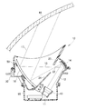
図3に示すように、このヘッドアップディスプレイ装置10では、ケース20は、第1・第2凹面鏡14、16を支えると共に第2遮蔽部24を備えるセンターフレーム30と、このセンターフレーム30の上に取付けられ第1遮蔽部23を備える上カバー50と、センターフレーム30の下に取付けられる下カバー55と、からなる。
As shown in FIG. 3, in the head-up
センターフレーム30は、取付けフランジ31、31を外周に備え、内部に斜め上に延びる第2遮蔽部24を備えるアルミニウムダイカスト品である。
The
例えば、センターフレーム30にステイ32を溶接し、このステイ32に接着層33で第1凹面鏡14を固定する。また、センターフレーム30の内面に溶接されたステイ34〜36に接着層37〜39で第2凹面鏡16を固定する。
For example, a
センターフレーム30の下部からステイ41を延ばす。一方、光源11と表示器13を筒形ブラケット42に嵌め、この筒形ブラケット42から延ばしたブラケット片43をステイ41にビス44、44で固定する。
The
センターフレーム30は、アルミニウムダイカスト品であれば、樹脂成形品より格段に強度が高く、剛性に富む。剛性に富むセンターフレーム30に、第1・第2凹面鏡14、16や表示器13を一括して取付けるため、これらの光軸調整が狂い難くなる。さらに、剛性に富むセンターフレーム30は、取付けフランジ31、31で車両に取付けられる。カバーが全体的に樹脂で構成されている場合は、剛性が不足して光軸の再調整が必要になりうる。一方、実施例のヘッドアップディスプレイ装置10は、剛性に富むためその心配が小さい。
If the
上カバー50は、例えば、ポリカーボネート成形品であり、上面にカバーガラス51を備え、斜め下へ延びる第1遮蔽部23を一体的に備えている。
The
下カバー55は、上に開口する有底筒体であり、例えば、ABS樹脂成形品であり、プリント基板56を内蔵している。
The
センターフレーム30に、下からビス57、57で下カバー55を取付け、上からビス52で上カバー50を取付ける。
A
図4に示すヘッドアップディスプレイ装置10が完成する。表示器13から出射された表示光12は第1凹面鏡14で反射され、この第1凹面鏡14で反射された表示光15は、第1・第2遮蔽部23、24の間を通過して、第2凹面鏡16に至る。第2凹面鏡16で反射された表示光17は上昇し、車両のフロントガラス66(反射された表示光17が投射される投射部66)に至る。
The head-up
図5(a)に示すように、太陽58の高度が低い場合、太陽光に代表される外光25は、カバーガラス51を通過し、第2凹面鏡16で反射され、第1遮蔽部23で遮蔽される。第1遮蔽部23は、耐熱性に優れるポリカーボネートであるため、熱に対する強度が高い。
As shown in FIG. 5A, when the altitude of the
太陽58の高度が高い場合、図5(b)に示すように、外光25は、カバーガラス51を通過し、第2凹面鏡16で反射され、第2遮蔽部24で遮蔽される。第2遮蔽部24は、耐熱性にさらに優れるアルミニウムであるため、熱に対する強度がさらに高い。
When the altitude of the
次に、熱伝導率について検討する。 Next, the thermal conductivity will be examined.
ポリカーボネート(PC)樹脂は、熱伝導率が約0.2W/m/Kである。一方、アルミニウムダイカスト品(ADC12)は、熱伝導率が約100W/m/Kである。 Polycarbonate (PC) resin has a thermal conductivity of about 0.2 W / m / K. On the other hand, the aluminum die-cast product (ADC12) has a thermal conductivity of about 100 W / m / K.
図6(a)はごく簡単な伝熱モデルを説明する図であり、ポリカーボネート(PC)樹脂製の棒59の一端が高温t1p、他端のt1pより低温t2p(t2pは大気温度t3より高い)で熱的に定常状態にあるとする。棒59の外周が断熱されていると仮定すると、棒59の内部を流れる熱Q1pと、棒59の他端から大気へ放出される熱Q2pは等しくなる。ここで、棒の断面積は単位断面積(1.0)であれば、Q1pは、熱伝導率λp×棒の長さ×(t1p−t2p)で算出される。また、Q2pは熱伝達率cp×(t2p−t3)で算出される。
FIG. 6A is a diagram for explaining a very simple heat transfer model, in which one end of a polycarbonate (PC)
アルミニウムダイカスト品(ADC12)の棒59の一端が高温t1a、他端のt1aより低温t2a(t2aは大気温度t3より高い)で熱的に定常状態にあるとする。棒59の外周が断熱されていると仮定すると、棒59の内部を流れる熱Q1aと、棒59の他端から大気へ放出される熱Q2aは等しくなる。ここで、棒の断面積は単位断面積(1.0)であれば、Q1aは、熱伝導率λa×棒の長さ×(t1a−t2a)で算出される。また、Q2aは熱伝達率ca×(t2a−t3)で算出される。
It is assumed that one end of the
Q1p=λp×棒の長さ×(t1p−t2p)と、Q1a=λa×棒の長さ×(t1a−t2a)とにおいて、λpは、λaの約1/500であって、λaよりも格段に小さい。Q1p<Q1aであるものの、その比は1:500よりは格段に小さいと予想される。
λpが極めて小さいため、傾向として(t1p−t2p)が格段に大きくなる。一方、λaが極めて大きくなるため、傾向として(t1a−t2a)が格段に小さくなる。
In Q1p = λp × bar length × (t1p−t2p) and Q1a = λa × bar length × (t1a−t2a), λp is about 1/500 of λa, which is much higher than λa. Small. Although Q1p <Q1a, the ratio is expected to be much smaller than 1: 500.
Since λp is extremely small, (t1p−t2p) is remarkably large. On the other hand, since λa becomes extremely large, (t1a−t2a) is remarkably reduced as a tendency.
また、Q1p=Q2p、Q1a=Q2aであって、Q1p<Q1aからQ2p<Q2aとなる。Q2p=cp×(t2p−t3)と、Q2a=ca×(t2a−t3)において、t3は共通である。そして、cpがcaとほぼ等しいと仮定すると、t2p<t2aとなる。 Further, Q1p = Q2p, Q1a = Q2a, and Q1p <Q1a to Q2p <Q2a. In Q2p = cp × (t2p−t3) and Q2a = ca × (t2a−t3), t3 is common. Assuming that cp is substantially equal to ca, t2p <t2a.
以上から、図6(b)に示す温度曲線が得られ、t1pがt1aより格段に大きくなる。熱伝導率が大きいほど、第1・第2遮蔽部23、24の温度を早急に低くすることができる。温度が低いほど熱劣化が少なくなる。
From the above, the temperature curve shown in FIG. 6B is obtained, and t1p is significantly larger than t1a. The higher the thermal conductivity, the quicker the temperature of the first and
この知見から、第1遮蔽部23も第2遮蔽部24と同じアルミニウムダイカスト製、又は軽金属製であれば望ましい。
From this knowledge, it is desirable that the first shielding
図7に示すように、第1遮蔽部23に放熱フィン61を一体形成したアルミニウムダイカスト品63を予め製造し、このアルミニウムダイカスト品63を成形用金型のキャビティに置き、キャビティへPC樹脂64を射出することで、いわゆるインサート成形が実施できる。
As shown in FIG. 7, an aluminum die-
第1遮蔽部23が外光25で熱せられると、熱が、第1遮蔽部23を伝わって、放熱フィン61に至る。放熱フィン61は放熱面積が大きいため、大気に向かって盛んに熱を放出する。
When the first shielding
なお、上カバー50の全部をアルミニウムダイカスト製、又は軽金属製にすることは差し支えない。
<実施例2>
The entire
<Example 2>
図8を参照する。次に、本発明の実施例2を図面に基づいて説明する。図8には、実施例2のヘッドアップディスプレイ装置の断面構成が示されている。図8は、上記図4に対応させて表している。 Please refer to FIG. Next, a second embodiment of the present invention will be described with reference to the drawings. FIG. 8 shows a cross-sectional configuration of the head-up display device of the second embodiment. FIG. 8 is shown corresponding to FIG.
実施例2によるヘッドアップディスプレイ装置10Aは、第1遮蔽部23の上面に、金属板71が配置されてなる。その他の基本的な構成については、実施例1によるヘッドアップディスプレイ装置10(図4参照)と共通する。実施例1と共通する部分については、符号を流用すると共に、詳細な説明を省略する。
In the head-up
上カバー50Aは、樹脂成形品であり、例えば、ポリカーボネートとポリエチレンテレフタレート(PET)との混合樹脂材料を用いることができる。
The
金属板71の素材には、アルミニウムやアルミニウム合金を用いることができる。
Aluminum or an aluminum alloy can be used for the material of the
なお、樹脂成形品の素材となる樹脂は、金属板71に用いられる金属の密度よりも小さい。加えて、素材に用いられる樹脂の耐熱温度は、金属板71に用いられる金属の耐熱温度よりも低い。即ち、金属板71の耐熱温度は、樹脂の耐熱温度よりも高い。これらの条件を満たしていれば、樹脂や金属は、任意の素材を選択することができる。
The resin used as the material of the resin molded product is smaller than the density of the metal used for the
図9を参照する。上カバー50Aには、3枚の金属板71が貼り付けられている。金属板71は、それぞれ、第1遮蔽部23の上面、及び、この上面の左右の端部からそれぞれ前方に延びる上カバー50Aの左右の側面部内面に貼り付けられている。これらは、外部から視認可能な意匠面ということができる。即ち、金属板71は、意匠面に配置されている。視認可能な部位に金属板71が敷き詰められることにより、意匠性をより向上させることができる。
Please refer to FIG. Three
なお、金属板71は、両面テープによる貼り付け、接着剤による接着、ねじを用いたねじ止め、固定フックを用いた係止等、任意の方法によって上カバー50Aに配置することができる。
The
以上をまとめて、以下のようにいうことができる。樹脂成形品である第1遮蔽部23の上面には、金属板71が配置されている。第1遮蔽部23は、ケース20A内へ向かう外光を遮断するための部位である。即ち、第1遮蔽部23の上面には、外光が当たる。第1遮蔽部23に当たる外光の一例として、太陽光が挙げられる。太陽光が当たる第1遮蔽部23には、高い耐熱性が求められる。一方、ヘッドアップディスプレイ装置10A全体としては、軽量であることが望まれる。上カバー50Aに用いられる樹脂は、金属板71よりも密度が小さい(低い)。このため、上カバー50Aを樹脂成形品とすることにより、ヘッドアップディスプレイ装置10Aの軽量化を図ることができる。一方、金属板71は上カバー50Aに用いられる樹脂よりも耐熱温度(耐熱性)が高い。このため、太陽光が当たる第1遮蔽部23の上面に金属板71を配置することにより、耐熱性を高めることができる。即ち、ヘッドアップディスプレイ装置10Aの軽量化を図りつつ、第1遮蔽部23の耐熱性を高めることができる。
The above can be summarized as follows. A
図10を参照する。図10には、金属板71Bを変更したヘッドアップディスプレイ装置10Bの変更例が示されている。即ち、金属板71Bは、1枚板によって構成することもできる。この場合においても、本発明の所定の効果を得ることができる。また、1枚板によって構成した場合には、複数の板によって構成した場合に比べ、金属板同士の継ぎ目が存在しないため、意匠性をより高めることができる。
Please refer to FIG. FIG. 10 shows a modified example of the head-up
尚、本発明のヘッドアップディスプレイ装置は、乗用車に好適であるが、一般の車両、船舶、航空機に適用することは差し支えない。即ち、本発明の作用及び効果を奏する限りにおいて、本発明は、実施例に限定されるものではない。 The head-up display device of the present invention is suitable for a passenger car, but may be applied to general vehicles, ships, and aircraft. That is, the present invention is not limited to the examples as long as the operations and effects of the present invention are exhibited.
本発明のヘッドアップディスプレイ装置は、フロントガラスを備える車両に好適である。 The head-up display device of the present invention is suitable for a vehicle including a windshield.
10,10A,10B…ヘッドアップディスプレイ装置
11…光源
12、15…表示光
13…表示器
14…第1ミラー(第1凹面鏡)
16…第2ミラー(第2凹面鏡)
20,20A…ケース
22…クロス点
23…第1遮蔽部
24…第2遮蔽部
25…外光
26…一般部
27…反射防止処理膜
30…センターフレーム
50,50A…上カバー
55…下カバー
71,71B…金属板
DESCRIPTION OF
16 ... Second mirror (second concave mirror)
20, 20A ...
Claims (8)
前記第1ミラーは、反射された表示光を前記第2ミラーに到達する前に上下でクロスさせる曲率を有した第1凹面鏡であり、
前記第2ミラーは、受けた表示光を反射する第2凹面鏡であり、
前記ケースは、前記第1・第2凹面鏡間の光路を挟むように、且つ前記クロスするクロス点の近傍まで延びる第1遮蔽部及び第2遮蔽部を備えており、
前記ケース外からケース内に侵入し前記第2凹面鏡で反射され前記第1凹面鏡に向かう外光を、前記第1・第2遮蔽部で遮蔽するようにしたことを特徴とするヘッドアップディスプレイ装置。 A display that emits display light; a first mirror that reflects display light emitted from the display; a second mirror that reflects display light reflected from the first mirror; the display; In a head-up display device comprising a case for housing a first mirror and a second mirror,
The first mirror is a first concave mirror having a curvature that causes the reflected display light to cross up and down before reaching the second mirror;
The second mirror is a second concave mirror that reflects the received display light;
The case includes a first shielding part and a second shielding part extending so as to sandwich the optical path between the first and second concave mirrors and to the vicinity of the crossing point where the cloth crosses.
A head-up display device characterized in that external light entering the case from outside the case, reflected by the second concave mirror and directed toward the first concave mirror is shielded by the first and second shielding portions.
前記センターフレームの下に取付けられる下カバーと、からなることを特徴とする請求項1記載のヘッドアップディスプレイ装置。 The case includes a center frame that supports the first and second concave mirrors and includes the second shielding part, and an upper cover that is mounted on the center frame and includes the first shielding part.
The head-up display device according to claim 1, further comprising a lower cover attached under the center frame.
前記上カバーは、樹脂成形品であり、
少なくとも前記第1遮蔽部の上面には、金属板が配置され、
前記樹脂成形品の素材に用いられる樹脂の密度は、前記金属板の密度よりも小さく、
前記金属板の耐熱温度は、前記樹脂の耐熱温度よりも高いことを特徴とする請求項1記載のヘッドアップディスプレイ装置。 The case includes a center frame that supports the first and second concave mirrors and includes the second shielding part, and an upper cover that is mounted on the center frame and includes the first shielding part.
The upper cover is a resin molded product,
A metal plate is disposed on at least the upper surface of the first shielding part,
The density of the resin used for the material of the resin molded product is smaller than the density of the metal plate,
The head-up display device according to claim 1, wherein a heat resistance temperature of the metal plate is higher than a heat resistance temperature of the resin.
Priority Applications (4)
| Application Number | Priority Date | Filing Date | Title |
|---|---|---|---|
| US15/526,078 US10114218B2 (en) | 2014-11-12 | 2015-11-11 | Head up display device |
| PCT/JP2015/081683 WO2016076342A1 (en) | 2014-11-12 | 2015-11-11 | Head up display device |
| CN201580061256.6A CN107111133A (en) | 2014-11-12 | 2015-11-11 | Head-up display |
| EP15858147.0A EP3220186B1 (en) | 2014-11-12 | 2015-11-11 | Head up display device |
Applications Claiming Priority (2)
| Application Number | Priority Date | Filing Date | Title |
|---|---|---|---|
| JP2014229919 | 2014-11-12 | ||
| JP2014229919 | 2014-11-12 |
Publications (2)
| Publication Number | Publication Date |
|---|---|
| JP2016103008A JP2016103008A (en) | 2016-06-02 |
| JP6579319B2 true JP6579319B2 (en) | 2019-09-25 |
Family
ID=56089460
Family Applications (1)
| Application Number | Title | Priority Date | Filing Date |
|---|---|---|---|
| JP2015212180A Active JP6579319B2 (en) | 2014-11-12 | 2015-10-28 | Head-up display device |
Country Status (4)
| Country | Link |
|---|---|
| US (1) | US10114218B2 (en) |
| EP (1) | EP3220186B1 (en) |
| JP (1) | JP6579319B2 (en) |
| CN (1) | CN107111133A (en) |
Families Citing this family (19)
| Publication number | Priority date | Publication date | Assignee | Title |
|---|---|---|---|---|
| FR3050039B1 (en) * | 2016-04-12 | 2021-11-19 | Valeo Comfort & Driving Assistance | HEAD-UP DISPLAY |
| US20190146217A1 (en) * | 2016-05-09 | 2019-05-16 | Nippon Seiki Co., Ltd. | Head-up display device |
| CN109477968B (en) * | 2016-07-07 | 2021-08-13 | 麦克赛尔株式会社 | Head-up display device |
| WO2018061745A1 (en) * | 2016-09-30 | 2018-04-05 | 日本精機株式会社 | Head-up display device |
| EP3533655B1 (en) * | 2016-10-26 | 2021-09-29 | Nippon Seiki Co., Ltd. | Head-up display device |
| JP7115471B2 (en) * | 2017-04-27 | 2022-08-09 | 日本精機株式会社 | head-up display device |
| JP6876932B2 (en) * | 2017-06-20 | 2021-05-26 | パナソニックIpマネジメント株式会社 | Image display device |
| JP6864574B2 (en) * | 2017-07-04 | 2021-04-28 | 株式会社ホンダロック | Vehicle peripheral display |
| JP2019028137A (en) * | 2017-07-26 | 2019-02-21 | 矢崎総業株式会社 | Display apparatus for vehicle |
| JP7037760B2 (en) * | 2018-03-16 | 2022-03-17 | 株式会社リコー | Image projection device and moving object |
| JP7173768B2 (en) | 2018-07-04 | 2022-11-16 | キヤノン株式会社 | Electronic viewfinder and imaging device |
| WO2020026865A1 (en) * | 2018-07-30 | 2020-02-06 | 日本精機株式会社 | Head-up display device |
| WO2020080384A1 (en) * | 2018-10-16 | 2020-04-23 | 日本精機株式会社 | Head-up display device |
| WO2021230277A1 (en) * | 2020-05-14 | 2021-11-18 | 日本精機株式会社 | Head-up display device |
| JP7435337B2 (en) | 2020-07-27 | 2024-02-21 | 株式会社デンソー | cover member |
| JP7163344B2 (en) * | 2020-09-08 | 2022-10-31 | 矢崎総業株式会社 | vehicle display |
| DE102021106972B4 (en) | 2021-03-22 | 2024-02-08 | Dr. Ing. H.C. F. Porsche Aktiengesellschaft | Head-up display for a motor vehicle and motor vehicle with this |
| DE102021203930A1 (en) * | 2021-04-20 | 2022-10-20 | Continental Automotive Technologies GmbH | Mirror for a head-up display |
| WO2023063084A1 (en) * | 2021-10-11 | 2023-04-20 | 株式会社小糸製作所 | Image irradiation device, control method for image irradiation device, image generation device, head-up display, and cover |
Family Cites Families (14)
| Publication number | Priority date | Publication date | Assignee | Title |
|---|---|---|---|---|
| GB2186001B (en) * | 1986-01-29 | 1990-04-04 | Pilkington Brothers Plc | Bendable and/or toughenable silver coatings on glass |
| JPH0628993B2 (en) * | 1986-05-23 | 1994-04-20 | 日産自動車株式会社 | Vehicle display |
| JPS62275845A (en) * | 1986-05-23 | 1987-11-30 | Nissan Motor Co Ltd | Display device for vehicle |
| JPH04242785A (en) * | 1990-12-28 | 1992-08-31 | Shimadzu Corp | Head-up display |
| DE69228644T2 (en) * | 1991-10-09 | 1999-11-18 | Denso Corp | hologram |
| JP3321849B2 (en) * | 1991-10-09 | 2002-09-09 | 株式会社デンソー | hologram |
| JPH09159986A (en) * | 1995-12-13 | 1997-06-20 | Kansei Corp | Information display device for vehicle |
| JP4114194B2 (en) | 1998-10-29 | 2008-07-09 | 日本精機株式会社 | Head-up display device |
| JP2003237411A (en) | 2002-02-12 | 2003-08-27 | Denso Corp | Head-up display device |
| JP2004226469A (en) * | 2003-01-20 | 2004-08-12 | Denso Corp | Head-up display device for vehicle |
| JP4739149B2 (en) * | 2006-08-29 | 2011-08-03 | 矢崎総業株式会社 | Display device |
| DE102011075205A1 (en) * | 2011-05-04 | 2012-11-08 | Robert Bosch Gmbh | Display device for vehicle, has housing with outer wall, in which outlet opening is arranged, while imager for generating image information is arranged inside housing, where optical element is arranged inside housing |
| JP5873707B2 (en) * | 2011-12-15 | 2016-03-01 | 矢崎総業株式会社 | Head-up display device |
| JP6004706B2 (en) * | 2012-04-04 | 2016-10-12 | 三菱電機株式会社 | Display device and head-up display system provided with the same |
-
2015
- 2015-10-28 JP JP2015212180A patent/JP6579319B2/en active Active
- 2015-11-11 US US15/526,078 patent/US10114218B2/en active Active
- 2015-11-11 EP EP15858147.0A patent/EP3220186B1/en active Active
- 2015-11-11 CN CN201580061256.6A patent/CN107111133A/en active Pending
Also Published As
| Publication number | Publication date |
|---|---|
| EP3220186A4 (en) | 2018-10-24 |
| CN107111133A (en) | 2017-08-29 |
| US20170315351A1 (en) | 2017-11-02 |
| US10114218B2 (en) | 2018-10-30 |
| EP3220186B1 (en) | 2022-10-19 |
| EP3220186A1 (en) | 2017-09-20 |
| JP2016103008A (en) | 2016-06-02 |
Similar Documents
| Publication | Publication Date | Title |
|---|---|---|
| JP6579319B2 (en) | Head-up display device | |
| JP6642172B2 (en) | Head-up display device | |
| JP6769481B2 (en) | Head-up display device | |
| JP6819679B2 (en) | Head-up display device | |
| JP6563711B2 (en) | Head-up display device | |
| JP2018198145A (en) | Heating device | |
| US10513168B2 (en) | Vehicular optical system | |
| US20190285884A1 (en) | Display device and apparatus | |
| WO2016076342A1 (en) | Head up display device | |
| JP7115471B2 (en) | head-up display device | |
| JP2011246056A (en) | On-vehicle camera | |
| JP2008292953A (en) | Cooling structure of dlp system projector | |
| JP2008192317A (en) | Spectral heat radiator | |
| JP2015169816A (en) | Dew condensation prevention structure of optical component and head up display device | |
| WO2019151482A1 (en) | Head-up display device | |
| JP2019162929A (en) | Vehicle sensor device | |
| JP2018087775A (en) | Display device for vehicle | |
| JP6766525B2 (en) | Display device | |
| JP2018198375A (en) | Heating device | |
| JP7068223B2 (en) | Head-up display | |
| JP2018198144A (en) | Heating device | |
| WO2020166306A1 (en) | Optical component, and image display device using same | |
| JP6428078B2 (en) | Head-up display device for vehicle | |
| JP2015055694A (en) | Flash light emission device | |
| JP2019185012A (en) | Imaging device |
Legal Events
| Date | Code | Title | Description |
|---|---|---|---|
| A621 | Written request for application examination |
Free format text: JAPANESE INTERMEDIATE CODE: A621 Effective date: 20180810 |
|
| TRDD | Decision of grant or rejection written | ||
| A01 | Written decision to grant a patent or to grant a registration (utility model) |
Free format text: JAPANESE INTERMEDIATE CODE: A01 Effective date: 20190731 |
|
| A61 | First payment of annual fees (during grant procedure) |
Free format text: JAPANESE INTERMEDIATE CODE: A61 Effective date: 20190813 |
|
| R150 | Certificate of patent or registration of utility model |
Ref document number: 6579319 Country of ref document: JP Free format text: JAPANESE INTERMEDIATE CODE: R150 |