JP6568979B2 - Design method for number mode optical fiber - Google Patents
Design method for number mode optical fiber Download PDFInfo
- Publication number
- JP6568979B2 JP6568979B2 JP2018099856A JP2018099856A JP6568979B2 JP 6568979 B2 JP6568979 B2 JP 6568979B2 JP 2018099856 A JP2018099856 A JP 2018099856A JP 2018099856 A JP2018099856 A JP 2018099856A JP 6568979 B2 JP6568979 B2 JP 6568979B2
- Authority
- JP
- Japan
- Prior art keywords
- refractive index
- core
- cladding
- trench
- mode
- Prior art date
- Legal status (The legal status is an assumption and is not a legal conclusion. Google has not performed a legal analysis and makes no representation as to the accuracy of the status listed.)
- Active
Links
Images

Landscapes
- Optical Fibers, Optical Fiber Cores, And Optical Fiber Bundles (AREA)
Description
本発明は、複数の伝搬モードを用いる数モード光ファイバに関する。 The present invention relates to a number mode optical fiber using a plurality of propagation modes.
伝送容量を拡大する技術として複数の伝搬モードを用いる数モード光ファイバが提案されている。特に複数の伝搬モードを用いたモード多重伝送は、伝送容量をモード数倍に向上させられることから、新たな大容量伝送方式として注目されている。 A number mode optical fiber using a plurality of propagation modes has been proposed as a technique for expanding the transmission capacity. In particular, mode multiplex transmission using a plurality of propagation modes is attracting attention as a new large-capacity transmission system because the transmission capacity can be improved several times the number of modes.
この数モード光ファイバを用いた伝送においては、伝送路中でモード間クロストークが発生することから、その補償手段として、受信端においてMIMO(Multiple−Input Multiple−Output)等化器が用いられる。しかしながら、受信端においてモード間の群遅延差(Differential Mode Delay:以下、DMD)が大きいと、MIMOに関わるディジタル処理(DSP)の負荷が大きくなり、長距離伝送を実現する為にはDSP負荷の低減が課題となる。そこで、DMDを50ps/km程度に抑えた光ファイバや、基本モードが高次モードよりも速い正のDMDを有する光ファイバと基本モードが高次モードよりも遅い負のDMDを有する光ファイバを組み合わせたDMD補償伝送路が提案されている(例えば、非特許文献1、2を参照。)。
In transmission using this number mode optical fiber, crosstalk between modes occurs in the transmission path. Therefore, a MIMO (Multiple-Input Multiple-Output) equalizer is used at the receiving end as the compensation means. However, if the group delay difference between the modes (hereinafter referred to as DMD) is large at the receiving end, the load of digital processing (DSP) related to MIMO increases, and in order to realize long-distance transmission, the DSP load is large. Reduction is an issue. Therefore, an optical fiber with a DMD suppressed to about 50 ps / km, an optical fiber having a positive DMD whose fundamental mode is faster than the higher order mode, and an optical fiber having a negative DMD whose fundamental mode is slower than the higher order mode are combined. DMD compensated transmission lines have been proposed (see, for example,
しかしながら、非特許文献1、2においては伝搬モード数が2に限定され、3以上の伝搬モード数を実現できない、という問題があった。
However, in
そこで、本願発明は、一般的なグレーデッド型コア構成(中心軸から外側に向けて屈折率が指数的に小さくなるコアと、コアの外側にあり、屈折率がコアの屈折率よりも小さく、屈折率が一様なクラッドによる構成)を抜本的に見直すことで、伝搬モード数を3以上にしても、DMDの抑制が可能な、数モード光ファイバを提供することを目的とする。 Therefore, the present invention has a general graded core configuration (a core whose refractive index decreases exponentially from the central axis toward the outside, and the outside of the core, where the refractive index is smaller than the refractive index of the core, An object of the present invention is to provide a number-mode optical fiber capable of suppressing DMD even if the number of propagation modes is 3 or more by drastically reviewing the configuration of a clad having a uniform refractive index.
上記目的を達成するために、本発明の数モード光ファイバは、屈折率のプロファイルがグレーデッド型であるコアと、一部にトレンチが配置されたクラッドの構造とし、中心軸から外側に向けて屈折率が指数的に小さくなるコアのすぐ外側にトレンチ(底面)を配置することとした。 In order to achieve the above object, the number mode optical fiber of the present invention has a core structure having a graded refractive index profile and a clad structure in which a trench is disposed in part, and is directed outward from the central axis. The trench (bottom surface) is arranged just outside the core where the refractive index decreases exponentially.
具体的には、本発明に係る数モード光ファイバは、
中心軸から外側に向けて屈折率が指数関数的に小さくなるコアと、
前記コアの外側に配置され、屈折率が前記コアの屈折率以下のトレンチと、
前記トレンチの外側に配置され、屈折率が前記トレンチの屈折率よりも大きいクラッドと、
を備える。
Specifically, the number mode optical fiber according to the present invention is:
A core whose refractive index decreases exponentially from the central axis toward the outside,
A trench disposed outside the core and having a refractive index equal to or lower than the refractive index of the core;
A cladding disposed outside the trench and having a refractive index greater than the refractive index of the trench;
Is provided.
具体的には、本発明に係る数モード光ファイバは、
中心軸から外側に向けて屈折率が指数関数的に小さくなるコアと、
前記コアの外側に配置され、屈折率が前記コアの屈折率以下の第1のクラッドと、
前記第1のクラッドの外側に配置され、屈折率が前記第1のクラッドの屈折率よりも小さいトレンチと、
前記トレンチの外側に配置され、屈折率が前記第1のクラッドと等しい第2のクラッドと、
を備え、
前記第1のクラッド及び第2のクラッドの屈折率はシリカレベルであり、
前記トレンチは屈折率をシリカレベルよりも下げるドーパントを含み、
前記第1のクラッドは、シリカレベル以下の前記コアの屈折率分布のグレーデッド形状をトレンチまで模擬させる。
Specifically, the number mode optical fiber according to the present invention is:
A core whose refractive index decreases exponentially from the central axis toward the outside,
A first cladding disposed outside the core and having a refractive index equal to or lower than the refractive index of the core;
A trench disposed outside the first cladding and having a refractive index smaller than that of the first cladding;
A second cladding disposed outside the trench and having a refractive index equal to the first cladding;
With
The refractive index of the first cladding and the second cladding is at a silica level,
The trench includes a dopant that lowers the refractive index below the silica level;
The first cladding simulates the graded shape of the refractive index profile of the core below the silica level up to the trench.
本発明に係る数モード光ファイバでは、
本発明に係る少なくとも2本の数モード光ファイバが縦続接続された数モード光ファイバであって、
前記2本の数モード光ファイバは、4モードを伝搬し、前記コアの屈折率の指数定数が特定値のときに前記4モードの光信号間に発生する3つのDMDの絶対値が最小になり、
前記2本の数モード光ファイバの一方は、前記コアの屈折率の指数定数が前記特定値よりも大きく、
前記2本の数モード光ファイバの他方は、前記コアの屈折率の指数定数が前記特定値よりも小さい構成を採用しうる。
ここで、前記4モードは、例えばLP01、LP21、LP02、LP11である。
In the number mode optical fiber according to the present invention,
A number mode optical fiber in which at least two number mode optical fibers according to the present invention are cascade-connected,
The two number mode optical fibers propagate four modes, and the absolute values of three DMDs generated between the four mode optical signals are minimized when the index constant of the refractive index of the core is a specific value. ,
One of the two number mode optical fibers has an index constant of the refractive index of the core larger than the specific value,
The other of the two number mode optical fibers may employ a configuration in which the index constant of the refractive index of the core is smaller than the specific value.
Here, the four modes are, for example, LP01, LP21, LP02, and LP11.
具体的には、本発明に係る光ファイバ伝送システムは、
データを光信号に変換して送信する複数の光送信機と、
前記複数の光送信機からの光信号を伝搬モードが異なるように合波する合波器と、
前記合波器からの光信号を伝搬する本発明に係る数モード光ファイバと、
前記数モード光ファイバからの光信号を異なる分岐比で分波する分波器と、
前記分波器の分岐する各光信号を個別に電気信号に変換する複数の光受信機と、
前記光受信機が出力する電気信号から、前記数モード光ファイバの伝搬中に生じた信号劣化を補償し、前記複数の光送信機が送信したデータを復元するデータ復元部と、
を備える。
Specifically, the optical fiber transmission system according to the present invention is:
A plurality of optical transmitters for converting data into optical signals and transmitting the data;
A multiplexer that multiplexes optical signals from the plurality of optical transmitters so that propagation modes are different, and
A number mode optical fiber according to the present invention for propagating an optical signal from the multiplexer;
A demultiplexer for demultiplexing the optical signal from the several-mode optical fiber at different branching ratios;
A plurality of optical receivers that individually convert each optical signal branched by the duplexer into an electrical signal;
A data restoration unit that compensates for signal degradation that occurs during propagation of the several-mode optical fiber from the electrical signal output by the optical receiver, and restores data transmitted by the plurality of optical transmitters;
Is provided.
具体的には、本発明に係る数モード光ファイバの設計方法は、
中心軸から外側に向けて屈折率が指数関数的に小さくなるコアと、
前記コアの外側に配置され、屈折率が前記コアの屈折率以下のトレンチと、
前記トレンチの外側に配置され、屈折率が前記トレンチの屈折率よりも大きいクラッドと、
を備える数モード光ファイバの設計方法であって、
前記コアの外周半径及び比屈折率差を変化させた時の使用波長帯における各高次モードのDMD(Differential Mode Delay)を算出し、各高次モードDMDが予め定められた条件をみたすように、前記指数関数の指数定数、前記コアの外周半径及び比屈折率差を求めるコア設計手順と、
前記コア設計手順で求めた前記コアの外周半径及び比屈折率差を用いて、使用波長帯における各高次モードの正規化伝搬定数を算出し、算出した正規化伝搬定数に基づき、使用波長帯において各高次モードが伝搬可能になるような、前記トレンチに対する前記クラッドの比屈折率の範囲を求めるクラッド設計手順と、
前記コア設計手順で求めた前記コアの外周半径及び比屈折率差並びに前記クラッド設計手順で求めた前記トレンチに対する前記クラッドの比屈折率を用いて、使用波長帯における曲げ損失を算出し、算出した曲げ損失が予め定められた条件をみたすように、前記トレンチの幅及び前記トレンチに対する前記クラッドの比屈折率を求める曲げ損失調整手順と、
を順に有する。
Specifically, the design method of the number mode optical fiber according to the present invention is:
A core whose refractive index decreases exponentially from the central axis toward the outside,
A trench disposed outside the core and having a refractive index equal to or lower than the refractive index of the core;
A cladding disposed outside the trench and having a refractive index greater than the refractive index of the trench;
A method for designing a number mode optical fiber comprising:
To calculate DMD (Differential Mode Delay) of each higher-order mode in the used wavelength band when the outer peripheral radius of the core and the relative refractive index difference are changed, so that each higher-order mode DMD satisfies predetermined conditions. A core design procedure for obtaining an exponential constant of the exponential function, an outer peripheral radius of the core and a relative refractive index difference;
Using the outer peripheral radius and relative refractive index difference of the core obtained in the core design procedure, calculate a normalized propagation constant of each higher-order mode in the used wavelength band, and based on the calculated normalized propagation constant, A clad design procedure for determining a range of relative refractive index of the clad with respect to the trench so that each higher-order mode can propagate in
Using the outer peripheral radius and relative refractive index difference of the core determined in the core design procedure and the relative refractive index of the cladding with respect to the trench determined in the cladding design procedure, the bending loss in the used wavelength band was calculated and calculated. A bending loss adjustment procedure for obtaining a width of the trench and a relative refractive index of the clad with respect to the trench so that the bending loss satisfies a predetermined condition;
In order.
具体的には、本発明に係る数モード光ファイバの設計方法は、
中心軸から外側に向けて屈折率が指数関数的に小さくなるコアと、
前記コアの外側に配置され、屈折率が前記コアの屈折率以下の第1のクラッドと、
前記第1のクラッドの外側に配置され、屈折率が前記第1のクラッドの屈折率よりも小さいトレンチと、
前記トレンチの外側に配置され、屈折率が前記第1のクラッドと等しい第2のクラッドと、
を備え、
前記第1のクラッド及び第2のクラッドの屈折率はシリカレベルであり、
前記トレンチは屈折率をシリカレベルよりも下げるドーパントを含み、
前記第1のクラッドは、シリカレベル以下の前記コアの屈折率分布のグレーデッド形状をトレンチまで模擬させる、数モード光ファイバの設計方法であって、
前記コアの外周半径及び比屈折率差を変化させた時の使用波長帯における各高次モードのDMDを算出し、各高次モードDMDが予め定められた条件をみたすように、前記指数関数の指数定数、前記コアの外周半径及び比屈折率差の理想値を求めるコア理想値設計手順と、
前記第1のクラッド及び前記第2のクラッドの比屈折率差の絶対値と前記トレンチの比屈折率差の絶対値の和が前記コア理想値設計手順で求めた比屈折率差の理想値となりかつ各高次モードのDMDが前記予め定められた条件をみたす前記第1のクラッド及び前記第2のクラッドの比屈折率差の絶対値と前記トレンチの比屈折率差の絶対値の組み合わせを求める比屈折率差設計手順と、
前記比屈折率差設計手順で求めた前記組み合わせごとに、前記コア理想値設計手順で求めた前記指数定数のときの前記指数関数を用いて前記コアの外周半径を求め、当該コアの外周半径を用いて前記第1のクラッドの幅を変化させたときの各高次モードのDMDを算出し、算出した各高次モードのDMDが前記予め定められた条件をみたすような前記コアの外周半径と前記第1のクラッドの外周半径の組み合わせで求められる外周半径の比の範囲を求めるクラッド幅設計手順と、
前記クラッド幅設計手順で求めた前記外周半径の比の範囲に含まれる前記第1のクラッド及び前記第2のクラッドの比屈折率差の絶対値、前記トレンチの比屈折率差の絶対値、前記コアの外周半径並びに前記第1のクラッドの外周半径の組み合わせを用いて、使用波長帯における曲げ損失を算出し、算出した曲げ損失が予め定められた条件をみたすように、前記第1のクラッド及び前記第2のクラッドの比屈折率差の絶対値、前記トレンチの比屈折率差の絶対値、前記コアの外周半径並びに前記第1のクラッドの外周半径を求める曲げ損失調整手順と、
を順に有する。
Specifically, the design method of the number mode optical fiber according to the present invention is:
A core whose refractive index decreases exponentially from the central axis toward the outside,
A first cladding disposed outside the core and having a refractive index equal to or lower than the refractive index of the core;
A trench disposed outside the first cladding and having a refractive index smaller than that of the first cladding;
A second cladding disposed outside the trench and having a refractive index equal to the first cladding;
With
The refractive index of the first cladding and the second cladding is at a silica level,
The trench includes a dopant that lowers the refractive index below the silica level;
The first cladding is a design method of a number mode optical fiber that simulates the graded shape of the refractive index profile of the core below the silica level up to the trench,
Calculate the DMD of each higher-order mode in the used wavelength band when the outer peripheral radius of the core and the relative refractive index difference are changed, so that each higher-order mode DMD satisfies a predetermined condition. A core ideal value design procedure for obtaining an ideal value of an exponential constant, an outer peripheral radius of the core, and a relative refractive index difference;
The sum of the absolute value of the relative refractive index difference of the first cladding and the second cladding and the absolute value of the relative refractive index difference of the trench is the ideal value of the relative refractive index difference obtained by the core ideal value design procedure. The DMD of each higher order mode obtains a combination of the absolute value of the relative refractive index difference between the first cladding and the second cladding and the absolute value of the relative refractive index difference of the trench satisfying the predetermined condition. Specific refractive index difference design procedure,
For each of the combinations obtained in the relative refractive index difference design procedure, obtain the outer radius of the core using the exponential function at the exponential constant obtained in the core ideal value design procedure, and determine the outer radius of the core. And calculating the DMD of each higher-order mode when the width of the first cladding is changed, and the calculated outer peripheral radius of the core such that the DMD of each higher-order mode satisfies the predetermined condition. A cladding width design procedure for obtaining a range of a ratio of outer radiuses determined by a combination of outer radiuses of the first cladding;
An absolute value of a relative refractive index difference between the first clad and the second clad included in a range of a ratio of the outer peripheral radii obtained by the cladding width design procedure, an absolute value of a relative refractive index difference of the trench, Using the combination of the outer peripheral radius of the core and the outer peripheral radius of the first cladding, the bending loss in the used wavelength band is calculated, and the calculated bending loss satisfies the predetermined condition. A bending loss adjustment procedure for obtaining an absolute value of the relative refractive index difference of the second cladding, an absolute value of the relative refractive index difference of the trench, an outer peripheral radius of the core and an outer peripheral radius of the first cladding;
In order.
なお、上記各発明は、可能な限り組み合わせることができる。 The above inventions can be combined as much as possible.
本発明によれば、伝搬モード数を3以上にしても、DMDの抑制が可能な、数モード光ファイバを提供することが可能となる。 According to the present invention, it is possible to provide a number mode optical fiber capable of suppressing DMD even when the number of propagation modes is three or more.
以下、本発明の実施形態について、図面を参照しながら詳細に説明する。なお、本発明は、以下に示す実施形態に限定されるものではない。これらの実施の例は例示に過ぎず、本発明は当業者の知識に基づいて種々の変更、改良を施した形態で実施することができる。なお、本明細書及び図面において符号が同じ構成要素は、相互に同一のものを示すものとする。 Hereinafter, embodiments of the present invention will be described in detail with reference to the drawings. In addition, this invention is not limited to embodiment shown below. These embodiments are merely examples, and the present invention can be implemented in various modifications and improvements based on the knowledge of those skilled in the art. In the present specification and drawings, the same reference numerals denote the same components.
(実施形態1)
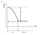
数モードファイバは、コアと、その外側のクラッドから構成されている。コアの屈折率分布は、数1で表されるような、中心軸から外側に向けて屈折率が指数関数的に小さくなるα乗屈折率分布をもつ。数1において、n(r)は中心から半径方向の位置rにおける屈折率、n1はコア中心の屈折率、Δ1はコアの比屈折率差、αを指数定数を表す。

(Embodiment 1)
The number mode fiber is composed of a core and an outer cladding. The refractive index distribution of the core has an α power refractive index distribution that is expressed by
図1に、数モード光ファイバの屈折率分布の一例を示す。数モード光ファイバの屈折率分布は、半径rがa1より小さい領域ではα乗屈折率分布に従う。なお、指数定数αはグレーテッド型プロファイルを示す無次元パラメータであり、アルファパラメータと呼ばれることもある。 FIG. 1 shows an example of the refractive index distribution of a number mode optical fiber. Refractive index distribution of the number-mode optical fiber, the radius r follows the refractive index profile multiply α is a 1 smaller area. The exponent constant α is a dimensionless parameter indicating a graded profile, and is sometimes called an alpha parameter.
一般的にコア部の外周半径a1が25μm、比屈折率差Δ1が1.0%、αが2.0であり、伝搬モード数は通信波長帯において数十〜百である。伝搬モード数を制限するためには、コア部の外周半径a1や比屈折率差Δ1を調整する必要がある。以下、簡単のため伝搬モード数は弱導波近似によるLPモードにて換算する。 Generally, the outer peripheral radius a 1 of the core part is 25 μm, the relative refractive index difference Δ 1 is 1.0%, α is 2.0, and the number of propagation modes is several tens to hundreds in the communication wavelength band. In order to limit the number of propagation modes, it is necessary to adjust the outer peripheral radius a 1 and the relative refractive index difference Δ 1 of the core. Hereinafter, for the sake of simplicity, the number of propagation modes is converted into an LP mode based on weak waveguide approximation.
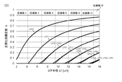
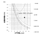
図2にコア部の外周半径a1と正規化伝搬定数bの関係を示す。この時、比屈折率差Δ1が1.0%、αが2.0、波長は1550nmである。コア部の外周半径a1を変えた場合、有限要素法に基づいて正規化伝搬定数bを計算した。伝搬モードに対しては0<b<1であり、カットオフ条件はb=0で表される。 Shows the relationship between the outer peripheral radius a 1 and a normalized propagation constant b of the core portion in Fig. In this case, the relative refractive index difference delta 1 is 1.0%, alpha is 2.0, the wavelength is 1550 nm. If you change the outer peripheral radius a 1 of the core portion was calculated normalized propagation constant b based on the finite element method. For the propagation mode, 0 <b <1, and the cutoff condition is expressed as b = 0.
図2より例えば、4.2[μm]<コア部の外周半径a1<6.8[μm]の時に伝搬モード数が2、6.8[μm]<コア部の外周半径a1<9.3[μm]の時に伝搬モード数が4、9.3[μm]<コア部の外周半径a1<11.8[μm]の時に伝搬モード数が6の光ファイバが実現可能である。 From FIG. 2, for example, when 4.2 [μm] <the outer radius a 1 <6.8 [μm] of the core portion, the number of propagation modes is 2, 6.8 [μm] <the outer radius a 1 <9 of the core portion. An optical fiber with a propagation mode number of 6 can be realized when the propagation mode number is 4, 9.3 [μm] <the outer peripheral radius of the core portion a 1 <11.8 [μm] when .3 [μm].
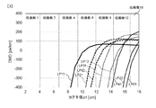
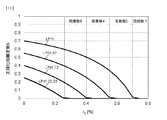
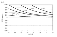
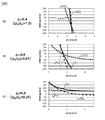
次に、コア部の外周半径a1を変えた場合、有限要素法に基づいて計算した高次モード(LP11、LP21、LP02、LP31、LP12、LP41、LP22、LP03モード)と基本モード(LP01モード)のモード群遅延差(DMD:Differential Mode Delay)の変化を図3に示す。DMDは高次モードの群遅延から基本モードの群遅延を引いた値であり、DMDは波長1550nmにおいて算出している。 Next, the case of changing the outer peripheral radius a 1 of the core unit, the high-order mode calculated based on the finite element method (LP11, LP21, LP02, LP31 , LP12, LP41, LP22, LP03 modes) and the fundamental mode (LP01 mode FIG. 3 shows changes in the mode group delay difference (DMD: Differential Mode Delay). DMD is a value obtained by subtracting the group delay of the fundamental mode from the group delay of the higher-order mode, and DMD is calculated at a wavelength of 1550 nm.
図3より、LP11モードに注目した場合、コア半径a1が10.2[μm]のとき、0[ps/km]のDMDを実現可能であることが分かる。ただし、2モード動作が実現出来ていない。同様に、LP11モードより高次のモードに注目した場合においても、伝搬モード数を制限しつつ、低DMD化を実現することが困難であることが分かる。 FIG. 3 shows that when the LP11 mode is focused, a DMD of 0 [ps / km] can be realized when the core radius a1 is 10.2 [μm]. However, the two-mode operation cannot be realized. Similarly, even when attention is paid to higher-order modes than the LP11 mode, it is difficult to realize a low DMD while limiting the number of propagation modes.
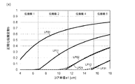
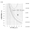
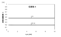
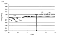
一方で、さらに構造パラメータの比屈折率差Δ1やαを最適化することにより伝搬モード数2の低DMD化を実現している報告がある(例えば非特許文献3)。図4に比屈折率差Δ1が0.4%、αが2.3、波長は1550nmの時のコア半径a1と正規化伝搬定数bの関係を示す。図4より6.5[μm]<コア部の外周半径a1<11.2[μm]の時、伝搬モード数が2の光ファイバが実現可能である。 On the other hand, there is a report that realizes a low DMD with two propagation modes by optimizing the relative refractive index differences Δ 1 and α of the structural parameters (for example, Non-Patent Document 3). 4 to the relative refractive index difference delta 1 is 0.4%, alpha is 2.3, the wavelength showing the relationship between the core radius a1 and the normalized propagation constant b for the time of 1550 nm. From FIG. 4, it is possible to realize an optical fiber having a propagation mode number of 2 when 6.5 [μm] <the outer peripheral radius of the core portion a 1 <11.2 [μm].
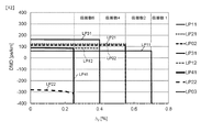
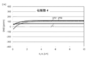
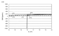
次に、コア部の外周半径a1を変えた場合、有限要素法に基づいて計算した高次モード(LP11、LP21、LP02、LP31モード)と基本モード(LP01モード)のモード群遅延差(DMD:Differential Mode Delay)の変化を図5に示す。図5より、LP11モードに注目した場合、コア部の外周半径a1が11.2[μm]のとき、−200[ps/km]のDMDを実現可能であることが分かる。2モード動作も実現出来ている。ただし、LP11モードより高次のモードに注目した場合においても、伝搬モード数を制限しつつ、低DMD化を実現することが困難であることが分かる。 Next, the case of changing the outer peripheral radius a 1 of the core unit, the high-order mode calculated based on the finite element method (LP11, LP21, LP02, LP31 mode) and the mode group delay difference of the fundamental mode (LP01 mode) (DMD : Differential Mode Delay) is shown in FIG. FIG. 5 shows that when the LP11 mode is focused, a DMD of −200 [ps / km] can be realized when the outer peripheral radius a 1 of the core portion is 11.2 [μm]. Two-mode operation can also be realized. However, even when attention is paid to higher-order modes than the LP11 mode, it can be seen that it is difficult to realize a low DMD while limiting the number of propagation modes.
つまり、2よりも大きいモード数の伝搬モード数を考慮した場合、グレーデッド型コアだけでは、構造パラメータを調整したとしても低DMD(−200[ps/km]<DMD<200[ps/km])かつNモード動作(N>2)を実現することが困難であることが分かる。 That is, when the number of propagation modes having a mode number greater than 2 is taken into consideration, the graded core alone has a low DMD (−200 [ps / km] <DMD <200 [ps / km] even if the structural parameters are adjusted. ) And N-mode operation (N> 2) is difficult to realize.
典型的なコア半径の製造誤差は±0.25μmであり、2LPモードにおいてDMDの絶対値が200ps/km以下を目標値として定めている。DMDの設計値がたとえ0ps/kmであっても、ファイバ作製上DMDは厳密に0にすることはできず、厳しい製造条件を仮定したとしてもDMDは少なくとも±200ps/km以内の範囲で変化する。よって、本実施形態の光ファイバにおいても、±200ps/km以下を目標値とする。 The manufacturing error of a typical core radius is ± 0.25 μm, and the absolute value of DMD is set to 200 ps / km or less as a target value in the 2LP mode. Even if the design value of the DMD is 0 ps / km, the DMD cannot be strictly set to 0 for fiber fabrication, and the DMD changes within a range of at least ± 200 ps / km even if severe manufacturing conditions are assumed. . Therefore, also in the optical fiber of this embodiment, the target value is ± 200 ps / km or less.
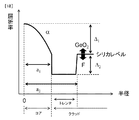
図6は、本実施形態の数モード光ファイバにおける半径方向の屈折率分布を示す図である。本数モード光ファイバは、中心から半径a1までのコアと、コアの外側にあるクラッドと、クラッド内に形成されるトレンチと、を有する。ここで、トレンチは、クラッドのうち、相対的に低屈折率の領域であり、図6ではa1からa2までの領域(α乗屈折率分布をもつコアの外側)に形成される。 FIG. 6 is a diagram showing a refractive index distribution in the radial direction in the number mode optical fiber of the present embodiment. The number mode optical fiber has a core from the center to the radius a 1 , a cladding outside the core, and a trench formed in the cladding. Here, the trench is a relatively low refractive index region of the clad, and is formed in a region from a 1 to a 2 (outside of the core having α power refractive index distribution) in FIG.
本実施形態の数モード光ファイバの屈折率分布は、半径rがa1より小さい領域では、数1で表されるα乗屈折率分布に従う。コアは、中心から半径方向の屈折率プロファイルが、指数定数αのグレーデッド型である。トレンチに対するコアの中心の比屈折率はΔ1である。トレンチに対するクラッド層の比屈折率Δ2である。トレンチの屈折率分布は、クラッドよりも低く均一であることが好ましい。
Refractive index distribution of the number-mode optical fiber of this embodiment, the radius r is a 1 smaller area, according to the α-th power refractive index distribution represented by the
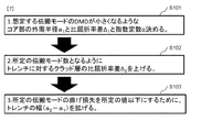
以下、図7を参照しながら、伝搬モード数が2よりも大きい低DMD数モード光ファイバの設計方法について詳細に説明する。本実施形態に係る数モード光ファイバの設計方法は、コア設計手順(S101)と、クラッド設計手順(S102)と、トレンチ設計手順(S103)と、を順に有する。1例として、伝搬モードが4(LP01、LP11、LP21、LP02モード)、DMDが200ps/km以下の光ファイバを設計目標とする。波長は1550nmにて考慮する。 Hereinafter, a design method of a low DMD number mode optical fiber having a propagation mode number larger than 2 will be described in detail with reference to FIG. The design method of the number mode optical fiber according to the present embodiment includes a core design procedure (S101), a cladding design procedure (S102), and a trench design procedure (S103) in this order. As an example, an optical fiber having a propagation mode of 4 (LP01, LP11, LP21, LP02 mode) and a DMD of 200 ps / km or less is a design target. The wavelength is considered at 1550 nm.
まず、コア設計手順(S101)を実行し、コア部の外周半径a1と比屈折率差Δ1および指数定数αを決める。例えば、コアの外周半径a1及び比屈折率差Δ1を変化させた時の使用波長帯における各高次モードのDMDを算出し、各高次モードDMDが予め定められた条件をみたすように、コアの外周半径a1及び比屈折率差Δ1を求める。 First, perform the core design procedure (S101), determining the outer circumference radius a 1 and a relative refractive index difference delta 1 and exponent constant α of the core portion. For example, the DMD of each higher-order mode in the used wavelength band when the outer peripheral radius a 1 and the relative refractive index difference Δ 1 are changed is calculated so that each higher-order mode DMD satisfies a predetermined condition. Then, the outer peripheral radius a 1 and the relative refractive index difference Δ 1 of the core are obtained.
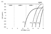
本実施形態では、使用波長帯が1550nmであり、予め定められた条件は200ps/km以下である。図8〜図10は、コア部の外周半径a1と比屈折率差Δ1を変化させた時の各高次モードのDMDの一例を示す。図8はLP11モードを示し、図9はLP21モードを示し、図10はLP02モードを示す。本実施形態では、DMDの算出において、一例として、αを2.0とした。図8〜図10より、コア部の外周半径a1が16[μm]でありかつ比屈折率差Δ1が1.0[%]であるとき、LP11、LP21、LP02の全てのモードにおいてのDMDが0〜200ps/kmとなる。そこで、構造パラメータとして、コア部の外周半径a1を16[μm]、比屈折率差Δ1を1.0[%]と定める。 In the present embodiment, the used wavelength band is 1550 nm, and the predetermined condition is 200 ps / km or less. 8 to 10 show examples of DMDs of higher order modes when the outer peripheral radius a 1 and the relative refractive index difference Δ 1 of the core part are changed. 8 shows the LP11 mode, FIG. 9 shows the LP21 mode, and FIG. 10 shows the LP02 mode. In the present embodiment, α is set to 2.0 as an example in the calculation of DMD. 8 to 10, when the outer peripheral radius a 1 of the core portion is 16 [μm] and the relative refractive index difference Δ 1 is 1.0 [%], in all modes of LP11, LP21, and LP02. DMD is 0 to 200 ps / km. Therefore, as the structural parameters, the outer peripheral radius a 1 of the core portion is set to 16 [μm], and the relative refractive index difference Δ 1 is set to 1.0 [%].
次に、クラッド設計手順(S102)を実行し、トレンチに対するクラッド層の比屈折率Δ2を上げる。例えば、コア設計手順で求めたコアの外周半径a1及び比屈折率差Δ1を用いて使用波長帯における各高次モードの正規化伝搬定数bを算出する。そして、正規化伝搬定数bの算出結果に基づき、使用波長帯において各高次モードが伝搬可能になるように、トレンチに対するクラッドの比屈折率Δ2の範囲を求める。 Then run clad design procedure (S102), raising the relative refractive index delta 2 of the clad layer with respect to the trench. For example, the normalized propagation constant b of each higher-order mode in the used wavelength band is calculated using the core outer radius a 1 and the relative refractive index difference Δ 1 obtained in the core design procedure. Based on the calculation result of the normalized propagation constant b, the range of the relative refractive index Δ2 of the cladding with respect to the trench is obtained so that each higher-order mode can propagate in the used wavelength band.
本実施形態では、コア部の外周半径a1は16[μm]、比屈折率差Δ1は1.0[%]であり、使用波長帯は1550nmである。トレンチに対するクラッド層の比屈折率Δ2を変えた場合の正規化伝搬定数bを図11に示す。トレンチの幅(a2−a1)は7[μm]、波長は1550[nm]とした。図11より、0.40<Δ2<0.55[%]のとき、伝搬モード数が4となることが分かる。 In the present embodiment, the outer peripheral radius a 1 of the core portion is 16 [μm], the relative refractive index difference Δ 1 is 1.0 [%], and the used wavelength band is 1550 nm. The normalized propagation constant b in the case of changing the relative refractive index delta 2 of the clad layer for the trench shown in FIG. 11. The width (a2-a1) of the trench was 7 [μm], and the wavelength was 1550 [nm]. FIG. 11 shows that the number of propagation modes is 4 when 0.40 <Δ 2 <0.55 [%].
ここで、トレンチに対するクラッド層の比屈折率Δ2を変えた場合のDMDを図12に示す。図12より、DMDはトレンチに対するクラッド層の比屈折率Δ2の影響を受けないことが分かる。 Here, FIG. 12 shows a DMD when the relative refractive index Δ 2 of the cladding layer with respect to the trench is changed. FIG. 12 shows that DMD is not affected by the relative refractive index Δ 2 of the cladding layer with respect to the trench.
トレンチの幅(a2−a1)について、図13に正規化伝搬定数b、図14にDMDを示す。この時、Δ2は0.45[%]とした。図13及び図14より、トレンチの幅(a2−a1)は伝搬モード数やDMDにほとんど影響がないことが分かる。 FIG. 13 shows the normalized propagation constant b and FIG. 14 shows the DMD for the trench width (a2-a1). At this time, delta 2 was 0.45%. 13 and 14, it can be seen that the trench width (a2-a1) has little influence on the number of propagation modes and DMD.
次に、伝搬モードの曲げ損失を調整するために、トレンチ設計手順(S103)を実行し、トレンチの幅(a2−a1)およびトレンチに対するクラッド層の比屈折率Δ2を微調整する。例えば、コア設計手順で求めたコアの外周半径a1及び比屈折率差Δ1並びにクラッド設計手順で求めたトレンチに対するクラッド層の比屈折率Δ2の範囲を用いて、使用波長帯における曲げ損失を算出する。そして、算出した曲げ損失が予め定められた条件をみたすように、トレンチに対するクラッド層の比屈折率Δ2の範囲のなかから値を選択し、トレンチの幅(a2−a1)を求める。 Next, in order to adjust the bending loss of the propagating mode, perform the trench design procedure (S103), fine adjustment of the relative refractive index delta 2 of the clad layer to the width (a2-a1) and the trench of the trench. For example, using the range of the outer peripheral radius a 1 and the relative refractive index difference Δ 1 obtained in the core design procedure and the relative refractive index Δ 2 of the clad layer with respect to the trench obtained in the clad design procedure, the bending loss in the used wavelength band Is calculated. Then, a value is selected from the range of the relative refractive index Δ2 of the cladding layer with respect to the trench so that the calculated bending loss satisfies a predetermined condition, and the width (a2-a1) of the trench is obtained.
本実施形態では、コア部の外周半径a1は16[μm]、比屈折率差Δ1は1.0[%]、比屈折率Δ2の範囲は0.40<Δ2<0.55[%]であり、使用波長帯は1550nmである。予め定められた条件は、例えば、シングルモードのカットオフシフトファイバ(ITU−T G.654)の場合、使用波長帯において曲げ半径30mmにおける曲げ損失が0.5dB/100turn以下である。 In the present embodiment, the outer peripheral radius a 1 of the core portion is 16 [μm], the relative refractive index difference Δ 1 is 1.0 [%], and the range of the relative refractive index Δ 2 is 0.40 <Δ 2 <0.55. % And the wavelength band used is 1550 nm. For example, in the case of a single-mode cutoff shift fiber (ITU-T G.654), the bending loss at a bending radius of 30 mm is 0.5 dB / 100 turn or less in the wavelength band used.
ここで、伝搬モードの曲げ損失の算出は、伝搬モードの中で最も曲げ損失が大きくなるLP02モードについて考えればよい。また、C+L帯(1530〜1625nm)での利用を想定した場合、伝搬モードの曲げ損失の算出は、最も曲げ損失が大きくなる1625nmを考慮する必要がある。 Here, the calculation of the bending loss of the propagation mode may be made by considering the LP02 mode in which the bending loss is the largest among the propagation modes. Further, assuming the use in the C + L band (1530 to 1625 nm), the calculation of the bending loss in the propagation mode needs to consider 1625 nm at which the bending loss becomes the largest.
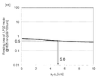
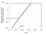
図15にトレンチの幅(a2−a1)を変化させた場合のLP02モードの曲げ損失を示す。このとき、トレンチに対するクラッド層の比屈折率Δ2を0.43[%]とした。図16にトレンチに対するクラッド層の比屈折率Δ2を変化させた場合のLP02モードの曲げ損失を示す。このとき、トレンチの幅(a2−a1)を10[μm]とした。図15より、曲げ損失は、トレンチの幅(a2−a1)により、微調整可能であることが分かる。図16より、曲げ損失は、トレンチに対するクラッド層の比屈折率Δ2により、大きく調整可能であることが分かる。 FIG. 15 shows the LP02 mode bending loss when the trench width (a2-a1) is changed. At this time, the relative refractive index Δ 2 of the cladding layer with respect to the trench was set to 0.43 [%]. Figure 16 shows the LP02 mode bending loss when changing the relative refractive index delta 2 of the clad layer with respect to the trench. At this time, the width (a2-a1) of the trench was set to 10 [μm]. From FIG. 15, it can be seen that the bending loss can be finely adjusted by the width (a2-a1) of the trench. FIG. 16 shows that the bending loss can be largely adjusted by the relative refractive index Δ 2 of the cladding layer with respect to the trench.
全ての伝搬モードにおいて、曲げ半径30mmにおける0.5dB/100turn以下の曲げ損失を得るためには、トレンチの幅(a2−a1)が5.0[μm]以上、トレンチに対するクラッド層の比屈折率Δ2が高さ0.43[%]以下であれば良い。さらにカットオフを考慮した場合、0.4[%]以上が望ましい。 In all propagation modes, in order to obtain a bending loss of 0.5 dB / 100 turn or less at a bending radius of 30 mm, the trench width (a2-a1) is 5.0 [μm] or more, and the relative refractive index of the cladding layer with respect to the trench delta 2 height 0.43 [%] may be any less. Furthermore, when cut-off is considered, 0.4 [%] or more is desirable.
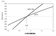
コア部の指数定数αを変えた場合、有限要素法に基づいて計算した高次モード(LP11、LP21、LP02)と基本モード(LP01モード)のDMDの変化を図17に示す。図17に示すように、コア部の指数定数αが1.92〜2.02の時に全ての高次モードにおいてDMDの絶対値が200ps/km以下となる。αが1.97のとき、最もDMDが小さくなる。 FIG. 17 shows changes in DMD between the higher-order modes (LP11, LP21, LP02) and the basic mode (LP01 mode) calculated based on the finite element method when the exponent constant α of the core portion is changed. As shown in FIG. 17, when the exponent constant α of the core is 1.92 to 2.02, the absolute value of DMD is 200 ps / km or less in all higher-order modes. When α is 1.97, DMD is the smallest.
以上の手順により、屈折率分布の各構造パラメータを設定することで、伝搬モード数が4であり、DMDの絶対値が200ps/km以下である数モード光ファイバを製造することができる。この設計手法は伝搬モード数が4よりも大きい場合においても有効である。 By setting each structural parameter of the refractive index distribution by the above procedure, a number mode optical fiber having a propagation mode number of 4 and an DMD absolute value of 200 ps / km or less can be manufactured. This design method is effective even when the number of propagation modes is larger than four.
以上説明したように、本実施形態に係る本数モード光ファイバは、中心軸から外側に向けて屈折率が指数的に小さくなるコアと、前記コアの外側にあり、屈折率が前記コアの屈折率よりも小さいクラッドと、前記コアと前記クラッドとの間にあり、屈折率が前記クラッドの屈折率以下のトレンチと、を有する。コアはトレンチまで指数的に小さくなる。そして、これらの屈折率分布のパラメータを適正にすることで伝搬モード数を2よりも大きくし、伝搬モード間の群遅延差を低減することができる。従って、本実施形態に係る発明は、伝搬モード間の群遅延差を低減できるとともに伝搬モード数を2より大きくすることができる数モード光ファイバ及び光ファイバ伝送システムを提供することができる。 As described above, the number mode optical fiber according to the present embodiment includes the core whose refractive index decreases exponentially from the central axis toward the outside, the outside of the core, and the refractive index is the refractive index of the core. And a trench that is between the core and the cladding and has a refractive index that is less than or equal to the refractive index of the cladding. The core decreases exponentially to the trench. And by making these parameters of the refractive index distribution appropriate, the number of propagation modes can be made larger than 2, and the group delay difference between the propagation modes can be reduced. Therefore, the invention according to the present embodiment can provide a number mode optical fiber and an optical fiber transmission system that can reduce the group delay difference between the propagation modes and can increase the number of propagation modes to more than two.
(実施形態2)
例えば、本実施形態の数モード光ファイバは、実施形態1で説明した数モード光ファイバが少なくとも2本縦続接続されている。
(Embodiment 2)
For example, in the number mode optical fiber of this embodiment, at least two of the number mode optical fibers described in the first embodiment are connected in cascade.
2本の数モード光ファイバは、コアの屈折率の指数定数が特定値のときに高次モードのDMDが最小になる。例えば、図17に示す実施形態1に係る数モード光ファイバであれば、特定値はα=1.97である。
In the two number mode optical fibers, the higher order mode DMD is minimized when the index constant of the refractive index of the core is a specific value. For example, in the case of the number mode optical fiber according to
2本の数モード光ファイバの一方は、コアの屈折率の指数定数αが特定値1.97よりも大きい。2本の数モード光ファイバの他方は、コアの屈折率の指数定数αが特定値1.97よりも小さい。 One of the two number mode optical fibers has an index constant α of the refractive index of the core larger than a specific value of 1.97. In the other of the two number mode optical fibers, the index constant α of the refractive index of the core is smaller than the specific value 1.97.
このように、本実施形態の数モード光ファイバは、光の伝搬方向の区間でコアの指数定数αが異なることを特徴とする。さらに、前記区間が2つ以上である場合、少なくとも1つの区間の指数定数αが1.97以上であり、少なくとも1つの区間の指数定数αが1.97未満であることを特徴とする。 As described above, the number mode optical fiber of the present embodiment is characterized in that the core exponent constant α is different in the section in the light propagation direction. Furthermore, when there are two or more sections, the exponent constant α of at least one section is 1.97 or more, and the exponent constant α of at least one section is less than 1.97.
図17のグラフより、第2高次モードと第3高次モードのDMDがほぼ等しくなっており、群化されており、コア部の指数定数α=1.97を境にDMDが負から正になっている様子が分かる。さらに、コア部の指数定数αに対し各高次モードのDMDは比例の関係である。このことより、作製誤差により1本の光ファイバによる低DMD化が困難な場合においても、DMDが正と負の光ファイバをつなげ、ファイバ長を調整することによりさらなるDMDの低減化が可能である。 From the graph of FIG. 17, the DMDs of the second higher order mode and the third higher order mode are almost equal and grouped, and the DMD increases from negative to positive at the core constant α = 1.97. You can see how it is. Furthermore, the DMD of each higher order mode is proportional to the exponent constant α of the core. As a result, even when it is difficult to reduce the DMD using a single optical fiber due to manufacturing errors, it is possible to further reduce the DMD by connecting the positive and negative optical fibers and adjusting the fiber length. .
例えばα=1.85の負のDMDを有する4モードファイバとα=2.10の正のDMDを有する4モードファイバを同じファイバ長だけ接続することにより、伝搬モード数が4のモード遅延補償伝送路が実現できる。このとき、DMDは100ps/km以下とすることが出来る。 For example, mode delay compensated transmission with a propagation mode number of 4 by connecting a 4-mode fiber having a negative DMD of α = 1.85 and a 4-mode fiber having a positive DMD of α = 2.10 by the same fiber length. A road can be realized. At this time, DMD can be 100 ps / km or less.
以上のように、数モード光ファイバのモード群遅延差を屈折率分布の各パラメータで調整して正又は負とすることができ、正のモード群遅延差の数モード光ファイバと負のモード群遅延差の数モード光ファイバと連結することで、伝搬モード数が4であり、モード群遅延差を100ps/km以下とした数モード光ファイバ(モード遅延補償伝送路)を製造することができる。 As described above, the mode group delay difference of the number mode optical fiber can be adjusted to be positive or negative by adjusting each parameter of the refractive index distribution, and the positive mode group delay difference of the number mode optical fiber and the negative mode group By connecting to a delay mode number mode optical fiber, it is possible to manufacture a number mode optical fiber (mode delay compensation transmission line) having a propagation mode number of 4 and a mode group delay difference of 100 ps / km or less.
実施形態1の設計手法を取ることにより、伝搬モード数が4よりも大きい場合のモード遅延補償伝送路を実現可能である。 By adopting the design method of the first embodiment, it is possible to realize a mode delay compensation transmission line when the number of propagation modes is larger than four.
(実施形態3)
実施形態1に示す図6の屈折率分布を持つ光ファイバを製造する場合、トレンチがシリカであり、コア部、クラッド部にはこれに酸化ゲルマニウム(GeO2)をドープして屈折率を高める手法が一般的だと考える(例えば、非特許文献4参照。)。しかし、コア部やクラッド部へのドープ量が増えるため、製造上の困難さや製造コストの増大が課題になると考えられる。そこで、クラッド層をシリカレベルにし、トレンチはフッ素(F)をドープしてシリカレベルよりも下げる手段が考えられる。図18にこの屈折率分布を示す。
(Embodiment 3)
In the case of manufacturing the optical fiber having the refractive index profile of FIG. 6 shown in the first embodiment, there is a technique in which the trench is silica, and the core portion and the cladding portion are doped with germanium oxide (GeO 2) to increase the refractive index. I think that it is general (for example, refer nonpatent literature 4). However, since the amount of doping into the core and cladding is increased, it is considered that the difficulty in manufacturing and the increase in the manufacturing cost become problems. Therefore, a means is conceivable in which the cladding layer is made to be a silica level and the trench is doped with fluorine (F) to be lower than the silica level. FIG. 18 shows this refractive index distribution.
図18に示す屈折率分布では、グレーデッド型プロファイルを有するコアと、コアの外側にあり、屈折率がコアの屈折率よりも小さいクラッドと、コアとクラッドとの間にあり、屈折率がクラッドの屈折率以下のトレンチとを有する。コアは、外周半径がa1、クラッド層に対する比屈折率がΔ1、指数定数がαである。トレンチは、トレンチの外側境界までの半径がa2であり、クラッド層に対する比屈折率がΔ2であるとする。 In the refractive index distribution shown in FIG. 18, a core having a graded profile, a cladding outside the core and having a refractive index smaller than the refractive index of the core, and between the core and the cladding, the refractive index is clad. And a trench having a refractive index equal to or lower than the above. The core has an outer radius of a 1 , a relative refractive index relative to the cladding layer of Δ 1 , and an exponential constant of α. It is assumed that the trench has a radius to the outer boundary of the trench of a 2 and a relative refractive index of Δ 2 with respect to the cladding layer.
屈折率分布の各パラメータを、a2−a1=11μm、Δ1=0.6%、Δ2=−0.4%、α=2.0とし、コア部外周半径a1を変えた場合のDMDを図19に示す。図19より、図18の屈折率分布では、伝搬モード数の制限かつDMDの低減が不可能であることが分かる。 When each parameter of the refractive index distribution is a 2 −a 1 = 11 μm, Δ 1 = 0.6%, Δ 2 = −0.4%, α = 2.0, and the core part outer radius a 1 is changed The DMD is shown in FIG. From FIG. 19, it can be seen that the refractive index profile in FIG. 18 cannot limit the number of propagation modes and reduce DMD.
参考のため、実施形態1に示す図6の屈折率分布における、屈折率分布の各パラメータがa2−a1=7μm、Δ1=1.0%、Δ2=0.45%、α=2.0とし、コア部外周半径a1を変えた場合のDMDを図20に示す。実施形態1に示す図6の屈折率分布においては、伝搬モード数の制限かつDMDの低減が可能であることが分かる。
For reference, each parameter of the refractive index distribution in the refractive index distribution of FIG. 6 shown in
図18の屈折率分布は図6の屈折率分布と比較し、トレンチまでグレーデッド形状が保持されておらず、そのため、DMDが大きな値となると考えられる。
そこで、図21の屈折率分布により、上記の課題を解決する。
Compared with the refractive index distribution of FIG. 6, the refractive index distribution of FIG. 18 does not maintain a graded shape up to the trench, and therefore it is considered that DMD has a large value.
Therefore, the above problem is solved by the refractive index distribution of FIG.
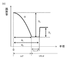
図21の屈折率分布では、グレーデッド型プロファイルを有するコアと、コアの外側にあり、屈折率がコアの屈折率以下の第1のクラッドと、第1のクラッドの外側にあり、屈折率が第1のクラッドの屈折率より小さいトレンチと、トレンチの外側にあり、屈折率が第1のクラッドの屈折率と等しい第2のクラッドを有する。コアは、外周半径がa1、クラッド層に対する比屈折率がΔ1、指数定数がαである。トレンチは、トレンチの内側境界までの半径がa2、トレンチの外側境界までの半径がa3であり、クラッド層に対する比屈折率がΔ2であるとする。特に、コアとトレンチとの間に、幅(a2−a1)の第1のクラッドを設けることを特徴とする。 In the refractive index profile of FIG. 21, a core having a graded profile, a first cladding that is outside the core and having a refractive index equal to or lower than the refractive index of the core, and the first cladding are outside the refractive index. A trench having a refractive index smaller than that of the first cladding and a second cladding outside the trench and having a refractive index equal to that of the first cladding. The core has an outer radius of a 1 , a relative refractive index relative to the cladding layer of Δ 1 , and an exponential constant of α. The trench has a radius to the inner boundary of the trench a 2 , a radius to the outer boundary of the trench a 3 , and a relative refractive index with respect to the cladding layer of Δ 2 . In particular, a first clad having a width (a 2 −a 1 ) is provided between the core and the trench.
例えば、屈折率分布の各パラメータが、第1のクラッドの幅であるコアとトレンチとの間隔a2−a1=1.5μm、トレンチの幅a3−a2=11μm、Δ1=0.6%、Δ2=−0.4%、α=2.0とし、コアの外周半径a1を変えた場合のDMDを図22に示す。図22より図20と同等のDMDが得られていることが分かる。コア部の外周半径a1が10.4〜13.0μmの場合、伝搬モード数が4かつDMDの絶対値が200ps/km以下の光ファイバが実現可能であることが分かる。このように、コアとトレンチとの間隔(a2−a1)を設けることで、あたかもトレンチまでグレーデッド形状であるように模擬することが可能である。
For example, each parameter of the refractive index distribution includes a core-trench distance a 2 −a 1 = 1.5 μm, a trench width a 3 −a 2 = 11 μm, and Δ 1 = 0. FIG. 22 shows a DMD when 6%, Δ 2 = −0.4%, α = 2.0, and the outer peripheral radius a 1 of the core is changed. FIG. 22 shows that a DMD equivalent to that in FIG. 20 is obtained. If the outer peripheral radius a 1 of the core portion of 10.4~13.0Myuemu, it can be seen the absolute value of the number of
まず、コア部外周半径a1=12.0μm、Δ1=0.6%、Δ2=−0.4%、α=2.0を固定し、コアとトレンチとの間隔a2−a1を変化させた場合を考える。図23にコアとトレンチとの間隔a2−a1を変化させた時のDMDを示す。図22よりコアとトレンチとの間隔a2−a1が1.3〜1.9μmの時に全ての高次モード(LP11,LP21、LP02モード)においてDMDの絶対値が200ps/km以下になる。コアとトレンチとの間隔が大きくなりすぎる場合、グレーデッド形状を模擬することが出来なくなっていると考えられる。以上、コアとトレンチとの間隔a2−a1を調整することにより、4モード動作にて低DMD化が可能である。 First, the core portion outer radius a 1 = 12.0 μm, Δ 1 = 0.6%, Δ 2 = −0.4%, α = 2.0 are fixed, and the interval between the core and the trench a 2 −a 1 Consider the case of changing. FIG. 23 shows a DMD when the interval a 2 -a 1 between the core and the trench is changed. From FIG. 22, when the distance a 2 -a 1 between the core and the trench is 1.3 to 1.9 μm, the absolute value of DMD becomes 200 ps / km or less in all higher-order modes (LP11, LP21, LP02 modes). If the distance between the core and the trench becomes too large, it is considered that the graded shape cannot be simulated. As described above, by adjusting the interval a 2 -a 1 between the core and the trench, the DMD can be reduced by the four-mode operation.
次に、シリカのレベルを変化させた場合を考える。
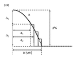
図24に理想となるコア半径a、比屈折率差Δ、指数定数αのグレーデッド型プロファイルおよび、Δ1とΔ2の比を変化させた場合の提案する光ファイバのプロファイルを示す。このとき、|Δ1|+|Δ2|=Δである。
Next, consider a case where the silica level is changed.
Core radius a, the relative refractive index difference to be ideal in Figure 24 delta, graded profile and exponential constants alpha, showing the profile of the optical fiber proposed in the case of changing the ratio of delta 1 and delta 2. At this time, | Δ 1 | + | Δ 2 | = Δ.
以下、図25を参照しながら、伝搬モード数が2よりも大きい低DMD数モード光ファイバの設計方法について詳細に説明する。本実施形態に係る数モード光ファイバの設計方法は、コア理想値設計手順(S201)と、比屈折率差設計手順(S202)と、クラッド幅設計手順(S203)と、を順に有する。1例として、伝搬モードが4(LP01、LP11、LP21、LP02モード)、DMDが200ps/km以下の光ファイバを設計目標とする。波長は1550nmにて考慮する。 Hereinafter, a design method of a low DMD number mode optical fiber having a propagation mode number larger than 2 will be described in detail with reference to FIG. The design method of the number mode optical fiber according to the present embodiment includes a core ideal value design procedure (S201), a relative refractive index difference design procedure (S202), and a cladding width design procedure (S203) in this order. As an example, an optical fiber having a propagation mode of 4 (LP01, LP11, LP21, LP02 mode) and a DMD of 200 ps / km or less is a design target. The wavelength is considered at 1550 nm.
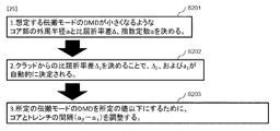
まず、コア理想値設計手順(S201)を実行し、想定する伝搬モードのDMDが小さくなるようなコア部の外周半径aと比屈折率差Δ、指数定数αを決める。例えば、コアの外周半径a及び比屈折率差Δを変化させた時の使用波長帯における各高次モードのDMDを算出し、各高次モードDMDが予め定められた条件をみたすように、コアの外周半径の理想値a及び比屈折率差の理想値Δを求める。 First, the core ideal value design procedure (S201) is executed, and the outer peripheral radius a, the relative refractive index difference Δ, and the exponent constant α are determined so that the DMD of the assumed propagation mode becomes small. For example, the DMD of each higher-order mode in the wavelength band to be used when the outer peripheral radius “a” and the relative refractive index difference Δ are changed is calculated so that each higher-order mode DMD satisfies a predetermined condition. The ideal value a of the outer peripheral radius and the ideal value Δ of the relative refractive index difference are obtained.
本実施形態では、使用波長帯が1550nmであり、予め定められた条件は200ps/km以下である。LP11、LP21、LP02モードのDMDが0〜200ps/kmになるよう、理想となるグレーデッド型プロファイルの構造パラメータとして実施形態1で示したように、コア部の外周半径の理想値aを16[μm]、比屈折率差の理想値Δを1.0[%]、指数定数αを2.0とする。 In the present embodiment, the used wavelength band is 1550 nm, and the predetermined condition is 200 ps / km or less. As shown in the first embodiment, the ideal value a of the outer peripheral radius of the core portion is set to 16 [ μm], the ideal value Δ of the relative refractive index difference is 1.0 [%], and the exponential constant α is 2.0.
次に、比屈折率差設計手順(S202)を実行し、クラッドからの比屈折率差Δ1を決めることで、Δ2、およびa1が自動的に決定される。式1より、Δ/aaの値が等しくなれば、中心からa1まで同じ形状となる。例えば、クラッドの比屈折率差|Δ1|とトレンチの比屈折率差|Δ2|の和がコア理想値設計手順で求めた比屈折率差の理想値Δとなるように、|Δ1|及び|Δ2|を求める。これにより、式1のα乗屈折率分布関数を用いて、コアの外周半径a1が算出可能になる。
Then, run the relative refractive index difference design procedure (S202), by determining the relative refractive index difference delta 1 from clad, Delta] 2, and a 1 are determined automatically. From
本実施形態では、コア部の外周半径の理想値aは16[μm]、比屈折率差の理想値Δは1.0[%]である。Δ1=0.4[%]の場合、Δ2=−0.6[%]であり、|Δ2/Δ1|=1.5となる。a1は式1より10.1[μm]と定まる。Δ1=0.6[%]の場合、Δ2=−0.4[%]であり、Δ2/Δ1=0.67となる。a1は式1より12.4[μm]と定まる。Δ1=0.8[%]の場合、Δ2=−0.2[%]であり、Δ2/Δ1=0.25となる。a1は式1より14.3[μm]と定まる。
In the present embodiment, the ideal value a of the outer peripheral radius of the core portion is 16 [μm], and the ideal value Δ of the relative refractive index difference is 1.0 [%]. In the case of Δ 1 = 0.4 [%], Δ 2 = −0.6 [%], and | Δ 2 / Δ 1 | = 1.5. a 1 is determined to be 10.1 [μm] from
次に、クラッド幅設計手順(S203)を実行し、所定の伝搬モードのDMDが所定の値以下になるように、コアとトレンチの間隔すなわち第1のクラッドの幅(a2−a1)を調整する。例えば、比屈折率差設計手順で求めた組み合わせごとに、コア理想値設計手順で求めた指数定数αのときの指数関数を用いてコアの外周半径a1を求める。そして、当該コアの外周半径a1を用いて第1のクラッドの幅(a2−a1)を変化させたときの各高次モードのDMDを算出する。そして、算出した各高次モードのDMDが予め定められた条件をみたすようなコアの外周半径a1と第1のクラッドの外周半径a2の組み合わせで求められる外周半径の比a2/a1の範囲を求める。予め定められた条件は、例えば、DMDの絶対値が200ps/km以下である。 Next, a cladding width design procedure (S203) is executed, and the interval between the core and the trench, that is, the width of the first cladding (a 2 −a 1 ) is set so that the DMD of a predetermined propagation mode is not more than a predetermined value. adjust. For example, for each combination obtained by the relative refractive index difference design procedure, the outer peripheral radius a1 of the core is obtained using an exponential function when the exponent constant α is obtained by the core ideal value design procedure. Then, the DMD of each higher order mode when the width (a 2 −a 1 ) of the first clad is changed using the outer peripheral radius a1 of the core is calculated. The range of the outer radius ratio a 2 / a 1 determined by the combination of the outer radius a 1 of the core and the outer radius a 2 of the first cladding so that the calculated DMD of each higher order mode satisfies a predetermined condition. Ask for. The predetermined condition is, for example, that the absolute value of DMD is 200 ps / km or less.
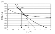
図26(a)に、Δ1を0.4[%]、Δ2を−0.6[%]、|Δ2/Δ1|を1.5、コア部の外周半径a1を10.1[μm]に固定し、コアとトレンチとの間隔a2−a1を変化させた時のDMDを示す。図26(a)より、コアとトレンチとの間隔a2−a1が2.4〜2.6[μm]の時に全ての高次モード(LP11、LP21、LP02モード)においてDMDの絶対値が200ps/km以下になる。このとき、a2/a1の範囲は1.24〜1.26である。 26A, Δ 1 is 0.4 [%], Δ 2 is −0.6 [%], | Δ 2 / Δ 1 | is 1.5, and the outer peripheral radius a 1 of the core portion is 10. The DMD is shown when the distance a 2 -a 1 between the core and the trench is changed while being fixed at 1 [μm]. From FIG. 26A, the absolute value of the DMD is obtained in all higher-order modes (LP11, LP21, LP02 modes) when the interval a 2 -a 1 between the core and the trench is 2.4 to 2.6 [μm]. 200 ps / km or less. In this case, the range of a 2 / a 1 is 1.24 to 1.26.
図26(b)に、Δ1を0.6[%]、Δ2を−0.4[%]、|Δ2/Δ1|を0.67、コア部の外周半径a1を12.4[μm]に固定し、コアとトレンチとの間隔a2−a1を変化させた時のDMDを示す。図26(b)より、コアとトレンチとの間隔a2−a1が1.3〜2.1μmの時に全ての高次モード(LP11、LP21、LP02モード)においてDMDの絶対値が200ps/km以下になる。このとき、a2/a1の範囲は1.10〜1.17である。 In FIG. 26B, Δ 1 is 0.6 [%], Δ 2 is −0.4 [%], | Δ 2 / Δ 1 | is 0.67, and the outer peripheral radius a 1 of the core is 12. The DMD is shown when the distance a 2 -a 1 between the core and the trench is changed while being fixed at 4 [μm]. From FIG. 26B, the absolute value of DMD is 200 ps / km in all higher-order modes (LP11, LP21, LP02 modes) when the distance a 2 -a 1 between the core and the trench is 1.3 to 2.1 μm. It becomes the following. At this time, the range of a 2 / a 1 is 1.10 to 1.17.
図26(c)に、Δ1を0.8%、Δ2を−0.2%、|Δ2/Δ1|を0.25、コア部の外周半径a1を14.3μmに固定し、コアとトレンチとの間隔a2−a1を変化させた時のDMDを示す。図26(c)より、コアとトレンチとの間隔a2−a1が0.1以上の時に全ての高次モード(LP11、LP21、LP02モード)においてDMDの絶対値が200ps/km以下になる。このとき、a2/a1の範囲は1.01以上である。 Figure 26 (c), Δ 1 to 0.8%, delta 2 to -0.2%, | Δ 2 / Δ 1 | 0.25, secure the outer peripheral radius a 1 of the core portion to 14.3μm The DMD when the distance a 2 -a 1 between the core and the trench is changed is shown. From FIG. 26 (c), the absolute value of DMD becomes 200 ps / km or less in all higher-order modes (LP11, LP21, LP02 modes) when the distance a 2 -a 1 between the core and the trench is 0.1 or more. . At this time, the range of a 2 / a 1 is 1.01 or more.
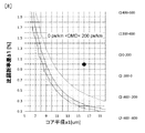
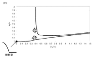
このように、|Δ2/Δ1|を変化(Δ1:変数、Δ2:固定)させ、DMDの絶対値が200ps/km以下になるa2/a1(a1:固定、a2:変数)の範囲を求めた結果、図27に示す設計範囲が得られる。2つの曲線に囲まれた領域が伝搬モード数4にてDMDの絶対値が200ps/km以下になる領域である。 Thus, | Δ2 / Δ1 | is changed (Δ 1 : variable, Δ 2 : fixed), and the absolute value of DMD becomes 200 ps / km or less, a 2 / a 1 (a 1 : fixed, a 2 : variable) 27), the design range shown in FIG. 27 is obtained. A region surrounded by two curves is a region where the absolute value of DMD is 200 ps / km or less when the number of propagation modes is four.
実施形態1より、DMDはトレンチに対するクラッド層の比屈折率の影響を受けない。トレンチの幅について、伝搬モード数やDMDにほとんど影響がない。したがって、本実施形態においてもコア部の|Δ2/Δ1|およびa2/a1のみの設計にてDMDの制御が可能である。
From
最後に、所定のモード数のみが伝搬するための調整として、実施形態1にて示したように、曲げ損失調整手順(S103)を実行し、トレンチの幅およびトレンチに対する外側のクラッド層の比屈折率差をシリカのレベルから調整し、想定する伝搬モードの曲げ損失を調整する。本実施形態では、クラッド幅設計手順で求めた図27に示すa2/a1の範囲に含まれる比屈折率差Δ1及びΔ2、コアの外周半径a1並びに第1のクラッドの外周半径a2の組み合わせを用いて、使用波長帯における曲げ損失を算出する。そして、算出した曲げ損失が予め定められた条件をみたすように、比屈折率差Δ1及びΔ2、コアの外周半径a1並びに第1のクラッドの外周半径a2を求める。ここで、予め定められた条件は、例えば、使用波長帯において曲げ半径30mmにおける曲げ損失が0.5dB/100turn以下である。 Finally, as an adjustment for propagating only a predetermined number of modes, the bending loss adjustment procedure (S103) is executed as shown in the first embodiment, and the trench width and the relative refraction of the outer cladding layer with respect to the trench are performed. The rate difference is adjusted from the silica level, and the bending loss of the assumed propagation mode is adjusted. In the present embodiment, a combination of the relative refractive index differences Δ1 and Δ2, the core outer radius a1, and the first cladding outer radius a2 included in the range of a 2 / a 1 shown in FIG. Is used to calculate the bending loss in the used wavelength band. Then, the relative refractive index differences Δ1 and Δ2, the core outer radius a1, and the first cladding outer radius a2 are determined so that the calculated bending loss satisfies a predetermined condition. Here, the predetermined condition is, for example, that the bending loss at a bending radius of 30 mm is 0.5 dB / 100 turn or less in the used wavelength band.
以上の手順により、屈折率分布の各構造パラメータを設定することで、伝搬モード数が4であり、DMDの絶対値が200ps/km以下とした数モード光ファイバを製造することができる。構造パラメータが6つあるが、以上の手順によりΔ1およびa2のみを調整することで容易に所定のモード数のみが伝搬し、低DMDである数モード光ファイバが実現可能である。この設計手法は伝搬モード数が4よりも大きい場合においても有効である。 By setting each structural parameter of the refractive index distribution by the above procedure, a number mode optical fiber having a propagation mode number of 4 and an absolute value of DMD of 200 ps / km or less can be manufactured. Although there are six structural parameters, by adjusting only Δ1 and a 2 by the above procedure, only a predetermined number of modes can be easily propagated, and a low-DMD number-mode optical fiber can be realized. This design method is effective even when the number of propagation modes is larger than four.
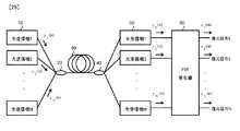
(実施形態4)
図28は、本実施形態の光ファイバ伝送システムの概略図である。光ファイバ伝送システムは、
N個のデータを光信号としてそれぞれ送信するN個(Nは2以上の整数)の光送信機10と、
光送信機10からのN個の光信号を伝搬モードが異なるように合波する合波器20と、
合波器20からの光信号を伝搬する数モード光伝送路30と、
数モード光伝送路30からの光信号を異なる分岐比で分波する分波器40と、
分波器40からの光信号を受信するM個(MはN以上の整数)の光受信機50と、
光受信機50が出力するM個の電気信号から、数モード光伝送路30の伝搬中に生じた信号劣化を補償し、光送信機10が送信したN個のデータを復元するデータ復元部として機能するFIR等化器60と、
を備える。
(Embodiment 4)
FIG. 28 is a schematic diagram of the optical fiber transmission system of the present embodiment. Optical fiber transmission system
N (N is an integer of 2 or more)
A
A number mode
A
M optical receivers 50 (M is an integer equal to or greater than N) for receiving optical signals from the
As a data restoration unit that compensates for signal degradation caused during propagation in the several-mode
Is provided.
N個(Nは2以上の整数)の送信機10から発せられるN種の信号(x(n))は合波器20において結合する伝搬モード比率が異なるように合波される。伝搬モード比率とは、数モード光伝送路30で伝搬する各伝搬モードの強度の割合である。数モード光伝送路30は、実施形態1又は3で説明した数モード光ファイバを用いた光伝送路である。数モード光伝送路30は、実施形態2で説明したように、αの異なる複数の数モード光ファイバを縦続接続することでDMD補償機能をもたせた数モード光ファイバを用いてもよい。この場合、縦続接続する数モード光ファイバは、実施形態1の数モード光ファイバであってもよいし、実施形態3の数モード光ファイバであってもよい。伝送した信号の復元度を考慮した場合、伝搬モード比率は光信号ごとに大きく異なることが望ましい。例えば、合波器20は、ファイバのコアへ光を照射する場所を変えることで任意のモードが励振可能な3次元導波路構造の合波器が望ましい。
N types of signals (x (n)) emitted from N (N is an integer of 2 or more)
合波された光信号は数モード光伝送路30中に入射され、出射側に設置された分波器40において異なる分岐比でMポート(MはN以上の整数)に分波される。分岐比率についても合波器20と同様に、全ての伝搬モードが完全に同比率とならないように光信号を分岐する。信号の復元度を考慮した場合、分岐比率はポートごとに大きく異なることが望ましい。
The multiplexed optical signal enters the several-mode
分波されたM種の信号(y(n))はM個の受信機50で受信され、後段に設置されたFIR等化器60において数モード光ファイバで受けた信号劣化を補償し、復元信号(u(n))を得る。光ファイバ伝送システムは、N入力M出力のMIMO伝送であり、N種の信号の並列伝送が可能である。
なお、FIR等化器60では、モード分散、波長分散、偏波分散の補償も可能である。また、受信信号の電界振幅及び位相情報を取得するためには、局発光源、90°光ハイブリッド、バランスレシーバ、アナログデジタルコンバータ、及び計算器で受信機50を構成する。
The demultiplexed M kinds of signals (y (n)) are received by the
The
FIR等化器60は、数モード光伝送路30中で発生する線形歪を補償することができ、タップの遅延量及び係数を適切に設定することで、数モード光伝送路30中で発生する他送信機からの混信、モード分散、波長分散、偏波分散による信号劣化を補償することができる。ただし、モード分散による信号劣化を補償する場合、基本モード及び高次モードのモード群遅延差が大きくなると、信号劣化補償に必要な計算量が膨大になる。しかし、光ファイバ伝送システムは、モード群遅延差が小さい数モード光伝送路30を用いており、補償に必要な計算量を少なくできる。さらに、伝搬モード数が2よりも大きいため、大容量化も可能である。換言すれば、数モード光伝送路30を備えることで、従来のFIR等化器のままで伝送システムの大容量化や長距離化が可能である。
The
以上説明したように、本光ファイバ伝送システムは、光の伝搬モードの群遅延差を低減できる数モード光ファイバを備えており、受信時のデジタル信号処理の負荷を低減できる。従って、本実施形態に係る発明は、信号の復元に必要なデジタル処理の負荷を低減できる光ファイバ伝送システムを提供することができる。 As described above, the present optical fiber transmission system includes the number mode optical fiber that can reduce the group delay difference in the light propagation mode, and can reduce the load of digital signal processing during reception. Therefore, the invention according to this embodiment can provide an optical fiber transmission system that can reduce the load of digital processing necessary for signal restoration.
本発明は、ファイバ中の高次モードの利用により光ファイバ伝送の大容量化及び長距離化を実現することができる。 The present invention can realize a large capacity and a long distance of optical fiber transmission by using a higher-order mode in the fiber.
10:光送信機
20:合波器
30:数モード光伝送路
40:分波器
50:光受信機
60:FIR等化器
10: optical transmitter 20: multiplexer 30: number mode optical transmission line 40: demultiplexer 50: optical receiver 60: FIR equalizer
Claims (1)
前記コアの外側に配置され、半径a1からa2において屈折率が一様かつ半径a1において屈折率が前記コアの屈折率と等しい第1のクラッドと、
前記第1のクラッドの外側に配置され、半径a2からa3において屈折率が一様かつ前記第1のクラッドの屈折率よりも小さいトレンチと、
前記トレンチの外側に配置され、屈折率が前記第1のクラッドと等しい第2のクラッドと、
を備え、
前記コアの中心と前記第1のクラッドの比屈折率差はΔ1であり、
前記第1のクラッドと前記トレンチの比屈折率差はΔ2であり、
前記第1のクラッド及び第2のクラッドの屈折率はシリカレベルであり、
前記トレンチは屈折率をシリカレベルよりも下げるドーパントを含み、
前記Δ1とΔ2の絶対値の和を比屈折率差Δとし、
前記コアが中心軸から指数関数的に減少し、外周半径aにおいて比屈折率差がΔとなる屈折率分布形状を、前記第1のクラッドおよびトレンチにより模擬するようにΔ1、Δ2、a1、a2、およびa3を設定する、数モード光ファイバの設計方法であって、
前記コアの外周半径a及び比屈折率差Δを変化させた時の使用波長帯における想定する伝搬モードのDMDを算出し、各高次モードDMDが所定値をみたすように、前記指数関数の指数定数α、前記コアの外周半径a及び比屈折率差Δの理想値を求めるコア理想値設計手順と、
前記Δ1の絶対値と前記Δ2の絶対値の和が前記コア理想値設計手順で求めた比屈折率差Δの理想値とする比屈折率差設計手順と、
前記比屈折率差設計手順で求めたΔ1と、前記コア理想値設計手順で求めた前記指数定数αのときの前記屈折率分布において、Δ―Δ1となる屈折率の半径a1を(数1)を用いて求め、当該半径a1を用いて前記第1のクラッドの幅を変化させたときの各高次モードのDMDを算出し、算出した各高次モードのDMDが前記予め定められた条件をみたすような前記半径a1と前記半径a2を求めるクラッド幅設計手順と、
前記比屈折率差設計手順とクラッド幅設計手順で求めたΔ1、Δ2、a1、a2を用いて、使用波長帯において所定のモード数のみが伝搬するように、トレンチ幅a3により曲げ損失を調整する、トレンチ幅設計手順と、
を順に有する数モード光ファイバの設計方法。
(数1)
ただし、rは中心から半径方向の距離、
n(r)は中心から半径方向の距離rにおける屈折率、
n1はコア中心の屈折率、
とする。
A core whose refractive index decreases exponentially with an exponential constant α from the central axis toward the radius a1 toward the outside;
A first cladding disposed outside the core, having a uniform refractive index at radii a1 to a2 and a refractive index equal to the refractive index of the core at a radius a1 ;
A trench disposed outside the first cladding and having a uniform refractive index at radii a2 to a3 and smaller than the refractive index of the first cladding;
A second cladding disposed outside the trench and having a refractive index equal to the first cladding;
With
The relative refractive index difference between the center of the core and the first cladding is Δ1,
The relative refractive index difference between the first cladding and the trench is Δ2,
The refractive index of the first cladding and the second cladding is at a silica level,
The trench includes a dopant that lowers the refractive index below the silica level;
The sum of absolute values of Δ1 and Δ2 is a relative refractive index difference Δ,
Δ1, Δ2, a1, a2 so that the core decreases exponentially from the central axis and the refractive index distribution shape in which the relative refractive index difference becomes Δ at the outer peripheral radius a is simulated by the first cladding and the trench. And a3 , a number mode optical fiber design method comprising:
An exponent of the exponential function is calculated so as to calculate a DMD of an assumed propagation mode in a used wavelength band when the outer peripheral radius a of the core and the relative refractive index difference Δ are changed, and each higher-order mode DMD satisfies a predetermined value. A core ideal value design procedure for obtaining an ideal value of a constant α, an outer peripheral radius a of the core, and a relative refractive index difference Δ;
A relative refractive index difference design procedure in which the sum of the absolute value of Δ1 and the absolute value of Δ2 is an ideal value of the relative refractive index difference Δ obtained by the core ideal value design procedure;
In the refractive index distribution when Δ1 obtained in the relative refractive index difference design procedure and the exponential constant α obtained in the core ideal value design procedure, the radius a1 of the refractive index that becomes Δ−Δ1 is expressed by The DMD of each higher-order mode when the width of the first cladding is changed using the radius a1 is calculated, and the calculated DMD of each higher-order mode satisfies the predetermined condition. A cladding width design procedure for determining the radius a1 and the radius a2;
Using Δ1, Δ2, a1, a2 obtained in the relative refractive index difference design procedure and the cladding width design procedure, the bending loss is adjusted by the trench width a3 so that only a predetermined number of modes propagate in the used wavelength band. , Trench width design procedure ,
A method of designing a number mode optical fiber having
(Equation 1)
Where r is the radial distance from the center,
n (r) is the refractive index at a distance r in the radial direction from the center,
n1 is the refractive index of the core center,
And
Priority Applications (1)
| Application Number | Priority Date | Filing Date | Title |
|---|---|---|---|
| JP2018099856A JP6568979B2 (en) | 2018-05-24 | 2018-05-24 | Design method for number mode optical fiber |
Applications Claiming Priority (1)
| Application Number | Priority Date | Filing Date | Title |
|---|---|---|---|
| JP2018099856A JP6568979B2 (en) | 2018-05-24 | 2018-05-24 | Design method for number mode optical fiber |
Related Parent Applications (1)
| Application Number | Title | Priority Date | Filing Date |
|---|---|---|---|
| JP2014095098A Division JP2015212757A (en) | 2014-05-02 | 2014-05-02 | Multi-mode optical fiber and design method of multi-mode optical fiber |
Publications (2)
| Publication Number | Publication Date |
|---|---|
| JP2018146973A JP2018146973A (en) | 2018-09-20 |
| JP6568979B2 true JP6568979B2 (en) | 2019-08-28 |
Family
ID=63590039
Family Applications (1)
| Application Number | Title | Priority Date | Filing Date |
|---|---|---|---|
| JP2018099856A Active JP6568979B2 (en) | 2018-05-24 | 2018-05-24 | Design method for number mode optical fiber |
Country Status (1)
| Country | Link |
|---|---|
| JP (1) | JP6568979B2 (en) |
Family Cites Families (5)
| Publication number | Priority date | Publication date | Assignee | Title |
|---|---|---|---|---|
| JPH1164665A (en) * | 1997-06-13 | 1999-03-05 | Sumitomo Electric Ind Ltd | Optical fiber |
| JP5330729B2 (en) * | 2008-04-16 | 2013-10-30 | 三菱電線工業株式会社 | Graded index multimode optical fiber |
| US8670643B2 (en) * | 2011-05-18 | 2014-03-11 | Corning Incorporated | Large effective area optical fibers |
| IN2014DN07356A (en) * | 2012-02-20 | 2015-04-24 | Corning Inc | |
| US8948559B2 (en) * | 2012-09-05 | 2015-02-03 | Ofs Fitel, Llc | Multiple LP mode fiber designs for mode division multiplexing |
-
2018
- 2018-05-24 JP JP2018099856A patent/JP6568979B2/en active Active
Also Published As
| Publication number | Publication date |
|---|---|
| JP2018146973A (en) | 2018-09-20 |
Similar Documents
| Publication | Publication Date | Title |
|---|---|---|
| JP6397899B2 (en) | Low mode fiber optic optical link for space division multiplexing. | |
| JP6397898B2 (en) | Low-mode optical fiber for space division multiplexing. | |
| JP6177994B2 (en) | Multi-core fiber | |
| CN113711094B (en) | Multi-core optical fiber and design method | |
| JP5193398B2 (en) | Optical fiber and optical transmission system | |
| WO2014038512A1 (en) | Optical fiber | |
| JP5242405B2 (en) | Optical fiber and optical fiber transmission line | |
| JP5059797B2 (en) | Optical fiber, optical fiber design method, and optical wavelength division multiplexing communication system | |
| JP4851371B2 (en) | Optical fiber and optical fiber transmission line | |
| JP6368279B2 (en) | Number mode optical fiber and optical fiber transmission system | |
| WO2020032016A1 (en) | Intermode loss difference compensation fiber, optical amplifier, and transmission path design method | |
| JP2015515765A (en) | Mode delay managed minority mode fiber optic links. | |
| JP2012063697A (en) | Multi-mode fiber and design method thereof | |
| CN110741293B (en) | Optical fiber and optical transmission system | |
| JP7024973B2 (en) | Number mode multi-core optical fiber | |
| US12019267B2 (en) | Multicore optical fiber and design method | |
| JP2015022083A (en) | Multimode optical fiber and optical fiber transmission system | |
| JP5937974B2 (en) | Multimode optical fiber and optical fiber transmission system | |
| JP2015212757A (en) | Multi-mode optical fiber and design method of multi-mode optical fiber | |
| JP6568979B2 (en) | Design method for number mode optical fiber | |
| JP6258618B2 (en) | Multi-core optical fiber | |
| WO2015053369A1 (en) | Optical fibre, and optical transmission system | |
| JP6048890B2 (en) | Optical fiber | |
| JP5702707B2 (en) | Optical fiber and optical fiber transmission system | |
| JP5486138B2 (en) | Optical fiber and optical transmission line |
Legal Events
| Date | Code | Title | Description |
|---|---|---|---|
| A621 | Written request for application examination |
Free format text: JAPANESE INTERMEDIATE CODE: A621 Effective date: 20180524 |
|
| A131 | Notification of reasons for refusal |
Free format text: JAPANESE INTERMEDIATE CODE: A131 Effective date: 20190228 |
|
| A977 | Report on retrieval |
Free format text: JAPANESE INTERMEDIATE CODE: A971007 Effective date: 20190227 |
|
| A521 | Request for written amendment filed |
Free format text: JAPANESE INTERMEDIATE CODE: A523 Effective date: 20190418 |
|
| TRDD | Decision of grant or rejection written | ||
| A01 | Written decision to grant a patent or to grant a registration (utility model) |
Free format text: JAPANESE INTERMEDIATE CODE: A01 Effective date: 20190730 |
|
| A61 | First payment of annual fees (during grant procedure) |
Free format text: JAPANESE INTERMEDIATE CODE: A61 Effective date: 20190805 |
|
| R150 | Certificate of patent or registration of utility model |
Ref document number: 6568979 Country of ref document: JP Free format text: JAPANESE INTERMEDIATE CODE: R150 |