JP6568214B2 - Multistage skip fire - Google Patents
Multistage skip fire Download PDFInfo
- Publication number
- JP6568214B2 JP6568214B2 JP2017523940A JP2017523940A JP6568214B2 JP 6568214 B2 JP6568214 B2 JP 6568214B2 JP 2017523940 A JP2017523940 A JP 2017523940A JP 2017523940 A JP2017523940 A JP 2017523940A JP 6568214 B2 JP6568214 B2 JP 6568214B2
- Authority
- JP
- Japan
- Prior art keywords
- ignition
- combustion
- combustion cycle
- engine
- cycle
- Prior art date
- Legal status (The legal status is an assumption and is not a legal conclusion. Google has not performed a legal analysis and makes no representation as to the accuracy of the status listed.)
- Active
Links
Images


Classifications
-
- F—MECHANICAL ENGINEERING; LIGHTING; HEATING; WEAPONS; BLASTING
- F02—COMBUSTION ENGINES; HOT-GAS OR COMBUSTION-PRODUCT ENGINE PLANTS
- F02D—CONTROLLING COMBUSTION ENGINES
- F02D41/00—Electrical control of supply of combustible mixture or its constituents
- F02D41/008—Controlling each cylinder individually
- F02D41/0087—Selective cylinder activation, i.e. partial cylinder operation
-
- F—MECHANICAL ENGINEERING; LIGHTING; HEATING; WEAPONS; BLASTING
- F02—COMBUSTION ENGINES; HOT-GAS OR COMBUSTION-PRODUCT ENGINE PLANTS
- F02D—CONTROLLING COMBUSTION ENGINES
- F02D41/00—Electrical control of supply of combustible mixture or its constituents
- F02D41/0002—Controlling intake air
-
- F—MECHANICAL ENGINEERING; LIGHTING; HEATING; WEAPONS; BLASTING
- F02—COMBUSTION ENGINES; HOT-GAS OR COMBUSTION-PRODUCT ENGINE PLANTS
- F02D—CONTROLLING COMBUSTION ENGINES
- F02D13/00—Controlling the engine output power by varying inlet or exhaust valve operating characteristics, e.g. timing
- F02D13/02—Controlling the engine output power by varying inlet or exhaust valve operating characteristics, e.g. timing during engine operation
- F02D13/0257—Independent control of two or more intake or exhaust valves respectively, i.e. one of two intake valves remains closed or is opened partially while the other is fully opened
-
- F—MECHANICAL ENGINEERING; LIGHTING; HEATING; WEAPONS; BLASTING
- F02—COMBUSTION ENGINES; HOT-GAS OR COMBUSTION-PRODUCT ENGINE PLANTS
- F02D—CONTROLLING COMBUSTION ENGINES
- F02D13/00—Controlling the engine output power by varying inlet or exhaust valve operating characteristics, e.g. timing
- F02D13/02—Controlling the engine output power by varying inlet or exhaust valve operating characteristics, e.g. timing during engine operation
- F02D13/06—Cutting-out cylinders
-
- F—MECHANICAL ENGINEERING; LIGHTING; HEATING; WEAPONS; BLASTING
- F02—COMBUSTION ENGINES; HOT-GAS OR COMBUSTION-PRODUCT ENGINE PLANTS
- F02M—SUPPLYING COMBUSTION ENGINES IN GENERAL WITH COMBUSTIBLE MIXTURES OR CONSTITUENTS THEREOF
- F02M35/00—Combustion-air cleaners, air intakes, intake silencers, or induction systems specially adapted for, or arranged on, internal-combustion engines
- F02M35/10—Air intakes; Induction systems
- F02M35/104—Intake manifolds
- F02M35/108—Intake manifolds with primary and secondary intake passages
- F02M35/1085—Intake manifolds with primary and secondary intake passages the combustion chamber having multiple intake valves
-
- F—MECHANICAL ENGINEERING; LIGHTING; HEATING; WEAPONS; BLASTING
- F01—MACHINES OR ENGINES IN GENERAL; ENGINE PLANTS IN GENERAL; STEAM ENGINES
- F01L—CYCLICALLY OPERATING VALVES FOR MACHINES OR ENGINES
- F01L13/00—Modifications of valve-gear to facilitate reversing, braking, starting, changing compression ratio, or other specific operations
- F01L13/0005—Deactivating valves
-
- F—MECHANICAL ENGINEERING; LIGHTING; HEATING; WEAPONS; BLASTING
- F01—MACHINES OR ENGINES IN GENERAL; ENGINE PLANTS IN GENERAL; STEAM ENGINES
- F01L—CYCLICALLY OPERATING VALVES FOR MACHINES OR ENGINES
- F01L2800/00—Methods of operation using a variable valve timing mechanism
- F01L2800/06—Timing or lift different for valves of same cylinder
-
- F—MECHANICAL ENGINEERING; LIGHTING; HEATING; WEAPONS; BLASTING
- F01—MACHINES OR ENGINES IN GENERAL; ENGINE PLANTS IN GENERAL; STEAM ENGINES
- F01L—CYCLICALLY OPERATING VALVES FOR MACHINES OR ENGINES
- F01L9/00—Valve-gear or valve arrangements actuated non-mechanically
- F01L9/10—Valve-gear or valve arrangements actuated non-mechanically by fluid means, e.g. hydraulic
-
- F—MECHANICAL ENGINEERING; LIGHTING; HEATING; WEAPONS; BLASTING
- F01—MACHINES OR ENGINES IN GENERAL; ENGINE PLANTS IN GENERAL; STEAM ENGINES
- F01L—CYCLICALLY OPERATING VALVES FOR MACHINES OR ENGINES
- F01L9/00—Valve-gear or valve arrangements actuated non-mechanically
- F01L9/20—Valve-gear or valve arrangements actuated non-mechanically by electric means
-
- F—MECHANICAL ENGINEERING; LIGHTING; HEATING; WEAPONS; BLASTING
- F02—COMBUSTION ENGINES; HOT-GAS OR COMBUSTION-PRODUCT ENGINE PLANTS
- F02D—CONTROLLING COMBUSTION ENGINES
- F02D41/00—Electrical control of supply of combustible mixture or its constituents
- F02D41/0002—Controlling intake air
- F02D2041/001—Controlling intake air for engines with variable valve actuation
-
- F—MECHANICAL ENGINEERING; LIGHTING; HEATING; WEAPONS; BLASTING
- F02—COMBUSTION ENGINES; HOT-GAS OR COMBUSTION-PRODUCT ENGINE PLANTS
- F02D—CONTROLLING COMBUSTION ENGINES
- F02D2250/00—Engine control related to specific problems or objectives
- F02D2250/18—Control of the engine output torque
-
- F—MECHANICAL ENGINEERING; LIGHTING; HEATING; WEAPONS; BLASTING
- F02—COMBUSTION ENGINES; HOT-GAS OR COMBUSTION-PRODUCT ENGINE PLANTS
- F02N—STARTING OF COMBUSTION ENGINES; STARTING AIDS FOR SUCH ENGINES, NOT OTHERWISE PROVIDED FOR
- F02N11/00—Starting of engines by means of electric motors
- F02N11/08—Circuits or control means specially adapted for starting of engines
- F02N11/0814—Circuits or control means specially adapted for starting of engines comprising means for controlling automatic idle-start-stop
-
- F—MECHANICAL ENGINEERING; LIGHTING; HEATING; WEAPONS; BLASTING
- F02—COMBUSTION ENGINES; HOT-GAS OR COMBUSTION-PRODUCT ENGINE PLANTS
- F02P—IGNITION, OTHER THAN COMPRESSION IGNITION, FOR INTERNAL-COMBUSTION ENGINES; TESTING OF IGNITION TIMING IN COMPRESSION-IGNITION ENGINES
- F02P5/00—Advancing or retarding ignition; Control therefor
- F02P5/04—Advancing or retarding ignition; Control therefor automatically, as a function of the working conditions of the engine or vehicle or of the atmospheric conditions
- F02P5/145—Advancing or retarding ignition; Control therefor automatically, as a function of the working conditions of the engine or vehicle or of the atmospheric conditions using electrical means
- F02P5/15—Digital data processing
- F02P5/152—Digital data processing dependent on pinking
-
- F—MECHANICAL ENGINEERING; LIGHTING; HEATING; WEAPONS; BLASTING
- F02—COMBUSTION ENGINES; HOT-GAS OR COMBUSTION-PRODUCT ENGINE PLANTS
- F02P—IGNITION, OTHER THAN COMPRESSION IGNITION, FOR INTERNAL-COMBUSTION ENGINES; TESTING OF IGNITION TIMING IN COMPRESSION-IGNITION ENGINES
- F02P9/00—Electric spark ignition control, not otherwise provided for
- F02P9/002—Control of spark intensity, intensifying, lengthening, suppression
-
- Y—GENERAL TAGGING OF NEW TECHNOLOGICAL DEVELOPMENTS; GENERAL TAGGING OF CROSS-SECTIONAL TECHNOLOGIES SPANNING OVER SEVERAL SECTIONS OF THE IPC; TECHNICAL SUBJECTS COVERED BY FORMER USPC CROSS-REFERENCE ART COLLECTIONS [XRACs] AND DIGESTS
- Y02—TECHNOLOGIES OR APPLICATIONS FOR MITIGATION OR ADAPTATION AGAINST CLIMATE CHANGE
- Y02T—CLIMATE CHANGE MITIGATION TECHNOLOGIES RELATED TO TRANSPORTATION
- Y02T10/00—Road transport of goods or passengers
- Y02T10/10—Internal combustion engine [ICE] based vehicles
- Y02T10/12—Improving ICE efficiencies
-
- Y—GENERAL TAGGING OF NEW TECHNOLOGICAL DEVELOPMENTS; GENERAL TAGGING OF CROSS-SECTIONAL TECHNOLOGIES SPANNING OVER SEVERAL SECTIONS OF THE IPC; TECHNICAL SUBJECTS COVERED BY FORMER USPC CROSS-REFERENCE ART COLLECTIONS [XRACs] AND DIGESTS
- Y02—TECHNOLOGIES OR APPLICATIONS FOR MITIGATION OR ADAPTATION AGAINST CLIMATE CHANGE
- Y02T—CLIMATE CHANGE MITIGATION TECHNOLOGIES RELATED TO TRANSPORTATION
- Y02T10/00—Road transport of goods or passengers
- Y02T10/10—Internal combustion engine [ICE] based vehicles
- Y02T10/40—Engine management systems
Description
関連出願の相互参照
本出願は、2014年11月10日出願の米国仮特許出願第62/077,439号明細書「Multi Level Dynamic Skip Fire」、2015年2月17日出願の米国仮特許出願第62/117,426号明細書「Multi Level Dynamic Skip Fire」、2015年2月26日出願の米国仮特許出願第62/121,374号明細書「Using Multi−Level Skip Fire」、2015年10月21日出願の米国特許出願第14/919,011号明細書「Multi−level Skip Fire」、および2015年10月21日出願の米国特許出願第14/919,018号明細書「Multi−level Skip Fire」を優先権主張するものであり、各々の全文をあらゆる目的で本明細書に引用している。
This application is related to US Provisional Patent Application No. 62 / 077,439 “Multi Level Dynamic Skip Fire”, filed on Nov. 10, 2014, US Provisional Patent Application filed on February 17, 2015. No. 62 / 117,426, “Multi Level Dynamic Skip Fire”, US Provisional Patent Application No. 62 / 121,374, filed Feb. 26, 2015, “Using Multi-Level Skip Fire”, 2015 October U.S. Patent Application No. 14 / 919,011 "Multi-level Skip Fire" filed on May 21, and US Patent Application No. 14 / 919,018 filed Oct. 21, 2015 "Multi-level" Also claim “Skip Fire” Each of which is incorporated herein in its entirety for all purposes.
本発明は、スキップファイア方式でエンジンを動作させる方法およびシステムに関する。各種の実施形態において、燃焼室を選択的に休止させ、または複数の異なる出力レベルで点火させるスキップファイアエンジン制御システムについて記述する。 The present invention relates to a method and system for operating an engine in a skip fire manner. In various embodiments, a skipfire engine control system is described that selectively deactivates a combustion chamber or ignites at a plurality of different power levels.
今日使用されている車両(および他の多くの装置)の大多数は、内燃(IC)エンジンにより動力を得ている。内燃エンジンは典型的に、燃焼が生じる複数の気筒または他の燃焼室を有している。通常の運転条件下で、内燃エンジンにより生じたトルクは、運転者の操作要求に対応すべく広範囲にわたり変動する必要がある。長年にわたり、内燃エンジントルクを制御する多くの方法が提案および利用されてきた。そのような方法のいくつかは、エンジンの有効排気量を変化させるものである。エンジンの有効排気量を変化させるエンジン制御は二種類の制御方式、すなわち複数固定排気量およびスキップファイアに分類することができる。複数固定排気量制御では、いくつかの気筒の一定の組を低負荷条件下で休止させる、例えば、特定の条件下で同一4個の気筒を動作させることができる8気筒エンジンである。対照的に、スキップファイアエンジン制御は、選択された点火機会中、特定の気筒の点火を選択的に間引くものである。従って、特定の気筒を、あるエンジンサイクルで点火させ、次のエンジンサイクルで休止させ、更に次のサイクルで選択的に休止または点火させることができる。例えば、4気筒エンジンを2気筒置きに点火させることで全エンジン排気量のl/3の有効排気量が得られるが、これは単に一組の気筒を休止させることでは得られない排気量の割合である。同様に、3気筒エンジンを1気筒置きに点火させることで有効排気量1/2が得られるが、これは単に一組の気筒を休止させることでは得られない排気量の割合である。米国特許第8、131、445号明細書(本出願の譲受人により出願され、全文をあらゆる目的で本明細書に引用している)に、各種のスキップファイアエンジン制御の実装例が開示されている。一般に、スキップファイアエンジン制御は、多くの用途で燃費が大幅に向上させる可能性を含む、多くの可能な利ことをもたらすものと理解されている。スキップファイアエンジン制御の概念は長年にわたり知られ、その利点も理解されているにもかかわらず、スキップファイアエンジン制御は依然として顕著な商業的成功を収めていない。 The vast majority of vehicles (and many other devices) in use today are powered by an internal combustion (IC) engine. Internal combustion engines typically have multiple cylinders or other combustion chambers in which combustion occurs. Under normal driving conditions, the torque generated by the internal combustion engine needs to vary over a wide range to accommodate the operating requirements of the driver. Over the years, many methods for controlling internal combustion engine torque have been proposed and utilized. Some such methods change the effective displacement of the engine. Engine control for changing the engine's effective displacement can be classified into two types of control, namely, a plurality of fixed displacements and a skip fire. In the multiple fixed displacement control, a fixed set of several cylinders is stopped under a low load condition, for example, an 8-cylinder engine capable of operating the same four cylinders under a specific condition. In contrast, skip fire engine control selectively decimates the ignition of a particular cylinder during a selected ignition opportunity. Thus, a particular cylinder can be ignited in one engine cycle, paused in the next engine cycle, and selectively paused or ignited in the next cycle. For example, when a 4-cylinder engine is ignited every other cylinder, an effective displacement of 1/3 of the total engine displacement can be obtained, but this is a ratio of the displacement that cannot be obtained by simply stopping a pair of cylinders. It is. Similarly, an effective displacement of ½ is obtained by igniting every other cylinder in a three-cylinder engine, but this is the proportion of the displacement that cannot be obtained by simply deactivating a set of cylinders. U.S. Pat. No. 8,131,445 (filed by the assignee of the present application and incorporated herein in its entirety for all purposes) discloses various implementations of skip fire engine control. Yes. In general, skip fire engine control is understood to provide a number of possible benefits, including the potential for significant improvements in fuel economy in many applications. Although the concept of skipfire engine control has been known for many years and its benefits have been understood, skipfire engine control has not yet achieved significant commercial success.
動作中のエンジンが、当該分野においてNVH(騒音、振動および不快感)として集合的に言及される顕著な騒音および振動の発生源にある傾向があることはよく理解されている。一般に、スキップファイアエンジン制御に伴う固定観念は、エンジンのスキップファイア動作により、従来方式で動作するエンジンと比較してエンジン動作が粗くなる、すなわちNVHが増大するというものである。自動車用途等の多くの用途において、スキップファイアエンジン制御における最も顕著な難点の一つが振動制御である。実際、NVHの懸念に満足に対処できないことが、スキップファイア方式のエンジン制御の広範な普及を阻害してきた主な障害の一つであると考えられる。 It is well understood that an engine in operation tends to be a significant source of noise and vibration, collectively referred to in the art as NVH (noise, vibration and discomfort). In general, the fixed idea associated with skipfire engine control is that engine skipfire operation results in rougher engine operation, ie, increased NVH, compared to engines operating in a conventional manner. In many applications, such as automotive applications, vibration control is one of the most significant difficulties in skip fire engine control. In fact, the inability to satisfactorily address the concerns of NVH is considered to be one of the main obstacles that have prevented the widespread use of skipfire engine control.
米国特許第7,954,474号明細書、第7,886,715号明細書、第7,849,835号明細書、第7,577,511号明細書、第8,099,224号明細書、第8,131,445号明細書および第8,131,447号明細書、並びに米国特許出願第13/004,839号明細書、第13/004,844号明細書その他に、広範な内燃エンジンをスキップファイア動作モードで現実的に動作させる各種のエンジンコントローラが記述されている。これらの特許および特許出願の各々を本明細書に引用している。記述されているコントローラは良好に動作するが、スキップファイア制御下で動作するエンジンにおけるNVH問題を更に軽減させるべく、これらおよび他のスキップファイアエンジンコントローラの性能を更に向上させる努力が継続されている。本出願は、各種の用途におけるエンジン性能の向上を図ることができる追加的なスキップファイア制御特徴および強化策について記述する。 U.S. Patent Nos. 7,954,474, 7,886,715, 7,849,835, 7,577,511, 8,099,224 , 8,131,445 and 8,131,447, as well as U.S. patent applications 13 / 004,839, 13 / 004,844 and others. Various engine controllers have been described that allow an internal combustion engine to operate realistically in a skip fire mode of operation. Each of these patents and patent applications is cited herein. Although the described controller works well, efforts continue to further improve the performance of these and other skipfire engine controllers to further reduce the NVH problem in engines operating under skipfire control. This application describes additional skipfire control features and enhancements that can improve engine performance in various applications.
本発明はスキップファイア制御に関する。一態様において、エンジンを制御する方法について記述する。選択された燃焼サイクルが間引かれて、所望のエンジン出力を伝達すべく選択された稼働燃焼サイクルが点火される。1個以上の燃焼室は、例えば同一カムフェーザおよび/またはMAP(吸気マニホールド絶対圧)設定に対して複数の可能なレベルのトルク出力を発生することができる。特定レベルのトルク出力(例:高または低トルク出力)が、各点火燃焼室(すなわち、点火予定の燃焼室)に対して選択される。これを本明細書では多段スキップファイアエンジン制御と称する。各種の設計において、点火燃焼室に対して高または低トルク出力のいずれが選択されたかに基づいて、点火燃焼室への給気が調整される。各種の実施形態が上述の方法の実装に役立つエンジンコントローラ、ソフトウェア、およびシステムに関係している。 The present invention relates to skip fire control. In one aspect, a method for controlling an engine is described. The selected combustion cycle is decimated to ignite the selected operating combustion cycle to deliver the desired engine power. One or more combustion chambers can generate multiple possible levels of torque output, eg, for the same cam phaser and / or MAP (intake manifold absolute pressure) setting. A particular level of torque output (eg, high or low torque output) is selected for each ignition combustion chamber (ie, the combustion chamber that is to be ignited). This is called multistage skip fire engine control in this specification. In various designs, the charge to the ignition combustion chamber is adjusted based on whether a high or low torque output is selected for the ignition combustion chamber. Various embodiments relate to engine controllers, software, and systems that are useful for implementing the methods described above.
別の態様において、エンジンコントローラについて記述する。エンジンコントローラは複数の燃焼室を含んでいる。各燃焼室は、少なくとも1個のカム作動吸気弁を含んでいる。エンジンコントローラは、点火比計算器、点火タイミング決定モジュール、および点火制御部を含んでいる。点火比計算器は、所望のトルクの伝達に適した点火比を決定すべく構成されている。点火タイミング決定モジュールは、点火比に基づいてスキップファイア点火シーケンスを決定すべく構成されている。スキップファイア点火シーケンスは、選択された点火機会中、選択された燃焼室を休止または点火させるか否かを示し、更に、各点火毎に、当該点火が低トルク出力または高トルク出力を発生させるか否かを示す。点火制御部は、点火シーケンスに基づいて燃焼室をスキップファイア方式で動作させるべく構成されている。各種の実施形態において、点火制御部はまた、点火シーケンスが、点火燃焼室について低トルク出力または高トルク出力を示すか否かに基づいて、各点火燃焼室(すなわち点火予定である各燃焼室)への給気を調整すべく構成されている。 In another aspect, an engine controller is described. The engine controller includes a plurality of combustion chambers. Each combustion chamber includes at least one cam operated intake valve. The engine controller includes an ignition ratio calculator, an ignition timing determination module, and an ignition control unit. The ignition ratio calculator is configured to determine an ignition ratio suitable for transmitting the desired torque. The ignition timing determination module is configured to determine a skip fire ignition sequence based on the ignition ratio. The skip fire ignition sequence indicates whether the selected combustion chamber is to be paused or ignited during the selected ignition opportunity, and for each ignition, whether the ignition generates a low torque output or a high torque output. Indicates whether or not. The ignition control unit is configured to operate the combustion chamber in a skip fire manner based on the ignition sequence. In various embodiments, the ignition controller may also determine each ignition combustion chamber (ie, each combustion chamber that is scheduled to ignite) based on whether the ignition sequence indicates a low torque output or a high torque output for the ignition combustion chamber. It is configured to adjust the air supply.
多段スキップファイアエンジン制御は、広範な仕方で行うことができる。いくつかの実施形態において、例えば、各燃焼サイクルを点火または休止させるかに関する判定、および/または点火燃焼室について特定のレベルのトルク出力を選択するか否かの判定は点火機会毎になされる。このような決定は、参照テーブル、回路、シグマデルタ変換器その他の技術のうち一つ以上を用いて行うことができる。 Multi-stage skipfire engine control can be performed in a wide variety of ways. In some embodiments, for example, a determination as to whether to ignite or pause each combustion cycle, and / or whether to select a particular level of torque output for the ignition combustion chamber is made at each ignition opportunity. Such a determination can be made using one or more of look-up tables, circuits, sigma-delta converters, and other techniques.
各種のシステムを用いて点火燃焼室のトルク出力を制御することができる。いくつかの方式において、例えば、1個以上の燃焼室の各々が、独立に制御される1個以上の吸気弁を含んでいる。吸気弁は、異なる時点で、および/または異なるサイクル(例:アトキンソンおよびオットーサイクル)に応じて開閉可能であるため、燃焼室のトルク出力を変化させるのに役立つ。燃焼室の吸気弁は、燃焼サイクル毎に独立に作動または休止させることができる。各種の実施形態において、燃焼室の弁制御システムは燃焼室に、同一エンジン条件、例えば同一カムフェーザ、スロットル位置、および/またはエンジン速度設定の下で2、3段階以上のトルク出力レベルを提供させることができる。多段スキップファイアエンジン制御を実装させるべく本明細書に記述する方法を任意の適当な燃焼室設計または弁制御システムと合わせて利用できることを理解されたい。 Various systems can be used to control the torque output of the ignition combustion chamber. In some schemes, for example, each of the one or more combustion chambers includes one or more intake valves that are independently controlled. The intake valve can be opened and closed at different times and / or in response to different cycles (eg, Atkinson and Otto cycles), thus helping to change the torque output of the combustion chamber. The combustion chamber intake valves can be activated or deactivated independently for each combustion cycle. In various embodiments, the combustion chamber valve control system allows the combustion chamber to provide a few or more torque output levels under the same engine conditions, eg, the same cam phaser, throttle position, and / or engine speed setting. Can do. It should be understood that the methods described herein for implementing multi-stage skipfire engine control can be utilized in conjunction with any suitable combustion chamber design or valve control system.
別の態様において、エンジンシステムについて記述する。エンジンシステムは、1個の吸気マニホールド、1個以上の燃焼室、および2個以上の吸気路を含んでいる。各種の実施形態において、2個の吸気路が燃焼室に接続されている。2個の吸気路は、各々の吸気路の中心軸が、燃焼室の中心軸と実質的に交差するように燃焼室に対して配置されている。 In another aspect, an engine system is described. The engine system includes one intake manifold, one or more combustion chambers, and two or more intake passages. In various embodiments, two intake passages are connected to the combustion chamber. The two intake passages are arranged with respect to the combustion chamber so that the central axis of each intake passage substantially intersects the central axis of the combustion chamber.
本発明およびその利点は、以下の記述を添付の図面と合わせて参照すること、最も良く理解されよう。 The invention and its advantages are best understood by referring to the following description in conjunction with the accompanying drawings.
各図面において、類似の構成要素を示すために類似参照番号を用いる場合がある。また、図面の描写は模式的であって原寸大ではないことを理解されたい。 In the drawings, like reference numerals may be used to indicate like components. It should also be understood that the depictions in the drawings are schematic and not actual.
本発明は、内燃エンジンをスキップファイア方式で動作させるシステムに関する。より具体的には、本発明の各種実装方式は、複数の異なるトルク出力レベルで、燃焼室を選択的に点火可能なスキップファイアエンジン制御システムを含んでいる。 The present invention relates to a system for operating an internal combustion engine by a skip fire method. More specifically, various implementations of the present invention include a skip fire engine control system that can selectively ignite the combustion chamber at a plurality of different torque output levels.
一般に、スキップファイアエンジン制御は、選択された点火機会中、特定の気筒の点火を選択的に休止させるものである。従って、例えば、特定の気筒を、ある点火機会で点火させ、次の点火機会で休止させ、更に次の機会で選択的に休止または点火させることができる。これは、特定の低負荷動作条件において気筒の一定の組を休止させる従来の可変排気量エンジン動作とは対照的である。 In general, skip fire engine control selectively stops ignition of a particular cylinder during a selected ignition opportunity. Thus, for example, a specific cylinder can be ignited at a certain ignition opportunity, stopped at the next ignition opportunity, and selectively stopped or ignited at the next opportunity. This is in contrast to conventional variable displacement engine operation that deactivates a certain set of cylinders at certain low load operating conditions.
スキップファイアエンジン制御に伴う難点の一つは、望ましくない騒音、振動、および不快感(NVH)を許容可能なレベルまで下げることである。エンジンにより生じる騒音および振動は各種の経路を介して車室内の搭乗者に伝わる場合がある。これらの経路のあるもの、例えば駆動系は、エンジン騒音および振動シグネチャに存在する各種の周波数成分の振幅を変更し得る。具体的には、トランスミッションが車輪のトルクおよびトルク変動を増大させるため、変速比が低いほど振動を増幅させる傾向がある。騒音および振動はまた、各種の車両共鳴を励起させ、共鳴は次いで車両室内に伝わる恐れがある。 One of the difficulties associated with skipfire engine control is reducing undesirable noise, vibration, and discomfort (NVH) to an acceptable level. Noise and vibration generated by the engine may be transmitted to passengers in the passenger compartment via various routes. Some of these paths, such as the drive train, can change the amplitude of the various frequency components present in the engine noise and vibration signatures. Specifically, since the transmission increases the wheel torque and torque fluctuation, the lower the gear ratio, the more the vibration tends to be amplified. Noise and vibration can also excite various vehicle resonances, which can then be transmitted into the vehicle compartment.
騒音および振動周波数のいくつかは特に車両搭乗者にとり不快な場合がある。特に、低周波数の反復的パターン(例:0.2〜8Hzの範囲の周波数成分)により車両搭乗者が感じる不快な振動が生じ易い。これらのパターンの高次調和項により車室内で騒音が生じる恐れがある。特に、いわゆる「ブーム」周波数である40Hz前後の周波数は、車室内で共鳴する場合がある。商業的に可能性のあるスキップファイアエンジン制御は許容可能なNVHレベルでの動作を必要とすると同時に、運転者が所望または要求するエンジントルク出力を伝達して顕著な燃費利得を実現する。 Some of the noise and vibration frequencies can be uncomfortable, especially for vehicle occupants. In particular, an unpleasant vibration that is felt by a vehicle occupant is likely to occur due to a low-frequency repetitive pattern (for example, a frequency component in the range of 0.2 to 8 Hz). There is a possibility that noise is generated in the passenger compartment due to the higher-order harmonics of these patterns. In particular, a frequency around 40 Hz, which is a so-called “boom” frequency, may resonate in the passenger compartment. Commercially possible skipfire engine control requires operation at an acceptable NVH level, while at the same time delivering the engine torque output desired or required by the driver to achieve significant fuel economy gains.
NVH特徴は、エンジン速度、点火周期、および変速ギアにより異なる。例えば、特定のエンジン速度およびギアに所望のトルクを伝達するのに必要な点火の百分率を示す特定の点火周期を選択するエンジンコントローラを考える。エンジンコントローラは、点火周期に基づいて、エンジンの燃焼室をスキップファイア方式で動作させるべく反復的点火パターンを生成する。当業者には公知のように、いくつかの点火パターンで滑らかに動作するエンジンは、所与のエンジン速度で、他の点火パターンでは不快な音響または振動効果が生じる場合がある。同様に、あるエンジン速度で所与の点火パターンは許容可能なNVHをもたらし得るが、同一パターンが他のエンジン速度では許容できないNVHをもたらす場合がある。エンジン由来の騒音および振動はまた、気筒負荷または燃焼室出力により影響され得る。気筒に送られる空気および燃料が少ないほど、気筒の点火により発生する出力が少なく、また騒音および振動もより少なくなる。その結果、気筒出力が減少すれば、NVH特徴が不良のため使用不可能であったいくつかの点火周期およびシーケンスが使用可能になることがある。 NVH characteristics vary with engine speed, ignition cycle, and transmission gear. For example, consider an engine controller that selects a specific ignition cycle that indicates the percentage of ignition required to transmit the desired torque to a specific engine speed and gear. Based on the ignition cycle, the engine controller generates a repetitive ignition pattern to operate the engine combustion chamber in a skip fire manner. As is known to those skilled in the art, an engine that runs smoothly in some ignition patterns may produce unpleasant acoustic or vibration effects at a given engine speed and other ignition patterns. Similarly, a given ignition pattern at one engine speed may result in acceptable NVH, but the same pattern may result in unacceptable NVH at other engine speeds. Engine-derived noise and vibration can also be affected by cylinder load or combustion chamber power. The less air and fuel sent to the cylinder, the less power generated by cylinder ignition and the less noise and vibration. As a result, if the cylinder output decreases, some ignition cycles and sequences that could not be used due to poor NVH characteristics may become available.
全文をあらゆる目的で本明細書に引用している米国特許出願第14/638,908号明細書に記述されているように、スキップファイアエンジンコントローラ設計が、燃料消費を最小化して許容可能なNVH性能を提供しながら、要求されるエンジン出力を伝達することが一般に望ましい。これは、車両動作中に遭遇する多様な動作条件のため、困難な課題である。要求されるエンジン出力は、あるエンジン動作速度でのトルク要求として表すことができる。伝達されるエンジントルクの量が点火周期と気筒負荷の積で表すことができることを理解されたい。従って、点火周期(FF)が短縮されたならば、気筒トルク負荷(CTF)を減らして同一エンジントルクを生じさせることができ、その逆も同様である。換言すれば、
エンジントルク比(ETF)=CTF*FF (式1)
ここに、ETFは正規化された正味または定格エンジントルクを示す値である。上式において全ての値は無次元であるため、あらゆる種類のエンジンおよびあらゆる種類の車両で使用可能である。すなわち、同一エンジントルクを伝達するために、各種の異なる点火周期とCTFの組み合わせを用いてよい。式1はエンジン摩擦の影響を含んでいない。摩擦を含めた同様の分析も行うことができる。この場合、計算されるパラメータはブレーキトルク比である。エンジン正味トルク比、エンジンブレーキトルク比、エンジン定格トルク比、または同様のいくつかの測定基準のいずれを制御アルゴリズムの基礎として用いてもよい。明快さのため、「エンジントルク比」という用語はエンジン出力のこれらの尺度のいずれを指していてもよく、以下のエンジンコントローラおよびエンジン制御方法に関する議論で用いられる。
As described in US patent application Ser. No. 14 / 638,908, which is hereby incorporated by reference in its entirety for all purposes, a skipfire engine controller design minimizes fuel consumption and is an acceptable NVH. It is generally desirable to deliver the required engine power while providing performance. This is a difficult task due to the various operating conditions encountered during vehicle operation. The required engine power can be expressed as a torque demand at a certain engine operating speed. It should be understood that the amount of engine torque transmitted can be expressed as the product of the ignition period and the cylinder load. Therefore, if the ignition cycle (FF) is shortened, the cylinder torque load (CTF) can be reduced to produce the same engine torque, and vice versa. In other words,
Engine torque ratio (ETF) = CTF * FF (Formula 1)
Here, ETF is a value indicating the normalized net or rated engine torque. Since all values in the above equation are dimensionless, they can be used with any kind of engine and any kind of vehicle. That is, various different ignition cycle and CTF combinations may be used to transmit the same engine torque.
本発明の各種の実施形態は、選択された燃焼室を複数の異なる出力レベルで点火可能なスキップファイアエンジン制御システムに関する。本明細書ではこれを多段スキップファイア動作と称す。いくつかの実施形態において、多段スキップファイア動作は、以下のように複数の点火レベルの可能性を含むよう上述の式1を修正することによりモデル化することができる。
エンジントルク比(ETF)=CTF1*FF1+CTF2*FF2+..+CTFn*FFn (式2)
ここにCTF1は気筒トルク比、FF1は第1レベルでの点火比、CTF2は気筒トルク比、FF2は第2レベルでの点火比、CTFnは気筒トルク比、FFnは第nレベルでの点火比である。各レベルの点火比の和は全点火比、すなわち次式に等しい。
FF=FF1+FF2+...+FFn (式3)
後述するいくつかの実施形態において、nは2に等しいがこれに限定されない。
Various embodiments of the present invention relate to a skipfire engine control system capable of igniting selected combustion chambers at a plurality of different power levels. In this specification, this is called a multistage skip fire operation. In some embodiments, multi-stage skipfire operation can be modeled by modifying
Engine torque ratio (ETF) = CTF 1 * FF 1 + CTF 2 * FF 2 +. . + CTF n * FF n (Formula 2)
Here, CTF 1 is the cylinder torque ratio, FF 1 is the ignition ratio at the first level, CTF 2 is the cylinder torque ratio, FF 2 is the ignition ratio at the second level, CTF n is the cylinder torque ratio, and FF n is the nth It is the ignition ratio at the level. The sum of the ignition ratios at each level is equal to the total ignition ratio, ie,
FF = FF 1 + FF 2 +. . . + FF n (Formula 3)
In some embodiments described below, n is equal to 2, but not limited to.
上述の概念を表す多くの等価な方法があることを理解されたい。例えば、エンジントルク比(ETF)に基づくモデリングではなく、諸量が単に比例的であるため正味エンジントルク(ET)に基づくモデリングであってもよい。気筒トルク比(CTF)は正味平均有効圧力(NMEP)に比例し、第nレベルの点火比(FFn)は第nレベルで動作する気筒のエンジン排気量の割合(FEDn)に比例していてよい。式2は従って以下のように等価に定式化することができる。
ET=NMEP1*FED1+NMEP2*FED2+...+NMEPn*FEDn(式4)
上の式4は例示的な修正に過ぎず、多くの等価な修正が考えられる。これらは全て、各量が気筒群の出力に関係する複数の量の和として表されるエンジン出力トルクに関する量を共通に有し、異なる非ゼロの出力を伴う少なくとも2個の気筒群がある。
It should be understood that there are many equivalent ways of representing the above concepts. For example, instead of modeling based on the engine torque ratio (ETF), modeling based on the net engine torque (ET) may be performed because the quantities are simply proportional. The cylinder torque ratio (CTF) is proportional to the net mean effective pressure (NMEP), and the n-th level ignition ratio (FF n ) is proportional to the engine displacement ratio (FEDn) of the cylinder operating at the n-th level. Good.
ET = NMEP 1 * FED 1 + NMEP 2 * FED 2 +. . . + NMEP n * FED n (Formula 4)
多段スキップファイア動作の一例を以下のように記述したことができる。燃焼室を、選択された一燃焼サイクル中は休止させ、次の燃焼サイクル中は高レベルの出力で点火させ、更に次の燃焼サイクル中はより低レベルの出力(例:高レベル出力の0〜80%)で点火させることができる。各種の実装例において、低レベル出力は実質的に、最適燃費、すなわち最低BSFC(ブレーキ固有の燃料消費)動作を実現する燃焼室負荷に対応していてよい。公知であるように、BSFC燃焼室負荷はRPMの関数として変動する。従って、高点火レベルと低点火レベルの比率は、エンジンRPMおよび可能性として本発明の各種実施形態における他の変数の関数として変動し得る。点火および休止は所望のエンジントルクが生じるように調整される。多段スキップファイア動作が利用できることにより、エンジン制御システムは、エンジン出力、燃費、騒音、および振動の間のバランスを見出すためのより多くの選択肢を有することができる。 An example of a multi-stage skip fire operation can be described as follows. The combustion chamber is paused during one selected combustion cycle, ignited at a high level output during the next combustion cycle, and at a lower level output during the next combustion cycle (eg, 0 to 0 at a high level output). 80%). In various implementations, the low level output may substantially correspond to a combustion chamber load that achieves optimum fuel economy, ie, the lowest BSFC (brake specific fuel consumption) operation. As is known, the BSFC combustion chamber load varies as a function of RPM. Thus, the ratio of high and low ignition levels can vary as a function of engine RPM and possibly other variables in various embodiments of the invention. Ignition and pause are adjusted to produce the desired engine torque. The availability of multi-stage skipfire operation allows the engine control system to have more options for finding a balance between engine power, fuel economy, noise, and vibration.
任意の適当な技術を用いて多段スキップファイア動作を可能にすることができることを理解されたい。いくつかの実施形態において、例えば、燃焼室トルク出力は、スロットル制御、点火タイミング、弁開閉タイミング、MAP調整および/または排気ガス再循環を用いる制御される。本出願において、各種の燃焼室制御システムおよび構成について記述している。そのようなシステムは、燃焼室が複数レベルのトルク出力を生じることができるように構成されている。本出願はまた、上述のシステムを用いて実行可能な各種の多段スキップファイアエンジン制御方法(例えば図16〜26に関して記述するように)について記述している。しかし、これらの方法は、本明細書に記述するシステムに限定されず、任意の適当な燃焼室設計、システム、または機構と共に用いられてよい。 It should be understood that any suitable technique can be used to enable multi-stage skipfire operation. In some embodiments, for example, the combustion chamber torque output is controlled using throttle control, ignition timing, valve opening / closing timing, MAP adjustment and / or exhaust gas recirculation. In this application, various combustion chamber control systems and configurations are described. Such a system is configured such that the combustion chamber can produce multiple levels of torque output. This application also describes various multi-stage skipfire engine control methods (eg, as described with respect to FIGS. 16-26) that can be performed using the system described above. However, these methods are not limited to the systems described herein and may be used with any suitable combustion chamber design, system, or mechanism.
燃焼室弁制御システム
本発明の各種の実施形態は、燃焼室弁制御システムに関係している。最初に図1A、1Bを参照するに、例示的な燃焼室弁制御システム100の2個の断面図を示している。燃焼室弁制御システム100は、ピストン104を備えた燃焼室102、2個の吸気弁120a/120bおよび、2個の排気弁122a/122bを含んでいる。アクチュエータ116a/116bは吸気弁の開閉を制御する。吸気路110a/110bは、吸気弁120a/120bを各々吸気マニホールド(図示せず)に接続する。
Combustion Chamber Valve Control System Various embodiments of the present invention relate to a combustion chamber valve control system. Referring initially to FIGS. 1A and 1B, two cross-sectional views of an exemplary combustion chamber
吸気弁が開いた際に、対応する吸気路110a/110bを通して空気が吸気マニホールドから燃焼室102に送られる。当業者には公知のように、燃焼室102が点火予定である場合、燃焼室102内で空気が燃料と混合され、燃料と空気の混合気に点火される。結果的に生じた燃焼がピストン104を燃焼室102の底部まで駆動する。排気弁122a/122bが開き、ピストン104が上昇するにつれて排気ガスが燃焼室102から排気路112a/112bに押し出される。
When the intake valve is opened, air is sent from the intake manifold to the
多くの従来型設計において、燃焼室102の吸気弁120a/120bは同時に開閉される。すなわち同一アクチュエータにより制御、および/または同一揚程曲線に従い開閉される。揚程曲線のタイミングは、クランクシャフト運動に相対的に弁の開閉時点をずらすカムフェーザを用いて調整することができる。しかし、各種の従来型設計において、カムフェーザの整備士は一般に、サイクル毎に弁開閉タイミングの僅かな変更しか許さず、バンクの全ての気筒を同様に動作させる。しかし、例示する実施形態では吸気弁120a/120bは独立に作動して動作する。1個の吸気弁の開閉タイミングは燃焼サイクル毎に異なっていても、あるいは他の吸気弁と同じであってもよい。例えば、吸気弁120aは、選択された燃焼サイクル中に休止または閉じたままでよいのに対し、吸気弁120bは燃焼室に給気すべく開いている。代替的に、吸気弁120aは、選択された燃焼サイクル中にオットーサイクルに基づいて開閉できるのに対し、他の吸気弁120bはアトキンソンまたはその他のサイクルに基づいて開閉することができる。任意の選択された燃焼サイクル中に吸気弁の一方または両方を休止または閉じることができる。各種の実施形態において、燃焼室102の各吸気弁は、点火機会毎に独立に作動または休止させることができる。
In many conventional designs, the
同一燃焼室の吸気弁を独立に制御できることは各種の有利をもたらす。一例として、燃焼室のトルク出力を動的に調整することができる。例えば、各種の設計において、両方の吸気弁が吸気行程中は開いていて、続く圧縮行程中は閉じている場合、選択された燃焼サイクル中は吸気弁の1個を休止させることで結果的に燃焼室に送る空気が少なくなる。これは従って、両方の吸気弁が開いた状態と比較して、燃焼室の点火により生じるトルクを減らす。同様に、吸気行程の完了前に吸気弁の一方または両方を閉じることで結果的に、空気の取り入れが減って燃焼サイクルトルク出力が低下する。同様に、吸気弁の一方または両方を吸気行程と圧縮行程の一部の両方にわたり開いたままにしておくことで結果的に燃焼サイクル出力が低下する。この場合、気筒に取り入れられる空気は、動力行程の開始に先立って気筒から排出される。各吸気弁の独立制御および各吸気弁について異なる開/閉タイミングを用いることで、本出願で後述するように2または3段階以上の燃焼室出力は可能である。上述のように、燃焼室トルク出力を素早く、例えば点火機会毎に変更できることにより、振動、騒音、および燃料消費の制御を向上させることができる。 The ability to independently control intake valves in the same combustion chamber provides various advantages. As an example, the torque output of the combustion chamber can be adjusted dynamically. For example, in various designs, if both intake valves are open during the intake stroke and closed during the subsequent compression stroke, the result is that one of the intake valves is deactivated during the selected combustion cycle. Less air is sent to the combustion chamber. This therefore reduces the torque produced by ignition of the combustion chamber as compared to the state where both intake valves are open. Similarly, closing one or both of the intake valves prior to completion of the intake stroke results in reduced air intake and reduced combustion cycle torque output. Similarly, leaving one or both intake valves open throughout both the intake and compression strokes results in reduced combustion cycle output. In this case, the air taken into the cylinder is discharged from the cylinder prior to the start of the power stroke. By using independent control of each intake valve and different opening / closing timings for each intake valve, it is possible to output combustion chambers in two or more stages as described later in this application. As described above, the combustion chamber torque output can be changed quickly, for example, for each ignition opportunity, so that the control of vibration, noise, and fuel consumption can be improved.
アクチュエータ116a/116bは、燃焼室102の吸気弁120a/120bの開閉を制御する広範な機構を用いることができる。例えば、各種の実施形態において、各吸気弁はカム作動および/または機械的に制御される。例えば、例示の実施形態において、アクチュエータ116a、116bは各々、独立に吸気弁120a、120bを動作させる別々のカムである。いくつかの設計において、空動、折り畳み弁揚棒、折り畳みガタ調整器、折り畳みローラーフィンガー従動器、または折り畳み同心バケットが、弁の休止を可能にすべく弁列に配置されていてよい。これらの装置により、任意の所与の燃焼サイクルで吸気弁を起動または休止させることが可能になる。いくつかの実装例において、異なるカムローブを吸気弁システムと係合すべくずらすことが可能な、軸方向に移動するカムシャフトを用いて弁の動作を制御することができる。この場合、カムローブの1個が、気筒を効果的に休止させるゼロ揚程ローブであってよい。いくつかの実施形態において、1個の吸気弁だけを使用して、当該弁を2個以上の異なる揚程曲線に基づいて開いて動作させることができる。こられの異なる曲線は、異なるカムを用いて、またはより複雑な弁列を用いて生成することができる。しかし、本出願で後述するように各種の他の設計もまた可能であることを理解されたい。吸気弁の作動は、機械的、電気機械的、電気水力学的または他の任意の適当な機構により実行することができる。
The
広範なシステムを用いて燃焼室102の吸排気弁の作動および制御を行ってもよい。いくつかの設計例を図2〜7に示す。図2〜7は、燃焼室弁制御システムの例(例えば図1A、1Bに示す燃焼室制御システム100)の上面図である。図2〜7は各々、燃焼室102、アクチュエータ116a/116b、吸気弁120a/120b、排気弁122a、および可能性として追加的な排気弁122bを示す。アクチュエータと特定の弁の間に引かれた線は、アクチュエータが弁の開閉を制御することを示す。一般に、アクチュエータと2個以上の弁の間に線が引かれている場合、アクチュエータが起動されていれば選択された燃焼サイクル中は全ての弁を作動させなければならないことを意味する。代替的に、1個の燃焼サイクル中にアクチュエータが起動されていなければ当該燃焼サイクル中は全ての弁を休止させなければならない。アクチュエータと特定の弁の間に線が引かれていない場合、アクチュエータが当該特定弁を制御しないことを意味する。上述の作動は、1個以上のカムおよび/またはカムシャフトを含むカムシャフトアセンブリの利用等、任意の適当な技術または機構を用いて実行することができる。
A wide range of systems may be used to operate and control the intake and exhaust valves of the
各種の異なる弁制御構成があってよい。例えば図2において、吸気弁120aおよび排気弁122aは、燃焼室102の一方の側(すなわち対称軸線105の一方の側)にある。吸気弁120bおよび排気弁122bは燃焼室102の他方の側(すなわち線105の他方の側)にある。アクチュエータ116aが燃焼室102の一方の側の弁(すなわち吸気弁120aおよび排気弁122a)を制御し、別のアクチュエータ(アクチュエータ116b)が燃焼室の他方の側の弁(すなわち吸気弁120bおよび排気弁122b)を制御する。
There can be a variety of different valve control configurations. For example, in FIG. 2, the
図3に若干異なる構成を示す。この例では、アクチュエータ116a/116bが各々、燃焼室の一方の側の吸気弁および燃焼室の他方の側の排気弁を制御する。すなわち、アクチュエータ116aが吸気弁120aおよび排気弁122bを制御するのに対し、アクチュエータ116bが吸気弁120bおよび排気弁122aを制御する。
FIG. 3 shows a slightly different configuration. In this example, actuators 116a / 116b each control an intake valve on one side of the combustion chamber and an exhaust valve on the other side of the combustion chamber. That is, the
上述の構成から燃焼室102内の異なる流れが生じ得る。例えば、アクチュエータが燃焼室の同じ側の吸気弁および排気弁(例えば図2に示すような)を制御する場合、吸気弁から排気弁に流れる空気が燃焼室の中央または中心軸106を通っては流れない傾向を示す。アクチュエータが燃焼室の異なる側の吸気弁および排気弁(例えば図3に示すような)を制御する場合、吸気と排気弁の間を流れる空気は燃焼室の中央または中心軸を通る傾向を示す。このことは、燃焼室内の空気およびガスの渦流または回転流に異なる影響を及ぼし得る。アクチュエータおよび弁の異なる制御スキームおよび構成は、燃焼室内で所望の量の渦流を生成するのに役立つ。一般に、中程度の量の渦流が求められる。渦流が過剰な場合、燃焼室の壁に向かう熱対流が過剰になる恐れがある。渦流が過少な場合、燃焼室の燃焼速度が過度に低下する恐れがある。
Different flows in the
他の弁制御構成も可能である。例えば図4において、アクチュエータ116aが燃焼室102の一方の側の吸気弁120aおよび燃焼室の他方の側の両方の排気弁122a/122bを制御する。他方のアクチュエータ116bが残りの吸気弁(吸気弁120b)を制御する。従って、選択された燃焼サイクル中にアクチュエータ116bが起動して吸気弁120bを開き、排気動作が必要な都度、アクチュエータ116aもまた起動しなければならない。換言すれば、選択された燃焼サイクル中に排気動作が必要な都度アクチュエータ116aを起動し、吸気弁120aおよび両方の排気弁122a、122bは燃焼サイクル中は開いているであろう。両方の排気弁を開くことでブローダウン、すなわちピストンが上死点に到達する直前(すなわち吸気行程の開始前)に燃焼室から排気ガスを排出する動作が向上する。
Other valve control configurations are possible. For example, in FIG. 4, the
図5に別の弁制御システムを示す。この例では、アクチュエータ116aが燃焼室102の一方の側に吸気弁120a、および両方の排気弁122a、122bを制御する。他方のアクチュエータ116bは同様の機能を有している。すなわち、燃焼室の他方の側の吸気弁120bおよび両方の排気弁122a、122bをも制御する。この構成もまた、排気動作が求められる選択された燃焼サイクル中、および/または選択された燃焼サイクル中に吸気弁120a/120bの一方が作動する都度、両方の排気弁122a/122bを作動させる。アクチュエータ116a、116bの何れかが起動したならば排気弁122a、122bが起動する。しかし、図4とは対照的に、燃焼現象が望ましい場合、吸気弁120aの開弁を必要とせずに選択された燃焼サイクル中に吸気弁120bを開くことができる。
FIG. 5 shows another valve control system. In this example, the
上述の例では2個の吸気弁および2個の排気弁を有する燃焼室としているが、これは要求ではなく、燃焼室は任意の適当な個数の吸気または排気弁を含んでいてよい。例えば、図6に2個の吸気弁120a/120bおよび1個の排気弁122aを有する燃焼室102を示す。アクチュエータ116aは、燃焼室および排気弁122aの一方の側の吸気弁120aを制御する。アクチュエータ116bは、燃焼室102および排気弁116bの他方の側の吸気弁120bを制御する。従って、選択された燃焼サイクル中に排気動作が望まれる場合、どちらの吸気弁が開いているかに拘わらず、排気弁122aが開く。
Although the above example is a combustion chamber having two intake valves and two exhaust valves, this is not a requirement and the combustion chamber may include any suitable number of intake or exhaust valves. For example, FIG. 6 shows a
図7に、2個の吸気弁120a/120bおよび1個の排気弁122aを有する燃焼室102が関わる異なる制御スキームを示す。この例示的なスキームにおいて、アクチュエータ116aは、燃焼室102および排気弁122aの一方の側の吸気弁120aを制御する。アクチュエータ116bは、燃焼室の他方の側の吸気弁120bだけを制御する。図6に示す制御システムとは対照的に、アクチュエータ116bは排気弁122aも制御しない。従って、選択された燃焼サイクル中に排気動作が望まれる場合、アクチュエータ116aを作動して吸気弁120aを開かなければならない。すなわち、燃焼室102内で燃焼および排気動作が生じる選択された燃焼サイクル中に吸気弁120bは作動する唯一の吸気弁ではなく、常に吸気弁120aと共に作動する。しかし、選択された燃焼サイクル中、吸気弁120bを休止させたまま吸気弁120aおよび排気弁122aを開くことができる。
FIG. 7 shows a different control scheme involving a
図8、9に、吸気弁の開弁時間およびタイミングを変動可能なアクチュエータが関わる別の種類の制御スキームを示す。換言すれば、上述の例のいくつかではアクチュエータは2個の状態、すなわち対応する吸気弁の休止、または対応する吸気弁の作動しかとり得ない。吸気弁が作動したならば、選択された燃焼サイクル中で吸気弁の開弁タイミングおよび時間が固定される。しかし、他の実施形態では、アクチュエータは追加的な機能を実行できる。すなわち、アクチュエータは、各々が異なる弁開閉タイミング特徴を有する複数のカム曲線または弁揚程設定に追随できる。 FIGS. 8 and 9 show another type of control scheme involving an actuator capable of varying the valve opening time and timing of the intake valve. In other words, in some of the above examples, the actuator can only be in two states: a corresponding intake valve deactivation or a corresponding intake valve actuation. If the intake valve is activated, the opening timing and time of the intake valve are fixed during the selected combustion cycle. However, in other embodiments, the actuator can perform additional functions. That is, the actuator can follow a plurality of cam curves or valve lift settings, each having a different valve opening / closing timing feature.
この方式の一例を図8、9に示す。図8、9は、1個の吸気弁120a、排気弁122a、およびアクチュエータ116aを有する燃焼室102に関係している(図9)。図9に示すように、アクチュエータ116aが燃焼室102の全ての弁を制御する。アクチュエータ116aは、燃焼室の出力を変化させるために、弁揚程調整設定またはカム曲線に基づいて吸気弁120aの弁揚程を選択的に調整すべく構成されている。
An example of this method is shown in FIGS. FIGS. 8 and 9 relate to the
図8は、弁揚程を時間の関数として示すグラフ800である。2通りの弁揚程調整設定を曲線802、804で表している。アクチュエータ116aは、何れかの弁揚程調整設定に基づいて吸気弁120aを動作させるべく構成されている。各種の実施形態において、アクチュエータ116aは、燃焼サイクル毎に設定間を遷移することができる。グラフ800は、吸気弁120aの開弁時間および程度が設定毎にどのように変動するかを示している。すなわち、曲線804で表す設定の場合、選択された燃焼サイクル中での弁揚程の最大量および吸気弁120aが開いている時間は、グラフ802で表す設定によるものよりも大きい。従って、異なる設定により異なる量の空気が燃焼室102に送られる結果、燃焼室102から異なるレベルのトルク出力が得られる。異なる弁揚程調整設定の実装は、任意の適当な技術または弁調整機構を用いて行うことができる。
FIG. 8 is a
上述のように、上述の弁制御システムのいくつかを用いて燃焼室内でのガスの回転流および/または渦流の制御に役立てることができる。燃焼室内でのガス流の制御は、特定の吸気路設計により更に改善できる。このような設計の各種の例を図10、11に示す。 As described above, some of the valve control systems described above can be used to control the rotational and / or vortex flow of gases within the combustion chamber. Control of gas flow in the combustion chamber can be further improved by specific intake channel designs. Various examples of such a design are shown in FIGS.
比較目的で、図10は従来型設計による燃焼室1002および対応する吸気路1006a/1006bの上面図である。2個の吸気路1006a/1006bは各々、燃焼室102の2個の吸気弁を吸気マニホールド1014に接続する。この例では、1個の吸気路1004を共通の通路壁1112により分割することにより別々の吸気路1006a/1006bが形成される。各吸気路の中心軸(軸1008a、1008b)が燃焼室の中心軸1010と交差しない点に留意されたい(中心軸1010は紙面に垂直な線と理解されたい)。
For comparison purposes, FIG. 10 is a top view of
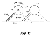
図11に、本発明の特定の実施形態による別の吸気路設計を示す。図11において、2個の吸気路1106a/1106bは、吸気マニホールド1114を燃焼室1102に接続しており、各々は燃焼室1102上の別々の吸気弁に接続している。吸気路1106a/1106bは斜めの関係、すなわち互いに平行に延びず、ある角度で燃焼室1102に接続している。図示する実施形態において、1個の燃焼室1102用の吸気路1106bは、隣接する燃焼室1120用の吸気路1122と空気流路を共有しているが、他の実施形態では、隣接する燃焼室用の吸気路が完全に別々である。
FIG. 11 illustrates another intake path design according to certain embodiments of the invention. In FIG. 11, two
各吸気路1106a/1106bが燃焼室1102に接続する角度は、各吸気路1106a/1106bの中心軸1108a/1108bを燃焼室1102の中心軸1110と(実質的に)交差させる。この設計により、吸気路1106a/1106bを用いて送られる空気は燃焼室の中央に直接送られるため、恐らく図10の構成と比較して渦流すなわち混合の程度が低下する。このような構成はオプションとして、図1〜7に示す弁システムと組み合わせて、燃焼室1102内でのガスの運動の制御の改善に役立つ。
The angle at which each
燃焼室への給気および/または燃焼室内でのガス流を更に制御すべく燃焼室の設計に対し追加的な調整を行うことができる。いくつかの実施形態において、例えば、燃焼室の吸気弁(例えば図1A、1Bの吸気弁120a/120b)のサイズおよび/または直径は異なっている。すなわち、これらの形状、サイズ、または設計に応じて弁を通る空気流の速度が異なる。燃焼室への非対称な給気により、燃焼室内で渦流が生じやすくなり、これはある条件下では望ましい。
Additional adjustments can be made to the combustion chamber design to further control the charge to the combustion chamber and / or the gas flow within the combustion chamber. In some embodiments, for example, the size and / or diameter of the combustion chamber intake valves (eg,
燃焼室の吸気弁が独立に制御される(例えば図1〜7に示すように)場合、これらはまた、異なる弁揚程曲線を辿る、および/または開/閉時点が異なり得る。これらの曲線および弁の開/閉時点は、利用可能な弁制御機構と整合する所望の仕方で混合および適合させることができる。例えば、一方の吸気弁を、吸気行程全体にわたり弁を開いておいてBDCの直後に閉じる揚程曲線を実行すべく作動させる。当該揚程曲線は、最大給気を誘発可能にするものであり、通常タイミングおよび揚程曲線とも称する。他方の吸気弁は、吸気弁早閉じ(EIVC)または吸気弁遅閉じ(LIVC)曲線を辿るべく作動させる。EIVCおよびLIVC曲線およびタイミングは共に、正常揚程曲線と比較して空気導入が減少する結果となる。通常タイミングおよび揚程曲線を用いた場合、エンジンはオットーサイクルで動作し、すなわち弁開閉タイミングは実質的に最大給気をもたらす。EIVCまたはLIVC弁開閉タイミングを用いた場合、給気が減少するため有効圧縮比が低下する。これは往々にしてアトキンソンまたはミラーサイクルを用いるエンジン動作と表現される。異なる揚程曲線およびタイミングを用いることで、燃焼室出力、振動、騒音、および燃費に対して追加的な制御を行うのに役立つ。 If the combustion chamber intake valves are independently controlled (eg, as shown in FIGS. 1-7), they may also follow different valve lift curves and / or open / close times may be different. These curves and valve opening / closing points can be mixed and adapted in any desired manner consistent with available valve control mechanisms. For example, one intake valve is actuated to perform a lift curve that opens and closes immediately after BDC throughout the entire intake stroke. The lift curve makes it possible to induce the maximum supply air, and is also called a normal timing and a lift curve. The other intake valve is actuated to follow an intake valve early closing (EIVC) or intake valve late closing (LIVC) curve. Both the EIVC and LIVC curves and timing result in reduced air introduction compared to the normal lift curve. With normal timing and lift curves, the engine operates on an Otto cycle, i.e. valve opening and closing timing results in substantially maximum charge. When the EIVC or LIVC valve opening / closing timing is used, the effective compression ratio decreases because the supply air decreases. This is often described as engine operation using an Atkinson or Miller cycle. Using different lift curves and timings helps provide additional control over combustion chamber power, vibration, noise, and fuel consumption.
1個以上の吸気弁に特定の揚程曲線および/または弁開閉タイミングを用いることにより特定レベルのトルクを発生する特定のスキームを本明細書で弁制御スキームと称する。従って、点火燃焼室から異なる(例:低、中および/または高)レベルのトルクを各々発生する異なる弁制御スキームがあり得る。各弁制御スキームは、燃焼室の各吸気弁を独立に制御して各吸気弁を特定の揚程曲線および/またはタイミングサイクル(例:オットー、アトキンソン等)に従い動作させるものである。特定の弁制御スキームにより同一または異なる揚程曲線および/またはタイミングサイクルに従い1個の燃焼室の複数の吸気弁を動作させることができる。 A particular scheme that generates a particular level of torque by using a particular lift curve and / or valve opening and closing timing for one or more intake valves is referred to herein as a valve control scheme. Thus, there can be different valve control schemes that each generate different (eg, low, medium and / or high) levels of torque from the ignition combustion chamber. Each valve control scheme independently controls each intake valve in the combustion chamber to operate each intake valve according to a specific lift curve and / or timing cycle (eg, Otto, Atkinson, etc.). Depending on the particular valve control scheme, multiple intake valves of a combustion chamber can be operated according to the same or different lift curves and / or timing cycles.
ここで図12A〜12Eを参照するに、上述の弁制御システムと従来型弁制御システムとのいくつかの相違点について記述する。比較のため、図12Aに、現在多くの自動車エンジンで用いられている例示的なオットーサイクルの吸気および圧縮行程における燃焼室の動作の各種の段階を示す。燃焼室は、共に通常タイミングおよび揚程曲線に基づいて動作することでエンジンをオットーサイクルで動作させる2個の吸気弁(吸気弁1202a、1202b)を含んでいる。
Referring now to FIGS. 12A-12E, some differences between the valve control system described above and a conventional valve control system will be described. For comparison, FIG. 12A shows the various stages of combustion chamber operation in an exemplary Otto cycle intake and compression stroke currently used in many automotive engines. The combustion chamber includes two intake valves (
吸気行程中、両方の弁1202a/1202bが動作する。ピストン1206は、上死点(TDC)から下死点(BDC)まで移動する。ピストン1206がBDCに到達する約40゜前に、弁揚程は自身の最高点に到達する。ピストン1206がBDCに到達したならば圧縮行程が開始される。ピストンは次いで上死点(TDC)へ逆向きに移動する。BDCの約40゜後で吸気弁が閉じられる。
During the intake stroke, both
アトキンソンサイクル中は、吸気弁を早めまたは遅めに閉じることができる。前者を吸気弁早閉じ(EIVC)と称する。EIVC弁動作の一例を図12Bに示す。図12Bにおいて、両方の吸気弁1202a/1202bがEIVCアトキンソンサイクルに従い動作している。吸気弁1202a/1202bは、吸気行程終了時点でピストン1206がBDCに到達するまでに閉じる。これは、吸気弁が40゜後に閉じる図12Aに示すオットーサイクルよりも大幅に早い。従って、オットーサイクルと比較して、吸気弁はより早く閉じ、開いている時間はより短いため、結果的に燃焼室内の空気が少なくなってトルク出力が低くなる。
During the Atkinson cycle, the intake valve can be closed earlier or later. The former is called intake valve early closing (EIVC). An example of EIVC valve operation is shown in FIG. 12B. In FIG. 12B, both
図12Cに、両方の吸気弁が標準的なオットーサイクルと比較して遅く閉じる代替的なアトキンソンサイクルを示す。当該方式を吸気弁遅閉じ(LIVC)と称する。図12CにLIVC弁制御システムの一例を示す。同図に示すように、吸気弁1202a/1202bは圧縮行程の途中でBDCの約90゜後に閉じる。対照的に、オットーサイクルの例では、吸気弁はBDCの約40°後に閉じる。この結果、吸気フェーズ中に燃焼室へ送られた空気のより多くが圧縮行程中に燃焼室から押し出されるため、燃焼室へ送られる空気が減少する。
FIG. 12C shows an alternative Atkinson cycle where both intake valves close late compared to a standard Otto cycle. This method is referred to as intake valve late closing (LIVC). FIG. 12C shows an example of the LIVC valve control system. As shown in the figure, the
アトキンソンサイクル中は吸気マニホールドから燃焼室への給気がオットーサイクルと比較して減少するため、燃焼室の点火により生じるトルク出力が低下する。しかし、アトキンソンサイクルは一般に、有効トルクに変換される燃焼エネルギーの割合が大きいためオットーサイクルより燃費が良い。燃焼室をアトキンソンサイクルで動作させることで、燃焼室を最低BSFC動作点又はその近傍で動作させることができる。 During the Atkinson cycle, the supply of air from the intake manifold to the combustion chamber is reduced as compared with the Otto cycle, so that the torque output generated by ignition of the combustion chamber is reduced. However, the Atkinson cycle generally has better fuel efficiency than the Otto cycle because of the large proportion of combustion energy converted into effective torque. By operating the combustion chamber in an Atkinson cycle, the combustion chamber can be operated at or near the lowest BSFC operating point.
図12A〜12Cに示す上述の例において、両方の吸気弁が同一サイクルに基づいて同時に起動される。図12D〜12Eで、独立に制御される吸気弁が異なるサイクルに基づいて開閉する実装例を考察する。これらの実施形態で記述する吸気弁は、上述の技術(例えば図1A、1Bおよび図2〜11を参照しながら記述したもの)のいずれを用いて制御または作動させてもよい。 In the above example shown in FIGS. 12A-12C, both intake valves are activated simultaneously based on the same cycle. 12D-12E, consider an implementation example in which independently controlled intake valves open and close based on different cycles. The intake valves described in these embodiments may be controlled or actuated using any of the techniques described above (eg, those described with reference to FIGS. 1A, 1B and FIGS. 2-11).
図12Dにおいて、吸気弁1202bはEIVCアトキンソンサイクルに従い動作する。吸気弁1202aはオットーサイクルに従い動作する。従って、同図に示すように、吸気弁1202aはBDCの約40°後に閉じるのに対し、ピストン1206は早くも圧縮行程に入っている。しかし、吸気弁1202bはより早く、すなわちピストンがBDCである時点で吸気行程の終了間際に閉じる。
In FIG. 12D, the
図12Eに、吸気弁1202aがオットーサイクルに従い動作し、吸気弁1202bがLIVCアトキンソンサイクルに従い動作するシステムを示す。吸気弁1202bは従って、吸気弁1202aより遅く、すなわちBDCの約40°後ではなく、圧縮行程中にBDCの約90゜後に閉じる。
FIG. 12E shows a system in which the
異なるサイクルに従う吸気弁の動作は、各種の潜在的な利益をもたらす。一つは、燃焼室内の流れを制御する別の手段を提供する。例えば、図12Dにおいて、空気は燃焼室1206に非対称に入る。すなわち、吸気フェーズ中に一方の吸気弁(吸気弁1202a)を通って他方の吸気弁よりも多くの空気がより長い時間流入する。これは燃焼室内のガスの動きに望ましい影響を及ぼす、すなわち、より多くの渦流を生じさせることができる。図12Eにおいて、圧縮行程中、一方の吸気弁(例:吸気弁1202b)から他方の吸気弁よりも多くの空気がより長い時間押し出される。この非対称な空気流は、より有利な特徴として、燃焼促進運動、すなわち渦流および回転流を増大させて燃焼特性を向上させる。
The operation of the intake valve following different cycles provides various potential benefits. One provides another means of controlling the flow in the combustion chamber. For example, in FIG. 12D, air enters the
いくつかの方式において、吸気弁はずれている、すなわち互いにフェーズが異なる。当該方式の一例を図12Fに示す。吸気弁1202a、1202bは同一オットーサイクルに基づいて動作するが、開閉タイミングがずれている。すなわち、吸気弁1202aは吸気弁1202bよりも早く開き早く閉じる。本システムは図12Eに示すシステムと幾分同様に機能する。空気は燃焼室から非対称的に排出されるため、燃焼室内の渦流が生じる場合ある。ずれの量は、特定用途での必要性に依存して大幅に変動し得る。
In some schemes, the intake valves are deviated, i.e., out of phase with each other. An example of this method is shown in FIG. 12F. The
燃焼室用の吸気弁を異なるサイクルに従い独立に動作させる更なる利点は、弁を動作させる仕方に応じて燃焼室のトルク出力を高度に制御できることである。次に図13A、13Bを参照しながら各種の例示的な弁制御スキームについて記述する。すなわち、図13A、13Bに示す表は、異なる仕方で吸気弁を動作させて異なるレベルのトルクを発生させることができる様子を示す。いくつかの実施形態において、図13A、13Bに示す弁制御スキームは各々、図12D、12Eに示すシステムを用いる。 A further advantage of operating the combustion chamber intake valves independently according to different cycles is that the combustion chamber torque output can be highly controlled depending on how the valves are operated. Various exemplary valve control schemes will now be described with reference to FIGS. 13A and 13B. That is, the tables shown in FIGS. 13A and 13B show how the intake valves can be operated in different ways to generate different levels of torque. In some embodiments, the valve control schemes shown in FIGS. 13A and 13B each use the system shown in FIGS. 12D and 12E.
図13Aに、例えば別個のアクチュエータまたはカムにより、独立に制御される2個の吸気弁を有する燃焼室弁制御システムを示す。当該弁制御システムは、図2〜7および/または12Dを参照しながら記述したシステムのいずれの特徴をも有していてよい。選択された燃焼サイクル中に吸気弁1202aはオットーサイクルに従い休止または作動させることができる(以下、「正常弁」と称す)。選択された燃焼サイクル中に吸気弁1202bはまた、アトキンソン(EIVC)サイクルに従い休止または作動させることができる(以下、「EIVC弁」と称す)。従って、正常およびEIVC弁に対して、4通りの異なる結果1302/1304/1306/1308をもたらす4通りの異なる弁制御スキームが可能であり、これらを図13Aの表1300に示す。
FIG. 13A shows a combustion chamber valve control system having two intake valves that are independently controlled, for example by separate actuators or cams. The valve control system may have any of the features of the system described with reference to FIGS. 2-7 and / or 12D. During the selected combustion cycle, the
結果1302、1304および1306において、選択された燃焼サイクル中に燃焼室は点火され、点火により生じたトルク出力のレベルは弁制御スキームに依存する。当該表の結果1302は、両方の吸気弁が作動した場合に最も高い燃焼室トルク出力が得られることを示す。これはまた、中程度の渦流を生じさせる。EIVC弁が休止して正常弁が作動した場合、次に最も高いレベルの燃焼室出力を発生させることができる(結果1306)。次に最も高いレベルの燃焼室出力(すなわち結果1302、1306よりも低い出力)が発生するのは、EIVC弁が作動して正常弁が休止した場合である(結果1304)。これは、EIVC動作により燃焼室へ送られる空気の量が制限されるためである。両方の結果1304、1306において、1個の弁だけを作動させることで燃焼室内のガスの流れおよび混合が促進されるため、より大量の(すなわち結果1302よりも高い)渦流を発生させることができる。また、両方の吸気弁を休止させることができ、これは図13Aの表の結果1308により示すように、選択された燃焼サイクル中に燃焼が起きず、トルク出力が発生しないことを意味する。
In
図13Bは同様な構造の表1350を含んでいるが、同図では吸気弁1202bはアトキンソン(LIVC)サイクルに従い休止または動作させることができる(以下、LIVC弁と称す)。弁1202aはオットーサイクルに基づいて休止または動作させることができる(以下、正常弁と称す)。従って、選択された燃焼サイクルに対して同じく4通りの異なる弁制御スキーム、すなわち1)LIVC弁作動、正常弁作動、燃焼現象生起、2)LIVC弁休止、正常弁作動、燃焼現象生起、3)LIVC弁休止、正常弁作動、燃焼現象生起、4)LIVC弁休止、正常弁休止、燃焼現象生起せず、が可能である。各弁制御スキームの結果を図13Bに示す。図13Bの弁制御スキームの何れかの実行に用いる弁制御システムは、図2〜7および/または12Eを参照しながら記述したシステムのいずれの特徴をも有している。
FIG. 13B includes a similarly structured table 1350, where the
図示する表1350の結果は図13Aの表1300とは全く異なる。特に、正常弁が作動してLIVC弁が休止した(結果1356)場合に最大燃焼室トルク出力が得られる。両方の弁が作動した(結果1352)場合、より低い、中程度のレベルの燃焼室出力が得られる。これは、両方弁が作動したならば、2個の弁を通って送られた空気の一部が、圧縮行程中のLIVC弁閉弁遅延に起因して燃焼室から押し出されるためである。正常弁が休止してLIVC弁が起動した場合、低レベルの(すなわち結果1352より低い)燃焼室出力もまた(結果1354)得られる。結果1358において両方の吸気弁が休止しており、トルク出力は発生しない。
The results shown in Table 1350 are completely different from Table 1300 in FIG. 13A. In particular, the maximum combustion chamber torque output is obtained when the normal valve is activated and the LIVC valve is deactivated (result 1356). If both valves are activated (result 1352), a lower, medium level combustion chamber output is obtained. This is because if both valves are activated, some of the air sent through the two valves will be pushed out of the combustion chamber due to the LIVC valve closing delay during the compression stroke. If the normal valve is deactivated and the LIVC valve is activated, a low level (ie, lower than result 1352) combustion chamber output is also obtained (result 1354). In
上述のように、結果1354、1356は、燃焼室への非対称な給気に起因して結果1352よりも大量の渦流を示している。また、LIVC弁および正常弁はまた、共に休止させる(結果1358)ことができ、すなわち燃焼サイクルを間引くことができる。
As described above,
図13A、13Bに示す表は、独立に制御される吸気弁、および異なる弁に異なるサイクルを用いることにより燃焼室の動作の柔軟性を向上させ得ることを示す。すなわち、燃焼室は、3または4通りの異なるレベルトルク出力を実現することができる。また、燃焼室は、1個の弁に対してアトキンソンサイクルを選択的に用いて、他の何らかの技術(例:スパークタイミング、スロットル等の調整によりトルク出力を低下させる)と比較してより良好な燃費でより低レベルのトルク出力を発生することが可能である。 The tables shown in FIGS. 13A and 13B indicate that the flexibility of operation of the combustion chamber can be improved by using independently controlled intake valves and different cycles for different valves. That is, the combustion chamber can achieve three or four different level torque outputs. Also, the combustion chamber is better compared to some other technique (eg, reducing the torque output by adjusting spark timing, throttle, etc.) by selectively using the Atkinson cycle for one valve. It is possible to generate a lower level torque output with fuel efficiency.
エンジンの燃焼室の全てが必ずしも同一弁制御システムを有している必要が無いことを理解されたい。その代わり、燃焼室を各々が異なる能力を有する2個以上の異なる組に分割することができる。例えば、1個以上の燃焼室が2モードのみ(すなわち全ての吸気弁が作動している状態で休止または点火)または1モードのみ(すなわち全てのエンジンサイクルで間引き無しに点火)で動作可能である。しかし、他の燃焼室が、図1〜13と参照しながら上で述べたように独立に制御される吸気弁を有していてよい。このように燃焼室の混合した組は、従来型エンジンと比較して柔軟性および制御性を向上させると同時に、全ての燃焼室が多段トルク出力可能であるエンジンと比較してハードウェアコストおよび複雑性さを低減させるのに役立つ。 It should be understood that not all engine combustion chambers need have the same valve control system. Instead, the combustion chamber can be divided into two or more different sets, each having different capabilities. For example, one or more combustion chambers can operate in only two modes (ie, pause or ignite with all intake valves operating) or only in one mode (ie, ignite without decimation in all engine cycles) . However, other combustion chambers may have intake valves that are independently controlled as described above with reference to FIGS. This combination of combustion chambers improves flexibility and controllability compared to conventional engines, while at the same time hardware cost and complexity compared to engines where all combustion chambers are capable of multistage torque output. Helps to reduce sexuality.
各種の異なる燃焼室構成の例を図14A〜14Hに示す。これらの図は各々、出力レベルおよび気筒番号に対応する複数のセルおよび指標を有する表を含んでいる。各表は、各気筒(番号1〜4で示す)が例示的な4気筒エンジンで発生可能な異なる出力レベル(すなわちトルク出力レベル)を示す。すなわち、ある気筒が出力レベル1と記入されたセルを有している場合、当該気筒が高トルク出力(例:CTF=1.0すなわち最大許容可能出力の100%)を発生すべく点火可能であることを意味する。ある気筒が出力レベル2と記入されたセルを有している場合、当該気筒が低または部分的トルク出力(例:CTF=0.7すなわち最大許容可能出力の70%)を発生すべく点火可能であることを意味する。ある気筒が出力レベル3と記入されたセルを有している場合、当該気筒が休止可能である(従って、選択された燃焼サイクル中トルク出力を発生させない)ことを意味する。
Examples of various different combustion chamber configurations are shown in FIGS. Each of these figures includes a table having a plurality of cells and indicators corresponding to power levels and cylinder numbers. Each table shows the different output levels (ie, torque output levels) that each cylinder (denoted by numbers 1-4) can generate in an exemplary four cylinder engine. That is, if a cylinder has a cell marked with
図示する実施形態では3出力レベルしか利用できないが、他の実施形態では、例えば図13A〜13Bに示すように、少なくともいくつかの気筒で3個以上の出力レベルを発生させることができる。図の14A〜14Hの各表は、異なる能力を有する燃焼室/弁システムの異なる構成および組み合せを示す。当該表に記述した気筒は、本出願に記述する(例えば図1〜13を参照しながら説明したもの)弁制御システム、動作、および特徴の何れかを用いて異なる出力レベルを生成すべく構成されている。 Although only three output levels are available in the illustrated embodiment, other embodiments can generate more than two output levels in at least some of the cylinders, for example, as shown in FIGS. The tables 14A-14H in the figure show different configurations and combinations of combustion chamber / valve systems with different capabilities. The cylinders described in the table are configured to generate different power levels using any of the valve control systems, operations, and features described in this application (eg, described with reference to FIGS. 1-13). ing.
各表には燃費数値も関連付けられている。各燃費数値は本願発明者により実行されるシミュレーションに基づいている。数値は、従来型4気筒エンジン(例:気筒を休止させる能力を一切有していない)と比較して当該構成がもたらす推定燃費利得を示す。図14A〜14Hの各表に関連付けられた燃費数値が実験シミュレーションに基づいて事前に用意されており、異なるエンジン設計および用途に応じて変動し得ることを理解されたい。 Each table is also associated with fuel efficiency figures. Each fuel consumption value is based on a simulation executed by the present inventor. The numerical value indicates the estimated fuel efficiency gain that the configuration provides compared to a conventional four-cylinder engine (eg, having no ability to deactivate cylinders). It should be understood that the fuel economy figures associated with the tables of FIGS. 14A-14H are prepared in advance based on experimental simulations and may vary for different engine designs and applications.
比較のため、図14Aは、全ての気筒が2出力レベルのみが可能である、すなわち各気筒が1レベルのトルク出力を発生すべく休止または点火可能である気筒構成を示す表である。このような構成をスキップファイアエンジン制御システムで用いることができる。当該設計において、どの点火時点でも両方の吸気弁が作動する。点火に伴う給気を、弁の開閉時間を制御するカムフェーザ、および全ての気筒のMAPを制御するスロットルにより調整することができる。一般に、これらの制御システムでは単独の燃焼室の出力を大幅且つ急激に調整することはできない。スパークタイミングを後ろへずらすことにより燃焼室の出力を低下させることができるが、この制御方法は燃費が悪いため避ける方が望ましい場合が多い。図14Aに示す気筒構成は、そのような条件下での点火は燃焼室のポンプ損失を減らすのに役立ち、ある場合にはほぼ最適な燃費で気筒を点火させることができるため、中程度に燃費が良好である。 For comparison, FIG. 14A is a table showing a cylinder configuration in which all cylinders are capable of only two output levels, that is, each cylinder can be paused or ignited to produce one level of torque output. Such a configuration can be used in a skip fire engine control system. In this design, both intake valves operate at any ignition time. The air supply accompanying ignition can be adjusted by a cam phaser that controls the valve opening and closing time and a throttle that controls the MAP of all cylinders. In general, these control systems cannot adjust the output of a single combustion chamber significantly and rapidly. Although the output of the combustion chamber can be reduced by shifting the spark timing backward, it is often desirable to avoid this control method because of poor fuel consumption. In the cylinder configuration shown in FIG. 14A, ignition under such conditions helps to reduce the combustion chamber pumping loss, and in some cases the cylinder can be ignited with nearly optimal fuel consumption, thus providing moderate fuel consumption. Is good.
図14Bに、気筒休止を行う従来型エンジンの構成を示す。2個の気筒が全てのエンジンサイクル中に点火され、すなわち休止不可能である。選択された燃焼サイクル中に他の2個の気筒を点火させて1レベルのトルク出力を発生させるか、または休止させることができる。そのようなエンジンは全ての気筒を休止させることができないため、図14Aに示す構成よりも若干燃費が低下し得る。しかし、例えば図14Aに示すような全気筒毎の一段スキップファイアエンジン設計と比較して、そのようなシステムを実現するためのハードウェアが少なくて済む。 FIG. 14B shows the configuration of a conventional engine that performs cylinder deactivation. The two cylinders are ignited during all engine cycles, i.e. they cannot be deactivated. During the selected combustion cycle, the other two cylinders can be ignited to produce a one level torque output or deactivated. Since such an engine cannot stop all cylinders, the fuel consumption may be slightly lower than the configuration shown in FIG. 14A. However, less hardware is required to implement such a system than, for example, a one-step skip fire engine design for every cylinder as shown in FIG. 14A.
図14Cに、全ての気筒で3出力レベル、すなわち休止(トルク出力無し)、および更に2個の異なる出力レベルでの点火が可能な構成を示す。このような構成は、本出願に記述する弁制御システム(例:各気筒毎に吸気弁を独立に制御する、オットーおよびアトキンソンサイクル等に基づく吸気弁を動作させる)のいずれを用いても可能である。このような方式により燃費が大幅に向上し得る。しかし、各気筒に追加的なハードウェアおよび弁制御関連の特徴を設けることも必要になり得る。 FIG. 14C shows a configuration in which all cylinders can be ignited at three output levels, that is, at rest (no torque output), and at two different output levels. Such a configuration can be used with any of the valve control systems described in the present application (eg, the intake valve is controlled independently for each cylinder, and the intake valve based on the Otto and Atkinson cycles is operated). is there. Such a method can greatly improve fuel efficiency. However, it may also be necessary to provide additional hardware and valve control related features in each cylinder.
図14Dに、2個の気筒で図14Cに示す3出力レベルが可能な、より簡単な方式を示す。しかし、残りの2個の気筒は休止不可能であり、全てのエンジンサイクル中、1出力レベルで点火される。従って、気筒2、3は、従来型の非スキップファイアエンジンの気筒と比較して追加的なハードウェアを殆どまたは一切必要としない。
FIG. 14D shows a simpler scheme that allows the three output levels shown in FIG. 14C with two cylinders. However, the remaining two cylinders cannot be deactivated and are ignited at one power level during all engine cycles. Thus,
いくつかの実施形態において、図14Dに示す気筒1〜4はエンジン内のスペースを最も効率良く利用すべく配置されている。そのような配置の一例を図15に示す。図15は、エンジン1500内の気筒1〜4のバンクまたは列の上面図である。気筒1、4は、バンクの両端に配置され、気筒2、3は気筒の列の中央に配置されている。
In some embodiments, cylinders 1-4 shown in FIG. 14D are arranged to make the most efficient use of space in the engine. An example of such an arrangement is shown in FIG. FIG. 15 is a top view of a bank or row of
図15に、より多くの出力レベル/休止が可能な気筒が気筒バンクの両端に配置され、より少ないトルク出力レベルが可能および/または休止不可能な気筒が中央に配置された例を示す。これにより、バンクの両端の気筒に追加的なハードウェアを取り付けられることがより容易になり、ハードウェア要求がより少ない気筒は、スペースより狭く各気筒の両側が別の気筒に接しているバンクの中央に配置されている。図示する実施形態は4個の気筒を含んでいるが、同様の装置を気筒数がより多いか少ないバンク/列(例:3乃至5個以上の気筒)にも用いることができることを理解されたい。換言すれば、各種の実装例において、最も外側の気筒(例:列の両端、またはその近傍の気筒(群))はより多くの出力レベルが可能であり、内側気筒(例:列の中央により近い、および/または両側が他の気筒に囲まれた気筒(群))はより少ない出力レベルが可能である。2個以上の気筒列/バンクを有するエンジンにおいて、各気筒バンク/列は図15に示すものと同一配置であってよい。 FIG. 15 shows an example in which more output levels / cylinders that can be deactivated are arranged at both ends of the cylinder bank, and cylinders that allow lower torque output levels and / or cannot be deactivated are arranged in the center. This makes it easier to install additional hardware on the cylinders at both ends of the bank, and the cylinders with less hardware requirements are smaller than the space and each side of each cylinder is in contact with another cylinder. Located in the center. Although the illustrated embodiment includes four cylinders, it should be understood that similar devices can be used for banks / rows with more or fewer cylinders (eg, 3-5 or more cylinders). . In other words, in various implementations, the outermost cylinder (e.g., the cylinder (group) at or near the end of the row) can have a higher output level, and the inner cylinder (e.g., at the center of the row). Lesser power levels are possible for cylinders (groups) that are close and / or surrounded by other cylinders on both sides. In an engine having two or more cylinder rows / banks, each cylinder bank / row may be arranged in the same manner as shown in FIG.
図14Eに、図14dおよび/または15に示す構成の変形例を示す。図14Dと同様に図14Eにおいて、気筒1、4は3レベルの出力が可能である。しかし、気筒2、3は2レベルの出力が可能である(すなわち、これらは休止、または1トルク出力レベルで点火可能である)。図14Eに示す構成はまた、図15に示すように配置することができ、最も内側の気筒(気筒2、3)は、最も外側の気筒(気筒1、4)よりも少ないハードウェアを必要とし、より少ない出力レベルが関連付けられていてよい。
FIG. 14E shows a modification of the configuration shown in FIG. 14d and / or 15. Similarly to FIG. 14D, in FIG. 14E, the
図14Fにおいて、各気筒は2出力レベルが可能であるが、可能な出力レベルの種類は異なる。本構成例では、気筒1、4は2出力レベルが可能であり、1トルク出力レベルを生成すべく点火可能であり、且つ選択された燃焼サイクルで休止可能である。気筒2、3は休止不可能であり、異なる2出力レベルで点火可能である。全ての気筒が3個以上の出力レベルを生成可能な構成と比較して、図14Fに示す構成が必要とするハードウェアは少なくて済む。事前テストもまた、このような構成の燃料が、1レベルのスキップファイアエンジンシステムと比較しても、かなり良好であることを示している(例えば図14Aに示すように)。
In FIG. 14F, each cylinder can have two output levels, but the types of possible output levels are different. In this configuration example, the
図14Gに、2個の気筒(気筒1、4)が3レベルの出力(すなわち休止、および2個の異なるトルク出力レベルでの点火)が可能な構成を示す。他の2気筒(気筒2、3)は休止不可能であるが、2個の異なるトルク出力レベルを発生すべく点火可能である。図14Gに示す構成もまた図15に示すように配置されていてよい。すなわち、より多くの出力レベルが可能な気筒1、4は、気筒の列/バンクの両端に配置されているのに対し、より少ない出力レベルが可能な気筒(気筒2、3)は列/バンクの中央または内側に配置されている。上述のように、各種の実施形態において気筒1、4は、追加的な出力レベルを実現するには更なるハードウェアを必要とし、気筒列/バンクの外側両端はそのようなハードウェアを設置すべくより多くのスペースを提供する。
FIG. 14G shows a configuration in which two cylinders (
図14Hに、全ての気筒が休止または間引き可能な訳ではない変型例を示す。しかし各気筒は、2個の異なるトルク出力レベルを発生すべく点火可能である。各種の実装例において、当該構成は、従来型のスキップファイアエンジン制御システムと比較してNVHがより低く、より多くの出力レベルが可能な気筒のシステムと比較して必要なハードウェアが少なくて済む。 FIG. 14H shows a modified example in which not all cylinders can be stopped or thinned out. However, each cylinder can be ignited to produce two different torque output levels. In various implementations, the configuration requires less hardware compared to a cylinder system with a lower NVH compared to a conventional skipfire engine control system and capable of more power levels. .
本出願に記述する弁制御システムのいずれを用いて図14A〜14Hに示す実施形態を実装してもよい。すなわち、図14A〜14Hに示す各種の実施形態は、複数レベルのトルク出力を発生すべく休止および/または点火可能な1個以上の気筒を含んでいる。このような多段トルク出力は様々な仕方で実現できる。いくつかの実装例において、例えば、各気筒は2個の吸気弁を含んでいて、各吸気弁は(例えば図2〜7に示すように)異なるアクチュエータにより制御される。高トルク出力を発生するには、選択された燃焼サイクル中に両方の吸気弁を通して給気する。低トルク出力を発生するには、選択された燃焼サイクル中に1個の吸気弁だけを通して給気するかまたはLIVC弁により気筒から空気を押し出す。図2〜7に示すように、1個以上の排気弁の制御が1個以上のアクチュエータにより扱われてよい。いくつかの方式において、気筒は、当該気筒が(例えば図8、9との関連で述べた)異なるトルク出力レベルを発生すべく点火可能なように弁揚程が調節可能な単一の吸気弁を有すべく構成されている。図14A〜14Hに示す構成はまた、(例えば図10A、10B、11との関連で述べた)上述の弁通路構成の何れかを備えたエンジンシステムで用いることができる。いくつかの設計において、多段トルク出力が可能な各気筒は、(例えば図12A〜12Eおよび13A〜13Bとの関連で述べた)異なるサイクルに従い異なる吸気弁を動作させる。すなわち、図14A〜14Hの表に示す異なるレベルのトルク出力は、図13A、13Bの表に示す技術(例:特定のトルク出力を発生すべくEIVC/LIVC弁および正常弁を作動させ、異なる第2のトルク出力を発生すべく弁の1個を休止させる等)を用いて発生させることができる。 The embodiments shown in FIGS. 14A-14H may be implemented using any of the valve control systems described in this application. That is, the various embodiments shown in FIGS. 14A-14H include one or more cylinders that can be paused and / or ignited to generate multiple levels of torque output. Such multi-stage torque output can be realized in various ways. In some implementations, for example, each cylinder includes two intake valves, and each intake valve is controlled by a different actuator (eg, as shown in FIGS. 2-7). To generate high torque output, air is supplied through both intake valves during the selected combustion cycle. To produce a low torque output, only one intake valve is charged during the selected combustion cycle or air is pushed out of the cylinder by the LIVC valve. As shown in FIGS. 2-7, control of one or more exhaust valves may be handled by one or more actuators. In some schemes, a cylinder has a single intake valve with adjustable valve lift so that the cylinder can be ignited to generate different torque output levels (eg, as described in connection with FIGS. 8 and 9). It is configured to have. The configurations shown in FIGS. 14A-14H can also be used in an engine system with any of the valve passage configurations described above (eg, as described in connection with FIGS. 10A, 10B, 11). In some designs, each cylinder capable of multi-stage torque output operates a different intake valve according to a different cycle (eg, as described in connection with FIGS. 12A-12E and 13A-13B). That is, the torque outputs at different levels shown in the tables of FIGS. 14A to 14H are different from those of the techniques shown in the tables of FIGS. 13A and 13B (e.g. For example, by pausing one of the valves to generate a torque output of 2).
多段スキップファイアエンジン制御システム
本発明の各種の実施形態は、多段スキップファイアエンジン制御システムに関係している。エンジンの1個以上の燃焼室は、非ゼロトルク出力の少なくとも二つの異なるレベルを発生すべく点火可能である。燃焼室出力トルクは点火機会毎に制御することができる。全体的なエンジントルク出力は、点火機会毎に気筒を点火または休止させることにより制御することができる。所望のエンジントルクに基づいて、エンジン制御システムは、エンジンをスキップファイア方式で動作させるべく点火シーケンスを決定する。シーケンスは一連の休止および点火を示す。各点火毎に、シーケンスは対応するトルク出力レベルを示す。エンジンの燃焼室は、所望のエンジントルクを伝達すべく点火シーケンスに基づいて動作される。そのようなスキップファイア点火シーケンスを本明細書では多段スキップファイア点火シーケンスと称する。
Multi-stage Skip Fire Engine Control System Various embodiments of the present invention relate to a multi-stage skip fire engine control system. One or more combustion chambers of the engine can be ignited to generate at least two different levels of non-zero torque output. The combustion chamber output torque can be controlled for each ignition opportunity. The overall engine torque output can be controlled by igniting or deactivating the cylinder at each ignition opportunity. Based on the desired engine torque, the engine control system determines an ignition sequence to operate the engine in a skip fire manner. The sequence shows a series of pauses and ignitions. For each ignition, the sequence indicates the corresponding torque output level. The engine combustion chamber is operated based on an ignition sequence to transmit the desired engine torque. Such a skip fire ignition sequence is referred to herein as a multi-stage skip fire ignition sequence.
多段スキップファイアエンジン制御システムの上述の実施形態は、本出願に記述するエンジン、燃焼室、吸気路、および弁制御システム設計のいずれと共に用いてもよい。各種の実施形態において、例えば、当該システムは1個以上の燃焼室から複数のトルク出力レベルで点火させる点火シーケンスを生成する。これらの燃焼室は各々、独立に制御される吸気弁および/または排気弁を用いることにより、異なるサイクル(例:オットーおよびアトキンソン)に従い同一燃焼室の吸気弁を動作させることにより、および/または図面との関連で述べた他の任意の特徴または技術により、そのような高または低トルク出力点火を生起させることができる。しかし、記述する多段スキップファイアエンジン制御システムはそのようなシステムおよび動作に限定されず、複数レベルの燃焼室出力を発生可能な任意のエンジンまたは燃焼室設計にも適用できることを理解されたい。本発明は特に点火機会毎に点火を決定する制御システムに適用できるが、そのような制御システムに限定されない。 The above-described embodiments of the multi-stage skipfire engine control system may be used with any of the engines, combustion chambers, intake channels, and valve control system designs described in this application. In various embodiments, for example, the system generates an ignition sequence that ignites from one or more combustion chambers at multiple torque output levels. Each of these combustion chambers uses independently controlled intake and / or exhaust valves, operates the same combustion chamber intake valves according to different cycles (eg, Otto and Atkinson), and / or drawings. Any other feature or technique described in connection with can cause such a high or low torque output ignition to occur. However, it should be understood that the described multi-stage skipfire engine control system is not limited to such systems and operations, and can be applied to any engine or combustion chamber design capable of generating multiple levels of combustion chamber output. The present invention is particularly applicable to a control system that determines ignition for each ignition opportunity, but is not limited to such a control system.
次に図16を参照するに、本発明の特定の実施形態による多段スキップファイアエンジンコントローラ1630について記述する。エンジンコントローラ1630は、点火比計算器1602、点火タイミング決定モジュール1606、点火制御部1610、動力系パラメータ調整モジュール1608、およびエンジン診断モジュール1650を含んでいる。エンジンコントローラ1630は、エンジンをスキップファイア方式で動作させるべく配置されている。
Referring now to FIG. 16, a multi-stage
エンジンコントローラ1630は、所望のエンジン出力および各種の車両動作パラメータ、例えばエンジン速度1632および変速ギア1634を表す入力信号1614を受信する。入力信号1614は、所望のエンジン出力またはトルクに対する要求として扱うことができる。信号1614は、アクセルペダル位置センサ(APP)または他の適当なソース、例えばクルーズコントローラ、トルク計算器等から受信または導入することができる。オプションのプリプロセッサにより、エンジンコントローラ1630に伝達する前にアクセルペダル信号を変更することができる。しかし、他の実装例では、アクセルペダル位置センサがエンジンコントローラ1630と直接通信可能であることを理解されたい。
The
点火比計算器1602は、入力信号1614(および存在すれば他の適当なソース)およびエンジン速度1632を受信し、所望の出力の伝達に適した点火比を決定すべく構成されている。各種の実施形態において、点火比は、点火対点火機会の比(すなわち点火に加え休止)を示す、または表す、任意のデータであってよい。
The
いくつかの実装例において、点火比計算器1602は最初に有効点火比を生成する。各種の実施形態において、有効点火比(EFF)は点火比と点火動作時の加重平均正規化基準気筒給気との積である。(従って、このような実施形態では、有効点火比は点火比と異なり、点火対点火機会の比率を明確に示すとは限らない)。各種の実施形態において、正規化基準気筒給気または気筒トルク比は、各々が気筒群に関連付けられた少なくとも2個の潜在的に異なる非ゼロ値を有している。数学的に、エンジントルク比(ETF)は、有効点火比(EFF)により表すことができる。
ETF=EFF*CTact H (式5a)
ここに、CTFact Hは最高給気レベルの気筒群における実際の給気である。2個の給気レベルを有するシステムの場合、高レベルトルク給気を完全給気と称し、低トルクレベル給気を部分給気と称することがある。本出願で上に述べた各種の例において、燃焼室の点火により生じたトルクの量は気筒トルク比(CTF)により特徴付けられ、これは基準値に相対的な燃焼室出力を示す。例えば、CTF値は、基準周囲圧力および温度、すなわち100kPaおよび0Cでスロットルを全開した際の燃焼室が発生する最大可能出力トルク、並びに適切な弁開閉および点火タイミングに関連していてよい。無論、他の範囲および基準値を用いてもよい。本出願において、CTFは一般に0〜1.0の値であるが、ある条件、例えば低周囲温度および/または海面下または過給エンジン内での動作では1.0より大きくてもよい。本出願に記述するいくつかの実施形態の場合、完全給気では基準CTF値が1.0、部分給気では基準CTF値が0.7である。説明の都合上これらの値を本発明の以下の記述で用いるが、これらの値は厳密なエンジン設計およびエンジン動作条件に応じて異なり得ることを理解されたい。燃焼室から伝達される実際のCTFはこれらの基準値から調整され得ることを理解されたい。
In some implementations, the
ETF = EFF * CT act H (Formula 5a)
Here, CTF act H is the actual air supply in the cylinder group at the highest air supply level. In the case of a system having two supply levels, the high level torque supply may be referred to as complete supply, and the low torque level supply may be referred to as partial supply. In the various examples described above in this application, the amount of torque produced by combustion chamber ignition is characterized by a cylinder torque ratio (CTF), which indicates the combustion chamber output relative to a reference value. For example, the CTF value may relate to a reference ambient pressure and temperature, i.e. the maximum possible output torque generated by the combustion chamber when the throttle is fully opened at 100 kPa and 0 C, and appropriate valve opening and closing and ignition timing. Of course, other ranges and reference values may be used. In this application, CTF is generally a value between 0 and 1.0, but may be greater than 1.0 under certain conditions such as low ambient temperature and / or operation at sea level or in a supercharged engine. For some embodiments described in this application, the reference CTF value is 1.0 for full charge and the reference CTF value is 0.7 for partial charge. For convenience of explanation, these values will be used in the following description of the invention, but it should be understood that these values may vary depending on the exact engine design and engine operating conditions. It should be understood that the actual CTF transmitted from the combustion chamber can be adjusted from these reference values.
いくつかの実施形態において、点火比計算器1602は、レベル点火比と所望の出力を伝達するのに適した(例えば式2に示すような)気筒トルクレベルとの1個以上の組み合せを決定すべく構成されている。これらの組み合せはまた、有効点火比(EFF)1611として表すことができる。いくつかの設計において、エンジントルク比(ETF)はEFFと調整係数αの積として表すことができる。
ETF=EFF*CTact H=EFF*CTFR H*α (式5b)
ここに、CTFR Hは気筒給気が最大である気筒に関連付けられた基準気筒トルク比である。上述のように、ここではCTFR Hを1と仮定しているが、これは必須ではない。調整係数αは、点火タイミングおよびスロットルとカムフェーザの位置等のエンジンパラメータ設定に応じて異なる。
In some embodiments, the
ETF = EFF * CT act H = EFF * CTF R H * α (Formula 5b)
Here, CTF R H is a reference cylinder torque ratio associated with the cylinder having the maximum cylinder charge. As described above, CTF R H is assumed to be 1 here, but this is not essential. The adjustment coefficient α varies depending on engine parameter settings such as ignition timing and throttle and cam phaser positions.
点火比計算器1602は、特定用途でのニーズに応じて様々な仕方で有効点火比を生成することができる。いくつかの実装例において、例えば、有効点火比は所定の有効点火比のライブラリから、および/または参照テーブルから選択される。各種の実装例では参照テーブルを利用して1個以上のエンジンパラメータ(例:ギア、エンジン速度等)、燃費、最大許容可能CTF、および/または各種の有効点火比に関連付けられたNVHに基づいて有効点火比を決定している。これらおよび他の方式について以下に詳述する。
The
計算器1602により有効点火比を決定したならば、点火タイミング決定モジュール1606に渡される。点火タイミング決定モジュール1606は、受信した有効点火比に基づいて、所望のエンジン出力を発生させるのに必要な点火および点火出力トルクレベルの百分率をエンジンに伝達させる点火コマンドのシーケンスを発行すべく構成されている。当該シーケンスは、例えばシグマ−デルタ変換器を用いる、または1個以上の参照テーブルを利用する、あるいは状態機械を用いる等、様々な仕方で生成することができる。点火タイミング決定モジュール1606から出力された点火コマンドのシーケンス(駆動パルス信号1616と称する場合がある)は、エンジン燃焼室1612に向けられた点火信号1619を介して実際の点火を調整する点火制御部1610に渡される。
If the effective ignition ratio is determined by the
点火タイミング決定モジュール1606により発行された点火コマンドのシーケンスは、休止および点火並びに当該点火に関連付けられたトルクレベルの組み合せを示す。各種の実施形態において、各点火毎に、シーケンスは2個以上の可能なトルク出力レベルから選択された特定のトルク出力レベルを示す。シーケンスは任意の適当な形式であってよい。いくつかの実施形態において、例えば、シーケンスは0、0、0.7、1等の値からなる。この例は、次の4回の点火機会中、対応する燃焼室を休止、休止、(基準気筒トルク出力の70%等、低レベル燃焼室出力で)点火、および(基準気筒トルク出力の100%等、高レベル燃焼室出力での)点火させることを示す。複数レベルの燃焼室出力を伴う休止および点火を示す点火シーケンスを本明細書において多段スキップファイア点火シーケンスと称す。
The sequence of ignition commands issued by the ignition
点火タイミング決定モジュール1606は、様々な仕方で点火判定および点火シーケンスを決定することができる。各種の実装例において、例えば、点火タイミング決定モジュール1606は、1個以上の参照テーブルを探索して適切な多段点火シーケンスを決定する。適切な多段点火シーケンスは、許容可能なNVH特徴の実現と整合して燃費を最大化すべく構成されていてよい。NVHに影響を及ぼす要因として、変速ギア、エンジン速度、気筒給気、および/または他のエンジンパラメータが含まれていてよい。有効点火比、燃費、NVHへの配慮および/または上述の1個以上の係数に基づいて、モジュール1606は複数の点火シーケンスオプションから多段点火シーケンスを選択する。他の実装例において、モジュール1606は、シグマデルタ変換器またはアルゴリズムを用いて適切な点火シーケンスを決定する。任意の適当なアルゴリズムまたは処理を用いて所望のエンジントルクを伝達する点火シーケンスを生成することができる。点火シーケンスを決定する各種の技術について図17〜22を参照しながら以下に述べる。
The ignition
図16に示す実施形態において、点火タイミング決定モジュール1606と協働する動力系パラメータ調整モジュール1608が設けられている。動力系パラメータ調整モジュール1608は、エンジン燃焼室1612に対し、実際のエンジン出力が要求されたエンジン出力に実質的に等しいことを保証すべく、選択された動力系パラメータを適切に設定するように指示する。例えば、ある条件下で、所望のエンジントルクを伝達するには燃焼室の各点火から生じる出力を調整しなければならない。動力系パラメータ調整モジュール1608は、任意の適当なエンジン設定(例:大量給気、点火タイミング、カムタイミング、弁制御、排気ガス再循環、スロットル等)を、実際のエンジン出力が要求されたエンジン出力に確実に合致させるのに役立つよう設定する役割を果たす。エンジン出力は従って、離散的なレベルでの動作に限定されておらず、各種の実装例においてエンジン設定の調整により連続的、すなわちアナログ的に調整可能である。数学的には、いくつかの方式において、これは各気筒群の出力に乗法的因子を含めることにより表すことができる。従って式2を修正して以下のように式5と組み合わせることができる。
ETF=α*CTFR H*EFF=α1*CTFR 1*FF1+α2*CTFR 2*FF2+...+αn*CTFR n*FFn (式6)
ここに、α1、α2およびαnは各気筒群に関連付けられた気筒負荷の調整係数を表し、CTFR 1、CTFR 2およびCTFR nは各気筒群の基準気筒トルク比を表す。いくつかのエンジン設定、例えばスロットル位置等は全ての気筒群の調整に影響を及ぼすのに対し、いくつかの設定、例えば点火タイミングおよび/または燃料注入量等は気筒群毎に、更には気筒毎に調整することができることを理解されたい。各種の実装例において、各々の異なる気筒群で点火タイミングおよび注入燃料量が異なる。各気筒群の点火タイミングは、当該気筒群に対して最適な燃費が得られるよう調整可能であり、注入燃料量は全ての気筒群で実質的に化学量論的な空気/燃料比が得られるよう調整可能である。この場合、注入される燃料の量は、発生する気筒トルクにほぼ比例する。
In the embodiment shown in FIG. 16, a power system
ETF = α * CTF R H * EFF = α 1 * CTF R 1 * FF 1 + α 2 * CTF R 2 * FF 2 +. . . + Α n * CTF R n * FF n (Formula 6)
Here, α 1 , α 2, and α n represent cylinder load adjustment coefficients associated with the respective cylinder groups, and CTF R 1 , CTF R 2, and CTF R n represent reference cylinder torque ratios of the respective cylinder groups. Some engine settings, such as throttle position, will affect the adjustment of all cylinder groups, while some settings, such as ignition timing and / or fuel injection amount, may vary from cylinder group to cylinder, and even from cylinder to cylinder. It should be understood that it can be adjusted to. In various implementation examples, the ignition timing and the amount of injected fuel differ for each different cylinder group. The ignition timing of each cylinder group can be adjusted so as to obtain the optimum fuel consumption for the cylinder group, and the injected fuel amount can obtain a substantially stoichiometric air / fuel ratio in all the cylinder groups. It can be adjusted. In this case, the amount of fuel injected is substantially proportional to the generated cylinder torque.
エンジンコントローラ1630はエンジン診断モジュール1650も含んでいる。エンジン診断モジュール1630は、エンジンに何らかのエンジン不具合(例:ノッキング、点火不良等)があれば検知するよう構成されている。不具合を検知すべくあらゆる公知の技術、センサ、または検知処理を用いてよい。各種の実施形態において、不具合が検知されたならば、エンジン診断モジュール1650は、点火制御部1610に対し、将来起こり得る不具合の可能性を減らす処置を実行するよう指示する。各種の実施形態において、潜在的な不具合に対処すべく多段スキップファイア点火シーケンスが生成されている。エンジン診断装置1650により実行可能な各種の動作例について、図24、26を参照しながら本明細書で後述する。
The
エンジンコントローラ1630が図16に示す特定の構成に限定されないことを理解されたい。図示するモジュールの1個以上を統合することができる。代替的に、特定のモジュールの特徴は複数のモジュールに分散されていてもよい。1個のモジュール/構成要素からの1個以上の特徴は別のモジュール/構成要素により(代替的に)実行されてもよい。エンジンコントローラはまた、米国特許第7,954,474号、第7,886,715号、第7,849,835号、第7,577,511号、第8,099,224号、第8,131,445号、第8,131,447号および第8,616,181号、米国特許出願第13/774、134号、第13/963,686号、第13/953,615号、第13/953,615号、第13/886,107号、第13/963,759号、第13/963,819号、第13/961,701号、第13/963,744号、第13/843,567号、第13/794,157号、第13/842,234号、第13/654,244,第13/654,248号、第14/638,908号、第14/799,389号、第14/207,109号、および第14/206,918号、米国仮特許出願第61/080,192号、第61/104,222号、第61/640,646号を含む他の特許出願に基づく追加的な特徴、モジュール、または動作を含んでいてよく、これらの全文をあらゆる目的で本明細書に引用している。上述の特許文献に記述した特徴、モジュール、および動作のいずれも図示するエンジンコントローラ1630に追加することができる。各種の代替的な実装例において、これらの機能ブロックはマイクロプロセッサ、ECUその他の計算装置を用いて、アナログまたはデジタル構成要素用いて、プログラム可能論理を用いて、上述の組み合せを用いて、および/または他の任意の適当な仕方でアルゴリズム的に実現することができる。
It should be understood that the
次に図17を参照するに、本発明の特定の実施形態による多段スキップファイア点火シーケンスを決定する方法について記述する。本方法は、図16に示すエンジンコントローラ1630により実行することができる。
Referring now to FIG. 17, a method for determining a multi-stage skipfire ignition sequence according to a particular embodiment of the present invention will be described. This method can be executed by the
最初に、ステップ1705において、エンジンコントローラ1630は入力信号1614(図16)、現在のエンジン動作速度、変速ギアおよび/または他のエンジンパラメータに基づいて所望のエンジントルクを決定する。入力信号1614は、例えばアクセルペダル位置センサを含む任意の適当なセンサ(群)または動作パラメータ(群)から導かれる。
Initially, at step 1705, the
ステップ1710において、点火比計算器1602は所望のトルクの伝達に適した有効点火比を決定する。各種の実施形態において、上述のように、有効点火比は各気筒群の点火比および当該気筒群に対応するトルクレベルの両方を含んでいる。有効点火比の決定は、任意の適当なエンジンパラメータ、例えばギア、エンジン速度等、および他のエンジン特徴、例えばNVHおよび燃費等に基づいてよい。いくつかの実施形態において、有効点火比は、当該エンジンパラメータを前提として燃費が良い、および/または許容可能なNVH特徴を有する、と判定された所定の有効点火比の組から選択される。有効点火比は、任意の適当な機構、例えば本出願の図18との関連で述べた1個以上の参照テーブルを用いて生成または選択されてよい。適切な有効点火比を決定する一方式を図18に示す。図18は、エンジン速度および有効点火比(EFF)の指標を含む例示的な参照テーブル1800を示す。本テーブルは特定のギアに関連付けられており、すなわち他のギアには他のテーブルが対応していてよい。代替的に、図示するテーブルの他のバージョンにおいて、ギアはテーブルの追加的指標である。有効点火比およびエンジン速度の各々に対して、テーブルは、依然として許容可能なNVH性能を提供する最大許容可能レベルの燃焼室トルク出力を示す。各有効点火比は、各点火レベルに関連付けられた点火比と、各レベルでの出力の組み合せに基づいている。トルクレベルが異なる2個の気筒群を有する多段スキップファイアエンジンの場合、有効点火比(EFF)は、点火比(FF)およびHLF(高)と表記される高レベル点火の全点火に対する比として表すことができる。異なる有効点火比に関連付けられたFFおよびHLFの値を図19に示す。
In
最大許容可能燃焼室出力値は、NVHが一般に、より高レベルの燃焼室出力で増大する傾向を示す事実を反映している。従って、任意の所与のエンジン速度および有効点火比に対して、NVHが許容可能なレベルに保たれるよう燃焼室出力が特定のレベルを超えないことを保証することが望ましい。各種の実施形態において、点火比計算器1602はテーブルを探索して、所望のトルクの伝達に適していて、且つテーブル内の燃焼室出力要求を満たす1個以上の有効点火比を見出す。
The maximum allowable combustion chamber power value reflects the fact that NVH generally tends to increase at higher levels of combustion chamber power. Therefore, for any given engine speed and effective ignition ratio, it is desirable to ensure that the combustion chamber output does not exceed a certain level so that NVH is maintained at an acceptable level. In various embodiments, the
テーブルの使用法を分かり易くすべく、一例を説明する。この例では所望のエンジントルク比は0.2、エンジン速度は1300RPMである。高レベル燃焼気筒群に関連付けられた基準トルク値が最大トルク値である場合、有効点火比は、所望のトルクを発生させるためにエンジントルク比以上でなければならない。従ってこの例では0.2以上のEFF値においてのみ要求トルク出力を生成可能である。図18のテーブル1800は列1802に、0.2を超えるEFF値のアレイのリストを示す。 An example will be described to make the usage of the table easier to understand. In this example, the desired engine torque ratio is 0.2 and the engine speed is 1300 RPM. If the reference torque value associated with the high level combustion cylinder group is the maximum torque value, the effective ignition ratio must be greater than or equal to the engine torque ratio in order to generate the desired torque. Therefore, in this example, the required torque output can be generated only at an EFF value of 0.2 or more. Table 1800 of FIG. 18 shows in column 1802 a list of arrays of EFF values greater than 0.2.
点火比計算器は、エンジン速度1300RPMの列1802の行を探索して要求エンジントルクの伝達と同時に最適燃費および許容可能なNVHを提供する適切な有効点火比を見出すことができる。
The ignition ratio calculator can search the row of
例えば、エンジン負荷(エンジントルク比)が0.2のとき有効点火比が0.57であると考える。テーブル1800を調べることにより、高トルク点火に関連付けられたトルクレベル(式5a、5bのCTFact)は、許容可能なNVH性能を得るためにセル1804のCTF値0.14未満でなければならないことを示す。しかし、これではETF値が0.57*0.14=0.08にしかならず、要求トルクレベルを大幅に下回る。従って、この場合、NVHおよびトルク要求が同時に満たされないためEFF値0.57の使用は除外される。各種の実施形態において、点火比計算器1602は、適当な有効点火比を見つかるまでテーブル1800の行を探索する。例えば、有効点火比0.70で、所望のトルクの伝達に必要とされる燃焼室出力(CTF)は0.2/0.70=0.29である。図19に示すテーブルを調べることにより、EFF値0.7がFF=1およびHLF=0に対応することが分かる。従って、全ての点火は低レベル基準CTF値0.7に対応する低レベル点火であり、全ての点火機会で点火が行われ、この場合は休止が無い。
For example, when the engine load (engine torque ratio) is 0.2, the effective ignition ratio is considered to be 0.57. By examining table 1800, the torque level associated with high torque ignition (CTF act in equations 5a, 5b) must be less than 0.14 CTF value for
所望のトルクの伝達に必要とされる高レベル燃焼室出力は0.29であってテーブル1800に示す高レベル燃焼室出力閾値(セル1806の0.58)を下回るため、エンジンの動作に有効点火比を用いることが考えられる。点火比計算器1602は、行の探索を続けて、複数の有効点火比がテーブルの最大燃焼室出力要求を満たすものと判定することができる。このような各有効点火比を本明細書では有効点火比候補と称す。
The high level combustion chamber output required to transmit the desired torque is 0.29, which is below the high level combustion chamber output threshold (0.58 of cell 1806) shown in Table 1800, so that effective ignition is performed for engine operation. It is conceivable to use a ratio. The
点火比計算器1602は次いで有効点火比候補の一つを選択する。この選択は、任意の適当な仕方で行われてよい。いくつかの実装例において、例えば、点火比計算器1602は、複数の有効点火比の各々について相対燃料消費すなわち燃費を示す別のテーブルまたはモジュールを探索する。この燃料消費情報に基づいて、計算器は有効点火比候補の一つを選択する。すなわち、計算器1602は、燃費が最高の、または高い、点火比候補を選択する。選択された有効点火比は、高レベルおよび低レベル点火毎に、所望の調整係数(式5との関連で述べた)を実現すべくエンジンパラメータを調整することにより、所望のエンジン出力の伝達に必要とされるトルク出力を仮定する。各種の実装例において、選択された有効点火比は一般に、許容可能なNVH性能で動作しながら燃費を最大化することに基づいて選択される。有効点火比が選択または生成されたならば、点火タイミング決定モジュール1606に渡される。
The
その後、図17のステップ1715において、点火タイミング決定モジュール1606は多段スキップファイア点火シーケンスを決定する。多段スキップファイア点火シーケンスは、点火判定のシーケンス(すなわち点火およびスキップ)を示す。シーケンスの各点火毎に燃焼室トルク出力レベルが選択される。各種の実施形態において、この選択をシーケンスに示している。
Thereafter, in step 1715 of FIG. 17, the ignition
多段スキップファイア点火シーケンスは、特定用途でのニーズに応じて様々な仕方で生成することができる。いくつかの実施形態において、例えば、点火タイミング決定モジュール1606は、有効点火比を含む1個以上の選択されたエンジンパラメータに基づいて、適切な点火シーケンスを示す1個以上の参照テーブルを探索する。追加的に、または代替的に、点火タイミング決定モジュール1606は、点火判定および/または点火シーケンスを出力するシグマデルタ変換器または回路を含んでいてよい。各種の異なる実装例について以下に図19〜22に示す。
The multi-stage skipfire ignition sequence can be generated in various ways depending on the needs of a particular application. In some embodiments, for example, the ignition
図19〜20に特定の一実装例を示す。当該実装例において、点火タイミング決定モジュール1606は1個以上の参照テーブルを用いて多段スキップファイア点火シーケンスの特徴を決定する。参照テーブルの一例を図19に示す。図19は、有効点火比(EFF)の組の各々について点火比(FF)および高レベル比(HLF)を示すテーブルである。点火比(FF)は、複数の点火機会の期間全体にわたる、点火機会(例:点火およびスキップ)に対する点火の比率を示す。点火比は必ずしも各点火に対して一定のトルク出力レベルを仮定している訳ではない。レベル比(LF)は、特定の(例:高または低)レベルのトルク出力を各々発生する点火の点火総数に対する比率を示すのに役立つ任意の値である。図示する実施形態では、点火総数に対する高レベルトルク出力点火の比率を示す高レベル比(HLF)を用いる。
19 to 20 show a specific implementation example. In this implementation, the ignition
この特定の例において、燃焼室の点火は、二つの異なるレベルの燃焼室出力、すなわち高レベル(例:基準気筒トルク出力の100%)のトルク出力および低レベル(例:基準気筒トルク出力の70%)のトルク出力を発生することができる。各点火により二つのトルク出力レベルが発生可能であるため、HLFが1/3の場合、ある期間にわたる点火の1/3は高レベルのトルク出力を発生し、点火の2/3は低レベルのトルク出力を発生する。上述のシステムおよび指標は、例えば燃焼室トルク出力が2レベルより多い場合等、異なる実装例に対して適宜変更することができる。 In this particular example, the ignition of the combustion chamber is performed at two different levels of combustion chamber output: a high level (eg, 100% of the reference cylinder torque output) and a low level (eg, 70 of the reference cylinder torque output). %) Torque output. Since each ignition can generate two torque output levels, if the HLF is 1/3, 1/3 of the ignition over a period of time will generate a high level of torque output and 2/3 of the ignition will be low. Generate torque output. The systems and indicators described above can be modified as appropriate for different implementations, such as when the combustion chamber torque output is greater than two levels.
図19に示す参照テーブルを用いて、点火タイミング決定モジュール1606は、ステップ1710で決定された有効点火比(EFF)に基づいて、多段スキップファイア点火シーケンスの特徴(例:高レベル比および点火比)を決定する。従って、図19に示す例においてEFFが0.57である場合、点火比は2/3であり、高レベル比は1/2である。
Using the reference table shown in FIG. 19, the ignition
各種の実施形態において、点火タイミング決定モジュール1606は次いで、決定された点火特徴に応じて多段スキップファイア点火シーケンスを生成する。すなわち、上述の例で言えば、点火比が2/3および高レベル比が1/2である場合、点火タイミング決定モジュール1606は、選択された期間にわたり点火機会の結果を混合させた点火シーケンスを生成する。当該期間中、点火判定の2/3は点火、1/3は休止である。点火のうち1/2は高トルク出力に関連付けられ、残りは低トルク出力に関連付けられている。いくつかの実施形態において、点火シーケンスは一連のCTFの形式であり、例えば0、1、0.7、0の数値シーケンスで休止、高トルク出力点火、低トルク出力点火、および別の休止を示すことができる。点火シーケンスは、任意の適当なアルゴリズム、回路、または機構を用いて生成することができる。
In various embodiments, the ignition
そのような回路の一つを図20に示す。図20は、点火タイミング決定モジュール1606の一部をなすシグマデルタ回路2000を示す。図示する例において、点火タイミング決定モジュール1606は、適切な多段スキップファイア点火シーケンスを生成すべく、図19の表から得られた点火比(FF)および高レベル比(HLF)をシグマデルタ回路2000に入力する。回路2000はハードウェアまたはソフトウェアで実装することができる(例:ソフトウェアモジュールの一部として、または実行可能なコンピュータコードでの実装)。同図において記号1/zは遅延を示す。
One such circuit is shown in FIG. FIG. 20 shows a
回路2000の最上部は、1次シグマデルタアルゴリズムを効果的に実装している。回路2000において、点火比(FF)が入力2002に与えられる。減算器2004で点火比2002とフィードバック2006が加算される。和2008が累算器2010に渡される。累算器2010は和2008とフィードバック2014を加算して和2012を求める。和2012はフィードバック2014として累算器2010へフィードバックされる。和2012は量子化器2018に渡されてバイナリストリームに変換される。すなわち、量子化器2018は、0と1のシーケンスをなす点火値2020を生成する。各々の0は、関連付けられた燃焼室を休止させる必要があることを示す。各々の1は、関連付けられた燃焼室を点火させる必要があることを示す。点火値は変換器2019で浮動小数点数に変換されて値2022を生成し、これをフィードバック2006として減算器2004に入力する。
The top of
回路の最下部は、値2020で示す各点火毎に、当該点火が所望のトルクを伝達するために発生すべきトルク出力のレベルを示す。値2022は、HLF2001をも受信する乗算器2023に渡される。乗算器2023はこれらの2個の入力を乗算する。従って、値2022で休止が示される場合、乗算器2023の出力が0になる。上述の乗算の結果、値2026が得られて減算器2035に渡される。減算器2035は、値2026からフィードバック2027を減算する。その結果生じた値2037が累算器2028に渡される。累算器2028は、値2037をフィードバック2030に加算する。結果的に得られた値2032は、フィードバック2030として累算器2028へフィードバックされ、同じく量子化器2040に渡される。量子化器2040は、入力をバイナリ値、すなわち0または1に変換する。(例:入力値2032が>=1ならば、量子化器の出力は1である。さもなければ出力は0である。)、結果的に得られた高レベルフラグ2042は、対応する点火(点火値2020により示すような)が高レベルトルク出力を発生すべき点火であるか否かを示す。すなわち、この例では、高レベルフラグ2042が0ならば、対応する点火は低レベル出力を発生する筈である。高レベルフラグ2042が1ならば、対応する点火は高レベル出力を発生する筈である。(点火値2020が休止を示している場合、高レベルフラグ2042は0であって無関係である。)高レベルフラグ2042は変換器2044に渡され、値を浮動小数点値に変換する。結果的に得られた番号2046は、フィードバック2027として減算器2035に渡される。
The bottom of the circuit shows the level of torque output that should be generated for each ignition indicated by the
上述の回路は従って、エンジンの動作に利用できる多段スキップファイア点火シーケンスを提供する。この例では、(例えば図17のステップ1710および/または図19の参照テーブルで決定されたような)点火比(FF)に基づいて点火値2020が生成される。点火値2020が1ならば対応する燃焼室が点火される。このような点火毎に、(例えば図19の参照テーブルを用いて決定されたような)(高い)レベル比2001に応じて高レベルフラグ2042は0または1であってよい。高レベルフラグが1ならば当該点火は高レベルの出力を発生する点火である。高レベルフラグが0ならば当該点火は低レベルの出力を発生する点火である。点火値2020が0ならば対応する燃焼室は休止される。当該0値を乗算器2023に渡すことにより対応する高レベルフラグもまた0になる。回路は、時間の経過に伴い、点火判定および燃焼室出力レベル、例えば1〜0(すなわち、点火値2020が0または1、高レベルフラグ2042が0または1)、0〜0、1〜0、0〜1、1〜1を示すバイナリ値の2個のストリームを生成することができる。
The above described circuit thus provides a multi-stage skipfire ignition sequence that can be utilized for engine operation. In this example, an
図21に、例えば図17のステップ1710で決定された有効点火比(EFF)に基づいて多段スキップファイア点火シーケンスを生成すべく構成された別の回路2100を示す。このような回路はマルチビットまたは多段シグマデルタと呼ばれることがある。当該回路は、有効点火比を表す入力2102から、休止、高レベルトルク出力での点火、または低レベルトルク出力での点火を示す出力2130を生成すべく構成されている。
FIG. 21 shows another
当該回路において、ステップ1710で決定されたEFFである入力2102が減算器2104に渡される。入力2102からフィードバック2132が減算される。結果的に得られた値2106が累算器2107に渡される。累算器2107は、値2106へフィードバック2108を加算する。結果的に得られた和2110がフィードバック2108として累算器2107へフィードバックされる。和2110はまた、減算器2126および減算器2112に渡される。値2124は、燃焼室出力の高レベルを示す1と定義される。値2124はスイッチ2122および減算器2126に渡される。減算器2126は、和2110から値2128を減算して値2124を生成してスイッチ2122に渡す。
In the circuit, the
この例では値2114は0.7として定義され、低レベルの燃焼室出力を示すものとする。値2114は減算器2112およびスイッチ2118に渡される。減算器2112は、和2110から値2114を減算して値2140を生成してスイッチ2118に渡す。
In this example, the
スイッチ2118は、3個の入力すなわち値2114、値2140、および値2116を受信する。値2116は、最小レベルの燃焼室出力(例:トルクを発生しない休止)を示す。スイッチ2118は、値2140に応じて自身の出力として値2114または値2116を渡す。値2140が0未満ならばスイッチ2118の出力は値2116に等しい。値2140が0以上ならばスイッチ2118の出力は値2114である。スイッチの出力2120はスイッチ2122に渡される。
スイッチ2122は、3個の入力すなわち値2120、値2128、および値2124を受信する。当該スイッチは出力として値2128に応じて値2120または値2124を渡す。和2128が0未満ならばスイッチ2130の出力は値2120である。値2128が0以上ならばスイッチ2130の出力は値2124である。スイッチ2122の出力はフィードバック2132として減算器2104に渡される。
スイッチ2122の出力2130は点火判定を示し、点火判定が点火を伴うものならば点火によるトルクの出力レベルを示す。図示する実施形態において、出力2130は0、1、または0.7の何れかである。従って、出力2130は、入力2102に基づいて、特定の燃焼サイクル中に対応する燃焼室を休止させるか、高レベルの出力で点火させるか、または低レベルの出力で点火させるか否かを示す。回路2100は、時間の経過に伴い、(例:スキップ、高レベルトルクでの点火、低レベルトルクでの点火、低レベルトルクでの点火、休止、高レベルトルクでの点火等を示す)多段スキップファイア点火シーケンスを形成する値の列(例:0、1、0.7、0.7、0、1等その他)を生成すべく構成されている。
An
上述の例において多段スキップ点火シーケンスが少なくとも3個の異なるレベル、0、0.7および1を混合したものである点に注意されたい。3個の異なるレベルを用いて、多くの異なるシーケンスから同一または同様の有効点火比を得ることができる。点火比計算器1602または点火タイミング決定モジュール1606(図16)を用いて、要求された出力トルクレベルおよび許容可能なNVH特徴の伝達と同時に、これらの多段スキップ点火シーケンスのうちいずれが最良の燃費を与えるかを決定することができる。若干直観には反するが、高出力トルクパルスを用いることで、エンジンから生じる騒音および振動を共鳴その他の望ましくない周波数からずらすことができるため、低出力トルクパルスだけを用いて全体的なエンジントルク出力が得られる場合であっても、高トルク出力点火を挿入することが望ましい場合がある。
Note that in the above example the multi-stage skip ignition sequence is a mix of at least three different levels, 0, 0.7 and 1. Three different levels can be used to obtain the same or similar effective firing ratio from many different sequences. Using the
図22に、図17のステップ1710で決定された有効点火比に基づいて多段スキップファイア点火シーケンスを決定する別の方式を示す。当該方式では、点火タイミング決定モジュール1606は1個以上の参照テーブルを用いて、ステップ1710で決定された有効点火比(EFF)に基づいて多段スキップファイア点火シーケンスを選択する。
FIG. 22 shows another method for determining the multi-stage skip fire ignition sequence based on the effective ignition ratio determined in
図22は例示的な参照テーブル2200を含んでいる。参照テーブル2200は、複数の異なる多段スキップファイア点火シーケンスを示す。各シーケンス(すなわちテーブルの各行)は多くの点火機会結果を含んでいて、異なる有効点火比に関連付けられている。各点火機会の結果がテーブルに、0(休止を示す)、1(高トルク出力レベルでの点火を示す)、または0.7(低トルク出力レベルでの点火を示す)として定義されている。各点火機会が、4気筒エンジンの気筒1〜4に関連付けられた列で示すように、特定の気筒に関連付けられている。 FIG. 22 includes an exemplary lookup table 2200. The lookup table 2200 shows a plurality of different multi-stage skip fire ignition sequences. Each sequence (ie, each row of the table) contains many ignition opportunity results and is associated with a different effective ignition ratio. The result of each ignition opportunity is defined in the table as 0 (indicating rest), 1 (indicating ignition at a high torque output level), or 0.7 (indicating ignition at a low torque output level). Each ignition opportunity is associated with a particular cylinder, as indicated by the columns associated with cylinders 1-4 of the four cylinder engine.
この例では、点火タイミング決定モジュール1606は、テーブル2200を用いて、ステップ1710で決定された有効点火比と実質的に等しいエンジントルクの量を伝達する多段スキップファイア点火シーケンスを決定する。例えば、有効点火比が0.47ならば、関連する点火シーケンスは0.7、0.7、0、0.7、0.7、0、0.7、0.7、0、0.7、0.7、0である。これは、連続的な燃焼サイクルで燃焼室は点火、点火、休止、点火、点火、休止、点火、点火、休止、点火、点火、および休止されることを意味する。各点火に0.7を使用し、且つ1が無いことで、全ての点火燃焼室が高トルク出力ではなく、低トルク出力を発生すべく点火されることを示す。
In this example, the ignition
図18〜22が、適切な多段スキップファイア点火シーケンスを決定するごく僅かな方法しか示しておらず、且つ上述の技術が異なる用途のニーズを満たすべく適宜修正可能であることを理解されたい。いくつかの実装例において、例えば、有効点火比を計算する必要がなく、および/またはシグマデルタ変換器が必要とされない。各種の実施形態は、(例えば図17のステップ1705との関連で述べた)要求トルクを決定して、要求トルクに基づいてスキップファイア点火シーケンスを決定すべく1個以上の参照テーブルを参照するものである。いくつかの方式において、テーブルの機能は代替的に、ソフトウェアモジュール、ソフトウェアコード、アルゴリズム、または回路により提供される。 It should be understood that FIGS. 18-22 show only a few ways of determining an appropriate multi-stage skipfire ignition sequence, and that the above techniques can be modified as appropriate to meet the needs of different applications. In some implementations, for example, there is no need to calculate an effective ignition ratio and / or no sigma-delta converter is required. Various embodiments determine a required torque (eg, as described in connection with step 1705 of FIG. 17) and reference one or more look-up tables to determine a skip fire ignition sequence based on the required torque. It is. In some schemes, table functionality is alternatively provided by software modules, software code, algorithms, or circuits.
図17に戻り、ステップ1720において、点火タイミング決定モジュール1606は、スキップファイアシーケンスを点火制御装置1610に伝達する。点火制御部1610は次いで、対応する燃焼室に点火判定を割り当てて燃焼室を相応に動作させる。すなわち、ステップ1715との関連で述べたように、各種の実施形態において、シーケンスの各点火には選択されたトルク出力レベル(例:高トルク出力、低トルク出力)が関連付けられている。点火制御部1610は、シーケンス内の各点火およびその対応トルク出力レベルを特定の燃焼室に割り当てる。燃焼室は点火され、対応するトルク出力レベルを発生すべく動作する。
Returning to FIG. 17, in
例えば、点火シーケンスが燃焼室を順次、休止、高トルク出力で点火、次いで低トルク出力で点火させる旨を示している場合、点火制御部1610は対応する燃焼室をそのように動作させるよう指示する。各種の実施形態において、これは対応する燃焼室の吸気弁を独立に制御してスキップファイア点火シーケンスに示された異なるトルク出力レベルを発生させるものであってよい。燃焼室は、異なるトルク出力レベルを発生させるべく本明細書に記述する弁制御技術(例えば図1A、1B、2〜11、12A〜12F、13A〜13B、14A〜14H、15と関連で述べた)のいずれを用いて動作させてもよい。燃焼室はまた、本明細書または上述の図面に示すいずれの設計または構成を有していてよい。必ずしも全ての燃焼室が点火/休止または異なるトルクレベルでの制御が可能な訳ではない各種の実施形態において、図17〜22に記述した制御方法が、エンジンハードウェアの限界を認識した上で燃焼室の高レベル点火/低レベル点火−点火/休止を適切に指示する提案を含み得ることを理解されたい。 For example, if the ignition sequence indicates that the combustion chambers are sequentially paused, ignited with a high torque output, and then ignited with a low torque output, the ignition control unit 1610 instructs the corresponding combustion chamber to operate as such. . In various embodiments, this may be to independently control the corresponding combustion chamber intake valves to generate different torque output levels as indicated in the skipfire ignition sequence. The combustion chamber is described in connection with the valve control techniques described herein to generate different torque output levels (eg, FIGS. 1A, 1B, 2-11, 12A-12F, 13A-13B, 14A-14H, 15). ) May be used to operate. The combustion chamber may also have any design or configuration shown in this specification or the drawings described above. In various embodiments where not all combustion chambers are capable of ignition / pause or control at different torque levels, the control method described in FIGS. It should be understood that the room high level ignition / low level ignition-suggestions may be included to properly indicate ignition / pause.
各種の実施形態において、有効点火比の決定(ステップ1710)、点火シーケンスの決定および/または選択された燃焼サイクルおよび燃焼室の高または低レベルトルク出力の選択(ステップ1715)は点火機会毎に実行される。従って、上述の各種の動作は、要求トルクその他の条件の変化に応答して迅速に実行することができる。他の実施形態では、上述の動作が実行される周期は、例えば2番目の点火機会毎、またはエンジンサイクル毎のように若干少ない。 In various embodiments, the determination of the effective ignition ratio (step 1710), the determination of the ignition sequence and / or the selection of the selected combustion cycle and high or low level torque output of the combustion chamber (step 1715) is performed at each ignition opportunity. Is done. Therefore, the various operations described above can be quickly executed in response to changes in required torque and other conditions. In other embodiments, the period in which the above operations are performed is slightly less, for example, every second ignition opportunity or every engine cycle.
図17の方法1700の動作は、図1〜15に記述したシステムのいずれを用いて実行してもよい。例えば、方法1700は、各点火が特定のトルク出力レベルに関連付けられている点火シーケンスを生成するものである。各種の実施形態において、これらのトルク出力レベルは、図13A〜13Bおよび14A〜14Hとの関連で述べた異なる出力レベルまたはトルク出力レベルである。すなわち、点火シーケンス(図17のステップ1720)がエンジンで実行されて、選択された燃焼室が点火されて異なるレベルのトルク出力を発生した場合、いずれの弁制御機構および/または図示する他のシステムを用いても当該異なるレベルのトルク出力を発生することができる。
The operations of
エンジントルク比と有効点火比との間の遷移
スキップファイアエンジン制御における難点の一つは、異なるエンジン出力トルクレベル間の遷移の管理である。もう少し多くのトルクが欲しいためアクセラレータを僅かに踏み込む例を考える。このより大きいトルクに対する要求は、NVHの許容可能なレベルを示すレベルを超えて気筒負荷を増すことでのみ実現できる。従って、異なる点火比およびレベル比が選択される。しかし、新たなパターンを急に用いた場合、得られるトルクの結果的に生じる変化が急激過ぎるため別個のNVH問題が生じる。その結果、二つの有効点火比間でより段階的な遷移を行うことが望ましいであろう。
Transition between engine torque ratio and effective ignition ratio One of the difficulties in skipfire engine control is the management of transitions between different engine output torque levels. Consider an example in which the accelerator is stepped in slightly because you want a little more torque. This greater torque requirement can only be realized by increasing the cylinder load beyond a level that indicates an acceptable level of NVH. Accordingly, different ignition ratios and level ratios are selected. However, when a new pattern is suddenly used, a separate NVH problem arises because the resulting change in the resulting torque is too rapid. As a result, it may be desirable to make a more gradual transition between the two effective ignition ratios.
このような遷移は各種の技術を用いて管理することができる。一例として、遷移中のトルク出力を低下させるように点火タイミングを調整することができる。しかし、このように点火タイミングを用いると一般に燃費が悪くなる。別のオプションは、多段スキップファイアエンジン制御を用いて遷移を管理するものである。 Such transitions can be managed using various techniques. As an example, the ignition timing can be adjusted so as to reduce the torque output during the transition. However, when the ignition timing is used in this way, the fuel efficiency is generally deteriorated. Another option is to manage transitions using multistage skipfire engine control.
例示的な技術を図23に示す。図23は、多段スキップファイアエンジン制御を用いて第1と第2の有効点火比の間の遷移を管理する方法2300を示す。最初に、ステップ2305において、特定の有効点火比を用いてエンジンを動作させる。その後、第2の、異なる有効点火比を用いてエンジンを動作させる(ステップ2310)。これらの異なる有効点火比は一般に異なるエンジン出力トルクレベルに関連付けられるが、ある場合には、有効点火比遷移を通じてエンジントルクは一定に保つことができる。
An exemplary technique is shown in FIG. FIG. 23 illustrates a
有効点火比は各々、エンジンをスキップファイア方式で動作させるものであってよい。ある場合には各種の点火パターンがあってよいのに対し、他の場合には限定された数の点火パターン、例えば点火機会毎に気筒が点火と休止を交互に行う輪番気筒休止があってよい。ある場合には、有効点火比は、例えば気筒の一定の組が休止する、または全ての気筒動作が使用される可変排気量動作に対応していてよい。たとえ一定の気筒の組による可変排気量動作がスキップファイア動作でなくても、エンジンハードウェアが対応していれば、スキップファイア制御を用いて各種の固定排気量レベル間を遷移することができる。惰走時等、ある場合には有効点火比はゼロであってもよい。特定の点火比を用いてエンジンを動作させる各動作状態中、図16〜22との関連で述べた技術の何れかを用いて、または他のエンジン制御技術を用いてエンジンを動作させることができる。 Each effective ignition ratio may be one that causes the engine to operate in a skip fire manner. In some cases, there may be various ignition patterns, while in other cases there may be a limited number of ignition patterns, for example, a ring cylinder deactivation where the cylinder alternates between ignition and deactivation at every ignition opportunity. . In some cases, the effective ignition ratio may correspond to a variable displacement operation where, for example, a certain set of cylinders are deactivated or all cylinder operations are used. Even if the variable displacement operation by a certain set of cylinders is not a skip fire operation, it is possible to transition between various fixed displacement levels using skip fire control if the engine hardware supports it. In some cases, such as during coasting, the effective ignition ratio may be zero. During each operating state of operating the engine using a specific ignition ratio, the engine can be operated using any of the techniques described in connection with FIGS. 16-22 or using other engine control techniques. .
ステップ2315において、二つの有効点火比の間を遷移中に多段スキップファイア点火シーケンスに従いエンジンを動作させる。多段スキップファイア点火シーケンスは、特定の用途でのニーズに応じて様々な仕方で生成することができる。いくつかの実施形態において、例えば、有効点火比は、遷移中に1個以上の中間点火比まで段階的に上昇する。中間点火比(群)に基づいて多段スキップファイア点火シーケンスが生成され、遷移にエンジン動作に用いられる。遷移中の有効点火比の変化率は、任意の適当なエンジンパラメータ、例えば絶対マニホールド気圧に基づいていてよい。図面との関連で述べた技術(例:1個以上の参照テーブル、シグマデルタ変換器等)のいずれを用いて多段スキップファイア点火シーケンスを生成してもよい。また、モード間を遷移中にスキップファイア動作を用いる各種の技術が、共同譲渡された米国特許出願第13/799、389号に記述されており、全文をあらゆる目的で本明細書に引用している。当該特許文献に記述された技術のいずれもまた利用可能である。
In
一つの方式は、所定の多段スキップファイア点火シーケンスをライブラリ(例:1個以上の参照テーブル)に保存するものである。各種の実施形態において、各スキップファイア点火シーケンスは特定の有効点火比に関連付けられている。点火タイミング決定モジュール1606は、遷移への利用のため適切な多段点火シーケンスを決定すべく、ライブラリを調べて所定のシーケンスの一つを選択する。選択されたシーケンスは次いで、遷移中にエンジンの動作に用いられる。
One method is to store a predetermined multistage skip fire ignition sequence in a library (eg, one or more reference tables). In various embodiments, each skipfire ignition sequence is associated with a specific effective ignition ratio. The ignition
4個の燃焼室がパターン0.7、0、0.7、0に基づいて点火または休止される点火シーケンスに従い4気筒エンジンを動作させる例を考える。すなわち、燃焼室1〜4は点火、休止、点火、休止を繰り返し、各点火は(例:CTF=0.7を含む)低レベル出力の点火である。従って、この種のエンジン動作に等価な有効点火比率は0.35である。エンジンは次いで、点火パターンが0.7、0.7、0.7、0.7となる別の種類のエンジン動作に遷移する。すなわち、燃焼室は点火を繰り返し、どの燃焼室も休止しない。各点火は同一の低レベル出力(例:CTF=0.7)を生成する。この種のエンジン動作の有効点火比は従って0.7である。すなわち、エンジン出力トルクは、MAPおよび点火時間等、他のエンジンパラメータが一定に保たれると仮定して、第1の有効点火比(0.35)から第2の有効点火比(0.7)への遷移で2倍になる。
Consider an example in which a four-cylinder engine is operated according to an ignition sequence in which four combustion chambers are ignited or stopped based on patterns 0.7, 0, 0.7, 0. That is, the
この例では、点火タイミング決定モジュール1606は、1個以上の参照テーブルを調べる。対応する有効点火比に基づいて、参照テーブル(群)は以下の遷移多段スキップファイア点火シーケンス(以下で下線を引いた)を提供する。

燃焼室1〜4は次いで、上述の遷移パターンに基づいて二つの有効点火比間のエンジン遷移として動作する。その結果、エンジントルクはより段階的に増大しており、従って遷移を円滑にして搭乗者の快適性を向上させるのに役立つ。 Combustion chambers 1-4 then operate as engine transitions between the two effective ignition ratios based on the transition pattern described above. As a result, the engine torque increases in a stepwise manner, thus helping to smooth the transition and improve passenger comfort.
遷移多段スキップファイア点火シーケンスの上述の使用法は広範な種類のエンジンに適用できることを理解されたい。従って、エンジンの各燃焼室が休止および/または複数のトルク出力レベルでの点火可能である必要がない。例えば、上の図14A〜14Hとの関連で述べたように、燃焼室の1個だけ、またはいくつかが上述の機能を有していてもよい。上述の例では、例えば、第1または第3の気筒だけが休止可能である。第2および第4の気筒は全てのエンジンサイクルで点火され、燃焼室出力を高レベルと低レベルの間で調整することができる。 It should be understood that the above-described use of the transition multi-stage skipfire ignition sequence is applicable to a wide variety of engines. Thus, it is not necessary for each combustion chamber of the engine to be able to pause and / or ignite at multiple torque output levels. For example, as described in connection with FIGS. 14A-14H above, only one or some of the combustion chambers may have the functions described above. In the above example, for example, only the first or third cylinder can be deactivated. The second and fourth cylinders are ignited in all engine cycles and the combustion chamber output can be adjusted between high and low levels.
いくつかの状況において、二つの有効点火比間を遷移中にレベル比を変更することが望ましい場合がある。すなわち、複数レベルの燃焼室トルク出力を許すエンジン制御システムにおいて、有効点火比間を遷移中に特定の燃焼室出力レベルを用いる周波数を変更することが有用な場合がある。 In some situations, it may be desirable to change the level ratio while transitioning between two effective ignition ratios. That is, in an engine control system that allows multiple levels of combustion chamber torque output, it may be useful to change the frequency at which a particular combustion chamber output level is used during transitions between effective ignition ratios.
エンジンが二つの有効点火比間を遷移している例を考える。第1の有効点火比を用いてエンジンを動作させる場合、有効点火比は1/2であり、エンジンの燃焼室1〜4は、シーケンス1−0−1−0(すなわち、高レベルの燃焼室トルク出力で点火、休止、高レベルの燃焼室トルク出力で点火、休止)を用いて動作している。第2の有効点火比を用いてエンジンを動作させる場合、有効点火比は1であり、エンジンはシーケンス1−1−1−1(すなわち、全ての燃焼室が高レベルの出力で点火されている)を用いて動作している。従って、エンジントルク出力は、他のエンジンパラメータが一定に保たれると仮定して、二つの有効点火比間を遷移中に2倍になる。 Consider an example where the engine is transitioning between two effective ignition ratios. When operating the engine using the first effective ignition ratio, the effective ignition ratio is ½ and the combustion chambers 1-4 of the engine are sequenced 1-0-1-0 (ie, high level combustion chambers). Ignition / pause at torque output and ignition / pause at high level combustion chamber torque output. When operating the engine using the second effective ignition ratio, the effective ignition ratio is 1, and the engine is sequence 1-1-1-1 (ie, all combustion chambers are ignited at a high level output). ). Therefore, the engine torque output doubles during the transition between the two effective ignition ratios, assuming that other engine parameters are kept constant.
上述の点火の全てが最大燃焼室出力を発生するものであるため、上述の動作状態の各々の点火比は有効点火比に等しく(各点火がCTF=1.0と仮定)、且つ両方の状態における高レベル比(HLF)は1である(すなわち、点火の100%が高レベル出力となる)。この例において、各々の燃焼室はまた、低レベルの燃焼室トルク出力(例:CTF=0.7)で点火可能である。各有効点火比は、以下の値により特徴付けられる。すなわち(X,Y)、図19に示すようにXは点火比、YはHLFである。従って、2個の状態が(1/2、1)および(1、1)により特徴付けられる。 Since all of the above ignitions produce the maximum combustion chamber output, the ignition ratio for each of the above operating conditions is equal to the effective ignition ratio (assuming each ignition is CTF = 1.0) and both conditions The high level ratio (HLF) at 1 is 1 (ie, 100% of the ignition is high level output). In this example, each combustion chamber can also be ignited with a low level combustion chamber torque output (eg, CTF = 0.7). Each effective ignition ratio is characterized by the following values: That is, (X, Y), as shown in FIG. 19, X is an ignition ratio, and Y is HLF. Thus, the two states are characterized by (1/2, 1) and (1, 1).
二つの異なる有効点火比間を遷移中、エンジンを一方または両方の状態で動作させた場合に用いたものとは異なるレベル比を用いてエンジンをスキップファイア方式で動作させることが望ましい場合がある。上述の例の関連で、遷移中に(1/2、1)から(1、0)への変化、すなわち点火シーケンス0.7−0.7−0.7−0.7がある。すなわち、二つの状態間を遷移中の点火のサブセット内に、燃焼室は低レベルの出力(例:CTF=0.7)で点火される。有効点火比は従って1/2から0.7を経由して1まで遷移する。遷移中に低レベル点火を用いる利点は、このような点火により発生するNVHがより低いことである。この理由は、点火がより低い気筒負荷を含み、且つ点火パターンに休止が無いためである。 While transitioning between two different effective ignition ratios, it may be desirable to operate the engine in a skipfire manner using a different level ratio than that used when the engine is operated in one or both states. In the context of the above example, there is a change from (1/2, 1) to (1, 0) during the transition, ie the ignition sequence 0.7-0.7-0.7-0.7. That is, the combustion chamber is ignited at a low level output (eg, CTF = 0.7) within a subset of ignitions that are transitioning between two states. The effective ignition ratio therefore transitions from 1/2 to 1 via 0.7. The advantage of using low level ignition during the transition is that the NVH generated by such ignition is lower. This is because ignition includes a lower cylinder load and there is no pause in the ignition pattern.
上述の例において、エンジンは、一定の有効点火比で動作する場合は高レベル比1で動作し、一定の点火比間での遷移中は0で動作する。その逆も起こり得る。換言すれば、各燃焼室が二つの出力レベル、すなわち高出力レベル(例:CTF=1.0)または低出力レベル(例:CTF=0.7)の一方で再び点火可能な例を考える。最初の有効点火比においてエンジンは(1/2,0)で動作する。目標有効点火比においてエンジンは(1,0)で動作する。すなわち、一定の有効点火比で動作する間、エンジンは高レベル比0で動作する(すなわち、全ての点火がより低レベルのトルク出力を発生する)。しかし、遷移は異なる高レベル比を伴う。この例では、エンジンはスキップファイア方式により高レベル比1、すなわち(1/2,1)で動作する。従って、有効点火比は0.35から0.5を経由して0.7まで変化する。 In the above example, the engine operates at a high level ratio of 1 when operating at a constant effective ignition ratio and operates at 0 during transitions between constant ignition ratios. The reverse is also possible. In other words, consider an example where each combustion chamber can be ignited again at one of two power levels, ie, a high power level (eg CTF = 1.0) or a low power level (eg CTF = 0.7). At the first effective ignition ratio, the engine operates at (1/2, 0). The engine operates at (1,0) at the target effective ignition ratio. That is, while operating at a constant effective ignition ratio, the engine operates at a high level ratio of 0 (ie, all ignition produces a lower level torque output). However, transitions have different high level ratios. In this example, the engine operates at a high level ratio of 1, that is, (1/2, 1) by the skip fire method. Accordingly, the effective ignition ratio varies from 0.35 to 0.7 via 0.5.
他の実施形態において、有効点火比をフィルタリングして、初期と最終点火比の間の遷移を減速することができる。これは、点火比をフィルタリングする、レベル比をフィルタリングする、または両方の量をフィルタリングすることにより実現できる。点火比およびレベル比のフィルタリング技術および時定数は遷移の特性に応じて等しいかまたは異なり得る。遷移をフィルタリングおよび管理する方法が米国特許出願第13/654、244号および第14/857、371号に記述されており、全文をあらゆる目的で本明細書に引用している。これらの方法のいずれを遷移中に用いてもよい。例えば、いくつかの実施形態において、FFを一定の速度で遷移させ、LFを適切に計算した速度で単調に遷移させることにより、EFFは一定の速度で遷移する。代替的に、最初は中間点へ、次いで最終的な比まで(例:1/2から0.7を経由して1まで)遷移することでLFまたはFFが単調に変化しないようにしてもよい。中間値は参照テーブルから決定することができる。例えば、1個の次元が開始時点の比であり、第2の次元が目標比である2次元テーブルは極めて役に立つ。エンジンパラメータまたはアクセルペダル位置の変化率等、第3の次元を追加してもよい。また、ある場合には、一定の有効点火比を維持するが、点火比およびレベル比を変えることが望ましい場合がある。この場合、FFおよびLFは、それらの積すなわちEFFが一定に保たれるように、一定の逆方向速度で遷移することができる。 In other embodiments, the effective ignition ratio can be filtered to slow down the transition between the initial and final ignition ratios. This can be accomplished by filtering the ignition ratio, filtering the level ratio, or filtering both quantities. The firing ratio and level ratio filtering techniques and time constants may be equal or different depending on the characteristics of the transition. Methods for filtering and managing transitions are described in US patent application Ser. Nos. 13 / 654,244 and 14 / 857,371, which are incorporated herein in their entirety for all purposes. Any of these methods may be used during the transition. For example, in some embodiments, the EFF transitions at a constant rate by transitioning the FF at a constant rate and monotonically transitioning the LF at an appropriately calculated rate. Alternatively, the LF or FF may not change monotonically by transitioning to the midpoint first and then to the final ratio (eg, from 1/2 to 0.7 via 1). . The intermediate value can be determined from a lookup table. For example, a two-dimensional table in which one dimension is the starting ratio and the second dimension is the target ratio is extremely useful. A third dimension, such as the rate of change of engine parameters or accelerator pedal position, may be added. In some cases, a constant effective ignition ratio is maintained, but it may be desirable to change the ignition ratio and level ratio. In this case, FF and LF can transition at a constant reverse speed so that their product, EFF, is kept constant.
ノッキングの検知および管理
多段スキップファイアエンジン制御を用いてノッキングを管理し易くすることができる。ノッキングは、例えば燃焼室が最大可能トルク出力を発生すべく最大量の空気と燃料で点火されている等、より高い圧力または温度の下で生じる頻度が多い傾向がある。従って、選択された条件下で、ノッキングが検知された場合に、より低いトルク出力レベルで燃焼室を点火させることが望ましい。
Detection and management of knocking Knocking can be easily managed using multistage skip fire engine control. Knocking tends to occur more frequently under higher pressures or temperatures, for example, the combustion chamber is ignited with the maximum amount of air and fuel to produce the maximum possible torque output. Therefore, it is desirable to ignite the combustion chamber at a lower torque output level when knocking is detected under selected conditions.
ここで図24を参照して、多段スキップファイアエンジン制御システムでノッキングが生じる可能性を減らす例示的な方法2400について記述する。最初に、ステップ2405において、多段スキップファイア点火シーケンスに従いエンジンを動作させる。すなわち、多段スキップファイアエンジンコントローラ1630は、トルク要求を受信し、所望のトルクを伝達すべく多段スキップファイア点火シーケンスを生成する。エンジンは点火シーケンスに基づいて動作する。各種の実施形態において、エンジンは、本出願に記述する(例えば図16または17に示すような)多段スキップファイア動作、機構、および/またはシステムの何れかを用いて動作する。
With reference now to FIG. 24, an
ステップ2410で、エンジン診断モジュール1650(図16)がエンジン1612の1個以上の燃焼室内の(潜在的)ノッキングを検知する。任意の適当な技術またはセンサを用いてエンジンで生じ得るノッキングを検知することができる。いくつかの実装例において、例えば、エンジン診断モジュール1650は、エンジン1612の燃焼室により生じた振動パターンを検知する1個以上のノッキングセンサから、センサデータを受信する。エンジン診断モジュール1650は振動パターンを解析してノッキングが生じているか否かを判定する。
At
エンジン1612の燃焼室内での(潜在的)ノッキングの検知に応答して、エンジン診断モジュール1650は、1個以上の選択された燃焼サイクル中に1個以上の選択された燃焼室をより低い出力レベル(群)だけで点火させるよう要求する(ステップ2415)。特定の燃焼室が、低(例:CTF=0.5)、中(CTF=0.7)、および高(CTF=1.0)レベルで点火可能な例示的多段スキップファイアエンジン制御システムを考える。特定の燃焼室内での(潜在的)ノッキングの検知に応答して、エンジン診断モジュール1650は、燃焼室が1個以上の選択されたレベル(例:中および/または高レベル)で点火されないようにする。換言すれば、(高)レベル比を(例えば1から0に)低減/変更してもよい。この制約は、1個の燃焼室、一部の燃焼室、または全ての燃焼室に適用されてよい。当該制約はまた、選択された個数の燃焼サイクルまたは全ての燃焼サイクルに対し所定の時間にわたり適用されてよい。
In response to detecting (potential) knocking in the combustion chamber of
各種の実施形態において、エンジン診断モジュール1650は上述の要求を点火タイミング決定モジュール1606に伝達することにより、要求トルクを伝達するシーケンスを決定する際に将来のスキップファイアシーケンスがそのような制約を考慮に入れる。ステップ2420において、当該要求に基づいてスキップファイア方式でエンジンを動作させる。すなわち、エンジンは、許容された燃焼室出力レベルだけを用いて要求トルクが伝達される場合を除き、ステップ2405に記述するように動作する。
In various embodiments, the engine
ノッキングは、燃焼室が高トルク出力を発生する、すなわちより高いCTFで点火される場合に生じる頻度が高い傾向がある。その理由は、燃焼室内の圧力および温度がそのような条件下で顕著に高くなる傾向があるためである。例えば点火タイミングを調整する等、燃焼室内の圧力および温度を下げる手段がある。しかし、このような技術は一般に燃費が悪い傾向がある。給気を減らしてより低いトルク出力レベルに点火を制限することにより、燃費を向上させつつノッキングが生じる可能性を減らすことができる。 Knocking tends to occur more frequently when the combustion chamber generates a high torque output, i.e., is ignited with a higher CTF. The reason is that the pressure and temperature in the combustion chamber tend to be significantly higher under such conditions. For example, there are means for lowering the pressure and temperature in the combustion chamber, such as adjusting the ignition timing. However, such techniques generally tend to have poor fuel economy. By reducing the supply air and limiting ignition to a lower torque output level, the possibility of knocking can be reduced while improving fuel efficiency.
オプションとして、エンジン診断モジュール1650は、高トルク要求に応答して高トルク出力点火を再び可能にする特徴を含んでいる。ステップ2425において、エンジンコントローラ1630は、例えばアクセルペダル位置センサから受信したデータに基づいて、高トルク要求を受信する。各種の実施形態において、本方法がステップ2430に進むためには高トルク要求が所定の閾値を超えなければならない。
Optionally, engine
ステップ2430において、エンジン診断モジュール1650は、高トルク要求に応答して、エンジン制御システムに高出力点火を再開させる。すなわち、ステップ2415で課された高出力点火に対する規制の一部または全部が解除される。ステップ2435において、エンジン診断モジュール1650、点火制御部1610、および/または動力系パラメータ調整モジュール1608は、更なるノッキングのリスクを減らすべく1個以上の適当な動作を実行する。任意の公知の技術、例えば点火タイミング調整を用いてノッキングのリスクを減らすことができる。
In
減速休筒および開始/休止特徴
多段スキップファイアエンジン制御は、点火されている燃焼室が無く、且つマニホールド絶対圧が気圧レベルまで上昇する特定の状況においても用いることができる。例えば、車両が惰走中および/または停止寸前である場合、運転者は自身の足をアクセルペダルから離すことができる。このような状況において、各種のエンジンシステムは減速休筒(DCCO)と称するモードへ遷移することができる。当該モードでは、燃料を節約すべく、エンジンがトルクを要求しない間はエンジンの気筒を休止させる。当該期間中、吸気および排気弁は閉じられ、吸気マニホールドからエンジンの燃焼室内へ給気されない。
Reduced cylinder deactivation and start / stop features Multi-stage skipfire engine control can also be used in certain situations where there is no combustion chamber being ignited and the manifold absolute pressure rises to atmospheric pressure level. For example, when the vehicle is coasting and / or on the verge of stopping, the driver can take his / her foot off the accelerator pedal. Under such circumstances, various engine systems can transition to a mode called decelerating cylinder (DCCO). In this mode, to save fuel, the engine cylinders are deactivated while the engine does not require torque. During this period, the intake and exhaust valves are closed and no air is supplied from the intake manifold into the combustion chamber of the engine.
別の状況は、開始/休止特徴を実行する場合である。すなわち、いくつかのエンジンシステムでは、車両が停止している場合、エンジンをアイドリングさせずに切ることにより燃料を節約する。上述の状況の両方において、吸気マニホールドから燃焼室内に給気されないため、マニホールド絶対圧(MAP)が気圧に等しくなる。これに関する問題の一つは、アクセルペダルが再び踏み込まれたかまたは他のエンジン制御がトルクを要求した場合に、高MAPがエンジンに必要以上のトルクを伝達させてしまうことである。このようなトルクサージを軽減する処置を取らなければ、車両および/またはエンジンは急加速する恐れがある。 Another situation is when performing a start / pause feature. That is, some engine systems save fuel by turning off the engine without idling when the vehicle is stationary. In both of the above situations, the manifold absolute pressure (MAP) is equal to the atmospheric pressure because no air is supplied from the intake manifold into the combustion chamber. One problem with this is that the high MAP causes the engine to transmit more torque than necessary when the accelerator pedal is depressed again or other engine control requires torque. If no action is taken to reduce such torque surges, the vehicle and / or engine may accelerate rapidly.
多段スキップファイアエンジン制御を用いて上述の問題に対処することができる。一例示的方法2500を図25に示す。最初に、ステップ2505において、多段スキップファイア点火シーケンスに従いエンジンを動作させる。すなわち、多段スキップファイアエンジンコントローラ1630は、トルク要求を受信し、所望のトルクを伝達すべく多段スキップファイア点火シーケンスを生成する。エンジンは点火シーケンスに基づいて動作する。各種の実施形態において、エンジンは、本出願に記述する(例えば図16または17に示すような)多段スキップファイア動作、機構、またはシステムの何れかを用いて動作する。
Multi-stage skipfire engine control can be used to address the above problems. One
ステップ2510において、エンジンコントローラ1630(またはコントローラ内の任意の適当なモジュール)は1個以上の状態が存在することを検知する。いくつかの実施形態において、例えば、コントローラ1630は、エンジンが惰走/減速していた、DCCO状態に入った、および/または現在トルクが要求されていることを検知する。他の実施形態では、コントローラ1630はエンジンが開始/休止特徴を用いて停止したこと、およびトルクが再び要求されていることを検知する。
In
条件(群)の検知に応答して、コントローラ1630は、1個以上の選択された燃焼サイクル中に1個以上の選択された燃焼室を低トルク出力レベル(群)だけで点火させるよう要求する(ステップ2515)。当該要求は多様な形式を取り得る。いくつかの実施形態において、例えば、コントローラ1630は1個以上のより高い燃焼室出力レベル(例:CTF=1.0)を一切使用できないようにする。換言すれば、高レベル比は下げられるかまたはより低いレベルに(例えば0、1/2等に設定されて)維持される。要求は、図24のステップ2415との関連で述べた動作およびの特徴のいずれも含んでいてよく、例えば、任意の個数の燃焼室または燃焼サイクルをこのように制約することができる。
In response to detecting the condition (s), the
ステップ2515において、要求に基づいてエンジンを多段スキップファイア方式で動作させる。すなわち、エンジンは、許容された燃焼室出力レベルだけを用いて要求トルクが伝達される場合を除き、ステップ2505に記述するように動作する。いくつかの実施形態において、当該要求は特定の条件が満たされるまで、または所定の期間中有効であり、その後通常のマルチレベルスキップファイアエンジン動作が再開される。代替的または追加的に、高レベル比は、通常の多段スキップファイアエンジン動作が再開されるまで時間の経過に伴い段階的に上昇してもよい。この段階的な上昇は、1個以上のエンジンパラメータ、例えばマニホールド絶対圧に基づいて動的に調整することができる。より低い高レベル比および/またはより低い燃焼室トルク出力レベルの使用は高MAPの影響を軽減するのに役立つ。
In
オプションとして、エンジンコントローラ1630は、高トルク要求に応答して高出力点火を再び可能にする特徴を有していてよい。ステップ2525において、エンジンコントローラ1630は、例えばアクセルペダル位置センサから受信するデータに基づいて高トルク要求を受信する。各種の実施形態において、本方法がステップ2530に進むためには高トルク要求が所定の閾値を超えなければならない。
As an option, the
ステップ2530において、エンジンコントローラ1630は、高トルク要求に応答して、点火制御部1610に高出力点火を再開させる。すなわち、ステップ2515で課された高トルク出力点火に対する規制の一部または全部が解除される。
In
方法2500のステップのいずれも、異なる用途で適宜変更することができる。例えば、以下で第’581号出願と称し、全文をあらゆる目的で引用している米国特許出願第14/743、581号に、スキップファイアエンジン制御により開始/休止特徴を実行する各種の技術が記述されている。第’581号出願に記述されている特徴または動作はいずれも本法2500に含まれていてよい。
Any of the steps of
エンジン診断アプリケーション
多段スキップファイアエンジン制御の使用はエンジン診断システムの設計にも影響を及ぼすことができる。各種のエンジン診断システムにおいて、エンジン不具合は、特定のエンジンパラメータ(例:クランクシャフト加速)の測定に基づいて検知される。各種の実施形態において、そのようなシステムは、異なるレベルのトルク出力を発生する点火の効果を考慮に入れる。
Engine diagnostic applications The use of multistage skipfire engine control can also affect the design of engine diagnostic systems. In various engine diagnostic systems, engine failures are detected based on measurements of specific engine parameters (eg, crankshaft acceleration). In various embodiments, such a system takes into account the effects of ignition producing different levels of torque output.
図26を参照するに、エンジン不具合を診断する例示的な方法2600について記述する。最初に、ステップ2605で、エンジン診断モジュール1650は、例えば点火タイミング決定モジュール1606および/または点火制御部1610から点火情報を取得する。点火情報は、点火判定(例:スキップまたは点火)、点火シーケンス、および対応する燃焼室の識別情報を含むがこれに限定されない。点火情報はまた、燃焼室を点火させる旨の各判定に関連付けられた燃焼室出力のレベルを示す情報を含んでいる。
Referring to FIG. 26, an
ステップ2610において、エンジン診断モジュール1650は各点火機会にウインドウを割り当てる。ウインドウは、目標燃焼室の目標点火機会に対応する任意の適当な時間または間隔であってよい。特定のエンジンパラメータは後でウインドウ期間にわたり測定されて、ウインドウ期間中に目標燃焼室内でエンジン不具合が生じたか否かを判定するのに役立つ。ウインドウの特徴は、エンジンパラメータ測定の種類に応じて異なり得る。
In
4行程8気筒エンジンを含む例を考える。この例では、割り当てられたウインドウは、クランクシャフトの90°回転をカバーするウインドウ角区間である。当該ウインドウ期間中、目標燃焼室は点火される。すなわち、この例では、ウインドウは、目標燃焼室の動力行程の前半に対応している。ウインドウは、特定の用途でのニーズに応じて任意の適当な長さを有していてよいことを理解されたい。 Consider an example involving a 4-stroke 8-cylinder engine. In this example, the assigned window is the window angle section covering 90 ° rotation of the crankshaft. During the window period, the target combustion chamber is ignited. That is, in this example, the window corresponds to the first half of the power stroke of the target combustion chamber. It should be understood that the window may have any suitable length depending on the needs of a particular application.
ステップ2615で、エンジン診断モジュール1650は、割り当てられたウインドウ期間中、当該ウインドウ期間中に1個以上の燃焼室に関連付けられた燃焼室トルク出力を決定する。換言すれば、各種の実施形態において、点火タイミング決定モジュール1606および/または点火制御部1610は各燃焼室に点火判定を割り当てている。ステップ2610で割り当てられた特定のウインドウ期間中、目標燃焼室は点火されている。同一ウインドウ期間中に、他の燃焼室は動作サイクルの異なる段階にある。上述の例を用いるために、いくつかの燃焼室は既に動力行程を完了しており、他のものは完了途上であるか、または後で動力行程に移る。各燃焼室は、自身に関連付けられた動力行程に対して、休止または点火するよう構成されている。各点火毎に、特定の燃焼室出力レベル、例えば低トルク出力での点火、高トルク出力での点火等が割り当てられる。エンジン診断モジュール1650は、割り当てられたウインドウ期間中に燃焼室の1個、一部または全部に関連付けられた燃焼室トルク出力を決定する。
At step 2615, engine
ステップ2620において、エンジン診断モジュール1650は、エンジンパラメータ閾値またはモデルを設定する。いくつかの実施形態において、例えば、エンジン診断モジュール1650は、後でエンジン不具合が存在するか否かの判定に役立てるべく用いられるエンジンパラメータ閾値(例:クランクシャフト加速閾値)を決定する。すなわち、当該閾値は、点火情報(ステップ2605)およびトルク出力レベル決定(ステップ2615)を前提として、後続のエンジンパラメータ測定の期待値を示すのに役立つ。他の実施形態では、エンジン診断モジュール1650は、エンジン不具合の識別にも役立つモデル(例:トルクモデル)を決定する。例えば、トルクモデルを用いて、ウインドウ期間中に燃焼室をより発生されるトルクを示すのに役立てることができる。当該モデルは、当該ウインドウ期間中に1個以上の燃焼室に対して行った(例えばステップ2605で得られた点火情報により示すような)点火判定、および各点火毎に、(例えばステップ2615でなされた決定が示すような)対応するトルク出力レベルを考慮に入れる。
In
ステップ2625において、エンジン診断モジュール1650は、ウインドウ期間中のエンジンパラメータを測定する。特定の用途でのニーズおよび診断対象のエンジン不具合に応じて、各種のエンジンパラメータが用いられてよい。いくつかの設計は、例えば、ウインドウ期間中に、クランクシャフト加速、MAP、および/または酸素センサ出力を測定するものであるが、任意の適当なパラメータを測定することができる。異なる測定値が異なるウインドウを用いてよいことを理解されたい。
In
測定(ステップ2625)および閾値/モデル(ステップ2620)に基づいて、エンジン診断モジュール1650は次いでエンジン不具合が存在するか否かを判定する。この判定は様々な仕方で行うことができる。いくつかの実施形態において、例えば、クランクシャフト加速が測定される(ステップ2625)。この測定は、ウインドウ期間中に発生する実際のトルクの推定に用いる。当該トルクを、トルクモデルを用いて計算された期待トルクと比較する(例:ステップ2620)。実際のトルクが期待トルクより小さい場合、エンジン診断モジュール1650はエンジン不具合(例:点火不良)が存在するものと判定する。別の実装例では、クランクシャフト加速の測定値が閾値と比較され(例:ステップ2620)、トルクの推定は必要でない。実際の測定値が閾値を上回った場合、エンジン不具合が存在するかまたは存在しそうであると仮定される。
Based on the measurement (step 2625) and the threshold / model (step 2620), the engine
本方法のいくつかの実施形態がどのように実行されるかを分かり易く説明するために、以下の例を挙げる。この例では、エンジンは4行程8気筒であり、気筒は1−8−7−2−6−5−4−3の順に点火される。各気筒は、独立に制御される吸気弁を有し、および/または図1〜15との関連で述べたように異なるサイクルに従い弁を動作させることが可能である。その結果、各気筒は点火された際に、二つのトルク出力レベル、例えば低トルク出力(例:CTF=0.7)または高出力(CTF=1.0)、の一方で点火可能である。 The following example is given to better illustrate how some embodiments of the method are implemented. In this example, the engine has four cylinders and eight cylinders, and the cylinders are ignited in the order of 1-8-7-2-6-5-4-3. Each cylinder has an independently controlled intake valve and / or can operate the valve according to a different cycle as described in connection with FIGS. As a result, each cylinder can be ignited at one of two torque output levels, eg, low torque output (eg, CTF = 0.7) or high output (CTF = 1.0) when ignited.
エンジン診断モジュール1650は、燃焼室8で点火不良が生じているか否かを判定するために配置される。当該モジュールは、連続的な点火機会中、燃焼室1、8、7、2、6、5、4および3が各々休止、点火、休止、点火、休止、点火、休止、点火することを示す点火情報を取得する(ステップ2605)。当該モジュールは、燃焼室8(ステップ2610)の上述の点火機会にウインドウを割り当てる。割り当てられたウインドウは、気筒8が自身の動力行程の前半にあるときに生起してクランクシャフトの90°回転をカバーする。
The engine
この例では、エンジン診断モジュール1650はまた、燃焼室8の点火を含む上述の点火の各々が低トルク出力であると判定(ステップ2615)。この例では、モジュール1650は、気筒トルク出力レベルを考慮に入れるクランクシャフト加速閾値を決定する。すなわち、先の場合とは異なりエンジン診断モジュール1650が、上述の点火の一つ、一部、または全部が高トルク出力であると判定したならば、閾値は異なるだろう。
In this example, engine
各種の実施形態において、クランクシャフト加速閾値は特に、燃焼室8の動作、すなわち気筒8が低または高トルク出力で点火したか否かに強く影響される。しかし、他の気筒に関連付けられたトルク出力レベルも同じく影響を及ぼし得る。例えば、割り当てられたウインドウ期間中に、気筒8が動力行程の前半にある場合、気筒1は自身の動力行程の後半にある。気筒1が高トルク出力ではなく低トルク出力で点火したか否かもまた、閾値に顕著に影響を及ぼし得る。
In various embodiments, the crankshaft acceleration threshold is particularly strongly influenced by the operation of the combustion chamber 8, i.e., whether the cylinder 8 has been ignited with a low or high torque output. However, torque output levels associated with other cylinders can also have an effect. For example, if the cylinder 8 is in the first half of the power stroke during the assigned window period, the
エンジン診断モジュール1650は次いで、ウインドウ期間中、実際のクランクシャフト加速を測定する(ステップ2625)。モジュール1650は測定値を閾値と比較する。測定値が閾値を(実質的に)下回った場合、燃焼室8で点火不良が生じた(または点火不良が生じた可能性がある)ものと判定される。
Engine
上述の例および方法2600は、異なる用途向けに様々な仕方で変更されてよい。例えば、全文をあらゆる目的で本明細書に引用している共同譲渡された米国特許出願第14/207、109号、第14/582、008号、第14/700、494号、および第14/206、918号に、各種のエンジン診断システムおよび動作が記述されている。これらの出願に記述した特徴または動作のいずれも方法2600に含めることができる。
The example and
上述の構成要素の何れかおよび全てが、自身の決定/計算を極めて迅速に更新すべく構成されていてよい。いくつかの好適な実施形態において、これらの決定/計算は、点火機会毎に更新されるが、これは必須ではない。いくつかの実施形態において、例えば、(有効)点火比の決定(図17のステップ1710)、多段スキップファイア点火シーケンスの決定(ステップ1715)、および/またはシーケンスに基づくエンジンの動作(ステップ1720)は、点火機会毎に実行される。各種の構成要素を点火機会毎に制御する利点の一つは、変更された入力および/または条件に対するエンジンの応答性が大幅に向上することである。点火機会毎の動作は極めて効果的であるが、各種の構成要素をより緩慢に更新しても依然として良好な制御が行える(例:点火比/シーケンスの決定は、クランクシャフトの回転毎、2個以上の点火機会毎に行われてもよい)ことを理解されたい。
Any and all of the above components may be configured to update their decisions / calculations very quickly. In some preferred embodiments, these determinations / calculations are updated at every ignition opportunity, but this is not required. In some embodiments, for example, determination of (effective) ignition ratio (
本発明は、主に自動車での使用に適した、自然吸気の4行程内燃ピストンエンジンを動作させる前提で記述してきた。しかし、上述の用途が広範な内燃エンジンでの使用に極めて良好に適していることを理解されたい。これらは、自動車、トラック、ボート、航空機、オートバイ、スクータ等を含む実質的にあらゆる種類の車両用のエンジン、および燃焼室を点火させて内燃エンジンを利用する実質的にあらゆる他の用途をも含んでいる。記述する各種の方式は広範な異なる熱力学サイクルの下で動作するエンジンで機能する実質的にあらゆる種類の2行程ピストンエンジン、ディーゼルエンジン、オットーサイクルエンジン、二重サイクルエンジン、ミラーサイクルエンジン、アトキンソンサイクルエンジン、ワンケルエンジンその他の種類のロータリーエンジン、複合サイクルエンジン(複合オットーおよびディーゼルエンジン等)、ハイブリッドエンジン、星型エンジン等を含んでいる。また、上述の方法は、現在知られている、または将来開発される熱力学サイクルを利用して動作するか否かに関わらず、新たに開発された内燃エンジンで良好に機能するものと思われる。過給エンジン、例えばスーパーチャージャまたはターボチャージャを用いるものを用いてもよい。この場合、最大気筒負荷は、吸気を過給させることにより得られる最大気筒給気に対応していてよい。 The present invention has been described on the premise of operating a naturally aspirated four-stroke internal combustion piston engine that is primarily suitable for use in an automobile. However, it should be understood that the above application is very well suited for use with a wide range of internal combustion engines. These include engines for virtually any type of vehicle, including automobiles, trucks, boats, aircraft, motorcycles, scooters, etc., and virtually any other application that uses an internal combustion engine to ignite the combustion chamber. It is out. The various schemes described include virtually any type of two-stroke piston engine, diesel engine, Otto cycle engine, dual cycle engine, Miller cycle engine, Atkinson cycle that works with engines operating under a wide range of different thermodynamic cycles. Includes engines, Wankel engines and other types of rotary engines, combined cycle engines (such as combined Otto and diesel engines), hybrid engines, and star engines. Also, the method described above will work well with newly developed internal combustion engines, whether or not they operate using currently known or future developed thermodynamic cycles. . A supercharged engine such as one using a supercharger or turbocharger may be used. In this case, the maximum cylinder load may correspond to the maximum cylinder air supply obtained by supercharging the intake air.
本明細書に記述する方法または動作のいずれも、適当なコンピュータ可読媒体に実行可能なコンピュータコードの形式で保存できることを理解されたい。これらの動作はプロセッサがコンピュータコードを実行したときに実行される。このような動作は、点火比計算器1602、点火タイミング決定モジュール1606、点火制御部1610、動力系パラメータ調整モジュール1608、エンジンコントローラ1630、エンジン診断モジュール1650、または本出願に記述する他の任意のモジュール、コンポーネント、またはコントローラにより実行される全ての動作を含んでいるが、これらに限定されない。
It should be understood that any of the methods or operations described herein can be stored in the form of computer code executable on a suitable computer readable medium. These operations are performed when the processor executes computer code. Such operations may include an
上述の実施形態のいくつかは燃焼室の休止に言及している。各種の実装例において、燃焼室の休止は、1個以上の選択された休止燃焼サイクル中はポンピング動作により空気が休止燃焼室を通るのを防止するものである。燃焼室は、様々な仕方で休止または停止させることができる。各種の方式において、先行燃焼サイクルで燃焼室から排気ガスが排出された後で、燃焼室内に低圧ばねが形成され、後続燃焼サイクル中に吸気弁も排気弁も開かないため、燃焼室内に低圧真空が形成される。更に他の実施形態において、休止燃焼室内に高圧ばねが形成され、燃焼室から空気および/または排気ガスが逃げるのを防止する。燃焼室は、燃焼室が自身の動力行程中、動力を殆どまたは全く発生しない任意の適当な仕方で休止してよい。 Some of the embodiments described above refer to combustion chamber deactivation. In various implementations, the combustion chamber pause prevents air from passing through the pause combustion chamber during one or more selected pause combustion cycles by a pumping action. The combustion chamber can be paused or stopped in various ways. In various systems, after exhaust gas is exhausted from the combustion chamber in the preceding combustion cycle, a low pressure spring is formed in the combustion chamber, and neither the intake valve nor the exhaust valve is opened during the subsequent combustion cycle. Is formed. In yet another embodiment, a high pressure spring is formed in the quiescent combustion chamber to prevent air and / or exhaust gas from escaping from the combustion chamber. The combustion chamber may be paused in any suitable manner that generates little or no power during the power stroke of the combustion chamber.
本出願はまた、異なるレベルのトルクを発生するまたは異なる給気または気筒負荷レベルを有すべく用いられる燃焼室の概念に言及している。例えば、トルク出力のこれらのレベルは、多段スキップファイア点火シーケンスに示す、および/または参照テーブルあるいはライブラリに保存することができる。上述のように、いくつかの実施形態において、そのようなトルク出力の各レベルは、本出願に記述した異なる動作の組(例:一方の吸気弁だけを開く、両方の吸気弁を開く、異なる吸気弁に異なるサイクルを用いる等)を用いて実現される。いくつかの方式において、燃焼室により生じるトルクのレベルは点火機会毎に変動し得る。例えば燃焼サイクル中は気筒を休止させる、次の燃焼サイクル中は高トルク出力で点火させる、次の燃焼サイクル中は低トルク出力で点火させる、次いで休止させるかまたはいずれのトルク出力レベルで点火させることができる。 The present application also refers to the concept of a combustion chamber that is used to generate different levels of torque or to have different charge or cylinder load levels. For example, these levels of torque output can be indicated in a multi-stage skipfire ignition sequence and / or stored in a lookup table or library. As mentioned above, in some embodiments, each level of such torque output is different for the different sets of operations described in this application (eg, opening only one intake valve, opening both intake valves, different For example, using a different cycle for the intake valve). In some schemes, the level of torque generated by the combustion chamber may vary from ignition opportunity to ignition opportunity. For example, the cylinder is deactivated during the combustion cycle, ignited with a high torque output during the next combustion cycle, ignited with a low torque output during the next combustion cycle, and then deactivated or ignited at any torque output level Can do.
本発明の各種の実施形態は主に、休止燃焼サイクル中はポンピング動作により空気が気筒を通過するのを防止すべく吸気および排気弁の両方を休止させることにより、休止燃焼サイクル中は気筒を休止させるスキップファイア制御装置を前提として記述してきた。しかし、いくつかのスキップファイア弁動作スキームは、排気弁だけまたは吸気弁だけを休止させることにより気筒を効果的に休止させて、ポンピング動作により気筒を空気が通るのを防止することを考慮していることを理解されたい。記述した方式のいくつかはそのような用途でも等しく良好に機能する。更に、気筒を休止させることにより間引かれた燃焼サイクル中は休止気筒を空気が通るのを防止することが一般には好適であるが、選択された休止燃焼サイクル中に空気が気筒を通ることが望ましい何らかの特定の場合がある。これは例えば、エンジン制動が望まれる場合、および/または特定の排出装置関連の診断または動作要求において望ましいことがある。これはまた、DCCO(減速休筒)状態から脱する場合に有用な場合がある。記述した弁制御方式はそのような用途でも等しく良好に機能する。 Various embodiments of the present invention primarily pause the cylinder during the resting combustion cycle by pausing both the intake and exhaust valves to prevent air from passing through the cylinder during the resting combustion cycle. It has been described on the assumption of a skip fire control device. However, some skip-fire valve operation schemes take into account effectively deactivating the cylinder by deactivating only the exhaust valve or only the intake valve and preventing air from passing through the cylinder by the pumping operation. I want you to understand. Some of the described schemes work equally well in such applications. Further, it is generally preferred to prevent air from passing through the idle cylinder during the combustion cycle that is culled by deactivating the cylinder, but air may pass through the cylinder during the selected idle combustion cycle. There are some specific cases that are desirable. This may be desirable, for example, when engine braking is desired and / or in certain exhaust device related diagnostic or operational requirements. This may also be useful in getting out of a DCCO (Decelerated Cylinder) condition. The described valve control scheme works equally well in such applications.
本出願は、点火燃焼室から複数の異なる(例:高または低)トルク出力レベルを選択的に発生する各種のシステムおよび技術に言及している。各種の実施形態において、燃焼室が点火する選択された燃焼サイクル中は各種のエンジン条件が実質的に同じままであること(必須ではないが)を理解されたい。そのようなエンジン条件は、マニホールド絶対圧、カムフェーザ設定、エンジン速度、および/またはスロットル位置を含んでいるが、これらに限定されない。換言すれば、本出願は、異なるレベルのトルク出力を発生させるために、例えばスロットル位置、MAP、エンジン速度、および/またはカムフェーザ設定を変動させる必要無しに点火燃焼室毎に異なるレベルトルク出力を発生させるべく構成された(例えば図1A、1B、2〜11、12A〜12F、13A、13B、14A〜14H、および15との関連で述べたような)各種の例示的弁制御システムおよび技術を記述している。 This application refers to various systems and techniques that selectively generate a plurality of different (eg, high or low) torque output levels from an ignition combustion chamber. It should be understood that in various embodiments, various engine conditions remain substantially the same (although not essential) during the selected combustion cycle in which the combustion chamber ignites. Such engine conditions include, but are not limited to, manifold absolute pressure, cam phasor settings, engine speed, and / or throttle position. In other words, the present application generates different level torque outputs for each ignition combustion chamber without the need to vary, for example, throttle position, MAP, engine speed, and / or cam phasor settings to generate different levels of torque output. Various exemplary valve control systems and techniques are described (eg, as described in connection with FIGS. 1A, 1B, 2-11, 12A-12F, 13A, 13B, 14A-14H, and 15). doing.
本発明の各種の実装例は、点火判定が点火機会毎になされるように、要求されたが伝達されなかった、または伝達されたが要求されなかった点火の部分を累算器その他の機構が追跡する動的なスキップファイア動作と協働的に用いるのに極めてよく適している。しかし、記述した技術は、回転気筒休止および/または各種の他のスキップファイア技術を用いた場合に起こり得る、一定の点火パターンまたは点火シーケンスを用いるスキップファイア動作を含む実質的にあらゆるスキップファイア用途(個々の気筒が特定の動作モードで動作中、時々点火し、時々休止する動作モード)にも等しく良好に適している。エンジンの排気量を効果的に変化させるために各燃焼サイクルの行程数が変更される可変行程エンジン制御においても同様の技術を用いることができる。 Various implementations of the present invention have accumulators and other mechanisms to determine the portion of ignition that was requested but not transmitted or transmitted but not required so that an ignition decision is made at each ignition opportunity. Very well suited for use in conjunction with a dynamic skipfire action to track. However, the described techniques are applicable to virtually any skipfire application (including skipfire operation using a fixed firing pattern or sequence) that can occur when rotating cylinder deactivation and / or various other skipfire techniques are used. It is equally well suited for operation modes in which the individual cylinders are sometimes ignited and occasionally paused when operating in a particular operating mode. Similar techniques can be used in variable stroke engine control in which the number of strokes in each combustion cycle is changed in order to effectively change the engine displacement.
本発明のごく少数の実施形態のみ詳述してきたが、本発明の趣旨または範囲から逸脱することなく、本発明が他の多くの形式で実現できることを理解されたい。点火比という用語に度々言及している。点火比が様々な仕方で解釈または表現できることを理解されたい。例えば、点火比は、上述の点火の百分率を含むかまたは本質的に表す点火パターン、シーケンス、または他の任意の点火特徴の形式を取り得る。「気筒」という用語にも度々言及している。各種の実施形態において、気筒という用語が任意の適当な種類の燃焼室を広義に含むものとして解釈すべきであることを理解されたい。エンジンはまた、休止と点火で動作する気筒ではなく、低トルクまたは高トルク出力点火の何れかで動作するスキップファイア的な技術を用いることができる。動的点火レベル変調と呼ばれる当該制御スキームでは気筒は休止しない。動的点火レベル変調では、点火された気筒の出力が休止/点火タイプパターンに従い動的に変動する。例えば、特定の気筒を時々「高い」または「より高い」トルク出力レベルで点火させ、時々「低い」または「より低い」トルク出力レベルで点火させることができ、スキップファイアパターンにおいて「低い」出力レベルは「休止」に対応し、「高い」出力レベルは点火に対応している。従って、本実施形態は例示的であって限定的ではないと考えるべきであり、本発明は本明細書に述べた詳細事項に限定されない。 Although only a few embodiments of the present invention have been described in detail, it should be understood that the present invention can be implemented in many other forms without departing from the spirit or scope of the invention. We often refer to the term ignition ratio. It should be understood that the ignition ratio can be interpreted or expressed in various ways. For example, the ignition ratio may take the form of an ignition pattern, sequence, or any other ignition feature that includes or essentially represents the percentage of ignition described above. We often refer to the term “cylinder”. It should be understood that in various embodiments, the term cylinder should be construed broadly to include any suitable type of combustion chamber. The engine can also use skip-fire technology that operates with either low torque or high torque output ignition rather than cylinders that operate with pauses and ignition. In this control scheme, called dynamic ignition level modulation, the cylinder does not pause. With dynamic ignition level modulation, the output of the ignited cylinder dynamically varies according to the rest / ignition type pattern. For example, a particular cylinder can sometimes be ignited with a "high" or "higher" torque output level, sometimes ignited with a "low" or "lower" torque output level, and a "low" output level in a skip fire pattern Corresponds to “pause” and “high” power level corresponds to ignition. Accordingly, the embodiments are to be considered as illustrative and not restrictive, and the invention is not limited to the details set forth herein.
Claims (30)
選択された低燃焼サイクルを低トルク出力で点火させ、選択された高燃焼サイクルを高トルク出力で点火させ、選択された燃焼サイクルをスキップさせる多段スキップファイア方式で前記エンジンを動作させ、選択された各燃焼サイクルを高または低トルク出力で点火させるかまたは選択された燃焼サイクルをスキップするか否かの判定を前記エンジンの動作中に点火機会毎に動的に行うステップと、
各点火燃焼サイクルへの給気を、前記点火燃焼サイクルに対して前記高または低トルク出力が選択されたか否かに基づいて調整するステップとを含むことを特徴とする方法。 A method of controlling the operation of an internal combustion engine having a plurality of combustion chambers to transmit a desired output, each combustion chamber having at least one intake valve and at least one exhaust valve, the method comprising:
The selected low combustion cycle is ignited at a low torque output, the selected high combustion cycle is ignited at a high torque output, and the engine is operated in a multi-stage skipfire system that skips the selected combustion cycle. Dynamically determining at each ignition opportunity during operation of the engine whether to ignite each combustion cycle with a high or low torque output or skip a selected combustion cycle;
Adjusting the charge to each ignition combustion cycle based on whether the high or low torque output has been selected for the ignition combustion cycle.
所望の出力を伝達すべく基準出力レベルで点火させることが必要な点火機会比を表す所望の有効点火比を決定するステップと;
前記有効点火比に基づいて、高出力で点火させる燃焼サイクルおよび低出力で点火させる燃焼サイクルを決定するステップとを更に含むこと特徴とする方法。 The method according to any one of claims 1 to 3,
Determining a desired effective ignition ratio that represents an ignition opportunity ratio that needs to be ignited at a reference output level to deliver the desired output;
Determining a combustion cycle for igniting at a high output and a combustion cycle for igniting at a low output based on the effective ignition ratio.
前記有効点火比が点火比計算器により決定され、
高出力で点火させる燃焼サイクルおよび低出力で点火させる燃焼サイクルの決定が、点火レベル決定モジュールにより行われること特徴とする方法。 The method of claim 4, wherein
The effective ignition ratio is determined by an ignition ratio calculator;
A method wherein the determination of a combustion cycle for igniting at high power and a combustion cycle for igniting at low power is made by an ignition level determination module.
アナログ部品と、
デジタル部品と、
プログラム可能論理
の少なくとも1個を用いて実装されることを特徴とする方法。 9. The method according to claim 6 or 8, wherein the sigma delta converter is
Analog parts,
Digital parts,
A method that is implemented using at least one of programmable logic.
選択された燃焼サイクル中、多段スキップファイア方式で前記エンジンを動作させると同時に異なるタイミングサイクルに基づいて前記第1および第2の吸気弁を開閉することを特徴とする方法。 15. The method according to any one of claims 1 to 14, wherein each combustion chamber includes a first intake valve and a second intake valve, the method further comprising:
A method comprising operating the engine in a multi-stage skipfire manner during a selected combustion cycle and simultaneously opening and closing the first and second intake valves based on different timing cycles.
前記第1の吸気弁が吸気弁早閉じ(EIVC)サイクルおよび吸気弁遅閉じ(LIVC)サイクルのうちの1つに基づいて動作し、
前記第2の吸気弁がオットーサイクルに基づいて動作することを特徴とする方法。 The method of claim 15, wherein
The first intake valve operates based on one of an intake valve early close (EIVC) cycle and an intake valve late close (LIVC) cycle;
The method wherein the second intake valve operates based on an Otto cycle.
各燃焼室が第1の吸気弁および第2の吸気弁を含み、
ある燃焼サイクルが高トルク出力で点火された場合、対応する燃焼室の前記第1および第2の吸気弁が高トルク弁制御スキームに基づいて独立に制御され、
ある燃焼サイクルが低トルク出力で点火された場合、点火燃焼室の前記第1および第2の吸気弁が高トルク弁制御スキームとは異なる低トルク弁制御スキームに基づいて独立に制御されることを特徴とする方法。 A method according to any one of claims 1 to 16,
Each combustion chamber includes a first intake valve and a second intake valve;
When a combustion cycle is ignited with a high torque output, the first and second intake valves of the corresponding combustion chamber are independently controlled based on a high torque valve control scheme;
When a combustion cycle is ignited with a low torque output, the first and second intake valves of the ignition combustion chamber are controlled independently based on a low torque valve control scheme different from the high torque valve control scheme. Feature method.
前記高トルク弁制御スキームが、選択された燃焼サイクル中に前記第1および第2の吸気弁を通して給気させ、
前記低トルク弁制御スキームが、選択された燃焼サイクル中に前記第1の吸気弁を通して給気させないことを特徴とする方法。 The method of claim 17, wherein
The high torque valve control scheme allows air to be supplied through the first and second intake valves during a selected combustion cycle;
The method wherein the low torque valve control scheme does not charge through the first intake valve during a selected combustion cycle.
前記高トルク弁制御スキームが、選択された燃焼サイクル中は前記第2の吸気弁ではなく第1の吸気弁を通して給気し、
前記高トルク弁制御スキームが更に、前記選択された燃焼サイクル中はオットーサイクルに基づいて前記第1の吸気弁を動作させ、
前記低トルク弁制御スキームが、選択された燃焼サイクル中は前記第1および第2の吸気弁を通して給気し、
前記低トルク弁制御スキームが更に、前記選択された燃焼サイクル中はオットーサイクルに基づいて前記第1の吸気弁を動作させ、前記選択された燃焼サイクル中は吸気弁遅閉じ(LIVC)サイクルに基づいて前記第2の吸気弁を動作させることを特徴とする方法。 The method of claim 17, wherein
The high torque valve control scheme supplies air through the first intake valve instead of the second intake valve during the selected combustion cycle;
The high torque valve control scheme further operates the first intake valve based on an Otto cycle during the selected combustion cycle;
The low torque valve control scheme supplies air through the first and second intake valves during a selected combustion cycle;
The low torque valve control scheme further operates the first intake valve based on an Otto cycle during the selected combustion cycle, and based on an intake valve late close (LIVC) cycle during the selected combustion cycle. And operating the second intake valve.
前記高トルク弁制御スキームは、選択された燃焼サイクル中は前記第2の吸気弁ではなく前記第1の吸気弁を通して給気し、
前記高トルク弁制御スキームが更に、前記選択された燃焼サイクル中はオットーサイクルに基づいて前記第1の吸気弁を動作させ、
前記低トルク弁制御スキームが、選択された燃焼サイクル中は前記第1および第2の吸気弁を通して給気し、
前記低トルク弁制御スキームが更に、前記選択された燃焼サイクル中はオットーサイクルに基づいて前記第1の吸気弁を動作させ、前記選択された燃焼サイクル中は吸気弁早閉じ(EIVC)サイクルに基づいて前記第2の吸気弁を動作させることを特徴とする方法。 The method of claim 17, wherein
The high torque valve control scheme supplies air through the first intake valve instead of the second intake valve during a selected combustion cycle;
The high torque valve control scheme further operates the first intake valve based on an Otto cycle during the selected combustion cycle;
The low torque valve control scheme supplies air through the first and second intake valves during a selected combustion cycle;
The low torque valve control scheme further operates the first intake valve based on an Otto cycle during the selected combustion cycle and is based on an intake valve early closing (EIVC) cycle during the selected combustion cycle. And operating the second intake valve.
選択された低燃焼サイクルを低トルク出力で点火させ、選択された高燃焼サイクルを高トルク出力で点火させ、選択された燃焼サイクルをスキップさせる多段スキップファイア方式で前記エンジンを動作させ、選択された各燃焼サイクルを高または低トルク出力で点火させるかまたは選択された燃焼サイクルをスキップするか否かの判定を前記エンジンの動作中に点火機会毎に動的に行うステップと、
各点火燃焼サイクルへの給気を、前記点火燃焼サイクルに対して前記高または低トルク出力が選択されたか否かに基づいて調整するステップと
を含み、
前記低トルク出力で点火された燃焼サイクルが、当該燃焼サイクルに関して最小のブレーキ固有の燃料消費条件で点火することを特徴とする方法。 A method of controlling the operation of an internal combustion engine having a plurality of combustion chambers to transmit a desired output, each combustion chamber having at least one intake valve and at least one exhaust valve, the method comprising:
The selected low combustion cycle is ignited at a low torque output, the selected high combustion cycle is ignited at a high torque output, and the engine is operated in a multi-stage skipfire system that skips the selected combustion cycle. Dynamically determining at each ignition opportunity during operation of the engine whether to ignite each combustion cycle with a high or low torque output or skip a selected combustion cycle;
Adjusting the charge to each ignition combustion cycle based on whether the high or low torque output has been selected for the ignition combustion cycle; and
A method wherein the combustion cycle ignited at the low torque output ignites with a minimum brake specific fuel consumption condition for the combustion cycle.
燃焼サイクルに関する出力の決定をするために、低トルク出力で点火させるべく選択された低出力燃焼サイクル、高トルク出力で点火させるべく選択された高出力燃焼サイクル、および点火させないよう選択されたスキップ燃焼サイクルを識別する点火レベル決定部、すなわち前記出力の決定を前記エンジンの動作中に点火機会毎に行うべく構成された点火レベル決定部と、
低出力燃焼サイクルでは高出力燃焼サイクルよりも少ない空気を給気するように吸気弁の動作を指示すべく構成された点火制御部とを含むことを特徴とする点火コントローラ。 An ignition controller used to control operation of an internal combustion engine having a plurality of combustion chambers to transmit a desired output, each combustion chamber having at least one intake valve and at least one exhaust valve, Ignition controller
To the determination of output for the combustion cycle, low power combustion cycle that is selected so as to ignite at low torque output, selected high power combustion cycle so as to ignite at high torque output, and the ignition is allowed so as not selected skipped ignition level determination unit identifies the combustion cycle, i.e. an ignition level determination unit configured to make the determination before Kide force to each ignition opportunities during operation of the engine,
Ignition controller in a low output combustion cycle, characterized in that it comprises a configured ignition control unit in order to direct the operation of the intake valves so as to supply less air than a high output combustion cycle.
所望の出力を伝達すべく基準出力レベルで点火させることが必要な点火機会比を表す所望の有効点火比を決定するように構成された点火比計算器を備え、
前記点火レベル決定部が、前記有効点火比に基づいて、高出力で点火させる燃焼サイクルおよび低出力で点火させる燃焼サイクルを決定することを特徴とする点火コントローラ。 The ignition controller according to any one of claims 22 to 24,
Comprising an ignition ratio calculator configured to determine a desired effective ignition ratio that represents an ignition opportunity ratio that needs to be ignited at a reference output level to transmit the desired output;
The ignition controller, wherein the ignition level determination unit determines a combustion cycle to be ignited at a high output and a combustion cycle to be ignited at a low output based on the effective ignition ratio.
アナログ部品と、
デジタル部品と、
プログラム可能論理と、
プロセッサ上で実行されるプログラム命令
の少なくとも1個を用いて実装されることを特徴とする点火コントローラ。 29. The ignition controller of claim 28, wherein the sigma delta converter is
Analog parts,
Digital parts,
With programmable logic,
An ignition controller, implemented using at least one of program instructions executed on a processor.
対応する燃焼室に燃料を供給し、且つ
正味トルクが前記低トルク燃焼サイクルによって送出されそれによって対応する燃焼サイクルが前記低トルク燃焼サイクル中に停止しないように、前記対応する燃焼室内で燃焼させるように更に構成されていることを特徴とする点火コントローラ。 30. The ignition controller of any one of claims 22 to 29, wherein the ignition controller is in each low torque combustion cycle.
Supplying fuel to the corresponding combustion chamber and burning in the corresponding combustion chamber such that a net torque is delivered by the low torque combustion cycle so that the corresponding combustion cycle does not stop during the low torque combustion cycle. The ignition controller further comprising:
Applications Claiming Priority (11)
| Application Number | Priority Date | Filing Date | Title |
|---|---|---|---|
| US201462077439P | 2014-11-10 | 2014-11-10 | |
| US62/077,439 | 2014-11-10 | ||
| US201562117426P | 2015-02-17 | 2015-02-17 | |
| US62/117,426 | 2015-02-17 | ||
| US201562121374P | 2015-02-26 | 2015-02-26 | |
| US62/121,374 | 2015-02-26 | ||
| US14/919,011 | 2015-10-21 | ||
| US14/919,018 | 2015-10-21 | ||
| US14/919,011 US9399964B2 (en) | 2014-11-10 | 2015-10-21 | Multi-level skip fire |
| US14/919,018 US9689327B2 (en) | 2008-07-11 | 2015-10-21 | Multi-level skip fire |
| PCT/US2015/059776 WO2016077246A1 (en) | 2014-11-10 | 2015-11-09 | Multi-level skip fire |
Related Child Applications (2)
| Application Number | Title | Priority Date | Filing Date |
|---|---|---|---|
| JP2019142264A Division JP6850032B2 (en) | 2014-11-10 | 2019-08-01 | Multi-stage skip fire |
| JP2019142263A Division JP7030341B2 (en) | 2014-11-10 | 2019-08-01 | Multi-stage skip fire |
Publications (3)
| Publication Number | Publication Date |
|---|---|
| JP2017533382A JP2017533382A (en) | 2017-11-09 |
| JP2017533382A5 JP2017533382A5 (en) | 2018-12-20 |
| JP6568214B2 true JP6568214B2 (en) | 2019-08-28 |
Family
ID=55954904
Family Applications (3)
| Application Number | Title | Priority Date | Filing Date |
|---|---|---|---|
| JP2017523940A Active JP6568214B2 (en) | 2014-11-10 | 2015-11-09 | Multistage skip fire |
| JP2019142263A Active JP7030341B2 (en) | 2014-11-10 | 2019-08-01 | Multi-stage skip fire |
| JP2019142264A Active JP6850032B2 (en) | 2014-11-10 | 2019-08-01 | Multi-stage skip fire |
Family Applications After (2)
| Application Number | Title | Priority Date | Filing Date |
|---|---|---|---|
| JP2019142263A Active JP7030341B2 (en) | 2014-11-10 | 2019-08-01 | Multi-stage skip fire |
| JP2019142264A Active JP6850032B2 (en) | 2014-11-10 | 2019-08-01 | Multi-stage skip fire |
Country Status (4)
| Country | Link |
|---|---|
| JP (3) | JP6568214B2 (en) |
| CN (6) | CN109113878B (en) |
| DE (1) | DE112015005091B4 (en) |
| WO (1) | WO2016077246A1 (en) |
Families Citing this family (9)
| Publication number | Priority date | Publication date | Assignee | Title |
|---|---|---|---|---|
| US10012161B2 (en) * | 2016-06-02 | 2018-07-03 | Tula Technology, Inc. | Torque estimation in a skip fire engine control system |
| US10161328B2 (en) * | 2016-10-20 | 2018-12-25 | Tula Technology, Inc. | Managing skip fire phase transitions |
| US10808672B2 (en) * | 2017-07-03 | 2020-10-20 | Tula Technology, Inc. | Dynamic charge compression ignition engine with multiple aftertreatment systems |
| EP3737840A1 (en) | 2018-01-11 | 2020-11-18 | Eaton Intelligent Power Limited | Multi-mode valve lift |
| CN110296011B (en) * | 2019-07-17 | 2022-02-22 | 杜福银 | High-efficiency engine and control method |
| JP7418915B2 (en) | 2020-01-31 | 2024-01-22 | ダイハツ工業株式会社 | internal combustion engine |
| WO2021225668A1 (en) * | 2020-05-06 | 2021-11-11 | Tula Technology, Inc. | Exhaust gas recirculation flow control for reducing emissions with variable displacement internal combustion engines |
| US11441492B2 (en) * | 2020-05-29 | 2022-09-13 | GM Global Technology Operations LLC | Deceleration cylinder cut-off with sliding cam |
| CN111645672B (en) * | 2020-06-08 | 2021-10-22 | 中国第一汽车股份有限公司 | Automatic parking control method, device, equipment and storage medium |
Family Cites Families (61)
| Publication number | Priority date | Publication date | Assignee | Title |
|---|---|---|---|---|
| JPS5397114A (en) * | 1977-02-07 | 1978-08-25 | Honda Motor Co Ltd | Exhaust gas cleaning device for internal combustion engine |
| DE3018065A1 (en) * | 1980-05-10 | 1982-01-14 | Audi Nsu Auto Union Ag, 7107 Neckarsulm | Diesel engine with two sets of cylinders - has resonant air intakes arranged for different characteristics to reduce low load losses |
| JP2745955B2 (en) * | 1992-04-30 | 1998-04-28 | 日産自動車株式会社 | Intake device for internal combustion engine |
| US5377631A (en) * | 1993-09-20 | 1995-01-03 | Ford Motor Company | Skip-cycle strategies for four cycle engine |
| DE4406982C2 (en) | 1994-03-03 | 1998-09-10 | Bayerische Motoren Werke Ag | Method for reducing the torque of an internal combustion engine in motor vehicles by retarding the ignition angle |
| JPH09170462A (en) * | 1995-12-19 | 1997-06-30 | Isuzu Motors Ltd | Output controller for internal combustion engine |
| US5826563A (en) * | 1997-07-28 | 1998-10-27 | General Electric Company | Diesel engine cylinder skip firing system |
| DE19825990A1 (en) * | 1998-06-10 | 1999-12-16 | Fev Motorentech Gmbh | Method for detecting misfires on a piston internal combustion engine with electromagnetically actuated gas exchange valves |
| JP2001152842A (en) * | 1999-11-22 | 2001-06-05 | Hitachi Ltd | Exhaust emission control device of internal combustion engine |
| JP2001271661A (en) * | 2000-01-19 | 2001-10-05 | Toyota Motor Corp | Internal combustion engine having electromagnetic driven type valve system |
| JP3743292B2 (en) * | 2001-01-26 | 2006-02-08 | トヨタ自動車株式会社 | Control device for internal combustion engine |
| JP2002276418A (en) * | 2001-03-23 | 2002-09-25 | Hitachi Ltd | Cylinder injection engine having turbo supercharger, and its control method |
| US6615804B2 (en) * | 2001-05-03 | 2003-09-09 | General Motors Corporation | Method and apparatus for deactivating and reactivating cylinders for an engine with displacement on demand |
| JP3951846B2 (en) * | 2002-07-25 | 2007-08-01 | 日産自動車株式会社 | Valve timing correction control device for internal combustion engine |
| JP2005067591A (en) | 2003-08-04 | 2005-03-17 | Toyota Central Res & Dev Lab Inc | Engine system, its control method and vehicle |
| JP2005256664A (en) * | 2004-03-10 | 2005-09-22 | Toyota Motor Corp | Output-control device of internal combustion engine |
| US7383820B2 (en) * | 2004-03-19 | 2008-06-10 | Ford Global Technologies, Llc | Electromechanical valve timing during a start |
| JP4096942B2 (en) * | 2004-12-14 | 2008-06-04 | トヨタ自動車株式会社 | Fuel injection control device for internal combustion engine |
| US7426915B2 (en) * | 2005-12-08 | 2008-09-23 | Ford Global Technologies, Llc | System and method for reducing vehicle acceleration during engine transitions |
| US7487033B2 (en) * | 2006-05-22 | 2009-02-03 | Fuji Jukogyo Kabushiki Kaisha | Engine control apparatus |
| CN101454552B (en) | 2006-05-25 | 2011-11-30 | 通用汽车环球科技运作公司 | Internal combustion engine and control method |
| JP4306719B2 (en) * | 2006-11-10 | 2009-08-05 | トヨタ自動車株式会社 | INTERNAL COMBUSTION ENGINE DEVICE, POWER OUTPUT DEVICE EQUIPPED WITH THE SAME, VEHICLE MOUNTING THE SAME, METHOD FOR CONTROLLING INTERNAL COMBUSTION ENGINE DEVICE |
| JP4967737B2 (en) * | 2007-03-22 | 2012-07-04 | トヨタ自動車株式会社 | Control device for internal combustion engine |
| JP2008255866A (en) | 2007-04-04 | 2008-10-23 | Nissan Motor Co Ltd | Internal combustion engine |
| US7503312B2 (en) | 2007-05-07 | 2009-03-17 | Ford Global Technologies, Llc | Differential torque operation for internal combustion engine |
| JP4867811B2 (en) | 2007-06-19 | 2012-02-01 | トヨタ自動車株式会社 | Internal combustion engine having a variable valve mechanism |
| JP2009085162A (en) * | 2007-10-02 | 2009-04-23 | Toyota Motor Corp | Control system for internal combustion engine |
| US8108132B2 (en) * | 2008-01-04 | 2012-01-31 | GM Global Technology Operations LLC | Component vibration based cylinder deactivation control system and method |
| KR101080792B1 (en) * | 2008-06-19 | 2011-11-07 | 기아자동차주식회사 | Six cylinder engine |
| US8616181B2 (en) | 2008-07-11 | 2013-12-31 | Tula Technology, Inc. | Internal combustion engine control for improved fuel efficiency |
| US8336521B2 (en) | 2008-07-11 | 2012-12-25 | Tula Technology, Inc. | Internal combustion engine control for improved fuel efficiency |
| US8131447B2 (en) | 2008-07-11 | 2012-03-06 | Tula Technology, Inc. | Internal combustion engine control for improved fuel efficiency |
| US7577511B1 (en) | 2008-07-11 | 2009-08-18 | Tula Technology, Inc. | Internal combustion engine control for improved fuel efficiency |
| US20100050993A1 (en) * | 2008-08-29 | 2010-03-04 | Yuanping Zhao | Dynamic Cylinder Deactivation with Residual Heat Recovery |
| US8214127B2 (en) * | 2008-10-01 | 2012-07-03 | GM Global Technology Operations LLC | Torque based clutch fuel cut off |
| WO2010073369A1 (en) * | 2008-12-26 | 2010-07-01 | トヨタ自動車株式会社 | Device for controlling internal combustion engine using variable valve mechanism |
| CN101978141B (en) * | 2009-05-29 | 2012-09-05 | 丰田自动车株式会社 | Variable valve device for internal combustion engine |
| US8511281B2 (en) * | 2009-07-10 | 2013-08-20 | Tula Technology, Inc. | Skip fire engine control |
| JP5446579B2 (en) | 2009-08-19 | 2014-03-19 | マツダ株式会社 | Internal combustion engine system control method and internal combustion engine system |
| US8590507B2 (en) * | 2009-09-30 | 2013-11-26 | GM Global Technology Operations LLC | Variable valve actuation control systems and methods |
| US8352156B2 (en) * | 2009-10-13 | 2013-01-08 | GM Global Technology Operations LLC | System and method for controlling engine components during cylinder deactivation |
| JP5103459B2 (en) * | 2009-10-30 | 2012-12-19 | 日立オートモティブシステムズ株式会社 | Engine control device |
| US8312849B2 (en) * | 2009-12-15 | 2012-11-20 | Delphi Technologies, Inc. | Dual intake valve system with one deactivation valve and one multi-lift valve for swirl enhancement |
| JP2011144780A (en) | 2010-01-18 | 2011-07-28 | Toyota Motor Corp | Variable valve system of internal combustion engine |
| US8555853B2 (en) * | 2010-03-08 | 2013-10-15 | GM Global Technology Operations LLC | Internal combustion engine port design layout for enhanced in-cylinder swirl generation |
| US20120046853A1 (en) * | 2010-08-20 | 2012-02-23 | Silvestri Chester J | System and Methods for Improved Efficiency Compression Ignition Internal Combustion Engine Control |
| TW201233887A (en) * | 2010-10-08 | 2012-08-16 | Pinnacle Engines Inc | Integrated muffler and emissions control for engine exhaust |
| JP2011089525A (en) | 2011-02-04 | 2011-05-06 | Honda Motor Co Ltd | Accessory arrangement structure of cylinder resting internal combustion engine |
| JP2012219741A (en) * | 2011-04-11 | 2012-11-12 | Honda Motor Co Ltd | Control device of internal combustion engine |
| JP5585526B2 (en) | 2011-04-28 | 2014-09-10 | トヨタ自動車株式会社 | Spark ignition internal combustion engine |
| US8631646B2 (en) * | 2011-05-12 | 2014-01-21 | Ford Global Technologies, Llc | Methods and systems for variable displacement engine control |
| US9151216B2 (en) * | 2011-05-12 | 2015-10-06 | Ford Global Technologies, Llc | Methods and systems for variable displacement engine control |
| US8607544B2 (en) * | 2011-05-12 | 2013-12-17 | Ford Global Technologies, Llc | Methods and systems for variable displacement engine control |
| JP5726697B2 (en) * | 2011-09-29 | 2015-06-03 | 本田技研工業株式会社 | Engine ignition timing control device |
| DE112012007306B3 (en) * | 2011-10-17 | 2020-08-06 | Tula Technology, Inc. | Management of ignition fractions in the ignition skip engine control |
| US8839766B2 (en) * | 2012-03-30 | 2014-09-23 | Tula Technology, Inc. | Control of a partial cylinder deactivation engine |
| EP2669495A1 (en) * | 2012-06-01 | 2013-12-04 | ABB Turbo Systems AG | Method for operating a multi-cylinder internal combustion engine |
| JP2014020265A (en) | 2012-07-17 | 2014-02-03 | Honda Motor Co Ltd | Control device for internal combustion engine |
| DE112013003999T5 (en) | 2012-08-10 | 2015-05-07 | Tula Technology, Inc. | Ignition fraction management in ignition omission engine control |
| US9605603B2 (en) * | 2013-04-05 | 2017-03-28 | Ford Global Technologies, Llc | Position detection for lobe switching camshaft system |
| US9273622B2 (en) * | 2014-03-07 | 2016-03-01 | Ford Global Technologies, Llc | Methods and systems for pre-ignition control in a variable displacement engine |
-
2015
- 2015-11-09 CN CN201810728850.1A patent/CN109113878B/en active Active
- 2015-11-09 CN CN201810728778.2A patent/CN109026493B/en active Active
- 2015-11-09 JP JP2017523940A patent/JP6568214B2/en active Active
- 2015-11-09 CN CN201810729225.9A patent/CN109026407B/en active Active
- 2015-11-09 CN CN201810728715.7A patent/CN109139278B/en active Active
- 2015-11-09 CN CN201810728990.9A patent/CN109026411B/en active Active
- 2015-11-09 CN CN201580059861.XA patent/CN107076041B/en active Active
- 2015-11-09 DE DE112015005091.4T patent/DE112015005091B4/en active Active
- 2015-11-09 WO PCT/US2015/059776 patent/WO2016077246A1/en active Application Filing
-
2019
- 2019-08-01 JP JP2019142263A patent/JP7030341B2/en active Active
- 2019-08-01 JP JP2019142264A patent/JP6850032B2/en active Active
Also Published As
| Publication number | Publication date |
|---|---|
| DE112015005091B4 (en) | 2019-05-29 |
| CN109139278A (en) | 2019-01-04 |
| CN107076041A (en) | 2017-08-18 |
| JP2019206969A (en) | 2019-12-05 |
| CN109026493A (en) | 2018-12-18 |
| CN109026493B (en) | 2020-05-15 |
| CN109026407A (en) | 2018-12-18 |
| CN109113878A (en) | 2019-01-01 |
| JP7030341B2 (en) | 2022-03-07 |
| CN109026411A (en) | 2018-12-18 |
| JP2017533382A (en) | 2017-11-09 |
| CN109113878B (en) | 2021-08-10 |
| CN107076041B (en) | 2018-08-03 |
| CN109026411B (en) | 2020-12-25 |
| JP6850032B2 (en) | 2021-03-31 |
| CN109026407B (en) | 2020-08-07 |
| WO2016077246A1 (en) | 2016-05-19 |
| JP2019206968A (en) | 2019-12-05 |
| DE112015005091T5 (en) | 2017-08-10 |
| CN109139278B (en) | 2021-01-01 |
Similar Documents
| Publication | Publication Date | Title |
|---|---|---|
| US10837382B2 (en) | Multi-level firing engine control | |
| US9689327B2 (en) | Multi-level skip fire | |
| JP6568214B2 (en) | Multistage skip fire | |
| US9328672B2 (en) | Engine braking controller | |
| JP6810477B2 (en) | Coordination of vehicle actuators during ignition ratio transition | |
| US9650971B2 (en) | Firing fraction management in skip fire engine control | |
| US10619584B2 (en) | Dynamic valve control in a skip fire controlled engine | |
| WO2015138342A1 (en) | Method and apparatus for determining optimum skip fire firing profile | |
| US10364765B2 (en) | Method to select optimal mode on a multi-mode engine with charging | |
| CN109863291B (en) | Method of changing phase of firing sequence and skip fire engine controller | |
| US11261807B2 (en) | Dynamic valve control in a skip fire controlled engine | |
| JP2015524541A (en) | Ignition ratio management in skip ignition engine control | |
| US11236689B2 (en) | Skip fire valve control | |
| JP2011038477A (en) | Control device of engine | |
| CN110637153B (en) | Dynamic valve control in skip fire controlled engine |
Legal Events
| Date | Code | Title | Description |
|---|---|---|---|
| A521 | Request for written amendment filed |
Free format text: JAPANESE INTERMEDIATE CODE: A523 Effective date: 20170704 |
|
| A521 | Request for written amendment filed |
Free format text: JAPANESE INTERMEDIATE CODE: A523 Effective date: 20181109 |
|
| A621 | Written request for application examination |
Free format text: JAPANESE INTERMEDIATE CODE: A621 Effective date: 20181109 |
|
| A871 | Explanation of circumstances concerning accelerated examination |
Free format text: JAPANESE INTERMEDIATE CODE: A871 Effective date: 20181109 |
|
| A975 | Report on accelerated examination |
Free format text: JAPANESE INTERMEDIATE CODE: A971005 Effective date: 20181121 |
|
| A131 | Notification of reasons for refusal |
Free format text: JAPANESE INTERMEDIATE CODE: A131 Effective date: 20181211 |
|
| A521 | Request for written amendment filed |
Free format text: JAPANESE INTERMEDIATE CODE: A523 Effective date: 20190308 |
|
| A131 | Notification of reasons for refusal |
Free format text: JAPANESE INTERMEDIATE CODE: A131 Effective date: 20190326 |
|
| A521 | Request for written amendment filed |
Free format text: JAPANESE INTERMEDIATE CODE: A523 Effective date: 20190620 |
|
| TRDD | Decision of grant or rejection written | ||
| A01 | Written decision to grant a patent or to grant a registration (utility model) |
Free format text: JAPANESE INTERMEDIATE CODE: A01 Effective date: 20190702 |
|
| A61 | First payment of annual fees (during grant procedure) |
Free format text: JAPANESE INTERMEDIATE CODE: A61 Effective date: 20190801 |
|
| R150 | Certificate of patent or registration of utility model |
Ref document number: 6568214 Country of ref document: JP Free format text: JAPANESE INTERMEDIATE CODE: R150 |
|
| R250 | Receipt of annual fees |
Free format text: JAPANESE INTERMEDIATE CODE: R250 |