JP6560206B2 - ECG high-pass filter, ECG monitor and defibrillator - Google Patents
ECG high-pass filter, ECG monitor and defibrillator Download PDFInfo
- Publication number
- JP6560206B2 JP6560206B2 JP2016528104A JP2016528104A JP6560206B2 JP 6560206 B2 JP6560206 B2 JP 6560206B2 JP 2016528104 A JP2016528104 A JP 2016528104A JP 2016528104 A JP2016528104 A JP 2016528104A JP 6560206 B2 JP6560206 B2 JP 6560206B2
- Authority
- JP
- Japan
- Prior art keywords
- pass filter
- baseline
- low
- impulse response
- signal
- Prior art date
- Legal status (The legal status is an assumption and is not a legal conclusion. Google has not performed a legal analysis and makes no representation as to the accuracy of the status listed.)
- Active
Links
Images


Classifications
-
- A—HUMAN NECESSITIES
- A61—MEDICAL OR VETERINARY SCIENCE; HYGIENE
- A61B—DIAGNOSIS; SURGERY; IDENTIFICATION
- A61B5/00—Measuring for diagnostic purposes; Identification of persons
- A61B5/24—Detecting, measuring or recording bioelectric or biomagnetic signals of the body or parts thereof
- A61B5/316—Modalities, i.e. specific diagnostic methods
-
- A—HUMAN NECESSITIES
- A61—MEDICAL OR VETERINARY SCIENCE; HYGIENE
- A61N—ELECTROTHERAPY; MAGNETOTHERAPY; RADIATION THERAPY; ULTRASOUND THERAPY
- A61N1/00—Electrotherapy; Circuits therefor
- A61N1/18—Applying electric currents by contact electrodes
- A61N1/32—Applying electric currents by contact electrodes alternating or intermittent currents
- A61N1/38—Applying electric currents by contact electrodes alternating or intermittent currents for producing shock effects
- A61N1/39—Heart defibrillators
- A61N1/3904—External heart defibrillators [EHD]
-
- A—HUMAN NECESSITIES
- A61—MEDICAL OR VETERINARY SCIENCE; HYGIENE
- A61B—DIAGNOSIS; SURGERY; IDENTIFICATION
- A61B5/00—Measuring for diagnostic purposes; Identification of persons
- A61B5/24—Detecting, measuring or recording bioelectric or biomagnetic signals of the body or parts thereof
- A61B5/25—Bioelectric electrodes therefor
-
- A—HUMAN NECESSITIES
- A61—MEDICAL OR VETERINARY SCIENCE; HYGIENE
- A61B—DIAGNOSIS; SURGERY; IDENTIFICATION
- A61B5/00—Measuring for diagnostic purposes; Identification of persons
- A61B5/24—Detecting, measuring or recording bioelectric or biomagnetic signals of the body or parts thereof
- A61B5/30—Input circuits therefor
-
- A—HUMAN NECESSITIES
- A61—MEDICAL OR VETERINARY SCIENCE; HYGIENE
- A61B—DIAGNOSIS; SURGERY; IDENTIFICATION
- A61B5/00—Measuring for diagnostic purposes; Identification of persons
- A61B5/24—Detecting, measuring or recording bioelectric or biomagnetic signals of the body or parts thereof
- A61B5/316—Modalities, i.e. specific diagnostic methods
- A61B5/318—Heart-related electrical modalities, e.g. electrocardiography [ECG]
- A61B5/339—Displays specially adapted therefor
-
- A—HUMAN NECESSITIES
- A61—MEDICAL OR VETERINARY SCIENCE; HYGIENE
- A61B—DIAGNOSIS; SURGERY; IDENTIFICATION
- A61B5/00—Measuring for diagnostic purposes; Identification of persons
- A61B5/24—Detecting, measuring or recording bioelectric or biomagnetic signals of the body or parts thereof
- A61B5/316—Modalities, i.e. specific diagnostic methods
- A61B5/318—Heart-related electrical modalities, e.g. electrocardiography [ECG]
- A61B5/346—Analysis of electrocardiograms
- A61B5/349—Detecting specific parameters of the electrocardiograph cycle
-
- A—HUMAN NECESSITIES
- A61—MEDICAL OR VETERINARY SCIENCE; HYGIENE
- A61N—ELECTROTHERAPY; MAGNETOTHERAPY; RADIATION THERAPY; ULTRASOUND THERAPY
- A61N1/00—Electrotherapy; Circuits therefor
- A61N1/18—Applying electric currents by contact electrodes
- A61N1/32—Applying electric currents by contact electrodes alternating or intermittent currents
- A61N1/38—Applying electric currents by contact electrodes alternating or intermittent currents for producing shock effects
- A61N1/39—Heart defibrillators
- A61N1/3925—Monitoring; Protecting
-
- A—HUMAN NECESSITIES
- A61—MEDICAL OR VETERINARY SCIENCE; HYGIENE
- A61N—ELECTROTHERAPY; MAGNETOTHERAPY; RADIATION THERAPY; ULTRASOUND THERAPY
- A61N1/00—Electrotherapy; Circuits therefor
- A61N1/18—Applying electric currents by contact electrodes
- A61N1/32—Applying electric currents by contact electrodes alternating or intermittent currents
- A61N1/38—Applying electric currents by contact electrodes alternating or intermittent currents for producing shock effects
- A61N1/39—Heart defibrillators
- A61N1/3987—Heart defibrillators characterised by the timing or triggering of the shock
-
- G—PHYSICS
- G06—COMPUTING; CALCULATING OR COUNTING
- G06F—ELECTRIC DIGITAL DATA PROCESSING
- G06F2218/00—Aspects of pattern recognition specially adapted for signal processing
- G06F2218/02—Preprocessing
Description
本発明は一般に心電図(electrocardiogram:ECG)信号のハイパスフィルタリングに関連する。本発明は、具体的には、特に、診断及び緊急医療サービス(emergency medical service:EMS)のためのECG信号のハイパスフィルタリングに関連する。 The present invention generally relates to high pass filtering of electrocardiogram (ECG) signals. The present invention specifically relates to high-pass filtering of ECG signals, particularly for diagnostic and emergency medical services (EMS).
当該技術分野で知られているように、ECG信号の信号振幅は一般に1mVのオーダーであるが、-300mVないし+300mV程度の範囲内で変動するDCオフセットを有する。このDCオフセットは、時間及び/又は患者の動きとともにドリフトし、しばしば「ベースライン変動」と言及される。除細動(defibrillation)のような出来事は、ベースラインに大きな影響をもたらし得る。特に、除細動イベントの後のDCオフセットは、除細動イベント中にECG電極を介して流れる電流に起因して、通常、ドリフトしている。 As is known in the art, the signal amplitude of an ECG signal is generally on the order of 1 mV, but has a DC offset that varies within a range of about -300 mV to +300 mV. This DC offset drifts with time and / or patient movement and is often referred to as “baseline variation”. Events such as defibrillation can have a significant impact on the baseline. In particular, the DC offset after a defibrillation event is usually drifting due to the current flowing through the ECG electrode during the defibrillation event.
ゲインを得るための典型的なECG信号表示設定は、1mVのECG信号が鮮明に見えるように、+/-2mVの範囲を有する。潜在的に大きくかつドリフトするDCオフセットに応えて、何らかのDCオフセットを除去し、ディスプレイ及びプリンタの画像ウィンドウの中にECG信号を維持するために、ハイパスフィルタが使用されている。特に、ECG信号の主要な診断測定は、STセグメントの上昇又は低下である。これは、QRS以前のECG信号のベースラインとQRS以後のベースラインとを比較することにより実行される。理想的には、ハイパスフィルタは、QRS前後のベースラインの相対的なレベルが影響を受けないような仕方で、ベースライン変動を除去すべきである。 A typical ECG signal display setting for gain has a range of +/− 2 mV so that a 1 mV ECG signal looks sharp. In response to a potentially large and drifting DC offset, a high pass filter is used to remove any DC offset and maintain the ECG signal in the display and printer image windows. In particular, the main diagnostic measure of the ECG signal is the rise or fall of the ST segment. This is performed by comparing the baseline of the ECG signal before QRS with the baseline after QRS. Ideally, the high pass filter should remove baseline fluctuations in such a way that the relative levels of the baseline before and after the QRS are not affected.
診断品質ECG測定のためのインパルス応答条件を記述するECG標準が規定されている(例えば、EN 60601-2-27及びAAMI EC13等)。例えば、標準テストで印加されるインパルスは、100mSの持続時間で3mVの振幅であり、その条件は、ベースラインの変動は100uV未満であるべきこと、及び、ベースラインの勾配はインパルスの後に300uV/sec未満であるべきことである。従って、ECGシステムのハイパスフィルタは、相容れない目標を有する。 ECG standards that describe impulse response conditions for diagnostic quality ECG measurements are defined (eg, EN 60601-2-27 and AAMI EC13, etc.). For example, the impulse applied in the standard test is 3 mV amplitude with a duration of 100 ms, the condition is that the baseline variation should be less than 100 uV, and the baseline slope should be 300 uV / Should be less than sec. Therefore, the high pass filter of the ECG system has a conflicting goal.
具体的には、ディスプレイの中心にECG信号のベースラインを安定的に維持するために、ハイパスフィルタがベースライン変動に非常に敏感に反応する場合、QRSに続くベースラインは、QRSに続いて、100uVより大きく変動するように、QRSに応答するであろう。ECGモニタが、通常、ハイパスフィルタに対する多くの帯域幅設定を臨床医に提供する理由は、そのためのである。設定(setting)は、ディスプレイスクリーン上にECG信号を見えるように維持するための「モニタ」帯域幅、或いは、(例えば、STセグメントの上昇及び下降のような)診断ECG測定を行うための「診断」帯域幅としばしば言及される。更に、最小の時間遅延でリアルタイムにECG信号を表示する意向も存在する。これは、例えば、同期式電気的除細動(synchronized cardioversion)のようなタイミングが重要な診断用途で重要になる。 Specifically, to maintain a stable baseline of the ECG signal in the center of the display, if the high-pass filter is very sensitive to baseline fluctuations, the baseline following the QRS will follow the QRS, It will respond to QRS as it fluctuates more than 100uV. That is why ECG monitors usually provide clinicians with many bandwidth settings for high-pass filters. The setting can be a “monitor” bandwidth to keep the ECG signal visible on the display screen, or a “diagnostic” to make a diagnostic ECG measurement (such as rising and falling ST segments). Often referred to as bandwidth. Furthermore, there is an intention to display the ECG signal in real time with a minimum time delay. This is important in diagnostic applications where timing is important, such as, for example, synchronized cardioversion.
従来、いくつかのタイプのハイパスフィルタがECGモニタで使用されている。 Conventionally, several types of high pass filters are used in ECG monitors.
ECGモニタに対するそのようなタイプのハイパスフィルタの1つは、実装の演算が簡易な無限インパルス応答(IIR)ハイパスフィルタである。例えば、二次のバタワース(Butterworth)ハイパスフィルタは、サンプル当たり5つの乗算器及び蓄積演算とともに最小の時間遅延で簡易に実現される。しかしながら、IIRハイパスフィルタの欠点は、群遅延(group delay)が周波数依存性であることである。これは、ECG信号の歪みを招く結果となる。言い換えれば、IIRハイパスフィルタは、ECG信号に続くベースラインを低下させることによって、正のECGQRS信号に応答する。更に、診断の用途に許容可能なレベルまで歪みを最小化するために、IIRハイパスフィルタのコーナー周波数は、0.05Hz以下の周波数まで抑制される必要がある。更に、一次のIIRハイパスフィルタが傾斜(ramp)に適用されるとDCオフセットを招く結果となり、二次のIIRハイパスフィルタが傾斜に適用されるとゼロ(0)のDCオフセットを招く結果となる。従って、除細動イベントの後にドリフトしているDCオフセットを除去するには、IIRハイパスフィルタは、最低限、二次のフィルタである必要がある。 One such type of high pass filter for ECG monitors is an infinite impulse response (IIR) high pass filter that is easy to implement. For example, a second order Butterworth high-pass filter is easily implemented with a minimum time delay with five multipliers per sample and an accumulation operation. However, the disadvantage of IIR high-pass filters is that the group delay is frequency dependent. This results in distortion of the ECG signal. In other words, the IIR high pass filter responds to the positive ECGQRS signal by lowering the baseline following the ECG signal. Furthermore, in order to minimize distortion to a level acceptable for diagnostic applications, the corner frequency of the IIR high pass filter needs to be suppressed to a frequency of 0.05 Hz or less. Furthermore, applying a first order IIR high pass filter to the ramp results in a DC offset, and applying a second order IIR high pass filter to the slope results in a zero (0) DC offset. Therefore, to remove the DC offset that is drifting after the defibrillation event, the IIR high-pass filter needs to be a second order filter at a minimum.
ECGモニタのための別のタイプのハイパスフィルタは、その名が示すように、線形な位相及び一定の群遅延を有する有限インパルス応答(FIR)フィルタである。留意すべきことに、FIRハイパスフィルタは、一定の、0.5Hzの或いは0.67Hzでさえ群遅延に起因する、ECG信号の歪みを最小化し、FIRハイパスフィルタは、ECG規格に従う診断品質ECG測定のための条件に合致するように実現され得る。また、FIRハイパスフィルタは、除細動の後のドリフトするDCオフセットに適切に応答し、その理由は、通常フィルタが対称的に設計されかつFIRハイパスフィルタを傾斜に適用するとゼロ(0)のDCオフセットをもたらすからである。しかしながら、FIRハイパスフィルタに幾つかの欠点が存在する。第1の欠点は、時間遅延である。具体的には、全ての周波数に関し、一定である時間遅延を持たせるには、ハイパスコーナー周波数の高域側及び低域側の双方の周波数が同じ時間遅延を受けることになり、典型的な時間遅延は約1秒のオーダーである。第2の欠点は、必要な演算負担である。具体的には、1秒の時間遅延(time delay)を有するFIRハイパスフィルタは、2秒の時間履歴(time history)を有する。1000Hzのサンプルレートは、1000サンプルレートで算出される各サンプルに関し、2000回の乗算蓄積演算を要する。従って、完全な12のリード測定(lead measurement)の場合、乗算蓄積回数はFIRハイパスフィルタでは24Mとなる。 Another type of high-pass filter for ECG monitoring, as the name implies, is a finite impulse response (FIR) filter with linear phase and constant group delay. It should be noted that the FIR high-pass filter minimizes the distortion of the ECG signal due to the group delay at a constant, even 0.5 Hz or even 0.67 Hz, and the FIR high-pass filter is for diagnostic quality ECG measurements according to the ECG standard. It can be realized to meet the following conditions. FIR high-pass filters also respond appropriately to drifting DC offsets after defibrillation, because the normal filter is designed symmetrically and the FIR high-pass filter is applied to the slope, zero (0) DC This is because it causes an offset. However, there are some drawbacks to FIR high pass filters. The first drawback is time delay. Specifically, in order to have a constant time delay for all frequencies, both the high frequency and the low frequency of the high pass corner frequency are subjected to the same time delay, which is a typical time. The delay is on the order of about 1 second. The second drawback is a necessary calculation burden. Specifically, an FIR high-pass filter having a time delay of 1 second has a time history of 2 seconds. The 1000 Hz sample rate requires 2000 multiplication and accumulation operations for each sample calculated at 1000 sample rate. Therefore, in the case of a complete 12 lead measurement, the multiplication accumulation count is 24M in the FIR high-pass filter.
更に、ECGモニタリングは、しばしば、動かされる患者に対して実行される。病院外の緊急医療サービス(EMS)は、一般に、患者の動きに起因する大きなベースライン変動を観察する。EMS環境用に設計されるECGシステムには、EMSハイパスフィルタがしばしば備えられている。このハイパスフィルタは、典型的には、1Hzないし2Hzの範囲内のコーナー周波数を有する。この高いコーナー周波数を有する簡易なIIRフィルタは、ECG波形を大幅に劣化させる。このようなコーナー周波数を有するFIRフィルタは、ECGの歪みを最小化するであろうが、演算負担の大幅な増加を必要としてしまう。 Furthermore, ECG monitoring is often performed on a patient being moved. Out-of-hospital emergency medical services (EMS) typically observe large baseline fluctuations due to patient movement. ECG systems designed for EMS environments are often equipped with EMS high-pass filters. This high pass filter typically has a corner frequency in the range of 1 Hz to 2 Hz. This simple IIR filter with a high corner frequency significantly degrades the ECG waveform. An FIR filter having such a corner frequency will minimize ECG distortion, but requires a significant increase in computational burden.
従来技術の欠点に対処するため、本発明は、診断目的(例えば、0.67以下のコーナー周波数)及びEMS目的(例えば、1Hzないし2Hzの範囲内のコーナー周波数)のためのECGハイパスフィルタを提供する。一形態のECGハイパスフィルタは、ベースラインローパスフィルタ、信号遅延部、及び、信号抽出部を使用する。動作の際に、ベースラインローパスフィルタは、ベースラインフィルタリング前ECG信号を協調してフィルタリングし、フィルタリングされたベースライン信号を出力するように、有限インパルス応答ローパスフィルタ及び無限インパルス応答ローパスフィルタを含む。信号遅延部は、遅延したベースラインフィルタリング前ECG信号を出力するように、ベースラインフィルタリング前ECG信号を時間遅延させ、信号抽出部は、遅延したベースラインフィルタリング前ECG信号から、フィルタリングされたベースライン信号を抽出し、ベースラインフィルタリング済みECG信号を出力する。 To address the shortcomings of the prior art, the present invention provides an ECG high pass filter for diagnostic purposes (eg, corner frequencies below 0.67) and EMS purposes (eg, corner frequencies in the range of 1 Hz to 2 Hz). One form of ECG high-pass filter uses a baseline low-pass filter, a signal delay unit, and a signal extraction unit. In operation, the baseline low-pass filter includes a finite impulse response low-pass filter and an infinite impulse response low-pass filter to coordinately filter the ECG signal before baseline filtering and output a filtered baseline signal. The signal delay unit delays the ECG signal before baseline filtering in time so as to output a delayed ECG signal before baseline filtering, and the signal extraction unit extracts a filtered baseline from the delayed ECG signal before baseline filtering. Extract signal and output baseline filtered ECG signal.
本発明の第2形態は、患者の心臓のECG波形を生成するプロセッサと、ECG波形を表示するECGディスプレイとを利用するECGモニタである(例えば、コンピュータスクリーン又は印刷出力で可視化される)。プロセッサは、診断用及び/又はEMS用の本発明の上記のECGハイパスフィルタを組み込んでいる。 A second form of the invention is an ECG monitor that utilizes a processor that generates an ECG waveform of the patient's heart and an ECG display that displays the ECG waveform (eg, visualized on a computer screen or printed output). The processor incorporates the above-described ECG high-pass filter of the present invention for diagnostic and / or EMS.
本発明の第3形態は自動的又は手動的な除細動器であり、除細動器は、患者の心臓のECG波形を生成するECGモニタと、ショックエネルギを保存するショックエネルギ源と、心電図波形のQRS分析に応じて、患者の心臓へのショックエネルギの供給を制御する除細動コントローラとを利用する。ECGモニタは、診断用及び/又はEMS用の本発明による上記のECGハイパスフィルタを組み込んでいる。 A third aspect of the present invention is an automatic or manual defibrillator, which includes an ECG monitor that generates an ECG waveform of the patient's heart, a shock energy source that stores shock energy, and an electrocardiogram. A defibrillation controller that controls the delivery of shock energy to the patient's heart is utilized in response to the QRS analysis of the waveform. The ECG monitor incorporates the above ECG high-pass filter according to the invention for diagnostic and / or EMS.
本発明の上記の形態及び他の形態並びに本発明の様々な特徴及び利点は、添付図面に関連して理解される本発明の様々な実施形態についての以下の詳細な説明から更に明らかになるであろう。詳細な説明及び図面は、本発明の例示であるにすぎず、添付の特許請求の範囲及びその均等な範囲により規定される本発明の範囲を限定するものではない。 These and other aspects of the invention, as well as various features and advantages of the invention, will become more apparent from the following detailed description of various embodiments of the invention that are to be understood in connection with the accompanying drawings. I will. The detailed description and drawings are merely illustrative of the invention and do not limit the scope of the invention, which is defined by the appended claims and equivalents thereof.
本発明の理解を促すため、本発明の実施形態は、ここでは除細動器のECGハイパスフィルタに関連して説明される。 To facilitate an understanding of the present invention, embodiments of the present invention are described herein in connection with an ECG high pass filter of a defibrillator.
図1に関し、本発明の除細動器(defibrillator)20は、一対の電極又はパドル21と、選択的なECGリード22と、(内的又は外的な)ECGモニタ23と、除細動コントローラ27と、ショックソース29とを利用する。
With reference to FIG. 1, the
電子パッド/パドル21は、図1に示されるような身体前方配置又は(不図示の)身体後方配置において患者10に導通可能に適用されるように当該技術分野で知られているように構造的に構成される。電極パッド/パドル21は、ショックソース29から患者10の心臓11へ除細動ショックを伝達し、患者10の心臓11の電気的な活動を表すECG信号(図示せず)をECGモニタ23に伝達する。代替的又は追加的に、ECGリード22は、ECG信号をECGモニタ23に伝達するために、当該技術分野で知られているように患者10に接続される。
The electronic pad /
ECGモニタ23は、図示の患者が組織的な心拍状態又は非組織的な心拍状態を体験している場合に、患者10の心臓の電気的活動を測定するためにECG信号を処理するように、当該技術分野で知られているように構造的に構成される。組織的な心拍状態を示すECG信号の具体例はECG波形30aであり、ECG波形30aは、血液をくみ上げることが可能な患者10の心臓の心室の規則的な収縮を表す。非組織的な心拍状態を示すECG信号の具体例はECG波形30bであり、ECG波形30bは、患者10の心臓11の心室細動を表す。
The ECG monitor 23 processes the ECG signal to measure the electrical activity of the heart of the patient 10 when the illustrated patient is experiencing a systematic or non-organized heartbeat state. It is structured structurally as is known in the art. A specific example of an ECG signal indicative of an organized heart rate condition is an
この目的のため、ECGモニタ23はプロセッサ24及びECGディスプレイ26を使用する。本発明の目的に関し、プロセッサ24は、ハードウェア、ソフトウェア、ファームウェア、及び/又は、ECG信号を処理する際にECGモニタ23により要求される機能を実行する回路等のような任意の構造的な構成として本願では広く規定される。一般に、動作の際に、プロセッサ24は、パッド/パドル21及び/又はECGリード22からアナログ形式で患者10の心臓11の電気的活動を表すECG信号を受信し、必要に応じて適切な状態に整え、ECG信号を除細動コントローラ27へストリーミングし、ECGディスプレイ26により表示するためのECG波形を生成するように構造的に構成される。特に、実際には、プロセッサ24は、様々なフィルタ及びアナログディジタル変換器を実現し、様々なフィルタは、高周波信号をフィルタリングするために(例えば、≧20Hzであるような)コーナー周波数を有するローパスフィルタと、本発明によるECGハイパスフィルタ25とを含み、ECGハイパスフィルタ25は、特に除細動イベントに起因するベースライン変動/ドリフトのような低周波数信号をフィルタリングするために(例えば、≦2Hzであるような)コーナー周波数を有する。図2ないし6の記述とともに更に説明されるように、ECGハイパスフィルタ25の構造的な設計は、プロセッサ24による実行に対して演算負担が小さな設計であり、ECG信号の歪みを最小化し、ECG信号のベースライン変動/ドリフトについての優れた排除性をもたらす結果となる。
For this purpose, the ECG monitor 23 uses a
本発明の目的に関し、ECGディスプレイ26は、観察するECG波形30を提示するように構造的に構成される任意の装置として本願では広く規定され、例えば、コンピュータディスプレイ及びプリンタを含んでよいが、これらに限定されない。
For purposes of the present invention,
更に図1に関し、ショックソース29は、除細動コントローラ27の制御により、患者10の心臓11に対して電極パッド/パドル21を介して除細動ショック32を伝達するための電気エネルギを保存するために、当該技術分野で知られているように構造的に構成される。実際には、除細動ショック32は当該技術分野で知られているような任意の波形を含んでよい。そのような波形の具体例は、図1に示されるように、例えば、単相正弦波形(正弦波の正の部分)32a及び打ち切られた二相波形32b等を含んでよいが、これらに限定されない。
Still referring to FIG. 1, the
一実施形態において、ショックソース29は、(不図示の)高電圧キャパシタバンクを利用し、高電圧キャパシタバンクは、充電ボタン28aの押下により、高電圧チャージャ及び電源を介して高電圧を保存する。ショックソース29は、切替/分離回路(図示せず)を利用し、切替/分離回路は、除細動コントローラ27の制御により、高電圧キャパシタバンクから電極パッド/パドル21へ、電気エネルギ充電の特定の波形を選択的に印加する。
In one embodiment, the
除細動コントローラ27は、ショックボタン28bによるマニュアル同期式の電気的除細動又は自動同期式の電気的除細動を実行するために、当該技術分野で知られているように構造的に構成される。実際には、除細動コントローラ27は、除細動コントローラ27内にソフトウェア/ファームウェアとしてインストールされるマニュアル又はオートマチックの同期式除細動を実行するためのハードウェア/回路(例えば、プロセッサ、メモリ等)を利用する。一実施形態では、ソフトウェア/ファームウェアは、患者10の心臓11に除細動ショック32を伝達する際にショックソース29を制御するための基礎として、ECG信号30のQRS31を検出する。
The
図2ないし6を参照しながら、本発明の理解を促すために、動作パフォーマンス及び動作パフォーマンスを実行するためのフィルタ形態の観点から、ECGハイパスフィルタ25の設計構造が説明される。
In order to facilitate understanding of the present invention, the design structure of the ECG high-
具体的には、診断目的のための動作パフォーマンスに関し、図2及び図3はそれぞれ既知の2極バタワースモニタ帯域幅ハイパスフィルタと比較した場合のECGハイパスフィルタ25の例示的な周波数応答及び例示的なインパルス応答を示し、各フィルタは、0.5Hzという3db落ち込むコーナー周波数及び1000Hzという入力ECG信号のサンプルレートを有する。図2に示されるように、ECGハイパスフィルタ25の周波数応答50は、既知のバタワースモニタ帯域幅ハイパスフィルタの周波数応答60よりも優れた低周波信号の排除パフォーマンスを有する。図3に示されるように、ECGハイパスフィルタ25のインパルス応答51は、インパルス印加後のベースラインも同じレベルで、インパルス印加前の入力ECG信号の実質的に平坦なベースラインを有する一方(すなわち、インパルス印加の前後で同程度なベースラインである一方)、2極バタワースハイパスフィルタのインパルス応答61は、インパルスの後に非常に大きなベースラインの移動がある。
Specifically, with respect to operational performance for diagnostic purposes, FIGS. 2 and 3 respectively illustrate an exemplary frequency response and exemplary frequency of the
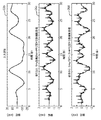
具体例として、図4は、時間0における300mVのオフセット変化及び5秒間の時定数の指数関数的な減衰による除細動イベントをもたらすECG信号の入力波形22aを示す。この例の場合、ECGハイパスフィルタ25の除細動回復26aは、既知の2極バタワースモニタ帯域幅ハイパスフィルタの除細動回復26bと同様なパフォーマンスをもたらす。
As a specific example, FIG. 4 shows an
別の例として、図5は、ECG信号の大レベルベースライン変動22bを示す。この例の場合、ECGハイパスフィルタ25によりフィルタリングされるECG信号のセンターディスプレイ26cは、既知の2極バタワースモニタ帯域幅ハイパスフィルタによりフィルタリングされるECG信号のセンターディスプレイ26dと類似するパフォーマンスを有する。
As another example, FIG. 5 shows a large
図6A及び6Bに関し、図2ないし5に示されるような動作パフォーマンスを達成するECGハイパスフィルタ25の構造形態は、本発明のベースラインローパスフィルタ40と、当該技術分野で知られているような信号遅延部43と、当該技術分野で知られているような信号抽出部44(例えば、加算回路)とを含む。ECGハイパスフィルタ25の実施形態25aに関し、ベースラインローパスフィルタ40aは、FIRローパスフィルタ41とIIRローパスフィルタ42との直列接続を図6Aに示されるように利用する。
6A and 6B, the ECG high-
ECGハイパスフィルタ25の実施形態25bの場合、ベースラインローパスフィルタ40bは、IIRローパスフィルタ42とFIRローパスフィルタ41との直列接続を図6Bに示されるように利用する。
In the case of the
双方の実施形態に関し、ECGハイパスフィルタ25は、信号遅延部43を有する近似的な線形位相フィルタとして動作し、ベースラインフィルタリング前心電図信号ECGbu(i)に適用される近似的な線形位相フィルタ応答を実現し、ECGbu(i)は、高周波信号をフィルタリングするために事前にローパスフィルタリングされ(例えば、≧20Hz)、所定のサンプルレート(例えば、1000Hz)を有する。特に重要なことに、ベースラインフィルタリング前心電図信号ECGbu(i)は、ベースライン変動/ドリフトを含んでいてよい。動作の際に、ベースラインフィルタリング前心電図信号ECGbu(i)は、ベースラインローパスフィルタ40及び信号遅延部43に入力される。何らかのベースライン変動/ドリフトを表現するフィルタリングされたベースライン信号BSEf(i)は、ベースラインローパスフィルタ40により出力され、かつ、信号抽出部44により、遅延したベースラインフィルタリング前心電図信号ECGdbu(i)から除去される。抽出は、ベースラインフィルタリング済み心電図信号ECGbf(i)をもたらし、ECGbf(i)は、ベースラインローパスフィルタ40により、ベースラインフィルタリング前心電図信号ECGbu(i)のうちの任意のベースライン変動/ドリフトについての優れた排除性、及び、最小の歪みを示す。
For both embodiments, the ECG
実際には、FIRローパスフィルタ41及びIIRローパスフィルタ42は、ベースラインフィルタリング前心電図信号ECGbu(i)をローパスフィルタリングするために協働するように構造的に設計され、これにより、ベースラインフィルタリング済み心電図信号ECGbf(i)は、ベースラインフィルタリング前心電図信号ECGbu(i)の傾斜(ramping)に対して敏感には応答せず、及び/又は、ベースラインローパスフィルタ40のインパルス応答の傾斜(slope)は、ベースラインフィルタリング前心電図信号ECGbu(i)のインパルスの前後で実質的に実際に平坦になる。
In practice, the FIR
FIRローパスフィルタ41の一形態において、ボックスカー(boxcar)FIRローパスフィルタが使用され、その場合、全ての係数が同じ値である。従って、ボックスカーFIRローパスフィルタの実装は、各々のサンプルインターバルにおいて、ボックスカーFIRローパスフィルタの最初に入力サンプルを加算し、その後に、ボックスカーFIRローパスフィルタの最後でそれを減算することにより、行われてもよい。
In one form of FIR
ベースラインローパスフィルタ40a(図6A)のボックスカーFIRローパスフィルタの実施形態は、以下の数式[1]に従う。
An embodiment of the boxcar FIR low-pass filter of the baseline low-
![]()
![]()
ベースラインローパスフィルタ40b(図6B)のボックスカーFIRローパスフィルタの実施形態は、以下の数式[2]に従う。
An embodiment of the boxcar FIR low pass filter of the baseline
![]()
![]()
IIRローパスフィルタ42の一形態では、バタワース二次ローパスフィルタが使用され、バタワース二次ローパスフィルタは、以下の数式[3]により表現されるz変換H(z)を有する:
In one form of the IIR low-
![]()
![]()
![]()
![]()
ベースラインローパスフィルタ40b(図6B)に対するバタワース二次ローパスフィルタの一形態は、以下の数式[5]に従ってもよい:
One form of Butterworth second order low pass filter for the baseline
![]()
![]()
FIRローパスフィルタ41とIIRローパスフィルタ42との協働する構造形態の一実施例は、バタワース二次ローパスフィルタのコーナー周波数の逆数に対するボックスカーFIRローパスフィルタの係数の数nの比率を決定することであり、これにより、ベースラインフィルタリング済み心電図信号ECGbf(i)は、ベースラインフィルタリング前心電図信号ECGbu(i)の傾斜に対して敏感には反応しなくなる。この目的のため、バタワース二次ローパスフィルタのコーナー周波数は、ECGハイパスフィルタ25の所望のコーナー周波数の割合として算出され、ボックスカーFIRローパスフィルタの係数の数nは、サンプルレートの半分に正規化されたバタワース二次ローパスフィルタの算出されたコーナー周波数の逆数と実験的に決定される比率との積として算出され、これにより、ベースラインフィルタリング済み心電図信号ECGbf(i)は、ベースラインフィルタリング前心電図信号ECGbu(i)の傾斜に対して敏感には反応しなくなる。この形態は、除細動イベントの後のECG信号の最適な回復をもたらす。この形態も、低周波数ベースライン変動信号の最適な排除をもたらす。
One embodiment of the cooperating structure of the FIR
例示的な診断の実施例では、ECGハイパスフィルタ25の所望のコーナー周波数は0.5Hzであり、バタワース二次ローパスフィルタの係数の算出されたコーナー周波数は0.5Hzの72.2%であり、ボックスカーFIRローパスフィルタの係数の数nは、0.7267の比率に基づいて、ボックスカーFIRローパスフィルタの長さに関して1006個のサンプルに等しい。
In the exemplary diagnostic embodiment, the desired corner frequency of the ECG
例示的なEMSの実施例では、ECGハイパスフィルタ25の所望のコーナー周波数は1.917Hzであり、バタワース二次ローパスフィルタの係数の算出されたコーナー周波数は1.917Hzの72.5%であり、ボックスカーFIRローパスフィルタの係数の数nは、0.7338の比率に基づいて、ボックスカーFIRローパスフィルタの長さに関して66個のサンプルに等しい。
In the exemplary EMS embodiment, the desired corner frequency of the ECG
FIRローパスフィルタ41及びIIRローパスフィルタ42の協働する構造形態の第2形態では、ベースラインローパスフィルタ40のゲインが信号遅延43のゲインに等しい。この形態は、ベースライン変動信号の最適な排除をもたらす。
In the second form of the cooperating structure of the FIR
FIRローパスフィルタ41及びIIRローパスフィルタ42の協働する構造形態の第3形態では、ベースラインローパスフィルタ40のインパルス応答のピークの時間遅延が、信号遅延部による、ベースラインフィルタリング前心電図信号ECGbuの時間遅延の基礎となる。この形態は、QRS波形の直前及び直後でベースライン信号の変化を最小化することにより、STセグメントの上昇又は下降の測定についての最適なパフォーマンスをもたらす。
In the third form of the cooperating structure form of the FIR low-
図1ないし6に関し、当業者は本発明についての多くの利点を認めるであろう。利点は、例えば、(1)ECGハイパスフィルタの処理を行う演算条件を大幅に削減し、ECG信号の歪みを最小化し、ベースライン変動/ドリフトの排除性に優れ、特に、除細動イベントの後にそのような効果を発揮できること、及び、(2)診断目的及びEMS目的の双方に対してECGハイパスフィルタを構築できることを含むが、これらに限定されない。 With reference to FIGS. 1-6, those skilled in the art will appreciate the many advantages of the present invention. Benefits include, for example, (1) significantly reducing the computational requirements for ECG high-pass filter processing, minimizing distortion of ECG signals, and excellent baseline fluctuation / drift elimination, especially after defibrillation events Including, but not limited to, being able to exert such effects and (2) being able to construct an ECG high-pass filter for both diagnostic purposes and EMS purposes.
以上、本発明の実施形態が説明及び記述されてきたが、本願で説明される本発明の実施形態は例示であり、本発明の真の範囲から逸脱することなく、様々な変形及び修正がなされてよいし、それらの要素に対する均等物で置換されてもよいことは、当業者は理解するであろう。更に、発明の本質から逸脱することなく、本発明の教示を適合させるために多くの修正が施されてもよい。従って、本発明は本発明を実施するためのベストモードであると考えられる開示された特定の形態に限定されず、本発明は、添付の特許請求の範囲に該当する全ての実施形態を包含することが、意図されている。 As mentioned above, although embodiment of this invention has been demonstrated and described, embodiment of this invention demonstrated by this application is an illustration, and various deformation | transformation and correction are made | formed without deviating from the true scope of this invention. Those skilled in the art will appreciate that they may be substituted with equivalents to those elements. In addition, many modifications may be made to adapt a teaching of the invention without departing from the essence of the invention. Accordingly, the invention is not limited to the particular forms disclosed which are considered to be the best modes for carrying out the invention, and the invention encompasses all embodiments falling within the scope of the appended claims. It is intended.
Claims (15)
有限インパルス応答ローパスフィルタ及び無限インパルス応答ローパスフィルタを含むベースラインローパスフィルタであって、前記有限インパルス応答ローパスフィルタ及び無限インパルス応答ローパスフィルタは、ベースラインフィルタリング前心電図信号をローパスフィルタリングし、フィルタリングされたベースライン信号を出力するために協働する構造で構成されかつ動作可能に接続される、ベースラインローパスフィルタ;
前記ベースラインフィルタリング前心電図信号を時間的に遅延させ、遅延したベースラインフィルタリング前心電図信号を出力するように動作する信号遅延部;及び
前記ベースラインローパスフィルタ及び前記信号遅延部に動作可能に接続され、前記遅延したベースラインフィルタリング前心電図信号から、前記フィルタリングされたベースライン信号を除去し、ベースラインフィルタリング済み心電図信号を出力する信号抽出部;
を有し、前記有限インパルス応答ローパスフィルタの係数の個数は、前記無限インパルス応答ローパスフィルタのコーナー周波数の逆数に所定の比率を乗算することにより算出される、心電図ハイパスフィルタ。 ECG high pass filter:
A baseline low-pass filter including a finite impulse response low-pass filter and an infinite impulse response low-pass filter, wherein the finite impulse response low-pass filter and the infinite impulse response low-pass filter are low-pass filtered and filtered base signals before the baseline filtering. A baseline low-pass filter constructed and operatively connected to cooperate to output a line signal;
A signal delay unit operative to delay the baseline ECG signal before baseline filtering and output a delayed baseline filtered ECG signal; and operably connected to the baseline low pass filter and the signal delay unit A signal extraction unit that removes the filtered baseline signal from the delayed baseline filtered ECG signal and outputs a baseline filtered ECG signal;
Have a number of coefficients of the finite impulse response low pass filter is calculated by multiplying the predetermined ratio to the reciprocal of the corner frequency of the infinite impulse response low pass filter, ECG high pass filter.
患者の心臓の心電図波形を生成する構造で構成されるプロセッサ;及び
前記心電図波形を表示する構造で構成される心電図ディスプレイ;
を有し、前記プロセッサは、
有限インパルス応答ローパスフィルタ及び無限インパルス応答ローパスフィルタを含むベースラインローパスフィルタであって、前記有限インパルス応答ローパスフィルタ及び無限インパルス応答ローパスフィルタは、ベースラインフィルタリング前心電図信号をローパスフィルタリングし、フィルタリングされたベースライン信号を出力するために協働する構造で構成されかつ動作可能に接続される、ベースラインローパスフィルタ;
前記ベースラインフィルタリング前心電図信号を時間的に遅延させ、遅延したベースラインフィルタリング前心電図信号を出力するように動作する信号遅延部;及び
前記ベースラインローパスフィルタ及び前記信号遅延部に動作可能に接続され、前記遅延したベースラインフィルタリング前心電図信号から、前記フィルタリングされたベースライン信号を除去し、ベースラインフィルタリング済み心電図信号を出力する信号抽出部;
を有し、前記有限インパルス応答ローパスフィルタの係数の個数は、前記無限インパルス応答ローパスフィルタのコーナー周波数の逆数に所定の比率を乗算することにより算出される、心電図モニタ。 An electrocardiogram monitor:
A processor configured with a structure for generating an electrocardiogram waveform of a patient's heart; and an electrocardiogram display configured with a structure for displaying the electrocardiogram waveform;
The processor includes:
A baseline low-pass filter including a finite impulse response low-pass filter and an infinite impulse response low-pass filter, wherein the finite impulse response low-pass filter and the infinite impulse response low-pass filter are low-pass filtered and filtered base signals before the baseline filtering. A baseline low-pass filter constructed and operatively connected to cooperate to output a line signal;
A signal delay unit operative to delay the baseline ECG signal before baseline filtering and output a delayed baseline filtered ECG signal; and operably connected to the baseline low pass filter and the signal delay unit A signal extraction unit that removes the filtered baseline signal from the delayed baseline filtered ECG signal and outputs a baseline filtered ECG signal;
Have a, the number of finite impulse response coefficients of the low pass filter is calculated by multiplying the predetermined ratio to the reciprocal of the corner frequency of the infinite impulse response low pass filter, an electrocardiogram monitor.
患者の心臓の心電図波形を生成する構造で構成される心電図モニタ;
ショックエネルギを保存する構造で構成されるショックエネルギソース;及び
前記心電図波形のQRS分析に応じて、前記患者の心臓へのショックエネルギの伝達を制御する構造で構成される除細動コントローラ;
を有し、前記心電図モニタは、
有限インパルス応答ローパスフィルタ及び無限インパルス応答ローパスフィルタを含むベースラインローパスフィルタであって、前記有限インパルス応答ローパスフィルタ及び無限インパルス応答ローパスフィルタは、ベースラインフィルタリング前心電図信号をローパスフィルタリングし、フィルタリングされたベースライン信号を出力するために協働する構造で構成されかつ動作可能に接続される、ベースラインローパスフィルタ;
前記ベースラインフィルタリング前心電図信号を時間的に遅延させ、遅延したベースラインフィルタリング前心電図信号を出力するように動作する信号遅延部;及び
前記ベースラインローパスフィルタ及び前記信号遅延部に動作可能に接続され、前記遅延したベースラインフィルタリング前心電図信号から、前記フィルタリングされたベースライン信号を除去し、ベースラインフィルタリング済み心電図信号を出力する信号抽出部;
を有し、前記有限インパルス応答ローパスフィルタの係数の個数は、前記無限インパルス応答ローパスフィルタのコーナー周波数の逆数に所定の比率を乗算することにより算出される、除細動器。 Defibrillator:
An electrocardiogram monitor comprising a structure for generating an electrocardiogram waveform of the patient's heart;
A shock energy source configured with a structure for storing shock energy; and a defibrillation controller configured with a structure for controlling transmission of shock energy to the patient's heart in response to a QRS analysis of the electrocardiogram waveform;
The electrocardiogram monitor comprises:
A baseline low-pass filter including a finite impulse response low-pass filter and an infinite impulse response low-pass filter, wherein the finite impulse response low-pass filter and the infinite impulse response low-pass filter are low-pass filtered and filtered base signals before the baseline filtering. A baseline low-pass filter constructed and operatively connected to cooperate to output a line signal;
A signal delay unit operative to delay the baseline ECG signal before baseline filtering and output a delayed baseline filtered ECG signal; and operably connected to the baseline low pass filter and the signal delay unit A signal extraction unit that removes the filtered baseline signal from the delayed baseline filtered ECG signal and outputs a baseline filtered ECG signal;
Have a number of coefficients of the finite impulse response low pass filter is calculated by multiplying the predetermined ratio to the reciprocal of the corner frequency of the infinite impulse response low pass filter, the defibrillator.
Applications Claiming Priority (3)
| Application Number | Priority Date | Filing Date | Title |
|---|---|---|---|
| US201361901477P | 2013-11-08 | 2013-11-08 | |
| US61/901,477 | 2013-11-08 | ||
| PCT/IB2014/065807 WO2015068106A1 (en) | 2013-11-08 | 2014-11-05 | Ecg high pass filter |
Publications (2)
| Publication Number | Publication Date |
|---|---|
| JP2016535632A JP2016535632A (en) | 2016-11-17 |
| JP6560206B2 true JP6560206B2 (en) | 2019-08-14 |
Family
ID=51903969
Family Applications (1)
| Application Number | Title | Priority Date | Filing Date |
|---|---|---|---|
| JP2016528104A Active JP6560206B2 (en) | 2013-11-08 | 2014-11-05 | ECG high-pass filter, ECG monitor and defibrillator |
Country Status (5)
| Country | Link |
|---|---|
| US (1) | US20160278655A1 (en) |
| EP (1) | EP3065632A1 (en) |
| JP (1) | JP6560206B2 (en) |
| CN (1) | CN105705086B (en) |
| WO (1) | WO2015068106A1 (en) |
Families Citing this family (2)
| Publication number | Priority date | Publication date | Assignee | Title |
|---|---|---|---|---|
| CN105877740B (en) * | 2016-04-12 | 2017-05-17 | 珠海市宏邦医疗科技有限公司 | Rapid resetting method for electrocardiogram waveform baseline |
| US10709349B2 (en) * | 2017-04-18 | 2020-07-14 | Boston Scientific Scimed Inc. | Annotation waveform |
Family Cites Families (13)
| Publication number | Priority date | Publication date | Assignee | Title |
|---|---|---|---|---|
| US4472785A (en) * | 1980-10-13 | 1984-09-18 | Victor Company Of Japan, Ltd. | Sampling frequency converter |
| US5042026A (en) * | 1987-03-03 | 1991-08-20 | Nec Corporation | Circuit for cancelling whole or part of a waveform using nonrecursive and recursive filters |
| DE4106858A1 (en) * | 1991-03-04 | 1992-09-10 | Siemens Ag | ARRANGEMENT FOR FILTERING BASELINE FLUCTUATIONS FROM PHYSIOLOGICAL MEASURING SIGNALS |
| US5269313A (en) * | 1991-09-09 | 1993-12-14 | Sherwood Medical Company | Filter and method for filtering baseline wander |
| US5918184A (en) * | 1992-09-21 | 1999-06-29 | Lucent Technologies Inc. | Method and apparatus for detecting a supervisory audio tone |
| SE9302432D0 (en) * | 1993-07-16 | 1993-07-16 | Siemens-Elema Ab | DEVICE FOR FILTERING ECG SIGNALS |
| JP3699234B2 (en) * | 1997-02-28 | 2005-09-28 | ジーイー横河メディカルシステム株式会社 | Magnetic resonance imaging device |
| CA2290629A1 (en) * | 1997-05-21 | 1998-11-26 | Victor M. Depinto | Ecg noise detection system |
| GB2342449B (en) * | 1998-12-22 | 2000-09-20 | Neoventa Medical Ab | Device for reducing signal noise in a fetal ECG signal |
| US6280391B1 (en) * | 1999-02-08 | 2001-08-28 | Physio-Control Manufacturing Corporation | Method and apparatus for removing baseline wander from an egg signal |
| US20070078353A1 (en) * | 2005-10-04 | 2007-04-05 | Welch Allyn, Inc. | Method and apparatus for removing baseline wander from an ECG signal |
| US7974366B2 (en) * | 2006-02-21 | 2011-07-05 | Marvell World Trade Ltd. | Low-latency baseline-wander compensation systems and methods |
| US8509881B2 (en) * | 2009-11-03 | 2013-08-13 | Cardiac Science Corporation | True ECG measurement during cardio pulmonary resuscitation by adaptive piecewise stitching algorithm |
-
2014
- 2014-11-05 CN CN201480060947.XA patent/CN105705086B/en active Active
- 2014-11-05 WO PCT/IB2014/065807 patent/WO2015068106A1/en active Application Filing
- 2014-11-05 US US15/034,267 patent/US20160278655A1/en not_active Abandoned
- 2014-11-05 EP EP14799551.8A patent/EP3065632A1/en not_active Ceased
- 2014-11-05 JP JP2016528104A patent/JP6560206B2/en active Active
Also Published As
| Publication number | Publication date |
|---|---|
| CN105705086B (en) | 2019-05-07 |
| CN105705086A (en) | 2016-06-22 |
| WO2015068106A1 (en) | 2015-05-14 |
| US20160278655A1 (en) | 2016-09-29 |
| EP3065632A1 (en) | 2016-09-14 |
| JP2016535632A (en) | 2016-11-17 |
Similar Documents
| Publication | Publication Date | Title |
|---|---|---|
| EP3065821B1 (en) | Variable bandwidth ecg high pass filter | |
| US7894885B2 (en) | Coherent signal rejection in ECG | |
| US8781567B2 (en) | Implantable medical devices using heuristic filtering in cardiac event detection | |
| WO2000041621A1 (en) | Electrocardiograph having large low frequency dynamic range | |
| Gaikwad et al. | Removal of high frequency noise from ECG signal using digital IIR butterworth filter | |
| JPH07163535A (en) | Patient monitor | |
| RU2677007C2 (en) | Apparatus and method for ecg motion artifact removal | |
| JP6560206B2 (en) | ECG high-pass filter, ECG monitor and defibrillator | |
| US6735466B1 (en) | Analytical signal method for analysis of T-wave alternans | |
| CN105790729A (en) | Power frequency filtering method and device by using CZT and adaptive filtering technology | |
| EP2767224B1 (en) | A method for the detection of subcutaneous cardiac signals and a cardiac device for use in detecting subcutaneous cardiac signals | |
| EP1215996A1 (en) | Analytical signal method for analysis of t-wave alternans | |
| JP2012529975A5 (en) | ||
| EP3893723B1 (en) | Filtering unit for electrocardiography applications | |
| CN108785049B (en) | Measuring device for external chest compression frequency | |
| RU2251968C1 (en) | Method and device for eliminating electrocardiogram signal isoline drift | |
| Dey et al. | ECG RECTIFICATION THROUGH MULTI-STAGE ADAPTIVE FILTERING | |
| Rantanen et al. | Stimulation waveform selection to suppress functional electrical stimulation artifact from surface EMG signals | |
| RU2532297C1 (en) | Device for suppressing power-frequency noise effect on electric cardiosignal | |
| Goyal et al. | To Compare Various Filters for Removal of Noise From ECG Wave | |
| AHMAD et al. | Power line noise reduction in ecg by butterworth notch filters: A comparative study | |
| EP2799005A1 (en) | Method and system for signal analyzing and processing module |
Legal Events
| Date | Code | Title | Description |
|---|---|---|---|
| A621 | Written request for application examination |
Free format text: JAPANESE INTERMEDIATE CODE: A621 Effective date: 20171102 |
|
| A977 | Report on retrieval |
Free format text: JAPANESE INTERMEDIATE CODE: A971007 Effective date: 20180927 |
|
| A131 | Notification of reasons for refusal |
Free format text: JAPANESE INTERMEDIATE CODE: A131 Effective date: 20181023 |
|
| A521 | Request for written amendment filed |
Free format text: JAPANESE INTERMEDIATE CODE: A523 Effective date: 20190121 |
|
| TRDD | Decision of grant or rejection written | ||
| A01 | Written decision to grant a patent or to grant a registration (utility model) |
Free format text: JAPANESE INTERMEDIATE CODE: A01 Effective date: 20190625 |
|
| A61 | First payment of annual fees (during grant procedure) |
Free format text: JAPANESE INTERMEDIATE CODE: A61 Effective date: 20190718 |
|
| R150 | Certificate of patent or registration of utility model |
Ref document number: 6560206 Country of ref document: JP Free format text: JAPANESE INTERMEDIATE CODE: R150 |
|
| R250 | Receipt of annual fees |
Free format text: JAPANESE INTERMEDIATE CODE: R250 |
|
| R250 | Receipt of annual fees |
Free format text: JAPANESE INTERMEDIATE CODE: R250 |