JP6554013B2 - INPUT DEVICE, METHOD OF CONTROLLING INPUT DEVICE, ELECTRONIC DEVICE PROVIDED WITH INPUT DEVICE, METHOD OF CONTROLLING ELECTRONIC DEVICE, PROGRAM, AND STORAGE MEDIUM - Google Patents
INPUT DEVICE, METHOD OF CONTROLLING INPUT DEVICE, ELECTRONIC DEVICE PROVIDED WITH INPUT DEVICE, METHOD OF CONTROLLING ELECTRONIC DEVICE, PROGRAM, AND STORAGE MEDIUM Download PDFInfo
- Publication number
- JP6554013B2 JP6554013B2 JP2015202912A JP2015202912A JP6554013B2 JP 6554013 B2 JP6554013 B2 JP 6554013B2 JP 2015202912 A JP2015202912 A JP 2015202912A JP 2015202912 A JP2015202912 A JP 2015202912A JP 6554013 B2 JP6554013 B2 JP 6554013B2
- Authority
- JP
- Japan
- Prior art keywords
- measurement
- intersections
- electrodes
- conductor
- self
- Prior art date
- Legal status (The legal status is an assumption and is not a legal conclusion. Google has not performed a legal analysis and makes no representation as to the accuracy of the status listed.)
- Active
Links
Images


Classifications
-
- G—PHYSICS
- G06—COMPUTING; CALCULATING OR COUNTING
- G06F—ELECTRIC DIGITAL DATA PROCESSING
- G06F3/00—Input arrangements for transferring data to be processed into a form capable of being handled by the computer; Output arrangements for transferring data from processing unit to output unit, e.g. interface arrangements
- G06F3/01—Input arrangements or combined input and output arrangements for interaction between user and computer
- G06F3/03—Arrangements for converting the position or the displacement of a member into a coded form
- G06F3/041—Digitisers, e.g. for touch screens or touch pads, characterised by the transducing means
- G06F3/044—Digitisers, e.g. for touch screens or touch pads, characterised by the transducing means by capacitive means
-
- G—PHYSICS
- G06—COMPUTING; CALCULATING OR COUNTING
- G06F—ELECTRIC DIGITAL DATA PROCESSING
- G06F3/00—Input arrangements for transferring data to be processed into a form capable of being handled by the computer; Output arrangements for transferring data from processing unit to output unit, e.g. interface arrangements
- G06F3/01—Input arrangements or combined input and output arrangements for interaction between user and computer
- G06F3/03—Arrangements for converting the position or the displacement of a member into a coded form
- G06F3/041—Digitisers, e.g. for touch screens or touch pads, characterised by the transducing means
- G06F3/0416—Control or interface arrangements specially adapted for digitisers
- G06F3/04166—Details of scanning methods, e.g. sampling time, grouping of sub areas or time sharing with display driving
- G06F3/041662—Details of scanning methods, e.g. sampling time, grouping of sub areas or time sharing with display driving using alternate mutual and self-capacitive scanning
-
- G—PHYSICS
- G06—COMPUTING; CALCULATING OR COUNTING
- G06F—ELECTRIC DIGITAL DATA PROCESSING
- G06F3/00—Input arrangements for transferring data to be processed into a form capable of being handled by the computer; Output arrangements for transferring data from processing unit to output unit, e.g. interface arrangements
- G06F3/01—Input arrangements or combined input and output arrangements for interaction between user and computer
- G06F3/03—Arrangements for converting the position or the displacement of a member into a coded form
- G06F3/041—Digitisers, e.g. for touch screens or touch pads, characterised by the transducing means
- G06F3/0416—Control or interface arrangements specially adapted for digitisers
- G06F3/0418—Control or interface arrangements specially adapted for digitisers for error correction or compensation, e.g. based on parallax, calibration or alignment
- G06F3/04186—Touch location disambiguation
-
- G—PHYSICS
- G06—COMPUTING; CALCULATING OR COUNTING
- G06F—ELECTRIC DIGITAL DATA PROCESSING
- G06F3/00—Input arrangements for transferring data to be processed into a form capable of being handled by the computer; Output arrangements for transferring data from processing unit to output unit, e.g. interface arrangements
- G06F3/01—Input arrangements or combined input and output arrangements for interaction between user and computer
- G06F3/03—Arrangements for converting the position or the displacement of a member into a coded form
- G06F3/041—Digitisers, e.g. for touch screens or touch pads, characterised by the transducing means
- G06F3/044—Digitisers, e.g. for touch screens or touch pads, characterised by the transducing means by capacitive means
- G06F3/0446—Digitisers, e.g. for touch screens or touch pads, characterised by the transducing means by capacitive means using a grid-like structure of electrodes in at least two directions, e.g. using row and column electrodes
-
- G—PHYSICS
- G01—MEASURING; TESTING
- G01R—MEASURING ELECTRIC VARIABLES; MEASURING MAGNETIC VARIABLES
- G01R27/00—Arrangements for measuring resistance, reactance, impedance, or electric characteristics derived therefrom
- G01R27/02—Measuring real or complex resistance, reactance, impedance, or other two-pole characteristics derived therefrom, e.g. time constant
- G01R27/26—Measuring inductance or capacitance; Measuring quality factor, e.g. by using the resonance method; Measuring loss factor; Measuring dielectric constants ; Measuring impedance or related variables
- G01R27/2605—Measuring capacitance
-
- G—PHYSICS
- G06—COMPUTING; CALCULATING OR COUNTING
- G06F—ELECTRIC DIGITAL DATA PROCESSING
- G06F2203/00—Indexing scheme relating to G06F3/00 - G06F3/048
- G06F2203/041—Indexing scheme relating to G06F3/041 - G06F3/045
- G06F2203/04111—Cross over in capacitive digitiser, i.e. details of structures for connecting electrodes of the sensing pattern where the connections cross each other, e.g. bridge structures comprising an insulating layer, or vias through substrate
Description
本発明は入力装置等に関する。 The present invention relates to an input device and the like.
スマートフォンやデジタルカメラの入力装置として静電容量方式のタッチパネルが普及している。静電容量方式では、列方向に配置された複数の列電極と行方向に配置された複数の行電極との間の静電容量に基づき、指等がタッチしている座標が特定される。タッチパネルにおいて端部に配置された電極に対する指等の接触面積は、タッチパネルの中央付近に配置された電極に対する指等の接触面積よりも小さくなる。これは、指の一部はタッチパネルに触れているものの、残りの部分はタッチパネルからはみ出してしまうためである。したがって、端部に配置された電極についてのタッチ検出の精度が低下しやすい。特許文献1によれば、カレントミラー回路によりタッチパネルの検出信号を増幅することで、タッチ検出の精度を向上することが提案されている。 Capacitive touch panels are widely used as input devices for smartphones and digital cameras. In the capacitance method, the coordinates touched by a finger or the like are specified based on the capacitance between a plurality of column electrodes arranged in the column direction and a plurality of row electrodes arranged in the row direction. The contact area of the finger or the like with respect to the electrode arranged at the end of the touch panel is smaller than the contact area of the finger or the like with respect to the electrode arranged near the center of the touch panel. This is because part of the finger touches the touch panel, but the remaining part protrudes from the touch panel. Therefore, the accuracy of touch detection for the electrodes disposed at the end tends to be reduced. According to Patent Document 1, it is proposed to improve the accuracy of touch detection by amplifying a detection signal of a touch panel by a current mirror circuit.
タッチパネルは液晶パネルなどの表示装置に対して積層されることが多い。したがって液晶パネルを駆動するための駆動信号などのノイズが、タッチパネルのカレントミラー回路によって増幅されてしまい、タッチ検出の精度が低下しうる。そこで、本発明は、タッチパネルの端部付近に対するタッチについても精度よく検出することを目的とする。 The touch panel is often stacked on a display device such as a liquid crystal panel. Therefore, noise such as a drive signal for driving the liquid crystal panel is amplified by the current mirror circuit of the touch panel, and the accuracy of touch detection may be reduced. Then, an object of this invention is to detect accurately also about the touch with the edge part vicinity of a touch panel.
本発明によれば、
複数の列電極と、前記複数の列電極に交差するように配置された複数の行電極とを有するタッチパネルセンサーと、
前記複数の列電極および前記複数の行電極のうち前記タッチパネルセンサーの外周部に配置された列電極および行電極である複数の外周電極のそれぞれについて自己容量測定を実行する第一測定手段と、
前記第一測定手段により測定された前記複数の外周電極の測定結果のいずれかが閾値を超えているかどうかを判定する判定手段と、
前記第一測定手段により測定された前記複数の外周電極の測定結果のいずれかが閾値を超えている場合、前記複数の列電極と前記複数の行電極とが交差することで形成されている複数の交点のそれぞれの相互容量の積算回数を、前記自己容量測定の測定結果に基づき推定される導体物の位置に近い交点の積算回数が多くなり、前記導体物の位置から遠い交点の積算回数が少なくなるように設定し、前記第一測定手段により測定された前記複数の外周電極の測定結果のいずれもが前記閾値を超えていない場合、前記複数の交点のそれぞれの相互容量の積算回数を同一の値に設定する設定手段と、
前記設定手段により前記複数の交点のそれぞれに設定された積算回数に応じて前記複数の交点のそれぞれについて相互容量測定を実行する第二測定手段と、
前記第二測定手段により実行された前記相互容量測定の測定結果に基づき前記導体物の座標を決定する決定手段と、
を有することを特徴とする入力装置が提供される。
According to the invention
A touch panel sensor having a plurality of column electrodes and a plurality of row electrodes arranged to intersect the plurality of column electrodes;
First measuring means for performing self-capacitance measurement for each of the plurality of column electrodes and the plurality of row electrodes, the plurality of column electrodes disposed on the outer peripheral portion of the touch panel sensor and the plurality of outer electrodes being row electrodes;
A determination unit that determines whether any one of the measurement results of the plurality of outer peripheral electrodes measured by the first measurement unit exceeds a threshold;
When any of the measurement results of the plurality of outer peripheral electrodes measured by the first measurement unit exceeds a threshold, a plurality of column electrodes and a plurality of row electrodes are formed by crossing each other The cumulative number of mutual capacitances at the intersections of each of the intersection points is closer to the position of the conductor object estimated based on the measurement result of the self-capacitance measurement, and the accumulated number of intersection points far from the position of the conductor object is increased. When all of the measurement results of the plurality of outer peripheral electrodes measured by the first measurement means do not exceed the threshold, the number of times of mutual capacitance integration of the plurality of intersections is the same. Setting means for setting the value of
Second measuring means for performing mutual capacitance measurement for each of the plurality of intersections according to the number of integrations set for each of the plurality of intersections by the setting means;
Determining means for determining coordinates of the conductor based on a measurement result of the mutual capacitance measurement performed by the second measuring means;
An input device is provided.
本発明によればタッチパネルの端部付近に対するタッチについても精度よく検出することが可能となる。 According to the present invention, it is possible to accurately detect a touch on the edge of the touch panel.
<タッチパネルの構成>
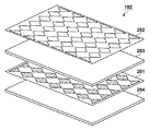
図1ないし図3を用いて入力装置100の構成の一例を説明する。タッチパネルドライバー101は入力装置100の駆動と座標の算出とを実行する。タッチパネルドライバー101はASIC(特定用途集積回路)により構成されてもよいし、図1に示すようにCPU120、ROM121およびRAM122などにより構成されてもよい。CPU120はROM121に記憶されている制御プログラムを実行することで測定部106、座標決定部108、設定部130および判定部111などとして機能する。タッチパネルコントローラ105は静電容量式のタッチパネルセンサー102の制御を行う制御ユニットである。タッチパネルセンサー102は指などの導体物103との間に静電容量104を発生させるセンサーである。図2が示すようにタッチパネルセンサー102はXセンサー201、ガラス203、Yセンサー202および保護フィルム204を積層することで形成されうる。なお、積層構造はこれに限定されることはない。たとえば、Xセンサー201とYセンサー202との間の透明部材が省略され、保護フィルム204がガラスなどに変更されてもよい。Xセンサー201はX方向に並んだ複数の列電極(X電極)を有している。Yセンサー202はY方向に並んだ複数の行電極(Y電極)を有している。
<Configuration of touch panel>
An example of the configuration of the
図1が示すように、列電極と行電極とは交差(例:直交)するように配置されている。列電極と行電極とが直交する部分は交点と呼ばれ、座標の基準となる。導体物103によるタッチパネルセンサー102の接触ないしは近接を検出する方法としては自己容量測定と相互容量測定とがある。自己容量測定ではタッチパネルコントローラ105がXセンサー201における各列電極に対して順番に駆動信号を供給し、各列電極の静電容量を検出する。同様に、タッチパネルコントローラ105は、Yセンサー202における各行電極に対して順番に駆動信号を供給し、各行電極の静電容量を検出する。つまり、各電極ごとに静電容量(自己容量)が測定される。なお、各電極の一端から駆動信号(駆動電流)が供給され、各電極の他端に生じる電圧が測定され、この測定された電圧が静電容量に換算される。さらに、換算された静電容量と、導体物103によるタッチパネルセンサー102の接触ないしは近接していないときのデフォルトの静電容量との差分が変化量として求められてもよい。タッチパネルドライバー101は静電容量の変化量の大きな列電極と行電極との交点の座標を導体物103による接触ないしは近接がなされた位置の座標として決定する。あるいは、タッチパネルドライバー101は静電容量の変化量を用いてX方向の重心109とY方向の重心109とを求めることで、導体物103による接触ないしは近接がなされた位置の座標を決定してもよい。相互容量測定ではタッチパネルコントローラ105は、Xセンサー201またはYセンサー202の一方のみをスキャンして行き、そのときの交点の静電容量の変化量を検出することで、タッチされた位置の座標を決定する。
As shown in FIG. 1, the column electrode and the row electrode are arranged so as to intersect (eg, orthogonal). The portion at which the column electrode and the row electrode cross at right angles is called an intersection point and serves as a reference of coordinates. Methods for detecting contact or proximity of the
図1においてタッチパネルセンサー102の上側には各行電極の静電容量104がグラフとして示され、タッチパネルセンサー102の右側には各列電極の静電容量104がグラフとして示されている。これらのグラフの縦軸は静電容量を示し、横軸は電極の位置を示している。
In FIG. 1, the
測定部106はタッチパネルコントローラ105と協働してタッチパネルセンサー102の静電容量を測定するユニットである。自己容量測定部161は、複数の外周電極のそれぞれについて自己容量測定を実行するユニットである。外周電極とは、複数の列電極および複数の行電極のうち、タッチパネルセンサー102の外周部に配置された列電極および行電極のことである。たとえば、Xセンサー201が列電極X1ないしXnから構成され、Yセンサー202が行電極Y1ないしYmから構成されている場合、最外周の電極は列電極X1、Xn、行電極Y1、Ymである。相互容量測定部162は、複数の交点のそれぞれに相互容量測定を実行するユニットである。なお、自己容量と比較して相互容量は微量であるため、相互容量測定部162は複数回の測定を実行し、測定結果を積算する。積算回数は設定部130によって設定される。
The
判定部111は自己容量測定の測定結果に基づき外周電極へのタッチ(接触ないし近接)の有無を判定したり、相互容量測定の測定結果に基づきタッチパネルセンサー102のいずれかの電極へのタッチの有無を判定したりするユニットである。判定部111は、たとえば、ある電極について静電容量104が検出閾値107を超えていれば、その電極についてタッチがあったと判定する。また、判定部111はある電極について静電容量104が検出閾値107を超えていなければ、その電極についてタッチがないと判定する。
The determination unit 111 determines the presence / absence of a touch (contact or proximity) to the outer peripheral electrode based on the measurement result of the self-capacitance measurement, or the presence / absence of a touch to any electrode of the
座標決定部108は、各列電極の静電容量104と各行電極の静電容量104とのそれぞれについて重心109を算出し、Xセンサー201の重心109とYセンサー202の重心109とをタッチ位置の座標として決定する。タッチパネルセンサー102の電極配置が二次元以上の場合、軸(ディメンション)毎に重心109が算出される。
The
設定部130は、各交点に適用される積算回数を設定するユニットである。変更部110は各交点の積算回数を変更するユニットである。とりわけ、相互容量測定では各交点の静電容量の変化量が複数回数にわたって測定され、測定結果が積算される。自己容量測定に基づき推定されたタッチ位置が外周電極の近傍であれば、変更部110は、タッチ位置から各交点までの距離に概ね比例して各交点の相互容量の積算回数を設定する。一方で、自己容量測定に基づき推定されたタッチ位置が外周電極の近傍でなければ、変更部110は、各交点の相互容量の積算回数を同一の回数(初期値)に設定する。このように、積算回数を可変とすることでタッチパネルセンサー102の端部付近における交点に対するタッチ検出の精度が向上する。エリア処理部112は、自己容量測定によって推定されたタッチ位置に応じて各交点を複数のエリア(領域)分類する。変更部110はエリア処理部112により分類されたエリアしたがって各エリアに属する交点の積算回数を設定する。つまり、同一のエリアに属している複数の交点には同一の積算回数が適用される。
The
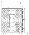
図3を用いてタッチパネルセンサー102の交点について説明する。電極配置領域300はタッチパネルセンサー102においてXセンサー201とYセンサー202とが配置されている領域である。Xセンサー201およびYセンサー202では、タッチパネルセンサー102の大きさに応じて必要な静電容量104が得られるように、電極パッドの形状と電極の本数とが選択されている。本実施例ではXセンサー201は7本の列電極X1ないしX7から構成されており、Yセンサー202は9本の行電極Y1ないしY9から構成されている。図3が示すように、本実施例では63個の交点C11〜C97が設けられている。ここでは、列電極Xiと行電極Yjの交点をCjiと表現している。iとjは電極の番号を示すインデックスである。タッチパネルコントローラ105は測定部106に自己容量測定を指示されると行電極Y1〜Y9、列電極X1〜X7のそれぞれについて静電容量104を測定する。また、タッチパネルコントローラ105は測定部106により相互容量測定を指示されると交点C11〜C97のそれぞれについて静電容量の変化量を測定する。タッチパネルコントローラ105における測定結果は電圧の情報であるため、測定部106において電圧から静電容量に換算される。
The intersection of the
図4を用いて導体物103が外周電極へタッチし場合における自己容量測定による静電容量の変化量について説明する。導体物103は、図4に示すように、外周電極である行電極Y1と列電極X7とにそれぞれ接触ないしは近接している。なお、導体物103はタッチパネルセンサー102の端部に位置しているため、導体物103一部のみがタッチパネルセンサー102に接触し、他の部分はタッチパネルセンサー102の外部に位置している。これは、静電容量の減少につながる。
The amount of change in capacitance due to self-capacitance measurement when the
タッチパネルドライバー101は自己容量測定を実行することで、タッチパネルセンサー102の外周部に配置された列電極X1、X7、行電極Y1、Y9のそれぞれの静電容量を測定する。これらの測定結果は図4において静電容量402、403、404、405として示されている。
The
自己容量測定では一つの電極のみで静電容量を測定することが可能である。そのため、導体物103の全体が電極配置領域300に含まれていなくても、列電極X7の静電容量403と行電極Y1の静電容量405には導体物103の存在を示す容量変化が表れる。
In self-capacitance measurement, it is possible to measure capacitance with only one electrode. Therefore, even if the
たとえば、判定部111は、静電容量405が検出閾値107を超えているため、導体物103が外周電極に接触または近接していると判定する。なお、判定部111は、静電容量402、403、404、405のうちで列電極X7の静電容量403の変化量が最も大きいことから、導体物103が列電極X7の線上に接していると推定してもよい。このような自己容量測定に基づくタッチ位置の推定は座標決定部108または設定部130が実行してもよい。次に、行電極Y1の静電容量405にも有意な容量変化あることから、判定部111は、導体物103が行電極Y1の近傍に存在すると推定する。ただし、行電極Y1の静電容量405の変化量が検出閾値107よりも少ないため、判定部111は、導体物103がタッチパネルセンサー102の外部に位置しているか、行電極Y2側に位置していると推定する。列電極X1の静電容量402と行電極Y9の静電容量404には有意な変化が発生していないため、判定部111は、導体物103が列電極X1と行電極Y9には接していないと推定する。
For example, since the
これら推定結果を総合し、判定部111は、交点C17近傍を導体物103の位置の第1候補に決定する。また、判定部111は、交点C17の隣接交点C16、C26、C27と、列電極X7と係る交点C27、C37、・・・、C87、C97近傍を第2候補に決定する。また、判定部111は、行電極Y1に係る交点C11、C12、・・・、C15を第3候補に決定する。
By combining these estimation results, the determination unit 111 determines the vicinity of the intersection C17 as the first candidate for the position of the
<フローチャート>
図5を用いてタッチ位置の座標決定処理を説明する。なお、CPU120は、ROM121に記憶されている制御プログラムをRAM122に展開して実行することで、各種の手段として機能する。
<Flow chart>
The touch position coordinate determination process will be described with reference to FIG. The
S501で自己容量測定部161はタッチパネルセンサー102の外周部に配置された電極X1、X7、Y1、Y9それぞれの静電容量402〜405を自己容量測定により測定する。静電容量402〜405は、たとえば、タッチパネルセンサー102に導体物103が接触も近接もしてない状態で測定された静電容量と測定された静電容量との差分(変化量)であってもよい。
In step S <b> 501, the self-capacitance measuring unit 161 measures the
S502で判定部111は、静電容量402〜405の測定結果に基づいて、外周電極へのタッチが有るかどうかを判定する。たとえば、静電容量402〜405のいずれかが所定の検出閾値(タッチ閾値)を超えていれば、判定部111は、外周電極へのタッチが有ると判定する。一方で、静電容量402〜405のいずれもが所定の検出閾値を超えていなければ、判定部111は、外周電極へのタッチが無いと判定する。外周電極へのタッチがあった場合には、タッチパネルドライバー101はS503に進む。
In S502, the determination unit 111 determines whether there is a touch on the outer peripheral electrode based on the measurement results of the
S503で設定部130は各交点C11〜C97の積算回数を可変設定する。たとえば、エリア処理部112は外周電極についての自己容量測定の結果に基づき導体物103の近傍エリアを決定する。変更部110は、近傍エリアに属している各交点の積算回数を相対的に多く設定し、導体物103から遠隔にあるエリアに属している交点の積算回数を相対的に少なく設定する。ただし、全交点の積算回数の合計値は常に一定に維持されてもよい。これにより、全交点の相互容量測定に要する測定時間を一定に維持することが可能となる。相互容量測定に要する測定時間が長くなると、ユーザがタッチを行ってから座標が確定するまでの時間も長くなるため、ユーザはタッチに対する応答が遅くなったように感じるであろう。よって、各交点の積算回数は個別に増減されるものの全交点の積算回数の合計値は一定に維持されるため、ユーザビリティを損なうことなく、外周部でのタッチの検出精度を向上させることが可能となろう。全交点の積算回数の合計値は常に一定に維持することはオプションにすぎない。
In S503, the
S502で外周電極へのタッチが検出されなかった場合、タッチパネルドライバー101はS504に進む。S504で設定部130は全交点に対して同一の積算回数(初期値)を設定する。この積算回数は、たとえば、タッチパネルセンサー102の感度などに応じて入力装置100の設計時に設定される初期値である。
If a touch on the outer peripheral electrode is not detected in S502, the
S505で相互容量測定部162はタッチパネルコントローラ105を通じて相互容量測定を実行する。たとえば、相互容量測定部162は設定部130により各交点C11〜C97に設定された積算回数に応じてすべての交点C11〜C97について相互容量測定を実行する。自己容量測定に基づく導体物103の推定位置が外周電極の近傍であれば可変設定された積算回数が適用される。導体物103の推定位置が外周電極の近傍でなければ一律の積算回数が適用される。
In step S505, the mutual
S506で判定部111は各交点C11〜C97で測定された静電容量の変化量に基づき何らかの導体物103がタッチパネルセンサー102にタッチしているかどうかを判定する。たとえば、判定部111は各交点C11〜C97で測定された静電容量の変化量のうちいずれかが検出閾値107を超えているかどうかを判定する。各交点C11〜C97で測定された静電容量の変化量のうち一つでも検出閾値107を超えていれば、判定部111は「タッチ有り」と判定し、S507に進む。一方で、各交点C11〜C97で測定された静電容量の変化量のうちいずれもが検出閾値107を超えていなければ、判定部111は「タッチ無し」と判定し、S507をスキップする。
In step S <b> 506, the determination unit 111 determines whether any
S507で座標決定部108はタッチの検出された近傍の交点の静電容量の変化量に基づき座標を算出する。たとえば、図1を用いて説明したように、Xセンサー201の静電容量の変化量の重心109と、Yセンサー202の静電容量の変化量の重心109とを算出することで座標を決定する。タッチパネルドライバー101はタッチが検出されたことを示す信号(タッチオン信号)と、算出された座標(タッチ位置データ)を外部に出力する。
In step S507, the coordinate
<効果>
図6(a)は比較例における積算回数と静電容量の変化量との関係を示している。なお、比較例は、自己容量測定に基づく導体物103のタッチ位置の推定を実行しないものであるため、各交点の積算回数が常に一律に設定されている。図6(b)は本実施例における積算回数と静電容量の変化量との関係を示している。図6(a)、図6(b)において、601は自己容量測定の実行タイミングを示している。602は相互容量測定の実行タイミングを示している。603は自己容量測定により測定された静電容量の変化量を示している。604は相互容量測定により測定された静電容量の変化量を示している。
<Effect>
FIG. 6A shows the relationship between the number of integrations and the amount of change in capacitance in the comparative example. Note that, in the comparative example, since the estimation of the touch position of the
図6(a)が示すように、比較例の入力装置では列電極X7と行電極Y1に導体物103がタッチしていたとしても、交点C17の静電容量の変化量が検出閾値107を超えない。これは、各交点の積算回数を一律にしているためである。また、このような状況は、タッチパネルセンサー102に対する導体物103の接触面積が少ないときに発生しやすい。したがって、比較例では、タッチパネルセンサー102の外周部におけるタッチの検出精度が低い。
As shown in FIG. 6A, in the input device of the comparative example, even when the
それに対して、図6(b)に示すように、本実施例に係る入力装置100では、外周部の交点についての積算回数を相対的に多く設定するため、外周部の交点近傍に対する導体物103のタッチの検出精度が向上する。また、入力装置100では、タッチパネルセンサー102の全面にわたって一様のタッチ検出精度を実現しやすくなる。
On the other hand, as shown in FIG. 6B, in the
<エリアの分割(分類)方法>
図7はエリア処理部112によるエリアの分割方法の一例を示している。変更部110は自己容量測定に基づき推定された導体物103のタッチ位置から各交点までの距離に応じて積算回数を設定してもよい。また、エリア処理部112は導体物103の候補位置から各交点までの距離や外周電極の静電容量の変化量に基づきタッチパネルセンサー102の全面を複数のエリアに分割してもよい。この場合、変更部110は、エリア処理部112により分割されたエリアごとに積算回数を増減させる。
<Division (classification) method of area>
FIG. 7 shows an example of an area dividing method by the
図7によれば、エリア処理部112は、導体物103が存在しうる第一エリア701として、交点C17近傍のエリアを決定する。第一エリア701は、基本的に、交点を一つだけ含むエリアである。エリア処理部112は第二エリア702として交点C17に隣接する交点C16、C26、C27を含むエリアを決定する。なお、本実施例では、列電極X7についての静電容量705の変化量が顕著に大きいため(閾値を超えているため)、エリア処理部112は列電極X7と係る交点C27、C37、・・・、C87、C97も第二エリア702に分類する。エリア処理部112は、交点C17が行電極Y1の一部であるため、行電極Y1に係る交点C11、C12、・・・、C15などを含むエリアを第三エリア703に決定する。なお、第三エリア703には、第二エリア702に隣接している交点C36、・・・、C96や交点C25なども分類される。第四エリア704には残りの交点が分類される。
According to FIG. 7,
変更部110は、導体物103に近い第一エリア701から積算回数を多く設定し、最も遠隔に位置する第四エリア704では積算回数を一番少なく設定する。なお、全交点の積算回数の合計値が一定値に制限されてもよい。これは座標決定時間を一定に維持する上で必要となる制限にすぎない。
The changing
<電子機器の一例>
図8は入力装置100を備えた電子機器800を示している。電子機器800の一例はデジタルスチルカメラである。操作部801は、表示装置803の上に入力装置100のタッチパネルセンサー102が積層されて形成されている。電子機器800の筐体内には上述したタッチパネルドライバー101やタッチパネルコントローラ105に加え、電子機器800のメイン制御部802などが設けられている。メイン制御部802は表示装置803に被写体を撮像して得られた画像を表示させる(ライブビュー)。ユーザは、操作部801のタッチパネルセンサー102上であって、ピントを合わせたい被写体が表示されている部分を触れる。メイン制御部802は、入力装置100からユーザの指が触れた位置の座標を取得し、指の座標に応じた処理を実行する実行手段として機能する。たとえば、メイン制御部802は、取得した座標に位置する被写体像のコントラストが大きくなるようにフォーカス制御を実行する。本実施例の入力装置100を電子機器800に適用することで、タッチパネルセンサー102の全面にわたり精度よくユーザによる指のタッチを検知できるようになる。
<Example of electronic device>
FIG. 8 shows an
なお、電子機器800はスマートフォンなどコンピュータであってもよい。たとえば、入力装置100が接続または組み込まれた電子機器800のメイン制御部に入力装置100からタッチオン信号とタッチ位置データが通知される。この通知に応じて、入力装置100が組み込まれた電子機器800のメイン制御部は、導体物103がタッチパネルセンサー102にタッチしたことに伴う所定の機能を実行する。たとえば、タッチされた位置にタッチアイコンが表示されていれば、メイン制御部はタッチアイコンの機能を実行する。たとえば特定のアプリケーションソフトを起動する機能が割り当てられたタッチアイコンがタッチされた場合、メイン制御部は特定のアプリケーションソフトを起動する。このように、導体物103の近傍と遠隔とで積算回数を異ならしめることで、外周部でのタッチの検出精度が向上する。
The
<まとめ>
図1ないし図3などを用いて説明したようにタッチパネルセンサー102は、複数の列電極と、複数の列電極に交差するように配置された複数の行電極とを有するタッチパネルセンサーの一例である。自己容量測定部161は複数の列電極および複数の行電極のうちタッチパネルセンサー102の外周部に配置された列電極および行電極である複数の外周電極のそれぞれについて自己容量測定を実行する第一測定手段の一例である。判定部111は自己容量測定により測定された複数の外周電極の測定結果のいずれかが閾値を超えているかどうかを判定する判定手段の一例である。なお、自己容量測定により測定された複数の外周電極の測定結果のいずれかが閾値を超えている場合は、外周電極に対して導体物103が接触ないしは近接している可能性が高い。よって、設定部130は、複数の列電極と複数の行電極とが交差することで形成されている複数の交点のそれぞれの相互容量の積算回数を可変設定する。上述したように、設定部130は、複数の交点のそれぞれの相互容量の積算回数を、自己容量測定の測定結果に基づき推定される導体物103の位置に近い交点の積算回数が多くなり、導体物103の位置から遠い交点の積算回数が少なくなるように、設定する。一方、自己容量測定により測定された複数の外周電極の測定結果のいずれもが閾値を超えていない場合、外周電極に対して導体物103が接触ないしは近接している可能性が低い。よって、設定部130は、複数の交点のそれぞれの相互容量の積算回数を同一の値に設定する。相互容量測定部162は設定部130により複数の交点のそれぞれに設定された積算回数に応じて複数の交点のそれぞれについて相互容量測定を実行する第二測定手段の一例である。座標決定部108は相互容量測定部162により実行された相互容量測定の測定結果に基づき導体物103の座標を決定する決定手段の一例である。このように、本実施例によればタッチパネルセンサー102の端部付近に対するタッチについても精度よく検出することが可能となる。
<Summary>
As described with reference to FIGS. 1 to 3 and the like, the
設定部130は、自己容量測定部161により測定された複数の外周電極の測定結果のいずれかが閾値を超えている場合、推定位置から複数の交点のそれぞれまでの距離に応じて複数の交点のそれぞれの積算回数を設定してもよい。推定位置とは自己容量測定の測定結果に基づき推定される導体物の位置のことである。実際の導体物103の位置は、経験上、自己容量測定の測定結果に基づく推定位置に近い。よって、推定位置に近い交点ほど積算回数を多くすることで、外周電極付近のタッチであっても相互容量測定によって精度よく検出することが可能となる。
When any of the measurement results of the plurality of outer peripheral electrodes measured by the self-capacitance measuring unit 161 exceeds the threshold value, the
設定部130は各交点ごとの重みに基づいて各交点の積算回数を決定してもよい。たとえば、設定部130の変更部110は、導体物103の推定位置から各交点までの距離に応じて各交点の重みを調整し、当該重みを積算回数の初期値に乗算することで各交点の積算回数を設定してもよい。
The
CPU120は、自己容量測定の測定結果をタッチパネルセンサー102に対する導体物103の接触面積に換算する換算手段として機能してもよい。この場合、設定部130は、距離に応じて調整された重みをさらに導体物103の接触面積に応じて調整してもよい。導体物103である指の大きさや、指の位置に応じて接触面積は変化する。接触面積は、導体物103とタッチパネルセンサー102とで形成されるコンデンサの極板の面積に相当する。したがって、接触面積が小さくなると、静電容量も小さくなり、タッチの検出精度が低下しうる。したがって、導体物103の接触面積が小さいほど積算回数が多くなるように積算回数が調整されてもよい。
The
図7などを用いて説明したように、自己容量測定部161により測定された複数の外周電極の測定結果のいずれかが閾値を超えている場合、エリア処理部112は分類手段として機能してもよい。すなわち、エリア処理部112は自己容量測定の測定結果に基づく推定位置から複数の交点のそれぞれまでの距離に応じて複数の交点を複数のエリアに分類する分類手段として機能する。この場合、変更部110は、エリア処理部112により分類されたエリアごとに積算回数を設定する。このようなエリア化を採用することで、積算回数の設定が簡易化されてもよい。なお、変更部110は、同一のエリアに属している交点には同一の積算回数を設定してもよい。これにより、これにより積算回数の設定がさらに簡易化されよう。
As described with reference to FIG. 7 and the like, if any of the measurement results of the plurality of outer peripheral electrodes measured by the self-capacitance measuring unit 161 exceeds the threshold value, the
図7を用いて説明したように、エリア処理部112は、複数の交点のうち導体物103の推定位置に最も近い交点を含むエリアを積算回数が一番多い第一エリアに分類してもよい。エリア処理部112は、第一エリアに含まれる交点に隣接する複数の交点を含むエリアを積算回数が二番目に多い第二エリアに分類してもよい。エリア処理部112は、導体物103の推定位置に最も近い交点において交差する列電極と行電極のうち自己容量測定の測定結果が大きいほうの電極によりもたらされる複数の交点のうち、第一エリアに含まれる交点を除いた交点を第二エリアに分類してもよい。
As described with reference to FIG. 7, the
なお、複数の交点の積算回数の合計値は常に一定に維持されてもよい。これにより、タッチの位置に依存することなく、座標決定時間が一定に維持される。つまり、ユーザビリティを損なうことなく、タッチの検出精度が向上しよう。 The total value of the integration times of the plurality of intersections may be constantly maintained constant. Thereby, the coordinate determination time is maintained constant without depending on the position of the touch. In other words, the accuracy of touch detection will improve without losing usability.
ところで、自己容量測定部161は、複数の列電極および複数の行電極のうちタッチパネルセンサーの外周部に配置された列電極および行電極である複数の外周電極のいずれかに対する導体物の接触ないしは近接を検出する第一検出手段として機能してもよい。また、設定部130は、複数の外周電極のいずれかに対する導体物の接触ないしは近接が検出された場合、各交点のそれぞれの相互容量の積算回数を、導体物の接触ないしは近接している位置から各交点までの距離に比例して設定してもよい。相互容量測定部162は複数の交点のそれぞれに設定された積算回数に応じて相互容量を積算し、積算された相互容量に基づき複数の交点のそれぞれについて導体物の接触ないしは近接を検出する第二検出手段として機能してもよい。座標決定部108は第二検出手段の検出結果に基づき導体物の座標を決定する決定手段として機能してもよい。
By the way, the self-capacitance measuring unit 161 is in contact with or in close proximity to any one of the plurality of column electrodes and the plurality of row electrodes arranged on the outer periphery of the touch panel sensor and the plurality of outer peripheral electrodes that are the row electrodes. It may function as a first detection means for detecting In addition, when the contact or proximity of the conductor to one of the plurality of outer peripheral electrodes is detected, the
<その他>
以上、本発明の好ましい実施例について説明したが、本発明はこれらの実施例に限定されず、その要旨の範囲内で種々の変形及び変更が可能である。
<Others>
Although the preferred embodiments of the present invention have been described above, the present invention is not limited to these embodiments, and various modifications and changes can be made within the scope of the present invention.
なお、タッチパネルドライバー101(フローチャートの動作主)の制御は1つのハードウェアが行ってもよいし、複数のハードウェアが処理を分担することで、装置全体の制御を行ってもよい。 Note that the control of the touch panel driver 101 (the main operator of the flowchart) may be performed by a single piece of hardware, or the entire apparatus may be controlled by a plurality of pieces of hardware sharing the processing.
また、本発明をその好適な実施例に基づいて詳述してきたが、本発明はこれら特定の実施例に限られるものではなく、この発明の要旨を逸脱しない範囲の様々な形態も本発明に含まれる。さらに、上述した各実施例は本発明の一実施例を示すものにすぎず、各実施例を適宜組み合わせることも可能である。 Although the present invention has been described in detail based on the preferred embodiments thereof, the present invention is not limited to these specific embodiments, and various forms within the scope of the present invention are also included in the present invention. included. Furthermore, the above-described embodiments are merely examples of the present invention, and the embodiments can be appropriately combined.
また、上述した実施例においては、本発明をデジタルカメラに適用した場合を例にして説明したが、これはこの例に限定されず、入力装置100を利用可能な電子機器800であれば適用可能である。つまり、本発明はパーソナルコンピュータやPDA(パーソナルデジタルアシスタンス)、携帯電話端末や携帯型の画像ビューワ、ディスプレイを備えるプリンタ装置、デジタルフォトフレーム、音楽プレーヤー、ゲーム機、電子ブックリーダーなどに適用可能である。
In the above-described embodiments, the case where the present invention is applied to a digital camera has been described as an example. However, the present invention is not limited to this example, and can be applied to any
(その他の実施例)
本発明は、上述の実施例の1以上の機能を実現するプログラムを、ネットワーク又は記憶媒体(記録媒体)を介してシステム又は装置に供給し、そのシステム又は装置のコンピュータにおける1つ以上のプロセッサーがプログラムを読出すことでも実現可能である。また、1以上の機能を実現する回路(たとえば、ASIC)によっても実現可能である。
(Other embodiments)
The present invention supplies a program that implements one or more functions of the above-described embodiments to a system or apparatus via a network or storage medium (recording medium), and one or more processors in a computer of the system or apparatus It can also be realized by reading the program. It can also be realized by a circuit (for example, ASIC) that realizes one or more functions.
100…入力装置、102…タッチパネルセンサー、108…座標決定部、111…判定部、130…設定部、161…自己容量測定部、162…相互容量測定部
DESCRIPTION OF
Claims (15)
前記複数の列電極および前記複数の行電極のうち前記タッチパネルセンサーの外周部に配置された列電極および行電極である複数の外周電極のそれぞれについて自己容量測定を実行する第一測定手段と、
前記第一測定手段により測定された前記複数の外周電極の測定結果のいずれかが閾値を超えているかどうかを判定する判定手段と、
前記第一測定手段により測定された前記複数の外周電極の測定結果のいずれかが閾値を超えている場合、前記複数の列電極と前記複数の行電極とが交差することで形成されている複数の交点のそれぞれの相互容量の積算回数を、前記自己容量測定の測定結果に基づき推定される導体物の位置に近い交点の積算回数が多くなり、前記導体物の位置から遠い交点の積算回数が少なくなるように設定し、前記第一測定手段により測定された前記複数の外周電極の測定結果のいずれもが前記閾値を超えていない場合、前記複数の交点のそれぞれの相互容量の積算回数を同一の値に設定する設定手段と、
前記設定手段により前記複数の交点のそれぞれに設定された積算回数に応じて前記複数の交点のそれぞれについて相互容量測定を実行する第二測定手段と、
前記第二測定手段により実行された前記相互容量測定の測定結果に基づき前記導体物の座標を決定する決定手段と、
を有することを特徴とする入力装置。 A touch panel sensor having a plurality of column electrodes and a plurality of row electrodes arranged to intersect the plurality of column electrodes;
First measuring means for performing self-capacitance measurement for each of the plurality of column electrodes and the plurality of row electrodes, the plurality of column electrodes disposed on the outer peripheral portion of the touch panel sensor and the plurality of outer electrodes being row electrodes;
A determination unit that determines whether any one of the measurement results of the plurality of outer peripheral electrodes measured by the first measurement unit exceeds a threshold;
When any of the measurement results of the plurality of outer peripheral electrodes measured by the first measurement unit exceeds a threshold, a plurality of column electrodes and a plurality of row electrodes are formed by crossing each other The cumulative number of mutual capacitances at the intersections of each of the intersection points is closer to the position of the conductor object estimated based on the measurement result of the self-capacitance measurement, and the accumulated number of intersection points far from the position of the conductor object is increased. When all of the measurement results of the plurality of outer peripheral electrodes measured by the first measurement means do not exceed the threshold, the number of times of mutual capacitance integration of the plurality of intersections is the same. Setting means for setting the value of
Second measuring means for performing mutual capacitance measurement for each of the plurality of intersections according to the number of integrations set for each of the plurality of intersections by the setting means;
Determining means for determining coordinates of the conductor based on a measurement result of the mutual capacitance measurement performed by the second measuring means;
An input device characterized by having.
前記設定手段は、前記距離に応じて調整された重みをさらに前記導体物の接触面積に応じて調整することを特徴とする請求項3に記載の入力装置。 Further comprising a conversion means for converting the measurement result of the self-capacitance measurement into a contact area between the touch panel sensor and the conductor,
The input device according to claim 3, wherein the setting unit further adjusts the weight adjusted in accordance with the distance in accordance with a contact area of the conductor.
前記設定手段は、前記分類手段により分類されたエリアごとに積算回数を設定することを特徴とする請求項1ないし4のいずれか一項に記載の入力装置。 When any of the measurement results of the plurality of outer peripheral electrodes measured by the first measurement means exceeds a threshold, the plurality of intersection points from the position of the conductor estimated based on the measurement result of the self-capacitance measurement Further comprising classification means for classifying the plurality of intersections into a plurality of areas according to the distance to each of
The input device according to any one of claims 1 to 4, wherein the setting unit sets an integration number for each of the areas classified by the classification unit.
前記複数の列電極および前記複数の行電極のうち前記タッチパネルセンサーの外周部に配置された列電極および行電極である複数の外周電極のそれぞれについて自己容量測定を実行し、
前記自己容量測定により測定された前記複数の外周電極の測定結果のいずれかが閾値を超えているかどうかを判定し、
前記自己容量測定により測定された前記複数の外周電極の測定結果のいずれかが閾値を超えている場合、前記複数の列電極と前記複数の行電極とが交差することで形成されている複数の交点のそれぞれの相互容量の積算回数を、前記自己容量測定の測定結果に基づき推定される導体物の位置に近い交点ほど多く設定し、前記導体物の位置から遠い交点ほど少なく設定し、
前記自己容量測定により測定された前記複数の外周電極の測定結果のいずれもが前記閾値を超えていない場合、前記複数の交点のそれぞれの積算回数を同一の値に設定し、
前記複数の交点のそれぞれに設定された積算回数に応じて前記複数の交点のそれぞれについて相互容量測定を実行し、
前記相互容量測定の測定結果に基づき前記導体物の座標を決定する
ことを特徴とする入力装置の制御方法。 A control method of a touch panel sensor having a plurality of column electrodes and a plurality of row electrodes arranged to intersect the plurality of column electrodes,
Self-capacitance measurement is performed for each of the plurality of column electrodes and the plurality of row electrodes, which are arranged on the outer peripheral portion of the touch panel sensor, and the plurality of outer electrodes which are row electrodes,
It is determined whether any of the measurement results of the plurality of outer peripheral electrodes measured by the self-capacitance measurement exceeds a threshold,
When any of the measurement results of the plurality of outer peripheral electrodes measured by the self-capacitance measurement exceeds a threshold, the plurality of column electrodes and the plurality of row electrodes are formed to intersect with each other. The number of integrations of the mutual capacitances of the intersections is set to a larger number at intersections closer to the position of the conductor estimated based on the measurement result of the self-capacitance measurement, and is set smaller at intersections farther from the position of the conductor.
When none of the measurement results of the plurality of outer peripheral electrodes measured by the self-capacitance measurement exceeds the threshold value, the number of integrations of each of the plurality of intersections is set to the same value,
Performing mutual capacitance measurement for each of the plurality of intersections according to the number of integrations set to each of the plurality of intersections;
A control method for an input device, wherein coordinates of the conductor are determined based on a measurement result of the mutual capacitance measurement.
前記入力装置から入力された導体物の座標に応じた処理を実行する実行手段と
を有し、
前記入力装置は、
複数の列電極と、前記複数の列電極に交差するように配置された複数の行電極とを有するタッチパネルセンサーと、
前記複数の列電極および前記複数の行電極のうち前記タッチパネルセンサーの外周部に配置された列電極および行電極である複数の外周電極のそれぞれについて自己容量測定を実行する第一測定手段と、
前記第一測定手段により測定された前記複数の外周電極の測定結果のいずれかが閾値を超えているかどうかを判定する判定手段と、
前記第一測定手段により測定された前記複数の外周電極の測定結果のいずれかが閾値を超えている場合、前記複数の列電極と前記複数の行電極とが交差することで形成されている複数の交点のそれぞれの相互容量の積算回数を、前記自己容量測定の測定結果に基づき推定される導体物の位置に近い交点の積算回数が多くなり、前記導体物の位置から遠い交点の積算回数が少なくなるように設定し、前記第一測定手段により測定された前記複数の外周電極の測定結果のいずれもが前記閾値を超えていない場合、前記複数の交点のそれぞれの相互容量の積算回数を同一の値に設定する設定手段と、
前記設定手段により前記複数の交点のそれぞれに設定された積算回数に応じて前記複数の交点のそれぞれについて相互容量測定を実行する第二測定手段と、
前記第二測定手段により実行された前記相互容量測定の測定結果に基づき前記導体物の座標を決定する決定手段と、
を有することを特徴とする電子機器。 An input device,
Execution means for executing processing according to the coordinates of the conductor object input from the input device,
The input device is
A touch panel sensor having a plurality of column electrodes and a plurality of row electrodes arranged to intersect the plurality of column electrodes;
First measuring means for performing self-capacitance measurement for each of the plurality of column electrodes and the plurality of row electrodes, the plurality of column electrodes disposed on the outer peripheral portion of the touch panel sensor and the plurality of outer electrodes being row electrodes;
Determination means for determining whether any of the measurement results of the plurality of outer peripheral electrodes measured by the first measurement means exceeds a threshold;
When any of the measurement results of the plurality of outer peripheral electrodes measured by the first measurement unit exceeds a threshold, a plurality of column electrodes and a plurality of row electrodes are formed by crossing each other The cumulative number of mutual capacitances at the intersections of each of the intersection points is closer to the position of the conductor object estimated based on the measurement result of the self-capacitance measurement, and the accumulated number of intersection points far from the position of the conductor object is increased. When all of the measurement results of the plurality of outer peripheral electrodes measured by the first measurement means do not exceed the threshold, the number of times of mutual capacitance integration of the plurality of intersections is the same. Setting means for setting the value of
Second measuring means for performing mutual capacitance measurement for each of the plurality of intersections according to the number of integrations set for each of the plurality of intersections by the setting means;
A determination unit that determines coordinates of the conductor based on the measurement result of the mutual capacitance measurement performed by the second measurement unit;
An electronic device comprising:
前記複数の列電極および前記複数の行電極のうち前記タッチパネルセンサーの外周部に配置された列電極および行電極である複数の外周電極のそれぞれについて自己容量測定を実行し、
前記自己容量測定により測定された前記複数の外周電極の測定結果のいずれかが閾値を超えているかどうかを判定し、
前記自己容量測定により測定された前記複数の外周電極の測定結果のいずれかが閾値を超えている場合、前記複数の列電極と前記複数の行電極とが交差することで形成されている複数の交点のそれぞれの相互容量の積算回数を、前記自己容量測定の測定結果に基づき推定される導体物の位置に近い交点ほど多く設定し、前記導体物の位置から遠い交点ほど少なく設定し、
前記自己容量測定により測定された前記複数の外周電極の測定結果のいずれもが前記閾値を超えていない場合、前記複数の交点のそれぞれの積算回数を同一の値に設定し、
前記複数の交点のそれぞれに設定された積算回数に応じて前記複数の交点のそれぞれについて相互容量測定を実行し、
前記相互容量測定の測定結果に基づき前記導体物の座標を決定し、
前記導体物の座標に応じた処理を実行する
ことを特徴とする電子機器の制御方法。 A control method of an electronic device comprising or connected to a touch panel sensor having a plurality of column electrodes and a plurality of row electrodes arranged to intersect the plurality of column electrodes,
Self-capacitance measurement is performed for each of the plurality of column electrodes and the plurality of row electrodes, which are arranged on the outer peripheral portion of the touch panel sensor, and the plurality of outer electrodes which are row electrodes,
It is determined whether any of the measurement results of the plurality of outer peripheral electrodes measured by the self-capacitance measurement exceeds a threshold,
When any of the measurement results of the plurality of outer peripheral electrodes measured by the self-capacitance measurement exceeds a threshold, the plurality of column electrodes and the plurality of row electrodes are formed to intersect with each other. The number of integrations of the mutual capacitances of the intersections is set to a larger number at intersections closer to the position of the conductor estimated based on the measurement result of the self-capacitance measurement, and is set smaller at intersections farther from the position of the conductor.
When none of the measurement results of the plurality of outer peripheral electrodes measured by the self-capacitance measurement exceeds the threshold value, the number of integrations of each of the plurality of intersections is set to the same value,
Performing mutual capacitance measurement for each of the plurality of intersections according to the number of integrations set to each of the plurality of intersections;
Determine the coordinates of the conductor based on the measurement results of the mutual capacitance measurement,
A method for controlling an electronic device, wherein a process corresponding to the coordinates of the conductor is executed.
Priority Applications (3)
| Application Number | Priority Date | Filing Date | Title |
|---|---|---|---|
| JP2015202912A JP6554013B2 (en) | 2015-10-14 | 2015-10-14 | INPUT DEVICE, METHOD OF CONTROLLING INPUT DEVICE, ELECTRONIC DEVICE PROVIDED WITH INPUT DEVICE, METHOD OF CONTROLLING ELECTRONIC DEVICE, PROGRAM, AND STORAGE MEDIUM |
| CN201610892753.7A CN106598366B (en) | 2015-10-14 | 2016-10-13 | Input unit, sensor control method, electronic equipment and its control method |
| US15/292,617 US10345974B2 (en) | 2015-10-14 | 2016-10-13 | Technique for improving capacitance type input apparatus |
Applications Claiming Priority (1)
| Application Number | Priority Date | Filing Date | Title |
|---|---|---|---|
| JP2015202912A JP6554013B2 (en) | 2015-10-14 | 2015-10-14 | INPUT DEVICE, METHOD OF CONTROLLING INPUT DEVICE, ELECTRONIC DEVICE PROVIDED WITH INPUT DEVICE, METHOD OF CONTROLLING ELECTRONIC DEVICE, PROGRAM, AND STORAGE MEDIUM |
Publications (3)
| Publication Number | Publication Date |
|---|---|
| JP2017076222A JP2017076222A (en) | 2017-04-20 |
| JP2017076222A5 JP2017076222A5 (en) | 2018-11-22 |
| JP6554013B2 true JP6554013B2 (en) | 2019-07-31 |
Family
ID=58523876
Family Applications (1)
| Application Number | Title | Priority Date | Filing Date |
|---|---|---|---|
| JP2015202912A Active JP6554013B2 (en) | 2015-10-14 | 2015-10-14 | INPUT DEVICE, METHOD OF CONTROLLING INPUT DEVICE, ELECTRONIC DEVICE PROVIDED WITH INPUT DEVICE, METHOD OF CONTROLLING ELECTRONIC DEVICE, PROGRAM, AND STORAGE MEDIUM |
Country Status (3)
| Country | Link |
|---|---|
| US (1) | US10345974B2 (en) |
| JP (1) | JP6554013B2 (en) |
| CN (1) | CN106598366B (en) |
Families Citing this family (4)
| Publication number | Priority date | Publication date | Assignee | Title |
|---|---|---|---|---|
| JP6742882B2 (en) * | 2016-10-14 | 2020-08-19 | クラリオン株式会社 | Touch panel device and touch panel device control method |
| US10775927B2 (en) * | 2017-08-14 | 2020-09-15 | Stmicroelectronics Asia Pacific Pte Ltd | Calculation of touch coordinates using mixed processing of mutual capacitance sensing data and self capacitance sensing data |
| US10996792B2 (en) * | 2017-09-15 | 2021-05-04 | Stmicroelectronics Asia Pacific Pte Ltd | Partial mutual capacitive touch sensing in a touch sensitive device |
| CN111037606B (en) * | 2019-12-27 | 2022-03-11 | 日照市越疆智能科技有限公司 | Robot display method and device and electronic equipment |
Family Cites Families (9)
| Publication number | Priority date | Publication date | Assignee | Title |
|---|---|---|---|---|
| JP2010002949A (en) | 2008-06-18 | 2010-01-07 | Sony Corp | Touch panel |
| CN102023768B (en) | 2009-09-09 | 2013-03-20 | 比亚迪股份有限公司 | A touch contact positioning method, system and video display terminal |
| US9372582B2 (en) | 2012-04-19 | 2016-06-21 | Atmel Corporation | Self-capacitance measurement |
| CN103995626B (en) * | 2013-02-19 | 2018-05-29 | 比亚迪股份有限公司 | A kind of touch independent positioning method and device for touch-screen |
| CN103677615A (en) | 2013-04-10 | 2014-03-26 | 敦泰科技有限公司 | Method and terminal for calling application program |
| KR20150014679A (en) | 2013-07-30 | 2015-02-09 | 삼성전자주식회사 | Display apparatus and control method thereof |
| US20150062058A1 (en) * | 2013-09-03 | 2015-03-05 | Himax Technologies Limited | Touch panel capable of detecting a stylus and a method of using the same |
| US8982097B1 (en) * | 2013-12-02 | 2015-03-17 | Cypress Semiconductor Corporation | Water rejection and wet finger tracking algorithms for truetouch panels and self capacitance touch sensors |
| KR102332015B1 (en) * | 2015-02-26 | 2021-11-29 | 삼성전자주식회사 | Touch processing method and electronic device supporting the same |
-
2015
- 2015-10-14 JP JP2015202912A patent/JP6554013B2/en active Active
-
2016
- 2016-10-13 CN CN201610892753.7A patent/CN106598366B/en active Active
- 2016-10-13 US US15/292,617 patent/US10345974B2/en active Active
Also Published As
| Publication number | Publication date |
|---|---|
| CN106598366B (en) | 2019-07-05 |
| US10345974B2 (en) | 2019-07-09 |
| JP2017076222A (en) | 2017-04-20 |
| US20170108966A1 (en) | 2017-04-20 |
| CN106598366A (en) | 2017-04-26 |
Similar Documents
| Publication | Publication Date | Title |
|---|---|---|
| JP6039343B2 (en) | Electronic device, control method of electronic device, program, storage medium | |
| KR102035166B1 (en) | Electronic apparatus, control method therefor, and storage medium | |
| US10545604B2 (en) | Apportionment of forces for multi-touch input devices of electronic devices | |
| JP5615235B2 (en) | Coordinate detection apparatus and coordinate detection program | |
| JP6554013B2 (en) | INPUT DEVICE, METHOD OF CONTROLLING INPUT DEVICE, ELECTRONIC DEVICE PROVIDED WITH INPUT DEVICE, METHOD OF CONTROLLING ELECTRONIC DEVICE, PROGRAM, AND STORAGE MEDIUM | |
| JP5656307B1 (en) | Electronics | |
| JP5904440B2 (en) | Operation input device, operation input method and program | |
| US9727147B2 (en) | Unlocking method and electronic device | |
| JP6366474B2 (en) | Electronic device, control method therefor, program, and recording medium | |
| US20160202840A1 (en) | Electronic device, control method for the same, and non-transitory computer-readable storage medium | |
| KR20140016853A (en) | Electronic device and method of detecting touches on a touch-sensitive display | |
| JP5679595B2 (en) | Electronic device and coordinate determination method | |
| JP5876207B2 (en) | Touch panel device and touch detection method for touch panel | |
| KR101818663B1 (en) | Touch detection system and driving method thereof | |
| JP2017076222A5 (en) | ||
| JP2017215842A (en) | Electronic apparatus | |
| JP6150712B2 (en) | Information processing apparatus and program | |
| US9996181B2 (en) | Information processing apparatus, information processing method, and program | |
| JP5884294B2 (en) | Content display device, content display system, server, terminal, content display method, and computer program | |
| JP2014235478A (en) | Touch input device, input detection method for touch input device, and computer program | |
| JP5997842B2 (en) | Touch panel system and electronic information device | |
| JP6282876B2 (en) | Information processing device | |
| JP2017090993A (en) | Haptic feedback device | |
| JP2015122013A (en) | Display device | |
| US20170131831A1 (en) | Information processing apparatus, operation determination method, and storage medium |
Legal Events
| Date | Code | Title | Description |
|---|---|---|---|
| A521 | Written amendment |
Free format text: JAPANESE INTERMEDIATE CODE: A523 Effective date: 20181012 |
|
| A621 | Written request for application examination |
Free format text: JAPANESE INTERMEDIATE CODE: A621 Effective date: 20181012 |
|
| A131 | Notification of reasons for refusal |
Free format text: JAPANESE INTERMEDIATE CODE: A131 Effective date: 20190419 |
|
| A977 | Report on retrieval |
Free format text: JAPANESE INTERMEDIATE CODE: A971007 Effective date: 20190417 |
|
| A521 | Written amendment |
Free format text: JAPANESE INTERMEDIATE CODE: A523 Effective date: 20190424 |
|
| TRDD | Decision of grant or rejection written | ||
| A01 | Written decision to grant a patent or to grant a registration (utility model) |
Free format text: JAPANESE INTERMEDIATE CODE: A01 Effective date: 20190607 |
|
| A61 | First payment of annual fees (during grant procedure) |
Free format text: JAPANESE INTERMEDIATE CODE: A61 Effective date: 20190705 |
|
| R151 | Written notification of patent or utility model registration |
Ref document number: 6554013 Country of ref document: JP Free format text: JAPANESE INTERMEDIATE CODE: R151 |