JP6553653B2 - Household appliances with output control - Google Patents
Household appliances with output control Download PDFInfo
- Publication number
- JP6553653B2 JP6553653B2 JP2016574421A JP2016574421A JP6553653B2 JP 6553653 B2 JP6553653 B2 JP 6553653B2 JP 2016574421 A JP2016574421 A JP 2016574421A JP 2016574421 A JP2016574421 A JP 2016574421A JP 6553653 B2 JP6553653 B2 JP 6553653B2
- Authority
- JP
- Japan
- Prior art keywords
- pressure
- area
- contact
- sensor
- household appliance
- Prior art date
- Legal status (The legal status is an assumption and is not a legal conclusion. Google has not performed a legal analysis and makes no representation as to the accuracy of the status listed.)
- Expired - Fee Related
Links
- 239000003990 capacitor Substances 0.000 claims description 15
- 238000000034 method Methods 0.000 claims description 15
- 230000004044 response Effects 0.000 claims description 10
- 239000003989 dielectric material Substances 0.000 claims description 8
- 238000005259 measurement Methods 0.000 claims description 7
- 238000003491 array Methods 0.000 claims description 5
- 238000007599 discharging Methods 0.000 claims description 5
- 235000013305 food Nutrition 0.000 claims description 5
- 230000003370 grooming effect Effects 0.000 claims description 3
- 230000000994 depressogenic effect Effects 0.000 claims description 2
- 230000008859 change Effects 0.000 description 10
- 238000013461 design Methods 0.000 description 8
- 230000033001 locomotion Effects 0.000 description 7
- 238000001514 detection method Methods 0.000 description 6
- 239000000463 material Substances 0.000 description 6
- 230000008569 process Effects 0.000 description 6
- 239000002245 particle Substances 0.000 description 5
- 238000012545 processing Methods 0.000 description 5
- OKTJSMMVPCPJKN-UHFFFAOYSA-N Carbon Chemical compound [C] OKTJSMMVPCPJKN-UHFFFAOYSA-N 0.000 description 4
- 230000008901 benefit Effects 0.000 description 4
- 229910052799 carbon Inorganic materials 0.000 description 4
- 239000002033 PVDF binder Substances 0.000 description 3
- 238000013459 approach Methods 0.000 description 3
- 229920001971 elastomer Polymers 0.000 description 3
- 239000002184 metal Substances 0.000 description 3
- 229920002981 polyvinylidene fluoride Polymers 0.000 description 3
- 238000003860 storage Methods 0.000 description 3
- 238000010411 cooking Methods 0.000 description 2
- 230000001419 dependent effect Effects 0.000 description 2
- -1 polyethylene Polymers 0.000 description 2
- 229920000642 polymer Polymers 0.000 description 2
- 239000005060 rubber Substances 0.000 description 2
- 235000000832 Ayote Nutrition 0.000 description 1
- 235000009854 Cucurbita moschata Nutrition 0.000 description 1
- 240000001980 Cucurbita pepo Species 0.000 description 1
- 235000009804 Cucurbita pepo subsp pepo Nutrition 0.000 description 1
- 229920001609 Poly(3,4-ethylenedioxythiophene) Polymers 0.000 description 1
- 239000004698 Polyethylene Substances 0.000 description 1
- 239000004642 Polyimide Substances 0.000 description 1
- 239000004743 Polypropylene Substances 0.000 description 1
- 244000061456 Solanum tuberosum Species 0.000 description 1
- 235000002595 Solanum tuberosum Nutrition 0.000 description 1
- NIXOWILDQLNWCW-UHFFFAOYSA-N acrylic acid group Chemical group C(C=C)(=O)O NIXOWILDQLNWCW-UHFFFAOYSA-N 0.000 description 1
- 238000004026 adhesive bonding Methods 0.000 description 1
- 238000004458 analytical method Methods 0.000 description 1
- 230000000844 anti-bacterial effect Effects 0.000 description 1
- 230000006835 compression Effects 0.000 description 1
- 238000007906 compression Methods 0.000 description 1
- 239000002322 conducting polymer Substances 0.000 description 1
- 229920001940 conductive polymer Polymers 0.000 description 1
- 239000004020 conductor Substances 0.000 description 1
- 229920001577 copolymer Polymers 0.000 description 1
- 238000010586 diagram Methods 0.000 description 1
- 230000003670 easy-to-clean Effects 0.000 description 1
- 239000000806 elastomer Substances 0.000 description 1
- 229920001746 electroactive polymer Polymers 0.000 description 1
- 239000007772 electrode material Substances 0.000 description 1
- 238000005538 encapsulation Methods 0.000 description 1
- 238000005187 foaming Methods 0.000 description 1
- 239000004519 grease Substances 0.000 description 1
- 231100001261 hazardous Toxicity 0.000 description 1
- 239000012212 insulator Substances 0.000 description 1
- 238000004519 manufacturing process Methods 0.000 description 1
- 230000007246 mechanism Effects 0.000 description 1
- 230000000737 periodic effect Effects 0.000 description 1
- 239000002985 plastic film Substances 0.000 description 1
- 239000002984 plastic foam Substances 0.000 description 1
- 229920000767 polyaniline Polymers 0.000 description 1
- 229920000573 polyethylene Polymers 0.000 description 1
- 229920001721 polyimide Polymers 0.000 description 1
- 229920001155 polypropylene Polymers 0.000 description 1
- 229920001296 polysiloxane Polymers 0.000 description 1
- 229920002635 polyurethane Polymers 0.000 description 1
- 239000004814 polyurethane Substances 0.000 description 1
- 235000012015 potatoes Nutrition 0.000 description 1
- 238000003825 pressing Methods 0.000 description 1
- 235000015136 pumpkin Nutrition 0.000 description 1
- 235000014347 soups Nutrition 0.000 description 1
- 229920001897 terpolymer Polymers 0.000 description 1
- 238000012360 testing method Methods 0.000 description 1
- 235000013311 vegetables Nutrition 0.000 description 1
- XLYOFNOQVPJJNP-UHFFFAOYSA-N water Substances O XLYOFNOQVPJJNP-UHFFFAOYSA-N 0.000 description 1
Images


Classifications
-
- A—HUMAN NECESSITIES
- A47—FURNITURE; DOMESTIC ARTICLES OR APPLIANCES; COFFEE MILLS; SPICE MILLS; SUCTION CLEANERS IN GENERAL
- A47J—KITCHEN EQUIPMENT; COFFEE MILLS; SPICE MILLS; APPARATUS FOR MAKING BEVERAGES
- A47J43/00—Implements for preparing or holding food, not provided for in other groups of this subclass
- A47J43/04—Machines for domestic use not covered elsewhere, e.g. for grinding, mixing, stirring, kneading, emulsifying, whipping or beating foodstuffs, e.g. power-driven
- A47J43/07—Parts or details, e.g. mixing tools, whipping tools
- A47J43/0716—Parts or details, e.g. mixing tools, whipping tools for machines with tools driven from the lower side
-
- A—HUMAN NECESSITIES
- A47—FURNITURE; DOMESTIC ARTICLES OR APPLIANCES; COFFEE MILLS; SPICE MILLS; SUCTION CLEANERS IN GENERAL
- A47J—KITCHEN EQUIPMENT; COFFEE MILLS; SPICE MILLS; APPARATUS FOR MAKING BEVERAGES
- A47J43/00—Implements for preparing or holding food, not provided for in other groups of this subclass
- A47J43/04—Machines for domestic use not covered elsewhere, e.g. for grinding, mixing, stirring, kneading, emulsifying, whipping or beating foodstuffs, e.g. power-driven
- A47J43/07—Parts or details, e.g. mixing tools, whipping tools
-
- A—HUMAN NECESSITIES
- A61—MEDICAL OR VETERINARY SCIENCE; HYGIENE
- A61C—DENTISTRY; APPARATUS OR METHODS FOR ORAL OR DENTAL HYGIENE
- A61C17/00—Devices for cleaning, polishing, rinsing or drying teeth, teeth cavities or prostheses; Saliva removers; Dental appliances for receiving spittle
- A61C17/16—Power-driven cleaning or polishing devices
- A61C17/22—Power-driven cleaning or polishing devices with brushes, cushions, cups, or the like
- A61C17/221—Control arrangements therefor
-
- H—ELECTRICITY
- H03—ELECTRONIC CIRCUITRY
- H03K—PULSE TECHNIQUE
- H03K17/00—Electronic switching or gating, i.e. not by contact-making and –breaking
- H03K17/94—Electronic switching or gating, i.e. not by contact-making and –breaking characterised by the way in which the control signals are generated
- H03K17/965—Switches controlled by moving an element forming part of the switch
- H03K17/975—Switches controlled by moving an element forming part of the switch using a capacitive movable element
-
- A—HUMAN NECESSITIES
- A47—FURNITURE; DOMESTIC ARTICLES OR APPLIANCES; COFFEE MILLS; SPICE MILLS; SUCTION CLEANERS IN GENERAL
- A47J—KITCHEN EQUIPMENT; COFFEE MILLS; SPICE MILLS; APPARATUS FOR MAKING BEVERAGES
- A47J43/00—Implements for preparing or holding food, not provided for in other groups of this subclass
- A47J43/04—Machines for domestic use not covered elsewhere, e.g. for grinding, mixing, stirring, kneading, emulsifying, whipping or beating foodstuffs, e.g. power-driven
- A47J43/044—Machines for domestic use not covered elsewhere, e.g. for grinding, mixing, stirring, kneading, emulsifying, whipping or beating foodstuffs, e.g. power-driven with tools driven from the top side
- A47J2043/04409—Apparatus of hand held type
- A47J2043/04427—Apparatus of hand held type with housing extending vertically in line with the tool axis
-
- H—ELECTRICITY
- H03—ELECTRONIC CIRCUITRY
- H03K—PULSE TECHNIQUE
- H03K2217/00—Indexing scheme related to electronic switching or gating, i.e. not by contact-making or -breaking covered by H03K17/00
- H03K2217/94—Indexing scheme related to electronic switching or gating, i.e. not by contact-making or -breaking covered by H03K17/00 characterised by the way in which the control signal is generated
- H03K2217/9401—Calibration techniques
-
- H—ELECTRICITY
- H03—ELECTRONIC CIRCUITRY
- H03K—PULSE TECHNIQUE
- H03K2217/00—Indexing scheme related to electronic switching or gating, i.e. not by contact-making or -breaking covered by H03K17/00
- H03K2217/94—Indexing scheme related to electronic switching or gating, i.e. not by contact-making or -breaking covered by H03K17/00 characterised by the way in which the control signal is generated
- H03K2217/96—Touch switches
- H03K2217/9607—Capacitive touch switches
- H03K2217/96071—Capacitive touch switches characterised by the detection principle
- H03K2217/960715—Rc-timing; e.g. measurement of variation of charge time or discharge time of the sensor
-
- H—ELECTRICITY
- H03—ELECTRONIC CIRCUITRY
- H03K—PULSE TECHNIQUE
- H03K2217/00—Indexing scheme related to electronic switching or gating, i.e. not by contact-making or -breaking covered by H03K17/00
- H03K2217/94—Indexing scheme related to electronic switching or gating, i.e. not by contact-making or -breaking covered by H03K17/00 characterised by the way in which the control signal is generated
- H03K2217/965—Switches controlled by moving an element forming part of the switch
- H03K2217/9651—Switches controlled by moving an element forming part of the switch the moving element acting on a force, e.g. pressure sensitive element
Description
本発明は、出力調整機能を有する携帯型家庭用電気器具に関する。 The present invention relates to a portable household electric appliance having an output adjustment function.
キッチン用電気器具並びに個人用グルーミング器具を含む、多くの家庭用電気器具が出力調整機能を有する。 Many home appliances, including kitchen appliances as well as personal grooming appliances, have output regulation capabilities.
例えば、キッチン用電気器具(例えば、ミキサー、ハンドブレンダー等)の電気モータは、典型的には、ノブ及びロータリスイッチによって制御される。これらの制御装置は、直感的でなく、制御装置は、大きいスペースを取るので、それらは、器具の設計の自由を制限する。 For example, electric motors in kitchen appliances (eg, mixers, hand blenders, etc.) are typically controlled by knobs and rotary switches. Because these controls are not intuitive and they take up a lot of space, they limit the freedom of the design of the instrument.
したがって、より少ないスペースを占める携帯型家庭用電気器具のユーザのためにより直感的である出力調整のための制御入力部の必要がある。 Thus, there is a need for a control input for power regulation that is more intuitive for users of portable home appliances that occupy less space.
特許文献1は、圧力パッドがモータ速度の制御を提供するために使用されるハンドブレンダーのようなポータブル食品加工装置を開示している。
特許文献2は、調理用オーブンが検知領域に基づいて制御されることができるように、領域検知要素を有する調理用オーブンを開示している。
U.S. Pat. No. 6,089,089 discloses a portable food processing apparatus such as a hand blender in which a pressure pad is used to provide motor speed control.
Patent document 2 is disclosing the cooking oven which has an area | region detection element so that a cooking oven can be controlled based on a detection area | region.
異なるユーザは異なる手の強さ及び手のサイズを有するので、圧力入力装置は、全てのユーザについて直感的であると感じるインターフェースを提供することができない。 Because different users have different hand strengths and hand sizes, the pressure input device can not provide an interface that feels intuitive for all users.
本発明は、請求項によって定められる。 The invention is defined by the claims.
本発明によれば、携帯型家庭用電気器具が提供され、
ハンドル部、
被駆動部材、
被駆動部材を駆動するモータ、及び
モータを制御するコントローラ、を有し、
ハンドル部は、接触表面領域及び圧力を検出する表面センサを有し、コントローラは、検知される接触表面領域及び検知される圧力に応じてモータに供給される電力を制御するように適合され、
電力の制御が前記検知される圧力に応じて変化する方法は、検知される接触領域に依存する。
According to the invention, a portable household appliance is provided,
Handle part,
Driven member,
A motor for driving the driven member, and a controller for controlling the motor;
The handle portion has a contact surface area and a surface sensor that detects pressure , and the controller is adapted to control the power supplied to the motor in response to the detected contact surface area and the pressure detected .
How to change in response to pressure control of the power is the sensed, that depend on the contact area to be detected.
この電気器具は、制御ボタンの物理的な動きではなく表面検知に依拠する直感的出力制御部を有する。接触領域(接触面積)検知は、例えば、異なる数の指が異なる所望の設定に対応するように、幾つの指が表面センサに当てられているかを決定するために使用され得る。例えば、1つの指をセンサ部分と接触させることは、1つの速度設定を与え、他の指を接触させることは、他の速度設定を与える。1つの例では、これは、ユーザが装置を操作するために如何なるかなりの力を加える必要もないことを意味する。検知された接触領域を考慮することによって、幼児及び子供の特定の危険な電気器具の使用を効果的にブロックすることも可能である。 The appliance has an intuitive output control that relies on surface sensing rather than physical movement of the control buttons. Contact area (contact area) sensing may be used, for example, to determine how many fingers are applied to the surface sensor, such that different numbers of fingers correspond to different desired settings. For example, contacting one finger with the sensor portion provides one speed setting and contacting another finger provides another speed setting. In one example, this means that the user does not need to apply any significant force to operate the device. By taking into account the detected contact area, it is also possible to effectively block the use of certain dangerous electrical appliances for infants and children.
コントローラは、検知される接触表面領域にユーザ定義の較正を適用するように適合され得る。これは、それより下では装置が動作しない閾値を設定するために及び/又は異なるレベル設定のための閾値を設定するために使用されることができる。 The controller can be adapted to apply a user-defined calibration to the sensed contact surface area. This can be used to set a threshold below which the device does not operate and / or to set a threshold for different level settings.
表面センサは、追加的に、圧力を検出するためにあり得るとともに、コントローラは、検知される圧力に応じて、モータに供給される電力を制御するように適合される。この場合、表面センサは、領域情報及び圧力情報両方を提供するために使用される。電力制御(power control)が圧力に応じて変化する方法はその後接触領域に依存することができる。例えば、小さい接触領域に関して、より低い圧力が与えられる電力設定(power setting)のために必要とされ得るので、小さい人は、特定の電力設定に必要な同じ全圧力レベルを達成するために、より小さい領域に対してより強く押す必要がない。この方法では、領域及び圧力両方の閾値の設定が適用されることができ、これは、ユーザのための最も直感的な感触を可能にする。この感触はまた、異なる手のサイズ及び強さの特定のユーザに合わせられることができる。 The surface sensor can additionally be for detecting pressure, and the controller is adapted to control the power supplied to the motor in response to the sensed pressure. In this case, the surface sensor is used to provide both area information and pressure information. The manner in which power control varies with pressure can then depend on the contact area. For example, for small contact areas, a smaller person may be required to achieve the same overall pressure level needed for a particular power setting, as a lower pressure may be required for the given power setting. There is no need to push more strongly against small areas. In this way, both area and pressure threshold settings can be applied, which allows the most intuitive feel for the user. This feel can also be tailored to specific users of different hand sizes and strengths.
圧力制御は概して、より強く押すことによって、モータ出力(したがって、速度)が、手を動かす必要無しに、増加され得ることを意味する。これは、より直感的な制御方法論を提供する。また、この場合も同様に、例えば、幼児及び子供の特定の危険な電気器具の使用を効果的にブロックするために、圧力レベルに基づいて(及び領域に基づいて又は領域に基づく代わりに)安全解決策を提供するために使用されることができる。 Pressure control generally means that by pushing harder, the motor output (and hence the speed) can be increased without having to move the hand. This provides a more intuitive control methodology. Also in this case, too, for example, safety based on pressure levels (and based on areas or instead of areas) to effectively block the use of certain hazardous appliances in infants and children Can be used to provide a solution.
コントローラは、検知される圧力にユーザ定義の較正を適用するように適合され得る。 The controller may be adapted to apply a user defined calibration to the sensed pressure.
領域及び/又は圧力のユーザ定義の較正は、閾値又は閾値のセットが、個人の性質(personal strain)及び/又はユーザの指、指(複数)、掌若しくは手のサイズの較正にしたがって、個人化されることができることを意味する。この方法では、特定のユーザのために快適且つ直感的な感触を与えるように装置の機能を合わせることが可能になる。較正は、ユーザが加える圧力及び/又は接触表面領域とモータに供給される電力(モータ速度としてそれ自体現れる)との間の関係を設定することを含む。 User defined calibration of region and / or pressure is personalized according to the calibration of the threshold or set of thresholds according to the personal strain and / or the user's finger, finger (s), palm or hand size It means being able to be done. In this way, it is possible to tailor the functionality of the device to give a comfortable and intuitive feel for a particular user. The calibration involves setting the relationship between the pressure applied by the user and / or the contact surface area and the power supplied to the motor (which manifests itself as motor speed).
表面センサは典型的には、単純なプッシュボタンより大きい面積を有する。 Surface sensors typically have a larger area than a simple push button.
表面センサは、電力制御の全範囲に対応する加えられる圧力の範囲について1mm未満だけ押し下がる外側表面を有し得る。表面センサの層(外側層であってもなくてもよい)が、加えられる圧力に応じて弾性的に変形する材料を有し得る。代替的には、層は、変形しなくてよいが、例えば、エアギャップ又は小さいガスポケットを変えるように、加えられる圧力に応じて動いてよい。 The surface sensor may have an outer surface that is pushed down by less than 1 mm for a range of applied pressure corresponding to the full range of power control. The layer of the surface sensor (which may or may not be the outer layer) may comprise a material that elastically deforms in response to the pressure applied. Alternatively, the layer may not deform but may move in response to the applied pressure, for example to change air gaps or small gas pockets.
速度制御はしたがって、(センサの変形がある動きを与えるとしても)動き及び圧力が加えられる領域ではなく加えられる圧力に本質的に依存する。 The speed control is thus essentially dependent on the pressure applied, not the area where motion and pressure are applied (even if some deformation of the sensor gives some movement).
センサは、さらに小さい圧縮、例えば、0.5mm未満又は0.2mm未満を有し得る。好ましくは、例えば、数マイクロメートルから数ミリメートルの範囲の厚さを持つ、例えば、ゴム、プラスチックシート又は発泡体(foam)のカバーが、センサを覆う又は囲むために使用されることができる。 The sensor may have even smaller compression, eg, less than 0.5 mm or less than 0.2 mm. Preferably, for example, a rubber, plastic sheet or foam cover having a thickness in the range of a few micrometers to a few millimeters, for example, can be used to cover or surround the sensor.
表面センサは、変形可能な誘電体材料の中に埋め込まれる又はその間に誘電体材料層が挟まれる、2つの電極アレイを有し得る。電極の対は、個々の圧力/接触センサを定め、アレイを設けることによって、センサは、圧力が加えられている局所性(localities)を検出することもできる。 The surface sensor may have two electrode arrays embedded in or between the deformable dielectric material, with the dielectric material layer being sandwiched therebetween. Pairs of electrodes define individual pressure / contact sensors, and by providing an array, the sensors can also detect the localities to which pressure is being applied.
これは、局所的な静電容量変化を検出することができる単純なセンサ構造を提供する。電気接点が、単純に、低コストで実装されることができる検出回路を使用する測定のための2つの電極アレイの電極に必要とされる。それぞれの個々の圧力センサは、増加した静電容量を与えるために積み重ねられた構成の2より多い電極を使用し得る。 This provides a simple sensor structure that can detect local capacitance changes. Electrical contacts are simply required to the electrodes of the two electrode arrays for measurement using a detection circuit which can be implemented at low cost. Each individual pressure sensor may use more than two electrodes in a stacked configuration to provide increased capacitance.
代替形態は、導電性粒子で満たされる層である。圧力が加えられるとき、粒子間の距離は減少されることができ、コンダクタンス/抵抗の変化を与える。 An alternative is a layer filled with conductive particles. When pressure is applied, the distance between particles can be reduced, giving a change in conductance / resistance.
表面センサは、2cm2から30cm2の範囲の面積を有し得る。 The surface sensor may have an area in the range of 2 cm 2 to 30 cm 2 .
センサ領域は、実装される制御の種類による。指の圧力を検出するために、2cm2から5cm2の面積が、制御の一部を形成する各指のために使用され得る。掌の圧力/領域又は全体的な把持きつさ(overall grip tightness)を検出するために、5cm2から30cm2のより大きい面積が使用され得る。 The sensor area depends on the type of control implemented. To detect finger pressure, an area of 2 cm 2 to 5 cm 2 can be used for each finger that forms part of the control. A larger area of 5 cm 2 to 30 cm 2 may be used to detect palm pressure / area or overall grip tightness.
大きい領域センサを実現するために、10cm2から30cm2の範囲の面積が使用され得る。大領域センサはまた、センサが、全接触領域及びオプションで加えられる圧力に反応することを可能にする。 To achieve a large area sensor, an area in the range of 10 cm 2 to 30 cm 2 can be used. Large area sensors also allow the sensor to react to the entire contact area and optionally applied pressure.
表面センサは、センサの背面に接点を有し得る。これは、例えば、接着することによる、電気器具の表面への単純な適用を可能にする。 A surface sensor may have contacts on the back of the sensor. This allows a simple application to the surface of the appliance, for example by gluing.
センサは、1つの指、指(複数)、掌、又は手の全体の把持による操作のために設計されることができる。これらの異なる可能性は、一般的な範囲の中の異なる好適なサイズをもたらす。手全体を検出するための大きい面積が、安全性の利点、例えば、小さい子供による操作を防ぐこと、をもたらすことができる。 The sensor can be designed for operation with one finger, fingers (s), palm or whole hand grip. These different possibilities result in different suitable sizes within the general range. A large area for detecting the entire hand can provide safety benefits, for example, preventing manipulation by small children.
コントローラは:
表面センサによって定められるコンデンサと直列の抵抗器;
コンデンサを放電させるための放電スイッチ;及び
放電状態から基準電圧へのコンデンサの充電の時間を測定する(timing)ための及びコンデンサ放電を実行するためにスイッチを制御するためのタイミング回路;を有し得る。
The controller is:
A resistor in series with a capacitor defined by the surface sensor;
A discharging switch for discharging the capacitor; and a timing circuit for measuring a time of charging of the capacitor from the discharging state to the reference voltage and for controlling the switch for performing the capacitor discharging; obtain.
これは、既知の抵抗器を通して充電時間を測定することによって、静電容量を測定するための単純な回路を提供する。実際の静電容量は、時間測定が静電容量に依存する制御信号を提供するという点で、導出される必要はない。 This provides a simple circuit for measuring capacitance by measuring the charge time through a known resistor. The actual capacitance need not be derived in that the time measurement provides a control signal that depends on the capacitance.
タイミング回路は好ましくは、放電及び時間測定動作を周期的に実行する。回路はしたがって、オンにされるとき、加えられる圧力を周期的に監視することができる。周期は、例えば、1msから100msの範囲である。周期は、速度が操作の間に調整されることができるほど十分低く、且つ必要な信号処理が単純に保たれるほど十分高い。 The timing circuit preferably performs the discharge and time measurement operations periodically. The circuit can thus periodically monitor the applied pressure when it is turned on. The period is, for example, in the range of 1 ms to 100 ms. The period is low enough that the speed can be adjusted during operation and high enough that the required signal processing is kept simple.
タイミング回路は、放電及び時間測定動作の周波数より速い周波数で動くカウンタを有し得る。 The timing circuit may have a counter that moves at a frequency faster than the frequency of the discharge and time measurement operations.
同じカウンタが、このように、周期的放電並びにコンデンサの充電のための継続時間測定のタイミングを制御することができる。コントローラは、低コストの標準的なマイクロコントローラであり得る。 The same counter can thus control the timing of the duration measurement for periodic discharge as well as capacitor charging. The controller can be a low cost standard microcontroller.
コントローラは、表面センサ出力に応じてモータ速度のセットのうちの1つを適用するように適合され得る。モータ速度のセットは、電気器具の種類及びその電気器具に適する異なる速度設定の数に基づいて選択され得る。モータ速度のセットは、ゼロスピード、フルスピード及び少なくとも1つの中間スピードを含み得る。 The controller may be adapted to apply one of the set of motor speeds in response to the surface sensor output. The set of motor speeds can be selected based on the type of appliance and the number of different speed settings appropriate for that appliance. The set of motor speeds may include zero speed, full speed and at least one intermediate speed.
電気器具は好ましくは、使用中に連続的に保持され、電力は使用中に調整可能である。表面センサの使いやすさは、このような装置に関して特に関心がある。 The appliance is preferably held continuously during use and the power is adjustable during use. The ease of use of surface sensors is of particular interest with such devices.
例の1つのセットでは、電気器具は、キッチン用電気器具を含むことができ、被駆動部材は食品処理部材を含み、電気器具は:
バーブレンダー;
ミキサー;
チョッパー;
フードプロセッサー;
グラインダー;
ジューサー;のうちの1つを含む。
In one set of examples, the appliance can include a kitchen appliance, the driven member includes a food processing member, and the appliance includes:
Bar blender;
mixer;
chopper;
food processor;
grinder;
Juicer; including one of:
例の他のセットでは、電気器具は:
歯ブラシのような口腔ケア装置;
シェーバーのようなグルーミング器具;のうちの1つを含み得る。
In the other set of examples, the appliance is:
Oral care devices such as toothbrushes;
It may include one of a grooming device such as a shaver.
本発明はしたがって、増大したユーザの快適さ及び直感的な制御を与えるために、広範な家庭電化製品に適用されることができる。 The invention can therefore be applied to a wide range of home appliances to provide increased user comfort and intuitive control.
本発明はまた、ハンドル部、被駆動部材、及び被駆動部材を駆動するモータを有する携帯型家庭用電気器具を制御する方法を提供し、電気器具は、接触表面領域及び圧力を検知するために電気器具のハンドル部に設けられる表面センサを有し、方法は:
表面センサを使用して接触表面領域及び圧力を検出するステップ;及び
検知される接触表面領域及び検知される圧力に応じてモータに供給される電力を制御するステップ、を含み、
電力の制御が検知される圧力に応じて変化する方法は、検知される接触領域に依存する。
The invention also provides a method of controlling a portable household appliance having a handle portion, a driven member, and a motor for driving the driven member, the appliance for detecting the contact surface area and pressure. It has a surface sensor provided on the handle of the appliance, the method is:
Step detecting the contact surface area and pressure using a surface sensor; controlling the power supplied to the motor in accordance with and detected by the contact surface area and sensed by the pressure, only including,
The way in which the control of the power changes in response to the pressure to be detected depends on the contact area to be detected .
本発明の例が次に添付の図面を参照して詳細に記載される。
本発明は、ハンドル部、被駆動部材、被駆動部材を駆動するモータ及びモータを制御するコントローラ、を有する携帯型家庭用電気器具を提供する。ハンドル部は、接触表面領域(接触表面積)及び/又は圧力を検出する表面センサを有し、コントローラは、検知される接触表面領域及び/又は圧力に応じてモータの出力を制御するように適合される。表面センサの動作は、特定のユーザに対して較正され得る。 The present invention provides a portable household appliance having a handle portion, a driven member, a motor for driving the driven member, and a controller for controlling the motor. The handle portion has a contact surface area (contact surface area) and / or a surface sensor for detecting pressure, and the controller is adapted to control the output of the motor in response to the detected contact surface area and / or pressure. The The operation of the surface sensor may be calibrated for a particular user.
これは、センサが、例えば、電気器具のグリップに組み込まれ得る、又は手及び/又は指の自然なタッチ位置にあり得るので、(ミキサー又はハンドブレンダーのような)家庭用電気器具のモータのための改良された制御機構を提供する。しばしば異なるレベルの制御(例えば、モータ速度)が必要とされるので、センサは、異なる制御レベルを提供するために加えられる圧力/力又は領域を測定することができる。さらに、これらの圧力又は領域信号に関する閾値が、ユーザ較正動作の一部として設定され得る。 This is for motors of household appliances (such as mixers or hand blenders), as the sensor may be, for example, incorporated into the grip of the appliance or be at the natural touch position of the hand and / or fingers. Provide an improved control mechanism. Since often different levels of control (eg motor speed) are required, the sensor can measure the pressure / force or area applied to provide different levels of control. In addition, thresholds for these pressures or area signals can be set as part of the user calibration operation.
センサは、表面取り付け用であるので、変形可能、耐水性及び掃除が簡単であり得る。 Since the sensor is for surface mounting, it can be deformable, water resistant and easy to clean.
図1は、本発明のセンサ装置を使用するバーブレンダーの第1の例を斜視図で示している。 FIG. 1 shows in a perspective view a first example of a bar blender using the sensor device of the invention.
ブレンダーは、ハンドルグリップ部12を有する主ハウジング10を有する。表面センサ14が、モータ速度を制御するためにハンドルグリップ部にある。この例では、表面センサは、ハンドルを把持するときユーザの指の場所に位置する。解放ボタン15が、混合ツール又は泡立てツールのような取り付けられたアタッチメントが交換されることを可能にする。
The blender has a
センサは、表面センサであり、表面圧力及び/又は領域を検出することを意味する。ユーザによって操作されるときのセンサの動きは、プッシュボタン又はプッシュスライダより小さい。例えば、センサは好ましくは、出力制御の最大範囲に対応する加えられる圧力の範囲に関して1mm未満だけ押し下がる外側表面を有する。変形は、著しく小さくなり得る、例えば、0.5mm未満又は0.2mm未満であり得る。 The sensor is a surface sensor and means to detect surface pressure and / or area. The movement of the sensor when operated by the user is smaller than the push button or push slider. For example, the sensor preferably has an outer surface that is depressed by less than 1 mm for a range of applied pressure corresponding to the maximum range of power control. The deformation can be significantly smaller, for example less than 0.5 mm or less than 0.2 mm.
表面センサは、接触面領域、及びオプションで加えられる圧力も検出するために使用される。 Surface sensors are also used to detect contact surface area and optionally pressure applied.
表面センサは、スイッチ又は回転ノブと比べてより直感的な制御を提供する。よりしっかりした把持が必要なポテト又はかぼちゃスープを混ぜるために、圧力検知の使用は、ブレンダーが野菜に押し込まれるとき、よりしっかりした把持が自動的にモータへの増加した電力をもたらすことを意味する。 Surface sensors provide more intuitive control compared to switches or rotary knobs. For mixing potatoes or pumpkin soups that need a firmer grip, the use of pressure sensing means that when the blender is pushed into the vegetable, a firmer grip will automatically result in increased power to the motor .
センサは、好ましくは、機械的に動くコンポーネントではなく変形可能な材料を使用する。この方法では、移動する機械的部品が、静止表面センサコンポーネントと交換される。これは、機械的な制御構造と比べてより直感的なインターフェースを与える。より大きい設計の自由度も可能にする。センサを柔軟材料(compliant material)から作ることによって、外側形状及び材料が自由に選択されることができる。例えば、これは、防水加工の、容易にクリーニングできる設計、及び抗細菌特性を提供しやすくする。 The sensor preferably uses a deformable material rather than a mechanically moving component. In this method, moving mechanical parts are replaced with stationary surface sensor components. This gives a more intuitive interface compared to a mechanical control structure. It also allows greater design freedom. By making the sensor from a compliant material, the outer shape and material can be freely chosen. For example, this facilitates providing a waterproof, easily cleanable design, and anti-bacterial properties.
移動する機械的部品を排除することによって、スペースを節約する利点も得られる。センサ厚さのみが、考慮される必要がある。カバーを含む厚さは、数マイクロメートルから数ミリメートルの範囲にあることができる。組み立てプロセスもまた簡略化され、例えば、センサ14は接着によって付けられることができる。
The advantage of saving space is also obtained by eliminating moving mechanical parts. Only the sensor thickness needs to be considered. The thickness, including the cover, can range from a few micrometers to a few millimeters. The assembly process is also simplified, for example, the
図2は、システム全体を示す。表面センサは、その出力を電気器具のモータ22を駆動するコントローラ20に提供する。
FIG. 2 shows the whole system. The surface sensor provides its output to the
図3は、センサ14の第1の例を示す。この例は、容量式圧力センサであり、柔軟電極(compliant electrodes)26に間に挟まれ(且つオプションで柔軟電極26を囲む)変形可能な誘電材料24を有する。一つのセンサ要素が、初期容量を増加させるために互いの上に積み重ねられることができる。
FIG. 3 shows a first example of the
図示されるように電極を誘電材料24で封止すること(encapsulating)によって、容量性の干渉(capacitive interference)は減少する。ユーザの手に面する電極はまた、共通グランド電極であるように選択される。
Capacitive interference is reduced by encapsulating the electrode with
センサは、キッチン用電気器具又は他の家庭用電気器具に適用されるのに適するように設計される。これは、センサが、人間の手の誘起圧力の範囲で柔軟(compliant)且つ高感度であることを必要とする。最小必要容量は、周囲かたの干渉を避けるのに十分高くなるべきであり、例えば、図示されるように容量センサに関して1pFより大きい。最大圧力範囲に対応する容量変化は、信頼できる方法で検出可能であるべきである。 The sensor is designed to be suitable for application to kitchen appliances or other household appliances. This requires the sensor to be compliant and sensitive in the range of induced pressure in the human hand. The minimum required capacitance should be high enough to avoid ambient interference, eg, greater than 1 pF for capacitive sensors as shown. The change in capacity corresponding to the maximum pressure range should be detectable in a reliable manner.
容量センサは、大きい面積、例えば、1cm2より大きく、オプションで約30cm2まで、を有し得る。センサは、例えば、装置が1つの手で使用されるように、図1に示されるように、電気器具のグリップに位置する。しかし、それは、例えば、装置が2つの手で使用されるように設計される場合、ハンドル部の別個のタッチ可能な表面に設けられ得る。 The capacitive sensor may have a large area, eg, greater than 1 cm 2 and optionally up to about 30 cm 2 . The sensor is located on the grip of the appliance, for example as shown in FIG. 1, so that the device is used with one hand. However, it can be provided on a separate touchable surface of the handle portion, for example if the device is designed to be used with two hands.
センサは、例えば、構成の変形性を確保するように間に柔らかいコンプライアント(compliant)ポリマーを持つ薄い金属の電極又はカーボン電極を有し得る。代替的には、電気活性ポリマーが、高い電気機械効率を提供する柔軟電極の間に挟まれることができる。他の可能な設計は、互いからある距離にある導電性粒子で満たされた層である。圧力を加えることによって、粒子は、互いに近くに動き、コンダクタンス/抵抗の変化を与える。 The sensor may have, for example, a thin metal electrode or carbon electrode with a soft compliant polymer in between to ensure configuration deformability. Alternatively, the electroactive polymer can be sandwiched between flexible electrodes that provide high electromechanical efficiency. Another possible design is a layer filled with conductive particles at a distance from each other. By applying pressure, the particles move closer together and give a change in conductance / resistance.
図3に示される変形可能な容量センサの構造は、他の触覚フィードバックアクチュエータに匹敵する。センサは、電極を誘電材料の内部に埋め込むように層の中に形成される。 The deformable capacitive sensor structure shown in FIG. 3 is comparable to other tactile feedback actuators. The sensor is formed in the layer to embed the electrodes inside the dielectric material.
変形可能な誘電材料は、そのヤング率(圧縮率を定義する)及び比誘電率(静電容量特性を定義する)にしたがって選ばれることができる。絶縁体は、シリコーン、アクリル又はポリウレタンのような、エラストマーであることができる。それらの高誘電率のためにポリフッ化ビニリデン(PVDF)及びPVDFベースの共重合体及びターポリマーのような、他の電歪材料が使用され得る。ポリエチレン、ポリイミド及びポリプロピレンのような工業用高分子並びに数種類のゴムが使用されてよく、これらはより低いコストを与え得る。誘電材料特性はしたがって、材料を変えることによって、異なる範囲の圧力/力、誘電値及び封止層のために選択されることができる。 The deformable dielectric material can be chosen according to its Young's modulus (which defines the compressibility) and the relative permittivity (which defines the capacitive properties). The insulator can be an elastomer, such as silicone, acrylic or polyurethane. Because of their high dielectric constant, other electrostrictive materials such as polyvinylidene fluoride (PVDF) and PVDF-based copolymers and terpolymers can be used. Industrial polymers such as polyethylene, polyimide and polypropylene as well as several types of rubber may be used, which may provide lower costs. The dielectric material properties can thus be selected for different ranges of pressure / force, dielectric value and encapsulation layer by changing the material.
電極は、金属、カーボン又は他の柔軟導電材料で作られることができる。幾つかの電極材料が使用されることができる。歪が、+/−5%未満にとどまる限り、大抵の金属電極が使用されることができる。より大きい歪が最終的な設計で必要とされる場合、PEDOT、PEDOT−PSS及びPANIのような導電性ポリマーが好ましくなり得る。非常に大きい歪のために、カーボン粒子又はカーボングリースが適切なオプションになり得る。 The electrode can be made of metal, carbon or other flexible conductive material. Several electrode materials can be used. Most metal electrodes can be used as long as the strain remains less than +/- 5%. Conducting polymers such as PEDOT, PEDOT-PSS and PANI may be preferred if greater strain is required in the final design. For very large strains, carbon particles or carbon grease can be a suitable option.
コントローラ20は、容量変化の検出、非ユーザイベントに基づく制御変化を防ぐための閾値機能、較正及び安全対策若しくはユーザ機能(クルーズコントロール等のような)又はフィードバックを含む、幾つかの異なる機能を有する。
The
較正機能は、ユーザが、軽い圧力、中間の圧力及び高い圧力を加えることを促されることを含むことができる。コントローラは、その後、装置の動作をユーザの特定の特性に適合させるために、適切な閾値の値(以下に記載される図6のステップ64、66、68で使用される値16、17、28、29、31)を導き出すことができる
The calibration function can include the user being prompted to apply a light pressure, an intermediate pressure and a high pressure. The controller then selects appropriate threshold values (
様々なアプローチが、静電容量の変化を測定するために可能である。 Various approaches are possible to measure the change in capacitance.
1つの単純なアプローチは、直列抵抗を通って静電容量にはっきり定義された電流を注入することである。電圧上昇は、以下の式によって定義される。これらの式の1つを除いた全てが定数であるので、静電容量を基準電圧(Vref)に充電するための時間は、容量値(C)に線形に関連する。

![]()
![]()
図4は、静電容量C、抵抗R、及び供給電圧Vsupを示す。 FIG. 4 shows the capacitance C, the resistance R, and the supply voltage Vsup.
コントローラ20は、タイミング制御のためのカウンタ21(コントローラのクロックに基づいてソフトウェアで実装される)を含む。コントローラは、静電容量と並列である放電スイッチ30を制御し、モータ22を駆動するためのスイッチ32を制御する。
The
コントローラは例えば、10ms毎に静電容量を放電させ得る。その後、直列抵抗を介する静電容量の充電が開始され、コントローラは、経過時間を監視する。コンデンサ電圧VC(t)が基準電圧Vrefに達するとき、経過時間が読み出されてモータを駆動するためのデューティーサイクルを計算するために使用される。 For example, the controller can discharge the capacitance every 10 ms. Thereafter, charging of the capacitance via the series resistor is started, and the controller monitors the elapsed time. When the capacitor voltage VC (t) reaches the reference voltage Vref, the elapsed time is read and used to calculate the duty cycle for driving the motor.
図5は、センサの動作を説明するためのタイミング図である。一番上のプロット(VC)はコンデンサの充電曲線を示す。一番下のプロット(M)は、モータ駆動信号を示し、中間のプロット(ClK)は、タイミングカウンタとして使用されるコントローラクロック信号を示す。タイミングカウンタは、3.2kHzの周波数を有するので、10ms周期毎に32クロックサイクルがある。 FIG. 5 is a timing chart for explaining the operation of the sensor. The top plot (VC) shows the capacitor charging curve. The bottom plot (M) shows the motor drive signal and the middle plot (ClK) shows the controller clock signal used as a timing counter. Since the timing counter has a frequency of 3.2 kHz, there are 32 clock cycles every 10 ms period.
小さい圧力が加えられるとき、容量値は比較的低く、したがって、基準電圧Vrefまでの充電にかかる時間は比較的短い。これは、時点AとBとの間及び時点CとDとの間で、図5の最初の2つの充電曲線によって示される。 When a small pressure is applied, the capacitance value is relatively low, and thus the time taken to charge up to the reference voltage Vref is relatively short. This is illustrated by the first two charging curves in FIG. 5 between time points A and B and between time points C and D.
時点A及びCにおいて、コンデンサは、放電され、充電サイクルのための準備ができている。時点B及びDにおいて、コントローラのクロックカウンタは、経過時間の尺度として読み出される。 At times A and C, the capacitors are discharged and ready for a charge cycle. At times B and D, the controller clock counter is read as a measure of elapsed time.
比較的低い圧力は、一番下のプロットに示されるように、50%のデューティーサイクルを引き起こす。 The relatively low pressure causes a 50% duty cycle, as shown in the bottom plot.
より大きい圧力が時点Eで加えられるので、容量値が増加し、それに伴ってVrefに充電するのにかかる時間が増加する。コンデンサ放電及びタイミングカウントは同じ方法で機能する。デューティーサイクルはその後、100%(高圧力)の近くになる。全ての状態の下で滑らかに動くモータを有するために、周波数は例えば10ms周期のモータ制御信号を与える100Hzに固定される。
As a greater pressure is applied at time E, the capacitance value increases and the time it takes to charge Vref increases accordingly. Capacitor discharge and timing count function in the same way. The duty cycle then approaches 100% (high pressure). In order to have the motor move smoothly under all conditions, the frequency is fixed at 100 Hz giving a motor control signal of
コントローラは、様々なプロセスで動作する。 The controller operates in various processes.
第1は、3.2kHzクロック速度で動作する0から31までのカウントである。これは、5ビットカウンタとして実現されることができる。カウンタは、クロックのサイクルを数え続けるために初期化される。充電のスタートにおいて、カウンタは、リセットされ、VCがVrefに達するのにかかる時間を監視するようにスタートされる。Vrefに達するときのカウンタ値に基づいて、所望のデューティーサイクルが、計算され、モータを駆動するために使用される。 The first is a count from 0 to 31 that operates at a 3.2 kHz clock rate. This can be realized as a 5-bit counter. The counter is initialized to keep counting clock cycles. At the start of charging, the counter is reset and started to monitor the time it takes VC to reach Vref. Based on the counter value when Vref is reached, the desired duty cycle is calculated and used to drive the motor.
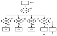
第2は、電圧が検知電圧に達するときのクロックカウンタの解析である。このプロセスは図6に示されている。 The second is analysis of the clock counter when the voltage reaches the detection voltage. This process is illustrated in FIG.
VCがVrefに達するとき、クロックカウンタ値は、閾値のセットと比較される。 When VC reaches Vref, the clock counter value is compared to a set of thresholds.
プロセスは、ステップ60でスタートし、次に、VCがVrefに達するのをステップ62で待つ。
The process starts at
カウンタ値は次に、閾値と比較される。 The counter value is then compared to a threshold value.
ステップ64の比較は、クロックカウンタが、非常に低い加えられた圧力を示す、16未満である場合、モータをオフに設定する。
The comparison of
ステップ66の比較は、クロックカウンタが、中間の加えられた圧力を示す、16から28の間である場合、モータを50%デューティーサイクルに設定する。
The comparison of
ステップ68の比較は、クロックカウンタが、最大の加えられた圧力を示す、29から31の間である場合、モータを100%デューティーサイクルに設定する。
The comparison of
したがって、モータのデューティーサイクル(DC)は、カウンタ値に応じて次の値を取る:
カウント<16→DC=0%、
カウント=22±6→DC=50%、
カウント=30±1→DC=100%。
Thus, the duty cycle (DC) of the motor takes the following values depending on the counter value:
Count <16 → DC = 0%,
Count = 22 ± 6 → DC = 50%,
Count = 30 ± 1 → DC = 100%.
ステップ70では、カウントが31に達するとき、サイクルが終了したがどうかが決定される。終了している場合、放電ステップ72があり、そうでなければ充電がステップ74で続く。
In
図6では、3つの異なるデューティーサイクル、0%、50%、100%のみが与えられている。しかし。これは、任意の他の数に簡単に増やされることができる。より多くのレベルが必要とされる場合、クロック周波数は増加され得る。 In FIG. 6, only three different duty cycles, 0%, 50% and 100%, are given. However. This can be easily increased to any other number. If more levels are needed, the clock frequency can be increased.
上述のように、閾値テストステップ64、66、68で使用される値は、初期シーケンスに基づいて、又はユーザがユーザインタフェースを通じてコントローラに入力できるパラメータとしてのいずれかで、ユーザによって調整されることができる。
As described above, the values used in the
この方法では、装置は、接触表面領域及び/又は圧力へのユーザ定義される較正を実現する。 In this way, the device implements a user-defined calibration to the contact surface area and / or pressure.
この較正を実現する1つの方法は、装置がユーザ較正モードを有することである。このモードの間、装置は、非常に軽い印加圧力又は小さい接触領域がハンドルに与えられることを要求し、次に、上述と同じ方法で容量を測定し得る。(以下に記載されるように)センサアレイに関して、加えられる圧力と独立して領域が決定されてもよい。装置はその後、最大の印加圧力又は接触領域を要求し得るとともに、再び上述と同じ方法で容量を測定することができ、この場合も同様に、独立して接触領域を決定し得る。これらの2つの極致から、2つの閾値が設定され得る、或いは3以上の閾値が推定されることができる。したがって、ユーザ較正モードは、その代わりに、2より多いユーザ入力圧力又は接触領域が与えられることを要求し得る。 One way to achieve this calibration is for the device to have a user calibration mode. During this mode, the device requires that a very light applied pressure or small contact area be applied to the handle, and then the volume can be measured in the same way as described above. For the sensor array (as described below) the area may be determined independently of the applied pressure. The device can then request the maximum applied pressure or contact area and again measure the capacity in the same way as described above, again in this case the contact area can be determined independently. From these two extremes, two thresholds can be set, or three or more thresholds can be estimated. Thus, the user calibration mode may instead require that more than two user input pressures or contact areas be provided.
以下の議論では、基準が圧力に作られるとき、同じ概念が、制御パラメータとして接触領域の使用に適用される。 In the following discussion, the same concept applies to the use of the contact area as a control parameter when the reference is made to pressure.
単一の入力が、ユーザが加えたい最大の圧力を定めるユーザ較正の間に十分であることができ、閾値の値はその後、固定最小圧力とユーザによって入力されるような最大圧力との間に設定されることができる。固定される代わりに、最小圧力レベルは、ユーザによって入力される最大圧力のである(例えば、その圧力の2分の1)であると推定され得る。 A single input can be sufficient during user calibration to determine the maximum pressure the user wants to apply, and the threshold value is then between the fixed minimum pressure and the maximum pressure as input by the user It can be set. Instead of being fixed, the minimum pressure level may be estimated to be that of the maximum pressure input by the user (e.g. half of that pressure).
装置は、このユーザ較正モードの間に食品加工部材の動作を提供し得るので、ユーザは、どの圧力レベルがこの挙動に対応すべきかを決定するときに装置がふるまっている方法に関して良好な感触を有する。代替的には、ユーザ較正は、モータが動いていることを必要とせずに実行され得る。 Since the device can provide the motion of the food processing component during this user calibration mode, the user has a good feel as to how the device is jammed when deciding which pressure level should correspond to this behavior Have. Alternatively, user calibration may be performed without requiring the motor to be moving.
多数のユーザプロフィールが、多数の人の間で共有される装置がこれらの異なるユーザに関して別々に構成されることができるように、入力され得る。ユーザはその後、例えば、入力ボタンのセットを使用しているどのユーザかを入力することがき、それぞれのボタンが異なる装置構成に対応する。 Multiple user profiles may be entered so that devices shared among multiple people can be configured separately for these different users. The user can then, for example, enter which user is using the set of input buttons, each button corresponding to a different device configuration.
図7は、モータを制御するプロセスを示す。プロセスは、ステップ80で始まる。ステップ82は、デューティーサイクル設定が50%値であるかどうかを決定する。そうである場合、ステップ84で決定されるようにカウンタが15に達するとき、モータはステップ85で始動される。
FIG. 7 shows the process of controlling the motor. The process begins at
ステップ86は、デューティーサイクル設定が100%値であるかどうかを決定する。そうである場合、ステップ88で決定されるようにカウンタが1に達するとき、モータはステップ85で始動される。
モータは、その後の停止指令によって停止されるまで動き続ける。特に、ステップ90は、いつカウンタが31に達するかを決定し、モータはその後ステップ31で停止する。したがって、100%デューティーサイクル設定でさえ、100Hz信号を与えるように、1つのクロックサイクル期間のゼロパルスを有する。
The motor continues to move until it is stopped by a subsequent stop command. In particular,
センサは、特に大きい領域センサが使用される場合に、追加の安全上の利点を提供するように設計されることができる。 The sensor can be designed to provide additional safety benefits, particularly when large area sensors are used.
大きい領域センサは10cm2から30cm2の面積を有し得る。 Large area sensors may have an area of 10 cm 2 to 30 cm 2 .
上述のように、表面センサは、接触領域及びオプションで圧力も測定できる。表面センサが、領域のみを測定できるように、或いは、領域及び圧力を独立して測定できるように、表面センサに関して様々な可能な設計がある。 As mentioned above, the surface sensor can also measure the contact area and optionally the pressure. There are various possible designs for the surface sensor so that the surface sensor can measure only the area, or the area and pressure can be measured independently.
第1の設計は、接触領域のみを検出し得る。この目的のために、圧力センサのアレイが、関心領域の上に設けられ得る。各圧力センサは、各個別の圧力センサが接触センサとして機能するように、単純なバイナリ出力を生成することができる。他の接触のみのセンサがこの目的のために使用されてよく、これらは静電容量センサであってもよい。接触が検出されるセンサの数は、接触領域を決定するために使用されることができる。異なる領域(及びこれらの領域の場所)が次に、異なる速度設定に関連付けることができる。例えば、センサに接触している指の数を検出するように、指パッド又は掌領域に検知領域があってよい。閾値レベルが次に、子供による操作を防ぐために、閾値サイズ未満の掌及び/又は指を無視するように使用されることができる。接触している指領域の数は次に速度制御を提供することができる一方、全領域又は掌の領域は、小さい子供による操作を防ぐために閾値を提供することができる。 The first design can detect only the contact area. For this purpose, an array of pressure sensors can be provided on the region of interest. Each pressure sensor can generate a simple binary output so that each individual pressure sensor functions as a contact sensor. Other contact-only sensors may be used for this purpose, and these may be capacitive sensors. The number of sensors for which touch is detected can be used to determine the touch area. Different areas (and the location of these areas) can then be associated with different speed settings. For example, there may be a sensing area in the finger pad or palm area to detect the number of fingers in contact with the sensor. The threshold level can then be used to ignore palms and / or fingers below the threshold size to prevent manipulation by the child. The number of touching finger areas can then provide speed control, while the whole area or palm area can provide a threshold to prevent manipulation by small children.
第2の設計は、接触領域及び圧力を検出し得る。この目的のために、圧力センサのアレイが、関心領域の上に設けられ得る。各圧力センサは、各個別の接触センサとして(すなわち、圧力が少しでも検出される場合)及びまた圧力センサとしての両方で機能するように、マルチレベルの圧力出力を生成することができる。この場合も同様に、接触を少しでも検出する圧力センサの数が、接触領域を決定するために使用されることができる。圧力レベル情報はまた、局所的な圧力レベル及び加えられる全体的な圧力を決定するために使用されることができる。異なる圧力レベルが、異なる速度設定に関連付けることができる一方、追加的に、領域及びオプションで圧力にも基づく閾値を組み入れる。例えば、そのとき基本的に圧力に基づく制御に加えて、効果的な安全機能を提供するために手の掌のサイズの検知があり得る。この方法では、装置は、効果的な安全機能並びに直感的な制御を組み合わせることができる。この例では、表面センサは、接触領域及び圧力を独立して検出することができる。 The second design can detect contact area and pressure. For this purpose, an array of pressure sensors can be provided on the region of interest. Each pressure sensor can generate a multi-level pressure output to function both as each individual contact sensor (ie, if any pressure is detected) and also as a pressure sensor. Again, the number of pressure sensors that detect any contact can be used to determine the contact area. The pressure level information can also be used to determine the local pressure level and the overall pressure applied. While different pressure levels can be associated with different speed settings, they additionally incorporate thresholds based on region and optionally pressure. For example, then there may be detection of palm size to provide an effective safety function, in addition to basically pressure based control. In this way, the device can combine effective safety functions as well as intuitive control. In this example, the surface sensor can detect the contact area and pressure independently.
容量センサは、それがたとえ単一のセンサ領域を有するとしても、接触領域センサとして使用され得ることに留意されたい。特に、加えられる接触又は圧力に応じて局所的な誘電体誘電率に基本的に二値(バイナリ)の変化があり、したがって、局所的な静電容量に二値の変化がある場合、小さい接触領域は、(加えられる圧力にかかわらず)大きい接触領域に比べて、より小さい静電容量の変化をもたらす。 Note that a capacitive sensor can be used as a contact area sensor even if it has a single sensor area. In particular, there is essentially a binary change in the local dielectric permittivity depending on the contact or pressure applied, and thus a small contact if there is a binary change in the local capacitance. The area results in a smaller capacitance change compared to a large contact area (regardless of the applied pressure).
安全閾値としての領域の使用はまた、装置が落とされた場合の誤った起動がありそうになく、並びに子供による起動をより困難にするという点で、安全機能の実装を可能にする。 The use of the area as a safety threshold also allows for the implementation of safety functions in that it is unlikely to be erroneously activated if the device is dropped and makes it more difficult for the child to activate.
センサが、接触領域だけでなく、加えられる圧力にも反応する場合、加えられる領域及び力の組合せによって達成される閾値が設定され得る。 If the sensor responds not only to the contact area but also to the applied pressure, the threshold achieved by the applied area and the combination of forces can be set.
他のセンサが、接触領域及びオプションで圧力も検出するために使用され得る。コントローラはまた、人によって生成されることができない短いピークをフィルターで除去することができる。 Other sensors can be used to detect the contact area and optionally also the pressure. The controller can also filter out short peaks that can not be generated by a person.
適切に閾値を設定すること及び形状を設計することによって、センサは、特に年配者又は身体障碍者に適するように作られることができる。 By appropriately setting the threshold and designing the shape, the sensor can be made to be particularly suitable for the elderly or the disabled.
図8は、センサアレイがどのように使用され得るかを概略的な形態で示し、このセンサアレイは、独立したセンサ要素のアレイを有する。この例のセンサアレイは、独立した容量式圧力センサのアレイを定める第1及び第2の電極アレイ92、93を有する。電極信号は、コントローラ94に送られる。上述のように、圧力センサは、作動したセンサの数が接触領域と関連するように、接触センサとしてのみ機能し得る、あるいは、各センサは、圧力指標も提供し得るので、表面センサは、領域及び圧力情報の両方の関連する処理を可能にする。
FIG. 8 shows in schematic form how a sensor array can be used, which comprises an array of independent sensor elements. The sensor array of this example has first and
センサは、追加の機能を実装するために使用されることができる。例えば、一連の圧力印加、又は一連の検知領域への接触の適用は、例えば、センサが2回押される場合にクルーズ機能(cruise function)を提供するために、認識されることができる。 The sensor can be used to implement additional functions. For example, a series of pressure applications, or application of contacts to a series of sensing areas can be recognized, for example, to provide a cruise function when the sensor is pressed twice.
センサは、触覚フィードバックを組み込むシステムと組み合わせられることができる。 The sensor can be combined with a system that incorporates haptic feedback.
センサは、ドライバ電子装置への電気的接続性のために必要であるフィードスルーのみを備えて、製造中に電気器具に接着されることができる。この目的のために、センサへの接点は、ユーザ入力が提供される領域と反対側のセンサの面上に設けられることができる。 The sensor can be bonded to the appliance during manufacture with only the feedthroughs needed for electrical connectivity to the driver electronics. For this purpose, the contacts to the sensor can be provided on the side of the sensor opposite to the area where the user input is provided.
上の例は、静電容量の変化を検出するセンサに基づいているが、他のインピーダンス値が変調され得るとともに表面センサによって読み出され得る。モータは、上の例のパルス幅変調によって制御されるが、他のモータ制御、例えば、検知された値に応じて供給電圧を変化させることが使用され得る。 The above example is based on a sensor that detects a change in capacitance, but other impedance values can be modulated and read out by the surface sensor. The motor is controlled by the above example pulse width modulation, but other motor controls, for example, changing the supply voltage in response to the sensed value can be used.
システムは、コントローラを使用する。コントローラのために用いられ得るコンポーネントは、限定されるものではないが、従来のマイクロプロセッサ、特定用途向け集積回路(ASIC)、及びフィールドプログラマブルゲートアレイ(FPGA)を含む。 The system uses a controller. Components that can be used for the controller include, but are not limited to, conventional microprocessors, application specific integrated circuits (ASICs), and field programmable gate arrays (FPGAs).
様々な実装において、プロセッサ又はコントローラは、例えばRAM、PROM、EPROM及びEEPROMなどの揮発性又は不揮発性コンピュータメモリのような1又は複数の記憶媒体に関連付けられる。記憶媒体は、1又は複数のプロセッサ及び/又はコントローラ上で実行されるとき、必要な機能を実行する1又は複数のプログラムでコード化され得る。様々な記憶媒体は、プロセッサ又はコントローラ内に固定されていても、又は、その上に記憶された1又は複数のプログラムが、プロセッサ又はコントローラにロードできるように持ち運び可能であってもよい。 In various implementations, a processor or controller is associated with one or more storage media such as volatile or non-volatile computer memory such as RAM, PROM, EPROM, and EEPROM. A storage media may be encoded with one or more programs that perform the required functions when executed on one or more processors and / or controllers. The various storage media may be fixed within the processor or controller or may be portable so that one or more programs stored thereon can be loaded into the processor or controller.
開示されている実施形態に対する他の変形態様は、図面、開示内容及び添付の請求項を検討することにより、請求項に係る発明を実施する当業者には理解され得るとともに実施可能であり得る。請求項において、「有する、含む」の語は、他の要素又はステップを排除するものではなく、また、不定冠詞「a」又は「an」は、複数形を排除するものではない。特定の手段が相互に異なる従属請求項に記載されるという単なる事実は、これらの手段の組み合わせが有利に使用されることができないことを示すものではない。請求項における如何なる参照符号も、範囲を限定しているものと解釈されるべきではない。
Other variations to the disclosed embodiments can be understood and effected by those skilled in the art in practicing the claimed invention, from a study of the drawings, the disclosure and the appended claims. In the claims, the word "comprising" does not exclude other elements or steps, and the indefinite article "a" or "an" does not exclude a plurality. The mere fact that certain measures are recited in mutually different dependent claims does not indicate that a combination of these measured cannot be used to advantage. Any reference signs in the claims should not be construed as limiting the scope.
Claims (14)
前記表面センサの接触面積のサイズと、
接触に関連する圧力と、を独立して検出するように構成される、
ハンドル部、
被駆動部材、
前記被駆動部材を駆動するモータ、並びに
コントローラであって、
前記表面センサから、独立して検出された
前記接触面積の前記サイズと、
前記接触に関連する前記圧力と、を受信し、
前記モータに供給される電力を制御する、ように適合され、
前記モータに与えられる前記電力は、前記接触面積の前記サイズ及び前記圧力に基づいて変化する、
コントローラ、
を有する、
携帯型家庭用電気器具。 A handle portion having a surface sensor configured to provide both area and pressure information, said surface sensor:
The size of the contact area of the surface sensor;
Configured to independently detect the pressure associated with the contact,
Handle part,
Driven member,
A motor for driving the driven member, and a controller,
The size of the contact area independently detected from the surface sensor;
Receiving the pressure associated with the contact;
Adapted to control the power supplied to the motor,
The power provided to the motor varies based on the size of the contact area and the pressure.
controller,
Have
Portable household appliances.
請求項1に記載の携帯型家庭用電気器具。 The controller is configured to apply a user-defined calibration to the contact area,
The portable household appliance according to claim 1.
請求項1に記載の携帯型家庭用電気器具。 The controller is configured to apply a user-defined calibration to the pressure,
The portable household appliance according to claim 1.
請求項1に記載の携帯型家庭用電気器具。 The surface sensor has an outer surface configured to be depressed by less than 1 mm, the depression corresponding to the pressure associated with the contact;
The portable household appliance according to claim 1.
請求項1に記載の携帯型家庭用電気器具。 The surface sensor comprises at least two electrode arrays with deformable dielectric material therebetween.
The portable household appliance according to claim 1.
請求項1に記載の携帯型家庭用電気器具。 The surface sensor has an area in the range of 2 cm 2 to 30 cm 2 ,
The portable household appliance according to claim 1.
請求項1に記載の携帯型家庭用電気器具。 The surface sensor has an electrical contact,
The portable household appliance according to claim 1.
前記コントローラは:
前記容量式圧力センサによって定められるコンデンサと直列の抵抗器;
前記コンデンサを放電させるための放電スイッチ;及び
放電状態から基準電圧への前記コンデンサの充電の時間を測定するように構成されるタイミング回路;を有し、
前記コントローラは:
コンデンサ放電を実行するために前記放電スイッチを制御するように構成される、
請求項1に記載の携帯型家庭用電気器具。 The surface sensor includes a capacitive pressure sensor
The controller is:
A resistor in series with a capacitor defined by the capacitive pressure sensor;
A discharge switch for discharging the capacitor; and a timing circuit configured to measure a time for charging the capacitor from a discharged state to a reference voltage;
The controller is:
Configured to control the discharge switch to perform a capacitor discharge,
The portable household appliance according to claim 1.
前記タイミング回路は、前記放電及び前記時間測定動作の周波数より速い周波数で動くように構成されるカウンタを有する、
請求項8に記載の携帯型家庭用電気器具。 The timing circuit is configured to periodically perform a discharge and time measurement operation,
The timing circuit comprises a counter configured to run at a frequency faster than the frequency of the discharge and the time measurement operation;
A portable household appliance according to claim 8.
請求項1に記載の携帯型家庭用電気器具。 The controller is configured to apply one of a set of motor speeds in response to an output from the surface sensor;
The portable household appliance according to claim 1.
請求項1に記載の携帯型家庭用電気器具。 The power is adjustable during use
The portable household appliance according to claim 1.
キッチン用電気器具;
バーブレンダー;
ミキサー;
チョッパー;
フードプロセッサー;
グラインダー;
ジューサー;
口腔ケア装置;
歯ブラシ;
グルーミング器具;
シェーバー;のうちの1つを含む、
請求項11に記載の携帯型家庭用電気器具。 The portable household appliances are:
Kitchen appliances;
Bar blender;
mixer;
chopper;
food processor;
grinder;
Juicer;
Oral care device;
toothbrush;
Grooming equipment;
A shaver; including one of:
A portable household appliance according to claim 11.
前記表面センサにより前記接触表面領域との接触を検出するステップ;
前記接触を検出するステップに基づいて、前記接触に関連する面積のサイズ及び前記接触表面領域に加えられる圧力を独立して決定するステップ;並びに
前記面積の前記サイズ及び前記圧力に応じて前記モータに供給される電力を制御するステップ、を含み、
前記モータに供給される前記電力は、前記圧力及び前記面積の前記サイズに基づいて変化する、
方法。 A method of controlling a portable household appliance comprising a handle portion, a driven member, and a motor for driving the driven member, the portable household appliance comprising a contact surface area and the contact surface area. of a surface sensor provided in the handle portion before Symbol portable domestic appliance detect independently the pressure, the method comprising:
Detecting contact with the contact surface area by the surface sensor;
Independently determining the size of the area associated with the contact and the pressure applied to the contact surface area based on the step of detecting the contact; and the motor according to the size of the area and the pressure Controlling the supplied power;
The power supplied to the motor varies based on the pressure and the size of the area.
Method.
請求項13に記載の方法。 The method further comprises setting a threshold counter value based on at least the contact surface area and the pressure applied to the contact surface area, the threshold counter value determining conditions for supplying the power to the motor. Represents the value of
The method of claim 13.
Applications Claiming Priority (3)
| Application Number | Priority Date | Filing Date | Title |
|---|---|---|---|
| EP14174658 | 2014-06-27 | ||
| EP14174658.6 | 2014-06-27 | ||
| PCT/EP2015/061268 WO2015197274A1 (en) | 2014-06-27 | 2015-05-21 | Domestic appliances with power control |
Publications (3)
| Publication Number | Publication Date |
|---|---|
| JP2017529881A JP2017529881A (en) | 2017-10-12 |
| JP2017529881A5 JP2017529881A5 (en) | 2018-09-27 |
| JP6553653B2 true JP6553653B2 (en) | 2019-07-31 |
Family
ID=51176094
Family Applications (1)
| Application Number | Title | Priority Date | Filing Date |
|---|---|---|---|
| JP2016574421A Expired - Fee Related JP6553653B2 (en) | 2014-06-27 | 2015-05-21 | Household appliances with output control |
Country Status (6)
| Country | Link |
|---|---|
| US (1) | US10136763B2 (en) |
| EP (1) | EP3160315B8 (en) |
| JP (1) | JP6553653B2 (en) |
| CN (1) | CN106488729B (en) |
| RU (1) | RU2678388C2 (en) |
| WO (1) | WO2015197274A1 (en) |
Families Citing this family (10)
| Publication number | Priority date | Publication date | Assignee | Title |
|---|---|---|---|---|
| US9814356B2 (en) * | 2014-11-07 | 2017-11-14 | Smartsy Llc | Device and method for thawing a frozen item in a container of liquid |
| JP6543759B2 (en) * | 2015-07-28 | 2019-07-10 | コーニンクレッカ フィリップス エヌ ヴェKoninklijke Philips N.V. | Method and system for minimizing sensor drive train interference in an oral cleaning device |
| US10796431B2 (en) | 2016-04-12 | 2020-10-06 | Tcms Transparent Beauty, Llc | Targeted deposition of dental care compounds |
| CN109855120A (en) * | 2017-11-30 | 2019-06-07 | 博西华电器(江苏)有限公司 | Household electrical appliance and its operating control device, gas-cooker and its control method |
| US20210050807A1 (en) * | 2018-03-07 | 2021-02-18 | Guangdong Midea Consumer Electric Manufacturing Co., Ltd. | Food processor and rotational speed increase control method and apparatus therefor |
| EP3556266A1 (en) * | 2018-04-17 | 2019-10-23 | Koninklijke Philips N.V. | A food processing apparatus and a method of operating the same |
| CN111413875B (en) * | 2019-01-08 | 2024-03-08 | 广东美的生活电器制造有限公司 | Driving part, household appliance and control method of driving part |
| DE102019101824A1 (en) * | 2019-01-25 | 2020-07-30 | Zwilling J. A. Henckels Ag | Handheld household appliance with a touch sensor |
| USD1020365S1 (en) | 2022-05-09 | 2024-04-02 | Sharkninja Operating Llc | Blender attachment |
| EP4304090A1 (en) * | 2022-07-06 | 2024-01-10 | Miele & Cie. KG | Electrical appliance, preferably domestic appliance |
Family Cites Families (21)
| Publication number | Priority date | Publication date | Assignee | Title |
|---|---|---|---|---|
| JP2867501B2 (en) | 1989-11-30 | 1999-03-08 | 松下電工株式会社 | electric toothbrush |
| JP2783916B2 (en) * | 1991-01-18 | 1998-08-06 | 三洋電機株式会社 | Electric razor |
| JPH05228088A (en) * | 1992-02-19 | 1993-09-07 | Sanyo Electric Co Ltd | Self-traveling vacuum cleaner |
| JPH07163421A (en) * | 1993-11-29 | 1995-06-27 | Matsushita Electric Works Ltd | Electrically driven tooth brush |
| DE29719596U1 (en) * | 1997-11-04 | 1998-01-15 | Moulinex Sa | Electric kitchen appliance |
| FR2823387B1 (en) | 2001-04-10 | 2003-08-15 | Faurecia Ind | CAPACITIVE-TYPE CONTROLLER FOR CONTROLLING AT LEAST ONE FUNCTIONAL MEMBER IN PARTICULAR OF A MOTOR VEHICLE |
| AU2003301707A1 (en) * | 2002-10-31 | 2004-05-25 | Harald Philipp | Charge transfer capacitive position sensor |
| DE102004020824A1 (en) * | 2004-04-28 | 2005-12-01 | BSH Bosch und Siemens Hausgeräte GmbH | Adjusting device with an at least two-dimensional Sen-sorbereich |
| DE102005041112A1 (en) * | 2005-08-30 | 2007-03-01 | BSH Bosch und Siemens Hausgeräte GmbH | Capacitive proximity switch for e.g. washing machine, has sensor surface with active shielding formed by shielding surface, and clock signal applied at shielding surface that is connected with earth for applying potential by switch |
| CN2888423Y (en) * | 2005-10-26 | 2007-04-11 | 邵宏庆 | Finger dynamics sensor and control circuit thereof |
| JP2011055934A (en) | 2009-09-08 | 2011-03-24 | Tiger Vacuum Bottle Co Ltd | Electric agitator for cooking |
| US8621783B2 (en) | 2010-06-28 | 2014-01-07 | Chin-Tai Tsai | Hollow pot |
| RU2595480C2 (en) * | 2010-09-30 | 2016-08-27 | Конинклейке Филипс Электроникс Н.В. | System for controlling amplitude of the device for oral care |
| CN102799292B (en) * | 2011-05-24 | 2016-03-30 | 联想(北京)有限公司 | A kind of method of toch control, device and electronic equipment |
| CN103049041A (en) * | 2011-10-12 | 2013-04-17 | 鸿富锦精密工业(深圳)有限公司 | Gamepad and component of tablet computer |
| US9063623B2 (en) | 2011-12-01 | 2015-06-23 | Green Cedar Holdings Llc | Capacitive touch sensor assembly for use in a wet environment |
| EP2667156B1 (en) * | 2012-05-25 | 2015-10-21 | Nxp B.V. | Capacitive position sensor system |
| JP2014021676A (en) * | 2012-07-17 | 2014-02-03 | Nikon Corp | Electronic device |
| CN202698918U (en) | 2012-07-23 | 2013-01-30 | 杨昌良 | Handheld linear displacement speed regulation stirrer |
| CN202794927U (en) * | 2012-08-10 | 2013-03-13 | 宁波市开利刀片制造有限公司 | Shaver touch induction switch |
| CN103720385B (en) * | 2012-10-11 | 2018-03-30 | 德昌电机(深圳)有限公司 | Kitchen appliance, electric machine assembly and control element |
-
2015
- 2015-05-21 WO PCT/EP2015/061268 patent/WO2015197274A1/en active Application Filing
- 2015-05-21 RU RU2017102331A patent/RU2678388C2/en active
- 2015-05-21 CN CN201580035130.1A patent/CN106488729B/en active Active
- 2015-05-21 EP EP15724288.4A patent/EP3160315B8/en active Active
- 2015-05-21 US US15/319,035 patent/US10136763B2/en active Active
- 2015-05-21 JP JP2016574421A patent/JP6553653B2/en not_active Expired - Fee Related
Also Published As
| Publication number | Publication date |
|---|---|
| EP3160315A1 (en) | 2017-05-03 |
| RU2017102331A3 (en) | 2018-11-29 |
| US10136763B2 (en) | 2018-11-27 |
| JP2017529881A (en) | 2017-10-12 |
| EP3160315B8 (en) | 2020-04-15 |
| RU2678388C2 (en) | 2019-01-28 |
| US20170143165A1 (en) | 2017-05-25 |
| EP3160315B1 (en) | 2020-03-04 |
| RU2017102331A (en) | 2018-07-27 |
| CN106488729A (en) | 2017-03-08 |
| CN106488729B (en) | 2019-12-13 |
| WO2015197274A1 (en) | 2015-12-30 |
Similar Documents
| Publication | Publication Date | Title |
|---|---|---|
| JP6553653B2 (en) | Household appliances with output control | |
| EP2889727B1 (en) | Friction augmented controls and method to convert buttons of touch control panels to friction augmented controls | |
| RU2677157C1 (en) | Toothbrush with variable touch selection system and method of operation thereof | |
| US8884901B2 (en) | Shaped capacitive touch sensor, devices, and methods of use | |
| EP3079524B1 (en) | Toothbrush with variable touch selection system and method of operation thereof | |
| KR101216489B1 (en) | Input apparatus and control method of input apparatus | |
| KR101174008B1 (en) | Input apparatus and control method of input apparatus | |
| WO2013021716A1 (en) | Electric toothbrush capable of accepting user operation | |
| TWI608382B (en) | Haptic presentation device and control method thereof | |
| TW201538137A (en) | Powered toothbrush | |
| CN109588851A (en) | System for oral care implement amplitude adjusted | |
| KR102143819B1 (en) | A skin care device and control method of the skin care device | |
| CN102473055A (en) | Input apparatus and control method of input apparatus | |
| WO2012030908A1 (en) | Skin sensing activated device | |
| JP2017529881A5 (en) | ||
| US20210145690A1 (en) | Sensing control method and apparatus | |
| WO2006003249A3 (en) | Electrical coupling of an electromechanical control unit |
Legal Events
| Date | Code | Title | Description |
|---|---|---|---|
| A621 | Written request for application examination |
Free format text: JAPANESE INTERMEDIATE CODE: A621 Effective date: 20180516 |
|
| A521 | Request for written amendment filed |
Free format text: JAPANESE INTERMEDIATE CODE: A523 Effective date: 20180817 |
|
| A871 | Explanation of circumstances concerning accelerated examination |
Free format text: JAPANESE INTERMEDIATE CODE: A871 Effective date: 20180817 |
|
| A975 | Report on accelerated examination |
Free format text: JAPANESE INTERMEDIATE CODE: A971005 Effective date: 20180829 |
|
| A131 | Notification of reasons for refusal |
Free format text: JAPANESE INTERMEDIATE CODE: A131 Effective date: 20180904 |
|
| A521 | Request for written amendment filed |
Free format text: JAPANESE INTERMEDIATE CODE: A523 Effective date: 20181023 |
|
| A131 | Notification of reasons for refusal |
Free format text: JAPANESE INTERMEDIATE CODE: A131 Effective date: 20190122 |
|
| A521 | Request for written amendment filed |
Free format text: JAPANESE INTERMEDIATE CODE: A523 Effective date: 20190320 |
|
| TRDD | Decision of grant or rejection written | ||
| A01 | Written decision to grant a patent or to grant a registration (utility model) |
Free format text: JAPANESE INTERMEDIATE CODE: A01 Effective date: 20190611 |
|
| A61 | First payment of annual fees (during grant procedure) |
Free format text: JAPANESE INTERMEDIATE CODE: A61 Effective date: 20190704 |
|
| R150 | Certificate of patent or registration of utility model |
Ref document number: 6553653 Country of ref document: JP Free format text: JAPANESE INTERMEDIATE CODE: R150 |
|
| LAPS | Cancellation because of no payment of annual fees |