JP6525416B1 - Vehicle control device - Google Patents
Vehicle control device Download PDFInfo
- Publication number
- JP6525416B1 JP6525416B1 JP2017253722A JP2017253722A JP6525416B1 JP 6525416 B1 JP6525416 B1 JP 6525416B1 JP 2017253722 A JP2017253722 A JP 2017253722A JP 2017253722 A JP2017253722 A JP 2017253722A JP 6525416 B1 JP6525416 B1 JP 6525416B1
- Authority
- JP
- Japan
- Prior art keywords
- target
- vehicle
- travel route
- speed
- traveling
- Prior art date
- Legal status (The legal status is an assumption and is not a legal conclusion. Google has not performed a legal analysis and makes no representation as to the accuracy of the status listed.)
- Active
Links
Images


Abstract
【課題】計算負荷を軽減しながら、運転者に違和感を与えにくい車両制御装置を提供する。【解決手段】本発明は、車両制御装置(100)であって、周辺物標検出部(10a)と、目標走行経路算出部(10c)と、目標走行経路を補正した補正走行経路を算出する補正走行経路算出部(10d)と、主制御部(10f)と、バックアップ制御部(10e)と、目標蛇角及び目標加減速度を制御信号として出力する出力調整部(10g)と、を有し、補正走行経路算出部は、回避すべき周辺物標が検出された場合において、周辺物標に対して自車両が走行可能な許容相対速度の上限ラインを設定するように構成されていると共に、上限ライン及び所定の評価関数に基づいて補正走行経路を算出するように構成され、評価関数の極値が複数存在する場合には、出力調整部は、バックアップ制御部が算出した目標蛇角及び目標加減速度を制御信号として出力することを特徴としている。【選択図】図2An object of the present invention is to provide a vehicle control device which is less likely to give a sense of discomfort to a driver while reducing a calculation load. The present invention relates to a vehicle control apparatus (100), which calculates a corrected travel route in which a target travel route is corrected, and a peripheral target detection unit (10a), a target travel route calculation unit (10c) and It has a correction travel route calculation unit (10d), a main control unit (10f), a backup control unit (10e), and an output adjustment unit (10g) that outputs a target deflection and a target acceleration / deceleration as control signals. The correction traveling route calculation unit is configured to set an upper limit line of an allowable relative speed at which the vehicle can travel with respect to the peripheral target when the peripheral target to be avoided is detected. The correction travel route is calculated based on the upper limit line and the predetermined evaluation function, and when there are a plurality of extreme values of the evaluation function, the output adjustment unit calculates the target snake angle and the target calculated by the backup control unit. It is characterized by outputting acceleration / deceleration as a control signal. [Selected figure] Figure 2
Description
本発明は、車両制御装置に関し、特に、運転者による車両の運転を支援する車両制御装置に関する。 The present invention relates to a vehicle control device, and more particularly to a vehicle control device for assisting a driver in driving a vehicle.
特開2010−155545号公報(特許文献1)には、車両制御装置が記載されている。この車両制御装置は、障害物の緊急回避時において、その際の他車両との車間距離に応じて制動回避(ブレーキ操作のみ)と操舵回避(ステアリング操作のみ)のいずれかを選択し、最適化処理を用いて目標走行経路計算をするように構成されている。この車両制御装置では、制動回避が選択されると、縦方向(車両前後方向)の運動のみに計算条件が簡略化される。また、操舵回避が選択されると、横方向(車両幅方向)の運動のみに計算条件が簡略化される。このように、この技術では、緊急時において計算負荷が軽減されるため、高い計算精度を確保しつつ、計算時間を短くすることができるようになっている。 The vehicle control apparatus is described in Unexamined-Japanese-Patent No. 2010-155545 (patent document 1). This vehicle control device selects and optimizes either braking avoidance (only brake operation) or steering avoidance (only steering operation) according to the inter-vehicle distance with other vehicles at the time of emergency avoidance of an obstacle. The processing is used to calculate the target travel route. In this vehicle control device, when the braking avoidance is selected, the calculation conditions are simplified only to the motion in the vertical direction (the vehicle longitudinal direction). In addition, when the steering avoidance is selected, the calculation condition is simplified only to the movement in the lateral direction (the vehicle width direction). As described above, in this technology, since the calculation load is reduced in an emergency, it is possible to shorten the calculation time while securing high calculation accuracy.
しかしながら、特許文献1記載の発明においては、障害物の回避が制動回避又は操舵回避の何れか一方に制約されてしまうので、車両制御装置によって選択される車両の走行経路が必ずしも適切なものにならない場合があり、このような場合には運転者に強い違和感を与えてしまうという問題がある。 However, in the invention described in Patent Document 1, the avoidance of the obstacle is restricted to either the braking avoidance or the steering avoidance, so that the traveling route of the vehicle selected by the vehicle control device is not necessarily appropriate. In such a case, there is a problem that the driver feels a strong sense of incongruity.
本発明は、このような問題を解決するためになされたものであり、車両制御装置による計算負荷を軽減しながら、運転者に違和感を与えにくい車両制御装置を提供することを目的としている。 The present invention has been made to solve such a problem, and it is an object of the present invention to provide a vehicle control device that is less likely to give a sense of discomfort to the driver while reducing the calculation load of the vehicle control device.
上述した課題を解決するために、本発明は、運転者による車両の運転を支援する車両制御装置であって、周辺物標を検出する周辺物標検出部と、自車両の目標走行経路を算出する目標走行経路算出部と、この目標走行経路算出部によって算出された目標走行経路を補正した補正走行経路を算出する補正走行経路算出部と、この補正走行経路算出部によって算出された補正走行経路上を走行するための目標舵角及び目標加減速度を計算する主制御部と、目標走行経路算出部によって算出された目標走行経路上を走行するための目標舵角及び目標加減速度を計算するバックアップ制御部と、主制御部によって算出された目標舵角及び目標加減速度、又はバックアップ制御部によって算出された目標舵角及び目標加減速度を制御信号として出力する出力調整部と、を有し、補正走行経路算出部は、周辺物標検出部によって回避すべき周辺物標が検出された場合において、少なくとも周辺物標から車両に向けて、周辺物標に対する車両の相対速度の許容上限値の分布を規定する速度分布領域を設定し、この速度分布領域における許容上限値は周辺物標から距離が離れるほど大きくなるように設定され、補正走行経路算出部は、所定の評価関数に基づいて、速度分布領域内において周辺物標に対する車両の相対速度が許容上限値を超えないように、目標走行経路を補正して速度分布領域内を車両が走行するための複数の補正走行経路を算出するように構成され、評価関数の極値が複数存在する場合には、出力調整部は、バックアップ制御部が算出した目標舵角及び目標加減速度を制御信号として出力することを特徴としている。 In order to solve the problems described above, the present invention is a vehicle control apparatus for assisting the driver to drive a vehicle, and calculates a target travel path of the vehicle and a peripheral target detection unit that detects a peripheral target. Target travel route calculation unit, a corrected travel route calculation unit for calculating a corrected travel route obtained by correcting the target travel route calculated by the target travel route calculation unit, and the corrected travel route calculated by the corrected travel route calculation unit backup to calculate a main control unit for calculating the target steering angle and the target acceleration for traveling on, the target steering angle and the target acceleration for traveling the target running path on which is calculated by the target traveling path calculator outputting a control unit, a main control unit target steering angle and the target acceleration calculated by, or target steering angle and the target acceleration calculated by the backup control section as a control signal Has a force adjuster, a correction travel route calculating unit, in a case where the peripheral target object to be avoided by the peripheral target object detection portion is detected, toward at least the peripheral target object in a vehicle, the vehicle to the peripheral target object The speed distribution area which defines the distribution of the allowable upper limit value of the relative speed of the vehicle is set, and the allowable upper limit value in this speed distribution area is set to become larger as the distance from the peripheral target increases. Based on a predetermined evaluation function, there are a plurality of corrections for the target travel route so that the vehicle travels in the speed distribution area so that the relative speed of the vehicle to the surrounding target does not exceed the allowable upper limit in the speed distribution area. It consists corrected travel route to calculate the, if the extreme values of the evaluation function there are multiple output adjustment section, the target steering angle and target acceleration backup control section is calculated as a control signal It is characterized by outputting.
このように構成された本発明によれば、周辺物標検出部によって回避すべき周辺物標が検出された場合には、補正走行経路算出部は、周辺物標に対して車両が走行可能な許容相対速度の上限ラインを設定する。また、補正走行経路算出部は、この上限ライン及び所定の評価関数に基づいて目標走行経路を補正して、補正走行経路を算出する。主制御部は、補正走行経路算出部によって算出された補正走行経路上を走行するための目標蛇角及び目標加減速度を計算する。このように、主制御部は目標走行経路を補正した補正走行経路上を走行するための目標蛇角及び目標加減速度を計算するので、車両制御装置の計算負荷を軽減することができる。また、出力調整部は、評価関数の極値が複数存在する場合には、バックアップ制御部が算出した目標蛇角及び目標加減速度を制御信号として出力するので、複数極値が存在する、評価が曖昧な評価関数に基づいて決定された補正走行経路を走行するのを回避することができる。 According to the present invention configured as described above, when the peripheral target detection unit detects a peripheral target to be avoided, the correction traveling route calculation unit can drive the vehicle relative to the peripheral target. Set the upper limit line of allowable relative speed. Further, the correction travel route calculation unit corrects the target travel route based on the upper limit line and the predetermined evaluation function to calculate the correction travel route. The main control unit calculates a target snake angle and a target acceleration / deceleration for traveling on the corrected travel route calculated by the corrected travel route calculation unit. As described above, since the main control unit calculates the target bending angle and the target acceleration / deceleration for traveling on the corrected traveling route corrected for the target traveling route, the calculation load of the vehicle control device can be reduced. In addition, since the output adjustment unit outputs the target snake angle and the target acceleration / deceleration calculated by the backup control unit as a control signal when there are a plurality of extreme values of the evaluation function, a plurality of extreme values exist. It is possible to avoid traveling on the corrected travel route determined based on an ambiguous evaluation function.
本発明において、好ましくは、出力調整部は、評価関数の極値が複数存在する場合であっても、最も評価が高い極値が、次に評価が高い極値よりも所定値以上評価が高い場合には、最も評価が高い極値に対応する補正走行経路上を走行するように、主制御部によって算出された目標舵角及び目標加減速度を制御信号として出力する。 In the present invention, preferably, the output adjustment unit is such that, even when there are a plurality of extrema of the evaluation function, the extremum with the highest evaluation has a higher evaluation by a predetermined value or more than the extremum with the next highest evaluation. In this case, the target steering angle and the target acceleration / deceleration calculated by the main control unit are output as a control signal so that the vehicle travels on the corrected traveling route corresponding to the highest evaluation extreme value.
このように構成された本発明によれば、評価関数の最も評価が高い極値が他の極値よりも所定値以上評価が高い場合には、極値が複数存在する場合であっても最も評価が高い極値に対応する補正走行経路が採用されるので、極値が複数存在することにより、明らかに評価の高い補正走行経路が不採用となるのを防止することができる。 According to the present invention configured as described above, when the extreme value of the evaluation function with the highest rating is higher than the other extreme values by the predetermined value or more, the maximum value is the largest even if there are a plurality of extreme values. Since the correction travel route corresponding to the extreme value with high evaluation is adopted, the existence of a plurality of extreme values makes it possible to prevent the adoption of a correction travel route with a clearly high evaluation.
本発明において、好ましくは、出力調整部は、評価関数の最も評価が高い極値が、所定の評価値以下の低い評価である場合には、極値が単一であっても、バックアップ制御部によって算出された目標舵角及び目標加減速度を制御信号として出力する。 In the present invention, preferably, the output adjusting unit is configured to control the backup control unit even if the extreme value of the evaluation function is the highest in the evaluation, if the extreme value is lower than a predetermined evaluation value. The target steering angle and the target acceleration / deceleration calculated by are output as a control signal.
このように構成された本発明によれば、評価関数の最も評価が高い極値が、所定の評価値以下の低い評価である場合には、極値が単一であっても、その最も評価が高い極値に対応する補正走行経路が不採用とされるので、評価の低い補正走行経路が採用され、運転者に強い違和感を与えるのを防止することができる。 According to the present invention configured as described above, when the highest evaluation extreme value of the evaluation function is a low evaluation below the predetermined evaluation value, the highest evaluation is made even if the extreme value is single. Since a correction travel route corresponding to a high extreme value is not adopted, a correction travel route with a low evaluation is adopted, and it is possible to prevent the driver from giving a strong feeling of discomfort.
本発明において、好ましくは、バックアップ制御部は、目標走行経路上を走行する自車両が速度分布領域における相対速度の許容上限値を超えるのを回避すべく、目標加減速度のみを変更する。 In the present invention, preferably, the backup control unit changes only the target acceleration / deceleration so as to avoid that the host vehicle traveling on the target traveling route exceeds the allowable upper limit value of the relative speed in the speed distribution region .
目標走行経路は、回避すべき周辺物標に対する走行経路の補正が行われていないので、目標走行経路上を走行し続けると、自車両は許容相対速度の上限ラインを越えてしまう。上記のように構成された本発明によれば、自車両が許容相対速度の上限ラインを満足しない領域に進入するのを回避すべく、目標走行経路上を走行する自車両の加減速度が算出されるので、車両制御装置の計算負荷を軽減しつつ、運転者に強い違和感を与えることなく衝突を回避することができる。 In the target travel route, correction of the travel route with respect to the peripheral target object to be avoided is not performed, so when the vehicle travels on the target travel route, the own vehicle exceeds the upper limit line of allowable relative speed. According to the present invention configured as described above, the acceleration / deceleration speed of the own vehicle traveling on the target traveling route is calculated in order to avoid the own vehicle entering the region not satisfying the upper limit line of the allowable relative speed. Therefore, while reducing the calculation load of the vehicle control device, it is possible to avoid the collision without giving the driver a strong sense of discomfort.
本発明の車両制御装置によれば、車両制御装置における計算負荷を軽減しながら、運転者に違和感を与えにくくすることができる。 According to the vehicle control device of the present invention, it is possible to make it difficult for the driver to feel discomfort while reducing the calculation load in the vehicle control device.
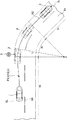
以下、添付図面を参照して、本発明の実施形態による車両制御装置について説明する。まず、図1及び図2を参照して、車両制御装置の構成について説明する。図1Aは車両制御装置の構成図であり、図1Bは運転者操作部の詳細を示す図であり、図2は車両制御装置の制御ブロック図である。 Hereinafter, a vehicle control device according to an embodiment of the present invention will be described with reference to the attached drawings. First, the configuration of the vehicle control device will be described with reference to FIGS. 1 and 2. FIG. 1A is a block diagram of a vehicle control device, FIG. 1B is a diagram showing details of a driver operation unit, and FIG. 2 is a control block diagram of the vehicle control device.
本実施形態の車両制御装置100は、これを搭載した車両1(図3等参照)に対して複数の運転支援モードにより、それぞれ異なる運転支援制御を提供するように構成されている。運転者は、複数の運転支援モードから所望の運転支援モードを選択可能である。
The
図1Aに示すように、車両制御装置100は車両1に搭載された、車両制御演算部(ECU)10と、複数のセンサ及びスイッチと、複数の制御システムと、運転支援モードについてのユーザ入力を行うための運転者操作部35を備えている。複数のセンサ及びスイッチには、前方カメラである車室外カメラ20、車室内カメラ21,ミリ波レーダ22,車両の挙動を検出する複数の挙動センサ(車速センサ23,加速度センサ24,ヨーレートセンサ25)及び運転者の挙動を検出する複数の挙動センサ(操舵角センサ26,アクセルセンサ27,ブレーキセンサ28),測位システム29,ナビゲーションシステム30が含まれる。また、複数の制御システムには、エンジン制御システム31,ブレーキ制御システム32,ステアリング制御システム33が含まれる。
As shown in FIG. 1A, a
図1Bに示すように、運転者操作部35は、運転者が操作可能なように車両1の車室内に設けられており、複数の運転支援モードから所望の運転支援モードを選択するための運転支援モード設定部として機能する。運転者操作部35には、速度制限モードを設定するためのISAスイッチ36aと、先行車追従モードを設定するためのTJAスイッチ36bと、自動速度制御モードを設定するためのACCスイッチ36cが設けられている。さらに、運転者操作部35には、先行車追従モードにおける車間距離を設定するための距離設定スイッチ37aと、自動速度制御モード等における車速を設定するための車速設定スイッチ37bと、を備えている。
As shown in FIG. 1B, the
図1Aに示すECU10は、CPU,各種プログラムを記憶するメモリ,入出力装置等を備えたコンピュータにより構成される。ECU10は、運転者操作部35から受け取った運転支援モード選択信号や設定車速信号、及び、複数のセンサ及びスイッチから受け取った信号に基づき、エンジン制御システム31,ブレーキ制御システム32,ステアリング制御システム33に対して、それぞれエンジンシステム,ブレーキシステム,ステアリングシステムを適宜に作動させるための要求信号を出力可能に構成されている。
The
車室外カメラ20は、車両1の前方を撮像し、撮像した画像データを出力する。ECU10は、画像データに基づいて対象物(例えば、車両、歩行者、道路、区画線(車線境界線、白線、黄線)、交通信号、交通標識、停止線、交差点、障害物等)を特定する。また、車両1の側方や後方を撮像する車室外カメラを設けることもできる。さらに、本実施形態においては、運転中の運転者を撮像する車室内カメラ21も車両に備えられている。なお、ECU10は、交通インフラや車々間通信等によって、車載通信機器を介して外部から対象物の情報を取得してもよい。
The
ミリ波レーダ22は、対象物(特に、先行車、駐車車両、歩行者、障害物等)の位置及び速度を測定する測定装置であり、車両1の前方へ向けて電波(送信波)を送信し、対象物により送信波が反射されて生じた反射波を受信する。そして、ミリ波レーダ22は、送信波と受信波に基づいて、車両1と対象物との間の距離(例えば、車間距離)や車両1に対する対象物の相対速度を測定する。なお、本実施形態においては、ミリ波レーダ22として、車両1の前方の対象物を検出する前方レーダ、側方の対象物の対象物を検出する側方レーダ、及び車両1の後方の対象物を検出する後方レーダが備えられている。また、ミリ波レーダ22に代えて、レーザレーダや超音波センサ等を用いて対象物との距離や相対速度を測定するように構成してもよい。また、複数のセンサを用いて、位置及び速度測定装置を構成してもよい。
The
車速センサ23は、車両1の絶対速度を検出する。
加速度センサ24は、車両1の加速度(前後方向の縦加速度、横方向の横加速度)を検出する。なお、加速度は、増速側(正)及び減速側(負)を含む。
ヨーレートセンサ25は、車両1のヨーレートを検出する。
操舵角センサ26は、車両1のステアリングホイールの回転角度(操舵角)を検出する。
アクセルセンサ27は、アクセルペダルの踏み込み量を検出する。
ブレーキセンサ28は、ブレーキペダルの踏み込み量を検出する。
The
The
The
The steering angle sensor 26 detects the rotation angle (steering angle) of the steering wheel of the vehicle 1.
The
The
測位システム29は、GPSシステム及び/又はジャイロシステムであり、車両1の位置(現在車両位置情報)を検出する。
ナビゲーションシステム30は、内部に地図情報を格納しており、ECU10へ地図情報を提供することができる。ECU10は、地図情報及び現在車両位置情報に基づいて、車両1の周囲(特に、進行方向前方)に存在する道路、交差点、交通信号、建造物等を特定する。地図情報は、ECU10内に格納されていてもよい。
The
The
エンジン制御システム31は、車両1のエンジンを制御するコントローラである。ECU10は、車両1を加速又は減速させる必要がある場合に、エンジン制御システム31に対して、目標加減速度が得られるようにエンジン出力の変更を要求するエンジン出力変更要求信号を出力する。
The
ブレーキ制御システム32は、車両1のブレーキ装置を制御するためのコントローラである。ECU10は、車両1を減速させる必要がある場合に、ブレーキ制御システム32に対して、目標加減速度が得られるように車両1への制動力の発生を要求するブレーキ要求信号を出力する。
The
ステアリング制御システム33は、車両1のステアリング装置を制御するコントローラである。ECU10は、車両1の進行方向を変更する必要がある場合に、ステアリング制御システム33に対して、目標蛇角が得られるように操舵方向の変更を要求する操舵方向変更要求信号を出力する。
The
図2に示すように、ECU10は、入力処理部10a、対象物標選択部10b、目標走行経路算出部10c、補正走行経路算出部10d、バックアップ制御部10e、主制御部10f、及び出力調整部10gとして機能する単一のCPUを備えている。なお、本実施形態では、単一のCPUが複数の上記機能を実行するように構成されているが、これに限らず、複数のCPUがこれら機能を実行するように構成することができる。
As shown in FIG. 2, the
入力処理部10aは、車室外カメラ20、及びその他の各センサ、運転者操作部35から入力された入力情報を処理するように構成されている。この入力処理部10aは、走行路面を撮像した車室外カメラ20の画像を解析し、自車両が走行している走行車線(車線の両側の区画線)を検出する画像解析部として機能する。また、入力処理部10aは、ミリ波レーダ22等のセンサからの入力信号や、車室外カメラ20の画像の解析に基づいて、自車両の周囲に存在する周辺物標を認識するように構成されている。従って、入力処理部10aは、周辺物標を検出する周辺物標検出部として機能する。本実施形態においては、入力処理部10aは、入力された情報に基づいて、約35種類の対象物を周辺物標として認識するように構成されている。
The input processing unit 10a is configured to process input information input from the
対象物標選択部10bは、入力処理部10aにおいて認識された多数の周辺物標の中から、自車両の運転支援に関係する対象物標を選択するように構成されている。例えば、自車両の進行方向に存在する周辺の車両や、道路標識、横断歩道、歩行者等が、対象物標選択部10bによって対象物標として選択される。本実施形態においては、対象物標選択部10bは、入力処理部10aによって認識された約35種類の対象物の中から、5つ程度の対象物を対象物標として選択するように構成されている。対象物標選択部10bによって選択される対象物標は、自車両の走行状態や、設定されている運転支援モードに応じて変更される。 The target target selecting unit 10b is configured to select a target target related to driving assistance of the host vehicle from among a large number of peripheral targets recognized by the input processing unit 10a. For example, surrounding vehicles existing in the traveling direction of the host vehicle, road signs, pedestrian crossings, pedestrians, and the like are selected by the target target selecting unit 10b as target targets. In the present embodiment, the target target selection unit 10b is configured to select about five targets as the target targets from among the approximately 35 types of targets recognized by the input processing unit 10a. There is. The target object selected by the target object selection unit 10b is changed according to the traveling state of the vehicle and the set driving support mode.
目標走行経路算出部10cは、ミリ波レーダ22、車室外カメラ21、その他の各センサ等からの入力情報に基づいて車両の目標走行経路を算出するように構成されている。
The target travel route calculation unit 10 c is configured to calculate a target travel route of the vehicle based on input information from the
補正走行経路算出部10dは、目標走行経路算出部10cによって算出された目標走行経路を補正して、補正走行経路を算出するように構成されている。例えば、補正走行経路算出部10dは、対象物標選択部10bによって選択された回避すべき対象物標に対して車両が走行可能な許容相対速度の上限ラインを設定し、この上限ラインを満足するように、目標走行経路算出部10cによって算出された目標走行経路を補正する。 The corrected travel route calculation unit 10d is configured to correct the target travel route calculated by the target travel route calculation unit 10c to calculate a corrected travel route. For example, the correction travel route calculation unit 10d sets an upper limit line of allowable relative speeds at which the vehicle can travel with respect to the target object to be avoided selected by the target target selection unit 10b, and satisfies the upper limit line. Thus, the target travel route calculated by the target travel route calculation unit 10c is corrected.
さらに、補正走行経路算出部10dは、車両が走行可能な許容相対速度の上限ラインを満足する走行経路の中から、所定の制約条件を満たす走行経路を選択する。さらに、補正走行経路算出部10dは、選択された走行経路の中から所定の評価関数が最小となる走行経路を最適な補正走行経路として決定するように構成されている。即ち、補正走行経路算出部10dは、上限ライン、所定の評価関数及び所定の制約条件に基づいて補正走行経路を算出する。また、本実施形態においては、最適な補正走行経路を決定するための制約条件は、選択されている運転支援モードや、運転者による運転状況に応じて異なるものが設定される。 Furthermore, the correction travel route calculation unit 10d selects a travel route that satisfies a predetermined restriction condition from among travel routes that satisfy the upper limit line of the allowable relative speed at which the vehicle can travel. Furthermore, the correction travel route calculation unit 10d is configured to determine, from among the selected travel routes, a travel route with which the predetermined evaluation function is minimized as an optimal correction travel route. That is, the corrected traveling route calculation unit 10d calculates the corrected traveling route based on the upper limit line, the predetermined evaluation function, and the predetermined constraint condition. Further, in the present embodiment, different constraint conditions for determining the optimum correction travel route are set in accordance with the selected driving support mode or the driving situation by the driver.
主制御部10fは、補正走行経路算出部10dによって算出された補正走行経路上を走行するための目標蛇角及び目標加減速度を算出する。また、バックアップ制御部10eは、目標走行経路算出部10cによって算出された目標走行経路上を走行するための目標蛇角及び目標加減速度を算出する。
出力調整部10gは、主制御部10fによって算出された目標蛇角及び目標加減速度、又はバックアップ制御部10eによって算出された目標蛇角及び目標加減速度を制御信号として出力する。
ECU10は、出力調整部10gから出力された目標加減速度、目標蛇角が達成されるように、少なくともエンジン制御システム31,ブレーキ制御システム32,又はステアリング制御システム33のいずれか1つ又は複数に対し、要求信号を出力する。
The main control unit 10 f calculates a target snake angle and a target acceleration / deceleration for traveling on the corrected travel route calculated by the corrected travel route calculation unit 10 d. Further, the backup control unit 10e calculates a target deflection angle and a target acceleration / deceleration for traveling on the target travel route calculated by the target travel route calculation unit 10c.
The output adjustment unit 10g outputs, as control signals, the target deflection and the target acceleration / deceleration calculated by the main control unit 10f, or the target deflection and the target acceleration / deceleration calculated by the backup control unit 10e.
The
次に、本実施形態による車両制御装置100が備える運転支援モードについて説明する。本実施形態では、運転支援モードとして、4つのモードが備えられている。即ち、ISAスイッチ36aを操作することにより実行される運転者操舵モードである速度制限モードと、TJAスイッチ36bを操作することにより実行される自動操舵モードである先行車追従モードと、ACCスイッチ36cを操作することにより実行される運転者操舵モードである自動速度制御モードと、何れの運転支援モードも選択されていない場合に実行される基本制御モードが備えられている。
Next, the driving support mode provided in the
<先行車追従モード>
先行車追従モードは、基本的に、車両1と先行車との間に車速に応じた所定の車間距離を維持しつつ、車両1を先行車に追従走行させる自動操舵モードであり、車両制御装置100による自動的なステアリング制御,速度制御(エンジン制御,ブレーキ制御),障害物回避制御(速度制御及びステアリング制御)を伴う。
<Preceding vehicle tracking mode>
The preceding vehicle follow-up mode is basically an automatic steering mode in which the vehicle 1 follows the preceding vehicle while maintaining a predetermined inter-vehicle distance between the vehicle 1 and the preceding vehicle according to the vehicle speed. Automatic steering control by 100, speed control (engine control, brake control), obstacle avoidance control (speed control and steering control).
先行車追従モードでは、車線両端部の検出の可否、及び、先行車の有無に応じて、異なるステアリング制御及び速度制御が行われる。ここで、車線両端部とは、車両1が走行する車線の両端部(白線等の区画線,道路端,縁石,中央分離帯,ガードレール等)であり、隣接する車線や歩道等との境界である。ECU10に備えられた入力処理部10aは、この車線両端部を車室外カメラ20により撮像された画像データから検出する。また、ナビゲーションシステム30の地図情報から車線両端部を検出してもよい。しかしながら、例えば、車両1が整備された道路ではなく、車線が存在しない平原を走行する場合や、車室外カメラ20からの画像データの読取り不良等の場合に車線両端部が検出できない場合が生じ得る。
In the preceding vehicle follow-up mode, different steering control and speed control are performed depending on whether or not detection of both ends of the lane is possible, and whether there is a preceding vehicle. Here, both ends of the lane are both ends of the lane on which the vehicle 1 travels (division lines such as white lines, road ends, curbs, median dividers, guard rails, etc.), and the boundaries between adjacent lanes and sidewalks etc. is there. The input processing unit 10 a included in the
また、本実施形態では、先行車検出部としてのECU10は、車室外カメラ20による画像データ、及びミリ波レーダ22のうちの前方レーダによる測定データにより、先行車を検出する。具体的には、車室外カメラ20による画像データにより前方を走行する他車両を走行車として検出する。更に、本実施形態では、ミリ波レーダ22による測定データにより、車両1と他車両との車間距離が所定距離(例えば、400〜500m)以下である場合に、当該他車両が先行車として検出される。
Further, in the present embodiment, the
なお、先行車追従モードにおいて、先行車の有無、車線両端部の検出の可否にかかわらず、入力処理部10aによって回避すべき周辺物標が検出された場合には、目標走行経路が補正され、自動的に障害物(周辺物標)が回避される。 In the following vehicle follow-up mode, regardless of the presence or absence of the preceding vehicle and whether or not detection of both ends of the lane, if the peripheral target object to be avoided is detected by the input processing unit 10a, the target travel route is corrected. An obstacle (surrounding target) is automatically avoided.
<自動速度制御モード>
また、自動速度制御モードは、車速設定スイッチ37bを使用して運転者によって予め設定された所定の設定車速(一定速度)を維持するように速度制御する運転者操舵モードであり、車両制御装置100による自動的な速度制御(エンジン制御,ブレーキ制御)を伴うが、ステアリング制御は行われない。この自動速度制御モードでは、車両1は、設定車速を維持するように走行するが、運転者によるアクセルペダルの踏み込みにより設定車速を超えて増速され得る。また、運転者がブレーキ操作を行った場合には、運転者の意思が優先され、設定車速から減速される。また、先行車に追いついた場合には、車速に応じた車間距離を維持しながら先行車に追従するように速度制御され、先行車が存在しなくなると、再び設定車速に復帰するように速度制御される。
<Automatic speed control mode>
The automatic speed control mode is a driver steering mode in which speed control is performed to maintain a predetermined set vehicle speed (constant speed) preset by the driver using the vehicle
<速度制限モード>
また、速度制限モードは、車両1の車速が速度標識による制限速度又は運転者によって設定された設定速度を超えないように、速度制御する運転者操舵モードであり、車両制御装置100による自動的な速度制御(エンジン制御)を伴う。制限速度は、車室外カメラ20により撮像された速度標識や路面上の速度表示の画像データをECU10が画像認識処理することにより特定してもよいし、外部からの無線通信により受信してもよい。速度制限モードでは、運転者が制限速度を超えるようにアクセルペダルを踏み込んだ場合であっても、車両1は制限速度までしか増速されない。
<Speed limit mode>
The speed limit mode is a driver steering mode in which the speed control is performed so that the vehicle speed of the vehicle 1 does not exceed the speed limit by the speed sign or the set speed set by the driver. With speed control (engine control). The speed limit may be specified by the
<基本制御モード>
また、基本制御モードは、運転者操作部35により、何れの運転支援モードも選択されていないときのモード(オフモード)であり、車両制御装置100による自動的なステアリング制御及び速度制御は行われない。ただし、車両1が対向車等に衝突する可能性がある場合には、衝突を回避する制御が実行される。また、これらの衝突回避は、先行車追従モード,自動速度制御,速度制限モードにおいても同様に実行される。
<Basic control mode>
Further, the basic control mode is a mode (off mode) when any driving support mode is not selected by the
次に、図3乃至図5を参照して、本実施形態による車両制御装置100により計算される複数の走行経路について説明する。図3乃至図5は、それぞれ第1走行経路〜第3走行経路の説明図である。本実施形態では、ECU10に備えられた目標走行経路算出部10cが、以下の第1走行経路R1〜第3走行経路R3を時間的に繰返し計算するように構成されている(例えば、0.1秒毎)。本実施形態では、ECU10は、センサ等の情報に基づいて、現時点から所定期間(例えば、3秒)が経過するまでの間の走行経路を計算する。走行経路Rx(x=1,2,3)は、走行経路上の車両1の目標位置(Px_k)及び目標速度(Vx_k)により特定される(k=0,1,2,・・・,n)。更に、各目標位置において、目標速度以外に複数の変数(加速度、加速度変化量、ヨーレート、操舵角、車両角度等)について目標値が特定される。
Next, with reference to FIGS. 3 to 5, a plurality of travel routes calculated by the
なお、図3乃至図5における走行経路(第1走行経路〜第3走行経路)は、車両1が走行する走行路上又は走行路周辺の物標(駐車車両、歩行者等の障害物)に関する周辺物標の検出情報を考慮せずに、走行路の形状,先行車の走行軌跡,車両1の走行挙動,及び設定車速に基づいて計算される。このように、本実施形態では、周辺物標の情報が計算に考慮されないので、これら複数の走行経路の全体的な計算負荷を低く抑えることができる。 In addition, the travel route (the first travel route to the third travel route) in FIGS. 3 to 5 is the periphery of a target on which the vehicle 1 travels or a target (an obstacle such as a parked vehicle or pedestrian) around the travel route. It is calculated based on the shape of the traveling path, the traveling trajectory of the preceding vehicle, the traveling behavior of the vehicle 1, and the set vehicle speed without considering the detection information of the target. As described above, in the present embodiment, since the information of the peripheral target is not considered in the calculation, the overall calculation load of the plurality of travel routes can be suppressed low.
以下では、理解の容易のため、車両1が直線区間5a,カーブ区間5b,直線区間5cからなる道路5を走行する場合において計算される各走行経路について説明する。道路5は、左右の車線5L,5Rからなる。現時点において、車両1は、直線区間5aの車線5L上を走行しているものとする。
In the following, for easy understanding, each travel route calculated when the vehicle 1 travels on the
(第1走行経路)
図3に示すように、第1走行経路R1は、道路5の形状に即して車両1に走行路である車線5L内の走行を維持させるように所定期間分だけ設定される。詳しくは、第1走行経路R1は、直線区間5a,5cでは車両1が車線5Lの中央付近の走行を維持するように設定され、カーブ区間5bでは車両1が車線5Lの幅方向中央よりも内側又はイン側(カーブ区間の曲率半径Lの中心O側)を走行するように設定される。
(First travel route)
As shown in FIG. 3, the first travel route R1 is set for a predetermined period so as to keep the vehicle 1 traveling in the
目標走行経路算出部10cは、車室外カメラ20により撮像された車両1の周囲の画像データの画像認識処理を実行し、車線両端部6L,6Rを検出する。車線両端部は、上述のように、区画線(白線等)や路肩等である。更に、目標走行経路算出部10cは、検出した車線両端部6L,6Rに基づいて、車線5Lの車線幅W及びカーブ区間5bの曲率半径Lを算出する。また、ナビゲーションシステム30の地図情報から車線幅W及び曲率半径Lを取得してもよい。更に、目標走行経路算出部10cは、画像データから速度標識Sや路面上に表示された制限速度を読み取る。なお、上述のように、制限速度を外部からの無線通信により取得してもよい。
Target traveling path calculator 10c performs the image recognition processing of the image data around the vehicle 1 captured by the
目標走行経路算出部10cは、直線区間5a,5cでは、車線両端部6L,6Rの幅方向の中央部を車両1の幅方向中央部(例えば、重心位置)が通過するように、第1走行経路R1の複数の目標位置P1_kを設定する。
Target traveling path calculator 10c is
一方、目標走行経路算出部10cは、カーブ区間5bでは、カーブ区間5bの長手方向の中央位置P1_cにおいて、車線5Lの幅方向中央位置からイン側への変位量Wsを最大に設定する。この変位量Wsは、曲率半径L,車線幅W,車両1の幅寸法D(ECU10のメモリに格納された規定値)に基づいて計算される。そして、目標走行経路算出部10cは、カーブ区間5bの中央位置P1_cと直線区間5a,5cの幅方向中央位置とを滑らかにつなぐように第1走行経路R1の複数の目標位置P1_kを設定する。なお、カーブ区間5bへの進入前後においても、直線区間5a,5cのイン側に第1走行経路R1を設定してもよい。
On the other hand, the target traveling path calculator 10c is the
第1走行経路R1の各目標位置P1_kにおける目標速度V1_kは、原則的に、運転者が運転者操作部35の車速設定スイッチ37bによって設定した速度、又は車両制御装置100によって予め設定された所定の設定車速(一定速度)に設定される。しかしながら、この設定車速が、速度標識S等から取得された制限速度、又は、カーブ区間5bの曲率半径Lに応じて規定される制限速度を超える場合、走行経路上の各目標位置P1_kの目標速度V1_kは、2つの制限速度のうち、より低速な制限速度に制限される。さらに、目標走行経路算出部10cは、車両1の現在の挙動状態(即ち、車速,加速度,ヨーレート,操舵角,横加速度等)に応じて、目標位置P1_k,目標車速V1_kを適宜に補正する。例えば、現車速が設定車速から大きく異なっている場合は、車速を設定車速に近づけるように目標車速が補正される。
The target speed V1_k at each target position P1_k of the first travel route R1 is, in principle, the speed set by the driver using the vehicle
(第2走行経路)
また、図4に示すように、第2走行経路R2は、先行車3の走行軌跡を追従するように所定期間分だけ設定される。目標走行経路算出部10cは、車室外カメラ20による画像データ,ミリ波レーダ22による測定データ,車速センサ23による車両1の車速に基づいて、車両1の走行する車線5L上の先行車3の位置及び速度を継続的に計算して、これらを先行車軌跡情報として記憶し、この先行車軌跡情報に基づいて、先行車3の走行軌跡を第2走行経路R2(目標位置P2_k、目標速度V2_k)として設定する。
(Second travel route)
Further, as shown in FIG. 4, the second traveling route R2 is set for a predetermined period so as to follow the traveling locus of the preceding
(第3走行経路)
また、図5に示すように、第3走行経路R3は、運転者による車両1の現在の運転状態に基づいて所定期間分だけ設定される。即ち、第3走行経路R3は、車両1の現在の走行挙動から推定される位置及び速度に基づいて設定される。
目標走行経路算出部10cは、車両1の操舵角,ヨーレート,横加速度に基づいて、所定期間分の第3走行経路R3の目標位置P3_kを計算する。ただし、目標走行経路算出部10cは、車線両端部が検出される場合、計算された第3走行経路R3が車線端部に近接又は交差しないように、目標位置P3_kを補正する。
(Third travel route)
Further, as shown in FIG. 5, the third travel route R3 is set for a predetermined period based on the current driving state of the vehicle 1 by the driver. That is, the third travel route R3 is set based on the position and speed estimated from the current travel behavior of the vehicle 1.
The target travel route calculation unit 10c calculates a target position P3_k of the third travel route R3 for a predetermined period based on the steering angle, the yaw rate, and the lateral acceleration of the vehicle 1. However, when both ends of a lane are detected, the target travel path calculation unit 10c corrects the target position P3_k so that the calculated third travel path R3 does not approach or cross the lane end.
また、目標走行経路算出部10cは、車両1の現在の車速,加速度に基づいて、所定期間分の第3走行経路R3の目標速度V3_kを計算する。なお、目標速度V3_kが速度標識S等から取得された制限速度を超えてしまう場合は、制限速度を超えないように目標速度V3_kを補正してもよい。 Further, the target travel route calculation unit 10c calculates the target velocity V3_k of the third travel route R3 for a predetermined period based on the current vehicle speed and acceleration of the vehicle 1. If the target speed V3_k exceeds the speed limit acquired from the speed mark S or the like, the target speed V3_k may be corrected so as not to exceed the speed limit.
次に、本実施形態による車両制御装置100における運転支援モードと走行経路との関係について説明する。本実施形態では、運転者が運転者操作部35を操作して1つの運転支援モードを選択すると、選択された運転支援モードに応じて走行経路が選択されるように構成されている。
Next, the relationship between the driving support mode and the travel route in the
先行車追従モードの選択時には、車線両端部が検出されていると、先行車の有無にかかわらず、第1走行経路が適用される。この場合、車速設定スイッチ37bによって設定された設定車速が目標速度となる。
一方、先行車追従モードの選択時において、車線両端部が検出されず、先行車が検出された場合、第2走行経路が適用される。この場合、目標速度は、先行車の車速に応じて設定される。また、先行車追従モードの選択時において、車線両端部が検出されず、先行車も検出されない場合、第3走行経路が適用される。
When the preceding vehicle follow-up mode is selected, when both ends of the lane are detected, the first travel route is applied regardless of the presence or absence of the preceding vehicle. In this case, the set vehicle speed set by the vehicle
On the other hand, when the preceding vehicle follow-up mode is selected, the second travel route is applied when the both ends of the lane are not detected and the preceding vehicle is detected. In this case, the target speed is set in accordance with the vehicle speed of the preceding vehicle. Further, at the time of selection of the preceding vehicle follow-up mode, the third travel route is applied when both ends of the lane are not detected and no preceding vehicle is also detected.
また、自動速度制御モードの選択時には、第3走行経路が適用される。自動速度制御モードは、上述のように速度制御を自動的に実行するモードであり、設定車速入力部37によって設定された設定車速が目標速度となる。また、運転者によるステアリングホイールの操作に基づいてステアリング制御が実行される。 Further, at the time of selection of the automatic speed control mode, the third travel route is applied. The automatic speed control mode is a mode for automatically executing speed control as described above, and the set vehicle speed set by the set vehicle speed input unit 37 becomes the target speed. In addition, steering control is performed based on the operation of the steering wheel by the driver.
また、速度制限モードの選択時にも第3走行経路が適用される。速度制限モードも、上述のように速度制御を自動的に実行するモードであり、目標速度は、制限速度以下の範囲で、運転者によるアクセルペダルの踏み込み量に応じて設定される。また、運転者によるステアリングホイールの操作に基づいてステアリング制御が実行される。 The third travel route is also applied when the speed limit mode is selected. The speed limit mode is also a mode in which the speed control is automatically executed as described above, and the target speed is set in a range equal to or less than the speed limit in accordance with the depression amount of the accelerator pedal by the driver. In addition, steering control is performed based on the operation of the steering wheel by the driver.
また、基本制御モード(オフモード)の選択時には、第3走行経路が適用される。基本制御モードは、基本的に、速度制限モードにおいて制限速度が設定されない状態と同様である。 Further, at the time of selection of the basic control mode (off mode), the third travel route is applied. The basic control mode is basically the same as the state in which the speed limit is not set in the speed limit mode.
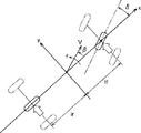
次に、図6乃至図8を参照して、本実施形態によるECU10の補正走行経路算出部10dにおいて実行される走行経路補正処理について説明する。図6は走行経路の補正による障害物回避の説明図である。図7は障害物を回避する際の障害物と車両との間のすれ違い速度の許容上限値とクリアランスとの関係を示す説明図であり、図8は車両モデルの説明図である。
図6では、車両1は走行路(車線)7上を走行しており、走行中又は停車中の車両3とすれ違って、車両3を追い抜こうとしている。
Next, with reference to FIG. 6 to FIG. 8, the travel route correction process executed in the corrected travel route calculation unit 10 d of the
In FIG. 6, the vehicle 1 travels on a traveling path (lane) 7 and is about to pass the
一般に、道路上又は道路付近の障害物(例えば、先行車、駐車車両、歩行者等)とすれ違うとき(又は追い抜くとき)、車両1の運転者は、進行方向に対して直交する横方向において、車両1と障害物との間に所定のクリアランス又は間隔(横方向距離)を保ち、且つ、車両1の運転者が安全と感じる速度に減速する。具体的には、先行車が急に進路変更したり、障害物の死角から歩行者が出てきたり、駐車車両のドアが開いたりするといった危険を回避するため、クリアランスが小さいほど、障害物に対する相対速度は小さくされる。 Generally, when passing (or overtaking) an obstacle on the road or in the vicinity of the road (for example, a preceding vehicle, a parked vehicle, a pedestrian, etc.), the driver of the vehicle 1 operates in the lateral direction orthogonal to the traveling direction. A predetermined clearance or interval (lateral distance) is maintained between the vehicle 1 and the obstacle, and the vehicle 1 is decelerated to a speed that the driver of the vehicle 1 feels safe. More specifically, the smaller the clearance, the less the clearance for the obstacle, in order to avoid the danger that the preceding vehicle will suddenly change course, the pedestrian will come out from the blind spot of the obstacle, or the door of the parked vehicle will open. The relative speed is reduced.
また、一般に、後方から先行車に近づいているとき、車両1の運転者は、進行方向に沿った車間距離(縦方向距離)に応じて速度(相対速度)を調整する。具体的には、車間距離が大きいときは、接近速度(相対速度)が大きく維持されるが、車間距離が小さくなると、接近速度は低速にされる。そして、所定の車間距離で両車両の間の相対速度はゼロとなる。これは、先行車が駐車車両であっても同様である。 In general, when approaching the preceding vehicle from the rear, the driver of the vehicle 1 adjusts the speed (relative speed) in accordance with the inter-vehicle distance (longitudinal distance) along the traveling direction. Specifically, when the inter-vehicle distance is large, the approach speed (relative speed) is maintained large, but when the inter-vehicle distance is small, the approach speed is reduced. Then, at a predetermined inter-vehicle distance, the relative speed between both vehicles is zero. This is the same even if the preceding vehicle is a parked vehicle.
このように、運転者は、障害物と車両1との間の距離(横方向距離及び縦方向距離を含む)と相対速度との関係を考慮しながら、危険がないように車両1を運転している。 Thus, the driver drives the vehicle 1 without danger while considering the relationship between the distance between the obstacle and the vehicle 1 (including lateral distance and longitudinal distance) and the relative speed. ing.
そこで、本実施形態では、図6に示すように、車両1は、車両1から検知される障害物(例えば、駐車車両3)に対して、障害物の周囲に(横方向領域、後方領域、及び前方領域にわたって)又は少なくとも障害物と車両1との間に、車両1の進行方向における相対速度についての許容上限値を規定する2次元分布(速度分布領域40)を設定するように構成されている。速度分布領域40では、障害物の周囲の各点において、相対速度の許容上限値Vlimが設定されている。本実施形態では、すべての運転支援モードにおいて、障害物に対する車両1の相対速度が速度分布領域40内の許容上限値Vlimを超えることがないように走行経路の補正が実施される。
Therefore, in the present embodiment, as shown in FIG. 6, the vehicle 1 is placed around the obstacle (lateral area, rear area, etc.) with respect to the obstacle detected from the vehicle 1 (for example, the parked vehicle 3). And over the front area) or at least between the obstacle and the vehicle 1, configured to set a two-dimensional distribution (speed distribution area 40) defining an allowable upper limit value for the relative speed in the traveling direction of the vehicle 1 There is. In the
図6から分かるように、速度分布領域40は、原則的に、障害物からの横方向距離及び縦方向距離が小さくなるほど(障害物に近づくほど)、相対速度の許容上限値が小さくなるように設定される。また、図6では、理解の容易のため、同じ許容上限値を有する点を連結した等相対速度線が示されている。等相対速度線a,b,c,dは、それぞれ許容上限値Vlimが0km/h,20km/h,40km/h,60km/hに相当する。本例では、各等相対速度領域は、略矩形に設定されている。このように、補正走行経路算出部10dは、入力処理部10aによって回避すべき障害物(周辺物標)が認識され、対象物標選択部10bによって選択された場合には、障害物に対して車両が走行可能な許容相対速度の上限ラインを設定している。そして、この上限ラインを満足するように、目標走行経路算出部10cによって算出された目標走行経路が補正される。 As can be seen from FIG. 6, in principle, the lower the lateral distance and the vertical distance from the obstacle (the closer to the obstacle), the smaller the upper limit of the relative speed becomes. It is set. Further, in FIG. 6, equal relative velocity lines in which points having the same allowable upper limit value are connected are shown for ease of understanding. The equal relative speed lines a, b, c, d correspond to 0 km / h, 20 km / h, 40 km / h, and 60 km / h, respectively, of the allowable upper limit value V lim . In this example, each equal relative velocity area is set to be substantially rectangular. As described above, when the correction processing route calculation unit 10d recognizes the obstacle (nearby target) to be avoided by the input processing unit 10a and selects the obstacle by the target target selection unit 10b, The upper limit line of the allowable relative speed that the vehicle can drive is set. Then, the target travel route calculated by the target travel route calculation unit 10c is corrected so as to satisfy the upper limit line.
なお、速度分布領域40は、必ずしも障害物の全周にわたって設定されなくてもよく、少なくとも障害物の後方、及び、車両1が存在する障害物の横方向の一方側(図6では、車両3の右側領域)に設定されればよい。
The
図7に示すように、車両1がある絶対速度で走行するときにおいて、障害物の横方向に設定される許容上限値Vlimは、クリアランスXがD0(安全距離)までは0(ゼロ)km/hであり、D0以上で2次関数的に増加する(Vlim=k(X−D0)2。ただし、X≧D0)。即ち、安全確保のため、クリアランスXがD0以下では車両1は相対速度がゼロとなる。一方、クリアランスXがD0以上では、クリアランスが大きくなるほど、車両1は大きな相対速度ですれ違うことが許容される。 As shown in FIG. 7, when the vehicle 1 travels at a certain absolute speed, the allowable upper limit value V lim set in the lateral direction of the obstacle is 0 (zero) until the clearance X is D 0 (safety distance). It is km / h, and increases quadratically above D 0 (V lim = k (X−D 0 ) 2 , where X ≧ D 0 ). That is, since the safety clearance X is the vehicle 1 is the relative speed is zero at D 0 below. On the other hand, when the clearance X is D 0 or more, as the clearance is larger, the vehicle 1 is allowed to pass at a higher relative speed.
図7の例では、障害物の横方向における許容上限値は、Vlim=f(X)=k(X−D0)2で定義されている。なお、kは、Xに対するVlimの変化度合いに関連するゲイン係数であり、障害物の種類等に依存して設定される。また、D0も障害物の種類等に依存して設定される。 In the example of FIG. 7, the allowable upper limit value in the lateral direction of the obstacle is defined by V lim = f (X) = k (X−D 0 ) 2 . Here, k is a gain coefficient related to the degree of change of V lim with respect to X, and is set depending on the type of obstacle or the like. Further, D 0 is also set depending on the type of obstacle or the like.
なお、本実施形態では、VlimがXの2次関数となるように定義されているが、これに限らず、他の関数(例えば、一次関数等)で定義されてもよい。また、図7を参照して、障害物の横方向の許容上限値Vlimについて説明したが、障害物の縦方向を含むすべての径方向について同様に設定することができる。その際、係数k、安全距離D0は、障害物からの方向に応じて設定することができる。 In the present embodiment, V lim is defined to be a quadratic function of X. However, the present invention is not limited to this and may be defined by another function (for example, a linear function or the like). Further, although the allowable upper limit value V lim in the lateral direction of the obstacle has been described with reference to FIG. 7, the same may be applied to all radial directions including the longitudinal direction of the obstacle. At that time, the coefficient k and the safety distance D 0 can be set according to the direction from the obstacle.
なお、速度分布領域40は、種々のパラメータに基づいて設定することが可能である。パラメータとして、例えば、車両1と障害物の相対速度、障害物の種類、車両1の進行方向、障害物の移動方向及び移動速度、障害物の長さ、車両1の絶対速度等を考慮することができる。即ち、これらのパラメータに基づいて、係数k及び安全距離D0を選択することができる。
The
また、本実施形態において、障害物は、車両,歩行者,自転車,崖,溝,穴,落下物等を含む。更に、車両は、自動車,トラック,自動二輪で区別可能である。歩行者は、大人,子供,集団で区別可能である。 Further, in the present embodiment, the obstacle includes a vehicle, a pedestrian, a bicycle, a cliff, a ditch, a hole, a falling object and the like. Furthermore, vehicles can be distinguished by cars, trucks, and motorcycles. Pedestrians are distinguishable among adults, children and groups.
図6に示すように、車両1が走行路7上を走行しているとき、車両1のECU10に内蔵された入力処理部10aは、車室外カメラ20から画像データに基づいて障害物(車両3)を検出する。このとき、障害物の種類(この場合は、車両、歩行者)が特定される。
As shown in FIG. 6, when the vehicle 1 is traveling on the traveling path 7, the input processing unit 10a built in the
また、入力処理部10aは、ミリ波レーダ22の測定データ及び車速センサ23の車速データに基づいて、車両1に対する障害物(車両3)の位置及び相対速度並びに絶対速度を算出する。なお、障害物の位置は、車両1の進行方向に沿ったx方向位置(縦方向距離)と、進行方向と直交する横方向に沿ったy方向位置(横方向距離)が含まれる。
Further, the input processing unit 10 a calculates the position and relative speed of the obstacle (vehicle 3) relative to the vehicle 1 and the absolute speed based on the measurement data of the
ECU10に内蔵された補正走行経路算出部10dは、検知したすべての障害物(図6の場合、車両3)について、それぞれ速度分布領域40を設定する。そして、補正走行経路算出部10dは、車両1の速度が速度分布領域40の許容上限値Vlimを超えないように走行経路の補正を行う。補正走行経路算出部10dは、障害物の回避に伴い、運転者の選択した運転支援モードに応じて適用された目標走行経路を補正する。
The corrected travel route calculation unit 10d built in the
即ち、目標走行経路を車両1が走行すると、ある目標位置において目標速度が速度分布領域40によって規定された許容上限値を超えてしまう場合には、目標位置を変更することなく目標速度を低下させるか(図6の経路Rc1)、目標速度を変更することなく目標速度が許容上限値を超えないように迂回経路上に目標位置を変更するか(図6の経路Rc3)、目標位置及び目標速度の両方が変更される(図6の経路Rc2)。
That is, when the vehicle 1 travels on the target traveling route, if the target speed exceeds the allowable upper limit defined by the
例えば、図6は、計算されていた目標走行経路Rが、走行路7の幅方向の中央位置(目標位置)を60km/h(目標速度)で走行する経路であった場合を示している。この場合、前方に駐車車両3が障害物として存在するが、上述のように、目標走行経路Rの計算段階においては、計算負荷の低減のため、この障害物は考慮されていない。
For example, FIG. 6 shows the case where the calculated target travel route R is a route traveling at a central position (target position) in the width direction of the travel route 7 at 60 km / h (target speed). In this case, the parked
目標走行経路Rを走行すると、車両1は、速度分布領域40の等相対速度線d,c,c,dを順に横切ることになる。即ち、60km/hで走行する車両1が等相対速度線d(許容上限値Vlim=60km/h)の内側の領域に進入することになる。したがって、補正走行経路算出部10dは、目標走行経路Rの各目標位置における目標速度を許容上限値Vlim以下に制限するように目標走行経路Rを補正して、補正後の目標走行経路Rc1を生成する。即ち、補正後の目標走行経路Rc1では、各目標位置において目標車速が許容上限値Vlim以下となるように、車両3に接近するに連れて目標速度が徐々に40km/h未満に低下し、その後、車両3から遠ざかるに連れて目標速度が元の60km/hまで徐々に増加される。
When traveling on the target traveling route R, the vehicle 1 crosses the equal relative velocity lines d, c, c, d of the
また、目標走行経路Rc3は、目標走行経路Rの目標速度(60km/h)を変更せず、このため等相対速度線d(相対速度60km/hに相当)の外側を走行するように設定された経路である。補正走行経路算出部10dは、目標走行経路Rの目標速度を維持するため、目標位置が等相対速度線d上又はその外側に位置するように目標位置を変更するように目標走行経路Rを補正して、目標走行経路Rc3を生成する。したがって、目標走行経路Rc3の目標速度は、目標走行経路Rの目標速度であった60km/hに維持される。 Further, the target travel route Rc3 is set so as to travel outside the equal relative speed line d (corresponding to a relative velocity of 60 km / h) without changing the target velocity (60 km / h) of the target travel route R. Route. The corrected travel route calculation unit 10d corrects the target travel route R so as to change the target position so that the target position is located on the equal relative speed line d or outside thereof in order to maintain the target speed of the target travel route R. To generate a target travel route Rc3. Therefore, the target speed of the target travel route Rc3 is maintained at 60 km / h, which is the target speed of the target travel route R.
また、目標走行経路Rc2は、目標走行経路Rの目標位置及び目標速度の両方が変更された経路である。目標走行経路Rc2では、目標速度は、60km/hには維持されず、車両3に接近するに連れて徐々に低下し、その後、車両3から遠ざかるに連れて元の60km/hまで徐々に増加される。
Further, the target travel route Rc2 is a route in which both the target position and the target speed of the target travel route R have been changed. In the target travel route Rc2, the target speed is not maintained at 60 km / h, and gradually decreases as the
目標走行経路Rc1のように、目標走行経路Rの目標位置を変更せず、目標速度のみを変更する補正は、速度制御を伴うが、ステアリング制御を伴わない運転支援モードに適用することができる(例えば、自動速度制御モード、速度制限モード、基本制御モード)。
また、目標走行経路Rc3のように、目標走行経路Rの目標速度を変更せず、目標位置のみを変更する補正は、ステアリング制御を伴う運転支援モードに適用することができる(例えば、先行車追従モード)。
また、目標走行経路Rc2のように、目標走行経路Rの目標位置及び目標速度を共に変更する補正は、速度制御及びステアリング制御を伴う運転支援モードに適用することができる(例えば、先行車追従モード)。
The correction that changes only the target speed without changing the target position of the target travel route R like the target travel route Rc1 can be applied to a driving support mode that involves speed control but does not involve steering control ( For example, automatic speed control mode, speed limit mode, basic control mode).
Further, as in the target travel route Rc3, the correction for changing only the target position without changing the target speed of the target travel route R can be applied to the driving support mode with steering control (for example, following vehicle mode).
Further, as in the target travel route Rc2, a correction that changes both the target position and the target speed of the target travel route R can be applied to the driving support mode with speed control and steering control (for example, the following vehicle follow-up mode ).
次に、ECU10に内蔵された補正走行経路算出部10dは、設定可能な補正走行経路の中から、センサ情報等に基づいて、最適な補正走行経路を決定する。即ち、補正走行経路算出部10dは、設定可能な補正走行経路の中から、所定の評価関数及び所定の制約条件に基づいて最適な補正走行経路を決定する。
Next, among the settable corrected travel routes, the corrected travel route calculation unit 10d built in the
ECU10は、評価関数J、制約条件及び車両モデルをメモリ内に記憶している。補正走行経路算出部10dは、最適な補正走行経路を決定するに際し、制約条件及び車両モデルを満たす範囲で、評価関数Jが極値をもつ最適な補正走行経路を算出する(最適化処理)。
The
評価関数Jは、複数の評価ファクタを有する。本例の評価ファクタは、例えば、速度(縦方向及び横方向)、加速度(縦方向及び横方向)、加速度変化量(縦方向及び横方向)、ヨーレート、車線中心に対する横位置、車両角度、操舵角、その他ソフト制約について、目標走行経路を補正した複数の走行経路の良否を評価するための関数である。 The evaluation function J has a plurality of evaluation factors. The evaluation factors in this example are, for example, velocity (longitudinal and lateral), acceleration (longitudinal and lateral), acceleration variation (longitudinal and lateral), yaw rate, lateral position relative to lane center, vehicle angle, steering It is a function for evaluating the quality of a plurality of travel routes obtained by correcting the target travel route with regard to corners and other software constraints.
評価ファクタには、車両1の縦方向の挙動に関する評価ファクタ(縦方向評価ファクタ:縦方向の速度、加速度、加速度変化量等)と、車両1の横方向の挙動に関する評価ファクタ(横方向評価ファクタ:横方向の速度、加速度、加速度変化量、ヨーレート、車線中心に対する横位置、車両角度、操舵角等)が含まれる。 The evaluation factors include an evaluation factor related to the longitudinal behavior of the vehicle 1 (longitudinal evaluation factor: longitudinal velocity, acceleration, acceleration change amount, etc.) and an evaluation factor related to the lateral behavior of the vehicle 1 (horizontal evaluation factor) : Lateral velocity, acceleration, acceleration change amount, yaw rate, lateral position with respect to lane center, vehicle angle, steering angle, etc. are included.
本実施形態においては、評価関数Jは、以下の式で記述される。

式中、Wk(Xk−Xrefk)2は評価ファクタ、Xkは補正走行経路の評価ファクタに関する物理量、Xrefkは目標走行経路(補正前)の評価ファクタに関する物理量、Wkは評価ファクタの重み値(例えば、0≦Wk≦1)である(但し、k=1〜n)。したがって、本実施形態の評価関数Jは、n個の評価ファクタの物理量について、目標走行経路(補正前)の物理量に対する補正走行経路の物理量の差の2乗の和を重み付けして、所定期間(例えば、N=3秒)の走行経路長にわたって合計した値に相当する。 Where Wk (Xk-Xrefk) 2 is an evaluation factor, Xk is a physical quantity related to the evaluation factor of the corrected travel route, Xrefk is a physical quantity related to the evaluation factor of the target travel route (before correction), Wk is a weight value of the evaluation factor (for example, It is 0 <= Wk <= 1) (however, k = 1-n). Therefore, the evaluation function J according to the present embodiment weights the sum of the squares of the physical quantities of the corrected travel route with respect to the physical quantities of the target travel route (before correction) for the physical quantities of n evaluation factors For example, it corresponds to the value summed over the travel path length of N = 3 seconds.
本実施形態においては、目標走行経路を補正した走行経路の評価が高いほど評価関数Jは小さな値をもつので、評価関数Jが極小値となる走行経路が、補正走行経路算出部10dによって最適な補正走行経路として算出される。 In the present embodiment, the evaluation function J has a smaller value as the evaluation of the travel route corrected the target travel route is higher, so the travel route with the evaluation function J having a minimum value is optimum by the correction travel route calculation unit 10d. It is calculated as a correction travel route.
制約条件は、補正走行経路が満足する必要がある条件であり、制約条件によって評価すべき補正走行経路を絞り込むことにより、評価関数Jによる最適化処理に要する計算負荷を減少させることが可能となり、計算時間を短縮することができる。 The constraint condition is a condition that the correction travel route needs to be satisfied, and by narrowing the correction travel route to be evaluated by the constraint condition, it becomes possible to reduce the calculation load required for the optimization processing by the evaluation function J. Calculation time can be shortened.
車両モデルは、車両1の物理的な運動を規定するものであり、以下の運動方程式で記述される。この車両モデルは、本例では図8に示す2輪モデルである。車両モデルにより車両1の物理的な運動が規定されることにより、走行時の違和感が低減された補正走行経路を算出することができると共に、評価関数Jによる最適化処理を早期に収束させることができる。 The vehicle model defines the physical motion of the vehicle 1 and is described by the following equation of motion. This vehicle model is a two-wheel model shown in FIG. 8 in this example. By defining the physical movement of the vehicle 1 by the vehicle model, it is possible to calculate a corrected traveling route with reduced discomfort when traveling, and at the same time to make the optimization process by the evaluation function J converge early. it can.
![]()
![]()
![]()
![]()
図8及び式(1)、(2)中、mは車両1の質量、Iは車両1のヨーイング慣性モーメント、lはホイールベース、lfは車両重心点と前車軸間の距離、lrは車両重心点と後車軸間の距離、Kfは前輪1輪あたりのタイヤコーナリングパワー、Krは後輪1輪あたりのタイヤコーナリングパワー、Vは車両1の車速、δは前輪の実舵角、βは車両重心点の横すべり角、rは車両1のヨー角速度、θは車両1のヨー角、yは絶対空間に対する車両1の横変位、tは時間である。
このように、補正走行経路算出部10dは、目標走行経路、制約条件、車両モデル等に基づいて、多数の走行経路の中から、評価関数Jが最小になる最適な補正走行経路を算出する。
In FIG. 8 and Equations (1) and (2), m is the mass of the vehicle 1, I is the yawing moment of the vehicle 1, l is the wheel base, l f is the distance between the vehicle center of gravity and the front axle, l r is the distance between the vehicle center of gravity and a rear axle, K f is tire cornering power per wheel one wheel, K r is a tire cornering power per rear one wheel, V is the vehicle 1 speed, [delta] is the actual steering angle of the front wheels, β is the side slip angle of the center of gravity of the vehicle, r is the yaw angular velocity of the vehicle 1, θ is the yaw angle of the vehicle 1, y is the lateral displacement of the vehicle 1 relative to the absolute space, and t is time.
As described above, the correction travel route calculation unit 10d calculates an optimum correction travel route with the smallest evaluation function J among a large number of travel routes based on the target travel route, the constraint condition, the vehicle model, and the like.
次に、図9乃至図13を参照して、補正走行経路に対する制約条件を説明する。図9乃至図12は、補正後の走行経路が満足すべき、走行経路に対する制約条件を示す図である。図13は、補正後の走行経路が満足すべき走行パラメータに対する制約条件を示す図である。 Next, constraint conditions for the correction travel route will be described with reference to FIGS. 9 to 13. FIGS. 9 to 12 are diagrams showing constraints on the travel route that the travel route after the correction should satisfy. FIG. 13 is a diagram showing constraint conditions for the travel parameters that the travel route after correction should satisfy.
目標走行経路算出部10cによって算出された目標走行経路は、補正走行経路算出部10dによって、周辺物標に対して自車両が走行可能な許容相対速度の上限ライン(図6)、上述した評価関数J、及び以下に説明する制約条件に基づいて補正され、補正走行経路が算出される。即ち、周辺物標に対する許容相対速度の上限ラインを越えないように変更された走行経路のうち、各制約条件を満足すると共に、評価関数の値が最も小さくなる走行経路が最適な補正走行経路として算出される。 The target travel route calculated by the target travel route calculation unit 10c is adjusted by the corrected travel route calculation unit 10d to the upper limit line (FIG. 6) of the allowable relative speed at which the vehicle can travel with respect to the peripheral target. The corrected traveling route is calculated based on J and the constraints described below. That is, among the travel routes changed so as not to exceed the upper limit line of the allowable relative speed with respect to the peripheral target, the travel route which satisfies each constraint condition and has the smallest evaluation function value is the optimum correction travel route. It is calculated.
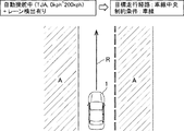
図9に示すように、例えば、自動操舵モードである先行車追従モードの実行中であり、且つ車室外カメラ20によって車線が検出されている場合には、目標走行経路算出部10cは、車線両側の区画線の中央に目標走行経路Rを設定し、補正走行経路算出部10dは、制約条件として、検出された車線(両側の区画線の外側の領域A(図9の斜線の領域))を設定する。即ち、車線が検出されている場合には、先行車追従モードの実行中であっても、車線の中央に目標走行経路Rが設定され、車線の外側の領域Aに制約条件が設定される。このように制約条件が設定されることにより、補正走行経路算出部10dは、車両1が領域Aに侵入しない範囲で目標走行経路Rを補正する。
As shown in FIG. 9, for example, when the preceding vehicle follow-up mode which is an automatic steering mode is being executed and the lane is detected by the camera outside the
一方、図10に示すように、先行車追従モードにおいて、車線が検出されず、且つ先行車両が検出されている場合には、先行車3の走行軌跡が目標走行経路Rとして設定される。さらに、この目標走行経路R(先行車両の走行軌跡)を自車両が走行した場合における推定走行経路を中心とする自車幅よりも外側の領域Aが制約条件として設定される。このように、先行車3の走行軌跡と同一の経路を自車が走行した場合において、自車が通る領域の外側が制約条件として設定される。このように制約条件が設定されることにより、補正走行経路算出部10dは、車両1が領域Aに侵入しない範囲で目標走行経路Rを補正する。
On the other hand, as shown in FIG. 10, when the lane is not detected and the preceding vehicle is detected in the following vehicle follow-up mode, the traveling locus of the preceding
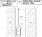
さらに、図11に示すように、先行車追従モードにおいて、車線及び先行車両が検出されていない場合には、運転者の意志による現在の運転状況が継続された場合に車両が走行すると推定される推定走行経路が目標走行経路Rとして設定され、この推定走行経路を中心として、自車幅よりも外側の領域Aが制約条件として設定される。即ち、先行車両が検出されていない場合には、目標走行経路算出部10cによって算出された目標走行経路Rを基準とした制約条件が設定される。このように制約条件が設定されることにより、補正走行経路算出部10dは、車両1が領域Aに侵入しない範囲で目標走行経路Rを補正する。 Furthermore, as shown in FIG. 11, in the preceding vehicle following mode, when the lane and the preceding vehicle are not detected, it is estimated that the vehicle travels when the current driving condition by the driver's will is continued. An estimated travel route is set as a target travel route R, and an area A outside the vehicle width is set as a constraint condition around this estimated travel route. That is, when the preceding vehicle is not detected, the constraint condition based on the target travel route R calculated by the target travel route calculation unit 10c is set. By setting the constraint conditions in this manner, the corrected traveling route calculation unit 10 d corrects the target traveling route R in a range in which the vehicle 1 does not intrude into the area A.
また、図12に示すように、先行車追従モード以外の制御モードにおいて、車線が検出されている場合には、運転者の意志による現在の運転状況が継続された場合に車両が走行すると推定される推定走行経路が目標走行経路Rとして設定される。図12に示す例では、車両1は、車線内において、車線中央よりも左側の区画線に近い位置を、運転者の意志により走行しており、この運転状況が継続すれば、車両1は左側の区画線に近い位置を走行し続けると推定される。このため、推定される走行経路である車線中央よりも左側の区画線に近い位置が、目標走行経路Rとして設定される。さらに、この推定走行経路を中心として、自車幅よりも外側の領域であり、車線両側の区画線よりも外側の領域である領域Aが制約条件として設定される。このように制約条件が設定されることにより、補正走行経路算出部10dは、車両1が領域Aに侵入しない範囲で目標走行経路Rを補正する。 Further, as shown in FIG. 12, when the lane is detected in a control mode other than the preceding vehicle follow-up mode, it is estimated that the vehicle travels when the current driving condition by the driver's will is continued. The estimated travel route is set as a target travel route R. In the example shown in FIG. 12, the vehicle 1 travels at a position near the lane line on the left side of the center of the lane in the lane by the driver's will, and if this driving situation continues, the vehicle 1 is on the left side. It is estimated that the vehicle will continue to travel near the lane line of Therefore, a position closer to the lane line on the left side than the lane center which is the estimated travel route is set as the target travel route R. Further, an area A which is an area outside the vehicle width with respect to the estimated travel route and an area outside the dividing lines on both sides of the lane is set as a constraint condition. By setting the constraint conditions in this manner, the corrected traveling route calculation unit 10 d corrects the target traveling route R in a range in which the vehicle 1 does not intrude into the area A.
次に、図13を参照して、補正後の走行経路が満足すべき走行パラメータに関する制約条件を説明する。
上述したように、ECU10の目標走行経路算出部10cは目標走行経路Rを算出し、この目標走行経路Rは、補正走行経路算出部10dによって、上記各制約条件(図9乃至図12)を満足するように補正される。これに加えて補正走行経路算出部10dは、制約条件として、図13に示す走行パラメータの制限値をも満足するように目標走行経路Rを補正する。即ち、補正された走行経路が図9乃至図12に示す制約条件を満足しているとしても、自車両1の運動性能に対して実現困難な走行経路であったり、車両の乗員に不快感を与える走行経路であったりしては、採用することができない。このため、本実施形態においては、車両の加速度等、自車両の運動に関する走行パラメータに対しても制約条件を設けている。
Next, with reference to FIG. 13, constraint conditions on travel parameters that the travel route after correction should satisfy will be described.
As described above, the target travel route calculation unit 10c of the
即ち、図13に示すように、本実施形態では、先行車追従モード(TJA)において、自車の前後加速度が±3m/s2以内に制限され、自車の横加速度が±4m/s2以内に制限され、自車の前後加加速度が±5m/s3以内に制限され、自車の横加加速度が±2m/s3以内に制限され、自車の操蛇角が±90deg以内に制限され、自車の操蛇角速度が±90deg/s以内に制限され、自車のヨーレートが±10deg/s以内に制限される。このように、自動操舵モードである先行車追従モードにおいては、制約条件が走行パラメータの絶対値として与えられ、走行パラメータにこのような制約条件を設けることにより、車両の乗員に大きなG(加速度)が作用し、不快感を与えるのを防止している。 That is, as shown in FIG. 13, in the present embodiment, in the preceding vehicle following mode (TJA), the longitudinal acceleration of the vehicle is limited to ± 3 m / s 2 , and the lateral acceleration of the vehicle is ± 4 m / s 2 Within the vehicle, the longitudinal acceleration of the vehicle is limited to ± 5 m / s 3 , the lateral acceleration of the vehicle is limited to ± 2 m / s 3 , and the steering angle of the vehicle is within ± 90 deg. The steering angular velocity of the vehicle is limited to ± 90 deg / s, and the yaw rate of the vehicle is limited to ± 10 deg / s. Thus, in the preceding vehicle following mode which is the automatic steering mode, the constraint condition is given as an absolute value of the travel parameter, and by providing such a constraint condition in the travel parameter, a large G (acceleration) of the vehicle occupant To prevent it from acting and causing discomfort.
次に、図14を参照して、ECU10による目標蛇角及び目標加減速度の計算手順を説明する。図14は、車室外カメラ20及びその他の各センサからの入力情報に基づいて、ECU10により目標蛇角及び目標加減速度を計算する手順を示すフローチャートである。この図14に示すフローチャートによる処理は、運転支援制御の実行中において、所定の時間間隔で繰り返し実行される。本実施形態においては、図14に示すフローチャートの処理は、目標走行経路や補正走行経路を更新する時間間隔である約0.1秒毎に実行される。
Next, with reference to FIG. 14, the calculation procedure of the target snake angle and the target acceleration / deceleration by the
まず、図14のステップS1においては、車室外カメラ20及びその他の各センサからの入力情報に基づいて、車両1が走行している走行路の情報や、車両状態の情報が検出される。このステップS1における処理は、主としてECU10の入力処理部10aによって実行される。走行路の情報としては、車両1が走行している車線の幅や、直線道路か、カーブした道路か等の道路形状に関する情報が、主として車室外カメラ20によって撮像された画像から検出される。また、車両状態の情報としては、車速センサ23によって測定された現在の車速や、操蛇角センサ26によって測定された現在の操舵角、アクセルセンサ27によって測定されたアクセルペダルの踏み込み量等が検出される。
First, in step S1 of FIG. 14, information of a traveling path on which the vehicle 1 is traveling and information of a vehicle state are detected based on input information from the
次に、ステップS2においては、主としてミリ波レーダ22や車室外カメラ20からの入力情報に基づいて、車両1の周辺に存在する物標の情報が検出(認識)される。ステップS2において検出される物標は、本実施形態においては、目標走行経路が生成される約3秒後までに車両1が到達する可能性のある範囲に存在する物標であり、先行車、歩行者、障害物、信号、道路標識、横断歩道等が検出される。このステップS2における物標の検出処理も、主としてECU10の入力処理部10aによって実行される。
さらに、ステップS2においては、検出された周辺物標の中から走行経路の算出に必要な対象物標が選択される。この周辺物標から対象物標を選択する処理は、主としてECU10の対象物標選択部10bによって実行される。
Next, in step S2, information of a target existing around the vehicle 1 is detected (recognized) based mainly on input information from the
Furthermore, in step S2, a target target required for calculation of the travel route is selected from among the detected peripheral targets. The process of selecting a target object from the peripheral objects is mainly performed by the target object selection unit 10b of the
また、ECU10に接続された車室外カメラ20や、その他の何れかのセンサからの検出信号が入力されない場合、或いは、車室外カメラ20を含む各センサの検出信号相互間の検出信号の間に整合性がない場合には、入力処理部10aは何れかのセンサに異常があると推定する。例えば、ミリ波レーダ20のうちの前方レーダ及び側方レーダによって検出されるべき位置にある物標が、一方のレーダのみによって検出されている場合や、車室外カメラ20の画像に基づいて障害物の存在が検出されているにも関わらず、これに対応する対象物が何れのミリ波レーダ22によっても検出されていない場合等は、車室外カメラ20を含む何れかのセンサに異常があると推定される。
In addition, when a detection signal from the
次いで、ステップS3においては、ステップS1において検出された走行路情報、車両状態情報、及びステップS2において検出、選択された対象物標の情報に基づいて目標走行経路(図3乃至図5)が算出される。このステップS3における目標走行経路の算出は、主としてECU10の目標走行経路算出部10cによって実行される。上述したように、目標走行経路は設定されている運転支援モードに応じて設定される走行経路であり、目標走行経路の算出には、対象物標選択部10bによって選択された先行車や、歩行者、障害物等は加味されない。しかしながら、本実施形態においては、対象物標が信号や横断歩道である場合には、目標走行経路の算出にこれらの対象物標が加味される。具体的には、車両1が赤信号や横断歩道に接近している場合において、車両の走行速度を低下させるように目標走行経路を算出することもできる。
Next, in step S3, the target travel route (FIGS. 3 to 5) is calculated based on the travel path information detected in step S1, the vehicle state information, and the information of the target object detected and selected in step S2. Be done. The calculation of the target travel route in step S3 is mainly performed by the target travel route calculation unit 10c of the
さらに、ステップS4においては、ステップS3において算出された目標走行経路、及びステップS2において検出、選択された対象物標の情報に基づいて、目標走行経路が補正され、補正走行経路が算出される。このステップS4における補正走行経路の算出は、主としてECU10の補正走行経路算出部10dによって実行される。なお、目標走行経路上に回避すべき障害物等が存在しない場合には、目標走行経路の補正は実行されず、目標走行経路と補正走行経路は同一になる。
Further, in step S4, the target travel route is corrected based on the information on the target travel route calculated in step S3 and the target target detected and selected in step S2, and the corrected travel route is calculated. The calculation of the corrected travel route in step S4 is mainly performed by the corrected travel route calculation unit 10d of the
目標走行経路上に回避すべき障害物等の物標が存在する場合には、この物標との衝突を回避するために、物標に対して車両1が走行可能な許容相対速度の上限ラインが設定される(図6)。さらに、補正走行経路算出部10dは、許容相対速度の上限ラインを越えないように複数の走行経路(例えば、図6のRc1〜Rc3)を生成すると共に、これらの走行経路の中から、所定の制約条件(例えば、図9乃至図13)を満足しないものを排除する。さらに、排除されずに残った各走行経路について評価関数Jを計算し、この値の極値(極小値)に対応する走行経路が、補正走行経路として算出される。 When a target such as an obstacle to be avoided exists on the target travel route, the upper limit line of the allowable relative speed at which the vehicle 1 can travel with respect to the target to avoid a collision with the target Is set (FIG. 6). Furthermore, the correction travel route calculation unit 10d generates a plurality of travel routes (for example, Rc1 to Rc3 in FIG. 6) so as not to exceed the upper limit line of the allowable relative speed, and selects a predetermined travel route among these travel routes. Eliminate those that do not satisfy the constraints (eg, FIGS. 9-13). Furthermore, the evaluation function J is calculated for each travel route remaining without being excluded, and a travel route corresponding to an extreme value (minimum value) of this value is calculated as a corrected travel route.
なお、補正走行経路の算出は、目標走行経路が複雑な場合や、複数の障害物が存在する場合、評価関数Jを計算すべき走行経路が多数存在する場合等には計算負荷が大きくなる。計算負荷が大きく、所定の時間内に補正走行経路を算出できない場合には、補正走行経路を算出するステップS4の処理が途中で打ち切られる。本実施形態においては、ステップS4における補正走行経路の算出処理は、図14のフローチャートを実行する時間周期である0.1秒以下に設定された所定の制限時間内に計算が完了しない場合には打ち切られる。 The calculation of the correction travel route is heavy when the target travel route is complicated, when there are a plurality of obstacles, and when there are many travel routes for which the evaluation function J is to be calculated. If the calculation load is large and the corrected traveling route can not be calculated within the predetermined time, the process of step S4 for calculating the corrected traveling route is discontinued halfway. In the present embodiment, the calculation process of the correction traveling route in step S4 is performed when the calculation is not completed within a predetermined time limit set to 0.1 second or less, which is a time period for executing the flowchart of FIG. It is discontinued.
さらに、図15に示すように、許容相対速度の上限ラインを越えないように生成された走行経路の中に、所定の制約条件を満足するものがない場合には、ステップS4において、補正走行経路は算出されない。即ち、図15に示す例においては、自車両1の目標走行経路は走行中の車線の中央に設定されているが、前方に車両3が駐車しているため、目標走行経路上をそのまま走行すると車両3と衝突してしまうので目標走行経路を補正する必要がある。
Further, as shown in FIG. 15, when there is no traveling route that is generated so as not to exceed the upper limit line of allowable relative speed, the correction traveling route is corrected in step S4 when there is no one satisfying the predetermined constraint condition. Is not calculated. That is, in the example shown in FIG. 15, although the target travel route of the own vehicle 1 is set at the center of the traveling lane, since the
ここで、図15に示す速度分布領域40は、許容できる相対速度の上限がゼロのライン(許容相対速度の上限ライン)である。従って、如何に速度を低下させたとしても、自車両1が図15の速度分布領域40の内側に進入する走行経路は許容されない。このため、補正走行経路算出部10dは、自車両1が速度分布領域40の内側に進入しないように補正走行経路を算出しようとするが、速度分布領域40に進入しない経路をとると、制約条件によって進入が規制されている領域Aに自車両1が進入してしまう。このような場合には、制約条件を満足する補正走行経路を算出することができない。
Here, the
また、図16に示す例のように、周辺車両の走行に起因して補正走行経路が算出不能となる場合もある。図16は、目標走行経路(障害物等がないため補正走行経路も同一)上を走行している自車両1の直前に、周辺車両3が突然車線変更して近づいた例を示している。このような場合には、周辺車両3の走行に起因して、自車両1が偶発的に周辺車両3に対する許容相対速度の上限ラインの内側に進入してしまうことがある。例えば、直前に車線変更してきた周辺車両3との間の相対速度が20km/hであるにも関わらず、自車両1の前端が許容相対速度20km/hのラインよりも内側に入ってしまった場合である。補正走行経路算出部10dは、自車両1が許容相対速度の上限ラインの内側に進入することがないよう補正走行経路を算出するように構成されているが、周辺車両の走行に起因して突発的に上限ラインを満足しない領域に進入してしまった場合には、この時点において補正走行経路を算出することができなくなる。
In addition, as in the example illustrated in FIG. 16, the corrected travel route may not be able to be calculated due to the travel of the surrounding vehicle. FIG. 16 shows an example in which the
さらに、図17に示す例のように、評価関数Jの極値が複数存在する場合にも、補正走行経路の算出が困難となる場合がある。図17に示す例では、自車両1が走行している車線のほぼ中央に障害物42が存在し、自車両1がこの障害物42を回避すべく、障害物42の右側を通過することも、左側を通過することも可能になっている。このような状況では、評価関数Jは、障害物42の右側を通過する走行経路と、左側を通過する走行経路の2つの走行経路に対応する2つの極値(極小値)もつこととなる。このような場合において、2つの極値の値が同一である場合には、最も適切な1つの補正走行経路を算出することが困難となる。また、評価関数Jの値が2つ以上の極値をもつ場合には、評価関数Jにより走行経路が適正に評価できていない可能性もある。
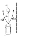
Furthermore, as in the example shown in FIG. 17, it may be difficult to calculate the corrected travel route even when there are a plurality of extreme values of the evaluation function J. In the example shown in FIG. 17, an
次いで、ステップS5においては、ECU10の主制御部10f及びバックアップ制御部10eによって、目標蛇角及び目標加減速度が計算される。即ち、主制御部10fは、ステップS4において算出された補正走行経路上を走行するための目標蛇角及び目標加減速度を算出する。一方、バックアップ制御部10eは、ステップS3において算出された目標走行経路上を走行するための目標蛇角及び目標加減速度を算出する。なお、目標走行経路上に障害物等が存在する場合には、バックアップ制御部10eは、この障害物との衝突を回避するために目標加減速度を変更する(減速する)。また、目標走行経路上を走行した場合にも自車両が、障害物(周辺物標)に対する許容相対速度の上限ラインを満足しない領域に進入しないよう、目標加減速度を算出するようにバックアップ制御部10eを構成することもできる。しかしながら、バックアップ制御部10eは、障害物との衝突を回避するための目標蛇角の変更は実行せず、目標蛇角は、専ら目標走行経路に沿って走行することを目的として算出される。
Next, in step S5, the main control unit 10f and the backup control unit 10e of the
図14に示すフローチャートでは、ステップS3において目標走行経路が算出され、ステップS4において補正走行経路が算出され、ステップS5において目標走行経路及び補正走行経路を夫々走行するための目標蛇角及び目標加減速度が夫々算出されているが、これらの処理の一部又は全部を1つ又は複数のCPUによって並列的に処理することもできる。或いは、これらの処理の順序を適宜入れ替えることもできる。 In the flowchart shown in FIG. 14, the target travel route is calculated in step S3, the correction travel route is calculated in step S4, and the target travel angle and target acceleration / deceleration for traveling the target travel route and the correction travel route in step S5. Although each is calculated, part or all of these processes may be processed in parallel by one or more CPUs. Alternatively, the order of these processes can be changed as appropriate.
次に、ステップS6においては、補正走行経路の信頼度が計算される。上述したように、ステップS2において、車室外カメラ20やその他の何れかのセンサ等に異常があると推定された場合には、算出された補正走行経路の信頼度が低いということができる。また、ステップS4において、所定の制限時間内に補正走行経路を算出する計算が完了せず、途中で計算が打ち切られた場合にも、算出された補正走行経路の信頼度が低いということができる。さらに、ステップS4において、許容相対速度の上限ラインを越えないように生成された走行経路の中に、所定の制約条件を満足するものがない場合も補正走行経路の信頼度が低いとすることができる。
Next, in step S6, the reliability of the corrected travel route is calculated. As described above, when it is estimated that there is an abnormality in the camera outside the
さらに、本実施形態においては、ステップS4において計算された評価関数Jが複数の極値をもつ場合にも、補正走行経路の信頼度が低いものと評価される。しかしながら、評価関数Jの極値が複数存在する場合であっても、最も評価が高い極値が他の極値よりも所定値以上評価が高い場合には、最も評価が高い極値に対応する走行経路を、信頼度の高い補正走行経路とすることもできる。即ち、評価関数Jの極値は複数存在するものの、最も小さい極小値の値が飛び抜けて小さく、2番目に小さい極小値の値よりも所定値以上小さい場合に、最も小さい極小値に対応する補正走行経路を、信頼度の高い補正走行経路とすることもできる。逆に、評価関数Jの最も評価が高い極小値が、所定の評価値以下の低い評価である場合には、極小値が単一であっても、その極小値に対応する補正走行経路を、信頼度の低い補正走行経路とすることもできる。即ち、評価関数Jの極値が1つである場合でも、その極小値における評価関数Jの絶対的な値が大きい(評価が低い)場合には、その極値に対応する走行経路を信頼度の低い補正走行経路とすることもできる。 Furthermore, in the present embodiment, even when the evaluation function J calculated in step S4 has a plurality of extreme values, it is evaluated that the reliability of the corrected traveling route is low. However, even if there are multiple extreme values of the evaluation function J, if the extreme value with the highest rating is higher than the other extreme values by a predetermined value or more, the extreme value corresponding to the highest rating is corresponded. The travel route can also be a highly reliable corrected travel route. That is, although there are a plurality of extreme values of the evaluation function J, the correction corresponding to the smallest minimum value when the value of the smallest minimum value jumps out and is smaller than the second smallest minimum value by a predetermined value or more The travel route can also be a highly reliable corrected travel route. Conversely, if the local minimum with the highest evaluation of the evaluation function J is a low evaluation below the predetermined evaluation value, even if the local minimum is single, the correction travel route corresponding to the local minimum is It can also be a correction travel route with low reliability. That is, even when the extremum value of the evaluation function J is one, if the absolute value of the evaluation function J at the local minimum value is large (the evaluation is low), the traveling route corresponding to the extremum has the reliability It is also possible to set a low correction travel route.
次いで、ステップS7においては、ステップS4において算出された補正走行経路が、信頼度が高く適正なものであるか否かが判断される。補正走行経路が適正なものと判断された場合にはステップS8に進み、適正なものでないと判断された場合にはステップS9に進む。ステップS8においては、主制御部10fによって算出された、補正走行経路を走行するための目標蛇角及び目標加減速度が制御信号としてECU10から出力されて、図14に示すフローチャートの1回の処理を終了する。
Next, in step S7, it is determined whether the corrected traveling route calculated in step S4 is highly reliable and appropriate. If it is determined that the correction travel route is appropriate, the process proceeds to step S8, and if it is determined that the corrected travel path is not appropriate, the process proceeds to step S9. In step S8, the target snake angle and the target acceleration / deceleration for traveling on the corrected traveling route, which are calculated by the main control unit 10f, are output from the
本実施形態においては、車室外カメラ20やその他の何れかのセンサ等に異常があると推定された場合、途中で計算が打ち切られた場合、及び制約条件を満足する走行経路がない場合の何れの場合においても、補正走行経路が適正なものではないと判断される。或いは、センサ等の異常の程度、計算が打ち切られるまでに算出された走行経路の評価関数Jの値、制約条件の逸脱の程度等を点数化し、この点数に応じて補正走行経路が適正であるか否かを判断するように本発明を構成することもできる。
In the present embodiment, when it is estimated that there is an abnormality in the camera outside the
ステップS7において補正走行経路が適正なものでないと判断された場合にはステップS9に進み、ミリ波レーダ22のうちの前方レーダ及び車室外カメラ20に異常があるか否かが判断される。前方レーダ及び車室外カメラ20に異常がない場合にはステップS10に進み、バックアップ制御部10eによって算出された、目標走行経路を走行するための目標蛇角及び目標加減速度が制御信号としてECU10から出力されて、図14に示すフローチャートの1回の処理を終了する。
If it is determined in step S7 that the corrected travel route is not appropriate, the process proceeds to step S9, and it is determined whether or not there is an abnormality in the forward radar of the
このように、前方レーダ及び車室外カメラ20に異常がない場合であっても、その他のセンサに異常が推定されている場合には、主制御部10fによる、補正走行経路を走行するための目標蛇角及び目標加減速度は採用されない。即ち、図18に一例を示すように、ミリ波レーダ22のうちの前方レーダ及び車室外カメラ20に異常がなく、補正走行経路が算出されている場合であっても、後方レーダが故障している場合には、自車両1が駐車している前方の車両3を回避した後、車線内の元の走行位置に復帰する際に安全が十分に確認できないためである。
As described above, even when there is no abnormality in the front radar and the camera outside the
一方、ステップS9において、前方レーダ及び車室外カメラ20の何れかに異常があると推定されている場合にはステップS11に進む。ステップS11においては、出力調整部10gは、主制御部10f及びバックアップ制御部10eによる何れの制御も実行せず、センサに異常があり、主制御部10f及びバックアップ制御部10eによる制御が不能である旨を運転者に報知して、図14に示すフローチャートの1回の処理を終了する。即ち、前方レーダ及び車室外カメラ20の何れかに異常があると推定されている場合には、算出されている目標走行経路についても信頼性が十分でないため、バックアップ制御部10eによる制御も実行されない。
On the other hand, when it is estimated that there is an abnormality in either the front radar or the camera outside the
本発明の実施形態の車両制御装置100によれば、主制御部10fは目標走行経路(図3〜図5)を補正した補正走行経路(図6)上を走行するための目標蛇角及び目標加減速度を計算するので、車両制御装置100の計算負荷を軽減することができる。また、出力調整部10gは、評価関数Jの極値が複数存在する場合には、バックアップ制御部10eが算出した目標蛇角及び目標加減速度を制御信号として出力するので、複数極値が存在する、評価が曖昧な評価関数Jに基づいて決定された補正走行経路を走行するのを回避することができる。
According to the
また、本実施形態の車両制御装置100によれば、評価関数Jの最も評価が高い極値が他の極値よりも所定値以上評価が高い場合には、極値が複数存在する場合であっても最も評価が高い極値に対応する補正走行経路が採用されるので、極値が複数存在することにより、明らかに評価の高い補正走行経路が不採用となるのを防止することができる。
Further, according to the
さらに、本実施形態の車両制御装置100によれば、評価関数Jの最も評価が高い極値が、所定の評価値以下の低い評価である場合には、極値が単一であっても、その最も評価が高い極値に対応する補正走行経路が不採用とされるので、評価の低い補正走行経路が採用され、運転者に強い違和感を与えるのを防止することができる。
Furthermore, according to the
また、本実施形態の車両制御装置100によれば、自車両1が許容相対速度の上限ラインを満足しない領域に進入するのを回避すべく、目標走行経路上を走行する自車両の加減速度が算出されるので、車両制御装置100の計算負荷を軽減しつつ、運転者に強い違和感を与えることなく衝突を回避することができる。
Further, according to the
1 車両
10 車両制御演算部(ECU)
10a 入力処理部(周辺物標検出部)
10b 対象物標選択部
10c 目標走行経路算出部
10d 補正走行経路算出部
10e バックアップ制御部
10f 主制御部
10g 出力調整部
20 車室外カメラ
21 車室内カメラ(前方カメラ)
22 ミリ波レーダ(前方レーダ)
23 車速センサ
24 加速度センサ
25 ヨーレートセンサ
26 操舵角センサ
27 アクセルセンサ
28 ブレーキセンサ
29 測位システム
30 ナビゲーションシステム
31 エンジン制御システム
32 ブレーキ制御システム
33 ステアリング制御システム
35 運転者操作部(運転支援モード設定部)
36a ISAスイッチ
36b TJAスイッチ
36c ACCスイッチ
37a 距離設定スイッチ
37b 車速設定スイッチ
40 速度分布領域
100 車両制御装置
1
10a Input processing unit (peripheral target detection unit)
10b Target target selection unit 10c Target travel route calculation unit 10d Corrected travel route calculation unit 10e Backup control unit 10f Main control unit 10g
22 mm-wave radar (forward radar)
Claims (4)
周辺物標を検出する周辺物標検出部と、
自車両の目標走行経路を算出する目標走行経路算出部と、
この目標走行経路算出部によって算出された上記目標走行経路を補正した補正走行経路を算出する補正走行経路算出部と、
この補正走行経路算出部によって算出された上記補正走行経路上を走行するための目標舵角及び目標加減速度を計算する主制御部と、
上記目標走行経路算出部によって算出された上記目標走行経路上を走行するための目標舵角及び目標加減速度を計算するバックアップ制御部と、
上記主制御部によって算出された目標舵角及び目標加減速度、又は上記バックアップ制御部によって算出された目標舵角及び目標加減速度を制御信号として出力する出力調整部と、を有し、
上記補正走行経路算出部は、上記周辺物標検出部によって回避すべき周辺物標が検出された場合において、少なくとも上記周辺物標から上記車両に向けて、上記周辺物標に対する上記車両の相対速度の許容上限値の分布を規定する速度分布領域を設定し、この速度分布領域における許容上限値は上記周辺物標から距離が離れるほど大きくなるように設定され、
上記補正走行経路算出部は、所定の評価関数に基づいて、上記速度分布領域内において上記周辺物標に対する上記車両の相対速度が上記許容上限値を超えないように、上記目標走行経路を補正して上記速度分布領域内を上記車両が走行するための複数の補正走行経路を算出するように構成され、
上記評価関数の極値が複数存在する場合には、上記出力調整部は、上記バックアップ制御部が算出した目標舵角及び目標加減速度を制御信号として出力することを特徴とする車両制御装置。 A vehicle control apparatus for assisting a driver in driving a vehicle, the vehicle control apparatus comprising:
A peripheral target detection unit that detects a peripheral target;
A target travel route calculation unit that calculates a target travel route of the host vehicle;
A corrected travel route calculation unit that calculates a corrected travel route obtained by correcting the target travel route calculated by the target travel route calculation unit;
A main control unit that calculates a target steering angle and a target acceleration / deceleration for traveling on the corrected traveling route calculated by the corrected traveling route calculation unit;
A backup control unit that calculates a target steering angle and a target acceleration / deceleration for traveling on the target travel route calculated by the target travel route calculation unit;
An output adjustment unit that outputs, as control signals, the target steering angle and the target acceleration / deceleration calculated by the main control unit, or the target steering angle and the target acceleration / deceleration calculated by the backup control unit;
The correction traveling route calculation unit is configured to determine the relative velocity of the vehicle with respect to the peripheral target at least from the peripheral target when the peripheral target to be avoided is detected by the peripheral target detection unit. The velocity distribution area which defines the distribution of the allowable upper limit value of the above is set, and the allowable upper limit value in this velocity distribution area is set to become larger as the distance from the peripheral target increases.
The correction travel route calculation unit corrects the target travel route based on a predetermined evaluation function so that the relative velocity of the vehicle with respect to the peripheral target does not exceed the allowable upper limit in the velocity distribution region. Configured to calculate a plurality of corrected travel routes for the vehicle to travel within the speed distribution region ;
A vehicle control apparatus characterized in that the output adjustment unit outputs the target steering angle and the target acceleration / deceleration calculated by the backup control unit as a control signal when a plurality of extreme values of the evaluation function exist.
Priority Applications (1)
| Application Number | Priority Date | Filing Date | Title |
|---|---|---|---|
| JP2017253722A JP6525416B1 (en) | 2017-12-28 | 2017-12-28 | Vehicle control device |
Applications Claiming Priority (1)
| Application Number | Priority Date | Filing Date | Title |
|---|---|---|---|
| JP2017253722A JP6525416B1 (en) | 2017-12-28 | 2017-12-28 | Vehicle control device |
Publications (2)
| Publication Number | Publication Date |
|---|---|
| JP6525416B1 true JP6525416B1 (en) | 2019-06-05 |
| JP2019119259A JP2019119259A (en) | 2019-07-22 |
Family
ID=66730639
Family Applications (1)
| Application Number | Title | Priority Date | Filing Date |
|---|---|---|---|
| JP2017253722A Active JP6525416B1 (en) | 2017-12-28 | 2017-12-28 | Vehicle control device |
Country Status (1)
| Country | Link |
|---|---|
| JP (1) | JP6525416B1 (en) |
Families Citing this family (1)
| Publication number | Priority date | Publication date | Assignee | Title |
|---|---|---|---|---|
| US11807266B2 (en) * | 2020-12-04 | 2023-11-07 | Mitsubishi Electric Corporation | Driving system for distribution of planning and control functionality between vehicle device and cloud computing device, vehicle computing device, and cloud computing device |
Family Cites Families (4)
| Publication number | Priority date | Publication date | Assignee | Title |
|---|---|---|---|---|
| JP2010006334A (en) * | 2008-06-30 | 2010-01-14 | Toyota Motor Corp | Vehicle speed limiting device and vehicle speed limiting method |
| JP2016037267A (en) * | 2014-08-11 | 2016-03-22 | 日産自動車株式会社 | Travel control device and travel control method |
| JP6323246B2 (en) * | 2014-08-11 | 2018-05-16 | 日産自動車株式会社 | Vehicle travel control apparatus and method |
| US9821801B2 (en) * | 2015-06-29 | 2017-11-21 | Mitsubishi Electric Research Laboratories, Inc. | System and method for controlling semi-autonomous vehicles |
-
2017
- 2017-12-28 JP JP2017253722A patent/JP6525416B1/en active Active
Also Published As
| Publication number | Publication date |
|---|---|
| JP2019119259A (en) | 2019-07-22 |
Similar Documents
| Publication | Publication Date | Title |
|---|---|---|
| JP6525413B1 (en) | Vehicle control device | |
| JP6573224B2 (en) | Vehicle control device | |
| JP6573223B2 (en) | Vehicle control device | |
| JP6573222B2 (en) | Vehicle control device | |
| JP6525402B2 (en) | Vehicle control device | |
| JP6525401B2 (en) | Vehicle control device | |
| JP2019123377A (en) | Vehicle controller | |
| WO2019159725A1 (en) | Vehicle control device | |
| JP2019142301A (en) | Vehicle control device | |
| JP2019142302A (en) | Vehicle control device | |
| JP6572948B2 (en) | Vehicle control device | |
| JP6525415B1 (en) | Vehicle control device | |
| JP7397408B2 (en) | Vehicle control device | |
| JP6572949B2 (en) | Vehicle control device | |
| JP6525416B1 (en) | Vehicle control device | |
| JP6525414B1 (en) | Vehicle control device | |
| JP6525417B1 (en) | Vehicle control device | |
| JP7185191B2 (en) | vehicle controller | |
| JP7454122B2 (en) | Vehicle control device | |
| JP7205804B2 (en) | vehicle controller | |
| JP7186952B2 (en) | vehicle controller | |
| JP2019142300A (en) | Vehicle control device |
Legal Events
| Date | Code | Title | Description |
|---|---|---|---|
| A621 | Written request for application examination |
Free format text: JAPANESE INTERMEDIATE CODE: A621 Effective date: 20180228 |
|
| A131 | Notification of reasons for refusal |
Free format text: JAPANESE INTERMEDIATE CODE: A131 Effective date: 20181203 |
|
| A601 | Written request for extension of time |
Free format text: JAPANESE INTERMEDIATE CODE: A601 Effective date: 20181212 |
|
| A521 | Written amendment |
Free format text: JAPANESE INTERMEDIATE CODE: A523 Effective date: 20190328 |
|
| TRDD | Decision of grant or rejection written | ||
| A01 | Written decision to grant a patent or to grant a registration (utility model) |
Free format text: JAPANESE INTERMEDIATE CODE: A01 Effective date: 20190415 |
|
| R150 | Certificate of patent or registration of utility model |
Ref document number: 6525416 Country of ref document: JP Free format text: JAPANESE INTERMEDIATE CODE: R150 |
|
| A61 | First payment of annual fees (during grant procedure) |
Free format text: JAPANESE INTERMEDIATE CODE: A61 Effective date: 20190428 |