JP6520424B2 - Vehicle battery pack mounting structure - Google Patents
Vehicle battery pack mounting structure Download PDFInfo
- Publication number
- JP6520424B2 JP6520424B2 JP2015114957A JP2015114957A JP6520424B2 JP 6520424 B2 JP6520424 B2 JP 6520424B2 JP 2015114957 A JP2015114957 A JP 2015114957A JP 2015114957 A JP2015114957 A JP 2015114957A JP 6520424 B2 JP6520424 B2 JP 6520424B2
- Authority
- JP
- Japan
- Prior art keywords
- vehicle
- bracket
- battery pack
- joint
- battery module
- Prior art date
- Legal status (The legal status is an assumption and is not a legal conclusion. Google has not performed a legal analysis and makes no representation as to the accuracy of the status listed.)
- Active
Links
Images


Classifications
-
- B—PERFORMING OPERATIONS; TRANSPORTING
- B60—VEHICLES IN GENERAL
- B60K—ARRANGEMENT OR MOUNTING OF PROPULSION UNITS OR OF TRANSMISSIONS IN VEHICLES; ARRANGEMENT OR MOUNTING OF PLURAL DIVERSE PRIME-MOVERS IN VEHICLES; AUXILIARY DRIVES FOR VEHICLES; INSTRUMENTATION OR DASHBOARDS FOR VEHICLES; ARRANGEMENTS IN CONNECTION WITH COOLING, AIR INTAKE, GAS EXHAUST OR FUEL SUPPLY OF PROPULSION UNITS IN VEHICLES
- B60K1/00—Arrangement or mounting of electrical propulsion units
- B60K1/04—Arrangement or mounting of electrical propulsion units of the electric storage means for propulsion
-
- B—PERFORMING OPERATIONS; TRANSPORTING
- B60—VEHICLES IN GENERAL
- B60L—PROPULSION OF ELECTRICALLY-PROPELLED VEHICLES; SUPPLYING ELECTRIC POWER FOR AUXILIARY EQUIPMENT OF ELECTRICALLY-PROPELLED VEHICLES; ELECTRODYNAMIC BRAKE SYSTEMS FOR VEHICLES IN GENERAL; MAGNETIC SUSPENSION OR LEVITATION FOR VEHICLES; MONITORING OPERATING VARIABLES OF ELECTRICALLY-PROPELLED VEHICLES; ELECTRIC SAFETY DEVICES FOR ELECTRICALLY-PROPELLED VEHICLES
- B60L50/00—Electric propulsion with power supplied within the vehicle
- B60L50/50—Electric propulsion with power supplied within the vehicle using propulsion power supplied by batteries or fuel cells
- B60L50/60—Electric propulsion with power supplied within the vehicle using propulsion power supplied by batteries or fuel cells using power supplied by batteries
- B60L50/66—Arrangements of batteries
-
- B—PERFORMING OPERATIONS; TRANSPORTING
- B62—LAND VEHICLES FOR TRAVELLING OTHERWISE THAN ON RAILS
- B62D—MOTOR VEHICLES; TRAILERS
- B62D25/00—Superstructure or monocoque structure sub-units; Parts or details thereof not otherwise provided for
- B62D25/08—Front or rear portions
-
- B—PERFORMING OPERATIONS; TRANSPORTING
- B60—VEHICLES IN GENERAL
- B60K—ARRANGEMENT OR MOUNTING OF PROPULSION UNITS OR OF TRANSMISSIONS IN VEHICLES; ARRANGEMENT OR MOUNTING OF PLURAL DIVERSE PRIME-MOVERS IN VEHICLES; AUXILIARY DRIVES FOR VEHICLES; INSTRUMENTATION OR DASHBOARDS FOR VEHICLES; ARRANGEMENTS IN CONNECTION WITH COOLING, AIR INTAKE, GAS EXHAUST OR FUEL SUPPLY OF PROPULSION UNITS IN VEHICLES
- B60K11/00—Arrangement in connection with cooling of propulsion units
- B60K11/06—Arrangement in connection with cooling of propulsion units with air cooling
-
- B—PERFORMING OPERATIONS; TRANSPORTING
- B60—VEHICLES IN GENERAL
- B60K—ARRANGEMENT OR MOUNTING OF PROPULSION UNITS OR OF TRANSMISSIONS IN VEHICLES; ARRANGEMENT OR MOUNTING OF PLURAL DIVERSE PRIME-MOVERS IN VEHICLES; AUXILIARY DRIVES FOR VEHICLES; INSTRUMENTATION OR DASHBOARDS FOR VEHICLES; ARRANGEMENTS IN CONNECTION WITH COOLING, AIR INTAKE, GAS EXHAUST OR FUEL SUPPLY OF PROPULSION UNITS IN VEHICLES
- B60K1/00—Arrangement or mounting of electrical propulsion units
- B60K2001/003—Arrangement or mounting of electrical propulsion units with means for cooling the electrical propulsion units
- B60K2001/005—Arrangement or mounting of electrical propulsion units with means for cooling the electrical propulsion units the electric storage means
-
- B—PERFORMING OPERATIONS; TRANSPORTING
- B60—VEHICLES IN GENERAL
- B60K—ARRANGEMENT OR MOUNTING OF PROPULSION UNITS OR OF TRANSMISSIONS IN VEHICLES; ARRANGEMENT OR MOUNTING OF PLURAL DIVERSE PRIME-MOVERS IN VEHICLES; AUXILIARY DRIVES FOR VEHICLES; INSTRUMENTATION OR DASHBOARDS FOR VEHICLES; ARRANGEMENTS IN CONNECTION WITH COOLING, AIR INTAKE, GAS EXHAUST OR FUEL SUPPLY OF PROPULSION UNITS IN VEHICLES
- B60K1/00—Arrangement or mounting of electrical propulsion units
- B60K1/04—Arrangement or mounting of electrical propulsion units of the electric storage means for propulsion
- B60K2001/0405—Arrangement or mounting of electrical propulsion units of the electric storage means for propulsion characterised by their position
- B60K2001/0416—Arrangement in the rear part of the vehicle
-
- B—PERFORMING OPERATIONS; TRANSPORTING
- B60—VEHICLES IN GENERAL
- B60K—ARRANGEMENT OR MOUNTING OF PROPULSION UNITS OR OF TRANSMISSIONS IN VEHICLES; ARRANGEMENT OR MOUNTING OF PLURAL DIVERSE PRIME-MOVERS IN VEHICLES; AUXILIARY DRIVES FOR VEHICLES; INSTRUMENTATION OR DASHBOARDS FOR VEHICLES; ARRANGEMENTS IN CONNECTION WITH COOLING, AIR INTAKE, GAS EXHAUST OR FUEL SUPPLY OF PROPULSION UNITS IN VEHICLES
- B60K1/00—Arrangement or mounting of electrical propulsion units
- B60K1/04—Arrangement or mounting of electrical propulsion units of the electric storage means for propulsion
- B60K2001/0405—Arrangement or mounting of electrical propulsion units of the electric storage means for propulsion characterised by their position
- B60K2001/0438—Arrangement under the floor
-
- B—PERFORMING OPERATIONS; TRANSPORTING
- B60—VEHICLES IN GENERAL
- B60Y—INDEXING SCHEME RELATING TO ASPECTS CROSS-CUTTING VEHICLE TECHNOLOGY
- B60Y2410/00—Constructional features of vehicle sub-units
- B60Y2410/10—Housings
-
- Y—GENERAL TAGGING OF NEW TECHNOLOGICAL DEVELOPMENTS; GENERAL TAGGING OF CROSS-SECTIONAL TECHNOLOGIES SPANNING OVER SEVERAL SECTIONS OF THE IPC; TECHNICAL SUBJECTS COVERED BY FORMER USPC CROSS-REFERENCE ART COLLECTIONS [XRACs] AND DIGESTS
- Y02—TECHNOLOGIES OR APPLICATIONS FOR MITIGATION OR ADAPTATION AGAINST CLIMATE CHANGE
- Y02T—CLIMATE CHANGE MITIGATION TECHNOLOGIES RELATED TO TRANSPORTATION
- Y02T10/00—Road transport of goods or passengers
- Y02T10/60—Other road transportation technologies with climate change mitigation effect
- Y02T10/70—Energy storage systems for electromobility, e.g. batteries
Description
本発明は、車両用バッテリパックの取付け構造に関し、特に、車両のフロアパネルに締結部によって取付けられる車両用バッテリパックの取付け構造に関する。 The present invention relates to a mounting structure for a vehicle battery pack, and more particularly, to a mounting structure for a vehicle battery pack mounted to a floor panel of a vehicle by a fastening portion.
内燃機関およびモータを駆動源とするハイブリッド電気自動車や、モータを駆動源とする電気自動車等にあっては、駆動用の電源となるバッテリモジュールを収容したバッテリパックが搭載されている。 In a hybrid electric vehicle using an internal combustion engine and a motor as a drive source, an electric vehicle using a motor as a drive source, and the like, a battery pack containing a battery module serving as a power supply for driving is mounted.
従来のこのバッテリパックの取付け構造としては、例えば、特許文献1に記載されたものが知られている。
このバッテリパックの取付け構造は、円周方向に形成されたフランジ部が接合されることで内部にバッテリモジュールを収容する第1のケース部および第2のケース部を有する。第1のケース部および第2のケース部の間にはフランジ部で挟むようにしてセンタプレート(ブラケットに相当)が取付けられおり、センタプレートにはバッテリモジュールが取付けられている。
As a conventional attachment structure of the battery pack, for example, the one described in
The mounting structure of the battery pack includes a first case portion and a second case portion that accommodate the battery module inside by joining flange portions formed in a circumferential direction. A center plate (corresponding to a bracket) is attached between the first case portion and the second case portion so as to be sandwiched by the flange portion, and a battery module is attached to the center plate.
このように構成されるバッテリパックの取付け構造にあっては、第1のケース部および第2のケース部と別体のセンタプレートによって第1のケース部および第2のケース部の剛性を高めてバッテリモジュールを保護することができる。 In the battery pack mounting structure thus configured, the rigidity of the first case portion and the second case portion is enhanced by the center plate which is separate from the first case portion and the second case portion. The battery module can be protected.
このような従来の車両用バッテリパックの取付け構造にあっては、センタプレートが第1のケース部および第2のケース部のフランジ部の円周方向全周に亙って連結されている。
これにより、フロアパネルの変形に伴ってバッテリパックが変形した場合に、第1のケース部または第2のケース部からセンタプレートを介してバッテリモジュールに荷重が伝達され易い。このため、バッテリモジュールが変形し易い。
In such a conventional vehicle battery pack mounting structure, the center plate is connected along the entire circumferential direction of the flange portions of the first case portion and the second case portion.
Thus, when the battery pack is deformed due to the deformation of the floor panel, the load is easily transmitted from the first case portion or the second case portion to the battery module via the center plate. Therefore, the battery module is easily deformed.
本発明は、上記のような問題点に着目してなされたものであり、フロアパネルの変形による荷重がバッテリモジュールに伝達され難くして、バッテリモジュールが変形することを抑制できる車両用バッテリパックの取付け構造を提供することを目的とするものである。 The present invention has been made focusing on the above problems, and it is difficult for a load due to deformation of a floor panel to be transmitted to the battery module, thereby suppressing deformation of the battery module. The purpose is to provide a mounting structure.
本発明は、車両のフロアパネルに取付けられるバッテリパックを有し、バッテリパックが、円周方向にフランジ状の第1の接合部が形成されたロアケースおよび円周方向に第1の接合部に接合されるフランジ状の第2の接合部が形成されたアッパケースを有し、バッテリモジュールを収容する本体ケースと、第1の接合部および第2の接合部に挟まれるようにして本体ケースの内部に設置されるブラケットとを含んで構成され、バッテリパックが、本体ケースの車幅方向両端部に設けられた締結部を介してフロアパネルに固定される車両用バッテリパックの取付け構造であって、ブラケットを本体ケースの車幅方向両端部から本体ケースの車幅方向内方に向かって離隔して設置し、ブラケットの車両の前後方向前端部を第1の接合部および第2の接合部の車両の前後方向前端部に締結するとともに、ブラケットの車両の前後方向後端部を第1の接合部および第2の接合部の車両の前後方向後端部に締結することにより、ブラケットを本体ケースの車両の前後方向前端部から車両の前後方向後端部に亙って設置し、バッテリモジュールは、車両の上下方向においてブラケットと重なるようにブラケットの下方に設置され、ブラケットは、車両の前後方向に延びる複数の凸部および複数の凹部を有し、凸部および凹部は、車幅方向に交互に連続するものから構成されている。 The present invention has a battery pack attached to a floor panel of a vehicle, and the battery pack is joined to a lower case in which a first flange-shaped joint is formed in a circumferential direction and to the first joint in a circumferential direction The upper case having the flange-shaped second joint portion formed therein, and the inside of the main body case being sandwiched between the first joint portion and the second joint portion, which accommodates the battery module, and A mounting structure for a vehicle battery pack in which the battery pack is fixed to the floor panel via fastening portions provided at both ends in the vehicle width direction of the main body case. The bracket is disposed apart from both end portions in the vehicle width direction of the main body case inward in the vehicle width direction of the main body case, and the front end portion in the longitudinal direction of the vehicle of the bracket is By fastening the rear end of the vehicle in the longitudinal direction of the vehicle to the longitudinal rear end of the vehicle at the first joint and the second joint, the bracket is placed over the front-rear direction front end portion of the vehicle body case in the longitudinal direction rear end of the vehicle, the battery module is disposed below the bracket so as to overlap with the bracket in the vertical direction of the vehicle, the bracket, a plurality of protrusions extending in the longitudinal direction of the vehicle and has a plurality of recesses, protrusions and recesses are composed shall be continuously alternately in the vehicle width direction.
このように上記の本発明によれば、本体ケースの車幅方向において、締結部を有する本体ケースの車幅方向両端部の剛性に対してブラケットを有する本体ケースの車幅方向中央側の剛性を高くできる。 As described above, according to the present invention, in the vehicle width direction of the main body case, the rigidity in the vehicle width direction center side of the main body case having the bracket is compared with the rigidity of the vehicle width direction both end portions of the main body case having the fastening portion. It can be expensive.
このため、車両の悪路走行時等に車幅方向左右が上下方向に大きく振動してフロアパネルが変形した場合に、締結部を介してフロアパネルに締結される本体ケースの車幅方向両端部を大きく振動させてフロアパネルの変形による荷重を本体ケースの車幅方向両端部で吸収できる。 Therefore, when the floor panel is deformed due to large vibration in the vehicle width direction left and right largely in vertical direction during traveling on a rough road of the vehicle, etc., both end portions in the vehicle width direction of the main body case fastened to the floor panel The load caused by the deformation of the floor panel can be absorbed at both ends in the vehicle width direction of the main body case.
これに加えて、バッテリモジュールが設けられたブラケットの下方の本体ケースの部位の変形を抑制できる。このため、フロアパネルに変形による荷重をバッテリモジュールに伝達し難くして、バッテリモジュールが変形することを抑制できる。 In addition to this, it is possible to suppress the deformation of the portion of the main body case below the bracket provided with the battery module. Therefore, it is difficult to transmit the load due to the deformation to the floor panel to the battery module, and it is possible to suppress the deformation of the battery module.
さらに、車両の後方からフロアパネルに外力が作用した場合に、ブラケットによって本体ケースが前後方向に変形することを抑制でき、ブラケットの下方に設けられたバッテリモジュールが本体ケースの前後方向後側の壁部に衝突して変形することを抑制できる。
この結果、バッテリモジュールを効果的に保護できる。
Furthermore, when an external force acts on the floor panel from the rear of the vehicle, the bracket can suppress deformation of the main body case in the front and rear direction, and the battery module provided below the bracket has a wall on the rear side in the front and rear direction of the main body case. It can suppress that it collides with a part and is deformed.
As a result, the battery module can be effectively protected.
以下、本発明に係る車両用バッテリパックの取付け構造の実施の形態について、図面を用いて説明する。
図1〜図8は、本発明に係る一実施の形態の車両用バッテリパックの取付け構造を示す図である。なお、図1〜図8において、上下左右方向は、車両に搭乗する運転者から見た方向を示している。
Hereinafter, an embodiment of a mounting structure for a vehicle battery pack according to the present invention will be described using the drawings.
FIGS. 1-8 is a figure which shows the attachment structure of the battery pack for vehicles of one Embodiment concerning this invention. In FIGS. 1 to 8, the up, down, left, and right directions indicate directions as viewed from a driver who gets on the vehicle.
まず、構成を説明する。
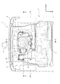
図1、図2において、自動車等の車両1は、車体2を備えており、車体2は、フロアパネル3と、フロアパネル3の後端部に設けられて車幅方向に延びるバックパネル4とを備えている。ここで、前、後という方向は、車両1の前後方向における方向を指す。
First, the configuration will be described.
1 and 2, a
バックパネル4に対して前方にはリヤシート5が設けられており、バックパネル4とリヤシート5との間のフロアパネル3の上方の空間は、荷室6を構成する。フロアパネル3には凹部7が形成されており、凹部7は、リヤシート5の下端部が固定される高さ位置に対して、鉛直方向下方に窪んで形成されている。
A
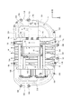
図1〜図5において、凹部7にはバッテリパック8が収容されている。図5において、バッテリパック8は、バッテリモジュール9と、インバータ10と、バッテリモジュール9およびインバータ10を収容する本体ケース11とを備えている。なお、インバータ10は、本発明の高電圧機器を構成する。
In FIGS. 1 to 5, the battery pack 8 is accommodated in the
バッテリモジュール9は、複数の単電池を纏めた組電池を複数個有する。ここで、単電池は、リチウムイオン電池、ニッケル水素電池等の二次電池、あるいはキャパシタであってもよい。インバータ10は、バッテリモジュール9から与えられる直流電圧を三相交流電圧に変換して図示しないモータに出力する。
The
図5において、本体ケース11は、ロアケース12およびアッパケース13を備えている。図6〜図8において、ロアケース12には接合部12Aが形成されており、接合部12Aは、ロアケース12の円周方向にフランジ状に形成されている。
In FIG. 5, the
図1、図4において、アッパケース13には接合部13Aが形成されており、接合部13Aは、アッパケース13の円周方向にフランジ状に形成されている。接合部13Aは、接合部12Aに対向して位置合わせされることにより、ボルト16A、16Bによってロアケース12の接合部12Aに接合される。
In FIG. 1 and FIG. 4, a
これにより、バッテリモジュール9およびインバータ10は、本体ケース11に収容される。ここで、接合部12Aは、本発明の第1の接合部を構成し、接合部13Aは、本発明の第2の接合部を構成する。
Thereby, the
図5、図6において、本体ケース11にはブラケット14が設けられており、ブラケット14は、接合部12A、13Aに挟まれるようにして本体ケース11の内部に設置されている。
図6〜図8において、ロアケース12の車幅方向両端部には締結部15A、15Bが形成されている。締結部15A、15Bは、接合部12Aと同一面に形成されており、締結部15A、15Bは、ボルト16Aによって凹部7の内壁に形成された取付け部7A、7B(図4参照)に固定される。
In FIGS. 5 and 6, a
In FIG. 6 to FIG. 8, fastening
ロアケース12の前端部には締結部15Cが形成されている。図8において、締結部15Cは、ロアケース12の前側の壁部12Bに取付けられたブラケットから構成されており、締結部15Cは、ボルト16Bによって凹部7の内壁に形成された取付け部7C(図4参照)に固定される。これにより、本体ケース11は、締結部15A〜15Cを介してフロアパネル3に固定される。ここで、壁部12Bは、本発明のロアケースの車両の前後方向前側の壁部を構成する。
A fastening portion 15C is formed at the front end of the
本実施の形態の締結部15A、15Bは、本発明の第1の締結部を構成し、締結部15Cは、本発明の第2の締結部を構成する。なお、締結部15A〜15Cは、ロアケース12ではなく、アッパケース13に形成されてもよい。
The fastening
図6において、ブラケット14の車幅方向の幅は、ロアケース12の車幅方向の幅よりも短く形成されており、ブラケット14は、ロアケース12の車幅方向両端部からロアケース12の車幅方向内方に向かって離隔して設置されている。
In FIG. 6, the width of the
ブラケット14の前端部14aは、ボルト17Aによってロアケース12の接合部12Aに固定されており、ブラケット14の後端部14bは、ボルト17Bによってロアケース12の接合部12Aに固定されている。ここで、本実施の形態の前端部14aは、本発明のブラケットの車両の前後方向前端部を構成し、後端部14bは、本発明のブラケットの前記車両の前後方向後端部を構成する。
The
ブラケット14の前端部14aは、ロアケース12の接合部12Aとアッパケース13の接合部13Aに上下方向から挟み込まれるようにして接合部12A、13Aに締結されている。ブラケット14の後端部14bは、ロアケース12の接合部12Aとアッパケース13の接合部13Aに上下方向から挟み込まれるようにして接合部12A、13Aに締結されている。
これにより、ブラケット14は、本体ケース11の前端部から後端部に亙って設置される。
The
Thus, the
締結部15Cの後端部分は、車両1の上下方向においてブラケット14に重なる位置に設置されている。すなわち、締結部15Cの一部分は、車両1の上下方向においてブラケット14に重なる位置に設置されている。なお、ブラケット14は、車両1の上下方向において締結部15Cの前面と重なっていてもよい。
The rear end portion of the fastening portion 15C is installed at a position overlapping the
バッテリモジュール9は、ロアケース12に設置されており、バッテリモジュール9は、車両1の上下方向においてブラケット14と重なるようにブラケット14の下方に設置されている。
The
図6において、ブラケット14は、車両1の前後方向に延びる複数の凸部14Aおよび複数の凹部14Bを備えており、凸部14Aおよび凹部14Bは、前端部14aから後端部14bに亙って形成され、車幅方向に交互に連続している。
In FIG. 6, the
ブラケット14の上面には一対のブラケット18A、18Bが設けられており、ブラケット18A、18Bは、縦断面がU字形状に形成されている。ブラケット18A、18Bは、車両1の前後方向に並んで設置されており、ブラケット18A、18Bは、ブラケット14の凸部14Aおよび凹部14Bの延びる方向に対して直交する方向に延びている。
ブラケット18A、18Bの上部にはインバータ10が設けられており、インバータ10は、複数のボルト19によってブラケット18A、18Bに取付けられている。
A pair of
An
図3〜図5において、アッパケース13には膨出部13Bが形成されており、図5に示すように、膨出部13Bは、バッテリモジュール9の車幅方向両端部に対して車幅方向中央部が高くなるように車両1の上方に膨れ出ている。
In FIGS. 3 to 5, a bulging
インバータ10は、膨出部13Bの下方に位置するように本体ケース11に収容されており、車両1の上下方向上方から見た場合に、膨出部13Bは、ブラケット14と上下方向に重なるように設置されている。
The
ロアケース12にはブラケット20が設けられており、ブラケット20は、ブラケット14の車幅方向左端部14cで、かつ、ブラケット18A、18Bの車両1の前後方向の間の部位と、ロアケース12の車幅方向左端部12aの接合部12Aおよびアッパケース13の車幅方向左端部の接合部13A(図6に図示なし)とを連結している。
The
ここで、本実施の形態のブラケット14は、本発明の第1のブラケットを構成し、ブラケット18A、18Bは、本発明の第2のブラケットを構成し、ブラケット20は、本発明の第3のブラケットを構成する。
Here, the
ブラケット20の左端部20aとロアケース12の接合部12Aおよびアッパケース13の接合部13Aとの連結位置(図6において、接合部13Aは図示なし)は、締結部15A、15Bに対して前方に設置されている。
The connection position of the
また、インバータ10は、ブラケット14の車幅方向中央部に対してブラケット20側に偏倚して設けられており、インバータ10の左端側は、ボルト19によってブラケット20を介してブラケット14に固定されている。
The
図8において、ロアケース12の底面には複数の凸部12Cが形成されており、凸部12Cは、車幅方向に延び、かつ、車両1の前後方向に離隔している。
In FIG. 8, a plurality of
ロアケース12の凸部12Cの車幅方向両端部の上面には台座用ブラケット21A、21Bが設けられており、台座用ブラケット21A、21Bは、車両1の前後方向に離隔する凸部12C同士を連結している。
台座用ブラケット21A、21Bにはバッテリモジュール9が取付けられており、バッテリモジュール9は、台座用ブラケット21A、21Bを介してロアケース12に取付けられている。
The
図7において、ロアケース12にはバッテリモジュール管理装置22が設けられており、バッテリモジュール管理装置22は、ブラケット14、バッテリモジュール9およびロアケース12の前側の壁部12Bによって囲まれる空間に設置されている。
In FIG. 7, the
バッテリモジュール管理装置22は、ワイヤハーネス23を介してバッテリモジュール9に接続されており、バッテリモジュール管理装置22は、バッテリモジュール9を管理する。
The battery
図1において、バッテリパック8には吸気ダクト24、吸気ファン25および吸気ダクト26が取付けられている。吸気ダクト24は、リヤシート5の前側から空気を取り入れ、吸気ファン25は、吸気ダクト24から取り入れた空気を吸気ダクト26から本体ケース11に導入する。これにより、バッテリモジュール9およびインバータ10が冷却される。
In FIG. 1, an
バッテリモジュール管理装置22は、図示しないコンピュータや温度センサ等を備えており、バッテリモジュール管理装置22は、例えば、バッテリモジュール9の温度が所定温度以上となる場合に、吸気ファン25を駆動する制御を行う。
図1において、車両1には後輪27L、27Rが設けられており、後輪27L、27Rは、フロアパネル3を挟んで車幅方向に対向している。
The battery
In FIG. 1, the
本実施の形態のバッテリパック8の取付け構造によれば、ブラケット14を本体ケース11の車幅方向両端部から本体ケース11の車幅方向内方に向かって離隔して設置する。さらに、ブラケット14の前端部14aを接合部12Aおよび接合部13Aの前端部に締結するとともに、ブラケット14の後端部14bを接合部12Aおよび接合部13Aの後端部に締結することにより、ブラケット14を本体ケース11の前端部から後端部に亙って設置する。これに加えて、バッテリモジュール9を、車両1の上下方向においてブラケット14と重なるようにブラケット14の下方に設置する。
According to the mounting structure of battery pack 8 of the present embodiment,
これにより、本体ケース11の車幅方向において、締結部15A、15Bを有する本体ケース11の車幅方向両端部の剛性に対してブラケット14を有する本体ケース11の車幅方向中央側の剛性を高くできる。
Thereby, in the vehicle width direction of the
このため、車両1の悪路走行時等に車幅方向左右が上下方向に大きく振動してフロアパネル3が変形した場合に、締結部15A、15Bを介してフロアパネル3に締結される本体ケース11の車幅方向両端部を大きく振動させて(図3に振動方向をF1、F2で示す)、フロアパネル3の変形による荷重を本体ケース11の車幅方向両端部で吸収できる。
Therefore, when the
これに加えて、バッテリモジュール9が設けられたブラケット14の下方の本体ケース11の部位の変形を抑制できる。このため、フロアパネル3の変形に伴う荷重をバッテリモジュール9に伝達し難くして、バッテリモジュール9が変形することを抑制できる。
In addition to this, it is possible to suppress the deformation of the portion of the
さらに、図2に示すように、車両1の後方からフロアパネル3に外力Fが作用した場合に、ブラケット14によって本体ケース11が前後方向に変形することを抑制でき、ブラケット14の下方に設けられたバッテリモジュール9がロアケース12の前後方向後側の壁部12Dに衝突して変形することを抑制できる。この結果、バッテリモジュール9を効果的に保護できる。
Furthermore, as shown in FIG. 2, when an external force F acts on the
また、本実施の形態のバッテリパック8の取付け構造によれば、ロアケース12の前端に締結部15Cを設け、締結部15Cの少なくとも一部を、車両1の上下方向においてブラケット14に重なる位置に設置した。
Further, according to the attachment structure of battery pack 8 of the present embodiment, fastening portion 15C is provided at the front end of
これにより、バッテリパック8をフロアパネル3に強固に固定できる。このため、車両1の悪路走行時やフロアパネル3に外力Fが加わった場合に、バッテリパック8がフロアパネル3に対して移動することを防止して、本体ケース11に収容されたバッテリモジュール9を本体ケース11によって保護できる。
Thereby, the battery pack 8 can be firmly fixed to the
また、本実施の形態のバッテリパック8の取付け構造によれば、ブラケット14が、車両1の前後方向に延びる複数の凸部14Aおよび複数の凹部14Bを有し、凸部14Aおよび凹部14Bを車幅方向に交互に連続させた。
Further, according to the attachment structure of battery pack 8 of the present embodiment,
これにより、ブラケット14の剛性を高くできるので、本体ケース11の車幅方向において、締結部15A、15Bを有する本体ケース11の車幅方向両端部の剛性に対してブラケット14を有する本体ケース11の車幅方向中央側の剛性をより一層大きくできる。
このため、フロアパネル3の変形による荷重を本体ケース11の車幅方向両端部でより効果的に吸収できる。
Thus, the rigidity of the
Therefore, the load due to the deformation of the
これに加えて、バッテリモジュール9が設けられたブラケット14の下方の本体ケース11の部位の変形をより効果的に抑制できる。このため、フロアパネル3に変形による荷重をバッテリモジュール9により効果的に伝達し難くして、バッテリモジュール9が変形することをより効果的に抑制できる。
In addition to this, the deformation of the portion of the
また、車両1の後方からフロアパネル3に外力Fが作用した場合に、剛性の高いブラケット14によって本体ケース11が前後方向に変形することをより効果的に抑制でき、ブラケット14の下方に設けられたバッテリモジュール9がロアケース12の前後方向後側の壁部12Dに衝突して変形することをより効果的に抑制できる。この結果、バッテリモジュール9をより効果的に保護できる。
Further, when external force F acts on
また、本実施の形態のバッテリパック8の取付け構造によれば、凸部14Aおよび凹部14Bが、ブラケット14の前端部14aから後端部14bに亙って形成され、接合部12Aおよび接合部13Aによって車両1の上下方向から凸部14Aおよび凸部14Aを挟みこむように、ブラケット14が本体ケース11に取付けられる。
Further, according to the mounting structure of battery pack 8 of the present embodiment,
これにより、ブラケット14の剛性をより効果的に高めることができるとともに、ブラケット14を挟み込む接合部12Aおよび接合部13Aの剛性を高くできる。このため、本体ケース11の車幅方向において、締結部15A、15Bを有する本体ケース11の車幅方向両端部の剛性に対してブラケット14を有する本体ケース11の車幅方向中央側の剛性をより一層大きくできる。
Thereby, the rigidity of the
また、車両1の後方からフロアパネル3に外力Fが作用した場合に、接合部12A、13Aの中でもブラケット14に挟み込む接合部12Aおよび接合部13Aの部位の剛性を高くでき、本体ケース11が前後方向に変形することをより効果的に抑制できる。この結果、バッテリモジュール9をより効果的に保護できる。
In addition, when external force F acts on
さらに、接合部12A、接合部13Aおよびブラケット14が上下方向に重なる部位において、ブラケット14の凸部14Aおよび凹部14Bによって本体ケース11の外部と本体ケース11の内部とを連通する開口28(図3参照)を形成でき、本体ケース11の内部の冷却風W(図6参照)を凸部14Aの内周面に沿って車両1の前後方向に移動させた後、開口28から本体ケース11の外部に円滑に排出できる。
Further, at a portion where the joint 12A, the joint 13A and the
これに加えて、開口28を通して本体ケース11の内部に液体が流れ込んだ場合に、ブラケット14の凸部14Aおよび凹部14Bに沿って液体を本体ケース11の外部に円滑に排出できる。これによって、液体がバッテリモジュール9に流れ込むことを防止でき、バッテリモジュール9を液体から保護できる。
In addition to this, when the liquid flows into the inside of the
また、本実施の形態のバッテリパック8の取付け構造によれば、ブラケット14に縦断面がU字形状のブラケット18A、18Bを設け、ブラケット18A、18Bを車両1の前後方向に並んで設置した。これに加えて、ブラケット18A、18Bを凸部14Aおよび凹部14Bの延びる方向に対して直交する方向に延ばし、ブラケット18A、18Bにインバータ10を取付けた。
Further, according to the attachment structure of battery pack 8 of the present embodiment,
これにより、ブラケット18A、18Bによってブラケット14の剛性をより一層高くできる上に、ブラケット18A、18Bに取付けられたインバータ10によってブラケット18A、18B同士が撓むことや、変形することを抑制できる。
As a result, the rigidity of the
このため、締結部15A、15Bを有する本体ケース11の車幅方向両端部の剛性に対してブラケット14を有する本体ケース11の車幅方向中央側の剛性をより効果的に大きくできるとともに、車両1の後方からフロアパネル3に外力Fが作用した場合に、ブラケット14によって本体ケース11が前後方向に変形することをより効果的に抑制できる。
For this reason, the rigidity of the vehicle width direction center side of the
また、本実施の形態のバッテリパック8の取付け構造によれば、アッパケース13に、バッテリモジュール9の車幅方向両端部に対して車幅方向中央部が高くなるように車両1の上下方向上方に膨れ出る膨出部13Bを形成した。
これに加えて、膨出部13Bの下方に位置するように本体ケース11にインバータ10を収容し、車両1の上下方向上方から見た場合に、膨出部13Bをブラケット14と上下方向に重なるようにした。
Further, according to the mounting structure of battery pack 8 of the present embodiment,
In addition to this, the
これにより、バッテリモジュール9の上方のアッパケース13の剛性を高くでき、締結部15A、15Bを有する本体ケース11の車幅方向両端部の剛性に対してブラケット14を有する本体ケース11の車幅方向中央側の剛性をより一層大きくできる。
Thereby, the rigidity of the
このため、締結部15A、15Bを有する本体ケース11の車幅方向両端部の剛性に対してブラケット14を有する本体ケース11の車幅方向中央側の剛性をより効果的に大きくできるとともに、車両1の後方からフロアパネル3に外力Fが作用した場合に、ブラケット14によって本体ケース11が前後方向に変形することをより効果的に抑制できる。
For this reason, the rigidity of the vehicle width direction center side of the
さらに、膨出部13Bの下方に位置するように本体ケース11にインバータ10を収容したので、アッパケース13が大型化することを防止して、バッテリパック8が大型化することを防止でき、バッテリパック8の車載性を向上できる。
Furthermore, since the
また、本実施の形態のバッテリパック8の取付け構造によれば、バッテリパック8が、ブラケット14の車幅方向左端部14cで、かつ、一対のブラケット18A、18Bの車両1の前後方向の間の部位と、ロアケース12の車幅方向左端部12aの接合部12Aとを連結するブラケット20を有し、ブラケット20と接合部12Aとの連結位置を、締結部15Aに対して車両1の前方に設置した。なお、ブラケット14の車幅方向左端部14cは、本発明のブラケットの車幅方向端部を構成する。
Further, according to the attachment structure of battery pack 8 of the present embodiment, battery pack 8 is at the vehicle width direction
これにより、ブラケット14をブラケット20によって補強できるので、締結部15A、15Bを有する本体ケース11の車幅方向両端部の剛性に対して本体ケース11の車幅方向中央側の剛性をより一層大きくできる。
Thereby, since the
これに加えて、ブラケット20と接合部12Aとの連結位置を、締結部15Aに対して前方に設置することで、車両1の前後方向において締結部15Aと締結部15Aに対して前方側の接合部12Aの部位との剛性の差を大きくできる。
In addition to this, by providing the connecting position of the
このため、車両1の悪路走行時等に車幅方向左右が上下方向に大きく振動してフロアパネル3が変形した場合に、締結部15A、15Bを介してフロアパネル3に締結される本体ケース11の車幅方向両端部をより一層大きく振動させてフロアパネル3の変形による荷重を本体ケース11の車幅方向両端部でより効果的に吸収できる。
Therefore, when the
また、本実施の形態のバッテリパック8の取付け構造によれば、インバータ10がブラケット14の車幅方向中央部に対してブラケット20側に偏倚して設けられる。
これにより、ブラケット20で補強されて剛性が高いブラケット14にインバータ10を設置でき、比較的重量が大きいインバータ10の振動を効果的に低減できる。
Further, according to the attachment structure of battery pack 8 of the present embodiment,
Thus, the
また、本実施の形態のバッテリパック8の取付け構造によれば、ロアケース12の底面に、車幅方向に延び、かつ、車両1の前後方向に離隔する複数の凸部12Cを形成し、凸部12Cの車幅方向両端部の上面に、車両1の前後方向に離隔する凸部12C同士を連結する台座用ブラケット21A、21Bを設け、台座用ブラケット21A、21Bにバッテリモジュール9を取付けた。
Further, according to the mounting structure of battery pack 8 of the present embodiment, a plurality of
これにより、ロアケース12の底面の剛性を高くしてバッテリモジュール9をロアケース12に安定して支持することができる。このため、車両1の悪路走行時等にフロアパネル3が変形した場合に、ロアケース12の底面が変形することを抑制して、バッテリモジュール9が変形することを抑制できる。このため、バッテリモジュール9をより効果的に保護できる。
Thus, the rigidity of the bottom surface of
また、本実施の形態のバッテリパック8の取付け構造によれば、バッテリパック8が、バッテリモジュール9を管理するバッテリモジュール管理装置22を有し、バッテリモジュール管理装置22を、ブラケット14、バッテリモジュール9およびロアケース12の車両1の前後方向前側の壁部12Bによって囲まれる空間に設置した。
Further, according to the attachment structure of the battery pack 8 of the present embodiment, the battery pack 8 has the battery
これにより、車両1の後方からフロアパネル3に外力Fが作用した場合に、ブラケット14によって本体ケース11が前後方向に過剰に変形することを防止してバッテリモジュール9が規定位置から車両1の前後方向前方に移動することを抑制できるので、バッテリモジュール管理装置22がバッテリモジュール9に衝突することを抑制できる。このため、バッテリモジュール管理装置22を保護できる。
Thereby, when external force F acts on
また、バッテリモジュール管理装置22がバッテリモジュール9に衝突することを抑制できるので、バッテリモジュール管理装置22をバッテリモジュール9に近接して設置することができる。これにより、バッテリモジュール管理装置22とバッテリモジュール9とを接続するワイヤハーネス23の取り回しを簡素化できる。
Further, since the battery
本発明の実施の形態を開示したが、当業者によっては本発明の範囲を逸脱することなく変更が加えられうることは明白である。すべてのこのような修正および等価物が次の請求項に含まれることが意図されている。 While embodiments of the present invention have been disclosed, it will be apparent to those skilled in the art that changes may be made without departing from the scope of the present invention. All such modifications and equivalents are intended to be included in the following claims.
1...車両、3...フロアパネル、8...バッテリパック、9...バッテリモジュール、10...インバータ(高電圧機器)、11...本体ケース、12...ロアケース、12A...接合部(第1の接合部)、12B...壁部(ロアケースの前記車両の前後方向前側の壁部)、12C...凸部、13...アッパケース、13A...接合部(第2の接合部)、13B...膨出部、14...ブラケット(第1のブラケット)、14A...凸部、14B...凹部、14a...前端部(ブラケットの車両の前後方向前端部)、14b...後端部(ブラケットの車両の前後方向後端部)、14c...車幅方向左端部(ブラケットの車幅方向端部)、15A,15B...締結部(第1の締結部)、15C...締結部(第2の締結部)、18A,18B...ブラケット(第2のブラケット)、20...ブラケット(第3のブラケット)、21A,21B...台座用ブラケット、22...バッテリモジュール管理装置
DESCRIPTION OF
Claims (9)
前記バッテリパックが、円周方向にフランジ状の第1の接合部が形成されたロアケースおよび円周方向に前記第1の接合部に接合されるフランジ状の第2の接合部が形成されたアッパケースを有し、バッテリモジュールを収容する本体ケースと、前記第1の接合部および前記第2の接合部に挟まれるようにして前記本体ケースの内部に設置されるブラケットとを含んで構成され、
前記バッテリパックが、前記本体ケースの車幅方向両端部に設けられた締結部を介して前記フロアパネルに固定される車両用バッテリパックの取付け構造であって、
前記ブラケットを前記本体ケースの車幅方向両端部から前記本体ケースの車幅方向内方に向かって離隔して設置し、
前記ブラケットの前記車両の前後方向前端部を前記第1の接合部および前記第2の接合部の前記車両の前後方向前端部に締結するとともに、前記ブラケットの前記車両の前後方向後端部を前記第1の接合部および前記第2の接合部の前記車両の前後方向後端部に締結することにより、前記ブラケットを前記本体ケースの前記車両の前後方向前端部から前記車両の前後方向後端部に亙って設置し、
前記バッテリモジュールは、前記車両の上下方向において前記ブラケットと重なるように前記ブラケットの下方に設置され、
前記ブラケットは、前記車両の前後方向に延びる複数の凸部および複数の凹部を有し、
前記凸部および前記凹部は、車幅方向に交互に連続することを特徴とする車両用バッテリパックの取付け構造。 Has a battery pack attached to the floor panel of the vehicle,
The battery pack includes a lower case in which a flange-shaped first joint is formed in the circumferential direction, and an upper in which a flange-shaped second joint is formed in the circumferential direction to be joined to the first joint. It has a case and is comprised including a body case which accommodates a battery module, and a bracket installed inside the body case so as to be sandwiched between the first joint portion and the second joint portion,
The mounting structure of a vehicle battery pack, wherein the battery pack is fixed to the floor panel via fastening portions provided at both ends in the vehicle width direction of the main body case.
The brackets are spaced apart from both end portions in the vehicle width direction of the main body case inward in the vehicle width direction of the main body case,
The front end in the longitudinal direction of the vehicle of the bracket is fastened to the front end in the longitudinal direction of the vehicle of the first joint portion and the second joint, and the rear end in the longitudinal direction of the vehicle of the bracket is the By fastening the bracket to the rear end of the vehicle in the front-rear direction of the first joint portion and the second joint, the front-rear end of the vehicle in the front-rear direction from the front end of the vehicle of the main body case Set up,
The battery module is installed below the bracket so as to overlap the bracket in the vertical direction of the vehicle.
The bracket has a plurality of protrusions and a plurality of recesses extending in the front-rear direction of the vehicle.
The convex portion and the concave portion, the mounting structure for a vehicle battery pack, characterized that you continuously alternately in the vehicle width direction.
前記第2の締結部の少なくとも一部を、前記車両の上下方向において前記ブラケットに重なる位置に設置したことを特徴とする請求項1に記載の車両用バッテリパックの取付け構造。 The fastening portion provided in the vehicle widthwise ends of the main body case when the first fastening portion, the lower case or the second fastening part in the longitudinal direction front end of one of the vehicle of the upper case Provide
The vehicle battery pack mounting structure according to claim 1, wherein at least a part of the second fastening portion is installed at a position overlapping the bracket in the vertical direction of the vehicle.
前記第1の接合部および前記第2の接合部によって前記車両の上下方向から前記凸部および前記凸部を挟みこむように、前記ブラケットが前記本体ケースに取付けられることを特徴とする請求項1または請求項2に記載の車両用バッテリパックの取付け構造。 The convex portion and the concave portion are formed from a front end in the front-rear direction of the vehicle to a rear end in the front-rear direction of the vehicle.
The first which sandwich the convex portion and the convex portion in the vertical direction of the vehicle by the junction and the second junction claim 1, wherein the bracket is attached to the main body case or The attachment structure of the battery pack for vehicles of Claim 2.
前記一対の第2のブラケットは、前記車両の前後方向に並んで設置されて、前記凸部および前記凹部の延びる方向に対して直交する方向に延び、
前記一対の第2のブラケットに高電圧機器を取付けたことを特徴とする請求項2に記載の車両用バッテリパックの取付け構造。 When the bracket is a first bracket, the first bracket is provided with a pair of second brackets having a U-shaped longitudinal cross section,
The pair of second brackets are disposed side by side in the front-rear direction of the vehicle, and extend in a direction orthogonal to the extending direction of the convex portion and the concave portion.
The high voltage apparatus was attached to a pair of said 2nd brackets, The attachment structure of the battery pack for vehicles of Claim 2 characterized by the above-mentioned.
前記膨出部の下方に位置するように前記本体ケースに前記高電圧機器を収容し、
前記車両の上下方向上方から見た場合に、前記膨出部を前記第1のブラケットと上下方向に重なるように設置したことを特徴とする請求項4に記載の車両用バッテリパックの取付け構造。 The upper case is formed with a bulging portion which bulges upward in the vertical direction of the vehicle such that a central portion in the vehicle width direction is higher than both end portions in the vehicle width direction of the battery module.
The high voltage apparatus is accommodated in the main body case so as to be located below the bulging portion,
The mounting structure of a battery pack for a vehicle according to claim 4 , wherein the bulging portion is installed so as to vertically overlap the first bracket when viewed from above in the vertical direction of the vehicle.
前記第3のブラケットと前記第1の接合部および前記第2の接合部との連結位置を、前記第1の締結部に対して前記車両の前後方向前方に設置したことを特徴とする請求項4に記載の車両用バッテリパックの取付け構造。 The battery pack is a vehicle width direction end of the first bracket and a portion of the pair of second brackets between the front and rear direction of the vehicle, and a vehicle width direction end of the upper case and the lower case. A third bracket connecting the first joint of the part and the second joint,
The connection position between the third bracket and the first joint portion and the second joint portion is disposed forward in the front-rear direction of the vehicle with respect to the first fastening portion. The mounting structure of the battery pack for vehicles as described in 4 .
前記ロアケースの前記凸部の車幅方向両端部の上面に、前記車両の前後方向に離隔する前記ロアケースの前記凸部同士を連結する台座用ブラケットを設け、前記台座用ブラケットに前記バッテリモジュールを取付けたことを特徴とする請求項1から請求項7のいずれか1項に記載の車両用バッテリパックの取付け構造。 A plurality of convex portions extending in the vehicle width direction and separated in the front-rear direction of the vehicle are formed on the bottom surface of the lower case,
A bracket for pedestal which connects the convex portions of the lower case separated in the front-rear direction of the vehicle is provided on the upper surfaces of both widthwise end portions of the convex portions of the lower case, and the battery module is attached to the pedestal bracket mounting structure for a vehicle battery pack as claimed in any one of claims 7, characterized in that the.
前記バッテリモジュール管理装置は、前記第1のブラケット、前記バッテリモジュールおよび前記ロアケースの前記車両の前後方向前側の壁部によって囲まれる空間に設置されることを特徴とする請求項4から請求項7のいずれか1項に記載の車両用バッテリパックの取付け構造。 The battery pack has a battery module management device that manages the battery module,
The battery module management apparatus, the first bracket, the battery module and the claims 7 claim 4, characterized in that it is installed in a space surrounded by the wall portion in the longitudinal direction front side of the vehicle of the lower case The attachment structure of the battery pack for vehicles of any one statement.
Priority Applications (3)
| Application Number | Priority Date | Filing Date | Title |
|---|---|---|---|
| JP2015114957A JP6520424B2 (en) | 2015-06-05 | 2015-06-05 | Vehicle battery pack mounting structure |
| DE102016209105.0A DE102016209105A1 (en) | 2015-06-05 | 2016-05-25 | BATTERY PACK |
| CN201610374453.XA CN106240330B (en) | 2015-06-05 | 2016-05-31 | The mounting structure of vehicle battery packet |
Applications Claiming Priority (1)
| Application Number | Priority Date | Filing Date | Title |
|---|---|---|---|
| JP2015114957A JP6520424B2 (en) | 2015-06-05 | 2015-06-05 | Vehicle battery pack mounting structure |
Related Child Applications (1)
| Application Number | Title | Priority Date | Filing Date |
|---|---|---|---|
| JP2019009368A Division JP6635205B2 (en) | 2019-01-23 | 2019-01-23 | Vehicle battery pack mounting structure |
Publications (3)
| Publication Number | Publication Date |
|---|---|
| JP2017001441A JP2017001441A (en) | 2017-01-05 |
| JP2017001441A5 JP2017001441A5 (en) | 2018-03-01 |
| JP6520424B2 true JP6520424B2 (en) | 2019-05-29 |
Family
ID=57352514
Family Applications (1)
| Application Number | Title | Priority Date | Filing Date |
|---|---|---|---|
| JP2015114957A Active JP6520424B2 (en) | 2015-06-05 | 2015-06-05 | Vehicle battery pack mounting structure |
Country Status (3)
| Country | Link |
|---|---|
| JP (1) | JP6520424B2 (en) |
| CN (1) | CN106240330B (en) |
| DE (1) | DE102016209105A1 (en) |
Cited By (1)
| Publication number | Priority date | Publication date | Assignee | Title |
|---|---|---|---|---|
| JP2022149000A (en) * | 2021-03-25 | 2022-10-06 | 本田技研工業株式会社 | Vehicle body structure |
Families Citing this family (14)
| Publication number | Priority date | Publication date | Assignee | Title |
|---|---|---|---|---|
| EP3567908A4 (en) | 2017-01-06 | 2020-08-12 | NTT DoCoMo, Inc. | User terminal and wireless communication method |
| JP6885156B2 (en) * | 2017-03-31 | 2021-06-09 | 三菱自動車エンジニアリング株式会社 | High voltage equipment |
| FI3428993T3 (en) | 2017-07-13 | 2023-02-21 | Safety battery compartment for battery electric vehicles | |
| EP3636364A1 (en) | 2018-10-09 | 2020-04-15 | Outokumpu Oyj | Method for manufacturing a crash frame of a battery compartment for battery electric vehicles |
| WO2020146419A1 (en) | 2019-01-07 | 2020-07-16 | Canoo Inc. | Methods and systems for battery pack thermal management |
| FR3092527A1 (en) * | 2019-02-12 | 2020-08-14 | Valeo Systemes Thermiques | Box for electrical energy storage device for motor vehicle |
| JP6944972B2 (en) | 2019-05-16 | 2021-10-06 | 本田技研工業株式会社 | Vehicle battery unit |
| US11833895B2 (en) | 2019-05-20 | 2023-12-05 | Canoo Technologies Inc. | Electric vehicle platform |
| US11165119B2 (en) * | 2019-05-30 | 2021-11-02 | Mazda Motor Corporation | Battery unit mounting structure of electric vehicle |
| JP7336544B2 (en) | 2019-07-02 | 2023-08-31 | カヌー・テクノロジーズ・インコーポレイテッド | impact feature |
| WO2021050605A1 (en) | 2019-09-09 | 2021-03-18 | Canoo Inc. | Suspension system |
| WO2021055978A1 (en) | 2019-09-20 | 2021-03-25 | Canoo Inc. | Vehicle seating systems |
| US11251494B2 (en) | 2019-09-20 | 2022-02-15 | Canoo Technologies Inc. | Electric vehicle battery enclosure |
| CN110884337A (en) * | 2019-12-24 | 2020-03-17 | 东风小康汽车有限公司重庆分公司 | Power battery mounting structure |
Family Cites Families (15)
| Publication number | Priority date | Publication date | Assignee | Title |
|---|---|---|---|---|
| JP3199296B2 (en) * | 1993-12-06 | 2001-08-13 | 本田技研工業株式会社 | Assembly structure of electric vehicle |
| JP2002205555A (en) * | 2001-01-12 | 2002-07-23 | Suzuki Motor Corp | Battery fixing structure for vehicle |
| JP3880901B2 (en) * | 2002-07-24 | 2007-02-14 | 本田技研工業株式会社 | Vehicle mounting structure for high piezoelectric parts |
| CN102050009B (en) * | 2006-09-07 | 2013-03-13 | 本田技研工业株式会社 | Electrical device cooling structure in vehicle |
| JP4769274B2 (en) * | 2008-07-07 | 2011-09-07 | 本田技研工業株式会社 | Car body rear structure |
| EP2501576B1 (en) * | 2009-11-18 | 2013-08-21 | Benteler Aluminium Systems France SNC | Battery tray for vehicle and method for producing the battery tray |
| CN201590441U (en) * | 2009-12-25 | 2010-09-22 | 天津清源电动车辆有限责任公司 | Battery pack for supplying power to electric vehicles |
| JP5811830B2 (en) * | 2011-12-22 | 2015-11-11 | 株式会社デンソー | Battery pack |
| JP5878048B2 (en) * | 2012-03-16 | 2016-03-08 | 本田技研工業株式会社 | Battery unit |
| JP2013199196A (en) * | 2012-03-26 | 2013-10-03 | Suzuki Motor Corp | Battery pack mounting structure for electric car |
| JP5983058B2 (en) * | 2012-06-05 | 2016-08-31 | スズキ株式会社 | Electric vehicle battery pack mounting structure |
| JP2014024359A (en) * | 2012-07-24 | 2014-02-06 | Suzuki Motor Corp | Vehicular battery pack |
| DE102012218473A1 (en) * | 2012-10-10 | 2014-06-12 | Bayerische Motoren Werke Aktiengesellschaft | Energy storage arrangement and mounting device |
| JP6048284B2 (en) * | 2013-04-03 | 2016-12-21 | スズキ株式会社 | Battery pack device for vehicle |
| CN204375869U (en) * | 2015-01-13 | 2015-06-03 | 南京特种汽车制配厂有限公司 | A kind of batteries of electric automobile bag with maintenance function |
-
2015
- 2015-06-05 JP JP2015114957A patent/JP6520424B2/en active Active
-
2016
- 2016-05-25 DE DE102016209105.0A patent/DE102016209105A1/en active Pending
- 2016-05-31 CN CN201610374453.XA patent/CN106240330B/en active Active
Cited By (2)
| Publication number | Priority date | Publication date | Assignee | Title |
|---|---|---|---|---|
| JP2022149000A (en) * | 2021-03-25 | 2022-10-06 | 本田技研工業株式会社 | Vehicle body structure |
| JP7326376B2 (en) | 2021-03-25 | 2023-08-15 | 本田技研工業株式会社 | car body structure |
Also Published As
| Publication number | Publication date |
|---|---|
| DE102016209105A1 (en) | 2016-12-08 |
| CN106240330A (en) | 2016-12-21 |
| JP2017001441A (en) | 2017-01-05 |
| CN106240330B (en) | 2019-08-02 |
Similar Documents
| Publication | Publication Date | Title |
|---|---|---|
| JP6520424B2 (en) | Vehicle battery pack mounting structure | |
| US11034248B2 (en) | Battery case fixing structure | |
| JP4386131B2 (en) | Electric car | |
| JP7126552B2 (en) | Battery pack layout structure | |
| JP6020958B2 (en) | Battery pack tray | |
| US10189371B2 (en) | Electrically-powered vehicle | |
| JP6689911B2 (en) | Underbody structure | |
| JP2017193299A (en) | Battery-mounting structure for vehicle | |
| JP6610412B2 (en) | Vehicle battery mounting structure | |
| US20130200654A1 (en) | Vehicle body rear structure | |
| JP6997525B2 (en) | In-vehicle battery | |
| JP5888955B2 (en) | Battery module mounting structure | |
| US10040413B2 (en) | Vehicle | |
| JP2013147137A (en) | Floor structure of electrically driven vehicle | |
| JP6284041B2 (en) | Vehicle battery mounting structure | |
| JP6137105B2 (en) | Battery drive battery mounting structure | |
| JP6769903B2 (en) | In-vehicle battery | |
| JP6311687B2 (en) | Vehicle battery mounting structure | |
| JP7352856B2 (en) | Vehicle undercarriage structure | |
| WO2020162028A1 (en) | Battery pack mounting structure | |
| JP2015067122A (en) | Vehicle equipped with electric drive apparatus | |
| JP6635205B2 (en) | Vehicle battery pack mounting structure | |
| JP2018106811A (en) | Protection structure of battery pack | |
| US20200127254A1 (en) | Power storage unit and power storage device | |
| JP6777580B2 (en) | In-vehicle battery |
Legal Events
| Date | Code | Title | Description |
|---|---|---|---|
| A521 | Written amendment |
Free format text: JAPANESE INTERMEDIATE CODE: A523 Effective date: 20180112 |
|
| A621 | Written request for application examination |
Free format text: JAPANESE INTERMEDIATE CODE: A621 Effective date: 20180112 |
|
| A977 | Report on retrieval |
Free format text: JAPANESE INTERMEDIATE CODE: A971007 Effective date: 20181115 |
|
| A131 | Notification of reasons for refusal |
Free format text: JAPANESE INTERMEDIATE CODE: A131 Effective date: 20181204 |
|
| A521 | Written amendment |
Free format text: JAPANESE INTERMEDIATE CODE: A523 Effective date: 20190123 |
|
| TRDD | Decision of grant or rejection written | ||
| A01 | Written decision to grant a patent or to grant a registration (utility model) |
Free format text: JAPANESE INTERMEDIATE CODE: A01 Effective date: 20190402 |
|
| A61 | First payment of annual fees (during grant procedure) |
Free format text: JAPANESE INTERMEDIATE CODE: A61 Effective date: 20190415 |
|
| R151 | Written notification of patent or utility model registration |
Ref document number: 6520424 Country of ref document: JP Free format text: JAPANESE INTERMEDIATE CODE: R151 |