JP6497893B2 - Delivery device and related method - Google Patents
Delivery device and related method Download PDFInfo
- Publication number
- JP6497893B2 JP6497893B2 JP2014231220A JP2014231220A JP6497893B2 JP 6497893 B2 JP6497893 B2 JP 6497893B2 JP 2014231220 A JP2014231220 A JP 2014231220A JP 2014231220 A JP2014231220 A JP 2014231220A JP 6497893 B2 JP6497893 B2 JP 6497893B2
- Authority
- JP
- Japan
- Prior art keywords
- chamber
- drug
- housing
- mouthpiece
- fluid flow
- Prior art date
- Legal status (The legal status is an assumption and is not a legal conclusion. Google has not performed a legal analysis and makes no representation as to the accuracy of the status listed.)
- Active
Links
Images


Classifications
-
- A—HUMAN NECESSITIES
- A61—MEDICAL OR VETERINARY SCIENCE; HYGIENE
- A61M—DEVICES FOR INTRODUCING MEDIA INTO, OR ONTO, THE BODY; DEVICES FOR TRANSDUCING BODY MEDIA OR FOR TAKING MEDIA FROM THE BODY; DEVICES FOR PRODUCING OR ENDING SLEEP OR STUPOR
- A61M15/00—Inhalators
- A61M15/0001—Details of inhalators; Constructional features thereof
- A61M15/0005—Details of inhalators; Constructional features thereof with means for agitating the medicament
- A61M15/0006—Details of inhalators; Constructional features thereof with means for agitating the medicament using rotating means
- A61M15/0008—Details of inhalators; Constructional features thereof with means for agitating the medicament using rotating means rotating by airflow
-
- A—HUMAN NECESSITIES
- A61—MEDICAL OR VETERINARY SCIENCE; HYGIENE
- A61M—DEVICES FOR INTRODUCING MEDIA INTO, OR ONTO, THE BODY; DEVICES FOR TRANSDUCING BODY MEDIA OR FOR TAKING MEDIA FROM THE BODY; DEVICES FOR PRODUCING OR ENDING SLEEP OR STUPOR
- A61M15/00—Inhalators
- A61M15/0028—Inhalators using prepacked dosages, one for each application, e.g. capsules to be perforated or broken-up
-
- A—HUMAN NECESSITIES
- A61—MEDICAL OR VETERINARY SCIENCE; HYGIENE
- A61M—DEVICES FOR INTRODUCING MEDIA INTO, OR ONTO, THE BODY; DEVICES FOR TRANSDUCING BODY MEDIA OR FOR TAKING MEDIA FROM THE BODY; DEVICES FOR PRODUCING OR ENDING SLEEP OR STUPOR
- A61M11/00—Sprayers or atomisers specially adapted for therapeutic purposes
- A61M11/001—Particle size control
- A61M11/002—Particle size control by flow deviation causing inertial separation of transported particles
-
- A—HUMAN NECESSITIES
- A61—MEDICAL OR VETERINARY SCIENCE; HYGIENE
- A61M—DEVICES FOR INTRODUCING MEDIA INTO, OR ONTO, THE BODY; DEVICES FOR TRANSDUCING BODY MEDIA OR FOR TAKING MEDIA FROM THE BODY; DEVICES FOR PRODUCING OR ENDING SLEEP OR STUPOR
- A61M11/00—Sprayers or atomisers specially adapted for therapeutic purposes
- A61M11/006—Sprayers or atomisers specially adapted for therapeutic purposes operated by applying mechanical pressure to the liquid to be sprayed or atomised
- A61M11/008—Sprayers or atomisers specially adapted for therapeutic purposes operated by applying mechanical pressure to the liquid to be sprayed or atomised by squeezing, e.g. using a flexible bottle or a bulb
-
- A—HUMAN NECESSITIES
- A61—MEDICAL OR VETERINARY SCIENCE; HYGIENE
- A61M—DEVICES FOR INTRODUCING MEDIA INTO, OR ONTO, THE BODY; DEVICES FOR TRANSDUCING BODY MEDIA OR FOR TAKING MEDIA FROM THE BODY; DEVICES FOR PRODUCING OR ENDING SLEEP OR STUPOR
- A61M15/00—Inhalators
- A61M15/0001—Details of inhalators; Constructional features thereof
- A61M15/0013—Details of inhalators; Constructional features thereof with inhalation check valves
-
- A—HUMAN NECESSITIES
- A61—MEDICAL OR VETERINARY SCIENCE; HYGIENE
- A61M—DEVICES FOR INTRODUCING MEDIA INTO, OR ONTO, THE BODY; DEVICES FOR TRANSDUCING BODY MEDIA OR FOR TAKING MEDIA FROM THE BODY; DEVICES FOR PRODUCING OR ENDING SLEEP OR STUPOR
- A61M15/00—Inhalators
- A61M15/0001—Details of inhalators; Constructional features thereof
- A61M15/002—Details of inhalators; Constructional features thereof with air flow regulating means
-
- A—HUMAN NECESSITIES
- A61—MEDICAL OR VETERINARY SCIENCE; HYGIENE
- A61M—DEVICES FOR INTRODUCING MEDIA INTO, OR ONTO, THE BODY; DEVICES FOR TRANSDUCING BODY MEDIA OR FOR TAKING MEDIA FROM THE BODY; DEVICES FOR PRODUCING OR ENDING SLEEP OR STUPOR
- A61M15/00—Inhalators
- A61M15/0001—Details of inhalators; Constructional features thereof
- A61M15/0021—Mouthpieces therefor
-
- A—HUMAN NECESSITIES
- A61—MEDICAL OR VETERINARY SCIENCE; HYGIENE
- A61M—DEVICES FOR INTRODUCING MEDIA INTO, OR ONTO, THE BODY; DEVICES FOR TRANSDUCING BODY MEDIA OR FOR TAKING MEDIA FROM THE BODY; DEVICES FOR PRODUCING OR ENDING SLEEP OR STUPOR
- A61M15/00—Inhalators
- A61M15/0028—Inhalators using prepacked dosages, one for each application, e.g. capsules to be perforated or broken-up
- A61M15/003—Inhalators using prepacked dosages, one for each application, e.g. capsules to be perforated or broken-up using capsules, e.g. to be perforated or broken-up
- A61M15/0033—Details of the piercing or cutting means
- A61M15/0035—Piercing means
-
- A—HUMAN NECESSITIES
- A61—MEDICAL OR VETERINARY SCIENCE; HYGIENE
- A61M—DEVICES FOR INTRODUCING MEDIA INTO, OR ONTO, THE BODY; DEVICES FOR TRANSDUCING BODY MEDIA OR FOR TAKING MEDIA FROM THE BODY; DEVICES FOR PRODUCING OR ENDING SLEEP OR STUPOR
- A61M15/00—Inhalators
- A61M15/0028—Inhalators using prepacked dosages, one for each application, e.g. capsules to be perforated or broken-up
- A61M15/003—Inhalators using prepacked dosages, one for each application, e.g. capsules to be perforated or broken-up using capsules, e.g. to be perforated or broken-up
- A61M15/0033—Details of the piercing or cutting means
- A61M15/004—Details of the piercing or cutting means with fixed piercing or cutting means
-
- A—HUMAN NECESSITIES
- A61—MEDICAL OR VETERINARY SCIENCE; HYGIENE
- A61M—DEVICES FOR INTRODUCING MEDIA INTO, OR ONTO, THE BODY; DEVICES FOR TRANSDUCING BODY MEDIA OR FOR TAKING MEDIA FROM THE BODY; DEVICES FOR PRODUCING OR ENDING SLEEP OR STUPOR
- A61M15/00—Inhalators
- A61M15/0028—Inhalators using prepacked dosages, one for each application, e.g. capsules to be perforated or broken-up
- A61M15/003—Inhalators using prepacked dosages, one for each application, e.g. capsules to be perforated or broken-up using capsules, e.g. to be perforated or broken-up
- A61M15/0033—Details of the piercing or cutting means
- A61M15/0041—Details of the piercing or cutting means with movable piercing or cutting means
-
- A—HUMAN NECESSITIES
- A61—MEDICAL OR VETERINARY SCIENCE; HYGIENE
- A61M—DEVICES FOR INTRODUCING MEDIA INTO, OR ONTO, THE BODY; DEVICES FOR TRANSDUCING BODY MEDIA OR FOR TAKING MEDIA FROM THE BODY; DEVICES FOR PRODUCING OR ENDING SLEEP OR STUPOR
- A61M15/00—Inhalators
- A61M15/0028—Inhalators using prepacked dosages, one for each application, e.g. capsules to be perforated or broken-up
- A61M15/003—Inhalators using prepacked dosages, one for each application, e.g. capsules to be perforated or broken-up using capsules, e.g. to be perforated or broken-up
- A61M15/0043—Non-destructive separation of the package, e.g. peeling
-
- A—HUMAN NECESSITIES
- A61—MEDICAL OR VETERINARY SCIENCE; HYGIENE
- A61M—DEVICES FOR INTRODUCING MEDIA INTO, OR ONTO, THE BODY; DEVICES FOR TRANSDUCING BODY MEDIA OR FOR TAKING MEDIA FROM THE BODY; DEVICES FOR PRODUCING OR ENDING SLEEP OR STUPOR
- A61M15/00—Inhalators
- A61M15/0028—Inhalators using prepacked dosages, one for each application, e.g. capsules to be perforated or broken-up
- A61M15/0045—Inhalators using prepacked dosages, one for each application, e.g. capsules to be perforated or broken-up using multiple prepacked dosages on a same carrier, e.g. blisters
- A61M15/0046—Inhalators using prepacked dosages, one for each application, e.g. capsules to be perforated or broken-up using multiple prepacked dosages on a same carrier, e.g. blisters characterized by the type of carrier
- A61M15/0048—Inhalators using prepacked dosages, one for each application, e.g. capsules to be perforated or broken-up using multiple prepacked dosages on a same carrier, e.g. blisters characterized by the type of carrier the dosages being arranged in a plane, e.g. on diskettes
-
- A—HUMAN NECESSITIES
- A61—MEDICAL OR VETERINARY SCIENCE; HYGIENE
- A61M—DEVICES FOR INTRODUCING MEDIA INTO, OR ONTO, THE BODY; DEVICES FOR TRANSDUCING BODY MEDIA OR FOR TAKING MEDIA FROM THE BODY; DEVICES FOR PRODUCING OR ENDING SLEEP OR STUPOR
- A61M15/00—Inhalators
- A61M15/0028—Inhalators using prepacked dosages, one for each application, e.g. capsules to be perforated or broken-up
- A61M15/0045—Inhalators using prepacked dosages, one for each application, e.g. capsules to be perforated or broken-up using multiple prepacked dosages on a same carrier, e.g. blisters
- A61M15/0046—Inhalators using prepacked dosages, one for each application, e.g. capsules to be perforated or broken-up using multiple prepacked dosages on a same carrier, e.g. blisters characterized by the type of carrier
- A61M15/005—Inhalators using prepacked dosages, one for each application, e.g. capsules to be perforated or broken-up using multiple prepacked dosages on a same carrier, e.g. blisters characterized by the type of carrier the dosages being arranged on a cylindrical surface
-
- A—HUMAN NECESSITIES
- A61—MEDICAL OR VETERINARY SCIENCE; HYGIENE
- A61M—DEVICES FOR INTRODUCING MEDIA INTO, OR ONTO, THE BODY; DEVICES FOR TRANSDUCING BODY MEDIA OR FOR TAKING MEDIA FROM THE BODY; DEVICES FOR PRODUCING OR ENDING SLEEP OR STUPOR
- A61M15/00—Inhalators
- A61M15/0028—Inhalators using prepacked dosages, one for each application, e.g. capsules to be perforated or broken-up
- A61M15/0061—Inhalators using prepacked dosages, one for each application, e.g. capsules to be perforated or broken-up using pre-packed dosages having an insert inside
-
- A—HUMAN NECESSITIES
- A61—MEDICAL OR VETERINARY SCIENCE; HYGIENE
- A61M—DEVICES FOR INTRODUCING MEDIA INTO, OR ONTO, THE BODY; DEVICES FOR TRANSDUCING BODY MEDIA OR FOR TAKING MEDIA FROM THE BODY; DEVICES FOR PRODUCING OR ENDING SLEEP OR STUPOR
- A61M15/00—Inhalators
- A61M15/0065—Inhalators with dosage or measuring devices
- A61M15/0068—Indicating or counting the number of dispensed doses or of remaining doses
- A61M15/007—Mechanical counters
- A61M15/0071—Mechanical counters having a display or indicator
- A61M15/0075—Mechanical counters having a display or indicator on a disc
-
- A—HUMAN NECESSITIES
- A61—MEDICAL OR VETERINARY SCIENCE; HYGIENE
- A61M—DEVICES FOR INTRODUCING MEDIA INTO, OR ONTO, THE BODY; DEVICES FOR TRANSDUCING BODY MEDIA OR FOR TAKING MEDIA FROM THE BODY; DEVICES FOR PRODUCING OR ENDING SLEEP OR STUPOR
- A61M15/00—Inhalators
- A61M15/0065—Inhalators with dosage or measuring devices
- A61M15/0068—Indicating or counting the number of dispensed doses or of remaining doses
- A61M15/0081—Locking means
-
- A—HUMAN NECESSITIES
- A61—MEDICAL OR VETERINARY SCIENCE; HYGIENE
- A61M—DEVICES FOR INTRODUCING MEDIA INTO, OR ONTO, THE BODY; DEVICES FOR TRANSDUCING BODY MEDIA OR FOR TAKING MEDIA FROM THE BODY; DEVICES FOR PRODUCING OR ENDING SLEEP OR STUPOR
- A61M15/00—Inhalators
- A61M15/0086—Inhalation chambers
- A61M15/0088—Inhalation chambers with variable volume
-
- A—HUMAN NECESSITIES
- A61—MEDICAL OR VETERINARY SCIENCE; HYGIENE
- A61M—DEVICES FOR INTRODUCING MEDIA INTO, OR ONTO, THE BODY; DEVICES FOR TRANSDUCING BODY MEDIA OR FOR TAKING MEDIA FROM THE BODY; DEVICES FOR PRODUCING OR ENDING SLEEP OR STUPOR
- A61M15/00—Inhalators
- A61M15/009—Inhalators using medicine packages with incorporated spraying means, e.g. aerosol cans
-
- A—HUMAN NECESSITIES
- A61—MEDICAL OR VETERINARY SCIENCE; HYGIENE
- A61M—DEVICES FOR INTRODUCING MEDIA INTO, OR ONTO, THE BODY; DEVICES FOR TRANSDUCING BODY MEDIA OR FOR TAKING MEDIA FROM THE BODY; DEVICES FOR PRODUCING OR ENDING SLEEP OR STUPOR
- A61M16/00—Devices for influencing the respiratory system of patients by gas treatment, e.g. mouth-to-mouth respiration; Tracheal tubes
- A61M16/04—Tracheal tubes
- A61M16/0488—Mouthpieces; Means for guiding, securing or introducing the tubes
- A61M16/049—Mouthpieces
- A61M16/0495—Mouthpieces with tongue depressors
-
- A—HUMAN NECESSITIES
- A61—MEDICAL OR VETERINARY SCIENCE; HYGIENE
- A61M—DEVICES FOR INTRODUCING MEDIA INTO, OR ONTO, THE BODY; DEVICES FOR TRANSDUCING BODY MEDIA OR FOR TAKING MEDIA FROM THE BODY; DEVICES FOR PRODUCING OR ENDING SLEEP OR STUPOR
- A61M11/00—Sprayers or atomisers specially adapted for therapeutic purposes
- A61M11/02—Sprayers or atomisers specially adapted for therapeutic purposes operated by air or other gas pressure applied to the liquid or other product to be sprayed or atomised
-
- A—HUMAN NECESSITIES
- A61—MEDICAL OR VETERINARY SCIENCE; HYGIENE
- A61M—DEVICES FOR INTRODUCING MEDIA INTO, OR ONTO, THE BODY; DEVICES FOR TRANSDUCING BODY MEDIA OR FOR TAKING MEDIA FROM THE BODY; DEVICES FOR PRODUCING OR ENDING SLEEP OR STUPOR
- A61M11/00—Sprayers or atomisers specially adapted for therapeutic purposes
- A61M11/06—Sprayers or atomisers specially adapted for therapeutic purposes of the injector type
-
- A—HUMAN NECESSITIES
- A61—MEDICAL OR VETERINARY SCIENCE; HYGIENE
- A61M—DEVICES FOR INTRODUCING MEDIA INTO, OR ONTO, THE BODY; DEVICES FOR TRANSDUCING BODY MEDIA OR FOR TAKING MEDIA FROM THE BODY; DEVICES FOR PRODUCING OR ENDING SLEEP OR STUPOR
- A61M2202/00—Special media to be introduced, removed or treated
- A61M2202/06—Solids
- A61M2202/064—Powder
-
- A—HUMAN NECESSITIES
- A61—MEDICAL OR VETERINARY SCIENCE; HYGIENE
- A61M—DEVICES FOR INTRODUCING MEDIA INTO, OR ONTO, THE BODY; DEVICES FOR TRANSDUCING BODY MEDIA OR FOR TAKING MEDIA FROM THE BODY; DEVICES FOR PRODUCING OR ENDING SLEEP OR STUPOR
- A61M2205/00—General characteristics of the apparatus
- A61M2205/07—General characteristics of the apparatus having air pumping means
- A61M2205/071—General characteristics of the apparatus having air pumping means hand operated
- A61M2205/075—Bulb type
-
- A—HUMAN NECESSITIES
- A61—MEDICAL OR VETERINARY SCIENCE; HYGIENE
- A61M—DEVICES FOR INTRODUCING MEDIA INTO, OR ONTO, THE BODY; DEVICES FOR TRANSDUCING BODY MEDIA OR FOR TAKING MEDIA FROM THE BODY; DEVICES FOR PRODUCING OR ENDING SLEEP OR STUPOR
- A61M2205/00—General characteristics of the apparatus
- A61M2205/60—General characteristics of the apparatus with identification means
- A61M2205/6045—General characteristics of the apparatus with identification means having complementary physical shapes for indexing or registration purposes
-
- A—HUMAN NECESSITIES
- A61—MEDICAL OR VETERINARY SCIENCE; HYGIENE
- A61M—DEVICES FOR INTRODUCING MEDIA INTO, OR ONTO, THE BODY; DEVICES FOR TRANSDUCING BODY MEDIA OR FOR TAKING MEDIA FROM THE BODY; DEVICES FOR PRODUCING OR ENDING SLEEP OR STUPOR
- A61M2205/00—General characteristics of the apparatus
- A61M2205/60—General characteristics of the apparatus with identification means
- A61M2205/6063—Optical identification systems
- A61M2205/6081—Colour codes
-
- A—HUMAN NECESSITIES
- A61—MEDICAL OR VETERINARY SCIENCE; HYGIENE
- A61M—DEVICES FOR INTRODUCING MEDIA INTO, OR ONTO, THE BODY; DEVICES FOR TRANSDUCING BODY MEDIA OR FOR TAKING MEDIA FROM THE BODY; DEVICES FOR PRODUCING OR ENDING SLEEP OR STUPOR
- A61M2205/00—General characteristics of the apparatus
- A61M2205/82—Internal energy supply devices
- A61M2205/8218—Gas operated
- A61M2205/8225—Gas operated using incorporated gas cartridges for the driving gas
-
- A—HUMAN NECESSITIES
- A61—MEDICAL OR VETERINARY SCIENCE; HYGIENE
- A61M—DEVICES FOR INTRODUCING MEDIA INTO, OR ONTO, THE BODY; DEVICES FOR TRANSDUCING BODY MEDIA OR FOR TAKING MEDIA FROM THE BODY; DEVICES FOR PRODUCING OR ENDING SLEEP OR STUPOR
- A61M2206/00—Characteristics of a physical parameter; associated device therefor
- A61M2206/10—Flow characteristics
- A61M2206/16—Rotating swirling helical flow, e.g. by tangential inflows
-
- A—HUMAN NECESSITIES
- A61—MEDICAL OR VETERINARY SCIENCE; HYGIENE
- A61M—DEVICES FOR INTRODUCING MEDIA INTO, OR ONTO, THE BODY; DEVICES FOR TRANSDUCING BODY MEDIA OR FOR TAKING MEDIA FROM THE BODY; DEVICES FOR PRODUCING OR ENDING SLEEP OR STUPOR
- A61M2209/00—Ancillary equipment
- A61M2209/06—Packaging for specific medical equipment
Description
本願は、2007年7月6日に出願された米国仮出願第60/948,331号、20
07年9月12日に出願された米国仮出願第60/971,812号、及び2008年5
月12日に出願された米国仮出願第61/052,632号の利益を主張するものであり
、各仮出願は、参照によりその内容全体が本明細書に組み込まれる。
This application is based on US Provisional Application No. 60 / 948,331, filed Jul. 6, 2007, 20
US Provisional Application No. 60 / 971,812, filed September 12, 2007, and May 2008
Which claims the benefit of US Provisional Application No. 61 / 052,632, filed on May 12, each provisional application being incorporated herein by reference in its entirety.
乾燥粉末の形の薬物は、吸入等によって肺に直接デリバリー(delivery)され
得る。この形式での薬物投与は、皮下注射等の他の薬剤デリバリー技法よりも侵襲性が低
いことが立証される可能性がある。薬物の直接吸入は、同じ薬剤が経口摂取される場合と
同様の結果を達成する上で使用すべき薬物の用量を少なくすることができる可能性もある
。吸入は、薬剤の経口投与又は注射投与に関連する望ましくない副作用を回避するのに役
立つ可能性もある。
The drug in the form of a dry powder can be delivered directly to the lung, such as by inhalation. This form of drug administration may prove less invasive than other drug delivery techniques such as subcutaneous injection. Direct inhalation of the drug may be able to reduce the dose of drug that should be used to achieve similar results as if the same drug was taken orally. Inhalation can also help avoid undesirable side effects associated with oral or injection administration of drugs.
本発明の諸態様は、薬剤/薬物(液体及び/又は粉末等)のデリバリーに使用される装
置、システム、及び方法に関するものである。これらの装置、システム、及び方法は、薬
剤を使用前に(例えば汚染及び/又は劣化から)保護し、精密且つ正確にデリバリーする
ことを可能にする特徴を含むことができる。例えば、いくつかの実施形態では、薬剤は、
選択された容積/用量チャンバ(volume/dose chamber)に隔離され
、選択された容積の外に使用前に出ることが防止される。その結果、薬剤の用量の初期位
置が知られ、用量を同じ始点から予測可能な形でデリバリーすることが可能となる。
Aspects of the invention relate to devices, systems, and methods used for drug / drug (such as liquid and / or powder) delivery. These devices, systems, and methods can include features that allow the drug to be protected prior to use (eg, from contamination and / or degradation) and delivered accurately and accurately. For example, in some embodiments, the agent is
Isolated in a selected volume / dose chamber and prevented from exiting the selected volume before use. As a result, the initial position of the drug dose is known and the dose can be delivered in a predictable manner from the same starting point.
本発明のいくつかの態様では、薬剤は、それ自体の初期位置から分散、流動化、及び/
又は計量供給(meter)することができる。薬剤は、微粒子としてデリバリーするこ
とにより、例えば薬剤の治療効果を低下させる恐れがある1つ(又は複数)の大きい凝集
塊(clump)の発生を抑制することができる。分散、流動化、及び計量供給の満足の
いく組合せを用いると、例えば薬剤のほぼすべての用量をデリバリーすることを可能にす
ることによって薬剤デリバリー能力が高められる可能性があり、その結果、安全性の向上
ならびにコスト及び廃棄物の削減が可能となる。
In some aspects of the invention, the drug is dispersed, fluidized, and / or from its own initial position.
Or it can be metered. By delivering the drug as microparticles, for example, it is possible to suppress the generation of one (or more) large clumps that may reduce the therapeutic effect of the drug. Using a satisfactory combination of dispersion, fluidization, and metering can increase drug delivery capability, for example by allowing almost all doses of the drug to be delivered, resulting in safety. As well as cost and waste reduction.
本発明の諸態様は、典型的には薬物を含む、単回又は複数回用量の吸入可能粉末を保管
及びデリバリーするように構成することが可能な装置に関するものである。前記装置は、
前記薬物が保管され得る用量チャンバをそれぞれ有する1つ又は複数の分散エンジンと、
前記薬物がそこを通ってデリバリーされ得る通路と、を含むことができる。前記装置の本
態様において薬物を投与するために、前記用量チャンバと前記通路との間の流体連通が開
放される。空気は、受動的に、能動的に、又は受動的な空気流と能動的な空気流の組合せ
を利用して、前記通路及び前記用量チャンバを通じて引き込まれる。前記用量チャンバを
通過する空気は、前記粉末を飛沫同伴し、前記通路を通過する空気と組み合わされ、それ
によって対象への前記粉末の計量供給デリバリーが実現される。
Aspects of the invention relate to devices that can be configured to store and deliver single or multiple doses of inhalable powder, typically containing a drug. The device is
One or more distributed engines each having a dose chamber in which the drug can be stored;
A passage through which the drug can be delivered. To administer a drug in this embodiment of the device, fluid communication between the dose chamber and the passage is opened. Air is drawn through the passage and the dose chamber passively, actively, or using a combination of passive and active airflow. The air passing through the dose chamber entrains the powder and combines with the air passing through the passage, thereby realizing metered delivery of the powder to the subject.
本発明の諸態様は、薬物を保管及びデリバリーする装置に関するものである。前記装置
は、空気経路と、薬物を保管及びデリバリーするように構成されたチャンバと、を備える
。前記チャンバは、実質的に湾曲した内部表面と、前記空気経路との流体連通をもたらす
開口と、を有することができる。少なくとも1つの前記開口は、前記空気経路からの空気
を通すインレットと、薬物を飛沫同伴した空気が前記空気経路に退出するためのアウトレ
ットと、を含むことができる。前記湾曲した内部表面の一セクションは、前記インレット
の流れの少なくとも一部分を前記インレットの空気流に向けて方向転換(redirec
t)させるように構成することができる。このような構成では、前記方向転換された空気
流の一部分は、前記アウトレットを通じて前記チャンバから退出して前記空気経路に進む
ことができ、前記方向転換された空気流の他の部分は、前記チャンバの周りに再循環され
得る。
Aspects of the invention relate to devices for storing and delivering drugs. The apparatus comprises an air path and a chamber configured to store and deliver a drug. The chamber may have a substantially curved interior surface and an opening that provides fluid communication with the air path. At least one of the openings may include an inlet through which air from the air path passes and an outlet through which air entrained with a drug escapes into the air path. A section of the curved inner surface redirects at least a portion of the inlet flow toward the inlet air flow.
t). In such a configuration, a portion of the redirected air flow can exit the chamber through the outlet and travel to the air path, and the other portion of the redirected air flow can be in the chamber. Can be recirculated around.
本発明の他の態様は、薬物を保管及びデリバリーする装置に関するものである。前記装
置は、薬物を保管及びデリバリーするように構成されたチャンバであって、空気インレッ
トと、空気アウトレットと、湾曲セクション、インレット・セクション、及びアウトレッ
ト・セクションを含む内部表面と、を有するチャンバを備える。前記インレット・セクシ
ョンは、前記空気インレット内で受け取られる空気に対して平行に置かれるように構成さ
れるとともに、前記チャンバの周りに循環させて前記チャンバから前記アウトレット・セ
クションに沿ってデリバリーするための空気を前記湾曲セクションに供給するように構成
される。前記装置は、前記空気インレット及び前記空気アウトレットを通じて前記チャン
バと流体連通する空気通路も備える。流体連通は、前記流体通路と前記空気インレット及
び前記空気アウトレットとの間で選択的に開放可能及び閉鎖可能である。前記流体通路内
の前記空気インレットと前記空気アウトレットとの間には、絞りが配置される。
Another aspect of the invention relates to an apparatus for storing and delivering a drug. The apparatus comprises a chamber configured to store and deliver a drug, the chamber having an air inlet, an air outlet, and a curved section, an inlet section, and an internal surface including the outlet section. . The inlet section is configured to be placed parallel to the air received in the air inlet and is circulated around the chamber for delivery from the chamber along the outlet section. It is configured to supply air to the curved section. The apparatus also includes an air passage in fluid communication with the chamber through the air inlet and the air outlet. Fluid communication can be selectively opened and closed between the fluid passage and the air inlet and the air outlet. A throttle is disposed between the air inlet and the air outlet in the fluid passage.
本発明の別の態様は、薬物を保管及びデリバリーする装置であって、空気通路と、薬物
を保管及びデリバリーするように構成された略円環形状のチャンバと、を備える装置に関
するものである。空気インレット及び空気アウトレットは、前記円環形状のチャンバの中
心部分に沿って配置され、前記空気経路との流体連通をもたらす。前記円環形状のチャン
バは、前記空気インレットから前記湾曲した表面の接線に実質的に沿って空気を受け取り
、前記湾曲した表面の接線に沿って前記空気アウトレットに空気をデリバリーする湾曲し
た内部表面を含む。
Another aspect of the present invention relates to an apparatus for storing and delivering a drug comprising an air passage and a generally toroidal chamber configured to store and deliver the drug. An air inlet and an air outlet are disposed along a central portion of the toroidal chamber and provide fluid communication with the air path. The toroidal chamber receives a curved inner surface that receives air substantially from the air inlet along a tangent of the curved surface and delivers air to the air outlet along the tangent of the curved surface. Including.
本発明のまた別の態様は、薬物を保管及びデリバリーする装置に関するものである。前
記装置は、空気経路と、薬物を保管及びデリバリーするように構成された略円環形状のチ
ャンバと、を備える。前記チャンバは、実質的に湾曲した内部表面と、前記空気経路との
流体連通をもたらす開口と、を有する。前記湾曲した内部表面の第1のセクションは、イ
ンレットの空気流から前記チャンバに対する空気を受け取るように構成される。前記湾曲
した内部表面の第2のセクションは、前記インレットの空気流を受け取るように構成され
るとともに、前記インレットの流れの少なくとも一部分を、前記湾曲した内部表面の前記
第1のセクションに向けて、前記インレットの空気流を通過するように方向転換させるよ
うに構成される。前記方向転換された空気流の第1の部分は、前記チャンバから退出して
前記空気経路に流れ、前記方向転換された空気流の第2の部分は、前記インレットの空気
流に再び進入する。
Yet another aspect of the invention relates to an apparatus for storing and delivering a drug. The apparatus includes an air path and a generally toroidal chamber configured to store and deliver a drug. The chamber has a substantially curved interior surface and an opening that provides fluid communication with the air path. The first section of the curved interior surface is configured to receive air to the chamber from an inlet air stream. The second section of the curved inner surface is configured to receive the inlet air flow and directs at least a portion of the inlet flow to the first section of the curved inner surface; It is configured to redirect the air flow through the inlet. A first portion of the redirected air flow exits the chamber and flows into the air path, and a second portion of the redirected air flow reenters the inlet air flow.
本発明の別の態様は、複数回用量の粉末薬物を保管及びデリバリーする装置に関するも
のである。前記装置は、用量チャンバ及び通路をそれぞれ含む複数の分散エンジンを備え
る。各分散エンジンは、用量チャンバから用量をデリバリーするために前記用量チャンバ
と前記通路とが流体連通する第1の位置を有する。各分散エンジンは、前記用量を前記チ
ャンバ内に保管するために前記用量チャンバと前記通路との流体連通が解除される第2の
位置も有する。前記装置は、前記複数の各分散エンジンの前記通路と順次位置合わせされ
るように移動可能なアウトレットも備える。
Another aspect of the invention relates to an apparatus for storing and delivering multiple doses of powdered drug. The apparatus includes a plurality of distributed engines each including a dose chamber and a passage. Each dispersion engine has a first position where the dose chamber and the passage are in fluid communication for delivering a dose from the dose chamber. Each dispersion engine also has a second position where fluid communication between the dose chamber and the passage is released to store the dose in the chamber. The apparatus also includes an outlet that is movable to sequentially align with the passages of each of the plurality of distributed engines.
本発明の別の態様は、複数回用量の粉末薬物を保管及びデリバリーする装置に関するも
のである。前記装置は、通路と、前記通路と順次位置合わせされるように移動可能な用量
チャンバをそれぞれ含む複数の分散エンジンと、を備える。前記通路又は用量チャンバを
移動させて位置合わせすることにより、前記通路と、前記通路と位置合わせされた用量チ
ャンバとの間の開口において流体連通が開放される。前記開口は、位置合わせされた前記
用量チャンバに出入りする空気の流路を提供するように構成される。前記通路と位置合わ
せされた前記分散エンジンは、空気を前記用量チャンバ内に進入する空気流に向けて誘導
するように構成された内壁を含む。
Another aspect of the invention relates to an apparatus for storing and delivering multiple doses of powdered drug. The apparatus includes a passageway and a plurality of distributed engines each including a dose chamber movable to sequentially align with the passageway. By moving and aligning the passage or dose chamber, fluid communication is opened at the opening between the passage and the dose chamber aligned with the passage. The opening is configured to provide a flow path for air into and out of the aligned dose chamber. The dispersion engine aligned with the passage includes an inner wall configured to direct air toward an air flow entering the dose chamber.
いくつかの実施形態では、前記装置、システム、及び方法は、緊急状況等の高ストレス
環境下で前記薬剤を可能な限り早くデリバリーする必要があるときに、前記薬剤の迅速且
つ容易なデリバリーを可能にするために2次包装を省略することができる。
In some embodiments, the devices, systems, and methods allow for rapid and easy delivery of the drug when it is necessary to deliver the drug as soon as possible in a high stress environment such as an emergency situation. In order to avoid this, the secondary packaging can be omitted.
本明細書に記載の諸実施形態は、受動的応用例又は能動的応用例向けに、あるいは受動
的輸液と能動的輸液の組合せ向けに構成され得る。例えば、本明細書に記載の諸実施形態
はそれぞれ、前記薬剤の分散を支援する圧縮流体の使用を含むことができる。
Embodiments described herein may be configured for passive or active applications, or for a combination of passive and active infusions. For example, each of the embodiments described herein can include the use of a compressed fluid to assist in the dispersion of the drug.
本明細書に記載の装置及びシステムは、例えば能動的応用例、受動的応用例、又は能動
的/受動的応用例のいずれかにおける単回用量及び複数回用量の応用例を含めた多種多様
なデリバリー構成に組み込むことができる。また、前記装置、システム、及び方法は、併
用的な用量構成及び療法に応用することができる。
The devices and systems described herein can be used in a wide variety of applications, including single-dose and multi-dose applications, for example, in either active applications, passive applications, or active / passive applications. Can be incorporated into a delivery configuration. The devices, systems, and methods can also be applied to combination dose configurations and therapies.
本明細書に記載の装置、システム、及び方法は、薬剤/薬物以外の材料を身体にデリバ
リーするのに使用することもできる。これらの材料は、口又は鼻を通じて口腔及び/又は
肺にデリバリーされ得る。口腔へのデリバリーが企図される材料としては、例えば栄養組
成物(液状及び/又は粉末(例えばナノ粒子)状の砂糖、キャンディ、食品、ビタミン、
簡易エネルギー補給食品等)、及び非栄養組成物(香料(例えばエステル類)等)が挙げ
られる。口腔にデリバリーされ得る他の材料としては、口腔衛生及び歯科治療に使用され
る材料(例えば、呼気清涼剤、フッ素塗布剤、歯用漂白剤、抗菌組成物、洗口剤等)が挙
げられる。口腔には薬剤及び関連組成物(麻酔薬や治療マーカー等)もデリバリーされ得
る。肺に吸入され得る材料としては、例えば薬剤(喘息、気管支炎、肺炎の治療用薬剤等
)、及び治療マーカー(液状及び/又は粉末(例えばナノ粒子)状の染料、スキャン剤、
放射標識又はタギング剤、UV標識剤、造影剤等)が挙げられる。なお、本明細書に記載
の装置、システム、及び方法では、上記の任意の材料を1つ(又は複数)の薬剤/薬物の
代わりに使用することができることを理解していただきたい。また、「薬剤(drug)
」及び「薬物(medicament)」という用語は、本明細書では相互に置き換え可
能な形で使用されており、各用語には、治療用、診断用、又は他の効果を得るために人間
又は動物にデリバリーされ得る粉末状、液状、あるいは他の形態をとる上記及び他の任意
の組成物が含まれることを理解していただきたい。いくつかの態様では、前記デリバリー
装置は、自然に形成されたものであれ他の何らかの方法で作成されたものであれ、人間又
は動物の体内に通じる他の通路での使用向けに構成され、また、人間又は動物の身体の呼
吸器系以外の側面での使用向けに構成される。本明細書に記載の諸実施形態は、薬物をデ
リバリーする流体として空気を含むが、他の流体も想定されることが当業者には理解され
るはずである。
The devices, systems, and methods described herein can also be used to deliver materials other than drugs / drugs to the body. These materials can be delivered to the oral cavity and / or lungs through the mouth or nose. Materials intended for delivery to the oral cavity include, for example, nutritional compositions (liquid and / or powder (eg nanoparticles) sugar, candy, food, vitamins,
Simple energy supplement foods, etc.), and non-nutritive compositions (perfumes (eg, esters), etc.). Other materials that can be delivered to the oral cavity include materials used for oral hygiene and dental treatment (eg, breath fresheners, fluorine coatings, dental bleaches, antibacterial compositions, mouthwashes, etc.). Drugs and related compositions (such as anesthetics and therapeutic markers) can also be delivered to the oral cavity. Examples of materials that can be inhaled into the lung include drugs (asthma, bronchitis, pneumonia therapeutic drugs, etc.), and therapeutic markers (liquid and / or powder (for example, nanoparticles) dyes, scanning agents,
Radiolabeling or tagging agents, UV labeling agents, contrast agents, etc.). It should be understood that any of the materials described above can be used in place of one (or more) drug / drug in the devices, systems, and methods described herein. In addition, "drug (drug)
And the term “medicament” are used interchangeably herein and each term may refer to a human or animal for therapeutic, diagnostic, or other effects. It should be understood that any of the above and other compositions in powdered, liquid, or other forms that can be delivered to the body are included. In some embodiments, the delivery device is configured for use in other passageways that are naturally formed or made in some other way into the human or animal body, and Configured for use on aspects of the human or animal body other than the respiratory system. Although the embodiments described herein include air as the fluid for delivering the drug, it should be understood by those skilled in the art that other fluids are envisioned.
以下の用語は、本願の明細書全体で使用される。各用語の定義は、以下のとおりである
。
The following terms are used throughout the specification of this application. The definition of each term is as follows.
「能動的(active)」という用語は、患者の呼吸に加えて1つ又は複数の外部の
機構体及び/又は外力を使用することを指す。
The term “active” refers to the use of one or more external mechanisms and / or external forces in addition to patient breathing.
「受動的(passive)」という用語は、患者の呼吸を使用することを指す。 The term “passive” refers to using the patient's breathing.
他の態様、特徴、及び利点は、以下の諸実施形態に関する説明及び添付の特許請求の範
囲を読めば明らかとなるだろう。
Other aspects, features, and advantages will become apparent after reading the following description of the embodiments and the appended claims.
添付図面は、必ずしも縮尺どおりに描かれているわけではない。各図面では、様々な図
面に示される同一の又は略同一の構成部品は、それぞれ同様の番号で示される可能性があ
る。図面を見やすくするために、各図面では一部の構成部品に標識が付されていないこと
もある。
The accompanying drawings are not necessarily drawn to scale. In the drawings, each identical or nearly identical component that is illustrated in various figures may be represented by a like numeral. In order to make the drawings easier to see, some components may not be marked in each drawing.
本発明の装置は、1つ又は複数の薬物保管デリバリー用チャンバを含む。前記チャンバ
は、薬物を対象にすぐにデリバリーすることができるように空気通路と流体連通され得る
。空気は、前記空気通路を通じて引き込まれ又は押し出され、該空気の一部分は、前記チ
ャンバ内に進入して前記薬物を飛沫同伴し、その後前記薬物を対象にデリバリーする。
The device of the present invention includes one or more drug storage and delivery chambers. The chamber may be in fluid communication with an air passage so that drug can be immediately delivered to the subject. Air is drawn or pushed through the air passage, and a portion of the air enters the chamber and entrains the drug and then delivers the drug to the subject.
いくつかの態様によれば、吸入装置内の「分散エンジン」に複数の用量チャンバを組み
込むことができる。各分散エンジンは、前記用量を対象にデリバリーするための通路が提
供されるように対応する用量チャンバと選択的に流体連通され得る。かかる装置は、本明
細書では「複数回用量」装置と呼ばれる。別法として、複数回用量装置は、複数回用量を
対象にデリバリーするための通路が提供されるように複数の各用量チャンバと選択的に流
体連通され得る共通通路を含むことができる。
According to some aspects, multiple dose chambers can be incorporated into a “distributed engine” within an inhalation device. Each dispersion engine can be selectively in fluid communication with a corresponding dose chamber such that a passage for delivering the dose to a subject is provided. Such devices are referred to herein as “multiple dose” devices. Alternatively, the multiple dose device can include a common passage that can be selectively in fluid communication with each of the plurality of dose chambers such that a passage for delivering multiple doses to a subject is provided.
他の態様によれば、用量チャンバは、選択的に開放及び/又は閉鎖することができる。
薬物のデリバリー前に、前記薬物が前記装置のある領域内、例えば前記用量チャンバ内や
前記チャンバの通路内等、及び/又は前記チャンバの一部分に仕切られた状態を維持する
ことにより、デリバリープロセス中の薬物の一貫した出発点を提供することができる。一
方、一貫した出発点を提供することにより、対象への薬物の計量供給デリバリーの一貫性
を高めることもできる。また、前記装置の選択的に開放可能/閉鎖可能な部分に薬物を保
持することにより、光、湿気、汚染物質等への暴露による前記薬物の劣化を防止すること
もできる。
According to another aspect, the dose chamber can be selectively opened and / or closed.
Prior to drug delivery, during the delivery process, the drug is maintained in a region of the device, such as in the dose chamber, in the passage of the chamber, and / or in a portion of the chamber. Can provide a consistent starting point for drugs. On the other hand, providing a consistent starting point can also increase the consistency of drug delivery to the subject. Also, by holding the drug in a selectively openable / closable part of the device, it is possible to prevent the drug from degrading due to exposure to light, moisture, contaminants, and the like.
他の態様によれば、前記通路は、用量チャンバを通過する空気と、他の場所から前記通
路内に進入する空気とを混合するように構成され得る。この構成は、前記チャンバから流
れる薬物の更なる分散、及び/又は前記対象への薬物の計量供給デリバリーの実現に役立
つ可能性がある。これらの実施形態では、前記通路に続く前記チャンバのアウトレットの
上流の前記通路内に絞りを配置することができ、その結果、流れを前記用量チャンバから
前記絞りを通って前記通路に押しやることができる。
According to another aspect, the passage may be configured to mix air passing through the dose chamber with air entering the passage from other locations. This configuration may help to achieve further distribution of the drug flowing from the chamber and / or metered delivery of the drug to the subject. In these embodiments, a restriction can be placed in the passage upstream of the chamber outlet following the passage so that flow can be forced from the dose chamber through the restriction into the passage. .
他の態様によれば、チャンバは、薬物に混入した空気が前記チャンバ内に進入してくる
空気に向かって引き返すように誘導する障害物又は他のフィーチャを含むことができる。
前記空気の一部分と、薬物の飛沫同伴粒子、典型的にはより大きい粒子とは、前記チャン
バ内に進入してくる前記空気中を通過し、その後前記チャンバ内で再循環され得る。典型
的にはより小さい薬物粒子を含む前記空気の別の部分は、前記対象へのデリバリーのため
に前記チャンバから退出して前記通路へと進むことができる。この点に関して、空気が前
記チャンバ内に進入してくる空気に向かって引き返すように誘導することは、前記チャン
バからの薬物の流れの計量供給に役立つ可能性があり、且つ/又はより大きい凝集粒子が
より小さい粒子に分解される前に分散するのを防止することができる。
According to other aspects, the chamber may include an obstruction or other feature that guides the air entrained in the drug back toward the air entering the chamber.
A portion of the air and drug entrained particles, typically larger particles, can pass through the air entering the chamber and then be recirculated in the chamber. Another portion of the air, typically containing smaller drug particles, can exit the chamber and travel into the passage for delivery to the subject. In this regard, directing air back toward the air entering the chamber may help meter drug flow from the chamber and / or larger aggregated particles. Can be prevented from dispersing before being broken down into smaller particles.
他の態様によれば、用量チャンバは、障害物を有さないが、角張った幾何形状、角のあ
る幾何形状、又は他の非湾曲幾何形状を有する用量チャンバ内で薬物が集積しやすい場合
に生じるポケット又はデッド・スポットを少なくするために、空気が前記用量チャンバ全
体に流れる上で自然な形状を提供する湾曲構造を有することができる。空気が前記用量チ
ャンバ内を流れると、薬物は、前記チャンバの内部表面全体に拡散される。前記空気が循
環すると、前記薬物は、前記内部表面から飛沫同伴され、吸入器の作動後に前記用量チャ
ンバ内に残る残留薬物を最小限に抑えながら前記空気通路にデリバリーされる。
According to another aspect, the dose chamber has no obstruction but is prone to drug accumulation in a dose chamber having an angular geometry, an angular geometry, or other non-curved geometry. To reduce the resulting pockets or dead spots, it can have a curved structure that provides a natural shape for air to flow through the dose chamber. As air flows through the dose chamber, the drug diffuses across the interior surface of the chamber. As the air circulates, the drug is entrained from the inner surface and delivered to the air passage with minimal residual drug remaining in the dose chamber after actuation of the inhaler.
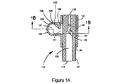
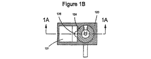
図1A、図1B、図1C、及び図1Dには薬剤デリバリー装置100が示されており、
図1Aは閉位置における装置を、図1Cは開位置における装置を示す。薬剤デリバリー装
置100は、通路122を有するハウジング120と、当該通路内に回転可能に配置され
る第1の部材124と、を含む。
1A, 1B, 1C, and 1D show a
FIG. 1A shows the device in the closed position and FIG. 1C shows the device in the open position. The
通路122に加えて、ハウジング100は、開口111を介して通路と流体連通可能な
第1のチャンバ101を含む。第1のチャンバ101は、1つ又は複数の薬剤を収容する
のに使用され、また、薬剤(例えば粉末及び/又は液体)を計量供給し、薬剤が1つ(又
は複数)の大きい凝集塊として装置100から出ることを防止し、(例えば第1のチャン
バ内での再循環による)薬剤の流動化を支援するように構成された幾何形状を有する。図
示のとおり、チャンバ101は、第1のチャンバ101からの薬剤の流出速度を低下させ
るように構成された障害物104によって部分的に画定される。第1の部材124のイン
レット・チャネル105から第1のチャンバ101内に進入する流体の流れは、薬剤を飛
沫同伴し、薬剤を第1のチャンバの形状に沿って搬送し、第1のチャンバ内で再循環させ
る(経路118)。
In addition to the
図1A及び図1Cに示されるように、第1のチャンバ101の断面は、流体の流れがそ
れ自体の境界壁に沿って開口111(流体の流れの進入地点)に戻るように誘導する湾曲
形状である。この少なくとも部分的に湾曲した形状(例えば略円形、長円形、レーストラ
ック形、又は楕円形)は、薬剤を遠心力によって境界壁に衝突させ、それによって解凝集
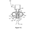
及び分散を生じさせると考えられる。他の実施形態では、長手方向の断面形状は、例えば
レーストラック形(図1E)、円形(図1F)、及び周方向楕円形(図1F)を含めた様
々な形状が存在する可能性がある。第1のチャンバ101の幅は、インレット・チャネル
105と同じにすることも、インレット・チャネル105より広くすることもできる。
As shown in FIGS. 1A and 1C, the cross section of the
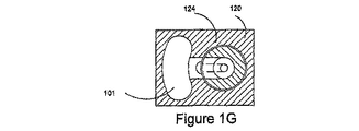
更に、第1のチャンバ101の幾何形状は、障害物104によって第1のチャンバ内の
再循環流体経路118から隔離され、第1の部材124のアウトレット・チャネル106
に近接し、第1のチャンバとアウトレット・チャネルとの間の流体経路を提供する容積1
38を生み出す。使用中、容積138は、第1のチャンバ101及び障害物104と共に
、例えば薬剤が1つ(又は複数)の大きい凝集塊としてデリバリーされないような薬剤の
分散及び計量供給を実現する、より大きい空間(容積138、第1のチャンバ101、及
び障害物104を含む)の一部として働く。しかしながら、後述するように、いくつかの
実施形態(例えば装置200、400、800)では、薬剤が第1のチャンバ内に残され
るように、容積(例えば容積138、238)は当初、第1のチャンバから隔離される。
薬剤を既知の位置(即ち、第1のチャンバ)に隔離することによって既知の始点が与えら
れ、その結果、すべての薬剤を正確且つ予測可能な形でデリバリーすることが可能となる
。第1のチャンバがシール解除(unseal)(該当する場合)されたとき、第1のチ
ャンバは、障害物及び容積(該当する場合)と共に薬剤を分散させ、計量供給するように
働く。更に、後述の他の実施形態で説明するように、容積138は、様々な断面形状を有
する可能性があり、且つ/又は第1のチャンバ101からアウトレット・チャネル106
への薬剤のデリバリーを制御する面積が異なる可能性がある。
Further, the geometry of the
A volume 1 that provides a fluid path between the first chamber and the outlet channel
38 is produced. In use, the
By isolating the drug to a known location (ie, the first chamber), a known starting point is provided, so that all drugs can be delivered in an accurate and predictable manner. When the first chamber is unsealed (if applicable), the first chamber serves to disperse and meter the drug along with obstacles and volume (if applicable). Further, as will be described in other embodiments described below, the
The area that controls the delivery of drugs to can be different.
他の実施形態では、薬剤デリバリー装置は、容積138を含まない。例えば、この装置
は、障害物104を含まず、第1のチャンバ101は、広い開口111を介してアウトレ
ット・チャネル105と流体連通する。
In other embodiments, the drug delivery device does not include a
図示のとおり、ハウジング120は、通路122及び第1のチャンバ101を画定する
ように接合(join)される2つの部品125及び126と、第1のチャンバ101と
流体連通する開口128と、を含む。開口128は、第1のチャンバ101に薬剤を装填
するのに使用することができ、その後プラグ130で覆うことができる。他の手法を利用
して薬物を第1のチャンバ内に配置することもできることが当業者には理解されるだろう
。ハウジング100は、薬剤の汚染及び/又は劣化を防止する耐湿性材料(プラスチック
等)を含む(例えば該材料から形成する)ことができる。他の実施形態では、ハウジング
100は、3つ以上の部品を含むことも1つの単体部品だけを含むこともできる。
As shown, the
第1の部材124は、通路122によって受けられ、第1のチャンバ101と第1の流
体経路103との間の流体連通を選択的にもたらすように構成され得る。第1の部材12
4は、第1の部材の外部表面と通路122の表面との間が密封シールされながらも、第1
の部材がそれ自体の長手方向の軸Lの周りを回転することが可能となるような形状及びサ
イズとすることができる。第1の部材124は、インレット115及びアウトレット11
6を有する第1の流体経路103と、第1の流体経路103と流体連通するインレット・
チャネル105と、第1の流体経路103と流体連通するアウトレット・チャネル106
と、を含む。
The
4, while the outer surface of the first member and the surface of the
And can be shaped and sized such that the member can rotate about its own longitudinal axis L. The
A first
An
And including.
図示のとおり、第1の流体経路103は、それ自体の長さに沿って可変の直径/幅を有
するが、他の実施形態では、それ自体の長さに沿って一定の直径/幅を有する。例えば、
図1Cを参照すると、インレット115付近の第1の流体経路103の直径/幅をアウト
レット116付近の直径/幅よりも大きくすることができる。理論上の制約がなければ、
第1の流体経路103に沿った抵抗は、一般に断面積及び長さを含めたそれ自体の形状で
決まる。直径/幅を可変とすることにより、第1の流体経路103に沿った通気抵抗を制
御することが可能となり、インレット流体チャネル105の下流にあるアウトレット流体
チャネル106の接合部付近に第1の絞り107(直径/幅を減少させた第1の流体経路
に沿った長さ)を配置することが可能となる。その結果、第1の絞り107の断面積は、
インレット・チャネル105の断面積よりも小さくすることができ、したがって、第1の
流体経路103から退出して第1のチャンバ101に分流される総質量流量の比率が大き
くなる可能性がある。これらの割合を変更することにより、第1のチャンバ101内の質
量流量を増減させることができ、インレット・チャネル105から第1のチャンバ101
内に流入する流体の流れの速度に影響を及ぼすことができる。第1のチャンバ101内に
流入する流体の流れが増加すると、薬剤の乱流、せん断、及び力学的相互作用が増大し、
解凝集及び分散が大きくなる可能性がある。第1のチャンバ101内に流入する流体の流
れは、第1のチャンバから取り出される薬剤の量、及び薬剤が第1のチャンバから出る速
さにも影響を及ぼす可能性がある。更に、アウトレット・チャネル106を第1の絞り1
07の長さの範囲内に配置することにより、アウトレット・チャネルのアウトレット(下
流)側でベンチュリ効果が生み出され、それによって第1のチャンバ101からのアウト
レット・チャネルに沿った流体の引き出しを支援することが可能となる。いくつかの実施
形態では、第1の流体経路103に沿った抵抗を減少させ、ベンチュリ効果を高める(例
えば最適化する)ために、第1の流体経路103の断面積は、アウトレット・チャネル1
06の上流で増加する。
As shown, the first
Referring to FIG. 1C, the diameter / width of the first
The resistance along the first
It can be smaller than the cross-sectional area of the
It is possible to influence the flow speed of the fluid flowing into it. As the flow of fluid entering the
Deagglomeration and dispersion can be large. The flow of fluid entering the
By placing it within a length of 07, a venturi effect is created on the outlet (downstream) side of the outlet channel, thereby assisting withdrawing fluid from the
Increase upstream of 06.
更に、第1のチャンバ101を経由する流体の流れの割合は、インレット・チャネル1
05、アウトレット・チャネル106、及び/又は第1の絞り107の断面積を変更する
ことによって制御することができる。例えば、インレット・チャネル105及びアウトレ
ット・チャネル106の断面積を変更することにより、各チャネルに沿った流体速度を変
更することができる。高い速度の流体の流れは、乱流を発生させる可能性があり、第1の
チャンバ101及びアウトレット・チャネル106内の薬剤の流動化及び分散に有益であ
る可能性がある。
Further, the rate of fluid flow through the
05, can be controlled by changing the cross-sectional area of the
上述のとおり、インレット・チャネル105及びアウトレット・チャネル106は、第
1のチャンバに対する第1の部材124の回転位置に応じて第1のチャンバ101と流体
連通することができる。図1A及び図1Bを参照すると、閉位置では、インレット・チャ
ネル105とアウトレット・チャネル106は、ハウジング120によって遮断(blo
ck)され、第1のチャンバ101と第1の流体経路103との間に流体連通は存在しな
い。図1C及び図1Dに示されるように、開位置では、インレット・チャネル105とア
ウトレット・チャネル106は、少なくとも部分的に遮断解除され、開口111と流体連
通する。その結果、第1のチャンバ101及び第1の流体経路103は、流体連通する。
As described above, the
ck) and there is no fluid communication between the
装置100は、閉位置(図1A及び図1B)で提供され得る。第1の部材124及び/
又はハウジング120を互いに対して回転させると、インレット・チャネル105及びア
ウトレット・チャネル106の少なくとも一部分が遮断解除され(例えば図1C及び図1
D)、その結果、第1のチャンバ101と第1の流体経路103とが、チャネル105及
び106を介して流体連通する。その後、(例えば受動的な例では)ユーザは、アウトレ
ット116から吸入を行う。あるいは、流れを能動的にもたらすことも、受動的な流れと
能動的な流れ(いずれも図1A乃至図1Dでは図示せず)の組合せによってもたらすこと
もできる。アウトレット116から空気が引き出されるときに、空気はインレット115
からアウトレット116へと移動する。また、空気は、インレット・チャネル105を経
て第1のチャンバ101内を通過し、アウトレット・チャネル106を経て第1の流体経
路103内に入り、アウトレット116を通過するように流れる。空気は、第1のチャン
バ101内を移動するときに第1のチャンバ内で再循環され(経路118)、保管されて
いる薬剤を分散させ、薬剤を空気流に飛沫同伴させる。薬剤は主に、せん断、振動、及び
乱流によって分散される。再循環流体流によって搬送される薬剤は、第1のチャンバ10
1の壁と接触することによって分散される。また、再循環流体経路118からアウトレッ
ト・チャネル106に向かって移動する飛沫同伴された薬剤は、インレット・チャネル1
05から第1のチャンバ101内に流入する空気を横切り、その結果もたらされるせん断
及び乱流によって更に分散される。やがて、分散及び飛沫同伴された薬剤は、アウトレッ
ト・チャネル106を経てアウトレット116を通過したところでユーザによって吸入さ
れる。いくつかの実施形態では、アウトレット・チャネル106は、飛沫同伴された薬剤
をアウトレット・チャネルの壁に接触させる(軸Lに沿って見て)径方向に湾曲した空気
経路を有する。代替的に又は追加的に、薬剤を更に分散させるために、インレット・チャ
ネル105の幾何形状は、流入する空気が第1のチャンバ101の選択された部分に誘導
されるように修正することができる。例えば、空気は、第1のチャンバ101の壁の略接
線方向にアウトレット・チャネル106に向かい、アウトレット・チャネルから離れるよ
うに誘導することができ、あるいは再循環流体経路118と同様の湾曲した経路内に誘導
することができる。
Alternatively, rotating
D) As a result, the
To
Dispersed by contact with one wall. Also, the entrained drug traveling from the
The air flowing from 05 into the
他の実施形態では、装置100は、第1のチャンバ101内に薬剤が隔離された状態を
維持するように構成され得る。薬剤が(例えば輸送中の動きによって)使用前に第1のチ
ャンバ101外に出ることを防止することにより、第1のチャンバから分散、流動化、及
び/又は計量供給される薬剤量を最適化することができる。図1Hは、閉位置における装
置100’を、図1Iは、開位置における装置100’を示す。装置100’は、装置1
00と同様であるが、開口111をシールし、第1のチャンバ101を容積138から分
離するように構成された、第1の部材124上の突起部134を更に含む。突起部134
は、第1の部材124をハウジング120に対して回転させることにより、障害物104
及び開口111と係合解除することができ、それによって第1のチャンバ101を容積1
38及び第1の経路103と流体連通させることが可能となる。薬剤は、上述のとおりユ
ーザにデリバリーされ得る。
In other embodiments, the
00 but further includes a
The
And the
38 and the
いくつかの実施形態では、装置100は、第1の絞り107を含まない。他の実施形態
では、第1の流体経路103は、長手方向の軸Lに沿って連続的に延在しない。ユーザが
アウトレット116から吸入を行うと、空気は、インレット115を通り、第1の流体経
路の第1の部分を経て、インレット・チャネル105から第1のチャンバ101内に流入
し(ここで空気は再循環され、最終的にそこから出される)、その後、アウトレット・チ
ャネル106を通り、上記第1の部分と直接流体連通しない第1の流体経路の第2の部分
を経て、アウトレットから出るように流れる。換言すると、空気は、インレット115か
ら直接アウトレット116に流れることはできず、第1のチャンバ101内を必ず流れる
ことになる。
In some embodiments, the
同様に、装置の他の特徴も修正することができる。例えば、図1Jは、第1の流体経路
103、インレット・チャネル105、及びアウトレット・チャネル106の修正形態を
示す。第1の流体経路103の断面は、円形であっても、非円形であってもよい(例えば
レーストラック型(図示)、長円形、楕円形、不規則な湾曲形状、3辺、4辺、5辺、6
辺、7辺、又は8辺以上の不規則な又は規則的な多角形)。長手方向の軸Lを上から見て
、インレット・チャネル105及びアウトレット・チャネル106は、互いに重複させる
ことも(図示)、部分的に重複させることも、まったく重複しないようにすることもでき
る。
Similarly, other features of the device can be modified. For example, FIG. 1J shows a modification of the first
Irregular or regular polygons with sides, 7 sides, or 8 sides). Looking at the longitudinal axis L from above, the
第1の部材124及びハウジング120は、互いに対して回転するように構成されるが
、他の実施形態では、互いに平行移動(translate)するように構成される。図
2A及び図2Bは、図1Aに示される装置100と同様の構造的特徴を含む薬剤デリバリ
ー装置200を示す。(図1A及び図1Bと同様の構造的特徴には同じ参照番号が付され
るが、先頭の「1」は「2」で置き換えられている。)図2Aは、閉位置における装置2
00を、図2Bは、開位置における装置200を示す。薬剤デリバリー装置200は、通
路222を有するハウジング220と、通路222内に配置され、通路222内で平行移
動可能な第1の部材224と、を含む。ハウジング220は、ハウジング120と同様で
あるが、第1の部材224の平行移動を所定の位置で制限するように構成された停止部2
32を更に含む。第1の部材224は、第1の部材124と同様であるが、第1のチャン
バ201(図2A)内の薬剤の汚染を防止するために、それ自体の外部表面と通路222
の表面との間の密封シール212を提供する突起部234を更に含む。突起部234は、
第1のチャンバ201への薬剤の保持を促進し、薬剤が(例えば輸送中に)容積238内
に移動することを防止することができる。その結果、第1のチャンバ201からの薬剤の
分散、流動化、及び/又は計量供給を最適化することができる。インレット・チャネル1
05及びアウトレット・チャネル106と同様に、インレット・チャネル205及びアウ
トレット・チャネル206は、装置200が閉位置にあるときは第1のチャンバ201と
流体連通しない。
The
00, FIG. 2B shows the
32 is further included. The
It further includes a
The retention of the drug in the
Similar to 05 and
装置200は、閉位置(図2A)で提供され得る。この装置は、(例えば第1の部材2
24をハウジング220内に押し込むことにより(矢印A))第1の部材224及び/又
はハウジング220を互いに平行移動させることによって開位置に置くことができる。こ
の平行移動により、第1のチャンバ201近傍の突起部234と通路222との間のシー
ル212が解除され、インレット・チャネル205及びアウトレット・チャネル206の
少なくとも一部分が第1のチャンバ201と流体連通する(例えば図2B)。その結果、
第1のチャンバ201と第1の流体経路203とが、チャネル205及び206を介して
流体連通する。インレット・チャネル205及びアウトレット・チャネル206は、第1
の部材224が方向Aに沿ってそれ以上平行移動するのを防止することが可能な停止部2
32に第1の部材224が接触したときに遮断解除される。その後、ユーザは、アウトレ
ット216から吸入を行う。アウトレット216から空気が引き出されるときに、空気は
インレット215からアウトレット216へと移動する。また、空気は、インレット・チ
ャネル205を経て第1のチャンバ201内を通過し、アウトレット・チャネル206を
経て第1の流体経路203内に入り、アウトレット216を通過するように流れる。空気
は、第1のチャンバ201内を移動するときに第1のチャンバ内で再循環され(経路21
8)、保管されている薬剤を分散させ、薬剤を空気流に飛沫同伴させる。薬剤は主に、せ
ん断、振動、及び乱流によって分散され得る。再循環流体流によって搬送される薬剤は、
第1のチャンバ201の壁と接触することによって分散され得る。また、再循環流体経路
218からアウトレット・チャネル206に向かって移動する飛沫同伴された薬剤は、イ
ンレット・チャネル205から第1のチャンバ201内に流入する空気を横切り、その結
果もたらされるせん断及び乱流によって更に分散される。やがて、分散及び飛沫同伴され
た薬剤は、アウトレット・チャネル206を経てアウトレット216を通過したところで
ユーザによって吸入され得る。いくつかの実施形態では、アウトレット・チャネル206
は、飛沫同伴された薬剤をアウトレット・チャネルの壁に接触させる径方向に湾曲した空
気経路を有する。インレット・チャネル205は、インレット・チャネル105と同様に
、流入する空気が第1のチャンバ201の選択された部分に誘導されるように修正するこ
とができる。
By pushing 24 into the housing 220 (arrow A), the
The
Stop portion 2 capable of preventing further translation of
When the
8) Disperse the stored medicine and entrain the medicine in the air stream. The drug can be dispersed primarily by shear, vibration, and turbulence. The drug carried by the recirculating fluid stream is
It can be dispersed by contacting the wall of the
Has a radially curved air path that allows the entrained drug to contact the wall of the outlet channel.
他の実施形態では、ハウジング220は、停止部232を含まない。例えば、第1の部
材224は、第1のチャンバ201と第1の流体経路203とがチャネル205及び20
6を介して流体連通する地点まで第1の部材を移動させ、それ以上移動させないようにす
る停止部を有するプランジャ(例えば図16A参照)によって平行移動させることができ
る。
In other embodiments, the
The first member can be moved to a point of fluid communication via 6 and can be translated by a plunger (see, for example, FIG. 16A) having a stop that prevents further movement.
図3は、図2A及び図2Bに示される薬剤デリバリー装置200と同様であるが、能動
流体流源308を更に含む薬剤デリバリー装置300を示す。(図2A及び図2Bと同様
の構造的特徴には同じ参照番号が付されるが、先頭の「2」は「3」で置き換えられてい
る。他の実施形態でも同様の番号付け方式が使用される。)能動流体流源308は、イン
レット315と係合し、薬剤デリバリー中の分散を支援するように構成される。流源30
8の例としては、圧縮された流体(例えば空気)、及び気体推進器(gas mover
)(例えばファン、ベローズ、スクイズ・バルブ、及び/又はポンプ)が挙げられる。い
くつかの実施形態では、能動的な装置は、環境被害をもたらさない噴射剤を含む。能動流
体流源308は、(図1A及び図1Bに示される)薬剤デリバリー装置100、及び本明
細書に記載される他の任意の装置に組み込むことができる。
FIG. 3 shows a
Examples of 8 include a compressed fluid (eg, air), and a gas mover (gas mover)
(E.g., fans, bellows, squeeze valves, and / or pumps). In some embodiments, the active device includes a propellant that does not cause environmental damage. The active
いくつかの実施形態では、上述(図1A乃至図1J、図2A、図2B、及び図3)の第
1のチャンバは、第1の部材の周辺(perimeter)に延在させることができる。
例えば、後述の諸実施形態の場合と同様に、装置は、第1の部材の周辺に延在する連続的
な容積(トーラス等)を有する第1のチャンバを含むことができる。装置は、第1の部材
の周辺に配置される複数の非連続的な第1のチャンバを含むこともできる。他の実施形態
では、薬剤デリバリー装置は、ハウジング及び第1の部材に関する他の構成を有すること
ができる。一例として、図4A及び図4Bを参照すると、薬剤デリバリー装置400は、
輪状(annular)の第1のチャンバ401及び通路422を有するハウジング42
0と、通路によって受けられるように構成された第1の部材424と、を含む。第1の部
材424及びハウジング420は、通路422の長手方向の軸に沿って互いに平行移動す
ることができる。図4Aは、閉位置における装置400を、図4Bは、開位置における装
置400を示す。
In some embodiments, the first chamber described above (FIGS. 1A-1J, 2A, 2B, and 3) can extend to the periphery of the first member.
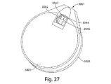
For example, as in the embodiments described below, the apparatus can include a first chamber having a continuous volume (such as a torus) that extends around the periphery of the first member. The apparatus can also include a plurality of non-continuous first chambers disposed about the first member. In other embodiments, the drug delivery device can have other configurations for the housing and the first member. As an example, referring to FIGS. 4A and 4B, a
A housing 42 having an annular
0 and a
ハウジング420は、ハウジング220(図2A及び図2B)と同様の特徴を共有する
。図示のとおり、ハウジング400は、通路422及び輪状の第1のチャンバ401を画
定するように接合される2つの耐湿性部品425及び426と、第1のチャンバ401と
流体連通する開口428と、を含む。第1のチャンバ401には開口428を通じて薬剤
を装填することができ、開口428はその後、プラグ430で覆うことができる。ハウジ
ング220と同様に、ハウジング420は、ハウジング420に対する第1の部材424
の平行移動を制限するように構成された停止部432を所定の位置に含む。
The
A
図示のとおり、第1のチャンバ401は、円環(toroidal)形状とすることが
でき、第1の部材424の長手方向の軸(L’)を横切る(図中では直行する)平面内に
置かれる。第1のチャンバ101と同様に、第1のチャンバ401は、薬剤が1つ(又は
複数)の大きい凝集塊として装置400から出ることを防止するとともに、薬剤の流動化
を支援するように構成された計量供給用幾何形状(metering geometry
)を有する。例えば、この計量供給用幾何形状は、第1のチャンバ401からの薬剤の流
出速度を低下させるように構成された障害物404を有する。第1のチャンバ401は、
上述の第1のチャンバ101のように構成され得る。更に、第1のチャンバ401は連続
的なトーラスとして示されているが、他の実施形態では、装置400は、第1の部材42
4の周り(例えば周方向)に配置される複数の(例えば2つ、3つ、4つ、5つ、又は6
つ以上の)非連続的な第1のチャンバを含む。これらの非連続的な第1のチャンバは、第
1の部材424の各チャネルを介して互いに流体連通することができる。
As shown, the
). For example, the metering geometry has an
It can be configured like the
A plurality (eg, 2, 3, 4, 5, or 6) arranged around 4 (eg, circumferential direction)
One or more non-continuous first chambers. These non-continuous first chambers can be in fluid communication with each other via each channel of the
第1の部材424は、第1の部材224と同様である。例えば、第1の部材424は、
薬剤の汚染を防止するとともに薬剤が第1のチャンバ401から出ることを防止するため
に、それ自体の外部表面と通路422の表面との間の密封シール412を提供する突起部
434を更に含む(図4A)。図4C及び図4Dを参照すると、第1の部材424は、第
1の流体経路403及び第1のチャンバ401と流体連通可能な複数の(図中では6つの
)インレット・チャネル405及びアウトレット・チャネル406を更に含む。装置40
0が閉位置(図4A)にあるときは、第1のチャンバ401は、突起部434によってし
っかりと遮断することができ、インレット・チャネル405、アウトレット・チャネル4
06、及び第1の流体経路403と流体連通しない。装置400が開位置(図4B)にあ
るときは、インレット・チャネル405及びアウトレット・チャネル406は、第1の流
体経路403及び第1のチャンバ401と流体連通する。複数の流体チャネルを有するこ
とは、第1のチャンバ401から第1の流体経路403に薬剤を均一に分散させるのに役
立つ。図示のとおり、インレット・チャネル405及びアウトレット・チャネル406は
実質的に、第1の流体経路403の周りに放射状配列の形で延在する。図4B及び図4C
を参照すると、インレット流体経路405は、再循環式の断面流れパターン(re‐ci
rculating cross‐sectional flow pattern)4
18(図4B)に加えて、周方向の流れ419方向が生み出されるように流体の流れを誘
導することができ、それによって第1のチャンバ401内に収容された薬剤の流動化を支
援することができる。更に、インレット・チャネル405は、周方向の流体の流れが最適
化される形状とすることができる。インレット・チャネル405及びアウトレット・チャ
ネル406は、直線形状、湾曲形状、あるいはその組合せを有することができる。第1の
チャンバ401を経由する流体の流れの割合は、インレット・チャネル405、アウトレ
ット・チャネル406、及び/又は第1の絞り407の断面積を変更することによって制
御することができる。装置400が複数の非連続的な第1のチャンバを含む実施形態では
、インレット・チャネル405及びアウトレット・チャネル406は、装置400が開位
置にあるときに第1のチャンバと流体連通するように構築及び構成される。
The
Further included is a
When 0 is in the closed position (FIG. 4A), the
06 and the first
, The
circulating cross-section flow pattern) 4
18 (FIG. 4B), fluid flow can be induced such that a
引き続き図4A及び図4Bを参照すると、装置400は更に、第1の部材424と連結
(例えば一体形成)されたマウスピース440を含む。図示のとおり、マウスピース44
0は、流体(例えば外気)が第1の部材424から退出する薬剤を迂回して流れることを
可能にする流体バイパス441を含む。いくつかの実施形態によれば、これらのバイパス
は、マウスピースと一体形成することができる。バイパス441内を流れる空気は、薬剤
がマウスピース440に貼り付くのを防止し、肺への薬剤デリバリー能力を高めることが
できる。バイパス441の断面積を変更することにより、第1の流体経路403内の流れ
特性を変化させることができる。バイパス441の断面形状は、様々な形状をとることが
でき、容積測定流体の流れ(volumetric fluid flow)が特定の領
域に集中するように変更することが可能である。
With continued reference to FIGS. 4A and 4B, the
0 includes a
使用において、装置400は、閉位置(図4A)で提供され得る。この装置は、(例え
ば第1の部材424をハウジング420内に押し込むことにより(矢印B))第1の部材
424及び/又はハウジング420を互いに平行移動させることによって開位置に置くこ
とができる。この平行移動により、第1のチャンバ401近傍の突起部434と通路42
2との間のシール412が解除され、インレット・チャネル405及びアウトレット・チ
ャネル406の少なくとも一部分が第1のチャンバ401と流体連通する(例えば図4B
)。その結果、第1のチャンバ401と第1の流体経路403とが、チャネル405及び
406を介して流体連通する。インレット・チャネル405及びアウトレット・チャネル
406は、第1の部材424が方向Bに沿ってそれ以上平行移動するのを防止することが
可能な停止部432に突起部434が接触したときに遮断解除される。その後、ユーザは
、アウトレット416から吸入を行う。アウトレット416から空気が引き出されるとき
に、空気はインレット415からアウトレット416へと移動する。また、空気は、イン
レット・チャネル405を通り、毛管作用によって第1のチャンバ401内を通過し(図
4C)、アウトレット・チャネル406を経て第1の流体経路403に入り(図4D)、
アウトレット416を通過するように流れる。空気は、第1のチャンバ401内を移動す
るときに第1のチャンバ内で再循環され、保管されている薬剤を分散させ、薬剤を空気流
に飛沫同伴させる。薬剤は主に、せん断、振動、及び乱流によって分散され得る。再循環
流体流によって搬送される薬剤は、第1のチャンバ401の壁と接触することによって分
散され得る。また、再循環流体経路418からアウトレット・チャネル406に向かって
移動する飛沫同伴された薬剤は、インレット・チャネル405から第1のチャンバ401
内に流入する空気を横切り、その結果もたらされるせん断及び乱流によって更に分散され
る。やがて、分散及び飛沫同伴された薬剤は、アウトレット・チャネル406を経てアウ
トレット416を通過し、マウスピース440を通過したところでユーザによって吸入さ
れ得る。他の実施形態では、ユーザは、装置400を開位置に置いたまま吸入を行う。こ
のような吸入と開放の同時操作は、本明細書に記載されるすべての実施形態で適用するこ
とができる。
In use, the
2 is released, and at least a portion of the
). As a result, the
Flows through outlet 416. As the air moves through the
It is further dispersed by the resulting shear and turbulence across the air flowing into it. Eventually, the dispersed and entrained drug passes through the
他の実施形態では、図4Eを参照すると、障害物404は、薬剤の計量供給に役立つと
ともに、薬剤の大きい粒子が第1のチャンバから退出することを防止する1つ又は複数の
フィーチャ409(例えばスロット、窪み、溝、開口、及び/又は穴)を含む。
In other embodiments, referring to FIG. 4E, the
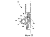
図5A、図5B、図5C、図5D、図5E、及び図5Fは、薬剤の分散及び計量供給能
力を高める装置400の例示的な修正形態を示す。図5A、図5B、及び図5Cは、類似
する特徴に類似する番号が付された、装置400と同様の装置500を示す。装置500
は、流体の流れがインレット・チャネル505から薬剤に向かい、第1のチャンバ501
の遠い方の壁527に向けて誘導され得るように、インレット・チャネル505の方向に
傾斜した第1のチャンバ501の表面523を含む。第1のチャンバ501の表面を傾斜
させることにより、薬剤が平坦面(即ち、インレット・チャネル505の方向と同一平面
)に貼り付くことを防止することができ、薬剤の完全なデリバリー能力が高まる。いくつ
かの実施形態では、第1のチャンバ501の表面の傾斜は、インレット・チャネル505
の方向から約1度〜約30度とすることができる。表面523は、平坦(例えば略一定の
傾斜)であっても湾曲していてもよい。装置500は更に、それ自体の断面直径を変更し
て内部の流体の流れ抵抗が制御される第1の流体経路503を含む。図示のとおり、第1
の流体経路503は、インレット・チャネル505とアウトレット・チャネル506の中
間に所在する第1の絞り507と、アウトレット・チャネル506とアウトレット516
の中間に所在する第2の絞り507’と、直径が拡大されたアウトレット端部(例えば、
約1度〜約30度の角度を有する円錐)と、を含む。
5A, 5B, 5C, 5D, 5E, and 5F illustrate an exemplary modification of the
The fluid flow is directed from the
A
From about 1 degree to about 30 degrees. The
The
A second aperture 507 'located in the middle of the outlet end with an enlarged diameter (e.g.,
A cone having an angle of about 1 degree to about 30 degrees.
インレット・チャネル505及びアウトレット・チャネル506は、第1のチャンバ5
01に出入りする流体の流れを制御するように修正することもできる。図5B及び図5C
に示されるように、インレット・チャネル505及びアウトレット・チャネル506は、
同じ方向に径方向に湾曲させることができる。他の実施形態では、各チャネル505及び
506は、異なる方向に径方向に湾曲させることができ、また、いくつかのチャネルを同
じ方向に湾曲させ、他のチャネルを異なる方向に湾曲させることもできる。図5Dは、第
1の部材524からより多くの材料が取り除かれ、ファン状の構成を有するインレット・
チャネル505が作成される一実施形態を示す。アウトレット・チャネル506にも同様
の修正を施すことができる。図5Eは、アウトレット・チャネル506が径方向に直線的
である一実施形態を示す。各チャネルの幅は、一定であることも、異なることもある(例
えば、第1のチャンバ501から第1の流体経路503に向けて減少させ(図5E参照)
、あるいは第1のチャンバから第1の流体経路に向けて増加させることができる)。イン
レット・チャネル505にも同様の修正を施すことができる。
The
Modifications can be made to control the flow of fluid into and out of 01. 5B and 5C
As shown, the
It can be curved radially in the same direction. In other embodiments, each
Fig. 4 illustrates an embodiment in which a
Or alternatively from the first chamber towards the first fluid path). Similar modifications can be made to the
図5Fは、アウトレット・チャネル506への薬剤の流出速度を低下させるように設計
された容積538の一修正形態を示す。図示のとおり、容積538は、インレット・チャ
ネル505からアウトレット・チャネル506まで延在するので、断面積が拡大されてい
る。他の実施形態では、容積538の断面積は、(例えば図5Aに示されるように)略一
定とすることができる。容積538は、(例えば複数の第1のチャンバが互いに連結され
ずに第1の部材の周りに配置される一実施形態では)離散的なチャネルとすることも、第
1の部材の周りに延在し、様々な断面を有する環状リングとすることもできる。容積53
8は、例えば大きい薬剤粒子を容積538の壁に打ちつけながら転動(tumbling
)させ、流体の流れによって搬送可能なより小さい粒子に分解する遠心力により、薬剤を
更に分散させる働きをする。図示のとおり、障害物504は、インレット・チャネル50
5から容積538内に流入する少なくとも一部の空気を分流するように構成され得る。こ
のように分流された空気は、容積538内の乱流を増大させて容積538内に存在し得る
薬剤をすべて取り除き、分散させるのに役立つ。障害物504は、装置500の長手方向
の軸Lに対して略平行であっても鋭角であってもよい長手方向の軸Bを有することができ
る。
FIG. 5F shows a modification of volume 538 designed to reduce the rate of drug outflow to
8, for example, rolling large drug particles against the wall of volume 538
) And the centrifugal force that breaks down into smaller particles that can be transported by the flow of the fluid to further disperse the drug. As shown, the
5 may be configured to divert at least a portion of the air flowing into volume 538. This diverted air increases the turbulence in volume 538 and helps remove and disperse any drug that may be present in volume 538.
図6A、図6B、及び図6Cは、第1のチャンバ601の外側の壁(即ち、本装置の長
手方向の軸を上から見て、径方向の遠い方の壁)上に薬剤を集めるように設計された薬剤
デリバリー装置600を示す。流体がインレット・チャネル605を経て第1のチャンバ
601内に流入すると、その流体は、第1の流体経路603の周りで円運動するように移
動し、薬剤の露出した表層を剥離し、薬剤がインレット・チャネルから流入する流体を実
質的に横切りながらアウトレット・チャネル606に向かって移動することを可能にする
。図示のとおり、第1のチャンバ601は、インレット・チャネル605及びアウトレッ
ト・チャネル606から径方向の遠い方の壁に向かって拡大し、対向する壁部分に分岐す
る涙滴形(tear‐drop)断面を有する。この涙滴形断面と直交する第1のチャン
バ601の断面は、円形であっても非円形であってもよい。他の実施形態では、図6Dを
参照すると、第1のチャンバ601は、対向する平行な壁と、湾曲して閉鎖された径方向
の遠い方の端部(curved, closed radially far end)
と、を含む。第1のチャンバ601は、対向する平行な壁と、湾曲して閉鎖された径方向
の遠い方の端部と、湾曲して開放された径方向の近い方の端部(curved, ope
ned radially near end)(図6E参照)と、を含むこともできる
。図6A及び図6Eに示される実施形態では、インレット・チャネル605から流入する
空気を対称中心線に沿って第1のチャンバ601内に導入することにより、第1のチャン
バ内で薬剤を略対称に(経路681)分散及び循環させることが可能となる。引き続き図
6D及び図6Eを参照すると、X−X線に沿った断面は、円形であっても非円形であって
もよい。
FIGS. 6A, 6B, and 6C illustrate collecting the drug on the outer wall of the first chamber 601 (ie, the farther wall in the radial direction as viewed from the longitudinal axis of the device). A
And including. The
nd radially near end) (see FIG. 6E). In the embodiment shown in FIGS. 6A and 6E, the drug is substantially symmetric in the first chamber by introducing air flowing from the
他の実施形態では、アウトレットから退出した流体の流れは、様々な構成を有する容積
内に進入する。図7A、図7B、及び図7Cは、アウトレット716から退出した流体の
流れが、薬剤を更に分散させるように構成された第2の分散チャンバ731(第1のチャ
ンバ701が事実上第1の分散チャンバとなる)内に流入する点を除いて、装置400(
図4A)と同様の装置700を示す。第2の分散チャンバ731は、アウトレット716
から出る流体の流れの方向(方向O)を横切る(図中では直交する)長手方向の軸Dを有
し、図示のとおり、軸Dは方向Oと直行する。より具体的には、図7Cを参照すると、第
1の流体経路703から退出する流体の流れは、第2の分散チャンバ731内に進入する
と、当該第2のチャンバの断面の接線方向に流れ、それによって当該分散チャンバ内で薬
剤を再循環させ、薬剤を更に分散させる。図示のとおり、第2の分散チャンバ731の断
面は、略円形とすることができるが、他の実施形態では、非円形(例えば、長円形、楕円
形、及び多角形)とすることもできる。
In other embodiments, the fluid flow exiting the outlet enters volumes having various configurations. 7A, 7B, and 7C show a second dispersion chamber 731 (where the
An
It has a longitudinal axis D that intersects (orthogonal in the figure) the direction of flow of fluid exiting (direction O), which is perpendicular to direction O as shown. More specifically, referring to FIG. 7C, when the fluid flow exiting the first
使用中に、薬剤が第1の流体経路703内に飛沫同伴されると、薬剤は、第2の分散チ
ャンバ731及びマウスピース740に向かって移動する。薬剤は、第2の分散チャンバ
731内に進入すると、第2の分散チャンバの壁に衝突し、それらの壁に沿って移動し、
第2の分散チャンバから退出する前に更に分散される。図示のとおり、マウスピース74
0は、流体が第2の分散チャンバ731から退出する薬剤を迂回して流れることを可能に
する、一体形成されたバイパス741を含むことができる。バイパス741の断面積を変
更することにより、第1の流体経路703及び第2の分散チャンバ731内の流れ特性を
変化させることができる。バイパス741の1つ(又は複数)の断面形状は、様々な形状
をとることができ、容積測定流体の流れが選択された領域に集中するように変更すること
が可能である。第2の分散チャンバ731は、それ自体の長手方向の軸(図7A)と平行
な壁を有することができる。あるいは、図7Dに示されるように、これらの壁を長手方向
の軸に沿って下流で収束させ、薬剤が分散チャンバから退出する前に分散チャンバの壁と
接触する機会を増やすことにより、分散能力を高めることができる。
During use, as the drug is entrained in the first
It is further dispersed before exiting the second dispersion chamber. As shown, the mouthpiece 74
0 can include an integrally formed
他の実施形態では、図7Cを参照すると、分散チャンバ731は、薬剤が分散チャンバ
内を移動するときに薬剤を更に分散させ、肺への薬剤デリバリー能力を高めるために、空
気を提供するバイパス741と同様の空気インレット又はベント761を含む。
In other embodiments, referring to FIG. 7C, the
いくつかの実施形態では、上述の各実施形態のような薬剤デリバリー装置は、第2のチ
ャンバ内に封入することができ、第2のチャンバを内部で開放するように構成され得る。
図8A及び図8Bには装置400(図4A及び図4B)と同様の特徴を有する装置800
が示されており、図8Aは閉位置における装置を、図8Bは開位置における装置を示す。
装置800は、ハウジング820と、ハウジング820によって受けられる第1の部材8
24と、ハウジング820及び第1の部材824を封入する第2のチャンバ850と、第
2のチャンバ850の陥凹部842とアウトレット・リング852を介して係合するマウ
スピース840と、第2のチャンバ850の(図示のとおり第1の部分と対向する)第2
の部分と係合する基部854と、を含む。いくつかの実施形態では、第2のチャンバ85
0は、基部854と係合するように構成された追加的な陥凹部を含む。
In some embodiments, drug delivery devices such as those described above can be enclosed within a second chamber and configured to open the second chamber therein.
8A and 8B show an
8A shows the device in the closed position and FIG. 8B shows the device in the open position.
The
24, a
And a
0 includes an additional recess configured to engage the
ハウジング820及び第1の部材824は、それぞれハウジング420及び第1の部材
424(図4A)と同様であるが、第2のチャンバ850を内部で開放するフィーチャを
更に含む。ハウジング420と同様に、ハウジング820は、薬剤を保管する円環状の第
1のチャンバ801、第1の部材824を受ける通路822、及び停止部832を含むが
、第2のチャンバ850を穿刺するように構成された切削縁部856と、基部854と係
合するように構成された肩部858と、を更に含む。第1の部材424と同様に、第1の
部材824は、インレット・チャネル805及びアウトレット・チャネル806、第1の
流体経路803、及び突起部834を含むが、第2のチャンバ850を穿刺するように構
成された切削縁部860と、アウトレット・リング852と係合するように構成された肩
部862と、を更に含む(後述)。ハウジング820及び第1の部材824は、ハウジン
グ420及び第1の部材424と同様に互いに平行移動するように構成される。
第2のチャンバ850は、第1のチャンバ801内の薬剤に追加的な保護を与え、使用
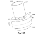
中にハウジング820及び第1の部材824によって穿刺されるように構成され得る。図
23A及び図23Bも参照すると、第2のチャンバ850は全体的に、装置800に強度
及び構造的完全性を与えながら、使用中に予測可能且つ制御可能な形で変形させる(例え
ば軸方向Bに圧潰する)ことも可能な形状とすることができる(図23B)。図示のとお
り、第2のチャンバ850は、第1の湾曲部分857と、略平坦部分879の周りに円形
の溝を形成する第2の湾曲部分859と、を含む。この溝は、アウトレット・リング85
2と係合することができる。他の実施形態では、図23Cを参照すると、第2のチャンバ
850’は、平坦部分を含まない。いくつかの実施形態では、第2のチャンバ850は、
2層のプラスチック被覆箔のような耐湿性材料を含む。これらの2層の材料は、互いに結
合されたときに第2のチャンバ850が作成されるように予備成形することができる。図
示のとおり、これらの層は、アウトレット・リング852と接続される陥凹部842(例
えば、アウトレット・リング852に対応するパターンの円形の溝又は一連の溝)を有す
る成形段(formed step)864と、基部854に接続される成形段866と
、を有する。第2のチャンバ850は更に、ハウジング820を第2のチャンバの内側の
選択された位置に配置し安定化させる安定化フィーチャ851を含む。また、安定化フィ
ーチャ851は、第2のチャンバ850が使用中に変形可能となるまで、切削縁部856
及び860が第2のチャンバ850と接触しないように又は第2のチャンバ850を穿刺
しないようにする。図示のとおり、安定化フィーチャ851(輪状リング、1つ又は複数
のリブ、タブ等)は、2層の第2のチャンバ850によって形成することができ、ハウジ
ング820の対応するフィーチャ853(突出タブ等)と接続される。他の実施形態では
、安定化フィーチャ851及び/又はフィーチャ853は、それぞれ第2のチャンバ85
0及びハウジング820に取り付けられる別個の構成部品である。アウトレット・リング
852及び/又は基部854は、第2のチャンバ850に取り付けられることも取り付け
られないこともある。
The
2 can be engaged. In other embodiments, referring to FIG. 23C, the
Includes moisture resistant material such as two layers of plastic coated foil. These two layers of material can be preformed such that a
And 860 are not in contact with the
0 and separate components attached to the
装置800は、閉位置(図8A)でユーザに提供され得る。突起部834は、第1の部
材824と通路822との間の輪状密封シールを提供し、薬剤が保管される第1のチャン
バ801内への流体連通を防止することができる。薬剤は更に、第2のチャンバ850に
よって(例えば湿気及び/又は空気から)保護され得る。
装置800を使用する際は、基部854及びマウスピース840が互いに向かって移動
するように、基部854及びマウスピース840に反対方向の圧力が印加される。印加さ
れた圧力は、第2のチャンバ850の成形段864及び866に伝達することができ、そ
れによって第2のチャンバ850を切削縁部856及び860に向かって移動させ、第2
のチャンバ850を穿刺することができる。第2のチャンバ850の穿刺された部分は、
第2のチャンバ850に取り付けられたままであり、それらの部分が流体流路803を遮
断しないように制御された形で(例えばベローズのように)変形する。その結果、第1の
部材824の第1の流体経路803が開放され、マウスピース840と基部854との間
の流体連通がもたらされる。第2のチャンバ850は、基部854とマウスピース840
の相対的な移動が可能となるように変形を続ける。
When using the
The
It remains attached to the
The deformation is continued so that the relative movement of can be performed.
基部854とマウスピース840とが互いに向かって移動を続けると、アウトレット・
リング852は最終的に肩部862と接触し、基部854は最終的に肩部858と接触す
る。基部854とマウスピース840とが互いに向かって連続的に移動することにより、
装置400に関して概説したように、第1の部材824及びハウジング820が互いに平
行移動し、最終的にインレット・チャネル805、アウトレット・チャネル806、及び
第1の流体経路803と、第1のチャンバ801との間の完全な流体連通がもたらされる
。この時点で、装置800は開位置になる(図8B)。他の実施形態では、第2のチャン
バ850は、インレット・チャネル805、アウトレット・チャネル806、及び第1の
流体経路803と、第1のチャンバ801とが完全に流体連通した後に、印加される力及
び摩擦に応じて穿刺される。
When the
The
As outlined with respect to the
その後、装置400に関して上述したように、ユーザは、マウスピース840から吸入
を行い、第1のチャンバ801内の薬剤がマウスピース840を通じてデリバリーされる
。他の実施形態では、図8A及び図8Bに示されるように、マウスピース840は、バイ
パス441に関して上述したように流体が第1の部材824から退出する薬剤を迂回して
流れることを可能にする、一体形成された流体バイパス841を含む。
Thereafter, as described above with respect to the
上述の各実施形態は、(薬剤が保管される)第1のチャンバに通じる1つの開口を含む
ハウジングを有するものとして示されているが、他の実施形態では、ハウジングは、第1
のチャンバに通じる複数の開口を含む。図9A及び図9Bは、第1のチャンバに通じる複
数の開口を含むハウジングを有する薬剤デリバリー装置900を示す。図9Aは、閉位置
における装置900を、図9Bは、開位置における装置900を示す。
While each of the above embodiments is shown as having a housing that includes one opening leading to a first chamber (where the medication is stored), in other embodiments the housing is a first
A plurality of openings leading to the chamber. 9A and 9B show a
図示のとおり、装置900は、ハウジング220(図2A)と同様の特徴を有し、追加
的な特徴を含むハウジング920を含む。ハウジング920は、第1の部材924を受け
る通路922と、薬剤を保管する第1のチャンバ901と、を含む。ハウジング920は
更に、ハウジング920と一体形成されたインレット・チャネル905’及びアウトレッ
ト・チャネル906’を含む。
As shown, the
装置900は更に、ハウジング920の通路922内に受けられるように構成された第
1の部材924を含む。第1の部材924は、使用中に第1の部材924及びハウジング
920が互いに平行移動することを可能にしながら、インレット・チャネル905’及び
アウトレット・チャネル906’を密封シールすることが可能な固定部分970を有する
。第1の部材924は、第1の流体経路903と、アウトレット・チャネル906’と整
合して第1のチャンバ901と第1の流体経路903との間の流体連通をもたらすことが
可能なアウトレット・チャネル906と、を含む。図示のとおり、第1の流体経路903
は、それ自体の長さに沿って絞り907を有する。
The
Has a
使用において、装置900は、閉位置(図9A)でユーザに提供される可能性があり、
ユーザは、第1の部材924及び/又はハウジング920を互いに平行移動させてインレ
ット・チャネル905’及びアウトレット・チャネル906’をシール解除し、第1のチ
ャンバ901と第1の流体経路903とを流体連通させる(図9B)。その後、ユーザは
、アウトレット916から吸入を行う。流体がインレット915からアウトレット916
に向かって移動すると、流体は、第1のチャンバ901内にも流入し、薬剤を流体流に飛
沫同伴させる。飛沫同伴された薬剤は、装置200に関して上述したようにアウトレット
916を通じてデリバリーされ得る。第1のチャンバ901内に流入する流体の流れの割
合は、インレット・チャネル905’、アウトレット・チャネル906’、及び/又は第
1の絞り907の断面積を変更することによって制御することができる。
In use, the
The user translates the
When moving toward the fluid, the fluid also flows into the
図10は、図9A及び図9Bに示される薬剤デリバリー装置900と同様であるが、能
動流体流源1008を更に含む薬剤デリバリー装置1000を示す。能動流体流源100
8は、インレット1015と係合し、薬剤デリバリー中の分散を支援するように構成され
得る。流源1008の例は、後述する。
FIG. 10 shows a
8 may be configured to engage with inlet 1015 and assist in dispersion during drug delivery. An example of the
装置900は、薬剤保管用の円環状の第1のチャンバを含み、第2のチャンバ内に封入
されるように修正することができる。図11Aは、閉位置における薬剤デリバリー装置1
100を、図11Bは、開位置における薬剤デリバリー装置1100を示す。図示のとお
り、装置1100は、ハウジング1120と、ハウジング1120によって受けられる第
1の部材1124と、ハウジング1120及び第1の部材1124を封入する第2のチャ
ンバ1150と、マウスピース1140と、切削端部を有するプランジャ1175と、を
含む。いくつかの実施形態では、プランジャ1175は、ハウジング1120との流体連
通をもたらすように端部が開放された通路を含む。
The
FIG. 11B shows the
ハウジング1120は、ハウジング920と同様である。ハウジング1120は、円環
状の第1のチャンバ1101(例えば図4A及び図8A)と、第1の部材1124を受け
る通路1122と、第1のチャンバ1101と流体連通する複数組の湾曲したインレット
・チャネル1105’及びアウトレット・チャネル1106’と、を含む。湾曲したイン
レット・チャネル1105’及びアウトレット・チャネル1106’は、図示のとおりハ
ウジング1120と一体形成されるが、他の実施形態では別個の構成部品を備えることも
できる。他の実施形態では、装置1100は、図示のような1つの連続的な円環状の第1
のチャンバ1101を有する代わりに、第1の部材1124の周りに配置され、一体形成
された複数組のインレット・チャネル及びアウトレット・チャネルを介して第1の流体経
路1103と流体連通可能な複数の非連続的な第1のチャンバを含む。
The
Instead of having a plurality of
第1の部材1124は、第1の部材924(図9A)と同様であり、ハウジング112
0の通路1122内に受けられるように構成される。第1の部材1124は、使用中に第
1の部材1124及びハウジング1120が互いに平行移動することを可能にしながら、
インレット・チャネル1105’及びアウトレット・チャネル1106’を密封シールす
ることが可能な固定部分1170を有する。第1の部材1124は、第1の流体経路11
03と、各アウトレット・チャネル1106’と整合して第1のチャンバ1101と第1
の流体経路1103との間の流体連通をもたらすことが可能なアウトレット・チャネル1
106と、を含む。第1の流体経路1103は、それ自体の長さに沿って第1の幅/直径
からより小さい第2の幅/直径となる絞り1107を有する。下流側では、第1の部材1
124は、第2のチャンバ1150を穿刺するように構成された切削縁部1160も含む
。
The
It is configured to be received in zero
It has a fixed
03 and the
Outlet channel 1 capable of providing fluid communication with
106. The
124 also includes a
第2のチャンバ1150は、第1のチャンバ1101内の薬剤に追加的な保護を与え、
使用中に第1の部材1124の切削縁部1160によって穿刺されるように構成され得る
。いくつかの実施形態では、第2のチャンバ1150は、2層のプラスチック被覆箔のよ
うな耐湿性材料を含む。これらの2層の材料は、互いに結合されたときに第2のチャンバ
1150が作成されるように予備成形することができる。更に、これらの層は、マウスピ
ース1140に接続される成形段1164と、プランジャ1175に接続される成形段1
166と、を有する。
The
It may be configured to be pierced by the
166.
後述するように、マウスピース1140は、ハウジング1120のアウトレット端部と
係合するように構成することができ、プランジャ1175は、第1の部材1124のイン
レット端部と係合するように構成され得る。図示のとおり、マウスピース1140は、流
体がマウスピース1140内を流れる薬剤を迂回して流れることを可能にする、一体形成
された流体バイパス1141を含む。バイパス1141の断面積を変更することにより、
第1の流体経路1103内の流れ特性を変化させることができる。バイパス1141の断
面形状は、様々な形状をとることができ、容積測定流体の流れが特定の領域に集中するよ
うに変更することが可能である。
As described below, the
The flow characteristics in the
装置1100は、閉位置(図11A)で提供され得る。第1のチャンバ1101内の薬
剤は、インレット・チャネル1105’及びアウトレット・チャネル1106’を密封シ
ールし、第1のチャンバ1101外への薬剤の移動を防止することが可能な、第1の部材
1124の固定部分1170によって(例えば湿気及び/又は空気から)保護され得る。
薬剤は、第2のチャンバ1150によっても保護され得る。
The drug can also be protected by the
使用において、マウスピース1140は、ハウジング1120のアウトレット端部と係
合し、プランジャ1175は、第1の部材1124のインレット端部と係合し、マウスピ
ース1140及びプランジャ1175は、互いに向かって反対方向に移動される。プラン
ジャ1175が第1の部材1124に向かって第2のチャンバ1150内へと移動すると
き、プランジャ1175は、成形段1166を穿刺し、第1の部材1124をハウジング
1120に対して平行移動させ、それにより、インレット・チャネル1105’とアウト
レット・チャネル1106’とを遮断している密封シールを解除する。最終的に、第1の
部材1124の切削縁部1160が段1164を穿刺し、第1の部材1124の各アウト
レット・チャネル1106がハウジング1120の各アウトレット・チャネル1106’
と整合する。その後、プランジャ1175は、ハウジング1120から引き抜かれ、ある
いはプランジャ1175が空気通路を含む場合は所定位置に維持され得る。装置1100
が開位置(図11B)になると、第1のチャンバ1101は、第1の流体経路1103と
流体連通し、薬剤のデリバリー準備が整う。図11C及び図11Dも参照すると、その後
、ユーザがマウスピース1140から吸入を行うと、流体は、インレット・チャネル11
05’を経て第1のチャンバ1101内に進入して薬剤を飛沫同伴し、その後、薬剤は、
アウトレット・チャネル1106’を経て第1のチャンバ1101から退出し、例えば装
置400及び装置900に関して上述したようにデリバリーされる。
In use, the
Consistent with. Thereafter, the
When in the open position (FIG. 11B), the
05 'through the
Exiting the
他の実施形態では、装置1100のインレット・チャネル及びアウトレット・チャネル
は、第1の部材のフィーチャとなる。図11Eは、閉位置における薬剤デリバリー装置1
100’を、図11Fは、開位置における薬剤デリバリー装置1100’を示す。図示の
とおり、装置1100’は、ハウジング1120’と、ハウジング1120’によって受
けられる第1の部材1124’と、ハウジング1120’及び第1の部材1124’を封
入する第2のチャンバ1150’と、マウスピース1140と、切削端部を有するプラン
ジャ1175と、を含む。いくつかの実施形態では、プランジャ1175は、ハウジング
1120’との流体連通をもたらすように端部が開放された通路を含む。装置1100’
は、低プロファイルであり、例えば複数回用量薬剤デリバリーシステムでは特に有益であ
る可能性がある。
In other embodiments, the inlet and outlet channels of the
FIG. 11F shows the
Is a low profile and may be particularly beneficial, for example, in a multiple dose drug delivery system.
ハウジング1120’は、ハウジング1120と同様であるが、インレット・チャネル
又はアウトレット・チャネルを含まない。ハウジング1120’は、円環状の第1のチャ
ンバ1101と、第1の部材1124’を受ける通路1122’と、を含む。他の実施形
態では、装置1100’は、図示のような1つの連続的な円環状の第1のチャンバ110
1を有する代わりに、第1の部材1124’の周りに配置され、一体形成された複数組の
インレット・チャネル及びアウトレット・チャネルを介して第1の流体経路1103と流
体連通可能な複数の非連続的な第1のチャンバを含む。
The
Instead of having a plurality of discontinuous layers disposed around the
第1の部材1124’は、ハウジング1120’の通路1122’内に受けられるよう
に構成される。第1の部材1124’は、使用中に第1の部材1124’及びハウジング
1120’が互いに平行移動することを可能にしながら、第1のチャンバ1101’の開
口1111を密封シールすることが可能な固定部分1170’を有する。第1の部材11
24は、第1の流体経路1103’と、インレット・チャネル1105’と、アウトレッ
ト・チャネル1106’と、を含む。インレット・チャネル1105’及びアウトレット
・チャネル1106’は、開口1111と整合して第1のチャンバ1101’と第1の流
体経路1103’との間の流体連通をもたらすことができる。第1の流体経路1103’
は、それ自体の長さに沿って上流の幅/直径からより小さい下流の幅/直径となる絞り1
107’及び1107’’を有する。下流側では、第1の部材1124’は、第2のチャ
ンバ1150’を穿刺するように構成された切削縁部1160’も含む。
The
24 includes a
Is a restriction 1 that has a smaller downstream width / diameter from its upstream width / diameter along its own length.
107 ′ and 1107 ″. Downstream, the
第2のチャンバ1150’は、第1のチャンバ1101’内の薬剤に追加的な保護を与
え、使用中に第1の部材1124’の切削縁部1160’によって穿刺されるように構成
され得る。いくつかの実施形態では、第2のチャンバ1150’は、2層のプラスチック
被覆箔のような耐湿性材料を含む。これらの2層の材料は、互いに結合されたときに第2
のチャンバ1150’が作成されるように予備成形することができる。
The
Can be preformed to create a
装置1100’は、閉位置(図11E)で提供され得る。第1のチャンバ1101’内
の薬剤は、開口1111を密封シールし、第1のチャンバ1101’外への薬剤の移動を
防止することが可能な、第1の部材1124’の固定部分1170’によって(例えば湿
気及び/又は空気から)保護され得る。薬剤は、第2のチャンバ1150’によっても保
護され得る。
使用において、マウスピース1140’は、ハウジング1120’のアウトレット端部
と係合し、プランジャ1175’は、第1の部材1124’のインレット端部と係合し、
マウスピース1140’及びプランジャ1175’は、互いに向かって反対方向に移動さ
れる。プランジャ1175が第1の部材1124’に向かって第2のチャンバ1150’
内へと移動するとき、第2のチャンバ1150’を穿刺し、第1の部材1124’をハウ
ジング1120’に対して平行移動させ、それにより、開口1111を遮断している密封
シールを解除する。最終的に、第1の部材1124’の切削縁部1160’が第2のチャ
ンバ1150’を穿刺し、第1の部材1124’のインレット・チャネル1105’及び
アウトレット・チャネル1106’が第1のチャンバ1101’の開口1111と整合す
る。その後、プランジャ1175は、ハウジング1120’から引き抜かれ、あるいはプ
ランジャ1175が通路を含む場合は所定位置に維持され得る。装置1100’が開位置
(図11F)になると、第1のチャンバ1101は、第1の流体経路1103’と流体連
通し、薬剤のデリバリー準備が整えられ得る。その後、(例えば受動的な実施形態では)
ユーザがマウスピース1140から吸入を行うと、流体は、インレット・チャネル110
5’を経て第1のチャンバ1101’内に進入して薬剤を飛沫同伴し、その後、薬剤は、
アウトレット・チャネル1106’を経て第1のチャンバ1101’から退出し、第1の
流体経路1103’を通じてデリバリーされる。
In use, the
The
When moving in, the
When the user inhales from the
5 'through the first chamber 1101' and entraining the drug, after which the drug is
It exits the
他の実施形態では、第2のチャンバは、薬剤が保管される第1のチャンバの一部分を画
定することができる。図12Aは、ハウジング1220と、ハウジング1220によって
受けられる第1の部材1224と、マウスピース1240と、プランジャ1275と、を
含む、図11に示される装置1100と同様の装置1200を示す。装置1200は更に
、第1のチャンバ1201の一部分を画定する壁を形成する第2のチャンバ1250を含
む。
In other embodiments, the second chamber can define a portion of the first chamber in which the medication is stored. FIG. 12A shows a
また、他の実施形態では、第2のチャンバは、薬剤が保管される第1のチャンバの全体
を画定することができる。図12Bは、第1の部材1224と、ハウジング1220’と
、マウスピース1240と、プランジャ1275と、を含む、図11に示される装置11
00と同様の装置1200’を示す。装置1200’は更に、第1のチャンバ1201’
を画定する壁を形成する第2のチャンバ1250’を含む。第2のチャンバ1250’は
更に、マウスピース1240と係合し、薬剤の分散及び計量供給能力を高める障害物とし
て働く陥凹部1242を含む。ハウジング1220’は、上述したように第1の部材12
24と整合可能なインレット・チャネル1205’及びアウトレット・チャネル1206
’を含む。
In other embodiments, the second chamber can define the entire first chamber in which the medication is stored. FIG. 12B shows the device 11 shown in FIG. 11 including a
A
A second chamber 1250 'forming a wall defining The
24 and inlet channel 1205 'and
'including.
次に、図12Cを参照すると、第1の部材1224’’が第2のチャンバ1250’’
内に配置され、第1の部材1224’’と第2のチャンバ1250’’との間のハウジン
グを有さない装置1200’’が示されている。装置1200’’は更に、マウスピース
1240と、プランジャ1275と、を含む。図示のとおり、第1の部材1224’’は
、使用時まで第2のチャンバ1250’’によって遮断されるインレット・チャネル12
05’’及びアウトレット・チャネル1206’’を含む。第2のチャンバ1250’’
は、第1のチャンバ1201’’を画定する壁を形成する。第2のチャンバ1250’’
は更に、マウスピース1240と係合し、第1のチャンバ1201’’内の薬剤の分散及
び計量供給能力を高める障害物として働く陥凹部1242’’を含む。第1のチャンバ1
201’’は、使用時まで第1の部材1224’’の固定部分によって遮断される。
Referring now to FIG. 12C, the first member 1224 '' is moved to the second chamber 1250 ''.
Shown is a device 1200 '' disposed within and without a housing between the first member 1224 '' and the second chamber 1250 ''.
05 ″ and
Forms a wall defining a first chamber 1201 ''. Second chamber 1250 ''
Further includes a recess 1242 '' that engages the
201 '' is blocked by the fixed portion of the first member 1224 '' until use.
使用中は、プランジャ1275が第1の部材1224’’を押すことによって第2のチ
ャンバ1250’’が穿刺され、第1のチャンバ1201’’上のシールが解除され、イ
ンレット・チャネル1205’’及びアウトレット・チャネル1206’’と、第1のチ
ャンバ1201’’とが整合する。薬剤は、本明細書で説明されるように第1のチャンバ
1201’’からマウスピース1240を通じてデリバリーされ得る。
In use,
図12Dは、ハウジング1120’’’と、ハウジング1220’’’内に摺動可能に
配置される第1の部材1224’’’と、ハウジング1220’’’及び第1の部材12
24’’’を封入する第2のチャンバ1250’’’と、を有する装置1200’’’を
示す。装置1200’’’は更に、マウスピース1240と、プランジャ1275と、を
含む。図示のとおり、ハウジング1220’’’は、第1のチャンバ1201’’’と流
体連通するが、使用時まで第1の部材1224’’’の固定部分によって遮断される開口
1247を含む。第1の部材1224’’’は、使用時までハウジング1220’’’に
よって遮断されるインレット・チャネル1205’’’及びアウトレット・チャネル12
06’’’を含む。第2のチャンバ1250’’’は、第1のチャンバ1201’’’を
画定する壁を形成する。第2のチャンバ1250’’’は更に、マウスピース1240と
係合し、第1のチャンバ1201’’’内の薬剤の分散及び計量供給能力を高める障害物
として働く陥凹部1242’’’を含む。第1のチャンバ1201’’’は、使用時まで
第1の部材1224’’の固定部分によって遮断される。
FIG. 12D shows a
A device 1200 '''is shown having a second chamber 1250''' enclosing 24 '''.
Contains 06 '''. The
使用中は、プランジャ1275が第1の部材1224’’’を押すことによって第2の
チャンバ1250’’’が穿刺され、開口1247上のシールが解除され、インレット・
チャネル1205’’’及びアウトレット・チャネル1206’’’と、開口1247及
び第1のチャンバ1201’’’とが整合する。薬剤は、本明細書で説明されるように第
1のチャンバ1201’’’からマウスピース1240を通じてデリバリーされ得る。
In use, the
図12Eは、閉位置における装置1200’’’’を、図12Fは、開位置における装
置1200’’’’を示す。装置1200’’’’は、ハウジング1220’’’’と、
ハウジング1220’’’’内に摺動可能に配置される第1の部材1224’’’’と、
ハウジング1220’’’’及び第1の部材1224’’’’を封入する第2のチャンバ
1250’’’’と、を含む。装置1200’’’’は更に、マウスピース1240と、
プランジャ1275と、を含む。図示のとおり、第1の部材1224’’’’は、使用時
までハウジング1220’’’によって遮断されるインレット・チャネル1205’’’
’、アウトレット・チャネル1206’’’’、及び容積1238’’’を含む。第2の
チャンバ1250’’’’は、第1のチャンバ1201’’’’を画定する壁を形成する
。第2のチャンバ1250’’’’は更に、マウスピース1240と係合し、第1のチャ
ンバ1201’’’’内の薬剤の分散及び計量供給能力を高める障害物として働く陥凹部
1242’’’’を含む。第1のチャンバ1201’’’’は、使用時まで第1の部材1
224’’の固定部分によって遮断される。
FIG. 12E shows the
A first member 1224 '''' slidably disposed within the housing 1220 '''';
And a
A
',
It is blocked by a fixed part of 224 ″.
使用中は、プランジャ1275が第1の部材1224’’’’を押すことによって第2
のチャンバ1250’’’’が穿刺される。また、第1の部材1224’’’’の移動に
よって第1のチャンバ1201’’’’のシールが解除され、最終的にインレット・チャ
ネル1205’’’’及びアウトレット・チャネル1206’’と、第1のチャンバ12
01’’’’とが整合する(図12F)。プランジャ1275は、取り外すことができ、
また、それ自体が流体通路を含む場合は所定位置に維持され得る。薬剤は、本明細書で説
明されるように、(障害物1204’’’’として働く)陥凹部1242’’’’及び容
積1238’’’’によって計量供給及び分散され、第1のチャンバ1201’’’’か
らマウスピース1240を通じてデリバリーされ得る。
In use, the
The
01 '''' matches (FIG. 12F). The
It can also be maintained in place if it itself includes a fluid passage. The drug is metered and distributed by a
他の実施形態では、第1のチャンバは、薬剤デリバリー装置が閉位置にあるときにアウ
トレット空気経路と流体連通することができる。図13Aは、閉位置における薬剤デリバ
リー装置1300を、図13Bは、開位置における薬剤デリバリー装置1300を示す。
In other embodiments, the first chamber can be in fluid communication with the outlet air path when the drug delivery device is in the closed position. FIG. 13A shows the
装置1300は、ハウジング1320と、ハウジング1320内に固定される第1の部
材1324と、第1の部材1324と係合するように構成されたマウスピース1340と
、第1の部材1324を移動させるように構成されたプランジャ1375と、を含む。図
示のとおり、ハウジング1320は、2層のプラスチック被覆箔のような耐湿性材料から
形成することができる。これらの層は、互いに結合されたときにハウジング1320が作
成されるように事前成形することができ、また、薬剤が保管される第1のチャンバ130
1を形成する。図示のとおり、第1のチャンバ1301は、略円環形状(図13B)とす
ることができ、第1の部材1324の周りに延在するが、他の実施形態では、他の断面形
状及び容積を有する。図示のとおり、ハウジング1320及び第1のチャンバ1301は
、マウスピース1340と連結されるが、他の実施形態では、マウスピース1340は、
ハウジング1320と連結されないこともある。
1 is formed. As shown, the
It may not be connected to the
第1の部材1324は、マウスピース1340と第1のチャンバ1301との間の流体
連通をもたらし、ハウジング1320を穿刺するように構成され得る。第1の部材132
4は、複数のアウトレット・チャネル1306と流体連通する第1の流体経路1303と
、複数のインレット・チャネル1305と流体連通する第2の流体経路1303’と、を
含む。インレット・チャネル1305及びアウトレット・チャネル1306は、第1のチ
ャンバ1301と流体連通する。第1の部材1324は、ハウジング1320を穿刺し、
マウスピース1340と係合するように構成された切削縁部1360も含む。
The
4 includes a
Also included is a cutting edge 1360 configured to engage the
マウスピース1340は、アウトレット・リング1352と、一体形成された流体バイ
パス1341と、を含む。アウトレット・リング1352は、使用中に第1の流体経路1
303と係合し、流体連通するように構成され得る。バイパス1341は、流体がマウス
ピース1340内を流れる薬剤を迂回するように流れることを可能にする。バイパス13
41の断面積を変更することにより、マウスピース1340及び第1のチャンバ1324
内の流れ特性を変化させることができる。
The
303 may be configured to engage and be in fluid communication.
41 by changing the cross-sectional area of the
The flow characteristics within can be changed.
プランジャ1375は、ハウジング1320を穿刺し、第1の部材1324を前進(a
dvance)させ、ハウジング1320の外部から第1のチャンバ1301内への流体
連通をもたらすように構成され得る。図示のとおり、プランジャ1375は、切削縁部1
376と、第2の流体経路1303’と係合するように構成された流体チャネル1378
と、を含む。流体チャネル1378は、外部環境と流体連通することができる。
and can be configured to provide fluid communication from the exterior of the
376 and a
And including. The
装置1300は、閉位置(図13A)で提供され得る。薬剤は、ハウジング1320の
第1のチャンバ1301内に保管され、シールされ得る。マウスピース1340は、ハウ
ジング1320に取り付けられることもハウジング1320から隔置されることもある。
装置1300を使用する際は、プランジャ1375を第1の部材1324に向かって前
進させて2つの穿孔を形成することができる。プランジャ1375の切削縁部1376は
、ハウジング1320を穿刺して、流体チャネル1378と第1のチャンバ1301とを
、第2の流体経路1303’及びインレット・チャネル1305を介して流体連通させる
。同時に又は順次的に、第1の部材1324の切削縁部1360は、ハウジング1320
を穿刺して、マウスピース1340と第1のチャンバ1301とを、第1の流体経路13
03及びアウトレット・チャネル1306を介して流体連通させる。最終的に、第1の部
材1324がマウスピース1340と係合すると、装置1300は、開位置になる(図1
3B)。ハウジング1320が変形されると、第1のチャンバ1301は略円環形状とな
る。こうして装置1300の吸入準備が整えられ得る。
In using the
, The
03 and fluid communication through outlet channel 1306. Eventually, when the
3B). When the
その後、(例えば受動的な実施形態では)ユーザがマウスピース1340から吸入を行
うと、薬剤は、第1のチャンバ1301からマウスピース1340を通じてデリバリーさ
れる。より具体的には、引き続き図13Bを参照すると、流体は、プランジャ1375の
流体チャネル1378を通り、インレット・チャネル1305を経て第1のチャンバ13
01内に移動する。その後、流体の流れは、薬剤を第1のチャンバ1301内に飛沫同伴
する。第1のチャンバ1301は、本明細書に記載される他の第1のチャンバと同様に、
薬剤を流動化し、薬剤が1つ(又は複数)の大きい凝集塊として装置1300から出るこ
とを防止するように設計され得る。薬剤は、第1のチャンバ1301内の再循環経路内を
移動し、最終的にアウトレット・チャネル1306から退出し、第1の流体経路1303
を通過し、マウスピース1340を通じてユーザに届けられる。
Thereafter, when the user inhales from the mouthpiece 1340 (eg, in a passive embodiment), the drug is delivered from the
Move into 01. Thereafter, the fluid flow entrains the drug into the
It may be designed to fluidize the drug and prevent it from leaving the
And delivered to the user through the
他の実施形態では、図13Cを参照すると、装置1300は、インレット・チャネル1
305とアウトレット・チャネル1306との間の第1の絞り1307を含む。
In other embodiments, referring to FIG. 13C, the
A
図14A及び図14Bは、第2のチャンバを構成する材料によってハウジング及び/又
は第1のチャンバの実質的な部分(例えば全体)が形成される別の装置1400を示す。
図14Aは、閉位置における薬剤デリバリー装置1400を、図14Bは、開位置におけ
る薬剤デリバリー装置1400を示す。
14A and 14B show another
FIG. 14A shows the
装置1400は、ハウジング1420と、ハウジング1420内に固定される第1の部
材1424と、第1の部材1424と係合するように構成されたマウスピース1440と
、第1の部材1424を移動させるように構成されたプランジャ1475と、を含む。図
示のとおり、ハウジング1420は、2層のプラスチック被覆箔のような耐湿性材料から
形成することができる。これらの層は、互いに結合されたときにハウジング1420が作
成されるように事前成形することができ、また、薬剤が保管される第1のチャンバ140
1を形成する。図示のとおり、第1のチャンバ1401は、略円環形状(図14B)とす
ることができ、第1の部材1424の周りに延在するが、他の実施形態では、他の断面形
状及び容積を有する。図示のとおり、ハウジング1420及び第1のチャンバ1401は
、マウスピース1440と連結されるが、他の実施形態では連結されない。
1 is formed. As shown, the
第1の部材1424は、マウスピース1440と第1のチャンバ1401との間の流体
連通をもたらし、ハウジング1420を穿刺するように構成され得る。第1の部材142
4は、複数のアウトレット・チャネル1406と流体連通する第1の流体経路1403と
、複数のインレット・チャネル1405と、を含む。インレット・チャネル1405及び
アウトレット・チャネル1406は、第1のチャンバ1401と流体連通する。第1の部
材1424は、ハウジング1420を穿刺し、マウスピース1440と係合するように構
成された切削縁部1460も含む。
The
4 includes a
マウスピース1440は、流体チャネル1480と、一体形成された流体バイパス14
41と、を含む。流体チャネル1480は、使用中に第1の流体経路1403と係合し、
流体連通するように構成され得る。バイパス1441は、流体がマウスピース1440内
を流れる薬剤を迂回するように流れることを可能にする。バイパス1441の断面積を変
更することにより、マウスピース1440及び第1の部材1424内の流れ特性を変化さ
せることができる。
The
41. The
It can be configured to be in fluid communication.
図示のとおり、プランジャ1475は、鈍端部(blunt tip)を有するが、他
の実施形態では、ハウジング1420を穿刺するための鋭端部(sharp tip)を
有する。使用中は、先の鋭いプランジャによってハウジング1420を穿刺し、その後プ
ランジャを引き抜くことができる。穿刺によって生じるハウジング1420の変形は、流
体流路1403(例えば、後述の図15A及び図15Bを参照)に沿った絞りとして働く
ことができる。
As shown, the
装置1400は、閉位置(図14A)で提供され得る。薬剤は、ハウジング1420の
第1のチャンバ1401内に保管され、シールされ得る。マウスピース1440は、ハウ
ジング1420に取り付けられてもハウジング1420から分離されてもよい。
装置1400を使用する際は、プランジャ1475を第1の部材1424に向かって前
進させて、ハウジング1420を切削縁部1460で穿刺することができる。他の実施形
態では、ユーザは、指を使用して第1の部材1424を前進させてハウジング1420を
穿刺する。最終的に、第1の部材1424が流体チャネル1480と接触し、係合し、流
体チャネル1480をシールすると、装置1400は、開位置になり得る。マウスピース
1440は、流体チャネル1480、第1の流体経路1403、及びアウトレット・チャ
ネル1406を介して第1のチャンバ1401と流体連通することができる。マウスピー
ス1440は、ハウジング1420の外に延出するインレット・チャネル1405も介し
て第1のチャンバ1401と流体連通する。ハウジング1420が変形されると、第1の
チャンバ1401は略円環形状となり得る。こうして装置1400の吸入準備が整えられ
得る。
In using the
その後、(例えば受動的な使用向けに構成された実施形態では)ユーザがマウスピース
1440から吸入を行うと、薬剤は、第1のチャンバ1401からマウスピース1440
を通じてデリバリーされる。より具体的には、図14Cも参照すると、流体は、インレッ
ト・チャネル1405を経て第1のチャンバ1401内に移動する。その後、流体の流れ
は、薬剤を第1のチャンバ1401内に飛沫同伴する。第1のチャンバ1401は、本明
細書に記載される他の第1のチャンバと同様に、薬剤を流動化し、薬剤が1つ(又は複数
)の大きい凝集塊として装置1400から出ることを防止するように設計され得る。薬剤
は、第1のチャンバ1401内の再循環経路内を移動し、最終的にアウトレット・チャネ
ル1406から退出し(図14D)、第1の流体経路1403を通過し、流体チャネル1
480を通り、マウスピース1440を通じてユーザに届けられる。
Thereafter, when the user inhales from the mouthpiece 1440 (eg, in an embodiment configured for passive use), the medication is transferred from the
Delivered through. More specifically, referring also to FIG. 14C, fluid travels through
It passes through 480 and is delivered to the user through the
他の実施形態では、薬剤が収容される第1のチャンバ内への流体の流れは、第1のチャ
ンバを穿刺することによって生み出すことができる。図15Aは、閉位置における薬剤デ
リバリー装置1500を、図15Bは、開位置における薬剤デリバリー装置1500を示
す。
In other embodiments, fluid flow into the first chamber in which the medicament is housed can be created by puncturing the first chamber. FIG. 15A shows the
装置1500は、ハウジング1520と、ハウジング1520内に固定される第1の部
材1524と、第1の部材1524と係合するように構成されたマウスピース1540と
、任意選択の鋭端部1543を有し、第1の部材1524を移動させるように構成された
プランジャ1575と、を含む。図示のとおり、ハウジング1520は、2層のプラスチ
ック被覆箔のような耐湿性材料から形成することができる。これらの層は、互いに結合さ
れたときにハウジング1520が作成されるように事前成形することができ、また、薬剤
が保管される第1のチャンバ1501を形成する。図示のとおり、第1のチャンバ150
1は、略円環形状(図15B)とすることができ、第1の部材1524の周りに延在する
が、他の実施形態では、他の断面形状を有する。
The
1 may have a generally annular shape (FIG. 15B) and extends around the
第1の部材1524は、マウスピース1540と第1のチャンバ1501との間の流体
連通をもたらし、ハウジング1520を穿刺するように構成され得る。第1の部材152
4は、複数のアウトレット・チャネル1506と流体連通する第1の流体経路1503を
含み、各アウトレット・チャネル1506は、第1のチャンバ1501と流体連通する。
第1の部材1524は、ハウジング1520を穿刺し、マウスピース1540と係合する
ように構成された切削縁部1560も含む。
The
4 includes a first fluid path 1503 in fluid communication with a plurality of
The
マウスピース1540は、流体チャネル1580と、一体形成された流体バイパス15
41と、1つ又は複数の(図中では2つの)穿刺要素1582と、を含む。流体チャネル
1580は、使用中に第1の流体経路1503と係合し、流体連通するように構成され得
る。バイパス1541は、流体がマウスピース1540内を流れる薬剤を迂回するように
流れることを可能にする。バイパス1541の断面積を変更することにより、マウスピー
ス1540及び第1の部材1524内の流れ特性を変化させることができる。図15Eも
参照すると、穿刺要素1582は、薬剤をデリバリーするために、ハウジング1520を
穿刺して流体の流れをハウジング1520内、より具体的には第1のチャンバ1501内
に供給することができる。各穿刺要素1582は、湾曲した斜歯状(helical)の
切削縁部1574を形成するように接する2つの壁であって、第1の端部で接するととも
に第1の端部よりも幅の広い第2の端部に分岐する2つの壁によって画定され得る略三角
形の断面を有する。これらの壁は、穿刺要素1585の長さにわたって延在し、より幅の
広い第2の端部で開放されるチャネル1572を画定する。チャネル1572は、使用中
にハウジング1520の外部から第1のチャンバ1501内に空気が流入することを可能
にする。穿刺要素1582の上部(図15A参照)は、開放することができる。穿刺要素
1582の形状は、外方に張り出す(flared)湾曲形状を有する開口をハウジング
1520上に作成する(図15C)。より具体的には、ハウジング1520をスライスし
てみると、穿刺要素1582は、ハウジング1520に取り付けられる2つのフラップ1
577を形成する。各フラップ1577の幅(W)は、穿刺要素1582の幅の約半分と
することができる。各フラップ1577は、ハウジング1520の表面に対して斜歯状に
延在する、長手方向に湾曲した縁部1555も有する。穿刺要素1582及びフラップ1
577の空気力学的な斜歯形状は、薬剤の分散及び計量供給能力を高めるために、流体の
流れをハウジング1520内に誘導し、ハウジング1520内で循環させるのに役立つと
考えられる。このような穿刺要素1582及びフラップ1577の空気力学的な斜歯形状
、特にハウジング1520内の空気流に対するそれらの向きは、穿刺要素1582及び/
又はフラップ1577上に貼り付く薬剤の量も減少させることができる。他の実施形態で
は、穿刺要素1582は、マウスピース1540から分離され、プランジャ側に配置され
、且つ/又はプランジャ上に取り付けられる。
The
41 and one or more (two in the figure) piercing
577 is formed. The width (W) of each
The 577 aerodynamic tooth profile is believed to help direct fluid flow into the
Alternatively, the amount of drug stuck on the
装置1500は、閉位置(図15A)で提供され得る。薬剤は、ハウジング1520の
第1のチャンバ1501内に保管され、シールされ得る。穿刺要素1582は、ハウジン
グ1520から隔置される。
装置1500を使用する際は、プランジャ1575とマウスピース1540とが互いに
向かって前進される。プランジャ1575が第1の部材1524に向かって前進され得る
ので、ハウジング1520は、鋭端部1543及び切削縁部1560によって穿刺され得
る。他の実施形態では、ユーザは、指を使用してハウジング1520を第1の部材152
4で穿刺する。鋭端部1543は、ハウジング1520の外部とアウトレット・チャネル
1506との間に、ハウジング1520内の第1の絞り1507(図15B)を形成する
。同時に又は順次的に、マウスピース1540の穿刺要素1582は、ハウジング152
0を穿刺する(図15C)。最終的に、第1の部材1524が流体チャネル1580と接
触して係合し、流体チャネル1580をシールすると、装置1500は、開位置になり得
る(図15B)。マウスピース1540は、流体チャネル1580、第1の流体経路15
03、及びアウトレット・チャネル1506を介して第1のチャンバ1501と流体連通
することができる。第1のチャンバ1501は、穿刺要素1582のチャネル1572を
介してハウジング1520の外部とも流体連通する。ハウジング1520が変形されると
、第1のチャンバ1501は略円環形状となる。こうして装置1500の吸入準備が整え
られ得る。
When using
Puncture with 4. The
Puncture 0 (FIG. 15C). Eventually, when the
03, and can be in fluid communication with the
その後、(例えば受動的な使用向けに構成された実施形態では)ユーザがマウスピース
1540から吸入を行うと、薬剤は、第1のチャンバ1501からマウスピース1540
を通じてデリバリーされる。より具体的には、図15B及び図15Cを参照すると、流体
は、チャネル1572を通じて第1のチャンバ1501内に引き込まれ得る。その後、流
体の流れは、薬剤を第1のチャンバ1501内に飛沫同伴する。第1のチャンバ1501
は、本明細書に記載される他の第1のチャンバと同様に、薬剤を流動化し、薬剤が1つ(
又は複数)の大きい凝集塊として装置1500から出ることを防止するように設計され得
る。薬剤は、第1のチャンバ1501内の再循環経路内を移動し、最終的にアウトレット
・チャネル1506から退出し(図15D)、第1の流体経路1503を通過し、流体チ
ャネル1580を通り、マウスピース1540を通じてユーザに届けられる。
Subsequently, when the user inhales from the mouthpiece 1540 (eg, in an embodiment configured for passive use), the medication is transferred from the
Delivered through. More specifically, referring to FIGS. 15B and 15C, fluid may be drawn into the
, Like the other first chambers described herein, fluidizes the drug and contains one drug (
Or may be designed to prevent exiting the
いくつかの実施形態では、ハウジング1520は、図15Aに示されるハウジング15
20の上部以外の他の位置で穿刺され得る。例えば、ハウジング1520は、図15Aに
示されるように、1つ(又は複数)の側面及び/又は底部が穿刺され得る。装置1500
は、穿刺要素1582を有さないこともあり、ハウジング1520は、後で引き抜くこと
が可能な任意の穿刺ツールで穿刺され得る。
In some embodiments, the
It can be punctured at other locations other than the top of 20. For example, the
May not have a piercing
他の実施形態では、プランジャは、薬剤が収容される第1のチャンバとのすべての流体
連通、ならびに第1のチャンバの開放機構体を提供する。図16Aは、閉位置における薬
剤デリバリー装置1600を、図16Bは、開位置における薬剤デリバリー装置1600
を示す。
In other embodiments, the plunger provides all fluid communication with the first chamber in which the medicament is accommodated, as well as the opening mechanism of the first chamber. 16A shows the
Indicates.
装置1600は、ハウジング1620と、ハウジング1620と係合するように構成さ
れたマウスピース1640と、ハウジング1620を穿刺し、ハウジング1620の内外
への流体連通をもたらすように構成されたプランジャ1675と、を含む。図示のとおり
、ハウジング1620は、2層のプラスチック被覆箔のような耐湿性材料から形成するこ
とができる。これらの層は、互いに結合されたときにハウジング1620が作成されるよ
うに事前成形することができ、また、薬剤が保管される第1のチャンバ1601を形成す
る。図示のとおり、第1のチャンバ1601は、略円環形状(図16B)であるが、他の
実施形態では、他の断面形状を有する。ハウジング1620は、ハウジング1620の形
状を提供し、プランジャ1675を受ける通路1622を画定するのに役立つ有孔支持体
(perforated support)1602も含む。図示のとおり、ハウジング
1620及び第1のチャンバ1601は、マウスピース1640と連結されるが、他の実
施形態では、マウスピース1640は、ハウジング1620と連結されないこともある。
The
プランジャ1675は、ハウジング1620を穿刺し、ハウジング1620の内外、特
に第1のチャンバ1601の内外への流体連通をもたらすように構成される。先述したい
くつかの第1の部材(例えば第1の部材824(図8A))と同様に、プランジャ167
5は、複数のインレット・チャネル1605及び複数のアウトレット・チャネル1606
と流体連通する第1の流体経路1603を含む。第1の流体経路1603は、外部環境と
流体連通する。プランジャ1675は更に、ハウジング1620を穿刺し、マウスピース
1640と係合するように構成された切削縁部1685と、使用中のハウジング1620
に対するプランジャ1675の移動を制限するように構成された停止部1689と、を含
む。
5 is a plurality of
Including a
And a
マウスピース1640は、流体チャネル1680と、一体形成された流体バイパス16
41と、を含む。流体チャネル1680は、使用中に第1の流体経路1603と係合し、
流体連通するように構成される。バイパス1641は、流体がマウスピース1640内を
流れる薬剤を迂回するように流れることを可能にし、本明細書に記載される様々な断面形
状を有することができる。
The mouthpiece 1640 includes a
41. The
It is configured to be in fluid communication. The bypass 1641 allows fluid to flow to bypass the drug flowing through the mouthpiece 1640 and can have various cross-sectional shapes as described herein.
装置1600は、閉位置(図16A)で提供され得る。薬剤は、ハウジング1620の
第1のチャンバ1601内に保管され、シールされる。マウスピース1640は、ハウジ
ング1620に取り付けられてもハウジング1620から分離されてもよい。
装置1600を使用する際は、プランジャ1675が、特に有孔支持体1602によっ
て画定される通路1622を通じてハウジング1620に向かって前進される。プランジ
ャ1475が前進されると、切削縁部1685がハウジング1620の2つの異なる部分
を穿刺する。最終的に、プランジャ1675がマウスピース1640と係合すると、装置
1600は、開位置になり得る(図16B)。第1のチャンバ1601は、インレット・
チャネル1605及び第1の流体経路1603を介して外部環境と流体連通することがで
きる。第1のチャンバ1601は、アウトレット・チャネル1606及び第1の流体経路
1603を介してマウスピースとも流体連通することができる。プランジャ1675は、
停止部1689によってそれ以上前進するのを防止することができる。こうして装置16
00の吸入準備が整えられ得る。
In using the
Fluid communication with the external environment may be achieved via
Further advancement by the
00 can be prepared for inhalation.
その後、(例えば受動的な使用向けに構成された実施形態では)ユーザがマウスピース
1640から吸入を行うと、薬剤は、第1のチャンバ1601からマウスピース1640
を通じてデリバリーされる。より具体的には、引き続き図16Bを参照すると、流体は、
プランジャ1675の第1の流体経路1603を経て、インレット・チャネル1605を
通じて第1のチャンバ1601内に引き込まれ得る(図16C)。その後、流体の流れは
、薬剤を第1のチャンバ1601内に飛沫同伴する。第1のチャンバ1601は、本明細
書に記載される他の第1のチャンバと同様に、薬剤を流動化し、薬剤が1つ(又は複数)
の大きい凝集塊として装置1600から出ることを防止するように設計され得る。薬剤は
、第1のチャンバ1601内の再循環経路内を移動し、最終的にアウトレット・チャネル
1606から退出し、第1の流体経路1603を通過し(図16D)、マウスピース16
40を通じてユーザに届けられる。第1のチャンバ1601内に入らずに第1の流路16
03を直接通過する流体もある。
Thereafter, when the user inhales from the mouthpiece 1640 (eg, in an embodiment configured for passive use), the medication is transferred from the
Delivered through. More specifically, still referring to FIG. 16B, the fluid is
It can be drawn through the
Can be designed to prevent exiting the
40 to the user. The first flow path 16 does not enter the
Some fluids pass directly through 03.
他の実施形態では、マウスピース1640とプランジャ1675とが一体的な構造体を
形成するように連結される。図16Eは、上述のハウジング1620と、プランジャ16
75’のアウトレット端部1636と連結されたマウスピース1640’と、を含む装置
1600’を示す。プランジャ1675’のインレット端部1637は、ハウジング16
20を穿刺するように構成され得る。それ以外の点では、マウスピース1640’及びプ
ランジャ1675’は、それぞれマウスピース1640及びプランジャ1675と同じで
ある。
In other embodiments, the mouthpiece 1640 and the
A
20 may be configured to puncture. Otherwise, mouthpiece 1640 ′ and
使用中は、プランジャ1675’をハウジング1620に向かって前進させてハウジン
グ1620を穿刺し、マウスピース1640’の内部と第1のチャンバ1601とを、イ
ンレット・チャネル1605及びアウトレット・チャネル1606を介して流体連通させ
ることができる。第1のチャンバ1601内の薬剤は、上述のとおりユーザにデリバリー
され得る。
In use, the
図22A、図22B、図22C、及び図22Dは、マウスピース2240とプランジャ
2275とが一体的な構造体を形成するように連結される別の装置2200を示す。プラ
ンジャ2275は、インレット・チャネル2205と、アウトレット・チャネル2206
と、第1の流体経路2203と、を含む。マウスピース2240の内部は、第1の流体経
路2203と流体連通することができる。ハウジング2220は、ハウジング1720と
略同一とすることができ、第1のチャンバ2201と、穿刺可能な材料2287と、硬い
材料2286と、を含むことができる。
22A, 22B, 22C, and 22D show another
And a
使用中は、プランジャ2275をハウジング2220に向かって前進させてハウジング
2220の穿刺可能な材料2287を穿刺し、インレット・チャネル2205及びアウト
レット・チャネル2206を第1のチャンバ2201と流体連通させることができる(図
22B)。第1のチャンバ2201内の薬剤は、上述のとおりユーザにデリバリーされ得
る。空気は、インレット・チャネル2205を通じて第1のチャンバ2201内に引き込
むことができ、第1のチャンバ2201で循環される。この空気は、薬剤を飛沫同伴し、
該薬剤をアウトレット・チャネル2206を経て第1の流体経路2203を通過させ、マ
ウスピース2240を通じてユーザにデリバリーする。
In use, the
The drug is passed through the
他の実施形態では、図22E及び図22Fを参照すると、ハウジング2220’は、当
初突起部2234によってシールされ得る第1のチャンバ2201’と、突起部2234
を受けるように構成された空間2248と、を含む。突起部2234は、薬剤を第1のチ
ャンバ2201’内に維持するのに使用され得る。ハウジング2220’は、ハウジング
2220と同様であり、穿刺可能な材料2287’と、硬い材料2286’と、を含む。
ハウジング2220’は、例えばマウスピース2240及びプランジャ2275と共に使
用され得る。
In other embodiments, referring to FIGS. 22E and 22F, the
And a
The
使用中は、プランジャ2275をハウジング2220’に向かって前進させてハウジン
グ2220’の穿刺可能な材料2287’を穿刺し、インレット・チャネル2205及び
アウトレット・チャネル2206を第1のチャンバ2201’と流体連通させることがで
きる(図22F)。その結果、突起部2234が空間2248の方に移動され、突起部2
234と第1のチャンバ2201’との間のシールが解除され得る。第1のチャンバ22
01’内の薬剤は、上述のとおりユーザにデリバリーされ得る。空気は、インレット・チ
ャネル2205を通じて第1のチャンバ2201’内に引き込むことができ、第1のチャ
ンバ2201’で循環される。この空気は、薬剤を飛沫同伴し、該薬剤をアウトレット・
チャネル2206を経て第1の流体経路2203を通過させ、マウスピース2240を通
じてユーザにデリバリーする。他の実施形態では、ハウジング1620は、内部支持体を
有さないこともある。図17は、内部支持体(例えば有孔支持体1602)を有さないハ
ウジング1720を示す。ハウジング1720は、ハウジング1720の形状を提供する
硬い材料1786と、ハウジング1720の穿刺領域を形成する穿刺可能な材料1787
と、を含む(例えばそれらの材料から形成される)。硬い材料1786及び穿刺可能な材
料1787は、互いに重複させ、それらの重複部分1795を例えば接着剤によってシー
ルすることにより、互いに接合され得る。穿刺可能な材料1787は、例えば硬い材料1
786と同じであってもよいが、穿刺が容易となるようにより薄くすることができ、ある
いは箔とすることができる。ハウジング1720は更に、薬剤の分散及び計量供給を改善
する障害物として働くことができ、例えばマウスピースと係合可能な陥凹部1742を含
む。ハウジング1720は、上述のマウスピース1640及びプランジャ1675と共に
使用され得る。
In use, the
The seal between 234 and the
Drugs within 01 'can be delivered to the user as described above. Air can be drawn into the
The
(E.g., formed from those materials). The hard material 1786 and the
It may be the same as 786, but it can be made thinner to facilitate puncture, or it can be a foil. The
本明細書に記載される薬剤デリバリー装置は、単回使用デリバリー(single‐u
se delivery)向けにも反復使用デリバリー(multi‐use deli
very)向けにも適合され得る。例えば、図18A、図18B、図18C、及び図18
Dは、単回使用デリバリーシステム1800に組み込まれた薬剤デリバリー装置800を
示す。システム1800は、裏蓋1890内に収容される装置800及びマウスピース1
840と、マウスピース・カバー1891と、を含む。図示のとおり、裏蓋1890は、
上述の基部854(図8A及び図8B)と同様の基部1854を含む。マウスピース・カ
バー1891及びマウスピース1840は、一緒に摺動し、プラスチック・スナップ18
93によって咬合(interlock)される。マウスピース・カバー1891及びマ
ウスピース1840は、裏蓋1890と一緒に摺動して装置800の外部障壁を形成し、
これらの構成部品は共に、タンパー・シール1892によって閉位置にロックされる(図
18A)。使用中にタンパー・シール1892が除去された後、マウスピース1840及
び裏蓋1890は、互いに向かって摺動することができる。
The drug delivery device described herein is a single-use delivery.
re-use delivery (se-delivery) (multi-use deli)
very). For example, FIG. 18A, FIG. 18B, FIG. 18C, and FIG.
D shows a
840 and
It includes a
93 is interlocked.
Both of these components are locked in the closed position by a tamper seal 1892 (FIG. 18A). After the
システム1800を使用する際は、タンパー・シール1892が除去され、マウスピー
ス・カバー1891及び裏蓋1890を互いに向かって移動させる圧力が印加され得る。
シール1892を除去することにより、マウスピース1840と裏蓋1890との間の咬
合が解除される。マウスピース・カバー1891及び裏蓋1890を互いに向かって移動
させることにより、装置800が上述のとおり、また図18Cに示すように開放され、ス
ナップ1893が変形され、それによってマウスピース・カバー1891を取り外すこと
が可能となる(図18D)。その後、(例えば受動的な作動向けに構成された実施形態で
は)ユーザがマウスピース1840から吸入を行うと、薬剤は、装置800に関して上述
したとおりデリバリーされ得る。
In using the
By removing the
いくつかの実施形態では、システム1800は、装置に関する有益な情報を提供する標
識(indicia)を含む。例えば、システム1800は、薬剤のタイプ及び/又は用
量強度を識別するのに役立つようにカラー・コーディングされ得る。システム1800は
、マウスピース・カバー1891が取り外された後にユーザに視認され得るカラー・コー
ディング・ラベルであってよい用量準備インジケータ1894を含むことができる。また
、装置800の内側の第1の部材1824は、視認用にカラー・コーディングすることが
できる。各装置800が開放されると、第1の部材1824が露出され、マウスピース1
840及び/又は裏蓋1890の窓からユーザが視認可能な状態となり得る。露出した色
(例えば緑)によって、システム1800の吸入準備が整った可能性があることを指示す
ることができる。
In some embodiments, the
840 and / or the window of the
別の例として、図19A、図19B、図19C、及び図19Dは、装置800と同様で
あるが、切削縁部856を有さない薬剤デリバリー装置1999を含むシステム1900
を示す。システム1900は、マウスピース1940と、薬剤デリバリー装置1999と
、マウスピース1940及び薬剤デリバリー装置1999を受けるように構成された基部
カバー1990と、基部カバー1990の内側に配置されたばね1998と、を含む。基
部カバー1990は、薬剤デリバリー装置1999を貫通(pierce)するプランジ
ャ1975と、薬剤デリバリー装置1999を受けるように構成された支持体1997(
図中ではリング)と、を含む。
As another example, FIGS. 19A, 19B, 19C, and 19D are similar to the
Indicates.
In the figure).
装置1900を使用する際は、薬剤デリバリー装置1999が支持体1997の内側に
配置されると、マウスピース1940及び基部カバー1990を互いに向かって移動させ
る圧力が印加される。この移動によって、薬剤デリバリー装置1999及びプランジャ1
975が互いに向かって移動され(これによって薬剤デリバリー装置1999が穿刺され
る)、薬剤デリバリー装置1999が変形され、薬剤デリバリー装置1999の切削縁部
が第2のチャンバ1950を通過したときに薬剤デリバリー装置1999が穿刺される(
図19C)。この移動によってばね1998も圧縮される。システム1900に対する圧
力が解放されると、ばね1998は、薬剤デリバリー装置1999からプランジャ197
5を引き抜く(図19D)。その後、(例えば装置が受動的な作動向けに構成される場合
は)ユーザがマウスピース1940から吸入を行って薬剤が投与され得る。
When using the
When the 975 is moved toward each other (this causes the
FIG. 19C). This movement also compresses the
5 is pulled out (FIG. 19D). Thereafter, the drug can be administered by inhalation from the mouthpiece 1940 (eg, if the device is configured for passive operation).
図20は、本明細書に記載の薬剤デリバリー装置が組み込まれ、ユーザ体験を簡略化す
る組織的なシステムとして働く複数回用量薬剤デリバリーシステム2000を示す。シス
テム2000は、保管ケース2063と、複数の薬剤デリバリー装置2065(例えば装
置1300及び装置1999)と、開放機構体2067(例えばシステム1800及びシ
ステム1900)と、を含む。図示のとおり、保管ケース2063には、複数の薬剤デリ
バリー装置2065を編成し、特定の位置に固定する用量オーガナイザ2068が組み込
まれる。保管ケース2063は、蝶番2071によって取り付けられ得るケース・カバー
2069を含む。ケース・カバー2069は、ケース・カバー2069が開いたときにユ
ーザから視認可能な使用説明書2073の位置を提供する。薬剤デリバリー装置2065
は、開放機構体2067と置き換え可能に設計され、その結果、複数回用量療法を受ける
ユーザは、使用済み用量を置き換えることが可能となる。
FIG. 20 illustrates a multi-dose
Is designed to be replaceable with the
他の実施形態では、薬剤デリバリーシステム(システム1800、1900、開放機構
体2067等)は、薬剤デリバリー装置が所定の位置及び向きに配置され得るときにだけ
当該システムの動作を可能にする、1つ又は複数の定着又は配向フィーチャ(keyin
g or orientation feature)を含む。例えば、図19Bを参照
すると、装置1999は、水平軸に沿って実質的に非対称となるように示されているが、
他の実施形態では、それ自体が適切に配向された場合にのみ基部カバー1990に嵌合し
動作するように、より非対称な形状及び/又は他の定着フィーチャを有することができる
。装置1999は、例えば基部カバー1990又は支持体1997のスロットと係合する
ように構成され得る突起部を含むことができる。別の例として、第2のチャンバ1950
は、ごく小さい下端部(図19B参照)を含むことができ、支持体1997は、その小さ
い下端部を受け入れるが、より大きい上端部は受け入れない開口を含むことができる。
In other embodiments, the drug delivery system (
g or orientation feature). For example, referring to FIG. 19B, the
In other embodiments, it may have a more asymmetrical shape and / or other anchoring features so that it only fits and operates on the
Can include a very small lower end (see FIG. 19B) and the
いくつかの実施形態について説明してきたが、本発明は、図面及び本明細書に具体的に
記載される構成に限定されるものではない。限定ではなく一例として、薬剤デリバリー装
置の第2のチャンバは、他の薬剤デリバリー装置と共に使用することもできる。1つ又は
複数の装置又はシステム、例えばハウジング又は第1の部材のインレット・チャネル、ハ
ウジング又は第1の部材のアウトレット・チャネル、第1のチャンバ、障害物、第1の流
体経路、プランジャ、マウスピース、第2の分散チャンバ、絞り等について説明した構造
的特徴は、他の装置及びシステム向けに適合し、他の装置及びシステム内での使用向けに
適合することができる。
Although several embodiments have been described, the present invention is not limited to the drawings and configurations specifically described herein. By way of example and not limitation, the second chamber of a drug delivery device can also be used with other drug delivery devices. One or more devices or systems, for example, an inlet channel of a housing or first member, an outlet channel of a housing or first member, a first chamber, an obstruction, a first fluid path, a plunger, a mouthpiece The structural features described for the second dispersion chamber, aperture, etc. can be adapted for other devices and systems and adapted for use in other devices and systems.
第1の部材、通路、流体経路、及びプランジャは、主に円形断面を有するように示され
ているが、これらの構造体は、必ずしもそれだけに限定されるわけではないが、長円形、
楕円形、及び3辺、4辺、5辺、6辺、7辺、又は8辺以上の規則的な又は不規則な多角
形を含めた他の断面を有してもよい。
Although the first member, passage, fluid path, and plunger are shown as having a predominantly circular cross-section, these structures are not necessarily limited to oval,
It may have an ellipse and other cross sections including regular, irregular polygons with 3 sides, 4 sides, 5 sides, 6 sides, 7 sides, or 8 sides or more.
第1の部材がハウジング内で平行移動され得る装置(装置200、300、400、5
00、600、700、800、900、1000、1100、1200等)では、それ
らの装置は、第1の部材が平行移動され得るときに、第1の部材がそれ自体の長手方向の
軸に沿って回転することを防止し、それによって第1のチャンバと第1の流体経路との間
の流体連通を減少させることが可能な1つ又は複数のフィーチャを含むことができる。例
えば、第1の部材は、ハウジング内の対応する非円形通路に嵌合する非円形断面を有する
ことができる。ハウジングは、それ自体の通路の表面に沿って延在する長手方向の溝を含
むことができ、第1の部材は、その溝を辿る突起部を含むことができる。
Device in which the first member can be translated in the housing (
00, 600, 700, 800, 900, 1000, 1100, 1200, etc.), the devices allow the first member to move along its own longitudinal axis when the first member can be translated. One or more features that can prevent rotation and thereby reduce fluid communication between the first chamber and the first fluid path. For example, the first member can have a non-circular cross section that fits into a corresponding non-circular passage in the housing. The housing can include a longitudinal groove that extends along the surface of its own passage, and the first member can include a protrusion that follows the groove.
能動流体流源は、本明細書に記載されるすべての実施形態と共に使用することができる
。
An active fluid flow source can be used with all the embodiments described herein.
マウスピース等のアクセス・ピースは、本明細書に記載される任意の実施形態で提供す
ることができる。マウスピースは更に、マウスピース内に流入する流体の流れを制御する
1つ又は複数のバイパスを含むことができる。いくつかの実施形態では、マウスピースは
バイパスを含まない。更に、本明細書に記載される装置はいずれも、例えば図7A及び図
7Dに示されるように、マウスピースの上流に第2の分散チャンバを含むことができる。
第2の分散チャンバは、ベントを含むことも含まないこともある。アクセス・ピースには
、ネーザル・ピース(nasal piece)、併用型ネーザル/マウスピース、ある
いは自然に又は他の何らかの方法で生み出された身体の他の任意の開口部に嵌る(mat
e)ように構成された構造体も含まれ得ることを理解していただきたい。
An access piece, such as a mouthpiece, can be provided in any of the embodiments described herein. The mouthpiece can further include one or more bypasses that control the flow of fluid flowing into the mouthpiece. In some embodiments, the mouthpiece does not include a bypass. Further, any of the devices described herein can include a second dispersion chamber upstream of the mouthpiece, for example as shown in FIGS. 7A and 7D.
The second dispersion chamber may or may not include a vent. The access piece fits into a nasal piece, a combined nasal / mouthpiece, or any other opening in the body naturally or in some other way.
It should be understood that structures configured as e) may also be included.
他の実施形態では、薬剤デリバリー装置又はシステムは、マウスピースを含まない。ユ
ーザは、薬剤が収容された第1のチャンバとの流体連通をもたらすことが可能な第1の部
材に自身の口を直接被せることによって薬剤を吸入することができる。
In other embodiments, the drug delivery device or system does not include a mouthpiece. The user can inhale the drug by directly covering his / her mouth on a first member capable of providing fluid communication with the first chamber containing the drug.
薬剤デリバリー置又はシステムは、マウスピースとユーザの口との間のスペーサ又は保
持チャンバを含むことができる。このスペーサ又は保持チャンバは、(例えば能動的なシ
ステムでは)ユーザの口の上流の気流速度を低下させるのに使用することができる。
The drug delivery device or system can include a spacer or holding chamber between the mouthpiece and the user's mouth. This spacer or holding chamber can be used to reduce the air velocity upstream of the user's mouth (eg, in an active system).
インレット・チャネル及びアウトレット・チャネルは、チャネルとして説明されている
が、いくつかの実施形態では、実質的な長手方向の長さを有さない開口とすることもでき
る。
Although the inlet and outlet channels are described as channels, in some embodiments, they may be openings that do not have a substantial longitudinal length.
本明細書に記載されるプランジャは、空気通路を含むことも含まないこともある。いく
つかの実施形態では、空気通路を含まないプランジャは、貫通又は穿刺によって第1のチ
ャンバ内への流体連通をもたらした後は、取り外す必要が生じる可能性がある。
The plunger described herein may or may not include an air passage. In some embodiments, a plunger that does not include an air passage may need to be removed after providing fluid communication into the first chamber by penetration or puncture.
装置の内部において、インレット・チャネル及びアウトレット・チャネルは、第1の部
材の長手方向の軸に沿って見たときに、径方向に直線的とすることも、径方向に湾曲させ
ることも、曲線と直線の組合せとすることもできる。インレット・チャネル及びアウトレ
ット・チャネルは、第1の部材の長手方向の軸に沿って見たときに、互いに重複させるこ
と、部分的に重複させること、及び/又は互いに重複させないことができる。湾曲したイ
ンレット・チャネル及びアウトレット・チャネルは、同じ方向(例えば時計回り/時計回
り)に湾曲させることも、異なる方向(例えば時計回り/反時計回り)に湾曲させること
も、同じ方向と異なる方向の組合せで湾曲させることもできる。
Inside the device, the inlet channel and outlet channel can be either linear in the radial direction, curved in the radial direction, or curved when viewed along the longitudinal axis of the first member. And a straight line combination. The inlet channel and outlet channel may overlap each other, partially overlap, and / or not overlap each other when viewed along the longitudinal axis of the first member. Curved inlet and outlet channels can be curved in the same direction (eg, clockwise / clockwise) or in different directions (eg, clockwise / counterclockwise) It can also be curved in combination.
第1の絞りは、本明細書では1つの開口として示されているが、他の実施形態では、流
体流内のそれらの前又は後の部分よりも幅及び直径が小さい複数の開口を含むことができ
る。例えば、絞りの断面は、隣り合う2つの開口を含むことも、あるパターン(例えば円
形パターン、非円形パターン(長円形や楕円形等)、プラス記号型、星型、及び多角形)
で配置された複数の(例えば3つ、4つ、5つ、又は6つ以上の)開口を含むこともでき
る。これらの開口自体は、長円形、楕円形、プラス記号型、星型、多角形等の非円形断面
を有することができる。第1の絞りは、流体の流れを第1のチャンバ内及び/又は第1の
チャンバ外に分流又は誘導して、第1の流体経路に沿った分散(例えば渦流)を増大させ
るように設計され得る。一例として、図21は、4つの開口を含む絞り2107を示す。
図示のとおり、湾曲したアウトレット・チャネル2106を有する第1の部材2124は
、流体の流れを第1の流体経路2103の断面の略接線方向に案内して、第1の流体経路
2103内の円形流体流2121をもたらしている。
Although the first restriction is shown herein as a single opening, in other embodiments, it includes a plurality of openings that are smaller in width and diameter than their front or rear portions in the fluid flow. Can do. For example, the diaphragm cross-section may include two adjacent apertures, or a certain pattern (eg, circular pattern, non-circular pattern (eg, oval or oval), plus sign, star, and polygon).
Can also include a plurality (eg, 3, 4, 5, or 6 or more) openings arranged in These openings themselves can have non-circular cross sections such as oval, oval, plus sign, star, polygon. The first restriction is designed to divert or direct fluid flow into and / or out of the first chamber to increase dispersion (eg, vortex flow) along the first fluid path. obtain. As an example, FIG. 21 shows a
As shown, a
図24A乃至図24cには、複数回用量装置の一実施形態が示されている。図示のとお
り、この装置は、対象がそれを通じて複数の分散エンジン3002のうちの1つから薬物
を吸入して取り込むことが可能となるマウスピース3001を含む。マウスピース300
1は、下部ハウジング3004に対して回転してマウスピース3001を複数の各分散エ
ンジン3002と順次位置合わせすることが可能な上部ハウジング3003に組み込むこ
とができる。各用量チャンバのレバー部分3005は、対応する3002分散エンジンが
3001マウスピースと位置合わせされたときに、上部ハウジング3003のポートを通
るように延在する。レバー部分3005を押下することにより、マウスピース3001と
、位置合わせされた分散エンジンとの間の流体連通を開放することができ、それによって
該用量の分配(dispense)の準備を整えることができる。この複数回用量装置は
、図示のとおり、装置内の残りの用量数又は分配済みの用量数を指示するインジケータ3
006も含む。
An embodiment of a multiple dose device is shown in FIGS. 24A-24c. As shown, the device includes a
1 can be incorporated into an
006 is also included.
図24A乃至図24Cの実施形態では、各分散エンジンは、用量チャンバ3007と、
当該チャンバと流体連通可能な通路3008と、を含む。複数回用量装置に組み込まれ得
る分散エンジンの一実施形態は、図25A乃至図25Eに示されており、本明細書では、
当該分散エンジンを図24A乃至図24Cに示される複数回用量装置と共に使用する場合
について論じる。しかしながら、他の様々なタイプの分散エンジンが代替的に使用される
可能性があり、図25A乃至図25Eの分散エンジンと、図24A乃至図24Cの実施形
態との組合せに関する論述は、単なる例示にすぎないことを理解していただきたい。
In the embodiment of FIGS. 24A-24C, each distributed engine includes a
A
The use of the distributed engine with the multiple dose device shown in FIGS. 24A-24C will be discussed. However, various other types of distributed engines may alternatively be used, and the discussion regarding the combination of the distributed engine of FIGS. 25A-25E and the embodiment of FIGS. 24A-24C is merely exemplary. I hope you understand that.
図25Aに示される分散エンジンは、用量チャンバ3007と、通路ハウジング301
0と、を含む用量チャンバ・ハウジング3009を有し、通路ハウジング3010は、通
路3008と、空気進入路(air entryway)3011と、を含む。通路ハウ
ジング内には1対のベアリング・トラック3012が形成され、ベアリング・トラック3
012は、図25Aに示されるように、用量チャンバ・ハウジング3009の対応するベ
アリング構造体3013と係合して、用量チャンバ・ハウジング3009及び通路ハウジ
ング3010の各合わせ面(mating face)3014を互いに摺動可能に係合
した状態で保持する。通路ハウジングの合わせ面3014の下部は、通路3008及び空
気進入路3011と流体連通する開口3015を含む。通路ハウジングの開口3015は
、用量チャンバ・ハウジング内の対応する開口と流体連通させることができ、それにより
、用量チャンバを通路及び空気進入路と流体連通させることが可能となる。図25Aの実
施形態では、このような流体連通は、用量チャンバ・ハウジング3009を通路ハウジン
グのベアリング・トラック3012に沿って下方に移動させることによって達成される。
これとは逆に、用量チャンバ・ハウジング3009をベアリング・トラック3012に沿
って上方に移動させると、用量チャンバと通路との間の流体連通が解除されるように用量
チャンバを移動させることが可能となる。異なるタイプの機構体及び/又は運動を使用し
て用量チャンバへの流体連通をもたらすこともできることを理解していただきたい。いく
つかの実施形態によれば、このような流体連通は、静止した通路ハウジングに対して用量
チャンバ・ハウジングを上方に移動させることによって達成される。他の実施形態では、
静止した用量チャンバ・ハウジングと相対的に通路ハウジングを移動させることにより、
用量チャンバとの流体連通をもたらすことができる。更に、用量チャンバ・ハウジングと
通路ハウジングとの間の運動は、図示の実施形態の場合と同様に、線形運動ではなく回転
運動とすることができることを理解していただきたい。
The distributed engine shown in FIG. 25A includes a
0, and the
012 engages the corresponding
Conversely, when the
By moving the passage housing relative to the stationary dose chamber housing,
Fluid communication with the dose chamber can be provided. Furthermore, it should be understood that the motion between the dose chamber housing and the passage housing can be a rotational motion rather than a linear motion, as in the illustrated embodiment.
図25Bは、図25Aの分散エンジンの25B−25B線に沿った側面断面図であり、
空気が用量チャンバ3007から通路の上部3016に流れ得る経路を示す。図示のとお
り、通路の上部3016と用量チャンバ3007との間には開口が存在する。この開口は
、空気がそこを通じて用量チャンバから通路に流れ得るチャンバ・アウトレット3017
を含む。この開口は、空気が通路ハウジング内の空気進入路から用量チャンバ内に進入す
ることを可能にする空気インレット3018(図25C及び図25E参照)も含む。通路
は、チャンバ・アウトレット3017の上流に絞り3019を含む。絞り3019は、通
路の上部3016に流れる空気の一部が通路の下部3020から絞り3019を通過する
ことを可能にするとともに、空気流を用量チャンバ3007及び空気進入路3011を通
じて通路の上部3016にも推進(promote)する。図25C及び図25Dは、そ
れぞれ25C−25C線及び25D−25D線に沿った断面図であり、用量チャンバ、通
路、空気進入路、及びそれらの間の境界面を詳しく示す。図25Bの実施形態は、1つの
可能な構成にすぎないことを理解していただきたい。例えば、他の実施形態では、空気進
入路は、通路の下部から空気を受け取ることもできる。
25B is a side cross-sectional view of the dispersion engine of FIG. 25A along line 25B-25B;
The path through which air can flow from the
including. The opening also includes an air inlet 3018 (see FIGS. 25C and 25E) that allows air to enter the dose chamber from an air entry path in the passage housing. The passage includes a
図24Aの実施形態の分解組立図である図24Bに示されるように、複数の分散エンジ
ン3002は、各用量チャンバ・ハウジングを通路ハウジングの径方向外側に配置した円
形パターンで構成することができる。本実施形態では、各通路3008は、本装置の中心
軸と平行に配向される。しかしながら、分散チャンバは、複数回用量装置に様々な構成で
組み込まれ得ることを理解していただきたい。例えば、複数の分散エンジンは、本明細書
でより詳細に論じる図26Aの実施形態の場合と同様に、各用量チャンバを円形パターン
の径方向内側に配置し、各通路を外側に配置して構成することもできる。別法として、分
散エンジンは、やはり本明細書でより詳細に論じる図27の実施形態に示されるように、
各通路が本装置の半径線に沿って延在する円形パターンで構成することができる。複数の
分散エンジンが単一の通路の周りに円形パターンで配置される一実施形態である、図28
A及び図28Bの実施形態を含めた他の構成も可能である。この実施形態では、分散エン
ジンは、用量を対象にデリバリーするために通路と順次流体連通され得る用量チャンバを
含む。また、非限定的な例として、複数の分散エンジンは、U字状の構成、線形配列、格
子パターン、又は他のタイプのパターンで複数回用量装置に組み込むことができる。
As shown in FIG. 24B, which is an exploded view of the embodiment of FIG. 24A, the plurality of
Each passage may be configured with a circular pattern extending along the radius of the device. FIG. 28 is an embodiment in which multiple distributed engines are arranged in a circular pattern around a single passage.
Other configurations are possible, including the embodiment of A and FIG. 28B. In this embodiment, the dispersion engine includes a dose chamber that can be in sequential fluid communication with the passageway to deliver dose to the subject. Also, as a non-limiting example, multiple distribution engines can be incorporated into a multi-dose device in a U-shaped configuration, linear array, grid pattern, or other type of pattern.
使用において、対象は、複数回用量装置のマウスピースから空気を吸い込む。これによ
ってハウジングの内部が減圧され、その結果、空気が用量チャンバ3007内に引き込ま
れることにより、対象にデリバリーされる薬物が飛沫同伴される。空気は、ハウジング・
ポート3021、インジケータ窓3006、及び/又はハウジングに通じる他の任意の開
口を経て複数回用量装置内に進入することができる。本装置内に進入する空気の一部分は
、分散エンジン3002をバイパスしてマウスピース3001内に直接流入し、分散エン
ジン3002を通過してきた空気とマウスピース3001内で交わる可能性がある。本装
置内に進入する空気の他の部分は、通路インレット3022及び空気進入路3011に向
かって流れ、内部に流入する。通路インレット3022に進入する空気は、直接通路30
08を通過して通路アウトレット3023に流れ、マウスピースを通じて本装置から退出
することができる。空気進入路を経て用量チャンバに流れ込む空気は、薬物を飛沫同伴し
て通路に流れ込んだ後、薬物を対象にデリバリーするためにマウスピース3001を通じ
て本装置から退出することができる。
In use, the subject draws air from the mouthpiece of the multi-dose device. This depressurizes the interior of the housing so that air is drawn into the
The multi-dose device can be entered through
Pass through 08 to the
本装置の様々な部分に流れる空気の割合は、本装置内を通る様々な流路のサイズ及び/
又は構成によって制御することができる。例えば、ハウジング・ポート3021(又は本
装置内の他の空気進入路)とマウスピース3001との間の様々な空気通路の制約を小さ
くして、空気が分散エンジン3002に流れずにマウスピース3001に流れる割合を高
めることができる。同様に、ハウジング・ポート3021から通路インレット3022及
び/又は空気進入路3011に続く流路の制約を大きくすれば、分散エンジン3022に
流れずにマウスピース3001に直接流れる空気の比率を高めることができ、また、その
ような流路の制約を小さくすれば、逆の効果が得られることになる。通路インレット30
22及び絞り3019を経て通路3008に進入する空気流と、空気進入路3011及び
用量チャンバ3007を通る空気量の比率も、通路3008内の絞り3019のサイズ及
び/又は空気進入路3011のサイズによって制御することができる。
The proportion of air flowing through the various parts of the device is dependent on the size of the various flow paths and / or through the device.
Or it can be controlled by configuration. For example, various air passage restrictions between the housing port 3021 (or other air entry path in the apparatus) and the
22 and the ratio of the air flow entering the
図24A乃至図24Cに示される実施形態は、一用量の薬物3025をマウスピース3
001から分配する準備が整う前に、マウスピース3001と位置合わせされた分散エン
ジン3002の通路3008へのアクセスを選択的に防止する通路カバー3024を含む
。この点で、通路カバーは、破片(debris)が通路に進入するのを防止することが
できる。図示のとおり、通路カバーは、複数回用量装置の中心軸の周りを旋回する機構体
に組み込まれる。この機構体は、通路カバー3024と、旋回部3026と、ばね荷重装
置3027と、用量チャンバの一部分(図示の実施形態ではレバー部分)と係合して通路
3008を覆う位置に通路カバー3024を保持する脚部3028と、を含む。一用量の
デリバリー準備を整える前に、通路へのアクセスが遮断されるように分散エンジンがマウ
スピースと位置合わせされるときに、通路カバー3024は、通路のアウトレット302
3とマウスピースのインレットとの間に配置される。この位置で、機構体の脚部3028
は、位置合わせされた分散エンジンのレバー部分3005と係合され、それにより、ばね
荷重装置3027は、上部ハウジング3003内の合わせフィーチャに対して圧縮された
状態に保持される。一用量のデリバリー準備を整えるために用量チャンバ・ハウジング3
009が下方に移動されると、レバー部分3005は、脚部3028と係合解除されるよ
うに移動する。これにより、ばね荷重装置3027は、通路カバー3024を通路アウト
レット3023とマウスピース3001のインレットとの間から外に押しやることができ
、それにより、それらの間の流体連通を開放することが可能となる。上述の機構体は、マ
ウスピースと通路との間の流体連通を開放するのに使用され得る1つのタイプの機構体に
すぎず、他の実施形態は、様々な機構体を組み込むことができ、また、そのような特徴を
何ら有さない可能性もあることを理解していただきたい。
The embodiment shown in FIGS. 24A-24C provides a dose of
A
3 and the mouthpiece inlet. At this position, the
Is engaged with the aligned distributed
When 009 is moved downward, the
複数回用量装置の諸実施形態は、少なくとも装置内の各用量がデリバリーされるまで、
用量が収容されなくなった分散エンジンとの位置合わせ位置にマウスピース3001が移
動することを防止する機構体を含むことができる。これを実現するために、図24A乃至
図24Cに示される実施形態は、ラチェット機構体3029と、ハウジング・ポート30
21上の当接部3030と、を含む。ラチェット機構体3029は、複数回用量装置の中
心軸上に所在する主軸上に取り付けられる。主軸3031は、複数回用量装置が組み立て
られたときに上部ハウジング3003とラチェット機構体3029との間の回転が防止さ
れ得る形で、上部ハウジング3003と係合する。1つ又は複数の湾曲した可撓性フィン
ガ3032は、主軸3031から延出し、各分散エンジン及び下部ハウジング3004を
支持するリング状の構造体3032の歯と係合する。上部ハウジング3003が下部ハウ
ジング3004に対して(上部ハウジング3003の上から見て)時計回り方向に回転す
ると、可撓性フィンガ3032は、異なる組の複数の歯に割り出し(index)され得
る。一方、反対方向の回転は、可撓性フィンガ3032と歯の間の係合によって防止され
る。また、用量チャンバ・ハウジング3009のレバー部分3005が押下されたときに
生じる用量チャンバ・ハウジング3009のレバー部分3005とハウジング・ポートの
当接部との間の係合により、用量チャンバが誤った方向に移動するのを防止することがで
きる。図24A乃至図24Cの実施形態に関して説明したラチェット機構体及び当接部は
、用量が収容されなくなった分散チャンバにマウスピースが位置合わせされることを防止
し得る2つのタイプのフィーチャにすぎず、他のフィーチャも可能であることを理解して
いただきたい。
Embodiments of the multi-dose device at least until each dose in the device is delivered
A mechanism may be included that prevents the
21 abutting portion 3030. The
複数回用量装置の諸実施形態は、分散エンジンとマウスピースとが互いに位置合わせさ
れたときに対象にアラートを出すフィーチャも含むことができる。図24A乃至図24C
の実施形態では、上部ハウジング3003内のポート3021は、用量チャンバのレバー
部分3005と係合して分散エンジンとマウスピースとが位置合わせされた位置を越える
不注意による回転を防止する位置合わせ停止部(registration stop)
3035を含む。レバー部分3005を押下して用量チャンバ3007からの一用量の分
配準備が整えられると、レバー部分3005は、位置合わせ停止部3035の下方の位置
に移動し、それによって例えば当該用量のデリバリー後に更に回転することが可能となる
。上述のとおり、これと同じ運動によってレバー部分3005をハウジング・ポート30
21の当接部と1列に整列させることができ、それにより、分散エンジン3002がマウ
スピース3001に対して反対方向に回転するのを防止することが可能となる。図24A
及び図24Bに示される位置合わせ停止部は、分散エンジンが位置合わせされたときにユ
ーザにアラートを出すのに使用され得る1つのタイプのフィーチャにすぎず、他の構成の
能動的な停止部も可能であることを理解していただきたい。追加的に及び/又は代替的に
、様々な実施形態は、分散エンジンが所定位置に置かれたときに作動される視認可能なイ
ンジケータ及び/又は聴取可能なインジケータを含むことができる。
Embodiments of multi-dose devices can also include features that alert the subject when the distributed engine and mouthpiece are aligned with each other. 24A to 24C
In this embodiment, the
3035. When the
21 can be aligned in a row with the
And the alignment stop shown in FIG. 24B is just one type of feature that can be used to alert the user when the distributed engine is aligned, and other configurations of active stops are also possible. Please understand that this is possible. Additionally and / or alternatively, various embodiments may include a visible indicator and / or an audible indicator that is activated when the distributed engine is in place.
いくつかの実施形態では、残りの用量数又は分配済みの用量数を指示するインジケータ
を複数回用量装置に組み込むことができる。図24A乃至図24Cの実施形態では、用量
数に対応する番号がインジケータ・バンド3036上に配置され、これらの番号は、上部
ハウジング3003のインジケータ窓3006から視認可能である。分散エンジン300
2から一用量がデリバリーされ、マウスピース3001が装置内の次の分散エンジンに割
り出しされた後、インジケータ窓3006は、インジケータ・バンド3036に対して移
動し、新しい番号を表示する。いくつかの実施形態によれば、他のタイプのインジケータ
を使用することもできる。例えば、いくつかの実施形態では、インジケータは、装置内の
用量がなくなったこと又は装置内の残用量がごく僅かであることが赤で指示され、残用量
の注意が黄色で指示され、多数の用量が残っていることが緑で指示されるような色を含む
ことができる。他の実施形態は、異なるタイプのインジケータを含むこともインジケータ
をまったく含まないこともあることも理解していただきたい。
In some embodiments, an indicator that indicates the number of remaining doses or the number of dispensed doses can be incorporated into the multi-dose device. In the embodiment of FIGS. 24A-24C, numbers corresponding to the number of doses are located on
After one to two doses have been delivered and the
分散エンジン3002が移動してマウスピース3001と位置合わせされたときは、図
24A乃至図24Cの複数回投与チャンバの内部で様々な動作が発生する。上部ハウジン
グ3003が下部ハウジング3004に対して(上部ハウジング3003の上から見て)
時計回りに回転されると、分散エンジン3002は、ハウジング・ポート3021内に移
動し、マウスピース3001と位置合わせされる。通路カバー3024の脚部3028は
、用量チャンバ・ハウジング3009のレバー部分3005と係合して、通路カバー30
24を分散エンジン3002と共に移動させ、機構体の荷重装置を上部ハウジング300
3内のフィーチャに対して圧縮させる。用量チャンバ・ハウジングのレバー部分3005
は、分散エンジン3002がマウスピース3001と位置合わせされたときに、それ自体
の上方位置において上部ハウジング3003のポート3021内の位置合わせ停止部30
35と係合する。また、ラチェット機構体3029は、マウスピースが反対方向に移動し
て分散チャンバとの位置合わせが解除されることを防止するように割り出しされる。
When the
When rotated clockwise, the
24 is moved together with the
Compress the features in 3. Dose chamber
The alignment stop 30 in the
35 is engaged. The
図24A乃至図24Cに示される複数回用量装置の位置合わせされた分散エンジン内の
用量は、ハウジング・ポート3021を通じて延在する用量チャンバのレバー部分300
5を押下することによってデリバリー準備を整えることができる。レバー部分3005が
押下されると、用量チャンバ・ハウジング3009は、同じ分散エンジンの通路ハウジン
グに対して下方に移動する。この運動により、用量チャンバ・ハウジング3009の開口
と、通路ハウジング3010の開口とが1列に整列され、したがって、通路3008と、
用量が所在する用量チャンバ3007との間の流体連通が開放される。レバー部分300
5が押下されると、通路カバー3024の脚部3028の下方のレバーも移動され、それ
により、ばね荷重要素3027を伸長させて通路カバー3024をマウスピース3001
と通路3008との間から移動させ、それらの間の流体連通をもたらすことが可能となる
。その後、対象は、マウスピース3001から吸入を行って分散エンジンからの薬物を取
り込むことができる。また、レバー部分3005が押下されると、レバーが位置合わせ停
止部3035と係合解除されるように移動し、それにより、一用量がデリバリーされた後
にマウスピースと分散エンジンの位置合わせが解除されるように、マウスピースを移動さ
せることが可能となる。
The dose in the aligned distributed engine of the multiple dose device shown in FIGS. 24A-24C is a dose
By pressing 5, the preparation for delivery can be made. When the
Fluid communication with the
When 5 is pressed, the lever below the
And between
分散エンジンは、用量チャンバへの空気や湿気等の流入を防止し、そのため用量チャン
バが閉鎖されているときに用量チャンバ内の薬物を保存するのに役立つ可能性があるフィ
ーチャを含むことができる。例えば、図25A乃至図25Eの実施形態では、通路ハウジ
ング3010のベアリング・トラック3012と、用量チャンバ・ハウジング3009の
対応するフィーチャとの間の係合により、通路ハウジング3010及び用量チャンバ・ハ
ウジング3009の各合わせ面3014が互いに押し付けられてシール連結される。各合
わせ面は、各表面を互いに一致させて良好なシールをもたらし得るプラスチックのような
比較的軟らかい材料を含むことができる。分散チャンバの用量デリバリー構成前に用量チ
ャンバをシールするのに役立つ追加的なシール材料を分散エンジンに組み込むこともでき
る。例えば、いくつかの実施形態では、ワックス、ゴム、及び/又は箔のようなシール材
料を用量チャンバ・ハウジングの周りに配置して、用量チャンバへの空気の流入を防止す
ることができる。用量チャンバのシールは、接着剤、ヒート・シール、超音波溶接等を使
用して提供することもできる。通路と流体連通する用量チャンバの移動により、シール材
料によって提供されるシールを用量の分配準備が整ったときに取り除くことができる。
The dispersion engine may include features that prevent inflow of air, moisture, etc. into the dose chamber, and thus may help preserve the drug in the dose chamber when the dose chamber is closed. For example, in the embodiment of FIGS. 25A-25E, each engagement of the
上述のとおり、複数回用量装置には様々な構成の分散エンジンを組み込むことができる
。図25A乃至図25Eは、そのような分散エンジンの1つの実施形態を示すにすぎない
。図25A乃至図25Eの分散エンジンは、長手方向の軸が通路の長手方向の軸と平行に
なるように配向された略円筒形の用量チャンバを含む。この用量チャンバの開口は、空気
が用量チャンバ内に進入し用量チャンバから退出する兼用通路を提供する。図25Eに示
されるチャンバ3007は、チャンバ内で循環する空気がチャンバ内に進入してくる空気
に向かって引き返すように誘導することが可能な障害物3037を含む。これにより、用
量チャンバ内を流れる空気の再循環、用量チャンバからの薬物の均一な計量供給、及び/
又は用量チャンバ内に存在し得る凝集粒子の分解が促進され得る。
As mentioned above, multiple configurations of distributed engines can be incorporated into a multi-dose device. Figures 25A through 25E only show one embodiment of such a distributed engine. The dispersion engine of FIGS. 25A-25E includes a generally cylindrical dose chamber oriented such that the longitudinal axis is parallel to the longitudinal axis of the passage. This dose chamber opening provides a combined passage for air to enter and exit the dose chamber. The
Alternatively, the degradation of aggregated particles that may be present in the dose chamber may be facilitated.
流れは、図25Eに示されるように用量チャンバ3007の内壁の進入路壁3036に
沿って用量チャンバ3007の開口に進入する。空気流は実質的に、円筒形の用量チャン
バ3007の周りの内壁3038を辿り、最終的に内壁3038の障害物3037又は後
続部分によって用量チャンバ3007の進入路壁3036に向かって引き返すように誘導
される。用量チャンバの進入路壁に向かって引き返すように誘導された空気は、用量チャ
ンバ内で再循環される部分もあれば、開口を通じて用量チャンバの外に流出する部分もあ
る可能性がある。
Flow enters the opening of the
この用量チャンバ内の空気流により、用量チャンバ内の薬物が用量チャンバの内壁に対
して外側に押され、薬物を内壁の周りに均一に拡散させることが可能となる。その後、空
気は、薬物の表面全体に流れ、用量チャンバの周りを進む流れに従って薬物の粒子を飛沫
同伴する。飛沫同伴された粒子は、チャンバの周りを転動することができ、より小さい粒
子に分解されることでデリバリーが改善される可能性がある。また、流れに飛沫同伴され
たより大きい粒子は、空気流が開口に向かって引き返しチャンバから退出するときに、運
動量が大きすぎるために開口に向かって引き返すことができない可能性がある。これらの
より大きい粒子は、引き続き用量チャンバの進入路壁に向かう経路を辿り、チャンバ内に
進入してくる空気流に飛沫同伴され得る。この点で、より大きい粒子は、チャンバ内に戻
って再循環されることでより小さい粒子に解凝集され、あるいはチャンバ内にいつまでも
残る可能性がある。
This air flow in the dose chamber pushes the drug in the dose chamber outward against the inner wall of the dose chamber, allowing the drug to diffuse evenly around the inner wall. The air then flows across the surface of the drug and entrains the drug particles as it flows around the dose chamber. The entrained particles can roll around the chamber and can be broken down into smaller particles that can improve delivery. Also, larger particles entrained in the flow may not be able to be pulled back towards the opening due to too much momentum when the air flow is turned back toward the opening and out of the chamber. These larger particles can then be entrained in the air stream entering the chamber, following the path toward the entry chamber wall of the dose chamber. At this point, larger particles can be deagglomerated into smaller particles by being recycled back into the chamber or can remain in the chamber indefinitely.
用量チャンバから退出した空気は、開口から外に出て蛇行通路3040を通り、渦流チ
ャンバ3039に向かって流れる。図示のとおり、蛇行通路3040は、空気流を第1の
方向に誘導する直角曲げ部(right angle bend)3041と、その後空
気流を渦流チャンバ3039に向かう別の方向に誘導する別の直角曲げ部3042と、を
含むことができる。空気に飛沫同伴された粒子は、蛇行通路3040を通過するときに蛇
行通路3040の壁に衝突する可能性があり、それによって粒子の転動が引き起こされ、
その結果、粒子が分解され且つ/又は流れの周りに更に分散される可能性がある。追加的
に又は代替的に、通路内のフィーチャによって通路内を流れる空気の乱流が引き起こされ
、その結果、薬物が流れの周りに更に分散される可能性がる。図25Eに示される通路は
1対の直角曲げ部を有するが、他の実施形態では、蛇行通路内に任意の数の任意の角度の
曲げ部が配置され得ることを理解していただきたい。追加的に又は代替的に、各通路は、
粒子の乱流及び/又は転動を生み出して薬物を流路の周りに更に分散させるために、バッ
フル又は他のフィーチャを内部に含むことができる。しかしながら、他の実施形態では蛇
行通路がまったく存在しないこともあり、追加的な乱流又は転動を意図的に生み出すこと
なく流れがチャンバ・アウトレットを通じて通路に誘導される可能性もある。
Air exiting the dose chamber exits the opening, passes through the
As a result, the particles can be broken down and / or further dispersed around the flow. Additionally or alternatively, features in the passage cause turbulence of the air flowing in the passage so that the drug can be further distributed around the flow. While the passage shown in FIG. 25E has a pair of right angle bends, it should be understood that in other embodiments, any number of any angle bends may be disposed within the serpentine passage. Additionally or alternatively, each passage is
Baffles or other features can be included internally to create particle turbulence and / or rolling to further disperse the drug around the flow path. However, in other embodiments there may be no serpentine passages at all, and flow may be directed to the passages through the chamber outlet without intentionally creating additional turbulence or rolling.
通路は、チャンバ・アウトレット3017から受け取られた空気の更なる乱流を生み出
す渦流チャンバ3039を含むことができる。図25B及び図25Eに示されるように、
渦流チャンバ3039は、通路3008内の絞り3019の下流に配置することができ、
通路3008の軸を中心とした断面積を絞り3019よりも広くすることができる。この
点で、絞り3019は、絞り3019を通過した空気が渦流チャンバ3039内に進入す
るときに加速されるようなベンチュリを生み出すことができる。図25Eに示されるよう
に、渦流チャンバは、蛇行通路3040及び/又はチャンバ・アウトレット3017から
接線方向に送られる空気を受け取ることができる。これにより、薬物が飛沫同伴された空
気が用量チャンバから受け取られたときに、その空気は、絞りから渦流チャンバに進入す
る空気の周りを渦状に旋回することが可能となる。このような渦によって生み出される乱
流は、通路の周りの薬物の分散、ならびに絞りから受け取られる空気と用量チャンバから
受け取られる空気との混合を更に促進することができる。図25Bに示されるように、渦
流チャンバの壁は、通路アウトレットに近い方の地点で先細りしており、これにより、渦
流チャンバ内に進入し用量チャンバ・アウトレットを経て絞りを通過する流れの混合が更
に促進される。また、ベンチュリによって生み出されるより高い速度の空気流は、渦流チ
ャンバから残留粉末を除去するのにも役立つ可能性がある。
The passageway can include a
The
The cross-sectional area around the axis of the
上述のとおり、図24A乃至図24Cに示される実施形態は、複数回用量装置が構成さ
れ得る1つの手法を示すにすぎない。1つの代替的な構成が図26Aに示されており、分
散エンジン3002は、通路ハウジング3010を用量チャンバ・ハウジング3009の
径方向外側に配置した円形パターンで配置される。マウスピース3001は、図24A乃
至図24Cの実施形態の場合と同様に、複数の分散エンジンに対して回転可能な上部ハウ
ジング3003に組み込まれる。この複数回用量装置は、マウスピース3001と位置合
わせされた分散エンジン3002からの一用量のデリバリー準備を整えるために押下され
得る単一の中央ボタン3043を含む。図26の実施形態は、分散エンジンを位置合わせ
位置3045に配置するのに役立つ機構体、一用量のデリバリー準備が整うまで分散エン
ジンの通路を覆う機構体、及び/又は装置内に残る用量数の指示を提供するフィーチャ等
、図24A乃至図24Cの実施形態に関して説明した他のフィーチャを含むことができる
。
As mentioned above, the embodiment shown in FIGS. 24A-24C is only one way in which a multi-dose device can be configured. One alternative configuration is shown in FIG. 26A where the
図27の実施形態は、複数回用量装置が構成され得るまた別の手法を示す。図示のとお
り、マウスピース3001は、上部ハウジング3003の周辺上に配置され、空気及び薬
物を装置の径方向外側3044にデリバリーするように配向される。複数の分散エンジン
3002は、各分散エンジン3002の通路3008も装置の半径線に沿って配向された
円形パターンで装置内に配置される。図24A乃至図24Cの実施形態の場合と同様に、
各分散エンジンは、複数の分散エンジンと連結された下部ハウジング3004に対して上
部ハウジング3003を回転させることによってマウスピース3001と位置合わせ30
45され得る。位置合わせが行われると、分散エンジンのタブ3046が上部ハウジング
3003上の窓3047に露出し、タブ3046を移動させることにより、位置合わせさ
れた分散エンジン3045からの一用量のデリバリー準備を整えることができる。図示の
実施形態では、このデリバリー準備は、タブ3046を複数回用量装置の径方向内側に押
しやることによって達成される。タブ3046を移動させることにより、図24A乃至図
24Cに示される実施形態のレバー部分3005を移動させる場合と同様に、一用量のデ
リバリー準備を整えることができる。例えば、タブ3046を移動させることにより、用
量チャンバを位置合わせされた分散エンジン3045の通路と流体連通させることができ
、また、通路カバー3024を移動させてマウスピースと通路との間の流体連通が開放さ
れ得るようにすることができる。また、タブ3046を内側に移動させることにより、位
置合わせされた分散チャンバ3045を、例えば一用量がデリバリーされた後にマウスピ
ースとの位置合わせが解除されるように移動させることもできる。
The embodiment of FIG. 27 illustrates yet another approach in which a multiple dose device may be configured. As shown, the
Each dispersion engine is aligned with the
45. Once aligned, the
図24A乃至図24C、図26A乃至図26C、及び図27に示される各実施形態は、
ほんの一部の特徴を示すにすぎず、複数回用量装置にはそれらの様々な変形形態が組み込
まれ得ることを理解していただきたい。例えば、図24A、図24B、図26A乃至図2
6Cと略同様の構成の他の実施形態において、マウスピースは、マウスピース・アウトレ
ットが装置の径方向に配向されるような直角曲げ部を含むことができる。他の実施形態で
は、マウスピースは、使用されていないときは装置の封入部(envelope)に折り
畳まれるように構成することができる。このような形で折り畳み可能なマウスピースを含
むことにより、装置全体のサイズを縮小することが可能となり、それによって携帯性が高
まるとともに、対象がより容易な形で装置をポケットに入れることが可能となる。また、
マウスピースを開くことは、いくつかの実施形態によればリンク又はカム作用を利用して
用量チャンバと通路との間の流体連通を開放するのに使用することができる。
Each of the embodiments shown in FIGS. 24A to 24C, FIGS. 26A to 26C, and FIG.
It should be understood that only a few features are shown, and that multiple dose devices may incorporate various variations thereof. For example, FIG. 24A, FIG. 24B, FIG.
In another embodiment of a configuration generally similar to 6C, the mouthpiece can include a right angle bend such that the mouthpiece outlet is oriented in the radial direction of the device. In other embodiments, the mouthpiece can be configured to fold into the device's envelope when not in use. By including a foldable mouthpiece in this way, it is possible to reduce the overall size of the device, which increases portability and allows the device to be pocketed in an easier way It becomes. Also,
Opening the mouthpiece can be used to open fluid communication between the dose chamber and the passage using a link or cam action according to some embodiments.
図28A及び図28Bは、複数の分散エンジンが共通通路3048を共用する、複数回
用量装置の別の実施形態を示す。図示のとおり、複数の用量チャンバ3007は、円形パ
ターンの外部ハウジング3049内に配置される。外部ハウジングは、共通通路3048
及びマウスピース3001を含む内部ハウジング3050上に回転可能に取り付けられる
。使用において、対象がマウスピース3001から空気を吸い込むと、空気が位置合わせ
された用量チャンバ3045内に進入し、薬物が飛沫同伴されて対象にデリバリーされ得
る。その後、外部ハウジング3049を内部ハウジング3050に対して回転させること
により、別の用量チャンバを位置合わせして一用量のデリバリー準備を整えることができ
る。
FIGS. 28A and 28B show another embodiment of a multiple dose device in which multiple distributed engines share a
And rotatably mounted on an
対象がマウスピース3001から空気を吸い込むと、空気は、図28A及び図28Bに
示される装置の通路インレット3022及びバイパス3051内に進入する。バイパス3
051内に進入した空気は、用量チャンバ3007を通過せずに直接マウスピース・アウ
トレット3052に移動する。通路インレット3022を経て進入した空気の第1の部分
は、絞り/ベンチュリ3019を通過し、そこで空気は加速され、渦流チャンバ3039
内に進入した後に下流のマウスピース・アウトレット3052に移動する。通路を経て進
入した空気の第2の部分は、空気進入路3011内に移動する。空気進入路3011内に
進入した空気は、直接渦流チャンバ3039に向かって移動し、又は空気進入路3011
内に延出する柄杓状の(scoop‐like)構造体3053によって位置合わせされ
た用量チャンバ3045に分流される。用量チャンバ内に進入した空気は、薬物を飛沫同
伴しながら用量チャンバの内壁3038の周りを移動した後、空気進入路に戻り、下流の
渦流チャンバへと移動する。
As the subject inhales air from the
The air that has entered into 051 moves directly to the
After entering, it moves to the
It is diverted to a
絞りは、上述の実施形態で示したものとは異なる手法で装置に組み込むことができる。
絞りは、例えばチャンバ・アウトレットと渦流チャンバの接合部に配置することによって
空気流をチャンバ・アウトレットの空気流に誘導するように配置することもできる。また
、いくつかの実施形態によれば、絞りは、渦流チャンバの床ではなく壁に組み込むことが
でき、空気流を渦流チャンバの壁に沿って誘導して渦流を促進するように構成ことができ
る。
The aperture can be incorporated into the device in a manner different from that shown in the above embodiments.
The restriction can also be arranged to direct the air flow to the air flow at the chamber outlet, for example by being located at the junction of the chamber outlet and the vortex chamber. Also, according to some embodiments, the restriction can be incorporated into the wall rather than the floor of the vortex chamber and can be configured to guide the air flow along the wall of the vortex chamber to promote the vortex flow. .
いくつかの実施形態によれば、バイパスは、図26Cに示されるような装置の通路30
08からマウスピース3001内に進入する空気に対して平行方向に、マウスピース30
01への流れをもたらすように構成することができる。いくつかの実施形態によれば、カ
ム機構体を使用して、その達成に役立つような割り出しが行われたときに、マウスピース
を上方に移動させ、その後マウスピースを通路アウトレットの上部に着座させることがで
きる。
According to some embodiments, the bypass is a passage 30 of the device as shown in FIG. 26C.
The mouthpiece 30 is parallel to the air entering the
Can be configured to provide a flow to 01. According to some embodiments, the cam mechanism is used to move the mouthpiece upward when indexed to help achieve it, and then seat the mouthpiece on top of the passage outlet be able to.
図25A乃至25Eの実施形態について説明したように、一部の空気を用量チャンバ3
007内で再循環させてより大きい粒子及び/又は凝集粒子を分解することができる。上
述のとおり、用量チャンバ3007の内部又は近傍に1つ又は複数の障害物3037を配
置して、上記のより大きい粒子及び/又は凝集粒子を再循環させて小さい粒子に分解した
後にレシピエントに投与することを容易にすることができる。しかしながら、いくつかの
実施形態では、用量チャンバ3007は、空気流路内に障害物を含まないこともある。特
に、本出願人は、障害物を使用して再循環を支援しなくても、チャンバ自体の幾何形状に
より薬物を満足のいく形でデリバリーすることが十分可能であると認識する。
As described with respect to the embodiment of FIGS.
It can be recycled in 007 to break up larger and / or agglomerated particles. As described above, one or
例えば、図29は、薬物をデリバリーするように適合された用量チャンバ3007を有
し、用量チャンバ内に障害物が設けられない吸入装置の一部分を示す。用量チャンバ30
07の略湾曲構造は、角張った幾何形状、角のある幾何形状、又は他の非湾曲幾何形状を
有する用量チャンバ内で薬物が集積しやすい場合に通常発生し得るポケット又はデッド・
スポットを少なくするために、空気が用量チャンバ3007全体に流れる上で自然な形状
を提供する。空気が用量チャンバ3007内を流れると、薬物(例えば粉末形態の薬物)
は、用量チャンバ3007の内部表面3054全体に拡散される。空気が循環すると、薬
物は、当該表面から飛沫同伴され、吸入器の作動後に用量チャンバ3007内に残る残留
薬物を最小限に抑えながら空気通路3008にデリバリーされる。用量チャンバの円形の
幾何形状による遠心力及び剥離効果があれば、障害物の必要なしに薬物を満足のいく形で
投与することが十分可能となる。図6A、図6D、及び図6Eは、障害物を必要とせずに
利用することが可能な用量チャンバの適切な幾何形状の他の実施形態を示す。
For example, FIG. 29 shows a portion of an inhalation device having a
The generally curved structure of 07 is a pocket or dead shape that can normally occur when drugs are likely to accumulate in dose chambers that have an angular, angular, or other non-curved geometry.
In order to reduce spots, a natural shape is provided for air to flow throughout the
Is diffused throughout the
更に、図29の実施形態に示されるように、インレット3056及びアウトレット30
57は、用量チャンバ3007と整合させることにより、用量チャンバ3007の周囲の
自然な空気流を生み出すことができ、その結果、用量チャンバ3007の内部表面305
4全体に拡散された薬物を飛沫同伴する追加的な力をもたらすことができる。即ち、イン
レット/アウトレットが用量チャンバに関連して配置されることにより、薬物が湾曲面に
押し付けられ、それにより、空気がチャンバ内を循環するときに最適な形で飛沫同伴され
得る。図29のインレット3056及びアウトレット3057は、それぞれ通路と略直交
し、用量チャンバの内外に進入/退出する空気流に対して略平行に置かれる開口及び出口
を提供するように配置されているが、傾斜させること及び/又は他の手法で構成すること
もできる。本発明の諸態様はこの点に限定されないので、空気流が用量チャンバ全体に行
きわたるように促す他のインレット/アウトレット構成を使用することも可能である。
Further, as shown in the embodiment of FIG. 29, the
57 can be aligned with the
4 can provide an additional force of entraining drug diffused throughout. That is, the inlet / outlet is positioned relative to the dose chamber so that the drug is pressed against the curved surface so that air can be entrained in an optimal manner as it circulates in the chamber.
上述のとおり、吸入装置のいくつかの実施形態は、受動的に、即ち患者の呼吸のみによ
って作動される。しかしながら、いくつかの実施形態は、薬物投与を容易にする1つ又は
複数の能動空気源を含む。能動空気源を有する吸入装置は、小児用又は老人用、あるいは
薬物を受け取る個人が各自で薬物を投与する能力が制限され、且つ/又は肺機能が弱い又
は未発達である他の状況に特に適している可能性がある。能動空気源は、親又は他の補助
者が薬物を正しく投与することを可能にする。また、能動空気源は、小児向けや老人向け
のような低流量の応用例で薬物を飛沫同伴するのに有益であることが証明され得る比較的
高容量の噴射をもたらすように構成することができるので、相対的に少量の薬物投与を容
易にすることができる。
As mentioned above, some embodiments of the inhalation device are activated passively, i.e. only by patient breathing. However, some embodiments include one or more active air sources that facilitate drug administration. Inhalation devices with an active air source are particularly suitable for children or the elderly, or other situations where the individual receiving the drug has limited ability to administer the drug and / or has weak or undeveloped lung function There is a possibility. The active air source allows the parent or other assistant to administer the drug correctly. The active air source can also be configured to provide a relatively high volume injection that can prove beneficial to entrain the drug in low flow applications such as for children and the elderly. As a result, a relatively small amount of drug can be easily administered.
図30は、ベローズ3059によって形成される能動空気源3058を有する吸入装置
を示す。ベローズ3059が圧縮されると、空気は、通路3008を通じて矢印3060
の方向に押し込まれる。ベローズ3059は、ベローズ3059が解放されたときに空気
の逆流を防止する孔3061も含む。ベローズ3059を操作する際は、親指又は他の障
害物で孔3061が覆われると同時にベローズ3059が圧縮され、それによって空気が
通路3008を通じて薬物のレシピエントへと押しやられる。ベローズが解放されると、
孔から障害物が取り除かれ、又は漏れが可能となるように孔にかけられた圧力が減じられ
、その結果、(例えばベローズが伸長され)空気が孔を通じて吸入装置に戻ることが可能
となる。孔3061への空気の進入を許可することにより、薬物の一部の投与を妨げ、且
つ/又はレシピエントの方向から膨張空気が流れる原因となる吸引力を発生させる恐れが
ある逆流の発生を防止することができる。
FIG. 30 shows an inhalation device having an
It is pushed in the direction of.
Obstruction is removed from the hole or the pressure applied to the hole is reduced so that leakage is possible, so that the air can return to the inhaler through the hole (eg, the bellows is extended). Allowing the entry of air into the
ベローズ3059内の孔3061は、吸入装置の構造を複雑にし、製造コストを高める
恐れがある逆止弁の必要性を解消することができる。しかしながら、本発明の諸態様はこ
の点に限定されないので、逆止弁は、ベローズ内の逃がし孔と組み合わせて使用すること
も可能である。いくつかの実施形態では、ベローズは、相対的に廉価なブロー成形プラス
チックから構築することができ、それによって吸入装置のコスト及び複雑さを更に低減す
ることができる。しかしながら、本発明の諸態様はこの点に限定されないので、他の材料
を使用してベローズを構築することも可能である。能動空気源は、高速ジェット、低容量
流源、既存の換気装置等、他の個別の機構体あるいはベローズと組み合わされた機構体を
含むことができる。
The
上述のとおり、全体的に望ましい吸入器は、正確で効率的な信頼性のある且つ/又は比
較的単純な薬物投与を実現することができる。薬物投与前の吸入器の最後の部分として、
マウスピース3001は、上述の吸入器の望ましい側面の1つ又は複数を実現する上で重
要な構成部品となり得る。したがって、本出願人は、比較的単純で信頼性のある薬物投与
を容易にするマウスピースフィーチャをいくつか特定している。これらのフィーチャの多
くは、特に小児又は老人を対象とする文脈、又は簡潔且つフールプルーフな措置が特に魅
力的であり得る他の状況での適切な薬物投与を支援することができる。しかしながら、本
発明の諸態様はこの点に限定されないので、本明細書に記載される様々なマウスピースフ
ィーチャは、任意のタイプの個人への薬物投与を目的とした任意のタイプの吸入器に含め
ることが可能である。
As mentioned above, an overall desirable inhaler can achieve accurate, efficient, reliable and / or relatively simple drug administration. As the last part of the inhaler before drug administration,
The
能動空気源を有する吸入装置は、しばしば薬物のレシピエント以外の人によって管理さ
れる。身近な例は、親が子供に又は補助者が高齢者に薬物を投与する場合である。したが
って、薬物をより効果的に投与するために、投与者がレシピエントの吸入/呼気パターン
を知覚できることが有益である可能性がある。本出願人は、マウスピース3001の内部
又は近傍に配設された空気流インジケータ3062によって、投与者がレシピエントの吸
入に合わせて吸入器を適切なタイミングで作動するのを支援することができると認識する
。
Inhalation devices with an active air source are often managed by a person other than the drug recipient. A familiar example is when a parent administers a drug to a child or an assistant to an elderly person. Thus, in order to more effectively administer the drug, it may be beneficial for the administrator to be able to perceive the recipient's inhalation / expiration pattern. Applicants will be able to assist the administrator in operating the inhaler in time with the recipient's inhalation by means of an
いくつかの実施形態によれば、図30の実施形態に示されるようなマウスピース300
1の流路内に比較的薄いフィルム3063から形成されるインジケータ3062が配置さ
れる。レシピエントの呼吸に由来する空気流が生じたときに、薄いフィルム3063は、
その空気流の方向に知覚可能な形で曲がり、それにより、レシピエントが吸入中であるこ
と及びレシピエントが呼気中であることが指示される。また、薄いフィルム3063は、
流速が比較的低速となる状況(例えばレシピエントの呼吸が浅い又は比較的弱い可能性が
あり、且つ/又は肺気量が何らかの理由で低下し得る文脈)でも、動きが確実に知覚可能
となるように比較的大きい表面積を含むことができる。本発明の諸態様はこの点に限定さ
れないので、インジケータ3062は、任意の材料から形成することが可能であり、また
、(例えば呼吸パターンが知覚可能となるように)空気流の方向を示す知覚可能な指示を
提供する任意の機構体を含むことが可能である。
According to some embodiments, the
An
Bends in a perceptible manner in the direction of the air flow, thereby indicating that the recipient is inhaling and the recipient is exhaling. The
Motion can be reliably perceived even in situations where the flow rate is relatively slow (eg, the recipient's breathing may be shallow or relatively weak and / or lung volume may be reduced for any reason) A relatively large surface area can be included. Since aspects of the present invention are not limited in this respect,
本出願人は更に、マウスピースの幾何形状は、最適な薬物デリバリーが容易となるよう
に構築することができると認識する。上述のとおり(特に小児医学又は老年医学の文脈で
は)、不慣れなユーザであっても薬物を信頼性のある形で投与することができるように、
非常に簡単に使用でき、且つ一定のレベルのフールプルーフを含む吸入器を提供すること
が有利である可能性がある。
Applicants further recognize that the mouthpiece geometry can be constructed to facilitate optimal drug delivery. As mentioned above (especially in the context of pediatric or geriatrics), even inexperienced users can administer drugs in a reliable manner,
It may be advantageous to provide an inhaler that is very simple to use and includes a certain level of foolproof.
いくつかの実施形態では、マウスピースは、薬物が口内の構造物によって部分的に又は
完全に遮断されることなくレシピエントの通気道にデリバリーされるように、歯及び舌を
バイパスする形状とされる。例えば、マウスピースは、口内に挿入されたときに歯をバイ
パスするように延出し、且つ/又は投与された薬物が殆ど遮られずにレシピエントの通気
道に至るように舌上に自然に配置される細長い部分を含むことができる。
In some embodiments, the mouthpiece is shaped to bypass the teeth and tongue so that the drug is delivered to the recipient's airway without being partially or completely blocked by the structure in the mouth. The For example, the mouthpiece extends to bypass the teeth when inserted into the mouth and / or is naturally placed on the tongue so that the administered drug reaches the recipient's airway with little obstruction An elongated portion that can be included.
多くの従来の吸入器上のマウスピースは通常、気道及び/又は口腔の開口の平面に対し
て略垂直配向で口腔に嵌合するように構築される。この幾何形状は、薬物の一部分を気道
の奥ではなく咽喉の背側に投与する傾向がある。本出願人は、マウスピースを適切な形状
にすることにより、マウスピース内の開口からの空気流を咽喉の背側に向けてではなく気
道の奥により効果的に誘導することができると認識する。例えば、マウスピースの形状は
、レシピエントの気道内へのより効率的な薬物投与を容易にするために、下方に緩やかに
湾曲させることができる。
Mouthpieces on many conventional inhalers are typically constructed to fit into the oral cavity in a generally perpendicular orientation relative to the plane of the airway and / or oral opening. This geometry tends to administer a portion of the drug to the back of the throat rather than to the back of the airway. Applicant recognizes that by properly shaping the mouthpiece, the air flow from the opening in the mouthpiece can be more effectively guided to the back of the airway rather than toward the back of the throat. . For example, the shape of the mouthpiece can be gently curved downward to facilitate more efficient drug administration into the recipient's airways.
本出願人は更に、マウスピースの幾何形状は、使用中の吸入装置の正しい配向及び/又
は一貫性のある配向が保証される形状とすることができると認識する。いくつかの実施形
態では、マウスピースは、誤った配向で挿入されたときにレシピエントの顔面構造物に干
渉して吸入装置が正しく挿入されていないことをレシピエントに指示する障害物を含む。
例えば、吸入装置が正しく配向されたときはマウスピースの挿入が相対的に快適で直感的
となり、誤って配向されたときはマウスピースの挿入がぎこちなくなり又は非直感的とな
るように、マウスピース上に突起部又は陥凹部を含めることができる。また、本発明の諸
態様はこの点に限定されないので、マウスピースの形状は、誤った配向に対する実際の物
理的な障害物を伴う場合も伴わない場合も、マウスピースの正しい配向の直感的な指示を
提供することが可能である。
Applicants further recognize that the geometry of the mouthpiece can be a shape that ensures correct and / or consistent orientation of the inhaler device in use. In some embodiments, the mouthpiece includes an obstacle that, when inserted in the wrong orientation, interferes with the recipient's facial structure and indicates to the recipient that the inhaler is not inserted correctly.
For example, mouthpiece insertion is relatively comfortable and intuitive when the inhaler is correctly oriented, and mouthpiece insertion becomes awkward or non-intuitive when misoriented. Protrusions or depressions can be included on the top. Also, aspects of the present invention are not limited in this respect, so the shape of the mouthpiece can be intuitive with the correct orientation of the mouthpiece, with or without actual physical obstacles to the wrong orientation. Instructions can be provided.
マウスピースの幾何形状は、吸入前に薬物を受け入れ、薬物を更に分散させる分散キャ
ビティを含むように構築することもできる。例えば、スペーサ・チャンバ3064は、吸
入器の通路3008とマウスピース3001の出口端部3065との間に配置することが
でき、あるいはマウスピース3001の一部として又はマウスピース3001と一体に構
築することができる。分散チャンバは、吸入器からの空気流内の薬物を受け取り、当該薬
物を吸入前に一時的に収容し、それによって吸入時の分散を改善し、レシピエントの肺に
デリバリーされる薬物量を増加させ、したがって投与効率を高める。
The mouthpiece geometry can also be constructed to include a dispersion cavity that receives the drug prior to inhalation and further disperses the drug. For example, the
本出願人は、マウスピース内及び/又はレシピエントの口内の薬物沈着は、マウスピー
ス3001上に空気流バイパス3051を設けることによって低減することができると認
識する。この空気流バイパスは、それぞれマウスピースと接する又は合流する地点まで続
く、吸入器の通路と独立した空気用流路を提供する。図28Aは、空気流バイパスを有す
るマウスピースの一実施形態を示す。吸入器の通路は、本質的に略円筒形の外部ハウジン
グ及びマウスピースの軸に沿った流路を含む。円筒形のマウスピースの基部には、吸入器
内を通る(即ち用量チャンバから続く)通路と独立したマウスピース内に続く流路を提供
する、複数の空気流バイパスが設けられる。
Applicants recognize that drug deposition in the mouthpiece and / or in the recipient's mouth can be reduced by providing an
マウスピース3001の周囲(circumference)のバイパス3051の構
成は、それによって薬物を取り囲む薬物を含まない空気のクッションが提供され、マウス
ピース及び患者の口の周辺の薬剤沈着量が低減されるので、特に有利である可能性がある
。即ち、薬物が添加されない空気の略円形の障壁により、薬物がマウスピース及びレシピ
エントの口の内部構造物の各部分に付着することが防止され、したがって、より多くの薬
物をレシピエントにデリバリーすることが可能となる。しかしながら、本発明の諸態様は
この点に限定されないので、空気流バイパスの他の構成及び配置を使用することも可能で
ある。
The configuration of the
また、このバイパスの追加によってレシピエントの咽喉に対する流れ又は空気の速度を
低下させることができ、それにより、通常なら薬物を積んだ空気がレシピエントの咽喉の
背側に衝突してレシピエントの肺への薬物のデリバリーを妨げる恐れがあるが、これを防
止することも可能となる。
The addition of this bypass can also reduce the flow or air velocity to the recipient's throat so that normally air loaded with the drug will impinge on the dorsal side of the recipient's throat and the recipient's lungs. Although this may interfere with the delivery of the drug to, it can also be prevented.
いくつかの実施形態では有利なことに、上述の空気流インジケータ3062を空気流バ
イパス3051と一体化させて、空気がレシピエントの呼吸に合わせてバイパス3051
を両方向に通過するときに、レシピエントの吸入/呼気パターンを指示することができる
。また、呼気は、バイパスを通過し、且つ/又は通路に後退し、且つ/又は対象の鼻を通
過する可能性があることを理解していただきたい。
In some embodiments, the
The recipient's inhalation / expiration pattern can be indicated when passing in both directions. It should also be understood that exhaled breath can pass through the bypass and / or retract into the passageway and / or pass through the subject's nose.
いくつかの実施形態では、マウスピースは、空気(例えば呼気気流)がマウスピース3
001及び/又は吸入器の通路3008を誤った方向に通過することを防止するために、
1つ又は複数の逆止弁を含むことができる。この逆止弁は、必ずしもそれだけに限定され
るわけではないが、フラッパ弁、アンブレラ弁、ダックビル弁、ボール・イン・キャビテ
ィ等を含めた任意のタイプの逆止弁として実装することができる。
In some embodiments, the mouthpiece has air (eg, expiratory airflow) when the mouthpiece 3
To prevent 001 and / or
One or more check valves may be included. This check valve can be implemented as any type of check valve including, but not necessarily limited to, flapper valves, umbrella valves, duckbill valves, ball-in-cavities, and the like.
いくつかの実施形態では、1つ又は複数の逆止弁は、マウスピースの空気流バイパス3
051(例えば図28Aに関して説明した空気流バイパス)と一体化させることができる
。即ち、空気が空気流バイパス3051を通じてマウスピース3001内に進入すること
は許可されるが、空気流バイパス3051から反対方向に退出することは防止されるよう
な1つ又は複数の逆止弁を配置することができる。空気流バイパスに組み込まれた逆止弁
は、吸入器の通路からデリバリーされる薬物がレシピエントの口腔内に配置されたマウス
ピースの出口から出る代わりに誤ってバイパスから押し出されるのを防止することができ
る。空気流バイパス内に組み込まれた逆止弁は、空気流インジケータとして利用すること
もできる。例えば、バルブ・チェックが薬物の投与者から視認可能である場合は、バルブ
・チェックの開閉によってレシピエントの呼吸パターンの指示が提供され、それにより、
吸入器を正しいタイミングで作動することが容易となる。
In some embodiments, the one or more check valves are provided in the mouthpiece airflow bypass 3.
051 (eg, the airflow bypass described with respect to FIG. 28A). That is, one or more check valves are arranged so that air is allowed to enter the
It becomes easy to operate the inhaler at the correct timing.
上述のとおり、用量チャンバの実質的な気密シールにより、封入薬物の貯蔵寿命を延長
することが容易となる可能性があり、汚染物質が用量チャンバ内に進入するのを防止する
ことによって薬物の完全性を維持するのを支援することが可能となる。このことは、すべ
ての用量が直ちに使用されるわけではなく、薬物の完全性をある時間間隔にわたって、時
にはかなり長い時間間隔にわたって維持することが重要となり得る複数回用量吸入器の文
脈では、特に重要である可能性がある。本出願人は、プラスチック・オン・プラスチック
・シールは、クリープ及び弛緩に弱く、したがって時間の経過とともに用量チャンバ内に
汚染物質を通してしまう可能性があると認識する。その結果、本出願人は、用量チャンバ
・シールの完全性を保証するいくつかの対策を開発した。
As noted above, the substantial hermetic seal of the dose chamber can facilitate extending the shelf life of the encapsulated drug, and prevent drug contamination by preventing contaminants from entering the dose chamber. It becomes possible to help maintain sex. This is particularly important in the context of multi-dose inhalers where not all doses are used immediately and it may be important to maintain drug integrity over a time interval, sometimes over a fairly long time interval. There is a possibility. Applicants recognize that plastic-on-plastic seals are vulnerable to creep and relaxation and thus can pass contaminants into the dose chamber over time. As a result, the Applicant has developed several measures to ensure the integrity of the dose chamber seal.
いくつかの実施形態では、シールを改善するために、複数の用量チャンバ・ハウジング
の各合わせ面を対応する合わせ面の通路ハウジングに押し付ける、着脱可能な円形バンド
を配置することができる。一実施形態では、円形バンドは、「C」字状の金属クリップを
含むことができるが、他の構成も可能である。このバンドは、用量チャンバ・ハウジング
と通路ハウジングとの間の合わせ面において密封シールを提供する実質的な圧力をもたら
すように緊密に調整可能であってよい。このバンドは、長い保管期間の間適用して追加的
なシール力をもたらすことができ、後に吸入器が使用される際に取り外すことができる。
In some embodiments, a removable circular band can be arranged to press each mating surface of the plurality of dose chamber housings against a corresponding mating surface passage housing to improve the seal. In one embodiment, the circular band can include a “C” -shaped metal clip, although other configurations are possible. The band may be tightly adjustable to provide a substantial pressure that provides a hermetic seal at the mating surface between the dose chamber housing and the passage housing. This band can be applied for long storage periods to provide additional sealing force and can be removed later when the inhaler is used.
一代替実施形態では、追加的なシール力を生み出すために、非可動及び非可撓性の幾何
形状を装置に組み込むことができる。例えば、図26B及び図26Cに示されるように、
用量チャンバ・ハウジング3009を対応する通路ハウジング3010に向かって径方向
外側に押しやるバンド3066が、上部ハウジング3003に組み込まれる。ここで、バ
ンド3066は、用量チャンバに外向きの圧力をかけ、その結果、各用量チャンバと円形
ハウジングの対応する各合わせ面との間のシール力が高められる。
In an alternative embodiment, non-movable and non-flexible geometries can be incorporated into the device to create additional sealing forces. For example, as shown in FIGS. 26B and 26C,
A
バンドの諸実施形態は、マウスピースと位置合わせされた分散エンジンに圧力が印加さ
れないように上部ハウジングと共に回転する間隙を含むことができる。したがって、特定
の分散エンジンが回転されてハウジング・ポート3021と位置合わせされたときに、用
量チャンバ3007は、この間隙により幾何形状の圧力から解放されることになる。その
結果、用量チャンバをより容易な形で開位置に移行させ、一用量の投与準備を整えること
が可能となる。開放された用量チャンバ内の薬物の投与は直ちに開始される可能性が高く
、そのような比較的短い時間フレーム内に薬物の完全性が損なわれる可能性は低いことか
ら、用量チャンバが回転されてハウジング・ポートと整合したときに生じるシール力の低
下によって問題が生じることはないはずである。
Embodiments of the band can include a gap that rotates with the upper housing so that no pressure is applied to the distributed engine aligned with the mouthpiece. Thus, when a particular dispersion engine is rotated and aligned with the
吸入装置の諸実施形態は、使い捨て装置及び/又は再使用可能な装置として製造するこ
とができる。いくつかの実施形態によれば、一部の構成部品を使い捨てとし、他の構成部
品を再使用可能とすることができる。例えば、図26A乃至図26Cに示されるような複
数回用量のいくつかの実施形態では、分散エンジン3002は、各チャンバから薬物が分
配されたときにユーザによって置き換えられ得る部分組立体を備えることができ、また、
本実施形態の上部ハウジング3003及びマウスピース3001は、再使用可能とするこ
とができる。かかる構成では、分散エンジンが上部ハウジングと係合する前に、シール・
バンド3066を下部ハウジングの方に移動させてシールを改善することができる。
Embodiments of the inhalation device can be manufactured as a disposable device and / or a reusable device. According to some embodiments, some components can be disposable and other components can be reused. For example, in some embodiments of multiple doses as shown in FIGS. 26A-26C, the
The
The
また、諸実施形態は、2次包装付きで製造されても2次包装なしで製造されてもよい。
2次包装を省略すると、追加的に又は代替的に装置及びシステムの全体的な嵩が減少する
可能性があり、製造の複雑さが低減される可能性がある。本装置及びシステムは、貯蔵寿
命の長い適切な材料から製造することができる。例えば、本装置及びシステムは、経時的
に脆化しない材料、あるいは薬剤を汚染する可能性がある微生物学的有機体を含み得る生
物学的起源を有する材料から製造することができる。
Also, the embodiments may be manufactured with or without secondary packaging.
Omitting secondary packaging may additionally or alternatively reduce the overall bulk of the device and system and reduce manufacturing complexity. The apparatus and system can be manufactured from suitable materials with a long shelf life. For example, the devices and systems can be made from materials that do not embrittle over time, or materials that have biological origins that can include microbiological organisms that can contaminate drugs.
他の実施形態では、チャンバが閉位置にあるときにシールを提供する追加的な材料、例
えばエラストマー又は変形可能なプラスチックを用量チャンバと合わせ面との間に配置し
て、改善されたシールを生み出すことができる。また、各用量チャンバと円形ハウジング
の各合わせ面との間でラビリンス・シールを使用することもでき、それによって用量チャ
ンバ内に湿気が進入し、薬物の完全性が損なわれるのを防止することができる。
In other embodiments, an additional material that provides a seal when the chamber is in the closed position, such as an elastomer or deformable plastic, is placed between the dose chamber and the mating surface to create an improved seal. be able to. A labyrinth seal can also be used between each dose chamber and each mating surface of the circular housing, thereby preventing moisture from entering the dose chamber and compromising the integrity of the drug. it can.
複数回用量装置の文脈での用量チャンバは、各用量チャンバの開口を覆うように箔層(
例えばブリスター・シール)を設けることによってシールすることもできる。各用量チャ
ンバが回転されて所定位置に置かれたときに、多数の機構体のうちの1つを利用してブリ
スター・シールを穿刺し、それによって薬物へのアクセスを提供することができる。特に
、本出願人は、単回用量吸入器の文脈でのブリスター・シールの外部及び内部穿刺に関す
る様々な方法を開発した。例えば、参照によりその内容全体が本明細書に組み込まれる2
006年7月20日に出願された米国特許出願公開第2007/0151562号には、
ブリスター・シールの様々な穿刺方法が記載されている。また、追加的な内部及び外部穿
刺方法は、図11、図12、及び図13に図示され、本明細書の関連する本文に記載され
ている。
The dose chamber in the context of a multiple dose device is a foil layer (covering the opening of each dose chamber)
For example, it can be sealed by providing a blister seal. As each dose chamber is rotated into place, one of a number of mechanisms can be utilized to puncture the blister seal, thereby providing access to the drug. In particular, Applicants have developed various methods for external and internal punctures of blister seals in the context of single dose inhalers. For example, the entire contents of which are incorporated herein by reference 2
US Patent Application Publication No. 2007/0151562 filed on July 20, 006 includes:
Various methods of puncturing blister seals are described. Additional internal and external puncture methods are also illustrated in FIGS. 11, 12, and 13 and described in the relevant text of this specification.
これらの方法は、複数回用量吸入器に拡張することができる。例えば、図11A乃至図
11F、図12A乃至図12F、図13乃至図13C等に記載される単回用量装置は、複
数回用量装置としての使用向けに構成することができる。例えば、図11A乃至図11F
の実施形態に関して説明したマウスピース1140及びプランジャ1175は、ブリスタ
ー・パッケージ(即ち、図11Aに示される第2のハウジング1150)内に封入された
複数の分散エンジンと共に使用されるように構成することができる。ブリスター・パッケ
ージを形成するシートは、個別にアクセスされ得る複数の分散エンジンをプランジャ及び
マウスピースとは別々に封入することができ、それによって一用量をすぐに分配すること
が可能となる。いくつかの実施形態によれば、複数の分散エンジン/ブリスターが格子状
に配置されるが、他の実施形態は、個々のブリスター内に配設された線形又は円形配列の
分散エンジンを備えることができる。
These methods can be extended to multiple dose inhalers. For example, the single dose devices described in FIGS. 11A-11F, 12A-12F, 13-13C, etc. can be configured for use as multiple dose devices. For example, FIGS. 11A to 11F
The
以上、本発明の少なくとも一実施形態のいくつかの態様について説明したが、当業者に
は様々な変更形態、修正形態、及び改良形態が想到されることが理解されるだろう。非限
定的な例として、粉末薬物の分配に使用されるものとして本明細書に記載した各実施形態
は、粉末食品や液体等の他の材料の分配にも使用することができる。かかる変更形態、修
正形態、及び改良形態は、本開示の一部を構成し、本発明の趣旨及び範囲に含まれるもの
とする。したがって、上記の説明及び添付図面は、単なる例示にすぎない。
While several aspects of at least one embodiment of the present invention have been described above, it will be appreciated by those skilled in the art that various changes, modifications, and improvements are contemplated. By way of non-limiting example, each embodiment described herein as used for dispensing powdered drugs can also be used for dispensing other materials such as powdered foods and liquids. Such alterations, modifications, and improvements constitute part of this disclosure and are intended to be within the spirit and scope of the invention. Accordingly, the foregoing description and accompanying drawings are merely examples.
Claims (19)
インレット及びアウトレットを有する流体流路と、
前記流体流路内の前記インレットと前記アウトレットとの間に配置された絞りと、
薬剤をデリバリーするように構成された開放可能なチャンバと、
前記開放可能なチャンバ内に空気を受け入れるように配置されたインレット・チャネルと、
前記開放可能なチャンバを前記流体流路に接続するアウトレット・チャネルと、を備え、
前記チャンバは、少なくとも部分的に湾曲した内部表面と、前記アウトレット・チャネルを介して前記流体流路と流体連通する開口とを有し、前記内部表面は、前記インレット・チャネルを介して前記開口を通じて受け入れられる流体の流れを受け取るように構成されるとともに、前記流体の流れの少なくとも一部分を前記開口に向けて戻るように方向転換させることにより前記方向転換された流体の流れの少なくとも一部分が前記開口及び前記アウトレット・チャネルを通じて、かつ前記流体流路を横切って前記流体流路に進入するように構成される、装置。 A device for delivering a drug,
A fluid flow path having an inlet and an outlet;
A throttle disposed between the inlet and the outlet in the fluid flow path;
An openable chamber configured to deliver a drug;
An inlet channel arranged to receive air in the openable chamber;
An outlet channel connecting the openable chamber to the fluid flow path,
The chamber has an interior surface that is at least partially curved and an opening in fluid communication with the fluid flow path through the outlet channel, the interior surface passing through the opening through the inlet channel. Is configured to receive an accepted fluid flow and redirects at least a portion of the fluid flow back toward the opening such that at least a portion of the redirected fluid flow is the opening and An apparatus configured to enter the fluid flow path through the outlet channel and across the fluid flow path.
Applications Claiming Priority (6)
| Application Number | Priority Date | Filing Date | Title |
|---|---|---|---|
| US94833107P | 2007-07-06 | 2007-07-06 | |
| US60/948,331 | 2007-07-06 | ||
| US97181207P | 2007-09-12 | 2007-09-12 | |
| US60/971,812 | 2007-09-12 | ||
| US5263208P | 2008-05-12 | 2008-05-12 | |
| US61/052,632 | 2008-05-12 |
Related Parent Applications (1)
| Application Number | Title | Priority Date | Filing Date |
|---|---|---|---|
| JP2013021615A Division JP5651200B2 (en) | 2007-07-06 | 2013-02-06 | Delivery device |
Related Child Applications (1)
| Application Number | Title | Priority Date | Filing Date |
|---|---|---|---|
| JP2017011539A Division JP2017070849A (en) | 2007-07-06 | 2017-01-25 | Delivery device and related method |
Publications (2)
| Publication Number | Publication Date |
|---|---|
| JP2015037613A JP2015037613A (en) | 2015-02-26 |
| JP6497893B2 true JP6497893B2 (en) | 2019-04-10 |
Family
ID=39790456
Family Applications (4)
| Application Number | Title | Priority Date | Filing Date |
|---|---|---|---|
| JP2010514883A Expired - Fee Related JP5528336B2 (en) | 2007-07-06 | 2008-07-06 | Delivery device and related method |
| JP2013021615A Active JP5651200B2 (en) | 2007-07-06 | 2013-02-06 | Delivery device |
| JP2014231220A Active JP6497893B2 (en) | 2007-07-06 | 2014-11-14 | Delivery device and related method |
| JP2017011539A Pending JP2017070849A (en) | 2007-07-06 | 2017-01-25 | Delivery device and related method |
Family Applications Before (2)
| Application Number | Title | Priority Date | Filing Date |
|---|---|---|---|
| JP2010514883A Expired - Fee Related JP5528336B2 (en) | 2007-07-06 | 2008-07-06 | Delivery device and related method |
| JP2013021615A Active JP5651200B2 (en) | 2007-07-06 | 2013-02-06 | Delivery device |
Family Applications After (1)
| Application Number | Title | Priority Date | Filing Date |
|---|---|---|---|
| JP2017011539A Pending JP2017070849A (en) | 2007-07-06 | 2017-01-25 | Delivery device and related method |
Country Status (6)
| Country | Link |
|---|---|
| US (5) | US8291901B2 (en) |
| EP (3) | EP2898914B1 (en) |
| JP (4) | JP5528336B2 (en) |
| CN (1) | CN101795723B (en) |
| DK (1) | DK2898914T3 (en) |
| WO (1) | WO2009009013A2 (en) |
Families Citing this family (82)
| Publication number | Priority date | Publication date | Assignee | Title |
|---|---|---|---|---|
| US9006175B2 (en) | 1999-06-29 | 2015-04-14 | Mannkind Corporation | Potentiation of glucose elimination |
| EP1894591B1 (en) | 2002-03-20 | 2013-06-26 | MannKind Corporation | Cartridge for an inhalation apparatus |
| CN101010305B (en) | 2004-08-20 | 2010-08-11 | 曼金德公司 | Catalysis of diketopiperazine synthesis |
| PL2322180T3 (en) | 2004-08-23 | 2015-10-30 | Mannkind Corp | Diketopiperazine salts for drug delivery |
| US8763605B2 (en) | 2005-07-20 | 2014-07-01 | Manta Devices, Llc | Inhalation device |
| CN104324362B (en) | 2005-09-14 | 2018-04-24 | 曼金德公司 | Method for preparation of drug based on improving affinity of the active agent to crystalline microparticle surfaces |
| CN104383546B (en) | 2006-02-22 | 2021-03-02 | 曼金德公司 | Method for improving the pharmaceutical properties of microparticles comprising diketopiperazines and an active agent |
| DK2898914T3 (en) | 2007-07-06 | 2018-09-03 | Manta Devices Llc | INHALATION DEVICES FOR STORAGE AND DELIVERY OF MEDICINES |
| US11224704B2 (en) | 2007-07-06 | 2022-01-18 | Manta Devices, Llc | Dose delivery device for inhalation |
| WO2011163272A1 (en) | 2010-06-21 | 2011-12-29 | Mannkind Corporation | Dry powder drug delivery system and methods |
| WO2009079078A1 (en) | 2007-12-14 | 2009-06-25 | Labogroup S.A.S. | Delivering aerosolizable food products |
| MX2010006658A (en) | 2007-12-20 | 2010-10-05 | Astrazeneca Ab | Dispenser and method for entraining powder in an airflow 537. |
| EP2082764A1 (en) | 2008-01-24 | 2009-07-29 | Boehringer Ingelheim International GmbH | Inhaler |
| US8485180B2 (en) | 2008-06-13 | 2013-07-16 | Mannkind Corporation | Dry powder drug delivery system |
| DK2293833T3 (en) | 2008-06-13 | 2016-05-23 | Mannkind Corp | DRY POWDER INHALER AND MEDICINAL ADMINISTRATION SYSTEM |
| KR101628410B1 (en) | 2008-06-20 | 2016-06-08 | 맨카인드 코포레이션 | An interactive apparatus and method for real-time profiling of inhalation efforts |
| TWI494123B (en) | 2008-08-11 | 2015-08-01 | Mannkind Corp | Use of ultrarapid acting insulin |
| US9050427B2 (en) * | 2008-09-30 | 2015-06-09 | Oriel Therapeutics, Inc. | Dry powder inhalers with multi-facet surface deagglomeration chambers and related devices and methods |
| US8991391B2 (en) | 2008-09-30 | 2015-03-31 | Oriel Therapeutics, Inc. | Dry powder inhalers with endless strips and cooperating piercers and related methods |
| AT507631B1 (en) | 2008-11-26 | 2012-05-15 | Haas Rouven Mag | DEVICE FOR INTAKING POWDER OR GRANULATE MATERIAL AND CAPSULE THEREFOR |
| US8314106B2 (en) | 2008-12-29 | 2012-11-20 | Mannkind Corporation | Substituted diketopiperazine analogs for use as drug delivery agents |
| DE102009006431B4 (en) * | 2009-01-23 | 2010-12-30 | Ing. Erich Pfeiffer Gmbh | discharge |
| DK2405963T3 (en) | 2009-03-11 | 2013-12-16 | Mannkind Corp | DEVICE, SYSTEM AND PROCEDURE FOR MEASURING RESISTANCE IN AN INHALATOR |
| BRPI1013154B1 (en) | 2009-06-12 | 2020-04-07 | Mannkind Corp | MICROPARTICLES OF DICETOPIPERAZINE WITH SPECIFIC SURFACE AREAS DEFINED, DRY POWDER UNDERSTANDING THE REFERRED MICROPARTICLES, METHOD FOR FORMATION OF THE REFERENCESMICROPARTICLES AND THE FORMATION OF MICROPARTYSTEMS |
| US9211383B2 (en) | 2009-07-01 | 2015-12-15 | Astrazeneca Ab | Dispenser and method for entraining powder in an airflow |
| EP2496295A1 (en) | 2009-11-03 | 2012-09-12 | MannKind Corporation | An apparatus and method for simulating inhalation efforts |
| WO2011116293A2 (en) * | 2010-03-19 | 2011-09-22 | Manta Devices, Llc | Delivery device and related methods |
| KR20130090877A (en) * | 2010-07-21 | 2013-08-14 | 아스트라제네카 아베 | Inhaler |
| WO2012054878A2 (en) * | 2010-10-21 | 2012-04-26 | Gliders, LLC | Delivery systems and method thereof |
| ES2492679T3 (en) * | 2011-02-02 | 2014-09-10 | Sulzer Mixpac Ag | Discharge device for fluid material |
| SG194034A1 (en) | 2011-04-01 | 2013-11-29 | Mannkind Corp | Blister package for pharmaceutical cartridges |
| WO2012156725A1 (en) * | 2011-05-16 | 2012-11-22 | The Technology Partnership Plc | Dose container |
| WO2012171443A1 (en) * | 2011-06-13 | 2012-12-20 | 上海秀新臣邦医药科技有限公司 | Dry powder drug administration device |
| WO2012174472A1 (en) | 2011-06-17 | 2012-12-20 | Mannkind Corporation | High capacity diketopiperazine microparticles |
| US11103659B2 (en) * | 2011-07-06 | 2021-08-31 | Manta Devices, Llc | Delivery device and related methods |
| FR2979058B1 (en) * | 2011-08-19 | 2013-08-30 | Valois Sas | INHALATION DEVICE FOR POWDER. |
| CN106730186B (en) | 2011-09-07 | 2020-06-09 | 康森特里克斯药物公司 | Dry powder inhalation device |
| AU2012328885B2 (en) | 2011-10-24 | 2017-08-31 | Mannkind Corporation | Methods and compositions for treating pain |
| US10463815B2 (en) * | 2012-02-21 | 2019-11-05 | Respira Therapeutics, Inc. | Inhaler to deliver substances for prophylaxis or prevention of disease or injury caused by the inhalation of biological or chemical agents |
| CN108057154B (en) | 2012-07-12 | 2021-04-16 | 曼金德公司 | Dry powder drug delivery system and method |
| US9248247B2 (en) * | 2012-07-26 | 2016-02-02 | Nathaniel Gerald Portney | Capsular medication delivery and inhalation device |
| EP2708219A1 (en) * | 2012-09-12 | 2014-03-19 | PARI Pharma GmbH | Opening element for opening an ampoule in an aerosol generation device and aerosol generation device comprising the opening element |
| WO2014066856A1 (en) | 2012-10-26 | 2014-05-01 | Mannkind Corporation | Inhalable influenza vaccine compositions and methods |
| EP2928315A2 (en) * | 2012-12-06 | 2015-10-14 | AeroDesigns, Inc | Aerosol dispenser with edible cartridge |
| US9808639B2 (en) * | 2012-12-26 | 2017-11-07 | Koninklijke Philips N.V. | Intuitive overlaid readiness indicator for defibrillators |
| US8845578B2 (en) | 2013-02-28 | 2014-09-30 | Medtronic Xomed, Inc. | Biomaterial delivery device |
| US8920364B2 (en) | 2013-02-28 | 2014-12-30 | Medtronic Xomed, Inc. | Biomaterial delivery device |
| ES2928365T3 (en) | 2013-03-15 | 2022-11-17 | Mannkind Corp | Microcrystalline diketopiperazine compositions, methods of preparation and use thereof |
| WO2014184095A1 (en) * | 2013-05-17 | 2014-11-20 | Koninklijke Philips N.V. | Cartridge for substance delivery module |
| CN105209097B (en) | 2013-05-17 | 2020-03-31 | 皇家飞利浦有限公司 | Substance delivery module |
| US20160158470A1 (en) * | 2013-07-16 | 2016-06-09 | Victor Esteve | Powder inhaler |
| EP3021834A1 (en) | 2013-07-18 | 2016-05-25 | MannKind Corporation | Heat-stable dry powder pharmaceutical compositions and methods |
| CN105517607A (en) | 2013-08-05 | 2016-04-20 | 曼金德公司 | Insufflation apparatus and methods |
| CN103417466B (en) * | 2013-08-15 | 2015-01-07 | 江南大学 | Natural moisture-preserving and skin-protecting composition and application thereof in cosmetics |
| US10307464B2 (en) | 2014-03-28 | 2019-06-04 | Mannkind Corporation | Use of ultrarapid acting insulin |
| SE538399C2 (en) * | 2014-04-03 | 2016-06-14 | Iconovo Ab | Dry powder inhaler |
| US11147936B2 (en) | 2014-05-02 | 2021-10-19 | Manta Devices, Llc | Dose delivery device with cover connected to dose chamber seal |
| WO2016014153A1 (en) * | 2014-07-23 | 2016-01-28 | Microdose Therapeutx, Inc. | Dry powder nebulizer |
| DE102014215064A1 (en) | 2014-07-31 | 2016-02-04 | Pari GmbH Spezialisten für effektive Inhalation | nebulizer |
| US10561806B2 (en) | 2014-10-02 | 2020-02-18 | Mannkind Corporation | Mouthpiece cover for an inhaler |
| US10799652B2 (en) | 2015-01-08 | 2020-10-13 | Convexity Scientific Inc. | Nebulizer device |
| CN108498913A (en) * | 2015-05-16 | 2018-09-07 | 苏州汉方医药有限公司 | A kind of medicine box for treating diabetes that medicine instrument is combined into |
| CA2992325C (en) | 2015-07-18 | 2022-04-19 | Harro Hofliger Verpackungsmaschinen Gmbh | Method and device for separating and transferring pellets |
| MX2018005250A (en) * | 2015-11-06 | 2018-08-01 | Boehringer Ingelheim Int | System with nebulizer and container. |
| WO2017179071A1 (en) * | 2016-04-15 | 2017-10-19 | Atul Sardana | An integrated packing, reconstitution and delivery device for oral vaccines and drugs containing multiple components |
| CN115591066A (en) * | 2017-01-10 | 2023-01-13 | 波士顿科学国际有限公司(Us) | Device and method for delivering a powdered medicament |
| CN108567448A (en) * | 2017-03-10 | 2018-09-25 | 阿普洛维克斯公司 | For vaginal fluid collect from sampling equipment |
| US10456537B2 (en) | 2017-03-28 | 2019-10-29 | Concentrx Pharmaceuticals, Inc. | Devices and methods for delivering dry powder medicaments |
| WO2018222810A1 (en) * | 2017-05-31 | 2018-12-06 | Virginia Commonwealth University | Devices, systems, and methods for dry powder therapies |
| GB201713899D0 (en) * | 2017-08-30 | 2017-10-11 | Indosys Ltd | Multi-dose medicament delivery device |
| WO2020105290A1 (en) * | 2018-11-19 | 2020-05-28 | 株式会社新日本科学 | Medicine dispensing device and method for manufacturing same |
| KR102593691B1 (en) | 2018-12-06 | 2023-10-26 | 필립모리스 프로덕츠 에스.에이. | Mouthpiece with inner and outer tubular sections |
| JP7358482B2 (en) * | 2019-01-14 | 2023-10-10 | フィリップ・モーリス・プロダクツ・ソシエテ・アノニム | dry powder inhaler |
| US10813386B1 (en) * | 2019-08-29 | 2020-10-27 | Puff Corporation | Transportable mouthpiece |
| CN110575446A (en) * | 2019-09-09 | 2019-12-17 | 上海臣邦医药科技股份有限公司 | compound inhalation composition and preparation method thereof |
| WO2021089485A1 (en) * | 2019-11-05 | 2021-05-14 | Jt International Sa | Inhaler |
| RU2742406C1 (en) * | 2020-09-29 | 2021-02-05 | Общество с ограниченной ответственностью "ВКМ групп" | Inhaler |
| US11000067B1 (en) | 2020-10-05 | 2021-05-11 | Puff Corporation | Portable electronic vaporizing device |
| CN115120819B (en) * | 2021-03-24 | 2024-02-09 | 心诚镁行动医电股份有限公司 | Atomizing device and nozzle module |
| WO2023186758A1 (en) * | 2022-03-28 | 2023-10-05 | Astrazeneca Ab | Dry powder formulation inhaler and capsule |
| FR3134520A1 (en) * | 2022-04-14 | 2023-10-20 | Aptar France Sas | Single-dose powder inhaler |
| DE102022121402A1 (en) * | 2022-08-24 | 2024-02-29 | Nebu-Tec Med. Produkte Eike Kern Gmbh | Flow-optimized mouthpiece with air gap for an inhaler |
Family Cites Families (134)
| Publication number | Priority date | Publication date | Assignee | Title |
|---|---|---|---|---|
| US2603216A (en) * | 1952-07-15 | Powder inhaler | ||
| US1410556A (en) * | 1919-03-07 | 1922-03-28 | Frank C Dorment | Inhaler |
| US2307986A (en) | 1940-02-15 | 1943-01-12 | Bolte | Insufflator |
| US2436878A (en) * | 1945-03-02 | 1948-03-02 | Joseph B Biederman | Inhaler |
| US2590832A (en) | 1949-03-29 | 1952-03-25 | Frederick M Turnbull | Inhaler with closure |
| US2860638A (en) | 1956-02-21 | 1958-11-18 | Bartolomeo Frank | Smoking device |
| US2893392A (en) | 1958-01-08 | 1959-07-07 | American Cyanamid Co | Article of manufacture for intracutaneous injections |
| US2974787A (en) | 1960-05-10 | 1961-03-14 | American Cyanamid Co | Single use, prepackaged vaccinator |
| GB983870A (en) * | 1961-12-29 | 1965-02-17 | Longworth Scient Instr Company | Improvements in or relating to anaesthetising apparatus |
| FR1591549A (en) | 1967-11-17 | 1970-04-27 | ||
| US3888253A (en) | 1972-08-04 | 1975-06-10 | Beecham Group Ltd | Device for administration of medicines |
| GB1521000A (en) * | 1975-06-13 | 1978-08-09 | Syntex Puerto Rico Inc | Inhalation device |
| US4104027A (en) | 1977-11-21 | 1978-08-01 | Carroll Robert B | Process for the presumptive identification of narcotics and drugs of abuse |
| DE2960616D1 (en) | 1978-05-03 | 1981-11-12 | Fisons Plc | Inhalation device |
| IT1116047B (en) | 1979-04-27 | 1986-02-10 | Sigma Tau Ind Farmaceuti | DEVICE FOR THE QUICK INHALATION OF POWDER DRUGS BY PERSONS SUFFERING FROM ASTHMA |
| US4601896A (en) | 1984-03-21 | 1986-07-22 | Mark Nugent | Pharmaceutical capsule compositions and structures for gastric sensitive materials |
| GB2178965B (en) | 1985-07-30 | 1988-08-03 | Glaxo Group Ltd | Devices for administering medicaments to patients |
| AT384552B (en) * | 1985-08-01 | 1987-12-10 | Hurka Wilhelm | INHALATION DEVICE FOR DOSING AND DISTRIBUTING SOLID BODIES INTO THE BREATHING AIR |
| DK479189D0 (en) * | 1989-01-06 | 1989-09-28 | Hans Gernot Schenk | INHALER |
| FR2649323B1 (en) | 1989-07-04 | 1995-06-30 | Valois | DEVICE FOR SPRAYING AND SPRAYING A DOSE OF A DIVIDABLE PRODUCT |
| DE4004904A1 (en) * | 1990-02-16 | 1990-09-13 | Gerhard Brendel | DRUM APPLICATOR |
| US6536427B2 (en) * | 1990-03-02 | 2003-03-25 | Glaxo Group Limited | Inhalation device |
| US5167242A (en) | 1990-06-08 | 1992-12-01 | Kabi Pharmacia Aktiebolaq | Nicotine-impermeable container and method of fabricating the same |
| EP0640354B1 (en) * | 1990-09-26 | 2001-12-05 | Pharmachemie B.V. | Whirl chamber powder inhaler |
| FR2667509B1 (en) | 1990-10-04 | 1995-08-25 | Valois | POWDER INHALER, DEVICE FOR PACKAGING POWDER MICRODOSES IN THE FORM OF BANDS SUITABLE FOR USE IN A POWDER INHALER, AND METHOD FOR MANUFACTURING SUCH BANDS. |
| FR2676929B1 (en) * | 1991-05-30 | 1994-02-11 | Aerosols Bouchage Ste Fse | POWDER INHALER. |
| AU662919B2 (en) * | 1991-07-02 | 1995-09-21 | Inhale, Inc. | Method and device for delivering aerosolized medicaments |
| US5337740A (en) | 1991-08-01 | 1994-08-16 | New England Pharmaceuticals, Inc. | Inhalation devices |
| US5476093A (en) | 1992-02-14 | 1995-12-19 | Huhtamaki Oy | Device for more effective pulverization of a powdered inhalation medicament |
| US5239993A (en) * | 1992-08-26 | 1993-08-31 | Glaxo Inc. | Dosage inhalator providing optimized compound inhalation trajectory |
| GB2270293A (en) | 1992-09-05 | 1994-03-09 | Medix Ltd | Drug dispensing system |
| RU2111020C1 (en) * | 1992-12-18 | 1998-05-20 | Шеринг Корпорейшн | Powdered drug inhaler |
| US5533502A (en) * | 1993-05-28 | 1996-07-09 | Vortran Medical Technology, Inc. | Powder inhaler with aerosolization occurring within each individual powder receptacle |
| SE9302550D0 (en) | 1993-07-30 | 1993-07-30 | Ernst Hoerlin | POWDER INHALES |
| US5388572A (en) | 1993-10-26 | 1995-02-14 | Tenax Corporation (A Connecticut Corp.) | Dry powder medicament inhalator having an inhalation-activated piston to aerosolize dose and deliver same |
| DE4400083C2 (en) | 1994-01-04 | 1997-07-03 | Asta Medica Ag | Packaging for small pre-dosed quantities of a finely divided solid |
| ATE205098T1 (en) | 1994-05-19 | 2001-09-15 | Pari Gmbh | DEVICE FOR DRYING AND BUFFERING AEROSOLS |
| US5483954A (en) * | 1994-06-10 | 1996-01-16 | Mecikalski; Mark B. | Inhaler and medicated package |
| JP3706136B2 (en) * | 1994-09-21 | 2005-10-12 | ネクター セラピューティクス | Apparatus and method for dispersing dry powder drug |
| JPH08103499A (en) * | 1994-10-04 | 1996-04-23 | Unisia Jecs Corp | Inhalation type medicine administrator |
| DE4440734A1 (en) | 1994-11-15 | 1996-05-23 | Bayer Ag | Separation system for a powder inhaler |
| US5921237A (en) | 1995-04-24 | 1999-07-13 | Dura Pharmaceuticals, Inc. | Dry powder inhaler |
| US5622166A (en) | 1995-04-24 | 1997-04-22 | Dura Pharmaceuticals, Inc. | Dry powder inhaler delivery system |
| JP3320261B2 (en) * | 1995-06-01 | 2002-09-03 | 株式会社ユニシアジェックス | Inhaler type dispenser |
| US6209538B1 (en) | 1995-08-02 | 2001-04-03 | Robert A. Casper | Dry powder medicament inhalator having an inhalation-activated flow diverting means for triggering delivery of medicament |
| US5823183A (en) | 1995-08-02 | 1998-10-20 | Innovative Devices | Dry powder medicament inhalator having an inhalation-activated flow diverting means for triggering delivery of medicament |
| SE9502800D0 (en) | 1995-08-10 | 1995-08-10 | Astra Ab | Disposable inhalers |
| JPH11513641A (en) | 1995-10-20 | 1999-11-24 | ファルマシア・アンド・アップジョン・カンパニー | Blister package |
| US5673793A (en) | 1995-10-27 | 1997-10-07 | Seidler; David | Blister pack with built-in product ejection system |
| US5669378A (en) | 1995-12-21 | 1997-09-23 | Pera; Ivo | Inhaling device |
| US5694920A (en) * | 1996-01-25 | 1997-12-09 | Abrams; Andrew L. | Inhalation device |
| US6470884B2 (en) * | 1996-01-29 | 2002-10-29 | Aventis Pharma Limited | Capsule opening arrangement for use in a powder inhaler |
| FR2744991B1 (en) | 1996-02-15 | 1998-03-20 | Oreal | SINGLE-BODY MIXER, FOR SEPARATE PACKAGING AND MIXING OF AT LEAST TWO PRODUCTS |
| IL126545A (en) | 1996-04-25 | 2003-09-17 | Astrazeneca Ab | Inhaler |
| GB9626263D0 (en) | 1996-12-18 | 1997-02-05 | Innovata Biomed Ltd | Powder inhaler |
| SK9562000A3 (en) * | 1997-12-22 | 2000-11-07 | Astrazeneca Ab | A suction tube and inhalation device comprising such a tube |
| US6257233B1 (en) * | 1998-06-04 | 2001-07-10 | Inhale Therapeutic Systems | Dry powder dispersing apparatus and methods for their use |
| US6234169B1 (en) * | 1998-08-14 | 2001-05-22 | Arthur Slutsky | Inhaler |
| FI108518B (en) | 1999-04-23 | 2002-02-15 | Orion Yhtymae Oyj | Powder inhaler for combination medicine |
| GB9909357D0 (en) * | 1999-04-24 | 1999-06-16 | Glaxo Group Ltd | Medicament carrier |
| US6606992B1 (en) * | 1999-06-30 | 2003-08-19 | Nektar Therapeutics | Systems and methods for aerosolizing pharmaceutical formulations |
| EP1072530A1 (en) | 1999-07-19 | 2001-01-31 | Société des Produits Nestlé S.A. | An assembly for two products to be mixed just prior to use |
| US7305986B1 (en) | 1999-07-23 | 2007-12-11 | Mannkind Corporation | Unit dose capsules for use in a dry powder inhaler |
| US7464706B2 (en) * | 1999-07-23 | 2008-12-16 | Mannkind Corporation | Unit dose cartridge and dry powder inhaler |
| US6880555B1 (en) * | 1999-10-12 | 2005-04-19 | Shl Medical Ab | Inhaler |
| US6810872B1 (en) | 1999-12-10 | 2004-11-02 | Unisia Jecs Corporation | Inhalant medicator |
| US20010029947A1 (en) | 1999-12-17 | 2001-10-18 | Steve Paboojian | Receptacles to facilitate the extraction of powders |
| US20030034271A1 (en) | 2000-01-25 | 2003-02-20 | Burridge Michael D. | Internal ejector punch for blister-pack type containers |
| US6443307B1 (en) | 2000-01-25 | 2002-09-03 | Michael D. Burridge | Medication dispenser with an internal ejector |
| US6427688B1 (en) | 2000-02-01 | 2002-08-06 | Dura Pharmaceuticals, Icn. | Dry powder inhaler |
| US7069929B2 (en) | 2000-02-01 | 2006-07-04 | Quadrant Technologies Limited | Dry powder inhaler |
| DE10011120A1 (en) * | 2000-03-09 | 2001-09-13 | Pfeiffer Erich Gmbh & Co Kg | Media Donor |
| US6948494B1 (en) * | 2000-05-10 | 2005-09-27 | Innovative Devices, Llc. | Medicament container with same side airflow inlet and outlet and method of use |
| US6668827B2 (en) | 2000-05-16 | 2003-12-30 | Nektar Therapeutics | Systems devices and methods for opening receptacles having a powder to be fluidized |
| US20020020408A1 (en) | 2000-05-25 | 2002-02-21 | Invivotech, Inc. | Inhalation medicament delivery device |
| AR028746A1 (en) * | 2000-06-23 | 2003-05-21 | Norton Health Care Ltd | DOSE CARTRIDGE PREVIOUSLY MEASURES FOR DRY POWDER INHALER OPERATED BY BREATHING, INHALER AND A METHOD OF PROVISION OF DOSE PREVIOUSLY DRY POWDER MEASURES |
| TWI224511B (en) | 2000-06-23 | 2004-12-01 | Norton Healthcare Ltd | De-agglomerator for breath-actuated dry powder inhaler |
| JP3974748B2 (en) | 2000-11-29 | 2007-09-12 | 株式会社日立製作所 | Powder suction tool |
| US6595210B2 (en) | 2000-11-27 | 2003-07-22 | Unisia Jecs Corporation | Inhalator for administering powder composition |
| US6595203B1 (en) * | 2000-11-28 | 2003-07-22 | Forrest M. Bird | Apparatus for administering intermittent percussive ventilation and unitary breathing head assembly for use therein |
| US6722364B2 (en) | 2001-01-12 | 2004-04-20 | Becton, Dickinson And Company | Medicament inhalation delivery devices and methods for using the same |
| US6443152B1 (en) | 2001-01-12 | 2002-09-03 | Becton Dickinson And Company | Medicament respiratory delivery device |
| WO2002089879A1 (en) | 2001-05-10 | 2002-11-14 | Vectura Delivery Devices Limited | Inhalers |
| GB2375308A (en) * | 2001-05-10 | 2002-11-13 | Cambridge Consultants | Inhalers |
| SE0101825D0 (en) | 2001-05-22 | 2001-05-22 | Astrazeneca Ab | An inhalation device |
| GB0113881D0 (en) | 2001-06-07 | 2001-08-01 | Innovate Biomed Ltd | Foil cutting system |
| TW553752B (en) | 2001-06-20 | 2003-09-21 | Inhale Therapeutic Syst | Powder aerosolization apparatus and method |
| US6681768B2 (en) | 2001-06-22 | 2004-01-27 | Sofotec Gmbh & Co. Kg | Powder formulation disintegrating system and method for dry powder inhalers |
| GB0120018D0 (en) | 2001-08-16 | 2001-10-10 | Meridica Ltd | Pack containing medicament and dispensing device |
| CN100506312C (en) * | 2002-02-28 | 2009-07-01 | 赛氏联合企业 | Portable battery operated aspirator |
| GB0205572D0 (en) | 2002-03-09 | 2002-04-24 | Chawla Brinda P S | Medicament delivery and packaging |
| EP1894591B1 (en) * | 2002-03-20 | 2013-06-26 | MannKind Corporation | Cartridge for an inhalation apparatus |
| US20030192532A1 (en) * | 2002-04-12 | 2003-10-16 | Hopkins Andrew David | Nebulizer |
| AU2003215347A1 (en) | 2002-04-19 | 2003-11-03 | 3M Innovative Properties Company | A spacer for inertial removal of the non-respirable fraction of medicinal aerosols |
| JP4074481B2 (en) | 2002-06-11 | 2008-04-09 | 株式会社日立製作所 | Medication assisting device |
| GB0215904D0 (en) | 2002-07-09 | 2002-08-21 | Team Holdings Uk Ltd | Drug delivery system and method |
| US20060108877A1 (en) | 2002-09-24 | 2006-05-25 | Tegel Robert G | Extensible coil for biaxial driver |
| GB0227128D0 (en) | 2002-11-20 | 2002-12-24 | Glaxo Group Ltd | A capsule |
| AU2003285246A1 (en) | 2002-12-02 | 2004-06-23 | The Governors Of The University Of Alberta | Device and method for deagglomeration of powder for inhalation |
| CA2507794C (en) * | 2002-12-13 | 2012-04-24 | Otsuka Pharmaceutical Co., Ltd. | Inhalation device for transpulmonary administration |
| US6941947B2 (en) | 2002-12-18 | 2005-09-13 | Quadrant Technologies Limited | Unit dose dry powder inhaler |
| US20040206350A1 (en) | 2002-12-19 | 2004-10-21 | Nektar Therapeutics | Aerosolization apparatus with non-circular aerosolization chamber |
| US7669596B2 (en) | 2002-12-31 | 2010-03-02 | Novartis Pharma Ag | Aerosolization apparatus with rotating capsule |
| GB0303870D0 (en) | 2003-02-20 | 2003-03-26 | Norton Healthcare Ltd | Pre-metered dose magazine for breath-actuated dry powder inhaler |
| FR2853302B1 (en) | 2003-04-02 | 2006-02-24 | Nestle Waters Man & Technology | CAPSULE WITH PERCABLE CAPSULE HAVING SUCH A CAPSULE CONTAINING A SUBSTANCE INTENDED TO BE ADDED TO THE CONTENTS OF THE CONTAINER THUS MOUTH AND CORRESPONDING CONTAINER |
| GB0312007D0 (en) * | 2003-05-24 | 2003-07-02 | Innovata Biomed Ltd | Container |
| EP1488819A1 (en) | 2003-06-16 | 2004-12-22 | Rijksuniversiteit te Groningen | Dry powder inhaler and method for pulmonary inhalation of dry powder |
| GB0315509D0 (en) * | 2003-07-02 | 2003-08-06 | Meridica Ltd | Dispensing device |
| JP3887356B2 (en) | 2003-07-08 | 2007-02-28 | エスアイアイ・ナノテクノロジー株式会社 | Thin sample preparation method |
| GB2406088B (en) * | 2003-09-10 | 2006-07-19 | Rexam Med Packaging Ltd | Packaging |
| GB2405798A (en) | 2003-09-15 | 2005-03-16 | Vectura Ltd | Dry powder inhaler with primary and secondary piercing elements and a medicament pack for use with an inhalation device. |
| GB0322544D0 (en) | 2003-09-26 | 2003-10-29 | Innovata Biomed Ltd | Apparatus |
| GB2407042B (en) | 2003-10-17 | 2007-10-24 | Vectura Ltd | Inhaler |
| US7861712B2 (en) * | 2004-04-23 | 2011-01-04 | Manta Product Development | Sealed capsule including an integrated puncturing mechanism |
| GB0427028D0 (en) * | 2004-12-09 | 2005-01-12 | Cambridge Consultants | Dry powder inhalers |
| GB0427858D0 (en) | 2004-12-20 | 2005-01-19 | Glaxo Group Ltd | Manifold for use in medicament dispenser |
| GB0503738D0 (en) * | 2005-02-23 | 2005-03-30 | Optinose As | Powder delivery devices |
| JP4475530B2 (en) * | 2005-03-31 | 2010-06-09 | 株式会社吉野工業所 | Suction powder dispenser |
| GB0507711D0 (en) * | 2005-04-15 | 2005-05-25 | Vectura Group Plc | Improved blister piercing |
| US20080251072A1 (en) * | 2005-07-13 | 2008-10-16 | Amar Lulla | Inhaler Device |
| US8763605B2 (en) * | 2005-07-20 | 2014-07-01 | Manta Devices, Llc | Inhalation device |
| CN101232913B (en) * | 2005-08-01 | 2011-04-06 | 阿斯利康(瑞典)有限公司 | Inhaler valve |
| GB0520794D0 (en) | 2005-10-12 | 2005-11-23 | Innovata Biomed Ltd | Inhaler |
| AR058289A1 (en) * | 2005-12-12 | 2008-01-30 | Glaxo Group Ltd | COLLECTOR TO BE USED IN MEDICINAL DISPENSER |
| EP1844809A1 (en) | 2006-04-13 | 2007-10-17 | Boehringer Ingelheim Pharma GmbH & Co. KG | Container for inhaler, and multidose inhaler |
| EP1844806A1 (en) * | 2006-04-13 | 2007-10-17 | Boehringer Ingelheim Pharma GmbH | Device for delivery of medicaments, magazine for medicaments, and method for withdrawing medicaments from a medicament chamber |
| GR1005620B (en) * | 2006-05-09 | 2007-09-03 | Improved dry powder inhaler | |
| PT103481B (en) | 2006-05-16 | 2008-08-01 | Hovione Farmaciencia S A | INHALER OF SIMPLE USE AND INHALATION METHOD |
| DK2898914T3 (en) | 2007-07-06 | 2018-09-03 | Manta Devices Llc | INHALATION DEVICES FOR STORAGE AND DELIVERY OF MEDICINES |
| HUE027246T2 (en) | 2008-01-24 | 2016-10-28 | Vectura Delivery Devices Ltd | Inhaler |
| DK2293833T3 (en) | 2008-06-13 | 2016-05-23 | Mannkind Corp | DRY POWDER INHALER AND MEDICINAL ADMINISTRATION SYSTEM |
| WO2010021589A1 (en) | 2008-08-20 | 2010-02-25 | Astrazeneca Ab | Inhaler |
| WO2011116293A2 (en) | 2010-03-19 | 2011-09-22 | Manta Devices, Llc | Delivery device and related methods |
| CN106730186B (en) | 2011-09-07 | 2020-06-09 | 康森特里克斯药物公司 | Dry powder inhalation device |
-
2008
- 2008-07-06 DK DK15150445.3T patent/DK2898914T3/en active
- 2008-07-06 EP EP15150445.3A patent/EP2898914B1/en active Active
- 2008-07-06 EP EP08826238.1A patent/EP2170444B1/en not_active Not-in-force
- 2008-07-06 WO PCT/US2008/008303 patent/WO2009009013A2/en active Application Filing
- 2008-07-06 JP JP2010514883A patent/JP5528336B2/en not_active Expired - Fee Related
- 2008-07-06 CN CN2008801060089A patent/CN101795723B/en active Active
- 2008-07-06 EP EP18178534.6A patent/EP3453418A1/en not_active Withdrawn
- 2008-07-07 US US12/168,445 patent/US8291901B2/en active Active
-
2012
- 2012-10-09 US US13/647,881 patent/US8607787B2/en active Active
-
2013
- 2013-02-06 JP JP2013021615A patent/JP5651200B2/en active Active
- 2013-12-13 US US14/105,412 patent/US9713684B2/en active Active
-
2014
- 2014-04-10 US US14/249,409 patent/US9919115B2/en active Active
- 2014-11-14 JP JP2014231220A patent/JP6497893B2/en active Active
-
2017
- 2017-01-25 JP JP2017011539A patent/JP2017070849A/en active Pending
-
2018
- 2018-03-19 US US15/924,906 patent/US20180207374A1/en not_active Abandoned
Also Published As
| Publication number | Publication date |
|---|---|
| US20180207374A1 (en) | 2018-07-26 |
| JP2017070849A (en) | 2017-04-13 |
| DK2898914T3 (en) | 2018-09-03 |
| WO2009009013A3 (en) | 2009-04-23 |
| CN101795723B (en) | 2013-06-19 |
| US20140216454A1 (en) | 2014-08-07 |
| JP5651200B2 (en) | 2015-01-07 |
| US20130032144A1 (en) | 2013-02-07 |
| CN101795723A (en) | 2010-08-04 |
| US20140102451A1 (en) | 2014-04-17 |
| EP2898914A3 (en) | 2015-10-21 |
| EP2170444B1 (en) | 2016-09-07 |
| JP2010532677A (en) | 2010-10-14 |
| JP2013121528A (en) | 2013-06-20 |
| US20090013994A1 (en) | 2009-01-15 |
| JP5528336B2 (en) | 2014-06-25 |
| EP2898914B1 (en) | 2018-06-20 |
| EP2170444A2 (en) | 2010-04-07 |
| US8607787B2 (en) | 2013-12-17 |
| WO2009009013A8 (en) | 2009-11-05 |
| US9713684B2 (en) | 2017-07-25 |
| JP2015037613A (en) | 2015-02-26 |
| EP3453418A1 (en) | 2019-03-13 |
| WO2009009013A2 (en) | 2009-01-15 |
| US9919115B2 (en) | 2018-03-20 |
| EP2898914A2 (en) | 2015-07-29 |
| US8291901B2 (en) | 2012-10-23 |
Similar Documents
| Publication | Publication Date | Title |
|---|---|---|
| JP6497893B2 (en) | Delivery device and related method | |
| US5161524A (en) | Dosage inhalator with air flow velocity regulating means | |
| KR100321814B1 (en) | Dry powder inhaler | |
| US9283336B2 (en) | Delivery device and related methods | |
| US7032593B2 (en) | Inhalation device and method | |
| US8550074B2 (en) | Delivery device and related methods | |
| JP4395642B2 (en) | Simple inhaler | |
| WO2000044426A1 (en) | Inhalation type drug dispenser | |
| MXPA06002544A (en) | Unit dose cartridge and dry powder inhaler. | |
| US20170106154A1 (en) | Dry powder inhaler | |
| US11224704B2 (en) | Dose delivery device for inhalation | |
| US9649454B2 (en) | Delivery device and related methods | |
| WO2008042951A2 (en) | Inhalation devices and related methods | |
| JP2020515366A (en) | Device and method for delivering dry powder drug | |
| EP4037745B1 (en) | Nasal cannula with integrated nebulizer | |
| CN111182934A (en) | Multi-dose drug delivery device |
Legal Events
| Date | Code | Title | Description |
|---|---|---|---|
| A521 | Request for written amendment filed |
Free format text: JAPANESE INTERMEDIATE CODE: A523 Effective date: 20141211 |
|
| A621 | Written request for application examination |
Free format text: JAPANESE INTERMEDIATE CODE: A621 Effective date: 20141211 |
|
| A131 | Notification of reasons for refusal |
Free format text: JAPANESE INTERMEDIATE CODE: A131 Effective date: 20151125 |
|
| A601 | Written request for extension of time |
Free format text: JAPANESE INTERMEDIATE CODE: A601 Effective date: 20160224 |
|
| A601 | Written request for extension of time |
Free format text: JAPANESE INTERMEDIATE CODE: A601 Effective date: 20160324 |
|
| A521 | Request for written amendment filed |
Free format text: JAPANESE INTERMEDIATE CODE: A523 Effective date: 20160425 |
|
| A02 | Decision of refusal |
Free format text: JAPANESE INTERMEDIATE CODE: A02 Effective date: 20160926 |
|
| A601 | Written request for extension of time |
Free format text: JAPANESE INTERMEDIATE CODE: A601 Effective date: 20180831 |
|
| A601 | Written request for extension of time |
Free format text: JAPANESE INTERMEDIATE CODE: A601 Effective date: 20180926 |
|
| A521 | Request for written amendment filed |
Free format text: JAPANESE INTERMEDIATE CODE: A523 Effective date: 20181019 |
|
| A61 | First payment of annual fees (during grant procedure) |
Free format text: JAPANESE INTERMEDIATE CODE: A61 Effective date: 20190312 |
|
| R150 | Certificate of patent or registration of utility model |
Ref document number: 6497893 Country of ref document: JP Free format text: JAPANESE INTERMEDIATE CODE: R150 |
|
| R250 | Receipt of annual fees |
Free format text: JAPANESE INTERMEDIATE CODE: R250 |
|
| R250 | Receipt of annual fees |
Free format text: JAPANESE INTERMEDIATE CODE: R250 |