JP6495485B2 - Adapter and charge control method - Google Patents
Adapter and charge control method Download PDFInfo
- Publication number
- JP6495485B2 JP6495485B2 JP2017568136A JP2017568136A JP6495485B2 JP 6495485 B2 JP6495485 B2 JP 6495485B2 JP 2017568136 A JP2017568136 A JP 2017568136A JP 2017568136 A JP2017568136 A JP 2017568136A JP 6495485 B2 JP6495485 B2 JP 6495485B2
- Authority
- JP
- Japan
- Prior art keywords
- voltage
- current
- adapter
- output
- unit
- Prior art date
- Legal status (The legal status is an assumption and is not a legal conclusion. Google has not performed a legal analysis and makes no representation as to the accuracy of the status listed.)
- Active
Links
Images


Classifications
-
- H—ELECTRICITY
- H02—GENERATION; CONVERSION OR DISTRIBUTION OF ELECTRIC POWER
- H02J—CIRCUIT ARRANGEMENTS OR SYSTEMS FOR SUPPLYING OR DISTRIBUTING ELECTRIC POWER; SYSTEMS FOR STORING ELECTRIC ENERGY
- H02J7/00—Circuit arrangements for charging or depolarising batteries or for supplying loads from batteries
- H02J7/02—Circuit arrangements for charging or depolarising batteries or for supplying loads from batteries for charging batteries from ac mains by converters
-
- G—PHYSICS
- G01—MEASURING; TESTING
- G01R—MEASURING ELECTRIC VARIABLES; MEASURING MAGNETIC VARIABLES
- G01R31/00—Arrangements for testing electric properties; Arrangements for locating electric faults; Arrangements for electrical testing characterised by what is being tested not provided for elsewhere
- G01R31/36—Arrangements for testing, measuring or monitoring the electrical condition of accumulators or electric batteries, e.g. capacity or state of charge [SoC]
- G01R31/382—Arrangements for monitoring battery or accumulator variables, e.g. SoC
- G01R31/3842—Arrangements for monitoring battery or accumulator variables, e.g. SoC combining voltage and current measurements
-
- H—ELECTRICITY
- H01—ELECTRIC ELEMENTS
- H01M—PROCESSES OR MEANS, e.g. BATTERIES, FOR THE DIRECT CONVERSION OF CHEMICAL ENERGY INTO ELECTRICAL ENERGY
- H01M10/00—Secondary cells; Manufacture thereof
- H01M10/05—Accumulators with non-aqueous electrolyte
- H01M10/052—Li-accumulators
- H01M10/0525—Rocking-chair batteries, i.e. batteries with lithium insertion or intercalation in both electrodes; Lithium-ion batteries
-
- H—ELECTRICITY
- H01—ELECTRIC ELEMENTS
- H01M—PROCESSES OR MEANS, e.g. BATTERIES, FOR THE DIRECT CONVERSION OF CHEMICAL ENERGY INTO ELECTRICAL ENERGY
- H01M10/00—Secondary cells; Manufacture thereof
- H01M10/42—Methods or arrangements for servicing or maintenance of secondary cells or secondary half-cells
- H01M10/425—Structural combination with electronic components, e.g. electronic circuits integrated to the outside of the casing
-
- H—ELECTRICITY
- H01—ELECTRIC ELEMENTS
- H01M—PROCESSES OR MEANS, e.g. BATTERIES, FOR THE DIRECT CONVERSION OF CHEMICAL ENERGY INTO ELECTRICAL ENERGY
- H01M10/00—Secondary cells; Manufacture thereof
- H01M10/42—Methods or arrangements for servicing or maintenance of secondary cells or secondary half-cells
- H01M10/44—Methods for charging or discharging
-
- H—ELECTRICITY
- H02—GENERATION; CONVERSION OR DISTRIBUTION OF ELECTRIC POWER
- H02J—CIRCUIT ARRANGEMENTS OR SYSTEMS FOR SUPPLYING OR DISTRIBUTING ELECTRIC POWER; SYSTEMS FOR STORING ELECTRIC ENERGY
- H02J7/00—Circuit arrangements for charging or depolarising batteries or for supplying loads from batteries
- H02J7/00032—Circuit arrangements for charging or depolarising batteries or for supplying loads from batteries characterised by data exchange
- H02J7/00036—Charger exchanging data with battery
-
- H—ELECTRICITY
- H02—GENERATION; CONVERSION OR DISTRIBUTION OF ELECTRIC POWER
- H02J—CIRCUIT ARRANGEMENTS OR SYSTEMS FOR SUPPLYING OR DISTRIBUTING ELECTRIC POWER; SYSTEMS FOR STORING ELECTRIC ENERGY
- H02J7/00—Circuit arrangements for charging or depolarising batteries or for supplying loads from batteries
- H02J7/00032—Circuit arrangements for charging or depolarising batteries or for supplying loads from batteries characterised by data exchange
- H02J7/00038—Circuit arrangements for charging or depolarising batteries or for supplying loads from batteries characterised by data exchange using passive battery identification means, e.g. resistors or capacitors
- H02J7/00043—Circuit arrangements for charging or depolarising batteries or for supplying loads from batteries characterised by data exchange using passive battery identification means, e.g. resistors or capacitors using switches, contacts or markings, e.g. optical, magnetic or barcode
-
- H—ELECTRICITY
- H02—GENERATION; CONVERSION OR DISTRIBUTION OF ELECTRIC POWER
- H02J—CIRCUIT ARRANGEMENTS OR SYSTEMS FOR SUPPLYING OR DISTRIBUTING ELECTRIC POWER; SYSTEMS FOR STORING ELECTRIC ENERGY
- H02J7/00—Circuit arrangements for charging or depolarising batteries or for supplying loads from batteries
- H02J7/0013—Circuit arrangements for charging or depolarising batteries or for supplying loads from batteries acting upon several batteries simultaneously or sequentially
- H02J7/0025—Sequential battery discharge in systems with a plurality of batteries
-
- H—ELECTRICITY
- H02—GENERATION; CONVERSION OR DISTRIBUTION OF ELECTRIC POWER
- H02J—CIRCUIT ARRANGEMENTS OR SYSTEMS FOR SUPPLYING OR DISTRIBUTING ELECTRIC POWER; SYSTEMS FOR STORING ELECTRIC ENERGY
- H02J7/00—Circuit arrangements for charging or depolarising batteries or for supplying loads from batteries
- H02J7/0029—Circuit arrangements for charging or depolarising batteries or for supplying loads from batteries with safety or protection devices or circuits
- H02J7/0031—Circuit arrangements for charging or depolarising batteries or for supplying loads from batteries with safety or protection devices or circuits using battery or load disconnect circuits
-
- H—ELECTRICITY
- H02—GENERATION; CONVERSION OR DISTRIBUTION OF ELECTRIC POWER
- H02J—CIRCUIT ARRANGEMENTS OR SYSTEMS FOR SUPPLYING OR DISTRIBUTING ELECTRIC POWER; SYSTEMS FOR STORING ELECTRIC ENERGY
- H02J7/00—Circuit arrangements for charging or depolarising batteries or for supplying loads from batteries
- H02J7/0042—Circuit arrangements for charging or depolarising batteries or for supplying loads from batteries characterised by the mechanical construction
-
- H—ELECTRICITY
- H02—GENERATION; CONVERSION OR DISTRIBUTION OF ELECTRIC POWER
- H02J—CIRCUIT ARRANGEMENTS OR SYSTEMS FOR SUPPLYING OR DISTRIBUTING ELECTRIC POWER; SYSTEMS FOR STORING ELECTRIC ENERGY
- H02J7/00—Circuit arrangements for charging or depolarising batteries or for supplying loads from batteries
- H02J7/0047—Circuit arrangements for charging or depolarising batteries or for supplying loads from batteries with monitoring or indicating devices or circuits
- H02J7/0048—Detection of remaining charge capacity or state of charge [SOC]
- H02J7/0049—Detection of fully charged condition
-
- H—ELECTRICITY
- H02—GENERATION; CONVERSION OR DISTRIBUTION OF ELECTRIC POWER
- H02J—CIRCUIT ARRANGEMENTS OR SYSTEMS FOR SUPPLYING OR DISTRIBUTING ELECTRIC POWER; SYSTEMS FOR STORING ELECTRIC ENERGY
- H02J7/00—Circuit arrangements for charging or depolarising batteries or for supplying loads from batteries
- H02J7/007—Regulation of charging or discharging current or voltage
- H02J7/0071—Regulation of charging or discharging current or voltage with a programmable schedule
-
- H—ELECTRICITY
- H02—GENERATION; CONVERSION OR DISTRIBUTION OF ELECTRIC POWER
- H02J—CIRCUIT ARRANGEMENTS OR SYSTEMS FOR SUPPLYING OR DISTRIBUTING ELECTRIC POWER; SYSTEMS FOR STORING ELECTRIC ENERGY
- H02J7/00—Circuit arrangements for charging or depolarising batteries or for supplying loads from batteries
- H02J7/007—Regulation of charging or discharging current or voltage
- H02J7/00711—Regulation of charging or discharging current or voltage with introduction of pulses during the charging process
-
- H—ELECTRICITY
- H02—GENERATION; CONVERSION OR DISTRIBUTION OF ELECTRIC POWER
- H02J—CIRCUIT ARRANGEMENTS OR SYSTEMS FOR SUPPLYING OR DISTRIBUTING ELECTRIC POWER; SYSTEMS FOR STORING ELECTRIC ENERGY
- H02J7/00—Circuit arrangements for charging or depolarising batteries or for supplying loads from batteries
- H02J7/007—Regulation of charging or discharging current or voltage
- H02J7/00712—Regulation of charging or discharging current or voltage the cycle being controlled or terminated in response to electric parameters
- H02J7/00714—Regulation of charging or discharging current or voltage the cycle being controlled or terminated in response to electric parameters in response to battery charging or discharging current
-
- H—ELECTRICITY
- H02—GENERATION; CONVERSION OR DISTRIBUTION OF ELECTRIC POWER
- H02J—CIRCUIT ARRANGEMENTS OR SYSTEMS FOR SUPPLYING OR DISTRIBUTING ELECTRIC POWER; SYSTEMS FOR STORING ELECTRIC ENERGY
- H02J7/00—Circuit arrangements for charging or depolarising batteries or for supplying loads from batteries
- H02J7/007—Regulation of charging or discharging current or voltage
- H02J7/00712—Regulation of charging or discharging current or voltage the cycle being controlled or terminated in response to electric parameters
- H02J7/007182—Regulation of charging or discharging current or voltage the cycle being controlled or terminated in response to electric parameters in response to battery voltage
-
- H—ELECTRICITY
- H02—GENERATION; CONVERSION OR DISTRIBUTION OF ELECTRIC POWER
- H02J—CIRCUIT ARRANGEMENTS OR SYSTEMS FOR SUPPLYING OR DISTRIBUTING ELECTRIC POWER; SYSTEMS FOR STORING ELECTRIC ENERGY
- H02J7/00—Circuit arrangements for charging or depolarising batteries or for supplying loads from batteries
- H02J7/007—Regulation of charging or discharging current or voltage
- H02J7/007188—Regulation of charging or discharging current or voltage the charge cycle being controlled or terminated in response to non-electric parameters
- H02J7/007192—Regulation of charging or discharging current or voltage the charge cycle being controlled or terminated in response to non-electric parameters in response to temperature
-
- H—ELECTRICITY
- H02—GENERATION; CONVERSION OR DISTRIBUTION OF ELECTRIC POWER
- H02J—CIRCUIT ARRANGEMENTS OR SYSTEMS FOR SUPPLYING OR DISTRIBUTING ELECTRIC POWER; SYSTEMS FOR STORING ELECTRIC ENERGY
- H02J7/00—Circuit arrangements for charging or depolarising batteries or for supplying loads from batteries
- H02J7/02—Circuit arrangements for charging or depolarising batteries or for supplying loads from batteries for charging batteries from ac mains by converters
- H02J7/04—Regulation of charging current or voltage
- H02J7/06—Regulation of charging current or voltage using discharge tubes or semiconductor devices
-
- H—ELECTRICITY
- H02—GENERATION; CONVERSION OR DISTRIBUTION OF ELECTRIC POWER
- H02J—CIRCUIT ARRANGEMENTS OR SYSTEMS FOR SUPPLYING OR DISTRIBUTING ELECTRIC POWER; SYSTEMS FOR STORING ELECTRIC ENERGY
- H02J7/00—Circuit arrangements for charging or depolarising batteries or for supplying loads from batteries
- H02J7/14—Circuit arrangements for charging or depolarising batteries or for supplying loads from batteries for charging batteries from dynamo-electric generators driven at varying speed, e.g. on vehicle
- H02J7/16—Regulation of the charging current or voltage by variation of field
- H02J7/24—Regulation of the charging current or voltage by variation of field using discharge tubes or semiconductor devices
- H02J7/2434—Regulation of the charging current or voltage by variation of field using discharge tubes or semiconductor devices with pulse modulation
-
- H—ELECTRICITY
- H02—GENERATION; CONVERSION OR DISTRIBUTION OF ELECTRIC POWER
- H02M—APPARATUS FOR CONVERSION BETWEEN AC AND AC, BETWEEN AC AND DC, OR BETWEEN DC AND DC, AND FOR USE WITH MAINS OR SIMILAR POWER SUPPLY SYSTEMS; CONVERSION OF DC OR AC INPUT POWER INTO SURGE OUTPUT POWER; CONTROL OR REGULATION THEREOF
- H02M1/00—Details of apparatus for conversion
- H02M1/0003—Details of control, feedback or regulation circuits
- H02M1/0009—Devices or circuits for detecting current in a converter
-
- H—ELECTRICITY
- H02—GENERATION; CONVERSION OR DISTRIBUTION OF ELECTRIC POWER
- H02M—APPARATUS FOR CONVERSION BETWEEN AC AND AC, BETWEEN AC AND DC, OR BETWEEN DC AND DC, AND FOR USE WITH MAINS OR SIMILAR POWER SUPPLY SYSTEMS; CONVERSION OF DC OR AC INPUT POWER INTO SURGE OUTPUT POWER; CONTROL OR REGULATION THEREOF
- H02M1/00—Details of apparatus for conversion
- H02M1/08—Circuits specially adapted for the generation of control voltages for semiconductor devices incorporated in static converters
-
- H—ELECTRICITY
- H02—GENERATION; CONVERSION OR DISTRIBUTION OF ELECTRIC POWER
- H02M—APPARATUS FOR CONVERSION BETWEEN AC AND AC, BETWEEN AC AND DC, OR BETWEEN DC AND DC, AND FOR USE WITH MAINS OR SIMILAR POWER SUPPLY SYSTEMS; CONVERSION OF DC OR AC INPUT POWER INTO SURGE OUTPUT POWER; CONTROL OR REGULATION THEREOF
- H02M1/00—Details of apparatus for conversion
- H02M1/44—Circuits or arrangements for compensating for electromagnetic interference in converters or inverters
-
- H—ELECTRICITY
- H02—GENERATION; CONVERSION OR DISTRIBUTION OF ELECTRIC POWER
- H02M—APPARATUS FOR CONVERSION BETWEEN AC AND AC, BETWEEN AC AND DC, OR BETWEEN DC AND DC, AND FOR USE WITH MAINS OR SIMILAR POWER SUPPLY SYSTEMS; CONVERSION OF DC OR AC INPUT POWER INTO SURGE OUTPUT POWER; CONTROL OR REGULATION THEREOF
- H02M3/00—Conversion of dc power input into dc power output
- H02M3/22—Conversion of dc power input into dc power output with intermediate conversion into ac
- H02M3/24—Conversion of dc power input into dc power output with intermediate conversion into ac by static converters
- H02M3/28—Conversion of dc power input into dc power output with intermediate conversion into ac by static converters using discharge tubes with control electrode or semiconductor devices with control electrode to produce the intermediate ac
- H02M3/325—Conversion of dc power input into dc power output with intermediate conversion into ac by static converters using discharge tubes with control electrode or semiconductor devices with control electrode to produce the intermediate ac using devices of a triode or a transistor type requiring continuous application of a control signal
- H02M3/335—Conversion of dc power input into dc power output with intermediate conversion into ac by static converters using discharge tubes with control electrode or semiconductor devices with control electrode to produce the intermediate ac using devices of a triode or a transistor type requiring continuous application of a control signal using semiconductor devices only
- H02M3/33507—Conversion of dc power input into dc power output with intermediate conversion into ac by static converters using discharge tubes with control electrode or semiconductor devices with control electrode to produce the intermediate ac using devices of a triode or a transistor type requiring continuous application of a control signal using semiconductor devices only with automatic control of the output voltage or current, e.g. flyback converters
- H02M3/33523—Conversion of dc power input into dc power output with intermediate conversion into ac by static converters using discharge tubes with control electrode or semiconductor devices with control electrode to produce the intermediate ac using devices of a triode or a transistor type requiring continuous application of a control signal using semiconductor devices only with automatic control of the output voltage or current, e.g. flyback converters with galvanic isolation between input and output of both the power stage and the feedback loop
-
- H—ELECTRICITY
- H02—GENERATION; CONVERSION OR DISTRIBUTION OF ELECTRIC POWER
- H02M—APPARATUS FOR CONVERSION BETWEEN AC AND AC, BETWEEN AC AND DC, OR BETWEEN DC AND DC, AND FOR USE WITH MAINS OR SIMILAR POWER SUPPLY SYSTEMS; CONVERSION OF DC OR AC INPUT POWER INTO SURGE OUTPUT POWER; CONTROL OR REGULATION THEREOF
- H02M3/00—Conversion of dc power input into dc power output
- H02M3/22—Conversion of dc power input into dc power output with intermediate conversion into ac
- H02M3/24—Conversion of dc power input into dc power output with intermediate conversion into ac by static converters
- H02M3/28—Conversion of dc power input into dc power output with intermediate conversion into ac by static converters using discharge tubes with control electrode or semiconductor devices with control electrode to produce the intermediate ac
- H02M3/325—Conversion of dc power input into dc power output with intermediate conversion into ac by static converters using discharge tubes with control electrode or semiconductor devices with control electrode to produce the intermediate ac using devices of a triode or a transistor type requiring continuous application of a control signal
- H02M3/335—Conversion of dc power input into dc power output with intermediate conversion into ac by static converters using discharge tubes with control electrode or semiconductor devices with control electrode to produce the intermediate ac using devices of a triode or a transistor type requiring continuous application of a control signal using semiconductor devices only
- H02M3/33569—Conversion of dc power input into dc power output with intermediate conversion into ac by static converters using discharge tubes with control electrode or semiconductor devices with control electrode to produce the intermediate ac using devices of a triode or a transistor type requiring continuous application of a control signal using semiconductor devices only having several active switching elements
- H02M3/33576—Conversion of dc power input into dc power output with intermediate conversion into ac by static converters using discharge tubes with control electrode or semiconductor devices with control electrode to produce the intermediate ac using devices of a triode or a transistor type requiring continuous application of a control signal using semiconductor devices only having several active switching elements having at least one active switching element at the secondary side of an isolation transformer
- H02M3/33592—Conversion of dc power input into dc power output with intermediate conversion into ac by static converters using discharge tubes with control electrode or semiconductor devices with control electrode to produce the intermediate ac using devices of a triode or a transistor type requiring continuous application of a control signal using semiconductor devices only having several active switching elements having at least one active switching element at the secondary side of an isolation transformer having a synchronous rectifier circuit or a synchronous freewheeling circuit at the secondary side of an isolation transformer
-
- H—ELECTRICITY
- H02—GENERATION; CONVERSION OR DISTRIBUTION OF ELECTRIC POWER
- H02M—APPARATUS FOR CONVERSION BETWEEN AC AND AC, BETWEEN AC AND DC, OR BETWEEN DC AND DC, AND FOR USE WITH MAINS OR SIMILAR POWER SUPPLY SYSTEMS; CONVERSION OF DC OR AC INPUT POWER INTO SURGE OUTPUT POWER; CONTROL OR REGULATION THEREOF
- H02M5/00—Conversion of ac power input into ac power output, e.g. for change of voltage, for change of frequency, for change of number of phases
- H02M5/02—Conversion of ac power input into ac power output, e.g. for change of voltage, for change of frequency, for change of number of phases without intermediate conversion into dc
- H02M5/04—Conversion of ac power input into ac power output, e.g. for change of voltage, for change of frequency, for change of number of phases without intermediate conversion into dc by static converters
-
- H—ELECTRICITY
- H02—GENERATION; CONVERSION OR DISTRIBUTION OF ELECTRIC POWER
- H02M—APPARATUS FOR CONVERSION BETWEEN AC AND AC, BETWEEN AC AND DC, OR BETWEEN DC AND DC, AND FOR USE WITH MAINS OR SIMILAR POWER SUPPLY SYSTEMS; CONVERSION OF DC OR AC INPUT POWER INTO SURGE OUTPUT POWER; CONTROL OR REGULATION THEREOF
- H02M7/00—Conversion of ac power input into dc power output; Conversion of dc power input into ac power output
- H02M7/02—Conversion of ac power input into dc power output without possibility of reversal
- H02M7/04—Conversion of ac power input into dc power output without possibility of reversal by static converters
- H02M7/06—Conversion of ac power input into dc power output without possibility of reversal by static converters using discharge tubes without control electrode or semiconductor devices without control electrode
-
- H—ELECTRICITY
- H02—GENERATION; CONVERSION OR DISTRIBUTION OF ELECTRIC POWER
- H02M—APPARATUS FOR CONVERSION BETWEEN AC AND AC, BETWEEN AC AND DC, OR BETWEEN DC AND DC, AND FOR USE WITH MAINS OR SIMILAR POWER SUPPLY SYSTEMS; CONVERSION OF DC OR AC INPUT POWER INTO SURGE OUTPUT POWER; CONTROL OR REGULATION THEREOF
- H02M7/00—Conversion of ac power input into dc power output; Conversion of dc power input into ac power output
- H02M7/02—Conversion of ac power input into dc power output without possibility of reversal
- H02M7/04—Conversion of ac power input into dc power output without possibility of reversal by static converters
- H02M7/12—Conversion of ac power input into dc power output without possibility of reversal by static converters using discharge tubes with control electrode or semiconductor devices with control electrode
- H02M7/21—Conversion of ac power input into dc power output without possibility of reversal by static converters using discharge tubes with control electrode or semiconductor devices with control electrode using devices of a triode or transistor type requiring continuous application of a control signal
- H02M7/217—Conversion of ac power input into dc power output without possibility of reversal by static converters using discharge tubes with control electrode or semiconductor devices with control electrode using devices of a triode or transistor type requiring continuous application of a control signal using semiconductor devices only
-
- H—ELECTRICITY
- H01—ELECTRIC ELEMENTS
- H01M—PROCESSES OR MEANS, e.g. BATTERIES, FOR THE DIRECT CONVERSION OF CHEMICAL ENERGY INTO ELECTRICAL ENERGY
- H01M10/00—Secondary cells; Manufacture thereof
- H01M10/42—Methods or arrangements for servicing or maintenance of secondary cells or secondary half-cells
- H01M10/425—Structural combination with electronic components, e.g. electronic circuits integrated to the outside of the casing
- H01M10/4257—Smart batteries, e.g. electronic circuits inside the housing of the cells or batteries
-
- H—ELECTRICITY
- H01—ELECTRIC ELEMENTS
- H01M—PROCESSES OR MEANS, e.g. BATTERIES, FOR THE DIRECT CONVERSION OF CHEMICAL ENERGY INTO ELECTRICAL ENERGY
- H01M10/00—Secondary cells; Manufacture thereof
- H01M10/42—Methods or arrangements for servicing or maintenance of secondary cells or secondary half-cells
- H01M10/425—Structural combination with electronic components, e.g. electronic circuits integrated to the outside of the casing
- H01M2010/4271—Battery management systems including electronic circuits, e.g. control of current or voltage to keep battery in healthy state, cell balancing
-
- H—ELECTRICITY
- H02—GENERATION; CONVERSION OR DISTRIBUTION OF ELECTRIC POWER
- H02J—CIRCUIT ARRANGEMENTS OR SYSTEMS FOR SUPPLYING OR DISTRIBUTING ELECTRIC POWER; SYSTEMS FOR STORING ELECTRIC ENERGY
- H02J2207/00—Indexing scheme relating to details of circuit arrangements for charging or depolarising batteries or for supplying loads from batteries
- H02J2207/10—Control circuit supply, e.g. means for supplying power to the control circuit
-
- H—ELECTRICITY
- H02—GENERATION; CONVERSION OR DISTRIBUTION OF ELECTRIC POWER
- H02J—CIRCUIT ARRANGEMENTS OR SYSTEMS FOR SUPPLYING OR DISTRIBUTING ELECTRIC POWER; SYSTEMS FOR STORING ELECTRIC ENERGY
- H02J2207/00—Indexing scheme relating to details of circuit arrangements for charging or depolarising batteries or for supplying loads from batteries
- H02J2207/20—Charging or discharging characterised by the power electronics converter
-
- H—ELECTRICITY
- H02—GENERATION; CONVERSION OR DISTRIBUTION OF ELECTRIC POWER
- H02J—CIRCUIT ARRANGEMENTS OR SYSTEMS FOR SUPPLYING OR DISTRIBUTING ELECTRIC POWER; SYSTEMS FOR STORING ELECTRIC ENERGY
- H02J7/00—Circuit arrangements for charging or depolarising batteries or for supplying loads from batteries
- H02J7/00032—Circuit arrangements for charging or depolarising batteries or for supplying loads from batteries characterised by data exchange
- H02J7/00034—Charger exchanging data with an electronic device, i.e. telephone, whose internal battery is under charge
-
- H—ELECTRICITY
- H02—GENERATION; CONVERSION OR DISTRIBUTION OF ELECTRIC POWER
- H02J—CIRCUIT ARRANGEMENTS OR SYSTEMS FOR SUPPLYING OR DISTRIBUTING ELECTRIC POWER; SYSTEMS FOR STORING ELECTRIC ENERGY
- H02J7/00—Circuit arrangements for charging or depolarising batteries or for supplying loads from batteries
- H02J7/0029—Circuit arrangements for charging or depolarising batteries or for supplying loads from batteries with safety or protection devices or circuits
- H02J7/00304—Overcurrent protection
-
- Y—GENERAL TAGGING OF NEW TECHNOLOGICAL DEVELOPMENTS; GENERAL TAGGING OF CROSS-SECTIONAL TECHNOLOGIES SPANNING OVER SEVERAL SECTIONS OF THE IPC; TECHNICAL SUBJECTS COVERED BY FORMER USPC CROSS-REFERENCE ART COLLECTIONS [XRACs] AND DIGESTS
- Y02—TECHNOLOGIES OR APPLICATIONS FOR MITIGATION OR ADAPTATION AGAINST CLIMATE CHANGE
- Y02E—REDUCTION OF GREENHOUSE GAS [GHG] EMISSIONS, RELATED TO ENERGY GENERATION, TRANSMISSION OR DISTRIBUTION
- Y02E60/00—Enabling technologies; Technologies with a potential or indirect contribution to GHG emissions mitigation
- Y02E60/10—Energy storage using batteries
Description
本発明の実施例は充電技術分野に関し、より詳しくは、アダプター及び充電制御方法に関する。 Embodiments of the present invention relate to the field of charging technology, and more particularly, to an adapter and a charging control method.
アダプターは、電源アダプターとも呼ばれる充電対象機器(例えば、端末)を充電するためのものである。現在市販されているアダプターは、一般的には定電圧の方式で充電対象機器(例えば、端末)を充電し、充電対象機器(例えば、端末)により吸収される電流がアダプターが提供できる最大の電流出力閾値を超える場合、アダプターが過負荷保護状態に移行し、引き続き充電対象機器(例えば、端末)を充電することができないことが引き起こされる問題がある。 The adapter is for charging a charging target device (for example, a terminal) also called a power adapter. Currently available adapters generally charge a device to be charged (eg, a terminal) in a constant voltage manner, and the maximum current that the adapter can provide is absorbed by the device to be charged (eg, a terminal). When the output threshold value is exceeded, there is a problem that the adapter shifts to the overload protection state, and the device to be charged (for example, the terminal) cannot be continuously charged.
本発明の実施形態は、アダプター及び充電制御方法を提供して、充電プロセスの安全性を向上させる。 Embodiments of the present invention provide an adapter and a charge control method to improve the safety of the charging process.
第1態様としては、充電対象機器の充電用アダプターを提供する。該アダプターは、入力される交流を変換して出力電圧及び出力電流を取得する電力変換ユニットと、入力端が前記電力変換ユニットに接続され、前記出力電圧を測定して、該出力電圧が所定の目標電圧に達するか否かを示すための電圧フィードバック信号を生成する電圧フィードバックユニットと、入力端が前記電力変換ユニットに接続され、前記出力電流を測定して、該出力電流が所定の目標電流に達するか否かを示すための電流フィードバック信号を生成する電流フィードバックユニットと、入力端が前記電圧フィードバックユニットの出力端及び前記電流フィードバックユニットの出力端に接続され、出力端が前記電力変換ユニットに接続され、前記電圧フィードバック信号と前記電流フィードバック信号とを受信し、前記電圧フィードバック信号は前記出力電圧が前記目標電圧に達することを示す、又は前記電流フィードバック信号は前記出力電流が前記目標電流に達することを示す場合に、前記出力電圧及び前記出力電流を一定に維持する電力調整ユニットとを備える。 As a 1st aspect, the adapter for charge of the charge object apparatus is provided. The adapter includes a power conversion unit for obtaining the converted and output voltage and output current alternating current input, the input end connected to said power conversion unit, and measuring the output voltage, the output voltage A voltage feedback unit for generating a voltage feedback signal for indicating whether or not a predetermined target voltage is reached, and an input terminal connected to the power conversion unit, measuring the output current, and the output current is determined to be a predetermined target A current feedback unit for generating a current feedback signal for indicating whether or not a current is reached; an input end connected to an output end of the voltage feedback unit and an output end of the current feedback unit; and an output end of the power conversion unit And receiving the voltage feedback signal and the current feedback signal, and Power back signal is maintained to indicate that the output voltage reaches the target voltage, or the current feedback signal which indicates that the output current reaches the target current, the output voltage and the output current constant And an adjustment unit.
第2態様側面としては、充電対象機器の充電制御方法を提供する。前記方法は、入力される交流を変換して前記アダプターの出力電圧及び出力電流を取得するステップと、前記アダプターの前記出力電圧を測定し、前記アダプターの前記出力電圧が所定の目標電圧に達するか否かを示すための電圧フィードバック信号を生成するステップと、前記アダプターの前記出力電流を測定し、前記アダプターの前記出力電流が所定の目標電流に達するか否かを示すための電流フィードバック信号を生成するステップと、前記電圧フィードバック信号が前記アダプターの前記出力電圧が前記目標電圧に達することを示す、又は前記電流フィードバック信号が前記アダプターの前記出力電流が前記目標電流に達することを示す場合に、前記アダプターの前記出力電圧及び前記出力電流を一定に維持するステップとを含む。
As a 2nd aspect side surface, the charge control method of the charge object apparatus is provided . Before SL method includes acquiring an output voltage and output current before Symbol adapter converts AC input, the output voltage of the adapter was measured, the output voltage of the adapter to a predetermined target voltage Generating a voltage feedback signal to indicate whether or not, measuring the output current of the adapter, and indicating whether or not the output current of the adapter reaches a predetermined target current And when the voltage feedback signal indicates that the output voltage of the adapter reaches the target voltage, or the current feedback signal indicates that the output current of the adapter reaches the target current. And maintaining the output voltage and the output current of the adapter constant .
本発明の実施形態に係るアダプターは、電圧フィードバックユニットと電流フィードバックユニットとの両方を備える。ここで、電圧フィードバックユニット、電力調整ユニット及び電力変換ユニットは、アダプターの出力電圧を閉ループ制御するためのハードウェア回路、即ちハードウェア式の電圧フィードバックループを形成し、電流フィードバックユニット、電力調整ユニット及び電力変換ユニットは、アダプターの出力電流を閉ループ制御するためのハードウェア回路、即ちハードウェア式の電流フィードバックループを形成する。ダブルループフィードバック制御に基づき、本発明の実施形態における電力調整ユニットは、電圧フィードバック信号及び電流フィードバック信号により提供されるフィードバック情報に基づいて、アダプターの出力電圧とアダプターの出力電流とのうちのいずれか一つが目標値に達する場合に、アダプターの出力電圧及び出力電流を安定させる。言い換えると、本発明の実施形態において、アダプターの出力電圧と出力電流とのうちの何れか一つが目標値に達する場合、電力調整ユニットは、いずれの場合も直ちにこのイベントの発生を検知し、直ちにこのイベントに対して応答することができ、アダプターの出力電圧及び出力電流を安定させ、充電プロセスの安全性を向上させる。 The adapter according to the embodiment of the present invention includes both a voltage feedback unit and a current feedback unit. Here, the voltage feedback unit, the power adjustment unit, and the power conversion unit form a hardware circuit for controlling the output voltage of the adapter in a closed loop, that is, a hardware-type voltage feedback loop, and the current feedback unit, the power adjustment unit, and The power conversion unit forms a hardware circuit for controlling the output current of the adapter in a closed loop, that is, a hardware-type current feedback loop. Based on the double-loop feedback control, the power adjustment unit in the embodiment of the present invention is based on feedback information provided by the voltage feedback signal and the current feedback signal, and is one of the output voltage of the adapter and the output current of the adapter. Stabilizes the output voltage and output current of the adapter when one reaches the target value. In other words, in the embodiment of the present invention, when any one of the output voltage and output current of the adapter reaches the target value, the power adjustment unit immediately detects the occurrence of this event in any case, and immediately It can respond to this event, stabilize the adapter output voltage and output current, and improve the safety of the charging process.
本発明の実施形態の明細書をより明確に説明するために、以下、本発明の実施形態において使用する必要のある図面を簡単に説明する。明確には、以下に説明する図面はただ本発明の一部の実施例であり、当業者にとって、創造的労働を払わないという前提で、これらの図面に基づいて、他の図面をさらに得ることができる。
以下、本発明の実施形態における図面に組み合わせて、本発明の実施形態における明細書について明確かつ完全な説明を行う。明確には、説明される実施形態は、本発明の一部の実施例であり、すべての実施例ではない。本発明における実施例に基づいて、当業者が創造的労働を払わないという前提で取得したすべての他の実施例は、本発明の保護範囲に属すべきである。 Hereinafter, the specification in the embodiment of the present invention will be clearly and completely described in combination with the drawings in the embodiment of the present invention. Apparently, the described embodiments are some examples of the present invention, and not all examples. Based on the embodiments in the present invention, all other embodiments obtained on the premise that those skilled in the art do not pay creative labor should belong to the protection scope of the present invention.
関連技術において、充電対象機器(例えば、端末)を充電するための第1アダプターが言及された。該第1アダプターが定電圧モードで作動する。定電圧モードにおいて、第1アダプターの出力電圧は、基本的に、例えば5V、9V、12V又は20Vなどの一定に維持される。 In the related art, a first adapter for charging a device to be charged (for example, a terminal) has been mentioned. The first adapter operates in a constant voltage mode. In the constant voltage mode, the output voltage of the first adapter is basically maintained constant, for example, 5V, 9V, 12V or 20V.
第1アダプターの出力電圧は、バッテリの両端に直接に印加されることに適さず、充電対象機器(例えば、端末)内のバッテリの予期充電電圧及び/又は充電電流を取得するために先ず充電対象機器(例えば、端末)内の変換回路によって変換する必要がある。 The output voltage of the first adapter is not suitable for being directly applied to both ends of the battery, and is first charged in order to obtain the expected charging voltage and / or charging current of the battery in the charging target device (eg, terminal). It is necessary to convert by a conversion circuit in a device (for example, a terminal).
変換回路は、第1アダプターの出力電圧を変換して、バッテリの予期充電電圧及び/又は充電電流の需要を満たす。 The conversion circuit converts the output voltage of the first adapter to meet the expected charge voltage and / or charge current of the battery.
一例として、該変換回路は、充電管理モジュール、例えば、充電集積回路(integrated circuit,IC)を指してもよく、バッテリの充電プロセスにおいて、バッテリの充電電圧及び/又は充電電流を管理する。変換回路は、電圧フィードバックモジュールの機能、及び/又は電流フィードバックモジュールの機能を有することにより、バッテリの充電電圧及び/又は充電電流の管理を実現する。 As an example, the conversion circuit may refer to a charge management module, for example, an integrated circuit (IC), and manages a charging voltage and / or a charging current of the battery in a battery charging process. The conversion circuit has the function of the voltage feedback module and / or the function of the current feedback module, thereby realizing management of the charging voltage and / or charging current of the battery.
一例を挙げると、バッテリの充電プロセスは、トリクル充電段階と、定電流充電段階と、定電圧充電段階とのうち一つ又は複数を含んでもよい。トリクル充電段階において、変換回路は、電流フィードバックループを利用して、トリクル充電段階でバッテリに流れ込む電流がバッテリの予期充電電流の大きさ(例えば、第1充電電流)を満たすようにすることができる。定電流充電段階において、変換回路は電流フィードバックループを利用して、定電流充電段階でバッテリに流れ込む電流がバッテリの予期充電電流の大きさ(例えば、第2充電電流、該第2充電電流は第1充電電流より大きくてもよい)を満たすようにすることができる。定電圧充電段階において、変換回路は電圧フィードバックループを利用して定電圧充電段階でバッテリの両端に印加される電圧がバッテリの予期充電電圧の大きさを満たすようにすることができる。 In one example, the battery charging process may include one or more of a trickle charging phase, a constant current charging phase, and a constant voltage charging phase. In the trickle charge phase, the conversion circuit can utilize a current feedback loop to ensure that the current flowing into the battery in the trickle charge phase meets the expected charge current magnitude of the battery (eg, the first charge current). . In the constant current charging stage, the conversion circuit uses a current feedback loop so that the current flowing into the battery in the constant current charging stage is the magnitude of the expected charging current of the battery (for example, the second charging current, the second charging current is the first charging current). It may be larger than 1 charging current). In the constant voltage charging stage, the conversion circuit may utilize a voltage feedback loop so that the voltage applied across the battery in the constant voltage charging stage satisfies the expected charging voltage of the battery.
一例として、第1アダプターの出力電圧がバッテリの予期充電電圧より大きい場合に、変換回路は、第1アダプターの出力電圧を降圧処理して、降圧変換した後に得られた充電電圧がバッテリの予期充電電圧の需要を満たすようにすることができる。他の一例として、第1アダプターの出力電圧がバッテリの予期充電電圧より小さい場合に、変換回路は、第1アダプターの出力電圧を昇圧処理して、昇圧変換した後に得られた充電電圧がバッテリの予期充電電圧の需要を満たすようにすることができる。 As an example, when the output voltage of the first adapter is larger than the expected charging voltage of the battery, the conversion circuit steps down the output voltage of the first adapter, and the charging voltage obtained after the step-down conversion is the expected charging voltage of the battery. The voltage demand can be met. As another example, when the output voltage of the first adapter is smaller than the expected charging voltage of the battery, the conversion circuit boosts the output voltage of the first adapter, and the charging voltage obtained after the boost conversion is The expected charging voltage demand can be met.
他の一例として、例えば、第1アダプターが5Vの定電圧を出力する。バッテリが一つのセル(例えば、リチウムバッテリのバッテリセルを例とし、一つのバッテリセルの充電終止電圧が4.2Vである)を含む場合に、変換回路(例えば、Buck降圧回路)は、第1アダプターの出力電圧を降圧処理して、降圧した後に得られた充電電圧がバッテリの予期充電電圧の需要を満たすようにすることができる。 As another example, for example, the first adapter outputs a constant voltage of 5V. When the battery includes one cell (for example, a battery cell of a lithium battery, and the end-of-charge voltage of one battery cell is 4.2 V), the conversion circuit (for example, Buck buck circuit) The adapter output voltage can be stepped down so that the charging voltage obtained after stepping down meets the demand for the expected charging voltage of the battery.
他の一例として、例えば、第1アダプターが5Vの定電圧を出力する。第1アダプターが、二つ以上のシングルバッテリセルが直列接続されるバッテリ(リチウムバッテリのバッテリセルを例とし、一つのバッテリセルの充電終止電圧が4.2Vである)を充電する場合に、変換回路(例えば、Boost昇圧回路)は、第1アダプターの出力電圧を昇圧処理して、昇圧処理した後に得られた充電電圧がバッテリの予期充電電圧の需要を満たすようにすることができる。 As another example, for example, the first adapter outputs a constant voltage of 5V. Conversion is performed when the first adapter charges a battery in which two or more single battery cells are connected in series (for example, a battery cell of a lithium battery, and the end-of-charge voltage of one battery cell is 4.2 V). The circuit (for example, the boost booster circuit) can boost the output voltage of the first adapter so that the charging voltage obtained after the boosting process satisfies the demand for the expected charging voltage of the battery.
変換回路が回路の変換効率の低下という原因に制限され、変換されていない部分の電気エネルギーが熱の形で散逸する。この部分の熱が充電対象機器(例えば、端末)の内部に集まる。充電対象機器(例えば、端末)の設計スペース及び放熱スペースが非常に小さいため(例えば、ユーザが使用する携帯端末の物理的なサイズがますます薄くなるとともに、携帯端末の性能を向上させるために、携帯端末内に数多くの電子素子が密に配置されている)、変換回路の設計難易度を上げるだけでなく、充電対象機器(例えば、端末)内に集まっている熱を急速に除去しにくくなり、充電対象機器(例えば、端末)の異常を引き起こす。 The conversion circuit is limited to the cause of a decrease in the conversion efficiency of the circuit, and the electric energy in the unconverted part is dissipated in the form of heat. This portion of heat collects inside the device to be charged (for example, a terminal). The design space and heat dissipation space of the device to be charged (for example, the terminal) is very small (for example, in order to improve the performance of the mobile terminal while the physical size of the mobile terminal used by the user becomes increasingly thinner, Many electronic elements are densely arranged in the mobile terminal), not only increase the design difficulty of the conversion circuit, but also makes it difficult to quickly remove the heat collected in the device to be charged (for example, the terminal) , Causing an abnormality of a device to be charged (for example, a terminal).
例えば、変換回路に集まっている熱は、変換回路の付近の電子素子に対して熱干渉を引き起こし、電子素子の作動異常の誘因となるおそれがある。また、例えば、変換回路に集まっている熱は、変換回路及び付近の電子素子の使用寿命を短縮するおそれがある。また、例えば、変換回路に集まっている熱は、バッテリに対して熱干渉を引き起こし、バッテリの充放電異常の誘因となるおそれがある。また、例えば、変換回路に集まっている熱は、充電対象機器(例えば、端末)の温度上昇を引き起こすおそれがあり、充電時のユーザの使用体験に影響を及ぼす。また、例えば、変換回路に集まっている熱は、変換回路自身の短絡を引き起こすおそれがあり、第1アダプターの出力電圧を直接バッテリの両端に印加することにより、充電異常を引き起こし、バッテリが長時間に過電圧充電状態であると、バッテリの爆発まで引き起こし、ユーザに危険を与えることになる。 For example, heat collected in the conversion circuit may cause thermal interference with an electronic element in the vicinity of the conversion circuit, and may cause malfunction of the electronic element. Further, for example, heat collected in the conversion circuit may shorten the service life of the conversion circuit and nearby electronic elements. In addition, for example, heat collected in the conversion circuit may cause thermal interference with the battery, which may lead to abnormal charging / discharging of the battery. In addition, for example, heat collected in the conversion circuit may cause a temperature increase of a device to be charged (for example, a terminal), which affects the user's use experience during charging. In addition, for example, heat collected in the conversion circuit may cause a short circuit of the conversion circuit itself, and by applying the output voltage of the first adapter directly to both ends of the battery, charging abnormality may be caused, and the battery may be If the battery is in an overvoltage charged state, the battery may even explode, causing danger to the user.
本発明の実施例は、出力電圧の調節可能な第2アダプターを提供する。該第2アダプターは、バッテリの状態情報を取得することができる。バッテリの状態情報は、バッテリの現在の電気量情報及び/又は電圧情報を含むことができる。第2アダプターが、取得されたバッテリの状態情報に基づいて第2アダプターの出力電圧を調節することにより、バッテリの予期充電電圧及び/又は充電電流の需要を満たすができる。さらに、バッテリの充電プロセスの定電流充電段階において、第2アダプターによって調節された後の出力電圧は、直接にバッテリの両端に印加してバッテリを充電することができる。 Embodiments of the present invention provide a second adapter with adjustable output voltage. The second adapter can acquire battery status information. The battery status information may include battery current electricity information and / or voltage information. The second adapter adjusts the output voltage of the second adapter based on the acquired battery state information, thereby satisfying the demand for the expected charging voltage and / or charging current of the battery. Furthermore, in the constant current charging stage of the battery charging process, the output voltage after being adjusted by the second adapter can be directly applied to both ends of the battery to charge the battery.
バッテリの充電電圧及び/又は充電電流の管理を実現するために、第2アダプターは、電圧フィードバックモジュールの機能及び電流フィードバックモジュールの機能を有することができる。 In order to realize management of the charging voltage and / or charging current of the battery, the second adapter may have a voltage feedback module function and a current feedback module function.
第2アダプターが、取得されたバッテリの状態情報に基づいて第2アダプターの出力電圧を調節することとは、バッテリの予期充電電圧及び/又は充電電流を満たすために、第2アダプターが、バッテリの状態情報をリアルタイムに取得し、毎回取得されたバッテリのリアルタイム状態情報に基づいて第2アダプター自身の出力電圧を調節することができることを指してもよい。 When the second adapter adjusts the output voltage of the second adapter based on the acquired battery state information, the second adapter is connected to the battery in order to satisfy the expected charging voltage and / or charging current of the battery. It may be pointed out that the status information is acquired in real time, and the output voltage of the second adapter itself can be adjusted based on the acquired real-time status information of the battery each time.
第2アダプターが、リアルタイムに取得されたバッテリの状態情報に基づいて第2アダプター自身の出力電圧を調節することとは、バッテリの予期充電電圧及び/又は充電電流の需要を満たすために、充電プロセスでのバッテリの電圧が絶えずに上昇するにつれて、第2アダプターが、充電プロセスでの異なる時刻のバッテリの現在の状態情報を取得し、バッテリの現在の状態情報に基づいて第2アダプター自身の出力電圧をリアルタイムに調節することができることを指してもよい。 The adjustment of the output voltage of the second adapter based on the battery status information acquired in real time means that the charging process is performed in order to meet the expected charging voltage and / or charging current of the battery. As the battery voltage at the battery constantly increases, the second adapter obtains the current state information of the battery at different times in the charging process and outputs the output voltage of the second adapter itself based on the current state information of the battery. May be adjusted in real time.
例を挙げると、バッテリの充電プロセスは、トリクル充電段階と、定電流充電段階と、定電圧充電段階とのうち少なくとも一つを含んでいてもよい。トリクル充電段階において、第2アダプターは、電流フィードバックループを利用して、トリクル充電段階で第2アダプターから出力され且つバッテリに流れ込む電流がバッテリの予期充電電流の需要(例えば第1充電電流)を満たすようにすることができる。定電流充電段階において、第2アダプターは、電流フィードバックループを利用して、定電流充電段階で第2アダプターから出力され且つバッテリに流れ込む電流がバッテリの予期充電電流の需要(例えば第2充電電流、該第2充電電流が第1充電電流より大きくてもよい)を満たすようにすることができる。また、定電流充電段階において、第2アダプターは、出力された充電電圧を直接にバッテリの両端に印加してバッテリを充電することができる。定電圧充電段階において、第2アダプターは電圧フィードバックループを利用して、定電圧充電段階で第2アダプターから出力された電圧がバッテリの予期充電電圧の需要を満たすようにすることができる。 By way of example, the battery charging process may include at least one of a trickle charge phase, a constant current charge phase, and a constant voltage charge phase. In the trickle charge phase, the second adapter uses a current feedback loop, and the current output from the second adapter and flowing into the battery in the trickle charge phase satisfies the expected charge current demand of the battery (eg, the first charge current). Can be. In the constant current charging stage, the second adapter uses a current feedback loop, and the current output from the second adapter and flowing into the battery in the constant current charging stage is the demand of the expected charging current of the battery (for example, the second charging current, The second charging current may be larger than the first charging current). In the constant current charging stage, the second adapter can charge the battery by directly applying the output charging voltage to both ends of the battery. In the constant voltage charging stage, the second adapter may utilize a voltage feedback loop so that the voltage output from the second adapter in the constant voltage charging stage satisfies the demand for the expected charging voltage of the battery.
トリクル充電段階及び定電圧充電段階について、第2アダプターの出力電圧は、第1アダプターに類似する処理方式を採用してもよく、即ち、充電対象機器(例えば、端末)内の変換回路によって変換されることにより、充電対象機器(例えば、端末)内のバッテリの予期充電電圧及び/又は充電電流を取得する。 For the trickle charge stage and the constant voltage charge stage, the output voltage of the second adapter may adopt a processing method similar to that of the first adapter, that is, converted by a conversion circuit in the device to be charged (eg, terminal). Thus, the expected charging voltage and / or charging current of the battery in the device to be charged (for example, the terminal) is acquired.
好ましくは、一つの実現形態として、第2アダプターの電流フィードバックループは、電圧フィードバックループに基づき、ソフトウェアの方式を採用して実現することができる。具体的には、第2アダプターから出力される充電電流が要求を満たさない場合、第2アダプターは、所期の充電電流に基づいて所期の充電電圧を算出し、電圧フィードバックループにより第2アダプターから出力される充電電圧を該算出された所期の充電電圧に調整することができ、ソフトウェアの方式で、電圧フィードバックループによって電流フィードバックループの機能を実現することに相当する。しかし、定電圧の方式を採用して電池を充電するプロセスにおいて、充電回路上の負荷電流は、常に急速に変化し、第2アダプターがソフトウェアの方式で電流フィードバックループを実現する場合に、電流サンプリング、電流電圧変換等の中間操作を行う必要があり、第2アダプターの負荷電流に対する応答速度が遅くなることにつながり、したがって、充電対象機器(例えば、端末)により吸収される電流が第2アダプターの提供できる最大電流出力閾値を超えるおそれがあり、第2アダプターが過負荷保護状態に入ることが引き起こされ、引き続き充電対象機器(例えば、端末)を充電することができない。 Preferably, as one implementation, the current feedback loop of the second adapter can be realized by adopting a software method based on the voltage feedback loop. Specifically, when the charging current output from the second adapter does not satisfy the request, the second adapter calculates the intended charging voltage based on the intended charging current, and the second adapter is calculated by the voltage feedback loop. Can be adjusted to the calculated intended charging voltage, which corresponds to realizing the function of the current feedback loop by the voltage feedback loop in a software manner. However, in the process of charging the battery using the constant voltage method, the load current on the charging circuit always changes rapidly, and the current sampling is performed when the second adapter realizes the current feedback loop by the software method. Therefore, it is necessary to perform an intermediate operation such as current-voltage conversion, which leads to a slow response speed to the load current of the second adapter. Therefore, the current absorbed by the device to be charged (for example, the terminal) is absorbed by the second adapter. The maximum current output threshold that can be provided may be exceeded, causing the second adapter to enter an overload protection state, and the device to be charged (for example, the terminal) cannot subsequently be charged.
第2アダプターの負荷電流に対する応答速度を向上させるために、第2アダプターの内部にハードウェア式の電圧フィードバックループとハードウェア式の電流フィードバックループとを設けることができ、以下は、図1Aに組み合わせて詳しく説明する。 In order to improve the response speed of the second adapter to the load current, a hardware voltage feedback loop and a hardware current feedback loop can be provided inside the second adapter, and the following are combined in FIG. 1A. Will be described in detail.
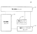
図1Aは、本発明の実施態様に係る第2アダプターの構成概略図である。図1Aの第2アダプター10は、電力変換ユニット11と、電圧フィードバックユニット12と、電流フィードバックユニット13と、電力調整ユニット14とを備えていてもよい。
FIG. 1A is a schematic configuration diagram of a second adapter according to an embodiment of the present invention. The
電力変換ユニット11は、入力された交流電流を変換して第2アダプター10の出力電圧及び出力電流を取得する。
The
電圧フィードバックユニット12の入力端が、電力変換ユニット11に接続され、電圧フィードバックユニット12は、第2アダプター10の出力電圧を測定して、第2アダプター10の出力電圧が所定の目標電圧に達するか否かを示すための電圧フィードバック信号を生成するために用いられる。
The input terminal of the
電流フィードバックユニット13の入力端が、電力変換ユニット11に接続され、電流フィードバックユニット13は、第2アダプター10の出力電流を測定して、第2アダプター10の出力電流が所定の目標電流に達するか否かを示すための電流フィードバック信号を生成するために用いられる。
The input terminal of the
電力調整ユニット14の入力端が、電圧フィードバックユニット12の出力端及び電流フィードバックユニット13の出力端に接続され、電力調整ユニット14の出力端が電力変換ユニット11に接続され、電力調整ユニット14は、電圧フィードバック信号と電流フィードバック信号とを受信し、電圧フィードバック信号が第2アダプター10の出力電圧が目標電圧に達することを示す、又は電流フィードバック信号が第2アダプター10の出力電流が目標電流に達することを示す場合に、第2アダプター10の出力電圧及び出力電流を安定させるために用いられる。
The input terminal of the
電力調整ユニット14が第2アダプター10の出力電圧及び出力電流を安定させるとは、電力調整ユニット14が、第2アダプター10の出力電圧及び出力電流を一定に維持するように、第2アダプター10を制御することを指してもよい。例えば、電力調整ユニット14がパルス幅変調(Pulse Width Modulation,PWM)に基づく電力調整ユニットであり、PWM制御信号の周波数及びデューティ比が一定に維持される場合に、第2アダプター10の出力電圧及び出力電流は、安定を維持することができる。
When the
本発明の実施形態に係る第2アダプターは、電圧フィードバックユニットと電流フィードバックユニットとの両方を含み、ここで、電圧フィードバックユニット、電力調整ユニット及び電力変換ユニットは、第2アダプターの出力電圧を閉ループ制御するためのハードウェア回路、即ちハードウェア式の電圧フィードバックループを形成し、電流フィードバックユニット、電力調整ユニット及び電力変換ユニットは、アダプターの出力電流を閉ループ制御するためのハードウェア回路、即ちハードウェア式の電流フィードバックループを形成する。ダブルループフィードバック制御に基づき、本発明の実施形態における電力調整ユニットは、電圧フィードバック信号及び電流フィードバック信号により提供されるフィードバック情報に基づいて、第2アダプターの出力電圧と第2アダプターの出力電流とのうちのいずれか一つが目標値に達する場合に、第2アダプターの出力電圧及び出力電流を安定させる。言い換えると、本発明の実施形態において、第2アダプターの出力電圧と出力電流とのうちのいずれか一つが目標値に達する場合、電力調整ユニットは、いずれの場合も直ちにこのイベントの発生を検知し、直ちにこのイベントに対して応答することができ、第2アダプターの出力電圧及び出力電流を安定させ、充電プロセスの安全性を向上させる。 The second adapter according to the embodiment of the present invention includes both a voltage feedback unit and a current feedback unit. Here, the voltage feedback unit, the power adjustment unit, and the power conversion unit control the output voltage of the second adapter in a closed loop. The hardware feedback circuit, that is, the hardware-type voltage feedback loop is formed, and the current feedback unit, the power adjustment unit, and the power conversion unit are the hardware circuit for controlling the output current of the adapter in a closed loop, that is, the hardware type Current feedback loop. Based on the double-loop feedback control, the power adjustment unit in the embodiment of the present invention is configured to calculate the output voltage of the second adapter and the output current of the second adapter based on feedback information provided by the voltage feedback signal and the current feedback signal. When any one of them reaches the target value, the output voltage and output current of the second adapter are stabilized. In other words, in the embodiment of the present invention, when any one of the output voltage and the output current of the second adapter reaches the target value, the power adjustment unit immediately detects the occurrence of this event in any case. Can respond immediately to this event, stabilize the output voltage and output current of the second adapter and improve the safety of the charging process.
定電圧モードを例として、電圧フィードバックループは、主に第2アダプターの出力電圧を定電圧モードに対応する電圧に調整する役割を担い、電流フィードバックループは、第2アダプターの出力電流が目標電流(この場合の目標電流は、定電圧モードにおいて出力が許容される最大電流であってもよい)に達するか否かを測定する役割を担うことができ、第2アダプターの出力電流が目標電流に達すると、電力調整ユニットは、電流フィードバックループにより直ちにこのイベントを検知し、第2アダプターの出力電流を適時に安定させ、その更なる増大を防止することができる。同様に、定電流モードにおいて、電流フィードバックループは、第2アダプターの出力電流を定電流モードに対応する電流に調整する役割を担うことができ、電圧フィードバックループは、第2アダプターの出力電圧が目標電圧(この場合の目標電圧は、定電流モードにおいて出力が許容される最大電圧であってもよい)に達するか否かを測定する役割を担うことができ、出力電圧が目標電圧に達すると、電力調整ユニットは、電圧フィードバックループにより直ちにこのイベントを検知し、第2アダプターの出力電圧を適時に安定させ、その更なる増大を防止することができる。 Taking the constant voltage mode as an example, the voltage feedback loop mainly plays a role of adjusting the output voltage of the second adapter to a voltage corresponding to the constant voltage mode, and the current feedback loop has the output current of the second adapter as a target current ( In this case, the target current may play a role of measuring whether or not the output current of the second adapter reaches the target current. Then, the power adjustment unit can immediately detect this event by the current feedback loop, stabilize the output current of the second adapter in a timely manner, and prevent further increase thereof. Similarly, in the constant current mode, the current feedback loop can play a role of adjusting the output current of the second adapter to a current corresponding to the constant current mode, and the voltage feedback loop has the target of the output voltage of the second adapter. Can be responsible for measuring whether the voltage (the target voltage in this case may be the maximum voltage allowed for output in constant current mode), and when the output voltage reaches the target voltage, The power adjustment unit can immediately detect this event by the voltage feedback loop, stabilize the output voltage of the second adapter in a timely manner, and prevent further increase thereof.
電圧フィードバック信号と電流フィードバック信号とは、両者によりフィードバックされる対象が異なることを指し、電圧フィードバック信号及び電流フィードバック信号の信号タイプを限定するわけではない。具体的には、電圧フィードバック信号は、第2アダプターの出力電圧をフィードバックするために用いられることができ、電流フィードバック信号は、第2アダプターの出力電流をフィードバックするために用いられることができるが、両者とも電圧信号であってもよい。 The voltage feedback signal and the current feedback signal indicate that the feedback targets are different from each other, and the signal types of the voltage feedback signal and the current feedback signal are not limited. Specifically, the voltage feedback signal can be used to feed back the output voltage of the second adapter, and the current feedback signal can be used to feed back the output current of the second adapter, Both may be voltage signals.
目標電圧は、予め設定された固定値であってもよく、調整可能な変量であってもよい。一部の実施例において、第2アダプター10は、実際の要求に応じて、一定の調節回路により目標電圧の電圧値を調節することができる。例えば、充電対象機器(端末)は、第2アダプターに目標電圧の調節命令を送信することができ、第2アダプター10は、該目標電圧の調節命令に基づいて目標電圧の電圧値を調節する。また他の一例として、第2アダプター10は、充電対象機器から電池の状態情報を受信し、電池の状態に基づいて目標電圧の電圧値をリアルタイムに調節することができる。同様に、目標電流は、予め設定された固定値であってもよいし、調整可能な変量であってもよい。一部の実施例において、第2アダプター10は、実際の要求に応じて、一定の調節回路により目標電流の電圧値を調節することができる。例えば、充電対象機器(端末)は、第2アダプター10に目標電流の調節命令を送信することができ、第2アダプター10は、該目標電流の調節命令に基づいて目標電流の電圧値を調節する。また他の一例として、第2アダプター10は、充電対象機器から電池の状態情報を受信し、電池の状態に基づいて目標電流の電流値をリアルタイムに調節することができる。
The target voltage may be a preset fixed value or an adjustable variable. In some embodiments, the
本発明の実施形態で使用される充電対象機器は、「通信端末」(又は「端末」と略する)であってもよく、有線回線を介して接続される(例えば、公衆交換電話網(public switched telephone network, PSTN)、デジタル加入者線(digital subscriber line, DSL)、デジタルケーブル、直接ケーブル接続、及び/又は別のデータネットワークを介して接続される)及び/又は(例えば、セルラーネットワーク、無線LAN(wireless local area network, WLAN)、例えば、デジタルビデオブロードキャスティングハンドヘルド(digital video broadcasting handheld,DVB−H)ネットワークのデジタルテレビネットワーク、衛星ネットワーク、振幅変調−周波数変調(amplitude modulation−frequency modulation, AM−FM)ラジオ送信機、及び/又は別の通信端末の)無線インターフェースを介して通信信号を受信、送信するように設けられる装置を含むが、これらに限定されない。無線インターフェースを介して通信するように構成される通信端末は、「無線通信端末」、「無線端末」及び/又は「携帯端末」と呼ばれてもよい。携帯端末の一例として、衛星又はセルラー電話と、セルラー無線電話、データ処理、ファックス及びデータ通信機能を組み合わせることのできる個人通信システム(personal communication system, PCS)端末と、無線電話、ポケベル、インターネット/イントラネットへのアクセス、Webブラウザ、ノートブック、カレンダー及び/又は全地球測位システム(global positioning system, GPS)受信機を含むことが可能であるパーソナルデジタルアシスタント(Personal Digital Assistant, PDA)と、一般的にはラップトップ型及び/又はパームトップ型受信機又は無線電話トランシーバーを含む他の電子装置とを含むが、これらに限定されない。 The charging target device used in the embodiment of the present invention may be a “communication terminal” (or abbreviated as “terminal”), and is connected via a wired line (for example, a public switched telephone network (public) connected via switched telephone network (PSTN), digital subscriber line (DSL), digital cable, direct cable connection, and / or another data network) and / or (eg, cellular network, wireless LAN (wireless local area network, WLAN), for example, digital video broadcasting handheld (DVB-H) network To receive and transmit communication signals via a digital television network, satellite network, amplitude modulation-frequency modulation (AM-FM) radio transmitter and / or another communication terminal radio interface Including, but not limited to, devices provided. A communication terminal configured to communicate via a wireless interface may be referred to as a “wireless communication terminal”, “wireless terminal” and / or “mobile terminal”. As an example of a portable terminal, a personal communication system (PCS) terminal capable of combining a satellite or cellular telephone and a cellular wireless telephone, data processing, fax and data communication functions, a wireless telephone, a pager, an Internet / intranet Personal digital assistants (PDAs), which can include access to, web browsers, notebooks, calendars and / or global positioning system (GPS) receivers, generally Including but not limited to laptop and / or palmtop receivers or other electronic devices including radiotelephone transceivers. No.
一部の実施例において、第2アダプター10は、第2アダプター10の知能度を向上させるために、充電プロセスを制御するための制御ユニット(図23におけるMCUを参照)を備えていてもよい。具体的には、制御ユニットは、充電対象機器(例えば、端末)の命令又は状態情報(状態情報は、充電対象機器電池の現在電圧及び/又は充電対象機器の温度等の状態情報を指してもよい)を取得するために、充電対象機器(例えば、端末)と双方向通信を行うために用いられることができ、これにより、充電対象機器(例えば、端末)の命令又は状態信号に基づいて第2アダプター10の充電対象機器(例えば、端末)に対する充電プロセスを制御する。一部の実施例において、該制御ユニットは、マイクロコントローラユニット(Microcontroller Unit,MCU)であってもよいが、本発明の実施例は、これに限定されず、他のタイプのチップ又は回路であってもよい。
In some embodiments, the
一部の実施例において、第2アダプター10は、充電インターフェース(図19Aの充電インターフェース191を参照)を備えていてもよいが、本発明の実施形態は、充電インターフェースのタイプについて具体的に限定せず、例えば、ユニバーサル・シリアル・バス(Universal Serial Bus,USB)インターフェースであってもよい。USBインターフェースは、標準USBインターフェースであってもよいし、micro USBインターフェースであってもよいし、Type−Cインターフェースであってもよい。
In some examples, the
第2アダプター10の充電モード又は機能は、目標電圧及び目標電流の選択につながり、第2アダプター10の充電モード又は機能が異なる場合、目標電圧及び目標電流の値は、若干異なってもよく、以下は、定電圧モード及び定電流モードを一例としてそれぞれ詳しく説明する。
The charging mode or function of the
好ましくは、一部の実施例において、第2アダプター10は、第1充電モードをサポートする(つまり、第2アダプター10は、第1充電モードで作動し、充電対象機器(例えば、端末)を充電することができる)。第1充電モードは、定電圧モードである。定電圧モードにおいて、第2アダプター10の目標電圧は、定電圧モードに対応する電圧である。目標電流は、第2アダプター10の定電圧モードにおける出力が許容される最大電流である。電力調整ユニット14は、具体的には、電圧フィードバック信号に基づいて、第2アダプター10の出力電圧を定電圧モードに対応する電圧に調整し、電流フィードバック信号は、第2アダプター10の出力電流が第2アダプター10の定電圧モードにおける出力が許容される最大電流に達することを示す場合、第2アダプター10の定電圧モードにおける出力が許容される最大電流を超えないように第2アダプター10の出力電流を制御する。
Preferably, in some embodiments, the
定電圧モードにおいて、第2アダプター10の出力電圧がある一定の電圧値に調節され、上記定電圧モードに対応する電圧は、即ち一定の電圧値である。例えば、定電圧モードにおいて、第2アダプター10の出力電圧が5Vであれば、定電圧モードに対応する電圧は5Vである。
In the constant voltage mode, the output voltage of the
本発明の実施例では、目標電圧を定電圧モードに対応する電圧に設定し、目標電流を定電圧モードにおいて第2アダプターの出力が許容される最大電流に設定する。このようにして、第2アダプターは、電圧フィードバックループにより、第2アダプターの出力電圧を定電圧モードに対応する電圧に急速に調整し、充電対象機器(例えば、端末)を定電圧充電により充電することができる。定電圧充電のプロセスにおいて、第2アダプターの出力電流(即ち負荷電流)が第2アダプターの出力が許容される最大電流に達すると、第2アダプターは、電流フィードバックループによりこの状況を適時に検知し、第2アダプターの出力電流の更なる上昇を適時に阻止することができ、充電故障の発生を回避し、第2アダプターの負荷電流に対する応答能力を向上させる。 In the embodiment of the present invention, the target voltage is set to a voltage corresponding to the constant voltage mode, and the target current is set to the maximum current allowed for the output of the second adapter in the constant voltage mode. In this way, the second adapter rapidly adjusts the output voltage of the second adapter to a voltage corresponding to the constant voltage mode by the voltage feedback loop, and charges the charging target device (for example, terminal) by constant voltage charging. be able to. In the constant voltage charging process, when the output current of the second adapter (ie, the load current) reaches the maximum current allowed for the output of the second adapter, the second adapter detects this situation in a timely manner by the current feedback loop. Further increase in the output current of the second adapter can be prevented in a timely manner, the occurrence of a charging failure can be avoided, and the response capacity of the second adapter to the load current can be improved.
一例を挙げて説明すると、定電圧モードにおいて、定電圧モードに対応する一定の電圧値が5Vである場合に、第2アダプターの出力電流は、一般的には、100mA〜200mAの間に維持する。この場合に、目標電圧を一定の電圧値(例えば、5V)に設定し、目標電流を500mA又は1Aに設定することができる。第2アダプターの出力電流が目標電流に対応する電流値に増加すると、電力調整ユニット14は、電流フィードバックループにより直ちにこのイベントの発生を検知し、第2アダプターの出力電流の更なる増加を阻止することができる。
For example, in the constant voltage mode, when the constant voltage value corresponding to the constant voltage mode is 5 V, the output current of the second adapter is generally maintained between 100 mA and 200 mA. . In this case, the target voltage can be set to a constant voltage value (for example, 5 V), and the target current can be set to 500 mA or 1 A. When the output current of the second adapter increases to a current value corresponding to the target current, the
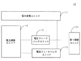
図1Bに示すように、上記実施例に基づき、電力変換ユニット11は、1次整流ユニット15と、トランス16と、2次整流ユニット17と、2次フィルタユニット18とを備え、1次整流ユニット15は、脈動式の電圧をトランス16に直接に出力する。
As shown in FIG. 1B, based on the above embodiment, the
従来技術において、電力変換ユニットは、1次側に位置する整流ユニットとフィルタユニットとを備え、その上、2次側に位置する整流ユニットとフィルタユニットとをさらに備える。1次側に位置する整流ユニットとフィルタユニットは、1次整流ユニットと1次フィルタユニットと称してもよい。2次側に位置する整流ユニットとフィルタユニットは、2次整流ユニットと2次フィルタユニットと称してもよい。1次フィルタユニットは、一般的には、液体アルミニウム電解コンデンサを採用してフィルタを行い、液体アルミニウム電解コンデンサの体積が比較的大きいので、アダプターの体積が比較的大きいである。 In the prior art, the power conversion unit includes a rectification unit and a filter unit located on the primary side, and further includes a rectification unit and a filter unit located on the secondary side. The rectification unit and the filter unit located on the primary side may be referred to as a primary rectification unit and a primary filter unit. The rectification unit and the filter unit located on the secondary side may be referred to as a secondary rectification unit and a secondary filter unit. The primary filter unit generally performs a filter by using a liquid aluminum electrolytic capacitor, and the volume of the liquid aluminum electrolytic capacitor is relatively large, so that the volume of the adapter is relatively large.
本発明の実施形態において、電力変換ユニット11は、1次整流ユニット15と、トランス16と、2次整流ユニット17と、2次フィルタユニット18とを備え、1次整流ユニット15は、脈動式の電圧をトランス16に直接に出力する。言い換えると、本発明の実施形態において提供される電力変換ユニット11は、1次フィルタユニットを備えず、このようにして、第2アダプター10の体積をかなりの程度まで減少することができ、第2アダプター10が益々携帯に便利である。2次フィルタユニット18は、主に固体アルミニウム電解コンデンサによりフィルタを行い、電力変換ユニット11における1次フィルタユニットを取り外した後、固体アルミニウム電解コンデンサの負荷能力には限界があるが、ハードウェア式の電流フィードバックループが存在するため、負荷電流の変化に適時に応答することができ、これにより、第2アダプターの過大な出力電流による充電故障を回避する。
In the embodiment of the present invention, the
上記1次フィルタユニットを取り外す方案において、第2アダプター10の定電圧モードにおける出力が許容される最大電流は、2次フィルタユニットにおけるコンデンサの容量に基づいて決定することができる。例えば、2次フィルタユニットにおけるコンデンサの容量に基づいて該2次フィルタユニットの受忍できる最大の負荷電流が500mA又は1Aと決定する場合、目標電流を500mA又は1Aに設けることができ、これにより、第2アダプターの出力電流が目標電流を超えるために引き起こされる充電故障を回避することができる。
In the method of removing the primary filter unit, the maximum current allowed to be output in the constant voltage mode of the
好ましくは、一部の実施形態において、第2アダプター10は、第2充電モードをサポートし(つまり、第2アダプター10は、第2充電モードで作動し、充電対象機器(例えば、端末)を充電することができる)、第2充電モードは、定電流モードである。定電流モードにおいて、目標電圧は、第2アダプター10の定電流モードにおける出力が許容される最大電圧であり、目標電流は、定電流モードに対応する電流である。電力調整ユニット14は、具体的には、電流フィードバック信号に基づいて、第2アダプター10の出力電流を定電流モードに対応する電流に調整し、電圧フィードバック信号は、第2アダプター10の出力電圧が第2アダプター10の定電流モードにおける出力が許容される最大電圧に達することを示す場合、第2アダプター10の定電流モードにおける出力が許容される最大電圧を超えないように第2アダプター10の出力電圧を制御する。
Preferably, in some embodiments, the
本発明の実施形態では、目標電流を定電流モードに対応する電流に設定し、目標電圧を定電流モードにおいて第2アダプターの出力が許容される最大電圧に設定し、このようにして、第2アダプターは、電流フィードバックループにより、第2アダプターの出力電流を定電流モードに対応する電流に急速に調整し、充電対象機器(例えば、端末)を充電し、充電プロセスにおいて、第2アダプターの出力電圧が第2アダプターの出力が許容される最大電圧に達すると、第2アダプターは、電圧フィードバックループによりこの状況を適時に検知し、第2アダプターの出力電圧の更なる上昇を適時に阻止することができ、充電故障の発生を回避する。 In the embodiment of the present invention, the target current is set to a current corresponding to the constant current mode, and the target voltage is set to the maximum voltage at which the output of the second adapter is allowed in the constant current mode. The adapter rapidly adjusts the output current of the second adapter to a current corresponding to the constant current mode by the current feedback loop, charges the charging target device (for example, terminal), and outputs the output voltage of the second adapter in the charging process. When the output of the second adapter reaches the maximum voltage allowed, the second adapter can detect this situation in a timely manner by the voltage feedback loop and prevent further increase in the output voltage of the second adapter in a timely manner. And avoid the occurrence of charging failure.
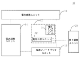
好ましくは、図2に示すように、上記いずれか一つの実施例に基づき、第2アダプター10は、第1調整ユニット21をさらに備える。第1調整ユニット21が電圧フィードバックユニット12に接続され、該第1調整ユニット21は、目標電圧の値を調整するために用いられることができる。
Preferably, as shown in FIG. 2, based on any one of the above embodiments, the
本発明の実施形態は、第1調整ユニットを導入した。第1調整ユニットは、実際の要求に応じて、第2アダプターの出力電圧を調整することができ、第2アダプターの知能度を向上させる。例えば、第2アダプター10は、第1充電モード又は第2充電モードで作動することができ、第1調整ユニット21は、第2アダプター10の現在使用している第1充電モード又は第2充電モードに基づいて目標電圧の値をそれに応じて調整することができる。
The embodiment of the present invention introduced the first adjustment unit. The first adjustment unit can adjust the output voltage of the second adapter according to the actual demand, thereby improving the intelligence of the second adapter. For example, the
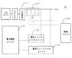
好ましくは、図2の実施形態に基づき、図3に示されるように、電圧フィードバックユニット12は、電圧サンプリングユニット31と、電圧比較ユニット32とを備えていてもよい。電圧サンプリングユニット31の入力端が、電力変換ユニット11に接続され、第2アダプター10の出力電圧をサンプリングして、第1電圧を取得するために用いられる。電圧比較ユニット32の入力端が電圧サンプリングユニット31の出力端に接続される。電圧比較ユニット32は、第1電圧と第1参考電圧とを比較し、第1電圧と第1参考電圧との比較結果に基づいて、電圧フィードバック信号を生成するために用いられる。第1調整ユニット21が電圧比較ユニット32に接続され、電圧比較ユニット32に第1参考電圧を提供し、第1調整ユニット21は、第1参考電圧の値を調整することにより、目標電圧の値を調整する目的を実現する。
Preferably, based on the embodiment of FIG. 2, the
なお、本発明の実施形態における第1電圧は、第2アダプターの出力電圧に対応し、又は、第1電圧は、第2アダプターの現在出力電圧の大きさを示すために用いられる。また、本発明の実施例における第1参考電圧は、目標電圧に対応し、又は、第1参考電圧は、目標電圧の大きさを示すために用いられる。 In addition, the 1st voltage in embodiment of this invention respond | corresponds to the output voltage of a 2nd adapter, or a 1st voltage is used in order to show the magnitude | size of the present output voltage of a 2nd adapter. In addition, the first reference voltage in the embodiment of the present invention corresponds to the target voltage, or the first reference voltage is used to indicate the magnitude of the target voltage.
一部の実施例において、第1電圧が第1参考電圧より小さい場合、電圧比較ユニットは、第2アダプターの出力電圧が目標電圧に達していないことを示すための第1電圧フィードバック信号を生成し、第1電圧が第1参考電圧に等しい場合、電圧比較ユニットは、第2アダプターの出力電圧が目標電圧に達することを示すための第2電圧フィードバック信号を生成する。 In some embodiments, if the first voltage is less than the first reference voltage, the voltage comparison unit generates a first voltage feedback signal to indicate that the output voltage of the second adapter has not reached the target voltage. If the first voltage is equal to the first reference voltage, the voltage comparison unit generates a second voltage feedback signal to indicate that the output voltage of the second adapter reaches the target voltage.
本発明の実施例は、電圧サンプリングユニット31の具体的な形式について限定せず、例えば、電圧サンプリングユニット31は、導線であってもよい。この場合、第1電圧は、即ち第2アダプターの出力電圧であり、第1参考電圧は、即ち目標電圧であり、また他の一例として、電圧サンプリングユニット31は、直列接続による電圧分割を行う二つの抵抗器を備えていてもよく、この場合、第1電圧は、該二つの抵抗器により電圧分割した後に得られる電圧であってもよい。第1参考電圧の値は、二つの抵抗器の電圧分割比に関連し、例えば、目標電圧が5Vに等しく、仮に第2アダプターの出力電圧が5Vに達する場合、二つの抵抗器の直列接続による電圧分割により、第1電圧を0.5Vとすると、第1参考電圧を0.5Vと設けることができる。
The embodiment of the present invention is not limited to a specific form of the
図3実施例における第1調整ユニット21が第1参考電圧を調整する方式は、複数であってもよく、以下は、図4から図6に組み合わせて詳しく説明する。
There may be a plurality of methods for adjusting the first reference voltage by the
好ましくは、一部の実施例において、図4に示されるように、第1調整ユニット21は、制御ユニット41と第1デジタルアナログコンバータ(Digital to Analog Converter,DAC)42とを備えていてもよい。DAC42の入力端が制御ユニット41に接続され、DAC42の出力端が電圧比較ユニット32に接続される。制御ユニット41は、第1のDAC42を介して第1参考電圧の値を調整する目的を実現する。
Preferably, in some embodiments, as shown in FIG. 4, the
具体的には、制御ユニット41は、MCUであってもよく、MCUは、DACポートを介して第1のDAC42に接続されてもよく、MCUは、DACポートによりデジタル信号を出力し、第1のDAC42によりデジタル信号をアナログ信号に変換し、該アナログ信号は、即ち第1参考電圧の電圧値である。DACは、信号の変換速度が速く、精度が高いという特性を有し、DACにより参考電圧を調整することは、第2アダプターの参考電圧に対する調節速度及び制御精度を向上させることができる。
Specifically, the
好ましくは、一部の実施例において、図5に示されるように、第1調整ユニット21は、制御ユニット51と、RCフィルタユニット52とを備えていてもよい。RCフィルタユニット52の入力端が制御ユニット51に接続され、RCフィルタユニット52の出力端が電圧比較ユニット32に接続される。制御ユニット51は、PWM信号を生成し、PWM信号のデューティ比を調整することにより第1参考電圧の値を調整するために用いられる。
Preferably, in some embodiments, as shown in FIG. 5, the
具体的には、制御ユニット51は、MCUであってもよく、MCUは、PWMポートによりPWM信号を出力し、PWM信号は、RCフィルタ回路52によりフィルタされた後、安定なアナログ量、即ち第1参考電圧を形成することができる。RCフィルタ回路52は、実現が簡単で、価格が安いという特性を有し、比較的低いコストで第1参考電圧の調節を実現することができる。
Specifically, the
好ましくは、一部の実施例において、図6に示されるように、第1調整ユニット21は、制御ユニット61と、デジタルポテンショメータ62とを備えていてもよい。デジタルポテンショメータ62の制御端が制御ユニット61に接続され、デジタルポテンショメータ62の出力端が電圧比較ユニット32に接続される。制御ユニット61は、デジタルポテンショメータ62の電圧分割比を調整することにより、第1参考電圧の値を調整する。
Preferably, in some embodiments, as shown in FIG. 6, the
具体的には、制御ユニット61は、MCUであってもよく、MCUは、アイ・スクウェア・シー(Inter Integrated Circuit,I2C)インターフェースを介してデジタルポテンショメータ62の制御端に接続され、デジタルポテンショメータ62の電圧分割比を調節するために用いられ、デジタルポテンショメータ62の高電位端は、VDD、即ち電源端であってもよく、デジタルポテンショメータ62の低電位端は、接地されてもよく、デジタルポテンショメータ62の出力端(又は調節出力端と称される)が電圧比較ユニット32に接続され、電圧比較ユニット32に第1参考電圧を出力するために用いられる。デジタルポテンショメータの実現が簡単で、価格が安く、比較的低いコストで第1参考電圧の調節を実現することができる。
Specifically, the
好ましくは、図2の実施例に基づき、図7に示すように、電圧フィードバックユニット12は、電圧分割ユニット71と、電圧比較ユニット72とを備えていてもよい。電圧分割ユニット71の入力端が、電力変換ユニット11に接続され、所定の電圧分割比に基づいて第2アダプター10の出力電圧を電圧分割し、第1電圧を生成するために用いられる。電圧比較ユニット72の入力端が電圧分割ユニット71の出力端に接続され、第1電圧と第1参考電圧とを比較し、第1電圧と第1参考電圧との比較結果に基づいて、電圧フィードバック信号を生成するために用いられる。第1調整ユニット21が電圧分割ユニット71に接続され、電圧分割ユニット71の電圧分割比を調整することにより、目標電圧の電圧値を調整する。
Preferably, based on the embodiment of FIG. 2, as shown in FIG. 7, the
図7の実施例と図3から図6の実施例との主な差異は、図3から図6の実施例が電圧比較ユニットの参考電圧を調整することにより目標電圧の電圧値の調整を実現し、図7の実施例が電圧分割ユニット71の電圧分割比を調整することにより目標電圧の電圧値の調整を実現することにある。言い換えると、図7の実施例において、第1参考電圧を固定値VREFに設けてもよく、第2アダプターの出力電圧が5Vであることが望ましいなら、電圧分割ユニット71の電圧分割比を調節して、第2アダプターの出力電圧が5Vである場合、電圧分割ユニット71の出力端の電圧をVREFに等しくすることができ、同様に、第2アダプターの出力電圧が3Vであることが望ましいなら、電圧分割ユニット71の電圧分割比を調整することにより、第2アダプターの出力電圧が3Vである場合、電圧分割ユニット71の出力端の電圧をVREFに等しくすることができる。
The main difference between the embodiment of FIG. 7 and the embodiment of FIGS. 3 to 6 is that the embodiment of FIGS. 3 to 6 can adjust the voltage value of the target voltage by adjusting the reference voltage of the voltage comparison unit. 7 is to realize the adjustment of the voltage value of the target voltage by adjusting the voltage division ratio of the
本発明の実施例は、電圧分割ユニットにより、第2アダプターの出力電圧のサンプリング及び目標電圧の電圧値の調整を実現し、第2アダプターの回路構造を簡素化する。 The embodiment of the present invention realizes sampling of the output voltage of the second adapter and adjustment of the voltage value of the target voltage by the voltage dividing unit, thereby simplifying the circuit structure of the second adapter.
本発明の実施例の電圧分割ユニット71の実現形態は、複数あり、例えば、デジタルポテンショメータを採用して実現してもよく、ディスクリート抵抗器、スイッチ等の素子により上記電圧分割及び電圧分割比調節という機能を実現してもよい。
There are a plurality of implementations of the
デジタルポテンショメータの実現形態を一例として、図8に示されるように、電圧分割ユニット71は、デジタルポテンショメータ81を備えていてもよい。第1調整ユニット21は、制御ユニット82を備えていてもよい。デジタルポテンショメータ81の高電位端が電力変換ユニット11に接続され、デジタルポテンショメータ81の低電位端が接地される。デジタルポテンショメータ81の出力端が電圧比較ユニット72の入力端に接続される。制御ユニット82がデジタルポテンショメータ81の制御端に接続され、デジタルポテンショメータ81の電圧分割比を調整するために用いられる。
Taking the implementation form of the digital potentiometer as an example, as shown in FIG. 8, the
上記電圧比較ユニット72の実現形態は、複数あり、一部の実施例において、図9に示されるように、電圧比較ユニット72は、第1オペアンプを備えていてもよい。第1オペアンプの逆相入力端は、第1電圧を受信するために用いられ、第1オペアンプの同相入力端は、第1参考電圧を受信するために用いられ、第1オペアンプの出力端は、電圧フィードバック信号を生成するために用いられる。第1オペアンプは、第1誤差増幅器又は電圧誤差増幅器と称されてもよい。
There are a plurality of implementations of the
好ましくは、図10に示されるように、上記いずれか一つの実施例に基づき、第2アダプター10は、第2調整ユニット101をさらに備えていてもよく、第2調整ユニット101が電流フィードバックユニット13に接続され、目標電流の電流値を調整するために用いられる。
Preferably, as shown in FIG. 10, based on any one of the above embodiments, the
本発明の実施例は、第2調整ユニットを導入し、第2調整ユニットは、実際の要求に応じて、第2アダプターの出力電流を調整し、第2アダプターの知能度を向上させる。例えば、第2アダプター10は、第1充電モード又は第2充電モードで作動し、第2調整ユニット101は、第2アダプター10の現在使用している第1充電モード又は第2充電モードに基づいて目標電流の電流値を調整する。
The embodiment of the present invention introduces a second adjustment unit, and the second adjustment unit adjusts the output current of the second adapter according to actual requirements, thereby improving the intelligence of the second adapter. For example, the
好ましくは、一部の実施例において、図10の実施例に基づき、図11に示されるように、電流フィードバックユニット13は、電流サンプリングユニット111と、電流比較ユニット112とを備えていてもよい。電流サンプリングユニット111の入力端が、電力変換ユニット11に接続され、第2アダプター10の出力電流をサンプリングして、第2アダプター10の出力電流の大きさを示すための第2電圧を取得するために用いられる。電流比較ユニット112の入力端が電流サンプリングユニット111の出力端に接続され、第2電圧と第2参考電圧とを比較し、第2電圧と第2参考電圧との比較結果に基づいて、電流フィードバック信号を生成するために用いられる。第2調整ユニット101が電流比較ユニット112に接続され、電流比較ユニット112に第2参考電圧を提供し、第2参考電圧の電圧値を調整することにより、目標電流の電流値を調整する。
Preferably, in some embodiments, based on the embodiment of FIG. 10, the
なお、本発明の実施例における第2電圧が第2アダプターの出力電流に対応し、又は第2電圧が第2アダプターの出力電流の大きさを示すために用いられる。また、本発明の実施例における第2参考電圧が目標電流に対応し、又は第2参考電圧が目標電流の大きさを示すために用いられる。 In the embodiment of the present invention, the second voltage corresponds to the output current of the second adapter, or the second voltage is used to indicate the magnitude of the output current of the second adapter. In addition, the second reference voltage in the embodiment of the present invention corresponds to the target current, or the second reference voltage is used to indicate the magnitude of the target current.
具体的には、第2電圧が第2参考電圧より小さい場合、電流比較ユニットは、第2アダプターの出力電流が目標電流に達していないことを示すための第1電流フィードバック信号を生成し、第2電圧が第2参考電圧に等しい場合、電流比較ユニットは、第2アダプターの出力電流が目標電流に達することを示すための第2電流フィードバック信号を生成する。 Specifically, if the second voltage is less than the second reference voltage, the current comparison unit generates a first current feedback signal to indicate that the output current of the second adapter has not reached the target current, If the two voltages are equal to the second reference voltage, the current comparison unit generates a second current feedback signal to indicate that the output current of the second adapter reaches the target current.
電流サンプリングユニット111が第2電圧を取得する方式は、具体的には、電流サンプリングユニット111は、先ず第2アダプターの出力電流をサンプリングして、サンプリング電流を取得する。そして、サンプリング電流の大きさに基づいて、それを対応するサンプリング電圧に変換する(サンプリング電圧値は、サンプリング電流値とサンプリング抵抗の積に等しい)。一部の実施例において、該サンプリング電圧を直接に第2電圧とすることができる。他の一部の実施例において、複数の抵抗器を採用して該サンプリング電圧を電圧分割し、電圧分割した後の電圧を第2電圧とすることもできる。電流サンプリングユニット111における電流サンプリング機能は、具体的には、検流計により実現することができる。
More specifically, the
図11の実施例における第2調整ユニットが第2参考電圧を調整する方式は、複数あってもよく、以下は、図12から図14に組み合わせて詳しく説明する。 There may be a plurality of methods by which the second adjustment unit in the embodiment of FIG. 11 adjusts the second reference voltage, and the following will be described in detail with reference to FIGS. 12 to 14.
好ましくは、一部の実施例において、図12に示されるように、第2調整ユニット101は、制御ユニット121と、第2のDAC122とを備えていてもよい。第2のDAC122の入力端が制御ユニット121に接続され、第2のDAC122の出力端が電流比較ユニット112に接続される。制御ユニット121は、第2のDAC122により第2参考電圧の電圧値を調整する。
Preferably, in some embodiments, as shown in FIG. 12, the
具体的には、制御ユニット121は、MCUであってもよい。MCUは、DACポートを介して第2のDAC122に接続されてもよい。MCUは、DACポートによりデジタル信号を出力し、第2のDAC122によりデジタル信号をアナログ信号に変換する。該アナログ信号は、即ち第1参考電圧の電圧値である。DACは、信号の変換速度が速く、精度が高いという特性を有し、DACにより参考電圧を調整することは、第2アダプターの参考電圧に対する調節速度及び制御精度を向上させることができる。
Specifically, the
好ましくは、一部の実施例において、図13に示されるように、第2調整ユニット101は、制御ユニット131とRCフィルタユニット132とを備えていてもよい。RCフィルタユニット132の入力端が制御ユニット131に接続され、RCフィルタユニット132の出力端が電流比較ユニット112に接続される。制御ユニット131は、PWM信号を生成し、PWM信号のデューティ比を調整することにより第2参考電圧の電圧値を調整するために用いられる。
Preferably, in some embodiments, as shown in FIG. 13, the
具体的には、制御ユニット131は、MCUであってもよい。MCUは、PWMポートによりPWM信号を出力する。PWM信号は、RCフィルタ回路132によりフィルタされた後、安定なアナログ量、即ち第2参考電圧を形成することができる。RCフィルタ回路132は、実現が簡単で、価格が安いという特性を有し、比較的低いコストで第2参考電圧の調節を実現することができる。
Specifically, the
好ましくは、一部の実施例において、図14に示されるように、第2調整ユニット101は、制御ユニット141と、デジタルポテンショメータ142とを備えていてもよい。デジタルポテンショメータ142の制御端が制御ユニット141に接続され、デジタルポテンショメータ142の出力端が電流比較ユニット112に接続される。制御ユニット141は、デジタルポテンショメータ142の電圧分割比を調整することにより、第2参考電圧の電圧値を調整する。
Preferably, in some embodiments, the
一部の実施例において、制御ユニット141は、MCUであってもよい。MCUは、I2Cインターフェースを介してデジタルポテンショメータ142の制御端に接続され、デジタルポテンショメータ142の電圧分割比を調節するために用いられる。デジタルポテンショメータ142の高電位端は、VDD、即ち電源端であってもよく、デジタルポテンショメータ142の低電位端は、接地されてもよい。デジタルポテンショメータ142の出力端(又は調節出力端と称される)が電流比較ユニット112に接続され、電流比較ユニット112に第2参考電圧を出力するために用いられる。デジタルポテンショメータの実現が簡単で、価格が安く、比較的低いコストで第2参考電圧の調節を実現することができる。
In some embodiments, the
好ましくは、一部の実施例において、図10の実施例に基づき、図15に示されるように、電流フィードバックユニット13は、電流サンプリングユニット151と、電圧分割ユニット152と、電流比較ユニット153とを備えていてもよい。電流サンプリングユニット151の入力端が、電力変換ユニット11に接続され、第2アダプター10の出力電流をサンプリングし、第2アダプター10の出力電流の大きさを示すための第3電圧を取得するために用いられる。電圧分割ユニット152の入力端が電流サンプリングユニット151の出力端に接続され、所定の電圧分割比に基づいて第3電圧を電圧分割し、第2電圧を生成するために用いられる。電流比較ユニット153の入力端が電圧分割ユニット152の出力端に接続され、第2電圧と第2参考電圧とを比較し、第2電圧と第2参考電圧との比較結果に基づいて、電流フィードバック信号を生成するために用いられる。第2調整ユニット101が電圧分割ユニット152に接続され、電圧分割ユニット152の電圧分割比を調整することにより、目標電流の電流値を調整する。
Preferably, in some embodiments, based on the embodiment of FIG. 10, as shown in FIG. 15, the
図15の実施例と図11から図14の実施例との主な差異は、図11から図14の実施例が電流比較ユニットの参考電圧を調整することにより目標電流の電流値の調整を実現し、図15の実施例が電圧分割ユニット152の電圧分割比を調整することにより目標電流の電流値の調整を実現することにある。言い換えると、図15の実施例において、第2参考電圧を固定値VREFに設けてもよく、第2アダプターの出力電流が300mVであることが望ましいなら、電圧分割ユニット152の電圧分割比を調節して、第2アダプターの出力電流が300mVである場合、電圧分割ユニット152の出力端の電圧をVREFに等しくすることができ、同様に、第2アダプターの出力電流が500mVであることが望ましいなら、電圧分割ユニット152の電圧分割比を調整することにより、第2アダプターの出力電流が500mVである場合、電圧分割ユニット152の出力端の電圧をVREFに等しくすることができる。
The main difference between the embodiment of FIG. 15 and the embodiment of FIGS. 11 to 14 is that the embodiment of FIGS. 11 to 14 realizes adjustment of the current value of the target current by adjusting the reference voltage of the current comparison unit. 15 is to realize the adjustment of the current value of the target current by adjusting the voltage division ratio of the
本発明の実施例の電圧分割ユニット152の実現形態は、複数あり、例えば、デジタルポテンショメータを採用して実現してもよく、ディスクリート抵抗器、スイッチ等の素子により上記電圧分割及び電圧分割比調節という機能を実現してもよい。
There are a plurality of implementations of the
デジタルポテンショメータの実現形態を例として、図16に示されるように、電圧分割ユニット152は、デジタルポテンショメータ161を備え、第2調整ユニット101は、制御ユニット162を備える。デジタルポテンショメータ161の高電位端が電流サンプリングユニット151の出力端に接続され、デジタルポテンショメータ161の低電位端が接地され、デジタルポテンショメータ161の出力端が電流比較ユニット153の入力端に接続される。制御ユニット162がデジタルポテンショメータ161の制御端に接続され、デジタルポテンショメータ161の電圧分割比を調整するために用いられる。
As an example of a digital potentiometer implementation, as shown in FIG. 16, the
上記制御ユニットは、一つの制御ユニットであってもよく、複数の制御ユニットであってもよい。一部の実施例において、上記第1調整ユニット及び第2調整ユニットにおける制御ユニットは、同一制御ユニットである。 The control unit may be a single control unit or a plurality of control units. In some embodiments, the control units in the first adjustment unit and the second adjustment unit are the same control unit.
上記電流比較ユニット153の実現形態は、複数あり、一部の実施例において、図17に示されるように、電流比較ユニット153は、第2オペアンプを備えていてもよい。第2オペアンプの逆相入力端は、第2電圧を受信するために用いられ、第2オペアンプの同相入力端は、第2参考電圧を受信するために用いられ、第2オペアンプの出力端は、電流フィードバック信号を生成するために用いられる。第2オペアンプは、第2誤差増幅器又は電流誤差増幅器と称されてもよい。
There are a plurality of implementations of the
以上は、図1から図17に組み合わせて、電圧フィードバックユニット12及び電流フィードバックユニット13の実現形態、並びに電圧フィードバックユニット12に対応する目標電圧及び電流フィードバックユニット13に対応する目標電流の調整方式について詳しく説明した。以下は、図18に組み合わせて、電力調整ユニット14の実現形態について詳しく説明する。
The above is a detailed description of the implementation of the
好ましくは、一部の実施例において、図18に示すように、電圧フィードバックユニット12は、第1オペアンプを備えていてもよく(図18に示されてないが、具体的には図9を参照してもよい)、電圧フィードバックユニット12の第1オペアンプの出力端は、電圧フィードバック信号を出力するために用いられる。電流フィードバックユニット13は、第2オペアンプを備えていてもよく(図18に示されてないが、具体的には図17を参照してもよい)、電流フィードバックユニット13の第2オペアンプの出力端は、電流フィードバック信号を出力するために用いられる。電力調整ユニット14は、第1ダイオードD1と、第2ダイオードD2と、光結合ユニット181と、PWM制御ユニット182とを備えていてもよい。電圧フィードバックユニット12の第1オペアンプ(図9を参照すると、第1オペアンプの出力端は、電圧フィードバック信号を出力するために用いられる)の出力端が第1ダイオードD1のカソードに接続される。第1ダイオードD1のアノードが光結合ユニット181の入力端に接続される。電流フィードバックユニット13の第2オペアンプの出力端(図17を参照すると、第2オペアンプの出力端は、電流フィードバック信号を出力するために用いられる)が第2ダイオードD2のカソードに接続される。第2ダイオードD2のアノードが光結合ユニット181の入力端に接続される。光結合ユニット181の出力端がPWM制御ユニット182の入力端に接続される。PWM制御ユニット182の出力端が電力変換ユニット11に接続される。
Preferably, in some embodiments, as shown in FIG. 18, the
なお、本文に現れる第1オペアンプは、同一オペアンプを指してもよい。同様に、本文に現れる第2オペアンプは、同一オペアンプを指してもよい。 The first operational amplifier appearing in the text may refer to the same operational amplifier. Similarly, the second operational amplifier appearing in the text may refer to the same operational amplifier.
具体的には、本実施例において、第1オペアンプから出力される電圧信号は、即ち電圧フィードバック信号であり、第2オペアンプから出力される電圧信号は、即ち電流フィードバック信号であり、第1オペアンプから出力される電圧信号が0である場合、第2アダプターの出力電圧が目標電圧に達することを示し、第2オペアンプから出力される電圧信号が0である場合、第2アダプターの出力端電流が目標電流に達することを示す。第1ダイオードD1と第2ダイオードD2とは、逆並列接続される二つのダイオードであり、第1オペアンプと第2オペアンプとのうちの何れか一つのオペアンプから出力される電圧信号が0である場合、図18におけるフィードバックポイントの電圧が約0である(ダイオードが導通するには、一定の電圧差が必要であるため、フィードバックポイントの実際の電圧は、0より若干大きく、例えば、0.7Vであってもよい)。この場合に、光結合ユニット181が安定状態で作動し、PWM制御ユニット182に安定な電圧信号を出力する。そして、PWM制御ユニット182が、デューティ比が一定のPWM制御信号を生成し、電力変換ユニット11により第2アダプターの出力電圧及び出力電流を安定させる。言い換えると、第2アダプターの出力電圧と出力電流とのうちのいずれか一つが目標値に達する場合、逆並列接続される第1ダイオードD1と第2ダイオードD2とは、直ちにこのイベントの発生を検知し、さらに、第2アダプターの出力電圧及び出力電流を安定させる。
Specifically, in this embodiment, the voltage signal output from the first operational amplifier is a voltage feedback signal, and the voltage signal output from the second operational amplifier is a current feedback signal. When the output voltage signal is 0, it indicates that the output voltage of the second adapter reaches the target voltage. When the voltage signal output from the second operational amplifier is 0, the output end current of the second adapter is the target. Indicates that the current is reached. The first diode D1 and the second diode D2 are two diodes connected in antiparallel, and the voltage signal output from any one of the first operational amplifier and the second operational amplifier is zero. The voltage at the feedback point in FIG. 18 is about 0 (since a certain voltage difference is necessary for the diode to conduct, the actual voltage at the feedback point is slightly larger than 0, for example, 0.7V. May be). In this case, the
好ましくは、一部の実施例において、第2アダプター10は、第1充電モード及び第2充電モードを有することができ、第2アダプター10の第2充電モードでの充電対象機器(例えば、端末)への充電速度が第2アダプター10の第1充電モードでの充電対象機器(例えば、端末)への充電速度より速い。言い換えると、第1充電モードで作動する第2アダプター10に比べて、第2充電モードで作動する第2アダプター10が同じ容量の充電対象機器(例えば、端末)におけるバッテリを満充電するのにかかる時間のほうがより短い。
Preferably, in some embodiments, the
第2アダプター10は、制御ユニットを備え、第2アダプター10が充電対象機器(例えば、端末)と接続されているプロセスにおいて、制御ユニットが充電対象機器(例えば、端末)と二方向通信して、第2充電モードの充電プロセスを制御する。制御ユニットは、上記いずれかの実施例における制御ユニットであってもよく、例えば、第1調整ユニットにおける制御ユニットであってもよいし第2調整ユニットにおける制御ユニットであってもよい。
The
第1充電モードは、普通充電モードであってもよい。第2充電モードは、急速充電モードであってもよい。普通充電モードとは、第2アダプターが比較的小さい電流値(一般的には2.5Aより小さい)を出力すること、又は比較的小さい電力(一般的には15Wより小さい)で充電対象機器(例えば、端末)におけるバッテリを充電することを指す。普通充電モードで比較的大容量のバッテリ(例えば、3000mAh容量のバッテリ)を完全に満充電しようとするなら、一般的には数時間をかける必要があるが、急速充電モードで、第2アダプターが比較的大きい電流(一般的には、2.5Aより大きく、例えば4.5A、5A、さらに高く)を出力し、又は比較的大きい電力(一般的には15W以上である)で充電対象機器(例えば、端末)におけるバッテリを充電することができる。普通充電モードに比べて、第2アダプターが急速充電モードで同じ容量のバッテリを完全に満充電するのに必要とする充電時間は、明らかに短縮することができ、充電速度がより速い。 The first charging mode may be a normal charging mode. The second charge mode may be a quick charge mode. In the normal charging mode, the second adapter outputs a relatively small current value (generally less than 2.5 A), or a device to be charged with relatively small power (generally less than 15 W) ( For example, it refers to charging a battery in a terminal. If you want to fully charge a battery with a relatively large capacity (for example, a battery with a capacity of 3000 mAh) in the normal charging mode, it usually takes several hours, but in the quick charging mode, the second adapter Output a relatively large current (typically larger than 2.5A, for example, 4.5A, 5A or even higher), or a device to be charged with relatively large power (typically 15W or more) ( For example, the battery in the terminal) can be charged. Compared to the normal charging mode, the charging time required for the second adapter to fully charge a battery of the same capacity in the fast charging mode can obviously be shortened and the charging speed is faster.
本発明の実施例は、第2アダプターの制御ユニットと充電対象機器(例えば、端末)との通信内容、及び制御ユニットが第2アダプターの第2充電モードでの出力を制御する方式について具体的に限定せず、例えば、制御ユニットは、充電対象機器(例えば、端末)と通信して、充電対象機器(例えば、端末)におけるバッテリの現在の電圧又は現在の電気量についてやりとりを行い、バッテリの現在の電圧又は現在の電気量に基づいて、第2アダプターの出力電圧又は出力電流を調整することができる。以下、具体的な実施例に組み合わせて、制御ユニットと充電対象機器(例えば、端末)との間の通信内容、及び制御ユニットが第2充電モードでの第2アダプターの出力を制御する方式について詳しく説明する。 The embodiment of the present invention specifically relates to communication contents between the control unit of the second adapter and the device to be charged (for example, a terminal), and a method in which the control unit controls the output of the second adapter in the second charging mode. Without limitation, for example, the control unit communicates with a charging target device (for example, a terminal), exchanges the current voltage or current amount of the battery in the charging target device (for example, the terminal), and The output voltage or output current of the second adapter can be adjusted based on the current voltage or the current amount of electricity. Hereinafter, in combination with specific embodiments, details of communication between the control unit and the charging target device (for example, a terminal) and a method in which the control unit controls the output of the second adapter in the second charging mode will be described in detail. explain.
好ましくは、一部の実施例において、制御ユニットが充電対象機器(例えば、端末)と二方向通信して、第2充電モードでの第2アダプターの出力を制御するプロセスは、制御ユニットが充電対象機器(例えば、端末)と二方向通信して、第2アダプターと充電対象機器(例えば、端末)との間の充電モードをネゴシエーションすることを含んでもよい。 Preferably, in some embodiments, the process of controlling the output of the second adapter in the second charging mode when the control unit communicates with the charging target device (for example, a terminal) in two directions is controlled by the control unit. It may include two-way communication with a device (for example, a terminal) and negotiating a charging mode between the second adapter and a device to be charged (for example, a terminal).
本発明の実施例において、第2アダプターは、第2充電モードを盲目的に採用して充電対象機器(例えば、端末)を急速充電するわけではなく、充電対象機器(例えば、端末)と二方向通信して、第2アダプターが第2充電モードで充電対象機器(例えば、端末)を急速充電してもよいか否かをネゴシエーションし、このようにすると、充電プロセスの安全性を向上させることができる。 In the embodiment of the present invention, the second adapter does not blindly adopt the second charging mode to rapidly charge the charging target device (for example, terminal), but in two directions with the charging target device (for example, terminal). Communicate and negotiate whether the second adapter may quickly charge the device to be charged (eg, terminal) in the second charging mode, and this can improve the safety of the charging process. it can.
具体的には、制御ユニットが充電対象機器(例えば、端末)と二方向通信して、第2アダプターと充電対象機器(例えば、端末)との間の充電モードをネゴシエーションすることは、制御ユニットが、充電対象機器(例えば、端末)が第2充電モードをオンにするか否かを問い合わせるための第1コマンドを充電対象機器(例えば、端末)に送信することと、制御ユニットが、充電対象機器(例えば、端末)から送信された、充電対象機器(例えば、端末)が第2充電モードをオンにすることに同意するか否かを示すための第1コマンドに対する返信コマンドを受信することと、充電対象機器(例えば、端末)が第2充電モードをオンにすることに同意した場合に、制御ユニットが第2充電モードで充電対象機器(例えば、端末)を充電することとを含んでもよい。 Specifically, the control unit negotiates the charging mode between the second adapter and the charging target device (eg, terminal) through two-way communication with the charging target device (eg, terminal). The charging target device (for example, the terminal) transmits a first command for inquiring whether or not to turn on the second charging mode to the charging target device (for example, the terminal); Receiving a reply command to the first command for indicating whether or not the charging target device (for example, the terminal) agrees to turn on the second charging mode, transmitted from the (for example, the terminal); When the charging target device (for example, terminal) agrees to turn on the second charging mode, the control unit charges the charging target device (for example, terminal) in the second charging mode. Toto may also include.
本発明の実施例の上記説明は、第2アダプター(又は第2アダプターの制御ユニット)と充電対象機器(例えば、端末)とのマスター及びスレーブを限定することはない。言い換えると、制御ユニットと充電対象機器(例えば、端末)とのうちいずれか一方がマスター装置側として、二方向通信セッションを開始することができる。相応的に、他方がスレーブ装置側としてマスター装置側が開始する通信に対して第1レ応答又は第1返信を出す。一種の実行可能な方式として、通信プロセスにおいて、第2アダプター側及び充電対象機器(例えば、端末)側のアースに対するレベルの高さを比較することにより、マスター及びスレーブ装置の身分を確認することができる。 The above description of the embodiment of the present invention does not limit the master and slave of the second adapter (or the control unit of the second adapter) and the charging target device (for example, a terminal). In other words, a two-way communication session can be started with either the control unit or the charging target device (for example, a terminal) as the master device side. Correspondingly, a first response or a first reply is issued in response to communication initiated by the master device side as the slave device side. As a kind of feasible method, in the communication process, it is possible to confirm the status of the master and slave devices by comparing the level of ground level on the second adapter side and the device to be charged (eg terminal) side it can.
本発明の実施例は、第2アダプター(又は第2アダプターの制御ユニット)と充電対象機器(例えば、端末)との間の二方向通信の具体的な実現方式を限定していない。つまり、第2アダプター(又は第2アダプターの制御ユニット)と充電対象機器(例えば、端末)とのうちいずれか一方がマスター装置側として通信セッションを開始して、相応的に、他方がスレーブ装置側として、マスター装置側が開始する通信セッションに対して第1レ応答又は第1返信を出す。同時に、マスター装置側は、スレーブ装置側からの第1応答又は第1返信に対して第2応答することができる。即ち、マスター及びスレーブ装置の間で一回の充電モードに関するネゴシエーションプロセスが完成されたと考えてもよい。一種の実行可能な実施方式として、マスター及びスレーブ装置側の間で複数回の充電モードに関するネゴシエーションが完成された後、マスター及びスレーブ装置側の間の充電操作を実行することにより、ネゴシエーション後の充電プロセスが安全かつ確実に実行されることを確保することができる。 The embodiment of the present invention does not limit a specific implementation method of two-way communication between the second adapter (or the control unit of the second adapter) and the charging target device (for example, a terminal). That is, one of the second adapter (or the control unit of the second adapter) and the charging target device (for example, a terminal) starts the communication session as the master device side, and the other is correspondingly the slave device side. As a result, the first response or the first reply is issued to the communication session started by the master device side. At the same time, the master device side can make a second response to the first response or the first reply from the slave device side. That is, it may be considered that the negotiation process regarding the single charging mode is completed between the master and the slave devices. As a kind of feasible implementation method, charging after negotiation is performed by executing a charging operation between the master and slave device side after the completion of the negotiation regarding the multiple charging modes between the master and slave device side. It can be ensured that the process is executed safely and reliably.
マスター装置側として、スレーブ装置側の通信セッションに対する第1応答又は第1返信に応じて第2応答を出すことができる一つの方式は、マスター装置側がスレーブ装置側の通信セッションに対する第1応答又は第1返信を受信し、受信されたスレーブ装置の第1応答又は第1返信に応じて対応性のある第2応答を出すことができる方式であってもよい。一例として、マスター装置側が所定時間内でスレーブ装置側の通信セッションに対する第1応答又は第1返信を受信した場合に、マスター装置側は、スレーブ装置の第1応答又は第1返信に対して対応性のある第2応答を出すことは、具体的に、マスター装置側とスレーブ装置側とが一回の充電モードに関するネゴシエーションを完成し、マスター装置側とスレーブ装置側との間がネゴシエーションの結果に基づいて、第1充電モード又は第2充電モードに従って充電操作を実行し、即ち、第2アダプターがネゴシエーションの結果に基づいて、第1充電モード又は第2充電モードで作動して充電対象機器(例えば、端末)を充電する。 One method by which the master device side can send a second response in response to a first response or a first reply to a communication session on the slave device side is as follows: The system may be such that one reply is received and a corresponding second response can be issued in response to the received first response or first reply of the slave device. As an example, when the master device side receives the first response or the first reply for the communication session on the slave device side within a predetermined time, the master device side responds to the first response or the first reply of the slave device. In other words, the master device side and the slave device side have completed the negotiation for one charge mode, and the master device side and the slave device side are based on the result of the negotiation. The charging operation is performed according to the first charging mode or the second charging mode, i.e., the second adapter is operated in the first charging mode or the second charging mode based on a result of the negotiation to be charged (for example, Device).
マスター装置側として、スレーブ装置側の通信セッションに対する第1応答又は第1返信に応じて、更に第2応答を出すことができる一つの方式は、マスター装置側が所定時間内でスレーブ装置側の通信セッションに対する第1応答又は第1返信を受信していなくても、マスター装置側がスレーブ装置の第1応答又は第1返信に対して対応性のある第2応答を出すことであってもよい。一例として、マスター装置側が所定時間内でスレーブ装置側の通信セッションに対する第1応答又は第1返信を受信していなくても、マスター装置側がスレーブ装置の第1応答又は第1返信に対して対応性のある第2応答を出すことは、具体的に、マスター装置側とスレーブ装置側とが一回の充電モードに関するネゴシエーションを完成し、マスター装置側とスレーブ装置側との間で第1充電モードに従って充電操作が実行され、即ち、第2アダプターが第1充電モードで作動して充電対象機器(例えば、端末)を充電する。 As a master device side, one method in which a second response can be further issued in response to a first response or a first reply to a communication session on the slave device side is that the master device side has a communication session on the slave device side within a predetermined time. Even if the first response or the first response to the master device is not received, the master device side may issue a second response that corresponds to the first response or the first response of the slave device. As an example, even if the master device side does not receive the first response or the first reply for the communication session on the slave device side within a predetermined time, the master device side supports the first response or the first reply of the slave device. In other words, the master device side and the slave device side have completed the negotiation regarding the charge mode once, and the master device side and the slave device side follow the first charge mode. A charging operation is performed, that is, the second adapter operates in the first charging mode to charge a device to be charged (for example, a terminal).
好ましくは、一部の実施例において、充電対象機器(例えば、端末)がマスター装置として、通信セッションを開始する場合に、第2アダプター(又は第2アダプターの制御ユニット)がスレーブ装置として、マスター装置側が開始する通信セッションに対して第1応答又は第1返信を出した後、充電対象機器(例えば、端末)が第2アダプターの第1応答又は第1返信に対して対応性のある第2応答を出さなくても、第2アダプター(又は第2アダプターの制御ユニット)と充電対象機器(例えば、端末)との間で一回の充電モードに関するネゴシエーションプロセスが完成されたと考えてもよい。さらに、第2アダプターがネゴシエーション結果に基づいて第1充電モード又は第2充電モードで充電対象機器(例えば、端末)を充電することを決定することができる。 Preferably, in some embodiments, the charging target device (eg, terminal) is the master device, and when the communication session is started, the second adapter (or the control unit of the second adapter) is the slave device, and the master device. After issuing a first response or a first reply to the communication session started by the side, the charging target device (for example, a terminal) is compatible with the first response or the first reply of the second adapter. It may be considered that the negotiation process for one charge mode has been completed between the second adapter (or the control unit of the second adapter) and the charging target device (for example, a terminal). Furthermore, it can be determined that the second adapter charges the device to be charged (for example, a terminal) in the first charging mode or the second charging mode based on the negotiation result.
好ましくは、一部の実施例において、制御ユニットが充電対象機器(例えば、端末)と二方向通信して、第2アダプターの第2充電モードでの出力を制御するプロセスは、制御ユニットが充電対象機器(例えば、端末)と二方向通信して、第2充電モードでの第2アダプターから出力された充電対象機器(例えば、端末)を充電するための充電電圧を決定することと、制御ユニットが目標電圧の電圧値を調整して、目標電圧の電圧値が、第2充電モードでの第2アダプターから出力された充電対象機器(例えば、端末)を充電するための充電電圧と等しくなるようにすることとを含んでもよい。 Preferably, in some embodiments, the process in which the control unit performs two-way communication with a charging target device (eg, a terminal) and controls the output of the second adapter in the second charging mode is performed by the control unit. Two-way communication with a device (for example, a terminal), determining a charging voltage for charging a device to be charged (for example, a terminal) output from the second adapter in the second charging mode; The voltage value of the target voltage is adjusted so that the voltage value of the target voltage becomes equal to the charging voltage for charging the charging target device (for example, the terminal) output from the second adapter in the second charging mode. May include.
具体的には、制御ユニットが充電対象機器(例えば、端末)と二方向通信して、第2充電モードでの第2アダプターから出力された充電対象機器(例えば、端末)を充電するための充電電圧を決定することは、制御ユニットが、第2アダプターの出力電圧と充電対象機器(例えば、端末)のバッテリの現在の電圧とがマッチングしているか否かを問い合わせるための第2コマンドを充電対象機器(例えば、端末)に送信することと、制御ユニットが、充電対象機器(例えば、端末)から送信された、第2アダプターの出力電圧とバッテリの現在の電圧とがマッチングしている、高めである又は低めであることを示すための第2コマンドの返信コマンドを受信することとを含んでもよい。代替的には、第2コマンドは、第2アダプターの現在の出力電圧を第2充電モードでの第2アダプターから出力された充電対象機器(例えば、端末)を充電するための充電電圧とするのが適切であるか否かを問い合わせることができる。第2コマンドの返信コマンドは、現在の第2アダプターの出力電圧が適切である、高め又は低めであることを示すことができる。第2アダプターの現在の出力電圧とバッテリの現在の電圧とがマッチングしている、又は第2アダプターの現在の出力電圧が第2充電モードでの第2アダプターから出力された充電対象機器(例えば、端末)を充電するための充電電圧として適切であることとは、第2アダプターの現在の出力電圧が、バッテリの現在の電圧よりやや高く、且つ第2アダプターの出力電圧とバッテリの現在の電圧との間の差が所定範囲内(一般的には、数百ミリボルトの等級)にあることを指してもよい。 Specifically, the control unit performs two-way communication with a charging target device (for example, a terminal), and charging for charging the charging target device (for example, the terminal) output from the second adapter in the second charging mode. Determining the voltage means that the control unit issues a second command for inquiring whether or not the output voltage of the second adapter matches the current voltage of the battery of the charging target device (eg, terminal). Transmitting to the device (eg, terminal), and the control unit matches the output voltage of the second adapter and the current voltage of the battery transmitted from the device to be charged (eg, terminal). Receiving a return command of a second command to indicate that the current command is lower or higher. Alternatively, the second command uses the current output voltage of the second adapter as a charging voltage for charging the charging target device (eg, terminal) output from the second adapter in the second charging mode. Can be queried as to whether it is appropriate. The return command of the second command can indicate that the current output voltage of the second adapter is appropriate, higher or lower. The current output voltage of the second adapter matches the current voltage of the battery, or the current output voltage of the second adapter is output from the second adapter in the second charging mode (for example, Appropriate as a charging voltage for charging the terminal is that the current output voltage of the second adapter is slightly higher than the current voltage of the battery, and the output voltage of the second adapter and the current voltage of the battery May be within a predetermined range (typically on the order of hundreds of millivolts).
好ましくは、一部の実施例において、制御ユニットが充電対象機器(例えば、端末)と二方向通信して、第2充電モードでの第2アダプターの出力を制御するプロセスは、制御ユニットが充電対象機器(例えば、端末)と二方向通信して、第2充電モードでの第2アダプターから出力された充電対象機器(例えば、端末)を充電するための充電電流を決定することと、制御ユニットが目標電流の電流値を調整して、目標電流の電流値が、第2充電モードでの第2アダプターから出力された充電対象機器(例えば、端末)を充電するための充電電流と等しくなるようにすることとを含んでもよい。 Preferably, in some embodiments, the process of controlling the output of the second adapter in the second charging mode when the control unit communicates with the charging target device (for example, a terminal) in two directions is controlled by the control unit. A two-way communication with a device (for example, a terminal), determining a charging current for charging a device to be charged (for example, a terminal) output from the second adapter in the second charging mode; The current value of the target current is adjusted so that the current value of the target current becomes equal to the charging current for charging the charging target device (for example, the terminal) output from the second adapter in the second charging mode. May include.
具体的には、制御ユニットが充電対象機器(例えば、端末)と二方向通信して、第2充電モードでの第2アダプターから出力された充電対象機器(例えば、端末)を充電するための充電電流を決定することは、制御ユニットが、充電対象機器(例えば、端末)の現在サポートする最大充電電流を問い合わせるための第3コマンドを充電対象機器(例えば、端末)に送信することと、制御ユニットが、充電対象機器(例えば、端末)から送信された充電対象機器(例えば、端末)の現在サポートする最大充電電流を示すための第3コマンドの返信コマンドを受信することと、制御ユニットが充電対象機器(例えば、端末)の現在サポートする最大充電電流に基づいて、第2充電モードでの第2アダプターから出力された充電対象機器(例えば、端末)を充電するための充電電流を決定することとを含んでもよい。なお、制御ユニットが充電対象機器(例えば、端末)の現在サポートする最大充電電流に基づいて、第2充電モードでの第2アダプターから出力された充電対象機器(例えば、端末)を充電するための充電電流を決定する方式は複数あり、例えば、第2アダプターは、充電対象機器(例えば、端末)の現在サポートする最大充電電流を第2充電モードでの第2アダプターから出力された充電対象機器(例えば、端末)を充電するための充電電流として決定してもよいし、充電対象機器(例えば、端末)の現在サポートする最大充電電流及び自身の電流出力能力などの要素を総合的に考慮した後、第2充電モードでの第2アダプターから出力された充電対象機器(例えば、端末)を充電するための充電電流を決定してもよい。 Specifically, the control unit performs two-way communication with a charging target device (for example, a terminal), and charging for charging the charging target device (for example, the terminal) output from the second adapter in the second charging mode. Determining the current includes transmitting a third command for inquiring a maximum charging current currently supported by the charging target device (eg, terminal) to the charging target device (eg, terminal); Receives a return command of the third command for indicating the maximum charging current currently supported by the charging target device (eg, terminal) transmitted from the charging target device (eg, terminal), and the control unit is charged Based on the currently supported maximum charging current of the device (eg, terminal), the device to be charged (eg, output from the second adapter in the second charging mode) And it may include determining a charging current for charging the powder). The control unit is for charging the charging target device (for example, terminal) output from the second adapter in the second charging mode based on the maximum charging current that is currently supported by the charging target device (for example, terminal). There are a plurality of methods for determining the charging current. For example, the second adapter uses the charging target device (for example, the terminal) that is currently supported by the charging target device (for example, the terminal) and is output from the second adapter in the second charging mode ( For example, it may be determined as a charging current for charging the terminal), or after comprehensively considering factors such as the maximum charging current currently supported by the charging target device (for example, the terminal) and its own current output capability The charging current for charging the charging target device (for example, the terminal) output from the second adapter in the second charging mode may be determined.
好ましくは、一部の実施例において、制御ユニットが充電対象機器(例えば、端末)と二方向通信して、第2充電モードでの第2アダプターの出力を制御するプロセスは、第2アダプターが第2充電モードで充電対象機器(例えば、端末)を充電するプロセスにおいて、制御ユニットが充電対象機器(例えば、端末)と二方向通信して、第2充電モードでの第2アダプターの出力電流を調整することを含んでもよい。 Preferably, in some embodiments, the process in which the control unit communicates with the charging target device (eg, terminal) in two directions and controls the output of the second adapter in the second charging mode is performed by the second adapter. In the process of charging the charging target device (for example, terminal) in the two charging mode, the control unit communicates with the charging target device (for example, terminal) in two directions to adjust the output current of the second adapter in the second charging mode. May include.
具体的には、制御ユニットが充電対象機器(例えば、端末)と二方向通信して、第2アダプターの出力電流を調整することは、制御ユニットが充電対象機器(例えば、端末)のバッテリの現在の電圧を問い合わせるための第4コマンドを充電対象機器(例えば、端末)に送信することと、制御ユニットが、第2アダプターから送信された、バッテリの現在の電圧を示すための第4コマンドの返信コマンドを受信することと、制御ユニットがバッテリの現在の電圧に基づいて、第2アダプターの出力電流を調整することとを含んでもよい。 Specifically, the control unit communicates with the charging target device (for example, the terminal) in two directions and adjusts the output current of the second adapter, so that the control unit presents the current battery of the charging target device (for example, the terminal). Transmitting a fourth command for inquiring the voltage of the battery to the device to be charged (for example, a terminal), and returning a fourth command for indicating the current voltage of the battery transmitted from the second adapter by the control unit. Receiving the command and the control unit adjusting the output current of the second adapter based on the current voltage of the battery.
好ましくは、一部の実施例において、図19Aに示すように、第2アダプター10は、充電インターフェース191を備える。さらに、一部の実施例において、第2アダプター10における制御ユニット(図23に示すMCU)は、充電インターフェース191におけるデータケーブル192を介して充電対象機器(例えば、端末)と二方向通信することができる。
Preferably, in some embodiments, the
好ましくは、一部の実施例において、制御ユニットが充電対象機器(例えば、端末)と二方向通信して、第2充電モードでの第2アダプターの出力を制御するプロセスは、制御ユニットが充電対象機器(例えば、端末)と二方向通信して、充電インターフェースが接触不良であるか否かを決定することを含んでもよい。 Preferably, in some embodiments, the process of controlling the output of the second adapter in the second charging mode when the control unit communicates with the charging target device (for example, a terminal) in two directions is controlled by the control unit. It may include two-way communication with a device (eg, a terminal) to determine whether the charging interface is in poor contact.
具体的には、制御ユニットが充電対象機器(例えば、端末)と二方向通信して、充電インターフェースが接触不良であるか否かを決定することは、制御ユニットが、充電対象機器(例えば、端末)のバッテリの現在の電圧を問い合わせるための第4コマンドを充電対象機器(例えば、端末)に送信することと、制御ユニットが、充電対象機器(例えば、端末)から送信された、充電対象機器(例えば、端末)のバッテリの現在の電圧を示すための第4コマンドの返信コマンドを受信することと、制御ユニットが第2アダプターの出力電圧及び充電対象機器(例えば、端末)のバッテリの現在の電圧に基づいて、充電インターフェースが接触不良であるか否かを決定することとを含んでもよい。例えば、制御ユニットが第2アダプターの出力電圧と充電対象機器(例えば、端末)の現在の電圧との電圧差が所定電圧閾値より大きいと決定すると、この場合の電圧差を第2アダプターから出力された現在の電流値で割って得られる抵抗値が、所定抵抗閾値より大きいであることを表し、充電インターフェースが接触不良であると決定することができる。 Specifically, when the control unit performs two-way communication with a charging target device (for example, a terminal) and determines whether or not the charging interface has poor contact, ) To transmit the fourth command for inquiring the current voltage of the battery to the charging target device (for example, terminal), and the control unit transmits the charging target device (for example, the terminal) For example, receiving a return command of a fourth command for indicating the current voltage of the battery of the terminal), and the control unit outputs the output voltage of the second adapter and the current voltage of the battery of the charging target device (for example, the terminal) And determining whether the charging interface is in poor contact. For example, if the control unit determines that the voltage difference between the output voltage of the second adapter and the current voltage of the charging target device (eg, terminal) is greater than a predetermined voltage threshold, the voltage difference in this case is output from the second adapter. It can be determined that the resistance value obtained by dividing by the current current value is larger than a predetermined resistance threshold value, and the charging interface is in a poor contact state.
好ましくは、一部の実施例において、充電インターフェースが接触不良であることは、充電対象機器(例えば、端末)によって決定されてもよい。充電対象機器(例えば、端末)が第2アダプターの出力電圧を問い合わせるための第6コマンドを制御ユニットに送信し、充電対象機器(例えば、端末)が、制御ユニットから送信された、第2アダプターの出力電圧を示すための第6コマンドの返信コマンドを受信し、充電対象機器(例えば、端末)が充電対象機器(例えば、端末)のバッテリの現在の電圧及び第2アダプターの出力電圧に基づいて、充電インターフェースが接触不良であるか否かを決定する。充電対象機器(例えば、端末)が、充電インターフェースが接触不良であると決定した後、充電対象機器(例えば、端末)が、充電インターフェースが接触不良であることを示すための第5コマンドを制御ユニットに送信する。制御ユニットが第5コマンドを受信した後、第2充電モードを終了するように第2アダプターを制御することができる。 Preferably, in some embodiments, the contact failure of the charging interface may be determined by a charging target device (for example, a terminal). The charging target device (for example, terminal) transmits a sixth command for inquiring the output voltage of the second adapter to the control unit, and the charging target device (for example, terminal) of the second adapter is transmitted from the control unit. Based on the current voltage of the battery of the charging target device (for example, the terminal) and the output voltage of the second adapter, the charging target device (for example, the terminal) receives a reply command of the sixth command for indicating the output voltage, Determine whether the charging interface is in poor contact. After the charging target device (for example, terminal) determines that the charging interface has a poor contact, the charging target device (for example, the terminal) sends a fifth command for indicating that the charging interface has a poor contact to the control unit. Send to. After the control unit receives the fifth command, the second adapter can be controlled to end the second charging mode.
以下、図19Bに組み合わせて、第2アダプターにおける制御ユニットと充電対象機器(例えば、端末)との間の通信プロセスをさらに詳しく説明する。なお、図19Bの一例は、ただ当業者が本発明の実施例を理解するのに力を添えるためのものであって、本発明の実施例を例示された具体的な数値又は具体的な場面に限定するためのものではない。当業者は、図19Bに示される一例に基づいて、各種同等の修正又は変更を行うことができるのが明らかなことであり、このような修正又は変更も本発明の実施例の範囲内に該当する。 Hereinafter, in combination with FIG. 19B, a communication process between the control unit and the charging target device (for example, a terminal) in the second adapter will be described in more detail. Note that the example in FIG. 19B is merely for helping those skilled in the art to understand the embodiment of the present invention, and is a specific numerical value or a specific scene illustrating the embodiment of the present invention. It is not meant to be limited to. It will be apparent to those skilled in the art that various equivalent modifications or changes can be made based on the example shown in FIG. 19B, and such modifications or changes fall within the scope of the embodiments of the present invention. To do.
図19Bに示されるように、第2充電モードでの第2アダプターの出力で充電対象機器(例えば、端末)を充電するプロセス、即ち充電プロセスは、五つの段階を含んでもよい。 As shown in FIG. 19B, the process of charging the device to be charged (for example, the terminal) with the output of the second adapter in the second charging mode, that is, the charging process may include five stages.
段階1:
充電対象機器(例えば、端末)が電源供給装置に接続された後、充電対象機器(例えば、端末)は、データケーブルD+、D−を介して電源供給装置のタイプを検出することができる。電源供給装置が第2アダプターであることを検出した場合に、充電対象機器(例えば、端末)が受け入れた電流は、所定電流閾値I2(例えば1Aであってもよい)より大きくてもよい。第2アダプターにおける制御ユニットが所定持続時間(例えば、連続的なT1時間)内で第2アダプターの出力電流がI2以上であることを検出した場合に、制御ユニットは、充電対象機器(例えば、端末)の電源供給装置のタイプを認識することが既に完成されたと判定してもよい。制御ユニットは、第2アダプターと充電対象機器(例えば、端末)との間のネゴシエーションプロセスを開始し、コマンド1(上記第1コマンドに対応する)を充電対象機器(例えば、端末)に送信して、充電対象機器(例えば、端末)が、第2アダプターが第2充電モードで充電対象機器(例えば、端末)を充電することに同意するか否かを問い合わせる。
Stage 1:
After the charging target device (for example, a terminal) is connected to the power supply device, the charging target device (for example, the terminal) can detect the type of the power supply device via the data cables D + and D−. When it is detected that the power supply device is the second adapter, the current received by the device to be charged (for example, the terminal) may be larger than a predetermined current threshold I2 (for example, 1A). When the control unit in the second adapter detects that the output current of the second adapter is equal to or greater than I2 within a predetermined duration (for example, continuous T1 time), the control unit determines that the device to be charged (for example, the terminal It may be determined that the recognition of the type of the power supply device is already completed. The control unit starts a negotiation process between the second adapter and the charging target device (eg, terminal), and sends a command 1 (corresponding to the first command) to the charging target device (eg, terminal). The charging target device (for example, terminal) inquires whether or not the second adapter agrees to charge the charging target device (for example, terminal) in the second charging mode.
制御ユニットが、充電対象機器(例えば、端末)から送信された、コマンド1の返信コマンドを受信し、且つ該コマンド1の返信コマンドが、充電対象機器(例えば、端末)が、第2アダプターが第2充電モードで充電対象機器(例えば、端末)を充電することに同意しないと示した場合に、制御ユニットは、第2アダプターの出力電流を再度に検出する。第2アダプターの出力電流が所定連続する時間内(例えば、可以は、連続的なT1時間)で依然としてI2以上である場合に、制御ユニットは、充電対象機器(例えば、端末)にコマンド1を再送信し、充電対象機器(例えば、端末)が、第2アダプターが第2充電モードで充電対象機器(例えば、端末)を充電することに同意するか否かを問い合わせる。制御ユニットは、充電対象機器(例えば、端末)が、第2アダプターが第2充電モードで充電対象機器(例えば、端末)を充電することに同意する、又は第2アダプターの出力電流がI2以上であるという条件を満たさないまで段階1の上記ステップを繰り返す。
The control unit receives a
充電対象機器(例えば、端末)が、第2アダプターが第2充電モードで充電対象機器(例えば、端末)を充電することに同意した後、通信プロセスが第2段階に入る。 After the device to be charged (eg, terminal) agrees that the second adapter will charge the device to be charged (eg, terminal) in the second charging mode, the communication process enters the second stage.
段階2:
第2アダプターの出力電圧は、複数のグレードを含んでもよい。制御ユニットが充電対象機器(例えば、端末)にコマンド2(上記第2コマンドに対応する)を送信して、第2アダプターの出力電圧(現在の出力電圧)と充電対象機器(例えば、端末)のバッテリの現在の電圧とがマッチングしているか否かを問い合わせる。
Stage 2:
The output voltage of the second adapter may include a plurality of grades. The control unit transmits command 2 (corresponding to the second command) to the charging target device (for example, terminal), and the output voltage (current output voltage) of the second adapter and the charging target device (for example, terminal) Queries whether the current voltage of the battery matches.
充電対象機器(例えば、端末)が制御ユニットにコマンド2の返信コマンドを送信し手、第2アダプターの出力電圧と充電対象機器(例えば、端末)のバッテリの現在の電圧とがマッチングしている、高めである又は低めであることを示す。コマンド2に対する返信コマンドが第2アダプターの出力電圧が高めである又は低めであることを示した場合に、制御ユニットは、第2アダプターの出力電圧を1グレード調整し、充電対象機器(例えば、端末)にコマンド2を再送信して、第2アダプターの出力電圧と充電対象機器(例えば、端末)のバッテリの現在の電圧とがマッチングしているか否かを再度に問い合わせることができる。充電対象機器(例えば、端末)が第2アダプターの出力電圧と充電対象機器(例えば、端末)のバッテリの現在の電圧とがマッチングしていると決定するまで段階2の上記ステップを繰り返して、3段階に入る。 The charging target device (for example, terminal) sends a command 2 reply command to the control unit, and the output voltage of the second adapter matches the current voltage of the battery of the charging target device (for example, terminal). Indicates that it is higher or lower. When the reply command to the command 2 indicates that the output voltage of the second adapter is higher or lower, the control unit adjusts the output voltage of the second adapter by one grade, and the charging target device (for example, terminal) ) Can be retransmitted to inquire again whether or not the output voltage of the second adapter matches the current voltage of the battery of the device to be charged (for example, the terminal). The above-mentioned step 2 is repeated until the charging target device (for example, terminal) determines that the output voltage of the second adapter matches the current voltage of the battery of the charging target device (for example, terminal). Enter the stage.
段階3:
制御ユニットが充電対象機器(例えば、端末)にコマンド3(上記第3コマンドに対応する)を送信して、充電対象機器(例えば、端末)の現在サポートする最大充電電流を問い合わせる。充電対象機器(例えば、端末)が制御ユニットにコマンド3の返信コマンドを送信して、充電対象機器(例えば、端末)の現在サポートする最大充電電流を示して、第4段階に入る。
Stage 3:
The control unit transmits a command 3 (corresponding to the third command) to the charging target device (for example, the terminal) to inquire about the maximum charging current currently supported by the charging target device (for example, the terminal). The charging target device (for example, terminal) transmits a command 3 reply command to the control unit, indicating the maximum charging current currently supported by the charging target device (for example, terminal), and enters the fourth stage.
段階4:
制御ユニットは、充電対象機器(例えば、端末)の現在サポートする最大充電電流に基づいて、第2充電モードでの第2アダプターから出力された充電対象機器(例えば、端末)を充電するための充電電流を決定した後、定電流充電段階である段階5に入る。
Stage 4:
The control unit charges for charging the charging target device (for example, the terminal) output from the second adapter in the second charging mode based on the maximum charging current currently supported by the charging target device (for example, the terminal). After determining the current, step 5 is entered, which is a constant current charging phase.
段階5:
定電流充電段階に入った後、制御ユニットは、一定時間ごとに充電対象機器(例えば、端末)にコマンド4(上記第4コマンドに対応する)を送信して、充電対象機器(例えば、端末)のバッテリの現在の電圧を問い合わせることができる。充電対象機器(例えば、端末)は、制御ユニットにコマンド4の返信コマンドを送信して、充電対象機器(例えば、端末)のバッテリの現在の電圧をフィードバックすることができる。制御ユニットは、充電対象機器(例えば、端末)のバッテリの現在の電圧に基づいて、充電インターフェースが接触良好であるか否か、及び第2アダプターの出力電流を低下させる必要があるか否かを判断することができる。第2アダプターが、充電インターフェースが接触不良であると判断した場合に、充電対象機器(例えば、端末)にコマンド5(上記第5コマンドに対応する)を送信することができ、第2アダプターは、第2充電モードを終了し、その後、リセットして再度に段階1に入る。
Stage 5:
After entering the constant current charging stage, the control unit transmits the command 4 (corresponding to the fourth command) to the charging target device (for example, the terminal) at regular intervals, and the charging target device (for example, the terminal). You can query the current voltage of the battery. The charging target device (for example, terminal) can send back a
好ましくは、一部の実施例において、段階1において、充電対象機器(例えば、端末)がコマンド1の返信コマンドを送信する場合に、コマンド1の返信コマンドは、該充電対象機器(例えば、端末)の通路抵抗のデータ(又は情報)を運ぶことができる。充電対象機器(例えば、端末)の通路抵抗データは、段階5で充電インターフェースの接触が良好であるか否かを判断するためのものである。
Preferably, in some embodiments, when the charging target device (eg, terminal) transmits a reply command of
好ましくは、一部の実施例において、段階2において、充電対象機器(例えば、端末)が、第2アダプターが第2充電モードで充電対象機器(例えば、端末)を充電することに同意した時点から、制御ユニットが第2アダプターの出力電圧を適切な充電電圧に調整する時点までかかった時間は、一定範囲内に制御することができる。時間が所定範囲を超えると、第2アダプター又は充電対象機器(例えば、端末)は、急速充電通信プロセスが異常であると判定し、リセットして再度に段階1に入ることができる。
Preferably, in some embodiments, from stage 2, in step 2, the charging target device (eg, terminal) agrees that the second adapter charges the charging target device (eg, terminal) in the second charging mode. The time taken until the control unit adjusts the output voltage of the second adapter to an appropriate charging voltage can be controlled within a certain range. When the time exceeds the predetermined range, the second adapter or the charging target device (for example, the terminal) can determine that the quick charging communication process is abnormal, reset, and enter
好ましくは、一部の実施例において、段階2において、第2アダプターの出力電圧が充電対象機器(例えば、端末)のバッテリの現在の電圧よりΔV(ΔVは、200〜500mVとしてもよい)高い場合に、充電対象機器(例えば、端末)は、制御ユニットにコマンド2の返信コマンドを送信して、第2アダプターの出力電圧と充電対象機器(例えば、端末)のバッテリ電圧とがマッチングしていることを示すことができる。 Preferably, in some embodiments, in step 2, the output voltage of the second adapter is higher by ΔV (ΔV may be 200 to 500 mV) than the current voltage of the battery of the charging target device (eg, terminal). In addition, the charging target device (for example, the terminal) transmits a command 2 reply command to the control unit, and the output voltage of the second adapter matches the battery voltage of the charging target device (for example, the terminal). Can be shown.
好ましくは、一部の実施例において、段階4において、第2アダプターの出力電流の調整速度は、一定範囲内に制御することができる。このようにすると、調整速度が速すぎることによる第2充電モードでの第2アダプターの出力が充電対象機器(例えば、端末)を充電するプロセスの異常の発生を避けることができる。
Preferably, in some embodiments, in
好ましくは、一部の実施例において、段階5において、第2アダプターの出力電流の変化幅は、5%以内に制御することができる。 Preferably, in some embodiments, in Step 5, the change width of the output current of the second adapter can be controlled within 5%.
好ましくは、一部の実施例において、段階5において、制御ユニットは、充電回路の通路抵抗をリアルタイムにモニターリングすることができる。具体的には、制御ユニットは、第2アダプターの出力電圧ト、出力電流と、充電対象機器(例えば、端末)によってフィードバックされたバッテリの現在の電圧とに基づいて、充電回路の通路抵抗をモニターリングすることができる。「充電回路の通路抵抗」>「充電対象機器(例えば、端末)の通路抵抗+充電ケーブルの抵抗器」の場合に、充電インターフェースが接触不良であると判定することができ、第2アダプターは第2充電モードで充電対象機器(例えば、端末)を充電するのを停止する。 Preferably, in some embodiments, in step 5, the control unit can monitor the path resistance of the charging circuit in real time. Specifically, the control unit monitors the passage resistance of the charging circuit based on the output voltage and output current of the second adapter and the current voltage of the battery fed back by the charging target device (for example, terminal). Can ring. In the case of “path resistance of charging circuit”> “path resistance of charging target device (for example, terminal) + resistor of charging cable”, it can be determined that the charging interface is in poor contact, and the second adapter The charging of the charging target device (for example, the terminal) in the two charging mode is stopped.
好ましくは、一部の実施例において、第2アダプターが第2充電モードで充電対象機器(例えば、端末)を充電するのを開始した後、制御ユニットと充電対象機器(例えば、端末)との間の通信時間の間隔は、一定範囲内に制御することができ、通信間隔が短すぎることによる通信プロセスの異常の発生を避ける。 Preferably, in some embodiments, between the control unit and the charging target device (eg, terminal) after the second adapter starts charging the charging target device (eg, terminal) in the second charging mode. The communication time interval can be controlled within a certain range to avoid the occurrence of an abnormality in the communication process due to the communication interval being too short.
好ましくは、一部の実施例において、充電プロセスの停止(又は第2アダプターが第2充電モードで充電対象機器(例えば、端末)を充電するプロセスの停止)は、回復可能な停止と回復不可能な停止との2種類に分けることができる。 Preferably, in some embodiments, a charging process stop (or a process in which the second adapter charges a charging target device (eg, terminal) in the second charging mode) is recoverable and non-recoverable. Can be divided into two types:
例えば、充電対象機器(例えば、端末)のバッテリの満充電されたこと又は充電インターフェースが接触不良であることが検出された場合に、充電プロセスが停止され、充電通信プロセスがリセットされ、充電プロセスが再度に段階1に入る。その後、充電対象機器(例えば、端末)が、第2アダプターが第2充電モードで充電対象機器(例えば、端末)を充電することに同意しないと、通信プロセスは段階2に入らない。このような場合の充電プロセスの停止は、回復不可能な停止と見なされてもよい。
For example, when it is detected that the battery of the charging target device (eg, terminal) is fully charged or the charging interface is in poor contact, the charging process is stopped, the charging communication process is reset, and the charging process is
また、例えば、制御ユニットと充電対象機器(例えば、端末)との間に通信異常が現れた場合に、充電プロセスが停止され、充電通信プロセスがリセットされ、充電プロセスが再度に段階1に入る。段階1の需要が満たされた後、充電対象機器(例えば、端末)が、第2アダプターが第2充電モードで充電対象機器(例えば、端末)を充電することに同意して、充電プロセスを回復する。このような場合の充電プロセスの停止は、回復可能な停止と見なされてもよい。
In addition, for example, when a communication abnormality occurs between the control unit and a charging target device (for example, a terminal), the charging process is stopped, the charging communication process is reset, and the charging process enters
また、例えば、充電対象機器(例えば、端末)がバッテリに異常が現れたことを検出した場合に、充電プロセスが停止され、充電通信プロセスがリセットされ、充電プロセスが再度に段階1に入る。その後、充電対象機器(例えば、端末)が、第2アダプターが第2充電モードで充電対象機器(例えば、端末)を充電することに同意しない。バッテリが正常に回復して、段階1の需要を満たした後、充電対象機器(例えば、端末)が、第2アダプターが第2充電モードで充電対象機器(例えば、端末)を充電することに同意する。このような場合の急速充電プロセスの停止は、回復可能な停止と見なされてもよい。
Also, for example, when the charging target device (for example, terminal) detects that an abnormality has occurred in the battery, the charging process is stopped, the charging communication process is reset, and the charging process enters
以上、図19Bに示す通信ステップ又は操作は一例に過ぎない。例えば、段階1において、充電対象機器(例えば、端末)が第2アダプターに接続された後、充電対象機器(例えば、端末)と制御ユニットとの間のハンドシェイク通信は、充電対象機器(例えば、端末)によって開始されてもよく、即ち、充電対象機器(例えば、端末)がコマンド1を送信し、制御ユニットが第2充電モードをオンにするか否かを問い合わせる。充電対象機器(例えば、端末)が、制御ユニットから送信された、制御ユニットが、第2アダプターが第2充電モードで充電対象機器(例えば、端末)を充電することに同意することを示す返信コマンドを受信した場合に、第2アダプターは、第2充電モードで充電対象機器(例えば、端末)のバッテリを充電し始める。
As described above, the communication step or operation illustrated in FIG. 19B is merely an example. For example, in
また、例えば、段階5の後、定電圧充電段階をさらに含んでもよい。具体的には、段階5において、充電対象機器(例えば、端末)は、制御ユニットにバッテリの現在の電圧をフィードバックすることができ、バッテリの現在の電圧が定電圧充電電圧閾値に達した場合に、充電段階は、定電流充電段階から定電圧充電段階に入る。定電圧充電段階において、充電電流が次第に減少していき、電流がある閾値に低下した場合に、充電のプロセスの全体が停止され、充電対象機器(例えば、端末)のバッテリが満充電されることを表す。 Also, for example, after the step 5, a constant voltage charging step may be further included. Specifically, in stage 5, the charging target device (eg, terminal) can feed back the current voltage of the battery to the control unit, and when the current voltage of the battery reaches the constant voltage charging voltage threshold value. The charging stage enters the constant voltage charging stage from the constant current charging stage. In the constant voltage charging stage, when the charging current gradually decreases and the current drops to a certain threshold value, the entire charging process is stopped, and the battery of the charging target device (for example, terminal) is fully charged. Represents.
好ましくは、一部の実施例において、第2アダプターの出力電流が脈動直流である(また、単方向脈動の出力電流と称されてもよく、また、脈動波形の電流と称されてもよく、また、饅頭波電流と称されてもよい)。脈動直流の波形は、図20に示される。 Preferably, in some embodiments, the output current of the second adapter is a pulsating direct current (also referred to as a unidirectional pulsating output current or a pulsating waveform current, It may also be referred to as a Sonogas current). The waveform of the pulsating direct current is shown in FIG.
第2アダプターの出力電力が大きくなるとともに、第2アダプターが充電対象機器(例えば、端末)内の電池を充電する場合、電池のリチウム析出現象が容易に引き起こされ、したがって、電池の使用寿命が低下する。電池の信頼性及び安全性を向上させるために、本発明の実施例は、脈動直流を出力するように第2アダプターを制御する。脈動直流は、充電インターフェースの接点のアーク放電の確率及び強度を減少し、充電インターフェースの寿命を向上させることができる。第2アダプターの出力電流を脈動直流に設ける方式は、複数あってもよく、例えば、電力変換ユニット11における2次フィルタユニットを取り外して、整流された後の2次電流を、直接に出力し、脈動直流を形成してもよい。
When the output power of the second adapter increases, and when the second adapter charges the battery in the device to be charged (for example, the terminal), the lithium deposition phenomenon of the battery is easily caused, and thus the service life of the battery is reduced. To do. In order to improve the reliability and safety of the battery, the embodiment of the present invention controls the second adapter to output pulsating direct current. The pulsating direct current can reduce the probability and intensity of arcing of the charging interface contacts and improve the life of the charging interface. There may be a plurality of methods for providing the output current of the second adapter in the pulsating direct current. For example, the secondary filter unit in the
さらに、図21に示されるように、上記いずれかの実施例のもとで、第2アダプター10は、第1充電モード及び第2充電モードを有することができる。第2アダプターの第2充電モードでの充電対象機器(例えば、端末)への充電速度は、第2アダプターの第1充電モードでの充電対象機器(例えば、端末)への充電速度より速い。電力変換ユニット11は、2次フィルタユニット211を備えていてもよい、第2アダプター10は、2次フィルタユニット211に接続される制御ユニット212を備えていてもよい。第1充電モードにおいて、制御ユニット212は、作動するように2次フィルタユニット211を制御して、第2アダプター10の出力電圧の電圧値が一定であるようにする。第2充電モードおいて、制御ユニット212は作動を停止するように2次フィルタユニット211を制御して、第2アダプター10の出力電流が脈動直流であるようにする。
Furthermore, as shown in FIG. 21, the
本発明の実施例において、制御ユニットは、2次フィルタユニットが作動するか否かを制御することにより、第2アダプターは電流値が一定である普通直流電流を出力することができるほか、電流値が変化する脈動直流電流を出力することもでき、従来の充電モードを兼ねている。 In the embodiment of the present invention, the control unit controls whether or not the secondary filter unit is operated, so that the second adapter can output a normal DC current having a constant current value, as well as a current value. It is also possible to output a pulsating DC current that changes, and this also serves as a conventional charging mode.
好ましくは、一部の実施例において、第2アダプター10は、第2充電モードをサポートする。第2充電モードは、定電流モードであってもよく、第2充電モードにおいて、第2アダプターの出力電流が交流であり、交流も同じくリチウム電池セルのリチウム析出現象を低減し、電池セルの使用寿命を向上させることができる。
Preferably, in some embodiments, the
好ましくは、一部の実施例において、第2アダプター10は、第2充電モードをサポートし、第2充電モードは、定電流モードであってもよく、第2充電モードにおいて、第2アダプターの出力電圧及び出力脈動電流が直接充電対象機器(例えば、端末)のバッテリの両端に印加され、バッテリを直接充電する。
Preferably, in some embodiments, the
具体的には、直接充電とは、第2アダプターの出力電圧及び出力電流を直接充電対象機器(例えば、端末)のバッテリの両端に印加して(又は直接ガイドする)、充電対象機器(例えば、端末)のバッテリを充電し、途中で変換回路によって第2アダプターの出力電流又は出力電圧を変換する必要がなく、変換プロセスによるエネルギーの損失が避けられることを指してよい。第2充電モードで充電するプロセスにおいて、充電回路における充電電圧又は充電電流を調整できるために、第2アダプターを知能的なアダプターとして設計することができ、第2アダプターにより充電電圧又は充電電流の変換を完成する。このようにすると、充電対象機器(例えば、端末)の負担を軽減し、充電対象機器の発熱量を低下させることができる。本文における定電流モードとは、第2アダプターの出力電流を制御する充電モードを指し、第2アダプターの出力電流が一定に維持されて変動しないことを要求することではない。実際に第2アダプターが定電流モードで一般的には多段階定電流の方式で充電する。 Specifically, the direct charging means that the output voltage and output current of the second adapter are directly applied to (or directly guided to) both ends of the battery of the charging target device (for example, terminal), and the charging target device (for example, The battery of the terminal) is charged, and it is not necessary to convert the output current or output voltage of the second adapter by the conversion circuit in the middle, and it may be pointed out that energy loss due to the conversion process can be avoided. In the process of charging in the second charging mode, since the charging voltage or charging current in the charging circuit can be adjusted, the second adapter can be designed as an intelligent adapter, and the second adapter converts the charging voltage or charging current. To complete. If it does in this way, the burden of charge object apparatus (for example, terminal) can be eased and the emitted-heat amount of charge object apparatus can be reduced. The constant current mode in the text refers to a charging mode for controlling the output current of the second adapter, and does not require that the output current of the second adapter is kept constant and does not vary. Actually, the second adapter is charged in a constant current mode, generally in a multi-stage constant current mode.
多段階定電流充電(Multi−stage constant current charging)がN個の充電段階(Nが2以上の整数である)を有する。多段階定電流充電は、所定の充電電流で第1段階の充電を始めることができる。多段階定電流充電のN個の充電段階は、第1段階から第(N−1)段階まで順次に実行される。充電段階のうち前の充電段階が次の充電段階に入った後、充電電流値が小さくなる。バッテリ電圧が充電終止電圧閾値に達した場合に、充電段階のうち前の充電段階が次の充電段階に入ることになる。 A multi-stage constant current charging has N charging stages (N is an integer of 2 or more). In the multi-stage constant current charging, the first stage charging can be started with a predetermined charging current. The N charging stages of the multistage constant current charging are sequentially executed from the first stage to the (N-1) th stage. After the previous charging stage in the charging stage enters the next charging stage, the charging current value decreases. When the battery voltage reaches the end-of-charge voltage threshold, the previous charging stage in the charging stage enters the next charging stage.
さらに、第2アダプターの出力電流が脈動直流電流である場合に、定電流モードとは、脈動直流電流のピーク値又は平均値を制御する充電モードを指してもよい。即ち、図22に示されるように、第2アダプターの出力電流のピーク値が定電流モードに対応する電流を超えないように制御する。また、第2アダプターの出力電流が交流である場合に、定電流モードは、交流のピーク値を制御する充電モードを指してもよい。 Furthermore, when the output current of the second adapter is a pulsating DC current, the constant current mode may indicate a charging mode for controlling the peak value or the average value of the pulsating DC current. That is, as shown in FIG. 22, control is performed so that the peak value of the output current of the second adapter does not exceed the current corresponding to the constant current mode. Further, when the output current of the second adapter is an alternating current, the constant current mode may indicate a charging mode for controlling the peak value of the alternating current.
以下、具体的な一例に組み合わせて、本発明の実施例をさらに詳しく説明する。なお、図23の一例は、ただ当業者が本発明の実施例を理解するのに力を添えるためのものであって、本発明の実施例を例示された具体的な数値又は具体的な場面に限定するためのものではない。当業者は、提供される図23の一例に基づいて、各種同等の修正又は変更を行うことができるのは明らかなことであり、このような修正又は変更も本発明の実施例の範囲内に該当する。 Hereinafter, the embodiment of the present invention will be described in more detail in combination with a specific example. Note that the example in FIG. 23 is only for helping those skilled in the art to understand the embodiment of the present invention, and is a specific numerical value or a specific scene illustrating the embodiment of the present invention. It is not meant to be limited to. It will be apparent to those skilled in the art that various equivalent modifications or changes can be made based on the example of FIG. 23 provided, and such modifications or changes are also within the scope of the embodiments of the present invention. Applicable.
第2アダプターは、電力変換ユニット(上記の電力変換ユニット11に対応する)を備える。図23に示されるように、該電力変換ユニットは、交流電流ACの入力端と、1次整流ユニット231と、変圧器T1と、2次整流ユニット232と、2次フィルタユニット233とを備えていてもよい。
The second adapter includes a power conversion unit (corresponding to the
具体的には、交流電流ACの入力端が商用電源(一般的には、220Vの交流電流である)を導入して、商用電源を1次整流ユニット231に供給する。
Specifically, the input terminal of the alternating current AC introduces a commercial power supply (generally, an alternating current of 220 V) and supplies the commercial power supply to the
1次整流ユニット231は、商用電源を第1脈動直流に変換し、第1脈動直流を変圧器T1に供給する。1次整流ユニット231は、ブリッジ整流ユニットであってもよく、例えば、図23に示されるようなフルブリッジ整流ユニットであってもよいし、又は、ハーフブリッジ整流ユニットであってもよい。本発明の実施例は、これについて具体的に限定しない。
The
従来のアダプターの1次側は、1次フィルタユニットを備え、1次フィルタユニットは、一般的には、液体アルミニウム電解コンデンサによりフィルタを行うが、液体アルミニウム電解コンデンサの体積が比較的大きいため、アダプターの体積は、比較的大きいであり、本発明の実施例により提供される第2アダプターの1次側は、1次フィルタユニットを含まず、このようにして、第2アダプターの体積を大幅に減少することができる。 The primary side of the conventional adapter includes a primary filter unit, and the primary filter unit is generally filtered by a liquid aluminum electrolytic capacitor, but the volume of the liquid aluminum electrolytic capacitor is relatively large, so the adapter And the primary side of the second adapter provided by the embodiment of the present invention does not include the primary filter unit, thus greatly reducing the volume of the second adapter. can do.
変圧器T1は、第1脈動直流電流を変圧器の1次より2次に結合して、第2脈動直流を取得し、トランスT1の2次巻線により該第2脈動直流を出力するために用いられる。変圧器T1は、普通の変圧器であってもよいし、作動周波数が50KHz〜2MHzである高周波変圧器であってもよい。変圧器T1の1次巻線の数及び接続形式が第2アダプターにおいて採用されるスイッチング電源のタイプに関連し、本発明の実施例は、これについて具体的に限定しない。図23に示されるように、第2アダプターは、フライバックスイッチング電源を採用する。変圧器の1次巻線の一端が1次整流ユニット231に接続され、1次巻線の他端がPWMコントローラによって制御されるスイッチに接続されてもよい。無論、第2アダプターは、順方向スイッチング電源又はプッシュプルスイッチング電源を採用する第2アダプターであってもよい。異なるタイプのスイッチング電源における1次整流ユニット及び変圧器は、それぞれの接続形式を有し、簡潔のために、ここでは、枚挙しない。
The transformer T1 combines the first pulsating direct current from the primary of the transformer to obtain the second pulsating direct current, and outputs the second pulsating direct current by the secondary winding of the transformer T1. Used. The transformer T1 may be an ordinary transformer or a high-frequency transformer having an operating frequency of 50 KHz to 2 MHz. The number of primary windings and the connection type of the transformer T1 are related to the type of switching power supply employed in the second adapter, and embodiments of the present invention are not specifically limited thereto. As shown in FIG. 23, the second adapter employs a flyback switching power supply. One end of the primary winding of the transformer may be connected to the
2次整流ユニット232は、変圧器T1の2次巻線から出力される第2脈動直流を整流して、第3脈動直流を取得する。2次整流ユニット232の形式は複数あり、図23に示されるのは、一種の典型的な2次同期整流回路であり、該同期整流回路は、同期整流(Synchronous Rectifier,SR)チップと、該SRチップによって制御されるMOS(Metal Oxide Semiconductor,MOS)トランジスタと、MOSトランジスタのソース電極及びドレイン電極の両端に接続されるダイオードとを備える。SRチップがMOSトランジスタのゲート電極にPWM制御信号を送信し、MOSトランジスタの導通及び遮断を制御して、2次同期整流を実現する。
The
2次フィルタユニット233は、2次整流ユニット232から出力される第2脈動直流を整流して、第2アダプターの出力電圧及び出力電流(即ち、図23におけるVBUS及びGNDの両端の電圧及び電流である)を取得するために用いられる。図23の実施例において、2次フィルタユニット233におけるコンデンサは、固体コンデンサ、又は固体コンデンサと普通のコンデンサ(例えば、セラミックコンデンサ)とを並列接続する方式を採用してフィルタを行うことができる。
The
さらに、2次フィルタユニット233は、図23におけるスイッチトランジスタQ1のようなスイッチユニットをさらに備えていてもよい。スイッチトランジスタQ1は、MCUから送信される制御信号を受信する。MCUがオンになるようにスイッチトランジスタQ1を制御する場合、2次フィルタユニット233が作動し、第2アダプターが第1充電モードで作動するようにする。第1充電モードにおいて、第2アダプターの出力電圧が5Vであってもよく、出力電流が安定な直流であってもよい。MCUがオフになるようにスイッチトランジスタQ1を制御する場合、2次フィルタユニット233が作動を停止し、第2アダプターが第2充電モードで作動する。第2充電モードにおいて、第2アダプターは、2次整流ユニット232により整流された脈動直流を直接に出力する。
Further, the
さらに、第2アダプターは、電圧フィードバックユニットを備えていてもよい(上記電圧フィードバックユニット12に対応する)。図23に示されるように、電圧フィードバックユニットは、抵抗器R1と、抵抗器R2と、第1オペアンプOPA1とを備えていてもよい。 Further, the second adapter may include a voltage feedback unit (corresponding to the voltage feedback unit 12). As shown in FIG. 23, the voltage feedback unit may include a resistor R1, a resistor R2, and a first operational amplifier OPA1.
具体的には、抵抗器R1及び抵抗器R2は、第2アダプターの出力電圧の大きさを示すために、第2アダプターの出力電圧(即ち、VBUSの電圧)をサンプリングし、サンプリングされた第1電圧をOPA1の逆相入力端に送信する。第1オペアンプOPA1の同相入力端がDAC1を介してMCUのDAC1ポートに接続される。MCUは、DAC1から出力されるアナログ量の大きさを制御することにより、第1オペアンプOPA1の参考電圧(上記第1参考電圧に対応する)の電圧値を調節し、さらに、電圧フィードバックユニットに対応する目標電圧の電圧値を調節する。 Specifically, the resistor R1 and the resistor R2 sample the output voltage of the second adapter (that is, the voltage of VBUS) to indicate the magnitude of the output voltage of the second adapter. A voltage is transmitted to the negative phase input terminal of OPA1. The common-mode input terminal of the first operational amplifier OPA1 is connected to the DAC1 port of the MCU via the DAC1. The MCU adjusts the voltage value of the reference voltage (corresponding to the first reference voltage) of the first operational amplifier OPA1 by controlling the magnitude of the analog amount output from the DAC1, and further corresponds to the voltage feedback unit. Adjust the target voltage value.
さらに、第2アダプターは、電流フィードバックユニットを備えていてもよい(上記電流フィードバックユニット13に対応する)。図23に示されるように、電流フィードバックユニットは、抵抗器R3と、検流計と、抵抗器R4と、抵抗器R5と、第2オペアンプOPA2とを備えていてもよい。 Further, the second adapter may include a current feedback unit (corresponding to the current feedback unit 13). As shown in FIG. 23, the current feedback unit may include a resistor R3, a galvanometer, a resistor R4, a resistor R5, and a second operational amplifier OPA2.
具体的には、抵抗器R3が検流抵抗器である。検流計は、抵抗器R3を流れる電流を測定することにより、第2アダプターの出力電流を取得し、そして、第2アダプターの出力電流を対応する電圧値に変換して抵抗器R4及び抵抗器R5の両端に出力し、電圧分割を行い、第2電圧を取得する。第2電圧は、第2アダプターの出力電流の大きさを示すために用いられてもよい。第2オペアンプOPA2の逆相入力端は、第2電圧を受信するために用いられる。第2オペアンプOPA2の同相入力端は、DAC2を介してMCUのDAC2ポートに接続される。MCUは、DAC2から出力されるアナログ量の大きさを制御することにより、第2オペアンプOPA2の参考電圧(上記第2参考電圧に対応する)の電圧値を調節し、さらに、電流フィードバックユニットに対応する目標電流の電流値を調節する。 Specifically, the resistor R3 is a galvanic resistor. The galvanometer obtains the output current of the second adapter by measuring the current flowing through the resistor R3, and converts the output current of the second adapter into a corresponding voltage value to generate the resistor R4 and the resistor. It outputs to both ends of R5, performs voltage division, and acquires the second voltage. The second voltage may be used to indicate the magnitude of the output current of the second adapter. The negative phase input terminal of the second operational amplifier OPA2 is used for receiving the second voltage. The common-mode input terminal of the second operational amplifier OPA2 is connected to the DAC2 port of the MCU via the DAC2. The MCU adjusts the voltage value of the reference voltage (corresponding to the second reference voltage) of the second operational amplifier OPA2 by controlling the magnitude of the analog amount output from the DAC2, and further corresponds to the current feedback unit. Adjust the target current value.
第2アダプターは、電力調整ユニットをさらに備えていてもよい(上記電力調整ユニット14に対応する)。図23に示されるように、電力調整ユニットは、第1ダイオードD1と、第2ダイオードD2と、光結合ユニット234と、PWMコントローラと、スイッチトランジスタQ2とを備えていてもよい。
The second adapter may further include a power adjustment unit (corresponding to the power adjustment unit 14). As shown in FIG. 23, the power adjustment unit may include a first diode D1, a second diode D2, an
具体的には、第1ダイオードD1と第2ダイオードD2とは、二つの逆並列接続されるダイオードであり、第1ダイオードD1及び第2ダイオードD2のアノードが図23に示されるフィードバックポイントに接続される。光結合ユニット234の入力端は、フィードバックポイントの電圧信号を受信するために用いられる。フィードバックポイントの電圧が光結合ユニット234の作動電圧VDDより低い場合、光結合ユニット234は、作動し始め、PWMコントローラのFB端にフィードバック電圧を提供する。PWMコントローラは、CS端とFB端の電圧を比較することにより、PWM端から出力されるPWM信号のデューティ比を制御する。第1オペアンプOPA1から出力される電圧信号(即ち上記電圧フィードバック信号である)が0であり、又は第2オペアンプOPA2から出力される電圧信号(即ち上記電流フィードバック信号である)が0である場合、FB端の電圧が安定し、PWMコントローラのPWM端から出力されるPWM制御信号のデューティ比が一定に維持する。PWMコントローラのPWM端は、スイッチトランジスタQ2を介してトランスT1の1次巻線に接続され、第2アダプターの出力電圧及び出力電流を制御するために用いられる。PWM端から発する制御信号のデューティ比が一定である場合、第2アダプターの出力電圧及び出力電流は、安定を維持する。
Specifically, the first diode D1 and the second diode D2 are two diodes connected in antiparallel, and the anodes of the first diode D1 and the second diode D2 are connected to the feedback point shown in FIG. The The input end of the
さらに、図23の第2アダプターは、第1調整ユニットと、第2調整ユニットと、をさらに備える。図23に示されるように、第1調整ユニットは、MCU(上記制御ユニットに対応する)と、DAC1とを備え、第1オペアンプOPA1の参考電圧の電圧値を調整し、さらに、電圧フィードバックユニットに対応する目標電圧の電圧値を調整するために用いられる。第2調整ユニットは、MCU(上記制御ユニットに対応する)と、DAC2とを備え、第2オペアンプOPA2の参考電圧を調整し、さらに、電流フィードバックユニットに対応する目標電流の電流値を調整するために用いられる。 Furthermore, the second adapter in FIG. 23 further includes a first adjustment unit and a second adjustment unit. As shown in FIG. 23, the first adjustment unit includes an MCU (corresponding to the control unit) and DAC1, adjusts the voltage value of the reference voltage of the first operational amplifier OPA1, and further includes a voltage feedback unit. Used to adjust the voltage value of the corresponding target voltage. The second adjustment unit includes an MCU (corresponding to the control unit) and a DAC 2, adjusts the reference voltage of the second operational amplifier OPA 2, and further adjusts the current value of the target current corresponding to the current feedback unit. Used for.
MCUは、第2アダプターの現在使用している充電モードに基づいて目標電圧の電圧値及び目標電流の電流値を調整することができる。例えば、第2アダプターが定電圧モードで充電する場合、目標電圧を定電圧モードに対応する電圧に調整し、目標電流を定電圧モードで出力が許容される最大電流に調整することができる。また他の一例として、第2アダプターが定電流モードで充電する場合、目標電流を定電流モードに対応する電流に調整し、目標電圧を定電流モードで出力が許容される最大電圧に調整することができる。 The MCU can adjust the voltage value of the target voltage and the current value of the target current based on the currently used charging mode of the second adapter. For example, when the second adapter charges in the constant voltage mode, the target voltage can be adjusted to a voltage corresponding to the constant voltage mode, and the target current can be adjusted to the maximum current allowed for output in the constant voltage mode. As another example, when the second adapter is charged in the constant current mode, the target current is adjusted to a current corresponding to the constant current mode, and the target voltage is adjusted to the maximum voltage allowed for output in the constant current mode. Can do.
一例を挙げて説明すると、定電圧モードにおいて、目標電圧を一定の電圧値(例えば5V)に調整することができる。1次側に1次フィルタユニットが設けられていないことを考えると(1次フィルタユニットは、体積の比較的大きい液体アルミニウム電解コンデンサを採用し、第2アダプターの体積を減少するために、本発明の実施例は、1次フィルタユニットを取り外す)、2次フィルタユニット233の負荷能力が限られていて、目標電流を500mA又は1Aに設けることができる。第2アダプターは、先ず電圧フィードバックループにより出力電圧を5Vに調整する。第2アダプターの出力電流が目標電流に達すると、電流フィードバックループにより目標電流を超えないように第2アダプターの出力電流を制御する。定電流モードにおいて、目標電流を4Aに設け、目標電圧を5Vに設けることができる。第2アダプターの出力電流が脈動直流であるため、電流フィードバックループにより4Aより高い電流をクリッピング処理して、脈動直流の電流ピーク値を4Aに維持させる。第2アダプターの出力電圧が目標電圧を超えると、目標電圧を超えないように電圧フィードバックループにより第2アダプターの出力電圧を制御する。
For example, in the constant voltage mode, the target voltage can be adjusted to a constant voltage value (for example, 5 V). Considering that the primary filter unit is not provided on the primary side (the primary filter unit employs a liquid aluminum electrolytic capacitor having a relatively large volume and reduces the volume of the second adapter. In this embodiment, the primary filter unit is removed), and the load capacity of the
また、MCUは、通信インターフェースをさらに備えていてもよい。MCUは、該通信インターフェースを介して充電対象機器(例えば、端末)と二方向通信して、第2アダプターの充電プロセスを制御することができる。充電インターフェースがUSBインターフェースであるのを一例とし、通信インターフェースは、USBインターフェースであってもよい。具体的には、第2アダプターは、USBインターフェースにおける電源コードを用いて充電対象機器(例えば、端末)を充電し、USBインターフェースにおけるデータケーブル(D+及び/又はD−)を用いて充電対象機器(例えば、端末)と通信することができる。 The MCU may further include a communication interface. The MCU can control the charging process of the second adapter through two-way communication with a charging target device (for example, a terminal) via the communication interface. For example, the charging interface may be a USB interface, and the communication interface may be a USB interface. Specifically, the second adapter charges a target device (for example, a terminal) using a power cord in the USB interface, and uses a data cable (D + and / or D−) in the USB interface. For example, it can communicate with a terminal.
また、光結合ユニット234は、さらに、電圧レギュレータユニットに接続されてもよく、光結合の作動電圧が安定に維持されるようにする。図23に示されるように、本発明の実施例における電圧レギュレータユニットは、低ドロップアウトレギュレータ(Low Dropout Regulator,LDO)を採用することにより、実現することができる。
Further, the
図23は、制御ユニット(MCU)がDAC1により第1オペアンプOPA1の参考電圧を調整することを一例として、例示的な説明を行うものであり、このような参考電圧の調整方式は、図4に示される参考電圧の調整方式に対応するが、本発明の実施例は、これに限定されず、図5から図8に記載されるいずれか一つの参考電圧の調整方式を採用してもよく、簡潔のために、ここでは詳述しない。
FIG. 23 illustrates an example in which the control unit (MCU) adjusts the reference voltage of the first operational amplifier OPA1 using the
図23は、制御ユニット(MCU)がDAC2により第2オペアンプOPA2の参考電圧を調整することを一例として、例示的な説明を行うものであり、このような参考電圧の調整方式は、図12に示される参考電圧の調整方式に対応するが、本発明の実施例は、これに限定されず、図13から図16に記載されるいずれか一つの参考電圧の調整方式を採用してもよく、簡潔のために、ここでは詳述しない。 FIG. 23 illustrates an example in which the control unit (MCU) adjusts the reference voltage of the second operational amplifier OPA2 by the DAC 2. An adjustment method of such a reference voltage is illustrated in FIG. It corresponds to the reference voltage adjustment method shown, but the embodiment of the present invention is not limited to this, and any one of the reference voltage adjustment methods described in FIGS. 13 to 16 may be adopted, For brevity, it will not be detailed here.
以上、図1から図23に組み合わせて、本発明の装置の実施例を詳しく説明した。以下、図24に組み合わせて、本発明の実施形態の方法の実施例を詳しく説明し、なお、方法の説明と装置の説明とが互いに対応しており、簡潔のために、重複した説明を適宜に省略する。 The embodiment of the apparatus of the present invention has been described in detail above in combination with FIGS. Hereinafter, an example of the method according to the embodiment of the present invention will be described in detail in combination with FIG. 24, and the description of the method and the description of the apparatus correspond to each other. Omitted.
図24は、本発明の実施形態に係る充電制御方法の概略フローチャートである。図24の充電方法は、上記第2アダプター10により実行してもよく、方法は、以下のような動作を含んでもよい。
2410、入力される交流を変換して、第2アダプターの出力電圧及び出力電流を取得する。
2420、第2アダプターの出力電圧を測定して、第2アダプターの出力電圧が所定の目標電圧に達するか否かを示す電圧フィードバック信号を生成する。
2430、第2アダプターの出力電流を測定して、第2アダプターの出力電流が所定の目標電流に達するか否かを示す電流フィードバック信号を生成する。
2440、電圧フィードバック信号が第2アダプターの出力電圧が目標電圧に達することを示す、又は電流フィードバック信号が第2アダプターの出力電流が目標電流に達することを示す場合に、第2アダプターの出力電圧及び出力電流を安定させる。
FIG. 24 is a schematic flowchart of the charge control method according to the embodiment of the present invention. The charging method of FIG. 24 may be executed by the
2410, converting the input alternating current to obtain the output voltage and output current of the second adapter.
2420, measuring the output voltage of the second adapter to generate a voltage feedback signal indicating whether the output voltage of the second adapter reaches a predetermined target voltage.
2430, measuring the output current of the second adapter to generate a current feedback signal indicating whether the output current of the second adapter reaches a predetermined target current.
2440, if the voltage feedback signal indicates that the output voltage of the second adapter reaches the target voltage, or if the current feedback signal indicates that the output current of the second adapter reaches the target current, and Stabilizes the output current.
好ましくは、一部の実施例において、第2アダプターは、第1充電モードを有し、第1充電モードが定電圧モードである。定電圧モードにおいて、目標電圧が定電圧モードに対応する電圧であり、目標電流が第2アダプターの定電圧モードにおける出力が許容される最大電流である。図24の方法は、電圧フィードバック信号に基づいて、第2アダプターの出力電圧を定電圧モードに対応する電圧に調整するステップをさらに含んでもよい。2440において、電流フィードバック信号が第2アダプターの出力電流が第2アダプターの定電圧モードにおける出力が許容される最大電流に達することを示す場合、第2アダプターの定電圧モードにおける出力が許容される最大電流を超えないように第2アダプターの出力電流を制御するステップを含んでもよい。 Preferably, in some embodiments, the second adapter has a first charging mode, and the first charging mode is a constant voltage mode. In the constant voltage mode, the target voltage is a voltage corresponding to the constant voltage mode, and the target current is the maximum current allowed to be output in the constant voltage mode of the second adapter. The method of FIG. 24 may further include adjusting the output voltage of the second adapter to a voltage corresponding to the constant voltage mode based on the voltage feedback signal. At 2440, if the current feedback signal indicates that the output current of the second adapter reaches the maximum current allowed for output in the second adapter's constant voltage mode, the maximum allowed output in the constant voltage mode of the second adapter is allowed. A step of controlling the output current of the second adapter so as not to exceed the current may be included.
好ましくは、一部の実施例において、第2アダプターは、1次整流ユニットと、トランスと、2次整流ユニットと、2次フィルタユニットとを備え、前記1次整流ユニットは、脈動式の電圧を前記トランスに直接に出力する。 Preferably, in some embodiments, the second adapter comprises a primary rectifier unit, a transformer, a secondary rectifier unit, and a secondary filter unit, wherein the primary rectifier unit generates a pulsating voltage. Output directly to the transformer.
好ましくは、一部の実施例において、第2アダプターの定電圧モードにおける出力が許容される最大電流は、2次フィルタユニットにおけるコンデンサの容量に基づいて決定される。 Preferably, in some embodiments, the maximum current allowed for output in the constant voltage mode of the second adapter is determined based on the capacitance of the capacitor in the secondary filter unit.
好ましくは、一部の実施例において、第2アダプターは、第2充電モードをサポートする。第2充電モードが定電流モードである。定電流モードにおいて、目標電圧が第2アダプターの定電流モードにおける出力が許容される最大電圧であり、目標電流が定電流モードに対応する電流である。図24の方法は、電流フィードバック信号に基づいて、第2アダプターの出力電流を定電流モードに対応する電流に調整するステップをさらに含む。2440において、電圧フィードバック信号が第2アダプターの出力電圧が第2アダプターの定電流モードにおける出力が許容される最大電圧に達することを示す場合、第2アダプターの定電流モードにおける出力が許容される最大電圧を超えないように第2アダプターの出力電圧を制御するステップを含んでもよい。 Preferably, in some embodiments, the second adapter supports a second charging mode. The second charging mode is a constant current mode. In the constant current mode, the target voltage is a maximum voltage that is allowed to be output in the constant current mode of the second adapter, and the target current is a current corresponding to the constant current mode. The method of FIG. 24 further includes adjusting the output current of the second adapter to a current corresponding to the constant current mode based on the current feedback signal. At 2440, if the voltage feedback signal indicates that the output voltage of the second adapter reaches the maximum voltage allowed for output in the constant current mode of the second adapter, the maximum allowed output in constant current mode of the second adapter. A step of controlling the output voltage of the second adapter so as not to exceed the voltage may be included.
好ましくは、一部の実施例において、図24の方法は、目標電圧の値を調整するステップをさらに含んでもよい。 Preferably, in some embodiments, the method of FIG. 24 may further include adjusting the value of the target voltage.
好ましくは、一部の実施例において、第2アダプターは、第1充電モード及び第2充電モードを有し、前記目標電圧の値を調整するステップは、第2アダプターの現在使用している第1充電モード又は第2充電モードに基づいて、目標電圧の値を調整するステップを含んでもよい。 Preferably, in some embodiments, the second adapter has a first charging mode and a second charging mode, and the step of adjusting the value of the target voltage is a first used by the second adapter. A step of adjusting the value of the target voltage based on the charging mode or the second charging mode may be included.
好ましくは、一部の実施例において、第2アダプターの出力電圧を測定して、電圧フィードバック信号を生成するステップは、第2アダプターの出力電圧をサンプリングして、第1電圧を取得するステップと、第1電圧と第1参考電圧とを比較するステップと、第1電圧と第1参考電圧との比較結果に基づいて、電圧フィードバック信号を生成するステップと、を含んでもよい。目標電圧の値を調整するステップは、第1参考電圧の値を調整することにより、目標電圧の値を調整するステップを含む。 Preferably, in some embodiments, measuring the output voltage of the second adapter to generate a voltage feedback signal samples the output voltage of the second adapter to obtain the first voltage; Comparing the first voltage with the first reference voltage and generating a voltage feedback signal based on a comparison result between the first voltage and the first reference voltage may be included. The step of adjusting the value of the target voltage includes the step of adjusting the value of the target voltage by adjusting the value of the first reference voltage.
好ましくは、一部の実施例において、第1参考電圧の値は、第1のDACにより調整される。 Preferably, in some embodiments, the value of the first reference voltage is adjusted by the first DAC.
好ましくは、一部の実施例において、第1参考電圧の値は、RCフィルタユニットにより調整される。 Preferably, in some embodiments, the value of the first reference voltage is adjusted by the RC filter unit.
好ましくは、一部の実施例において、第1参考電圧の値は、デジタルポテンショメータにより調整される。 Preferably, in some embodiments, the value of the first reference voltage is adjusted by a digital potentiometer.
第2アダプターの出力電圧を測定して、電圧フィードバック信号を生成するステップは、所定の電圧分割比に基づいて第2アダプターの出力電圧を電圧分割して、第1電圧を生成するステップと、第1電圧と第1参考電圧とを比較するステップと、第1電圧と第1参考電圧との比較結果に基づいて、電圧フィードバック信号を生成するステップとを含んでもよく、目標電圧の値を調整するステップは、電圧分割比を調整することにより、目標電圧の電圧値を調整するステップを含んでもよい。 The step of measuring the output voltage of the second adapter and generating the voltage feedback signal includes: dividing the output voltage of the second adapter based on a predetermined voltage division ratio to generate the first voltage; A step of comparing the first voltage with the first reference voltage, and generating a voltage feedback signal based on a comparison result between the first voltage and the first reference voltage, and adjusting a value of the target voltage The step may include a step of adjusting a voltage value of the target voltage by adjusting a voltage division ratio.
好ましくは、一部の実施例において、電圧分割比は、デジタルポテンショメータの電圧分割比である。 Preferably, in some embodiments, the voltage division ratio is that of a digital potentiometer.
好ましくは、一部の実施例において、図24の方法は、目標電流の電流値を調整するステップをさらに含んでもよい。 Preferably, in some embodiments, the method of FIG. 24 may further include adjusting the current value of the target current.
好ましくは、一部の実施例において、第2アダプターは、第1充電モード及び第2充電モードを有する。目標電流の電流値を調整するステップは、第2アダプターの現在使用している第1充電モード又は第2充電モードに基づいて、目標電流の電流値を調整するステップを含んでもよい。 Preferably, in some embodiments, the second adapter has a first charge mode and a second charge mode. The step of adjusting the current value of the target current may include a step of adjusting the current value of the target current based on the first charging mode or the second charging mode currently used by the second adapter.
好ましくは、一部の実施例において、第2アダプターの出力電流を測定して、電流フィードバック信号を生成するステップは、第2アダプターの出力電流をサンプリングして、第2アダプターの出力電流の大きさを示すための第2電圧を取得するステップと、第2電圧と第2参考電圧とを比較するステップと、第2電圧と第2参考電圧との比較結果に基づいて、電流フィードバック信号を生成するステップとを含んでもよく、目標電流の電流値を調整するステップは、第2参考電圧の電圧値を調整することにより、目標電流の電流値を調整するステップを含んでもよい。 Preferably, in some embodiments, measuring the output current of the second adapter to generate a current feedback signal samples the output current of the second adapter to measure the magnitude of the output current of the second adapter. And generating a current feedback signal based on a step of obtaining a second voltage for indicating, a step of comparing the second voltage with the second reference voltage, and a comparison result between the second voltage and the second reference voltage. The step of adjusting the current value of the target current may include the step of adjusting the current value of the target current by adjusting the voltage value of the second reference voltage.
好ましくは、一部の実施例において、第2参考電圧の値は、第2のDACにより調整される。 Preferably, in some embodiments, the value of the second reference voltage is adjusted by the second DAC.
好ましくは、一部の実施例において、第2参考電圧の値は、RCフィルタユニットにより調整される。 Preferably, in some embodiments, the value of the second reference voltage is adjusted by the RC filter unit.
好ましくは、一部の実施例において、第2参考電圧の値は、デジタルポテンショメータにより調整される。 Preferably, in some embodiments, the value of the second reference voltage is adjusted by a digital potentiometer.
好ましくは、一部の実施例において、第2アダプターの出力電流を測定して、電流フィードバック信号を生成するステップは、第2アダプターの出力電流をサンプリングして、第2アダプターの出力電流の大きさを示すための第3電圧を取得するステップと、所定の電圧分割比に基づいて、第3電圧を電圧分割して、第2電圧を生成するステップと、第2電圧と第2参考電圧とを比較するステップと、第2電圧と第2参考電圧との比較結果に基づいて、電流フィードバック信号を生成するステップとを含んでもよく、目標電流の電流値を調整するステップは、電圧分割比を調整することにより、目標電流の電流値を調整するステップを含んでもよい。 Preferably, in some embodiments, measuring the output current of the second adapter to generate a current feedback signal samples the output current of the second adapter to measure the magnitude of the output current of the second adapter. Obtaining a third voltage for indicating, a step of dividing the third voltage based on a predetermined voltage division ratio to generate a second voltage, and a second voltage and a second reference voltage. And a step of generating a current feedback signal based on a comparison result between the second voltage and the second reference voltage, and the step of adjusting a current value of the target current adjusts a voltage division ratio. Thus, the step of adjusting the current value of the target current may be included.
好ましくは、一部の実施例において、電圧分割比は、デジタルポテンショメータの電圧分割比である。 Preferably, in some embodiments, the voltage division ratio is that of a digital potentiometer.
好ましくは、一部の実施例において、第2アダプターは、第1充電モード及び第2充電モードを有する。第2アダプターの第2充電モードでの充電対象機器への充電速度は、第2アダプターの第1充電モードでの充電対象機器への充電速度より速い。図24の方法は、第2アダプターが充電対象機器と接続されているプロセスにおいて、充電対象機器と二方向通信して、第2充電モードでの第2アダプターの出力を制御するステップをさらに含んでもよい。 Preferably, in some embodiments, the second adapter has a first charge mode and a second charge mode. The charging speed of the second adapter to the charging target device in the second charging mode is faster than the charging speed of the second adapter to the charging target device in the first charging mode. The method of FIG. 24 may further include a step of controlling the output of the second adapter in the second charging mode by performing two-way communication with the charging target device in a process in which the second adapter is connected to the charging target device. Good.
好ましくは、一部の実施例において、充電対象機器と二方向通信して、第2充電モードでの第2アダプターの出力を制御するプロセスは、充電対象機器と二方向通信して、第2アダプターと充電対象機器との間の充電モードをネゴシエーションするステップを含んでいてもよい。 Preferably, in some embodiments, the process of bi-directionally communicating with the charging target device and controlling the output of the second adapter in the second charging mode is performed in two-way communication with the charging target device and the second adapter. And a step of negotiating a charging mode between the charging target device and the charging target device.
好ましくは、一部の実施例において、充電対象機器と二方向通信して、第2アダプターと充電対象機器との間の充電モードをネゴシエーションするステップは、充電対象機器が第2充電モードをオンにするか否かを問い合わせるための第1コマンドを充電対象機器に送信するステップと、充電対象機器から送信された、充電対象機器が第2充電モードをオンにすることに同意するか否かを示すための第1コマンドの返信コマンドを受信するステップと、充電対象機器が第2充電モードをオンにすることに同意した場合に、第2充電モードで充電対象機器を充電するステップとを含んでもよい。 Preferably, in some embodiments, the two-way communication with the charging target device to negotiate a charging mode between the second adapter and the charging target device is performed when the charging target device turns on the second charging mode. A step of transmitting a first command for inquiring whether or not to perform charging to the charging target device, and whether or not the charging target device agrees to turn on the second charging mode transmitted from the charging target device. Receiving a first command reply command for charging, and charging the device to be charged in the second charging mode when the device to be charged has agreed to turn on the second charging mode. .
好ましくは、一部の実施例において、充電対象機器と二方向通信して、第2充電モードでの第2アダプターの出力を制御するプロセスは、充電対象機器と二方向通信して、第2充電モードでの第2アダプターから出力された充電対象機器を充電するための充電電圧を決定するステップと、目標電圧の電圧値を調整して、目標電圧の電圧値が、第2充電モードでの第2アダプターから出力された充電対象機器を充電するための充電電圧と等しくなるようにするステップとを含んでもよい。 Preferably, in some embodiments, the process of bi-directionally communicating with the charging target device and controlling the output of the second adapter in the second charging mode is performed by bi-directionally communicating with the charging target device and performing the second charging. Determining a charging voltage for charging the charging target device output from the second adapter in the mode, and adjusting the voltage value of the target voltage so that the voltage value of the target voltage is the second voltage in the second charging mode. And a step of making the charging voltage equal to the charging voltage for charging the charging target device output from the two adapters.
好ましくは、一部の実施例において、充電対象機器と二方向通信して、第2充電モードでの第2アダプターから出力された充電対象機器を充電するための充電電圧を決定するステップは、第2アダプターの出力電圧と充電対象機器のバッテリの現在の電圧とがマッチングしているか否かを問い合わせるための第2コマンドを充電対象機器に送信するステップと、充電対象機器から送信された、第2アダプターの出力電圧とバッテリの現在の電圧とがマッチングしている、高めである又は低めであることを示すための第2コマンドの返信コマンドを受信するステップとを含んでもよい。 Preferably, in some embodiments, the step of bi-directionally communicating with the charging target device to determine a charging voltage for charging the charging target device output from the second adapter in the second charging mode includes: 2 a step of transmitting a second command for inquiring whether or not the output voltage of the adapter matches the current voltage of the battery of the charging target device to the charging target device, and a second command transmitted from the charging target device. Receiving a second command return command to indicate that the output voltage of the adapter matches the current voltage of the battery, which is higher or lower.
好ましくは、一部の実施例において、充電対象機器と二方向通信して、第2充電モードでの第2アダプターの出力を制御するプロセスは、充電対象機器と二方向通信して、第2充電モードでの第2アダプターから出力された充電対象機器を充電するための充電電流を決定するステップと、目標電流の電流値を調整して、目標電流の電流値が、第2充電モードでの第2アダプターから出力された充電対象機器を充電するための充電電流と等しくなるようにするステップとを含んでもよい。 Preferably, in some embodiments, the process of bi-directionally communicating with the charging target device and controlling the output of the second adapter in the second charging mode is performed by bi-directionally communicating with the charging target device and performing the second charging. Determining the charging current for charging the charging target device output from the second adapter in the mode, and adjusting the current value of the target current so that the current value of the target current is the second in the second charging mode. And a step of making the charging current equal to the charging current for charging the device to be charged output from the two adapters.
好ましくは、一部の実施例において、充電対象機器と二方向通信して、第2充電モードでの第2アダプターから出力された充電対象機器を充電するための充電電流を決定するステップは、充電対象機器の現在サポートする最大充電電流を問い合わせるための第3コマンドを充電対象機器に送信するステップと、充電対象機器から送信された、充電対象機器の現在サポートする最大充電電流を示すための第3コマンドの返信コマンドを受信するステップと、充電対象機器の現在サポートする最大充電電流に基づいて、第2充電モードでの第2アダプターから出力された充電対象機器を充電するための充電電流を決定するステップとを含んでもよい。 Preferably, in some embodiments, the step of bi-directionally communicating with the charging target device and determining a charging current for charging the charging target device output from the second adapter in the second charging mode includes: charging Transmitting a third command for inquiring the maximum charging current currently supported by the target device to the charging target device; and a third command for indicating the maximum charging current currently supported by the target device transmitted from the charging target device. A charging current for charging the charging target device output from the second adapter in the second charging mode is determined based on the step of receiving a command reply command and the maximum charging current currently supported by the charging target device. Steps may be included.
好ましくは、一部の実施例において、充電対象機器と二方向通信して、第2充電モードでの第2アダプターの出力を制御するプロセスは、第2充電モードで充電するプロセスにおいて、充電対象機器と二方向通信して、第2アダプターの出力電流を調整するステップを含んでもよい。 Preferably, in some embodiments, the process of controlling the output of the second adapter in the second charging mode through two-way communication with the charging target device is the charging target device in the process of charging in the second charging mode. And two-way communication to adjust the output current of the second adapter.
好ましくは、一部の実施例において、充電対象機器と二方向通信して、第2アダプターの出力電流を調整するステップは、充電対象機器のバッテリの現在の電圧を問い合わせるための第4コマンドを充電対象機器に送信するステップと、第2アダプターから送信された、バッテリの現在の電圧を示すための第4コマンドの返信コマンドを受信するステップと、バッテリの現在の電圧に基づいて、第2アダプターの出力電流を調整するステップとを含んでもよい。 Preferably, in some embodiments, the step of bi-directionally communicating with the charging target device and adjusting the output current of the second adapter charges a fourth command for inquiring the current voltage of the battery of the charging target device. A step of transmitting to the target device; a step of receiving a reply command of the fourth command for indicating the current voltage of the battery transmitted from the second adapter; and Adjusting the output current.
好ましくは、一部の実施例において、第2アダプターは、充電インターフェースを備えている。第2アダプターは、充電インターフェースにおけるデータケーブルを介して充電対象機器と二方向通信する。 Preferably, in some embodiments, the second adapter comprises a charging interface. The second adapter performs two-way communication with the charging target device via a data cable in the charging interface.
好ましくは、一部の実施例において、第2アダプターは、第2充電モードをサポートする。第2充電モードは、定電流モードであり、第2充電モードにおいて、第2アダプターの出力電流が脈動直流である。 Preferably, in some embodiments, the second adapter supports a second charging mode. The second charging mode is a constant current mode, and in the second charging mode, the output current of the second adapter is a pulsating direct current.
好ましくは、一部の実施例において、第2アダプターは、第1充電モードを有する。第1充電モードが定電圧モードである。第2アダプターは、2次フィルタユニットを備える。図24の方法は、第1充電モードで、作動するように2次フィルタユニットを制御して、第2アダプターの出力電圧の電圧値が一定であるようにするステップと、第2充電モードで、作動を停止するように2次フィルタユニットを制御して、第2アダプターの出力電流が脈動直流であるようにするステップとをさらに含んでもよい。 Preferably, in some embodiments, the second adapter has a first charging mode. The first charging mode is a constant voltage mode. The second adapter includes a secondary filter unit. The method of FIG. 24 includes controlling the secondary filter unit to operate in the first charging mode so that the voltage value of the output voltage of the second adapter is constant, and in the second charging mode, And controlling the secondary filter unit to stop the operation so that the output current of the second adapter is a pulsating direct current.
好ましくは、一部の実施例において、第2アダプターは、第2充電モードをサポートする。第2充電モードが定電流モードであり、第2充電モードにおいて、第2アダプターの出力電流が交流である。 Preferably, in some embodiments, the second adapter supports a second charging mode. The second charging mode is a constant current mode, and in the second charging mode, the output current of the second adapter is alternating current.
好ましくは、一部の実施例において、第2アダプターは、第2充電モードを有する。第2充電モードにおいて、第2アダプターの出力電圧及び出力脈動電流が充電対象機器のバッテリの両端に直接印加され、バッテリを直接充電する。 Preferably, in some embodiments, the second adapter has a second charge mode. In the second charging mode, the output voltage and the output pulsating current of the second adapter are directly applied to both ends of the battery of the charging target device to directly charge the battery.
好ましくは、一部の実施例において、第2アダプターは、携帯充電対象機器を充電するための第2アダプターである。 Preferably, in some embodiments, the second adapter is a second adapter for charging the portable charging target device.
好ましくは、一部の実施例において、第2アダプターは、充電プロセスを制御するための制御ユニットを備え、制御ユニットがMCUである。 Preferably, in some embodiments, the second adapter comprises a control unit for controlling the charging process, and the control unit is an MCU.
好ましくは、一部の実施例において、第2アダプターは、充電インターフェースを備え、充電インターフェースがUSBインターフェースである。 Preferably, in some embodiments, the second adapter comprises a charging interface, and the charging interface is a USB interface.
なお、本文における「第1アダプター」及び「第2アダプター」は、ただ、説明を便利にするためのものであって、本発明の実施例のアダプターの具体的なタイプについて限定するためのものではない。 The “first adapter” and the “second adapter” in the text are merely for convenience of explanation, and are not intended to limit specific types of adapters in the embodiments of the present invention. Absent.
当業者としては、本発明に開示されている実施形態に組み合わせて説明された各実施例のユニット及アルゴリズムステップは、電子ハードウェア、又はコンピュータソフトウェアと電子ハードウェアとの結合によって実現することができる。これらの機能が一体ハードウェア、それともソフトウェアの方式によって実行されるのかは明細書の特定応用及び設計拘束条件によるものであると意識することができる。当業者は、各特定の応用に対して、説明された機能を異なる方法で実現することができ、このような実現は、本発明の範囲を超えたと考えてはいけない。 For those skilled in the art, the unit and algorithm steps of each example described in combination with the embodiments disclosed in the present invention can be realized by electronic hardware or a combination of computer software and electronic hardware. . It can be recognized that whether these functions are executed by an integrated hardware or software method depends on the specific application and design constraint conditions in the specification. Those skilled in the art can implement the described functionality in different ways for each particular application, and such implementation should not be considered beyond the scope of the present invention.
当業者は、以下のことを明白に理解することができる。便利及び簡潔に説明するために、上記システムと、装置と、ユニットとの具体的な作動プロセスは、方法の実施例における対応するプロセスを参照することができ、ここでは詳細に説明しない。 A person skilled in the art can clearly understand the following. For convenience and brevity, the specific operating processes of the system, apparatus, and unit may refer to corresponding processes in the method embodiments and will not be described in detail here.
なお、本発明が提供するいくつの実施例において、開示されているシステムと、装置と、方法とは、他の方式によって実現することができる。例えば、上記装置の実施例は、概略的なものだけである。例えば、ユニットの区分は、ロジック機能の区分だけである。実際に実現する時に、他の区分方式を有することができる。例えば、複数のユニット又はコンポーネントは、結合することができる、又は他のシステムに集成することができ、又は一部の特徴を無視することができ、又は実行しないことができる。一方、示された又は論議された相互間の結合又は直接に結合又は通信接続は、一部のインターフェースを介して、装置又はユニットの間接結合又は通信接続であってもよく、電気的、機械的又は他の形式であってもよい。 Note that in some embodiments provided by the present invention, the disclosed system, apparatus, and method may be implemented in other ways. For example, the above apparatus embodiment is only schematic. For example, the unit classification is only the logic function classification. It can have other partitioning schemes when actually implemented. For example, multiple units or components can be combined or assembled into other systems, or some features can be ignored or not performed. On the other hand, the shown or discussed coupling or direct coupling or communication connection may be an indirect coupling or communication connection of devices or units via some interfaces, and may be electrical, mechanical Or other formats may be used.
分離部品として説明されたユニットは、物理上に分離していてもよいし、物理上に分離していなくてもよい。ユニットとして示された部品は、物理的なユニットであってもよいし、物理的なユニットでなくてもよい。即ち、一つの場所にあってもよいし、又は複数のネットワークユニットに分布されてもよい。必要に応じて、そのうちの一部又は全部のユニットを選択して本実施例の明細書の目的を実現することができる。 The unit described as the separation component may be physically separated or may not be physically separated. The component shown as a unit may be a physical unit or may not be a physical unit. That is, it may be in one place or distributed over a plurality of network units. If necessary, some or all of the units can be selected to achieve the purpose of the specification of this embodiment.
また、本発明の各実施例においての各機能ユニットは、一つの処理ユニットに集められてもよいが、各ユニットが独立な物理存在であってもよく、二つ以上のユニットが一つのユニットに集めてもよい。 In addition, each functional unit in each embodiment of the present invention may be collected in one processing unit, but each unit may be an independent physical entity, and two or more units may be combined into one unit. May be collected.
前記機能が、ソフトウェア機能のユニットの形式で実現されて、且つ独立する製品として販売又は利用される場合に、一つのコンピュータ読み取り可能な記憶媒体に記憶されてもよい。このような理解に基づいて、本発明の明細書は、本質的に又は従来の技術に対する貢献の部分又は明細書の一部は、ソフトウェア製品の形として示すことができる。コンピュータソフトウェア製品は、一つの記憶媒体に記憶され、一台のコンピュータ設備(個人コンピュータ、サーバ、第2アダプター又はネットワーク設備等であってもよい)に本発明の各実施例の方法の全部又は一部ステップを実行させる若干のコマンドを含む。記憶媒体は、USBメモリ、ポータブルハードディスク、読み取り専用メモリ(Read−Only Memory、ROM)、ランダムアクセスメモリ(Random Access Memory、RAM)、磁気ディスク又はCD等のプログラムコードを記憶できる各種の媒体を含む。 When the function is realized in the form of a software function unit and sold or used as an independent product, it may be stored in a single computer-readable storage medium. Based on this understanding, the specification of the present invention can be presented in the form of a software product, essentially or part of the contribution to the prior art or part of the specification. The computer software product is stored in one storage medium, and all or one of the methods of each embodiment of the present invention is stored in one computer facility (which may be a personal computer, a server, a second adapter, or a network facility). Contains some commands to execute some steps. The storage medium includes various media that can store program codes such as a USB memory, a portable hard disk, a read-only memory (Read-Only Memory, ROM), a random access memory (Random Access Memory, RAM), a magnetic disk, or a CD.
以上の記載は、ただ本発明の実施形態であり、本発明の保護範囲はこれに限定されない。当分野に詳しいあらゆる当業者が本発明に開示された技術範囲内で容易に想到する変化又は取り替えは、本発明の保護範囲に含まれるべきである。従って、本発明の保護範囲はその特許請求の範囲に準ずるべきである。
The above description is merely an embodiment of the present invention, and the protection scope of the present invention is not limited to this. Any variation or replacement readily figured out by a person skilled in the art within the technical scope disclosed in the present invention shall fall within the protection scope of the present invention. Therefore, the protection scope of the present invention should be subject to the scope of the claims.
Claims (15)
入力される交流を変換して出力電圧及び出力電流を取得する電力変換ユニットと、
入力端が前記電力変換ユニットに接続され、前記出力電圧を測定して、該出力電圧が所定の目標電圧に達するか否かを示すための電圧フィードバック信号を生成する電圧フィードバックユニットと、
入力端が前記電力変換ユニットに接続され、前記出力電流を測定して、該出力電流が所定の目標電流に達するか否かを示すための電流フィードバック信号を生成する電流フィードバックユニットと、
入力端が前記電圧フィードバックユニットの出力端及び前記電流フィードバックユニットの出力端に接続され、出力端が前記電力変換ユニットに接続され、前記電圧フィードバック信号と前記電流フィードバック信号とを受信し、前記電圧フィードバック信号は前記出力電圧が前記目標電圧に達することを示す、又は前記電流フィードバック信号は前記出力電流が前記目標電流に達することを示す場合に、前記出力電圧及び前記出力電流を一定に維持する電力調整ユニットとを備えるアダプター。 An adapter for charging a device to be charged ,
A power conversion unit for obtaining the output voltage and output current by converting the AC input,
A voltage feedback unit having an input connected to the power conversion unit, measuring the output voltage and generating a voltage feedback signal to indicate whether the output voltage reaches a predetermined target voltage;
A current feedback unit that has an input connected to the power conversion unit, measures the output current, and generates a current feedback signal to indicate whether the output current reaches a predetermined target current;
An input terminal is connected to an output terminal of the voltage feedback unit and an output terminal of the current feedback unit, an output terminal is connected to the power conversion unit, receives the voltage feedback signal and the current feedback signal, and receives the voltage feedback. A power adjustment that maintains the output voltage and the output current constant when a signal indicates that the output voltage reaches the target voltage, or the current feedback signal indicates that the output current reaches the target current An adapter with a unit.
前記電圧フィードバックユニットは、
入力端が前記電力変換ユニットに接続され、前記出力電圧をサンプリングして、第1電圧を取得するための電圧サンプリングユニットと、
入力端が前記電圧サンプリングユニットの出力端に接続される電圧比較ユニットとを備え、
前記第1調整ユニットが、前記電圧比較ユニットに接続され、該電圧比較ユニットに第1参考電圧を提供し、
前記電圧比較ユニットは、前記第1電圧と第1参考電圧とを比較し、前記第1電圧と前記第1参考電圧との比較結果に基づいて、電圧フィードバック信号を生成し、
前記第1調整ユニットは、第1参考電圧の値を調整することにより、前記目標電圧の値を調整する請求項1に記載のアダプター。 Further comprising a first adjustment unit connected to the voltage feedback unit,
The voltage feedback unit includes:
A voltage sampling unit for connecting an input end to the power conversion unit, sampling the output voltage, and obtaining a first voltage;
A voltage comparison unit having an input terminal connected to an output terminal of the voltage sampling unit;
The first adjustment unit is connected to the voltage comparison unit and provides a first reference voltage to the voltage comparison unit;
The voltage comparison unit compares the first voltage with a first reference voltage, and generates a voltage feedback signal based on a comparison result between the first voltage and the first reference voltage;
The adapter according to claim 1, wherein the first adjustment unit adjusts the value of the target voltage by adjusting a value of the first reference voltage .
前記デジタルポテンショメータの制御端が前記制御ユニットに接続され、前記デジタルポテンショメータの出力端が前記電圧比較ユニットに接続され、
前記制御ユニットが、前記デジタルポテンショメータの電圧分割比を調整することにより、前記第1参考電圧の値を調整する請求項2に記載のアダプター。 The first adjustment unit includes a control unit and a digital potentiometer,
The control end of the digital potentiometer is connected to the control unit, the output end of the digital potentiometer is connected to the voltage comparison unit,
The adapter according to claim 2 , wherein the control unit adjusts a value of the first reference voltage by adjusting a voltage division ratio of the digital potentiometer.
前記電圧比較ユニットの前記第1オペアンプの逆相入力端は、前記第1電圧を受信するために用いられ、前記電圧比較ユニットの前記第1オペアンプの同相入力端は、前記第1参考電圧を受信するために用いられ、前記電圧比較ユニットの前記第1オペアンプの出力端は、前記電圧フィードバック信号を生成するために用いられる請求項2又は請求項3に記載のアダプター。 The voltage comparison unit comprises a first operational amplifier;
A negative phase input terminal of the first operational amplifier of the voltage comparison unit is used to receive the first voltage, and an in-phase input terminal of the first operational amplifier of the voltage comparison unit receives the first reference voltage. used to, the output terminal of the first operational amplifier, the adapter according to claim 2 or claim 3 is used to generate the voltage feedback signal of the voltage comparison unit.
前記第1調整ユニットが、現在使用している前記第1充電モード又は前記第2充電モードに基づいて、前記目標電圧の値を調整する請求項2から請求項4のいずれかに記載のアダプター。 A first charging mode for outputting a constant direct current and a second charging mode for outputting a pulsating direct current;
The adapter according to any one of claims 2 to 4 , wherein the first adjustment unit adjusts the value of the target voltage based on the first charging mode or the second charging mode currently used.
入力端が前記電力変換ユニットに接続され、前記出力電流をサンプリングして、前記出力電流の大きさを示すための第2電圧を取得する電流サンプリングユニットと、
入力端が前記電流サンプリングユニットの出力端に接続され、前記第2電圧と第2参考電圧とを比較し、前記第2電圧と前記第2参考電圧との比較結果に基づいて、前記電流フィードバック信号を生成するための電流比較ユニットとを備え、
前記第2調整ユニットが、前記電流比較ユニットに接続され、該電流比較ユニットに前記第2参考電圧を提供し、該第2参考電圧の電圧値を調整することにより、前記目標電流の電流値を調整する請求項6に記載のアダプター。 The current feedback unit is
A current sampling unit that has an input connected to the power conversion unit, samples the output current, and obtains a second voltage for indicating the magnitude of the output current;
An input terminal is connected to an output terminal of the current sampling unit, compares the second voltage with a second reference voltage, and determines the current feedback signal based on a comparison result between the second voltage and the second reference voltage. A current comparison unit for generating
The second adjustment unit is connected to the current comparison unit, provides the second reference voltage to the current comparison unit, and adjusts the voltage value of the second reference voltage, thereby adjusting the current value of the target current. The adapter according to claim 6 to be adjusted.
該RCフィルタユニットの入力端が前記制御ユニットに接続され、前記RCフィルタユニットの出力端が前記電流比較ユニットに接続され、前記制御ユニットは、パルス幅変調PWM信号を生成し、該PWM信号のデューティ比を調整することにより前記第2参考電圧の電圧値を調整するために用いられる請求項7に記載のアダプター。 The second adjustment unit includes a control unit and an RC filter unit;
An input end of the RC filter unit is connected to the control unit, an output end of the RC filter unit is connected to the current comparison unit, and the control unit generates a pulse width modulation PWM signal, and the duty of the PWM signal The adapter according to claim 7 , wherein the adapter is used to adjust a voltage value of the second reference voltage by adjusting a ratio.
前記電流比較ユニットの前記第2オペアンプの逆相入力端は、前記第2電圧を受信するために用いられ、前記電流比較ユニットの前記第2オペアンプの同相入力端は、前記第2参考電圧を受信するために用いられ、前記電流比較ユニットの前記第2オペアンプの出力端は、前記電流フィードバック信号を生成するために用いられる請求項7又は請求項8に記載のアダプター。 The current comparison unit includes a second operational amplifier,
A negative-phase input terminal of the second operational amplifier of the current comparison unit is used to receive the second voltage, and an in-phase input terminal of the second operational amplifier of the current comparison unit receives the second reference voltage. The adapter according to claim 7 or 8 , wherein an output terminal of the second operational amplifier of the current comparison unit is used to generate the current feedback signal.
前記第2調整ユニットが、現在使用している前記第1充電モード又は前記第2充電モードに基づいて、前記目標電流の電流値を調整する請求項7から請求項9のいずれかに記載のアダプター。 A first charging mode for outputting a constant direct current and a second charging mode for outputting a pulsating direct current;
The adapter according to any one of claims 7 to 9 , wherein the second adjustment unit adjusts a current value of the target current based on the first charging mode or the second charging mode currently used. .
該定電圧モードにおいて、前記目標電圧は、前記定電圧モードに対応する電圧であり、前記目標電流は、前記定電圧モードにおける出力が許容される最大電流であり、
前記電力調整ユニットは、具体的には、前記電圧フィードバック信号に基づいて、前記出力電圧を前記定電圧モードに対応する電圧に調整し、前記電流フィードバック信号は、前記出力電流が前記定電圧モードにおける出力が許容される最大電流に達することを示す場合、前記定電圧モードにおける出力が許容される最大電流を超えないように前記出力電流を制御する請求項10に記載のアダプター。 The first charging mode is a constant voltage mode,
In the constant voltage mode, the target voltage is a voltage corresponding to the constant voltage mode, and the target current is a maximum current allowed to be output in the constant voltage mode,
Specifically, the power adjustment unit adjusts the output voltage to a voltage corresponding to the constant voltage mode based on the voltage feedback signal, and the current feedback signal indicates that the output current is in the constant voltage mode. 11. The adapter of claim 10 , wherein the output current is controlled such that the output in the constant voltage mode does not exceed the maximum allowable current when indicating that the output reaches a maximum allowable current.
前記電流フィードバックユニットは、出力端が電流フィードバック信号を生成する第2オペアンプを備え、The current feedback unit includes a second operational amplifier whose output terminal generates a current feedback signal;
前記電力調整ユニットは、第1ダイオードと、第2ダイオードと、光結合ユニットと、PWM制御ユニットと、を備え、The power adjustment unit includes a first diode, a second diode, an optical coupling unit, and a PWM control unit,
前記電圧フィードバックユニットの第1オペアンプの出力端が前記第1ダイオードのカソードに接続され、An output terminal of a first operational amplifier of the voltage feedback unit is connected to a cathode of the first diode;
前記第1ダイオードのアノードが前記光結合ユニットの入力端に接続され、An anode of the first diode is connected to an input end of the optical coupling unit;
前記電流フィードバックユニットの第2オペアンプの出力端が前記第2ダイオードのカソードに接続され、An output terminal of a second operational amplifier of the current feedback unit is connected to a cathode of the second diode;
前記第2ダイオードのアノードが前記光結合ユニットの入力端に接続され、An anode of the second diode is connected to an input end of the optical coupling unit;
前記光結合ユニットの出力端が前記PWM制御ユニットの入力端に接続され、An output terminal of the optical coupling unit is connected to an input terminal of the PWM control unit;
前記PWM制御ユニットの出力端が前記電力変換ユニットに接続され、The output terminal of the PWM control unit is connected to the power conversion unit,
前記第1オペアンプと前記第2オペアンプとのうちの何れか一つのオペアンプから出力される電圧信号が0である場合、前記第1オペアンプと前記第2オペアンプとのアノードを接続したフィードバックポイントの電圧が0になり、前記光結合ユニットが前記PWM制御ユニットに安定な電圧信号を出力し、前記PWM制御ユニットがデューティ比が一定のPWM制御信号を生成し、前記電力変換ユニットはPWM制御信号に基づいて前記アダプターの出力電圧及び出力電流を一定に維持する請求項1から請求項13のいずれかに記載のアダプター。When the voltage signal output from any one of the first operational amplifier and the second operational amplifier is 0, the voltage at the feedback point connecting the anodes of the first operational amplifier and the second operational amplifier is 0, the optical coupling unit outputs a stable voltage signal to the PWM control unit, the PWM control unit generates a PWM control signal with a constant duty ratio, and the power conversion unit is based on the PWM control signal. The adapter according to claim 1, wherein an output voltage and an output current of the adapter are kept constant.
入力される交流を変換して前記アダプターの出力電圧及び出力電流を取得するステップと、
前記アダプターの前記出力電圧を測定し、前記アダプターの前記出力電圧が所定の目標電圧に達するか否かを示すための電圧フィードバック信号を生成するステップと、
前記アダプターの前記出力電流を測定し、前記アダプターの前記出力電流が所定の目標電流に達するか否かを示すための電流フィードバック信号を生成するステップと、
前記電圧フィードバック信号が前記アダプターの前記出力電圧が前記目標電圧に達することを示す、又は前記電流フィードバック信号が前記アダプターの前記出力電流が前記目標電流に達することを示す場合に、前記アダプターの前記出力電圧及び前記出力電流を一定に維持するステップとを含む充電制御方法。 A charge control method for a device to be charged,
Obtaining the output voltage and output current before Symbol adapter converts AC input,
Measuring the output voltage of the adapter and generating a voltage feedback signal to indicate whether the output voltage of the adapter reaches a predetermined target voltage;
Measuring the output current of the adapter and generating a current feedback signal to indicate whether the output current of the adapter reaches a predetermined target current;
The output of the adapter when the voltage feedback signal indicates that the output voltage of the adapter reaches the target voltage, or the current feedback signal indicates that the output current of the adapter reaches the target current. And maintaining the voltage and the output current constant .
Applications Claiming Priority (5)
| Application Number | Priority Date | Filing Date | Title |
|---|---|---|---|
| CNPCT/CN2016/073679 | 2016-02-05 | ||
| PCT/CN2016/073679 WO2017133001A1 (en) | 2016-02-05 | 2016-02-05 | Charging method, adapter, and mobile terminal |
| CN201610600612 | 2016-07-26 | ||
| CN201610600612.3 | 2016-07-26 | ||
| PCT/CN2017/070549 WO2017133403A2 (en) | 2016-02-05 | 2017-01-07 | Adapter and charging control method |
Publications (2)
| Publication Number | Publication Date |
|---|---|
| JP2018521621A JP2018521621A (en) | 2018-08-02 |
| JP6495485B2 true JP6495485B2 (en) | 2019-04-03 |
Family
ID=59499282
Family Applications (26)
| Application Number | Title | Priority Date | Filing Date |
|---|---|---|---|
| JP2017564896A Active JP6546295B2 (en) | 2016-02-05 | 2017-01-07 | Terminal charging system, charging method and power adapter |
| JP2018512567A Active JP6503138B2 (en) | 2016-02-05 | 2017-01-07 | Adapter and charge control method |
| JP2018539393A Active JP6728372B2 (en) | 2016-02-05 | 2017-01-07 | Terminal charging system, charging method and power adapter |
| JP2017560302A Active JP6670852B2 (en) | 2016-02-05 | 2017-01-07 | Adapter and charge control method |
| JP2017557443A Active JP6420499B2 (en) | 2016-02-05 | 2017-01-07 | Adapter and charge control method |
| JP2018508703A Active JP6810738B2 (en) | 2016-02-05 | 2017-01-07 | adapter |
| JP2017568217A Active JP6393001B2 (en) | 2016-02-05 | 2017-01-07 | Terminal charging system, charging method and power adapter, switching power supply |
| JP2018508172A Active JP6483325B2 (en) | 2016-02-05 | 2017-01-07 | Terminal charging system, charging method and power adapter |
| JP2017557434A Active JP6420498B2 (en) | 2016-02-05 | 2017-01-07 | Adapter and charge control method |
| JP2017568136A Active JP6495485B2 (en) | 2016-02-05 | 2017-01-07 | Adapter and charge control method |
| JP2017557133A Active JP6421253B2 (en) | 2016-02-05 | 2017-01-07 | Adapter and charge control method |
| JP2018508173A Active JP6458200B2 (en) | 2016-02-05 | 2017-01-07 | Terminal charging system, charging method and terminal |
| JP2018504669A Active JP6589046B6 (en) | 2016-02-05 | 2017-01-07 | Adapter and charge control method |
| JP2017568074A Active JP6386199B2 (en) | 2016-02-05 | 2017-01-07 | Charging system, protection method during charging, and power adapter |
| JP2017564836A Active JP6623237B2 (en) | 2016-02-05 | 2017-01-07 | Adapter and charge control method |
| JP2017557134A Active JP6378454B2 (en) | 2016-02-05 | 2017-01-07 | Adapter and charge control method |
| JP2018500630A Active JP6495535B2 (en) | 2016-02-05 | 2017-01-07 | Adapter and charge control method |
| JP2018513611A Active JP6559888B2 (en) | 2016-02-05 | 2017-01-10 | Terminal charging system, charging method and power adapter |
| JP2017560298A Active JP6738834B2 (en) | 2016-02-05 | 2017-01-10 | Charging system for terminals, charging method and power adapter |
| JP2018549330A Active JP6705010B2 (en) | 2016-02-05 | 2017-07-18 | Charging system, charging method and power adapter |
| JP2018140376A Active JP6692390B2 (en) | 2016-02-05 | 2018-07-26 | Adapter and charge control method |
| JP2018156093A Active JP6712294B2 (en) | 2016-02-05 | 2018-08-23 | Terminal charging system, charging method and power adapter, switching power supply |
| JP2019015865A Active JP6761061B2 (en) | 2016-02-05 | 2019-01-31 | Charging system, charging method and power adapter for terminals |
| JP2019032208A Active JP6948356B2 (en) | 2016-02-05 | 2019-02-26 | Adapter and charge control method |
| JP2019097976A Active JP6918862B2 (en) | 2016-02-05 | 2019-05-24 | Terminal charging system, charging method and power adapter |
| JP2019108071A Active JP6976993B2 (en) | 2016-02-05 | 2019-06-10 | Adapter and charge control method |
Family Applications Before (9)
| Application Number | Title | Priority Date | Filing Date |
|---|---|---|---|
| JP2017564896A Active JP6546295B2 (en) | 2016-02-05 | 2017-01-07 | Terminal charging system, charging method and power adapter |
| JP2018512567A Active JP6503138B2 (en) | 2016-02-05 | 2017-01-07 | Adapter and charge control method |
| JP2018539393A Active JP6728372B2 (en) | 2016-02-05 | 2017-01-07 | Terminal charging system, charging method and power adapter |
| JP2017560302A Active JP6670852B2 (en) | 2016-02-05 | 2017-01-07 | Adapter and charge control method |
| JP2017557443A Active JP6420499B2 (en) | 2016-02-05 | 2017-01-07 | Adapter and charge control method |
| JP2018508703A Active JP6810738B2 (en) | 2016-02-05 | 2017-01-07 | adapter |
| JP2017568217A Active JP6393001B2 (en) | 2016-02-05 | 2017-01-07 | Terminal charging system, charging method and power adapter, switching power supply |
| JP2018508172A Active JP6483325B2 (en) | 2016-02-05 | 2017-01-07 | Terminal charging system, charging method and power adapter |
| JP2017557434A Active JP6420498B2 (en) | 2016-02-05 | 2017-01-07 | Adapter and charge control method |
Family Applications After (16)
| Application Number | Title | Priority Date | Filing Date |
|---|---|---|---|
| JP2017557133A Active JP6421253B2 (en) | 2016-02-05 | 2017-01-07 | Adapter and charge control method |
| JP2018508173A Active JP6458200B2 (en) | 2016-02-05 | 2017-01-07 | Terminal charging system, charging method and terminal |
| JP2018504669A Active JP6589046B6 (en) | 2016-02-05 | 2017-01-07 | Adapter and charge control method |
| JP2017568074A Active JP6386199B2 (en) | 2016-02-05 | 2017-01-07 | Charging system, protection method during charging, and power adapter |
| JP2017564836A Active JP6623237B2 (en) | 2016-02-05 | 2017-01-07 | Adapter and charge control method |
| JP2017557134A Active JP6378454B2 (en) | 2016-02-05 | 2017-01-07 | Adapter and charge control method |
| JP2018500630A Active JP6495535B2 (en) | 2016-02-05 | 2017-01-07 | Adapter and charge control method |
| JP2018513611A Active JP6559888B2 (en) | 2016-02-05 | 2017-01-10 | Terminal charging system, charging method and power adapter |
| JP2017560298A Active JP6738834B2 (en) | 2016-02-05 | 2017-01-10 | Charging system for terminals, charging method and power adapter |
| JP2018549330A Active JP6705010B2 (en) | 2016-02-05 | 2017-07-18 | Charging system, charging method and power adapter |
| JP2018140376A Active JP6692390B2 (en) | 2016-02-05 | 2018-07-26 | Adapter and charge control method |
| JP2018156093A Active JP6712294B2 (en) | 2016-02-05 | 2018-08-23 | Terminal charging system, charging method and power adapter, switching power supply |
| JP2019015865A Active JP6761061B2 (en) | 2016-02-05 | 2019-01-31 | Charging system, charging method and power adapter for terminals |
| JP2019032208A Active JP6948356B2 (en) | 2016-02-05 | 2019-02-26 | Adapter and charge control method |
| JP2019097976A Active JP6918862B2 (en) | 2016-02-05 | 2019-05-24 | Terminal charging system, charging method and power adapter |
| JP2019108071A Active JP6976993B2 (en) | 2016-02-05 | 2019-06-10 | Adapter and charge control method |
Country Status (17)
| Country | Link |
|---|---|
| US (23) | US10389164B2 (en) |
| EP (20) | EP3285362B1 (en) |
| JP (26) | JP6546295B2 (en) |
| KR (21) | KR102157342B1 (en) |
| CN (5) | CN108141058B (en) |
| AU (7) | AU2017215236B2 (en) |
| DK (1) | DK3249777T3 (en) |
| ES (4) | ES2788707T3 (en) |
| HK (1) | HK1246011A1 (en) |
| IL (2) | IL258469B (en) |
| MY (3) | MY190877A (en) |
| PH (1) | PH12018501667A1 (en) |
| PT (1) | PT3249777T (en) |
| SG (4) | SG11201806219QA (en) |
| TW (13) | TWI663810B (en) |
| WO (30) | WO2017133395A1 (en) |
| ZA (5) | ZA201707146B (en) |
Families Citing this family (99)
| Publication number | Priority date | Publication date | Assignee | Title |
|---|---|---|---|---|
| CN108988417B (en) * | 2014-01-28 | 2023-07-25 | Oppo广东移动通信有限公司 | Power adapter and terminal |
| WO2017000216A1 (en) * | 2015-06-30 | 2017-01-05 | 深圳市大疆创新科技有限公司 | Charging control circuit, charging device, charging system and charging control method |
| SG11201700500WA (en) * | 2015-09-22 | 2017-04-27 | Guangdong Oppo Mobile Telecomm | Charge control method and device, and electronic device |
| US10565657B2 (en) | 2015-10-02 | 2020-02-18 | Engie Storage Services Na Llc | Methods and apparatuses for risk assessment and insuring intermittent electrical systems |
| US10248146B2 (en) | 2015-10-14 | 2019-04-02 | Honeywell International Inc. | System for dynamic control with interactive visualization to optimize energy consumption |
| ES2712066T3 (en) * | 2016-01-05 | 2019-05-09 | Guangdong Oppo Mobile Telecommunications Corp Ltd | Fast charging method, mobile terminal and adapter |
| AU2016291545B2 (en) * | 2016-02-05 | 2018-12-13 | Guang Dong Oppo Mobile Telecommunications Corp., Ltd. | Charge method, adapter and mobile terminal |
| KR102157342B1 (en) | 2016-02-05 | 2020-09-17 | 광동 오포 모바일 텔레커뮤니케이션즈 코포레이션 리미티드 | Charging system, protection method during charging, power adapter |
| KR102023617B1 (en) * | 2016-03-22 | 2019-09-20 | 삼성전자주식회사 | Method for supplying power to implantable medical device and power supply system thereof |
| CN108923390B (en) | 2016-03-29 | 2020-01-07 | 昂宝电子(上海)有限公司 | System and method for overvoltage protection of LED lighting |
| WO2017209238A1 (en) * | 2016-06-02 | 2017-12-07 | 株式会社村田製作所 | Battery module voltage control device, battery module and power supply system |
| JP6358304B2 (en) * | 2016-09-30 | 2018-07-18 | 株式会社オートネットワーク技術研究所 | Vehicle power supply |
| JP2018087879A (en) * | 2016-11-28 | 2018-06-07 | キヤノン株式会社 | Image forming apparatus |
| TWI612750B (en) * | 2017-03-22 | 2018-01-21 | 華碩電腦股份有限公司 | Electronic device and charging method thereof |
| WO2018184583A1 (en) | 2017-04-07 | 2018-10-11 | Oppo广东移动通信有限公司 | Device to be charged, wireless charging apparatus, wireless charging method and system |
| KR102328496B1 (en) * | 2017-04-07 | 2021-11-17 | 광동 오포 모바일 텔레커뮤니케이션즈 코포레이션 리미티드 | Wireless charging systems, devices, methods and devices on standby for charging |
| JP6720410B2 (en) | 2017-04-25 | 2020-07-08 | オッポ広東移動通信有限公司Guangdong Oppo Mobile Telecommunications Corp., Ltd. | Power supply device and charging control method |
| US10978882B2 (en) * | 2017-05-16 | 2021-04-13 | Dong Guan Juxing Power Co., Ltd. | Constant-current charging circuit, energy storage power source and constant-current charging method |
| US10999652B2 (en) * | 2017-05-24 | 2021-05-04 | Engie Storage Services Na Llc | Energy-based curtailment systems and methods |
| EP3610552B1 (en) * | 2017-06-12 | 2023-11-29 | Gbatteries Energy Canada Inc. | Battery charging through multi-stage voltage conversion |
| US11249139B2 (en) * | 2017-06-14 | 2022-02-15 | Hitachi Automotive Systems, Ltd. | Battery monitoring system |
| CN109148985A (en) * | 2017-06-15 | 2019-01-04 | 苏州宝时得电动工具有限公司 | A kind of battery pack charging method and device |
| US10658841B2 (en) | 2017-07-14 | 2020-05-19 | Engie Storage Services Na Llc | Clustered power generator architecture |
| CA3181599A1 (en) * | 2017-07-24 | 2019-01-31 | Koki Holdings Co., Ltd. | Battery pack and electrical device using battery pack |
| EP3657660B1 (en) * | 2017-09-22 | 2021-07-07 | Guangdong Oppo Mobile Telecommunications Corp., Ltd. | Power supply circuit, power supply device, and control method |
| WO2019056317A1 (en) * | 2017-09-22 | 2019-03-28 | Oppo广东移动通信有限公司 | Power supply circuit, power supply device, and control method |
| KR102343010B1 (en) | 2017-09-22 | 2021-12-23 | 광동 오포 모바일 텔레커뮤니케이션즈 코포레이션 리미티드 | Power circuits and adapters |
| CN109804542B (en) | 2017-09-22 | 2021-06-11 | Oppo广东移动通信有限公司 | Power supply circuit, power supply device, and control method |
| EP3537567B1 (en) * | 2017-09-22 | 2023-02-15 | Guangdong Oppo Mobile Telecommunications Corp., Ltd. | Power supply circuit, power supply device, and control method |
| CN109599905B (en) * | 2017-09-30 | 2020-11-06 | 比亚迪股份有限公司 | Charging current adjusting method and device |
| US10379921B1 (en) * | 2017-11-14 | 2019-08-13 | Juniper Networks, Inc. | Fault detection and power recovery and redundancy in a power over ethernet system |
| US11476697B2 (en) * | 2017-11-29 | 2022-10-18 | Mahle Electric Drives Japan Corporation | Battery-charging device |
| CN110119177B (en) * | 2018-02-07 | 2020-08-28 | 珠海市一微半导体有限公司 | Integrated circuit of low-voltage manufacturing process and power supply circuit thereof |
| TWI663514B (en) * | 2018-04-27 | 2019-06-21 | 宏碁股份有限公司 | Electronic apparatus and temperature controlling method thereof |
| EP3719956B1 (en) * | 2018-05-15 | 2022-11-02 | Guangdong Oppo Mobile Telecommunications Corp., Ltd. | Device to be charged and wireless charging method and system |
| RU2730547C1 (en) | 2018-05-31 | 2020-08-24 | Гуандун Оппо Мобайл Телекоммьюникейшнс Корп., Лтд. | Charging method and charging device |
| CN111433619B (en) * | 2018-06-15 | 2023-02-28 | Oppo广东移动通信有限公司 | Adapter aging detection method and device for equipment to be charged |
| WO2019237331A1 (en) * | 2018-06-15 | 2019-12-19 | Oppo广东移动通信有限公司 | Adapter aging detection method and apparatus for device to be charged |
| CN110838739B (en) * | 2018-08-17 | 2023-03-14 | 群光电能科技(苏州)有限公司 | Charging device and operation method thereof |
| CN110879316B (en) * | 2018-09-05 | 2022-03-22 | Oppo(重庆)智能科技有限公司 | Terminal charging current detection method, system and storage medium |
| WO2020051775A1 (en) * | 2018-09-11 | 2020-03-19 | Oppo广东移动通信有限公司 | Power supply providing device and charging control method |
| WO2020073307A1 (en) * | 2018-10-12 | 2020-04-16 | Oppo广东移动通信有限公司 | Charging method, terminal and computer storage medium |
| KR102403478B1 (en) * | 2018-10-12 | 2022-05-30 | 광동 오포 모바일 텔레커뮤니케이션즈 코포레이션 리미티드 | Charging method, terminal and computer storage medium |
| KR102316486B1 (en) * | 2018-11-27 | 2021-10-22 | 주식회사 엘지화학 | Driving system of starting battery and method of recognizing off-state of external system using it |
| KR102219370B1 (en) * | 2018-12-20 | 2021-02-23 | 현대트랜시스 주식회사 | Commuication system in vehicle and the method using the same |
| CN109888864B (en) * | 2019-02-25 | 2021-03-23 | 宁德时代新能源科技股份有限公司 | Battery management system |
| TWI703330B (en) * | 2019-03-15 | 2020-09-01 | 德禮實業有限公司 | Zero point detection circuit capable of controlling switch |
| CN109831262B (en) * | 2019-03-28 | 2021-04-16 | 黄小花 | Intelligent low temperature stores up grain system signal calibration circuit |
| TWI704744B (en) * | 2019-03-29 | 2020-09-11 | 威達高科股份有限公司 | Power bridge device using mobile robot battery |
| NO345214B1 (en) * | 2019-04-04 | 2020-11-09 | Hark Tech As | POWER ADJUSTMENT CIRCUIT AND METHOD FOR ADJUSTING THE POWER SOCKET FROM A CURRENT METER |
| TWI691158B (en) * | 2019-04-24 | 2020-04-11 | 奇源科技有限公司 | AC charging and power supply circuit |
| TWI688197B (en) * | 2019-04-30 | 2020-03-11 | 宏碁股份有限公司 | Power conversion apparatus |
| TWI692192B (en) * | 2019-05-29 | 2020-04-21 | 宏碁股份有限公司 | Power supply circuit capable of setting turn-off point |
| JP7269380B2 (en) * | 2019-05-31 | 2023-05-08 | 広東美的制冷設備有限公司 | Operation control method, device, circuit, home appliance and computer storage medium |
| CN113924721B (en) * | 2019-06-07 | 2023-08-25 | 松下知识产权经营株式会社 | Vehicle-mounted power supply system |
| JP7056803B2 (en) * | 2019-06-21 | 2022-04-19 | 富士電機株式会社 | Integrated circuit, power supply circuit |
| CN110308322B (en) * | 2019-06-29 | 2021-07-23 | 杭州涂鸦信息技术有限公司 | Method for calculating electric quantity of power adapter |
| TWI704753B (en) * | 2019-07-05 | 2020-09-11 | 宏碁股份有限公司 | Power conversion apparatus |
| CN112311024A (en) * | 2019-07-25 | 2021-02-02 | Oppo广东移动通信有限公司 | To-be-charged equipment, wireless charging method and system |
| TWI695564B (en) * | 2019-09-03 | 2020-06-01 | 飛宏科技股份有限公司 | Temperature dependent current and pulse controlled charging method for a battery charger |
| CN110635544A (en) * | 2019-09-16 | 2019-12-31 | 深圳第三代半导体研究院 | Vehicle-mounted charging system for automobile |
| CN110635546B (en) * | 2019-09-18 | 2021-11-30 | 华为数字能源技术有限公司 | Wireless charging electronic equipment, method and system |
| CN110488086A (en) * | 2019-09-20 | 2019-11-22 | 成都沃特塞恩电子技术有限公司 | The power measurement method and system of burst pulse |
| CN110690751B (en) * | 2019-11-17 | 2021-10-01 | 鲨湾科技(上海)有限公司 | Charging base and charging system |
| US11498446B2 (en) * | 2020-01-06 | 2022-11-15 | Ford Global Technologies, Llc | Plug-in charge current management for battery model-based online learning |
| US11145257B2 (en) * | 2020-02-02 | 2021-10-12 | Novatek Microelectronics Corp. | Display device driving method and related driver circuit |
| CN113364072A (en) * | 2020-03-06 | 2021-09-07 | 华为技术有限公司 | Charging method, device and system |
| CN111327020B (en) * | 2020-03-10 | 2020-12-25 | 珠海格力电器股份有限公司 | Power supply protection circuit and power supply |
| CN113394979B (en) * | 2020-03-12 | 2023-11-17 | Oppo广东移动通信有限公司 | Power supply device and charging control method |
| CN113495195A (en) * | 2020-03-20 | 2021-10-12 | 富泰华工业(深圳)有限公司 | Electronic device and diagnostic method thereof |
| CN111293757A (en) * | 2020-03-24 | 2020-06-16 | 上海广为美线电源电器有限公司 | Fully-automatic control charging equipment |
| CN111413624B (en) * | 2020-04-13 | 2021-04-09 | 清华大学 | Fuel cell service life and residual life reciprocal prediction method and device |
| EP4154377A1 (en) * | 2020-05-21 | 2023-03-29 | Iontra LLC | Systems and methods for impedance measurement of a battery cell |
| TWI730802B (en) * | 2020-06-05 | 2021-06-11 | 安沛科技股份有限公司 | Control system and method of charging device |
| CN111917152B (en) * | 2020-07-07 | 2021-03-23 | 珠海智融科技有限公司 | Method for improving power efficiency, terminal, storage medium and charging device |
| TWI767280B (en) * | 2020-07-24 | 2022-06-11 | 台達電子工業股份有限公司 | Method for reducing line loss of power supply system and power supply system with reduced line loss |
| WO2022036514A1 (en) * | 2020-08-17 | 2022-02-24 | 华为数字能源技术有限公司 | Charging circuit, terminal device, adapter, and charging system and method |
| TWI740615B (en) * | 2020-08-19 | 2021-09-21 | 僑威科技股份有限公司 | Fast charging device for mobile electronic device |
| CN112019060A (en) * | 2020-08-28 | 2020-12-01 | 东莞市大忠电子有限公司 | Vehicle-mounted AC/DC quick-charging power adapter circuit |
| CN112319296B (en) * | 2020-10-13 | 2022-08-30 | 武汉蔚来能源有限公司 | Charging protection method and system and rechargeable battery |
| TWI741850B (en) * | 2020-10-22 | 2021-10-01 | 僑威科技股份有限公司 | Power conversion system |
| TWI729966B (en) | 2020-12-11 | 2021-06-01 | 四零四科技股份有限公司 | Power management system |
| TWI767452B (en) * | 2020-12-16 | 2022-06-11 | 廣達電腦股份有限公司 | Electronic device |
| TWI741920B (en) * | 2020-12-23 | 2021-10-01 | 大陸商艾科微電子(深圳)有限公司 | Voltage supply circuit and power supply unit |
| CN112731984B (en) * | 2020-12-23 | 2022-02-22 | 恒大新能源汽车投资控股集团有限公司 | Power battery temperature adjusting method, storage medium and system |
| KR20220112077A (en) * | 2021-02-03 | 2022-08-10 | 삼성전자주식회사 | Electric power supply method and electronic device supporting the same |
| CN115145349A (en) | 2021-03-30 | 2022-10-04 | 台达电子工业股份有限公司 | Power supply system and method |
| CN113193770B (en) * | 2021-05-08 | 2022-12-13 | Oppo广东移动通信有限公司 | Power supply device, power adapter, and power supply device control method |
| CN113252949B (en) * | 2021-05-13 | 2021-11-05 | 北京芯格诺微电子有限公司 | High-precision current sampling circuit with on-chip real-time calibration |
| US11791648B2 (en) * | 2021-05-28 | 2023-10-17 | Deltran Operations Usa, Inc. | Automated battery charging |
| CN113671251A (en) * | 2021-06-30 | 2021-11-19 | 北京航天发射技术研究所 | Input electricity form identification method and device and electronic equipment |
| CN113640565A (en) * | 2021-07-26 | 2021-11-12 | 台达电子企业管理(上海)有限公司 | Current detection circuit, current detection method and converter |
| TWI817432B (en) * | 2022-04-07 | 2023-10-01 | 宏碁股份有限公司 | Power delivery system with electric arc suppression |
| KR102530292B1 (en) * | 2022-05-04 | 2023-05-10 | (주)케이엔씨 | Charging device |
| KR102598301B1 (en) * | 2022-08-19 | 2023-11-03 | (주)케이엔씨 | Charging device |
| CN115220387B (en) * | 2022-09-15 | 2022-11-29 | 成都市易冲半导体有限公司 | Wide-range high-precision linear charging current control method |
| CN115986880A (en) * | 2023-01-06 | 2023-04-18 | 中国铁塔股份有限公司 | Charging method and charging circuit |
| CN116826892A (en) * | 2023-05-26 | 2023-09-29 | 荣耀终端有限公司 | Charging method, charging device, electronic apparatus, and readable storage medium |
| CN116742762A (en) * | 2023-08-14 | 2023-09-12 | 陕西拓普索尔电子科技有限责任公司 | Charging method, device and equipment |
Family Cites Families (441)
| Publication number | Priority date | Publication date | Assignee | Title |
|---|---|---|---|---|
| US1897394A (en) * | 1930-11-17 | 1933-02-14 | United States Gypsum Co | Gypsum calciner |
| JPS502047B1 (en) * | 1970-03-18 | 1975-01-23 | ||
| JPS502047A (en) | 1973-05-08 | 1975-01-10 | ||
| US3974660A (en) | 1974-07-01 | 1976-08-17 | Tecumseh Products Company | Power supply for refrigeration units |
| CA1025940A (en) | 1975-07-25 | 1978-02-07 | Serge Casagrande | Battery charger |
| JPS5441434A (en) * | 1977-09-06 | 1979-04-02 | Matsushita Electric Works Ltd | Method of charging battery |
| US4354148A (en) | 1979-04-18 | 1982-10-12 | Sanyo Electric Co., Ltd. | Apparatus for charging rechargeable battery |
| JPS5822304B2 (en) | 1979-12-06 | 1983-05-07 | 東芝機械株式会社 | Workpiece feed device for double-head surface grinder |
| JPS58105743U (en) * | 1982-01-14 | 1983-07-19 | 三洋電機株式会社 | battery charging device |
| DE3303223A1 (en) | 1983-02-01 | 1984-08-09 | Silcon Elektronik As | POWER SUPPLY DEVICE |
| US6075340A (en) * | 1985-11-12 | 2000-06-13 | Intermec Ip Corp. | Battery pack having memory |
| JPS61244267A (en) | 1985-04-18 | 1986-10-30 | Nec Corp | Power source circuit |
| JPS6289431A (en) | 1985-10-15 | 1987-04-23 | 株式会社マキタ | Charging circuit of quick charging battery |
| JPS63184073A (en) * | 1986-07-23 | 1988-07-29 | Shimadzu Corp | Peak value detecting circuit |
| JPS63187321A (en) * | 1987-01-30 | 1988-08-02 | Hitachi Ltd | Coordinate reader |
| US5614802A (en) | 1987-02-13 | 1997-03-25 | Nilssen; Ole K. | Frequency, voltage and waveshape converter for a three phase induction motor |
| US4763045A (en) | 1987-05-04 | 1988-08-09 | Bang H. Mo | Spark ignitor generated by capacitor discharge synchronized with alternate current power frequency |
| JPH0191626A (en) * | 1987-10-02 | 1989-04-11 | Sony Corp | Battery charging equipment |
| JPH0186475U (en) | 1987-11-25 | 1989-06-08 | ||
| JPH01170330A (en) | 1987-12-25 | 1989-07-05 | Nec Corp | Charger |
| JPH01197998A (en) * | 1988-02-03 | 1989-08-09 | Hitachi Medical Corp | Inverter type x-ray device |
| US5270635A (en) * | 1989-04-11 | 1993-12-14 | Solid State Chargers, Inc. | Universal battery charger |
| JPH0326194A (en) | 1989-06-23 | 1991-02-04 | Matsushita Electric Ind Co Ltd | Isdn exchange |
| JPH03189569A (en) | 1989-12-20 | 1991-08-19 | Toshiba Corp | Voltage measuring device |
| JP3019353B2 (en) | 1990-02-27 | 2000-03-13 | ソニー株式会社 | Charging device |
| JP2646824B2 (en) | 1990-09-28 | 1997-08-27 | 富士通株式会社 | Power supply |
| JPH0476133U (en) * | 1990-11-09 | 1992-07-02 | ||
| JPH0739341Y2 (en) * | 1991-03-26 | 1995-09-06 | 太陽誘電株式会社 | Constant current circuit |
| US5382893A (en) | 1991-05-16 | 1995-01-17 | Compaq Computer Corporation | Maximum power regulated battery charger |
| JPH0513108A (en) | 1991-07-01 | 1993-01-22 | Yoshimura Denki Kk | Secondary battery |
| JP3187454B2 (en) | 1991-07-05 | 2001-07-11 | 松下電工株式会社 | Charging circuit |
| JPH0549182A (en) * | 1991-08-08 | 1993-02-26 | Sharp Corp | Charger for battery set |
| JPH05103430A (en) | 1991-10-07 | 1993-04-23 | Murata Mfg Co Ltd | Battery charging circuit |
| JPH05137271A (en) * | 1991-11-08 | 1993-06-01 | Nec Corp | Charging method of battery |
| US5214369A (en) | 1991-12-30 | 1993-05-25 | The Charles Machine Works, Inc. | Universal battery charger |
| JPH0646535A (en) | 1992-05-22 | 1994-02-18 | Tamura Seisakusho Co Ltd | Charger |
| US5442274A (en) | 1992-08-27 | 1995-08-15 | Sanyo Electric Company, Ltd. | Rechargeable battery charging method |
| JP2601974B2 (en) | 1992-09-16 | 1997-04-23 | インターナショナル・ビジネス・マシーンズ・コーポレイション | Power supply for electronic equipment and electronic equipment system |
| US5614805A (en) | 1992-11-19 | 1997-03-25 | Tokin Corporation | Method and apparatus for charging a secondary battery by supplying pulsed current as charging current |
| JPH06165407A (en) | 1992-11-24 | 1994-06-10 | Toyonori Akiba | Switching converter type charger |
| JPH06351170A (en) * | 1993-06-02 | 1994-12-22 | Fujitsu Ltd | Charge current detecting circuit |
| JP3226396B2 (en) * | 1993-09-24 | 2001-11-05 | オリジン電気株式会社 | DC power supply |
| US5463304A (en) * | 1993-11-22 | 1995-10-31 | Winters; Thomas L. | Life extending circuit for storage batteries |
| JPH07177672A (en) | 1993-12-20 | 1995-07-14 | Sony Corp | Charger for secondary battery |
| JP3605733B2 (en) | 1994-01-25 | 2004-12-22 | 株式会社エイ・ティーバッテリー | Charging method |
| US5561596A (en) | 1994-02-22 | 1996-10-01 | International Business Machines Corporation | AC line stabilization circuitry for high power factor loads |
| GB9408056D0 (en) | 1994-04-22 | 1994-06-15 | Switched Reluctance Drives Ltd | A control circuit for an inductive load |
| JPH0865904A (en) | 1994-06-06 | 1996-03-08 | Nippondenso Co Ltd | Charger for electric automobile |
| JP3198222B2 (en) * | 1994-10-07 | 2001-08-13 | 株式会社東芝 | Bolt vertical support structure and method of mounting the same |
| JP3291402B2 (en) * | 1994-10-20 | 2002-06-10 | 三洋電機株式会社 | Rechargeable battery charging method |
| JPH08182215A (en) | 1994-12-26 | 1996-07-12 | Shin Kobe Electric Mach Co Ltd | Charging method and charging apparatus for secondary battery |
| JP3208270B2 (en) | 1995-01-30 | 2001-09-10 | 三洋電機株式会社 | Rechargeable battery charging method |
| JPH08223907A (en) | 1995-02-06 | 1996-08-30 | Internatl Business Mach Corp <Ibm> | Power unit and power supply supplying method |
| DE19504320C1 (en) | 1995-02-10 | 1996-07-25 | Starck H C Gmbh Co Kg | Process for the preparation of cobalt metal-containing cobalt (II) oxide and its use |
| JP3660398B2 (en) * | 1995-06-28 | 2005-06-15 | ヤマハ発動機株式会社 | Rechargeable battery charging method |
| JP3469681B2 (en) | 1995-08-22 | 2003-11-25 | 三洋電機株式会社 | Battery pack with built-in condenser |
| FR2738416B1 (en) * | 1995-08-31 | 1997-09-26 | Lacme | ELECTRIC CHARGING AND / OR STARTING ASSISTANCE DEVICE FOR A MOTOR VEHICLE |
| JP3620118B2 (en) * | 1995-10-24 | 2005-02-16 | 松下電器産業株式会社 | Constant current / constant voltage charger |
| KR0151495B1 (en) * | 1995-12-02 | 1998-12-15 | 김광호 | Charging mode control circuit of battery |
| US5648895A (en) * | 1995-12-19 | 1997-07-15 | Sysgration Ltd. | Flyback and charging circuitry for an uninterruptible power supply system |
| JPH09233725A (en) | 1996-02-20 | 1997-09-05 | Brother Ind Ltd | Quick charge circuit |
| JP3508384B2 (en) * | 1996-04-05 | 2004-03-22 | ソニー株式会社 | Battery charging apparatus and method, and battery pack |
| EP0847123B1 (en) * | 1996-05-21 | 2004-12-29 | Matsushita Electric Industrial Co., Ltd. | Pulse charging method and a charger |
| JPH10136573A (en) * | 1996-10-28 | 1998-05-22 | Sanyo Electric Co Ltd | Charge system of electric vehicle |
| JP2000511040A (en) | 1997-03-12 | 2000-08-22 | コーニンクレッカ フィリップス エレクトロニクス エヌ ヴィ | Converter, power and battery charger |
| JP3038652B2 (en) | 1997-05-28 | 2000-05-08 | 日本電気株式会社 | Uninterruptible power system |
| US6025695A (en) * | 1997-07-09 | 2000-02-15 | Friel; Daniel D. | Battery operating system |
| JPH11143591A (en) * | 1997-11-11 | 1999-05-28 | Matsushita Electric Ind Co Ltd | Power unit |
| JP3216595B2 (en) | 1997-11-13 | 2001-10-09 | ソニー株式会社 | Rechargeable battery charger |
| AU1699499A (en) * | 1997-11-17 | 1999-06-07 | Lifestyle Technologies | Universal power supply |
| US6184660B1 (en) * | 1998-03-26 | 2001-02-06 | Micro International, Ltd. | High-side current-sensing smart battery charger |
| JPH11332238A (en) * | 1998-05-19 | 1999-11-30 | Sanyo Electric Co Ltd | Power supply device |
| US6198645B1 (en) * | 1998-07-02 | 2001-03-06 | National Semiconductor Corporation | Buck and boost switched capacitor gain stage with optional shared rest state |
| CN1079603C (en) | 1998-08-20 | 2002-02-20 | 苏永贵 | Combined pulse charging method |
| US6137265A (en) | 1999-01-11 | 2000-10-24 | Dell Usa, L.P. | Adaptive fast charging of lithium-ion batteries |
| KR20010006576A (en) | 1999-01-18 | 2001-01-26 | 가나이 쓰도무 | Apparatus for charging and discharging electric power accumulating mean and method for manufacturing electric power accumulating mean using the same |
| JP2000275282A (en) | 1999-03-26 | 2000-10-06 | Mitsubishi Electric Corp | One-chip extreme value detecting device |
| US6100664A (en) | 1999-03-31 | 2000-08-08 | Motorola Inc. | Sub-miniature high efficiency battery charger exploiting leakage inductance of wall transformer power supply, and method therefor |
| US6127804A (en) | 1999-09-10 | 2000-10-03 | Oglesbee; John Wendell | Lithium ion charging means and method using ionic relaxation control |
| AU1889201A (en) | 1999-12-14 | 2001-06-25 | Takion Co., Ltd. | Power supply and led lamp device |
| JP2001178013A (en) * | 1999-12-20 | 2001-06-29 | Casio Comput Co Ltd | Charging circuit and charging control method thereof |
| US6229287B1 (en) | 2000-01-24 | 2001-05-08 | Michael T. Ferris | Battery charger |
| US6456511B1 (en) | 2000-02-17 | 2002-09-24 | Tyco Electronics Corporation | Start-up circuit for flyback converter having secondary pulse width modulation |
| JP2001286070A (en) | 2000-03-31 | 2001-10-12 | Sony Corp | Charging apparatus and charge control method |
| US6459237B1 (en) * | 2000-06-13 | 2002-10-01 | Hewlett-Packard Company | Battery charger apparatus and method |
| CN1168210C (en) | 2000-06-27 | 2004-09-22 | 百利通电子(上海)有限公司 | Infrared-induction electronic switch for lighting lamp |
| JP3486603B2 (en) | 2000-07-06 | 2004-01-13 | Tdk株式会社 | Power supply |
| JP3428955B2 (en) | 2000-08-25 | 2003-07-22 | オーツー・マイクロ・インターナショナル・リミテッド | Buffer battery power supply system |
| JP3574394B2 (en) | 2000-10-02 | 2004-10-06 | シャープ株式会社 | Switching power supply |
| US6563235B1 (en) * | 2000-10-03 | 2003-05-13 | National Semiconductor Corporation | Switched capacitor array circuit for use in DC-DC converter and method |
| CA2426426A1 (en) | 2000-10-20 | 2002-05-02 | Rayovac Corporation | Method and apparatus for regulating charging of electrochemical cells |
| JP2002218749A (en) | 2001-01-19 | 2002-08-02 | Sony Corp | Switching power supply unit |
| JP4167811B2 (en) | 2001-03-05 | 2008-10-22 | Tdk株式会社 | Switching power supply |
| JP3714882B2 (en) * | 2001-03-16 | 2005-11-09 | シャープ株式会社 | Portable communication terminal charging system |
| US6414465B1 (en) | 2001-06-22 | 2002-07-02 | France/Scott Fetzer Company | Method and apparatus for charging a lead acid battery |
| JP2003028901A (en) * | 2001-07-11 | 2003-01-29 | Fujitsu Ten Ltd | Current-detecting circuit using multi-source mos |
| US7012405B2 (en) | 2001-09-14 | 2006-03-14 | Ricoh Company, Ltd. | Charging circuit for secondary battery |
| JP2003111386A (en) * | 2001-09-26 | 2003-04-11 | Sanyo Electric Co Ltd | Method of controlling dc-dc converter |
| JP2003116232A (en) * | 2001-10-04 | 2003-04-18 | Matsushita Electric Ind Co Ltd | Power supply unit |
| EP1451921A4 (en) * | 2001-11-02 | 2006-01-11 | Aker Wade Power Technologies L | Fast charger for high capacity batteries |
| US6664765B2 (en) * | 2002-01-30 | 2003-12-16 | Denso Corporation | Lithium-ion battery charger power limitation method |
| CN1659758A (en) | 2002-06-14 | 2005-08-24 | 皇家飞利浦电子股份有限公司 | Charger for rechargeable batteries |
| JP3557198B2 (en) * | 2002-06-17 | 2004-08-25 | 株式会社東芝 | Switching power supply circuit and electronic equipment |
| SI21248B (en) | 2002-06-20 | 2008-12-31 | Mikro + Polo Druĺ˝Ba Za Inĺ˝Eniring, Proizvodnjo In Trgovino D.O.O. | Method and device for fast recharging of batteries |
| JP3753112B2 (en) | 2002-08-20 | 2006-03-08 | 株式会社村田製作所 | Switching power supply device and electronic device using the same |
| JP3905005B2 (en) | 2002-09-18 | 2007-04-18 | 富士通株式会社 | Portable device and semiconductor integrated circuit device |
| KR20050048692A (en) * | 2002-10-21 | 2005-05-24 | 어드밴스드 파워 테크놀로지 인코포레이티드 | Ac-dc power converter having high input power factor and low harmonic distortion |
| US6965220B2 (en) | 2002-11-14 | 2005-11-15 | Fyre Storm, Inc. | System for controlling a plurality of pulse-width-modulated switching power converters |
| JP2004172963A (en) | 2002-11-20 | 2004-06-17 | Uniden Corp | Cordless telephone set |
| US7176654B2 (en) | 2002-11-22 | 2007-02-13 | Milwaukee Electric Tool Corporation | Method and system of charging multi-cell lithium-based batteries |
| US6844705B2 (en) | 2002-12-09 | 2005-01-18 | Intersil Americas Inc. | Li-ion/Li-polymer battery charger configured to be DC-powered from multiple types of wall adapters |
| US6914415B2 (en) * | 2003-02-14 | 2005-07-05 | Motorola, Inc. | Battery adaptor to facilitate reconditioning in a smart charger |
| JP2004260911A (en) * | 2003-02-25 | 2004-09-16 | Canon Inc | Ac adapter |
| US7135836B2 (en) | 2003-03-28 | 2006-11-14 | Power Designers, Llc | Modular and reconfigurable rapid battery charger |
| US6862194B2 (en) | 2003-06-18 | 2005-03-01 | System General Corp. | Flyback power converter having a constant voltage and a constant current output under primary-side PWM control |
| GB2403609A (en) | 2003-07-01 | 2005-01-05 | Univ Leicester | Pulse charging an electrochemical device |
| JP3905867B2 (en) | 2003-07-17 | 2007-04-18 | 東芝テック株式会社 | Rechargeable vacuum cleaner |
| JP4124041B2 (en) | 2003-07-18 | 2008-07-23 | 日立工機株式会社 | DC power supply with charging function |
| US7528579B2 (en) | 2003-10-23 | 2009-05-05 | Schumacher Electric Corporation | System and method for charging batteries |
| JP2005151740A (en) | 2003-11-18 | 2005-06-09 | Sanyo Electric Co Ltd | Charger |
| US6909617B1 (en) | 2004-01-22 | 2005-06-21 | La Marche Manufacturing Co. | Zero-voltage-switched, full-bridge, phase-shifted DC-DC converter with improved light/no-load operation |
| CN1564421A (en) | 2004-03-17 | 2005-01-12 | 毛锦铭 | Charger for lithium cell |
| US7755330B2 (en) | 2004-03-31 | 2010-07-13 | Texas Instruments Incorporated | Methods and systems for controlling an AC adapter and battery charger in a closed loop configuration |
| US20050253557A1 (en) | 2004-05-14 | 2005-11-17 | Grand Power Sources Inc. | Electric charging system |
| TWI298970B (en) * | 2004-07-29 | 2008-07-11 | Sanyo Electric Co | Voltage reduction type dc-dc converter |
| JP2006121797A (en) | 2004-10-20 | 2006-05-11 | Matsushita Electric Ind Co Ltd | Charger |
| TWI251395B (en) | 2004-11-12 | 2006-03-11 | Niko Semiconductor Co Ltd | Pulse width modulation apparatus by using output voltage feedback delay circuit to automatically change the output frequency |
| JP2006158073A (en) * | 2004-11-29 | 2006-06-15 | Fuji Electric Holdings Co Ltd | Charging/discharging method for capacitor and power conversion equipment |
| US7723964B2 (en) | 2004-12-15 | 2010-05-25 | Fujitsu General Limited | Power supply device |
| US20060164044A1 (en) * | 2005-01-25 | 2006-07-27 | Keat Cheong S | Digital pulse controlled capacitor charging circuit |
| SG124315A1 (en) * | 2005-01-31 | 2006-08-30 | Stl Corp | Battery pack |
| CN1828467A (en) | 2005-03-03 | 2006-09-06 | 华邦电子股份有限公司 | Adjustable stabilized voltage supply device |
| TWI278162B (en) * | 2005-05-24 | 2007-04-01 | Compal Electronics Inc | Power management device and method for an electronic device |
| CN1881738B (en) | 2005-06-17 | 2011-06-22 | 鸿富锦精密工业(深圳)有限公司 | Charge mode control circuit and method |
| CN100438261C (en) * | 2005-07-14 | 2008-11-26 | 栢怡国际股份有限公司 | Alternative looping recharger |
| JP4544092B2 (en) | 2005-08-12 | 2010-09-15 | パナソニック電工株式会社 | Electric razor system |
| US20070138971A1 (en) * | 2005-08-15 | 2007-06-21 | Liang Chen | AC-to-DC voltage converter as power supply for lamp |
| US20070040516A1 (en) * | 2005-08-15 | 2007-02-22 | Liang Chen | AC to DC power supply with PFC for lamp |
| US7595619B2 (en) | 2005-08-23 | 2009-09-29 | Texas Instruments Incorporated | Feed-forward circuit for adjustable output voltage controller circuits |
| TW200723660A (en) | 2005-09-30 | 2007-06-16 | Sony Corp | Switching power supply circuit |
| KR20070079783A (en) | 2006-02-03 | 2007-08-08 | 엘지전자 주식회사 | Apparatus and method for controlling charge of battery |
| US10099308B2 (en) | 2006-02-09 | 2018-10-16 | Illinois Tool Works Inc. | Method and apparatus for welding with battery power |
| JP2007252116A (en) * | 2006-03-16 | 2007-09-27 | Matsushita Electric Ind Co Ltd | Pulse charger |
| TWI312603B (en) | 2006-03-17 | 2009-07-21 | Innolux Display Corp | Battery charging circuit |
| JP4193857B2 (en) | 2006-03-23 | 2008-12-10 | ソニー株式会社 | Lithium ion secondary battery charging device and charging method |
| JP4431119B2 (en) | 2006-03-28 | 2010-03-10 | パナソニック株式会社 | Charger |
| JP4495105B2 (en) | 2006-03-28 | 2010-06-30 | 富士通株式会社 | Uninterruptible power system |
| WO2008001153A1 (en) * | 2006-06-29 | 2008-01-03 | Nokia Corporation | Device and method for detecting a usb charger |
| KR101259642B1 (en) * | 2006-08-01 | 2013-04-30 | 엘지전자 주식회사 | charging device, portable apparatus having charging device and charging method using the same |
| US20080149320A1 (en) | 2006-10-19 | 2008-06-26 | Sony Ericsson Mobile Communications Ab | Electronic device with dual function outer surface |
| JP2008136278A (en) * | 2006-11-27 | 2008-06-12 | Matsushita Electric Works Ltd | Charger |
| DE102006057523B4 (en) | 2006-12-06 | 2008-08-07 | Siemens Ag | Control method for a volume flow control |
| US7750604B2 (en) * | 2007-02-16 | 2010-07-06 | O2Micro, Inc. | Circuits and methods for battery charging |
| CN101051701B (en) | 2007-03-01 | 2010-08-11 | 华为技术有限公司 | Pulse quick charging method and system for accumulator |
| CN201017967Y (en) | 2007-03-05 | 2008-02-06 | 南京德朔实业有限公司 | Lithium cell system with self-charging function |
| US7973515B2 (en) | 2007-03-07 | 2011-07-05 | O2Micro, Inc | Power management systems with controllable adapter output |
| US20080218127A1 (en) | 2007-03-07 | 2008-09-11 | O2Micro Inc. | Battery management systems with controllable adapter output |
| JP4379480B2 (en) | 2007-03-09 | 2009-12-09 | ソニー株式会社 | Charger and charging method |
| CN101022179A (en) | 2007-03-15 | 2007-08-22 | 淮阴工学院 | Storage battery fast charging method |
| JP2008236878A (en) | 2007-03-19 | 2008-10-02 | Hitachi Koki Co Ltd | Charging device |
| FR2914123B1 (en) | 2007-03-20 | 2009-12-04 | Advanced Electromagnetic Syste | UNIVERSAL FAST CHARGER FOR ALL ELECTROLYTIC ELEMENT, ALKALINE BATTERIES AND RECHARGEABLE BATTERIES |
| US8018204B2 (en) * | 2007-03-26 | 2011-09-13 | The Gillette Company | Compact ultra fast battery charger |
| CN101291079B (en) | 2007-04-18 | 2010-10-13 | 深圳市盈基实业有限公司 | Adaptive battery charging circuit |
| JP2009017648A (en) * | 2007-07-03 | 2009-01-22 | Canon Inc | Charging device |
| US8040699B2 (en) * | 2007-07-09 | 2011-10-18 | Active-Semi, Inc. | Secondary side constant voltage and constant current controller |
| US8193778B2 (en) * | 2007-07-13 | 2012-06-05 | Sanyo Electric Co., Ltd. | Method of charging a battery array |
| JP4380747B2 (en) * | 2007-07-25 | 2009-12-09 | ソニー株式会社 | Charger |
| JP4479760B2 (en) * | 2007-07-25 | 2010-06-09 | ソニー株式会社 | Charging apparatus and charging method |
| US7663352B2 (en) | 2007-08-27 | 2010-02-16 | System General Corp. | Control circuit for measuring and regulating output current of CCM power converter |
| JP5162187B2 (en) | 2007-08-31 | 2013-03-13 | 京セラ株式会社 | Mobile terminal and activation method |
| US9071073B2 (en) | 2007-10-04 | 2015-06-30 | The Gillette Company | Household device continuous battery charger utilizing a constant voltage regulator |
| US7755916B2 (en) | 2007-10-11 | 2010-07-13 | Solarbridge Technologies, Inc. | Methods for minimizing double-frequency ripple power in single-phase power conditioners |
| CN101202462A (en) * | 2007-11-02 | 2008-06-18 | 南开大学 | Multifunctional carry-on power supply |
| US7969043B2 (en) * | 2007-11-05 | 2011-06-28 | O2 Micro, Inc. | Power management systems with multiple power sources |
| CN101431250A (en) | 2007-11-06 | 2009-05-13 | 上海辰蕊微电子科技有限公司 | Charging management control circuit used for battery charger and its control method |
| US20110280047A1 (en) * | 2007-11-29 | 2011-11-17 | Eng Electronic Co., Ltd. | Switching power adaptor circuit |
| KR100998304B1 (en) | 2008-01-23 | 2010-12-03 | 삼성에스디아이 주식회사 | Battery Pack and Charging Method of the same |
| US7855520B2 (en) * | 2008-03-19 | 2010-12-21 | Niko Semiconductor Co., Ltd. | Light-emitting diode driving circuit and secondary side controller for controlling the same |
| JP5551342B2 (en) * | 2008-03-26 | 2014-07-16 | 富士重工業株式会社 | Charger |
| JP2009247101A (en) * | 2008-03-31 | 2009-10-22 | Tdk Corp | Charger device |
| US8320143B2 (en) | 2008-04-15 | 2012-11-27 | Powermat Technologies, Ltd. | Bridge synchronous rectifier |
| CN101312297B (en) * | 2008-05-16 | 2010-12-08 | 浙江华源电气有限公司 | Power supply apparatus for pulse charging of accumulator |
| JP2010011563A (en) | 2008-06-25 | 2010-01-14 | Mitsumi Electric Co Ltd | Dc power supply device |
| JP2010010499A (en) * | 2008-06-30 | 2010-01-14 | New Japan Radio Co Ltd | Method of manufacturing semiconductor device |
| JP5301897B2 (en) | 2008-07-03 | 2013-09-25 | セミコンダクター・コンポーネンツ・インダストリーズ・リミテッド・ライアビリティ・カンパニー | Charger |
| CN101621209A (en) * | 2008-07-03 | 2010-01-06 | 深圳富泰宏精密工业有限公司 | Charging device and charging method thereof |
| JP5098912B2 (en) | 2008-07-11 | 2012-12-12 | ソニー株式会社 | Battery pack and charge control system |
| JP5138490B2 (en) * | 2008-07-17 | 2013-02-06 | ルネサスエレクトロニクス株式会社 | Sample and hold circuit and digital / analog converter |
| CN101651356A (en) | 2008-08-11 | 2010-02-17 | 鸿富锦精密工业(深圳)有限公司 | Power adapter and charging method thereof |
| WO2010028303A2 (en) | 2008-09-04 | 2010-03-11 | Allsop, Inc. | System and method for providing power to portable electronic devices |
| JP5313635B2 (en) | 2008-11-10 | 2013-10-09 | 株式会社マキタ | Electric tool charging system, electric tool battery pack, and electric tool charger |
| CN101714647B (en) * | 2008-10-08 | 2012-11-28 | 株式会社牧田 | Battery pack for power tool, and power tool |
| JP4766095B2 (en) * | 2008-10-09 | 2011-09-07 | ソニー株式会社 | Charger |
| US8488342B2 (en) | 2008-10-21 | 2013-07-16 | On-Bright Electronics (Shanghai) Co., Ltd. | Systems and methods for constant voltage mode and constant current mode in flyback power converters with primary-side sensing and regulation |
| JP5431842B2 (en) * | 2008-10-21 | 2014-03-05 | セイコーインスツル株式会社 | Battery state monitoring circuit and battery device |
| TWI414126B (en) | 2009-01-23 | 2013-11-01 | Asustek Comp Inc | Charge device |
| JP5451094B2 (en) | 2009-02-02 | 2014-03-26 | スパンション エルエルシー | Charging circuit, charging device, electronic device, and charging method |
| US8169806B2 (en) * | 2009-02-12 | 2012-05-01 | Apple Inc. | Power converter system with pulsed power transfer |
| JP5600881B2 (en) * | 2009-03-06 | 2014-10-08 | セイコーエプソン株式会社 | DC-DC converter circuit, electro-optical device, and electronic apparatus |
| US8143862B2 (en) * | 2009-03-12 | 2012-03-27 | 02Micro Inc. | Circuits and methods for battery charging |
| US8159091B2 (en) * | 2009-04-01 | 2012-04-17 | Chimei Innolux Corporation | Switch circuit of DC/DC converter configured to conduct various modes for charging/discharging |
| JP2010251104A (en) * | 2009-04-15 | 2010-11-04 | Sanyo Electric Co Ltd | Battery pack |
| JP2010263734A (en) | 2009-05-11 | 2010-11-18 | Funai Electric Co Ltd | Safety protection circuit, as well as power supply device with the same and electric apparatus |
| JP2010263735A (en) | 2009-05-11 | 2010-11-18 | Toshiba Corp | Information processing apparatus and battery charging control method |
| JP2010288360A (en) * | 2009-06-11 | 2010-12-24 | Mitsubishi Electric Corp | Power converter |
| JP2010288403A (en) * | 2009-06-12 | 2010-12-24 | Nissan Motor Co Ltd | Battery pack charge control device |
| JP5593849B2 (en) | 2009-06-12 | 2014-09-24 | 日産自動車株式会社 | Battery monitoring device |
| CN101572496B (en) | 2009-06-15 | 2012-07-11 | 哈尔滨工程大学 | Programmed switch power supply controlled by SCM |
| CN101706558B (en) * | 2009-07-20 | 2013-07-03 | 深圳市普禄科智能检测设备有限公司 | On-line monitoring system for direct-current power supply and storage battery |
| CN101986502A (en) * | 2009-07-28 | 2011-03-16 | 深圳富泰宏精密工业有限公司 | Mobile phone battery charging circuit |
| US8787040B2 (en) | 2009-07-29 | 2014-07-22 | Delta Electronics, Inc. | Voltage-regulating circuit with input voltage detecting circuit and parallel voltage-regulating circuit system using the same |
| TWI427892B (en) | 2009-09-08 | 2014-02-21 | Pegatron Corp | Power supply system for power saving and method thereof |
| US8148942B2 (en) | 2009-11-05 | 2012-04-03 | O2Micro International Limited | Charging systems with cell balancing functions |
| US20120262950A1 (en) | 2009-11-25 | 2012-10-18 | Rohm Co., Ltd. | Power supply adaptor |
| US20110140673A1 (en) | 2009-12-10 | 2011-06-16 | Texas Insturments Incorporated | Pulse width modulated battery charging |
| JP5454781B2 (en) | 2010-01-15 | 2014-03-26 | 株式会社ダイフク | Lead-acid battery charger |
| JP2011151891A (en) | 2010-01-19 | 2011-08-04 | Sony Corp | Method and apparatus for charging secondary battery |
| US9087656B1 (en) * | 2010-02-08 | 2015-07-21 | VI Chip, Inc. | Power supply system with power factor correction and efficient low power operation |
| US8553439B2 (en) | 2010-02-09 | 2013-10-08 | Power Integrations, Inc. | Method and apparatus for determining zero-crossing of an AC input voltage to a power supply |
| US8310845B2 (en) * | 2010-02-10 | 2012-11-13 | Power Integrations, Inc. | Power supply circuit with a control terminal for different functional modes of operation |
| JP4848038B2 (en) | 2010-02-26 | 2011-12-28 | 幸男 高橋 | Charger and charger |
| CN101867295B (en) | 2010-03-16 | 2014-07-16 | 成都芯源系统有限公司 | Circuit and control method |
| CN101944853B (en) * | 2010-03-19 | 2013-06-19 | 郁百超 | Green power inverter |
| JP2011205839A (en) * | 2010-03-26 | 2011-10-13 | Hitachi Koki Co Ltd | Charger and battery pack |
| JP5486986B2 (en) | 2010-03-31 | 2014-05-07 | 新電元工業株式会社 | Battery charging device, battery charging circuit, and semiconductor integrated circuit device |
| JP5412355B2 (en) | 2010-03-31 | 2014-02-12 | 株式会社日立製作所 | Battery charging device, battery charging circuit, and semiconductor integrated circuit device |
| JP5693870B2 (en) | 2010-04-13 | 2015-04-01 | ミネベア株式会社 | Switching power supply circuit |
| TWM391795U (en) | 2010-06-18 | 2010-11-01 | Digilion Inc | Power supply adapter |
| CN101924471B (en) | 2010-08-31 | 2013-05-01 | 深圳市明微电子股份有限公司 | Method for constantly outputting current and device thereof |
| CN201904769U (en) * | 2010-09-01 | 2011-07-20 | 文祚明 | Quick switching device for sampling circuit gears |
| CN101938154B (en) | 2010-09-09 | 2013-11-06 | 中兴通讯股份有限公司 | Terminal charging method, device and system |
| JP5817096B2 (en) * | 2010-09-22 | 2015-11-18 | 日産自動車株式会社 | Power supply apparatus and power supply method |
| JP5226753B2 (en) * | 2010-10-04 | 2013-07-03 | レノボ・シンガポール・プライベート・リミテッド | Charging system and charging method |
| US20120086393A1 (en) | 2010-10-08 | 2012-04-12 | Richard Landry Gray | Device and Method for an Intermittent Load |
| JP5685885B2 (en) | 2010-10-21 | 2015-03-18 | 株式会社デンソー | Battery pack for vehicles |
| US9252463B2 (en) | 2010-10-21 | 2016-02-02 | Chervon (Hk) Limited | Battery charging system having multiple charging modes |
| US9153999B2 (en) | 2010-10-22 | 2015-10-06 | Qualcomm, Incorporated | Circuits and methods for automatic power source detection |
| JP5369082B2 (en) | 2010-12-06 | 2013-12-18 | パナソニック株式会社 | Charger, adapter and charging system |
| CN102055344B (en) | 2010-12-22 | 2013-03-06 | 上海明石光电科技有限公司 | Switch power supply |
| JP5664223B2 (en) | 2010-12-27 | 2015-02-04 | ソニー株式会社 | Charger |
| US8971074B2 (en) | 2011-01-05 | 2015-03-03 | General Electric Company | Bias supply, a power supply and a method of using bias supply voltage levels to signal information across an isolation barrier |
| CN102364848B (en) | 2011-02-01 | 2013-04-03 | 杭州士兰微电子股份有限公司 | Primary side-controlled constant current switch power supply controller and primary side-controlled constant current switch power supply control method |
| CN102364990B (en) * | 2011-02-01 | 2012-10-10 | 杭州士兰微电子股份有限公司 | Switching power supply controller for constant current driving of LED by primary side control and method therefor |
| JP2012165546A (en) * | 2011-02-07 | 2012-08-30 | Konica Minolta Medical & Graphic Inc | Charging system, electronic apparatus and charging apparatus |
| US8351302B2 (en) * | 2011-02-09 | 2013-01-08 | Jeremy Laurence Fischer | Power supply for clock |
| JP2012200781A (en) * | 2011-03-28 | 2012-10-22 | Nippon Avionics Co Ltd | Charge control method for electrostatic energy storage welding power source and electrostatic energy storage welding power source |
| US20120249054A1 (en) * | 2011-03-29 | 2012-10-04 | Paul King | Universal charging board assembly and method for providing power to devices connected thereof |
| JP5403288B2 (en) | 2011-03-30 | 2014-01-29 | 株式会社エクォス・リサーチ | Power transmission system |
| JP2012217276A (en) * | 2011-03-31 | 2012-11-08 | Sanyo Electric Co Ltd | Power supply and vehicle having the same |
| JP5617748B2 (en) * | 2011-04-08 | 2014-11-05 | 株式会社デンソー | Charger |
| JP2012223077A (en) | 2011-04-14 | 2012-11-12 | Kyocera Corp | Charging system |
| CN202019221U (en) | 2011-04-18 | 2011-10-26 | 成都秦川科技发展有限公司 | PWM (Pulse-Width Modulation) rectifying and variable-voltage variable-current pulse charging system for electric vehicle |
| US8836287B2 (en) * | 2011-05-03 | 2014-09-16 | Apple Inc. | Time-domain multiplexing of power and data |
| CN102769383B (en) * | 2011-05-05 | 2015-02-04 | 广州昂宝电子有限公司 | System and method for constant-current control via primary side sensing and regulating |
| CN202026118U (en) | 2011-05-17 | 2011-11-02 | 李秉哲 | Charging device for preventing storage battery from being overcharged |
| CN202059194U (en) | 2011-05-17 | 2011-11-30 | 杭州电子科技大学 | Intelligent general type liquid crystal display charger |
| JP5097289B1 (en) | 2011-05-27 | 2012-12-12 | シャープ株式会社 | Battery charger and charging device for electric vehicle charging |
| JP2012249410A (en) * | 2011-05-27 | 2012-12-13 | Sharp Corp | Electric vehicle charger and charging system |
| KR101813011B1 (en) * | 2011-05-27 | 2017-12-28 | 삼성전자주식회사 | Wireless power and data transmission system |
| CN102820682B (en) | 2011-06-09 | 2016-01-20 | 中兴通讯股份有限公司 | A kind of communicated by USB interface and be external equipment charging device and method |
| DE102011077716A1 (en) | 2011-06-17 | 2012-12-20 | Robert Bosch Gmbh | Charging device and method for charging an electrical energy store |
| US9263968B2 (en) | 2011-06-22 | 2016-02-16 | Eetrex, Inc. | Bidirectional inverter-charger |
| CN102364856B (en) | 2011-06-30 | 2013-10-16 | 成都芯源系统有限公司 | Switching power supply and no-load control circuit and no-load control method thereof |
| US8788852B2 (en) * | 2011-07-01 | 2014-07-22 | Intel Corporation | System and method for providing power through a reverse local data transfer connection |
| EP2735076A2 (en) | 2011-07-24 | 2014-05-28 | Makita Corporation | Adapter for power tools, power tool system and method for wirelessly communicating maintenance information therefor |
| JP5887081B2 (en) | 2011-07-26 | 2016-03-16 | ローム株式会社 | AC / DC converter, AC power adapter using the same, and electronic device |
| JP2013031303A (en) | 2011-07-28 | 2013-02-07 | Sanyo Electric Co Ltd | Battery pack non-contact charge method and battery pack |
| US9746525B2 (en) * | 2011-09-08 | 2017-08-29 | Hitachi Automotive Systems, Ltd. | Battery system monitoring device |
| JP5780894B2 (en) * | 2011-09-16 | 2015-09-16 | 株式会社半導体エネルギー研究所 | Contactless power supply system |
| JP5773435B2 (en) * | 2011-10-25 | 2015-09-02 | ニチコン株式会社 | Charger |
| US8699243B2 (en) | 2011-10-28 | 2014-04-15 | Apple Inc. | Power converter system with synchronous rectifier output stage and reduced no-load power consumption |
| US9805890B2 (en) * | 2011-11-07 | 2017-10-31 | Cooper Technologies Company | Electronic device state detection for zero power charger control, systems and methods |
| CN102427260A (en) | 2011-12-02 | 2012-04-25 | 苏州冠硕新能源有限公司 | Charging management system and charging holder using same |
| CN103167663A (en) * | 2011-12-09 | 2013-06-19 | 鸿富锦精密工业(深圳)有限公司 | Light-emitting diode (LED) control circuit |
| US20130147543A1 (en) * | 2011-12-12 | 2013-06-13 | Futurewei Technologies, Inc. | Apparatus and Method for Fractional Charge Pumps |
| JP2013135510A (en) | 2011-12-26 | 2013-07-08 | Sanyo Electric Co Ltd | Determination method of charging current and battery pack |
| CN102570546B (en) | 2011-12-28 | 2016-07-27 | 中兴通讯股份有限公司 | A kind of mobile terminal and charger, method |
| EP2805409B1 (en) * | 2012-01-19 | 2019-04-24 | Koninklijke Philips N.V. | Power supply device |
| KR101629997B1 (en) * | 2012-01-30 | 2016-06-13 | 엘에스산전 주식회사 | An apparatus for discharhing dc-link capacitor for electric vehicle charger |
| WO2013114497A1 (en) | 2012-02-01 | 2013-08-08 | パナソニック株式会社 | Control device for power supply control system |
| DE112012005842T5 (en) | 2012-02-08 | 2014-11-06 | Mitsubishi Electric Corporation | Energy conversion device |
| CN102545360A (en) | 2012-02-09 | 2012-07-04 | 刘德军 | Intelligent charger for storage battery of electric vehicle |
| CN103001272A (en) | 2012-02-15 | 2013-03-27 | 西安胜唐电源有限公司 | Charging station with electric energy metering and battery management functions |
| IL218213A0 (en) * | 2012-02-20 | 2012-07-31 | Better Place GmbH | Charging management method and system |
| KR20130098521A (en) * | 2012-02-28 | 2013-09-05 | 삼성전자주식회사 | Wireless power providing device and method for controlling thereof |
| US9287731B2 (en) * | 2012-02-29 | 2016-03-15 | Fairchild Semiconductor Corporation | Battery charging system including current observer circuitry to avoid battery voltage overshoot based on battery current draw |
| FR2987946B1 (en) | 2012-03-09 | 2014-03-07 | Valeo Sys Controle Moteur Sas | METHOD FOR DISCHARGING AT LEAST ONE CAPACITOR OF AN ELECTRIC CIRCUIT |
| JP5773920B2 (en) | 2012-03-19 | 2015-09-02 | ルネサスエレクトロニクス株式会社 | Charger |
| JP5822304B2 (en) | 2012-03-26 | 2015-11-24 | ニチコン株式会社 | Charger |
| US9450452B2 (en) | 2012-04-03 | 2016-09-20 | Micorsoft Technology Licensing, LLC | Transformer coupled current capping power supply topology |
| CN102629773B (en) | 2012-04-12 | 2014-04-30 | 杭州创美实业有限公司 | Intelligent pulse temperature-control charger |
| CN103376346B (en) * | 2012-04-26 | 2015-12-02 | 比亚迪股份有限公司 | A kind of low limit current detecting system |
| AT512887B1 (en) | 2012-04-27 | 2014-03-15 | Siemens Ag | Output stage of a charger |
| US9118185B2 (en) * | 2012-05-14 | 2015-08-25 | Qualcomm Incorporated | Systems and methods for high power factor charging |
| CN104303229B (en) | 2012-05-18 | 2017-09-12 | 杜比实验室特许公司 | System for maintaining the reversible dynamic range control information associated with parametric audio coders |
| CN202616850U (en) | 2012-06-01 | 2012-12-19 | 宋新林 | Storage battery charger |
| CN102723880A (en) | 2012-06-13 | 2012-10-10 | 广州金升阳科技有限公司 | Alternating current-to-direct current circuit |
| CN202651863U (en) | 2012-06-28 | 2013-01-02 | 华为终端有限公司 | Charger and charging system |
| JP6122257B2 (en) | 2012-07-04 | 2017-04-26 | ローム株式会社 | DC / DC converter and control circuit thereof, power supply using the same, power adapter, and electronic device |
| CN103580506B (en) * | 2012-07-19 | 2016-09-07 | 比亚迪股份有限公司 | Switching Power Supply and power supply control chip |
| US8933662B2 (en) * | 2012-07-26 | 2015-01-13 | Daifuku Co., Ltd. | Charging apparatus for lead storage battery |
| CN102801340B (en) | 2012-08-20 | 2014-07-02 | 浙江大学 | Control method and controller for AC-DC converter |
| JP6008365B2 (en) | 2012-09-05 | 2016-10-19 | 新電元工業株式会社 | Charger |
| CN102916595B (en) * | 2012-10-25 | 2015-02-18 | 深圳市明微电子股份有限公司 | Switching power supply and multi-threshold switching circuit thereof |
| TWI498704B (en) * | 2012-11-06 | 2015-09-01 | 泰達電子公司 | Power converter capable of dynamically adjusting output voltage and power supply system using the same |
| WO2014077978A1 (en) * | 2012-11-14 | 2014-05-22 | Apple Inc. | High voltage charging for a portable device |
| CN102957193B (en) | 2012-11-19 | 2015-12-23 | 中兴通讯股份有限公司 | A kind of charging management method, device and system |
| US9209676B2 (en) | 2012-12-07 | 2015-12-08 | Motorola Solutions, Inc. | Method and apparatus for charging batteries having different voltage ranges with a single conversion charger |
| JP6092604B2 (en) * | 2012-12-10 | 2017-03-08 | ローム株式会社 | DC / DC converter and control circuit thereof, power supply using the same, power adapter, and electronic device |
| CN103036437B (en) | 2012-12-11 | 2015-03-11 | 航天科工深圳(集团)有限公司 | Distribution network terminal power supply device |
| KR101489226B1 (en) * | 2012-12-21 | 2015-02-06 | 주식회사 만도 | An all in one onboard battery charger for electric vehicle, electric vehicle having the function of the charge, and the system and method for controlling a battery charger for electric vehicle including the on board battery charger |
| CN203104000U (en) | 2012-12-24 | 2013-07-31 | 华联电电子(深圳)有限公司 | Portable-type charger |
| US20140184189A1 (en) * | 2013-01-02 | 2014-07-03 | Loai Galal Bahgat Salem | Inductively assisted switched capacitor dc-dc converter |
| US9921627B2 (en) | 2013-01-08 | 2018-03-20 | Semiconductor Components Industries, Llc | Control circuit for programmable power supply |
| JP6101493B2 (en) * | 2013-01-15 | 2017-03-22 | ローム株式会社 | Power supply device, AC adapter, electronic device, and power supply system |
| US9425634B2 (en) | 2013-01-17 | 2016-08-23 | Tamura Corporation | Charging apparatus for secondary battery |
| JP5997063B2 (en) | 2013-01-17 | 2016-09-21 | 株式会社タムラ製作所 | Secondary battery charger |
| CN103066666B (en) * | 2013-01-22 | 2015-08-26 | 矽力杰半导体技术(杭州)有限公司 | A kind of booster type battery charging management system and control method thereof |
| JP6081207B2 (en) * | 2013-01-29 | 2017-02-15 | 三洋電機株式会社 | Contactless power supply system, power receiving device, power supply stand, contactless power supply method |
| JP2014161146A (en) | 2013-02-19 | 2014-09-04 | Denso Corp | Switching power supply device |
| US20140239882A1 (en) | 2013-02-26 | 2014-08-28 | System General Corporation | Apparatus for charging battery through programmable power adapter |
| US20140253051A1 (en) * | 2013-03-07 | 2014-09-11 | Apple Inc. | Charging a battery in a portable electronic device |
| US9318963B2 (en) | 2013-03-13 | 2016-04-19 | Dialog Semiconductor Inc. | Switching power converter with secondary to primary messaging |
| CN203135543U (en) | 2013-03-14 | 2013-08-14 | 广东欧珀移动通信有限公司 | Cell phone adapter |
| CN103178595B (en) | 2013-03-14 | 2015-06-24 | 广东欧珀移动通信有限公司 | Mobile phone adapter |
| US9559538B1 (en) | 2013-03-15 | 2017-01-31 | Maxim Integrated Products, Inc. | Switch mode battery charger with improved battery charging time |
| KR20140120699A (en) * | 2013-04-04 | 2014-10-14 | 삼성전자주식회사 | Control Method for Charging and Electronic Device, and Charging Device supporting the same |
| JP6030018B2 (en) * | 2013-04-16 | 2016-11-24 | 株式会社マキタ | Charging system |
| TWI479294B (en) * | 2013-04-18 | 2015-04-01 | Asustek Comp Inc | Power adaptor apparatus |
| US9231481B2 (en) | 2013-04-26 | 2016-01-05 | Motorola Solutions, Inc. | Power converter apparatus |
| CN203368317U (en) | 2013-04-28 | 2013-12-25 | 矽恩微电子(厦门)有限公司 | High PFC constant current control device without loop compensation and voltage converter |
| JP2014220876A (en) | 2013-05-02 | 2014-11-20 | 株式会社ブリッジ・マーケット | Electronic transformer |
| JP6279229B2 (en) * | 2013-05-07 | 2018-02-14 | 東芝Itコントロールシステム株式会社 | Charge / discharge control device |
| DE102013105119B4 (en) | 2013-05-17 | 2016-03-03 | H-Tech Ag | Method and device for charging rechargeable cells |
| US20160164324A1 (en) * | 2013-06-03 | 2016-06-09 | Mediatek Inc. | Portable device capable of controlling output characteristics of adaptor, and corresponding method |
| US9553519B2 (en) | 2013-06-04 | 2017-01-24 | Intel Corporation | Small form factor voltage adapters and devices, platforms, and techniques for managing power boosts |
| JP2015006068A (en) * | 2013-06-21 | 2015-01-08 | 三洋電機株式会社 | Noncontact power supply method |
| US9419455B2 (en) * | 2013-09-06 | 2016-08-16 | Broadcom Corporation | Multimode battery charger |
| JP5895912B2 (en) | 2013-09-11 | 2016-03-30 | トヨタ自動車株式会社 | In-vehicle battery charging system and in-vehicle battery charging method |
| KR101502230B1 (en) * | 2013-09-17 | 2015-03-12 | 삼성에스디아이 주식회사 | Charging method of battery and battery charging system |
| CN203537225U (en) * | 2013-09-18 | 2014-04-09 | 江门市三通科技实业有限公司 | Novel antisurge constant-current switching power supply |
| JP2015065736A (en) | 2013-09-24 | 2015-04-09 | 日立工機株式会社 | Charger |
| KR101854218B1 (en) * | 2013-10-22 | 2018-05-03 | 삼성에스디아이 주식회사 | Battery pack, energy storage system, and method of charging the battery pack |
| JP5519853B1 (en) * | 2013-11-11 | 2014-06-11 | パナソニック株式会社 | Electronic equipment and electronic equipment system |
| KR20150054464A (en) * | 2013-11-12 | 2015-05-20 | 삼성에스디아이 주식회사 | Charging method of battery and battery charging system |
| TWI506937B (en) | 2013-12-03 | 2015-11-01 | Grenergy Opto Inc | Power controllers and relevant control methods capable of providing load compensation |
| JP6225679B2 (en) | 2013-12-09 | 2017-11-08 | 横浜ゴム株式会社 | Rubber composition for tire bead filler and pneumatic tire using the same |
| CN203645386U (en) | 2013-12-10 | 2014-06-11 | 中兴通讯股份有限公司 | Charging adapter and mobile terminal |
| KR102215085B1 (en) | 2013-12-23 | 2021-02-15 | 삼성전자주식회사 | Charging apparatus and operating method thereof |
| US9287790B2 (en) * | 2013-12-24 | 2016-03-15 | Panasonic Intellectual Property Management Co., Ltd. | Electric power converter |
| CN103698594A (en) * | 2013-12-31 | 2014-04-02 | 广东易事特电源股份有限公司 | Detection range-adjustable current detection circuit and method |
| KR101938220B1 (en) * | 2014-01-27 | 2019-01-14 | 엘에스산전 주식회사 | Analog current output module |
| DK3101770T3 (en) | 2014-01-28 | 2019-07-22 | Guangdong Oppo Mobile Telecommunications Corp Ltd | POWER ADAPTERS AND TERMINAL |
| CN106532884B (en) | 2014-01-28 | 2019-07-19 | Oppo广东移动通信有限公司 | Battery charger and method |
| CN203747485U (en) | 2014-01-28 | 2014-07-30 | 广东欧珀移动通信有限公司 | Electronic equipment charging device and power supply adapter thereof |
| CN103746434B (en) | 2014-01-28 | 2016-04-06 | 广东欧珀移动通信有限公司 | Charging method and system |
| CN106487065B (en) | 2014-01-28 | 2019-02-05 | Oppo广东移动通信有限公司 | Fast charge method and system |
| CN203747451U (en) * | 2014-01-28 | 2014-07-30 | 广东欧珀移动通信有限公司 | Battery charging device |
| CN103762702B (en) * | 2014-01-28 | 2015-12-16 | 广东欧珀移动通信有限公司 | Charging device of electronic appliances and power supply adaptor thereof |
| CN108988417B (en) | 2014-01-28 | 2023-07-25 | Oppo广东移动通信有限公司 | Power adapter and terminal |
| CN106329688B (en) * | 2014-01-28 | 2019-09-27 | Oppo广东移动通信有限公司 | Electronic equipment and its power supply adaptor |
| CN203747452U (en) * | 2014-01-28 | 2014-07-30 | 广东欧珀移动通信有限公司 | Battery charging device |
| CN103762691B (en) | 2014-01-28 | 2015-12-23 | 广东欧珀移动通信有限公司 | Battery charger and cell charge protection control method |
| CN104810873B (en) | 2014-01-28 | 2018-03-16 | 广东欧珀移动通信有限公司 | Electronic equipment battery charge controller and method |
| US9641014B2 (en) * | 2014-02-12 | 2017-05-02 | Qualcomm Incorporated | Circuits and methods for controlling skin temperature of an electronic device |
| CN103856060A (en) | 2014-02-13 | 2014-06-11 | 苏州市职业大学 | Flyback switching power supply with adjustable maximum output current |
| US20150244187A1 (en) * | 2014-02-26 | 2015-08-27 | Kabushiki Kaisha Toshiba | Electronic device |
| JP2015162967A (en) | 2014-02-27 | 2015-09-07 | 日立マクセル株式会社 | Energy management system and program |
| US9562951B2 (en) | 2014-03-11 | 2017-02-07 | Venable Corporation | Digital Frequency response analysis system and method useful for power supplies |
| TWI536706B (en) | 2014-03-11 | 2016-06-01 | 登騰電子股份有限公司 | Smart power adaptor and control method of power supplay thereof |
| JP2017508437A (en) | 2014-03-14 | 2017-03-23 | アヴォジー,インコーポレイテッド | Adaptive synchronous switching in resonant converters. |
| TWM481439U (en) | 2014-03-14 | 2014-07-01 | San-Shan Hong | Switching power supply and protection device |
| US20150280576A1 (en) | 2014-03-26 | 2015-10-01 | Infineon Technologies Austria Ag | System and Method for a Switched Mode Power Supply |
| EP2928038A1 (en) * | 2014-03-31 | 2015-10-07 | ABB Technology AG | Inductive power transfer system and method for operating an inductive power transfer system |
| US9711983B2 (en) * | 2014-04-09 | 2017-07-18 | Blackberry Limited | Device, system and method for charging a battery |
| CN106134029B (en) * | 2014-04-16 | 2018-09-25 | 三菱电机株式会社 | Vehicle charger |
| US9158325B1 (en) | 2014-04-22 | 2015-10-13 | Infineon Technologies Ag | Cable quality detection and power consumer devices |
| CN203827185U (en) | 2014-05-07 | 2014-09-10 | 昂宝电子(上海)有限公司 | Switching power supply circuit being compatible with various communication command and supporting multistage buck-boost |
| CN203981764U (en) * | 2014-05-09 | 2014-12-03 | 中节能六合天融环保科技有限公司 | High-speed pulse peak value is screened sample circuit |
| CN203872379U (en) | 2014-05-28 | 2014-10-08 | 佛山市顺德区美的电热电器制造有限公司 | Electromagnetic heating circuit and electromagnetic heating device |
| TW201547175A (en) | 2014-06-06 | 2015-12-16 | Wei-Chih Huang | AC to DC converter with reduced standby power |
| WO2015189983A1 (en) * | 2014-06-13 | 2015-12-17 | 日産自動車株式会社 | Charge control device and charge control method |
| TWI539731B (en) | 2014-06-19 | 2016-06-21 | 立錡科技股份有限公司 | Voltage converter controller, voltage converter circuit, and control method for voltage converting |
| CN104022634B (en) * | 2014-06-30 | 2016-06-29 | 中国电子科技集团公司第四十三研究所 | A kind of storage capacitor formula high and low pressure surge restraint circuit and suppressing method thereof |
| CN204190621U (en) | 2014-07-09 | 2015-03-04 | 昂宝电子(上海)有限公司 | A kind of switching power circuit |
| WO2016013451A1 (en) | 2014-07-22 | 2016-01-28 | ローム株式会社 | Charging circuit, electronic device using same, and charger |
| KR102271730B1 (en) | 2014-07-31 | 2021-07-02 | 삼성전자주식회사 | Charging control Method and Device |
| KR101592751B1 (en) | 2014-08-13 | 2016-02-05 | 현대자동차주식회사 | Apparatus and Method for preventing over-shoot in early charging stand |
| US9634502B2 (en) * | 2014-08-20 | 2017-04-25 | Qualcomm Incorporated | Fast battery charging through digital feedback |
| CN105472827B (en) | 2014-08-22 | 2018-11-09 | 比亚迪股份有限公司 | LED drive control circuits and its control chip |
| CN104393628B (en) * | 2014-08-29 | 2017-02-01 | 展讯通信(上海)有限公司 | USB charger, mobile terminal and charging control method |
| DE102015011718A1 (en) | 2014-09-10 | 2016-03-10 | Infineon Technologies Ag | Rectifier device and arrangement of rectifiers |
| JP6400407B2 (en) | 2014-09-18 | 2018-10-03 | Ntn株式会社 | Charger |
| US9784777B2 (en) * | 2014-09-24 | 2017-10-10 | Qualcomm Incorporated | Methods and systems for measuring power in wireless power systems |
| US9929568B2 (en) | 2014-09-26 | 2018-03-27 | Integrated Device Technology, Inc. | Methods and apparatuses for power control during backscatter modulation in wireless power receivers |
| TWI640145B (en) * | 2014-10-13 | 2018-11-01 | 力智電子股份有限公司 | Adapter, portable electronic device and charge control method thereof |
| CN105576306A (en) * | 2014-10-17 | 2016-05-11 | 东莞新能源科技有限公司 | Fast battery charging method |
| CN104362842A (en) * | 2014-10-20 | 2015-02-18 | 矽力杰半导体技术(杭州)有限公司 | Switching power supply and surge protection circuit and method adaptive to same |
| CN204118838U (en) * | 2014-10-20 | 2015-01-21 | 广州市江科电子有限公司 | A kind of syllogic adds pulse intelligent electric motor car charger |
| EP3220506B1 (en) * | 2014-11-11 | 2020-02-19 | Guangdong Oppo Mobile Telecommunications Corp., Ltd. | Communication method, power adaptor and terminal |
| US9577452B2 (en) | 2014-12-05 | 2017-02-21 | Htc Corporation | Portable electronic device and charging method therefor |
| US10250053B2 (en) | 2014-12-16 | 2019-04-02 | Virginia Tech Intellectual Properties, Inc. | Optimal battery current waveform for bidirectional PHEV battery charger |
| CN104506055B (en) | 2014-12-26 | 2018-07-06 | 东莞市时瑞电池有限公司 | Adaptive voltage output power supply circuit and supply unit |
| CN104467139B (en) | 2014-12-31 | 2017-10-24 | 展讯通信(上海)有限公司 | charging method, device and charger |
| CN104917222B (en) * | 2015-01-05 | 2018-08-10 | 惠州市英盟科技有限公司 | Electric-vehicle-mounted digital charger |
| US10193380B2 (en) | 2015-01-13 | 2019-01-29 | Inertech Ip Llc | Power sources and systems utilizing a common ultra-capacitor and battery hybrid energy storage system for both uninterruptible power supply and generator start-up functions |
| CN105991018B (en) | 2015-01-27 | 2018-08-21 | 意瑞半导体(上海)有限公司 | Circuit of power factor correction, multiplier and electric voltage feed forward circuit |
| TWI573365B (en) * | 2015-02-04 | 2017-03-01 | 通嘉科技股份有限公司 | Protection circuit applied to an alternating current power source and related protection method thereof |
| WO2016128956A1 (en) | 2015-02-10 | 2016-08-18 | StoreDot Ltd. | High-power charging devices for charging energy-storage devices |
| CN104600813B (en) * | 2015-02-11 | 2017-12-19 | 南京矽力杰半导体技术有限公司 | The charger and its control method of adaptive input current limit |
| CN104767260B (en) * | 2015-03-30 | 2017-04-05 | 华为技术有限公司 | Charger, terminal unit and charging system |
| US9525333B1 (en) | 2015-06-05 | 2016-12-20 | Power Integrations Limited | BJT driver with dynamic adjustment of storage time versus input line voltage variations |
| CN104917267B (en) | 2015-06-05 | 2017-09-05 | 凤冠电机(深圳)有限公司 | The two-in-one charging circuit of compatible MTK and QC2.0 charging schemes |
| CN104917271A (en) | 2015-06-19 | 2015-09-16 | 李�昊 | Adapter |
| DE102015212403B4 (en) * | 2015-07-02 | 2021-03-25 | Dialog Semiconductor (Uk) Limited | BATTERY CHARGING SYSTEM WITH CONTROL LOOP |
| CN104967201B (en) | 2015-08-05 | 2018-10-02 | 青岛海信移动通信技术股份有限公司 | Fast charge method, mobile terminal and the source adapter that can directly charge |
| CN105098900B (en) | 2015-08-05 | 2018-05-29 | 青岛海信移动通信技术股份有限公司 | Mobile terminal, can directly charge source adapter and charging method |
| CN104993562B (en) * | 2015-08-05 | 2017-12-05 | 青岛海信移动通信技术股份有限公司 | Can directly be charged source adapter |
| CN104967199B (en) | 2015-08-05 | 2018-07-10 | 青岛海信移动通信技术股份有限公司 | Fast charge method and mobile terminal |
| CN104993182B (en) * | 2015-08-05 | 2018-01-09 | 青岛海信移动通信技术股份有限公司 | A kind of mobile terminal, can directly charge source adapter and charging method |
| CN105098945B (en) * | 2015-08-05 | 2018-01-09 | 青岛海信移动通信技术股份有限公司 | One kind can directly charge source adapter |
| CN204858705U (en) | 2015-08-13 | 2015-12-09 | 深圳市龙威盛电子科技有限公司 | Mobile phone charger |
| TWI579678B (en) | 2015-08-13 | 2017-04-21 | 華碩電腦股份有限公司 | Power adapter and control method thereof |
| CN105048613B (en) | 2015-09-02 | 2018-10-16 | 泉州市海通电子设备有限公司 | A kind of intelligent charger for electric bicycle |
| TWI536409B (en) * | 2015-09-11 | 2016-06-01 | 萬國半導體(開曼)股份有限公司 | Novel pulse transformer |
| CN105226759A (en) * | 2015-10-28 | 2016-01-06 | 北京新能源汽车股份有限公司 | The synchronous sampling method of battery management system and sampling system |
| CN105305551B (en) * | 2015-11-11 | 2018-11-30 | 南京矽力杰半导体技术有限公司 | Charge power supply and its control method |
| US9559521B1 (en) | 2015-12-09 | 2017-01-31 | King Electric Vehicles Inc. | Renewable energy system with integrated home power |
| US20170187200A1 (en) | 2015-12-28 | 2017-06-29 | Dialog Semiconductor (Uk) Limited | Charger Communication by Load Modulation |
| TWM523138U (en) * | 2015-12-29 | 2016-06-01 | 律源興業股份有限公司 | Switching power supply and a power supply apparatus that incorporates the same |
| US10536024B2 (en) | 2016-01-19 | 2020-01-14 | Texas Instruments Incorporated | Battery charging system |
| KR102157342B1 (en) * | 2016-02-05 | 2020-09-17 | 광동 오포 모바일 텔레커뮤니케이션즈 코포레이션 리미티드 | Charging system, protection method during charging, power adapter |
| AU2016291545B2 (en) | 2016-02-05 | 2018-12-13 | Guang Dong Oppo Mobile Telecommunications Corp., Ltd. | Charge method, adapter and mobile terminal |
| JP2017163779A (en) * | 2016-03-11 | 2017-09-14 | ローム株式会社 | Power supply device, primary side controller, ac adapter, electronic equipment, and short-circuit detection method |
| US20170293335A1 (en) * | 2016-04-08 | 2017-10-12 | Robert A. Dunstan | Adjustable power delivery apparatus for universal serial bus (usb) type-c |
| CN106028327A (en) | 2016-05-19 | 2016-10-12 | 徐美琴 | Method for realizing hotspot security through authentication server |
| EP4037175A1 (en) | 2016-07-26 | 2022-08-03 | Guangdong Oppo Mobile Telecommunications Corp., Ltd. | Charging system, charging method, and power adapter |
| EP3723231B1 (en) | 2016-07-26 | 2021-10-06 | Guangdong Oppo Mobile Telecommunications Corp., Ltd. | Charging system, charging method, and power adapter |
| CN106297726B (en) | 2016-09-08 | 2018-10-23 | 京东方科技集团股份有限公司 | Sampling hold circuit, discharge control method and display device |
| US10476394B2 (en) * | 2016-12-28 | 2019-11-12 | Texas Instruments Incorporated | Dynamic learning of voltage source capabilities |
| US20180214971A1 (en) | 2017-02-02 | 2018-08-02 | Illinois Tool Works Inc. | Methods and apparatus for a multi-mode welding-type power supply |
-
2017
- 2017-01-07 KR KR1020177037879A patent/KR102157342B1/en active IP Right Grant
- 2017-01-07 MY MYPI2018702449A patent/MY190877A/en unknown
- 2017-01-07 EP EP17755705.5A patent/EP3285362B1/en active Active
- 2017-01-07 AU AU2017215236A patent/AU2017215236B2/en active Active
- 2017-01-07 US US15/573,445 patent/US10389164B2/en active Active
- 2017-01-07 KR KR1020177031772A patent/KR102191090B1/en active IP Right Grant
- 2017-01-07 US US15/562,011 patent/US10985595B2/en active Active
- 2017-01-07 KR KR1020187006346A patent/KR102301104B1/en active IP Right Grant
- 2017-01-07 EP EP17746712.3A patent/EP3282547B1/en active Active
- 2017-01-07 DK DK17746701.6T patent/DK3249777T3/en active
- 2017-01-07 WO PCT/CN2017/070540 patent/WO2017133395A1/en active Application Filing
- 2017-01-07 JP JP2017564896A patent/JP6546295B2/en active Active
- 2017-01-07 WO PCT/CN2017/070538 patent/WO2017133393A1/en active Application Filing
- 2017-01-07 KR KR1020177031773A patent/KR102189990B1/en active IP Right Grant
- 2017-01-07 WO PCT/CN2017/070527 patent/WO2017133387A1/en active Application Filing
- 2017-01-07 EP EP17746709.9A patent/EP3407460B1/en active Active
- 2017-01-07 KR KR1020187003186A patent/KR102183635B1/en active IP Right Grant
- 2017-01-07 KR KR1020177032891A patent/KR102183491B1/en active IP Right Grant
- 2017-01-07 ES ES17746708T patent/ES2788707T3/en active Active
- 2017-01-07 WO PCT/CN2017/070530 patent/WO2017133389A1/en active Application Filing
- 2017-01-07 WO PCT/CN2017/070521 patent/WO2017133383A1/en active Application Filing
- 2017-01-07 US US15/564,026 patent/US10291060B2/en active Active
- 2017-01-07 JP JP2018512567A patent/JP6503138B2/en active Active
- 2017-01-07 KR KR1020187001286A patent/KR102196455B1/en active IP Right Grant
- 2017-01-07 WO PCT/CN2017/070552 patent/WO2017133405A1/en active Application Filing
- 2017-01-07 WO PCT/CN2017/070537 patent/WO2017133392A1/en unknown
- 2017-01-07 CN CN201780002632.3A patent/CN108141058B/en active Active
- 2017-01-07 CN CN201720022432.1U patent/CN206490598U/en active Active
- 2017-01-07 SG SG11201806219QA patent/SG11201806219QA/en unknown
- 2017-01-07 US US15/561,880 patent/US10566827B2/en not_active Expired - Fee Related
- 2017-01-07 JP JP2018539393A patent/JP6728372B2/en active Active
- 2017-01-07 WO PCT/CN2017/070545 patent/WO2017133399A1/en active Application Filing
- 2017-01-07 JP JP2017560302A patent/JP6670852B2/en active Active
- 2017-01-07 EP EP17746704.0A patent/EP3282551B1/en active Active
- 2017-01-07 WO PCT/CN2017/070535 patent/WO2017133390A1/en active Application Filing
- 2017-01-07 MY MYPI2017001495A patent/MY183550A/en unknown
- 2017-01-07 AU AU2017215242A patent/AU2017215242B2/en active Active
- 2017-01-07 US US15/570,802 patent/US10491030B2/en active Active
- 2017-01-07 KR KR1020177037882A patent/KR102157343B1/en active IP Right Grant
- 2017-01-07 JP JP2017557443A patent/JP6420499B2/en active Active
- 2017-01-07 SG SG11201708528PA patent/SG11201708528PA/en unknown
- 2017-01-07 AU AU2017215235A patent/AU2017215235B2/en active Active
- 2017-01-07 WO PCT/CN2017/070536 patent/WO2017133391A1/en active Application Filing
- 2017-01-07 KR KR1020187021404A patent/KR102193332B1/en active IP Right Grant
- 2017-01-07 WO PCT/CN2017/070526 patent/WO2017133386A2/en active Application Filing
- 2017-01-07 JP JP2018508703A patent/JP6810738B2/en active Active
- 2017-01-07 EP EP17746706.5A patent/EP3285360B1/en active Active
- 2017-01-07 WO PCT/CN2017/070551 patent/WO2017133404A1/en active Application Filing
- 2017-01-07 JP JP2017568217A patent/JP6393001B2/en active Active
- 2017-01-07 WO PCT/CN2017/070523 patent/WO2017133384A2/en unknown
- 2017-01-07 KR KR1020177037496A patent/KR102134066B1/en active IP Right Grant
- 2017-01-07 ES ES17746701T patent/ES2746231T3/en active Active
- 2017-01-07 JP JP2018508172A patent/JP6483325B2/en active Active
- 2017-01-07 EP EP17746722.2A patent/EP3291410B1/en active Active
- 2017-01-07 JP JP2017557434A patent/JP6420498B2/en active Active
- 2017-01-07 EP EP17746700.8A patent/EP3282550B1/en active Active
- 2017-01-07 CN CN201780001158.2A patent/CN107836066B/en active Active
- 2017-01-07 EP EP17746711.5A patent/EP3282569B1/en active Active
- 2017-01-07 KR KR1020177035929A patent/KR102138109B1/en active IP Right Grant
- 2017-01-07 WO PCT/CN2017/070541 patent/WO2017133396A1/en active Application Filing
- 2017-01-07 AU AU2017215247A patent/AU2017215247B2/en active Active
- 2017-01-07 KR KR1020177031620A patent/KR102157331B1/en active IP Right Grant
- 2017-01-07 EP EP17746714.9A patent/EP3282548B1/en active Active
- 2017-01-07 WO PCT/CN2017/070524 patent/WO2017133385A2/en active Application Filing
- 2017-01-07 WO PCT/CN2017/070546 patent/WO2017133400A2/en active Application Filing
- 2017-01-07 US US15/573,913 patent/US10381860B2/en active Active
- 2017-01-07 EP EP17746699.2A patent/EP3413429B1/en active Active
- 2017-01-07 JP JP2017568136A patent/JP6495485B2/en active Active
- 2017-01-07 US US15/570,519 patent/US10566828B2/en active Active
- 2017-01-07 JP JP2017557133A patent/JP6421253B2/en active Active
- 2017-01-07 EP EP17746701.6A patent/EP3249777B1/en active Active
- 2017-01-07 JP JP2018508173A patent/JP6458200B2/en active Active
- 2017-01-07 CN CN201780001264.0A patent/CN107735922B/en active Active
- 2017-01-07 WO PCT/CN2017/070517 patent/WO2017133380A1/en active Application Filing
- 2017-01-07 US US15/561,713 patent/US10581264B2/en not_active Expired - Fee Related
- 2017-01-07 EP EP17746707.3A patent/EP3249779B1/en active Active
- 2017-01-07 US US15/573,035 patent/US10320225B2/en active Active
- 2017-01-07 WO PCT/CN2017/070528 patent/WO2017133388A1/en active Application Filing
- 2017-01-07 EP EP17746716.4A patent/EP3285361B1/en active Active
- 2017-01-07 EP EP17746703.2A patent/EP3285364B1/en active Active
- 2017-01-07 WO PCT/CN2017/070547 patent/WO2017133401A1/en active Application Filing
- 2017-01-07 JP JP2018504669A patent/JP6589046B6/en active Active
- 2017-01-07 KR KR1020187004498A patent/KR102227157B1/en active IP Right Grant
- 2017-01-07 US US15/561,297 patent/US10541553B2/en active Active
- 2017-01-07 EP EP17746702.4A patent/EP3285363B1/en active Active
- 2017-01-07 ES ES17746704T patent/ES2744852T3/en active Active
- 2017-01-07 JP JP2017568074A patent/JP6386199B2/en active Active
- 2017-01-07 WO PCT/CN2017/070544 patent/WO2017133398A1/en active Application Filing
- 2017-01-07 KR KR1020187006356A patent/KR102301103B1/en active IP Right Grant
- 2017-01-07 KR KR1020177031582A patent/KR102178666B1/en active IP Right Grant
- 2017-01-07 WO PCT/CN2017/070542 patent/WO2017143876A1/en unknown
- 2017-01-07 WO PCT/CN2017/070516 patent/WO2017133379A1/en unknown
- 2017-01-07 WO PCT/CN2017/070539 patent/WO2017133394A1/en active Application Filing
- 2017-01-07 WO PCT/CN2017/070519 patent/WO2017133381A1/en active Application Filing
- 2017-01-07 AU AU2017215241A patent/AU2017215241B2/en active Active
- 2017-01-07 ES ES17746699T patent/ES2857570T3/en active Active
- 2017-01-07 WO PCT/CN2017/070548 patent/WO2017133402A2/en active Application Filing
- 2017-01-07 EP EP17746708.1A patent/EP3273571B1/en active Active
- 2017-01-07 US US15/573,853 patent/US10348119B2/en active Active
- 2017-01-07 JP JP2017564836A patent/JP6623237B2/en active Active
- 2017-01-07 US US15/576,236 patent/US10651677B2/en active Active
- 2017-01-07 PT PT17746701T patent/PT3249777T/en unknown
- 2017-01-07 CN CN201780003822.7A patent/CN108450037B/en active Active
- 2017-01-07 WO PCT/CN2017/070549 patent/WO2017133403A2/en unknown
- 2017-01-07 EP EP17746705.7A patent/EP3319202B1/en active Active
- 2017-01-07 SG SG11201806170UA patent/SG11201806170UA/en unknown
- 2017-01-07 US US16/063,268 patent/US10644530B2/en active Active
- 2017-01-07 KR KR1020177031705A patent/KR102138091B1/en active IP Right Grant
- 2017-01-07 KR KR1020187007677A patent/KR102204603B1/en active IP Right Grant
- 2017-01-07 KR KR1020177036990A patent/KR102157329B1/en active IP Right Grant
- 2017-01-07 US US15/575,788 patent/US10566829B2/en not_active Expired - Fee Related
- 2017-01-07 US US15/739,618 patent/US10644529B2/en active Active
- 2017-01-07 WO PCT/CN2017/070520 patent/WO2017133382A1/en active Application Filing
- 2017-01-07 JP JP2017557134A patent/JP6378454B2/en active Active
- 2017-01-07 US US15/560,911 patent/US10411494B2/en active Active
- 2017-01-07 WO PCT/CN2017/070543 patent/WO2017133397A2/en active Application Filing
- 2017-01-07 JP JP2018500630A patent/JP6495535B2/en active Active
- 2017-01-07 EP EP17746723.0A patent/EP3282549B1/en active Active
- 2017-01-10 IL IL258469A patent/IL258469B/en unknown
- 2017-01-10 JP JP2018513611A patent/JP6559888B2/en active Active
- 2017-01-10 AU AU2017215263A patent/AU2017215263B2/en active Active
- 2017-01-10 US US15/563,594 patent/US10910866B2/en active Active
- 2017-01-10 JP JP2017560298A patent/JP6738834B2/en active Active
- 2017-01-10 EP EP17746730.5A patent/EP3273570B1/en active Active
- 2017-01-10 WO PCT/CN2017/070724 patent/WO2017133409A1/en active Application Filing
- 2017-01-10 KR KR1020187006369A patent/KR102204865B1/en active IP Right Grant
- 2017-01-10 AU AU2017215264A patent/AU2017215264B2/en active Active
- 2017-01-10 EP EP17746729.7A patent/EP3249778B1/en active Active
- 2017-01-10 SG SG11201801422UA patent/SG11201801422UA/en unknown
- 2017-01-10 KR KR1020177033644A patent/KR102183637B1/en active IP Right Grant
- 2017-01-10 WO PCT/CN2017/070728 patent/WO2017133410A1/en active Application Filing
- 2017-01-10 MY MYPI2018700316A patent/MY188691A/en unknown
- 2017-01-26 TW TW106103382A patent/TWI663810B/en active
- 2017-01-26 TW TW106103241A patent/TWI625916B/en active
- 2017-01-26 TW TW106103243A patent/TWI610509B/en active
- 2017-01-26 TW TW106103251A patent/TWI651914B/en active
- 2017-01-26 TW TW106137238A patent/TWI666849B/en active
- 2017-01-26 TW TW106103385A patent/TWI656710B/en active
- 2017-01-26 TW TW106103373A patent/TWI661640B/en active
- 2017-01-26 TW TW106103370A patent/TWI663805B/en active
- 2017-01-26 TW TW106103369A patent/TWI655821B/en active
- 2017-01-26 TW TW106103252A patent/TWI651915B/en active
- 2017-01-26 TW TW106103242A patent/TWI625917B/en active
- 2017-01-26 TW TW106103390A patent/TWI617113B/en active
- 2017-01-26 TW TW106103384A patent/TWI656709B/en active
- 2017-07-18 JP JP2018549330A patent/JP6705010B2/en active Active
- 2017-07-18 KR KR1020187034034A patent/KR102176549B1/en active IP Right Grant
- 2017-09-20 US US15/710,612 patent/US10461568B2/en active Active
- 2017-10-20 ZA ZA2017/07146A patent/ZA201707146B/en unknown
- 2017-10-30 ZA ZA2017/07368A patent/ZA201707368B/en unknown
- 2017-11-08 US US15/807,511 patent/US11539230B2/en active Active
- 2017-11-11 IL IL255584A patent/IL255584B2/en unknown
- 2017-11-14 US US15/811,770 patent/US10819134B2/en active Active
- 2017-11-22 ZA ZA2017/07933A patent/ZA201707933B/en unknown
-
2018
- 2018-02-12 ZA ZA2018/00935A patent/ZA201800935B/en unknown
- 2018-02-19 ZA ZA2018/01132A patent/ZA201801132B/en unknown
- 2018-04-18 HK HK18105031.0A patent/HK1246011A1/en unknown
- 2018-07-26 JP JP2018140376A patent/JP6692390B2/en active Active
- 2018-08-06 PH PH12018501667A patent/PH12018501667A1/en unknown
- 2018-08-23 JP JP2018156093A patent/JP6712294B2/en active Active
-
2019
- 2019-01-31 JP JP2019015865A patent/JP6761061B2/en active Active
- 2019-02-26 JP JP2019032208A patent/JP6948356B2/en active Active
- 2019-05-24 JP JP2019097976A patent/JP6918862B2/en active Active
- 2019-06-10 JP JP2019108071A patent/JP6976993B2/en active Active
- 2019-06-24 US US16/450,785 patent/US10637276B2/en active Active
- 2019-07-03 US US16/502,177 patent/US10608462B2/en active Active
- 2019-09-06 US US16/562,690 patent/US10714963B2/en active Active
Also Published As
Similar Documents
| Publication | Publication Date | Title |
|---|---|---|
| JP6495485B2 (en) | Adapter and charge control method | |
| CN109155529B (en) | Adapter and charging control method | |
| JP6966518B2 (en) | Adapter and charge control method | |
| JP2020503827A (en) | Power supply circuit, power supply device and control method | |
| JP2020504589A (en) | Power supply circuit, power supply device and control method |
Legal Events
| Date | Code | Title | Description |
|---|---|---|---|
| A975 | Report on accelerated examination |
Free format text: JAPANESE INTERMEDIATE CODE: A971005 Effective date: 20180510 |
|
| A131 | Notification of reasons for refusal |
Free format text: JAPANESE INTERMEDIATE CODE: A131 Effective date: 20180807 |
|
| A521 | Request for written amendment filed |
Free format text: JAPANESE INTERMEDIATE CODE: A523 Effective date: 20181107 |
|
| TRDD | Decision of grant or rejection written | ||
| A01 | Written decision to grant a patent or to grant a registration (utility model) |
Free format text: JAPANESE INTERMEDIATE CODE: A01 Effective date: 20190212 |
|
| A61 | First payment of annual fees (during grant procedure) |
Free format text: JAPANESE INTERMEDIATE CODE: A61 Effective date: 20190306 |
|
| R150 | Certificate of patent or registration of utility model |
Ref document number: 6495485 Country of ref document: JP Free format text: JAPANESE INTERMEDIATE CODE: R150 |
|
| S533 | Written request for registration of change of name |
Free format text: JAPANESE INTERMEDIATE CODE: R313533 |
|
| R350 | Written notification of registration of transfer |
Free format text: JAPANESE INTERMEDIATE CODE: R350 |
|
| R250 | Receipt of annual fees |
Free format text: JAPANESE INTERMEDIATE CODE: R250 |
|
| R250 | Receipt of annual fees |
Free format text: JAPANESE INTERMEDIATE CODE: R250 |