JP6495190B2 - Shoulder prosthesis with variable tilting humeral head component - Google Patents
Shoulder prosthesis with variable tilting humeral head component Download PDFInfo
- Publication number
- JP6495190B2 JP6495190B2 JP2015561545A JP2015561545A JP6495190B2 JP 6495190 B2 JP6495190 B2 JP 6495190B2 JP 2015561545 A JP2015561545 A JP 2015561545A JP 2015561545 A JP2015561545 A JP 2015561545A JP 6495190 B2 JP6495190 B2 JP 6495190B2
- Authority
- JP
- Japan
- Prior art keywords
- mounting stud
- prosthesis
- head
- joint prosthesis
- joint
- Prior art date
- Legal status (The legal status is an assumption and is not a legal conclusion. Google has not performed a legal analysis and makes no representation as to the accuracy of the status listed.)
- Active
Links
- 210000004095 humeral head Anatomy 0.000 title description 40
- 210000000988 bone and bone Anatomy 0.000 claims description 24
- 210000002758 humerus Anatomy 0.000 claims description 19
- 210000001991 scapula Anatomy 0.000 claims description 10
- 238000003754 machining Methods 0.000 claims description 4
- 238000003780 insertion Methods 0.000 claims description 3
- 230000037431 insertion Effects 0.000 claims description 3
- 230000000994 depressogenic effect Effects 0.000 claims 1
- 238000000034 method Methods 0.000 description 23
- 241001653121 Glenoides Species 0.000 description 15
- 238000011882 arthroplasty Methods 0.000 description 14
- 238000006073 displacement reaction Methods 0.000 description 13
- 210000001624 hip Anatomy 0.000 description 6
- 230000000295 complement effect Effects 0.000 description 5
- 238000013461 design Methods 0.000 description 4
- 210000001503 joint Anatomy 0.000 description 4
- 239000000463 material Substances 0.000 description 4
- 238000012546 transfer Methods 0.000 description 4
- 230000008901 benefit Effects 0.000 description 3
- MCMNRKCIXSYSNV-UHFFFAOYSA-N Zirconium dioxide Chemical compound O=[Zr]=O MCMNRKCIXSYSNV-UHFFFAOYSA-N 0.000 description 2
- 210000004394 hip joint Anatomy 0.000 description 2
- 230000000670 limiting effect Effects 0.000 description 2
- 210000004197 pelvis Anatomy 0.000 description 2
- 210000000689 upper leg Anatomy 0.000 description 2
- 229910000531 Co alloy Inorganic materials 0.000 description 1
- 239000004698 Polyethylene Substances 0.000 description 1
- 229910001069 Ti alloy Inorganic materials 0.000 description 1
- 230000005856 abnormality Effects 0.000 description 1
- 229910052782 aluminium Inorganic materials 0.000 description 1
- XAGFODPZIPBFFR-UHFFFAOYSA-N aluminium Chemical compound [Al] XAGFODPZIPBFFR-UHFFFAOYSA-N 0.000 description 1
- 210000003423 ankle Anatomy 0.000 description 1
- 230000015572 biosynthetic process Effects 0.000 description 1
- 238000005422 blasting Methods 0.000 description 1
- 239000004918 carbon fiber reinforced polymer Substances 0.000 description 1
- 239000004568 cement Substances 0.000 description 1
- 239000000919 ceramic Substances 0.000 description 1
- 239000003086 colorant Substances 0.000 description 1
- 230000002860 competitive effect Effects 0.000 description 1
- 239000002131 composite material Substances 0.000 description 1
- 238000005520 cutting process Methods 0.000 description 1
- 230000007423 decrease Effects 0.000 description 1
- 230000007547 defect Effects 0.000 description 1
- 238000009826 distribution Methods 0.000 description 1
- 210000001513 elbow Anatomy 0.000 description 1
- 210000003811 finger Anatomy 0.000 description 1
- 210000002683 foot Anatomy 0.000 description 1
- 239000007943 implant Substances 0.000 description 1
- 238000002513 implantation Methods 0.000 description 1
- 210000003127 knee Anatomy 0.000 description 1
- 229910052751 metal Inorganic materials 0.000 description 1
- 239000002184 metal Substances 0.000 description 1
- 229910001092 metal group alloy Inorganic materials 0.000 description 1
- 238000000465 moulding Methods 0.000 description 1
- 210000003205 muscle Anatomy 0.000 description 1
- 230000003647 oxidation Effects 0.000 description 1
- 238000007254 oxidation reaction Methods 0.000 description 1
- 230000036961 partial effect Effects 0.000 description 1
- 229920002492 poly(sulfone) Polymers 0.000 description 1
- -1 polyethylene Polymers 0.000 description 1
- 229920000573 polyethylene Polymers 0.000 description 1
- 239000002861 polymer material Substances 0.000 description 1
- 238000011160 research Methods 0.000 description 1
- 230000000717 retained effect Effects 0.000 description 1
- 230000002441 reversible effect Effects 0.000 description 1
- 238000012552 review Methods 0.000 description 1
- 238000007788 roughening Methods 0.000 description 1
- 210000000323 shoulder joint Anatomy 0.000 description 1
- 229910001256 stainless steel alloy Inorganic materials 0.000 description 1
- 238000001356 surgical procedure Methods 0.000 description 1
- 229910052715 tantalum Inorganic materials 0.000 description 1
- GUVRBAGPIYLISA-UHFFFAOYSA-N tantalum atom Chemical compound [Ta] GUVRBAGPIYLISA-UHFFFAOYSA-N 0.000 description 1
- 238000012360 testing method Methods 0.000 description 1
- 210000003813 thumb Anatomy 0.000 description 1
- 229910052720 vanadium Inorganic materials 0.000 description 1
- 238000012795 verification Methods 0.000 description 1
Images


Classifications
-
- A—HUMAN NECESSITIES
- A61—MEDICAL OR VETERINARY SCIENCE; HYGIENE
- A61F—FILTERS IMPLANTABLE INTO BLOOD VESSELS; PROSTHESES; DEVICES PROVIDING PATENCY TO, OR PREVENTING COLLAPSING OF, TUBULAR STRUCTURES OF THE BODY, e.g. STENTS; ORTHOPAEDIC, NURSING OR CONTRACEPTIVE DEVICES; FOMENTATION; TREATMENT OR PROTECTION OF EYES OR EARS; BANDAGES, DRESSINGS OR ABSORBENT PADS; FIRST-AID KITS
- A61F2/00—Filters implantable into blood vessels; Prostheses, i.e. artificial substitutes or replacements for parts of the body; Appliances for connecting them with the body; Devices providing patency to, or preventing collapsing of, tubular structures of the body, e.g. stents
- A61F2/02—Prostheses implantable into the body
- A61F2/30—Joints
- A61F2/40—Joints for shoulders
- A61F2/4014—Humeral heads or necks; Connections of endoprosthetic heads or necks to endoprosthetic humeral shafts
-
- A—HUMAN NECESSITIES
- A61—MEDICAL OR VETERINARY SCIENCE; HYGIENE
- A61F—FILTERS IMPLANTABLE INTO BLOOD VESSELS; PROSTHESES; DEVICES PROVIDING PATENCY TO, OR PREVENTING COLLAPSING OF, TUBULAR STRUCTURES OF THE BODY, e.g. STENTS; ORTHOPAEDIC, NURSING OR CONTRACEPTIVE DEVICES; FOMENTATION; TREATMENT OR PROTECTION OF EYES OR EARS; BANDAGES, DRESSINGS OR ABSORBENT PADS; FIRST-AID KITS
- A61F2/00—Filters implantable into blood vessels; Prostheses, i.e. artificial substitutes or replacements for parts of the body; Appliances for connecting them with the body; Devices providing patency to, or preventing collapsing of, tubular structures of the body, e.g. stents
- A61F2/02—Prostheses implantable into the body
- A61F2/30—Joints
- A61F2/46—Special tools or methods for implanting or extracting artificial joints, accessories, bone grafts or substitutes, or particular adaptations therefor
- A61F2/4684—Trial or dummy prostheses
-
- A—HUMAN NECESSITIES
- A61—MEDICAL OR VETERINARY SCIENCE; HYGIENE
- A61F—FILTERS IMPLANTABLE INTO BLOOD VESSELS; PROSTHESES; DEVICES PROVIDING PATENCY TO, OR PREVENTING COLLAPSING OF, TUBULAR STRUCTURES OF THE BODY, e.g. STENTS; ORTHOPAEDIC, NURSING OR CONTRACEPTIVE DEVICES; FOMENTATION; TREATMENT OR PROTECTION OF EYES OR EARS; BANDAGES, DRESSINGS OR ABSORBENT PADS; FIRST-AID KITS
- A61F2/00—Filters implantable into blood vessels; Prostheses, i.e. artificial substitutes or replacements for parts of the body; Appliances for connecting them with the body; Devices providing patency to, or preventing collapsing of, tubular structures of the body, e.g. stents
- A61F2/02—Prostheses implantable into the body
- A61F2/30—Joints
- A61F2/46—Special tools or methods for implanting or extracting artificial joints, accessories, bone grafts or substitutes, or particular adaptations therefor
- A61F2/4637—Special tools or methods for implanting or extracting artificial joints, accessories, bone grafts or substitutes, or particular adaptations therefor for connecting or disconnecting two parts of a prosthesis
-
- A—HUMAN NECESSITIES
- A61—MEDICAL OR VETERINARY SCIENCE; HYGIENE
- A61F—FILTERS IMPLANTABLE INTO BLOOD VESSELS; PROSTHESES; DEVICES PROVIDING PATENCY TO, OR PREVENTING COLLAPSING OF, TUBULAR STRUCTURES OF THE BODY, e.g. STENTS; ORTHOPAEDIC, NURSING OR CONTRACEPTIVE DEVICES; FOMENTATION; TREATMENT OR PROTECTION OF EYES OR EARS; BANDAGES, DRESSINGS OR ABSORBENT PADS; FIRST-AID KITS
- A61F2/00—Filters implantable into blood vessels; Prostheses, i.e. artificial substitutes or replacements for parts of the body; Appliances for connecting them with the body; Devices providing patency to, or preventing collapsing of, tubular structures of the body, e.g. stents
- A61F2/02—Prostheses implantable into the body
- A61F2/30—Joints
- A61F2002/30001—Additional features of subject-matter classified in A61F2/28, A61F2/30 and subgroups thereof
- A61F2002/30316—The prosthesis having different structural features at different locations within the same prosthesis; Connections between prosthetic parts; Special structural features of bone or joint prostheses not otherwise provided for
- A61F2002/30329—Connections or couplings between prosthetic parts, e.g. between modular parts; Connecting elements
- A61F2002/30331—Connections or couplings between prosthetic parts, e.g. between modular parts; Connecting elements made by longitudinally pushing a protrusion into a complementarily-shaped recess, e.g. held by friction fit
- A61F2002/30378—Spherically-shaped protrusion and recess
-
- A—HUMAN NECESSITIES
- A61—MEDICAL OR VETERINARY SCIENCE; HYGIENE
- A61F—FILTERS IMPLANTABLE INTO BLOOD VESSELS; PROSTHESES; DEVICES PROVIDING PATENCY TO, OR PREVENTING COLLAPSING OF, TUBULAR STRUCTURES OF THE BODY, e.g. STENTS; ORTHOPAEDIC, NURSING OR CONTRACEPTIVE DEVICES; FOMENTATION; TREATMENT OR PROTECTION OF EYES OR EARS; BANDAGES, DRESSINGS OR ABSORBENT PADS; FIRST-AID KITS
- A61F2/00—Filters implantable into blood vessels; Prostheses, i.e. artificial substitutes or replacements for parts of the body; Appliances for connecting them with the body; Devices providing patency to, or preventing collapsing of, tubular structures of the body, e.g. stents
- A61F2/02—Prostheses implantable into the body
- A61F2/30—Joints
- A61F2002/30001—Additional features of subject-matter classified in A61F2/28, A61F2/30 and subgroups thereof
- A61F2002/30316—The prosthesis having different structural features at different locations within the same prosthesis; Connections between prosthetic parts; Special structural features of bone or joint prostheses not otherwise provided for
- A61F2002/30535—Special structural features of bone or joint prostheses not otherwise provided for
- A61F2002/30537—Special structural features of bone or joint prostheses not otherwise provided for adjustable
- A61F2002/30538—Special structural features of bone or joint prostheses not otherwise provided for adjustable for adjusting angular orientation
-
- A—HUMAN NECESSITIES
- A61—MEDICAL OR VETERINARY SCIENCE; HYGIENE
- A61F—FILTERS IMPLANTABLE INTO BLOOD VESSELS; PROSTHESES; DEVICES PROVIDING PATENCY TO, OR PREVENTING COLLAPSING OF, TUBULAR STRUCTURES OF THE BODY, e.g. STENTS; ORTHOPAEDIC, NURSING OR CONTRACEPTIVE DEVICES; FOMENTATION; TREATMENT OR PROTECTION OF EYES OR EARS; BANDAGES, DRESSINGS OR ABSORBENT PADS; FIRST-AID KITS
- A61F2/00—Filters implantable into blood vessels; Prostheses, i.e. artificial substitutes or replacements for parts of the body; Appliances for connecting them with the body; Devices providing patency to, or preventing collapsing of, tubular structures of the body, e.g. stents
- A61F2/02—Prostheses implantable into the body
- A61F2/30—Joints
- A61F2002/30001—Additional features of subject-matter classified in A61F2/28, A61F2/30 and subgroups thereof
- A61F2002/30316—The prosthesis having different structural features at different locations within the same prosthesis; Connections between prosthetic parts; Special structural features of bone or joint prostheses not otherwise provided for
- A61F2002/30535—Special structural features of bone or joint prostheses not otherwise provided for
- A61F2002/30617—Visible markings for adjusting, locating or measuring
-
- A—HUMAN NECESSITIES
- A61—MEDICAL OR VETERINARY SCIENCE; HYGIENE
- A61F—FILTERS IMPLANTABLE INTO BLOOD VESSELS; PROSTHESES; DEVICES PROVIDING PATENCY TO, OR PREVENTING COLLAPSING OF, TUBULAR STRUCTURES OF THE BODY, e.g. STENTS; ORTHOPAEDIC, NURSING OR CONTRACEPTIVE DEVICES; FOMENTATION; TREATMENT OR PROTECTION OF EYES OR EARS; BANDAGES, DRESSINGS OR ABSORBENT PADS; FIRST-AID KITS
- A61F2/00—Filters implantable into blood vessels; Prostheses, i.e. artificial substitutes or replacements for parts of the body; Appliances for connecting them with the body; Devices providing patency to, or preventing collapsing of, tubular structures of the body, e.g. stents
- A61F2/02—Prostheses implantable into the body
- A61F2/30—Joints
- A61F2/40—Joints for shoulders
- A61F2/4014—Humeral heads or necks; Connections of endoprosthetic heads or necks to endoprosthetic humeral shafts
- A61F2002/4037—Connections of heads to necks
Description
関連出願の相互参照
本出願は、2013年3月8日付けで出願された米国特許出願第61/774,969号に基づく優先権を主張する。
This application claims priority from US patent application Ser. No. 61 / 774,969, filed Mar. 8, 2013.
米国連邦政府支援研究に関する陳述
該当なし
Statement on federal government-supported research Not applicable
本発明は、肩関節形成のための上腕骨ヘッドコンポーネント、肩用関節窩球、肘用橈骨頭、または股関節形成のための大腿骨頭、の可変傾斜および/または転位(version)のためのプロテーゼおよび方法に関する。 The present invention provides a prosthesis for variable tilt and / or version of a humeral head component for shoulder arthroplasty, a shoulder glenoid ball, an elbow radius head, or a femoral head for hip arthroplasty, and Regarding the method.
肩関節の置換のための様々なプロテーゼが知られている。一例の肩プロテーゼにおいて、上腕骨の上部は、(i)上腕骨の内部に形成された内腔の中へ延びるステム、すなわち、クリートと、(ii)ステムに連結されたほぼ半球状ヘッド部と、を含む上腕骨コンポーネントによって置換される。上腕骨コンポーネントの半球状ヘッドは、肩甲骨の関節窩の内部に取り付けられた関節窩コンポーネントの相補的な凹状セクションと関節接合する。この種の肩プロテーゼは、「基本(primary)」または「全(total)」プロテーゼと呼ばれることがある。また、半関節形成としばしば呼ばれる他のプロテーゼの例においては、上腕骨コンポーネントの半球状ヘッドは、生体関節窩と関節接合する。また、「逆(reverse)」または「反転(inverted)」プロテーゼとしばしば呼ばれる別の肩プロテーゼの例において、関節窩コンポーネントは、上腕骨コンポーネントのヘッドの相補的な凹状セクションと関節接合する凸状セクションを含む。 Various prostheses for the replacement of shoulder joints are known. In an example shoulder prosthesis, the upper portion of the humerus includes (i) a stem extending into a lumen formed within the humerus, ie, a cleat, and (ii) a substantially hemispherical head portion coupled to the stem. , And is replaced by a humeral component. The hemispherical head of the humeral component articulates with a complementary concave section of the glenoid component mounted inside the glenoid of the scapula. This type of shoulder prosthesis is sometimes referred to as a “primary” or “total” prosthesis. In another example of a prosthesis often referred to as hemiarthroplasty, the hemispherical head of the humeral component articulates with the living glenoid. In another example of a shoulder prosthesis, often referred to as a “reverse” or “inverted” prosthesis, the glenoid component is a convex section that articulates with a complementary concave section of the head of the humeral component. including.
肩関節形成において上腕骨コンポーネントを可変傾斜にする重要な理論的かつ実際的な必要性が示されている。このことは、肩関節形成における市場で強く受け入れられ、かつ、この特徴が明らかに要求されていることで示されている。肘関節形成および股関節形成は、可変調整に対する同様の必要性を共有している。さらに、肩、肘、および股関節形成において患者の固有器具に向けた将来動向がある。可変傾斜は、外科医が手術前計画中に上腕骨ヘッドコンポーネントのため選択された傾斜を正確に一致させ、この個々の患者のための器具に一致させることを可能にするために、肩関節形成システムの、必須ではないとしても、非常に望ましいコンポーネントである。 There is an important theoretical and practical need for variable tilting of the humeral component in shoulder arthroplasty. This is shown by the strong acceptance in the market for shoulder arthroplasty and the clear demand for this feature. Elbow arthroplasty and hip arthroplasty share a similar need for variable adjustment. In addition, there are future trends towards patient specific devices in shoulder, elbow and hip arthroplasty. The variable tilt allows the surgeon to accurately match the tilt selected for the humeral head component during pre-operative planning and to match the instrument for this individual patient. It is a highly desirable component, if not essential.
しかしながら、市場における競合システムの再検討で、これらのシステムによって提供された傾斜の範囲が肩関節形成時に引き起こされた上腕骨ヘッドコンポーネント傾斜の範囲を適切に取り扱わないことが明らかになった。さらに、肩関節形成システムによって提供された範囲の多くは、生理学的ではなく、結果として重大なコンポーネント位置異常を生じることがある。現在利用可能なシステムにおける傾斜の範囲は、真の解剖学的根拠なしで無作為に選ばれているように思われる。 However, a review of competitive systems in the market revealed that the range of tilt provided by these systems did not adequately handle the range of humeral head component tilt caused during shoulder arthroplasty. Furthermore, much of the range provided by the shoulder arthroplasty system is not physiological and can result in significant component position abnormalities. The range of slopes in currently available systems appears to be randomly selected without a true anatomical basis.
上腕骨コンポーネントのため必要である適切な傾斜範囲の理解の欠如に加えて、この傾斜を達成する方法は、課題を伴っている。市場で利用可能な上腕骨の傾斜を変えるためにいくつかの戦略候補が存在する。これらの方法の各々は、欠点がある。 In addition to the lack of understanding of the proper range of tilt required for the humeral component, methods for achieving this tilt are associated with challenges. There are several strategy candidates to change the humeral tilt available in the market. Each of these methods has drawbacks.
傾斜の量が固定している種々の上腕骨ステムを製造することができる。しかしながら、これは、結果として、幅の広いステム直径に対して複数のステム傾斜を必要とする在庫の著しい増加を生じる恐れがある。 Various humeral stems with a fixed amount of tilt can be manufactured. However, this can result in a significant increase in inventory requiring multiple stem tilts for wide stem diameters.
1つの代替的な方法において、位置決めねじが上腕骨コンポーネントの傾斜角を固定するためにステムの内部で使用される。このことは、位置決めねじを設計において「弱連結(weak link)」にすることができ、取り外しの試みの間に問題になることがあり得る。 In one alternative method, a set screw is used inside the stem to fix the tilt angle of the humeral component. This can cause the set screw to be “weak link” in the design and can be problematic during removal attempts.
別の代替的な方法において、傾斜の量を固定するために、上腕骨ステム内の横方向開口部を通って上腕骨ヘッドコンポーネントに入り込むねじを使用する可能性がある。これは、結果として上腕骨ステムを取り外すことなしに上腕骨ヘッドコンポーネントを取り外すことを不可能にする可能性がある。このシステムは、位置決めねじなしで使用されることがあるが、製造業者は、上腕骨内に挿入する前にヘッドおよびステムを一体として衝突させることを推奨する。しかしながら、上腕骨ステム内の横方向開口部は、セメントと共に使用された場合、上腕骨ステムの取り外しをより一層困難にさせる状態となる。 In another alternative method, a screw that enters the humeral head component through a lateral opening in the humeral stem may be used to fix the amount of tilt. This can result in the inability to remove the humeral head component without removing the humeral stem. Although this system may be used without a set screw, the manufacturer recommends that the head and stem collide together prior to insertion into the humerus. However, the lateral opening in the humeral stem makes the removal of the humeral stem even more difficult when used with cement.
さらに別の代替的な方法において、複雑な組立体は、上腕骨ステムと上腕骨ヘッドコンポーネントとを連結するロック機構を使って行われる可能性があり、10を超えるステップを必要とする。この方法は、上腕骨ヘッドコンポーネントとは独立にステムを上腕管内に入れることもできない。このことは、縫合線を回旋筋間隔に入れる能力を低下させ、安定性および結果に影響を与えることがある。 In yet another alternative method, the complex assembly may be performed using a locking mechanism that connects the humeral stem and the humeral head component, requiring more than ten steps. This method also does not allow the stem to be placed in the humeral canal independently of the humeral head component. This reduces the ability to place suture lines in the rotator muscle spacing and can affect stability and results.
このように、肩関節形成において上腕骨ヘッドコンポーネントの可変傾斜および/または転位を提供する改良されたプロテーゼおよび方法の必要性があると共に、肘関節形成および股関節形成における可変性の必要性がある。 Thus, there is a need for improved prostheses and methods that provide variable tilt and / or displacement of the humeral head component in shoulder arthroplasty, as well as variability in elbow and hip arthroplasty.
本発明は、関節(たとえば、肩)形成のための改良された方法および装置を提供することにより上記必要性に対処する。関節(たとえば、肩)プロテーゼが提供される。プロテーゼステムに関してプロテーゼヘッドの傾斜および/または転位を決定する装置がさらに提供される。関節(たとえば、肩)の骨の中に埋め込まれた、または、埋め込まれるステムに関してプロテーゼヘッドの傾斜角および/または転位角を設定する方法がさらに提供される。 The present invention addresses the above need by providing an improved method and apparatus for joint (eg, shoulder) formation. A joint (eg, shoulder) prosthesis is provided. There is further provided an apparatus for determining the tilt and / or displacement of the prosthesis head with respect to the prosthesis stem. There is further provided a method of setting the prosthesis head tilt angle and / or dislocation angle with respect to a stem embedded in or implanted in a joint (eg, shoulder) bone.
一態様において、本発明は、対象者の関節の第1の骨の中に埋め込まれるような寸法にされているステムと、関節の第2の骨の生体または人工関節面の関節面との関節接合のための寸法にされている外面を有するプロテーゼヘッドと、プロテーゼヘッドの外面と反対側にあるプロテーゼヘッドの端部面内の陥没部の中に嵌め込まれるような寸法にされ、その結果、陥没部との間に締まり嵌めを形成するアダプタと、第1端部および第2端部を有し、第1端部は、アダプタ内のソケットの中への嵌め込みのための寸法にされ、その結果、第1端部とソケットとの間に締まり嵌めを形成し、第2端部は、ステム内の開口部の中への挿入のための寸法にされている、取り付け用スタッドと、を含む関節プロテーゼを提供する。 In one aspect, the present invention provides a joint between a stem dimensioned to be embedded in a first bone of a subject's joint and a living surface of a second bone of the joint or a joint surface of an artificial joint surface. Prosthesis head having an outer surface dimensioned for bonding, and dimensioned to fit into a recess in the end surface of the prosthesis head opposite the outer surface of the prosthesis head, resulting in a recess An adapter that forms an interference fit with the first portion, and a first end and a second end, the first end being dimensioned for fitting into a socket within the adapter, and as a result A joint including a mounting stud that forms an interference fit between the first end and the socket, the second end being dimensioned for insertion into the opening in the stem. Prosthesis is provided.
関節プロテーゼの1つの変形では、取り付け用スタッドの第2端部は、ステム内の開口部の中への嵌め込みのための寸法にされ、その結果、第2端部とステムとの間に締まり嵌めを形成する。 In one variation of the joint prosthesis, the second end of the mounting stud is dimensioned for fitting into an opening in the stem, so that an interference fit is provided between the second end and the stem. Form.
関節プロテーゼの別の変形では、取り付け用スタッドの第1端部は、球面を含む。取り付け用スタッドの第1端部の球面は、取り付け用スタッドの第1端部とソケットとの間に締まり嵌めを形成する前に、ステムに関してヘッドの傾斜および/または転位を設定するためにソケット内で回転させられ得る。 In another variation of the joint prosthesis, the first end of the mounting stud includes a spherical surface. The spherical surface of the first end of the mounting stud is within the socket to set the head tilt and / or displacement relative to the stem before forming an interference fit between the first end of the mounting stud and the socket. Can be rotated at.
関節プロテーゼの別の変形では、取り付け用スタッドの第2端部は、取り付け用スタッドの第2端部の中間セクションから最も外側のセクションまで内向きに先細になる外面を含む。 In another variation of the joint prosthesis, the second end of the mounting stud includes an outer surface that tapers inwardly from an intermediate section of the second end of the mounting stud to the outermost section.
関節プロテーゼの別の変形では、取り付け用スタッドは、取り付け用スタッドの第1端部の球面と取り付け用スタッドの第2端部の外面との接合点またはその近傍に円周基準指標を含む。 In another variation of the joint prosthesis, the mounting stud includes a circumferential reference indicator at or near the junction of the spherical surface of the first end of the mounting stud and the outer surface of the second end of the mounting stud.
関節プロテーゼの別の変形では、取り付け用スタッドの第2端部の縦軸は、第1端部とソケットとの間に締まり嵌めが形成されたとき、プロテーゼヘッドの軸に関して斜角を形成する。 In another variation of the joint prosthesis, the longitudinal axis of the second end of the mounting stud forms an oblique angle with respect to the axis of the prosthesis head when an interference fit is formed between the first end and the socket.
関節プロテーゼの別の変形では、アダプタのソケットは、アダプタの中心縦軸に関してオフセットしている。 In another variation of the joint prosthesis, the adapter socket is offset with respect to the central longitudinal axis of the adapter.
関節プロテーゼの別の変形では、アダプタと陥没部との間に締まり嵌めを形成する前にアダプタがステムに関してヘッドの半径方向オフセットを設定するために陥没部の中で回転させられ得るように、アダプタは、円形外面を有し、陥没部は、円形内面を有する。 In another variation of the joint prosthesis, the adapter can be rotated in the recess to set a radial offset of the head relative to the stem before forming an interference fit between the adapter and the recess. Has a circular outer surface and the depression has a circular inner surface.
関節プロテーゼの別の変形では、ヘッドは、アダプタ上の第2の基準マークとの位置合わせのための少なくとも1つの第1の基準マーキングを含む。 In another variation of the joint prosthesis, the head includes at least one first fiducial marking for alignment with a second fiducial mark on the adapter.
関節プロテーゼは、様々な関節で用いるため適している。たとえば、第1の骨は、上腕骨となることがあり、第2の骨は、肩甲骨となることがある。第1の骨は、肩甲骨となり、第2の骨は、上腕骨となることもある。第1の骨は、大腿骨となることがあり、第2の骨は、骨盤となることがある。第1の骨は、上腕骨となることがあり、第2の骨は、橈骨となることがある。 Joint prostheses are suitable for use in various joints. For example, the first bone may be the humerus and the second bone may be the scapula. The first bone may be the scapula and the second bone may be the humerus. The first bone may be the femur and the second bone may be the pelvis. The first bone may be the humerus and the second bone may be the radius.
別の態様において、本発明は、プロテーゼヘッドがステムに結合されているときに使用される、ステムに関してプロテーゼヘッドの傾斜および/または転位を決定する装置を提供する。プロテーゼヘッドは、対象者の関節の骨の生体または人工関節面の関節面との関節接合のための外面を有する。この装置は、ウェル部を有する本体と、第1端部および第2端部を有し、第1端部は、ウェル部に位置決めされ、第2端部は、第2端部の縦軸が本体の軸に関して角度をなす位置の間で移動できる、関節要素と、を含んでもよい。 In another aspect, the present invention provides an apparatus for determining prosthesis head tilt and / or displacement relative to a stem for use when the prosthesis head is coupled to the stem. The prosthesis head has an outer surface for articulation with the living body of the bone of the subject's joint or the joint surface of the artificial joint surface. The apparatus has a main body having a well portion, a first end portion and a second end portion, the first end portion is positioned in the well portion, and the second end portion has a vertical axis of the second end portion. And an articulating element that can move between positions that are angled with respect to the axis of the body.
装置の1つの変形は、第1側面と反対側にある第2側面との間に延在する開口部を有するリテーナーを含み、リテーナーは、ウェル部に配置され、リテーナーは、ウェル部の中での移転のための寸法にされている。関節要素の第1端部は、関節要素の第2端部がリテーナーの開口部を通って、外向きに延在するように、本体とリテーナーの第1側面との間に位置決めされる寸法にされ、関節要素の第2端部は、第2端部の縦軸がリテーナーの開口部の軸に関して角度をなす位置の間で移動できる寸法にされている。リテーナーは、1対の側面が平行である縦長形状を有する。 One variation of the device includes a retainer having an opening extending between a first side and a second side opposite the first side, the retainer being disposed in the well portion, wherein the retainer is within the well portion. Are dimensioned for relocation. The first end of the joint element is dimensioned to be positioned between the body and the first side of the retainer such that the second end of the joint element extends outwardly through the retainer opening. The second end of the articulation element is dimensioned to move between positions where the longitudinal axis of the second end is angled with respect to the axis of the retainer opening. The retainer has a vertically long shape in which a pair of side surfaces are parallel to each other.
装置の別の変形は、リテーナーがウェル部の中で移転することを可能にする第1の位置とウェル部の中でのリテーナーの移転を防ぐ第2の位置との間で移動できる締結部を含む。締結部は、第2の位置にあるとき、関節要素の第1端部を本体とリテーナーとの間で動かなくさせるねじであることがある。 Another variation of the apparatus includes a fastener that is movable between a first position that allows the retainer to move within the well portion and a second position that prevents transfer of the retainer within the well portion. Including. The fastening portion may be a screw that prevents the first end of the joint element from moving between the body and the retainer when in the second position.
装置の1つの変形において、関節要素の第1端部は、球状座面を含み、関節要素の第2端部は、関節要素の第2端部の中間セクションから最も外側のセクションまで減少する外径を含む。関節要素の第2端部は、ステム内の開口部の内面に接触する寸法にされることがある。 In one variation of the device, the first end of the joint element includes a spherical seating surface, and the second end of the joint element decreases from the middle section of the second end of the joint element to the outermost section. Includes diameter. The second end of the joint element may be dimensioned to contact the inner surface of the opening in the stem.
装置の1つの変形において、本体およびリテーナーは、本体に関してリテーナーの位置的関係を決定する基準マーキングを含む。 In one variation of the device, the body and retainer include a reference marking that determines the positional relationship of the retainer with respect to the body.
装置は、様々な関節のためのプロテーゼのステムに関してプロテーゼヘッドの傾斜および/または転位を決定するため適している。たとえば、プロテーゼヘッドは、関節が肩であるとき、肩甲骨と関節接合することがある。プロテーゼヘッドは、関節が肩であるとき、上腕骨と関節接合することがある。プロテーゼヘッドは、関節が股関節であるとき、骨盤と関節接合することがある。プロテーゼヘッドは、関節が肘であるとき、橈骨と関節接合することがある。 The device is suitable for determining the prosthesis head tilt and / or displacement with respect to the prosthesis stem for the various joints. For example, the prosthetic head may articulate with the scapula when the joint is the shoulder. The prosthetic head may articulate with the humerus when the joint is the shoulder. The prosthetic head may articulate with the pelvis when the joint is a hip joint. The prosthetic head may articulate with the ribs when the joint is an elbow.
別の態様において、本発明は、対象者の関節の骨の中に埋め込まれた、または、埋め込まれるステムに関してプロテーゼヘッドの傾斜角および/または転位角を設定する方法を提供する。この方法は、(i)ウェル部を有する本体と、(ii)第1端部および第2端部を有し、第1端部は、ウェル部の中に位置決めされ、第2端部は、第2端部の縦軸が本体の軸に関して角度をなす位置の間で移動できる、関節要素と、を含むトライアル装置を使用する。関節要素の第2端部は、ステム内の開口部の中に挿入され、関節要素は、本体に関して動かなくさせられる。取り付け用スタッドは、本体に関して動かなくされた関節要素の姿勢を一致させるように、プロテーゼヘッドに関して固定した位置においてプロテーゼヘッドに締め付けられている。取り付け用スタッドの端部は、ステム内の開口部の中で締め付けられることがある。 In another aspect, the present invention provides a method of setting a prosthesis head tilt angle and / or dislocation angle with respect to a stem that is implanted or implanted in the bone of a subject's joint. The method includes (i) a body having a well portion, and (ii) a first end and a second end, the first end being positioned in the well portion, and the second end being A trial device is used that includes an articulation element that is movable between positions where the longitudinal axis of the second end is angled with respect to the axis of the body. The second end of the articulation element is inserted into an opening in the stem and the articulation element is made immobile with respect to the body. The mounting stud is fastened to the prosthesis head in a fixed position with respect to the prosthesis head so as to match the posture of the articulated element that is stationary with respect to the body. The end of the mounting stud may be clamped in an opening in the stem.
方法の1つの変形において、トライアル装置は、ウェル部の中に配置されたリテーナーをさらに含み、関節要素の第1端部は、本体とリテーナーとの間で動かなくさせられることがある。リテーナーは、ウェル部の中での移転のための寸法にされることがあり、この方法は、ウェル部の中のリテーナーの移転を防ぐことを備えることがある。締結部は、締結部がウェル部の中のリテーナーの移転を防ぐ位置へ動かすことができることがある。 In one variation of the method, the trial device further includes a retainer disposed in the well portion, and the first end of the articulating element may be immovable between the body and the retainer. The retainer may be dimensioned for transfer within the well portion and the method may comprise preventing transfer of the retainer within the well portion. The fastening portion may be able to be moved to a position where the fastening portion prevents transfer of the retainer in the well portion.
方法の別の変形において、テンプレートが動かなくされた関節要素の上に置かれ、本体上の第1の基準点に関してテンプレート上の基準線の位置に注目させられる。テンプレートは、次に、取り付け用スタッドの上に置かれ、基準線がプロテーゼヘッド上の第2の基準点と一直線にされる。取り付け用スタッドは、次に、プロテーゼヘッドに関して固定した位置でプロテーゼヘッドに締め付けられる。テンプレートは、開口部を含むことがあり、開口部は、本体上の第1の基準点に関してテンプレート上の基準線の位置に注目する前に、動かなくされた関節要素の上に置かれることがある。開口部は、基準線をプロテーゼヘッド上の第2の基準点と一直線にする前に取り付け用スタッドの上に置かれることがある。 In another variation of the method, the template is placed over the immobile joint element and the position of the reference line on the template is noted with respect to the first reference point on the body. The template is then placed on the mounting stud and the reference line is aligned with a second reference point on the prosthesis head. The mounting stud is then tightened to the prosthesis head in a fixed position with respect to the prosthesis head. The template may include an opening, and the opening may be placed over the immobilized joint element before noting the location of the reference line on the template with respect to the first reference point on the body. is there. The opening may be placed on the mounting stud before aligning the reference line with a second reference point on the prosthesis head.
方法の別の変形において、取り付け用スタッドは、取り付け用スタッドが固定した位置でプロテーゼヘッドに締め付けられる前に、プロテーゼヘッドに関して第1の角度まで動かされ得る。第1の角度は、本体に関して動かなくされた関節要素の第2の角度とおよそ同じ(たとえば、±20°、または±10°、または±5°)である。この第1の角度は、取り付け用スタッドを取り囲む第1の基準円を使用して決定してもよく、第2の角度は、関節要素を取り囲む第2の基準円を使用して決定される。第1の角度は、取り付け用スタッドを取り囲む第1の基準円およびテンプレート上の基準線を使用して決定してもよく、第2の角度は、関節要素を取り囲む第2の基準円およびテンプレート上の基準線を使用して決定してもよい。 In another variation of the method, the mounting stud may be moved to a first angle with respect to the prosthesis head before being clamped to the prosthesis head in a fixed position. The first angle is approximately the same (eg, ± 20 °, or ± 10 °, or ± 5 °) as the second angle of the articulated element that is stationary relative to the body. This first angle may be determined using a first reference circle surrounding the mounting stud, and the second angle is determined using a second reference circle surrounding the joint element. The first angle may be determined using a first reference circle surrounding the mounting stud and a reference line on the template, and the second angle is on the second reference circle and template surrounding the joint element. May be determined using the reference line.
この方法は、対象者の様々な関節の骨の中に埋め込まれた、または、埋め込まれるステムに関してプロテーゼヘッドの傾斜角および/または転位角を設定するため適している。骨は、肩甲骨であってもよく、関節は、肩であってもよい。また、骨は、上腕骨であってもよく、関節は、肩であってもよい。骨は、大腿骨であってもよく、関節は、股関節であってもよい。骨は、上腕骨であってもよく、関節は、肘であってもよい。 This method is suitable for setting the inclination angle and / or the displacement angle of the prosthesis head with respect to the stems implanted or implanted in the bones of various joints of the subject. The bone may be a scapula and the joint may be a shoulder. Further, the bone may be a humerus and the joint may be a shoulder. The bone may be a femur and the joint may be a hip joint. The bone may be a humerus and the joint may be an elbow.
1つの限定されない実施形態において、肩プロテーゼの傾斜/転位を設定するために先細部を含んでいる上腕骨ヘッド組立体を使用することは本発明の利点である。この構造は、既存のステム設計の使用を可能にさせる。可変傾斜は、上腕骨ヘッド組立体の一部分である。上腕骨ヘッド組立体の内部での先細部の使用は、上腕骨傾斜を変えるだけでなく、上腕骨転位も変える能力を与える。これは、傾斜および転位の調整を可能にするために別個の上腕骨ステムを作る必要性を取り除く。上腕骨ヘッド組立体の先細部は、回転して、その後、上腕骨ヘッド内の望ましい傾斜/転位で所定の位置にロックする能力がある。これは、外科医が望ましい量の傾斜および転位を実現するために1つのステム設計を使用して手術中の順応性を最大化することを可能にさせる。これは、上腕骨コンポーネントの在庫を減らすのに役立ち、ステムを取り外すことなく、上腕骨傾斜/転位を変えることを可能にする。 In one non-limiting embodiment, it is an advantage of the present invention to use a humeral head assembly that includes a taper to set the tilt / displacement of the shoulder prosthesis. This structure allows the use of existing stem designs. The variable tilt is part of the humeral head assembly. The use of taper inside the humeral head assembly provides the ability to change not only the humerus inclination but also the humeral dislocation. This eliminates the need to make a separate humeral stem to allow adjustment of tilt and displacement. The taper of the humeral head assembly is capable of rotating and then locking into place with the desired tilt / displacement within the humeral head. This allows the surgeon to use a single stem design to achieve the desired amount of tilt and shift and maximize flexibility during surgery. This helps reduce humeral component inventory and allows changing humeral tilt / dislocation without removing the stem.
適切な傾斜の範囲は、患者に応えることがある傾斜の範囲を適切に定義するために患者研究を使って確立される。これは、システムのため欠くことのできない精密な傾斜の範囲を決定するために可変傾斜システムの正確かつ効率的な設計を実現し易くする。 Appropriate slope ranges are established using patient studies to properly define the slope ranges that may respond to the patient. This facilitates an accurate and efficient design of the variable tilt system to determine the precise tilt range that is essential for the system.
上腕骨傾斜の調整は、肩関節形成市場において明らかに必要なものになっている。解剖学的分布に基づかない傾斜の範囲を含めて、重大な欠陥が現在利用可能なシステムにおいて認識されている。その上、可変傾斜を作り出すために現在利用可能なシステムは、重大な技術的欠点がある。その結果、本発明の方法は、これらの重要な市場ニーズに対処するように設計されている。さらに、同様の調整機能から恩恵を受けることになる用途は、肩の関節窩球、肘の橈骨頭、股関節の大腿骨頭などを含む。 Adjustment of humerus tilt is clearly necessary in the shoulder arthroplasty market. Significant defects are recognized in currently available systems, including slope ranges that are not based on anatomical distributions. Moreover, currently available systems for creating variable slopes have significant technical drawbacks. As a result, the method of the present invention is designed to address these important market needs. Additionally, applications that would benefit from similar adjustment features include shoulder glenoid balls, elbow radius heads, hip femoral heads, and the like.
上記および本発明のその他の特徴、態様および利点は、以下の詳細な説明、図面、および特許請求の範囲を考慮した上でより完全に理解されるであろう。 The above and other features, aspects and advantages of the present invention will be more fully understood in view of the following detailed description, drawings, and claims.
同様の符号は、以下の図面の説明において全ての図を通じて同様の部品を参照するために使用される。 Like numbers are used throughout the drawings to refer to like parts throughout the drawings.
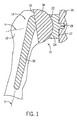
最初に図1を検討すると、従来型の肩プロテーゼ10の例が示されている。上腕骨12の上部は、上腕骨12の内部に形成された内腔の中へ延びるステム16を含む上腕骨コンポーネント14によって置換されている。一般的に、ステム16は、上腕骨12の内部に形成された内腔の内部に固定されている。ステム16は、縦方向ステム軸Sを有する。ほぼ半球状のヘッド18がステム16に連結されている。代替的に、ヘッド18は、ステム16と一体になっている。半球状ヘッド18は、底面19と縦方向ヘッド軸Hとを有する。上腕骨コンポーネント14の半球状ヘッド18は、セメントまたは非セメント支柱28を使用して肩甲骨26の関節窩の内部に固定されている関節窩コンポーネント24の相補的な凹状セクション22と関節接合する。関節窩コンポーネント24は、関節窩コンポーネント24の関節面としての役目を果たす凹状セクション22の反対側にある底面27を含む。
Considering initially FIG. 1, an example of a
図2〜図3を参照すると、本発明による肩プロテーゼの実施形態の例が示されている。上腕骨コンポーネント34は、上腕骨12の内部に形成された内腔の中へ延びるステム36を含む。ステム36は、縦方向ステム軸Sを有する。上腕骨ヘッド組立体37は、ほぼ半球状のヘッド38を有する。上腕骨ヘッド組立体37は、ステム36に連結されている。上腕骨コンポーネント34の半球状ヘッド38の外面41は、図1に示されるように肩甲骨26の関節窩の内部に固定されている関節窩コンポーネント24の相補的な凹状セクション22と関節接合する。上腕骨ヘッド組立体37において、ヘッド38は、アダプタ46を受容する陥没部43を含む。陥没部43は、ソケット48を備えた本体47を有する。ソケット48は、偏心している、すなわち、ソケット48の中心軸が、本体47の中心軸からオフセットしている。上腕骨ヘッド組立体37は、球状座面54を含む第1端部53と先細状シャフト57を備える第2端部56とを有する取り付け用スタッド51をさらに含む。取り付け用スタッド51の第1端部53は、取り付け用スタッド51をソケット48の中へ嵌め込むことにより形成された締まり嵌め(interference fit)を用いてアダプタ本体47のソケット48内に締め付けられている。取り付け用スタッド51の第2端部56は、取り付け用スタッド51をステム開口部61内に嵌め込むことにより形成された先細ロックを用いてステム36のステム開口部61内に締め付けられている。
With reference to FIGS. 2-3, an example embodiment of a shoulder prosthesis according to the present invention is shown. The
上腕骨コンポーネント34の部品は、たとえば、(i)チタン合金(たとえば、チタン−6−アルミニウム−4−バナジウム)、コバルト合金、ステンレス鋼合金、もしくはタンタルのような金属または金属合金、(ii)酸化アルミニウムもしくはジルコニアのような非吸収性セラミック、(iii)ポリエチレンのような非吸収性ポリマー材料、あるいは(iv)炭素繊維強化ポリマー(たとえば、ポリスルホン)のような非吸収性複合材料から形成される。プロテーゼコンポーネントは、これらの材料から形成された品物を機械加工することにより、または、これらの材料を適当な金型で成形することにより製造することができる。
The components of the
図2において、ステム軸Sとヘッド軸Hとの間で前面像内のねじ山の角度を度単位で取得し、180°から差し引くことは、上腕骨ヘッド38の傾斜角Ainclinationを度単位で定義する1つの方法である。上腕骨ヘッド38の傾斜角は、前述のとおり、上腕骨ヘッド組立体37をヘッド38に対して選択された位置においてアダプタ本体47のソケット48と、および、アダプタ本体47のソケット48内の選択された姿勢において取り付け用スタッド51と組み立てることにより、縦方向ヘッド軸Hと縦方向ステム軸Sとの間で選択された角を有するように調整される。
In FIG. 2, obtaining the angle of the thread in the front image between the stem axis S and the head axis H in degrees and subtracting from 180 degrees results in the inclination angle A inclination of the
図3において、ステム軸Sとヘッド軸Hとの間で内側像内のねじ山の角度を度単位で取得することは、上腕骨ヘッド38の転位角Aversionを度単位で定義する1つの方法である。上腕骨ヘッド38の転位角は、ステム軸Sに関して正または負の角度として表現される。上腕骨ヘッド38の転位角は、前述のとおり、上腕骨ヘッド組立体37をヘッド38に関して選択された位置においてアダプタ本体47のソケット48と、および、アダプタ本体47のソケット48内の選択された姿勢において取り付け用スタッド51と組み立てることにより、縦方向ヘッド軸Hと縦方向ステム軸Sとの間で選択された正または負の角度を有するように調整される。
In FIG. 3, obtaining the angle of the thread in the inner image between the stem axis S and the head axis H in degrees is one way to define the dislocation angle A version of the
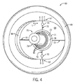
図4〜図9を参照すると、外科医は、上腕骨コンポーネント34が関節窩コンポーネント24の相補的な凹状セクション22と関節接合するように、上腕骨コンポーネント34を埋め込むことができる。肩甲骨26の関節窩内部での関節窩コンポーネント24の固定は、従来とおりの方法で行われる。本発明の方法では、トライアルヘッド組立体63を使用する(図4を参照のこと)。トライアルヘッド組立体63が準備されると、次に、アダプタ46の姿勢と上腕骨ヘッド組立体37の取り付け用スタッド51とが、トライアルヘッド組立体63に一致させられる。
With reference to FIGS. 4-9, the surgeon can implant the
トライアルヘッド組立体63は、本体65を含む。図4を参照すると、本体65の一方の側面は、ほぼ縦長形状のウェル部66を有し、ウェル部66の平行側面セクションにオフセットしたマーキング67(A,B,C,D,E)がある。ウェル部66を有する本体65の側面の反対側に、上腕骨コンポーネント34の半球状ヘッド38の外面41と全く同一のまたは実質的に類似するほぼ半球状の面を有する本体65の側面がある。リテーナー69は、図4にLで示されるように、本体65のウェル部66内を摺動することができる。トライアルヘッド組立体63において、位置決めねじ70は、ウェル部66内でリテーナー69の位置をロックできる。ウェル部66の縦長形状は、位置決めねじ70が締められている間にリテーナー69がウェル部66の内部で回転するのを防ぐ(同様に、隙間が密着したスロットに沿って摺動するピンなどは、リテーナー69の回転を防ぐために使用されることがある)。リテーナー69は、開口部71と、十字線マーキング72と、を有する。トライアルヘッド組立体63の球関節要素75は、球状座面78を含んでいる第1端部77と、先細状シャフト80の形をした第2端部79と、を有する。球関節要素75の第2端部79は、リテーナー開口部71を通って外向きに突出し、球関節要素75の第1端部77は、リテーナー69とウェル部66の面との間に位置決めされている。位置決めねじ70が締められるとき、球関節要素75の第2端部79は、リテーナー69の面およびウェル部66の面との接触によって締め付けられる。3つの同心円状基準円81は、球状座面78と先細状シャフト80との接合点の近くで球関節要素75を取り囲む。
The
図5に示されているのは、上腕骨ヘッド組立体37のコンポーネントの姿勢とトライアルヘッド組立体63とを一致させるために使用される透明テンプレート82である。テンプレート82は、開口部83と、基準線84と、十字線マーキング85とを有する。テンプレート82は、ヘッドがその最大オフセットまで回転させられている間にヘッドが上に載っている無損失、低摩擦面を含んでいるプラットフォームのような他の形をしていることがあるが、それでもなお、開口部83および基準線84を保持している。
Shown in FIG. 5 is a
トライアルヘッド組立体63を準備することは、トライアルヘッド組立体63上の2個の位置決めねじ70が緩んでいることを確実にすることから始まる。球関節要素75があらゆる方向に回転自在であり、リテーナー69がウェル部66内で摺動自在であることを証明する。ステム36は、上腕骨12の内部に形成された内腔の内部に固定される(図2を参照のこと)。球関節要素75の第2端部79は、次に、患者の上腕骨12の中に埋め込まれているステム36のステム開口部61内に取り付けられる。トライアルヘッド組立体63の本体65は、望ましい半径方向オフセット、患者内の傾斜および/または転位に調整され、2個の位置決めねじ70は、このオフセットと、トライアルヘッド組立体63の球関節要素75の角度とをロックするために締め付けされる。位置決めねじ70は、リテーナー69の反対側にある本体65の側面でアクセスすることができる。トライアルヘッド組立体63は、次に、ステム36から取り外される。
Preparing the
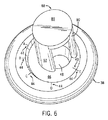
トライアルヘッド組立体63は、その後、図4の場合と同様に、リテーナー69および球関節要素75が外科医に見えるように裏返しにされる。外科医は、リテーナー69の面上の90度離れている4個の十字線マーキング72に注目する。オフセットは、本体65上のA、B、C、D、およびEオフセットマーキング67と相対的なリテーナー69の十字線マーキング72の垂直マーキングの位置によって指し示される。外科医は、球関節要素75上の同心円状基準円81によって指示された基準角にも注目する。図示された限定的ではない構成例において、黒、赤および青のような異なった色の3個の同心円状基準円81が球関節要素75の上に存在する。基準角は、十字線マーキング72のうち1つがリテーナー69の内側開口部71の円周と交差することになるロケーションで同心円状基準円81の位置に注目することによって読み取られる。これらの直交ロケーションのうち2つで(すなわち、2個の隣接する十字線マーキング72で)、同心円状基準円81の位置に注目することにより、基準角が完全に特徴付けられる。
The
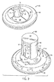
上腕骨ヘッド組立体37は、トライアルヘッド組立体63内の球関節要素75の姿勢と一致するように組み立てられる。アダプタ46は、ヘッド38の中へ挿入され、アダプタ46は、ヘッド38上のオフセットした基準マーキング44がアダプタ46上の適切なオフセットした基準マーク49と一直線になるように回転させられる。図6を参照のこと。
The
さらに図6を参照すると、衝撃部材88が本発明の方法において使用される。衝撃部材88は、丸く平らな端部面89と、端部面91を含んでいる第1の側壁90と、端部面93を含んでいる第2側面壁92とを有する。衝撃部材88の端部面91、93は、アダプタ46の上端に置かれ、木槌は、アダプタ46をヘッド38の陥没部43の内側に着座させるように衝撃部材88の平らな端部面89を打つために使用される。
Still referring to FIG. 6, an
図7を参照すると、取り付け用スタッド51の第1端部53は、アダプタ46のソケット48の上へ垂直方向に置かれ、取り付け用スタッド51は、この取り付け用スタッドを辛うじて装着させるのにちょうど十分な力を使用して押し下げられる。ソケット48は、スタッド51を所定の位置に保持するために作用することがあるゴムのような材料で裏打ちされることもある。透明テンプレート82の開口部83は、取り付け用スタッド51の第2端部56の上に置かれることがあり、テンプレート82の基準線84は、ヘッド38の最大オフセット方向をトライアルヘッド組立体63の本体65の最大オフセット方向と一直線にするために使用される。テンプレート82は、ヘッド38と相対的なその位置に注意して、取り外される。図7は、参考のためトライアルヘッド組立体63がどのようにして組立中に上腕骨ヘッド組立体37に隣接して位置決めされ得るかを示す。
Referring to FIG. 7, the
次に図8を参照すると、アパーチャ96を有する衝撃部材リング95が取り付け用スタッド51の上に置かれ、衝撃部材リング95がアダプタ46の指標特徴形状と一直線になるように回転する。前述のとおり、スタッド51は、組立中に姿勢を変えるべきではなく、衝撃部材リング95は、動きを阻止するためにゴムのような材料で裏打ちされることがある。衝撃部材リング95は、アダプタ46のポケットの中へ押し込まれる。テンプレートは、テンプレート82が取り外されたときと同じ位置において取り付け用スタッド51の上にもう一度置かれる。透明テンプレート82上の十字線マーキング85が基準にされ、取り付け用スタッド51は、球状座面54と取り付け用スタッド51の先細状シャフト57との接合点の近くで取り付け用スタッド51を取り囲む同心円状基準円59を使用してトライアルヘッド組立体63の球関節要素75の同じ角度まで動かされる。テンプレート82は、その後に取り外される。
Referring now to FIG. 8, an
図9を参照すると、ヘッド38の取り付け用スタッド51の角度とトライアルヘッド組立体63の球関節要素75の角度は、2つの直交する方向から水平方向にこれらを見ることにより視覚的に比較される。これらの角度が許容できる形で一致する場合、衝撃部材リング95を穏やかに押し下げて、取り付け用スタッド51の周りに均一な圧力を印加する。衝撃部材リング95は、後に続くステップの間、正しい角度で取り付け用スタッド51を保持する。その後、上腕骨ヘッド組立体37の取り付け用スタッド51の角度が依然として許容できることを視覚的に再確認する。
Referring to FIG. 9, the angle of the mounting
衝撃部材88は、衝撃部材88の端部面91、93が衝撃部材リング95と接触している状態で衝撃部材リング95と同心円状に位置決めされる。衝撃部材88を簡単に所定の位置で保持するために片手で下向き圧力を使用し、次に、木槌を使って衝撃部材88の端部面89を叩く。これは、衝撃部材リング95を押し下げ、この衝撃部材リングが、今度は、取り付け用スタッド51をアダプタ46のソケット48との締まり嵌めに至らせる。締まり嵌めは、ブラスト加工、粗面化、粗い機械加工線の切断、もしくは、反対面を係合する鋭利な刃のような構造体の追加などにより、取り付け用スタッド51もしくはソケット48のいずれかの面を変更することによって、あるいは、取り付け用スタッド51もしくはソケット48のいずれかの形状を変更することによって、補強されてもよい。取り付け用スタッド51は、衝撃部材リング95の上面がアダプタ46の上面とおおよそ同一平面にあるとき、完全に取り付けられる。その後、上腕骨ヘッド組立体37の取り付け用スタッド51の角度が依然として許容できることを視覚的に再確認する。
The
衝撃部材リング95は、2個のつまみ部97を親指と人差し指とを使ってつまみ、上向きに引っ張ることによって取り外される。上腕骨ヘッド組立体37は、このとき、埋め込みの準備が整っている。上腕骨ヘッド組立体37の取り付け用スタッド51の第2端部56は、ステム36のステム開口部61内に締め付けられる。木槌を使用して上腕骨ステム36内に上腕骨ヘッド組立体37を装着させることは、図2に示されるように、組み付けられたコンポーネントを一体として装着させる。
The
このようにして、本発明は、肩関節形成において上腕骨ヘッドコンポーネントの可変傾斜および/または転位および/またはオフセットを提供する改良されたプロテーゼおよび方法を提供する。死体検証は、これらの方法および肩関節形成コンポーネントに関して行われているが、この方法は、他の関節(たとえば、股関節、膝、肘、足、足首など)のため使用することができる。 In this manner, the present invention provides an improved prosthesis and method that provides variable tilt and / or displacement and / or offset of the humeral head component in shoulder arthroplasty. Although cadaver verification has been performed on these methods and shoulder arthroplasty components, this method can be used for other joints (eg, hip, knee, elbow, foot, ankle, etc.).
本発明は、いくつかの実施形態に関連して詳細に説明されているが、当業者は、限定の目的ではなく、例示の目的のため説明された実施形態以外の実施形態によって本発明が実施され得ることが分かるであろう。従って、請求項の範囲は、本明細書に含まれている実施形態の説明に限定されるべきではない。 While the invention has been described in detail in connection with certain embodiments, those skilled in the art will recognize that the invention may be practiced by embodiments other than those described for purposes of illustration and not limitation. It will be appreciated that it can be done. Accordingly, the scope of the claims should not be limited to the description of the embodiments contained herein.
Claims (22)
対象者の関節の第1の骨の中に埋め込まれるような寸法にされているステムと、 ヘッド組立体と、を備え、
前記ステムは、前記ヘッド組立体を収容するよう構成された開口部を備え、
前記ヘッド組立体は、
生体の関節面または前記関節の第2の骨の人工関節面との関節接合のための寸法にされている外面を有するプロテーゼヘッドと、
前記プロテーゼヘッドの前記外面と反対側にある前記プロテーゼヘッドの端面内の陥没部の中に嵌め込まれるような寸法にされて、前記陥没部との間に締まり嵌めを形成するアダプタと、
第1端部および第2端部を有し、前記第2端部は、前記開口部内への挿入のための寸法にされ、前記第1端部は、前記アダプタ内のソケットの中への嵌め込みのための寸法にされて、前記第1端部と前記ソケットとの間に締まり嵌めを形成する、取り付け用スタッドと、を備え、
前記取り付け用スタッドの前記第1端部及び前記ソケットは、前記開口部内での前記取り付け用スタッドの回転位置から独立して、前記プロテーゼヘッドの前記取り付け用スタッドに対する姿勢を、傾斜角の範囲にわたって調整するよう構成されており、そして、
前記傾斜角の範囲内の選択された傾斜角は、前記関節プロテーゼが前記対象者に埋め込まれた後の状態において、ねじ部品を用いずに、前記取り付け用スタッドの前記第1端部と前記ソケットとの締まり嵌めによって固定されるものである
ことを特徴とする関節プロテーゼ。 A joint prosthesis,
A stem dimensioned to be embedded in a first bone of a subject's joint; and a head assembly;
The stem includes an opening configured to receive the head assembly;
The head assembly is
A prosthetic head having an outer surface dimensioned for articulation with a joint surface of a living body or an artificial joint surface of a second bone of the joint;
An adapter dimensioned to fit into a recess in an end surface of the prosthesis head opposite the outer surface of the prosthesis head, and forming an interference fit with the recess;
Having a first end and a second end, the second end being dimensioned for insertion into the opening, the first end being fitted into a socket in the adapter A mounting stud dimensioned for forming an interference fit between the first end and the socket;
The first end of the mounting stud and the socket adjust the attitude of the prosthesis head relative to the mounting stud over a range of tilt angles independent of the rotational position of the mounting stud within the opening. And is configured to
The selected tilt angle within the tilt angle range is such that the first end of the mounting stud and the socket without the use of screw parts in a state after the joint prosthesis is implanted in the subject. A joint prosthesis characterized by being fixed by an interference fit.
ことを特徴とする請求項1に記載の関節プロテーゼ。 The second end of the mounting stud is sized for fitting into the opening in the stem to form an interference fit with the stem. The joint prosthesis according to 1.
ことを特徴とする請求項1又は2に記載の関節プロテーゼ。 The joint prosthesis according to claim 1, wherein the first end of the mounting stud includes a spherical surface.
ことを特徴とする請求項3に記載の関節プロテーゼ。 The spherical surface of the first end of the mounting stud may be inclined and / or tilted with respect to the stem before forming an interference fit between the first end of the mounting stud and the socket. 4. The joint prosthesis according to claim 3, wherein the joint prosthesis rotates in the socket to set a dislocation.
ことを特徴とする請求項1〜4の何れか一項に記載の関節プロテーゼ。 2. The second end of the mounting stud includes an outer surface that tapers inwardly from an intermediate section to an outermost section of the second end of the mounting stud. 5. The joint prosthesis according to any one of 4 above.
ことを特徴とする請求項3又は4に記載の関節プロテーゼ。 The mounting stud includes a circumferential reference index at or near the junction between the spherical surface of the first end of the mounting stud and the outer surface of the second end of the mounting stud. The joint prosthesis according to claim 3 or 4.
ことを特徴とする請求項1〜6の何れか一項に記載の関節プロテーゼ。 The vertical axis of the second end of the mounting stud forms an oblique angle with respect to the axis of the prosthesis head when the interference fit is formed between the first end and the socket. The joint prosthesis according to any one of claims 1 to 6.
前記陥没部は、円形内面を有し、
前記アダプタと前記陥没部との間に前記締まり嵌めを形成する前に、前記ステムに関して前記プロテーゼヘッドの半径方向オフセットを設定するために、前記アダプタが前記陥没部内で回転する
ことを特徴とする請求項1〜8の何れか一項に記載の関節プロテーゼ。 The adapter has a circular outer surface;
The depressed portion has a circular inner surface;
The adapter rotates within the recess to set a radial offset of the prosthesis head relative to the stem prior to forming the interference fit between the adapter and the recess. Item 9. The joint prosthesis according to any one of Items 1 to 8.
ことを特徴とする請求項1〜9の何れか一項に記載の関節プロテーゼ。 The joint according to any one of the preceding claims, wherein the prosthesis head includes at least one first fiducial marking for alignment with a second fiducial mark on the adapter. Prosthesis.
前記第2の骨は、肩甲骨である
ことを特徴とする請求項1〜10の何れか一項に記載の関節プロテーゼ。 The first bone is a humerus;
The joint prosthesis according to any one of claims 1 to 10, wherein the second bone is a scapula.
前記第2の骨は、上腕骨である
ことを特徴とする請求項1〜10の何れか一項に記載の関節プロテーゼ。 The first bone is a scapula;
The joint prosthesis according to claim 1, wherein the second bone is a humerus.
ことを特徴とする請求項1〜12の何れか一項に記載の関節プロテーゼ。 The first end of the mounting stud and the socket are relative to the mounting stud of the prosthesis head such that a shift angle of the prosthesis head on the stem includes a selected shift angle within a range of shift angles. The joint prosthesis according to claim 1, wherein the joint prosthesis is configured to adjust a posture.
ことを特徴とする請求項13に記載の関節プロテーゼ。 14. The prosthesis head is held at the selected tilt angle and the selected shift angle by an interference fit between the first end of the mounting stud and the socket. Joint prosthesis.
ことを特徴とする請求項1〜14の何れか一項に記載の関節プロテーゼ。 The first end of the mounting stud, wherein configured to reinforce the interference fit of the socket and the first end, any claim 1 to 1 4, characterized in that it comprises a modified sphere The joint prosthesis according to claim 1.
ことを特徴とする請求項15に記載の関節プロテーゼ。 The joint prosthesis of claim 15 , wherein the modified spherical surface comprises a rough surface.
ことを特徴とする請求項15に記載の関節プロテーゼ。 The joint prosthesis of claim 15 , wherein the modified spherical surface comprises a machining line.
ことを特徴とする請求項15に記載の関節プロテーゼ。 The joint prosthesis of claim 15 , wherein the modified spherical surface comprises a structure configured to engage an opposite surface of the socket.
ことを特徴とする請求項1〜18の何れか一項に記載の関節プロテーゼ。 The socket may be any one of claims 1 to 1 8, wherein the first end of the mounting stud and configured to reinforce the interference fit of the socket, characterized in that it comprises a modified surface Joint prosthesis as described in 1.
ことを特徴とする請求項19に記載の関節プロテーゼ。 20. The joint prosthesis of claim 19 , wherein the modified surface comprises a rough surface.
ことを特徴とする請求項19に記載の関節プロテーゼ。 20. The joint prosthesis of claim 19 , wherein the modified surface comprises a machining line.
ことを特徴とする請求項19に記載の関節プロテーゼ。 The joint prosthesis of claim 19 , wherein the modified surface comprises a structure configured to engage an opposite surface of the first end of the mounting stud.
Applications Claiming Priority (3)
| Application Number | Priority Date | Filing Date | Title |
|---|---|---|---|
| US201361774969P | 2013-03-08 | 2013-03-08 | |
| US61/774,969 | 2013-03-08 | ||
| PCT/US2014/020308 WO2014138061A1 (en) | 2013-03-08 | 2014-03-04 | Shoulder prosthesis with variable inclination humeral head component |
Related Child Applications (1)
| Application Number | Title | Priority Date | Filing Date |
|---|---|---|---|
| JP2018112469A Division JP6707107B2 (en) | 2013-03-08 | 2018-06-13 | Shoulder prosthesis with variable tilt humeral head component |
Publications (3)
| Publication Number | Publication Date |
|---|---|
| JP2016508838A JP2016508838A (en) | 2016-03-24 |
| JP2016508838A5 JP2016508838A5 (en) | 2018-07-26 |
| JP6495190B2 true JP6495190B2 (en) | 2019-04-03 |
Family
ID=51491867
Family Applications (4)
| Application Number | Title | Priority Date | Filing Date |
|---|---|---|---|
| JP2015561545A Active JP6495190B2 (en) | 2013-03-08 | 2014-03-04 | Shoulder prosthesis with variable tilting humeral head component |
| JP2018112469A Active JP6707107B2 (en) | 2013-03-08 | 2018-06-13 | Shoulder prosthesis with variable tilt humeral head component |
| JP2020033495A Active JP6896902B2 (en) | 2013-03-08 | 2020-02-28 | Shoulder prosthesis with variable tilted humerus head component |
| JP2021095746A Active JP7187613B2 (en) | 2013-03-08 | 2021-06-08 | Shoulder prosthesis with variable tilt humeral head component |
Family Applications After (3)
| Application Number | Title | Priority Date | Filing Date |
|---|---|---|---|
| JP2018112469A Active JP6707107B2 (en) | 2013-03-08 | 2018-06-13 | Shoulder prosthesis with variable tilt humeral head component |
| JP2020033495A Active JP6896902B2 (en) | 2013-03-08 | 2020-02-28 | Shoulder prosthesis with variable tilted humerus head component |
| JP2021095746A Active JP7187613B2 (en) | 2013-03-08 | 2021-06-08 | Shoulder prosthesis with variable tilt humeral head component |
Country Status (7)
| Country | Link |
|---|---|
| US (3) | US10226349B2 (en) |
| EP (1) | EP2964156A4 (en) |
| JP (4) | JP6495190B2 (en) |
| AU (2) | AU2014226016B2 (en) |
| CA (2) | CA3111224A1 (en) |
| HK (1) | HK1219864A1 (en) |
| WO (1) | WO2014138061A1 (en) |
Families Citing this family (20)
| Publication number | Priority date | Publication date | Assignee | Title |
|---|---|---|---|---|
| US20070225821A1 (en) | 2006-03-21 | 2007-09-27 | Axiom Orthopaedics, Inc. | Femoral and humeral stem geometry and implantation method for orthopedic joint reconstruction |
| EP2604224A1 (en) | 2011-10-31 | 2013-06-19 | Tornier Orthopedics Ireland Ltd. | Modular reverse shoulder prosthesis |
| EP4309631A2 (en) | 2012-10-29 | 2024-01-24 | Stryker European Operations Limited | System for a modular reverse shoulder prosthesis |
| US11071635B2 (en) | 2013-03-08 | 2021-07-27 | Mayo Foundation For Medical Education And Research | Shoulder prosthesis with variable inclination humeral head component |
| CA3111224A1 (en) * | 2013-03-08 | 2014-09-12 | Mayo Foundation For Medical Education And Research | Shoulder prosthesis with variable inclination humeral head component |
| US9681960B2 (en) | 2014-05-16 | 2017-06-20 | Howmedica Osteonics Corp. | Guides for fracture system |
| US10575968B2 (en) | 2014-05-16 | 2020-03-03 | Howmedica Osteonics Corp. | Guides for fracture system |
| US9566162B2 (en) * | 2015-03-03 | 2017-02-14 | Biomet Manufacturing, Llc | Adjustable humeral tray for shoulder arthroplasty |
| AU2017253113B2 (en) | 2016-04-19 | 2021-10-07 | Stryker European Operations Limited | Pre-operatively planned humeral implant and planning method |
| US10709460B2 (en) | 2016-08-01 | 2020-07-14 | Howmedica Osteonics Corp. | Centering guide system for arthroplasty |
| WO2018039493A1 (en) | 2016-08-24 | 2018-03-01 | Greiwe Raymond Michael | Humeral head implant system |
| EP3551134A4 (en) * | 2016-12-06 | 2020-10-14 | Mayo Foundation for Medical Education and Research | Shoulder prosthesis with variable inclination, offset, and version of humeral component |
| EP3558171B1 (en) | 2016-12-21 | 2021-11-03 | Biomet Manufacturing, LLC | Apparatuses for trialing a humeral head |
| EP3600166A1 (en) | 2017-03-31 | 2020-02-05 | Tornier, Inc. | Modular humeral head |
| US10898338B1 (en) * | 2018-01-17 | 2021-01-26 | Matthew Budge | Reverse shoulder prosthesis |
| EP3829494A4 (en) | 2018-07-27 | 2022-04-06 | Ignite Orthopedics Llc | Implants, systems and methods of using the same |
| WO2020023971A1 (en) | 2018-07-27 | 2020-01-30 | Ignite Orthopedics Llc | Implants, systems and methods of using the same |
| CA3113978C (en) | 2018-10-02 | 2023-10-24 | Tornier, Inc. | Modular humeral head |
| USD938590S1 (en) | 2019-10-01 | 2021-12-14 | Howmedica Osteonics Corp. | Humeral implant |
| EP4255354A1 (en) | 2020-12-03 | 2023-10-11 | Zimmer, Inc. | Methods and apparatuses for trialing a humeral head |
Family Cites Families (26)
| Publication number | Priority date | Publication date | Assignee | Title |
|---|---|---|---|---|
| FR2685633B1 (en) | 1991-12-27 | 1998-02-27 | Tornier Sa | MODULAR HUMER PROSTHESIS. |
| US5665090A (en) | 1992-09-09 | 1997-09-09 | Dupuy Inc. | Bone cutting apparatus and method |
| FR2768330B1 (en) | 1997-09-12 | 2000-01-21 | Tornier Sa | HUMERAL PROSTHESIS WITH INDEXED SPHERE |
| FR2773469B1 (en) | 1998-01-09 | 2000-03-03 | Alain Leonard | SURGICAL EQUIPMENT FOR THE IMPLANTATION OF A TOTAL SHOULDER PROSTHESIS, AND TOTAL SHOULDER PROSTHESIS |
| DE59810997D1 (en) * | 1998-01-16 | 2004-04-22 | Ct Pulse Orthopedics Ltd | Construction kit for socket prostheses |
| KR100459673B1 (en) | 1998-09-11 | 2004-12-04 | 아르고메디컬 악티엔게젤샤프트 | Implantable prosthesis having at least two sections which can be displaced in relation to one another, and the use of displaceable sections |
| US6197062B1 (en) | 1999-01-11 | 2001-03-06 | Howmedica Osteonics, Corp. | Modular shoulder prosthesis system |
| US20020016634A1 (en) | 2000-07-28 | 2002-02-07 | Brian Maroney | Device and method for positioning an eccentric humeral head of a humerus prothesis for a shoulder arthroplasty |
| WO2002039931A1 (en) * | 2000-11-16 | 2002-05-23 | Willi Horber | Joint prosthesis |
| US20070162140A1 (en) * | 2001-02-27 | 2007-07-12 | Mcdevitt Dennis M | Method and apparatus for reconstructing a joint |
| US6942699B2 (en) * | 2001-07-11 | 2005-09-13 | Biomet, Inc. | Shoulder prosthesis |
| US8795379B2 (en) * | 2001-07-11 | 2014-08-05 | Biomet Manufacturing, Llc | Variable prosthesis |
| US6676705B1 (en) | 2001-09-13 | 2004-01-13 | Eugene M. Wolf | Variable tilt angle taper lock shoulder prosthesis |
| US7097663B1 (en) | 2001-12-17 | 2006-08-29 | Smith & Nephew, Inc. | Modular prosthesis system with novel locking mechanism |
| US7175663B1 (en) | 2003-10-08 | 2007-02-13 | Biomet Manufacturing Corp. | Shoulder implant assembly |
| US6986790B2 (en) | 2002-09-30 | 2006-01-17 | Depuy Products, Inc. | Shoulder prosthesis having infinitely adjustable humeral head |
| US8052758B1 (en) | 2005-03-09 | 2011-11-08 | Biomet Manufacturing Corp. | Method and apparatus for trialing a modular humeral head |
| EP1764065B1 (en) | 2005-08-25 | 2019-08-14 | Arthrex, Inc. | Shoulder prosthesis |
| GB0803723D0 (en) | 2008-02-29 | 2008-04-09 | Depuy Int Ltd | An instrument for use in a joint replacement procedure |
| US8002838B2 (en) | 2008-06-11 | 2011-08-23 | Depuy Products, Inc. | Joint prosthesis with positionable head |
| US20110106267A1 (en) * | 2009-10-30 | 2011-05-05 | Depuy Products, Inc. | Shoulder prosthesis adjustable humeral head mechanism |
| WO2012125795A2 (en) * | 2011-03-16 | 2012-09-20 | Smith & Nephew, Inc. | Compound angle implant |
| US8771362B2 (en) | 2012-10-17 | 2014-07-08 | Biomet Manufacturing, Llc | Variable angle humeral components |
| EP2767262B1 (en) | 2013-02-15 | 2018-09-26 | Arthrex, Inc. | Humeral prosthesis |
| CA3111224A1 (en) * | 2013-03-08 | 2014-09-12 | Mayo Foundation For Medical Education And Research | Shoulder prosthesis with variable inclination humeral head component |
| KR102150845B1 (en) | 2013-12-02 | 2020-09-03 | 짐머, 인크. | Adjustable orthopedic connections |
-
2014
- 2014-03-04 CA CA3111224A patent/CA3111224A1/en not_active Abandoned
- 2014-03-04 CA CA2903390A patent/CA2903390C/en active Active
- 2014-03-04 US US14/773,605 patent/US10226349B2/en active Active
- 2014-03-04 EP EP14760202.3A patent/EP2964156A4/en active Pending
- 2014-03-04 AU AU2014226016A patent/AU2014226016B2/en active Active
- 2014-03-04 WO PCT/US2014/020308 patent/WO2014138061A1/en active Application Filing
- 2014-03-04 JP JP2015561545A patent/JP6495190B2/en active Active
-
2016
- 2016-07-11 HK HK16108058.4A patent/HK1219864A1/en unknown
-
2018
- 2018-06-13 JP JP2018112469A patent/JP6707107B2/en active Active
- 2018-09-12 AU AU2018229471A patent/AU2018229471B2/en active Active
-
2019
- 2019-01-22 US US16/253,607 patent/US11096792B2/en active Active
-
2020
- 2020-02-28 JP JP2020033495A patent/JP6896902B2/en active Active
-
2021
- 2021-06-08 JP JP2021095746A patent/JP7187613B2/en active Active
- 2021-07-20 US US17/380,525 patent/US20220000628A1/en active Pending
Also Published As
| Publication number | Publication date |
|---|---|
| EP2964156A4 (en) | 2017-08-23 |
| JP6707107B2 (en) | 2020-06-10 |
| AU2014226016B2 (en) | 2018-06-21 |
| AU2014226016A1 (en) | 2015-09-17 |
| HK1219864A1 (en) | 2017-04-21 |
| JP2020096952A (en) | 2020-06-25 |
| US20220000628A1 (en) | 2022-01-06 |
| EP2964156A1 (en) | 2016-01-13 |
| CA2903390C (en) | 2021-04-06 |
| CA3111224A1 (en) | 2014-09-12 |
| AU2018229471A1 (en) | 2018-10-04 |
| AU2018229471B2 (en) | 2020-01-23 |
| WO2014138061A1 (en) | 2014-09-12 |
| JP2018171464A (en) | 2018-11-08 |
| US20190151104A1 (en) | 2019-05-23 |
| US11096792B2 (en) | 2021-08-24 |
| CA2903390A1 (en) | 2014-09-12 |
| US10226349B2 (en) | 2019-03-12 |
| JP2016508838A (en) | 2016-03-24 |
| JP2021175506A (en) | 2021-11-04 |
| JP6896902B2 (en) | 2021-06-30 |
| JP7187613B2 (en) | 2022-12-12 |
| US20160030187A1 (en) | 2016-02-04 |
Similar Documents
| Publication | Publication Date | Title |
|---|---|---|
| JP6896902B2 (en) | Shoulder prosthesis with variable tilted humerus head component | |
| US11071635B2 (en) | Shoulder prosthesis with variable inclination humeral head component | |
| US11679006B2 (en) | Systems for shoulder prostheses | |
| EP3078339B1 (en) | Device for retroversion correction for shoulder arthroplasty | |
| US20040153161A1 (en) | Humeral stem with anatomical location of taper access for fixation of humeral head | |
| US20220331120A1 (en) | Acetabular orthopaedic prosthesis and method | |
| CA3046366A1 (en) | Shoulder prosthesis with variable inclination, offset, and version of humeral component | |
| US20220249241A1 (en) | Reverse shoulder prosthesis and related methods |
Legal Events
| Date | Code | Title | Description |
|---|---|---|---|
| A621 | Written request for application examination |
Free format text: JAPANESE INTERMEDIATE CODE: A621 Effective date: 20170130 |
|
| A977 | Report on retrieval |
Free format text: JAPANESE INTERMEDIATE CODE: A971007 Effective date: 20171222 |
|
| A131 | Notification of reasons for refusal |
Free format text: JAPANESE INTERMEDIATE CODE: A131 Effective date: 20180123 |
|
| A601 | Written request for extension of time |
Free format text: JAPANESE INTERMEDIATE CODE: A601 Effective date: 20180420 |
|
| A521 | Request for written amendment filed |
Free format text: JAPANESE INTERMEDIATE CODE: A523 Effective date: 20180613 |
|
| A524 | Written submission of copy of amendment under article 19 pct |
Free format text: JAPANESE INTERMEDIATE CODE: A524 Effective date: 20180613 |
|
| RD04 | Notification of resignation of power of attorney |
Free format text: JAPANESE INTERMEDIATE CODE: A7424 Effective date: 20180703 |
|
| RD04 | Notification of resignation of power of attorney |
Free format text: JAPANESE INTERMEDIATE CODE: A7424 Effective date: 20180822 |
|
| A131 | Notification of reasons for refusal |
Free format text: JAPANESE INTERMEDIATE CODE: A131 Effective date: 20181120 |
|
| A521 | Request for written amendment filed |
Free format text: JAPANESE INTERMEDIATE CODE: A523 Effective date: 20190129 |
|
| TRDD | Decision of grant or rejection written | ||
| A01 | Written decision to grant a patent or to grant a registration (utility model) |
Free format text: JAPANESE INTERMEDIATE CODE: A01 Effective date: 20190219 |
|
| A61 | First payment of annual fees (during grant procedure) |
Free format text: JAPANESE INTERMEDIATE CODE: A61 Effective date: 20190306 |
|
| R150 | Certificate of patent or registration of utility model |
Ref document number: 6495190 Country of ref document: JP Free format text: JAPANESE INTERMEDIATE CODE: R150 |
|
| R250 | Receipt of annual fees |
Free format text: JAPANESE INTERMEDIATE CODE: R250 |
|
| R250 | Receipt of annual fees |
Free format text: JAPANESE INTERMEDIATE CODE: R250 |
|
| R250 | Receipt of annual fees |
Free format text: JAPANESE INTERMEDIATE CODE: R250 |