JP6494428B2 - Liquid discharge recording apparatus and liquid remaining amount detection method - Google Patents
Liquid discharge recording apparatus and liquid remaining amount detection method Download PDFInfo
- Publication number
- JP6494428B2 JP6494428B2 JP2015110804A JP2015110804A JP6494428B2 JP 6494428 B2 JP6494428 B2 JP 6494428B2 JP 2015110804 A JP2015110804 A JP 2015110804A JP 2015110804 A JP2015110804 A JP 2015110804A JP 6494428 B2 JP6494428 B2 JP 6494428B2
- Authority
- JP
- Japan
- Prior art keywords
- liquid
- ink
- electrode
- discharge
- recording apparatus
- Prior art date
- Legal status (The legal status is an assumption and is not a legal conclusion. Google has not performed a legal analysis and makes no representation as to the accuracy of the status listed.)
- Active
Links
Images


Description
本発明は液体吐出記録装置及びその装置で用いる液体残量検出方法に関し、特に、例えば、複数の電極を用いて液体収納容器内の液体残量を検出する液体吐出記録装置及びその装置で用いる液体残量検出方法に関する。 The present invention relates to a liquid discharge recording apparatus and a liquid remaining amount detection method used in the apparatus, and in particular, for example, a liquid discharge recording apparatus that detects a liquid remaining amount in a liquid storage container using a plurality of electrodes and a liquid used in the apparatus. The present invention relates to a remaining amount detection method.
記録装置の記録方式としては様々な方式が知られているが、記録用紙に非接触記録が可能であり、カラー化が容易である、静粛性に富む等の理由でインクジェット記録方式が広く用いられている。インクジェット記録方式を採用した記録装置(以下、記録装置)は、インク液滴を吐出するノズルが1列に並んだノズル列を備える記録ヘッドと記録ヘッドにインクを供給するためにインクを収容するインクタンクとを備える。記録ヘッドの複数のノズル各々にはインクを吐出するためのエネルギーを発生させる素子が設けられている。記録装置の本体部の制御回路はその素子を電気信号によって駆動制御することで、インクタンクから供給されるインクを吐出し記録ヘッドの直下に搬送された記録用紙などの記録媒体に画像を形成する。 Various methods are known as recording methods of the recording apparatus. However, the inkjet recording method is widely used because it can perform non-contact recording on recording paper, is easy to be colored, and is quiet. ing. 2. Description of the Related Art A recording apparatus (hereinafter referred to as a recording apparatus) that employs an ink jet recording method includes a recording head having a nozzle row in which nozzles for discharging ink droplets are arranged in a row, and an ink that contains ink for supplying ink to the recording head. With a tank. Each of the plurality of nozzles of the recording head is provided with an element that generates energy for ejecting ink. The control circuit of the main body of the recording apparatus controls the drive of the element with an electrical signal, thereby ejecting ink supplied from the ink tank and forming an image on a recording medium such as recording paper conveyed directly under the recording head. .
さて、インクタンク内のインクがなくなると、記録ヘッドにインクを供給できず、制御回路から電気信号を記録ヘッドに供給しても記録ヘッドからインク吐出ができず、その結果、記録媒体に画像を正確に形成することができなくなる。また、インクがノズルに供給されない状態で、インク吐出のためのエネルギーを加えると、そのノズル表面にコゲなどが発生してしまい、記録ヘッドのノズル自身を破壊してしまうこともある。従って、記録装置においてインクタンク内のインク量の低下を検出する構成は重要である。 When the ink in the ink tank runs out, ink cannot be supplied to the recording head, and even if an electric signal is supplied from the control circuit to the recording head, ink cannot be ejected from the recording head. It cannot be formed accurately. Further, if energy for ink ejection is applied in a state where ink is not supplied to the nozzles, kogation or the like may occur on the nozzle surface, and the nozzles of the recording head may be destroyed. Therefore, a configuration for detecting a decrease in the amount of ink in the ink tank in the recording apparatus is important.
近年、記録装置における高品位な画像記録とその高速化に伴い、より多くの色のインクを吐出可能な記録ヘッドや収容インク量を増やしたインクタンクを備えた記録装置が増えている。従来より、このような記録装置におけるインクタンクのインク残量の低下を検出するために以下の方法が提案されている。即ち、
(1)インクタンク内に2個の電極を有し、これらの電極間に電流を供給することで電極間の電気抵抗を検出し、その検出結果に基づいたインクの有無を判別する方法と、
(2)インクタンクを透光性の部材で形成し、そのインクタンク近傍に光学センサを設け、インクタンクを通過する光の透過量やインクタンクにより反射する光の反射量を計測し、その計測結果に基づいて、インクの有無を判別する方法と、
(3)ばねなどを用いてインクの重量によりインク容積の物理的な変化を、そのばねの移動度合いに基づいて検出し、その検出結果に基づいてインクの有無を判別する方法
などが実用化されている。
2. Description of the Related Art In recent years, with high-quality image recording and speeding up in a recording apparatus, recording apparatuses equipped with a recording head capable of ejecting more colors of ink and an ink tank with an increased amount of stored ink are increasing. Conventionally, the following method has been proposed to detect a decrease in the remaining amount of ink in an ink tank in such a recording apparatus. That is,
(1) a method of having two electrodes in an ink tank, detecting an electrical resistance between the electrodes by supplying a current between these electrodes, and determining the presence or absence of ink based on the detection result;
(2) An ink tank is formed of a translucent member, and an optical sensor is provided in the vicinity of the ink tank to measure the amount of light passing through the ink tank and the amount of light reflected by the ink tank. A method for determining the presence or absence of ink based on the results;
(3) A method of using a spring or the like to detect a physical change in the ink volume based on the weight of the ink based on the degree of movement of the spring and determining the presence or absence of ink based on the detection result has been put into practical use. ing.
この中でもコストや構成の自由度という点から、前記(1)の方法、即ち、電極間電圧の検出によりインクの有無を判別する方法が広く用いられている。 Among these, the method (1), that is, the method of determining the presence or absence of ink by detecting the voltage between the electrodes is widely used from the viewpoint of cost and the degree of freedom of configuration.
前記(1)の方法によれば、インクタンク内に設置した2つの電極間に所定の電流を供給し、2つの電極間に発生する電位差を検出することで2つの電極を介する液体の有無を判定する。電極間を介する液体、即ち、インクが存在する場合、インクの導電特性によって2つの電極間には電流が流れる。電流が流れて2つの電極間の電位差が所定電圧以下のであった場合、インクは「有り」と判定される。これに対して、インクが無い場合は、電流が供給しても、2つの電極間には電流が流れず、電極間には前記所定の電流を供給する電流源の最大印加電圧が出現し、これによってインクが無しと判断できる(例えば、特許文献1参照)。 According to the method (1), a predetermined current is supplied between two electrodes installed in the ink tank, and a potential difference generated between the two electrodes is detected to detect the presence or absence of liquid via the two electrodes. judge. When there is a liquid passing between the electrodes, that is, ink, a current flows between the two electrodes due to the conductive properties of the ink. When current flows and the potential difference between the two electrodes is equal to or lower than a predetermined voltage, the ink is determined as “present”. On the other hand, when there is no ink, even if current is supplied, current does not flow between the two electrodes, and the maximum applied voltage of the current source that supplies the predetermined current appears between the electrodes, Accordingly, it can be determined that there is no ink (see, for example, Patent Document 1).
しかしながら上記従来例では、単にインク残量検出動作実行時のインクの導電特性に着目した技術内容しか開示されておらず、電流供給による電極間電圧の検出の前後で生じるインクの電気的特性の変化については考慮されていなかった。そのため、様々なインクについて、その有無を正確に判定するには次のような課題があった。 However, in the above-described conventional example, only the technical content focusing on the conductive property of the ink at the time of executing the remaining ink amount detection operation is disclosed, and the change in the electrical property of the ink that occurs before and after the detection of the voltage between the electrodes due to the current supply Was not considered. Therefore, there are the following problems in accurately determining the presence or absence of various inks.
即ち、インクの有無を検出するための電流供給そのものが、その後のインク残量の検出(電極間電圧の検出)の精度に影響を及ぼす。さらに、複数のインクタンクごとに電流供給回路を設けることはコスト上、不利なので、1つの電流供給回路の出力を検出対象のインクタンクに対して切り替えて使用するという構成をとることが多い。このような構成の場合、その切替に切替回路を設けることが必要となるが、その切替回路で発生するわずかなリーク電流すら、インク残量の検出精度に影響を及ぼす。また、インクタンク内のインクが環境変化等により電荷を持っている場合に検出精度に影響を及ぼすこともある。 That is, the current supply itself for detecting the presence or absence of ink affects the accuracy of the subsequent detection of the remaining amount of ink (detection of the voltage between electrodes). Furthermore, since providing a current supply circuit for each of a plurality of ink tanks is disadvantageous in terms of cost, it is often the case that the output of one current supply circuit is switched to be used for the ink tank to be detected. In such a configuration, it is necessary to provide a switching circuit for the switching, but even a slight leak current generated in the switching circuit affects the detection accuracy of the remaining amount of ink. Also, detection accuracy may be affected when the ink in the ink tank has a charge due to environmental changes or the like.
本発明は上記従来例に鑑みてなされたもので、より高精度に液体残量の所定量の有無を検出可能な液体吐出記録装置及びその液体残量検出方法を提供すること目的とする。 The present invention has been made in view of the above conventional example, and an object of the present invention is to provide a liquid discharge recording apparatus and a liquid remaining amount detection method capable of detecting the presence or absence of a predetermined amount of liquid remaining with higher accuracy.
上記目的を達成するために、本発明の液体吐出記録装置は次のような構成からなる。 In order to achieve the above object, the liquid discharge recording apparatus of the present invention has the following configuration.
即ち、液体を吐出する記録ヘッドへ供給される液体をそれぞれ収容する複数の液体収納容器と、前記複数の液体収納容器の中から所定量の液体があるか否かの判定動作を行う液体収納容器を選択する選択手段と、前記複数の液体収納容器のそれぞれに備えられた第1の電極と第2の電極と、前記第1の電極、前記第2の電極、及び当該第1の電極と当該第2の電極を備えた液体収納容器に収容された液体に蓄積された電荷を放電する放電手段と、前記選択手段により選択された液体収納容器に備えられた前記第1の電極と前記第2の電極に電力を供給する通電手段と、前記第1の電極と前記第2の電極の間の電圧を検出する検出手段と、前記通電手段を動作させているときに前記検出手段により検出された電圧に基づいて、前記選択手段により選択された液体収納容器の液体に関して前記判定動作を行う判定手段と、を有する液体吐出記録装置であって、前記選択手段によって前記判定動作を行う液体収納容器が選択された後であって、当該液体収納容器の前記判定動作を行う直前に当該液体収納容器に対して前記放電手段を所定時間動作させることを特徴とする。 That is, a plurality of liquid storage containers each storing liquid supplied to a recording head that discharges the liquid, and a liquid storage container that performs an operation of determining whether or not there is a predetermined amount of liquid from among the plurality of liquid storage containers Selection means for selecting, a first electrode and a second electrode provided in each of the plurality of liquid storage containers, the first electrode, the second electrode, the first electrode, and the Discharging means for discharging the charge accumulated in the liquid stored in the liquid storage container including the second electrode, the first electrode provided in the liquid storage container selected by the selection means, and the second energizing means for supplying power to the electrodes of the detecting means for detecting a voltage between the front Symbol the first electrode and the second electrode, by said detecting means when operating said energizing means It was based on the voltage, to the selection means A liquid discharge recording apparatus having a determination means for performing the determining operation with respect to the liquid of the selected liquid container, even after the liquid container for performing the determining operation is selected by the selecting means, the Immediately before the determination operation of the liquid storage container is performed, the discharge unit is operated for a predetermined time with respect to the liquid storage container .
また本発明を別の側面から見れば、複数の液体収納容器それぞれから供給される液体を吐出する記録ヘッドによって記録を行う液体吐出記録装置における液体残量検出方法であって、それぞれに第1の電極と第2の電極を備えた前記複数の液体収納容器の中から、所定量の液体があるか否かの判定動作を行う液体収納容器を選択する選択工程と、前記選択工程において選択された液体収納容器に備えられた第1の電極と第2の電極と、該液体収納容器に収容された液体に蓄積された電荷を放電する放電工程と、当該液体収納容器に備えられた第1の電極と第2の電極に電力を供給する通電工程と、前記第1の電極と前記第2の電極の間の電圧を検出する検出工程と、前記通電工程において電力を供給しているときに、前記検出工程において検出された電圧に基づいて、前記選択工程において選択された液体収納容器に対する前記判定動作を行う判定工程とを有し、前記選択工程において選択された液体収納容器に対して前記判定工程における前記判定動作を行う直前に、前記放電工程における放電を所定時間、行うことを特徴とする液体残量検出方法を備える。 Also, look at the present invention from another aspect, there is provided a liquid Karadazanryou detection method in a liquid discharge recording apparatus for performing recording by a recording head for discharging the liquid supplied from each of the plurality of liquid container, a first respectively A selection step of selecting a liquid storage container for performing an operation of determining whether or not there is a predetermined amount of liquid from among the plurality of liquid storage containers including the second electrode and the second electrode; and selected in the selection step a first electrode and a second electrode provided on the liquid container has a discharge step of discharging the electric charges stored in the liquid contained in the liquid container, first provided in the liquid container electrode and the energizing step of supplying power to the second electrode, and a detection step of detecting a voltage between the front Symbol first electrode and the second electrode, while supplying power at the energizing step , the detection in the detection step Based on the voltage, and a determination step of performing said determining operation for a liquid container which is selected in said selecting step, said determining operation in the determining step for the selected liquid container in said selection step Immediately before performing, the discharge in the discharging step is performed for a predetermined time .
従って本発明によれば、少なくとも2つの電極間の電圧検出動作に先立ち、液体や電極に充電される電荷の放電動作を行うので、上記電圧検出を正確に行い、液体残量の所定量の有無の正確な判定ができるという効果がある。 Therefore, according to the present invention, prior to the voltage detection operation between at least two electrodes, the discharge operation of the charge charged to the liquid and the electrodes is performed. There is an effect that it is possible to accurately determine.
以下添付図面を参照して本発明の好適な実施例について、さらに具体的かつ詳細に説明する。 Hereinafter, preferred embodiments of the present invention will be described more specifically and in detail with reference to the accompanying drawings.
なお、この明細書において、「記録」(「プリント」という場合もある)とは、文字、図形等有意の情報を形成する場合のみならず、有意無意を問わない。さらに人間が視覚で知覚し得るように顕在化したものであるか否かも問わず、広く記録媒体上に画像、模様、パターン等を形成する、または媒体の加工を行う場合も表すものとする。 In this specification, “recording” (sometimes referred to as “printing”) is not limited to the case of forming significant information such as characters and graphics, but may be significant. Furthermore, it also represents a case where an image, a pattern, a pattern, or the like is widely formed on a recording medium or a medium is processed regardless of whether or not it is manifested so that a human can perceive it visually.
また、「記録媒体」とは、一般的な記録装置で用いられる紙のみならず、広く、布、プラスチック・フィルム、金属板、ガラス、セラミックス、木材、皮革等、インクを受容可能なものも表すものとする。 “Recording medium” refers not only to paper used in general recording apparatuses but also widely to cloth, plastic film, metal plate, glass, ceramics, wood, leather, and the like that can accept ink. Shall.
さらに、「インク」(「液体」と言う場合もある)とは、上記「記録(プリント)」の定義と同様広く解釈されるべきものである。従って、記録媒体上に付与されることによって、画像、模様、パターン等の形成または記録媒体の加工、或いはインクの処理(例えば記録媒体に付与されるインク中の色剤の凝固または不溶化)に供され得る液体を表すものとする。 Further, “ink” (sometimes referred to as “liquid”) should be interpreted widely as in the definition of “recording (printing)”. Therefore, by being applied on the recording medium, it is used for formation of images, patterns, patterns, etc., processing of the recording medium, or ink processing (for example, solidification or insolubilization of colorant in the ink applied to the recording medium). It shall represent a liquid that can be made.
またさらに、「記録要素」とは、特にことわらない限り吐出口ないしこれに連通する液路およびインク吐出に利用されるエネルギーを発生する素子を総括して言うものとする。 Furthermore, unless otherwise specified, the “recording element” collectively refers to an ejection port or a liquid path communicating with the ejection port and an element that generates energy used for ink ejection.
<記録装置の全体概要(図1)>
図1は本発明の代表的な実施例であるA0やB0サイズなどの大きなサイズの記録媒体を用いるインクジェット記録装置の外観斜視図である。
<Overview of recording apparatus (FIG. 1)>
FIG. 1 is an external perspective view of an ink jet recording apparatus using a recording medium having a large size such as A0 or B0, which is a typical embodiment of the present invention.
図1に示すインクジェット記録装置(以下、記録装置)100は、10インチ〜44インチサイズのロール紙に記録が可能である。記録装置100は、本体部を乗せるスタンド101、排紙された記録紙を積載するスタッカ102を備える。また、記録装置100には、種々の記録情報や設定結果などを表示するための表示パネル103と、記録モードや記録紙などの設定をするための操作パネル104がその上面に配設されている。また、開閉可能なアッパーカバー106も備えられている。なお、インクを上述の表現を用いてより一般的に「液体」と考えると、インクジェット記録装置は液体吐出記録装置ということもできる。
An ink jet recording apparatus (hereinafter referred to as a recording apparatus) 100 shown in FIG. 1 can perform recording on roll paper having a size of 10 inches to 44 inches. The
さらに、記録装置100の両脇には、ブラック、シアン、マゼンタ、イエロなどのインクタンクを収容して記録ヘッドにインクを供給するためのインクタンク収容部105が配置されている。
Further, on both sides of the
図2は図1に示す記録装置のインクタンク収容部の近傍の内部を模式的に示した図である。 FIG. 2 is a diagram schematically showing the inside of the vicinity of the ink tank housing portion of the recording apparatus shown in FIG.
図2に示すように、記録ヘッド201はホスト装置(不図示)から送られてきた記録データに基づき、記録ヘッド201内部にある電気熱変換素子に電気エネルギーを供給することで熱エネルギーを発生させる。発生した熱エネルギーが供給されているインクに気泡を発生させ、気泡の発生した際に生じる圧力によって記録ヘッド201内部にある各ノズルからインク滴を吐出する。
As shown in FIG. 2, the
記録ヘッド201を搭載したキャリッジ202は、メインレール203とキャリッジベルト204に案内されて記録用紙207の搬送方向とは垂直方向に往復走査され、その際に記録ヘッド201からインク液滴を吐出して記録を行う。記録ヘッド201には複数のノズルが設けられており、各ノズル列からブラック、シアン、マゼンタ、イエロなどのインクが吐出され、記録媒体上に画像を形成する。その際、キャリッジ202はリニアスケール205に設けられたスケールを読取り、その結果をエンコーダセンサ206がパルス信号として出力する。そのパルス信号をカウントすることで、キャリッジ202の相対的な移動距離と位置とが検出される。
The
インクタンク(メインタンク)208を保持するインクタンク設置台209からインクバッファタンク211にインクを供給する。インクタンク設置台209にはインクタンクからインクを供給するための供給針と兼用されたインクの残量を検出するための電極210が設けられている。インクタンク208がインクタンク設置台209に装着された状態で、電極210はインクタンク内に挿入されることとなる。そして、インクバッファタンク211からインクチューブ212を介して記録ヘッド201内部に備えたヘッド内サブタンク(不図示)までインクが供給される。
Ink is supplied to the
なお、キャリッジの移動方向に関し、インクタンク収容部の反対側には回復ユニット213が設けられており、定期的に記録ヘッドの状態をメンテナンスする。なお、インクを上述の表現を用いてより一般的に「液体」と考えると、インクタンクは「液体収納容器」ということもできる。
Note that a
図3は記録装置100の制御構成を示すブロック図である。
FIG. 3 is a block diagram illustrating a control configuration of the
記録装置100はCPU301によりすべて制御される。通信I/F302はLANやUSB等のホスト装置(PC)との通信制御を行う。モータ/センサ制御ユニット305はキャリッジ202を走査したり記録用紙207を搬送・検出を行うモータ306やセンサ307の制御を行う。
The
モータ306はステッピングモータやDCモータなどに代表されるモータで歯車、ギア、ベルト等を用いてそれぞれ、記録用紙207の搬送や、記録ヘッド201を搭載するキャリッジ202の移動させる。センサ307は光学的センサまたはメカレバーなどの機械的センサであり、例えば、記録用紙207の有無などをセンサ位置への侵入により検出する。
The
メモリ303はROMやRAMなどで構成される。メモリ303はCPU301の制御のためのプログラムを格納したり、ホスト装置から転送され通信I/F302により受信する画像データを一時的に蓄える画像処理バッファや作業領域として使用される。また、クリーニングやインクの充填動作などの確実に各タンク内にインクが供給された状態で、定電流を供給した際に発生する電極間の基準電圧値等もメモリ303に保存される。
The
ヘッド制御回路304は、記録ヘッド201の位置を示すエンコーダセンサ206と同期し、CPU301が読み出すべき画像データのメモリアドレスを記録走査前に与える。記録ヘッド201が記録用紙上を移動することで、記録ヘッド位置に対応する画像データをメモリ303から読み出し、記録ヘッド201に適時画像データおよび吐出タイミングを与える。
The
定電流/定電圧供給回路309は、CPU301の制御により随時、インクタンク設置台209に設けられた電極210の電極間に一定の電流又は電圧を供給する回路である。そして、定電流/定電圧供給回路309から供給される定電流又は定電圧を必要に応じて調整し、また電極間電圧を検出するタイミングを調整する。インクタンク設置台209は、定電流/定電圧供給回路309により検出された結果に応じて、インクバッファタンク211やインクタンク設置台209へのインクの充填制御や、記録ヘッド201へのインク供給を行う。
The constant current / constant
A/Dポート308は、インクタンク設置台209に設けられた2つの電極210間の電圧を検出する。A/Dポート308の検出結果は、メモリ303に格納する情報に反映されインクタンク208のインク残量管理に使用される。また、インクの充填動作後等に確実にインクが有る時のA/Dポート308の検出結果を定電流/定電圧供給回路309に反映させることも可能である。
The A /
次に、以上の構成の記録装置においてインクタンク208のインク残量を検出するいくつかの実施例について説明する。なお、インクを上述の表現を用いてより一般的に「液体」と考えると、インク残量は「液体残量」ということもできる。
Next, several embodiments for detecting the remaining amount of ink in the
図4は実施例1に従うインクタンク内のインクの残量を検出するために用いられる回路の接続構成を模式的に示す図である。 FIG. 4 is a diagram schematically illustrating a connection configuration of a circuit used for detecting the remaining amount of ink in the ink tank according to the first embodiment.
CPU301はメモリ303に格納された制御プログラムを実行することによりインク残量の検出(以下、残量検出)の実行に必要な種々の処理機能401、402、404〜407を実現する。CPU301は残量検出のためにインクタンク208の電極210に電力を供給するための定電流/定電圧供給回路(以下、電力供給回路)309と接続される。CPU301は電力供給制御部401の実行により、残量検出処理の開始信号に基づき電力供給回路309にHighレベル(この実施例では3V)となる電圧を印加し、残量検出処理を行わないときはLowレベル(この実施例では0V)の電圧を印加する。
The
さらに、CPU301は放電処理制御部402を動作させ、インクに充電された電荷を放電するためも電極210を放電回路403と接続し、インクに充電された電荷を放電する。CPU301の制御により残量検出の開始信号が出力されると、対象のインクタンク内の電極210間に電力を供給する直前に放電回路403を制御して放電を開始する。その後、各インクタンク内に設けられた電力を供給する側の電極210と、GND側に接続される電極210との2つの電極間に所定時間の間、所定の電流の供給あるいは所定の電圧の印加を行う。
Further, the
このときインクタンク208内にインクが所定量以下となった場合、供給される電力は電極間で遮断されるため、例えば、定電流が供給される場合、2つの電極間にはHighレベルの電圧が検出される。これに対して、インクタンク208内にインクが所定量以上存在する場合、インクの導電作用によって電流が流れ、2つの電極間には、インクの抵抗値に相当する電圧が検出される。ここで得られた電圧はCPU301内に備えられたA/D変換制御部404取得され、その取得された電圧値はデジタルデータに変換され、閾値電圧判定部405にて所定閾値と比較され、その比較結果が判定される。そして、残量判定データ抽出部406では、各インクタンク内208のインクの残量の所定量の有無が残量データとして抽出され、保持される。その後、残量データ制御部407では、保持された残量データに基づいて表示パネル103へのインク残量の表示、インクタンク設置台209へのインクの充填動作、インクタンク208の交換指示などの制御が行なわれる。
At this time, if the ink in the
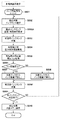
図5は実施例1に従うインクタンク内の残量検出の処理を示すフローチャートである。 FIG. 5 is a flowchart illustrating processing for detecting the remaining amount in the ink tank according to the first embodiment.
図5によれば、記録動作の前後、記録ヘッドの吐出ノズルのクリーニング動作、あるいはインク充填動作の前後などの各種インク供給系の動作の実行タイミングに合わせて、ステップS501のインクタンクの残量検出処理を開始する。 According to FIG. 5, the remaining amount detection of the ink tank in step S501 is performed in accordance with the execution timing of various ink supply system operations such as before and after the recording operation, cleaning operation of the discharge nozzle of the recording head, or before and after the ink filling operation. Start processing.
ステップS502では、残量検出の対象となるインクタンクの選択する。次にステップS503では、残量検出処理の対象となるインクタンクに対してCPU301の制御により放電回路403と電極210との接続制御を実行し、残量検出直前における放電処理を実行する。放電処理が完了後、処理はステップS504に進み、CPU301の制御により電力供給回路309を駆動し、対象インクタンクに備えられた電極210への所定電流の供給あるいは所定電圧の印加を実行する。
In step S502, an ink tank to be subjected to remaining amount detection is selected. Next, in step S503, connection control between the
次にステップS505では、ステップS504における電極への電力供給に基づいて生じた電極210間の電圧値(Vs)をCPU301に備えるA/D変換回路(不図示)を用いてA/D変換制御部404が取得する。ステップS506では取得した電極間電圧(Vs)とインク残量の所定量の有無を判定するための閾値電圧(Vth)を比較する。その比較の結果、Vs>Vth(電極間電圧が閾値電圧を超える)であると判定された場合、処理はステップS507に進み、対象インクタンク内のインク残量は「無し」と判定する。これに対して、Vs≦Vth(電極間電圧は閾値電圧以下)であると判定された場合、処理はステップS508に進み、対象インクタンクのインク残量は「有り」と判定しる。
Next, in step S505, the voltage value (Vs) between the
次に処理はステップS509に進み、残量検出の対象となるインクタンク全てに対する判定が完了したかどうかを調べる。ここで、対象となるインクタンク全てに対する判定がまだ完了していないと判定された場合は、処理はステップS502に戻り、全ての対象のインクタンクの残量検出の判定が完了されるまで処理を継続する。これに対して、対象となるインクタンク全てに対する判定が完了したと判定される場合、処理はステップS510に進む。ステップS510では、残量検出の処理を実行した全てのインクタンクの処理結果を記録装置内部に備えたメモリ303に保存し、処理を終了する。
Next, the process proceeds to step S509, and it is checked whether or not the determination has been completed for all the ink tanks to be subjected to the remaining amount detection. If it is determined that the determination for all the target ink tanks is not yet completed, the process returns to step S502, and the process is performed until the determination of the remaining amount detection for all the target ink tanks is completed. continue. On the other hand, if it is determined that the determination for all target ink tanks has been completed, the process proceeds to step S510. In step S510, the processing results of all the ink tanks for which the remaining amount detection processing has been executed are stored in the
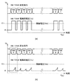
図6はインクの残量検出処理で測定される電極間電圧の時間変化を示す図である。 FIG. 6 is a diagram showing the change over time in the interelectrode voltage measured in the ink remaining amount detection process.
図6において、(a)は対象インクタンクのインク残量が全て「無し」となる場合に想定される電圧変化を示す図である。 In FIG. 6, (a) is a diagram showing a voltage change assumed when the remaining amount of ink in the target ink tank is “none”.
図4で示した構成を用いて、インクタンク内のインク残量検出(液体残量検出)を行いインク残量が「無し」と判定される場合、所定の電圧を印加、または所定の電流を供給しても2つの電極210の間で導通が遮断されるため電流は流れない。そのため、例えば、所定の電流を印加した場合、電極間電圧(Vs)はHighレベルとなって、残量判定の閾値電圧(Vth)を超える。
When the remaining amount of ink in the ink tank (liquid remaining amount detection) is detected using the configuration shown in FIG. 4 and it is determined that the remaining amount of ink is “None”, a predetermined voltage is applied or a predetermined current is applied. Even if it supplies, since conduction | electrical_connection is interrupted | blocked between the two
図6において、(b)は対象インクタンク内のインク残量が全て「有り」となる場合に想定される電圧変化を示す図である。 In FIG. 6, (b) is a diagram showing a voltage change assumed when the remaining amount of ink in the target ink tank is all “present”.
図6(a)に示す場合と同様に、図4で示した構成を用いて、インクタンク内のインク残量を行いインク残量が「有る」と判定される場合、2つの電極に接する導電性を持ったインクにより導通状態になり、インクの抵抗値に基づいた電流が流れ始める。所定時間(Ts)後には、Lowレベルの電極間電圧(Vs)が出力されるが、その電圧は残量判定の閾値電圧(Vth)以下となる。 Similarly to the case shown in FIG. 6A, when the remaining amount of ink in the ink tank is determined using the configuration shown in FIG. Due to the ink having the property, it becomes conductive, and a current based on the resistance value of the ink starts to flow. After a predetermined time (Ts), a low-level inter-electrode voltage (Vs) is output, but the voltage is equal to or lower than a threshold voltage (Vth) for determining the remaining amount.
なお、図6におけるINK0、INK1、INK2、INK3は、図7を参照して後述する残量検出対象となるインクタンクを設定する信号である。 Note that INK0, INK1, INK2, and INK3 in FIG. 6 are signals for setting an ink tank that is a remaining amount detection target to be described later with reference to FIG.
図7は図6(b)において、一つのインクタンク内のインク残量が有りとなる場合の電圧変化と各設定信号の時間変化を示すタイムチャートである。 FIG. 7 is a time chart showing the voltage change and the time change of each setting signal when the remaining amount of ink in one ink tank is present in FIG.
図7に示されるように、時刻T=t1でインクの残量検出の開始信号(STA)のONに基づき、残量検出対象となるインクタンクを設定する信号(INKn)が発生する。図7では、インクタンク0が指定されていることが図示されている。残量検出の対象となるインクタンクが確定したタイミングの後(T=t2)、インクタンクの放電設定信号(DS)が入力され、放電処理が実行される。その後、T=t3でインクタンクへの残量検出のための電力供給直前に測定のためのトリガ信号(TRG)が入力され、T=t4で電圧取り込みトリガ信号(TRG2)により、電極間電圧(Vs)を測定する。T=t4では検出対象のインクタンクへの電力供給を行うための通電設定信号(PSET)をONとして電力供給を行う。その後、所定時間(Ts)の経過後、再度、2つのトリガ信号(TRG1,TRG2)を入力して、T=t5で電極間電圧(Vs)を検出する。
As shown in FIG. 7, at time T = t1, a signal (INKn) for setting an ink tank as a remaining amount detection target is generated based on ON of a start signal (STA) for detecting the remaining amount of ink. FIG. 7 shows that the
以上のようにして、インクタンク0の電極間電圧(Vs)を検出することができる。
As described above, the interelectrode voltage (Vs) of the
従って以上説明した実施例によれば、インクタンクのインク残量有無検出を行う前に放電回路と電極とを接続して電極やインクに蓄積された電荷を放電するので、残留電荷による誤検出を防止することが可能となる。 Therefore, according to the embodiment described above, the discharge circuit and the electrode are connected before the ink remaining amount detection in the ink tank is detected, and the charge accumulated in the electrode and ink is discharged. It becomes possible to prevent.
実施例1はインクタンクのインク残量検出を行う前に放電回路と電極を接続して蓄積された電荷を放電する例について説明したが、この実施例ではインク残量検出後にも放電回路と電極を接続してインクと電極に蓄積された電荷を放電する例を説明する。 In the first embodiment, the discharge circuit and the electrode are connected before the remaining amount of ink in the ink tank is detected, and the accumulated electric charge is discharged. In this embodiment, the discharge circuit and the electrode are also detected after the remaining amount of ink is detected. An example of discharging the charge accumulated in the ink and the electrode by connecting the two will be described.
図8は実施例2に従うインクタンク内の残量検出の処理を示すフローチャートである。なお、図8において、既に実施例1において図5を参照して説明したのと同じ処理ステップについては、同じステップ参照番号を付し、その説明は省略する。 FIG. 8 is a flowchart showing processing for detecting the remaining amount in the ink tank according to the second embodiment. In FIG. 8, the same processing steps as those already described with reference to FIG. 5 in the first embodiment are denoted by the same step reference numerals, and the description thereof is omitted.
図8によれば、ステップS501〜S508の処理を実行し、対象インクタンク内のインク残量が「無し」と判定されても「有り」と判定されても、その後、処理はステップS509’に進む。そして、ステップS509’では、残量検出が完了したインクタンクに充電された電荷を放電するために、ステップS503と同様に、CPU301の制御により放電回路403と電極210を接続し、放電処理を実行する。その後は、前述のように、ステップS509〜S510の処理を実行する。
According to FIG. 8, the processes in steps S501 to S508 are executed, and even if the remaining ink level in the target ink tank is determined to be “None” or “Yes”, the process proceeds to Step S509 ′. move on. In step S509 ′, the
図9は、図8に対応して、実施例2に従うインクの残量検出処理で用いる各設定信号と測定される電極間電圧の時間変化を示す図である。ここでも、実施例1と同様にインクタンク0(INK0)に対する例が示されている。なお、図9において、既に実施例1における図7を参照して説明したのと同じ信号と同じ動作については同じ参照記号を付し、その説明は省略し、ここでは、この実施例に特有の動作についてのみ説明する。 FIG. 9 is a diagram corresponding to FIG. 8 and showing changes over time in the setting signals used in the remaining ink amount detection process according to the second embodiment and the measured interelectrode voltage. Here, as in the first embodiment, an example for the ink tank 0 (INK0) is also shown. In FIG. 9, the same reference numerals are given to the same operations as those already described with reference to FIG. 7 in the first embodiment, and the description thereof is omitted. Only the operation will be described.
図9によれば、時刻T=t5において電極間電圧(Vs)を検出した後、短い時間の経過後、T=t6においてインクタンクの放電設定信号(DS)が入力され、放電処理が再び実行される。 According to FIG. 9, after a short time has elapsed after detecting the interelectrode voltage (Vs) at time T = t5, the ink tank discharge setting signal (DS) is input at T = t6, and the discharge process is executed again. Is done.
従って以上説明した実施例によれば、インクタンクのインク残量検出後にも放電回路と電極とを接続して蓄積された電荷を放電するので、図9が示すように電極間電圧(Vs)は実施例1の場合(破線)と比べて速やかに低下する。これにより、次のインク残量検出動作における電極の放電動作をより短い時間で実行すれば良くなり、残量検出に要する時間を短縮することに貢献する。 Therefore, according to the embodiment described above, the accumulated charge is discharged by connecting the discharge circuit and the electrode even after the remaining amount of ink in the ink tank is detected, so that the interelectrode voltage (Vs) is as shown in FIG. Compared with the case of the first embodiment (broken line), it decreases rapidly. As a result, the electrode discharge operation in the next ink remaining amount detecting operation only needs to be executed in a shorter time, which contributes to shortening the time required for the remaining amount detection.
実施例2はインクタンクのインク残量検出の前後に放電回路と電極を接続してインクと電極に蓄積された電荷を放電する例を説明したが、この実施例ではさらに、電極への通電時間と放電時間とを設定可能な例について説明する。 In the second embodiment, the discharge circuit and the electrode are connected before and after the ink remaining amount detection in the ink tank to discharge the electric charge accumulated in the ink and the electrode. In this embodiment, the energization time for the electrode is further increased. An example in which the discharge time can be set will be described.
インクの成分に起因して、同一量のインクが残存する場合であっても、電極間から観測されるインクの抵抗値に応じた時間応答特性が常に同じではない。即ち、異なるインクに対し、所定の電流を供給したとき、検出される電極間電圧(Vs)の時間変化は異なる。この知見に基づき、この実施例では、インク毎に(インクタンク毎に)に電極への通電時間と放電時間とを異ならせることができるように、その時間設定を行うようにしている。 Due to the ink components, even when the same amount of ink remains, the time response characteristics corresponding to the resistance value of the ink observed between the electrodes are not always the same. That is, when a predetermined current is supplied to different inks, the temporal change in the detected interelectrode voltage (Vs) differs. Based on this knowledge, in this embodiment, the time is set so that the energization time and the discharge time for the electrode can be different for each ink (for each ink tank).
図10は実施例3に従うインクタンク内の残量検出の処理を示すフローチャートである。なお、図10において、既に実施例1、2において図5、図8を参照して説明したのと同じ処理ステップについては、同じステップ参照番号を付し、その説明は省略する。 FIG. 10 is a flowchart showing processing for detecting the remaining amount in the ink tank according to the third embodiment. In FIG. 10, the same processing steps as those already described with reference to FIGS. 5 and 8 in the first and second embodiments are denoted by the same step reference numerals, and the description thereof is omitted.
図10によれば、ステップS501〜S502の処理後、ステップS502Aにおいて検出処理の対象インクタンクに対して個別に電極210への電力供給時間の設定と電極210からの放電時間の設定を行う。
According to FIG. 10, after the processing of steps S501 to S502, the setting of the power supply time to the
その後、ステップS503ではその設定時間に従って電極210からの放電処理を行う。さらに、ステップS504ではその設定時間に従って対象インクタンクに備えられた電極210への所定電流の供給あるいは所定電圧の印加を実行する。その後は、実施例1、2で説明したように、ステップS505〜S510の処理を実行する。
Thereafter, in step S503, the discharge process from the
図11は、図9に対応して、実施例3に従うインクの残量検出処理で用いる各設定信号と測定される電極間電圧の時間変化を示す図である。ここでは、インクタンクX(INK X)に対する例が示されている。なお、図11において、既に実施例1、2における図7、9を参照して説明したのと同じ信号と同じ動作については同じ参照記号を付し、その説明は省略し、ここでは、この実施例に特有の動作についてのみ説明する。 FIG. 11 is a diagram corresponding to FIG. 9 and showing changes over time in the setting signals used in the ink remaining amount detection process according to the third embodiment and the measured interelectrode voltage. Here, an example for an ink tank X (INK X) is shown. In FIG. 11, the same reference numerals are given to the same operations as those already described with reference to FIGS. 7 and 9 in the first and second embodiments, and the description thereof will be omitted. Only the operation specific to the example will be described.
図11に示すように、検出対象のインクタンク(INK 0)に対しては検出される電極間電圧(Vs0)は閾値電圧(Vth)以下となる。しかしながら、別の検出対象のインクタンク(INK X)に対しては電極間電圧(VsX)が動的電気抵抗の違いにより、インク残量が十分あるにも係らず、同一の通電時間では、時刻T=t5のタイミングでは閾値電圧(Vth)以上になる場合がある。それはインクが充電作用によって内部電圧を持ち、見掛け上、抵抗値が増加してしまうからである。 As shown in FIG. 11, for the ink tank (INK 0) to be detected, the detected interelectrode voltage (Vs0) is equal to or lower than the threshold voltage (Vth). However, with respect to another detection target ink tank (INK X), the voltage between electrodes (VsX) has a sufficient amount of ink due to the difference in dynamic electrical resistance, but the same energization time causes the time At the timing of T = t5, the threshold voltage (Vth) may be exceeded. This is because the ink has an internal voltage due to the charging action, and the resistance value apparently increases.
この実施例では、このような状況を考慮し、図11に示すように、インクタンクX(INK X)に対する電力供給時間(Ts)を約1/2の時間を設定し供給することにより、インクタンクX(INK X)への通電時間を減少させる。図11の一番下には一点鎖線でインクタンクX(INK X)に対する電力供給時間をTsとした場合を示し、実線でその電力供給時間をTs/2とした場合の電極間電圧の時間変化を示している。また、これとともに、2つのトリガ信号(TRG1,TRG2)もより早いタイミングで入力されることになり、T=t5’で検出される電極間電圧(Vsx’)は閾値電圧(Vth)以下となる。 In this embodiment, in consideration of such a situation, as shown in FIG. 11, the ink supply time (Ts) for the ink tank X (INK X) is set to about ½ time and supplied. Reduce the energization time to tank X (INK X). The bottom of FIG. 11 shows a case where the power supply time for the ink tank X (INK X) is Ts by a one-dot chain line, and the time change of the interelectrode voltage when the power supply time is Ts / 2 by a solid line. Is shown. At the same time, the two trigger signals (TRG1, TRG2) are also input at an earlier timing, and the interelectrode voltage (Vsx ′) detected at T = t5 ′ is equal to or lower than the threshold voltage (Vth). .
このことから、そもそもの通電時間を一律に短く設定しておくことも考えられる。しかしながら、短時間の電力供給では、ノイズの除去には不十分であったり、また、インク種によっては逆に所定の供給時間を経過しないと、インク有無に相当する電気的特性の変化が得られない場合があることも分かっている。従って、この実施例のように、インク種個々に通電時間を設定することが精度の良いインク残量の判定には最適なのである。 For this reason, it is also conceivable to set the energization time short in the first place. However, short-time power supply is not sufficient for noise removal, and depending on the type of ink, if a predetermined supply time does not elapse, a change in electrical characteristics corresponding to the presence or absence of ink can be obtained. I know that there may be no cases. Therefore, as in this embodiment, setting the energization time for each ink type is optimal for accurate determination of the remaining ink amount.
加えて、通電時間のみならず放電時間をインクごとに設定してもよい。この放電時間はインクタンクごとに異なる値が設定されても良いことは言うまでもない。基本的には通電時間に比例して放電時間を設定することが好ましいが、電荷残留影響を考慮しながら、放電時間は短く設定する方が、全体の検出時間を短くする上で好ましい。 In addition, not only the energization time but also the discharge time may be set for each ink. It goes without saying that this discharge time may be set to a different value for each ink tank. Basically, it is preferable to set the discharge time in proportion to the energization time, but it is preferable to set the discharge time short in consideration of the residual charge effect in order to shorten the entire detection time.
従って以上説明した実施例に従えば、インタタンクごとに電極への通電時間と放電時間とを設定可能にするので、そのインクタンクに収容されるインクの特性に応じた最適な通電時間と放電時間を設定することができる。これにより、より正確なまた迅速なインク残量検出が可能になる。 Therefore, according to the embodiment described above, the energization time and discharge time for the electrodes can be set for each inter tank, so that the optimal energization time and discharge time according to the characteristics of the ink stored in the ink tank. Can be set. As a result, the remaining amount of ink can be detected more accurately and quickly.
実施例1では、電力供給回路309から複数のインクタンクの全ての電極に並列に電力を供給する構成としたが、この実施例では残量検出の対象となるインクタンクの電極に対してのみ電力を供給する構成について説明する。
In the first embodiment, power is supplied in parallel from the
図12は実施例4に従うインクタンク内のインクの残量を検出するために用いられる回路の接続構成を模式的に示す図である。なお、図12において、既に実施例1の図4を参照して説明したのと同じ構成には同じ参照番号を付し、その説明は省略し、ここではこの実施例に特有の構成と動作についてのみ説明する。 FIG. 12 is a diagram schematically showing a connection configuration of a circuit used for detecting the remaining amount of ink in the ink tank according to the fourth embodiment. In FIG. 12, the same components as those already described with reference to FIG. 4 of the first embodiment are denoted by the same reference numerals, and the description thereof is omitted. Here, the configurations and operations unique to this embodiment are described. Only explained.
電力供給回路309の内部は電流源から電力の供給を受けている時に所定の電流を出力する。ただし、解放電圧(負荷がオープンの時の電圧)は、電力供給回路309に供給された電源の電圧を超えることはない。
The
図12に示されているように、この実施例では、電力供給回路309及び放電回路403と複数のインクタンク208との間にインクタンク選択切替回路1202を備える。インクタンク選択切替回路1202はCPU301の切替回路制御部1201により検出対象のインクタンクを切替選択する。
As shown in FIG. 12, in this embodiment, an ink tank
CPU301は検出対象のインクタンクを切り替えるために切替回路制御部1201を介してインクタンク選択切替回路1202に制御信号を出力し、インクタンク選択切替回路1202はその制御信号に基づき検出対象のインクタンクを切り替える。さらには、電極間電圧(Vs)を検出するときの出力設定の切り替えを行う。
The
図13は実施例4に従うインクタンク内の残量検出の処理を示すフローチャートである。なお、図13において、既に実施例1、2において図5、図8を参照して説明したのと同じ処理ステップについては、同じステップ参照番号を付し、その説明は省略する。 FIG. 13 is a flowchart illustrating processing for detecting the remaining amount in the ink tank according to the fourth embodiment. In FIG. 13, the same processing steps as those already described in the first and second embodiments with reference to FIGS. 5 and 8 are denoted by the same step reference numerals, and the description thereof is omitted.
図13によれば、ステップS501の処理後、ステップS501Aにおいて、インクタンク選択切替回路1202を設定し、検出対象となるインクタンクを選択する。これにより、選択されたインクタンク208と電力供給回路309及び放電回路403とが接続される。
According to FIG. 13, after the process of step S501, in step S501A, the ink tank
次に選択されたインクタンクに対してステップS503では前述したように放電処理を実行し、さらにステップS504では選択されたインクタンクの電極210への所定電流の供給あるいは所定電圧の印加を実行する。これ以降、前述したステップS506〜S510の処理を実行する。なお、ステップS509’では選択されたインクタンクに対して前述したように放電処理を実行する。
Next, in step S503, the discharge process is performed on the selected ink tank as described above, and in step S504, a predetermined current is supplied to the
図14は、図13に対応して、実施例4に従うインクの残量検出処理で用いる各設定信号と測定される電極間電圧の時間変化を示す図である。ここでは、インクタンク0(INK0)、インクタンク1(INK1)、インクタンク(INK2)に対する例が示されている。なお、図14において、既に実施例1、2における図7、図9を参照して説明したのと同じ信号と同じ動作については同じ参照記号を付し、その説明は省略し、ここでは、この実施例に特有の動作についてのみ説明する。 FIG. 14 is a diagram corresponding to FIG. 13 and shows changes with time of each setting signal used in the remaining ink amount detection process according to the fourth embodiment and the measured interelectrode voltage. Here, an example is shown for ink tank 0 (INK0), ink tank 1 (INK1), and ink tank (INK2). In FIG. 14, the same reference numerals are given to the same operations as those already described with reference to FIGS. 7 and 9 in the first and second embodiments, and the description thereof will be omitted. Only operations specific to the embodiment will be described.
図14によれば、時刻T=t1でインクの残量検出の開始信号(STA)のONに基づき、残量検出対象となるインクタンク0を設定する信号(INK0)を発生すると、切替回路制御部1201からは制御信号をインクタンク選択切替回路1202に出力する。この実施例では残量検出対象となるインクタンクを選択する制御信号として3つの信号(SW0、SW1、SW2)を用いる。従って、この実施例ではこれら3つの信号により8つのインクタンクのいずれかを選択切替することができる。図14の例では、SW0とSW2がハイレベル、SW1がローレベルとなることによりインクタンク0を選択する。また、SW0とSW1がハイレベル、SW2がローレベルとなることによりインクタンク1を選択する。
According to FIG. 14, when a signal (INK0) for setting the
このようにして、インクタンク選択切替回路1202は検出対象としてインクタンク0を選択する。検出対象となるインクタンクを確定後、図14に示すように、実施例2と同様に、放電処理を実行し、その後、電力供給を行い電極間電圧を測定する。その後、インクタンク0への電力供給を行い、所定時間後、再度電極間電圧(Vs0)が検出される。そして、再度、放電処理を実行する。
In this way, the ink tank
このようにして、インクタンク0に対する残量検出を実行後、CPU301は検出対象となるインクタンクをインクタンク1(INK1)とするよう切替回路制御部1201を介して制御信号をインクタンク選択切替回路1202に出力する。これ以降、選択されたインクタンクに対して前述と同様の残量検出処理を実行して電極間電圧(Vs1)を検出する。インクタンク1に対する残量検出を実行後さらに、検出対象となるインクタンクをインクタンク2(INK2)に切替え、前述と同様の残量検出処理を実行する。以降、全ての検出対象のインクタンクの残量検出を実行する。
After executing the remaining amount detection for the
以上説明したような構成を用いることにより、この実施例に従えば次のような効果を奏する。所定電流のを供給により検出対象のインクタンクが収容するインクへの充電効果(インクに電荷が残留し、見掛け上、導通抵抗が上昇する現象)を除去するために、残量検出の電力供給の前後で放電処理を行なうことが重要であることは既に説明した通りである。しかしながら、電力供給回路からの微小なリーク電流さえも前記の充電効果が生じ、正確な残量検出に影響することがある。さらに言えば、インクタンク切替回路の切替動作時にもわずかながら発生するフィードスルー、あるいは、内部クロストーク、などのノイズも、正確な残量検出に影響を及ぼすことがある。 By using the configuration as described above, the following effects can be obtained according to this embodiment. In order to eliminate the charging effect on the ink stored in the ink tank to be detected by supplying a predetermined current (a phenomenon in which charge remains in the ink and apparently increases the conduction resistance) As described above, it is important to perform the discharge treatment before and after. However, even a minute leak current from the power supply circuit may cause the charging effect, which may affect accurate remaining amount detection. Furthermore, noise such as feedthrough or internal crosstalk that slightly occurs during the switching operation of the ink tank switching circuit may affect accurate remaining amount detection.
従って、この実施例では検出対象とするインクタンクにのみ電力を供給することにより、多数のインクタンクのインク残量検出を行う際の電力消費を削減するとともに、電極間電圧の検出前後に放電処理を実行することで微小なリーク電流の影響を低減している。これにより、より高精度なインク残量の判定を行なうことが可能になる。 Therefore, in this embodiment, power is supplied only to the ink tanks to be detected, thereby reducing the power consumption when detecting the remaining amount of ink in a large number of ink tanks, and the discharge process before and after the detection of the interelectrode voltage. By executing this, the influence of a minute leak current is reduced. This makes it possible to determine the remaining amount of ink with higher accuracy.
また、以上説明した実施例では、インクタンク設置台209に電極210を2本備えた例について説明したが、本発明はこれによって限定されるものではない。例えば、その内の1つのみを電極とし、他方は電気伝導性のある金属板など電気伝導体の構成であっても、インクを通じて電流を供給し、その際の電圧値を取得できる構成であれば本発明は適用可能である。
In the embodiment described above, an example in which two
さらに、本発明はインクタンク209設置台に着脱可能なインクタンク208のインク残量検知に限定されるものではない。例えば、バッファタンク211のインク残量検出や、記録ヘッド201内部に備えたヘッド内サブタンクのインク残量検出に適用することもできる。
Further, the present invention is not limited to detecting the remaining amount of ink in the
100 記録装置、103 表示パネル、104 操作パネル、
201 記録ヘッド、202 キャリッジ、206 エンコーダセンサ、
207 記録用紙、208 インクタンク、209 インクタンク設置台、
210 電極、301 CPU、302 通信インタフェース、303 メモリ
304 ヘッド制御回路、305 モータ・センサ制御回路、306 モータ、
307 センサ、308 A/Dポート、309 定電流/定電圧供給回路、
401 電力供給制御部、402 放電処理制御部、403 放電回路
404 A/D変換制御部、405 閾値電圧判定部、406 残量データ抽出部、
407 残量データ制御部、1201 切替回路制御部、1202 インク選択切替回路
100 recording device, 103 display panel, 104 operation panel,
201 recording head, 202 carriage, 206 encoder sensor,
207 recording paper, 208 ink tank, 209 ink tank installation base,
210 Electrode, 301 CPU, 302 Communication interface, 303
307 sensor, 308 A / D port, 309 constant current / constant voltage supply circuit,
401 power supply control unit 402 discharge
407 Residual amount data control unit, 1201 switching circuit control unit, 1202 ink selection switching circuit
Claims (8)
前記複数の液体収納容器の中から所定量の液体があるか否かの判定動作を行う液体収納容器を選択する選択手段と、
前記複数の液体収納容器のそれぞれに備えられた第1の電極と第2の電極と、
前記第1の電極、前記第2の電極、及び当該第1の電極と当該第2の電極を備えた液体収納容器に収容された液体に蓄積された電荷を放電する放電手段と、
前記選択手段により選択された液体収納容器に備えられた前記第1の電極と前記第2の電極に電力を供給する通電手段と、
前記第1の電極と前記第2の電極の間の電圧を検出する検出手段と、
前記通電手段を動作させているときに前記検出手段により検出された電圧に基づいて、前記選択手段により選択された液体収納容器の液体に関して前記判定動作を行う判定手段と、を有する液体吐出記録装置であって、
前記選択手段によって前記判定動作を行う液体収納容器が選択された後であって、当該液体収納容器の前記判定動作を行う直前に当該液体収納容器に対して前記放電手段を所定時間動作させることを特徴とする液体吐出記録装置。 A plurality of liquid storage containers each storing liquid supplied to a recording head that discharges the liquid;
Selecting means for selecting a liquid storage container for performing an operation of determining whether or not there is a predetermined amount of liquid from the plurality of liquid storage containers;
A first electrode and a second electrode provided in each of the plurality of liquid storage containers;
Discharge means for discharging the charge accumulated in the liquid stored in the liquid storage container including the first electrode, the second electrode, and the first electrode and the second electrode;
Energization means for supplying power to the first electrode and the second electrode provided in the liquid container selected by the selection means;
Detecting means for detecting a voltage between the front Symbol the first electrode and the second electrode,
Based on the voltage detected by said detecting means when operating said energizing means, a liquid discharge recording apparatus having a determination means for performing the determination operation with respect to the liquid of the selected liquid container by said selection means Because
After the liquid storage container that performs the determination operation is selected by the selection unit, and immediately before the determination operation of the liquid storage container is performed, the discharge unit is operated for a predetermined time with respect to the liquid storage container. A liquid discharge recording apparatus.
それぞれに第1の電極と第2の電極を備えた前記複数の液体収納容器の中から、所定量の液体があるか否かの判定動作を行う液体収納容器を選択する選択工程と、
前記選択工程において選択された液体収納容器に備えられた第1の電極と第2の電極と、該液体収納容器に収容された液体に蓄積された電荷を放電する放電工程と、
当該液体収納容器に備えられた第1の電極と第2の電極に電力を供給する通電工程と、
前記第1の電極と前記第2の電極の間の電圧を検出する検出工程と、
前記通電工程において電力を供給しているときに、前記検出工程において検出された電圧に基づいて、前記選択工程において選択された液体収納容器に対する前記判定動作を行う判定工程とを有し、
前記選択工程において選択された液体収納容器に対して前記判定工程における前記判定動作を行う直前に、前記放電工程における放電を所定時間、行うことを特徴とする液体残量検出方法。 A liquid Karadazanryou detection method in a liquid discharge recording apparatus for performing recording by a recording head for discharging the liquid supplied from each of the plurality of liquid containers,
A selection step of selecting a liquid storage container for performing a determination operation as to whether or not there is a predetermined amount of liquid from the plurality of liquid storage containers each provided with a first electrode and a second electrode;
A first electrode and a second electrode provided on the liquid container that has been selected in the selection step, a discharge step of discharging the charges accumulated in the liquid contained in the liquid container,
An energization step of supplying power to the first electrode and the second electrode provided in the liquid storage container;
A detection step of detecting a voltage between the front Symbol the first electrode and the second electrode,
A determination step of performing the determination operation on the liquid storage container selected in the selection step based on the voltage detected in the detection step when power is supplied in the energization step ;
Immediately before performing the determination operation in the determination step on the liquid storage container selected in the selection step, the discharge in the discharge step is performed for a predetermined time .
Priority Applications (1)
| Application Number | Priority Date | Filing Date | Title |
|---|---|---|---|
| JP2015110804A JP6494428B2 (en) | 2015-05-29 | 2015-05-29 | Liquid discharge recording apparatus and liquid remaining amount detection method |
Applications Claiming Priority (1)
| Application Number | Priority Date | Filing Date | Title |
|---|---|---|---|
| JP2015110804A JP6494428B2 (en) | 2015-05-29 | 2015-05-29 | Liquid discharge recording apparatus and liquid remaining amount detection method |
Publications (3)
| Publication Number | Publication Date |
|---|---|
| JP2016221847A JP2016221847A (en) | 2016-12-28 |
| JP2016221847A5 JP2016221847A5 (en) | 2018-02-08 |
| JP6494428B2 true JP6494428B2 (en) | 2019-04-03 |
Family
ID=57745593
Family Applications (1)
| Application Number | Title | Priority Date | Filing Date |
|---|---|---|---|
| JP2015110804A Active JP6494428B2 (en) | 2015-05-29 | 2015-05-29 | Liquid discharge recording apparatus and liquid remaining amount detection method |
Country Status (1)
| Country | Link |
|---|---|
| JP (1) | JP6494428B2 (en) |
Families Citing this family (2)
| Publication number | Priority date | Publication date | Assignee | Title |
|---|---|---|---|---|
| JP6888398B2 (en) | 2017-04-28 | 2021-06-16 | ブラザー工業株式会社 | Inkjet recording device |
| JP2021154518A (en) * | 2020-03-25 | 2021-10-07 | セイコーエプソン株式会社 | Liquid jetting device |
Family Cites Families (6)
| Publication number | Priority date | Publication date | Assignee | Title |
|---|---|---|---|---|
| US5162817A (en) * | 1989-01-28 | 1992-11-10 | Canon Kabushiki Kaisha | Ink jet with residual ink detection that compensates for different ink properties |
| JPH0867011A (en) * | 1994-08-30 | 1996-03-12 | Canon Inc | Recorder |
| JP2006137002A (en) * | 2004-11-10 | 2006-06-01 | Seiko Epson Corp | Judgment of printing material container |
| JP2007268805A (en) * | 2006-03-30 | 2007-10-18 | Canon Inc | Recorder and residual ink detection method |
| JP2014008742A (en) * | 2012-07-02 | 2014-01-20 | Canon Inc | Inkjet recording apparatus and remaining ink amount presence/absence detection method |
| JP6164985B2 (en) * | 2013-08-29 | 2017-07-19 | キヤノン株式会社 | Recording apparatus and ink remaining amount detection method |
-
2015
- 2015-05-29 JP JP2015110804A patent/JP6494428B2/en active Active
Also Published As
| Publication number | Publication date |
|---|---|
| JP2016221847A (en) | 2016-12-28 |
Similar Documents
| Publication | Publication Date | Title |
|---|---|---|
| US9415601B1 (en) | Printing apparatus | |
| US7850263B2 (en) | Liquid consumption apparatus and liquid consumption amount control method | |
| US9486999B2 (en) | Image forming apparatus | |
| US9233550B2 (en) | Printing apparatus and residual ink detection method | |
| TW201637880A (en) | Printer fluid impedance sensing in a printhead | |
| JPH0998243A (en) | Recorder and facsimile equipment using the recorder | |
| JP6494428B2 (en) | Liquid discharge recording apparatus and liquid remaining amount detection method | |
| US11878528B2 (en) | Liquid ejection device, method of controlling liquid ejection device, and non-transitory computer-readable recording medium therefor | |
| US9283790B2 (en) | Liquid ejecting method and liquid ejecting apparatus | |
| US9102144B2 (en) | Liquid consuming apparatus and control method for liquid consuming apparatus | |
| US10752010B2 (en) | Liquid ejection apparatus | |
| US8136912B2 (en) | Inspective ejection method for fluid ejection apparatus and fluid ejection apparatus implementing the method | |
| US9340014B2 (en) | Prefire before pixel in an inspection mode | |
| JP2015054484A (en) | Ink jet image forming apparatus, method of controlling the same and program | |
| JP2007112086A (en) | Printing head inspecting device, printer, printing head inspecting method and its program | |
| JP5955060B2 (en) | Recording apparatus and voltage supply method in recording apparatus | |
| US20070285446A1 (en) | Liquid consumption apparatus and liquid amount determination method | |
| US8240799B2 (en) | Inkjet printing apparatus and printhead control method of the apparatus | |
| JP2007076181A (en) | Droplet ejection device | |
| JP2018069533A (en) | Inkjet recording device | |
| JP2014008742A (en) | Inkjet recording apparatus and remaining ink amount presence/absence detection method | |
| JP2007268805A (en) | Recorder and residual ink detection method | |
| JP2023041441A (en) | Recording device and method for controlling the same | |
| US9283751B2 (en) | Liquid ejecting apparatus and method of controlling liquid ejecting apparatus | |
| JP2023025825A (en) | Recording device and control method of the same |
Legal Events
| Date | Code | Title | Description |
|---|---|---|---|
| A521 | Written amendment |
Free format text: JAPANESE INTERMEDIATE CODE: A523 Effective date: 20171218 |
|
| A621 | Written request for application examination |
Free format text: JAPANESE INTERMEDIATE CODE: A621 Effective date: 20171218 |
|
| A977 | Report on retrieval |
Free format text: JAPANESE INTERMEDIATE CODE: A971007 Effective date: 20180814 |
|
| A131 | Notification of reasons for refusal |
Free format text: JAPANESE INTERMEDIATE CODE: A131 Effective date: 20180820 |
|
| A521 | Written amendment |
Free format text: JAPANESE INTERMEDIATE CODE: A523 Effective date: 20181018 |
|
| TRDD | Decision of grant or rejection written | ||
| A01 | Written decision to grant a patent or to grant a registration (utility model) |
Free format text: JAPANESE INTERMEDIATE CODE: A01 Effective date: 20190204 |
|
| A61 | First payment of annual fees (during grant procedure) |
Free format text: JAPANESE INTERMEDIATE CODE: A61 Effective date: 20190305 |
|
| R151 | Written notification of patent or utility model registration |
Ref document number: 6494428 Country of ref document: JP Free format text: JAPANESE INTERMEDIATE CODE: R151 |