[第1の実施の形態]
以下、図面を用いて、本発明の第1の実施の形態に係る遊技台(例えば、パチンコ機100等の弾球遊技機やスロット機等の回胴遊技機)について詳細に説明する。まず、図1を用いて、本実施の形態に係るパチンコ機100の全体構成について説明する。なお、同図はパチンコ機100を正面側(遊技者側)から見た外観斜視図である。パチンコ機100は、外部的構造として、外枠102と、本体104と、前面枠扉106と、球貯留皿付扉108と、発射装置110と、遊技盤200と、をその前面に備える。
[First Embodiment]
Hereinafter, a gaming machine (for example, a ball game machine such as the pachinko machine 100 or a spinning machine such as a slot machine) according to the first embodiment of the present invention will be described in detail with reference to the drawings. First, the overall configuration of the pachinko machine 100 according to the present embodiment will be described with reference to FIG. In addition, the figure is the external appearance perspective view which looked at the pachinko machine 100 from the front side (player side). As an external structure, the pachinko machine 100 includes an outer frame 102, a main body 104, a front frame door 106, a door 108 with a ball storage tray, a launching device 110, and a game board 200 on the front surface.
外枠102は、遊技機設置営業店に設けられた設置場所(島設備等)へと固定させるための縦長方形状からなる木製の枠部材である。本体104は、内枠と呼ばれ、外枠102の内部に備えられ、ヒンジ部112を介して外枠102に回動自在に装着された縦長方形状の遊技機基軸体となる部材である。また、本体104は、枠状に形成され、内側に空間部114を有している。また、本体104が開放された場合、本体104の開放を検出する不図示の内枠開放センサを備える。
The outer frame 102 is a wooden frame member having a vertical rectangular shape for fixing to an installation location (island facilities or the like) provided in a gaming machine installation sales shop. The main body 104 is referred to as an inner frame, and is a member that is provided inside the outer frame 102 and serves as a longitudinal rectangular gaming machine base body that is rotatably attached to the outer frame 102 via a hinge portion 112. The main body 104 is formed in a frame shape and has a space 114 inside. In addition, when the main body 104 is opened, an inner frame opening sensor (not shown) that detects the opening of the main body 104 is provided.
前面枠扉106は、錠ユニット105によるロック機能付きで且つ開閉自在となるようにパチンコ機100の前面側となる本体104の前面に対しヒンジ部112を介して装着され、枠状に構成されることでその内側を開口部116とした扉部材である。なお、前面枠扉106には、開口部116にガラス製又は樹脂製の透明板部材118が設けられ、前面側には、スピーカ120や枠ランプ122が取り付けられている。前面枠扉106の後面と遊技盤200の前面とで遊技領域124を区画形成する。また、前面枠扉106が開放された場合、前面枠扉106の開放を検出する前面枠扉開放センサ107を備える。
The front frame door 106 is attached to the front surface of the main body 104 on the front side of the pachinko machine 100 via a hinge portion 112 so as to be openable and closable with a lock function by the lock unit 105, and is configured in a frame shape. Thus, the door member has an opening 116 inside thereof. The front frame door 106 is provided with a transparent plate member 118 made of glass or resin at the opening 116, and a speaker 120 and a frame lamp 122 are attached to the front side. A game area 124 is defined by the rear surface of the front frame door 106 and the front surface of the game board 200. Further, a front frame door opening sensor 107 that detects opening of the front frame door 106 when the front frame door 106 is opened is provided.
球貯留皿付扉108は、パチンコ機100の前面において本体104の下側に対して、ロック機能付きで且つ開閉自在となるように装着された扉部材である。球貯留皿付扉108は、複数の遊技球(以下、単に「球」と称する場合がある)が貯留可能で且つ発射装置110へと遊技球を案内させる通路が設けられている上皿126と、上皿126に貯留しきれない遊技球を貯留する下皿128と、遊技者の操作によって上皿126に貯留された遊技球を下皿128へと排出させる球抜ボタン130と、遊技者の操作によって下皿128に貯留された遊技球を遊技球収集容器(俗称、ドル箱)へと排出させる球排出レバー132と、遊技者の操作によって発射装置110へと案内された遊技球を遊技盤200の遊技領域124へと打ち出す球発射ハンドル134と、遊技者の操作によって各種演出装置206の演出態様に変化を与えるチャンスボタン136と、チャンスボタン136を発光させるチャンスボタンランプ138と、設定者(例えば、パチンコ機100の製造工場の作業者、遊技店員、遊技者)の操作によって遊技に関する設定(例えば、時刻の設定、演出内容の設定)を行う操作手段700(後述)と、遊技店に設置されたカードユニット(CRユニット)に対して球貸し指示を行う球貸操作ボタン140と、カードユニットに対して遊技者の残高の返却指示を行う返却操作ボタン142と、遊技者の残高やカードユニットの状態を表示する球貸表示部144と、を備える。また、下皿128が満タンであることを検出する不図示の下皿満タンセンサを備える。
The door 108 with a ball storage tray is a door member attached to the lower side of the main body 104 on the front surface of the pachinko machine 100 so as to have a lock function and be openable and closable. The ball storage tray-equipped door 108 is capable of storing a plurality of game balls (hereinafter simply referred to as “balls”), and an upper plate 126 provided with a passage for guiding the game balls to the launching device 110. A lower plate 128 that stores game balls that cannot be stored in the upper plate 126, a ball removal button 130 that discharges the game balls stored in the upper plate 126 to the lower plate 128 by the player's operation, A ball discharge lever 132 that discharges game balls stored in the lower plate 128 to a game ball collection container (common name, dollar box) by operation, and a game ball guided to the launching device 110 by operation of the player 200 ball launching handles 134 for launching into the game area 124, chance buttons 136 for changing the effects of the various effects devices 206 by the player's operation, and the chance button 136 to emit light. Operation means 700 for performing settings relating to a game (for example, setting of time and setting of effect contents) by operation of the sbutton lamp 138 and a setter (for example, an operator, a game shop clerk, or a player in a manufacturing factory of the pachinko machine 100). (Described later), a ball lending operation button 140 for instructing ball lending to a card unit (CR unit) installed in the game store, and a return operation button 142 for instructing the card unit to return the balance of the player. And a ball rental display unit 144 that displays the balance of the player and the state of the card unit. In addition, a lower plate full tank sensor (not shown) that detects that the lower plate 128 is full is provided.
発射装置110は、本体104の下方に取り付けられ、球発射ハンドル134が遊技者に操作されることによって回動する発射杆146と、遊技球を発射杆146の先端で打突する発射槌148と、を備える。
The launching device 110 is attached to the lower side of the main body 104, and a launching rod 146 that rotates when the ball launching handle 134 is operated by the player, and a launching rod 148 that strikes the game ball at the tip of the launching rod 146. .
遊技盤200は、前面に遊技領域124を有し、本体104の空間部114に臨むように、所定の固定部材を用いて本体104に着脱自在に装着されている。なお、遊技領域124は、遊技盤200を本体104に装着した後、開口部116から観察することができる。
The game board 200 has a game area 124 on the front surface, and is detachably attached to the main body 104 using a predetermined fixing member so as to face the space 114 of the main body 104. The game area 124 can be observed from the opening 116 after the game board 200 is mounted on the main body 104.
図2は、図1のパチンコ機100を背面側から見た外観図である。パチンコ機100の背面上部には、上方に開口した開口部を有し、遊技球を一時的に貯留するための球タンク150と、球タンク150の下方に位置し、球タンク150の底部に形成した連通孔を通過して落下する球を背面右側に位置する払出装置152に導くためのタンクレール154とを配設している。
FIG. 2 is an external view of the pachinko machine 100 of FIG. 1 viewed from the back side. The upper part of the back surface of the pachinko machine 100 has an opening that opens upward, a ball tank 150 for temporarily storing game balls, and a lower part of the ball tank 150 that is formed at the bottom of the ball tank 150. A tank rail 154 for guiding a ball that has passed through the communicating hole and dropped to the dispensing device 152 located on the right side of the back surface is provided.
払出装置152は、筒状の部材からなり、その内部には、不図示の払出モータとスプロケットと払出センサとを備えている。スプロケットは、払出モータによって回転可能に構成されており、タンクレール154を通過して払出装置152内に流下した遊技球を一時的に滞留させると共に、払出モータを駆動して所定角度だけ回転することにより、一時的に滞留した遊技球を払出装置152の下方へ1個ずつ送り出すように構成している。
The payout device 152 is formed of a cylindrical member, and includes a payout motor, a sprocket, and a payout sensor (not shown) inside. The sprocket is configured to be rotatable by a payout motor. The sprocket that temporarily passes through the tank rail 154 and flows down into the payout device 152 is temporarily retained, and the payout motor is driven to rotate by a predetermined angle. Thus, the temporarily accumulated game balls are sent one by one downward to the payout device 152.
払出センサは、スプロケットが送り出した遊技球の通過を検知するためのセンサであり、遊技球が通過しているときにハイまたはローの何れか一方の信号を、遊技球が通過していないときはハイまたはローの何れか他方の信号を払出制御部600へ出力する。なお、この払出センサを通過した遊技球は、不図示の球レールを通過してパチンコ機100の表側に配設した上皿126に到達するように構成しており、パチンコ機100は、この構成により遊技者に対して球の払い出しを行う。
The payout sensor is a sensor for detecting the passage of the game ball sent out by the sprocket. When the game ball is passing, either a high signal or a low signal is passed. Either the high signal or the low signal is output to the dispensing control unit 600. The game ball that has passed through the payout sensor passes through a ball rail (not shown) and reaches the upper plate 126 disposed on the front side of the pachinko machine 100. The pachinko machine 100 has this configuration. To pay out the ball to the player.
払出装置152の図中左側には、遊技全般の制御処理を行う主制御部300を構成する主基板156を収納する主基板ケース158、主制御部300が生成した処理情報に基づいて演出に関する制御処理を行う第1副制御部400を構成する第1副基板160を収納する第1副基板ケース162、第1副制御部400が生成した処理情報に基づいて演出に関する制御処理を行う第2副制御部500を構成する第2副基板164を収納する第2副基板ケース166、遊技球の払出に関する制御処理を行う払出制御部600を構成すると共に遊技店員の操作によってエラーを解除するエラー解除スイッチ168を備える払出基板170を収納する払出基板ケース172、遊技球の発射に関する制御処理を行う発射制御部630を構成する発射基板174を収納する発射基板ケース176、各種電気的遊技機器に電源を供給する電源制御部660を構成すると共に遊技店員の操作によって電源をオンオフする電源スイッチ178と電源投入時に操作されることによってRWMクリア信号を主制御部300に出力するRWMクリアスイッチ180とを備える電源基板182を収納する電源基板ケース184、および払出制御部600とカードユニットとの信号の送受信を行うCRインタフェース部186を配設している。
On the left side of the payout device 152 in the figure, a main board case 158 that houses the main board 156 that constitutes the main control section 300 that performs control processing for the entire game, and control related to effects based on the processing information generated by the main control section 300 The first sub-board case 162 that houses the first sub-board 160 that constitutes the first sub-control unit 400 that performs processing, and the second sub-board that performs control processing related to effects based on the processing information generated by the first sub-control unit 400. An error canceling switch that configures a second sub-board case 166 that houses the second sub-board 164 that constitutes the control unit 500, a payout control unit 600 that performs control processing related to the payout of game balls, and that releases an error by the operation of a game clerk Discharge board case 172 for storing a payout board 170 provided with 168, launch board constituting a launch control unit 630 for performing control processing relating to the launch of a game ball A launch board case 176 for storing 74, a power control unit 660 for supplying power to various electrical gaming machines, and a power switch 178 for turning on / off the power by the operation of a game clerk and an RWM clear by being operated when the power is turned on A power board case 184 that houses a power board 182 that includes an RWM clear switch 180 that outputs a signal to the main controller 300, and a CR interface 186 that transmits and receives signals between the payout controller 600 and the card unit are provided. ing.
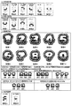
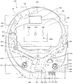
図3は、遊技盤200を正面から見た略示正面図である。遊技盤200には、外レール202と内レール204とを配設し、遊技球が転動可能な遊技領域124を区画形成している。遊技領域124の略中央には、演出装置206を配設している。外レール202は演出装置206の上方から右方にまで延びており、演出装置206上部と外レール202との空間を通って遊技盤200の右側の遊技領域124まで遊技球が飛翔できるようになっている。つまり、遊技領域124は、発射された遊技球が流下する経路として装飾部材としての演出装置206を挟んで左側となる第一流下経路と、発射された遊技球が流下する経路として装飾部材を挟んで右側となる第二流下経路とを有している。以下、第一流下経路に遊技球を打ち出すことを「左打ち」と称し、第二流下経路に遊技球を打ち出すことを「右打ち」と称する場合がある。
FIG. 3 is a schematic front view of the game board 200 as viewed from the front. In the game board 200, an outer rail 202 and an inner rail 204 are arranged, and a game area 124 in which a game ball can roll is defined. An effect device 206 is disposed in the approximate center of the game area 124. The outer rail 202 extends from the top of the effect device 206 to the right, and a game ball can fly to the game area 124 on the right side of the game board 200 through the space between the upper portion of the effect device 206 and the outer rail 202. ing. In other words, the game area 124 has a first flow path on the left side across the effect device 206 as a decoration member as a path for the fired game ball to flow down, and a decoration member as a path for the fired game ball to flow down. And a second flow path on the right side. Hereinafter, hitting a game ball on the first downstream path may be referred to as “left-handed”, and hitting a game ball on the second downstream path may be referred to as “right-handed”.
演出装置206には、略中央に第一装飾図柄表示装置208を配設し、その上部やや右寄りを初期位置(原点復帰位置)として第二装飾図柄表示装置209を備えた演出可動体224を配設している。第一装飾図柄表示装置208の大きさは、第二装飾図柄表示装置209の大きさより大きい。
The effect device 206 is provided with a first decorative symbol display device 208 disposed substantially at the center, and an effect movable body 224 provided with a second decorative symbol display device 209 with the upper part thereof slightly to the right as an initial position (origin return position). Has been established. The size of the first decorative symbol display device 208 is larger than the size of the second decorative symbol display device 209.
上記パチンコ機100によれば、第一の表示手段と第二の表示手段の大きさが異なるので、より多彩な演出を行うことができる場合がある。
また、遊技領域124の領域外の下方右側には、普通図柄表示装置210と、第1特別図柄表示装置212と、第2特別図柄表示装置214と、普通図柄保留ランプ216と、第1特別図柄保留ランプ218と、第2特別図柄保留ランプ220と、高確中ランプ222を配設している。演出装置206は、演出可動体224を動作して演出を行うものであり、詳細については後述する。なお、以下、普通図柄を「普図」、特別図柄を「特図」、第1特別図柄を「特図1」、第2特別図柄を「特図2」と称する場合がある。
According to the pachinko machine 100, since the first display means and the second display means are different in size, there are cases where more various effects can be performed.
Further, on the lower right side outside the game area 124, the normal symbol display device 210, the first special symbol display device 212, the second special symbol display device 214, the normal symbol hold lamp 216, and the first special symbol. A holding lamp 218, a second special symbol holding lamp 220, and a high-probability medium lamp 222 are provided. The effect device 206 performs the effect by operating the effect movable body 224, and details thereof will be described later. In addition, hereinafter, the normal symbol may be referred to as “general symbol”, the special symbol as “special symbol”, the first special symbol as “special symbol 1”, and the second special symbol as “special symbol 2”.
第一装飾図柄表示装置208と第二装飾図柄表示装置209は、装飾図柄ならびに演出に用いる様々な表示を行うための表示装置であり、本実施の形態では液晶表示装置(Liquid Crystal Display)によって構成する。第一装飾図柄表示装置208は、左図柄表示領域208a、中図柄表示領域208b、右図柄表示領域208cおよび演出表示領域208dの4つの表示領域に分割し、左図柄表示領域208a、中図柄表示領域208bおよび右図柄表示領域208cはそれぞれ異なった装飾図柄を表示し、演出表示領域208dは演出に用いる画像を表示する。さらに、各表示領域208a、208b、208c、208dの位置や大きさは、第一装飾図柄表示装置208の例えば横長長方形状の表示画面内で自由に変更することを可能としている。なお、第一装飾図柄表示装置208および第二装飾図柄表示装置209として液晶表示装置を採用しているが、液晶表示装置でなくとも、種々の演出や種々の遊技情報を表示可能に構成されていればよく、例えば、ドットマトリクス表示装置、7セグメント表示装置、有機EL(ElectroLuminescence)表示装置、リール(ドラム)式表示装置、リーフ式表示装置、プラズマディスプレイ、プロジェクタを含む他の表示デバイスを採用してもよい。
The first decorative symbol display device 208 and the second decorative symbol display device 209 are display devices for performing various displays used for decorative symbols and effects. In the present embodiment, the first decorative symbol display device 208 and the second decorative symbol display device 209 are configured by a liquid crystal display device (Liquid Crystal Display). To do. The first decorative symbol display device 208 is divided into four display areas, a left symbol display area 208a, a middle symbol display area 208b, a right symbol display area 208c, and an effect display area 208d, and the left symbol display area 208a, the middle symbol display area. 208b and the right symbol display area 208c display different decorative symbols, and the effect display area 208d displays an image used for the effect. Further, the positions and sizes of the display areas 208 a, 208 b, 208 c, and 208 d can be freely changed within, for example, a horizontally-long rectangular display screen of the first decorative symbol display device 208. In addition, although the liquid crystal display device is employ | adopted as the 1st decoration symbol display apparatus 208 and the 2nd decoration symbol display apparatus 209, even if it is not a liquid crystal display device, it is comprised so that various effects and various game information can be displayed. For example, a dot matrix display device, a 7-segment display device, an organic EL (ElectroLuminescence) display device, a reel (drum) display device, a leaf display device, a plasma display, and other display devices including a projector are adopted. May be.
普図表示装置210は、普図の表示を行うための表示装置であり、本実施形態では7セグメントLEDによって構成する。特図1表示装置212および特図2表示装置214は、特図の表示を行うための表示装置であり、本実施形態では7セグメントLEDによって構成する。
The general map display device 210 is a display device for displaying a general map, and is configured by a 7-segment LED in this embodiment. The special figure 1 display device 212 and the special figure 2 display device 214 are display devices for displaying the special figure, and are configured by 7-segment LEDs in this embodiment.
普図保留ランプ216は、保留している普図変動遊技(詳細は後述)の数を示すためのランプであり、本実施形態では、普図変動遊技を所定数(例えば、2つ)まで保留することを可能としている。特図1保留ランプ218および特図2保留ランプ220は、保留している特図変動遊技(詳細は後述)の数を示すためのランプであり、本実施形態では、特図変動遊技を所定数(例えば、4つ)まで保留することを可能としている。高確中ランプ222は、遊技状態が大当りが発生し易い高確率状態であること、または高確率状態になることを示すためのランプであり、遊技状態を大当りが発生し難い低確率状態から高確率状態にする場合に点灯し、高確率状態から低確率状態にする場合に消灯する。
The multi-purpose hold lamp 216 is a lamp for indicating the number of general-purpose variable games (details will be described later) that are on hold. In this embodiment, the general-purpose variable games are reserved up to a predetermined number (for example, two). It is possible to do. The special figure 1 hold lamp 218 and the special figure 2 hold lamp 220 are lamps for indicating the number of special figure variable games that are held (details will be described later). In the present embodiment, a predetermined number of special figure variable games are displayed. It is possible to hold up to (for example, four). The high-probability medium lamp 222 is a lamp for indicating that the gaming state is a high probability state in which a big hit is likely to occur or a high probability state, and the gaming state is changed from a low probability state in which a big hit is unlikely to occur. Turns on when switching to the probability state, and turns off when switching from the high probability state to the low probability state.
また、演出装置206の周囲には、所定の球進入口、例えば、一般入賞口226と、普図始動口228と、特図1始動口230と、特図2始動口232と、可変入賞口234を配設している。
In addition, there are predetermined ball entrances such as a general prize opening 226, a general figure start opening 228, a special figure 1 start opening 230, a special figure 2 start opening 232, and a variable prize opening around the rendering device 206. 234 is provided.
一般入賞口226は、本実施形態では遊技盤200の左方に配設しており、一般入賞口226への入球を所定の球検出センサ(図示省略)が検出した場合(一般入賞口226に入賞した場合)、払出装置152を駆動し、所定の個数(例えば、10個)の球を賞球として上皿126に排出する。上皿126に排出した球は遊技者が自由に取り出すことが可能であり、これらの構成により、入賞に基づいて賞球を遊技者に払い出すようにしている。なお、一般入賞口226に入球した球は、パチンコ機100の裏側に誘導した後、遊技島側に排出する。本実施形態では、遊技球には、入賞の対価として遊技者に払い出す球(以下、「賞球」と呼ぶ場合がある)と、遊技者に貸し出す球(以下、「貸球」と呼ぶ場合がある)とが含まれる。
The general winning opening 226 is arranged on the left side of the game board 200 in this embodiment, and when a predetermined ball detecting sensor (not shown) detects a ball entering the general winning opening 226 (the general winning opening 226). ), The payout device 152 is driven, and a predetermined number (for example, 10) of balls are discharged to the upper plate 126 as prize balls. The player can freely take out the balls discharged to the upper plate 126. With these configurations, the player can pay out the winning balls to the player based on winning. The ball that has entered the general winning opening 226 is guided to the back side of the pachinko machine 100 and then discharged to the amusement island side. In the present embodiment, a game ball is a ball that is paid out to a player as a consideration for winning (hereinafter, sometimes referred to as “prize ball”), and a ball that is lent to a player (hereinafter referred to as “lending ball”). Is included).
普図始動口228は、ゲートやスルーチャッカーと呼ばれる、遊技領域124の所定の領域を球が通過したか否かを判定するための装置で構成しており、本実施形態では遊技盤200の右側に1つ配設している。普図始動口228を通過した球は一般入賞口226に入球した球と違って、遊技島側に排出することはない。球が普図始動口228を通過したことを所定の球検出センサが検出した場合、パチンコ機100は、普図表示装置210による普図変動遊技を開始する。
The normal start port 228 is configured by a device called a gate or a through chucker for determining whether or not a ball has passed a predetermined area of the game area 124. In this embodiment, the right side of the game board 200 is used. One is arranged. Unlike the ball that has entered the general winning opening 226, the ball that has passed through the usual starting port 228 is not discharged to the amusement island side. When a predetermined ball detection sensor detects that a ball has passed through the general map starting port 228, the pachinko machine 100 starts a general map variable game by the general map display device 210.
特図1始動口230は、本実施形態では遊技盤200の中央下部に1つだけ配設している。特図1始動口230への入球を所定の球検出センサが検出した場合、後述する払出装置152を駆動し、所定の個数(例えば、3個)の球を賞球として上皿126に排出するとともに、特図1表示装置212による特図変動遊技を開始する。なお、特図1始動口230に入球した球は、パチンコ機100の裏側に誘導した後、遊技島側に排出する。
In the present embodiment, only one special figure 1 starting port 230 is arranged at the lower center of the game board 200. When a predetermined ball detection sensor detects a ball entering the special opening 1 starting port 230, a payout device 152, which will be described later, is driven, and a predetermined number (for example, three) of balls are discharged to the upper plate 126 as prize balls. At the same time, the special figure variable game by the special figure 1 display device 212 is started. Note that the ball that has entered the special figure 1 starting port 230 is guided to the back side of the pachinko machine 100 and then discharged to the amusement island side.
特図2始動口232は、電動チューリップ(電チュー)と呼ばれ、本実施形態では普図始動口228の下方に1つだけ配設している。特図2始動口232は、左右に開閉自在な羽根部材232aを備え、羽根部材232aの閉鎖中は球の入球が不可能であり、普図変動遊技に当選し、普図表示装置210が当り図柄を停止表示した場合に羽根部材232aが所定の時間間隔、所定の回数で開閉する。特図2始動口232への入球を所定の球検出センサが検出した場合、払出装置152を駆動し、所定の個数(例えば、4個)の球を賞球として上皿126に排出するとともに、特図2表示装置214による特図変動遊技を開始する。なお、特図2始動口232に入球した球は、パチンコ機100の裏側に誘導した後、遊技島側に排出する。普図始動口228およびその下方の特図2始動口232は、演出装置206を挟んで右側となる第二流下経路内にあるので、演出装置206を挟んで左側となる第一流下経路に進んだ遊技球が普図始動口228を通過したり、特図2始動口232に入球したりすることはない。また、特図1始動口230は、演出装置206を挟んで左側となる第一流下経路内にあるので、演出装置206を挟んで右側となる第二流下経路に進んだ遊技球が特図1始動口230に入球することはない。
The special figure 2 starting port 232 is called an electric tulip (electrical chew), and in the present embodiment, only one is provided below the general starting port 228. The special figure 2 starting port 232 includes a wing member 232a that can be opened and closed to the left and right. While the wing member 232a is closed, it is impossible to enter a sphere. When the winning symbol is stopped and displayed, the blade member 232a opens and closes at a predetermined time interval and a predetermined number of times. When a predetermined ball detection sensor detects a ball entering the special opening 2 232, the payout device 152 is driven, and a predetermined number (for example, four) of balls is discharged to the upper plate 126 as prize balls. Then, the special figure variable game by the special figure 2 display device 214 is started. The ball that has entered the special figure 2 starting port 232 is guided to the back side of the pachinko machine 100 and then discharged to the amusement island side. Since the normal start port 228 and the special view 2 start port 232 below the normal start port 228 are in the second downstream flow path on the right side with the effect device 206 in between, the first start flow path on the left side with the effect device 206 in between. The game ball does not pass through the normal starting port 228 or enter the special drawing 2 starting port 232. In addition, since the special figure 1 starting port 230 is in the first flow path on the left side with the effect device 206 in between, the game ball that has advanced to the second flow path on the right side with the effect device 206 in between is shown in FIG. There is no entry into the starting port 230.
可変入賞口234は、大入賞口またはアタッカと呼ばれ、本実施形態では遊技盤200の特図1始動口230の下方に1つだけ配設している。可変入賞口234は、開閉自在な扉部材234aを備え、扉部材234aの閉鎖中は球の入球が不可能であり、特図変動遊技に当選して特図表示装置が大当り図柄を停止表示した場合に扉部材234aが所定の時間間隔(例えば、開放時間29秒、閉鎖時間1.5秒)、所定の回数(例えば15回)で開閉する。可変入賞口234への入球を所定の球検出センサが検出した場合、払出装置152を駆動し、所定の個数(例えば、15個)の球を賞球として上皿126に排出する。なお、可変入賞口234に入球した球は、パチンコ機100の裏側に誘導した後、遊技島側に排出する。
The variable winning opening 234 is called a big winning opening or an attacker, and in the present embodiment, only one variable winning opening 234 is arranged below the special figure 1 starting opening 230 of the game board 200. The variable winning opening 234 includes a door member 234a that can be freely opened and closed. When the door member 234a is closed, it is impossible to enter a ball, and the special symbol display device stops and displays the big hit symbol when the special symbol variable game is won. In this case, the door member 234a opens and closes at a predetermined time interval (for example, an opening time of 29 seconds and a closing time of 1.5 seconds) at a predetermined number of times (for example, 15 times). When a predetermined ball detection sensor detects a ball entering the variable winning opening 234, the payout device 152 is driven to discharge a predetermined number (for example, 15 balls) of balls to the upper plate 126 as prize balls. The ball that entered the variable winning opening 234 is guided to the back side of the pachinko machine 100 and then discharged to the amusement island side.
さらに、これらの入賞口や始動口の近傍には、風車と呼ばれる円盤状の打球方向変換部材236や、遊技釘238を複数個、配設していると共に、内レール204の最下部には、いずれの入賞口や始動口にも入賞しなかった球をパチンコ機100の裏側に誘導した後、遊技島側に排出するためのアウト口240を設けている。
Further, a plurality of disc-shaped hitting direction changing members 236 called a windmill and a plurality of game nails 238 are arranged in the vicinity of these winning openings and start openings, and at the bottom of the inner rail 204, An out port 240 is provided for guiding a ball that has not won a prize or starting port to the back side of the pachinko machine 100 and then discharging it to the game island side.
特図1始動口230から可変入賞口234の左端までの領域に複数の遊技釘238が遊技球の径より狭い間隔でほぼ一直線状に並んで配置されている。このため、大当り時には右打ち(演出装置206上部と外レール202との空間を通って遊技盤200の右側の遊技領域124まで遊技球を飛翔させる打ち方)をして、第二流下経路に遊技球を飛翔させないと、可変入賞口234に遊技球が入賞しない構成となっている。
A plurality of game nails 238 are arranged in a substantially straight line at an interval narrower than the diameter of the game ball in the region from the special drawing 1 starting port 230 to the left end of the variable winning port 234. For this reason, at the time of a big hit, the player hits the right side (how to hit the game ball through the space between the upper part of the production device 206 and the outer rail 202 to the game area 124 on the right side of the game board 200), and plays the game on the second downstream path. If the ball does not fly, the game ball is not won in the variable winning opening 234.
パチンコ機100は、遊技者が上皿126に貯留している球を発射レールの発射位置に供給し、遊技者の操作ハンドルの操作量に応じた強度で発射モータを駆動し、発射杆146および発射槌148によって外レール202、内レール204を通過させて遊技領域124に打ち出す。そして、遊技領域124の上部に到達した球は、打球方向変換部材236や遊技釘238等によって進行方向を変えながら下方に落下し、入賞口(一般入賞口226、可変入賞口234)や始動口(特図1始動口230、特図2始動口232)に入賞するか、いずれの入賞口や始動口にも入賞することなく、または普図始動口228を通過するのみでアウト口240に到達する。
The pachinko machine 100 supplies the ball stored in the upper plate 126 by the player to the launch position of the launch rail, drives the launch motor with strength according to the operation amount of the player's operation handle, The outer rod 202 and the inner rail 204 are passed by the launcher 148 and are launched into the game area 124. Then, the ball that has reached the upper part of the game area 124 falls downward while changing the advancing direction by the hitting direction changing member 236, the game nail 238, etc. (Special Figure 1 Start Port 230, Special Figure 2 Start Port 232) Wins the Out Port 240 without winning any of the winning ports or start ports, or just passing through the normal start port 228 To do.
次に、パチンコ機100の演出装置206について説明する。演出装置206の前面側には、遊技球の転動可能な領域にワープ装置242およびステージ244を配設し、遊技球の転動不可能な領域に第二装飾図柄表示装置209を備えた演出可動体224を配設している。また、演出装置206の背面側には、第一装飾図柄表示装置208および遮蔽装置246(以下、扉あるいはシャッタと称する場合がある)を配設している。すなわち、演出装置206において、第一装飾図柄表示装置208および遮蔽装置246は、ワープ装置242、ステージ244、および演出可動体224の後方に位置することとなる。ワープ装置242は、演出装置206の左上方に設けたワープ入口242aに入った遊技球を演出装置206の前面下方のステージ244にワープ出口242bから排出する。ステージ244は、ワープ出口242bから排出された球や遊技盤200の釘などによって乗り上げた球などが転動可能であり、ステージ244の中央部には、通過した球が特図1始動口230へ入球し易くなるスペシャルルート244aを設けている。
Next, the rendering device 206 of the pachinko machine 100 will be described. On the front side of the production device 206, a warp device 242 and a stage 244 are arranged in a region where the game ball can roll, and a second decorative symbol display device 209 is provided in the region where the game ball cannot roll. A movable body 224 is provided. A first decorative symbol display device 208 and a shielding device 246 (hereinafter sometimes referred to as a door or a shutter) are disposed on the back side of the effect device 206. That is, in the effect device 206, the first decorative symbol display device 208 and the shielding device 246 are located behind the warp device 242, the stage 244, and the effect movable body 224. The warp device 242 discharges the game balls that have entered the warp inlet 242a provided at the upper left of the effect device 206 to the stage 244 below the front surface of the effect device 206 from the warp outlet 242b. The stage 244 can roll a ball discharged from the warp outlet 242b or a ball that has been picked up by a nail of the game board 200, and the passed ball passes to the special opening 1 230 in the center of the stage 244. A special route 244a is provided to facilitate entry.
演出可動体224は、横長長方形の枠状部内側に第二装飾図柄表示装置209を配した構成を有している。第二装飾図柄表示装置209は例えば液晶表示装置で構成されている。演出可動体224は初期状態で枠状部が図3に示すように第一装飾図柄表示装置208の外側上方の初期位置(原点位置)に停止している。
The effect movable body 224 has a configuration in which a second decorative symbol display device 209 is arranged inside a horizontally long rectangular frame-shaped portion. The second decorative symbol display device 209 is composed of, for example, a liquid crystal display device. In the initial state, the effect movable body 224 has its frame-like portion stopped at an initial position (origin position) above the outside of the first decorative symbol display device 208 as shown in FIG.
演出可動体224は、不図示の駆動系により、第一装飾図柄表示装置208の前方で第一装飾図柄表示装置208の表示画面にほぼ平行な平面(以下、表示画面前方平面と称する場合がある)内で2次元的に移動できるようになっている。演出可動体224の駆動系としては種々の構成を取り得る。例えば、回動可能に連結された2本の連接棒の一端を第一装飾図柄表示装置208の外側の演出装置206の所定位置に回転可能に固定して、表示画面前方平面内で2次元的に移動できるリンク機構を構成する。演出可動体224は連結された2本の連接棒の他端に上記平面内で回転可能に固定する。連結された2本の連接棒の一端部と連結節部とに連接棒駆動用のモータをそれぞれ配置する。これにより、表示画面前方平面内で演出可動体224を2次元的に移動できるようになる。また、2本の連接棒の他端部に演出可動体回転用のモータを配置する。これにより、表示画面前方平面内で演出可動体224を回転させることができるようになる。
The effect movable body 224 is a front plane of the first decorative symbol display device 208 that is substantially parallel to the display screen of the first decorative symbol display device 208 (hereinafter, referred to as a display screen front plane) by a drive system (not shown). ) Can be moved two-dimensionally. The drive system of the effect movable body 224 can take various configurations. For example, one end of two connecting rods connected so as to be rotatable is fixed to a predetermined position of the rendering device 206 outside the first decorative symbol display device 208 so as to be rotatable in a two-dimensional manner in the front plane of the display screen. A link mechanism that can be moved to is configured. The effect movable body 224 is fixed to the other end of the two connected connecting rods so as to be rotatable in the plane. A motor for driving the connecting rod is arranged at one end of the two connecting rods and the connecting node. Thereby, the effect movable body 224 can be moved two-dimensionally in the display screen front plane. Further, a motor for rotating the effect movable body is arranged at the other end of the two connecting rods. Thereby, the effect movable body 224 can be rotated in the display screen front plane.
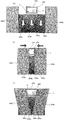
遮蔽装置246は、格子状の左扉246aおよび右扉246bからなり、第一装飾図柄表示装置208および前面ステージ244の間に配設する。左扉246aおよび右扉246bの上部には、不図示の2つのプーリに巻き回したベルトをそれぞれ固定している。すなわち、左扉246aおよび右扉246bは、モータによりプーリを介して駆動するベルトの動作に伴って左右にそれぞれ移動する。遮蔽装置246は、左扉246aおよび右扉246bを閉じた状態ではそれぞれの内側端部が重なり、遊技者が第一装飾図柄表示装置208を視認し難いように遮蔽する。左扉246aおよび右扉246bを開いた状態ではそれぞれの内側端部が第一装飾図柄表示装置208の表示画面の外側端部と若干重なるが、遊技者は第一装飾図柄表示装置208の表示の全てを視認可能である。また、左扉246aおよび右扉246bは、それぞれ任意の位置で停止可能であり、例えば、表示した装飾図柄がどの装飾図柄であるかを遊技者が識別可能な程度に、装飾図柄の一部だけを遮蔽するようなことができる。なお、左扉246aおよび右扉246bは、格子の孔から後方の第一装飾図柄表示装置208の一部を視認可能にしてもよいし、格子の孔の障子部分を半透明のレンズ体で塞ぎ、後方の第一装飾図柄表示装置208による表示を漠然と遊技者に視認させるようにしてもよいし、格子の孔の障子部分を完全に塞ぎ(遮蔽し)、後方の第一装飾図柄表示装置208を全く視認不可にしてもよい。
The shielding device 246 includes a lattice-like left door 246a and right door 246b, and is disposed between the first decorative symbol display device 208 and the front stage 244. Belts wound around two pulleys (not shown) are fixed to the upper portions of the left door 246a and the right door 246b, respectively. That is, the left door 246a and the right door 246b move to the left and right as the belt driven by the motor through the pulley moves. In the state where the left door 246a and the right door 246b are closed, the shielding device 246 covers the inner end portions of the shielding device 246 so that it is difficult for the player to visually recognize the first decorative symbol display device 208. In the state where the left door 246a and the right door 246b are opened, the inner end portions thereof slightly overlap the outer end portion of the display screen of the first decorative symbol display device 208, but the player can display the first decorative symbol display device 208. All are visible. In addition, the left door 246a and the right door 246b can be stopped at arbitrary positions, respectively, for example, only a part of the decorative design so that the player can identify which decorative design the displayed decorative design is. Can be shielded. In addition, the left door 246a and the right door 246b may be configured so that a part of the first decorative symbol display device 208 behind the lattice hole can be visually recognized, or the shoji part of the lattice hole is closed with a translucent lens body. The display by the first decorative symbol display device 208 on the rear side may be made vaguely visible to the player, or the shoji part of the holes in the lattice is completely closed (shielded), and the first decorative symbol display device 208 on the rear side. May not be visible at all.
次に、図4を用いて、パチンコ機100の制御部の回路構成について詳細に説明する。なお、同図は制御部の回路ブロック図を示したものである。パチンコ機100の制御部は、大別すると、遊技の中枢部分を制御する主制御部300と、主制御部300が送信するコマンド信号(以下、単に「コマンド」と呼ぶ)に応じて主に演出の制御を行う第1副制御部400と、第1副制御部400より送信されたコマンドに基づいて各種機器を制御する第2副制御部500と、主制御部300が送信するコマンドに応じて主に遊技球の払い出しに関する制御を行う払出制御部600と、遊技球の発射制御を行う発射制御部630と、パチンコ機100に供給される電源を制御する電源制御部660と、によって構成している。
Next, the circuit configuration of the control unit of the pachinko machine 100 will be described in detail with reference to FIG. This figure shows a circuit block diagram of the control unit. The control unit of the pachinko machine 100 can be roughly classified into a main control unit 300 that controls the central part of the game and a command signal (hereinafter simply referred to as “command”) transmitted by the main control unit 300. A first sub-control unit 400 that controls the second sub-control unit 500 that controls various devices based on a command transmitted from the first sub-control unit 400, and a command transmitted by the main control unit 300 The payout control unit 600 that mainly controls the game ball payout, the launch control unit 630 that controls the launch of the game ball, and the power supply control unit 660 that controls the power supplied to the pachinko machine 100 are configured. Yes.
まず、パチンコ機100の主制御部300について説明する。主制御部300は、主制御部300の全体を制御する基本回路302を備えており、基本回路302には、CPU304と、制御プログラムや各種データを記憶するためのROM306と、一時的にデータを記憶するためのRAM308と、各種デバイスの入出力を制御するためのI/O310と、時間や回数等を計測するためのカウンタタイマ312と、プログラム処理の異常を監視するWDT314を搭載している。なお、ROM306やRAM308については他の記憶装置を用いてもよく、この点は後述する第1副制御部400についても同様である。基本回路302のCPU304は、水晶発振器316bが出力する所定周期のクロック信号をシステムクロックとして入力して動作する。
First, the main control unit 300 of the pachinko machine 100 will be described. The main control unit 300 includes a basic circuit 302 that controls the entire main control unit 300. The basic circuit 302 includes a CPU 304, a ROM 306 for storing control programs and various data, and data temporarily. A RAM 308 for storing, an I / O 310 for controlling input / output of various devices, a counter timer 312 for measuring time and the number of times, and a WDT 314 for monitoring an abnormality in program processing are mounted. Note that another storage device may be used for the ROM 306 and the RAM 308, and this is the same for the first sub-control unit 400 described later. The CPU 304 of the basic circuit 302 operates by inputting a clock signal of a predetermined period output from the crystal oscillator 316b as a system clock.
また、基本回路302には、水晶発振器316aが出力するクロック信号を受信する度に0〜65535の範囲で数値を変動させるハードウェア乱数カウンタとして使用している乱数値生成回路318(この回路には2つのカウンタを内蔵しているものとする)と、所定の球検出センサ、例えば各始動口、入賞口、可変入賞口を通過する遊技球を検出するセンサや、前面枠扉開放センサや内枠開放センサや下皿満タンセンサを含む各種センサ320が出力する信号を受信し、増幅結果や基準電圧との比較結果を乱数値生成回路318および基本回路302に出力するためのセンサ回路322と、所定の図柄表示装置、例えば特図1表示装置212や特図2表示装置214の表示制御を行うための駆動回路324と、所定の図柄表示装置、例えば普図表示装置210の表示制御を行うための駆動回路326と、各種状態表示部328(例えば、普図保留ランプ216、特図1保留ランプ218、特図2保留ランプ220、高確中ランプ222等)の表示制御を行うための駆動回路330と、所定の可動部材、例えば特図2始動口232の羽根部材232aや可変入賞口234の扉部材234a等を開閉駆動する各種ソレノイド332を制御するための駆動回路334を接続している。
The basic circuit 302 also includes a random value generation circuit 318 used as a hardware random number counter that changes a numerical value in the range of 0 to 65535 every time a clock signal output from the crystal oscillator 316a is received (this circuit includes 2 counters) and a predetermined ball detection sensor, for example, a sensor that detects a game ball passing through each starting port, winning port, variable winning port, front frame door opening sensor, and inner frame A sensor circuit 322 for receiving signals output from various sensors 320 including an open sensor and a lower plate full sensor, and outputting a comparison result with an amplification result and a reference voltage to the random value generation circuit 318 and the basic circuit 302; Drive circuit 324 for controlling the display of the special symbol display device 212 or the special symbol 2 display device 214, a predetermined symbol display device, for example, A drive circuit 326 for performing display control of the general-purpose display device 210, and various status display units 328 (for example, a general-purpose reservation lamp 216, a special figure 1 retention lamp 218, a special figure 2 retention lamp 220, and a high-accuracy medium lamp 222) And the like, and a variety of solenoids 332 for opening and closing a predetermined movable member, for example, the blade member 232a of the special figure 2 starting port 232, the door member 234a of the variable prize opening 234, and the like. A driving circuit 334 is connected.
なお、特図1始動口230に球が入賞したことを球検出センサ320が検出した場合には、センサ回路322は球を検出したことを示す信号を乱数値生成回路318に出力する。この信号を受信した乱数値生成回路318は、特図1始動口230に対応するカウンタのそのタイミングにおける値をラッチし、ラッチした値を、特図1始動口230に対応する内蔵のカウンタ値記憶用レジスタに記憶する。また、乱数値生成回路318は、特図2始動口232に球が入賞したことを示す信号を受信した場合も同様に、特図2始動口232に対応するカウンタのそのタイミングにおける値をラッチし、ラッチした値を、特図2始動口232に対応する内蔵のカウンタ値記憶用レジスタに記憶する。
When the sphere detection sensor 320 detects that a sphere is won at the special figure 1 starting port 230, the sensor circuit 322 outputs a signal indicating that the sphere has been detected to the random value generation circuit 318. Upon receiving this signal, the random value generation circuit 318 latches the value at the timing of the counter corresponding to the special figure 1 starting port 230, and stores the latched value in the built-in counter value corresponding to the special figure 1 starting port 230. Store in the register. Similarly, when the random value generation circuit 318 receives a signal indicating that the ball has won the special figure 2 starting port 232, the random number generation circuit 318 latches the value at the timing of the counter corresponding to the special figure 2 starting port 232. The latched value is stored in a built-in counter value storage register corresponding to the special figure 2 starting port 232.
さらに、基本回路302には、情報出力回路336を接続しており、主制御部300は、情報出力回路336を介して、外部のホールコンピュータ(図示省略)等が備える情報入力回路350にパチンコ機100の遊技情報(例えば、遊技状態)を出力する。
Further, an information output circuit 336 is connected to the basic circuit 302, and the main control unit 300 is connected to an information input circuit 350 provided in an external hall computer (not shown) or the like via the information output circuit 336. 100 game information (for example, game state) is output.
また、主制御部300には、電源制御部660から主制御部300に供給している電源の電圧値を監視する電圧監視回路338を設けており、電圧監視回路338は、電源の電圧値が所定の値(本実施例では9V)未満である場合に電圧が低下したことを示す低電圧信号を基本回路302に出力する。
Further, the main control unit 300 is provided with a voltage monitoring circuit 338 for monitoring the voltage value of the power source supplied from the power source control unit 660 to the main control unit 300. The voltage monitoring circuit 338 has a voltage value of the power source. When the voltage is less than a predetermined value (9 V in this embodiment), a low voltage signal indicating that the voltage has decreased is output to the basic circuit 302.
また、主制御部300には、電源が投入されると起動信号(リセット信号)を出力する起動信号出力回路(リセット信号出力回路)340を設けており、CPU304は、起動信号出力回路340から起動信号を入力した場合に、遊技制御を開始する(後述する主制御部メイン処理を開始する)。
Further, the main control unit 300 is provided with a start signal output circuit (reset signal output circuit) 340 that outputs a start signal (reset signal) when the power is turned on, and the CPU 304 starts from the start signal output circuit 340. When a signal is input, game control is started (main control unit main processing described later is started).
また、主制御部300は、第1副制御部400にコマンドを送信するための出力インタフェースと、払出制御部600にコマンドを送信するための出力インタフェースをそれぞれ備えており、この構成により、第1副制御部400および払出制御部600との通信を可能としている。なお、主制御部300と第1副制御部400との情報通信は一方向の通信であり、主制御部300は第1副制御部400にコマンド等の信号を送信できるように構成しているが、第1副制御部400からは主制御部300にコマンド等の信号を送信できないように構成している。また、主制御部300と払出制御部600との情報通信は双方向の通信であり、主制御部300は払出制御部600にコマンド等の信号を送信できるように構成し、払出制御部600からも主制御部300にコマンド等の信号を送信できるように構成している。
The main control unit 300 includes an output interface for transmitting a command to the first sub-control unit 400 and an output interface for transmitting a command to the payout control unit 600. With this configuration, the first control unit 300 Communication with the sub-control unit 400 and the payout control unit 600 is enabled. Note that information communication between the main control unit 300 and the first sub control unit 400 is one-way communication, and the main control unit 300 is configured to be able to transmit signals such as commands to the first sub control unit 400. However, the first sub-control unit 400 is configured not to transmit a signal such as a command to the main control unit 300. In addition, the information communication between the main control unit 300 and the payout control unit 600 is a two-way communication, and the main control unit 300 is configured to transmit a signal such as a command to the payout control unit 600. Also, a signal such as a command can be transmitted to the main control unit 300.
次に、パチンコ機100の第1副制御部400について説明する。第1副制御部400は、主に主制御部300が送信したコマンド等に基づいて第1副制御部400の全体を制御する基本回路402を備えており、基本回路402には、CPU404と、一時的にデータを記憶するためのRAM408と、各種デバイスの入出力を制御するためのI/O410と、時間や回数等を計測するためのカウンタタイマ412を搭載している。基本回路402のCPU404は、水晶発振器414が出力する所定周期のクロック信号をシステムクロックとして入力して動作する。
Next, the first sub control unit 400 of the pachinko machine 100 will be described. The first sub-control unit 400 includes a basic circuit 402 that controls the entire first sub-control unit 400 mainly based on commands transmitted from the main control unit 300. The basic circuit 402 includes a CPU 404, A RAM 408 for temporarily storing data, an I / O 410 for controlling input / output of various devices, and a counter timer 412 for measuring time and frequency are mounted. The CPU 404 of the basic circuit 402 operates by inputting a clock signal of a predetermined period output from the crystal oscillator 414 as a system clock.
また、基本回路402には、スピーカ120(およびアンプ)の制御を行うための音源IC416と、各種ランプ418(例えば、チャンスボタンランプ138)の制御を行うための駆動回路420と、遮蔽装置の駆動制御を行うための駆動回路432と、遮蔽装置の現在位置を検出する遮蔽装置センサ430と、チャンスボタン136の押下を検出するチャンスボタン検出センサ426と、遮蔽装置センサ430やチャンスボタンの検出部724からの検出信号を基本回路402に出力するセンサ回路428と、制御プログラムや各種演出データを記憶するためのROM406と、CPU404からの信号に基づいてROM406に記憶された画像データ等を読み出してVRAM436のワークエリアを使用して表示画像を生成して第一装飾図柄表示装置208および第二装飾図柄表示装置209に画像を表示するVDP434(ビデオ・ディスプレイ・プロセッサー)と、を接続している。なお、ROM406は、制御プログラムと各種演出データとを別々のROMに記憶させてもよい。また、第一装飾図柄表示装置208と第二装飾図柄表示装置209のそれぞれに別個にVDP434やVRAM436を設けるようにしてもよい。
The basic circuit 402 includes a sound source IC 416 for controlling the speaker 120 (and amplifier), a drive circuit 420 for controlling various lamps 418 (for example, the chance button lamp 138), and driving of the shielding device. A drive circuit 432 for performing control, a shielding device sensor 430 that detects the current position of the shielding device, a chance button detection sensor 426 that detects pressing of the chance button 136, and a shielding device sensor 430 and a chance button detection unit 724. A sensor circuit 428 that outputs a detection signal from the ROM 406 to the basic circuit 402, a ROM 406 for storing a control program and various effects data, and image data stored in the ROM 406 based on signals from the CPU 404, and the VRAM 436 Use the work area to generate a display image and Connected VDP434 for displaying an image on the symbol display unit 208 and the second decoration symbol display device 209 and (video display processor), a. The ROM 406 may store the control program and various effect data in separate ROMs. Further, the VDP 434 and the VRAM 436 may be provided separately for the first decorative symbol display device 208 and the second decorative symbol display device 209, respectively.
次に、パチンコ機100の第2副制御部500について説明する。第2副制御部500は、第1副制御部400が送信した制御コマンドを入力インタフェースを介して受信し、この制御コマンドに基づいて第2副制御部500の全体を制御する基本回路502を備えており、基本回路502は、CPU504と、一時的にデータを記憶するためのRAM508と、各種デバイスの入出力を制御するためのI/O510と、時間や回数等を計測するためのカウンタタイマ512を搭載している。基本回路502のCPU504は、水晶発振器514が出力する所定周期のクロック信号をシステムクロックとして入力して動作し、第2副制御部500の全体を制御するための制御プログラムおよびデータ、画像表示用のデータ等が記憶されたROM506が設けられている。
Next, the second sub control unit 500 of the pachinko machine 100 will be described. The second sub-control unit 500 includes a basic circuit 502 that receives the control command transmitted from the first sub-control unit 400 via the input interface and controls the entire second sub-control unit 500 based on the control command. The basic circuit 502 includes a CPU 504, a RAM 508 for temporarily storing data, an I / O 510 for controlling input / output of various devices, and a counter timer 512 for measuring time and frequency. It is equipped with. The CPU 504 of the basic circuit 502 operates by inputting a clock signal of a predetermined cycle output from the crystal oscillator 514 as a system clock, and controls a control program and data for controlling the entire second sub-control unit 500, and an image display A ROM 506 storing data and the like is provided.
また、基本回路502には、演出可動体224の駆動制御を行うための駆動回路516と、チャンスボタンの駆動部708の駆動制御を行うための駆動回路517と、演出可動体224の現在位置を検出する可動体センサ424と、可動体センサ424からの検出信号を基本回路502に出力するセンサ回路518と、遊技盤用ランプ532の制御を行うための遊技盤用ランプ駆動回路530と、遊技台枠用ランプ542の制御を行うための遊技台枠用ランプ駆動回路540と、遊技盤用ランプ駆動回路530と遊技台枠用ランプ駆動回路540との間でシリアル通信による点灯制御を行うシリアル通信制御回路520と、を接続している。
Further, the basic circuit 502 includes a drive circuit 516 for performing drive control of the effect movable body 224, a drive circuit 517 for performing drive control of the chance button drive unit 708, and the current position of the effect movable body 224. A movable body sensor 424 to be detected, a sensor circuit 518 for outputting a detection signal from the movable body sensor 424 to the basic circuit 502, a game board lamp drive circuit 530 for controlling the game board lamp 532, and a game table A game table frame lamp drive circuit 540 for controlling the frame lamp 542, and serial communication control for performing lighting control by serial communication between the game board lamp drive circuit 530 and the game table frame lamp drive circuit 540 The circuit 520 is connected.
次に、パチンコ機100の払出制御部600、発射制御部630、電源制御部660について説明する。払出制御部600は、主に主制御部300が送信したコマンド等の信号に基づいて払出装置152の払出モータ602を制御すると共に、払出センサ604が出力する制御信号に基づいて賞球または貸球の払い出しが完了したか否かを検出すると共に、インタフェース部606を介して、パチンコ機100とは別体で設けられたカードユニット608との通信を行う。また、払出制御部600は、前面枠扉106の開放を検出する前面枠扉開放センサ107の検出結果を受け取り、受け取った結果を主制御部300に出力する。
Next, the payout control unit 600, the launch control unit 630, and the power supply control unit 660 of the pachinko machine 100 will be described. The payout control unit 600 controls the payout motor 602 of the payout device 152 mainly based on a command signal or the like transmitted from the main control unit 300, and a prize ball or a rental ball based on a control signal output from the payout sensor 604 It is detected whether or not the payout has been completed, and communication with a card unit 608 provided separately from the pachinko machine 100 is performed via the interface unit 606. Also, the payout control unit 600 receives the detection result of the front frame door opening sensor 107 that detects the opening of the front frame door 106, and outputs the received result to the main control unit 300.
発射制御部630は、払出制御部600が出力する、発射許可または停止を指示する制御信号や、球発射ハンドル134内に設けた発射強度出力回路が出力する、遊技者による球発射ハンドル134の操作量に応じた発射強度を指示する制御信号に基づいて、発射杆146および発射槌148を駆動する発射モータ632の制御や、上皿126から発射装置110に球を供給する球送り装置634の制御を行う。
The launch control unit 630 outputs a control signal output from the payout control unit 600 to permit or stop the launch, or a launch intensity output circuit provided in the ball launch handle 134 to operate the ball launch handle 134 by the player. Control of the launch motor 632 that drives the launcher 146 and launcher 148, and control of the ball feeder 634 that supplies the launcher 110 with a ball from the upper plate 126 based on a control signal that indicates the launch intensity according to the amount. I do.
電源制御部660は、パチンコ機100に外部から供給される交流電源を直流化し、所定の電圧に変換して主制御部300、第1副制御部400等の各制御部や払出装置152等の各装置に供給する。さらに、電源制御部660は、外部からの電源が断たれた後も所定の部品(例えば主制御部300のRAM308等)に所定の期間(例えば10日間)電源を供給するための蓄電回路(例えば、コンデンサ)を備えている。なお、本実施形態では、電源制御部660から払出制御部600と第2副制御部500に所定電圧を供給し、払出制御部600から主制御部300と第1副制御部400と発射制御部630に所定電圧を供給しているが、各制御部や各装置に他の電源経路で所定電圧を供給してもよい。
The power control unit 660 converts the AC power supplied from the outside to the pachinko machine 100 into a DC voltage, converts it to a predetermined voltage, and controls each control unit such as the main control unit 300 and the first sub control unit 400, the payout device 152, etc. Supply to each device. Further, the power supply control unit 660 supplies a power storage circuit (for example, a power supply circuit) for supplying power to a predetermined part (for example, the RAM 308 of the main control unit 300) for a predetermined period (for example, 10 days) even after the external power supply is cut off. , Capacitor). In the present embodiment, a predetermined voltage is supplied from the power supply control unit 660 to the payout control unit 600 and the second sub control unit 500, and the main control unit 300, the first sub control unit 400, and the launch control unit are supplied from the payout control unit 600. Although a predetermined voltage is supplied to 630, the predetermined voltage may be supplied to each control unit and each device through another power supply path.
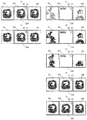
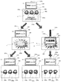
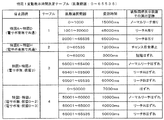
次に、図5を用いて、パチンコ機100の特図1表示装置212、特図2表示装置214、および普図表示装置210が停止表示する特図および普図の種類について説明する。図5(a)は特図1の停止図柄態様の一例を示したものである。図5(b)は特図2の停止図柄態様の一例を示したものである。特図1始動口230に球が入球したことを第1始動口センサが検出したことを条件として特図1変動遊技が開始され、特図2始動口232に球が入球したことを第2始動口センサが検出したことを条件として特図2変動遊技が開始される。特図1変動遊技が開始されると、特図1表示装置212は、7個のセグメントの全点灯と、中央の1個のセグメントの点灯を繰り返す「特図1の変動表示」を行う。また、特図2変動遊技が開始されると、特図2表示装置214は、7個のセグメントの全点灯と、中央の1個のセグメントの点灯を繰り返す「特図2の変動表示」を行う。これらの「特図1の変動表示」および「特図2の変動表示」が本実施形態にいう図柄の変動表示の一例に相当する。そして、特図1の変動開始前に決定した変動時間が経過すると、特図1表示装置212は特図1の停止図柄態様を停止表示し、特図2の変動開始前に決定した変動時間が経過すると、特図2表示装置214は特図2の停止図柄態様を停止表示する。したがって、「特図1の変動表示」を開始してから特図1の停止図柄態様を停止表示するまで、あるいは「特図2の変動表示」を開始してから特図2の停止図柄態様を停止表示するまでが本実施形態にいう図柄変動停止表示の一例に相当し、以下、この「特図1又は2の変動表示」を開始してから特図1又は2の停止図柄態様を停止表示するまでの一連の表示を図柄変動停止表示と称する。後述するように、図柄変動停止表示は複数回、連続して行われることがある。
Next, with reference to FIG. 5, the types of types of special maps and general maps that are stopped and displayed by the special map display device 212, the special map display device 214, and the general map display device 210 of the pachinko machine 100 will be described. Fig.5 (a) shows an example of the stop symbol aspect of the special figure 1. FIG. FIG.5 (b) shows an example of the stop symbol aspect of the special figure 2. FIG. The special figure 1 variable game is started on the condition that the first start port sensor detects that the ball has entered the special figure 1 start opening 230, and the special figure 2 start opening 232 indicates that the ball has entered 2 The special figure 2 variable game is started on condition that the start sensor is detected. When the special figure 1 variable game is started, the special figure 1 display device 212 performs “variable display of special figure 1” which repeats lighting of all seven segments and lighting of one central segment. When the special figure 2 variable game is started, the special figure 2 display device 214 performs “variable display of special figure 2” by repeating all lighting of the seven segments and lighting of the central one segment. . These “variation display of special figure 1” and “variation display of special figure 2” correspond to an example of the symbol fluctuation display in the present embodiment. When the fluctuation time determined before the start of the fluctuation in FIG. 1 elapses, the special figure 1 display device 212 stops and displays the stop symbol form of the special figure 1 and the fluctuation time determined before the fluctuation starts in the special figure 2. After the elapse, the special figure 2 display device 214 stops and displays the stop symbol form of the special figure 2. Therefore, from the start of “figure display of special figure 1” until the stop symbol form of special figure 1 is stopped, or after the start of “fluctuation display of special figure 2”, the stop symbol form of special figure 2 is displayed. Until stop display corresponds to an example of the symbol variation stop display referred to in the present embodiment, hereinafter, after the “variable display of special figure 1 or 2” is started, the stop symbol form of special figure 1 or 2 is stopped and displayed. A series of displays until this is done is referred to as symbol variation stop display. As will be described later, the symbol variation stop display may be continuously performed a plurality of times.
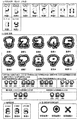
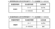
図5(a)には、特図1の図柄変動停止表示における停止図柄態様として「特図A」から「特図F」までの6種類の特図が示されている。図5(a)においては、図中の白抜きの部分が消灯するセグメントの場所を示し、黒塗りの部分が点灯するセグメントの場所を示している。「特図A」は15ラウンド(15R)特別大当り図柄であり、「特図B」は15R大当り図柄である。本実施形態のパチンコ機100では、後述するように、特図変動遊技における大当りか否かの決定はハードウェア乱数の抽選によって行い、特別大当りか否かの決定はソフトウェア乱数の抽選によって行う。大当りと特別大当りの違いは、大当り遊技後の特図変動遊技で、大当りに当選する確率が高い(確変大当り)か低い(通常大当り)かの違いである。以下、この大当りに当選する確率が高い状態のことを特図高確率状態と称し、その確率が低い状態のことを特図低確率状態と称する。また、15R特別大当り遊技終了後および15R大当り遊技終了後はいずれも電サポ状態(特図変動遊技の変動時間短縮状態と合わせて時短状態と呼ぶ)に移行する。時短状態については詳しくは後述するが、時短状態に移行する状態のことを普図高確率状態と称し、時短状態に移行しない状態のことを普図低確率状態と称する。15R特別大当り図柄である「特図A」は、大当り遊技終了後の遊技状態が特図高確率普図高確率状態(確変状態)であり、15R大当り図柄である「特図B」は、大当り遊技終了後の遊技状態が特図低確率普図高確率状態(電サポ状態または時短状態)である。なお、特図高確率普図高確率状態や特図低確率普図高確率状態になるタイミングは、大当り遊技終了後の最初の特図変動遊技の開始時である。これらの「特図A」および「特図B」は、遊技者に対する有利度が相対的に大きくなる図柄である。
FIG. 5 (a) shows six types of special figures from “Special figure A” to “Special figure F” as stop symbol forms in the symbol fluctuation stop display of special figure 1. FIG. In FIG. 5A, the white portions in the figure indicate the segment locations where the light is turned off, and the black portions indicate the location where the segments are turned on. “Special figure A” is a 15 round (15R) special jackpot symbol, and “Special figure B” is a 15R jackpot symbol. In the pachinko machine 100 according to the present embodiment, as will be described later, the determination as to whether or not the big hit in the special figure variable game is made by lottery of hardware random numbers, and the decision as to whether or not it is a special big hit is made by lottery of software random numbers. The difference between the big hit and the special big hit is a difference in the special figure variable game after the big hit game, and the probability of winning the big hit is high (probable big hit) or low (normally big hit). Hereinafter, a state having a high probability of winning the jackpot is referred to as a special figure high probability state, and a state having a low probability is referred to as a special figure low probability state. In addition, after the 15R special big hit game ends and after the 15R big hit game ends, the state shifts to the electric support state (referred to as a short time state together with the variable time reduction state of the special figure variable game). Although the time-short state will be described in detail later, the state that shifts to the time-short state is referred to as a normal high-probability state, and the state that does not shift to the time-short state is referred to as a normal-low probability state. “Special figure A”, which is a 15R special jackpot symbol, is a special figure high probability normal figure high probability state (probability variation state) after the jackpot game is ended, and “Special figure B” which is a 15R jackpot symbol is a big hit The game state after the game ends is a special figure low probability normal figure high probability state (electric support state or short time state). Note that the timing when the special figure high probability normal figure high probability state and the special figure low probability normal figure high probability state are reached is the start of the first special figure variable game after the end of the big hit game. These “special chart A” and “special chart B” are symbols that have a relatively high degree of advantage over the player.
「特図C」は2R大当り図柄であり突然確変と称する。突然確変は、大当り遊技終了後は15R特別大当り図柄と同様に特図高確率普図高確率状態になる。「特図D」は2R大当り図柄であり潜伏確変と称する。潜伏確変は、大当り遊技終了後は特図高確率普図低確率状態(潜伏確変状態)になる。
"Special figure C" is a 2R big hit symbol and is called sudden probability change. Sudden probability change will be in the special figure high probability normal figure high probability state after the big hit game, like the 15R special big hit symbol. "Special figure D" is a 2R big hit symbol and is called latent probability variation. The latent probability change becomes a special figure high probability low probability state (latency probability variation state) after the big hit game ends.
「特図E」は小当り図柄であり、小当り遊技終了後は特図低確率普図低確率状態(通常状態、あるいは通常遊技状態と称する場合がある)になる。小当り遊技では「特図C」や「特図D」と同じ回数(本実施形態の場合、2回)アタッカが開放される。また、「特図F」ははずれ図柄であり、アタッカの開放はなく、遊技者に対する有利度が相対的に小さくなる図柄である。
“Special figure E” is a small hit symbol, and after the small hit game, the special figure low probability normal figure low probability state (which may be referred to as a normal state or a normal game state). In the small hit game, the attacker is released the same number of times as the “special drawing C” and “special drawing D” (twice in the case of this embodiment). Further, the “special drawing F” is a detachment symbol, which is a symbol that does not release an attacker and has a relatively small advantage for the player.
図5(b)には、特図2の図柄変動停止表示における停止図柄態様として「特図a」から「特図d」までの4種類の特図が示されている。図5(b)においては、図中の白抜きの部分が消灯するセグメントの場所を示し、黒塗りの部分が点灯するセグメントの場所を示している。「特図a」は16ラウンド(16R)特別大当り図柄であり、「特図b」は8R特別大当り図柄である。「特図a」と「特図b」はともに、大当り遊技終了後の遊技状態が特図高確率普図高確率状態となる。これらの「特図a」および「特図b」は、遊技者に対する有利度が相対的に大きくなる図柄である。
FIG. 5B shows four types of special drawings from “special drawing a” to “special drawing d” as stop symbol forms in the symbol fluctuation stop display of special drawing 2. In FIG. 5B, the white portions in the figure indicate the segment locations where the light is turned off, and the black portions indicate the location where the segments are turned on. “Special figure a” is a 16 round (16R) special jackpot symbol, and “Special figure b” is an 8R special jackpot symbol. In both “special chart a” and “special chart b”, the gaming state after the end of the big hit game becomes a special chart high probability ordinary figure high probability state. These “special drawing a” and “special drawing b” are symbols with which the degree of advantage relative to the player is relatively large.
「特図c」は8R大当り図柄であり、大当り遊技終了後は特図低確率普図高確率状態になる。「特図d」ははずれ図柄であり、アタッカの開放はなく、遊技者に対する有利度が相対的に小さくなる図柄である。
“Special figure c” is an 8R jackpot symbol, and after the jackpot game is over, a special figure low probability normal figure high probability state is entered. The “special drawing d” is an off symbol, the attacker does not release, and the symbol has a relatively small advantage for the player.
図5(c)は装飾図柄の一例を示したものである。本実施形態の装飾図柄には、「装飾1」〜「装飾10」の10種類がある。特図1始動口230または特図2始動口232に球が入賞したこと、すなわち、特図1始動口230に球が入球したことを第1始動口センサが検出したこと、あるいは特図2始動口232に球が入球したことを第2始動口センサが検出したことを条件にして、第一装飾図柄表示装置208の左図柄表示領域208a、中図柄表示領域208b、右図柄表示領域208cの各図柄表示領域に、「装飾1」→「装飾2」→「装飾3」→・・・・「装飾9」→「装飾10」→「装飾1」→・・・の順番で表示を切り替える「装飾図柄の変動表示」を行う。
FIG. 5 (c) shows an example of a decorative design. There are 10 types of decoration patterns of the present embodiment: “Decoration 1” to “Decoration 10”. The first start port sensor detects that a ball has won the special figure 1 starting port 230 or the special figure 2 starting port 232, that is, the ball has entered the special figure 1 starting port 230, or the special figure 2 The first symbol display area 208a, the middle symbol display area 208b, and the right symbol display area 208c of the first decorative symbol display device 208 are provided on the condition that the second starting port sensor detects that a ball has entered the starting port 232. The display is switched in the order of “decoration 1” → “decoration 2” → “decoration 3” →... “Decoration 9” → “decoration 10” → “decoration 1” →. Perform “decorative display of decorative design”.
そして、15R大当り、15R特別大当り、16R特別大当り、8R大当り、または8R特別大当りを報知する場合には、図柄表示領域208a〜208cに同じ装飾図柄が3つ並んだ図柄組合せ(例えば「装飾1−装飾1−装飾1」や「装飾2−装飾2−装飾2」等)を停止表示する。15R特別大当りや16R特別大当りを明示的に報知する場合には、同じ装飾図柄が3つ並んだ図柄組合せ(例えば「装飾3−装飾3−装飾3」や「装飾7−装飾7−装飾7」等)を停止表示する。
When notifying 15R big hit, 15R special big hit, 16R special big hit, 8R big hit, or 8R special big hit, a combination of symbols in which three same decorative symbols are arranged in the symbol display areas 208a to 208c (for example, “decoration 1- “Decoration 1-decoration 1”, “decoration 2—decoration 2—decoration 2”, etc.) When the 15R special jackpot or the 16R special jackpot is explicitly notified, a combination of symbols in which three same decorative symbols are arranged (for example, “decoration 3-decoration 3-decoration 3” or “decoration 7-decoration 7-decoration 7”). Etc.) is stopped and displayed.
また、潜伏確変、または小当りを報知する場合には、図柄表示領域208a〜208cに装飾図柄が3つ並んだ図柄組合せ(例えば「装飾1−装飾2−装飾3」)を停止表示し、突然確変を報知する場合には、図柄表示領域208a〜208cに装飾図柄が3つ並んだ図柄組合せ(「装飾1−装飾3−装飾5」)を停止表示する。
When notifying the latent probability change or the small hit, the symbol combination (for example, “decoration 1-decoration 2-decoration 3”) in which three ornamental symbols are arranged in the symbol display areas 208a to 208c is stopped and displayed suddenly. When notifying the probability change, the symbol combination ("decoration 1-ornament 3-ornament 5") in which three ornament symbols are arranged in the symbol display areas 208a to 208c is stopped and displayed.
一方、「特図K」、「特図h」のはずれを報知する場合には、図柄表示領域208a〜208cに図5(c)に示す図柄組合せ以外の図柄組合せを停止表示する。
On the other hand, when notifying of the difference between “special drawing K” and “special drawing h”, symbol combinations other than the symbol combinations shown in FIG. 5C are stopped and displayed in the symbol display areas 208a to 208c.
なお、本実施形態では、一義的に装飾図柄の組合せと大当りの種類を決めているが、遊技者にどの装飾図柄の組合せがどの大当りになるかをわからないようにしてもよい。
In the present embodiment, the combination of decorative symbols and the type of jackpot are uniquely determined. However, the player may not know which combination of decorative symbols is which jackpot.
図5(d)は普図の停止表示図柄の一例を示したものである。本実施形態の普図の停止表示態様には、当り図柄である「普図A」と、はずれ図柄である「普図B」の2種類がある。普図始動口228を球が通過したことを上述のゲートセンサが検出したことに基づいて、普図表示装置210は、7個のセグメントの全点灯と、中央の1個のセグメントの点灯を繰り返す「普図の変動表示」を行う。そして、普図変動遊技の当選を報知する場合には「普図A」を停止表示し、普図変動遊技のはずれを報知する場合には「普図B」を停止表示する。図5(d)においても、図中の白抜きの部分が消灯するセグメントの場所を示し、黒塗りの部分が点灯するセグメントの場所を示している。
FIG.5 (d) shows an example of the usual stop display symbol. In the present embodiment, there are two types of stoppage display modes of “normal map A”, which is a winning symbol, and “general symbol B”, which is a missed symbol. Based on the fact that the above-mentioned gate sensor has detected that the sphere has passed through the general start port 228, the general map display device 210 repeats the lighting of all seven segments and the lighting of one central segment. Perform a “normal change display”. Then, when notifying the winning of the common figure variable game, the “normal figure A” is stopped and displayed, and when notifying the deviation of the common figure variable game, the “normal figure B” is stopped and displayed. Also in FIG. 5D, the white portions in the figure indicate the segment locations where the light is extinguished, and the black portions indicate the location of the segments where the light is illuminated.
次に、図6を用いて、主制御部300のCPU304が実行する主制御部メイン処理について説明する。なお、同図は主制御部メイン処理の流れを示すフローチャートである。上述したように、主制御部300には、電源が投入されると起動信号(リセット信号)を出力する起動信号出力回路(リセット信号出力回路)340を設けている。この起動信号を入力した基本回路302のCPU304は、リセット割込によりリセットスタートしてROM306に予め記憶している制御プログラムに従って図6に示す主制御部メイン処理を実行する。
Next, main control unit main processing executed by the CPU 304 of the main control unit 300 will be described with reference to FIG. This figure is a flowchart showing the flow of main processing of the main control unit. As described above, the main control unit 300 is provided with the start signal output circuit (reset signal output circuit) 340 that outputs the start signal (reset signal) when the power is turned on. The CPU 304 of the basic circuit 302 to which this activation signal has been input performs reset start by a reset interrupt, and executes main control unit main processing shown in FIG. 6 in accordance with a control program stored in advance in the ROM 306.
ステップS101では、初期設定1を行う。初期設定1では、CPU304のスタックポインタ(SP)へのスタック初期値の設定(仮設定)、割込マスクの設定、I/O310の初期設定、RAM308に記憶する各種変数の初期設定、WDT314への動作許可および初期値の設定等を行う。なお、本実施形態では、WDT314に、初期値として32.8ms(ミリ秒)に相当する数値を設定する。
In step S101, initial setting 1 is performed. In the initial setting 1, the stack initial value is set in the stack pointer (SP) of the CPU 304 (temporary setting), the interrupt mask is set, the I / O 310 is initialized, the various variables stored in the RAM 308 are initialized, and the WDT 314 is set. Enable operation, set initial values, etc. In the present embodiment, a numerical value corresponding to 32.8 ms (milliseconds) is set in WDT 314 as an initial value.
ステップS101の次のステップS103では、WDT314のカウンタの値をクリアし、WDT314による時間計測を再始動する。ステップS103の次のステップS105では、低電圧信号がオンであるか否か、すなわち、電圧監視回路338が、電源制御部660から主制御部300に供給している電源の電圧値が所定の値(本実施形態では9V)未満である場合に電圧が低下したことを示す低電圧信号を出力しているか否かを監視する。そして、低電圧信号がオンの場合(CPU304が電源の遮断を検知した場合)にはステップS103に戻り、低電圧信号がオフの場合(CPU304が電源の遮断を検知していない場合)にはステップS107に進む。なお、電源が投入された直後で未だ上記所定の値(9V)に達しない場合にもステップS103に戻り、供給電圧がその所定の値以上になるまで、ステップS105は繰り返し実行される。
In step S103 following step S101, the value of the counter of WDT 314 is cleared, and the time measurement by WDT 314 is restarted. In step S105 subsequent to step S103, whether or not the low voltage signal is ON, that is, the voltage value of the power supply that the voltage monitoring circuit 338 supplies from the power supply control unit 660 to the main control unit 300 is a predetermined value. It is monitored whether or not a low voltage signal indicating that the voltage has decreased when the voltage is less than (9 V in this embodiment). Then, when the low voltage signal is on (when the CPU 304 detects that the power supply is cut off), the process returns to step S103, and when the low voltage signal is off (when the CPU 304 does not detect that the power supply is cut off), the step is performed. The process proceeds to S107. Even when the predetermined value (9 V) is not yet reached immediately after the power is turned on, the process returns to step S103, and step S105 is repeatedly executed until the supply voltage becomes equal to or higher than the predetermined value.
ステップS107では、初期設定2を行う。初期設定2では、後述する主制御部タイマ割込処理を定期毎に実行するための周期を決める数値をカウンタタイマ312に設定する処理、I/O310の所定のポート(例えば試験用出力ポート、第1副制御部400への出力ポート)からクリア信号を出力する処理、RAM308への書き込みを許可する設定等を行う。
In step S107, initial setting 2 is performed. In the initial setting 2, a process for setting a numerical value for determining a cycle for executing a main control unit timer interrupt process, which will be described later, in the counter timer 312, a predetermined port of the I / O 310 (for example, a test output port, a second output port, etc.) 1) a process of outputting a clear signal from the output port 1), a setting for permitting writing to the RAM 308, and the like.
ステップS107の次のステップS109では、電源の遮断前(電断前)の状態に復帰するか否かの判定を行い、電断前の状態に復帰しない場合(主制御部300の基本回路302を初期状態にする場合)には初期化処理(ステップS113)に進む。具体的には、最初に、電源基板に設けたRWMクリアスイッチ180を遊技店の店員などが操作した場合に送信されるRAMクリア信号がオン(操作があったことを示す)であるか否か、すなわちRAMクリアが必要であるか否かを判定し、RAMクリア信号がオンの場合(RAMクリアが必要な場合)には、基本回路302を初期状態にすべくステップS113に進む。一方、RAMクリア信号がオフの場合(RAMクリアが必要でない場合)には、RAM308に設けた電源ステータス記憶領域に記憶した電源ステータスの情報を読み出し、この電源ステータスの情報がサスペンドを示す情報であるか否かを判定する。そして、電源ステータスの情報がサスペンドを示す情報でない場合には、基本回路302を初期状態にすべくステップS113に進み、電源ステータスの情報がサスペンドを示す情報である場合には、RAM308の所定の領域(例えば全ての領域)に記憶している1バイトデータを初期値が0である1バイト構成のレジスタに全て加算することによりチェックサムを算出し、算出したチェックサムの結果が特定の値(例えば0)であるか否か(チェックサムの結果が正常であるか否か)を判定する。そして、チェックサムの結果が特定の値(例えば0)の場合(チェックサムの結果が正常である場合)には電断前の状態に復帰すべくステップS111に進み、チェックサムの結果が特定の値(例えば0)以外である場合(チェックサムの結果が異常である場合)には、パチンコ機100を初期状態にすべくステップS113に進む。同様に電源ステータスの情報が「サスペンド」以外の情報を示している場合にもステップS113に進む。
In step S109 subsequent to step S107, it is determined whether or not the state before power interruption (before power interruption) is restored. If the state before power interruption is not restored (the basic circuit 302 of the main control unit 300 is changed). In the case of initializing), the process proceeds to initialization processing (step S113). Specifically, first, a RAM clear signal transmitted when a store clerk or the like of an amusement store operates the RWM clear switch 180 provided on the power supply board is turned on (indicates that there has been an operation). That is, it is determined whether or not the RAM clear is necessary. If the RAM clear signal is on (when the RAM clear is necessary), the process proceeds to step S113 to set the basic circuit 302 to the initial state. On the other hand, when the RAM clear signal is OFF (when the RAM clear is not necessary), the power status information stored in the power status storage area provided in the RAM 308 is read, and the power status information is information indicating suspend. It is determined whether or not. If the power status information is not information indicating suspend, the process proceeds to step S113 to set the basic circuit 302 to an initial state. If the power status information is information indicating suspend, a predetermined area of the RAM 308 is set. A checksum is calculated by adding all the 1-byte data stored in (for example, all areas) to a 1-byte register whose initial value is 0, and the calculated checksum results in a specific value (for example, 0) (whether or not the checksum result is normal). When the checksum result is a specific value (eg, 0) (when the checksum result is normal), the process proceeds to step S111 to return to the state before the power interruption, and the checksum result is a specific value. If the value is other than 0 (for example, 0) (if the result of the checksum is abnormal), the process proceeds to step S113 to set the pachinko machine 100 to the initial state. Similarly, when the power status information indicates information other than “suspend”, the process proceeds to step S113.
ステップS111では、復電時処理を行う。この復電時処理では、電断時にRAM308に設けられたスタックポインタ退避領域に記憶しておいたスタックポインタの値を読み出し、スタックポインタに再設定(本設定)する。また、電断時にRAM308に設けられたレジスタ退避領域に記憶しておいた各レジスタの値を読み出し、各レジスタに再設定した後、割込許可の設定を行う。以降、CPU304が、再設定後のスタックポインタやレジスタに基づいて制御プログラムを実行する結果、パチンコ機100は電源断時の状態に復帰する。すなわち、電断直前にタイマ割込処理(後述)に分岐する直前に行った(ステップS115内の所定の)命令の次の命令から処理を再開する。また、図4に示す主制御部300における基本回路302に搭載されているRAM308には、送信情報記憶領域が設けられている。このステップS111では、その送信情報記憶領域に、復電コマンドをセットする。この復電コマンドは、電源断時の状態に復帰したことを表すコマンドであり、後述する、主制御部300のタイマ割込処理におけるステップS233において、第1副制御部400へ送信される。
In step S111, power recovery processing is performed. In this power recovery process, the value of the stack pointer stored in the stack pointer save area provided in the RAM 308 at the time of power failure is read out and reset to the stack pointer (this setting). In addition, the value of each register stored in the register save area provided in the RAM 308 at the time of power interruption is read out and reset in each register, and then the interrupt permission is set. Thereafter, as a result of the CPU 304 executing the control program based on the reset stack pointer and registers, the pachinko machine 100 returns to the state when the power is turned off. That is, the processing is resumed from the instruction next to the instruction (predetermined in step S115) performed immediately before branching to the timer interrupt process (described later) immediately before the power interruption. A RAM 308 mounted on the basic circuit 302 in the main control unit 300 shown in FIG. 4 is provided with a transmission information storage area. In step S111, a power recovery command is set in the transmission information storage area. This power recovery command is a command indicating that the power has been restored to the state at the time of power-off, and is transmitted to the first sub-control unit 400 in step S233 in the timer interrupt process of the main control unit 300 described later.
ステップS113では、初期化処理を行う。この初期化処理では、割込禁止の設定、スタックポインタへのスタック初期値の設定(本設定)、RAM308の全ての記憶領域の初期化などを行う。さらにここで、主制御部300のRAM308に設けられた送信情報記憶領域に正常復帰コマンドをセットする。この正常復帰コマンドは、主制御部300の初期化処理(ステップS113)が行われたことを表すコマンドであり、復電コマンドと同じく、主制御部300のタイマ割込処理におけるステップS233において、第1副制御部400へ送信される。
In step S113, initialization processing is performed. In this initialization process, interrupt prohibition setting, stack initial value setting to the stack pointer (this setting), initialization of all storage areas of the RAM 308, and the like are performed. Further, here, a normal return command is set in the transmission information storage area provided in the RAM 308 of the main control unit 300. This normal return command is a command indicating that the initialization process (step S113) of the main control unit 300 has been performed, and in the same way as the power recovery command, in step S233 in the timer interrupt process of the main control unit 300, 1 is transmitted to the sub-control unit 400.
ステップS113の次のステップS115では、割込禁止の設定を行った後、基本乱数初期値更新処理を行う。この基本乱数初期値更新処理では、特図変動遊技での停止図柄を決定する抽選に用いる特図決定用乱数値を生成する特図決定用乱数値カウンタの初期値を生成するための初期値生成用乱数カウンタを更新する。また、普図変動遊技の当否判定に用いる普図当選乱数値を生成する普図当選乱数値カウンタの初期値を生成するための初期値生成用乱数カウンタを更新する。主制御部300のRAM308には、特図決定用乱数値カウンタとその初期値生成用乱数カウンタ、および普図当選乱数値カウンタとその初期値生成用乱数カウンタが設けられている。ステップS115では、これらのうち2つの初期値生成用乱数カウンタの初期値をそれぞれ更新する。例えば、初期値生成用乱数カウンタの取り得る数値範囲が0〜99とすると、初期値生成用乱数カウンタから値を取得し、取得した値に1を加算してから元の初期値生成用乱数カウンタに記憶する。このとき、取得した値に1を加算した結果が100であれば0を元の初期値生成用乱数カウンタに記憶する。他の初期値生成用乱数カウンタ、乱数カウンタもそれぞれ同様に更新する。なお、初期値生成用乱数カウンタは、後述するステップS207でも更新する。主制御部300は、所定の周期ごとに開始するタイマ割込処理を行っている間を除いて、ステップS115の処理を繰り返し実行する。
In step S115 subsequent to step S113, the basic random number initial value updating process is performed after setting the interrupt prohibition. In this basic random number initial value update processing, initial value generation for generating an initial value of a special figure determining random value counter for generating a special figure determining random value for use in a lottery for determining a stop symbol in a special figure variable game Update random number counter. In addition, an initial value generation random number counter for generating an initial value of a general winning random number counter for generating a normal winning random number used for determining whether or not the normal game is changed is updated. The RAM 308 of the main control unit 300 is provided with a special figure determining random value counter and its initial value generating random number counter, and a regular winning random number counter and its initial value generating random number counter. In step S115, the initial values of two initial value generation random number counters are updated respectively. For example, if the initial value generation random number counter can take a numerical value range of 0 to 99, a value is acquired from the initial value generation random number counter, 1 is added to the acquired value, and then the original initial value generation random number counter is obtained. To remember. At this time, if the result of adding 1 to the acquired value is 100, 0 is stored in the original initial value generation random number counter. Other initial value generation random number counters and random number counters are similarly updated. Note that the initial value generation random number counter is also updated in step S207 described later. The main control unit 300 repeatedly executes the process of step S115 except during a timer interrupt process that starts every predetermined period.
次に、図7を用いて、主制御部300のCPU304が実行する主制御部タイマ割込処理について説明する。なお、同図は主制御部タイマ割込処理の流れを示すフローチャートである。主制御部300は、所定の周期(本実施形態では約2msに1回)でタイマ割込信号を発生するカウンタタイマ312を備えており、このタイマ割込信号を契機として主制御部タイマ割込処理を所定の周期で開始する。
Next, the main control unit timer interrupt process executed by the CPU 304 of the main control unit 300 will be described with reference to FIG. This figure is a flowchart showing the flow of the main control unit timer interrupt process. The main control unit 300 includes a counter timer 312 that generates a timer interrupt signal at a predetermined cycle (in this embodiment, about once every 2 ms), and the main control unit timer interrupt is triggered by this timer interrupt signal. The process is started at a predetermined cycle.
ステップS201では、タイマ割込開始処理を行う。このタイマ割込開始処理では、CPU304の各レジスタの値をスタック領域に一時的に退避する処理などを行う。ステップS201の次のステップS203では、WDT314のカウント値が初期設定値(本実施形態では32.8ms)を超えてWDT割込が発生しないように(処理の異常を検出しないように)、WDTを定期的に(本実施形態では、主制御部タイマ割込の周期である約2msに1回)リスタートを行う。
In step S201, a timer interrupt start process is performed. In this timer interrupt start process, a process of temporarily saving each register value of the CPU 304 to the stack area is performed. In step S203 following step S201, the WDT is set so that the count value of the WDT 314 exceeds the initial set value (32.8 ms in the present embodiment) and no WDT interrupt occurs (so as not to detect a processing abnormality). It is restarted periodically (in this embodiment, once every 2 ms, which is the main controller timer interrupt period).
ステップS203の次のステップS205では、入力ポート状態更新処理を行う。この入力ポート状態更新処理では、I/O310の入力ポートを介して、上述の内枠開放センサや下皿満タンセンサ、各種の球検出センサを含む各種センサ320の検出信号を入力して検出信号の有無を監視し、RAM308に各種センサ320ごとに区画して設けた信号状態記憶領域に記憶する。球検出センサの検出信号を例にして説明すれば、前々回のタイマ割込処理(約4ms前)で検出した各々の球検出センサの検出信号の有無の情報を、RAM308に各々の球検出センサごとに区画して設けた前回検出信号記憶領域から読み出し、この情報をRAM308に各々の球検出センサごとに区画して設けた前々回検出信号記憶領域に記憶し、前回のタイマ割込処理(約2ms前)で検出した各々の球検出センサの検出信号の有無の情報を、RAM308に各々の球検出センサごとに区画して設けた今回検出信号記憶領域から読み出し、この情報を上述の前回検出信号記憶領域に記憶する。また、今回検出した各々の球検出センサの検出信号を、上述の今回検出信号記憶領域に記憶する。
In step S205 subsequent to step S203, input port state update processing is performed. In this input port state update process, the detection signals of the various sensors 320 including the above-described inner frame opening sensor, lower pan full sensor, and various ball detection sensors are input via the input port of the I / O 310 to detect the detection signal. The presence / absence is monitored and stored in a signal state storage area provided for each of the various sensors 320 in the RAM 308. If the detection signal of the sphere detection sensor is described as an example, information on the presence / absence of the detection signal of each sphere detection sensor detected in the timer interruption process (about 4 ms before) is stored in the RAM 308 for each sphere detection sensor. This information is read out from the previous detection signal storage area partitioned and stored in the RAM 308 in the previous detection signal storage area partitioned for each sphere detection sensor, and the previous timer interrupt processing (about 2 ms before) ) Is read from the current detection signal storage area provided for each sphere detection sensor in the RAM 308, and this information is read out from the previous detection signal storage area described above. To remember. Further, the detection signal of each sphere detection sensor detected this time is stored in the above-described current detection signal storage area.
また、ステップS205では、上述の前々回検出信号記憶領域、前回検出信号記憶領域、および今回検出信号記領域の各記憶領域に記憶した各々の球検出センサの検出信号の有無の情報を比較し、各々の球検出センサにおける過去3回分の検出信号の有無の情報が入賞判定パターン情報と一致するか否かを判定する。一個の遊技球が一つの球検出センサを通過する間に、約2msという非常に短い間隔で起動を繰り返すこの主制御部タイマ割込処理は何回か起動する。このため、主制御部タイマ割込処理が起動する度に、ステップS205では、同じ遊技球が同じ球検出センサを通過したことを表す検出信号を確認することになる。この結果、上述の前々回検出信号記憶領域、前回検出信号記憶領域、および今回検出信号記領域それぞれに、同じ遊技球が同じ球検出センサを通過したことを表す検出信号が記憶される。すなわち、遊技球が球検出センサを通過し始めたときには、前々回検出信号無し、前回検出信号有り、今回検出信号有りになる。本実施形態では、球検出センサの誤検出やノイズを考慮して、検出信号無しの後に検出信号が連続して2回記憶されている場合には、入賞があったと判定する。図4に示す主制御部300のROM306には、入賞判定パターン情報(本実施形態では、前々回検出信号無し、前回検出信号有り、今回検出信号有りであることを示す情報)が記憶されている。ステップS205では、各々の球検出センサにおいて過去3回分の検出信号の有無の情報が、予め定めた入賞判定パターン情報(本実施形態では、前々回検出信号無し、前回検出信号有り、今回検出信号有りであることを示す情報)と一致した場合に、一般入賞口226、可変入賞口234、特図1始動口230、および特図2始動口232への入球、または普図始動口228の通過があったと判定する。すなわち、これらの入賞口226、234やこれらの始動口230、232、228への入賞があったと判定する。例えば、一般入賞口226への入球を検出する一般入賞口センサにおいて過去3回分の検出信号の有無の情報が上述の入賞判定パターン情報と一致した場合には、一般入賞口226へ入賞があったと判定し、以降の一般入賞口226への入賞に伴う処理を行うが、過去3回分の検出信号の有無の情報が上述の入賞判定パターン情報と一致しなかった場合には、以降の一般入賞口226への入賞に伴う処理を行わずに後続の処理に分岐する。なお、主制御部300のROM306には、入賞判定クリアパターン情報(本実施形態では、前々回検出信号有り、前回検出信号無し、今回検出信号無しであることを示す情報)が記憶されている。入賞が一度あったと判定した後は、各々の球検出センサにおいて過去3回分の検出信号の有無の情報が、その入賞判定クリアパターン情報に一致するまで入賞があったとは判定せず、入賞判定クリアパターン情報に一致すれば、次からは上記入賞判定パターン情報に一致するか否かの判定を行う。
Further, in step S205, the information on the presence or absence of the detection signal of each sphere detection sensor stored in each storage area of the above-mentioned detection signal storage area, the previous detection signal storage area, and the current detection signal storage area is compared. It is determined whether or not the information on the presence or absence of detection signals for the past three times in the ball detection sensor matches the winning determination pattern information. This main control unit timer interrupt process that is repeatedly started at a very short interval of about 2 ms while one game ball passes one ball detection sensor is started several times. For this reason, every time the main control unit timer interrupt process is activated, a detection signal indicating that the same game ball has passed the same ball detection sensor is confirmed in step S205. As a result, a detection signal indicating that the same game ball has passed the same ball detection sensor is stored in each of the detection signal storage area, the previous detection signal storage area, and the current detection signal storage area. That is, when the game ball starts to pass through the ball detection sensor, there is no detection signal before, a previous detection signal, and a current detection signal. In the present embodiment, in consideration of erroneous detection of the sphere detection sensor and noise, it is determined that there is a prize when the detection signal is stored twice continuously after no detection signal. The ROM 306 of the main control unit 300 shown in FIG. 4 stores winning determination pattern information (in this embodiment, information indicating that there is no previous detection signal, that there is a previous detection signal, and that there is a current detection signal). In step S205, information on the presence or absence of detection signals for the past three times in each sphere detection sensor is predetermined winning determination pattern information (in this embodiment, no previous detection signal, previous detection signal, current detection signal present). If there is a match with the general winning opening 226, the variable winning opening 234, the special figure 1 starting opening 230, and the special figure 2 starting opening 232, or the normal figure starting opening 228 is passed. Judge that there was. In other words, it is determined that a prize has been awarded to the winning ports 226 and 234 and the starting ports 230, 232, and 228. For example, when the information on the presence / absence of the detection signals for the past three matches with the above-described winning determination pattern information in the general winning opening sensor for detecting the winning at the general winning opening 226, there is a winning at the general winning opening 226. If the information on the presence / absence of detection signals for the past three times does not match the above-described winning determination pattern information, the subsequent general winnings are performed. The process branches to the subsequent process without performing the process associated with winning the prize to the mouth 226. Note that the ROM 306 of the main control unit 300 stores winning determination clear pattern information (in this embodiment, information indicating that there is a detection signal before the previous time, no previous detection signal, and no current detection signal). After it is determined that there has been a single win, it is not determined that there has been a win until the information on the presence or absence of detection signals for the past three times matches the winning determination clear pattern information in each ball detection sensor, and the winning determination is cleared. If it matches the pattern information, it is next determined whether or not it matches the winning determination pattern information.
またステップS205では、前面枠扉106の開放を検出する前面枠扉開放センサ107からの検出結果を受け取った払出制御部600から出力された扉開放検出信号の有無を監視し、RAM308に設けた扉検出信号状態記憶領域に記憶する。
In step S205, the door provided in the RAM 308 is monitored for the presence or absence of a door opening detection signal output from the dispensing control unit 600 that has received the detection result from the front frame door opening sensor 107 that detects opening of the front frame door 106. Store in the detection signal state storage area.
ステップS205の次のステップS207およびステップS209では、基本乱数初期値更新処理および基本乱数更新処理を行う。これらの基本乱数初期値更新処理および基本乱数更新処理では、上記ステップS115で行った初期値生成用乱数カウンタの更新を行い、次に主制御部300で使用する、特図決定用乱数値を生成する特図決定用乱数値カウンタおよび普図当選乱数値を生成する普図当選乱数値カウンタを更新する。例えば、特図決定用乱数値として取り得る数値範囲が0〜99とすると、特図決定用乱数値を生成するためにRAM308に設けた特図決定用乱数値カウンタから値を取得し、取得した値に1を加算してから元の特図決定用乱数値カウンタに記憶する。このとき、取得した値に1を加算した結果が100であれば0を元の特図決定用乱数値カウンタに記憶する。また、取得した値に1を加算した結果、特図決定用乱数値カウンタが一周していると判定した場合には特図決定用乱数値カウンタに対応する初期値生成用乱数カウンタの値を取得し、特図決定用乱数値カウンタにセットする。例えば、0〜99の数値範囲で変動する特図決定用乱数値カウンタから値を取得し、取得した値に1を加算した結果が、RAM308に設けた所定の初期値記憶領域に記憶している前回設定した初期値と等しい値(例えば7)である場合に、特図決定用乱数値カウンタに対応する初期値生成用乱数カウンタから値を初期値として取得し、特図決定用乱数値カウンタにセットすると共に、特図決定用乱数値カウンタが次に1周したことを判定するために、今回設定した初期値を上述の初期値記憶領域に記憶しておく。また、特図決定用乱数値カウンタが次に1周したことを判定するための上述の初期値記憶領域とは別に、普図当選乱数値カウンタが1周したことを判定するための初期値記憶領域をRAM308に設けている。特図決定用乱数値カウンタは、特図1用の乱数値を取得するためのカウンタと特図2用の乱数値を取得するためのカウンタとを別に設けてもよいし、あるいは、同一のカウンタを用いてもよい。
In step S207 and step S209 following step S205, basic random number initial value update processing and basic random number update processing are performed. In these basic random number initial value update processing and basic random number update processing, the initial value generation random number counter performed in step S115 is updated, and then a special figure determination random number value used in the main control unit 300 is generated. The special figure determining random value counter and the common figure winning random value counter for generating the common winning random value are updated. For example, when the numerical value range that can be taken as the special figure determination random value is 0 to 99, the value is acquired from the special figure determination random value counter provided in the RAM 308 in order to generate the special figure determination random value. After adding 1 to the value, it is stored in the original special figure determination random value counter. At this time, if the result of adding 1 to the acquired value is 100, 0 is stored in the original special figure determination random value counter. If it is determined that the special figure determination random value counter has made a round as a result of adding 1 to the acquired value, the value of the initial value generation random number counter corresponding to the special figure determination random value counter is acquired. And set in the special figure determination random value counter. For example, a value is acquired from a special figure determination random value counter that fluctuates in a numerical value range of 0 to 99, and a result obtained by adding 1 to the acquired value is stored in a predetermined initial value storage area provided in the RAM 308. When the value is equal to the previously set initial value (for example, 7), the value is acquired as the initial value from the initial value generation random number counter corresponding to the special figure determination random value counter, and the special figure determination random value counter In addition to setting, the initial value set this time is stored in the above-described initial value storage area in order to determine that the special figure determination random value counter has made one round next. In addition to the initial value storage area for determining that the special figure determining random value counter has made one round next, an initial value storage for determining that the common figure winning random number counter has made one round An area is provided in the RAM 308. The special figure determining random value counter may be provided with a counter for acquiring the random number value for special figure 1 and a counter for acquiring the random value for special figure 2 or the same counter. May be used.
ステップS209の次のステップS211では、演出乱数更新処理を行う。この演出乱数更新処理では、主制御部300で使用する演出用乱数値を生成するための乱数カウンタを更新する。具体的には、特図変動遊技での図柄変動時間を決めるための特図タイマ番号決定用乱数値を生成する特図タイマ番号決定用乱数値カウンタの値あるいはその初期値を更新する。また、普図変動遊技での図柄変動時間を決めるための普図タイマ番号決定用乱数値を生成する普図タイマ番号決定用乱数値カウンタの値あるいはその初期値を更新する。
In step S211 following step S209, effect random number update processing is performed. In this effect random number update process, a random number counter for generating an effect random number used by the main control unit 300 is updated. Specifically, the value of the special figure timer number determining random value counter for generating the special figure timer number determining random value for determining the symbol changing time in the special figure changing game or its initial value is updated. In addition, the value of the random number value counter for determining the general-purpose timer number for generating the random number value for determining the general-purpose timer number for determining the symbol variation time in the general-purpose variable game or its initial value is updated.
ステップS211の次のステップS213では、タイマ更新処理を行う。このタイマ更新処理では、普図表示装置210に図柄を変動・停止表示する時間を計時するための普図表示図柄更新タイマ、特図1表示装置212に図柄を変動・停止表示する時間を計時するための特図1表示図柄更新タイマ、特図2表示装置214に図柄を変動・停止表示する時間を計時するための特図2表示図柄更新タイマ、所定の入賞演出時間、所定の開放時間、所定の閉鎖時間、所定の終了演出期間などを計時するためのタイマなどを含む各種タイマを更新する。
In step S213 following step S211, timer update processing is performed. In this timer update process, the time for displaying and changing the symbol on the special symbol display device 212 and the time for displaying and changing the symbol on the special symbol display device 212 are counted. Special figure 1 display symbol update timer, Special figure 2 display symbol update timer for measuring the time for the symbol to be changed / stopped on the special figure 2 display device 214, a predetermined winning effect time, a predetermined opening time, a predetermined time Various timers including a timer for counting the closing time, a predetermined end effect period, and the like are updated.
ステップS213の次のステップS215では、入賞口カウンタ更新処理を行う。この入賞口カウンタ更新処理では、入賞口226、234や始動口230、232、228に入賞があった場合に、RAM308に入賞口毎、あるいは始動口毎に設けた賞球数記憶領域の値を読み出し、1を加算して、元の賞球数記憶領域に設定する。
In step S215 subsequent to step S213, a winning opening counter updating process is performed. In this winning opening counter updating process, when winning holes 226, 234 and starting holes 230, 232, 228 have been won, the value of the number-of-a-number-ball storage area provided for each winning hole or each starting hole is stored in the RAM 308. Read and add 1 and set to the original prize ball number storage area.
また、ステップS215の次のステップS217では、入賞受付処理を行う。この入賞受付処理では、特図1始動口230、特図2始動口232、普図始動口228および可変入賞口234への入賞があったか否かを判定する。ここでは、ステップS205における入賞判定パターン情報と一致するか否かの判定結果を用いて判定する。
In step S217 following step S215, a winning acceptance process is performed. In this winning acceptance process, it is determined whether or not there has been a winning at the special figure 1 starting port 230, the special figure 2 starting port 232, the ordinary drawing starting port 228 and the variable winning port 234. Here, the determination is made using the determination result of whether or not it matches the winning determination pattern information in step S205.
特図1始動口230へ入賞があった場合且つRAM308に設けた対応する特図1保留数記憶領域が満タン(本例では、保留数4で満タンとなる)でない場合、乱数値生成回路(ハード乱数回路)318の特図1始動口230に対応する内蔵のカウンタ値記憶用レジスタに記憶された値に所定の加工を施して生成した当り判定用乱数値を取得すると共に、RAM308に設けた特図決定用乱数値カウンタから特図決定用乱数値を取得して特図1乱数値記憶領域に取得順に格納する。特図1乱数値記憶領域内の当り判定用乱数値および特図決定用乱数値の組(以下、「特図1乱数値の組」または「特図1始動情報」と略称する)は、特図1保留数記憶領域に記憶された特図1保留数と同数分だけ格納される。特図1乱数値記憶領域内では、特図1保留数が1つ減るごとに保留順位が最上位(最先であり最も過去に記憶されている)の特図1乱数値の組のデータが消去されると共に、残余の特図1乱数値の組のデータの保留順位が1ずつ繰り上がるように処理される。また、特図1保留数が1つ増えるごとに、保留順位が最下位(最後)の特図1乱数値の組のデータの次の保留順位に新たな特図1乱数値の組のデータが書き込まれる。
If there is a winning at the special figure 1 starting port 230 and the corresponding special figure 1 reserved number storage area provided in the RAM 308 is not full (in this example, the full number is 4), the random number value generation circuit (Hard Random Number Circuit) A random number value for hit determination generated by performing predetermined processing on the value stored in the built-in counter value storage register corresponding to the starting port 230 of the special figure 1 of 318 is provided in the RAM 308. The special figure determining random value is acquired from the special figure determining random value counter and stored in the special figure 1 random value storage area in the acquisition order. A pair of random numbers for hit determination and special figure determination random values in the special figure 1 random value storage area (hereinafter abbreviated as "special figure 1 random value group" or "special figure 1 start information") is special. 1 is stored in the same number as the number of the special figure 1 hold stored in the hold number storage area. In the special figure 1 random value storage area, each time the special figure 1 holding number decreases, the data of a set of special figure 1 random values having the highest holding order (the first and most recently stored) is stored. In addition to being erased, the remaining special figure 1 random value set data is processed so that the holding order is incremented by one. Each time the special figure 1 holding number increases by one, the new special figure 1 random value set data is added to the next holding order of the special figure 1 random value set data having the lowest (last) holding order. Written.
特図2始動口232へ入賞があった場合且つRAM308に設けた対応する特図2保留数記憶領域が満タン(本例では、保留数4で満タンとなる)でない場合、乱数値生成回路(ハード乱数回路)318の特図2始動口232に対応する内蔵のカウンタ値記憶用レジスタに記憶された値に所定の加工を施して生成した当り判定用乱数値を取得すると共に、RAM308に設けた特図決定用乱数値カウンタから特図決定用乱数値を取得して特図1乱数値記憶領域に取得順に格納する。特図2乱数値記憶領域内の当り判定用乱数値および特図決定用乱数値の組(以下、「特図2乱数値の組」または「特図2始動情報」と略称する)は、特図2保留数記憶領域に記憶された特図2保留数と同数分だけ格納される。特図2乱数値記憶領域内では、特図2保留数が1つ減るごとに保留順位が最上位の特図2乱数値の組のデータが消去されると共に、残余の特図2乱数値の組のデータの保留順位が1ずつ繰り上がるように処理される。また、特図2保留数が1つ増えるごとに、保留順位が最下位の特図2乱数値の組のデータの次の保留順位に新たな特図2乱数値の組のデータが書き込まれる。
When the special figure 2 starting port 232 is won and the corresponding special figure 2 reserved number storage area provided in the RAM 308 is not full (in this example, the reserved number 4 is full), the random value generation circuit (Hard Random Number Circuit) A random number value for hit determination generated by performing predetermined processing on a value stored in a built-in counter value storage register corresponding to the special figure 2 start port 232 of 318 is provided in the RAM 308. The special figure determining random value is acquired from the special figure determining random value counter and stored in the special figure 1 random value storage area in the acquisition order. A pair of random numbers for hit determination and special figure determination random values in the special figure 2 random value storage area (hereinafter abbreviated as "special figure 2 random value group" or "special figure 2 start information") 2 is stored as many as the number of the special figure 2 hold stored in the hold number storage area. In the special figure 2 random value storage area, each time the special figure 2 holding number is decreased, the data of the special figure 2 random value pair with the highest holding order is erased, and the remaining special figure 2 random number values are stored. Processing is performed so that the holding order of the set of data is incremented by one. Each time the special figure 2 holding number increases by one, the new special figure 2 random value set data is written in the next holding order of the special figure 2 random value set data having the lowest holding order.
普図始動口228へ入賞があった場合且つRAM308に設けた対応する普図保留数記憶領域が満タンでない場合、普図当選乱数値カウンタから値を普図当選乱数値として取得して対応する普図乱数値記憶領域に格納する。可変入賞口234へ入賞があった場合には、可変入賞口用の入賞記憶領域に、可変入賞口234に球が入球したことを示す情報を格納する。
If there is a winning at the general figure starting port 228 and the corresponding general figure holding number storage area provided in the RAM 308 is not full, a value is acquired from the normal figure winning random number counter as a normal winning number random number value, Store in the usual random number storage area. When there is a winning at the variable winning opening 234, information indicating that a ball has entered the variable winning opening 234 is stored in the winning storage area for the variable winning opening.
ステップS217の次のステップS219では、払出要求数送信処理を行う。なお、払出制御部600に出力する出力予定情報および払出要求情報は、例えば1バイトで構成しており、ビット7にストローブ情報(オンの場合、データをセットしていることを示す)、ビット6に電源投入情報(オンの場合、電源投入後一回目のコマンド送信であることを示す)、ビット4〜5に暗号化のための今回加工種別(0〜3)、およびビット0〜3に暗号化加工後の払出要求数を示すようにしている。
In step S219 following step S217, a payout request number transmission process is performed. Note that the output schedule information and the payout request information output to the payout control unit 600 are composed of, for example, 1 byte, strobe information (indicating that data is set when ON), bit 6 Power-on information (if turned on, indicates that this is the first command transmission after power-on), bits 4-5 indicate the current processing type for encryption (0-3), and bits 0-3 indicate encryption The number of payout requests after processing is shown.
ステップS219の次のステップS221では、普図状態更新処理を行う。この普図状態更新処理は、普図の状態に対応する複数の処理のうちの1つの処理を行う。例えば、普図変動表示の途中(上述する普図表示図柄更新タイマの値が1以上)における普図状態更新処理では、普図表示装置210を構成する7セグメントLEDの点灯と消灯を繰り返す点灯・消灯駆動制御を行う。この制御を行うことで、普図表示装置210は普図の変動表示(普図変動遊技)を行う。
In step S221 following step S219, a normal state update process is performed. This normal state update process performs one of a plurality of processes corresponding to the normal state. For example, in the general diagram state update process in the middle of the normal map change display (the value of the above-mentioned general map display symbol update timer is 1 or more), the 7 segment LED constituting the general map display device 210 is repeatedly turned on and off. Turns off drive control. By performing this control, the general map display device 210 performs normal variable display (normal map variable game).
また、普図変動表示時間が経過したタイミング(普図表示図柄更新タイマの値が1から0になったタイミング)における普図状態更新処理では、普図当りフラグがオンの場合には、当り図柄の表示態様となるように普図表示装置210を構成する7セグメントLEDの点灯・消灯駆動制御を行い、普図当りフラグがオフの場合には、はずれ図柄の表示態様となるように普図表示装置210を構成する7セグメントLEDの点灯・消灯駆動制御を行う。また、主制御部300のRAM308には、普図状態更新処理に限らず各種の処理において各種の設定を行う設定領域が用意されている。ここでは、上記点灯・消灯駆動制御を行うと共に、その設定領域に普図停止表示中であることを示す設定を行う。この制御を行うことで、普図表示装置210は、当り図柄(図5(d)に示す普図A)およびはずれ図柄(図5(d)に示す普図B)いずれか一方の図柄の確定表示を行う。さらにその後、所定の停止表示期間(例えば500ms間)、その表示を維持するためにRAM308に設けた普図停止時間管理用タイマの記憶領域に停止期間を示す情報を設定する。この設定により、確定表示された図柄が所定期間停止表示され、普図変動遊技の結果が遊技者に報知される。
Also, in the general state update process at the timing when the normal map change display time has elapsed (the timing at which the value of the general map display symbol update timer has changed from 1 to 0), When the 7-segment LED constituting the general-purpose display device 210 is turned on / off to control the display mode, and the normal-map hit flag is off, the general-purpose display is displayed so that the display mode of the off symbol is displayed. The 7 segment LED constituting the device 210 is controlled to be turned on / off. Further, the RAM 308 of the main control unit 300 is provided with a setting area for performing various settings in various processes, not limited to the normal state update process. Here, the on / off drive control is performed, and the setting area is set to indicate that the normal stop display is being performed. By performing this control, the universal symbol display device 210 determines the symbol of either the winning symbol (general symbol A shown in FIG. 5 (d)) or the off symbol (general symbol B shown in FIG. 5 (d)). Display. Thereafter, information indicating the stop period is set in a storage area of a normal stop time management timer provided in the RAM 308 in order to maintain the display for a predetermined stop display period (for example, for 500 ms). With this setting, the symbol that has been confirmed and displayed is stopped and displayed for a predetermined period, and the player is notified of the result of the normal game.
また、普図変動遊技の結果が当りであれば、後述するように、普図当りフラグがオンにされる。この普図当りフラグがオンの場合には、所定の停止表示期間が終了したタイミング(普図停止時間管理用タイマの値が1から0になったタイミング)における普図状態更新処理では、RAM308の設定領域に普図作動中を設定すると共に、所定の開放期間(例えば2秒間)、特図2始動口232の羽根部材232aの開閉駆動用のソレノイド(各種ソレノイド332の一部)に、羽根部材232aを開放状態に保持する信号を出力すると共に、RAM308に設けた羽根開放時間管理用タイマの記憶領域に開放期間を示す情報を設定する。
Further, if the result of the usual figure variable game is a hit, the usual figure hit flag is turned on as will be described later. When the usual figure hit flag is on, in the usual figure state update process at the timing when the predetermined stop display period ends (when the usual figure stop time management timer value changes from 1 to 0), A normal operation is set in the setting area, and a predetermined opening period (for example, 2 seconds), a solenoid for driving to open / close the blade member 232a of the special opening 2 232 (a part of various solenoids 332) A signal for holding the 232a in the open state is output, and information indicating the open period is set in the storage area of the blade open time management timer provided in the RAM 308.
また、所定の開放期間が終了したタイミング(羽根開放時間管理用タイマの値が1から0になったタイミング)で開始する普図状態更新処理では、所定の閉鎖期間(例えば500m秒間)、羽根部材の開閉駆動用のソレノイド332に、羽根部材を閉鎖状態に保持する信号を出力すると共に、RAM308に設けた羽根閉鎖時間管理用タイマの記憶領域に閉鎖期間を示す情報を設定する。
In the usual state update process that starts at the timing when the predetermined opening period ends (the timing when the value of the blade opening time management timer is changed from 1 to 0), the blade member has a predetermined closing period (for example, 500 milliseconds). A signal for holding the blade member in the closed state is output to the opening / closing drive solenoid 332, and information indicating the closing period is set in the storage area of the blade closing time management timer provided in the RAM 308.
また、所定の閉鎖期間が終了したタイミング(羽根閉鎖時間管理用タイマの値が1から0になったタイミング)で開始する普図状態更新処理では、RAM308の設定領域に普図非作動中を設定する。さらに、普図変動遊技の結果がはずれであれば、後述するように、普図はずれフラグがオンにされる。この普図はずれフラグがオンの場合には、上述した所定の停止表示期間が終了したタイミング(普図停止時間管理用タイマの値が1から0になったタイミング)における普図状態更新処理でも、RAM308の設定領域に普図非作動中を設定する。普図非作動中の場合における普図状態更新処理では、何もせずに次のステップS223に移行するようにしている。
Further, in the normal state update process that starts at the timing when the predetermined closing period ends (when the value of the blade closing time management timer is changed from 1 to 0), the non-operating state is set in the setting area of the RAM 308. To do. In addition, if the result of the usual figure variation game is out of place, the usual figure out flag is turned on as will be described later. When the usual figure off flag is on, even in the usual figure state update process at the timing when the above-mentioned predetermined stop display period ends (when the value of the usual figure stop time management timer is changed from 1 to 0), In the setting area of the RAM 308, normal operation inactive is set. In the general state update process in the case where the general map is not operating, nothing is done and the process proceeds to the next step S223.
ステップS223では、普図関連抽選処理を行う。この普図関連抽選処理では、普図変動遊技および特図2始動口232の開閉制御を行っておらず(普図の状態が非作動中)、且つ、保留している普図変動遊技の数が1以上である場合に、上述の普図乱数値記憶領域に記憶している普図当選乱数値に基づいた乱数抽選により普図変動遊技の結果を当選とするか、不当選とするかを決定する当り判定を行い、当選とする場合にはRAM308に設けた普図当りフラグにオンを設定する。不当選の場合には、普図当りフラグにオフを設定する。また、当り判定の結果に関わらず、次に上述の普図タイマ番号決定用乱数値を生成する普図タイマ番号決定用乱数値カウンタの値を普図タイマ番号決定用乱数値として取得し、取得した普図タイマ番号決定用乱数値に基づいて複数の変動時間のうちから普図表示装置210に普図を変動表示する時間を1つ選択し、この変動表示時間を、普図変動表示時間として、RAM308に設けた普図変動時間記憶領域に記憶する。なお、保留している普図変動遊技の数は、RAM308に設けた普図保留数記憶領域に記憶するようにしており、当り判定をするたびに、保留している普図変動遊技の数から1を減算した値を、この普図保留数記憶領域に記憶し直すようにしている。また当り判定に使用した乱数値を消去する。
In step S223, a general drawing related lottery process is performed. In this general map-related lottery process, the open / close control of the general map variable game and the special map 2 start port 232 is not performed (the state of the general map is inactive), and the number of the general map variable games that are on hold If the number is 1 or more, whether or not to win the result of the floating figure game based on the random number lottery based on the random number value stored in the above-mentioned common random number value storage area A hit determination to be determined is performed, and in the case of winning, a flag for a normal figure provided in the RAM 308 is set to ON. In the case of unsuccessful election, the flag for the usual figure is set to OFF. Also, regardless of the result of the hit determination, the value of the random number value counter for determining the normal timer number for generating the normal timer number determining random value is obtained as the random number value for determining the normal timer number. Based on the random number value for determining the general-purpose timer number, one time for displaying the general-purpose figure on the general-purpose display device 210 is selected from a plurality of variable times, and this variable display time is set as the normal-type variable display time. , It is stored in the usual variable time storage area provided in the RAM 308. In addition, the number of pending general figure variable games is stored in the usual figure pending number storage area provided in the RAM 308, and from the number of pending custom figure variable games each time a hit determination is made. The value obtained by subtracting 1 is re-stored in the usual figure number-of-holds storage area. Also, the random number value used for the hit determination is deleted.
ステップS223の次のステップS224では、特図先読み処理を行う。特図先読み処理は、特図保留数記憶領域に記憶された特図保留数が増加すると、当該増加した保留に係る始動情報を先読みして、特図変動遊技の停止図柄等を特図関連抽選処理での当否判定より前に事前判定する。特図先読み処理の流れについては後程図8および図9を用いて詳述する。
In step S224 following step S223, special figure prefetching processing is performed. In the special figure prefetching process, when the number of special figure reservations stored in the special figure holding number storage area increases, the start information related to the increased holding is prefetched, and the special symbol related lottery symbols are drawn Pre-determination is performed before the success / failure determination in the process. The flow of the special figure prefetching process will be described in detail later with reference to FIGS.
主制御部300のRAM308内には、特図先読み処理を実行した結果の特図先読み結果(事前判定結果ともいう)を記憶する特図先読み結果記憶部が設けられている。特図1用先読み結果記憶部は、本例では4個まで特図1の先読み結果を格納できるようになっている。また、RAM308内には、特図1用先読み結果記憶部に記憶されている特図1の先読み結果の数を特図1先読み数として記憶する特図1先読み数記憶領域が設けられている。主制御部300は、特図1先読み数が1つ増えるごとに、順位が最下位(最後)の特図1先読み結果の情報の次の順位に新たな特図1先読み結果の情報を書き込む。
In the RAM 308 of the main control unit 300, a special figure prefetching result storage unit that stores a special figure prefetching result (also referred to as a prior determination result) as a result of executing the special figure prefetching process is provided. The prefetch result storage unit for special figure 1 can store up to four prefetch results of special figure 1 in this example. Also, in the RAM 308, there is provided a special figure 1 prefetch number storage area for storing the number of special figure 1 prefetch results stored in the special figure 1 prefetch result storage unit as the special figure 1 prefetch number. Each time the special figure 1 prefetch number increases by one, the main control unit 300 writes new special figure 1 prefetch result information in the next rank after the special figure 1 prefetch result information of the lowest rank (last).
主制御部300は、特図1始動情報記憶領域の最先の特図1始動情報を消去する際には同時に特図1用先読み結果記憶部の最先の特図1先読み結果の情報を消去するとともに、特図1先読み数記憶領域に記憶された特図1先読み数を1減算する。また、最先の特図1先読み結果の情報を消去したら、残余の特図1先読み結果の情報の順位が1ずつ繰り上がるように処理する。
When erasing the first special figure 1 start information in the special figure 1 start information storage area, the main controller 300 simultaneously erases the first special figure 1 prefetch result information in the special figure 1 prefetch result storage part. At the same time, 1 is subtracted from the special figure 1 prefetch number stored in the special figure 1 prefetch number storage area. When the information of the first special figure 1 prefetch result is deleted, the remaining special figure 1 prefetch information is processed so that the rank of the information is advanced by one.
特図2用先読み結果記憶部は、本例では4個まで特図2の先読み結果を格納できるようになっている。また、RAM308内には、特図2用先読み結果記憶部に記憶されている特図2の先読み結果の数を特図2先読み数として記憶する特図2先読み数記憶領域が設けられている。主制御部300は、特図2先読み数が1つ増えるごとに、順位が最下位(最後)の特図2先読み結果の情報の次の順位に新たな特図2先読み結果の情報を書き込む。
The prefetch result storage unit for special figure 2 can store up to four prefetch results of special figure 2 in this example. The RAM 308 is provided with a special figure 2 prefetch number storage area for storing the number of prefetch results of the special figure 2 stored in the special figure 2 prefetch result storage unit as the special figure 2 prefetch number. Each time the special figure 2 prefetch number increases by one, the main control unit 300 writes new special figure 2 prefetch result information in the next rank after the special figure 2 prefetch result information of the lowest rank (last).
主制御部300は、特図2始動情報記憶領域の最先の特図2始動情報を消去する際には同時に特図2用先読み結果記憶部の最先の特図2先読み結果の情報を消去するとともに、特図2先読み数記憶領域に記憶された特図2先読み数を1減算する。また、最先の特図2先読み結果の情報を消去したら、残余の特図2先読み結果の情報の順位が1ずつ繰り上がるように処理する。
When erasing the first special figure 2 start information in the special figure 2 start information storage area, the main controller 300 simultaneously erases the first special figure 2 prefetch result information in the special figure 2 prefetch result storage unit. At the same time, 1 is subtracted from the special figure 2 prefetch number stored in the special figure 2 prefetch number storage area. When the information of the first special figure 2 prefetching result is deleted, the remaining special figure 2 prefetching information is processed so that the rank of the information is advanced by one.
なお本実施形態では保留の増加分だけ先読み処理をするようにしているが、毎回全保留に対して特図先読み処理を実施するようにしてもよい。また、後述するコマンド設定送信処理(ステップS233)でも、先読み結果の情報は増加分のみ送信してもよいし、全保留に対する先読み結果の情報を送信するようにしてもよい。
In the present embodiment, the prefetch process is performed for the increment of the hold, but the special figure prefetch process may be performed for all the hold each time. Also, in the command setting transmission process (step S233), which will be described later, the prefetch result information may be transmitted only in increments, or the prefetch result information for all suspensions may be transmitted.
次いで、特図1および特図2それぞれについての特図状態更新処理を行うが、最初に、特図2についての特図状態更新処理(特図2状態更新処理)を行う(ステップS225)。この特図2状態更新処理は、特図2の状態に応じて、次の複数(本例では9つ)の処理のうちの1つの処理を行う。
Next, the special figure state update process for each of the special figure 1 and the special figure 2 is performed. First, the special figure state update process (the special figure 2 state update process) for the special figure 2 is performed (step S225). In the special figure 2 state update process, one of the following plural (in this example, nine) processes is performed according to the special figure 2 state.
例えば、特図2変動開始のタイミングにおける特図2状態更新処理では、RAM308に設けた特図2保留数記憶領域に記憶された特図2保留数の値を1だけ減算した値を特図2保留数記憶領域に記憶し直す。それと共に、特図2保留ランプ220の点滅を制御する。例えば、図3の特図2保留ランプ220の4つのLEDを図左から右に向かって順にLED番号1−4とすると、LED番号の若い方から順に特図2保留数分のLEDを例えば赤色に点灯させ、他を消灯させる。
For example, in the special figure 2 state update process at the timing of the special figure 2 fluctuation start, a value obtained by subtracting 1 from the value of the special figure 2 holding number stored in the special figure 2 holding number storage area provided in the RAM 308 is shown in FIG. Re-store in the reserved number storage area. At the same time, the blinking of the special figure 2 holding lamp 220 is controlled. For example, if the four LEDs of the special figure 2 holding lamp 220 in FIG. 3 are LED numbers 1-4 in order from the left to the right in the figure, the LEDs corresponding to the special figure 2 holding number are red, for example, in order from the smallest LED number. Turn on and turn off the others.
また例えば、特図2変動表示の途中(上述の特図2表示図柄更新タイマの値が1以上)における特図2状態更新処理では、特図2表示装置214を構成する7セグメントLEDの点灯と消灯を繰り返す点灯・消灯駆動制御を行う。この制御を行うことで、特図2表示装置214は特図2の変動表示(特図2変動遊技)を行う。また、コマンド設定送信処理(ステップS233)で回転開始設定送信処理を実行させることを示す所定の送信情報を上述の送信情報記憶領域に追加記憶してから処理を終了する。
Also, for example, in the special figure 2 state update process in the middle of the special figure 2 fluctuation display (the value of the special figure 2 display symbol update timer described above is 1 or more), the 7-segment LED constituting the special figure 2 display device 214 is turned on. Performs lighting / extinguishing drive control that repeatedly turns off. By performing this control, the special figure 2 display device 214 performs the special figure 2 variable display (special figure 2 variable game). In addition, predetermined transmission information indicating that the rotation start setting transmission process is to be executed in the command setting transmission process (step S233) is additionally stored in the above-described transmission information storage area, and the process ends.
また、主制御部300のRAM308には、15R大当りフラグ、16R大当りフラグ、8R大当りフラグ、2R大当りフラグ、小当りフラグ、はずれフラグ、特図確率変動フラグ、および普図確率変動フラグそれぞれのフラグが用意されている。特図2変動表示時間が経過したタイミング(特図2表示図柄更新タイマの値が1から0になったタイミング)で開始する特図2状態更新処理では、15R大当りフラグはオフ、16R大当りフラグはオン、8R大当りフラグはオフ、2R大当りフラグはオフ、小当りフラグはオフ、はずれフラグはオフ、特図確率変動フラグはオン、および普図確率変動フラグはオンの場合には図5(b)に示す特図a、15R大当りフラグはオフ、16R大当りフラグはオフ、8R大当りフラグはオン、2R大当りフラグはオフ、小当りフラグはオフ、はずれフラグはオフ、特図確率変動フラグはオン、および普図確率変動フラグはオンの場合には特図b、15R大当りフラグはオフ、16R大当りフラグはオフ、8R大当りフラグはオン、2R大当りフラグはオフ、小当りフラグはオフ、はずれフラグはオフ、特図確率変動フラグはオフ、および普図確率変動フラグはオンの場合には特図c、15R大当りフラグはオフ、16R大当りフラグはオフ、8R大当りフラグはオフ、2R大当りフラグはオフ、小当りフラグはオフ、はずれフラグはオン、特図確率変動フラグはオフ、および普図確率変動フラグはオフの場合には特図dそれぞれの態様となるように、特図2表示装置214を構成する7セグメントLEDの点灯・消灯駆動制御を行い、RAM308の設定領域に特図2停止表示中であることを表す設定を行う。この制御を行うことで、特図2表示装置214は、16R特別大当り図柄(特図a)、8R特別大当り図柄(特図b)、8R大当り図柄(特図c)、およびはずれ図柄(特図d)のいずれか一つの図柄の確定表示を行う。さらにその後、所定の停止表示期間(例えば500ms間)その表示を維持するためにRAM308に設けた特図2停止時間管理用タイマの記憶領域に停止期間を示す情報を設定する。この設定により、確定表示された特図2が所定期間停止表示され、特図2変動遊技の結果が遊技者に報知される。また、RAM308に設けられた電サポ(詳細は後述)回数記憶部に記憶された電サポ回数が1以上であれば、その電サポ回数から1を減算し、減算結果が1から0となった場合は、特図確率変動中(詳細は後述)でなければ、時短フラグをオフにする。さらに、大当り遊技中(特別遊技状態中)にも、時短フラグをオフにする。また、コマンド設定送信処理(ステップS233)で回転停止設定送信処理を実行させることを示す所定の送信情報を上述の送信情報記憶領域に追加記憶すると共に、変動表示を停止する図柄が特図2であることを示す特図2識別情報を、後述するコマンドデータに含める情報としてRAM308に追加記憶してから処理を終了する。
In addition, the RAM 308 of the main control unit 300 includes flags for a 15R big hit flag, a 16R big hit flag, an 8R big hit flag, a 2R big hit flag, a small hit flag, an outlier flag, a special figure probability fluctuation flag, and an ordinary figure probability fluctuation flag. It is prepared. In the special figure 2 state update process that starts at the timing when the special figure 2 variable display time has elapsed (when the value of the special figure 2 display symbol update timer changes from 1 to 0), the 15R big hit flag is off and the 16R big hit flag is off FIG. 5 (b) when ON, 8R big hit flag is OFF, 2R big hit flag is OFF, small hit flag is OFF, outlier flag is OFF, special figure probability fluctuation flag is ON, and normal figure probability fluctuation flag is ON. Special figure a, 15R big hit flag is off, 16R big hit flag is off, 8R big hit flag is on, 2R big hit flag is off, small hit flag is off, outlier flag is off, special figure probability variation flag is on, and Special figure b when the normal probability fluctuation flag is on, 15R big hit flag is off, 16R big hit flag is off, 8R big hit flag is on, 2R big hit flag is off Is off, small hit flag is off, outlier flag is off, special figure probability fluctuation flag is off, and ordinary figure probability fluctuation flag is special figure c, 15R big hit flag is off, 16R big hit flag is off, When the 8R big hit flag is off, the 2R big hit flag is off, the small hit flag is off, the outlier flag is on, the special figure probability fluctuation flag is off, and the normal figure probability fluctuation flag is off, Thus, the 7-segment LED constituting the special figure 2 display device 214 is turned on / off, and a setting indicating that the special figure 2 is being stopped is set in the setting area of the RAM 308. By performing this control, the special figure 2 display device 214 can display the 16R special big hit symbol (special figure a), the 8R special big hit symbol (special figure b), the 8R special big hit symbol (special figure c), and the off symbol (special figure). d) Confirm and display one of the symbols. Thereafter, information indicating the stop period is set in the storage area of the special figure 2 stop time management timer provided in the RAM 308 in order to maintain the display for a predetermined stop display period (for example, for 500 ms). With this setting, the specially displayed special figure 2 is stopped and displayed for a predetermined period, and the result of the special figure 2 variable game is notified to the player. Also, if the electric support number stored in the RAM 308 is 1 or more, the subtraction result is changed from 1 to 0. In this case, if the special figure probability is not changing (details will be described later), the time reduction flag is turned off. Further, the hourly flag is also turned off during the big hit game (in the special game state). Further, the special transmission information indicating that the rotation stop setting transmission process is executed in the command setting transmission process (step S233) is additionally stored in the above-described transmission information storage area, and the design for stopping the variable display is shown in FIG. The special figure 2 identification information indicating the presence is additionally stored in the RAM 308 as information to be included in command data, which will be described later, and the processing is terminated.
また、特図2変動遊技の結果が大当りであれば、後述するように、大当りフラグがオンにされる。この大当りフラグがオンの場合には、所定の停止表示期間が終了したタイミング(特図2停止時間管理用タイマの値が1から0になったタイミング)における特図2状態更新処理では、RAM308の設定領域に特図2作動中を設定すると共に、所定の入賞演出期間(例えば3秒間)すなわち装飾図柄表示装置208による大当りを開始することを遊技者に報知する画像を表示している期間待機するためにRAM308に設けた特図2待機時間管理用タイマの記憶領域に入賞演出期間を示す情報を設定する。また、コマンド設定送信処理(ステップS233)で入賞演出設定送信処理を実行させることを示す所定の送信情報を上述の送信情報記憶領域に追加記憶する。
If the result of the special figure 2 variable game is a big hit, the big hit flag is turned on as will be described later. When the jackpot flag is on, in the special figure 2 state update process at the timing when the predetermined stop display period ends (the timing when the special figure 2 stop time management timer value changes from 1 to 0), the RAM 308 In the setting area, the special figure 2 is in operation and waits for a predetermined winning effect period (for example, 3 seconds), that is, a period during which an image for notifying the player that the big win by the decorative symbol display device 208 is started is displayed. Therefore, information indicating the winning effect period is set in the storage area of the special figure 2 standby time management timer provided in the RAM 308. Further, predetermined transmission information indicating that the winning effect setting transmission process is executed in the command setting transmission process (step S233) is additionally stored in the transmission information storage area.
また、所定の入賞演出期間が終了したタイミング(特図2待機時間管理用タイマの値が1から0になったタイミング)で開始する特図2状態更新処理では、所定の開放期間(例えば29秒間、または可変入賞口234に所定球数(例えば10球)の遊技球の入賞を検出するまで)可変入賞口234の扉部材234aの開閉駆動用のソレノイド(各種ソレノイド332の一部)に、扉部材234aを開放状態に保持する信号を出力すると共に、RAM308に設けた扉開放時間管理用タイマの記憶領域に開放期間を示す情報を設定する。また、コマンド設定送信処理(ステップS233)で大入賞口開放設定送信処理を実行させることを示す所定の送信情報を上述の送信情報記憶領域に追加記憶する。
Further, in the special figure 2 state update process that starts at the timing when the predetermined winning effect period ends (the timing when the value of the special figure 2 standby time management timer changes from 1 to 0), a predetermined release period (for example, 29 seconds) Or, until a winning of a predetermined number of game balls (for example, 10 balls) is detected at the variable winning opening 234, the door is connected to a solenoid for opening / closing the door member 234a of the variable winning opening 234 (a part of various solenoids 332). A signal for holding the member 234a in the open state is output, and information indicating the open period is set in the storage area of the door open time management timer provided in the RAM 308. In addition, predetermined transmission information indicating that the special winning opening release setting transmission process is executed in the command setting transmission process (step S233) is additionally stored in the transmission information storage area.
また、所定の開放期間が終了したタイミング(扉開放時間管理用タイマの値が1から0になったタイミング)で開始する特図2状態更新処理では、所定の閉鎖期間(例えば1.5秒間)可変入賞口234の扉部材234aの開閉駆動用のソレノイド(各種ソレノイド332の一部)に、扉部材234aを閉鎖状態に保持する信号を出力すると共に、RAM308に設けた扉閉鎖時間管理用タイマの記憶領域に閉鎖期間を示す情報を設定する。また、コマンド設定送信処理(ステップS233)で大入賞口閉鎖設定送信処理を実行させることを示す所定の送信情報を上述の送信情報記憶領域に追加記憶する。
In the special figure 2 state update process that starts at the timing when the predetermined opening period ends (the timing when the door opening time management timer value changes from 1 to 0), the predetermined closing period (for example, 1.5 seconds) A signal for holding the door member 234a in a closed state is output to an opening / closing solenoid (a part of various solenoids 332) of the door member 234a of the variable prize opening 234, and a door closing time management timer provided in the RAM 308 is also output. Information indicating the closing period is set in the storage area. In addition, predetermined transmission information indicating that the special winning opening closing setting transmission process is executed in the command setting transmission process (step S233) is additionally stored in the transmission information storage area.
また、この扉部材の開放・閉鎖制御を所定回数(本実施形態では16ラウンドまたは8ラウンド)繰り返し、終了したタイミングで開始する特図2状態更新処理では、所定の終了演出期間(例えば3秒間)すなわち装飾図柄表示装置208による大当りを終了することを遊技者に報知する画像を表示している期間待機するように設定するためにRAM308に設けた演出待機時間管理用タイマの記憶領域に演出待機期間を示す情報を設定する。また、普図確率変動フラグがオンに設定されていれば、この大当り遊技の終了と同時に、RAM308に設けられた電サポ回数記憶部に電サポ回数(例えば、100回)をセットするともに、RAM308に設けられた時短フラグをオンにする。なお、その普図確率変動フラグがオフに設定されていれば、電サポ回数記憶部に電サポ回数をセットすることもなく、また時短フラグをオンにすることもない。ここでの時短状態とは、大当り遊技を終了してから、次の大当り遊技を開始するまでの時間を短くするため、パチンコ機が遊技者にとって有利な状態になることをいう。この時短フラグがオンに設定されていると、普図高確率(普図確変)状態である。普図高確率状態では普図低確率状態に比べて、普図変動遊技で当りになる確率が高い。また、普図高確率状態の方が、普図低確率状態に比べて普図変動遊技の変動時間は短くなる(普図変短)。さらに、普図高確率状態では普図低確率状態に比べて、特図2始動口232の一対の羽根部材232aの1回の開放における開放時間が長くなり易い(電チュー開延)。加えて、普図高確率状態では普図低確率状態に比べて、一対の羽根部材232aは多く開き易い。これらの普図確変、普図変短、電チュー開延による制御状態をまとめて、電サポ(電動チューリップによる始動口入賞サポート)状態と呼ぶ。また、特図変動遊技の変動時間も短くする制御状態を含めて時短状態と呼ぶ。
Further, in the special figure 2 state update process that is started at the timing when the door member opening / closing control is repeated a predetermined number of times (16 rounds or 8 rounds in the present embodiment) and finished, a predetermined end effect period (for example, 3 seconds) In other words, the effect standby period is stored in the storage area of the effect standby time management timer provided in the RAM 308 in order to set to wait for a period during which an image for informing the player that the big hit by the decorative symbol display device 208 is to be ended is displayed. Set the information indicating. Also, if the ordinary probability fluctuation flag is set to ON, the power support number (for example, 100 times) is set in the power support number storage unit provided in the RAM 308 simultaneously with the end of the big hit game, and the RAM 308 Turns on the hourly flag provided in. If the usual probability fluctuation flag is set to OFF, the power support count storage unit does not set the power support count, and the time reduction flag is not turned ON. The short-time state here means that the pachinko machine is in an advantageous state for the player in order to shorten the time from the end of the big hit game to the start of the next big hit game. If the short time flag is set to ON at this time, it is in the normal figure high probability (normal figure certain change) state. There is a higher probability of hitting in the general-game variable game in the high-probability state than in the normal-game low-probability state. In addition, in the normal figure high probability state, the fluctuation time of the general figure variable game is shorter than in the normal figure low probability state (normal figure variable short). Furthermore, in the normal high probability state, compared to the normal low probability state, the opening time in one opening of the pair of blade members 232a of the special drawing 2 starting port 232 is likely to be longer (electrical chew extension). In addition, the pair of blade members 232a are more likely to open in the normal high probability state than in the normal low probability state. The control state due to the universal figure change, the universal figure change, and the electric Chu extension is collectively referred to as an electric support (starting prize winning support by electric tulip) state. In addition, a time-short state including a control state in which the fluctuation time of the special figure variable game is also shortened is called.
また、上述のごとく、時短フラグは、大当り遊技中(特別遊技状態中)にはオフに設定される。したがって、大当り遊技中には、普図低確率状態が維持される。これは、大当り遊技中に普図高確率状態であると、大当り遊技中に可変入賞口234に所定の個数、遊技球が入球するまでの間に特図2始動口232に多くの遊技球が入球し、大当り中に獲得することができる遊技球の数が多くなってしまい射幸性が高まってしまうという問題があり、これを解決するためのものである。
さらに、コマンド設定送信処理(ステップS233)で終了演出設定送信処理を実行させることを示す所定の送信情報を上述の送信情報記憶領域に追加記憶する。
In addition, as described above, the hourly flag is set to off during the big hit game (in the special game state). Therefore, the normal low probability state is maintained during the big hit game. This is because, if the game is in a high probability state during a big hit game, a predetermined number of game balls will be placed in the special figure 2 starting port 232 until a predetermined number of game balls are entered during the big hit game. In order to solve this, there is a problem that the number of game balls that can be acquired during the big hit increases and the number of game balls that can be acquired during a big hit increases, resulting in an increase in gambling.
Further, predetermined transmission information indicating that the end effect setting transmission process is executed in the command setting transmission process (step S233) is additionally stored in the transmission information storage area.
また、所定の終了演出期間が終了したタイミング(演出待機時間管理用タイマの値が1から0になったタイミング)で開始する特図2状態更新処理では、RAM308の設定領域に特図2非作動中を設定する。さらに、特図2変動遊技の結果がはずれであれば、後述するように、はずれフラグがオンにされる。このはずれフラグがオンの場合には、上述した所定の停止表示期間が終了したタイミング(特図2停止時間管理用タイマの値が1から0になったタイミング)における特図2状態更新処理でも、RAM308の設定領域に特図2非作動中を設定する。特図2非作動中の場合における特図2状態更新処理では、何もせずに次のステップS227に移行するようにしている。
Also, in the special figure 2 state update process that starts at the timing when the predetermined end production period ends (when the production standby time management timer value changes from 1 to 0), the special figure 2 is not activated in the setting area of the RAM 308. Set medium. Further, if the result of the special figure 2 variable game is out of place, the out-of-game flag is turned on as will be described later. In the case where the miss flag is on, even in the special figure 2 state update process at the timing when the predetermined stop display period described above ends (the timing when the special figure 2 stop time management timer value changes from 1 to 0), In the setting area of the RAM 308, special figure 2 inactive is set. In the special figure 2 state update process when the special figure 2 is not in operation, nothing is done and the process proceeds to the next step S227.
続いて、特図1についての特図状態更新処理(特図1状態更新処理)を行う(ステップS227)。この特図1状態更新処理では、特図1の状態に応じて、上述の特図2状態更新処理で説明した各処理を行う。この特図1状態更新処理で行う各処理は、上述の特図2状態更新処理で説明した内容の「特図2」を「特図1」と読み替えた処理と同一であるため、その説明は省略する。なお、特図2状態更新処理と特図1状態更新処理の順番は逆でもよい。
Subsequently, special figure state update processing (special figure 1 state update process) for special figure 1 is performed (step S227). In the special figure 1 state update process, each process described in the special figure 2 state update process is performed according to the state of the special figure 1. Each process performed in the special figure 1 state update process is the same as the process in which “special figure 2” in the contents described in the special figure 2 state update process is replaced with “special figure 1”. Omitted. The order of the special figure 2 state update process and the special figure 1 state update process may be reversed.
ステップS225およびステップS227における特図状態更新処理が終了すると、今度は、特図1および特図2それぞれについての特図関連抽選処理を行う。ここでも先に、特図2についての特図関連抽選処理(特図2関連抽選処理)を行い(ステップS229)、その後で、特図1についての特図関連抽選処理(特図1関連抽選処理)を行う(ステップS231)。これらの特図関連抽選処理についても、主制御部300が特図2関連抽選処理を特図1関連抽選処理よりも先に行うことで、特図2変動遊技の開始条件と、特図1変動遊技の開始条件が同時に成立した場合でも、特図2変動遊技が先に変動中となるため、特図1変動遊技は変動を開始しない。また、特図2変動遊技の保留数が0より多い場合には、特図1変動遊技の保留に関する抽選処理や変動遊技は行われない。装飾図柄表示装置208による、特図変動遊技の大当り判定の結果の報知は、第1副制御部400によって行われ、特図2始動口232への入賞に基づく抽選の抽選結果の報知が、特図1始動口230への入賞に基づく抽選の抽選結果の報知よりも優先して行われる。特図2関連抽選処理(ステップS229)の場合には、特図2乱数値記憶領域内の最先の(最も過去に記憶された)保留位置から特図2乱数値の組(始動情報)を取得し、不図示の判定用テーブルを用いて大当りとするか否かの決定、小当りとするか否かの決定、特図2の変動表示を開始してから停止表示するまでの時間の決定、特図2の変動表示後に停止表示する図柄(停止図柄)の決定などを行う。特図2乱数値記憶領域から最先の特図2乱数値の組を取り出した後、特図2乱数値記憶領域における当該特図2乱数値の組の記憶はクリアされると共に、特図2保留数を1減算する。このとき特図2乱数値記憶領域から取り出した特図2乱数値の組をRAM308に設けた一時領域(第2の始動情報記憶手段の一例)に当該特図2乱数値の組を記憶し、この一時領域に記憶している当該特図2乱数値の組に基づいて上述の決定を行うようにしてもよい。
When the special figure state update process in step S225 and step S227 is completed, a special figure related lottery process for each of special figure 1 and special figure 2 is performed. Also here, first, a special drawing related lottery process for special figure 2 (a special drawing 2 related lottery process) is performed (step S229), and then a special drawing related lottery process for special figure 1 (a special drawing 1 related lottery process). ) Is performed (step S231). Also for these special drawing related lottery processes, the main control unit 300 performs the special figure 2 related lottery processing before the special figure 1 related lottery processing, so that the special figure 2 variable game start condition and the special figure 1 fluctuation Even if the game start conditions are satisfied at the same time, since the special figure 2 variable game is changing first, the special figure 1 variable game does not start changing. In addition, when the number of special figure 2 variable games held is larger than 0, the lottery process and the variable game related to the special figure 1 variable game hold are not performed. The notification of the result of the jackpot determination of the special figure variable game by the decorative symbol display device 208 is performed by the first sub-control unit 400, and the lottery result of the lottery based on the winning at the special figure 2 starting port 232 is notified. 1 is performed in preference to the notification of the lottery result of the lottery based on the winning at the starting port 230. In the case of the special figure 2 related lottery process (step S229), a special figure 2 random value set (starting information) is obtained from the first (most recently stored) holding position in the special figure 2 random value storage area. Obtaining and determining whether or not to make a big hit, determining whether or not to make a big hit using a determination table (not shown), and determining the time from the start of the variable display in FIG. 2 to the stop display Then, determination of a symbol (stop symbol) to be stopped and displayed after the fluctuation display of the special symbol 2 is performed. After the first special figure 2 random value set is extracted from the special figure 2 random value storage area, the storage of the special figure 2 random value set in the special figure 2 random value storage area is cleared, and the special figure 2 Subtract 1 from the number of holds. At this time, the set of the special figure 2 random value extracted from the special figure 2 random value storage area is stored in the temporary area (an example of the second starting information storage means) provided in the RAM 308, You may make it perform the above-mentioned determination based on the group of the said special figure 2 random value memorize | stored in this temporary area | region.
ステップS231の次のステップS233では、コマンド設定送信処理を行い、各種のコマンドが第1副制御部400に送信される。なお、第1副制御部400に送信する出力予定情報は例えば16ビットで構成しており、ビット15はストローブ情報(オンの場合、データをセットしていることを示す)、ビット11〜14はコマンド種別(本実施形態では、基本コマンド、図柄変動開始コマンド、先読み結果情報コマンド、図柄変動停止コマンド、入賞演出開始コマンド、終了演出開始コマンド、大当りラウンド数指定コマンド、復電コマンド、RAMクリアコマンドなどコマンドの種類を特定可能な情報)、ビット0〜10はコマンドデータ(コマンド種別に対応する所定の情報)で構成している。
In step S233 following step S231, command setting transmission processing is performed, and various commands are transmitted to the first sub-control unit 400. The output schedule information to be transmitted to the first sub-control unit 400 is composed of 16 bits, for example, bit 15 is strobe information (indicating that data is set when ON), bits 11 to 14 are Command type (in this embodiment, basic command, symbol variation start command, prefetch result information command, symbol variation stop command, winning effect start command, end effect start command, jackpot round number designation command, power recovery command, RAM clear command, etc. Information that can specify the type of command), bits 0 to 10 are constituted by command data (predetermined information corresponding to the command type).
具体的には、ストローブ情報は上述のコマンド送信処理でオンまたはオフになるようにしている。また、コマンド種別が図柄変動開始コマンドの場合であればコマンドデータに、主制御部300のRAM308に格納されている15R大当りフラグ、16R大当りフラグ、8R大当りフラグ、2R大当りフラグ、小当りフラグ、はずれフラグ、特図確率変動フラグ、および普図確率変動フラグそれぞれのフラグの値、特図関連抽選処理で選択したタイマ番号などを示す情報を含み、図柄変動停止コマンドの場合であれば、15R大当りフラグ、16R大当りフラグ、8R大当りフラグ、2R大当りフラグ、小当りフラグ、はずれフラグ、特図確率変動フラグの値などを含み、15R大当り(または15R特別大当り)開始コマンドの場合であれば、15R大当りフラグの値、大当りラウンド数、特図確率変動フラグの値、時短フラグの値などを含み、16R特別大当り開始コマンドの場合であれば、16R大当りフラグの値、大当りラウンド数、特図確率変動フラグの値、時短フラグの値などを含み、大当り終了コマンドの場合、特図確率変動フラグの値、時短フラグの値、電サポ回数の値などを含み、2R大当り開始コマンドの場合であれば、2R大当りフラグの値、大当りラウンド数、特図確率変動フラグの値、時短フラグの値などを含み、大当り終了コマンドの場合、特図確率変動フラグの値、時短フラグの値、電サポ回数の値などを含み、入賞演出開始コマンドおよび終了演出開始コマンドの場合であれば、特図確率変動フラグの値などを含み、大当りラウンド数指定コマンドの場合であれば特図確率変動フラグの値、大当りラウンド数などを含むようにしている。コマンド種別が基本コマンドを示す場合は、コマンドデータにデバイス情報、特図1始動口230への入賞の有無、特図2始動口232への入賞の有無、可変入賞口234への入賞の有無などを含む。
Specifically, the strobe information is turned on or off by the command transmission process described above. If the command type is a symbol variation start command, the 15R big hit flag, 16R big hit flag, 8R big hit flag, 2R big hit flag, small hit flag stored in the RAM 308 of the main control unit 300 are not included in the command data. 15R jackpot flag in the case of a symbol variation stop command, including information indicating the flag value, the flag value of the special symbol probability variation flag, and the flag value of each of the common symbol probability variation flags, the timer number selected in the special symbol related lottery process , 16R big hit flag, 8R big hit flag, 2R big hit flag, small hit flag, outlier flag, special figure probability variation flag value, etc., 15R big hit flag (or 15R special big hit) start command Value, number of big hit rounds, special figure probability variation flag value, hourly flag value, etc. In the case of the 16R special jackpot start command, the value of the 16R jackpot flag, the number of jackpot rounds, the value of the special figure probability variation flag, the value of the short time flag, etc. In the case of a 2R jackpot start command, including the flag value, hourly flag value, electric support number value, etc., in the case of a 2R jackpot start command, the value of the 2R jackpot flag, the number of jackpot rounds, the special figure probability variation flag value, the value of the hourly flag In the case of a jackpot end command, the special figure probability variation flag value, hourly flag value, electric support number value, etc., and in the case of a winning effect start command and an end effect start command, the special figure probability In the case of a big hit round number designation command, the value of the special figure probability fluctuation flag, the number of big hit rounds, etc. are included. When the command type indicates a basic command, device information in the command data, presence / absence of winning at the special figure 1 starting port 230, presence / absence of winning at the special figure 2 starting port 232, presence / absence of winning at the variable winning port 234, etc. including.
また、先読み結果情報コマンドは、コマンドデータに特図1および2の種別とともに先読み結果記憶部に記憶された先読み結果の情報が含まれる。先読み結果情報コマンド内の先読み結果の情報は増加分のみでもよいし、全保留に対する先読み結果の情報を含んでいるようにしてもよい。本実施形態では、先読み結果情報コマンド内には全保留に対する先読み結果の情報が含まれている。
The prefetch result information command includes prefetch result information stored in the prefetch result storage unit together with the types of special figures 1 and 2 in the command data. The prefetch result information in the prefetch result information command may be only an increment or may include prefetch result information for all suspensions. In the present embodiment, the prefetch result information command includes prefetch result information for all suspensions.
また、上述の回転開始設定送信処理では、コマンドデータにRAM308に記憶している、15R大当りフラグ、16R大当りフラグ、8R大当りフラグ、2R大当りフラグの値、特図確率変動フラグの値、特図1関連抽選処理および特図2関連抽選処理で選択したタイマ番号、保留している特図1変動遊技または特図2変動遊技の数などを示す情報を設定する。上述の回転停止設定送信処理では、コマンドデータにRAM308に記憶している、15R大当りフラグ、16R大当りフラグ、8R大当りフラグ、2R大当りフラグのの値、特図確率変動フラグの値などを示す情報を設定する。上述の入賞演出設定送信処理では、コマンドデータに、RAM308に記憶している、入賞演出期間中に装飾図柄表示装置208・各種ランプ418・スピーカ120に出力する演出制御情報、特図確率変動フラグの値、保留している特図1変動遊技または特図2変動遊技の数などを示す情報を設定する。上述の終了演出設定送信処理では、コマンドデータに、RAM308に記憶している、演出待機期間中に装飾図柄表示装置208・各種ランプ418・スピーカ120に出力する演出制御情報、特図確率変動フラグの値、保留している特図1変動遊技または特図2変動遊技の数などを示す情報を設定する。上述の大入賞口開放設定送信処理では、コマンドデータにRAM308に記憶している大当りラウンド数、特図確率変動フラグの値、保留している特図1変動遊技または特図2変動遊技の数などを示す情報を設定する。上述の大入賞口閉鎖設定送信処理では、コマンドデータにRAM308に記憶している大当りラウンド数、特図確率変動フラグの値、保留している特図1変動遊技または特図2変動遊技の数などを示す情報を設定する。また、このステップS233では一般コマンド特図保留増加処理も行われる。この一般コマンド特図保留増加処理では、コマンドデータにRAM308の送信用情報記憶領域に記憶している特図識別情報(特図1または特図2を示す情報)、予告情報(事前予告情報、偽事前予告情報、または事前予告無情報のいずれか)を設定する。第1副制御部400では、受信した出力予定情報に含まれるコマンド種別により、主制御部300における遊技制御の変化に応じた演出制御の決定が可能になると共に、出力予定情報に含まれているコマンドデータの情報に基づいて、演出制御内容を決定することができるようになる。
In the rotation start setting transmission process described above, the 15R big hit flag, 16R big hit flag, 8R big hit flag, 2R big hit flag value, special figure probability variation flag value, special figure 1 stored in the RAM 308 as command data are also shown. Information indicating the timer number selected in the related lottery process and the special figure 2 related lottery process, the number of the special figure 1 variable game or the special figure 2 variable game being held, and the like are set. In the rotation stop setting transmission process described above, information indicating the value of the 15R big hit flag, 16R big hit flag, 8R big hit flag, 2R big hit flag, special figure probability variation flag, etc. stored in the RAM 308 as command data. Set. In the winning effect setting transmission process described above, the command control data stored in the RAM 308, the effect control information output to the decorative symbol display device 208, various lamps 418, and the speaker 120 during the winning effect period, the special figure probability variation flag Information indicating the value, the number of the special figure 1 variable game or the special figure 2 variable game being held, etc. is set. In the above-described end effect setting transmission process, the command control data stored in the RAM 308, the effect control information output to the decorative symbol display device 208, various lamps 418, and the speaker 120 during the effect standby period, the special figure probability variation flag Information indicating the value, the number of the special figure 1 variable game or the special figure 2 variable game being held, etc. is set. In the above-described winning prize opening release setting transmission process, the number of big hit rounds stored in the RAM 308 in the command data, the value of the special figure probability fluctuation flag, the number of special figure 1 variable games or special figure 2 variable games held, etc. Set the information indicating. In the above-described winning prize closing setting transmission process, the number of big hit rounds stored in the RAM 308 in the command data, the value of the special figure probability fluctuation flag, the number of special figure 1 variable games or special figure 2 variable games held, etc. Set the information indicating. In step S233, general command special figure hold increase processing is also performed. In this general command special figure pending increase process, special figure identification information (information showing special figure 1 or special figure 2) stored in the transmission information storage area of the RAM 308, command notice information (preliminary notice information, false) Set either advance notice information or no advance notice information). In the first sub-control unit 400, it is possible to determine the production control according to the change of the game control in the main control unit 300 by the command type included in the received output schedule information, and it is included in the output schedule information. Based on the information of the command data, the contents of effect control can be determined.
ステップS233の次のステップS235では、外部出力信号設定処理を行う。この外部出力信号設定処理では、RAM308に記憶している遊技情報を、情報出力回路336を介してパチンコ機100とは別体の情報入力回路350に出力する。
In step S235 following step S233, external output signal setting processing is performed. In this external output signal setting process, the game information stored in the RAM 308 is output to the information input circuit 350 separate from the pachinko machine 100 via the information output circuit 336.
ステップS235の次のステップS237では、デバイス監視処理を行う。このデバイス監視処理では、ステップS205において信号状態記憶領域に記憶した各種センサの信号状態を読み出して、所定のエラーの有無、例えば前面枠扉開放エラーの有無または下皿満タンエラーの有無などを監視し、前面枠扉開放エラーまたは下皿満タンエラーを検出した場合に、第1副制御部400に送信すべき送信情報に、前面枠扉開放エラーの有無または下皿満タンエラーの有無を示すデバイス情報を設定する。また、各種ソレノイド332を駆動して特図2始動口232や、可変入賞口234の開閉を制御したり、駆動回路324、326、330を介して普図表示装置210、特図1表示装置212、特図2表示装置214、各種状態表示部328などに出力する表示データを、I/O310の出力ポートに設定する。また、払出要求数送信処理(ステップS219)で設定した出力予定情報を出力ポート(I/O310)を介して第1副制御部400に出力する。
In step S237 following step S235, device monitoring processing is performed. In this device monitoring process, the signal states of the various sensors stored in the signal state storage area in step S205 are read, and the presence or absence of a predetermined error, for example, the presence or absence of a front frame door opening error or the presence or absence of a full tray error is monitored. When the front frame door opening error or the lower pan full error is detected, the transmission information to be transmitted to the first sub-control unit 400 includes device information indicating the presence or absence of the front frame door opening error or the lower pan full error. Set. Further, various solenoids 332 are driven to control the opening / closing of the special figure 2 starting port 232 and the variable prize opening 234, and the general diagram display device 210 and the special diagram 1 display device 212 via the drive circuits 324, 326, 330. The display data to be output to the special figure 2 display device 214, various status display units 328, and the like is set in the output port of the I / O 310. Further, the output schedule information set in the payout request number transmission process (step S219) is output to the first sub-control unit 400 via the output port (I / O 310).
ステップS237の次のステップS239では、低電圧信号がオンであるか否かを監視する。そして、低電圧信号がオンの場合(電源の遮断を検知した場合)にはステップS243に進み、低電圧信号がオフの場合(電源の遮断を検知していない場合)にはステップS241に進む。ステップS241では、タイマ割込終了処理を行う。このタイマ割込終了処理では、ステップS201で一時的に退避した各レジスタの値を元の各レジスタに設定したり、割込許可の設定などを行い、その後、図6に示す主制御部メイン処理に復帰する。一方、ステップS243では、復電時に電断時の状態に復帰するための特定の変数やスタックポインタを復帰データとしてRAM308の所定の領域に退避し、入出力ポートの初期化等の電断処理を行い、その後、図6に示す主制御部メイン処理に復帰する。
In step S239 following step S237, it is monitored whether or not the low voltage signal is ON. Then, when the low voltage signal is on (when power supply cutoff is detected), the process proceeds to step S243, and when the low voltage signal is off (when power supply cutoff is not detected), the process proceeds to step S241. In step S241, timer interrupt end processing is performed. In this timer interrupt end process, the value of each register temporarily saved in step S201 is set in each original register, interrupt permission is set, etc., and then the main control unit main process shown in FIG. Return to. On the other hand, in step S243, a specific variable or stack pointer for returning to the power-off state at the time of power recovery is saved in a predetermined area of the RAM 308 as return data, and power-off processing such as initialization of input / output ports is performed. After that, the process returns to the main process of the main control unit shown in FIG.
次に、図8を用いて、特図先読み処理(図7のステップS224)についてより詳細に説明する。図8は特図先読み処理の流れを示すフローチャートである。まず、主制御部300は、特図2始動情報が増加しているか否かを判断する(ステップS251)。特図2始動情報が増加しているか否かの判断は、特図2保留数記憶領域に記憶されている特図2保留数と、特図2先読み数記憶領域に記憶された特図2先読み数とを比較して行う。主制御部300は、特図2保留数と特図2先読み数とを比較して、特図2保留数が特図2先読み数より大きい場合には特図2始動情報が増加していると判断し、特図2保留数が特図2先読み数に等しい場合には特図2始動情報は増加していないと判断する。
Next, the special figure prefetching process (step S224 in FIG. 7) will be described in more detail with reference to FIG. FIG. 8 is a flowchart showing the flow of the special figure prefetching process. First, the main control unit 300 determines whether or not the special figure 2 start information has increased (step S251). It is determined whether or not the special figure 2 starting information has increased, the special figure 2 holding number stored in the special figure 2 holding number storage area and the special figure 2 prefetching stored in the special figure 2 prefetching number storage area. Compare with the number. The main control unit 300 compares the special figure 2 hold number with the special figure 2 prefetch number, and if the special figure 2 hold number is larger than the special figure 2 prefetch number, the special figure 2 start information is increased. If it is determined that the special figure 2 holding number is equal to the special figure 2 look-ahead number, it is determined that the special figure 2 start information has not increased.
特図2始動情報が増加していると判断した場合には、主制御部300は、増加した特図2始動情報に係る特図2乱数値の組を特図2始動情報記憶領域から取得し、取得した特図2始動情報内の当り判定用乱数値および特図決定用乱数値を先読みする。そして、特図2関連抽選処理(ステップS229)での当否判定に先立って、先読みした当り判定用乱数値と不図示の大当り判定用テーブルとを用いて、当該当否判定が大当りとなるか、小当りとなるか、あるいははずれとなるかの事前判定を行う(ステップS252)。次いで、主制御部300は、先読みした特図決定用乱数値と不図示の特図決定用テーブルとを用いて、特図2の変動表示後に停止表示する図柄(停止図柄)を事前判定する(同ステップS252)。なお、これらの事前判定処理は、当否判定時に用いる大当り判定テーブル、特図決定用テーブル(図11および図12参照)を参照することにより実行されるが、先読み処理用に特別の判定テーブルを用意してもよい。
When it is determined that the special figure 2 start information is increasing, the main control unit 300 acquires a special figure 2 random number set related to the increased special figure 2 start information from the special figure 2 start information storage area. Then, the hit determination random number value and the special figure determination random number value in the acquired special figure 2 start information are prefetched. Then, prior to the success / failure determination in the special figure 2 lottery process (step S229), using the pre-read random number for hit determination and the big hit determination table (not shown), the determination of whether or not the hit / failure is a big hit or small Pre-determination is made as to whether it is a win or a loss (step S252). Next, the main control unit 300 uses the pre-read special figure determination random value and the special figure determination table (not shown) to predetermine a symbol (stopped symbol) to be stopped and displayed after the fluctuation display of the special diagram 2 ( Step S252). These pre-determination processes are executed by referring to the jackpot determination table and the special figure determination table (see FIGS. 11 and 12) used at the time of the success / failure determination, but a special determination table is prepared for the prefetching process. May be.
次に、主制御部300は、事前判定した特図2変動遊技の停止図柄の情報を特図2先読み結果として、RAM308に設けられた特図2用先読み結果記憶部の最先の空き領域に記憶して(ステップS253)、ステップS254に移行する。主制御部300は、ステップS251において、特図2始動情報が増加していないと判断したら、ステップS252、S253を実行せずにステップS254へ移行する。
Next, the main control unit 300 uses the pre-determined special figure 2 variable game stop symbol information as a special figure 2 prefetching result in the preemptive space of the special figure 2 prefetching result storage unit provided in the RAM 308. Store (step S253), and proceed to step S254. If the main control unit 300 determines in step S251 that the special figure 2 start information has not increased, the main control unit 300 proceeds to step S254 without executing steps S252 and S253.
次に、主制御部300は、特図1始動情報が増加しているか否かを判断する(ステップS254)。特図1始動情報が増加しているか否かの判断は、例えば特図2と同様に、特図1保留数記憶領域に記憶されている特図1保留数と、特図1先読み数記憶領域に記憶された特図1先読み数とを比較して行う。特図1始動情報が増加していると判断した場合には、ステップS255に移行し、特図1始動情報が増加していないと判断した場合には、特図先読み処理を終了する。
Next, the main control unit 300 determines whether or not the special figure 1 start information has increased (step S254). The determination as to whether or not the special figure 1 starting information has increased is made, for example, in the same manner as in the special figure 2, the special figure 1 reservation number stored in the special figure 1 reservation number storage area and the special figure 1 prefetch number storage area This is performed by comparing the number of special figure 1 look-ahead stored in FIG. If it is determined that the special figure 1 start information has increased, the process proceeds to step S255, and if it is determined that the special figure 1 start information has not increased, the special figure prefetch process is terminated.
ステップS255では、主制御部300は、未判定情報設定条件として非電サポ中であるか否かを判断する。未判定情報設定条件としては、先読み結果の報知時点が電サポ期間に含まれる場合、大当り遊技中に含まれる場合、あるいは、特図1に係る保留に大当り図柄が事前判定されている場合等が挙げられる。
In step S255, the main control unit 300 determines whether or not non-electric support is being performed as an undetermined information setting condition. As the undetermined information setting condition, when the pre-reading result notification time is included in the electric support period, it is included in the jackpot game, or the case where the jackpot symbol is pre-determined for the suspension related to the special figure 1 etc. Can be mentioned.
主制御部300は、未判定情報設定条件が成立していないと判断した場合には、増加した特図1始動情報に係る特図1乱数値の組を特図1始動情報記憶領域から取得し、取得した特図1始動情報内の当り判定用乱数値および特図決定用乱数値を先読みする。そして、特図1関連抽選処理(ステップS231)での当否判定に先立って、先読みした当り判定用乱数値と不図示の大当り判定用テーブルとを用いて、当該当否判定が大当りとなるか、小当りとなるか、あるいははずれとなるかの事前判定を行う(ステップS256)。次いで、主制御部300は、先読みした特図決定用乱数値と不図示の特図決定用テーブルとを用いて、特図1の変動表示後に停止表示する図柄(停止図柄)を事前判定する(同ステップS256)。なお、これらの事前判定処理は、当否判定時に用いる大当り判定テーブル、特図決定用テーブル(図11および図12参照)を参照することにより実行されるが、先読み処理用に特別の判定テーブルを用意してもよい。
If the main control unit 300 determines that the undetermined information setting condition is not established, the main control unit 300 acquires a set of special figure 1 random number values related to the increased special figure 1 start information from the special figure 1 start information storage area. Then, the hit determination random number value and the special figure determination random number value in the acquired special figure 1 start information are prefetched. Then, prior to the success / failure determination in the special figure 1 related lottery process (step S231), whether or not the success / failure determination becomes a big hit by using the pre-read random number for hit determination and a big hit determination table (not shown). A pre-determination is made as to whether it is a win or a loss (step S256). Next, the main control unit 300 uses the pre-read special figure determination random value and the special figure determination table (not shown) to pre-determine a symbol (stop symbol) to be stopped and displayed after the fluctuation display of the special diagram 1 ( Step S256). These pre-determination processes are executed by referring to the jackpot determination table and the special figure determination table (see FIGS. 11 and 12) used at the time of the success / failure determination, but a special determination table is prepared for the prefetching process. May be.
次に、主制御部300は、事前判定した特図1変動遊技の停止図柄を特図1先読み結果として、RAM308に設けられた特図1用先読み結果記憶部の最先の空き領域に記憶して(ステップS257)、特図先読み処理を終了する。
Next, the main control unit 300 stores the pre-determined special figure 1 variable game stop symbol as the special figure 1 prefetching result in the earliest free area of the special figure 1 prefetching result storage unit provided in the RAM 308. (Step S257), the special figure prefetching process is terminated.
ステップS255において、未判定情報設定条件が成立していると判断した場合には、主制御部300は、増加した特図1始動情報を先読みせず、「未判定」情報を特図1用先読み結果記憶部に記憶して、特図先読み処理を終了する。
If it is determined in step S255 that the undetermined information setting condition is satisfied, the main control unit 300 does not prefetch the increased special figure 1 start information, and prefetches the "undecided" information for special figure 1 The result is stored in the result storage unit, and the special figure prefetching process is terminated.
図9は、先読み結果記憶部に先読み結果が記憶された状態を例示している。図9(a)は、特図1用先読み結果記憶部に先読み結果が記憶されている状態を例示しており、図9(b)は、特図2用先読み結果記憶部に先読み結果が記憶されている状態を例示している。また、図9(c)は、電サポ中の特図1用先読み結果記憶部に記憶されている情報を例示している。
FIG. 9 illustrates a state in which the prefetch result is stored in the prefetch result storage unit. FIG. 9A illustrates a state in which the prefetch result is stored in the special figure 1 prefetch result storage unit, and FIG. 9B illustrates the prefetch result stored in the special figure 2 prefetch result storage unit. This is an example of the state being performed. Moreover, FIG.9 (c) has illustrated the information memorize | stored in the prefetch result memory | storage part for special figures 1 in an electric support.
図9(a)に示すように、特図1用先読み結果記憶部は、例えば特図1変動遊技の保留可能数と同数(本実施形態では、4つ)の記憶領域「先読み結果1」〜「先読み結果4」を有している。記憶領域「先読み結果1」〜「先読み結果4」は特図1始動情報記憶領域の保留順序に対応付けられている。
As shown in FIG. 9A, the special figure 1 prefetch result storage unit includes, for example, the same number (four in this embodiment) of storage areas “prefetch results 1” to the number of the special figure 1 variable game that can be held. It has “look-ahead result 4”. The storage areas “prefetch result 1” to “prefetch result 4” are associated with the reservation order of the special figure 1 start information storage area.
図9(b)に示すように、特図2用先読み結果記憶部は、例えば特図2変動遊技の保留可能数と同数(本実施例では、4つ)の記憶領域「先読み結果1」〜「先読み結果4」を有している。記憶領域「先読み結果1」〜「先読み結果4」は特図2始動情報記憶領域の保留順序に対応付けられている。
As shown in FIG. 9B, the special figure 2 prefetch result storage unit has, for example, the same number (four in this embodiment) of storage areas “prefetch result 1” to the number of special figure 2 variable games that can be held. It has “look-ahead result 4”. The storage areas “prefetch result 1” to “prefetch result 4” are associated with the reservation order of the special figure 2 start information storage area.
図9(a)において、「先読み結果1」には先読み結果1として、停止図柄「特図F」が記憶されていることを示している。同様に、「先読み結果2」には停止図柄「特図F」が記憶され、「先読み結果3」には停止図柄「特図A」が記憶され、「先読み結果4」には停止図柄「特図F」が記憶されている。
図9(b)では、「先読み結果1」に停止図柄「特図d」が記憶され、「先読み結果2」〜「先読み結果4」には、停止図柄の情報が記憶されていない状態が例示されている。なお、図11において、停止図柄等の情報が記憶されていない状態は「なし」と表現するものとする。
図9(c)では、「先読み結果1」に停止図柄ではなく未判定情報が記憶されている。未判定情報が記憶されている場合には「未判定情報」と表現するものとする。「先読み結果2」〜「先読み結果4」には、停止図柄等の情報が記憶されていない「なし」が格納されている。
In FIG. 9A, “prefetch result 1” indicates that the stop symbol “special drawing F” is stored as the prefetch result 1. Similarly, the stop symbol “special diagram F” is stored in “prefetch result 2”, the stop symbol “special diagram A” is stored in “prefetch result 3”, and the stop symbol “special” is stored in “prefetch result 4”. FIG. F ”is stored.
In FIG. 9B, the stop symbol “special drawing d” is stored in “prefetch result 1”, and the state in which stop symbol information is not stored in “prefetch result 2” to “prefetch result 4” is illustrated. Has been. In FIG. 11, a state in which information such as a stop symbol is not stored is expressed as “none”.
In FIG. 9C, “not-read information” is stored in “prefetch result 1” instead of the stop symbol. When undetermined information is stored, it is expressed as “undetermined information”. In “prefetch result 2” to “prefetch result 4”, “none” in which information such as stop symbols is not stored is stored.
次に、本実施形態によるパチンコ機100での特図1関連抽選処理について図10を用いて説明する。本実施形態によるパチンコ機100は例えば、図10に示す流れに基づいて、特図1関連抽選処理を実行するようになっている。特図1関連抽選処理は、例えば主制御部300のCPU304がROM306やRAM308等を制御することにより実行される。
Next, the special drawing 1 related lottery process in the pachinko machine 100 according to the present embodiment will be described with reference to FIG. The pachinko machine 100 according to the present embodiment executes, for example, a special drawing 1 related lottery process based on the flow shown in FIG. The special figure 1 related lottery process is executed, for example, when the CPU 304 of the main control unit 300 controls the ROM 306, the RAM 308, and the like.
図10は、特図1関連抽選処理の流れの一例を示すフローチャートである。図10に示すように、特図1関連抽選処理ではまず、特別図柄または特別電動役物が作動中か否か、すなわち特図変動遊技中または当り遊技中か否かを判定する(ステップS301)。例えば主制御部300は、特図変動遊技中または当り遊技中であると判定すると後述するステップS303〜S321を実行せずに特図1関連抽選処理を終了し、特図変動遊技中または当り遊技中でないと判定するとステップS303に移行する。
FIG. 10 is a flowchart showing an example of the flow of the special drawing 1 related lottery process. As shown in FIG. 10, in the special figure 1 related lottery process, first, it is determined whether or not the special symbol or the special electric accessory is in operation, that is, whether or not the special figure variable game or the winning game is in progress (step S301). . For example, if the main control unit 300 determines that the special figure variable game or the winning game is in progress, the main control unit 300 ends the special figure 1 related lottery process without executing steps S303 to S321 to be described later, and during the special figure variable game or the winning game. If it is determined that it is not, the process proceeds to step S303.
ステップS301の次のステップS303では、保留球があるか否か、すなわち特図1乱数値の組が特図1保留数記憶領域に記憶されているか否かを判定する。例えば主制御部300は、特図1乱数値の組が特図1保留数記憶領域に記憶されていると判定するとステップS305に移行し、特図1乱数値の組が特図1保留数記憶領域に記憶されていないと判定すると後述するステップS305〜S321を実行せずに特図1関連抽選処理を終了する。
In step S303 subsequent to step S301, it is determined whether or not there is a holding ball, that is, whether or not a special figure 1 random number set is stored in the special figure 1 holding number storage area. For example, if the main control unit 300 determines that the special figure 1 random value pair is stored in the special figure 1 holding number storage area, the main control unit 300 proceeds to step S305, and the special figure 1 random value set stores the special figure 1 holding number storage area. If it is determined that it is not stored in the area, the special drawing 1 related lottery process is terminated without executing steps S305 to S321 described later.
ステップS305では、特図1確率変動フラグがオン状態か否かを判定する。例えば主制御部300は、特図1確率変動フラグがオン状態であると判定するとステップS307に移行し、当該フラグがオン状態でないと判定するとステップS309に移行する。
In step S305, it is determined whether or not the special figure 1 probability variation flag is on. For example, if the main control unit 300 determines that the special figure 1 probability variation flag is on, the main control unit 300 proceeds to step S307, and if it determines that the flag is not on, the main control unit 300 proceeds to step S309.
ステップS307では、後程図11(b)を用いて説明する特図1用の当否判定用高確率テーブル[特図1]を用いて当否判定を実行する。本実施形態によるパチンコ機100は特図1よりも特図2を優先して変動する特図2優先変動機の遊技台であるので、例えば主制御部300は、特図2保留数記憶領域に最先に記憶された特図2乱数値の組を読み出し、特図2乱数値の組が記憶されていない場合には特図1保留数記憶領域に最先に記憶された特図1乱数値の組を読み出し、図11(b)に示す当否判定用高確率テーブル[特図1]を参照して当否判定を実行し、ステップS311に移行する。
In step S307, the success / failure determination is executed by using the high / failure determination high probability table [Special Figure 1] for special figure 1 described later with reference to FIG. 11 (b). Since the pachinko machine 100 according to the present embodiment is a gaming machine of a special figure 2 priority change machine that changes in preference to the special figure 2 over the special figure 1, for example, the main control unit 300 has a special figure 2 reservation number storage area. The special figure 2 random value set stored first is read, and if the special figure 2 random value set is not stored, the special figure 1 random value stored first in the special figure 1 holding number storage area. , Read the high-probability determination table shown in FIG. 11B [Special Figure 1], execute the determination, and go to step S311.
一方、ステップS309では、後程図11(a)を用いて説明する特図1用の当否判定用低確率テーブル[特図1]を用いて当否判定を実行する。ステップS309における処理は、当否判定の際に参照するテーブルが図11(a)に示す当否判定用低確率テーブル[特図1]である点を除いてステップS307と同様であるため説明は省略する。主制御部300は、ステップS309の処理が終了するとステップS311に移行する。
On the other hand, in step S309, the success / failure determination is executed by using the low / probability determination probability table [Special Figure 1] for special figure 1 described later with reference to FIG. 11 (a). The processing in step S309 is the same as that in step S307 except that the table referred to in the determination of success / failure is the low probability table for determination of success / failure [Special Figure 1] shown in FIG. . When the process of step S309 ends, the main control unit 300 proceeds to step S311.
ステップS311では、当否判定結果が大当りであるか否かを判定する。例えば主制御部300は、当否判定結果が大当りである判定するとステップS319に移行し、当否判定結果が大当りでないと判断するとステップS313に移行する。
In step S311, it is determined whether or not the determination result is a big hit. For example, if the main control unit 300 determines that the determination result is a big hit, the process proceeds to step S319. If the main control unit 300 determines that the determination result is not a big hit, the process proceeds to step S313.
ステップS319では、大当り図柄を決定する。例えば主制御部300は、当否判定に用いた特図1乱数値の組のうちの特図決定用乱数値に対して図12(a)に示す特図1用の特図決定用テーブル[特図1]を参照して、特図1変動遊技後に停止表示する図柄(停止図柄)を決定し、ステップS321に移行する。
In step S319, a big hit symbol is determined. For example, the main control unit 300 uses the special figure determination table for special figure 1 shown in FIG. Referring to FIG. 1], a symbol (stop symbol) to be stopped and displayed after the special figure 1 variable game is determined, and the process proceeds to step S321.
一方、ステップS313では、当否判定結果が小当りであるか否かを判定する。例えば主制御部300は、当否判定結果が小当りである判定するとステップS317に移行し、当否判定結果が小当りでないと判定するとステップS315に移行する。
On the other hand, in step S313, it is determined whether or not the determination result is a small hit. For example, if the main control unit 300 determines that the determination result is a small hit, the process proceeds to step S317. If the determination result is not a small hit, the main control unit 300 proceeds to step S315.
ステップS317では、小当り図柄を決定する。例えば主制御部300は、当否判定に用いた特図1乱数値の組のうちの特図決定用乱数値に対して図12(a)に示す特図決定用テーブル[特図1]を参照して、特図1変動遊技後の停止図柄を決定し、ステップS321に移行する。なお、本実施形態では小当り図柄は1つなので100%の確率で「特図E」に決定される。
In step S317, a small hit symbol is determined. For example, the main control unit 300 refers to the special figure determination table [Special Figure 1] shown in FIG. Then, the stop symbol after the special figure 1 variable game is determined, and the process proceeds to step S321. In the present embodiment, since there is one small hit symbol, it is determined as “Special E” with a probability of 100%.
一方、ステップS315では、はずれ図柄を決定する。図12(a)に示す特図決定用テーブル[特図1]を参照して、特図1変動遊技後の停止図柄を決定し、ステップS321に移行する。なお、本実施形態でははずれ図柄は1つなので100%の確率で「特図F」に決定される。
On the other hand, in step S315, a missing symbol is determined. Referring to the special figure determination table [Special Figure 1] shown in FIG. 12A, the stop symbol after the special figure 1 variable game is determined, and the process proceeds to Step S321. In the present embodiment, since there is only one off symbol, it is determined as “special figure F” with a probability of 100%.
ステップS315、S317またはS319の次のステップS321では、図柄に応じて変動時間を決定する。例えば主制御部300は、図13に示す特図1変動時間決定テーブルを参照して特図1変動遊技における図柄変動表示の変動時間を決定する。なお、特図2関連抽選処理も同様であるのでその説明は省略する。
In step S321 following step S315, S317, or S319, the variation time is determined according to the symbol. For example, the main controller 300 refers to the special figure 1 fluctuation time determination table shown in FIG. Since the special drawing 2 related lottery process is the same, the description thereof is omitted.
次に、本実施の形態によるパチンコ機100において用いられる当否判定用テーブルおよび特図決定用テーブルについて図11および図12を用いて説明する。図11および図12に示すテーブルは、例えば主制御部300のROM306に記憶されている。図11(a)〜(d)は、主制御部タイマ割込処理の特図1または特図2関連抽選処理(ステップS229、S231)における特図1または特図2の当否判定処理で用いられる当否判定用テーブルの一例を示している。図11(a)は、特図低確率中に用いられる特図1用のテーブルを示し、図11(b)は、特図高確率中に用いられる特図1用のテーブルを示している。図11(c)は、特図低確率中に用いられる特図2用のテーブルを示し、図11(d)は、特図高確率中に用いられる特図2用のテーブルを示している。
Next, the success / failure determination table and the special figure determination table used in the pachinko machine 100 according to the present embodiment will be described with reference to FIGS. 11 and 12. The tables shown in FIGS. 11 and 12 are stored in the ROM 306 of the main control unit 300, for example. 11 (a) to 11 (d) are used in the success / failure determination process of FIG. 1 or FIG. An example of the success / failure determination table is shown. FIG. 11A shows a table for special figure 1 used during the special figure low probability, and FIG. 11B shows a table for special figure 1 used during the special figure high probability. FIG. 11C shows a table for special figure 2 used during the special figure low probability, and FIG. 11D shows a table for special figure 2 used during the special figure high probability.
図11(a)および図11(b)に示す当否判定用テーブル[特図1]は、左から1列目に「特図確率」、2列目に「乱数範囲」、3列目に「当否判定結果」の項目で構成されている。図11(a)に示す1列目の「特図確率」での「低確率」は当否判定時の遊技状態が特図低確率状態であることを表している。2列目の「乱数範囲」は、取得した当り判定用乱数値と比較する乱数の数値範囲(0〜65535)を示している。「乱数範囲」は、数値0〜10000、数値10001〜10219、数値10220〜10383および数値10384〜65535の4つに区分されている。3列目の「当否判定結果」は、「低確率」かつ数値0〜10000、数値10384〜65535に対応して「はずれ」が割り当てられ、数値10001〜10219に対応して「大当り」が割り当てられ、数値10220〜10383に対応して「小当り」が割り当てられている。
11A and 11B, the success / failure determination table [Special Figure 1] includes “Special Figure Probability” in the first column from the left, “Random Number Range” in the second column, “Random Number Range” in the third column, It is composed of items of “result of determination”. The “low probability” in the “special figure probability” in the first column shown in FIG. 11A indicates that the gaming state at the time of the determination is a special figure low probability state. The “random number range” in the second column indicates a numerical range (0 to 65535) of random numbers to be compared with the acquired hit determination random number value. The “random number range” is divided into four values of a numerical value 0 to 10000, a numerical value 10001 to 10219, a numerical value 10220 to 10383, and a numerical value 10384 to 65535. In the third column, the “results of success / failure determination” is assigned “low probability”, “0” to 10000, “loss” corresponding to the values 10384 to 65535, and “big hit” corresponding to the values 10001 to 10219. The “small hit” is assigned corresponding to the numerical values 10220 to 10383.
図11(b)に示す1列目の「特図確率」での「高確率」は当否判定時の遊技状態が特図高確率状態であることを表している。2列目の「乱数範囲」は、取得した当り判定用乱数値と比較する乱数の数値範囲(0〜65535)を示している。「乱数範囲」は、数値0〜10000、数値10001〜12185および数値12186〜12349、数値12350〜65535の4つに区分されている。3列目の「当否判定結果」は、「高確率」かつ数値0〜10000、数値12350〜65535に対応して「はずれ」が割り当てられ、数値10001〜12185に対応して「大当り」が割り当てられ、数値12186〜12349に対応して「小当り」が割り当てられている。
The “high probability” in the “special figure probability” in the first column shown in FIG. 11B indicates that the gaming state at the time of the determination is a special figure high probability state. The “random number range” in the second column indicates a numerical range (0 to 65535) of random numbers to be compared with the acquired hit determination random number value. The “random number range” is divided into four values of a numerical value 0 to 10000, a numerical value 10001 to 12185, a numerical value 12186 to 12349, and a numerical value 12350 to 65535. In the third column, “Win / Fail determination result” is assigned “high probability”, “0” to 10000, “loss” corresponding to the values 12350 to 65535, and “big hit” corresponding to the values 10001 to 12185. , “Small hit” is assigned corresponding to the numerical values 12186 to 12349.
主制御部300の基本回路302は、特図1変動遊技の結果を当選(当り)とするか、不当選(はずれ)とするかを決定するために、取得した当り判定用乱数値に対して当否判定用テーブル[特図1]を参照して当否判定を行う。例えば、基本回路302は、当否判定時の遊技状態が特図高確率状態である場合には図11(b)に示す当否判定用高確率テーブル[特図1]をROM306から読み出し、当否判定時の遊技状態が特図低確率状態である場合には図11(a)に示す当否判定用低確率テーブル[特図1]をROM306から読み出して、それぞれ参照するようになっている。
The basic circuit 302 of the main control unit 300 determines whether the result of the special figure 1 variable game is winning (winning) or not winning (missing) with respect to the acquired random number for hit determination. The success / failure determination is performed with reference to the determination table [Special Figure 1]. For example, when the game state at the time of the determination of success / failure is the special figure high probability state, the basic circuit 302 reads the high probability table for determination of success / failure [Special Figure 1] shown in FIG. When the game state is a special figure low probability state, the probability determination low probability table [Special figure 1] shown in FIG. 11A is read from the ROM 306 and referred to.
図11(c)は、特図低確率中に用いられる特図2用のテーブルを示し、図11(d)は、特図高確率中に用いられる特図2用のテーブルを示している。図11(c)および図11(d)に示す当否判定用テーブル[特図2]は、左から1列目に「特図確率」、2列目に「乱数範囲」、3列目に「当否判定結果」の項目で構成されている。図11(c)に示す1列目の「特図確率」での「低確率」は当否判定時の遊技状態が特図低確率状態であることを表している。2列目の「乱数範囲」は、取得した当り判定用乱数値と比較する乱数の数値範囲(0〜65535)を示している。「乱数範囲」は、数値0〜10000、数値10001〜10219、数値10220〜65535の3つに区分されている。3列目の「当否判定結果」は、「低確率」かつ数値0〜10000、数値10220〜65535に対応して「はずれ」が割り当てられ、数値10001〜10219に対応して「大当り」が割り当てられている。特図2では「小当り」は割り当てられていない。
FIG. 11C shows a table for special figure 2 used during the special figure low probability, and FIG. 11D shows a table for special figure 2 used during the special figure high probability. 11C and 11D, the success / failure determination table [Special Figure 2] includes “Special Figure Probability” in the first column from the left, “Random Number Range” in the second column, “Random Number Range” in the third column, It is composed of items of “result of determination”. The “low probability” in the “special figure probability” in the first column shown in FIG. 11C indicates that the gaming state at the time of the determination is a special figure low probability state. The “random number range” in the second column indicates a numerical range (0 to 65535) of random numbers to be compared with the acquired hit determination random number value. The “random number range” is divided into three values: a numerical value 0 to 10000, a numerical value 10001 to 10219, and a numerical value 10220 to 65535. In the third column, the “result of determination” is assigned “low probability”, “0” to 10000, “loss” corresponding to the values 10220 to 65535, and “big hit” corresponding to the values 10001 to 10219. ing. In FIG. 2, “small hit” is not assigned.
図11(d)に示す1列目の「特図確率」での「高確率」は当否判定時の遊技状態が特図高確率状態であることを表している。2列目の「乱数範囲」は、取得した当り判定用乱数値と比較する乱数の数値範囲(0〜65535)を示している。「乱数範囲」は、数値0〜10000、数値10001〜12185および数値12186〜65535の3つに区分されている。3列目の「当否判定結果」は、「高確率」かつ数値0〜10000、数値12186〜65535に対応して「はずれ」が割り当てられ、数値10001〜12185に対応して「大当り」が割り当てられている。特図2では「小当り」は割り当てられていない。
The “high probability” in the “special figure probability” in the first column shown in FIG. 11D indicates that the gaming state at the time of the determination is a special figure high probability state. The “random number range” in the second column indicates a numerical range (0 to 65535) of random numbers to be compared with the acquired hit determination random number value. The “random number range” is divided into three values: a numerical value 0 to 10,000, a numerical value 10001 to 12185, and a numerical value 12186 to 65535. In the third column, “Win / Fail determination result” is assigned “high probability”, “0” to 10000, “loss” corresponding to the values 12186 to 65535, and “big hit” corresponding to the values 10001 to 12185. ing. In FIG. 2, “small hit” is not assigned.
主制御部300の基本回路302は、特図2変動遊技の結果を当選(当り)とするか、不当選(はずれ)とするかを決定するために、取得した当り判定用乱数値に対して当否判定用テーブル[特図2]を参照して当否判定を行う。例えば、基本回路302は、当否判定時の遊技状態が特図高確率状態である場合には図11(d)に示す当否判定用高確率テーブル[特図2]をROM306から読み出し、当否判定時の遊技状態が特図低確率状態である場合には図11(c)に示す当否判定用低確率テーブル[特図2]をROM306から読み出して、それぞれ参照するようになっている。
The basic circuit 302 of the main control unit 300 determines whether the result of the special figure 2 variable game is winning (winning) or not winning (missing) with respect to the acquired random number for hit determination. The success / failure determination is performed with reference to the determination table [Special Figure 2]. For example, if the gaming state at the time of determination of success / failure is a special figure high probability state, the basic circuit 302 reads the high probability table for determination of success / failure [Special Figure 2] shown in FIG. When the gaming state is a special figure low probability state, the low / probability determination low probability table [Special figure 2] shown in FIG. 11C is read from the ROM 306 and referred to.
本実施形態では、特図2の小当り確率を特図1の小当り確率よりも低い例の1つとして、特図2の小当り確率を0にしている。特図2に小当りとなる乱数範囲を設定してももちろんよい。また、特図2の小当り確率を特図1と同じまたは特図1よりも高くしてもよい。
In the present embodiment, the small hit probability of special figure 2 is set to 0 as one example in which the small hit probability of special figure 2 is lower than the small hit probability of special figure 1. Of course, a special random number range may be set in the special figure 2 as a small hit. Further, the small hit probability of special figure 2 may be the same as or higher than special figure 1.
このように本実施形態では、特図1変動遊技による特図1当否判定結果は第一の確率で小当りが選択され、特図2変動遊技による特図2当否判定結果は第一の確率よりも低い第二の確率で小当りが選択される。
As described above, in this embodiment, the special figure 1 win / fail judgment result by the special figure 1 variable game is selected with the first probability, and the special figure 2 win / fail judgment result by the special figure 2 variable game is obtained by the first probability. Small hits are selected with a lower second probability.
本実施形態のパチンコ機100は特図2優先変動機である。また、特図2変動遊技に基づく特図2当否判定結果の小当り確率は特図1変動遊技に基づく特図1当否判定結果の小当り確率より低い。このため、電サポ中は、パチンコ機の開発者が意図した遊技をしていない遊技者へは小当りが多くなるようにしてペナルティを与え、パチンコ機の開発者が意図した遊技を行うよう促すことができる場合がある。例えば、遊技盤200の右側の領域に特図2始動口が配置されている場合、電サポ状態のときは遊技者が右打ちをすることを開発者は意図している。この場合において、遊技者が右打ちをせず開発者の意図とは異なる左打ちをすると、遊技者に不利な状態が生じるようにすれば、右に打った方が有利だと遊技者に思わせることができる場合がある。また、特図2変動遊技に基づく特図2当否判定結果の小当り確率が低いので、電サポ中の小当りは特図1変動遊技に基づく特図1当否判定結果の場合が多い。そのため、所定の変更条件が成立したときに変更可能な演出を異ならせることで、特図2始動口232にあまり入球していないことを遊技者に間接的に報知し、射幸性を抑えることができる場合がある。
The pachinko machine 100 of this embodiment is a special figure 2 priority change machine. Further, the small hit probability of the special figure 2 success / failure determination result based on the special figure 2 variable game is lower than the small hit probability of the special figure 1 success / failure determination result based on the special figure 1 variable game. For this reason, during the electric support, a penalty is given to the player who does not play the game intended by the pachinko machine developer so as to increase the small hit, and the pachinko machine developer is encouraged to play the game as intended. There are cases where it is possible. For example, in the case where the special figure 2 starting port is arranged in the right area of the game board 200, the developer intends that the player makes a right turn in the electric support state. In this case, if the player does not make a right strike and makes a left strike different from the intention of the developer, if the player is in a disadvantageous state, the player thinks that it is more advantageous to hit the right. There is a case that can be made. Further, since the small hit probability of the special figure 2 win / fail determination result based on the special figure 2 variable game is low, the small hit in the electric support is often the special figure 1 win / fail determination result based on the special figure 1 variable game. Therefore, by changing the production that can be changed when a predetermined change condition is established, the player is indirectly notified that the special figure 2 starting port 232 has not entered too much, thereby suppressing gambling. May be possible.
また、本実施形態のパチンコ機100によれば、特図2変動遊技に基づく特図2当否判定結果の小当り確率は特図1変動遊技に基づく特図1当否判定結果の小当り確率より低いので、特図2変動遊技で演出面でも不利な小当りを減らすことにより、特図2変動遊技が特図1変動遊技よりも有利であることを際立たせ、遊技の興趣を向上させることができる場合がある。
In addition, according to the pachinko machine 100 of the present embodiment, the small hit probability of the special figure 2 success / failure determination result based on the special figure 2 variable game is lower than the small hit probability of the special figure 1 success / failure determination result based on the special figure 1 variable game. Therefore, by reducing the small hits that are disadvantageous in terms of performance in the special figure 2 variable game, it is possible to highlight that the special figure 2 variable game is more advantageous than the special figure 1 variable game and to improve the interest of the game. There is a case.
図12は特図決定用テーブルを示している。図12(a)は特図1用の特図決定用テーブル[特図1]を示している。図12(b)は特図2用の特図決定用テーブル[特図2]を示している。図12(a)において、特図決定用テーブル[特図1]は、左列から「当否判定結果」、「乱数範囲」、「停止図柄」の項目で構成されている。左列の「当否判定結果」は「大当り」、「小当り」および「はずれ」に区分されている。「大当り」は図11(a)または図11(b)に示す当否判定用テーブル[特図1]を用いた当否判定の結果、「大当り」と判定された場合を示し、「小当り」は特図当否判定用テーブル[特図1]を用いた当否判定の結果、「小当り」と判定された場合を示し、「はずれ」は特図当否判定用テーブル[特図1]を用いた当否判定の結果、「はずれ」と判定された場合を示している。
FIG. 12 shows a special figure determination table. FIG. 12A shows a special figure determination table [special figure 1] for special figure 1. FIG. FIG. 12B shows a special figure determination table [special figure 2] for special figure 2. FIG. In FIG. 12 (a), the special figure determination table [special figure 1] is composed of items of "result / no-good determination result", "random number range", and "stop symbol" from the left column. The “win / fail judgment result” in the left column is divided into “big hit”, “small hit”, and “out of line”. “Big hit” indicates a case where it is determined as “big hit” as a result of the hit determination using the determination table [Special Figure 1] shown in FIG. 11 (a) or FIG. 11 (b). As a result of the success / failure determination using the special figure success / failure determination table [Special Figure 1], the case where “small hit” is determined is shown. As a result of the determination, a case where it is determined as “disconnected” is shown.
図12(a)に示すテーブルの中列の項目「乱数範囲」は、取得した特図決定用乱数値と比較する乱数の数値範囲を示している。「乱数範囲」は、左列「当否判定結果」の項目「大当り」に対応して、数値0〜24、数値25〜49、数値50〜54、および数値55〜99の4つに区分され、「小当り」に対応して、数値0〜99の1つに区分され、「はずれ」に対応して、数値0〜99の1つに区分されている。
The item “random number range” in the middle column of the table shown in FIG. 12A indicates the numerical range of random numbers to be compared with the acquired special figure determination random number value. The “random number range” is divided into four values of 0-24, numerical values 25-49, numerical values 50-54, and numerical values 55-99, corresponding to the item “big hit” in the left column “result of judgment”. Corresponding to “small hit”, it is divided into one of numerical values 0 to 99, and corresponding to “off”, it is divided into one of numerical values 0 to 99.
図12(a)に示すテーブルの右列の項目「停止図柄」は、特図1変動遊技における停止図柄を表している。「停止図柄」は、「大当り」かつ図柄乱数の範囲が数値0〜24に対応して「特図A(15R確変)」、数値25〜49に対応して「特図B(15R)」、数値50〜54に対応して「特図C(突然確変)」、数値55〜99に対応して「特図D(潜伏確変)」の停止図柄態様がそれぞれ割り当てられている。また、「停止図柄」は、「小当り」かつ図柄乱数の範囲が数値0〜99に対応して「特図E(小当り)」の停止図柄態様が割り当てられている。さらに、「停止図柄」は、「はずれ」かつ図柄乱数の範囲が数値0〜99に対応して「特図F(はずれ)」の停止図柄態様が割り当てられている。
The item “stop symbol” in the right column of the table shown in FIG. 12A represents a stop symbol in the special figure 1 variable game. The “stop symbol” is “big hit” and the range of the design random number corresponds to the numerical values 0 to 24, “special drawing A (15R probability variation)”, the numerical values 25 to 49, “special drawing B (15R)”, Stop symbols of “special drawing C (sudden probability change)” corresponding to numerical values 50 to 54 and “special drawing D (latency probability change)” corresponding to numerical values 55 to 99 are assigned. In addition, the “stop symbol” is assigned a stop symbol pattern of “special drawing E (small hit)” corresponding to the value “0” to “99” in the “random hit” range. Further, the “stop symbol” is assigned a stop symbol pattern of “special drawing F (missing)” corresponding to “0” and “99” in the range of the symbol random number.
このように、主制御部300の基本回路302は、特図1始動口230への入球に基づく当否判定結果が大当りの場合、特図1表示装置212に特図Aから特図Fのいずれの停止図柄態様を停止表示させるかを、取得した特図決定用乱数値に対して特図決定用テーブル[特図1]を参照して決定する。また、主制御部300の基本回路302は、特図1始動口230への入球に基づく当否判定結果が小当りの場合、特図1表示装置212に特図Eの停止図柄態様を停止表示させることを決定する。また、主制御部300の基本回路302は、特図1始動口230への入賞に基づく当否判定結果がはずれの場合、特図1表示装置212に特図Fの停止図柄態様を停止表示させることを決定する。
As described above, the basic circuit 302 of the main control unit 300 causes the special figure 1 display device 212 to display any one of the special figures A to F when the determination result based on the ball entering the special figure 1 starting port 230 is a big hit. Whether to stop the display of the stop symbol pattern is determined with reference to the special figure determination table [Special Figure 1] for the acquired special figure determination random value. In addition, the basic circuit 302 of the main control unit 300 displays the stop symbol form of the special figure E on the special figure 1 display device 212 when the determination result based on the entrance to the special figure 1 starting port 230 is a small hit. Decide what to do. Further, the basic circuit 302 of the main control unit 300 causes the special figure 1 display device 212 to stop and display the stop symbol form of the special figure F when the determination result based on the winning in the special figure 1 starting port 230 is out of place. To decide.
図12(b)において、特図決定用テーブル[特図2]は、左列から「当否判定結果」、「乱数範囲」、「停止図柄」の項目で構成されている。なお、理解を容易にするため、「停止図柄」の右側に「図柄の説明」を付している。左列の「当否判定結果」は「大当り」、「小当り」および「はずれ」に区分されている。「大当り」は図11(c)または図11(d)に示す当否判定用テーブル[特図2]を用いた当否判定の結果、「大当り」と判定された場合を示し、「はずれ」は特図当否判定用テーブル[特図2]を用いた当否判定の結果、「はずれ」と判定された場合を示している。
In FIG. 12B, the special figure determination table [special figure 2] is composed of items of “result / no-good determination result”, “random number range”, and “stop symbol” from the left column. In order to facilitate understanding, a “description of symbol” is attached to the right side of the “stop symbol”. The “win / fail judgment result” in the left column is divided into “big hit”, “small hit”, and “out of line”. “Big hit” indicates a case where “hit” is determined as a result of the success / failure determination using the success / failure determination table shown in FIG. 11 (c) or FIG. 11 (d). The case where it is determined as “out of” as a result of the determination as to whether or not the figure determination table [Special Figure 2] is used is shown.
図12(b)に示すテーブルの中列の項目「乱数範囲」は、取得した特図決定用乱数値と比較する乱数の数値範囲を示している。「乱数範囲」は、左列「当否判定結果」の項目「大当り」に対応して、数値0〜69、数値70〜74、および数値75〜99の3つに区分され、「はずれ」に対応して、数値0〜99の1つに区分されている。
The item “random number range” in the middle column of the table shown in FIG. 12B indicates the numerical range of random numbers to be compared with the acquired special figure determination random number value. “Random number range” is divided into three values of 0 to 69, 70 to 74, and 75 to 99 corresponding to the item “big hit” in the left column “result of judgment”, and corresponds to “out of” Thus, it is divided into one of numerical values 0 to 99.
図12(b)に示すテーブルの右列の項目「停止図柄」は、特図2変動遊技における停止図柄を表している。「停止図柄」は、「大当り」かつ図柄乱数の範囲が数値0〜69に対応して「特図a(16R確変)」、数値70〜74に対応して「特図b(8R確変)」、数値75〜99に対応して「特図c(8R)」の停止図柄態様がそれぞれ割り当てられている。また、「停止図柄」は、「はずれ」かつ図柄乱数の範囲が数値0〜99に対応して「特図d(はずれ)」の停止図柄態様がそれぞれ割り当てられている。
The item “stop symbol” in the right column of the table shown in FIG. 12B represents a stop symbol in the special figure 2 variable game. The “stop symbol” is “big hit” and the range of symbol random numbers corresponds to the numerical values 0 to 69, “special drawing a (16R probability variation)”, and the numerical values 70 to 74 “special symbol b (8R probability variation)”. , Corresponding to the numerical values 75 to 99, the special symbol c (8R) stop symbol form is respectively assigned. In addition, the “stop symbol” is assigned a stop symbol pattern of “special drawing d (missing)” corresponding to a numerical value of 0 to 99 and a “random” symbol random number range.
このように、主制御部300の基本回路302は、特図2始動口232への入球に基づく当否判定結果が大当りの場合、特図2表示装置214に特図aから特図cのいずれの停止図柄態様を停止表示させるかを、取得した特図決定用乱数値に対して特図決定用テーブル[特図2]を参照して決定する。また、主制御部300の基本回路302は、特図2始動口232への入賞に基づく当否判定結果がはずれの場合、特図2表示装置214に特図dの停止図柄態様を停止表示させることを決定する。
As described above, the basic circuit 302 of the main control unit 300 causes the special figure 2 display device 214 to display any one of the special figure a to the special figure c when the success / failure determination result based on the ball entering the special figure 2 starting port 232 is a big hit. It is determined with reference to the special figure determination table [special figure 2] with respect to the acquired special figure determination random value whether or not the stop symbol pattern is to be stopped and displayed. Further, the basic circuit 302 of the main control unit 300 causes the special figure 2 display device 214 to stop and display the stop symbol form of the special figure d when the determination result based on the winning in the special figure 2 starting port 232 is out of place. To decide.
図13は、特図1変動遊技における図柄変動停止表示の変動時間を決定する特図1変動表示時間決定テーブルの一例を示している。特図1変動表示時間決定テーブルは、主制御部タイマ割込処理の特図1関連抽選処理(ステップS231)において主に用いられる。図13に示すデータテーブルは、例えば主制御部300のROM306に記憶されている。図13に示すように、特図1変動表示時間決定テーブルは、左列から「停止図柄」、「変動時間」、「乱数選択範囲」および「装飾図柄表示装置での演出態様」の4項目で構成されている。
FIG. 13 shows an example of the special figure 1 fluctuation display time determination table for determining the fluctuation time of the symbol fluctuation stop display in the special figure 1 fluctuation game. The special figure 1 variable display time determination table is mainly used in the special figure 1 related lottery process (step S231) of the main control unit timer interruption process. The data table shown in FIG. 13 is stored in the ROM 306 of the main control unit 300, for example. As shown in FIG. 13, the special figure 1 variable display time determination table has four items of “stop symbol”, “variable time”, “random number selection range”, and “effect mode on the decorative symbol display device” from the left column. It is configured.
特図1変動時間決定テーブルは項目「停止図柄」ごとにサブテーブルが区切られている。本実施形態では、第1から第5までの5個のサブテーブルを有している。第1のサブテーブルは、「停止図柄」が特図Aまたは特図Bの場合に用いられる。このサブテーブルは当否判定時の遊技状態が電サポ中でも非電サポ中でも共通して用いられる。第1のサブテーブルの「乱数選択範囲」は、数値0〜1000、数値1001〜20000、数値20001〜65535の3つに区分されている。取得した特図タイマ番号決定用乱数値が数値0〜1000の範囲内にあれば、変動時間が15000msで装飾図柄表示装置208での演出態様がノーマルリーチ当りとなる演出が選択される。特図タイマ番号決定用乱数値が数値1001〜20000の範囲内にあれば、変動時間が45000msで装飾図柄表示装置208での演出態様がスーパーリーチA当りとなる演出が選択される。特図タイマ番号決定用乱数値が数値20001〜65535の範囲内にあれば、変動時間が65000msで装飾図柄表示装置208での演出態様がスーパーリーチB当りとなる演出が選択される。
In the special figure 1 variable time determination table, sub-tables are divided for each item “stop symbol”. In the present embodiment, the first to fifth sub-tables are provided. The first sub-table is used when the “stop symbol” is special figure A or special figure B. This sub-table is used in common regardless of whether the game state at the time of the determination is a power support or non-power support. The “random number selection range” in the first sub-table is divided into three values: a numerical value 0 to 1000, a numerical value 1001 to 20000, and a numerical value 20001 to 65535. If the acquired random number for determining the special figure timer number is within the range of the numerical value 0 to 1000, the effect that the variation time is 15000 ms and the effect mode on the decorative symbol display device 208 is per normal reach is selected. If the random number for determining the special figure timer number is within the range of 1001 to 20000, an effect in which the variation time is 45000 ms and the effect mode on the decorative symbol display device 208 is per super reach A is selected. If the special figure timer number determination random number value is in the range of numerical values 20001 to 65535, an effect in which the variation time is 65000 ms and the effect mode on the decorative symbol display device 208 is per super reach B is selected.
第2のサブテーブルは、「停止図柄」が特図Cの場合に用いられる。このサブテーブルは当否判定時の遊技状態が電サポ中でも非電サポ中でも共通して用いられる。第2のサブテーブルの「乱数選択範囲」は、数値0〜30000と数値30001〜45000と数値45001〜65535の3つに区分されている。取得した特図タイマ番号決定用乱数値が数値0〜30000の範囲内にあれば、変動時間が12000msで装飾図柄表示装置208での演出態様がチャンス目全停止となる演出が選択される。特図タイマ番号決定用乱数値が数値30001〜45000の範囲内にあれば、変動時間が45000msで装飾図柄表示装置208での演出態様がスーパーリーチAはずれ/チャンス目停止となる演出が選択される。ここで、スーパーリーチAはずれ/チャンス目停止とは、装飾図柄表示装置208にスーパーリーチAがはずれであることを報知する演出が終了した後に、チャンス目を停止させる表示を行うものである。少なくともチャンス目の表示が行われた後に特図停止図柄が停止表示される。特図タイマ番号決定用乱数値が数値45001〜65535の範囲内にあれば、変動時間が65000msで装飾図柄表示装置208での演出態様がスーパーリーチBはずれ/チャンス目停止となる演出が選択される。ここで、スーパーリーチBはずれ/チャンス目停止とは、装飾図柄表示装置208にスーパーリーチBがはずれであることを報知する演出が終了した後に、チャンス目を停止させる表示を行うものである。少なくともチャンス目の表示が行われた後に特図停止図柄が停止表示される。
The second sub-table is used when the “stop symbol” is special figure C. This sub-table is used in common regardless of whether the game state at the time of the determination is a power support or non-power support. The “random number selection range” in the second sub-table is divided into three values: a numerical value 0 to 30000, a numerical value 30001 to 45000, and a numerical value 45001 to 65535. When the acquired random number for determining the special figure timer number is within the range of the numerical value 0 to 30000, an effect that the variation time is 12000 ms and the effect mode on the decorative symbol display device 208 is the chance stop is selected. If the random number for determining the special figure timer number is within the range of 30001 to 45000, an effect is selected in which the variation time is 45000 ms and the effect on the decorative symbol display device 208 is Super Reach A / Chance stop. . Here, the super reach A miss / chance eye stop is a display for stopping the chance eye after the effect of notifying the decorative symbol display device 208 that the super reach A is missed. The special figure stop symbol is stopped and displayed after at least the chance display. If the special figure timer number determination random number value is within the range of the values 45001 to 65535, the effect that the variation time is 65000 ms and the effect mode on the decorative symbol display device 208 is super reach B / chance stop is selected. . Here, the super reach B miss / chance eye stop is a display in which the chance eye is stopped after the effect of notifying the decorative symbol display device 208 that the super reach B is missed. The special figure stop symbol is stopped and displayed after at least the chance display.
第3のサブテーブルは、「停止図柄」が特図Dまたは特図Eの場合に用いられる。このサブテーブルは当否判定時の遊技状態が電サポ中でも非電サポ中でも共通して用いられる。第3のサブテーブルの「乱数選択範囲」は、数値0〜30000と数値30001〜65535の2つに区分されている。取得した特図タイマ番号決定用乱数値が数値0〜30000の範囲内にあれば、変動時間が12000msで装飾図柄表示装置208での演出態様がチャンス目全停止となる演出が選択される。特図タイマ番号決定用乱数値が数値30001〜65535の範囲内にあれば、変動時間が15000msで装飾図柄表示装置208での演出態様がノーマルリーチはずれ/チャンス目停止となる演出が選択される。ここで、ノーマルリーチはずれ/チャンス目停止とは、装飾図柄表示装置208にノーマルリーチがはずれであることを報知する演出が終了した後に、チャンス目を停止させる表示を行うものである。少なくともチャンス目の表示が行われた後に特図停止図柄が停止表示される。
The third sub-table is used when the “stop symbol” is special figure D or special figure E. This sub-table is used in common regardless of whether the game state at the time of the determination is a power support or non-power support. The “random number selection range” in the third sub-table is divided into two values, a numerical value 0 to 30000 and a numerical value 30001 to 65535. When the acquired random number for determining the special figure timer number is within the range of the numerical value 0 to 30000, an effect that the variation time is 12000 ms and the effect mode on the decorative symbol display device 208 is the chance stop is selected. If the random number value for determining the special figure timer number is within the range of numerical values 30001 to 65535, an effect in which the variation time is 15000 ms and the effect mode on the decorative symbol display device 208 is out of the normal reach / chance stop is selected. Here, the normal reach miss / chance eye stop is a display that stops the chance eye after the effect of notifying the decorative symbol display device 208 that the normal reach is missed. The special figure stop symbol is stopped and displayed after at least the chance display.
第4のサブテーブルは、「停止図柄」が特図Fの場合であって、当否判定時の遊技状態が非電サポ中で特図1の保留数が3の場合に用いられる。第4のサブテーブルの「乱数選択範囲」は、数値0〜65000、数値65001〜65400、数値65401〜65500、数値65501〜65535の4つに区分されている。取得した特図タイマ番号決定用乱数値が数値0〜65000の範囲内にあれば、変動時間が3000msで装飾図柄表示装置208での演出態様が短縮はずれとなる演出が選択される。特図タイマ番号決定用乱数値が数値65001〜65400の範囲内にあれば、変動時間が10000msで装飾図柄表示装置208での演出態様がノーマルリーチはずれとなる演出が選択される。特図タイマ番号決定用乱数値が数値65401〜65500の範囲内にあれば、変動時間が40000msで装飾図柄表示装置208での演出態様がスーパーリーチAはずれとなる演出が選択される。特図タイマ番号決定用乱数値が数値65501〜65535の範囲内にあれば、変動時間が60000msで装飾図柄表示装置208での演出態様がスーパーリーチBはずれとなる演出が選択される。
The fourth sub-table is used when the “stop symbol” is the special figure F, the game state at the time of the determination of success / failure is the non-electric support, and the number of holds in the special figure 1 is three. The “random number selection range” in the fourth sub-table is divided into four values of a numerical value 0 to 65000, a numerical value 65001 to 65400, a numerical value 65401 to 65500, and a numerical value 65501 to 65535. If the acquired special figure timer number determination random number value is within the range of the numerical value 0 to 65000, the effect that the variation time is 3000 ms and the effect mode on the decorative symbol display device 208 is not shortened is selected. If the random number for determining the special figure timer number is within the range of the numerical values 65001 to 65400, an effect in which the variation time is 10,000 ms and the effect mode on the decorative symbol display device 208 is out of the normal reach is selected. If the random number for determining the special figure timer number is within the range of the values 65401 to 65500, an effect in which the variation time is 40000 ms and the effect mode on the decorative symbol display device 208 is super-reach A is selected. If the random number for determining the special figure timer number is in the range of the numerical values 65501 to 65535, an effect in which the variation time is 60000 ms and the effect mode on the decorative symbol display device 208 is super-reach B is selected.
第5のサブテーブルは、停止図柄が特図Fの場合であって、当否判定時の遊技状態が非電サポ中で特図1の保留数が0〜2の場合、または当否判定時の遊技状態が電サポ中で特図1の保留数が0〜3の場合に用いられる。第5のサブテーブルの「乱数選択範囲」は、数値0〜50000、数値50001〜60000、数値60001〜65000、数値65001〜65535の4つに区分されている。取得した特図タイマ番号決定用乱数値が数値0〜50000の範囲内にあれば、変動時間が8000msで装飾図柄表示装置208での演出態様がはずれとなる演出が選択される。特図タイマ番号決定用乱数値が数値50001〜60000の範囲内にあれば、変動時間が10000msで装飾図柄表示装置208での演出態様がノーマルリーチはずれとなる演出が選択される。特図タイマ番号決定用乱数値が数値60001〜65000の範囲内にあれば、変動時間が40000msで装飾図柄表示装置208での演出態様がスーパーリーチAはずれとなる演出が選択される。特図タイマ番号決定用乱数値が数値65001〜65535の範囲内にあれば、変動時間が60000msで装飾図柄表示装置208での演出態様がスーパーリーチBはずれとなる演出が選択される。
The fifth sub-table is for the case where the stop symbol is special figure F, the game state at the time of determination of success / failure is non-electric support and the number of holdings of special figure 1 is 0 to 2, or the game at the time of determination of success / failure It is used when the status is electric support and the number of holds in Fig. 1 is 0-3. The “random number selection range” in the fifth sub-table is divided into four values of a numerical value 0 to 50000, a numerical value 50001 to 60000, a numerical value 60001 to 65000, and a numerical value 65001 to 65535. If the acquired random number for determining the special figure timer number is within the range of the numerical value 0 to 50000, the effect that the variation time is 8000 ms and the effect mode on the decorative symbol display device 208 is off is selected. If the random number for determining the special figure timer number is within the range of the numerical values 50001 to 60000, an effect in which the variation time is 10,000 ms and the effect mode on the decorative symbol display device 208 is out of normal reach is selected. If the random number for determining the special figure timer number is within the range of 60001 to 65000, an effect in which the variation time is 40000 ms and the effect mode on the decorative symbol display device 208 is super-reach A is selected. If the random number value for determining the special figure timer number is within the range of the numerical values 65001 to 65535, an effect in which the variation time is 60000 ms and the effect mode on the decorative symbol display device 208 is super-reach B is selected.
図14は、特図2変動遊技における図柄変動停止表示の変動時間を決定する特図2変動表示時間決定テーブルの一例を示している。特図2変動表示時間決定テーブルは、主制御部タイマ割込処理の特図2関連抽選処理(ステップS229)において主に用いられる。図14に示すデータテーブルは、例えば主制御部300のROM306に記憶されている。図14に示すように、特図2変動表示時間決定テーブルは、左列から「停止図柄」、「変動時間」、「乱数選択範囲」および「装飾図柄表示装置での演出態様」の4項目で構成されている。
FIG. 14 shows an example of the special figure 2 variable display time determination table for determining the fluctuation time of the symbol fluctuation stop display in the special figure 2 variable game. The special figure 2 variable display time determination table is mainly used in the special figure 2 related lottery process (step S229) of the main control unit timer interrupt process. The data table shown in FIG. 14 is stored in the ROM 306 of the main control unit 300, for example. As shown in FIG. 14, the special figure 2 variable display time determination table includes four items of “stop symbol”, “variable time”, “random number selection range”, and “effect mode on the decorative symbol display device” from the left column. It is configured.
特図2変動時間決定テーブルは項目「停止図柄」ごとにサブテーブルが区切られている。本実施形態では、第1から第4までの4個のサブテーブルを有している。第1のサブテーブルは、停止図柄が特図a〜特図cの場合に用いられる。このサブテーブルは当否判定時の遊技状態が電サポ中でも非電サポ中でも共通して用いられる。第1のサブテーブルの「乱数選択範囲」は、数値0〜1000、数値1001〜20000、数値20001〜65535の3つに区分されている。取得した特図タイマ番号決定用乱数値が数値0〜1000の範囲内にあれば、変動時間が15000msで装飾図柄表示装置208での演出態様がノーマルリーチ当りとなる演出が選択される。特図タイマ番号決定用乱数値が数値1001〜20000の範囲内にあれば、変動時間が45000msで装飾図柄表示装置208での演出態様がスーパーリーチA当りとなる演出が選択される。特図タイマ番号決定用乱数値が数値20001〜65535の範囲内にあれば、変動時間が65000msで装飾図柄表示装置208での演出態様がスーパーリーチB当りとなる演出が選択される。
In the special figure 2 variable time determination table, sub-tables are divided for each item “stop symbol”. In the present embodiment, there are four sub-tables from first to fourth. The first sub-table is used when the stop symbol is special figure a to special figure c. This sub-table is used in common regardless of whether the game state at the time of the determination is a power support or non-power support. The “random number selection range” in the first sub-table is divided into three values: a numerical value 0 to 1000, a numerical value 1001 to 20000, and a numerical value 20001 to 65535. If the acquired random number for determining the special figure timer number is within the range of the numerical value 0 to 1000, the effect that the variation time is 15000 ms and the effect mode on the decorative symbol display device 208 is per normal reach is selected. If the random number for determining the special figure timer number is within the range of 1001 to 20000, an effect in which the variation time is 45000 ms and the effect mode on the decorative symbol display device 208 is per super reach A is selected. If the special figure timer number determination random number value is in the range of numerical values 20001 to 65535, an effect in which the variation time is 65000 ms and the effect mode on the decorative symbol display device 208 is per super reach B is selected.
第2のサブテーブルは、「停止図柄」が特図dの場合であって、当否判定時の遊技状態が電サポ中で特図2の保留数が1〜3の場合に用いられる。第2のサブテーブルの「乱数選択範囲」は、数値0〜65535の1つに区分されている。取得した特図タイマ番号決定用乱数値が数値0〜65535の範囲内にあれば、変動時間が1500msで装飾図柄表示装置208での演出態様が超短縮はずれとなる演出が選択される。
The second sub-table is used when the “stop symbol” is the special figure d, and the gaming state at the time of the determination of success / failure is the electric support, and the number of holds in the special figure 2 is 1 to 3. The “random number selection range” in the second sub-table is divided into one of numerical values 0 to 65535. When the acquired random number for determining the special figure timer number is within the range of the numerical value 0 to 65535, an effect in which the variation time is 1500 ms and the effect mode on the decorative symbol display device 208 is extremely short is selected.
第3のサブテーブルは、「停止図柄」が特図dの場合であって、当否判定時の遊技状態が電サポ中で特図2の保留数が0の場合に用いられる。第3のサブテーブルの「乱数選択範囲」は、数値0〜65535の1つに区分されている。取得した特図タイマ番号決定用乱数値が数値0〜65535の範囲内にあれば、変動時間が8000msで装飾図柄表示装置208での演出態様がはずれとなる演出が選択される。
The third sub-table is used when the “stop symbol” is the special figure d, and the gaming state at the time of the determination of success / failure is the electric support, and the holding number of the special figure 2 is 0. The “random number selection range” in the third sub-table is divided into one of numerical values 0 to 65535. If the acquired random number for determining the special figure timer number is within the range of the numerical value 0 to 65535, the effect that the variation time is 8000 ms and the effect mode on the decorative symbol display device 208 is off is selected.
第4のサブテーブルは、「停止図柄」が特図dの場合であって、当否判定時の遊技状態が非電サポ中で特図2の保留数が0〜3の場合に用いられる。第4のサブテーブルの「乱数選択範囲」は、数値0〜50000、数値50001〜60000、数値60001〜65000、数値65001〜65535の4つに区分されている。取得した特図タイマ番号決定用乱数値が数値0〜50000の範囲内にあれば、変動時間が8000msで装飾図柄表示装置208での演出態様がはずれとなる演出が選択される。特図タイマ番号決定用乱数値が数値50001〜60000の範囲内にあれば、変動時間が10000msで装飾図柄表示装置208での演出態様がノーマルリーチはずれとなる演出が選択される。特図タイマ番号決定用乱数値が数値60001〜65000の範囲内にあれば、変動時間が40000msで装飾図柄表示装置208での演出態様がスーパーリーチAはずれとなる演出が選択される。特図タイマ番号決定用乱数値が数値65001〜65535の範囲内にあれば、変動時間が60000msで装飾図柄表示装置208での演出態様がスーパーリーチBはずれとなる演出が選択される。
The fourth sub-table is used when the “stop symbol” is the special figure d, the game state at the time of the determination of success / failure is non-electric support, and the number of holds in the special figure 2 is 0-3. The “random number selection range” in the fourth sub-table is divided into four values: a numerical value 0 to 50000, a numerical value 50001 to 60000, a numerical value 60001 to 65000, and a numerical value 65001 to 65535. If the acquired random number for determining the special figure timer number is within the range of the numerical value 0 to 50000, the effect that the variation time is 8000 ms and the effect mode on the decorative symbol display device 208 is off is selected. If the random number for determining the special figure timer number is within the range of the numerical values 50001 to 60000, an effect in which the variation time is 10,000 ms and the effect mode on the decorative symbol display device 208 is out of normal reach is selected. If the random number for determining the special figure timer number is within the range of 60001 to 65000, an effect in which the variation time is 40000 ms and the effect mode on the decorative symbol display device 208 is super-reach A is selected. If the random number value for determining the special figure timer number is within the range of the numerical values 65001 to 65535, an effect in which the variation time is 60000 ms and the effect mode on the decorative symbol display device 208 is super-reach B is selected.
次に、図15を用いて、第1副制御部400の処理について説明する。なお、同図(a)は、第1副制御部400のCPU404が実行するメイン処理のフローチャートである。同図(b)は、第1副制御部400のコマンド受信割込処理(ストローブ割込み処理)のフローチャートである。同図(c)は、第1副制御部400のタイマ変数更新割込処理のフローチャートである。同図(d)は、第1副制御部400の画像制御処理のフローチャートである。
Next, processing of the first sub control unit 400 will be described with reference to FIG. FIG. 5A is a flowchart of main processing executed by the CPU 404 of the first sub control unit 400. FIG. 6B is a flowchart of command reception interrupt processing (strobe interrupt processing) of the first sub control unit 400. FIG. 6C is a flowchart of the timer variable update interrupt process of the first sub control unit 400. FIG. 4D is a flowchart of the image control process of the first sub control unit 400.
まず、同図(a)のステップS401では、各種の初期設定を行う。電源投入が行われると、まずステップS401で初期化処理が実行される。この初期化処理では、入出力ポートの初期設定や、RAM408内の記憶領域の初期化処理等を行う。この初期化処理は、例えば約30秒の時間を要する。
First, in step S401 in FIG. 9A, various initial settings are performed. When the power is turned on, an initialization process is first executed in step S401. In this initialization processing, initialization of input / output ports, initialization processing of a storage area in the RAM 408, and the like are performed. This initialization process takes about 30 seconds, for example.
ステップS401の次のステップS403では、タイマ変数が10以上か否かを判定し、タイマ変数が10となるまでこの処理を繰り返し、タイマ変数が10以上となったときには、ステップS405の処理に移行する。ステップS405では、タイマ変数に0を代入する。
In step S403 following step S401, it is determined whether or not the timer variable is 10 or more, and this process is repeated until the timer variable becomes 10. When the timer variable becomes 10 or more, the process proceeds to step S405. . In step S405, 0 is assigned to the timer variable.
ステップS405の次のステップS407では、コマンド処理を行う。第1副制御部400のCPU404は、主制御部300からコマンドを受信したか否かを判別する。
In step S407 following step S405, command processing is performed. The CPU 404 of the first sub control unit 400 determines whether a command has been received from the main control unit 300.
ステップS407の次のステップS409では、演出制御処理を行う。例えば、ステップS407で新たなコマンドがあった場合には、このコマンドに対応する演出データをROM406から読み出す等の処理を行い、演出データの更新が必要な場合には演出データの更新処理を行う。
In step S409 following step S407, an effect control process is performed. For example, when there is a new command in step S407, processing such as reading the effect data corresponding to this command from the ROM 406 is performed, and when the effect data needs to be updated, the effect data is updated.
ステップS409の次のステップS411では、チャンスボタンの押下を検出していた場合、ステップS409で更新した演出データをチャンスボタンの押下に応じた演出データに変更する処理を行う。
In step S411 subsequent to step S409, when it is detected that the chance button has been pressed, the effect data updated in step S409 is changed to effect data corresponding to the press of the chance button.
ステップS411の次のステップS413では、ステップS409で読み出した演出データの中にVDP434への命令がある場合には、この命令をVDP434に出力する(詳細は後述)。
In step S413 following step S411, if there is a command to the VDP 434 in the effect data read in step S409, this command is output to the VDP 434 (details will be described later).
ステップS413の次のステップS415では、ステップS409で読み出した演出データの中に音源IC416への命令がある場合には、この命令を音源IC416に出力する。
In step S415 subsequent to step S413, if there is a command to the sound source IC 416 in the effect data read in step S409, this command is output to the sound source IC 416.
ステップS415の次のステップS417では、ステップS409で読み出した演出データの中に各種ランプ418への命令がある場合には、この命令を駆動回路420に出力する。
In step S417 subsequent to step S415, if there is a command to the various lamps 418 in the effect data read out in step S409, this command is output to the drive circuit 420.
ステップS417の次のステップS419では、ステップS409で読み出した演出データの中に遮蔽装置246への命令がある場合には、この命令を駆動回路432に出力する。
In step S419 following step S417, if there is a command to the shielding device 246 in the effect data read in step S409, this command is output to the drive circuit 432.
ステップS419の次のステップS421では、ステップS409で読み出した演出データの中に第2副制御部500に送信する制御コマンドがある場合には、この制御コマンドを出力する設定を行い、ステップS403へ戻る。
In step S421 following step S419, if there is a control command to be transmitted to the second sub-control unit 500 in the effect data read in step S409, the control command is set to be output, and the process returns to step S403. .
次に、同図(b)を用いて、第1副制御部400のコマンド受信割込処理について説明する。このコマンド受信割込処理は、第1副制御部400が、主制御部300が出力するストローブ信号を検出した場合に実行する処理である。コマンド受信割込処理のステップS501では、主制御部300が出力したコマンドを未処理コマンドとしてRAM408に設けたコマンド記憶領域に記憶する。
Next, the command reception interrupt process of the first sub-control unit 400 will be described using FIG. This command reception interrupt process is a process executed when the first sub-control unit 400 detects a strobe signal output from the main control unit 300. In step S501 of the command reception interrupt process, the command output from the main control unit 300 is stored as an unprocessed command in a command storage area provided in the RAM 408.
次に、同図(c)を用いて、第1副制御部400のCPU404によって実行する第1副制御部タイマ割込処理について説明する。第1副制御部400は、所定の周期(本実施例では2msに1回)でタイマ割込を発生するハードウェアタイマを備えており、このタイマ割込を契機として、タイマ割込処理を所定の周期で実行する。第1副制御部タイマ割込処理のステップS601では、図15(a)に示す第1副制御部メイン処理におけるステップS403において説明したRAM408のタイマ変数記憶領域の値に、1を加算して元のタイマ変数記憶領域に記憶する。従って、ステップS403において、タイマ変数の値が10以上と判定されるのは20ms毎(2ms×10)となる。
Next, the first sub control unit timer interrupt process executed by the CPU 404 of the first sub control unit 400 will be described with reference to FIG. The first sub-control unit 400 includes a hardware timer that generates a timer interrupt at a predetermined cycle (in this embodiment, once every 2 ms). Execute in the cycle. In step S601 of the first sub control unit timer interrupt process, 1 is added to the value of the timer variable storage area of the RAM 408 described in step S403 in the first sub control unit main process shown in FIG. Is stored in the timer variable storage area. Therefore, in step S403, the value of the timer variable is determined to be 10 or more every 20 ms (2 ms × 10).
ステップS601の次のステップS603では、第1副制御部400のメイン処理におけるステップS421で設定された第2副制御部500への制御コマンドの送信やその他演出用乱数値の更新処理等を行う。
In step S603 subsequent to step S601, transmission of a control command to the second sub-control unit 500 set in step S421 in the main process of the first sub-control unit 400, update processing of random numbers for other effects, and the like are performed.
次に、同図(d)を用いて、第1副制御部400のメイン処理におけるステップS413の画像制御処理について説明する。同図は、画像制御処理の流れを示すフローチャートを示した図である。ステップS701では、画像データの転送指示を行う。ここでは、CPU404は、まず、VRAM436の表示領域Aと表示領域Bの描画領域の指定をスワップする。これにより、描画領域に指定されていない表示領域に記憶された1フレームの画像が第一装飾図柄表示装置208および/または第二装飾図柄表示装置209に表示される。次に、CPU404は、VDP434のアトリビュートレジスタに、位置情報等テーブルに基づいてROM座標(ROM406の転送元アドレス)、VRAM座標(VRAM436の転送先アドレス)などを設定した後、ROM406からVRAM436への画像データの転送開始を指示する命令を設定する。VDP434は、アトリビュートレジスタに設定された命令に基づいて画像データをROM406からVRAM436に転送する。その後、VDP434は、転送終了割込信号をCPU404に対して出力する。
Next, the image control process in step S413 in the main process of the first sub-control unit 400 will be described with reference to FIG. FIG. 5 is a flowchart showing the flow of image control processing. In step S701, an instruction to transfer image data is issued. Here, the CPU 404 first swaps the designation of the display areas A and B in the VRAM 436. As a result, an image of one frame stored in the display area not designated as the drawing area is displayed on the first decorative symbol display device 208 and / or the second decorative symbol display device 209. Next, the CPU 404 sets ROM coordinates (transfer source address of the ROM 406), VRAM coordinates (transfer destination address of the VRAM 436) and the like in the attribute register of the VDP 434 based on the position information table and the like, and then the image from the ROM 406 to the VRAM 436. Set an instruction to start data transfer. The VDP 434 transfers the image data from the ROM 406 to the VRAM 436 based on the command set in the attribute register. Thereafter, the VDP 434 outputs a transfer end interrupt signal to the CPU 404.
ステップS701の次のステップS703では、VDP434からの転送終了割込信号が入力されたか否かを判定し、転送終了割込信号が入力された場合はステップS705に進み、そうでない場合は転送終了割込信号が入力されるのを待つ。ステップS705では、演出シナリオ構成テーブルおよびアトリビュートデータなどに基づいて、パラメータ設定を行う。ここでは、CPU404は、ステップS701でVRAM436に転送した画像データに基づいてVRAM436の表示領域AまたはBに表示画像を形成するために、表示画像を構成する画像データの情報(VRAM436の座標軸、画像サイズ、VRAM座標(配置座標)など)をVDP434に指示する。VDP434はアトリビュートレジスタに格納された命令に基づいてアトリビュートに従ったパラメータ設定を行う。
In step S703 following step S701, it is determined whether or not a transfer end interrupt signal from the VDP 434 is input. If a transfer end interrupt signal is input, the process proceeds to step S705. Wait for the input signal to be input. In step S705, parameters are set based on the production scenario configuration table and attribute data. Here, in order to form a display image in the display area A or B of the VRAM 436 based on the image data transferred to the VRAM 436 in step S701, the CPU 404 has information on the image data constituting the display image (coordinate axis and image size of the VRAM 436). , VRAM coordinates (arrangement coordinates, etc.) are instructed to the VDP 434. The VDP 434 sets parameters according to attributes based on instructions stored in the attribute register.
ステップS705の次のステップS707では、描画指示を行う。この描画指示では、CPU404は、VDP434に画像の描画開始を指示する。VDP434は、CPU404の指示に従ってフレームバッファにおける画像描画を開始する。ステップS707の次のステップS709では、画像の描画終了に基づくVDP434からの生成終了割込み信号が入力されたか否かを判定し、生成終了割込み信号が入力された場合はステップS711に進み、そうでない場合は生成終了割込み信号が入力されるのを待つ。ステップS711では、RAM408の所定の領域に設定され、何シーンの画像を生成したかをカウントするシーン表示カウンタをインクリメント(+1)して処理を終了する。
In step S707 following step S705, a drawing instruction is performed. In this drawing instruction, the CPU 404 instructs the VDP 434 to start drawing an image. The VDP 434 starts drawing an image in the frame buffer in accordance with an instruction from the CPU 404. In step S709 following step S707, it is determined whether or not a generation end interrupt signal from the VDP 434 based on the end of image drawing is input. If a generation end interrupt signal is input, the process proceeds to step S711. Waits for the generation end interrupt signal to be input. In step S711, a scene display counter which is set in a predetermined area of the RAM 408 and counts how many scene images have been generated is incremented (+1), and the process ends.
次に、図16を用いて、第2副制御部500の処理について説明する。なお、同図(a)は、第2副制御部500のCPU504が実行するメイン処理のフローチャートである。同図(b)は、第2副制御部500のコマンド受信割込処理のフローチャートである。同図(c)は、第2副制御部500のタイマ割込処理のフローチャートである。
Next, the processing of the second sub control unit 500 will be described with reference to FIG. FIG. 6A is a flowchart of main processing executed by the CPU 504 of the second sub-control unit 500. FIG. 7B is a flowchart of command reception interrupt processing of the second sub control unit 500. FIG. 8C is a flowchart of the timer interrupt process of the second sub control unit 500.
まず、同図(a)のステップS801では、各種の初期設定を行う。電源投入が行われると、まずステップS801で初期化処理が実行される。この初期化処理では、入出力ポートの初期設定や、RAM508内の記憶領域の初期化処理等を行う。
First, in step S801 in FIG. 9A, various initial settings are performed. When the power is turned on, an initialization process is first executed in step S801. In this initialization processing, initial setting of input / output ports, initialization processing of a storage area in the RAM 508, and the like are performed.
ステップS801の次のステップS803では、タイマ変数が10以上か否かを判定し、タイマ変数が10となるまでこの処理を繰り返し、タイマ変数が10以上となったときには、ステップS805の処理に移行する。ステップS805では、タイマ変数に0を代入する。
In step S803 following step S801, it is determined whether or not the timer variable is 10 or more, and this process is repeated until the timer variable becomes 10. When the timer variable becomes 10 or more, the process proceeds to step S805. . In step S805, 0 is assigned to the timer variable.
ステップS805の次のステップS807では、コマンド処理を行う。第2副制御部500のCPU504は、第1副制御部400のCPU404からコマンドを受信したか否かを判別する。
In step S807 following step S805, command processing is performed. The CPU 504 of the second sub control unit 500 determines whether a command has been received from the CPU 404 of the first sub control unit 400.
ステップS807の次のステップS809では、演出制御処理を行う。例えば、ステップS807で新たなコマンドがあった場合には、このコマンドに対応する演出データをROM506から読み出す等の処理を行い、演出データの更新が必要な場合には演出データの更新処理を行う。
In step S809 following step S807, effect control processing is performed. For example, if there is a new command in step S807, the effect data corresponding to this command is read from the ROM 506, and if the effect data needs to be updated, the effect data is updated.
ステップS809の次のステップS811では、第1副制御部400からの遊技盤用ランプ532や遊技台枠用ランプ542への命令がある場合には、この命令をシリアル通信制御回路520に出力する。
In step S811 following step S809, if there is a command from the first sub-control unit 400 to the game board lamp 532 or the game table frame lamp 542, the command is output to the serial communication control circuit 520.
ステップS811の次のステップS813では、第1副制御部400からの演出可動体224への命令がある場合には、この命令を駆動回路516に出力し、ステップS803に戻る。
In step S813 following step S811, if there is a command from the first sub-control unit 400 to the effect movable body 224, this command is output to the drive circuit 516, and the process returns to step S803.
次に、同図(b)を用いて、第2副制御部500のコマンド受信割込処理について説明する。このコマンド受信割込処理は、第2副制御部500が、第1副制御部400が出力するストローブ信号を検出した場合に実行する処理である。コマンド受信割込処理のステップS901では、第1副制御部400が出力したコマンドを未処理コマンドとしてRAM508に設けたコマンド記憶領域に記憶する。
Next, the command reception interrupt process of the second sub control unit 500 will be described with reference to FIG. This command reception interrupt process is a process executed when the second sub control unit 500 detects the strobe signal output from the first sub control unit 400. In step S901 of the command reception interrupt process, the command output from the first sub control unit 400 is stored as an unprocessed command in a command storage area provided in the RAM 508.
次に、同図(c)を用いて、第2副制御部500のCPU504によって実行する第2副制御部タイマ割込処理について説明する。第2副制御部500は、所定の周期(本実施例では2msに1回)でタイマ割込を発生するハードウェアタイマを備えており、このタイマ割込を契機として、タイマ割込処理を所定の周期で実行する。ステップS1001では、図16(a)に示す第2副制御部メイン処理におけるステップS803において説明したRAM508のタイマ変数記憶領域の値に、1を加算して元のタイマ変数記憶領域に記憶する。従って、ステップS803において、タイマ変数の値が10以上と判定されるのは20ms毎(2ms×10)となる。第2副制御部タイマ割込処理のステップS1003では、演出用乱数値の更新処理等を行う。
Next, the second sub control unit timer interrupt process executed by the CPU 504 of the second sub control unit 500 will be described with reference to FIG. The second sub-control unit 500 includes a hardware timer that generates a timer interrupt at a predetermined cycle (in this embodiment, once every 2 ms), and a timer interrupt process is performed in response to this timer interrupt. Execute in the cycle. In step S1001, 1 is added to the value of the timer variable storage area of the RAM 508 described in step S803 in the second sub-control unit main process shown in FIG. 16A, and the result is stored in the original timer variable storage area. Therefore, in step S803, the value of the timer variable is determined to be 10 or more every 20 ms (2 ms × 10). In step S1003 of the second sub-control unit timer interrupt process, an effect random number update process is performed.
次に、図16(a)の第2副制御部メイン処理のステップS813の可動体制御処理について図17を用いて説明する。図17(a)は、演出可動体224への制御処理の流れを示すフローチャートである。可動体制御処理では、ステップS1101において、受信コマンドに基づく各種の処理を実行する。第1副制御部400を介して送出された主制御部300または第1副制御部400の制御コマンド中に演出可動体224への命令がある場合には、第2副制御部500は、この命令に基づき所定データを駆動回路516内の記憶領域に格納あるいは退避させ、また記憶領域内から破棄する。なお、コマンド受信時に演出可動体センサ424からの所定信号をセンサ回路518が検出していない場合には、制御コマンドに基づく動作を破棄して演出可動体224を原点位置に復帰させる動作を実行させてもよい。
Next, the movable body control process in step S813 of the second sub control unit main process in FIG. 16A will be described with reference to FIG. FIG. 17A is a flowchart showing a flow of control processing to the effect movable body 224. In the movable body control process, various processes based on the received command are executed in step S1101. When there is a command to the effect movable body 224 in the control command of the main control unit 300 or the first sub control unit 400 sent via the first sub control unit 400, the second sub control unit 500 Based on the command, predetermined data is stored or saved in a storage area in the drive circuit 516, and discarded from the storage area. If the sensor circuit 518 has not detected a predetermined signal from the effect movable body sensor 424 at the time of command reception, the operation based on the control command is discarded and the operation to return the effect movable body 224 to the origin position is executed. May be.
図17(b)は、可動体割込処理の流れを示すフローチャートである。可動体制御処理に所定の周期(例えば1ms毎)で割込み、所定の処理を実行する。例えば、ステップS1201では駆動回路(ドライバ)516の記憶領域に所定のデータを書き込む。例えば、駆動系がソレノイドである場合には励磁用の所定の電圧データを駆動回路516に書込み、ステッピング・モータ等の場合には駆動パルスやトルク情報等を書き込む。ステップS1201の次のステップS1203では、演出可動体センサ424からの信号の状態(オン/オフ)を監視する。上述のように、演出可動体センサ424からの所定信号をセンサ回路518が検出していない場合には演出可動体224を原点位置に復帰させる動作を実行させてもよい。ステップS1203の次のステップS1205では、駆動回路516内の記憶領域に記憶されている演出可動体224の駆動用データを制御コマンドに基づいた新たな駆動用データに更新する。
FIG. 17B is a flowchart showing the flow of the movable body interruption process. The movable body control process is interrupted at a predetermined cycle (for example, every 1 ms), and the predetermined process is executed. For example, in step S1201, predetermined data is written in the storage area of the drive circuit (driver) 516. For example, when the drive system is a solenoid, predetermined voltage data for excitation is written in the drive circuit 516, and in the case of a stepping motor or the like, a drive pulse, torque information, or the like is written. In step S1203 following step S1201, the state (ON / OFF) of the signal from the effect movable body sensor 424 is monitored. As described above, when the sensor circuit 518 has not detected the predetermined signal from the effect movable body sensor 424, an operation of returning the effect movable body 224 to the origin position may be executed. In step S1205 following step S1203, the driving data for the rendering movable body 224 stored in the storage area in the driving circuit 516 is updated to new driving data based on the control command.
次に、本発明の第1の実施の形態によるパチンコ機100における演出可動体224を用いた演出について図18〜図38を用いて説明する。図18は、本発明の第1の実施の形態によるパチンコ機100の演出可動体224の動作例(その1)を示している。図18(a)〜(e)のそれぞれは、図3に示す遊技盤200における第一装飾図柄表示装置208、演出可動体224、および演出可動体224に取り付けられた第二装飾図柄表示装置209を示している。図18(a)〜(e)はこの順に演出可動体224の動作を時系列に示している。図18は、演出可動体224が後述する第一の経路(初期位置Aから目標位置Bまで)を移動する場合について説明する。また、図19〜図21は、演出可動体224が後述する第二の経路(初期位置Aから目標位置Cまで)を移動する場合について、それぞれ説明する。図18および図19では、演出可動体224が図18における移動経路(第一の経路)と図19における移動経路(第二の経路)の2つの経路で移動可能であることを説明する。また、図20および図21では、図19の変形例について説明する。
Next, an effect using the effect movable body 224 in the pachinko machine 100 according to the first embodiment of the present invention will be described with reference to FIGS. FIG. 18 shows an operation example (part 1) of the effect movable body 224 of the pachinko machine 100 according to the first embodiment of the present invention. 18A to 18E respectively show the first decorative symbol display device 208, the effect movable body 224, and the second decorative symbol display device 209 attached to the effect movable body 224 in the gaming board 200 shown in FIG. Is shown. FIGS. 18A to 18E show the operation of the effect movable body 224 in this order in this order. FIG. 18 illustrates a case where the effect movable body 224 moves on a first path (from the initial position A to the target position B) described later. Moreover, FIGS. 19-21 demonstrates the case where the effect movable body 224 moves the 2nd path | route (from the initial position A to the target position C) mentioned later, respectively. 18 and 19, it will be described that the effect movable body 224 can move along two routes, that is, the movement route (first route) in FIG. 18 and the movement route (second route) in FIG. 19. 20 and FIG. 21, a modification of FIG. 19 will be described.
図18(a)は、演出可動体224が初期位置(原点位置)Aに停止している状態を示している。これ以降の図示において、演出可動体224の位置を示す場合には、位置を示す符号A、B、C等を演出可動体224の内方に付すものとする。この場合は、第二装飾図柄表示装置209の表示領域に当該符号A、B、C等が表示されているのではないものとする。図3にも示すように、パチンコ機100を島設備等に設置した状態で、演出可動体224は初期位置Aにおいて、第一装飾図柄表示装置208の長方形枠部の上辺の中央よりやや右側に位置し、演出可動体224の横長の長方形枠状部の下方の長辺が第一装飾図柄表示装置208の長方形枠部の上方の長辺とほぼ平行になっている。
FIG. 18A shows a state in which the effect movable body 224 is stopped at the initial position (origin position) A. In the subsequent illustrations, when the position of the effect movable body 224 is indicated, reference numerals A, B, C, and the like indicating the position are attached to the inside of the effect movable body 224. In this case, it is assumed that the symbols A, B, C, etc. are not displayed in the display area of the second decorative symbol display device 209. As shown in FIG. 3, with the pachinko machine 100 installed in an island facility or the like, the effect movable body 224 is slightly on the right side from the center of the upper side of the rectangular frame portion of the first decorative symbol display device 208 at the initial position A. The long side below the horizontally long rectangular frame portion of the effect movable body 224 is substantially parallel to the long side above the rectangular frame portion of the first decorative symbol display device 208.
図18(b)は、演出可動体224が初期位置Aから目標位置Bへ移動を開始した状態を示している。図18(b)は、演出可動体224が第一装飾図柄表示装置208の長方形枠部の上辺(以下、水平方向と称する場合がある)に対しほぼ直交方向(以下、垂直方向と称する場合がある)を下方に移動して、第一装飾図柄表示装置208の上辺を跨いだ時点の状態を示している。これ以降の図において、図中に示す黒矢印は演出可動体224の移動方向を示し、破線で表す枠状部は演出可動体224が図で示す位置に移動する前の位置(一つ前の図に記載の演出可動体224の位置)を示すものとする。例えば、図18(c)における破線で表す枠状部は、図18(b)における演出可動体224の位置と同じ位置を示している。
FIG. 18B shows a state in which the effect movable body 224 has started moving from the initial position A to the target position B. In FIG. 18B, the effect movable body 224 is sometimes referred to as a substantially orthogonal direction (hereinafter referred to as the vertical direction) with respect to the upper side (hereinafter also referred to as the horizontal direction) of the rectangular frame portion of the first decorative symbol display device 208. A) is moved downward, and the state at the time of straddling the upper side of the first decorative symbol display device 208 is shown. In the subsequent figures, the black arrow shown in the figure indicates the moving direction of the effect movable body 224, and the frame-shaped portion indicated by a broken line indicates the position before the effect movable body 224 moves to the position shown in the figure (the previous one). The position of the effect movable body 224 shown in the drawing is shown. For example, the frame-shaped portion represented by a broken line in FIG. 18C indicates the same position as the position of the effect movable body 224 in FIG.
図18(c)は、演出可動体224が目標位置Bに到達して停止した状態を示している。図18(d)は、演出可動体224が目標位置Bから初期位置Aへの移動を開始した状態を示している。図18(d)は、演出可動体224が第一装飾図柄表示装置208の長方形枠部の上辺に対し垂直上方に移動して、第一装飾図柄表示装置208の上辺を跨いだ時点の状態を示している。図18(e)は、演出可動体224がさらに垂直上方に移動して初期位置Aに到達して停止した状態を示している。
FIG. 18C shows a state in which the effect movable body 224 has reached the target position B and stopped. FIG. 18D shows a state in which the effect movable body 224 has started moving from the target position B to the initial position A. FIG. 18D shows a state when the effect movable body 224 moves vertically upward with respect to the upper side of the rectangular frame portion of the first decorative symbol display device 208 and straddles the upper side of the first decorative symbol display device 208. Show. FIG. 18E shows a state where the effect movable body 224 further moves vertically upward, reaches the initial position A, and stops.
このように、図18に示す演出可動体224の動作パターンは、初期位置Aから目標位置Bへ移動する経路(第一の経路)と目標位置Bから初期位置Aへ戻る際の経路が同一である点に特徴を有している。
As described above, the movement pattern of the effect movable body 224 shown in FIG. 18 has the same path for moving from the initial position A to the target position B (first path) and the path for returning from the target position B to the initial position A. It has a feature in a certain point.
また、図18に示すように目標位置Bが第一装飾図柄表示装置208の表示画面内にある場合には、初期位置Aと目標位置Bとの間を移動する途中および目標位置Bに停止した状態において、演出可動体224に配置された第二装飾図柄表示装置209の少なくとも一部は、第一装飾図柄表示装置208による表示の少なくとも一部を隠すようになっている。
In addition, as shown in FIG. 18, when the target position B is within the display screen of the first decorative symbol display device 208, it is stopped during the movement between the initial position A and the target position B and at the target position B. In the state, at least a part of the second decorative symbol display device 209 arranged on the effect movable body 224 hides at least a part of the display by the first decorative symbol display device 208.
また、図18および図19に示すように、第一装飾図柄表示装置208の大きさ(面積)を第一の大きさとし、第二装飾図柄表示装置209の大きさを第二の大きさ(面積)とすると第一の大きさは第二の大きさより大きくなっている。こうすることにより、第一装飾図柄表示装置208と第二装飾図柄表示装置209の大きさが異なるので、より多彩な演出を行うことができる場合がある。なお、第一の大きさが第二の大きさより小さくてもよい。
As shown in FIGS. 18 and 19, the size (area) of the first decorative symbol display device 208 is set to the first size, and the size of the second decorative symbol display device 209 is set to the second size (area). ) The first size is larger than the second size. By doing so, since the first decorative symbol display device 208 and the second decorative symbol display device 209 are different in size, there are cases where more various effects can be performed. The first size may be smaller than the second size.
図19は、本発明の第1の実施の形態によるパチンコ機100の演出可動体224の動作例(その2)を示している。図19(a)〜(e)のそれぞれは、図3に示す遊技盤200における第一装飾図柄表示装置208、演出可動体224、および演出可動体224に取り付けられた第二装飾図柄表示装置209を示している。図19(a)〜(e)はこの順に演出可動体224の動作を時系列に示している。
FIG. 19 shows an operation example (part 2) of the effect movable body 224 of the pachinko machine 100 according to the first embodiment of the present invention. 19A to 19E respectively show the first decorative symbol display device 208, the effect movable body 224, and the second decorative symbol display device 209 attached to the effect movable body 224 in the gaming board 200 shown in FIG. Is shown. 19A to 19E show the operations of the effect movable body 224 in this order in this order.
図19(a)は、演出可動体224が初期位置(原点位置)Aに停止している状態を示している。図19(b)は、演出可動体224が初期位置Aから目標位置Bとは異なる目標位置Cへ移動を開始した状態を示している。図19(b)は、演出可動体224が水平左方向および垂直下方向、つまり斜め左下方向に移動して、第一装飾図柄表示装置208の上辺を跨ぐ位置に到達した状態を示している。
FIG. 19A shows a state in which the effect movable body 224 is stopped at the initial position (origin position) A. FIG. 19B shows a state in which the effect movable body 224 has started to move from the initial position A to the target position C different from the target position B. FIG. 19B shows a state in which the effect movable body 224 moves in the horizontal left direction and the vertical lower direction, that is, in the diagonally lower left direction, and reaches a position straddling the upper side of the first decorative symbol display device 208.
図19(c)は、図19(b)に示す状態から水平方向の移動成分がなくなり、垂直下方に演出可動体224が移動して目標位置Cに到達して停止した状態を示している。図19(d)は、演出可動体224が目標位置Cから初期位置Aへ戻るための移動を開始した状態を示している。図19(d)は、演出可動体224が垂直上方に移動して、第一装飾図柄表示装置208の上辺を跨ぐ位置に到達した状態を示している。図19(e)は、演出可動体224が水平右方向および垂直上方、つまり斜め右上方向に移動して、初期位置Aに到達して停止した状態を示している。
FIG. 19C shows a state where the horizontal movement component disappears from the state shown in FIG. 19B, the effect movable body 224 moves vertically downward, reaches the target position C, and stops. FIG. 19D shows a state in which the effect movable body 224 has started moving to return from the target position C to the initial position A. FIG. 19D shows a state in which the effect movable body 224 moves vertically upward and reaches a position straddling the upper side of the first decorative symbol display device 208. FIG. 19E shows a state in which the effect movable body 224 moves in the horizontal right direction and vertically upward, that is, obliquely in the upper right direction, reaches the initial position A, and stops.
このように、図19に示す演出可動体224の動作パターンも図18に示す動作パターンと同様に、初期位置Aから目標位置Cへ移動する経路(第二の経路)と目標位置Cから初期位置Aへ戻る際の経路が同一である点に特徴を有している。
As described above, the movement pattern of the effect movable body 224 shown in FIG. 19 is the same as the movement pattern shown in FIG. It is characterized in that the route when returning to A is the same.
また、図19に示すように目標位置Cが第一装飾図柄表示装置208の表示画面内にある場合には、初期位置Aと目標位置Cとの間を移動する途中および目標位置Cに停止した状態において、演出可動体224に配置された第二装飾図柄表示装置209の少なくとも一部は、第一装飾図柄表示装置208による表示の少なくとも一部を隠すようになっている。
In addition, when the target position C is within the display screen of the first decorative symbol display device 208 as shown in FIG. In the state, at least a part of the second decorative symbol display device 209 arranged on the effect movable body 224 hides at least a part of the display by the first decorative symbol display device 208.
このように図18および図19に示すように本実施の形態によるパチンコ機100は、表示を少なくとも実行可能な第一の表示手段としての第一装飾図柄表示装置208と、表示を少なくとも実行可能な第二の表示手段としての第二装飾図柄表示装置209と、を備えた遊技台であって、第二装飾図柄表示装置209は、第一の位置としての初期位置Aから第二の位置としての目標位置Bへ移動(以下、第一の移動という)を少なくとも行うことが可能なものであり、第二装飾図柄表示装置209は、初期位置Aから第三の位置としての目標位置Cへ移動(以下、第二の移動という)を少なくとも行うことが可能なものであり、第一の移動は、第一の経路(例えば、図18に示す第一の経路)に沿って少なくとも行われるものであり、第二の移動は、第二の経路(例えば、図19に示す第二の経路)に沿って少なくとも行われるものであり、第一の経路は、第二の経路とは別の経路であり、目標位置Bにある第二装飾図柄表示装置209の少なくとも一部は、第一装飾図柄表示装置208による表示の少なくとも一部を隠すものであり、目標位置Cにある第二装飾図柄表示装置209の少なくとも一部は、第一装飾図柄表示装置208による表示の少なくとも一部を隠すものであることを特徴とする。
As shown in FIGS. 18 and 19, the pachinko machine 100 according to the present embodiment can at least execute the first decorative symbol display device 208 as the first display means capable of executing at least display. A second decorative symbol display device 209 as a second display means, wherein the second decorative symbol display device 209 is changed from the initial position A as the first position to the second position. It is possible to move at least to the target position B (hereinafter referred to as the first movement), and the second decorative symbol display device 209 moves from the initial position A to the target position C as the third position ( Hereinafter, the second movement) can be performed at least, and the first movement is performed at least along the first path (for example, the first path shown in FIG. 18). The second The movement is performed at least along a second path (for example, the second path shown in FIG. 19), and the first path is a path different from the second path, and the target position B At least a part of the second decorative symbol display device 209 in FIG. 9 hides at least a part of the display by the first decorative symbol display device 208, and at least a part of the second decorative symbol display device 209 at the target position C. Is characterized by hiding at least part of the display by the first decorative symbol display device 208.
上記構成を備えたパチンコ機100によれば、演出可動体224の移動に伴って移動する第二装飾図柄表示装置209が異なる経路で移動し、移動後に第一装飾図柄表示装置208の表示の一部を隠すので、意外性のある動作を行うことができ、多彩な演出を行うことができる場合がある。また、表示の一部を隠すことにより、遊技者をより第一および/または装飾図柄表示装置208へ注目させ、遊技の興趣を向上させることができる場合がある。
According to the pachinko machine 100 having the above configuration, the second decorative symbol display device 209 that moves in accordance with the movement of the effect movable body 224 moves along a different route, and after the movement, one of the displays on the first decorative symbol display device 208 is displayed. Since the part is hidden, an unexpected operation can be performed and various effects can be performed. Further, by hiding a part of the display, there are cases where the player can be more focused on the first and / or decorative symbol display device 208 to improve the interest of the game.
また、図17に示す可動体制御処理により、第一の移動を行った第二装飾図柄表示装置209は、第一の条件としての所定のコマンドの受信があった場合に目標位置Bから初期位置Aへ移動し、第二の移動を行った第二装飾図柄表示装置209は、第二の条件としての所定のコマンドの受信があった場合に目標位置Cから初期位置Aへ移動する。こうすることにより、条件成立(コマンド受信)で元の位置に戻るので、正常な動作を行っていることを確認しやすくできる場合がある。
Further, the second decorative symbol display device 209 that has performed the first movement by the movable body control process shown in FIG. 17 receives the predetermined command as the first condition from the target position B to the initial position. The second decorative symbol display device 209 that has moved to A and has performed the second movement moves from the target position C to the initial position A when receiving a predetermined command as the second condition. By doing so, it returns to the original position when the condition is satisfied (command reception), so it may be easy to confirm that normal operation is being performed.
また、第一装飾図柄表示装置208の表示領域を2分割し、一方の表示領域を元の第一装飾図柄表示装置208で制御し、他方の表示領域を不図示の第三装飾図柄表示装置で制御するようにしてもよい。こうすることにより、表示を少なくとも実行可能な第三の表示手段としての第三装飾図柄表示装置を備え、第二装飾図柄表示装置209は、初期位置Aから第四の位置(例えば、第三装飾図柄表示装置の表示領域にある目標位置D)へ移動(以下、第三の移動という。)を少なくとも行うことが可能なものであり、第三の移動は、第三の経路(例えば、図19に示す第二の経路と同様)を通るものであり、第四の位置にある第二装飾図柄表示装置209の少なくとも一部は、第三装飾図柄表示装置による表示の少なくとも一部を隠すものであることを特徴とする。このようなパチンコ機100によれば、第三装飾図柄表示装置を備え、第二装飾図柄表示装置209が第三装飾図柄表示装置の表示領域の一部を隠すので、より多彩な演出を行うことができる場合がある。
なお、第三装飾図柄表示装置は、第一装飾図柄表示装置208の一部であってもよい。また、第三装飾図柄表示装置は、第一装飾図柄表示装置208とは別に、図3に示す遊技盤200に設けられているものであってもよい。
Further, the display area of the first decorative symbol display device 208 is divided into two, one display region is controlled by the original first decorative symbol display device 208, and the other display region is controlled by a third decorative symbol display device (not shown). You may make it control. In this way, a third decorative symbol display device is provided as third display means capable of executing at least display, and the second decorative symbol display device 209 has a fourth position (for example, a third decorative symbol) from the initial position A. It is possible to move at least to a target position D) in the display area of the symbol display device (hereinafter referred to as a third movement), and the third movement is a third path (for example, FIG. 19). And at least a part of the second decorative symbol display device 209 at the fourth position hides at least a part of the display by the third decorative symbol display device. It is characterized by being. According to such a pachinko machine 100, since the third decorative symbol display device is provided and the second decorative symbol display device 209 hides a part of the display area of the third decorative symbol display device, more various effects can be performed. May be possible.
The third decorative symbol display device may be a part of the first decorative symbol display device 208. Further, the third decorative symbol display device may be provided on the game board 200 shown in FIG. 3 separately from the first decorative symbol display device 208.
図20は、本発明の第1の実施の形態によるパチンコ機100の演出可動体224の動作例(その3)を示している。図20(a)〜(f)のそれぞれは、図3に示す遊技盤200における第一装飾図柄表示装置208、演出可動体224、および演出可動体224に取り付けられた第二装飾図柄表示装置209を示している。図20(a)〜(f)はこの順に演出可動体224の動作を時系列に示している。
FIG. 20 shows an operation example (part 3) of the effect movable body 224 of the pachinko machine 100 according to the first embodiment of the present invention. Each of FIGS. 20A to 20F is the first decorative symbol display device 208, the effect movable body 224, and the second decorative symbol display device 209 attached to the effect movable body 224 in the game board 200 shown in FIG. Is shown. 20A to 20F show the operation of the effect movable body 224 in this order in this order.
図20(a)〜(c)の動作は、初期位置Aから目標位置Cへの移動であるが、図19(a)〜(c)の動作と同一であるのでその説明は省略する。図20(d)は、演出可動体224が目標位置Cから初期位置Aへの移動を開始した状態を示している。図20(d)は、演出可動体224が僅かに垂直上方に移動するとともに水平右方向に相対的に大きく移動して、初期位置Aの垂直下方の例えば図18に示す目標位置Bに到達した状態を示している。
The operations in FIGS. 20A to 20C are movements from the initial position A to the target position C. However, the operations are the same as those in FIGS. FIG. 20D shows a state in which the effect movable body 224 has started moving from the target position C to the initial position A. In FIG. 20D, the effect movable body 224 slightly moves vertically upward and relatively greatly moves in the horizontal right direction, and reaches the target position B shown in FIG. Indicates the state.
図20(e)は、演出可動体224が目標位置Bから垂直上方に移動して、第一装飾図柄表示装置208の上辺を跨ぐ位置に到達した状態を示している。図20(f)は、演出可動体224がさらに垂直上方に移動して、初期位置Aに到達して停止した状態を示している。
FIG. 20E shows a state where the effect movable body 224 moves vertically upward from the target position B and reaches a position straddling the upper side of the first decorative symbol display device 208. FIG. 20F shows a state in which the effect movable body 224 further moves vertically upward, reaches the initial position A, and stops.
このように、図20に示す演出可動体224の動作パターンは、初期位置Aから目標位置Cへ移動する経路(第二の経路)と目標位置Cから初期位置Aへ戻る際の経路(目標位置Bを経由)が異なる点に特徴を有している。
As described above, the operation pattern of the effect movable body 224 shown in FIG. 20 includes a path (second path) for moving from the initial position A to the target position C and a path for returning from the target position C to the initial position A (target position). (Via B) is different.
図21は、本発明の第1の実施の形態によるパチンコ機100の演出可動体224の動作例(その4)を示している。図21(a)〜(e)のそれぞれは、図3に示す遊技盤200における第一装飾図柄表示装置208、演出可動体224、および演出可動体224に取り付けられた第二装飾図柄表示装置209を示している。図21(a)〜(e)はこの順に演出可動体224の動作を時系列に示している。
FIG. 21 shows an operation example (part 4) of the effect movable body 224 of the pachinko machine 100 according to the first embodiment of the present invention. Each of FIGS. 21A to 21E is the first decorative symbol display device 208, the effect movable body 224, and the second decorative symbol display device 209 attached to the effect movable body 224 in the game board 200 shown in FIG. Is shown. FIGS. 21A to 21E show the operations of the effect movable body 224 in this order in this order.
図21(a)〜(c)の動作は、初期位置Aから目標位置Cへの移動であるが、図19(a)〜(c)の動作と同一であるのでその説明は省略する。図21(d)は、演出可動体224が目標位置Cから初期位置Aへの移動を開始した状態を示している。図21(d)は、演出可動体224が初期位置Aに向かって一直線に、つまり、斜め右上方向にして第一装飾図柄表示装置208の上辺に演出可動体224の上辺が重なる位置に到達した状態を示している。図21(e)は、演出可動体224がさらに初期位置Aに向かって一直線に斜め右上方向に移動して、初期位置Aに到達して停止した状態を示している。
The operations in FIGS. 21A to 21C are movements from the initial position A to the target position C. However, since the operations are the same as those in FIGS. 19A to 19C, description thereof is omitted. FIG. 21D shows a state in which the effect movable body 224 has started moving from the target position C to the initial position A. In FIG. 21D, the effect movable body 224 reaches a position where the upper side of the effect movable body 224 overlaps with the upper side of the first decorative symbol display device 208 in a straight line toward the initial position A, that is, in an oblique upper right direction. Indicates the state. FIG. 21 (e) shows a state where the effect movable body 224 further moves in a straight line toward the initial position A obliquely in the upper right direction, reaches the initial position A, and stops.
このように、図21に示す演出可動体224の動作パターンは、初期位置Aから目標位置Cへ移動する経路と目標位置Cから初期位置Aへ戻る際の経路が異なっている。また。図20に示す戻り経路では目標位置Bを経由しているのに対し目標位置Bを経由せずに初期位置Aに戻っている。
As described above, the movement pattern of the effect movable body 224 shown in FIG. 21 is different in the path from the initial position A to the target position C and the path to return from the target position C to the initial position A. Also. In the return route shown in FIG. 20, the target position B is passed, but the target position B is not passed and the initial position A is returned.
次に、本発明の第1の実施の形態によるパチンコ機100による演出動作の実施例1について図22〜図24を用いて説明する。図22は、本発明の第1の実施の形態によるパチンコ機100の演出可動体224を用いた具体的演出の実施例1(その1)を示している。図22は、実施例1におけるパチンコ機100の第一装飾図柄表示装置208と第二装飾図柄表示装置209で実行される演出を示している。図22(a)〜(f)のそれぞれは、図3に示す遊技盤200における第一装飾図柄表示装置208、演出可動体224、および演出可動体224に取り付けられた第二装飾図柄表示装置209を示している。図22(a)〜(f)はこの順に時系列に並べられている。
Next, Example 1 of the rendering operation by the pachinko machine 100 according to the first embodiment of the present invention will be described with reference to FIGS. FIG. 22 shows Example 1 (part 1) of a specific effect using the effect movable body 224 of the pachinko machine 100 according to the first embodiment of the present invention. FIG. 22 shows effects performed by the first decorative symbol display device 208 and the second decorative symbol display device 209 of the pachinko machine 100 according to the first embodiment. 22 (a) to 22 (f) respectively show the first decorative symbol display device 208, the effect movable body 224, and the second decorative symbol display device 209 attached to the effect movable body 224 in the gaming board 200 shown in FIG. Is shown. 22A to 22F are arranged in time series in this order.
図22(a)は、特図変動遊技が終了して、第一装飾図柄表示装置208の長方形の表示領域中央部の左中右図柄表示領域208a、208b、208cに「装飾4−装飾8−装飾5」の装飾図柄が停止表示されて当該特図変動遊技に係る当否判定結果がはずれであることが報知された状態を示している。装飾図柄表示装置208の表示領域の右短辺(縦辺)の中央からやや下側近傍には、2個の小さな正方形状の表示領域を備えた2つの第四図柄表示領域b1、b2が設けられている。上側の正方形表示領域が特図1用の特図1第四図柄表示領域b1であり、下側の正方形表示領域が特図2用の特図2第四図柄表示領域b2となっている。第四図柄は、特図変動遊技中は、正方形表示領域内が例えば所定の色で点滅を繰り返し、図柄停止表示中は例えば所定色で塗りつぶされている状態になる。本例およびこれ以降の例において、特図変動遊技中の第四図柄の正方形表示領域内は白抜きとし、正方形表示領域の輪郭だけを示すものとする。図22(a)に示す状態では、特図1および特図2の双方の特図変動遊技は実行されていないので、2つの第四図柄表示領域b1、b2の双方とも所定色で塗りつぶされている。また、装飾図柄表示装置208の表示領域の下長辺(横辺)の中央からやや左側近傍には、4個の円形の特図1用保留表示領域が表示可能に配置されている。本例では、第四図柄表示領域b1、b2は遊技状態や演出の種類の如何にかかわらず常時定位置に表示されている。特図1用保留表示領域は、遊技状態や演出の種類に応じて表示されたり非表示になったりする。また、演出可動体224は図18等に示す初期位置Aに停止している。演出可動体224の枠状部内の第二装飾図柄表示装置209は、「CR吉宗」の文字列の表示を含む演出を実行している。
FIG. 22A shows “decoration 4-decoration 8-- in the middle left and right symbol display areas 208 a, 208 b, 208 c at the center of the rectangular display area of the first decoration symbol display device 208 after the special figure variable game is finished. This shows a state in which the decorative symbol “decoration 5” is stopped and displayed, and it is notified that the result of the determination regarding the special figure variable game is out of date. Two fourth symbol display areas b1 and b2 having two small square display areas are provided in the vicinity of a slightly lower side from the center of the right short side (vertical side) of the display area of the decorative symbol display device 208. It has been. The upper square display area is the special figure 1 fourth symbol display area b1 for the special figure 1, and the lower square display area is the special figure 2 fourth symbol display area b2 for the special figure 2. In the fourth symbol, the square display area repeatedly blinks in a predetermined color, for example, during the special symbol variation game, and is in a state of being painted in the predetermined color, for example, during the symbol stop display. In this example and the following examples, the square display area of the fourth symbol in the special figure variable game is outlined, and only the outline of the square display area is shown. In the state shown in FIG. 22 (a), since the special figure variation game of both special figure 1 and special figure 2 is not executed, both of the four fourth symbol display areas b1 and b2 are filled with a predetermined color. Yes. Also, four circular reserved display areas for special figure 1 are arranged so as to be displayed in the vicinity of the left side slightly from the center of the lower long side (horizontal side) of the display area of the decorative symbol display device 208. In this example, the fourth symbol display areas b1 and b2 are always displayed at a fixed position regardless of the gaming state and the type of effect. The special display area for special figure 1 is displayed or hidden depending on the gaming state and the type of effect. The effect movable body 224 is stopped at the initial position A shown in FIG. The second decorative symbol display device 209 in the frame portion of the effect movable body 224 executes an effect including display of a character string “CR Yoshimune”.
図22(b)は特図1変動遊技が実行されている状態を示している。第一装飾図柄表示装置208の表示領域中央では左中右図柄表示領域208a、208b、208cのそれぞれに装飾0〜装飾9が上から下に順次移動する画像(図中、下向きの矢印で示す)で装飾図柄の変動表示が行われている。特図1第四図柄表示領域b1は、特図1変動遊技が実行中であるため図中の正方形表示領域内は白抜きで表示され正方形表示領域の輪郭だけが示されている。特図2第四図柄表示領域b2は、特図2変動遊技は実行されていないので正方形表示領域内が所定色で塗りつぶされている。
FIG. 22B shows a state in which the special figure 1 variable game is being executed. In the center of the display area of the first decorative symbol display device 208, an image in which the ornament 0 to the ornament 9 sequentially move from top to bottom in each of the left middle right symbol display areas 208a, 208b, 208c (indicated by a downward arrow in the figure). The display of the decorative pattern is changed. Since the special figure 1 variable game is being executed, the special figure 1 fourth symbol display area b1 is displayed in white in the square display area in the figure, and only the outline of the square display area is shown. In the special figure 2 fourth symbol display area b2, since the special figure 2 variable game is not executed, the square display area is filled with a predetermined color.
初期位置Aに停止している演出可動体224に配置された第二装飾図柄表示装置209には、当該特図変動遊技がリーチに発展することを示唆する「リーチだ」という文字列を含むリーチ予告表示が装飾図柄変動中に表示開始される。当該リーチ予告表示は図柄変動中に表示を完了する。なお、第二装飾図柄表示装置209でのリーチ予告表示は、装飾図柄の変動開始前(ただし、特図の変動が開始されている場合)に表示開始されてもよく、装飾図柄が少なくとも1つまたは2つ停止した状態で表示開始されてもよく、装飾図柄が3つ停止した状態で揺れ変動中に表示開始されてもよい。また、第二装飾図柄表示装置209でのリーチ予告表示は、装飾図柄の変動開始(特図の変動開始中)前に表示が完了してもよく、装飾図柄が少なくとも1つまたは2つ停止した状態で表示完了してもよく、装飾図柄が3つ停止した状態で揺れ変動中に表示完了してもよい。ただし、特図が停止した場合は表示されないようにしてもよい。
The second decorative symbol display device 209 arranged on the effect movable body 224 stopped at the initial position A includes a character string “Leach” that suggests that the special figure variation game will be developed into a reach. The notice display starts when the decorative symbols are changing. The reach notice display is completed during symbol change. The reach notice display on the second decorative symbol display device 209 may be displayed before the start of the variation of the decorative symbol (however, when the variation of the special symbol is started), and there is at least one decorative symbol. Alternatively, the display may be started in a state where two are stopped, or the display may be started during the fluctuation of fluctuation while three decorative symbols are stopped. Further, the reach notice display on the second decorative symbol display device 209 may be completed before the decorative symbol change starts (during the start of the special symbol change), and at least one or two decorative symbols are stopped. The display may be completed in the state, or the display may be completed during the shaking fluctuation in a state where three decorative symbols are stopped. However, when the special figure stops, it may not be displayed.
図22(c)は特図1変動遊技でリーチ演出が実行されている状態を示している。第一装飾図柄表示装置208の表示領域中央では左右図柄表示領域208a、208cのそれぞれに装飾3が停止表示されている。また、中図柄表示領域208bには装飾0〜装飾9が上から下に順次移動する画像(図中、下向きの矢印で示す)で装飾図柄の変動表示が行われている。
FIG. 22 (c) shows a state where the reach effect is executed in the special figure 1 variable game. In the center of the display area of the first decorative symbol display device 208, the decoration 3 is stopped and displayed in each of the left and right symbol display areas 208a and 208c. In the middle symbol display area 208b, the ornament symbols 0 and 9 are displayed in a moving image from the top to the bottom (indicated by a downward arrow in the drawing).
初期位置Aに停止している演出可動体224に配置された第二装飾図柄表示装置209には、リーチ演出でリーチがかかったことを示す「リーチ!!」という文字列を含むリーチ表示が表示される。このリーチ表示は、左右の装飾図柄が停止表示された状態になった後に表示される。なお、リーチ表示は、左右の装飾図柄の停止と同時に表示されてもよく、左右の装飾図柄のうちのいずれか一方の装飾図柄が停止した場合に表示されてもよく、すべての装飾図柄が変動表示中に表示されてもよい。
On the second decorative symbol display device 209 arranged on the effect movable body 224 stopped at the initial position A, a reach display including a character string “reach!” Indicating that reach has been reached in the reach effect is displayed. Is done. This reach display is displayed after the left and right decorative symbols are stopped. The reach display may be displayed simultaneously with the stop of the left and right decorative symbols, or may be displayed when one of the left and right decorative symbols stops, and all the decorative symbols change. It may be displayed during display.
図22(d)は図22(c)でのリーチが「スーパーリーチA」と称するリーチ演出に発展した状態を示している。「スーパーリーチA」に係るリーチ演出は、二人の武士c1、c2が戦いをするストーリーが展開される。「スーパーリーチA」のリーチ演出では、第一装飾図柄表示装置208の表示領域の広い部分が演出表示領域208dとして使用され、左中右図柄表示領域208a、208b、208cは、第一装飾図柄表示装置208の表示領域の左上角部に縮小表示されるように配置される。図22(c)に示すような左中右図柄表示領域208a、208b、208cが表示領域中央部に大面積で表示されている状態から、図22(d)に示すような表示領域の広い部分が演出表示領域208dとして使用される「スーパーリーチA」に係るリーチ演出への切換えは、徐々に図22(c)に示す画面表示が消え、徐々に図22(d)の画面表示が表示されるように行われる。「スーパーリーチA」に係るリーチ演出では、特図1用保留表示領域は非表示になる。なお、図22(c)に示す画面表示から図22(d)に示す画面表示に画像が瞬時に切り替わるようにしてもよい。
FIG. 22D shows a state where the reach in FIG. 22C has been developed into a reach effect called “super reach A”. The reach production related to “Super Reach A” is a story in which two samurai c1 and c2 fight. In the reach effect of “Super Reach A”, a wide portion of the display area of the first decorative symbol display device 208 is used as the effect display area 208d, and the left middle right symbol display areas 208a, 208b, 208c are displayed as the first decorative symbol display. The device 208 is arranged so as to be reduced and displayed at the upper left corner of the display area. From the state in which the left middle right symbol display areas 208a, 208b, 208c as shown in FIG. 22C are displayed in a large area at the center of the display area, the wide part of the display area as shown in FIG. Is switched to the reach effect related to “super reach A” used as the effect display area 208d, the screen display shown in FIG. 22 (c) gradually disappears, and the screen display shown in FIG. 22 (d) is gradually displayed. To be done. In the reach effect related to “Super Reach A”, the reserved display area for special figure 1 is not displayed. Note that the image may be instantaneously switched from the screen display shown in FIG. 22C to the screen display shown in FIG.
初期位置Aに停止している演出可動体224に配置された第二装飾図柄表示装置209には、現在実行中のリーチ演出の名称が表示される。第一装飾図柄表示装置209には、「スーパーリーチA」という文字列を含むリーチ表示が表示される。第二装飾図柄表示装置209での「スーパーリーチA」という文字列を含むリーチ表示は、第一装飾図柄表示装置208の表示領域で「スーパーリーチA」に係るリーチ演出が開始された後に開始される。なお、第二装飾図柄表示装置209でのリーチ表示は、第一装飾図柄表示装置208で「スーパーリーチA」に係るリーチ演出が開始される前に開始されてもよい。また、第二装飾図柄表示装置209でのリーチ表示は、第一装飾図柄表示装置208で「スーパーリーチA」に係るリーチ演出が実行中に開始されてもよい。また、第一装飾図柄表示装置208が図22(d)に示す画像を表示した後に第二装飾図柄表示装置209でのリーチ表示が完了するようにしてもよい。なお、第一装飾図柄表示装置208が表示完了する前に第二装飾図柄表示装置209が表示完了してもよく、第一装飾図柄表示装置208が表示中に第二装飾図柄表示装置209が表示完了してもよい。なお、リーチ演出中に第二装飾図柄表示装置209は、リーチ演出の名称以外の表示(デフォルト表示、当該変動の予告、装飾図柄、保留、第四図柄、黒色の画像など)を行ってもよい。また、何も表示しなくてもよい。他の実施例におけるリーチ演出についても同様である。
On the second decorative symbol display device 209 arranged on the effect movable body 224 stopped at the initial position A, the name of the reach effect currently being executed is displayed. The first decorative symbol display device 209 displays a reach display including the character string “super reach A”. The reach display including the character string “super reach A” on the second decorative symbol display device 209 is started after the reach effect relating to “super reach A” is started in the display area of the first decorative symbol display device 208. The The reach display on the second decorative symbol display device 209 may be started before the reach effect relating to “Super Reach A” is started on the first decorative symbol display device 208. The reach display on the second decorative symbol display device 209 may be started while the reach effect relating to “Super Reach A” is being executed on the first decorative symbol display device 208. Further, the reach display on the second decorative symbol display device 209 may be completed after the first decorative symbol display device 208 displays the image shown in FIG. The second decorative symbol display device 209 may complete the display before the first decorative symbol display device 208 completes the display, and the second decorative symbol display device 209 displays while the first decorative symbol display device 208 is displaying. May be completed. During the reach effect, the second decorative symbol display device 209 may perform display other than the name of the reach effect (default display, notice of change, decorative symbol, hold, fourth symbol, black image, etc.). . Also, nothing needs to be displayed. The same applies to reach production in other embodiments.
図22(e)は図22(d)で開始された「スーパーリーチA」のリーチ演出での途中の画像(戦いの最中を示す)を示している。図22(f)は図22(e)で示された戦いに決着がついたことを示唆する画像が表示されていることを示している。
FIG. 22 (e) shows an image (showing the middle of the battle) in the middle of the reach effect of “Super Reach A” started in FIG. 22 (d). FIG. 22F shows that an image suggesting that the battle shown in FIG. 22E has been settled is displayed.
図23は、本発明の第1の実施の形態によるパチンコ機100の演出可動体224を用いた具体的演出の実施例1(その2)を示している。図23(a)〜(f)は、図22(f)に引き続いて実行される演出であって、この順に時系列に並べられている。図23では、演出可動体224が図18に示す演出可動体224の動作例(その1)と同じ動作をするようになっている。図23は、当否判定の結果が大当り、小当り、またははずれのいずれかの場合に行われる可能性のある演出である。なお、当否判定の結果が大当りの場合は行われない演出であってもよい。また、当否判定の結果が小当りおよび/またははずれのみで行われる演出であってもよい。他の実施例における第二装飾図柄表示装置209で「負け」が表示されるリーチ演出についても同様である。
FIG. 23 shows Example 1 (part 2) of a specific effect using the effect movable body 224 of the pachinko machine 100 according to the first embodiment of the present invention. FIGS. 23A to 23F are effects executed subsequently to FIG. 22F, and are arranged in time series in this order. In FIG. 23, the effect movable body 224 performs the same operation as the operation example (part 1) of the effect movable body 224 shown in FIG. FIG. 23 is an effect that may be performed when the determination result is either a big hit, a small hit, or a loss. In addition, it may be an effect that is not performed when the result of the determination is a big hit. Further, the result of the determination may be an effect that is performed only with a small hit and / or off. The same applies to the reach effect in which “losing” is displayed on the second decorative symbol display device 209 in other embodiments.
図23(a)は、演出可動体224が初期位置Aから目標位置Bへ移動を開始した状態を示している。図23(a)は、演出可動体224が第一装飾図柄表示装置208の長方形枠部の上辺に対しほぼ直交方向を下方に移動して、第一装飾図柄表示装置208の上辺を跨いだ時点の状態を示している。演出可動体224の第二装飾図柄表示装置209は、演出可動体224が図22(f)の位置から図23(a)の位置へ移動開始した後に、「スーパーリーチA」という文字列を含むリーチ表示が消去される。さらに、「スーパーリーチA」という文字列を含むリーチ表示が消去された後に「負け」の文字が表示開始する。なお、「スーパーリーチA」という文字列を含むリーチ表示が徐々に相対的に低コントラストで表示された後に非表示になるようにしてもよく、瞬時に「負け」の文字に切り替わるようにしてもよい。演出可動体224の第二装飾図柄表示装置209には「負け」の文字が初めは相対的に低コントラストで表示され、演出可動体224の移動に伴って徐々に高コントラストに表示される。なお、第二装飾図柄表示装置209が停止した状態で「負け」の文字の表示が開始されてもよく、第二装飾図柄表示装置209の移動前に「負け」の文字の表示が開始してもよい。
FIG. 23A shows a state in which the effect movable body 224 has started to move from the initial position A to the target position B. FIG. 23A shows a point in time when the effect movable body 224 moves downward substantially orthogonally to the upper side of the rectangular frame portion of the first decorative symbol display device 208 and straddles the upper side of the first decorative symbol display device 208. Shows the state. The second decorative symbol display device 209 of the effect movable body 224 includes the character string “super reach A” after the effect movable body 224 starts moving from the position of FIG. 22 (f) to the position of FIG. 23 (a). The reach display is cleared. Furthermore, after the reach display including the character string “Super Reach A” is erased, the “Lose” character starts to be displayed. Note that the reach display including the character string “Super Reach A” may be gradually displayed with relatively low contrast and then disappear, or may be instantaneously switched to the “Lose” character. Good. On the second decorative symbol display device 209 of the effect movable body 224, the character “losing” is initially displayed with a relatively low contrast, and gradually displayed with a high contrast as the effect movable body 224 moves. The display of the “losing” character may be started in a state where the second decorative symbol display device 209 is stopped, and the display of the “losing” character is started before the second decorative symbol display device 209 is moved. Also good.
図23(a)に示す第一装飾図柄表示装置208の演出表示領域208dに示される画像における武士c1の表情は戦いに「負け」たことを示唆する(負けが確定した)表示である。つまり、負けの際にのみ表示される背景画像である。本実施例では図23(a)に示す画像は、当該特図1変動遊技の結果がはずれであることを示唆している。なお、図23(a)に示す画像が当該特図1変動遊技の結果がはずれであることを示唆しないものであってもよい。演出可動体224の移動動作および第二装飾図柄表示装置209での「負け」の文字列の表示は、武士c1の表情が変わった後に開始される。なお、演出可動体224の移動動作および第二装飾図柄表示装置209での「負け」の文字列の表示は、武士c1の表情が変わる前でもよく、変わったと同時であってもよい。
The expression of samurai c1 in the image shown in the effect display area 208d of the first decorative symbol display device 208 shown in FIG. 23 (a) is a display that suggests that the player has “lost” (the loss has been confirmed). That is, the background image is displayed only when losing. In the present embodiment, the image shown in FIG. 23A suggests that the result of the special figure 1 variable game is out of place. Note that the image shown in FIG. 23A may not indicate that the result of the special figure 1 variable game is out of date. The moving operation of the effect movable body 224 and the display of the character string “losing” on the second decorative symbol display device 209 are started after the expression of the samurai c1 is changed. Note that the moving operation of the effect movable body 224 and the display of the character string “losing” on the second decorative symbol display device 209 may be before the facial expression of the samurai c1 changes or at the same time.
図23(b)は、演出可動体224が目標位置Bに到達した状態を示している。また、図23(c)は、演出可動体224が目標位置Bに停止した状態を示している。図23(b)および(c)に示すように、第二装飾図柄表示装置209は目標位置Bにおいて高コントラストで「負け」の文字列を表示している。また、背景画像では武士c2が勝利して敗れた武士c1が倒れた状態が示されている。また、第一装飾図柄表示装置208の表示領域の左上角部に縮小表示された左中右図柄表示領域208a、208b、208cには、「装飾3−装飾2−装飾3」が揺れ変動を伴って表示されている。揺れ変動では左中右図柄表示領域208a、208b、208cに表示される装飾図柄が完全には停止しておらず、各装飾図柄が僅かに上下に揺れているように表示される。揺れ変動状態は装飾図柄の変動表示が続いていることを示している。
FIG. 23B shows a state where the effect movable body 224 has reached the target position B. FIG. 23C shows a state where the effect movable body 224 is stopped at the target position B. As shown in FIGS. 23B and 23C, the second decorative symbol display device 209 displays the character string “losing” with high contrast at the target position B. In addition, the background image shows a state in which the samurai c1 who has won and lost the samurai c2 has fallen. In addition, in the left middle right symbol display areas 208a, 208b, 208c displayed in a reduced size in the upper left corner of the display area of the first decorative symbol display device 208, “decoration 3-decoration 2-decoration 3” is accompanied by fluctuations. Is displayed. In the shaking fluctuation, the decorative symbols displayed in the left middle right symbol display areas 208a, 208b, 208c are not completely stopped, and the decorative symbols are displayed as if slightly swinging up and down. The shaking fluctuation state indicates that the decorative symbols are continuously displayed.
図23(d)は、演出可動体224が目標位置Bから初期位置Aへの移動を開始した状態を示している。図23(d)は、演出可動体224が第一装飾図柄表示装置208の長方形枠部の上辺に対し垂直上方に移動して、第一装飾図柄表示装置208の上辺を跨いだ時点の状態を示している。この演出可動体224の移動の最中に第二装飾図柄表示装置209の表示画面の「負け」の表示が徐々に消えていく(フェードアウトする)演出が実行される。また、第一装飾図柄表示装置208の演出表示領域208d全体と、左中右図柄表示領域208a、208b、208cに揺れ変動表示されている装飾図柄もフェードアウトしていく演出が行われる。なお、演出表示領域208dと左中右図柄表示領域208a、208b、208cでのフェードアウトの演出は演出可動体224の移動後、または移動前に実行されてもよい。なお、フェードアウトさせずに、画像が次の画像に瞬時に切り替わるようにしてもよい。
FIG. 23D shows a state in which the effect movable body 224 has started moving from the target position B to the initial position A. FIG. 23D shows a state when the effect movable body 224 moves vertically upward with respect to the upper side of the rectangular frame portion of the first decorative symbol display device 208 and straddles the upper side of the first decorative symbol display device 208. Show. During the movement of the effect movable body 224, the effect that the display of “losing” on the display screen of the second decorative symbol display device 209 gradually disappears (fades out) is executed. In addition, the effect of fading out the decorative symbols displayed in a swinging manner in the entire effect display area 208d of the first decorative symbol display device 208 and the left middle right symbol display areas 208a, 208b, 208c is performed. Note that the effect of fading out in the effect display area 208d and the left middle right symbol display areas 208a, 208b, and 208c may be executed after the effect movable body 224 is moved or before the movement. Note that the image may be instantaneously switched to the next image without fading out.
図23(e)は、演出可動体224がさらに垂直上方に移動して初期位置Aに到達した状態を示している。本例では、第二装飾図柄表示装置209が図22(a)に示す「CR吉宗」と同じ表示(デフォルトの表示)を行うようにしているが、これ以外の表示(例えば、「負け」の表示や背景画像の表示)を行うようにしてもよく、何も表示させないようにしてもよい。この表示は、第二装飾図柄表示装置209が最後の位置(最終的に停止する位置)に来た時に表示完了する。なお、第二装飾図柄表示装置209が動作中にこの表示が表示開始されてもよく。動作後に表示開始してもよい。さらに、動作中に表示が完了してもよい。左中右図柄表示領域208a、208b、208cは第一装飾図柄表示装置208の長方形の表示領域中央部に移動して「装飾3−装飾2−装飾3」の装飾図柄が揺れ変動している。また、「スーパーリーチA」に係るリーチ演出が終了したので、特図1用保留表示領域は表示状態になる。このような大きく揺れ変動表示されている装飾図柄と保留の表示は、演出可動体224の移動(動作)中に表示開始される。なお、このような装飾図柄と保留の表示は、演出可動体224の動作前や動作後(第二装飾図柄表示装置209が停止したとき)に表示開始されてもよい。また、装飾図柄と保留の表示完了は演出可動体224の動作中に行われる。なお、装飾図柄と保留の表示は、演出可動体224の動作前や動作後に表示完了してもよい。このように本例では、演出可動体224は、左中右図柄表示領域208a、208b、208cを含む領域へ移動し、第一装飾図柄表示装置208の長方形の表示領域中央部に装飾図柄が大きく表示される前に、元の位置に戻る。なお、演出可動体224は、装飾図柄が表示される領域を含む領域へは移動しないものであってもよい。また、演出可動体224は、装飾図柄が大きく表示開始されたあとに元の位置に戻ってもよく、装飾図柄が大きく表示完了したあとに戻ってもよい。なお、図23(d)と図23(e)の間に、図23(d)と図23(e)に示す画像でない画像(例えば、画面全体が真白となる画像)を表示してもよい。
FIG. 23E shows a state in which the effect movable body 224 further moves vertically upward and reaches the initial position A. In this example, the second decorative symbol display device 209 performs the same display (default display) as “CR Yoshimune” shown in FIG. 22A, but other displays (for example, “losing”) Display or background image display), or nothing may be displayed. This display is completed when the second decorative symbol display device 209 reaches the last position (the position where it finally stops). The display may be started while the second decorative symbol display device 209 is operating. Display may be started after the operation. Further, the display may be completed during operation. The left middle right symbol display areas 208a, 208b, and 208c move to the center of the rectangular display area of the first decorative symbol display device 208, and the decorative symbols "decoration 3-decoration 2-decoration 3" fluctuate. Further, since the reach effect relating to “Super Reach A” has been completed, the reserved display area for special figure 1 is displayed. The display of the decorative symbol and the hold display that are displayed in such a large fluctuation manner is started during the movement (operation) of the effect movable body 224. In addition, such display of the decorative symbol and the hold may be started before or after the operation of the effect movable body 224 (when the second decorative symbol display device 209 is stopped). In addition, the completion of the display of the decorative symbol and the hold is performed during the operation of the effect movable body 224. The display of the decorative symbol and the hold may be completed before or after the operation of the effect movable body 224. As described above, in this example, the effect movable body 224 moves to the area including the left middle right symbol display areas 208a, 208b, and 208c, and the decorative pattern is large in the center of the rectangular display area of the first decorative symbol display device 208. Return to the original position before being displayed. The effect movable body 224 may not move to the area including the area where the decorative symbol is displayed. Further, the effect movable body 224 may return to the original position after the display of the large decorative symbol is started, or may return after the display of the large decorative symbol is completed. Note that an image that is not the image shown in FIGS. 23D and 23E (for example, an image in which the entire screen is completely white) may be displayed between FIGS. 23D and 23E. .
図23(f)は、演出可動体224が初期位置Aに停止した状態を示している。本例では、第二装飾図柄表示装置209が図22(a)に示す「CR吉宗」と同じ表示(デフォルトの表示)を行って図柄確定(変動停止)であることを報知している。第一装飾図柄表示装置208の長方形の表示領域中央部の左中右図柄表示領域208a、208b、208cには「装飾3−装飾2−装飾3」の装飾図柄が停止表示されて当該特図1変動遊技の結果である当否判定結果がはずれであったことが報知される。なお、図柄の確定は、演出可動体224の停止後に行われる。なお、演出可動体224が動作中または動作前に図柄が確定してもよい。なお、図23(d)〜図23(g)で図23(b)において表示された「負け」の表示を継続して表示している場合、図柄確定と同時にデフォルト表示に戻してもよく、図柄確定前(例えば、図23(e)と図23(f)の間)にデフォルト表示に戻してもよく、図柄確定後にデフォルト表示に戻してもよく、次変動の開始(特図の変動開始)と同時にデフォルト表示に戻してもよく、次変動の開始(特図の変動開始)の後にいデフォルト表示に戻してもよい。後述する「勝ち」の表示についても同様である。
FIG. 23 (f) shows a state in which the effect movable body 224 is stopped at the initial position A. In this example, the second decorative symbol display device 209 performs the same display (default display) as “CR Yoshimune” shown in FIG. The decorative pattern “decoration 3—decoration 2—decoration 3” is stopped and displayed in the left middle right symbol display areas 208 a, 208 b, 208 c in the center of the rectangular display area of the first decoration symbol display device 208. It is notified that the winning / failing determination result that is the result of the variable game is out of date. The symbol is determined after the effect movable body 224 is stopped. It should be noted that the symbol may be fixed while the effect movable body 224 is operating or before the operation. In addition, when the display of “losing” displayed in FIG. 23B in FIGS. 23D to 23G is continuously displayed, the display may be returned to the default display simultaneously with the symbol determination. It may be returned to the default display before symbol determination (for example, between FIG. 23 (e) and FIG. 23 (f)), or may be returned to the default display after symbol determination, and the start of the next variation (start of variation of special symbol) ) May be returned to the default display at the same time, or may be returned to the default display after the start of the next change (start of the special figure change). The same applies to the display of “win” to be described later.
なお、当否判定の結果が当りであっても、「負け」用の動作を行うようにしてもよい。その場合、図柄が確定するまでの間(例えば、図23(e)と図23(f)の間、図23(b)から図23(c)の間など)に復活演出(大当りの図柄が揃う演出)を行うようにしてもよい。また、第一装飾図柄表示装置208の表示領域で第二装飾図柄表示装置209により覆われている領域は、画像表示を行わないようにしてもよいし、画像表示を行うようにしてもよい。また、第二装飾図柄表示装置209によって隠されない表示(例えば、第四図柄、装飾図柄など)があってもよい。また、第二装飾図柄表示装置209によって隠される表示(装飾図柄、予告(例えば、当該変動の結果を示唆可能な予告、先読み予告など)、演出(当該変動の大当り信頼度を示唆する予告、次回以降の変動の大当り信頼度を示唆する予告、当否判定結果を示唆しない演出(当該遊技機で行われる演出の説明を行う演出説明表示(チュートリアル)))、後述するダイトモ、二次元コードなどのアクセス画像など)があってもよい。
It should be noted that even if the determination result is a win, an operation for “losing” may be performed. In that case, a rebirth effect (a jackpot symbol is displayed until the symbol is determined (for example, between FIG. 23 (e) and FIG. 23 (f), between FIG. 23 (b) and FIG. 23 (c), etc.)). May be performed). In addition, the area covered by the second decorative symbol display device 209 in the display area of the first decorative symbol display device 208 may not display an image or may display an image. In addition, there may be a display (for example, a fourth symbol, a decorative symbol, etc.) that is not hidden by the second decorative symbol display device 209. In addition, a display hidden by the second decorative symbol display device 209 (decorative symbol, notice (for example, a notice that can suggest the result of the change, a pre-read notice, etc.), a production (a notice that suggests the jackpot reliability of the change, the next time Access to subsequent announcements that suggest jackpot reliability of fluctuations, productions that do not imply success / failure determination results (production explanation display that explains production performed on the game machine (tutorial)), Daitomo, two-dimensional code, etc. described later Image).
図24は、本発明の第1の実施の形態によるパチンコ機100の演出可動体224を用いた具体的演出の実施例1(その3)を示している。図24(a)〜(f)は、図22(f)に引き続いて実行される演出であって、この順に時系列に並べられている。図24では、演出可動体224が図19に示す演出可動体224の動作例(その2)と同じ動作をするようになっている。また、図24は、当否判定の結果が大当りの場合に行われる可能性のある演出である。なお、当否判定の結果が小当りまたははずれの場合に行われてもよい。また、当否判定の結果が小当りおよびはずれの場合には、行われない演出であってもよい。他の実施例における第二装飾図柄表示装置209で「勝ち」が表示されるリーチ演出についても同様である。
FIG. 24 shows Example 1 (part 3) of a specific effect using the effect movable body 224 of the pachinko machine 100 according to the first embodiment of the present invention. 24 (a) to 24 (f) are effects executed following FIG. 22 (f), and are arranged in time series in this order. In FIG. 24, the effect movable body 224 performs the same operation as the operation example (part 2) of the effect movable body 224 shown in FIG. FIG. 24 shows an effect that may be performed when the result of the determination is a big hit. It may be performed when the result of the determination is a small hit or miss. In addition, when the result of the determination is a small hit or miss, the effect may not be performed. The same applies to the reach effect in which “win” is displayed on the second decorative symbol display device 209 in another embodiment.
図24(a)は、演出可動体224が初期位置Aから目標位置Bとは異なる目標位置Cへ移動を開始した状態を示している。図24(a)は、演出可動体224が水平左方向および垂直下方向、つまり斜め左下方向に移動して、第一装飾図柄表示装置208の上辺を跨ぐ位置に到達した状態を示している。演出可動体224の第二装飾図柄表示装置209は、演出可動体224が図22(f)の位置から図24(a)の位置へ移動開始した後に、「スーパーリーチA」という文字列を含むリーチ表示が消去される。さらに、「スーパーリーチA」という文字列を含むリーチ表示が消去された後に「勝ち」の文字が表示開始する。なお、「スーパーリーチA」という文字列を含むリーチ表示が徐々に相対的に低コントラストで表示された後に非表示になるようにしてもよく、瞬時に「勝ち」の文字に切り替わるようにしてもよい。演出可動体224の第二装飾図柄表示装置209には「勝ち」の文字が初めは相対的に低コントラストで表示され、演出可動体224の移動に伴って徐々に高コントラストに表示される。なお、第二装飾図柄表示装置209が停止した状態で「勝ち」の文字の表示が開始されてもよく、第二装飾図柄表示装置209の移動前に「勝ち」の文字の表示が開始してもよい。
FIG. 24A shows a state in which the effect movable body 224 has started to move from the initial position A to the target position C different from the target position B. FIG. 24A shows a state in which the effect movable body 224 has moved in the horizontal left direction and the vertically lower direction, that is, in the diagonally lower left direction, and has reached a position straddling the upper side of the first decorative symbol display device 208. The second decorative symbol display device 209 of the effect movable body 224 includes the character string “super reach A” after the effect movable body 224 starts moving from the position of FIG. 22 (f) to the position of FIG. 24 (a). The reach display is cleared. Further, after the reach display including the character string “super reach A” is erased, the display of the character “win” starts. Note that the reach display including the character string “Super Reach A” may be gradually displayed with relatively low contrast and then be hidden, or may be instantaneously switched to the “win” character. Good. On the second decorative symbol display device 209 of the effect movable body 224, the character “win” is initially displayed with a relatively low contrast, and gradually displayed with a high contrast as the effect movable body 224 moves. The display of the “win” character may be started with the second decorative symbol display device 209 stopped, and the display of the “win” character starts before the second decorative symbol display device 209 moves. Also good.
図24(a)に示す第一装飾図柄表示装置208の演出表示領域208dに示される画像における武士c1の表情は戦いに「勝ち」得たことを示唆する(勝ちが確定した)表示である。つまり、勝ちの際にのみ表示される背景画像である。本実施例では図24(a)に示す画像は、当該特図1変動遊技の結果が当りであることを示唆している。なお、図24(a)に示す画像が当該特図1変動遊技の結果が当りであることを示唆しないものであってもよい。演出可動体224の移動動作および第二装飾図柄表示装置209での「勝ち」の文字列の表示は、武士c1の表情が変わった後に開始される。なお、演出可動体224の移動動作および第二装飾図柄表示装置209での「勝ち」の文字列の表示は、武士c1の表情が変わる前でもよく、変わったと同時であってもよい。
The expression of samurai c1 in the image shown in the effect display area 208d of the first decorative symbol display device 208 shown in FIG. That is, it is a background image that is displayed only when winning. In the present embodiment, the image shown in FIG. 24A suggests that the result of the special figure 1 variable game is a win. Note that the image shown in FIG. 24A may not imply that the result of the special figure 1 variable game is a win. The moving operation of the effect movable body 224 and the display of the character string “win” on the second decorative symbol display device 209 are started after the expression of the samurai c1 is changed. Note that the moving operation of the effect movable body 224 and the display of the character string “win” on the second decorative symbol display device 209 may be before the facial expression of the samurai c1 changes, or at the same time.
2つの第四図柄表示領域b1、b2は動作中の演出可動体224の第二装飾図柄表示装置209により覆われない位置に表示されている。これに対し、左中右図柄表示領域208a、208b、208cは、第一装飾図柄表示装置208の表示領域の左上角部に縮小表示されるように配置されているので、演出可動体224が図示のように移動すると、左中右図柄表示領域208a、208b、208cでの装飾図柄は、移動中の第二装飾図柄表示装置209により少なくとも一部が覆われる位置に変動表示される。
The two fourth symbol display areas b1 and b2 are displayed at positions that are not covered by the second decorative symbol display device 209 of the moving effect movable body 224. On the other hand, the left middle right symbol display areas 208a, 208b, and 208c are arranged so as to be reduced and displayed at the upper left corner of the display area of the first decorative symbol display device 208, so that the effect movable body 224 is illustrated. When the symbol is moved as described above, the decorative symbols in the left middle right symbol display areas 208a, 208b, and 208c are variably displayed at positions where at least a part is covered by the moving second decorative symbol display device 209.
図24(b)は、図24(a)に示す状態から水平方向の移動成分がなくなり、垂直下方に演出可動体224が移動して目標位置Cに到達した状態を示している。また、図24(c)は、演出可動体224が目標位置Cに停止した状態を示している。図24(b)および(c)に示すように、第二装飾図柄表示装置209は目標位置Cにおいて高コントラストで「勝ち」の文字列を表示している。また、背景画像では武士c1が勝利して敗れた武士c2が倒れた状態が示されている。また、第一装飾図柄表示装置208の表示領域の左上角部に縮小表示された左中右図柄表示領域208a、208b、208cには、「装飾3−装飾3−装飾3」が揺れ変動を伴って表示されている。揺れ変動では左中右図柄表示領域208a、208b、208cに表示される装飾図柄が完全には停止しておらず、各装飾図柄が僅かに上下に揺れているように表示される。揺れ変動状態は装飾図柄の変動表示が続いていることを示している。
FIG. 24B shows a state where the moving component in the horizontal direction has disappeared from the state shown in FIG. 24A and the effect movable body 224 has moved vertically downward to reach the target position C. FIG. 24C shows a state where the effect movable body 224 is stopped at the target position C. As shown in FIGS. 24B and 24C, the second decorative symbol display device 209 displays a character string of “win” at a target position C with high contrast. Further, the background image shows a state in which samurai c2 who has won and lost samurai c1 has fallen. In addition, in the left middle right symbol display areas 208a, 208b, and 208c displayed in a reduced size in the upper left corner of the display area of the first decorative symbol display device 208, “decoration 3—decoration 3—decoration 3” is accompanied by fluctuation. Is displayed. In the shaking fluctuation, the decorative symbols displayed in the left middle right symbol display areas 208a, 208b, 208c are not completely stopped, and the decorative symbols are displayed as if slightly swinging up and down. The shaking fluctuation state indicates that the decorative symbols are continuously displayed.
なお、図24(a)に示す状態から図24(b)に示す状態になるまでの間で、右図柄表示領域208cに表示される装飾図柄は第二装飾図柄表示装置209により全部隠され、中図柄表示領域208bに表示される装飾図柄は一部が隠された状態になる。また、左図柄表示領域208aに表示される装飾図柄は第二装飾図柄表示装置209によって隠されない位置に配置されている。また、第二装飾図柄表示装置209に表示される「勝ち」と「負け」の演出のうち、「勝ち」の場合のみ第二装飾図柄表示装置209で装飾図柄の一部が隠されている。なお、「勝ち」と「負け」の演出の双方で第二装飾図柄表示装置209で装飾図柄の一部を隠してもよいし、「負け」の場合のみ第二装飾図柄表示装置209で装飾図柄の一部を隠すようにしてもよい。
It should be noted that all the decorative symbols displayed in the right symbol display area 208c are hidden by the second symbol display device 209 from the state shown in FIG. 24A to the state shown in FIG. The decorative symbols displayed in the middle symbol display area 208b are partially hidden. Further, the decorative symbols displayed in the left symbol display area 208a are arranged at positions that are not hidden by the second decorative symbol display device 209. In addition, among the “win” and “losing” effects displayed on the second decorative symbol display device 209, a part of the decorative symbol is hidden on the second decorative symbol display device 209 only in the case of “win”. A part of the decorative design may be hidden by the second decorative symbol display device 209 for both the “win” and “losing” effects. You may make it hide a part of.
なお、左中右図柄表示領域208a、208b、208cで表示される装飾図柄について、第二装飾図柄表示装置209で隠される位置に当該装飾図柄を表示してもよいし、第二装飾図柄表示装置209で一部が隠される位置に装飾図柄を表示してもよいし、第二装飾図柄表示装置209で全てが隠される位置に装飾図柄を表示してもよい。また、複数の装飾図柄が隠される状態について、少なくとも全部隠される図柄が2以上であってもよいし、少なくとも一部が隠される図柄が2以上あってもよいし、少なくとも隠されない図柄があるようにしてもよい。また、全部隠される装飾図柄と一部が隠される装飾図柄が組合わされている状態になるようにしてもよい。
For the decorative symbols displayed in the left middle right symbol display areas 208a, 208b and 208c, the decorative symbol may be displayed at a position hidden by the second decorative symbol display device 209, or the second decorative symbol display device. The decorative symbol may be displayed at a position where a part is hidden in 209, or the decorative symbol may be displayed at a position where all is hidden by the second decorative symbol display device 209. In addition, regarding the state in which a plurality of decorative symbols are hidden, there may be two or more symbols that are at least completely hidden, there may be two or more symbols that are at least partially hidden, and there are at least symbols that are not hidden. It may be. Moreover, you may make it be in the state which combined the decorative symbol which is hidden entirely, and the decorative symbol which is partially hidden.
図24(d)は、演出可動体224が目標位置Cから初期位置Aへ戻るための移動を開始した状態を示している。図24(d)は、演出可動体224が垂直上方に移動して、第一装飾図柄表示装置208の上辺を跨ぐ位置に到達した状態を示している。この演出可動体224の移動の最中に第二装飾図柄表示装置209の表示画面の「勝ち」の表示がフェードアウトする演出が実行される。また、第一装飾図柄表示装置208の演出表示領域208d全体と、左中右図柄表示領域208a、208b、208cに揺れ変動表示されている装飾図柄もフェードアウトする演出が行われる。なお、演出表示領域208dと左中右図柄表示領域208a、208b、208cでのフェードアウトの演出は演出可動体224の移動後、または移動前に実行されてもよい。なお、フェードアウトさせずに、画像が次の画像に瞬時に切り替わるようにしてもよい。左中右図柄表示領域208a、208b、208cは、第一装飾図柄表示装置208の表示領域の左上角部に縮小表示されるように配置されているので、演出可動体224が図示のように移動すると、左中右図柄表示領域208a、208b、208cでの装飾図柄は、移動中の第二装飾図柄表示装置209により少なくとも一部が覆われる位置に変動表示される。本例では、中図柄表示領域208bの装飾図柄が揺れ変動になった後に右図柄表示領域208cの装飾図柄の全部と中図柄表示領域208bの装飾図柄の一部を隠している。
FIG. 24D shows a state in which the effect movable body 224 has started moving to return from the target position C to the initial position A. FIG. 24D shows a state where the effect movable body 224 moves vertically upward and reaches a position straddling the upper side of the first decorative symbol display device 208. During the movement of the effect movable body 224, the effect that the display of “win” on the display screen of the second decorative symbol display device 209 fades out is executed. In addition, the effect of fading out the decorative symbols displayed in a swinging manner in the entire effect display area 208d of the first decorative symbol display device 208 and the left middle right symbol display areas 208a, 208b, and 208c is performed. Note that the effect of fading out in the effect display area 208d and the left middle right symbol display areas 208a, 208b, and 208c may be executed after the effect movable body 224 is moved or before the movement. Note that the image may be instantaneously switched to the next image without fading out. The left middle right symbol display areas 208a, 208b, and 208c are arranged so as to be reduced and displayed at the upper left corner of the display area of the first decorative symbol display device 208, so that the effect movable body 224 moves as illustrated. Then, the decorative symbols in the left middle right symbol display areas 208a, 208b and 208c are variably displayed at positions where at least a part is covered by the moving second decorative symbol display device 209. In this example, after the decorative symbols in the middle symbol display area 208b are swaying, all of the decorative symbols in the right symbol display area 208c and part of the decorative symbols in the middle symbol display area 208b are hidden.
図24(e)は、演出可動体224が水平右方向および垂直上方、つまり斜め右上方向に移動して、初期位置Aに到達した状態を示している。本例では、第二装飾図柄表示装置209が図22(a)に示す「CR吉宗」と同じデフォルトの表示を行うようにしているが、これ以外の表示(例えば、「勝ち」の表示や背景画像の表示)を行うようにしてもよく、何も表示させないようにしてもよい。この表示は、第二装飾図柄表示装置209が最後の位置(最終的に停止する位置)に来た時に表示完了する。なお、第二装飾図柄表示装置209が動作中にこの表示が表示開始されてもよく。動作後に表示開始してもよい。さらに、動作中に表示が完了してもよい。左中右図柄表示領域208a、208b、208cは第一装飾図柄表示装置208の長方形の表示領域中央部に移動して「装飾3−装飾3−装飾3」の装飾図柄が揺れ変動している。また、「スーパーリーチA」に係るリーチ演出が終了したので、特図1用保留表示領域は表示状態になる。このような大きく揺れ変動表示されている装飾図柄と保留の表示は、演出可動体224の移動(動作)中に表示開始される。なお、このような装飾図柄と保留の表示は、演出可動体224の動作前や動作後(第二装飾図柄表示装置209が停止したとき)に表示開始されてもよい。また、装飾図柄と保留の表示完了は演出可動体224の動作中に行われる。なお、装飾図柄と保留の表示は、演出可動体224の動作前や動作後に表示完了してもよい。このように本例では、演出可動体224は、左中右図柄表示領域208a、208b、208cを含む領域へ移動し、第一装飾図柄表示装置208の長方形の表示領域中央部に装飾図柄が大きく表示される前に、元の位置に戻る。なお、演出可動体224は、装飾図柄が表示される領域を含む領域へは移動しないものであってもよい。また、演出可動体224は、装飾図柄が大きく表示開始されたあとに元の位置に戻ってもよく、装飾図柄が大きく表示完了したあとに戻ってもよい。なお、図24(d)と図24(e)の間に、図24(d)と図24(e)に示す画像でない画像(例えば、画面全体が真白となる画像)を表示してもよい。
FIG. 24E shows a state in which the effect movable body 224 has moved to the right position in the horizontal direction and vertically upward, that is, in the diagonally upper right direction, and has reached the initial position A. In this example, the second decorative symbol display device 209 performs the same default display as “CR Yoshimune” shown in FIG. 22A, but other displays (for example, “win” display or background) (Image display) may be performed, or nothing may be displayed. This display is completed when the second decorative symbol display device 209 reaches the last position (the position where it finally stops). The display may be started while the second decorative symbol display device 209 is operating. Display may be started after the operation. Further, the display may be completed during operation. The left middle right symbol display areas 208a, 208b, and 208c move to the center of the rectangular display area of the first decorative symbol display device 208, and the decorative symbol “decoration 3-decoration 3-decoration 3” fluctuates. Further, since the reach effect relating to “Super Reach A” has been completed, the reserved display area for special figure 1 is displayed. The display of the decorative symbol and the hold display that are displayed in such a large fluctuation manner is started during the movement (operation) of the effect movable body 224. In addition, such display of the decorative symbol and the hold may be started before or after the operation of the effect movable body 224 (when the second decorative symbol display device 209 is stopped). In addition, the completion of the display of the decorative symbol and the hold is performed during the operation of the effect movable body 224. The display of the decorative symbol and the hold may be completed before or after the operation of the effect movable body 224. As described above, in this example, the effect movable body 224 moves to the area including the left middle right symbol display areas 208a, 208b, and 208c, and the decorative pattern is large in the center of the rectangular display area of the first decorative symbol display device 208. Return to the original position before being displayed. The effect movable body 224 may not move to the area including the area where the decorative symbol is displayed. Further, the effect movable body 224 may return to the original position after the display of the large decorative symbol is started, or may return after the display of the large decorative symbol is completed. Note that an image other than the images shown in FIGS. 24D and 24E (for example, an image in which the entire screen is completely white) may be displayed between FIGS. 24D and 24E. .
図24(f)は、演出可動体224が初期位置Aに停止した状態を示している。本例では、第二装飾図柄表示装置209が図22(a)に示す「CR吉宗」と同じデフォルト表示を行って図柄確定(変動停止)であることを報知している。第一装飾図柄表示装置208の長方形の表示領域中央部の左中右図柄表示領域208a、208b、208cには「装飾3−装飾3−装飾3」の装飾図柄が停止表示されて当該特図1変動遊技の結果である当否判定結果が大当りであったことが報知される。なお、図柄の確定は、演出可動体224の停止後に行われる。なお、演出可動体224が動作中または動作前に図柄が確定してもよい。
FIG. 24F shows a state in which the effect movable body 224 is stopped at the initial position A. In this example, the second decorative symbol display device 209 performs the same default display as “CR Yoshimune” shown in FIG. 22A to notify that the symbol is confirmed (variation stop). The decorative pattern “decoration 3—decoration 3—decoration 3” is stopped and displayed in the left middle right symbol display areas 208 a, 208 b, 208 c at the center of the rectangular display area of the first decoration symbol display device 208. It is notified that the winning / failing determination result that is the result of the variable game is a big hit. The symbol is determined after the effect movable body 224 is stopped. It should be noted that the symbol may be fixed while the effect movable body 224 is operating or before the operation.
また、第一装飾図柄表示装置208の表示領域で第二装飾図柄表示装置209により覆われている領域は、画像表示を行わないようにしてもよいし、画像表示を行うようにしてもよい。また、第二装飾図柄表示装置209によって隠されない表示(例えば、第四図柄、装飾図柄、保留表示など)があってもよい。また、第二装飾図柄表示装置209によって隠される表示(装飾図柄、予告(例えば、当該変動の結果を示唆可能な予告、先読み予告など)、演出(当該変動の大当り信頼度を示唆する予告、次回以降の変動の大当り信頼度を示唆する予告、当否判定結果を示唆しない演出(当該遊技機で行われる演出の説明を行う演出説明表示(チュートリアル)など))、保留表示、後述するダイトモ、二次元コードなどのアクセス画像など)があってもよい。また上記実施例は、図18と図19に示す演出可動体の動作例を用いて説明したが、図20や図21等の他の動作例に関しても上記具体的実施例は適用可能である。
In addition, the area covered by the second decorative symbol display device 209 in the display area of the first decorative symbol display device 208 may not display an image or may display an image. Further, there may be a display (for example, a fourth design, a decorative design, a hold display, etc.) that is not hidden by the second decorative design display device 209. In addition, a display (decoration symbol, notice (for example, a notice that can suggest the result of the change, a pre-read notice, etc.), a production (a notice that suggests the jackpot reliability of the change, the next time, hidden) by the second decorative symbol display device 209 Advance notice that suggests the jackpot reliability of subsequent fluctuations, effects that do not suggest the result of the success / failure determination (effect explanation display (tutorial) that explains the effects performed on the game machine), hold display, Daitomo, which will be described later, two-dimensional There may be an access image such as a code). Moreover, although the said Example was demonstrated using the operation example of the production | presentation movable body shown to FIG. 18 and FIG. 19, the said specific Example is applicable also about other operation examples, such as FIG.
図25は、本発明の第1の実施の形態によるパチンコ機100の演出可動体224の動作例(その5)を示している。図25(a)〜(e)のそれぞれは、図3に示す遊技盤200における第一装飾図柄表示装置208、演出可動体224、および演出可動体224に取り付けられた第二装飾図柄表示装置209を示している。図25(a)〜(e)はこの順に演出可動体224の動作を時系列に示している。図25は、演出可動体224が後述する第一の経路で初期位置Aから目標位置Bまでを移動する場合について説明する。また、図26は、演出可動体224が後述する第二の経路で初期位置Aから目標位置Bまでを移動する場合について説明する。図27および図28では、図25の変形例について説明する。
FIG. 25 shows an operation example (part 5) of the effect movable body 224 of the pachinko machine 100 according to the first embodiment of the present invention. Each of FIGS. 25A to 25E is a first decorative symbol display device 208, an effect movable body 224, and a second decorative symbol display device 209 attached to the effect movable body 224 in the game board 200 shown in FIG. Is shown. FIGS. 25A to 25E show the operations of the effect movable body 224 in this order in this order. FIG. 25 illustrates a case where the effect movable body 224 moves from the initial position A to the target position B on a first route described later. FIG. 26 illustrates a case where the effect movable body 224 moves from the initial position A to the target position B on a second route described later. 27 and 28, a modification of FIG. 25 will be described.
図25(a)は、演出可動体224が初期位置Aに停止している状態を示している。図25(b)は、演出可動体224が初期位置Aから目標位置Bへ移動を開始した状態を示している。図25(b)は、演出可動体224が垂直方向を下方に移動して、第一装飾図柄表示装置208の上辺を超えて第二装飾図柄表示装置209全体が第一装飾図柄表示装置208の表示領域内に入った状態を示している。
FIG. 25A shows a state in which the effect movable body 224 is stopped at the initial position A. FIG. 25B shows a state in which the effect movable body 224 has started moving from the initial position A to the target position B. In FIG. 25B, the effect movable body 224 moves downward in the vertical direction, and the second decorative symbol display device 209 as a whole extends beyond the upper side of the first decorative symbol display device 208. A state where the display area is entered is shown.
図25(c)は、演出可動体224が目標位置Bに到達して停止した状態を示している。図25(d)は、演出可動体224が目標位置Bから初期位置Aへ戻る移動を開始した状態を示している。図25(d)は、演出可動体224が第一装飾図柄表示装置208の長方形枠部の上辺に対し垂直上方に移動して、第一装飾図柄表示装置208の上辺を跨いだ時点の状態を示している。図25(e)は、演出可動体224がさらに垂直上方に移動して初期位置Aに到達して停止した状態を示している。
FIG. 25C shows a state where the effect movable body 224 has reached the target position B and stopped. FIG. 25D shows a state in which the effect movable body 224 has started moving back from the target position B to the initial position A. FIG. 25D shows a state when the effect movable body 224 moves vertically upward with respect to the upper side of the rectangular frame portion of the first decorative symbol display device 208 and straddles the upper side of the first decorative symbol display device 208. Show. FIG. 25E shows a state where the effect movable body 224 further moves vertically upward, reaches the initial position A, and stops.
このように、図25に示す演出可動体224の動作パターンは、図18に示したものと同一であり、初期位置Aから目標位置Bへ移動する経路(第一の経路)と目標位置Bから初期位置Aへ戻る際の経路が同一である。なお、演出可動体224の動作は、図21に示すような、直線動作で移動して目標位置Bに到達し、次いで斜め直線の移動動作で初期位置Aに戻るようなものでもよい。
As described above, the operation pattern of the effect movable body 224 illustrated in FIG. 25 is the same as that illustrated in FIG. 18, and the path from the initial position A to the target position B (first path) and the target position B are the same. The route for returning to the initial position A is the same. The operation of the effect movable body 224 may be such that it moves by a linear motion to reach the target position B and then returns to the initial position A by an oblique linear movement operation, as shown in FIG.
図26は、本発明の第1の実施の形態によるパチンコ機100の演出可動体224の動作例(その6)を示している。図26(a)〜(e)のそれぞれは、図3に示す遊技盤200における第一装飾図柄表示装置208、演出可動体224、および演出可動体224に取り付けられた第二装飾図柄表示装置209を示している。図26(a)〜(e)はこの順に演出可動体224の動作を時系列に示している。
FIG. 26 shows an operation example (part 6) of the effect movable body 224 of the pachinko machine 100 according to the first embodiment of the present invention. 26A to 26E respectively show the first decorative symbol display device 208, the effect movable body 224, and the second decorative symbol display device 209 attached to the effect movable body 224 in the gaming board 200 shown in FIG. Is shown. 26A to 26E show the operations of the effect movable body 224 in this order in this order.
図26(a)は、演出可動体224が初期位置Aに停止している状態を示している。図26(b)は、演出可動体224が初期位置Aから目標位置Bへ移動を開始した状態を示している。図26(b)は、演出可動体224が水平左方向および垂直下方向、つまり斜め左下方向に移動して、第一装飾図柄表示装置208の上辺を超えて第二装飾図柄表示装置209全体が第一装飾図柄表示装置208の表示領域内に入った状態を示している。
FIG. 26A shows a state where the effect movable body 224 is stopped at the initial position A. FIG. 26B shows a state in which the effect movable body 224 has started moving from the initial position A to the target position B. FIG. 26B shows that the effect movable body 224 moves in the horizontal left direction and the vertically lower direction, that is, in the diagonally lower left direction, so that the entire second decorative symbol display device 209 extends beyond the upper side of the first decorative symbol display device 208. The state which entered into the display area of the 1st decoration symbol display apparatus 208 is shown.
図26(c)は、演出可動体224が水平右方向および垂直下方、つまり斜め右下方向に移動して、目標位置Bに到達して停止した状態を示している。図26(d)は、演出可動体224が目標位置Bから初期位置Aへ戻る移動を開始した状態を示している。図26(d)は、演出可動体224が水平左方向および垂直上方、つまり斜め左上方向に移動して、図26(b)に示す位置にまで戻った時点の状態を示している。図26(e)は、演出可動体224が水平右方向および垂直上方向、つまり斜め右上方向に移動して、初期位置Aに到達して停止した状態を示している。
FIG. 26C shows a state in which the effect movable body 224 moves in the horizontal right direction and vertically downward, that is, obliquely in the lower right direction, reaches the target position B, and stops. FIG. 26D shows a state in which the effect movable body 224 has started to move from the target position B back to the initial position A. FIG. 26D shows a state when the effect movable body 224 moves in the horizontal left direction and vertically upward, that is, in the diagonally upper left direction, and returns to the position shown in FIG. FIG. 26E shows a state in which the effect movable body 224 moves in the horizontal right direction and the vertical upward direction, that is, in the diagonally upper right direction, reaches the initial position A, and stops.
このように、図26に示す演出可動体224の動作パターンは、図25に示す動作パターンに示す経路と異なる第二の経路を通って目標位置Bに到達している。また、演出可動体224の動作パターンは、初期位置Aから目標位置Bへ移動する第二の経路と目標位置Bから初期位置Aへ戻る際の経路が同一である。
As described above, the operation pattern of the effect movable body 224 shown in FIG. 26 reaches the target position B through the second route different from the route shown in the operation pattern shown in FIG. Further, in the operation pattern of the effect movable body 224, the second path for moving from the initial position A to the target position B and the path for returning from the target position B to the initial position A are the same.
このように図25および図26に示すように本実施の形態によるパチンコ機100は、表示を少なくとも実行可能な第一の表示手段としての第一装飾図柄表示装置208と、表示を少なくとも実行可能な第二の表示手段としての第二装飾図柄表示装置209と、を備えた遊技台であって、第二装飾図柄表示装置209は、第一の位置としての初期位置Aから第二の位置としての目標位置Bへ移動(以下、第一の移動という)を少なくとも行うことが可能なものであり、第二装飾図柄表示装置209は、初期位置Aから第三の位置として、第二の位置と同一の位置である目標位置Bへ移動(以下、第二の移動という)を少なくとも行うことが可能なものであり、第一の移動は、第一の経路(例えば、図25に示す第一の経路)に沿って少なくとも行われるものであり、第二の移動は、第二の経路(例えば、図26に示す第二の経路)に沿って少なくとも行われるものであり、第一の経路は、第二の経路とは別の経路であり、目標位置Bにある第二装飾図柄表示装置209の少なくとも一部は、第一装飾図柄表示装置208による表示の少なくとも一部を隠すものであることを特徴とする。
As described above, as shown in FIGS. 25 and 26, the pachinko machine 100 according to the present embodiment is capable of executing at least the first decorative symbol display device 208 as the first display means capable of executing at least the display. A second decorative symbol display device 209 as a second display means, wherein the second decorative symbol display device 209 is changed from the initial position A as the first position to the second position. The second decorative symbol display device 209 is the same as the second position as the third position from the initial position A. It is possible to at least move to the target position B (hereinafter referred to as second movement), and the first movement is the first path (for example, the first path shown in FIG. 25). ) Along at least The second movement is performed at least along the second route (for example, the second route shown in FIG. 26), and the first route is the second route. It is another route, and at least a part of the second decorative symbol display device 209 at the target position B is characterized in that at least a part of the display by the first decorative symbol display device 208 is hidden.
上記構成を備えたパチンコ機100によれば、演出可動体224の移動に伴って移動する第二装飾図柄表示装置209が異なる経路で移動し、移動後に第一装飾図柄表示装置208の表示の一部を隠すので、意外性のある動作を行うことができ、多彩な演出を行うことができる場合がある。また、表示の一部を隠すことにより、遊技者をより第一および/または第二装飾図柄表示装置208へ注目させ、遊技の興趣を向上させることができる場合がある。また、第二の位置と第三の位置が同一の位置なので、意外性のある動作を行うことができ、遊技者をより表示装置へ注目させることができる場合がある。
なお、第一の移動と第二の移動とに要する時間は異なるものであってもよく、同じものであってもよい。また、第一の移動時と第二の移動時の演出可動体224の移動速度は同じものであってもよく、異なるものであってもよい。
According to the pachinko machine 100 having the above configuration, the second decorative symbol display device 209 that moves in accordance with the movement of the effect movable body 224 moves along a different route, and after the movement, Since the part is hidden, an unexpected operation can be performed and various effects can be performed. Further, by concealing a part of the display, the player may be more focused on the first and / or second decorative symbol display device 208 to improve the interest of the game. In addition, since the second position and the third position are the same position, an unexpected operation can be performed, and the player can be more focused on the display device.
Note that the time required for the first movement and the second movement may be different or the same. In addition, the moving speed of the effect movable body 224 during the first movement and during the second movement may be the same or different.
図27は、本発明の第1の実施の形態によるパチンコ機100の演出可動体224の動作例(その7)を示している。図27(a)〜(e)のそれぞれは、図3に示す遊技盤200における第一装飾図柄表示装置208、演出可動体224、および演出可動体224に取り付けられた第二装飾図柄表示装置209を示している。図27(a)〜(e)はこの順に演出可動体224の動作を時系列に示している。
FIG. 27 shows an operation example (part 7) of the effect movable body 224 of the pachinko machine 100 according to the first embodiment of the present invention. 27A to 27E respectively show the first decorative symbol display device 208, the effect movable body 224, and the second decorative symbol display device 209 attached to the effect movable body 224 in the gaming board 200 shown in FIG. Is shown. FIGS. 27A to 27E show the operations of the effect movable body 224 in this order in this order.
図27(a)〜(c)の動作は、初期位置Aから目標位置Bへの移動であるが、図25(a)〜(c)の動作と同一であるのでその説明は省略する。図27(d)は、演出可動体224が目標位置Bから初期位置Aへの移動を開始した状態を示している。図27(d)は、演出可動体224が僅かに垂直上方に移動するとともに水平右方向に相対的に大きく移動して、第二装飾図柄表示装置208の右側であって表示領域外に到達した状態を示している。
The operations in FIGS. 27A to 27C are movements from the initial position A to the target position B, but are the same as the operations in FIGS. FIG. 27D shows a state where the effect movable body 224 has started moving from the target position B to the initial position A. FIG. 27D shows that the effect movable body 224 slightly moves vertically upward and relatively greatly moves in the horizontal right direction, and reaches the outside of the display area on the right side of the second decorative symbol display device 208. Indicates the state.
図27(e)は、演出可動体224が第二装飾図柄表示装置208の右側であって表示領域外から初期位置Aへの移動を開始した状態を示している。図27(e)は、演出可動体224が垂直上方に移動するとともに水平左方向に移動して、初期位置Aに到達して停止した状態を示している。
FIG. 27E shows a state in which the effect movable body 224 is on the right side of the second decorative symbol display device 208 and starts moving from outside the display area to the initial position A. FIG. 27E shows a state in which the effect movable body 224 moves vertically upward and horizontally in the left direction, reaches the initial position A, and stops.
このように、図27に示す演出可動体224の動作パターンは、図20や図21に示す動作パターンと同様に、初期位置Aから目標位置Bへ移動する経路と目標位置Bから初期位置Aへ戻る際の経路が異なる点に特徴を有している。
As described above, the operation pattern of the effect movable body 224 shown in FIG. 27 is the same as the operation pattern shown in FIGS. 20 and 21, and the path from the initial position A to the target position B and the target position B to the initial position A. It is characterized in that the route when returning is different.
また、図27に示す動作パターンは、演出可動体224に設けられた第二装飾図柄表示装置209が第一装飾図柄表示装置208の表示画面の一部を隠すとともに、図27(d)に示すように、第一装飾図柄表示装置209の外側の領域に配置された、例えば装飾物、演出可動手段、球通路、遊技領域、遊技球などの少なくとも一部を隠すようにしている。
27, the second decorative symbol display device 209 provided on the effect movable body 224 hides a part of the display screen of the first decorative symbol display device 208, and the operation pattern shown in FIG. As described above, at least a part of, for example, a decorative object, an effect movable means, a ball passage, a game area, a game ball, and the like, which are arranged in the area outside the first decorative symbol display device 209, are hidden.
図28は、本発明の第1の実施の形態によるパチンコ機100の演出可動体224の動作例(その8)を示している。図28(a)〜(f)のそれぞれは、図3に示す遊技盤200における第一装飾図柄表示装置208、演出可動体224、および演出可動体224に取り付けられた第二装飾図柄表示装置209を示している。図28(a)〜(f)はこの順に演出可動体224の動作を時系列に示している。
FIG. 28 shows an operation example (part 8) of the effect movable body 224 of the pachinko machine 100 according to the first embodiment of the present invention. Each of FIGS. 28A to 28F is the first decorative symbol display device 208, the effect movable body 224, and the second decorative symbol display device 209 attached to the effect movable body 224 in the gaming board 200 shown in FIG. Is shown. 28A to 28F show the operation of the effect movable body 224 in this order in this order.
図28(a)〜(c)の動作は、初期位置Aから目標位置Bへの移動であるが、図27(a)〜(c)の動作と同一であるのでその説明は省略する。図28(d)は、演出可動体224が目標位置Bで時計回りに90°回転した状態を示している。
The operations in FIGS. 28A to 28C are movements from the initial position A to the target position B. However, the operations are the same as those in FIGS. FIG. 28D shows a state in which the effect movable body 224 is rotated 90 ° clockwise at the target position B.
図28(e)は、演出可動体224が目標位置Bで反時計回りに90°回転して元の位置に戻った状態を示している。図28(f)は、目標位置Bから垂直上方に移動して大きく移動して、初期位置Aに到達して停止した状態を示している。
FIG. 28E shows a state in which the effect movable body 224 is rotated 90 ° counterclockwise at the target position B and returned to the original position. FIG. 28 (f) shows a state in which it has moved vertically upward from the target position B, moved greatly, reached the initial position A, and stopped.
このように、図28に示す演出可動体224の動作パターンは、初期位置Aから目標位置Bへ移動する経路と目標位置Bから初期位置Aへ戻る際の経路において、初期位置Aへ戻る際に目標位置Bで演出可動体224が回転動作を行う点に特徴を有している。
本例は、一方の経路(往路)は回転動作を行わず、他方の経路(復路)は回転動作を行うものである。なお、本例では往路と復路とが同一経路であるが、往復で経路が異なる場合でも回転動作を実行可能なものであってもよい。その場合、回転動作を行う場所は同じであってもよく、異なるものであってもよい。また、回転動作以外に、裏返る、振動するなどの動作を実行可能であってもよい。
As described above, the operation pattern of the effect movable body 224 shown in FIG. 28 is obtained when returning to the initial position A in the path moving from the initial position A to the target position B and the path returning from the target position B to the initial position A. It is characterized in that the effect movable body 224 performs a rotation operation at the target position B.
In this example, one path (outward path) does not rotate, and the other path (return path) rotates. In this example, the forward path and the return path are the same path, but the rotation may be executed even when the path is different in the round trip. In that case, the place where the rotation operation is performed may be the same or different. In addition to the rotating operation, an operation such as turning over or vibrating may be executed.
また、回転した演出可動体224を元に戻すタイミングは、直線動作前、直線動作中、直線動作後のいずれであってもよい。また、図28では、目標位置Bで90°正回転させた後、90°逆回転させてから初期位置Aまで移動させるようにしているが、90°正回転させた状態を維持しながら初期位置Aまで移動し、初期位置Aで90°逆回転させて元の状態に戻るようにしてもよい。
In addition, the timing for returning the rotated effect movable body 224 may be before the linear motion, during the linear motion, or after the linear motion. In FIG. 28, after 90 ° forward rotation at the target position B and then 90 ° reverse rotation, it is moved to the initial position A, but the initial position is maintained while maintaining the 90 ° forward rotation state. It may be moved to A and reversely rotated 90 ° at the initial position A to return to the original state.
次に、本発明の第1の実施の形態によるパチンコ機100による演出動作の実施例2について図29〜図38を用いて説明する。図29は、本発明の第1の実施の形態によるパチンコ機100の演出可動体224を用いた具体的演出の実施例2(その1)を示している。図29は、実施例2におけるパチンコ機100の第一装飾図柄表示装置208と第二装飾図柄表示装置209で実行される演出を示している。図29(a)〜(c)のそれぞれは、図3に示す遊技盤200における第一装飾図柄表示装置208、演出可動体224、および演出可動体224に取り付けられた第二装飾図柄表示装置209を示している。図29(a)〜(c)はこの順に時系列に並べられている。
Next, Example 2 of the rendering operation by the pachinko machine 100 according to the first embodiment of the present invention will be described with reference to FIGS. FIG. 29 shows Example 2 (part 1) of a specific effect using the effect movable body 224 of the pachinko machine 100 according to the first embodiment of the present invention. FIG. 29 shows effects performed by the first decorative symbol display device 208 and the second decorative symbol display device 209 of the pachinko machine 100 according to the second embodiment. Each of FIGS. 29A to 29C is a first decorative symbol display device 208, an effect movable body 224, and a second decorative symbol display device 209 attached to the effect movable body 224 in the game board 200 shown in FIG. Is shown. 29A to 29C are arranged in time series in this order.
図29(a)は、特図変動遊技が終了して、第一装飾図柄表示装置208の長方形の表示領域中央部の左中右図柄表示領域208a、208b、208cに「装飾4−装飾8−装飾5」の装飾図柄が停止表示されて当該特図変動遊技に係る当否判定結果がはずれであることが報知された状態を示している。装飾図柄表示装置208の表示領域の右短辺(縦辺)の中央からやや下側近傍には、2個の小さな正方形状の表示領域を備えた2つの第四図柄表示領域b1、b2が設けられている。上側の正方形表示領域が特図1用の特図1第四図柄表示領域b1であり、下側の正方形表示領域が特図2用の特図2第四図柄表示領域b2となっている。第四図柄は、特図変動遊技中は、正方形表示領域内が例えば所定の色で点滅を繰り返し、図柄停止表示中は例えば所定色で塗りつぶされている状態になる。図29(a)に示す状態では、特図1および特図2の双方の特図変動遊技は実行されていないので、2つの第四図柄表示領域b1、b2の双方とも所定色で塗りつぶされている。また、装飾図柄表示装置208の表示領域の下長辺(横辺)の中央からやや左側近傍には、4個の円形の特図1用保留表示領域が表示可能に配置されている。本例では、第四図柄表示領域b1、b2は遊技状態や演出の種類の如何にかかわらず常時定位置に表示されている。特図1用保留表示領域は、遊技状態や演出の種類に応じて表示されたり非表示になったりする。また、演出可動体224は図18等に示す初期位置Aに停止している。演出可動体224の枠状部内の第二装飾図柄表示装置209は、「CR吉宗」の文字列の表示を含む演出を実行している。
In FIG. 29A, when the special figure variable game is finished, “decoration 4-decoration 8-- This shows a state in which the decorative symbol “decoration 5” is stopped and displayed, and it is notified that the determination result regarding the special figure variable game is out of date. Two fourth symbol display areas b1 and b2 having two small square display areas are provided in the vicinity of a slightly lower side from the center of the right short side (vertical side) of the display area of the decorative symbol display device 208. It has been. The upper square display area is the special figure 1 fourth symbol display area b1 for the special figure 1, and the lower square display area is the special figure 2 fourth symbol display area b2 for the special figure 2. In the fourth symbol, the square display area repeatedly blinks in a predetermined color, for example, during the special symbol variation game, and is in a state of being painted in the predetermined color, for example, during the symbol stop display. In the state shown in FIG. 29 (a), since the special figure variation game of both special figure 1 and special figure 2 is not executed, both of the four fourth symbol display areas b1 and b2 are filled with a predetermined color. Yes. Also, four circular reserved display areas for special figure 1 are arranged so as to be displayed in the vicinity of the left side slightly from the center of the lower long side (horizontal side) of the display area of the decorative symbol display device 208. In this example, the fourth symbol display areas b1 and b2 are always displayed at a fixed position regardless of the gaming state and the type of effect. The special display area for special figure 1 is displayed or hidden depending on the gaming state and the type of effect. The effect movable body 224 is stopped at the initial position A shown in FIG. The second decorative symbol display device 209 in the frame portion of the effect movable body 224 executes an effect including display of a character string “CR Yoshimune”.
図29(b)は特図1変動遊技が実行されている状態を示している。第一装飾図柄表示装置208の表示領域中央では左中右図柄表示領域208a、208b、208cのそれぞれに装飾0〜装飾9が上から下に順次移動する画像(図中、下向きの矢印で示す)で装飾図柄の変動表示が行われている。特図1第四図柄表示領域b1は、特図1変動遊技が実行中であるため図中の正方形表示領域内は白抜きで表示され正方形表示領域の輪郭だけが示されている。特図2第四図柄表示領域b2は、特図2変動遊技は実行されていないので正方形表示領域内が所定色で塗りつぶされている。
FIG. 29B shows a state in which the special figure 1 variable game is being executed. In the center of the display area of the first decorative symbol display device 208, an image in which the ornament 0 to the ornament 9 sequentially move from top to bottom in each of the left middle right symbol display areas 208a, 208b, 208c (indicated by a downward arrow in the figure). The display of the decorative pattern is changed. Since the special figure 1 variable game is being executed, the special figure 1 fourth symbol display area b1 is displayed in white in the square display area in the figure, and only the outline of the square display area is shown. In the special figure 2 fourth symbol display area b2, the special figure 2 variable game is not executed, so the square display area is filled with a predetermined color.
初期位置Aに停止している演出可動体224に配置された第二装飾図柄表示装置209には、当該特図変動遊技がリーチに発展することを示唆する「リーチだ」という文字列を含むリーチ予告表示が装飾図柄変動中に表示開始される。当該リーチ予告表示は装飾図柄の変動中に表示を完了する。なお、第二装飾図柄表示装置209でのリーチ予告表示は、装飾図柄の変動開始前(ただし、特図の変動が開始されている場合)に表示開始されてもよく、装飾図柄が少なくとも1つまたは2つ停止した状態で表示開始されてもよく、装飾図柄が3つ停止した状態で揺れ変動中に表示開始されてもよい。また、装飾図柄の変動開始(特図の変動開始中)前に表示が完了してもよく、装飾図柄が少なくとも1つまたは2つ停止した状態で表示完了してもよく、装飾図柄が3つ停止した状態で揺れ変動中に表示完了してもよい。ただし、特図が停止した場合は表示されないようにしてもよい。
The second decorative symbol display device 209 arranged on the effect movable body 224 stopped at the initial position A includes a character string “Leach” that suggests that the special figure variation game will be developed into a reach. The notice display starts when the decorative symbols are changing. The reach notice display is completed during the change of the decorative symbol. The reach notice display on the second decorative symbol display device 209 may be displayed before the start of the variation of the decorative symbol (however, when the variation of the special symbol is started), and there is at least one decorative symbol. Alternatively, the display may be started in a state where two are stopped, or the display may be started during the fluctuation of fluctuation while three decorative symbols are stopped. Further, the display may be completed before the start of the variation of the decorative symbol (during the start of the variation of the special symbol), or the display may be completed in a state where at least one or two of the decorative symbols are stopped, and there are three decorative symbols. The display may be completed during the fluctuation of shaking in the stopped state. However, when the special figure stops, it may not be displayed.
図29(c)は特図1変動遊技が実行されている状態を示している。左中右図柄表示領域208a、208b、208cは第一装飾図柄表示装置208の表示領域の右下に縮小配置されて、装飾図柄の変動表示が行われている。第一装飾図柄表示装置208の表示領域の中央部および上方領域は演出表示領域208dとして使用されている。演出表示領域208dには、「激熱」か「リーチ」のいずれにするかを武士c1が座して思案している演出がされている。「激熱」と書かれた扇子の画像(以下、「激熱」の画像と称する場合がある)が第一装飾図柄表示装置208の表示領域の左上部に表示され、「リーチ」と書かれた本の画像(以下、「リーチ」の画像と称する場合がある)が第一装飾図柄表示装置208の表示領域の右上部に表示されている。
FIG. 29 (c) shows a state in which the special figure 1 variable game is being executed. The left middle right symbol display areas 208a, 208b, and 208c are reduced and arranged in the lower right of the display area of the first decorative symbol display device 208, and the decorative symbols are displayed in a variable manner. The center and upper area of the display area of the first decorative symbol display device 208 are used as the effect display area 208d. In the effect display area 208d, there is an effect in which the samurai c1 sits and thinks about whether to select "Intense heat" or "Reach". An image of a fan written as “Intense Heat” (hereinafter may be referred to as an image of “Intense Heat”) is displayed in the upper left part of the display area of the first decorative symbol display device 208 and written as “Leach”. A book image (hereinafter may be referred to as “reach” image) is displayed in the upper right part of the display area of the first decorative symbol display device 208.
初期位置Aに停止している演出可動体224に配置された第二装飾図柄表示装置209には、演出表示領域208dでの演出で武士c1が思案していることを遊技者に報知するために「どっちにしよう?」という文字列を含む表示が開始される。第二装飾図柄表示装置209で図29(b)に示す「リーチだ」というリーチ予告表示から図29(c)に示す「どっちにしよう?」の表示に変わるタイミングは、第一装飾図柄表示装置208での表示が図柄変動表示(図29(b)の状態)のときであってもよく、第一装飾図柄表示装置208での表示が図29(b)から図29(c)に示す状態に変化中であってもよく、第一装飾図柄表示装置208での表示が図29(c)に示す状態になった後であってもよい。
In order to inform the player that the samurai c1 is thinking about the effect in the effect display area 208d on the second decorative symbol display device 209 disposed on the effect movable body 224 stopped at the initial position A. The display including the character string “Which one do you want?” Is started. The timing at which the second decorative symbol display device 209 changes from the reach notice display “Leach is” shown in FIG. 29B to the display “Which way?” Shown in FIG. The display at 208 may be a symbol variation display (the state of FIG. 29B), and the display at the first decorative symbol display device 208 is the state shown in FIGS. 29B to 29C. Or may be after the display on the first decorative symbol display device 208 is in the state shown in FIG. 29 (c).
なお、「激熱」の画像と「リーチ」の画像は大当りの予告報知であり、大当りの信頼度は「リーチ」よりも「激熱」の方が高く設定されている。第一装飾図柄表示装置208が当該変動の予告を開始したタイミングで、第二装飾図柄表示装置209の表示を変えている。なお、第一装飾図柄表示装置208の予告開始タイミングと第二装飾図柄表示装置209の予告開始タイミングは異なるものであってもよい。第一装飾図柄表示装置208よりも第二装飾図柄表示装置209が早くてもよいし、遅くてもよい。
It should be noted that the image of “Intense heat” and the image of “Leach” are notifications of jackpot announcements, and the reliability of the jackpot is set higher for “Extreme heat” than for “Leach”. The display of the second decorative symbol display device 209 is changed at the timing when the first decorative symbol display device 208 starts the notice of the change. Note that the notice start timing of the first decorative symbol display device 208 and the notice start timing of the second decorative symbol display device 209 may be different. The second decorative symbol display device 209 may be earlier or later than the first decorative symbol display device 208.
図30は、本発明の第1の実施の形態によるパチンコ機100の演出可動体224を用いた具体的演出の実施例2(その2)を示している。図30(a)〜(f)は、図29(c)に引き続いて実行される演出であって、この順に時系列に並べられている。図30では、演出可動体224が図26に示す演出可動体224の動作例(その6)と同じ動作をするようになっている。
FIG. 30 shows a second example (part 2) of a specific effect using the effect movable body 224 of the pachinko machine 100 according to the first embodiment of the present invention. FIGS. 30A to 30F are effects executed subsequently to FIG. 29C, and are arranged in time series in this order. In FIG. 30, the effect movable body 224 is configured to perform the same operation as the operation example (part 6) of the effect movable body 224 shown in FIG.
図30(a)は、演出可動体224が初期位置Aから目標位置Bへ移動を開始した状態を示している。図30(a)は、演出可動体224が水平左方向および垂直下方向、つまり斜め左下方向に移動して、第一装飾図柄表示装置208の上辺を超えて第二装飾図柄表示装置209全体が第一装飾図柄表示装置208の表示領域内に入った状態を示している。この状態で第一装飾図柄表示装置208の表示領域の左上部は第二装飾図柄表示装置209で隠されてしまう。このため、第一装飾図柄表示装置208の表示領域の左上部の「激熱」の画像が第二装飾図柄表示装置209で隠されてしまうが、第二装飾図柄表示装置209の表示領域には、第一装飾図柄表示装置208に表示された「激熱」の画像と同様の「激熱」の画像が表示される。第一装飾図柄表示装置208の表示領域の「激熱」の画像は、演出可動体224が初期位置Aから移動を開始して第一装飾図柄表示装置208の表示領域の左上部の「激熱」の画像を隠してしまうまでは表示されている。第一装飾図柄表示装置208に表示していた予告表示と同じものを第二装飾図柄表示装置209に表示している。第一装飾図柄表示装置208が第二装飾図柄表示装置209の少なくとも一部または全部に覆われている場合において、第二装飾図柄表示装置209に覆われている領域の画像は、少なくとも一部(例えば、第二装飾図柄表示装置209に覆われていない領域の画像)が表示されていてもよく、画像が非表示になっていてもよい。なお、演出可動体224の移動中は、第二装飾図柄表示装置209の表示領域に何も表示されていなくてもよい。また、演出可動体224の移動中は、第二装飾図柄表示装置209の表示領域に「どっちにしよう?」の画像が表示されていてもよく、背景表示などの異なる表示を表示していてもよい。また、第二装飾図柄表示装置209の表示領域に「激熱」の画像が表示される前に「どっちにしよう?」の画像が表示されていてもよい。あるいは、第二装飾図柄表示装置209の表示領域に「激熱」の画像のみが表示されていてもよいし、「どっちにしよう?」の画像のみが表示されていてもよい。
FIG. 30A shows a state in which the effect movable body 224 has started to move from the initial position A to the target position B. FIG. 30A shows that the effect movable body 224 moves horizontally left and vertically downward, that is, diagonally lower left, and the second decorative symbol display device 209 as a whole extends beyond the upper side of the first decorative symbol display device 208. The state which entered into the display area of the 1st decoration symbol display apparatus 208 is shown. In this state, the upper left portion of the display area of the first decorative symbol display device 208 is hidden by the second decorative symbol display device 209. For this reason, the image of “extreme heat” at the upper left of the display area of the first decorative symbol display device 208 is hidden by the second decorative symbol display device 209, but in the display area of the second decorative symbol display device 209, Then, an image of “Intense heat” similar to the image of “Intense heat” displayed on the first decorative symbol display device 208 is displayed. The image of “Intense heat” in the display area of the first decorative symbol display device 208 is displayed in the form “ It is displayed until the image of "" is hidden. The same notice display displayed on the first decorative symbol display device 208 is displayed on the second decorative symbol display device 209. When the first decorative symbol display device 208 is covered by at least a part or all of the second decorative symbol display device 209, the image of the area covered by the second decorative symbol display device 209 is at least a part ( For example, an image of an area not covered with the second decorative symbol display device 209) may be displayed, or the image may be hidden. During the movement of the effect movable body 224, nothing may be displayed in the display area of the second decorative symbol display device 209. Further, while the effect movable body 224 is moving, an image of “Which one?” May be displayed in the display area of the second decorative symbol display device 209, or a different display such as a background display may be displayed. Good. In addition, an image of “Which way?” May be displayed before the image of “extreme heat” is displayed in the display area of the second decorative symbol display device 209. Alternatively, only the “Intense heat” image may be displayed in the display area of the second decorative symbol display device 209, or only the “Which one?” Image may be displayed.
図30(b)は、演出可動体224が水平右方向および垂直下方、つまり斜め右下方向に移動して、目標位置Bに到達した状態を示している。第一装飾図柄表示装置208の表示領域において、図30(a)に示した第二装飾図柄表示装置209の存在した位置には、第二装飾図柄表示装置209で表示されている「激熱」の画像と同じ画像は表示されていない。第一装飾図柄表示装置208の表示領域の当該位置に表示されていた「激熱」の画像は、第二装飾図柄表示装置209が通過中に消去されている。なお、第一装飾図柄表示装置208に表示されていた「激熱」の画像は、第二装飾図柄表示装置209の通過前や通過後に消去されてもよい。また、そのまま表示されていてもよい。なお、第二装飾図柄表示装置209は、選択していない予告表示「リーチ」の画像の上を通過している。なお、通過しないようにしてもよい。また、選択していない予告表示(「リーチ」の画像)は徐々に薄くなって消去される。なお、「激熱」の画像は、「リーチ」の画像と同時に消去されてもよく、「リーチ」の画像よりも先に消去されてもよく、またその逆であってもよい。また、第一装飾図柄表示装置208の表示領域の左側には比較的大きく武士c1が表示される。このキャラクタの表示は、当該特図変動遊技での大当りの信頼度を示す演出が決定したことを示す。
FIG. 30B shows a state in which the effect movable body 224 has reached the target position B by moving in the horizontal right direction and vertically downward, that is, obliquely in the lower right direction. In the display area of the first decorative symbol display device 208, the position of the second decorative symbol display device 209 shown in FIG. The same image as that of is not displayed. The image of “extreme heat” displayed at the position in the display area of the first decorative symbol display device 208 is erased while the second decorative symbol display device 209 is passing. Note that the image of “extreme heat” displayed on the first decorative symbol display device 208 may be erased before or after passing through the second decorative symbol display device 209. Further, it may be displayed as it is. Note that the second decorative symbol display device 209 passes over the image of the notice display “Leach” that has not been selected. In addition, you may make it not pass. In addition, the notice display which has not been selected (the “reach” image) is gradually faded and deleted. It should be noted that the “hot” image may be erased at the same time as the “reach” image, may be erased before the “reach” image, or vice versa. A samurai c1 is displayed relatively large on the left side of the display area of the first decorative symbol display device 208. The display of this character indicates that an effect indicating the reliability of the jackpot in the special figure variable game has been determined.
図30(c)は、演出可動体224が目標位置Bに停止した状態を示している。図30(c)に示すように第四図柄表示領域b1、b2と特図1用保留表示領域a1〜a4は、第二装飾図柄表示装置209によって隠されない位置に表示されている。
FIG. 30C shows a state in which the effect movable body 224 has stopped at the target position B. As shown in FIG. 30 (c), the fourth symbol display areas b 1 and b 2 and the special symbol 1 holding display areas a 1 to a 4 are displayed at positions not hidden by the second decorative symbol display device 209.
図30(d)は、演出可動体224が目標位置Bから初期位置Aへ戻る移動を開始した状態を示している。図30(d)は、演出可動体224が水平左方向および垂直上方、つまり斜め左上方向に移動して、図30(a)に示す位置にまで戻った時点の状態を示している。演出可動体224が図30(a)に示す位置にまで戻るタイミングは予め決められており、例えば、装飾図柄の1つが停止表示されるまでの間でもよい。戻るときは、移動してきたルート(経路)と同じルートで戻る。この演出可動体224の移動の最中に第二装飾図柄表示装置209の表示画面の「激熱」の画像が徐々に消えていく(フェードアウトする)演出が実行される。また、第一装飾図柄表示装置208の演出表示領域208d全体と、第一装飾図柄表示装置208の演出表示領域208dに表示されている武士c1の画像もフェードアウトしていく演出が行われる。なお、演出表示領域208dと左中右図柄表示領域208a、208b、208cでのフェードアウトの演出は演出可動体224の移動後、または移動前に実行されてもよい。また、演出可動体224の移動と同時にフェードアウトしていく演出が行われてもよい。なお、フェードアウトさせずに、画像が次の画像に瞬時に切り替わるようにしてもよい。
FIG. 30D shows a state in which the effect movable body 224 has started to move from the target position B back to the initial position A. FIG. 30D shows a state at the time when the effect movable body 224 moves in the horizontal left direction and vertically upward, that is, obliquely in the upper left direction, and returns to the position shown in FIG. The timing at which the effect movable body 224 returns to the position shown in FIG. 30A is determined in advance, and may be until, for example, one of the decorative symbols is stopped and displayed. When returning, return with the same route as the route you have traveled. During the movement of the effect movable body 224, an effect is produced in which the “extreme heat” image on the display screen of the second decorative symbol display device 209 gradually disappears (fades out). Also, the effect of fading out the entire effect display area 208d of the first decorative symbol display device 208 and the image of the samurai c1 displayed in the effect display region 208d of the first decorative symbol display device 208 is performed. Note that the effect of fading out in the effect display area 208d and the left middle right symbol display areas 208a, 208b, and 208c may be executed after the effect movable body 224 is moved or before the movement. An effect of fading out simultaneously with the movement of the effect movable body 224 may be performed. Note that the image may be instantaneously switched to the next image without fading out.
図30(e)は、演出可動体224が水平右方向および垂直上方向、つまり斜め右上方向に移動して、初期位置Aに到達した状態を示している。図30(e)に示す状態は、図29(b)に示す状態と同様である。第一装飾図柄表示装置208の表示領域中央では左中右図柄表示領域208a、208b、208cのそれぞれに装飾図柄の変動表示が行われている。なお、演出可動体224が初期位置に到達した時点で、左中右図柄表示領域208a、208b、208cのそれぞれに装飾図柄の変動表示を行わず、図30(f)のようにリーチ演出が行われている状態になっていてもよい。特図1第四図柄表示領域b1は、特図1変動遊技が実行中であるため図中の正方形表示領域内は白抜きで表示され正方形表示領域の輪郭だけが示されている。特図2第四図柄表示領域b2は、特図2変動遊技は実行されていないので正方形表示領域内が所定色で塗りつぶされている。初期位置Aに到達した演出可動体224に配置された第二装飾図柄表示装置209には、デフォルト表示の「CR吉宗」の画像が表示される。
FIG. 30 (e) shows a state where the effect movable body 224 has moved to the horizontal right direction and the vertical upward direction, that is, obliquely to the upper right, and has reached the initial position A. The state shown in FIG. 30E is the same as the state shown in FIG. In the center of the display area of the first decorative symbol display device 208, the variable display of decorative symbols is performed in each of the left middle right symbol display areas 208a, 208b and 208c. Note that when the effect movable body 224 reaches the initial position, the decorative display is not displayed on the left middle right symbol display areas 208a, 208b, and 208c, and the reach effect is performed as shown in FIG. 30 (f). It may be in a state of being broken. Since the special figure 1 variable game is being executed, the special figure 1 fourth symbol display area b1 is displayed in white in the square display area in the figure, and only the outline of the square display area is shown. In the special figure 2 fourth symbol display area b2, the special figure 2 variable game is not executed, so the square display area is filled with a predetermined color. On the second decorative symbol display device 209 arranged on the effect movable body 224 that has reached the initial position A, an image of “CR Yoshimune” as a default display is displayed.
本例では、第二装飾図柄表示装置209が図22(a)に示す「CR吉宗」と同じ表示(デフォルトの表示)を行うようにしているが、これ以外の表示(例えば、「激熱」の画像や背景画像の表示)を行うようにしてもよく、何も表示させないようにしてもよい。この表示は、第二装飾図柄表示装置209が最後の位置(最終的に停止する位置)に来た時に表示完了する。なお、第二装飾図柄表示装置209が動作中にこの表示が表示開始されてもよく。動作後に表示開始してもよい。さらに、動作中に表示が完了してもよい。また、「CR吉宗」の画像ではなく図30(c)に示す「激熱」の画像を引き続き表示していてもよい。
In this example, the second decorative symbol display device 209 performs the same display (default display) as “CR Yoshimune” shown in FIG. 22A, but other displays (for example, “hot”) Display or background image) may be performed, or nothing may be displayed. This display is completed when the second decorative symbol display device 209 reaches the last position (the position where it finally stops). The display may be started while the second decorative symbol display device 209 is operating. Display may be started after the operation. Further, the display may be completed during operation. Further, instead of the “CR Yoshimune” image, the “hot heat” image shown in FIG. 30C may be continuously displayed.
図30(f)は、演出可動体224が初期位置Aに停止した状態を示している。図30(f)は特図1変動遊技でリーチ演出が実行されている状態を示している。第一装飾図柄表示装置208の表示領域中央では左右図柄表示領域208a、208cのそれぞれに装飾3が停止表示されている。また、中図柄表示領域208bには装飾0〜装飾9が上から下に順次移動する画像(図中、下向きの矢印で示す)で装飾図柄の変動表示が行われている。
FIG. 30F shows a state where the effect movable body 224 is stopped at the initial position A. FIG. 30 (f) shows a state where the reach effect is being executed in the special figure 1 variable game. In the center of the display area of the first decorative symbol display device 208, the decoration 3 is stopped and displayed in each of the left and right symbol display areas 208a and 208c. In the middle symbol display area 208b, the ornament symbols 0 and 9 are displayed in a moving image from the top to the bottom (indicated by a downward arrow in the drawing).
初期位置Aに停止している演出可動体224に配置された第二装飾図柄表示装置209には、当該リーチ演出で「激熱!」という文字列を含む画像が表示された予告報知演出が実行されている。「激熱!」という文字列を含む画像は大当りの信頼度が高い予告報知演出である。また、この予告報知演出は、左右の装飾図柄が停止表示された状態になった後に表示される。なお、予告報知演出は、左右の装飾図柄の停止と同時に表示されてもよく、左右の装飾図柄のうちのいずれか一方の装飾図柄が停止した場合に表示されてもよく、すべての装飾図柄が変動表示中に表示されてもよい。また、「激熱!」という文字列を含む画像に代えて図30(d)に示す「激熱」の画像や図30(e)に示す「CR吉宗」の画像を引き続き表示してもよい。
On the second decorative symbol display device 209 arranged on the effect movable body 224 stopped at the initial position A, a notice notification effect in which an image including the character string “Intense heat!” Is displayed in the reach effect is executed. Has been. An image including the character string “Intense heat!” Is a notice notification effect with high reliability of jackpot. Further, the notice notification effect is displayed after the left and right decorative symbols are stopped and displayed. The notice notification effect may be displayed simultaneously with the stop of the left and right decorative symbols, or may be displayed when one of the left and right decorative symbols stops, and all the decorative symbols are displayed. It may be displayed during the variable display. Further, instead of an image including the character string “Intense heat!”, An image of “Intense heat” shown in FIG. 30D or an image of “CR Yoshimune” shown in FIG. 30E may be continuously displayed. .
図31は、本発明の第1の実施の形態によるパチンコ機100の演出可動体224を用いた具体的演出の実施例2(その3)を示している。図31(a)〜(f)は、図29(c)に引き続いて実行される演出であって、この順に時系列に並べられている。図31では、演出可動体224が図25に示す演出可動体224の動作例(その5)と同じ動作をするようになっている。
FIG. 31 shows Example 2 (part 3) of a specific effect using the effect movable body 224 of the pachinko machine 100 according to the first embodiment of the present invention. FIGS. 31A to 31F are effects executed subsequent to FIG. 29C, and are arranged in time series in this order. In FIG. 31, the effect movable body 224 performs the same operation as the operation example (part 5) of the effect movable body 224 shown in FIG.
図31(a)は、演出可動体224が初期位置Aから目標位置Bへ移動を開始した状態を示している。図31(a)は、演出可動体224が垂直方向を下方に移動して、第一装飾図柄表示装置208の上辺を超えて第二装飾図柄表示装置209全体が第一装飾図柄表示装置208の表示領域内に入った状態を示している。この状態で第一装飾図柄表示装置208の表示領域の右上部は第二装飾図柄表示装置209で隠されてしまう。このため、第一装飾図柄表示装置208の表示領域の右上部の「リーチ」の画像が第二装飾図柄表示装置209で隠されてしまうが、第二装飾図柄表示装置209の表示領域には、第一装飾図柄表示装置208に表示された「リーチ」の画像と同様の「リーチ」の画像が表示される。第一装飾図柄表示装置208の表示領域の「リーチ」の画像は、演出可動体224が初期位置Aから移動を開始して第一装飾図柄表示装置208の表示領域の右上部の「リーチ」の画像を隠してしまうまでは表示されている。第一装飾図柄表示装置208に表示していた予告表示と同じものを第二装飾図柄表示装置209に表示している。第二装飾図柄表示装置209に覆われている領域の画像は、少なくとも一部が表示されていてもよく、画像が非表示になっていてもよい。なお、演出可動体224の移動中は、第二装飾図柄表示装置209の表示領域に何も表示されていなくてもよい。また、第二装飾図柄表示装置209の表示領域に「どっちにしよう?」の画像が表示されていてもよく、背景表示などの異なる表示を表示していてもよい。また、第二装飾図柄表示装置209の表示領域に「リーチ」の画像が表示される前に「どっちにしよう?」の画像が表示されていてもよい。あるいは、第二装飾図柄表示装置209の表示領域に「リーチ」の画像のみが表示されていてもよいし、「どっちにしよう?」の画像のみが表示されていてもよい。
FIG. 31A shows a state in which the effect movable body 224 has started to move from the initial position A to the target position B. In FIG. 31A, the effect movable body 224 moves downward in the vertical direction, and the second decorative symbol display device 209 as a whole extends beyond the upper side of the first decorative symbol display device 208 of the first decorative symbol display device 208. A state where the display area is entered is shown. In this state, the upper right portion of the display area of the first decorative symbol display device 208 is hidden by the second decorative symbol display device 209. For this reason, the “reach” image in the upper right part of the display area of the first decorative symbol display device 208 is hidden by the second decorative symbol display device 209, but in the display area of the second decorative symbol display device 209, The “reach” image similar to the “reach” image displayed on the first decorative symbol display device 208 is displayed. The image of “reach” in the display area of the first decorative symbol display device 208 indicates that the effect movable body 224 starts moving from the initial position A and the “reach” in the upper right part of the display region of the first decorative symbol display device 208 is displayed. It is displayed until the image is hidden. The same notice display displayed on the first decorative symbol display device 208 is displayed on the second decorative symbol display device 209. At least a part of the image of the area covered by the second decorative symbol display device 209 may be displayed, or the image may be hidden. During the movement of the effect movable body 224, nothing may be displayed in the display area of the second decorative symbol display device 209. Further, an image of “Which one?” May be displayed in the display area of the second decorative symbol display device 209, or a different display such as a background display may be displayed. In addition, the image “Let ’s do it?” May be displayed before the image “Leach” is displayed in the display area of the second decorative symbol display device 209. Alternatively, only the “Leach” image may be displayed in the display area of the second decorative symbol display device 209, or only the “Which one?” Image may be displayed.
図31(b)は、演出可動体224が目標位置Bに到達した状態を示している。第一装飾図柄表示装置208の表示領域において、図31(a)に示した第二装飾図柄表示装置209の存在した位置には、第二装飾図柄表示装置209で表示されている「リーチ」の画像と同じ画像は表示されていない。第一装飾図柄表示装置208の表示領域の当該位置に表示されていた「リーチ」の画像は、第二装飾図柄表示装置209が通過中に消去されている。なお、第一装飾図柄表示装置208に表示されていた「リーチ」の画像は、第二装飾図柄表示装置209の通過前や通過後に消去されてもよい。また、そのまま表示されていてもよい。また、「激熱」の画像は徐々に薄くなって消去される。第二装飾図柄表示装置209は、選択していない予告表示(「激熱」の画像)の上を通過せず、「激熱」の画像の消去を遊技者が視認可能な状態となっている。なお、第二装飾図柄表示装置209は、「激熱」の画像の上を通過してもよい。なお、図30(b)と図31(b)のように、選択された予告表示の大当りの信頼度によって、選択されていない予告表示の画像の上を第二装飾図柄表示装置209が通過する場合としない場合があってもよい。また、選択された予告表示の大当りの信頼度に関係なく、選択されていない予告表示の画像の上を第二装飾図柄表示装置209が通過する場合としない場合があってもよい。さらに、選択した予告によらず選択されていない予告表示の上を第二装飾図柄表示装置209が通過するようにしてもよく、通過しないようにしてもよい。また、第一装飾図柄表示装置208の表示領域の左側には比較的大きく武士c1が表示される。このキャラクタの表示は、当該特図変動遊技での大当りの信頼度を示す演出が決定したことを示す。
FIG. 31B shows a state in which the effect movable body 224 has reached the target position B. In the display area of the first decorative symbol display device 208, at the position where the second decorative symbol display device 209 shown in FIG. The same image as the image is not displayed. The “reach” image displayed at the position in the display area of the first decorative symbol display device 208 is erased while the second decorative symbol display device 209 is passing. The “reach” image displayed on the first decorative symbol display device 208 may be erased before or after passing through the second decorative symbol display device 209. Further, it may be displayed as it is. In addition, the “hot” image is gradually faded and erased. The second decorative symbol display device 209 does not pass over the unselected notice display (“hot heat” image), and the player can visually recognize the deletion of the “hot heat” image. . It should be noted that the second decorative symbol display device 209 may pass over the “hot” image. Note that, as shown in FIGS. 30B and 31B, the second decorative symbol display device 209 passes over the image of the unselected notice display depending on the reliability of the jackpot of the selected notice display. You may or may not. Moreover, the second decorative symbol display device 209 may or may not pass over the image of the unselected notice display regardless of the reliability of the jackpot of the selected notice display. Further, the second decorative symbol display device 209 may pass over the notice display that is not selected regardless of the selected notice, or may not be passed. A samurai c1 is displayed relatively large on the left side of the display area of the first decorative symbol display device 208. The display of this character indicates that an effect indicating the reliability of the jackpot in the special figure variable game has been determined.
図31(c)は、演出可動体224が目標位置Bに停止した状態を示している。図31(c)に示すように第四図柄表示領域b1、b2と特図1用保留表示領域a1〜a4は、第二装飾図柄表示装置209によって隠されない位置に表示されている。
FIG. 31 (c) shows a state where the effect movable body 224 is stopped at the target position B. As shown in FIG. 31 (c), the fourth symbol display areas b 1 and b 2 and the special symbol 1 holding display areas a 1 to a 4 are displayed at positions that are not hidden by the second decorative symbol display device 209.
図31(d)は、演出可動体224が目標位置Bから初期位置Aへ戻る移動を開始した状態を示している。図31(d)は、演出可動体224が第一装飾図柄表示装置208の長方形枠部の上辺に対し垂直上方に移動して、第一装飾図柄表示装置208の表示領域内上方に位置した時点の状態を示している。演出可動体224が図31(a)に示す位置にまで戻るタイミングは予め決められており、例えば、装飾図柄の1つが停止表示されるまでの間でもよい。戻るときは、移動してきたルート(経路)と同じルートで戻る。この演出可動体224の移動の最中に第二装飾図柄表示装置209の表示画面の「リーチ」の画像が徐々に消えていく(フェードアウトする)演出が実行される。また、第一装飾図柄表示装置208の演出表示領域208d全体と、第一装飾図柄表示装置208の演出表示領域208dに表示されている武士c1の画像もフェードアウトしていく演出が行われる。なお、演出表示領域208dと左中右図柄表示領域208a、208b、208cでのフェードアウトの演出は演出可動体224の移動後、または移動前に実行されてもよい。なお、フェードアウトさせずに、画像が次の画像に瞬時に切り替わるようにしてもよい。
FIG. 31D shows a state in which the effect movable body 224 has started moving back from the target position B to the initial position A. FIG. 31 (d) shows that the effect movable body 224 moves vertically upward with respect to the upper side of the rectangular frame portion of the first decorative symbol display device 208 and is positioned above the display area of the first decorative symbol display device 208. Shows the state. The timing at which the effect movable body 224 returns to the position shown in FIG. 31A is determined in advance, and may be until, for example, one of the decorative symbols is stopped and displayed. When returning, return with the same route as the route you have traveled. During the movement of the effect movable body 224, an effect is executed in which the “reach” image on the display screen of the second decorative symbol display device 209 gradually disappears (fades out). Also, the effect of fading out the entire effect display area 208d of the first decorative symbol display device 208 and the image of the samurai c1 displayed in the effect display region 208d of the first decorative symbol display device 208 is performed. Note that the effect of fading out in the effect display area 208d and the left middle right symbol display areas 208a, 208b, and 208c may be executed after the effect movable body 224 is moved or before the movement. Note that the image may be instantaneously switched to the next image without fading out.
図31(e)は、演出可動体224がさらに垂直上方に移動して初期位置Aに到達した状態を示している。図31(e)に示す状態は、図29(b)に示す状態と同様である。第一装飾図柄表示装置208の表示領域中央では左中右図柄表示領域208a、208b、208cのそれぞれに装飾図柄の変動表示が行われている。なお、演出可動体224が初期位置に到達した時点で、左中右図柄表示領域208a、208b、208cのそれぞれに装飾図柄の変動表示を行わず、図30(f)のようにリーチ演出が行われている状態になっていてもよい。特図1第四図柄表示領域b1は、特図1変動遊技が実行中であるため図中の正方形表示領域内は白抜きで表示され正方形表示領域の輪郭だけが示されている。特図2第四図柄表示領域b2は、特図2変動遊技は実行されていないので正方形表示領域内が所定色で塗りつぶされている。初期位置Aに到達した演出可動体224に配置された第二装飾図柄表示装置209には、デフォルト表示の「CR吉宗」の画像が表示される。
FIG. 31E shows a state in which the effect movable body 224 has further moved vertically upward and has reached the initial position A. The state shown in FIG. 31E is the same as the state shown in FIG. In the center of the display area of the first decorative symbol display device 208, the variable display of decorative symbols is performed in each of the left middle right symbol display areas 208a, 208b and 208c. Note that when the effect movable body 224 reaches the initial position, the decorative display is not displayed on the left middle right symbol display areas 208a, 208b, and 208c, and the reach effect is performed as shown in FIG. 30 (f). It may be in a state of being broken. Since the special figure 1 variable game is being executed, the special figure 1 fourth symbol display area b1 is displayed in white in the square display area in the figure, and only the outline of the square display area is shown. In the special figure 2 fourth symbol display area b2, the special figure 2 variable game is not executed, so the square display area is filled with a predetermined color. On the second decorative symbol display device 209 arranged on the effect movable body 224 that has reached the initial position A, an image of “CR Yoshimune” as a default display is displayed.
本例では、第二装飾図柄表示装置209が図22(a)に示す「CR吉宗」と同じ表示(デフォルトの表示)を行うようにしているが、これ以外の表示を行うようにしてもよい。この表示は、第二装飾図柄表示装置209が最後の位置(最終的に停止する位置)に来た時に表示完了する。なお、第二装飾図柄表示装置209が動作中にこの表示が表示開始されてもよく。動作後に表示開始してもよい。さらに、動作中に表示が完了してもよい。また、「CR吉宗」の画像ではなく図31(c)に示す「リーチ」の画像を引き続き表示していてもよい。
In this example, the second decorative symbol display device 209 performs the same display (default display) as “CR Yoshimune” shown in FIG. . This display is completed when the second decorative symbol display device 209 reaches the last position (the position where it finally stops). The display may be started while the second decorative symbol display device 209 is operating. Display may be started after the operation. Further, the display may be completed during operation. Further, instead of the “CR Yoshimune” image, the “reach” image shown in FIG. 31C may be continuously displayed.
図31(f)は、演出可動体224が初期位置Aに停止した状態を示している。図31(f)は特図1変動遊技でリーチ演出が実行されている状態を示している。第一装飾図柄表示装置208の表示領域中央では左右図柄表示領域208a、208cのそれぞれに装飾3が停止表示されている。また、中図柄表示領域208bには装飾0〜装飾9が上から下に順次移動する画像(図中、下向きの矢印で示す)で装飾図柄の変動表示が行われている。
FIG. 31 (f) shows a state in which the effect movable body 224 is stopped at the initial position A. FIG. 31 (f) shows a state where the reach effect is executed in the special figure 1 variable game. In the center of the display area of the first decorative symbol display device 208, the decoration 3 is stopped and displayed in each of the left and right symbol display areas 208a and 208c. In the middle symbol display area 208b, the ornament symbols 0 and 9 are displayed in a moving image from the top to the bottom (indicated by a downward arrow in the drawing).
初期位置Aに停止している演出可動体224に配置された第二装飾図柄表示装置209には、当該リーチ演出で「リーチ」という文字列を含む画像が表示された予告報知演出が実行されている。「リーチ」という文字列を含む画像は大当りの信頼度が相対的に低い予告報知演出である。また、この予告報知演出は、左右の装飾図柄が停止表示された状態になった後に表示される。なお、予告報知演出は、左右の装飾図柄の停止と同時に表示されてもよく、左右の装飾図柄のうちのいずれか一方の装飾図柄が停止した場合に表示されてもよく、すべての装飾図柄が変動表示中に表示されてもよい。また、「リーチ」という文字列を含む画像に代えて図31(d)に示す「リーチ」の画像や図31(e)に示す「CR吉宗」の画像を引き続き表示してもよい。なお、図30(a)〜(f)、図31(a)〜(f)のように第二装飾図柄表示装置209の動作経路により当該特図変動遊技における大当りの信頼度を示唆するようにしてもよい。なお、第二装飾図柄表示装置209の動作経路により当該特図変動遊技における大当りの信頼度を示唆しないようにしてもよい。また、上記実施例は、図25と図26に示す演出可動体の動作例を用いて説明したが、図27や図28等の他の動作例に関しても上記具体的実施例は適用可能である。
On the second decorative symbol display device 209 arranged on the effect movable body 224 stopped at the initial position A, a notice notification effect in which an image including the character string “reach” is displayed in the reach effect is executed. Yes. An image including the character string “reach” is a notice notification effect having a relatively low reliability of the jackpot. Further, the notice notification effect is displayed after the left and right decorative symbols are stopped and displayed. The notice notification effect may be displayed simultaneously with the stop of the left and right decorative symbols, or may be displayed when one of the left and right decorative symbols stops, and all the decorative symbols are displayed. It may be displayed during the variable display. Further, instead of an image including the character string “reach”, an image of “reach” shown in FIG. 31D or an image of “CR Yoshimune” shown in FIG. 30 (a) to (f) and FIGS. 31 (a) to (f), the reliability of the jackpot in the special figure variable game is suggested by the operation path of the second decorative symbol display device 209. May be. Note that the reliability of the jackpot in the special figure variable game may not be suggested by the operation path of the second decorative symbol display device 209. Moreover, although the said Example demonstrated using the operation example of the production | presentation movable body shown to FIG. 25 and FIG. 26, the said specific Example is applicable also about other operation examples, such as FIG.27 and FIG.28. .
図32は、本発明の第1の実施の形態によるパチンコ機100の演出可動体224を用いた具体的演出の実施例2(その4)を示している。図32は、実施例2におけるパチンコ機100の第一装飾図柄表示装置208と第二装飾図柄表示装置209で実行される演出を示している。図32(a)〜(f)のそれぞれは、図3に示す遊技盤200における第一装飾図柄表示装置208、演出可動体224、および演出可動体224に取り付けられた第二装飾図柄表示装置209を示している。図32(a)〜(f)は、図30(f)または図31(f)に引き続いて実行される演出であって、この順に時系列に並べられている。
FIG. 32 shows a second example (part 4) of a specific effect using the effect movable body 224 of the pachinko machine 100 according to the first embodiment of the present invention. FIG. 32 shows effects performed by the first decorative symbol display device 208 and the second decorative symbol display device 209 of the pachinko machine 100 according to the second embodiment. Each of FIGS. 32A to 32F is the first decorative symbol display device 208, the effect movable body 224, and the second decorative symbol display device 209 attached to the effect movable body 224 in the game board 200 shown in FIG. Is shown. 32 (a) to (f) are effects executed subsequent to FIG. 30 (f) or FIG. 31 (f), and are arranged in time series in this order.
図32(a)は図30(f)または図31(f)でのリーチが「スーパーリーチA」と称するリーチ演出に発展した状態を示している。「スーパーリーチA」に係るリーチ演出は、二人の武士c1、c2が戦いをするストーリーが展開される。「スーパーリーチA」のリーチ演出では、第一装飾図柄表示装置208の表示領域の広い部分が演出表示領域208dとして使用され、左中右図柄表示領域208a、208b、208cは、第一装飾図柄表示装置208の表示領域の左上角部に縮小表示されるように配置される。図30(f)または図31(f)に示すような左中右図柄表示領域208a、208b、208cが表示領域中央部に大面積で表示されている状態から、図32(a)に示すような表示領域の広い部分が演出表示領域208dとして使用される「スーパーリーチA」に係るリーチ演出への切換えは、徐々に図30(f)または図31(f)に示す画面表示が消え、徐々に図32(a)の画面表示が表示されるように行われる。「スーパーリーチA」に係るリーチ演出では、特図1用保留表示領域は非表示になる。なお、図30(f)または図31(f)に示す画面表示から図32(a)に示す画面表示に画像が瞬時に切り替わるようにしてもよい。
FIG. 32A shows a state where the reach in FIG. 30F or FIG. 31F has been developed into a reach effect called “super reach A”. The reach production related to “Super Reach A” is a story in which two samurai c1 and c2 fight. In the reach effect of “Super Reach A”, a wide portion of the display area of the first decorative symbol display device 208 is used as the effect display area 208d, and the left middle right symbol display areas 208a, 208b, 208c are displayed as the first decorative symbol display. The device 208 is arranged so as to be reduced and displayed at the upper left corner of the display area. From the state where the left middle right symbol display areas 208a, 208b, 208c as shown in FIG. 30 (f) or FIG. 31 (f) are displayed in a large area at the center of the display area, as shown in FIG. 32 (a). When switching to the reach effect related to “Super Reach A” in which a wide display area is used as the effect display region 208d, the screen display shown in FIG. 30 (f) or FIG. 31 (f) gradually disappears. The screen display of FIG. 32A is displayed. In the reach effect related to “Super Reach A”, the reserved display area for special figure 1 is not displayed. Note that the image may be instantaneously switched from the screen display shown in FIG. 30F or 31F to the screen display shown in FIG.
初期位置Aに停止している演出可動体224に配置された第二装飾図柄表示装置209には、現在実行中のリーチ演出の名称が表示される。第二装飾図柄表示装置209には、「スーパーリーチA」という文字列を含むリーチ表示が表示される。第二装飾図柄表示装置209での「スーパーリーチA」という文字列を含むリーチ表示は、第一装飾図柄表示装置208の表示領域で「スーパーリーチA」に係るリーチ演出が開始された後に開始される。なお、第二装飾図柄表示装置209でのリーチ表示は、第一装飾図柄表示装置208で「スーパーリーチA」に係るリーチ演出が開始される前に開始されてもよい。また、第二装飾図柄表示装置209でのリーチ表示は、第一装飾図柄表示装置208で「スーパーリーチA」に係るリーチ演出が実行中に開始されてもよい。また、第一装飾図柄表示装置208が図32(a)に示す画像を表示した後に第二装飾図柄表示装置209でのリーチ表示が完了するようにしてもよい。なお、第一装飾図柄表示装置208が表示完了する前に第二装飾図柄表示装置209が表示完了してもよく、第一装飾図柄表示装置208が表示中に第二装飾図柄表示装置209が表示完了してもよい。
On the second decorative symbol display device 209 arranged on the effect movable body 224 stopped at the initial position A, the name of the reach effect currently being executed is displayed. The second decorative symbol display device 209 displays a reach display including the character string “super reach A”. The reach display including the character string “super reach A” on the second decorative symbol display device 209 is started after the reach effect relating to “super reach A” is started in the display area of the first decorative symbol display device 208. The The reach display on the second decorative symbol display device 209 may be started before the reach effect relating to “Super Reach A” is started on the first decorative symbol display device 208. The reach display on the second decorative symbol display device 209 may be started while the reach effect relating to “Super Reach A” is being executed on the first decorative symbol display device 208. Further, the reach display on the second decorative symbol display device 209 may be completed after the first decorative symbol display device 208 displays the image shown in FIG. The second decorative symbol display device 209 may complete the display before the first decorative symbol display device 208 completes the display, and the second decorative symbol display device 209 displays while the first decorative symbol display device 208 is displaying. May be completed.
図32(b)は図32(a)で開始された「スーパーリーチA」のリーチ演出での途中の画像(戦いの最中を示す)を示している。図32(c)は図32(b)で示された戦いに決着がついたことを示唆する画像が表示されていることを示している。
FIG. 32B shows an image (showing the middle of a battle) in the middle of the reach effect of “Super Reach A” started in FIG. FIG. 32 (c) shows that an image suggesting that the battle shown in FIG. 32 (b) has been settled is displayed.
図32(d)は、演出可動体224が初期位置Aから目標位置Bへ移動を開始した状態を示している。図32(d)は、演出可動体224が第一装飾図柄表示装置208の長方形枠部の上辺に対しほぼ直交方向を下方に移動して、第一装飾図柄表示装置208の上辺を跨いだ時点の状態を示している。演出可動体224の第二装飾図柄表示装置209には「負け」の文字が初めは相対的に低コントラストで表示され、演出可動体224の移動に伴って徐々に高コントラストに表示される。なお、第二装飾図柄表示装置209が停止した状態で「負け」の文字の表示が開始されてもよく、第二装飾図柄表示装置209の移動前に「負け」の文字の表示が開始してもよい。
FIG. 32D shows a state in which the effect movable body 224 has started to move from the initial position A to the target position B. FIG. 32D shows a point in time when the effect movable body 224 moves downward substantially in the orthogonal direction with respect to the upper side of the rectangular frame portion of the first decorative symbol display device 208 and straddles the upper side of the first decorative symbol display device 208. Shows the state. On the second decorative symbol display device 209 of the effect movable body 224, the character “losing” is initially displayed with a relatively low contrast, and gradually displayed with a high contrast as the effect movable body 224 moves. The display of the “losing” character may be started in a state where the second decorative symbol display device 209 is stopped, and the display of the “losing” character is started before the second decorative symbol display device 209 is moved. Also good.
図32(d)に示す第一装飾図柄表示装置208の演出表示領域208dに示される画像における武士c1の表情は戦いに「負け」たことを示唆する(負けが確定した)表示である。つまり、負けの際にのみ表示される背景画像である。本実施例では図32(d)に示す画像は、当該特図1変動遊技の結果がはずれであることを示唆している。なお、図32(d)に示す画像が当該特図1変動遊技の結果がはずれであることを示唆しないものであってもよい。演出可動体224の移動動作および第二装飾図柄表示装置209での「負け」の文字列の表示は、武士c1の表情が変わった後に開始される。なお、演出可動体224の移動動作および第二装飾図柄表示装置209での「負け」の文字列の表示は、武士c1の表情が変わる前でもよく、変わったと同時であってもよい。
The expression of samurai c1 in the image shown in the effect display area 208d of the first decorative symbol display device 208 shown in FIG. 32 (d) is a display that suggests that the player has “lost” (the loss has been confirmed). That is, the background image is displayed only when losing. In the present embodiment, the image shown in FIG. 32 (d) suggests that the result of the special figure 1 variable game is out of place. Note that the image shown in FIG. 32D may not indicate that the result of the special figure 1 variable game is out of date. The moving operation of the effect movable body 224 and the display of the character string “losing” on the second decorative symbol display device 209 are started after the expression of the samurai c1 is changed. Note that the moving operation of the effect movable body 224 and the display of the character string “losing” on the second decorative symbol display device 209 may be before the facial expression of the samurai c1 changes or at the same time.
図32(e)は、演出可動体224が目標位置Bに到達した状態を示している。また、図32(f)は、演出可動体224が目標位置Bに停止した状態を示している。図32(e)および(f)に示すように、第二装飾図柄表示装置209は目標位置Bにおいて高コントラストで「負け」の文字列を表示している。また、背景画像では武士c2が勝利して敗れた武士c1が倒れた状態が示されている。また、第一装飾図柄表示装置208の表示領域の左上角部に縮小表示された左中右図柄表示領域208a、208b、208cには、「装飾3−装飾2−装飾3」が揺れ変動を伴って表示されている。揺れ変動では左中右図柄表示領域208a、208b、208cに表示される装飾図柄が完全には停止しておらず、各装飾図柄が僅かに上下に揺れているように表示される。揺れ変動状態は装飾図柄の変動表示が続いていることを示している。
FIG. 32E shows a state in which the effect movable body 224 has reached the target position B. FIG. 32F shows a state where the effect movable body 224 is stopped at the target position B. As shown in FIGS. 32 (e) and 32 (f), the second decorative symbol display device 209 displays a character string “losing” with high contrast at the target position B. In addition, the background image shows a state in which the samurai c1 who has won and lost the samurai c2 has fallen. In addition, in the left middle right symbol display areas 208a, 208b, 208c displayed in a reduced size in the upper left corner of the display area of the first decorative symbol display device 208, “decoration 3-decoration 2-decoration 3” is accompanied by fluctuations. Is displayed. In the shaking fluctuation, the decorative symbols displayed in the left middle right symbol display areas 208a, 208b, 208c are not completely stopped, and the decorative symbols are displayed as if slightly swinging up and down. The shaking fluctuation state indicates that the decorative symbols are continuously displayed.
図33は、本発明の第1の実施の形態によるパチンコ機100の演出可動体224を用いた具体的演出の実施例2(その5)を示している。図33(a)〜(f)は、当否判定の結果が大当りである場合に図32(f)に引き続いて実行される演出であって、この順に時系列に並べられている。図23では、演出可動体224が図28に示す演出可動体224の動作例(その8)と同じ動作をするようになっている。なお、当否判定の結果が小当りの場合に行われる演出であってもよい。また、当否判定の結果が大当りの場合にのみ行われる演出であってもよい。
FIG. 33 shows Example 2 (part 5) of a specific effect using the effect movable body 224 of the pachinko machine 100 according to the first embodiment of the present invention. FIGS. 33 (a) to 33 (f) are effects executed subsequent to FIG. 32 (f) when the result of the determination is a big hit, and are arranged in time series in this order. In FIG. 23, the effect movable body 224 performs the same operation as the operation example (part 8) of the effect movable body 224 shown in FIG. An effect that is performed when the result of the determination is a small hit may be used. Further, it may be an effect performed only when the determination result is a big hit.
図33(a)は、演出可動体224が目標位置Bに到達して停止した状態を示している。図33(a)に示すように、第二装飾図柄表示装置209は目標位置Bにおいて高コントラストで「負け」の文字列を表示している。また、背景画像では一見、武士c2が勝利して敗れた武士c1が倒れたように見える状態が示されている。武士c2の額の辺りには武士c2の表情が変わったことを示す予告報知画像c3が表示されている。予告報知画像c3は、武士c2ではなく武士c1の「勝ち」を示唆している。つまり、武士c1の「負け」を一度表示した後に「勝ち」を表示する場合のみに表示される。また、予告報知画像c3は、当該特図変動遊技の結果が大当りであることを示唆するものである。なお、予告報知画像c3が当該特図変動遊技の結果が大当りであることを示唆するものでなくてもよい(例えば、小当りを示唆してもよい)。また、第一装飾図柄表示装置208の表示領域の左上角部に縮小表示された左中右図柄表示領域208a、208b、208cには、「装飾3−装飾2−装飾3」が揺れ変動を伴って表示されている。揺れ変動では左中右図柄表示領域208a、208b、208cに表示される装飾図柄が完全には停止しておらず、各装飾図柄が僅かに上下に揺れているように表示される。揺れ変動状態は装飾図柄の変動表示が続いていることを示している。
FIG. 33A shows a state where the effect movable body 224 has reached the target position B and stopped. As shown in FIG. 33A, the second decorative symbol display device 209 displays a character string “losing” with high contrast at the target position B. In addition, the background image shows a state in which it seems that samurai c1 who has won and lost samurai c2 has fallen. A notice image c3 indicating that the expression of the samurai c2 has changed is displayed around the forehead of the samurai c2. The advance notice image c3 suggests “winning” of the samurai c1, not the samurai c2. That is, it is displayed only when “win” is displayed after displaying “losing” of samurai c1 once. Further, the notice image c3 suggests that the result of the special figure variation game is a big hit. Note that the notice image c3 does not have to indicate that the result of the special figure variation game is a big hit (for example, a big hit may be suggested). In addition, in the left middle right symbol display areas 208a, 208b, 208c displayed in a reduced size in the upper left corner of the display area of the first decorative symbol display device 208, “decoration 3-decoration 2-decoration 3” is accompanied by fluctuations. Is displayed. In the shaking fluctuation, the decorative symbols displayed in the left middle right symbol display areas 208a, 208b, 208c are not completely stopped, and the decorative symbols are displayed as if slightly swinging up and down. The shaking fluctuation state indicates that the decorative symbols are continuously displayed.
図33(b)は、図33(a)に示す状態において演出可動体224が目標位置Bで時計回りに90°回転して停止した状態を示している。回転して停止した演出可動体224の第二装飾図柄表示装置209には「負け」の画像に代えて「もう1回!」の文字列を含む画像が表示される。演出可動体224の回転動作は予告報知画像c3が表示された後に行う。なお、予告報知画像c3が表示される前に演出可動体224が回転動作を行ってもよく、予告報知画像c3に画像が変化しつつある段階で演出可動体224が回転動作を行ってもよい。第二装飾図柄表示装置209は、演出可動体224が回転中に「負け」の画像を徐々に消去し、「もう1回!」の画像を徐々に表示開始する。そして、演出可動体224が回転を完了するまでの間に「もう1回!」の画像の表示が完了する。なお、「負け」の画像から「もう1回!」の画像の表示は瞬時に切り替えるようにしてもよい。なお、「もう1回!」の画像の表示は第二装飾図柄表示装置209の回転開始前に表示開始されてもよく、回転完了後に表示開始されてもよい。また、第二装飾図柄表示装置209の回転開始前に表示完了してもよく、回転完了後に表示完了してもよい。
FIG. 33B shows a state where the effect movable body 224 is rotated 90 ° clockwise at the target position B and stopped in the state shown in FIG. On the second decorative symbol display device 209 of the effect movable body 224 that has stopped rotating, an image including the character string “one more time!” Is displayed instead of the “losing” image. The effect movable body 224 is rotated after the notice image c3 is displayed. The effect movable body 224 may perform a rotation operation before the notice notification image c3 is displayed, and the effect movable body 224 may perform a rotation operation when the image is changing to the notice notification image c3. . The second decorative symbol display device 209 gradually erases the “losing” image while the effect movable body 224 is rotating, and gradually starts displaying the “one more!” Image. Then, the display of the “another time!” Image is completed before the effect movable body 224 completes the rotation. It should be noted that the display of an image of “one more time!” From an image of “losing” may be switched instantaneously. It should be noted that the display of the “another time!” Image may be started before the rotation of the second decorative symbol display device 209 or may be started after the rotation is completed. Moreover, the display may be completed before the rotation of the second decorative symbol display device 209 is started, or the display may be completed after the rotation is completed.
図33(c)は、演出可動体224が目標位置Bで反時計回りに90°回転して元の位置に戻った状態を示している。回転して停止した演出可動体224の第二装飾図柄表示装置209には「もう1回!」の画像に代えて「勝ち」の文字列を含む画像が低コントラストで表示される。また、背景画像は低コントラストで武士c1の「勝ち」を示唆する画像である。つまり、武士c1の「負け」を一度表示した後に「勝ち」を表示する場合のみに表示される。演出可動体224の戻りの回転方向は、往きの回転方向の逆であるが、往きの回転方向と同方向に回転させて(例えば、1回転するなどして)戻るようにしてもよい。図33(c)では図33(b)に示す背景画像が消去され、図33(c)に示す背景画像の表示中に、演出可動体224が回転動作を行う。なお、図33(b)に示す背景画像を表示中に演出可動体224が回転動作を行ってもよく、図33(b)に示す背景画像が徐々に消去されている間に演出可動体224が回転動作を行ってもよく、図33(c)に示す背景画像が表示完了したときに演出可動体224が回転動作を行ってもよく、図33(b)と図33(c)以外の画像表示または何も表示されていないときに演出可動体224が回転動作を行ってもよい。また、「勝ち」の画像の表示は第二装飾図柄表示装置209が回転中に表示開始される。なお、「勝ち」の画像の表示は、第二装飾図柄表示装置209が回転前に表示開始されてもよく、回転後に表示開始してもよい。装飾図柄208a、208b、208cは、演出可動体が回転中に装飾3が3つ表示された状態を表示する。なお、演出可動体が回転する前に表示されるようにしてもよく、演出可動体が回転した後に表示されるようにしてもよい。なお、装飾図柄208a、208b、208cのそれぞれが表示を切り替えるようにしてもよく、装飾図柄208bが装飾2から装飾3に画像が切り替えられるようにしてもよい。
FIG. 33C shows a state in which the effect movable body 224 is rotated 90 ° counterclockwise at the target position B and returned to the original position. On the second decorative symbol display device 209 of the effect movable body 224 that has stopped rotating, an image including the character string of “win” is displayed with low contrast instead of the image of “one more time!”. Further, the background image is an image that suggests “winning” of samurai c1 with low contrast. That is, it is displayed only when “win” is displayed after displaying “losing” of samurai c1 once. The return rotation direction of the effect movable body 224 is opposite to the forward rotation direction, but may be rotated in the same direction as the forward rotation direction (for example, by one rotation). In FIG. 33 (c), the background image shown in FIG. 33 (b) is deleted, and the effect movable body 224 rotates while the background image shown in FIG. 33 (c) is displayed. It should be noted that the effect movable body 224 may rotate while the background image shown in FIG. 33B is displayed, and the effect movable body 224 is displayed while the background image shown in FIG. May perform a rotation operation, and the rendering movable body 224 may perform a rotation operation when the display of the background image shown in FIG. 33 (c) is completed, other than those shown in FIG. 33 (b) and FIG. The effect movable body 224 may perform a rotating operation when an image is displayed or nothing is displayed. The display of the “win” image is started while the second decorative symbol display device 209 is rotating. The display of the “win” image may be displayed before the second decorative symbol display device 209 rotates, or may be displayed after the rotation. The decorative symbols 208a, 208b, and 208c display a state in which three decorations 3 are displayed while the effect movable body is rotating. In addition, it may be displayed before the effect movable body is rotated, or may be displayed after the effect movable body is rotated. Note that each of the decorative symbols 208a, 208b, and 208c may be switched in display, or the decorative symbol 208b may be switched from the decoration 2 to the decoration 3.
図33(d)は、演出可動体224が目標位置Bで停止した状態を示している。演出可動体224の第二装飾図柄表示装置209には「勝ち」の文字列を含む画像が高コントラストで表示される。また、背景画像は高コントラストで武士c1の「勝ち」を示唆する画像である。
FIG. 33 (d) shows a state where the effect movable body 224 is stopped at the target position B. On the second decorative symbol display device 209 of the effect movable body 224, an image including the character string “Win” is displayed with high contrast. The background image is a high-contrast image that suggests “winning” of the samurai c1.
図33(d)は、演出可動体224が目標位置Bから初期位置Aへの移動を開始した状態を示している。図33(d)は、演出可動体224が第一装飾図柄表示装置208の長方形枠部の上辺に対し垂直上方に移動して、第一装飾図柄表示装置208の上辺を跨いだ時点の状態を示している。この演出可動体224の移動の最中に第二装飾図柄表示装置209の表示画面の「勝ち」の表示が徐々に消えていく(フェードアウトする)演出が実行される。また、第一装飾図柄表示装置208の演出表示領域208d全体と、左中右図柄表示領域208a、208b、208cに揺れ変動表示されている装飾図柄もフェードアウトしていく演出が行われる。なお、演出表示領域208dと左中右図柄表示領域208a、208b、208cでのフェードアウトの演出は演出可動体224の移動後、または移動前に実行されてもよい。なお、フェードアウトさせずに、画像が次の画像に瞬時に切り替わるようにしてもよい。
FIG. 33 (d) shows a state in which the effect movable body 224 has started to move from the target position B to the initial position A. FIG. 33D shows a state when the effect movable body 224 moves vertically upward with respect to the upper side of the rectangular frame portion of the first decorative symbol display device 208 and straddles the upper side of the first decorative symbol display device 208. Show. During the movement of the effect movable body 224, the effect of gradually disappearing (fading out) the display of “win” on the display screen of the second decorative symbol display device 209 is executed. In addition, the effect of fading out the decorative symbols displayed in a swinging manner in the entire effect display area 208d of the first decorative symbol display device 208 and the left middle right symbol display areas 208a, 208b, 208c is performed. Note that the effect of fading out in the effect display area 208d and the left middle right symbol display areas 208a, 208b, and 208c may be executed after the effect movable body 224 is moved or before the movement. Note that the image may be instantaneously switched to the next image without fading out.
図33(f)は、演出可動体224がさらに垂直上方に移動して初期位置Aに到達した状態を示している。本例では、第二装飾図柄表示装置209が図22(a)に示す「CR吉宗」と同じ表示(デフォルトの表示)を行うようにしているが、これ以外の表示を行うようにしてもよい。この表示は、第二装飾図柄表示装置209が最後の位置(最終的に停止する位置)に来た時に表示完了する。なお、第二装飾図柄表示装置209が動作中にこの表示が表示開始されてもよく。動作後に表示開始してもよい。さらに、動作中に表示が完了してもよい。左中右図柄表示領域208a、208b、208cは第一装飾図柄表示装置208の長方形の表示領域中央部に移動して「装飾3−装飾3−装飾3」の装飾図柄が揺れ変動している。また、「スーパーリーチA」に係るリーチ演出が終了したので、特図1用保留表示領域は表示状態になる。このような大きく揺れ変動表示されている装飾図柄と保留の表示は、演出可動体224の移動(動作)中に表示開始される。なお、このような装飾図柄と保留の表示は、演出可動体224の動作前や動作後(第二装飾図柄表示装置209が停止したとき)に表示開始されてもよい。また、装飾図柄と保留の表示完了は演出可動体224の動作中に行われる。なお、装飾図柄と保留の表示は、演出可動体224の動作前や動作後に表示完了してもよい。このように本例では、演出可動体224は、左中右図柄表示領域208a、208b、208cを含む領域へ移動し、第一装飾図柄表示装置208の長方形の表示領域中央部に装飾図柄が大きく表示される前に、元の位置に戻る。なお、演出可動体224は、装飾図柄が表示される領域を含む領域へは移動しないものであってもよい。また、演出可動体224は、装飾図柄が大きく表示開始されたあとに元の位置に戻ってもよく、装飾図柄が大きく表示完了したあとに戻ってもよい。なお、図33(e)と図33(f)の間に、図33(e)と図33(f)に示す画像でない画像(例えば、画面全体が真白となる画像)を表示してもよい。
FIG. 33 (f) shows a state where the effect movable body 224 has further moved vertically upward and has reached the initial position A. In this example, the second decorative symbol display device 209 performs the same display (default display) as “CR Yoshimune” shown in FIG. . This display is completed when the second decorative symbol display device 209 reaches the last position (the position where it finally stops). The display may be started while the second decorative symbol display device 209 is operating. Display may be started after the operation. Further, the display may be completed during operation. The left middle right symbol display areas 208a, 208b, and 208c move to the center of the rectangular display area of the first decorative symbol display device 208, and the decorative symbol “decoration 3-decoration 3-decoration 3” fluctuates. Further, since the reach effect relating to “Super Reach A” has been completed, the reserved display area for special figure 1 is displayed. The display of the decorative symbol and the hold display that are displayed in such a large fluctuation manner is started during the movement (operation) of the effect movable body 224. In addition, such display of the decorative symbol and the hold may be started before or after the operation of the effect movable body 224 (when the second decorative symbol display device 209 is stopped). In addition, the completion of the display of the decorative symbol and the hold is performed during the operation of the effect movable body 224. The display of the decorative symbol and the hold may be completed before or after the operation of the effect movable body 224. As described above, in this example, the effect movable body 224 moves to the area including the left middle right symbol display areas 208a, 208b, and 208c, and the decorative pattern is large in the center of the rectangular display area of the first decorative symbol display device 208. Return to the original position before being displayed. The effect movable body 224 may not move to the area including the area where the decorative symbol is displayed. Further, the effect movable body 224 may return to the original position after the display of the large decorative symbol is started, or may return after the display of the large decorative symbol is completed. Note that an image other than the images shown in FIGS. 33 (e) and 33 (f) (for example, an image in which the entire screen is completely white) may be displayed between FIGS. 33 (e) and 33 (f). .
図34は、本発明の第1の実施の形態によるパチンコ機100の演出可動体224を用いた具体的演出の実施例2(その6)を示している。図34(a)〜(e)は、図32(c)に引き続いて実行される演出であって、この順に時系列に並べられている。図34では、演出可動体224が図19に示す演出可動体224の動作例(その2)と同じ動作をするようになっている。
FIG. 34 shows Example 2 (part 6) of a specific effect using the effect movable body 224 of the pachinko machine 100 according to the first embodiment of the present invention. FIGS. 34 (a) to (e) are effects executed subsequent to FIG. 32 (c), and are arranged in time series in this order. In FIG. 34, the effect movable body 224 performs the same operation as the operation example (part 2) of the effect movable body 224 shown in FIG.
図34(a)は、演出可動体224が初期位置Aから目標位置Bとは異なる目標位置Cへ移動を開始した状態を示している。図34(a)は、演出可動体224が水平左方向および垂直下方向、つまり斜め左下方向に移動して、第一装飾図柄表示装置208の上辺を跨ぐ位置に到達した状態を示している。演出可動体224の第二装飾図柄表示装置209には「勝ち」の文字が初めは相対的に低コントラストで表示され、演出可動体224の移動に伴って徐々に高コントラストに表示される。なお、第二装飾図柄表示装置209が停止した状態で「勝ち」の文字の表示が開始されてもよく、第二装飾図柄表示装置209の移動前に「勝ち」の文字の表示が開始してもよい。
FIG. 34A shows a state in which the effect movable body 224 has started to move from the initial position A to the target position C different from the target position B. FIG. 34A shows a state in which the effect movable body 224 has moved in the horizontal left direction and the vertically lower direction, that is, in the diagonally lower left direction, and has reached a position straddling the upper side of the first decorative symbol display device 208. On the second decorative symbol display device 209 of the effect movable body 224, the character “win” is initially displayed with a relatively low contrast, and gradually displayed with a high contrast as the effect movable body 224 moves. The display of the “win” character may be started with the second decorative symbol display device 209 stopped, and the display of the “win” character starts before the second decorative symbol display device 209 moves. Also good.
図34(a)に示す第一装飾図柄表示装置208の演出表示領域208dに示される画像における武士c1の表情は戦いに「勝ち」得たことを示唆する(勝ちが確定した)表示である。つまり、勝ちの際にのみ表示される背景画像である。本実施例では図34(a)に示す画像は、当該特図1変動遊技の結果が当りであることを示唆している。なお、図34(a)に示す画像が当該特図1変動遊技の結果が当りであることを示唆しないものであってもよい。演出可動体224の移動動作および第二装飾図柄表示装置209での「勝ち」の文字列の表示は、武士c1の表情が変わった後に開始される。なお、演出可動体224の移動動作および第二装飾図柄表示装置209での「勝ち」の文字列の表示は、武士c1の表情が変わる前でもよく、変わったと同時であってもよい。
The expression of samurai c1 in the image shown in the effect display area 208d of the first decorative symbol display device 208 shown in FIG. That is, it is a background image that is displayed only when winning. In this embodiment, the image shown in FIG. 34 (a) suggests that the result of the special figure 1 variable game is a win. Note that the image shown in FIG. 34A may not imply that the result of the special figure 1 variable game is a win. The moving operation of the effect movable body 224 and the display of the character string “win” on the second decorative symbol display device 209 are started after the expression of the samurai c1 is changed. Note that the moving operation of the effect movable body 224 and the display of the character string “win” on the second decorative symbol display device 209 may be before the facial expression of the samurai c1 changes, or at the same time.
2つの第四図柄表示領域b1、b2は動作中の演出可動体224の第二装飾図柄表示装置209により覆われない位置に表示されている。これに対し、左中右図柄表示領域208a、208b、208cは、第一装飾図柄表示装置208の表示領域の左上角部に縮小表示されるように配置されているので、演出可動体224が図示のように移動すると、左中右図柄表示領域208a、208b、208cでの装飾図柄は、移動中の第二装飾図柄表示装置209により少なくとも一部が覆われる位置に変動表示される。なお、第二装飾図柄表示装置209で「負け」の画像の表示後に「勝ち」の画像を表示する場合も装飾図柄を隠していなくてもよいし、「負け」の画像の表示後に「勝ち」の画像を表示する場合も装飾図柄を隠してもよい。
The two fourth symbol display areas b1 and b2 are displayed at positions that are not covered by the second decorative symbol display device 209 of the moving effect movable body 224. On the other hand, the left middle right symbol display areas 208a, 208b, and 208c are arranged so as to be reduced and displayed at the upper left corner of the display area of the first decorative symbol display device 208, so that the effect movable body 224 is illustrated. When the symbol is moved as described above, the decorative symbols in the left middle right symbol display areas 208a, 208b, and 208c are variably displayed at positions where at least a part is covered by the moving second decorative symbol display device 209. It should be noted that, in the case where the “win” image is displayed after the “losing” image is displayed on the second decorative symbol display device 209, the decorative symbol may not be hidden, and the “win” is displayed after the “losing” image is displayed. The decorative pattern may also be hidden when displaying the image.
図34(b)は、図34(a)に示す状態から水平方向の移動成分がなくなり、垂直下方に演出可動体224が移動して目標位置Cに到達した状態を示している。また、図34(c)は、演出可動体224が目標位置Cに停止した状態を示している。図34(b)および(c)に示すように、第二装飾図柄表示装置209は目標位置Cにおいて高コントラストで「勝ち」の文字列を表示している。また、背景画像では武士c1が勝利して敗れた武士c2が倒れた状態が示されている。また、第一装飾図柄表示装置208の表示領域の左上角部に縮小表示された左中右図柄表示領域208a、208b、208cには、「装飾3−装飾3−装飾3」が揺れ変動を伴って表示されている。揺れ変動では左中右図柄表示領域208a、208b、208cに表示される装飾図柄が完全には停止しておらず、各装飾図柄が僅かに上下に揺れているように表示される。揺れ変動状態は装飾図柄の変動表示が続いていることを示している。
FIG. 34B shows a state in which the horizontal moving component disappears from the state shown in FIG. 34A and the effect movable body 224 moves vertically downward to reach the target position C. FIG. 34C shows a state in which the effect movable body 224 has stopped at the target position C. As shown in FIGS. 34B and 34C, the second decorative symbol display device 209 displays a character string of “win” at the target position C with high contrast. Further, the background image shows a state in which samurai c2 who has won and lost samurai c1 has fallen. In addition, in the left middle right symbol display areas 208a, 208b, and 208c displayed in a reduced size in the upper left corner of the display area of the first decorative symbol display device 208, “decoration 3—decoration 3—decoration 3” is accompanied by fluctuation. Is displayed. In the shaking fluctuation, the decorative symbols displayed in the left middle right symbol display areas 208a, 208b, 208c are not completely stopped, and the decorative symbols are displayed as if slightly swinging up and down. The shaking fluctuation state indicates that the decorative symbols are continuously displayed.
なお、図34(a)に示す状態から図34(b)に示す状態になるまでの間で、右図柄表示領域208cに表示される装飾図柄は第二装飾図柄表示装置209により全部隠され、中図柄表示領域208bに表示される装飾図柄は一部が隠された状態になる。また、左図柄表示領域208aに表示される装飾図柄は第二装飾図柄表示装置209によって隠されない位置に配置されている。また、第二装飾図柄表示装置209に表示される「勝ち」と「負け」の演出のうち、「勝ち」の場合のみ第二装飾図柄表示装置209で装飾図柄の一部が隠されている。なお、「勝ち」と「負け」の演出の双方で第二装飾図柄表示装置209で装飾図柄の一部を隠してもよいし、「負け」の場合のみ第二装飾図柄表示装置209で装飾図柄の一部を隠すようにしてもよい。
Note that the decorative symbol displayed in the right symbol display area 208c is completely hidden by the second decorative symbol display device 209 between the state shown in FIG. 34A and the state shown in FIG. 34B. The decorative symbols displayed in the middle symbol display area 208b are partially hidden. Further, the decorative symbols displayed in the left symbol display area 208a are arranged at positions that are not hidden by the second decorative symbol display device 209. In addition, among the “win” and “losing” effects displayed on the second decorative symbol display device 209, a part of the decorative symbol is hidden on the second decorative symbol display device 209 only in the case of “win”. A part of the decorative design may be hidden by the second decorative symbol display device 209 for both the “win” and “losing” effects. You may make it hide a part of.
なお、左中右図柄表示領域208a、208b、208cで表示される装飾図柄について、第二装飾図柄表示装置209で隠される位置に当該装飾図柄を表示してもよいし、第二装飾図柄表示装置209で一部が隠される位置に装飾図柄を表示してもよいし、第二装飾図柄表示装置209で全てが隠される位置に装飾図柄を表示してもよい。また、複数の装飾図柄が隠される状態について、少なくとも全部隠される図柄が2以上であってもよいし、少なくとも一部が隠される図柄が2以上あってもよいし、少なくとも隠されない図柄があるようにしてもよい。また、全部隠される装飾図柄と一部が隠される装飾図柄が組合わされている状態になるようにしてもよい。
For the decorative symbols displayed in the left middle right symbol display areas 208a, 208b and 208c, the decorative symbol may be displayed at a position hidden by the second decorative symbol display device 209, or the second decorative symbol display device. The decorative symbol may be displayed at a position where a part is hidden in 209, or the decorative symbol may be displayed at a position where all is hidden by the second decorative symbol display device 209. In addition, regarding the state in which a plurality of decorative symbols are hidden, there may be two or more symbols that are at least completely hidden, there may be two or more symbols that are at least partially hidden, and there are at least symbols that are not hidden. It may be. Moreover, you may make it be in the state which combined the decorative symbol which is hidden entirely, and the decorative symbol which is partially hidden.
図34(d)は、演出可動体224が目標位置Cから初期位置Aへ戻るための移動を開始した状態を示している。図34(d)は、演出可動体224が垂直上方に移動して、第一装飾図柄表示装置208の上辺を跨ぐ位置に到達した状態を示している。この演出可動体224の移動の最中に第二装飾図柄表示装置209の表示画面の「勝ち」の表示がフェードアウトする演出が実行される。また、第一装飾図柄表示装置208の演出表示領域208d全体と、左中右図柄表示領域208a、208b、208cに揺れ変動表示されている装飾図柄もフェードアウトする演出が行われる。なお、演出表示領域208dと左中右図柄表示領域208a、208b、208cでのフェードアウトの演出は演出可動体224の移動後、または移動前に実行されてもよい。なお、フェードアウトさせずに、画像が次の画像に瞬時に切り替わるようにしてもよい。左中右図柄表示領域208a、208b、208cは、第一装飾図柄表示装置208の表示領域の左上角部に縮小表示されるように配置されているので、演出可動体224が図示のように移動すると、左中右図柄表示領域208a、208b、208cでの装飾図柄は、移動中の第二装飾図柄表示装置209により少なくとも一部が覆われる位置に変動表示される。本例では、中図柄表示領域208bの装飾図柄が揺れ変動になった後に右図柄表示領域208cの装飾図柄の全部と中図柄表示領域208bの装飾図柄の一部を隠している。
FIG. 34D shows a state in which the effect movable body 224 has started moving to return from the target position C to the initial position A. FIG. 34 (d) shows a state where the effect movable body 224 has moved vertically upward and has reached a position straddling the upper side of the first decorative symbol display device 208. During the movement of the effect movable body 224, the effect that the display of “win” on the display screen of the second decorative symbol display device 209 fades out is executed. In addition, the effect of fading out the decorative symbols displayed in a swinging manner in the entire effect display area 208d of the first decorative symbol display device 208 and the left middle right symbol display areas 208a, 208b, and 208c is performed. Note that the effect of fading out in the effect display area 208d and the left middle right symbol display areas 208a, 208b, and 208c may be executed after the effect movable body 224 is moved or before the movement. Note that the image may be instantaneously switched to the next image without fading out. The left middle right symbol display areas 208a, 208b, and 208c are arranged so as to be reduced and displayed at the upper left corner of the display area of the first decorative symbol display device 208, so that the effect movable body 224 moves as illustrated. Then, the decorative symbols in the left middle right symbol display areas 208a, 208b and 208c are variably displayed at positions where at least a part is covered by the moving second decorative symbol display device 209. In this example, after the decorative symbols in the middle symbol display area 208b are swaying, all of the decorative symbols in the right symbol display area 208c and part of the decorative symbols in the middle symbol display area 208b are hidden.
図34(e)は、演出可動体224が水平右方向および垂直上方、つまり斜め右上方向に移動して、初期位置Aに到達した状態を示している。本例では、第二装飾図柄表示装置209が図22(a)に示す「CR吉宗」と同じデフォルトの表示を行うようにしているが、これ以外の表示を行うようにしてもよい。この表示は、第二装飾図柄表示装置209が最後の位置(最終的に停止する位置)に来た時に表示完了する。なお、第二装飾図柄表示装置209が動作中にこの表示が表示開始されてもよく。動作後に表示開始してもよい。さらに、動作中に表示が完了してもよい。左中右図柄表示領域208a、208b、208cは第一装飾図柄表示装置208の長方形の表示領域中央部に移動して「装飾3−装飾3−装飾3」の装飾図柄が揺れ変動している。また、「スーパーリーチA」に係るリーチ演出が終了したので、特図1用保留表示領域は表示状態になる。このような大きく揺れ変動表示されている装飾図柄と保留の表示は、演出可動体224の移動(動作)中に表示開始される。なお、このような装飾図柄と保留の表示は、演出可動体224の動作前や動作後(第二装飾図柄表示装置209が停止したとき)に表示開始されてもよい。また、装飾図柄と保留の表示完了は演出可動体224の動作中に行われる。なお、装飾図柄と保留の表示は、演出可動体224の動作前や動作後に表示完了してもよい。このように本例では、演出可動体224は、左中右図柄表示領域208a、208b、208cを含む領域へ移動し、第一装飾図柄表示装置208の長方形の表示領域中央部に装飾図柄が大きく表示される前に、元の位置に戻る。なお、演出可動体224は、装飾図柄が表示される領域を含む領域へは移動しないものであってもよい。また、演出可動体224は、装飾図柄が大きく表示開始されたあとに元の位置に戻ってもよく、装飾図柄が大きく表示完了したあとに戻ってもよい。なお、図34(d)と図34(e)の間に、図34(d)と図34(e)に示す画像でない画像(例えば、画面全体が真白となる画像)を表示してもよい。
FIG. 34 (e) shows a state in which the effect movable body 224 has moved in the horizontal right direction and vertically upward, that is, obliquely in the upper right direction, and has reached the initial position A. In this example, the second decorative symbol display device 209 performs the same default display as “CR Yoshimune” shown in FIG. 22A, but other displays may be performed. This display is completed when the second decorative symbol display device 209 reaches the last position (the position where it finally stops). The display may be started while the second decorative symbol display device 209 is operating. Display may be started after the operation. Further, the display may be completed during operation. The left middle right symbol display areas 208a, 208b, and 208c move to the center of the rectangular display area of the first decorative symbol display device 208, and the decorative symbol “decoration 3-decoration 3-decoration 3” fluctuates. Further, since the reach effect relating to “Super Reach A” has been completed, the reserved display area for special figure 1 is displayed. The display of the decorative symbol and the hold display that are displayed in such a large fluctuation manner is started during the movement (operation) of the effect movable body 224. In addition, such display of the decorative symbol and the hold may be started before or after the operation of the effect movable body 224 (when the second decorative symbol display device 209 is stopped). In addition, the completion of the display of the decorative symbol and the hold is performed during the operation of the effect movable body 224. The display of the decorative symbol and the hold may be completed before or after the operation of the effect movable body 224. As described above, in this example, the effect movable body 224 moves to the area including the left middle right symbol display areas 208a, 208b, and 208c, and the decorative pattern is large in the center of the rectangular display area of the first decorative symbol display device 208. Return to the original position before being displayed. The effect movable body 224 may not move to the area including the area where the decorative symbol is displayed. Further, the effect movable body 224 may return to the original position after the display of the large decorative symbol is started, or may return after the display of the large decorative symbol is completed. Note that an image other than the images shown in FIGS. 34 (d) and 34 (e) (for example, an image in which the entire screen is completely white) may be displayed between FIGS. 34 (d) and 34 (e). .
図35は、本発明の第1の実施の形態によるパチンコ機100の演出可動体224を用いた具体的演出の実施例2(その7)を示している。図35(a)〜(c)は、図32(f)に引き続いて実行される演出であって、この順に時系列に並べられている。図35(a)〜(c)では、演出可動体224が図25に示す演出可動体224の動作例(その5)と同じ動作をするようになっている。
FIG. 35 shows Example 2 (part 7) of a specific effect using the effect movable body 224 of the pachinko machine 100 according to the first embodiment of the present invention. FIGS. 35A to 35C are effects executed subsequent to FIG. 32F, and are arranged in time series in this order. 35A to 35C, the effect movable body 224 performs the same operation as the operation example (part 5) of the effect movable body 224 shown in FIG.
図35(a)は、演出可動体224が目標位置Bから初期位置Aへの移動を開始した状態を示している。図35(a)は、演出可動体224が第一装飾図柄表示装置208の長方形枠部の上辺に対し垂直上方に移動して、第一装飾図柄表示装置208の上辺を跨いだ時点の状態を示している。この演出可動体224の移動の最中に第二装飾図柄表示装置209の表示画面の「負け」の表示が徐々に消えていく(フェードアウトする)演出が実行される。また、第一装飾図柄表示装置208の演出表示領域208d全体と、左中右図柄表示領域208a、208b、208cに揺れ変動表示されている装飾図柄もフェードアウトしていく演出が行われる。なお、演出表示領域208dと左中右図柄表示領域208a、208b、208cでのフェードアウトの演出は演出可動体224の移動後、または移動前に実行されてもよい。なお、フェードアウトさせずに、画像が次の画像に瞬時に切り替わるようにしてもよい。
FIG. 35A shows a state in which the effect movable body 224 has started moving from the target position B to the initial position A. FIG. 35A shows a state when the effect movable body 224 moves vertically upward with respect to the upper side of the rectangular frame portion of the first decorative symbol display device 208 and straddles the upper side of the first decorative symbol display device 208. Show. During the movement of the effect movable body 224, the effect that the display of “losing” on the display screen of the second decorative symbol display device 209 gradually disappears (fades out) is executed. In addition, the effect of fading out the decorative symbols displayed in a swinging manner in the entire effect display area 208d of the first decorative symbol display device 208 and the left middle right symbol display areas 208a, 208b, 208c is performed. Note that the effect of fading out in the effect display area 208d and the left middle right symbol display areas 208a, 208b, and 208c may be executed after the effect movable body 224 is moved or before the movement. Note that the image may be instantaneously switched to the next image without fading out.
図35(b)は、演出可動体224がさらに垂直上方に移動して初期位置Aに到達した状態を示している。本例では、第二装飾図柄表示装置209が図22(a)に示す「CR吉宗」と同じ表示(デフォルトの表示)を行うようにしているが、これ以外の表示を行うようにしてもよい。この表示は、第二装飾図柄表示装置209が最後の位置(最終的に停止する位置)に来た時に表示完了する。なお、第二装飾図柄表示装置209が動作中にこの表示が表示開始されてもよく。動作後に表示開始してもよい。さらに、動作中に表示が完了してもよい。左中右図柄表示領域208a、208b、208cは第一装飾図柄表示装置208の長方形の表示領域中央部に移動して「装飾3−装飾2−装飾3」の装飾図柄が揺れ変動している。また、「スーパーリーチA」に係るリーチ演出が終了したので、特図1用保留表示領域は表示状態になる。このような大きく揺れ変動表示されている装飾図柄と保留の表示は、演出可動体224の移動(動作)中に表示開始される。なお、このような装飾図柄と保留の表示は、演出可動体224の動作前や動作後(第二装飾図柄表示装置209が停止したとき)に表示開始されてもよい。また、装飾図柄と保留の表示完了は演出可動体224の動作中に行われる。なお、装飾図柄と保留の表示は、演出可動体224の動作前や動作後に表示完了してもよい。このように本例では、演出可動体224は、左中右図柄表示領域208a、208b、208cを含む領域へ移動し、第一装飾図柄表示装置208の長方形の表示領域中央部に装飾図柄が大きく表示される前に、元の位置に戻る。なお、演出可動体224は、装飾図柄が表示される領域を含む領域へは移動しないものであってもよい。また、演出可動体224は、装飾図柄が大きく表示開始されたあとに元の位置に戻ってもよく、装飾図柄が大きく表示完了したあとに戻ってもよい。なお、図35(a)と図35(b)の間に、図35(a)と図35(b)に示す画像でない画像(例えば、画面全体が真白となる画像)を表示してもよい。また、図35(b)が表示された後に復活演出が行われてもよい。その場合、第一装飾図柄表示装置208の表示が図34(e)と同じ表示がされた後に、図34(d)が表示されるようにしてもよい。
FIG. 35B shows a state in which the effect movable body 224 further moves vertically upward and reaches the initial position A. In this example, the second decorative symbol display device 209 performs the same display (default display) as “CR Yoshimune” shown in FIG. . This display is completed when the second decorative symbol display device 209 reaches the last position (the position where it finally stops). The display may be started while the second decorative symbol display device 209 is operating. Display may be started after the operation. Further, the display may be completed during operation. The left middle right symbol display areas 208a, 208b, and 208c move to the center of the rectangular display area of the first decorative symbol display device 208, and the decorative symbols "decoration 3-decoration 2-decoration 3" fluctuate. Further, since the reach effect relating to “Super Reach A” has been completed, the reserved display area for special figure 1 is displayed. The display of the decorative symbol and the hold display that are displayed in such a large fluctuation manner is started during the movement (operation) of the effect movable body 224. In addition, such display of the decorative symbol and the hold may be started before or after the operation of the effect movable body 224 (when the second decorative symbol display device 209 is stopped). In addition, the completion of the display of the decorative symbol and the hold is performed during the operation of the effect movable body 224. The display of the decorative symbol and the hold may be completed before or after the operation of the effect movable body 224. As described above, in this example, the effect movable body 224 moves to the area including the left middle right symbol display areas 208a, 208b, and 208c, and the decorative pattern is large in the center of the rectangular display area of the first decorative symbol display device 208. Return to the original position before being displayed. The effect movable body 224 may not move to the area including the area where the decorative symbol is displayed. Further, the effect movable body 224 may return to the original position after the display of the large decorative symbol is started, or may return after the display of the large decorative symbol is completed. Note that an image other than the images shown in FIGS. 35 (a) and 35 (b) (for example, an image in which the entire screen is completely white) may be displayed between FIGS. 35 (a) and 35 (b). . In addition, the rebirth effect may be performed after FIG. 35B is displayed. In that case, FIG. 34 (d) may be displayed after the first decorative symbol display device 208 displays the same display as FIG. 34 (e).
図35(c)は、演出可動体224が初期位置Aに停止した状態を示している。本例では、第二装飾図柄表示装置209が図22(a)に示す「CR吉宗」と同じ表示(デフォルトの表示)を行って図柄確定(変動停止)であることを報知している。第一装飾図柄表示装置208の長方形の表示領域中央部の左中右図柄表示領域208a、208b、208cには「装飾3−装飾2−装飾3」の装飾図柄が停止表示されて当該特図1変動遊技の結果である当否判定結果がはずれであったことが報知される。なお、図柄の確定は、演出可動体224の停止後に行われる。なお、演出可動体224が動作中または動作前に図柄が確定してもよい。
FIG. 35C shows a state in which the effect movable body 224 is stopped at the initial position A. In this example, the second decorative symbol display device 209 performs the same display (default display) as “CR Yoshimune” shown in FIG. The decorative pattern “decoration 3—decoration 2—decoration 3” is stopped and displayed in the left middle right symbol display areas 208 a, 208 b, 208 c in the center of the rectangular display area of the first decoration symbol display device 208. It is notified that the winning / failing determination result that is the result of the variable game is out of date. The symbol is determined after the effect movable body 224 is stopped. It should be noted that the symbol may be fixed while the effect movable body 224 is operating or before the operation.
図35(d)は、図33(f)または図34(e)に引き続いて実行される演出である。図35(d)は、演出可動体224が初期位置Aに停止した状態を示している。本例では、第二装飾図柄表示装置209が図22(a)に示す「CR吉宗」と同じデフォルト表示を行って図柄確定(変動停止)であることを報知している。第一装飾図柄表示装置208の長方形の表示領域中央部の左中右図柄表示領域208a、208b、208cには「装飾3−装飾3−装飾3」の装飾図柄が停止表示されて当該特図1変動遊技の結果である当否判定結果が大当りであったことが報知される。なお、図柄の確定は、演出可動体224の停止後に行われる。なお、演出可動体224が動作中または動作前に図柄が確定してもよい。
FIG. 35 (d) is an effect executed subsequent to FIG. 33 (f) or FIG. 34 (e). FIG. 35D shows a state where the effect movable body 224 is stopped at the initial position A. In this example, the second decorative symbol display device 209 performs the same default display as “CR Yoshimune” shown in FIG. 22A to notify that the symbol is confirmed (variation stop). The decorative pattern “decoration 3—decoration 3—decoration 3” is stopped and displayed in the left middle right symbol display areas 208 a, 208 b, 208 c at the center of the rectangular display area of the first decoration symbol display device 208. It is notified that the winning / failing determination result that is the result of the variable game is a big hit. The symbol is determined after the effect movable body 224 is stopped. It should be noted that the symbol may be fixed while the effect movable body 224 is operating or before the operation.
図36は、本発明の第1の実施の形態によるパチンコ機100の演出可動体224を用いた具体的演出の実施例2(その8)を示している。図36(a)〜(f)は、図29(b)に引き続いて実行される演出であって、この順に時系列に並べられている。
FIG. 36 shows Example 2 (part 8) of a specific effect using the effect movable body 224 of the pachinko machine 100 according to the first embodiment of the present invention. 36 (a) to 36 (f) are effects executed following FIG. 29 (b), and are arranged in time series in this order.
図36(a)は特図1変動遊技が実行されている状態を示している。左中右図柄表示領域208a、208b、208cは第一装飾図柄表示装置208の表示領域の右下に縮小配置されて、装飾図柄の変動表示が行われている。第一装飾図柄表示装置208の表示領域の中央部および上方領域は演出表示領域208dとして使用されている。演出表示領域208dには、「激熱」か「リーチ」のいずれにするかを武士c1が座して思案している演出がされている。「激熱」と書かれた扇子の画像(以下、「激熱」の画像と称する場合がある)が第一装飾図柄表示装置208の表示領域の左上部に表示され、「リーチ」と書かれた本の画像(以下、「リーチ」の画像と称する場合がある)が第一装飾図柄表示装置208の表示領域の右上部に表示されている。
FIG. 36A shows a state in which the special figure 1 variable game is being executed. The left middle right symbol display areas 208a, 208b, and 208c are reduced and arranged in the lower right of the display area of the first decorative symbol display device 208, and the decorative symbols are displayed in a variable manner. The center and upper area of the display area of the first decorative symbol display device 208 are used as the effect display area 208d. In the effect display area 208d, there is an effect in which the samurai c1 sits and thinks about whether to select "Intense heat" or "Reach". An image of a fan written as “Intense Heat” (hereinafter may be referred to as an image of “Intense Heat”) is displayed in the upper left part of the display area of the first decorative symbol display device 208 and written as “Leach”. A book image (hereinafter may be referred to as “reach” image) is displayed in the upper right part of the display area of the first decorative symbol display device 208.
また、演出可動体224は初期位置Aから斜め左下方向に移動して第一装飾図柄表示装置208の「激熱」の画像と「リーチ」の画像の上方で両画像にほぼ均等に跨る位置に到達している。演出可動体224の枠状部内の第二装飾図柄表示装置209は、「CR吉宗」の文字列の表示が徐々に消える演出を実行している。なお、「CR吉宗」の文字列を消す動作は演出可動体224の動作前から徐々に消えてもよく、動作後に徐々に消えてもよい。なお、瞬時に次画像に表示を切り替えてもよい。
Also, the effect movable body 224 moves obliquely downward to the left from the initial position A, and is positioned so as to almost equally straddle both images above the “hot” image and the “reach” image of the first decorative symbol display device 208. Has reached. The second decorative symbol display device 209 in the frame portion of the effect movable body 224 executes an effect in which the display of the character string “CR Yoshimune” gradually disappears. The operation of deleting the character string “CR Yoshimune” may disappear gradually before the operation of the effect movable body 224 or may disappear gradually after the operation. Note that the display may be switched to the next image instantly.
図36(b)は、演出可動体224が図36(a)に示す位置から垂直下方に移動して第一装飾図柄表示装置208の「激熱」の画像と「リーチ」の画像の両方にほぼ均等に跨る位置に到達している状態を示している。この状態で「激熱」の画像の右側のほぼ半分と「リーチ」の画像の左側のほぼ半分が第二装飾図柄表示装置209で隠されてしまう。なお、第二装飾図柄表示装置209により「激熱」の画像のみを隠してもよく、また、「リーチ」の画像のみを隠してもよい。演出可動体224が移動を開始すると第二装飾図柄表示装置209の表示領域には、第一装飾図柄表示装置208に表示された「激熱」の画像と同様の「激熱」の画像の表示が開始される。また、下方向への演出可動体224の動作が完了したときも「激熱」の画像の表示が薄く表示されている。なお、「激熱」の画像の表示は演出可動体224の動作前から開始されてもよく、動作後に開始されてもよい。なお、下方向への演出可動体224の動作が完了したときに「激熱」の画像の表示が完了している状態でもよい。なお、一気に次に表示される画像に切り替えてもよい。
36 (b) shows that the effect movable body 224 moves vertically downward from the position shown in FIG. 36 (a) to both the “hot” image and the “reach” image of the first decorative symbol display device 208. The state which has reached the position straddling substantially evenly is shown. In this state, the second half of the “decreased heat” image and the left half of the “reach” image are hidden by the second decorative symbol display device 209. Note that the second decorative symbol display device 209 may hide only the “extremely hot” image, or may hide only the “reach” image. When the effect movable body 224 starts to move, the display area of the second decorative symbol display device 209 displays a “hot” image similar to the “hot” image displayed on the first decorative symbol display device 208. Is started. In addition, when the operation of the effect movable body 224 in the downward direction is completed, the display of the “super heat” image is displayed lightly. It should be noted that the display of the “extremely hot” image may be started before the operation of the effect movable body 224 or may be started after the operation. Note that when the operation of the effect movable body 224 in the downward direction is completed, the display of the “hot heat” image may be completed. In addition, you may switch to the image displayed next at a stretch.
図36(c)〜(f)は演出可動体224が左右に移動(または振動)している状態を示している。図36(c)は、演出可動体224が左方向に移動して第一装飾図柄表示装置208の「激熱」の画像の大部分を隠している状態を示している。第二装飾図柄表示装置209の表示領域には、「激熱」の画像の表示が濃く表示されている。「激熱」の画像の表示は左方向へ移動中に表示完了してもよいし、左方向へ動作する前に表示完了してもよく、左方向へ動作した後で表示完了してもよい。図36(d)は、左方向に移動した演出可動体224が所定時間だけ停止して「激熱」の画像の大部分を隠し続けている状態を示している。
36 (c) to 36 (f) show a state in which the effect movable body 224 is moved (or vibrated) to the left and right. FIG. 36C shows a state in which the effect movable body 224 moves to the left and hides most of the “hot heat” image of the first decorative symbol display device 208. In the display area of the second decorative symbol display device 209, the display of the “extreme heat” image is displayed darkly. The display of the “hot heat” image may be completed while moving to the left, may be completed before moving to the left, or may be completed after moving to the left. . FIG. 36D shows a state in which the effect movable body 224 that has moved to the left is stopped for a predetermined time and the most part of the “hot heat” image is being hidden.
図36(e)は、演出可動体224が右方向に移動して第一装飾図柄表示装置208の「リーチ」の画像に向かっている状態を示している。この状態で第二装飾図柄表示装置209の「激熱」の画像は徐々に薄くなっていく。
FIG. 36 (e) shows a state in which the effect movable body 224 moves to the right and faces the “reach” image of the first decorative symbol display device 208. In this state, the image of “extreme heat” of the second decorative symbol display device 209 gradually becomes thinner.
図36(f)は、演出可動体224がさらに右方向に移動して第一装飾図柄表示装置208の「激熱」の画像と「リーチ」の画像の両方にほぼ均等に跨る位置に到達している状態を示している。この状態で「激熱」の画像の右側のほぼ半分と「リーチ」の画像の左側のほぼ半分が第二装飾図柄表示装置209で隠されてしまう。演出可動体224が移動を開始すると第二装飾図柄表示装置209の表示領域には、「激熱」の画像から「リーチ」の画像に徐々に切り替わる表示が開始される。なお、「リーチ」の画像の表示は演出可動体224の動作前から開始されてもよく、動作後に開始されてもよい。なお、右方向への演出可動体224の動作が完了したときに「激熱」の画像の表示が完了している状態でもよい。なお、一気に次に表示される画像に切り替えてもよい。
In FIG. 36 (f), the effect movable body 224 moves further to the right and reaches a position almost evenly straddling both the “hot” image and the “reach” image of the first decorative symbol display device 208. It shows the state. In this state, the second half of the “decreased heat” image and the left half of the “reach” image are hidden by the second decorative symbol display device 209. When the effect movable body 224 starts to move, the display area of the second decorative symbol display device 209 starts to gradually switch from the “hot” image to the “reach” image. The display of the “reach” image may be started before the operation of the effect movable body 224 or may be started after the operation. In addition, when the operation of the effect movable body 224 in the right direction is completed, the display of the image of “hot heat” may be completed. In addition, you may switch to the image displayed next at a stretch.
図37は、本発明の第1の実施の形態によるパチンコ機100の演出可動体224を用いた具体的演出の実施例2(その9)を示している。図37(a)〜(e)は、図36(f)に引き続いて実行される演出であって、この順に時系列に並べられている。
FIG. 37 shows Example 2 (part 9) of a specific effect using the effect movable body 224 of the pachinko machine 100 according to the first embodiment of the present invention. FIGS. 37 (a) to 37 (e) are effects executed following FIG. 36 (f), and are arranged in time series in this order.
図37(a)〜(d)は演出可動体224が左右に移動(または振動)している状態を示している。図37(a)は、演出可動体224が右方向に移動して第一装飾図柄表示装置208の「リーチ」の画像の大部分を隠している状態を示している。第二装飾図柄表示装置209の表示領域には、「リーチ」の画像の表示が薄く表示されている。「リーチ」の画像の表示は右方向へ移動中に表示完了してもよいし、右方向へ動作する前に表示完了してもよく、右方向へ動作した後で表示完了してもよい。図37(b)は、右方向に移動した演出可動体224が所定時間だけ停止して「リーチ」の画像の大部分を隠し続けている状態を示している。
FIGS. 37A to 37D show a state in which the effect movable body 224 is moved (or vibrated) to the left and right. FIG. 37A shows a state in which the effect movable body 224 moves rightward and hides most of the “reach” image of the first decorative symbol display device 208. In the display area of the second decorative symbol display device 209, the image of “reach” is displayed lightly. The display of the “reach” image may be completed while moving to the right, may be completed before moving to the right, or may be completed after moving to the right. FIG. 37B shows a state in which the effect movable body 224 moved to the right is stopped for a predetermined time and the most part of the “reach” image is kept hidden.
図37(c)は、演出可動体224が左方向に移動して第一装飾図柄表示装置208の「激熱」の画像に向かっている状態を示している。この状態で第二装飾図柄表示装置209の「リーチ」の画像は徐々に薄くなっていく。なお、第二装飾図柄表示装置209により第一装飾図柄表示装置208の「激熱」の画像のみを隠してもよく、また、「リーチ」の画像のみを隠してもよい。
FIG. 37 (c) shows a state in which the effect movable body 224 moves to the left and is directed to the “hot heat” image of the first decorative symbol display device 208. In this state, the “reach” image of the second decorative symbol display device 209 gradually fades. It should be noted that the second decorative symbol display device 209 may hide only the “high heat” image of the first decorative symbol display device 208, or may hide only the “reach” image.
図37(d)は、演出可動体224が左方向に移動して第一装飾図柄表示装置208の「激熱」の画像と「リーチ」の画像の両方にほぼ均等に跨る位置に到達している状態を示している。また、図37(e)は演出可動体224が第一装飾図柄表示装置208の「激熱」の画像と「リーチ」の画像の両方にほぼ均等に跨る位置で停止している状態を示している。この状態で「激熱」の画像の右側のほぼ半分と「リーチ」の画像の左側のほぼ半分が第二装飾図柄表示装置209で隠されている。演出可動体224が移動を開始すると第二装飾図柄表示装置209の表示領域には、「リーチ」の画像から薄い「吹き出し」の画像の表示が開始される。また、右方向への演出可動体224の動作が完了したときも「吹き出し」の画像の表示が薄く表示されている。なお、「吹き出し」の画像の表示は演出可動体224の動作前から開始されてもよく、動作後に開始されてもよい。なお、左方向への演出可動体224の動作が完了したときに「吹き出し」の画像の表示が完了している状態でもよい。なお、一気に次に表示される画像に切り替えてもよい。また、図37(d)(e)は、「吹き出し」の画像のように「リーチ」の画像および「激熱」の画像以外の画像を表示してもよく、画像を表示しないようにしてもよい。
In FIG. 37 (d), the effect movable body 224 moves to the left and reaches a position almost evenly straddling both the “hot” image and the “reach” image of the first decorative symbol display device 208. It shows the state. FIG. 37 (e) shows a state in which the effect movable body 224 is stopped at a position almost evenly straddling both the “high heat” image and the “reach” image of the first decorative symbol display device 208. Yes. In this state, the second decorative symbol display device 209 hides almost the right half of the “hot” image and the left half of the “reach” image. When the effect movable body 224 starts to move, the display of the thin “balloon” from the “reach” image is started in the display area of the second decorative symbol display device 209. Also, when the operation of the effect movable body 224 in the right direction is completed, the display of the “speech balloon” image is displayed lightly. Note that the display of the “balloon” image may be started before the operation of the effect movable body 224 or may be started after the operation. Note that the display of the “speech balloon” image may be completed when the operation of the effect movable body 224 in the left direction is completed. In addition, you may switch to the image displayed next at a stretch. 37D and 37E may display images other than the “reach” image and the “hot” image, such as a “speech balloon” image, or may not display the image. Good.
図38は、本発明の第1の実施の形態によるパチンコ機100の演出可動体224を用いた具体的演出の実施例2(その10)を示している。図38(a)、(b)は、図36(b)に引き続いて実行される演出を示している。
FIG. 38 shows Example 2 (part 10) of a specific effect using the effect movable body 224 of the pachinko machine 100 according to the first embodiment of the present invention. 38 (a) and 38 (b) show effects performed subsequent to FIG. 36 (b).
図38(a)に示す演出では、演出可動体224が図36(b)に示す位置からやや斜め右下方向に移動して第一装飾図柄表示装置208の「リーチ」の画像全体を覆う位置に到達している。演出可動体224が移動している最中に第二装飾図柄表示装置209には「リーチ」の画像が表示される。なお、「リーチ」の画像の表示は演出可動体224の動作前から開始されてもよく、動作後に開始されてもよい。なお、やや斜め右下方向への演出可動体224の動作が完了したときに「リーチ」の画像の表示が完了している状態でもよい。
In the effect shown in FIG. 38 (a), the effect movable body 224 moves slightly diagonally downward from the position shown in FIG. 36 (b) to cover the entire “reach” image of the first decorative symbol display device 208. Has reached. While the effect movable body 224 is moving, an image “reach” is displayed on the second decorative symbol display device 209. The display of the “reach” image may be started before the operation of the effect movable body 224 or may be started after the operation. Note that the display of the “reach” image may be completed when the operation of the effect movable body 224 in the slightly lower right direction is completed.
図38(b)に示す演出では、演出可動体224が図36(b)に示す位置からやや斜め左下方向に移動して第一装飾図柄表示装置208の「激熱」の画像全体を覆う位置に到達している。演出可動体224が移動している最中に第二装飾図柄表示装置209には「激熱」の画像が表示される。なお、「激熱」の画像の表示は演出可動体224の動作前から開始されてもよく、動作後に開始されてもよい。なお、やや斜め左下方向への演出可動体224の動作が完了したときに「激熱」の画像の表示が完了している状態でもよい。
(A1)本実施の形態による遊技台は、
複数の表示手段を備えた遊技台であって、
前記複数の表示手段のうちの一つは、第一の表示手段(例えば、第一装飾図柄表示装置208)であり、
前記複数の表示手段のうちの一つは、第二の表示手段(例えば、第二装飾図柄表示装置209)であり、
前記第一の表示手段は、第一の演出表示(例えば、図22に示すスーパーリーチAによる演出表示、図36に示す「激熱」か「リーチ」のいずれにするかを武士c1が座して思案している演出)を表示可能な表示手段であり、
前記第二の表示手段は、複数の位置に移動可能な表示手段であり、
前記複数の位置のうちの一つは、第一の位置(例えば、図23(b)に示す目標位置B、図38(a)に示す演出可動体224の位置)であり、
前記複数の位置のうちの一つは、第二の位置(例えば、図24(b)に示す目標位置C、図38(b)に示す演出可動体224の位置)であり、
前記第一の位置は、前記第一の表示手段の表示領域の少なくとも一部が前記第二の表示手段と前後方向に重なる位置であり(例えば、図23(b)、図38(a)参照)、
前記第二の位置は、前記第一の表示手段の表示領域の少なくとも一部が前記第二の表示手段と前後方向に重なる位置であり(例えば、図24(b)、図38(b)参照)、
前記第二の位置は、前記第一の位置と異なる位置であり、
前記第二の表示手段は、前記第一の演出表示の結果(例えば、スーパーリーチAによる二人の武士c1とc2の戦いの結果、図36に示す「激熱」か「リーチ」のいずれにするかを武士c1が座して思案している演出の結果)に関連して前記第一の位置と前記第二の位置のうちの一方の位置に移動する表示手段である(例えば、図23(b)、図24(b)、図38(a)、図38(b)参照)、
ことを特徴とする遊技台。
(A2)
(A1)に記載の遊技台であって、
前記第二の表示手段は、前記第一の位置に位置する場合に前記第一の演出表示の結果を示唆する表示(以下、「第一の表示(例えば、「負け」の文字列の表示、または「リーチ」の文字列の表示)」という。)を表示する表示手段であり(例えば、図23(b)、(c)、図38(a)参照)、
前記第二の表示手段は、前記第二の位置に位置する場合に前記第一の演出表示の結果を示唆する表示(以下、「第二の表示(例えば、「勝ち」の文字列の表示、または「激熱」の文字列の表示)」という。)を表示する表示手段であり(例えば、図24(b)、(c)、図38(b)参照)、
前記第一の演出表示は、図柄変動表示の実行中に表示される演出表示であり、
前記第二の表示手段は、前記図柄変動表示が終了するまでの間に前記第一の表示に替えて第三の表示(例えば、「CR吉宗」の文字列の表示)を表示する表示手段であり(例えば、図23(e)、図24(e)参照)、
前記第二の表示手段は、前記図柄変動表示が終了するまでの間に前記第二の表示に替えて前記第三の表示を表示する表示手段であり(例えば、図23(e)、図24(e)参照)、
前記第三の表示は、前記第一の表示と異なる表示であり、
前記第三の表示は、前記第二の表示と異なる表示である、
ことを特徴とする遊技台。
(A3)
(A2)に記載の遊技台であって、
前記複数の位置のうちの少なくとも一つは、第三の位置(例えば、初期位置A)であり、
前記第三の位置は、前記第二の表示手段の初期位置であり、
前記第二の表示手段は、前記図柄変動表示が終了するまでの間に前記第一の位置から前記第三の位置に移動する表示手段であり(例えば、図23(b)〜図23(e)参照)、 前記第二の表示手段は、前記図柄変動表示が終了するまでの間に前記第二の位置から前記第三の位置に移動する表示手段である(例えば、図24(b)〜図24(e)参照)、ことを特徴とする遊技台。
(A4)
(A1)乃至(A3)のいずれか一項に記載の遊技台であって、
前記第一の表示手段は、装飾図柄を表示可能な表示手段であり、
前記第一の演出表示は、前記装飾図柄を導出するための演出表示である(例えば、図22(d)、図36(a)参照)、
ことを特徴とする遊技台。
(A5)
(A1)乃至(A4)のいずれか一項に記載の遊技台であって、
前記第一の演出表示は、予告の演出表示である(例えば、図22(d)、図36(a)参照)、
ことを特徴とする遊技台。
(A6)
(A1)乃至(A5)のいずれか一項に記載の遊技台であって、
前記第一の演出表示は、複数の選択肢のうちから一の選択肢を選択する選択演出(例えば、「激熱」か「リーチ」のいずれにするかを武士c1が座して思案している演出)の演出表示である(例えば、図36(a)参照)、
ことを特徴とする遊技台。
(A7)
(A1)乃至(A6)のいずれか一項に記載の遊技台であって、
前記遊技台は、パチンコ機(例えば、パチンコ機100)である、
ことを特徴とする遊技台。
(A8)
(A1)乃至(A6)のいずれか一項に記載の遊技台であって、
前記遊技台は、スロットマシン(例えば、スロットマシン1000)である、
ことを特徴とする遊技台。
In the effect shown in FIG. 38 (b), the effect movable body 224 moves slightly diagonally to the lower left from the position shown in FIG. 36 (b) to cover the entire “hot” image on the first decorative symbol display device 208. Has reached. While the effect movable body 224 is moving, an image of “Intense heat” is displayed on the second decorative symbol display device 209. It should be noted that the display of the “extremely hot” image may be started before the operation of the effect movable body 224 or may be started after the operation. It should be noted that when the operation of the effect movable body 224 in the slightly lower left direction is completed, the display of the “super heat” image may be completed.
(A1) The game stand according to this embodiment is
A gaming machine having a plurality of display means,
One of the plurality of display means is a first display means (for example, the first decorative symbol display device 208),
One of the plurality of display means is a second display means (for example, a second decorative symbol display device 209),
The first display means is a first effect display (for example, the effect display by super reach A shown in FIG. 22, the samurai c1 sits on either “super heat” or “reach” shown in FIG. 36). Is a display means that can display
The second display means is a display means movable to a plurality of positions,
One of the plurality of positions is a first position (for example, the target position B shown in FIG. 23 (b), the position of the effect movable body 224 shown in FIG. 38 (a)),
One of the plurality of positions is a second position (for example, the target position C shown in FIG. 24B, the position of the effect movable body 224 shown in FIG. 38B),
The first position is a position where at least a part of the display area of the first display unit overlaps with the second display unit in the front-rear direction (see, for example, FIG. 23B and FIG. 38A). ),
The second position is a position where at least a part of the display area of the first display unit overlaps with the second display unit in the front-rear direction (see, for example, FIGS. 24B and 38B). ),
The second position is a position different from the first position;
The second display means displays the result of the first effect display (for example, as a result of the battle between the two samurai c1 and c2 by Super Reach A, either “Intense Heat” or “Reach” shown in FIG. Display means that moves to one of the first position and the second position in relation to the result of the effect that the samurai c1 sits and thinks about (for example, FIG. 23) (B), FIG. 24 (b), FIG. 38 (a), FIG. 38 (b)),
A game stand characterized by that.
(A2)
A gaming machine according to (A1),
When the second display means is located at the first position, the second display means suggests a result of the first effect display (hereinafter referred to as “first display (for example, display of character string of“ losing ”, Or display of “reach” character string) ”) (see, for example, FIGS. 23B, 23C, and 38A).
When the second display means is located at the second position, the second display means suggests a result of the first effect display (hereinafter referred to as “second display (for example, display of a character string of“ win ”, Or display of a character string of “Intense Heat”) ”) (see, for example, FIGS. 24B, 24C, and 38B),
The first effect display is an effect display displayed during execution of the symbol variation display,
The second display means is a display means for displaying a third display (for example, display of a character string of “CR Yoshimune”) instead of the first display until the symbol variation display is completed. Yes (for example, see FIG. 23 (e) and FIG. 24 (e)),
The second display means is a display means for displaying the third display instead of the second display until the symbol variation display is completed (for example, FIG. 23 (e), FIG. 24). (See (e)),
The third display is a display different from the first display,
The third display is a display different from the second display.
A game stand characterized by that.
(A3)
(A2) is a gaming machine according to
At least one of the plurality of positions is a third position (for example, the initial position A),
The third position is an initial position of the second display means;
The second display means is a display means that moves from the first position to the third position until the symbol variation display is completed (for example, FIG. 23B to FIG. 23E). )), The second display means is display means that moves from the second position to the third position until the symbol variation display is completed (for example, FIG. FIG. 24 (e)).
(A4)
(A1) thru | or the game stand as described in any one of (A3),
The first display means is a display means capable of displaying a decorative design,
The first effect display is an effect display for deriving the decorative design (see, for example, FIG. 22D and FIG. 36A).
A game stand characterized by that.
(A5)
(A1) to (A4) according to any one of (A4),
The first effect display is a notice effect display (see, for example, FIG. 22D and FIG. 36A).
A game stand characterized by that.
(A6)
(A1) thru | or the game machine as described in any one of (A5),
The first effect display is an effect in which the samurai c1 sits and thinks about whether to select one option from among a plurality of options (for example, “hot” or “reach”) ) Effect display (see, for example, FIG. 36A),
A game stand characterized by that.
(A7)
(A1) thru | or the game machine as described in any one of (A6),
The game machine is a pachinko machine (for example, a pachinko machine 100).
A game stand characterized by that.
(A8)
(A1) thru | or the game machine as described in any one of (A6),
The gaming table is a slot machine (for example, slot machine 1000).
A game stand characterized by that.
[第2の実施の形態]
次に、本発明の第2の実施の形態によるパチンコ機100について図39〜図45を用いて説明する。図39は遊技盤200の変形例を示している。図40は遊技盤200を右上方から見た斜視図である。図39および図40に示す遊技盤200の演出装置206は、3つの装飾図柄表示装置701、703、705と、リール707とを有している点に特徴を有している。遊技盤200に向かって相対的に左側にある左装飾図柄表示装置701と相対的に右側にある右装飾図柄表示装置705との間に開口が設けられ、開口内にリール707が回転可能に支持されている。中装飾図柄表示装置703は左装飾図柄表示装置701、リール707が配置されている開口、および右装飾図柄表示装置705の前方を移動可能に支持されている。
[Second Embodiment]
Next, a pachinko machine 100 according to a second embodiment of the present invention will be described with reference to FIGS. FIG. 39 shows a modification of the game board 200. FIG. 40 is a perspective view of the game board 200 as viewed from the upper right. The effect device 206 of the game board 200 shown in FIGS. 39 and 40 is characterized in that it has three decorative symbol display devices 701, 703, and 705 and a reel 707. An opening is provided between the left decorative symbol display device 701 on the left side relative to the game board 200 and the right decorative symbol display device 705 on the right side, and a reel 707 is rotatably supported in the opening. Has been. The middle decorative symbol display device 703 is supported so as to be movable in front of the left decorative symbol display device 701, the opening in which the reel 707 is disposed, and the right decorative symbol display device 705.
図39および図40(a)は、中装飾図柄表示装置703が開口を塞いでリール707を視認不可能にする位置に停止しており、一方、左右装飾図柄表示装置703、705が視認可能になっている状態を示している。図40(b)は、中装飾図柄表示装置703が左方に移動して左装飾図柄表示装置703を視認不可能に覆っているとともに、リール707および右装飾図柄表示装置705が視認可能になっている状態を示している。
39 and 40 (a), the medium decorative symbol display device 703 is stopped at a position where the opening is blocked to make the reel 707 invisible, while the left and right decorative symbol display devices 703 and 705 are visible. It shows the state. In FIG. 40B, the middle decorative symbol display device 703 moves to the left to cover the left decorative symbol display device 703 in an invisible manner, and the reel 707 and the right decorative symbol display device 705 become visible. It shows the state.
左中右装飾図柄表示装置701、703、705は、装飾図柄ならびに演出に用いる様々な表示を行うための表示装置であり、本実施の形態では液晶表示装置によって構成する。左中右装飾図柄表示装置701、703、705は、第一の実施の形態での左図柄表示領域208a、中図柄表示領域208b、右図柄表示領域208cに対応し、左中右装飾図柄表示装置701、703、705のそれぞれ、または組み合わせて、第一の実施の形態での演出表示領域208dを構成する。左装飾図柄表示装置701、中装飾図柄表示装置703および右装飾図柄表示装置705はそれぞれ異なった装飾図柄を表示し、左中右装飾図柄表示装置701、703、705のそれぞれあるいは組合わせて演出に用いる画像を表示する。なお、左中右装飾図柄表示装置701、703、705として液晶表示装置を採用しているが、液晶表示装置でなくとも、種々の演出や種々の遊技情報を表示可能に構成されていればよく、例えば、ドットマトリクス表示装置、7セグメント表示装置、有機EL表示装置、リール(ドラム)式表示装置、リーフ式表示装置、プラズマディスプレイ、プロジェクタを含む他の表示デバイスを採用してもよい。リール707は、円筒状表面に左向き矢印と右向き矢印と「V」の字とがほぼ均等間隔で印刷されている。
The left middle right decorative symbol display devices 701, 703, and 705 are display devices for performing various displays used for decorative symbols and effects. In the present embodiment, the liquid crystal display device is used. Left middle right decorative symbol display devices 701, 703, and 705 correspond to the left symbol display region 208a, middle symbol display region 208b, and right symbol display region 208c in the first embodiment, and the left middle right decorative symbol display device. Each of 701, 703, and 705, or a combination thereof, constitutes the effect display area 208d in the first embodiment. The left decorative symbol display device 701, the middle decorative symbol display device 703, and the right decorative symbol display device 705 display different decorative symbols, respectively. The image to be used is displayed. In addition, although the liquid crystal display device is employ | adopted as the left middle right decoration symbol display devices 701, 703, and 705, as long as it is not a liquid crystal display device, it should just be comprised so that various effects and various game information can be displayed. For example, other display devices including a dot matrix display device, a 7-segment display device, an organic EL display device, a reel (drum) display device, a leaf display device, a plasma display, and a projector may be adopted. The reel 707 is printed with a left-pointing arrow, a right-pointing arrow, and a letter “V” at substantially equal intervals on a cylindrical surface.
中装飾図柄表示装置703は、左右装飾図柄表示装置701、705、リール707および前面ステージ244の間に配設する。中装飾図柄表示装置703は枠状の演出可動体224に固定されている。演出可動体224の上部には、不図示の2つのプーリに巻き回したベルトを固定している。すなわち、演出可動体224は、モータによりプーリを介して駆動するベルトの動作に伴って左右に移動する。演出可動体224は、任意の位置で停止可能であり、演出可動体224に固定された中装飾図柄表示装置703は、後方の画像を全く視認不可に遮蔽したり、表示した装飾図柄がどの装飾図柄であるかを遊技者が識別可能な程度に、左右装飾図柄表示装置701、705に停止表示された装飾図柄の一部だけを遮蔽したりすることができる。なお、中装飾図柄表示装置703は、後方の画像の一部を視認可能にしてもよいし、後方の画像を半透明にして後方の表示を漠然と遊技者に視認させるようにしてもよい。なお、本実施形態では、中装飾図柄表示装置703が演出可動体224に固定され、移動可能となっていたが、他の装飾図柄表示装置が演出可動体に固定され移動可能となっていてもよい。また、本実施形態では一の装飾図柄表示装置が演出可動体に固定されることで移動可能となっていたが、複数(一以上)の装飾図柄表示装置がそれぞれ演出可動体に固定されることで移動可能となっていてもよい。さらに、本実施形態では、一の装飾図柄表示装置が一の演出可動体に固定されることで移動可能となっていたが、一の演出可動体に複数(一以上)の装飾図柄表示装置が固定されていてもよい。
The middle decorative symbol display device 703 is disposed between the left and right decorative symbol display devices 701 and 705, the reel 707 and the front stage 244. The medium decorative symbol display device 703 is fixed to the frame-shaped effect movable body 224. A belt wound around two pulleys (not shown) is fixed to the upper part of the effect movable body 224. That is, the effect movable body 224 moves to the left and right with the operation of the belt driven by the motor via the pulley. The effect movable body 224 can be stopped at an arbitrary position, and the medium decorative design display device 703 fixed to the effect movable body 224 blocks the rear image completely invisible, and which decoration the displayed decorative design shows. Only a part of the decorative symbols stopped and displayed on the left and right decorative symbol display devices 701 and 705 can be shielded so that the player can identify whether the symbol is a symbol. The interior decoration symbol display device 703 may make a part of the rear image visible, or make the rear image translucent so that the player can visually recognize the rear display. In the present embodiment, the medium decorative symbol display device 703 is fixed to the effect movable body 224 and can be moved, but other decorative symbol display devices may be fixed to the effect movable member and movable. Good. In the present embodiment, one decorative symbol display device can be moved by being fixed to the effect movable body. However, a plurality of (one or more) decorative symbol display devices are fixed to the effect movable body. May be movable. Furthermore, in the present embodiment, one decorative symbol display device is movable by being fixed to one effect movable body. However, a plurality of (one or more) decorative symbol display devices are provided on one effect movable member. It may be fixed.
図41は、本発明の第2の実施の形態によるパチンコ機100の演出可動体224の動作例を示している。図41(a)〜(l)のそれぞれは、図39に示す遊技盤200における左右装飾図柄表示装置701、705、リール707、演出可動体224、および演出可動体224に取り付けられた中装飾図柄表示装置703を示している。図41(a)〜(f)はこの順に演出可動体224の動作パターン1を時系列に示している。図41(g)〜(l)はこの順に演出可動体224の動作パターン2を時系列に示している。
FIG. 41 shows an operation example of the effect movable body 224 of the pachinko machine 100 according to the second embodiment of the present invention. 41 (a) to 41 (l) are respectively the left and right decorative symbol display devices 701 and 705, the reel 707, the effect movable body 224, and the medium decorative symbol attached to the effect movable body 224 in the game board 200 shown in FIG. A display device 703 is shown. 41A to 41F show the operation pattern 1 of the effect movable body 224 in this order in this order. 41 (g) to (l) show the operation pattern 2 of the effect movable body 224 in this order in this order.
動作パターン1では、演出可動体224の中装飾図柄表示装置703が開口を塞いでリール707を視認不可能にする位置を初期位置Aとして(図41(a)参照)、初期位置Aから目標位置Bの左装飾図柄表示装置701に向かって演出可動体224が左方に移動する(図41(b)、(c)参照)。この移動により左装飾図柄表示装置701が右側から左側に向かって徐々に中装飾図柄表示装置703で覆われていき、一方、中装飾図柄表示装置703で全面的に隠されていたリール707が右側から徐々に視認可能になる。右装飾図柄表示装置705は動作パターン1では常時視認可能である。図41(d)の段階で、演出可動体224が左方終端まで移動して目標位置Bに到達し、左装飾図柄表示装置701が完全に中装飾図柄表示装置703で遮蔽され、一方、リール707全体が視認可能になる。
In the operation pattern 1, the position where the medium decorative design display device 703 of the effect movable body 224 closes the opening and makes the reel 707 invisible is set as the initial position A (see FIG. 41A), and the target position from the initial position A is set. The effect movable body 224 moves to the left toward the left decorative design display device 701 of B (see FIGS. 41B and 41C). By this movement, the left decorative symbol display device 701 is gradually covered with the middle decorative symbol display device 703 from the right side to the left side, while the reel 707 which is completely hidden by the middle decorative symbol display device 703 is on the right side. It becomes visible gradually. The right decorative design display device 705 is always visible in the operation pattern 1. In the stage of FIG. 41 (d), the effect movable body 224 moves to the left end, reaches the target position B, and the left decorative symbol display device 701 is completely shielded by the middle decorative symbol display device 703, while the reel The entire 707 becomes visible.
次いで、演出可動体224は目標位置Bを出発してリール707が露出する開口に向かって右方に移動する(図41(e)参照)。この移動により中装飾図柄表示装置703で全面的に隠されていた左装飾図柄表示装置701が左側から右側に向かって徐々に露出していき、一方、全面的に視認可能であったリール707が左側から徐々に中装飾図柄表示装置703で覆われていく。図41(f)の段階で、演出可動体224が初期位置Aまで移動して、左装飾図柄表示装置701が完全に視認可能になり、一方、リール707全体が中装飾図柄表示装置703で遮蔽されて視認不可能になる。
Next, the effect movable body 224 moves from the target position B to the right toward the opening where the reel 707 is exposed (see FIG. 41E). As a result of this movement, the left decorative symbol display device 701 that has been completely hidden by the middle decorative symbol display device 703 is gradually exposed from the left side to the right side, while the reel 707 that has been fully visible is provided. It is gradually covered with a medium decorative symbol display device 703 from the left side. In the stage of FIG. 41 (f), the effect movable body 224 moves to the initial position A, and the left decorative symbol display device 701 becomes completely visible, while the entire reel 707 is shielded by the middle decorative symbol display device 703. And become invisible.
動作パターン2では、演出可動体224の中装飾図柄表示装置703が開口を塞いでリール707を視認不可能にする位置を初期位置Aとして(図41(g)参照)、初期位置Aから目標位置Cの右装飾図柄表示装置705に向かって演出可動体224が右方に移動する(図41(h)、(i)参照)。この移動により右装飾図柄表示装置705が左側から右側に向かって徐々に中装飾図柄表示装置703で覆われていき、一方、中装飾図柄表示装置703で全面的に隠されていたリール707が左側から徐々に視認可能になる。左装飾図柄表示装置701は動作パターン2では常時視認可能である。図41(j)の段階で、演出可動体224が右方終端まで移動して目標位置Cに到達し、右装飾図柄表示装置705が完全に中装飾図柄表示装置703で遮蔽され、一方、リール707全体が視認可能になる。
In the operation pattern 2, the position where the medium decorative design display device 703 of the effect movable body 224 closes the opening and makes the reel 707 invisible is set as the initial position A (see FIG. 41G), and the target position from the initial position A is set. The effect movable body 224 moves rightward toward the right decorative symbol display device 705 of C (see FIGS. 41 (h) and (i)). By this movement, the right decorative symbol display device 705 is gradually covered with the middle decorative symbol display device 703 from the left side to the right side, while the reel 707 that is completely hidden by the middle decorative symbol display device 703 is left. It becomes visible gradually. The left decorative symbol display device 701 is always visible in the operation pattern 2. In the stage of FIG. 41 (j), the effect movable body 224 moves to the right end and reaches the target position C, and the right decorative symbol display device 705 is completely shielded by the medium decorative symbol display device 703, while the reel The entire 707 becomes visible.
次いで、演出可動体224は目標位置Cを出発してリール707が露出する開口に向かって左方に移動する(図41(k)参照)。この移動により中装飾図柄表示装置703で全面的に隠されていた右装飾図柄表示装置705が右側から左側に向かって徐々に露出していき、一方、全面的に視認可能であったリール707が右側から徐々に中装飾図柄表示装置703で覆われていく。図41(l)の段階で、演出可動体224が初期位置Aまで移動して、右装飾図柄表示装置705が完全に視認可能になり、一方、リール707全体が中装飾図柄表示装置703で遮蔽されて視認不可能になる。
Next, the effect movable body 224 moves from the target position C to the left toward the opening where the reel 707 is exposed (see FIG. 41 (k)). By this movement, the right decorative symbol display device 705 which has been entirely hidden by the middle decorative symbol display device 703 is gradually exposed from the right side to the left side. It is gradually covered with the medium decorative symbol display device 703 from the right side. In the stage of FIG. 41 (l), the effect movable body 224 moves to the initial position A, and the right decorative symbol display device 705 becomes completely visible, while the entire reel 707 is shielded by the medium decorative symbol display device 703. And become invisible.
次に、本発明の第2の実施の形態によるパチンコ機100による演出動作の実施例1〜4について図42〜図45を用いて説明する。図42は、本発明の第2の実施の形態によるパチンコ機100の演出可動体224を用いた具体的演出の実施例1を示している。図42は、実施例1におけるパチンコ機100の左中右装飾図柄表示装置701、703、705、およびリール707で実行される演出を示している。図42(a)〜(j)のそれぞれは、図39に示す遊技盤200における左右装飾図柄表示装置701、705、リール707、演出可動体224、および演出可動体224に取り付けられた中装飾図柄表示装置703を示している。図42(a)〜(j)はこの順に時系列に並べられている。
Next, Examples 1-4 of the rendering operation by the pachinko machine 100 according to the second embodiment of the present invention will be described with reference to FIGS. FIG. 42 shows Example 1 of a specific effect using the effect movable body 224 of the pachinko machine 100 according to the second embodiment of the present invention. FIG. 42 shows effects performed by the left middle right decorative symbol display devices 701, 703, 705 and the reel 707 of the pachinko machine 100 according to the first embodiment. Each of FIGS. 42A to 42J is a left and right decorative symbol display devices 701 and 705, a reel 707, a production movable body 224, and a middle decoration design attached to the production movable body 224 in the game board 200 shown in FIG. A display device 703 is shown. 42A to 42J are arranged in time order in this order.
図42(a)は、特図変動遊技が終了して、左装飾図柄表示装置701に「装飾4」、中装飾図柄表示装置703に「装飾8」、右装飾図柄表示装置705に「装飾5」の装飾図柄が停止表示されて当該特図変動遊技に係る当否判定結果がはずれであることが報知された状態を示している。中装飾図柄表示装置703の表示領域の右上角部近傍には、2個の小さな円形状の表示領域を備えた2つの第四図柄表示領域b1、b2が上下に設けられている。上側の正方形表示領域が特図1用の特図1第四図柄表示領域b1であり、下側の正方形表示領域が特図2用の特図2第四図柄表示領域b2となっている。第四図柄は、特図変動遊技中は、正方形表示領域内が例えば所定の色で点滅を繰り返し、図柄停止表示中は例えば所定色で塗りつぶされている状態になる。本例およびこれ以降の例において、特図変動遊技中の第四図柄は正方形表示領域内は白抜きとし、正方形表示領域の輪郭だけを示すものとする。図42(a)に示す状態では、特図1および特図2の双方の特図変動遊技は実行されていないので、2つの第四図柄表示領域b1、b2の双方とも所定色で塗りつぶされている。本例では、第四図柄表示領域b1、b2は遊技状態や演出の種類の如何にかかわらず常時定位置に表示されている。また、演出可動体224は図41(a)に示す初期位置Aに停止している。なお、本例では、各装飾図柄表示装置にそれぞれ一の装飾図柄を表示している場合があるが(例えば、図42(a)〜(c)、図42(h)〜(j)など)、各装飾図柄は同じ装飾図柄表示装置に表示(例えば、図42(f)など)されるようにしてもよい。他の例における装飾図柄表示装置についても同様である。
In FIG. 42A, when the special figure changing game is finished, “decoration 4” is displayed on the left decorative symbol display device 701, “decoration 8” is displayed on the middle decorative symbol display device 703, and “decoration 5” is displayed on the right decorative symbol display device 705. ”Is displayed in a stopped state, and it is indicated that the determination result of the special figure variation game is out of date. In the vicinity of the upper right corner of the display area of the medium decorative symbol display device 703, two fourth symbol display areas b1 and b2 having two small circular display areas are provided above and below. The upper square display area is the special figure 1 fourth symbol display area b1 for the special figure 1, and the lower square display area is the special figure 2 fourth symbol display area b2 for the special figure 2. In the fourth symbol, the square display area repeatedly blinks in a predetermined color, for example, during the special symbol variation game, and is in a state of being painted in the predetermined color, for example, during the symbol stop display. In this example and subsequent examples, the fourth symbol in the special figure variable game is white in the square display area, and only the outline of the square display area is shown. In the state shown in FIG. 42 (a), since the special figure variation game of both the special figure 1 and the special figure 2 is not executed, both of the four fourth symbol display areas b1 and b2 are filled with a predetermined color. Yes. In this example, the fourth symbol display areas b1 and b2 are always displayed at a fixed position regardless of the gaming state and the type of effect. The effect movable body 224 is stopped at the initial position A shown in FIG. In this example, one decorative symbol may be displayed on each decorative symbol display device (for example, FIGS. 42 (a) to (c), FIGS. 42 (h) to (j)). Each decorative symbol may be displayed on the same decorative symbol display device (for example, FIG. 42 (f)). The same applies to the decorative symbol display apparatus in other examples.
図42(b)は特図1変動遊技が実行されている状態を示している。左中右装飾図柄表示装置701、703、705のそれぞれに装飾0〜装飾9が上から下に順次移動する画像(図中、下向きの矢印で示す)で装飾図柄の変動表示が行われている。特図1第四図柄表示領域b1は、特図1変動遊技が実行中であるため図中の正方形表示領域内は白抜きで表示され正方形表示領域の輪郭だけが示されている。特図2第四図柄表示領域b2は、特図2変動遊技は実行されていないので正方形表示領域内が所定色で塗りつぶされている。
FIG. 42B shows a state in which the special figure 1 variable game is being executed. On the left, middle, and right decorative symbol display devices 701, 703, and 705, the decorative symbols are displayed in a variable manner by images (indicated by downward arrows in the figure) in which the ornaments 0 to 9 sequentially move from top to bottom. . Since the special figure 1 variable game is being executed, the special figure 1 fourth symbol display area b1 is displayed in white in the square display area in the figure, and only the outline of the square display area is shown. In the special figure 2 fourth symbol display area b2, the special figure 2 variable game is not executed, so the square display area is filled with a predetermined color.
図42(c)は特図1変動遊技でリーチ演出が実行されている状態を示している。左右装飾図柄表示装置701、705のそれぞれに装飾3が停止表示されている。また、中装飾図柄表示装置703には装飾0〜装飾9が上から下に順次移動する画像(図中、下向きの矢印で示す)で装飾図柄の変動表示が行われている。
FIG. 42 (c) shows a state in which the reach effect is executed in the special figure 1 variable game. The decoration 3 is stopped and displayed on each of the left and right decorative symbol display devices 701 and 705. In addition, the decorative decoration display device 703 displays decorative symbols in an image (indicated by a downward arrow in the figure) in which the decorations 0 to 9 move sequentially from top to bottom.
図42(d)は特図1変動遊技が実行されている状態を示している。左中右の装飾図柄は中装飾図柄表示装置703の表示領域の左上部に縮小配置されて、装飾図柄の変動表示が行われている。左中右装飾図柄表示装置701、703、705の表示領域の大部分は演出表示領域として使用されている。左装飾図柄表示装置701には、「スーパーリーチA」が選択される可能性を示す予告画像が表示されている。右装飾図柄表示装置705には、「ハズレ」が選択される可能性を示す予告画像が表示されている。中装飾図柄表示装置703には、「スーパーリーチA」か「ハズレ」のいずれを選択するかを武士c1が座して「どっちにしよう??」と思案している演出がされている。なお、図42(c)に示す画像から徐々に図42(d)の表示に変化するようになっている。なお、図42(c)に示す画像から図42(d)の表示に瞬時に切り替わるようにしてもよい。本例では、左右装飾図柄表示装置701、705のそれぞれに停止表示されていた装飾3がほぼ同時に消去された後に、「スーパーリーチA」の予告画像と「ハズレ」の予告画像がほぼ同時に表示される。なお、装飾3の消去中に「スーパーリーチA」の予告画像と「ハズレ」の予告画像が表示開始してもよい。また、左右装飾図柄表示装置701、705に表示されていた装飾3の消去タイミングは、同時でなくてもよく、左装飾図柄表示装置が右装飾図柄表示装置よりも先に消去されてもよく、逆であってもよい。「スーパーリーチA」の予告画像と「ハズレ」の予告画像の表示タイミングについても同様である。なお、他の例における左右装飾図柄表示装置についても同様である。
FIG. 42 (d) shows a state in which the special figure 1 variable game is being executed. The left, middle, and right decorative symbols are reduced and arranged in the upper left part of the display area of the middle decorative symbol display device 703, and the decorative symbols are displayed in a variable manner. Most of the display area of the left middle right decorative symbol display devices 701, 703, and 705 is used as an effect display area. The left decorative symbol display device 701 displays a preview image indicating the possibility of selecting “Super Reach A”. The right decorative symbol display device 705 displays a preview image indicating the possibility of selecting “losing”. On the medium decorative symbol display device 703, there is an effect that the samurai c1 sits down and decides "Which one?" To select "Super Reach A" or "Lose". Note that the display shown in FIG. 42C gradually changes from the image shown in FIG. 42C. Note that the display shown in FIG. 42C may be instantaneously switched to the display shown in FIG. In this example, after the decoration 3 stopped and displayed on each of the left and right decorative symbol display devices 701 and 705 is erased almost simultaneously, the notice image of “Super Reach A” and the notice image of “Lose” are displayed almost simultaneously. The It should be noted that while the decoration 3 is being erased, the notice image of “Super Reach A” and the notice image of “Lose” may be displayed. Also, the erasure timing of the decoration 3 displayed on the left and right decorative design display devices 701 and 705 may not be the same, and the left decorative design display device may be erased before the right decorative design display device, The reverse may be possible. The same applies to the display timing of the “Super Reach A” notice image and the “Lose” notice image. The same applies to the left and right decorative symbol display devices in other examples.
図42(e)〜(i)は動作パターン1で演出可動体224が移動動作をした状態を示している。図42(e)では、演出可動体224が左方向に移動して中装飾図柄表示装置703が徐々に左装飾図柄表示装置701の表示領域に表示されている「スーパーリーチA」の画像を隠しつつある状態を示している。中装飾図柄表示装置703には武士c1が元気なく立っている画像が薄く表示されている。この画像は「スーパーリーチA」に移行しない時のみ表示される演出である。なお、「スーパーリーチA」に移行する時に本画像が表示される演出が行われてもよい。その場合、本画像および/または「はずれ」の画像が異なる画像(例えば、図43(f)の武士c1の画像や図42(d)の「スーパーリーチA」の画像など)が表示されてもよく、演出可動体224が再度移動開始し、図43(f)に示す表示を行うようにしてもよい。他の例における左中右装飾図柄表示装置についても同様である。演出可動体224が動作中に図42(d)の画像が徐々に消去され、図42(e)の画像が徐々に表示される。なお、図42(d)に示す画面表示から図42(e)に示す画面表示に画像が瞬時に切り替わるようにしてもよい。また、図42(e)では、演出可動体224が左方向に移動するにつれてリール707が露出する。リール707は回転しており、予め決められた位置(図柄)を表示するようになっている。
FIGS. 42E to 42I show a state in which the effect movable body 224 has moved in the operation pattern 1. In FIG. 42 (e), the effect movable body 224 moves to the left, and the middle decorative symbol display device 703 gradually hides the image of “super reach A” displayed in the display area of the left decorative symbol display device 701. It shows a state that is going. An image in which the samurai c1 is standing well is displayed lightly on the medium decorative symbol display device 703. This image is an effect that is displayed only when the transition is not made to “super reach A”. It should be noted that an effect may be performed in which the main image is displayed when shifting to “super reach A”. In this case, even if an image (for example, an image of samurai c1 in FIG. 43 (f) or an image of “super reach A” in FIG. 42 (d)) is displayed in which the main image and / or the “out of” image is different. The effect movable body 224 may start moving again, and the display shown in FIG. 43 (f) may be performed. The same applies to the left middle right decorative symbol display device in other examples. While the effect movable body 224 is operating, the image in FIG. 42D is gradually deleted, and the image in FIG. 42E is gradually displayed. Note that the image may be instantaneously switched from the screen display shown in FIG. 42D to the screen display shown in FIG. In FIG. 42E, the reel 707 is exposed as the effect movable body 224 moves in the left direction. The reel 707 rotates and displays a predetermined position (symbol).
図42(f)では、演出可動体224が左方終端まで移動して目標位置Bに到達し、左装飾図柄表示装置701の「スーパーリーチA」の画像が完全に中装飾図柄表示装置703で遮蔽された状態を示している。このとき左装飾図柄表示装置701の「スーパーリーチA」の画像は徐々に消去されている。一方、リール707全体が視認可能になる。左装飾図柄表示装置701を遮蔽した中装飾図柄表示装置703には武士c1が元気なく立っている画像が濃く表示されている。また、リール707の回転が停止して右装飾図柄表示装置705に表示された「ハズレ」の画像を指し示すように右向き矢印が停止表示される。なお、左装飾図柄表示装置701に表示されていた「スーパーリーチA」の画像は、中装飾図柄表示装置703の通過前や通過後に消去されてもよい。また、そのまま表示されていてもよい。なお、中装飾図柄表示装置703は、選択していない予告表示「スーパーリーチA」の画像の上を通過しているが、通過しないようにしてもよい。中装飾図柄表示装置には、左中右装飾図柄が揺れ変動の状態で表示されている。
In FIG. 42 (f), the effect movable body 224 moves to the left end and reaches the target position B, and the image of “super reach A” on the left decorative symbol display device 701 is completely displayed on the middle decorative symbol display device 703. It shows a shielded state. At this time, the image of “super reach A” on the left decorative symbol display device 701 is gradually erased. On the other hand, the entire reel 707 becomes visible. An image in which the samurai c1 stands up vigorously is displayed darkly on the middle decorative symbol display device 703 that shields the left decorative symbol display device 701. Further, the rotation of the reel 707 is stopped, and a right arrow is stopped and displayed so as to indicate the “losing” image displayed on the right decorative symbol display device 705. Note that the image of “Super Reach A” displayed on the left decorative symbol display device 701 may be erased before or after passing through the medium decorative symbol display device 703. Further, it may be displayed as it is. In addition, although the interior decoration symbol display device 703 passes over the image of the preview display “Super Reach A” that has not been selected, it may not pass. On the middle decorative symbol display device, the left middle right decorative symbol is displayed in a state of fluctuation.
図42(g)では、演出可動体224が目標位置Bから初期位置Aに向かって移動している状態を示している。演出可動体224の移動に伴い露出する左装飾図柄表示装置701には停止状態の装飾図柄が徐々に視認可能になる。一方、演出可動体224の移動に伴いリール707は徐々に視認不可能になる。中右装飾図柄表示装置703、705の画像は徐々に薄くなってくる。図42(f)に示す状態から図42(g)に示す状態への演出の切換えは、徐々に図42(f)に示す画面表示が消え、徐々に図42(g)の画面表示がされるように行われてもよい。なお、図42(f)に示す画面表示から図42(g)に示す画面表示に画像が瞬時に切り替わるようにしてもよい。また、左装飾図柄表示装置701に画像表示をせずに右中装飾図柄表示装置703、705の装飾図柄表示と同じタイミングで表示を開始させてもよい。本例では、図42(f)に示すタイミングで左装飾図柄表示装置に左装飾図柄が揺れ変動の状態で表示されるとともに、中装飾図柄表示装置に左中右装飾図柄が揺れ変動の状態で表示されている。なお、演出可動体の動作中は、左右装飾図柄が表示されないようにしてもよい。また、右装飾図柄表示装置でも装飾図柄が揺れ変動表示を行うようにしてもよい。
FIG. 42G shows a state in which the effect movable body 224 is moving from the target position B toward the initial position A. On the left decorative symbol display device 701 exposed as the effect movable body 224 moves, the decorative symbol in the stopped state can be gradually recognized. On the other hand, the reel 707 gradually becomes invisible as the effect movable body 224 moves. The images on the middle right decorative symbol display devices 703 and 705 gradually fade. When the effect is switched from the state shown in FIG. 42 (f) to the state shown in FIG. 42 (g), the screen display shown in FIG. 42 (f) gradually disappears and the screen display shown in FIG. 42 (g) is gradually displayed. It may be performed as follows. Note that the image may be instantaneously switched from the screen display shown in FIG. 42F to the screen display shown in FIG. Further, the display may be started at the same timing as the decorative symbol display of the right middle decorative symbol display devices 703 and 705 without displaying the image on the left decorative symbol display device 701. In this example, at the timing shown in FIG. 42 (f), the left decorative design is displayed on the left decorative design display device in a swinging state, and the left, middle and right decorative design is displayed on the middle decorative design display device in a swinging change state. It is displayed. Note that the left and right decorative symbols may not be displayed during the operation of the effect movable body. Also, the decorative pattern may be displayed in a swinging manner on the right decorative symbol display device.
図42(h)では、演出可動体224が初期位置Aに戻って停止し、左装飾図柄表示装置701に「装飾3」、中装飾図柄表示装置703に「装飾2」、右装飾図柄表示装置705に「装飾3」の装飾図柄が停止して薄く表示されている状態を示している。左装飾図柄表示装置701の「装飾3」の画像は右装飾図柄表示装置705の移動速度に合わせて薄い表示から濃い表示に徐々に変化する。つまり、左装飾図柄表示装置701の「装飾3」の画像は表示完了までの時間が中右装飾図柄表示装置703、705の画像の表示完了時間よりも長い。なお、左装飾図柄表示装置701の「装飾3」の画像の表示速度を右装飾図柄表示装置705の移動速度に合わせて薄い表示から濃い表示に徐々に変化する。つまり、左装飾図柄表示装置701の「装飾3」の画像は表示完了までの時間が中右装飾図柄表示装置703、705の画像の表示完了時間と同じにして、先に左装飾図柄表示装置701の「装飾3」が表示完了していてもよい。また逆に、後に左装飾図柄表示装置701の「装飾3」が表示完了していてもよい。特図1第四図柄表示領域b1では、特図1変動遊技中なので正方形表示領域内が所定の色で点滅を繰り返している。また、リール707は停止位置をそのまま維持した状態であってもよいし、予め決められた基準位置(デフォルトの位置)に戻るようにしてもよい。
In FIG. 42 (h), the effect movable body 224 returns to the initial position A and stops, “decoration 3” is displayed on the left decorative symbol display device 701, “decoration 2” is displayed on the middle decorative symbol display device 703, and the right decorative symbol display device. Reference numeral 705 shows a state in which the decorative symbol “decoration 3” is stopped and displayed lightly. The image of “decoration 3” on the left decorative symbol display device 701 gradually changes from a light display to a dark display in accordance with the moving speed of the right decorative symbol display device 705. In other words, the “decoration 3” image of the left decorative symbol display device 701 has a longer time until display completion than the display completion time of the images of the middle right decorative symbol display devices 703 and 705. The display speed of the “decoration 3” image on the left decorative symbol display device 701 is gradually changed from a light display to a dark display in accordance with the moving speed of the right decorative symbol display device 705. That is, for the “decoration 3” image on the left decorative design display device 701, the display completion time is the same as the display completion time of the images on the middle right decorative design display devices 703 and 705, and the left decorative design display device 701 is first displayed. "Decoration 3" may have been displayed. Conversely, the display of “decoration 3” of the left decorative symbol display device 701 may be completed later. In the special figure 1 fourth symbol display area b1, since the special figure 1 variable game is in progress, the square display area repeatedly blinks in a predetermined color. The reel 707 may be in a state where the stop position is maintained as it is, or may be returned to a predetermined reference position (default position).
図42(i)では、左装飾図柄表示装置701に「装飾3」、中装飾図柄表示装置703に「装飾2」、右装飾図柄表示装置705に「装飾3」の装飾図柄が揺れ変動状態で濃く表示されている。これらの装飾図柄の表示タイミングは右装飾図柄表示装置705の移動中に3つの装飾図柄が表示完了するようにしているが、3つあるいはいずれか2つがほぼ同時に表示完了するようにしてもよいし、全ての表示完了時が不一致でもよいし、左中右装飾図柄表示装置701、703、705いずれかが一番早く表示完了させるようにしてもよい。また、右装飾図柄表示装置705の移動動作の前後のいずれであってもよい。
In FIG. 42 (i), the decorative pattern of “decoration 3” on the left decorative symbol display device 701, “decoration 2” on the central decorative symbol display device 703, and the decorative symbol “decoration 3” on the right decorative symbol display device 705 are in a fluctuation state. It is darkly displayed. The display timing of these decorative symbols is such that three decorative symbols are completely displayed while the right decorative symbol display device 705 is moving, but three or any two may be displayed almost simultaneously. All display completions may be inconsistent, or one of the left middle right decorative symbol display devices 701, 703, and 705 may complete the display first. Further, it may be before or after the moving operation of the right decorative symbol display device 705.
図42(j)では、左装飾図柄表示装置701に「装飾3」、中装飾図柄表示装置703に「装飾2」、右装飾図柄表示装置705に「装飾3」の装飾図柄が停止表示されて当該特図変動遊技に係る当否判定結果がはずれであることが報知された状態を示している。2つの第四図柄表示領域b1、b2は特図変動遊技中でないので所定色で塗りつぶされている。
In FIG. 42 (j), “decoration 3” is displayed on the left decorative symbol display device 701, “decoration 2” is displayed on the middle decorative symbol display device 703, and “decoration 3” is displayed on the right decorative symbol display device 705. A state in which it is informed that the determination result of the special figure variable game is out of place is shown. The two fourth symbol display areas b1 and b2 are filled with a predetermined color because they are not in the special figure variation game.
次に、図43を用いて本発明の第2の実施の形態によるパチンコ機100の演出可動体224を用いた具体的演出の実施例2について説明する。図43は、実施例2におけるパチンコ機100の左中右装飾図柄表示装置701、703、705、およびリール707で実行される演出を示している。図43(a)〜(j)のそれぞれは、図39に示す遊技盤200における左右装飾図柄表示装置701、705、リール707、演出可動体224、および演出可動体224に取り付けられた中装飾図柄表示装置703を示している。図43(a)〜(j)はこの順に時系列に並べられている。
Next, Example 2 of a specific effect using the effect movable body 224 of the pachinko machine 100 according to the second embodiment of the present invention will be described with reference to FIG. FIG. 43 shows effects performed by the left middle right decorative symbol display devices 701, 703, 705 and the reel 707 of the pachinko machine 100 according to the second embodiment. Each of FIGS. 43A to 43J is the left and right decorative symbol display devices 701 and 705, the reel 707, the effect movable body 224, and the medium decorative symbol attached to the effect movable body 224 in the game board 200 shown in FIG. A display device 703 is shown. 43A to 43J are arranged in time order in this order.
図43(a)は、特図変動遊技が終了して、左装飾図柄表示装置701に「装飾4」、中装飾図柄表示装置703に「装飾8」、右装飾図柄表示装置705に「装飾5」の装飾図柄が停止表示されて当該特図変動遊技に係る当否判定結果がはずれであることが報知された状態を示している。中装飾図柄表示装置703の表示領域の右上角部近傍には、2個の小さな円形状の表示領域を備えた2つの第四図柄表示領域b1、b2が上下に設けられている。上側の正方形表示領域が特図1用の特図1第四図柄表示領域b1であり、下側の正方形表示領域が特図2用の特図2第四図柄表示領域b2となっている。第四図柄は、特図変動遊技中は、正方形表示領域内が例えば所定の色で点滅を繰り返し、図柄停止表示中は例えば所定色で塗りつぶされている状態になる。図43(a)に示す状態では、特図1および特図2の双方の特図変動遊技は実行されていないので、2つの第四図柄表示領域b1、b2の双方とも所定色で塗りつぶされている。本例では、第四図柄表示領域b1、b2は遊技状態や演出の種類の如何にかかわらず常時定位置に表示されている。また、演出可動体224は図41(a)に示す初期位置Aに停止している。
In FIG. 43A, when the special figure variation game is finished, “decoration 4” is displayed on the left decorative symbol display device 701, “decoration 8” is displayed on the middle decorative symbol display device 703, and “decoration 5” is displayed on the right decorative symbol display device 705. ”Is displayed in a stopped state, and it is indicated that the determination result of the special figure variation game is out of date. In the vicinity of the upper right corner of the display area of the medium decorative symbol display device 703, two fourth symbol display areas b1 and b2 having two small circular display areas are provided above and below. The upper square display area is the special figure 1 fourth symbol display area b1 for the special figure 1, and the lower square display area is the special figure 2 fourth symbol display area b2 for the special figure 2. In the fourth symbol, the square display area repeatedly blinks in a predetermined color, for example, during the special symbol variation game, and is in a state of being painted in the predetermined color, for example, during the symbol stop display. In the state shown in FIG. 43 (a), since the special figure variable games of both special figure 1 and special figure 2 are not executed, both of the four fourth symbol display areas b1 and b2 are filled with a predetermined color. Yes. In this example, the fourth symbol display areas b1 and b2 are always displayed at a fixed position regardless of the gaming state and the type of effect. The effect movable body 224 is stopped at the initial position A shown in FIG.
図43(b)は特図1変動遊技が実行されている状態を示している。左中右装飾図柄表示装置701、703、705のそれぞれに装飾0〜装飾9が上から下に順次移動する画像(図中、下向きの矢印で示す)で装飾図柄の変動表示が行われている。特図1第四図柄表示領域b1は、特図1変動遊技が実行中であるため図中の正方形表示領域内は白抜きで表示され正方形表示領域の輪郭だけが示されている。特図2第四図柄表示領域b2は、特図2変動遊技は実行されていないので正方形表示領域内が所定色で塗りつぶされている。
FIG. 43 (b) shows a state in which the special figure 1 variable game is being executed. On the left, middle, and right decorative symbol display devices 701, 703, and 705, the decorative symbols are displayed in a variable manner by images (indicated by downward arrows in the figure) in which the ornaments 0 to 9 sequentially move from top to bottom. . Since the special figure 1 variable game is being executed, the special figure 1 fourth symbol display area b1 is displayed in white in the square display area in the figure, and only the outline of the square display area is shown. In the special figure 2 fourth symbol display area b2, the special figure 2 variable game is not executed, so the square display area is filled with a predetermined color.
図43(c)は特図1変動遊技でリーチ演出が実行されている状態を示している。左右装飾図柄表示装置701、705のそれぞれに装飾3が停止表示されている。また、中装飾図柄表示装置703には装飾0〜装飾9が上から下に順次移動する画像(図中、下向きの矢印で示す)で装飾図柄の変動表示が行われている。
FIG. 43 (c) shows a state in which the reach effect is executed in the special figure 1 variable game. The decoration 3 is stopped and displayed on each of the left and right decorative symbol display devices 701 and 705. In addition, the decorative decoration display device 703 displays decorative symbols in an image (indicated by a downward arrow in the figure) in which the decorations 0 to 9 move sequentially from top to bottom.
図43(d)は特図1変動遊技が実行されている状態を示している。左中右の装飾図柄は中装飾図柄表示装置703の表示領域の左上部に縮小配置されて、装飾図柄の変動表示が行われている。左中右装飾図柄表示装置701、703、705の表示領域の大部分は演出表示領域として使用されている。左装飾図柄表示装置701には、「スーパーリーチA」が選択される可能性を示す予告画像が表示されている。右装飾図柄表示装置705には、「ハズレ」が選択される可能性を示す予告画像が表示されている。中装飾図柄表示装置703には、「スーパーリーチA」か「ハズレ」のいずれを選択するかを武士c1が座して「どっちにしよう??」と思案している演出がされている。なお、図43(c)に示す画像から徐々に図43(d)の表示に変化するようになっている。
FIG. 43 (d) shows a state in which the special figure 1 variable game is being executed. The left, middle, and right decorative symbols are reduced and arranged in the upper left part of the display area of the middle decorative symbol display device 703, and the decorative symbols are displayed in a variable manner. Most of the display area of the left middle right decorative symbol display devices 701, 703, and 705 is used as an effect display area. The left decorative symbol display device 701 displays a preview image indicating the possibility of selecting “Super Reach A”. The right decorative symbol display device 705 displays a preview image indicating the possibility of selecting “losing”. On the medium decorative symbol display device 703, there is an effect that the samurai c1 sits down and decides "Which one?" To select "Super Reach A" or "Lose". Note that the display shown in FIG. 43 (c) gradually changes to the display shown in FIG. 43 (d).
図43(e)〜(i)は動作パターン2で演出可動体224が移動動作をした状態を示している。図43(e)では、演出可動体224が右方向に移動して中装飾図柄表示装置703が徐々に右装飾図柄表示装置705の表示領域に表示されている「ハズレ」の画像を隠しつつある状態を示している。中装飾図柄表示装置703には武士c1が元気よく立っている画像が薄く表示されている。この画像は当該特図1変動遊技の結果が「スーパーリーチA」に移行する時のみ表示される演出である。演出可動体224が動作中に図43(d)の画像が徐々に消去され、図43(e)の画像が徐々に表示される。なお、図43(d)に示す画面表示から図43(e)に示す画面表示に画像が瞬時に切り替わるようにしてもよい。また、図43(e)では、演出可動体224が右方向に移動するにつれてリール707が露出する。リール707は回転しており、予め決められた位置(図柄)を表示するようになっている。
43 (e) to (i) show a state in which the effect movable body 224 has moved in the operation pattern 2. FIG. In FIG. 43 (e), the effect movable body 224 moves to the right, and the middle decorative symbol display device 703 gradually hides the “losing” image displayed in the display area of the right decorative symbol display device 705. Indicates the state. The medium decorative symbol display device 703 displays a light image of the samurai c1 standing well. This image is an effect displayed only when the result of the special figure 1 variable game shifts to “super reach A”. While the effect movable body 224 is operating, the image in FIG. 43D is gradually deleted, and the image in FIG. 43E is gradually displayed. Note that the image may be instantaneously switched from the screen display shown in FIG. 43 (d) to the screen display shown in FIG. 43 (e). In FIG. 43 (e), the reel 707 is exposed as the effect movable body 224 moves in the right direction. The reel 707 rotates and displays a predetermined position (symbol).
図43(f)では、演出可動体224が右方終端まで移動して目標位置Cに到達し、右装飾図柄表示装置705の「ハズレ」の画像が完全に中装飾図柄表示装置703で遮蔽された状態を示している。このとき右装飾図柄表示装置705の「ハズレ」の画像は徐々に消去されている。一方、リール707全体が視認可能になる。右装飾図柄表示装置705を遮蔽した中装飾図柄表示装置703には武士c1が元気よく立っている画像が濃く表示されている。また、リール707の回転が停止して左装飾図柄表示装置701に表示された「スーパーリーチA」の画像を指し示すように左向き矢印が停止表示される。なお、右装飾図柄表示装置705に表示されていた「ハズレ」の画像は、中装飾図柄表示装置703の通過前や通過後に消去されてもよい。また、そのまま表示されていてもよい。なお、中装飾図柄表示装置703は、選択していない予告表示「ハズレ」の画像の上を通過しているが、通過しないようにしてもよい。
In FIG. 43 (f), the effect movable body 224 moves to the right end and reaches the target position C, and the “losing” image of the right decorative symbol display device 705 is completely shielded by the middle decorative symbol display device 703. Shows the state. At this time, the “lost” image of the right decorative design display device 705 is gradually deleted. On the other hand, the entire reel 707 becomes visible. An image in which the samurai c1 stands up vigorously is displayed darkly on the middle decorative symbol display device 703 that shields the right decorative symbol display device 705. Further, the rotation of the reel 707 is stopped, and a left-pointing arrow is stopped and displayed so as to indicate an image of “super reach A” displayed on the left decorative symbol display device 701. Note that the “losing” image displayed on the right decorative symbol display device 705 may be erased before or after passing through the middle decorative symbol display device 703. Further, it may be displayed as it is. It should be noted that the medium decorative symbol display device 703 passes over the image of the notice display “lost” that has not been selected, but it may not pass.
図43(g)では、演出可動体224が目標位置Cから初期位置Aに向かって移動している状態を示している。演出可動体224の移動に伴い露出する右装飾図柄表示装置705には画像が何も表示されていない状態が視認可能になる。一方、演出可動体224の移動に伴いリール707は徐々に視認不可能になる。左中装飾図柄表示装置701、703の画像は徐々に薄くなってくる。図43(f)に示す状態から図43(g)に示す状態への演出の切換えは、徐々に図43(f)に示す画面表示が消え、徐々に図43(g)の画面表示がされるように行われてもよい。なお、図43(f)に示す画面表示から図43(g)に示す画面表示に画像が瞬時に切り替わるようにしてもよい。また、右装飾図柄表示装置705に画像表示をせずに左右装飾図柄表示装置701、703の画像表示と同じタイミングで表示を開始させてもよい。
FIG. 43G shows a state in which the effect movable body 224 is moving from the target position C toward the initial position A. A state in which no image is displayed on the right decorative symbol display device 705 exposed as the effect movable body 224 moves is visible. On the other hand, the reel 707 gradually becomes invisible as the effect movable body 224 moves. The images on the left middle decorative symbol display devices 701 and 703 gradually fade. When the effect is switched from the state shown in FIG. 43 (f) to the state shown in FIG. 43 (g), the screen display shown in FIG. 43 (f) gradually disappears and the screen display shown in FIG. 43 (g) is gradually displayed. It may be performed as follows. Note that the image may be instantaneously switched from the screen display shown in FIG. 43 (f) to the screen display shown in FIG. 43 (g). Alternatively, the display may be started at the same timing as the image display of the left and right decorative symbol display devices 701 and 703 without displaying the image on the right decorative symbol display device 705.
図43(h)では、演出可動体224が初期位置Aに戻って停止し、左中右装飾図柄表示装置701、703、705全体が一つの演出表示領域として機能している。左装飾図柄表示装置701には武士c1が刀を構えて右方を凝視し、右装飾図柄表示装置705には武士c2が刀を抜く構えで左方を凝視している構図が薄く描かれる。中央の中装飾図柄表示装置703には「吉宗vs剣豪」の文字列を含む画像が薄く表示されている状態を示している。これらの演出は演出可動体224が初期位置Aに戻った直後から徐々に表示開始される。中装飾図柄表示装置703中で変動している装飾図柄と第四図柄は最初から濃く表示されている。図43(i)では、演出可動体224が初期位置Aに停止状態で、図43(h)から始まった画像が徐々に濃くなってはっきりした画像として完成した状態を示している。
In FIG. 43 (h), the effect movable body 224 returns to the initial position A and stops, and the left middle right decorative symbol display devices 701, 703, and 705 function as one effect display area. The left decorative design display device 701 is thinly drawn with a samurai c1 holding a sword and staring at the right, and the right decorative design display 705 is thinly depicted with a samurai c2 pulling out the sword and staring at the left. An image including the character string “Yoshimune vs Kengou” is displayed in a thin state on the central medium decorative symbol display device 703. These effects are gradually displayed immediately after the effect movable body 224 returns to the initial position A. The decorative symbol and the fourth symbol which are changing in the middle decorative symbol display device 703 are darkly displayed from the beginning. FIG. 43 (i) shows a state where the effect movable body 224 is stopped at the initial position A and the image starting from FIG. 43 (h) is gradually darkened and completed as a clear image.
図43(j)では、左中右装飾図柄表示装置701、703、705の全画面を使って二人の武士c1、c2による戦いが開始された演出が実行されている。本例では、左中装飾図柄表示装置701、703の2つの表示領域を使って一人の武士c1が右方に進み出ている状態を表示している。また、右装飾図柄表示装置705に表示された武士c2の画像は、左装飾図柄表示装置701に武士c1の画像が表示されているときに表示されてもよい。また、右装飾図柄表示装置705に表示された武士c2の画像は、中装飾図柄表示装置703に武士c1の画像が表示されているときに表示されてもよい。なお、本件では、それぞれの装飾図柄表示装置が枠で囲われているが、少なくとも一部または全部が囲われていない状態であってもよい。本件では、左中装飾図柄表示装置701、703の2つの表示領域で表示されている画像は重複していない。なお、左中装飾図柄表示装置701、703の2つの表示領域で少なくとも一部が重複した画像が表示されていてもよい。他の実施例についても同様である。
In FIG. 43 (j), an effect in which a battle between two samurai c1 and c2 is started using the full screen of the left middle right decorative symbol display devices 701, 703, and 705 is executed. In this example, a state where one samurai c1 is proceeding to the right is displayed using two display areas of the left middle decorative symbol display devices 701 and 703. In addition, the image of the samurai c2 displayed on the right decorative design display device 705 may be displayed when the image of the samurai c1 is displayed on the left decorative design display device 701. The image of the samurai c2 displayed on the right decorative design display device 705 may be displayed when the image of the samurai c1 is displayed on the medium decorative design display device 703. In this case, each decorative symbol display device is surrounded by a frame, but may be in a state where at least a part or all of the decorative symbol display device is not surrounded. In this case, the images displayed in the two display areas of the left middle decorative symbol display devices 701 and 703 do not overlap. It should be noted that an image at least partially overlapping may be displayed in the two display areas of the left middle decorative symbol display devices 701 and 703. The same applies to the other embodiments.
次に、図44を用いて本発明の第2の実施の形態によるパチンコ機100の演出可動体224を用いた具体的演出の実施例3について説明する。図44は、実施例3におけるパチンコ機100の左中右装飾図柄表示装置701、703、705、およびリール707で実行される演出を示している。図44(a)〜(i)のそれぞれは、図39に示す遊技盤200における左右装飾図柄表示装置701、705、リール707、演出可動体224、および演出可動体224に取り付けられた中装飾図柄表示装置703を示している。図44(a)〜(i)は図43(j)に引き続いて実行される演出であって、この順に時系列に並べられている。
Next, Example 3 of a specific effect using the effect movable body 224 of the pachinko machine 100 according to the second embodiment of the present invention will be described with reference to FIG. FIG. 44 shows effects performed by the left middle right decorative symbol display devices 701, 703, 705 and the reel 707 of the pachinko machine 100 according to the third embodiment. 44 (a) to 44 (i) are respectively the left and right decorative symbol display devices 701 and 705, the reel 707, the effect movable body 224, and the medium decorative symbol attached to the effect movable body 224 in the game board 200 shown in FIG. A display device 703 is shown. 44 (a) to 44 (i) are effects executed subsequently to FIG. 43 (j), and are arranged in time series in this order.
図44(a)〜(d)では、左中右装飾図柄表示装置701、703、705の全画面を使って二人の武士c1、c2による戦いの演出が実行されている。図44(a)では、武士c1が中装飾図柄表示装置701の表示領域に表示されてさらに右方に進み出た状態を表示している。武士c2の額の辺りには武士c2の表情が変わったことを示す予告報知画像c3が表示されている。予告報知画像c3は、武士c2ではなく武士c1の「勝ち」を示唆している。
44 (a) to 44 (d), a battle effect by two samurai c1 and c2 is executed using the full screen of the left middle right decorative symbol display devices 701, 703, and 705. In FIG. 44A, a state in which the samurai c1 is displayed in the display area of the medium decorative symbol display device 701 and further proceeds to the right is displayed. A notice image c3 indicating that the expression of the samurai c2 has changed is displayed around the forehead of the samurai c2. The advance notice image c3 suggests “winning” of the samurai c1, not the samurai c2.
図44(b)では、左中右装飾図柄表示装置701、703、705の全画面を使って刀と刀のぶつかり合いを表現するエフェクト画像が表示されている。図44(c)では、戦いが終わって左装飾図柄表示装置701の表示領域に武士x2の画像が表示され、右装飾図柄表示装置705の表示領域に武士c1の画像が表示されている状態を示す。中装飾図柄表示装置703にはチャンスボタン136の押下を促す画像が表示される。チャンスボタン136の押下を促す画像として、中装飾図柄表示装置703の表示領域にはチャンスボタン136の画像とともに押下の受付期間を示すメーターの画像が表示される。受付期間の残残期間はメーター内の横棒の長さで示され、横棒の長さが短くなるほど残存期間が短いことを示している。図44(d)では、図44(c)で開始されたチャンスボタン136の押下の受付期間が終了してメーターに残存期間がなくなった表示がされている。
In FIG. 44 (b), an effect image representing the collision between the sword and the sword is displayed using the full screen of the left middle right decorative symbol display devices 701, 703, and 705. In FIG. 44 (c), the image of the samurai x2 is displayed in the display area of the left decorative symbol display device 701 after the battle is over, and the image of the samurai c1 is displayed in the display region of the right decorative symbol display device 705. Show. An image that prompts the user to press the chance button 136 is displayed on the medium decorative symbol display device 703. As an image that prompts the user to press the chance button 136, a meter image indicating a pressing reception period is displayed in the display area of the interior decoration symbol display device 703 together with the image of the chance button 136. The remaining period of the reception period is indicated by the length of the horizontal bar in the meter. The shorter the horizontal bar length, the shorter the remaining period. In FIG. 44 (d), a display is displayed in which the acceptance period for pressing the chance button 136 started in FIG.
図44(e)〜(i)は動作パターン1で演出可動体224が移動動作をした状態を示している。演出可動体224が移動動作は、遊技者によるチャンスボタン136の押下、または受付期間の終了のいずれか一方が満たされると開始される。図44(e)では、演出可動体224が左方向に移動して、中装飾図柄表示装置703が左装飾図柄表示装置701の表示領域の画像を次第に隠していく状態を示している。左装飾図柄表示装置701の武士c2の画像は演出可動体224が左方向に移動するに従って徐々に薄くなって消えていき、中装飾図柄表示装置703の武士c2の画像は演出可動体224が左方向に移動するに従って徐々に濃くなって現れる。中装飾図柄表示装置703にも武士c2の画像が薄く表示されている。また、図44(e)では、演出可動体224が左方向に移動するにつれてリール707が露出する。リール707は既に回転を停止しており、勝利を想起させる「V」の字の画像が視認できる。この画像は当該特図1変動遊技の結果が大当りのときのみ表示される。また、右装飾図柄表示装置705には武士c1の画像が薄く表示されている。
44 (e) to 44 (i) show a state in which the effect movable body 224 has moved in the operation pattern 1. FIG. The moving operation of the effect movable body 224 is started when either the depression of the chance button 136 by the player or the end of the reception period is satisfied. FIG. 44 (e) shows a state in which the effect movable body 224 moves to the left and the middle decorative symbol display device 703 gradually hides the image in the display area of the left decorative symbol display device 701. The image of samurai c2 on the left decorative symbol display device 701 gradually fades and disappears as the effect movable body 224 moves to the left, and the image of the samurai c2 on the center ornament symbol display device 703 appears on the left side of the effect movable body 224. It gradually darkens as you move in the direction. The image of samurai c2 is also displayed lightly on the medium decorative symbol display device 703. In FIG. 44E, the reel 707 is exposed as the effect movable body 224 moves leftward. The reel 707 has already stopped rotating, and an image of the letter “V” reminding of victory can be visually recognized. This image is displayed only when the result of the special figure 1 variable game is a big hit. In addition, the image of samurai c1 is displayed lightly on the right decorative symbol display device 705.
図44(f)では、演出可動体224が左方終端まで移動して目標位置Bに到達し、左装飾図柄表示装置701の武士c2の画像が完全に中装飾図柄表示装置703で遮蔽された状態を示している。一方、リール707全体が視認可能になる。左装飾図柄表示装置701を遮蔽した中装飾図柄表示装置703には武士c2が今にも倒れそうな状態で立っている画像が濃く表示されている。また、リール707の「V」の字の画像が完全に露出している。また、右装飾図柄表示装置705には武士c1の画像が濃く表示されている。左右中装飾図柄は、それぞれ装飾3で揺れ変動表示されている。
In FIG. 44 (f), the effect movable body 224 moves to the left end and reaches the target position B, and the image of the samurai c2 of the left decorative symbol display device 701 is completely shielded by the middle decorative symbol display device 703. Indicates the state. On the other hand, the entire reel 707 becomes visible. An image of the samurai c2 standing in a state where the samurai c2 is likely to fall is displayed darkly on the middle decorative symbol display device 703 that shields the left decorative symbol display device 701. Further, the “V” -shaped image of the reel 707 is completely exposed. In addition, the image of samurai c1 is displayed darkly on the right decorative design display device 705. The left and right middle decorative symbols are displayed in a swinging manner by the decoration 3 respectively.
図44(g)では、演出可動体224が左方終端まで移動して目標位置Bに到達しており、左装飾図柄表示装置701の画像が完全に中装飾図柄表示装置703で遮蔽された状態を示している。左装飾図柄表示装置701を遮蔽した中装飾図柄表示装置703には武士c2が倒れている画像が濃く表示されている。また、リール707の「V」の字の画像が完全に露出している。また、右装飾図柄表示装置705には勝利した武士c1の画像が濃く表示されている。左右中装飾図柄は、それぞれ装飾3で揺れ変動表示されている。
In FIG. 44 (g), the effect movable body 224 moves to the left end and reaches the target position B, and the image of the left decorative symbol display device 701 is completely shielded by the middle decorative symbol display device 703. Is shown. An image in which the samurai c2 is tilted is displayed darkly on the middle decorative symbol display device 703 that shields the left decorative symbol display device 701. Further, the “V” -shaped image of the reel 707 is completely exposed. In addition, the image of the winning samurai c1 is displayed darkly on the right decorative symbol display device 705. The left and right middle decorative symbols are displayed in a swinging manner by the decoration 3 respectively.
図44(h)では、演出可動体224が目標位置Bから初期位置Aに向かって移動している状態を示している。演出可動体224の移動に伴い露出する左装飾図柄表示装置701には揺れ変動状態の装飾図柄が徐々に視認可能になる。一方、演出可動体224の移動に伴いリール707は徐々に視認不可能になる。左中右装飾図柄表示装置701、703、705の画像は徐々に薄くなってくる。図44(g)に示す状態から図44(h)に示す状態への演出の切換えは、徐々に図44(g)に示す画面表示が消え、徐々に図44(h)の画面表示がされるように行われてもよい。なお、図44(g)に示す画面表示から図44(h)に示す画面表示に画像が瞬時に切り替わるようにしてもよい。また、左装飾図柄表示装置701に画像表示をせずに右中装飾図柄表示装置703、705の装飾図柄表示と同じタイミングで表示を開始させてもよい。
FIG. 44 (h) shows a state in which the effect movable body 224 is moving from the target position B toward the initial position A. On the left decorative design display device 701 that is exposed as the effect movable body 224 moves, the decorative design in the state of fluctuation can be gradually recognized. On the other hand, the reel 707 gradually becomes invisible as the effect movable body 224 moves. The images of the left, middle, and right decorative symbol display devices 701, 703, and 705 are gradually faded. When the effect is switched from the state shown in FIG. 44 (g) to the state shown in FIG. 44 (h), the screen display shown in FIG. 44 (g) gradually disappears and the screen display shown in FIG. 44 (h) is gradually displayed. It may be performed as follows. Note that the image may be instantaneously switched from the screen display shown in FIG. 44 (g) to the screen display shown in FIG. 44 (h). Further, the display may be started at the same timing as the decorative symbol display of the right middle decorative symbol display devices 703 and 705 without displaying the image on the left decorative symbol display device 701.
図44(i)では、左装飾図柄表示装置701に「装飾3」、中装飾図柄表示装置703に「装飾3」、右装飾図柄表示装置705に「装飾3」の装飾図柄が揺れ変動状態で表示されている状態を示している。左装飾図柄表示装置701の「装飾3」の画像は右装飾図柄表示装置705の移動速度に合わせて薄い表示から濃い表示に徐々に変化する。つまり、左装飾図柄表示装置701の「装飾3」の画像は表示完了までの時間が中右装飾図柄表示装置703、705の画像の表示完了時間よりも長い。なお、左装飾図柄表示装置701の「装飾3」の画像の表示速度を右装飾図柄表示装置705の移動速度に合わせて薄い表示から濃い表示に徐々に変化する。つまり、左装飾図柄表示装置701の「装飾3」の画像は表示完了までの時間が中右装飾図柄表示装置703、705の画像の表示完了時間と同じにして、先に左装飾図柄表示装置701の「装飾3」が表示完了していてもよい。また逆に、後に左装飾図柄表示装置701の「装飾3」が表示完了していてもよい。特図1第四図柄表示領域b1では、特図1変動遊技中なので正方形表示領域内が所定の色で点滅を繰り返している。また、リール707は停止位置をそのまま維持した状態であってもよいし、予め決められた基準位置(デフォルトの位置)に戻るようにしてもよい。
In FIG. 44 (i), the decorative pattern “decoration 3” on the left decorative symbol display device 701, “decoration 3” on the middle decorative symbol display device 703, and the decorative symbol “decoration 3” on the right decorative symbol display device 705 are in a swinging state. Indicates the displayed state. The image of “decoration 3” on the left decorative symbol display device 701 gradually changes from a light display to a dark display in accordance with the moving speed of the right decorative symbol display device 705. In other words, the “decoration 3” image of the left decorative symbol display device 701 has a longer time until display completion than the display completion time of the images of the middle right decorative symbol display devices 703 and 705. The display speed of the “decoration 3” image on the left decorative symbol display device 701 is gradually changed from a light display to a dark display in accordance with the moving speed of the right decorative symbol display device 705. That is, for the “decoration 3” image on the left decorative design display device 701, the display completion time is the same as the display completion time of the images on the middle right decorative design display devices 703 and 705, and the left decorative design display device 701 is first displayed. "Decoration 3" may have been displayed. Conversely, the display of “decoration 3” of the left decorative symbol display device 701 may be completed later. In the special figure 1 fourth symbol display area b1, since the special figure 1 variable game is in progress, the square display area repeatedly blinks in a predetermined color. The reel 707 may be in a state where the stop position is maintained as it is, or may be returned to a predetermined reference position (default position).
次に、図45を用いて本発明の第2の実施の形態によるパチンコ機100の演出可動体224を用いた具体的演出の実施例4について説明する。図45は、実施例4におけるパチンコ機100の左中右装飾図柄表示装置701、703、705、およびリール707で実行される演出を示している。図45(a)〜(g)のそれぞれは、図39に示す遊技盤200における左右装飾図柄表示装置701、705、リール707、演出可動体224、および演出可動体224に取り付けられた中装飾図柄表示装置703を示している。図45(a)、(b)は図44(i)に引き続いて実行される演出であって、この順に時系列に並べられている。また、図45(c)〜(g)は図44(d)に引き続いて実行される演出であって、この順に時系列に並べられている。
Next, Example 4 of a specific effect using the effect movable body 224 of the pachinko machine 100 according to the second embodiment of the present invention will be described with reference to FIG. FIG. 45 shows effects performed by the left middle right decorative symbol display devices 701, 703, 705 and the reel 707 of the pachinko machine 100 according to the fourth embodiment. 45 (a) to 45 (g) are respectively the left and right decorative symbol display devices 701 and 705, the reel 707, the effect movable body 224, and the medium decorative symbol attached to the effect movable body 224 in the game board 200 shown in FIG. A display device 703 is shown. 45 (a) and 45 (b) are effects executed subsequently to FIG. 44 (i), and are arranged in time series in this order. 45 (c) to 45 (g) are effects executed subsequently to FIG. 44 (d), and are arranged in time series in this order.
図45(a)では、左装飾図柄表示装置701に「装飾3」、中装飾図柄表示装置703に「装飾3」、右装飾図柄表示装置705に「装飾3」の装飾図柄が揺れ変動状態で濃く表示されている。これらの装飾図柄の表示タイミングは右装飾図柄表示装置705の移動中に3つの装飾図柄が表示完了するようにしているが、3つあるいはいずれか2つがほぼ同時に表示完了するようにしてもよいし、全ての表示完了時が不一致でもよいし、左中右装飾図柄表示装置701、703、705いずれかが一番早く表示完了させるようにしてもよい。また、右装飾図柄表示装置705の移動動作の前後のいずれであってもよい。
In FIG. 45 (a), the decorative pattern “decoration 3” on the left decorative symbol display device 701, “decoration 3” on the middle decorative symbol display device 703, and the decorative symbol “decoration 3” on the right decorative symbol display device 705 are in a fluctuation state. It is darkly displayed. The display timing of these decorative symbols is such that three decorative symbols are completely displayed while the right decorative symbol display device 705 is moving, but three or any two may be displayed almost simultaneously. All display completions may be inconsistent, or one of the left middle right decorative symbol display devices 701, 703, and 705 may complete the display first. Further, it may be before or after the moving operation of the right decorative symbol display device 705.
図43(b)では、左装飾図柄表示装置701に「装飾3」、中装飾図柄表示装置703に「装飾3」、右装飾図柄表示装置705に「装飾3」の装飾図柄が停止表示されて当該特図変動遊技に係る当否判定結果が大当りであることが報知された状態を示している。2つの第四図柄表示領域b1、b2は特図変動遊技中でないので所定色で塗りつぶされている。
In FIG. 43 (b), the decorative pattern “decoration 3” is stopped on the left decorative symbol display device 701, the decorative symbol “decoration 3” is displayed on the middle decorative symbol display device 703, and the decorative symbol “decoration 3” is stopped on the right decorative symbol display device 705. A state in which it is informed that the determination result of the special figure variable game is a big hit is shown. The two fourth symbol display areas b1 and b2 are filled with a predetermined color because they are not in the special figure variation game.
図45(c)では、左装飾図柄表示装置701に武士c2の画像が薄く表示され、右装飾図柄表示装置705に武士c1の画像が薄く表示されている。中装飾図柄表示装置703には縮小表示された装飾図柄の変動表示と第四図柄の表示だけが行われている。なお、他の画像表示(例えば、「負け」など)を表示してもよい。武士c1の表情は負けを示唆している。また、演出可動体224は初期位置Aに停止して作動していない。このため、リール707は視認できない。図45(d)では、図45(c)に示す画像が徐々に濃くなっている状態を示している。また、変動中であった中図柄表示領域208bに「装飾2」が停止状態になり、左右中装飾図柄は、揺れ変動表示されている。なお、演出可動体224を動作させてもよい。
In FIG. 45 (c), the image of the samurai c2 is displayed lightly on the left decorative design display device 701, and the image of the samurai c1 is displayed lightly on the right decorative design display device 705. In the middle decorative symbol display device 703, only the variable display of the reduced decorative symbol and the fourth symbol are displayed. Note that another image display (for example, “losing”) may be displayed. Samurai c1's expression suggests losing. Further, the effect movable body 224 stops at the initial position A and does not operate. For this reason, the reel 707 cannot be visually recognized. FIG. 45D shows a state where the image shown in FIG. 45C is gradually darkened. In addition, “decoration 2” is stopped in the middle symbol display area 208b that has been fluctuating, and the left and right middle ornament symbols are displayed in a swinging manner. The effect movable body 224 may be operated.
図45(e)では、左装飾図柄表示装置701には勝負に勝った武士c2の画像が表示され、右装飾図柄表示装置705には勝負に負けて倒れた武士c1の画像が表示されている。中装飾図柄表示装置703には、縮小表示された装飾図柄の揺れ変動表示と第四図柄の表示だけが行われている。
In FIG. 45 (e), an image of the samurai c2 who has won the game is displayed on the left decorative symbol display device 701, and an image of the samurai c1 who has been defeated by the game is displayed on the right decorative symbol display device 705. . On the medium decorative symbol display device 703, only the fluctuation variation display of the reduced decorative symbol and the fourth symbol are displayed.
図45(f)では、左装飾図柄表示装置701に「装飾3」、中装飾図柄表示装置703に「装飾2」、右装飾図柄表示装置705に「装飾3」の装飾図柄が揺れ変動状態で濃く表示されている。これらの装飾図柄の表示タイミングは右装飾図柄表示装置705の移動中に3つの装飾図柄が表示完了するようにしているが、3つあるいはいずれか2つがほぼ同時に表示完了するようにしてもよいし、全ての表示完了時が不一致でもよいし、左中右装飾図柄表示装置701、703、705いずれかが一番早く表示完了させるようにしてもよい。また、右装飾図柄表示装置705の移動動作の前後のいずれであってもよい。 なお、当否判定の結果が当りであっても、「負け」用の動作を行うようにしてもよい。その場合、図柄が確定するまでの間(例えば、図45(e)と図45(f)の間など)に復活演出(大当りの図柄が揃う演出)を行うようにしてもよい。
In FIG. 45 (f), the decorative pattern of “decoration 3” on the left decorative symbol display device 701, “decoration 2” on the middle decorative symbol display device 703, and the decorative symbol “decoration 3” on the right decorative symbol display device 705 are in a fluctuation state. It is darkly displayed. The display timing of these decorative symbols is such that three decorative symbols are completely displayed while the right decorative symbol display device 705 is moving, but three or any two may be displayed almost simultaneously. All display completions may be inconsistent, or one of the left middle right decorative symbol display devices 701, 703, and 705 may complete the display first. Further, it may be before or after the moving operation of the right decorative symbol display device 705. It should be noted that even if the determination result is a win, an operation for “losing” may be performed. In that case, you may make it perform a resurrection effect (effect in which a big hit symbol aligns) until a symbol is decided (for example, between FIG. 45 (e) and FIG. 45 (f) etc.).
図45(g)では、左装飾図柄表示装置701に「装飾3」、中装飾図柄表示装置703に「装飾2」、右装飾図柄表示装置705に「装飾3」の装飾図柄が停止表示されて当該特図変動遊技に係る当否判定結果がはずれであることが報知された状態を示している。2つの第四図柄表示領域b1、b2は特図変動遊技中でないので所定色で塗りつぶされている。
In FIG. 45 (g), the decorative pattern “decoration 3” is stopped on the left decorative symbol display device 701, the decorative symbol “decoration 2” is displayed on the middle decorative symbol display device 703, and the decorative symbol “decoration 3” is stopped on the right decorative symbol display device 705. A state in which it is informed that the determination result of the special figure variable game is out of place is shown. The two fourth symbol display areas b1 and b2 are filled with a predetermined color because they are not in the special figure variation game.
[第3の実施の形態]
次に、本発明の第3の実施の形態によるパチンコ機100について図46〜図49を用いて説明する。図46は遊技盤200の変形例を示している。図47〜図49は遊技盤200を右上方から見た斜視図である。図46および図47に示す遊技盤200の演出装置206は、1つの装飾図柄表示装置713と、3つのリール711、717、715とを有している点に特徴を有している。遊技盤200の演出装置206には横方向に長い開口が設けられ、開口内に3つのリール711、717、715がそれぞれ回転可能に支持されている。装飾図柄表示装置713は、リール711、717、715が配置されている開口の前方を移動可能に支持されている。
[Third Embodiment]
Next, a pachinko machine 100 according to a third embodiment of the present invention will be described with reference to FIGS. FIG. 46 shows a modification of the game board 200. 47 to 49 are perspective views of the game board 200 as viewed from the upper right. The effect device 206 of the game board 200 shown in FIGS. 46 and 47 is characterized in that it has one decorative symbol display device 713 and three reels 711, 717, and 715. The effect device 206 of the game board 200 is provided with a laterally long opening, and three reels 711, 717, and 715 are rotatably supported in the opening. The decorative symbol display device 713 is supported so as to be movable in front of the opening in which the reels 711, 717, and 715 are disposed.
図46および図47(a)は、装飾図柄表示装置713が中リール717の前面を塞ぐ位置に停止しており中リール717は視認不可能になっている状態を示している。一方、左右リール711、715は視認可能になっている。図47(b)は、装飾図柄表示装置713が左方に移動して左リール713を視認不可能に覆っているとともに、中右リール717、715が視認可能になっている状態を示している。
46 and 47A show a state in which the decorative symbol display device 713 is stopped at a position where the front surface of the middle reel 717 is blocked, and the middle reel 717 is not visible. On the other hand, the left and right reels 711 and 715 are visible. FIG. 47B shows a state in which the decorative symbol display device 713 moves to the left and covers the left reel 713 in an invisible manner, and the middle right reels 717 and 715 are visible. .
左中右リール711、717、715は、装飾図柄ならびに演出に用いる様々な表示を行うための表示装置であり、本実施の形態ではリール(ドラム)式表示装置を用いている。左中右リール711、717、715のそれぞれには、円筒状表面に「装飾0」〜「装飾「9」の装飾図柄や、左向き矢印、右向き矢印、「V」の字などの演出用図柄がほぼ均等間隔で印刷されている。
The left middle right reels 711, 717, and 715 are display devices for performing various displays used for decorative symbols and effects. In this embodiment, a reel (drum) type display device is used. Each of the left middle right reels 711, 717, and 715 has a decorative pattern of “decoration 0” to “decoration“ 9 ”, a leftward arrow, a rightward arrow, and a“ V ”character on the cylindrical surface. It is printed at almost even intervals.
装飾図柄表示装置713は、例えば液晶表示装置が用いられ、左中右リール711、717、715および前面ステージ244の間に配設する。装飾図柄表示装置713は枠状の演出可動体224に固定されている。演出可動体224の上部には、不図示の2つのプーリに巻き回したベルトを固定している。すなわち、演出可動体224は、モータによりプーリを介して駆動するベルトの動作に伴って左右に移動する。演出可動体224は、任意の位置で停止可能であり、演出可動体224に固定された装飾図柄表示装置713は、後方の画像を全く視認不可に遮蔽したり、表示した装飾図柄がどの装飾図柄であるかを遊技者が識別可能な程度に、左中右リール711、717、715に停止表示された装飾図柄の一部だけを遮蔽したりすることができる。なお、装飾図柄表示装置713は、後方の画像の一部を視認可能にしてもよいし、後方の画像を半透明にして後方の表示を漠然と遊技者に視認させるようにしてもよい。
As the decorative symbol display device 713, for example, a liquid crystal display device is used, and is arranged between the left middle right reels 711, 717, 715 and the front stage 244. The decorative symbol display device 713 is fixed to the frame-shaped effect movable body 224. A belt wound around two pulleys (not shown) is fixed to the upper part of the effect movable body 224. That is, the effect movable body 224 moves to the left and right with the operation of the belt driven by the motor via the pulley. The effect movable body 224 can be stopped at an arbitrary position, and the decorative design display device 713 fixed to the effect movable body 224 shields the rear image completely invisible or which decorative design is displayed. It is possible to block only a part of the decorative symbols stopped and displayed on the left middle right reels 711, 717, and 715 to such an extent that the player can identify whether or not. Note that the decorative symbol display device 713 may make a part of the rear image visible, or make the rear image semi-transparent so that the player can visually recognize the rear display.
図48に示す遊技盤200の演出装置206は、1つの装飾図柄表示装置713と、2つのリール711、715とを有している点に特徴を有している。遊技盤200の演出装置206には横方向に2つの開口が設けられ、2つの開口内に左右リール711、715がそれぞれ回転可能に支持されている。装飾図柄表示装置713は、左右リール711、715が配置されている開口の前方を移動可能に支持されている。
The effect device 206 of the game board 200 shown in FIG. 48 is characterized in that it has one decorative symbol display device 713 and two reels 711 and 715. The effect device 206 of the game board 200 is provided with two openings in the horizontal direction, and left and right reels 711 and 715 are rotatably supported in the two openings, respectively. The decorative symbol display device 713 is supported so as to be movable in front of the opening in which the left and right reels 711 and 715 are arranged.
図48(a)は、装飾図柄表示装置713が左右リール711、715の間の領域の前面を塞ぐ位置に停止している状態を示している。一方、左右リール711、715は視認可能になっている。図48(b)は、装飾図柄表示装置713が左方に移動して左リール713を視認不可能に覆っているとともに、左右リール711、715の間の領域と右リール715が視認可能になっている状態を示している。
FIG. 48A shows a state in which the decorative symbol display device 713 is stopped at a position where the front surface of the area between the left and right reels 711 and 715 is closed. On the other hand, the left and right reels 711 and 715 are visible. In FIG. 48B, the decorative symbol display device 713 moves to the left and covers the left reel 713 in an invisible manner, and the region between the left and right reels 711 and 715 and the right reel 715 become visible. It shows the state.
左右リール711、715は、装飾図柄ならびに演出に用いる様々な表示を行うための表示装置であり、本実施の形態ではリール(ドラム)式表示装置を用いている。左右リール711、715のそれぞれには、円筒状表面に「装飾0」〜「装飾「9」の装飾図柄や、左向き矢印、右向き矢印、「V」の字などの演出用図柄がほぼ均等間隔で印刷されている。
The left and right reels 711 and 715 are display devices for performing various displays used for decorative symbols and effects. In this embodiment, reel (drum) type display devices are used. Each of the left and right reels 711 and 715 has a decorative surface of “decoration 0” to “decoration“ 9 ”, a leftward arrow, a rightward arrow, a“ V ”character, etc. on the cylindrical surface at almost equal intervals. It is printed.
装飾図柄表示装置713は、例えば7セグメント表示装置が用いられ、左右リール711、715および前面ステージ244の間に配設する。装飾図柄表示装置713は枠状の演出可動体224に固定されている。演出可動体224の上部には、不図示の2つのプーリに巻き回したベルトを固定している。すなわち、演出可動体224は、モータによりプーリを介して駆動するベルトの動作に伴って左右に移動する。演出可動体224は、任意の位置で停止可能であり、演出可動体224に固定された装飾図柄表示装置713は、後方の画像を全く視認不可に遮蔽したり、表示した装飾図柄がどの装飾図柄であるかを遊技者が識別可能な程度に、左右リール711、715に停止表示された装飾図柄の一部だけを遮蔽したりすることができる。なお、装飾図柄表示装置713は、後方の画像の一部を視認可能にしてもよいし、後方の画像を半透明にして後方の表示を漠然と遊技者に視認させるようにしてもよい。なお、装飾図柄表示装置713の後ろには、装飾部や壁部、液晶などの表示装置が設けられいてもよい。
For example, a 7-segment display device is used as the decorative symbol display device 713 and is disposed between the left and right reels 711 and 715 and the front stage 244. The decorative symbol display device 713 is fixed to the frame-shaped effect movable body 224. A belt wound around two pulleys (not shown) is fixed to the upper part of the effect movable body 224. That is, the effect movable body 224 moves to the left and right with the operation of the belt driven by the motor via the pulley. The effect movable body 224 can be stopped at an arbitrary position, and the decorative design display device 713 fixed to the effect movable body 224 shields the rear image completely invisible, and which decorative design the displayed decorative design is. It is possible to block only a part of the decorative symbols that are stopped and displayed on the left and right reels 711 and 715 to the extent that the player can identify whether or not. Note that the decorative symbol display device 713 may make a part of the rear image visible, or make the rear image semi-transparent so that the player can visually recognize the rear display. In addition, behind the decorative symbol display device 713, a display device such as a decorative portion, a wall portion, or a liquid crystal may be provided.
図49に示す遊技盤200の演出装置206は、3つの左中右装飾図柄表示装置721、723、725と、2つの左右リール727、728とを有している点に特徴を有している。遊技盤200の演出装置206には横方向に2つの開口が設けられ、2つの開口内に左右リール727、728がそれぞれ回転可能に支持されている。左装飾図柄表示装置721は、左リール727が配置されている開口の前方を左方向に移動可能に支持されている。右装飾図柄表示装置725は、右リール728が配置されている開口の前方を右方向に移動可能に支持されている。中装飾図柄表示装置723は、左リール727と右リール728が配置されている開口の間に固定されて配置されている。
The effect device 206 of the game board 200 shown in FIG. 49 is characterized in that it includes three left middle right decorative symbol display devices 721, 723, and 725 and two left and right reels 727 and 728. . The effect device 206 of the game board 200 has two openings in the horizontal direction, and left and right reels 727 and 728 are rotatably supported in the two openings, respectively. The left decorative symbol display device 721 is supported so as to be movable in the left direction in front of the opening where the left reel 727 is disposed. The right decorative symbol display device 725 is supported so as to be movable in the right direction in front of the opening where the right reel 728 is disposed. The interior decoration symbol display device 723 is fixedly disposed between the openings in which the left reel 727 and the right reel 728 are disposed.
図49(a)は、左右装飾図柄表示装置721、725がそれぞれ左右リール727、728の間の領域の前面を塞ぐ位置に停止している状態を示している。図49(b)は、左装飾図柄表示装置721が左方に移動して左リール727が視認可能になり、右装飾図柄表示装置725が右方に移動して右リール728が視認可能になっている状態を示している。
FIG. 49A shows a state in which the left and right decorative symbol display devices 721 and 725 are stopped at positions where they block the front of the area between the left and right reels 727 and 728, respectively. In FIG. 49B, the left decorative symbol display device 721 moves to the left and the left reel 727 becomes visible, and the right decorative symbol display device 725 moves to the right and the right reel 728 becomes visible. It shows the state.
左右リール727、728は、装飾図柄ならびに演出に用いる様々な表示を行うための表示装置であり、本実施の形態ではリール(ドラム)式表示装置を用いている。左右リール727、728のそれぞれには、円筒状表面に「装飾0」〜「装飾「9」の装飾図柄や、左向き矢印、右向き矢印、「V」の字などの演出用図柄がほぼ均等間隔で印刷されている。
The left and right reels 727 and 728 are display devices for performing various displays used for decorative symbols and effects. In this embodiment, reel (drum) type display devices are used. Each of the left and right reels 727 and 728 has a decorative surface of “decoration 0” to “decoration“ 9 ”, and a design symbol such as a left-pointing arrow, a right-pointing arrow, and a“ V ”character on the cylindrical surface at almost equal intervals. It is printed.
左中右装飾図柄表示装置721、723、725は、例えば7セグメント表示装置が用いられている。左右装飾図柄表示装置721、725は、左右リールおよび前面ステージ244の間に配設する。左装飾図柄表示装置721は枠状の演出可動体224aに固定されている。右装飾図柄表示装置725は枠状の演出可動体224bに固定されている。演出可動体224a、224bのそれぞれの上部には、不図示の2つのプーリに巻き回したベルトを固定している。すなわち、演出可動体224a、224bのそれぞれは、モータによりプーリを介して駆動するベルトの動作に伴って左右に移動する。演出可動体224a、224bのそれぞれは、任意の位置で停止可能であり、演出可動体224a、224bのそれぞれに固定された左右装飾図柄表示装置721、725は、後方の画像を全く視認不可に遮蔽したり、表示した装飾図柄がどの装飾図柄であるかを遊技者が識別可能な程度に、左右リール727、728に停止表示された装飾図柄の一部だけを遮蔽したりすることができる。
なお、第2の実施の形態および第3の実施の形態で説明したリールは、装飾図柄表示装置であってもよく、液晶などの表示装置であってもよい。
For example, a 7-segment display device is used as the left middle right decorative symbol display devices 721, 723, and 725. The left and right decorative symbol display devices 721 and 725 are disposed between the left and right reels and the front stage 244. The left decorative symbol display device 721 is fixed to a frame-shaped effect movable body 224a. The right decorative symbol display device 725 is fixed to the frame-shaped effect movable body 224b. Belts wound around two pulleys (not shown) are fixed to the upper portions of the effect movable bodies 224a and 224b. That is, each of the effect movable bodies 224a and 224b moves to the left and right with the operation of the belt driven by the motor via the pulley. Each of the effect movable bodies 224a and 224b can be stopped at an arbitrary position, and the left and right decorative symbol display devices 721 and 725 fixed to each of the effect movable bodies 224a and 224b shield the rear image completely invisible. It is possible to block only a part of the decorative symbols stopped and displayed on the left and right reels 727 and 728 to the extent that the player can identify which decorative symbol the displayed decorative symbol is.
Note that the reel described in the second and third embodiments may be a decorative symbol display device or a display device such as a liquid crystal display.
次に、以上説明した第1〜第3の実施の形態によるパチンコ機100の特徴的構成について再度図1〜49を参照しつつ説明する。
(1)本実施の形態によるパチンコ機100は、
表示を少なくとも実行可能な第一の表示手段(例えば、第一装飾図柄表示装置208)と、
表示を少なくとも実行可能な第二の表示手段(例えば、第二装飾図柄表示装置209)と、
を備えた遊技台であって、
前記第二の表示手段は、第一の位置(例えば、初期位置A)から第二の位置(例えば、目標位置B)へ移動(以下、第一の移動という)を少なくとも行うことが可能なものであり、
前記第二の表示手段は、前記第一の位置から第三の位置(例えば、目標位置C)へ移動(以下、第二の移動という)を少なくとも行うことが可能なものであり、
前記第一の移動は、第一の経路(例えば、図18に示す第一の経路)に沿って少なくとも行われるものであり、
前記第二の移動は、第二の経路(例えば、図19に示す第二の経路)に沿って少なくとも行われるものであり、
前記第一の経路は、前記第二の経路とは別の経路であり、
前記第二の位置にある前記第二の表示手段の少なくとも一部は、前記第一の表示手段による表示の少なくとも一部を隠すものであり、
前記第三の位置にある前記第二の表示手段の少なくとも一部は、前記第一の表示手段による表示の少なくとも一部を隠すものである、
ことを特徴とする。
Next, a characteristic configuration of the pachinko machine 100 according to the first to third embodiments described above will be described with reference to FIGS. 1 to 49 again.
(1) The pachinko machine 100 according to the present embodiment
A first display means (for example, a first decorative symbol display device 208) capable of performing at least display;
A second display means (for example, a second decorative symbol display device 209) capable of at least performing display;
A game machine equipped with
The second display means is capable of at least moving from the first position (for example, the initial position A) to the second position (for example, the target position B) (hereinafter referred to as the first movement). And
The second display means is capable of at least moving from the first position to a third position (for example, a target position C) (hereinafter referred to as second movement),
The first movement is performed at least along a first route (for example, the first route shown in FIG. 18),
The second movement is performed at least along a second route (for example, the second route shown in FIG. 19),
The first route is a route different from the second route,
At least a part of the second display means in the second position hides at least a part of the display by the first display means;
At least a part of the second display means in the third position is for hiding at least a part of the display by the first display means.
It is characterized by that.
上記構成を備えたパチンコ機100によれば、第二の表示装置が異なる経路で移動し、移動後に第一の表示装置の表示の一部を隠すので、意外性のある動作を行うことができ、多彩な演出を行うことができる場合がある。また、表示の一部を隠すことにより、遊技者をより表示装置へ注目させ、遊技の興趣を向上させることができる場合がある。
ここで、隠す表示としては、装飾図柄、予告表示(当該変動の予告、先読み予告、普図変動表示など)、保留表示などがある。
According to the pachinko machine 100 having the above-described configuration, the second display device moves along a different route, and after the movement, a part of the display of the first display device is hidden, so that an unexpected operation can be performed. In some cases, a variety of effects can be performed. Further, by hiding a part of the display, the player may be more focused on the display device, and the interest of the game may be improved.
Here, the hidden display includes a decorative symbol, a notice display (such as a notice of the change, a pre-read notice, a normal figure change display, etc.), a hold display, and the like.
(2)上記パチンコ機100において、
前記第二の位置と前記第三の位置は、同一の位置(例えば、図25と図26に示す目標位置B)である、
ことを特徴とする。
(2) In the pachinko machine 100,
The second position and the third position are the same position (for example, the target position B shown in FIGS. 25 and 26).
It is characterized by that.
上記パチンコ機100によれば、第二の位置と第三の位置は同一の位置なので、意外性のある動作を行うことができ、遊技者をより表示装置へ注目させることができる場合がある。
According to the pachinko machine 100, since the second position and the third position are the same position, an unexpected operation can be performed, and the player can be more focused on the display device.
(3)上記パチンコ機100において、
表示を少なくとも実行可能な第三の表示手段(例えば、第三装飾図柄表示装置)を備え、
前記第二の表示手段は、前記第一の位置から第四の位置(例えば、第三装飾図柄表示装置の表示領域にある目標位置D)へ移動(以下、第三の移動という。)を少なくとも行うことが可能なものであり、
前記第三の移動は、第三の経路(例えば、図19に示す第二の経路と同様)を通るものであり、
前記第四の位置にある前記第二の表示手段の少なくとも一部は、前記第三の表示手段による表示の少なくとも一部を隠すものであることを特徴とする。
(3) In the pachinko machine 100,
Provided with a third display means (for example, a third decorative symbol display device) capable of executing at least display;
The second display means moves at least from the first position to a fourth position (for example, a target position D in the display area of the third decorative symbol display device) (hereinafter referred to as a third movement). Is something that can be done,
The third movement is through a third route (for example, the same as the second route shown in FIG. 19),
At least a part of the second display unit at the fourth position is configured to hide at least a part of the display by the third display unit.
上記パチンコ機100によれば、第三の表示装置を備え、第二の表示装置が一部を隠すので、より多彩な演出を行うことができる場合がある。
According to the pachinko machine 100, the third display device is provided, and the second display device hides a part thereof.
(4)上記パチンコ機100において、
前記第一の表示手段の大きさは、第一の大きさであり、
前記第二の表示手段の大きさは、第二の大きさであり、
前記第一の大きさは、前記第二の大きさと異なる大きさである、
ことを特徴とする。
(4) In the pachinko machine 100,
The size of the first display means is the first size,
The size of the second display means is the second size,
The first size is different from the second size.
It is characterized by that.
上記パチンコ機100によれば、第一の表示手段と第二の表示手段の大きさが異なるので、より多彩な演出を行うことができる場合がある。
According to the pachinko machine 100, since the first display means and the second display means are different in size, there are cases where more various effects can be performed.
(5)上記パチンコ機100において、
前記第一の移動を行った前記第二の表示手段は、第一の条件(例えば、所定のコマンドの受信)が成立した場合に、前記第二の位置から前記第一の位置へ移動するものであり
前記第二の移動を行った前記第二の表示手段は、第二の条件(例えば、所定のコマンドの受信)が成立した場合に、前記第三の位置から前記第一の位置へ移動するものである、ことを特徴とする。
(5) In the pachinko machine 100,
The second display means that has performed the first movement moves from the second position to the first position when a first condition (for example, reception of a predetermined command) is satisfied. The second display means that has performed the second movement moves from the third position to the first position when a second condition (for example, reception of a predetermined command) is satisfied. It is what is to be done.
上記パチンコ機100によれば、条件成立(コマンド受信)で元の位置に戻るので、正常な動作を行っていることを確認しやすくできる場合がある。
According to the pachinko machine 100, when the condition is satisfied (command reception), the original position is restored, so that it may be easy to confirm that normal operation is being performed.
また、上記パチンコ機100において、
前記第一の条件と前記第二の条件は同じもの(経路によって戻る条件は同じ)であってもよいし、前記第一の条件と前記第二の条件は異なるもの(経路によって戻る条件は異なる)であってもよい。戻るコマンドの例としては、変動開始コマンド、変動停止コマンド、初期位置に戻るための制御コマンドなどがある。こうすることにより、条件成立(コマンド受信)で元の位置に戻るので、正常な動作を行っていることを確認しやすくできる場合がある。
In the pachinko machine 100,
The first condition and the second condition may be the same (the conditions for returning depending on the route are the same), and the first condition and the second condition are different (the conditions for returning depending on the route are different). ). Examples of the return command include a change start command, a change stop command, and a control command for returning to the initial position. By doing so, it returns to the original position when the condition is established (command reception), so it may be easy to confirm that normal operation is being performed.
また、上記パチンコ機100において、前記第一の表示手段による表示のうちの第一の表示は、第二の表示手段によって隠されない位置に表示されてもよい。第一の表示としては、第四図柄、装飾図柄、保留表示(保留アイコン、変動アイコン)などがある。第一の表示が第二の表示手段によって隠されないので、遊技者の遊技に支障が生じるのを防ぐことができる場合がある。
In the pachinko machine 100, the first display of the display by the first display unit may be displayed at a position not hidden by the second display unit. As the first display, there are a fourth symbol, a decorative symbol, a hold display (hold icon, variable icon) and the like. Since the first display is not hidden by the second display means, it may be possible to prevent the player from having trouble.
また、上記パチンコ機100において、前記第二の表示手段の初期位置は第一の位置であり、第二の位置は移動後の位置であってもよい。こうすることにより、初期位置が第一の位置として第二の位置へ移動する場合に異なる経路で動作することができるので、多彩な演出を行うことができる場合がある。
In the pachinko machine 100, the initial position of the second display means may be a first position, and the second position may be a position after movement. By doing so, when the initial position moves to the second position as the first position, it is possible to operate on different routes, and thus various effects may be performed.
また、上記パチンコ機100において、前記第二の表示手段の初期位置が前記第二の位置または前記第三の位置であってもよい。第一の位置は移動後の位置であり、初期位置が第二の位置または第三の位置で、第一の位置から戻る場合に異なる経路で動作することができる。このため、多彩な演出を行うことができる場合がある。
In the pachinko machine 100, the initial position of the second display means may be the second position or the third position. The first position is the position after the movement, and the initial position is the second position or the third position, and when returning from the first position, the first position can be operated. For this reason, there are cases where various effects can be performed.
なお、第一の表示手段と第二の表示手段は、少なくとも動作可能なものであってもよい。また、少なくとも第二の表示手段は、少なくとも動作可能なものであってもよい。また、第一の表示手段は、動作しないものであり、第二の表示手段のみ動作可能なものであってもよい。さらに、動作可能な表示手段が複数(2以上)あってもよい。表示手段が複数ある場合、動作しない表示手段が少なくとも一以上あればよい。
なお、第一の表示手段の上端と第二の表示手段の下端が、平行になるように設けられていなくてもよい。なお、第一の経路は、第二の経路の一部であってもよい。また、第一の経路は、第二の経路の一部であってもよい。
なお、第一の経路は、第二の経路の一部に含まれないものであってもよい。また、第二の経路は、第一の経路の一部に含まれないものであってもよい。
なお、可動体(演出可動体224や他の演出可動体)が複数の表示手段の少なくとも一部を隠す位置に設けられてもよく、複数の表示手段の少なくとも一部を隠す位置に移動可能であってもよい。
なお、本件における「覆う」は、「隠す」を意味するものであってもよい。また、逆でもよい。
The first display unit and the second display unit may be operable at least. In addition, at least the second display means may be operable at least. Further, the first display means may not operate, and only the second display means may be operable. Furthermore, there may be a plurality of (two or more) operable display means. When there are a plurality of display means, it is sufficient that there is at least one display means that does not operate.
Note that the upper end of the first display unit and the lower end of the second display unit may not be provided in parallel. The first route may be a part of the second route. The first route may be a part of the second route.
The first route may not be included in a part of the second route. The second route may not be included in a part of the first route.
In addition, the movable body (the production movable body 224 and other production movable bodies) may be provided at a position where at least a part of the plurality of display means is hidden, and can be moved to a position where at least a part of the plurality of display means is hidden. There may be.
Note that “cover” in this case may mean “hide”. The reverse is also possible.
[第4の実施の形態]
次に、本発明の第4の実施の形態によるパチンコ機100について図50〜図58を用いて説明する。図50は本発明の第4の実施の形態によるパチンコ機100の遊技盤200を正面から見た略示正面図である。図50に示す遊技盤200には、第1〜第3の実施の形態での演出可動体224とは移動動作が異なる演出可動体224が搭載されている。演出可動体224以外の構成要素は図3に示す遊技盤200の構成要素と同一であるので同一の符号を付してその詳細説明は省略する。なお、図50では図示を省略したがシャッタ246も設けられている。
[Fourth Embodiment]
Next, a pachinko machine 100 according to a fourth embodiment of the present invention will be described with reference to FIGS. FIG. 50 is a schematic front view of the gaming board 200 of the pachinko machine 100 according to the fourth embodiment of the present invention as seen from the front. The game board 200 shown in FIG. 50 is equipped with an effect movable body 224 having a moving operation different from that of the effect movable body 224 in the first to third embodiments. Since the components other than the effect movable body 224 are the same as the components of the gaming board 200 shown in FIG. Although not shown in FIG. 50, a shutter 246 is also provided.
本実施形態の第一装飾図柄表示装置208と第二装飾図柄表示装置209は、装飾図柄ならびに演出に用いる様々な表示を行うための表示装置であり、液晶表示装置によって構成する。第一装飾図柄表示装置208は、左図柄表示領域208a、中図柄表示領域208b、右図柄表示領域208cおよび演出表示領域208dの4つの表示領域に分割し、左図柄表示領域208a、中図柄表示領域208bおよび右図柄表示領域208cはそれぞれ異なった装飾図柄を表示し、演出表示領域208dは演出に用いる画像を表示する。さらに、各表示領域208a、208b、208c、208dの位置や大きさは、第一装飾図柄表示装置208の例えば横長長方形状の表示画面内で自由に変更することを可能としている。なお、第一装飾図柄表示装置208および第二装飾図柄表示装置209として液晶表示装置を採用しているが、液晶表示装置でなくとも、種々の演出や種々の遊技情報を表示可能に構成されていればよく、例えば、ドットマトリクス表示装置、7セグメント表示装置、有機EL表示装置、リール(ドラム)式表示装置、リーフ式表示装置、プラズマディスプレイ、プロジェクタを含む他の表示デバイスを採用してもよい。
The first decorative symbol display device 208 and the second decorative symbol display device 209 of the present embodiment are display devices for performing various displays used for decorative symbols and effects, and are configured by a liquid crystal display device. The first decorative symbol display device 208 is divided into four display areas, a left symbol display area 208a, a middle symbol display area 208b, a right symbol display area 208c, and an effect display area 208d, and the left symbol display area 208a, the middle symbol display area. 208b and the right symbol display area 208c display different decorative symbols, and the effect display area 208d displays an image used for the effect. Further, the positions and sizes of the display areas 208 a, 208 b, 208 c, and 208 d can be freely changed within, for example, a horizontally-long rectangular display screen of the first decorative symbol display device 208. In addition, although the liquid crystal display device is employ | adopted as the 1st decoration symbol display apparatus 208 and the 2nd decoration symbol display apparatus 209, even if it is not a liquid crystal display device, it is comprised so that various effects and various game information can be displayed. For example, other display devices including a dot matrix display device, a 7-segment display device, an organic EL display device, a reel (drum) display device, a leaf display device, a plasma display, and a projector may be adopted. .
本例では第一装飾図柄表示装置208は移動不可能に遊技盤200に固定されており、第二装飾図柄表示装置209は移動可能に固定されている。第一装飾図柄表示装置208の表示領域の方が第二装飾図柄表示装置209の表示領域より面積が大きい。本実施形態では、第一装飾図柄表示装置208の長方形の表示領域の左縦辺中央近傍に第四図柄表示領域bが配置されている。第四図柄は第二装飾図柄表示装置209で隠されない位置に表示している。また、第二装飾図柄表示装置209の長方形の表示領域の右下角部近傍に保留表示領域aが配置されている。
In this example, the first decorative symbol display device 208 is fixed to the game board 200 so as not to move, and the second decorative symbol display device 209 is fixed to be movable. The display area of the first decorative symbol display device 208 has a larger area than the display region of the second decorative symbol display device 209. In the present embodiment, the fourth symbol display area b is arranged near the center of the left vertical side of the rectangular display area of the first decorative symbol display device 208. The fourth symbol is displayed at a position not hidden by the second decorative symbol display device 209. In addition, a holding display area a is arranged near the lower right corner of the rectangular display area of the second decorative symbol display device 209.
演出可動体224は、横長長方形の枠状部内側に第二装飾図柄表示装置209を配した構成を有している。演出可動体224は初期状態で枠状部が第一装飾図柄表示装置208の外側上方の初期位置(原点位置)に停止している。図50では、演出可動体224が下方に僅かに移動して長方形の枠状部の下側長辺部が第一装飾図柄表示装置208の長方形の表示領域の上側長辺より表示領域内に入り込んでいる状態を示している。ここで、演出可動体224の初期位置は、第一装飾図柄表示装置208の一部にも重ならない位置であってもよいし、図50に示すように、一部が重なる位置であってもよい。ここでいう初期位置とは、例えば電源投入後、変動が行われなかった場合に設定される位置のことをいう。
The effect movable body 224 has a configuration in which a second decorative symbol display device 209 is arranged inside a horizontally long rectangular frame-shaped portion. In the initial state, the effect movable body 224 has its frame-like portion stopped at an initial position (origin position) above and outside the first decorative symbol display device 208. In FIG. 50, the effect movable body 224 moves slightly downward, and the lower long side portion of the rectangular frame-shaped portion enters the display area from the upper long side of the rectangular display area of the first decorative symbol display device 208. It shows the state of being out. Here, the initial position of the effect movable body 224 may be a position that does not overlap with a part of the first decorative symbol display device 208, or may be a position that partially overlaps as shown in FIG. Good. The initial position here refers to a position that is set when no change is made after the power is turned on, for example.
演出可動体224は、所定の駆動系により、第一装飾図柄表示装置208の前方で第一装飾図柄表示装置208の表示画面にほぼ平行な平面(以下、表示画面前方平面と称する場合がある)内で鉛直方向に移動できるようになっている。演出可動体224の駆動系としては種々の構成を取り得るが、本例の駆動系は、パチンコ機100を島設備に設置した場合に鉛直方向に向くように設けられた移動用案内溝224bと、移動用案内溝224bに案内されて鉛直方向に移動可能な移動部224aとを有している。移動用案内溝224bは、第一装飾図柄表示装置208の長方形表示領域の上側長辺近傍に溝の一端が位置し、演出可動体224の長方形枠状部の上下長辺間の距離分以上の長さだけ鉛直上方に離れた場所に他端が位置している。演出可動体224は枠状部裏面上部が移動部224aに接続されている。移動部224aは遊技盤200の裏面に設けられた不図示の駆動機構により、移動用案内溝224bの任意の位置に移動可能になっている。移動部224aを移動用案内溝224bの他端に位置させると第二装飾図柄表示装置209を第一装飾図柄表示装置208の表示領域外に位置させることができ、移動部224aを移動用案内溝224bの一端に位置させると第二装飾図柄表示装置209全体を第一装飾図柄表示装置208の表示領域内に位置させることができる。
The effect movable body 224 is a plane substantially parallel to the display screen of the first decorative symbol display device 208 in front of the first decorative symbol display device 208 by a predetermined drive system (hereinafter sometimes referred to as a display screen front plane). It can move in the vertical direction. Although the drive system of the production movable body 224 can take various configurations, the drive system of this example includes a movement guide groove 224b provided so as to face in the vertical direction when the pachinko machine 100 is installed in an island facility. And a moving part 224a that is guided by the moving guide groove 224b and is movable in the vertical direction. The movement guide groove 224b has one end of the groove located near the upper long side of the rectangular display area of the first decorative symbol display device 208, and is equal to or more than the distance between the upper and lower long sides of the rectangular frame portion of the effect movable body 224. The other end is located at a location vertically apart by the length. The effect movable body 224 has a frame-like portion on the back side connected to the moving portion 224a. The moving part 224a can be moved to an arbitrary position of the moving guide groove 224b by a driving mechanism (not shown) provided on the back surface of the game board 200. When the moving unit 224a is positioned at the other end of the moving guide groove 224b, the second decorative symbol display device 209 can be positioned outside the display area of the first decorative symbol display device 208, and the moving unit 224a is moved to the moving guide groove. When positioned at one end of 224b, the entire second decorative symbol display device 209 can be positioned within the display area of the first decorative symbol display device 208.
次に、本発明の第4の実施の形態によるパチンコ機100による演出動作の実施例1について図51を用いて説明する。図51は、本発明の第4の実施の形態によるパチンコ機100の第一装飾図柄表示装置208と、演出可動体224に固定された第二装飾図柄表示装置209とで実行される演出を示している。本例では、第一装飾図柄表示装置208と第二装飾図柄表示装置209とで当該特図変動遊技での当否判定結果の予告報知演出を行っている。図51(a)と(b)は、大当り信頼度が低い予告報知演出を示し、図51(c)と(d)は、大当り信頼度が高い予告報知演出を示している。
Next, Example 1 of the rendering operation by the pachinko machine 100 according to the fourth embodiment of the present invention will be described with reference to FIG. FIG. 51 shows effects executed by the first decorative symbol display device 208 of the pachinko machine 100 according to the fourth embodiment of the present invention and the second decorative symbol display device 209 fixed to the effect movable body 224. ing. In this example, the first decorative symbol display device 208 and the second decorative symbol display device 209 perform a notice notification effect of the determination result of the special figure variation game. 51 (a) and 51 (b) show a notification notification effect with a low jackpot reliability, and FIGS. 51 (c) and 51 (d) show a notification notification effect with a high jackpot reliability.
図51(a)は、特図変動遊技中にリーチ演出が開始された状態を示している。第一装飾図柄表示装置208の演出表示領域208dでは背景演出として、武士c1と武士c2による戦いが行われている。左右図柄表示領域208a、208cのそれぞれには「装飾2」が停止表示している。中図柄表示領域208bでは装飾図柄の変動表示(図中下向きの矢印で示す)が行われている。第四図柄表示領域bでは、特図変動遊技中であることを示す「−」を示す画像が表示されている。第二装飾図柄表示装置209全体は、第一装飾図柄表示装置208の表示領域外であって、当該表示領域より上方の位置(以下、初期位置と称する場合がある)に停止している。第二装飾図柄表示装置209の表示領域には「リーチ」の文字列を含む画像が表示されている。
FIG. 51A shows a state in which the reach effect is started during the special figure variable game. In the effect display area 208d of the first decorative symbol display device 208, a battle between the samurai c1 and the samurai c2 is performed as a background effect. “Decoration 2” is stopped and displayed in each of the left and right symbol display areas 208a and 208c. In the middle symbol display area 208b, a decorative symbol variation display (indicated by a downward arrow in the figure) is performed. In the fourth symbol display area b, an image indicating “-” indicating that the special figure variable game is being displayed is displayed. The entire second decorative symbol display device 209 is stopped at a position outside the display area of the first decorative symbol display device 208 and above the display region (hereinafter sometimes referred to as an initial position). In the display area of the second decorative symbol display device 209, an image including the character string “reach” is displayed.
図51(b)も、特図変動遊技中にリーチ演出が開始された状態を示している。第一装飾図柄表示装置208の演出表示領域208dでは背景演出として、武士c1と武士c2による戦いが行われている。左右図柄表示領域208a、208cのそれぞれには「装飾2」が停止表示している。中図柄表示領域208bは装飾図柄の変動表示中だが、「リーチ」の文字列を含む画像が表示されて、当該変動表示は遊技者には視認できなくなっている。第四図柄表示領域bでは、特図変動遊技中であることを示す「−」を示す画像が表示されている。第二装飾図柄表示装置209は初期位置に停止している。第二装飾図柄表示装置209の表示領域には全面に黒が表示されている。第二装飾図柄表示装置209を移動させない場合には、第一装飾図柄表示装置208での演出を目立たせるために、第二装飾図柄表示装置209での表示をしないか、目立たない画像を表示するようにしてもよい。また、特定の画像(本例では「リーチ」の文字列を含む画像)が第二装飾図柄表示装置209にのみ表示される場合と、第一装飾図柄表示装置208にのみ表示される場合があることを示しているが、該特定の画像が第二装飾図柄表示装置209および第一装飾図柄表示装置208の両方に同時に表示される場合があってもよいし、第二装飾図柄表示装置209および第一装飾図柄表示装置208に跨って表示される場合があってもよい。
FIG. 51 (b) also shows a state in which the reach effect is started during the special figure variable game. In the effect display area 208d of the first decorative symbol display device 208, a battle between the samurai c1 and the samurai c2 is performed as a background effect. “Decoration 2” is stopped and displayed in each of the left and right symbol display areas 208a and 208c. In the middle symbol display area 208b, the decorative symbol is displayed in a variable manner, but an image including the character string “reach” is displayed, and the variation indication is not visible to the player. In the fourth symbol display area b, an image indicating “-” indicating that the special figure variable game is being displayed is displayed. The second decorative symbol display device 209 is stopped at the initial position. Black is displayed on the entire display area of the second decorative symbol display device 209. When the second decorative symbol display device 209 is not moved, the second decorative symbol display device 209 is not displayed or an inconspicuous image is displayed in order to make the first decorative symbol display device 208 stand out. You may do it. In addition, a specific image (an image including a character string “reach” in this example) may be displayed only on the second decorative symbol display device 209 or may be displayed only on the first decorative symbol display device 208. However, the specific image may be displayed on both the second decorative symbol display device 209 and the first decorative symbol display device 208 at the same time, or the second decorative symbol display device 209 and It may be displayed across the first decorative symbol display device 208.
図51(a)、(b)に示すように、リーチ演出の際に、第二装飾図柄表示装置209が第一装飾図柄表示装置208の表示領域より上方の初期位置に停止しており、第一装飾図柄表示装置208の表示領域を全く隠さない予告報知は、以下に例示するようなリーチ演出の際に、第二装飾図柄表示装置209が第一装飾図柄表示装置208の表示領域の少なくとも一部を隠す予告報知よりも大当り信頼度が低くなっている。
As shown in FIGS. 51A and 51B, the second decorative symbol display device 209 is stopped at the initial position above the display area of the first decorative symbol display device 208 at the time of reach production. The notice notification that does not hide the display area of the one decorative design display device 208 is performed when the second decorative design display device 209 displays at least one of the display areas of the first decorative design display device 208 in the case of a reach effect as exemplified below. The big hit reliability is lower than the notice to hide the part.
図51(c)は、特図変動遊技中にリーチ演出が開始された状態を示している。第一装飾図柄表示装置208の演出表示領域208dでは背景演出として、武士c1と武士c2による戦いが行われている。左右図柄表示領域208a、208cのそれぞれには「装飾2」が停止表示している。中図柄表示領域208bでは装飾図柄の変動表示中だがエフェクト画像zzでその一部が隠されている。第四図柄表示領域bでは、特図変動遊技中であることを示す「−」を示す画像が表示されている。また、保留表示領域a1〜a4に保留表示がされている。保留表示は、エフェクト画像zzよりも手前に表示される。さらに、移動部224aが移動用案内溝224bの一端にまで移動したことにより演出可動体224が第一装飾図柄表示装置208の表示領域の前面に移動して、第二装飾図柄表示装置209が第一装飾図柄表示装置208の表示領域内の前面に位置している(以下、この位置を目標位置と称する場合がある)。このため、第二装飾図柄表示装置209で第一装飾図柄表示装置208の表示領域内の画像を一部隠している。第二装飾図柄表示装置209の表示領域には「激アツ」の文字列を含む画像が表示されている。図51(c)には図示していないが、「激アツ」の文字列を含む画像で保留表示領域aの表示を隠してもよいし、その逆に保留表示領域aによって、該「激アツ」の文字列を含む画像を隠してもよい。エフェクト画像zzは、第二装飾図柄表示装置209の移動に対応して、第一装飾図柄表示装置208の表示領域内に表示するようにしてもよい。第二装飾図柄表示装置209の移動によって、第一装飾図柄表示装置208に表示される装飾図柄や当該変動に関する予告表示が隠されるようにしてもよい。また、第二装飾図柄表示装置209およびエフェクト画像zzによって、第一装飾図柄表示装置208に表示される画像の一部が隠されるものの、それらで隠されない領域においては、図51(a)や(b)に示す第二装飾図柄表示装置209が移動しないパターンと同様の表示が行われてもよい。
FIG. 51 (c) shows a state in which the reach effect is started during the special figure variable game. In the effect display area 208d of the first decorative symbol display device 208, a battle between the samurai c1 and the samurai c2 is performed as a background effect. “Decoration 2” is stopped and displayed in each of the left and right symbol display areas 208a and 208c. In the middle symbol display area 208b, the decorative symbol is being displayed in a variable manner, but part of it is hidden by the effect image zz. In the fourth symbol display area b, an image indicating “-” indicating that the special figure variable game is being displayed is displayed. In addition, a hold display is displayed in the hold display areas a1 to a4. The hold display is displayed in front of the effect image zz. Furthermore, when the moving part 224a moves to one end of the moving guide groove 224b, the effect movable body 224 moves to the front of the display area of the first decorative symbol display device 208, and the second decorative symbol display device 209 becomes the first one. It is located in front of the display area of one decorative symbol display device 208 (hereinafter, this position may be referred to as a target position). For this reason, the second decorative symbol display device 209 partially hides the image in the display area of the first decorative symbol display device 208. In the display area of the second decorative symbol display device 209, an image including the character string “Katsuatsu” is displayed. Although not shown in FIG. 51 (c), the display of the hold display area a may be hidden by an image including the character string “Gekiatsu”, and vice versa. The image including the character string “” may be hidden. The effect image zz may be displayed in the display area of the first decorative symbol display device 208 in response to the movement of the second decorative symbol display device 209. By the movement of the second decorative symbol display device 209, the decorative symbol displayed on the first decorative symbol display device 208 and the notice display regarding the change may be hidden. Further, although a part of the image displayed on the first decorative symbol display device 208 is hidden by the second decorative symbol display device 209 and the effect image zz, in an area that is not hidden by them, FIG. A display similar to the pattern in which the second decorative symbol display device 209 shown in b) does not move may be performed.
図51(d)も、特図変動遊技中にリーチ演出が開始された状態を示している。第一装飾図柄表示装置208の演出表示領域208dでは背景演出として、武士c1と武士c2による戦いが行われている。左右図柄表示領域208a、208cのそれぞれには「装飾2」が停止表示している。中図柄表示領域208bでは装飾図柄の変動表示中である。第四図柄表示領域bでは、特図変動遊技中であることを示す「−」を示す画像が表示されている。さらに、移動部224aが移動用案内溝224bの一端にまで移動したことにより演出可動体224が第一装飾図柄表示装置208の表示領域の前面に移動して、第二装飾図柄表示装置209が目標位置に移動して、第二装飾図柄表示装置209で第一装飾図柄表示装置208の表示領域内の画像を一部隠している。第二装飾図柄表示装置209の表示領域には「リーチ」の文字列を含む画像が表示されている。このように、第二装飾図柄表示装置209の移動があった場合であっても、図51(a)に示す移動が無かった場合と同じ表示を行ってもよい。こうすることにより、第二装飾図柄表示装置209の移動有無でのみ大当り信頼度に差を設けるようにしてもよい。
FIG. 51 (d) also shows a state in which the reach effect is started during the special figure variable game. In the effect display area 208d of the first decorative symbol display device 208, a battle between the samurai c1 and the samurai c2 is performed as a background effect. “Decoration 2” is stopped and displayed in each of the left and right symbol display areas 208a and 208c. In the middle symbol display area 208b, the variation of the decorative symbol is being displayed. In the fourth symbol display area b, an image indicating “-” indicating that the special figure variable game is being displayed is displayed. Furthermore, when the moving part 224a moves to one end of the moving guide groove 224b, the effect movable body 224 moves to the front of the display area of the first decorative symbol display device 208, and the second decorative symbol display device 209 is the target. Moving to the position, the second decorative symbol display device 209 partially hides the image in the display area of the first decorative symbol display device 208. In the display area of the second decorative symbol display device 209, an image including the character string “reach” is displayed. As described above, even when the second decorative symbol display device 209 is moved, the same display as that when there is no movement shown in FIG. By doing so, a difference in the jackpot reliability may be provided only by whether or not the second decorative symbol display device 209 is moved.
図51(c)、(d)に示すように、リーチ演出の際に、第二装飾図柄表示装置209が第一装飾図柄表示装置208の表示領域内に移動して第一装飾図柄表示装置208の表示領域の一部を隠す予告報知は大当り信頼度が高くなっている。このように、本実施例では、第二装飾図柄表示装置209が第一装飾図柄表示装置208に重ならない場合よりも重なる場合の方が遊技者にとって有利になっている。
As shown in FIGS. 51 (c) and 51 (d), the second decorative symbol display device 209 moves into the display area of the first decorative symbol display device 208 during the reach effect, and the first decorative symbol display device 208. The notice notification that hides a part of the display area of the is a big hit reliability. Thus, in this embodiment, it is more advantageous for the player when the second decorative symbol display device 209 overlaps the first decorative symbol display device 208 than when it does not overlap the first decorative symbol display device 208.
次に、本発明の第4の実施の形態によるパチンコ機100による演出動作の実施例2について図52を用いて説明する。図52は、本発明の第4の実施の形態によるパチンコ機100の第一装飾図柄表示装置208と、演出可動体224に固定された第二装飾図柄表示装置209とで実行される演出を示している。本例では、第一装飾図柄表示装置208と第二装飾図柄表示装置209とで当該特図変動遊技での当否判定結果の予告報知演出を行っている。
Next, Example 2 of the rendering operation by the pachinko machine 100 according to the fourth embodiment of the present invention will be described with reference to FIG. FIG. 52 shows effects performed by the first decorative symbol display device 208 of the pachinko machine 100 according to the fourth embodiment of the present invention and the second decorative symbol display device 209 fixed to the effect movable body 224. ing. In this example, the first decorative symbol display device 208 and the second decorative symbol display device 209 perform a notice notification effect of the determination result of the special figure variation game.
図52(a)は、特図変動遊技中のリーチ演出で第一装飾図柄表示装置208の左中右図柄表示装置208a、208b、208cに「装飾4−装飾4−装飾4」が揺れ変動している状態を示している。演出表示領域208dには「気合を入れてボタンを押すんだ!」という文字列を含む画像が表示されている。第四図柄表示領域bでは、特図変動遊技中であることを示す「−」を示す画像が表示されている。第二装飾図柄表示装置209全体は、第一装飾図柄表示装置208の表示領域外であって、当該表示領域より上方の初期位置に停止している。第二装飾図柄表示装置209の表示領域には「昇格チャレンジ」の文字列を含む画像が表示されている。
In FIG. 52A, “decoration 4-decoration 4-decoration 4” fluctuates in the left middle right symbol display devices 208a, 208b, 208c of the first ornament symbol display device 208 due to the reach effect during the special figure fluctuation game. It shows the state. In the effect display area 208d, an image including a character string “Push your mind and press the button!” Is displayed. In the fourth symbol display area b, an image indicating “-” indicating that the special figure variable game is being displayed is displayed. The entire second decorative symbol display device 209 is outside the display area of the first decorative symbol display device 208 and is stopped at an initial position above the display region. In the display area of the second decorative symbol display device 209, an image including the character string “promotion challenge” is displayed.
図52(b)と(c)は、図52(a)に示す状態から遊技者がチャンスボタン136を押下したか、あるいはチャンスボタンの押下許可期間が経過した時点での第一装飾図柄表示装置208と第二装飾図柄表示装置209による演出を示している。図52(b)に示す演出では、揺れ変動中の装飾図柄全体を隠すエフェクト画像zzが表示されている。第四図柄表示領域bでは、特図変動遊技中であることを示す「−」を示す画像が表示されている。第二装飾図柄表示装置209は引き続き初期位置に停止しており、その表示領域には図52(a)と同じ「昇格チャレンジ」の文字列を含む画像が表示されている。
52 (b) and 52 (c) show the first decorative symbol display device when the player presses the chance button 136 from the state shown in FIG. 52 (a) or when the chance button pressing permission period elapses. An effect by 208 and the second decorative symbol display device 209 is shown. In the effect shown in FIG. 52 (b), an effect image zz is displayed that hides the entire decorative design during fluctuation of shaking. In the fourth symbol display area b, an image indicating “-” indicating that the special figure variable game is being displayed is displayed. The second decorative symbol display device 209 continues to stop at the initial position, and an image including the same “elevation challenge” character string as that in FIG. 52A is displayed in the display area.
図52(c)に示す演出では、揺れ変動中の装飾図柄全体を隠すエフェクト画像zzが表示されている。または、該エフェクト画像zzを表示するタイミングで、ゆれ変動中の装飾図柄の表示自体を中断している。また、図示していないが、該装飾図柄の表示を中断するのではなく、例えば縮小し、上記エフェクト画像zzの表示を邪魔しない位置に該装飾図柄を表示してもよい。第四図柄表示領域bでは、特図変動遊技中であることを示す「−」を示す画像が表示されている。また、移動部224aが移動用案内溝224bの一端にまで移動して第一装飾図柄表示装置208の表示領域の前面に下降することにより、第二装飾図柄表示装置209が第一装飾図柄表示装置208の表示領域内の前面の目標位置に停止している。これにより、第二装飾図柄表示装置209で第一装飾図柄表示装置208の表示領域内の画像が一部隠されている。第二装飾図柄表示装置209の表示領域には「大盤振舞」の文字列を含む画像が表示されている。
In the effect shown in FIG. 52 (c), an effect image zz that hides the entire decorative pattern during fluctuations is displayed. Alternatively, the display itself of the decorative symbol during fluctuation is interrupted at the timing of displaying the effect image zz. Although not shown, the display of the decorative design may not be interrupted, but may be reduced, for example, and displayed in a position that does not interfere with the display of the effect image zz. In the fourth symbol display area b, an image indicating “-” indicating that the special figure variable game is being displayed is displayed. Further, the moving part 224a moves to one end of the guide groove 224b for movement and descends to the front of the display area of the first decorative symbol display device 208, so that the second decorative symbol display device 209 becomes the first decorative symbol display device. It stops at the front target position in the display area 208. Thereby, the image in the display area of the first decorative symbol display device 208 is partially hidden by the second decorative symbol display device 209. In the display area of the second decorative symbol display device 209, an image including the character string “Ohban behavior” is displayed.
第一装飾図柄表示装置208と第二装飾図柄表示装置209とが協働して当該特図変動遊技の当否判定結果の予告報知を行う場合、図52(c)に示すような第二装飾図柄表示装置209の移動を伴う演出の方が、図52(b)に示すような第二装飾図柄表示装置209の移動を伴わない演出より大当りの信頼度が高い予告報知となっている。
When the first decorative symbol display device 208 and the second decorative symbol display device 209 cooperate to give a notice of the determination result of the special figure variable game, the second decorative symbol as shown in FIG. The effect that accompanies the movement of the display device 209 is a notice notification with higher reliability of the big hit than the effect that does not accompany the movement of the second decorative symbol display device 209 as shown in FIG.
図52(d)、(e)、(f)は、特図変動遊技が終了して左中右図柄表示装置208a、208b、208cに装飾図柄が停止表示されている状態を示している。図52(d)と(e)は、図52(b)に示す予告報知演出から移行した状態を示している。図52(f)は、図52(c)に示す予告報知演出から移行した状態を示している。図52(d)に示す状態は、図52(a)に示す「装飾4−装飾4−装飾4」の揺れ変動が確定して「装飾4−装飾4−装飾4」が確定表示された状態を示している。図52(e)に示す状態は、図52(a)に示す「装飾4−装飾4−装飾4」の揺れ変動から昇格して「装飾5−装飾5−装飾5」が確定表示された状態を示している。図52(f)に示す状態は、図52(a)に示す「装飾4−装飾4−装飾4」の揺れ変動から昇格して「装飾7−装飾7−装飾7」が確定表示された状態を示している。このように、第二装飾図柄表示装置209が移動した時点で確変16R(ラウンド)大当り確定となっている。つまり、第二装飾図柄表示装置209が第一装飾図柄表示装置208に重ならない場合よりも重なる場合の方が遊技者にとって有利となっている。また、図52(e)に示すように、第二装飾図柄表示装置209が移動しなかった場合であっても確変およびR数の多い大当りが発生してもよい。また、第二装飾図柄表示装置209が移動した時点で、該第二装飾図柄表示装置209が移動しなかった場合よりも有利になりやすければ良く、必ず有利にならなくてもよい。
52 (d), (e), and (f) show a state in which the decorative symbols are stopped and displayed on the left middle right symbol display devices 208a, 208b, and 208c after the special figure variable game is finished. FIGS. 52D and 52E show a state shifted from the notice notification effect shown in FIG. FIG. 52 (f) shows a state shifted from the notice notification effect shown in FIG. 52 (c). The state shown in FIG. 52D is a state in which the fluctuation of “decoration 4—decoration 4—decoration 4” shown in FIG. Is shown. The state shown in FIG. 52E is a state in which “decoration 5—decoration 5—decoration 5” is confirmed and displayed after being promoted from the fluctuation of “decoration 4—decoration 4—decoration 4” shown in FIG. Is shown. The state shown in FIG. 52 (f) is a state where “decoration 7-decoration 7-decoration 7” is confirmed and displayed after being promoted from the fluctuation of “decoration 4-decoration 4-decoration 4” shown in FIG. Is shown. Thus, the probability variation 16R (round) big hit is confirmed when the second decorative symbol display device 209 moves. That is, it is more advantageous for the player when the second decorative symbol display device 209 overlaps the first decorative symbol display device 208 than when it does not overlap the first decorative symbol display device 208. Further, as shown in FIG. 52 (e), even if the second decorative symbol display device 209 does not move, probability variation and a big hit with a large R number may occur. In addition, when the second decorative symbol display device 209 moves, it may be more advantageous than when the second decorative symbol display device 209 does not move, and it may not necessarily be advantageous.
このように、第二装飾図柄表示装置209が第一装飾図柄表示装置208に重ならない場合よりも重なる場合の方が遊技者にとって有利となる。なお、第二装飾図柄表示装置209の移動の有無に関わらず第一装飾図柄表示装置208に同じ画像が表示されてもよいし、異なる画像が表示されてもよい。
As described above, it is more advantageous for the player when the second decorative symbol display device 209 overlaps the first decorative symbol display device 208 than when it does not overlap the first decorative symbol display device 208. Note that the same image may be displayed on the first decorative symbol display device 208 regardless of whether the second decorative symbol display device 209 has moved, or different images may be displayed.
次に、本発明の第4の実施の形態によるパチンコ機100による演出動作の実施例3について図53を用いて説明する。図53は、本発明の第4の実施の形態によるパチンコ機100の第一装飾図柄表示装置208と、演出可動体224に固定された第二装飾図柄表示装置209とで実行される演出を示している。本例では、第一装飾図柄表示装置208と第二装飾図柄表示装置209とで先読み予告報知演出を行っている。
Next, Example 3 of the rendering operation by the pachinko machine 100 according to the fourth embodiment of the present invention will be described with reference to FIG. FIG. 53 shows an effect executed by the first decorative symbol display device 208 of the pachinko machine 100 according to the fourth embodiment of the present invention and the second decorative symbol display device 209 fixed to the effect movable body 224. ing. In this example, the first decorative symbol display device 208 and the second decorative symbol display device 209 perform a pre-read notice notification effect.
図53(a)は、特図変動遊技中の状態を示している。第一装飾図柄表示装置208のの左中右図柄表示領域208a、208b、208cのそれぞれには装飾図柄の変動表示(図中下向きの矢印で示す)が行われている。演出表示領域208dでは背景演出として、武士c1と武士c2による戦いが行われている。第四図柄表示領域bでは、特図変動遊技中であることを示す「−」を示す画像が表示されている。また、保留表示領域a1〜a4で特図1の保留が4個あることが示されている。第二装飾図柄表示装置209全体は、第一装飾図柄表示装置208の表示領域外であって、当該表示領域より上方の初期位置に停止している。第二装飾図柄表示装置209の表示領域には「姫」の画像とともに「チャンス!」の文字列を含む画像が表示されている。また、保留表示領域aには特図1の保留が4個あり、特図2の保留がないことが示されている。
FIG. 53 (a) shows a state during the special figure variable game. In each of the left middle right symbol display areas 208a, 208b and 208c of the first decorative symbol display device 208, a decorative symbol variation display (indicated by a downward arrow in the figure) is performed. In the effect display area 208d, a battle between the samurai c1 and the samurai c2 is performed as a background effect. In the fourth symbol display area b, an image indicating “-” indicating that the special figure variable game is being displayed is displayed. Moreover, it is shown that there are four holds in FIG. 1 in the hold display areas a1 to a4. The entire second decorative symbol display device 209 is outside the display area of the first decorative symbol display device 208 and is stopped at an initial position above the display region. In the display area of the second decorative symbol display device 209, an image including the character string “chance!” Is displayed together with the image “princess”. In addition, in the hold display area a, there are four holds in FIG. 1 and there is no hold in FIG.
図53(b)は、特図変動遊技中に演出可動体224の移動動作により第二装飾図柄表示装置209が下降移動を開始した状態を示している。左中右図柄表示領域208a、208b、208cは第一装飾図柄表示装置208の表示領域の左上角部近傍に縮小表示されて装飾図柄の変動表示が行われている。なお、該縮小表示は、第二装飾図柄表示装置209が目標位置に移動した場合であっても隠されない位置に表示される。演出表示領域208dでは二人の武士c1、c2による戦いのに画像に加えて、エフェクト画像zzが表示されている。第二装飾図柄表示装置209の表示領域には、第一装飾図柄表示装置208に表示されたエフェクト画像zzと同様のエフェクト画像が表示されている。また、保留表示領域aには特図1の保留が4個あり、億図2の保留がないことが示されている。
FIG. 53 (b) shows a state in which the second decorative symbol display device 209 starts to move downward during the special figure variation game by the moving operation of the effect movable body 224. The left middle right symbol display areas 208a, 208b, and 208c are reduced and displayed in the vicinity of the upper left corner of the display area of the first decorative symbol display device 208, and the decorative symbols are displayed in a variable manner. The reduced display is displayed at a position that is not hidden even when the second decorative symbol display device 209 is moved to the target position. In the effect display area 208d, an effect image zz is displayed in addition to the image of the battle between the two samurai c1 and c2. In the display area of the second decorative symbol display device 209, an effect image similar to the effect image zz displayed on the first decorative symbol display device 208 is displayed. Further, it is shown that there are four holds in FIG. 1 in the hold display area a and there is no hold in FIG.
図53(c)は、特図変動遊技中であって、図53(b)に示す状態よりさらに第二装飾図柄表示装置209が下降移動した状態を示している。第一装飾図柄表示装置208および第二装飾図柄表示装置209の双方に表示されているエフェクト画像zzはその大きさが大きくなって表示されている。
FIG. 53 (c) shows a state in which the second decorative symbol display device 209 is further moved downward in the special figure variable game from the state shown in FIG. 53 (b). The effect image zz displayed on both the first decorative symbol display device 208 and the second decorative symbol display device 209 is displayed with a larger size.
図53(d)は、特図変動遊技中であって、図53(c)に示す状態よりさらに第二装飾図柄表示装置209が下降移動して目標位置に到達した状態を示している。第一装飾図柄表示装置208および第二装飾図柄表示装置209の双方に表示されているエフェクト画像zzはさらにその大きさが大きくなって表示されている。第二装飾図柄表示装置209が目標位置に移動しても隠されない位置にある4個の保留表示a1〜a4は、エフェクト画像zzによって大部分が隠されている。
FIG. 53 (d) shows a state in which a special figure variation game is in progress, and the second decorative symbol display device 209 has further moved down and reached the target position from the state shown in FIG. 53 (c). The effect image zz displayed on both the first decorative symbol display device 208 and the second decorative symbol display device 209 is displayed with a larger size. Most of the four hold displays a1 to a4 that are not hidden even when the second decorative symbol display device 209 moves to the target position are hidden by the effect image zz.
図53(e)は、特図変動遊技中であって、第二装飾図柄表示装置209が目標位置に停止している状態を示している。第一装飾図柄表示装置208および第二装飾図柄表示装置209の双方に表示されていたエフェクト画像zzは消滅して、第一装飾図柄表示装置208の演出表示領域208dでは二人の武士c1、c2が戦っている演出が表示され、4個の保留表示a1〜a4も再表示される。但し、保留表示a3の表示態様が変化して先読み予告報知がなされている。また、第二装飾図柄表示装置209では背景表示はされていない。このように、本実施例の先読み予告報知は、第二装飾図柄表示装置209が第一装飾図柄表示装置208の前面の一部を隠すように移動し、次いで、第一装飾図柄表示装置208の表示領域内で第二装飾図柄表示装置209が隠さない領域に表示された保留表示の態様が、第二装飾図柄表示装置209の移動に合わせて変化するようになっている。このように第二装飾図柄表示装置209の移動を伴う保留表示a3での先読み報知態様は、他の態様よりも大当り信頼度が高い先読み予告保留アイコンである。また、第二装飾図柄表示装置209が目標位置に移動した場合には、先読み報知態様を移動前よりも大当り信頼度の高い態様に必ず変更してもよいし、移動しなかった場合よりも移動した場合の方が変更しやすくしていてもよい。
FIG. 53 (e) shows a state in which the special symbol variation game is in progress and the second decorative symbol display device 209 is stopped at the target position. The effect image zz displayed on both the first decorative symbol display device 208 and the second decorative symbol display device 209 disappears, and two samurai c1 and c2 are displayed in the effect display area 208d of the first decorative symbol display device 208. The effect that is fighting is displayed, and the four hold displays a1 to a4 are also displayed again. However, the display mode of the hold display a3 is changed, and a pre-reading notice is made. In addition, the second decorative symbol display device 209 does not display a background. Thus, the pre-reading notice in this embodiment is such that the second decorative symbol display device 209 moves so as to hide part of the front surface of the first decorative symbol display device 208, and then the first decorative symbol display device 208 The mode of the hold display displayed in the area where the second decorative symbol display device 209 is not hidden in the display area is changed in accordance with the movement of the second decorative symbol display device 209. Thus, the prefetch notification mode in the hold display a3 accompanied by the movement of the second decorative symbol display device 209 is a prefetch notice hold icon having a higher hit reliability than the other modes. In addition, when the second decorative symbol display device 209 moves to the target position, the pre-read notification mode may be changed to a mode with higher jackpot reliability than before the movement, or it moves more than when it does not move. It may be easier to change if you do.
図53(f)は、特図変動遊技中であって、第二装飾図柄表示装置209が図52(e)に示す表示を維持して目標位置から初期位置へ戻る動作を開始した状態を示している。なお、本例の先読み予告報知態様とともに、二装飾図柄表示装置209の移動を伴わずに保留アイコンの態様が変化する先読み予告報知態様を備えていてもよい。
なお本例においては、図(b)において、第一装飾図柄表示装置208および第二装飾図柄表示装置209のそれぞれにエフェクト画像zzを表示した後、図(d)において、第一装飾図柄表示装置208では、エフェクト画像zzの全体を表示し、第二装飾図柄表示装置209では、エフェクト画像zzの一部のみを表示していたがこれに限らない。
FIG. 53 (f) shows a state in which the special symbol variation game is in progress and the second decorative symbol display device 209 starts the operation of returning from the target position to the initial position while maintaining the display shown in FIG. 52 (e). ing. In addition to the prefetch notice notification mode of this example, a prefetch notice notification mode in which the mode of the hold icon changes without the movement of the two-decorated symbol display device 209 may be provided.
In this example, after the effect image zz is displayed on each of the first decorative symbol display device 208 and the second decorative symbol display device 209 in FIG. (B), the first decorative symbol display device in FIG. In 208, the entire effect image zz is displayed, and in the second decorative symbol display device 209, only a part of the effect image zz is displayed, but this is not restrictive.
次に、本発明の第4の実施の形態によるパチンコ機100による演出動作の実施例4について図54を用いて説明する。図54は、本発明の第4の実施の形態によるパチンコ機100の第一装飾図柄表示装置208と、演出可動体224に固定された第二装飾図柄表示装置209とで実行される演出を示している。本例では、第一装飾図柄表示装置208と第二装飾図柄表示装置209とで当該特図変動遊技での当否判定結果の予告報知演出を行っている。
Next, Example 4 of the rendering operation by the pachinko machine 100 according to the fourth embodiment of the present invention will be described with reference to FIG. FIG. 54 shows effects performed by the first decorative symbol display device 208 of the pachinko machine 100 according to the fourth embodiment of the present invention and the second decorative symbol display device 209 fixed to the effect movable body 224. ing. In this example, the first decorative symbol display device 208 and the second decorative symbol display device 209 perform a notice notification effect of the determination result of the special figure variation game.
図54(a)は、特図変動遊技中の状態を示している。本例では第一装飾図柄表示装置208および第二装飾図柄表示装置209での背景演出の画像表示は省略している。第四図柄表示領域bでは、特図変動遊技中であることを示す「−」を示す画像が表示されている。第二装飾図柄表示装置209全体は、第一装飾図柄表示装置208の表示領域外であって、当該表示領域より上方の初期位置に停止している。第二装飾図柄表示装置209の表示領域には太い矢印c3の画像が表示領域の左上から右下にかけて直線状に進むアニメーション表示が行われている。
FIG. 54A shows a state during the special figure variable game. In this example, image display of background effects on the first decorative symbol display device 208 and the second decorative symbol display device 209 is omitted. In the fourth symbol display area b, an image indicating “-” indicating that the special figure variable game is being displayed is displayed. The entire second decorative symbol display device 209 is outside the display area of the first decorative symbol display device 208 and is stopped at an initial position above the display region. In the display area of the second decorative symbol display device 209, an animation display is performed in which the image of the thick arrow c3 advances linearly from the upper left to the lower right of the display area.
図54(b)は、図54(a)に引き続いて特図変動遊技が行われている状態を示している。第一装飾図柄表示装置208の表示領域では、第二装飾図柄表示装置209に表示された矢印c3の移動方向および移動速度に同期して、第一装飾図柄表示装置208の表示領域の上辺から矢印c3と同形状の矢印c4の画像が進入してくるアニメーション表示が行われている。図54(b)では、第二装飾図柄表示装置209に矢印c3の尾部が表示され第一装飾図柄表示装置208に矢印c4の矢頭部が表示されて、あたかも一つの矢印が第二装飾図柄表示装置209の表示領域から第一装飾図柄表示装置208の表示領域にかけて移動するアニメーションとして視認される。また、このように複数の表示装置にまたがる表示を行う場合に、手前に配置された表示装置に表示されている内容と同様の表示を背面に配置された表示装置で行っていてもよいし、行っていなくてもよい。
FIG. 54 (b) shows a state in which the special figure variable game is being performed following FIG. 54 (a). In the display area of the first decorative symbol display device 208, the arrow from the upper side of the display region of the first decorative symbol display device 208 is synchronized with the moving direction and moving speed of the arrow c3 displayed on the second decorative symbol display device 209. An animation display in which an image of an arrow c4 having the same shape as c3 enters is performed. In FIG. 54 (b), the tail part of the arrow c3 is displayed on the second decorative symbol display device 209, the arrow head of the arrow c4 is displayed on the first decorative symbol display device 208, and one arrow indicates the second decorative symbol display. It is visually recognized as an animation that moves from the display area of the device 209 to the display area of the first decorative symbol display device 208. Further, when performing display across a plurality of display devices in this way, the same display as the content displayed on the display device arranged in front may be performed on the display device arranged on the back surface, You don't have to go.
図54(c)は、図54(b)に引き続いて特図変動遊技が行われている状態を示しており、一つの矢印が第二装飾図柄表示装置209の表示領域を通り過ぎて第一装飾図柄表示装置208の表示領域内に全て移動した状態を示している。図54(a)〜(c)に示すように、第一装飾図柄表示装置208と第二装飾図柄表示装置209の表示領域を跨いで一つの画像が表示される演出で当該特図変動遊技での当否判定結果の予告報知演出を行っている。本例では、第二装飾図柄表示装置209が移動しない場合であっても、第一装飾図柄表示装置208と第二装飾図柄表示装置209の表示領域に跨って画像が表示されるが、これは第一装飾図柄表示装置208と第二装飾図柄表示装置209のうちの一方の表示領域にのみ画像が表示される場合よりも遊技者にとって有利になり易い。また、第一装飾図柄表示装置208に第一の画像(本例では、矢印c4)を表示し、第二装飾図柄表示装置209に第二の画像(本例では、矢印c3)を表示することで、第一装飾図柄表示装置208と第二装飾図柄表示装置209に跨る一の画像としている。なお、第一の画像と第二の画像の表示位置が多少ずれていてもよい。むしろ、あえてずらして表示することで、遊技者に違和感を与えて注目を集めることができる場合がある。
FIG. 54 (c) shows a state in which a special figure variable game is being carried out following FIG. 54 (b), and one arrow passes through the display area of the second decorative symbol display device 209 and the first decoration. A state in which the symbol display device 208 is completely moved into the display area is shown. As shown in FIGS. 54 (a) to 54 (c), in the special figure variation game with the effect that one image is displayed across the display areas of the first decorative symbol display device 208 and the second decorative symbol display device 209. The notice notification effect of the determination result is performed. In this example, even if the second decorative symbol display device 209 does not move, an image is displayed across the display areas of the first decorative symbol display device 208 and the second decorative symbol display device 209. It is more advantageous for the player than when an image is displayed only in one display area of the first decorative symbol display device 208 and the second decorative symbol display device 209. In addition, a first image (in this example, arrow c4) is displayed on the first decorative symbol display device 208, and a second image (in this example, arrow c3) is displayed on the second decorative symbol display device 209. Thus, the first decorative symbol display device 208 and the second decorative symbol display device 209 form one image. Note that the display positions of the first image and the second image may be slightly shifted. Rather, there are cases where it is possible to draw attention by giving the player a sense of incongruity by intentionally shifting the display.
図54(d)は、特図変動遊技中の状態を示している。本例では第一装飾図柄表示装置208および第二装飾図柄表示装置209での背景演出の画像表示は省略している。第四図柄表示領域bでは、特図変動遊技中であることを示す「−」を示す画像が表示されている。本例では、演出可動体224が移動しており第二装飾図柄表示装置209が第一装飾図柄表示装置208の表示領域を徐々に隠しつつある状態を示している。第二装飾図柄表示装置209の表示領域には太い矢印c3の画像が表示領域の左上から右下にかけて直線状に進むアニメーション表示が行われている。
FIG. 54 (d) shows a state during the special figure variable game. In this example, image display of background effects on the first decorative symbol display device 208 and the second decorative symbol display device 209 is omitted. In the fourth symbol display area b, an image indicating “-” indicating that the special figure variable game is being displayed is displayed. In this example, the effect movable body 224 is moving, and the second decorative symbol display device 209 shows a state where the display area of the first decorative symbol display device 208 is gradually hidden. In the display area of the second decorative symbol display device 209, an animation display is performed in which the image of the thick arrow c3 advances linearly from the upper left to the lower right of the display area.
図54(e)は、図54(d)に引き続いて特図変動遊技が行われている状態を示している。演出可動体224が移動が目標位置に到達して第二装飾図柄表示装置209が第一装飾図柄表示装置208の表示領域を一部隠した状態を示している。第一装飾図柄表示装置208の表示領域では、第二装飾図柄表示装置209に表示された矢印c3の進路と同進路で直線状に矢印c4が進むアニメーション表示が行われている。図54(e)では、第二装飾図柄表示装置209に矢印c3の尾部が表示され第一装飾図柄表示装置208に矢印c4の矢頭部が表示されて、あたかも一つの矢印が第二装飾図柄表示装置209の表示領域から第一装飾図柄表示装置208の表示領域にかけて移動するアニメーションとして視認される。
FIG. 54 (e) shows a state in which a special figure variable game is being performed following FIG. 54 (d). The effect movable body 224 shows a state in which the movement reaches the target position and the second decorative symbol display device 209 partially hides the display area of the first decorative symbol display device 208. In the display area of the first decorative symbol display device 208, an animation is displayed in which the arrow c4 advances linearly along the route indicated by the arrow c3 displayed on the second decorative symbol display device 209. In FIG. 54 (e), the tail part of the arrow c3 is displayed on the second decorative symbol display device 209, the arrow head of the arrow c4 is displayed on the first decorative symbol display device 208, and one arrow indicates the second decorative symbol display. It is visually recognized as an animation that moves from the display area of the device 209 to the display area of the first decorative symbol display device 208.
図54(f)は、図54(e)に引き続いて特図変動遊技が行われている状態を示しており、一つの矢印が第二装飾図柄表示装置209の表示領域を通り過ぎて第一装飾図柄表示装置208の表示領域内に全て移動した状態を示している。図54(d)〜(f)に示すように、第二装飾図柄表示装置209の移動を伴いつつ、第一装飾図柄表示装置208と第二装飾図柄表示装置209の表示領域を跨いで一つの画像が表示される演出で当該特図変動遊技での当否判定結果の予告報知演出を行っている。第二装飾図柄表示装置209が移動し、且つ第一装飾図柄表示装置208と第二装飾図柄表示装置209の表示領域に跨って画像が表示される本例は、第二装飾図柄表示装置209が移動しない場合よりも遊技者に有利になり易い。つまり、本例のような、第二装飾図柄表示装置209が移動し、且つ第一装飾図柄表示装置208と第二装飾図柄表示装置209に跨る画像が表示される場合が最も有利者にとって有利となる。
FIG. 54 (f) shows a state in which a special figure variation game is being performed following FIG. 54 (e), and one arrow passes through the display area of the second decorative symbol display device 209 and the first decoration. A state in which the symbol display device 208 is completely moved into the display area is shown. As shown in FIGS. 54 (d) to 54 (f), the second decorative symbol display device 209 is moved along with the first decorative symbol display device 208 and the second decorative symbol display device 209 across the display area. The notice notification effect of the determination result of the success / failure in the special figure variation game is performed by the effect of displaying the image. In this example in which the second decorative symbol display device 209 moves and an image is displayed across the display areas of the first decorative symbol display device 208 and the second decorative symbol display device 209, the second decorative symbol display device 209 It is more advantageous for the player than when it does not move. That is, the case where the second decorative symbol display device 209 is moved and an image straddling the first decorative symbol display device 208 and the second decorative symbol display device 209 is displayed is most advantageous for the most advantageous person as in this example. Become.
次に、本発明の第4の実施の形態によるパチンコ機100による演出動作の実施例5について図55を用いて説明する。図55は、本発明の第4の実施の形態によるパチンコ機100の第一装飾図柄表示装置208と、演出可動体224に固定された第二装飾図柄表示装置209とで実行される演出を示している。本例では、第一装飾図柄表示装置208と第二装飾図柄表示装置209とで当該特図変動遊技の結果が確変状態への移行か否かの予告報知演出を行っている。なお、本例では演出可動体224が第一装飾図柄表示装置208の右縦辺側に配置され、右方向から左方向に移動することにより第二装飾図柄表示装置209を第一装飾図柄表示装置208の表示領域内に移動させるようになっている。
Next, Example 5 of the rendering operation by the pachinko machine 100 according to the fourth embodiment of the present invention will be described with reference to FIG. FIG. 55 shows effects executed by the first decorative symbol display device 208 of the pachinko machine 100 according to the fourth embodiment of the present invention and the second decorative symbol display device 209 fixed to the effect movable body 224. ing. In this example, the first decorative symbol display device 208 and the second decorative symbol display device 209 perform a notice notification effect as to whether or not the result of the special figure variable game is a transition to a certain change state. In this example, the effect movable body 224 is disposed on the right vertical side of the first decorative symbol display device 208, and moves from the right direction to the left direction, whereby the second decorative symbol display device 209 is changed to the first decorative symbol display device. It is designed to move within the 208 display area.
図55(a)は、特図変動遊技中に確変への移行を予告する演出が開始された状態を示している。第一装飾図柄表示装置208の演出表示領域208dでは背景演出として、「〜喧嘩みこしモード突入!〜」および「吉宗が悪宗を押し出すことができれば確変!?」という文字列を含む画像が表示されている。第一装飾図柄表示装置208の表示領域の左下角部には縮小された左中右図柄表示領域208a、208b、208cで「装飾1−装飾2−装飾3」が停止表示され、小当りまたは潜伏確変となる図柄組み合わせとなっている。第四図柄表示領域bでは、特図変動遊技中であることを示す「−」を示す画像が表示されている。第二装飾図柄表示装置209全体は、第一装飾図柄表示装置208の表示領域外であって、当該表示領域より右方の位置(以下、初期位置と称する場合がある)に停止している。第二装飾図柄表示装置209の表示領域には「吉宗」のキャラクタ画像を含む画像が表示されている。
FIG. 55 (a) shows a state in which the effect of notifying the transition to probability change is started during the special figure variable game. In the effect display area 208d of the first decorative symbol display device 208, as a background effect, an image including the character strings “~ Entry into the fighting mode! ing. In the lower left corner of the display area of the first decorative symbol display device 208, “decoration 1-decoration 2-decoration 3” is stopped and displayed in the reduced left middle right symbol display areas 208a, 208b, 208c, and a small hit or latent It is a symbol combination that is probable. In the fourth symbol display area b, an image indicating “-” indicating that the special figure variable game is being displayed is displayed. The entire second decorative symbol display device 209 is stopped at a position outside the display area of the first decorative symbol display device 208 and to the right of the display region (hereinafter sometimes referred to as an initial position). An image including a character image of “Yoshimune” is displayed in the display area of the second decorative symbol display device 209.
図55(b)〜(d)のそれぞれは、図55(a)に示す小当りまたは潜伏確変となる図柄組み合わせが表示された後、所定の期間に亘って行われる演出を示している。遊技状態が確変状態となっている場合の方が確変状態となっていない場合よりも該演出が実行される期間が長く、さらに第二装飾図柄表示装置209の移動量も大きくなる。つまり、第二装飾図柄表示装置209で第一装飾図柄表示装置208の表示領域を隠す面積が大きくなる方が、遊技者にとって有利な状態になり易い。また、上記所定の期間とは、例えば小当たりまたは潜伏確変大当りから複数回の図柄変動に跨って行われるものであってもよいし、上記小当たりまたは潜伏確変大当り状態(アタッカが複数回開放する期間)中に行われるものであってもよい。
Each of FIGS. 55B to 55D shows an effect that is performed over a predetermined period after the symbol combination shown in FIG. 55A or the symbol combination that changes the latent probability is displayed. The period in which the effect is executed is longer in the case where the gaming state is in the probability changing state than in the case where the gaming state is not in the probability changing state, and the movement amount of the second decorative symbol display device 209 is also increased. That is, it becomes easier for the player to increase the area for hiding the display area of the first decorative symbol display device 208 on the second decorative symbol display device 209. In addition, the predetermined period may be, for example, performed over a plurality of symbol variations from a small hit or latent probability variation big hit, or the small hit or latent probability variation big hit state (the attacker opens multiple times). During the period).
図55(b)に示す演出では、第一装飾図柄表示装置208の演出表示領域208dでの背景演出として、「喧嘩みこしモード」および「〜悪宗を押し出すことができれば?〜」という文字列と「悪宗」という武士が右方向に手を突っ張っている画像が表示されている。第一装飾図柄表示装置208の表示領域の左下角部には縮小された左中右図柄表示領域208a、208b、208cで装飾図柄の変動表示が行われている。第四図柄表示領域bでは、特図変動遊技中であることを示す「−」を示す画像が表示されている。第二装飾図柄表示装置209は初期位置に停止している。第二装飾図柄表示装置209の表示領域には、「劣勢」という文字列と「吉宗」が左方向に手を突っ張っている画像が表示されている。「吉宗」の手と「悪宗」の手は演出可動体224の枠状部の枠を挟んで対向している。また、4個の保留表示領域a1〜a4に保留があることが表示され、そのうち保留表示a3の表示態様が変化して先読み予告報知がなされている。図55(b)に示す例では、第二装飾図柄表示装置209の移動量が少ない(本例では、初期位置に停止しているので移動量はゼロ)演出態様を示しており、確変期待度が低いことを報知している。
In the effect shown in FIG. 55 (b), as a background effect in the effect display area 208d of the first decorative symbol display device 208, a character string “If fight can be pushed out?” An image of a Samurai warrior who is holding his hand in the right direction is displayed. In the lower left corner of the display area of the first decorative symbol display device 208, the decorative symbols are displayed in a variable manner in the left middle right symbol display areas 208a, 208b, 208c. In the fourth symbol display area b, an image indicating “-” indicating that the special figure variable game is being displayed is displayed. The second decorative symbol display device 209 is stopped at the initial position. In the display area of the second decorative symbol display device 209, an image in which the character string “inferior” and “Yoshimune” are reaching in the left direction is displayed. The hands of “Yoshimune” and “Misamune” face each other across the frame of the frame-shaped portion of the directing movable body 224. In addition, it is displayed that there are holds in the four hold display areas a1 to a4, and among them, the display mode of the hold display a3 is changed, and a prefetch notice is made. In the example shown in FIG. 55 (b), the second decorative symbol display device 209 has a small movement amount (in this example, the movement amount is zero because it is stopped at the initial position), and the expected variation degree is shown. Is low.
図55(c)に示す演出では、第一装飾図柄表示装置208の演出表示領域208dでの背景演出として、「喧嘩みこしモード」および「〜悪宗を押し出すことができれば?〜」という文字列と「悪宗」という武士が右方向に手を突っ張っている画像が表示されている。第一装飾図柄表示装置208の表示領域の左下角部には縮小された左中右図柄表示領域208a、208b、208cで装飾図柄の変動表示が行われている。第四図柄表示領域bでは、特図変動遊技中であることを示す「−」を示す画像が表示されている。また、4個の保留表示領域a1〜a4に保留があることが表示され、そのうち保留表示a3の表示態様が変化して先読み予告報知がなされている。演出可動体224の移動により、第二装飾図柄表示装置209は第一装飾図柄表示装置208の表示領域内で保留表示領域a3とa4を隠した位置で停止している。このため、先読み予告報知が第二装飾図柄表示装置208で隠されて視認できなくなっている。第二装飾図柄表示装置209の表示領域には、「均衡」という文字列と「吉宗」が左方向に手を突っ張っている画像が表示されている。「吉宗」の手と「悪宗」の手は演出可動体224の枠状部の枠を挟んで対向している。図55(c)に示す例では、第二装飾図柄表示装置209の移動量が中程度の演出態様を示しており、確変期待度が中程度であることを報知している。図55(c)に示すように、遊技状態の有利度を表すための第二装飾図柄表示装置209の移動により、第一装飾図柄表示装置208の表示領域内のいくつかの表示が隠されてもよく、例えば、当該変動における予告等が隠されてもよい。また、遊技者とって有利なほど、第二装飾図柄表示装置209で種々の予告が隠されるようにしてもよい。あるいは、予告が隠され易かったり、予告が隠される領域が大きくなったりしてもよい。また、第二装飾図柄表示装置209の移動により保留や装飾図柄等の抽選に関する表示が隠される場合があってもよい。
In the effect shown in FIG. 55 (c), as a background effect in the effect display area 208 d of the first decorative symbol display device 208, a character string of “Fighting and fighting mode” and “~ If you can push out the sect?” An image of a Samurai warrior who is holding his hand in the right direction is displayed. In the lower left corner of the display area of the first decorative symbol display device 208, the decorative symbols are displayed in a variable manner in the left middle right symbol display areas 208a, 208b, 208c. In the fourth symbol display area b, an image indicating “-” indicating that the special figure variable game is being displayed is displayed. In addition, it is displayed that there are holds in the four hold display areas a1 to a4, and among them, the display mode of the hold display a3 is changed, and a prefetch notice is made. Due to the movement of the effect movable body 224, the second decorative symbol display device 209 stops at a position where the hold display areas a3 and a4 are hidden in the display area of the first decorative symbol display device 208. For this reason, the prefetch notice is hidden by the second decorative symbol display device 208 and cannot be visually recognized. In the display area of the second decorative symbol display device 209, an image in which the character string “balance” and “Yoshimune” are reaching in the left direction is displayed. The hands of “Yoshimune” and “Misamune” face each other across the frame of the frame-shaped portion of the directing movable body 224. In the example shown in FIG. 55 (c), the second decorative symbol display device 209 has a medium amount of movement and notifies that the probability variation expectation is medium. As shown in FIG. 55 (c), several displays in the display area of the first decorative symbol display device 208 are hidden by the movement of the second decorative symbol display device 209 for representing the advantage of the gaming state. For example, a notice regarding the change may be hidden. Further, various notices may be hidden by the second decorative symbol display device 209 as advantageous to the player. Alternatively, the notice may be easily hidden, or the area where the notice is hidden may be increased. Moreover, the display about a lottery, such as a holding | maintenance and a decoration symbol, may be hidden by the movement of the 2nd decoration symbol display apparatus 209. FIG.
図55(d)に示す演出では、演出可動体224の移動により第二装飾図柄表示装置209の殆どが第一装飾図柄表示装置208の表示領域内に入り込んでいる。第二装飾図柄表示装置209の表示領域には、「押し出し」、「成功」という文字列と「吉宗」が左方向に手を突っ張っている画像が表示されている。第一装飾図柄表示装置208の演出表示領域208dでの背景演出として、「喧嘩みこしモード」および「〜悪宗を押し出すことができれば?〜」という文字列と「悪宗」という武士が「吉宗」の「押し出し」により逆さまになって左方に飛んでいく形態の画像が表示されている。第一装飾図柄表示装置208の表示領域の左下角部には縮小された左中右図柄表示領域208a、208b、208cで装飾図柄の変動表示が行われている。第四図柄表示領域bでは、特図変動遊技中であることを示す「−」を示す画像が表示されている。また、4個の保留表示領域a1〜a4に保留があることが表示され、そのうち保留表示a3の表示態様が変化して先読み予告報知がなされている。第二装飾図柄表示装置209は第一装飾図柄表示装置208の表示領域内で保留表示領域a1〜a4をほぼ隠した位置で停止している。このため、先読み予告報知が第二装飾図柄表示装置208で隠されて視認できなくなっている。図55(d)に示す例では、第二装飾図柄表示装置209の移動量が大の演出態様を示しており、確変期待度が大(あるいは確定)であることを報知している。なお、有利な状態であることを明確に報知した後であっても、第二装飾図柄表示装置209によって第一装飾図柄表示装置208の表示領域の一部を隠しつづけてもよいし、第二装飾図柄表示装置209を第一装飾図柄表示装置208の表示領域を隠さない初期位置に戻してもよい。
なお、複数変動に跨って本例の演出を実行した場合に、第二装飾図柄表示装置209を左右に移動させてもよい。そのような場合には、第二装飾図柄表示装置209の移動に対応して第一装飾図柄表示装置208に表示された「悪宗」の表示位置を変更してもよい。つまり、移動可能な第二装飾図柄表示装置209の移動に合わせて移動不能な第一装飾図柄表示装置208の表示を切り替えてもよい。またそのような場合には、移動可能な第二装飾図柄表示装置209の表示の一部または全部を移動前後で変更せずに移動させてもよい。本例では、第二装飾図柄表示装置209に表示されている「吉宗」については、表示位置および表示態様を変更していない。
In the effect shown in FIG. 55 (d), most of the second decorative symbol display device 209 enters the display area of the first decorative symbol display device 208 due to the movement of the effect movable body 224. In the display area of the second decorative symbol display device 209, an image in which the character strings “extruded” and “success” and “Yoshimune” are reaching in the left direction is displayed. As a background effect in the effect display area 208d of the first decorative symbol display device 208, the character string “Kenshi Mikoshi mode” and “If you can push out the sect? The image of the form which flies upside down by "pushing out" of is displayed. In the lower left corner of the display area of the first decorative symbol display device 208, the decorative symbols are displayed in a variable manner in the left middle right symbol display areas 208a, 208b, 208c. In the fourth symbol display area b, an image indicating “-” indicating that the special figure variable game is being displayed is displayed. In addition, it is displayed that there are holds in the four hold display areas a1 to a4, and among them, the display mode of the hold display a3 is changed, and a prefetch notice is made. The second decorative symbol display device 209 stops at a position where the on-hold display regions a1 to a4 are substantially hidden within the display region of the first decorative symbol display device 208. For this reason, the prefetch notice is hidden by the second decorative symbol display device 208 and cannot be visually recognized. In the example shown in FIG. 55 (d), the amount of movement of the second decorative symbol display device 209 indicates a large effect mode, and it is notified that the expected variation degree is large (or confirmed). Even after clearly informing that the state is advantageous, a part of the display area of the first decorative symbol display device 208 may be kept hidden by the second decorative symbol display device 209. The decorative symbol display device 209 may be returned to the initial position where the display area of the first decorative symbol display device 208 is not hidden.
Note that the second decorative symbol display device 209 may be moved left and right when the effect of this example is executed across a plurality of variations. In such a case, the display position of “bad sect” displayed on the first decorative symbol display device 208 may be changed corresponding to the movement of the second decorative symbol display device 209. That is, the display of the first decorative symbol display device 208 that cannot be moved may be switched in accordance with the movement of the movable second decorative symbol display device 209. In such a case, part or all of the display of the movable second decorative symbol display device 209 may be moved without being changed before and after the movement. In this example, the display position and display mode of “Yoshimune” displayed on the second decorative symbol display device 209 are not changed.
次に、本発明の第4の実施の形態によるパチンコ機100による演出動作の実施例6について図56〜図58を用いて説明する。図56〜図58は、本発明の第4の実施の形態によるパチンコ機100の第一装飾図柄表示装置208と、演出可動体224に固定された第二装飾図柄表示装置209とで実行される演出を示している。本例では、第一装飾図柄表示装置208と第二装飾図柄表示装置209とで当該特図変動遊技での当否判定結果の予告報知演出を行っている。
Next, Example 6 of the rendering operation by the pachinko machine 100 according to the fourth embodiment of the present invention will be described with reference to FIGS. 56 to 58 are executed by the first decorative symbol display device 208 of the pachinko machine 100 according to the fourth embodiment of the present invention and the second decorative symbol display device 209 fixed to the effect movable body 224. The production is shown. In this example, the first decorative symbol display device 208 and the second decorative symbol display device 209 perform a notice notification effect of the determination result of the special figure variation game.
図56(a)は、特図変動遊技中の状態を示している。第一装飾図柄表示装置208の演出表示領域208dでは、「変身チャレンジ」、「〜変身できればチャンス〜」の文字列を含む画像が表示されている。第一装飾図柄表示装置208の表示領域の右下角部には縮小された左中右図柄表示領域208a、208b、208cで装飾図柄の変動表示が行われている。第四図柄表示領域bでは、特図変動遊技中であることを示す「−」を示す画像が表示されている。第二装飾図柄表示装置209全体は、第一装飾図柄表示装置208の表示領域外であって、当該表示領域より上方の初期位置に停止している。
FIG. 56 (a) shows a state during the special figure variable game. In the effect display area 208d of the first decorative symbol display device 208, an image including a character string of “transformation challenge” and “˜chance if possible to transform” is displayed. In the lower right corner of the display area of the first decorative symbol display device 208, the decorative symbols are displayed in a variable manner in the left middle right symbol display areas 208a, 208b, and 208c. In the fourth symbol display area b, an image indicating “-” indicating that the special figure variable game is being displayed is displayed. The entire second decorative symbol display device 209 is outside the display area of the first decorative symbol display device 208 and is stopped at an initial position above the display region.
図56(b)は、図56(a)に引き続いて特図変動遊技が行われている状態を示している。第一装飾図柄表示装置208の演出表示領域208dのほぼ中央には「吉宗」が立ち上がっている全身画像が表示されている。第一装飾図柄表示装置208の表示領域の右下角部には縮小された左中右図柄表示領域208a、208b、208cで装飾図柄の変動表示が行われている。第四図柄表示領域bでは、特図変動遊技中であることを示す「−」を示す画像が表示されている。第二装飾図柄表示装置209は初期位置で上下に揺れ動く煽り動作をしている(図中、左上と右下の波線で煽り動作を示している)。該煽り動作は大当り信頼度の高低に関わらず共通して行われる。第二装飾図柄表示装置209の表示領域には、「兜」の画像が表示されている。
FIG. 56 (b) shows a state in which a special figure variable game is being performed following FIG. 56 (a). A whole-body image in which “Yoshimune” stands is displayed in the approximate center of the effect display area 208d of the first decorative symbol display device 208. In the lower right corner of the display area of the first decorative symbol display device 208, the decorative symbols are displayed in a variable manner in the left middle right symbol display areas 208a, 208b, and 208c. In the fourth symbol display area b, an image indicating “-” indicating that the special figure variable game is being displayed is displayed. The second decorative symbol display device 209 performs a rolling operation that swings up and down at the initial position (in the drawing, the rolling operation is indicated by the upper left and lower right wavy lines). The hitting operation is performed in common regardless of whether the big hit reliability is high or low. In the display area of the second decorative symbol display device 209, an image of “兜” is displayed.
図56(c)は、図56(b)に引き続いて特図変動遊技が行われている状態を示している。第二装飾図柄表示装置209全体は、第一装飾図柄表示装置208の表示領域外であって、当該表示領域より上方の初期位置に停止している。第二装飾図柄表示装置209の表示領域には「兜」の画像が鉛直下方に降下するアニメーション表示が行われている。一方、第一装飾図柄表示装置208の表示領域では、第二装飾図柄表示装置209に表示された「兜」の画像の降下速度に同期して、第一装飾図柄表示装置208の表示領域の上辺から「兜」の画像が鉛直下方に降下するアニメーション表示が行われている。図56(c)では、第二装飾図柄表示装置209に「兜」の上部が表示され第一装飾図柄表示装置208に「兜」の上部以外が表示されて、あたかも一つの兜が第二装飾図柄表示装置209の表示領域から第一装飾図柄表示装置208の表示領域にかけて降下移動するアニメーションとして視認される。
FIG. 56 (c) shows a state in which the special figure variable game is being performed following FIG. 56 (b). The entire second decorative symbol display device 209 is outside the display area of the first decorative symbol display device 208 and is stopped at an initial position above the display region. In the display area of the second decorative symbol display device 209, an animation display in which the image of “兜” descends vertically downward is performed. On the other hand, in the display area of the first decorative symbol display device 208, the upper side of the display region of the first decorative symbol display device 208 is synchronized with the descending speed of the image of “兜” displayed on the second decorative symbol display device 209. The animation display of the image of “ア ニ メ ー シ ョ ン” descending vertically downward is performed. In FIG. 56 (c), the upper part of “表示” is displayed on the second decorative symbol display device 209, and the portion other than the upper part of “兜” is displayed on the first decorative symbol display device 208. It is visually recognized as an animation that moves downward from the display area of the symbol display device 209 to the display area of the first decorative symbol display device 208.
図56(d)は、図56(c)に引き続いて特図変動遊技が行われている状態を示している。第二装飾図柄表示装置209全体は、第一装飾図柄表示装置208の表示領域外であって、当該表示領域より上方の初期位置に停止している。第一装飾図柄表示装置208の演出表示領域208dではほぼ全面にエフェクト画像zzが表示されて「吉宗」の画像全体を隠している。エフェクト画像zzの前面には「ドッカーン」の文字列が表示されている。
FIG. 56 (d) shows a state in which a special figure variable game is being performed following FIG. 56 (c). The entire second decorative symbol display device 209 is outside the display area of the first decorative symbol display device 208 and is stopped at an initial position above the display region. In the effect display area 208d of the first decorative symbol display device 208, the effect image zz is displayed on almost the entire surface to hide the entire image of “Yoshimune”. A character string “docker” is displayed in front of the effect image zz.
図56(e)は、図56(d)に引き続いて特図変動遊技が行われている状態を示している。エフェクト画像zzが消えると、「八代将軍」の文字列と兜を被った吉宗の画像が現れる。初期位置にある第二装飾図柄表示装置209の表示領域には、「チャンス!」の文字列を含む画像が表示されている。この画像は、後述する図24に示すような複数の表示装置を跨ぐ画像が表示されなかった場合にのみ表示され、大当りの信頼度が低い場合にのみ表示される。
FIG. 56 (e) shows a state in which the special figure variable game is being performed following FIG. 56 (d). When the effect image zz disappears, a character string of “Yatsushiro Shogun” and an image of Yoshimune wearing a spear appear. In the display area of the second decorative symbol display device 209 at the initial position, an image including the character string “chance!” Is displayed. This image is displayed only when an image straddling a plurality of display devices as shown in FIG. 24 to be described later is not displayed, and is displayed only when the reliability of the jackpot is low.
図56に示す演出では第二装飾図柄表示装置209は初期位置に留まって移動しないよにしているが、図57に示す演出では第二装飾図柄表示装置209は初期位置から移動して第一装飾図柄表示装置208の表示領域内を一部隠すようにしている。図57(a)は、特図変動遊技中の状態を示している。第一装飾図柄表示装置208の演出表示領域208dでは、「変身チャレンジ」、「〜変身できればチャンス〜」の文字列を含む画像が表示されている。第一装飾図柄表示装置208の表示領域の右下角部には縮小された左中右図柄表示領域208a、208b、208cで装飾図柄の変動表示が行われている。第四図柄表示領域bでは、特図変動遊技中であることを示す「−」を示す画像が表示されている。第二装飾図柄表示装置209全体は、第一装飾図柄表示装置208の表示領域外であって、当該表示領域より上方の初期位置に停止している。
In the effect shown in FIG. 56, the second decorative symbol display device 209 stays at the initial position and does not move. However, in the effect shown in FIG. 57, the second decorative symbol display device 209 moves from the initial position and moves to the first decoration. A part of the display area of the symbol display device 208 is hidden. FIG. 57 (a) shows a state during the special figure variable game. In the effect display area 208d of the first decorative symbol display device 208, an image including a character string of “transformation challenge” and “˜chance if possible to transform” is displayed. In the lower right corner of the display area of the first decorative symbol display device 208, the decorative symbols are displayed in a variable manner in the left middle right symbol display areas 208a, 208b, and 208c. In the fourth symbol display area b, an image indicating “-” indicating that the special figure variable game is being displayed is displayed. The entire second decorative symbol display device 209 is outside the display area of the first decorative symbol display device 208 and is stopped at an initial position above the display region.
図57(b)は、図57(a)に引き続いて特図変動遊技が行われている状態を示している。第一装飾図柄表示装置208の演出表示領域208dのほぼ中央には「吉宗」が立ち上がっている全身画像が表示されている。第一装飾図柄表示装置208の表示領域の右下角部には縮小された左中右図柄表示領域208a、208b、208cで装飾図柄の変動表示が行われている。第四図柄表示領域bでは、特図変動遊技中であることを示す「−」を示す画像が表示されている。第二装飾図柄表示装置209は初期位置で上下に揺れ動く煽り動作をしている(図中、左上と右下の波線で煽り動作を示している)。該煽り動作は大当り信頼度の高低に関わらず共通して行われる。第二装飾図柄表示装置209の表示領域には、「兜」の画像が表示されている。
FIG. 57 (b) shows a state in which the special figure variable game is being performed following FIG. 57 (a). A whole-body image in which “Yoshimune” stands is displayed in the approximate center of the effect display area 208d of the first decorative symbol display device 208. In the lower right corner of the display area of the first decorative symbol display device 208, the decorative symbols are displayed in a variable manner in the left middle right symbol display areas 208a, 208b, and 208c. In the fourth symbol display area b, an image indicating “-” indicating that the special figure variable game is being displayed is displayed. The second decorative symbol display device 209 performs a rolling operation that swings up and down at the initial position (in the drawing, the rolling operation is indicated by the upper left and lower right wavy lines). The hitting operation is performed in common regardless of whether the big hit reliability is high or low. In the display area of the second decorative symbol display device 209, an image of “兜” is displayed.
図57(c)は、図57(b)に引き続いて特図変動遊技が行われている状態を示している。演出可動体224の移動動作により第二装飾図柄表示装置209は第一装飾図柄表示装置208の表示領域内に移動し、「吉宗」の画像をその頭部から徐々に隠していく。これに同期して第二装飾図柄表示装置209の表示領域には、表示領域下辺から「吉宗」の頭部が徐々に現れるアニメーション表示が行われる。図57(c)では、第二装飾図柄表示装置209に「兜」の下方から「吉宗」の頭部が現れて、あたかも「吉宗」の頭部に「兜」が被せられるアニメーションとして視認される。
FIG. 57 (c) shows a state in which a special figure variable game is being performed following FIG. 57 (b). By the moving operation of the effect movable body 224, the second decorative symbol display device 209 moves into the display area of the first decorative symbol display device 208 and gradually hides the image of “Yoshimune” from its head. In synchronization with this, in the display area of the second decorative symbol display device 209, an animation display in which the head of “Yoshimune” gradually appears from the lower side of the display area is performed. In FIG. 57 (c), the head of “Yoshimune” appears on the second decorative symbol display device 209 from below “の”, and it is visually recognized as if the head of “Yoshimune” is covered with “兜”. .
なお、図57(c)に示すように、第二装飾図柄表示装置209が移動しない限り視認できない位置に装飾が設けられていてもよい。本例では装飾として、「吉宗」の文字が現れている。この装飾は、図56に示す大当り信頼度が低い演出パターンでは視認できない装飾である。
In addition, as shown in FIG.57 (c), the decoration may be provided in the position which cannot be visually recognized unless the 2nd decoration symbol display apparatus 209 moves. In this example, the character “Yoshimune” appears as a decoration. This decoration is a decoration that cannot be visually recognized in the effect pattern shown in FIG.
図57(d)は、図57(c)に引き続いて特図変動遊技が行われている状態を示している。第二装飾図柄表示装置209は目標位置に停止しており、第一装飾図柄表示装置208の表示領域を一部隠している。第一装飾図柄表示装置208の演出表示領域208dではほぼ全面にエフェクト画像zzが表示されて「吉宗」の画像全体を隠している。また、第二装飾図柄表示装置209の表示領域には第一装飾図柄表示装置208のエフェクト画像zzに対応したエフェクト画像zzの一部が表示されている。これにより遊技者は、第一装飾図柄表示装置208の表示領域に第二装飾図柄表示装置209が被さっていても一つのまとまりのあるエフェクト画像zzを視認できる。エフェクト画像zzの前面には「ドッカーン」の文字列が表示されている。このように、第二装飾図柄表示装置209の表示領域に、第二装飾図柄表示装置209が重ならない場合の第一装飾図柄表示装置208の表示画像と似た表示を行っている。しかしながら、演出可動体224の枠状部や第二装飾図柄表示装置209の額縁領域、あるいは駆動系が第一装飾図柄表示装置208の表示領域の視認を邪魔してしまうのは致し方なく、画像を表示可能な領域が縮小してしまう。これを勘案して当該演出の大当り信頼度を高め、当該演出の出現頻度を下げている。また、出現頻度を下げることで、演出可動体224の駆動頻度を下げられるので、演出可動体224の駆動系(移動部224aと移動用案内溝224bおよびその他の駆動系)の耐久性を向上させることができる場合がある。
FIG. 57 (d) shows a state in which a special figure variable game is being performed following FIG. 57 (c). The second decorative symbol display device 209 is stopped at the target position and partially hides the display area of the first decorative symbol display device 208. In the effect display area 208d of the first decorative symbol display device 208, the effect image zz is displayed on almost the entire surface to hide the entire image of “Yoshimune”. A part of the effect image zz corresponding to the effect image zz of the first decorative symbol display device 208 is displayed in the display area of the second decorative symbol display device 209. As a result, the player can visually recognize a single effect image zz even when the second decorative symbol display device 209 covers the display area of the first decorative symbol display device 208. A character string “docker” is displayed in front of the effect image zz. In this way, a display similar to the display image of the first decorative symbol display device 208 when the second decorative symbol display device 209 does not overlap the display area of the second decorative symbol display device 209 is performed. However, the frame portion of the effect movable body 224, the frame area of the second decorative symbol display device 209, or the drive system does not interfere with the visual recognition of the display region of the first decorative symbol display device 208. The displayable area is reduced. Considering this, the jackpot reliability of the production is increased, and the appearance frequency of the production is lowered. Further, since the frequency of driving the effect movable body 224 can be reduced by lowering the appearance frequency, the durability of the drive system (the moving portion 224a, the movement guide groove 224b, and other drive systems) of the effect movable body 224 is improved. There are cases where it is possible.
図57(e)は、図57(d)に引き続いて特図変動遊技が行われている状態を示している。エフェクト画像zzが消えると、第一装飾図柄表示装置208の表示領域および第二装飾図柄表示装置209の表示領域が協働して全体としてひとまとまりの画像として、「八代将軍」の文字列と兜を被った吉宗の画像を表示する。なお、表示された「吉宗」は片目に眼帯をした画像に変更されている。演出可動体224の枠状部や第二装飾図柄表示装置209の額縁領域によって、画像の少なくとも一部が隠されてもよい。第二装飾図柄表示装置209が初期位置等に移動した後で、「兜を被った吉宗」が表示される場合があってもよい。また、図56(e)に示す画像と全く同じ画像である必要はなく、複数の画像のうちの少なくとも一つが表示されていればよく、全く同じ画像が表示される必要はない。例えば、図56(e)に示す吉宗は両目が明いているの対し図57(e)に示す吉宗は右目に眼帯をしている。このように、少なくとも第一装飾図柄表示装置208に表示された画像を含む画像が第一装飾図柄表示装置208と第二装飾図柄表示装置209を跨いで表示される予告報知演出の方が大当り信頼度が高くなっている。
FIG. 57 (e) shows a state in which a special figure variable game is being carried out following FIG. 57 (d). When the effect image zz disappears, the display region of the first decorative symbol display device 208 and the display region of the second decorative symbol display device 209 cooperate to form a character image of “Yatsushiro Shogun” and the The image of Yoshimune who suffered from is displayed. The displayed “Yoshimune” has been changed to an image with an eye patch on one eye. At least a part of the image may be hidden by the frame portion of the effect movable body 224 or the frame area of the second decorative symbol display device 209. After the second decorative symbol display device 209 has moved to the initial position or the like, “Yoshimune with a cicada” may be displayed. In addition, the image does not need to be exactly the same as the image shown in FIG. 56 (e), and it is sufficient that at least one of the plurality of images is displayed, and it is not necessary to display the same image. For example, the Yoshimune shown in FIG. 56 (e) has both eyes clear, whereas the Yoshimune shown in FIG. 57 (e) has an eye patch on the right eye. In this way, the notice notification effect in which an image including at least the image displayed on the first decorative symbol display device 208 is displayed across the first decorative symbol display device 208 and the second decorative symbol display device 209 is more reliable in the big hit reliability. The degree is getting higher.
図57(f)は、図57(e)に示す状態において、演出可動体224と第二装飾図柄表示装置209を取り外して第一装飾図柄表示装置208及びその周辺を示している。図57(f)に示すように、第二装飾図柄表示装置209に隠されてしまう領域であっても第一装飾図柄表示装置208に表示しておくことで、遊技者が視点を変更した場合に視認できる場合があるので、第二装飾図柄表示装置209に隠されてしまう領域の画像は表示しておく。このように、第二装飾図柄表示装置209よりも後ろに配置された第一装飾図柄表示装置208でも同じ画像を表示していてもよい。また逆に、第一装飾図柄表示装置208と第二装飾図柄表示装置209に跨る表示を行わなくてもよい。
FIG. 57 (f) shows the first decorative symbol display device 208 and its surroundings by removing the effect movable body 224 and the second decorative symbol display device 209 in the state shown in FIG. 57 (e). As shown in FIG. 57 (f), when the player changes the viewpoint by displaying on the first decorative symbol display device 208 even if it is an area hidden by the second decorative symbol display device 209. Therefore, an image of an area hidden in the second decorative symbol display device 209 is displayed. As described above, the same image may be displayed on the first decorative symbol display device 208 arranged behind the second decorative symbol display device 209. Conversely, it is not necessary to perform display across the first decorative symbol display device 208 and the second decorative symbol display device 209.
図58は、図57(e)に示すのと同様に、図57(d)に引き続いて特図変動遊技が行われている状態を示している。エフェクト画像zzが消えると、第一装飾図柄表示装置208の表示領域および第二装飾図柄表示装置209の表示領域が協働して全体としてひとまとまりの画像として、「八代将軍」の文字列と兜を被った吉宗の画像を表示する。なお、表示された「吉宗」は片目に眼帯をした画像に変更されている。さらに、図57(e)に示す眼帯は無地の黒であったが、本例では黒い地に「当」の文字が表示されている。このように、第一装飾図柄表示装置208と第二装飾図柄表示装置209に跨る表示にも複数種類の態様があってもよい。また、それら複数の態様の全てが、図56に示すような第一装飾図柄表示装置208と第二装飾図柄表示装置209との間に跨らない表示よりも大当り信頼度が高くなっていてもよい。例えば、図58に示すような「当」の文字を表示させる態様を特に大当り確定となる報知態様としてもよい。
また、例えば、第二装飾図柄表示装置209が目標位置に移動しなかった場合に視認可能で、第二装飾図柄表示装置209が目標位置に移動した場合に、該第二装飾図柄表示装置209によって隠される画像を第一装飾図柄表示装置208に表示していてもよい、つまり、該画像が視認できる場合は大当り信頼度が低く、該画像が視認できない場合は大当り信頼度が高いといった判断の指針となるような画像を表示していてもよい。また該画像は、予告画像や装飾図柄等の抽選結果に関する画像であってもよいし、背景や枠の表示等の抽選結果に関わらず複数の変動で共通して表示される画像であってもよい。
FIG. 58 shows a state in which a special figure variable game is being performed following FIG. 57 (d), as shown in FIG. 57 (e). When the effect image zz disappears, the display region of the first decorative symbol display device 208 and the display region of the second decorative symbol display device 209 cooperate to form a character image of “Yatsushiro Shogun” and the The image of Yoshimune who suffered from is displayed. The displayed “Yoshimune” has been changed to an image with an eye patch on one eye. Furthermore, although the eye patch shown in FIG. 57 (e) is a solid black, in this example, the character “T” is displayed on the black ground. As described above, there may be a plurality of types of modes in the display straddling the first decorative symbol display device 208 and the second decorative symbol display device 209. Moreover, even if all of these plural aspects have a higher hit reliability than the display that does not straddle between the first decorative symbol display device 208 and the second decorative symbol display device 209 as shown in FIG. Good. For example, a mode of displaying the “right” character as shown in FIG.
Further, for example, when the second decorative symbol display device 209 is not moved to the target position, it can be visually recognized. When the second decorative symbol display device 209 is moved to the target position, the second decorative symbol display device 209 can An image to be hidden may be displayed on the first decorative symbol display device 208, that is, the big hit reliability is low when the image is visible, and the high hit reliability is high when the image is not visible. Such an image may be displayed. The image may be an image related to a lottery result such as a preview image or a decorative design, or may be an image that is displayed in common with a plurality of fluctuations regardless of the lottery result such as display of a background or a frame. Good.
次に、以上説明した第4の実施の形態によるパチンコ機100の特徴的構成について再度図50〜図58を参照しつつ説明する。
(1)本実施の形態によるパチンコ機100は、
表示を少なくとも実行可能な第一の表示手段(例えば、第一装飾図柄表示装置208)と、
表示を少なくとも実行可能な第二の表示手段(例えば、第二装飾図柄表示装置209)と、
を備えた遊技台であって、
前記第二の表示手段は、第一の位置(例えば、初期位置)から第二の位置(例えば、目標位置)へ少なくとも移動可能なものであり、
前記第二の表示手段は、前記第二の位置にある場合に、前記第一の表示手段による表示の少なくとも一部を隠すものであり、
前記第一の表示手段は、第一の画像(例えば、装飾図柄の変動表示)を少なくとも表示可能なものであり、
前記第一の画像は、前記第二の表示手段が前記第一の位置にある場合に、前記第一の表示手段に表示される(以下、「第一の表示」とする)ものであり、
前記第一の画像は、前記第二の表示手段が前記第二の位置にある場合に、前記第一の表示手段に表示される(以下、「第二の表示」とする)ものであり、
前記第二の表示以降の第二の遊技状態(例えば、大当り遊技状態、特図高確率状態、電サポ状態等)は、前記第一の表示以降の第一の遊技状態(例えば、通常遊技状態、特図低確率状態、非電サポ状態等)よりも有利な遊技状態である、
ことを特徴とする。
Next, a characteristic configuration of the pachinko machine 100 according to the fourth embodiment described above will be described with reference to FIGS. 50 to 58 again.
(1) The pachinko machine 100 according to the present embodiment
A first display means (for example, a first decorative symbol display device 208) capable of performing at least display;
A second display means (for example, a second decorative symbol display device 209) capable of at least performing display;
A game machine equipped with
The second display means is at least movable from a first position (for example, an initial position) to a second position (for example, a target position),
The second display means hides at least a part of the display by the first display means when in the second position;
The first display means is capable of displaying at least a first image (for example, a decorative pattern variation display),
The first image is displayed on the first display means when the second display means is in the first position (hereinafter referred to as “first display”),
The first image is displayed on the first display means when the second display means is at the second position (hereinafter referred to as “second display”),
The second gaming state after the second display (for example, jackpot gaming state, special figure high probability state, electric support state, etc.) is the first gaming state after the first display (for example, normal gaming state). , Gaming state that is more advantageous than special figure low probability state, non-electric support state, etc.,
It is characterized by that.
上記パチンコ機100によれば、表示手段の移動を伴う演出の方が有利であり、表示手段の移動可否に関わらず共通の画像が表示され、共通の画像は移動しない表示手段に表示される。また、上記パチンコ機100によれば、画像を多様な態様で表示することができ、遊技台の興趣を向上させることができる場合がある。また、遊技者が注目すべき領域を狭めることで、該狭められた以降の遊技状態が有利になることをに遊技者に気づき易くすることができる場合がある。また、第一の画像の近傍の領域または第一の画像が表示されている領域そのものが第二の表示手段によって隠されるため、第二の表示手段が移動したことに気づき易く、それにより、遊技者にとって有利な状態になったことを確実に伝えることができる場合がある。特に第一の画像に注目していた遊技者を驚かせることもできる場合がある。
According to the pachinko machine 100, an effect accompanied by movement of the display means is more advantageous, and a common image is displayed regardless of whether the display means can be moved, and the common image is displayed on a display means that does not move. In addition, according to the pachinko machine 100, an image can be displayed in various modes, and the interest of the game table can be improved. In addition, by narrowing the area that the player should pay attention to, it may be possible to make it easier for the player to notice that the game state after the narrowing becomes advantageous. Further, since the area near the first image or the area where the first image is displayed is hidden by the second display means, it is easy to notice that the second display means has moved, thereby In some cases, it can be surely communicated that it has become advantageous to the person. In particular, a player who has focused on the first image may be surprised.
(2)上記パチンコ機100において、
前記第一の表示手段は、第三の画像(例えば、矢印c4)を少なくとも表示可能なものであり、
前記第二の表示手段は、第二の画像(例えば、矢印c3)を少なくとも表示可能なものであり、
前記第一の表示手段に表示された前記第三の画像および前記第二の表示手段に表示された前記第二の画像により、見た目上一つに見える画(例えば、一つの矢印の画像)を構成する、
ことを特徴とする。
(2) In the pachinko machine 100,
The first display means is capable of displaying at least a third image (for example, an arrow c4),
The second display means is capable of displaying at least a second image (for example, an arrow c3),
By the third image displayed on the first display means and the second image displayed on the second display means, an image that appears to be visually apparent (for example, an image of one arrow) Configure,
It is characterized by that.
上記パチンコ機100によれば、複数の表示手段に跨る画像を表示することで、複数の画像それぞれに遊技者に注目を集めることができる場合がある。特に、第二の表示手段によって、第一の表示手段による表示の少なくとも一部が隠されている場合には、より、複数の表示手段が近づいた状態であるため、遊技者が注目し易い場合がある。また、複数の表示手段に跨る画像を表示することで、一の表示手段では表示できない大きさの画像を表示することができる場合がある。
According to the pachinko machine 100 described above, there are cases where the player can be focused on each of the plurality of images by displaying the images straddling the plurality of display means. In particular, when at least a part of the display by the first display means is hidden by the second display means, the plurality of display means are closer to each other, so that the player is more likely to pay attention There is. In addition, by displaying an image straddling a plurality of display means, an image having a size that cannot be displayed by one display means may be displayed.
(3)上記パチンコ機100において、
前記第一の表示手段は、第四の画像(例えば、「兜」を被った「吉宗」の全身の画像)を少なくとも表示可能なものであり、
前記第二の画像(例えば、「兜」を被った「吉宗」の頭部の画像)は、前記第二の表示手段が前記第二の位置にある場合に、前記第二の表示手段に表示されるものであり、
前記第三の画像(例えば、「兜」を被った「吉宗」の頭部以外の画像)は、前記第二の表示手段が前記第二の位置にある場合に、前記第一の表示手段に表示されるものであり、 前記第四の画像は、前記第二の表示手段が前記第一の位置にある場合に、前記第一の表示手段に表示されるものであり、
前記第二の画像は、前記第三の画像が表示されている間に表示される場合がある画像であり、
前記第二の画像および第三の画像の見た目は、前記第四の画像の見た目と同じである、ことを特徴とする。
(3) In the pachinko machine 100,
The first display means is capable of displaying at least a fourth image (for example, an image of the whole body of “Yoshimune” wearing “兜”),
The second image (for example, the image of the head of “Yoshimune” wearing “被”) is displayed on the second display means when the second display means is in the second position. Is,
The third image (for example, an image other than the head of “Yoshimune” wearing “を”) is displayed on the first display means when the second display means is in the second position. The fourth image is displayed on the first display means when the second display means is in the first position;
The second image is an image that may be displayed while the third image is displayed,
The appearance of the second image and the third image is the same as the appearance of the fourth image.
上記パチンコ機100によれば、複数の表示手段に跨って表示される画と単体の表示手段に表示される画の見た目を同じにすることで、複数の表示手段に跨って表示された場合により遊技者を驚かせることができる場合がある。特に第二の表示手段が移動し、第一の表示手段による表示の少なくとも一部を隠した状態において複数の表示手段に跨る画を表示した場合における見た目と、第一の表示手段単体に表示された画像の見た目を同じにすることで、第二の表示手段の移動可否を強調することができる場合がある。見た目は同じであっても、第二の表示手段に表示されている部分(第二の画像)はその他の部分よりも手前に表示されるため、当該部分により遊技者を注目させることができる。見た目が同じであっても、表示手段の移動可否や複数の表示手段に跨っているか否かで有利度を切り替えることができる場合がある。
According to the pachinko machine 100, by making the appearance of the image displayed across the plurality of display means and the image displayed on the single display means the same, the case where the image is displayed across the plurality of display means It may be possible to surprise the player. In particular, when the second display means moves and an image straddling a plurality of display means is displayed in a state where at least a part of the display by the first display means is hidden, it is displayed on the first display means alone. In some cases, it is possible to emphasize whether or not the second display means can be moved by making the appearance of the images the same. Even if the appearance is the same, the portion (second image) displayed on the second display means is displayed in front of the other portions, so that the player can be noticed by the portion. Even if the appearance is the same, there are cases where the advantage can be switched depending on whether or not the display means can be moved and whether or not the display means straddles a plurality of display means.
(4)上記パチンコ機100において、
前記第二の表示手段は、前記第一の位置にある場合に、前記第一の表示手段による表示の少なくとも一部を隠すものであり、
前記第二の表示手段は、前記第一の位置にある場合よりも前記第二の位置にある場合の方が前記第一の表示手段による表示を大きく隠すものである、
ことを特徴とする。
(4) In the pachinko machine 100,
The second display means hides at least a part of the display by the first display means when in the first position;
The second display means largely hides the display by the first display means when it is in the second position than when it is in the first position.
It is characterized by that.
上記パチンコ機100によれば、可動する第二の表示手段に隠される領域が大きい程遊技者に有利になる。また、第二の表示手段の移動可否に限らず移動時の態様にも遊技者を注目させることができる場合がある。また、従来一般的であった「大きな表示程有利」といったセオリーとは反対に、「小さな表示程有利」になるため、遊技者を驚かせつつ興趣を向上することができる。また、過剰に大きな表示手段を備えなくてもよいという利点を有する。
According to the pachinko machine 100, the larger the area hidden by the movable second display means, the more advantageous to the player. In addition, there are cases where the player can be focused not only on whether the second display means can move, but also on the mode of movement. Further, contrary to the conventional theory of “large display is advantageous”, “small display is advantageous”, it is possible to improve the interest while surprised the player. Further, there is an advantage that it is not necessary to provide an excessively large display means.
(5)上記パチンコ機100において、
前記第二の表示手段は、第五の画像を少なくとも表示可能なものであり、
前記第五の画像は、前記第二の表示手段が前記第一の位置にある場合に、前記第二の表示手段に表示されるものであり、
前記第五の画像は、前記第二の表示手段が前記第二の位置にある場合に、前記第二の表示手段に表示されないものであり、
前記第五の画像は、前記第一の表示手段に表示されないものである、
ことを特徴とする。
(5) In the pachinko machine 100,
The second display means is capable of displaying at least a fifth image;
The fifth image is displayed on the second display means when the second display means is in the first position,
The fifth image is not displayed on the second display means when the second display means is in the second position;
The fifth image is not displayed on the first display means.
It is characterized by that.
上記パチンコ機100によれば、移動しなかった表示手段で専用の表示が行われる場合があるので、表示手段が移動しなかった場合であっても遊技者を落胆させることが無い場合がある。また、表示手段の移動可否、移動態様に加え、移動しなかった場合における該表示手段の表示態様にも注目させることで、遊技者を遊技に集中させることができる場合がある。
According to the pachinko machine 100, a dedicated display may be performed on the display means that has not moved, so that even if the display means does not move, the player may not be discouraged. In addition to whether or not the display means can be moved and the movement mode, the player may be able to concentrate on the game by paying attention to the display mode of the display means when the display means does not move.
従来は表示手段による表示が単調になりがちで、遊技者が飽きてしまう恐れがあった。また、年々遊技台に搭載される表示手段のサイズが大きくなっているため、遊技台の価格の高騰や、その他の部品の配置スペース圧迫が問題になっていた。さらに、遊技の間、長時間遊技者が注視する表示手段自体に動作が無いため視点が一点に集中しやすく目が疲れるし、飽き易いという問題もあった。特に視点が前後方向に移動しないため眼筋の運動が無くなり、眼が悪くなる恐れがあった。本発明によれば、画像を多様な態様で表示することができる遊技台を提供できる。
Conventionally, the display by the display means tends to be monotonous, and the player may get bored. In addition, since the size of the display means mounted on the game table has been increasing year by year, the price of the game table has risen and the space for placing other components has become a problem. In addition, there is a problem that during the game, the display means itself that the player keeps gazing for a long time does not operate, so that the viewpoint tends to concentrate on one point and eyes are tired and tired easily. In particular, since the viewpoint does not move in the front-rear direction, the movement of the eye muscles is lost, and the eyes may be deteriorated. ADVANTAGE OF THE INVENTION According to this invention, the game stand which can display an image in a various aspect can be provided.
なお、従来技術で用いられているシャッタを用いた表示手段の遮蔽については、所定の画像を表示している表示手段による表示の少なくとも一部を隠す点で本願発明と類似するかもしれないが、本願発明においては、表示手段が他の表示手段を隠すことで、該隠された領域の手前で新たな表示を行うことができる点で異なる。更に、隠しているのが表示手段であるため、表示内容を切り替えることで、隠している最中であっても多様な態様での表示が可能となる。
Note that the shielding of the display means using the shutter used in the prior art may be similar to the present invention in that at least a part of the display by the display means displaying a predetermined image is hidden, The present invention is different in that a new display can be performed in front of the hidden area by hiding the other display means by the display means. Furthermore, since it is the display means that is concealed, it is possible to display in various modes even during the concealment by switching the display contents.
なお、有利な遊技状態とは、大当り信頼度が高い(当該変動における予告、先読み予告等)、潜伏確変の期待度が高い、付与される利益が大きくなりやすい(ラウンド昇格、確変昇格、時短付与等の、総じて遊技者の得られる出玉利益の大きさが大きくなり易い)、出現頻度の低いレア画像やレア演出をみることができる等を実現可能な遊技状態を指す。
In addition, the advantageous gaming state is that the reliability of jackpot is high (notice in advance of the change, look-ahead notice, etc.), the expectation of latent probability change is high, and the profit to be given is likely to increase (round promotion, probability change promotion, short-time grant) And the like, the size of the payout profit obtained by the player as a whole is likely to increase), and it indicates a gaming state in which it is possible to see rare images and rare effects with low appearance frequency.
表示手段の大小関係および重複時に隠される領域については、表示領域の小さい表示手段が移動されることで、相対的に表示領域の大きい表示手段の表示領域が隠されるようにしてもよい。また、表示領域の大きい表示手段が移動されることで、相対的に表示領域の小さい表示手段の表示領域が隠されるようにしてもよい。また、隠された状態であっても、表示領域の少なくとも一部が遊技者から視認できるようにしてもよい。また、隠された状態においては、表示領域を遊技者が視認することはできないようにしてもよい。また、移動可能な領域のどの位置においても可動表示手段が他方の表示手段による表示の少なくとも一部を隠すようにしてもよい。また、移動可能な領域における所定の位置においては、可動表示手段が他方の表示手段による表示を隠さないようにしてもよい。また、移動可能な可動表示手段が、移動によって、移動不能な表示手段の少なくとも一部を隠してもよいし、その逆に移動可能な可動表示手段が、移動によって、自身の少なくとも一部が移動不能な表示手段に隠される位置に移動してもよい。
Regarding the size relationship of the display means and the area hidden when overlapping, the display means having a relatively large display area may be hidden by moving the display means having a small display area. Further, the display area of the display means having a relatively small display area may be hidden by moving the display means having a large display area. Further, even in a hidden state, at least a part of the display area may be visible to the player. In the hidden state, the player may not be able to visually recognize the display area. Further, at any position in the movable region, the movable display means may hide at least a part of the display by the other display means. Further, at a predetermined position in the movable area, the movable display means may not hide the display by the other display means. In addition, the movable display means that can move may hide at least a part of the display means that cannot be moved by movement, and the movable display means that can move, on the contrary, moves at least a part of itself by movement. You may move to the position hidden by the impossible display means.
また、第一の位置関係(表示手段同士が重なっていない場合)では、複数の表示手段に跨る画像の表示は行わず、第二の位置関係(一方の表示手段が他方の表示手段に重なった状態)で複数の表示手段に跨る画像の表示を行うようにしてもよい。また、表示手段が移動する場合に行われる演出にかかる時間と表示手段が移動しない場合に行われる演出にかかる時間が同じであってもよい。また、実施例4に記載しているように、表示手段が移動し、他方の表示手段による表示の少なくとも一部を隠す場合と、表示手段が移動しない場合とで、一部の演出を共通にしていてもよい。また、移動する場合としない場合で演出の実行時間(演出タイマ)を共通にし、同じ抽選結果および同じ演出タイマであってもサブ側の抽選により表示手段の移動可否を決定してもよい。
In addition, in the first positional relationship (when the display means do not overlap each other), no image is displayed across the plurality of display means, and the second positional relationship (one display means overlaps the other display means) In the state), an image straddling a plurality of display means may be displayed. Further, the time required for the effect performed when the display means moves may be the same as the time required for the effect performed when the display means does not move. Further, as described in the fourth embodiment, some effects are shared between the case where the display unit moves and at least a part of the display by the other display unit is hidden and the case where the display unit does not move. It may be. Also, the execution time (production timer) of the production may be made common in the case of moving and the case of movement, and whether or not the display means can be moved is determined by lottery on the sub side even with the same lottery result and the same production timer.
[第5の実施の形態]
次に、本発明の第5の実施の形態によるパチンコ機100について図59〜図65を用いて説明する。図59は本発明の第5の実施の形態によるパチンコ機100の遊技盤200を正面から見た略示正面図である。図59に示す遊技盤200には、第4の実施の形態の演出可動体224と同様の移動動作を含む移動動作を行うことができる演出可動体224が搭載されている。演出可動体224以外の構成要素は図50に示す遊技盤200の構成要素と同一であるので同一の符号を付してその詳細説明は省略する。また、演出可動体224の駆動系については拡張部分についてのみ説明する。
[Fifth Embodiment]
Next, a pachinko machine 100 according to a fifth embodiment of the present invention is described with reference to FIGS. FIG. 59 is a schematic front view of the game board 200 of the pachinko machine 100 according to the fifth embodiment of the present invention as seen from the front. The game board 200 shown in FIG. 59 is equipped with an effect movable body 224 capable of performing a moving operation including the same moving operation as the effect movable body 224 of the fourth embodiment. Since the constituent elements other than the effect movable body 224 are the same as the constituent elements of the game board 200 shown in FIG. Further, only the extended portion of the drive system of the effect movable body 224 will be described.
演出可動体224は、所定の駆動系により、表示画面前方平面内で鉛直方向および垂直方向に移動できるようになっている。本例の駆動系は、第4の実施の形態における案内溝が第一装飾図柄表示装置208の上辺および右辺に沿って延長された移動用案内溝224bと、移動用案内溝224bに案内されて移動可能な移動部224aとを有している。移動用案内溝224bは、第一装飾図柄表示装置208の長方形表示領域の上側長辺近傍に溝の第一曲部が位置し、第一曲部から演出可動体224の長方形枠状部の上下長辺間の距離分だけ鉛直上方に離れた場所に一端が位置している。また、移動用案内溝224bは、第一装飾図柄表示装置208の長方形表示領域の上側長辺と右側短辺の角部外側近傍に第二曲部が位置し、第二曲部から鉛直下方に右側短辺中央部外側近傍に他端が位置している。演出可動体224は枠状部裏面上部が移動部224aに接続されている。また、演出可動体224は、表示画面前方平面内で回転可能に移動部224aに固定されている。移動部224aは遊技盤200の裏面に設けられた不図示の駆動機構により、移動用案内溝224bの任意の位置に移動可能になっている。移動部224aを移動用案内溝224bの一端に位置させると第二装飾図柄表示装置209を第一装飾図柄表示装置208の表示領域外に位置させることができ、移動部224aを移動用案内溝224bの第一曲部に位置させると第二装飾図柄表示装置209全体を第一装飾図柄表示装置208の表示領域内に位置させることができる。また、移動部224aを移動用案内溝224bの第一曲部から第二曲部、さらに他端に移動させると第二装飾図柄表示装置209の少なくとも一部を第一装飾図柄表示装置208の表示領域内に位置させることができる。
The effect movable body 224 can be moved in the vertical direction and the vertical direction in the front plane of the display screen by a predetermined drive system. In the drive system of this example, the guide groove in the fourth embodiment is guided by the movement guide groove 224b that extends along the upper side and the right side of the first decorative symbol display device 208, and the movement guide groove 224b. The movable part 224a is movable. The first guide part of the groove is located in the vicinity of the upper long side of the rectangular display area of the first decorative symbol display device 208, and the guide groove for movement 224b is located above and below the rectangular frame part of the effect movable body 224. One end is located at a location vertically upward by the distance between the long sides. The movement guide groove 224b has a second curved portion located in the vicinity of the outer corner of the upper long side and the right short side of the rectangular display area of the first decorative symbol display device 208, and vertically downward from the second curved portion. The other end is located near the outside on the right short side center. The effect movable body 224 has a frame-like portion on the back side connected to the moving portion 224a. Further, the effect movable body 224 is fixed to the moving unit 224a so as to be rotatable within the plane in front of the display screen. The moving part 224a can be moved to an arbitrary position of the moving guide groove 224b by a driving mechanism (not shown) provided on the back surface of the game board 200. When the moving unit 224a is positioned at one end of the moving guide groove 224b, the second decorative symbol display device 209 can be positioned outside the display area of the first decorative symbol display device 208, and the moving unit 224a is moved to the moving guide groove 224b. The second decorative symbol display device 209 as a whole can be positioned within the display area of the first decorative symbol display device 208. Further, when the moving part 224a is moved from the first curved part of the moving guide groove 224b to the second curved part and further to the other end, at least a part of the second decorative symbol display device 209 is displayed on the first decorative symbol display device 208. It can be located in the region.
次に、本発明の第5の実施の形態によるパチンコ機100による演出動作の実施例1について図60を用いて説明する。図60は、本発明の第5の実施の形態によるパチンコ機100の第一装飾図柄表示装置208と、演出可動体224に固定された第二装飾図柄表示装置209とで実行される演出を示している。
Next, Example 1 of the rendering operation by the pachinko machine 100 according to the fifth embodiment of the present invention will be described with reference to FIG. FIG. 60 shows effects executed by the first decorative symbol display device 208 of the pachinko machine 100 according to the fifth embodiment of the present invention and the second decorative symbol display device 209 fixed to the effect movable body 224. ing.
図60(a)は、特図変動遊技中の状態を示している。第一装飾図柄表示装置208では表示領域全体が演出用に使用されている。左中右図柄表示領域208a、208b、208cのそれぞれには装飾図柄の変動表示(図中下向きの矢印で示す)が行われている。演出表示領域208dでは真っ黒の背景に「チャンスなのか?」という文字列が表示される演出が行われている。第二装飾図柄表示装置209全体は、第一装飾図柄表示装置208の表示領域外であって、当該表示領域より上方の初期位置に停止している。第二装飾図柄表示装置209の表示領域には「姫」の画像と「?」の文字を含む画像が表示されている。第四図柄表示領域bでは、特図変動遊技中であることを示す「−」を示す画像が表示されている。また、保留表示領域aには、特図1保留が2個で特図2保留がないことが示されている。
FIG. 60 (a) shows a state during the special figure variable game. In the first decorative symbol display device 208, the entire display area is used for production. In each of the left middle right symbol display areas 208a, 208b, 208c, a decorative symbol change display (indicated by a downward arrow in the figure) is performed. In the effect display area 208d, an effect is displayed in which a character string “Is it a chance?” Is displayed on a black background. The entire second decorative symbol display device 209 is outside the display area of the first decorative symbol display device 208 and is stopped at an initial position above the display region. In the display area of the second decorative symbol display device 209, an image including a “princess” image and a character “?” Is displayed. In the fourth symbol display area b, an image indicating “-” indicating that the special figure variable game is being displayed is displayed. In the hold display area a, it is shown that there are two special figure 1 hold and no special figure 2 hold.
図60(a)に示す特図変動遊技では、第一装飾図柄表示装置208の表示領域(横の長さ=X1、縦の長さ=Y1)の全域、つまり、第一装飾図柄表示装置208の表示領域の全域の面積S1=X1×Y1で演出が行われている。また、第二装飾図柄表示装置209の表示領域(横の長さ=X2、縦の長さ=Y2)の全域、つまり、第二装飾図柄表示装置209の表示領域の全域の面積S2=X2×Y2で演出が行われている。
In the special figure variable game shown in FIG. 60A, the entire display area (horizontal length = X1, vertical length = Y1) of the first decorative symbol display device 208, that is, the first decorative symbol display device 208. The production is performed in the area S1 = X1 × Y1 of the entire display area. Further, the entire area of the display area (horizontal length = X2, vertical length = Y2) of the second decorative symbol display device 209, that is, the entire area S2 = X2 × the entire display area of the second decorative symbol display device 209. The production is performed at Y2.
図60(b)は、特図変動遊技中の状態であって、第一装飾図柄表示装置208の表示領域の一部が演出用に使用されている状態を示している。例えば、第一装飾図柄表示装置208の表示領域の中央部で横方向の幅がX1より狭いX1´の幅で高さはY1で変わらない領域(X1´×Y1)が演出用領域となっている。当該演出用領域内の上方に縮小表示された左右図柄表示領域208a、208cには「装飾7」が停止表示され、中図柄表示装置208bでは装飾図柄の変動表示が行われており、リーチ演出が行われている。第二装飾図柄表示装置209全体は、第一装飾図柄表示装置208の表示領域外であって、当該表示領域より上方の初期位置に停止している。第二装飾図柄表示装置209の表示領域には「姫」の画像と「そうよ!」の文字を含む画像が表示されている。第四図柄表示領域bでは、リーチ演出中であることを示す「▲」を示す画像が表示されている。また、保留表示領域aには、特図1保留が2個で特図2保留がないことが示されている。
FIG. 60B shows a state in which a special figure variation game is in progress, and a part of the display area of the first decorative symbol display device 208 is used for production. For example, a region (X1 ′ × Y1) in which the width in the horizontal direction is X1 ′ narrower than X1 and the height is Y1 at the center of the display region of the first decorative symbol display device 208 (X1 ′ × Y1) is the effect region. Yes. “Decoration 7” is stopped and displayed in the left and right symbol display areas 208a and 208c, which are reduced and displayed above the effect area, and the decorative symbols are displayed in a variable manner on the middle symbol display device 208b. Has been done. The entire second decorative symbol display device 209 is outside the display area of the first decorative symbol display device 208 and is stopped at an initial position above the display region. In the display area of the second decorative symbol display device 209, an image including a “princess” image and a character “So!” Is displayed. In the fourth symbol display area b, an image indicating “▲” indicating that the reach effect is being performed is displayed. In the hold display area a, it is shown that there are two special figure 1 hold and no special figure 2 hold.
図60(b)に示す特図変動遊技では、第一装飾図柄表示装置208の表示領域(横の長さ=X1、縦の長さ=Y1)の一部の面積S2=X1´×Y1で演出が行われている。また、第二装飾図柄表示装置209の表示領域(横の長さ=X2、縦の長さ=Y2)の全域の面積S2=X2×Y2で演出が行われている。
In the special figure variable game shown in FIG. 60B, a partial area S2 = X1 ′ × Y1 of the display area (horizontal length = X1, vertical length = Y1) of the first decorative symbol display device 208. Production is being performed. In addition, the effect is performed in the area S2 = X2 × Y2 of the entire area of the display area (horizontal length = X2, vertical length = Y2) of the second decorative symbol display device 209.
このように本実施例では、特図変動遊技中で所定条件が成立すると画像が表示されている領域の比率が変化するようにしている。こうすることにより、第一装飾図柄表示装置208で画像が表示される領域の幅が変更された場合であっても、第二装飾図柄表示装置209に表示されていた画像(本実施例では姫の画像)の大きさは維持することで、相対的に第二装飾図柄表示装置209に表示されていた画像に遊技者の注目を集めることができる場合がある。なお、画像を表示しない、または、黒や白などの単色の画像を表示することで、画像が表示されている領域を狭めることができる。これにより今まで目立っていた第一装飾図柄表示装置208よりも、今まで目立っていなかった第二装飾図柄表示装置209を目立たせることが可能となる。本実施例においては、第一装飾図柄表示装置208の演出用の横幅を第二装飾図柄表示装置209の横幅よりも小さくすることで、遊技者を第二装飾図柄表示装置209に注目させていたが、例えば縦幅を小さくしてもよいし、両方を小さくしてもよい。また、長さの大小関係を逆転せずとも、大きさを変更するだけでも遊技者が注目する箇所を変更することができる場合がある。また、幅を変更すると共に、第二装飾図柄表示装置209へ注目させるような表示を行ってもよい。例えば、第一装飾図柄表示装置208に表示されたキャラクタ画像が第二装飾図柄表示装置209の方向を指差す等の演出を行ってもよい。なお、上述では第一装飾図柄表示装置208での演出用面積の比率が小さくなると遊技者に有利な遊技状態になるようにしているが、第一装飾図柄表示装置208の演出用表示領域と第二装飾図柄表示装置209の演出用表示領域の合計面積が、遊技者に有利な程狭くなるようにしてももちろんよい。
As described above, in this embodiment, the ratio of the area in which the image is displayed changes when a predetermined condition is satisfied in the special figure variable game. In this way, even when the width of the area where the image is displayed on the first decorative symbol display device 208 is changed, the image displayed on the second decorative symbol display device 209 (in this embodiment, the princess By maintaining the size of the image), the player's attention may be attracted relatively to the image displayed on the second decorative symbol display device 209 in some cases. Note that by not displaying an image or displaying a single color image such as black or white, the area where the image is displayed can be narrowed. This makes it possible to make the second decorative symbol display device 209, which has not been conspicuous, more conspicuous than the first decorative symbol display device 208, which has been conspicuous until now. In the present embodiment, the player is made to pay attention to the second decorative symbol display device 209 by making the horizontal width for production of the first decorative symbol display device 208 smaller than the horizontal width of the second decorative symbol display device 209. However, for example, the vertical width may be reduced, or both may be reduced. In addition, there is a case where the player pays attention to the location of the player's attention only by changing the size without reversing the size relationship. In addition, the width may be changed and a display that causes the second decorative symbol display device 209 to be noted may be performed. For example, effects such as a character image displayed on the first decorative symbol display device 208 pointing in the direction of the second decorative symbol display device 209 may be performed. In the above description, if the ratio of the effect area on the first decorative symbol display device 208 is reduced, the game state is advantageous to the player. Of course, the total area of the effect display area of the two-decorated symbol display device 209 may be made so narrow that it is advantageous to the player.
次に、本発明の第5の実施の形態によるパチンコ機100による演出動作の実施例2について図61を用いて説明する。図61は、本発明の第5の実施の形態によるパチンコ機100の第一装飾図柄表示装置208と、演出可動体224に固定された第二装飾図柄表示装置209とで実行される演出を示している。
Next, Example 2 of the rendering operation by the pachinko machine 100 according to the fifth embodiment of the present invention will be described with reference to FIG. FIG. 61 shows effects executed by the first decorative symbol display device 208 of the pachinko machine 100 according to the fifth embodiment of the present invention and the second decorative symbol display device 209 fixed to the effect movable body 224. ing.
図61(a)は、特図変動遊技中の状態を示している。第一装飾図柄表示装置208では表示領域全体が演出用に使用されている。左中右図柄表示領域208a、208b、208cのそれぞれには装飾図柄の変動表示(図中下向きの矢印で示す)が行われている。第二装飾図柄表示装置209全体は、第一装飾図柄表示装置208の表示領域外であって、当該表示領域より上方の初期位置に停止している。第二装飾図柄表示装置209の表示領域の第四図柄表示領域bでは、特図変動遊技中であることを示す「−」を示す画像が表示されている。また、保留表示領域aには、特図1保留が2個で特図2保留がないことが示されている。
FIG. 61 (a) shows a state during the special figure variable game. In the first decorative symbol display device 208, the entire display area is used for production. In each of the left middle right symbol display areas 208a, 208b, 208c, a decorative symbol change display (indicated by a downward arrow in the figure) is performed. The entire second decorative symbol display device 209 is outside the display area of the first decorative symbol display device 208 and is stopped at an initial position above the display region. In the fourth symbol display area b of the display area of the second decorative symbol display device 209, an image indicating "-" indicating that a special figure variable game is being displayed is displayed. In the hold display area a, it is shown that there are two special figure 1 hold and no special figure 2 hold.
図61(a)に示す特図変動遊技では、第一装飾図柄表示装置208の表示領域(横の長さ=X1、縦の長さ=Y1)の全域、つまり、第一装飾図柄表示装置208の表示領域の全域の面積S1=X1×Y1で演出が行われている。また、第二装飾図柄表示装置209の表示領域(横の長さ=X2、縦の長さ=Y2)の全域、つまり、第二装飾図柄表示装置209の表示領域の全域の面積S2=X2×Y2で演出が行われている。
In the special figure variable game shown in FIG. 61 (a), the entire display area (horizontal length = X1, vertical length = Y1) of the first decorative symbol display device 208, that is, the first decorative symbol display device 208. The production is performed in the area S1 = X1 × Y1 of the entire display area. Further, the entire area of the display area (horizontal length = X2, vertical length = Y2) of the second decorative symbol display device 209, that is, the entire area S2 = X2 × the entire display area of the second decorative symbol display device 209. The production is performed at Y2.
図61(b)は、特図変動遊技中の状態であって、シャッタ246により第一装飾図柄表示装置208の表示領域の一部が遮蔽されており、残余の表示領域が演出用に使用されている状態を示している。本例では、シャッタ246の左扉246aと右扉246bが第一装飾図柄表示装置208の表示領域を左右からほぼ均等に狭めて、第一装飾図柄表示装置208の表示領域の中央部で横方向の幅がX1より狭いX1´の幅で高さはY1で変わらない領域(X1´×Y1)が演出用領域となっている。当該演出用領域内の上方に「迫る壁を押し返せ!」という文字列を含む画像が表示されている。第二装飾図柄表示装置209全体は、第一装飾図柄表示装置208の表示領域外であって、当該表示領域より上方の初期位置に停止している。第二装飾図柄表示装置209の表示領域には左右図柄表示領域208a、208cには「装飾7」が停止表示され、中図柄表示装置208bでは装飾図柄の変動表示が行われており、リーチ演出が行われている。第四図柄表示領域bでは、リーチ演出中であることを示す「▲」を示す画像が表示されている。また、保留表示領域aには、特図1保留が2個で特図2保留がないことが示されている。
FIG. 61 (b) shows a state in which a special figure variation game is in progress, where a part of the display area of the first decorative symbol display device 208 is shielded by the shutter 246, and the remaining display area is used for production. It shows the state. In this example, the left door 246a and the right door 246b of the shutter 246 narrow the display area of the first decorative symbol display device 208 almost equally from the left and right, and in the horizontal direction at the center of the display area of the first decorative symbol display device 208 The area (X1 ′ × Y1) where the width of X1 ′ is narrower than X1 and the height is Y1 is the rendering area. An image including a character string “Push back the approaching wall!” Is displayed above the production area. The entire second decorative symbol display device 209 is outside the display area of the first decorative symbol display device 208 and is stopped at an initial position above the display region. In the display area of the second decorative symbol display device 209, “decoration 7” is stopped and displayed in the left and right symbol display regions 208 a and 208 c, and the decorative symbol variable display is performed on the middle symbol display device 208 b, thereby achieving reach production. Has been done. In the fourth symbol display area b, an image indicating “▲” indicating that the reach effect is being performed is displayed. In the hold display area a, it is shown that there are two special figure 1 hold and no special figure 2 hold.
図61(b)に示す特図変動遊技では、第一装飾図柄表示装置208の表示領域(横の長さ=X1、縦の長さ=Y1)の一部の面積S2=X1´×Y1で演出が行われている。また、第二装飾図柄表示装置209の表示領域(横の長さ=X2、縦の長さ=Y2)の全域の面積S2=X2×Y2で演出が行われている。
In the special figure variation game shown in FIG. 61 (b), a partial area S2 = X1 ′ × Y1 of the display area (horizontal length = X1, vertical length = Y1) of the first decorative symbol display device 208. Production is being performed. In addition, the effect is performed in the area S2 = X2 × Y2 of the entire area of the display area (horizontal length = X2, vertical length = Y2) of the second decorative symbol display device 209.
このように本実施例では、特図変動遊技中で所定条件が成立すると画像が表示されている領域の比率が変化するようにしている。こうすることにより、第一装飾図柄表示装置208で画像が表示される領域の幅が変更された場合であっても、第二装飾図柄表示装置209に表示されていた画像の大きさは維持することで、相対的に第二装飾図柄表示装置209に表示されていた画像に遊技者の注目を集めることができる場合がある。本実施例においては、第一装飾図柄表示装置208の演出用の横幅を第二装飾図柄表示装置209の横幅よりも小さくすることで、遊技者を第二装飾図柄表示装置209に注目させていたが、例えば縦幅を小さくしてもよいし、両方を小さくしてもよい。また、幅を変更すると共に、第二装飾図柄表示装置209へ注目させるような表示を行ってもよい。例えば、第一装飾図柄表示装置208に表示されたキャラクタ画像が第二装飾図柄表示装置209の方向を指差す等の演出を行ってもよい。なお、上述では第一装飾図柄表示装置208での演出用面積の比率が小さくなると遊技者に有利な遊技状態になるようにしているが、第一装飾図柄表示装置208の演出用表示領域と第二装飾図柄表示装置209の演出用表示領域の合計面積が、遊技者に有利な程狭くなるようにしてももちろんよい。
なお、本例におけるシャッタ246(左扉246aと右扉246b)は、重なった領域全てを視認不能とするものとしたが、これに限られる訳ではなく、例えばシャッタ246の一部に開口部が設けられ、背面が視認可能になっていてもよいし、シャッタ246自体が透過性を有することで、背面が視認可能になっていてもよい。
As described above, in this embodiment, the ratio of the area in which the image is displayed changes when a predetermined condition is satisfied in the special figure variable game. By doing so, the size of the image displayed on the second decorative symbol display device 209 is maintained even when the width of the area where the image is displayed on the first decorative symbol display device 208 is changed. Thus, in some cases, the player's attention can be attracted to the image displayed on the second decorative symbol display device 209 relatively. In the present embodiment, the player is made to pay attention to the second decorative symbol display device 209 by making the horizontal width for production of the first decorative symbol display device 208 smaller than the horizontal width of the second decorative symbol display device 209. However, for example, the vertical width may be reduced, or both may be reduced. In addition, the width may be changed and a display that causes the second decorative symbol display device 209 to be noted may be performed. For example, effects such as a character image displayed on the first decorative symbol display device 208 pointing in the direction of the second decorative symbol display device 209 may be performed. In the above description, if the ratio of the effect area on the first decorative symbol display device 208 is reduced, the game state is advantageous to the player. Of course, the total area of the effect display area of the two-decorated symbol display device 209 may be made so narrow that it is advantageous to the player.
Note that the shutter 246 (the left door 246a and the right door 246b) in this example is configured such that the entire overlapped area cannot be visually recognized. However, the present invention is not limited to this. For example, a part of the shutter 246 has an opening. It may be provided and the back surface may be visible, or the shutter 246 itself may be transmissive so that the back surface may be visible.
本実施例では、第一装飾図柄表示装置208の手前に配置されたシャッタ246が閉鎖されることで、第一装飾図柄表示装置208の表示領域が狭められる。シャッタ246の閉鎖が行われた場合に、第一装飾図柄表示装置208に表示されていた装飾図柄を第二装飾図柄表示装置209に表示してもよい。第二の表示装置に装飾図柄を表示するタイミングは、該狭められたタイミングのみであってもよいし、他の条件が成立した場合にも表示されるような構成であってもよい。なお、シャッタ246は、第一装飾図柄表示装置208の表示領域を遮蔽することができるが、第二装飾図柄表示装置209の表示領域を遮蔽することはできない。
In the present embodiment, the display area of the first decorative symbol display device 208 is narrowed by closing the shutter 246 disposed in front of the first decorative symbol display device 208. When the shutter 246 is closed, the decorative symbol displayed on the first decorative symbol display device 208 may be displayed on the second decorative symbol display device 209. The timing for displaying the decorative symbol on the second display device may be only the narrowed timing, or may be configured to be displayed even when other conditions are satisfied. The shutter 246 can block the display area of the first decorative symbol display device 208, but cannot block the display area of the second decorative symbol display device 209.
次に、本発明の第5の実施の形態によるパチンコ機100による演出動作の実施例3について図62を用いて説明する。図62は、本発明の第5の実施の形態によるパチンコ機100の第一装飾図柄表示装置208と、演出可動体224に固定された第二装飾図柄表示装置209とで実行される演出を示している。
Next, Example 3 of the rendering operation by the pachinko machine 100 according to the fifth embodiment of the present invention will be described with reference to FIG. FIG. 62 shows effects executed by the first decorative symbol display device 208 of the pachinko machine 100 according to the fifth embodiment of the present invention and the second decorative symbol display device 209 fixed to the effect movable body 224. ing.
図62(a)は、特図変動遊技中の状態を示している。第一装飾図柄表示装置208では表示領域全体が演出用に使用されている。左中右図柄表示領域208a、208b、208cのそれぞれには装飾図柄の変動表示(図中下向きの矢印で示す)が行われている。第二装飾図柄表示装置209全体は、第一装飾図柄表示装置208の表示領域外であって、当該表示領域より上方の初期位置に停止している。第二装飾図柄表示装置209の表示領域の第四図柄表示領域bでは、特図変動遊技中であることを示す「−」を示す画像が表示されている。また、保留表示領域aには、特図1保留が2個で特図2保留がないことが示されている。
FIG. 62A shows a state during the special figure variable game. In the first decorative symbol display device 208, the entire display area is used for production. In each of the left middle right symbol display areas 208a, 208b, 208c, a decorative symbol change display (indicated by a downward arrow in the figure) is performed. The entire second decorative symbol display device 209 is outside the display area of the first decorative symbol display device 208 and is stopped at an initial position above the display region. In the fourth symbol display area b of the display area of the second decorative symbol display device 209, an image indicating "-" indicating that a special figure variable game is being displayed is displayed. In the hold display area a, it is shown that there are two special figure 1 hold and no special figure 2 hold.
図62(a)に示す特図変動遊技では、第一装飾図柄表示装置208の表示領域(横の長さ=X1、縦の長さ=Y1)の全域、つまり、第一装飾図柄表示装置208の表示領域の全域の面積S1=X1×Y1で演出が行われている。また、第二装飾図柄表示装置209の表示領域(横の長さ=X2、縦の長さ=Y2)の全域、つまり、第二装飾図柄表示装置209の表示領域の全域の面積S2=X2×Y2で演出が行われている。
In the special figure variable game shown in FIG. 62A, the entire display area (horizontal length = X1, vertical length = Y1) of the first decorative symbol display device 208, that is, the first decorative symbol display device 208. The production is performed in the area S1 = X1 × Y1 of the entire display area. Further, the entire area of the display area (horizontal length = X2, vertical length = Y2) of the second decorative symbol display device 209, that is, the entire area S2 = X2 × the entire display area of the second decorative symbol display device 209. The production is performed at Y2.
図62(b)は、特図変動遊技中の状態であって、第二装飾図柄表示装置209が演出可動体224の動作により下降して第一装飾図柄表示装置208の表示領域の一部が遮蔽された状態を示している。これにより、第二装飾図柄表示装置209の表示領域の全域の面積S2=X2×Y2で演出が行われているのに対し、第一装飾図柄表示装置208の表示領域では面積S1´=X1×Y1−X2×Y2で演出が行われる。
FIG. 62 (b) shows a state during the special figure variation game, where the second decorative symbol display device 209 is lowered by the operation of the effect movable body 224, and a part of the display area of the first decorative symbol display device 208 is displayed. It shows a shielded state. As a result, the effect is performed in the area S2 = X2 × Y2 of the entire display area of the second decorative symbol display device 209, whereas the area S1 ′ = X1 × in the display region of the first decorative symbol display device 208. An effect is performed at Y1-X2 × Y2.
図62(c)は、特図変動遊技中の状態であって、第二装飾図柄表示装置209が演出可動体224の動作により右に移動し、さらに時計回りに45°回転して、第一装飾図柄表示装置208の表示領域の右上角部を遮蔽した状態を示している。第二装飾図柄表示装置209が移動中の表示は遊技者が正しく視認できない態様(表示が斜めになってしまう等)であってもよいし、移動中も第二装飾図柄表示装置209の姿勢に合わせて表示を変更し続けるようにしてもよい。
FIG. 62 (c) shows a state during the special figure variation game, in which the second decorative symbol display device 209 moves to the right by the operation of the effect movable body 224, and further rotates 45 ° clockwise, The state where the upper right corner of the display area of the decorative symbol display device 208 is shielded is shown. The display in which the second decorative symbol display device 209 is moving may be in a mode in which the player cannot visually recognize it correctly (such as the display being slanted). At the same time, the display may be continuously changed.
図62(d)は、特図変動遊技中の状態であって、第二装飾図柄表示装置209が演出可動体224の動作により下降し、さらに時計回りに45°回転して、第一装飾図柄表示装置208の表示領域の右側一部が遮蔽された状態を示している。これにより、第二装飾図柄表示装置209の表示領域の全域の面積S2=X2×Y2で演出が行われているのに対し、第一装飾図柄表示装置208の表示領域では面積S1´=X1×Y1−X2×Y2で演出が行われる。図示のように本例では、第二装飾図柄表示装置209自体の回転に合わせて表示する画像も回転して表示している。このように、第二装飾図柄表示装置209が第一装飾図柄表示装置208と重なることで第一装飾図柄表示装置208と第二装飾図柄表示装置209の表示面積の比率を変化させ、さらに、第一装飾図柄表示装置208と第二装飾図柄表示装置209の表示領域の比率を維持したまま様々な表示を行うことができる。なお、図62(b)〜(c)では、左中右図柄表示領域208a、208b、208cは第一装飾図柄表示装置208の表示領域の左上角部に縮小表示されて装飾図柄の変動表示が行われている。
なお、本例において、第二装飾図柄表示装置209を遊技台の前後方向を通る仮想軸周りに回転させたが、これに限らず、例えば遊技台の上下方向を通る仮想軸周りに回転させてもよい。またこの特、第二装飾図柄表示装置209の表示面が遊技台における背面方向を向いてもよい。更に、この時第二装飾図柄表示装置209の背面に設けられた装飾等が遊技者から視認可能になっていてもよい。
なお、本例においては、図62(d)に示すように、第二装飾図柄表示装置209自体の回転に併せて第二装飾図柄表示装置209の表示内容自体も切り替えた(保留表示領域aや第四図柄表示領域bの表示角度を切り替え)が、例えば、第二装飾図柄表示装置209自体が回転した後も回転前と同様の表示を継続してもよいし、逆に、第二装飾図柄表示装置209自体が回転していないにも関わらず、上記表示を回転させてもよい。
FIG. 62 (d) shows a state during the special figure variation game, and the second decorative symbol display device 209 is lowered by the operation of the effect movable body 224, and further rotated 45 ° clockwise, so that the first decorative symbol is displayed. The right side part of the display area of the display device 208 is shielded. As a result, the effect is performed in the area S2 = X2 × Y2 of the entire display area of the second decorative symbol display device 209, whereas the area S1 ′ = X1 × in the display region of the first decorative symbol display device 208. An effect is performed at Y1-X2 × Y2. As shown in the figure, in this example, the image displayed in accordance with the rotation of the second decorative symbol display device 209 itself is also rotated and displayed. In this way, the second decorative symbol display device 209 overlaps the first decorative symbol display device 208, thereby changing the ratio of the display areas of the first decorative symbol display device 208 and the second decorative symbol display device 209. Various displays can be performed while maintaining the ratio of the display areas of the one decorative symbol display device 208 and the second decorative symbol display device 209. 62B to 62C, the left middle right symbol display areas 208a, 208b, and 208c are reduced and displayed in the upper left corner of the display area of the first decorative symbol display device 208, and the decorative symbols are displayed in a variable manner. Has been done.
In this example, the second decorative symbol display device 209 is rotated around the virtual axis passing through the front-rear direction of the game table. However, the present invention is not limited to this, for example, rotating around the virtual axis passing through the vertical direction of the game table. Also good. Further, the display surface of the special decorative symbol display device 209 may face the back direction of the game table. Furthermore, the decoration etc. which were provided in the back surface of the 2nd decoration symbol display apparatus 209 at this time may be visible from a player.
In this example, as shown in FIG. 62 (d), the display content itself of the second decorative symbol display device 209 is switched in accordance with the rotation of the second decorative symbol display device 209 itself (the hold display area a or For example, after the second decorative symbol display device 209 itself has rotated, the same display as before rotation may be continued, or conversely, the second decorative symbol display area b may be switched. The display may be rotated even though the display device 209 itself is not rotated.
次に、本発明の第5の実施の形態によるパチンコ機100による演出動作の実施例4について図63を用いて説明する。図63は、本発明の第5の実施の形態によるパチンコ機100の第一装飾図柄表示装置208と、演出可動体224に固定された第二装飾図柄表示装置209とで実行される演出を示している。
Next, Example 4 of the rendering operation by the pachinko machine 100 according to the fifth embodiment of the present invention will be described with reference to FIG. FIG. 63 shows effects executed by the first decorative symbol display device 208 of the pachinko machine 100 according to the fifth embodiment of the present invention and the second decorative symbol display device 209 fixed to the effect movable body 224. ing.
図63(a)は、特図変動遊技中の状態であって、第二装飾図柄表示装置209が演出可動体224の動作により下降して第一装飾図柄表示装置208の表示領域の一部が遮蔽された状態を示している。これにより、第二装飾図柄表示装置209の表示領域の全域で演出が行われているのに対し、第一装飾図柄表示装置208の表示領域では演出可動体224の枠状部と第二装飾図柄表示装置209の面積分だけ小さい面積で演出が行われる。第二装飾図柄表示装置209の表示領域内に表示された左中右図柄表示領域208a、208b、208cで装飾図柄の変動表示(図中下向きの矢印で示す)が行われている。第二装飾図柄表示装置209の表示領域内の第四図柄表示領域bでは、特図変動遊技中であることを示す「−」を示す画像が表示されている。また、保留表示領域aには、特図1保留が2個で特図2保留がないことが示されている。
FIG. 63 (a) shows a state in which a special figure variable game is in progress. The second decorative symbol display device 209 is lowered by the operation of the effect movable body 224, and a part of the display area of the first decorative symbol display device 208 is displayed. It shows a shielded state. Thereby, while the effect is performed in the entire display area of the second decorative symbol display device 209, the frame portion of the effect movable body 224 and the second decorative symbol are displayed in the display area of the first decorative symbol display device 208. The effect is performed in an area that is smaller by the area of the display device 209. In the left middle right symbol display areas 208a, 208b, 208c displayed in the display area of the second decorative symbol display device 209, the decorative symbols are displayed in a variable manner (indicated by a downward arrow in the figure). In the fourth symbol display area b in the display area of the second decorative symbol display device 209, an image indicating “-” indicating that a special figure variable game is being displayed is displayed. In the hold display area a, it is shown that there are two special figure 1 hold and no special figure 2 hold.
図63(b)は、シャッタ246により第一装飾図柄表示装置208の表示領域の一部が遮蔽されており、残余の表示領域が演出用に使用されている状態を示している。本例では、シャッタ246の左扉246aと右扉246bが初期位置から第一装飾図柄表示装置208の表示領域を左右からほぼ均等に狭めて、第二装飾図柄表示装置209の表示領域の左右縦辺の外側で両扉246a、246bの端部が位置する目標位置で停止しており、第一装飾図柄表示装置208の表示領域の中央部だけが演出用領域となっている。
FIG. 63B shows a state in which a part of the display area of the first decorative symbol display device 208 is shielded by the shutter 246 and the remaining display area is used for production. In this example, the left door 246a and the right door 246b of the shutter 246 narrow the display area of the first decorative symbol display device 208 from the left and right sides almost uniformly from the initial position, and the left and right vertical direction of the display area of the second decorative symbol display device 209 is reduced. It stops at the target position where the ends of the doors 246a and 246b are located outside the side, and only the center of the display area of the first decorative symbol display device 208 is an effect area.
図63(c)は、シャッタ246により第一装飾図柄表示装置208の表示領域の大部分が遮蔽されており、残余の表示領域が演出用に使用されている状態を示している。本例では、シャッタ246の左扉246aと右扉246bが第一装飾図柄表示装置208の表示領域を左右からほぼ均等に狭めて、第二装飾図柄表示装置209の表示領域の左右縦辺の内側で両扉246a、246bの端部が位置して停止しており、第一装飾図柄表示装置208の表示領域の中央部だけが演出用領域となっている。
FIG. 63 (c) shows a state in which most of the display area of the first decorative symbol display device 208 is shielded by the shutter 246, and the remaining display area is used for production. In this example, the left door 246a and the right door 246b of the shutter 246 narrow the display area of the first decorative symbol display device 208 substantially equally from the left and right, and the inside of the left and right vertical sides of the display area of the second decorative symbol display device 209. Thus, the ends of the doors 246a and 246b are located and stopped, and only the central portion of the display area of the first decorative symbol display device 208 is an effect area.
図63(d)は、シャッタ246により第一装飾図柄表示装置208の表示領域が完全に閉鎖されている状態を示している。このように本実施例では、まず、第二装飾図柄表示装置209が第一装飾図柄表示装置208と重なることで第一装飾図柄表示装置208と第二装飾図柄表示装置209の表示面積の比率を変化させている。そして、第一装飾図柄表示装置208による表示が第二装飾図柄表示装置209の移動によって隠された状態で、さらに他の構成(本例では、シャッタ246)の移動によって、第一装飾図柄表示装置208による表示を隠している。
本例では、第二装飾図柄表示装置209が移動により第一装飾図柄表示装置208の一部を隠した状態でシャッタ246が移動し、第一装飾図柄表示装置208の全部を隠す内容を例示したがこれに限るものではなく、例えば、第二装飾図柄表示装置209が初期位置に位置した状態でシャッタ246が第一装飾図柄表示装置208の全部を隠すことで、第二装飾図柄表示装置209を目立たせてもよいし、第二装飾図柄表示装置209とシャッタ246による第一装飾図柄表示装置208を隠す動作同時に行われてもよい。
FIG. 63D shows a state in which the display area of the first decorative symbol display device 208 is completely closed by the shutter 246. In this way, in this embodiment, first, the second decorative symbol display device 209 overlaps the first decorative symbol display device 208, so that the ratio of the display areas of the first decorative symbol display device 208 and the second decorative symbol display device 209 is set. It is changing. Then, in a state where the display by the first decorative symbol display device 208 is hidden by the movement of the second decorative symbol display device 209, the first decorative symbol display device is further moved by the movement of another configuration (shutter 246 in this example). The display by 208 is hidden.
In this example, the second decorative symbol display device 209 has moved and the shutter 246 has moved in a state where a part of the first decorative symbol display device 208 is hidden, and the first decorative symbol display device 208 is completely hidden. However, for example, the shutter 246 hides all of the first decorative symbol display device 208 while the second decorative symbol display device 209 is positioned at the initial position, so that the second decorative symbol display device 209 is displayed. You may make it conspicuous, and the operation | movement which conceals the 1st decoration symbol display apparatus 208 by the 2nd decoration symbol display apparatus 209 and the shutter 246 may be performed simultaneously.
次に、本発明の第5の実施の形態によるパチンコ機100による演出動作の実施例5について図64を用いて説明する。図64は、本発明の第5の実施の形態によるパチンコ機100の第一装飾図柄表示装置208と、演出可動体224に固定された第二装飾図柄表示装置209とで実行される演出を示している。
Next, Example 5 of the rendering operation by the pachinko machine 100 according to the fifth embodiment of the present invention will be described with reference to FIG. FIG. 64 shows an effect executed by the first decorative symbol display device 208 of the pachinko machine 100 and the second decorative symbol display device 209 fixed to the effect movable body 224 according to the fifth embodiment of the present invention. ing.
図64(a)は、特図変動遊技中の状態であって、第二装飾図柄表示装置209が演出可動体224の動作により下降して第一装飾図柄表示装置208の表示領域の一部が遮蔽された状態を示している。これにより、第二装飾図柄表示装置209の表示領域の全域で演出が行われているのに対し、第一装飾図柄表示装置208の表示領域では演出可動体224の枠状部と第二装飾図柄表示装置209の面積分だけ狭い領域が演出用に用いられる。また、シャッタ246により第一装飾図柄表示装置208の表示領域の一部が遮蔽されており、残余の表示領域が演出用に使用される。本例では、シャッタ246の左扉246aと右扉246bが第一装飾図柄表示装置208の表示領域を左右からほぼ均等に狭めて、第二装飾図柄表示装置209の表示領域の左右縦辺にほぼ一致する位置で両扉246a、246bの端部が停止している。このようにシャッタ246を配置することにより、第一装飾図柄表示装置208と第二装飾図柄表示装置209の表示領域が協働して上下に延びる一つの帯状に視認できるため、一つのまとまりのある演出ができるようになる。上下に帯状の表示領域では、第一装飾図柄表示装置208の演出用領域中央部両側に相対的に小さく表示された左右図柄表示領域208a、208cに「装飾3」が停止表示されており、中図柄表示領域208bでは、帯状の表示領域の中央部上下に亘って相対的に大きな装飾図柄(「装飾0」から「装飾9」)が上から下に移動する変動表示が行われている。第二装飾図柄表示装置209の表示領域内の第四図柄表示領域bでは、特図変動遊技中であることを示す「−」を示す画像が表示されている。また、保留表示領域aには、特図1保留が2個で特図2保留がないことが示されている。
FIG. 64 (a) shows a state in which a special figure variable game is in progress. The second decorative symbol display device 209 is lowered by the operation of the effect movable body 224, and a part of the display area of the first decorative symbol display device 208 is displayed. It shows a shielded state. Thereby, while the effect is performed in the entire display area of the second decorative symbol display device 209, the frame portion of the effect movable body 224 and the second decorative symbol are displayed in the display area of the first decorative symbol display device 208. A region narrowed by the area of the display device 209 is used for production. In addition, a part of the display area of the first decorative symbol display device 208 is shielded by the shutter 246, and the remaining display area is used for production. In this example, the left door 246a and the right door 246b of the shutter 246 narrow the display area of the first decorative symbol display device 208 substantially equally from the left and right, and are approximately on the left and right vertical sides of the display area of the second decorative symbol display device 209. The ends of the doors 246a and 246b are stopped at the matching position. By arranging the shutter 246 in this way, the display areas of the first decorative symbol display device 208 and the second decorative symbol display device 209 can be visually recognized as one band extending vertically, so there is one unity. It will be possible to produce. In the upper and lower band-shaped display areas, “decoration 3” is stopped and displayed in the left and right symbol display areas 208a and 208c displayed relatively small on both sides of the central part of the effect area of the first decorative symbol display device 208. In the symbol display area 208b, a variable display is performed in which a relatively large decorative symbol ("decoration 0" to "decoration 9") moves from top to bottom over the upper and lower parts of the center of the strip-shaped display area. In the fourth symbol display area b in the display area of the second decorative symbol display device 209, an image indicating “-” indicating that a special figure variable game is being displayed is displayed. In the hold display area a, it is shown that there are two special figure 1 hold and no special figure 2 hold.
図64(b)は、図64(a)に示す状態から演出可動体224が上方に移動して第二装飾図柄表示装置209が第一装飾図柄表示装置208の表示領域内から上方に移動して、第一装飾図柄表示装置208と第二装飾図柄表示装置209の表示領域による上下に延びた一つの帯状表示領域があたかも上方に延びたように視認される状態を示している。ここで、第一装飾図柄表示装置208と第二装飾図柄表示装置209同士の表示幅の長さを合わせる場合には、第二装飾図柄表示装置209のフレーム(縁)を考慮して合わせてもよいし、あえて合わせなくてもよい。このように本実施例によれば、第一装飾図柄表示装置208と第二装飾図柄表示装置209の縦または横の幅を合わせることで、第一装飾図柄表示装置208と第二装飾図柄表示装置209の表示領域が一つの表示領域に合体したかのように見せることができる。また、合体した状態から第一装飾図柄表示装置208に対し第二装飾図柄表示装置209が離れる方向に動かすことで、表示領域が分離したかのように見せることができる。また、第二装飾図柄表示装置209に遮蔽されていた第一装飾図柄表示装置208が視認できるようになるため、表示領域自体が伸びているかのように見せることができる。従来は、複数の表示領域の縦または横の幅を合わせていない場合、複数の表示装置が複数枚重ねられている状態であることが遊技者に容易に認識されてしまうため、図64(b)と同様の動作を行っても遊技者を驚かせることができなかったが、本実施例によると遊技の興趣を向上させることができる場合がある。
本例に記載した通り、複数の表示装置を備えた場合に、一方の表示装置の表示領域を表示装置以外の構成によって隠した状態で演出を行ってもよい。
64 (b), the effect movable body 224 moves upward from the state shown in FIG. 64 (a), and the second decorative symbol display device 209 moves upward from the display area of the first decorative symbol display device 208. Thus, a state is shown in which one strip-like display area extending vertically by the display areas of the first decorative symbol display device 208 and the second decorative symbol display device 209 is visually recognized as if it extended upward. Here, when the display widths of the first decorative symbol display device 208 and the second decorative symbol display device 209 are matched, the frames (edges) of the second decorative symbol display device 209 may be taken into consideration. It ’s okay or you do n’t have to. Thus, according to the present embodiment, the first decorative symbol display device 208 and the second decorative symbol display device 209 are matched with the vertical or horizontal width of the first decorative symbol display device 208 and the second decorative symbol display device 209. It is possible to make it appear as if the display area 209 is combined into one display area. Further, by moving the second decorative symbol display device 209 away from the first decorative symbol display device 208 from the combined state, it is possible to make the display area appear to be separated. In addition, since the first decorative symbol display device 208 that has been shielded by the second decorative symbol display device 209 can be visually recognized, the display area itself can be seen as if it is extended. Conventionally, when the vertical or horizontal widths of the plurality of display areas are not matched, the player easily recognizes that a plurality of display devices are stacked, so that FIG. ), The player could not be surprised by performing the same operation, but according to the present embodiment, there are cases where the interest of the game can be improved.
As described in this example, when a plurality of display devices are provided, the presentation may be performed in a state where the display area of one display device is hidden by a configuration other than the display device.
次に、本発明の第5の実施の形態によるパチンコ機100による演出動作の実施例6について図65を用いて説明する。図65は、本発明の第5の実施の形態によるパチンコ機100の第一装飾図柄表示装置208と、演出可動体224に固定された第二装飾図柄表示装置209とで実行される演出を示している。
Next, Example 6 of the rendering operation by the pachinko machine 100 according to the fifth embodiment of the present invention will be described with reference to FIG. FIG. 65 shows an effect executed by the first decorative symbol display device 208 of the pachinko machine 100 according to the fifth embodiment of the present invention and the second decorative symbol display device 209 fixed to the effect movable body 224. ing.
図65に示すシャッタ246は、第一装飾図柄表示装置208の手前に位置するだけでなく、第二装飾図柄表示装置209の手前に配置されている。図65(a)に示すようにシャッタ246の高さは第一装飾図柄表示装置208の高さを超えて、第二装飾図柄表示装置209の高さ以上になっている。図65(b)は、シャッタ246により第一装飾図柄表示装置208の表示領域とともに第二装飾図柄表示装置209の表示領域も一部遮蔽されている状態を示している。シャッタ246が複数の表示手段を同時に隠すことで、複数の表示手段による表示が視認可能な領域の横幅が同じになっている。なお、シャッタ246で第四図柄や保留表示を隠してもよい。ただし、このようなシステム的な表示を隠す時間は極力短い方がよい。特に図柄停止表示期間においては隠さない方がよい。
The shutter 246 shown in FIG. 65 is located not only in front of the first decorative symbol display device 208 but also in front of the second decorative symbol display device 209. As shown in FIG. 65 (a), the height of the shutter 246 exceeds the height of the first decorative symbol display device 208 and is equal to or higher than the height of the second decorative symbol display device 209. FIG. 65B shows a state in which the display area of the first decorative symbol display device 208 and the display area of the second decorative symbol display device 209 are partially shielded by the shutter 246. The shutter 246 simultaneously hides the plurality of display units, so that the horizontal widths of the regions where the display by the plurality of display units is visible are the same. Note that the fourth symbol and the hold display may be hidden by the shutter 246. However, the time for hiding such a systematic display should be as short as possible. In particular, it is better not to hide during the symbol stop display period.
図65(c)は、シャッタ246の変形例を示している。図65(c)に示すシャッタ246の左扉246aと右扉246bの形状がともに平行四辺形であり、左扉246aは上辺が下辺より左に位置し、右扉246bは上辺が下辺より右に位置している。図65(c)では、左扉246aと右扉246bがそれぞれの下辺が接する位置で停止して全体としてV字形状になって第一装飾図柄表示装置208と第二装飾図柄表示装置209の表示領域の一部を遮蔽されている状態を示している。なお、第一装飾図柄表示装置208と第二装飾図柄表示装置209の表示領域の一部を遮蔽するシャッタ246形状は任意である。また、シャッタ246の左右扉246a、246bに孔を設けたり、形状を工夫することで、第一装飾図柄表示装置208と第二装飾図柄表示装置209の表示領域の一部を隠している最中であっても一部の表示が視認できるようにしていてもよい。
図65(c)に示すように、シャッタ246は、第一装飾図柄表示装置208または第二装飾図柄表示装置209のうちのいずれか一方または両方の全領域を隠すことができないものであってもよいし、前述したように全領域を隠すことができるものであってもよい。
FIG. 65C shows a modification of the shutter 246. The shapes of the left door 246a and the right door 246b of the shutter 246 shown in FIG. 65 (c) are both parallelograms. The upper side of the left door 246a is located to the left of the lower side, and the upper side of the right door 246b is to the right of the lower side. positioned. In FIG. 65 (c), the left door 246a and the right door 246b are stopped at the positions where the lower sides of the doors 246a are in contact with each other, and become V-shaped as a whole. The display of the first decorative symbol display device 208 and the second decorative symbol display device 209 is displayed. A state where a part of the region is shielded is shown. The shape of the shutter 246 that blocks a part of the display area of the first decorative symbol display device 208 and the second decorative symbol display device 209 is arbitrary. In addition, the left and right doors 246a and 246b of the shutter 246 are provided with holes or devised in shape so that a part of the display area of the first decorative symbol display device 208 and the second decorative symbol display device 209 is hidden. However, a part of the display may be visible.
As shown in FIG. 65 (c), even if the shutter 246 cannot hide the entire area of one or both of the first decorative symbol display device 208 and the second decorative symbol display device 209. Alternatively, the entire area may be hidden as described above.
次に、以上説明した第5の実施の形態によるパチンコ機100の特徴的構成について再度図59〜図65を参照しつつ説明する。
(1)本実施の形態によるパチンコ機100は、
表示を少なくとも実行可能な第一の表示手段(例えば、第一装飾図柄表示装置208)と、
表示を少なくとも実行可能な第二の表示手段(例えば、第二装飾図柄表示装置209)と、
を備えた遊技台であって、
第一の期間(例えば、特図変動遊技の期間(除リーチ期間))における前記第二の表示手段による前記表示を視認可能な領域の大きさは、第一の大きさ(例えば、表示領域全域)であり、
前記第一の期間における前記第一の表示手段による前記表示を視認可能な領域の大きさは、第二の大きさ(例えば、表示領域全域)であり、
第二の期間(例えば、リーチ演出期間)における前記第二の表示手段による前記表示を視認可能な領域の大きさは、第三の大きさ(例えば、表示領域全域)であり、
前記第二の期間における前記第一の表示手段による前記表示を視認可能な領域の大きさは、第四の大きさ(例えば、表示領域の一部)であり、
前記第二の大きさは、前記第四の大きさとは少なくとも異なる大きさ(例えば、第二の大きさの方が第四の大きさより大きい)である、
ことを特徴とする。
Next, a characteristic configuration of the pachinko machine 100 according to the fifth embodiment described above will be described with reference to FIGS. 59 to 65 again.
(1) The pachinko machine 100 according to the present embodiment
A first display means (for example, a first decorative symbol display device 208) capable of performing at least display;
A second display means (for example, a second decorative symbol display device 209) capable of at least performing display;
A game machine equipped with
The size of the area in which the display by the second display means can be visually recognized in the first period (for example, the period of the special figure variable game (exclusive reach period)) is the first size (for example, the entire display area) ) And
The size of the area where the display by the first display means in the first period can be visually recognized is a second size (for example, the entire display area),
The size of the area where the display by the second display means can be visually recognized in the second period (for example, the reach effect period) is the third size (for example, the entire display area),
The size of the area in which the display by the first display means in the second period can be visually recognized is a fourth size (for example, a part of the display area),
The second size is at least different from the fourth size (for example, the second size is larger than the fourth size).
It is characterized by that.
上記パチンコ機100によれば、複数の表示手段を備え、画像を表示可能な領域の比率を変化させるので、画像を多様な態様で表示することができ、遊技台の興趣を向上させることができる場合がある。また、複数の表示手段における表示を視認可能な大きさを変化させることで、期間毎に遊技者を注目させる表示手段を変更することができる。また、表示手段毎に注目度合いを細かく変更することができる場合がある。
According to the pachinko machine 100 described above, since a plurality of display means are provided and the ratio of the area in which an image can be displayed is changed, the image can be displayed in various modes, and the fun of the game stand can be improved. There is a case. Moreover, the display means to which a player pays attention for every period can be changed by changing the magnitude | size which can visually recognize the display in a some display means. In some cases, the degree of attention can be finely changed for each display means.
(2)上記パチンコ機100において、
第一の位置(例えば、初期位置)から第二の位置(例えば、目標位置)へ少なくとも移動可能な隠し手段(例えば、シャッタ246)を備え、
前記隠し手段は、前記第二の期間において前記第二の位置へ少なくとも移動可能なものであり、
前記隠し手段は、前記第二の位置において前記第二の表示手段による表示の少なくとも一部を隠すものである、
ことを特徴とする。
(2) In the pachinko machine 100,
A concealing means (for example, a shutter 246) that is movable at least from a first position (for example, an initial position) to a second position (for example, a target position);
The concealing means is at least movable to the second position in the second period;
The concealing means is for concealing at least a part of the display by the second display means at the second position.
It is characterized by that.
上記パチンコ機100によれば、物理的に隠されることで、表示領域の大きさが変化し、覗き込むと後ろの表示が見える場合があるため、遊技者の興味をそそることができる場合がある。また、実可動物により表示を隠すことで、遊技者の視点を前後方向に移動させることができる場合がある。
According to the pachinko machine 100, the size of the display area is changed by being physically hidden, and there is a case where the back display may be seen when looking into the pachinko machine 100. Therefore, the player may be intrigued. . Further, there are cases where the player's viewpoint can be moved in the front-rear direction by hiding the display with an actual movable object.
(3)上記パチンコ機100において、
前記隠し手段は、前記第二の表示手段からなる、
ことを特徴とする。
(3) In the pachinko machine 100,
The concealing means comprises the second display means.
It is characterized by that.
上記パチンコ機100によれば、一方の表示手段が移動することで、他方の表示手段の表示を隠して表示領域を変更するので、隠された表示に代わって、隠した表示手段で新たな表示を行うことができ、該新たな表示に遊技者を注目させることができる場合がある。
According to the pachinko machine 100, since one display means moves to hide the display of the other display means and change the display area, a new display is made with the hidden display means instead of the hidden display. In some cases, the player can be made to pay attention to the new display.
(4)上記パチンコ機100において、
前記第一の表示手段は、第一の画像(例えば、装飾図柄の変動表示)を少なくとも表示可能なものであり、
前記第一の画像は、前記第一の期間において前記第一の表示手段に前記第一の大きさで表示されるものであり、
前記第一の画像は、前記第二の期間において前記第一の表示手段に前記第二の大きさで表示されるものであり、
前記第一の大きさは、前記第二の大きさと同じ大きさである、
ことを特徴とする。
(4) In the pachinko machine 100,
The first display means is capable of displaying at least a first image (for example, a decorative pattern variation display),
The first image is displayed in the first size on the first display means in the first period,
The first image is displayed in the second size on the first display means in the second period,
The first size is the same size as the second size.
It is characterized by that.
上記パチンコ機100によれば、表示手段の大きさが変わっても大きさが変更されずに比率を保つ画像があり、表示される領域が小さくなったにも関わらず、小さくなる前と変わらぬ大きさで画像の表示を継続することで、相対的に該画像を目立たせることができ、遊技者を注目させることができる場合がある。他に、表示される領域が小さくなったことに合わせて小さく表示された画像がある場合には、より上記画像を目立たせることができる場合がある。
According to the pachinko machine 100, there is an image that maintains the ratio without changing the size even if the size of the display means is changed, and it is the same as before the size is reduced although the displayed area is reduced. By continuing to display the image with the size, the image can be relatively conspicuous and the player can be noticed in some cases. In addition, when there is an image that is displayed in a small size in accordance with the reduction of the displayed area, the image may be more conspicuous.
(5)上記パチンコ機100において、
前記第一の大きさと前記第二の大きさの大小関係は、前記第三の大きさと前記第四の大きさの大小関係と反対である、
ことを特徴とする。
(5) In the pachinko machine 100,
The magnitude relationship between the first size and the second size is opposite to the size relationship between the third size and the fourth size.
It is characterized by that.
上記パチンコ機100によれば、変更前後で比率の大小関係が逆になるので、一方の表示手段に集中させていた遊技者の注目を他方の表示手段に集中させることができる場合がある。特に一方の表示手段による表示の大きさを変更せずに、他方の表示手段による表示のみを小さくした場合には、表示の大きさを変更していないにも関わらず相対的に目立たせることができる場合がある。
According to the pachinko machine 100, the magnitude relationship of the ratios is reversed before and after the change, so that the player's attention concentrated on one display unit may be concentrated on the other display unit. In particular, when only the display by the other display means is reduced without changing the display size by one display means, the display size can be relatively conspicuous even though the display size is not changed. There are cases where it is possible.
従来技術では表示手段による表示が単調になりがちで、遊技者が飽きてしまう恐れがあったが、本発明によれば画像を多様な態様で表示することができる。
In the prior art, the display by the display means tends to be monotonous and the player may get bored. However, according to the present invention, images can be displayed in various modes.
また、図62に示すように、面積比は保たれたまま、隠される表示が変化する遊技台を実現できる。第一の表示手段の表示が第一の位置関係(図62(b))で隠されている状態と、第二の位置関係{図62(d)}で隠されている状態とで、面積比は変わらないが、第一の表示手段の表示が隠されている領域が異なる。第一の位置関係では第一の表示手段に表示された予告が隠されるが、第二の位置関係では第一の表示手段に表示された予告が隠されない。
In addition, as shown in FIG. 62, it is possible to realize a game machine in which the hidden display changes while the area ratio is maintained. Area in which the display of the first display means is hidden in the first positional relationship (FIG. 62B) and in the state hidden in the second positional relationship {FIG. 62D) Although the ratio does not change, the area where the display of the first display means is hidden is different. The notice displayed on the first display means is hidden in the first positional relationship, but the notice displayed on the first display means is not hidden in the second positional relation.
複数の表示手段で表示用の要素を同じに揃えてもよい。例えば、縦方向の大きさ(幅)が複数の表示手段で同じであってもよいし、横方向の大きさ(幅)が複数の表示手段で同じであってもよいし、表示領域の大きさが複数の表示手段で同じであってもよい。幅や表示領域の大きさを揃えることで、別々に配置された複数の表示手段を一つの表示手段であるかのように錯覚させることができる場合がある。
A plurality of display means may have the same display elements. For example, the vertical size (width) may be the same for a plurality of display means, the horizontal size (width) may be the same for a plurality of display means, or the size of the display area The plurality of display means may be the same. By aligning the width and the size of the display area, it may be possible to make an illusion that a plurality of display means arranged separately are one display means.
表示手段が縦方向に並んでいる場合には、横幅を合わせることで、複数の表示手段を一体的に見せることができ、表示手段が横方向に並んでいる場合には、縦幅を合わせることで、複数の表示手段を一体的にみせることができる場合がある。複数の表示手段の中心を結ぶ架空の線と並行な位置に幅を合わせてもよい。
When the display means are arranged in the vertical direction, it is possible to make a plurality of display means appear integrally by adjusting the horizontal width, and when the display means are arranged in the horizontal direction, adjust the vertical width. In some cases, a plurality of display means can be shown integrally. The width may be adjusted to a position parallel to an imaginary line connecting the centers of the plurality of display means.
また、遊技者にとって有利な状態の方が、画像を表示可能な領域が小さくなるようにしてもよい。一方の表示手段が完全に隠される場合がある。一の表示手段による表示を複数の可動物によって隠してもよい。複数の可動物の動作により同時に隠してもよいし、第一の可動物の移動によって第一の表示手段による表示を隠した後、第二の可動物の移動によって更に第一の表示手段による表示を隠してもよい。第一の表示手段を隠す可動物にスリットや孔が設けられ、隠されている表示の一部が視認できるようになっていてもよい。
Further, the area that can display an image may be reduced in a state that is more advantageous to the player. One display means may be completely hidden. The display by one display means may be hidden by a plurality of movable objects. It may be hidden simultaneously by the movement of a plurality of movable objects, or after the display by the first display means is hidden by the movement of the first movable object, the display by the first display means is further performed by the movement of the second movable object. May be hidden. A movable object that hides the first display means may be provided with slits or holes so that part of the hidden display can be visually recognized.
さらに、
(1)本実施の形態によるパチンコ機100は、
表示を少なくとも実行可能な第一の表示手段と、
表示を少なくとも実行可能な第二の表示手段と、
を備えた遊技台であって、
前記第一の表示手段は、第一の画像を少なくとも表示可能なものであり、
前記第二の表示手段は、第二の画像を少なくとも表示可能なものであり、
前記第二の表示手段は、第一の位置から第二の位置へ少なくとも移動可能なものであり、
前記第二の表示手段は、前記第二の位置にある場合に、前記第一の表示手段による表示の少なくとも一部を隠すものであり、
前記第一の表示手段は、前記第二の表示手段が前記第二の位置にある場合に、前記第一の画像を少なくとも表示可能なものであり、
前記第二の表示手段は、該第二の表示手段が前記第二の位置にある場合に、前記第二の画像を少なくとも表示可能なものである、
ことを特徴とする。
further,
(1) The pachinko machine 100 according to the present embodiment
A first display means capable of executing at least display;
A second display means capable of executing at least display;
A game machine equipped with
The first display means is capable of displaying at least a first image;
The second display means is capable of displaying at least a second image,
The second display means is at least movable from the first position to the second position,
The second display means hides at least a part of the display by the first display means when in the second position;
The first display means is capable of displaying at least the first image when the second display means is at the second position;
The second display means is capable of displaying at least the second image when the second display means is in the second position.
It is characterized by that.
上記パチンコ機100によれば、第一の画像が表示されている不動表示手段を、第二の画像が表示されている可動表示手段で隠すので、画像を多様な態様で表示することができ、遊技台の興趣を向上させることができる。また、第一の画像よりも手前に表示される第二の画像を目立たせることができる場合がある。特に第一の画像から第二の画像に視点を移動させることで、視点を前後方向に移動させることができる。また、第二の表示手段が移動する前に遊技者が第一の表示手段に注目していた場合には、遊技者の視点を左右上下方向に移動させることなく、第二の表示手段に表示されている第二の画像に注目させることができる場合がある。特に、第二の表示手段が第一の表示手段に表示されていた第一の画像の少なくとも一部を隠す場合には、より遊技者を第二の表示手段に注目させることができる場合がある。
According to the pachinko machine 100, the immovable display means on which the first image is displayed is hidden by the movable display means on which the second image is displayed, so that the image can be displayed in various ways. The fun of the game stand can be improved. In some cases, the second image displayed in front of the first image can stand out. In particular, the viewpoint can be moved in the front-rear direction by moving the viewpoint from the first image to the second image. Also, if the player is paying attention to the first display means before the second display means moves, the player's viewpoint is displayed on the second display means without moving in the horizontal and vertical directions. In some cases, attention may be paid to the second image. In particular, when the second display unit hides at least a part of the first image displayed on the first display unit, the player may be able to focus more attention on the second display unit. .
(2)上記パチンコ機100において、
前記第一の表示手段は、前記第一の画像とは異なる第三の画像を少なくとも表示可能なものであり、
前記第一の表示手段は、前記第二の表示手段が前記第一の位置にある場合に、前記第三の画像を少なくとも表示可能なものであり、
前記第二の表示手段は、前記第二の位置にある場合の方が、前記第一の位置にある場合よりも、前記第一の表示手段による表示を大きく隠すものである、
ことを特徴とする。
(2) In the pachinko machine 100,
The first display means can display at least a third image different from the first image,
The first display means is capable of displaying at least the third image when the second display means is at the first position;
The second display means largely hides the display by the first display means when the second display means is at the second position than when the second display means is at the first position.
It is characterized by that.
上記パチンコ機100によれば、第二の表示手段は、第一の画像が表示されている場合よりも第三の画像が表示されている場合の方が表示を大きく隠すので、第二の表示手段が第一の表示手段を隠すという条件が同じであっても、第一の画像よりも第三の画像を目立たせることができる場合がある。
According to the pachinko machine 100, the second display means hides the display more largely when the third image is displayed than when the first image is displayed. Even if the condition that the means hides the first display means is the same, the third image may be more conspicuous than the first image.
(3)上記パチンコ機100において、
前記第二の表示手段は、前記第二の位置にある場合に、前記第一の表示手段による表示を隠さないものである、
ことを特徴とする。
(3) In the pachinko machine 100,
When the second display means is in the second position, the display by the first display means is not hidden.
It is characterized by that.
上記パチンコ機100によれば、第三の画像が表示されている間は、第二の表示手段が第一の表示手段を隠さないため、遊技者に第三の画像を確実に視認させることができる場合がある。
According to the pachinko machine 100, while the third image is displayed, the second display unit does not hide the first display unit, so that the player can surely view the third image. There are cases where it is possible.
(4)上記パチンコ機100において、
図柄変動表示を行った後に当否判定の結果に応じた図柄態様を停止表示可能な図柄表示手段を備え、
前記第一の表示手段は、装飾図柄の変動表示を行った後に前記当否判定の結果に応じた装飾図柄態様を停止表示可能なものであり、
前記第一の画像は、前記変動表示中の前記装飾図柄であり、
前記第三の画像は、前記停止表示中の前記装飾図柄である、
ことを特徴とする。
(4) In the pachinko machine 100,
A symbol display means capable of stopping and displaying a symbol aspect corresponding to the result of the determination of success or failure after performing symbol variation display,
The first display means is capable of stopping and displaying a decorative design aspect according to the result of the determination of success / failure after performing a variable display of a decorative design,
The first image is the decorative design during the variation display,
The third image is the decorative design during the stop display.
It is characterized by that.
上記パチンコ機100によれば、装飾図柄の確定表示が行われている場合よりも、装飾図柄の変動表示が行われている場合の方が第二の表示手段が第一の表示手段による表示を大きく隠すことで、変動中は多様な表示により遊技を盛り上げつつも、抽選結果が報知される場合には、該抽選結果を遊技者に確実に報知することができる場合がある。なお、停止表示中は隠れるか否かに関わらず可動表示手段を動作させない。装飾図柄の停止表示中ずっと動かさない訳ではなく、図柄が停止表示されてから所定の期間は可動表示手段を動かさない。
According to the pachinko machine 100, the second display means displays the display by the first display means when the decorative symbols are displayed in a variable manner, rather than when the decorative symbols are confirmed. If the lottery result is informed while the game is excited by various displays during the change, the lottery result may be surely notified to the player. During the stop display, the movable display means is not operated regardless of whether or not it is hidden. The movable display means is not moved during a predetermined period after the symbol is stopped and displayed.
(5)上記パチンコ機100において、
前記第一の表示手段は、第四の画像を少なくとも表示可能なものであり、
前記第一の表示手段は、前記第二の表示手段が前記第一の位置にある場合に、前記第四の画像を少なくとも表示可能なものであり、
前記第一の表示手段は、前記第二の表示手段が前記第二の位置にある場合に、前記第四の画像を少なくとも表示可能なものであり、
前記第二の表示手段は、該第二の表示手段が前記第二の位置にある場合に、前記第一の表示手段に表示された前記第四の画像の少なくとも一部を隠すものであり、
前記第四の画像は、エラー画像である、
ことを特徴とする。
(5) In the pachinko machine 100,
The first display means is capable of displaying at least a fourth image;
The first display means is capable of displaying at least the fourth image when the second display means is at the first position;
The first display means is capable of displaying at least the fourth image when the second display means is at the second position;
The second display means hides at least a part of the fourth image displayed on the first display means when the second display means is at the second position;
The fourth image is an error image;
It is characterized by that.
上記パチンコ機100によれば、重要な情報であるエラー画像については、第二の表示手段の位置に関わらず表示を行うことで、エラーが発生したことを遊技者や店員に早急に伝えることができる場合がある。第二の表示手段によって表示の少なくとも一部が隠されている第一の表示手段であえてエラー画像を表示することで、エラーが発生していることをより強調することができる。あえて表示手段の一部を隠すことで、深刻なエラーが発生しているかのように遊技者を勘違いさせることができる場合がある。
According to the pachinko machine 100, the error image, which is important information, is displayed regardless of the position of the second display means, so that the player or the store clerk can be informed promptly that an error has occurred. There are cases where it is possible. By displaying the error image with the first display means in which at least a part of the display is hidden by the second display means, it is possible to further emphasize that an error has occurred. By hiding part of the display means, the player may be misled as if a serious error has occurred.
また本発明によれば、装飾が施された遮蔽手段により、画像が表示されている表示装置の少なくとも一部が遊技者から視認困難に遮蔽されるので、遮蔽によって、表示されていた画像よりも手前の装飾を目立たせるだけでなく、表示手段を用いたことで、より多様な表示を行うことができる場合がある。表示手段に、該表示手段に隠された領域に表示された画像と同じ画像を表示することで、実際に遮蔽されたはずの画像が視認できるといった不思議な表示が可能になる場合がある。
Further, according to the present invention, since at least a part of the display device on which the image is displayed is shielded from the player by the shield means with decoration, it is more difficult to see than the image displayed by the shield. In addition to making the front decoration stand out, there are cases where more various displays can be performed by using the display means. By displaying the same image as the image displayed in the area hidden by the display unit on the display unit, a mysterious display in which an image that should have been actually shielded can be visually recognized may be possible.
また、第二の表示手段の移動により表示が隠される第一の表示手段が移動可能に備えられていてもよい。その場合には、第一の表示手段が第三の位置にある場合には、第二の位置にある第二の表示手段により表示が隠され、第一の表示手段が第四の位置にある場合には、第二の位置にある第二の表示手段により表示が隠されない。また、第一の画像は、第二の表示手段が第二の位置にある場合に、少なくとも一部が隠される。なお、全部が隠されてもよい。第三の画像は、第二の表示手段が第二の位置にある場合に、隠されない位置に表示される。第二の表示手段は、第一の位置においても第一の表示手段による表示の少なくとも一部を隠す。また、第二の表示手段は、第二の位置において、第一の位置において隠していた領域を含む領域を更に隠してもよいし、第一の位置において隠していた領域を含まない別の領域を隠す構成であってもよい。第二の表示手段が移動可能な第一の位置は、電源投入時に設定される初期位置であってもよい。第二の表示手段は、第一および第二の位置とは異なる第三の位置に移動可能で、該第三の位置における第一の表示手段を隠す領域の大きさが前記第一および第二の位置における第一の表示手段を隠す領域の大きさと異なっていてもよい。
(B1)本実施の形態による遊技台は、
複数の表示手段を備えた遊技台であって、
前記複数の表示手段のうちの一つは、第一の表示手段(例えば、第一装飾図柄表示装置208)であり、
前記複数の表示手段のうちの一つは、第二の表示手段(例えば、第二装飾図柄表示装置209)であり、
前記第一の表示手段は、装飾図柄変動表示を表示可能な表示手段であり(例えば、図5(c)参照)、
前記第一の表示手段は、前記装飾図柄変動表示においてリーチ演出表示を表示可能な表示手段であり(例えば、図64参照)、
前記第一の表示手段は、移動不能に構成された表示手段であり、
前記第二の表示手段は、第一の位置(例えば、図64(a)に示す第二装飾図柄表示装置209の位置)から第二の位置(例えば、図64(b)に示す第二装飾図柄表示装置209の位置)に移動可能な表示手段であり、
前記第一の位置にある前記第二の表示手段は、該第二の表示手段の一部が前記第一の表示手段の一部と前後方向に重なるように構成されており(例えば、図64(a)参照)、 前記第二の位置にある前記第二の表示手段は、該第二の表示手段の一部が前記第一の表示手段の一部と前後方向に重なるように構成されており(例えば、図64(b)参照)、 前記第二の表示手段は、前記第一の位置よりも前記第二の位置の方が高い位置となる表示手段であり(例えば、図64(a)、図64(b)参照)、
前記第二の位置にある前記第二の表示手段は、該第二の表示手段の表示領域の上端が前記第一の表示手段の表示領域の上端よりも高くなる構成であり(例えば、図64(b)参照)、
前記第二の表示手段は、前記リーチ演出表示に関連して前記第一の位置から前記第二の位置に移動する表示手段であり(例えば、図64(b)参照)、
前記リーチ演出表示におけるリーチ図柄は、前記第一の表示手段の表示領域に表示される図柄であり(例えば、図64(b)参照)、
前記リーチ演出表示における変動中図柄は、前記第二の位置にある前記第二の表示手段の表示領域の上部から前記第一の表示手段の表示領域の下部にわたってスクロール表示される図柄である(例えば、図64(b)参照)、
ことを特徴とする遊技台。
(B2)
上記(B1)に記載の遊技台であって、
前記装飾図柄変動表示は、装飾図柄の変動を開始した後で当否判定の結果に応じた組合せ(以下、「装飾図柄の組合せ」という。)を停止表示する表示であり(例えば、図5(c)参照)、
前記装飾図柄の組合せとは、三つの前記装飾図柄による組合せのことであり、
前記三つの装飾図柄のうちの一つは、第一の装飾図柄(例えば、左図柄)であり、
前記三つの装飾図柄のうちの一つは、第二の装飾図柄(例えば、中図柄)であり、
前記三つの装飾図柄のうちの一つは、第三の装飾図柄(例えば、右図柄)であり、
前記リーチ演出表示における前記リーチ図柄として前記第一の装飾図柄が前記第一の表示手段の表示領域に表示され、
前記リーチ演出表示における前記リーチ図柄として前記第三の装飾図柄が前記第一の表示手段の表示領域に表示され、
前記リーチ演出表示とは、前記第一の装飾図柄と前記第三の装飾図柄が前記リーチ図柄として表示された後で前記第二の装飾図柄を表示する演出表示のことであり、
前記リーチ図柄とは、前記第一の装飾図柄と前記第三の装飾図柄が同じ装飾図柄となる装飾図柄のことであり、
上記(B1)に記載された「前記リーチ演出表示における変動中図柄」とは、前記第二の装飾図柄のことである、
ことを特徴とする遊技台。
(B3)
上記(B2)に記載の遊技台であって、
前記リーチ演出表示は、複数の前記装飾図柄から一の装飾図柄を前記第二の装飾図柄として選択する演出表示である(例えば、図64参照)、
ことを特徴とする遊技台。
(B4)
上記(B1)乃至(B3)のいずれか一項に記載の遊技台であって、
前記遊技台は、パチンコ機(例えば、パチンコ機100)である、
ことを特徴とする遊技台。
(B5)
上記(B1)乃至(B3)のいずれか一項に記載の遊技台であって、
前記遊技台は、スロットマシン(例えば、スロットマシン1000)である、
ことを特徴とする遊技台。
Moreover, the 1st display means in which a display is hidden by the movement of a 2nd display means may be provided so that a movement is possible. In that case, when the first display means is at the third position, the display is hidden by the second display means at the second position, and the first display means is at the fourth position. In this case, the display is not hidden by the second display means at the second position. The first image is at least partially hidden when the second display means is at the second position. All may be hidden. The third image is displayed at a position that is not hidden when the second display means is at the second position. The second display means hides at least a part of the display by the first display means even at the first position. The second display means may further hide an area including the area hidden at the first position in the second position, or another area not including the area hidden at the first position. The structure which hides may be sufficient. The first position where the second display means can move may be an initial position set when the power is turned on. The second display means is movable to a third position different from the first and second positions, and the size of the area for hiding the first display means at the third position is the first and second positions. The size of the area for hiding the first display means at the position may be different.
(B1) The game stand according to this embodiment is
A gaming machine having a plurality of display means,
One of the plurality of display means is a first display means (for example, the first decorative symbol display device 208),
One of the plurality of display means is a second display means (for example, a second decorative symbol display device 209),
The first display means is a display means capable of displaying a decorative symbol variation display (see, for example, FIG. 5C),
The first display means is a display means capable of displaying a reach effect display in the decorative symbol variation display (for example, see FIG. 64),
The first display means is display means configured to be immovable,
The second display means moves from the first position (for example, the position of the second decorative symbol display device 209 shown in FIG. 64A) to the second position (for example, the second decoration shown in FIG. 64B). The display means is movable to the position of the symbol display device 209),
The second display means at the first position is configured such that a part of the second display means overlaps a part of the first display means in the front-rear direction (for example, FIG. 64). (See (a)), the second display means in the second position is configured such that a part of the second display means overlaps a part of the first display means in the front-rear direction. (For example, see FIG. 64B), the second display means is display means in which the second position is higher than the first position (for example, FIG. 64 (a) ), FIG. 64 (b)),
The second display means at the second position is configured such that the upper end of the display area of the second display means is higher than the upper end of the display area of the first display means (for example, FIG. 64). (See (b)),
The second display means is a display means that moves from the first position to the second position in relation to the reach effect display (see, for example, FIG. 64B).
The reach symbol in the reach effect display is a symbol displayed in the display area of the first display means (for example, see FIG. 64 (b)),
The changing symbol in the reach effect display is a symbol that is scroll-displayed from the upper part of the display area of the second display means at the second position to the lower part of the display area of the first display means (for example, FIG. 64 (b)),
A game stand characterized by that.
(B2)
A gaming machine as set forth in (B1) above,
The decorative symbol variation display is a display that stops and displays a combination (hereinafter referred to as “decorative symbol combination”) according to the result of the determination of success / failure after the variation of the decorative symbol is started (for example, FIG. )reference),
The combination of the decorative symbols is a combination of the three decorative symbols,
One of the three decorative symbols is a first decorative symbol (for example, the left symbol),
One of the three decorative symbols is a second decorative symbol (for example, a middle symbol),
One of the three decorative symbols is a third decorative symbol (for example, the right symbol),
The first decorative design is displayed in the display area of the first display means as the reach design in the reach production display,
The third decorative design is displayed in the display area of the first display means as the reach design in the reach production display,
The reach effect display is an effect display that displays the second decorative symbol after the first decorative symbol and the third decorative symbol are displayed as the reach symbol,
The reach design is a decorative design in which the first decorative design and the third decorative design are the same decorative design,
The “changing symbol in the reach effect display” described in (B1) above is the second decorative symbol.
A game stand characterized by that.
(B3)
The game stand according to (B2) above,
The reach effect display is an effect display for selecting one decorative symbol from the plurality of decorative symbols as the second decorative symbol (for example, see FIG. 64).
A game stand characterized by that.
(B4)
The game stand according to any one of (B1) to (B3) above,
The game machine is a pachinko machine (for example, a pachinko machine 100).
A game stand characterized by that.
(B5)
The game stand according to any one of (B1) to (B3) above,
The gaming table is a slot machine (for example, slot machine 1000).
A game stand characterized by that.
[第6の実施の形態]
次に、本発明の第6の実施の形態によるパチンコ機100について図66〜図75を用いて説明する。図66は本発明の第6の実施の形態によるパチンコ機100の遊技盤200を正面から見た略示正面図である。図66は遊技盤200の変形例を示している。図66に示す遊技盤200には、第1〜第3の実施の形態での演出可動体224とは移動動作が異なる演出可動体224が搭載されている。演出可動体224以外の構成要素は図3に示す遊技盤200の構成要素と同一であるので同一の符号を付してその詳細説明は省略する。なお、図66では図示を省略したがシャッタ246も設けられている。
[Sixth Embodiment]
Next, a pachinko machine 100 according to a sixth embodiment of the present invention is described with reference to FIGS. 66 to 75. FIG. 66 is a schematic front view of the game board 200 of the pachinko machine 100 according to the sixth embodiment of the present invention as seen from the front. FIG. 66 shows a modification of the game board 200. The game board 200 shown in FIG. 66 is equipped with an effect movable body 224 having a different movement operation from the effect movable body 224 in the first to third embodiments. Since the components other than the effect movable body 224 are the same as the components of the gaming board 200 shown in FIG. Although not shown in FIG. 66, a shutter 246 is also provided.
本実施形態の第一装飾図柄表示装置208と第二装飾図柄表示装置209は、装飾図柄ならびに演出に用いる様々な表示を行うための表示装置であり、液晶表示装置によって構成する。第一装飾図柄表示装置208は、左図柄表示領域208a、中図柄表示領域208b、右図柄表示領域208cおよび演出表示領域208dの4つの表示領域に分割し、左図柄表示領域208a、中図柄表示領域208bおよび右図柄表示領域208cはそれぞれ異なった装飾図柄を表示し、演出表示領域208dは演出に用いる画像を表示する。さらに、各表示領域208a、208b、208c、208dの位置や大きさは、第一装飾図柄表示装置208の例えば横長長方形状の表示画面内で自由に変更することを可能としている。第二装飾図柄表示装置209は周囲を加工して円形状の表示領域としている。なお、第一装飾図柄表示装置208および第二装飾図柄表示装置209として液晶表示装置を採用しているが、液晶表示装置でなくとも、種々の演出や種々の遊技情報を表示可能に構成されていればよく、例えば、ドットマトリクス表示装置、有機EL表示装置、プラズマディスプレイ、プロジェクタを含む他の表示デバイスを採用してもよい。
The first decorative symbol display device 208 and the second decorative symbol display device 209 of the present embodiment are display devices for performing various displays used for decorative symbols and effects, and are configured by a liquid crystal display device. The first decorative symbol display device 208 is divided into four display areas, a left symbol display area 208a, a middle symbol display area 208b, a right symbol display area 208c, and an effect display area 208d, and the left symbol display area 208a, the middle symbol display area. 208b and the right symbol display area 208c display different decorative symbols, and the effect display area 208d displays an image used for the effect. Further, the positions and sizes of the display areas 208 a, 208 b, 208 c, and 208 d can be freely changed within, for example, a horizontally-long rectangular display screen of the first decorative symbol display device 208. The second decorative symbol display device 209 forms a circular display area by processing the periphery. In addition, although the liquid crystal display device is employ | adopted as the 1st decoration symbol display apparatus 208 and the 2nd decoration symbol display apparatus 209, even if it is not a liquid crystal display device, it is comprised so that various effects and various game information can be displayed. For example, other display devices including a dot matrix display device, an organic EL display device, a plasma display, and a projector may be employed.
本例では第一装飾図柄表示装置208は移動不可能に遊技盤200に固定されており、第二装飾図柄表示装置209は移動可能に固定されている。第一装飾図柄表示装置208の表示領域の方が第二装飾図柄表示装置209の表示領域より大きい。本実施形態では、第一装飾図柄表示装置208の長方形の表示領域の左縦辺中央近傍に第四図柄表示領域bが配置されている。第四図柄は第二装飾図柄表示装置209で隠されない位置に表示している。
In this example, the first decorative symbol display device 208 is fixed to the game board 200 so as not to move, and the second decorative symbol display device 209 is fixed to be movable. The display area of the first decorative symbol display device 208 is larger than the display area of the second decorative symbol display device 209. In the present embodiment, the fourth symbol display area b is arranged near the center of the left vertical side of the rectangular display area of the first decorative symbol display device 208. The fourth symbol is displayed at a position not hidden by the second decorative symbol display device 209.
演出可動体224は、ほぼ正方形の枠状部内側に第二装飾図柄表示装置209を配した構成を有している。図66に示すように、演出可動体224は初期状態で枠状部が第一装飾図柄表示装置208の外側右上方の初期位置(原点位置)に停止している。初期位置は電源投入時の初期位置設定動作が行われた後の位置である。なお、第一装飾図柄表示装置208を隠すことができる第二装飾図柄表示装置209を更に隠す構成を有していてもよい。図66では、一部が隠されているが、初期位置における第二装飾図柄表示装置209が全て隠されてもよい。このとき、第二装飾図柄表示装置209を隠す構成が遊技球が転動する遊技盤であってもよい。つまり第二装飾図柄表示装置209の手前を遊技球が転動可能に構成されていてもよい。また、第二装飾図柄表示装置209の手前に配置された部材が透過性を有し、初期位置における第二装飾図柄表示装置209が遊技者から視認可能であってもよい。
The effect movable body 224 has a configuration in which a second decorative symbol display device 209 is disposed inside a substantially square frame-shaped portion. As shown in FIG. 66, in the effect movable body 224, the frame-like portion is stopped at the initial position (origin position) at the upper right outside the first decorative symbol display device 208 in the initial state. The initial position is a position after the initial position setting operation at power-on is performed. In addition, you may have the structure which further hides the 2nd decoration symbol display apparatus 209 which can hide the 1st decoration symbol display apparatus 208. FIG. In FIG. 66, a part is hidden, but the second decorative symbol display device 209 in the initial position may be entirely hidden. At this time, the structure which hides the 2nd decoration symbol display apparatus 209 may be the game board on which a game ball rolls. That is, the game ball may be configured to roll in front of the second decorative symbol display device 209. Moreover, the member arrange | positioned in front of the 2nd decorative design display apparatus 209 may have transparency, and the 2nd decorative design display apparatus 209 in an initial position may be visually recognizable from a player.
図67は、本実施形態による演出可動体224の駆動ユニットの構造を示している。図67に示す直交座標系は、第一装飾図柄表示装置208の長方形表示領域の長辺に平行(水平方向)にx軸(左方向が正方向)をとり、第一装飾図柄表示装置208の長方形表示領域の短辺に平行(鉛直方向)にy軸(下方が正方向)をとり、遊技盤200の盤面法線方向にz軸(遊技者に向かう方向が正方向)をとっている。なお、本例では記載していないがz軸方向に移動可能であってもよいことは言うまでもない。
FIG. 67 shows the structure of the drive unit of the effect movable body 224 according to this embodiment. The orthogonal coordinate system shown in FIG. 67 has the x axis (the left direction is the positive direction) parallel to the long side of the rectangular display area of the first decorative symbol display device 208 (the left direction is the positive direction). The y axis (downward is the positive direction) is parallel to the short side of the rectangular display area (vertical direction), and the z axis (the direction toward the player is the positive direction) is normal to the board surface of the game board 200. Although not described in this example, it goes without saying that it may be movable in the z-axis direction.
駆動ユニットは、y軸に平行な中心軸を有する細長円筒形状を備え、y軸との平行状態を保ってxy面内でx軸方向に移動可能なx方向移動部材224x1と、x軸に平行な中心軸を有する細長円筒形状を備え、x軸との平行状態を保ってxy面内でy軸方向に移動可能なy方向移動部材224y1とを有している。x方向移動部材224x1とy方向移動部材224y1とは移動に際し互いに干渉し合わないように、x方向移動部材224x1が移動するxy面に対しy方向移動部材224y1が移動するxy面がz軸方向に所定量ずれるように、例えばx方向移動部材224x1がy方向移動部材224y1より+z方向にずれて配置されている。
The drive unit has an elongated cylindrical shape having a central axis parallel to the y-axis, an x-direction moving member 224x1 that can move in the x-axis direction within the xy plane while maintaining a parallel state with the y-axis, and parallel to the x-axis. And a y-direction moving member 224y1 that has an elongated cylindrical shape having a central axis and is movable in the y-axis direction within the xy plane while maintaining a parallel state with the x-axis. In order for the x-direction moving member 224x1 and the y-direction moving member 224y1 not to interfere with each other during the movement, the xy plane on which the y-direction moving member 224y1 moves is in the z-axis direction with respect to the xy plane on which the x-direction moving member 224x1 moves. For example, the x-direction moving member 224x1 is displaced from the y-direction moving member 224y1 in the + z direction so as to be shifted by a predetermined amount.
演出可動体224の上辺中央部には、細長円筒状のy方向移動部材224y1を挿通してy方向移動部材224y1上でx軸方向に摺動可能な中空円筒状のx方向摺動リング224x2が固定されている。また、演出可動体224の右辺中央部には、細長円筒状のx方向移動部材224x1を挿通してx方向移動部材224x1上でy軸方向に摺動可能な中空円筒状のy方向摺動リング224y2が固定されている。
A hollow cylindrical x-direction sliding ring 224x2 that is slidable in the x-axis direction on the y-direction moving member 224y1 through the elongated cylindrical y-direction moving member 224y1 at the center of the upper side of the effect movable body 224. It is fixed. In addition, a hollow cylindrical y-direction sliding ring that is slidable in the y-axis direction on the x-direction moving member 224x1 by inserting an elongated cylindrical x-direction moving member 224x1 into the center of the right side of the effect movable body 224. 224y2 is fixed.
細長円筒状のx方向移動部材224x1の両端部224x3、224x4は不図示の駆動系に接続されて、x方向に同じ移動量で移動できるようになっている。細長円筒状のy方向移動部材224y1の両端部224y3、224y4は不図示の駆動系に接続されて、y方向に同じ移動量で移動できるようになっている。
Both end portions 224x3 and 224x4 of the elongated cylindrical x-direction moving member 224x1 are connected to a drive system (not shown) so that they can move with the same amount of movement in the x direction. Both end portions 224y3 and 224y4 of the elongated cylindrical y-direction moving member 224y1 are connected to a drive system (not shown) so that they can move with the same amount of movement in the y direction.
図67に示すように、x方向移動部材224x1のx軸方向の移動範囲は第一装飾図柄表示装置の長辺の長さと演出可動体224の上(下)辺の長さの合計より長くなっている。また、y方向移動部材224y1のy軸方向の移動範囲は第一装飾図柄表示装置の短辺の長さと演出可動体224の左(右)辺の長さの合計より長くなっている。このため、図67に示すように、初期位置で演出可動体224は第一装飾図柄表示装置208の表示領域外に位置できると共に、第一装飾図柄表示装置208の表示領域内の任意の領域を隠すように目標位置を定めることができる。
As shown in FIG. 67, the moving range in the x-axis direction of the x-direction moving member 224x1 is longer than the sum of the length of the long side of the first decorative symbol display device and the length of the upper (lower) side of the effect movable body 224. ing. The moving range in the y-axis direction of the y-direction moving member 224y1 is longer than the sum of the short side length of the first decorative symbol display device and the left (right) side length of the effect movable body 224. For this reason, as shown in FIG. 67, the effect movable body 224 can be positioned outside the display area of the first decorative symbol display device 208 at the initial position, and an arbitrary region within the display area of the first decorative symbol display device 208 can be defined. The target position can be determined so as to be hidden.
目標位置を定めてx方向移動部材224x1を移動させると、x方向移動部材224x1を挿通したy方向摺動リング224y2もx方向移動部材224x1と一体的に移動する。一方、y方向移動部材224y1を挿通したx方向摺動リング224x2は、y方向移動部材224y1上を摺動する。これにより、演出可動体224をx軸方向に所望量だけ移動させることができる。同様に、y方向移動部材224y1を移動させると、y方向移動部材224y1を挿通したx方向摺動リング224x2もy方向移動部材224y1と一体的に移動する。一方、x方向移動部材224x1を挿通したy方向摺動リング224y2は、x方向移動部材224x1上を摺動する。これにより、演出可動体224をy軸方向に所望量だけ移動させることができる。x軸方向とy軸方向の移動動作を組合わせると演出可動体224をxy面内で2次元的に移動させることができる。なお、演出可動体224に取り付けられた第二装飾図柄表示装置209は、第四図柄の手前を移動可能に構成されて隠しながら移動することはあるものの隠した状態で停止はしない。
When the x-direction moving member 224x1 is moved with the target position determined, the y-direction sliding ring 224y2 inserted through the x-direction moving member 224x1 also moves integrally with the x-direction moving member 224x1. On the other hand, the x-direction sliding ring 224x2 inserted through the y-direction moving member 224y1 slides on the y-direction moving member 224y1. Thereby, the effect movable body 224 can be moved by a desired amount in the x-axis direction. Similarly, when the y-direction moving member 224y1 is moved, the x-direction sliding ring 224x2 inserted through the y-direction moving member 224y1 also moves integrally with the y-direction moving member 224y1. On the other hand, the y-direction sliding ring 224y2 inserted through the x-direction moving member 224x1 slides on the x-direction moving member 224x1. Thereby, the effect movable body 224 can be moved by a desired amount in the y-axis direction. When the moving operations in the x-axis direction and the y-axis direction are combined, the effect movable body 224 can be moved two-dimensionally in the xy plane. The second decorative symbol display device 209 attached to the effect movable body 224 is configured to be movable in front of the fourth symbol and may move while concealing, but does not stop in a concealed state.
次に、本発明の第6の実施の形態によるパチンコ機100による演出動作の実施例1について図68〜図70を用いて説明する。図68〜図70は、パチンコ機100の第一装飾図柄表示装置208と第二装飾図柄表示装置209で実行される演出を示している。図68(a)〜(c)、図69(a)〜(c)、図70のそれぞれは、図66および図67に示す第一装飾図柄表示装置208、演出可動体224、および演出可動体224に取り付けられた第二装飾図柄表示装置209を示している。
Next, Example 1 of the rendering operation by the pachinko machine 100 according to the sixth embodiment of the present invention will be described with reference to FIGS. 68 to 70 show effects performed by the first decorative symbol display device 208 and the second decorative symbol display device 209 of the pachinko machine 100. FIG. 68 (a) to 68 (c), 69 (a) to 69 (c), and 70, respectively, are the first decorative symbol display device 208, the effect movable body 224, and the effect movable body shown in FIGS. 66 and 67. A second decorative symbol display device 209 attached to 224 is shown.
図68(a)は、特図変動遊技中に実行されたリーチ演出を示している。第一装飾図柄表示装置208の長方形の表示領域中央部の左右図柄表示領域208a、208cにそれぞれ「装飾3」の装飾図柄が停止表示され、中図柄表示領域208bに装飾0〜装飾9が上から下に順次移動する画像(図中、下向きの矢印で示す)で装飾図柄の変動表示が行われている。演出表示領域208dには「リーチ」の文字列を含む画像が表示されている。装飾図柄表示装置208の表示領域の左短辺(縦辺)の中央近傍には、小さな正方形状の表示領域を備えた第四図柄表示領域bが設けられている。第四図柄は、特図変動遊技中は、正方形表示領域内が例えば所定の色で点滅を繰り返し、図柄停止表示中は例えば所定色で塗りつぶされている状態になる。本例およびこれ以降の例において、特図変動遊技中の第四図柄の正方形表示領域内は「−」で点滅状態を示し、図柄停止表示中の第四図柄の正方形表示領域内は「○」や「×」で塗りつぶし状態を示すものとする。本例では、第四図柄表示領域bは遊技状態や演出の種類の如何にかかわらず常時定位置に表示されている。
FIG. 68A shows the reach effect executed during the special figure variable game. The decoration symbol “decoration 3” is stopped and displayed in the left and right symbol display areas 208a and 208c at the center of the rectangular display area of the first decoration symbol display device 208, and decorations 0 to 9 are displayed in the middle symbol display area 208b from above. The decorative symbols are displayed in a variable manner in the images that move sequentially downward (indicated by downward arrows in the figure). An image including the character string “reach” is displayed in the effect display area 208d. In the vicinity of the center of the left short side (longitudinal side) of the display area of the decorative symbol display device 208, a fourth symbol display area b having a small square display area is provided. In the fourth symbol, the square display area repeatedly blinks in a predetermined color, for example, during the special symbol variation game, and is in a state of being painted in the predetermined color, for example, during the symbol stop display. In this example and subsequent examples, the square display area of the 4th symbol during the special figure variation game indicates a blinking state with “-”, and the square display area of the 4th symbol during the symbol stop display indicates “○”. The fill state is indicated by or “×”. In this example, the fourth symbol display area b is always displayed at a fixed position regardless of the gaming state and the type of effect.
演出可動体224は初期位置に停止しており、円形状の表示領域を有する第二装飾図柄表示装置209は第一装飾図柄表示装置208の表示領域外に位置している。第二装飾図柄表示装置209の表示領域には、座した武士c1の画像と「チャンスかな?」の文字列が表示されている。
The effect movable body 224 is stopped at the initial position, and the second decorative symbol display device 209 having a circular display region is located outside the display region of the first decorative symbol display device 208. In the display area of the second decorative symbol display device 209, an image of the sitting samurai c1 and a character string “Is it a chance?” Are displayed.
図68(b)は、中図柄表示領域208bに「装飾4」が仮停止して、左中右図柄表表示領域208a、208b、208cに「装飾3−装飾4−装飾3」が揺れ変動状態で仮停止している状態示している。演出可動体224は初期位置に停止しており、第二装飾図柄表示装置209の表示領域には、立ち上って項垂れた武士c1の画像と「ざんねん」の文字列が表示されている。
In FIG. 68B, “decoration 4” temporarily stops in the middle symbol display area 208b, and “decoration 3-decoration 4-decoration 3” fluctuates in the middle left and right symbol display areas 208a, 208b, and 208c. Indicates a temporarily stopped state. The effect movable body 224 is stopped at the initial position, and in the display area of the second decorative symbol display device 209, an image of the samurai c1 standing up and hanging down and a character string “Zanen” are displayed.
図68(c)は、左中右図柄表表示領域208a、208b、208cに「装飾3−装飾4−装飾3」が揺れ変動状態で仮停止している状態を示している。また、図68(c)の矢印に示すように、演出可動体224が初期位置から第一装飾図柄表示装置208に向かって移動を開始して、第一装飾図柄表示装置208の表示領域の右上部を第二装飾図柄表示装置209で一部隠した状態を示している。演出可動体224の枠状部に取り付けられた第二装飾図柄表示装置209の円形の表示領域には「装飾3」の装飾図柄が表示されている。このように本実施例では、第二装飾図柄表示装置209は、初期位置において装飾図柄を表示せず、第二装飾図柄表示装置209を少し動かした時点で、第二装飾図柄表示装置209の移動が完了したときに表示される画像(本例では装飾図柄の画像)の表示が開始される。つまり、移動完了よりも前から移動完了時の画像の表示を開始する。
なお、図68(c)に示すように移動中の第二装飾図柄表示装置209に表示している「装飾3」の装飾図柄についてはゆれ変動表示を行っていなくてもよいが、ゆれ変動表示を行っていてもよい。
FIG. 68C shows a state in which “decoration 3—decoration 4—decoration 3” is temporarily stopped in a swinging variation state in the left middle right symbol table display areas 208a, 208b, 208c. Also, as shown by the arrow in FIG. 68 (c), the effect movable body 224 starts moving from the initial position toward the first decorative symbol display device 208, and the upper right of the display area of the first decorative symbol display device 208 is displayed. The part is partially hidden by the second decorative symbol display device 209. In the circular display area of the second decorative symbol display device 209 attached to the frame-shaped portion of the effect movable body 224, the decorative symbol “decoration 3” is displayed. As described above, in the present embodiment, the second decorative symbol display device 209 does not display the decorative symbol at the initial position, and when the second decorative symbol display device 209 is slightly moved, the second decorative symbol display device 209 moves. The display of an image (in this example, an image of a decorative pattern) displayed when is completed is started. That is, the display of the image when the movement is completed is started before the movement is completed.
As shown in FIG. 68C, the fluctuation variation display may not be performed for the decoration symbol “decoration 3” displayed on the moving second decoration symbol display device 209, but the fluctuation variation display is not performed. You may have done.
図69(a)は、左中右図柄表表示領域208a、208b、208cに「装飾3−装飾4−装飾3」が揺れ変動状態で仮停止している状態を示している。また、図69(a)の矢印に示すように、演出可動体224がさらに移動して第一装飾図柄表示装置208の表示領域内の右図柄表示領域208cの大部分を第二装飾図柄表示装置209で隠した状態を示している。左中右図柄表表示領域208a、208b、208cの背景画像として演出表示領域208dにエフェクト画像が表示されている。演出可動体224の第二装飾図柄表示装置209の円形の表示領域には「装飾3」の装飾図柄とともにエフェクト画像に用いられているのと同じ色が背景色に使われている。このように、移動完了後に整合がとれるエフェクト画像を第二装飾図柄表示装置209の移動中に第一装飾図柄表示装置208と第二装飾図柄表示装置209の双方に表示している。また、演出可動体224の初期位置には「大盤振舞」の文字装飾730が施されている。この文字装飾730は、第二装飾図柄表示装置209が移動した場合にのみ視認可能となる。文字装飾730は、パチンコ機100の遊技台タイトルやキャラクタ画像のニックネーム等であって特図変動遊技の当否判定結果に直接関係しないものが好ましい。なお、文字装飾730の内容が変化する機構を設けてもよい。
FIG. 69A shows a state in which “decoration 3-decoration 4-decoration 3” is temporarily stopped in a swinging variation state in the left middle right symbol table display areas 208a, 208b, 208c. Also, as shown by the arrow in FIG. 69 (a), the effect movable body 224 further moves, and the right design display area 208c in the display area of the first decoration design display device 208 is largely covered by the second decoration design display device. The state hidden at 209 is shown. An effect image is displayed in the effect display area 208d as a background image of the left middle right symbol table display areas 208a, 208b, 208c. In the circular display area of the second decorative symbol display device 209 of the effect movable body 224, the same color as that used in the effect image is used as the background color together with the decorative symbol “decoration 3”. In this way, the effect image that can be matched after the movement is completed is displayed on both the first decorative symbol display device 208 and the second decorative symbol display device 209 while the second decorative symbol display device 209 is moving. In addition, a character decoration 730 of “large board behavior” is applied to the initial position of the effect movable body 224. This character decoration 730 becomes visible only when the second decorative symbol display device 209 moves. The character decoration 730 is preferably a game machine title of the pachinko machine 100, a nickname of a character image, or the like, which is not directly related to the result of determination of whether or not the special figure variable game is successful. A mechanism for changing the contents of the character decoration 730 may be provided.
図69(b)は、左右図柄表示領域208a、208cにそれぞれ「装飾3」が揺れ変動状態で仮停止している状態を示している。背景画像として演出表示領域208dにエフェクト画像が表示されている。また、中図柄表示領域208bの手前には、エフェクト画像と同色の背景色で「装飾3」が揺れ変動している第二装飾図柄表示装置209が停止している。第一装飾図柄表示装置208に表示された画像と目標位置に停止した第二装飾図柄表示装置209に表示された画像とで一つのまとまりのある画像として視認される。第二装飾図柄表示装置209の移動完了でエフェクト画像の整合もとれている。なお、左中右図柄表示領域208a、208b、208cに表示される装飾図柄と同じ図柄(本例では、「装飾3」)を第二装飾図柄表示装置209に表示させる場合、手前に配置される第二装飾図柄表示装置209においては、装飾図柄のサイズを小さくして表示してもよい。あるいは、手前にあるにも関わらず同サイズで表示してもよい。なお、第二装飾図柄表示装置209に表示された装飾図柄もゆれ変動される。また、大当りとなる図柄組み合わせは、ゆれ変動中は複数の表示装置に跨って表示されるが、確定表示は必ず一方の表示装置でのみ行われる。なお、第二装飾図柄表示装置209の背面に、はずれ図柄である「装飾4」を表示していてもよいし、当り図柄となる「装飾3」を表示してもよい。
FIG. 69B shows a state where “decoration 3” is temporarily stopped in a swinging fluctuation state in the left and right symbol display areas 208a and 208c, respectively. An effect image is displayed in the effect display area 208d as a background image. Further, in front of the middle symbol display area 208b, the second decorative symbol display device 209 in which “decoration 3” fluctuates with the same background color as the effect image is stopped. The image displayed on the first decorative symbol display device 208 and the image displayed on the second decorative symbol display device 209 stopped at the target position are visually recognized as one united image. When the movement of the second decorative symbol display device 209 is completed, the effect images are matched. When the second decorative symbol display device 209 displays the same symbol (in this example, “decoration 3”) as the decorative symbol displayed in the left middle right symbol display areas 208a, 208b, and 208c, it is arranged in front. In the second decorative symbol display device 209, the size of the decorative symbol may be reduced and displayed. Alternatively, it may be displayed in the same size despite being in front. The decorative symbol displayed on the second decorative symbol display device 209 is also fluctuated. Further, the symbol combination that is a big hit is displayed across a plurality of display devices during fluctuation fluctuation, but the definite display is always performed only on one display device. It should be noted that “decoration 4”, which is a missing symbol, may be displayed on the back surface of the second decorative symbol display device 209, or “decoration 3,” which is a hit symbol, may be displayed.
図69(c)は、左中右図柄表示領域208a、208b、208cにそれぞれ「装飾3」が揺れ変動状態で仮停止している状態を示している。演出可動体224は目標位置から初期位置への移動を開始している。図69(c)では、第二装飾図柄表示装置209が移動しつつ、中図柄表示領域208bを一部隠して「装飾3」が揺れ変動している状態を示している。中図柄表示領域208bで揺れ変動している「装飾3」と移動中の第二装飾図柄表示装置209で揺れ変動している「装飾3」一つのまとまりのある画像として視認される。なお、第二装飾図柄表示装置209は、装飾図柄を隠すことがあるが、特別図柄表示装置を隠すことはない。
FIG. 69C shows a state in which “decoration 3” is temporarily stopped in a swinging variation state in the left middle right symbol display areas 208a, 208b, and 208c. The effect movable body 224 has started moving from the target position to the initial position. FIG. 69 (c) shows a state in which “decoration 3” fluctuates while the second decorative symbol display device 209 is moving, partially hiding the middle symbol display area 208b. The “decoration 3” that fluctuates in the middle symbol display area 208b and the “decoration 3” that fluctuates in the moving second ornament symbol display device 209 are visually recognized as a single image. The second decorative symbol display device 209 may hide the decorative symbol, but does not hide the special symbol display device.
図70は、左中右図柄表示領域208a、208b、208cにそれぞれ「装飾3」が停止表示している状態を示している。図柄停止表示中の第四図柄の正方形表示領域内は塗りつぶし状態になっている。第二装飾図柄表示装置209の表示領域には、立ち上った武士c1の画像と「大当り」の文字列が表示されている。特図確定表示が行われる期間においては、第二装飾図柄表示装置209を必ず初期位置に位置させるようにしている。このように、本実施例による演出では第二装飾図柄表示装置209が移動した場合にのみ第二装飾図柄表示装置209に装飾図柄が表示される。
FIG. 70 shows a state in which “decoration 3” is stopped and displayed in the left middle right symbol display areas 208a, 208b, and 208c. The square display area of the fourth symbol during the symbol stop display is filled. In the display area of the second decorative symbol display device 209, an image of the standing samurai c1 and a character string of “big hit” are displayed. During the period in which the special figure confirmation display is performed, the second decorative symbol display device 209 is always positioned at the initial position. Thus, in the effect according to the present embodiment, the decorative symbol is displayed on the second decorative symbol display device 209 only when the second decorative symbol display device 209 moves.
次に、本発明の第6の実施の形態によるパチンコ機100による演出動作の実施例2について図71〜図73を用いて説明する。図71〜図73は、第一装飾図柄表示装置208と第二装飾図柄表示装置209で実行される演出を示している。図71(a)〜(c)、図72(a)〜(c)、図73(a)のそれぞれは、図66および図67に示す第一装飾図柄表示装置208、演出可動体224、および演出可動体224に取り付けられた第二装飾図柄表示装置209を示している。図72(a)〜(c)、図73(a)〜(c)はこの順に時系列に並べられている。
Next, Example 2 of the rendering operation by the pachinko machine 100 according to the sixth embodiment of the present invention will be described with reference to FIGS. FIGS. 71 to 73 show effects performed by the first decorative symbol display device 208 and the second decorative symbol display device 209. 71 (a) to (c), FIGS. 72 (a) to (c), and FIG. 73 (a) are respectively the first decorative symbol display device 208, the effect movable body 224, and the movable movable body 224 shown in FIGS. A second decorative symbol display device 209 attached to the effect movable body 224 is shown. 72A to 72C and FIGS. 73A to 73C are arranged in this order in time series.
図71(a)は、特図変動遊技中に実行されたリーチ演出を示している。左中右図柄表示領域208a、208b、208cは第一装飾図柄表示装置208の長方形の表示領域の右上角部近傍に縮小表示されている。左右図柄表示領域208a、208cにそれぞれ「装飾3」の装飾図柄が停止表示され、中図柄表示領域208bに装飾0〜装飾9が上から下に順次移動する画像(図中、下向きの矢印で示す)で装飾図柄の変動表示が行われている。演出表示領域208dには、ビルの最上階の窓に見える黒いターゲットの画像(以下、第一の画像という場合がある)と、「(指令)ターゲットを狙撃せよ!」の文字列を含む画像とが表示されている。装飾図柄表示装置208の表示領域の左短辺(縦辺)の中央近傍には、小さな正方形状の表示領域を備えた第四図柄表示領域bが設けられている。特図変動遊技中であるので第四図柄の正方形表示領域内は点滅表示されている。
FIG. 71A shows the reach effect executed during the special figure variable game. The left middle right symbol display areas 208a, 208b, and 208c are reduced and displayed near the upper right corner of the rectangular display area of the first decorative symbol display device 208. An image in which the decoration symbol “decoration 3” is stopped and displayed in each of the left and right symbol display areas 208a and 208c, and the decoration 0 to decoration 9 sequentially move from top to bottom in the middle symbol display area 208b (indicated by a downward arrow in the figure). ) Is used to display decorative symbols. In the effect display area 208d, an image of a black target (hereinafter sometimes referred to as a first image) that can be seen in a window on the top floor of the building, and an image including a character string “(command) snip the target!” Is displayed. In the vicinity of the center of the left short side (longitudinal side) of the display area of the decorative symbol display device 208, a fourth symbol display area b having a small square display area is provided. Since the special figure variation game is in progress, the square display area of the fourth symbol is blinked.
演出可動体224は初期位置に停止しており、円形状の表示領域を有する第二装飾図柄表示装置209は第一装飾図柄表示装置208の表示領域外に位置している。第二装飾図柄表示装置209の表示領域には、狙撃用の銃に装着された照準器(スコープ)を通して見た場合の画像(以下、スコープ画像と称する場合がある)が表示されている。初期位置ではスコープ画像には照準用のスケールだけが表示されている。
The effect movable body 224 is stopped at the initial position, and the second decorative symbol display device 209 having a circular display region is located outside the display region of the first decorative symbol display device 208. In the display area of the second decorative symbol display device 209, an image when viewed through an sight (scope) attached to a sniper gun (hereinafter, sometimes referred to as a scope image) is displayed. At the initial position, only the aiming scale is displayed on the scope image.
図71(b)は、演出可動体224が初期位置から第一装飾図柄表示装置208に向かって移動を開始して、第一装飾図柄表示装置208の表示領域の右上部に縮小表示された左中右図柄表示領域208a、208b、208cのうち、左中図柄表示領域208a、208bを第二装飾図柄表示装置209で隠した状態を示している。演出可動体224の枠状部に取り付けられた第二装飾図柄表示装置209の円形の表示領域には照準用のスケールの左下方にビルの最上階の角部が拡大された画像が表示されている。第二装飾図柄表示装置209に重ねられたビルの角部は第二装飾図柄表示装置209に拡大して表示されたにも関わらず、同様に重ねられた装飾図柄については第二装飾図柄表示装置209に表示しない。第二装飾図柄表示装置209に重ねられた場合であっても第二装飾図柄表示装置209に表示されない画像がある。例えば、装飾図柄、第四図柄および保留等の当否判定結果に関する表示は第二装飾図柄表示装置209が重ねられても第二装飾図柄表示装置209には表示されない。本実施例においては、第一装飾図柄表示装置208に表示された画像を拡大した画像を第二装飾図柄表示装置209に表示している。なお、第二装飾図柄表示装置209に表示される画像については、実際に画像を拡大したものであってもよいし、予め拡大して見えるように設けられた画像であってもよい。
FIG. 71 (b) shows that the effect movable body 224 starts to move from the initial position toward the first decorative symbol display device 208 and is displayed in a reduced size in the upper right part of the display area of the first decorative symbol display device 208. Of the middle right symbol display areas 208a, 208b and 208c, the left middle symbol display areas 208a and 208b are hidden by the second decorative symbol display device 209. In the circular display area of the second decorative symbol display device 209 attached to the frame portion of the effect movable body 224, an image in which the corner of the top floor of the building is enlarged is displayed at the lower left of the aiming scale. Yes. Even though the corner of the building superimposed on the second decorative symbol display device 209 is enlarged and displayed on the second decorative symbol display device 209, the second decorative symbol display device is used for the decorative symbol superimposed in the same manner. 209 is not displayed. There is an image that is not displayed on the second decorative symbol display device 209 even when it is superimposed on the second decorative symbol display device 209. For example, the display relating to the determination result of the decorative symbol, the fourth symbol, and the hold or the like is not displayed on the second decorative symbol display device 209 even if the second decorative symbol display device 209 is overlapped. In the present embodiment, an image obtained by enlarging the image displayed on the first decorative symbol display device 208 is displayed on the second decorative symbol display device 209. The image displayed on the second decorative symbol display device 209 may be an actually enlarged image or an image provided so as to appear enlarged in advance.
図71(c)は、演出可動体224がさらに移動して、第一装飾図柄表示装置208の表示領域に表示されビルの最上階の窓に見える第一の画像を第二装飾図柄表示装置209で隠した状態を示している。第二装飾図柄表示装置209の円形の表示領域には照準用のスケールのほぼ中央に窓にいる第一の画像の拡大画像(以下、第二の画像という場合がある)が表示されている。第一装飾図柄表示装置208は、第二装飾図柄表示装置209が重ねられた後も第一の画像を表示し続ける。このため、遊技者が遊技盤200を斜めから第二装飾図柄表示装置209の後ろ側を覗き込むと第一の画像を見ることができる。第一装飾図柄表示装置208に表示された第一の画像が第二装飾図柄表示装置209に隠された場合に、第二装飾図柄表示装置209に第二の画像が表示される。第二の画像は、第一の画像に関連している。ここで、「関連」した画像の例として、第一の画像と第二の画像が同一のキャラクタの画像である場合、第一の画像と第二の画像が類似、相似の画像である場合、第一の画像と第二の画像の輪郭が似ている場合、第二の画像は、第一の画像の少なくとも一部の詳細を示す画像である場合、第二の画像は、第一の画像を第二装飾図柄表示装置209が隠した場合にのみ表示される画像である場合等が挙げられる。また、第二装飾図柄表示装置209は、第一装飾図柄表示装置208の手前に配置されているため、第二の画像が表示される面が第一の画像が表示される面よりも手前に来るため、立体感を出すことで、第二の画像への注目をより高めることができる。
In FIG. 71 (c), the effect movable body 224 further moves, and the first decorative symbol display device 209 displays the first image displayed in the display area of the first decorative symbol display device 208 and seen in the window on the top floor of the building. The hidden state is shown. In the circular display area of the second decorative symbol display device 209, an enlarged image of the first image in the window (hereinafter sometimes referred to as a second image) is displayed at substantially the center of the aiming scale. The first decorative symbol display device 208 continues to display the first image even after the second decorative symbol display device 209 is overlaid. Therefore, the first image can be seen when the player looks into the game board 200 obliquely from behind the second decorative symbol display device 209. When the first image displayed on the first decorative symbol display device 208 is hidden by the second decorative symbol display device 209, the second image is displayed on the second decorative symbol display device 209. The second image is related to the first image. Here, as an example of the “related” image, when the first image and the second image are images of the same character, when the first image and the second image are similar and similar images, When the contours of the first image and the second image are similar, the second image is an image showing details of at least a part of the first image. For example, when the second decorative symbol display device 209 hides the image. Further, since the second decorative symbol display device 209 is arranged in front of the first decorative symbol display device 208, the surface on which the second image is displayed is in front of the surface on which the first image is displayed. For this reason, attention to the second image can be further enhanced by providing a three-dimensional effect.
図72(a)は、狙撃に失敗した演出を示している。演出表示領域208dに「狙撃失敗」の文字が表示されるとともに、演出可動体224は初期位置に戻って停止している。図72(a)に示すように、第二装飾図柄表示装置209による遮蔽が解除された場合に、第一装飾図柄表示装置208に第二の画像(または第二の画像に関連した画像)を表示してもよい。
FIG. 72 (a) shows an effect in which the sniper fails. The character “sniper failure” is displayed in the effect display area 208d, and the effect movable body 224 returns to the initial position and stops. As shown in FIG. 72A, when the shielding by the second decorative symbol display device 209 is released, a second image (or an image related to the second image) is displayed on the first decorative symbol display device 208. It may be displayed.
図72(b)は、図71(b)に引き続き図71(c)までに行う演出例を示している。図72(b)に示すように、照準用のスケールのほぼ中央に第一の画像を表示した後に、図71(c)に示すように、第二装飾図柄表示装置209の照準用のスケールのほぼ中央に第二の画像を表示するようにしてもよい。また、遊技者の操作に基づいて拡大・縮小を変更可能に構成されていても良く、図72(b)の表示の後で、遊技者によるチャンスボタンの押下が検出された場合にのみ図71(c)に示すような拡大表示が行われるようなものであってもよい。
FIG. 72 (b) shows an example of effects performed up to FIG. 71 (c) following FIG. 71 (b). As shown in FIG. 72 (b), after the first image is displayed at substantially the center of the aiming scale, as shown in FIG. 71 (c), the aiming scale of the second decorative symbol display device 209 is displayed. The second image may be displayed substantially at the center. Further, it may be configured to be able to change the enlargement / reduction based on the player's operation, and only after the display of FIG. 72 (b) has been detected that the player has pressed the chance button, FIG. An enlarged display as shown in (c) may be performed.
図72(c)は、演出可動体224が移動して、第一装飾図柄表示装置208の表示領域に表示されビルの最上階の窓に見える第一の画像を第二装飾図柄表示装置209で隠した状態を示している。第二装飾図柄表示装置209の円形の表示領域には照準用のスケールのほぼ中央に第一の画像(本例ではパンダの画像であるものとする)の拡大画像(以下、第三の画像という場合がある)が表示されている。第一装飾図柄表示装置208は、第二装飾図柄表示装置209が重ねられた後も第一の画像を表示し続ける。このため、遊技者が遊技盤200を斜めから第二装飾図柄表示装置209の後ろ側を覗き込むと第三の画像を見ることができる。第一装飾図柄表示装置208に表示された第一の画像が第二装飾図柄表示装置209に隠された場合に、第二装飾図柄表示装置209に第三の画像が表示される。第三の画像は、第一の画像に関連している。また、第二装飾図柄表示装置209は、第一装飾図柄表示装置208の手前に配置されているため、第三の画像が表示される面が第一の画像が表示される面よりも手前に来るため、立体感を出すことで、第三の画像への注目をより高めることができる。また、第一装飾図柄表示装置208に表示された第一の画像の手前に第二装飾図柄表示装置209を移動して重ねた場合に、図71(c)のように第二の画像を表示する場合と、図72(c)のように第三の画像を表示する場合があってもよい。また、どの画像を表示するかは特図変動遊技の当否判定結果に応じて選択してもよいし、当否判定結果とは別に専用の抽選を行ってもよい。一方の画像が表示された場合、他方の画像が表示された場合よりも大当り信頼度を高く設定してもよい。また、一方の画像が表示された場合における大当り信頼度は100%でもよい。
FIG. 72 (c) shows that the first image displayed on the display area of the first decorative design display device 208 and viewed on the top floor window of the building is displayed on the second decorative design display device 209 as the effect movable body 224 moves. It shows a hidden state. In the circular display area of the second decorative symbol display device 209, an enlarged image (hereinafter referred to as a third image) of a first image (assumed to be a panda image in this example) at the approximate center of the aiming scale. May be displayed). The first decorative symbol display device 208 continues to display the first image even after the second decorative symbol display device 209 is overlaid. For this reason, when the player looks into the game board 200 obliquely from behind the second decorative symbol display device 209, the third image can be seen. When the first image displayed on the first decorative symbol display device 208 is hidden by the second decorative symbol display device 209, the third image is displayed on the second decorative symbol display device 209. The third image is related to the first image. Further, since the second decorative symbol display device 209 is arranged in front of the first decorative symbol display device 208, the surface on which the third image is displayed is in front of the surface on which the first image is displayed. For this reason, attention to the third image can be further enhanced by providing a three-dimensional effect. Further, when the second decorative symbol display device 209 is moved and superimposed before the first image displayed on the first decorative symbol display device 208, the second image is displayed as shown in FIG. 71 (c). In some cases, the third image may be displayed as shown in FIG. Further, which image is displayed may be selected according to the determination result of the special figure variation game, or a dedicated lottery may be performed separately from the determination result. When one image is displayed, the big hit reliability may be set higher than when the other image is displayed. Also, the big hit reliability when one image is displayed may be 100%.
図73(a)は、第一装飾図柄表示装置208に第一の画像(例えば、ビルの屋上の画像)が表示され、第二装飾図柄表示装置209が該第一の画像を隠した場合に、第二装飾図柄表示装置209に第一の画像および第一の画像とは異なる第三の画像(例えば、キャラクタ画像)を表示した状態を示している。第三の画像は、第二装飾図柄表示装置209が第一装飾図柄表示装置208を隠している場合にのみ第二装飾図柄表示装置209に表示される。なお、第三の画像は、第一装飾図柄表示装置208に表示されてもよいし、表示されなくてもよいが、第二装飾図柄表示装置209において第三の画像を表示している場合には、第一装飾図柄表示装置208では第三の画像を少なくとも表示しない。
また、第二装飾図柄表示装置209の移動する位置を遊技者が指定できてもよい。例えば演出用の操作手段として十字キーを設け、予め定められた期間においては、該十字キーを操作することで、第二装飾図柄表示装置209を自在に移動することができてもよい。また、該移動に併せて第二装飾図柄表示装置209の表示内容や該第一装飾図柄表示装置208の表示内容を適宜変更してもよい。
FIG. 73A shows a case where a first image (for example, an image on the roof of a building) is displayed on the first decorative symbol display device 208 and the second decorative symbol display device 209 hides the first image. 2 shows a state in which the first decorative image display device 209 displays a first image and a third image (for example, a character image) different from the first image. The third image is displayed on the second decorative symbol display device 209 only when the second decorative symbol display device 209 hides the first decorative symbol display device 208. Note that the third image may or may not be displayed on the first decorative symbol display device 208, but when the third image is displayed on the second decorative symbol display device 209. The first decorative symbol display device 208 does not display at least the third image.
In addition, the player may be able to specify the position where the second decorative symbol display device 209 moves. For example, a cross key may be provided as an operation means for production, and the second decorative symbol display device 209 may be moved freely by operating the cross key during a predetermined period. Further, the display content of the second decorative symbol display device 209 and the display content of the first decorative symbol display device 208 may be changed as appropriate in accordance with the movement.
図73(b)は、図73(a)に示す状態において、演出可動体224および第二装飾図柄表示装置209の図示を省略した状態を示している。第二装飾図柄表示装置209に隠されている領域には第三の画像に関連する画像は何も表示していない。つまり前述の第一の画像は、第二装飾図柄表示装置209にのみ表示され、第一装飾図柄表示装置208には表示されない画像であってもよい。
FIG. 73 (b) shows a state in which the effect movable body 224 and the second decorative symbol display device 209 are not shown in the state shown in FIG. 73 (a). No image related to the third image is displayed in the area hidden in the second decorative symbol display device 209. That is, the first image described above may be an image that is displayed only on the second decorative symbol display device 209 and not displayed on the first decorative symbol display device 208.
次に、本発明の第6の実施の形態によるパチンコ機100による演出動作の実施例3について図74を用いて説明する。図74は、パチンコ機100の第一装飾図柄表示装置208と第二装飾図柄表示装置209で実行される演出を示している。図74(a)は、特図変動遊技中の演出であって、第一装飾図柄表示装置208の演出表示領域208dに「(人影チャンス)姫ならリーチ?」の文字を含む画像が表示されている。第一装飾図柄表示装置208の表示領域の中央部まで演出可動体224が移動して停止しており、第二装飾図柄表示装置209が第一装飾図柄表示装置208の表示領域中央部を隠している。第一装飾図柄表示装置208の表示領域中央部から下にかけて人物の首から下のシルエット画像が表示されている。首から上の画像は第二装飾図柄表示装置209によって隠されている。第二装飾図柄表示装置209の表示領域には、首から上のシルエット画像が「?」の文字と共に表示されている。
Next, Example 3 of the rendering operation by the pachinko machine 100 according to the sixth embodiment of the present invention will be described with reference to FIG. FIG. 74 shows effects performed by the first decorative symbol display device 208 and the second decorative symbol display device 209 of the pachinko machine 100. FIG. 74A shows an effect during a special figure variation game, and an image including the characters “(Humanity Chance) Princess is Reach?” Is displayed in the effect display area 208d of the first decorative symbol display device 208. Yes. The effect movable body 224 moves to the center of the display area of the first decorative symbol display device 208 and stops, and the second decorative symbol display device 209 hides the central portion of the display area of the first decorative symbol display device 208. Yes. A silhouette image from the neck of the person to the bottom is displayed from the center of the display area of the first decorative symbol display device 208 to the bottom. The image above the neck is hidden by the second decorative symbol display device 209. In the display area of the second decorative symbol display device 209, a silhouette image above the neck is displayed together with a character “?”.
第二装飾図柄表示装置209に表示された首から上のシルエットから結果をある程度推測できるようにしている。例えば、結果表示として、「吉宗、姫、爺、婆」の4種類の画像が表示される場合に、第二装飾図柄表示装置209に表示された影にカンザシがあることから、「姫または婆」であると推測できてもよい。また、陰にカンザシがあっても吉宗や爺が表示される場合があってもよい。また、第二装飾図柄表示装置209に表示された画像からは結果を全く予想できなくてもよい。リーチや大当り期待度に応じて影の色を変更したり、「?」の文字を変更したりしてもよい。第二装飾図柄表示装置209に隠された状態で第一装飾図柄表示装置208の表示が変更される。遊技者は、当該特図変動遊技がリーチ演出に発展する可能性の高い「姫」の画像が出現するのを期待してこの演出を楽しむことができる場合がある。
The result can be estimated to some extent from the silhouette above the neck displayed on the second decorative symbol display device 209. For example, when four types of images “Yoshimune, princess, fox, and eagle” are displayed as the result display, the shadow displayed on the second decorative symbol display device 209 has a Kanzashi, You may be able to guess that. Moreover, even if there is a kansai in the shade, Yoshimune or Aoi may be displayed. Further, the result may not be predicted at all from the image displayed on the second decorative symbol display device 209. The color of the shadow may be changed or the character of “?” May be changed according to the reach or the big hit expectation. The display of the first decorative symbol display device 208 is changed while being hidden by the second decorative symbol display device 209. The player may be able to enjoy this effect in the hope that an image of a “princess” that is likely to develop the special figure variation game into a reach effect will appear.
図74(b)は、図74(a)に示す状態において、演出可動体224および第二装飾図柄表示装置209の図示を省略した状態を示している。第一装飾図柄表示装置208には人物の首から下のシルエット画像と共に、首から上の画像が表示されている。本例では「婆」の顔の画像が表示されている。このように、第二装飾図柄表示装置209の背面に結果の画像を表示していてもよい。第一装飾図柄表示装置208の表示面と第二装飾図柄表示装置209の背面には必ず隙間があるため、遊技者は覗きこむことができる。また、覗きこんだ際に、判別できない程度に角度を設けるように演出可動体224の取り付けを行ってもよい。更に、遊技者にチャンスボタン136の操作を促し、チャンスボタン136の操作を検出した場合には、第二装飾図柄表示装置209を移動させ、第一装飾図柄表示装置208に表示された画像の少なくとも一部のみが見えるような演出(第一装飾図柄表示装置208に表示された画像を推測可能な程度に見えるような演出)を行ってもよい。また、図74(a)で表示されている黒画像と対応する箇所の画像の少なくとも一部が視認できればよい。
FIG. 74B shows a state in which the effect movable body 224 and the second decorative symbol display device 209 are not shown in the state shown in FIG. The first decorative symbol display device 208 displays an image above the neck as well as a silhouette image below the person's neck. In this example, an image of the face “婆” is displayed. Thus, the resulting image may be displayed on the back of the second decorative symbol display device 209. Since there is always a gap between the display surface of the first decorative symbol display device 208 and the back surface of the second decorative symbol display device 209, the player can look into it. Further, the effect movable body 224 may be attached so as to provide an angle that cannot be discriminated when looking into it. Further, when the player is prompted to operate the chance button 136 and the operation of the chance button 136 is detected, the second decorative symbol display device 209 is moved, and at least the image displayed on the first decorative symbol display device 208 is moved. An effect that allows only a part of the image to be seen (an effect that allows an image displayed on the first decorative symbol display device 208 to be estimated) may be performed. In addition, it is sufficient that at least a part of the image corresponding to the black image displayed in FIG.
図74(c)は、図74(a)に示す演出が終了すると共に特図変動遊技が終了した状態を示している。演出可動体224は第一装飾図柄表示装置208の表示領域外に移動している。第二装飾図柄表示装置209は画像を表示していない。一方、第一装飾図柄表示装置208の演出表示領域208dには、「残念・・・婆でした。」という文字列とシルエット表示に代えて実際の婆の画像が表示されている。縮小表示された左中右図柄表示領域208a、208b、208cには「装飾2−装飾3−装飾2」が停止表示されて当否判定結果がはずれであることが報知されている。
また、上記した以外にも、第二装飾図柄表示装置209の移動前(図74(a)に示す状態)において、第二装飾図柄表示装置209の背面を覗きこんだ際に「婆」が遊技者から視認できるように第一装飾図柄表示装置208に「婆」を表示していた場合であっても、第二装飾図柄表示装置209の移動に併せて該「婆」表示を「姫」表示に変更し、遊技者を驚かせてもよい。第二装飾図柄表示装置209を覗きこみ、「婆」の表示を視認し、落胆していた遊技者をより驚かせることができる場合がある。
FIG. 74 (c) shows a state where the effect shown in FIG. 74 (a) is finished and the special figure variable game is finished. The effect movable body 224 has moved outside the display area of the first decorative symbol display device 208. The second decorative symbol display device 209 does not display an image. On the other hand, in the effect display area 208d of the first decorative symbol display device 208, an image of an actual bag is displayed instead of the character string “Sorry ... it was a bag” and a silhouette display. It is notified that “decoration 2—decoration 3—decoration 2” is stopped and displayed in the left middle right symbol display areas 208 a, 208 b, 208 c displayed in a reduced scale, and the determination result is incorrect.
In addition to the above, when the second decorative symbol display device 209 is moved (the state shown in FIG. 74 (a)), when the second decorative symbol display device 209 is looked into, the “婆” is played. Even when “婆” is displayed on the first decorative symbol display device 208 so that the user can see it, the “婆” display is displayed as “princess” in conjunction with the movement of the second decorative symbol display device 209. You may change it to surprise the player. In some cases, the player can look at the second decorative symbol display device 209 and visually recognize the display of “婆” to surprise the player who has been discouraged.
次に、本発明の第6の実施の形態によるパチンコ機100による演出動作の実施例4について図75を用いて説明する。図75は、パチンコ機100の第一装飾図柄表示装置208と第二装飾図柄表示装置209で実行される演出を示している。図75(a)は、図50に示す演出可動体224を有している。
Next, Example 4 of the rendering operation by the pachinko machine 100 according to the sixth embodiment of the present invention will be described with reference to FIG. FIG. 75 shows effects executed by the first decorative symbol display device 208 and the second decorative symbol display device 209 of the pachinko machine 100. FIG. 75A includes the effect movable body 224 shown in FIG.
図75(a)は、特図変動遊技中にリーチ演出が開始された状態を示している。左右図柄表示領域208a、208cのそれぞれには「装飾7」が停止表示している。中図柄表示領域208bでは装飾図柄の変動表示(図中下向きの矢印で示す)が行われている。第四図柄表示領域bでは、特図変動遊技中であることを示す「−」を示す画像が表示されている。第二装飾図柄表示装置209全体は、第一装飾図柄表示装置208の表示領域外の初期位置に停止している。また、第一装飾図柄表示装置208の演出表示領域208dの下方には保留表示領域に3つの保留表示a1〜a3がなされると共に、第二装飾図柄表示装置209の長方形の表示領域の右下角部近傍の保留表示領域a1〜a3に保留表示がされている。
FIG. 75A shows a state in which the reach effect is started during the special figure variable game. “Decoration 7” is stopped and displayed in each of the left and right symbol display areas 208a and 208c. In the middle symbol display area 208b, a decorative symbol variation display (indicated by a downward arrow in the figure) is performed. In the fourth symbol display area b, an image indicating “-” indicating that the special figure variable game is being displayed is displayed. The entire second decorative symbol display device 209 is stopped at an initial position outside the display area of the first decorative symbol display device 208. Also, three hold displays a1 to a3 are made in the hold display area below the effect display area 208d of the first decorative symbol display device 208, and the lower right corner of the rectangular display region of the second decorative symbol display device 209 The hold display is performed in the nearby hold display areas a1 to a3.
図75(b)は、特図変動遊技中のリーチ演出において、第二装飾図柄表示装置209の表示領域内の左中右図柄表示領域208a、208b、208cに「装飾7−装飾7−装飾7」が揺れ変動している状態を示している。第二装飾図柄表示装置209の演出表示領域208dでは背景演出として、エフェクト画像zzを表示している。保留表示領域aの表示はエフェクト画像zzで隠されていない。移動部224aが移動用案内溝224bの一端にまで移動して演出可動体224が第一装飾図柄表示装置208の表示領域の前面に移動して、第二装飾図柄表示装置209が第一装飾図柄表示装置208の表示領域内の前面の目標位置に停止している。このため、第二装飾図柄表示装置209で第一装飾図柄表示装置208の表示領域内の画像を一部隠している。第一装飾図柄表示装置208の表示領域には、第二装飾図柄表示装置209で表示されている画像表示と同じ画像表示が行われて、第二装飾図柄表示装置209でのエフェクト画像zzと同形状のエフェクト画像が第一装飾図柄表示装置208の演出表示領域208dに表示されている。第四図柄表示領域bでは、特図変動遊技中であることを示す「−」を示す画像が表示されている。また、保留表示領域a1〜a3に保留表示がされている。保留表示は、エフェクト画像zzよりも手前に表示される。
FIG. 75B shows “decoration 7-decoration 7-decoration 7” in the left middle right symbol display areas 208a, 208b, 208c in the display area of the second ornamental symbol display device 209 in the reach effect during the special figure variable game. "" Shows a state of fluctuation. In the effect display area 208d of the second decorative symbol display device 209, an effect image zz is displayed as a background effect. The display of the hold display area a is not hidden by the effect image zz. The moving unit 224a moves to one end of the moving guide groove 224b, the effect movable body 224 moves to the front of the display area of the first decorative symbol display device 208, and the second decorative symbol display device 209 moves to the first decorative symbol. The display device 208 is stopped at the front target position in the display area. For this reason, the second decorative symbol display device 209 partially hides the image in the display area of the first decorative symbol display device 208. In the display area of the first decorative symbol display device 208, the same image display as the image displayed on the second decorative symbol display device 209 is performed, and the same effect image zz as the second decorative symbol display device 209 is displayed. The effect image of the shape is displayed in the effect display area 208d of the first decorative symbol display device 208. In the fourth symbol display area b, an image indicating “-” indicating that the special figure variable game is being displayed is displayed. In addition, a hold display is displayed in the hold display areas a1 to a3. The hold display is displayed in front of the effect image zz.
図75(c)は、図75(b)から演出可動体224および第二装飾図柄表示装置209の図示を省略した状態を示している。第一装飾図柄表示装置208の表示領域にはエフェクト画像zzと保留表示領域a1〜a3に保留表示がされているが、揺れ変動している装飾図柄は表示されていない。本実施例では第二装飾図柄表示装置209で第一装飾図柄表示装置208の表示領域を一部隠している場合に、第二装飾図柄表示装置209で表示している画像の少なくとも一部を第一装飾図柄表示装置208の表示領域で表示させる点に特徴を有している。なお、全く同じ画像を表示する必要はなく、少なくとも一つ同じ画像が、重複関係にある第一装飾図柄表示装置208と第二装飾図柄表示装置209に表示されていればよい。また見た目で同一に見えればよく全く同じ画像である必要もない。
FIG. 75 (c) shows a state where the effect movable body 224 and the second decorative symbol display device 209 are omitted from FIG. 75 (b). In the display area of the first decorative symbol display device 208, the effect image zz and the reserved display areas a1 to a3 are displayed on hold, but the decorative design that fluctuates is not displayed. In this embodiment, when the second decorative symbol display device 209 partially hides the display area of the first decorative symbol display device 208, at least a part of the image displayed on the second decorative symbol display device 209 is displayed. It is characterized in that it is displayed in the display area of one decorative symbol display device 208. Note that it is not necessary to display the exact same image, and it is sufficient that at least one identical image is displayed on the first decorative symbol display device 208 and the second decorative symbol display device 209 that are in an overlapping relationship. Also, the images need not be exactly the same as long as they look the same.
次に、以上説明した第6の実施の形態によるパチンコ機100の特徴的構成について再度図66〜図75を参照しつつ説明する。
(1)本実施の形態によるパチンコ機100は、
表示を少なくとも実行可能な第一の表示手段(例えば、第一装飾図柄表示装置208)と、
表示を少なくとも実行可能な第二の表示手段(例えば、第二装飾図柄表示装置209)と、
を備えた遊技台であって、
前記第二の表示手段は、第一の位置(例えば、初期位置)から第二の位置(例えば、目標位置)へ少なくとも移動可能なものであり、
前記第二の表示手段は、前記第二の位置にある場合に、前記第一の表示手段による表示の少なくとも一部を隠すものであり、
前記第二の表示手段は、第一の画像(例えば、装飾図柄の画像)を少なくとも表示可能なものであり、
前記第一の画像は、前記第一の位置にある前記第二の表示手段に表示されないものであり、
前記第一の画像は、前記第二の位置にある前記第二の表示手段に表示されるものである、
ことを特徴とする。
Next, a characteristic configuration of the pachinko machine 100 according to the sixth embodiment described above will be described with reference to FIGS. 66 to 75 again.
(1) The pachinko machine 100 according to the present embodiment
A first display means (for example, a first decorative symbol display device 208) capable of performing at least display;
A second display means (for example, a second decorative symbol display device 209) capable of at least performing display;
A game machine equipped with
The second display means is at least movable from a first position (for example, an initial position) to a second position (for example, a target position),
The second display means hides at least a part of the display by the first display means when in the second position;
The second display means is capable of displaying at least a first image (for example, an image of a decorative design),
The first image is not displayed on the second display means at the first position;
The first image is displayed on the second display means at the second position.
It is characterized by that.
上記パチンコ機100によれば、可動表示手段に表示される第一の画像は、可動表示手段が他の表示手段の手前に重ねられた場合に表示され、可動表示手段が他の表示手段の手前に重ねられていない場合には表示されないので、画像を多様な態様で表示することができ、遊技台の興趣を向上させることができる。また、移動によって第一の表示手段による表示の少なくとも一部を隠すことにより、目立たせた第二の表示手段に第一の画像を表示させることで、第一の画像を目立たせることができる場合がある。第一の画像が表示されていることに気が付いた遊技者は、同時に第一の表示手段による表示の少なくとも一部が隠されていることに気づくことができ、該隠された表示に遊技者を注目させることもできる場合がある。第一の表示手段と第二の表示手段が一体的な形状になっていることを目立たせることができる場合がある。なお、第一の位置において、第二の表示手段が第一の表示手段に表示された画像の少なくとも一部を隠すか否かについては、隠していてもよいし、隠していなくてもよい。また隠している場合には、第一の位置にあるよりも第二の位置にある方が隠す領域が大きければよい。
According to the pachinko machine 100, the first image displayed on the movable display means is displayed when the movable display means is superimposed on the other display means, and the movable display means is in front of the other display means. Since the image is not displayed when it is not overlaid, the image can be displayed in various ways, and the fun of the game stand can be improved. In addition, when the first image is displayed on the conspicuous second display means by hiding at least a part of the display by the first display means by movement, the first image can be made conspicuous There is. A player who notices that the first image is displayed can at the same time notice that at least a part of the display by the first display means is hidden, and shows the player to the hidden display. Sometimes it can be noticed. In some cases, it can be made conspicuous that the first display means and the second display means have an integral shape. Note that whether or not the second display unit hides at least a part of the image displayed on the first display unit at the first position may or may not be hidden. Further, in the case of hiding, it is sufficient that the area hidden in the second position is larger than that in the first position.
(2)上記パチンコ機100において、
前記第一の表示手段は、第二の表示位置(例えば、ビルの画像の窓の位置)に第二の画像(例えば、黒いターゲット画像)を少なくとも表示可能なものであり、
前記第一の表示手段は、前記第二の表示手段が前記第一の位置にある場合に、前記第二の画像を少なくとも表示可能なものであり、
前記第二の表示位置は、前記第二の位置にある前記第一の表示手段によって少なくとも一部が隠される位置であり、
前記第二の画像の表示態様は、前記第一の画像の表示態様に関連した表示態様である、ことを特徴とする。
(2) In the pachinko machine 100,
The first display means is capable of displaying at least a second image (for example, a black target image) at a second display position (for example, the position of a building image window),
The first display means is capable of displaying at least the second image when the second display means is at the first position;
The second display position is a position that is at least partially hidden by the first display means in the second position,
The display mode of the second image is a display mode related to the display mode of the first image.
上記パチンコ機100によれば、第一の画像は、第一の表示手段に表示されていた第二の画像と関連した画像であり、第二の表示手段の移動により隠されたかのように見えた第二の画像に関連した第一の画像を第二の表示手段に表示することで、遊技者を驚かせることができる場合がある(実際に隠していなくともそのように見えればよい)。第二の表示手段は、第一の表示手段よりも遊技者側(前方)に配設されているため、該表示を行った場合には、第一の表示手段に表示されていた第二の画像が、前方に飛び出してきたかのように遊技者を錯覚させることができる場合がある。第一の表示手段に第二の画像を表示した後で、第二の表示手段を移動し、該第二の表示手段に第一の画像を表示することで、第二の表示手段が透過しているかのように遊技者を錯覚させることができる場合がある。これにより、より第二の表示手段に遊技者を注目させることができる場合がある。
According to the pachinko machine 100, the first image is an image related to the second image displayed on the first display means, and appeared to be hidden by the movement of the second display means. By displaying the first image related to the second image on the second display means, it may be possible to surprise the player (if it is not actually hidden, it may only look like that). Since the second display means is arranged on the player side (front side) than the first display means, the second display means displayed on the first display means when the display is performed. In some cases, the player can make an illusion as if the image jumped forward. After the second image is displayed on the first display unit, the second display unit is moved by moving the second display unit and displaying the first image on the second display unit. It may be possible to make an illusion of the player as if it were. Thereby, there are cases where the player can be more focused on the second display means.
(3)上記パチンコ機100において、
前記第二の表示手段は、第三の画像(例えば、照準用のスケールだけのスコープ画像)を少なくとも表示可能なものであり、
前記第三の画像は、前記第一の位置にある前記第二の表示手段に表示されるものであり、
前記第三の画像は、前記第二の位置にある前記第二の表示手段に表示されるものである、
ことを特徴とする。
(3) In the pachinko machine 100,
The second display means is capable of displaying at least a third image (for example, a scope image having only an aiming scale),
The third image is displayed on the second display means at the first position,
The third image is displayed on the second display means at the second position.
It is characterized by that.
上記パチンコ機100によれば、第二の表示手段に重ねられていても重ねられていなくても表示される画像があるので、第二の位置にある第二の表示手段の一部(第一の画像が表示された領域)だけが透過したかのように遊技者を錯覚させることができる場合がある。また、第三の画像として、エラー報知画像や保留画像等の重要な表示を行うことで、第二の表示手段がどのように移動しても遊技者に重要な表示を視認させることができる場合がある。特に上記重要な表示を第一の表示手段で行った場合には、第二の表示手段の移動する位置によっては隠される恐れがあるため、第二の表示手段に表示しつつ、位置とは無関係に表示を行った方がよい。
According to the pachinko machine 100, there is an image that can be displayed whether it is superimposed on the second display means or not. Therefore, a part of the second display means in the second position (first In some cases, it is possible to make the player have an illusion as if only the region where the image of (1) is displayed is transmitted. In addition, by performing important display such as an error notification image or a hold image as the third image, the player can visually recognize the important display no matter how the second display means moves. There is. In particular, when the important display is performed by the first display means, it may be hidden depending on the position where the second display means moves. It is better to display on
(4)上記パチンコ機100において、
前記第二の表示手段は、第四の画像を少なくとも表示可能なものであり、
前記第四の画像は、前記第一の位置にある前記第二の表示手段に表示されるものであり、
前記第四の画像は、前記第二の位置にある前記第二の表示手段に表示されないものである、
ことを特徴とする。
(4) In the pachinko machine 100,
The second display means is capable of displaying at least a fourth image;
The fourth image is displayed on the second display means at the first position;
The fourth image is not displayed on the second display means in the second position;
It is characterized by that.
上記パチンコ機100によれば、第四の画像を表示することで、第二の表示手段が移動していないこと、および第二の表示手段によって第一の表示手段による表示が隠されていないことをより明確に遊技者に伝えることができる場合がある。
According to the pachinko machine 100, by displaying the fourth image, the second display means is not moved, and the display by the first display means is not hidden by the second display means. May be more clearly communicated to the player.
(5)上記パチンコ機100において、
前記第二の表示手段は、前記第一の位置にある場合に、前記第一の表示手段による表示の少なくとも一部を隠すものであり、
前記第二の表示手段は、前記第一の位置にある場合よりも前記第一の位置にある場合の方が、前記第二の表示手段による表示を大きく隠すものである、
ことを特徴とする。
(5) In the pachinko machine 100,
The second display means hides at least a part of the display by the first display means when in the first position;
The second display means largely hides the display by the second display means in the case where the second display means is in the first position than in the first position.
It is characterized by that.
上記パチンコ機100によれば、第二の表示手段が第一の表示手段を隠す領域は、第二の位置の方が第一の位置より大きいので、第二の表示手段が第一の表示手段による表示を大きく隠した場合に前記第一の画像を表示することで、より第一の画像を目立たせることができる場合がある。また、第二の表示手段が第一の表示手段による表示を大きく隠す場合の方が第一の画像を大きく表示することができる。
According to the pachinko machine 100, the second display means hides the first display means in the second position because the second position is larger than the first position. When the display by is largely hidden, the first image may be displayed more prominently by displaying the first image. Further, when the second display means largely hides the display by the first display means, the first image can be displayed larger.
従来は複数の液晶に跨って表示を行うものがあったが、表示領域の大きな一つの液晶表示装置であり表示態様に大きな差を設けることができなかったため、遊技者に飽きられていた。また、遊技の間、長時間遊技者が注視する表示手段自体に動作が無いため視点が一点に集中しやすく目が疲れるし、飽きやすいという問題もあった。特に視点が前後方向に移動しないため眼筋の運動が無くなり、眼が悪くなる恐れがあった。これに対し本発明によれば、表示手段を前後方向に重ねた場合に視点も前後方向に移動させることができ画像を多様な態様で表示することができる。
Conventionally, there has been a display over a plurality of liquid crystals, but since it is one liquid crystal display device having a large display area and a large difference in display mode cannot be provided, the player is bored. In addition, there is a problem that during the game, the display means itself that the player keeps gazing for a long time does not operate, so that the viewpoint easily concentrates on one point and eyes are tired and tired. In particular, since the viewpoint does not move in the front-rear direction, the movement of the eye muscles is lost, and the eyes may be deteriorated. On the other hand, according to the present invention, when the display unit is overlapped in the front-rear direction, the viewpoint can be moved in the front-rear direction, and the image can be displayed in various modes.
従来技術においても例えば、カーテンの画像を表示した後、その手前にスコープのような画像を表示し、あたかも該スコープによってカーテンが透視されているかのような表現を行っている演出があった。これに対し、本発明においては、実際に第二の表示手段が第一の表示手段の手前に移動しているため、該第二の表示手段が第一の表示手段による表示を隠している最中であっても、姿勢を変更し覗き込むことで第一の表示手段による表示が視認できる場合がある点に特徴を有している。
In the prior art, for example, after an image of a curtain is displayed, an image such as a scope is displayed in front of it, and there is an effect that the expression is as if the curtain is seen through the scope. In contrast, in the present invention, since the second display means is actually moved in front of the first display means, the second display means hides the display by the first display means. Even if it is in the middle, it is characterized in that the display by the first display means may be visible by changing the posture and looking into it.
上記の第一の画像と第二の画像の「関連」について、第一の画像と第二の画像は同じ画像からなるものであってもよい。また、第一の画像は、第二の画像と相似の画像からなるものであってもよい。また、第一の画像は、第二の画像に他の画像を加えた画像からなるものであってもよい。少なくとも第二の画像が含まれるものであればよい。第一の画像は、第二の画像の少なくとも一部が含まれた画像からなるものであってもよい。第一の画像は、第二の画像の少なくとも一部を拡大表示した画像からなるものであってもよい。第一の画像は、第二の画像と同じキャラクター・モチーフの画像からなるものであってもよい。第一の画像は、第二の画像と色違いの画像からなるものであってもよい。第一の画像は、第二の画像の外形や輪郭が似た画像からなるものであってもよい。第一の画像は、第二の画像を不明瞭にした画像からなるものであってもよい。これらの関連性を有することにより、第一の画像と第二の画像の表示態様が近いほど、第二の表示手段が透過しているかのように遊技者を錯覚させることができる場合がある。また、第二の表示手段をただの液晶表示装置ではなく、特別な表示装置に錯覚させることができる場合がある。また、相互に関連する演出とは、表示のみならず、表示手段が動いて重なる状態等を含むものである。
Regarding the “relationship” between the first image and the second image, the first image and the second image may be the same image. The first image may be an image similar to the second image. The first image may be an image obtained by adding another image to the second image. What is necessary is just to include at least the second image. The first image may be an image including at least a part of the second image. The first image may be an image obtained by enlarging and displaying at least a part of the second image. The first image may be an image having the same character / motif as the second image. The first image may be an image of a different color from the second image. The first image may be an image having a similar outer shape and outline of the second image. The first image may be an image obtained by obscuring the second image. By having these relations, the closer the display mode of the first image and the second image is, the more the player can have an illusion as if the second display means is transmitting. In some cases, the second display means can be an illusion instead of just a liquid crystal display device. The effects related to each other include not only the display but also the state in which the display means moves and overlaps.
また、第二の表示手段では装飾図柄の確定表示が行われず、第一の表示手段でのみ装飾図柄の確定表示が行われるようにしてもよい。第一および第二の表示手段の両方で装飾図柄のゆれ変動表示(仮停止表示)が行われてもよい。第一の画像および第二の画像は同じ装飾図柄からなっていてもよい。第一の画像は、装飾図柄のゆれ変動表示からなり、第二の画像は、装飾図柄の停止表示からなっていてもよい。第一の画像は、第二の画像よりも有利な装飾図柄からなっていてもよい。こうすることにより、移動機構が故障した場合に、図柄を正しい位置で停止表示できない恐れがあるため、第二の表示手段では図柄の確定表示を行わないようにできる。また、第二の表示手段を移動することで、奥側に表示された不利な装飾図柄を手前側に表示された有利な装飾図柄で上書きしたかのような演出を行うことができる場合がある。
In addition, the decorative display of the decorative symbol may not be performed on the second display unit, and the final display of the decorative symbol may be performed only on the first display unit. The decoration pattern fluctuation display (temporary stop display) may be performed on both the first and second display means. The first image and the second image may be made of the same decorative design. The first image may be a display of fluctuation variation of the decorative symbol, and the second image may be a stop display of the decorative symbol. The first image may be made of a decorative design that is more advantageous than the second image. By doing so, there is a possibility that the symbol cannot be stopped and displayed at the correct position when the moving mechanism breaks down, so that the second display means can prevent the symbol from being confirmed. Further, by moving the second display means, it may be possible to produce an effect as if an unfavorable decorative symbol displayed on the back side was overwritten with an advantageous decorative symbol displayed on the near side. .
また、第一の画像の大きさは、第二の位置にある第二の表示手段によって隠された第一の表示手段による表示の大きさよりも小さい。こうすることにより、大きく隠して小さく表示することで段階的に遊技者の注目を集めることができる場合がある。また、第二の表示手段の表示領域の大きさは、第一の表示手段の表示領域の大きさよりも小さい、同じまたは大きくてもよい。第二の表示手段は、抽選結果や遊技の結果等に応じて移動および表示の切り替えが行われる。特に遊技者が有利な場合に移動や表示の切り替えが行われ易い。第一の画像の表示位置と第二の画像の表示位置は完全に一致していなくてもよい。遊技者からみて、大体一致していればよい。第二の表示手段に表示されるエラー画像は、第二の表示手段が第一の位置および第二の位置のいずれであっても該第二の表示手段上の同一に表示される。第二の表示手段は、第一の表示手段において装飾図柄の確定表示が行われる領域の手前を移動可能に設けられ、該領域において装飾図柄の確定表示が行われている期間においては、該領域の手前を移動しない。または、該領域において装飾図柄の確定表示が行われている期間においては、第一の表示手段による表示の少なくとも一部も隠さない。または、該領域において装飾図柄の確定表示が行われている期間においては、第二の表示手段は初期位置に移動される。表示領域同士の比率が変わっても、各表示手段に表示されていた画像同士の比率は変わらない。大きい表示手段に表示されたマルチリーチのうちの一つが小さい表示手段に表示されたリーチよりも小さいようにしてもよい。本発明では、表示領域の大きさと画像が表示されている領域の大きさとが等しくなくてもよく、画像が表示されている領域の大小関係が変化するものでもよい。可動表示手段は、不動表示手段の背面に自ら移動することで、自身の表示を不動表示手段が隠すような構成になっていてもよい。
Further, the size of the first image is smaller than the size of the display by the first display means hidden by the second display means at the second position. By doing so, there are cases where the player's attention can be gathered step by step by hiding and displaying small. Further, the size of the display area of the second display means may be the same as or larger than the size of the display area of the first display means. The second display means is switched between movement and display according to the lottery result, game result, and the like. In particular, when the player is advantageous, the movement and the display are easily switched. The display position of the first image and the display position of the second image may not completely match. From the viewpoint of the player, it is only necessary that they are generally the same. The error image displayed on the second display means is displayed in the same manner on the second display means regardless of whether the second display means is at the first position or the second position. The second display means is provided so as to be movable in front of the area where the decorative display of the decorative symbol is displayed on the first display means, and during the period when the decorative display of the decorative symbol is displayed in the area, the area is displayed. Do not move in front of. Alternatively, at least a part of the display by the first display means is not hidden during the period in which the decorative symbols are confirmed and displayed in the area. Alternatively, the second display means is moved to the initial position during the period in which the decorative symbols are confirmed and displayed in the area. Even if the ratio between the display areas changes, the ratio between the images displayed on each display means does not change. One of the multi-reach displayed on the large display means may be smaller than the reach displayed on the small display means. In the present invention, the size of the display area may not be equal to the size of the area where the image is displayed, and the size relationship between the areas where the image is displayed may be changed. The movable display means may be configured such that the stationary display means hides its own display by moving to the back of the stationary display means.
[第7の実施の形態]
次に、本発明の第7の実施の形態に係るパチンコ機100について図76〜図127を用いて説明する。まず、図76を用いて、本実施の形態に係るパチンコ機100が備える遊技盤200について説明する。
[Seventh Embodiment]
Next, a pachinko machine 100 according to a seventh embodiment of the present invention is described with reference to FIGS. 76 to 127. First, the game board 200 provided in the pachinko machine 100 according to the present embodiment will be described with reference to FIG.
図76は、遊技盤200を正面から見た略示正面図である。遊技盤200には、外レール202と内レール204とを配設し、遊技球が転動可能な遊技領域124を区画形成している。遊技領域124の略中央には、演出装置206を配設している。外レール202は演出装置206の上方から右方にまで延びており、演出装置206上部と外レール202との空間を通って遊技盤200の右側の遊技領域124まで遊技球が飛翔できるようになっている。つまり、遊技領域124は、発射された遊技球が流下する経路として装飾部材としての演出装置206を挟んで左側となる第一流下経路と、発射された遊技球が流下する経路として装飾部材を挟んで右側となる第二流下経路とを有している。以下、第一流下経路に遊技球を打ち出すことを「左打ち」と称し、第二流下経路に遊技球を打ち出すことを「右打ち」と称する場合がある。
FIG. 76 is a schematic front view of the game board 200 as viewed from the front. In the game board 200, an outer rail 202 and an inner rail 204 are arranged, and a game area 124 in which a game ball can roll is defined. An effect device 206 is disposed in the approximate center of the game area 124. The outer rail 202 extends from the top of the effect device 206 to the right, and a game ball can fly to the game area 124 on the right side of the game board 200 through the space between the upper portion of the effect device 206 and the outer rail 202. ing. In other words, the game area 124 has a first flow path on the left side across the effect device 206 as a decoration member as a path for the fired game ball to flow down, and a decoration member as a path for the fired game ball to flow down. And a second flow path on the right side. Hereinafter, hitting a game ball on the first downstream path may be referred to as “left-handed”, and hitting a game ball on the second downstream path may be referred to as “right-handed”.
演出装置206には、略中央に第一装飾図柄表示装置208を配設し、その上方を初期位置(原点復帰位置)として第二装飾図柄表示装置209を備えた演出可動体224を配設している。第一装飾図柄表示装置208の大きさは、第二装飾図柄表示装置209の大きさより大きい。
In the effect device 206, a first decorative symbol display device 208 is disposed substantially in the center, and an effect movable body 224 including the second decorative symbol display device 209 is disposed with the upper position being an initial position (origin return position). ing. The size of the first decorative symbol display device 208 is larger than the size of the second decorative symbol display device 209.
また、遊技領域124の領域外の下方右側には、普通図柄表示装置210と、第1特別図柄表示装置212と、第2特別図柄表示装置214と、普通図柄保留ランプ216と、第1特別図柄保留ランプ218と、第2特別図柄保留ランプ220とを配設している。演出装置206は、演出可動体224を動作して演出を行うものであり、詳細については後述する。なお、以下、普通図柄を「普図」、特別図柄を「特図」、第1特別図柄を「特図1」、第2特別図柄を「特図2」と称する場合がある。
Also, on the lower right side outside the game area 124, the normal symbol display device 210, the first special symbol display device 212, the second special symbol display device 214, the normal symbol hold lamp 216, and the first special symbol. A holding lamp 218 and a second special symbol holding lamp 220 are provided. The effect device 206 performs the effect by operating the effect movable body 224, and details thereof will be described later. In addition, hereinafter, the normal symbol may be referred to as “general symbol”, the special symbol as “special symbol”, the first special symbol as “special symbol 1”, and the second special symbol as “special symbol 2”.
第一装飾図柄表示装置208と第二装飾図柄表示装置209は、装飾図柄ならびに演出に用いる様々な表示を行うための表示装置であり、本実施の形態では液晶表示装置(Liquid Crystal Display)によって構成する。第一装飾図柄表示装置208は、左図柄表示領域208a、中図柄表示領域208b、右図柄表示領域208cおよび演出表示領域208dの4つの表示領域に分割し、左図柄表示領域208a、中図柄表示領域208bおよび右図柄表示領域208cはそれぞれ異なった装飾図柄を表示し、演出表示領域208dは演出に用いる画像を表示する。さらに、各表示領域208a、208b、208c、208dの位置や大きさは、第一装飾図柄表示装置208の例えば横長長方形状の表示画面内で自由に変更することを可能としている。なお、第一装飾図柄表示装置208および第二装飾図柄表示装置209として液晶表示装置を採用しているが、液晶表示装置でなくとも、種々の演出や種々の遊技情報を表示可能に構成されていればよく、例えば、ドットマトリクス表示装置、7セグメント表示装置、有機EL(ElectroLuminescence)表示装置、リール(ドラム)式表示装置、リーフ式表示装置、プラズマディスプレイ、プロジェクタを含む他の表示デバイスを採用してもよい。
The first decorative symbol display device 208 and the second decorative symbol display device 209 are display devices for performing various displays used for decorative symbols and effects. In the present embodiment, the first decorative symbol display device 208 and the second decorative symbol display device 209 are configured by a liquid crystal display device (Liquid Crystal Display). To do. The first decorative symbol display device 208 is divided into four display areas, a left symbol display area 208a, a middle symbol display area 208b, a right symbol display area 208c, and an effect display area 208d, and the left symbol display area 208a, the middle symbol display area. 208b and the right symbol display area 208c display different decorative symbols, and the effect display area 208d displays an image used for the effect. Further, the positions and sizes of the display areas 208 a, 208 b, 208 c, and 208 d can be freely changed within, for example, a horizontally-long rectangular display screen of the first decorative symbol display device 208. In addition, although the liquid crystal display device is employ | adopted as the 1st decoration symbol display apparatus 208 and the 2nd decoration symbol display apparatus 209, even if it is not a liquid crystal display device, it is comprised so that various effects and various game information can be displayed. For example, a dot matrix display device, a 7-segment display device, an organic EL (ElectroLuminescence) display device, a reel (drum) display device, a leaf display device, a plasma display, and other display devices including a projector are adopted. May be.
普図表示装置210は、普図の表示を行うための表示装置であり、本実施形態では7セグメントLEDによって構成する。特図1表示装置212および特図2表示装置214は、特図の表示を行うための表示装置であり、本実施形態では7セグメントLEDによって構成する。
The general map display device 210 is a display device for displaying a general map, and is configured by a 7-segment LED in this embodiment. The special figure 1 display device 212 and the special figure 2 display device 214 are display devices for displaying the special figure, and are configured by 7-segment LEDs in this embodiment.
普図保留ランプ216は、保留している普図変動遊技(詳細は後述)の数を示すためのランプであり、本実施形態では、普図変動遊技を所定数(例えば、4つ)まで保留することを可能としている。特図1保留ランプ218および特図2保留ランプ220は、保留している特図変動遊技(詳細は後述)の数を示すためのランプであり、本実施形態では、特図変動遊技を所定数(例えば、4つ)まで保留することを可能としている。
The general figure hold lamp 216 is a lamp for indicating the number of general figure variable games (details will be described later), and in this embodiment, the general figure variable game is reserved up to a predetermined number (for example, four). It is possible to do. The special figure 1 hold lamp 218 and the special figure 2 hold lamp 220 are lamps for indicating the number of special figure variable games that are held (details will be described later). In the present embodiment, a predetermined number of special figure variable games are displayed. It is possible to hold up to (for example, four).
また、本実施の形態によるパチンコ機100は、遊技盤200に高確中ランプ(不図示)を有している。高確中ランプは、遊技状態が大当りが発生し易い高確率状態であること、または高確率状態になることを示すためのランプであり、遊技状態を大当りが発生し難い低確率状態から高確率状態にする場合に点灯し、高確率状態から低確率状態にする場合に消灯する。
In addition, the pachinko machine 100 according to the present embodiment has a high-probability medium lamp (not shown) in the game board 200. The high-probability ramp is a lamp for indicating that the gaming state is a high-probability state where a big hit is likely to occur or a high-probability state. Turns on when switching to a state, and turns off when switching from a high probability state to a low probability state.
また、演出装置206の周囲には、所定の球進入口、例えば、一般入賞口226と、第一普図始動口227と、第二普図始動口229と、特図1始動口230と、特図2始動口232と、可変入賞口234を配設している。
In addition, there are predetermined ball entrances, for example, a general prize opening 226, a first general figure starting port 227, a second general figure starting port 229, and a special figure 1 starting port 230, around the rendering device 206. A special figure 2 starting port 232 and a variable winning port 234 are provided.
一般入賞口226は、本実施形態では遊技盤200に複数配設しており、一般入賞口226への入球を所定の球検出センサ(図示省略)が検出した場合(一般入賞口226に入賞した場合)、払出装置152を駆動し、所定の個数(例えば、10個)の球を賞球として上皿126に排出する。上皿126に排出した球は遊技者が自由に取り出すことが可能であり、これらの構成により、入賞に基づいて賞球を遊技者に払い出すようにしている。なお、一般入賞口226に入球した球は、パチンコ機100の裏側に誘導した後、遊技島側に排出する。本実施形態では、遊技球には、入賞の対価として遊技者に払い出す球(以下、「賞球」と呼ぶ場合がある)と、遊技者に貸し出す球(以下、「貸球」と呼ぶ場合がある)とが含まれる。
In the present embodiment, a plurality of general winning holes 226 are arranged on the game board 200, and when a predetermined ball detection sensor (not shown) detects a ball entering the general winning holes 226 (wins in the general winning holes 226). In this case, the payout device 152 is driven, and a predetermined number (for example, 10) of balls are discharged to the upper plate 126 as prize balls. The player can freely take out the balls discharged to the upper plate 126. With these configurations, the player can pay out the winning balls to the player based on winning. The ball that has entered the general winning opening 226 is guided to the back side of the pachinko machine 100 and then discharged to the amusement island side. In the present embodiment, a game ball is a ball that is paid out to a player as a consideration for winning (hereinafter, sometimes referred to as “prize ball”), and a ball that is lent to a player (hereinafter referred to as “lending ball”). Is included).
第一普図始動口227および第二普図始動口229は、ゲートやスルーチャッカーと呼ばれる、遊技領域124の所定の領域を球が通過したか否かを判定するための装置で構成されている。本実施の形態では、演出装置206を挟んで左側となる第一流下経路内に第一普図始動口227が配置され、演出装置206を挟んで右側となる第二流下経路内に第二普図始動口229が配置されている。すなわち、本実施の形態では、左打ちで第一普図始動口227に遊技球が通過可能になっていおり、右打ちで第二普図始動口229に遊技球が通過可能になっている。第一普図始動口227および第二普図始動口229を通過した球は一般入賞口226に入球した球と違って、遊技島側に排出することはない。球が第一普図始動口227および第二普図始動口229を通過したことを所定の球検出センサが検出した場合、パチンコ機100は、普図表示装置210による普図変動遊技を開始する。また、所定期間(例えば、電サポ状態中、スーパーリーチ演出実行中、大当り遊技中)以外の期間において、球が第一普図始動口227を通過したことを所定の球検出センサが検出した場合、パチンコ機100は、第一装飾図柄表示装置208や第二装飾図柄表示装置209を用いて、所定の確率で普図装飾図柄変動ゲーム(詳細は後述)を実行する。
The first general map start port 227 and the second general map start port 229 are configured by a device called a gate or a through chucker for determining whether or not a ball has passed a predetermined area of the game area 124. . In the present embodiment, the first general start port 227 is arranged in the first downstream path on the left side with the rendering device 206 in between, and the second universal channel in the second downstream path on the right side with the rendering device 206 in between. A starting port 229 is disposed. That is, in the present embodiment, the game ball can pass through the first general figure starting port 227 by left-handing, and the game ball can pass through the second general figure starting port 229 by right-handing. Unlike the balls that have entered the general winning opening 226, the balls that have passed through the first general opening 227 and the second general opening 229 are not discharged to the amusement island side. When a predetermined ball detection sensor detects that a ball has passed through the first general map start port 227 and the second general map start port 229, the pachinko machine 100 starts a general map variable game by the general map display device 210. . In addition, when a predetermined ball detection sensor detects that a ball has passed through the first normal start port 227 during a period other than a predetermined period (for example, during the electric support state, during the execution of the super reach effect, or during the big hit game) The pachinko machine 100 uses the first decorative symbol display device 208 and the second decorative symbol display device 209 to execute a general-purpose decorative symbol variation game (details will be described later) with a predetermined probability.
特図1始動口230は、本実施形態では遊技盤200の中央下部に1つだけ配設している。特図1始動口230への入球を所定の球検出センサが検出した場合、後述する払出装置152を駆動し、所定の個数(例えば、3個)の球を賞球として上皿126に排出するとともに、特図1表示装置212による特図変動遊技を開始する。なお、特図1始動口230に入球した球は、パチンコ機100の裏側に誘導した後、遊技島側に排出する。
In the present embodiment, only one special figure 1 starting port 230 is arranged at the lower center of the game board 200. When a predetermined ball detection sensor detects a ball entering the special opening 1 starting port 230, a payout device 152, which will be described later, is driven, and a predetermined number (for example, three) of balls are discharged to the upper plate 126 as prize balls. At the same time, the special figure variable game by the special figure 1 display device 212 is started. Note that the ball that has entered the special figure 1 starting port 230 is guided to the back side of the pachinko machine 100 and then discharged to the amusement island side.
特図2始動口232は、電動チューリップ(電チュー)と呼ばれ、本実施形態では第二普図始動口229の下方に1つだけ配設している。特図2始動口232は、左右に開閉自在な羽根部材232aを備え、羽根部材232aの閉鎖中は球の入球が不可能であり、普図変動遊技に当選し、普図表示装置210が当り図柄を停止表示した場合に羽根部材232aが所定の時間間隔、所定の回数で開閉する。特図2始動口232への入球を所定の球検出センサが検出した場合、払出装置152を駆動し、所定の個数(例えば、4個)の球を賞球として上皿126に排出するとともに、特図2表示装置214による特図変動遊技を開始する。なお、特図2始動口232に入球した球は、パチンコ機100の裏側に誘導した後、遊技島側に排出する。第二普図始動口229およびその下方の特図2始動口232は、演出装置206を挟んで右側となる第二流下経路内にあるので、演出装置206を挟んで左側となる第一流下経路に進んだ遊技球が第二普図始動口229を通過したり、特図2始動口232に入球したりすることはない。また、第一普図始動口229および特図1始動口230は、演出装置206を挟んで左側となる第一流下経路内にあるので、演出装置206を挟んで右側となる第二流下経路に進んだ遊技球が第一普図始動口227を通過したり、特図1始動口230に入球したりすることはない。
The special figure 2 starting port 232 is called an electric tulip (electrical chew). In the present embodiment, only one starting port 232 is arranged below the second general-purpose starting port 229. The special figure 2 starting port 232 includes a wing member 232a that can be opened and closed to the left and right. While the wing member 232a is closed, it is impossible to enter a sphere. When the winning symbol is stopped and displayed, the blade member 232a opens and closes at a predetermined time interval and a predetermined number of times. When a predetermined ball detection sensor detects a ball entering the special opening 2 232, the payout device 152 is driven, and a predetermined number (for example, four) of balls is discharged to the upper plate 126 as prize balls. Then, the special figure variable game by the special figure 2 display device 214 is started. The ball that has entered the special figure 2 starting port 232 is guided to the back side of the pachinko machine 100 and then discharged to the amusement island side. Since the second general map start port 229 and the special figure 2 start port 232 below the second general map start port 229 are in the second flow path on the right side across the effect device 206, the first flow down path on the left side across the effect device 206 The game ball that has advanced to does not pass through the second general start port 229 or enter the special view 2 start port 232. In addition, since the first general map start port 229 and the special figure 1 start port 230 are in the first downflow path on the left side with the effect device 206 in between, the first general start port 229 and the special figure 1 start port 230 are in the second downflow path on the right side with the effect device 206 in between. The advanced game ball does not pass through the first ordinary start port 227 or enter the special view 1 start port 230.
可変入賞口234は、大入賞口またはアタッカと呼ばれ、本実施形態では遊技盤200の特図1始動口230の下方に1つだけ配設している。可変入賞口234は、開閉自在な扉部材234aを備え、扉部材234aの閉鎖中は球の入球が不可能であり、特図変動遊技に当選して特図表示装置が大当り図柄を停止表示した場合に扉部材234aが所定の時間間隔(例えば、開放時間29秒、閉鎖時間1.5秒)、所定の回数(例えば15回)で開閉する。可変入賞口234への入球を所定の球検出センサが検出した場合、払出装置152を駆動し、所定の個数(例えば、15個)の球を賞球として上皿126に排出する。なお、可変入賞口234に入球した球は、パチンコ機100の裏側に誘導した後、遊技島側に排出する。
The variable winning opening 234 is called a big winning opening or an attacker, and in the present embodiment, only one variable winning opening 234 is arranged below the special figure 1 starting opening 230 of the game board 200. The variable winning opening 234 includes a door member 234a that can be freely opened and closed. When the door member 234a is closed, it is impossible to enter a ball, and the special symbol display device stops and displays the big hit symbol when the special symbol variable game is won. In this case, the door member 234a opens and closes at a predetermined time interval (for example, an opening time of 29 seconds and a closing time of 1.5 seconds) at a predetermined number of times (for example, 15 times). When a predetermined ball detection sensor detects a ball entering the variable winning opening 234, the payout device 152 is driven to discharge a predetermined number (for example, 15 balls) of balls to the upper plate 126 as prize balls. The ball that entered the variable winning opening 234 is guided to the back side of the pachinko machine 100 and then discharged to the amusement island side.
さらに、これらの入賞口や始動口の近傍には、風車と呼ばれる円盤状の打球方向変換部材236や、遊技釘238を複数個、配設していると共に、内レール204の最下部には、いずれの入賞口や始動口にも入賞しなかった球をパチンコ機100の裏側に誘導した後、遊技島側に排出するためのアウト口240を設けている。
Further, a plurality of disc-shaped hitting direction changing members 236 called a windmill and a plurality of game nails 238 are arranged in the vicinity of these winning openings and start openings, and at the bottom of the inner rail 204, An out port 240 is provided for guiding a ball that has not won a prize or starting port to the back side of the pachinko machine 100 and then discharging it to the game island side.
パチンコ機100は、遊技者が上皿126に貯留している球を発射レールの発射位置に供給し、遊技者の操作ハンドルの操作量に応じた強度で発射モータを駆動し、発射杆146および発射槌148によって外レール202、内レール204を通過させて遊技領域124に打ち出す。そして、遊技領域124の上部に到達した球は、打球方向変換部材236や遊技釘238等によって進行方向を変えながら下方に落下し、入賞口(一般入賞口226、可変入賞口234)や始動口(特図1始動口230、特図2始動口232)に入賞するか、いずれの入賞口や始動口にも入賞することなく、または第一普図始動口227、第二普図始動口229を通過するのみでアウト口240に到達する。
The pachinko machine 100 supplies the ball stored in the upper plate 126 by the player to the launch position of the launch rail, drives the launch motor with strength according to the operation amount of the player's operation handle, The outer rod 202 and the inner rail 204 are passed by the launcher 148 and are launched into the game area 124. Then, the ball that has reached the upper part of the game area 124 falls downward while changing the advancing direction by the hitting direction changing member 236, the game nail 238, etc., and a winning opening (general winning opening 226, variable winning opening 234) or start opening (Special Figure 1 Start Port 230, Special Figure 2 Start Port 232) or without winning any winning port or start port, or the first general start port 227, the second general start port 229 It reaches the out port 240 only by passing.
次に、パチンコ機100の演出装置206について説明する。演出装置206の前面側には、遊技球の転動可能な領域にワープ装置242およびステージ244を配設し、遊技球の転動不可能な領域に第二装飾図柄表示装置209を備えた演出可動体224を配設している。また、演出装置206の背面側には、第一装飾図柄表示装置208および遮蔽装置(不図示)を配設している。すなわち、演出装置206において、第一装飾図柄表示装置208および遮蔽装置(不図示)は、ワープ装置242、ステージ244、および演出可動体224の後方に位置することとなる。ワープ装置242は、演出装置206の左上方に設けたワープ入口(不図示)に入った遊技球を演出装置206の前面下方のステージ244にワープ出口(不図示)から排出する。ステージ244は、ワープ出口242bから排出された球や遊技盤200の釘などによって乗り上げた球などが転動可能であり、ステージ244の中央部には、通過した球が特図1始動口230へ入球し易くなるスペシャルルート244aを設けている。
Next, the rendering device 206 of the pachinko machine 100 will be described. On the front side of the production device 206, a warp device 242 and a stage 244 are arranged in a region where the game ball can roll, and a second decorative symbol display device 209 is provided in the region where the game ball cannot roll. A movable body 224 is provided. A first decorative symbol display device 208 and a shielding device (not shown) are disposed on the back side of the effect device 206. That is, in the effect device 206, the first decorative symbol display device 208 and the shielding device (not shown) are positioned behind the warp device 242, the stage 244, and the effect movable body 224. The warp device 242 discharges the game ball that has entered the warp entrance (not shown) provided at the upper left of the effect device 206 to the stage 244 below the front surface of the effect device 206 from the warp exit (not shown). The stage 244 can roll a ball discharged from the warp outlet 242b or a ball that has been picked up by a nail of the game board 200, and the passed ball passes to the special opening 1 230 in the center of the stage 244. A special route 244a is provided to facilitate entry.
演出可動体224は、横長長方形の枠状部内側に第二装飾図柄表示装置209を配した構成を有している。第二装飾図柄表示装置209は例えば液晶表示装置で構成されている。演出可動体224は初期状態で枠状部が図76に示すように第一装飾図柄表示装置208の外側上方の初期位置(原点位置)に停止している。
The effect movable body 224 has a configuration in which a second decorative symbol display device 209 is arranged inside a horizontally long rectangular frame-shaped portion. The second decorative symbol display device 209 is composed of, for example, a liquid crystal display device. In the initial state, the effect movable body 224 has its frame-like portion stopped at the initial position (origin position) above the outside of the first decorative symbol display device 208 as shown in FIG.
演出可動体224は、不図示の駆動系により、第一装飾図柄表示装置208の前方で第一装飾図柄表示装置208の表示画面にほぼ平行な平面(以下、表示画面前方平面と称する場合がある)内で2次元的に移動できるようになっている。演出可動体224の駆動系としては第1実施の形態と同様の構成を取り得る。また、本実施の形態によるパチンコ機100は、所定条件の成立で稼働する演出可導体を複数備えていてもよい。
The effect movable body 224 is a front plane of the first decorative symbol display device 208 that is substantially parallel to the display screen of the first decorative symbol display device 208 (hereinafter, referred to as a display screen front plane) by a drive system (not shown). ) Can be moved two-dimensionally. The drive system of the effect movable body 224 can have the same configuration as that of the first embodiment. Moreover, the pachinko machine 100 according to the present embodiment may include a plurality of effectable conductors that operate when a predetermined condition is satisfied.
次に、図77を用いて、本実施の形態によるパチンコ機100の特図1表示装置212、特図2表示装置214、および普図表示装置210が停止表示する特図および普図の種類について説明する。図77(a)は特図の停止図柄態様の一例を示したものである。特図1始動口230に球が入球したことを第1始動口センサが検出したことを条件として特図1変動遊技が開始され、特図2始動口232に球が入球したことを第2始動口センサが検出したことを条件として特図2変動遊技が開始される。特図1変動遊技が開始されると、特図1表示装置212は、7個のセグメントの全点灯と、中央の1個のセグメントの点灯を繰り返す「特図1の変動表示」を行う。また、特図2変動遊技が開始されると、特図2表示装置214は、7個のセグメントの全点灯と、中央の1個のセグメントの点灯を繰り返す「特図2の変動表示」を行う。これらの「特図1の変動表示」および「特図2の変動表示」が本実施形態にいう図柄の変動表示の一例に相当する。そして、特図1の変動開始前に決定した変動時間(本実施形態にいう変動時間が相当)が経過すると、特図1表示装置212は特図1の停止図柄態様を停止表示し、特図2の変動開始前に決定した変動時間(これも本実施形態にいう変動時間が相当)が経過すると、特図2表示装置214は特図2の停止図柄態様を停止表示する。したがって、「特図1の変動表示」を開始してから特図1の停止図柄態様を停止表示するまで、あるいは「特図2の変動表示」を開始してから特図2の停止図柄態様を停止表示するまでが本実施形態にいう図柄変動表示の一例に相当し、以下、この「特図1又は2の変動表示」を開始してから特図1又は2の停止図柄態様を停止表示するまでの一連の表示を図柄変動表示と称する。後述するように、図柄変動表示は複数回、連続して行われることがある。
Next, with reference to FIG. 77, the types of special drawings and general drawings that are stopped and displayed by special display device 212, special display device 214, and general display device 210 of pachinko machine 100 according to the present embodiment. explain. FIG. 77 (a) shows an example of the stop symbol form of the special figure. The special figure 1 variable game is started on the condition that the first start port sensor detects that the ball has entered the special figure 1 start opening 230, and the special figure 2 start opening 232 indicates that the ball has entered 2 The special figure 2 variable game is started on condition that the start sensor is detected. When the special figure 1 variable game is started, the special figure 1 display device 212 performs “variable display of special figure 1” which repeats lighting of all seven segments and lighting of one central segment. When the special figure 2 variable game is started, the special figure 2 display device 214 performs “variable display of special figure 2” by repeating all lighting of the seven segments and lighting of the central one segment. . These “variation display of special figure 1” and “variation display of special figure 2” correspond to an example of the symbol fluctuation display in the present embodiment. When the fluctuation time determined before the fluctuation start of the special figure 1 (corresponding to the fluctuation time in the present embodiment) elapses, the special figure 1 display device 212 stops and displays the stop symbol form of the special figure 1, When the variation time determined before the start of the variation 2 (this also corresponds to the variation time in the present embodiment) has elapsed, the special figure 2 display device 214 stops and displays the stop symbol form of the special illustration 2. Therefore, from the start of “figure display of special figure 1” until the stop symbol form of special figure 1 is stopped, or after the start of “fluctuation display of special figure 2”, the stop symbol form of special figure 2 is displayed. Until stop display corresponds to an example of the symbol variation display in the present embodiment, hereinafter, after the “variable display of special figure 1 or 2” is started, the stop symbol form of special figure 1 or 2 is stopped and displayed. The series of displays up to is referred to as symbol variation display. As will be described later, the symbol variation display may be continuously performed a plurality of times.
図77(a)には、図柄変動表示における停止図柄態様として「特図A」から「特図J」までの10種類の特図が示されている。図77(a)においては、図中の白抜きの部分が消灯するセグメントの場所を示し、黒塗りの部分が点灯するセグメントの場所を示している。「特図A」および「特図B」は15ラウンド(15R)特別大当り図柄であり、「特図C」および「特図D」は15R大当り図柄である。本実施形態のパチンコ機100では、後述するように、特図変動遊技における大当りか否かの決定はハードウェア乱数の抽選によって行い、特別大当りか否かの決定はソフトウェア乱数の抽選によって行う。大当りと特別大当りの違いは、次回の特図変動遊技で、大当りに当選する確率が高い(特別大当り)か低い(大当り)かの違いである。以下、この大当りに当選する確率が高い状態のことを特図高確率状態と称し、その確率が低い状態のことを特図低確率状態と称する。また、15R特別大当り遊技終了後および15R大当り遊技終了後はいずれも電サポ状態(時短状態という場合もある)に移行する。電サポ状態については詳しくは後述するが、電サポ状態に移行する状態のことを普図高確率状態と称し、電サポ状態に移行しない状態のことを普図低確率状態と称する。15R特別大当り図柄である「特図A」および「特図B」は、特図高確率普図高確率状態であり、15R大当り図柄である「特図C」および「特図D」は、特図低確率普図高確率状態である。これらの「特図A」、「特図B」、「特図C」、「特図D」は、遊技者に対する有利度が相対的に大きくなる図柄である。
FIG. 77 (a) shows ten types of special figures from “Special figure A” to “Special figure J” as stop symbol forms in the symbol variation display. In FIG. 77 (a), the white portions in the drawing indicate the locations of the segments that are turned off, and the black portions indicate the locations of the segments that are turned on. “Special Figure A” and “Special Figure B” are 15 round (15R) special jackpot symbols, and “Special Figure C” and “Special Figure D” are 15R jackpot symbols. In the pachinko machine 100 according to the present embodiment, as will be described later, the determination as to whether or not the big hit in the special figure variable game is made by lottery of hardware random numbers, and the decision as to whether or not it is a special big hit is made by lottery of software random numbers. The difference between the jackpot and the special jackpot is the difference in whether the probability of winning the jackpot is high (special jackpot) or low (jackpot) in the next special figure variation game. Hereinafter, a state having a high probability of winning the jackpot is referred to as a special figure high probability state, and a state having a low probability is referred to as a special figure low probability state. In addition, after the 15R special jackpot game ends and after the 15R jackpot game ends, the state shifts to an electric support state (sometimes referred to as a short time state). Although the electric support state will be described in detail later, the state that shifts to the electric support state is referred to as a normal high probability state, and the state that does not shift to the electric support state is referred to as a normal low probability state. “Special Figure A” and “Special Figure B”, which are 15R special jackpot symbols, are the special figure high-probability ordinary figure high-probability state, and “Special Figure C” and “Special Figure D”, which are 15R jackpot symbols, are special It is a low probability normal figure high probability state. These “special chart A”, “special chart B”, “special chart C”, and “special chart D” are symbols that have a relatively large advantage over the player.
「特図E」は2R大当り図柄であり突然確変と称する。突然確変は、大当り遊技終了後には15R特別大当り図柄と同様に特図高確率普図高確率状態になる。「特図F」は2R大当り図柄であり隠れ確変と称する。隠れ確変は、大当り遊技終了後には特図高確率普図低確率状態(潜伏確変状態)になる。隠れ確変は、基本的には、大当り遊技終了後には電サポ状態に移行しない。ただし、大当りした時の普図の遊技状態が普図高確率状態である場合には、大当り遊技終了後に電サポ状態に移行する。本実施形態は、特図2優先変動機であり、特図2の大当り図柄で、「特図F」が選択されることはない(図80参照)が、電サポ状態において特図1が変動した場合に起こりうる可能性がある。
"Special figure E" is a 2R big hit symbol and is called sudden change. Sudden probability change will be in a special figure high probability normal figure high probability state after the big hit game, like the 15R special big hit symbol. "Special figure F" is a 2R big hit symbol and is called hidden probability change. The hidden probability change becomes a special figure high probability low probability state (latent probability change state) after the big hit game ends. The hidden probability change basically does not shift to the electric support state after the end of the big hit game. However, if the normal gaming state at the time of a big hit is a normal high probability state, the game shifts to the electric support state after the big hit game ends. This embodiment is a special figure 2 priority fluctuation machine, and the special figure 2 is a big hit symbol, and "Special figure F" is not selected (see FIG. 80), but the special figure 1 changes in the electric support state. It may happen if you do.
「特図G」は第1小当り図柄であり、「特図H」は第2小当り図柄である。小当り遊技終了後は特図低確率普図低確率状態(通常状態、あるいは通常遊技状態と称する場合がある)になる。小当り遊技では「特図E」や「特図F」と同じ回数(本実施形態の場合、2回)アタッカが開放される。
“Special figure G” is the first small hit symbol, and “Special figure H” is the second small bonus symbol. After the small hit game ends, a special figure low probability normal figure low probability state (which may be referred to as a normal state or a normal game state) is obtained. In the small hit game, the attacker is released the same number of times as “Special Figure E” and “Special Figure F” (in this embodiment, twice).
また、「特図I」は第1はずれ図柄であり、「特図J」は第2はずれ図柄であり、遊技者に対する有利度が相対的に小さくなる図柄である。
In addition, “Special Figure I” is a first off symbol, and “Special Figure J” is a second off symbol, which is a symbol that is relatively less advantageous to the player.
詳細は後述するが、本実施の形態によるパチンコ機100は、当否判定において大当りであるか否かの抽選を行い、その後、当該当否判定の結果に基づいて、図柄変動表示後に「特図A」〜「特図J」のいずれを特図1または特図2表示装置212、214に停止表示するのかを決定するように構成されている。このため、本実施の形態によるパチンコ機100は、図柄変動表示後に停止表示する図柄(停止図柄)を決定することにより、大当り遊技のラウンド数や大当り遊技後の利益状態(例えば、特図確変状態の有無や電サポ状態の有無)が自動的に決定されるようになっている。しかしながら、パチンコ機100は、これに限られず、例えば、停止図柄の決定とは別に、大当り遊技のラウンド数や大当り遊技後の利益状態を抽選により決定するように構成されていてもよい。また、パチンコ機100は、例えば停止図柄を決定すると大当り遊技のラウンド数が自動的に決定するのに対し、大当り遊技後の利益状態を抽選により決定するといったように、停止図柄、当該ラウンド数および当該利益状態を適宜関連付けて構成されていてもよい。
As will be described in detail later, the pachinko machine 100 according to the present embodiment performs a lottery to determine whether or not it is a big hit in the determination of success / failure. ~ "Special Figure J" is configured to determine whether to stop display on Special Figure 1 or Special Figure 2 display devices 212 and 214. For this reason, the pachinko machine 100 according to the present embodiment determines the symbol (stop symbol) to be stopped and displayed after the symbol variation display, so that the number of rounds of the big hit game and the profit state after the big hit game (for example, the special figure certain change state) The presence / absence of the power supply and the presence / absence of the electric support state are automatically determined. However, the pachinko machine 100 is not limited to this. For example, apart from the determination of the stop symbol, the number of rounds of the big hit game and the profit state after the big hit game may be determined by lottery. The pachinko machine 100, for example, automatically determines the number of rounds of the jackpot game when the stop symbol is determined, whereas the pachinko machine 100 automatically determines the profit state after the jackpot game by lottery. The profit status may be appropriately associated.
図77(b)は装飾図柄の一例を示したものである。本実施形態の装飾図柄には、「装飾1」〜「装飾10」の10種類がある。特図1始動口230または特図2始動口232に球が入賞したこと、すなわち、特図1始動口230に球が入球したことを第1始動口センサが検出したこと、あるいは特図2始動口232に球が入球したことを第2始動口センサが検出したことを条件にして、第一装飾図柄表示装置208の左図柄表示領域208a、中図柄表示領域208b、右図柄表示領域208cの各図柄表示領域に、「装飾1」→「装飾2」→「装飾3」→・・・・「装飾9」→「装飾10」→「装飾1」→・・・の順番で表示を切り替える「装飾図柄の変動表示」を行う。
FIG. 77 (b) shows an example of a decorative design. There are 10 types of decoration patterns of the present embodiment: “Decoration 1” to “Decoration 10”. The first start port sensor detects that a ball has won the special figure 1 starting port 230 or the special figure 2 starting port 232, that is, the ball has entered the special figure 1 starting port 230, or the special figure 2 The first symbol display area 208a, the middle symbol display area 208b, and the right symbol display area 208c of the first decorative symbol display device 208 are provided on the condition that the second starting port sensor detects that a ball has entered the starting port 232. The display is switched in the order of “decoration 1” → “decoration 2” → “decoration 3” →... “Decoration 9” → “decoration 10” → “decoration 1” →. Perform “decorative display of decorative design”.
そして、15R大当り、15R特別大当りを報知する場合には、図柄表示領域208a〜208cに同じ装飾図柄が3つ並んだ図柄組合せ(例えば「装飾1−装飾1−装飾1」や「装飾2−装飾2−装飾2」等)を停止表示する。15R特別大当りを明示的に報知する場合には、同じ装飾図柄が3つ並んだ図柄組合せ(例えば「装飾3−装飾3−装飾3」や「装飾7−装飾7−装飾7」等)を停止表示する。
When notifying 15R big hit and 15R special big hit, a combination of symbols in which three same decorative symbols are arranged in the symbol display areas 208a to 208c (for example, “decoration 1-decoration 1-decoration 1” or “decoration 2-decoration”). 2-decoration 2 "etc.) is stopped and displayed. When explicitly alerting the 15R special jackpot, stop the combination of three identical decorative symbols (for example, “decoration 3-decoration 3-decoration 3” or “decoration 7-decoration 7-decoration 7”). indicate.
また、「特図F」の隠れ確変と称される2R大当り、「特図G」および「特図H」の小当りを報知する場合には、「装飾1−装飾2−装飾3」を停止表示する。また、「特図E」の突然確変と称される2R大当りを報知する場合には、「装飾1−装飾3−装飾5」を停止表示する。
In addition, when notifying the 2R big hit called “hidden probability change” of “special drawing F” and the small hit of “special drawing G” and “special drawing H”, “decoration 1-decoration 2-decoration 3” is stopped. indicate. Further, when a 2R jackpot called “sudden change of“ special drawing E ”is notified,“ decoration 1-decoration 3—decoration 5 ”is stopped and displayed.
一方、「特図I」、「特図J」のはずれを報知する場合には、図柄表示領域208a〜208cに図77(b)に示す図柄組合せ以外の図柄組合せを停止表示する。
On the other hand, when notifying of the difference between “Special Figure I” and “Special Figure J”, symbol combinations other than the symbol combinations shown in FIG. 77B are stopped and displayed in the symbol display areas 208a to 208c.
なお、本実施形態では、一義的に装飾図柄の組合せと大当りの種類を決めているが、遊技者にどの装飾図柄の組合せがどの大当りになるかをわからないようにしてもよい。
In the present embodiment, the combination of decorative symbols and the type of jackpot are uniquely determined. However, the player may not know which combination of decorative symbols is which jackpot.
図77(c)は普図の停止表示図柄の一例を示したものである。本実施形態の普図の停止表示態様には、当り図柄1である「普図A」と、当り図柄2である「普図B」と、はずれ図柄である「普図C」の3種類がある。本実施の形態によるパチンコ機100は、普図変動遊技における当りか否かの決定および停止図柄の決定はソフトウェア乱数の抽選によって行う。後述するように、本例の当り図柄1、2は、特図2始動口232(電チュー)の開放パターンが異なっている。第一普図始動口227または第二普図始動口229を球が通過したことを上述のゲートセンサが検出したことに基づいて、普図表示装置210は、7個のセグメントの全点灯と、中央の1個のセグメントの点灯を繰り返す「普図の変動表示」を行う。そして、普図変動遊技の当選を報知する場合には「普図A」または「普図B」を停止表示し、普図変動遊技のはずれを報知する場合には「普図C」を停止表示する。図77(c)においても、図中の白抜きの部分が消灯するセグメントの場所を示し、黒塗りの部分が点灯するセグメントの場所を示している。
FIG. 77 (c) shows an example of a usual stop display symbol. In this embodiment, there are three types of stoppage display modes: “general symbol A”, which is a winning symbol 1, “general symbol B”, which is a winning symbol 2, and “general symbol C” which is an outlier symbol. is there. In the pachinko machine 100 according to the present embodiment, determination as to whether or not the game is a hit in the ordinary game and determination of a stop symbol are performed by lottery of software random numbers. As will be described later, hit patterns 1 and 2 in this example are different in the opening pattern of special figure 2 starting port 232 (electric Chu). Based on the detection of the above-mentioned gate sensor that the sphere has passed through the first general map start port 227 or the second general map start port 229, the general map display device 210 is configured to turn on all seven segments, The “variable display of the usual map” is performed by repeatedly lighting one segment in the center. Then, when notifying the winning of the usual figure variable game, the "usual figure A" or "common figure B" is stopped and displayed, and when notifying the deviation of the usual figure variable game, the "normal figure C" is stopped and displayed. To do. Also in FIG. 77 (c), the white portions in the figure indicate the locations of the segments that are turned off, and the black portions indicate the locations of the segments that are turned on.
図77(d)は普通図柄用装飾図柄の一例を示したものである。本実施形態の普通図柄用装飾図柄には、「普図装飾1」、「普図装飾2」、「普図装飾3」の3種類がある。所定期間(例えば、電サポ状態中、スーパーリーチ演出実行中、大当り遊技中)以外に第一普図始動口227を球が通過したことを所定の球検出センサが検出したことを条件にして、第一装飾図柄表示装置208や第二装飾図柄表示装置209に、「普図装飾1」→「普図装飾2」→「普図装飾3」・・・の順番で表示を切り替える普図装飾図柄変動ゲームを所定の確率で行う。
FIG. 77 (d) shows an example of a normal symbol decorative symbol. There are three types of decorative symbols for ordinary symbols in the present embodiment: “common figure decoration 1”, “common figure decoration 2”, and “common figure decoration 3”. On condition that a predetermined ball detection sensor has detected that a ball has passed through the first normal opening 227 except for a predetermined period (for example, during the electric support state, during the execution of the super reach effect, during the big hit game) The general decorative pattern display is switched to the first decorative symbol display device 208 and the second decorative symbol display device 209 in the order of “normal decoration 1” → “normal decoration 2” → “normal decoration 3”. A variable game is played with a predetermined probability.
「普図A」の当りを報知する場合には、「普図装飾1」を停止表示し、「普図B」の当りを報知する場合には、「普図装飾2」を停止表示し、「普図C」のはずれを報知する場合には、「普図装飾3」を停止表示する。
In order to notify the hit of “common figure A”, the “normal figure decoration 1” is stopped and displayed. In the case of notification of the hit of “normal figure B”, the “normal figure decoration 2” is stopped and displayed. In the case of notifying the deviation of “general map C”, “general map decoration 3” is stopped and displayed.
次に、図78を用いて、主制御部300のCPU304が実行する主制御部タイマ割込処理について説明する。なお、同図は主制御部タイマ割込処理の流れを示すフローチャートである。主制御部300は、所定の周期(本実施形態では約2msに1回)でタイマ割込信号を発生するカウンタタイマ312を備えており、このタイマ割込信号を契機として主制御部タイマ割込処理を所定の周期で開始する。
Next, the main control unit timer interrupt process executed by the CPU 304 of the main control unit 300 will be described with reference to FIG. This figure is a flowchart showing the flow of the main control unit timer interrupt process. The main control unit 300 includes a counter timer 312 that generates a timer interrupt signal at a predetermined cycle (in this embodiment, about once every 2 ms), and the main control unit timer interrupt is triggered by this timer interrupt signal. The process is started at a predetermined cycle.
ステップS2001では、タイマ割込開始処理を行う。このタイマ割込開始処理では、CPU304の各レジスタの値をスタック領域に一時的に退避する処理などを行う。ステップS2001の次のステップS2003では、WDT314のカウント値が初期設定値(本実施形態では32.8ms)を超えてWDT割込が発生しないように(処理の異常を検出しないように)、WDTを定期的に(本実施形態では、主制御部タイマ割込の周期である約2msに1回)リスタートを行う。
In step S2001, a timer interrupt start process is performed. In this timer interrupt start process, a process of temporarily saving each register value of the CPU 304 to the stack area is performed. In step S2003 following step S2001, the WDT is set so that the count value of the WDT 314 exceeds the initial setting value (32.8 ms in the present embodiment) and no WDT interruption occurs (so as not to detect a processing abnormality). It is restarted periodically (in this embodiment, once every 2 ms, which is the main controller timer interrupt period).
ステップS2003の次のステップS2005では、入力ポート状態更新処理を行う。この入力ポート状態更新処理では、I/O310の入力ポートを介して、上述の内枠開放センサや下皿満タンセンサ、各種の球検出センサを含む各種センサ320の検出信号を入力して検出信号の有無を監視し、RAM308に各種センサ320ごとに区画して設けた信号状態記憶領域に記憶する。球検出センサの検出信号を例にして説明すれば、前々回のタイマ割込処理(約4ms前)で検出した各々の球検出センサの検出信号の有無の情報を、RAM308に各々の球検出センサごとに区画して設けた前回検出信号記憶領域から読み出し、この情報をRAM308に各々の球検出センサごとに区画して設けた前々回検出信号記憶領域に記憶し、前回のタイマ割込処理(約2ms前)で検出した各々の球検出センサの検出信号の有無の情報を、RAM308に各々の球検出センサごとに区画して設けた今回検出信号記憶領域から読み出し、この情報を上述の前回検出信号記憶領域に記憶する。また、今回検出した各々の球検出センサの検出信号を、上述の今回検出信号記憶領域に記憶する。
In step S2005 following step S2003, input port state update processing is performed. In this input port state update process, the detection signals of the various sensors 320 including the above-described inner frame opening sensor, lower pan full sensor, and various ball detection sensors are input via the input port of the I / O 310 to detect the detection signal. The presence / absence is monitored and stored in a signal state storage area provided for each of the various sensors 320 in the RAM 308. If the detection signal of the sphere detection sensor is described as an example, information on the presence / absence of the detection signal of each sphere detection sensor detected in the timer interruption process (about 4 ms before) is stored in the RAM 308 for each sphere detection sensor. This information is read out from the previous detection signal storage area partitioned and stored in the RAM 308 in the previous detection signal storage area partitioned for each sphere detection sensor, and the previous timer interrupt processing (about 2 ms before) ) Is read from the current detection signal storage area provided for each sphere detection sensor in the RAM 308, and this information is read out from the previous detection signal storage area described above. To remember. Further, the detection signal of each sphere detection sensor detected this time is stored in the above-described current detection signal storage area.
また、ステップS2005では、上述の前々回検出信号記憶領域、前回検出信号記憶領域、および今回検出信号記領域の各記憶領域に記憶した各々の球検出センサの検出信号の有無の情報を比較し、各々の球検出センサにおける過去3回分の検出信号の有無の情報が入賞判定パターン情報と一致するか否かを判定する。一個の遊技球が一つの球検出センサを通過する間に、約2msという非常に短い間隔で起動を繰り返すこの主制御部タイマ割込処理は何回か起動する。このため、主制御部タイマ割込処理が起動する度に、ステップS2005では、同じ遊技球が同じ球検出センサを通過したことを表す検出信号を確認することになる。この結果、上述の前々回検出信号記憶領域、前回検出信号記憶領域、および今回検出信号記領域それぞれに、同じ遊技球が同じ球検出センサを通過したことを表す検出信号が記憶される。すなわち、遊技球が球検出センサを通過し始めたときには、前々回検出信号無し、前回検出信号有り、今回検出信号有りになる。本実施形態では、球検出センサの誤検出やノイズを考慮して、検出信号無しの後に検出信号が連続して2回記憶されている場合には、入賞があったと判定する。図4に示す主制御部300のROM306には、入賞判定パターン情報(本実施形態では、前々回検出信号無し、前回検出信号有り、今回検出信号有りであることを示す情報)が記憶されている。ステップS2005では、各々の球検出センサにおいて過去3回分の検出信号の有無の情報が、予め定めた入賞判定パターン情報(本実施形態では、前々回検出信号無し、前回検出信号有り、今回検出信号有りであることを示す情報)と一致した場合に、一般入賞口226、可変入賞口234、特図1始動口230、および特図2始動口232への入球、若しくは第一普図始動口227または第二普図始動口229の通過があったと判定する。すなわち、これらの入賞口226、234やこれらの始動口230、232、227、229への入賞があったと判定する。例えば、一般入賞口226への入球を検出する一般入賞口センサにおいて過去3回分の検出信号の有無の情報が上述の入賞判定パターン情報と一致した場合には、一般入賞口226へ入賞があったと判定し、以降の一般入賞口226への入賞に伴う処理を行うが、過去3回分の検出信号の有無の情報が上述の入賞判定パターン情報と一致しなかった場合には、以降の一般入賞口226への入賞に伴う処理を行わずに後続の処理に分岐する。なお、主制御部300のROM306には、入賞判定クリアパターン情報(本実施形態では、前々回検出信号有り、前回検出信号無し、今回検出信号無しであることを示す情報)が記憶されている。入賞が一度あったと判定した後は、各々の球検出センサにおいて過去3回分の検出信号の有無の情報が、その入賞判定クリアパターン情報に一致するまで入賞があったとは判定せず、入賞判定クリアパターン情報に一致すれば、次からは上記入賞判定パターン情報に一致するか否かの判定を行う。
Further, in step S2005, the information on the presence or absence of the detection signal of each sphere detection sensor stored in each storage area of the detection signal storage area, the previous detection signal storage area, and the current detection signal storage area is compared. It is determined whether or not the information on the presence or absence of detection signals for the past three times in the ball detection sensor matches the winning determination pattern information. This main control unit timer interrupt process that is repeatedly started at a very short interval of about 2 ms while one game ball passes one ball detection sensor is started several times. For this reason, every time the main control unit timer interrupt process is activated, in step S2005, a detection signal indicating that the same game ball has passed the same ball detection sensor is confirmed. As a result, a detection signal indicating that the same game ball has passed the same ball detection sensor is stored in each of the detection signal storage area, the previous detection signal storage area, and the current detection signal storage area. That is, when the game ball starts to pass through the ball detection sensor, there is no detection signal before the previous time, there is a previous detection signal, and there is a detection signal this time. In the present embodiment, in consideration of erroneous detection of the sphere detection sensor and noise, it is determined that there is a prize when the detection signal is stored twice continuously after no detection signal. The ROM 306 of the main control unit 300 shown in FIG. 4 stores winning determination pattern information (in this embodiment, information indicating that there is no previous detection signal, that there is a previous detection signal, and that there is a current detection signal). In step S2005, information on the presence or absence of detection signals for the past three times in each sphere detection sensor is predetermined winning determination pattern information (in this embodiment, no previous detection signal, previous detection signal, current detection signal present). Or the first prize opening 227 or the general winning opening 226, the variable winning opening 234, the special figure 1 starting opening 230, and the special figure 2 starting opening 232, It is determined that there has been a passage through the second ordinary start port 229. In other words, it is determined that a prize has been received at these winning openings 226 and 234 and these starting openings 230, 232, 227, and 229. For example, when the information on the presence / absence of the detection signals for the past three matches with the above-described winning determination pattern information in the general winning opening sensor for detecting the winning at the general winning opening 226, there is a winning at the general winning opening 226. If the information on the presence / absence of detection signals for the past three times does not match the above-described winning determination pattern information, the subsequent general winnings are performed. The process branches to the subsequent process without performing the process associated with winning the prize to the mouth 226. Note that the ROM 306 of the main control unit 300 stores winning determination clear pattern information (in this embodiment, information indicating that there is a detection signal before the previous time, no previous detection signal, and no current detection signal). After it is determined that there has been a single win, it is not determined that there has been a win until the information on the presence or absence of detection signals for the past three times matches the winning determination clear pattern information in each ball detection sensor, and the winning determination is cleared. If it matches the pattern information, it is next determined whether or not it matches the winning determination pattern information.
またステップS2005では、前面枠扉106の開放を検出する前面枠扉開放センサ107からの検出結果を受け取った払出制御部600から出力された扉開放検出信号の有無を監視し、RAM308に設けた扉検出信号状態記憶領域に記憶する。
In step S2005, the door provided in the RAM 308 is monitored for the presence or absence of a door opening detection signal output from the payout control unit 600 that has received the detection result from the front frame door opening sensor 107 that detects the opening of the front frame door 106. Store in the detection signal state storage area.
ステップS2005の次のステップS2007およびステップS2009では、基本乱数初期値更新処理および基本乱数更新処理を行う。これらの基本乱数初期値更新処理および基本乱数更新処理では、図6に示す主制御部メイン処理のステップS115で行った初期値生成用乱数カウンタの更新を行う。本実施の形態によるパチンコ機100の主制御部メイン処理の初期値生成用乱数では、普図の図柄決定抽選(図91に示す普通図柄決定用テーブル参照)で用いる普図決定用乱数値を生成するための乱数カウンタの初期値を生成するための初期値生成用乱数カウンタを更新するようになっている。例えば、普図決定用乱数値として取り得る数値範囲が0〜99とすると、RAM308に設けた普図決定用乱数値を生成するための乱数カウンタ記憶領域から値を取得し、取得した値に1を加算してから元の乱数カウンタ記憶領域に記憶する。このとき、取得した値に1を加算した結果が100であれば0を元の乱数カウンタ記憶領域に記憶する。
In step S2007 and step S2009 subsequent to step S2005, basic random number initial value update processing and basic random number update processing are performed. In these basic random number initial value update processing and basic random number update processing, the initial value generation random number counter performed in step S115 of the main process shown in FIG. 6 is updated. In the initial value generation random number of the main process of the main control unit of the pachinko machine 100 according to the present embodiment, a random number value for determining the general figure used in the normal symbol determination lottery (see the normal symbol determination table shown in FIG. 91) is generated. The initial value generation random number counter for generating the initial value of the random number counter for updating is updated. For example, assuming that the range of values that can be taken as random numbers for determining a custom is from 0 to 99, a value is acquired from a random number counter storage area for generating a random value for determining a normal map provided in the RAM 308. Are stored in the original random number counter storage area. At this time, if the result of adding 1 to the acquired value is 100, 0 is stored in the original random number counter storage area.
また、基本乱数初期値更新処理および基本乱数更新処理では、主制御部300で使用する、特図決定用乱数値を生成する特図決定用乱数値カウンタ、普図当選乱数値を生成する普図当選乱数値カウンタおよび普図決定用乱数値を生成する普図決定用乱数値カウンタを更新する。例えば、特図決定用乱数値として取り得る数値範囲が0〜99とすると、特図決定用乱数値を生成するためにRAM308に設けた特図決定用乱数値カウンタから値を取得し、取得した値に1を加算してから元の特図決定用乱数値カウンタに記憶する。このとき、取得した値に1を加算した結果が100であれば0を元の特図決定用乱数値カウンタに記憶する。また、取得した値に1を加算した結果、特図決定用乱数値カウンタが一周していると判定した場合には特図決定用乱数値カウンタに対応する初期値生成用乱数カウンタの値を取得し、特図決定用乱数値カウンタにセットする。例えば、0〜99の数値範囲で変動する特図決定用乱数値カウンタから値を取得し、取得した値に1を加算した結果が、RAM308に設けた所定の初期値記憶領域に記憶している前回設定した初期値と等しい値(例えば7)である場合に、特図決定用乱数値カウンタに対応する初期値生成用乱数カウンタから値を初期値として取得し、特図決定用乱数値カウンタにセットすると共に、特図決定用乱数値カウンタが次に1周したことを判定するために、今回設定した初期値を上述の初期値記憶領域に記憶しておく。また、特図決定用乱数値カウンタが次に1周したことを判定するための上述の初期値記憶領域とは別に、普図当選乱数値カウンタが1周したことを判定するための初期値記憶領域をRAM308に設けている。特図決定用乱数値カウンタは、特図1用の乱数値を取得するためのカウンタと特図2用の乱数値を取得するためのカウンタとを別に設けてもよいし、あるいは、同一のカウンタを用いてもよい。
Further, in the basic random number initial value update process and the basic random number update process, a special figure determining random value counter for generating a special figure determining random value used in the main control unit 300, and a common figure for generating a normal winning random number value are used. The winning random number counter and the universal determination random number counter for generating the universal determination random value are updated. For example, when the numerical value range that can be taken as the special figure determination random value is 0 to 99, the value is acquired from the special figure determination random value counter provided in the RAM 308 in order to generate the special figure determination random value. After adding 1 to the value, it is stored in the original special figure determination random value counter. At this time, if the result of adding 1 to the acquired value is 100, 0 is stored in the original special figure determination random value counter. If it is determined that the special figure determination random value counter has made a round as a result of adding 1 to the acquired value, the value of the initial value generation random number counter corresponding to the special figure determination random value counter is acquired. And set in the special figure determination random value counter. For example, a value is acquired from a special figure determination random value counter that fluctuates in a numerical value range of 0 to 99, and a result obtained by adding 1 to the acquired value is stored in a predetermined initial value storage area provided in the RAM 308. When the value is equal to the previously set initial value (for example, 7), the value is acquired as the initial value from the initial value generation random number counter corresponding to the special figure determination random value counter, and the special figure determination random value counter In addition to setting, the initial value set this time is stored in the above-described initial value storage area in order to determine that the special figure determination random value counter has made one round next. In addition to the initial value storage area for determining that the special figure determining random value counter has made one round next, an initial value storage for determining that the common figure winning random number counter has made one round An area is provided in the RAM 308. The special figure determining random value counter may be provided with a counter for acquiring the random number value for special figure 1 and a counter for acquiring the random value for special figure 2 or the same counter. May be used.
また、例えば、普図当選乱数値として取り得る数値範囲が0〜65535とすると、RAM308に設けた普図当選乱数値を生成するための乱数カウンタ記憶領域から値を取得し、取得した値に1を加算してから元の乱数カウンタ記憶領域に記憶する。このとき、取得した値に1を加算した結果が65536であれば0を元の乱数カウンタ記憶領域に記憶する。また、取得した値に1を加算した結果、乱数カウンタが一周していると判定した場合には、それぞれの乱数カウンタに対応する初期値生成用乱数カウンタの値を取得し、乱数カウンタの記憶領域にセットする。例えば、0〜65535の数値範囲で変動する普図当選乱数値生成用の乱数カウンタから値を取得し、取得した値に1を加算した結果が、RAM308に設けた所定の初期値記憶領域に記憶している前回設定した初期値と等しい値である場合に、普図当選乱数値生成用の乱数カウンタに対応する初期値生成用乱数カウンタから値を初期値として取得し、普図当選乱数値生成用の乱数カウンタにセットするとともに、普図当選乱数値生成用の乱数カウンタが次に1周したことを判定するために、今回設定した初期値を上述の初期値記憶領域に記憶しておく。
Also, for example, if a numerical value range that can be taken as a normal winning random number value is 0 to 65535, a value is acquired from a random number counter storage area for generating a normal winning random number value provided in the RAM 308, and the acquired value is set to 1. Are stored in the original random number counter storage area. At this time, if the result of adding 1 to the acquired value is 65536, 0 is stored in the original random number counter storage area. If it is determined that the random number counter has made a round as a result of adding 1 to the acquired value, the value of the initial value generating random number counter corresponding to each random number counter is acquired, and the random number counter storage area Set to. For example, a value is acquired from a random number counter for generating a normal winning random number value that fluctuates in a numerical range of 0 to 65535, and a result obtained by adding 1 to the acquired value is stored in a predetermined initial value storage area provided in the RAM 308. If the value is equal to the previously set initial value, the value is acquired as the initial value from the random number counter for generating the initial value corresponding to the random number counter for generating the normal number winning random number value, and the normal number winning random number value is generated. The initial value set this time is stored in the above-described initial value storage area in order to determine that the random number counter for generating the normal winning random number value has made one round next.
また、例えば、普図決定用乱数値として取り得る数値範囲が0〜99とすると、RAM308に設けた普図決定用乱数値を生成するための乱数カウンタ記憶領域から値を取得し、取得した値に1を加算してから元の乱数カウンタ記憶領域に記憶する。このとき、取得した値に1を加算した結果が100であれば0を元の乱数カウンタ記憶領域に記憶する。また、取得した値に1を加算した結果、乱数カウンタが一周していると判定した場合には、それぞれの乱数カウンタに対応する初期値生成用乱数カウンタの値を取得し、乱数カウンタの記憶領域にセットする。例えば、0〜99の数値範囲で変動する普図決定用乱数値生成用の乱数カウンタから値を取得し、取得した値に1を加算した結果が、RAM308に設けた所定の初期値記憶領域に記憶している前回設定した初期値と等しい値である場合に、普図決定用乱数値生成用の乱数カウンタに対応する初期値生成用乱数カウンタから値を初期値として取得し、普図決定用乱数値生成用の乱数カウンタにセットするとともに、普図決定用乱数値生成用の乱数カウンタが次に1周したことを判定するために、今回設定した初期値を上述の初期値記憶領域に記憶しておく。
Also, for example, if a numerical value range that can be taken as a random number value for determining a normal map is 0 to 99, a value is acquired from the random number counter storage area for generating a random number value for determining a normal map provided in the RAM 308, and the acquired value 1 is added to and stored in the original random number counter storage area. At this time, if the result of adding 1 to the acquired value is 100, 0 is stored in the original random number counter storage area. If it is determined that the random number counter has made a round as a result of adding 1 to the acquired value, the value of the initial value generating random number counter corresponding to each random number counter is acquired, and the random number counter storage area Set to. For example, a value is obtained from a random number counter for generating a random number for determining a customary figure that fluctuates in a numerical range of 0 to 99, and the result obtained by adding 1 to the obtained value is stored in a predetermined initial value storage area provided in the RAM 308. If the stored initial value is equal to the previously set initial value, the value is acquired as the initial value from the initial value generation random number counter corresponding to the random number counter for generating the general purpose determination random number, The initial value set this time is stored in the above-described initial value storage area in order to determine that the random number counter for generating random numbers for general-purpose determination next makes one round. Keep it.
ステップS2009の次のステップS2011では、演出乱数更新処理を行う。この演出乱数更新処理では、主制御部300で使用する演出用乱数値を生成するための乱数カウンタを更新する。具体的には、特図変動遊技での図柄変動時間を決めるための特図変動時間決定用乱数値を生成する特図変動時間決定用乱数値カウンタの値あるいはその初期値を更新する。また、本実施の形態では、普図変動遊技の変動時間は、普図低確率状態で20000msになっており、普図高確率状態で1000msになっている。パチンコ機100は、普図変動遊技の変動時間を所定のテーブルを用いた抽選で決定してもよく、ステップS2011で普図変動遊技での図柄変動時間を決めるための普図変動時間決定用乱数値を生成する普図変動時間決定用乱数値カウンタの値あるいはその初期値を更新してもよい。
In step S2011 following step S2009, effect random number update processing is performed. In this effect random number update process, a random number counter for generating an effect random number used by the main control unit 300 is updated. Specifically, the value of the special figure fluctuation time determination random value counter for generating the special figure fluctuation time determination random value value for determining the symbol fluctuation time in the special figure fluctuation game or the initial value thereof is updated. Further, in the present embodiment, the fluctuation time of the usual figure variable game is 20000 ms in the usual figure low probability state and 1000 ms in the usual figure high probability state. The pachinko machine 100 may determine the fluctuation time of the usual figure variation game by a lottery using a predetermined table. In step S2011, the pachinko machine 100 determines the fluctuation time of the usual figure fluctuation time for determining the symbol variation time in the usual figure fluctuation game. The value of the random number counter for determining the normal time changing time for generating a numerical value or its initial value may be updated.
ステップS2011の次のステップS2013では、タイマ更新処理を行う。このタイマ更新処理では、普図表示装置210に図柄を変動・停止表示する時間を計時するための普図表示図柄更新タイマ、特図1表示装置212に図柄を変動・停止表示する時間を計時するための特図1表示図柄更新タイマ、特図2表示装置214に図柄を変動・停止表示する時間を計時するための特図2表示図柄更新タイマ、所定の入賞演出時間、所定の開放時間、所定の閉鎖時間、所定の終了演出期間などを計時するためのタイマなどを含む各種タイマを更新する。
In step S2013 following step S2011, timer update processing is performed. In this timer update process, the time for displaying and changing the symbol on the special symbol display device 212 and the time for displaying and changing the symbol on the special symbol display device 212 are counted. Special figure 1 display symbol update timer, Special figure 2 display symbol update timer for measuring the time for the symbol to be changed / stopped on the special figure 2 display device 214, a predetermined winning effect time, a predetermined opening time, a predetermined time Various timers including a timer for counting the closing time, a predetermined end effect period, and the like are updated.
ステップS2013の次のステップS2015では、入賞口カウンタ更新処理を行う。この入賞口カウンタ更新処理では、入賞口226、234や始動口230、232、227、229に入賞があった場合に、RAM308に入賞口毎、あるいは始動口毎に設けた賞球数記憶領域の値を読み出し、1を加算して、元の賞球数記憶領域に設定する。
In step S2015 subsequent to step S2013, winning prize counter updating processing is performed. In this winning hole counter updating process, when winning holes 226, 234 and starting holes 230, 232, 227, 229 are won, the RAM 308 stores the number of prize balls stored in each winning hole or each starting hole. The value is read out, 1 is added, and the original prize ball number storage area is set.
また、ステップS2015の次のステップS2017では、入賞受付処理を行う。この入賞受付処理では、特図1始動口230、特図2始動口232、第一普図始動口227、第二普図始動口229および可変入賞口234への入賞があったか否かを判定する。ここでは、ステップS2005における入賞判定パターン情報と一致するか否かの判定結果を用いて判定する。
In step S2017 following step S2015, a winning acceptance process is performed. In this winning acceptance process, it is determined whether or not there has been a prize at the special figure 1 starting port 230, the special figure 2 starting port 232, the first general figure starting port 227, the second general figure starting port 229 and the variable winning port 234. . Here, the determination is made using the determination result of whether or not it matches the winning determination pattern information in step S2005.
特図1始動口230へ入賞があった場合且つRAM308に設けた対応する特図1保留数記憶領域が満タン(本例では、保留数4で満タンとなる)でない場合、乱数値生成回路(ハード乱数回路)318の特図1始動口230に対応する内蔵のカウンタ値記憶用レジスタに記憶された値に所定の加工を施して生成した当り判定用乱数値を取得すると共に、RAM308に設けた特図決定用乱数値カウンタから特図決定用乱数値を取得して特図1乱数値記憶領域に取得順に格納する。特図1乱数値記憶領域内の当り判定用乱数値および特図決定用乱数値の組(以下、「特図1乱数値の組」または「特図1始動情報」と略称する)は、特図1保留数記憶領域に記憶された特図1保留数と同数分だけ格納される。特図1乱数値記憶領域内では、特図1保留数が1つ減るごとに保留順位が最上位(最先であり最も過去に記憶されている)の特図1乱数値の組のデータが消去されると共に、残余の特図1乱数値の組のデータの保留順位が1ずつ繰り上がるように処理される。また、特図1保留数が1つ増えるごとに、保留順位が最下位(最後)の特図1乱数値の組のデータの次の保留順位に新たな特図1乱数値の組のデータが書き込まれる。
If there is a winning at the special figure 1 starting port 230 and the corresponding special figure 1 reserved number storage area provided in the RAM 308 is not full (in this example, the full number is 4), the random number value generation circuit (Hard Random Number Circuit) A random number value for hit determination generated by performing predetermined processing on the value stored in the built-in counter value storage register corresponding to the starting port 230 of the special figure 1 of 318 is provided in the RAM 308. The special figure determining random value is acquired from the special figure determining random value counter and stored in the special figure 1 random value storage area in the acquisition order. A pair of random numbers for hit determination and special figure determination random values in the special figure 1 random value storage area (hereinafter abbreviated as "special figure 1 random value group" or "special figure 1 start information") is special. 1 is stored in the same number as the number of the special figure 1 hold stored in the hold number storage area. In the special figure 1 random value storage area, each time the special figure 1 holding number decreases, the data of a set of special figure 1 random values having the highest holding order (the first and most recently stored) is stored. In addition to being erased, the remaining special figure 1 random value set data is processed so that the holding order is incremented by one. Each time the special figure 1 holding number increases by one, the new special figure 1 random value set data is added to the next holding order of the special figure 1 random value set data having the lowest (last) holding order. Written.
特図2始動口232へ入賞があった場合且つRAM308に設けた対応する特図2保留数記憶領域が満タン(本例では、保留数4で満タンとなる)でない場合、乱数値生成回路(ハード乱数回路)318の特図2始動口232に対応する内蔵のカウンタ値記憶用レジスタに記憶された値に所定の加工を施して生成した当り判定用乱数値を取得すると共に、RAM308に設けた特図決定用乱数値カウンタから特図決定用乱数値を取得して特図1乱数値記憶領域に取得順に格納する。特図2乱数値記憶領域内の当り判定用乱数値および特図決定用乱数値の組(以下、「特図2乱数値の組」または「特図2始動情報」と略称する)は、特図2保留数記憶領域に記憶された特図2保留数と同数分だけ格納される。特図2乱数値記憶領域内では、特図2保留数が1つ減るごとに保留順位が最上位の特図2乱数値の組のデータが消去されると共に、残余の特図2乱数値の組のデータの保留順位が1ずつ繰り上がるように処理される。また、特図2保留数が1つ増えるごとに、保留順位が最下位の特図2乱数値の組のデータの次の保留順位に新たな特図2乱数値の組のデータが書き込まれる。
When the special figure 2 starting port 232 is won and the corresponding special figure 2 reserved number storage area provided in the RAM 308 is not full (in this example, the reserved number 4 is full), the random value generation circuit (Hard Random Number Circuit) A random number value for hit determination generated by performing predetermined processing on a value stored in a built-in counter value storage register corresponding to the special figure 2 start port 232 of 318 is provided in the RAM 308. The special figure determining random value is acquired from the special figure determining random value counter and stored in the special figure 1 random value storage area in the acquisition order. A pair of random numbers for hit determination and special figure determination random values in the special figure 2 random value storage area (hereinafter abbreviated as "special figure 2 random value group" or "special figure 2 start information") 2 is stored as many as the number of the special figure 2 hold stored in the hold number storage area. In the special figure 2 random value storage area, each time the special figure 2 holding number is decreased, the data of the special figure 2 random value pair with the highest holding order is erased, and the remaining special figure 2 random number values are stored. Processing is performed so that the holding order of the set of data is incremented by one. Each time the special figure 2 holding number increases by one, the new special figure 2 random value set data is written in the next holding order of the special figure 2 random value set data having the lowest holding order.
第一普図始動口227または第二普図始動口229へ入賞があった場合且つRAM308に設けた対応する普図保留数記憶領域(本例では、保留数4で満タンとなる)が満タンでない場合、普図当選乱数値カウンタから値を普図当選乱数値として取得して対応する普図乱数値記憶領域に格納する。可変入賞口234へ入賞があった場合には、可変入賞口用の入賞記憶領域に、可変入賞口234に球が入球したことを示す情報を格納する。
When there is a prize at the first general map start port 227 or the second general map start port 229 and the corresponding general map hold number storage area provided in the RAM 308 (in this example, the hold number 4 is full) If not, the value is acquired from the normal winning random number counter as a normal winning random value and stored in the corresponding normal random value storage area. When there is a winning at the variable winning opening 234, information indicating that a ball has entered the variable winning opening 234 is stored in the winning storage area for the variable winning opening.
ステップS2017の次のステップS2019では、払出要求数送信処理を行う。なお、払出制御部600に出力する出力予定情報および払出要求情報は、例えば1バイトで構成しており、ビット7にストローブ情報(オンの場合、データをセットしていることを示す)、ビット6に電源投入情報(オンの場合、電源投入後一回目のコマンド送信であることを示す)、ビット4〜5に暗号化のための今回加工種別(0〜3)、およびビット0〜3に暗号化加工後の払出要求数を示すようにしている。
In step S2019 subsequent to step S2017, a payout request number transmission process is performed. Note that the output schedule information and the payout request information output to the payout control unit 600 are composed of, for example, 1 byte, strobe information (indicating that data is set when ON), bit 6 Power-on information (if turned on, indicates that this is the first command transmission after power-on), bits 4-5 indicate the current processing type for encryption (0-3), and bits 0-3 indicate encryption The number of payout requests after processing is shown.
ステップS2019の次のステップS2021では、普図状態更新処理を行う。この普図状態更新処理は、普図の状態に対応する複数の処理のうちの1つの処理を行う。例えば、普図変動表示の途中(上述する普図表示図柄更新タイマの値が1以上)における普図状態更新処理では、普図表示装置210を構成する7セグメントLEDの点灯と消灯を繰り返す点灯・消灯駆動制御を行う。この制御を行うことで、普図表示装置210は普図の変動表示(普図変動遊技)を行う。
In step S2021 following step S2019, a normal state update process is performed. This normal state update process performs one of a plurality of processes corresponding to the normal state. For example, in the general diagram state update process in the middle of the normal map change display (the value of the above-mentioned general map display symbol update timer is 1 or more), the 7 segment LED constituting the general map display device 210 is repeatedly turned on and off. Turns off drive control. By performing this control, the general map display device 210 performs normal variable display (normal map variable game).
また、普図変動表示時間が経過したタイミング(普図表示図柄更新タイマの値が1から0になったタイミング)における普図状態更新処理では、第1普図当りフラグがオンの場合には当り図柄1(普図A)の表示態様となるように、第2普図当りフラグがオンの場合には当り図柄2(普図B)に表示態様となるように、はずれフラグがオンの場合にははずれ図柄(普図C)の表示態様となるように、普図表示装置210を構成する7セグメントLEDの点灯・消灯駆動制御を行い、普図当りフラグがオフの場合には、はずれ図柄の表示態様となるように普図表示装置210を構成する7セグメントLEDの点灯・消灯駆動制御を行う。また、主制御部300のRAM308には、普図状態更新処理に限らず各種の処理において各種の設定を行う設定領域が用意されている。ここでは、上記点灯・消灯駆動制御を行うと共に、その設定領域に普図停止表示中であることを示す設定を行う。この制御を行うことで、普図表示装置210は、当り図柄1(普図A)、当り図柄2(図5普図B)、およびはずれ図柄(普図C)のいずれかにの図柄の確定表示を行う。さらにその後、所定の停止表示期間(例えば500ms間)、その表示を維持するためにRAM308に設けた普図停止時間管理用タイマの記憶領域に停止期間を示す情報を設定する。この設定により、確定表示された図柄が所定期間停止表示され、普図変動遊技の結果が遊技者に報知される。
Also, in the general chart state update process at the timing when the normal map change display time has elapsed (the timing when the value of the general map display symbol update timer has changed from 1 to 0), if the flag for the first normal map is ON, When the second common symbol flag is turned on so that the display mode of symbol 1 (common figure A) is turned on, when the outlier flag is turned on so as to be displayed on the winning symbol 2 (common figure B). The 7-segment LED composing the universal display device 210 is controlled to be turned on / off so that the display pattern of the extraordinary symbol (common figure C) is displayed. The 7-segment LED constituting the general-purpose display device 210 is controlled to be turned on / off so as to be in the display mode. Further, the RAM 308 of the main control unit 300 is provided with a setting area for performing various settings in various processes, not limited to the normal state update process. Here, the on / off drive control is performed, and the setting area is set to indicate that the normal stop display is being performed. By performing this control, the common symbol display device 210 determines the symbol as one of the winning symbol 1 (common symbol A), the winning symbol 2 (FIG. 5 common symbol B), and the off symbol (common symbol C). Display. Thereafter, information indicating the stop period is set in a storage area of a normal stop time management timer provided in the RAM 308 in order to maintain the display for a predetermined stop display period (for example, for 500 ms). With this setting, the symbol that has been confirmed and displayed is stopped and displayed for a predetermined period, and the player is notified of the result of the normal game.
また、普図変動遊技の結果が当りであれば、普図決定結果に基づき第1普図当りフラグまたは第2普図当りフラグのいずれかがオンにされる。この第1、第2普図当りフラグがオンの場合には、所定の停止表示期間が終了したタイミング(普図停止時間管理用タイマの値が1から0になったタイミング)における普図状態更新処理では、RAM308の設定領域に普図作動中を設定すると共に、所定の開放期間(例えば2秒間)、特図2始動口232の羽根部材232aの開閉駆動用のソレノイド(各種ソレノイド332の一部)に、羽根部材232aを開放状態に保持する信号を出力すると共に、RAM308に設けた羽根開放時間管理用タイマの記憶領域に開放期間を示す情報を設定する。
In addition, if the result of the usual figure variation game is a win, either the first ordinary figure hit flag or the second ordinary figure hit flag is turned on based on the usual figure determination result. When the flag for the first and second maps is on, the diagram status update at the timing when the predetermined stop display period ends (the timing when the diagram stop time management timer value changes from 1 to 0) In the processing, a normal operation is set in the setting area of the RAM 308, and a solenoid for opening and closing the blade member 232a of the special opening 2 232 for a predetermined opening period (for example, 2 seconds) (part of various solenoids 332). ), A signal for holding the blade member 232a in the open state is output, and information indicating the open period is set in the storage area of the blade open time management timer provided in the RAM 308.
また、所定の開放期間が終了したタイミング(羽根開放時間管理用タイマの値が1から0になったタイミング)で開始する普図状態更新処理では、所定の閉鎖期間(例えば500m秒間)、羽根部材の開閉駆動用のソレノイド332に、羽根部材を閉鎖状態に保持する信号を出力すると共に、RAM308に設けた羽根閉鎖時間管理用タイマの記憶領域に閉鎖期間を示す情報を設定する。
In the usual state update process that starts at the timing when the predetermined opening period ends (the timing when the value of the blade opening time management timer is changed from 1 to 0), the blade member has a predetermined closing period (for example, 500 milliseconds). A signal for holding the blade member in the closed state is output to the opening / closing drive solenoid 332, and information indicating the closing period is set in the storage area of the blade closing time management timer provided in the RAM 308.
また、所定の閉鎖期間が終了したタイミング(羽根閉鎖時間管理用タイマの値が1から0になったタイミング)で開始する普図状態更新処理では、RAM308の設定領域に普図非作動中を設定する。さらに、普図変動遊技の結果がはずれであれば、後述するように、普図はずれフラグがオンにされる。この普図はずれフラグがオンの場合には、上述した所定の停止表示期間が終了したタイミング(普図停止時間管理用タイマの値が1から0になったタイミング)における普図状態更新処理でも、RAM308の設定領域に普図非作動中を設定する。普図非作動中の場合における普図状態更新処理では、何もせずに次のステップS2023に移行するようにしている。
Further, in the normal state update process that starts at the timing when the predetermined closing period ends (when the value of the blade closing time management timer is changed from 1 to 0), the non-operating state is set in the setting area of the RAM 308. To do. In addition, if the result of the usual figure variation game is out of place, the usual figure out flag is turned on as will be described later. When the usual figure off flag is on, even in the usual figure state update process at the timing when the above-mentioned predetermined stop display period ends (when the value of the usual figure stop time management timer is changed from 1 to 0), In the setting area of the RAM 308, normal operation inactive is set. In the general state update process in the case where the general map is not in operation, nothing is done and the process proceeds to the next step S2023.
ステップS2023では、普図関連抽選処理を行う。この普図関連抽選処理では、普図変動遊技および特図2始動口232の開閉制御を行っておらず(普図の状態が非作動中)、且つ、保留している普図変動遊技の数が1以上である場合に、上述の普図乱数値記憶領域に記憶している普図当選乱数値と後述する図90に示すテーブルとに基づいた乱数抽選により普図変動遊技の結果を当選とするか、不当選とするかを決定する当り判定(普図変動遊技の当否判定)を行う。当り判定の結果が当りの場合には、乱数値記憶領域に記憶している普図乱数値に基づいた乱数抽選により図柄の決定を行う(図91に示す普図決定用テーブル参照)。普図決定結果が当り図柄1である場合にはRAM308に設けた第1普図当りフラグをオンに設定し、普図決定結果が当り図柄2である場合にはRAM308に設けた第2普図当りフラグをオンに設定する。当り判定の結果がはずれの場合には、RAM308に設けた普図はずれフラグをオンに設定する。また、本実施の形態では、普図高確率状態での普図の図柄変動時間は1000msであり、普図低確率状態での普図の図柄変動時間は20000msになっている。普図の図柄変動時間を抽選で決定する場合には、普図変動時間決定用乱数値を生成する普図変動時間決定用乱数値カウンタの値を普図変動時間決定用乱数値として取得し、取得した普図変動時間決定用乱数値に基づいて複数の変動時間のうちから普図表示装置210に普図を変動表示する時間を1つ選択し、この変動表示時間を、普図変動表示時間として、RAM308に設けた普図変動時間記憶領域に記憶する。なお、保留している普図変動遊技の数は、RAM308に設けた普図保留数記憶領域に記憶するようにしており、当り判定をするたびに、保留している普図変動遊技の数から1を減算した値を、この普図保留数記憶領域に記憶し直すようにしている。また当り判定に使用した乱数値を消去する。
In step S2023, a general drawing related lottery process is performed. In this general map-related lottery process, the open / close control of the general map variable game and the special map 2 start port 232 is not performed (the state of the general map is inactive), and the number of the general map variable games that are on hold Is equal to or greater than 1, the result of the general variable game is determined by random lottery based on the standard random number value stored in the general random number storage area and the table shown in FIG. A hit determination (determining whether or not to change the ordinary game) is performed to determine whether to win or not. When the result of the hit determination is a win, the symbol is determined by random number lottery based on the common random number value stored in the random value storage area (see the common figure determination table shown in FIG. 91). When the universal symbol determination result is the winning symbol 1, the first universal symbol flag provided in the RAM 308 is set to ON, and when the universal symbol determination result is the winning symbol 2, the second universal symbol provided in the RAM 308 is set. Set the hit flag on. When the result of the hit determination is out of place, the usual off-set flag provided in the RAM 308 is set to ON. In the present embodiment, the normal symbol variation time in the normal high probability state is 1000 ms, and the normal symbol variation time in the normal low probability state is 20000 ms. When determining the symbol variation time of the usual figure by lottery, obtain the value of the random number value counter for determining the ordinary diagram variation time for generating the random value for determining the ordinary diagram variation time as the random value for determining the ordinary diagram variation time, Based on the acquired random number value for determining the normal map change time, one time for displaying the normal map on the general map display device 210 is selected from a plurality of variable times, and this variable display time is selected as the normal map change display time. Is stored in a normal variable time storage area provided in the RAM 308. In addition, the number of pending general figure variable games is stored in the usual figure pending number storage area provided in the RAM 308, and from the number of pending custom figure variable games each time a hit determination is made. The value obtained by subtracting 1 is re-stored in the usual figure number-of-holds storage area. Also, the random number value used for the hit determination is deleted.
ステップS2023の次のステップS2024では、特図先読み処理を行う。特図先読み処理は、特図保留数記憶領域に記憶された特図保留数が増加すると、当該増加した保留に係る始動情報を先読みして、特図変動遊技の停止図柄等を特図関連抽選処理での当否判定より前に事前判定する。特図先読み処理の流れについては後程図92、図93を用いて詳述する。
In step S2024 following step S2023, special figure prefetching processing is performed. In the special figure prefetching process, when the number of special figure reservations stored in the special figure holding number storage area increases, the start information related to the increased holding is prefetched, and the special symbol related lottery symbols are drawn Pre-determination is performed before the success / failure determination in the process. The flow of the special figure prefetching process will be described in detail later with reference to FIGS. 92 and 93.
主制御部300のRAM308内には、特図先読み処理を実行した結果の特図先読み結果(事前判定結果ともいう)を記憶する特図先読み結果記憶部が設けられている。特図1用先読み結果記憶部は、本例では4個まで特図1の先読み結果を格納できるようになっている。また、RAM308内には、特図1用先読み結果記憶部に記憶されている特図1の先読み結果の数を特図1先読み数として記憶する特図1先読み数記憶領域が設けられている。主制御部300は、特図1先読み数が1つ増えるごとに、順位が最下位(最後)の特図1先読み結果の情報の次の順位に新たな特図1先読み結果の情報を書き込む。
In the RAM 308 of the main control unit 300, a special figure prefetching result storage unit that stores a special figure prefetching result (also referred to as a prior determination result) as a result of executing the special figure prefetching process is provided. The prefetch result storage unit for special figure 1 can store up to four prefetch results of special figure 1 in this example. Also, in the RAM 308, there is provided a special figure 1 prefetch number storage area for storing the number of special figure 1 prefetch results stored in the special figure 1 prefetch result storage unit as the special figure 1 prefetch number. Each time the special figure 1 prefetch number increases by one, the main control unit 300 writes new special figure 1 prefetch result information in the next rank after the special figure 1 prefetch result information of the lowest rank (last).
主制御部300は、特図1始動情報記憶領域の最先の特図1始動情報を消去する際には同時に特図1用先読み結果記憶部の最先の特図1先読み結果の情報を消去するとともに、特図1先読み数記憶領域に記憶された特図1先読み数を1減算する。また、最先の特図1先読み結果の情報を消去したら、残余の特図1先読み結果の情報の順位が1ずつ繰り上がるように処理する。
When erasing the first special figure 1 start information in the special figure 1 start information storage area, the main controller 300 simultaneously erases the first special figure 1 prefetch result information in the special figure 1 prefetch result storage part. At the same time, 1 is subtracted from the special figure 1 prefetch number stored in the special figure 1 prefetch number storage area. When the information of the first special figure 1 prefetch result is deleted, the remaining special figure 1 prefetch information is processed so that the rank of the information is advanced by one.
特図2用先読み結果記憶部は、本例では4個まで特図2の先読み結果を格納できるようになっている。また、RAM308内には、特図2用先読み結果記憶部に記憶されている特図2の先読み結果の数を特図2先読み数として記憶する特図2先読み数記憶領域が設けられている。主制御部300は、特図2先読み数が1つ増えるごとに、順位が最下位(最後)の特図2先読み結果の情報の次の順位に新たな特図2先読み結果の情報を書き込む。
The prefetch result storage unit for special figure 2 can store up to four prefetch results of special figure 2 in this example. The RAM 308 is provided with a special figure 2 prefetch number storage area for storing the number of prefetch results of the special figure 2 stored in the special figure 2 prefetch result storage unit as the special figure 2 prefetch number. Each time the special figure 2 prefetch number increases by one, the main control unit 300 writes new special figure 2 prefetch result information in the next rank after the special figure 2 prefetch result information of the lowest rank (last).
主制御部300は、特図2始動情報記憶領域の最先の特図2始動情報を消去する際には同時に特図2用先読み結果記憶部の最先の特図2先読み結果の情報を消去するとともに、特図2先読み数記憶領域に記憶された特図2先読み数を1減算する。また、最先の特図2先読み結果の情報を消去したら、残余の特図2先読み結果の情報の順位が1ずつ繰り上がるように処理する。
When erasing the first special figure 2 start information in the special figure 2 start information storage area, the main controller 300 simultaneously erases the first special figure 2 prefetch result information in the special figure 2 prefetch result storage unit. At the same time, 1 is subtracted from the special figure 2 prefetch number stored in the special figure 2 prefetch number storage area. When the information of the first special figure 2 prefetching result is deleted, the remaining special figure 2 prefetching information is processed so that the rank of the information is advanced by one.
なお本実施形態では保留の増加分だけ先読み処理をするようにしているが、毎回全保留に対して特図先読み処理を実施するようにしてもよい。また、後述するコマンド設定送信処理(ステップS2033)でも、先読み結果の情報は増加分のみ送信してもよいし、全保留に対する先読み結果の情報を送信するようにしてもよい。
In the present embodiment, the prefetch process is performed for the increment of the hold, but the special figure prefetch process may be performed for all the hold each time. Also, in the command setting transmission process (step S2033) to be described later, the prefetch result information may be transmitted only for the increment, or the prefetch result information for all suspensions may be transmitted.
次いで、特図1および特図2それぞれについての特図状態更新処理を行うが、最初に、特図2についての特図状態更新処理(特図2状態更新処理)を行う(ステップS2025)。この特図2状態更新処理は、特図2の状態に応じて、次の複数(本例では9つ)の処理のうちの1つの処理を行う。
Subsequently, the special figure state update process for each of the special figure 1 and the special figure 2 is performed. First, the special figure state update process (the special figure 2 state update process) for the special figure 2 is performed (step S2025). In the special figure 2 state update process, one of the following plural (in this example, nine) processes is performed according to the special figure 2 state.
例えば、特図2変動開始のタイミングにおける特図2状態更新処理では、RAM308に設けた特図2保留数記憶領域に記憶された特図2保留数の値を1だけ減算した値を特図2保留数記憶領域に記憶し直す。それと共に、特図2保留ランプ220の点滅を制御する。例えば、図76の特図2保留ランプ220の4つのLEDを図左から右に向かって順にLED番号1−4とすると、LED番号の若い方から順に特図2保留数分のLEDを例えば赤色に点灯させ、他を消灯させる。
For example, in the special figure 2 state update process at the timing of the special figure 2 fluctuation start, a value obtained by subtracting 1 from the value of the special figure 2 holding number stored in the special figure 2 holding number storage area provided in the RAM 308 is shown in FIG. Re-store in the reserved number storage area. At the same time, the blinking of the special figure 2 holding lamp 220 is controlled. For example, if the four LEDs of the special figure 2 holding lamp 220 in FIG. 76 are LED numbers 1-4 in order from the left to the right in the figure, the LEDs corresponding to the special figure 2 holding number are red, for example, in order from the smallest LED number. Turn on and turn off the others.
また例えば、特図2変動表示の途中(上述の特図2表示図柄更新タイマの値が1以上)における特図2状態更新処理では、特図2表示装置214を構成する7セグメントLEDの点灯と消灯を繰り返す点灯・消灯駆動制御を行う。この制御を行うことで、特図2表示装置214は特図2の変動表示(特図2変動遊技)を行う。また、コマンド設定送信処理(ステップS233)で回転開始設定送信処理を実行させることを示す所定の送信情報を上述の送信情報記憶領域に追加記憶してから処理を終了する。
Also, for example, in the special figure 2 state update process in the middle of the special figure 2 fluctuation display (the value of the special figure 2 display symbol update timer described above is 1 or more), the 7-segment LED constituting the special figure 2 display device 214 is turned on. Performs lighting / extinguishing drive control that repeatedly turns off. By performing this control, the special figure 2 display device 214 performs the special figure 2 variable display (special figure 2 variable game). In addition, predetermined transmission information indicating that the rotation start setting transmission process is to be executed in the command setting transmission process (step S233) is additionally stored in the above-described transmission information storage area, and the process ends.
また、主制御部300のRAM308には、15R大当りフラグ、2R大当りフラグ、第1小当りフラグ、第2小当りフラグ、第1はずれフラグ、第2はずれフラグ、特図確率変動フラグ、および普図確率変動フラグそれぞれのフラグが用意されている。特図2変動表示時間が経過したタイミング(特図2表示図柄更新タイマの値が1から0になったタイミング)で開始する特図2状態更新処理では、15R大当りフラグはオン、特図確率変動フラグもオン、普図確率変動フラグもオンの場合には図77(a)に示す特図Aまたは特図B、15R大当りフラグはオン、特図確率変動フラグはオフ、普図確率変動フラグはオンの場合には特図Cまたは特図D、2R大当りフラグはオン、特図確率変動フラグはオン、普図確率変動フラグはオンの場合には特図E、2R大当りフラグはオン、特図確率変動フラグはオフ、普図確率変動フラグはオンの場合には特図F、第1小当りフラグがオンの場合には特図G、第2小当りフラグがオンの場合には特図H、第1はずれフラグがオンの場合には特図I、第2はずれフラグがオンの場合には特図Jそれぞれの態様となるように、特図2表示装置214を構成する7セグメントLEDの点灯・消灯駆動制御を行い、RAM308の設定領域に特図2停止表示中であることを表す設定を行う。この制御を行うことで、特図2表示装置214は、15R特別大当り図柄(特図A、特図B)、15R大当り図柄(特図C、特図D)、突然確変図柄(特図E)、隠れ確変図柄(特図F)、第1小当り図柄(特図G)、第2小当り図柄(特図H)、第1はずれ図柄(特図I)、および第2はずれ図柄(特図J)のいずれか一つの図柄の確定表示を行う。さらにその後、所定の停止表示期間(例えば500ms間)その表示を維持するためにRAM308に設けた特図2停止時間管理用タイマの記憶領域に停止期間を示す情報を設定する。この設定により、確定表示された特図2が所定期間停止表示され、特図2変動遊技の結果が遊技者に報知される。また、RAM308に設けられた電サポ(詳細は後述)回数記憶部に記憶された電サポ回数が1以上であれば、その電サポ回数から1を減算し、減算結果が1から0となった場合は、特図確率変動中(詳細は後述)でなければ、時短フラグをオフにする。さらに、大当り遊技中(特別遊技状態中)にも、時短フラグをオフにする。また、コマンド設定送信処理(ステップS2033)で回転停止設定送信処理を実行させることを示す所定の送信情報を上述の送信情報記憶領域に追加記憶するとともに、変動表示を停止する図柄が特図2であることを示す特図2識別情報を、後述するコマンドデータに含める情報としてRAM308に追加記憶してから処理を終了する。
Further, the RAM 308 of the main control unit 300 includes a 15R big hit flag, a 2R big hit flag, a first small hit flag, a second small hit flag, a first off flag, a second off flag, a special figure probability variation flag, and a normal figure. A flag for each probability variation flag is prepared. In the special figure 2 state update process starting at the timing when the special figure 2 fluctuation display time has elapsed (the timing when the special figure 2 display symbol update timer value has changed from 1 to 0), the 15R big hit flag is on, and the special figure probability fluctuation When the flag is also on and the normal figure probability fluctuation flag is on, the special figure A or special figure B, 15R jackpot flag shown in FIG. 77 (a) is on, the special figure probability fluctuation flag is off, and the common figure probability fluctuation flag is When ON, the special figure C or special figure D, 2R jackpot flag is on, the special figure probability fluctuation flag is on, and when the common figure probability fluctuation flag is on, the special figure E, 2R jackpot flag is on, special figure When the probability fluctuation flag is off and the normal figure probability fluctuation flag is on, special figure F, when the first small hit flag is on, special figure G, when the second small hit flag is on, special figure H When the first loss flag is ON, When the 2 off flag is on, the 7-segment LED constituting the special figure 2 display device 214 is turned on / off to control the special figure J so that the special figure J is turned on, and the special figure 2 is stopped in the setting area of the RAM 308. Set to indicate that it is being displayed. By performing this control, the special figure 2 display device 214 has a 15R special jackpot symbol (special figure A, special figure B), a 15R jackpot symbol (special figure C, special figure D), and a sudden probability change symbol (special figure E) , Hidden probability variation (special figure F), first small hit symbol (special figure G), second small hit symbol (special figure H), first off symbol (special symbol I), and second off symbol (special symbol) J) Confirm the display of any one of the symbols. Thereafter, information indicating the stop period is set in the storage area of the special figure 2 stop time management timer provided in the RAM 308 in order to maintain the display for a predetermined stop display period (for example, for 500 ms). With this setting, the specially displayed special figure 2 is stopped and displayed for a predetermined period, and the result of the special figure 2 variable game is notified to the player. Also, if the electric support number stored in the RAM 308 is 1 or more, the subtraction result is changed from 1 to 0. In this case, if the special figure probability is not changing (details will be described later), the time reduction flag is turned off. Further, the hourly flag is also turned off during the big hit game (in the special game state). Further, the special transmission information indicating that the rotation stop setting transmission process is executed in the command setting transmission process (step S2033) is additionally stored in the above-described transmission information storage area, and the design for stopping the variable display is shown in FIG. The special figure 2 identification information indicating the presence is additionally stored in the RAM 308 as information to be included in command data to be described later, and the processing is terminated.
また、特図2変動遊技の結果が大当りであれば、後述するように、大当りフラグがオンにされる。この大当りフラグがオンの場合には、所定の停止表示期間が終了したタイミング(特図2停止時間管理用タイマの値が1から0になったタイミング)における特図2状態更新処理では、RAM308の設定領域に特図2作動中を設定すると共に、所定の入賞演出期間(例えば3秒間)すなわち装飾図柄表示装置208による大当りを開始することを遊技者に報知する画像を表示している期間待機するためにRAM308に設けた特図2待機時間管理用タイマの記憶領域に入賞演出期間を示す情報を設定する。また、コマンド設定送信処理(ステップS2033)で入賞演出設定送信処理を実行させることを示す所定の送信情報を上述の送信情報記憶領域に追加記憶する。
If the result of the special figure 2 variable game is a big hit, the big hit flag is turned on as will be described later. When the jackpot flag is on, in the special figure 2 state update process at the timing when the predetermined stop display period ends (the timing when the special figure 2 stop time management timer value changes from 1 to 0), the RAM 308 In the setting area, the special figure 2 is in operation and waits for a predetermined winning effect period (for example, 3 seconds), that is, a period during which an image for notifying the player that the big win by the decorative symbol display device 208 is started is displayed. Therefore, information indicating the winning effect period is set in the storage area of the special figure 2 standby time management timer provided in the RAM 308. Further, predetermined transmission information indicating that the winning effect setting transmission process is executed in the command setting transmission process (step S2033) is additionally stored in the transmission information storage area.
また、所定の入賞演出期間が終了したタイミング(特図2待機時間管理用タイマの値が1から0になったタイミング)で開始する特図2状態更新処理では、所定の開放期間(例えば29秒間、または可変入賞口234に所定球数(例えば10球)の遊技球の入賞を検出するまで)可変入賞口234の扉部材234aの開閉駆動用のソレノイド(各種ソレノイド332の一部)に、扉部材234aを開放状態に保持する信号を出力すると共に、RAM308に設けた扉開放時間管理用タイマの記憶領域に開放期間を示す情報を設定する。また、コマンド設定送信処理(ステップS2033)で大入賞口開放設定送信処理を実行させることを示す所定の送信情報を上述の送信情報記憶領域に追加記憶する。
Further, in the special figure 2 state update process that starts at the timing when the predetermined winning effect period ends (the timing when the value of the special figure 2 standby time management timer changes from 1 to 0), a predetermined release period (for example, 29 seconds) Or, until a winning of a predetermined number of game balls (for example, 10 balls) is detected at the variable winning opening 234, the door is connected to a solenoid for opening / closing the door member 234a of the variable winning opening 234 (a part of various solenoids 332). A signal for holding the member 234a in the open state is output, and information indicating the open period is set in the storage area of the door open time management timer provided in the RAM 308. In addition, predetermined transmission information indicating that the special winning opening release setting transmission process is executed in the command setting transmission process (step S2033) is additionally stored in the transmission information storage area.
また、所定の開放期間が終了したタイミング(扉開放時間管理用タイマの値が1から0になったタイミング)で開始する特図2状態更新処理では、所定の閉鎖期間(例えば1.5秒間)可変入賞口234の扉部材234aの開閉駆動用のソレノイド(各種ソレノイド332の一部)に、扉部材234aを閉鎖状態に保持する信号を出力すると共に、RAM308に設けた扉閉鎖時間管理用タイマの記憶領域に閉鎖期間を示す情報を設定する。また、コマンド設定送信処理(ステップS2033)で大入賞口閉鎖設定送信処理を実行させることを示す所定の送信情報を上述の送信情報記憶領域に追加記憶する。
In the special figure 2 state update process that starts at the timing when the predetermined opening period ends (the timing when the door opening time management timer value changes from 1 to 0), the predetermined closing period (for example, 1.5 seconds) A signal for holding the door member 234a in a closed state is output to an opening / closing solenoid (a part of various solenoids 332) of the door member 234a of the variable prize opening 234, and a door closing time management timer provided in the RAM 308 is also output. Information indicating the closing period is set in the storage area. In addition, predetermined transmission information indicating that the special winning opening closing setting transmission process is executed in the command setting transmission process (step S2033) is additionally stored in the transmission information storage area.
また、この扉部材の開放・閉鎖制御を所定回数(本実施形態では15ラウンド)繰り返し、終了したタイミングで開始する特図2状態更新処理では、所定の終了演出期間(例えば3秒間)すなわち装飾図柄表示装置208による大当りを終了することを遊技者に報知する画像を表示している期間待機するように設定するためにRAM308に設けた演出待機時間管理用タイマの記憶領域に演出待機期間を示す情報を設定する。また、普図確率変動フラグがオンに設定されていれば、この大当り遊技の終了と同時に、RAM308に設けられた電サポ回数記憶部に電サポ回数(例えば、100回)をセットするともに、RAM308に設けられた時短フラグをオンにする。なお、その普図確率変動フラグがオフに設定されていれば、電サポ回数記憶部に電サポ回数をセットすることもなく、また時短フラグをオンにすることもない。ここでの時短状態とは、大当り遊技を終了してから、次の大当り遊技を開始するまでの時間を短くするため、パチンコ機が遊技者にとって有利な状態になることをいう。この時短フラグがオンに設定されていると、普図高確率(普図確変)状態である。普図高確率状態では普図低確率状態に比べて、普図変動遊技で当りになる確率が高い。また、普図高確率状態の方が、普図低確率状態に比べて普図変動遊技の変動時間は短くなる(普図変短)。さらに、普図高確率状態では普図低確率状態に比べて、特図2始動口232の一対の羽根部材232aの1回の開放における開放時間が長くなり易い(電チュー開延または電チューロング開放)。加えて、普図高確率状態では普図低確率状態に比べて、一対の羽根部材232aは多く開き易い。これらの普図確変、普図変短、電チュー開延による制御状態をまとめて、電サポ(電動チューリップによる始動口入賞サポート)状態と呼ぶ。また、特図変動遊技の変動時間も短くする制御状態を含めて時短状態と呼ぶ。
Further, in the special figure 2 state update process that is repeated at predetermined times (15 rounds in the present embodiment) for the opening / closing control of the door member and is started at the end timing, a predetermined end effect period (for example, 3 seconds), that is, a decorative pattern Information indicating the effect standby period in the storage area of the effect standby time management timer provided in the RAM 308 in order to set to wait for a period during which an image for informing the player that the big hit by the display device 208 is to be ended is displayed. Set. Also, if the ordinary probability fluctuation flag is set to ON, the power support number (for example, 100 times) is set in the power support number storage unit provided in the RAM 308 simultaneously with the end of the big hit game, and the RAM 308 Turns on the hourly flag provided in. If the usual probability fluctuation flag is set to OFF, the power support count storage unit does not set the power support count, and the time reduction flag is not turned ON. The short-time state here means that the pachinko machine is in an advantageous state for the player in order to shorten the time from the end of the big hit game to the start of the next big hit game. If the short time flag is set to ON at this time, it is in the normal figure high probability (normal figure certain change) state. There is a higher probability of hitting in the general-game variable game in the high-probability state than in the normal-game low-probability state. In addition, in the normal figure high probability state, the fluctuation time of the general figure variable game is shorter than in the normal figure low probability state (normal figure variable short). Further, in the normal high probability state, compared to the normal low probability state, the opening time in one opening of the pair of blade members 232a of the special figure 2 start port 232 is likely to be long (electric chew extension or electric tulong). Open). In addition, the pair of blade members 232a are more likely to open in the normal high probability state than in the normal low probability state. The control state due to the universal figure change, the universal figure change, and the electric Chu extension is collectively referred to as an electric support (starting prize winning support by electric tulip) state. In addition, a time-short state including a control state in which the fluctuation time of the special figure variable game is also shortened is called.
また、上述のごとく、時短フラグは、大当り遊技中(特別遊技状態中)にはオフに設定される。したがって、大当り遊技中には、普図低確率状態が維持される。これは、大当り遊技中に普図高確率状態であると、大当り遊技中に可変入賞口234に所定の個数、遊技球が入球するまでの間に特図2始動口232に多くの遊技球が入球し、大当り中に獲得することができる遊技球の数が多くなってしまい射幸性が高まってしまうという問題があり、これを解決するためのものである。
さらに、コマンド設定送信処理(ステップS2033)で終了演出設定送信処理を実行させることを示す所定の送信情報を上述の送信情報記憶領域に追加記憶する。
In addition, as described above, the hourly flag is set to off during the big hit game (in the special game state). Therefore, the normal low probability state is maintained during the big hit game. This is because, if the game is in a high probability state during a big hit game, a predetermined number of game balls will be placed in the special figure 2 starting port 232 until a predetermined number of game balls are entered during the big hit game. In order to solve this, there is a problem that the number of game balls that can be acquired during the big hit increases and the number of game balls that can be acquired during a big hit increases, resulting in an increase in gambling.
Further, predetermined transmission information indicating that the end effect setting transmission process is executed in the command setting transmission process (step S2033) is additionally stored in the transmission information storage area.
また、所定の終了演出期間が終了したタイミング(演出待機時間管理用タイマの値が1から0になったタイミング)で開始する特図2状態更新処理では、RAM308の設定領域に特図2非作動中を設定する。さらに、特図2変動遊技の結果がはずれであれば、後述するように、はずれフラグがオンにされる。このはずれフラグがオンの場合には、上述した所定の停止表示期間が終了したタイミング(特図2停止時間管理用タイマの値が1から0になったタイミング)における特図2状態更新処理でも、RAM308の設定領域に特図2非作動中を設定する。特図2非作動中の場合における特図2状態更新処理では、何もせずに次のステップS2027に移行するようにしている。
Also, in the special figure 2 state update process that starts at the timing when the predetermined end production period ends (when the production standby time management timer value changes from 1 to 0), the special figure 2 is not activated in the setting area of the RAM 308. Set medium. Further, if the result of the special figure 2 variable game is out of place, the out-of-game flag is turned on as will be described later. In the case where the miss flag is on, even in the special figure 2 state update process at the timing when the predetermined stop display period described above ends (the timing when the special figure 2 stop time management timer value changes from 1 to 0), In the setting area of the RAM 308, special figure 2 inactive is set. In the special figure 2 state update process when the special figure 2 is not in operation, nothing is done and the process proceeds to the next step S2027.
続いて、特図1についての特図状態更新処理(特図1状態更新処理)を行う(ステップS2027)。この特図1状態更新処理では、特図1の状態に応じて、上述の特図2状態更新処理で説明した各処理を行う。この特図1状態更新処理で行う各処理は、上述の特図2状態更新処理で説明した内容の「特図2」を「特図1」と読み替えた処理と同一であるため、その説明は省略する。なお、特図2状態更新処理と特図1状態更新処理の順番は逆でもよい。
Subsequently, special figure state update processing (special figure 1 state update process) for special figure 1 is performed (step S2027). In the special figure 1 state update process, each process described in the special figure 2 state update process is performed according to the state of the special figure 1. Each process performed in the special figure 1 state update process is the same as the process in which “special figure 2” in the contents described in the special figure 2 state update process is replaced with “special figure 1”. Omitted. The order of the special figure 2 state update process and the special figure 1 state update process may be reversed.
ステップS2025およびステップS2027における特図状態更新処理が終了すると、今度は、特図1および特図2それぞれについての特図関連抽選処理を行う。ここでも先に、特図2についての特図関連抽選処理(特図2関連抽選処理)を行い(ステップS2029)、その後で、特図1についての特図関連抽選処理(特図1関連抽選処理)を行う(ステップS2031)。これらの特図関連抽選処理についても、主制御部300が特図2関連抽選処理を特図1関連抽選処理よりも先に行うことで、特図2変動遊技の開始条件と、特図1変動遊技の開始条件が同時に成立した場合でも、特図2変動遊技が先に変動中となるため、特図1変動遊技は変動を開始しない。また、特図2変動遊技の保留数が0より多い場合には、特図1変動遊技の保留に関する抽選処理や変動遊技は行われない。装飾図柄表示装置208による、特図変動遊技の大当り判定の結果の報知は、第1副制御部400によって行われ、特図2始動口232への入賞に基づく抽選の抽選結果の報知が、特図1始動口230への入賞に基づく抽選の抽選結果の報知よりも優先して行われる。特図2関連抽選処理(ステップS2029)の場合には、特図2乱数値記憶領域内の最先の(最も過去に記憶された)保留位置から特図2乱数値の組(始動情報)を取得し、図79に示すの判定用テーブルを用いて大当りとするか否かの決定、小当りとするか否かの決定、はずれとするか否かの決定、特図2の変動表示を開始してから停止表示するまでの時間の決定、特図2の変動表示後に停止表示する図柄(停止図柄)の決定などを行う。特図2乱数値記憶領域から最先の特図2乱数値の組を取り出した後、特図2乱数値記憶領域における当該特図2乱数値の組の記憶はクリアされると共に、特図2保留数を1減算する。このとき特図2乱数値記憶領域から取り出した特図2乱数値の組をRAM308に設けた一時領域(第2の始動情報記憶手段の一例)に当該特図2乱数値の組を記憶し、この一時領域に記憶している当該特図2乱数値の組に基づいて上述の決定を行うようにしてもよい。
When the special figure state update process in steps S2025 and S2027 is completed, a special figure related lottery process for each of special figure 1 and special figure 2 is performed. Also here, the special figure related lottery process (special figure 2 related lottery process) for special figure 2 is performed first (step S2029), and then the special figure related lottery process for special figure 1 (special figure 1 related lottery process). (Step S2031). Also for these special drawing related lottery processes, the main control unit 300 performs the special figure 2 related lottery processing before the special figure 1 related lottery processing, so that the special figure 2 variable game start condition and the special figure 1 fluctuation Even if the game start conditions are satisfied at the same time, since the special figure 2 variable game is changing first, the special figure 1 variable game does not start changing. In addition, when the number of special figure 2 variable games held is larger than 0, the lottery process and the variable game related to the special figure 1 variable game hold are not performed. The notification of the result of the jackpot determination of the special figure variable game by the decorative symbol display device 208 is performed by the first sub-control unit 400, and the lottery result of the lottery based on the winning at the special figure 2 starting port 232 is notified. 1 is performed in preference to the notification of the lottery result of the lottery based on the winning at the starting port 230. In the case of the special figure 2 related lottery process (step S2029), a special figure 2 random value set (starting information) is stored from the first (most recently stored) hold position in the special figure 2 random value storage area. Acquire and start determination of whether or not to make a big hit, determination of whether or not to make a small hit, determination of whether or not to lose, and display of fluctuation in FIG. 2 using the determination table shown in FIG. Then, the time until the stop display is determined, and the symbol (stop symbol) to be stopped and displayed after the fluctuation display of the special figure 2 is determined. After the first special figure 2 random value set is extracted from the special figure 2 random value storage area, the storage of the special figure 2 random value set in the special figure 2 random value storage area is cleared, and the special figure 2 Subtract 1 from the number of holds. At this time, the set of the special figure 2 random value extracted from the special figure 2 random value storage area is stored in the temporary area (an example of the second starting information storage means) provided in the RAM 308, You may make it perform the above-mentioned determination based on the group of the said special figure 2 random value memorize | stored in this temporary area | region.
ステップS2031の次のステップS2033では、コマンド設定送信処理を行い、各種のコマンドが第1副制御部400に送信される。なお、第1副制御部400に送信する出力予定情報は例えば16ビットで構成しており、ビット15はストローブ情報(オンの場合、データをセットしていることを示す)、ビット11〜14はコマンド種別(本実施形態では、基本コマンド、図柄変動開始コマンド、先読み結果情報コマンド、図柄変動停止コマンド、入賞演出開始コマンド、終了演出開始コマンド、大当りラウンド数指定コマンド、復電コマンド、RAMクリアコマンドなどコマンドの種類を特定可能な情報)、ビット0〜10はコマンドデータ(コマンド種別に対応する所定の情報)で構成している。
In step S2033 following step S2031, command setting transmission processing is performed, and various commands are transmitted to the first sub-control unit 400. The output schedule information to be transmitted to the first sub-control unit 400 is composed of 16 bits, for example, bit 15 is strobe information (indicating that data is set when ON), bits 11 to 14 are Command type (in this embodiment, basic command, symbol variation start command, prefetch result information command, symbol variation stop command, winning effect start command, end effect start command, jackpot round number designation command, power recovery command, RAM clear command, etc. Information that can specify the type of command), bits 0 to 10 are constituted by command data (predetermined information corresponding to the command type).
具体的には、ストローブ情報は上述のコマンド送信処理でオンまたはオフになるようにしている。また、コマンド種別が図柄変動開始コマンドの場合であればコマンドデータに、主制御部300のRAM308に格納されている15R大当りフラグ、2R大当りフラグ、第1小当りフラグ、第2小当りフラグ、第1はずれフラグ、第2はずれフラグ、特図確率変動フラグ、および普図確率変動フラグそれぞれのフラグの値、特図関連抽選処理で選択した特図変動遊技の変動時間などを示す情報を含み、図柄変動停止コマンドの場合であれば、15R大当りフラグ、2R大当りフラグ、第1小当りフラグ、第2小当りフラグ、第1はずれフラグ、第2はずれフラグ、特図確率変動フラグの値などを含み、15R大当り(または15R特別大当り)開始コマンドの場合であれば、15R大当りフラグの値、大当りラウンド数、特図確率変動フラグの値、時短フラグの値などを含み、大当り終了コマンドの場合、特図確率変動フラグの値、時短フラグの値、電サポ回数の値などを含み、2R大当り開始コマンドの場合であれば、2R大当りフラグの値、大当りラウンド数、特図確率変動フラグの値、時短フラグの値などを含み、大当り終了コマンドの場合、特図確率変動フラグの値、時短フラグの値、電サポ回数の値などを含み、入賞演出開始コマンドおよび終了演出開始コマンドの場合であれば、特図確率変動フラグの値などを含み、大当りラウンド数指定コマンドの場合であれば特図確率変動フラグの値、大当りラウンド数などを含むようにしている。コマンド種別が基本コマンドを示す場合は、コマンドデータにデバイス情報、特図1始動口230への入賞の有無、特図2始動口232への入賞の有無、可変入賞口234への入賞の有無などを含む。
Specifically, the strobe information is turned on or off by the command transmission process described above. If the command type is a symbol variation start command, the 15R big hit flag, the 2R big hit flag, the first small hit flag, the second small hit flag, the second small hit flag, which are stored in the RAM 308 of the main control unit 300 are included in the command data. It includes information indicating the flag value of each of the 1 off flag, the 2 off flag, the special figure probability fluctuation flag, and the normal figure probability fluctuation flag, the fluctuation time of the special figure fluctuation game selected in the special figure related lottery process, and the like. In the case of a change stop command, the value of 15R big hit flag, 2R big hit flag, first small hit flag, second small hit flag, first off flag, second off flag, special figure probability fluctuation flag, etc. In the case of a 15R big hit (or 15R special big hit) start command, the value of the 15R big hit flag, the number of big hit rounds, the special figure probability fluctuation flag In the case of a big hit end command, the special figure probability variation flag value, the hourly flag value, the power support count value, etc. are included, and in the case of a 2R big hit start command, 2R Includes jackpot flag value, number of jackpot rounds, special figure probability fluctuation flag value, hourly flag value, etc. For jackpot end command, special figure probability fluctuation flag value, hourly flag value, electric support number, etc. In the case of a winning effect start command and an end effect start command, it includes the value of the special figure probability variation flag, etc., and in the case of a jackpot round number designation command, the value of the special figure probability variation flag, the number of jackpot rounds Etc. are included. When the command type indicates a basic command, device information in the command data, presence / absence of winning at the special figure 1 starting port 230, presence / absence of winning at the special figure 2 starting port 232, presence / absence of winning at the variable winning port 234, etc. including.
また、先読み結果情報コマンドは、コマンドデータに特図1および2の種別とともに先読み結果記憶部に記憶された先読み結果の情報が含まれる。先読み結果情報コマンド内の先読み結果の情報は増加分のみでもよいし、全保留に対する先読み結果の情報を含んでいるようにしてもよい。本実施形態では、先読み結果情報コマンド内には全保留に対する先読み結果の情報が含まれている。
The prefetch result information command includes prefetch result information stored in the prefetch result storage unit together with the types of special figures 1 and 2 in the command data. The prefetch result information in the prefetch result information command may be only an increment or may include prefetch result information for all suspensions. In the present embodiment, the prefetch result information command includes prefetch result information for all suspensions.
また、上述の回転開始設定送信処理では、コマンドデータにRAM308に記憶している、15R大当りフラグ、2R大当りフラグの値、特図確率変動フラグの値、特図1関連抽選処理および特図2関連抽選処理で選択した特図2変動遊技の変動時間、保留している特図1変動遊技または特図2変動遊技の数などを示す情報を設定する。上述の回転停止設定送信処理では、コマンドデータにRAM308に記憶している、15R大当りフラグ、2R大当りフラグの値、特図確率変動フラグの値などを示す情報を設定する。上述の入賞演出設定送信処理では、コマンドデータに、RAM308に記憶している、入賞演出期間中に装飾図柄表示装置208・各種ランプ418・スピーカ120に出力する演出制御情報、特図確率変動フラグの値、保留している特図1変動遊技または特図2変動遊技の数などを示す情報を設定する。上述の終了演出設定送信処理では、コマンドデータに、RAM308に記憶している、演出待機期間中に装飾図柄表示装置208・各種ランプ418・スピーカ120に出力する演出制御情報、特図確率変動フラグの値、保留している特図1変動遊技または特図2変動遊技の数などを示す情報を設定する。上述の大入賞口開放設定送信処理では、コマンドデータにRAM308に記憶している大当りラウンド数、特図確率変動フラグの値、保留している特図1変動遊技または特図2変動遊技の数などを示す情報を設定する。上述の大入賞口閉鎖設定送信処理では、コマンドデータにRAM308に記憶している大当りラウンド数、特図確率変動フラグの値、保留している特図1変動遊技または特図2変動遊技の数などを示す情報を設定する。また、このステップS2033では一般コマンド特図保留増加処理も行われる。この一般コマンド特図保留増加処理では、コマンドデータにRAM308の送信用情報記憶領域に記憶している特図識別情報(特図1または特図2を示す情報)、予告情報(事前予告情報、偽事前予告情報、または事前予告無情報のいずれか)を設定する。第1副制御部400では、受信した出力予定情報に含まれるコマンド種別により、主制御部300における遊技制御の変化に応じた演出制御の決定が可能になると共に、出力予定情報に含まれているコマンドデータの情報に基づいて、演出制御内容を決定することができるようになる。
In the rotation start setting transmission process described above, the 15R big hit flag, 2R big hit flag value, special figure probability variation flag value, special figure 1 related lottery process and special figure 2 related are stored in the RAM 308 as command data. Information indicating the variation time of the special figure 2 variable game selected in the lottery process, the number of the special figure 1 variable game or the special figure 2 variable game being held, etc. is set. In the rotation stop setting transmission process described above, information indicating the value of the 15R big hit flag, the value of the 2R big hit flag, the value of the special figure probability variation flag, etc. stored in the RAM 308 is set in the command data. In the winning effect setting transmission process described above, the command control data stored in the RAM 308, the effect control information output to the decorative symbol display device 208, various lamps 418, and the speaker 120 during the winning effect period, the special figure probability variation flag Information indicating the value, the number of the special figure 1 variable game or the special figure 2 variable game being held, etc. is set. In the above-described end effect setting transmission process, the command control data stored in the RAM 308, the effect control information output to the decorative symbol display device 208, various lamps 418, and the speaker 120 during the effect standby period, the special figure probability variation flag Information indicating the value, the number of the special figure 1 variable game or the special figure 2 variable game being held, etc. is set. In the above-described winning prize opening release setting transmission process, the number of big hit rounds stored in the RAM 308 in the command data, the value of the special figure probability fluctuation flag, the number of special figure 1 variable games or special figure 2 variable games held, etc. Set the information indicating. In the above-described winning prize closing setting transmission process, the number of big hit rounds stored in the RAM 308 in the command data, the value of the special figure probability fluctuation flag, the number of special figure 1 variable games or special figure 2 variable games held, etc. Set the information indicating. In step S2033, general command special figure hold increase processing is also performed. In this general command special figure pending increase process, special figure identification information (information showing special figure 1 or special figure 2) stored in the transmission information storage area of the RAM 308, command notice information (preliminary notice information, false) Set either advance notice information or no advance notice information). In the first sub-control unit 400, it is possible to determine the production control according to the change of the game control in the main control unit 300 by the command type included in the received output schedule information, and it is included in the output schedule information. Based on the information of the command data, the contents of effect control can be determined.
ステップS2033の次のステップS2035では、外部出力信号設定処理を行う。この外部出力信号設定処理では、RAM308に記憶している遊技情報を、情報出力回路336を介してパチンコ機100とは別体の情報入力回路350に出力する。
In step S2035 following step S2033, external output signal setting processing is performed. In this external output signal setting process, the game information stored in the RAM 308 is output to the information input circuit 350 separate from the pachinko machine 100 via the information output circuit 336.
ステップS2035の次のステップS2037では、デバイス監視処理を行う。このデバイス監視処理では、ステップS2005において信号状態記憶領域に記憶した各種センサの信号状態を読み出して、所定のエラーの有無、例えば前面枠扉開放エラーの有無または下皿満タンエラーの有無などを監視し、前面枠扉開放エラーまたは下皿満タンエラーを検出した場合に、第1副制御部400に送信すべき送信情報に、前面枠扉開放エラーの有無または下皿満タンエラーの有無を示すデバイス情報を設定する。また、各種ソレノイド332を駆動して特図2始動口232や、可変入賞口234の開閉を制御したり、駆動回路324、326、330を介して普図表示装置210、特図1表示装置212、特図2表示装置214、各種状態表示部328などに出力する表示データを、I/O310の出力ポートに設定する。また、払出要求数送信処理(ステップS219)で設定した出力予定情報を出力ポート(I/O310)を介して第1副制御部400に出力する。
In step S2037 following step S2035, device monitoring processing is performed. In this device monitoring process, the signal states of various sensors stored in the signal state storage area in step S2005 are read, and the presence or absence of a predetermined error, for example, the presence or absence of a front frame door opening error or the presence or absence of a full pan error is monitored. When the front frame door opening error or the lower pan full error is detected, the transmission information to be transmitted to the first sub-control unit 400 includes device information indicating the presence or absence of the front frame door opening error or the lower pan full error. Set. Further, various solenoids 332 are driven to control the opening / closing of the special figure 2 starting port 232 and the variable prize opening 234, and the general diagram display device 210 and the special diagram 1 display device 212 via the drive circuits 324, 326, 330. The display data to be output to the special figure 2 display device 214, various status display units 328, and the like is set in the output port of the I / O 310. Further, the output schedule information set in the payout request number transmission process (step S219) is output to the first sub-control unit 400 via the output port (I / O 310).
ステップS2037の次のステップS2039では、低電圧信号がオンであるか否かを監視する。そして、低電圧信号がオンの場合(電源の遮断を検知した場合)にはステップS2043に進み、低電圧信号がオフの場合(電源の遮断を検知していない場合)にはステップS2041に進む。ステップS2041では、タイマ割込終了処理を行う。このタイマ割込終了処理では、ステップS2001で一時的に退避した各レジスタの値を元の各レジスタに設定したり、割込許可の設定などを行い、その後、図6に示す主制御部メイン処理に復帰する。一方、ステップS2043では、復電時に電断時の状態に復帰するための特定の変数やスタックポインタを復帰データとしてRAM308の所定の領域に退避し、入出力ポートの初期化等の電断処理を行い、その後、図6に示す主制御部メイン処理に復帰する。
In step S2039 following step S2037, it is monitored whether or not the low voltage signal is ON. Then, if the low voltage signal is on (when power supply shutoff is detected), the process proceeds to step S2043. If the low voltage signal is off (power supply shutoff is not detected), the process proceeds to step S2041. In step S2041, timer interrupt end processing is performed. In this timer interrupt end process, the value of each register temporarily saved in step S2001 is set in each original register, interrupt permission is set, etc., and then the main control unit main process shown in FIG. Return to. On the other hand, in step S2043, a specific variable or stack pointer for returning to the power-off state at the time of power recovery is saved as a return data in a predetermined area of the RAM 308, and power-off processing such as initialization of input / output ports is performed. After that, the process returns to the main process of the main control unit shown in FIG.
次に、本実施の形態によるパチンコ機100での特図変動遊技等について図79乃至図127を用いて説明する。まず、本実施の形態によるパチンコ機100において用いられる当否判定用テーブルについて図79を用いて説明する。図79に示すデータテーブルは、例えば主制御部300のROM306に記憶されている。図79(a)および図79(b)は、主制御部タイマ割込処理の特図2または特図1関連抽選処理(ステップS2029、S2031)における特図2または特図1の当否判定処理で用いられる当否判定用テーブルの一例を示している。図79(a)は、特図高確率中に用いられるテーブルを示し、図79(b)は、特図低確率中に用いられるテーブルを示している。また、図79(c)は、図79(a)または図79(b)を用いた抽選において「はずれ」が選択された場合に、小当り判定で用いられる小当り判定用テーブルを示している。
Next, a special figure variation game and the like in the pachinko machine 100 according to the present embodiment will be described with reference to FIGS. 79 to 127. First, the success / failure determination table used in the pachinko machine 100 according to the present embodiment will be described with reference to FIG. The data table shown in FIG. 79 is stored in the ROM 306 of the main control unit 300, for example. FIG. 79A and FIG. 79B are the special judgment 2 or special figure 1 pass / fail determination processing in the special drawing 2 or special drawing 1 related lottery processing (steps S2029, S2031) of the main control unit timer interruption processing. An example of the use determination table used is shown. FIG. 79A shows a table used during the special figure high probability, and FIG. 79B shows a table used during the special figure low probability. FIG. 79 (c) shows a small hit determination table used in the small hit determination when “off” is selected in the lottery using FIG. 79 (a) or 79 (b). .
図79(a)および図79(b)に示す当否判定用テーブルは、左から1列目に「特図確率」、2列目に「乱数範囲」、3列目に「当否結果」の項目で構成されている。図79(a)に示す1列目の「特図確率」での「高確率」は当否判定時の遊技状態が特図高確率状態であることを表している。2列目の「乱数範囲」は、取得した当り判定用乱数値と比較する乱数の数値範囲(0〜65535)を示している。「乱数範囲」は、数値0〜10000、数値10001〜11638および数値11639〜65535の3つに区分されている。3列目の「当否結果」は、「高確率」かつ数値0〜10000、数値11639〜65535に対応して「はずれ」が割り当てられ、数値10001〜11638に対応して「大当り」が割り当てられている。
79 (a) and 79 (b) are items for “special figure probability” in the first column from the left, “random number range” in the second column, and “result of success” in the third column. It consists of The “high probability” in the “special figure probability” in the first column shown in FIG. 79A indicates that the gaming state at the time of the determination is a special figure high probability state. The “random number range” in the second column indicates a numerical range (0 to 65535) of random numbers to be compared with the acquired hit determination random number value. The “random number range” is divided into three values of a numerical value 0 to 10000, a numerical value 10001 to 11638, and a numerical value 11639 to 65535. In the third column, the “result of success / failure” is assigned “high probability”, “0” to 10000, “out” is assigned to the values 11639 to 65535, and “big hit” is assigned to the values 10001 to 11638. Yes.
図79(b)に示す1列目の「特図確率」での「低確率」は当否判定時の遊技状態が特図低確率状態であることを表している。2列目の「乱数範囲」は、取得した当り判定用乱数値と比較する乱数の数値範囲(0〜65535)を示している。「乱数範囲」は、数値0〜10000、数値10001〜10162、数値10163〜65535の3つに区分されている。3列目の「当否結果」は、「低確率」かつ数値0〜10000、数値10163〜65535に対応して「はずれ」が割り当てられ、数値10001〜10162に対応して「大当り」が割り当てられている。
The “low probability” in the “special figure probability” in the first column shown in FIG. 79 (b) indicates that the gaming state at the time of the determination is a special figure low probability state. The “random number range” in the second column indicates a numerical range (0 to 65535) of random numbers to be compared with the acquired hit determination random number value. The “random number range” is divided into three values: a numerical value 0 to 10000, a numerical value 10001 to 10162, and a numerical value 10163 to 65535. In the third column, the “result of success / failure” is assigned “low probability”, “0” to 10000, “loss” corresponding to the values 10163 to 65535, and “big hit” corresponding to the values 10001 to 10162. Yes.
図79(c)に示す小当り判定用テーブルは、左から1列目に「特図の種類」、2列目に「乱数範囲」、3列目に「当否結果」の項目で構成されている。図79(c)に示す1列目の「特図の種類」での「特図1」は特図1変動遊技であることを示している。本実施の形態では、特図2変動遊技の当否判定結果に小当りは設けられていない。このため、本実施の形態では、特図1変動遊技の当否判定において、図79(a)または図79(b)のテーブルを用いた抽選で「はずれ」となった場合にのみ図79(c)に示す小当り判定用テーブルを用いた小当り判定の抽選が行われる。特図2変動遊技の当否判定では、図79(a)または図79(b)のテーブルを用いた抽選で「はずれ」となった場合には、当該当否判定結果は、はずれになる。
The table for determining small hits shown in FIG. 79C is composed of items of “special drawing type” in the first column from the left, “random number range” in the second column, and “result of success / failure” in the third column. Yes. “Special figure 1” in “Special figure type” in the first column shown in FIG. 79 (c) indicates that it is a special figure 1 variable game. In the present embodiment, no small hit is provided in the determination result of the special figure 2 variable game. For this reason, in the present embodiment, in the determination of whether or not the special figure 1 variable game is successful, only when the lottery using the table of FIG. 79 (a) or FIG. The lottery for the small hit determination using the small hit determination table shown in FIG. In the special figure 2 variable game success / failure determination, if the lottery using the table of FIG. 79 (a) or FIG. 79 (b) results in “out of”, the result of the success / failure determination is lost.
図79(c)のテーブルの2列目の「乱数範囲」は、取得した小当り判定用乱数値と比較する乱数の数値範囲(0〜65535)を示している。「乱数範囲」は、数値0〜12999および数値13000〜65535の2つに区分されている。3列目の「当否結果」は、「特図1」かつ数値0〜12999に対応して「小当り」が割り当てられ、数値13000〜65535に対応して「はずれ」が割り当てられている。
“Random number range” in the second column of the table in FIG. 79C indicates a numerical range (0 to 65535) of random numbers to be compared with the acquired small hit determination random number value. The “random number range” is divided into two values, a numerical value 0-12999 and a numerical value 13000-65535. In the third column, “Success / Failure result” is assigned “special figure 1” and “small hit” corresponding to the numerical values 0 to 12999, and “off” corresponding to the numerical values 13000 to 65535.
主制御部300の基本回路302は、特図1または特図2の変動遊技の結果を当選(大当り)とするか、不当選(はずれ)とするかを決定するために、取得した当り判定用乱数値に対して当否判定用テーブルを参照して当否判定を行う。例えば、基本回路302は、当否判定時の遊技状態が特図高確率状態である場合には図79(a)に示す当否判定用高確率テーブルをROM306から読み出し、当否判定時の遊技状態が特図低確率状態である場合には図79(b)に示す当否判定用低確率テーブルをROM306から読み出して、それぞれ参照するようになっている。さらに、特図1変動遊技の当否判定では、図79(a)または図79(b)のテーブルを用いた抽選で「はずれ」となった場合に図79(c)に示す小当り判定用テーブルを用いた小当り判定の抽選を行う。
The basic circuit 302 of the main control unit 300 uses the acquired hit determination for determining whether the result of the floating game in FIG. 1 or FIG. 2 is to be won (big hit) or not to be won (missed). Whether or not the random number is determined is determined by referring to the determination table. For example, when the gaming state at the time of winning / failing determination is a special figure high probability state, the basic circuit 302 reads out the high probability table for success / failure determination shown in FIG. In the case of the low-probability state in FIG. 79, the low / probability determination table shown in FIG. 79 (b) is read from the ROM 306 and referred to. Further, in the special figure 1 variable game success / failure determination, when the lottery using the table of FIG. 79 (a) or FIG. 79 (b) results in “out”, the small hit determination table shown in FIG. 79 (c). The lottery of the small hit judgment using is performed.
図80は、図柄変動終了後に停止表示される図柄を決定するために用いられる特図決定用テーブルを示している。図80に示す特図決定用テーブルは、左から1列目に「当否判定結果」、2列目に「特図1乱数範囲」、3列目に「特図2乱数範囲」、4列目に「停止図柄」の項目で構成されている。1列目の「当否判定結果」は「大当り」、「小当り」および「はずれ」に区分されている。「大当り」は図79(a)または図79(b)に示す特図当否判定用テーブルを用いた当否判定の結果、「大当り」と判定された場合を示し、「小当り」は図79(c)に示す当否判定の結果、「小当り」と判定された場合を示し、「はずれ」は図79(c)に示す小当り判定用テーブルを用いた特図1変動遊技の当否判定の結果、「はずれ」と判定された場合、または、図79(a)または図79(b)に示す特図当否判定用テーブルを用いた特図2変動遊技の当否判定の結果、「はずれ」と判定された場合を示している。
FIG. 80 shows a special figure determination table used for determining a symbol to be stopped and displayed after completion of symbol variation. In the special figure determination table shown in FIG. 80, the first column from the left is “result of determination”, the second column is “special figure 1 random number range”, the third column is “special figure 2 random number range”, the fourth column It is composed of items of “stop symbols”. The “Win / Fail determination result” in the first column is divided into “big hit”, “small hit”, and “out of line”. “Big hit” indicates a case where it is determined as “big hit” as a result of the hit determination using the special figure determination table shown in FIG. 79A or FIG. 79B, and “small hit” is shown in FIG. As a result of the success / failure determination shown in c), the case where it is determined as “small hit” is shown. , “Judgment” is determined as a result of determination of whether or not the special figure 2 variable game is successful using the special figure determination table shown in FIG. 79 (a) or 79 (b). Shows the case.
2列目の項目「特図1乱数範囲」は、取得した当り時用特図1決定用乱数値またははずれ図柄決定用乱数値と比較する乱数の数値範囲(0〜99)を示している。「特図1乱数範囲」は、1列目の「当否判定結果」の項目「大当り」に対応して、数値0〜19、数値20〜29、数値30〜39、数値40〜49、数値50〜69および数値70〜99の6つに区分され、「小当り」に対応して、数値0〜79および数値80〜99の2つに区分され、「はずれ」に対応して、数値0〜96および数値97〜99の2つに区分されている。
The item “Special Figure 1 Random Range” in the second column indicates the numerical value range (0 to 99) of random numbers to be compared with the acquired random number value for determining the special figure for hit 1 or the random number value for determining the off symbol. “Special figure 1 random number range” corresponds to the item “big hit” of the “Win / Fail determination result” in the first column, the numerical value 0-19, the numerical value 20-29, the numerical value 30-39, the numerical value 40-49, the numerical value 50 To 69 and numerical values 70 to 99, corresponding to “small hit”, divided into two numerical values 0 to 79 and 80 to 99, and corresponding to “out”, numerical values 0 to 96 and numerical values 97-99.
3列目の項目「特図2乱数範囲」は、取得した当り時用特図2決定用乱数値またははずれ図柄決定用乱数値と比較する乱数の数値範囲(0〜99)を示している。「特図2乱数範囲」は、1列目の「当否判定結果」の項目「大当り」に対応して、数値0〜49、数値50〜69、数値70〜79、数値80〜89および数値90〜99の5つに区分され、「小当り」に数値は振り分けられておれず、「はずれ」に対応して、数値0〜96および数値97〜99の2つに区分されている。
The item “Special Figure 2 Random Number Range” in the third column indicates a numerical value range (0 to 99) of random numbers to be compared with the acquired random number value for determining the special figure for hit 2 or the random number value for determining the off symbol. The “special figure 2 random number range” corresponds to the item “big hit” of the “result determination” in the first column, the numerical values 0 to 49, the numerical values 50 to 69, the numerical values 70 to 79, the numerical values 80 to 89, and the numerical value 90. The numerical value is not assigned to “small hit”, and is divided into two values of 0 to 96 and 97 to 99 corresponding to “out of”.
4列目の項目「停止図柄」は、特図変動遊技における停止図柄を表している。「停止図柄」は、「大当り」かつ特図1乱数範囲が数値0〜19に対応して「特図A」、数値20〜29に対応して「特図B」、数値30〜39に対応して「特図C」、数値40〜49に対応して「特図D」、数値50〜69に対応して「特図E」、数値70〜99に対応して「特図F」の停止図柄態様がそれぞれ割り当てられている。また、「停止図柄」は、「小当り」かつ特図1乱数範囲が数値0〜79に対応して「特図G」、数値80〜99に対応して「特図H」の停止図柄態様がそれぞれ割り当てられている。さらに、「停止図柄」は、「はずれ」かつ特図1乱数範囲が数値0〜96に対応して「特図I」、数値97〜99に対応して「特図J」の停止図柄態様がそれぞれ割り当てられている。
The item “stop symbol” in the fourth column represents a stop symbol in the special figure variable game. “Stop symbol” corresponds to “Big Bonus” and the special figure 1 random number range corresponds to the numerical value 0-19, “Special figure A”, the numerical value 20-29 corresponds to “Special figure B”, and the numerical value 30-39. "Special Figure C", "Special Figure D" corresponding to numerical values 40-49, "Special Figure E" corresponding to numerical values 50-69, "Special Figure F" corresponding to numerical values 70-99 Each stop symbol pattern is assigned. Further, the “stop symbol” is “stop symbol” and the special symbol 1 random number range corresponds to the numerical values 0 to 79, “special diagram G”, and the special symbol H corresponds to the numerical values 80 to 99, “stop symbol”. Are assigned to each. Furthermore, the “stop symbol” has “stop” and the special symbol 1 random number range corresponding to the numerical values 0 to 96 is “special diagram I”, and the special symbol J is corresponding to the numerical values 97 to 99. Each is assigned.
また、「停止図柄」は、「大当り」かつ特図2乱数範囲が数値0〜49に対応して「特図A」、数値50〜69に対応して「特図B」、数値70〜79に対応して「特図C」、数値80〜89に対応して「特図D」、数値90〜99に対応して「特図E」の停止図柄態様がそれぞれ割り当てられている。また、特図2変動遊技の当否判定結果に特図Fの大当りと小当りとは設けられていない。このため、特図2乱数範囲は、「特図F」と「小当り」に割り当てられていない。さらに、「停止図柄」は、「はずれ」かつ特図2乱数範囲が数値0〜96に対応して「特図I」、数値97〜99に対応して「特図J」の停止図柄態様がそれぞれ割り当てられている。なお、図80およびこれ以降に示すテーブルでは、数値が割り当てられていない場所には「−」が表示されている。
The “stop symbol” is “big hit” and the special figure 2 random number range corresponds to the numerical values 0 to 49, “special figure A”, the numerical values 50 to 69 correspond to “special figure B”, and the numerical values 70 to 79 "Special figure C", "Special figure D" corresponding to numerical values 80 to 89, and "Special figure E" stop symbol forms corresponding to numerical values 90 to 99, respectively. In addition, the big hit and the small hit of special figure F are not provided in the determination result of special figure 2 variable game. For this reason, the special figure 2 random number range is not assigned to “special figure F” and “small hit”. Furthermore, the “stop symbol” has “stop” and the special symbol 2 random number range corresponding to the numerical values 0 to 96 is “special symbol I”, and the special symbol J is corresponding to the numerical values 97 to 99. Each is assigned. Note that in the tables shown in FIG. 80 and subsequent figures, “-” is displayed in places where numerical values are not assigned.
このように、主制御部300の基本回路302は、特図1始動口230への入球に基づく当否判定結果が大当りの場合、特図1表示装置212に「特図A」〜「特図F」のいずれの停止図柄態様を停止表示させるかを、取得した当り時用特図決定用乱数値に対して特図決定用テーブルを参照して決定する。
As described above, the basic circuit 302 of the main control unit 300 displays “Special Figure A” to “Special Figure” on the Special Figure 1 display device 212 when the determination result based on the ball entering the Special Figure 1 starting port 230 is a big hit. Which stop symbol form of “F” is to be stopped and displayed is determined with reference to the special figure determining table with respect to the acquired random number for determining the special figure for hitting.
また、主制御部300の基本回路302は、特図1始動口230への入球に基づく当否判定結果が小当りの場合、特図1表示装置212に「特図G」または「特図H」のいずれの停止図柄態様を停止表示させるかを、取得した当り時用特図決定用乱数値に対して特図決定用テーブルを参照して決定する。
In addition, the basic circuit 302 of the main control unit 300 displays “Special Figure G” or “Special Figure H” on the Special Figure 1 display device 212 when the determination result based on the ball entering the Special Figure 1 starting port 230 is a small hit. Which stop symbol form of “” is to be stopped and displayed is determined with reference to the special figure determination table with respect to the acquired random number value for determining the special figure for hitting.
また、主制御部300の基本回路302は、特図1始動口230への入賞に基づく当否判定結果がはずれの場合、特図1表示装置212に「特図I」または「特図J」のいずれの停止図柄態様を停止表示させるかを、取得したはずれ図柄決定用乱数値に対して特図決定用テーブルを参照して決定する。なお、はずれ図柄決定用乱数値は、はずれの停止図柄を決定する際に、RAM308に設けられたはずれ図柄決定用乱数カウンタから取得される。
In addition, the basic circuit 302 of the main control unit 300 displays “special drawing I” or “special drawing J” on the special figure 1 display device 212 when the determination result based on the winning in the special figure 1 starting port 230 is out of place. Which stop symbol pattern is to be stopped and displayed is determined with reference to the special symbol determination table with respect to the acquired random symbol value for determining the error symbol. Note that the random symbol value for losing symbol determination is acquired from the random symbol counter for losing symbol determination provided in the RAM 308 when determining the symbol for stopping detachment.
また、主制御部300の基本回路302は、特図2始動口232への入球に基づく当否判定結果が大当りの場合、特図2表示装置214に「特図A」〜「特図E」のいずれの停止図柄態様を停止表示させるかを、取得した当り時用特図決定用乱数値に対して特図2決定用テーブルを参照して決定する。また、図80に示すように、「当否判定結果」が「大当り」である場合の「特図2乱数範囲」における乱数値は、「停止図柄」が「特図F」に振り分けられていない。このため、特図2変動遊技において、当否判定結果が大当りである場合の停止図柄は「特図A」〜「特図E」のいずれかに決定され、「特図F」は選択されないようになっている。「特図F」の大当り遊技終了後に遊技状態は、普図低確率状態になる。一方、「特図A」〜「特図E」の大当り遊技終了後に遊技状態は、普図高確率状態になる。特図2変動遊技当否判定結果が大当りである場合の停止図柄は「特図A」〜「特図E」であるため、特図2変動遊技の大当り遊技は、特図1変動遊技の大当り遊技と比較して遊技者に対して有利に設定されている。また、本実施の形態では、特図2始動口232への入球に基づく当否判定結果に小当りは設けられていないが、特図2始動口232への入球に基づく当否判定結果に小当りを設けてもよい。
In addition, the basic circuit 302 of the main control unit 300 displays “special drawing A” to “special drawing E” on the special figure 2 display device 214 when the success / failure determination result based on the entrance to the special figure 2 starting port 232 is a big hit. Which stop symbol pattern is to be stopped and displayed is determined with reference to the special figure 2 determination table with respect to the acquired random number value for determining the special figure for hitting. Further, as shown in FIG. 80, the “stop symbol” is not assigned to “special figure F” in the random value in “special figure 2 random number range” in the case where the “win / fail judgment result” is “big hit”. For this reason, in the special figure 2 variable game, the stop symbol in the case where the determination result is a big hit is determined as one of “Special Figure A” to “Special Figure E”, and “Special Figure F” is not selected. It has become. After the big hit game of “Special Figure F” ends, the gaming state becomes a normal low probability state. On the other hand, after the big hit games of “Special Figure A” to “Special Figure E” are finished, the gaming state becomes a normal high probability state. The special symbol 2 variable game jackpot game is the special symbol 2 variable game jackpot game because the stop symbols in the case of the special figure 2 variable game success / failure determination result are “Special Figure A” to “Special Figure E”. It is set more advantageous for the player than Further, in the present embodiment, although a small hit is not provided in the result of the winning / failure determination based on the entrance to the special figure 2 starting port 232, the result of the outcome determining based on the entrance to the special figure 2 starting port 232 is small. A hit may be provided.
また、主制御部300の基本回路302は、特図2始動口232への入賞に基づく当否判定結果がはずれの場合、特図2表示装置214に「特図I」および「特図J」のいずれの停止図柄態様を停止表示させるかを、取得したはずれ図柄決定用乱数値に対して特図決定用テーブルを参照して決定する。なお、はずれ図柄決定用乱数値は、はずれの停止図柄を決定する際に、RAM308に設けられたはずれ図柄決定用乱数カウンタから取得される。
In addition, the basic circuit 302 of the main control unit 300 displays “special drawing I” and “special drawing J” on the special figure 2 display device 214 when the determination result based on winning in the special figure 2 starting port 232 is out of place. Which stop symbol pattern is to be stopped and displayed is determined with reference to the special symbol determination table with respect to the acquired random symbol value for determining the error symbol. Note that the random symbol value for losing symbol determination is acquired from the random symbol counter for losing symbol determination provided in the RAM 308 when determining the symbol for stopping detachment.
図80に示すように、15R特別大当りである「特図A」および「特図B」の乱数値の振り分けは、特図1乱数範囲よりも特図2乱数範囲の方が振り分け幅が大きくなっている。このため、特図2変動遊技は、特図1変動遊技よりも15R特別大当りに当選する確率が高くなっている。
As shown in FIG. 80, in the distribution of random numbers of “Special Figure A” and “Special Figure B”, which are 15R special jackpots, the distribution range of the Special Figure 2 random number range is larger than that of the Special Figure 1 random number range. ing. For this reason, the special figure 2 variable game has a higher probability of winning the 15R special jackpot than the special figure 1 variable game.
図81は、特図1変動遊技における図柄変動表示の変動時間を決定する特図1変動表示時間決定テーブルの一例を示している。特図1変動表示時間決定テーブルは、主制御部タイマ割込処理の特図1関連抽選処理(ステップS2031)において用いられる。図81に示すデータテーブルは、例えば主制御部300のROM306に記憶されている。図81に示すように、特図1変動表示時間決定テーブルは、左列から「停止図柄」、「テーブル」、「乱数選択範囲」、「変動時間」および「装飾図柄表示装置での演出態様」の5項目で構成されている。
FIG. 81 shows an example of the special figure 1 fluctuation display time determination table for determining the fluctuation time of the symbol fluctuation display in the special figure 1 fluctuation game. The special figure 1 variable display time determination table is used in the special figure 1 related lottery process (step S2031) of the main control unit timer interruption process. The data table shown in FIG. 81 is stored in the ROM 306 of the main control unit 300, for example. As shown in FIG. 81, the special figure 1 variable display time determination table includes “stop symbol”, “table”, “random number selection range”, “variable time” and “effect mode on the decorative symbol display device” from the left column. It consists of five items.
左列の「停止図柄」は、図80の特図決定用テーブルを用いて決定された停止図柄であって、「特図A〜特図D(電サポ有無で共通)」、「特図E〜特図H(電サポ有無で共通)」、「特図I・特図J(電サポ無:保留3)」、および「特図I・特図J(電サポ無:保留0〜2、または電サポ有:保留0〜3)」の4つに区分されている。「停止図柄」が「特図A〜特図D」の場合は、変動時間決定時の遊技状態が電サポ状態であるか否か(電サポ有無)および特図1変動遊技の保留数にかかわらず、テーブル「1」が選択される。また、「停止図柄」が「特図E〜特図H」の場合は、変動時間決定時の電サポ有無および特図1変動遊技の保留数にかかわらず、テーブル「2」が選択される。
The “stop symbol” in the left column is a stop symbol determined using the special figure determination table of FIG. 80, and is “Special figure A to Special figure D (common with or without electric support)”, “Special figure E”. ~ Special figure H (common with and without electric support) "," Special figure I and special figure J (no electric support: hold 3) ", and" Special figure I and special figure J (no electric support: hold 0-2, Or, electric support is available: hold 0-3) ”. When the “stop symbol” is “special chart A to special chart D”, whether or not the game state at the time of variation determination is the electric support state (whether or not the electric support is present) and the number of the special figure 1 variable game being held are determined. First, the table “1” is selected. Further, when the “stop symbol” is “special drawing E to special diagram H”, the table “2” is selected regardless of the presence / absence of electric support at the time of determination of the variation time and the number of suspension of the special diagram 1 variation game.
「停止図柄」が「特図I・特図J」の場合は、変動時間決定時の電サポ有無および特図1変動遊技の保留数に応じて、テーブル「3」またはテーブル「4」が選択されるようになっている。停止図柄として特図Iまたは特図Jのいずれかに決定され、電サポ無しかつ特図1変動遊技の保留数が3個の場合にはテーブル「3」が選択され、電サポ無しかつ当該保留数が0〜2個の場合または電サポ有りかつ当該保留数が0〜3の場合にはテーブル「4」が選択されるようになっている。
When “Stop Symbol” is “Special Figure I / Special Figure J”, the table “3” or the table “4” is selected according to the presence / absence of electric support when the variable time is determined and the number of special figure 1 variable games held. It has come to be. If the special symbol I or J is determined as the stop symbol, there is no electric support and the number of special figure 1 variable games held is 3, the table “3” is selected and there is no electric support and the hold When the number is 0 to 2 or when there is electric support and the number of reservations is 0 to 3, the table “4” is selected.
「テーブル」の図中右隣の「乱数選択範囲」は、取得した特図変動時間決定用乱数値と比較する乱数の数値範囲(0〜65535)を示している。特図変動時間決定用乱数値は、例えば特図1の始動情報取得と同時に取得されてRAM308の所定の記憶領域に記憶され、特図1変動表示時間決定時に当該所定の記憶領域から読み出されるようになっている。テーブル「1」では、「乱数選択範囲」は数値0〜1000、数値1001〜20000および数値20001〜65535の3つに区分されている。テーブル「2」では、「乱数選択範囲」は全数値0〜65535の1つに区分されている。テーブル「3」では、「乱数選択範囲」は数値0〜65000、数値65001〜65400、数値65401〜65500および数値65501〜65535の4つに区分されている。テーブル「4」では、「乱数選択範囲」は数値0〜50000、数値50001〜60000、数値60001〜65000および数値65001〜65535の4つに区分されている。
“Random number selection range” on the right side of the “table” in the figure indicates a numerical range (0 to 65535) of random numbers to be compared with the acquired random number value for determining the special figure fluctuation time. The random number value for determining the special figure variation time is acquired, for example, at the same time as the acquisition of the start information of FIG. It has become. In the table “1”, the “random number selection range” is divided into three values of a numerical value 0 to 1000, a numerical value 1001 to 20000, and a numerical value 20001 to 65535. In the table “2”, the “random number selection range” is divided into one of all numerical values 0 to 65535. In the table “3”, the “random number selection range” is divided into four values of a numerical value 0 to 65000, a numerical value 65001 to 65400, a numerical value 65401 to 65500, and a numerical value 65501 to 65535. In the table “4”, the “random number selection range” is divided into four values of a numerical value 0 to 50000, a numerical value 50001 to 60000, a numerical value 60001 to 65000, and a numerical value 65001 to 65535.
「乱数選択範囲」の図中右隣の「変動時間」は、特図1変動遊技の変動時間を示している。「変動時間」は、テーブル「1」かつ、乱数選択範囲が数値0〜1000に対応して「15000ms」、数値1001〜20000に対応して「45000ms」、数値20001〜65535に対応して「65000ms」がそれぞれ割り当てられている。また、「変動時間」は、テーブル「2」かつ、乱数選択範囲が全数値0〜65535に対応して「12000ms」が割り当てられている。また、「変動時間」は、テーブル「3」かつ、乱数選択範囲が数値0〜65000に対応して「3000ms」、数値65001〜65400に対応して「10000ms」、数値65401〜65500に対応して「40000ms」、数値65501〜65535に対応して「60000ms」がそれぞれ割り当てられている。さらに、「変動時間」は、テーブル「4」かつ、乱数選択範囲が数値0〜50000に対応して「7000ms」、数値50001〜60000に対応して「10000ms」、数値60001〜65000に対応して「40000ms」、数値65001〜65535に対応して「60000ms」がそれぞれ割り当てられている。
“Variation time” on the right side of the “Random number selection range” indicates the fluctuation time of the special figure 1 variable game. The “variable time” is “15000 ms” corresponding to the table “1” and the random number selection range corresponding to the numerical values 0 to 1000, “45000 ms” corresponding to the numerical values 1001 to 20000, and “65000 ms corresponding to the numerical values 20001 to 65535. "Is assigned to each. “Variation time” is assigned with “12000 ms” corresponding to the table “2” and the random number selection range corresponding to all the numerical values 0 to 65535. The “variation time” corresponds to the table “3”, the random number selection range corresponding to the numerical values 0 to 65000, “3000 ms”, the numerical values 65001 to 65400, “10000 ms”, and the numerical values 65401 to 65500. “60000 ms” and “60000 ms” are assigned to the numerical values 65501 to 65535, respectively. Further, the “variation time” corresponds to the table “4”, the random number selection range corresponding to the numerical values 0 to 50000, “7000 ms”, the numerical values 50001 to 60000 corresponding to “10000 ms”, and the numerical values 60001 to 65000. “60000 ms” and “60000 ms” are respectively assigned to the numerical values 65001 to 65535.
「変動時間」の図中右隣の「装飾図柄表示装置での演出態様」は、「停止図柄」および選択された「変動時間」の組合せに対応する特図1変動遊技において第一装飾図柄表示装置208や第二装飾図柄表示装置209で実行される演出態様を示している。「装飾図柄表示装置での演出態様」は、「停止図柄」が「特図A〜特図D」かつ、変動時間「1500ms」に対応して「ノーマルリーチ当り」、変動時間「45000ms」に対応して「リーチA当り」、変動時間「65000ms」に対応して「リーチB当り」がそれぞれ割り当てられている。また、「装飾図柄表示装置での演出態様」は、「停止図柄」が「特図E〜特図H」かつ変動時間「12000ms」に対応して「チャンス目全停止」が割り当てられている。また、「装飾図柄表示装置での演出態様」は、「停止図柄」が「特図I・特図J」かつ、変動時間「3000ms」に対応して「短縮はずれ」、変動時間「7000ms」に対応して「はずれ」、変動時間「10000ms」に対応して「ノーマルリーチはずれ」、変動時間「40000ms」に対応して「リーチAはずれ」、変動時間「60000ms」に対応して「リーチBはずれ」がそれぞれ割り当てられている。
The “effect mode on the decorative symbol display device” to the right of the “variable time” diagram is the first decorative symbol display in the special diagram 1 variable game corresponding to the combination of the “stop symbol” and the selected “variable time”. The effect aspect performed with the apparatus 208 and the 2nd decoration symbol display apparatus 209 is shown. The “effect pattern on the decorative symbol display device” corresponds to the “stop symbol” corresponding to “special A to D”, the variable time “1500 ms”, “normal reach”, and the variable time “45000 ms”. “Per reach A” and “per reach B” corresponding to the fluctuation time “65000 ms”. In addition, in the “effect mode on the decorative symbol display device”, “stop chance” is assigned “special E to special H” and “variable time“ 12000 ms ”is assigned“ all chance stop ”. Also, the “effect pattern on the decorative symbol display device” is “stop symbol” corresponding to “special drawing I / special drawing J”, “variable shortening” corresponding to the variable time “3000 ms”, and variable time “7000 ms”. Correspondingly, “out of”, “variable reach out” corresponding to fluctuation time “10000 ms”, “reach out of reach A” corresponding to fluctuation time “40000 ms”, “reach out of reach B” corresponding to fluctuation time “60000 ms” Are assigned to each.
図82は、特図2変動遊技における図柄変動表示の変動時間を決定する特図2変動表示時間決定テーブルの一例を示している。特図2変動表示時間決定テーブルは、主制御部タイマ割込処理の特図2関連抽選処理(ステップS2029)において用いられる。図82に示すデータテーブルは、例えば主制御部300のROM306に記憶されている。図82に示すように、特図2変動表示時間決定テーブルは、左列から「停止図柄」、「テーブル」、「乱数選択範囲」、「変動時間」および「装飾図柄表示装置での演出態様」の5項目で構成されている。
FIG. 82 shows an example of a special figure 2 fluctuation display time determination table for determining the fluctuation time of the symbol fluctuation display in the special figure 2 fluctuation game. The special figure 2 variable display time determination table is used in the special figure 2 related lottery process (step S2029) of the main control unit timer interruption process. The data table shown in FIG. 82 is stored in the ROM 306 of the main control unit 300, for example. As shown in FIG. 82, the special figure 2 variable display time determination table includes “stop symbol”, “table”, “random number selection range”, “variable time” and “effect mode on the decorative symbol display device” from the left column. It consists of five items.
左列の「停止図柄」は、図80の特図決定用テーブルを用いて決定された停止図柄であって、「特図A〜特図D(電サポ無)」、「特図A〜特図D(電サポ無:保留1〜3)」、「特図A〜特図D(電サポ有:保留0)」、「特図E(電サポ有:保留1〜3)(特図高確率)」、「特図E(テーブル8以外の状態)」、「特図I・特図J(電サポ有:保留1〜3)」、「特図I・特図J(電サポ有:保留0)」、および「特図I・特図J(電サポ無:保留0〜3)」の8つに区分されている。「停止図柄」が「特図A〜特図D」の場合は、変動時間決定時の電サポ有無または特図2変動遊技の保留数に応じて、テーブル「5」〜「7」のいずれかが選択される。「停止図柄」が「特図A〜特図D(電サポ無)」である場合は、テーブル「5」が選択される。「停止図柄」が「特図A〜特図D(電サポ有:保留1〜3)」である場合は、テーブル「6」が選択される。「停止図柄」が「特図A〜特図D(電サポ有:保留0)」である場合は、テーブル「7」が選択される。
The “stop symbol” in the left column is a stop symbol determined using the special figure determination table of FIG. 80, and is “Special figure A to Special figure D (no electric support)”, “Special figure A to Special figure”. Figure D (No Electric Support: Hold 1-3), "Special Figure A-Special D (Electric Support: Hold 0)", "Special E (Electric Support: Hold 1-3) (Special Figure High) "Probability)", "Special Figure E (state other than Table 8)", "Special Figure I / Special Figure J (With Electric Support: Hold 1-3)", "Special Figure I / Special Figure J (With Electric Support: There are eight categories: “hold 0)” and “special map I / special map J (no electric support: hold 0 to 3)”. When “stop symbol” is “special chart A to special chart D”, any of the tables “5” to “7” is selected depending on the presence or absence of electric support at the time of determining the variation time or the number of special figure 2 variable games held. Is selected. When the “stop symbol” is “special drawing A to special diagram D (no electric support)”, the table “5” is selected. When the “stop symbol” is “special diagram A to special diagram D (with electric support: hold 1 to 3)”, the table “6” is selected. When the “stop symbol” is “special diagram A to special diagram D (with electric support: hold 0)”, the table “7” is selected.
また、「停止図柄」が「特図E(電サポ有:保留1〜3)(特図高確率)」である場合は、テーブル「8」が選択される。また、「停止図柄」が「特図E(テーブル8以外の状態)」である場合は、テーブル「9」が選択される。ここで、テーブル8以外の状態とは、電サポ有:保留0の特図高確率中の状態、電サポ無:保留0〜3の状態、または電サポ有:保留0〜3の特図低確率中、普図高確率中(時短中)の状態である。
Further, when the “stop symbol” is “special diagram E (with electric support: hold 1 to 3) (special diagram high probability)”, the table “8” is selected. Further, when the “stop symbol” is “special drawing E (a state other than the table 8)”, the table “9” is selected. Here, the states other than the table 8 are: electric support is present: state of special figure high probability of hold 0, no electric support: state of hold 0-3, or electric support: special figure low of hold 0-3 It is in a state where the probability is normal and the probability is high (short time).
「停止図柄」が「特図I・特図J」の場合は、変動時間決定時の電サポ有無および特図2変動遊技の保留数に応じて、テーブル「10」〜「12」のいずれかが選択される。「停止図柄」が「特図I・特図J(電サポ有:保留1〜3)」である場合は、テーブル「10」が選択される。「停止図柄」が「特図I・特図J(電サポ有:保留0)」である場合は、テーブル「11」が選択される。「停止図柄」が「特図I・特図J(電サポ無:保留0〜3)」である場合は、テーブル「12」が選択される。
When “Stop Symbol” is “Special Figure I / Special Figure J”, one of the tables “10” to “12” depending on the presence of electric support at the time of variable time determination and the number of special figure 2 variable games held Is selected. When the “stop symbol” is “special diagram I / special diagram J (with electric support: hold 1 to 3)”, the table “10” is selected. When the “stop symbol” is “special diagram I / special diagram J (with electric support: hold 0)”, the table “11” is selected. When the “stop symbol” is “special diagram I / special diagram J (no electric support: hold 0 to 3)”, the table “12” is selected.
「テーブル」の図中右隣の「乱数選択範囲」は、取得した特図変動時間決定用乱数値と比較する乱数の数値範囲(0〜65535)を示している。特図変動時間決定用乱数値は、例えば特図2の始動情報取得と同時に取得されてRAM308の所定の記憶領域に記憶され、特図2変動表示時間決定時に当該所定の記憶領域から読み出されるようになっている。テーブル「5」では、「乱数選択範囲」は数値0〜1000、数値1001〜20000および数値20001〜65535の3つに区分されている。テーブル「6」では、「乱数選択範囲」は数値0〜1000、数値1001〜20000および数値20001〜65535の3つに区分されている。テーブル「7」では、「乱数選択範囲」は数値0〜20000および数値20001〜65535の2つに区分されている。テーブル「8」、「9」のそれぞれは、「乱数選択範囲」は全数値0〜65535の1つに区分されている。テーブル「10」では、「乱数選択範囲」は数値0〜65500および数値65501〜65535の2つに区分されている。テーブル「11」では、「乱数選択範囲」は数値0〜65500および数値65501〜65535の2つに区分されている。テーブル「12」では、「乱数選択範囲」は数値0〜50000、数値50001〜60000、数値60001〜65000および数値65001〜65535の4つに区分されている。
“Random number selection range” on the right side of the “table” in the figure indicates a numerical range (0 to 65535) of random numbers to be compared with the acquired random number value for determining the special figure fluctuation time. The random number value for determining the special figure variation time is acquired, for example, simultaneously with the acquisition of the start information of FIG. It has become. In the table “5”, the “random number selection range” is divided into three values of a numerical value 0 to 1000, a numerical value 1001 to 20000, and a numerical value 20001 to 65535. In the table “6”, the “random number selection range” is divided into three values of a numerical value 0 to 1000, a numerical value 1001 to 20000, and a numerical value 20001 to 65535. In the table “7”, the “random number selection range” is divided into a numerical value 0 to 20000 and a numerical value 20001 to 65535. In each of the tables “8” and “9”, the “random number selection range” is divided into one of all numerical values 0 to 65535. In the table “10”, the “random number selection range” is divided into a numerical value 0 to 65500 and a numerical value 65501 to 65535. In the table “11”, the “random number selection range” is divided into two values of a numerical value 0 to 65500 and a numerical value 65501 to 65535. In the table “12”, the “random number selection range” is divided into four values of a numerical value 0 to 50000, a numerical value 50001 to 60000, a numerical value 60001 to 65000, and a numerical value 65001 to 65535.
「乱数選択範囲」の図中右隣の「変動時間」は、特図2変動遊技の変動時間を示している。「変動時間」は、テーブル「5」かつ、乱数選択範囲が数値0〜1000に対応して「15000ms」、数値1001〜20000に対応して「45000ms」、数値20001〜65535に対応して「65000ms」がそれぞれ割り当てられている。また、「変動時間」は、テーブル「6」かつ、乱数選択範囲が数値0〜1000に対応して「1000ms」、数値1001〜20000に対応して「15000ms」、数値20001〜65535に対応して「45000ms」がそれぞれ割り当てられている。また、「変動時間」は、テーブル「7」かつ、乱数選択範囲が数値0〜20000に対応して「15000ms」、数値20001〜65535に対応して「45000ms」がそれぞれ割り当てられている。また、「変動時間」は、テーブル「8」かつ乱数選択範囲が全数値0〜65535に対応して「1000ms」が割り当てられている。また、「変動時間」は、テーブル「9」かつ乱数選択範囲が全数値0〜65535に対応して「12000ms」が割り当てられている。また、「変動時間」は、テーブル「10」かつ、乱数選択範囲が数値0〜65500に対応して「1000ms」、数値65001〜65535に対応して「40000ms」がそれぞれ割り当てられている。また、「変動時間」は、テーブル「11」かつ、乱数選択範囲が数値0〜65500に対応して「7000ms」、数値65001〜65535に対応して「40000ms」がそれぞれ割り当てられている。さらに、「変動時間」は、テーブル「12」かつ、乱数選択範囲が数値0〜50000に対応して「7000ms」、数値50001〜60000に対応して「10000ms」、数値60001〜65000に対応して「40000ms」、数値65001〜65535に対応して「60000ms」がそれぞれ割り当てられている。
“Variation time” on the right side of the “Random number selection range” indicates the fluctuation time of the special figure 2 variable game. “Variation time” is “55000” corresponding to the table “5”, the random number selection range corresponding to the numerical values 0 to 1000, “45000 ms” corresponding to the numerical values 1001 to 20000, and “65000 ms corresponding to the numerical values 20001 to 65535. "Is assigned to each. The “variation time” corresponds to the table “6”, the random number selection range corresponding to the numerical values 0 to 1000 “1000 ms”, the numerical values 1001 to 20000 corresponding to “15000 ms”, and the numerical values 20001 to 65535. “45000 ms” is assigned. “Variation time” has a table “7”, and the random number selection range is assigned “15000 ms” corresponding to numerical values 0 to 20000, and “45000 ms” corresponding to numerical values 20001 to 65535, respectively. “Variation time” is assigned “1000 ms” corresponding to the table “8” and the random number selection range corresponding to all numerical values 0 to 65535. Further, “12000 ms” is assigned to the “variation time” corresponding to the table “9” and the random number selection range corresponding to all numerical values 0 to 65535. The “variable time” is assigned with a table “10” and a random number selection range of “1000 ms” corresponding to numerical values 0 to 65500 and “40000 ms” corresponding to numerical values 65001 to 65535. “Variation time” has a table “11”, and the random number selection range is assigned “7000 ms” corresponding to numerical values 0 to 65500, and “40000 ms” corresponding to numerical values 65001 to 65535, respectively. Further, the “variation time” corresponds to the table “12”, the random number selection range corresponding to the numerical values 0 to 50000, “7000 ms”, the numerical values 50001 to 60000 corresponding to “10000 ms”, and the numerical values 60001 to 65000. “60000 ms” and “60000 ms” are respectively assigned to the numerical values 65001 to 65535.
「変動時間」の図中右隣の「装飾図柄表示装置での演出態様」は、「停止図柄」および選択された「変動時間」の組合せに対応する特図2変動遊技において装飾図柄表示装置208で実行される演出態様を示している。「装飾図柄表示装置での演出態様」は、「停止図柄」が「特図A〜特図D(電サポ無)」かつ、変動時間15000msに対応して「ノーマルリーチ当り」、変動時間45000msに対応して「リーチA当り」、変動時間65000msに対応して「リーチB当り」がそれぞれ割り当てられている。また、「装飾図柄表示装置での演出態様」は、「停止図柄」が「特図A〜特図D(電サポ有:保留1〜3)」かつ、変動時間1000msに対応して「突発当り」、変動時間15000msに対応して「ノーマルリーチ当り」、変動時間45000msに対応して「リーチA当り」がそれぞれ割り当てられている。また、「装飾図柄表示装置での演出態様」は、「停止図柄」が「特図E(電サポ有:保留1〜3)(特図高確率)」かつ変動時間1000msに対応して「超短縮変動」が割り当てられている。また、「装飾図柄表示装置での演出態様」は、「停止図柄」が「特図E(テーブル8以外の状態)」かつ変動時間12000msに対応して「チャンス目全停止」が割り当てられている。また、「装飾図柄表示装置での演出態様」は、「停止図柄」が「特図I・特図J(電サポ有:保留1〜3)」かつ変動時間1000msに対応して「超短縮はずれ」、変動時間40000msに対応して「リーチAはずれ」がそれぞれ割り当てられている。また、「装飾図柄表示装置での演出態様」は、「停止図柄」が「特図I・特図J(電サポ有:保留0)」かつ変動時間7000msに対応して「はずれ」、変動時間40000msに対応して「リーチAはずれ」がそれぞれ割り当てられている。さらに、「装飾図柄表示装置での演出態様」は、「停止図柄」が「特図I・特図J(電サポ無:保留0〜3)」かつ変動時間7000msに対応して「はずれ」、変動時間10000msに対応して「ノーマルリーチはずれ」、変動時間40000msに対応して「リーチAはずれ」、変動時間60000msに対応して「リーチBはずれ」がそれぞれ割り当てられている。
The “effect mode on the decorative symbol display device” on the right side of the “variable time” diagram is the decorative symbol display device 208 in the special figure 2 variable game corresponding to the combination of the “stop symbol” and the selected “variable time”. The production | generation aspect performed by is shown. "Decoration mode on decoration design display device" corresponds to "stop pattern" is "Special Figure A to Special Figure D (no electric support)", corresponding to a fluctuation time of 15000ms, "per normal reach", and a fluctuation time of 45000ms Then, “per reach A” and “per reach B” are allocated corresponding to the fluctuation time of 65000 ms. In addition, the “appearance mode on the decorative symbol display device” is “stop symbol” is “special diagram A to special diagram D (with electric support: on hold 1 to 3)” and the fluctuation time is 1000 ms. “Per normal reach” corresponding to a fluctuation time of 15000 ms, and “per reach A” corresponding to a fluctuation time of 45000 ms. In addition, the “appearance mode on the decorative symbol display device” is “super-design” corresponding to the “stop symbol” is “special E (electric support: with hold 1 to 3) (special symbol high probability)” and the fluctuation time is 1000 ms. "Shortening fluctuation" is assigned. In addition, in the “appearance mode on the decorative symbol display device”, “stop symbol” is assigned as “special symbol E (a state other than the table 8)” and “all chance stop” corresponding to the fluctuation time of 12000 ms. . In addition, the “effect pattern on the decorative symbol display device” is “super-shortened” corresponding to the “stop symbol” is “special symbol I / special symbol J (with electric support: hold 1 to 3)” and the fluctuation time is 1000 ms. "Reach A loss" is assigned in correspondence with the fluctuation time of 40,000 ms. In addition, the “appearance mode on the decorative symbol display device” has “stop symbol” corresponding to “special diagram I / special diagram J (with electric support: 0 hold)” and fluctuating time of 7000 ms. Corresponding to 40000 ms, “reach A loss” is assigned. Furthermore, the “effect pattern on the decorative symbol display device” is “out of symbol” corresponding to the “stop symbol” is “special symbol I / special symbol J (no electric support: 0-3 on hold)” and the variation time is 7000 ms. “Normal reach losing” is assigned corresponding to the fluctuation time 10000 ms, “reach A losing” is assigned to the changing time 40000 ms, and “reach B losing” is assigned corresponding to the changing time 60000 ms.
本実施の形態によるパチンコ機100は、図82のテーブルを用いた特図2変動表示時間決定の抽選において、停止図柄「特図E」が選択され、特図高確率状態かつ普図高確率状態(電サポ中)で特図2変動遊技の保留数が0である場合には、特図2優先変動機では、新たに増加した特図2変動遊技を高速消化してしまうと、特図1変動遊技を開始してしまう可能性があるため、特図2始動口232に新たに遊技球が入賞するだけの時間を設けるため、「チャンス目全停止」の演出を行い、「12000ms」の変動を行うため、テーブル「9」を選択する。
In the pachinko machine 100 according to the present embodiment, in the special drawing 2 variation display time determination lottery using the table of FIG. When the number of reserved special figure 2 variable games is 0 (during electric support) and the special figure 2 priority game machine digests the newly increased special figure 2 variable game at high speed, special figure 1 Since there is a possibility of starting a variable game, in order to provide a time for a new game ball to win in the special figure 2 starting port 232, the effect of “stop all chances” is performed, and the fluctuation of “12000 ms” Therefore, the table “9” is selected.
また、停止図柄「特図E」が選択され、特図低確率状態かつ普図低確率状態(非電サポ中)で特図2変動遊技の保留数が0〜3である場合、特図高確率状態に移行することを遊技者に期待させるため、「チャンス目全停止」の演出を行い、「12000ms」の変動を行う。
In addition, when the stop symbol “Special E” is selected, and the special figure low probability state and the normal figure low probability state (non-electric support), the special figure 2 variable game hold number is 0-3, the special figure high In order to make the player expect to shift to the probability state, an effect of “stop all chances” is performed and a fluctuation of “12000 ms” is performed.
また、停止図柄「特図E」が選択され、特図低確率状態かつ普図低確率状態で特図2変動遊技の保留数が0〜3である場合、特図高確率状態に移行することを遊技者に期待させるため、「チャンス目全停止」の演出を行い、「12000ms」の変動を行う。
In addition, when the stop symbol “special drawing E” is selected and the special figure low probability state and the normal figure low probability state and the number of holdings of the special figure 2 variable game is 0 to 3, the transition to the special figure high probability state In order to make the player expect the game, the effect of “stop chance chance” is performed, and the fluctuation of “12000 ms” is performed.
次に、第一装飾図柄表示装置208に表示される保留表示画像(保留アイコン)(詳細は後述)の表示態様を変更するか否かを抽選する際に参照する保留変化予告抽選テーブルについて図83を用いて説明する。図83は、保留表示画像の表示態様を変更するか否かを抽選する保留変化予告抽選の際に参照する保留変化予告抽選テーブル(先読み予告:始動口入賞時)を示している。保留変化予告抽選テーブルは、後述の始動情報取得時の第1副制御部先読み予告実行処理におけるステップS2301(保留変化の抽選1)で用いられる。保留変化抽選テーブルは、例えば第1副制御部400のROM406に記憶されている。
Next, FIG. 83 shows a hold change notice lottery table that is referred to when lottery is performed to determine whether or not to change the display mode of the hold display image (hold icon) (details will be described later) displayed on the first decorative symbol display device 208. Will be described. FIG. 83 shows a pending change advance notice lottery table (prefetching advance notice: at start-up winning) that is referred to in the pending change advance notice lottery for drawing whether to change the display mode of the held display image. The hold change notice lottery table is used in step S2301 (hold change lottery 1) in the first sub-control unit look-ahead notice execution process at the time of starting information acquisition described later. The pending change lottery table is stored in the ROM 406 of the first sub control unit 400, for example.
図83に示す保留変化予告抽選テーブルは、左列から「変動時間」、「装飾図柄表示装置での演出態様」、「通常」、「A」、「B」、「通→A」および「通→B」の7つに区分されている。「変動時間」は、図81に示す特図1変動表示時間決定テーブルまたは図82に示す特図2変動表示時間決定テーブルを用いて決定された「変動時間」であって、図78に示す主制御部タイマ割込処理でのコマンド設定送信処理(ステップS2033)において、主制御部300から第1副制御部400に送信された変動時間を示している。「変動時間」は、「10000ms」、「40000ms」、「60000ms」、「15000ms」、「45000ms」および「65000ms」の6つに区分されている。
83. From the left column, the pending change notice lottery table shown in FIG. → B ”. "Variation time" is "variation time" determined using the special figure 1 fluctuation display time determination table shown in FIG. 81 or the special figure 2 fluctuation display time determination table shown in FIG. In the command setting transmission process (step S2033) in the control unit timer interrupt process, the fluctuation time transmitted from the main control unit 300 to the first sub control unit 400 is shown. The “variation time” is divided into six “10000 ms”, “40000 ms”, “60000 ms”, “15000 ms”, “45000 ms”, and “65000 ms”.
「変動時間」の図中右隣の「装飾図柄表示装置での演出態様」は、特図変動遊技における第一装飾図柄表示装置208や第二装飾図柄表示装置209での演出態様を示している。「装飾図柄表示装置での演出態様」は、図81に示す特図1変動表示時間決定テーブルまたは図82に示す特図2変動表示時間決定テーブルでの「変動時間」と「装飾図柄表示装置での演出態様」との対応付けと同じになるように、「変動時間」に対応付けられている。「10000ms」では「ノーマルリーチはずれ」となり、「40000ms」では「リーチAはずれ」となり、「60000ms」では「リーチBはずれ」となり、「15000ms」では「ノーマルリーチ当り」となり、「45000ms」では「リーチA当り」となり、「65000ms」では「リーチB当り」となる。
The “effect mode on the decorative symbol display device” on the right side of the “variable time” diagram indicates the effect mode on the first decorative symbol display device 208 and the second decorative symbol display device 209 in the special symbol variable game. . The “effect mode on the decorative symbol display device” is “variable time” and “decorative symbol display device” in the special figure 1 variable display time determination table shown in FIG. 81 or the special figure 2 variable display time determination table shown in FIG. It is associated with “variation time” so as to be the same as the association with “effect mode”. “10000 ms” is “normal reach miss”, “40000 ms” is “reach A miss”, “60000 ms” is “reach B miss”, “15000 ms” is “per normal reach”, and “45000 ms” is “per reach A”. And “65,000 ms” is “per reach B”.
「装飾図柄表示装置での演出態様」の図中右隣の「通常」は、後述する図84(a)に「通常保留」として示す保留表示画像の表示態様が変化せずに、デフォルト表示(例えば、白色円形の保留表示)のままで特図変動遊技の保留が表示されることを示し、その右隣の「A」は、後述する図84(b)に「保留A」として示す「隻眼のパンダ」のキャラクタ画像の表示態様で特図変動遊技の先読み予告が実行されることを示し、その右隣の「保留B」は、後述する図84(c)に「保留B」として示す「番長」のキャラクタ画像の表示態様で特図変動遊技の先読み予告が実行されることを示し、その右隣の「通→A」は、後述する図86に示すテーブルを用いた抽選で決定されたタイミングで通常保留から保留Aに保留表示画像が変化することを示し、その右隣の「通→B」は、後述する図86に示すテーブルを用いた抽選で決定されたタイミングで通常保留から保留Bに保留表示画像が変化することを示している。「通常」、「A」、「B」、「通→A」および「通→B」は、「変動時間」に対応して、保留変化抽選用乱数値と比較する乱数の数値範囲(0〜99)でそれぞれ区分されている。第1副制御部400は、例えばRAM408に設けられた保留変化抽選用乱数カウンタから保留変化抽選用乱数値を取得するようになっている。
“Normal” on the right side of the “effect mode on the decorative design display device” is the default display (without changing the display mode of the hold display image shown as “normal hold” in FIG. 84A described later). For example, it indicates that the special figure variable game hold is displayed with the white circle hold display), and the “A” on the right side of the “A” is the “boat eye” shown as “hold A” in FIG. 84B described later. "Panda of no" shows that the pre-reading notice of the special figure variable game is executed in the display mode of the character image, and "hold B" on the right side thereof is shown as "hold B" in FIG. 84 (c) described later. In the display mode of the character image of “Bancho”, it indicates that the pre-reading notice of the special figure variable game is executed, and “communication → A” on the right side thereof is determined by lottery using the table shown in FIG. 86 described later. The hold display image changes from normal hold to hold A at the timing. Are shown, "passing → B" on the right side shows that the hold display image is changed to hold B usually hold at a timing determined by lottery using the table shown in FIG. 86 to be described later. “Normal”, “A”, “B”, “communication → A”, and “communication → B” correspond to the “variation time” and the numerical value range of random numbers (0 to 0) to be compared with the random number value for holding change lottery. 99). For example, the first sub-control unit 400 acquires a random number value for holding change lottery from a random number counter for holding change lottery provided in the RAM 408.
「変動時間」が「10000ms」の場合には、「通常」に数値0〜98が割り当てられ、「A」に数値99が割り当てられ、「B」、「通→A」および「通→B」に数値が割り当てられていない。「変動時間」が「40000ms」の場合には、「通常」に数値0〜89が割り当てられ、「A」に数値90が割り当てられ、「B」に数値91が割り当てられ、「通→A」に数値92〜97が割り当てられ、「通→B」に数値98〜99が割り当てられている。「変動時間」が「60000ms」の場合には、「通常」に数値0〜89が割り当てられ、「A」に数値90が割り当てられ、「B」に数値91が割り当てられ、「通→A」に数値92〜97が割り当てられ、「通→B」に数値98〜99が割り当てられている。「変動時間」が「15000ms」の場合には、「通常」に数値0〜69が割り当てられ、「A」に数値70〜77が割り当てられ、「B」に数値78〜79が割り当てられ、「通→A」に数値80〜98が割り当てられ、「通→B」に数値99が割り当てられている。「変動時間」が「45000ms」の場合には、「通常」に数値0〜29が割り当てられ、「A」に数値30〜69が割り当てられ、「B」に数値70〜85が割り当てられ、「通→A」に数値86〜94が割り当てられ、「通→B」に数値85〜99が割り当てられている。「変動時間」が「65000ms」の場合には、「通常」に数値0〜19が割り当てられ、「A」に数値20〜39が割り当てられ、「B」に数値40〜69が割り当てられ、「通→A」に数値70〜83が割り当てられ、「通→B」に数値84〜99が割り当てられている。
When the “variation time” is “10000 ms”, the numerical value 0 to 98 is assigned to “normal”, the numerical value 99 is assigned to “A”, and “B”, “communication → A”, and “communication → B”. No numeric value is assigned to. When the “variation time” is “40000 ms”, the numerical value 0 to 89 is assigned to “normal”, the numerical value 90 is assigned to “A”, the numerical value 91 is assigned to “B”, and “communication → A”. Numerical values 92 to 97 are assigned to “B”, and numerical values 98 to 99 are assigned to “communication → B”. When the “variation time” is “60000 ms”, a numerical value 0 to 89 is assigned to “normal”, a numerical value 90 is assigned to “A”, a numerical value 91 is assigned to “B”, and “communication → A”. Numerical values 92 to 97 are assigned to “B”, and numerical values 98 to 99 are assigned to “communication → B”. When “Variation time” is “15000 ms”, numerical values 0 to 69 are assigned to “normal”, numerical values 70 to 77 are assigned to “A”, and numerical values 78 to 79 are assigned to “B”. A numerical value 80 to 98 is assigned to “communication → A”, and a numerical value 99 is assigned to “communication → B”. When “Fluctuation time” is “45000 ms”, numerical values 0 to 29 are assigned to “normal”, numerical values 30 to 69 are assigned to “A”, and numerical values 70 to 85 are assigned to “B”. Numerical values 86 to 94 are assigned to “A → A”, and numerical values 85 to 99 are assigned to “A → B”. When “variation time” is “65000 ms”, numerical values 0 to 19 are assigned to “normal”, numerical values 20 to 39 are assigned to “A”, and numerical values 40 to 69 are assigned to “B”. Numerical values 70 to 83 are assigned to “A → A”, and numerical values 84 to 99 are assigned to “A → B”.
本実施の形態によるパチンコ機100は、保留変化による先読み予告演出において、特定の当否判定結果(例えば、大当り)を導出する可能性の高低である信頼度を示唆することができるようになっている。詳細な説明は省略するが、保留変化による先読み予告演出に基づく信頼度は、当りとなる確率やはずれとなる確率、所定のリーチ演出が選択される確率、所定の保留態様が選択される確率などに基づいて決定される。本実施の形態では、「A」、「B」、「通→A」および「通→B」が「通常」よりも信頼度が高くなるように、「A」、「B」、「通→A」および「通→B」は、「通常」と比較して、図83に示す乱数の振り分けが当りのリーチ演出(「ノーマルリーチ当り」、「リーチA当り」および「リーチB当り」)の場合に多く、はずれのリーチ演出(「ノーマルリーチはずれ」、「リーチAはずれ」および「リーチBはずれ」)の場合に少なくなるように設定されている。また、「B」の方が「A」よりも信頼度が高くなるように、「B」は、「A」と比較して、乱数の振り分けが当りのリーチ演出(「リーチA当り」および「リーチB当り」)の場合に多く、はずれのリーチ演出(「ノーマルリーチはずれ」、「リーチAはずれ」および「リーチBはずれ」)の場合に少なくなるように設定されている。さらに、「通→B」の方が「通→A」よりも信頼度が高くなるように、「通→B」は、「通→A」と比較して、乱数の振り分けが当りのリーチ演出(「リーチA当り」および「リーチB当り」)の場合に多く、はずれのリーチ演出(「ノーマルリーチはずれ」、「リーチAはずれ」および「リーチBはずれ」)の場合に少なくなるように設定されている。
The pachinko machine 100 according to the present embodiment is able to suggest a reliability that is high or low in the possibility of deriving a specific success / failure determination result (for example, a big hit) in the pre-reading notice effect due to a change in hold. . Although detailed explanation is omitted, the reliability based on the pre-reading notice effect due to the hold change is the probability of winning or losing, the probability of selecting a predetermined reach effect, the probability of selecting a predetermined hold mode, etc. To be determined. In the present embodiment, “A”, “B”, “communication → A”, and “communication → B” have higher reliability than “normal”, so that “A”, “B”, “communication → In the case of “A” and “communication → B”, when the random number distribution shown in FIG. 83 is a hit production (“per normal reach”, “per reach A”, and “per reach B”) compared to “normal” It is set so as to be less in the case of an outlier reach effect (“out of normal reach”, “out of reach A” and “out of reach B”). In addition, “B” has a higher reach of reliability than “A”, and “B” has a reach effect (“per reach A” and “per reach A” compared to “A”). In the case of “per reach B”), it is set so as to decrease in the case of the reach effect of “out of reach” (“out of normal reach”, “out of reach A” and “out of reach B”). Furthermore, in order that “communication → B” is more reliable than “communication → A”, “communication → B” has a higher reach of random numbers compared to “communication → A”. It is set to be small in the case of “per reach A” and “per reach B”, and less in the case of outlier reach production (“normal reach out”, “reach A out” and “reach B out”). Yes.
このように保留Aの信頼度よりも保留Bの信頼度の方が高く設定されているので、パチンコ機100は、保留Aを表示するよりも保留Bを表示する方が大当りに当選することを遊技者に期待させることができる。また、通常保留から保留Aに変化する信頼度よりも通常保留から保留Bに変化する信頼度の方が高く設定されているので、通常保留から保留Aに変化させるよりも通常保留から保留Bを表示する方が大当りに当選することを遊技者に期待させることができる。このように、保留A、保留B、通常保留から保留Aへの変化、通常保留から保留Bへの変化は、大当りに当選することの期待の高低、すなわち期待度も示唆することができるようになっている。
As described above, since the reliability of the hold B is set higher than the reliability of the hold A, the pachinko machine 100 indicates that the display of the hold B wins the big hit when the hold A is displayed. It can make a player expect. In addition, since the reliability that changes from normal hold to hold B is set higher than the reliability that changes from normal hold to hold A, normal hold to hold B is changed from normal hold to hold A. The player can expect that the player who wins the display wins the jackpot. As described above, the change from the hold A, the hold B, the normal hold to the hold A, and the change from the normal hold to the hold B can also indicate the level of expectation of winning the big hit, that is, the degree of expectation. It has become.
また、図83の保留変化予告抽選テーブルを用いた抽選において「通→A」、「通→B」を選択した場合には、第二装飾図柄表示装置209を用いた保留変化演出を実行する。保留変化抽選の詳細は後述する。
In addition, when “communication → A” and “communication → B” are selected in the lottery using the reservation change notice lottery table shown in FIG. Details of the pending change lottery will be described later.
図84は、特図変動遊技の保留表示の表示態様の一例を示している。パチンコ機100は、特図変動遊技の保留表示として例えば3つの表示態様を有している。図84(a)は、保留変化予告抽選において「通常」が選択された場合(保留変化抽選において不当選となった場合)の保留表示画像の表示態様を示している。図84(a)に示すように、「通常」での保留表示画像の表示態様は、例えば白色円形の絵柄を表した表示態様となる。図84(a)に示す保留表示画像の表示態様は特図変動遊技の保留表示の表示態様が変更されない場合のデフォルト表示での表示態様である。このため、保留変化抽選が実行されない場合の保留表示画像も図84(a)に示す表示態様となる。図84(b)は、保留変化予告抽選において「A」に当選した場合の保留表示画像の表示態様を示している。図84(b)に示すように、「A」に当選した場合、または「通→A」に当選して保留変化演出終了後の保留表示画像は、「隻眼のパンダ」のキャラクタを表した表示態様となる。図84(c)は、保留変化予告抽選において「B」に当選した場合の保留表示画像の表示態様を示している。図84(c)に示すように、「B」に当選した場合、または「通→B」に当選して保留変化演出終了後の保留表示画像は、「番長」のキャラクタを表した表示態様となる。「保留A」または「保留B」の表示態様は、通常の表示態様とは異なる特別表示態様に相当している。
FIG. 84 shows an example of the display mode of the hold display of the special figure variable game. The pachinko machine 100 has, for example, three display modes as a special display variable game hold display. FIG. 84 (a) shows the display mode of the hold display image when “normal” is selected in the hold change notice lottery (in the case of incorrect selection in the hold change lottery). As shown in FIG. 84A, the display mode of the hold display image in “normal” is, for example, a display mode representing a white circular pattern. The display mode of the hold display image shown in FIG. 84 (a) is a display mode in the default display when the display mode of the special display variable game hold display is not changed. For this reason, the hold display image when the hold change lottery is not executed is also the display mode shown in FIG. FIG. 84B shows a display mode of the hold display image when “A” is won in the hold change notice lottery. As shown in FIG. 84 (b), when “A” is won, or after the “change → A” is won and the hold change effect is ended, the hold display image is a display representing the character “Panda” It becomes an aspect. FIG. 84 (c) shows the display mode of the hold display image when “B” is won in the hold change notice lottery. As shown in FIG. 84 (c), when “B” is won, or after the “change → B” is won and the hold change effect ends, the hold display image has a display mode representing the “bancho” character. Become. The display mode of “hold A” or “hold B” corresponds to a special display mode different from the normal display mode.
次に、図83の保留変化予告抽選テーブルで「通常」、「A」または「B」を選択した場合に保留変化演出のガセ演出の実行するか否かの抽選する際に参照するガセ演出抽選テーブルについて図85を用いて説明する。図85は、保留変化演出のガセ演出の実行するか否かの抽選するガセ演出抽選の際に参照するガセ演出抽選テーブルを示している。ここでのガセ演出では、保留変化予告抽選テーブルで「通→A」または「通→B」を選択した場合と同様の保留変化演出を実行するが、ガセ演出終了後には保留表示画像の表示態様を変更しないようになっている。ガセ演出抽選テーブルは、後述の始動情報取得時の第1副制御部先読み予告実行処理におけるステップS2305(ガセ演出抽選)で用いられる。ガセ演出抽選テーブルは、例えば第1副制御部400のROM406に記憶されている。
Next, when “normal”, “A” or “B” is selected in the hold change notice lottery table of FIG. The table will be described with reference to FIG. FIG. 85 shows a gasse effect lottery table which is referred to in the case of a gasse effect lottery for lottery of whether or not to execute a hold change effect gasse effect. In the gasse effect here, a hold change effect similar to the case where “communication → A” or “communication → B” is selected in the hold change notice lottery table is executed. Is not to change. The gasse effect lottery table is used in step S2305 (gasse effect lottery) in the first sub-control unit pre-reading notice execution process at the time of starting information acquisition described later. The gasse effect lottery table is stored in the ROM 406 of the first sub-control unit 400, for example.
図85に示すガセ演出抽選テーブルは、左列から「表示態様」、「ガセ演出実行」および「ガセ演出非実行」の3つに区分されている。「表示態様」は、図83に示す保留変化予告抽選テーブルを用いて決定された保留表示画像の表示態様を示している。
The gasse effect lottery table shown in FIG. 85 is divided into three “display mode”, “gase effect execution”, and “gase effect non-execution” from the left column. The “display mode” indicates the display mode of the hold display image determined using the hold change notice lottery table shown in FIG.
「表示態様」の図中右隣の「ガセ演出実行」は、ガセ演出を実行することを示し、その隣の「ガセ演出非実行」は、ガセ演出しないことを示している。「ガセ演出実行」および「ガセ演出非実行」は、「表示態様」に対応して、ガセ演出抽選用乱数値と比較する乱数の数値範囲(0〜99)でそれぞれ区分されている。第1副制御部400は、例えばRAM408に設けられたガセ演出抽選用乱数カウンタからガセ演出抽選用乱数値を取得するようになっている。
“Gase effect execution” on the right side of the “display mode” in the drawing indicates that the gaze effect is executed, and “Gase effect non-execution” next to it indicates that the gaze effect is not performed. “Gase effect execution” and “Gase effect non-execution” are each divided by a numerical value range (0 to 99) of random numbers to be compared with a random number value for gasse effect lottery corresponding to “display mode”. For example, the first sub-control unit 400 acquires a random number value for lottery lottery from a random counter for lottery lottery provided in the RAM 408.
「表示態様」が「通常」の場合には、「ガセ演出実行」に数値0〜9が割り当てられ、「ガセ演出非実行」に数値10〜99が割り当てられている。「表示態様」が「A」の場合には、「ガセ演出実行」に数値0〜39が割り当てられ、「ガセ演出非実行」に数値40〜99が割り当てられている。「表示態様」が「B」の場合には、「ガセ演出実行」に数値が割り当てられておらず、「ガセ演出非実行」に全数値0〜99が割り当てられている。
When the “display mode” is “normal”, the numerical values 0 to 9 are assigned to “execution of the gasse effect”, and the numerical values 10 to 99 are assigned to “non-execution of the gaze effect”. When the “display mode” is “A”, the numerical values 0 to 39 are assigned to “execution of the gasse effect”, and the numerical values 40 to 99 are assigned to “non-execution of the gaze effect”. When the “display mode” is “B”, no numerical value is assigned to “execution of the gaze effect”, and all numerical values 0 to 99 are assigned to “non-execution of the gaze effect”.
図85のガセ演出抽選テーブルが示すように、保留表示画像の表示態様が保留Bの場合には、ガセ演出を実行しないようになっている。また、保留表示画像の表示態様が通常保留または保留Aの場合には、ガセ演出を実行する確率よりもガセ演出を実行しない確率の方が高くなっている。
As shown in the gasse effect lottery table in FIG. 85, when the display mode of the hold display image is hold B, the gaze effect is not executed. Further, when the display mode of the hold display image is normal hold or hold A, the probability of not executing the gaze effect is higher than the probability of executing the gaze effect.
次に、図83の保留変化予告抽選テーブルで「通→A」若しくは「通→B」を選択した場合、または、図85のガセ演出抽選テーブルで「ガセ演出実行」を選択した場合に、演出開始タイミングを決定する際に参照する演出開始タイミング決定テーブルについて図86を用いて説明する。図86は、保留変化演出または保留変化演出のガセ演出を実行するタイミングを決定する際に参照する演出開始タイミング決定テーブルを示している。演出開始タイミング決定テーブルは、後述の始動情報取得時の第1副制御部先読み予告実行処理におけるステップS2309(演出開始タイミング抽選)で用いられる。演出開始タイミング決定テーブルは、例えば第1副制御部400のROM406に記憶されている。
Next, when “communication → A” or “communication → B” is selected in the pending change notice lottery table of FIG. 83, or when “gase effect execution” is selected in the gasse effect lottery table of FIG. An effect start timing determination table referred to when determining the start timing will be described with reference to FIG. FIG. 86 shows an effect start timing determination table that is referred to when determining the timing for executing the hold change effect or the gas change effect of the hold change effect. The effect start timing determination table is used in step S2309 (effect start timing lottery) in the first sub-control unit prefetch notice execution process at the time of starting information acquisition described later. The effect start timing determination table is stored in the ROM 406 of the first sub control unit 400, for example.
図86に示す演出開始タイミング決定テーブルは、左列から「入賞時保留数」、「ガセ演出実行」および「ガセ演出非実行」の3つに区分されている。「入賞時保留数」は、特図1始動口230または特図2始動口232に遊技球が入賞して予告に係る保留が増加時の保留数を示している。本実施の形態によるパチンコ機100は、特図1変動遊技または特図2変動遊技をそれぞれ4個まで保留することができる。予告に係る保留が増加する時には、各特図変動遊技の保留数は0〜3個である。このため、「入賞時保留数」は、0〜3の4つに区分されている。また、「入賞時保留数」が「0」の場合には、予告に係る保留が増加した直後に当該保留が消化されて、予告に係る特図変動遊技が開始される。このため、「入賞時保留数」が「0」の場合には、増加した保留に係る特図変動遊技は当該変動であるとみることができる。
86. The effect start timing determination table shown in FIG. 86 is divided into three from the left column: “Number of holds at winning prize”, “Gase effect execution” and “Gase effect non-execution”. “Holding number at the time of winning” indicates the number of holdings when a game ball wins a prize in the special figure 1 starting port 230 or the special figure 2 starting port 232 and the number of holds for the advance notice increases. The pachinko machine 100 according to the present embodiment can hold up to four special figure 1 variable games or special figure 2 variable games. When the number of holds for the advance notice increases, the number of holds for each special figure variable game is 0 to 3. For this reason, “the number of winning reservations” is divided into four, 0-3. In addition, when “the number of holds at the time of winning” is “0”, the hold is consumed immediately after the hold related to the notice increases, and the special figure variable game related to the notice is started. For this reason, when the “pending number at the time of winning” is “0”, it can be considered that the special figure variable game related to the increased holding is the change.
「入賞時保留数」の図中右隣の「保留4で変化」は、予告に係る特図変動遊技が4番目の保留になった場合に保留変化演出またはそのガセ演出が実行されることを示し、「保留4で変化」の図中右隣の「保留3で変化」は、予告に係る特図変動遊技が3番目の保留になった場合に保留変化演出またはそのガセ演出が実行されることを示し、「保留3で変化」の図中右隣の「保留2で変化」は、予告に係る特図変動遊技が2番目の保留になった場合に保留変化演出またはそのガセ演出が実行されることを示し、「保留2で変化」の図中右隣の「保留1で変化」は、予告に係る特図変動遊技が1番目の保留になった場合に保留変化演出またはそのガセ演出が実行されることを示している。
“Change on hold 4” on the right side of the “Pending number at the time of winning” figure indicates that the change change effect or its gusset effect is executed when the special figure variable game related to the notice becomes the fourth hold. "Change on hold 4" on the right side of the figure "change on hold 4" indicates that the change change effect or its gusset effect is executed when the special figure change game related to the notice becomes the third hold. "Change on hold 3" on the right side of the figure "Change on hold 3" indicates that the special change game related to the advance notice is changed to the second hold, the hold change effect or its gaze effect is executed "Change on hold 2" on the right side of the "Change on hold 2" figure indicates that the special figure change game related to the advance notice becomes the first hold, the change change effect or its gasset effect Indicates that will be executed.
「保留4で変化」、「保留3で変化」、「保留2で変化」および「保留1で変化」は、「入賞時保留数」に対応して、演出開始タイミング抽選用乱数値と比較する数値範囲(0〜99)でそれぞれ区分されている。第1副制御部400は、例えばRAM408に設けられた演出開始タイミング抽選用乱数カウンタから演出開始タイミング抽選用乱数値を取得するようになっている。
“Change in hold 4”, “change in hold 3”, “change in hold 2”, and “change in hold 1” are compared with the random number value for effect start timing lottery corresponding to “the number of holds when winning”. Each is divided by a numerical range (0 to 99). For example, the first sub-control unit 400 obtains an effect start timing lottery random value from an effect start timing lottery random number counter provided in the RAM 408.
「入賞時保留数」が「3」の場合には、「保留4で変化」に数値0〜39が割り当てられ、「保留3で変化」に数値40〜79が割り当てられ、「保留2で変化」に数値80〜89が割り当てられ、「保留1で変化」に数値90〜99が割り当てられている。また、「入賞時保留数」が「2」の場合には、予告に係る保留が4番目の保留になることがないので「保留4で変化」に数値が割り当てられておらず、「保留3で変化」に数値0〜39が割り当てられ、「保留2で変化」に数値40〜79が割り当てられ、「保留1で変化」に数値90〜99が割り当てられている。また、「入賞時保留数」が「1」の場合には、予告に係る保留が4番目および3番目の保留になることがないので「保留4で変化」および「保留3で変化」に数値が割り当てられておらず、「保留2で変化」に数値0〜89が割り当てられ、「保留1で変化」に数値90〜99が割り当てられている。また、「入賞時保留数」が「0(当該変動)」の場合には、予告に係る保留が4番目〜2番目の保留になることがないので「保留4で変化」〜「保留2で変化」に数値が割り当てられておらず、「保留1で変化」に全数値0〜99が割り当てられている。
When “the number of holds at the time of winning” is “3”, a value of 0 to 39 is assigned to “change at hold 4”, a value of 40 to 79 is assigned to “change at hold 3”, and “change at hold 2” Are assigned numerical values 80 to 89, and “changed by hold 1” are assigned numerical values 90 to 99. In addition, when “the number of holds at the time of winning” is “2”, the hold related to the notice will not be the fourth hold, so no value is assigned to “change in hold 4”, and “hold 3 Numerical values 0 to 39 are assigned to “Change in”, numerical values 40 to 79 are assigned to “Change in hold 2”, and Numerical values 90 to 99 are assigned to “Change in hold 1”. In addition, when “the number of holds at the time of winning” is “1”, the hold for the advance notice does not become the fourth and third hold, so “change in hold 4” and “change in hold 3” are numerical values. Are assigned, numerical values 0 to 89 are assigned to “changes in hold 2”, and numerical values 90 to 99 are assigned to “changes in hold 1”. In addition, when “the number of holds at the time of winning” is “0 (the change)”, the hold related to the notice does not become the fourth to second hold, so “change from hold 4” to “hold 2” No numerical value is assigned to “change”, and all numerical values 0 to 99 are assigned to “change in hold 1”.
「入賞時保留数」が「0(当該変動)」で「保留1で変化」を選択すると、予告に係る保留が増加した直後に当該保留が消化されて、予告に係る特図変動遊技が開始されるので、当該保留が保留されている期間に保留変化演出またはそのガセ演出を実行することができず、予告に係る特図変動遊技の実行中に保留変化演出またはそのガセ演出を実行する。このため、この場合の保留変化演出またはそのガセ演出は、当該変動の予告として機能する。
When “Number of Holds at Winning” is “0 (Change)” and “Change with Hold 1” is selected, the hold is consumed immediately after the increase in the hold related to the advance notice, and the special figure variable game related to the advance starts. Therefore, the on-hold change effect or its gasse effect cannot be executed during the period in which the on-hold is on hold, and the on-hold change effect or its gaze effect is executed during execution of the special figure variable game related to the advance notice. For this reason, the pending change effect or the gusset effect in this case functions as a notice of the change.
また、保留変化演出またはそのガセ演出の演出時間は、本実施の形態では、50000msである。また、保留変化演出またはそのガセ演出が当該変動の予告として実行される場合の当該変動の変動時間は、最も短くて10000ms(ノーマルリーチはずれ)である。このため、保留変化演出またはそのガセ演出が当該変動の予告として実行されても、当該変動が終了する前に保留変化演出またはそのガセ演出を確実に終了させることができる。
In addition, in the present embodiment, the on-hold change effect or the effect time of the gusset effect is 50000 ms. In addition, when the hold change effect or the gase effect is executed as a notice of the change, the change time of the change is the shortest 10000 ms (out of normal reach). For this reason, even if the hold change effect or its gasse effect is executed as a notice of the change, it is possible to reliably end the hold change effect or the gaze effect before the change ends.
次に、図87を用いて、普図変動遊技の当否結果と特図2始動口(電チュー)の開放パターンについて説明する。図87は、普図変動遊技の当否結果と特図2始動口(電チュー)の開放パターンを説明するテーブルである。図87に示すテーブルは、左列から「普図の種類」、「普図装飾図柄の種類」および「電チュー開放パターン」の3つに区分されている。
Next, with reference to FIG. 87, the success / failure result of the usual figure variation game and the opening pattern of the special figure 2 starting port (electricity Chu) will be described. FIG. 87 is a table for explaining the success / failure result of the usual figure variation game and the opening pattern of the special figure 2 starting port (electricity Chu). The table shown in FIG. 87 is divided into three from the left column: “common figure type”, “common figure decorative type”, and “electric chew release pattern”.
「普図の種類」は、普図変動遊技の当否判定を報知する普図の停止表示図柄を示している。本実施の形態では、普図の停止表示図柄として、図77(c)に示すように、普図A、普図B、普図Cの3種類が設けられている。
The “type of common map” indicates a stop display pattern of a general map for notifying whether or not a common variable game is successful. In the present embodiment, there are three types of stop-display symbols for ordinary maps, such as ordinary diagram A, ordinary diagram B, and ordinary diagram C, as shown in FIG. 77 (c).
「普図の種類」の図中右隣の「普図装飾図柄の種類」は、普図装飾図柄変動ゲームの実行時に停止表示される普通図柄用装飾図柄を示している。図77(d)に示すように、「普図A」の当りを報知する場合には、「○」(普図装飾1)の普通図柄用装飾図柄を停止表示し、「普図B」の当りを報知する場合には、「◎」(普図装飾2)を停止表示し、「普図C」のはずれを報知する場合には、「×」(普図装飾3)を停止表示する。
The “common figure decoration type” on the right side of the “normal figure type” diagram indicates a normal symbol decoration symbol that is stopped and displayed during the execution of the universal figure variation game. As shown in FIG. 77 (d), when notifying the hit of “general map A”, the normal symbol decorative symbol of “◯” (general symbol decoration 1) is stopped and displayed. When notifying the winning, “「 ”(common figure decoration 2) is stopped and displayed, and when notifying“ normal figure C ”,“ × ”(common figure decoration 3) is stopped and displayed.
「普図装飾図柄の種類」の図中右隣の「電チュー開放パターン」は、特図2始動口232の羽根部材232aの開放態様を示している。図87に示すように、普図変動遊技の当否結果が「普図A」の当りの場合には、羽根部材232aが300msで1回開放される(ショート開放)。また、普図変動遊技の当否結果が「普図B」の当りの場合には、羽根部材232aが300msで1回開放された後、500msのインターバル期間をおいて、羽根部材232aが5000msで1回開放される(ロング開放)。また、普図変動遊技の当否結果が「普図C」のはずれの場合には、羽根部材232aは開放されない。
“Electric chew release pattern” on the right side of “general decoration type” in the drawing indicates an opening mode of the blade member 232a of the special figure 2 starting port 232. As shown in FIG. 87, when the success / failure result of the usual figure variable game is a hit of "common figure A", the blade member 232a is opened once in 300 ms (short-circuit opening). In addition, when the success / failure result of the usual figure floating game is “Fusual figure B”, after the blade member 232a is released once at 300 ms, the blade member 232a is 1 at 5000 ms after an interval of 500 ms. Opened once (long open). In addition, when the result of determining whether or not the normal figure variable game is successful is out of the “normal figure C”, the blade member 232a is not opened.
次に、図88を用いて、普図装飾図柄変動ゲームについて説明する。図88に示すテーブルは、普図装飾図柄変動ゲームの変動時間および変動パターンを示している。図88に示すテーブルは、左列から「普通装飾図柄変動ゲームの変動時間」および「普図装飾図柄変動ゲームの変動パターン」の2つに区分されている。
Next, a general-purpose decorative symbol variation game will be described with reference to FIG. The table shown in FIG. 88 shows the variation time and variation pattern of the usual decoration symbol variation game. The table shown in FIG. 88 is divided into two from the left column: “variation time of normal decoration symbol variation game” and “variation pattern of ordinary symbol variation game”.
「普通装飾図柄変動ゲームの変動時間」は、第一装飾図柄表示装置208や第二装飾図柄表示装置209を用いた普図装飾図柄変動ゲームの変動時間を示している。普図装飾図柄変動ゲームは、普図低確率状態(非電サポ状態)中に所定の確率で実行される。本実施の形態では、普図低確率状態における普図変動遊技の変動時間は、20000msである。本実施の形態では、普図装飾図柄変動ゲームの変動時間は、普図変動遊技の変動時間に対応していなく、例えば、3000ms、15000ms、10000ms、5000msおよび8000msの5種類設けられている。
The “variation time of the normal decorative symbol variation game” indicates the variation time of the ordinary decorative symbol variation game using the first decorative symbol display device 208 and the second decorative symbol display device 209. The general-purpose decorative symbol variation game is executed with a predetermined probability during the general-purpose low probability state (non-electric support state). In the present embodiment, the fluctuation time of the usual figure variable game in the usual figure low probability state is 20000 ms. In the present embodiment, the variation time of the general-purpose decorative symbol variation game does not correspond to the variation time of the general-purpose variation game, and for example, five types of 3000 ms, 15000 ms, 10000 ms, 5000 ms, and 8000 ms are provided.
「普通装飾図柄変動ゲームの変動時間」の図中右隣の「普図装飾図柄変動ゲームの変動パターン」は、普図装飾図柄変動ゲームの実行時に、例えば、第一装飾図柄表示装置208に表示される図柄の変動表示を示している。図88に示すように、「普通装飾図柄変動ゲームの変動時間」が「3000ms」である場合、「○」(普図装飾1)→「◎」(普図装飾2)→「×」(普図装飾3)の順に表示し、当該表示が繰り返される普図装飾図柄変動ゲームが実行される。「普通装飾図柄変動ゲームの変動時間」が「15000ms」である場合、「◎」(普図装飾2)→「◎」(普図装飾2)→「×」(普図装飾3)の順に表示し、当該表示が繰り返される普図装飾図柄変動ゲームが実行される。また、「普通装飾図柄変動ゲームの変動時間」が「15000ms」である場合には、「◎」(普図装飾2)を連続して表示して、普図Bの当りになり、電チューがロング開放されることの期待度をアップさせることができる。「普通装飾図柄変動ゲームの変動時間」が「10000ms」である場合、「◎」(普図装飾2)→「◎」(普図装飾2)→「◎」(普図装飾2)の順に表示し、当該表示が繰り返される普図装飾図柄変動ゲームが実行される。「◎」(普図装飾2)のみが変動表示される1000msの普図装飾図柄変動ゲームが実行されると、普図Bの当り確定となり、電チューのロング開放が確定する。
The “variation pattern of the regular pattern variation game” on the right side of the “variation time of the normal decoration symbol variation game” is displayed on the first decoration symbol display device 208, for example, when the regular pattern variation game is executed. The change display of the symbol is shown. As shown in FIG. 88, when the “variation time of the normal decoration symbol variation game” is “3000 ms”, “○” (common figure decoration 1) → “◎” (common figure decoration 2) → “×” (general The general-purpose decorative symbol variation game is executed in the order of graphic decoration 3), and the display is repeated. When “Change Time of Normal Ornamental Design Variation Game” is “15000 ms”, “◎” (common figure decoration 2) → “◎” (common figure decoration 2) → “×” (common figure decoration 3) are displayed in this order. Then, the general-purpose decorative symbol variation game in which the display is repeated is executed. In addition, when the “variation time of the normal decoration symbol variation game” is “15000 ms”, “◎” (ordinary decoration 2) is continuously displayed, hitting the ordinary figure B, and the electric chew is The expectation of being released long can be increased. When “Change Time of Normal Ornamental Design Variation Game” is “10000 ms”, “◎” (common figure decoration 2) → “◎” (common figure decoration 2) → “◎” (common figure decoration 2) are displayed in this order. Then, the general-purpose decorative symbol variation game in which the display is repeated is executed. When a 1000 ms general symbol decoration symbol change game in which only “◎” (general symbol decoration 2) is variably displayed is executed, the hit of the general symbol B is confirmed and the long release of the electric chew is confirmed.
また、本実施の形態によるパチンコ機100は、普図装飾図柄変動ゲームを用いて実行中の特図変動遊技の予告を実行することができる。例えば、「普通装飾図柄変動ゲームの変動時間」が「10000ms」である場合、「○」(普図装飾1)→「◎」(普図装飾2)→「×」(普図装飾3)→「激アツ!」の順に表示し、当該表示が繰り返される普図装飾図柄変動ゲームが実行される。この場合には、「激アツ!」の表示は特図変動遊技の予告をしている。また、「普通装飾図柄変動ゲームの変動時間」が「10000ms」である場合、「◎」(普図装飾2)→「激アツ!」→「◎」(普図装飾2)→「激アツ!」(普図装飾3)の順に表示し、当該表示が繰り返される普図装飾図柄変動ゲームを実行してもよい。この場合には、普図装飾図柄変動ゲームの変動表示が一巡する間に「激アツ!」を2回表示して、特図変動遊技で大当りになることの期待度をアップさせることができる。また、「普通装飾図柄変動ゲームの変動時間」が「5000ms」である場合、「潜伏?」→「突確」→「大当り」の順に表示し、当該表示が繰り返される普図装飾図柄変動ゲームを実行する。「大当り」が表示されると、実行中の特図変動遊技で大当りになることが確定し、可変入賞口234(アタッカ)の開放が確定する。また、「普通装飾図柄変動ゲームの変動時間」が「8000ms」である場合、「潜伏?」→「突確」→「激アツ」→「大当り」の順に表示し、当該表示が繰り返される普図装飾図柄変動ゲームが実行される。これにより、実行中の特図変動遊技が大当りになることを予告することができる。
In addition, the pachinko machine 100 according to the present embodiment can execute the advance notice of the special figure variation game being executed using the general-purpose decorative symbol variation game. For example, if the “variation time of the normal decoration symbol variation game” is “10000 ms”, “○” (common figure decoration 1) → “◎” (common figure decoration 2) → “×” (common figure decoration 3) → The game is displayed in the order of “Gekiatsu!”, And the general-purpose decorative symbol variation game in which the display is repeated is executed. In this case, the display of “Gekiatsu!” Gives a notice of the special figure variable game. In addition, when “variation time of a normal decoration symbol variation game” is “10000 ms”, “◎” (common figure decoration 2) → “Gekiatsu!” → “◎” (general figure decoration 2) → “Gekiatsu! ”(Common figure decoration 3) may be displayed in this order, and the common figure decoration symbol variation game in which the display is repeated may be executed. In this case, during the cycle of the variation display of the general-purpose decorative symbol variation game, “Gekiatsu!” Can be displayed twice to increase the expectation of winning a big hit in the special diagram variation game. In addition, when the “variation time of the normal decorative symbol variation game” is “5000 ms”, the display is performed in the order of “Hidden?” → “Accuracy” → “Big hit”, and the normal symbol variation symbol variation game is executed. To do. When “Big Bonus” is displayed, it is determined that a big win will be made in the special figure variation game being executed, and the opening of the variable winning opening 234 (Attacker) is confirmed. In addition, when the “variation time of the normal decoration symbol variation game” is “8000 ms”, the display is repeated in the order of “Hidden?” → “Accuracy” → “Super hot” → “Big hit” and the display is repeated. The symbol variation game is executed. Thereby, it can be notified that the special figure variation game being executed will be a big hit.
このように、普図装飾図柄変動ゲームでは、普通図柄用装飾図柄のみを用いて普図変動遊技の演出を実行してもよいし、普通図柄用装飾図柄と図88に示す「激アツ!」などの文字画像を用いて実行中の特図変動遊技も予告として実行してもよい。特図変動遊技も予告として普図装飾図柄変動ゲームを実行する場合には、普通図柄用装飾図柄を用いずに、「激アツ!」や「大当り」などの文字画像のみで普図装飾図柄変動ゲームを実行してもよい。また、本実施の形態によるパチンコ機100は、普通図柄用装飾図柄や図88に示すような文字画像の他に、例えば、キャラクタ画像を用いて普図装飾図柄変動ゲームを実行してもよい。また、詳細な説目は省略するが、普図装飾図柄変動ゲームの変動時間は、普図変動遊技の当否結果や実行中の特図変動遊技に基づいて決定される。なお、普図変動遊技の変動時間と、普図装飾図柄変動ゲームの時間は、異なる時間であってもよいし、同じ時間であってもよい。普図変動遊技の結果や、特図変動遊技の結果との矛盾が生じなければ、普図装飾図柄変動ゲームの時間、回数、タイミングは適宜設定可能である。
In this way, in the general symbol decoration symbol variation game, the effect of the universal symbol variation game may be executed using only the regular symbol decoration symbol, or the normal symbol decoration symbol and “Gekiatsu!” Shown in FIG. A special figure variation game being executed using a character image such as may be executed as a notice. When a special-figure-changing game is also executed as a notice, a normal-figure-design-fluctuating game is executed using only a character image such as "Gekiatsu!" You may run a game. Further, the pachinko machine 100 according to the present embodiment may execute a general-purpose decorative symbol variation game using, for example, a character image in addition to the normal symbol decorative symbol and the character image as shown in FIG. Although detailed explanations are omitted, the variation time of the general-purpose decorative symbol variation game is determined based on whether or not the common-variation game is successful and the special-variation game being executed. It should be noted that the variation time of the general-purpose variable game and the time of the general-purpose decorative symbol variation game may be different times or the same time. If there is no contradiction with the result of the usual figure variation game and the result of the special figure variation game, the time, the number of times, and the timing of the ordinary figure decoration symbol variation game can be set as appropriate.
次に、図89を用いて、電チューがロング開放する場合に第一装飾図柄表示装置208や第二装飾図柄表示装置209を用いて実行される電チューロング開放報知演出について説明する。図89は、電チューロング開放報知演出の実行時に表示されるキャラクタ画像を示している。
Next, with reference to FIG. 89, an electric-chu-long opening notification effect that is executed using the first decorative symbol display device 208 and the second decorative symbol display device 209 when the electric chew is long-opened will be described. FIG. 89 shows a character image that is displayed when the electric tulong opening notification effect is executed.
電チュー(特図2始動口232)は、普図変動遊技で「普図B」の当りになると、羽根部材232aが300msで1回開放された後、500msのインターバル期間をおいて、羽根部材232aが5000msで1回開放される。このような、電チューの開放は、ロング開放と呼ばれている。
When the electric Chu (special drawing 2 starting port 232) hits the "genuine figure B" in the ordinary figure variation game, the blade member 232a is opened once in 300ms, and then the blade member is put in an interval period of 500ms. 232a is released once in 5000 ms. Such opening of electric Chu is called long opening.
普図低確率状態(非電サポ中)であって、所定期間(例えば、スーパーリーチのリーチ演出中、大当り遊技中)以外の期間に所定の確率で実行される普図装飾図柄変動ゲームで「普図装飾2」が停止表示されて、普図変動遊技で「普図B」の当りになった場合には、電チューはロング開放される。第一装飾図柄表示装置208や第二装飾図柄表示装置209に「普図装飾2」が停止表示されてから所定時間経過後に、図89に示す、吉宗がピースをしている態様のキャラクタ画像が第一装飾図柄表示装置208や第二装飾図柄表示装置209に表示されて、電チューロング開放報知演出が実行される。
In a general-purpose decorative symbol variation game that is executed with a predetermined probability during a period other than a predetermined period (for example, during the reach of Super Reach, during the jackpot game) in a low probability state (during non-electric support), When the “Popular Decoration 2” is stopped and displayed, and the “Popular B” is hit in the “Popular Variation” game, the electric Chu is released long. A character image in which Yoshimune is in the form of a piece shown in FIG. 89 is displayed after a predetermined time has elapsed since the “decorative decoration 2” was stopped and displayed on the first decorative symbol display device 208 and the second decorative symbol display device 209. It is displayed on the first decorative symbol display device 208 and the second decorative symbol display device 209, and the electric tulong opening notification effect is executed.
また、普図確率中(非電サポ中)であって、所定期間(例えば、スーパーリーチのリーチ演出中、大当り遊技中)に普図装飾図柄変動ゲームは実行されないが、普図変動遊技で「普図B」の当りになった場合には、電チューはロング開放され、図89に示す、吉宗がピースをしている態様のキャラクタ画像が第一装飾図柄表示装置208や第二装飾図柄表示装置209表示されて、電チューロング開放報知演出が実行される。
In addition, during the normal probability (during non-electric support) and during the predetermined period (for example, during the reach of Super Reach, during the jackpot game), the general-purpose decorative symbol variation game will not be executed. In the case of hitting the “common figure B”, the electric chew is opened long, and the character image in the form of Yoshimune's piece shown in FIG. 89 is displayed in the first decorative symbol display device 208 and the second decorative symbol display. The device 209 is displayed and an electric long open notification effect is executed.
次に、本実施の形態によるパチンコ機100において用いられる普図変動遊技当否判定用テーブルについて図90を用いて説明する。図90に示すデータテーブルは、例えば主制御部300のROM306に記憶されている。図90(a)および図90(b)は、主制御部タイマ割込処理の普図関連抽選処理(ステップS2023)における当否判定処理で用いられる普通図柄当否判定用テーブルの一例を示している。図90(a)は、普図低確率状態で用いられるテーブルを示し、図90(b)は、普図高確率状態で用いられるテーブルを示している。
Next, a general-purpose game change determination table used in the pachinko machine 100 according to the present embodiment will be described with reference to FIG. The data table shown in FIG. 90 is stored in the ROM 306 of the main control unit 300, for example. 90 (a) and 90 (b) show an example of a normal symbol success / failure determination table used in the success / failure determination processing in the common symbol related lottery processing (step S2023) of the main control unit timer interrupt processing. FIG. 90A shows a table used in a normal low probability state, and FIG. 90B shows a table used in a normal high probability state.
図90(a)および図90(b)に示す普通図柄当否判定用テーブルは、左から1列目に「普通図柄確率」、2列目に「乱数選択範囲」、3列目に「当否結果」の項目で構成されている。図90(a)に示す1列目の「普通図柄確率」での「低確率」は普図変動遊技の当否判定時の遊技状態が普図高確率状態であることを表している。2列目の「乱数選択範囲」は、取得した普図当選乱数値と比較する乱数の数値範囲(0〜65535)を示している。「乱数範囲」は、数値0〜3、数値4〜65535の2つに区分されている。3列目の「当否結果」は、「低確率」かつ数値0〜3に対応して「はずれ」が割り当てられ、数値4〜65535に対応して「当り」が割り当てられている。
The normal symbol success / failure determination table shown in FIG. 90 (a) and FIG. 90 (b) has “normal symbol probability” in the first column from the left, “random number selection range” in the second column, and “result of success / failure” in the third column. It is composed of items. The “low probability” in the “ordinary symbol probability” in the first column shown in FIG. 90 (a) indicates that the gaming state at the time of determining whether or not the usual figure variable game is successful is a usual figure high probability state. “Random number selection range” in the second column indicates a numerical range (0 to 65535) of random numbers to be compared with the acquired regular winning random value. The “random number range” is divided into two numbers, 0 to 3 and 4 to 65535. In the third column, the “result of success / failure” is assigned “low probability”, “loss” corresponding to the numerical values 0 to 3 and “winning” corresponding to the numerical values 4 to 65535.
図90(b)に示す1列目の「普通図柄確率」での「高確率」は普図変動遊技の当否判定時の遊技状態が普図高確率状態であることを表している。2列目の「乱数選択範囲」は、取得した当り判定用乱数値と比較する乱数の数値範囲(0〜65535)を示している。「乱数範囲」は、数値0〜1、数値2〜65535の2つに区分されている。3列目の「当否結果」は、「高確率」かつ数値0〜1に対応して「はずれ」が割り当てられ、数値2〜65535に対応して「当り」が割り当てられている。
“High probability” in the “ordinary symbol probability” in the first column shown in FIG. 90 (b) indicates that the gaming state at the time of determining whether or not the normal figure variable game is successful is a normal high probability state. The “random number selection range” in the second column indicates a numerical range (0 to 65535) of random numbers to be compared with the acquired random number value for hit determination. The “random number range” is divided into two numbers, 0 to 1 and 2 to 65535. In the third column, the “result of success / failure” is assigned “high probability”, “out of” corresponding to the numerical values 0 to 1 and “winning” corresponding to the numerical values 2 to 65535.
図91は、普図関連抽選処理(ステップS2023)で普図の停止図柄を決定する際に用いられる普図決定用テーブルの一例を示している。図91(a)は、普図低確率状態で用いられるテーブルを示し、図91(b)は、普図高確率状態で用いられるテーブルを示している。図91(a)および図91(b)に示す普通図柄決定用テーブルは、左から1列目に「当否結果」、2列目に「乱数選択範囲」、3列目に「停止図柄」の項目で構成されている。1列目の「当否結果」は「はずれ」および「当り」に区分されている。
FIG. 91 shows an example of a general map determination table used when determining a stop symbol of a general map in the general map related lottery process (step S2023). FIG. 91A shows a table used in a normal low probability state, and FIG. 91B shows a table used in a normal high probability state. The normal symbol determination table shown in FIG. 91A and FIG. 91B includes “correct / unsuccessful result” in the first column from the left, “random number selection range” in the second column, and “stop symbol” in the third column. It consists of items. The “result of success / failure” in the first column is divided into “out” and “win”.
普図低確率状態で用いられる図16(a)に示す「当否結果」の項目「はずれ」は、図90(a)に示す普図変動遊技当否判定用低確率テーブルを用いた当否結果が「はずれ」と判定された場合を示し、「当り」は普図変動遊技当否判定用低確率テーブルを用いた普図変動遊技の当否結果が「当り」と判定された場合を示している。
The item “exclusion” of “win / fail result” shown in FIG. 16A used in the usual low probability state indicates that the success / failure result using the low probability table for normal figure variable game win / fail judgment shown in FIG. The case where it is determined to be “out of” indicates the case where “winning” indicates the case where the success / failure result of the common figure variable game using the low probability table for determining whether or not the normal figure variation game is determined to be “winning”.
図16(a)に示す2列目の項目「乱数範囲選択」は、取得した普図決定用乱数値と比較する乱数の数値範囲(0〜99)を示している。本実施の形態では、普図変動遊技がはずれの場合の普図停止図柄として「普図C」の1種類が設けられている。このため、1列目の「当否判定」の項目「はずれ」に対応して、「乱数選択範囲」は、全数値0〜99が割り当てられている。
The item “Random number range selection” in the second column shown in FIG. 16A indicates the numerical range (0 to 99) of the random number to be compared with the acquired random number value for general-purpose determination. In the present embodiment, one type of “general map C” is provided as the general map stop symbol when the normal map variable game is out of play. For this reason, all the numerical values 0 to 99 are assigned to the “random number selection range” in correspondence with the item “departure” of “judgment determination” in the first column.
また、普図低確率状態で普図変動遊技に当ると、99%の確率で「普図A」の当りとなり、1%の確率で「普図B」の当りとなるようになっている。このため、図16(a)に示すテーブルでは、「当り」に対応して、「乱数選択範囲」は、数値0〜98および数値99の2つに区分されている。
In addition, when hitting the usual figure variable game in the usual figure low probability state, the probability of hitting the "normal figure B" is 99% of probability and the probability of "normal figure B" is 1% of the probability. For this reason, in the table shown in FIG. 16A, the “random number selection range” is divided into two values, 0 to 98 and 99, corresponding to “win”.
3列目の項目「停止図柄」は、普図変動遊技における停止図柄を表している。「停止図柄」は、「はずれ」かつ乱数選択範囲が全数値0〜99に対応して「普図C」に割り当てられている。また、「停止図柄」は、「当り」かつ乱数選択範囲が数値0〜98に対応して「普図A」、数値99に対応して「普図B」がそれぞれ割り当てられている。このため、普図低確率状態で普図変動遊技に当ると、99%の確率で「普図A」の当りとなり、1%の確率で「普図B」の当りとなる。
The item “stop symbol” in the third column represents a stop symbol in the general variable game. The “stop symbol” is assigned to “general symbol C” corresponding to “all” values 0 to 99 and “random” selection range. In addition, “stop symbol” is assigned “general map A” corresponding to “winning” and the random number selection range corresponding to numerical values 0 to 98, and “general map B” corresponding to numerical value 99. For this reason, when the normal figure variable game is hit in the normal figure low probability state, the probability of hitting the "normal figure A" becomes 99% of probability, and the probability of "normal figure B" becomes 1% of the probability.
普図高確率状態で用いられる図16(b)に示す「当否結果」の項目「はずれ」は、図90(b)に示す普図変動遊技当否判定用高確率テーブルを用いた当否結果が「はずれ」と判定された場合を示し、「当り」は普図変動遊技当否判定用高確率テーブルを用いた普図変動遊技の当否結果が「当り」と判定された場合を示している。
In the “high / low result” item shown in FIG. 16B used in the usual high probability state, the item “out of” indicates that the high / low result using the high probability table for determining whether or not to change the normal game shown in FIG. In this case, it is determined that the game is determined to be “out of place”, and “winning” indicates a case where the success / failure result of the usual figure variation game using the high probability table for determining whether or not the common figure variation game is determined to be “winning”.
図16(b)に示す2列目の項目「乱数範囲選択」は、取得した普図決定用乱数値または普図決定用乱数値と比較する乱数の数値範囲(0〜99)を示している。普図変動遊技がはずれの場合の普図停止図柄は「普図C」の1種類であるので、1列目の「当否判定」の項目「はずれ」に対応して、「乱数選択範囲」は、全数値0〜99が割り当てられている。
The item “random number range selection” in the second column shown in FIG. 16B indicates a numerical value range (0 to 99) of random numbers to be compared with the acquired common-decision random number value or the common-decision random number value. . In the case of the usual figure variable game, the usual figure stop symbol is one kind of “general figure C”, so the “random selection range” corresponds to the item “missing” of the “judgment determination” in the first column. All numerical values 0 to 99 are assigned.
また、普図高確率状態で普図変動遊技に当ると、「普図B」の当りとなるようになっている。このため、「当り」に対応して、「乱数選択範囲」は、全数値0〜99が「普図B」に割り当てられている。このため、普図高確率状態で普図変動遊技に当ると、「普図B」の当りとなる。
In addition, when hitting the usual figure variable game in the usual figure high probability state, it becomes a hit of "common figure B". For this reason, in the “random number selection range”, all numerical values 0 to 99 are assigned to “general map B” corresponding to “winning”. For this reason, hitting the ordinary figure variable game in the ordinary figure high probability state is a hit of the ordinary figure B.
次に、図92および図93を用いて特図先読み処理について説明する。図92および図93は、図78に示す主制御部タイマ割込み処理での特図先読み処理(ステップS2024)の流れを示すフローチャートである。
Next, the special figure prefetching process will be described with reference to FIGS. 92 and 93. 92 and 93 are flowcharts showing the flow of the special figure prefetching process (step S2024) in the main control unit timer interruption process shown in FIG.
図92に示すように、特図先読み処理ではまず、現在の遊技状態が電サポ中か否かを判断する(ステップS2100)。ステップS2100では、例えば主制御部300は、時短フラグがオン状態か否かを判断し、オン状態であって電サポ中であると判断するとステップS1001に移行し、時短フラグがオフ状態であって非電サポ中であると判断するとステップS1101に移行する。
As shown in FIG. 92, in the special figure prefetching process, first, it is determined whether or not the current gaming state is in electric support (step S2100). In step S2100, for example, the main control unit 300 determines whether or not the time reduction flag is in an ON state. If it is determined that the non-electric support is being performed, the process proceeds to step S1101.
本実施の形態によるパチンコ機100は図76に示すように、電サポ時には第二普図始動口229を遊技球が通過させ、特図2始動口232に遊技球が入球するように右打ちをさせ、非電サポ時には特図1始動口230に遊技球が入球するように、左打ちをさせる構成になっている。このため、電サポ時の特図1始動口230への入賞や非電サポ時の特図2始動口232への入賞はイレギュラーであるので、このようなイレギュラーの入賞については特図先読み処理の対象から除外している。
As shown in FIG. 76, the pachinko machine 100 according to the present embodiment strikes right so that the game ball passes through the second general-purpose start opening 229 and the game ball enters the special view 2 start opening 232 during electric support. In the non-electric support, the left-handed configuration is made so that the game ball enters the special figure 1 starting port 230. For this reason, winning at the special figure 1 starting port 230 at the time of electric support and winning at the special figure 2 starting port 232 at the time of non-electric support are irregular. Excluded from processing.
ステップS2100の次のステップS2101では、特図2始動口232への入賞があったか否かを判断する。当該入賞があったか否かの判断は、例えば、特図2保留数記憶領域に記憶されている特図2保留数と、後述の特図2先読み数記憶領域に記憶された特図2先読み数とを比較して行う。例えば主制御部300は、特図2保留数と特図2先読み数とを比較して、特図2保留数が特図2先読み数より大きい場合には特図2始動口232に入賞があったと判断して、ステップS2103へ移行する。一方、特図2保留数が特図2先読み数に等しい場合には、主制御部300は、特図2始動口232に入賞がなかったと判断して、後述のステップS2103〜S2113の処理をせずにステップS2115に移行する。
In step S2101 following step S2100, it is determined whether or not there is a winning in the special figure 2 starting port 232. The determination as to whether or not there has been a prize is, for example, the special figure 2 reservation number stored in the special figure 2 reservation number storage area, and the special figure 2 prefetch number stored in the special figure 2 prefetch number storage area described later. To compare. For example, the main control unit 300 compares the special figure 2 hold number with the special figure 2 prefetch number, and if the special figure 2 hold number is larger than the special figure 2 prefetch number, the special figure 2 start port 232 has won a prize. It judges that it was, and transfers to step S2103. On the other hand, if the special figure 2 hold number is equal to the special figure 2 look-ahead number, the main control unit 300 determines that the special figure 2 starting port 232 has not won a prize, and performs the processing of steps S2103 to S2113 described later. Without proceeding to step S2115.
ステップS2101の次のステップS2103では、入賞により増加した保留に係る始動情報を先読みして当該保留に係る特図2変動遊技の当否を事前判定し、当否結果が大当りであるか否かを判断する。例えば主制御部300は、事前判定による当否結果が大当りであると判断するとステップS2105に移行し、当該当否結果が大当りでないと判断するとステップS2107に移行する。
In step S2103 following step S2101, the start information related to the hold increased due to winning is prefetched to determine whether or not the special figure 2 variable game related to the hold is in advance, and it is determined whether or not the result is a big hit. . For example, if the main control unit 300 determines that the result of the preliminary determination is a big hit, the process proceeds to step S2105. If the main control unit 300 determines that the result is not a big hit, the process proceeds to step S2107.
ステップS2103の次のステップS2105では、大当り図柄を決定する。例えば主制御部300は、先読みした当り時用特図決定用乱数値に対して図80に示す特図決定用テーブルを参照して、特図2変動遊技後に停止表示する図柄(停止図柄)を事前判定し、ステップS2113へ移行する。
In step S2105 following step S2103, a big hit symbol is determined. For example, the main control unit 300 refers to the special figure determination table shown in FIG. 80 with respect to the pre-reading special figure determination random number value, and displays a symbol (stop symbol) to be stopped and displayed after the special figure 2 variable game. Prior determination is made, and the process proceeds to step S2113.
一方、事前判定による当否結果が大当りでない場合はステップS2107に移行し、当該当否結果が小当りであるか否かを判断する。例えば主制御部300は、当該当否結果が小当りである判断するとステップS2109に移行し、当該当否結果が小当りでないと判断するとステップS2111に移行する。
On the other hand, if the result of prior determination is not a big hit, the process proceeds to step S2107, and it is determined whether or not the result is a small hit. For example, if the main control unit 300 determines that the determination result is a small hit, the process proceeds to step S2109. If the main control unit 300 determines that the determination result is not a small hit, the process proceeds to step S2111.
事前判定による当否結果が小当りの場合はステップS2109において、小当り図柄を決定する。例えば主制御部300は、先読みした当り時用特図決定用乱数値に対して図80に示す特図決定用テーブルを参照して、特図2変動遊技後の停止図柄を事前判定し、ステップS2113へ移行する。
If the result of the prior determination is a small hit, a small hit symbol is determined in step S2109. For example, the main control unit 300 refers to the special figure determination table shown in FIG. 80 with respect to the pre-read random number value for special figure determination for pre-reading, and determines in advance the stop symbol after special figure 2 variable game, The process moves to S2113.
一方、ステップS2107で事前判定した当否結果が小当りでなく、はずれであると判断した場合はステップS2111に移行し、はずれ図柄を決定する。例えば主制御部300は、RAM308に記憶されたはずれ図柄決定用乱数値を先読みし、当該乱数値に対して図80に示す特図決定用テーブルを参照して、特図2変動遊技後の停止図柄を事前判定し、ステップS2113へ移行する。
On the other hand, if it is determined that the result of the determination in advance in step S2107 is not a small hit but a loss, the process proceeds to step S2111 to determine a loss symbol. For example, the main control unit 300 pre-reads the random symbol value for determining the loss symbol stored in the RAM 308, and refers to the special symbol determination table shown in FIG. The symbol is determined in advance, and the process proceeds to step S2113.
ステップS2105、S2109、またはS2111の次のステップS2113では、これらのステップにおいて事前判定された停止図柄に基づいて、特図2変動遊技の変動時間の抽選を行う。例えば主制御部300は、当該停止図柄と、特図変動時間決定用乱数値と、図82に示す特図2変動表示時間決定テーブルとを用いて特図2変動遊技の変動時間を決定し、ステップS2115へ移行する。
In step S2113 following step S2105, S2109, or S2111, lottery of the variation time of the special figure 2 variable game is performed based on the stop symbol determined in advance in these steps. For example, the main control unit 300 determines the fluctuation time of the special figure 2 variable game using the stop symbol, the special figure fluctuation time determination random value, and the special figure 2 fluctuation display time determination table shown in FIG. The process moves to step S2115.
また、ステップS2113では例えば、特図2先読み処理を実行した保留に係る特図2変動遊技の当否結果と、ステップS2113で事前判定した特図変動時間とを特図2先読み結果として主制御部300のRAM308内に設けられた特図2先読み結果記憶部(図9参照)に記憶する。主制御部300は、事前判定した特図2変動遊技の停止図柄および特図変動時間を特図2先読み結果として、特図2先読み結果記憶部の最先の空き領域に記憶するようになっている。本実施の形態では、特図2先読み結果記憶部は、例えば4個まで特図2先読み結果を格納できるようになっている。
In step S2113, for example, the main control unit 300 uses the result of special figure 2 variable game related to the suspension in which the special figure 2 prefetching process is executed and the special figure variation time determined in advance in step S2113 as the special figure 2 prefetch result. Are stored in the special figure 2 prefetch result storage unit (see FIG. 9) provided in the RAM 308. The main control unit 300 stores the pre-determined special figure 2 variable game stop symbol and special figure fluctuation time as a special figure 2 prefetch result in the earliest free area of the special figure 2 prefetch result storage unit. Yes. In the present embodiment, the special figure 2 prefetch result storage unit can store, for example, up to four special figure 2 prefetch results.
また、RAM308内には、特図2先読み結果記憶部に記憶されている特図2先読み結果の数を特図2先読み数として記憶する特図2先読み数記憶領域が設けられている。主制御部300は、特図2先読み数が1つ増えるごとに、順位が最下位(最後)の特図2先読み結果の情報の次の順位に新たな特図2先読み結果の情報を書き込む。なお、本実施の形態では保留の増加分だけ先読み処理をするようにしているが、毎回全保留に対して特図先読み処理を実施するようにしてもよい。
The RAM 308 also has a special figure 2 prefetch number storage area for storing the number of special figure 2 prefetch results stored in the special figure 2 prefetch result storage unit as the special figure 2 prefetch number. Each time the special figure 2 prefetch number increases by one, the main control unit 300 writes new special figure 2 prefetch result information in the next rank after the special figure 2 prefetch result information of the lowest rank (last). In the present embodiment, the prefetch process is performed for the increment of the hold, but the special figure prefetch process may be performed for all the hold each time.
本実施の形態では図82に示すテーブルを用いたで抽選により変動時間や装飾図柄表示装置での演出態様が事前に決定されているが、本発明はこれに限られない。例えば、先読み時処理実行時には、「はずれ・ノーマルリーチはずれ」のグループか「リーチAはずれ・リーチBハズレ」のグループかのみを抽選し、先読み対象の特図変動遊技開始時に変動時間や装飾図柄表示装置での詳細な演出態様を決定するようにしてもよい。
In the present embodiment, the table shown in FIG. 82 is used, and the variation time and the effect mode on the decorative symbol display device are determined in advance by lottery, but the present invention is not limited to this. For example, when the pre-reading process is executed, only the group of “out of normal / reach out of reach” or the group of “reach out of reach A / reach B lose” is selected by lottery, and the variable time and decorative symbol display device at the start of the special figure variable game to be pre-read You may make it determine the detailed production aspect in.
ステップS2113の次のステップS2115では、特図2または特図1の当否判定結果を事前判定した場合には、特図の先読み結果を含むコマンドを第1副制御部400に出力する。第1副制御部400は、当該コマンドに基づいて、後述する図94に示す始動入賞時第1副制御部予告処理を実行する。
In step S2115 subsequent to step S2113, if the determination result of special figure 2 or special figure 1 is determined in advance, a command including the prefetch result of special figure is output to first sub-control unit 400. Based on the command, the first sub-control unit 400 executes a start-up winning first sub-control unit notice process shown in FIG. 94 to be described later.
一方、ステップS2100において、例えば主制御部300は、時短フラグがオフ状態であって電サポ状態でないと判断すると、図93に示すステップS2201へ移行する。図93に示すステップS2201〜S2213で行う各処理は、図92を用いて説明したステップS2101〜S2113の内容の「特図2」を「特図1」と読み替えた処理と同一であるため、その説明は省略する。また、図92および図93に示す特図先読み処理は、当該処理を実行する対象の特図変動遊技の保留記憶数が上限範囲内である場合に実行する。
On the other hand, in step S2100, for example, when the main control unit 300 determines that the time reduction flag is in the off state and is not in the electric support state, the process proceeds to step S2201 shown in FIG. Each process performed in steps S2201 to S2213 shown in FIG. 93 is the same as the process in which “Special Figure 2” in the contents of Steps S2101 to S2113 described with reference to FIG. 92 is replaced with “Special Figure 1”. Description is omitted. Further, the special figure prefetching process shown in FIGS. 92 and 93 is executed when the number of reserved memories of the special figure variable game to be processed is within the upper limit range.
図92および図93における特図先読み処理は、当否判定時に用いる当否判定用テーブルおよび特図決定用テーブルを参照することにより実行されるが、先読み処理用に特別の判定テーブルを用いてもよい。
92 and 93 are executed by referring to the success / failure determination table and the special figure determination table used at the time of determination of success / failure, but a special determination table may be used for the prefetching process.
次に、特図1または2始動口230、232に遊技球が入球して始動情報が取得された場合の第1副制御部先読み予告実行処理について図94を用いて説明する。図94は、例えば図15に示す演出制御処理(ステップS409)において実行される始動情報取得時の第1副制御部予告実行処理の流れの一例を示すフローチャートである。本処理は、主制御部300から特図の先読み結果を含むコマンドが送信される毎に実行される。また、本実施の形態によるパチンコ機100では、第1副制御部400は、CPU404によりRAM408等を制御して始動情報取得時の第1副制御部予告実行処理および後述の特図変動遊技の開始時の第1副制御部予告処理を実行するようになっている。
Next, the first sub-control unit pre-reading notice execution process when a game ball enters the special opening 1 or 2 start opening 230, 232 and the start information is acquired will be described with reference to FIG. FIG. 94 is a flowchart showing an example of the flow of the first sub-control unit notice execution process at the time of starting information acquisition executed in, for example, the effect control process (step S409) shown in FIG. This process is executed every time a command including a prefetch result of a special figure is transmitted from the main control unit 300. Further, in the pachinko machine 100 according to the present embodiment, the first sub-control unit 400 controls the RAM 408 and the like by the CPU 404 and starts the first sub-control unit notice execution process at the time of starting information acquisition and a special figure variable game described later. The first sub-control unit notice process at the time is executed.
図94に示すように、始動情報取得時の第1副制御部先読み予告実行処理ではまず、保留変化の抽選1を実行する。第1副制御部400は、例えばRAM408に設けられた保留変化抽選用乱数カウンタから保留変化抽選用乱数値を取得して、図83に示す保留変化抽選テーブルを用いて「通常」、「A」、「B」、「通→A」、「通→B」のいずれかの抽選結果を得る(ステップS2301)。より具体的には、第1副制御部400は、主制御部300から送信された先読み結果情報コマンドに含まれる変動時間と、ROM406から読み出した図83に示す保留変化抽選テーブルと、RAM408に設けられた保留変化抽選用乱数カウンタから取得した保留変化抽選用乱数値とを用いて、保留変化の抽選1を実行する。また、第1副制御部400は、保留変化の抽選1の抽選結果をRAM408の所定の記憶領域に記憶する。
As shown in FIG. 94, in the first sub-control unit pre-reading notice execution process at the time of starting information acquisition, a lottery 1 for holding change is executed first. For example, the first sub-control unit 400 acquires a random number for holding change lottery from a random number counter for holding change lottery provided in the RAM 408, and uses the holding change lottery table shown in FIG. , “B”, “communication → A”, and “communication → B” are obtained (step S2301). More specifically, the first sub-control unit 400 is provided in the RAM 408, the variation time included in the prefetch result information command transmitted from the main control unit 300, the pending change lottery table shown in FIG. Using the change random number for hold change lottery obtained from the random number counter for hold change lottery, hold change lottery 1 is executed. Further, the first sub-control unit 400 stores the lottery result of the lottery 1 with the change in hold in a predetermined storage area of the RAM 408.
ステップS2301の次のステップS2303では、上記の保留変化の抽選1での抽選結果が「通→A」または「通→B」である場合に、第二装飾図表示装置209を用いた保留変化演出を実行するか(第二装飾図柄表示装置使用パターンであるか否か)が判断される。第1副制御部400は、RAM408の所定の記憶領域に記憶されている保留変化の抽選1の抽選結果を読み出して、当該抽選結果が「通→A」または「通→B」のいずれかであると判定すると、第二装飾図表示装置209を用いた保留変化演出を実行すると判断してステップS2309に移行し、当該抽選結果が「通常」、「A」または「B」のいずれかであると判定すると、第二装飾図表示装置209を用いた保留変化演出を実行しないと判断してステップS2305に移行する。
In step S2303 following step S2301, when the lottery result in the above-mentioned lottery 1 for change in hold is “through → A” or “through → B”, the hold change effect using the second decoration diagram display device 209. Is determined (whether it is the second decorative symbol display device usage pattern). The first sub-control unit 400 reads the lottery result of the pending change lottery 1 stored in the predetermined storage area of the RAM 408 and determines whether the lottery result is “communication → A” or “communication → B”. If it is determined that there is a hold change effect using the second decoration diagram display device 209, the process proceeds to step S2309, and the lottery result is “normal”, “A”, or “B”. If it is determined that the hold change effect using the second decoration diagram display device 209 is not executed, the process proceeds to step S2305.
ステップS2303の次のステップS2305では、保留変化の抽選1で「通常」、「A」または「B」を選択した場合に保留変化演出のガセ演出の実行するか否かを決定するガセ演出抽選を実行する。第1副制御部400は、ROM406から読み出した図85に示すガセ演出抽選テーブルと、RAM408に設けられたガセ演出抽選用乱数カウンタから取得したガセ演出抽選用乱数値とを用いて、「ガセ演出実行」または「ガセ演出非実行」を抽選するガセ演出抽選を実行する。また、第1副制御部400は、ガセ演出抽選の抽選結果をRAM408の所定の記憶領域に記憶する。
In step S2305 subsequent to step S2303, when “normal”, “A”, or “B” is selected in the lottery 1 for change in hold, a lottery effect lottery that determines whether or not to execute the case change effect in the hold change effect is performed. Run. The first sub-control unit 400 uses the Gase effect lottery table shown in FIG. 85 read from the ROM 406 and the Gase effect lottery random number value obtained from the Gase effect lottery random number counter provided in the RAM 408 to generate “ A Gase production lottery for drawing “execution” or “gase production non-execution” is executed. Further, the first sub-control unit 400 stores the lottery result of the gasse effect lottery in a predetermined storage area of the RAM 408.
ステップS2305の次のステップS2307では、上記のガセ演出抽選での抽選結果が「ガセ演出実行」であるか否かを判定する。第1副制御部400は、RAM408の所定の記憶領域に記憶されているガセ演出抽選の抽選結果を読み出して、当該抽選結果が「ガセ演出実行」である場合には、保留変化演出のガセ演出を実行すると判断してステップS2309に移行し、当該抽選結果が「ガセ演出非実行」である場合には、保留変化演出のガセ演出を実行しない判断してステップS2309の処理を実行せずにステップS2311に移行する。
In step S2307 subsequent to step S2305, it is determined whether or not the lottery result in the above-mentioned gasse effect lottery is “execute gasse effect”. The first sub-control unit 400 reads the lottery result of the gasse effect lottery stored in the predetermined storage area of the RAM 408, and when the lottery result is “execute the gasse effect”, the gaze effect of the hold change effect If the lottery result is “Gase effect non-execution”, it is determined that the hold change effect Gase effect is not executed and the process of Step S2309 is not executed. The process shifts to S2311.
また、ステップS2307の次のステップS2309では、保留変化演出またはそのガセ演出を実行するタイミングを決定する演出開始タイミング抽選を実行する。第1副制御部400は、ROM406から読み出した図86に示す演出開始タイミング決定テーブルと、RAM408に設けられた演出開始タイミング抽選用乱数カウンタから演出開始タイミング抽選用乱数値とを用いて、保留変化演出またはそのガセ演出を実行するタイミングを決定する。また、第1副制御部400は、演出開始タイミング抽選の抽選結果をRAM408の所定の記憶領域に記憶する。
Further, in step S2309 subsequent to step S2307, an effect start timing lottery for determining the timing for executing the hold change effect or the gusset effect is executed. The first sub-control unit 400 uses the production start timing determination table shown in FIG. 86 read from the ROM 406 and the production start timing lottery random number counter provided in the RAM 408 to change the suspension. The timing for performing the performance or the performance effect is determined. Further, the first sub-control unit 400 stores the lottery result of the production start timing lottery in a predetermined storage area of the RAM 408.
また、ステップS2307またはステップS2309の次のステップS2311では、各抽選の抽選結果を含むコマンドの出力処理を実行する。ステップS2309に続くステップS2311では、例えば第1副制御部400は、保留変化の抽選1の抽選結果に対応する保留表示画像の表示態様の情報と、保留変化演出またはそのガセ演出の演出開始タイミングとの情報を含むコマンドを第一装飾図柄表示装置208および第二装飾図柄表示装置209に出力し、始動情報取得時の第1副制御部予告処理を終了する。これにより、予告に係る保留の保留表示画像は、当初は白色円形の「通常保留」表示態様で第一装飾図柄表示装置208に表示され、保留変化演出実行時には、決定された演出開始タイミングで保留変化演出が第二装飾図柄表示装置209で実行され、その後、予告に係る保留の保留表示画像は、保留変化の抽選1の抽選結果に対応する、隻眼のパンダの「A」または番長の「B」のいずれかの表示態様で第一装飾図柄表示装置208表示にされる。また、ガセ演出実行時には、決定された演出開始タイミングでガセ演出が第二装飾図柄表示装置209で実行され、その後、予告に係る保留の保留表示画像は、当初と同じ白色円形の「通常保留」の表示態様で第一装飾図柄表示装置208に表示される。
In step S2311 following step S2307 or step S2309, a command output process including the lottery result of each lottery is executed. In step S2311 following step S2309, for example, the first sub-control unit 400 includes information on the display mode of the hold display image corresponding to the lottery result of the hold change lottery 1, and the start change effect of the hold change effect or the effect of the gasset effect. Is output to the first decorative symbol display device 208 and the second decorative symbol display device 209, and the first sub-control unit advance notice process at the time of starting information acquisition is terminated. Thereby, the hold display image of the hold related to the notice is initially displayed on the first decorative symbol display device 208 in a white circular “normal hold” display mode, and is held at the determined effect start timing when the hold change effect is executed. The change effect is executed by the second decorative symbol display device 209, and thereafter, the hold display image of the hold related to the advance notice corresponds to the lottery result of the lottery 1 of the hold change, “A” of the boat-eye panda or “B” ”Is displayed on the first decorative symbol display device 208. Further, at the time of execution of the gaze effect, the gaze effect is executed by the second decorative symbol display device 209 at the determined effect start timing, and thereafter, the hold display image of the hold related to the notice is “normal hold” having the same white circle as the original. Are displayed on the first decorative symbol display device 208.
また、ステップS2307に続くステップS2311では、例えば第1副制御部400は、保留変化の抽選1の抽選結果に対応する保留表示画像の表示態様の情報を含むコマンドを第一装飾図柄表示装置208に出力して、始動情報取得時の第1副制御部予告処理を終了する。これにより、保留変化の抽選1の対応する、白色円形の「通常保留」、隻眼のパンダの「A」または番長の「B」のいずれかの表示態様による保留表示画像が第一装飾図柄表示装置208に表示される。
In step S2311 following step S2307, for example, the first sub-control unit 400 sends a command including information on the display mode of the hold display image corresponding to the lottery result of the hold change lottery 1 to the first decorative symbol display device 208. To output the first sub-control unit notice process when starting information is acquired. As a result, the hold display image corresponding to the lottery 1 of the hold change corresponding to the display form of the white circular “normal hold”, the boat-eye panda “A”, or the head length “B” is displayed as the first decorative symbol display device. 208 is displayed.
次に、特図変動遊技の開始時の第1副制御部予告処理について図95を用いて説明する。図95は、例えば図15に示す演出制御処理(ステップS409)において実行される特図変動遊技開始時の第1副制御部予告処理の流れの一例を示すフローチャートである。本処理は1回の特図変動遊技に対して1回実行される。
Next, the first sub-control unit notice process at the start of the special figure variable game will be described with reference to FIG. FIG. 95 is a flowchart showing an example of the flow of the first sub-control unit notice process at the start of the special figure variable game executed in, for example, the effect control process (step S409) shown in FIG. This process is executed once for each special figure variable game.
図95に示すように、特図変動遊技開始時の第1副制御部予告実行処理ではまず、通常共通予告の抽選処理を実行する(ステップS2401)。通常共通予告は、これから開始する特図変動遊技の当否判定結果の予告をする。通常共通予告では、第一装飾図柄表示装置208や第二装飾図柄表示装置209に所定のキャラクタ画像(例えば、パンダの画像)を表示したり、枠ランプ122や遊技盤用ランプ532を所定の態様で点灯したりして行う。第1副制御部400は、主制御部300から送信されたコマンドに含まれる変動時間の情報と、ROM406から読み出した所定の通常予告抽選テーブル(不図示)と、RAM408に設けられた通常予告抽選用乱数カウンタから取得した通常予告抽選用乱数値とを用いて、通常予告を実行するか否かを判定してステップS2403に移行する。
As shown in FIG. 95, in the first sub-control unit notice execution process at the start of the special figure variable game, first, the common common notice lottery process is executed (step S2401). In general, the common notice is a notice of the success / failure determination result of the special figure variable game to be started. In the normal common notice, a predetermined character image (for example, a panda image) is displayed on the first decorative symbol display device 208 or the second decorative symbol display device 209, or the frame lamp 122 or the game board lamp 532 is displayed in a predetermined mode. Or turn it on. The first sub control unit 400 includes information on the variation time included in the command transmitted from the main control unit 300, a predetermined normal notice lottery table (not shown) read from the ROM 406, and a normal notice lottery provided in the RAM 408. It is determined whether or not the normal notice is to be executed using the normal notice lottery random number value acquired from the random number counter, and the process proceeds to step S2403.
ステップS2401の次のステップS2403では、第1副制御部400は、通常予告抽選の抽選結果の情報を含む通常共通予告コマンドを第一装飾図柄表示装置208や第二装飾図柄表示装置209、第2副制御部500に出力する。これにより、第一装飾図柄表示装置208や第二装飾図柄表示装置209、枠ランプ122や遊技盤用ランプ532によって通常共通予告が実行される。また、通常共通予告を実行しない場合には、第1副制御部400は、通常共通予告コマンドを第一装飾図柄表示装置208に出力しないようになっている。
In step S2403 following step S2401, the first sub-control unit 400 sends a normal common notice command including information on the lottery result of the normal notice lottery to the first decorative symbol display device 208, the second decorative symbol display device 209, and the second. Output to the sub-control unit 500. As a result, the first common symbol display device 208, the second decorative symbol display device 209, the frame lamp 122, and the game board lamp 532 normally execute the common notice. Further, when the normal common notice is not executed, the first sub-control unit 400 is configured not to output the normal common notice command to the first decorative symbol display device 208.
ステップS2403の次のステップS2405は、普図演出決定処理を実行する。普図変出決定処理では、普図変動遊技に関する演出が決定される。普図演出決定処理の詳細については後述する。本実施の形態では、図88で示すように、普図装飾図柄変動ゲームにおいても実行中の特図変動遊技の予告が実行されるため、普図演出決定処理は、特図変動遊技開始時の第1副制御部予告実行処理内で実行される。普図演出決定処理は、特図変動遊技開始時ではなく普図変動遊技の開始時に実行されるようにしてもよい。
In step S2405 subsequent to step S2403, an ordinary drawing effect determination process is executed. In the general map change determination process, an effect related to the general map change game is determined. Details of the general drawing production determination process will be described later. In the present embodiment, as shown in FIG. 88, since the advance notice of the special figure variation game being executed is also executed in the ordinary figure decoration symbol variation game, the ordinary figure effect determination process is performed at the start of the special figure variation game. It is executed in the first sub-control unit notice execution process. The general drawing effect determination process may be executed not at the start of the special figure variable game but at the start of the general figure variable game.
第1副制御部400は、ステップS2405の普図演出決定処理が終了すると、特図変動遊技の開始時の第1副制御部予告処理を終了する。
The 1st sub control part 400 will complete | finish the 1st sub control part notice process at the time of the start of a special figure variable game, if the common figure production | presentation determination process of step S2405 is complete | finished.
次に、普図演出決定処理について図96を用いて説明する。図96は、例えば図20に示す普図演出決定処理(ステップS2405)において実行される普図演出決定処理の流れの一例を示すフローチャートである。
Next, the ordinary drawing effect determination process will be described with reference to FIG. FIG. 96 is a flowchart showing an example of the flow of the general drawing effect determination process executed in the normal drawing effect determination process (step S2405) shown in FIG.
図96に示すように、普図演出決定処理ではまず、現在の遊技状態が非電サポ中か否かを判断する(ステップS2501)。例えば、第1副制御部400は、RAM408の所定の記憶領域に記憶された時短フラグの値を読み出して、当該値が「0」であれば、非電サポ中であると判断してステップS2503に移行し、当該値が「1」であれば非電サポ中でない(電サポ中)と判断して後述のステップS2503〜S2511を実行せずに普図演出決定処理を終了する。このように、本実施の形態によるパチンコ機100は、電サポ中には、第一装飾図柄表示装置208や第二装飾図柄表示装置209による普図変動遊技の演出を実行しないようになっている。また、RAM408に記憶された時短フラグの値は、主制御部タイマ割込み処理のコマンド設定送信処理(ステップS2033)において主制御部300から送信されたコマンドに含まれる時短フラグのオン/オフ状態の情報に基づいて設定される。
As shown in FIG. 96, in the ordinary drawing effect determination process, it is first determined whether or not the current gaming state is during non-electric support (step S2501). For example, the first sub-control unit 400 reads the value of the short time flag stored in the predetermined storage area of the RAM 408, and if the value is “0”, the first sub control unit 400 determines that the non-electric support is being performed, and step S2503. If the value is “1”, it is determined that the non-electric support is not being performed (the electric support is being performed), and the ordinary drawing effect determination process is terminated without executing steps S2503 to S2511 described later. As described above, the pachinko machine 100 according to the present embodiment is configured not to execute the effect of the common figure variable game by the first decorative symbol display device 208 or the second decorative symbol display device 209 during the electric support. . The value of the time reduction flag stored in the RAM 408 is information on the on / off state of the time reduction flag included in the command transmitted from the main control unit 300 in the command setting transmission process (step S2033) of the main control unit timer interrupt process. Is set based on
ステップS2501の次のステップS2503では、普図演出を実行するか否かの判定をする。例えば、第1副制御部400は、主制御部300から送信されたコマンドの中に普図変動遊技が開始された情報が含まれていないと判断すると、普図演出を実行しないと判定して、後述のステップS2503〜S2511を実行せずに普図演出決定処理を終了する。また、第1副制御部400は、主制御部300から送信されたコマンドの中に普図変動遊技が開始された情報が含まれていると判断すると、普図演出を実行すると判定して、ステップS2505に移行する。
In step S2503 subsequent to step S2501, it is determined whether or not to execute the ordinary drawing effect. For example, if the first sub-control unit 400 determines that the command transmitted from the main control unit 300 does not include information on the start of the general-game variable game, the first sub-control unit 400 determines that the normal-game effect is not executed. The ordinary drawing effect determination process is terminated without executing steps S2503 to S2511 described later. Further, when the first sub-control unit 400 determines that the command transmitted from the main control unit 300 includes information on the start of the general-purpose variable game, the first sub-control unit 400 determines to execute the general-purpose effect, The process proceeds to step S2505.
ステップS2503の次のステップS2505では、所定期間中であるか否かの判定する。本実施の形態では、例えば、スーパーリーチ演出中または大当り遊技中が当該所定期間に該当する。例えば、第1副制御部400は、これから開始される特図変動遊技の変動時間がスーパーリーチ演出を含む変動時間であると判断すると所定期間であると判定する。また、第1副制御部400は、主制御部300から送信されて、RAM408の所定の記憶領域に記憶した15R大当りフラグおよび2R大当りフラグの値をそれぞれ読み出して、15R大当りフラグまたは2R大当りフラグのいずれか1つの値が「1」であれば、大当り遊技中であると判断して所定期間であると判定し、15R大当りフラグおよび2R大当りフラグがいずれも「0」であれば、大当り遊技中ではないと判断して所定期間でないと判定する。第1副制御部400は、所定期間中であると判定するとステップS2507に移行し、所定期間中でないと判定するとステップS2509に移行する。また、RAM408に記憶された15R大当りフラグおよび2R大当りフラグの値は、主制御部タイマ割込み処理のコマンド設定送信処理(ステップS2033)において主制御部300から送信されたコマンドに含まれる15R大当りフラグおよび2R大当りフラグのオン/オフ状態の情報に基づいて設定される。
In step S2505 following step S2503, it is determined whether or not it is during a predetermined period. In the present embodiment, for example, the super-reach production or the big hit game corresponds to the predetermined period. For example, if the first sub control unit 400 determines that the variation time of the special figure variation game to be started is a variation time including a super reach effect, it determines that it is a predetermined period. Further, the first sub-control unit 400 reads the values of the 15R big hit flag and the 2R big hit flag transmitted from the main control unit 300 and stored in the predetermined storage area of the RAM 408, respectively, and sets the 15R big hit flag or the 2R big hit flag. If any one value is “1”, it is determined that a big hit game is in progress, and it is determined that it is a predetermined period. If both the 15R big hit flag and the 2R big hit flag are “0”, the big hit game is in progress. It is determined that it is not a predetermined period. If the first sub-control unit 400 determines that it is during the predetermined period, it proceeds to step S2507, and if it determines that it is not during the predetermined period, it proceeds to step S2509. The values of the 15R jackpot flag and 2R jackpot flag stored in the RAM 408 are the values of the 15R jackpot flag included in the command transmitted from the main controller 300 in the command setting transmission process (step S2033) of the main controller timer interrupt process. It is set based on the on / off state information of the 2R jackpot flag.
ステップS2505の次のステップ2507では、実行中の普図変動遊技の当否結果が「普図B」の当りの場合には電チューロング開放報知演出のみの実行を選択し、当該当否結果が「普図A」の当りまたははずれの場合には、電チューロング開放報知演出を実行しないことを選択する。例えば、第1副制御部400は、主制御部300から送信されて、RAM408の所定の記憶領域に記憶した第2普図当りフラグの値を読み出して、当該値が「1」であれば、「普図B」の当りに当選したと判断して、図89に示す電チューロング開放報知演出を実行することを選択し、当該値が「0」であれば、「普図B」の当りに当選しなかったと判断して、図89に示す電チューロング開放報知演出を実行しないことを選択する。また、RAM408に記憶された第2普図当りフラグの値は、主制御部タイマ割込み処理のコマンド設定送信処理(ステップS2033)において主制御部300から送信されたコマンドに含まれる第2普図当りフラグのオン/オフ状態の情報に基づいて設定される。
In step 2507 following step S2505, if the success / failure result of the currently-executed common figure variable game is hitting “normal figure B”, the execution of only the electric-chu-long opening notification effect is selected. In the case of hitting or losing the figure “A”, it is selected not to execute the electric-chu-long opening notification effect. For example, the first sub-control unit 400 reads the value of the second common map flag transmitted from the main control unit 300 and stored in a predetermined storage area of the RAM 408, and if the value is “1”, It is determined that the winning of “Tutorial B” has been won, and it is selected to execute the electric-chu long opening notification effect shown in FIG. 89. Therefore, it is determined that the electric-chu-long opening notification effect shown in FIG. 89 is not executed. In addition, the value of the second common map flag stored in the RAM 408 is based on the second common map included in the command transmitted from the main control unit 300 in the command setting transmission process (step S2033) of the main control unit timer interrupt process. It is set based on information on the on / off state of the flag.
また、ステップS2505の次のステップS2509では、普図装飾図柄変動ゲームを実行することを選択する。第1副制御部400は、図88に示す普通装飾図柄変動ゲームを第一装飾図柄表示装置208や第二装飾図柄表示装置209を用いて実行する。また、第1副制御部400は、普図変動遊技において「普図B」の当りになった場合には、電チューロング開放報知演出を実行することを選択する。
In step S2509 subsequent to step S2505, it is selected to execute the general-purpose decorative symbol variation game. The first sub-control unit 400 executes the normal decorative symbol variation game shown in FIG. 88 using the first decorative symbol display device 208 and the second decorative symbol display device 209. In addition, the first sub-control unit 400 selects to execute the electric tulong release notification effect when the “normal figure B” is hit in the normal figure variable game.
ステップS2507、ステップS2509の次のステップS2511では、第1副制御部400は、第一装飾図柄表示装置208や第二装飾図柄表示装置209に普図演出コマンドを出力する。普図装飾図柄変動ゲームを実行する場合には、普図演出コマンドには、普図装飾図柄変動ゲームの変動時間および変動パターンの情報と、電チューロング開放報知演出の情報とを含むコマンドが出力される。また、電チューロング開放報知演出のみを実行する場合には、電チューロング開放報知演出の情報を含むコマンドが出力される。
In step S2511 subsequent to step S2507 and step S2509, the first sub-control unit 400 outputs a normal drawing effect command to the first decorative symbol display device 208 and the second decorative symbol display device 209. When a general-purpose decorative design variation game is executed, a command including information on the variation time and variation pattern of the general-design decorative design variation game and information on the electric-chu-long release notification production is output as the general design variation command. Is done. Further, when only the electric long open notification effect is executed, a command including information on the electric long open notification effect is output.
次に、本実施の形態によるパチンコ機100の演出について図97〜図126を用いてより具体的に説明する。図97〜図126の各図には、パチンコ機100の遊技盤200の一部を構成する第一装飾図柄表示装置208と、第二装飾図柄表示装置209とを示している。図97(a)では、第二装飾図柄表示装置209は、初期位置(第一の位置)に位置している。また、図97〜図126の各図では、演出可導体224の図示は省略する。
Next, the effects of the pachinko machine 100 according to the present embodiment will be described more specifically with reference to FIGS. 97 to 126 show a first decorative symbol display device 208 and a second decorative symbol display device 209 that constitute a part of the game board 200 of the pachinko machine 100. In FIG. 97 (a), the second decorative symbol display device 209 is located at the initial position (first position). In each of FIGS. 97 to 126, the effectable conductor 224 is not shown.
(実施例1)
まず、図97〜図100を用いて本実施の形態の実施例1によるパチンコ機100における遊技演出について説明する。図97(a)〜図98(f)はこの順に、実施例1によるパチンコ機100での特図変動遊技を時系列で示している。なお、以降で説明する図において、ある図と次の図との間の時間経過は各図間において必ずしも一致していない。
Example 1
First, a game effect in the pachinko machine 100 according to Example 1 of the present embodiment will be described with reference to FIGS. 97 (a) to 98 (f) show, in this order, the special figure variable game in the pachinko machine 100 according to the first embodiment in time series. In the drawings described below, the time lapse between one figure and the next figure does not necessarily match between the figures.
図97(a)では、第一装飾図柄表示装置208の左中右図柄表示領域208a、208b、208cには「装飾6−装飾7−装飾2」が停止表示され、特図1変動遊技がはずれであることが報知されている。
97A, “decoration 6-decoration 7-decoration 2” is stopped and displayed in the left middle right symbol display areas 208a, 208b, 208c of the first ornamental symbol display device 208, and the special figure 1 variable game is lost. It is informed that it is.
第一装飾図柄表示装置208の演出表示領域208d内の下方中央には、ほぼ正方形状の普図演出表示領域800が設けられている。普図演出表示領域800では、普図変動遊技の演出が実行される。普図変動遊技の演出については、後述の実施例で説明する。
In the lower center of the effect display area 208d of the first decorative symbol display device 208, a general square effect display area 800 having a substantially square shape is provided. In the ordinary drawing effect display area 800, an effect of a usual figure variable game is executed. The effects of the usual figure floating game will be described in the examples described later.
演出表示領域208d内の普図演出表示領域800の左方には、特図1保留表示領域208d1が設けられている。特図1保留表示領域208d1は、特図1乱数値記憶領域に記憶されている特図1乱数値の組の数を特図1保留数(特図1始動情報保留数)として遊技者に報知可能になっている。図97(a)に示す時点では特図1変動遊技が2個保留されているので、特図1保留表示領域208d1に、1個目に保留された特図1変動遊技に対応する保留表示画像a11が表示され、2個目に保留された特図1変動遊技に対応する保留表示画像a12が表示され、2個の特図1変動遊技が保留されていることが報知されている。保留表示画像a11、a12はいずれも図84(a)に示す通常保留の表示態様である。
A special figure 1 hold display area 208d1 is provided on the left side of the ordinary drawing effect display area 800 in the effect display area 208d. The special figure 1 hold display area 208d1 informs the player of the number of special figure 1 random value pairs stored in the special figure 1 random value storage area as the special figure 1 hold number (the special figure 1 start information hold number). It is possible. Since two special figure 1 variable games are held at the time shown in FIG. 97 (a), the hold display image corresponding to the special figure 1 variable game held first in the special figure 1 hold display area 208d1. a11 is displayed, a hold display image a12 corresponding to the second special figure 1 variable game is displayed, and it is notified that two special figure 1 variable games are held. The hold display images a11 and a12 are both in the normal hold display mode shown in FIG.
また、演出表示領域208d内の普図演出表示領域800の右方には、特図2変動遊技に係る保留を表示する特図2保留表示領域208d2が設けられている。特図保留表示領域208d2は、特図2変動遊技の保留を表示することを除いて、特図1保留表示領域208d1と同様の作用機能を奏するため、詳細な説明は省略する。本例では、特図2変動遊技は保留されていないので、特図2保留表示領域208d2には、保留表示画像は表示されていない。
Further, a special figure 2 hold display area 208d2 for displaying a hold related to the special figure 2 variable game is provided to the right of the general drawing effect display area 800 in the effect display area 208d. Since the special figure hold display area 208d2 has the same function and function as the special figure 1 hold display area 208d1 except that the special figure 2 variable game hold is displayed, detailed description is omitted. In this example, since the special figure 2 variable game is not put on hold, the hold display image is not displayed in the special figure 2 hold display area 208d2.
また、現在の遊技状態は、特図低確率状態であり、かつ非電サポ状態である通常状態である。第二装飾図柄表示装置209には、現在の遊技状態が通常状態であることを報知するために「通常モード」という文字画像が表示されている。
Further, the current gaming state is a normal state which is a special figure low probability state and a non-electric support state. The second decorative symbol display device 209 displays a character image “normal mode” to notify that the current gaming state is the normal state.
左中右図柄表示領域208a、208b、208cに「装飾6−装飾7−装飾2」が停止表示されてから所定時間の経過後に図97(b)に示すように、次の特図1変動遊技が開始される。図97(b)に示す特図1変動遊技の開始に先立って、例えば以下の処理が実行される。まず、主制御部300は、特図1乱数値記憶領域の最先に記憶された特図1乱数値の組を取得してこれから開始される特図変動遊技に係る当否判定を実行するとともに、取得した特図1乱数値の組の記憶を消去して残余の特図1乱数値の組のデータの保留順位が1ずつ繰り上がるように処理し、さらに特図1保留数を1減算する。また、主制御部300は、特図1乱数値記憶領域の最先の特図1乱数値の組のデータを消去する際には同時に特図1先読み結果記憶部の最先の特図1先読み結果の情報を消去するとともに、特図1先読み数記憶領域に記憶された特図1先読み数を1減算する。また、主制御部300は同処理において、特図変動時間決定用乱数値を取得して当該特図1変動遊技の変動時間を決定する。本例では例えば、当否判定結果ははずれ(例えば、停止図柄は「特図I」)となり、特図1変動遊技の変動時間は7000msとなる。主制御部300は、当否判定結果および特図変動表示時間の情報を含むコマンドを第1副制御部400に送信する。
As shown in FIG. 97 (b) after the elapse of a predetermined time after "decoration 6-decoration 7-decoration 2" is stopped and displayed in the left middle right symbol display areas 208a, 208b, 208c, as shown in FIG. Is started. Prior to the start of the special figure 1 variable game shown in FIG. 97 (b), for example, the following processing is executed. First, the main control unit 300 acquires a special figure 1 random number pair stored at the earliest of the special figure 1 random value storage area and executes a success / failure determination relating to the special figure variable game to be started. The stored special figure 1 random value set is erased, the remaining special figure 1 random value group data is processed so that the holding rank is incremented by 1, and the special figure 1 reservation number is subtracted by one. In addition, when erasing the data of the first special figure 1 random value set in the special figure 1 random value storage area, the main controller 300 simultaneously reads the first special figure 1 prefetch in the special figure 1 prefetch result storage part. The information of the result is erased, and 1 is subtracted from the special figure 1 prefetch number stored in the special figure 1 prefetch number storage area. Further, in the same process, the main control unit 300 acquires the random number value for determining the special figure variation time and determines the variation time of the special figure 1 variable game. In this example, for example, the determination result is out of place (for example, the stop symbol is “Special Figure I”), and the fluctuation time of the special figure 1 variable game is 7000 ms. The main control unit 300 transmits a command including information on the determination result and the special figure change display time to the first sub control unit 400.
また、主制御部300から当該コマンドを受信した第1副制御部400は、特図変動遊技の開始時の第1副制御部予告処理を実行する。本例では、通常共通予告の抽選処理で通常共通予告の実行に当選せず(ステップS2401、ステップS2503)、普図演出決定処理(ステップS2405)において、非電サポ中であると判定し(ステップS2501)、普図演出を実行しないと判定し(ステップS2503のNo)、普図演出決定処理を終了して、第1副制御部400は特図変動遊技の開始時の第1副制御部予告処理を終了する。
The first sub-control unit 400 that has received the command from the main control unit 300 executes the first sub-control unit notice process at the start of the special figure variable game. In this example, in the normal common notice lottery process, the execution of the common common notice is not won (steps S2401 and S2503), and it is determined that the non-electric support is being performed in the ordinary drawing effect determining process (step S2405) (step S2401). S2501), it is determined that the ordinary drawing effect is not executed (No in step S2503), the ordinary drawing effect determining process is terminated, and the first sub-control unit 400 notifies the first sub-control unit at the start of the special figure variable game. The process ends.
以上の処理が終了すると、特図1変動遊技が開始され、図97(b)に示すように、第一装飾図柄表示装置208の左中右図柄表示領域208a、208b、208cのそれぞれに図中下向きの矢印で示すように装飾図柄が上から下に移動(回転)する演出の特図1変動遊技が開始される。
When the above processing is completed, the special figure 1 variable game is started, and as shown in FIG. As shown by the downward arrow, the special figure 1 variable game of the effect that the decorative symbol moves (rotates) from top to bottom is started.
また、第1副制御部400は、特図1保留数が1減少した情報を含むコマンドを受信しているので、図97(b)に示すように、保留表示画像a12は消去される。
Further, since the first sub-control unit 400 has received a command including information in which the special figure 1 hold number is decreased by 1, the hold display image a12 is deleted as shown in FIG. 97 (b).
この特図1変動遊技が開始されてから所定時間経過後(図柄変動表示が開始されてから例えば7000msの経過後)に、不図示の特図1表示装置212に「特図I」が停止表示されるとともに図97(c)に示すように、左中右図柄表示領域208a、208b、208cに「装飾2−装飾3−装飾9」が停止表示されて、当該特図1変動遊技がはずれであることが報知される。また、本実施形態のようにはずれの停止図柄やリーチの停止図柄など、複数の図柄が1図により示されることがあるが、詳細には、第一停止図柄(例えば左図柄)、第二停止図柄(例えば右図柄)、第三停止図柄(例えば中図柄)の順に停止する。なお、図示されるようにはずれ変動や電サポ状態中などの条件下においては、左図柄、右図柄および中図柄が同時に停止する構成も適宜採用可能である。
After a predetermined time has elapsed since the start of the special figure 1 variable game (for example, after 7000 ms has elapsed since the start of the symbol fluctuation display), “Special Figure I” is stopped and displayed on the special figure 1 display device 212 (not shown). In addition, as shown in FIG. 97 (c), “decoration 2—decoration 3—decoration 9” is stopped and displayed in the left middle right symbol display areas 208a, 208b, 208c, and the special figure 1 variable game is lost. It is notified that there is. In addition, as in the present embodiment, a plurality of symbols such as a slippage stop symbol and a reach stop symbol may be shown in one figure, but in detail, the first stop symbol (for example, the left symbol), the second stop symbol, etc. It stops in the order of a symbol (for example, right symbol) and a third stop symbol (for example, middle symbol). Note that, as shown in the figure, a configuration in which the left symbol, the right symbol, and the middle symbol are simultaneously stopped under conditions such as a deviation variation or an electric support state can be employed as appropriate.
特図変動遊技の当否判定結果がはずれである場合には、装飾図柄の図柄変動表示は、左図柄表示領域208aでの図柄変動、右図柄表示領域208cでの図柄変動、中図柄表示領域208bでの図柄変動の順に装飾図柄が停止表示される。本例では、左図柄表示領域208aに「装飾2」が停止表示され、次に、左図柄表示領域208cに「装飾9」が停止表示され、最後に、中図柄表示領域208bに「装飾3」が停止表示される。
When the result of determining whether or not the special symbol variation game is successful is out of place, the symbol variation display of the decorative symbol is symbol variation in the left symbol display region 208a, symbol variation in the right symbol display region 208c, and middle symbol display region 208b. The decorative symbols are stopped and displayed in the order of the symbol variation. In this example, “decoration 2” is stopped and displayed in the left symbol display area 208a, then “decoration 9” is stopped and displayed in the left symbol display area 208c, and finally “decoration 3” is displayed in the middle symbol display area 208b. Is stopped.
左中右図柄表示領域208a、208b、208cに「装飾2−装飾3−装飾4」が停止表示されてから所定時間の経過後に開始される、図97(d)に示す特図1変動遊技の開始に先立って、主制御部300は、特図1乱数値記憶領域の最先に記憶された特図1乱数値の組を取得してこれから開始される特図変動遊技に係る当否判定を実行するとともに、取得した特図1乱数値の組の記憶を消去して、特図1保留数を1減算する。また、主制御部300は、特図1乱数値記憶領域の最先の特図1乱数値の組のデータを消去する際には同時に特図1先読み結果記憶部の最先の特図1先読み結果の情報を消去するとともに、特図1先読み数記憶領域に記憶された特図1先読み数を1減算する。また、主制御部300は同処理において、特図変動時間決定用乱数値を取得して当該特図1変動遊技の変動時間を決定する。本例では例えば、当否判定結果ははずれ(例えば、停止図柄は「特図I」)となり、特図1変動遊技の変動時間は40000ms(リーチAはずれ)となる。主制御部300は、当否判定結果および特図変動表示時間の情報を含むコマンドを第1副制御部400に送信する。
In the left middle right symbol display area 208a, 208b, 208c, “decoration 2—decoration 3—decoration 4” is stopped and displayed after a predetermined period of time has elapsed and the special figure 1 variable game shown in FIG. Prior to the start, the main control unit 300 obtains a pair of special figure 1 random values stored at the earliest position of the special figure 1 random value storage area and executes a determination of whether or not the special figure variable game starts from now on. At the same time, the stored special figure 1 random number set is deleted and 1 is subtracted from the special figure 1 holding number. In addition, when erasing the data of the first special figure 1 random value set in the special figure 1 random value storage area, the main controller 300 simultaneously reads the first special figure 1 prefetch in the special figure 1 prefetch result storage part. The information of the result is erased, and 1 is subtracted from the special figure 1 prefetch number stored in the special figure 1 prefetch number storage area. Further, in the same process, the main control unit 300 acquires the random number value for determining the special figure variation time and determines the variation time of the special figure 1 variable game. In this example, for example, the determination result is out of order (for example, the stop symbol is “Special Figure I”), and the fluctuation time of the special figure 1 variable game is 40000 ms (reach A is out). The main control unit 300 transmits a command including information on the determination result and the special figure change display time to the first sub control unit 400.
また、主制御部300から当該コマンドを受信した第1副制御部400は、特図変動遊技の開始時の第1副制御部予告処理を実行する。本例では、通常共通予告の抽選処理で「パンダ」の画像による予告を実行することに当選し(ステップS2401)、通常共通予告のコマンドを出力し(ステップS2403)、普図演出決定処理(ステップS2405)において、非電サポ中であると判定し(ステップS2501のYes)、普図演出を実行しないと判定し(ステップS2503のNo)、普図演出決定処理を終了して、第1副制御部400は特図変動遊技の開始時の第1副制御部予告処理を終了する。
The first sub-control unit 400 that has received the command from the main control unit 300 executes the first sub-control unit notice process at the start of the special figure variable game. In this example, it is elected to execute a notice by the “panda” image in the common common notice lottery process (step S2401), a normal common notice command is output (step S2403), and the ordinary drawing effect determining process (step S2403). In S2405), it is determined that the non-electric support is being performed (Yes in Step S2501), it is determined that the ordinary drawing effect is not executed (No in Step S2503), the ordinary drawing effect determining process is terminated, and the first sub-control is performed. The unit 400 ends the first sub-control unit notice process at the start of the special figure variable game.
以上の処理が終了すると、特図1変動遊技が開始され、図97(d)に示すように、左中右図柄表示領域208a、208b、208cにおいて図柄変動表示が開始される。また、第1副制御部400は、特図1保留数が1減少した情報を含むコマンドを受信しているので、図97(d)に示すように、保留表示画像a11は消去される。
When the above processing is completed, the special figure 1 variable game is started, and as shown in FIG. 97 (d), the symbol fluctuation display is started in the left middle right symbol display areas 208a, 208b and 208c. Further, since the first sub-control unit 400 has received a command including information in which the special figure 1 hold number is decreased by 1, the hold display image a11 is deleted as shown in FIG. 97 (d).
左中右図柄表示領域208a、208b、208cにおいて図柄変動表示が開始されてから所定時間経過後に、図97(e)に示すように、中図柄表示領域208bと重なる演出表示領域208dに「パンダ」を表したキャラクタ画像が表示されて通常共通予告の演出が実行されていることが報知される。演出表示領域208dに「パンダ」を表したキャラクタ画像が表示されてから所定時間の経過後に、図97(f)に示すように、左右図柄表示領域208a、208cでは装飾図柄の「装飾6」が表示され、演出表示領域208dに表示されていた「パンダ」に代えて、中図柄表示領域208bには図中下向きの太矢印で示すように装飾図柄が上から下に移動(回転)する演出が表示される。第二装飾図柄表示装置209には「リーチ!」という文字画像が表示されて、リーチ演出が実行されていることが報知される。リーチ演出が開始されてから所定時間の経過後に、図98(a)に示すように、第一装飾図柄表示装置208の右上方において、図柄表示領域208a、208bで「装飾6」を表示し、図柄表示領域208bで装飾図柄を変動表示し、装飾図柄の変動がリーチになっていることを表示し、第一装飾図柄表示装置208の演出表示領域208dには、「サボハニ」(サボテンと埴輪をモチーフとしたキャラクタ)を表したキャラクタ画像を表示して、リーチAの演出を実行する。
After a predetermined time has elapsed since the start of the symbol variation display in the left middle right symbol display areas 208a, 208b, 208c, as shown in FIG. 97 (e), the “panda” is displayed in the effect display area 208d overlapping the middle symbol display area 208b. Is displayed, and it is notified that the effect of the common common notice is being executed. As shown in FIG. 97 (f), after the character image representing “panda” is displayed in the effect display area 208d, the decorative pattern “decoration 6” is displayed in the left and right symbol display areas 208a and 208c. Instead of the “panda” displayed and displayed in the effect display area 208d, the middle symbol display area 208b has an effect in which the decorative symbol moves (rotates) from top to bottom as indicated by a downward-pointing thick arrow in the figure. Is displayed. A character image “reach!” Is displayed on the second decorative symbol display device 209 to notify that the reach effect is being executed. After a predetermined time has elapsed since the start of the reach effect, as shown in FIG. 98 (a), “decoration 6” is displayed in the symbol display areas 208a and 208b on the upper right side of the first decorative symbol display device 208. The decorative display is variably displayed in the symbol display area 208b, and it is displayed that the variation of the decorative pattern is reach. In the effect display area 208d of the first decorative symbol display device 208, “cactus” (cactus and haniwa are displayed). A character image representing the character as a motif is displayed, and the reach A effect is executed.
また、第一装飾図柄表示装置208の演出表示領域208dには、「上に注目せよ!」という文字画像が表示され、第二装飾図柄表示装置209には「リーチA」という文字画像が表示されてリーチAの演出が実行されていることが報知される。
In addition, in the effect display area 208 d of the first decorative symbol display device 208, a character image “Look at the top!” Is displayed, and in the second decorative symbol display device 209, a character image “Leach A” is displayed. It is notified that the effect of reach A is being executed.
その後、図98(b)に示すように、第二装飾図柄表示装置209には、当該リーチ演出において、中図柄表示領域208bに停止表示されれば大当りとなる「装飾6」と、はずれとなる「装飾7」との装飾図柄の対決演出が開始される。第二装飾図柄表示装置209での装飾図柄の対決演出は、第一装飾図柄表示装置208で実行される装飾図柄の図柄変動表示の結果を表示するようになっている。
Thereafter, as shown in FIG. 98 (b), the second decorative symbol display device 209 deviates from “decoration 6”, which is a big hit if stopped in the middle symbol display area 208b in the reach effect. The confrontation effect of the decoration symbol with “decoration 7” is started. The confrontation effect of the decorative symbol on the second decorative symbol display device 209 displays the result of the symbol variation display of the decorative symbol executed by the first decorative symbol display device 208.
本実施例によるパチンコ機100は、リーチ演出の中で遊技者が特に注目している中図柄表示領域208bでの停止図柄に係る演出を第二装飾図柄表示装置209で実行する。装飾図柄の対決演出が開始される前に、遊技者が注目している第一装飾図柄表示装置208に「上に注目せよ!」という文字画像を表示させて、第一装飾図柄表示装置208の上方に配置された第二装飾図表示装置209に注目することを遊技者に促すことができる場合がある。このため、本実施例によるパチンコ機100は、装飾図柄の対決演出を遊技者に見逃させないようにすることができる場合がある。
The pachinko machine 100 according to the present embodiment uses the second decorative symbol display device 209 to perform the effect related to the stop symbol in the middle symbol display area 208b that is particularly noted by the player in the reach effect. Before the confrontation effect of the decorative symbol is started, the character image of “Look up!” Is displayed on the first decorative symbol display device 208 that the player is paying attention to. In some cases, the player may be encouraged to pay attention to the second decoration diagram display device 209 disposed above. For this reason, the pachinko machine 100 according to the present embodiment may be able to prevent the player from overlooking the confrontation effect of the decorative symbol.
装飾図柄の対決演出が開始されてから所定時間経過後、図98(c)に示すように、第二装飾図柄表示装置209では、「装飾6」と「装飾7」とが押し合う対決演出が開始される。本例では、中図柄表示領域208bに「装飾6」が停止表示されれば大当りであるので、第一装飾図柄表示装置208の演出表示領域208dには、「7を押し出せ!」という文字画像が表示される。
As shown in FIG. 98 (c), the second decorative symbol display device 209 displays a confrontation effect in which “decoration 6” and “decoration 7” are pressed after a predetermined time has elapsed since the start of the ornamental symbol confrontation effect. Be started. In this example, if “decoration 6” is stopped and displayed in the middle symbol display area 208b, it is a big hit. Therefore, the character image “Push out 7!” Is displayed in the effect display area 208d of the first ornament symbol display device 208. Is displayed.
「装飾6」と「装飾7」とが押し合う対決を開始してから所定時間経過後、図98(d)に示すように、六角星状のエフェクト画像が第二装飾図柄表示装置209に表示される。また、第二装飾図柄表示装置209は、第一装飾図柄表示装置208の一部と重なる第二の位置に移動する。これにより、第一装飾図柄表示装置208と第二装飾図柄表示装置209との位置関係が変化して、第一装飾図柄表示装置208の左図柄表示領域208aと第二装飾図柄表示装置209とが重なり、左図柄表示領域208aに表示されている「装飾6」の上半分が隠される。第二装飾図柄表示装置209は、第一装飾図柄表示装置208に表示されている「装飾6」の下半分とつながるように、左図柄表示領域208aでの「装飾6」のうち隠れている上半分を表示する。これにより、第一装飾図柄表示装置208と第二装飾図柄表示装置209とに跨って左側の装飾図柄「6」の全体が遊技者に視認可能に表示される。
After a predetermined time has elapsed since the confrontation where “decoration 6” and “decoration 7” are pressed, a hexagonal star-shaped effect image is displayed on the second ornamental symbol display device 209 as shown in FIG. 98 (d). Is done. In addition, the second decorative symbol display device 209 moves to a second position overlapping with a part of the first decorative symbol display device 208. As a result, the positional relationship between the first decorative symbol display device 208 and the second decorative symbol display device 209 changes, and the left symbol display area 208a of the first decorative symbol display device 208 and the second decorative symbol display device 209 change. The upper half of the “decoration 6” displayed in the left symbol display area 208a is hidden. The second decorative symbol display device 209 is hidden above “decoration 6” in the left symbol display area 208a so as to be connected to the lower half of “decoration 6” displayed on the first decorative symbol display device 208. Display half. Thereby, the entire left decorative symbol “6” is displayed so as to be visible to the player across the first decorative symbol display device 208 and the second decorative symbol display device 209.
また、第二装飾図柄表示装置209に六角星状のエフェクト画像が表示されるのと、第二装飾図柄表示装置209が第二の位置に移動されるのと、第二装飾図柄表示装置209に「装飾6」の上半分が表示されるのとは、同時に行われてもよいし、順番に行われてもよい。例えば、六角星状のエフェクト画像が表示され、次いで、第二装飾図柄表示装置209が第二の位置に移動し、次いで、第二装飾図柄表示装置209に「装飾6」の上半分が表示されてもよい。また、例えば、第二装飾図柄表示装置209が第二の位置に移動し、次いで、六角星状のエフェクト画像が表示され、次いで、第二装飾図柄表示装置209に「装飾6」の上半分が表示されてもよい。この場合には、第二装飾図柄表示装置209に「装飾6」の上半分が表示された後、六角星状のエフェクト画像が表示されもよいし、「装飾6」の上半分と、六角星状のエフェクト画像とは同時に表示されてもよい。
In addition, the hexagon star-shaped effect image is displayed on the second decorative symbol display device 209, the second decorative symbol display device 209 is moved to the second position, and the second decorative symbol display device 209 is displayed. The display of the upper half of “decoration 6” may be performed simultaneously or sequentially. For example, a hexagonal star-shaped effect image is displayed, then the second decorative symbol display device 209 is moved to the second position, and then the upper half of “decoration 6” is displayed on the second decorative symbol display device 209. May be. Also, for example, the second decorative symbol display device 209 moves to the second position, then a hexagonal star-shaped effect image is displayed, and then the upper half of “decoration 6” is displayed on the second decorative symbol display device 209. May be displayed. In this case, after the upper half of “decoration 6” is displayed on the second decorative symbol display device 209, an effect image of a hexagonal star shape may be displayed, or the upper half of “decoration 6” and the hexagonal star may be displayed. The effect image may be displayed at the same time.
また、第二装飾図柄表示装置209は、第一装飾図柄表示装置208の隠している表示、本例では、「装飾6」の上半分を表示せずに、そのまま、「装飾6」の上半分を遊技者に対し隠してもよい。
Further, the second decorative symbol display device 209 does not display the hidden display of the first decorative symbol display device 208, in this example, the upper half of the “decoration 6”, and the upper half of the “decoration 6”. May be hidden from the player.
また、図98(d)に示すように、装飾図柄の対決演出の結果が表示されるのを示唆するために、第一装飾図柄表示装置208の演出表示領域208dには、「どうだ?」という文字画像が表示される。
In addition, as shown in FIG. 98 (d), in order to suggest that the result of the confrontation effect of the decorative symbol is displayed, the effect display area 208d of the first decorative symbol display device 208 displays “How is it?” Is displayed.
第二装飾図柄表示装置209が第二の位置に移動してから所定時間経過後に、装飾図柄の対決演出の結果が表示される。本例では、当該特図1変動遊技ははずれであるので、「装飾7」が勝利し、図98(e)に示すように、第二装飾図柄表示装置209に「装飾7」が表示される。この際、第二装飾図柄表示装置209では、第一装飾図柄表示装置208に表示されている「装飾6」よりも大きい表示サイズで「装飾7」を表示する。これにより、中図柄表示領域208bにその後停止表示される装飾図柄が「装飾7」であることを目立たせることができる場合がある。
After a predetermined time has elapsed since the second decorative symbol display device 209 moved to the second position, the result of the confrontation effect of the decorative symbol is displayed. In this example, since the special figure 1 variable game is out of place, “decoration 7” wins and “decoration 7” is displayed on the second ornamental symbol display device 209 as shown in FIG. 98 (e). . At this time, the second decorative symbol display device 209 displays “decoration 7” in a display size larger than “decoration 6” displayed on the first decorative symbol display device 208. Thereby, it may be possible to make it conspicuous that the decoration symbol that is subsequently stopped and displayed in the middle symbol display area 208b is “decoration 7”.
さらに、「装飾7」が勝利して、はずれになったので、第一装飾図柄表示装置208の演出表示領域208dには、「残念・・・」という文字画像が表示される。
In addition, since “decoration 7” has been won and lost, a character image “sorry ...” is displayed in the effect display area 208d of the first decorative symbol display device 208.
図柄変動表示が開始されてから40000msの経過後に、リーチAの演出が終了して、図98(f)に示すように、中図柄表示領域208bには、装飾図柄の対決演出の結果である「装飾7」が表示される。これにより、左中右図柄表示領域208a、208b、208cに「装飾6−装飾7−装飾6」が停止表示されて、当該特図1変動遊技が「リーチAはずれ」であることが報知される。装飾図柄の停止表示時には、第一装飾図柄表示装置208だけで3つの装飾図柄が停止表示され、第一装飾図柄表示装置208と第二装飾図柄表示装置209とに跨って装飾図柄が停止表示されることはない。また、装飾図柄の停止表示時には、リーチ演出実行中よりも大きな表示サイズで装飾図柄が左中右図柄表示領域208a、208b、208cのそれぞれに停止表示される。
After 40000 ms from the start of the symbol variation display, the reach A effect is completed, and, as shown in FIG. 98 (f), the middle symbol display area 208 b is the result of the confrontation effect of the decorative symbol “ Decoration 7 "is displayed. Thereby, “decoration 6-decoration 7-decoration 6” is stopped and displayed in the left middle right symbol display areas 208a, 208b, 208c, and it is notified that the special figure 1 variable game is “reach A miss”. . When the decorative symbols are stopped and displayed, the three decorative symbols are stopped and displayed only by the first decorative symbol display device 208, and the decorative symbols are stopped and displayed across the first decorative symbol display device 208 and the second decorative symbol display device 209. Never happen. In addition, when the decorative symbol is stopped and displayed, the decorative symbol is stopped and displayed in each of the left middle right symbol display areas 208a, 208b, and 208c with a display size larger than that during execution of the reach effect.
第二装飾図柄表示装置209には、現在の遊技状態が通常状態であることを報知するために「通常モード」という文字画像が表示される。また、図示は省略するが、特図1表示装置212には「特図I」が停止表示される。
The second decorative symbol display device 209 displays a character image “normal mode” to notify that the current gaming state is the normal state. Although not shown, “Special Figure I” is stopped and displayed on the special figure 1 display device 212.
次に、リーチAに係る特図1変動遊技の当否判定結果が大当り(例えば、「特図C」)である場合の遊技演出について、図99(a)〜図99(b)を用いて説明する。図99(a)は、図98(d)から続く遊技演出を示している。
Next, with reference to FIGS. 99 (a) to 99 (b), description will be given of game effects when the result of determining whether or not the special figure 1 variable game relating to reach A is a big hit (for example, “Special Figure C”). To do. FIG. 99 (a) shows a game effect that continues from FIG. 98 (d).
図99(a)に示すように、第二装飾図柄表示装置209が第二の位置に移動してから所定時間経過後、装飾図柄の対決演出の結果が表示される。本例では、当該特図1変動遊技は大当りであるので、「装飾6」が勝利し、第二装飾図柄表示装置209に「装飾6」が表示される。第二装飾図柄表示装置209では、第一装飾図柄表示装置208に表示されている「装飾6」よりも大きい表示サイズで「装飾6」を表示する。また、「装飾6」が勝利して、大当りになるので、第一装飾図柄表示装置208の演出表示領域208dに「おめでとう」という文字画像が表示される。
As shown in FIG. 99 (a), after a predetermined time has elapsed since the second decorative symbol display device 209 moved to the second position, the result of the confrontation effect of the decorative symbol is displayed. In this example, since the special figure 1 variable game is a big hit, “decoration 6” wins and “decoration 6” is displayed on the second decorative symbol display device 209. The second decorative symbol display device 209 displays “decoration 6” in a display size larger than “decoration 6” displayed on the first decorative symbol display device 208. Since “decoration 6” wins and is a big hit, a character image “congratulations” is displayed in the effect display area 208 d of the first decorative symbol display device 208.
図柄変動表示が開始されてから例えば45000msの経過後に、リーチAの演出が終了して、図99(b)に示すように、中図柄表示領域208bには、装飾図柄の対決演出の結果である「装飾6」が表示される。これにより、左中右図柄表示領域208a、208b、208cに「装飾6−装飾6−装飾6」が停止表示されて、当該特図1変動遊技が「リーチA当り」であることが報知される。また、第二装飾図柄表示装置209には、大当りに当選したことを報知するため「大当り」という文字画像が表示される。また、図示は省略するが、特図1表示装置212には「特図C」が停止表示される。
For example, after 45000 ms have elapsed since the start of the symbol variation display, the reach A effect is finished, and as shown in FIG. 99 (b), the middle symbol display area 208b is a result of the confrontation effect of the decorative symbol. “Decoration 6” is displayed. Accordingly, “decoration 6-decoration 6-decoration 6” is stopped and displayed in the left middle right symbol display areas 208a, 208b, 208c, and it is notified that the special figure 1 variable game is “per reach A”. . Further, the second decorative symbol display device 209 displays a character image “big hit” to notify that the big hit is won. Although not shown, “Special Figure C” is stopped and displayed on the special figure 1 display device 212.
次に、リーチAに係る特図1変動遊技の当否判定結果がはずれである場合の遊技演出の変更例について、図99(c)〜図99(e)を用いて説明する。図99(c)は、図98(c)から続く遊技演出を示している。
Next, an example of changing the game effect when the result of determining whether or not the special figure 1 variable game relating to reach A is out of date will be described with reference to FIGS. 99 (c) to 99 (e). FIG. 99 (c) shows a game effect continued from FIG. 98 (c).
図98(c)に示す「装飾6」と「装飾7」とが押し合う対決を開始してから所定時間経過後、図99(c)に示すように、六角星状のエフェクト画像が第二装飾図柄表示装置209に表示される。また、第二装飾図柄表示装置209は、第一装飾図柄表示装置208の一部と重なる第二の位置に移動する。これにより、第一装飾図柄表示装置208と第二装飾図柄表示装置209との位置関係が変化して、第一装飾図柄表示装置208の左図柄表示領域208aと第二装飾図柄表示装置209とが重なり、左図柄表示領域208aに表示されている「装飾6」の上半分が隠される。第二装飾図柄表示装置209は、第一装飾図柄表示装置208に表示されている「装飾6」の下半分とつながるように、左図柄表示領域208aでの「装飾6」のうち隠れている上半分を表示する。これにより、第一装飾図柄表示装置208と第二装飾図柄表示装置209とに跨って左側の装飾図柄「装飾6」の全体が遊技者に視認可能に表示される。
After a predetermined time has elapsed since the start of the confrontation where “decoration 6” and “decoration 7” are pressed against each other as shown in FIG. It is displayed on the decorative symbol display device 209. In addition, the second decorative symbol display device 209 moves to a second position overlapping with a part of the first decorative symbol display device 208. As a result, the positional relationship between the first decorative symbol display device 208 and the second decorative symbol display device 209 changes, and the left symbol display area 208a of the first decorative symbol display device 208 and the second decorative symbol display device 209 change. The upper half of the “decoration 6” displayed in the left symbol display area 208a is hidden. The second decorative symbol display device 209 is hidden above “decoration 6” in the left symbol display area 208a so as to be connected to the lower half of “decoration 6” displayed on the first decorative symbol display device 208. Display half. As a result, the entire left decorative symbol “decoration 6” is displayed so as to be visible to the player across the first decorative symbol display device 208 and the second decorative symbol display device 209.
また、装飾図柄の対決演出の結果が表示されるのを示唆するために、第一装飾図柄表示装置208の演出表示領域208dには、「どうだ?」という文字画像が表示される。
Further, in order to suggest that the result of the confrontation effect of the decorative symbol is displayed, a character image “How is it?” Is displayed in the effect display region 208 d of the first decorative symbol display device 208.
図99(d)に示すように、第二装飾図柄表示装置209が第二の位置に移動してから所定時間経過後に、第二装飾図柄表示装置209は、初期位置に移動し、第二装飾図柄表示装置209にはリーチAの演出実行中であることを示す「リーチA」という文字画像が表示される。
As shown in FIG. 99 (d), after a predetermined time has elapsed since the second decorative symbol display device 209 moved to the second position, the second decorative symbol display device 209 moves to the initial position, and the second decorative symbol display device 209 moves to the second position. The symbol display device 209 displays a character image “reach A” indicating that the effect of reach A is being executed.
また、第一装飾図柄表示装置208には装飾図柄の対決演出の結果が表示される。本例では、当該特図1変動遊技ははずれであるので、「装飾7」が勝利し、図99(d)に示すように、第一装飾図柄表示装置208の演出表示領域208dに「装飾7」が表示される。この際、第一装飾図柄表示装置208は、左右図柄表示領域208a、208c表示されている「装飾6」よりも大きい表示サイズで「装飾7」を演出表示領域208dに表示する。これにより、中図柄表示領域208bにその後停止表示される装飾図柄が「装飾7」であることを目立たせることができる場合がある。さらに、「装飾7」が勝利して、はずれになったので、第一装飾図柄表示装置208の演出表示領域208dには、「残念・・・」という文字画像が表示される。
The first decorative symbol display device 208 displays the result of the decorative symbol confrontation effect. In this example, since the special figure 1 variable game is out of play, “decoration 7” wins and “decoration 7” is displayed in the effect display area 208d of the first ornamental symbol display device 208 as shown in FIG. Is displayed. At this time, the first decorative symbol display device 208 displays “decoration 7” in the effect display region 208d with a display size larger than “decoration 6” displayed in the left and right symbol display regions 208a and 208c. Thereby, it may be possible to make it conspicuous that the decoration symbol that is subsequently stopped and displayed in the middle symbol display area 208b is “decoration 7”. In addition, since “decoration 7” has been won and lost, a character image “sorry ...” is displayed in the effect display area 208d of the first decorative symbol display device 208.
このように、本実施例によるパチンコ機100は、第二装飾図柄表示装置209が初期位置に移動してから、装飾図柄の対決演出の結果を第一装飾図柄表示装置208に表示してもよい。
As described above, the pachinko machine 100 according to the present embodiment may display the result of the confrontation effect of the decorative symbols on the first decorative symbol display device 208 after the second decorative symbol display device 209 moves to the initial position. .
また、第二装飾図柄表示装置209は、装飾図柄の対決演出の結果を表示しない場合には、図99(d)に示すように、現在実行しているリーチAの演出の説明表示等を行っても良い。
Further, when the result of the confrontation effect of the decorative symbol is not displayed, the second decorative symbol display device 209 displays the explanation of the effect of reach A currently being executed, as shown in FIG. 99 (d). May be.
図柄変動表示が開始されてから40000msの経過後に、リーチAの演出が終了して、図99(e)に示すように、中図柄表示領域208bには、装飾図柄の対決演出の結果である「装飾7」が表示される。これにより、左中右図柄表示領域208a、208b、208cに「装飾6−装飾7−装飾6」が停止表示されて、当該特図1変動遊技が「リーチAはずれ」であることが報知される。第二装飾図柄表示装置209には、現在の遊技状態が通常状態であることを報知するために「通常モード」という文字画像が表示される。また、図示は省略するが、特図1表示装置212には「特図I」が停止表示される。
After 40000 ms have elapsed since the start of the symbol variation display, the reach A effect is finished, and as shown in FIG. 99 (e), the middle symbol display area 208b is the result of the confrontation effect of the decorative symbol “ Decoration 7 "is displayed. Thereby, “decoration 6-decoration 7-decoration 6” is stopped and displayed in the left middle right symbol display areas 208a, 208b, 208c, and it is notified that the special figure 1 variable game is “reach A miss”. . The second decorative symbol display device 209 displays a character image “normal mode” to notify that the current gaming state is the normal state. Although not shown, “Special Figure I” is stopped and displayed on the special figure 1 display device 212.
次に、リーチAに係る特図1変動遊技の当否判定結果が大当り(例えば、「特図C」)である場合の遊技演出の変更例について、図100を用いて説明する。図100(a)は、図98(c)から続く遊技演出を示している。
Next, an example of changing the game effect when the result of determining whether or not the special figure 1 variable game relating to reach A is a big hit (for example, “special figure C”) will be described with reference to FIG. 100. FIG. 100 (a) shows a game effect that continues from FIG. 98 (c).
図99(c)に示す「装飾6」と「装飾7」とが押し合う対決を開始してから所定時間経過後、図100(a)に示すように、六角星状のエフェクト画像が第二装飾図柄表示装置209に表示される。また、第二装飾図柄表示装置209は、初期位置に位置している。また、装飾図柄の対決演出の結果が表示されるのを示唆するために、第一装飾図柄表示装置208の演出表示領域208dには、「どうだ?」という文字画像が表示される。
After a predetermined time has elapsed since the start of the confrontation in which “decoration 6” and “decoration 7” are pressed against each other as shown in FIG. 99 (c), a hexagonal star-like effect image is displayed as shown in FIG. 100 (a). It is displayed on the decorative symbol display device 209. The second decorative symbol display device 209 is located at the initial position. Further, in order to suggest that the result of the confrontation effect of the decorative symbol is displayed, a character image “How is it?” Is displayed in the effect display region 208 d of the first decorative symbol display device 208.
図100(a)に示すように、「装飾6」と「装飾7」とが押し合う対決を開始してから所定時間経過後、装飾図柄の対決演出の結果が表示される。本例では、当該特図1変動遊技は大当りであるので、「装飾6」が勝利し、第二装飾図柄表示装置209に「装飾6」が表示される。第二装飾図柄表示装置209では、第一装飾図柄表示装置208に表示されている「装飾6」よりも大きい表示サイズで「装飾6」を表示する。
As shown in FIG. 100A, after a predetermined time has elapsed since the start of the confrontation where “decoration 6” and “decoration 7” are pressed, the result of the confrontation effect of the decorative symbol is displayed. In this example, since the special figure 1 variable game is a big hit, “decoration 6” wins and “decoration 6” is displayed on the second decorative symbol display device 209. The second decorative symbol display device 209 displays “decoration 6” in a display size larger than “decoration 6” displayed on the first decorative symbol display device 208.
また、図100(c)に示すように、装飾図柄の対決演出の結果の表示時には、第二装飾図柄表示装置209が第二の位置に移動し、第一装飾図柄表示装置208と第二装飾図柄表示装置209との位置関係が変化する。また、第一装飾図柄表示装置208と第二装飾図柄表示装置209とに跨って六角星状のエフェクト画像が表示される。当該エフェクト画像は、第一装飾図柄表示装置208の中図柄表示領域208bに重なるように表示される。
Also, as shown in FIG. 100 (c), when displaying the result of the decorative design confrontation effect, the second decorative design display device 209 is moved to the second position, and the first decorative design display device 208 and the second decorative design are displayed. The positional relationship with the symbol display device 209 changes. A hexagonal star-like effect image is displayed across the first decorative symbol display device 208 and the second decorative symbol display device 209. The effect image is displayed so as to overlap the middle symbol display area 208b of the first decorative symbol display device 208.
図柄変動表示が開始されてから例えば45000msの経過後に、リーチAの演出が終了して、図100(d)に示すように、中図柄表示領域208bには、装飾図柄の対決演出の結果である「装飾6」が表示される。これにより、左中右図柄表示領域208a、208b、208cに「装飾6−装飾6−装飾6」が停止表示されて、当該特図1変動遊技が「リーチA当り」であることが報知される。また、第二装飾図柄表示装置209には、大当りに当選したことを報知するため第二の位置で「大当り」という文字画像が表示される。また、図示は省略するが、特図1表示装置212には「特図C」が停止表示される。
For example, after 45000 ms have elapsed since the start of the symbol variation display, the reach A effect ends, and as shown in FIG. 100 (d), the middle symbol display area 208b shows the result of the confrontation effect of the decorative symbol. “Decoration 6” is displayed. Accordingly, “decoration 6-decoration 6-decoration 6” is stopped and displayed in the left middle right symbol display areas 208a, 208b, 208c, and it is notified that the special figure 1 variable game is “per reach A”. . In addition, the second decorative symbol display device 209 displays a character image “big hit” at the second position in order to notify that the big hit has been won. Although not shown, “Special Figure C” is stopped and displayed on the special figure 1 display device 212.
その後、大当り遊技に移行し、大当り遊技終了後には、図100(e)に示すように、左中右図柄表示領域208a、208b、208cに「装飾6−装飾6−装飾6」が停止表示される。また、「特図C」の大当り遊技終了後には、遊技状態は電サポ状態に移行するので、第二装飾図柄表示装置209には「右打ち」という文字画像表示される。
Thereafter, the game shifts to a jackpot game, and after the jackpot game ends, “decoration 6-decoration 6-decoration 6” is stopped and displayed in the left middle right symbol display areas 208a, 208b, 208c as shown in FIG. The In addition, after the big hit game of “special drawing C” is finished, the gaming state shifts to the electric support state, so that the character image “right-handed” is displayed on the second decorative symbol display device 209.
次に、以上説明した本実施例によるパチンコ機100の特徴的構成について再度図97〜図100を参照しつつ説明する。
Next, the characteristic configuration of the pachinko machine 100 according to the present embodiment described above will be described with reference to FIGS. 97 to 100 again.
(1)本実施例によるパチンコ機100は、
第一の演出(例えば、装飾図柄の停止表示)を少なくとも実行可能な第一の表示手段(例えば、第一装飾図柄表示装置208)と、
第二の演出(例えば、装飾図柄の対決演出)を少なくとも実行可能な第二の表示手段(例えば、第二装飾図柄表示装置209)と
を備えた遊技台であって、
前記第一の表示手段と前記第二の表示手段との相対的な位置関係として、複数種類の位置関係を取ることが可能(例えば、第二装飾図柄表示装置209が初期位置から第二の位置に移動可能)であり、
前記複数種類の位置関係のうちの少なくとも一の位置関係は、第一の位置関係(例えば、第二装飾図柄表示装置209が初期位置にある)であり、
前記複数種類の位置関係のうちの少なくとも一の位置関係は、第二の位置関係(例えば、第二装飾図柄表示装置209が第二の位置にある)であり、
前記第一の位置関係と前記第二の位置関係とは少なくとも異なる位置関係であり、
前記第一の演出は、前記第二の演出に応じた結果を表示可能な演出を少なくとも実行可能な演出であり、
前記第一の表示手段は、前記第二の位置関係の場合に、前記第一の演出を少なくとも実行可能なものであり、
前記第二の表示手段は、前記第一の位置関係の場合に、前記第二の演出を少なくとも実行可能なものである、
ことを特徴とする。
(1) The pachinko machine 100 according to the present embodiment is
A first display means (for example, a first decorative symbol display device 208) capable of executing at least a first effect (for example, a decorative symbol stop display);
A game machine comprising: a second display means (for example, a second decorative symbol display device 209) capable of executing at least a second effect (for example, a decorative symbol confrontation effect);
As the relative positional relationship between the first display unit and the second display unit, it is possible to take a plurality of types of positional relationships (for example, the second decorative symbol display device 209 is moved from the initial position to the second position. Can be moved to)
At least one of the plurality of types of positional relationships is a first positional relationship (for example, the second decorative symbol display device 209 is in the initial position),
At least one of the plurality of types of positional relationships is a second positional relationship (for example, the second decorative symbol display device 209 is in the second position),
The first positional relationship and the second positional relationship are at least different positional relationships,
The first effect is an effect capable of executing at least an effect capable of displaying a result according to the second effect,
In the case of the second positional relationship, the first display means is capable of executing at least the first effect,
In the case of the first positional relationship, the second display means can execute at least the second effect.
It is characterized by that.
(2)本実施例によるパチンコ機100は、
第一の演出(例えば、装飾図柄の停止表示)を少なくとも実行可能な第一の表示手段(例えば、第一装飾図柄表示装置208)と、
第二の演出(例えば、装飾図柄の対決演出)を少なくとも実行可能な第二の表示手段(例えば、第二装飾図柄表示装置209)と
を備えた遊技台であって、
前記第一の表示手段と前記第二の表示手段との相対的な位置関係として、複数種類の位置関係を取ることが可能(例えば、第二装飾図柄表示装置209が初期位置から第二の位置に移動可能)であり、
前記複数種類の位置関係のうちの少なくとも一の位置関係は、第一の位置関係(例えば、第二装飾図柄表示装置209が初期位置にある)であり、
前記複数種類の位置関係のうちの少なくとも一の位置関係は、第二の位置関係(例えば、第二装飾図柄表示装置209が第二の位置にある)であり、
前記第一の位置関係と前記第二の位置関係とは少なくとも異なる位置関係であり、
前記第一の演出は、第一の結果を表示する演出を少なくとも実行可能な演出であり、
前記第二の演出は、第二の結果を表示する演出を少なくとも実行可能な演出であり、
前記第一の結果は、前記第二の結果に少なくとも応じた結果であり、
前記第一の表示手段は、前記第二の位置関係の場合に、前記第一の演出を少なくとも実行可能なものであり、
前記第二の表示手段は、前記第一の位置関係の場合に、前記第二の演出を少なくとも実行可能なものである、
ことを特徴とする。
(2) The pachinko machine 100 according to the present embodiment is
A first display means (for example, a first decorative symbol display device 208) capable of executing at least a first effect (for example, a decorative symbol stop display);
A game machine comprising: a second display means (for example, a second decorative symbol display device 209) capable of executing at least a second effect (for example, a decorative symbol confrontation effect);
As the relative positional relationship between the first display unit and the second display unit, it is possible to take a plurality of types of positional relationships (for example, the second decorative symbol display device 209 is moved from the initial position to the second position. Can be moved to)
At least one of the plurality of types of positional relationships is a first positional relationship (for example, the second decorative symbol display device 209 is in the initial position),
At least one of the plurality of types of positional relationships is a second positional relationship (for example, the second decorative symbol display device 209 is in the second position),
The first positional relationship and the second positional relationship are at least different positional relationships,
The first effect is an effect that can at least execute an effect displaying the first result,
The second effect is an effect capable of executing at least an effect for displaying the second result,
The first result is a result at least according to the second result;
In the case of the second positional relationship, the first display means is capable of executing at least the first effect,
In the case of the first positional relationship, the second display means can execute at least the second effect.
It is characterized by that.
上記構成を備えたパチンコ機100によれば、遊技の興趣を向上できる場合がある。また、上記構成を備えたパチンコ機100によれば、第一の表示手段に第二の演出の結果が反映されることを遊技者に分かりやすく報知することができる場合がある。
According to the pachinko machine 100 having the above configuration, there are cases where the interest of the game can be improved. In addition, according to the pachinko machine 100 having the above-described configuration, it may be possible to inform the player in an easy-to-understand manner that the result of the second effect is reflected on the first display means.
(3)上記パチンコ機100であって、
前記第一の表示手段および前記第二の表示手段の少なくとも一方が移動可能であることにより前記第一の位置関係、前記第二の位置関係を取ることが可能である、
ことを特徴とする。
(3) The pachinko machine 100,
Since at least one of the first display means and the second display means is movable, it is possible to take the first positional relationship and the second positional relationship.
It is characterized by that.
上記構成を備えたパチンコ機100によれば、表示手段に移動により遊技者にインパクトを与えることができる場合がある。また、上記構成を備えたパチンコ機100によれば、表示手段の位置関係と演出とを関連付けることができる場合がある。
According to the pachinko machine 100 having the above-described configuration, there are cases where an impact can be given to the player by moving the display means. Moreover, according to the pachinko machine 100 having the above-described configuration, there are cases where the positional relationship of the display means and the effects can be associated.
(4)上記パチンコ機100であって、
前記第一の表示手段は、第一の表示領域を備えており、
前記第二の表示手段は、第二の表示領域を備えており、
前記第一の表示領域と前記第二の表示領域とは大きさが異なる、
ことを特徴とする遊技台。
(4) The pachinko machine 100,
The first display means includes a first display area,
The second display means includes a second display area,
The first display area and the second display area are different in size.
A game stand characterized by that.
上記構成を備えたパチンコ機100によれば、演出のメリハリをつけることができる場合がある。
According to the pachinko machine 100 having the above-described configuration, there may be a case where the sharpness of the production can be added.
(5)上記パチンコ機100であって、
前記第二の表示領域は、前記第一の表示領域よりも小さく、
前記第二の表示手段が移動可能であることにより、前記第一の表示手段と前記第二の表示手段とは、前記第一の位置関係と前記第二の位置関係とを取ることが可能である、
ことを特徴とする遊技台。
(5) The pachinko machine 100,
The second display area is smaller than the first display area,
Since the second display means is movable, the first display means and the second display means can take the first positional relationship and the second positional relationship. is there,
A game stand characterized by that.
上記構成を備えたパチンコ機100によれば、第一の表示領域よりも小さい第二の表示領域を備える第二の表示手段の移動を容易にすることができる。
According to the pachinko machine 100 having the above-described configuration, it is possible to easily move the second display unit including the second display area that is smaller than the first display area.
(6)上記パチンコ機100であって、
前記第一の位置関係および前記第二の位置関係の一方の位置関係は、前記第一の表示領域の少なくとも一部を前記第二の表示手段が隠す位置関係である、
ことを特徴とする遊技台。
(6) The pachinko machine 100,
One of the first positional relationship and the second positional relationship is a positional relationship in which the second display means hides at least a part of the first display area.
A game stand characterized by that.
上記構成を備えたパチンコ機100によれば、第一表示手段に第二の表示手段が重なることにより、複数の表示手段による演出の関連性を分かりやすく報知できる場合がある。
According to the pachinko machine 100 having the above-described configuration, the second display unit overlaps the first display unit, so that the relevance of effects by the plurality of display units may be easily reported.
上記パチンコ機100では、前記第一の表示手段は、装飾図柄変動表示を実行可能である。
前記装飾図柄変動表示は、特定の装飾図柄の組合せが停止表示された場合に大当りとなる。
前記装飾図柄変動表示は、リーチ演出を少なくとも実行可能である。
前記リーチ演出は、前記特定の装飾図柄の組合せの一部が表示された場合に少なくとも実行可能である。
上記パチンコ機100は、前記第一の表示手段でリーチ演出となる前記特定の装飾図柄の組合せの一部が表示され、前記第二の表示手段で、最終図柄(大当りorはずれとなる装飾図柄)を導出する演出(第二の演出)を行い、導出された結果を第一の表示手段で表示して、装飾図柄組合せを確定させる(第一の演出)。
また、第一の表示手段は、第二の演出の結果を示唆する演出(中図柄表示領域208bに停止表示される装飾図柄を示唆する演出)を実行可能である。
In the pachinko machine 100, the first display means can execute a decorative symbol variation display.
The decorative symbol variation display is a big hit when a specific combination of decorative symbols is stopped and displayed.
The decorative symbol variation display can execute at least a reach effect.
The reach effect can be executed at least when a part of the combination of the specific decorative symbols is displayed.
In the pachinko machine 100, a part of the combination of the specific decorative symbols that is a reach effect is displayed on the first display means, and the final display (decorative symbol that is a big hit or off) is displayed on the second display means. The effect (leading effect) is derived, the derived result is displayed on the first display means, and the decorative symbol combination is determined (first effect).
Further, the first display means can execute an effect suggesting a result of the second effect (an effect suggesting a decorative symbol stopped and displayed in the middle symbol display area 208b).
また、上記パチンコ機100では、前記第一の表示手段は、図柄変動表示の開始が少なくとも保留されていることを示す始動保留表示(保留表示画像の表示)を実行可能である。
前記第二の演出は、始動保留表示の表示態様を変化させるか否かを示唆する演出(保留変化演出またはそのガセ演出)として実行可能である(詳細は、実施例2参照)。
前記第二の表示手段は、始動保留表示に対応する図柄変動表示が開始される前に前記第二の演出として前記始動保留表示の表示態様を変化させるか否かの演出を行い、その結果を第一の表示手段で表示する(第一の演出)。
In the pachinko machine 100, the first display means can execute a start hold display (display of a hold display image) indicating that the start of the symbol variation display is held at least.
The second effect can be executed as an effect suggesting whether or not to change the display mode of the start hold display (the hold change effect or its gusset effect) (see Example 2 for details).
The second display means performs an effect as to whether or not to change the display mode of the start hold display as the second effect before the symbol variation display corresponding to the start hold display is started, and displays the result. Displayed by the first display means (first effect).
また、上記パチンコ機100では、前記第一の表示手段は、装飾図柄変動表示を少なくとも実行可能である。
始動入賞時(特図始動口230、232への遊技球の入賞時)以外にも先読み予告で期待することができ、さらに、先読み予告を煽る第二の演出は、装飾図柄変動表示とは別の表示手段(第二の表示手段)で行われるので、先読み予告に係る装飾図柄変動表示とは別の装飾図柄変動表示を分かりやすく演出することができる場合がある。
In the pachinko machine 100, the first display means can execute at least a decorative symbol variation display.
In addition to the start winning a prize (at the time of winning a game ball to the special figure starting opening 230, 232), it can be expected by a pre-reading notice. Since the display means (second display means) is used, there is a case where it is possible to produce a decorative symbol variation display different from the decorative symbol variation display related to the pre-reading notice in an easily understandable manner.
また、上記パチンコ機100では、第一の大当り(例えば、「特図C」、「特図D」の大当り)と第二の大当り(例えば、「特図A」、「特図B」の大当り)がある。
第一の大当りよりも第二の大当りの方が有利である。
第一の表示手段で、第一の大当りであることを示唆する演出を行い(例えば、「装飾4」−「装飾4」−「装飾4」の停止表示)、第二の表示手段で第二の大当りであることを示す内容に変化するか否かの演出(第二の演出)を行い、結果を第一の表示手段に反映させる(第一の演出)。
Further, in the pachinko machine 100, the first big hit (for example, "Special Figure C", "Special Figure D" big hit) and the second big hit (for example, "Special Figure A", "Special Figure B" big hit) )
The second jackpot is more advantageous than the first jackpot.
The first display means performs an effect suggesting that it is the first big hit (for example, “decoration 4”-“decoration 4”-“decoration 4” stop display), and the second display means performs the second display. An effect (second effect) as to whether or not the content changes to a content indicating that it is a big hit is performed, and the result is reflected on the first display means (first effect).
本発明は、上記実施例1に限られず、種々の変形が可能である。
例えば、第一の表示手段が移動可能であってもよいし、第二の表示手段が移動可能であってもよいし、第一の表示手段および第二の表示手段の両方が移動可能であってもよい。
また、第一の表示手段および第二の表示手段の両方の表示手段が動く構成であって、一方の表示手段が動かない場合であっても、他方の表示手段が動くことで、相対的な位置関係が変化するので、第一の表示手段と第二の表示手段とは、第一の位置関係、第二の位置関係を取ることができる。
The present invention is not limited to the first embodiment, and various modifications can be made.
For example, the first display means may be movable, the second display means may be movable, or both the first display means and the second display means may be movable. May be.
Further, the display means of both the first display means and the second display means move, and even if one display means does not move, the other display means moves, Since the positional relationship changes, the first display unit and the second display unit can take the first positional relationship and the second positional relationship.
また、上記パチンコ機100は、第二の表示手段の第二の表示領域が第一の表示手段で隠される構成であってもよい。
また、上記パチンコ機100は、第一の表示手段と第二の表示手段とが演出の間に第一、第二の位置関係とは異なる第三の位置関係を取るような構成であってもよい。上記パチンコ機100は、第一の表示手段と第二の表示手段とが第一の演出と第二の演出との間に第三の位置関係で第三の演出が行われる構成であってもよい。また、第一の演出は第二の演出の結果に間接的に対応する関係性を有していてもよい。
また、第一、第二の位置関係において、第一、第二表示領域のいずれかが隠される構成でなくてもよい。例えば、第一の表示手段と第二の表示手段との距離が、第一の位置関係と第二の位置関係で異なり、第一、第二の位置関係のいずれでも第一の表示手段と第二の表示手段とが重ならなくてもよい。この場合にも、パチンコ機100は、表示手段が移動することにより遊技者にインパクトを与え、複数の表示手段による演出の関連性を分かりやすく報知できる場合がある。
例えば第一の表示領域や第二の表示領域の前側に別の演出可動体が移動してくる場合が想定されるが、第一の表示手段と第二の表示手段との前後関係の位置関係は変化しないため、演出可動体の動作有無に影響することなく本発明は適用可能である。
The pachinko machine 100 may be configured such that the second display area of the second display unit is hidden by the first display unit.
Further, the pachinko machine 100 may be configured such that the first display means and the second display means take a third positional relationship different from the first and second positional relationships during the production. Good. Even if the pachinko machine 100 is configured such that the first display means and the second display means perform the third effect in the third positional relationship between the first effect and the second effect. Good. The first effect may have a relationship that indirectly corresponds to the result of the second effect.
Further, in the first and second positional relations, either the first display area or the second display area may not be hidden. For example, the distance between the first display means and the second display means is different between the first positional relationship and the second positional relationship, and the first display means and the second positional relationship are both the first and second positional relationships. The second display means may not overlap. Also in this case, the pachinko machine 100 may give an impact to the player by the movement of the display means, and may be able to easily notify the relevance of the effects by the plurality of display means.
For example, it is assumed that another effect movable body moves to the front side of the first display area or the second display area, but the positional relationship of the front and rear relationship between the first display means and the second display means Therefore, the present invention can be applied without affecting the presence or absence of the operation of the effect movable body.
また、上記パチンコ機100は、第一の演出を第二の表示手段で行い、第二の演出を第一の表示手段で行ってもよい。第一の表示手段と第二の表示手段との間での演出の関連性が薄い場合であっても第一の表示手段または第二の表示手段を移動させる場合がある。例えば、第一の表示手段または第二の表示手段を移動を単なる予告として使用すれば、第一の表示手段または第二の表示手段を演出可動体(役物)として用いることができる。
Further, the pachinko machine 100 may perform the first effect with the second display means and perform the second effect with the first display means. Even when the relevance of performance between the first display means and the second display means is low, the first display means or the second display means may be moved. For example, if the first display means or the second display means is used as a mere notice, the first display means or the second display means can be used as an effect movable body (a combination).
第一の表示手段と第二の表示手段との大きさは同じであってもよい。第一の表示手段と第二の表示手段との大小関係の判断は、第一の表示手段の第一の表示領域と第二の表示手段の第二の表示領域との大きさだけに着目してもよいし、第一の表示手段と第二の表示手段との全体の大きさに着目してもよい。
The first display unit and the second display unit may have the same size. The determination of the magnitude relationship between the first display means and the second display means focuses only on the size of the first display area of the first display means and the second display area of the second display means. Alternatively, the overall size of the first display unit and the second display unit may be noted.
(実施例2)
次に、図101〜図110を用いて本実施の形態の実施例2によるパチンコ機100における遊技演出について説明する。図101(a)〜図110(b)はこの順に、実施例2によるパチンコ機100での特図変動遊技を時系列で示している。
(Example 2)
Next, a game effect in the pachinko machine 100 according to Example 2 of the present embodiment will be described with reference to FIGS. 101 (a) to 110 (b) show, in this order, time-series special figure fluctuation games in the pachinko machine 100 according to the second embodiment.
図101(a)では、第一装飾図柄表示装置208の左中右図柄表示領域208a、208b、208cには「装飾1−装飾4−装飾8」が停止表示され、特図1変動遊技がはずれであることが報知されている。
In FIG. 101 (a), “decoration 1-decoration 4-decoration 8” is stopped and displayed in the left middle right symbol display areas 208a, 208b, 208c of the first ornament symbol display device 208, and the special figure 1 variable game is lost. It is informed that it is.
図101(a)に示す時点では特図1変動遊技が3個保留されているので、特図1保留表示領域208d1に、1個目に保留された特図1変動遊技に対応する保留表示画像a11が表示され、2個目に保留された特図1変動遊技に対応する保留表示画像a12が表示され、3個目に保留された特図1変動遊技に対応する保留表示画像a13が表示され、3個の特図1変動遊技が保留されていることが報知されている。保留表示画像a11、a12、a13はいずれも図84(a)に示す通常保留の表示態様である。また、特図2変動遊技は保留されていないので、特図2保留表示領域208d2には、保留表示画像は表示されていない。
Since three special figure 1 variable games are held at the time shown in FIG. 101 (a), the hold display image corresponding to the special figure 1 variable game held first in the special figure 1 hold display area 208d1. a11 is displayed, a hold display image a12 corresponding to the special figure 1 variable game held on the second is displayed, and a hold display image a13 corresponding to the special figure 1 variable game held on the third is displayed. It is reported that three special figure 1 variable games are put on hold. The hold display images a11, a12, and a13 are all in the normal hold display mode shown in FIG. Further, since the special figure 2 variable game is not held, no hold display image is displayed in the special figure 2 hold display area 208d2.
また、現在の遊技状態は、特図低確率状態であり、かつ非電サポ状態である通常状態である。第二装飾図柄表示装置209には、現在の遊技状態が通常状態であることを報知するために「通常モード」という文字画像が表示されている。
Further, the current gaming state is a normal state which is a special figure low probability state and a non-electric support state. The second decorative symbol display device 209 displays a character image “normal mode” to notify that the current gaming state is the normal state.
図101(a)に示すように、左中右図柄表示領域208a、208b、208cに「装飾1−装飾4−装飾8」が停止表示されてから所定時間の経過後に図101(b)に示すように、次の特図1変動遊技が開始される。図101(b)に示す特図1変動遊技の開始に先立って、例えば以下の処理が実行される。まず、主制御部300は、特図1乱数値記憶領域の最先に記憶された特図1乱数値の組を取得してこれから開始される特図変動遊技に係る当否判定を実行するとともに、取得した特図1乱数値の組の記憶を消去して残余の特図1乱数値の組のデータの保留順位が1ずつ繰り上がるように処理し、さらに特図1保留数を1減算する。また、主制御部300は、特図1乱数値記憶領域の最先の特図1乱数値の組のデータを消去する際には同時に特図1先読み結果記憶部の最先の特図1先読み結果の情報を消去するとともに、特図1先読み数記憶領域に記憶された特図1先読み数を1減算する。また、主制御部300は同処理において、特図変動時間決定用乱数値を取得して当該特図1変動遊技の変動時間を決定する。本例では例えば、当否判定結果ははずれ(例えば、停止図柄は「特図I」)となり、特図1変動遊技の変動時間は7000msとなる。主制御部300は、当否判定結果および特図変動表示時間の情報を含むコマンドを第1副制御部400に送信する。
As shown in FIG. 101 (a), it is shown in FIG. 101 (b) after a predetermined time has elapsed since the “decoration 1-decoration 4-decoration 8” was stopped and displayed in the left middle right symbol display areas 208a, 208b, 208c. Thus, the next special figure 1 variable game is started. Prior to the start of the special figure 1 variable game shown in FIG. 101 (b), for example, the following processing is executed. First, the main control unit 300 acquires a special figure 1 random number pair stored at the earliest of the special figure 1 random value storage area and executes a success / failure determination relating to the special figure variable game to be started. The stored special figure 1 random value set is erased, the remaining special figure 1 random value group data is processed so that the holding rank is incremented by 1, and the special figure 1 reservation number is subtracted by one. In addition, when erasing the data of the first special figure 1 random value set in the special figure 1 random value storage area, the main controller 300 simultaneously reads the first special figure 1 prefetch in the special figure 1 prefetch result storage part. The information of the result is erased, and 1 is subtracted from the special figure 1 prefetch number stored in the special figure 1 prefetch number storage area. Further, in the same process, the main control unit 300 acquires the random number value for determining the special figure variation time and determines the variation time of the special figure 1 variable game. In this example, for example, the determination result is out of place (for example, the stop symbol is “Special Figure I”), and the fluctuation time of the special figure 1 variable game is 7000 ms. The main control unit 300 transmits a command including information on the determination result and the special figure change display time to the first sub control unit 400.
また、主制御部300から当該コマンドを受信した第1副制御部400は、特図変動遊技の開始時の第1副制御部予告処理を実行する。本例では、通常共通予告の抽選処理で通常共通予告の実行に当選せず(ステップS2401、ステップS2503)、普図演出決定処理(ステップS2405)において、非電サポ中であると判定し(ステップS2501のYes)、普図演出を実行しないと判定し(ステップS2503のNo)、普図演出決定処理を終了して、第1副制御部400は特図変動遊技の開始時の第1副制御部予告処理を終了する。
The first sub-control unit 400 that has received the command from the main control unit 300 executes the first sub-control unit notice process at the start of the special figure variable game. In this example, in the normal common notice lottery process, the execution of the common common notice is not won (steps S2401 and S2503), and it is determined that the non-electric support is being performed in the ordinary drawing effect determining process (step S2405) (step S2401). (Yes in S2501), it is determined that the ordinary drawing effect is not to be executed (No in Step S2503), the ordinary drawing effect determining process is terminated, and the first sub-control unit 400 performs the first sub-control at the start of the special figure variable game. The part notice process ends.
以上の処理が終了すると、特図1変動遊技が開始され、図101(b)に示すように、左中右図柄表示領域208a、208b、208cにおいて図柄変動表示が開始される。また、第1副制御部400は、特図1保留数が1減少した情報を含むコマンドを受信しているので、図101(b)に示すように、保留表示画像a13は消去される。
When the above processing is completed, the special figure 1 variable game is started, and as shown in FIG. 101 (b), the symbol fluctuation display is started in the left middle right symbol display areas 208a, 208b and 208c. Further, since the first sub-control unit 400 has received a command including information in which the special figure 1 holding number is decreased by 1, the holding display image a13 is deleted as shown in FIG. 101 (b).
この特図1変動遊技中に特図1始動口230に1個の遊技球が入賞し、当該特図変動遊技の実行中に以下の処理が実行される。主制御部300は、導出された特図1始動情報について図92および図93に示す特図先読み処理を実行する。主制御部300はまず、現在の遊技状態が電サポ中でないと判断し(ステップS2100のNo)、次いで特図1始動口230への入賞であると判断し(ステップS2201のYes)、導出された特図1始動情報に基づいて図79(b)に示す当否判定用低確率テーブルを参照して事前判定結果が大当りであると判定し(ステップS2203のYes)、図80に示す特図決定用テーブルを参照して停止図柄を例えば「特図A」と決定し(ステップS2205)、図81に示す特図1変動表示時間決定テーブルを参照して変動時間を例えば45000msと決定し(ステップS2213)、事前判定結果の情報を含むコマンドを第1副制御部400に出力し(ステップS2115)、特図先読み処理を終了する。
During this special figure 1 variable game, one game ball wins the special figure 1 start slot 230, and the following processing is executed during the execution of the special figure variable game. The main control unit 300 executes special figure prefetching processing shown in FIGS. 92 and 93 for the derived special figure 1 start information. First, the main control unit 300 determines that the current gaming state is not in electric support (No in step S2100), and then determines that the winning is for the special figure 1 starting port 230 (Yes in step S2201). Based on the special figure 1 starting information, it is determined that the pre-determination result is a big hit with reference to the low / probability determination table shown in FIG. 79B (Yes in step S2203), and the special figure determination shown in FIG. For example, the stop symbol is determined as “Special Figure A” with reference to the table (step S2205), and the variable time is determined as 45000 ms with reference to the special chart 1 variable display time determination table shown in FIG. 81 (Step S2213). ), A command including information on the prior determination result is output to the first sub-control unit 400 (step S2115), and the special figure prefetching process is terminated.
これらの事前判定結果の情報を含むコマンドを受信した第1副制御部400は、図94に示す始動情報取得時の第1副制御部予告処理を実行する。例えば、第1副制御部400は、図83に示す保留変化抽選テーブルを参照して保留変化の抽選1を実行し(ステップS2301)、保留変化の抽選1で「通→A」に当選して、第二装飾図柄表示装置使用パターンであると判定し(ステップS2303のYes)、図86に示す演出開始タイミング決定テーブルを参照して演出開始タイミング抽選を実行して「保留2で変化」を選択し(ステップS2309)、保留変化の抽選1の抽選結果に対応する保留表示画像の表示態様の情報と、保留変化演出の演出開始タイミングとの情報を含むコマンドを第一装飾図柄表示装置208および第二装飾図柄表示装置209に出力し(ステップS2311)、始動情報取得時の第1副制御部予告処理を終了する。これにより、図101(c)に示すように、通常保留の表示態様の保留表示画像a13が特図1保留表示領域208d1に表示される。
The first sub-control unit 400 that has received the command including the information on the prior determination results executes the first sub-control unit advance notice process when starting information shown in FIG. For example, the first sub-control unit 400 refers to the pending change lottery table shown in FIG. 83, executes the pending change lottery 1 (step S2301), and wins “communication → A” in the pending change lottery 1. The second decorative symbol display device usage pattern is determined (Yes in step S2303), the effect start timing lottery is executed with reference to the effect start timing determination table shown in FIG. (Step S2309), a command including information on the display mode of the hold display image corresponding to the lottery result of the hold change lottery 1 and information on the start timing of the hold change effect is displayed. The two-decorated symbol display device 209 is outputted (step S2311), and the first sub-control unit notice process at the time of starting information acquisition is ended. Thereby, as shown in FIG. 101 (c), the hold display image a13 in the normal hold display mode is displayed in the special figure 1 hold display area 208d1.
この特図1変動遊技が開始されてから所定時間経過後(図柄変動表示が開始されてから例えば7000msの経過後)に、不図示の特図1表示装置212に「特図I」が停止表示されるとともに図101(d)に示すように、左中右図柄表示領域208a、208b、208cに「装飾3−装飾3−装飾7」が停止表示されて、当該特図1変動遊技がはずれであることが報知される。
After a predetermined time has elapsed since the start of the special figure 1 variable game (for example, after 7000 ms has elapsed since the start of the symbol fluctuation display), “Special Figure I” is stopped and displayed on the special figure 1 display device 212 (not shown). In addition, as shown in FIG. 101 (d), “decoration 3—decoration 3—decoration 7” is stopped and displayed in the left middle right symbol display areas 208a, 208b, 208c, and the special figure 1 variable game is lost. It is notified that there is.
また、「装飾3−装飾3−装飾7」は、本実施例によるパチンコ機100では、いわゆるチャンス目であり、3つ目に保留されている特図1変動遊技で大当りとなる可能性がある(または、チャンス目が停止した場合に大当りとなる可能性が高い)ことを先読み予告している。
In addition, “decoration 3—decoration 3—decoration 7” is a so-called chance in the pachinko machine 100 according to the present embodiment, and may be a big hit in the special figure 1 variable game reserved for the third. (Or, if chances are stopped, there is a high possibility that it will be a big hit.)
左中右図柄表示領域208a、208b、208cに「装飾3−装飾3−装飾7」が停止表示されてから所定時間の経過後に開始される、図101(e)に示す特図1変動遊技の開始に先立って、主制御部300は、特図1乱数値記憶領域の最先に記憶された特図1乱数値の組を取得してこれから開始される特図変動遊技に係る当否判定を実行するとともに、取得した特図1乱数値の組の記憶を消去して、特図1保留数を1減算する。また、主制御部300は、特図1乱数値記憶領域の最先の特図1乱数値の組のデータを消去する際には同時に特図1先読み結果記憶部の最先の特図1先読み結果の情報を消去するとともに、特図1先読み数記憶領域に記憶された特図1先読み数を1減算する。また、主制御部300は同処理において、特図変動時間決定用乱数値を取得して当該特図1変動遊技の変動時間を決定する。本例では例えば、当否判定結果ははずれ(例えば、停止図柄は「特図I」)となり、特図1変動遊技の変動時間は7000ms(はずれ)となる。主制御部300は、当否判定結果および特図変動表示時間の情報を含むコマンドを第1副制御部400に送信する。
The special figure 1 variable game shown in FIG. 101 (e) is started after a lapse of a predetermined time after “decoration 3—decoration 3—decoration 7” is stopped and displayed in the left middle right symbol display areas 208a, 208b, 208c. Prior to the start, the main control unit 300 obtains a pair of special figure 1 random values stored at the earliest position of the special figure 1 random value storage area and executes a determination of whether or not the special figure variable game starts from now on. At the same time, the stored special figure 1 random number set is deleted, and the special figure 1 holding number is subtracted by one. In addition, when erasing the data of the first special figure 1 random value set in the special figure 1 random value storage area, the main controller 300 simultaneously reads the first special figure 1 prefetch in the special figure 1 prefetch result storage part. The information of the result is erased, and 1 is subtracted from the special figure 1 prefetch number stored in the special figure 1 prefetch number storage area. Further, in the same process, the main control unit 300 acquires the random number value for determining the special figure variation time and determines the variation time of the special figure 1 variable game. In this example, for example, the determination result is out of place (for example, the stop symbol is “Special Figure I”), and the fluctuation time of the special figure 1 variable game is 7000 ms (out of line). The main control unit 300 transmits a command including information on the determination result and the special figure change display time to the first sub control unit 400.
また、主制御部300から当該コマンドを受信した第1副制御部400は、特図変動遊技の開始時の第1副制御部予告処理を実行する。本例では、通常共通予告の抽選処理で通常共通予告の実行に当選せず(ステップS2401、ステップS2503)、普図演出決定処理(ステップS2405)において、非電サポ中であると判定し(ステップS2501のYes)、普図演出を実行しないと判定し(ステップS2503のNo)、普図演出決定処理を終了して、第1副制御部400は特図変動遊技の開始時の第1副制御部予告処理を終了する。
The first sub-control unit 400 that has received the command from the main control unit 300 executes the first sub-control unit notice process at the start of the special figure variable game. In this example, in the normal common notice lottery process, the execution of the common common notice is not won (steps S2401 and S2503), and it is determined that the non-electric support is being performed in the ordinary drawing effect determining process (step S2405) (step S2401). (Yes in S2501), it is determined that the ordinary drawing effect is not to be executed (No in Step S2503), the ordinary drawing effect determining process is terminated, and the first sub-control unit 400 performs the first sub-control at the start of the special figure variable game. The part notice process ends.
以上の処理が終了すると、特図1変動遊技が開始され、図101(e)に示すように、左中右図柄表示領域208a、208b、208cにおいて図柄変動表示が開始される。また、第1副制御部400は、特図1保留数が1減少した情報を含むコマンドを受信しているので、図101(e)に示すように、保留表示画像a12は消去される。
When the above processing is completed, the special figure 1 variable game is started, and as shown in FIG. 101 (e), the symbol fluctuation display is started in the left middle right symbol display areas 208a, 208b, 208c. Further, since the first sub-control unit 400 has received a command including information in which the special figure 1 holding number is decreased by 1, the holding display image a12 is deleted as shown in FIG. 101 (e).
本例では、2番目に保留されている始動情報の取得時の始動情報取得時第1副制御部予告処理の演出開始タイミング抽選において、「保留2で変化」を選択している。このため、図101(e)に示すように、第二装飾図柄表示装置209が初期位置から第二の位置に移動し、第二装飾図柄表示装置209に「爺」のキャラクタ画像と「保留変化チャンス」の文字画像とが表示されて保留変化演出が開始される。保留変化演出の開始時では、初めに、第二装飾図柄表示装置209が初期位置から第二の位置に移動し、その後、「爺」のキャラクタ画像と「保留変化チャンス」の文字画像とが第二装飾図柄表示装置209に表示されてもよいし、初めに、「爺」のキャラクタ画像と「保留変化チャンス」の文字画像とが第二装飾図柄表示装置209に表示され、その後、第二装飾図柄表示装置209が初期位置から第二の位置に移動してもよいし、第二装飾図柄表示装置209の初期位置から第二の位置に移動と、第二装飾図柄表示装置209での「爺」のキャラクタ画像と「保留変化チャンス」の文字画像との表示が同時に行われてもよい。
In this example, “change in hold 2” is selected in the production start timing lottery of the first sub-control unit advance notice process at the time of starting information acquisition at the time of acquisition of the start information that is held second. For this reason, as shown in FIG. 101 (e), the second decorative symbol display device 209 moves from the initial position to the second position, and the character image “爺” and “holding change” are displayed on the second decorative symbol display device 209. A character image of “chance” is displayed and a hold change effect is started. At the start of the hold change effect, first, the second decorative symbol display device 209 moves from the initial position to the second position, and thereafter, the character image of “爺” and the character image of “hold change chance” are the first. The character image of “爺” and the character image of “holding change chance” may be displayed on the second decorative symbol display device 209, and then the second decorative symbol display device 209. The symbol display device 209 may move from the initial position to the second position, or move from the initial position of the second decorative symbol display device 209 to the second position. The character image of “” and the character image of “holding change chance” may be simultaneously displayed.
また、本実施例では、保留変化演出の実行中には、第二装飾図柄表示装置209は第二の位置に移動するようになっている。
In the present embodiment, the second decorative symbol display device 209 is moved to the second position during execution of the hold change effect.
保留変化演出が開始されると、図101(f)に示すように、保留表示画像の表示態様として設けられている、白色円形の「通常保留」の画像、隻眼のパンダの「保留A」の画像および番長の「保留B」と、「ボタンで止めろ」という文字画像とが、第二装飾図柄表示装置209に表示される。この際、第二装飾図柄表示装置209に表示される白色円形の「通常保留」の画像、隻眼のパンダの「保留A」の画像および番長の「保留B」は、第一装飾図柄表示装置208に表示されている保留表示画像a11、a12の表示サイズよりも大きい表示サイズで表示される。
When the hold change effect is started, as shown in FIG. 101 (f), a white circular “normal hold” image provided as a display mode of the hold display image, and the “hold A” of the panda with the eyes is displayed. The image and the number “hold B” and the character image “Stop with a button” are displayed on the second decorative symbol display device 209. At this time, the white circular “normal hold” image, the “hold A” image of the boat-eye panda, and the “length hold” “Pending” displayed on the second decorative symbol display device 209 are displayed on the first decorative symbol display device 208. Are displayed in a display size larger than the display size of the hold display images a11 and a12 displayed on the screen.
次いで、図102(a)に示すように、第二装飾図柄表示装置209において、図中下向きの矢印で示すように「通常保留」、「保留A」および「保留B」の画像が上から下に移動(回転)する演出が開始され、さらに、チャンスボタン136の押下を促す操作要求画像が表示される。操作要求画像では、チャンスボタン136を模したチャンスボタン画像を中央に配し、その上部に「PUSH」という文字列を配し、その下部にチャンスボタン136の押下(操作)を受け付ける操作有効期間を示す有効期間画像を配している。本例での有効期間画像は横に長い枠形状を有しており、当初は当該枠形状内で有効期間の全期間を所定色の棒状で示し、期間の経過とともに所定色の棒状の部分が徐々に短くなるように表示されるようになっている。
Next, as shown in FIG. 102 (a), in the second decorative symbol display device 209, images of “normal hold”, “hold A” and “hold B” are displayed from the top to the bottom as shown by the downward arrows in the figure. The effect of moving (rotating) is started, and an operation request image prompting the user to press the chance button 136 is displayed. In the operation request image, a chance button image imitating the chance button 136 is arranged in the center, a character string “PUSH” is arranged in the upper part thereof, and an operation valid period for accepting pressing (operation) of the chance button 136 is provided in the lower part thereof. An effective period image is shown. The effective period image in this example has a horizontally long frame shape. Initially, the entire period of the effective period is indicated by a bar shape of a predetermined color within the frame shape, and the bar portion of the predetermined color is displayed as the period passes. It is displayed so that it gradually becomes shorter.
図102(b)は、図102(a)に示す構成に加えて図中右上方にチャンスボタン136を模式的に示している。図102(b)に示すように、遊技者がチャンスボタン136を押下すると、保留変化の抽選1の抽選結果に基づく隻眼のパンダの「保留A」の画像が第二装飾図柄表示装置209に表示される。この際、第二装飾図柄表示装置209に表示される隻眼のパンダの「保留A」の画像は、第一装飾図柄表示装置208に表示されている保留表示画像a11、a12の表示サイズよりも大きい表示サイズで表示される。
FIG. 102 (b) schematically shows a chance button 136 on the upper right in the drawing in addition to the configuration shown in FIG. 102 (a). As shown in FIG. 102 (b), when the player presses the chance button 136, an image of the “holding A” of the panda with the eye based on the lottery result of the lottery 1 of the holding change is displayed on the second decorative symbol display device 209. Is done. At this time, the “hold A” image of the panda with the eye displayed on the second decorative symbol display device 209 is larger than the display sizes of the reserved display images a11 and a12 displayed on the first decorative symbol display device 208. Displayed in display size.
また、保留変化演出中では、遊技者がチャンスボタン136を押下すると、第二装飾図柄表示装置209が初期位置から第二の位置に移動するようにしてもよい。
Further, during the on-hold change effect, when the player presses the chance button 136, the second decorative symbol display device 209 may move from the initial position to the second position.
隻眼のパンダの「保留A」の画像が第二装飾図柄表示装置209に表示されると、保留変化演出の結果が第一装飾図柄表示装置208での保留表示画像に反映される。このため、図102(c)に示すように、予告に係る2番目の保留に対応する保留表示画像a12が「通常保留」から「保留A」の表示態様に変化する。また、図102(c)に示す例では、第一装飾図柄表示装置208に「保留A」の表示態様で保留表示画像a12が表示され、第二装飾図柄表示装置209に「保留A」の画像が表示されており、保留変化演出の結果が第一装飾図柄表示装置208と第二装飾図柄表示装置209とで同時に表示されている。
When the “pending A” image of the panda with the eyes is displayed on the second decorative symbol display device 209, the result of the hold change effect is reflected in the hold display image on the first decorative symbol display device 208. For this reason, as shown in FIG. 102 (c), the hold display image a12 corresponding to the second hold related to the notice changes from “normal hold” to “hold A”. In the example shown in FIG. 102C, the hold display image a12 is displayed on the first decorative symbol display device 208 in the display mode of “hold A”, and the image of “hold A” is displayed on the second decorative symbol display device 209. Is displayed, and the result of the hold change effect is simultaneously displayed on the first decorative symbol display device 208 and the second decorative symbol display device 209.
保留変化変出の演出時間は、例えば、5000msであり、当該特図1変動遊技の変動時間は7000msであるので、当該特図1変動遊技内で保留変化演出を終了させることができる。
For example, the effect time of the change on hold change is 5000 ms, and the change time of the special figure 1 variable game is 7000 ms. Therefore, the hold change effect can be ended in the special figure 1 variable game.
当該特図1変動遊技が開始されてから所定時間経過後(図柄変動表示が開始されてから例えば7000msの経過後)に、不図示の特図1表示装置212に「特図I」が停止表示されるとともに図102(d)に示すように、左中右図柄表示領域208a、208b、208cに「装飾3−装飾3−装飾7」が停止表示されて、当該特図1変動遊技がはずれであることが報知される。「装飾3−装飾3−装飾7」は、2番目に保留されている特図1変動遊技についての先読み予告をするチャンス目である。
After a specific time has elapsed since the start of the special figure 1 variable game (for example, after 7000 ms has elapsed since the start of symbol fluctuation display), “Special Figure I” is stopped and displayed on the special figure 1 display device 212 (not shown). At the same time, as shown in FIG. 102 (d), “decoration 3—decoration 3—decoration 7” is stopped and displayed in the left middle right symbol display areas 208a, 208b, 208c, and the special figure 1 variable game is lost. It is notified that there is. “Decoration 3—Decoration 3—Decoration 7” is a chance to make a prefetch notice about the special figure 1 variable game reserved second.
また、図102(d)に示すように、保留表示画像が「通常保留」以外の表示態様で表示されて、先読み予告が実行されている場合には、第二装飾図柄表示装置209に「先読み保留変化中」という文字画像が表示される。また、保留変化演出の終了後には、第二装飾図柄表示装置209は初期位置に移動する。
In addition, as shown in FIG. 102 (d), when the hold display image is displayed in a display mode other than “normal hold” and the pre-reading notice is executed, “pre-reading” is displayed on the second decorative symbol display device 209. A character image “change pending” is displayed. In addition, after the hold change effect ends, the second decorative symbol display device 209 moves to the initial position.
左中右図柄表示領域208a、208b、208cに「装飾3−装飾3−装飾7」が停止表示されてから所定時間の経過後に開始される、図102(e)に示す特図1変動遊技の開始に先立って、主制御部300は、特図1乱数値記憶領域の最先に記憶された特図1乱数値の組を取得してこれから開始される特図変動遊技に係る当否判定を実行するとともに、取得した特図1乱数値の組の記憶を消去して、特図1保留数を1減算する。また、主制御部300は、特図1乱数値記憶領域の最先の特図1乱数値の組のデータを消去する際には同時に特図1先読み結果記憶部の最先の特図1先読み結果の情報を消去するとともに、特図1先読み数記憶領域に記憶された特図1先読み数を1減算する。また、主制御部300は同処理において、特図変動時間決定用乱数値を取得して当該特図1変動遊技の変動時間を決定する。本例では例えば、当否判定結果ははずれ(例えば、停止図柄は「特図I」)となり、特図1変動遊技の変動時間は7000ms(はずれ)となる。主制御部300は、当否判定結果および特図変動表示時間の情報を含むコマンドを第1副制御部400に送信する。
In the left middle right symbol display area 208a, 208b, 208c, “decoration 3—decoration 3—decoration 7” is stopped and displayed after a predetermined period of time has elapsed and the special figure 1 variable game shown in FIG. Prior to the start, the main control unit 300 obtains a pair of special figure 1 random values stored at the earliest position of the special figure 1 random value storage area and executes a determination of whether or not the special figure variable game starts from now on. At the same time, the stored special figure 1 random number set is deleted, and the special figure 1 holding number is subtracted by one. In addition, when erasing the data of the first special figure 1 random value set in the special figure 1 random value storage area, the main controller 300 simultaneously reads the first special figure 1 prefetch in the special figure 1 prefetch result storage part. The information of the result is erased, and 1 is subtracted from the special figure 1 prefetch number stored in the special figure 1 prefetch number storage area. Further, in the same process, the main control unit 300 acquires the random number value for determining the special figure variation time and determines the variation time of the special figure 1 variable game. In this example, for example, the determination result is out of place (for example, the stop symbol is “Special Figure I”), and the fluctuation time of the special figure 1 variable game is 7000 ms (out of line). The main control unit 300 transmits a command including information on the determination result and the special figure change display time to the first sub control unit 400.
また、主制御部300から当該コマンドを受信した第1副制御部400は、特図変動遊技の開始時の第1副制御部予告処理を実行する。本例では、通常共通予告の抽選処理で通常共通予告の実行に当選せず(ステップS2401、ステップS2503)、普図演出決定処理(ステップS2405)において、非電サポ中であると判定し(ステップS2501のYes)、普図演出を実行しないと判定し(ステップS2503のNo)、普図演出決定処理を終了して、第1副制御部400は特図変動遊技の開始時の第1副制御部予告処理を終了する。
The first sub-control unit 400 that has received the command from the main control unit 300 executes the first sub-control unit notice process at the start of the special figure variable game. In this example, in the normal common notice lottery process, the execution of the common common notice is not won (steps S2401 and S2503), and it is determined that the non-electric support is being performed in the ordinary drawing effect determining process (step S2405) (step S2401). (Yes in S2501), it is determined that the ordinary drawing effect is not to be executed (No in Step S2503), the ordinary drawing effect determining process is terminated, and the first sub-control unit 400 performs the first sub-control at the start of the special figure variable game. The part notice process ends.
以上の処理が終了すると、特図変動遊技が開始され、図102(e)に示すように、左中右図柄表示領域208a、208b、208cにおいて図柄変動表示が開始される。また、第1副制御部400は、特図1保留数が1減少した情報を含むコマンドを受信しているので、図102(e)に示すように、保留表示画像a11は「保留A」の表示態様で表示される。
When the above processing is completed, the special symbol variation game is started, and the symbol variation display is started in the left middle right symbol display areas 208a, 208b, and 208c as shown in FIG. In addition, since the first sub-control unit 400 has received a command including information in which the number of special figure 1 holds is decreased by 1, as shown in FIG. 102 (e), the hold display image a11 is “hold A”. Displayed in display mode.
また、当該特図1変動遊技の開始後、特図1始動口230に2個の遊技球が入賞して、主制御部300は、導出された2つの特図1始動情報について図92および図93に示す特図先読み処理を実行する。本例では、特図先読み処理の結果についての説明は省略する。また、第1副制御部400は、図94に示す始動情報取得時の第1副制御部予告処理を実行する。本例では、保留変化の抽選1(ステップS2301)において、「A」および「B」以外が選択される。その他の始動情報取得時の第1副制御部予告処理との結果についての説明は省略する。
In addition, after the start of the special figure 1 variable game, two game balls are awarded to the special figure 1 starting port 230, and the main control unit 300 determines the two derived special figure 1 start information in FIG. 92 and FIG. The special figure prefetch process shown in 93 is executed. In this example, a description of the result of the special figure prefetch process is omitted. Further, the first sub control unit 400 executes the first sub control unit notice process at the time of starting information acquisition shown in FIG. In this example, other than “A” and “B” are selected in the lottery 1 for holding change (step S2301). The description about the result with the 1st sub control part notice process at the time of other starting information acquisition is omitted.
保留変化の抽選1(ステップS2301)において、「A」および「B」以外が選択されたので、図102(e)に示すように、保留表示画像a12、a13はいずれも「通常保留」の表示態様で表示される。
Since “A” and “B” other than “A” were selected in the lottery 1 for holding change (step S2301), as shown in FIG. 102 (e), the holding display images a12 and a13 both display “normally holding”. Displayed in a manner.
当該特図1変動遊技が開始されてから所定時間経過後(図柄変動表示が開始されてから例えば7000msの経過後)に、不図示の特図1表示装置212に「特図I」が停止表示されるとともに図102(f)に示すように、左中右図柄表示領域208a、208b、208cに「装飾3−装飾3−装飾7」が停止表示されて、当該特図1変動遊技がはずれであることが報知される。「装飾3−装飾3−装飾7」は、1番目に保留されている特図1変動遊技についての先読み予告をするチャンス目である。
After a specific time has elapsed since the start of the special figure 1 variable game (for example, after 7000 ms has elapsed since the start of symbol fluctuation display), “Special Figure I” is stopped and displayed on the special figure 1 display device 212 (not shown). At the same time, as shown in FIG. 102 (f), “decoration 3—decoration 3—decoration 7” is stopped and displayed in the left middle right symbol display areas 208a, 208b, 208c, and the special figure 1 variable game is lost. It is notified that there is. “Decoration 3—Decoration 3—Decoration 7” is a chance to make a pre-reading notice about the special figure 1 variable game that is reserved first.
また、当該特図1変動遊技の終了前に、特図1始動口230に1個の遊技球が入賞して、主制御部300は、導出された特図1始動情報について図92および図93に示す特図先読み処理を実行する。本例では、特図先読み処理の結果についての説明は省略する。また、第1副制御部400は、図94に示す始動情報取得時の第1副制御部予告処理を実行する。本例では、保留変化の抽選1(ステップS2301)において、「A」および「B」以外が選択される。その他の始動情報取得時の第1副制御部予告処理との結果についての説明は省略する。
Further, before the end of the special figure 1 variable game, one game ball wins the special figure 1 starting port 230, and the main control unit 300 shows the derived special figure 1 start information in FIGS. 92 and 93. The special figure prefetch process shown in FIG. In this example, a description of the result of the special figure prefetch process is omitted. Further, the first sub control unit 400 executes the first sub control unit notice process at the time of starting information acquisition shown in FIG. In this example, other than “A” and “B” are selected in the lottery 1 for holding change (step S2301). The description about the result with the 1st sub control part notice process at the time of other starting information acquisition is omitted.
保留変化の抽選1(ステップS2301)において、「A」および「B」以外が選択されたので、図102(f)に示すように、保留表示画像a14は「通常保留」の表示態様で表示される。
Since “A” and “B” other than “A” are selected in the lottery 1 for holding change (step S2301), the holding display image a14 is displayed in the “normal holding” display mode as shown in FIG. The
左中右図柄表示領域208a、208b、208cに「装飾3−装飾3−装飾7」が停止表示されてから所定時間の経過後に図103(a)に示すように、次の特図1変動遊技が開始される。図103(a)に示す特図1変動遊技の開始に先立って、例えば以下の処理が実行される。まず、主制御部300は、特図1乱数値記憶領域の最先に記憶された特図1乱数値の組を取得してこれから開始される特図変動遊技に係る当否判定を実行するとともに、取得した特図1乱数値の組の記憶を消去して残余の特図1乱数値の組のデータの保留順位が1ずつ繰り上がるように処理し、さらに特図1保留数を1減算する。また、主制御部300は、特図1乱数値記憶領域の最先の特図1乱数値の組のデータを消去する際には同時に特図1先読み結果記憶部の最先の特図1先読み結果の情報を消去するとともに、特図1先読み数記憶領域に記憶された特図1先読み数を1減算する。また、主制御部300は同処理において、特図変動時間決定用乱数値を取得して当該特図1変動遊技の変動時間を決定する。本例では例えば、当否判定結果は大当り(例えば、停止図柄は「特図A」)となり、特図1変動遊技の変動時間は45000msとなる。主制御部300は、当否判定結果および特図変動表示時間の情報を含むコマンドを第1副制御部400に送信する。
As shown in FIG. 103 (a) after the elapse of a predetermined time after “decoration 3—decoration 3—decoration 7” is stopped and displayed in the left middle right symbol display areas 208a, 208b, 208c, the following special figure 1 variable game is performed. Is started. Prior to the start of the special figure 1 variable game shown in FIG. 103 (a), for example, the following processing is executed. First, the main control unit 300 acquires a special figure 1 random number pair stored at the earliest of the special figure 1 random value storage area and executes a success / failure determination relating to the special figure variable game to be started. The stored special figure 1 random value set is erased, the remaining special figure 1 random value group data is processed so that the holding rank is incremented by 1, and the special figure 1 reservation number is subtracted by one. In addition, when erasing the data of the first special figure 1 random value set in the special figure 1 random value storage area, the main controller 300 simultaneously reads the first special figure 1 prefetch in the special figure 1 prefetch result storage part. The information of the result is erased, and 1 is subtracted from the special figure 1 prefetch number stored in the special figure 1 prefetch number storage area. Further, in the same process, the main control unit 300 acquires the random number value for determining the special figure variation time and determines the variation time of the special figure 1 variable game. In this example, for example, the success / failure determination result is a big hit (for example, the stop symbol is “special diagram A”), and the variation time of the special diagram 1 variable game is 45000 ms. The main control unit 300 transmits a command including information on the determination result and the special figure change display time to the first sub control unit 400.
また、主制御部300から当該コマンドを受信した第1副制御部400は、特図変動遊技の開始時の第1副制御部予告処理を実行する。本例では、通常共通予告の抽選処理で「パンダ」の画像による予告を実行することに当選し(ステップS2401)、通常共通予告のコマンドを出力し(ステップS2403)、普図演出決定処理(ステップS2405)において、非電サポ中であると判定し(ステップS2501のYes)、普図演出を実行すると判定し(ステップS2503のYes)、当該特図1変動遊技ではリーチAのスーパーリーチ演出が実行されるので所定期間であると判定し(ステップS2505のYes)、普図変動遊技で「普図B」の当りに当選するので電チューロング開放報知演出のみの実行を選択し(ステップS2507)、普図演出コマンドを出力し(ステップS2511)、普図演出決定処理を終了して、第1副制御部400は特図変動遊技の開始時の第1副制御部予告処理を終了する。
The first sub-control unit 400 that has received the command from the main control unit 300 executes the first sub-control unit notice process at the start of the special figure variable game. In this example, it is elected to execute a notice by the “panda” image in the common common notice lottery process (step S2401), a normal common notice command is output (step S2403), and the ordinary drawing effect determining process (step S2403). In S2405), it is determined that the non-electric support is being performed (Yes in Step S2501), it is determined that the ordinary drawing effect is executed (Yes in Step S2503), and the super reach effect of reach A is executed in the special figure 1 variable game. Therefore, it is determined that it is a predetermined period (Yes in Step S2505), and since it is won at the time of the “Utsu figure B” in the ordinary figure variable game, the execution of only the electric long opening notification effect is selected (Step S2507). The general drawing production command is output (step S2511), the general drawing production determination process is terminated, and the first sub-control unit 400 opens the special figure variation game. It ends the first sub-control unit notice process when.
以上の処理が終了すると、特図1変動遊技が開始され、図103(a)に示すように、左中右図柄表示領域208a、208b、208cにおいて図柄変動表示が開始される。また、第1副制御部400は、特図1保留数が1減少した情報を含むコマンドを受信しているので、図103(a)に示すように、保留表示画像a14は消去される。
When the above processing is completed, the special figure 1 variable game is started, and as shown in FIG. 103 (a), the symbol variable display is started in the left middle right symbol display areas 208a, 208b and 208c. Further, since the first sub-control unit 400 has received a command including information in which the special figure 1 hold number is decreased by 1, the hold display image a14 is deleted as shown in FIG. 103 (a).
隻眼のパンダの「保留A」の表示態様の保留表示画像での先読み予告に係る特図変動遊技が開始されると、第二装飾図柄表示装置209が初期位置から第二の位置に移動して、第二装飾図柄表示装置209に「爺」のキャラクタ画像と、「熱いかも」という文字画像が表示されて実行中の特図1変動遊技の予告が行われる。この際、第二装飾図柄表示装置209が第二の位置に移動するのと、「爺」のキャラクタ画像とおよび「熱いかも」という文字画像とが表示されるのとは同時に行われてもよいし、第二装飾図柄表示装置209が第二の位置へ移動した後に、「爺」のキャラクタ画像とおよび「熱いかも」という文字画像が表示されてもよいし、「爺」のキャラクタ画像とおよび「熱いかも」という文字画像が表示された後に、第二装飾図柄表示装置209が第二の位置へ移動してもよい。
When the special figure variation game related to the pre-reading notice in the hold display image of the “hold A” display mode of the panda with the eyes is started, the second decorative symbol display device 209 moves from the initial position to the second position. Then, the character image of “文字” and the character image of “hot squirrel” are displayed on the second decorative symbol display device 209, and the special figure 1 variable game being executed is notified. At this time, the movement of the second decorative symbol display device 209 to the second position and the display of the character image “画像” and the character image “hot may” may be performed simultaneously. Then, after the second decorative symbol display device 209 has moved to the second position, a character image of “爺” and a character image of “hot may” may be displayed, and a character image of “爺” The second decorative symbol display device 209 may move to the second position after the character image “maybe hot” is displayed.
また、先読み予告に係る特図変動遊技の実行中には、第二装飾図柄表示装置209に当該特図変動遊技を予告する変動アイコン(詳細は後述)を表示してもよい。また、第二装飾図柄表示装置209での表示は、保留表示画像(保留アイコン)の変化予告としての機能を有していてもよい。
Further, during execution of the special figure variable game related to the pre-reading notice, a change icon (details will be described later) for notifying the special figure variable game may be displayed on the second decorative symbol display device 209. In addition, the display on the second decorative symbol display device 209 may have a function as a change notice of the hold display image (hold icon).
左中右図柄表示領域208a、208b、208cにおいて図柄変動表示が開始されてから所定時間経過後に、図103(b)に示すように、中図柄表示領域208bと重なる演出表示領域208dに「パンダ」を表したキャラクタ画像が表示されて通常共通予告の演出が実行されていることが報知される。また、通常共通予告の開始時には、第二装飾図柄表示装置209は初期位置に移動する。
As shown in FIG. 103 (b), after the predetermined time has elapsed since the start of the symbol variation display in the left middle right symbol display areas 208a, 208b, 208c, “Panda” is displayed in the effect display area 208d overlapping the middle symbol display area 208b. Is displayed, and it is notified that the effect of the common common notice is being executed. At the start of the normal common notice, the second decorative symbol display device 209 moves to the initial position.
演出表示領域208dに「パンダ」を表したキャラクタ画像が表示されてから所定時間の経過後に、図103(c)に示すように、左右図柄表示領域208a、208cでは装飾図柄の「装飾7」が表示され、演出表示領域208dに表示されていた「パンダ」に代えて、中図柄表示領域208bには図中下向きの太矢印で示すように装飾図柄が上から下に移動(回転)する演出が表示される。また、第二装飾図柄表示装置209が第二の位置に移動し、第二装飾図柄表示装置209には「爺」のキャラクタ画像と、「チャンス」という文字画像とが表示されて、リーチ演出が実行されていることが報知される。
As shown in FIG. 103 (c), after the character image representing “panda” is displayed in the effect display area 208d, the decorative pattern “decoration 7” is displayed in the left and right symbol display areas 208a and 208c. Instead of the “panda” displayed and displayed in the effect display area 208d, the middle symbol display area 208b has an effect in which the decorative symbol moves (rotates) from top to bottom as indicated by a downward-pointing thick arrow in the figure. Is displayed. In addition, the second decorative symbol display device 209 moves to the second position, and the character image “爺” and the character image “chance” are displayed on the second decorative symbol display device 209, thereby achieving a reach effect. It is informed that it is being executed.
リーチ演出が開始されてから所定時間の経過後に、図103(d)に示すように、第一装飾図柄表示装置208の右上方において、図柄表示領域208a、208bで「装飾7」を表示し、図柄表示領域208bで装飾図柄を変動表示し、装飾図柄の変動がリーチになっていることを表示し、第一装飾図柄表示装置208の演出表示領域208dには、「サボハニ」(サボテンと埴輪をモチーフとしたキャラクタ)を表したキャラクタ画像を表示して、リーチAの演出を実行する。
After a predetermined time has elapsed since the start of the reach effect, “decoration 7” is displayed in the symbol display areas 208a and 208b on the upper right side of the first decorative symbol display device 208, as shown in FIG. The decorative display is variably displayed in the symbol display area 208b, and it is displayed that the variation of the decorative pattern is reach. In the effect display area 208d of the first decorative symbol display device 208, “cactus” (cactus and haniwa are displayed). A character image representing the character as a motif is displayed, and the reach A effect is executed.
また、第一装飾図柄表示装置208の演出表示領域208dには、「上に注目せよ!」という文字画像が表示される。演出表示領域208dには、第二装飾図柄表示装置209を遊技者に注目させるような画像が表示されればよい。例えば、「上に注目せよ!」という文字画像に代えて、エフェクト画像やアニメーションを表示して、遊技者に第二装飾図柄表示装置209を注目させるようにしもてよい。
In the effect display area 208d of the first decorative symbol display device 208, a character image of “Look up!” Is displayed. An image that causes the player to pay attention to the second decorative symbol display device 209 may be displayed in the effect display area 208d. For example, an effect image or animation may be displayed in place of the character image “Let's pay attention to the top!” So as to make the player pay attention to the second decorative symbol display device 209.
また、第二装飾図柄表示装置209が第二の位置に移動し、第二装飾図柄表示装置209には「リーチA」という文字画像が表示されてリーチAの演出が実行されていることが報知される。
Further, the second decorative symbol display device 209 is moved to the second position, and a character image “reach A” is displayed on the second decorative symbol display device 209 to notify that the effect of reach A is being executed. Is done.
その後、図103(e)に示すように、第二装飾図柄表示装置209には、当該リーチ演出において、中図柄表示領域208bに停止表示されれば大当りとなる「装飾7」と、はずれとなる「装飾6」との装飾図柄の対決演出が開始される。第二装飾図柄表示装置209での装飾図柄の対決演出は、第一装飾図柄表示装置208で実行される装飾図柄の図柄変動表示の結果を表示するようになっている。
Thereafter, as shown in FIG. 103 (e), the second decorative symbol display device 209 deviates from “decoration 7”, which is a big hit if stopped in the middle symbol display area 208b in the reach effect. The confrontation effect of the decoration symbol with “decoration 6” is started. The confrontation effect of the decorative symbol on the second decorative symbol display device 209 displays the result of the symbol variation display of the decorative symbol executed by the first decorative symbol display device 208.
また、当該特図1変動遊技の実行中に実行されていた普図変動遊技で「普図B」の当りに当選した。リーチAのスーパーリーチ演出の実行中であったので、普図装飾図柄変動ゲームは実行されなかったが、普図変動遊技の終了後に、電チュー(特図2始動口232)がロング開放する。電チューロング開放を報知するため、第一装飾図柄表示装置208の普図演出表示領域800には、図89に示す「吉宗」のキャラクタ画像を用いた電チューロング開放報知演出が実行される。これにより、遊技者は、電チューのロング開放を認識することができるので、今まで左打ちで行っていた遊技を右打ちに代えて、特図2始動口232に遊技球を入賞されることができる。
In addition, the player was elected to win the “normal figure B” in the ordinary figure variable game that was being executed during the execution of the special figure 1 variable game. Since the super-reaching effect of Reach A was being executed, the general-purpose decorative symbol change game was not executed, but after the normal-type variable game was over, the electric Chu (special drawing 2 start port 232) was opened long. In order to notify the opening of the electric long, the electric long opening notification effect using the character image of “Yoshimune” shown in FIG. 89 is executed in the general effect display area 800 of the first decorative symbol display device 208. As a result, the player can recognize the long release of the electric chew, so that the game that has been left-handed until now is replaced with the right-handed, and a game ball is awarded to the special figure 2 starting port 232. Can do.
装飾図柄の対決演出が開始されてから所定時間経過後、図103(f)に示すように、第二装飾図柄表示装置209では、「装飾7」と「装飾6」とが押し合う対決演出が開始される。本例では、中図柄表示領域208bに「装飾7」が停止表示されれば大当りであるので、第一装飾図柄表示装置208の演出表示領域208dには、「6を押し出せ!」という文字画像が表示される。また、リーチAの演出である装飾図柄の対決演出の実行中には、第二装飾図柄表示装置209では当該対決演出が優先して実行され、普図変動遊技についての演出は実行されない。
After a predetermined time has elapsed since the start of the decorative design confrontation effect, as shown in FIG. 103 (f), the second decorative design display device 209 displays a confrontation effect in which “decoration 7” and “decoration 6” are pressed. Be started. In this example, if “decoration 7” is stopped and displayed in the middle symbol display area 208b, it is a big hit. Therefore, the character image “Push 6!” Is displayed in the effect display area 208d of the first ornament symbol display device 208. Is displayed. In addition, during the execution of the confrontation effect of the decorative symbol, which is the effect of reach A, the confrontation effect is preferentially executed in the second decorative symbol display device 209, and the effect of the ordinary figure variable game is not executed.
また、電チューロング開放時に遊技者が右打ちを行ったので、特図2始動口232に2個の遊技球が入賞する。主制御部300は、導出された特図2始動情報について図92および図93に示す特図先読み処理を実行する。主制御部300はまず、現在の遊技状態が電サポ中でないと判断し(ステップS2100のNo)、次いで特図1始動口230への入賞であると判断し(ステップS2201のNo)、事前判定を行わなかった未判定の情報を含むコマンドを第1副制御部400に出力し(ステップS2115)、特図先読み処理を終了する。このため、第1副制御部400は、未判定の情報を含むコマンドを受信した場合には、図94に示す始動情報取得時第1副制御部予告処理を実行しないようになっている。このため、第一装飾図柄表示装置208の特図2保留表示領域208dには、いずれも「通常保留」の表示態様で保留表示画像a21、a22が表示され、合計2個の特図2変動遊技が保留されたことが報知される。また、電チューロング開放中であるので、普図演出表示領域800では電チューロング開放報知演出が実行される。
In addition, since the player made a right turn when the electric tulong was released, two game balls win the special figure 2 starting port 232. The main control unit 300 executes special figure prefetching processing shown in FIGS. 92 and 93 for the derived special figure 2 start information. First, the main control unit 300 determines that the current gaming state is not in power support (No in step S2100), and then determines that the winning is for the special figure 1 starting port 230 (No in step S2201). A command including undetermined information that has not been performed is output to the first sub-control unit 400 (step S2115), and the special figure prefetching process is terminated. Therefore, when the first sub control unit 400 receives a command including undetermined information, the first sub control unit 400 does not execute the first sub control unit advance notice process at the time of starting information acquisition shown in FIG. For this reason, in the special figure 2 hold display area 208d of the first decorative symbol display device 208, the hold display images a21 and a22 are both displayed in the “normal hold” display mode, and a total of two special figure 2 variable games are displayed. Is informed that has been put on hold. In addition, since the electric-chu-long opening is in progress, the electric-chu-long opening notification effect is executed in the general drawing effect display area 800.
図103(f)に示す「装飾7」と「装飾6」とが押し合う対決を開始してから所定時間経過後、図103(a)に示すように、六角星状のエフェクト画像が第二装飾図柄表示装置209に表示される。また、第二装飾図柄表示装置209は、第一装飾図柄表示装置208の一部と重なる第二の位置に移動する。これにより、第一装飾図柄表示装置208と第二装飾図柄表示装置209との位置関係が変化して、第一装飾図柄表示装置208の左図柄表示領域208aと第二装飾図柄表示装置209とが重なり、左図柄表示領域208aに表示されている「装飾7」の上半分が隠される。第二装飾図柄表示装置209は、第一装飾図柄表示装置208に表示されている「装飾7」の下半分とつながるように、左図柄表示領域208aでの「装飾7」のうち隠れている上半分を表示する。これにより、第一装飾図柄表示装置208と第二装飾図柄表示装置209とに跨って左側の装飾図柄「装飾7」の全体が遊技者に視認可能に表示される。
After a predetermined time has elapsed since the start of the confrontation where “decoration 7” and “decoration 6” shown in FIG. 103 (f) are pressed, a hexagonal star-shaped effect image is displayed as shown in FIG. 103 (a). It is displayed on the decorative symbol display device 209. In addition, the second decorative symbol display device 209 moves to a second position overlapping with a part of the first decorative symbol display device 208. As a result, the positional relationship between the first decorative symbol display device 208 and the second decorative symbol display device 209 changes, and the left symbol display area 208a of the first decorative symbol display device 208 and the second decorative symbol display device 209 change. The upper half of the “decoration 7” displayed in the left symbol display area 208a is hidden. The second decorative symbol display device 209 is hidden above the “decoration 7” in the left symbol display area 208a so as to be connected to the lower half of the “decoration 7” displayed on the first decorative symbol display device 208. Display half. As a result, the entire left decorative symbol “decoration 7” is displayed so as to be visible to the player across the first decorative symbol display device 208 and the second decorative symbol display device 209.
また、装飾図柄の対決演出の結果が表示されるのを示唆するために、第一装飾図柄表示装置208の演出表示領域208dには、「どうだ?」という文字画像が表示される。
Further, in order to suggest that the result of the confrontation effect of the decorative symbol is displayed, a character image “How is it?” Is displayed in the effect display region 208 d of the first decorative symbol display device 208.
また、電チューのロング開放中であるので、普図演出表示領域800では、電チューロング開放報知演出が実行されている。このため、遊技者は右打ちを続けたので、特図2始動口232にさらに2個の遊技球が入賞する。主制御部300は、導出された特図2始動情報について図92および図93に示す特図先読み処理を実行する。主制御部300はまず、現在の遊技状態が電サポ中でないと判断し(ステップS2100のNo)、次いで特図1始動口230への入賞であると判断し(ステップS2201のNo)、事前判定を行わなかった未判定の情報を含むコマンドを第1副制御部400に出力し(ステップS2115)、特図先読み処理を終了する。このため、第1副制御部400は、未判定の情報を含むコマンドを受信した場合には、図94に示す始動情報取得時第1副制御部予告処理を実行しないようになっている。このため、第一装飾図柄表示装置208の特図2保留表示領域208dには、いずれも「通常保留」の表示態様で保留表示画像a23、a24が表示され、合計4個の特図2変動遊技が保留されたことが報知される。
In addition, since the electric Chu is being opened long, the electric figure long opening notification effect is being executed in the general drawing effect display area 800. For this reason, since the player continued to hit the right, two more game balls win the special figure 2 starting port 232. The main control unit 300 executes special figure prefetching processing shown in FIGS. 92 and 93 for the derived special figure 2 start information. First, the main control unit 300 determines that the current gaming state is not in power support (No in step S2100), and then determines that the winning is for the special figure 1 starting port 230 (No in step S2201). A command including undetermined information that has not been performed is output to the first sub-control unit 400 (step S2115), and the special figure prefetching process is terminated. Therefore, when the first sub control unit 400 receives a command including undetermined information, the first sub control unit 400 does not execute the first sub control unit advance notice process at the time of starting information acquisition shown in FIG. For this reason, in the special figure 2 hold display area 208d of the first decorative symbol display device 208, the hold display images a23 and a24 are displayed in the “normal hold” display mode, and a total of four special figure 2 variable games are displayed. Is informed that has been put on hold.
図104(b)に示すように、第二装飾図柄表示装置209が第二の位置に移動してから所定時間経過後、装飾図柄の対決演出の結果が表示される。本例では、当該特図1変動遊技は大当りであるので、「装飾7」が勝利し、第二装飾図柄表示装置209に「装飾7」が表示される。第二装飾図柄表示装置209では、第一装飾図柄表示装置208に表示されている「装飾7」よりも大きい表示サイズで「装飾7」を表示する。また、「装飾7」が勝利して、大当りになるので、第一装飾図柄表示装置208の演出表示領域208dに「おめでとう」という文字画像が表示される。また、電チューロング開放は終了したので、普図演出表示領域800での電チューロング開放演出は終了する。
As shown in FIG. 104 (b), after a predetermined time has elapsed since the second decorative symbol display device 209 moved to the second position, the result of the confrontation effect of the decorative symbol is displayed. In this example, since the special figure 1 variable game is a big hit, “decoration 7” wins and “decoration 7” is displayed on the second ornamental symbol display device 209. The second decorative symbol display device 209 displays “decoration 7” in a display size larger than “decoration 7” displayed on the first decorative symbol display device 208. Further, since “decoration 7” wins and is a big hit, a character image “congratulations” is displayed in the effect display area 208 d of the first decorative symbol display device 208. Moreover, since the electric-chu-long opening has ended, the electric-chu-long opening effect in the general drawing effect display area 800 ends.
図柄変動表示が開始されてから例えば45000msの経過後に、リーチAの演出が終了して、図104(c)に示すように、中図柄表示領域208bには、装飾図柄の対決演出の結果である「装飾7」が表示される。これにより、左中右図柄表示領域208a、208b、208cに「装飾7−装飾7−装飾7」が停止表示されて、当該特図1変動遊技が「リーチA当り」であることが報知される。また、第二装飾図柄表示装置209が初期位置に移動し、第二装飾図柄表示装置209には、大当りに当選したことを報知するため「大当り」という文字画像が表示される。また、図示は省略するが、特図1表示装置212には「特図A」が停止表示される。
For example, after 45000 ms have elapsed since the start of the symbol variation display, the reach A effect is finished, and as shown in FIG. 104 (c), the middle symbol display area 208b is a result of the confrontation effect of the decorative symbol. “Decoration 7” is displayed. As a result, “decoration 7-decoration 7-decoration 7” is stopped and displayed in the left middle right symbol display areas 208a, 208b, 208c, and it is notified that the special figure 1 variable game is “per reach A”. . In addition, the second decorative symbol display device 209 moves to the initial position, and a character image “big hit” is displayed on the second decorative symbol display device 209 to notify that the big hit is won. Although not shown, “Special Figure A” is stopped and displayed on the special figure 1 display device 212.
図104(d)は、大当り遊技が開始された状態を示している。本実施の形態によるパチンコ機100は、図76に示すように、大当り中は右打ちで遊技を行う。このため、第二装飾図柄表示装置209には「大当り中右打ち」という文字画像が表示され、遊技者に右打ちで大当り遊技を進めることを報知する。また、第一装飾図柄表示装置208の左中右図柄表示領域208a、208b、208cに重なる演出表示領域208dに「パンダ」のキャラクタ画像が表示されて、大当り遊技中の演出が実行される。
FIG. 104 (d) shows a state in which the big hit game is started. As shown in FIG. 76, the pachinko machine 100 according to the present embodiment plays a right-handed game during a big hit. For this reason, the second decorative symbol display device 209 displays a character image of “hit right in the big hit” to notify the player that the big hit game is advanced by right hitting. In addition, the “panda” character image is displayed in the effect display area 208d that overlaps the left middle right symbol display areas 208a, 208b, and 208c of the first decorative symbol display device 208, and the effect during the big hit game is executed.
また、図104(d)に示すように、特図1保留表示領域208d1および特図2保留表示領域209d2に表示されていた保留表示画像は、大当り遊技中には消去される。
As shown in FIG. 104 (d), the hold display images displayed in the special figure 1 hold display area 208d1 and the special figure 2 hold display area 209d2 are erased during the big hit game.
また、電チューロング開放時の特図2始動口232への遊技球の入賞に基づいた始動情報の取得時には、非電サポ中であっても特図先読み処理を行ってもよい。本例では、1つ目に保留されている特図2変動遊技についての先読み予告処理の結果、大当りになると判定された。このため、図104(e)に示すように、現在保留されている特図2変動遊技で大当りとなることを予告するため、第二装飾図柄表示装置209が第二の位置に移動し、第二装飾図柄表示装置209には「保留連確定」という文字画像と、「サボハニ」と「ボクサーの女の子」とのキャラクタ画像が表示される。この際、第二装飾図柄表示装置209が第二の位置に移動するのと、「保留連確定」という文字画像および「サボハニ」と「ボクサーの女の子」とのキャラクタ画像が表示されるのとは、同時に行われてもよいし。いずれかが先に行われてもよい。
Also, when starting information is acquired based on winning of a game ball to the special figure 2 starting port 232 when the electric tulong is released, special figure prefetching processing may be performed even during non-electric support. In this example, as a result of the pre-reading notice process for the special figure 2 variable game held for the first time, it has been determined that it will be a big hit. For this reason, as shown in FIG. 104 (e), the second decorative symbol display device 209 moves to the second position in order to foresee that it will be a big hit in the currently reserved special figure 2 variable game. On the two-decorated symbol display device 209, a character image of “holding continuous confirmation” and character images of “savohani” and “boxer girl” are displayed. At this time, when the second decorative symbol display device 209 moves to the second position, the character image “settlement continuous confirmation” and the character images “Sabohani” and “Boxer girl” are displayed. It may be done at the same time. Either may be done first.
また、図104(e)は、当該大当り遊技が8Rまで進んだ状態を示している。大当り遊技中では、現在のラウンド数と右打ちの報知とが第二装飾図柄表示装置209で行われるが、図104(e)で示す時点では、第二装飾図柄表示装置209では、保留連確定の予告が行われている。このため、第一装飾図柄表示装置208の演出表示領域208dには「8R中右打ち」という文字画像が表示される。
FIG. 104 (e) shows a state where the jackpot game has progressed to 8R. During the big hit game, the current number of rounds and the right-handed notification are performed by the second decorative symbol display device 209. At the time shown in FIG. A notice is being made. Therefore, a character image “8R right-handed” is displayed in the effect display area 208d of the first decorative symbol display device 208.
第二装飾図柄表示装置209での保留連確定の予告が終了すると、図104(f)に示すように、第二装飾図柄表示装置209は第二の位置に移動し、第二装飾図柄表示装置209には「8R中右打ち」という文字画像が表示される。
When the advance notice of the pending continuous confirmation in the second decorative symbol display device 209 is completed, as shown in FIG. 104 (f), the second decorative symbol display device 209 moves to the second position, and the second decorative symbol display device. A character image “8R right-handed” is displayed in 209.
また、第一装飾図柄表示装置208の演出表示領域208dには「超激熱確定」という文字画像が表示されて、保留されている特図2変動遊技での大当り(熱い保留)の予告される。
In addition, in the effect display area 208d of the first decorative symbol display device 208, a character image of “super intense heat confirmation” is displayed, and a big hit (hot hold) is announced in the special figure 2 variable game that is put on hold. .
図105(a)は、大当り遊技終了時の状態を示している。第二装飾図柄表示装置209には、「大当り終了」という文字画像と「爺」のキャラクタ画像とが表示される。また、「特図A」の大当りに基づく大当り遊技終了後には、遊技状態は特図高確率状態および普図高確率状態(電サポ状態)に移行する。第二装飾図柄表示装置209には「次回確変」という文字画像が表示されて、次回の特図変動遊技から特図高確率状態に移行することが報知される。
FIG. 105 (a) shows a state at the end of the big hit game. The second decorative symbol display device 209 displays a character image of “Big hit end” and a character image of “爺”. Further, after the big hit game based on the big hit of “Special Figure A”, the gaming state shifts to a special figure high probability state and a normal figure high probability state (electric support state). The second decorative symbol display device 209 displays a character image “next-probability change” to notify that the next special-figure change game shifts to the special-probability high probability state.
図105(b)は、大当り遊技が終了した後の状態を示している。第一装飾図柄表示装置208では、左中右図柄表示領域208a、208b、208cに前回の装飾図柄の停止表示である「装飾7−装飾7−装飾7」が表示され、特図1保留表示領域208d1では、保留表示画像a11、a12、a13が表示され合計3個の特図1変動遊技が保留されていることが報知され、特図2保留表示領域208d2では、保留表示画像a21、a22、a23、a24が表示され合計4個の特図2変動遊技が保留されていることが報知される。また、第二装飾図柄表示装置209には「確変中」という文字画像が表示され、遊技状態が特図高確率状態に移行したことが報知される。
FIG. 105 (b) shows a state after the big hit game is over. In the first decorative symbol display device 208, “decoration 7-decoration 7-decoration 7”, which is a stop display of the previous ornament symbol, is displayed in the left middle right symbol display areas 208 a, 208 b, 208 c, and the special figure 1 hold display area In 208d1, the hold display images a11, a12, and a13 are displayed, and it is notified that a total of three special figure 1 variable games are held. In the special figure 2 hold display area 208d2, the hold display images a21, a22, and a23 are informed. , A24 is displayed and it is notified that a total of four special figure 2 variable games are on hold. In addition, the second decorative symbol display device 209 displays a character image “probably changing” to notify that the gaming state has shifted to the special figure high probability state.
本実施の形態によるパチンコ機100は、特図2優先変動機である。このため、特図1変動遊技と特図2変動遊技の両方が保留されている場合には、特図2変動遊技から消化される。大当り遊技が終了してから所定時間の経過後に図105(c)に示すように、次の特図2変動遊技が開始される。図105(c)に示す特図2変動遊技の開始に先立って、例えば以下の処理が実行される。まず、主制御部300は、特図2乱数値記憶領域の最先に記憶された特図2乱数値の組を取得してこれから開始される特図変動遊技に係る当否判定を実行するとともに、取得した特図2乱数値の組の記憶を消去して残余の特図2乱数値の組のデータの保留順位が1ずつ繰り上がるように処理し、さらに特図2保留数を1減算する。また、主制御部300は、特図2乱数値記憶領域の最先の特図2乱数値の組のデータを消去する際には同時に特図2先読み結果記憶部の最先の特図2先読み結果の情報を消去するとともに、特図2先読み数記憶領域に記憶された特図2先読み数を1減算する。また、主制御部300は同処理において、特図変動時間決定用乱数値を取得して当該特図2変動遊技の変動時間を決定する。本例では例えば、当否判定結果は大当り(例えば、停止図柄は「特図A」)となり、特図2変動遊技の変動時間は45000ms(リーチA当り)となる。主制御部300は、当否判定結果および特図変動表示時間の情報を含むコマンドを第1副制御部400に送信する。
The pachinko machine 100 according to the present embodiment is a special figure 2 priority change machine. For this reason, when both the special figure 1 variable game and the special figure 2 variable game are put on hold, the special figure 2 variable game is digested. As shown in FIG. 105 (c), the next special figure 2 variable game is started after a lapse of a predetermined time from the end of the big hit game. Prior to the start of the special figure 2 variable game shown in FIG. 105 (c), for example, the following processing is executed. First, the main control unit 300 acquires a special figure 2 random value set stored at the earliest position of the special figure 2 random value storage area, and executes a success / failure determination relating to the special figure variable game to be started. The stored special figure 2 random value set is erased, the remaining special figure 2 random value set data is processed so that the holding rank is incremented by one, and the special figure 2 reserved number is subtracted by one. Further, when the main control unit 300 erases the data of the first special figure 2 random value set in the special figure 2 random value storage area, the main control part 300 simultaneously reads the first special figure 2 prefetch in the special figure 2 prefetch result storage unit. The information of the result is erased, and 1 is subtracted from the special figure 2 prefetch number stored in the special figure 2 prefetch number storage area. Further, in the same process, the main control unit 300 acquires a random number value for determining the special figure fluctuation time and determines the fluctuation time of the special figure 2 variable game. In this example, for example, the determination result is a big hit (for example, the stop symbol is “Special Figure A”), and the fluctuation time of the special figure 2 variable game is 45000 ms (per reach A). The main control unit 300 transmits a command including information on the determination result and the special figure change display time to the first sub control unit 400.
また、主制御部300から当該コマンドを受信した第1副制御部400は、特図変動遊技の開始時の第1副制御部予告処理を実行する。本例では、通常共通予告の抽選処理で通常共通予告の実行に当選し(ステップS2401)通常共通予告のコマンドを出力し(ステップS2403)、普図演出決定処理(ステップS2405)において、電サポ中であると判定し(ステップS2501のNo)、普図演出決定処理を終了して、第1副制御部400は特図変動遊技の開始時の第1副制御部予告処理を終了する。
The first sub-control unit 400 that has received the command from the main control unit 300 executes the first sub-control unit notice process at the start of the special figure variable game. In this example, the normal common notice is won in the common common notice lottery process (step S2401), and the normal common notice command is output (step S2403). (No in step S2501), the ordinary drawing effect determination process is ended, and the first sub-control unit 400 ends the first sub-control unit notice process at the start of the special figure variable game.
以上の処理が終了すると、特図2変動遊技が開始され、図105(c)に示すように、左中右図柄表示領域208a、208b、208cにおいて図柄変動表示が開始される。また、第1副制御部400は、特図2保留数が1減少した情報を含むコマンドを受信しているので、図105(c)に示すように、保留表示画像a24は消去される。
When the above processing is completed, the special figure 2 variable game is started, and as shown in FIG. 105 (c), the symbol variable display is started in the left middle right symbol display areas 208a, 208b and 208c. Further, since the first sub-control unit 400 has received a command including information in which the special figure 2 holding number is decreased by 1, the holding display image a24 is deleted as shown in FIG. 105 (c).
当該特図2変動遊技の開始から所定時間経過後、図示は省略するが通常共通予告が行われ、次いで、図105(d)に示すように、リーチAのリーチ演出が実行される。左右図柄表示領域208a、208cでは装飾図柄の「装飾7」が表示され、中図柄表示領域208bには図中下向きの太矢印で示すように装飾図柄が上から下に移動(回転)する演出が表示される。また、第二装飾図柄表示装置209には「リーチ!」という文字画像が表示されて、リーチ演出が実行されていることが報知される。
After a predetermined time has elapsed since the start of the special figure 2 variable game, although not shown, a common common notice is performed, and then a reach effect of reach A is executed as shown in FIG. 105 (d). The decorative symbol “decoration 7” is displayed in the left and right symbol display areas 208a and 208c, and the middle symbol display area 208b has an effect in which the decorative symbol moves (rotates) from top to bottom as indicated by a thick arrow pointing downward in the drawing. Is displayed. In addition, a character image “reach!” Is displayed on the second decorative symbol display device 209 to notify that the reach effect is being executed.
図柄変動表示が開始されてから例えば45000msの経過後に、リーチAの演出が終了して、図105(e)に示すように、中図柄表示領域208bには「装飾7」が表示される。これにより、左中右図柄表示領域208a、208b、208cに「装飾7−装飾7−装飾7」が停止表示されて、当該特図2変動遊技が「リーチA当り」であることが報知される。また、第二装飾図柄表示装置209には、現在の遊技状態を示す「確変中」という文字画像が表示されている。また、図示は省略するが、特図2表示装置214には「特図A」が停止表示される。
For example, after 45000 ms have elapsed since the start of the symbol variation display, the reach A effect ends, and “decoration 7” is displayed in the middle symbol display area 208b as shown in FIG. 105 (e). As a result, “decoration 7-decoration 7-decoration 7” is stopped and displayed in the left middle right symbol display areas 208a, 208b, 208c, and it is notified that the special figure 2 variable game is “per reach A”. . The second decorative symbol display device 209 displays a character image “probably changing” indicating the current gaming state. Although not shown, “Special Figure A” is stopped and displayed on the special figure 2 display device 214.
図106(a)は、大当り遊技終了時の状態を示している。第二装飾図柄表示装置209には、「大当り終了」という文字画像と「爺」のキャラクタ画像とが表示される。また、「特図A」の大当りに基づく大当り遊技終了後には、遊技状態は特図高確率状態および普図高確率状態(電サポ状態)に移行する。第二装飾図柄表示装置209には「次回確変」という文字画像が表示されて、次回の特図変動遊技から特図高確率状態に移行することが報知される。
FIG. 106 (a) shows a state at the end of the big hit game. The second decorative symbol display device 209 displays a character image of “Big hit end” and a character image of “爺”. Further, after the big hit game based on the big hit of “Special Figure A”, the gaming state shifts to a special figure high probability state and a normal figure high probability state (electric support state). The second decorative symbol display device 209 displays a character image “next-probability change” to notify that the next special-figure change game shifts to the special-probability high probability state.
図106(b)は、大当り遊技が終了した後の状態を示している。第一装飾図柄表示装置208では、左中右図柄表示領域208a、208b、208cに前回の装飾図柄の停止表示である「装飾7−装飾7−装飾7」が表示され、特図1保留表示領域208d1では、保留表示画像a11、a12、a13が表示され合計3個の特図1変動遊技が保留されていることが報知され、特図2保留表示領域208d2では、保留表示画像a21、a22、a23が表示され合計3個の特図2変動遊技が保留されていることが報知される。また、第二装飾図柄表示装置209には「確変中」という文字画像が表示され、遊技状態が特図高確率状態に移行したことが報知される。
FIG. 106 (b) shows a state after the big hit game is finished. In the first decorative symbol display device 208, “decoration 7-decoration 7-decoration 7”, which is a stop display of the previous ornament symbol, is displayed in the left middle right symbol display areas 208 a, 208 b, 208 c, and the special figure 1 hold display area In 208d1, the hold display images a11, a12, and a13 are displayed, and it is notified that a total of three special figure 1 variable games are held. In the special figure 2 hold display area 208d2, the hold display images a21, a22, and a23 are informed. Is displayed and it is notified that a total of three special figure 2 variable games are on hold. In addition, the second decorative symbol display device 209 displays a character image “probably changing” to notify that the gaming state has shifted to the special figure high probability state.
大当り遊技が終了してから所定時間の経過後に図106(c)に示すように、次の特図2変動遊技が開始される。図106(c)に示す特図2変動遊技の開始に先立って、例えば以下の処理が実行される。まず、主制御部300は、特図2乱数値記憶領域の最先に記憶された特図2乱数値の組を取得してこれから開始される特図変動遊技に係る当否判定を実行するとともに、取得した特図2乱数値の組の記憶を消去して残余の特図2乱数値の組のデータの保留順位が1ずつ繰り上がるように処理し、さらに特図2保留数を1減算する。また、主制御部300は、特図2乱数値記憶領域の最先の特図2乱数値の組のデータを消去する際には同時に特図2先読み結果記憶部の最先の特図2先読み結果の情報を消去するとともに、特図2先読み数記憶領域に記憶された特図2先読み数を1減算する。また、主制御部300は同処理において、特図変動時間決定用乱数値を取得して当該特図2変動遊技の変動時間を決定する。本例では例えば、当否判定結果は大当り(例えば、停止図柄は「特図I」)となり、特図2変動遊技の変動時間は7000msとなる。主制御部300は、当否判定結果および特図変動表示時間の情報を含むコマンドを第1副制御部400に送信する。
As shown in FIG. 106 (c), the next special figure 2 variable game is started after a lapse of a predetermined time from the end of the big hit game. Prior to the start of the special figure 2 variable game shown in FIG. 106 (c), for example, the following processing is executed. First, the main control unit 300 acquires a special figure 2 random value set stored at the earliest position of the special figure 2 random value storage area, and executes a success / failure determination relating to the special figure variable game to be started. The stored special figure 2 random value set is erased, the remaining special figure 2 random value set data is processed so that the holding rank is incremented by one, and the special figure 2 reserved number is subtracted by one. Further, when the main control unit 300 erases the data of the first special figure 2 random value set in the special figure 2 random value storage area, the main control part 300 simultaneously reads the first special figure 2 prefetch in the special figure 2 prefetch result storage unit. The information of the result is erased, and 1 is subtracted from the special figure 2 prefetch number stored in the special figure 2 prefetch number storage area. Further, in the same process, the main control unit 300 acquires a random number value for determining the special figure fluctuation time and determines the fluctuation time of the special figure 2 variable game. In this example, for example, the determination result is a big hit (for example, the stop symbol is “Special Figure I”), and the fluctuation time of the special figure 2 variable game is 7000 ms. The main control unit 300 transmits a command including information on the determination result and the special figure change display time to the first sub control unit 400.
また、主制御部300から当該コマンドを受信した第1副制御部400は、特図変動遊技の開始時の第1副制御部予告処理を実行する。本例では、通常共通予告の抽選処理で通常共通予告の実行に当選せず(ステップS2401、ステップS2403)、普図演出決定処理(ステップS2405)において、電サポ中であると判定し(ステップS2501のNo)、普図演出決定処理を終了して、第1副制御部400は特図変動遊技の開始時の第1副制御部予告処理を終了する。
The first sub-control unit 400 that has received the command from the main control unit 300 executes the first sub-control unit notice process at the start of the special figure variable game. In this example, in the normal common notice lottery process, the execution of the common common notice is not won (steps S2401 and S2403), and it is determined that the electric support is being performed in the ordinary drawing effect determining process (step S2405) (step S2501). No), the ordinary drawing effect determination process is ended, and the first sub-control unit 400 ends the first sub-control unit notice process at the start of the special figure variable game.
以上の処理が終了すると、特図2変動遊技が開始され、図106(c)に示すように、左中右図柄表示領域208a、208b、208cにおいて図柄変動表示が開始される。また、第1副制御部400は、特図2保留数が1減少した情報を含むコマンドを受信しているので、図106(c)に示すように、保留表示画像a23は消去される。
When the above processing is completed, the special figure 2 variable game is started, and the symbol variation display is started in the left middle right symbol display areas 208a, 208b and 208c as shown in FIG. Further, since the first sub-control unit 400 has received a command including information in which the special figure 2 holding number is decreased by 1, the holding display image a23 is deleted as shown in FIG.
図柄変動表示が開始されてから例えば7000msの経過後、図106(d)に示すように、左中右図柄表示領域208a、208b、208cに「装飾6−装飾7−装飾2」が停止表示されて、当該特図2変動遊技が「はずれ」であることが報知される。また、第二装飾図柄表示装置209には、現在の遊技状態を示す「確変中」という文字画像が表示されている。また、図示は省略するが、特図2表示装置214には「特図I」が停止表示される。
For example, after 7000 ms has elapsed since the start of the symbol variation display, “decoration 6-decoration 7-decoration 2” is stopped and displayed in the left middle right symbol display areas 208a, 208b, 208c as shown in FIG. 106 (d). Thus, it is notified that the special figure 2 variable game is “out of”. The second decorative symbol display device 209 displays a character image “probably changing” indicating the current gaming state. Although not shown, “Special Figure I” is stopped and displayed on the special figure 2 display device 214.
前回の特図2変動遊技が終了してから所定時間の経過後に図106(e)に示すように、次の特図2変動遊技が開始される。図106(e)に示す特図2変動遊技の開始に先立って、例えば以下の処理が実行される。まず、主制御部300は、特図2乱数値記憶領域の最先に記憶された特図2乱数値の組を取得してこれから開始される特図変動遊技に係る当否判定を実行するとともに、取得した特図2乱数値の組の記憶を消去して残余の特図2乱数値の組のデータの保留順位が1ずつ繰り上がるように処理し、さらに特図2保留数を1減算する。また、主制御部300は、特図2乱数値記憶領域の最先の特図2乱数値の組のデータを消去する際には同時に特図2先読み結果記憶部の最先の特図2先読み結果の情報を消去するとともに、特図2先読み数記憶領域に記憶された特図2先読み数を1減算する。また、主制御部300は同処理において、特図変動時間決定用乱数値を取得して当該特図2変動遊技の変動時間を決定する。本例では例えば、当否判定結果は大当り(例えば、停止図柄は「特図I」)となり、特図2変動遊技の変動時間は7000msとなる。主制御部300は、当否判定結果および特図変動表示時間の情報を含むコマンドを第1副制御部400に送信する。
As shown in FIG. 106 (e), the next special figure 2 variable game is started after the elapse of a predetermined time since the previous special figure 2 variable game has ended. Prior to the start of the special figure 2 variable game shown in FIG. 106 (e), for example, the following processing is executed. First, the main control unit 300 acquires a special figure 2 random value set stored at the earliest position of the special figure 2 random value storage area, and executes a success / failure determination relating to the special figure variable game to be started. The stored special figure 2 random value set is erased, the remaining special figure 2 random value set data is processed so that the holding rank is incremented by one, and the special figure 2 reserved number is subtracted by one. Further, when the main control unit 300 erases the data of the first special figure 2 random value set in the special figure 2 random value storage area, the main control part 300 simultaneously reads the first special figure 2 prefetch in the special figure 2 prefetch result storage unit. The information of the result is erased, and 1 is subtracted from the special figure 2 prefetch number stored in the special figure 2 prefetch number storage area. Further, in the same process, the main control unit 300 acquires a random number value for determining the special figure fluctuation time and determines the fluctuation time of the special figure 2 variable game. In this example, for example, the determination result is a big hit (for example, the stop symbol is “Special Figure I”), and the fluctuation time of the special figure 2 variable game is 7000 ms. The main control unit 300 transmits a command including information on the determination result and the special figure change display time to the first sub control unit 400.
また、主制御部300から当該コマンドを受信した第1副制御部400は、特図変動遊技の開始時の第1副制御部予告処理を実行する。本例では、通常共通予告の抽選処理で通常共通予告の実行に当選せず(ステップS2401、ステップS2403)、普図演出決定処理(ステップS2405)において、電サポ中であると判定し(ステップS2501のNo)、普図演出決定処理を終了して、第1副制御部400は特図変動遊技の開始時の第1副制御部予告処理を終了する。
The first sub-control unit 400 that has received the command from the main control unit 300 executes the first sub-control unit notice process at the start of the special figure variable game. In this example, in the normal common notice lottery process, the execution of the common common notice is not won (steps S2401 and S2403), and it is determined that the electric support is being performed in the ordinary drawing effect determining process (step S2405) (step S2501). No), the ordinary drawing effect determination process is ended, and the first sub-control unit 400 ends the first sub-control unit notice process at the start of the special figure variable game.
以上の処理が終了すると、特図2変動遊技が開始され、図106(e)に示すように、左中右図柄表示領域208a、208b、208cにおいて図柄変動表示が開始される。また、第1副制御部400は、特図2保留数が1減少した情報を含むコマンドを受信しているので、図106(e)に示すように、保留表示画像a22は消去される。
When the above processing is completed, the special figure 2 variable game is started, and as shown in FIG. 106 (e), the symbol variable display is started in the left middle right symbol display areas 208a, 208b and 208c. Further, since the first sub-control unit 400 has received a command including information in which the special figure 2 hold number is decreased by 1, the hold display image a22 is deleted as shown in FIG.
本例では、図106(f)に示すように、当該特図2変動遊技の実行中に保留変化演出が開始される。本例では、現在の遊技状態が電サポ中であるので、保留変化演出の対象は特図2変動遊技の保留である。保留変化演出が開始されると、第二装飾図柄表示装置209が初期位置から第二の位置に移動し、「爺」のキャラクタ画像と「保留変化チャンス」という文字画像とが第二装飾図柄表示装置209に表示される。
In this example, as shown in FIG. 106 (f), the hold change effect is started during the execution of the special figure 2 variable game. In this example, since the current gaming state is during the electric support, the subject of the pending change effect is the suspension of the special figure 2 variable game. When the hold change effect is started, the second decorative symbol display device 209 moves from the initial position to the second position, and the character image “爺” and the character image “holding change chance” are displayed in the second decorative symbol display. Displayed on the device 209.
このように、遊技状態が電サポ中である場合には、保留変化演出を所定の確率で実行してもよい。本実施例での時短中よりも特図2変動遊技の変動時間を短縮して電サポ中の遊技を行う加速装置を用いたパチンコ機では、所定の確率で保留変化演出が実行されると、特図2変動遊技についての先読み予告が行われているように演出することができる場合がある。また、保留変化演出の実行中には、第二装飾図柄表示装置209は第二の位置に移動するようになっている。
As described above, when the gaming state is during the electric support, the hold change effect may be executed with a predetermined probability. In the pachinko machine using the acceleration device that shortens the fluctuation time of the special figure 2 variable game and performs the game during the electric support rather than the short time in this embodiment, when the hold change effect is executed with a predetermined probability, There is a case where it can be produced as if a pre-reading notice for the special figure 2 variable game is being made. Further, during the execution of the hold change effect, the second decorative symbol display device 209 is moved to the second position.
図107(a)に示すように、保留変化演出が開始されると、保留表示画像の表示態様として設けられている、白色円形の「通常保留」の画像、隻眼のパンダの「保留A」の画像および番長の「保留B」と、「ボタンで止めろ」という文字画像とが、第二装飾図柄表示装置209に表示される。
As shown in FIG. 107 (a), when the hold change effect is started, the white-circular “normal hold” image provided as the display mode of the hold display image, the “hold A” of the boat panda The image and the number “hold B” and the character image “Stop with a button” are displayed on the second decorative symbol display device 209.
また、図107(a)に示す時点では、保留変化演出は終了していないが、図柄変動表示が開始されてから例えば7000ms経過しているので、図107(a)に示すように、左中右図柄表示領域208a、208b、208cに「装飾2−装飾3−装飾9」が停止表示されて、当該特図2変動遊技が「はずれ」であることが報知される。また、図示は省略するが、特図2表示装置214には「特図I」が停止表示される。
In addition, at the time shown in FIG. 107 (a), the hold change effect has not ended, but since, for example, 7000 ms has elapsed since the start of the symbol variation display, as shown in FIG. 107 (a), the middle left In the right symbol display areas 208a, 208b, 208c, “decoration 2—decoration 3—decoration 9” is stopped and displayed, and it is notified that the special figure 2 variable game is “out of place”. Although not shown, “Special Figure I” is stopped and displayed on the special figure 2 display device 214.
このように、保留変化演出は、演出開始時に実行されている特図変動遊技内で終了せずに、次の特図変動遊技に亘って実行される場合がある。
As described above, the hold change effect may be executed over the next special figure variable game without ending in the special figure variable game executed at the start of the effect.
また、当該特図2変動遊技の実行中に、特図2始動口232に2個の遊技球が入賞し、以下の処理が実行される。主制御部300は、導出された2つの特図2始動情報のそれぞれについて図92に示す特図先読み処理を実行する。主制御部300はまず、現在の遊技状態が電サポ中であると判断し(ステップS2100のYes)、次いで特図2始動口232への入賞であると判断し(ステップS2201のYes)、導出された特図2始動情報に基づいて図79(a)に示す当否判定用高確率テーブルを参照して事前判定結果がはずれであると判定し(ステップS2103のNo、ステップS2107のNo)、図80に示す特図決定用テーブルを参照して停止図柄を例えば「特図I」と決定し(ステップS2211)、図82に示す特図2変動表示時間決定テーブルを参照して変動時間を例えば1000msと決定し(ステップS2213)、事前判定結果の情報を含むコマンドを第1副制御部400に出力し(ステップS2115)、特図先読み処理を終了する。
Further, during the execution of the special figure 2 variable game, two game balls win the special figure 2 start port 232 and the following processing is executed. The main control unit 300 executes the special figure prefetching process shown in FIG. 92 for each of the derived two special figure 2 start information. First, the main control unit 300 determines that the current gaming state is in power support (Yes in step S2100), and then determines that the winning is for the special figure 2 start port 232 (Yes in step S2201). Based on the special figure 2 start information thus made, it is determined that the pre-determination result is out of reference with reference to the high probability table for success / failure determination shown in FIG. 79A (No in step S2103, No in step S2107). Referring to the special figure determination table shown in FIG. 80, the stop symbol is determined as, for example, “Special Figure I” (step S2211), and the fluctuation time is set to 1000 ms, for example, with reference to the special figure 2 variable display time determination table shown in FIG. Is determined (step S2213), a command including information on the prior determination result is output to the first sub-control unit 400 (step S2115), and the special figure prefetching process is terminated.
これらの事前判定結果の情報を含むコマンドを受信した第1副制御部400は、それぞれの始動情報について、図94に示す始動情報取得時の第1副制御部予告処理を実行する。例えば、第1副制御部400は、図83に示す保留変化抽選テーブルを参照して保留変化の抽選1を実行し(ステップS2301)、保留変化の抽選1で「通常」に当選して、第二装飾図柄表示装置使用パターンでないと判定し(ステップS2303のNo)、図85に示すガセ演出抽選テーブルを参照してガセ演出抽選を実行し(ステップS2305)、ガセ演出抽選において「ガセ演出非実行」を選択したので、ガセ演出を実行しないと判定し(ステップS2307のNo)、コマンドを出力し(ステップS2311)、始動情報取得時の第1副制御部予告処理を終了する。これにより、図107(a)に示すように、通常保留の表示態様の保留表示画像a22、a23が特図2保留表示領域208d2に表示される。
The first sub-control unit 400 that has received the command including the information on the prior determination results executes the first sub-control unit advance notice process at the time of starting information acquisition shown in FIG. 94 for each start information. For example, the first sub-control unit 400 executes the hold change lottery 1 with reference to the hold change lottery table shown in FIG. 83 (step S2301), wins “normal” in the hold change lottery 1, It is determined that the pattern is not a two-decorative symbol display device use pattern (No in step S2303), and a gasse effect lottery is executed with reference to the gasse effect lottery table shown in FIG. 85 (step S2305). Is selected (No in step S2307), a command is output (step S2311), and the first sub-control unit advance notice process when starting information is acquired is terminated. As a result, as shown in FIG. 107A, the hold display images a22 and a23 in the normal hold display mode are displayed in the special figure 2 hold display area 208d2.
前回の特図2変動遊技が終了してから所定時間の経過後に図107(b)に示すように、次の特図2変動遊技が開始される。図107(b)に示す特図2変動遊技の開始に先立って、例えば以下の処理が実行される。まず、主制御部300は、特図2乱数値記憶領域の最先に記憶された特図2乱数値の組を取得してこれから開始される特図変動遊技に係る当否判定を実行するとともに、取得した特図2乱数値の組の記憶を消去して残余の特図2乱数値の組のデータの保留順位が1ずつ繰り上がるように処理し、さらに特図2保留数を1減算する。また、主制御部300は、特図2乱数値記憶領域の最先の特図2乱数値の組のデータを消去する際には同時に特図2先読み結果記憶部の最先の特図2先読み結果の情報を消去するとともに、特図2先読み数記憶領域に記憶された特図2先読み数を1減算する。また、主制御部300は同処理において、特図変動時間決定用乱数値を取得して当該特図2変動遊技の変動時間を決定する。本例では例えば、当否判定結果は大当り(例えば、停止図柄は「特図I」)となり、特図2変動遊技の変動時間は7000msとなる。主制御部300は、当否判定結果および特図変動表示時間の情報を含むコマンドを第1副制御部400に送信する。
As shown in FIG. 107 (b), the next special figure 2 variable game is started after a lapse of a predetermined time from the end of the previous special figure 2 variable game. Prior to the start of the special figure 2 variable game shown in FIG. 107 (b), for example, the following processing is executed. First, the main control unit 300 acquires a special figure 2 random value set stored at the earliest position of the special figure 2 random value storage area, and executes a success / failure determination relating to the special figure variable game to be started. The stored special figure 2 random value set is erased, the remaining special figure 2 random value set data is processed so that the holding rank is incremented by one, and the special figure 2 reserved number is subtracted by one. Further, when the main control unit 300 erases the data of the first special figure 2 random value set in the special figure 2 random value storage area, the main control part 300 simultaneously reads the first special figure 2 prefetch in the special figure 2 prefetch result storage unit. The information of the result is erased, and 1 is subtracted from the special figure 2 prefetch number stored in the special figure 2 prefetch number storage area. Further, in the same process, the main control unit 300 acquires a random number value for determining the special figure fluctuation time and determines the fluctuation time of the special figure 2 variable game. In this example, for example, the determination result is a big hit (for example, the stop symbol is “Special Figure I”), and the fluctuation time of the special figure 2 variable game is 7000 ms. The main control unit 300 transmits a command including information on the determination result and the special figure change display time to the first sub control unit 400.
また、主制御部300から当該コマンドを受信した第1副制御部400は、特図変動遊技の開始時の第1副制御部予告処理を実行する。本例では、通常共通予告の抽選処理で通常共通予告の実行に当選せず(ステップS2401、ステップS2403)、普図演出決定処理(ステップS2405)において、電サポ中であると判定し(ステップS2501のNo)、普図演出決定処理を終了して、第1副制御部400は特図変動遊技の開始時の第1副制御部予告処理を終了する。
The first sub-control unit 400 that has received the command from the main control unit 300 executes the first sub-control unit notice process at the start of the special figure variable game. In this example, in the normal common notice lottery process, the execution of the common common notice is not won (steps S2401 and S2403), and it is determined that the electric support is being performed in the ordinary drawing effect determining process (step S2405) (step S2501). No), the ordinary drawing effect determination process is ended, and the first sub-control unit 400 ends the first sub-control unit notice process at the start of the special figure variable game.
以上の処理が終了すると、特図2変動遊技が開始され、図107(b)に示すように、左中右図柄表示領域208a、208b、208cにおいて図柄変動表示が開始される。また、第1副制御部400は、特図2保留数が1減少した情報を含むコマンドを受信しているので、図107(b)に示すように、保留表示画像a23は消去される。
When the above processing is completed, the special figure 2 variable game is started, and as shown in FIG. 107 (b), the symbol variable display is started in the left middle right symbol display areas 208a, 208b and 208c. Further, since the first sub-control unit 400 has received a command including information in which the special figure 2 holding number is reduced by 1, the holding display image a23 is deleted as shown in FIG. 107 (b).
また、図107(b)に示すように、第二装飾図柄表示装置209において、図中下向きの矢印で示すように「通常保留」、「保留A」および「保留B」の画像が上から下に移動(回転)する演出が実行され、さらに、チャンスボタン136の押下を促す操作要求画像が表示される。
Further, as shown in FIG. 107 (b), in the second decorative symbol display device 209, images of “normal hold”, “hold A” and “hold B” are displayed from the top to the bottom as shown by the downward arrows in the figure. An effect to move (rotate) is executed, and an operation request image that prompts the user to press the chance button 136 is displayed.
図107(c)は、図107(b)に示す構成に加えて図中右上方にチャンスボタン136を模式的に示している。図107(c)に示すように、遊技者がチャンスボタン136を押下すると、「通常保留」の画像が第二装飾図柄表示装置209に表示される。この際、第二装飾図柄表示装置209に表示される「通常保留」の画像は、第一装飾図柄表示装置208に表示されている保留表示画像a11〜a13、a21〜a23の表示サイズよりも大きい表示サイズで表示される。
FIG. 107 (c) schematically shows a chance button 136 on the upper right in the figure in addition to the configuration shown in FIG. 107 (b). As shown in FIG. 107 (c), when the player presses the chance button 136, an image of “normal hold” is displayed on the second decorative symbol display device 209. At this time, the “normal hold” image displayed on the second decorative symbol display device 209 is larger than the display sizes of the hold display images a11 to a13 and a21 to a23 displayed on the first decorative symbol display device 208. Displayed in display size.
本例では、保留変化演出で「通常保留」で表示されている保留表示画像a21〜a23の表示態様が変化していない。このため、本例の保留変化演出はガセ演出である。このため、第二装飾図柄表示装置209には「残念」という文字画像が表示される。
In this example, the display mode of the hold display images a21 to a23 displayed as “normal hold” in the hold change effect is not changed. For this reason, the on-hold change effect in this example is a gasse effect. For this reason, the character image “sorry” is displayed on the second decorative symbol display device 209.
このように、本例では、2回の特図2変動遊技に亘って保留変化演出のガセ演出が実行されている。また、ガセ演出であったので、いずれの保留表示画像の表示態様は変化しない。このため、いずれの保留について保留変化演出のガセ演出が行われたのか遊技者にとって不明である。このため、先読み予告演出としてのガセ演出の出現頻度を高めることができる場合がある。
In this way, in this example, the hold change effect gasse effect is executed over two special figure 2 variable games. Moreover, since it was a gaze effect, the display mode of any hold display image does not change. For this reason, it is unclear to the player which of the holdings the holding change effect has been performed. For this reason, the appearance frequency of the gasse effect as the pre-reading notice effect may be increased.
保留変化演出のガセ演出とほぼ同時に、当該特図2変動遊技が開始されてから所定時間(7000ms)が経過し、不図示の特図2表示装置214に「特図I」が停止表示されるとともに図107(c)に示すように、左中右図柄表示領域208a、208b、208cに「装飾2−装飾7−装飾3」が停止表示されて、当該特図2変動遊技がはずれであることが報知される。
Almost simultaneously with the Gase effect of the hold change effect, a predetermined time (7000 ms) has elapsed since the start of the special figure 2 variable game, and “Special Figure I” is stopped and displayed on the special figure 2 display device 214 (not shown). In addition, as shown in FIG. 107 (c), “decoration 2-decoration 7-decoration 3” is stopped and displayed in the left middle right symbol display areas 208a, 208b, 208c, and the special figure 2 variable game is out of place. Is notified.
また、当該特図2変動遊技の実行中に特図2始動口232に1個の遊技球が入賞し、以下の処理が実行される。主制御部300は、導出された特図2始動情報について図92に示す特図先読み処理を実行する。主制御部300はまず、現在の遊技状態が電サポ中であると判断し(ステップS2100のYes)、次いで特図2始動口232への入賞であると判断し(ステップS2201のYes)、導出された特図2始動情報に基づいて図79(a)に示す当否判定用高確率テーブルを参照して事前判定結果がはずれであると判定し(ステップS2103のNo、ステップS2107のNo)、図80に示す特図決定用テーブルを参照して停止図柄を例えば「特図I」と決定し(ステップS2111)、図82に示す特図2変動表示時間決定テーブルを参照して変動時間を例えば1000msと決定し(ステップS2213)、事前判定結果の情報を含むコマンドを第1副制御部400に出力し(ステップS2115)、特図先読み処理を終了する。
In addition, during the execution of the special figure 2 variable game, one game ball wins the special figure 2 start port 232, and the following processing is executed. The main control unit 300 executes the special figure prefetching process shown in FIG. 92 for the derived special figure 2 starting information. First, the main control unit 300 determines that the current gaming state is in power support (Yes in step S2100), and then determines that the winning is for the special figure 2 start port 232 (Yes in step S2201). Based on the special figure 2 start information thus made, it is determined that the pre-determination result is out of reference with reference to the high probability table for success / failure determination shown in FIG. 79A (No in step S2103, No in step S2107). The special symbol determination table shown in FIG. 80 is used to determine the stop symbol as, for example, “special drawing I” (step S2111), and the special symbol 2 variable display time determination table shown in FIG. Is determined (step S2213), a command including information on the prior determination result is output to the first sub-control unit 400 (step S2115), and the special figure prefetching process is terminated.
これらの事前判定結果の情報を含むコマンドを受信した第1副制御部400は、始動情報について、図94に示す始動情報取得時の第1副制御部予告処理を実行する。例えば、第1副制御部400は、図83に示す保留変化抽選テーブルを参照して保留変化の抽選1を実行し(ステップS2301)、保留変化の抽選1で「通常」に当選して、第二装飾図柄表示装置使用パターンでないと判定し(ステップS2303のNo)、図85に示すガセ演出抽選テーブルを参照してガセ演出抽選を実行し(ステップS2305)、ガセ演出抽選において「ガセ演出非実行」を選択したので、ガセ演出を実行しないと判定し(ステップS2307のNo)、コマンドを出力し(ステップS2311)、始動情報取得時の第1副制御部予告処理を終了する。これにより、図107(c)に示すように、通常保留の表示態様の保留表示画像a23が特図2保留表示領域208d2に表示される。
The first sub-control unit 400 that has received the command including the information on the prior determination results executes the first sub-control unit advance notice process at the time of starting information acquisition shown in FIG. 94 for the starting information. For example, the first sub-control unit 400 executes the hold change lottery 1 with reference to the hold change lottery table shown in FIG. 83 (step S2301), wins “normal” in the hold change lottery 1, It is determined that the pattern is not a two-decorative symbol display device use pattern (No in step S2303), and a gasse effect lottery is executed with reference to the gasse effect lottery table shown in FIG. 85 (step S2305). Is selected (No in step S2307), a command is output (step S2311), and the first sub-control unit advance notice process when starting information is acquired is terminated. As a result, as shown in FIG. 107 (c), the hold display image a23 in the normal hold display mode is displayed in the special figure 2 hold display area 208d2.
前回の特図2変動遊技が終了してから所定時間の経過後に図107(d)に示すように、次の特図2変動遊技が開始される。図107(d)に示す特図2変動遊技の開始に先立って、例えば以下の処理が実行される。まず、主制御部300は、特図2乱数値記憶領域の最先に記憶された特図2乱数値の組を取得してこれから開始される特図変動遊技に係る当否判定を実行するとともに、取得した特図2乱数値の組の記憶を消去して残余の特図2乱数値の組のデータの保留順位が1ずつ繰り上がるように処理し、さらに特図2保留数を1減算する。また、主制御部300は、特図2乱数値記憶領域の最先の特図2乱数値の組のデータを消去する際には同時に特図2先読み結果記憶部の最先の特図2先読み結果の情報を消去するとともに、特図2先読み数記憶領域に記憶された特図2先読み数を1減算する。また、主制御部300は同処理において、特図変動時間決定用乱数値を取得して当該特図2変動遊技の変動時間を決定する。本例では例えば、当否判定結果は大当り(例えば、停止図柄は「特図I」)となり、特図2変動遊技の変動時間は1000ms(超短縮はずれ)となる。主制御部300は、当否判定結果および特図変動表示時間の情報を含むコマンドを第1副制御部400に送信する。
As shown in FIG. 107 (d), the next special figure 2 variable game is started after a lapse of a predetermined time from the end of the previous special figure 2 variable game. Prior to the start of the special figure 2 variable game shown in FIG. 107 (d), for example, the following processing is executed. First, the main control unit 300 acquires a special figure 2 random value set stored at the earliest position of the special figure 2 random value storage area, and executes a success / failure determination relating to the special figure variable game to be started. The stored special figure 2 random value set is erased, the remaining special figure 2 random value set data is processed so that the holding rank is incremented by one, and the special figure 2 reserved number is subtracted by one. Further, when the main control unit 300 erases the data of the first special figure 2 random value set in the special figure 2 random value storage area, the main control part 300 simultaneously reads the first special figure 2 prefetch in the special figure 2 prefetch result storage unit. The information of the result is erased, and 1 is subtracted from the special figure 2 prefetch number stored in the special figure 2 prefetch number storage area. Further, in the same process, the main control unit 300 acquires a random number value for determining the special figure fluctuation time and determines the fluctuation time of the special figure 2 variable game. In this example, for example, the determination result is a big hit (for example, the stop symbol is “special diagram I”), and the variation time of the special diagram 2 variable game is 1000 ms (out of super shortening). The main control unit 300 transmits a command including information on the determination result and the special figure change display time to the first sub control unit 400.
また、主制御部300から当該コマンドを受信した第1副制御部400は、特図変動遊技の開始時の第1副制御部予告処理を実行する。本例では、通常共通予告の抽選処理で通常共通予告の実行に当選せず(ステップS2401、ステップS2403)、普図演出決定処理(ステップS2405)において、電サポ中であると判定し(ステップS2501のNo)、普図演出決定処理を終了して、第1副制御部400は特図変動遊技の開始時の第1副制御部予告処理を終了する。
The first sub-control unit 400 that has received the command from the main control unit 300 executes the first sub-control unit notice process at the start of the special figure variable game. In this example, in the normal common notice lottery process, the execution of the common common notice is not won (steps S2401 and S2403), and it is determined that the electric support is being performed in the ordinary drawing effect determining process (step S2405) (step S2501). No), the ordinary drawing effect determination process is ended, and the first sub-control unit 400 ends the first sub-control unit notice process at the start of the special figure variable game.
以上の処理が終了すると、特図2変動遊技が開始され、図107(d)に示すように、左中右図柄表示領域208a、208b、208cにおいて図柄変動表示が開始される。また、第1副制御部400は、特図2保留数が1減少した情報を含むコマンドを受信しているので、図107(d)に示すように、保留表示画像a23は消去される。また、第二装飾図柄表示装置209には、現在の遊技状態を示す「確変中」という文字画像が表示されている。
When the above processing is completed, the special figure 2 variable game is started, and as shown in FIG. 107 (d), the symbol variable display is started in the left middle right symbol display areas 208a, 208b and 208c. Further, since the first sub-control unit 400 has received a command including information in which the special figure 2 holding number is decreased by 1, the holding display image a23 is deleted as shown in FIG. 107 (d). The second decorative symbol display device 209 displays a character image “probably changing” indicating the current gaming state.
図柄変動表示が開始されてから例えば1000msの経過後、図107(e)に示すように、左中右図柄表示領域208a、208b、208cに「装飾6−装飾9−装飾2」が停止表示されて、当該特図2変動遊技が「はずれ」であることが報知される。また、図示は省略するが、特図2表示装置214には「特図I」が停止表示される。
For example, after 1000 ms has elapsed since the start of the symbol variation display, “decoration 6-decoration 9-decoration 2” is stopped and displayed in the left middle right symbol display areas 208a, 208b, 208c as shown in FIG. 107 (e). Thus, it is notified that the special figure 2 variable game is “out of”. Although not shown, “Special Figure I” is stopped and displayed on the special figure 2 display device 214.
また、図107(e)に示すように、装飾図柄の停止表示中に保留変化演出が開始される。本例では、現在の遊技状態が電サポ中であるので、保留変化演出の対象は特図2変動遊技の保留である。本例では、保留変化演出が開始されると、第二装飾図柄表示装置209が初期位置のままで、「爺」のキャラクタ画像と「保留変化チャンス」という文字画像とが第二装飾図柄表示装置209に表示される。
Further, as shown in FIG. 107 (e), the hold change effect is started during the stop display of the decorative symbol. In this example, since the current gaming state is during the electric support, the subject of the pending change effect is the suspension of the special figure 2 variable game. In this example, when the hold change effect is started, the second decorative design display device 209 remains in the initial position, and the character image “爺” and the character image “holding change chance” are displayed on the second decorative design display device. 209.
前回の特図2変動遊技が終了してから所定時間の経過後に図107(f)に示すように、次の特図2変動遊技が開始される。図107(f)に示す特図2変動遊技の開始に先立って、例えば以下の処理が実行される。まず、主制御部300は、特図2乱数値記憶領域の最先に記憶された特図2乱数値の組を取得してこれから開始される特図変動遊技に係る当否判定を実行するとともに、取得した特図2乱数値の組の記憶を消去して残余の特図2乱数値の組のデータの保留順位が1ずつ繰り上がるように処理し、さらに特図2保留数を1減算する。また、主制御部300は、特図2乱数値記憶領域の最先の特図2乱数値の組のデータを消去する際には同時に特図2先読み結果記憶部の最先の特図2先読み結果の情報を消去するとともに、特図2先読み数記憶領域に記憶された特図2先読み数を1減算する。また、主制御部300は同処理において、特図変動時間決定用乱数値を取得して当該特図2変動遊技の変動時間を決定する。本例では例えば、当否判定結果は大当り(例えば、停止図柄は「特図I」)となり、特図2変動遊技の変動時間は1000msとなる。主制御部300は、当否判定結果および特図変動表示時間の情報を含むコマンドを第1副制御部400に送信する。
As shown in FIG. 107 (f), the next special figure 2 variable game is started after a lapse of a predetermined time from the end of the previous special figure 2 variable game. Prior to the start of the special figure 2 variable game shown in FIG. 107 (f), for example, the following processing is executed. First, the main control unit 300 acquires a special figure 2 random value set stored at the earliest position of the special figure 2 random value storage area, and executes a success / failure determination relating to the special figure variable game to be started. The stored special figure 2 random value set is erased, the remaining special figure 2 random value set data is processed so that the holding rank is incremented by one, and the special figure 2 reserved number is subtracted by one. Further, when the main control unit 300 erases the data of the first special figure 2 random value set in the special figure 2 random value storage area, the main control part 300 simultaneously reads the first special figure 2 prefetch in the special figure 2 prefetch result storage unit. The information of the result is erased, and 1 is subtracted from the special figure 2 prefetch number stored in the special figure 2 prefetch number storage area. Further, in the same process, the main control unit 300 acquires a random number value for determining the special figure fluctuation time and determines the fluctuation time of the special figure 2 variable game. In this example, for example, the determination result is a big hit (for example, the stop symbol is “Special Figure I”), and the fluctuation time of the special figure 2 variable game is 1000 ms. The main control unit 300 transmits a command including information on the determination result and the special figure change display time to the first sub control unit 400.
また、主制御部300から当該コマンドを受信した第1副制御部400は、特図変動遊技の開始時の第1副制御部予告処理を実行する。本例では、通常共通予告の抽選処理で通常共通予告の実行に当選せず(ステップS2401、ステップS2403)、普図演出決定処理(ステップS2405)において、電サポ中であると判定し(ステップS2501のNo)、普図演出決定処理を終了して、第1副制御部400は特図変動遊技の開始時の第1副制御部予告処理を終了する。
The first sub-control unit 400 that has received the command from the main control unit 300 executes the first sub-control unit notice process at the start of the special figure variable game. In this example, in the normal common notice lottery process, the execution of the common common notice is not won (steps S2401 and S2403), and it is determined that the electric support is being performed in the ordinary drawing effect determining process (step S2405) (step S2501). No), the ordinary drawing effect determination process is ended, and the first sub-control unit 400 ends the first sub-control unit notice process at the start of the special figure variable game.
以上の処理が終了すると、特図2変動遊技が開始され、図107(f)に示すように、左中右図柄表示領域208a、208b、208cにおいて図柄変動表示が開始される。
When the above processing is completed, the special figure 2 variable game is started, and as shown in FIG. 107 (f), the symbol variable display is started in the left middle right symbol display areas 208a, 208b and 208c.
また、保留変化演出が開始されたので、図107(f)に示すように、保留表示画像の表示態様として設けられている、白色円形の「通常保留」の画像、隻眼のパンダの「保留A」の画像および番長の「保留B」と、「ボタンで止めろ」という文字画像とが、第二装飾図柄表示装置209に表示される。
Since the hold change effect has been started, as shown in FIG. 107 (f), a white circular “normal hold” image provided as a display mode of the hold display image, “hold A” And a character image “Hold with a button” are displayed on the second decorative symbol display device 209.
また、保留変化演出の開始後に、特図2始動口232に1個の遊技球が入賞し、以下の処理が実行される。主制御部300は、導出された特図2始動情報について図92に示す特図先読み処理を実行する。主制御部300はまず、現在の遊技状態が電サポ中であると判断し(ステップS2100のYes)、次いで特図2始動口232への入賞であると判断し(ステップS2201のYes)、導出された特図2始動情報に基づいて図79(a)に示す当否判定用高確率テーブルを参照して事前判定結果がはずれであると判定し(ステップS2103のNo、ステップS2107のNo)、図80に示す特図決定用テーブルを参照して停止図柄を例えば「特図I」と決定し(ステップS2211)、図82に示す特図2変動表示時間決定テーブルを参照して変動時間を例えば1000msと決定し(ステップS2213)、事前判定結果の情報を含むコマンドを第1副制御部400に出力し(ステップS2115)、特図先読み処理を終了する。
In addition, after the start of the hold change effect, one game ball wins the special figure 2 starting port 232, and the following processing is executed. The main control unit 300 executes the special figure prefetching process shown in FIG. 92 for the derived special figure 2 starting information. First, the main control unit 300 determines that the current gaming state is in power support (Yes in step S2100), and then determines that the winning is for the special figure 2 start port 232 (Yes in step S2201). Based on the special figure 2 start information thus made, it is determined that the pre-determination result is out of reference with reference to the high probability table for success / failure determination shown in FIG. 79A (No in step S2103, No in step S2107). Referring to the special figure determination table shown in FIG. 80, the stop symbol is determined as, for example, “Special Figure I” (step S2211), and the fluctuation time is set to 1000 ms, for example, with reference to the special figure 2 variable display time determination table shown in FIG. Is determined (step S2213), a command including information on the prior determination result is output to the first sub-control unit 400 (step S2115), and the special figure prefetching process is terminated.
これらの事前判定結果の情報を含むコマンドを受信した第1副制御部400は、始動情報について、図94に示す始動情報取得時の第1副制御部予告処理を実行する。例えば、第1副制御部400は、図83に示す保留変化抽選テーブルを参照して保留変化の抽選1を実行し(ステップS2301)、保留変化の抽選1で「通常」に当選して、第二装飾図柄表示装置使用パターンでないと判定し(ステップS2303のNo)、図85に示すガセ演出抽選テーブルを参照してガセ演出抽選を実行し(ステップS2305)、ガセ演出抽選において「ガセ演出非実行」を選択したので、ガセ演出を実行しないと判定し(ステップS2307のNo)、コマンドを出力し(ステップS2311)、始動情報取得時の第1副制御部予告処理を終了する。これにより、図107(f)に示すように、通常保留の表示態様の保留表示画像a22が特図2保留表示領域208d2に表示される。
The first sub-control unit 400 that has received the command including the information on the prior determination results executes the first sub-control unit advance notice process at the time of starting information acquisition shown in FIG. 94 for the starting information. For example, the first sub-control unit 400 executes the hold change lottery 1 with reference to the hold change lottery table shown in FIG. 83 (step S2301), wins “normal” in the hold change lottery 1, It is determined that the pattern is not a two-decorative symbol display device use pattern (No in step S2303), and a gasse effect lottery is executed with reference to the gasse effect lottery table shown in FIG. 85 (step S2305). Is selected (No in step S2307), a command is output (step S2311), and the first sub-control unit advance notice process when starting information is acquired is terminated. Thereby, as shown in FIG. 107 (f), the hold display image a22 in the normal hold display mode is displayed in the special figure 2 hold display area 208d2.
また、保留変化演出の開始後、さらに、特図2始動口232に1個の遊技球が入賞し、以下の処理が実行される。主制御部300は、導出された特図2始動情報について図92に示す特図先読み処理を実行する。主制御部300はまず、現在の遊技状態が電サポ中であると判断し(ステップS2100のYes)、次いで特図2始動口232への入賞であると判断し(ステップS2201のYes)、導出された特図2始動情報に基づいて図79(a)に示す当否判定用高確率テーブルを参照して事前判定結果が大当りであると判定し(ステップS2103のYes)、図80に示す特図決定用テーブルを参照して停止図柄を例えば「特図A」と決定し(ステップS2205)、図82に示す特図2変動表示時間決定テーブルを参照して変動時間を例えば65000msと決定し(ステップS2213)、事前判定結果の情報を含むコマンドを第1副制御部400に出力し(ステップS2115)、特図先読み処理を終了する。
In addition, after the start of the hold change effect, one game ball wins the special figure 2 starting port 232, and the following processing is executed. The main control unit 300 executes the special figure prefetching process shown in FIG. 92 for the derived special figure 2 starting information. First, the main control unit 300 determines that the current gaming state is in power support (Yes in step S2100), and then determines that the winning is for the special figure 2 start port 232 (Yes in step S2201). Based on the special figure 2 starting information that has been made, it is determined that the pre-determination result is a big hit with reference to the high probability table for success / failure judgment shown in FIG. 79A (Yes in step S2103), and the special figure shown in FIG. The stop symbol is determined, for example, as “Special Figure A” with reference to the determination table (step S2205), and the variable time is determined as, for example, 65000 ms with reference to the special chart 2 variable display time determination table shown in FIG. In step S2213), a command including information on the result of the prior determination is output to the first sub-control unit 400 (step S2115), and the special figure prefetch process is terminated.
これらの事前判定結果の情報を含むコマンドを受信した第1副制御部400は、始動情報について、図94に示す始動情報取得時の第1副制御部予告処理を実行する。例えば、第1副制御部400は、図83に示す保留変化抽選テーブルを参照して保留変化の抽選1を実行し(ステップS2301)、保留変化の抽選1で「通→B」に当選して、第二装飾図柄表示装置使用パターンであると判定し(ステップS2303のYes)、図86に示す演出開始タイミング決定テーブルを参照して演出開始タイミング抽選を実行して「保留2で変化」を選択し(ステップS2309)、コマンドを出力し(ステップS2311)、始動情報取得時の第1副制御部予告処理を終了する。これにより、図107(f)に示すように、通常保留の表示態様の保留表示画像a23が特図2保留表示領域208d2に表示される。
The first sub-control unit 400 that has received the command including the information on the prior determination results executes the first sub-control unit advance notice process at the time of starting information acquisition shown in FIG. 94 for the starting information. For example, the first sub-control unit 400 refers to the pending change lottery table shown in FIG. 83, executes the pending change lottery 1 (step S2301), and wins “communication → B” in the pending change lottery 1. The second decorative symbol display device usage pattern is determined (Yes in step S2303), the effect start timing lottery is executed with reference to the effect start timing determination table shown in FIG. (Step S2309), a command is output (Step S2311), and the first sub-control unit notice process at the time of starting information acquisition is terminated. Thereby, as shown in FIG. 107 (f), the hold display image a23 in the normal hold display mode is displayed in the special figure 2 hold display area 208d2.
保留変化演出開始後には、図108(a)に示すように、第二装飾図柄表示装置209において、図中下向きの矢印で示すように「通常保留」、「保留A」および「保留B」の画像が上から下に移動(回転)する演出が実行され、さらに、チャンスボタン136の押下を促す操作要求画像が表示される。
After starting the hold change effect, as shown in FIG. 108 (a), in the second decorative symbol display device 209, "normal hold", "hold A" and "hold B" are indicated as indicated by downward arrows in the figure. An effect that the image moves (rotates) from top to bottom is executed, and an operation request image that prompts the user to press the chance button 136 is displayed.
また、当該特図2変動遊技が開始されてから所定時間(1000ms)が経過し、不図示の特図2表示装置214に「特図I」が停止表示されるとともに図108(a)に示すように、左中右図柄表示領域208a、208b、208cに「装飾1−装飾4−装飾8」が停止表示されて、当該特図2変動遊技がはずれであることが報知される。
Further, a predetermined time (1000 ms) has elapsed since the start of the special figure 2 variable game, “Special figure I” is stopped and displayed on the special figure 2 display device 214 (not shown), and as shown in FIG. Thus, “decoration 1-decoration 4—decoration 8” is stopped and displayed in the left middle right symbol display areas 208a, 208b, 208c, and it is notified that the special figure 2 variable game is out of play.
また、当該特図2変動遊技の実行中に、特図2始動口232に1個の遊技球が入賞して、主制御部300は、導出された特図2始動情報について図92に示す特図先読み処理を実行する。本例では、特図先読み処理の結果についての説明は省略する。また、第1副制御部400は、図94に示す始動情報取得時の第1副制御部予告処理を実行する。本例では、保留変化の抽選1(ステップS2301)において、「A」および「B」以外が選択される。その他の始動情報取得時の第1副制御部予告処理との結果についての説明は省略する。
Also, during the execution of the special figure 2 variable game, one game ball wins the special figure 2 starting port 232, and the main control unit 300 displays the special figure 2 starting information shown in FIG. The figure prefetch process is executed. In this example, a description of the result of the special figure prefetch process is omitted. Further, the first sub control unit 400 executes the first sub control unit notice process at the time of starting information acquisition shown in FIG. In this example, other than “A” and “B” are selected in the lottery 1 for holding change (step S2301). The description about the result with the 1st sub control part notice process at the time of other starting information acquisition is omitted.
保留変化の抽選1(ステップS2301)において、「A」および「B」以外が選択されたので、図108(a)に示すように、保留表示画像a23、a24はいずれも「通常保留」の表示態様で表示される。
Since other than “A” and “B” are selected in the lottery 1 for holding change (step S2301), as shown in FIG. 108A, both the holding display images a23 and a24 display “normally holding”. Displayed in a manner.
左中右図柄表示領域208a、208b、208cに「装飾1−装飾4−装飾8」が停止表示されてから所定時間の経過後に図108(b)に示すように、次の特図2変動遊技が開始される。図108(b)に示す特図2変動遊技の開始に先立って、例えば以下の処理が実行される。まず、主制御部300は、特図2乱数値記憶領域の最先に記憶された特図2乱数値の組を取得してこれから開始される特図変動遊技に係る当否判定を実行するとともに、取得した特図2乱数値の組の記憶を消去して残余の特図2乱数値の組のデータの保留順位が1ずつ繰り上がるように処理し、さらに特図2保留数を1減算する。また、主制御部300は、特図2乱数値記憶領域の最先の特図2乱数値の組のデータを消去する際には同時に特図2先読み結果記憶部の最先の特図2先読み結果の情報を消去するとともに、特図2先読み数記憶領域に記憶された特図2先読み数を1減算する。また、主制御部300は同処理において、特図変動時間決定用乱数値を取得して当該特図2変動遊技の変動時間を決定する。本例では例えば、当否判定結果は大当り(例えば、停止図柄は「特図I」)となり、特図2変動遊技の変動時間は1000msとなる。主制御部300は、当否判定結果および特図変動表示時間の情報を含むコマンドを第1副制御部400に送信する。
As shown in FIG. 108 (b) after the elapse of a predetermined time after “decoration 1-decoration 4—decoration 8” is stopped and displayed in the left middle right symbol display areas 208 a, 208 b, 208 c, as shown in FIG. Is started. Prior to the start of the special figure 2 variable game shown in FIG. 108 (b), for example, the following processing is executed. First, the main control unit 300 acquires a special figure 2 random value set stored at the earliest position of the special figure 2 random value storage area, and executes a success / failure determination relating to the special figure variable game to be started. The stored special figure 2 random value set is erased, the remaining special figure 2 random value set data is processed so that the holding rank is incremented by one, and the special figure 2 reserved number is subtracted by one. Further, when the main control unit 300 erases the data of the first special figure 2 random value set in the special figure 2 random value storage area, the main control part 300 simultaneously reads the first special figure 2 prefetch in the special figure 2 prefetch result storage unit. The information of the result is erased, and 1 is subtracted from the special figure 2 prefetch number stored in the special figure 2 prefetch number storage area. Further, in the same process, the main control unit 300 acquires a random number value for determining the special figure fluctuation time and determines the fluctuation time of the special figure 2 variable game. In this example, for example, the determination result is a big hit (for example, the stop symbol is “Special Figure I”), and the fluctuation time of the special figure 2 variable game is 1000 ms. The main control unit 300 transmits a command including information on the determination result and the special figure change display time to the first sub control unit 400.
また、主制御部300から当該コマンドを受信した第1副制御部400は、特図変動遊技の開始時の第1副制御部予告処理を実行する。本例では、通常共通予告の抽選処理で通常共通予告の実行に当選せず(ステップS2401、ステップS2404)、普図演出決定処理(ステップS2405)において、電サポ中であると判定し(ステップS2501のNo)、普図演出決定処理を終了して、第1副制御部400は特図変動遊技の開始時の第1副制御部予告処理を終了する。
The first sub-control unit 400 that has received the command from the main control unit 300 executes the first sub-control unit notice process at the start of the special figure variable game. In this example, the normal common notice is not won in the normal common notice lottery process (steps S2401 and S2404), and it is determined that the electric support is being performed in the ordinary drawing effect determining process (step S2405) (step S2501). No), the ordinary drawing effect determination process is ended, and the first sub-control unit 400 ends the first sub-control unit notice process at the start of the special figure variable game.
以上の処理が終了すると、特図2変動遊技が開始され、図108(b)に示すように、左中右図柄表示領域208a、208b、208cにおいて図柄変動表示が開始される。また、第1副制御部400は、特図2保留数が1減少した情報を含むコマンドを受信しているので、図108(b)に示すように、保留表示画像a24は消去される。
When the above processing is completed, the special figure 2 variable game is started, and as shown in FIG. 108 (b), the symbol variable display is started in the left middle right symbol display areas 208a, 208b and 208c. Further, since the first sub-control unit 400 has received a command including information in which the special figure 2 holding number is decreased by 1, the holding display image a24 is deleted as shown in FIG. 108 (b).
また、保留表示画像a22で表示されている保留については、2番目の保留になると表示態様が「保留B」の表示態様に変化することが選択されている。本例では、既に実行されている保留変化演出中で、番長の「保留B」に変化することが報知される。第二装飾図柄表示装置209に「保留B」の画像が表示される。また、遊技者がチャンスボタン136を押下したことに基づいて、第二装飾図柄表示装置209が初期位置から第二の位置に移動する。また、本例では、保留変化演出が2回の特図変動遊技に亘って実行されている。
Further, regarding the hold displayed in the hold display image a22, it is selected that the display mode changes to the display mode of “hold B” when the second hold is made. In this example, it is informed that the change is to the “pending B” of the head length during the holding change effect that has already been executed. An image of “hold B” is displayed on the second decorative symbol display device 209. Further, based on the player pressing the chance button 136, the second decorative symbol display device 209 moves from the initial position to the second position. Further, in this example, the hold change effect is executed over two special figure variable games.
保留変化演出の終了後には、図108(c)に示すように、第二装飾図柄表示装置209は初期位置に移動する。初期位置に移動後の第二装飾図柄表示装置209には、保留変化演出の結果である番長の「保留B」の画像が表示されている。また、保留変化演出が終了したので、保留表示画像a22の表示態様が「保留B」に変化する。
After the end of the hold change effect, as shown in FIG. 108 (c), the second decorative symbol display device 209 moves to the initial position. On the second decorative symbol display device 209 after moving to the initial position, an image of “pending B” of the head length as a result of the holding change effect is displayed. Further, since the hold change effect has ended, the display mode of the hold display image a <b> 22 changes to “hold B”.
本例では、保留変化演出の開始時(図107(e)に示す時点)で保留されていなかった特図2変動遊技についての保留表示画像の表示画像が変化している。この場合には、遊技状態が特図高確率状態であり、大当りに当選する確率が高く、時短状態(電サポ状態)により特図2変動遊技の変動時間が短いことにより、保留変化演出開始時には大当りになる特図変動遊技や熱い特図変動遊技がない状態であっても、保留変化演出中の保留増加により、大当りになる特図変動遊技や熱い特図変動遊技が保留される可能性が高く、偶発的な演出を行うことができる場合がある。
In this example, the display image of the hold display image for the special figure 2 variable game that has not been put on hold at the start of the hold change effect (the time shown in FIG. 107 (e)) has changed. In this case, the gaming state is a special figure high probability state, the probability of winning a big hit is high, and the fluctuation time of the special figure 2 variable game is short due to the short time state (electric support state), so at the start of the hold change production Even if there is no special figure change game or hot special figure change game that will be a big hit, there is a possibility that a special figure change game or a hot special figure change game that will be a big hit will be put on hold due to the increase in hold during the change change production In some cases, it is expensive and can be performed accidentally.
また、保留変化演出終了後に、当該特図2変動遊技が開始されてから所定時間(1000ms)が経過し、不図示の特図2表示装置214に「特図I」が停止表示されるとともに図108(c)に示すように、左中右図柄表示領域208a、208b、208cに「装飾3−装飾3−装飾7」が停止表示されて、当該特図2変動遊技がはずれであることが報知される。「装飾3−装飾3―装飾7」の停止表示は、2番目に保留されている特図2変動遊技について先読み予告をするチャンス目である。
In addition, after the hold change effect ends, a special time (1000 ms) has elapsed after the special figure 2 variable game is started, and “Special Figure I” is stopped and displayed on the special figure 2 display device 214 (not shown). As shown in 108 (c), “decoration 3—decoration 3—decoration 7” is stopped and displayed in the left middle right symbol display areas 208a, 208b, 208c, and it is informed that the special figure 2 variable game is off. Is done. The stop display of “decoration 3—decoration 3—decoration 7” is a chance to make a pre-reading notice for the special figure 2 variable game that is held second.
前回の特図2変動遊技が終了してから所定時間の経過後に図108(d)に示すように、次の特図2変動遊技が開始される。図108(d)に示す特図2変動遊技の開始に先立って、例えば以下の処理が実行される。まず、主制御部300は、特図2乱数値記憶領域の最先に記憶された特図2乱数値の組を取得してこれから開始される特図変動遊技に係る当否判定を実行するとともに、取得した特図2乱数値の組の記憶を消去して残余の特図2乱数値の組のデータの保留順位が1ずつ繰り上がるように処理し、さらに特図2保留数を1減算する。また、主制御部300は、特図2乱数値記憶領域の最先の特図2乱数値の組のデータを消去する際には同時に特図2先読み結果記憶部の最先の特図2先読み結果の情報を消去するとともに、特図2先読み数記憶領域に記憶された特図2先読み数を1減算する。また、主制御部300は同処理において、特図変動時間決定用乱数値を取得して当該特図2変動遊技の変動時間を決定する。本例では例えば、当否判定結果は大当り(例えば、停止図柄は「特図I」)となり、特図2変動遊技の変動時間は1000msとなる。主制御部300は、当否判定結果および特図変動表示時間の情報を含むコマンドを第1副制御部400に送信する。
As shown in FIG. 108 (d), the next special figure 2 variable game is started after a lapse of a predetermined time from the end of the previous special figure 2 variable game. Prior to the start of the special figure 2 variable game shown in FIG. 108 (d), for example, the following processing is executed. First, the main control unit 300 acquires a special figure 2 random value set stored at the earliest position of the special figure 2 random value storage area, and executes a success / failure determination relating to the special figure variable game to be started. The stored special figure 2 random value set is erased, the remaining special figure 2 random value set data is processed so that the holding rank is incremented by one, and the special figure 2 reserved number is subtracted by one. Further, when the main control unit 300 erases the data of the first special figure 2 random value set in the special figure 2 random value storage area, the main control part 300 simultaneously reads the first special figure 2 prefetch in the special figure 2 prefetch result storage unit. The information of the result is erased, and 1 is subtracted from the special figure 2 prefetch number stored in the special figure 2 prefetch number storage area. Further, in the same process, the main control unit 300 acquires a random number value for determining the special figure fluctuation time and determines the fluctuation time of the special figure 2 variable game. In this example, for example, the determination result is a big hit (for example, the stop symbol is “Special Figure I”), and the fluctuation time of the special figure 2 variable game is 1000 ms. The main control unit 300 transmits a command including information on the determination result and the special figure change display time to the first sub control unit 400.
また、主制御部300から当該コマンドを受信した第1副制御部400は、特図変動遊技の開始時の第1副制御部予告処理を実行する。本例では、通常共通予告の抽選処理で通常共通予告の実行に当選せず(ステップS2401、ステップS2403)、普図演出決定処理(ステップS2405)において、電サポ中であると判定し(ステップS2501のNo)、普図演出決定処理を終了して、第1副制御部400は特図変動遊技の開始時の第1副制御部予告処理を終了する。
The first sub-control unit 400 that has received the command from the main control unit 300 executes the first sub-control unit notice process at the start of the special figure variable game. In this example, in the normal common notice lottery process, the execution of the common common notice is not won (steps S2401 and S2403), and it is determined that the electric support is being performed in the ordinary drawing effect determining process (step S2405) (step S2501). No), the ordinary drawing effect determination process is ended, and the first sub-control unit 400 ends the first sub-control unit notice process at the start of the special figure variable game.
以上の処理が終了すると、特図2変動遊技が開始され、図108(d)に示すように、左中右図柄表示領域208a、208b、208cにおいて図柄変動表示が開始される。また、第1副制御部400は、特図2保留数が1減少した情報を含むコマンドを受信しているので、図108(d)に示すように、保留表示画像a23は消去される。
When the above process is completed, the special figure 2 variable game is started, and as shown in FIG. 108 (d), the symbol variable display is started in the left middle right symbol display areas 208a, 208b and 208c. Further, since the first sub-control unit 400 has received a command including information in which the special figure 2 holding number is decreased by 1, the holding display image a23 is deleted as shown in FIG. 108 (d).
また、図108(d)に示すように、保留表示画像が「通常保留」以外の表示態様で表示されて、先読み予告が実行されている場合には、第二装飾図柄表示装置209に「先読み保留変化中」という文字画像と、先読み予告の保留表示画像の表示態様に対応する番長の「保留B」の画像とが表示される。第二装飾図柄表示装置209の番長の「保留B」の表示画像の表示サイズは、第一装飾図柄表示装置208での保留表示画像a21の表示サイズと同じにしてもよいし、第二装飾図柄表示装置209の番長の「保留B」の表示画像の表示サイズを一装飾図柄表示装置208での保留表示画像a21の表示サイズよりも大きくしてもよい。また、第二装飾図柄表示装置209に番長の「保留B」の表示画像を表示しなくてもよい。また、第二装飾図柄表示装置209に番長の「保留B」の表示画像以外の画像(例えば、番長以外のキャラクタ画像)を表示してもよい。
Further, as shown in FIG. 108 (d), when the hold display image is displayed in a display mode other than “normal hold” and the pre-reading notice is being executed, “pre-reading” is displayed on the second decorative symbol display device 209. A character image “pending change” and an image of “pending B” having a number corresponding to the display mode of the hold display image of the pre-reading notice are displayed. The display size of the display image of the number “hold B” of the second decorative symbol display device 209 may be the same as the display size of the reserved display image a21 in the first decorative symbol display device 208, or the second decorative symbol. The display size of the display image “Pending B” of the display device 209 may be larger than the display size of the hold display image a21 on the decorative symbol display device 208. In addition, the display image of “Pending B” of the head length may not be displayed on the second decorative symbol display device 209. Moreover, you may display images (for example, character images other than the number length) other than the display image of the number “hold B” on the second decorative symbol display device 209.
当該特図2変動遊技が開始されてか1000msの経過後に、図108(e)に示すように、左中右図柄表示領域208a、208b、208cに「装飾3−装飾3−装飾7」が停止表示されて、当該特図2変動遊技がはずれであることが報知される。「装飾3−装飾3−装飾7」は、1番目に保留されている特図1変動遊技についての先読み予告をするチャンス目である。
As shown in FIG. 108 (e), “decoration 3—decoration 3—decoration 7” stops in the left middle right symbol display areas 208a, 208b, and 208c after 1000 ms has elapsed since the special figure 2 variable game was started. Displayed to notify that the special figure 2 variable game is out of play. “Decoration 3—Decoration 3—Decoration 7” is a chance to make a pre-reading notice about the special figure 1 variable game that is reserved first.
また、当該特図2変動遊技の実行中に、特図2始動口232に2個の遊技球が入賞して、主制御部300は、導出された特図2始動情報について図92に示す特図先読み処理を実行する。本例では、特図先読み処理の結果についての説明は省略する。また、第1副制御部400は、図94に示す始動情報取得時の第1副制御部予告処理を実行する。本例では、保留変化の抽選1(ステップS2301)において、「A」および「B」以外が選択される。その他の始動情報取得時の第1副制御部予告処理との結果についての説明は省略する。
Further, during the execution of the special figure 2 variable game, two game balls win the special figure 2 start port 232, and the main control unit 300 shows the special figure 2 start information derived as shown in FIG. The figure prefetch process is executed. In this example, a description of the result of the special figure prefetch process is omitted. Further, the first sub control unit 400 executes the first sub control unit notice process at the time of starting information acquisition shown in FIG. In this example, other than “A” and “B” are selected in the lottery 1 for holding change (step S2301). The description about the result with the 1st sub control part notice process at the time of other starting information acquisition is omitted.
保留変化の抽選1(ステップS2301)において、「A」および「B」以外が選択されたので、図108(f)に示すように、保留表示画像a23、a24はいずれも「通常保留」の表示態様で表示される。
Since other than “A” and “B” are selected in the lottery 1 for holding change (step S2301), as shown in FIG. 108 (f), both the holding display images a23 and a24 display “normal holding”. Displayed in a manner.
左中右図柄表示領域208a、208b、208cに「装飾3−装飾3−装飾7」が停止表示されてから所定時間の経過後に図108(f)に示すように、次の特図2変動遊技が開始される。図108(f)に示す特図2変動遊技の開始に先立って、例えば以下の処理が実行される。まず、主制御部300は、特図2乱数値記憶領域の最先に記憶された特図2乱数値の組を取得してこれから開始される特図変動遊技に係る当否判定を実行するとともに、取得した特図2乱数値の組の記憶を消去して残余の特図2乱数値の組のデータの保留順位が1ずつ繰り上がるように処理し、さらに特図2保留数を1減算する。また、主制御部300は、特図2乱数値記憶領域の最先の特図2乱数値の組のデータを消去する際には同時に特図2先読み結果記憶部の最先の特図2先読み結果の情報を消去するとともに、特図2先読み数記憶領域に記憶された特図2先読み数を1減算する。また、主制御部300は同処理において、特図変動時間決定用乱数値を取得して当該特図2変動遊技の変動時間を決定する。本例では例えば、当否判定結果は大当り(例えば、停止図柄は「特図A」)となり、特図2変動遊技の変動時間は65000ms(リーチB当り)となる。主制御部300は、当否判定結果および特図変動表示時間の情報を含むコマンドを第1副制御部400に送信する。
As shown in FIG. 108 (f) after a predetermined time has elapsed after “decoration 3—decoration 3—decoration 7” is stopped and displayed in the left middle right symbol display areas 208a, 208b, 208c, the following special figure 2 variable game is performed. Is started. Prior to the start of the special figure 2 variable game shown in FIG. 108 (f), for example, the following processing is executed. First, the main control unit 300 acquires a special figure 2 random value set stored at the earliest position of the special figure 2 random value storage area, and executes a success / failure determination relating to the special figure variable game to be started. The stored special figure 2 random value set is erased, the remaining special figure 2 random value set data is processed so that the holding rank is incremented by one, and the special figure 2 reserved number is subtracted by one. Further, when the main control unit 300 erases the data of the first special figure 2 random value set in the special figure 2 random value storage area, the main control part 300 simultaneously reads the first special figure 2 prefetch in the special figure 2 prefetch result storage unit. The information of the result is erased, and 1 is subtracted from the special figure 2 prefetch number stored in the special figure 2 prefetch number storage area. Further, in the same process, the main control unit 300 acquires a random number value for determining the special figure fluctuation time and determines the fluctuation time of the special figure 2 variable game. In this example, for example, the determination result is a big hit (for example, the stop symbol is “Special Figure A”), and the fluctuation time of the special figure 2 variable game is 65,000 ms (per reach B). The main control unit 300 transmits a command including information on the determination result and the special figure change display time to the first sub control unit 400.
また、主制御部300から当該コマンドを受信した第1副制御部400は、特図変動遊技の開始時の第1副制御部予告処理を実行する。本例では、通常共通予告の抽選処理で通常共通予告の実行に当選し(ステップS2401)、通常共通予告コマンドを出力し(ステップS2404)、普図演出決定処理(ステップS2405)において、電サポ中であると判定し(ステップS2501のNo)、普図演出決定処理を終了して、第1副制御部400は特図変動遊技の開始時の第1副制御部予告処理を終了する。
The first sub-control unit 400 that has received the command from the main control unit 300 executes the first sub-control unit notice process at the start of the special figure variable game. In this example, in the normal common notice lottery process, the execution of the normal common notice is won (step S2401), the normal common notice command is output (step S2404), and in the ordinary drawing effect determination process (step S2405) (No in step S2501), the ordinary drawing effect determination process is ended, and the first sub-control unit 400 ends the first sub-control unit notice process at the start of the special figure variable game.
以上の処理が終了すると、特図2変動遊技が開始され、図108(f)に示すように、左中右図柄表示領域208a、208b、208cにおいて図柄変動表示が開始される。また、第1副制御部400は、特図2保留数が1減少した情報を含むコマンドを受信しているので、図108(f)に示すように、保留表示画像a24は消去され、保留表示画像21の表示態様は「通常保留」になる。
When the above processing is completed, the special figure 2 variable game is started, and the symbol variation display is started in the left middle right symbol display areas 208a, 208b and 208c as shown in FIG. 108 (f). In addition, since the first sub-control unit 400 has received a command including information in which the special figure 2 holding number is reduced by 1, as shown in FIG. 108 (f), the holding display image a24 is erased and the holding display is performed. The display mode of the image 21 is “normal hold”.
また、先読み予告に係る特図変動遊技の開始前に第二装飾図柄表示装置209に表示されていた番長の「保留B」の画像が、当該特図変動遊技の開始時には、別のキャラクタ画像である「爺」に表示が変化する。当該表示の変化は、アニメーションによる変化であってもよい。第二装飾図柄表示装置209には、「爺」の画像と、「熱いかも」という文字画像とが表示されて、実行中の特図変動遊技の予告(当該変動の予告)がなされる。
In addition, the image of “pending B” of the head of the number displayed on the second decorative symbol display device 209 before the start of the special figure variable game related to the pre-reading notice is displayed as another character image at the start of the special figure variable game. The display changes to a certain “爺”. The change in display may be a change due to animation. On the second decorative symbol display device 209, an image of “爺” and a character image of “maybe hot” are displayed, and a notice of the special figure changing game being executed (notice of the change) is made.
図109(a)は、当該特図2変動遊技の実行中を示している。第二装飾図柄表示装置209には、当該変動の予告として変動アイコン(詳細は後述)を表示してもよい。また、第二装飾図柄表示装置209に表示される画像は、保留アイコン(保留表示画像)としての機能を有していてもよい。
FIG. 109 (a) shows that the special figure 2 variable game is being executed. The second decorative symbol display device 209 may display a change icon (details will be described later) as a notice of the change. Further, the image displayed on the second decorative symbol display device 209 may have a function as a hold icon (hold display image).
左中右図柄表示領域208a、208b、208cにおいて図柄変動表示が開始されてから所定時間経過後に、図109(b)に示すように、中図柄表示領域208bと重なる演出表示領域208dに「パンダ」を表したキャラクタ画像が表示されて通常共通予告の演出が実行されていることが報知される。演出表示領域208dに「パンダ」を表したキャラクタ画像が表示されてから所定時間の経過後に、図109(c)に示すように、左右図柄表示領域208a、208cでは装飾図柄の「装飾7」が表示され、演出表示領域208dに表示されていた「パンダ」に代えて、中図柄表示領域208bには図中下向きの太矢印で示すように装飾図柄が上から下に移動(回転)する演出が表示される。第二装飾図柄表示装置209には「激熱」という文字画像が表示されて、熱い変動のリーチ演出が実行されていることが報知される。「激熱」という文字画像は、リーチ演出の報知と、当該変動の予告との機能を有している。また、リーチ演出が開始されると第二装飾図柄表示装置209は初期位置から第二の位置に移動する。
As shown in FIG. 109 (b), “Panda” is displayed in the effect display area 208 d overlapping the middle symbol display area 208 b after a predetermined time has elapsed since the start of the symbol variation display in the left middle right symbol display areas 208 a, 208 b, 208 c. Is displayed, and it is notified that the effect of the common common notice is being executed. As shown in FIG. 109 (c), after the character image representing “panda” is displayed in the effect display area 208d, the decorative pattern “decoration 7” is displayed in the left and right symbol display areas 208a and 208c. Instead of the “panda” displayed and displayed in the effect display area 208d, the middle symbol display area 208b has an effect in which the decorative symbol moves (rotates) from top to bottom as indicated by a downward-pointing thick arrow in the figure. Is displayed. The second decorative symbol display device 209 displays a character image of “Intense heat” to notify that the reach effect of hot fluctuation is being executed. The character image “Intense heat” has functions of notifying the reach effect and notifying the change. When the reach effect is started, the second decorative symbol display device 209 moves from the initial position to the second position.
また、当該特図2変動遊技の実行中に、特図2始動口232に1個の遊技球が入賞して、主制御部300は、導出された特図2始動情報について図92に示す特図先読み処理を実行する。本例では、特図先読み処理の結果についての説明は省略する。また、第1副制御部400は、図94に示す始動情報取得時の第1副制御部予告処理を実行する。本例では、保留変化の抽選1(ステップS2301)において、「A」および「B」以外が選択される。その他の始動情報取得時の第1副制御部予告処理との結果についての説明は省略する。
Also, during the execution of the special figure 2 variable game, one game ball wins the special figure 2 starting port 232, and the main control unit 300 displays the special figure 2 starting information shown in FIG. The figure prefetch process is executed. In this example, a description of the result of the special figure prefetch process is omitted. Further, the first sub control unit 400 executes the first sub control unit notice process at the time of starting information acquisition shown in FIG. In this example, other than “A” and “B” are selected in the lottery 1 for holding change (step S2301). The description about the result with the 1st sub control part notice process at the time of other starting information acquisition is omitted.
保留変化の抽選1(ステップS2301)において、「A」および「B」以外が選択されたので、図109(c)に示すように、保留表示画像a24は「通常保留」の表示態様で表示される。
In the hold change lottery 1 (step S2301), since “A” and “B” are selected, the hold display image a24 is displayed in the “normal hold” display mode as shown in FIG. 109 (c). The
本例のリーチ演出はリーチBの演出である。リーチBの演出が開始されてから所定時間の経過後に、図109(d)に示すように、第一装飾図柄表示装置208では、左図柄表示領域208aと重なる演出表示領域208dに「番長」のキャラクタ画像と、中図柄表示領域208bと重なる演出表示領域208dに「押せ」という文字画像と、右図柄表示領域208cと重なる演出表示領域208dにチャンスボタン136の所定部材が回転し、振動している状態のチャンスボタン136の画像と、演出表示領域208dに「連打で服を破れば大当り」という文字画像が表示され、リーチBでのミッション演出が実行される。
The reach production in this example is the production of reach B. As shown in FIG. 109 (d), after the predetermined time has elapsed since the start of the reach B effect, the first decorative symbol display device 208 displays “bancho” in the effect display area 208d that overlaps the left symbol display area 208a. A predetermined member of the chance button 136 rotates and vibrates in the character image, the character image “press” in the effect display area 208d that overlaps the middle symbol display area 208b, and the effect display area 208d that overlaps the right symbol display area 208c. The image of the state chance button 136 and the character image “Big hit if clothes are broken by repeated hits” are displayed in the effect display area 208d, and the mission effect in reach B is executed.
また、リーチBのミッション演出実行時には、第一装飾図柄表示装置208で装飾図柄の変動表示が行われず、第二装飾図柄表示装置209で装飾図柄の変動表示が行われる。本例では、「装飾7−装飾7−装飾7」の大当りのリーチになっているので、左右に「装飾7」が表示され、その間で装飾図柄を変動表示し、装飾図柄の変動がリーチになっていることを表示する。
When the mission effect of reach B is executed, the first decorative symbol display device 208 does not display the decorative symbol variation display, and the second decorative symbol display device 209 displays the decorative symbol variation display. In this example, the reach of “decoration 7-decoration 7-decoration 7” is a big hit, so “decoration 7” is displayed on the left and right, and the ornamental symbols are displayed variably between them. Is displayed.
図109(e)に示すように、リーチBのミッション演出実行時には、チャンスボタン136が回転、振動した状態になる。また、第一装飾図柄表示装置208の演出表示領域208dには、チャンスボタン136の押下(操作)を受け付ける操作有効期間を示す有効期間画像が表示される。
As shown in FIG. 109 (e), when the mission effect of reach B is executed, the chance button 136 is rotated and vibrated. In the effect display area 208d of the first decorative symbol display device 208, an effective period image indicating an operation effective period for accepting pressing (operation) of the chance button 136 is displayed.
図109(e)に示すように、遊技者がチャンスボタン136を所定回数連打すると、ミッションを達成し、図109(f)に示すように、番長が服を破る画像が表示される。ミッション達成を報知する番長が服を破る画像は、第二装飾図柄表示装置209で番長の顔部分が表示され、第一装飾図柄表示装置208で番長の胴体部分が表示される。このように、第一装飾図柄表示装置208で実行されていたミッション演出の結果が、第一装飾図柄表示装置208と第二装飾図柄表示装置209とに跨って表示される。このため、本例では、ミッション達成時の画像を二つの表示装置で表示するので、ミッション達成時の画像を一つの表示装置で表示する場合よりも、大きな画像で表示することができる。また、このように二つの表示装置で、一つの画像を表示可能なように、第二装飾図柄表示装置209が移動して第一装飾図柄表示装置208に重なることができるようになっている。
As shown in FIG. 109 (e), when the player repeatedly hits the chance button 136 a predetermined number of times, the mission is achieved, and as shown in FIG. 109 (f), an image in which the watchmaster breaks clothes is displayed. In the image where the Bancho who reports the mission completion breaks clothes, the face part of the Bancho is displayed on the second decorative symbol display device 209 and the trunk part of the Bancho is displayed on the first decorative symbol display device 208. As described above, the result of the mission effect executed on the first decorative symbol display device 208 is displayed across the first decorative symbol display device 208 and the second decorative symbol display device 209. For this reason, in this example, since the image at the time of accomplishing the mission is displayed on the two display devices, the image at the time of accomplishing the mission can be displayed as a larger image than when displayed on the single display device. Further, the second decorative symbol display device 209 can be moved and overlapped with the first decorative symbol display device 208 so that one image can be displayed on the two display devices.
また、ミッション達成を報知するため、第二装飾図柄表示装置209には「やったぜ!」という文字画像が表示される。また、第二装飾図柄表示装置209には、「装飾7」の表示と装飾図柄の変動表示に重なって、ミッション達成を報知する番長の顔が表示される。
Further, in order to notify the mission completion, the second decorative symbol display device 209 displays a character image “Yay! In addition, on the second decorative symbol display device 209, a face of a head length that notifies the mission completion is displayed overlapping the display of “decoration 7” and the variation display of the decorative symbol.
図110(a)に示すように、ミッション達成から所定時間の経過後には、第一装飾図柄表示装置208の演出表示領域208dに服を破った「番長」の画像と、「装飾7」のリーチであることを示す「装飾7」とが表示される。また、第二装飾図柄表示装置209では、「装飾7」の表示と、装飾図柄の変動表示が行われ、リーチ演出が継続されている。
As shown in FIG. 110 (a), after a predetermined time has elapsed since the mission was completed, the “bancho” image that broke clothes in the effect display area 208d of the first decorative symbol display device 208 and the reach of “decoration 7” “Decoration 7” is displayed. In the second decorative symbol display device 209, the display of “decoration 7” and the variation display of the decorative symbol are performed, and the reach effect is continued.
また、図110(a)に示すように、第一装飾図柄表示装置208で表示されている「装飾7」と、第二装飾図柄表示装置209で表示されている「装飾7」とは、「装飾7」のリーチであることを示す同種類の情報の表示である。本例では、第一装飾図柄表示装置208で表示されている「装飾7」の方が第二装飾図柄表示装置209で表示されている「装飾7」よりも大きい表示サイズで表示されている。第一装飾図柄表示装置208で表示されている「装飾7」と第二装飾図柄表示装置209で表示されている「装飾7」との表示サイズの比は、第一装飾図柄表示装置208と第二装飾図柄表示装置209との大きさと比と対応している。なお、第一装飾図柄表示装置208で表示されている「装飾7」と第二装飾図柄表示装置209で表示されている「装飾7」との表示サイズの比は、第一装飾図柄表示装置208と第二装飾図柄表示装置209との大きさと比と対応していなくてもよい。
110A, “decoration 7” displayed on the first decorative symbol display device 208 and “decoration 7” displayed on the second decorative symbol display device 209 are “ It is a display of the same type of information indicating the reach of “decoration 7”. In this example, “decoration 7” displayed on the first decorative symbol display device 208 is displayed in a larger display size than “decoration 7” displayed on the second decorative symbol display device 209. The display size ratio between “decoration 7” displayed on the first decorative symbol display device 208 and “decoration 7” displayed on the second decorative symbol display device 209 is the same as that of the first decorative symbol display device 208 and the second decorative symbol display device 208. This corresponds to the size and ratio of the two decorative symbol display device 209. The ratio of the display sizes of “decoration 7” displayed on the first decorative symbol display device 208 and “decoration 7” displayed on the second decorative symbol display device 209 is the first decorative symbol display device 208. And the second decorative symbol display device 209 may not correspond to the size and ratio.
リーチ演出Bの終了直前には、第二装飾図柄表示装置209が第二の位置から第一の位置に移動し、当該移動時に、ミッション演出の結果に対応する「装飾7−装飾7−装飾7」が第一装飾図柄表示装置208に表示され、第二装飾図柄表示装置209で実行されていた装飾図柄の変動表示のリーチが第一装飾図柄表示装置208に反映される。
Immediately before the end of the reach effect B, the second decorative symbol display device 209 moves from the second position to the first position, and at that time, “decoration 7-decoration 7-decoration 7” corresponding to the result of the mission effect. ”Is displayed on the first decorative symbol display device 208, and the reach of the variation display of the decorative symbols executed by the second decorative symbol display device 209 is reflected on the first decorative symbol display device 208.
図柄変動表示が開始されてから例えば65000msの経過後に、リーチBの演出が終了して、図110(b)に示すように、中図柄表示領域208bには「装飾7」が表示される。これにより、左中右図柄表示領域208a、208b、208cに「装飾7−装飾7−装飾7」が停止表示されて、当該特図2変動遊技が「リーチB当り」であることが報知される。また、図示は省略するが、特図2表示装置214には「特図A」が停止表示される。
For example, after 65000 ms have elapsed since the start of the symbol variation display, the reach B effect is completed, and “decoration 7” is displayed in the middle symbol display area 208b as shown in FIG. 110 (b). As a result, “decoration 7-decoration 7-decoration 7” is stopped and displayed in the left middle right symbol display areas 208a, 208b, 208c, and it is notified that the special figure 2 variable game is “per reach B”. . Although not shown, “Special Figure A” is stopped and displayed on the special figure 2 display device 214.
また、現在の遊技状態は特図高確状態であることを報知するため、第二装飾図柄表示装置209には「確変中」という文字画像が表示される。また、第二装飾図柄表示装置209は、現在の遊技状態を報知するだけでなく、所定の演出を実行してもよい。
Further, in order to notify that the current gaming state is a special figure high-probability state, a character image “probably changing” is displayed on the second decorative symbol display device 209. Further, the second decorative symbol display device 209 may not only notify the current gaming state but also execute a predetermined effect.
次に、以上説明した本実施例によるパチンコ機100の特徴的構成について再度図101〜図110を参照しつつ説明する。
Next, the characteristic configuration of the pachinko machine 100 according to the present embodiment described above will be described with reference to FIGS. 101 to 110 again.
(1)本実施例によるパチンコ機100は、
遊技に少なくとも関連した第一の演出(例えば、「保留A」または「保留B」の表示態様の保留表示画像を用いた先読み予告の演出)を少なくとも実行可能な第一の表示手段(例えば、第一装飾図柄表示装置208)と、
遊技に少なくとも関連した第二の演出(例えば、保留変化演出)を少なくとも実行可能な第二の表示手段(例えば、第二装飾図柄表示装置209)と、
を少なくとも備えた遊技台であって、
前記第一の演出は、前記第二の演出の結果に関する表示を少なくとも含む演出である、ことを特徴とする。
(1) The pachinko machine 100 according to the present embodiment is
First display means (for example, the first display means capable of executing at least the first effect related to the game (for example, the effect of the pre-reading notice using the hold display image in the display mode of “hold A” or “hold B”)) A decorative symbol display device 208);
A second display means (for example, a second decorative symbol display device 209) capable of executing at least a second effect (for example, a hold change effect) at least related to a game;
A game machine equipped with at least
The first effect is an effect including at least a display relating to a result of the second effect.
上記構成を備えたパチンコ機100によれば、遊技の興趣を向上できる場合がある。また、上記構成を備えたパチンコ機100によれば、二つの表示手段を連動させた演出を行うことができる場合がある。
According to the pachinko machine 100 having the above configuration, there are cases where the interest of the game can be improved. In addition, according to the pachinko machine 100 having the above-described configuration, it may be possible to perform an effect in which two display units are linked.
(2)上記パチンコ機100であって、
前記第二の表示手段は、前記第二の演出の結果を該第二の表示手段で少なくとも導出可能なものであり、
前記第一の表示手段は、前記第二の演出の結果に応じた表示を含む前記第一の演出を、少なくとも実行可能なものである、
ことを特徴とする。
(2) The pachinko machine 100,
The second display means can derive at least the result of the second effect by the second display means,
The first display means is capable of executing at least the first effect including a display according to the result of the second effect.
It is characterized by that.
上記構成を備えたパチンコ機100によれば、第二の表示手段で第二の演出の結果を導出するので、二つの表示手段の演出が連動することが遊技者に分かりやすくすることができる場合がある。
According to the pachinko machine 100 having the above-described configuration, the second display means derives the result of the second presentation, so that the player can easily understand that the presentation of the two display means is linked. There is.
(3)上記パチンコ機100であって、
前記第一の表示手段は、第三の演出を少なくとも実行可能なものであり、
前記第三の演出は、演出実行条件が成立した場合に少なくとも実行可能な演出であり、
前記第三の演出は、遊技に関する報知を少なくとも含む演出であり、
前記第二の演出は、前記第三の演出に少なくとも関連する演出である、
ことを特徴とする。
(3) The pachinko machine 100,
The first display means is capable of executing at least a third effect,
The third effect is an effect that can be executed at least when the effect execution condition is satisfied,
The third effect is an effect including at least a notification regarding the game,
The second effect is an effect related at least to the third effect,
It is characterized by that.
上記構成を備えたパチンコ機100によれば、第三の演出により演出実行条件が成立したことを迅速かつ確実に報知しつつ(例えば、保留の増加の報知)、第二の表示手段で関連する演出を行うことで、面白味を持たせることができる場合がある。
According to the pachinko machine 100 having the above-described configuration, the second display unit relates to the pachinko machine 100 while promptly and reliably notifying that the performance execution condition is satisfied by the third effect (for example, notification of an increase in the hold). In some cases, it can be interesting to produce an effect.
(4)上記パチンコ機100であって、
前記第一の表示手段は、遊技に関する報知として複数の報知態様のうちの一の報知態様で表示可能なものであり、
前記複数の報知態様のうちの少なくとも一の報知態様は、第一の報知態様(例えば、「通常保留」の表示態様)であり、
前記複数の報知態様のうちの少なくとも一の報知態様は、第二の報知態様(例えば、「保留A」または「保留B」の表示態様)であり、
前記第一の表示手段は、第一の報知態様を少なくとも含む前記第三の演出を少なくとも実行可能なものであり、
前記第二の表示手段は、前記第一の報知態様および前記第二の報知態様を少なくとも含む前記第二の演出を少なくとも実行可能なものであり、
前記第一の表示手段は、前記第二の演出の結果に応じて、前記第二の報知態様を含む前記第一の演出を少なくとも実行可能なものである、
ことを特徴とする。
(4) The pachinko machine 100,
The first display means can be displayed in one notification mode among a plurality of notification modes as a notification about a game,
At least one notification mode of the plurality of notification modes is a first notification mode (for example, a “normal hold” display mode),
At least one notification mode of the plurality of notification modes is a second notification mode (for example, a display mode of “hold A” or “hold B”),
The first display means is capable of at least executing the third effect including at least a first notification mode;
The second display means is capable of executing at least the second effect including at least the first notification mode and the second notification mode,
The first display means can execute at least the first effect including the second notification mode according to the result of the second effect.
It is characterized by that.
上記構成を備えたパチンコ機100によれば、最初に第三の演出で表示された表示態様が第二の演出の結果に応じて変化する場合があるので、遊技者に予告としての期待を持たせることができる場合がある。
According to the pachinko machine 100 having the above-described configuration, since the display mode initially displayed in the third effect may change depending on the result of the second effect, the player has expectation as a notice. There is a case that can be made.
(5)上記パチンコ機100であって、
先読み予告を少なくとも実行可能な先読み予告手段を備え、
前記遊技に関する報知は、始動保留表示(例えば、保留表示画像)であり、
前記第一の報知態様は、第一の始動保留表示を少なくとも含む報知態様であり、
前記第二の報知態様は、第二の始動保留表示を少なくとも含む報知態様であり、
前記先読み予告手段は、前記第一の表示手段に前記第二の始動保留表示を表示させることで前記先読み予告を少なくとも実行可能なものである、
ことを特徴とする。
(5) The pachinko machine 100,
A prefetch notice means capable of executing at least a prefetch notice is provided.
The notification regarding the game is a start hold display (for example, a hold display image),
The first notification mode is a notification mode including at least a first start hold display,
The second notification mode is a notification mode including at least a second start hold display,
The prefetch notice means is capable of at least executing the prefetch notice by displaying the second start hold display on the first display means.
It is characterized by that.
上記構成を備えたパチンコ機100によれば、始動保留表示に関する演出を行う場合、まず図柄変動表示の保留が増加したことを始動保留表示として遊技者に確実、かつ迅速に第三の演出で報知できるので遊技者が不利益を被ることがない。そして、報知された始動保留表示に関する演出(例えば、第二の演出)を行って、その結果を第一の演出で遊技者に報知するため、始動入賞時以外にも期待を持たせることができる場合がある。
According to the pachinko machine 100 having the above-described configuration, when performing an effect related to the start hold display, first, the player is surely and quickly notified of the increase in the hold of the symbol variation display as the start hold display with the third effect. Because it can, the player will not suffer any disadvantages. And since the effect (for example, 2nd effect) regarding the notified start hold display is performed and the result is notified to the player by the 1st effect, expectation can be given other than at the time of start winning. There is a case.
(6)上記パチンコ機100であって、
前記第二の表示手段は、前記第三の演出が開始された後に、前記第二の演出を開始可能なものであり、
前記第一の表示手段は、前記第二の演出の結果が導出されてから前記第一の演出を開始可能なものである、
ことを特徴とする。
(6) The pachinko machine 100,
The second display means is capable of starting the second effect after the third effect is started,
The first display means is capable of starting the first effect after the result of the second effect is derived.
It is characterized by that.
上記構成を備えたパチンコ機100によれば、各演出の開始に時間差を持たせることで、遊技者が演出や当該演出が行われる表示手段に注目しやすく、遊技者が注目すべき演出のポイントを分かりやすくできる場合がある。
According to the pachinko machine 100 having the above configuration, by giving a time difference to the start of each production, it is easy for the player to pay attention to the production and the display means on which the production is performed, and the points of the production that the player should pay attention to May be easy to understand.
(7)上記パチンコ機100であって、
前記第一の表示手段と前記第二の表示手段は、相対的に複数の位置関係を取ることが可能なものであり、
前記複数の位置関係のうちの少なくとも一の位置関係は、第一の位置関係(例えば、第二装飾図柄表示装置209が初期位置に位置する場合)であり、
前記複数の位置関係のうちの少なくとも一の位置関係は、第二の位置関係(例えば、第二装飾図柄表示装置209が第二の位置に位置する場合)であり、
前記第二の位置関係は前記第一の位置関係よりも、前記第一の表示手段と第二の表示手段の距離が近く、
前記第三の演出の開始から、前記第一の演出の終了までの期間に第二の位置関係を取ることが少なくとも可能である、
ことを特徴とする。
(7) The pachinko machine 100,
The first display means and the second display means can take a plurality of relative positional relationships,
At least one of the plurality of positional relationships is a first positional relationship (for example, when the second decorative symbol display device 209 is positioned at the initial position),
At least one of the plurality of positional relationships is a second positional relationship (for example, when the second decorative symbol display device 209 is positioned at the second position),
The second positional relationship is closer to the first display means and the second display means than the first positional relationship,
It is at least possible to take the second positional relationship in the period from the start of the third effect to the end of the first effect,
It is characterized by that.
上記構成を備えたパチンコ機100によれば、表示手段の可動動作により、各演出の関連性を密にすることができる場合がある。
According to the pachinko machine 100 having the above configuration, there is a case where the relevance of each effect can be made dense by the movable operation of the display means.
(8)上記パチンコ機100であって、
前記第一の表示手段は、装飾図柄変動表示を少なくとも実行可能なものであり、
前記装飾図柄変動表示は、装飾図柄を変動した後で当否判定の結果に応じた装飾図柄態様を少なくとも停止表示可能である、
ことを特徴とする。
(8) The pachinko machine 100,
The first display means is capable of executing at least a decorative symbol variation display,
The decorative design variation display can at least stop displaying the decorative design according to the result of the determination of success / failure after changing the decorative design.
It is characterized by that.
上記構成を備えたパチンコ機100は、第一の表示手段で実行中の図柄変動(装飾図柄変動表示)に遊技者の興味を持たせつつ、第二の表示手段で先読み予告に対する遊技者の期待を高めることができる場合がある。
The pachinko machine 100 having the above-described configuration allows the player to be interested in the symbol variation (decorative symbol variation display) being executed by the first display unit, and the player's expectation for the pre-reading notice by the second display unit. May be able to increase.
上記パチンコ機100であって、
前記第一の表示手段は、第一の表示領域を少なくとも有するものであり、
前記第二の表示手段は、第二の表示領域を少なくとも有するものであり、
前記第一の表示領域は前記第二の表示領域よりも広こと、
を特徴とする。
The pachinko machine 100,
The first display means has at least a first display area,
The second display means has at least a second display area,
The first display area is wider than the second display area;
It is characterized by.
上記パチンコ機100であって、
前記第二の表示手段は、前記第三の演出が開始された後に、前記第二の演出を開始可能なものであり、
前記第一の表示手段は、前記第二の演出の結果が導出されてから前記第一の演出を開始可能なものである、
ことを特徴とする。
The pachinko machine 100,
The second display means is capable of starting the second effect after the third effect is started,
The first display means is capable of starting the first effect after the result of the second effect is derived.
It is characterized by that.
上記パチンコ機100であって、
前記第二の位置関係は、前記第一の表示手段の少なくとも一部と、前記第二の表示手段の少なくとも一部とが重なる位置関係である、
ことを特徴とする。
The pachinko machine 100,
The second positional relationship is a positional relationship in which at least a part of the first display unit and at least a part of the second display unit overlap.
It is characterized by that.
上記パチンコ機100であって、
前記第二の表示手段は、前記第三の演出開始前に前記第二の演出を実行可能なものである、
ことを特徴とする。
The pachinko machine 100,
The second display means is capable of executing the second effect before the start of the third effect.
It is characterized by that.
また、上記パチンコ機100では、前記第二の表示手段は、前記第二の演出で保留表示画像と同じ表示態様の画像を表示することが可能である。
前記第二の演出の結果が導出された時には、前記第三の演出の開始契機となった保留に関する図柄変動表示は終了している。しかし、その後に増加した保留に対して第二の演出の結果に応じた第一の演出を行う。前記第二の演出は、図柄変動表示の時間にとらわれることなく、演出時間を確保することができる場合がある。また、第二の演出を保留記憶の概念にとらわれない、信頼度の伴う予告などを遊技者に印象付けできる場合がある。電サポ状態中や加速装置を用いた演出中に第二の演出を実行することができる。
パチンコ機100は、将来の当否判定結果に係る演出を前記第二の演出として行い、前記第二の演出の結果を第一の演出に反映させることを特徴とする。
In the pachinko machine 100, the second display means can display an image having the same display mode as the hold display image in the second effect.
When the result of the second effect is derived, the symbol variation display related to the hold that has triggered the start of the third effect is finished. However, the first effect corresponding to the result of the second effect is performed on the increased holding thereafter. The second effect may be able to ensure the effect time without being limited by the time of symbol variation display. Further, the player may be able to impress the player with a notice with reliability, which is not limited to the concept of reserved storage. The second effect can be executed during the power support state or during the effect using the acceleration device.
The pachinko machine 100 is characterized in that an effect relating to a future success / failure determination result is performed as the second effect, and the result of the second effect is reflected in the first effect.
上記パチンコ機100は、前記第三の演出の実行契機となった保留表示による前記第二の演出が結果を導出し、導出した結果を前記第一の演出により、第一の表示手段に反映させるが、その時の保留表示位置は、前記第三の演出による報知より(例えば、保留4)と同じか、それよりも前の保留(例えば、保留3以下)であることを特徴とする。
前記第二の演出が複数回の図柄変動表示を跨いで行われる可能性と、複数回の図柄変動表示を跨がないで行われる可能性がある。
前記第三の演出による報知が行われた保留に係る図柄変動表示と同じ、または異なる図柄変動表示中に前記第二の演出を開始可能である。
前記第二の演出が開始された時の図柄変動表示中、またはそれと異なる図柄変動表示中に前記第一の演出を開始可能である。
前記第三の演出、前記第二の演出、前記第一の演出とでの演出の移行時のいずれかで操作手段(例えば、チャンスボタン136)の操作が関係する場合がある。これにより、遊技者に達成感を付与できる場合がある。
The pachinko machine 100 derives the result of the second presentation based on the hold display that triggered the execution of the third presentation, and reflects the derived result on the first display unit using the first presentation. However, the hold display position at that time is the same as the notification by the third effect (for example, hold 4) or the hold before that (for example, hold 3 or less).
There is a possibility that the second effect may be performed across a plurality of symbol variation displays and a plurality of symbol variation displays may be performed without straddling a plurality of symbol variation displays.
The second effect can be started during the symbol variation display that is the same as or different from the symbol variation display related to the hold for which the notification by the third effect is performed.
The first effect can be started during the symbol variation display when the second effect is started or during a symbol variation display different from the symbol variation display.
The operation of the operation means (for example, the chance button 136) may be involved in any of the transitions of the third effect, the second effect, and the first effect. Thereby, a sense of achievement may be imparted to the player.
普図変動遊技の演出が行われることの報知を第一の表示手段で行い、普図変動遊技の演出を第二の表示手段で行い、結果を第一の表示手段に反映させる。第一の表示手段と第二の表示手段で普図装飾図柄の変動演出を行うが、普図装飾図柄の停止タイミングそれぞれの表示手段で異なる場合がある。
The first display means notifies that the effect of the usual figure variable game is performed, the effect of the usual figure variable game is given by the second display means, and the result is reflected on the first display means. Although the first display means and the second display means produce a variation effect of the usual figure decoration symbol, there are cases where the display means of each stop timing of the ordinary figure decoration symbol are different.
先読み予告として、前記第三の演出時にすでに信頼度の高い先読み予告(例えば、第二の始動保留表示の予告)を行うようにしてもよい。この場合、さらに信頼度の高い保留表示が前記第二の演出や、前記第一の演出で導出される。
また、先読み予告は必ずしも時系列の変化に伴って信頼度や期待度が高くならなくてもよい。いわゆる降格に相当する演出を先読み予告に混ぜることで、前記第三の演出の発生頻度の向上、第二の演出のドキドキ感などを付与できる場合がある。
As the prefetching notice, a prefetching notice with high reliability (for example, a notice of the second start hold display) may be performed at the time of the third presentation. In this case, a more reliable hold display is derived from the second effect or the first effect.
In addition, the pre-reading notice does not necessarily have to have high reliability and expectation as time series changes. By mixing an effect equivalent to so-called demotion with the pre-reading notice, there are cases where the frequency of occurrence of the third effect is improved, the thrilling feeling of the second effect, and the like.
第一の表示手段が可動する構成であっても、第二の表示手段が可動する構成であっても、両方の表示手段が可動する構成であってもよい。
The first display unit may be movable, the second display unit may be movable, or both display units may be movable.
(実施例3)
次に、図111〜図112を用いて本実施の形態の実施例3によるパチンコ機100における遊技演出について説明する。図111(a)〜図111(b)はこの順に、実施例3によるパチンコ機100での特図変動遊技を時系列で示している。
(Example 3)
Next, a game effect in the pachinko machine 100 according to Example 3 of the present embodiment will be described with reference to FIGS. FIG. 111 (a) to FIG. 111 (b) show, in this order, the special figure variable game in the pachinko machine 100 according to the third embodiment in time series.
図111(a)では、第一装飾図柄表示装置208の左中右図柄表示領域208a、208b、208cには「装飾6−装飾7−装飾2」が停止表示され、特図1変動遊技がはずれであることが報知されている。
In FIG. 111 (a), “decoration 6-decoration 7-decoration 2” is stopped and displayed in the left middle right symbol display areas 208a, 208b, 208c of the first ornament symbol display device 208, and the special figure 1 variable game is lost. It is informed that it is.
図111(a)に示す時点では特図1変動遊技が2個保留されているので、特図1保留表示領域208d1に、1個目に保留された特図1変動遊技に対応する保留表示画像a11が表示され、2個目に保留された特図1変動遊技に対応する保留表示画像a12が表示され、2個の特図1変動遊技が保留されていることが報知されている。保留表示画像a11、a12はいずれも図84(a)に示す通常保留の表示態様である。また、特図2変動遊技は保留されていないので、特図2保留表示領域208d2には、保留表示画像は表示されていない。
Since two special figure 1 variable games are held at the time shown in FIG. 111 (a), the hold display image corresponding to the special figure 1 variable game held first in the special figure 1 hold display area 208d1. a11 is displayed, a hold display image a12 corresponding to the second special figure 1 variable game is displayed, and it is notified that two special figure 1 variable games are held. The hold display images a11 and a12 are both in the normal hold display mode shown in FIG. Further, since the special figure 2 variable game is not held, no hold display image is displayed in the special figure 2 hold display area 208d2.
図111(a)に示すように、左中右図柄表示領域208a、208b、208cに「装飾6−装飾7−装飾2」が停止表示されてから所定時間の経過後に図111(b)に示すように、次の特図1変動遊技が開始される。図111(b)に示す特図1変動遊技の開始に先立って、例えば以下の処理が実行される。まず、主制御部300は、特図1乱数値記憶領域の最先に記憶された特図1乱数値の組を取得してこれから開始される特図変動遊技に係る当否判定を実行するとともに、取得した特図1乱数値の組の記憶を消去して残余の特図1乱数値の組のデータの保留順位が1ずつ繰り上がるように処理し、さらに特図1保留数を1減算する。また、主制御部300は、特図1乱数値記憶領域の最先の特図1乱数値の組のデータを消去する際には同時に特図1先読み結果記憶部の最先の特図1先読み結果の情報を消去するとともに、特図1先読み数記憶領域に記憶された特図1先読み数を1減算する。また、主制御部300は同処理において、特図変動時間決定用乱数値を取得して当該特図1変動遊技の変動時間を決定する。本例では例えば、当否判定結果ははずれ(例えば、停止図柄は「特図I」)となり、特図1変動遊技の変動時間は7000msとなる。主制御部300は、当否判定結果および特図変動表示時間の情報を含むコマンドを第1副制御部400に送信する。
As shown in FIG. 111 (a), it is shown in FIG. 111 (b) after a predetermined time has elapsed since “decoration 6-decoration 7-decoration 2” was stopped and displayed in the left middle right symbol display areas 208a, 208b, 208c. Thus, the next special figure 1 variable game is started. Prior to the start of the special figure 1 variable game shown in FIG. 111 (b), for example, the following processing is executed. First, the main control unit 300 acquires a special figure 1 random number pair stored at the earliest of the special figure 1 random value storage area and executes a success / failure determination relating to the special figure variable game to be started. The stored special figure 1 random value set is erased, the remaining special figure 1 random value group data is processed so that the holding rank is incremented by 1, and the special figure 1 reservation number is subtracted by one. In addition, when erasing the data of the first special figure 1 random value set in the special figure 1 random value storage area, the main controller 300 simultaneously reads the first special figure 1 prefetch in the special figure 1 prefetch result storage part. The information of the result is erased, and 1 is subtracted from the special figure 1 prefetch number stored in the special figure 1 prefetch number storage area. Further, in the same process, the main control unit 300 acquires the random number value for determining the special figure variation time and determines the variation time of the special figure 1 variable game. In this example, for example, the determination result is out of place (for example, the stop symbol is “Special Figure I”), and the fluctuation time of the special figure 1 variable game is 7000 ms. The main control unit 300 transmits a command including information on the determination result and the special figure change display time to the first sub control unit 400.
また、主制御部300から当該コマンドを受信した第1副制御部400は、特図変動遊技の開始時の第1副制御部予告処理を実行する。本例では、通常共通予告の抽選処理で通常共通予告の実行に当選せず(ステップS2401、ステップS2503)、普図演出決定処理(ステップS2405)において、非電サポ中であると判定し(ステップS2501のYes)、普図演出を実行すると判定し(ステップS2503のYes)、所定期間中でないと判定し(ステップS2505のNo)、普図装飾図柄変動ゲームの実行を選択し(ステップS2509)、普図演出コマンドを出力し(ステップS2511)、普図演出決定処理を終了して、第1副制御部400は特図変動遊技の開始時の第1副制御部予告処理を終了する。
The first sub-control unit 400 that has received the command from the main control unit 300 executes the first sub-control unit notice process at the start of the special figure variable game. In this example, in the normal common notice lottery process, the execution of the common common notice is not won (steps S2401 and S2503), and it is determined that the non-electric support is being performed in the ordinary drawing effect determining process (step S2405) (step S2401). (Yes in S2501), it is determined that the ordinary drawing effect is to be executed (Yes in Step S2503), it is determined that it is not in the predetermined period (No in Step S2505), and the execution of the ordinary symbol decoration symbol variation game is selected (Step S2509). A general drawing effect command is output (step S2511), the general drawing effect determination process is terminated, and the first sub control unit 400 ends the first sub control unit notice process at the start of the special figure variable game.
以上の処理が終了すると、特図1変動遊技が開始され、図111(b)に示すように、左中右図柄表示領域208a、208b、208cにおいて図柄変動表示が開始される。また、第1副制御部400は、特図1保留数が1減少した情報を含むコマンドを受信しているので、図111(b)に示すように、保留表示画像a12は消去される。
When the above processing is completed, the special figure 1 variable game is started, and as shown in FIG. 111 (b), the symbol fluctuation display is started in the left middle right symbol display areas 208a, 208b and 208c. Further, since the first sub-control unit 400 has received a command including information in which the special figure 1 holding number is reduced by 1, the holding display image a12 is deleted as shown in FIG. 111 (b).
また、図111(b)に示すように、第一装飾図柄表示装置208の普図演出領域800では、例えば、図88に示す変動時間3000msの変動パターンで普通装飾図柄の変動表示(図中、下向き矢印で示す)が開始される。また、演出表示領域208dには、「爺」のキャラクタ画像と、「上を見ろ」という文字画像が表示され、その後、第二装飾図柄表示装置209で開始される普図変動遊技の演出を遊技者に注目させるようになっている。演出表示領域208dにアニメーション画像やエフェクト画像を表示して、遊技者に第二装飾図柄表示装置209を注目させるようにしてもよい。
In addition, as shown in FIG. 111 (b), in the ordinary drawing effect area 800 of the first decorative symbol display device 208, for example, the variation display of the normal ornament symbols with the variation pattern of the variation time of 3000 ms shown in FIG. Is indicated). In addition, in the effect display area 208d, a character image of “文字” and a character image “Look Up” are displayed, and thereafter, an effect of the usual figure variable game started by the second decorative symbol display device 209 is played. To attract attention. An animation image or an effect image may be displayed in the effect display area 208d to make the player pay attention to the second decorative symbol display device 209.
普図装飾図柄変動ゲームが開始されると、第二装飾図柄表示装置209で普図変動遊技についての演出が開始され、図111(c)に示すように、演出表示領域208dでの第二装飾図柄表示装置209を注目させる演出と関連性を持たせるため「爺」のキャラクタ画像が表示され、さらに、「電チュー開放チャンス」という文字画像が表示され、次いで、図111(d)に示すように、「普図装飾2」と、「停止で電チュー開放」という文字画像とが表示され、普図演出表示領域800に「普図装飾2」が停止表示されれば、電チューがロング開放されることが報知される。
When the general-purpose decorative symbol variation game is started, the second decorative symbol display device 209 starts an effect on the general-purpose variable game, and as shown in FIG. 111 (c), the second decoration in the effect display area 208d. A character image of “爺” is displayed in order to have a relevance to the effect that draws attention to the symbol display device 209, and further, a character image “Chance of opportunity to release electric power” is displayed, and then, as shown in FIG. 111 (d). In addition, if “general decoration 2” and a character image “open electric Chu when stopped” are displayed, and “general decoration 2” is stopped and displayed in the general drawing effect display area 800, the electric chew is long open. To be notified.
図111(e)は、第二装飾図柄表示装置209で普通図柄用装飾図柄が右から左へ向かって変動表示される演出が開始された状態を示している。このように、普図装飾図柄変動ゲームの開始時には、第一装飾図柄表示装置208で実行されていた普通図柄用装飾図柄の変動表示が、普図装飾図柄変動ゲームの開始から所定期間経過後には第二装飾図柄表示装置209でも実行される。
FIG. 111 (e) shows a state in which an effect has been started in which the decorative symbol for normal symbol is variably displayed from right to left on the second decorative symbol display device 209. In this way, at the start of the general-purpose decorative symbol variation game, the variation display of the normal symbol decorative symbol executed on the first decorative symbol display device 208 is not performed after a predetermined period of time has elapsed since the start of the general-purpose decorative symbol variation game. The second decorative symbol display device 209 is also executed.
普図装飾図柄変動ゲームの開始から所定時間経過後、図111(f)に示すように、第二装飾図柄表示装置209で「普図装飾2」が停止表示され、普図変動遊技の結果が報知される。また、この時点では、普図演出表示領域800では普通図柄用装飾図柄の変動表示は引き続き行われる。
After a predetermined time has elapsed from the start of the general-purpose decorative symbol variation game, as shown in FIG. 111 (f), the second decorative symbol display device 209 stops and displays “general-specific ornament 2”, and the result of the general-variable symbol variation game is displayed. Informed. At this time, the normal symbol decorative symbols are continuously displayed in the normal symbol effect display area 800.
図112(a)は、普図演出表示領域800での普通図柄用装飾図柄の変動表示が終了した状態を示している。本例では、第二装飾図柄表示装置209に「普図装飾2」が停止表示された後、第一装飾図柄表示装置208に「普図装飾2」が停止表示される。この際、第二装飾図柄表示装置209に表示される「普図装飾2」は、第一装飾図柄表示装置208で表示される「普図装飾2」よりも大きい表示サイズで表示される。
FIG. 112 (a) shows a state in which the variation display of the decorative symbol for the normal symbol in the general drawing effect display area 800 has been completed. In this example, after “general decoration 2” is stopped and displayed on the second decorative symbol display device 209, “general decoration 2” is stopped and displayed on the first decorative symbol display device 208. At this time, the “general decoration 2” displayed on the second decorative symbol display device 209 is displayed in a larger display size than the “general decoration 2” displayed on the first decorative symbol display device 208.
また、普図装飾図柄変動ゲームの終了時には、第二装飾図柄表示装置209が初期位置から第二の位置に移動して、普図変動遊技の結果を報知する。
Further, at the end of the general-purpose decorative symbol variation game, the second decorative symbol display device 209 moves from the initial position to the second position to notify the result of the general-purpose variable symbol game.
図112(b)は、「普図B」に当選して普図変動遊技が終了して電チューがロング開放されている時の状態を示している。第一装飾図柄表示装置208と第二装飾図柄表示装置とで、図89に示す電チューロング開放演出が実行されている。この際、第二装飾図柄表示装置209に表示される「吉宗」の画像は、第一装飾図柄表示装置208で表示される「吉宗」の画像よりも大きい表示サイズで表示される。また、第二装飾図柄表示装置209は、第一装飾図柄表示装置208よりも大きい表示サイズで「吉宗」を表示して、第一装飾図柄表示装置208での普図演出を補足している。なお、第二装飾図柄表示装置209には、電チューが開放されていることを示すため「開放中」という文字画像が表示される。
FIG. 112 (b) shows a state in which “Uchu-U B” is won and the Utsu-fu variation game is completed and the electric Chu is long open. The electric ornament long opening effect shown in FIG. 89 is executed by the first decorative symbol display device 208 and the second decorative symbol display device. At this time, the image of “Yoshimune” displayed on the second decorative symbol display device 209 is displayed in a larger display size than the image of “Yoshimune” displayed on the first decorative symbol display device 208. In addition, the second decorative symbol display device 209 displays “Yoshimune” in a display size larger than that of the first decorative symbol display device 208, and supplements the ordinary drawing effect on the first decorative symbol display device 208. The second decorative symbol display device 209 displays a character image “opening” to indicate that the electric chew is opened.
上記の実施例2の図103(e)を参照すると、電チューロング開放報知演出が第一装飾図柄表示装置208で行われ、スーパーリーチ演出が第二装飾図柄表示装置209で行われている。一方、本実施例では、電チューロング開放報知演出が第二装飾図柄表示装置209でも行われている。このように、電チューロング開放報知演出は、遊技状態や演出の状態に応じて、いずれの表示装置を用いて実行されてもよい。第一装飾図柄表示装置208および第二装飾図柄表示装置209でいずれの演出を優先して実行するかは適宜選択可能である。
Referring to FIG. 103 (e) of the second embodiment, the electric long open notification effect is performed by the first decorative symbol display device 208, and the super reach effect is performed by the second decorative symbol display device 209. On the other hand, in this embodiment, the electric long open notification effect is also performed on the second decorative symbol display device 209. In this way, the electric tulong opening notification effect may be executed using any display device according to the gaming state or the state of the effect. It is possible to appropriately select which effect is preferentially executed in the first decorative symbol display device 208 and the second decorative symbol display device 209.
(実施例4)
次に、図113を用いて本実施の形態の実施例4によるパチンコ機100における遊技演出について説明する。図113(a)〜(f)はこの順に、実施例4によるパチンコ機100での特図変動遊技を時系列で示している。
Example 4
Next, a game effect in the pachinko machine 100 according to Example 4 of the present embodiment will be described with reference to FIG. 113 (a) to (f) show, in this order, time-series special figure variable games in the pachinko machine 100 according to the fourth embodiment.
図113(a)は、特図1変動遊技実行中の状態を示している。当該特図1変動遊技の当否判定結果は「特図A」の大当りになっている。このため、第一装飾図柄表示装置208の右中左装飾図柄表示領域では「装飾6−装飾6−装飾6」が仮停止(揺れ変動)し、第二装飾図柄表示装置209では「大当り」という文字画像が表示され、当該特図1変動遊技で大当りになることが示唆されている。
FIG. 113 (a) shows a state in which the special figure 1 variable game is being executed. The determination result of the special figure 1 variable game is a big hit of “Special figure A”. For this reason, “decoration 6-decoration 6-decoration 6” temporarily stops (fluctuates) in the right middle left decorative symbol display area of the first decorative symbol display device 208, and “big hit” is indicated in the second decorative symbol display device 209. A character image is displayed, which suggests that the special figure 1 variable game will be a big hit.
図113(b)では、再抽選演出が開始された状態を示している。「装飾6−装飾6―装飾6」の停止図柄は、確変大当りを明示的に報知する図柄ではなく、再抽選演出を行うことで遊技者に確変大当りに当選することを期待させることができる場合がある。
FIG. 113 (b) shows a state in which the re-lottery effect is started. The stop symbol “decoration 6-decoration 6-decoration 6” is not a symbol that explicitly notifies the probable big hit, but if the player can expect to win the probable big hit by performing a redrawing effect. There is.
再抽選演出が開始されると、第一装飾図柄表示装置208では、右上方の右中左装飾図柄表示領域で「装飾6−装飾6−装飾6」が仮停止(揺れ変動)し、演出表示領域208dでは、2つの「宝箱」画像と、それらの上に矢印と、「宝箱を選べ」という文字画像を表示させて、いずれかの宝箱を遊技者に選ばせさせる演出が行われる。遊技者は、チャンスボタン136を操作することにより、いずれかの宝箱を選ぶことができる。
When the re-lottery effect is started, in the first decorative symbol display device 208, “decoration 6-decoration 6-decoration 6” temporarily stops (fluctuates) in the upper right middle left decorative symbol display area, and the effect display is performed. In the area 208d, two “treasure chest” images, an arrow above them, and a character image “Choose a treasure chest” are displayed, and the player is allowed to select one of the treasure chests. The player can select any treasure chest by operating the chance button 136.
また、再抽選演出開始時には、第二装飾図柄表示装置209は第二の位置に移動し、「ファイナルチャンス吉宗出現で確変大当り」という文字画像が第二装飾図柄表示装置209に表示され、宝箱から吉宗が出現すれば確変大当りに当選することが示唆される。
In addition, at the start of the re-drawing effect, the second decorative symbol display device 209 moves to the second position, and a character image “final chance Yoshimune appears and probable big hit” is displayed on the second decorative symbol display device 209 from the treasure chest. If Yoshimune appears, it is suggested that he wins a promising big hit.
遊技者は、チャンスボタン136を操作して、例えば、右側の宝箱を選択したので、右側の宝箱が第二装飾図柄表示装置209に向かって移動するアニメーション画像が演出表示領域208dに表示される。図113(c)に示す時点では、第一装飾図柄表示装置208と第二装飾図柄表示装置209とに跨って、遊技者が選択した宝箱が表示されている状態を示している。
Since the player operates the chance button 136 to select the right treasure chest, for example, an animation image in which the right treasure chest moves toward the second decorative symbol display device 209 is displayed in the effect display area 208d. At the time shown in FIG. 113 (c), the treasure box selected by the player is displayed across the first decorative symbol display device 208 and the second decorative symbol display device 209.
図113(d)は、遊技者が選択した宝箱が第二装飾図柄表示装置209に表示されている状態を示している。本例では、第二装飾図柄表示装置209で表示されている「宝箱」と、第一装飾図柄表示装置208で表示されている「宝箱」とは、同じ表示サイズで表示される。
FIG. 113 (d) shows a state where the treasure chest selected by the player is displayed on the second decorative symbol display device 209. In this example, the “treasure chest” displayed on the second decorative symbol display device 209 and the “treasure chest” displayed on the first decorative symbol display device 208 are displayed in the same display size.
また、図113(d)に示すように、本例では、第一装飾図柄表示装置208に表示されていた宝箱は、遊技者によるチャンスボタン136の操作に基づき第二装飾図柄表示装置209に表示される。第一装飾図柄表示装置208から第二装飾図柄表示装置209への宝箱の移動表示は、アニメーションにより表示されなくてもよい。また、第二装飾図柄表示装置209には静止画が表示されてもよい。
In addition, as shown in FIG. 113D, in this example, the treasure box displayed on the first decorative symbol display device 208 is displayed on the second decorative symbol display device 209 based on the operation of the chance button 136 by the player. Is done. The treasure chest movement display from the first decorative symbol display device 208 to the second decorative symbol display device 209 may not be displayed by animation. Further, a still image may be displayed on the second decorative symbol display device 209.
図113(e)、遊技者が選択した宝箱から「吉宗」が出現する演出を示している。再抽選演出で吉宗が出現したので、図113(f)に示すように、第一装飾図柄表示装置208の演出表示領域208dに「確変大当り」という文字画像が表示され、右上方の右中左装飾図柄表示領域で「装飾6−装飾6−装飾6」が停止表示され、当該特図1変動遊技で確変大当りに当選したことが報知される。
FIG. 113 (e) shows an effect in which “Yoshimune” appears from the treasure chest selected by the player. Since Yoshimune appeared in the redrawing effect, as shown in FIG. 113 (f), the character image “probability big hit” is displayed in the effect display area 208d of the first decorative symbol display device 208, and the upper right middle left In the decorative symbol display area, “decoration 6-decoration 6-decoration 6” is stopped and displayed, and it is informed that the probable big hit is won in the special figure 1 variable game.
本例では、第二装飾図柄表示装置209に再抽選演出の結果を報知する「吉宗」の画像が表示された後、第一装飾図柄表示装置208に「吉宗」が表示されず、再抽選演出の結果である「確変大当り」という文字画像が表示される。このように、第二装飾図柄表示装置209に表示された演出の結果をそのまま第一装飾図柄表示装置208にせず、第一装飾図柄表示装置208は、第二装飾図柄表示装置209での表示内容とは別の表示内容で再抽選演出の結果を報知してもよい。
In this example, after the image of “Yoshimune” notifying the result of the re-lottery effect is displayed on the second decorative symbol display device 209, “Yoshimune” is not displayed on the first decorative symbol display device 208, and the re-lottery effect is displayed. As a result, a character image “probability big hit” is displayed. In this way, the result of the effect displayed on the second decorative symbol display device 209 is not used as it is on the first decorative symbol display device 208, but the first decorative symbol display device 208 displays the contents displayed on the second decorative symbol display device 209. You may alert | report the result of a re-lottery effect with the display content different from.
(実施例5)
次に、図114を用いて本実施の形態の実施例5によるパチンコ機100における遊技演出について説明する。図114(a)〜図114(e)はこの順に、実施例5によるパチンコ機100での特図変動遊技を時系列で示している。
(Example 5)
Next, a game effect in the pachinko machine 100 according to Example 5 of the present embodiment will be described with reference to FIG. FIG. 114 (a) to FIG. 114 (e) show, in this order, the special figure variation game in the pachinko machine 100 according to the fifth embodiment in time series.
図114(a)では、第一装飾図柄表示装置208の左中右図柄表示領域208a、208b、208cには「装飾2−装飾3−装飾9」が停止表示され、特図1変動遊技がはずれであることが報知されている。
In FIG. 114 (a), “decoration 2—decoration 3—decoration 9” is stopped and displayed in the left middle right symbol display areas 208a, 208b, 208c of the first ornamental symbol display device 208, and the special figure 1 variable game is lost. It is informed that it is.
また、演出表示領域208dには、「ダイトモ設定中LV34」という文字画像が表示されている。ダイトモとは、遊技者が会員登録を行い、ミッションをクリアしていくことにより、打ちこみ度合い(レベル)がアップしていく遊技機のサービスのことである。本例では、遊技者は、ダイトモの会員ログインし、遊技を行っている。本例では、例えば、打ちこみ度合い(レベル)は、「LV34」である。
In the effect display area 208d, a character image “Daitomo setting LV34” is displayed. Daitomo is a service of a gaming machine in which the player is registered as a member and clears the mission, so that the degree of hitting (level) increases. In this example, the player logs in as a member of Daitomo and plays a game. In this example, for example, the indentation degree (level) is “LV34”.
図114(a)に示す時点では特図1変動遊技が1個保留されているので、特図1保留表示領域208d1に、1個目に保留された特図1変動遊技に対応する保留表示画像a11が表示され、1個の特図1変動遊技が保留されていることが報知されている。保留表示画像a11は図84(a)に示す通常保留の表示態様である。また、特図2変動遊技は保留されていないので、特図2保留表示領域208d2には、保留表示画像は表示されていない。
Since one special figure 1 variable game is held at the time shown in FIG. 114 (a), the hold display image corresponding to the special figure 1 variable game held first in the special figure 1 hold display area 208d1. a11 is displayed and it is notified that one special figure 1 variable game is put on hold. The hold display image a11 is a normal hold display mode shown in FIG. Further, since the special figure 2 variable game is not held, no hold display image is displayed in the special figure 2 hold display area 208d2.
図114(b)に示すように、左中右図柄表示領域208a、208b、208cに「装飾2−装飾3−装飾9」が停止表示されてから所定時間の経過後に図114(b)に示すように、次の特図1変動遊技が開始される。図114(b)に示す特図1変動遊技の開始に先立って、例えば以下の処理が実行される。まず、主制御部300は、特図1乱数値記憶領域の最先に記憶された特図1乱数値の組を取得してこれから開始される特図変動遊技に係る当否判定を実行するとともに、取得した特図1乱数値の組の記憶を消去して残余の特図1乱数値の組のデータの保留順位が1ずつ繰り上がるように処理し、さらに特図1保留数を1減算する。また、主制御部300は、特図1乱数値記憶領域の最先の特図1乱数値の組のデータを消去する際には同時に特図1先読み結果記憶部の最先の特図1先読み結果の情報を消去するとともに、特図1先読み数記憶領域に記憶された特図1先読み数を1減算する。また、主制御部300は同処理において、特図変動時間決定用乱数値を取得して当該特図1変動遊技の変動時間を決定する。本例では例えば、当否判定結果ははずれ(例えば、停止図柄は「特図A」)となり、特図1変動遊技の変動時間は45000msとなる。主制御部300は、当否判定結果および特図変動表示時間の情報を含むコマンドを第1副制御部400に送信する。
As shown in FIG. 114 (b), it is shown in FIG. 114 (b) after a predetermined time has elapsed since the “decoration 2-decoration 3-decoration 9” was stopped and displayed in the left middle right symbol display areas 208a, 208b, 208c. Thus, the next special figure 1 variable game is started. Prior to the start of the special figure 1 variable game shown in FIG. 114 (b), for example, the following processing is executed. First, the main control unit 300 acquires a special figure 1 random number pair stored at the earliest of the special figure 1 random value storage area and executes a success / failure determination relating to the special figure variable game to be started. The stored special figure 1 random value set is erased, the remaining special figure 1 random value group data is processed so that the holding rank is incremented by 1, and the special figure 1 reservation number is subtracted by one. In addition, when erasing the data of the first special figure 1 random value set in the special figure 1 random value storage area, the main controller 300 simultaneously reads the first special figure 1 prefetch in the special figure 1 prefetch result storage part. The information of the result is erased, and 1 is subtracted from the special figure 1 prefetch number stored in the special figure 1 prefetch number storage area. Further, in the same process, the main control unit 300 acquires the random number value for determining the special figure variation time and determines the variation time of the special figure 1 variable game. In this example, for example, the result of the determination is wrong (for example, the stop symbol is “special diagram A”), and the variation time of the special diagram 1 variable game is 45000 ms. The main control unit 300 transmits a command including information on the determination result and the special figure change display time to the first sub control unit 400.
以上の処理が終了すると、特図1変動遊技が開始され、図114(b)に示すように、左中右図柄表示領域208a、208b、208cにおいて図柄変動表示が開始される。また、第1副制御部400は、特図1保留数が1減少した情報を含むコマンドを受信しているので、図114(b)に示すように、保留表示画像a12は消去される。
When the above processing is completed, the special figure 1 variable game is started, and as shown in FIG. 114 (b), the symbol fluctuation display is started in the left middle right symbol display areas 208a, 208b and 208c. In addition, since the first sub-control unit 400 has received a command including information in which the special figure 1 holding number is reduced by 1, the holding display image a12 is deleted as shown in FIG. 114 (b).
図114(c)は、当該特図1変動遊技中にダイトモのミッションの一つであるプレミア予告が第一装飾図柄表示装置208で開始された状態を示している。4人の「爺」が左中右図柄表示領域208a、208b、208cと重なる演出表示領域208dに表示される。
FIG. 114 (c) shows a state in which a premier notice, which is one of the missions of Daitomo, is started on the first decorative symbol display device 208 during the special figure 1 variable game. The four “爺” are displayed in the effect display area 208d overlapping the left middle right symbol display areas 208a, 208b, 208c.
図115(d)は、プレミア予告のミッションが達成された状態を示している。第二装飾図柄表示装置209は初期位置から第二の位置に移動する。第一装飾図柄表示装置208で行われていたミッションの演出の結果が第二装飾図柄表示装置209の表示に反映されて、「ダイトモNo.77達成・LVアップ」という文字画像と、4人の「爺」の画像とが表示され、ミッションのNo.77を達成したことが報知される。また、第二装飾図柄表示装置209が第二の位置に移動するのと、第二装飾図柄表示装置209にミッションの演出の結果が表示されるのとは、同時であってもよいし、いずれか一方が先におこなわれてもよい。
FIG. 115 (d) shows a state in which the mission of premier notice has been achieved. The second decorative symbol display device 209 moves from the initial position to the second position. The result of the mission effect performed on the first decorative symbol display device 208 is reflected on the display of the second decorative symbol display device 209, and a character image of “Daitomo No. 77 achievement / LV up” and four people are displayed. “爺” image is displayed and the mission number is displayed. 77 is notified. Also, the second decorative symbol display device 209 may move to the second position and the mission effect result may be displayed on the second decorative symbol display device 209 at the same time. Either one may be performed first.
また、図114(d)に示すように、当該特図1変動遊技の装飾図柄の図柄変動表示では、左右図柄表示領域208a、208cに「装飾7」が表示され、リーチ演出が開始されている。
In addition, as shown in FIG. 114 (d), in the symbol variable display of the decorative symbol of the special figure 1 variable game, “decoration 7” is displayed in the left and right symbol display areas 208a and 208c, and the reach effect is started. .
図114(e)は、当該特図1変動遊技が終了した状態を示している。左中右図柄表示領域208a、208b、208cには「装飾7」が停止表示されている。また、第二装飾図柄表示装置209に表示されているミッション達成の結果が第一装飾図柄表示装置208に反映され、ミッションの達成によりレベルが1上がり、演出表示領域208dには「LV35」と表示される。
FIG. 114 (e) shows a state in which the special figure 1 variable game is completed. “Decoration 7” is stopped and displayed in the left middle right symbol display areas 208a, 208b, and 208c. In addition, the mission achievement result displayed on the second decorative symbol display device 209 is reflected on the first decorative symbol display device 208, and the level is increased by one when the mission is achieved, and “LV35” is displayed in the effect display area 208d. Is done.
このように、第一装飾図柄表示装置208での演出の結果が第二装飾図柄表示装置209の表示に反映され(図114(d)参照)、次いで、第二装飾図柄表示装置209での演出の結果が第一装飾図柄表示装置208の表示に反映されてもよい(図114(e)参照)。
In this way, the result of the effect on the first decorative symbol display device 208 is reflected on the display of the second decorative symbol display device 209 (see FIG. 114 (d)), and then the effect on the second decorative symbol display device 209. May be reflected on the display of the first decorative symbol display device 208 (see FIG. 114 (e)).
(実施例6)
次に、図115を用いて本実施の形態の実施例6によるパチンコ機100における演出について説明する。図115(a)〜(d)、(e)はこの順に、実施例6によるパチンコ機100での演出例を時系列で示している。
(Example 6)
Next, an effect in the pachinko machine 100 according to Example 6 of the present embodiment will be described with reference to FIG. 115 (a) to 115 (d) and (e) show, in this order, examples of effects on the pachinko machine 100 according to the sixth embodiment in time series.
図115(a)は、遊技が行われてない時に行われるデモレーション演出(デモ演出)の実行中を示している。第一装飾図柄表示装置208の演出表示領域208dには、パチンコ機100の機種名を示す「CR吉宗」という文字画像と、パチンコ機100に登場するキャラクタの「吉宗」と「爺」のキャラクタ画像とが表示されている。
FIG. 115 (a) shows that a demonstration effect (demonstration effect) that is performed when a game is not being performed is being executed. In the effect display area 208 d of the first decorative symbol display device 208, a character image “CR Yoshimune” indicating the model name of the pachinko machine 100 and character images “Yoshimune” and “と” of the characters appearing in the pachinko machine 100 are displayed. And are displayed.
また、本例のデモ演出中に遊技者が所定の操作を行うと、所定の演出が実行される。例えば、遊技者が20秒以内にチャンスボタン236を押下すると、第二装飾図柄表示装置209が初期位置から第二の位置に移動するようになっている。これを報知するため、第二装飾図柄表示装置209には「ボタンを100回押すとサブディスプレイの落下が見られるよ制限時間が20秒」と表示される。
Further, when the player performs a predetermined operation during the demonstration effect of the present example, the predetermined effect is executed. For example, when the player presses the chance button 236 within 20 seconds, the second decorative symbol display device 209 moves from the initial position to the second position. In order to notify this, the second decorative symbol display device 209 displays “If the button is pressed 100 times, the sub display will fall and the time limit will be 20 seconds”.
また、遊技者にチャンスボタン136の押下を促すために、第一装飾図柄表示装置208の演出表示領域208dには「PUSH」という文字画像と、チャンスボタン136を模した画像とが表示される。
Further, in order to prompt the player to press the chance button 136, a character image “PUSH” and an image imitating the chance button 136 are displayed in the effect display area 208 d of the first decorative symbol display device 208.
図115(b)は、制限時間が残り19秒の状態を示している。第二装飾図柄表示装置209には制限時間を示す「残り19秒」という文字画像と、チャンスボタン136の押下を促すため、チャンスボタン136を模した画像とが表示される。また、第一装飾図柄表示装置208の演出表示領域208dには「5」という文字画像が表示され、現時点でのチャンスボタン136の押下回数が報知されている。なお、図115(b)〜(e)では、図115(a)に示す構成に加えて図中右上方にチャンスボタン136を模式的に示し、遊技者がチャンスボタン136を押下している様子を模式的に表している。
FIG. 115 (b) shows a state where the time limit is 19 seconds remaining. On the second decorative symbol display device 209, a character image “19 seconds remaining” indicating the time limit and an image imitating the chance button 136 are displayed to prompt the user to press the chance button 136. In addition, a character image “5” is displayed in the effect display area 208 d of the first decorative symbol display device 208, and the number of times the chance button 136 is pressed is notified. 115 (b) to 115 (e), in addition to the configuration shown in FIG. 115 (a), a chance button 136 is schematically shown at the upper right in the figure, and the player is pressing the chance button 136. Is schematically represented.
また、遊技者によるチャンスボタン136の押下が開始されると、図115(b)に示すように、第一装飾図柄表示装置208の演出表示領域208dに表示されていたチャンスボタン136の押下を促すためのチャンスボタン136を模した画像は第二装飾図柄表示装置209で表示される。
When the player starts to press the chance button 136, the player is prompted to press the chance button 136 displayed in the effect display area 208d of the first decorative symbol display device 208, as shown in FIG. 115 (b). An image simulating the chance button 136 is displayed on the second decorative symbol display device 209.
図115(c)は、制限時間が残り1秒である状態を示している。現時点でのチャンスボタン136の押下回数は94回である。残り1秒で、チャンスボタン136を6回押下できず、例えば、20秒間の押下回数が99回であった場合には、図115(d)に示すように、第二装飾図柄表示装置209に「隻眼のパンダ」の画像と、「残念」という文字画像とが表示され、遊技者が条件をクリアできなかったことが報知される。条件がクリアできなかった場合には、図115(d)に示すように、第二装飾図柄表示装置209は初期位置から移動しない。
FIG. 115 (c) shows a state where the remaining time is 1 second. The number of times the chance button 136 is pressed at the present time is 94 times. If the chance button 136 cannot be pressed 6 times in the remaining 1 second, for example, if the number of presses for 20 seconds is 99, the second decorative symbol display device 209 is displayed as shown in FIG. An image of “Bulleye Panda” and a character image of “Sorry” are displayed to inform the player that the condition could not be cleared. If the condition cannot be cleared, as shown in FIG. 115 (d), the second decorative symbol display device 209 does not move from the initial position.
一方、残り1秒で、チャンスボタン136を6回押下できた場合には、例えば、20秒間の押下回数が100回であった場合には、図115(e)に示すように、第二装飾図柄表示装置209に「番長」の画像と、「達成」という文字画像とが表示され、遊技者が条件をクリアできたことが報知される。条件がクリアできたので、図115(e)に示すように、第二装飾図柄表示装置209は初期位置から第二の位置に移動(落下)する。
On the other hand, when the chance button 136 can be pressed 6 times in the remaining 1 second, for example, when the number of times of pressing for 20 seconds is 100, as shown in FIG. On the symbol display device 209, an image of “bancho” and a character image of “achievement” are displayed to notify that the player has cleared the condition. Since the condition has been cleared, the second decorative symbol display device 209 moves (drops) from the initial position to the second position as shown in FIG.
このように、遊技者が所定条件(例えば、20秒間でチャンスボタン136を100回押下)を達成した場合に第二装飾図柄表示装置209が移動するようになっていてもよい。本実施例によるパチンコ機100によれば、遊技者に所定条件クリアの達成感を付与することができる場合がある。
As described above, the second decorative symbol display device 209 may move when the player achieves a predetermined condition (for example, pressing the chance button 136 100 times in 20 seconds). According to the pachinko machine 100 according to the present embodiment, it may be possible to give the player a sense of achievement of the predetermined condition clear.
(実施例7)
次に、図116〜図117を用いて本実施の形態の実施例7によるパチンコ機100における遊技演出について説明する。図116(a)〜図117(d)はこの順に、実施例7によるパチンコ機100での特図変動遊技を時系列で示している。
(Example 7)
Next, a game effect in the pachinko machine 100 according to Example 7 of the present embodiment will be described with reference to FIGS. 116 to 117. 116 (a) to 117 (d) show, in this order, the special figure variable game in the pachinko machine 100 according to the seventh embodiment in time series.
図116(a)では、第一装飾図柄表示装置208の左中右図柄表示領域208a、208b、208cには「装飾1−装飾4−装飾8」が停止表示され、特図1変動遊技がはずれであることが報知されている。
In FIG. 116 (a), “decoration 1-decoration 4-decoration 8” is stopped and displayed in the left middle right symbol display areas 208a, 208b, 208c of the first ornament symbol display device 208, and the special figure 1 variable game is lost. It is informed that it is.
図116(a)に示す時点では特図1変動遊技が2個保留されているので、特図1保留表示領域208d1に、1個目に保留された特図1変動遊技に対応する保留表示画像a11が表示され、2個目に保留された特図1変動遊技に対応する保留表示画像a12が表示され、2個の特図1変動遊技が保留されていることが報知されている。保留表示画像a11、a12はいずれも図84(a)に示す通常保留の表示態様である。また、特図2変動遊技は保留されていないので、特図2保留表示領域208d2には、保留表示画像は表示されていない。
At the time shown in FIG. 116 (a), since two special figure 1 variable games are held, the hold display image corresponding to the first special figure 1 variable game held in the special figure 1 hold display area 208d1. a11 is displayed, a hold display image a12 corresponding to the second special figure 1 variable game is displayed, and it is notified that two special figure 1 variable games are held. The hold display images a11 and a12 are both in the normal hold display mode shown in FIG. Further, since the special figure 2 variable game is not held, no hold display image is displayed in the special figure 2 hold display area 208d2.
図116(a)に示すように、左中右図柄表示領域208a、208b、208cに「装飾1−装飾4−装飾8」が停止表示されてから所定時間の経過後に図116(b)に示すように、次の特図1変動遊技が開始される。図116(b)に示す特図1変動遊技の開始に先立って、例えば以下の処理が実行される。まず、主制御部300は、特図1乱数値記憶領域の最先に記憶された特図1乱数値の組を取得してこれから開始される特図変動遊技に係る当否判定を実行するとともに、取得した特図1乱数値の組の記憶を消去して残余の特図1乱数値の組のデータの保留順位が1ずつ繰り上がるように処理し、さらに特図1保留数を1減算する。また、主制御部300は、特図1乱数値記憶領域の最先の特図1乱数値の組のデータを消去する際には同時に特図1先読み結果記憶部の最先の特図1先読み結果の情報を消去するとともに、特図1先読み数記憶領域に記憶された特図1先読み数を1減算する。また、主制御部300は同処理において、特図変動時間決定用乱数値を取得して当該特図1変動遊技の変動時間を決定する。本例では例えば、当否判定結果ははずれ(例えば、停止図柄は「特図I」)となり、特図1変動遊技の変動時間は7000msとなる。主制御部300は、当否判定結果および特図変動表示時間の情報を含むコマンドを第1副制御部400に送信する。主制御部300から当該コマンドを受信した第1副制御部400は、特図変動遊技の開始時の第1副制御部予告処理を実行する。本例での特図変動遊技の開始時の第1副制御部予告処理についての説明は省略する。
As shown in FIG. 116 (a), it is shown in FIG. 116 (b) after a predetermined time has elapsed since the “decoration 1-decoration 4-decoration 8” was stopped and displayed in the left middle right symbol display areas 208a, 208b, 208c. Thus, the next special figure 1 variable game is started. Prior to the start of the special figure 1 variable game shown in FIG. 116 (b), for example, the following processing is executed. First, the main control unit 300 acquires a special figure 1 random number pair stored at the earliest of the special figure 1 random value storage area and executes a success / failure determination relating to the special figure variable game to be started. The stored special figure 1 random value set is erased, the remaining special figure 1 random value group data is processed so that the holding rank is incremented by 1, and the special figure 1 reservation number is subtracted by one. In addition, when erasing the data of the first special figure 1 random value set in the special figure 1 random value storage area, the main controller 300 simultaneously reads the first special figure 1 prefetch in the special figure 1 prefetch result storage part. The information of the result is erased, and 1 is subtracted from the special figure 1 prefetch number stored in the special figure 1 prefetch number storage area. Further, in the same process, the main control unit 300 acquires the random number value for determining the special figure variation time and determines the variation time of the special figure 1 variable game. In this example, for example, the determination result is out of place (for example, the stop symbol is “Special Figure I”), and the fluctuation time of the special figure 1 variable game is 7000 ms. The main control unit 300 transmits a command including information on the determination result and the special figure change display time to the first sub control unit 400. The first sub-control unit 400 that has received the command from the main control unit 300 executes the first sub-control unit notice process at the start of the special figure variable game. Description of the first sub-control unit notice process at the start of the special figure variable game in this example is omitted.
以上の処理が終了すると、特図1変動遊技が開始され、図116(b)に示すように、左中右図柄表示領域208a、208b、208cにおいて図柄変動表示が開始される。
When the above processing is completed, the special figure 1 variable game is started, and as shown in FIG. 116 (b), the symbol fluctuation display is started in the left middle right symbol display areas 208a, 208b and 208c.
また、当該特図1変動遊技の開始とほぼ同時に、特図1始動口230に1個の遊技球が入賞し、当該特図変動遊技の実行中に以下の処理が実行される。主制御部300は、導出された特図1始動情報について図92および図93に示す特図先読み処理を実行する。主制御部300はまず、現在の遊技状態が電サポ中でないと判断し(ステップS2100のNo)、次いで特図1始動口230への入賞であると判断し(ステップS2201のYes)、導出された特図1始動情報に基づいて図79(b)に示す当否判定用低確率テーブルを参照して事前判定結果がはずれであると判定し(ステップS2203のYes)、図80に示す特図決定用テーブルを参照して停止図柄を例えば「特図I」と決定し(ステップS2205)、図81に示す特図1変動表示時間決定テーブルを参照して変動時間を例えば7000msと決定し(ステップS2213)、事前判定結果の情報を含むコマンドを第1副制御部400に出力し(ステップS2115)、特図先読み処理を終了する。
Also, almost simultaneously with the start of the special figure 1 variable game, one game ball wins the special figure 1 start port 230, and the following processing is executed during the execution of the special figure variable game. The main control unit 300 executes special figure prefetching processing shown in FIGS. 92 and 93 for the derived special figure 1 start information. First, the main control unit 300 determines that the current gaming state is not in electric support (No in step S2100), and then determines that the winning is for the special figure 1 starting port 230 (Yes in step S2201). Based on the special figure 1 starting information, it is determined that the pre-determination result is out of order by referring to the low / probability determination table shown in FIG. 79B (Yes in step S2203), and the special figure determination shown in FIG. The stop symbol is determined, for example, as “Special Figure I” with reference to the table (step S2205), and the variable time is determined as, for example, 7000 ms with reference to the special figure 1 variable display time determination table shown in FIG. 81 (step S2213). ), A command including information on the prior determination result is output to the first sub-control unit 400 (step S2115), and the special figure prefetching process is terminated.
これらの事前判定結果の情報を含むコマンドを受信した第1副制御部400は、図94に示す始動情報取得時の第1副制御部予告処理を実行する。例えば、第1副制御部400は、図83に示す保留変化抽選テーブルを参照して保留変化の抽選1を実行し(ステップS2301)、保留変化の抽選1で「通常」を選択して、第二装飾図柄表示装置使用パターンでないと判定し(ステップS2303のNo)、図85に示すガセ演出抽選テーブルを参照してガセ演出抽選を実行し(ステップS2305)、ガセ演出抽選で「ガセ演出非実行」を選択し(ステップS2307のNo)、コマンドを出力し(ステップS2311)、始動情報取得時の第1副制御部予告処理を終了する。これにより、図116(b)に示すように、通常保留の表示態様の保留表示画像a12が特図1保留表示領域208d1に表示される。
The first sub-control unit 400 that has received the command including the information on the prior determination results executes the first sub-control unit advance notice process when starting information shown in FIG. For example, the first sub-control unit 400 refers to the hold change lottery table shown in FIG. 83 and executes the hold change lottery 1 (step S2301), selects “normal” in the hold change lottery 1, It is determined that the pattern is not a two-decorated symbol display device use pattern (No in step S2303), and a gasse effect lottery is executed with reference to the gasse effect lottery table shown in FIG. 85 (step S2305). Is selected (No in step S2307), a command is output (step S2311), and the first sub-control unit advance notice process at the time of starting information acquisition ends. Thereby, as shown in FIG. 116 (b), the hold display image a12 in the normal hold display mode is displayed in the special figure 1 hold display area 208d1.
さらに、当該特図1変動遊技中に特図1始動口230に1個の遊技球が入賞し、当該特図変動遊技の実行中に以下の処理が実行される。主制御部300は、導出された特図1始動情報について図92および図93に示す特図先読み処理を実行する。主制御部300はまず、現在の遊技状態が電サポ中でないと判断し(ステップS2100のNo)、次いで特図1始動口230への入賞であると判断し(ステップS2201のYes)、導出された特図1始動情報に基づいて図80(b)に示す当否判定用低確率テーブルを参照して事前判定結果が大当りであると判定し(ステップS2203のYes)、図80に示す特図決定用テーブルを参照して停止図柄を例えば「特図A」と決定し(ステップS2205)、図81に示す特図1変動表示時間決定テーブルを参照して変動時間を例えば45000msと決定し(ステップS2213)、事前判定結果の情報を含むコマンドを第1副制御部400に出力し(ステップS2115)、特図先読み処理を終了する。
Furthermore, during the special figure 1 variable game, one game ball is won at the special figure 1 start port 230, and the following processing is executed during the execution of the special figure variable game. The main control unit 300 executes special figure prefetching processing shown in FIGS. 92 and 93 for the derived special figure 1 start information. First, the main control unit 300 determines that the current gaming state is not in electric support (No in step S2100), and then determines that the winning is for the special figure 1 starting port 230 (Yes in step S2201). Based on the special figure 1 starting information, it is determined that the pre-determination result is a big hit with reference to the low / probability determination table shown in FIG. 80B (Yes in step S2203), and the special figure determination shown in FIG. For example, the stop symbol is determined as “Special Figure A” with reference to the table (step S2205), and the variable time is determined as 45000 ms with reference to the special chart 1 variable display time determination table shown in FIG. 81 (Step S2213). ), A command including information on the prior determination result is output to the first sub-control unit 400 (step S2115), and the special figure prefetching process is terminated.
これらの事前判定結果の情報を含むコマンドを受信した第1副制御部400は、図94に示す始動情報取得時の第1副制御部予告処理を実行する。例えば、第1副制御部400は、保留変化抽選テーブルを参照して保留変化の抽選1を実行し(ステップS2301)、保留変化の抽選1で「A→B」に当選する。本実施例によるパチンコ機100では、「保留A」から「保留B」の保留表示画像の表示態様が変化する場合がある。このため、本実施例において用いられる保留変化演出テーブル(不図示)には「A→B」の選択が可能になっている。また、始動情報取得時の第1副制御部予告処理では、第二装飾図柄表示装置使用パターンであると判定し(ステップS2303のYes)、図86に示す演出開始タイミング決定テーブルを参照して演出開始タイミング抽選を実行して「保留2で変化」を選択し(ステップS2309)、保留変化の抽選1の抽選結果に対応する保留表示画像の表示態様の情報と、保留変化演出の演出開始タイミングとの情報を含むコマンドを第一装飾図柄表示装置208および第二装飾図柄表示装置209に出力し(ステップS2311)、始動情報取得時の第1副制御部予告処理を終了する。これにより、図116(c)に示すように、「保留A」の表示態様の保留表示画像a13が特図1保留表示領域208d1に表示される。
The first sub-control unit 400 that has received the command including the information on the prior determination results executes the first sub-control unit advance notice process when starting information shown in FIG. For example, the first sub-control unit 400 refers to the pending change lottery table, executes the pending change lottery 1 (step S2301), and wins “A → B” in the pending change lottery 1. In the pachinko machine 100 according to the present embodiment, the display mode of the hold display image from “hold A” to “hold B” may change. For this reason, “A → B” can be selected in the hold change effect table (not shown) used in this embodiment. Also, in the first sub-control unit advance notice process at the time of starting information acquisition, it is determined that the second decorative symbol display device usage pattern is used (Yes in step S2303), and the production is started with reference to the production start timing determination table shown in FIG. The start timing lottery is executed and “change on hold 2” is selected (step S2309), information on the display mode of the hold display image corresponding to the lottery result of the hold change lottery 1, the start timing of the production of the hold change effect, and Is output to the first decorative symbol display device 208 and the second decorative symbol display device 209 (step S2311), and the first sub-control unit notice process at the time of starting information acquisition is terminated. Thereby, as shown in FIG. 116 (c), the hold display image a13 having the display mode of “hold A” is displayed in the special figure 1 hold display area 208d1.
当該特図1変動遊技が開始されてから所定時間経過後(図柄変動表示が開始されてから例えば7000msの経過後)に、不図示の特図1表示装置212に「特図I」が停止表示されるとともに図116(d)に示すように、左中右図柄表示領域208a、208b、208cに「装飾3−装飾3−装飾7」が停止表示されて、当該特図1変動遊技がはずれであることが報知される。「装飾3−装飾3−装飾7」は、本実施例によるパチンコ機100では、いわゆるチャンス目であり、2つ目に保留されている特図1変動遊技で大当りとなることを先読み予告している。
After a specific time has elapsed since the start of the special figure 1 variable game (for example, after 7000 ms has elapsed since the start of symbol fluctuation display), “Special Figure I” is stopped and displayed on the special figure 1 display device 212 (not shown). In addition, as shown in FIG. 116 (d), “decoration 3—decoration 3—decoration 7” is stopped and displayed in the left middle right symbol display areas 208a, 208b, 208c, and the special figure 1 variable game is lost. It is notified that there is. The “decoration 3—decoration 3—decoration 7” is a so-called chance in the pachinko machine 100 according to the present embodiment, and it is a pre-notice that it will be a big hit in the special figure 1 variable game held on the second. Yes.
左中右図柄表示領域208a、208b、208cに「装飾3−装飾3−装飾7」が停止表示されてから所定時間の経過後に開始される、図116(e)に示す特図1変動遊技の開始に先立って、主制御部300は、特図1乱数値記憶領域の最先に記憶された特図1乱数値の組を取得してこれから開始される特図変動遊技に係る当否判定を実行するとともに、取得した特図1乱数値の組の記憶を消去して、特図1保留数を1減算する。また、主制御部300は、特図1乱数値記憶領域の最先の特図1乱数値の組のデータを消去する際には同時に特図1先読み結果記憶部の最先の特図1先読み結果の情報を消去するとともに、特図1先読み数記憶領域に記憶された特図1先読み数を1減算する。また、主制御部300は同処理において、特図変動時間決定用乱数値を取得して当該特図1変動遊技の変動時間を決定する。本例では例えば、当否判定結果ははずれ(例えば、停止図柄は「特図I」)となり、特図1変動遊技の変動時間は7000ms(はずれ)となる。主制御部300は、当否判定結果および特図変動表示時間の情報を含むコマンドを第1副制御部400に送信する。
116 (e), which starts after the elapse of a predetermined time after “decoration 3—decoration 3—decoration 7” is stopped and displayed in the left middle right symbol display areas 208a, 208b, 208c. Prior to the start, the main control unit 300 obtains a pair of special figure 1 random values stored at the earliest position of the special figure 1 random value storage area and executes a determination of whether or not the special figure variable game starts from now on. At the same time, the stored special figure 1 random number set is deleted, and the special figure 1 holding number is subtracted by one. In addition, when erasing the data of the first special figure 1 random value set in the special figure 1 random value storage area, the main controller 300 simultaneously reads the first special figure 1 prefetch in the special figure 1 prefetch result storage part. The information of the result is erased, and 1 is subtracted from the special figure 1 prefetch number stored in the special figure 1 prefetch number storage area. Further, in the same process, the main control unit 300 acquires the random number value for determining the special figure variation time and determines the variation time of the special figure 1 variable game. In this example, for example, the determination result is out of place (for example, the stop symbol is “Special Figure I”), and the fluctuation time of the special figure 1 variable game is 7000 ms (out of line). The main control unit 300 transmits a command including information on the determination result and the special figure change display time to the first sub control unit 400.
また、主制御部300から当該コマンドを受信した第1副制御部400は、特図変動遊技の開始時の第1副制御部予告処理を実行する。本例では、通常共通予告の抽選処理で通常共通予告の実行に当選せず(ステップS2401、ステップS2503)、普図演出決定処理(ステップS2405)において、非電サポ中であると判定し(ステップS2501のYes)、普図演出を実行しないと判定し(ステップS2503のNo)、普図演出決定処理を終了して、第1副制御部400は特図変動遊技の開始時の第1副制御部予告処理を終了する。
The first sub-control unit 400 that has received the command from the main control unit 300 executes the first sub-control unit notice process at the start of the special figure variable game. In this example, in the normal common notice lottery process, the execution of the common common notice is not won (steps S2401 and S2503), and it is determined that the non-electric support is being performed in the ordinary drawing effect determining process (step S2405) (step S2401). (Yes in S2501), it is determined that the ordinary drawing effect is not to be executed (No in Step S2503), the ordinary drawing effect determining process is terminated, and the first sub-control unit 400 performs the first sub-control at the start of the special figure variable game. The part notice process ends.
以上の処理が終了すると、特図1変動遊技が開始され、図116(e)に示すように、左中右図柄表示領域208a、208b、208cにおいて図柄変動表示が開始される。また、第1副制御部400は、特図1保留数が1減少した情報を含むコマンドを受信しているので、図116(e)に示すように、保留表示画像a13は消去され、保留表示画像a12は「保留A」の表示態様で表示される。
When the above processing is completed, the special figure 1 variable game is started, and as shown in FIG. 116 (e), the symbol fluctuation display is started in the left middle right symbol display areas 208a, 208b and 208c. Further, since the first sub-control unit 400 has received a command including information in which the number of special figure 1 hold is reduced by 1, the hold display image a13 is erased and the hold display as shown in FIG. 116 (e). The image a12 is displayed in the “hold A” display mode.
本例では、2番目に保留されている始動情報の取得時の始動情報取得時第1副制御部予告処理の演出開始タイミング抽選において、「保留2で変化」を選択している。このため、図116(e)に示すように、第二装飾図柄表示装置209が初期位置から第二の位置に移動し、第二装飾図柄表示装置209に「爺」のキャラクタ画像と「保留変化チャンス」の文字画像とが表示されて保留変化演出が開始される。
In this example, “change in hold 2” is selected in the production start timing lottery of the first sub-control unit advance notice process at the time of starting information acquisition at the time of acquisition of the start information that is held second. For this reason, as shown in FIG. 116 (e), the second decorative symbol display device 209 moves from the initial position to the second position, and the character image “爺” and “holding change” are displayed on the second decorative symbol display device 209. A character image of “chance” is displayed and a hold change effect is started.
保留変化演出が開始されると、図116(f)に示すように、保留表示画像の表示態様として設けられている、隻眼のパンダの「保留A」の画像および番長の「保留B」と、「ボタンで止めろ」という文字画像とが、第二装飾図柄表示装置209に表示される。本例では、保留変化演出に係る保留表示画像a12は、当初から「保留A」の表示態様で表示されているので、保留変化演出で「通常保留」に変化することはない。このため、保留変化演出の結果は「保留A」と「保留B」との二択であるので、第二装飾図柄表示装置209には、隻眼のパンダの「保留A」の画像と番長の「保留B」とが表示される。このため、保留変化演出の結果が三択である場合(図101(f)参照)と比較して、第二装飾図柄表示装置209での隻眼のパンダの「保留A」の画像と番長の「保留B」の画像が大きい表示サイズで表示される。
When the hold change effect is started, as shown in FIG. 116 (f), an image of “hold A” of the boat-eye panda and a number “hold B” provided as a display mode of the hold display image, A character image “Stop with a button” is displayed on the second decorative symbol display device 209. In this example, the hold display image a12 related to the hold change effect is displayed in the display mode of “hold A” from the beginning, so that the hold change effect does not change to “normal hold”. For this reason, since the result of the holding change effect is two choices of “holding A” and “holding B”, the second decorative symbol display device 209 displays the image of the “holding A” of the ship-eye panda and the number “ “Pending B” is displayed. For this reason, compared with the case where the result of the holding change effect is the three choices (see FIG. 101 (f)), the image of the “holding A” of the panda with the eye on the second decorative symbol display device 209 and the “ The “hold B” image is displayed in a large display size.
次いで、図117(a)に示すように、第二装飾図柄表示装置209において、図中下向きの矢印で示すように「保留A」および「保留B」の画像が上から下に移動(回転)する演出が開始され、さらに、チャンスボタン136の押下を促す操作要求画像が表示される。
Next, as shown in FIG. 117 (a), in the second decorative symbol display device 209, the images of “hold A” and “hold B” move (rotate) from top to bottom as indicated by the downward arrows in the figure. The operation request image that prompts the user to press the chance button 136 is displayed.
図116(b)は、図116(a)に示す構成に加えて図中右上方にチャンスボタン136を模式的に示している。図116(b)に示すように、遊技者がチャンスボタン136を押下すると、保留変化の抽選1の抽選結果に基づく番長の「保留B」の画像が第二装飾図柄表示装置209に表示される。
FIG. 116 (b) schematically shows a chance button 136 on the upper right in the drawing in addition to the configuration shown in FIG. 116 (a). As shown in FIG. 116 (b), when the player presses the chance button 136, an image of the number “hold B” based on the lottery result of the hold change lottery 1 is displayed on the second decorative symbol display device 209. .
番長の「保留B」の画像が第二装飾図柄表示装置209に表示されると、保留変化演出の結果が第一装飾図柄表示装置208での保留表示画像に反映される。このため、図117(c)に示すように、予告に係る2番目の保留に対応する保留表示画像a12が「保留A」から「保留B」の表示態様に変化する。
When the image of the ban “hold B” is displayed on the second decorative symbol display device 209, the result of the hold change effect is reflected in the hold display image on the first decorative symbol display device 208. Therefore, as shown in FIG. 117 (c), the hold display image a12 corresponding to the second hold related to the notice changes from “hold A” to “hold B”.
当該特図1変動遊技が開始されてから所定時間経過後(図柄変動表示が開始されてから例えば7000msの経過後)に、不図示の特図1表示装置212に「特図I」が停止表示されるとともに図117(d)に示すように、左中右図柄表示領域208a、208b、208cに「装飾3−装飾3−装飾7」が停止表示されて、当該特図1変動遊技がはずれであることが報知される。「装飾3−装飾3−装飾7」は、2番目に保留されている特図1変動遊技についての先読み予告をするチャンス目である。
After a specific time has elapsed since the start of the special figure 1 variable game (for example, after 7000 ms has elapsed since the start of symbol fluctuation display), “Special Figure I” is stopped and displayed on the special figure 1 display device 212 (not shown). At the same time, as shown in FIG. 117 (d), “decoration 3—decoration 3—decoration 7” is stopped and displayed in the left middle right symbol display areas 208a, 208b, 208c, and the special figure 1 variable game is lost. It is notified that there is. “Decoration 3—Decoration 3—Decoration 7” is a chance to make a prefetch notice about the special figure 1 variable game reserved second.
このように、保留表示画像が当初からデフォルト表示(「通常保留」)の表示態様で表示さていない場合であっても、パチンコ機100は、保留変化演出を実行して、保留表示画像の表示態様を変化させてもよい。
Thus, even if the hold display image is not displayed in the display mode of the default display (“normal hold”) from the beginning, the pachinko machine 100 executes the hold change effect and displays the hold display image. May be changed.
(実施例8)
次に、図118〜図120を用いて本実施の形態の実施例8によるパチンコ機100における遊技演出について説明する。図118(a)〜図120(f)はこの順に、実施例8によるパチンコ機100での特図変動遊技を時系列で示している。
(Example 8)
Next, a game effect in the pachinko machine 100 according to Example 8 of the present embodiment will be described with reference to FIGS. 118 to 120. 118 (a) to 120 (f) show, in this order, time-series special figure variation games in the pachinko machine 100 according to the eighth embodiment.
図118(a)では、第一装飾図柄表示装置208の左中右図柄表示領域208a、208b、208cには「装飾1−装飾4−装飾8」が停止表示され、特図1変動遊技がはずれであることが報知されている。
In FIG. 118 (a), “decoration 1-decoration 4-decoration 8” is stopped and displayed in the left middle right symbol display areas 208a, 208b, 208c of the first ornament symbol display device 208, and the special figure 1 variable game is lost. It is informed that it is.
本実施例によるパチンコ機100において、第一装飾図柄表示装置208の演出表示領域208d内の下方中央には、ほぼ正方形状の変動アイコン表示領域820が設けられている。変動アイコン表示領域820では、1つの変動アイコンを表示可能であり、変動アイコンの表示態様によって当該変動の当否を所定の信頼度で予告報知(当該変動予告)することが可能である。変動アイコンは、保留表示画像(保留アイコン)とは異なる表示サイズ(例えば、保留アイコンよりも大きい表示サイズ)で表示されるようにしてもよい。これにより、変動アイコンと保留アイコンとの識別が容易になる場合がある。
In the pachinko machine 100 according to the present embodiment, a substantially square variation icon display area 820 is provided in the lower center of the effect display area 208d of the first decorative symbol display device 208. In the variation icon display area 820, one variation icon can be displayed, and whether the variation is appropriate or not can be notified with a predetermined reliability (the variation notification) according to the display mode of the variation icon. The variation icon may be displayed in a display size (for example, a display size larger than the hold icon) different from the hold display image (hold icon). This may facilitate identification of the variation icon and the hold icon.
変動アイコン表示領域820には、「通常保留」と同様の表示態様で変動アイコン822が表示されている。変動アイコン822は、当該特図1変動遊技が1番目に保留されていた時の保留常時画像と同様の表示態様で表示される。
In the fluctuation icon display area 820, a fluctuation icon 822 is displayed in the same display manner as “normal hold”. The fluctuation icon 822 is displayed in the same display manner as the always-on-hold image when the special figure 1 variable game is first held.
図118(a)に示す時点では特図1変動遊技が2個保留されているので、特図1保留表示領域208d1に、1個目に保留された特図1変動遊技に対応する保留表示画像a11が表示され、2個目に保留された特図1変動遊技に対応する保留表示画像a12が表示され、2個の特図1変動遊技が保留されていることが報知されている。保留表示画像a11、a12はいずれも図84(a)に示す通常保留の表示態様である。また、特図2変動遊技は保留されていないので、特図2保留表示領域208d2には、保留表示画像は表示されていない。
Since two special figure 1 variable games are held at the time shown in FIG. 118 (a), the reserved display image corresponding to the first special figure 1 variable game held in the special figure 1 hold display area 208d1. a11 is displayed, a hold display image a12 corresponding to the second special figure 1 variable game is displayed, and it is notified that two special figure 1 variable games are held. The hold display images a11 and a12 are both in the normal hold display mode shown in FIG. Further, since the special figure 2 variable game is not held, no hold display image is displayed in the special figure 2 hold display area 208d2.
図118(a)に示すように、左中右図柄表示領域208a、208b、208cに「装飾1−装飾4−装飾8」が停止表示されてから所定時間の経過後に図118(b)に示すように、次の特図1変動遊技が開始される。図118(b)に示す特図1変動遊技の開始に先立って、例えば以下の処理が実行される。まず、主制御部300は、特図1乱数値記憶領域の最先に記憶された特図1乱数値の組を取得してこれから開始される特図変動遊技に係る当否判定を実行するとともに、取得した特図1乱数値の組の記憶を消去して残余の特図1乱数値の組のデータの保留順位が1ずつ繰り上がるように処理し、さらに特図1保留数を1減算する。また、主制御部300は、特図1乱数値記憶領域の最先の特図1乱数値の組のデータを消去する際には同時に特図1先読み結果記憶部の最先の特図1先読み結果の情報を消去するとともに、特図1先読み数記憶領域に記憶された特図1先読み数を1減算する。また、主制御部300は同処理において、特図変動時間決定用乱数値を取得して当該特図1変動遊技の変動時間を決定する。本例では例えば、当否判定結果ははずれ(例えば、停止図柄は「特図I」)となり、特図1変動遊技の変動時間は7000msとなる。主制御部300は、当否判定結果および特図変動表示時間の情報を含むコマンドを第1副制御部400に送信する。
As shown in FIG. 118 (a), it is shown in FIG. 118 (b) after a lapse of a predetermined time since “decoration 1-decoration 4-decoration 8” is stopped and displayed in the left middle right symbol display areas 208a, 208b, 208c. Thus, the next special figure 1 variable game is started. Prior to the start of the special figure 1 variable game shown in FIG. 118 (b), for example, the following processing is executed. First, the main control unit 300 acquires a special figure 1 random number pair stored at the earliest of the special figure 1 random value storage area and executes a success / failure determination relating to the special figure variable game to be started. The stored special figure 1 random value set is erased, the remaining special figure 1 random value group data is processed so that the holding rank is incremented by 1, and the special figure 1 reservation number is subtracted by one. In addition, when erasing the data of the first special figure 1 random value set in the special figure 1 random value storage area, the main controller 300 simultaneously reads the first special figure 1 prefetch in the special figure 1 prefetch result storage part. The information of the result is erased, and 1 is subtracted from the special figure 1 prefetch number stored in the special figure 1 prefetch number storage area. Further, in the same process, the main control unit 300 acquires the random number value for determining the special figure variation time and determines the variation time of the special figure 1 variable game. In this example, for example, the determination result is out of place (for example, the stop symbol is “Special Figure I”), and the fluctuation time of the special figure 1 variable game is 7000 ms. The main control unit 300 transmits a command including information on the determination result and the special figure change display time to the first sub control unit 400.
また、主制御部300から当該コマンドを受信した第1副制御部400は、特図変動遊技の開始時の第1副制御部予告処理を実行する。本例では、通常共通予告の抽選処理で通常共通予告の実行に当選せず(ステップS2401、ステップS2503)、普図演出決定処理(ステップS2405)において、非電サポ中であると判定し(ステップS2501)、普図演出を実行しないと判定し(ステップS2503のNo)、普図演出決定処理を終了して、第1副制御部400は特図変動遊技の開始時の第1副制御部予告処理を終了する。
The first sub-control unit 400 that has received the command from the main control unit 300 executes the first sub-control unit notice process at the start of the special figure variable game. In this example, in the normal common notice lottery process, the execution of the common common notice is not won (steps S2401 and S2503), and it is determined that the non-electric support is being performed in the ordinary drawing effect determining process (step S2405) (step S2401). S2501), it is determined that the ordinary drawing effect is not executed (No in step S2503), the ordinary drawing effect determining process is terminated, and the first sub-control unit 400 notifies the first sub-control unit at the start of the special figure variable game. The process ends.
以上の処理が終了すると、特図1変動遊技が開始され、図118(b)に示すように、左中右図柄表示領域208a、208b、208cにおいて図柄変動表示が開始される。また、第1副制御部400は、特図1保留数が1減少した情報を含むコマンドを受信しているので、図118(b)に示すように、保留表示画像a12は消去される。また、変動アイコン表示領域820には、「通常保留」と同様の表示態様で保留アイコン822が表示される。
When the above processing is completed, the special figure 1 variable game is started, and as shown in FIG. 118 (b), the symbol fluctuation display is started in the left middle right symbol display areas 208a, 208b and 208c. In addition, since the first sub-control unit 400 has received a command including information in which the special figure 1 holding number is decreased by 1, the holding display image a12 is deleted as shown in FIG. 118 (b). In the variation icon display area 820, a hold icon 822 is displayed in the same display mode as “normal hold”.
当該特図1変動遊技中に特図1始動口230に1個の遊技球が入賞し、当該特図変動遊技の実行中に以下の処理が実行される。主制御部300は、導出された特図1始動情報について図92および図93に示す特図先読み処理を実行する。主制御部300はまず、現在の遊技状態が電サポ中でないと判断し(ステップS2100のNo)、次いで特図1始動口230への入賞であると判断し(ステップS2201のYes)、導出された特図1始動情報に基づいて図79(b)に示す当否判定用低確率テーブルを参照して事前判定結果が大当りであると判定し(ステップS2203のYes)、図80に示す特図決定用テーブルを参照して停止図柄を例えば「特図A」と決定し(ステップS2205)、図81に示す特図1変動表示時間決定テーブルを参照して変動時間を例えば45000msと決定し(ステップS2213)、事前判定結果の情報を含むコマンドを第1副制御部400に出力し(ステップS2115)、特図先読み処理を終了する。
During the special figure 1 variable game, one game ball is won at the special figure 1 starting port 230, and the following processing is executed during the execution of the special figure variable game. The main control unit 300 executes special figure prefetching processing shown in FIGS. 92 and 93 for the derived special figure 1 start information. First, the main control unit 300 determines that the current gaming state is not in electric support (No in step S2100), and then determines that the winning is for the special figure 1 starting port 230 (Yes in step S2201). Based on the special figure 1 starting information, it is determined that the pre-determination result is a big hit with reference to the low / probability determination table shown in FIG. 79B (Yes in step S2203), and the special figure determination shown in FIG. For example, the stop symbol is determined as “Special Figure A” with reference to the table (step S2205), and the variable time is determined as 45000 ms with reference to the special chart 1 variable display time determination table shown in FIG. 81 (Step S2213). ), A command including information on the prior determination result is output to the first sub-control unit 400 (step S2115), and the special figure prefetching process is terminated.
これらの事前判定結果の情報を含むコマンドを受信した第1副制御部400は、図94に示す始動情報取得時の第1副制御部予告処理を実行する。例えば、第1副制御部400は、図83に示す保留変化抽選テーブルを参照して保留変化の抽選1を実行し(ステップS2301)、保留変化の抽選1で「A」を選択して、第二装飾図柄表示装置使用パターンでないと判定し(ステップS2303のNo)、図85に示すガセ演出抽選テーブルを参照してガセ演出抽選を実行し(ステップS2305)、ガセ演出抽選で「ガセ演出非実行」を選択し(ステップS2307のNo)、コマンドを出力し(ステップS2311)、始動情報取得時の第1副制御部予告処理を終了する。これにより、図118(c)に示すように、通常保留の表示態様の保留表示画像a12が特図1保留表示領域208d1に表示される。
The first sub-control unit 400 that has received the command including the information on the prior determination results executes the first sub-control unit advance notice process when starting information shown in FIG. For example, the first sub-control unit 400 refers to the hold change lottery table shown in FIG. 83 and executes the hold change lottery 1 (step S2301), selects “A” in the hold change lottery 1, It is determined that the pattern is not a two-decorated symbol display device use pattern (No in step S2303), and a gasse effect lottery is executed with reference to the gasse effect lottery table shown in FIG. 85 (step S2305). Is selected (No in step S2307), a command is output (step S2311), and the first sub-control unit advance notice process at the time of starting information acquisition ends. Thereby, as shown in FIG. 118C, the hold display image a12 in the normal hold display mode is displayed in the special figure 1 hold display area 208d1.
当該特図1変動遊技が開始されてから所定時間経過後(図柄変動表示が開始されてから例えば7000msの経過後)に、不図示の特図1表示装置212に「特図I」が停止表示されるとともに図118(d)に示すように、左中右図柄表示領域208a、208b、208cに「装飾3−装飾3−装飾7」が停止表示されて、当該特図1変動遊技がはずれであることが報知される。「装飾3−装飾3−装飾7」は、本実施例によるパチンコ機100では、いわゆるチャンス目であり、2つ目に保留されている特図1変動遊技で大当りとなることを先読み予告している。
After a specific time has elapsed since the start of the special figure 1 variable game (for example, after 7000 ms has elapsed since the start of symbol fluctuation display), “Special Figure I” is stopped and displayed on the special figure 1 display device 212 (not shown). At the same time, as shown in FIG. 118 (d), “decoration 3—decoration 3—decoration 7” is stopped and displayed in the left middle right symbol display areas 208a, 208b, 208c, and the special figure 1 variable game is lost. It is notified that there is. The “decoration 3—decoration 3—decoration 7” is a so-called chance in the pachinko machine 100 according to the present embodiment, and it is a pre-notice that it will be a big hit in the special figure 1 variable game held on the second. Yes.
左中右図柄表示領域208a、208b、208cに「装飾3−装飾3−装飾7」が停止表示されてから所定時間の経過後に開始される、図118(e)に示す特図1変動遊技の開始に先立って、主制御部300は、特図1乱数値記憶領域の最先に記憶された特図1乱数値の組を取得してこれから開始される特図変動遊技に係る当否判定を実行するとともに、取得した特図1乱数値の組の記憶を消去して、特図1保留数を1減算する。また、主制御部300は、特図1乱数値記憶領域の最先の特図1乱数値の組のデータを消去する際には同時に特図1先読み結果記憶部の最先の特図1先読み結果の情報を消去するとともに、特図1先読み数記憶領域に記憶された特図1先読み数を1減算する。また、主制御部300は同処理において、特図変動時間決定用乱数値を取得して当該特図1変動遊技の変動時間を決定する。本例では例えば、当否判定結果ははずれ(例えば、停止図柄は「特図I」)となり、特図1変動遊技の変動時間は7000ms(はずれ)となる。主制御部300は、当否判定結果および特図変動表示時間の情報を含むコマンドを第1副制御部400に送信する。
The special game 1 variable game shown in FIG. 118 (e) is started after the elapse of a predetermined time since “decoration 3—decoration 3—decoration 7” is stopped and displayed in the left middle right symbol display areas 208a, 208b, 208c. Prior to the start, the main control unit 300 obtains a pair of special figure 1 random values stored at the earliest position of the special figure 1 random value storage area and executes a determination of whether or not the special figure variable game starts from now on. At the same time, the stored special figure 1 random number set is deleted, and the special figure 1 holding number is subtracted by one. In addition, when erasing the data of the first special figure 1 random value set in the special figure 1 random value storage area, the main controller 300 simultaneously reads the first special figure 1 prefetch in the special figure 1 prefetch result storage part. The information of the result is erased, and 1 is subtracted from the special figure 1 prefetch number stored in the special figure 1 prefetch number storage area. Further, in the same process, the main control unit 300 acquires the random number value for determining the special figure variation time and determines the variation time of the special figure 1 variable game. In this example, for example, the determination result is out of place (for example, the stop symbol is “Special Figure I”), and the fluctuation time of the special figure 1 variable game is 7000 ms (out of line). The main control unit 300 transmits a command including information on the determination result and the special figure change display time to the first sub control unit 400.
また、主制御部300から当該コマンドを受信した第1副制御部400は、特図変動遊技の開始時の第1副制御部予告処理を実行する。本例では、通常共通予告の抽選処理で通常共通予告の実行に当選せず(ステップS2401、ステップS2503)、普図演出決定処理(ステップS2405)において、非電サポ中であると判定し(ステップS2501のYes)、普図演出を実行しないと判定し(ステップS2503のNo)、普図演出決定処理を終了して、第1副制御部400は特図変動遊技の開始時の第1副制御部予告処理を終了する。
The first sub-control unit 400 that has received the command from the main control unit 300 executes the first sub-control unit notice process at the start of the special figure variable game. In this example, in the normal common notice lottery process, the execution of the common common notice is not won (steps S2401 and S2503), and it is determined that the non-electric support is being performed in the ordinary drawing effect determining process (step S2405) (step S2401). (Yes in S2501), it is determined that the ordinary drawing effect is not to be executed (No in Step S2503), the ordinary drawing effect determining process is terminated, and the first sub-control unit 400 performs the first sub-control at the start of the special figure variable game. The part notice process ends.
以上の処理が終了すると、特図1変動遊技が開始され、図118(e)に示すように、左中右図柄表示領域208a、208b、208cにおいて図柄変動表示が開始される。また、第1副制御部400は、特図1保留数が1減少した情報を含むコマンドを受信しているので、図118(e)に示すように、保留表示画像a12は消去され、保留表示画像a11は「保留A」の表示態様で表示される。また、変動アイコン表示領域820には、「通常保留」と同様の表示態様で保留アイコン822が表示される。
When the above processing is completed, the special figure 1 variable game is started, and as shown in FIG. 118 (e), the symbol fluctuation display is started in the left middle right symbol display areas 208a, 208b and 208c. Further, since the first sub-control unit 400 has received a command including information in which the number of special figure 1 hold is reduced by 1, the hold display image a12 is erased as shown in FIG. The image a11 is displayed in the “hold A” display mode. In the variation icon display area 820, a hold icon 822 is displayed in the same display mode as “normal hold”.
また、当該特図1変動遊技の実行中には、変動アイコン表示領域820に加えて、第二装飾図柄表示装置209にも変動アイコン832が表示される。変動アイコン832の表示態様は、変動アイコン822の表示態様と同様である。このように、第二装飾図柄表示装置209に変動アイコンが表示される場合がある。なお、特図変動遊技の実行中、第二装飾図柄表示装置209に変動アイコンが表示されない場合もある(図118(b)参照)。
In addition, during the execution of the special figure 1 variable game, the variable icon 832 is displayed on the second decorative symbol display device 209 in addition to the variable icon display area 820. The display mode of the fluctuation icon 832 is the same as the display mode of the fluctuation icon 822. As described above, the variation icon may be displayed on the second decorative symbol display device 209. During the execution of the special figure variable game, the variable icon may not be displayed on the second decorative symbol display device 209 (see FIG. 118 (b)).
当該特図1変動遊技が開始されてから所定時間経過後(図柄変動表示が開始されてから例えば7000msの経過後)に、不図示の特図1表示装置212に「特図I」が停止表示されるとともに図118(f)に示すように、左中右図柄表示領域208a、208b、208cに「装飾3−装飾3−装飾7」が停止表示されて、当該特図1変動遊技がはずれであることが報知される。「装飾3−装飾3−装飾7」は、1番目(最先)に保留されている特図1変動遊技についての先読み予告をするチャンス目である。
After a specific time has elapsed since the start of the special figure 1 variable game (for example, after 7000 ms has elapsed since the start of symbol fluctuation display), “Special Figure I” is stopped and displayed on the special figure 1 display device 212 (not shown). At the same time, as shown in FIG. 118 (f), “decoration 3—decoration 3—decoration 7” is stopped and displayed in the left middle right symbol display areas 208a, 208b, 208c, and the special figure 1 variable game is lost. It is notified that there is. “Decoration 3—Decoration 3—Decoration 7” is a chance to make a prefetch notice about the special figure 1 variable game that is reserved first (first).
左中右図柄表示領域208a、208b、208cに「装飾3−装飾3−装飾7」が停止表示されてから所定時間の経過後に図119(a)に示すように、次の特図1変動遊技が開始される。図119(a)に示す特図1変動遊技の開始に先立って、例えば以下の処理が実行される。まず、主制御部300は、特図1乱数値記憶領域の最先に記憶された特図1乱数値の組を取得してこれから開始される特図変動遊技に係る当否判定を実行するとともに、取得した特図1乱数値の組の記憶を消去して残余の特図1乱数値の組のデータの保留順位が1ずつ繰り上がるように処理し、さらに特図1保留数を1減算する。また、主制御部300は、特図1乱数値記憶領域の最先の特図1乱数値の組のデータを消去する際には同時に特図1先読み結果記憶部の最先の特図1先読み結果の情報を消去するとともに、特図1先読み数記憶領域に記憶された特図1先読み数を1減算する。また、主制御部300は同処理において、特図変動時間決定用乱数値を取得して当該特図1変動遊技の変動時間を決定する。本例では例えば、当否判定結果は大当り(例えば、停止図柄は「特図A」)となり、特図1変動遊技の変動時間は45000msとなる。主制御部300は、当否判定結果および特図変動表示時間の情報を含むコマンドを第1副制御部400に送信する。
As shown in FIG. 119 (a) after the lapse of a predetermined time after “decoration 3—decoration 3—decoration 7” is stopped and displayed in the left middle right symbol display areas 208a, 208b, 208c, as shown in FIG. Is started. Prior to the start of the special figure 1 variable game shown in FIG. 119 (a), for example, the following processing is executed. First, the main control unit 300 acquires a special figure 1 random number pair stored at the earliest of the special figure 1 random value storage area and executes a success / failure determination relating to the special figure variable game to be started. The stored special figure 1 random value set is erased, the remaining special figure 1 random value group data is processed so that the holding rank is incremented by 1, and the special figure 1 reservation number is subtracted by one. In addition, when erasing the data of the first special figure 1 random value set in the special figure 1 random value storage area, the main controller 300 simultaneously reads the first special figure 1 prefetch in the special figure 1 prefetch result storage part. The information of the result is erased, and 1 is subtracted from the special figure 1 prefetch number stored in the special figure 1 prefetch number storage area. Further, in the same process, the main control unit 300 acquires the random number value for determining the special figure variation time and determines the variation time of the special figure 1 variable game. In this example, for example, the success / failure determination result is a big hit (for example, the stop symbol is “special diagram A”), and the variation time of the special diagram 1 variable game is 45000 ms. The main control unit 300 transmits a command including information on the determination result and the special figure change display time to the first sub control unit 400.
また、主制御部300から当該コマンドを受信した第1副制御部400は、特図変動遊技の開始時の第1副制御部予告処理を実行する。本例では、通常共通予告の抽選処理で通常共通予告の実行に当選し(ステップS2401)、通常共通予告のコマンドを出力し(ステップS2503)、普図演出決定処理(ステップS2405)において、非電サポ中であると判定し(ステップS2501)、普図演出を実行しないと判定し(ステップS2503のNo)、普図演出決定処理を終了して、第1副制御部400は特図変動遊技の開始時の第1副制御部予告処理を終了する。
The first sub-control unit 400 that has received the command from the main control unit 300 executes the first sub-control unit notice process at the start of the special figure variable game. In this example, in the normal common notice lottery process, the execution of the normal common notice is won (step S2401), the normal common notice command is output (step S2503), and the non-electrical effect determination process (step S2405) is performed. It is determined that support is in progress (step S2501), it is determined not to execute the ordinary drawing effect (No in step S2503), the ordinary drawing effect determining process is terminated, and the first sub-control unit 400 performs the special figure variable game. The first sub-control unit notice process at the start is terminated.
以上の処理が終了すると、特図1変動遊技が開始され、図119(a)に示すように、第一装飾図柄表示装置208の左中右図柄表示領域208a、208b、208cのそれぞれに図中下向きの矢印で示すように装飾図柄が上から下に移動(回転)する演出の特図1変動遊技が開始される。また、第1副制御部400は、特図1保留数が1減少した情報を含むコマンドを受信しているので、図119(a)に示すように、保留表示画像a11は消去される。
When the above processing is completed, the special figure 1 variable game is started. As shown in FIG. 119 (a), in the left middle right symbol display areas 208a, 208b, 208c of the first decorative symbol display device 208, As shown by the downward arrow, the special figure 1 variable game of the effect that the decorative symbol moves (rotates) from top to bottom is started. In addition, since the first sub-control unit 400 has received a command including information in which the special figure 1 holding number is decreased by 1, the holding display image a11 is deleted as shown in FIG. 119 (a).
また、変動アイコン表示領域820には、「保留A」と同様の表示態様で変動アイコン822が表示される。また、第二装飾図柄表示装置209には、番長の「保留B」と同様の表示態様で変動アイコン832が表示される。このように、変動アイコン822と変動アイコン832とは互いに異なる表示態様で表示される。また、変動アイコン832の方が変動アイコン822よりも大きい表示サイズで表示される。
In the variation icon display area 820, a variation icon 822 is displayed in the same display manner as “hold A”. In addition, the second decorative symbol display device 209 displays a variation icon 832 in a display manner similar to that of “Pending B” as the head length. Thus, the variation icon 822 and the variation icon 832 are displayed in different display modes. Further, the variation icon 832 is displayed in a larger display size than the variation icon 822.
当該特図1変動遊技の開始から所定時間経過後リーチ演出が開始され、図119(b)に示すように、左右図柄表示領域208a、208cでは装飾図柄の「装飾7」が表示され、中図柄表示領域208bには図中下向きの太矢印で示すように装飾図柄が上から下に移動(回転)する演出が表示される。
The reach effect is started after a lapse of a predetermined time from the start of the special figure 1 variable game. As shown in FIG. 119 (b), the decoration symbol “decoration 7” is displayed in the left and right symbol display areas 208a and 208c, and the middle symbol is displayed. In the display area 208b, an effect that the decorative symbol moves (rotates) from the top to the bottom is displayed as indicated by a downward-pointing thick arrow in the figure.
また、第二装飾図柄表示装置209は第二の位置に移動し、変動アイコン表領域820で表示されている変動アイコン822の表示態様が、第二装飾図柄表示装置209で表示されていた変動アイコン832の表示態様の同様に、すなわち、「保留B」と同様の表示態様で表示される。また、第二装飾図柄表示装置209は、「爺」の画像と「チャンス」の文字画像とを表示して通常共通予告を行う。第一装飾図柄表示装置208の変動アイコン表示領域820と、第二装飾図柄表領域とでは異なる画像が表示される。
The second decorative symbol display device 209 moves to the second position, and the display mode of the variation icon 822 displayed in the variation icon table region 820 is the variation icon displayed on the second decoration symbol display device 209. It is displayed in the same manner as the display mode of 832, that is, in the same display mode as “hold B”. In addition, the second decorative symbol display device 209 displays the image of “画像” and the character image of “chance” and performs a normal common notice. Different images are displayed in the variation icon display area 820 of the first decorative symbol display device 208 and the second decorative symbol table area.
また、当該特図1変動遊技の開始後、特図1始動口230に1個の遊技球が入賞して、主制御部300は、導出された特図1始動情報について図92および図93に示す特図先読み処理を実行する。本例では、特図先読み処理の結果についての説明は省略する。また、第1副制御部400は、図94に示す始動情報取得時の第1副制御部予告処理を実行する。本例では、保留変化の抽選1(ステップS2301)において、「A」および「B」以外が選択される。その他の始動情報取得時の第1副制御部予告処理との結果についての説明は省略する。
In addition, after the start of the special figure 1 variable game, one game ball wins the special figure 1 start port 230, and the main control unit 300 shows the derived special figure 1 start information in FIG. 92 and FIG. The special figure prefetch process shown is executed. In this example, a description of the result of the special figure prefetch process is omitted. Further, the first sub control unit 400 executes the first sub control unit notice process at the time of starting information acquisition shown in FIG. In this example, other than “A” and “B” are selected in the lottery 1 for holding change (step S2301). The description about the result with the 1st sub control part notice process at the time of other starting information acquisition is omitted.
保留変化の抽選1(ステップS2301)において、「A」および「B」以外が選択されたので、図119(b)に示すように、保留表示画像a11は「通常保留」の表示態様で表示される。
Since “A” and “B” other than “A” are selected in the lottery 1 for holding change (step S2301), the holding display image a11 is displayed in the “normal holding” display mode as shown in FIG. 119 (b). The
リーチ演出が開始されてから所定時間の経過後に、リーチAのスーパーリーチ演出が開始されて、図119(a)に示すように、第一装飾図柄表示装置208の右上方において、図柄表示領域208a、208bで「装飾7」を表示し、図柄表示領域208bで装飾図柄を変動表示し、装飾図柄の変動がリーチになっていることを表示し、第一装飾図柄表示装置208の演出表示領域208dには、「サボハニ」(サボテンと埴輪をモチーフとしたキャラクタ)を表したキャラクタ画像を表示して、リーチAの演出を実行する。
The super reach effect of reach A is started after a lapse of a predetermined time from the start of the reach effect, and as shown in FIG. 119 (a), in the upper right of the first decorative symbol display device 208, the symbol display area 208a. 208b, “decoration 7” is displayed, the decorative display is variably displayed in the symbol display area 208b, the change of the decorative symbol is displayed, and the effect display area 208d of the first decorative symbol display device 208 is displayed. Displays a character image representing “cactus” (a character having a cactus and a haniwa motif), and performs the effect of reach A.
また、第一装飾図柄表示装置208の演出表示領域208dには、「上に注目せよ!」という文字画像が表示され、第二装飾図柄表示装置209には「リーチA」という文字画像が表示されてリーチAの演出が実行されていることが報知される。また、スーパーリーチ演出の実行中には、変動アイコン表示領域820に変動アイコンが表示されなくなる。
In addition, in the effect display area 208 d of the first decorative symbol display device 208, a character image “Look at the top!” Is displayed, and in the second decorative symbol display device 209, a character image “Leach A” is displayed. It is notified that the effect of reach A is being executed. Further, during execution of the super reach effect, the variation icon is not displayed in the variation icon display area 820.
その後、図119(b)に示すように、第二装飾図柄表示装置209には、当該リーチ演出において、中図柄表示領域208bに停止表示されれば大当りとなる「装飾7」と、はずれとなる「装飾6」との装飾図柄の対決演出が開始される。第二装飾図柄表示装置209での装飾図柄の対決演出は、第一装飾図柄表示装置208で実行される装飾図柄の図柄変動表示の結果を表示するようになっている。
After that, as shown in FIG. 119 (b), the second decorative symbol display device 209 is out of the “decoration 7” that is a big hit if stopped in the middle symbol display area 208b in the reach effect. The confrontation effect of the decoration symbol with “decoration 6” is started. The confrontation effect of the decorative symbol on the second decorative symbol display device 209 displays the result of the symbol variation display of the decorative symbol executed by the first decorative symbol display device 208.
装飾図柄の対決演出が開始されてから所定時間経過後、図119(d)に示すように、第二装飾図柄表示装置209では、「装飾6」と「装飾7」とが押し合う対決演出が開始される。本例では、中図柄表示領域208bに「装飾7」が停止表示されれば大当りであるので、第一装飾図柄表示装置208の演出表示領域208dには、「6を押し出せ!」という文字画像が表示される。
As shown in FIG. 119 (d), the second decorative symbol display device 209 displays a confrontation effect in which “decoration 6” and “decoration 7” are pressed, after a predetermined time has elapsed since the advent of the ornamental symbol. Be started. In this example, if “decoration 7” is stopped and displayed in the middle symbol display area 208b, it is a big hit. Therefore, the character image “Push 6!” Is displayed in the effect display area 208d of the first ornament symbol display device 208. Is displayed.
「装飾7」と「装飾6」とが押し合う対決を開始してから所定時間経過後、図119(f)に示すように、六角星状のエフェクト画像が第二装飾図柄表示装置209に表示される。また、第二装飾図柄表示装置209は、第一装飾図柄表示装置208の一部と重なる第二の位置に移動する。これにより、第一装飾図柄表示装置208と第二装飾図柄表示装置209との位置関係が変化して、第一装飾図柄表示装置208の左図柄表示領域208aと第二装飾図柄表示装置209とが重なり、左図柄表示領域208aに表示されている「装飾7」の上半分が隠される。第二装飾図柄表示装置209は、第一装飾図柄表示装置208に表示されている「装飾7」の下半分とつながるように、左図柄表示領域208aでの「装飾7」のうち隠れている上半分を表示する。これにより、第一装飾図柄表示装置208と第二装飾図柄表示装置209とに跨って左側の装飾図柄「7」の全体が遊技者に視認可能に表示される。
After a predetermined time has elapsed since the start of the confrontation where “decoration 7” and “decoration 6” are pressed, a hexagonal star-like effect image is displayed on the second ornamental symbol display device 209 as shown in FIG. 119 (f). Is done. In addition, the second decorative symbol display device 209 moves to a second position overlapping with a part of the first decorative symbol display device 208. As a result, the positional relationship between the first decorative symbol display device 208 and the second decorative symbol display device 209 changes, and the left symbol display area 208a of the first decorative symbol display device 208 and the second decorative symbol display device 209 change. The upper half of the “decoration 7” displayed in the left symbol display area 208a is hidden. The second decorative symbol display device 209 is hidden above the “decoration 7” in the left symbol display area 208a so as to be connected to the lower half of the “decoration 7” displayed on the first decorative symbol display device 208. Display half. As a result, the entire decorative pattern “7” on the left side is displayed so as to be visible to the player across the first decorative symbol display device 208 and the second decorative symbol display device 209.
第二装飾図柄表示装置209が第二の位置に移動してから所定時間経過後に、装飾図柄の対決演出の結果が表示される。本例では、当該特図1変動遊技は大当りであるので、「装飾7」が勝利し、図120(a)に示すように、第二装飾図柄表示装置209に「装飾7」が表示される。さらに、「装飾7」が勝利して、大当りになったので、第一装飾図柄表示装置208の演出表示領域208dには、「おめでとう」という文字画像が表示される。
After a predetermined time has elapsed since the second decorative symbol display device 209 moved to the second position, the result of the confrontation effect of the decorative symbol is displayed. In this example, since the special figure 1 variable game is a big hit, “decoration 7” wins and “decoration 7” is displayed on the second decorative symbol display device 209 as shown in FIG. 120 (a). . Furthermore, since “decoration 7” has won and won a big hit, a character image “congratulations” is displayed in the effect display area 208 d of the first decorative symbol display device 208.
図柄変動表示が開始されてから45000msの経過後に、リーチAの演出が終了して、図120(b)に示すように、中図柄表示領域208bには、装飾図柄の対決演出の結果である「装飾7」が表示される。これにより、左中右図柄表示領域208a、208b、208cに「装飾7−装飾7−装飾7」が停止表示されて、当該特図1変動遊技が「リーチA当り」であることが報知される。また、装飾図柄の変動停止時には、変動アイコン表示領域820に変動アイコン822が表示される。変動アイコン822は、消去される直前の表示態様(本例では、「保留B」と同様の表示態様、図119(b)参照)で表示される。また、変動アイコン822は、当該特図1変動遊技開始時に第二装飾図柄表示装置209で表示されていた変動アイコン832よりも小さい表示サイズで表示される。
After 45000 ms from the start of the symbol variation display, the reach A effect is finished, and as shown in FIG. 120B, the middle symbol display area 208b is the result of the confrontation effect of the decorative symbol “ Decoration 7 "is displayed. As a result, “decoration 7-decoration 7-decoration 7” is stopped and displayed in the left middle right symbol display areas 208a, 208b, 208c, and it is notified that the special figure 1 variable game is “per reach A”. . In addition, when the decoration symbol variation is stopped, a variation icon 822 is displayed in the variation icon display area 820. The fluctuation icon 822 is displayed in a display mode immediately before being erased (in this example, a display mode similar to “hold B”, see FIG. 119 (b)). The variation icon 822 is displayed in a smaller display size than the variation icon 832 displayed on the second decorative symbol display device 209 at the start of the special figure 1 variation game.
(実施例9)
次に、図121〜図122を用いて本実施の形態の実施例9によるパチンコ機100における遊技演出について説明する。図121(a)〜図121(f)はこの順に、実施例9によるパチンコ機100での特図変動遊技を時系列で示している。
Example 9
Next, a game effect in the pachinko machine 100 according to Example 9 of the present embodiment will be described with reference to FIGS. 121 (a) to 121 (f) show, in this order, time-series special figure variation games in the pachinko machine 100 according to the ninth embodiment.
図121(a)では、第一装飾図柄表示装置208の左中右図柄表示領域208a、208b、208cには「装飾1−装飾4−装飾8」が停止表示され、特図1変動遊技がはずれであることが報知されている。また、変動アイコン表示領域820には、「通常保留」と同様の表示態様で変動アイコン822が表示されている。
In FIG. 121 (a), “decoration 1-decoration 4-decoration 8” is stopped and displayed in the left middle right symbol display areas 208a, 208b, 208c of the first ornament symbol display device 208, and the special figure 1 variable game is lost. It is informed that it is. In the variation icon display area 820, a variation icon 822 is displayed in the same display manner as “normal hold”.
また、第一装飾図柄表示装置208の右上方には、第四図柄表示領域840が設けられている。本実施例によるパチンコ機100では、特図変動遊技中に第四図柄表示領域840で第四図柄の「●」と「×」とで交互に表示が切り替わる変動表示(図中、下向き矢印で示す)が行われ、特図変動遊技が終了すると、当否判定結果が大当りの場合には「●」が停止表示され、当否判定結果がはずれの場合には「×」が停止表示される。図121(a)に示す時点では、特図1変動遊技の当否判定結果がはずれであるので、第四図柄表示領域840には「×」が停止表示されている。
A fourth symbol display area 840 is provided at the upper right of the first decorative symbol display device 208. In the pachinko machine 100 according to the present embodiment, during the special figure variation game, the variation display in which the display is alternately switched between “●” and “x” of the fourth symbol in the fourth symbol display area 840 (indicated by a downward arrow in the figure). When the special figure variation game is completed, “●” is stopped when the success / failure determination result is a big hit, and “×” is stopped and displayed when the determination result is out of place. At the point of time shown in FIG. 121 (a), since the determination result of the special figure 1 variable game is wrong, “x” is stopped and displayed in the fourth symbol display area 840.
また、図118(a)に示す時点では特図1変動遊技が3個保留されているので、特図1保留表示領域208d1に、1個目に保留された特図1変動遊技に対応する保留表示画像a11が表示され、2個目に保留された特図1変動遊技に対応する保留表示画像a12が表示され、3個目に保留された特図1変動遊技に対応する保留表示画像a13が表示され、3個の特図1変動遊技が保留されていることが報知されている。保留表示画像a11、a12、a13はいずれも図84(a)に示す通常保留の表示態様である。また、特図2変動遊技は保留されていないので、特図2保留表示領域208d2には、保留表示画像は表示されていない。
Since three special figure 1 variable games are held at the time shown in FIG. 118 (a), the special figure 1 variable game held in the special figure 1 hold display area 208d1 is reserved. A display image a11 is displayed, a hold display image a12 corresponding to the special figure 1 variable game reserved for the second one is displayed, and a hold display image a13 corresponding to the special figure 1 variable game reserved for the third piece is displayed. It is displayed and it is notified that three special figure 1 variable games are put on hold. The hold display images a11, a12, and a13 are all in the normal hold display mode shown in FIG. Further, since the special figure 2 variable game is not held, no hold display image is displayed in the special figure 2 hold display area 208d2.
本実施例によるパチンコ機100では、第二装飾図柄表示装置209で特図変動遊技の保留数を報知するようになっている。現時点での特図1変動遊技の保留数は2個であるので、第二装飾図柄表示装置209に設けられた保留数表示領域842に「2」と表示され、特図1変動遊技の保留数が報知されている。
In the pachinko machine 100 according to the present embodiment, the second decorative symbol display device 209 reports the number of reserved special figure variable games. Since the number of hold of the special figure 1 variable game at the present time is 2, “2” is displayed in the hold number display area 842 provided in the second decorative symbol display device 209, and the number of hold of the special figure 1 variable game is displayed. Is informed.
図121(b)に示すように、左中右図柄表示領域208a、208b、208cに「装飾1−装飾4−装飾8」が停止表示されてから所定時間の経過後に図118(b)に示すように、次の特図1変動遊技が開始される。図118(b)に示す特図1変動遊技の開始に先立って、例えば以下の処理が実行される。まず、主制御部300は、特図1乱数値記憶領域の最先に記憶された特図1乱数値の組を取得してこれから開始される特図変動遊技に係る当否判定を実行するとともに、取得した特図1乱数値の組の記憶を消去して残余の特図1乱数値の組のデータの保留順位が1ずつ繰り上がるように処理し、さらに特図1保留数を1減算する。また、主制御部300は、特図1乱数値記憶領域の最先の特図1乱数値の組のデータを消去する際には同時に特図1先読み結果記憶部の最先の特図1先読み結果の情報を消去するとともに、特図1先読み数記憶領域に記憶された特図1先読み数を1減算する。また、主制御部300は同処理において、特図変動時間決定用乱数値を取得して当該特図1変動遊技の変動時間を決定する。本例では例えば、当否判定結果ははずれ(例えば、停止図柄は「特図I」)となり、特図1変動遊技の変動時間は60000ms(リーチBはずれ)となる。主制御部300は、当否判定結果および特図変動表示時間の情報を含むコマンドを第1副制御部400に送信する。
As shown in FIG. 121 (b), it is shown in FIG. 118 (b) after a predetermined time has elapsed since the “decoration 1-decoration 4-decoration 8” was stopped and displayed in the left middle right symbol display areas 208a, 208b, 208c. Thus, the next special figure 1 variable game is started. Prior to the start of the special figure 1 variable game shown in FIG. 118 (b), for example, the following processing is executed. First, the main control unit 300 acquires a special figure 1 random number pair stored at the earliest of the special figure 1 random value storage area and executes a success / failure determination relating to the special figure variable game to be started. The stored special figure 1 random value set is erased, the remaining special figure 1 random value group data is processed so that the holding rank is incremented by 1, and the special figure 1 reservation number is subtracted by one. In addition, when erasing the data of the first special figure 1 random value set in the special figure 1 random value storage area, the main controller 300 simultaneously reads the first special figure 1 prefetch in the special figure 1 prefetch result storage part. The information of the result is erased, and 1 is subtracted from the special figure 1 prefetch number stored in the special figure 1 prefetch number storage area. Further, in the same process, the main control unit 300 acquires the random number value for determining the special figure variation time and determines the variation time of the special figure 1 variable game. In this example, for example, the determination result is out of order (for example, the stop symbol is “Special Figure I”), and the fluctuation time of the special figure 1 variable game is 60000 ms (Reach B is out). The main control unit 300 transmits a command including information on the determination result and the special figure change display time to the first sub control unit 400.
また、主制御部300から当該コマンドを受信した第1副制御部400は、特図変動遊技の開始時の第1副制御部予告処理を実行する。本例では、通常共通予告の抽選処理で通常共通予告の実行に当選し(ステップS2401)、通常共通予告コマンドを出力し(ステップS2503)、普図演出決定処理(ステップS2405)において、非電サポ中であると判定し(ステップS2501)、普図演出を実行しないと判定し(ステップS2503のNo)、普図演出決定処理を終了して、第1副制御部400は特図変動遊技の開始時の第1副制御部予告処理を終了する。
The first sub-control unit 400 that has received the command from the main control unit 300 executes the first sub-control unit notice process at the start of the special figure variable game. In this example, in the normal common notice lottery process, the execution of the normal common notice is won (step S2401), the normal common notice command is output (step S2503), and the non-electric support in the ordinary drawing effect determining process (step S2405). It is determined that it is in progress (step S2501), it is determined not to execute the ordinary drawing effect (No in step S2503), the ordinary drawing effect determining process is terminated, and the first sub-control unit 400 starts the special figure variable game. 1st sub control part notice process at the time is finished.
以上の処理が終了すると、特図1変動遊技が開始され、図121(b)に示すように、左中右図柄表示領域208a、208b、208cにおいて図柄変動表示が開始される。また、第1副制御部400は、特図1保留数が1減少した情報を含むコマンドを受信しているので、図121(b)に示すように、保留表示画像a13は消去される。また、第二装飾図柄表示装置209の保留数表示領域842には、特図1変動遊技の保留数を示す「2」という文字画像が表示される。また、変動アイコン表示領域820には、「通常保留」と同様の表示態様で保留アイコン822が表示される。また、第二装飾図柄表示装置209には、番長の「保留B」と同様の表示態様で変動アイコン832が表示される。
When the above processing is completed, the special figure 1 variable game is started, and as shown in FIG. 121 (b), the symbol fluctuation display is started in the left middle right symbol display areas 208a, 208b and 208c. In addition, since the first sub-control unit 400 has received a command including information in which the special figure 1 holding number is reduced by 1, the holding display image a13 is deleted as shown in FIG. 121 (b). Further, in the number-of-holds display area 842 of the second decorative symbol display device 209, a character image “2” indicating the number of holds of the special figure 1 variable game is displayed. In the variation icon display area 820, a hold icon 822 is displayed in the same display mode as “normal hold”. In addition, the second decorative symbol display device 209 displays a variation icon 832 in a display manner similar to that of “Pending B” as the head length.
当該特図1変動遊技の開始から所定時間経過後リーチ演出が開始され、図121(c)に示すように、左右図柄表示領域208a、208cでは装飾図柄の「装飾7」が表示され、中図柄表示領域208bには図中下向きの太矢印で示すように装飾図柄が上から下に移動(回転)する演出が表示される。
The reach effect is started after a lapse of a predetermined time from the start of the special figure 1 variable game. As shown in FIG. 121 (c), the decoration symbol “decoration 7” is displayed in the left and right symbol display areas 208a and 208c, and the middle symbol is displayed. In the display area 208b, an effect that the decorative symbol moves (rotates) from the top to the bottom is displayed as indicated by a downward-pointing thick arrow in the figure.
また、第二装飾図柄表示装置209は第二の位置に移動し、変動アイコン表領域820で表示されている変動アイコン822の表示態様が、第二装飾図柄表示装置209で表示されていた変動アイコン832の表示態様の同様に、すなわち、「保留B」と同様の表示態様で表示される。また、第二装飾図柄表示装置209は、「爺」の画像と「チャンス」の文字画像とを表示して通常共通予告を行う。第一装飾図柄表示装置208の変動アイコン表示領域820と、第二装飾図柄表領域とでは異なる画像が表示される。
The second decorative symbol display device 209 moves to the second position, and the display mode of the variation icon 822 displayed in the variation icon table region 820 is the variation icon displayed on the second decoration symbol display device 209. It is displayed in the same manner as the display mode of 832, that is, in the same display mode as “hold B”. In addition, the second decorative symbol display device 209 displays the image of “画像” and the character image of “chance” and performs a normal common notice. Different images are displayed in the variation icon display area 820 of the first decorative symbol display device 208 and the second decorative symbol table area.
図121(d)は、リーチBの演出が発展してスーパーリーチ演出が開始された状態を示している。本例のスーパーリーチ演出では、第一装飾図柄表示装置208にムービー等の高画質の動画像が表示される演出が実行される。図121(d)に示すように、第一装飾図柄表示装置208の全面に「吉宗」のキャラクタが剣豪との戦いを挑むムービーが表示される。
FIG. 121 (d) shows a state in which the reach B effect is developed and the super reach effect is started. In the super reach effect of this example, an effect in which a high-quality moving image such as a movie is displayed on the first decorative symbol display device 208 is executed. As shown in FIG. 121 (d), a movie in which the character “Yoshimune” challenges the swordsman is displayed on the entire surface of the first decorative symbol display device 208.
ムービー演出が開始されると、第二装飾図柄表示装置209は、ムービー演出開始前まで第一装飾図柄表示装置208で行われていた一部の演出を実行する。本例では、第二装飾図柄表示装置209において、保留表示画像a11、a12の表示と、装飾図柄の変動表示が行われる。また、本例では、ムービー演出開始後であっても、第一装飾図柄表示装置208では第四図柄表示領域840で第四図柄の変動表示が行われる。なお、第二装飾図柄表示装置209では、スーパーリーチに発展したことを示す「SPリーチ発展」という文字画像が表示されている。
When the movie effect is started, the second decorative symbol display device 209 executes a part of the effect performed by the first decorative symbol display device 208 before the movie effect starts. In this example, the second decorative symbol display device 209 displays the hold display images a11 and a12 and the decorative symbol variation display. Further, in this example, even after the movie effect is started, the first decorative symbol display device 208 displays the variation of the fourth symbol in the fourth symbol display area 840. The second decorative symbol display device 209 displays a character image “SP reach development” indicating that it has developed into super reach.
また、第二装飾図柄表示装置209は、ムービー演出の開始直後に、第一装飾図柄表示装置208で行われていた演出を表示してもよいし、ムービー演出の開始からある程度の時間(所定時間)が経過した後に第一装飾図柄表示装置208で行われていた演出を表示してもよい。
Also, the second decorative symbol display device 209 may display the effect performed by the first decorative symbol display device 208 immediately after the start of the movie effect, or a certain amount of time (predetermined time) from the start of the movie effect. ) May be displayed after the first decoration symbol display device 208 has elapsed.
図121(e)は、ムービー演出の結果が報知されている状態を示している。図121(e)に示すように、第一装飾図柄表示装置208の右側には剣豪に倒された「吉宗」の画像と、吉宗が負けたことを示す「負け」の文字画像とが表示され、第一装飾図柄表示装置208の左側には吉宗を倒した「剣豪」の画像が表示される。また、第二装飾図柄表示装置209では、中図柄に「装飾6」が仮停止(揺れ変動)される。「装飾6」は「装飾7」よりも大きい表示サイズで表示される。これにより、リーチ演出の結果を目立たせることができる場合がある。
FIG. 121 (e) shows a state where the result of the movie effect is informed. As shown in FIG. 121 (e), on the right side of the first decorative symbol display device 208, an image of “Yoshimune” defeated by the swordsman and a character image of “Lose” indicating that Yoshimune was defeated are displayed. On the left side of the first decorative symbol display device 208, an image of “Swordsman” who defeated Yoshimune is displayed. Further, in the second decorative symbol display device 209, “decoration 6” is temporarily stopped (fluctuated) in the middle symbol. “Decoration 6” is displayed in a larger display size than “Decoration 7”. Thereby, the result of reach production may be made conspicuous.
図柄変動表示が開始されてから60000msの経過後に、リーチBの演出が終了して、図121(f)に示すように、第一装飾図柄表示装置208の装飾図柄の表示が再開され、左中右図柄表示領域208a、208b、208cに「装飾7−装飾6−装飾7」が停止表示されて、当該特図1変動遊技が「リーチBはずれ」であることが報知される。また、第四図柄表示領域840では「×」が停止表示される。
After 60000 ms have elapsed since the start of the symbol variation display, the reach B effect is completed, and as shown in FIG. 121 (f), the display of the ornamental symbol on the first ornamental symbol display device 208 is resumed. “Decoration 7-Decoration 6-Decoration 7” is stopped and displayed in the right symbol display areas 208a, 208b, 208c, and it is notified that the special figure 1 variable game is “reach B miss”. Further, “x” is stopped and displayed in the fourth symbol display area 840.
また、ムービー演出が終了すると、第二装飾図柄表示装置209では、装飾図柄の表示と、保留表示画像の表示が終了し、第二装飾図柄表示装置209は現在の遊技状態を報知する「通常モード」の文字画像を表示する。保留表示画像a11、a12は、再び、第一装飾図柄表示装置208の特図1保留表示領域208d1に表示される。
When the movie effect is finished, the second decorative symbol display device 209 ends the display of the decorative symbol and the display of the hold display image, and the second decorative symbol display device 209 notifies the current gaming state “normal mode”. "Is displayed. The hold display images a11 and a12 are again displayed in the special figure 1 hold display area 208d1 of the first decorative symbol display device 208.
また、装飾図柄の変動停止時には、変動アイコン表示領域820に変動アイコン822が表示される。変動アイコン822は、消去される直前の表示態様(本例では、「保留B」と同様の表示態様、図121(c)参照)で表示される。また、第四図柄表示領域840では「×」が停止表示される。
In addition, when the decoration symbol variation is stopped, a variation icon 822 is displayed in the variation icon display area 820. The fluctuation icon 822 is displayed in a display mode immediately before being erased (in this example, the same display mode as “hold B”, see FIG. 121C). Further, “x” is stopped and displayed in the fourth symbol display area 840.
本実施例によるパチンコ機100は、ムービー演出の非実行時には、装飾図柄の変動表示と第四図柄の変動表示とは第一装飾図柄表示装置208で行われ、ムービー演出の実行時には、装飾図柄の変動表示は第二図柄表示装置209で行われ、第四図柄の変動表示は第一装飾図柄表示装置208で行われる。装飾図柄の変動表示と第四図柄の変動表示とは、ともに特図変動遊技の当否判定結果を示唆する情報を示している。
In the pachinko machine 100 according to the present embodiment, when the movie effect is not executed, the decorative symbol change display and the fourth symbol change display are performed by the first decorative symbol display device 208, and when the movie effect is executed, the decorative symbol change is displayed. The variation display is performed by the second symbol display device 209, and the variation display of the fourth symbol is performed by the first decorative symbol display device 208. The decorative symbol variation display and the fourth symbol variation display both indicate information that suggests whether or not the special symbol variation game is successful.
次に、リーチBのムービー演出に係る特図1変動遊技の当否判定結果が大当り(例えば、「特図A」)である場合の遊技演出について、図122(a)〜(b)を用いて説明する。図122(a)は、図121(d)から続く遊技演出を示している。
Next, with respect to the game effect when the result of determining whether or not the special figure 1 variable game relating to the movie effect of reach B is a big hit (for example, “Special Figure A”), FIG. 122 (a) to (b) are used. explain. FIG. 122 (a) shows a game effect continued from FIG. 121 (d).
図122(a)は、ムービー演出の結果が報知されている状態を示している。図122(a)に示すように、第一装飾図柄表示装置208の右側には剣豪を倒した「吉宗」の画像が表示され、第一装飾図柄表示装置208の左側には吉宗に倒された「剣豪」の画像と、吉宗が勝ったことを示す「勝ち」という文字画像とが表示される。また、第二装飾図柄表示装置209では、中図柄に「装飾7」が仮停止(揺れ変動)される。中図柄の「装飾7」は、当該特図1変動遊技終了後に第一装飾図柄表示装置208に停止表示される「装飾7」よりも大きい表示サイズで表示される。
FIG. 122 (a) shows a state in which the result of the movie effect is notified. As shown in FIG. 122 (a), an image of “Yoshimune” that defeated the swordsman is displayed on the right side of the first decorative symbol display device 208, and on the left side of the first decorative symbol display device 208, it was defeated by Yoshimune. An image of “Swordsman” and a character image of “Win” indicating that Yoshimune has won are displayed. In the second decorative symbol display device 209, “decoration 7” is temporarily stopped (fluctuated) in the middle symbol. The “decoration 7” of the middle symbol is displayed in a larger display size than the “decoration 7” that is stopped and displayed on the first ornamental symbol display device 208 after the end of the special figure 1 variable game.
図柄変動表示が開始されてから65000msの経過後に、リーチBの演出が終了して、図122(f)に示すように、第一装飾図柄表示装置208の装飾図柄の表示が再開され、左中右図柄表示領域208a、208b、208cに「装飾7−装飾7−装飾7」が停止表示されて、当該特図1変動遊技が「リーチB当り」であることが報知される。また、第四図柄表示領域840では「●」が停止表示される。
After 65000 ms have elapsed since the start of the symbol variation display, the reach B effect is completed, and as shown in FIG. 122 (f), the display of the ornamental symbol on the first ornamental symbol display device 208 is resumed. “Decoration 7-Decoration 7-Decoration 7” is stopped and displayed in the right symbol display areas 208a, 208b, 208c, and it is notified that the special figure 1 variable game is “per reach B”. In the fourth symbol display area 840, “●” is stopped and displayed.
(変更例)
次に、図123を用いて本実施の形態の実施例9の変更例によるパチンコ機100における遊技演出について説明する。図123(a)〜(f)はこの順に、実施例9の変更例によるパチンコ機100での特図変動遊技を時系列で示している。
(Example of change)
Next, a game effect in the pachinko machine 100 according to a modification of the ninth example of the present embodiment will be described with reference to FIG. FIGS. 123A to 123F show, in this order, time-series special figure variation games in the pachinko machine 100 according to the modified example of the ninth embodiment.
図123(a)では、第一装飾図柄表示装置208の左中右図柄表示領域208a、208b、208cには「装飾1−装飾4−装飾8」が停止表示され、特図1変動遊技がはずれであることが報知されている。また、変動アイコン表示領域820には、「通常保留」と同様の表示態様で変動アイコン822が表示されている。また、第四図柄表示領域840には「×」が停止表示されている。
In FIG. 123 (a), “decoration 1-decoration 4-decoration 8” is stopped and displayed in the left middle right symbol display areas 208a, 208b, 208c of the first ornament symbol display device 208, and the special figure 1 variable game is lost. It is informed that it is. In the variation icon display area 820, a variation icon 822 is displayed in the same display manner as “normal hold”. Further, “x” is stopped and displayed in the fourth symbol display area 840.
また、図123(a)に示す時点では特図1変動遊技が3個保留されているので、特図1保留表示領域208d1に、1個目に保留された特図1変動遊技に対応する保留表示画像a11が表示され、2個目に保留された特図1変動遊技に対応する保留表示画像a12が表示され、3個目に保留された特図1変動遊技に対応する保留表示画像a13が表示され、3個の特図1変動遊技が保留されていることが報知されている。保留表示画像a11、a12、a13はいずれも図84(a)に示す通常保留の表示態様である。また、特図2変動遊技は保留されていないので、特図2保留表示領域208d2には、保留表示画像は表示されていない。また、本変更例によるパチンコ機100では、ムービー演出非実行時には、第二装飾図柄表示装置209で特図変動遊技の保留数を報知しないようになっている。
In addition, since three special figure 1 variable games are held at the time shown in FIG. 123 (a), the special figure 1 variable game held in the special figure 1 hold display area 208d1 is reserved. A display image a11 is displayed, a hold display image a12 corresponding to the special figure 1 variable game reserved for the second one is displayed, and a hold display image a13 corresponding to the special figure 1 variable game reserved for the third piece is displayed. It is displayed and it is notified that three special figure 1 variable games are put on hold. The hold display images a11, a12, and a13 are all in the normal hold display mode shown in FIG. Further, since the special figure 2 variable game is not held, no hold display image is displayed in the special figure 2 hold display area 208d2. Further, in the pachinko machine 100 according to this modified example, when the movie effect is not executed, the second decorative symbol display device 209 does not notify the reserved number of special figure variable games.
図121(b)に示すように、左中右図柄表示領域208a、208b、208cに「装飾1−装飾4−装飾8」が停止表示されてから所定時間の経過後に図121(b)に示すように、次の特図1変動遊技が開始される。図121(b)に示す特図1変動遊技の開始に先立って、例えば以下の処理が実行される。まず、主制御部300は、特図1乱数値記憶領域の最先に記憶された特図1乱数値の組を取得してこれから開始される特図変動遊技に係る当否判定を実行するとともに、取得した特図1乱数値の組の記憶を消去して残余の特図1乱数値の組のデータの保留順位が1ずつ繰り上がるように処理し、さらに特図1保留数を1減算する。また、主制御部300は、特図1乱数値記憶領域の最先の特図1乱数値の組のデータを消去する際には同時に特図1先読み結果記憶部の最先の特図1先読み結果の情報を消去するとともに、特図1先読み数記憶領域に記憶された特図1先読み数を1減算する。また、主制御部300は同処理において、特図変動時間決定用乱数値を取得して当該特図1変動遊技の変動時間を決定する。本例では例えば、当否判定結果は大当り(例えば、停止図柄は「特図A」)となり、特図1変動遊技の変動時間は65000ms(リーチB当り)となる。主制御部300は、当否判定結果および特図変動表示時間の情報を含むコマンドを第1副制御部400に送信する。
As shown in FIG. 121 (b), it is shown in FIG. 121 (b) after a predetermined time has elapsed since the “decoration 1-decoration 4-decoration 8” was stopped and displayed in the left middle right symbol display areas 208a, 208b, 208c. Thus, the next special figure 1 variable game is started. Prior to the start of the special figure 1 variable game shown in FIG. 121 (b), for example, the following processing is executed. First, the main control unit 300 acquires a special figure 1 random number pair stored at the earliest of the special figure 1 random value storage area and executes a success / failure determination relating to the special figure variable game to be started. The stored special figure 1 random value set is erased, the remaining special figure 1 random value group data is processed so that the holding rank is incremented by 1, and the special figure 1 reservation number is subtracted by one. In addition, when erasing the data of the first special figure 1 random value set in the special figure 1 random value storage area, the main controller 300 simultaneously reads the first special figure 1 prefetch in the special figure 1 prefetch result storage part. The information of the result is erased, and 1 is subtracted from the special figure 1 prefetch number stored in the special figure 1 prefetch number storage area. Further, in the same process, the main control unit 300 acquires the random number value for determining the special figure variation time and determines the variation time of the special figure 1 variable game. In this example, for example, the success / failure determination result is a big hit (for example, the stop symbol is “Special Figure A”), and the fluctuation time of the special figure 1 variable game is 65000 ms (per reach B). The main control unit 300 transmits a command including information on the determination result and the special figure change display time to the first sub control unit 400.
また、主制御部300から当該コマンドを受信した第1副制御部400は、特図変動遊技の開始時の第1副制御部予告処理を実行する。本例では、通常共通予告の抽選処理で通常共通予告の実行に当選し(ステップS2401)、通常共通予告コマンドを出力し(ステップS2503)、普図演出決定処理(ステップS2405)において、非電サポ中であると判定し(ステップS2501)、普図演出を実行しないと判定し(ステップS2503のNo)、普図演出決定処理を終了して、第1副制御部400は特図変動遊技の開始時の第1副制御部予告処理を終了する。
The first sub-control unit 400 that has received the command from the main control unit 300 executes the first sub-control unit notice process at the start of the special figure variable game. In this example, in the normal common notice lottery process, the execution of the normal common notice is won (step S2401), the normal common notice command is output (step S2503), and the non-electric support in the ordinary drawing effect determining process (step S2405). It is determined that it is in progress (step S2501), it is determined not to execute the ordinary drawing effect (No in step S2503), the ordinary drawing effect determining process is terminated, and the first sub-control unit 400 starts the special figure variable game. 1st sub control part notice process at the time is finished.
以上の処理が終了すると、特図1変動遊技が開始され、図123(b)に示すように、左中右図柄表示領域208a、208b、208cにおいて図柄変動表示が開始される。また、第1副制御部400は、特図1保留数が1減少した情報を含むコマンドを受信しているので、図123(b)に示すように、保留表示画像a13は消去される。また、変動アイコン表示領域820には、「通常保留」と同様の表示態様で保留アイコン822が表示される。また、第二装飾図柄表示装置209には、番長の「保留B」と同様の表示態様で変動アイコン832が表示される。
When the above processing is completed, the special figure 1 variable game is started, and as shown in FIG. 123 (b), the symbol fluctuation display is started in the left middle right symbol display areas 208a, 208b and 208c. In addition, since the first sub-control unit 400 has received a command including information in which the special figure 1 holding number is reduced by 1, the holding display image a13 is deleted as shown in FIG. 123 (b). In the variation icon display area 820, a hold icon 822 is displayed in the same display mode as “normal hold”. In addition, the second decorative symbol display device 209 displays a variation icon 832 in a display manner similar to that of “Pending B” as the head length.
当該特図1変動遊技の開始から所定時間経過後リーチ演出が開始され、図123(c)に示すように、左右図柄表示領域208a、208cでは装飾図柄の「装飾7」が表示され、中図柄表示領域208bには図中下向きの太矢印で示すように装飾図柄が上から下に移動(回転)する演出が表示される。
The reach effect is started after a lapse of a predetermined time from the start of the special figure 1 variable game. As shown in FIG. 123 (c), the decoration symbol “decoration 7” is displayed in the left and right symbol display areas 208a and 208c, and the middle symbol is displayed. In the display area 208b, an effect that the decorative symbol moves (rotates) from the top to the bottom is displayed as indicated by a downward-pointing thick arrow in the figure.
また、第二装飾図柄表示装置209は第二の位置に移動し、変動アイコン表領域820で表示されている変動アイコン822の表示態様が、第二装飾図柄表示装置209で表示されていた変動アイコン832と同様の表示態様、すなわち、「保留B」と同様の表示態様で表示される。また、第二装飾図柄表示装置209は、「爺」の画像と「チャンス」の文字画像とを表示して通常共通予告を行う。第一装飾図柄表示装置208の変動アイコン表示領域820と、第二装飾図柄表領域とでは異なる画像が表示される。
The second decorative symbol display device 209 moves to the second position, and the display mode of the variation icon 822 displayed in the variation icon table region 820 is the variation icon displayed on the second decoration symbol display device 209. The display mode is the same as that of 832, that is, the same display mode as “hold B”. In addition, the second decorative symbol display device 209 displays the image of “画像” and the character image of “chance” and performs a normal common notice. Different images are displayed in the variation icon display area 820 of the first decorative symbol display device 208 and the second decorative symbol table area.
図123(d)は、リーチBの演出が発展してスーパーリーチ演出が開始された状態を示している。ムービー演出が開始されると、第一装飾図柄表示装置208では、右中左図柄表示領域208a、208b、208cが、ムービー演出非実行時と比較して小さい表示領域となって、表示領域内の上方に移動し、装飾図柄の変動表示が行われる。
FIG. 123 (d) shows a state in which the reach B effect has been developed and the super reach effect has been started. When the movie effect starts, in the first decorative symbol display device 208, the right middle left symbol display regions 208a, 208b, and 208c become smaller display regions than when the movie effect is not executed, It moves upward and the decorative symbols are displayed in a variable manner.
また、ムービー演出実行時には、第二装飾図柄表示装置209に保留数表示領域842が設けられ現在の特図1変動遊技の保留数が表示される。保留数表示領域842では、第一装飾図柄表示装置208で複数の保留表示画像による保留数の表示が、数字一文字でまとめて当該保留数が表示される。また、第二装飾図柄表示装置209にはスーパーリーチに発展したことを示す「SPリーチ発展」という文字画像が表示され、ムービー演出が開始される前に第二装飾図柄表示装置209に表示されていた現在の遊技状態を示す「通常モード」という文字画像は消去される。このように、ムービー演出の実行時には、相対的に重要度の低い情報(本例では、「通常モード」)の表示を消去してもよい。
In addition, when the movie effect is executed, the second decorative symbol display device 209 is provided with a hold number display area 842 for displaying the current hold number of the special figure 1 variable game. In the number-of-holds display area 842, the number of holds displayed by a plurality of hold-display images on the first decorative symbol display device 208 is displayed as a single number and displayed. The second decorative symbol display device 209 displays a character image “SP reach development” indicating that it has developed into super reach, and is displayed on the second decorative symbol display device 209 before the movie effect is started. The character image “normal mode” indicating the current gaming state is deleted. In this way, when the movie effect is executed, the display of relatively less important information (in this example, “normal mode”) may be deleted.
また、ムービー演出実行時には、第二装飾図柄表示装置209は、第一装飾図柄表示装置208と重ならない初期位置に位置する。これにより、パチンコ機100は、ムービー演出実行時に第二装飾図柄表示装置209を第一装飾図柄表示装置208と重ならないようにして、遊技者にムービー演出を堪能させることができる場合がある。
Further, when the movie effect is executed, the second decorative symbol display device 209 is located at an initial position that does not overlap the first decorative symbol display device 208. As a result, the pachinko machine 100 may allow the player to enjoy the movie effect by preventing the second decorative symbol display device 209 from overlapping the first decorative symbol display device 208 when the movie effect is executed.
図123(e)は、ムービー演出の結果が報知されている状態を示している。図123(e)に示すように、第一装飾図柄表示装置208の右側には剣豪を倒した「吉宗」の画像が表示され、第一装飾図柄表示装置208の左側には吉宗に倒された「剣豪」の画像が表示される。また、中図柄表示領域208bには「装飾7」が仮停止(揺れ変動)される。
FIG. 123 (e) shows a state where the result of the movie effect is informed. As shown in FIG. 123 (e), an image of “Yoshimune” that defeats the swordsman is displayed on the right side of the first decorative symbol display device 208, and on the left side of the first decorative symbol display device 208, it is defeated by Yoshimune. The image of “Swordsman” is displayed. Further, “decoration 7” is temporarily stopped (fluctuated) in the middle symbol display area 208b.
また、ムービー演出の結果の報知時(結果の導出時)には、第二装飾図柄表示装置209が第一装飾図柄表示装置208と重なる第二の位置に移動し、第二装飾図柄表示装置209にはムービー演出で「吉宗」が勝ったことを示す「勝ち」という文字画像が表示される。この際、第二装飾図柄表示装置209が第二の位置に移動するのと、第二装飾図柄表示装置209「勝ち」という文字画像が表示されるのとは、同時に行われてもよいし、いずれかが先に行われてもよい。
Further, at the time of notifying the result of the movie effect (when the result is derived), the second decorative symbol display device 209 moves to the second position overlapping the first decorative symbol display device 208, and the second decorative symbol display device 209. Displays a character image of “win” indicating that “Yoshimune” won in the movie production. At this time, the movement of the second decorative symbol display device 209 to the second position and the display of the character image of the second decorative symbol display device 209 “win” may be performed simultaneously, Either may be done first.
図柄変動表示が開始されてから65000msの経過後に、リーチBの演出が終了して、図123(f)に示すように、左中右図柄表示領域208a、208b、208cが表示領域の中央に移動し、左中右図柄表示領域208a、208b、208cに「装飾7−装飾7−装飾7」が停止表示されて、当該特図1変動遊技が「リーチB当り」であることが報知される。また、第四図柄表示領域840では「●」が停止表示される。
After 65,000 ms have elapsed since the start of the symbol variation display, the reach B effect is finished, and the left middle right symbol display areas 208a, 208b, 208c move to the center of the display area as shown in FIG. 123 (f). Then, “decoration 7-decoration 7-decoration 7” is stopped and displayed in the left middle right symbol display areas 208a, 208b, 208c, and it is notified that the special figure 1 variable game is “per reach B”. In the fourth symbol display area 840, “●” is stopped and displayed.
次に、以上説明した本実施例によるパチンコ機100の特徴的構成について再度図121〜図123を参照しつつ説明する。
Next, the characteristic configuration of the pachinko machine 100 according to the present embodiment described above will be described with reference to FIGS. 121 to 123 again.
(1)本実施例によるパチンコ機100は、
遊技に関連する情報表示(例えば、装飾図柄の変動表示、特図変動遊技の保留数)を少なくとも実行可能な複数の表示手段を備えた遊技台であって、
前記複数の表示手段のうちの少なくとも一の表示手段は、第一の表示手段(例えば、第一装飾図柄表示装置208)であり、
前記複数の表示手段のうちの少なくとも一の表示手段は、第二の表示手段(例えば、第二装飾図柄表示装置209)であり、
前記第一の表示手段は、前記情報表示を少なくとも表示可能なものであり、
前記第一の表示手段は、前記情報表示に関する第一の条件が成立(例えば、ムービー演出の開始)した場合に、該情報表示を少なくとも非表示にすることが可能であり、
前記第二の表示手段は、第一の期間の少なくとも一部の期間で前記情報表示を少なくとも表示可能なものであり、
前記第一の期間は、前記第一の表示手段で表示されていた前記情報表示が非表示とされた後の期間である、
ことを特徴とする。
(1) The pachinko machine 100 according to the present embodiment is
A gaming machine comprising a plurality of display means capable of executing at least information display related to a game (for example, a decorative symbol variation display, a special figure variation game hold count),
At least one display means of the plurality of display means is a first display means (for example, the first decorative symbol display device 208),
At least one display means of the plurality of display means is a second display means (for example, a second decorative symbol display device 209),
The first display means is capable of displaying at least the information display;
The first display means can at least hide the information display when a first condition regarding the information display is satisfied (for example, start of a movie effect),
The second display means is capable of displaying at least the information display in at least a part of the first period,
The first period is a period after the information display displayed on the first display means is hidden.
It is characterized by that.
上記構成を備えたパチンコ機100によれば、遊技の興趣を向上できる場合がある。また、上記構成を備えたパチンコ機100によれば、第一の表示手段を遊技に関連する情報表示以外の表示に利用できる場合がある。
According to the pachinko machine 100 having the above configuration, there are cases where the interest of the game can be improved. Moreover, according to the pachinko machine 100 having the above-described configuration, the first display unit may be used for displays other than information display related to the game.
(2)上記パチンコ機100であって、
前記第一の表示手段は、図柄変動に関連する演出表示(装飾図柄変動表示)を少なくとも実行可能なものであり、
前記情報表示は、前記演出表示中に少なくとも表示可能とされる表示であり、
前記第一の条件は、前記演出表示の実行中に少なくとも成立可能な条件である、
ことを特徴とする。
(2) The pachinko machine 100,
The first display means is capable of executing at least an effect display related to symbol variation (decorative symbol variation display),
The information display is a display that can be displayed at least during the effect display,
The first condition is a condition that can be satisfied at least during execution of the effect display.
It is characterized by that.
上記構成を備えたパチンコ機100によれば、第一の表示手段での演出表示を遊技者に注目させることができる場合がある。
According to the pachinko machine 100 having the above-described configuration, the player may be able to pay attention to the effect display on the first display means.
(3)上記パチンコ機100であって、
前記情報表示は、複数種類の表示態様で表示可能なものであり、
前記複数種類の表示態様のうちの少なくとも一の表示態様は、第一の表示態様であり、
前記複数種類の表示態様のうちの少なくとも一の表示態様は、第二の表示態様であり、
前記第一の表示態様と前記第二の表示態様とは、異なる表示態様であり、
前記第一の表示手段は、前記情報表示を第一の表示態様で少なくとも表示可能なものであり、
前記第二の表示手段は、前記情報表示を前記第一の表示態様および前記第二の表示態様のうちのいずれかで表示可能なものである、
ことを特徴とする。
(3) The pachinko machine 100,
The information display can be displayed in a plurality of types of display modes,
At least one display mode of the plurality of types of display modes is a first display mode,
At least one display mode of the plurality of types of display modes is a second display mode,
The first display mode and the second display mode are different display modes,
The first display means is capable of displaying at least the information display in a first display mode,
The second display means is capable of displaying the information display in one of the first display mode and the second display mode.
It is characterized by that.
上記構成を備えたパチンコ機100によれば、第二の表示手段は、情報表示を簡素化することにより遊技者に分かりやすく情報の報知ができる場合がある。また、第一の表示手段で行われる演出表示を相対的に目立たせることができる場合がある。
According to the pachinko machine 100 having the above-described configuration, the second display unit may be able to easily notify the player of information by simplifying the information display. Moreover, there may be a case where the effect display performed by the first display means can be made relatively conspicuous.
(4)上記パチンコ機100であって、
一の前記情報表示に対して複数個の表示態様で少なくとも第一の表示手段に表示可能であり、
前記複数個の表示態様のうちの少なくとも一の表示態様は、前記第一の表示態様であり、
前記複数個の表示態様のうちの少なくとも一の表示態様は、第三の表示態様であり、
前記第一の表示手段は、前記第一の条件が成立した場合に、前記第一の表示態様による情報表示を非表示とし、前記第三の表示態様による情報表示は、継続して表示可能なものである、
ことを特徴とする。
(4) The pachinko machine 100,
It can be displayed on at least the first display means in a plurality of display modes for one information display,
At least one display mode of the plurality of display modes is the first display mode,
At least one display mode of the plurality of display modes is a third display mode,
When the first condition is satisfied, the first display means hides the information display according to the first display mode, and the information display according to the third display mode can be continuously displayed. Is,
It is characterized by that.
上記構成を備えたパチンコ機100によれば、必要な情報を第一の表示手段での表示に残すことができる場合がある。
According to the pachinko machine 100 having the above configuration, necessary information may be left on the display on the first display means.
(5)上記パチンコ機100であって、
第一の情報に少なくとも関連する第一の情報表示があり、
第二の情報に少なくとも関連する第二の情報表示があり、
前記第一の表示手段は、前記演出表示中に前記第一の情報表示を少なくとも表示可能であり、
前記第一の表示手段は、前記演出表示中に前記第二の情報表示を少なくとも表示可能であり、
前記第一の表示手段は、前記第一の条件が成立した場合に、前記第一の情報表示を非表示とし、前記第二の情報表示は継続して表示可能なものである、
ことを特徴とする。
(5) The pachinko machine 100,
There is a first information display at least related to the first information,
There is a second information display at least related to the second information,
The first display means can display at least the first information display during the effect display;
The first display means can display at least the second information display during the effect display;
The first display means is configured to hide the first information display when the first condition is satisfied, and the second information display can be continuously displayed.
It is characterized by that.
上記構成を備えたパチンコ機100によれば、演出表示に必要な情報のみを第一の表示手段に継続して表示することができる場合がある。
According to the pachinko machine 100 having the above-described configuration, there are cases where only information necessary for effect display can be continuously displayed on the first display means.
(6)上記パチンコ機100であって、
第一の条件が成立した場合に、前記演出表示はムービー表示で行われるものであり、
前記情報表示は、非ムービー画像である、
ことを特徴とする。
(6) The pachinko machine 100,
When the first condition is satisfied, the effect display is a movie display,
The information display is a non-movie image;
It is characterized by that.
上記構成を備えたパチンコ機100によれば、第一の表示手段での美麗な演出表示を遊技者に堪能させることができる場合がある。
According to the pachinko machine 100 having the above-described configuration, the player may be able to enjoy the beautiful presentation display on the first display means.
(7)上記パチンコ機100であって、
前記演出表示は、装飾図柄変動表示であり、
前記装飾図柄変動表示は、第一のリーチ演出を少なくとも含む第一の装飾図柄変動表示を備え、
前記装飾図柄変動表示は、第二のリーチ演出を少なくとも含む第二の装飾図柄変動表示を備え、
前記第一のリーチ演出は、前記ムービー表示による演出表示であり、
前記第二のリーチ演出は、前記ムービー表示による演出表示でなく、
前記第一の条件は、前記第一の装飾図柄変動表示中に少なくとも成立可能であり、
前記第一の条件は、前記第二の装飾図柄変動表示中には成立しない、
ことを特徴とする。
(7) The pachinko machine 100,
The effect display is a decorative symbol variation display,
The decorative design variation display includes a first decorative design variation display including at least a first reach effect,
The decorative design variation display includes a second decorative design variation display including at least a second reach effect,
The first reach effect is an effect display by the movie display,
The second reach effect is not an effect display by the movie display,
The first condition can be established at least during the first decorative symbol variation display,
The first condition is not satisfied during the second decorative symbol variation display,
It is characterized by that.
上記構成を備えたパチンコ機100によれば、ムービーの演出に付加価値を与えつつ、該ムービーを使用した第一のリーチ演出(演出表示)をより堪能させることができる場合がある。
According to the pachinko machine 100 having the above-described configuration, there is a case where the first reach production (production display) using the movie can be more fully enjoyed while adding value to the production of the movie.
前記情報表示は、例えば、図柄変動遊技の保留表示である。
前記第一の表示手段に前記第一の表示態様で表示されていた前記情報表示は、前記第一の条件が成立した後、前記第二の表示手段で前記第一の表示態様で表示される。
The information display is, for example, an on-hold display of a symbol variation game.
The information display displayed in the first display mode in the first display mode is displayed in the first display mode in the second display mode after the first condition is satisfied. .
前記第一の表示手段に前記第一の表示態様で表示されていた前記情報表示は、前記第一の条件が成立した後、前記第二の表示手段で前記第二の表示態様で表示される。
前記第一の表示態様は、一の図柄変動表示の保留に対して一の保留表示(一つの保留表示画像)を行う態様である。
第二の表示態様は、一または複数の図柄変動表示の保留を一の情報で表示する態様(例えば数字で個数を表示、保留数表示領域842での表示)である。このため、前記第二の表示手段でも所定の演出を表示するの表示領域を確保することができる場合がある。
The information display displayed in the first display mode in the first display mode is displayed in the second display mode in the second display mode after the first condition is satisfied. .
The first display mode is a mode in which one hold display (one hold display image) is performed with respect to one symbol variation display hold.
The second display mode is a mode in which one or a plurality of symbol variation display holds are displayed as one piece of information (for example, the number is displayed as a number, and the display in the hold number display area 842). For this reason, the second display means may be able to secure a display area for displaying a predetermined effect.
前記情報表示は装飾図柄の変動表示である。
前記第一の表示手段に前記第一の表示態様で表示されていた前記情報表示は、前記第一の条件が成立した後、前記第二の表示手段で前記第二の表示態様で表示される。
前記第一の表示態様は、装飾図柄が識別部分と装飾部分で構成された図柄表示である(詳細は、後述の実施例10を参照)。
前記第二の表示態様は、前記第一の表示態様と少なくとも前記装飾部分が異なる図柄表示である。
前記第二の表示態様は、前記第一の表示態様の前記識別部分のみを備えている。
The information display is a variable display of decorative symbols.
The information display displayed in the first display mode in the first display mode is displayed in the second display mode in the second display mode after the first condition is satisfied. .
The first display mode is a symbol display in which a decorative symbol is composed of an identification portion and a decorative portion (for details, see Example 10 described later).
The second display mode is a symbol display in which at least the decorative portion is different from the first display mode.
The second display mode includes only the identification portion of the first display mode.
前記第一の表示態様は、装飾図柄の変動表示の表示態様である。
前記第三の表示態様は、第四図柄の変動表示の表示態様である。
第一の表示がされている場合に、第四図柄の方が装飾図柄よりも小さく表示される。
第四図柄により前記第一の表示手段で情報報知を継続しつつも、小さい表示で行うため演出表示の邪魔をしない場合があり、演出表示を目立たせることができる場合がある。
The first display mode is a display mode of decorative symbol variation display.
The third display mode is a display mode of a variation display of the fourth symbol.
When the first display is performed, the fourth symbol is displayed smaller than the decorative symbol.
Although the information notification is continued on the first display means according to the fourth design, the display is performed in a small display so that the effect display may not be disturbed, and the effect display may be conspicuous.
前記第一の条件には、スーパーリーチ演出の開始、先読み演出の開始、遊技者によるチャンスボタン136の操作、デモ演出中のダイトモ表示の開始などが含まれる。
The first condition includes the start of the super reach effect, the start of the prefetch effect, the operation of the chance button 136 by the player, the start of the Daitomo display during the demonstration effect, and the like.
前記演出表示は、装飾図柄変動表示である。
第二の表示手段は、第二の条件が成立した場合に前記情報表示を表示可能である。
前記第一の条件と前記第二の条件が異なる場合もある。
また、前記第二の表示手段に前記情報表示が表示されるタイミングが前記第一の表示手段から前記情報表示の表示が消えてから相対的に長い時間が経過している場合には、第一の条件と第二の条件は異なる。
前記第一の表示手段と前記第二の表示手段で同じ表示態様で前記情報表示を表示することができる。
The effect display is a decorative symbol variation display.
The second display means can display the information display when the second condition is satisfied.
The first condition and the second condition may be different.
In addition, when the information display is displayed on the second display means when a relatively long time has elapsed since the display of the information display disappeared from the first display means, The second condition is different from the second condition.
The information display can be displayed in the same display mode by the first display means and the second display means.
本実施例での二の画像の表示態様が同じということには、二つの画像の外郭形状が同じで大きさが互いに異なることが含まれる。
また、本実施例での二の画像の表示態様が異なるということには、表示色が異なることが含まれる。
The fact that the display modes of the two images in the present embodiment are the same includes that the contour shapes of the two images are the same and the sizes are different from each other.
Further, the difference in the display mode of the two images in the present embodiment includes that the display colors are different.
また、保留表示画像については、複数の保留表示画像が第一装飾図柄表示装置208で横並びに表示される場合と、第二装飾図柄表示装置209で縦並びに表示される場合とでは、いずれの場合にも保留表示画像の外郭形状が同じであれば、保留表示画像の表示態様は、同じ表示態様とも解釈できる一方、全体の配置関係を考慮すると異なる表示態様としても解釈できる。
As for the hold display image, either a case where a plurality of hold display images are displayed side by side on the first decorative symbol display device 208 or a case where the plurality of hold display images are displayed side by side on the second decorative symbol display device 209 is any case. In addition, if the outline shape of the hold display image is the same, the display mode of the hold display image can be interpreted as the same display mode, but can also be interpreted as a different display mode in consideration of the overall arrangement relationship.
同一の情報について異なる演出表示を行う例として、装飾図柄の変動表示と第四図柄の変動表示との表示、「通常保留」での保留表示と「通常保留」と表示態様が異なる先読み保留表示との表示、変動アイコンと保留アイコンとの表示が挙げられる。例えば、先読み予告中などは、通常の保留(第一の表示態様)は第一の表示手段で非表示として第二の表示手段で表示して、先読み保留(第三の表示態様)は、第一の表示手段に継続表示する構成などがある。
As an example of performing different presentation displays for the same information, a display with a variation display of a decorative symbol and a variation display of a fourth symbol, a hold display with “normal hold”, and a look-ahead hold display with a different display mode from “normal hold” Display, display of fluctuation icon and hold icon. For example, during the pre-reading notice, normal hold (first display mode) is displayed on the second display unit as non-display on the first display unit, and pre-read hold (third display mode) is displayed on the first display unit. There is a configuration in which continuous display is performed on one display means.
第一の情報表示は、保留表示であり、第二の情報表示は、装飾図柄での装飾図柄を継続表示する。当該変動のリーチ図柄などを分かりやすく報知しつつ、未来の変動に関する情報である保留表示を非表示とすることで、当該変動の行方に集中させることができる場合がある。
The first information display is an on-hold display, and the second information display continuously displays a decorative symbol as a decorative symbol. In some cases, it is possible to concentrate on the whereabouts of the change by notifying the hold display, which is information about the future change, while notifying the reach pattern of the change in an easy-to-understand manner.
情報表示が非表示とされる場合には、当該情報表示が消去される場合が含まれる。
第二装飾図柄表示装置209の移動と、第二装飾図柄表示装置209での演出の開始とのタイミングは適宜変更可能である。
The case where the information display is not displayed includes a case where the information display is erased.
The timing of the movement of the second decorative symbol display device 209 and the start of the effect on the second decorative symbol display device 209 can be changed as appropriate.
第一の条件は、ムービー演出の開始だけでなく、第一装飾図柄表示装置208での表示の画質が変更されて場合、例えば、当該表示の画質が高画質になった場合に成立し場合もある。この場合には、第一装飾図柄表示装置208での低画質の情報表示を第一装飾図柄表示装置208で非表示にする構成であってもよい。
The first condition is not only the start of the movie effect, but also when the image quality of the display on the first decorative symbol display device 208 is changed, for example, when the image quality of the display is high. is there. In this case, the low-quality information display on the first decorative symbol display device 208 may be hidden on the first decorative symbol display device 208.
また、第一の条件には、第一のリーチ演出が開始されることが含まれる場合がある。
また、第一の条件は、制御的に判定されることが必須ではなく、例えば、情報表示が非表示となるタイミングが成立条件と解釈することもできる。
また、第一の条件の成立条件は、特図変動遊技の開始から所定時間の経過が経過することであってもよい。
In addition, the first condition may include the start of the first reach effect.
The first condition is not necessarily determined in a control manner. For example, the timing at which the information display is not displayed can be interpreted as the establishment condition.
In addition, the establishment condition of the first condition may be that a predetermined time elapses from the start of the special figure variable game.
また、第一の条件は、所定の演出(例えば、ムービー演出)が開始されたことのように見た目上の把握される現象であってもよい。第二の条件成立も制御的に判定されることが必須ではなく、例えば、情報表示が非表示となるタイミングが成立条件と解釈することもできるし、見た目上の把握される現象であってもよい。
第一の表示手段および第二の表示手段は、上記実施例に記載の演出表示等のほか、既に知られている各種表示(各種演出)を行うことももちろん可能である。
Further, the first condition may be a phenomenon that is visually recognized as if a predetermined effect (for example, a movie effect) has been started. It is not essential to controlly determine whether the second condition is satisfied. For example, the timing at which the information display is not displayed can be interpreted as the satisfaction condition. Good.
The first display means and the second display means can of course perform various known displays (various effects) in addition to the effect display described in the above embodiment.
(実施例10)
まず、図124〜図126を用いて本実施の形態の実施例10によるパチンコ機100における遊技演出について説明する。図124(a)〜図126(a)はこの順に、実施例10によるパチンコ機100での特図変動遊技を時系列で示している。
(Example 10)
First, a game effect in the pachinko machine 100 according to Example 10 of the present embodiment will be described with reference to FIGS. 124 to 126. 124 (a) to 126 (a) show, in this order, the special figure variable game in the pachinko machine 100 according to the tenth embodiment in time series.
図124(a)では、第一装飾図柄表示装置208の左中右図柄表示領域208a、208b、208cには「装飾6−装飾7−装飾2」が仮停止表示(揺れ変動)され、疑似連の演出が開始される直前の状態を示している。疑似連とは、1回の特図の変動表示中に、はずれに対応する装飾図柄を仮停止させ、装飾図柄が複数回変動しているように見せかける疑似変動のことである。
In FIG. 124 (a), “decoration 6-decoration 7-decoration 2” is temporarily stopped (fluctuated) in the middle left and right symbol display areas 208a, 208b, 208c of the first ornamental symbol display device 208, and pseudo-continuous The state immediately before the start of the production is shown. The pseudo-ream is a pseudo-variation that temporarily stops the decorative design corresponding to the disengagement during the special variation display of one time and makes it appear that the decorative design has changed multiple times.
また、第一装飾図柄表示装置208の演出表示領域208d内の下方中央には、ほぼ正方形状の疑似連表示領域824が設けられている。図124(a)に示す時点では、1回目の疑似変動は開始される前であるので、疑似連表示領域824には、疑似変動の回数を表示する「0」という文字画像が表示されている。疑似連の演出実行中には、疑似連の回数を上記実施例の普図演出表示領域800や変動アイコン表示領域820に疑似変動の回数が表示されてもよい。また、第四図柄表示領域840では、第四図柄の変動表示が行われている。
Further, a substantially square pseudo continuous display area 824 is provided at the lower center in the effect display area 208d of the first decorative symbol display device 208. At the time shown in FIG. 124 (a), since the first pseudo variation is before the start, the pseudo continuous display area 824 displays a character image “0” that displays the number of pseudo variations. . During the execution of the pseudo-ream, the number of pseudo-variations may be displayed in the ordinary drawing effect display area 800 and the fluctuation icon display area 820 of the above-described embodiment. Further, in the fourth symbol display area 840, the variation display of the fourth symbol is performed.
また、図124(a)に示す時点では特図1変動遊技が1個保留されているので、特図1保留表示領域208d1に、1個目に保留された特図1変動遊技に対応する保留表示画像a11が表示され、1個の特図1変動遊技が保留されていることが報知されている。保留表示画像a11は図84(a)に示す通常保留の表示態様である。また、特図2変動遊技は保留されていないので、特図2保留表示領域208d2には、保留表示画像は表示されていない。また、第二装飾図柄表示装置209に設けられた保留数表示領域842に「1」と表示され、特図1変動遊技の保留数が報知されている。
In addition, since one special figure 1 variable game is held at the time shown in FIG. 124 (a), the special figure 1 variable game held in the special figure 1 hold display area 208d1 is reserved. The display image a11 is displayed, and it is notified that one special figure 1 variable game is put on hold. The hold display image a11 is a normal hold display mode shown in FIG. Further, since the special figure 2 variable game is not held, no hold display image is displayed in the special figure 2 hold display area 208d2. In addition, “1” is displayed in the number-of-holds display area 842 provided in the second decorative symbol display device 209, and the number of holds of the special figure 1 variable game is informed.
図124(b)に示すように、左中右図柄表示領域208a、208b、208cに「装飾6−装飾7−装飾2」が仮停止表示されてから所定時間経過後に1回目の疑似変動が開始される。疑似連表示領域824には、疑似変動の回数を示す「1」が表示される。
As shown in FIG. 124 (b), the first pseudo fluctuation starts after a predetermined time has elapsed after “decoration 6-decoration 7-decoration 2” is temporarily stopped and displayed in the left middle right symbol display areas 208a, 208b, 208c. Is done. In the pseudo continuous display area 824, “1” indicating the number of pseudo fluctuations is displayed.
1回目の疑似変動の開始から所定時間経過後、左中右図柄表示領域208a、208b、208cに「装飾7−装飾7−装飾8」が仮停止表示(ゆれ変動)される。疑似連では、左中右図柄表示領域208a、208b、208cに仮停止表示される一つの装飾図柄を他の二つの装飾図柄と別の装飾図柄に、はずれの装飾図柄を表示して演出が実行される。本例では、右図柄表示領域208cに「装飾8」が表示され、左中図柄表示領域208a、208bに「装飾7」が停止表示され、はずれの装飾図柄の仮停止表示(揺れ変動)が行えわれる。
After a predetermined time has elapsed from the start of the first pseudo change, “decoration 7-decoration 7-decoration 8” is temporarily stopped (fluctuated) in the left middle right symbol display areas 208a, 208b, 208c. In the quasi-ream, the effect is executed by displaying one decorative symbol temporarily displayed in the left middle right symbol display area 208a, 208b, 208c on the other two decorative symbols and another decorative symbol. Is done. In this example, “decoration 8” is displayed in the right symbol display area 208c, “decoration 7” is stopped and displayed in the middle left symbol display areas 208a and 208b, and temporary stop display (fluctuation fluctuation) of the off-decoration symbol can be performed. Is called.
図124(d)は、「装飾7―装飾7−装飾8」の仮停止表示から所定時間経過後、2回目の疑似変動が開始された状態を示している。疑似連表示領域824には疑似変動の回数を示す「2」が表示される。
FIG. 124 (d) shows a state in which the second pseudo variation is started after a predetermined time has elapsed since the temporary stop display of “decoration 7-decoration 7-decoration 8”. In the pseudo continuous display area 824, “2” indicating the number of pseudo fluctuations is displayed.
図124(e)は、2回目の疑似変動の開始から所定時間経過後、左中右図柄表示領域208a、208b、208cに「装飾7−装飾7−装飾8」が仮停止表示(ゆれ変動)されている状態を示している。
FIG. 124 (e) shows a temporary stop display of “decoration 7-decoration 7-decoration 8” in the left middle right symbol display areas 208a, 208b, 208c after a predetermined time has elapsed from the start of the second pseudo fluctuation (fluctuation fluctuation). It shows the state being done.
図124(f)は、「装飾7―装飾7−装飾8」の仮停止表示から所定時間経過後、3回目の疑似変動が開始された状態を示している。疑似連表示領域824には疑似変動の回数を示す「3」が表示される。
FIG. 124 (f) shows a state in which the third pseudo fluctuation is started after a predetermined time has elapsed since the temporary stop display of “decoration 7-decoration 7-decoration 8”. In the pseudo continuous display area 824, “3” indicating the number of pseudo fluctuations is displayed.
本例では、疑似変動の3回目にステップアップ予告が開始される。ステップアップ予告のステップ1では、中図柄表示領域208bに識別部分850aと装飾部分850bとを有する装飾図柄850が表示される。本例では、識別部分850aは数字を表す画像を備え、装飾部分850bはキャラクタ画像を備えている。ステップアップ予告のステップ1の演出では、図124(f)に示すように、数字の「1」表す画像を備えた識別部分850aと、番長の舎弟のキャラクタ画像を備えた装飾部分850bとを有する装飾図柄850が表示され、次いで、図125(a)に示すように、中図柄表示領域208bに数字の「2」表す画像を備えた識別部分850aと、隻眼のキャラクタ画像を備えた装飾部分850bとを有する装飾図柄850が表示され、次いで、図125(b)に示すように、中図柄表示領域208bに数字の「3」表す画像を備えた識別部分850aと、番長のキャラクタ画像を備えた装飾部分850bとを有する装飾図柄850が表示される。
In this example, the step-up notice is started at the third pseudo fluctuation. In step 1 of the step-up notice, a decorative symbol 850 having an identification portion 850a and a decorative portion 850b is displayed in the middle symbol display area 208b. In this example, the identification portion 850a includes an image representing a number, and the decoration portion 850b includes a character image. As shown in FIG. 124 (f), the effect of step 1 of the step-up notice has an identification portion 850a having an image representing the number “1” and a decoration portion 850b having a character image of the chief of the chief choir. The decorative symbol 850 is displayed, and then, as shown in FIG. 125 (a), an identification portion 850a having an image representing the number “2” in the middle symbol display area 208b, and a decorative portion 850b having a boat-eye character image. The decorative symbol 850 having the following is displayed, and then, as shown in FIG. 125 (b), the middle symbol display area 208b is provided with an identification portion 850a having an image representing the number “3”, and a character image of a number length. A decorative pattern 850 having a decorative portion 850b is displayed.
図125(c)は、ステップアップ予告のステップ1が終了し、第一装飾図柄表示装置208でリーチ演出が開始され、ステップアップ予告のステップ2が開始された状態を示している。図125(c)に示すように、左右図柄表示領域208a、208cでは装飾図柄の「装飾7」が表示され、中図柄表示領域208bには図中下向きの太矢印で示すように装飾図柄が上から下に移動(回転)する演出が表示される。また、第二装飾図柄表示装置209は、「爺」の画像と「チャンス」の文字画像とを表示して通常共通予告を行う。
FIG. 125 (c) shows a state in which step 1 of the step-up notice is completed after step 1 of the step-up notice is completed, the reach effect is started on the first decorative symbol display device 208, and step 2 of the step-up notice is started. As shown in FIG. 125 (c), the decorative symbol “decoration 7” is displayed in the left and right symbol display areas 208a and 208c, and the decorative symbol is displayed in the middle symbol display area 208b as indicated by a bold arrow pointing downward in the figure. An effect of moving (rotating) downward from is displayed. In addition, the second decorative symbol display device 209 displays the image of “画像” and the character image of “chance” and performs a normal common notice.
また、特図1始動口230に1個の遊技球が入賞して、主制御部300は、導出された特図1始動情報について図92および図93に示す特図先読み処理を実行する。本例では、特図先読み処理の結果についての説明は省略する。また、第1副制御部400は、図94に示す始動情報取得時の第1副制御部予告処理を実行する。本例では、保留変化の抽選1(ステップS2301)において、「A」および「B」以外が選択される。その他の始動情報取得時の第1副制御部予告処理との結果についての説明は省略する。
In addition, one game ball wins the special figure 1 starting port 230, and the main control unit 300 executes special figure prefetching processing shown in FIGS. 92 and 93 for the derived special figure 1 starting information. In this example, a description of the result of the special figure prefetch process is omitted. Further, the first sub control unit 400 executes the first sub control unit notice process at the time of starting information acquisition shown in FIG. In this example, other than “A” and “B” are selected in the lottery 1 for holding change (step S2301). The description about the result with the 1st sub control part notice process at the time of other starting information acquisition is omitted.
保留変化の抽選1(ステップS2301)において、「A」および「B」以外が選択されたので、図50(c)に示すように、保留表示画像a12は「通常保留」の表示態様で表示される。
Since “A” and “B” other than “A” are selected in the lottery 1 for holding change (step S2301), the holding display image a12 is displayed in the “normal holding” display mode as shown in FIG. The
図125(d)は、リーチ演出がスーパーリーチ演出に発展する直前の状態を示している。第二装飾図柄表示装置209では、「SPリーチ発展」という文字画像が表示され、スーパーリーチ演出に発展することが報知される。
FIG. 125 (d) shows a state immediately before the reach production has evolved into a super reach production. In the second decorative symbol display device 209, a character image “SP reach development” is displayed, and it is informed that it will develop into a super reach production.
図125(e)は、ステップアップ予告のステップ3でスーパーリーチ演出としてのムービー演出が開始された状態を示している。ムービー演出が開始されると、第二装飾図図柄表示装置209が初期位置から第二の位置に移動し、第一装飾図柄表示装置208で表示されていた情報が第二装飾図柄表示装置209で表示される。例えば、第二装飾図柄表示装置209には、疑似変動回数を示す「疑似3連」と、装飾図柄の変動表示で「装飾7」のリーチになっていることを示す「「装飾7」リーチ」とが表示される。また、第二装飾図柄表示装置209には、ステップアップ予告でステップ3まで発展したことを示す「ステップアップ3」の表示がされる。
FIG. 125 (e) shows a state where the movie effect as the super reach effect is started in step 3 of the step-up notice. When the movie effect is started, the second decorative symbol display device 209 moves from the initial position to the second position, and the information displayed on the first decorative symbol display device 208 is displayed on the second decorative symbol display device 209. Is displayed. For example, in the second decorative symbol display device 209, “pseudo triple” indicating the number of pseudo fluctuations and “decoration 7” reach indicating that “decoration 7” is reached in the decorative symbol fluctuation display. Is displayed. In addition, the second decorative symbol display device 209 displays “step up 3” indicating that the step up notice has been developed up to step 3.
このように、ムービー演出の開始時には、第一装飾図柄表示装置208で表示されていた一部の情報が第一装飾図柄表示装置208で消去され、当該一部の情報が第二装飾図柄表示装置209で表示される。
As described above, at the start of the movie effect, some information displayed on the first decorative symbol display device 208 is erased on the first decorative symbol display device 208, and the partial information is displayed on the second decorative symbol display device. 209 is displayed.
図125(f)は、ムービー演出の結果が報知されている状態を示している。図125(f)に示すように、第一装飾図柄表示装置208の右側には剣豪を倒した「吉宗」の画像が表示され、第一装飾図柄表示装置208の左側には吉宗に倒された「剣豪」の画像とが表示される。また、ムービー演出が終了する前に、第一装飾図柄表示装置208で装飾図柄の変動表示が再開され、右中左装飾図柄表示領域208a、208b、208cで「装飾7−装飾7−装飾7」が仮停止表示(揺れ変動)される。また、第二装飾図柄表示装置209では、疑似変動回数を示す表示と、装飾図柄の変動表示で「装飾7」のリーチになっていることを示す表示と、ステップアップ予告でステップ3まで発展したことを示す表示が消去され、吉宗が勝ったことを示す「勝ち」という文字画像が表示される。
FIG. 125 (f) shows a state where the result of the movie effect is informed. As shown in FIG. 125 (f), an image of “Yoshimune” that defeats the swordsman is displayed on the right side of the first decorative symbol display device 208, and the left side of the first decorative symbol display device 208 is defeated by Yoshimune. The image of “Swordsman” is displayed. Also, before the movie effect is finished, the decorative display of the decorative pattern is resumed on the first decorative symbol display device 208, and “decoration 7-decoration 7-decoration 7” is displayed in the right middle left decorative symbol display areas 208a, 208b, 208c. Is temporarily stopped (fluctuation fluctuation). In the second decorative symbol display device 209, a display indicating the number of pseudo fluctuations, a display indicating that “decoration 7” is reached in the decorative symbol variation display, and a step-up notice have been developed up to step 3. Is deleted, and a character image of “win” indicating that Yoshimune has won is displayed.
このように、第一装飾図柄表示装置208でムービー演出開始前に表示され、ムービー演出開始後に消去されていた情報が、ムービー演出終了前に第一装飾図柄表示装置208で表示が再開される場合がある。また、第二装飾図柄表示装置209は、ムービー演出開始後に第一装飾図柄表示装置208に代わって第二装飾図柄表示装置209で表示されていた情報の表示を、ムービー演出の終了に合わせて消去してもよい。
As described above, when the first decorative symbol display device 208 restarts the display of information that has been displayed on the first decorative symbol display device 208 before the start of the movie effect and has been erased after the movie effect starts, the first decorative symbol display device 208 restarts the display. There is. Also, the second decorative symbol display device 209 erases the display of information displayed on the second decorative symbol display device 209 in place of the first decorative symbol display device 208 after the start of the movie effect at the end of the movie effect. May be.
図柄変動表示が開始されてから65000msの経過後に、リーチBの演出が終了して、図126(a)に示すように、第一装飾図柄表示装置208の装飾図柄の表示が再開され、左中右図柄表示領域208a、208b、208cに「装飾7−装飾7−装飾7」が停止表示されて、当該特図1変動遊技が「リーチB当り」であることが報知される。また、第四図柄表示領域840では「●」が停止表示される。
After 65000 ms from the start of the symbol variation display, the reach B effect is finished, and as shown in FIG. 126 (a), the decorative symbol display of the first decorative symbol display device 208 is resumed. “Decoration 7-Decoration 7-Decoration 7” is stopped and displayed in the right symbol display areas 208a, 208b, 208c, and it is notified that the special figure 1 variable game is “per reach B”. In the fourth symbol display area 840, “●” is stopped and displayed.
図126(b)〜(f)は、本実施例の図125(b)から続く遊技演出の変更例を示している。図126(b)〜(f)は、この順に本変更例での遊技演出を時系列で表している。
126 (b) to 126 (f) show a modification example of the game effect that continues from FIG. 125 (b) of the present embodiment. 126 (b) to 126 (f) show the game effects in this modified example in this order in chronological order.
図126(c)は、ステップアップ予告のステップ1が終了し、第一装飾図柄表示装置208でリーチ演出が開始され、ステップアップ予告のステップ2が開始された状態を示している。本例のステップ2では、ステップ1で表示されていた態様の装飾図柄850を用いてリーチ演出が実行される図126(c)に示すように、左右図柄表示領域208a、208cでは装飾図柄850が表示される。装飾図柄850は、数字の「7」表す画像を備えた識別部分850aと、ボクサーの女の子のキャラクタ画像を備えた装飾部分850bとを有している。これにより、装飾図柄の変動表示で装飾7のリーチになっていることが報知される。
FIG. 126 (c) shows a state in which step 1 of the step-up notice is completed after step 1 of the step-up notice is completed, the reach effect is started on the first decorative symbol display device 208, and step 2 of the step-up notice is started. In step 2 of this example, as shown in FIG. 126 (c) in which the reach effect is executed using the decorative symbol 850 of the mode displayed in step 1, the decorative symbol 850 is displayed in the left and right symbol display areas 208a and 208c. Is displayed. The decorative design 850 includes an identification portion 850a including an image representing the number “7” and a decoration portion 850b including a character image of a boxer girl. Thereby, it is notified that the decoration 7 is reached by the variable display of the decoration symbol.
図126(c)は、リーチ演出がスーパーリーチ演出に発展する直前の状態を示している。第二装飾図柄表示装置209では、「SPリーチ発展」という文字画像が表示され、スーパーリーチ演出に発展することが報知される。
FIG. 126 (c) shows a state immediately before the reach effect is developed into a super reach effect. In the second decorative symbol display device 209, a character image “SP reach development” is displayed, and it is informed that it will develop into a super reach production.
図126(d)は、ステップアップ予告のステップ3でスーパーリーチ演出としてのムービー演出が開始された状態を示している。本変更例において、ムービー演出が開始されると、装飾図柄の変動表示はムービー演出開始前の比較して相対的に小さい表示サイズで第一装飾図柄表示装置208に表示される。また、第一装飾図柄表示装置208では第四図柄の変動表示が消去され、第二装飾図柄表示装置209で第四図柄の変動表示844が表示される。
FIG. 126 (d) shows a state where the movie effect as the super reach effect is started in step 3 of the step-up notice. In this modified example, when the movie effect is started, the decorative symbol variation display is displayed on the first decorative symbol display device 208 with a relatively smaller display size than before the movie effect is started. Further, the first symbol display device 208 deletes the fourth symbol variation display, and the second decoration symbol display device 209 displays the fourth symbol variation display 844.
また、本変更例では、ムービー演出が開始されると、ムービー演出開始前に第一装飾図柄表示装置208で表示されていた装飾図柄850のうち識別部分850aと同内容の表示だけが第二装飾図柄表示装置209で表示される。このため、第二装飾図柄表示装置209では「装飾7」が表示されている。また、ムービー演出開始後の第一装飾図柄表示装置208での図柄変動表示は装飾図柄850の識別部分850aと同内容の表示だけで行われる。
Further, in this modified example, when the movie effect is started, only the display of the same content as the identification portion 850a in the decorative symbol 850 displayed on the first decorative symbol display device 208 before the movie effect is started is the second decoration. It is displayed on the symbol display device 209. Therefore, “decoration 7” is displayed on the second decorative symbol display device 209. Further, the symbol variation display on the first decorative symbol display device 208 after the start of the movie effect is performed only by displaying the same content as the identification portion 850a of the decorative symbol 850.
図126(e)は、ムービー演出の結果が報知されている状態を示している。図126(e)に示すように、第一装飾図柄表示装置208の右側には剣豪を倒した「吉宗」の画像が表示され、第一装飾図柄表示装置208の左側には吉宗に倒された「剣豪」の画像とが表示される。また、ムービー演出が終了する前に、第一装飾図柄表示装置208で装飾図柄の変動表示が再開され、右中左装飾図柄表示領域208a、208b、208cで「装飾7−装飾7−装飾7」が仮停止表示(揺れ変動)される。また、第二装飾図柄表示装置209では、疑似変動回数を示す表示と、装飾図柄の変動表示で「装飾7」のリーチになっていることを示す表示と、ステップアップ予告でステップ3まで発展したことを示す表示が消去され、吉宗が勝ったことを示す「勝ち」という文字画像が表示される。
FIG. 126 (e) shows a state in which the result of the movie effect is notified. As shown in FIG. 126 (e), on the right side of the first decorative symbol display device 208, an image of “Yoshimune” that defeated the swordsman is displayed, and on the left side of the first decorative symbol display device 208, it was defeated by Yoshimune. The image of “Swordsman” is displayed. Also, before the movie effect is finished, the decorative display of the decorative pattern is resumed on the first decorative symbol display device 208, and “decoration 7-decoration 7-decoration 7” is displayed in the right middle left decorative symbol display areas 208a, 208b, 208c. Is temporarily stopped (fluctuation fluctuation). In the second decorative symbol display device 209, a display indicating the number of pseudo fluctuations, a display indicating that “decoration 7” is reached in the decorative symbol variation display, and a step-up notice have been developed up to step 3. Is deleted, and a character image of “win” indicating that Yoshimune has won is displayed.
図柄変動表示が開始されてから65000msの経過後に、リーチBの演出が終了して、図126(a)に示すように、数字の「7」表す画像を備えた識別部分850aと、ボクサーの女の子のキャラクタ画像を備えた装飾部分850bとを有する装飾図柄850が左中右図柄表示領域208a、208b、208cに表示され、当該特図1変動遊技が「リーチB当り」であることが報知される。また、第四図柄表示領域840では「●」が停止表示される。
After 65000 ms have elapsed since the start of the symbol variation display, the reach of the reach B is finished, and as shown in FIG. 126 (a), an identification portion 850a having an image representing the number “7” and a boxer girl The decorative symbol 850 having the decorative part 850b having the character image of the character is displayed in the left middle right symbol display areas 208a, 208b, 208c, and it is notified that the special figure 1 variable game is “per reach B”. . In the fourth symbol display area 840, “●” is stopped and displayed.
次に、図127を用いて、本実施の形態によるパチンコ機100の変更例について説明する。
Next, a modified example of the pachinko machine 100 according to the present embodiment will be described with reference to FIG.
上記実施例では、第一装飾図柄表示装置208が第二装飾図柄表示装置209よりも大きいとして説明したが、本発明はこれに限られない。例えば、図127(a)に示すように、第一装飾図柄表示装置208と第二装飾図柄表示装置209とが同じ大きさであってもよい。
In the above embodiment, the first decorative symbol display device 208 is described as being larger than the second decorative symbol display device 209, but the present invention is not limited to this. For example, as shown in FIG. 127 (a), the first decorative symbol display device 208 and the second decorative symbol display device 209 may have the same size.
また、第一装飾図柄表示装置208または第二装飾図柄表示装置209とに表示される同一種類の遊技情報(第一の種類の表示)には、以下のものが含まれる。図127(b)は、所定の遊技情報を示し、番長のキャラクタ画像860aと、「チャンス」という文字画像860bとを有するの画像860を示している。図127(c)は、所定の遊技情報を示し、番長のキャラクタ画像870aと、「激熱」という文字画像870bとを有するの画像870を示している。
The same type of game information (first type of display) displayed on the first decorative symbol display device 208 or the second decorative symbol display device 209 includes the following. FIG. 127 (b) shows predetermined game information, and shows an image 860 having a character image 860 a having a longest length and a character image 860 b “chance”. FIG. 127 (c) shows predetermined game information, and shows an image 870 having a character image 870a of a bancho and a character image 870b of “hot”.
画像860と画像870とで同一の遊技情報(第一の種類の表示)を示している部分は、番長のキャラクタ画像860aと番長のキャラクタ画像870aとのことであってもよいし、「チャンス」という文字画像860bと「激熱」という文字画像870bとのことであってもよいし、番長のキャラクタ画像860aおよび「チャンス」という文字画像860と、番長のキャラクタ画像870aと「激熱」という文字画像870bとのこと、すなわち、画像860の全体と画像870の全体とであってもよい。
The portion showing the same game information (first type display) in the image 860 and the image 870 may be the number-length character image 860a and the number-length character image 870a, or “chance” May be a character image 860b and a character image 870b of “Intense heat”, a character image 860a of a bancho and a character image 860 of “chance”, a character image 870a of a buncho and a character “hot” The image 870b may be the entire image 860 and the entire image 870.
また、上記実施例では、第二装飾図柄表示装置209が第二の位置に移動すると、遊技者から見て第一装飾図柄表示装置208の一部に第二装飾図柄表示装置209重なるとして説明したが、本発明がこれに限られない。例えば、図127(d)は、第二装飾図図柄表示装置209が初期位置に位置している状態を示し、図127(e)は、第二装飾図図柄表示装置209が第二の位置に位置している状態を示している。このように、第二の位置では、初期位置と比較して第二装飾図柄表示装置209が第一装飾図柄表示装置208に近づいていればよい。第一装飾図柄表示装置208または第二装飾図柄表示装置209の一方が移動することにより、第一装飾図柄表示装置208と第二装飾図柄表示装置209との位置関係が変化すればよい。
In the above embodiment, the second decorative symbol display device 209 is overlapped with a part of the first decorative symbol display device 208 when viewed from the player when the second decorative symbol display device 209 moves to the second position. However, the present invention is not limited to this. For example, FIG. 127 (d) shows a state in which the second decorative symbol display device 209 is located at the initial position, and FIG. 127 (e) shows that the second decorative symbol display device 209 is in the second position. The position is shown. Thus, in the second position, it is only necessary that the second decorative symbol display device 209 is closer to the first decorative symbol display device 208 than the initial position. If one of the first decorative symbol display device 208 or the second decorative symbol display device 209 moves, the positional relationship between the first decorative symbol display device 208 and the second decorative symbol display device 209 may change.
次に、以上説明した本実施の形態によるパチンコ機100の特徴的構成について再度図76〜図127を参照しつつ説明する。
Next, the characteristic configuration of the pachinko machine 100 according to the present embodiment described above will be described with reference to FIGS. 76 to 127 again.
(1)本実施の形態によるパチンコ機100は、
遊技に関する複数種類の表示を少なくとも実行可能な第一の表示手段(例えば、第一装飾図柄表示装置208)と、
遊技に関する複数種類の表示を少なくとも実行可能な第二の表示手段(例えば、第二装飾図柄表示装置209)と、
を備えた遊技台であって、
前記第二の表示手段は、前記第一の表示手段よりも表示領域が小さい表示手段であり、
前記第一の表示手段は、前記複数種類の表示のうちの第一の種類の表示を少なくとも表示可能なものであり、
前記第二の表示手段は、前記複数種類の表示のうちの前記第一の種類の表示を少なくとも表示可能なものであり、
前記第一の表示手段は、前記第一の種類の表示を第一の大きさで少なくとも表示可能なものであり、
前記第二の表示手段は、前記第一の種類の表示を第二の大きさで少なくとも表示可能なものであり、
前記第二の大きさは前記第一の大きさよりも大きい、
ことを特徴とする。
(1) The pachinko machine 100 according to the present embodiment
A first display means (for example, a first decorative symbol display device 208) capable of executing at least a plurality of types of display relating to a game;
A second display means (for example, a second decorative symbol display device 209) capable of executing at least a plurality of types of display relating to the game;
A game machine equipped with
The second display means is a display means having a display area smaller than that of the first display means,
The first display means is capable of displaying at least a first type of display among the plurality of types of display,
The second display means is capable of displaying at least the first type of the plurality of types of display,
The first display means is capable of displaying at least the first type of display in a first size,
The second display means is capable of displaying at least the first type of display in a second size,
The second size is greater than the first size;
It is characterized by that.
上記構成を備えたパチンコ機100によれば、遊技の興趣を向上できる場合がある。また、第二の表示手段での表示を大きく行うことで相対的に小さい表示領域を備えた第二の表示手段に遊技者を注目させることができる場合がある。
According to the pachinko machine 100 having the above configuration, there are cases where the interest of the game can be improved. In some cases, the player can be focused on the second display means having a relatively small display area by performing large display on the second display means.
(2)上記パチンコ機100であって、
前記第二の表示手段は、前記第一の種類の表示を第三の大きさで少なくとも表示可能なものであり、
前記第三の大きさは前記第一の大きさよりも小さい大きさである、
ことを特徴とする。
(2) The pachinko machine 100,
The second display means is capable of displaying at least the first type of display in a third size,
The third size is smaller than the first size;
It is characterized by that.
上記構成を備えたパチンコ機100によれば、表示手段の大小関係と同じ関係で第一の種類の表示を第一、第二の表示手段で表示可能であるので、第一の種類の表示を強調することができる場合がある。
According to the pachinko machine 100 having the above configuration, the first type display can be displayed by the first and second display means in the same relationship as the size relationship of the display means. Sometimes it can be emphasized.
(3)上記パチンコ機100であって、
前記第一の表示手段は、遊技に関する第一の遊技演出を少なくとも実行可能なものであり、
前記第二の表示手段は、遊技に関する第二の遊技演出を少なくとも実行可能なものであり、
前記第二の遊技演出は、前記第一の遊技演出に少なくとも関連する遊技演出であり、
前記第一の種類の表示は、前記第一の遊技演出に少なくとも関連する表示であり、
前記第二の表示手段は、前記第二の遊技演出を行う場合に、前記第一の種類の表示を前記第二の大きさで少なくとも実行可能なものである、
ことを特徴とする。
(3) The pachinko machine 100,
The first display means is capable of executing at least a first game effect relating to a game,
The second display means is capable of executing at least a second game effect relating to a game,
The second game effect is a game effect related to at least the first game effect,
The display of the first type is a display related at least to the first game effect,
The second display means is capable of executing at least the first type of display in the second size when performing the second game effect.
It is characterized by that.
上記構成を備えたパチンコ機100によれば、通常時遊技者が注目する大きい表示手段である第一の表示手段で行われる第一の遊技演出に関連した第二の遊技演出を行う場合に、第二の表示手段は第一の大きさよりも大きい第二の大きさで第一の種類の表示を行うことで、第二の遊技演出に注目させつつ、第一の遊技演出に期待を持たせることができる場合がある。
According to the pachinko machine 100 having the above-described configuration, when performing a second game effect related to the first game effect performed by the first display means, which is a large display means that the player usually pays attention to, The second display means displays the first type with a second size that is larger than the first size, so that the first game effect is expected while keeping the second game effect focused. There are cases where it is possible.
(4)上記パチンコ機100であって、
前記第一の種類の表示は予告表示である、
ことを特徴とする。
(4) The pachinko machine 100,
The first type of display is a notice display;
It is characterized by that.
上記構成を備えたパチンコ機100によれば、予告を目立たせることで遊技者の期待を大きくすることができる場合がある。
According to the pachinko machine 100 having the above-described configuration, the player's expectation may be increased by conspicuous notice.
(5)上記パチンコ機100であって、
先読み予告を少なくとも実行可能な先読み予告手段を備え、
前記第一の表示手段は、複数種類の始動保留表示(例えば、保留表示画像、保留アイコン)を少なくとも表示可能なものであり、
前記第一の種類の表示は、前記複数種類の始動保留表示のうちの少なくとも一の種類の始動保留表示であり、
前記複数種類の始動保留表示のうちの少なくとも一の始動保留表示は、第一の始動保留表示であり、
前記複数種類の始動保留表示のうちの少なくとも一の始動保留表示は、第二の始動保留表示であり、
前記先読み予告手段は、前記第一の表示手段に前記第二の始動保留表示を行わせることで前記先読み予告を少なくとも実行可能なものである、
ことを特徴とする。
(5) The pachinko machine 100,
A prefetch notice means capable of executing at least a prefetch notice is provided.
The first display means is capable of displaying at least a plurality of types of start hold display (for example, a hold display image, a hold icon),
The first type display is at least one type of start hold display among the plurality of types of start hold display,
At least one start hold display among the plurality of types of start hold displays is a first start hold display,
At least one start hold display among the plurality of types of start hold displays is a second start hold display,
The prefetch notice means is capable of at least executing the prefetch notice by causing the first display means to perform the second start hold display.
It is characterized by that.
上記構成を備えたパチンコ機100によれば、先読み予告は未来の図柄変動表示の大当りを期待させる予告として少なくとも機能するものであるから、現在行われている第二の遊技演出に注目させることができる場合がある。
According to the pachinko machine 100 having the above-described configuration, the pre-reading notice functions at least as a notice for expecting a big symbol of the future symbol variation display, so that the second game effect currently being performed can be noted. There are cases where it is possible.
(6)上記パチンコ機100であって、
前記第一の表示手段は、始動保留表示を少なくとも表示可能なものであり、
前記第一の表示手段は、図柄変動表示を少なくとも実行可能なものであり、
前記第一の表示手段は、複数種類の予告表示のうちの一つの予告表示を少なくとも表示可能なものであり、
前記複数種類の予告表示のうちの少なくとも一の予告表示は、第一の予告表示(例えば、変動アイコン822)であり、
前記第一の表示手段は、前記図柄変動表示を開始した後で前記第一の予告表示を少なくとも表示可能なものであり、
前記第一の予告表示は、前記始動保留表示と同じ態様の表示を少なくとも含む予告表示である、
ことを特徴とする。
(6) The pachinko machine 100,
The first display means is capable of displaying at least a start hold display,
The first display means is capable of at least executing symbol variation display;
The first display means is capable of displaying at least one notice display of a plurality of kinds of notice displays,
At least one of the plurality of types of notice displays is a first notice display (for example, a change icon 822),
The first display means is capable of displaying at least the first notice display after starting the symbol variation display,
The first notice display is a notice display including at least a display of the same mode as the start hold display,
It is characterized by that.
上記構成を備えたパチンコ機100によれば、変動開始時の予告を目立たせることができる場合がある。
According to the pachinko machine 100 having the above-described configuration, there are cases in which a notice at the start of fluctuation can be made conspicuous.
(7)上記パチンコ機100であって、
前記複数種類の予告表示のうちの少なくとも一の予告表示は、第二の予告表示であり、
前記第一の表示手段は、前記図柄変動表示を開始した後で前記第二の予告表示を少なくとも表示可能なものであり、
前記第二の予告表示は、前記始動保留表示とは異なる態様の表示を少なくとも含む予告表示であり、
前記第二の予告表示は、前記第一の予告表示とは少なくとも異なる予告表示であり、
前記第一の表示手段は、前記第一の予告表示を第一の表示領域で少なくとも表示可能なものであり、
前記第一の表示手段は、前記第二の予告表示を第二の表示領域で少なくとも表示可能なものである、
ことを特徴とする。
(7) The pachinko machine 100,
At least one of the plurality of types of notice display is a second notice display,
The first display means is capable of displaying at least the second notice display after starting the symbol variation display,
The second notice display is a notice display including at least a display of a mode different from the start hold display,
The second notice display is a notice display at least different from the first notice display,
The first display means is capable of displaying at least the first notice display in a first display area,
The first display means is capable of displaying at least the second notice display in a second display area.
It is characterized by that.
上記パチンコ機100であって、第一の表示手段および第二の表示手段は画像表示手段(液晶表示装置)である。
In the pachinko machine 100, the first display means and the second display means are image display means (liquid crystal display device).
上記パチンコ機100であって、前記第一の表示手段は、前記第一の種類の表示を、第四の大きさで少なくとも表示可能なものであり、前記第四の大きさは、前記第二の大きさよりも大きい大きさである。
In the pachinko machine 100, the first display means can display the first type of display at least in a fourth size, and the fourth size is the second size. The size is larger than the size of.
上記パチンコ機100であって、前記第一の表示手段は、図柄変動表示(装飾図柄変動表示)を少なくとも実行可能なものである。
In the pachinko machine 100, the first display means can execute at least symbol variation display (decorative symbol variation display).
上記パチンコ機100であって、前記第一の表示手段は、前記第一の種類の表示を第一の期間で少なくとも表示可能なものであり、前記第二の表示手段は、前記第一の種類の表示を第二の期間で少なくとも表示可能なものであり、前記第一の期間と前記第二の期間は、少なくとも重ならない期間がある。
In the pachinko machine 100, the first display means is capable of displaying at least the first type display in a first period, and the second display means is the first type display. Can be displayed at least in the second period, and the first period and the second period have at least a period that does not overlap.
上記パチンコ機100であって、前記第二の表示手段は、前記第二の遊技演出の実行に関連して、前記第一の種類の表示を少なくとも導出可能なものである。
In the pachinko machine 100, the second display means can derive at least the first type of display in relation to execution of the second game effect.
上記パチンコ機100であって、前記第二の表示手段は、一回、または複数回の図柄変動表示に亘って、前記第一の種類の表示を少なくとも表示可能なものである。
In the pachinko machine 100, the second display means can display at least the first type of display over one or more symbol fluctuation displays.
上記パチンコ機100であって、所定条件が成立した場合に第二の表示手段は、前記第一の種類の表示を第二の大きさで実行可能である。
In the pachinko machine 100, when the predetermined condition is satisfied, the second display means can execute the first type display in the second size.
上記パチンコ機100であって、前記第一の表示手段は、第二の種類の表示(例えば、第四図柄の変動表示)を少なくとも表示可能なものであり、前記第二の表示手段は、前記第二の種類の表示を少なくとも表示可能なものであり、前記第一の表示手段は、前記第二の種類の表示を第三の大きさでのみ表示可能なものであり、前記第二の表示手段は、前記第二の種類の表示を前記第三の大きさでのみ表示可能である。当該構成を備えたパチンコ機100によれば、第四図柄の変動表示を目立たせることなく、確実に報知できる場合がある。
In the pachinko machine 100, the first display means can display at least a second type of display (for example, a variation display of a fourth symbol), and the second display means The second type display can be displayed at least, and the first display means can display the second type display only in a third size, and the second display The means can display the second type of display only in the third size. According to the pachinko machine 100 having such a configuration, there may be a case where it is possible to reliably notify the change display of the fourth symbol without conspicuous.
上記パチンコ機100であって、前記第一の表示手段は、前記第一の種類の表示を少なくとも第一のアニメーション表示で表示可能なものであり、前記第二の表示手段は、前記第一の種類の表示を少なくとも第二のアニメーション表示で表示可能なものであり、前記第一のアニメーション表示と前記第二のアニメーション表示は表示態様が少なくとも異なるものである。当該構成を備えたパチンコ機100によれば、表示手段の表示領域と、表示の大きさの関係に対応したアニメーション表示を行うことができる場合がある。
In the pachinko machine 100, the first display means is capable of displaying the first type of display in at least a first animation display, and the second display means is the first display means. The type of display can be displayed at least in the second animation display, and the first animation display and the second animation display are at least different in display mode. According to the pachinko machine 100 having such a configuration, there are cases where animation display corresponding to the relationship between the display area of the display means and the display size may be performed.
二つの表示のうち同じ種類の情報表示には、少なくとも両表示の外郭形状が同じ場合や、同じ目的や機能で表示される保留表示画像や装飾図柄などが含まれる。
Of the two displays, the same type of information display includes at least a case where the outline shape of both displays is the same, a hold display image or a decorative design displayed with the same purpose and function.
第一の表示手段は、装飾図柄変動表示や、大当り遊技表示など行うが、第二の表示手段でもいろいろな表示を行うことが可能である。例えば、第二の表示手段は、デモ表示、ダイトモに関する表示、遊技履歴等の情報表示は勿論のこと従来の遊技台の液晶表示装置で行っていた表示演出の少なくとも一部を行うこともできる。
The first display means performs decorative symbol variation display, jackpot game display, etc., but the second display means can also perform various displays. For example, the second display means can perform at least a part of the display effect performed on the liquid crystal display device of the conventional game table as well as the demonstration display, the display regarding the Daitomo, and the information display such as the game history.
また、必ずしも、第一の表示手段と、第二の表示手段との表示内容は常時リンクする必要性はない。一方の表示手段では複数の図柄変動に亘って演出を行ってもよい。
In addition, the display contents of the first display unit and the second display unit are not necessarily linked at all times. One display means may produce effects over a plurality of symbol variations.
遊技状態が通常時の少なくとも一部は、第一の表示手段で行われる演出と第二の表示手段で行われる演出に関連性がない。少なくとも第一の表示手段で行われている表示に関する演出を第二の表示手段で行っていない場合がある。
At least a part of the game state is normal, there is no relevance between the effect performed by the first display means and the effect performed by the second display means. There may be a case where an effect relating to the display performed at least by the first display means is not performed by the second display means.
第二の表示手段で第二の大きさで表示される画像は、すべて表示されておらず、表示領域からはみ出すような表示であっても、第一の表示手段に表示されている画像と同一種類であることが認識できる程度であれば、大きさとして判断できるものである。すなわち、第一の表示手段と第二の表示手段に表示されている画像が見た目上異なるものであってもよい。
All the images displayed in the second size on the second display means are not displayed, and even if they are displayed outside the display area, they are the same as the images displayed on the first display means. If it can be recognized that it is a type, it can be determined as a size. That is, the images displayed on the first display unit and the second display unit may be visually different.
第一の大きさよりも大きい第二の大きさは、複数の大きさがあり、信頼度等によって大きさが変わるものであってもよい。
The second size larger than the first size may have a plurality of sizes, and the size may change depending on the reliability or the like.
第一の表示手段での所定表示の表示サイズと、第二の表示手段での所定表示の表示サイズとの関係には、見た目上の大きさの関係と、それぞれの表示手段の表示領域に対する大きさとの関係とがある。つまり、第一の表示手段での第一の種類の表示と、第二の表示手段での第一の種類の表示との大きさを直接比較してもよいし、第一の表示手段での第一の種類の表示の第一の表示手段の表示領域に対する割合と、第二の表示手段での第一の種類の表示の第二の表示手段の表示領域に対する割合とを比較してもよい。例えば、第一の表示手段での第一の種類の表示と、第二の表示手段での第一の種類の表示との大きさを直接比較すると第一の表示手段での第一の種類の表示の方が第二の表示手段での第一の種類の表示よりも大きい場合であっても、それぞれの表示手段の表示領域に対する大きさを比較すると、第一の表示手段での第一の種類の表示の第一の表示手段の表示領域に対する割合が例えば20%であり、第二の表示手段での第一の種類の表示の第二の表示手段の表示領域に対する割合が例えば30%であると、第二の表示手段での第一の種類の表示の方が第一の表示手段での所定表示よりも大きくなる場合がある。
The relationship between the display size of the predetermined display on the first display means and the display size of the predetermined display on the second display means includes the relationship between the apparent size and the size of the display area of each display means. There is a relationship with. That is, the size of the first type of display on the first display unit and the size of the first type of display on the second display unit may be directly compared, The ratio of the first type display to the display area of the first display means may be compared with the ratio of the first type display to the display area of the second display means in the second display means. . For example, when the size of the first type display on the first display unit and the size of the first type display on the second display unit are directly compared, the first type display on the first display unit Even when the display is larger than the first type of display on the second display means, the first display means on the first display means is compared when the sizes of the display areas of the respective display means are compared. The ratio of the type display to the display area of the first display means is 20%, for example, and the ratio of the first type display on the second display means to the display area of the second display means is 30%, for example. In some cases, the first type of display on the second display means is larger than the predetermined display on the first display means.
また、遊技者に視認可能な表示領域の大きさを基準として第一の種類の表示の大きさがを比較してもよい。例えば、第一の表示手段と第二の表示手段とが遮蔽物(演出可動体等)によって、一時的にそれらの表示領域が狭くなったときに、第一の表示手段に表示される第一の種類の画像よりも大きい画像を第二の表示手段に表示するようにしてもよい。
Further, the size of the first type of display may be compared based on the size of the display area visible to the player. For example, the first display means and the second display means are displayed on the first display means when their display areas are temporarily narrowed by a shield (such as an effect movable body). An image larger than this kind of image may be displayed on the second display means.
第一の種類の表示が第一の大きさで表示される表示の表示期間と、第二の大きさで表示される表示の表示期間が完全に重ならないようになっていてもよい。つまり、第一表示手段または第二の表示手段の一方でのみで第一の種類の表示を行い、その後、他方で第一の種類の表示を行う場合には、先に行われていた第一の種類の表示を消去するようにしてもよい。
The display period of the display in which the first type display is displayed in the first size and the display period of the display in the second size may not be completely overlapped. That is, when the first type of display is performed only on one of the first display unit or the second display unit and then the first type of display is performed on the other side, the first type performed first is performed. The type of display may be erased.
第一の種類の表示は、保留アイコン、変動アイコン、装飾図柄の変動表示に限られず、その他の表示であってもよい。例えば、第一の種類の表示は、普図装飾図柄変動ゲーム、ステップアップ予告、ダイトモのQRコード(登録商標)表示などであってもよい。
The first type of display is not limited to the hold icon, the change icon, and the change display of the decorative design, but may be another display. For example, the first type of display may be a general-purpose decorative symbol variation game, a step-up notice, a Daitomo QR code (registered trademark) display, or the like.
第二の表示手段は、先読み予告時の保留変化演出だけでなく、偶発的に発生した保留増加に関連する保留変化演出を行うようにしてもよい。例えば、加速装置のゲーム性を備えたパチンコ機で実行される先読み予告と、第二の表示手段による保留変化演出が時系列的に矛盾する構成であってもよい。例えば、第二の表示手段で保留変化演出を行って、その結果が導出される時点では先読み予告に係る保留表示がない状態であっても後続の保留表示に先読み予告に係るものがあれば、保留変化演出を書き換えるようにしてもよい。
The second display means may perform not only the hold change effect at the time of the pre-reading notice but also the hold change effect related to the hold increase that occurred accidentally. For example, the configuration may be such that the pre-reading notice executed on a pachinko machine equipped with the game characteristics of the accelerator and the hold change effect by the second display means contradict each other in time series. For example, if the second display means performs the hold change effect, and there is no hold display related to the prefetch notice at the time when the result is derived, the subsequent hold display is related to the prefetch notice, The on-hold change effect may be rewritten.
第二の表示手段での表示は、図柄変動表示中だけでなく、大当り遊技中などの表示でもよい。第二の表示手段での演出には、大当り遊技中の確変報知演出や、デモ中のダイトモ設定演出、RTC(リアルタイムクロック)を用いた定期的に実行可能な演出にも適用可能である。
The display on the second display means may be not only during the symbol variation display but also during the big hit game. The effect on the second display means can also be applied to a probable change notification effect during a big hit game, a Daitomo setting effect during a demonstration, and an effect that can be executed periodically using an RTC (real time clock).
パチンコ機100は、三つ以上の表示手段を備えていてもよい。この場合、所定の2つの表示手段のそれぞれが第一の表示手段と第二の表示手段の構成を備えていればよい。
The pachinko machine 100 may include three or more display means. In this case, each of the two predetermined display means only needs to have the configuration of the first display means and the second display means.
第一の表示手段若しくは第二の表示手段、または両方の表示手段のそれぞれに複数の同一種類の表示が行われている場合には、最大の表示と最少の表示のみを比べて本発明を適用することができる。
When a plurality of the same type of display is performed on each of the first display unit, the second display unit, or both display units, the present invention is applied by comparing only the maximum display and the minimum display. can do.
各実施例での第一装飾図柄表示装置208での表示と、第二装飾図柄表示装置209での表示とは互いに入れ替えることが可能である。例えば、各実施例で第一装飾図柄表示装置208で表示されていた情報が第二装飾図柄表示装置209で表示され、第二装飾図柄表示装置209で表示されていた情報が第一装飾図柄表示装置208で表示されてもよい。
The display on the first decorative symbol display device 208 and the display on the second decorative symbol display device 209 in each embodiment can be interchanged with each other. For example, the information displayed on the first decorative symbol display device 208 in each embodiment is displayed on the second decorative symbol display device 209, and the information displayed on the second decorative symbol display device 209 is displayed on the first decorative symbol display device 209. It may be displayed on the device 208.
また、第一装飾図柄表示装置208で表示されていた情報が第二装飾図柄表示装置209に表示される場合には、第一装飾図柄表示装置208から第二装飾図柄表示装置209に当該情報の表示が移動するようなアニメーション表示がされてもよい。この際、エフェクトが表示されてもよい。当該アニメーションまたは当該エフェクトは、第一装飾図柄表示装置208と第二装飾図柄表示装置209とに跨って表示されてもよい。
Further, when the information displayed on the first decorative symbol display device 208 is displayed on the second decorative symbol display device 209, the information of the information is displayed from the first decorative symbol display device 208 to the second decorative symbol display device 209. An animation may be displayed such that the display moves. At this time, an effect may be displayed. The animation or the effect may be displayed across the first decorative symbol display device 208 and the second decorative symbol display device 209.
第一装飾図柄表示装置208と第二装飾図柄表示装置209を別々の制御手段で制御してもよい。例えば、第一装飾図柄表示装置208を第1副制御部400が制御し、第二装飾図柄表示装置209を第2副制御部500が制御してもよい。また、第一装飾図柄表示装置208と第二装飾図柄表示装置209とを第2副制御部500で制御してもよい。
The first decorative symbol display device 208 and the second decorative symbol display device 209 may be controlled by separate control means. For example, the first decorative symbol display device 208 may be controlled by the first sub-control unit 400, and the second decorative symbol display device 209 may be controlled by the second sub-control unit 500. Further, the first decorative symbol display device 208 and the second decorative symbol display device 209 may be controlled by the second sub-control unit 500.
なお、第7の実施の形態で説明した事項、特に第7の実施の形態の実施例1〜10で説明した事項は組み合わせることが可能である。
Note that the items described in the seventh embodiment, particularly the items described in Examples 1 to 10 of the seventh embodiment, can be combined.
次に、以上説明した第4〜7の実施の形態によるパチンコ機100の特徴的構成について再度図面を参照しつつ説明する。
(1)本実施の形態によるパチンコ機100は、
複数の表示手段(例えば、第一装飾図柄表示装置208と第二装飾図柄表示装置209)を少なくとも備えた遊技台であって、
複数の表示手段は、演出を少なくとも実行可能なものである、
ことを特徴とする。
(2)上記パチンコ機100において、
前記複数の表示手段は、相互に関連する演出(例えば、第一の画像と第二の画像が同一のキャラクタの画像である)を少なくとも実行可能なものである、
ことを特徴とする。
(3)上記パチンコ機100において、
前記複数の表示手段のうちの少なくとも一の表示手段(例えば、第二装飾図柄表示装置209)は、位置変化可能である、
ことを特徴とする。
(4)上記パチンコ機100において、
前記複数の表示手段のうちの少なくとも二の表示手段(例えば、第一装飾図柄表示装置208と第二装飾図柄表示装置209)は、表示領域の大きさが互いに異なる、
ことを特徴とする。
(5)上記パチンコ機100において、
前記複数の表示手段のうちの少なくとも一の表示手段は、第一の表示手段(例えば、第一装飾図柄表示装置208)であり、
前記複数の表示手段のうちの少なくとも一の表示手段は、第二の表示手段(例えば、第二装飾図柄表示装置209)である、
ことを特徴とする。
(6)上記パチンコ機100において、
前記第一の表示手段は、第一の表示を少なくとも実行可能なものであり、
前記第二の表示手段は、第二の表示を少なくとも実行可能なものである、
ことを特徴とする。
(7)上記パチンコ機100において、
前記遊技台は、ぱちんこ機(例えば、パチンコ機100)である、
ことを特徴とする。
(C1)
複数の表示手段(例えば、第一装飾図柄表示装置208、第二装飾図柄表示装置209)を備えた遊技台であって、
前記複数の表示手段のうちの一つは、第一の表示手段(例えば、第一装飾図柄表示装置208)であり、
前記複数の表示手段のうちの一つは、第二の表示手段(例えば、第二装飾図柄表示装置209)であり、
前記第二の表示手段の表示領域は、前記第一の表示手段の表示領域よりも狭く構成されており(例えば、図103参照)、
前記第一の表示手段は、第一の表示(例えば、図103(d)〜図104(b)に示す左図柄表示領域208aに表示された装飾図柄の「装飾7」の表示)を表示可能な表示手段であり、
前記第二の表示手段は、第二の表示(例えば、図103(e)、(f)および図104(b)に示す第二装飾図柄表示装置209に表示された装飾図柄の「装飾7」の表示)を表示可能な表示手段であり、
前記第一の表示と前記第二の表示は同じ絵柄の表示(例えば、装飾図柄の「装飾7」の表示)であり、
前記第一の表示は、第一の大きさ(例えば、図103(d)〜図104(b)に示す左図柄表示領域208aに表示された装飾図柄の「装飾7」の大きさ)の表示であり、
前記第二の表示は、第二の大きさ(例えば、図103(e)、(f)および図104(b)に示す第二装飾図柄表示装置209に表示された装飾図柄の「装飾7」の大きさ)の表示であり、
前記第二の大きさは、前記第一の大きさと同じ大きさ(例えば、図103(e)、(f)に示す第二装飾図柄表示装置209に表示された装飾図柄の「装飾7」の大きさ)および該第一の大きさよりも大きい大きさ(例えば、図104(b)に示す第二装飾図柄表示装置209に表示された装飾図柄の「装飾7」の大きさ)のうちの一方の大きさであり、
前記第一の表示は、或る装飾図柄変動表示(例えば、図103(c)〜図104(c)に示す装飾図柄の変動表示)の実行中に表示される場合があるように構成されており、
前記第二の表示は、前記或る装飾図柄変動表示の実行中に表示される場合があるように構成されている(例えば、図103(e)、(f)および図104(b)参照)、
ことを特徴とする遊技台。
(C2)
(C1)に記載の遊技台であって、
前記第一の表示が表示される期間(例えば、図103(d)に示す状態から図104(b)に示す状態までの期間)と前記第二の表示が表示される期間(例えば、図103(e)に示す状態から図103(f)に示す状態までの期間および図104(b)に示す状態の期間)の一部が重なるように構成されている、
ことを特徴とする遊技台。
(C3)
(C1)または(C2)に記載の遊技台であって、
前記第二の表示手段は、第一の位置(例えば、図103(e)、(f)に示す第二装飾図柄表示装置209の位置)から第二の位置(例えば、図104(b)に示す第二装飾図柄表示装置209の位置)へ移動可能な表示手段であり、
前記第二の表示手段は、前記第一の位置に位置する場合よりも前記第二の位置に位置する場合の方が、前記第一の表示手段がオーバーラップされる範囲が広くなる表示手段であり(例えば、図103(e)、(f)および図104(b)参照)、
前記第二の表示手段は、前記第二の表示が表示されている期間のうちの一部の期間(例えば、図104(b)に示す状態の期間)で前記第二の位置に位置する表示手段である、ことを特徴とする遊技台。
(C4)
(C1)乃至(C3)のいずれか一項に記載の遊技台であって、
前記或る装飾図柄変動表示とは、リーチ演出(例えば、図103(c)〜図104(b)に示す左右図柄表示領域208a、208cで装飾図柄の「装飾7」が表示され、中図柄表示領域208bで図中下向きの太矢印で示すように装飾図柄が上から下に移動(回転)するリーチ演出)を実行可能な装飾図柄変動表示のことである、
ことを特徴とする遊技台。
(C5)
(C1)乃至(C4)のいずれか一項に記載の遊技台であって、
前記第一の表示は、装飾図柄の表示(例えば、図103(d)〜図104(b)に示す左図柄表示領域208aに表示された装飾図柄の「装飾7」の表示)である、
ことを特徴とする遊技台。
(C6)
(C1)乃至(C5)のいずれか一項に記載の遊技台であって、
前記遊技台は、パチンコ機(例えば、パチンコ機100)である、
ことを特徴とする遊技台。
(C7)
(C1)乃至(C3)のいずれか一項に記載の遊技台であって、
前記遊技台は、スロットマシン(例えば、スロットマシン1000)である、
ことを特徴とする遊技台。
(D1)
複数の表示手段(例えば、第一装飾図柄表示装置208、第二装飾図柄表示装置209)を備えた遊技台であって、
前記複数の表示手段のうちの一つは、第一の表示手段(例えば、第一装飾図柄表示装置208)であり、
前記複数の表示手段のうちの一つは、第二の表示手段(例えば、第二装飾図柄表示装置209)であり、
前記第二の表示手段の表示領域は、前記第一の表示手段の表示領域よりも狭く(例えば、図103参照)、
前記第一の表示手段は、第一の表示(例えば、図103(d)〜図104(b)に示す左図柄として表示された装飾図柄の「装飾7」の表示)を表示可能な表示手段であり、
前記第二の表示手段は、第二の表示(例えば、図103(e)、(f)に示す第二装飾図柄表示装置209に表示された装飾図柄の「装飾7」の表示、または図104(b)に示す第二装飾図柄表示装置209に表示された装飾図柄の「装飾7」の表示)を表示可能な表示手段であり、
前記第一の表示は、第一の大きさ(例えば、図103(d)〜図104(b)に示す左図柄として表示された装飾図柄の「装飾7」の大きさ)の表示であり、
前記第二の表示は、第二の大きさ(例えば、図103(e)、(f)に示す第二装飾図柄表示装置209に表示された装飾図柄の「装飾7」の大きさ、または図104(b)に示す第二装飾図柄表示装置209に表示された装飾図柄の「装飾7」の大きさ)の表示であり、
前記第二の大きさは、前記第一の大きさと同じ大きさ(例えば、図103(e)、(f)に示す第二装飾図柄表示装置209に表示された装飾図柄の「装飾7」の大きさ)および該第一の大きさよりも大きい大きさ(例えば、図104(b)に示す第二装飾図柄表示装置209に表示された装飾図柄の「装飾7」の大きさ)のうちの一方の大きさであり、
或る装飾図柄変動表示(例えば、図103(a)〜図104(b)に示す装飾図柄の変動表示)の実行中に前記第一の表示が表示される場合があり、
前記或る装飾図柄変動表示の実行中に前記第二の表示が表示される場合があり(例えば、図103(a)〜図104(b)参照)、
前記第一の表示は、前記或る装飾図柄変動表示の実行中に前記第一の表示手段と前記第二の表示手段にまたがって表示される場合がある表示であり(例えば、図103(d)〜図104(b)参照)、
前記第一の表示とは、前記或る装飾図柄変動表示において表示されるリーチ図柄(例えば、図103(d)〜図104(b)に示す左図柄として表示された「装飾7」の図柄)の表示のことであり、
前記第二の表示とは、前記或る装飾図柄変動表示において表示される前記リーチ図柄と同じ図柄(例えば、「装飾7」の図柄)の表示のことである、
ことを特徴とする遊技台。
(D2)
(D1)に記載の遊技台であって、
前記第二の表示手段は、第一の位置(例えば、図103(e)、(f)に示す第二装飾図柄表示装置209の位置)から第二の位置(例えば、図104(a)、(b)に示す第二装飾図柄表示装置209の位置)へ移動可能な表示手段であり、
前記第二の表示手段は、前記第一の位置に位置する場合よりも前記第二の位置に位置する場合の方が、前記第一の表示手段にオーバーラップする範囲が広くなる表示手段であり(例えば、図103(e)、(f)および図104(a)、(b)参照)、
前記第一の表示は、前記或る装飾図柄変動表示の実行中に前記第二の表示手段が前記第二の位置に移動した場合に、前記第一の表示手段と該第二の表示手段にまたがって表示される表示である(例えば、図104(a)、(b)に示すように、第二装飾図柄表示装置209が第二の位置に移動すると、左図柄表示領域208aに表示されている「装飾7」の上半分が隠されるので、第一装飾図柄表示装置208に表示されている「装飾7」の下半分とつながるように第二装飾図柄表示装置209に「装飾7」の上半分を表示する。)、
ことを特徴とする遊技台。
(D3)
(D1)または(D2)に記載の遊技台であって、
前記第一の表示手段は、第三の表示(例えば、図104(c)に示す左図柄表示領域208aに停止表示された装飾図柄の「装飾7」の表示)を表示可能な表示手段であり、
前記第三の表示は、前記第一の表示の表示が終了した後に表示される表示であり、
前記第一の表示と前記第三の表示は同じ図柄の表示であり、
前記第三の表示は、前記第一の大きさ(例えば、図103(d)〜図104(b)に示す左図柄として表示された装飾図柄の「装飾7」の大きさ)よりも大きい表示であり、
前記第一の表示手段は、第四の表示(例えば、図104(c)に示す中図柄表示領域208bに停止表示された装飾図柄の「装飾7」の表示)を表示可能な表示手段であり、
前記第四の表示は、前記第二の表示の表示が終了した後に表示される表示であり、
前記第四の表示は、前記第二の表示と同じ図柄の表示であり、
前記第四の表示は、前記第二の大きさ(例えば、図104(b)に示す第二装飾図柄表示装置209に表示された装飾図柄の「装飾7」の大きさ)よりも小さい表示である、
ことを特徴とする遊技台。
(D4)
(D1)乃至(D3)のいずれか一項に記載の遊技台であって、
前記遊技台は、パチンコ機(例えば、パチンコ機100)である、
ことを特徴とする遊技台。
(E1)
複数の表示手段(例えば、第一装飾図柄表示装置208、第二装飾図柄表示装置209)を備えた遊技台であって、
前記複数の表示手段のうちの一の表示手段は、第一の表示手段(例えば、第一装飾図柄表示装置208)であり、
前記複数の表示手段のうちの一の表示手段は、第二の表示手段(例えば、第二装飾図柄表示装置209)であり、
前記第二の表示手段の表示領域は、前記第一の表示手段の表示領域よりも狭い領域であり(例えば、図109〜図110参照)、
前記第一の表示手段は、装飾図柄の変動表示を表示可能な表示手段であり(例えば、図109(a)〜(c)参照)、
前記第一の表示手段において或る演出(例えば、図109(c)〜図110(a)に示すリーチB演出)が開始されることに関連して該第一の表示手段で変動している装飾図柄(例えば、図109(c)に示す装飾図柄の「装飾7」)と同じ表示態様の装飾図柄(以下、「第一の装飾図柄」(例えば、図109(d)に示す左図柄の装飾図柄の「装飾7」)という。)が前記第二の表示手段で表示される場合(以下、「第一の場合」という。)があり、
前記第一の場合において前記或る演出の終了(例えば、図110(a)〜(b)参照)に関連して前記第二の表示手段で表示されていた前記第一の装飾図柄(例えば、図110(a)に示す左図柄の装飾図柄の「装飾7」)と同じ表示態様の装飾図柄(以下、「第三の装飾図柄」(例えば、図110(b)に示す左図柄表示領域208aに停止表示される装飾図柄の「装飾7」)という。)が前記第一の表示手段で表示される、
ことを特徴とする遊技台。
(E2)
E1に記載の遊技台であって、
前記或る演出は、前記第一の表示手段と前記第二の表示手段にまたがって表示される表示(以下、「第一の表示」(例えば、図109(f)に示す番長のキャラクタ画像の表示)という。)を含む演出であり、
前記第二の表示手段に前記第一の装飾図柄が表示されている期間(例えば、図109(d)に示す状態から図110(a)に示す状態までの期間)の少なくとも一部の期間(例えば、図109(d)に示す状態の直前から図109(d)に示す状態の直後までの期間)において前記第一の表示が表示される、
ことを特徴とする遊技台。
(E3)
E2に記載の遊技台であって、
前記或る演出は、前記第一の表示手段にのみ表示される表示(以下、「第二の表示」(例えば、図110(a)に示す番長のキャラクタ画像の表示)という。)を含む演出であり、
前記或る演出において前記第一の表示が非表示となると前記第二の表示が表示され(例えば、図109(f)〜図110(a)参照)、
前記第二の表示の表示態様(例えば、図110(a)に示す番長が服を破った表示態様)は、前記第一の表示の表示態様(例えば、図109(f)に示す番長が服を破る表示態様)と同じ態様である、
ことを特徴とする遊技台。
(E4)
E2またはE3に記載の遊技台であって、
前記第一の表示の表示中に、前記第二の表示手段の表示領域の一部は、前記第一の表示手段の前側に位置している(例えば、図109(d)参照)、
ことを特徴とする遊技台。
(E5)
E2乃至E4のいずれか一項に記載の遊技台であって、
遊技者が操作可能な位置に設けられた操作手段(例えば、図109(e)、(f)に示すチャンスボタン136)を備え、
前記第一の表示は、前記操作手段の操作(例えば、押下)が行われたことに応じて表示される表示である(例えば、図109(e)、(f)参照)、
ことを特徴とする遊技台。
(E6)
E5に記載の遊技台であって、
前記或る演出は、前記操作手段を模した画像の表示(以下、「第三の表示」(例えば、図109(d)、(e)に示すチャンスボタン136の画像の表示)という。)を含む演出であり、
前記第三の表示は、前記第一の表示手段に表示される表示であり(例えば、図109(d)、(e)参照)、
前記第一の表示は、前記第三の表示の表示中に前記操作が行われたことに応じて表示される表示である(例えば、図109(d)、(e)参照)、
ことを特徴とする遊技台。
(E7)
E1乃至E6のいずれか一項に記載の遊技台であって、
前記第一の場合に前記第二の表示手段で表示されている前記第一の装飾図柄によってリーチ図柄(例えば、図110(a)に示すように、左図柄の装飾図柄と右図柄の装飾図柄が同じ「装飾7」となる図柄)が表示され、
前記或る演出の実行中に、リーチにおいて最終的に表示される装飾図柄(例えば、図110(b)に示す中図柄表示領域208bに停止表示される装飾図柄の「装飾7」)と同じ表示態様の装飾図柄(以下、「第二の装飾図柄」(例えば、図110(a)に示す第一装飾図柄表示装置208に表示される装飾図柄の「装飾7」)という。)が表示され、
前記第二の装飾図柄は、前記第一の表示手段に表示され(例えば、図110(a)参照)、
前記或る演出が終了した後(例えば、図110(b)に示す時点)で、前記第三の装飾図柄と、前記第二の装飾図柄と同じ表示態様の装飾図柄(例えば、図110(b)に示す中図柄表示領域208bに停止表示される装飾図柄の「装飾7」)との組み合わせが前記第一の表示手段で表示され、
前記第一の装飾図柄よりも前記第二の装飾図柄の方が大きく(例えば、図110(a)参照)、
前記第一の装飾図柄よりも前記第三の装飾図柄の方が大きく(例えば、図110(a)、(b)参照)、
前記第三の装飾図柄よりも前記第二の装飾図柄の方が大きい(例えば、図110(a)、(b)参照)、
ことを特徴とする遊技台。
(E8)
E1乃至E7のいずれか一項に記載の遊技台であって、
前記遊技台は、パチンコ機(例えば、パチンコ機100)である、
ことを特徴とする遊技台。
(Ea1)
遊技者が操作可能な位置に設けられた操作手段(例えば、図109(e)、(f)に示すチャンスボタン136)と、
複数の表示手段(例えば、第一装飾図柄表示装置208と第二装飾図柄表示装置209)と、
を備えた遊技台であって、
前記複数の表示手段のうちの一の表示手段は、第一の表示手段(例えば、第一装飾図柄表示装置208)であり、
前記複数の表示手段のうちの一の表示手段は、第二の表示手段(例えば、第二装飾図柄表示装置209)であり、
前記第二の表示手段の表示領域は、前記第一の表示手段の表示領域よりも狭い領域であり(例えば、図109〜図110参照)、
前記第一の表示手段は、装飾図柄の変動表示を表示可能な表示手段であり(例えば、図109(a)〜(c)参照)、
前記第一の表示手段において或る演出(例えば、図109(c)〜図110(a)に示すリーチB演出)が開始されることに関連して該第一の表示手段で変動している装飾図柄(例えば、図109(c)に示す装飾図柄の「装飾7」)と同じ表示態様の装飾図柄(以下、「第一の装飾図柄」(例えば、図109(d)〜図110(a)に示す左図柄の装飾図柄の「装飾7」)という。)が前記第二の表示手段で表示される場合(以下、「第一の場合」という。)があり、
前記第一の場合において前記或る演出の終了(例えば、図110(a)〜(b)参照)に関連して前記第二の表示手段で表示されていた前記第一の装飾図柄(例えば、図110(a)に示す左図柄の装飾図柄の「装飾7」)と同じ表示態様の装飾図柄(以下、「第三の装飾図柄」(例えば、図110(b)に示す左図柄表示領域208aに停止表示される装飾図柄の「装飾7」)という。)が前記第一の表示手段で表示され、
前記或る演出は、前記操作手段を模した画像の表示(以下、「第三の表示」(例えば、図109(d)、(e)に示すチャンスボタン136の画像の表示)という。)を前記第一の表示手段に表示する演出を含む演出であり、
前記或る演出は、前記第一の表示手段と前記第二の表示手段にまたがる表示(以下、「第一の表示」(例えば、図109(f)に示す番長のキャラクタ画像の表示)という。)を表示する演出を含む演出であり、
前記第一の表示は、前記第三の表示の表示中に前記操作手段の操作(例えば、押下)が行われたことに応じて表示される表示であり(例えば、図109(e)〜(f)参照)、
前記第二の表示手段に前記第一の装飾図柄が表示されている期間(例えば、図109(d)に示す状態から図110(a)に示す状態までの期間)の少なくとも一部の期間において前記第一の表示が表示される(例えば、図109(f)参照)、
ことを特徴とする遊技台。
(Ea2)
Ea1に記載の遊技台であって、
前記第一の表示の表示中に、前記第二の表示手段の表示領域の一部は、前記第一の表示手段の前側に位置している(例えば、図109(f)参照)、
ことを特徴とする遊技台。
(Ea3)
複数の表示手段(例えば、第一装飾図柄表示装置208と第二装飾図柄表示装置209)を備えた遊技台であって、
前記複数の表示手段のうちの一の表示手段は、第一の表示手段(例えば、第一装飾図柄表示装置208)であり、
前記複数の表示手段のうちの一の表示手段は、第二の表示手段(例えば、第二装飾図柄表示装置209)であり、
前記第二の表示手段の表示領域は、前記第一の表示手段の表示領域よりも狭い領域であり(例えば、図109〜図110参照)、
前記第一の表示手段は、装飾図柄の変動表示を表示可能な表示手段であり(例えば、図109(a)〜(c)参照)、
前記第一の表示手段において或る演出(例えば、図109(c)〜図110(a)に示すリーチB演出)が開始されることに関連して該第一の表示手段で変動している装飾図柄(例えば、図109(c)に示す装飾図柄の「装飾7」)と同じ表示態様の装飾図柄(以下、「第一の装飾図柄」(例えば、図109(d)〜図110(a)に示す左図柄の装飾図柄の「装飾7」)という。)が前記第二の表示手段で表示される場合(以下、「第一の場合」という。)があり、
前記第一の場合において前記或る演出の終了(例えば、図110(a)〜(b)参照)に関連して前記第二の表示手段で表示されていた前記第一の装飾図柄(例えば、図110(a)に示す左図柄の装飾図柄の「装飾7」)と同じ表示態様の装飾図柄(以下、「第三の装飾図柄」(例えば、図110(b)に示す左図柄表示領域208aに停止表示される装飾図柄の「装飾7」)という。)が前記第一の表示手段で表示され、
前記或る演出は、前記第一の表示手段と前記第二の表示手段にまたがる表示(以下、「第一の表示」(例えば、図109(f)に示す番長のキャラクタ画像の表示)という。)を表示する演出を含む演出であり、
前記第二の表示手段に前記第一の装飾図柄が表示されている期間(例えば、図109(d)に示す状態から図110(a)に示す状態までの期間)の少なくとも一部の期間において前記第一の表示が表示され(例えば、図109(f)参照)、
前記或る演出は、前記第一の表示手段にのみ表示される表示(以下、「第二の表示」(例えば、図110(a)に示す番長のキャラクタ画像の表示)という。)を表示する演出を含む演出であり、
前記或る演出において前記第一の表示が非表示となると前記第二の表示が表示され(例えば、図109(f)〜図110(a)参照)、
前記第二の表示の表示態様(例えば、図110(a)に示す番長が服を破った表示態様)は、前記第一の表示の表示態様(例えば、図109(f)に示す番長が服を破った表示態様)と同じ態様である、
ことを特徴とする遊技台。
(Ea4)
Ea3に記載の遊技台であって、
前記第一の表示の表示中に、前記第二の表示手段の表示領域の一部は、前記第一の表示手段の前側に位置している(例えば、図109(f)参照)、
ことを特徴とする遊技台。
(Ea5)
Ea3またはEa4に記載の遊技台であって、
遊技者が操作可能な位置に設けられた操作手段(例えば、図109(e)、(f)に示すチャンスボタン136)を備え、
前記第一の表示は、前記操作手段の操作(例えば、押下)が行われたことに応じて表示される表示である(例えば、図109(f)参照)、
ことを特徴とする遊技台。
(Ea6)
Ea5に記載の遊技台であって、
前記或る演出は、前記操作手段を模した画像の表示(以下、「第三の表示」(例えば、図109(d)、(e)に示すチャンスボタン136の画像の表示)という。)を前記第一の表示手段に表示する演出を含む演出であり、
前記第一の表示は、前記第三の表示の表示中に前記操作が行われたことに応じて表示される表示である(例えば、図109(e)〜(f)参照)、
ことを特徴とする遊技台。
(Ea7)
Ea1乃至Ea6のいずれか一項に記載の遊技台であって、
前記第一の場合に前記第二の表示手段で表示されている前記第一の装飾図柄によってリーチ図柄(例えば、図110(a)に示すように、左図柄の装飾図柄と右図柄の装飾図柄が同じ「装飾7」となる図柄)が表示され、
前記或る演出の実行中に、リーチにおいて最終的に表示される装飾図柄(例えば、図110(b)に示す中図柄表示領域208bに停止表示される装飾図柄の「装飾7」)と同じ表示態様の装飾図柄(以下、「第二の装飾図柄」(例えば、図110(a)に示す第一装飾図柄表示装置208に表示される装飾図柄の「装飾7」)という。)が表示され、
前記第二の装飾図柄は、前記第一の表示手段に表示され(例えば、図110(a)参照)、
前記或る演出が終了した後(例えば、図110(b)に示す時点)で、前記第三の装飾図柄と、前記第二の装飾図柄と同じ表示態様の装飾図柄(例えば、図110(b)に示す中図柄表示領域208bに停止表示される装飾図柄の「装飾7」)との組み合わせが前記第一の表示手段で表示され、
前記第一の装飾図柄よりも前記第二の装飾図柄の方が大きく(例えば、図110(a)参照)、
前記第一の装飾図柄よりも前記第三の装飾図柄の方が大きく(例えば、図110(a)、(b)参照)、
前記第三の装飾図柄よりも前記第二の装飾図柄の方が大きい(例えば、図110(a)、(b)参照)、
ことを特徴とする遊技台。
(Ea8)
Ea1乃至Ea7のいずれか一項に記載の遊技台であって、
前記遊技台は、パチンコ機(例えば、パチンコ機100)である、
ことを特徴とする遊技台。
Next, the characteristic configuration of the pachinko machine 100 according to the fourth to seventh embodiments described above will be described with reference to the drawings again.
(1) The pachinko machine 100 according to the present embodiment
A gaming machine comprising at least a plurality of display means (for example, a first decorative symbol display device 208 and a second decorative symbol display device 209),
The plurality of display means are capable of at least producing effects.
It is characterized by that.
(2) In the pachinko machine 100,
The plurality of display means are capable of at least performing effects related to each other (for example, the first image and the second image are images of the same character).
It is characterized by that.
(3) In the pachinko machine 100,
The position of at least one display means (for example, the second decorative symbol display device 209) of the plurality of display means is changeable.
It is characterized by that.
(4) In the pachinko machine 100,
At least two of the plurality of display means (for example, the first decorative symbol display device 208 and the second decorative symbol display device 209) have different display areas.
It is characterized by that.
(5) In the pachinko machine 100,
At least one display means of the plurality of display means is a first display means (for example, the first decorative symbol display device 208),
At least one display means of the plurality of display means is a second display means (for example, a second decorative symbol display device 209).
It is characterized by that.
(6) In the pachinko machine 100,
The first display means is capable of executing at least a first display;
The second display means is capable of executing at least a second display.
It is characterized by that.
(7) In the pachinko machine 100,
The game machine is a pachinko machine (for example, a pachinko machine 100).
It is characterized by that.
(C1)
A gaming machine comprising a plurality of display means (for example, a first decorative symbol display device 208, a second decorative symbol display device 209),
One of the plurality of display means is a first display means (for example, the first decorative symbol display device 208),
One of the plurality of display means is a second display means (for example, a second decorative symbol display device 209),
The display area of the second display means is configured to be narrower than the display area of the first display means (for example, see FIG. 103),
The first display means can display a first display (for example, display of “decoration 7” of the decorative symbol displayed in the left symbol display area 208a shown in FIGS. 103 (d) to 104 (b)). Display means,
The second display means displays a second display (for example, “decoration 7” of the decorative symbol displayed on the second decorative symbol display device 209 shown in FIGS. 103 (e), 103 (f) and 104 (b)). Display means), and display means capable of displaying
The first display and the second display are display of the same pattern (for example, display of “decoration 7” of a decorative pattern),
The first display is a display of a first size (for example, the size of “decoration 7” of the decorative symbol displayed in the left symbol display area 208a shown in FIGS. 103 (d) to 104 (b)). And
The second display has a second size (for example, “decoration 7” of the decorative symbol displayed on the second decorative symbol display device 209 shown in FIGS. 103 (e), 103 (f) and 104 (b). Display), and
The second size is the same size as the first size (for example, “decoration 7” of the decorative symbol displayed on the second decorative symbol display device 209 shown in FIGS. 103 (e) and 103 (f)). Size) and a size larger than the first size (for example, the size of “decoration 7” of the decorative symbol displayed on the second decorative symbol display device 209 shown in FIG. 104B). Is the size of
The first display is configured so that it may be displayed during execution of a certain decorative symbol variation display (for example, the decorative symbol variation display shown in FIGS. 103 (c) to 104 (c)). And
The second display is configured to be displayed during execution of the certain decorative symbol variation display (for example, see FIGS. 103 (e), 103 (f) and 104 (b)). ,
A game stand characterized by that.
(C2)
(C1) is a game machine,
The period during which the first display is displayed (for example, the period from the state shown in FIG. 103D to the state shown in FIG. 104B) and the period during which the second display is displayed (for example, FIG. 103). The period from the state shown in (e) to the state shown in FIG. 103 (f) and the period shown in FIG. 104 (b)) are configured to overlap.
A game stand characterized by that.
(C3)
(C1) or (C2) game machine,
The second display means changes from the first position (for example, the position of the second decorative symbol display device 209 shown in FIGS. 103 (e) and 103 (f)) to the second position (for example, FIG. 104 (b)). Display means capable of moving to the position of the second decorative symbol display device 209 shown in FIG.
The second display means is a display means in which the overlapping range of the first display means is wider when the second display means is located at the second position than when the second display means is located at the first position. Yes (for example, see FIG. 103 (e), (f) and FIG. 104 (b)),
The second display means is a display located at the second position in a part of the period during which the second display is displayed (for example, the period shown in FIG. 104 (b)). A game table characterized by being a means.
(C4)
(C1) thru | or the game stand as described in any one of (C3),
The certain decorative symbol variation display means a reach effect (for example, the decorative symbol “decoration 7” is displayed in the left and right symbol display areas 208a and 208c shown in FIG. 103 (c) to FIG. 104 (b), and the middle symbol is displayed. It is a decorative symbol variation display that can execute a reach effect in which the decorative symbol moves (rotates) from top to bottom as indicated by a downward bold arrow in the region 208b.
A game stand characterized by that.
(C5)
(C1) thru | or the game stand as described in any one of (C4),
The first display is a display of a decorative design (for example, display of “decoration 7” of the decorative design displayed in the left design display area 208a shown in FIGS. 103 (d) to 104 (b)).
A game stand characterized by that.
(C6)
(C1) thru | or the game stand as described in any one of (C5),
The game machine is a pachinko machine (for example, a pachinko machine 100).
A game stand characterized by that.
(C7)
(C1) thru | or the game stand as described in any one of (C3),
The gaming table is a slot machine (for example, slot machine 1000).
A game stand characterized by that.
(D1)
A gaming machine comprising a plurality of display means (for example, a first decorative symbol display device 208, a second decorative symbol display device 209),
One of the plurality of display means is a first display means (for example, the first decorative symbol display device 208),
One of the plurality of display means is a second display means (for example, a second decorative symbol display device 209),
The display area of the second display means is narrower than the display area of the first display means (see, for example, FIG. 103)
The first display means is capable of displaying a first display (for example, a display of “decoration 7” of the decorative symbol displayed as the left symbol shown in FIGS. 103 (d) to 104 (b)). And
The second display means displays a second display (for example, the display of “decoration 7” of the decorative symbol displayed on the second decorative symbol display device 209 shown in FIGS. 103 (e) and 103 (f)), or FIG. Display means capable of displaying the display of “decoration 7” of the decorative symbol displayed on the second decorative symbol display device 209 shown in FIG.
The first display is a display of a first size (for example, a size of “decoration 7” of the decorative symbol displayed as the left symbol shown in FIGS. 103 (d) to 104 (b)),
The second display is a second size (for example, the size of the “decoration 7” of the decorative symbol displayed on the second decorative symbol display device 209 shown in FIGS. 103 (e) and 103 (f)). 104 (b) is a display of the “decoration 7” size of the decoration symbol displayed on the second decorative symbol display device 209,
The second size is the same size as the first size (for example, “decoration 7” of the decorative symbol displayed on the second decorative symbol display device 209 shown in FIGS. 103 (e) and 103 (f)). Size) and a size larger than the first size (for example, the size of “decoration 7” of the decorative symbol displayed on the second decorative symbol display device 209 shown in FIG. 104B). Is the size of
The first display may be displayed during the execution of a certain decorative symbol variation display (for example, the decorative symbol variation display shown in FIGS. 103 (a) to 104 (b)).
The second display may be displayed during execution of the certain decorative symbol variation display (see, for example, FIGS. 103 (a) to 104 (b)).
The first display is a display that may be displayed across the first display means and the second display means during execution of the certain decorative symbol variation display (for example, FIG. 103 (d) ) To FIG. 104 (b)),
The first display is the reach symbol displayed in the certain decorative symbol variation display (for example, the symbol “decoration 7” displayed as the left symbol shown in FIGS. 103 (d) to 104 (b)). Is the display of
The second display is a display of the same design (for example, the design of “decoration 7”) as the reach design displayed in the certain decorative design variation display.
A game stand characterized by that.
(D2)
(D1) is a gaming machine according to
The second display means moves from a first position (for example, the position of the second decorative symbol display device 209 shown in FIGS. 103 (e) and 103 (f)) to a second position (for example, FIG. 104 (a), Display means movable to the second decorative symbol display device 209 shown in FIG.
The second display means is a display means in which the range overlapping with the first display means is wider when located at the second position than when located at the first position. (For example, see FIGS. 103 (e) and 103 (f) and FIGS. 104 (a) and 104 (b)),
The first display is displayed on the first display means and the second display means when the second display means moves to the second position during execution of the certain decorative symbol variation display. (For example, as shown in FIGS. 104 (a) and 104 (b)), when the second decorative symbol display device 209 moves to the second position, it is displayed in the left symbol display area 208a. Since the upper half of the “decoration 7” is hidden, the second ornamental symbol display device 209 is connected to the upper half of the “decoration 7” so as to be connected to the lower half of the “decoration 7” displayed on the first ornamental symbol display device 208. Half displayed.)
A game stand characterized by that.
(D3)
A gaming machine according to (D1) or (D2),
The first display means is a display means capable of displaying a third display (for example, display of “decoration 7” of the decoration symbol stopped and displayed in the left symbol display area 208a shown in FIG. 104C). ,
The third display is a display that is displayed after the display of the first display is completed,
The first display and the third display are the same symbol display,
The third display is a display larger than the first size (for example, the size of “decoration 7” of the decorative symbol displayed as the left symbol shown in FIGS. 103 (d) to 104 (b)). And
The first display means is a display means capable of displaying a fourth display (for example, display of “decoration 7” of the decoration symbol stopped and displayed in the middle symbol display area 208b shown in FIG. 104C). ,
The fourth display is a display that is displayed after the display of the second display is finished,
The fourth display is a display of the same design as the second display,
The fourth display is a display smaller than the second size (for example, the size of “decoration 7” of the decorative symbol displayed on the second decorative symbol display device 209 shown in FIG. 104B). is there,
A game stand characterized by that.
(D4)
(D1) to (D3) according to any one of the game tables,
The game machine is a pachinko machine (for example, a pachinko machine 100).
A game stand characterized by that.
(E1)
A gaming machine comprising a plurality of display means (for example, a first decorative symbol display device 208, a second decorative symbol display device 209),
One display means of the plurality of display means is a first display means (for example, the first decorative symbol display device 208),
One display means of the plurality of display means is a second display means (for example, a second decorative symbol display device 209),
The display area of the second display means is an area narrower than the display area of the first display means (for example, see FIGS. 109 to 110),
Said 1st display means is a display means which can display the variation display of a decoration design (for example, refer to Drawing 109 (a)-(c)),
The first display means varies in relation to the start of a certain effect (for example, reach B effect shown in FIGS. 109 (c) to 110 (a)). A decorative design (hereinafter referred to as “first decorative design” (for example, the left design shown in FIG. 109 (d)) having the same display mode as the decorative design (eg, “decoration 7” of the decorative design shown in FIG. 109 (c)). There is a case (hereinafter referred to as “first case”) that is displayed on the second display means.
In the first case, the first decorative design (for example, displayed on the second display means in relation to the end of the certain performance (for example, see FIGS. 110A to 110B)). The decorative pattern (hereinafter referred to as “third decorative pattern”) (for example, the left symbol display area 208a illustrated in FIG. 110B) of the same display mode as the decorative pattern “decoration 7” of the left symbol illustrated in FIG. Is displayed on the first display means.
A game stand characterized by that.
(E2)
A gaming machine according to E1,
The certain effect is a display displayed across the first display means and the second display means (hereinafter referred to as “first display” (for example, the character image of the length shown in FIG. 109 (f)). Display)))
At least a part of the period (for example, the period from the state shown in FIG. 109 (d) to the state shown in FIG. 110 (a)) when the first decorative design is displayed on the second display means ( For example, the first display is displayed in a period from immediately before the state shown in FIG. 109 (d) to immediately after the state shown in FIG. 109 (d).
A game stand characterized by that.
(E3)
A gaming table according to E2,
The certain effect includes an effect that is displayed only on the first display means (hereinafter referred to as “second display” (for example, display of the character image of the length shown in FIG. 110A)). And
When the first display is not displayed in the certain effect, the second display is displayed (see, for example, FIG. 109 (f) to FIG. 110 (a)).
The display mode of the second display (for example, the display mode in which the dress length shown in FIG. 110 (a) broke clothes) is the display mode of the first display (for example, the dress length shown in FIG. 109 (f)). Is the same mode as the display mode)
A game stand characterized by that.
(E4)
A gaming machine according to E2 or E3,
During the display of the first display, a part of the display area of the second display means is located on the front side of the first display means (for example, see FIG. 109 (d)).
A game stand characterized by that.
(E5)
The game stand according to any one of E2 to E4,
Provided with operating means (for example, a chance button 136 shown in FIGS. 109 (e) and (f)) provided at a position where the player can operate,
The first display is a display that is displayed in response to an operation (for example, pressing) of the operation means (see, for example, FIGS. 109 (e) and (f)).
A game stand characterized by that.
(E6)
A gaming machine according to E5,
The certain effect is referred to as display of an image simulating the operation means (hereinafter referred to as “third display” (for example, display of an image of the chance button 136 shown in FIGS. 109D and 109E)). It is a production that includes
The third display is a display displayed on the first display means (see, for example, FIGS. 109 (d) and (e)),
The first display is a display that is displayed in response to the operation being performed during the display of the third display (see, for example, FIGS. 109 (d) and (e)).
A game stand characterized by that.
(E7)
The game stand according to any one of E1 to E6,
According to the first decorative symbol displayed on the second display means in the first case, the left symbol decorative symbol and the right symbol decorative symbol as shown in FIG. 110 (a), for example. Are displayed as “Decoration 7”),
The same display as the decorative symbol that is finally displayed in the reach during execution of the certain effect (for example, “decoration 7” of the decorative symbol that is stopped and displayed in the middle symbol display area 208b shown in FIG. 110B). The decorative pattern of the mode (hereinafter referred to as “second decorative pattern” (for example, “decoration 7” of the decorative pattern displayed on the first decorative graphic display device 208 shown in FIG. 110A)) is displayed.
The second decorative design is displayed on the first display means (for example, see FIG. 110 (a)),
After the certain effect is finished (for example, at the time shown in FIG. 110 (b)), the third decorative symbol and the decorative symbol having the same display mode as the second decorative symbol (for example, FIG. 110 (b)). ) And a combination of “decoration 7” of the decorative symbols that are stopped and displayed in the middle symbol display area 208b shown in FIG.
The second decorative design is larger than the first decorative design (see, for example, FIG. 110 (a)),
The third decorative design is larger than the first decorative design (see, for example, FIGS. 110 (a) and (b)),
The second decorative design is larger than the third decorative design (see, for example, FIGS. 110 (a) and (b)).
A game stand characterized by that.
(E8)
The game stand according to any one of E1 to E7,
The game machine is a pachinko machine (for example, a pachinko machine 100).
A game stand characterized by that.
(Ea1)
Operation means provided at a position that can be operated by the player (for example, a chance button 136 shown in FIGS. 109 (e) and 109 (f)),
A plurality of display means (for example, a first decorative symbol display device 208 and a second decorative symbol display device 209);
A game machine equipped with
One display means of the plurality of display means is a first display means (for example, the first decorative symbol display device 208),
One display means of the plurality of display means is a second display means (for example, a second decorative symbol display device 209),
The display area of the second display means is an area narrower than the display area of the first display means (for example, see FIGS. 109 to 110),
Said 1st display means is a display means which can display the variation display of a decoration design (for example, refer to Drawing 109 (a)-(c)),
The first display means varies in relation to the start of a certain effect (for example, reach B effect shown in FIGS. 109 (c) to 110 (a)). The decoration pattern (hereinafter referred to as “first decoration pattern” (for example, FIG. 109 (d) to FIG. 110 (a)) having the same display mode as the decoration pattern (for example, “decoration 7” of the decoration pattern shown in FIG. 109 (c)). ) Is displayed on the second display means (hereinafter referred to as “first case”).
In the first case, the first decorative design (for example, displayed on the second display means in relation to the end of the certain performance (for example, see FIGS. 110A to 110B)). The decorative pattern (hereinafter referred to as “third decorative pattern”) (for example, the left symbol display area 208a illustrated in FIG. 110B) of the same display mode as the decorative pattern “decoration 7” of the left symbol illustrated in FIG. The decoration pattern “decoration 7”) stopped and displayed on the screen is displayed on the first display means,
The certain effect is referred to as display of an image simulating the operation means (hereinafter referred to as “third display” (for example, display of an image of the chance button 136 shown in FIGS. 109D and 109E)). It is an effect including an effect displayed on the first display means,
The certain effect is referred to as a display spanning the first display means and the second display means (hereinafter referred to as “first display” (for example, display of a character image having a number length shown in FIG. 109 (f)). ), Including the effect of displaying
The first display is a display that is displayed in response to an operation (for example, pressing) of the operation means during the display of the third display (for example, FIGS. 109 (e) to (e)). f))
In at least a part of the period during which the first decorative symbol is displayed on the second display means (for example, the period from the state shown in FIG. 109 (d) to the state shown in FIG. 110 (a)). The first display is displayed (for example, see FIG. 109 (f)).
A game stand characterized by that.
(Ea2)
A gaming machine according to Ea1,
During display of the first display, a part of the display area of the second display means is located on the front side of the first display means (for example, see FIG. 109 (f)).
A game stand characterized by that.
(Ea3)
A gaming machine comprising a plurality of display means (for example, a first decorative symbol display device 208 and a second decorative symbol display device 209),
One display means of the plurality of display means is a first display means (for example, the first decorative symbol display device 208),
One display means of the plurality of display means is a second display means (for example, a second decorative symbol display device 209),
The display area of the second display means is an area narrower than the display area of the first display means (for example, see FIGS. 109 to 110),
Said 1st display means is a display means which can display the variation display of a decoration design (for example, refer to Drawing 109 (a)-(c)),
The first display means varies in relation to the start of a certain effect (for example, reach B effect shown in FIGS. 109 (c) to 110 (a)). The decoration pattern (hereinafter referred to as “first decoration pattern” (for example, FIG. 109 (d) to FIG. 110 (a)) having the same display mode as the decoration pattern (for example, “decoration 7” of the decoration pattern shown in FIG. 109 (c)). ) Is displayed on the second display means (hereinafter referred to as “first case”).
In the first case, the first decorative design (for example, displayed on the second display means in relation to the end of the certain performance (for example, see FIGS. 110A to 110B)). The decorative pattern (hereinafter referred to as “third decorative pattern”) (for example, the left symbol display area 208a illustrated in FIG. 110B) of the same display mode as the decorative pattern “decoration 7” of the left symbol illustrated in FIG. The decoration pattern “decoration 7”) stopped and displayed on the screen is displayed on the first display means,
The certain effect is referred to as a display spanning the first display means and the second display means (hereinafter referred to as “first display” (for example, display of a character image having a number length shown in FIG. 109 (f)). ), Including the effect of displaying
In at least a part of the period during which the first decorative symbol is displayed on the second display means (for example, the period from the state shown in FIG. 109 (d) to the state shown in FIG. 110 (a)). The first display is displayed (for example, see FIG. 109 (f)),
The certain effect is displayed only on the first display means (hereinafter referred to as “second display” (for example, display of a character image having a number length shown in FIG. 110A)). It is a production including production,
When the first display is not displayed in the certain effect, the second display is displayed (see, for example, FIG. 109 (f) to FIG. 110 (a)).
The display mode of the second display (for example, the display mode in which the dress length shown in FIG. 110 (a) broke clothes) is the display mode of the first display (for example, the dress length shown in FIG. 109 (f)). Is the same mode as the display mode)
A game stand characterized by that.
(Ea4)
A gaming machine according to Ea3,
During display of the first display, a part of the display area of the second display means is located on the front side of the first display means (for example, see FIG. 109 (f)).
A game stand characterized by that.
(Ea5)
A gaming machine according to Ea3 or Ea4,
Provided with operating means (for example, a chance button 136 shown in FIGS. 109 (e) and (f)) provided at a position where the player can operate,
The first display is a display that is displayed in response to an operation (for example, pressing) of the operation means (for example, see FIG. 109 (f)).
A game stand characterized by that.
(Ea6)
A gaming machine according to Ea5,
The certain effect is referred to as display of an image simulating the operation means (hereinafter referred to as “third display” (for example, display of an image of the chance button 136 shown in FIGS. 109D and 109E)). It is an effect including an effect displayed on the first display means,
The first display is a display that is displayed in response to the operation being performed during the display of the third display (see, for example, FIGS. 109 (e) to (f)).
A game stand characterized by that.
(Ea7)
The game stand according to any one of Ea1 to Ea6,
According to the first decorative symbol displayed on the second display means in the first case, the left symbol decorative symbol and the right symbol decorative symbol as shown in FIG. 110 (a), for example. Are displayed as “Decoration 7”),
The same display as the decorative symbol that is finally displayed in the reach during execution of the certain effect (for example, “decoration 7” of the decorative symbol that is stopped and displayed in the middle symbol display area 208b shown in FIG. 110B). The decorative pattern of the mode (hereinafter referred to as “second decorative pattern” (for example, “decoration 7” of the decorative pattern displayed on the first decorative graphic display device 208 shown in FIG. 110A)) is displayed.
The second decorative design is displayed on the first display means (for example, see FIG. 110 (a)),
After the certain effect is finished (for example, at the time shown in FIG. 110 (b)), the third decorative symbol and the decorative symbol having the same display mode as the second decorative symbol (for example, FIG. 110 (b)). ) And a combination of “decoration 7” of the decorative symbols that are stopped and displayed in the middle symbol display area 208b shown in FIG.
The second decorative design is larger than the first decorative design (see, for example, FIG. 110 (a)),
The third decorative design is larger than the first decorative design (see, for example, FIGS. 110 (a) and (b)),
The second decorative design is larger than the third decorative design (see, for example, FIGS. 110 (a) and (b)).
A game stand characterized by that.
(Ea8)
The game stand according to any one of Ea1 to Ea7,
The game machine is a pachinko machine (for example, a pachinko machine 100).
A game stand characterized by that.
[第8の実施の形態]
次に、本発明の第8の実施の形態におけるパチンコ機100の画像制御について図128〜図132を用いて説明する。
[Eighth Embodiment]
Next, image control of the pachinko machine 100 in the eighth embodiment of the present invention will be described with reference to FIGS. 128 to 132.
<第1副制御部400のROMとVRAM>
まず、第1副制御部400のROM406とVRAM436の内部構成について説明する。図128は、VRAM436に画像データが展開される前のROM406とVRAM436の内部構成の一例を示したブロック図である。
<ROM and VRAM of the first sub-control unit 400>
First, the internal configuration of the ROM 406 and the VRAM 436 of the first sub control unit 400 will be described. FIG. 128 is a block diagram showing an example of the internal configuration of the ROM 406 and the VRAM 436 before image data is expanded in the VRAM 436.
上述の通り、第1副制御部400は、制御プログラムや画像データを記憶するためのROM406と、画像データ等を一時的に記憶するためのVRAM436と、ROM406に記憶された画像データ等を読み出してVRAM436の記憶領域を使用して表示画像を生成して第一装飾図柄表示装置208および/または第二装飾図柄表示装置209に画像を表示するVDP434と、を有している。
As described above, the first sub-control unit 400 reads out the ROM 406 for storing the control program and the image data, the VRAM 436 for temporarily storing the image data, and the image data stored in the ROM 406. And a VDP 434 that generates a display image using the storage area of the VRAM 436 and displays the image on the first decorative symbol display device 208 and / or the second decorative symbol display device 209.
ROM406には、制御プログラムのほか、圧縮されたムービーデータ(圧縮動画データ)や、静止画像からなるテクスチャデータなどの画像データが予め記憶されている。
In addition to the control program, the ROM 406 stores in advance image data such as compressed movie data (compressed moving image data) and texture data including still images.
VRAM436には、ムービーデータを一時的に記憶(展開)するためのムービーデータ展開用領域と、テクスチャデータを一時的に記憶(展開)するためのテクスチャデータ展開用領域と、第一装飾図柄表示装置208および/または第二装飾図柄表示装置209に表示させる画像に対応する画像データを一時的に記憶(展開)するためのフレームバッファ1(FB1)およびフレームバッファ2(FB2)が設けられている。なお、フレームバッファ1(FB1)およびフレームバッファ2(FB2)は、描画領域および表示領域のいずれか一方の指定が可能に構成され、描画領域に指定されたフレームバッファには画像データを展開することが可能であり、指定を描画領域から表示領域に変更することによって、表示領域に指定されたフレームバッファに記憶された画像データに対応する画像が、第一装飾図柄表示装置208および/または第二装飾図柄表示装置209に表示される。なお、VRAM436はVDP434に含まれるように構成してもよいし、ROM406はVDP434に含まれるように構成してもよい。
The VRAM 436 includes a movie data expansion area for temporarily storing (developing) movie data, a texture data expansion area for temporarily storing (developing) texture data, and a first decorative symbol display device. 208 and / or a frame buffer 1 (FB1) and a frame buffer 2 (FB2) for temporarily storing (developing) image data corresponding to an image to be displayed on the second decorative symbol display device 209 are provided. Note that the frame buffer 1 (FB1) and the frame buffer 2 (FB2) are configured so that one of a drawing area and a display area can be specified, and image data is developed in the frame buffer specified in the drawing area. By changing the designation from the drawing area to the display area, the image corresponding to the image data stored in the frame buffer designated in the display area is displayed in the first decorative design display device 208 and / or the second. It is displayed on the decorative symbol display device 209. The VRAM 436 may be configured to be included in the VDP 434, and the ROM 406 may be configured to be included in the VDP 434.
<画像制御処理/画像データの転送処理/初期転送処理>
図129は、VRAM436に画像データが展開された後のROM406とVRAM436の内部構成の一例を示したブロック図である。第1副制御部400は、電源投入後やリセット後の上記ステップS701においては、ムービーデータやテクスチャデータの初期転送処理を行う。
<Image control processing / image data transfer processing / initial transfer processing>
FIG. 129 is a block diagram illustrating an example of the internal configuration of the ROM 406 and the VRAM 436 after image data is expanded in the VRAM 436. The first sub-control unit 400 performs initial transfer processing of movie data and texture data in step S701 after the power is turned on or reset.
具体的には、ムービーデータの初期転送処理では、ROM406に記憶されたムービーデータの制御情報に応じて、ムービーデータ展開用領域に、制御情報の種類毎(例えば、解像度毎)に設けた展開用領域を設定する。また、テクスチャデータの初期転送処理では、ROM406に記憶された全てのテクスチャデータを、テクスチャデータ展開用領域に転送(展開)する。
Specifically, in the initial transfer process of movie data, the development data provided for each type of control information (for example, for each resolution) in the movie data development area in accordance with the control information of the movie data stored in the ROM 406. Set the area. In the texture data initial transfer process, all texture data stored in the ROM 406 is transferred (developed) to the texture data development area.
<画像制御処理/画像データの転送処理/定常転送処理>
また、第1副制御部400は、上記初期転送処理後のステップS701においては、ムービーデータの定常転送処理を行う。具体的には、ムービーデータの定常転送処理では、ROM406に記憶されたムービーデータのうち、再生を行うムービーに対応するムービーデータを複数の画像データに解凍した後、解凍後の画像データを1フレーム毎に、ムービーデータ展開用領域に転送(展開)する。なお、解凍後の画像データの解像度とムービーデータ展開用領域の解像度が異なる場合には、拡大縮小等の処理を行ったうえで転送(展開)する。
<Image control processing / image data transfer processing / steady transfer processing>
The first sub-control unit 400 performs regular transfer processing of movie data in step S701 after the initial transfer processing. Specifically, in the regular transfer process of movie data, the movie data corresponding to the movie to be played is decompressed into a plurality of image data out of the movie data stored in the ROM 406, and then the decompressed image data is stored in one frame. Each time it is transferred (expanded) to the movie data expansion area. If the resolution of the decompressed image data and the resolution of the movie data development area are different, the image data is transferred (expanded) after performing processing such as enlargement / reduction.
<画像制御処理/画像の描画処理>
次に、第1副制御部400が行う画像の描画処理について説明する。図130は、ムービーを再生する際の画像描画処理の流れを示した図である。
<Image control processing / image drawing processing>
Next, an image drawing process performed by the first sub-control unit 400 will be described. FIG. 130 is a diagram showing the flow of image drawing processing when a movie is played back.
<画像制御処理/画像の描画処理/ムービー>
ムービーを再生する場合、第1副制御部400は、ムービーデータを複数の画像データに解凍した後、解凍後の画像データを1フレーム毎に、ムービーデータ展開用領域に転送する。
<Image control processing / Image drawing processing / Movie>
When playing back a movie, the first sub-control unit 400 decompresses the movie data into a plurality of image data, and then transfers the decompressed image data to the movie data development area frame by frame.
続いて、第1副制御部400は、ムービーデータ展開用領域(例えば、解像度1280×1024用)に転送したムービーデータに基づいてVRAM436のフレームバッファ1(FB1)またはフレームバッファ2(FB2)に表示画像を形成するために、表示画像を構成する画像データの情報(VRAM436の座標軸、画像サイズ、VRAM座標(配置座標)など)をVDP434に指示する。
Subsequently, the first sub-control unit 400 displays the frame data in the frame buffer 1 (FB1) or the frame buffer 2 (FB2) of the VRAM 436 based on the movie data transferred to the movie data development area (for example, for resolution 1280 × 1024). In order to form an image, the VDP 434 is instructed on the image data constituting the display image (VRAM 436 coordinate axes, image size, VRAM coordinates (arrangement coordinates), etc.).
続いて、第1副制御部400は、表示画像を形成したフレームバッファを指定して描画指示を行う。VDP434は、この描画指示に従ってフレームバッファにおける画像描画を開始する。これにより、第一装飾図柄表示装置208および/または第二装飾図柄表示装置209にムービーデータに対応する画像が表示される。
Subsequently, the first sub-control unit 400 designates the frame buffer in which the display image is formed and issues a drawing instruction. The VDP 434 starts drawing an image in the frame buffer according to the drawing instruction. As a result, an image corresponding to the movie data is displayed on the first decorative symbol display device 208 and / or the second decorative symbol display device 209.
次に、VDP434からの信号に基づいて複数の表示装置(第一装飾図柄表示装置208および/または第二装飾図柄表示装置209)に画像を表示させるための構成について図131を用いて説明する。第一装飾図柄表示装置208は、VDP434からの信号に基づいて画像を表示可能に構成されている。分配回路438は、VDP434からの信号に基づいて所定の信号を前記第二装飾図柄表示装置209に出力可能に構成されている。第二装飾図柄表示装置209は、分配回路438からの信号に基づいて画像を表示可能に構成されている。
Next, a configuration for displaying an image on a plurality of display devices (first decorative symbol display device 208 and / or second decorative symbol display device 209) based on a signal from VDP 434 will be described with reference to FIG. 131. The first decorative symbol display device 208 is configured to display an image based on a signal from the VDP 434. The distribution circuit 438 is configured to output a predetermined signal to the second decorative symbol display device 209 based on the signal from the VDP 434. The second decorative symbol display device 209 is configured to display an image based on a signal from the distribution circuit 438.
次に、VDP434、分配回路438、第一装飾図柄表示装置208および第二装飾図柄表示装置209における信号の流れについて説明する。第一装飾図柄表示装置208は、VDP434から出力される信号である、RGB信号、データイネーブル信号(以下、「RGBDE信号」と略す場合がある)、CLK信号(例えば、ドットクロック信号)に基づいて、画像を表示可能に構成されている。なお、本実施例における第一装飾図柄表示装置208は、横1280ピクセル、縦800ピクセルの画像を表示可能な液晶パネルにより構成されているが、他の構成の表示パネルであってもよい。分配回路438は、VDP434から出力される信号である、RGB信号、CLK信号、HSYNC信号(水平同期信号)、VSYNC信号(垂直同期信号)に基づいて、RGB信号、RGBDE信号、CLK信号を第二装飾図柄表示装置209に出力可能に構成されている。なお、図131に示すように、VDP434から出力されるRGB信号とCLK信号は、第一装飾図柄表示装置208に入力されるとともに、伝送路の途中で分岐して分配回路438にも入力されるように構成されている。第二装飾図柄表示装置209は、分配回路438から出力される信号である、RGB信号(フレームバッファ上に展開された画像データに応じた画像信号)、RGBDE信号、CLK信号に基づいて、画像を表示可能に構成されている。なお、本実施例における第二装飾図柄表示装置209は、横320ピクセル、縦240ピクセルの画像を表示可能な液晶パネルにより構成されているが、他の構成の表示パネルであってもよい。
Next, the flow of signals in the VDP 434, the distribution circuit 438, the first decorative symbol display device 208, and the second decorative symbol display device 209 will be described. The first decorative symbol display device 208 is based on an RGB signal, a data enable signal (hereinafter sometimes abbreviated as “RGBDE signal”), and a CLK signal (for example, a dot clock signal) that are signals output from the VDP 434. The image can be displayed. Note that the first decorative symbol display device 208 in the present embodiment is configured by a liquid crystal panel capable of displaying an image of 1280 pixels in width and 800 pixels in length, but may be a display panel having another configuration. The distribution circuit 438 outputs the RGB signal, the RGBDE signal, and the CLK signal to the second signal based on the RGB signal, the CLK signal, the HSYNC signal (horizontal synchronization signal), and the VSYNC signal (vertical synchronization signal) that are signals output from the VDP 434. The decorative symbol display device 209 can be output. In addition, as shown in FIG. 131, the RGB signal and the CLK signal output from the VDP 434 are input to the first decorative symbol display device 208 and are also branched into the transmission path and input to the distribution circuit 438. It is configured as follows. The second decorative symbol display device 209 outputs an image based on the RGB signal (image signal corresponding to the image data developed on the frame buffer), the RGBDE signal, and the CLK signal, which are signals output from the distribution circuit 438. It is configured to be displayable. Note that the second decorative symbol display device 209 in the present embodiment is configured by a liquid crystal panel capable of displaying an image of 320 pixels in width and 240 pixels in height, but may be a display panel having another configuration.
次に、VDP434から出力される画像データに基づいて、第一の画像が第一装飾図柄表示装置208に表示されると共に第二の画像が第二装飾図柄表示装置209に表示される処理の流れについて図132を用いて説明する。図132(a)は、フレームバッファ(FB1、FB2)を示している。フレームバッファのサイズは、横1280ピクセル、縦1024ピクセルである。フレームバッファのうちの第一の領域のサイズは、横1280ピクセル、縦800ピクセルであり、フレームバッファのうちの第二の領域のサイズは、横300ピクセル、縦224ピクセルである。図132(b)は、処理の流れを示している。まず、VDP434は、第一装飾図柄表示装置208に表示させるための第一の画像データを第一の領域に展開する。次に、VDP434は、第二装飾図柄表示装置209に表示させるための第二の画像データを第二の領域に展開する。次に、VDP434は、フレームバッファに展開されたフレームデータに応じた画像データ(RGB信号)を出力する。その際、VDP434は、画像データの出力と共に、第一の画像データのサイズ(WXGAサイズ)に基づいてRGBDE信号を出力する。ここで、RGBDE信号は、画像データのうちの第一の画像データを出力している間はオンになるように構成されている。これにより、第一装飾図柄表示装置208は、第一の画像データに基づく第一の画像を表示することとなる。なお、RGBDE信号は常にオンではなく、HSYNC信号がオフの間かつWXGA分のラインデータを出力している間、オンになるなど、画像データのうちの第一の画像データを出力していることが識別可能となるようなタイミングでオンになっていればよい。一方、分配回路438は、VDP434から出力される画像データ(RGB信号)、HSYNC信号およびVSYNC信号に基づいて、タイミング調整および拡大縮小して画像データ(RGB信号)を出力する。具体的には、分配回路438は、VSYNC信号がオンからオフになった後のHSYNC信号のオンの回数をカウントし、該カウント回数が800〜1024の間に出力されるRGB信号をQVGAサイズに調整して出力する。これにより、第二装飾図柄表示装置209は、第二の画像データに基づく第二の画像を表示することとなる。このように、VDP434がSXGAサイズ(1280×1024)の画像データに基づいて、WXGAパネル(1280×800)を想定して各種信号を出力することにより、第一の画像が第一装飾図柄表示装置208に表示され、分配回路438がWXGA信号のブランキングに組み込まれた信号を抜き出し、QVGA(320×240)に調整して出力することにより、第二の画像が第二装飾図柄表示装置209に表示される。なお、分配回路438を1パッケージのICで構成してもよく、QVGA等のサイズ調整やタイミング調整は、該IC内の所定のレジスタに所定の値をセットすることにより実行可能に構成してもよい。例えば、HSYNC信号のオンの回数を記憶するためのカウンタを所定のレジスタで構成してもよい。また、複数の表示装置に画像を表示させるための構成および処理については本例に限られない。例えば、分配回路438を介して第一装飾図柄表示装置208に表示させる構成でもよい。また、分配回路438を複数用いて構成してもよい。また、分配回路438に入力する信号、分配回路438から出力する信号についても本例に限られない。また、VDP434が描画回路を2チャンネル有する構成でもよく、2チャンネルのうちの一のチャンネルを第一装飾図柄表示装置208、もう一方のチャンネルを第二装飾図柄表示装置209に割り当ててもよい。また、2チャンネルのうちの一のチャンネルに分配回路438を用いることにより、三以上の装飾図柄表示装置に画像を表示可能に構成してもよい。
Next, based on the image data output from the VDP 434, the first image is displayed on the first decorative symbol display device 208 and the second image is displayed on the second decorative symbol display device 209. Will be described with reference to FIG. FIG. 132 (a) shows the frame buffers (FB1, FB2). The size of the frame buffer is 1280 pixels horizontally and 1024 pixels vertically. The size of the first region of the frame buffer is 1280 pixels wide and 800 pixels vertically, and the size of the second region of the frame buffer is 300 pixels wide and 224 pixels vertically. FIG. 132 (b) shows the flow of processing. First, the VDP 434 expands the first image data to be displayed on the first decorative symbol display device 208 in the first area. Next, the VDP 434 expands the second image data to be displayed on the second decorative symbol display device 209 in the second area. Next, the VDP 434 outputs image data (RGB signals) corresponding to the frame data expanded in the frame buffer. At that time, the VDP 434 outputs an RGBDE signal based on the size of the first image data (WXGA size) together with the output of the image data. Here, the RGBDE signal is configured to be on while outputting the first image data of the image data. As a result, the first decorative symbol display device 208 displays the first image based on the first image data. Note that the RGBDE signal is not always on, and the first image data of the image data is being output, such as being on while the HSYNC signal is off and outputting WXGA line data. As long as it is turned on at such a timing that can be identified. On the other hand, the distribution circuit 438 adjusts the timing and scales the image data (RGB signal) based on the image data (RGB signal) output from the VDP 434, the HSYNC signal, and the VSYNC signal, and outputs the image data (RGB signal). Specifically, the distribution circuit 438 counts the number of times the HSYNC signal is turned on after the VSYNC signal is turned from on to off, and converts the RGB signal output when the count number is between 800 to 1024 to the QVGA size. Adjust and output. As a result, the second decorative symbol display device 209 displays a second image based on the second image data. As described above, the VDP 434 outputs various signals on the basis of the image data of the SXGA size (1280 × 1024), assuming the WXGA panel (1280 × 800), so that the first image becomes the first decorative symbol display device. 208, the distribution circuit 438 extracts the signal incorporated in the blanking of the WXGA signal, adjusts it to QVGA (320 × 240), and outputs it, so that the second image is displayed on the second decorative symbol display device 209. Is displayed. The distribution circuit 438 may be configured by an IC of one package, and the size adjustment and timing adjustment such as QVGA may be executed by setting a predetermined value in a predetermined register in the IC. Good. For example, a counter for storing the number of times the HSYNC signal is turned on may be constituted by a predetermined register. Further, the configuration and processing for displaying images on a plurality of display devices are not limited to this example. For example, it may be configured to display on the first decorative symbol display device 208 via the distribution circuit 438. Further, a plurality of distribution circuits 438 may be used. Further, the signal input to the distribution circuit 438 and the signal output from the distribution circuit 438 are not limited to this example. Further, the VDP 434 may have two drawing circuits, and one of the two channels may be assigned to the first decorative symbol display device 208 and the other channel may be assigned to the second decorative symbol display device 209. Further, by using the distribution circuit 438 for one of the two channels, an image may be displayed on three or more decorative symbol display devices.
本発明は、上記実施の形態に限らず種々の変形が可能である。
例えば、上記実施の形態では、一つの第二装飾図柄表示装置209を用いているが本発明はこれに限られず、複数の第二装飾図柄表示装置209を備えていてもよい。
また、大きさの異なる複数の第二装飾図柄表示装置209を搭載してもよい。
また、第二装飾図柄表示装置209は第一装飾図柄表示装置208よりも大きい(例えば、表示領域が広い、ユニットの重さが重い)構成であってもよい。
また、動く第二装飾図柄表示装置209と動かない第二装飾図柄表示装置209を備える構成であってもよい。
また、第一装飾図柄表示装置208と第二装飾図柄表示装置209の配置の前後関係が変化してもよい。例えば、第一装飾図柄表示装置208の裏に第二装飾図柄表示装置209が移動するものでもよい。
また、第一装飾図柄表示装置208を有さずに、複数の第二装飾図柄表示装置209が備えられていてもよい。
The present invention is not limited to the above embodiment, and various modifications can be made.
For example, in the above embodiment, one second decorative symbol display device 209 is used, but the present invention is not limited to this, and a plurality of second decorative symbol display devices 209 may be provided.
A plurality of second decorative symbol display devices 209 having different sizes may be mounted.
Further, the second decorative symbol display device 209 may be configured to be larger than the first decorative symbol display device 208 (for example, the display area is wide and the unit is heavy).
Moreover, the structure provided with the 2nd decorative symbol display apparatus 209 which moves and the 2nd decorative symbol display apparatus 209 which does not move may be sufficient.
Moreover, the order of the arrangement of the first decorative symbol display device 208 and the second decorative symbol display device 209 may change. For example, the second decorative symbol display device 209 may move behind the first decorative symbol display device 208.
In addition, a plurality of second decorative symbol display devices 209 may be provided without the first decorative symbol display device 208.
また、電源投入時に第一装飾図柄表示装置208と第二装飾図柄表示装置209ごとに異なる表示が行われてもよいし、同じ表示が行われてもよい。
また、電源投入時は、第一装飾図柄表示装置208と第二装飾図柄表示装置209のうちの少なくとも一方で電源投入報知が行われる(少なくとも第一装飾図柄表示装置208と第二装飾図柄表示装置209一方では電源投入報知を行わない)構成であってもよい。
また、電源投入時は、一方の表示装置で先に表示が行われてもよいし、両方の表示装置で表示が同時に行われてもよい。一方の表示装置が先に表示可能な状態になっても他方の表示装置が表示可能な状態になるまで表示を待機させてもよい。
Further, when the power is turned on, a different display may be performed for each of the first decorative symbol display device 208 and the second decorative symbol display device 209, or the same display may be performed.
When the power is turned on, at least one of the first decorative symbol display device 208 and the second decorative symbol display device 209 is notified of power-on (at least the first decorative symbol display device 208 and the second decorative symbol display device). 209 On the other hand, the power-on notification is not performed.
When the power is turned on, the display may be performed first on one display device, or the display may be performed simultaneously on both display devices. Even if one of the display devices can be displayed first, the display may be waited until the other display device can display.
また、3枚以上の表示装置で目立たせたい表示装置以外の複数の表示装置で同じ表示を行うことで、独立した表示が行われる表示装置を目立たせることができる場合がある。
また、一の遊技状態で、第一装飾図柄表示装置208と第二装飾図柄表示装置209を用いて異なる情報を報知してもよい。
また、複数の遊技状態で、少なくとも一の表示装置に表示される情報が共通であってもよい。
また、例えば獲得球数の表示は、アタッカ234に近い表示装置で表示されるようにしてもよい。アタッカ234から遠い位置にある表示装置には表示されないようにしてもよい。
Further, by performing the same display on a plurality of display devices other than the display device that is desired to be noticed by three or more display devices, a display device that performs independent display may be noticeable.
Moreover, you may alert | report different information using the 1st decoration symbol display apparatus 208 and the 2nd decoration symbol display apparatus 209 in one game state.
In addition, information displayed on at least one display device in a plurality of gaming states may be common.
Further, for example, the acquired number of balls may be displayed on a display device close to the attacker 234. It may not be displayed on a display device located far from the attacker 234.
また、特図1の保留情報は左側に位置する表示装置に表示され、特図2の保留情報は右側に位置する表示装置に表示されるようにしてもよい。あるいは、特図1の保留情報は上側にある表示装置に表示し、特図2の保留情報は下側にある表示装置に表示してもよい。つまり、遊技球の発射すべき領域(左打ち、右打ち)に合わせて、関連する情報が近い位置で表示される構成であってもよい。
Further, the hold information in FIG. 1 may be displayed on a display device located on the left side, and the hold information in FIG. 2 may be displayed on a display device located on the right side. Alternatively, the hold information in FIG. 1 may be displayed on the upper display device, and the hold information in FIG. 2 may be displayed on the lower display device. That is, the configuration may be such that related information is displayed at a close position in accordance with the area (left-handed, right-handed) where the game ball is to be launched.
また、第一装飾図柄表示装置208と第二装飾図柄表示装置209に跨る表示を行う場合は、所定の位置を基準に合わせ、該基準位置から離れた位置については表示がずれてもよい。あるいは、離れるほどずれるようにしてもよい。また、画像の一端はほぼ一致させ、他端は一致させないようにしていてもよい。
また、第一装飾図柄表示装置208と第二装飾図柄表示装置209は水平に配置されてもよいし、水平に配置されなくてもよい。例えば、初期位置において一方の表示装置が遊技者に向かう角度に傾斜するような構成であってもよい。
また、第一装飾図柄表示装置208に表示された揺れ変動中の図柄を第二装飾図柄表示装置209が隠す場合があってもよい。また、複数の第二装飾図柄表示装置209を備えた場合、少なくとも一方の第二装飾図柄表示装置209が隠すようにしてもよいし、両方の第二装飾図柄表示装置209が隠すようにしてもよい。
また、ゆれ変動表示または確定表示は、一方の装飾図柄表示装置でのみ行われるように構成してもよい。
In addition, when performing display across the first decorative symbol display device 208 and the second decorative symbol display device 209, the predetermined position may be set as a reference, and the display may be shifted at positions away from the reference position. Or you may make it shift | deviate, so that it leaves | separates. Further, one end of the image may be substantially matched and the other end may not be matched.
Further, the first decorative symbol display device 208 and the second decorative symbol display device 209 may be arranged horizontally or may not be arranged horizontally. For example, it may be configured such that one display device is inclined at an angle toward the player at the initial position.
In addition, the second decorative symbol display device 209 may hide the symbol which is displayed on the first decorative symbol display device 208 and is fluctuating. When a plurality of second decorative symbol display devices 209 are provided, at least one of the second decorative symbol display devices 209 may be hidden, or both the second decorative symbol display devices 209 may be hidden. Good.
Moreover, you may comprise so that a fluctuation | variation display or a fixed display may be performed only with one decoration symbol display apparatus.
また、複数の操作手段を備え第一の操作手段の操作に対応した第一の表示が第一の表示手段(例えば第一装飾図柄表示装置208)で行われ、第二の操作手段の操作に対応した第二の表示が第二の表示手段(例えば第二装飾図柄表示装置209)で行われるようにしてもよい。該表示は、一の状態で行われればよく、他の状態では上記内容に限らなくてよい。上記操作有効期間が重複する場合があり、例えば、同じ期間で第一の操作手段と、第二の操作手段の有効期間が重複する場合がある。
また、第一の操作手段の操作に対応した第一の表示を第一の表示手段で行いつつも、第二の操作手段に対応した第二の表示を第一の表示手段で行ってもよいし、第二の操作手段に対応した第二の表示を第一の表示手段と第二の表示手段の両方の表示手段で行ってもよい。
また、第一装飾図柄表示装置208と第二装飾図柄表示装置209が点対称で配置される構成であってもよい。該点は、それ以外の表示装置の表示領域上になるように配置されてもよい。また、対称に配置された複数の表示装置の表示領域の見え方がそれぞれで異なる場合がある。
In addition, a first display corresponding to the operation of the first operation means is provided on the first display means (for example, the first decorative symbol display device 208) provided with a plurality of operation means. The corresponding second display may be performed by the second display means (for example, the second decorative symbol display device 209). The display may be performed in one state and is not limited to the above contents in the other state. The operation effective period may overlap. For example, the effective period of the first operation unit and the second operation unit may overlap in the same period.
Further, while the first display corresponding to the operation of the first operation means is performed by the first display means, the second display corresponding to the second operation means may be performed by the first display means. Then, the second display corresponding to the second operation means may be performed by both the display means of the first display means and the second display means.
Moreover, the structure by which the 1st decoration design display apparatus 208 and the 2nd decoration design display apparatus 209 are arrange | positioned by point symmetry may be sufficient. The point may be arranged so as to be on a display area of another display device. In addition, the appearance of the display areas of a plurality of display devices arranged symmetrically may be different from each other.
また、確定表示中の図柄または保留を第二装飾図柄表示装置209が隠す場合がある。ただし、第二装飾図柄表示装置209が第一装飾図柄表示装置208に表示された第四図柄を隠さないようにする。
また、第四図柄は、第一装飾図柄表示装置208と第二装飾図柄表示装置209の中で表示面が最も手前にくる表示装置に表示されるようにしてもよい。さらに第四図柄は、第二装飾図柄表示装置209の移動可否にかかわらず少なくとも停止表示される際に視認可能な位置に表示される構成であってもよい。もちろん第二装飾図柄表示装置209が移動不能な領域に第四図柄を表示してもよい。
In addition, the second decorative symbol display device 209 may hide the symbol or the hold being confirmed. However, the second decorative symbol display device 209 does not hide the fourth symbol displayed on the first decorative symbol display device 208.
Further, the fourth symbol may be displayed on the display device whose display surface is closest to the first decorative symbol display device 208 and the second decorative symbol display device 209. Further, the fourth symbol may be displayed at a position where it can be visually recognized at least when it is stopped and displayed regardless of whether the second decorative symbol display device 209 is movable. Of course, the fourth decorative symbol display device 209 may display the fourth symbol in an area where it cannot move.
また、発光役物が発光しているにもかかわらず、移動してきた第二装飾図柄表示装置209が該発光役物を隠す場合がある。該第二装飾図柄表示装置209の移動中に第二装飾図柄表示装置209を発光役物の発光によって隠すようにしてもよい。発光により遊技者の眼を遊技盤から逸らせてもよい。
また、発光役物は、第一装飾図柄表示装置208と第二装飾図柄表示装置209のうちの少なくとも一方にのみ備えられる構成であってもよい。移動する第二装飾図柄表示装置209には備えられず、第一装飾図柄表示装置208にのみ備えられるようにしてもよい。
In addition, the second decorative symbol display device 209 that has moved may conceal the luminescent combination, even though the luminescent combination is emitting light. During the movement of the second decorative symbol display device 209, the second decorative symbol display device 209 may be hidden by the light emission of the light emitting accessory. The player's eyes may be deflected from the game board by light emission.
Moreover, the structure provided only in at least one of the 1st decoration symbol display apparatus 208 and the 2nd decoration symbol display apparatus 209 may be sufficient as a light-emitting accessory. The second decorative symbol display device 209 that moves may be provided only in the first decorative symbol display device 208.
また、移動可能な第二装飾図柄表示装置209は、初期位置において、第一装飾図柄表示装置208の少なくとも一部を隠す位置に備えられ、移動した場合に、隠さない位置に移動可能であってもよい。または移動により、より大きく隠す位置に移動してもよい。
また、ある報知(エラー・遊技に関連した報知・遊技者に操作を促す報知)は、第二装飾図柄表示装置209(小さい・動く・遊技台の中心から遠い)に表示せず、第一装飾図柄表示装置208にのみ表示する構成であってもよい。
In addition, the movable second decorative symbol display device 209 is provided at a position where at least a part of the first decorative symbol display device 208 is hidden at the initial position, and is movable to a position where it is not hidden when moved. Also good. Alternatively, it may be moved to a position to be largely hidden by movement.
In addition, certain notifications (notifications related to errors / games / notifications prompting the player to operate) are not displayed on the second decorative symbol display device 209 (small / moving / distant from the center of the game table), but the first decoration It may be configured to display only on the symbol display device 208.
また、複数の第二装飾図柄表示装置209が第一装飾図柄表示装置208の手前で接触する構成であってもよい。また、接触した状態で複数の第二装飾図柄表示装置209が一つの模様等の形状を形成し得るような、所謂合体する構成であってもよい(合体の場合は、接触しない構成であってもよい)。
また、合体した複数の第二装飾図柄表示装置209が合体していない第一装飾図柄表示装置208よりも大きくなるようにしてもよい。また、合体した複数の第二装飾図柄表示装置209で、合体していない第一装飾図柄表示装置208の表示領域全面を覆い隠すようにしてもよい)
Moreover, the structure which the some 2nd decoration symbol display apparatus 209 contacts in front of the 1st decoration symbol display apparatus 208 may be sufficient. In addition, a so-called united configuration may be employed such that a plurality of second decorative symbol display devices 209 can form a single pattern or the like in a contacted state (in the case of combining, a configuration that does not contact) Also good).
Further, the plurality of combined second decorative symbol display devices 209 may be larger than the first decorative symbol display device 208 that is not combined. Further, the plurality of combined second decorative symbol display devices 209 may cover the entire display area of the first decorative symbol display device 208 that is not combined.
また、第一装飾図柄表示装置208と第二装飾図柄表示装置209には、マトリクス状や円形状にLED等の光源を配置したものも含まれる。
また、第一装飾図柄表示装置208が暗転した場合には、第二装飾図柄表示装置209も暗転させる構成であってもよい。何も表示ないか黒画像を表示させるようにしてもよい。
The first decorative symbol display device 208 and the second decorative symbol display device 209 include those in which light sources such as LEDs are arranged in a matrix shape or a circular shape.
Further, when the first decorative symbol display device 208 is darkened, the second decorative symbol display device 209 may be darkened. A black image may be displayed with nothing displayed.
また、移動前(初期位置)の第二装飾図柄表示装置209の手前を遊技球が通過し、移動後の第二装飾図柄表示装置209の手前を遊技球が通過しない構成であってもよい。
また、第一の表示手段は、第二の表示手段と接触可能であってもよい。また、第一の表示手段は、第三の表示手段と接触可能であってもよい。第二の表示手段は第三の表示手段と接触可能でもよいし、接触不能でもよい。
The game ball may pass before the second decorative symbol display device 209 before the movement (initial position), and the game ball may not pass before the second decorative symbol display device 209 after the movement.
Further, the first display unit may be able to contact the second display unit. Further, the first display means may be able to contact the third display means. The second display means may be in contact with the third display means or may not be in contact.
第二装飾図柄表示装置209の移動可否や移動する位置にかかわらず、特定の表示装置の特定の位置に表示され続ける画像があってもよい。該画像は、保留表示や第四図柄、チュートリアル、その他の表示でもよい。
また、第二装飾図柄表示装置209にて保留数の表示を行っている場合、第二装飾図柄表示装置209が第一の位置に移動している最中には、保留数の増加も減少も発生するが、第二の位置に移動している場合には、減少は起こらず、増加のみが起こるようにしてもよい。第一の位置は初期位置で、第二の位置が移動中の位置であってもよい。
Regardless of whether the second decorative symbol display device 209 is movable or not, there may be an image that is continuously displayed at a specific position on a specific display device. The image may be a hold display, a fourth pattern, a tutorial, or other display.
In addition, when the number of holdings is displayed on the second decorative symbol display device 209, the number of holdings increases or decreases while the second decorative symbol display device 209 is moving to the first position. Although it occurs, if it has moved to the second position, it does not decrease but only increases. The first position may be an initial position, and the second position may be a moving position.
第二装飾図柄表示装置209はフチがあり、複数の表示装置に跨って表示を行う場合、第一装飾図柄表示装置208と第二装飾図柄表示装置209に跨る画像を表示する場合にはフチを考慮しない表示を行い、あるいは、第一装飾図柄表示装置208と第二装飾図柄表示装置209に跨る画像を表示する場合にはフチを考慮した表示を行うようにしてもよい。
また、複数の画像に跨る表示を行う場合、第一装飾図柄表示装置208と第二装飾図柄表示装置209ごとに縮尺が異なる場合がある。例えば、第二装飾図柄表示装置209の表示よりも第一装飾図柄表示装置208の表示のほうが大きい。
The second decorative symbol display device 209 has a border. When displaying across a plurality of display devices, the second decorative symbol display device 209 displays a border when displaying an image straddling the first decorative symbol display device 208 and the second decorative symbol display device 209. When displaying without consideration, or when displaying an image straddling the first decorative symbol display device 208 and the second decorative symbol display device 209, display may be performed in consideration of the border.
In addition, when performing display across a plurality of images, the first decorative symbol display device 208 and the second decorative symbol display device 209 may have different scales. For example, the display of the first decorative symbol display device 208 is larger than the display of the second decorative symbol display device 209.
また、第一の画像は第一装飾図柄表示装置208と第二装飾図柄表示装置209にまたがって表示され、第二の画像は第一装飾図柄表示装置208と第二装飾図柄表示装置209にまたがって表示されるようにしてもよい。第二の画像はたとえば装飾図柄である。
第一装飾図柄表示装置208で行われている表示を第二装飾図柄表示装置209が隠す場合がある。隠される表示は、エラーや操作の示唆などでもよい。
The first image is displayed across the first decorative symbol display device 208 and the second decorative symbol display device 209, and the second image is displayed across the first decorative symbol display device 208 and the second decorative symbol display device 209. May be displayed. The second image is, for example, a decorative design.
In some cases, the second decorative symbol display device 209 hides the display performed on the first decorative symbol display device 208. The hidden display may be an error or an operation suggestion.
また、第一装飾図柄表示装置208と第二装飾図柄表示装置209における相対位置が同じであっても、第一のタイミングでは、第一装飾図柄表示装置208と第二装飾図柄表示装置209に跨る表示が行われ、第二のタイミングでは、第一装飾図柄表示装置208と第二装飾図柄表示装置209に跨る表示を行わない構成であってもよい。
また、3枚以上の表示装置を有し、第一の表示装置と第二の表示装置の間に第三の表示装置が配置された状態で、第一の表示装置と第二の表示装置で関連した表示を行う構成であってもよい。ただし、該表示を行っている際に第三の表示装置では関連した表示を行わないのが好ましい。
Even if the relative positions of the first decorative symbol display device 208 and the second decorative symbol display device 209 are the same, the first decorative symbol display device 208 and the second decorative symbol display device 209 are straddled at the first timing. The display may be performed, and at the second timing, the display may not be performed across the first decorative symbol display device 208 and the second decorative symbol display device 209.
In addition, the first display device and the second display device have three or more display devices, and the third display device is disposed between the first display device and the second display device. The structure which performs a related display may be sufficient. However, it is preferable that the related display is not performed in the third display device during the display.
また、第一の位置関係(初期位置)は複数の第二装飾図柄表示装置209が最も離れた状態であってもよい。
また、第二の位置関係は、複数の第二装飾図柄表示装置209が最も近づいた状態(例えば接触した状態)であってもよい。
また、第三の位置関係は、第一の位置関係と第二の位置関係の間程度でもよい。
また、遊技状態(たとえば確変状態。)に応じて、第三の位置をとってもよい。
また、不利な遊技状態よりも有利な遊技状態の方が、頻度、時間的にみて第二の位置関係になり易いようにしてもよい。
また、独立した表示が行われる場合と連動した表示が行われる場合がある。独立はスプライト、連動はムービであってもよい。また、連動させつつも、一部の表示(例えば、エフェクト画像)については連動させないようにしてもよい。
The first positional relationship (initial position) may be a state in which the plurality of second decorative symbol display devices 209 are farthest apart.
Further, the second positional relationship may be a state in which the plurality of second decorative symbol display devices 209 are closest (for example, a contact state).
Further, the third positional relationship may be approximately between the first positional relationship and the second positional relationship.
Further, the third position may be taken according to the gaming state (for example, the probability variation state).
Further, the gaming state that is more advantageous than the unfavorable gaming state may be more likely to be in the second positional relationship in terms of frequency and time.
In addition, there are cases in which display is performed in conjunction with the case where independent display is performed. Independence may be a sprite, and interlocking may be a movie. Further, some displays (for example, effect images) may not be interlocked while being interlocked.
また、復電中は第一装飾図柄表示装置208と第二装飾図柄表示装置209の一方でのみ表示して他方は非表示としてもよい。
また、第一装飾図柄表示装置208と第二装飾図柄表示装置209の一方の表示を目立たせるために他方を非表示にしてもよい。
また、特図ごとに異なる表示装置に保留数を表示してもよい。
また、装飾保留は一つの表示装置に表示されるようにしてもよい。
また、それぞれで保留に関する表示が行われるが、第一装飾図柄表示装置208と第二装飾図柄表示装置209の一方は、他方よりも保留に関する表示が行われる時間が短いようにしてもよい。また、例えば、保留に関する表示が行われる時間が短い表示装置は保留に関する表示が行われる時間が長い表示装置よりも大きくてもよい。
Further, during power recovery, only one of the first decorative symbol display device 208 and the second decorative symbol display device 209 may be displayed and the other may not be displayed.
Further, in order to make one display of the first decorative symbol display device 208 and the second decorative symbol display device 209 conspicuous, the other may be hidden.
Further, the number of holds may be displayed on a different display device for each special figure.
The decoration hold may be displayed on one display device.
Moreover, although the display regarding hold is performed by each, the time which the display regarding hold is performed for one of the 1st decorative design display apparatus 208 and the 2nd decorative display apparatus 209 may be made shorter than the other. Further, for example, a display device in which the display related to the hold is short may be larger than a display device in which the display related to the hold is long.
例えば、上記実施の形態は、遊技機内に封入された遊技球を循環使用する封入式遊技機にも適用可能である。例えば、ぱちんこ機は、球を封入し、封入した球をぱちんこ機内で循環させて使用する封入式ぱちんこ機であってもよく、この封入式ぱちんこ機は、封入した球を発射球として使用し、球の払出は電子的な表示によって実行されるものであってもよい。
For example, the above embodiment can also be applied to an enclosed game machine that circulates and uses game balls enclosed in a game machine. For example, the pachinko machine may be an enclosed pachinko machine that encloses a sphere and circulates the enclosed sphere in the pachinko machine, and this enclosed pachinko machine uses the enclosed sphere as a launch ball, The ball payout may be executed by electronic display.
なお、上記詳細な説明で説明した事項、特に実施例および変形例で説明した事項は組み合わせることが可能である。
Note that the items described in the above detailed description, in particular, the items described in the examples and the modifications can be combined.
上記実施の形態では、遊技台の例としてパチンコ機を用いたが本発明はこれに限られない。本発明は、図133に示すようなスロットマシン1000にも適用可能である。
本発明に係る遊技台は、図133に示す「複数種類の図柄が施され、回転駆動される複数のリール1002と、リールの回転を指示するためのスタートレバー1004と、各々のリールに対応して設けられ、リールの回転を個別に停止させるための停止ボタン1006と、複数種類の役の内部当選の当否を抽選により判定する抽選手段(入賞役内部抽選)と、抽選手段の抽選結果に基づいてリールの回転の停止に関する停止制御を行うリール停止制御手段(リール停止制御処理)と、抽選手段の抽選結果に基づいて停止されたリールによって表示される図柄組合せが、内部当選した役に対応して予め定めた図柄組合せであるか否かの判定をする判定手段(入賞判定処理)と、図柄の停止態様が所定の入賞態様である場合、所定の入賞態様に対応する遊技媒体を払出す遊技媒体払出処理を行う払出制御手段(メダル払出処理1008)と、に加え、抽選手段の抽選結果に基づいて演出を実行する演出手段1010を備え、この演出手段が、所定の遊技領域1012に球を発射する発射装置1014と、発射装置から発射された球を入球可能に構成された入賞口1016と、入賞口1016に入球した球を検知する検知手段1018と、検知手段1018が球を検知した場合に球を払出す払出手段1020と、所定の図柄(識別情報)を変動表示する可変表示装置1022と、可変表示装置1022を遮蔽する位置に移動可能なシャッタ1024と、所定動作態様で動作する可動体1026と、を備え、入賞口に遊技球が入って入賞することを契機として、可変表示装置1022が図柄を変動させた後に停止表示させて、遊技を演出するような演出装置1010、であるスロットマシン1000」にも好適である。
In the above embodiment, a pachinko machine is used as an example of a game table, but the present invention is not limited to this. The present invention is also applicable to a slot machine 1000 as shown in FIG.
The gaming machine according to the present invention corresponds to each reel shown in FIG. 133, “a plurality of reels 1002 provided with a plurality of types of symbols and driven to rotate, a start lever 1004 for instructing the rotation of the reels”. A stop button 1006 for individually stopping the rotation of the reels, lottery means (lottery prize internal lottery) for determining whether or not internal winning of a plurality of types of winning combinations is successful, and a lottery result of the lottery means The combination of symbols displayed by the reel stop control means (reel stop control processing) that performs stop control for stopping the rotation of the reels and the reels stopped based on the lottery result of the lottery means corresponds to the winning combination. And determining means (winning determination process) for determining whether or not the symbol combination is predetermined, and when the symbol stop mode is a predetermined winning mode, In addition to payout control means (medal payout process 1008) for performing game medium payout processing for paying out game media to be played, the effect means 1010 for executing effects based on the lottery result of the lottery means, A launching device 1014 that launches a ball into the game area 1012, a winning opening 1016 configured to be able to enter a ball launched from the launching device, a detection means 1018 that detects a ball that has entered the winning opening 1016, A payout means 1020 for paying out a ball when the detection means 1018 detects a ball, a variable display device 1022 for variably displaying a predetermined symbol (identification information), and a shutter 1024 movable to a position for shielding the variable display device 1022 And a movable body 1026 that operates in a predetermined operation mode, and the variable display device 1022 is designed to receive a game ball in the winning opening. And the stopped displayed after varied is also suitable to the slot machine 1000 "is a rendering device 1010, such as to produce a game.
本発明に係る遊技台は図134(a)に示す、「紙幣投入口2002に紙幣を投入し、ベット2004およびスタート2006操作に基づいて抽選を実行し、抽選結果を抽選結果表示装置2008で表示し、当選時には特典コイン数を残クレジット数に加算し、キャッシュアウト2009が選択された場合には、レシート発行機2010から残クレジット数に対応するコードが記載されたレシートを発行するカジノマシン2000」であってもよい。
The game stand according to the present invention is shown in FIG. 134 (a). “Insert a bill into the bill insertion slot 2002, execute a lottery based on the bet 2004 and start 2006 operation, and display the lottery result on the lottery result display device 2008. Then, at the time of winning, the number of bonus coins is added to the remaining credit number, and when cashout 2009 is selected, the casino machine 2000 issues a receipt from the receipt issuing machine 2010 with a code corresponding to the remaining credit number. It may be.
さらには、同図(b)に示すように、本発明を実現する電子データを記憶する記憶部を備えている携帯電話機3000、同図(c)に示すように、本発明を実現する電子データを記憶する記憶部を備えているポータブルゲーム機4000、本発明を実現する電子データを記憶する記憶部を備えている家庭用テレビゲーム機5000、に適用してもよい。
Furthermore, as shown in FIG. 5B, the cellular phone 3000 having a storage unit for storing the electronic data for realizing the present invention, and the electronic data for realizing the present invention as shown in FIG. The present invention may be applied to a portable game machine 4000 having a storage unit for storing the video data and a home video game machine 5000 having a storage unit for storing electronic data for realizing the present invention.
より具体的には、同図(b)における携帯電話機3000は、遊技者によって操作される操作部と、ゲームに関するデータを携帯電話回線を通じで取得するデータ取得部と、取得したゲームに関するデータ(本発明を実現する電子データ)を記憶する記憶部と、記憶部に記憶したデータと操作部の操作とに基づいてゲームの制御を行う制御部を備えている。
More specifically, the mobile phone 3000 in FIG. 5B includes an operation unit operated by a player, a data acquisition unit that acquires data related to the game through a mobile phone line, and acquired data about the game (this book And a control unit that controls the game based on the data stored in the storage unit and the operation of the operation unit.
同図(c)におけるポータブルゲーム機4000は、遊技者によって操作される操作部と、ゲームに関するデータを所定の記憶媒体(DVD等)から取得するデータ取得部と、取得したゲームに関するデータ(本発明を実現する電子データ)を記憶する記憶部と、記憶部に記憶したデータと操作部の操作とに基づいてゲームの制御を行う制御部を備えている。同図(d)における家庭用テレビゲーム機5000は、遊技者によって操作される操作部と、ゲームに関するデータを所定の記憶媒体(DVD等)から取得するデータ取得部と、取得したゲームに関するデータ(本発明を実現する電子データ)を記憶する記憶部と、記憶部に記憶したデータと操作部の操作とに基づいてゲームの制御を行う制御部を備えている。
The portable game machine 4000 in FIG. 6C includes an operation unit operated by a player, a data acquisition unit that acquires data related to the game from a predetermined storage medium (DVD or the like), and acquired data related to the game (the present invention). And a control unit for controlling the game based on the data stored in the storage unit and the operation of the operation unit. The home video game machine 5000 in FIG. 6D includes an operation unit operated by a player, a data acquisition unit that acquires data related to a game from a predetermined storage medium (DVD or the like), and acquired data ( And a control unit that controls the game based on the data stored in the storage unit and the operation of the operation unit.
さらには、同図(e)に示すように、本発明を実現する電子データを記憶したデータサーバ6000に適用してもよい。このデータサーバ6000からインタネット回線を介して同図(d)に示す家庭用テレビゲーム機5000に本発明を実現する電子データをダウンロードするような場合がある。
Furthermore, as shown in FIG. 5E, the present invention may be applied to a data server 6000 that stores electronic data for realizing the present invention. In some cases, the electronic data for realizing the present invention is downloaded from the data server 6000 to the home video game machine 5000 shown in FIG.
また、パチンコ機等の実機の動作を家庭用ゲーム機用として擬似的に実行するようなゲームプログラムにおいても、本発明を適用してゲームを実行することができる。その場合、ゲームプログラムを記録する記録媒体は、DVD−ROM、CD−ROM、FD(フレキシブルディスク)、その他任意の記録媒体を利用できる。
In addition, a game can be executed by applying the present invention to a game program that simulates the operation of a real machine such as a pachinko machine for a home game machine. In that case, a DVD-ROM, CD-ROM, FD (flexible disk), or any other recording medium can be used as a recording medium for recording the game program.
さらに、本発明は、遊技台としてパチンコ機およびスロットマシンを例にあげたが、これに限るものではなく、アレンジボール遊技機や、じゃん球遊技機、スマートボール等に適用してもよい。
Furthermore, the present invention has been described by taking a pachinko machine and a slot machine as examples of game machines, but the present invention is not limited thereto, and may be applied to an arrangement ball game machine, a ball ball game machine, a smart ball, and the like.
上記実施の形態による本発明は以下のようにまとめられる。
(付記1)
表示を少なくとも実行可能な第一の表示手段と、
表示を少なくとも実行可能な第二の表示手段と、
を備えた遊技台であって、
前記第二の表示手段は、第一の位置から第二の位置へ移動(以下、第一の移動という)を少なくとも行うことが可能なものであり、
前記第二の表示手段は、前記第一の位置から第三の位置へ移動(以下、第二の移動という)を少なくとも行うことが可能なものであり、
前記第一の移動は、第一の経路に沿って少なくとも行われるものであり、
前記第二の移動は、第二の経路に沿って少なくとも行われるものであり、
前記第一の経路は、前記第二の経路とは別の経路であり、
前記第二の位置にある前記第二の表示手段の少なくとも一部は、前記第一の表示手段による表示の少なくとも一部を隠すものであり、
前記第三の位置にある前記第二の表示手段の少なくとも一部は、前記第一の表示手段による表示の少なくとも一部を隠すものである、
ことを特徴とする遊技台。
(付記2)
付記1に記載の遊技台であって、
前記第二の位置と前記第三の位置は、同一の位置である、
ことを特徴とする遊技台。
(付記3)
付記1または2に記載の遊技台において、
表示を少なくとも実行可能な第三の表示手段を備え、
前記第二の表示手段は、前記第一の位置から第四の位置へ移動(以下、第三の移動という。)を少なくとも行うことが可能なものであり、
前記第三の移動は、第三の経路を通るものであり、
前記第四の位置にある前記第二の表示手段の少なくとも一部は、前記第三の表示手段による表示の少なくとも一部を隠すものである、
ことを特徴とする遊技台。
(付記4)
付記1〜3のいずれか一項に記載の遊技台において、
前記第一の表示手段の大きさは、第一の大きさであり、
前記第二の表示手段の大きさは、第二の大きさであり、
前記第一の大きさは、前記第二の大きさと異なる大きさである、
ことを特徴とする遊技台。
(付記5)
付記1〜4のいずれか一項に記載の遊技台において、
前記第一の移動を行った前記第二の表示手段は、第一の条件が成立した場合に、前記第二の位置から前記第一の位置へ移動するものであり
前記第二の移動を行った前記第二の表示手段は、第二の条件が成立した場合に、前記第三の位置から前記第一の位置へ移動するものである、
ことを特徴とする遊技台。
(付記6)
複数の表示手段を少なくとも備えた遊技台であって、
複数の表示手段は、演出を少なくとも実行可能なものである、
ことを特徴とする遊技台。
(付記7)
付記6に記載の遊技台であって、
前記複数の表示手段は、相互に関連する演出を少なくとも実行可能なものである、
ことを特徴とする遊技台。
(付記8)
付記6または7に記載の遊技台であって、
前記複数の表示手段のうちの少なくとも一の表示手段は、位置変化可能である、
ことを特徴とする遊技台。
(付記9)
付記6〜8のいずれか一項に記載の遊技台であって、
前記複数の表示手段のうちの少なくとも二の表示手段は、表示領域の大きさが互いに異なる、
ことを特徴とする遊技台。
(付記10)
付記6〜9のいずれか一項に記載の遊技台であって、
前記複数の表示手段のうちの少なくとも一の表示手段は、第一の表示手段であり、
前記複数の表示手段のうちの少なくとも一の表示手段は、第二の表示手段である、
ことを特徴とする遊技台。
(付記11)
付記10に記載の遊技台であって、
前記第一の表示手段は、第一の表示を少なくとも実行可能なものであり、
前記第二の表示手段は、第二の表示を少なくとも実行可能なものである、
ことを特徴とする遊技台。
(付記12)
付記6〜11のいずれか一項に記載の遊技台であって、
前記遊技台は、ぱちんこ機である、
ことを特徴とする遊技台。
(付記13)
複数の表示手段を備えた遊技台であって、
前記複数の表示手段のうちの一つは、第一の表示手段であり、
前記複数の表示手段のうちの一つは、第二の表示手段であり、
前記第一の表示手段は、第一の演出表示を表示可能な表示手段であり、
前記第二の表示手段は、複数の位置に移動可能な表示手段であり、
前記複数の位置のうちの一つは、第一の位置であり、
前記複数の位置のうちの一つは、第二の位置であり、
前記第一の位置は、前記第一の表示手段の表示領域の少なくとも一部が前記第二の表示手段と前後方向に重なる位置であり、
前記第二の位置は、前記第一の表示手段の表示領域の少なくとも一部が前記第二の表示手段と前後方向に重なる位置であり、
前記第二の位置は、前記第一の位置と異なる位置であり、
前記第二の表示手段は、前記第一の演出表示の結果に関連して前記第一の位置と前記第二の位置のうちの一方の位置に移動する表示手段である、
ことを特徴とする遊技台。
(付記14)
付記13に記載の遊技台であって、
前記第二の表示手段は、前記第一の位置に位置する場合に前記第一の演出表示の結果を示唆する表示(以下、「第一の表示」という。)を表示する表示手段であり、
前記第二の表示手段は、前記第二の位置に位置する場合に前記第一の演出表示の結果を示唆する表示(以下、「第二の表示」という。)を表示する表示手段であり、
前記第一の演出表示は、図柄変動表示の実行中に表示される演出表示であり、
前記第二の表示手段は、前記図柄変動表示が終了するまでの間に前記第一の表示に替えて第三の表示を表示する表示手段であり、
前記第二の表示手段は、前記図柄変動表示が終了するまでの間に前記第二の表示に替えて前記第三の表示を表示する表示手段であり、
前記第三の表示は、前記第一の表示と異なる表示であり、
前記第三の表示は、前記第二の表示と異なる表示である、
ことを特徴とする遊技台。
(付記15)
付記14に記載の遊技台であって、
前記複数の位置のうちの少なくとも一つは、第三の位置であり、
前記第三の位置は、前記第二の表示手段の初期位置であり、
前記第二の表示手段は、前記図柄変動表示が終了するまでの間に前記第一の位置から前記第三の位置に移動する表示手段であり、
前記第二の表示手段は、前記図柄変動表示が終了するまでの間に前記第二の位置から前記第三の位置に移動する表示手段である、
ことを特徴とする遊技台。
(付記16)
付記13乃至15のいずれか一項に記載の遊技台であって、
前記第一の表示手段は、装飾図柄を表示可能な表示手段であり、
前記第一の演出表示は、前記装飾図柄を導出するための演出表示である、
ことを特徴とする遊技台。
(付記17)
付記13乃至16のいずれか一項に記載の遊技台であって、
前記第一の演出表示は、予告の演出表示である、
ことを特徴とする遊技台。
(付記18)
付記13乃至15のいずれか一項に記載の遊技台であって、
前記第一の演出表示は、複数の選択肢のうちから一の選択肢を選択する選択演出の演出表示である、
ことを特徴とする遊技台。
(付記19)
付記13乃至18のいずれか一項に記載の遊技台であって、
前記遊技台は、パチンコ機である、
ことを特徴とする遊技台。
(付記20)
付記13乃至18のいずれか一項に記載の遊技台であって、
前記遊技台は、スロットマシンである、
ことを特徴とする遊技台。
(付記21)
複数の表示手段を備えた遊技台であって、
前記複数の表示手段のうちの一つは、第一の表示手段であり、
前記複数の表示手段のうちの一つは、第二の表示手段であり、
前記第一の表示手段は、装飾図柄変動表示を表示可能な表示手段であり、
前記第一の表示手段は、前記装飾図柄変動表示においてリーチ演出表示を表示可能な表示手段であり、
前記第一の表示手段は、移動不能に構成された表示手段であり、
前記第二の表示手段は、第一の位置から第二の位置に移動可能な表示手段であり、
前記第一の位置にある前記第二の表示手段は、該第二の表示手段の一部が前記第一の表示手段の一部と前後方向に重なるように構成されており、
前記第二の位置にある前記第二の表示手段は、該第二の表示手段の一部が前記第一の表示手段の一部と前後方向に重なるように構成されており、
前記第二の表示手段は、前記第一の位置よりも前記第二の位置の方が高い位置となる表示手段であり、
前記第二の位置にある前記第二の表示手段は、該第二の表示手段の表示領域の上端が前記第一の表示手段の表示領域の上端よりも高くなる構成であり、
前記第二の表示手段は、前記リーチ演出表示に関連して前記第一の位置から前記第二の位置に移動する表示手段であり、
前記リーチ演出表示におけるリーチ図柄は、前記第一の表示手段の表示領域に表示される図柄であり、
前記リーチ演出表示における変動中図柄は、前記第二の位置にある前記第二の表示手段の表示領域の上部から前記第一の表示手段の表示領域の下部にわたってスクロール表示される図柄である、
ことを特徴とする遊技台。
(付記22)
付記21に記載の遊技台であって、
前記装飾図柄変動表示は、装飾図柄の変動を開始した後で当否判定の結果に応じた組合せ(以下、「装飾図柄の組合せ」という。)を停止表示する表示であり、
前記装飾図柄の組合せとは、三つの前記装飾図柄による組合せのことであり、
前記三つの装飾図柄のうちの一つは、第一の装飾図柄であり、
前記三つの装飾図柄のうちの一つは、第二の装飾図柄であり、
前記三つの装飾図柄のうちの一つは、第三の装飾図柄であり、
前記リーチ演出表示における前記リーチ図柄として前記第一の装飾図柄が前記第一の表示手段の表示領域に表示され、
前記リーチ演出表示における前記リーチ図柄として前記第三の装飾図柄が前記第一の表示手段の表示領域に表示され、
前記リーチ演出表示とは、前記第一の装飾図柄と前記第三の装飾図柄が前記リーチ図柄として表示された後で前記第二の装飾図柄を表示する演出表示のことであり、
前記リーチ図柄とは、前記第一の装飾図柄と前記第三の装飾図柄が同じ装飾図柄となる装飾図柄のことであり、
付記21に記載された「前記リーチ演出表示における変動中図柄」とは、前記第二の装飾図柄のことである、
ことを特徴とする遊技台。
(付記23)
付記22に記載の遊技台であって、
前記リーチ演出表示は、複数の前記装飾図柄から一の装飾図柄を前記第二の装飾図柄として選択する演出表示である、
ことを特徴とする遊技台。
(付記24)
付記21乃至23のいずれか一項に記載の遊技台であって、
前記遊技台は、パチンコ機である、
ことを特徴とする遊技台。
(付記25)
付記21乃至23のいずれか一項に記載の遊技台であって、
前記遊技台は、スロットマシンである、
ことを特徴とする遊技台。
(付記A1)
複数の表示手段を備えた遊技台であって、
前記複数の表示手段のうちの一つは、第一の表示手段であり、
前記複数の表示手段のうちの一つは、第二の表示手段であり、
前記第二の表示手段の表示領域は、前記第一の表示手段の表示領域よりも狭く構成されており、
前記第一の表示手段は、第一の表示を表示可能な表示手段であり、
前記第二の表示手段は、第二の表示を表示可能な表示手段であり、
前記第一の表示と前記第二の表示は同じ絵柄の表示であり、
前記第一の表示は、第一の大きさの表示であり、
前記第二の表示は、第二の大きさの表示であり、
前記第二の大きさは、前記第一の大きさと同じ大きさおよび該第一の大きさよりも大きい大きさのうちの一方の大きさであり、
前記第一の表示は、或る装飾図柄変動表示の実行中に表示される場合があるように構成されており、
前記第二の表示は、前記或る装飾図柄変動表示の実行中に表示される場合があるように構成されている、
ことを特徴とする遊技台。
(付記A2)
付記A1に記載の遊技台であって、
前記第一の表示が表示される期間と前記第二の表示が表示される期間の一部が重なるように構成されている、
ことを特徴とする遊技台。
(付記A3)
付記A1またはA2に記載の遊技台であって、
前記第二の表示手段は、第一の位置から第二の位置へ移動可能な表示手段であり、
前記第二の表示手段は、前記第一の位置に位置する場合よりも前記第二の位置に位置する場合の方が、前記第一の表示手段がオーバーラップされる範囲が広くなる表示手段であり、
前記第二の表示手段は、前記第二の表示が表示されている期間のうちの一部の期間で前記第二の位置に位置する表示手段である、
ことを特徴とする遊技台。
(付記A4)
付記A1乃至A3のいずれか一項に記載の遊技台であって、
前記或る装飾図柄変動表示とは、リーチ演出を実行可能な装飾図柄変動表示のことである、
ことを特徴とする遊技台。
(付記A5)
付記A1乃至A4のいずれか一項に記載の遊技台であって、
前記第一の表示は、装飾図柄の表示である、
ことを特徴とする遊技台。
(付記A6)
付記A1乃至A5のいずれか一項に記載の遊技台であって、
前記遊技台は、パチンコ機である、
ことを特徴とする遊技台。
(付記A7)
付記A1乃至A3のいずれか一項に記載の遊技台であって、
前記遊技台は、スロットマシンである、
ことを特徴とする遊技台。
(付記B1)
複数の表示手段を備えた遊技台であって、
前記複数の表示手段のうちの一つは、第一の表示手段であり、
前記複数の表示手段のうちの一つは、第二の表示手段であり、
前記第二の表示手段の表示領域は、前記第一の表示手段の表示領域よりも狭く、
前記第一の表示手段は、第一の表示を表示可能な表示手段であり、
前記第二の表示手段は、第二の表示を表示可能な表示手段であり、
前記第一の表示は、第一の大きさの表示であり、
前記第二の表示は、第二の大きさの表示であり、
前記第二の大きさは、前記第一の大きさと同じ大きさおよび該第一の大きさよりも大きい大きさのうちの一方の大きさであり、
或る装飾図柄変動表示の実行中に前記第一の表示が表示される場合があり、
前記或る装飾図柄変動表示の実行中に前記第二の表示が表示される場合があり、
前記第一の表示は、前記或る装飾図柄変動表示の実行中に前記第一の表示手段と前記第二の表示手段にまたがって表示される場合がある表示であり、
前記第一の表示とは、前記或る装飾図柄変動表示において表示されるリーチ図柄の表示のことであり、
前記第二の表示とは、前記或る装飾図柄変動表示において表示される前記リーチ図柄と同じ図柄の表示のことである、
ことを特徴とする遊技台。
(付記B2)
付記B1に記載の遊技台であって、
前記第二の表示手段は、第一の位置から第二の位置へ移動可能な表示手段であり、
前記第二の表示手段は、前記第一の位置に位置する場合よりも前記第二の位置に位置する場合の方が、前記第一の表示手段にオーバーラップする範囲が広くなる表示手段であり、
前記第一の表示は、前記或る装飾図柄変動表示の実行中に前記第二の表示手段が前記第二の位置に移動した場合に、前記第一の表示手段と該第二の表示手段にまたがって表示される表示である、
ことを特徴とする遊技台。
(付記B3)
付記B1またはB2に記載の遊技台であって、
前記第一の表示手段は、第三の表示を表示可能な表示手段であり、
前記第三の表示は、前記第一の表示の表示が終了した後に表示される表示であり、
前記第一の表示と前記第三の表示は同じ図柄の表示であり、
前記第三の表示は、前記第一の大きさよりも大きい表示であり、
前記第一の表示手段は、第四の表示を表示可能な表示手段であり、
前記第四の表示は、前記第二の表示の表示が終了した後に表示される表示であり、
前記第四の表示は、前記第二の表示と同じ図柄の表示であり、
前記第四の表示は、前記第二の大きさよりも小さい表示である、
ことを特徴とする遊技台。
(付記B4)
付記B1乃至B3のいずれか一項に記載の遊技台であって、
前記遊技台は、パチンコ機である、
ことを特徴とする遊技台。
(付記C1)
複数の表示手段を備えた遊技台であって、
前記複数の表示手段のうちの一の表示手段は、第一の表示手段であり、
前記複数の表示手段のうちの一の表示手段は、第二の表示手段であり、
前記第二の表示手段の表示領域は、前記第一の表示手段の表示領域よりも狭い領域であり、
前記第一の表示手段は、装飾図柄の変動表示を表示可能な表示手段であり、
前記第一の表示手段において或る演出が開始されることに関連して該第一の表示手段で変動している装飾図柄と同じ表示態様の装飾図柄(以下、「第一の装飾図柄」という。)が前記第二の表示手段で表示される場合(以下、「第一の場合」という。)があり、
前記第一の場合において前記或る演出の終了に関連して前記第二の表示手段で表示されていた前記第一の装飾図柄と同じ表示態様の装飾図柄(以下、「第三の装飾図柄」という。)が前記第一の表示手段で表示される、
ことを特徴とする遊技台。
(付記C2)
付記C1に記載の遊技台であって、
前記或る演出は、前記第一の表示手段と前記第二の表示手段にまたがって表示される表示(以下、「第一の表示」という。)を含む演出であり、
前記第二の表示手段に前記第一の装飾図柄が表示されている期間の少なくとも一部の期間において前記第一の表示が表示される、
ことを特徴とする遊技台。
(付記C3)
付記C2に記載の遊技台であって、
前記或る演出は、前記第一の表示手段にのみ表示される表示(以下、「第二の表示」という。)を含む演出であり、
前記或る演出において前記第一の表示が非表示となると前記第二の表示が表示され、
前記第二の表示の表示態様は、前記第一の表示の表示態様と同じ態様である、
ことを特徴とする遊技台。
(付記C4)
付記C2またはC3に記載の遊技台であって、
前記第一の表示の表示中に、前記第二の表示手段の表示領域の一部は、前記第一の表示手段の前側に位置している、
ことを特徴とする遊技台。
(付記C5)
付記C2乃至C4のいずれか一項に記載の遊技台であって、
遊技者が操作可能な位置に設けられた操作手段を備え、
前記第一の表示は、前記操作手段の操作が行われたことに応じて表示される表示である、
ことを特徴とする遊技台。
(付記C6)
付記C5に記載の遊技台であって、
前記或る演出は、前記操作手段を模した画像の表示(以下、「第三の表示」という。)を含む演出であり、
前記第三の表示は、前記第一の表示手段に表示される表示であり、
前記第一の表示は、前記第三の表示の表示中に前記操作が行われたことに応じて表示される表示である、
ことを特徴とする遊技台。
(付記C7)
付記C1乃至C6のいずれか一項に記載の遊技台であって、
前記第一の場合に前記第二の表示手段で表示されている前記第一の装飾図柄によってリーチ図柄が表示され、
前記或る演出の実行中に、リーチにおいて最終的に表示される装飾図柄と同じ表示態様の装飾図柄(以下、「第二の装飾図柄」という。)が表示され、
前記第二の装飾図柄は、前記第一の表示手段に表示され、
前記或る演出が終了した後で、前記第三の装飾図柄と、前記第二の装飾図柄と同じ表示態様の装飾図柄との組み合わせが前記第一の表示手段で表示され、
前記第一の装飾図柄よりも前記第二の装飾図柄の方が大きく、
前記第一の装飾図柄よりも前記第三の装飾図柄の方が大きく、
前記第三の装飾図柄よりも前記第二の装飾図柄の方が大きい、
ことを特徴とする遊技台。
(付記C8)
付記C1乃至C7のいずれか一項に記載の遊技台であって、
前記遊技台は、パチンコ機である、
ことを特徴とする遊技台。
(付記Ca1)
遊技者が操作可能な位置に設けられた操作手段と、
複数の表示手段と、
を備えた遊技台であって、
前記複数の表示手段のうちの一の表示手段は、第一の表示手段であり、
前記複数の表示手段のうちの一の表示手段は、第二の表示手段であり、
前記第二の表示手段の表示領域は、前記第一の表示手段の表示領域よりも狭い領域であり、
前記第一の表示手段は、装飾図柄の変動表示を表示可能な表示手段であり、
前記第一の表示手段において或る演出が開始されることに関連して該第一の表示手段で変動している装飾図柄と同じ表示態様の装飾図柄(以下、「第一の装飾図柄」という。)が前記第二の表示手段で表示される場合(以下、「第一の場合」という。)があり、
前記第一の場合において前記或る演出の終了に関連して前記第二の表示手段で表示されていた前記第一の装飾図柄と同じ表示態様の装飾図柄(以下、「第三の装飾図柄」という。)が前記第一の表示手段で表示され、
前記或る演出は、前記操作手段を模した画像の表示(以下、「第三の表示」という。)を前記第一の表示手段に表示する演出を含む演出であり、
前記或る演出は、前記第一の表示手段と前記第二の表示手段にまたがる表示(以下、「第一の表示」という。)を表示する演出を含む演出であり、
前記第一の表示は、前記第三の表示の表示中に前記操作手段の操作が行われたことに応じて表示される表示であり、
前記第二の表示手段に前記第一の装飾図柄が表示されている期間の少なくとも一部の期間において前記第一の表示が表示される、
ことを特徴とする遊技台。
(付記Ca2)
付記Ca1に記載の遊技台であって、
前記第一の表示の表示中に、前記第二の表示手段の表示領域の一部は、前記第一の表示手段の前側に位置している、
ことを特徴とする遊技台。
(付記Ca3)
複数の表示手段を備えた遊技台であって、
前記複数の表示手段のうちの一の表示手段は、第一の表示手段であり、
前記複数の表示手段のうちの一の表示手段は、第二の表示手段であり、
前記第二の表示手段の表示領域は、前記第一の表示手段の表示領域よりも狭い領域であり、
前記第一の表示手段は、装飾図柄の変動表示を表示可能な表示手段であり、
前記第一の表示手段において或る演出が開始されることに関連して該第一の表示手段で変動している装飾図柄と同じ表示態様の装飾図柄(以下、「第一の装飾図柄」という。)が前記第二の表示手段で表示される場合(以下、「第一の場合」という。)があり、
前記第一の場合において前記或る演出の終了に関連して前記第二の表示手段で表示されていた前記第一の装飾図柄と同じ表示態様の装飾図柄(以下、「第三の装飾図柄」という。)が前記第一の表示手段で表示され、
前記或る演出は、前記第一の表示手段と前記第二の表示手段にまたがる表示(以下、「第一の表示」という。)を表示する演出を含む演出であり、
前記第二の表示手段に前記第一の装飾図柄が表示されている期間の少なくとも一部の期間において前記第一の表示が表示され、
前記或る演出は、前記第一の表示手段にのみ表示される表示(以下、「第二の表示」という。)を表示する演出を含む演出であり、
前記或る演出において前記第一の表示が非表示となると前記第二の表示が表示され、
前記第二の表示の表示態様は、前記第一の表示の表示態様と同じ態様である、
ことを特徴とする遊技台。
(付記Ca4)
付記Ca3に記載の遊技台であって、
前記第一の表示の表示中に、前記第二の表示手段の表示領域の一部は、前記第一の表示手段の前側に位置している、
ことを特徴とする遊技台。
(付記Ca5)
付記Ca3またはCa4に記載の遊技台であって、
遊技者が操作可能な位置に設けられた操作手段を備え、
前記第一の表示は、前記操作手段の操作が行われたことに応じて表示される表示である、
ことを特徴とする遊技台。
(付記Ca6)
付記Ca5に記載の遊技台であって、
前記或る演出は、前記操作手段を模した画像の表示(以下、「第三の表示」という。)を前記第一の表示手段に表示する演出を含む演出であり、
前記第一の表示は、前記第三の表示の表示中に前記操作が行われたことに応じて表示される表示である、
ことを特徴とする遊技台。
(付記Ca7)
付記Ca1乃至Ca6のいずれか一項に記載の遊技台であって、
前記第一の場合に前記第二の表示手段で表示されている前記第一の装飾図柄によってリーチ図柄が表示され、
前記或る演出の実行中に、リーチにおいて最終的に表示される装飾図柄と同じ表示態様の装飾図柄(以下、「第二の装飾図柄」という。)が表示され、
前記第二の装飾図柄は、前記第一の表示手段に表示され、
前記或る演出が終了した後で、前記第三の装飾図柄と、前記第二の装飾図柄と同じ表示態様の装飾図柄との組み合わせが前記第一の表示手段で表示され、
前記第一の装飾図柄よりも前記第二の装飾図柄の方が大きく、
前記第一の装飾図柄よりも前記第三の装飾図柄の方が大きく、
前記第三の装飾図柄よりも前記第二の装飾図柄の方が大きい、
ことを特徴とする遊技台。
(付記Ca8)
付記Ca1乃至Ca7のいずれか一項に記載の遊技台であって、
前記遊技台は、パチンコ機である、
ことを特徴とする遊技台。
The present invention according to the above embodiment can be summarized as follows.
(Appendix 1)
A first display means capable of executing at least display;
A second display means capable of executing at least display;
A game machine equipped with
The second display means is capable of at least moving from the first position to the second position (hereinafter referred to as first movement),
The second display means is capable of at least moving from the first position to the third position (hereinafter referred to as second movement),
The first movement is performed at least along a first path;
The second movement is performed at least along a second path;
The first route is a route different from the second route,
At least a part of the second display means in the second position hides at least a part of the display by the first display means;
At least a part of the second display means in the third position is for hiding at least a part of the display by the first display means.
A game stand characterized by that.
(Appendix 2)
The game machine according to appendix 1,
The second position and the third position are the same position.
A game stand characterized by that.
(Appendix 3)
In the game stand described in Appendix 1 or 2,
A third display means capable of executing at least display;
The second display means is capable of at least moving from the first position to the fourth position (hereinafter referred to as third movement),
The third movement is through a third path;
At least a part of the second display means in the fourth position is to hide at least a part of the display by the third display means;
A game stand characterized by that.
(Appendix 4)
In the gaming machine according to any one of appendices 1 to 3,
The size of the first display means is the first size,
The size of the second display means is the second size,
The first size is different from the second size.
A game stand characterized by that.
(Appendix 5)
In the gaming machine according to any one of appendices 1 to 4,
The second display means that has performed the first movement moves from the second position to the first position when the first condition is satisfied, and performs the second movement. The second display means moves from the third position to the first position when the second condition is satisfied.
A game stand characterized by that.
(Appendix 6)
A game machine having at least a plurality of display means,
The plurality of display means are capable of at least producing effects.
A game stand characterized by that.
(Appendix 7)
A game machine as set forth in appendix 6,
The plurality of display means are capable of at least performing effects related to each other.
A game stand characterized by that.
(Appendix 8)
The game stand according to appendix 6 or 7,
The position of at least one of the plurality of display means is changeable.
A game stand characterized by that.
(Appendix 9)
The game stand according to any one of appendices 6 to 8,
At least two display means of the plurality of display means have different display areas.
A game stand characterized by that.
(Appendix 10)
The game stand according to any one of appendices 6 to 9,
At least one display means of the plurality of display means is a first display means,
At least one display means of the plurality of display means is a second display means.
A game stand characterized by that.
(Appendix 11)
The gaming machine according to appendix 10, wherein
The first display means is capable of executing at least a first display;
The second display means is capable of executing at least a second display.
A game stand characterized by that.
(Appendix 12)
The game stand according to any one of appendices 6 to 11,
The game machine is a pachinko machine,
A game stand characterized by that.
(Appendix 13)
A gaming machine having a plurality of display means,
One of the plurality of display means is a first display means,
One of the plurality of display means is a second display means,
The first display means is a display means capable of displaying a first effect display,
The second display means is a display means movable to a plurality of positions,
One of the plurality of positions is a first position;
One of the plurality of positions is a second position;
The first position is a position where at least a part of the display area of the first display unit overlaps the second display unit in the front-rear direction,
The second position is a position where at least a part of the display area of the first display unit overlaps the second display unit in the front-rear direction,
The second position is a position different from the first position;
The second display means is a display means that moves to one of the first position and the second position in relation to the result of the first effect display.
A game stand characterized by that.
(Appendix 14)
The gaming machine according to appendix 13,
The second display means is a display means for displaying a display (hereinafter referred to as “first display”) suggesting a result of the first effect display when the second display means is located at the first position;
The second display means is a display means for displaying a display (hereinafter referred to as “second display”) that suggests a result of the first effect display when the second display means is located at the second position;
The first effect display is an effect display displayed during execution of the symbol variation display,
The second display means is a display means for displaying a third display instead of the first display until the symbol variation display ends.
The second display means is a display means for displaying the third display instead of the second display until the symbol variation display ends.
The third display is a display different from the first display,
The third display is a display different from the second display.
A game stand characterized by that.
(Appendix 15)
The game stand according to appendix 14,
At least one of the plurality of positions is a third position;
The third position is an initial position of the second display means;
The second display means is a display means that moves from the first position to the third position until the symbol variation display ends.
The second display means is a display means that moves from the second position to the third position until the symbol variation display ends.
A game stand characterized by that.
(Appendix 16)
The game stand according to any one of appendices 13 to 15,
The first display means is a display means capable of displaying a decorative design,
The first effect display is an effect display for deriving the decorative design.
A game stand characterized by that.
(Appendix 17)
The game stand according to any one of appendices 13 to 16,
The first effect display is a notice effect display,
A game stand characterized by that.
(Appendix 18)
The game stand according to any one of appendices 13 to 15,
The first effect display is an effect display of a selection effect for selecting one option from a plurality of options.
A game stand characterized by that.
(Appendix 19)
The game stand according to any one of appendices 13 to 18,
The game machine is a pachinko machine,
A game stand characterized by that.
(Appendix 20)
The game stand according to any one of appendices 13 to 18,
The gaming table is a slot machine,
A game stand characterized by that.
(Appendix 21)
A gaming machine having a plurality of display means,
One of the plurality of display means is a first display means,
One of the plurality of display means is a second display means,
The first display means is a display means capable of displaying a decorative symbol variation display,
The first display means is a display means capable of displaying a reach effect display in the decorative symbol variation display,
The first display means is display means configured to be immovable,
The second display means is a display means movable from the first position to the second position,
The second display means in the first position is configured such that a part of the second display means overlaps a part of the first display means in the front-rear direction.
The second display means in the second position is configured such that a part of the second display means overlaps a part of the first display means in the front-rear direction,
The second display means is a display means in which the second position is higher than the first position,
The second display means in the second position is configured such that the upper end of the display area of the second display means is higher than the upper end of the display area of the first display means,
The second display means is a display means for moving from the first position to the second position in relation to the reach effect display;
The reach symbol in the reach effect display is a symbol displayed in the display area of the first display means,
The changing symbol in the reach effect display is a symbol scroll-displayed from the upper part of the display area of the second display unit at the second position to the lower part of the display area of the first display unit.
A game stand characterized by that.
(Appendix 22)
The gaming machine according to appendix 21,
The decorative symbol variation display is a display that stops and displays a combination (hereinafter referred to as “decorative symbol combination”) according to the determination result of the success / failure determination after starting the variation of the decorative symbol.
The combination of the decorative symbols is a combination of the three decorative symbols,
One of the three decorative symbols is a first decorative symbol;
One of the three decorative symbols is a second decorative symbol,
One of the three decorative symbols is a third decorative symbol,
The first decorative design is displayed in the display area of the first display means as the reach design in the reach production display,
The third decorative design is displayed in the display area of the first display means as the reach design in the reach production display,
The reach effect display is an effect display that displays the second decorative symbol after the first decorative symbol and the third decorative symbol are displayed as the reach symbol,
The reach design is a decorative design in which the first decorative design and the third decorative design are the same decorative design,
The “fluctuating symbol in the reach effect display” described in the appendix 21 is the second decorative symbol.
A game stand characterized by that.
(Appendix 23)
A gaming machine according to appendix 22,
The reach effect display is an effect display for selecting one decorative symbol as the second decorative symbol from the plurality of decorative symbols.
A game stand characterized by that.
(Appendix 24)
The game stand according to any one of appendices 21 to 23,
The game machine is a pachinko machine,
A game stand characterized by that.
(Appendix 25)
The game stand according to any one of appendices 21 to 23,
The gaming table is a slot machine,
A game stand characterized by that.
(Appendix A1)
A gaming machine having a plurality of display means,
One of the plurality of display means is a first display means,
One of the plurality of display means is a second display means,
The display area of the second display means is configured to be narrower than the display area of the first display means,
The first display means is a display means capable of displaying a first display,
The second display means is a display means capable of displaying a second display,
The first display and the second display are display of the same pattern,
The first display is a display of a first size,
The second display is a display of a second size,
The second size is one of the same size as the first size and a size larger than the first size,
The first display is configured to be displayed during execution of a certain decorative symbol variation display,
The second display is configured to be displayed during execution of the certain decorative symbol variation display.
A game stand characterized by that.
(Appendix A2)
A game machine as set forth in Appendix A1,
A period in which the first display is displayed and a part of the period in which the second display is displayed are configured to overlap.
A game stand characterized by that.
(Appendix A3)
A gaming machine according to appendix A1 or A2,
The second display means is a display means movable from the first position to the second position,
The second display means is a display means in which the overlapping range of the first display means is wider when the second display means is located at the second position than when the second display means is located at the first position. Yes,
The second display means is a display means located at the second position in a part of the period during which the second display is displayed.
A game stand characterized by that.
(Appendix A4)
The game stand according to any one of appendices A1 to A3,
The certain decorative symbol variation display is a decorative symbol variation display capable of performing reach production.
A game stand characterized by that.
(Appendix A5)
The game stand according to any one of appendices A1 to A4,
The first display is a decorative design display.
A game stand characterized by that.
(Appendix A6)
The game stand according to any one of appendices A1 to A5,
The game machine is a pachinko machine,
A game stand characterized by that.
(Appendix A7)
The game stand according to any one of appendices A1 to A3,
The gaming table is a slot machine,
A game stand characterized by that.
(Appendix B1)
A gaming machine having a plurality of display means,
One of the plurality of display means is a first display means,
One of the plurality of display means is a second display means,
The display area of the second display means is narrower than the display area of the first display means,
The first display means is a display means capable of displaying a first display,
The second display means is a display means capable of displaying a second display,
The first display is a display of a first size,
The second display is a display of a second size,
The second size is one of the same size as the first size and a size larger than the first size,
The first display may be displayed during execution of a certain decorative symbol variation display,
The second display may be displayed during execution of the certain decorative symbol variation display,
The first display is a display that may be displayed across the first display means and the second display means during execution of the certain decorative symbol variation display,
The first display is a display of reach symbols displayed in the certain decorative symbol variation display,
The second display is a display of the same symbol as the reach symbol displayed in the certain decorative symbol variation display.
A game stand characterized by that.
(Appendix B2)
A gaming machine as set forth in Appendix B1,
The second display means is a display means movable from the first position to the second position,
The second display means is a display means in which the range overlapping with the first display means is wider when located at the second position than when located at the first position. ,
The first display is displayed on the first display means and the second display means when the second display means moves to the second position during execution of the certain decorative symbol variation display. It is a display that is displayed across,
A game stand characterized by that.
(Appendix B3)
A gaming table according to appendix B1 or B2,
The first display means is a display means capable of displaying a third display,
The third display is a display that is displayed after the display of the first display is completed,
The first display and the third display are the same symbol display,
The third display is a display larger than the first size,
The first display means is a display means capable of displaying a fourth display,
The fourth display is a display that is displayed after the display of the second display is finished,
The fourth display is a display of the same design as the second display,
The fourth display is a display smaller than the second size.
A game stand characterized by that.
(Appendix B4)
The game stand according to any one of appendices B1 to B3,
The game machine is a pachinko machine,
A game stand characterized by that.
(Appendix C1)
A gaming machine having a plurality of display means,
One display means of the plurality of display means is a first display means,
One display means of the plurality of display means is a second display means,
The display area of the second display means is an area narrower than the display area of the first display means,
The first display means is display means capable of displaying a variation display of a decorative design,
The decorative pattern (hereinafter referred to as “first decorative pattern”) having the same display mode as the decorative pattern that is fluctuating on the first display means in relation to the start of a certain effect in the first display means. .) May be displayed on the second display means (hereinafter referred to as “first case”),
In the first case, the decorative pattern having the same display mode as the first decorative pattern displayed on the second display means in relation to the end of the certain performance (hereinafter referred to as “third decorative pattern”). Is displayed on the first display means.
A game stand characterized by that.
(Appendix C2)
A gaming machine as set forth in Appendix C1,
The certain effect is an effect including a display (hereinafter referred to as “first display”) displayed across the first display unit and the second display unit.
The first display is displayed in at least a part of the period in which the first decorative design is displayed on the second display means;
A game stand characterized by that.
(Appendix C3)
A gaming machine as set forth in Appendix C2,
The certain effect is an effect including a display (hereinafter referred to as “second display”) displayed only on the first display means.
When the first display is hidden in the certain performance, the second display is displayed.
The display mode of the second display is the same mode as the display mode of the first display.
A game stand characterized by that.
(Appendix C4)
A gaming table according to appendix C2 or C3,
During the display of the first display, a part of the display area of the second display means is located on the front side of the first display means,
A game stand characterized by that.
(Appendix C5)
The game stand according to any one of appendices C2 to C4,
Provided with operating means provided at a position where the player can operate,
The first display is a display that is displayed in response to an operation of the operation means.
A game stand characterized by that.
(Appendix C6)
A gaming machine as set forth in Appendix C5,
The certain effect is an effect including display of an image imitating the operation means (hereinafter referred to as “third display”),
The third display is a display displayed on the first display means,
The first display is a display that is displayed in response to the operation being performed during the display of the third display.
A game stand characterized by that.
(Appendix C7)
The game stand according to any one of appendices C1 to C6,
Reach symbols are displayed by the first decorative symbols displayed on the second display means in the first case,
During the execution of the certain effect, a decorative pattern (hereinafter referred to as “second decorative pattern”) having the same display form as the final displayed decorative pattern in the reach is displayed.
The second decorative design is displayed on the first display means,
After the certain effect is finished, a combination of the third decorative symbol and a decorative symbol having the same display mode as the second decorative symbol is displayed on the first display means.
The second decorative design is larger than the first decorative design,
The third decorative design is larger than the first decorative design,
The second decorative design is larger than the third decorative design,
A game stand characterized by that.
(Appendix C8)
The game stand according to any one of appendices C1 to C7,
The game machine is a pachinko machine,
A game stand characterized by that.
(Appendix Ca1)
Operation means provided at a position where the player can operate;
A plurality of display means;
A game machine equipped with
One display means of the plurality of display means is a first display means,
One display means of the plurality of display means is a second display means,
The display area of the second display means is an area narrower than the display area of the first display means,
The first display means is display means capable of displaying a variation display of a decorative design,
The decorative pattern (hereinafter referred to as “first decorative pattern”) having the same display mode as the decorative pattern that is fluctuating on the first display means in relation to the start of a certain effect in the first display means. .) May be displayed on the second display means (hereinafter referred to as “first case”),
In the first case, the decorative pattern having the same display mode as the first decorative pattern displayed on the second display means in relation to the end of the certain performance (hereinafter referred to as “third decorative pattern”). Is displayed on the first display means,
The certain effect is an effect including an effect of displaying an image imitating the operation means (hereinafter referred to as “third display”) on the first display means,
The certain effect is an effect including an effect of displaying a display across the first display unit and the second display unit (hereinafter referred to as “first display”),
The first display is a display that is displayed in response to an operation of the operation means during the display of the third display,
The first display is displayed in at least a part of the period in which the first decorative design is displayed on the second display means;
A game stand characterized by that.
(Appendix Ca2)
A game machine as set forth in Appendix Ca1,
During the display of the first display, a part of the display area of the second display means is located on the front side of the first display means,
A game stand characterized by that.
(Appendix Ca3)
A gaming machine having a plurality of display means,
One display means of the plurality of display means is a first display means,
One display means of the plurality of display means is a second display means,
The display area of the second display means is an area narrower than the display area of the first display means,
The first display means is display means capable of displaying a variation display of a decorative design,
The decorative pattern (hereinafter referred to as “first decorative pattern”) having the same display mode as the decorative pattern that is fluctuating on the first display means in relation to the start of a certain effect in the first display means. .) May be displayed on the second display means (hereinafter referred to as “first case”),
In the first case, the decorative pattern having the same display mode as the first decorative pattern displayed on the second display means in relation to the end of the certain performance (hereinafter referred to as “third decorative pattern”). Is displayed on the first display means,
The certain effect is an effect including an effect of displaying a display across the first display unit and the second display unit (hereinafter referred to as “first display”),
The first display is displayed in at least a part of the period in which the first decorative design is displayed on the second display means;
The certain effect is an effect including an effect of displaying a display (hereinafter referred to as “second display”) displayed only on the first display means.
When the first display is hidden in the certain performance, the second display is displayed.
The display mode of the second display is the same mode as the display mode of the first display.
A game stand characterized by that.
(Appendix Ca4)
A game machine as set forth in Appendix Ca3,
During the display of the first display, a part of the display area of the second display means is located on the front side of the first display means,
A game stand characterized by that.
(Appendix Ca5)
Additional game machine according to Ca3 or Ca4,
Provided with operating means provided at a position where the player can operate,
The first display is a display that is displayed in response to an operation of the operation means.
A game stand characterized by that.
(Appendix Ca6)
A game machine as set forth in Appendix Ca5,
The certain effect is an effect including an effect of displaying an image imitating the operation means (hereinafter referred to as “third display”) on the first display means,
The first display is a display that is displayed in response to the operation being performed during the display of the third display.
A game stand characterized by that.
(Appendix Ca7)
The game stand according to any one of appendices Ca1 to Ca6,
Reach symbols are displayed by the first decorative symbols displayed on the second display means in the first case,
During the execution of the certain effect, a decorative pattern (hereinafter referred to as “second decorative pattern”) having the same display form as the final displayed decorative pattern in the reach is displayed.
The second decorative design is displayed on the first display means,
After the certain effect is finished, a combination of the third decorative symbol and a decorative symbol having the same display mode as the second decorative symbol is displayed on the first display means.
The second decorative design is larger than the first decorative design,
The third decorative design is larger than the first decorative design,
The second decorative design is larger than the third decorative design,
A game stand characterized by that.
(Appendix Ca8)
The game stand according to any one of appendices Ca1 to Ca7,
The game machine is a pachinko machine,
A game stand characterized by that.