JP6466372B2 - All-fired combine harvester - Google Patents
All-fired combine harvester Download PDFInfo
- Publication number
- JP6466372B2 JP6466372B2 JP2016136982A JP2016136982A JP6466372B2 JP 6466372 B2 JP6466372 B2 JP 6466372B2 JP 2016136982 A JP2016136982 A JP 2016136982A JP 2016136982 A JP2016136982 A JP 2016136982A JP 6466372 B2 JP6466372 B2 JP 6466372B2
- Authority
- JP
- Japan
- Prior art keywords
- handling
- dust
- handling cylinder
- threshing
- top plate
- Prior art date
- Legal status (The legal status is an assumption and is not a legal conclusion. Google has not performed a legal analysis and makes no representation as to the accuracy of the status listed.)
- Active
Links
Images


Description
本発明は、車体フレームに脱穀装置が搭載され、前記脱穀装置に、前記脱穀装置の上部
に形成された扱室と、前記扱室の内部に設けられ、刈取穀稈の搬送方向に沿って架設した
支軸を支点にして回転駆動される扱胴とが備えられた全稈投入型コンバインに関する。
The threshing device is mounted on the body frame, and the threshing device is provided in the upper part of the threshing device and in the inside of the handling chamber, and is erected along the conveying direction of the harvested grain culm. The present invention relates to a full-throw-in type combine combiner that is provided with a handling cylinder that is rotationally driven with the support shaft as a fulcrum.
上記のような全稈投入型コンバインとしては、扱室に、外周部に螺旋状の扱歯を有する
ように構成された扱胴を装備することが一般的である(例えば特許文献1参照)。
As a full throwing type combine as described above, it is common to equip the handling chamber with a handling cylinder configured to have helical teeth on the outer periphery (see, for example, Patent Document 1).
つまり、全稈投入型のコンバインにおいては、自脱型コンバインのように脱穀装置にフ
ィードチェーンなどの刈取穀稈搬送用の搬送装置が装備されていないことから、上記のよ
うな扱胴を装備することで、扱胴の回転に伴って、脱穀処理物が脱穀処理されながら脱穀
処理方向下手側に向けてスクリュー搬送されるように構成しているのである。
In other words, in the all-throw-in type combine combiner, the threshing device is not equipped with a feed device such as a feed chain for the threshing device as in the self-removable combine combiner. Thus, with the rotation of the barrel, the threshing product is screwed toward the lower side in the threshing process direction while being threshed.
しかしながら、上記のように扱胴の外周部に螺旋状の扱歯を装備すると、脱穀処理物に
対する扱歯の打壁や梳き込みなどによる脱穀作用が不十分になって、穀粒の単粒化を促進
させることが難しくなることから、脱穀性能や穀粒回収効率の向上を図る上において改善
の余地がある。
However, when a spiral tooth-handling is provided on the outer periphery of the barrel as described above, the threshing action of the tooth-handling wall and the squeezing of the processed threshing product becomes insufficient, and the grain is made into a single grain. Since it becomes difficult to promote the threshing, there is room for improvement in improving the threshing performance and the grain recovery efficiency.
本発明の目的は、脱穀性能や穀粒回収効率の向上を図ることができる全稈投入型コンバ
インを提供することにある。
An object of the present invention is to provide a whole-pile-type combine that can improve threshing performance and grain recovery efficiency.
上記の目的を達成するため、本発明では、以下の構成を備えた全稈投入型コンバインが提供される。
[1]車体フレームに脱穀装置が搭載され、
前記脱穀装置に、前記脱穀装置の上部に形成された扱室と、前記扱室の内部に設けられ、刈取穀稈の搬送方向に沿って架設した支軸を支点にして回転駆動される扱胴とが備えられ、
前記扱胴に、前記扱胴の前端部を構成する掻込部と、前記掻込部の後端に連接された扱
き処理部とが備えられ、
前記掻込部は、円錐台状の基部と、前記基部の外周に設けられ、前記扱室に供給搬送された刈取穀稈を、前記扱胴の前記支軸周りの回転に伴って後方に向けて掻き込み搬送する螺旋歯とを有し、
前記扱き処理部は、前記扱胴の周方向に間隔を隔てて並ぶように支持された複数の扱胴フレームと、前記扱胴フレームから外方に向けて突出する複数の扱歯とを有し、
前記掻込部の下方に、前記螺旋歯による刈取穀稈の掻き込み搬送を補助する搬送補助部材が備えられ、
前記扱き処理部の下方に、前記扱き処理部における脱穀処理物を漏下させる受網が備えられ、
前記扱胴フレームは、着脱可能に構成され、
前記螺旋歯は、前記螺旋歯の後端部が前記基部の後端から前記扱き処理部側に突出しないように設けられ、かつ、前記複数の扱歯のうち最も搬送方向上手側に位置する扱歯は、前記掻込部の前記後端との間に間隔を空けて設けられ、
前記扱胴フレームがパイプ鋼材で構成され、
前記扱胴フレームに複数の取付孔を形成し、前記扱歯を前記各取付孔に挿通して前記扱胴の径方向内側及び径方向外側の2箇所で前記扱胴フレームに支持してある全稈投入型コンバイン。
In order to achieve the above object, the present invention provides an all-fired combine combine having the following configuration.
[1] A threshing device is mounted on the body frame,
In the threshing device, a handling chamber formed in the upper part of the threshing device, and a handling cylinder which is provided inside the handling chamber and is rotationally driven with a support shaft erected along the conveying direction of the harvested grain culm And
The handling cylinder is provided with a scraping portion that constitutes a front end portion of the handling cylinder, and a handling processing portion that is connected to a rear end of the scraping portion,
The scraping portion is provided on a frustoconical base and an outer periphery of the base, and the harvested cereal grains fed and conveyed to the handling chamber are directed rearward along with the rotation of the handling cylinder around the support shaft. And spiral teeth to be scraped and conveyed,
The handling section includes a plurality of handling cylinder frames supported so as to be arranged at intervals in a circumferential direction of the handling cylinder, and a plurality of teeth handling teeth protruding outward from the handling cylinder frame. ,
Below the scraping portion, a transport assisting member for assisting the scraped transport of the harvested cereal meal by the spiral teeth is provided,
Below the handling processing unit, a receiving net for leaking the threshing processed material in the handling processing unit is provided,
The barrel frame is configured to be detachable,
The helical tooth is provided such that a rear end portion of the helical tooth does not protrude from the rear end of the base portion toward the handling portion, and the handling portion located closest to the conveyance direction among the plurality of handling teeth. teeth, provided we are at a distance between the rear end of the scraping portion,
The barrel frame is made of pipe steel,
A plurality of mounting holes are formed in the barrel, and the teeth are inserted through the mounting holes and supported by the barrel frame at two locations on the radially inner side and radially outer side of the barrel.稈 Input type combine harvester.
[2]車体フレームに脱穀装置が搭載され、[2] A threshing device is mounted on the body frame,
前記脱穀装置に、前記脱穀装置の上部に形成された扱室と、前記扱室の内部に設けられ、刈取穀稈の搬送方向に沿って架設した支軸を支点にして回転駆動される扱胴とが備えられ、In the threshing device, a handling chamber formed in the upper part of the threshing device, and a handling cylinder which is provided inside the handling chamber and is rotationally driven with a support shaft erected along the conveying direction of the harvested cedar And
前記扱胴に、前記扱胴の前端部を構成する掻込部と、前記掻込部の後端に連接された扱き処理部とが備えられ、The handling cylinder is provided with a scraping portion that constitutes a front end portion of the handling cylinder, and a handling processing portion that is connected to a rear end of the scraping portion,
前記掻込部は、円錐台状の基部と、前記基部の外周に設けられ、前記扱室に供給搬送された刈取穀稈を、前記扱胴の前記支軸周りの回転に伴って後方に向けて掻き込み搬送する螺旋歯とを有し、The scraping portion is provided on a frustoconical base and an outer periphery of the base, and the harvested cereal grains fed and conveyed to the handling chamber are directed rearward along with the rotation of the handling cylinder around the support shaft. And spiral teeth to be scraped and conveyed,
前記扱き処理部は、前記扱胴の周方向に間隔を隔てて並ぶように支持された複数の扱胴フレームと、前記扱胴フレームから外方に向けて突出する複数の扱歯とを有し、The handling section includes a plurality of handling cylinder frames supported so as to be arranged at intervals in a circumferential direction of the handling cylinder, and a plurality of teeth handling teeth protruding outward from the handling cylinder frame. ,
前記掻込部の下方に、前記螺旋歯による刈取穀稈の掻き込み搬送を補助する搬送補助部材が備えられ、Below the scraping portion, a transport assisting member for assisting the scraped transport of the harvested cereal meal by the spiral teeth is provided,
前記扱き処理部の下方に、前記扱き処理部における脱穀処理物を漏下させる受網が備えられ、Below the handling processing unit, a receiving net for leaking the threshing processed material in the handling processing unit is provided,
前記複数の扱歯のうち最も搬送方向上手側に位置する扱歯は、前記掻込部の前記後端との間に間隔を空けて設けられ、Of the plurality of teeth handling teeth, the tooth handling located closest to the conveyance direction is provided with a gap between the rear end of the scraping portion,
前記扱胴フレームがパイプ鋼材で構成され、The barrel frame is made of pipe steel,
前記扱胴フレームに複数の取付孔を形成し、前記扱歯を前記各取付孔に挿通して前記扱胴の径方向内側及び径方向外側の2箇所で前記扱胴フレームに支持してある全稈投入型コンバイン。A plurality of mounting holes are formed in the barrel, and the teeth are inserted through the mounting holes and supported by the barrel frame at two locations on the radially inner side and radially outer side of the barrel.稈 Input type combine harvester.
本構成により、脱穀性能や穀粒回収効率の向上を図ることのできる全稈投入型コンバイ
ンを提供することができる。
With this configuration, it is possible to provide a whole-pile-type combine that can improve threshing performance and grain recovery efficiency.
以下、上記構成に備えると一層好適な実施形態を列挙する。 In the following, more preferred embodiments will be enumerated when preparing for the above configuration.
・前記扱室に、前記扱胴の上部側を覆う天板が備えられ、
複数の送塵弁が、前記天板の内面に前後方向に間隔を隔てて並ぶように装備され、前記
扱胴の回転に伴って前記扱室の上部に搬送された脱穀処理物を前記複数の送塵弁が搬送方
向下手側に向けて案内するように構成され、
前記複数の送塵弁は、前記天板における前記掻込部を装備した部位に、前記掻込部の回
転に伴って刈取穀稈を搬送方向下手側に向けて案内する掻込部用送塵弁を備える。
・前記掻込部用送塵弁は、その搬送方向上手側部分を前記掻込部側に入り込ませた状態で
、前記天板における前記掻込部を装備した部位と、前記天板における前記扱き処理部を装
備した部位とにわたって配備されている。
・前記扱室に、前記扱胴の上部側を覆う天板が備えられ、
複数の送塵弁が、前記天板の内面に前後方向に間隔を隔てて並ぶように装備され、前記
扱胴の回転に伴って前記扱室の上部に搬送された脱穀処理物を前記複数の送塵弁が搬送方
向下手側に向けて案内するように構成され、
前記複数の送塵弁のうち搬送方向最上手側の送塵弁は、前記天板の前側の縦壁部と左側
の側縁部とにわたって形成されている。
-The handling chamber is provided with a top plate that covers the upper side of the handling cylinder,
A plurality of dust feeding valves are provided on the inner surface of the top plate so as to be arranged at intervals in the front-rear direction, and the threshing processed product conveyed to the upper part of the handling chamber as the handling cylinder rotates is sent to the plurality of dust-removing products. The dust delivery valve is configured to guide the lower side in the transport direction,
The plurality of dust feeding valves are a dust feeding unit for a scraping unit that guides the harvested cereal rice cake toward the lower side in the conveying direction along with the rotation of the scraping unit on a portion of the top plate equipped with the scraping unit. Provide a valve.
-The dust feeding valve for the scraping unit is a state in which the upper side portion in the transport direction is inserted into the scraping unit side, and the part equipped with the scratching unit on the top plate and the handling on the top plate. It is deployed across the site equipped with the processing unit.
-The handling chamber is provided with a top plate that covers the upper side of the handling cylinder,
A plurality of dust feeding valves are provided on the inner surface of the top plate so as to be arranged at intervals in the front-rear direction, and the threshing processed product conveyed to the upper part of the handling chamber as the handling cylinder rotates is sent to the plurality of dust-removing products. The dust delivery valve is configured to guide the lower side in the transport direction,
Among the plurality of dust delivery valves, the dust delivery valve on the uppermost side in the transport direction is formed across the front vertical wall portion and the left side edge portion of the top plate.
・前記扱室に、前記扱胴の上部側を覆う天板が備えられ、
複数の送塵弁が、前記天板の内面に前後方向に間隔を隔てて並ぶように装備され、前記
扱胴の回転に伴って前記扱室の上部に搬送された脱穀処理物を前記複数の送塵弁が搬送方
向下手側に向けて案内するように構成され、
前記扱歯は、一直線状の棒状部材に構成されている。
・前記扱室に、前記扱胴の上部側を覆う天板が備えられ、
複数の送塵弁が、前記天板の内側に前後方向に間隔を隔てて並ぶように装備され、前記
扱胴の回転に伴って前記扱室の上部に搬送された脱穀処理物を前記複数の送塵弁が搬送方
向下手側に向けて案内するように構成され、
前記扱歯は、脱穀処理物に対する打撃や梳き込みのみを行う形状に形成されている。
-The handling chamber is provided with a top plate that covers the upper side of the handling cylinder,
A plurality of dust feeding valves are provided on the inner surface of the top plate so as to be arranged at intervals in the front-rear direction, and the threshing processed product conveyed to the upper part of the handling chamber as the handling cylinder rotates is sent to the plurality of dust-removing products. The dust delivery valve is configured to guide the lower side in the transport direction,
The teeth are configured as a straight bar-shaped member.
-The handling chamber is provided with a top plate that covers the upper side of the handling cylinder,
A plurality of dust feeding valves are provided inside the top plate so as to be arranged at intervals in the front-rear direction, and the threshing processed products conveyed to the upper part of the handling chamber as the handling cylinder rotates are moved to The dust delivery valve is configured to guide the lower side in the transport direction,
The said tooth treatment is formed in the shape which performs only the hit | damage and plunging with respect to a threshing processed material.
・前記扱室に、前記扱胴の上部側を覆う天板が備えられ、
複数の送塵弁が、前記天板の内面に前後方向に間隔を隔てて並ぶように装備され、前記
扱胴の回転に伴って前記扱室の上部に搬送された脱穀処理物を前記複数の送塵弁が搬送方
向下手側に向けて案内するように構成され、
前記扱胴の径方向において、前記扱歯の先端と前記送塵弁の下縁との間のクリアランス
は、前記扱歯の先端と前記扱胴の下部側を下方から覆う受網の内縁との間のクリアランス
よりも小さく設定されている。
・前記扱室に、前記扱胴の上部側を覆う天板が備えられ、
複数の送塵弁が、前記天板の内面に前後方向に間隔を隔てて並ぶように装備され、前記
扱胴の回転に伴って前記扱室の上部に搬送された脱穀処理物を前記複数の送塵弁が搬送方
向下手側に向けて案内するように構成され、
前記送塵弁は、前記天板の左右の側縁部にわたる円弧状に形成されている。
· The threshing chamber, the top plate covering a top side of the threshing drum is provided,
A plurality of dust feeding valves are provided on the inner surface of the top plate so as to be arranged at intervals in the front-rear direction, and the threshing processed product conveyed to the upper part of the handling chamber as the handling cylinder rotates is sent to the plurality of dust-removing products. The dust delivery valve is configured to guide the lower side in the transport direction,
In the radial direction of the handle cylinder, the clearance between the tip of the tooth handle and the lower edge of the dust delivery valve is the distance between the tip of the tooth handle and the inner edge of the receiving net that covers the lower side of the handle cylinder from below. It is set smaller than the clearance between.
-The handling chamber is provided with a top plate that covers the upper side of the handling cylinder,
A plurality of dust feeding valves are provided on the inner surface of the top plate so as to be arranged at intervals in the front-rear direction, and the threshing processed product conveyed to the upper part of the handling chamber as the handling cylinder rotates is sent to the plurality of dust-removing products. The dust delivery valve is configured to guide the lower side in the transport direction,
The dust delivery valve is formed in an arc shape extending over the left and right side edges of the top plate.
・前記扱室に、前記扱胴の上部側を覆う天板が備えられ、
複数の送塵弁が、前記天板の内面に前後方向に間隔を隔てて並ぶように装備され、前記
扱胴の回転に伴って前記扱室の上部に搬送された脱穀処理物を前記複数の送塵弁が搬送方
向下手側に向けて案内するように構成され、
前記複数の送塵弁のうち隣接する送塵弁の間隔は、前記扱き処理部において前後方向に
隣接する扱歯の間隔よりも大きく設定されている。
-The handling chamber is provided with a top plate that covers the upper side of the handling cylinder,
A plurality of dust feeding valves are provided on the inner surface of the top plate so as to be arranged at intervals in the front-rear direction, and the threshing processed product conveyed to the upper part of the handling chamber as the handling cylinder rotates is sent to the plurality of dust-removing products. The dust delivery valve is configured to guide the lower side in the transport direction,
Of the plurality of dust delivery valves, the interval between adjacent dust delivery valves is set to be larger than the interval between teeth handling adjacent in the front-rear direction in the handling unit.
・前記搬送補助部材は、前下がり形状に構成され、
前記掻込部の前記基部は、前窄まりの円錐台状に構成され、
前記螺旋歯の前側における前記基部からの高さは、前記螺旋歯の後側における前記基部
からの高さよりも高く形成されている。
-The conveyance auxiliary member is configured in a front lowering shape,
The base portion of the scraping portion is configured in a truncated conical shape,
The height from the base on the front side of the helical tooth is formed higher than the height from the base on the rear side of the helical tooth.
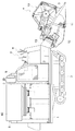
図1には、稲や麦などを収穫対象とする全稈投入型コンバインの全体側面が示されてお
り、このコンバインは、角パイプ鋼材などで形成した車体フレーム1に、エンジン2や図
外の変速装置などを搭載し、車体フレーム1の下部に、変速装置などを介して伝達される
エンジン2からの動力で駆動される左右一対のクローラ式走行装置3を装備し、車体フレ
ーム1の前部に、収穫対象の植立穀稈を刈り取って後方に向けて搬送する刈取搬送装置4
を昇降揺動可能に連結し、車体フレーム1の左半部に、刈取搬送装置4からの刈取穀稈に
対して脱穀処理を施すとともに、その脱穀処理で得られた処理物に対して選別処理を施す
脱穀装置5を搭載し、車体フレーム1の右半部に、脱穀装置5からの穀粒を貯留するとと
もに、その貯留した穀粒の袋詰めを可能にする袋詰装置6を搭載し、車体フレーム1にお
ける袋詰装置6の前方箇所に搭乗運転部7を形成して構成されている。
FIG. 1 shows an overall side view of an all-throw-type combine that harvests rice, wheat, and the like. This combine is attached to a
Are connected to the left half of the
左右のクローラ式走行装置3は、搭乗運転部7に備えた操縦レバー8の左右方向への揺
動操作に基づいて、それらが等速駆動されることで直進状態を現出し、それらが差動する
ことで旋回状態を現出するように構成されている。
The left and right crawler
図1及び図2に示すように、刈取搬送装置4は、車体の走行に伴って、その前部左右両
端に装備したデバイダ9が植立穀稈を収穫対象の植立穀稈と収穫対象外の植立穀稈とに梳
き分け、その前部上方に配備した回転リール10が、左右のデバイダ9で梳き分けられた
収穫対象の植立穀稈を後方に向けて掻き込み、その底部に装備したバリカン形の切断機構
11が収穫対象の植立穀稈の株元側を切断し、切断機構11の後方に配備したオーガ12
が、切断機構11による切断後の植立穀稈(刈取穀稈)を左右方向の所定箇所に寄せ集め
るとともに、その所定箇所において後方に向けて送り出し、その所定箇所から脱穀装置5
の前上部にわたる搬送コンベヤからなるフィーダ13が、オーガ12からの刈取穀稈を脱
穀装置5に向けて搬送するように構成されている。又、操縦レバー8の前後方向への揺動
操作に基づいて、車体フレーム1とフィーダ13とにわたって架設した油圧式の昇降シリ
ンダ(図示せず)が伸縮作動することで、脱穀装置5とフィーダ13との連結点を支点に
して昇降揺動し、その昇降揺動で、植立穀稈に対する切断機構11の高さ位置を変更する
刈り高さ調節を行えるように構成されている。
As shown in FIG. 1 and FIG. 2, the cutting and conveying
However, the planted cereals (cutted cereals) after being cut by the
A
図3〜5に示すように、脱穀装置5は、その上部に形成した扱室14に、刈取穀稈の搬
送方向に沿って架設した前後向きの支軸15を支点にして回転する扱胴16を配備し、そ
の扱胴16の下方に、扱胴16の下部側を下方から覆う正面視U字状に形成された受網1
7を装備し、脱穀装置5の脱穀処理方向下手側端部となる受網17の後方に排稈口18を
形成し、受網17の下方に揺動選別機構19を設け、その揺動選別機構19の前下方に唐
箕20を配備し、揺動選別機構19の前部側下方に1番回収部21を形成し、揺動選別機
構19の後部側下方に2番回収部22を形成し、揺動選別機構19の後方に排出口23を
形成し、扱胴16の上部側を上方から覆う天板24を備えて構成されている。
As shown in FIGS. 3 to 5, the threshing
7, a
扱室14は、扱胴16を覆う受網17や天板24などによって区画形成され、その前端
下方部位に供給口25が形成され、その供給口25にフィーダ13の後端部が接続され、
そのフィーダ13で搬送された刈取穀稈の全体が脱穀処理物として供給口25から投入供
給される。
The handling
The whole of the harvested cereal meal conveyed by the
扱胴16は、その支軸15が脱穀装置5の前壁26と後壁27とにわたって回転可能に
架設され、唐箕20などを介して伝達されるエンジン2からの動力で、支軸15を支点に
して正面視右回りに回転駆動されることで、扱室14に供給された刈取穀稈に対して脱穀
処理を施して、穀粒の単粒化を促しながら、その刈取穀稈を脱穀処理方向下手側となる後
方に向けて搬送する。
The handling
受網17は、格子状に形成されたコンケーブ受網であり、扱室14に供給された刈取穀
稈を受け止めて、刈取穀稈に対する扱胴16の脱穀処理を補助し、その脱穀処理で得られ
た単粒化穀粒や枝梗付き穀粒、あるいは、脱穀処理で発生した稈屑などを下方の揺動選別
機構19に向けて漏下させる一方で、脱粒穀稈などの揺動選別機構19への漏下を防止す
る。
The receiving
揺動選別機構19は、カム式の駆動機構28によって前後方向に揺動駆動されるシーブ
ケース29の上部に、粗選別用のグレンパン30とチャフシーブ31とストローラック3
2とを、その順にシーブケース29の前側から配備し、シーブケース29の下部に、精選
別用のグレンパン33とグレンシーブ34とを、その順にシーブケース29の前側から配
備して構成されている。そして、単粒化穀粒や稈屑などが混在する状態で受網17から漏
下した選別処理物を、上部のグレンパン30やチャフシーブ31あるいはストローラック
32で受け止めて、篩い選別による粗選別処理を施し、かつ、単粒化穀粒や枝梗付き穀粒
などが混在する状態でチャフシーブ31から漏下した選別処理物を、下部のグレンパン3
3やグレンシーブ34で受け止めて、篩い選別による精選別処理を施して、選別処理物を
、1番物としての単粒化穀粒と、2番物としての枝梗付き穀粒や稈屑などの混在物と、3
番物としての稈屑などの塵埃とに選別する。
The
2 are arranged in that order from the front side of the
3 and
Sorted into dust such as sawdust as a product.
唐箕20は、ベルト式の伝動機構35を介して伝達されるエンジン2からの動力で、そ
の支軸20Aを支点にして回転駆動されることで選別風を生起し、その選別風が、3つの
風路R1〜R3を通って、受網17から漏下した選別処理物や、揺動選別機構19で選別
される選別処理物などに向けて供給されることで、選別処理物に対して風力選別処理を施
して、選別処理物から比重の小さい稈屑などを吹き分けて、脱穀処理方向下手側の排出口
23に向けて搬送する。
The
1番回収部21は、唐箕20からの選別風でワラ屑などの塵埃が除去された状態で、揺
動選別機構19のグレンシーブ34から漏下した単粒化穀粒を、1番物として回収し、回
収した1番物を、その底部に左右向きに配備した1番スクリュー36で、その右端に連通
接続した揚送スクリュー37(図2参照)に向けて搬送する。
The
2番回収部22は、揺動選別機構19のグレンシーブ34から漏下せずにグレンシーブ
34の後端から流下した枝梗付き穀粒や稈屑などの混在物、及び、揺動選別機構19のス
トローラック32から漏下した枝梗付き穀粒や稈屑などの混在物を2番物として回収し、
回収した2番物を、その底部に左右向きに配備した2番スクリュー38で、その右端に連
通接続した2番還元機構39(図2参照)に向けて搬送する。
The
The collected second item is conveyed toward the second reduction mechanism 39 (see FIG. 2) connected to the right end thereof by a
揚送スクリュー37は、1番スクリュー36で搬送された1番物を揚送して、袋詰装置
6の上部に備えた穀粒タンク40に供給する(図1及び図2参照)。2番還元機構39は
、2番スクリュー38で搬送された2番物に対して再び脱穀処理を施す再処理部(図示せ
ず)を備え、その再処理部による脱穀処理後の2番物を揚送して揺動選別機構19に還元
する(図2参照)。
The lifting
排出口23は、受網17から漏下せずに排稈口18から流下する脱粒穀稈や、篩い選別
処理や風力選別処理で揺動選別機構19の後方に選別搬送された稈屑などを車外に放出す
る。
The
図3〜8に示すように、扱胴16は、その前端部に装備した円錐台状の掻込部41と、
その掻込部41の後端に連接した扱き処理部42とを備えて構成されている。掻込部41
の外周面には、扱胴16の回転作動時に、供給口25から供給された刈取穀稈を後方の扱
き処理部42に向けて掻き込み搬送する2枚の螺旋歯43が一体装備されている。
As shown in FIGS. 3 to 8, the handling
A
The outer peripheral surface is integrally equipped with two
扱き処理部42は、支軸15の前部に一体装備した第1支持プレート44、支軸15の
前後中間部に一体装備した第2支持プレート45、支軸15の後端部に一体装備した第3
支持プレート46、それらの支持プレート44〜46によって、支軸15に沿う前後向き
の姿勢で、扱胴16の周方向に一定間隔を隔てて並ぶように支持された丸パイプ鋼材など
からなる6本の扱胴フレーム(本体構成部材の一例)47、及び、各扱胴フレーム47に
、扱胴フレーム47から扱胴16の外方に向けて突出する姿勢で、前後方向に所定間隔を
隔てて並ぶように装備した複数の扱歯48、などによって籠状に構成されている。
The
Six of the
つまり、扱胴16は、その外方に向けて突出する複数の扱歯48が、扱き処理部42の
周方向と前後方向とに所定間隔を隔てて並ぶように整列配備され、又、扱き処理部42の
内部空間Sが扱室14に連通して、その内部空間Sへの脱穀処理物の入り込みを許容する
ようになっており、その結果、その回転作動時には、その周囲の脱穀処理物と内部空間S
に入り込んだ脱穀処理物とを攪拌しながら、それらの脱穀処理物に対して、扱胴フレーム
47や扱歯48の打撃や梳き込みなどによる脱穀処理を施すことになる。
That is, the handling
While stirring the threshing processed product that has entered, the threshing processing product is subjected to threshing processing by striking or punching the handling
又、扱き処理部42の内部空間Sが扱室14に連通することで、大量の刈取穀稈が脱穀
処理物として扱室14に供給された場合であっても、扱き処理部42の内部空間Sを脱穀
処理用の処理空間として有効利用することができ、これによって、処理空間での脱穀処理
物の滞留や処理空間の飽和を回避することができる。その結果、脱穀処理物の滞留や処理
空間の飽和に起因した、十分な脱穀処理が行われないまま脱穀処理物が受網17から漏下
する、あるいは、脱穀処理に要する負荷が増大して扱胴16に対する伝動系が損傷する、
などの不都合の発生を未然に回避することができる。
Further, the internal space S of the
Such inconveniences can be avoided in advance.
そして、扱胴16の回転作動時には、複数の扱歯48だけでなく、扱胴16の扱き処理
部42を形成する6本の扱胴フレーム47までもが、脱穀処理物に作用する扱き処理部材
として機能することから、脱穀性能や脱穀効率の向上を図ることができる。
When the handling
しかも、扱胴16の前部側での脱穀処理によって、多くの穀粒が単粒化して受網17か
ら漏下することで、脱穀処理物量が減少する扱胴16の前後中間部においては、第2支持
プレート45が、扱胴16の内部空間Sでの脱穀処理物の脱穀処理方向下手側への流動を
阻止し、扱胴16の回転とともに脱穀処理物を扱胴16の周囲に導いて、脱穀処理物に対
する扱歯48などの打撃や梳き込みなどによる脱穀や、単粒化穀粒の受網17からの漏下
を促すようになることから、脱穀処理物に含まれる単粒化穀粒や未脱粒穀稈などが扱胴1
6の内部空間Sを素通りして、脱粒穀稈とともに脱穀処理方向下手側端部の排稈口18か
ら排出されることに起因した3番ロスの発生を阻止することができる。
Moreover, by the threshing process on the front side of the handling
It is possible to prevent the occurrence of the third loss due to passing through the internal space S of 6 and being discharged from the
更に、扱胴16の回転作動時には、掻込部41の作用で掻き込み搬送される刈取穀稈と
ともに、螺旋歯43の回転に伴って供給口25から吸引された外気が、扱胴16の周囲や
扱き処理部42の内部空間Sにスムーズに流動するようになり、これによって、脱穀処理
によって発生した稈屑などの供給口25からフィーダ13への流出を防止することができ
るとともに、脱穀処理物の脱穀処理方向下手側への搬送をより速やかに行える。
Further, when the handling
その上、供給口25から吸引される外気は、供給口25に接続されたフィーダ13の内
部を通るものであり、そのフィーダ13は、切断機構11やオーガ12などを装備した刈
取搬送装置4の刈取回収部に形成した回収穀稈搬出用の搬出口(図示せず)と供給口25
とを連通するものであることから、扱胴16の回転作動時には、螺旋歯43の回転による
吸引作用で、刈取回収部での刈取処理や回収処理で発生した稈屑などの塵埃も、外気とと
もに、刈取回収部の搬出口からフィーダ13の内部空間及び供給口25を介して、扱胴1
6の周囲や扱き処理部42の内部空間Sに流入することになる。その結果、刈取回収部で
の稈屑などの付着堆積や舞い上がりを抑制することができ、その付着堆積に起因した刈取
穀稈の搬送不良や、その舞い上がりに起因した作業環境及び視界性の低下などを抑制する
ことができる。
In addition, the outside air sucked from the
Therefore, when the handling
6 and the internal space S of the
各支持プレート44〜46は、支軸15を中心とする円形で、その外周側における支軸
15からの等距離の位置に扱胴フレーム47がボルト連結されている。
Each of the
つまり、各支持プレート44〜46の外周側に、その周方向に一定間隔を隔てて並ぶ状
態に6本の扱胴フレーム47を配備して、扱胴16の胴径を大きくするようにしているの
であり、これによって、扱胴16に対する刈取穀稈の巻き付きを防止することができる。
That is, on the outer peripheral side of each
各扱胴フレーム47は、その前後方向を扱胴16の前後方向と一致させた通常姿勢と、
その前後方向を扱胴16の前後方向と逆にした反転姿勢とに向き変更可能に、かつ、隣り
合う扱胴フレーム47との前後向きが逆になるように、各支持プレート44〜46にボル
ト連結されている。
Each handling
Bolts are attached to the
各扱胴フレーム47には、扱歯48の取り付けを可能にする複数の取付孔47A,47
Bが、その前後方向に一定ピッチPで並ぶ状態に、かつ、扱胴フレーム47の前端から最
前の取付孔47Aの中心までの距離L1と、扱胴フレーム47の後端から最後の取付孔4
7Aの中心までの距離L2とを半ピッチ(=1/2P)だけ異ならせた状態で穿設されて
いる。
Each handling
B is aligned in the front-rear direction at a constant pitch P, and the distance L1 from the front end of the
The distance L2 to the center of 7A is perforated with a half pitch (= 1 / 2P).
そして、各扱胴フレーム47は、隣り合うものとの前後向きが逆になる状態で各支持プ
レート44〜46に連結支持されており、これによって、6本の扱胴フレーム47として
同じ構成のものを採用しながら、それらの各扱胴フレーム47に装備される扱歯48を、
隣り合う扱胴フレーム47の扱歯48と前後方向に半ピッチ分だけ位置ずれさせた状態で
位置させることができ、結果、隣り合う扱歯48の間隔を小さくすることなく、脱穀処理
物に対する扱歯48の打撃間隔を小さくすることができる。
Each handling
It can be positioned in a state shifted by a half pitch in the front-rear direction from the
つまり、各扱胴フレーム47を同じ構成とすることによるコストの削減を図りながら、
又、隣り合う扱歯48の間隔を小さくするほど招き易くなる、扱歯48に対する脱穀処理
物中の穀稈の絡み付きに起因した脱穀処理物の詰まりを効果的に防止しながら、脱穀処理
物に対する扱歯48の打撃回数を多くすることによる脱穀性能の向上を図ることができる
。
In other words, while trying to reduce the cost by making each handling
Moreover, it becomes easy to invite, so that the space | interval of the adjacent tooth-handling 48 becomes small, preventing clogging of the threshing processed material resulting from the entanglement of the cereal in the threshing processed material with respect to the tooth-handling 48, Threshing performance can be improved by increasing the number of times the tooth handling 48 is struck.
又、各扱胴フレーム47を、通常姿勢と反転姿勢とに向き変更可能に装備したことで、
脱穀処理物量が多いことで比較的に摩耗し易い脱穀処理方向上手側に位置する扱歯48の
摩耗が長期の使用によって著しくなった場合には、各扱胴フレーム47の向きを変更する
ことで、各扱胴フレーム47に備えた複数の扱歯48を、比較的に摩耗し易い脱穀処理方
向上手側の扱歯48と摩耗し難い脱穀処理方向下手側の扱歯48とを交換した状態に、一
挙に位置変更することができ、これによって、摩耗の少ない脱穀処理方向下手側の扱歯4
8を、脱穀処理物量の多い脱穀処理方向上手側の扱歯48として有効利用することができ
る。
In addition, by installing each handling
When wear of the
8 can be effectively used as the tooth handling 48 on the upper side in the threshing processing direction with a large amount of processed threshing.
複数の取付孔47A,47Bのうち、各扱胴フレーム47の前後両端部に位置する4つ
(前後2つずつ)の取付孔47Aは、中間部に位置する取付孔47Bよりも小径に形成さ
れている。
Of the plurality of mounting
各扱歯48のうち、小径の取付孔47Aを利用して取り付けられる扱歯48Aは、取付
孔47Aに挿通される小径部48aを備えた段付きの丸棒鋼材で構成され、その中心が、
支軸15の中心と扱胴フレーム47の中心とを通る線上に位置するように、扱胴フレーム
47に着脱可能にナット止めされている。
Of each
A nut is detachably attached to the
中間部の取付孔47Bを利用して取り付けられる扱歯48Bは、段無しの丸棒鋼材で構
成され、その中心が、支軸15の中心と扱胴フレーム47の中心とを通る線上に位置する
ように、扱胴フレーム47に着脱不能に溶接されている。
The
つまり、扱き処理部42の前後両端部に位置する各扱歯48Aが着脱可能であることか
ら、それらの扱歯48Aが、扱胴フレーム47の向き変更を含めた長期にわたる使用で著
しく摩耗した場合には、新しい扱歯48Aに簡単に交換することができる。
That is, since each
又、脱粒穀稈量が多くなる脱穀処理方向下手側においては、図9に示すように、扱胴1
6の後端部に位置する扱歯48Aを間引いた状態で配備すれば、扱胴後端部での扱歯48
Aの間隔が大きくなって、扱胴後端部での扱歯48Aに対する引っ掛かりに起因した脱粒
穀稈の滞留を効果的に抑制することができ、結果、脱粒穀稈の排出口23からの放出を促
進させることができる。
In addition, on the lower side of the threshing treatment direction in which the amount of threshing cereals increases, as shown in FIG.
If the
The interval of A becomes large, and it is possible to effectively suppress the retention of the threshing cereal caused by the hooking on the tooth handling 48A at the rear end of the handling cylinder, and as a result, the shed cereal shed is discharged from the
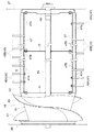
図3〜5、図10及び図11に示すように、天板24は、扱歯先端の回転軌跡Kに略沿
って湾曲する湾曲部24A、その湾曲部24Aの前後両端に位置する半円状の縦壁部24
B、及び、湾曲部24Aの左右に位置する一直線状の側縁部24C、などを備え、扱胴1
6の上部側を上方から覆う閉状態と、扱胴16の上部側を開放する開状態とに、左側の側
縁部24Cに備えた複数のヒンジ24Dを支点にした開閉揺動操作が可能となるように構
成されている。右側の側縁部24Cには、天板24を閉状態で固定する複数のボルト24
Eが備えられている。
As shown in FIGS. 3 to 5, 10, and 11, the
B, straight
6 can be opened and closed using a plurality of
E is provided.
湾曲部24Aの内面には、扱胴16の回転作動に伴って、扱室14の上部に搬送された
脱穀処理物を脱穀処理方向下手側に向けて案内する複数の送塵弁49が、前後方向に所定
間隔を隔てて並ぶように固定装備されている。複数の送塵弁49のうち、最前の送塵弁(
搬送方向最上手側の送塵弁に相当)49Aは、前側の縦壁部24Bから左側の側縁部24
Cにわたる円弧状に形成され、他の送塵弁49Bは、左右の側縁部24Cにわたる円弧状
に形成されている。
On the inner surface of the
49A corresponds to the dust feeding valve on the uppermost side in the transport direction) 49A is the
The other
つまり、天板24に湾曲部24Aを備えたことで、扱胴16の回転に伴って複数の扱歯
48などで扱室14の上部に掻き上げ搬送された脱穀処理物を、天板24に激しく衝突さ
せることなく、天板24や送塵弁49に沿わせながら、脱穀処理方向下手側下方の受網1
7に向けて滑らかに案内することができ、又、各送塵弁49を、左側の側縁部24C又は
左右の側縁部24Cにわたる長尺の円弧状に形成したことで、扱胴16の回転に伴って扱
室14の上部に搬送された脱穀処理物に対する各送塵弁49Aの案内作用を効果的に向上
させることができ、これによって、各扱歯48を、脱穀処理物に対する搬送作用を備える
形状ではなく、脱穀処理物に対する打撃や梳き込みを好適に行える脱穀専用の形状に形成
しながらも、脱穀処理物を脱穀処理方向下手側に向けて良好に搬送案内することができ、
結果、脱穀処理物に対する脱穀性能及び搬送性能の向上を図ることができる。
That is, by providing the
7 and each
As a result, it is possible to improve the threshing performance and conveyance performance for the threshing product.
左右の側縁部24Cには、湾曲部24Aの内面と受網17の内縁とに連なる案内面を有
するように形成された鋼板製の継目部材50が着脱可能にボルト連結されている。つまり
、受網17と天板24との継ぎ目に位置することにより脱穀処理物との接触が激しくなっ
て摩耗し易い継目部材50を着脱可能に構成したことで、その継目部材50を天板24に
一体形成した場合のように、継目部材50の摩耗によって天板24の全体を交換する、と
いった手間や経済的な不利を招くことなく、継目部材50の摩耗に対する処置を適切に行
える。
A steel
ちなみに、各扱歯48の先端と各送塵弁49の下縁との間には、送塵弁49による脱穀
処理物の案内を良好にするために小さいクリアランスが設定されている。又、各扱歯48
の先端と受網17の内縁との間には、単粒化穀粒の受網17からの漏下を促進させるため
に、各扱歯48の先端と各送塵弁49の下縁との間に設定したクリアランスよりも大きい
クリアランスが設定されている。
Incidentally, a small clearance is set between the tip of each tooth-handling 48 and the lower edge of each
In order to promote leakage of single grains from the receiving
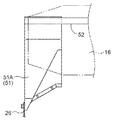
図3、図4、図6、図12及び図13に示すように、脱穀装置5の前壁26と受網17
との間には、供給口25から供給された刈取穀稈を受け止めて、扱胴16の掻込部41に
よる刈取穀稈の掻き込み搬送を補助する搬送補助部材51が配備されている。搬送補助部
材51は、扱胴16の下部側を下方から覆う正面視略U字状にボルト連結される2つのプ
レート51Aによって構成され、脱穀装置5の前壁26や脱穀装置5の上部に前後向きに
配備した左右一対の支持フレーム52に着脱可能にボルト連結されている。つまり、刈取
穀稈との接触が激しく摩耗し易い搬送補助部材51を着脱可能に構成したことで、その搬
送補助部材51を受網17又は左右の支持フレーム52に一体形成した場合のように、搬
送補助部材51の摩耗によって搬送補助部材51とともに受網17又は左右の支持フレー
ム52を交換する、といった手間や経済的な不利を招くことなく、搬送補助部材51の摩
耗に対する処置を適切に行える。
As shown in FIGS. 3, 4, 6, 12, and 13, the
Between the two, there is provided a
図3、図5、図6及び図14に示すように、受網17は、同一形状に形成された4つの
受網部材53によって構成され、左右の支持フレーム52に着脱可能にボルト連結されて
いる。各受網部材53は、基枠53Aに、帯状鋼板からなる複数の縦桟53Bを、扱胴1
6の周方向に一定間隔を隔てる状態で前後向きに整列配備し、円弧状に湾曲形成した帯状
鋼板からなる複数の第1横桟53Cを、扱胴16の支軸方向となる前後方向に所定間隔を
隔てる状態で左右向きに整列配備し、円弧状に湾曲形成したピアノ線材からなる複数の第
2横桟53Dを、隣接する第1横桟53Cの間において、前後方向に一定間隔を隔てる状
態で左右向きに整列配備して、その網目が、扱胴16の周方向に沿う方向の長さが前後方
向に沿う方向の長さよりも長くなる横長の矩形に形成されている。
As shown in FIGS. 3, 5, 6, and 14, the receiving
A plurality of first
つまり、受網17を、その網目が扱胴16の回転方向に長い横長の矩形となるように構
成したことで、刈取穀稈に対する脱穀処理で得られた単粒化穀粒などが受網17から漏下
し易くなり、もって、単粒化穀粒の受網17からの漏下が抑制されることに起因した脱ぷ
粒の発生を回避することができる。又、各受網部材53を同一形状に形成したことで、受
網17の生産性や組み付け性を向上させることができる。
That is, the receiving
図3及び図15に示すように、粗選別用のチャフシーブ31は単一の選別プレート54
で構成され、その選別方向下手側ほど上方に位置する後上がりの傾斜姿勢でシーブケース
29にボルト連結されている。
As shown in FIGS. 3 and 15, the rough
And is bolt-connected to the
選別プレート54の前部側(選別プレート54全体の1/3の領域)には、平面視矩形
状に形成された複数の漏下孔54Aが、前列の漏下孔54Aの間に後列の漏下孔54Aが
位置する千鳥状に整列形成されている。選別プレート54の後部側(選別プレート54全
体の2/3の領域)には、選別片54a,54bを有する平面視矩形状に形成された複数
の漏下孔54B,54Cが、前列の漏下孔54B,54Cの間に後列の漏下孔54B,5
4Cが位置する千鳥状に整列形成されている。
On the front side of the sorting plate 54 (1/3 of the entire sorting plate 54), a plurality of
4C is aligned and formed in a staggered pattern.
各選別片54a,54bのうち、選別プレート54の左右中央側に位置する選別片54
aは、その選別方向下手側ほど幅狭で上方に位置する鱗状に打ち出し形成されている。選
別プレート54の左右両端に位置する選別片54bは、左右中央側の選別片54aよりも
短尺の矩形状で、その選別方向下手側ほど上方に位置するように打ち出し形成されている
。
Among the sorting
A is formed so as to be narrower toward the lower side in the selection direction and in a scale-like shape that is positioned upward. The sorting
つまり、粗選別用のチャフシーブ31を単一の選別プレート54で構成することから、
例えば、チャフシーブ31を、帯鋼板からなる多数のチャフリップを前後方向に一定間隔
を隔てるように整列配備して構成する場合などに比較して、構成の簡素化やコストの削減
を図ることができる。
That is, since the
For example, the configuration of the
そして、単粒化穀粒の含有率が高い選別処理物が供給されるチャフシーブ31の前部側
に選別片54a,54bを備えていない漏下孔54Aを形成したことで、チャフシーブ3
1の前部側から下方のグレンパン33やグレンシーブ34に漏下する単粒化穀粒が多くな
り、結果、単粒化穀粒の回収率を高めることができる。
And by forming the
The number of single-grained grains leaking from the front side of 1 to the
又、チャフシーブ31の後部側に、選別片54a,54bを備えた漏下孔54B,54
Cを千鳥状で前後左右に整列形成したことで、篩い選別処理においては、チャフシーブ3
1上の選別処理物が左右方向に片寄りなく均等に分配されることになり、よって、単粒化
穀粒の各漏下孔54B,54Cからの漏下を促進させることができる。しかも、チャフシ
ーブ31を後上がりの傾斜姿勢で装備したことで、チャフシーブ31を水平姿勢で装備す
る場合に比較して、篩い選別処理において、チャフシーブ31が選別処理物を選別処理方
向上手側の上方に向けて押し出す力が大きくなり、これによって、選別処理物の選別方向
下手側への搬送が抑制されるとともに、選別処理物の上下動が激しくなって、選別処理物
の比重差選別をより効果的に行えることから、比重の大きい穀粒の各漏下孔54B,54
Cからの漏下が促進され、単粒化穀粒が排出口23から車外に放出される3番ロスの発生
を効果的に抑制することができ、結果、穀粒回収効率の向上を図ることができる。
Further, on the rear side of the
By forming C in a zigzag pattern in the front / rear / left / right direction, the
Therefore, it is possible to promote the leakage of single-grained grains from the
Leakage from C is promoted, and generation of No. 3 loss in which single grains are released from the
更に、チャフシーブ31における左右両端の選別片54bを、左右中央側の選別片54
aよりも短尺に形成したことで、チャフシーブ31における選別処理物が堆積し易い左右
両端部の漏下孔54Cからの穀粒などの漏下を促進させることができ、結果、チャフシー
ブ31の左右両端部での選別処理物の堆積に起因した選別効率の低下を回避することがで
きる。
Further, the left and right sorting
By making it shorter than a, it is possible to promote the leakage of grains and the like from the
ちなみに、チャフシーブ31に形成される選別片54a,54bを備えていない漏下孔
54Aと、選別片54a,54bを備えた漏下孔54B,54Cとの割合は、選別する穀
粒の種類などに応じて種々の変更が可能である。
Incidentally, the ratio of the
又、選別プレート54の前部側に、短尺で矩形状の選別片54bを有するように平面視
矩形状に形成された複数の漏下孔54Cを、前列の漏下孔54Cの間に後列の漏下孔54
Cが位置する千鳥状に整列形成するようにしてもよい。
In addition, a plurality of
You may make it form in a zigzag form where C is located.
図3に示すように、唐箕20からの選別風のうち、上段の風路R1を通る選別風は、シ
ーブケース29に形成した風路R4を通って、扱胴16の第2支持プレート45に向けて
流動するようになっている。これによって、第2支持プレート45によって脱穀処理方向
下手側への流動が阻止される脱穀処理物を、扱胴16の周囲に向けて風力搬送することが
でき、結果、脱穀処理物が第2支持プレート45の直前箇所で堆積して、脱穀処理に支障
を来す虞を未然に回避することができる。
As shown in FIG. 3, of the selected air from the
図3及び図6に示すように、扱胴16は、その後端に位置する扱歯48Aが、受網17
の後端よりも後方に位置して排稈口18に臨むようになっている。つまり、扱胴16の後
端においては、受網17が存在しないことで、その周囲に比較的大きい空間が形成された
状態となっており、これによって、扱胴後端の扱歯48Aに脱粒穀稈が絡み付いていたと
しても、その脱粒穀稈は、扱胴16の回転に伴う遠心力で、その扱歯48Aの先端から抜
け出るようになり、結果、扱胴16の後端での扱歯48Aに対する引っ掛かりに起因した
脱粒穀稈の滞留を効果的に抑制することができ、脱粒穀稈の排稈口18からの放出を促進
させることができる。
As shown in FIG. 3 and FIG. 6, the
It is located behind the rear end and faces the
〔別実施形態〕 [Another embodiment]
〔1〕扱胴16としては、掻込部41を備えないものであってもよく、又、掻込部41に
、螺旋歯43の代わりに整梳歯又は扱歯48を備えるものであってもよい。
[1] The
〔2〕扱胴16としては、各扱胴フレーム(本体構成部材)47に、丸棒鋼材、角棒鋼材
、角パイプ鋼材、アングル材、又はチャンネル材などを採用したものであってもよい。
[2] As the handling
〔3〕扱胴16において、扱胴フレーム(本体構成部材)47の装備数量は種々の変更が
可能であり、例えば、8本の扱胴フレーム47を装備するようにしてもよい。
[3] In the
〔4〕扱胴16において、複数の扱胴フレーム(本体構成部材)47を各支持プレート4
4〜46に向き変更不能に固着するようにしてもよい。
[4] In the
You may make it fix to 4-46 so that direction change is impossible.
〔5〕扱胴16としては、円筒状に形成されたプレートを本体構成部材47とするドラム
状に構成されたものであってもよい。
[5] The
〔6〕本体構成部材47に装備する全ての扱歯48を、本体構成部材47に溶接固定する
ようにしてもよく、又、本体構成部材47に着脱可能にボルト連結するようにしてもよい
。
[6] All the
〔7〕本体構成部材47に装備する全ての扱歯48又は一部の扱歯48を、扱胴16の回
転に伴って、脱穀処理物を脱穀処理方向下手側に向けて案内する案内面を有する羽根状に
形成するようにしてもよく、又、その先端部が、扱胴16の回転に伴って、脱穀処理物を
脱穀処理方向下手側に向けて案内する案内部として機能するようにL字状に屈曲形成して
もよい。
[7] A guide surface for guiding all of the
〔8〕扱歯48として、角棒鋼材や丸パイプ材などを採用するようにしてもよく、又、U
字状やV字状に屈曲形成されたものを採用するようにしてもよい。
[8] As the tooth-handling 48, a square bar steel material, a round pipe material or the like may be adopted.
You may make it employ | adopt the thing bent and formed in letter shape or V shape.
〔9〕扱歯48の配置間隔としては種々の変更が可能であり、例えば、扱胴フレーム(本
体構成部材)47の装備本数を3の倍数とする場合には、各扱歯48が、隣の扱胴フレー
ム(本体構成部材)47に装備された扱歯48と前後方向で1/3ピッチ分ずれた状態で
位置するように、又、扱胴フレーム(本体構成部材)47の装備本数を4の倍数とする場
合には、各扱歯48が、隣の扱胴フレーム(本体構成部材)47に装備された扱歯48と
前後方向で1/4ピッチ分ずれた状態で位置するように配置設定してもよい。又、例えば
、後部側での扱歯48の前後間隔が前部側での扱歯48の前後間隔よりも大きくなるよう
に、前部側と後部側とで扱歯48の配置間隔を異ならせるようにしてもよい。
[9] Various changes can be made to the arrangement interval of the
〔10〕天板24に装備する全ての送塵弁49又は一部の送塵弁49を、天板24の左右
いずれか一方の側縁部24C、又は、左右双方の側縁部24Cにわたらない短い長さに形
成するようにしてもよい。
[10] When all the
〔11〕送塵弁49を、扱室14内の脱穀処理物量に応じた開度調節が可能な可動式に構
成して、脱穀性能や脱穀効率の向上を更に図れるようにしてもよい。
[11] The
〔12〕天板24としては、その湾曲部24Aが扱歯48の先端が描く回転軌跡Kに沿っ
て湾曲するように形成されたものであってもよい。又、湾曲部24Aの代わりに、扱胴1
6の上部側を上方から覆うように屈曲形成された屈曲部を有するように構成されたもので
あってもよい。
[12] The
6 may be configured to have a bent portion that is bent to cover the upper side of 6 from above.
1 車体フレーム
5 脱穀装置
14 扱室
15 支軸
16 扱胴
17 受網
24 天板
24B 縦壁部
24C 側縁部
41 掻込部
42 扱き処理部
43 螺旋歯
47 扱胴フレーム(本体構成部材)
47A 取付孔
47B 取付孔
48 扱歯
49 送塵弁
49A 送塵弁(搬送方向最上手側の送塵弁)
51 搬送補助部材
DESCRIPTION OF
51 Conveyance auxiliary member
Claims (11)
前記脱穀装置に、前記脱穀装置の上部に形成された扱室と、前記扱室の内部に設けられ、刈取穀稈の搬送方向に沿って架設した支軸を支点にして回転駆動される扱胴とが備えられ、
前記扱胴に、前記扱胴の前端部を構成する掻込部と、前記掻込部の後端に連接された扱
き処理部とが備えられ、
前記掻込部は、円錐台状の基部と、前記基部の外周に設けられ、前記扱室に供給搬送された刈取穀稈を、前記扱胴の前記支軸周りの回転に伴って後方に向けて掻き込み搬送する螺旋歯とを有し、
前記扱き処理部は、前記扱胴の周方向に間隔を隔てて並ぶように支持された複数の扱胴フレームと、前記扱胴フレームから外方に向けて突出する複数の扱歯とを有し、
前記掻込部の下方に、前記螺旋歯による刈取穀稈の掻き込み搬送を補助する搬送補助部材が備えられ、
前記扱き処理部の下方に、前記扱き処理部における脱穀処理物を漏下させる受網が備えられ、
前記扱胴フレームは、着脱可能に構成され、
前記螺旋歯は、前記螺旋歯の後端部が前記基部の後端から前記扱き処理部側に突出しないように設けられ、かつ、前記複数の扱歯のうち最も搬送方向上手側に位置する扱歯は、前記掻込部の前記後端との間に間隔を空けて設けられ、
前記扱胴フレームがパイプ鋼材で構成され、
前記扱胴フレームに複数の取付孔を形成し、前記扱歯を前記各取付孔に挿通して前記扱胴の径方向内側及び径方向外側の2箇所で前記扱胴フレームに支持してある全稈投入型コンバイン。 A threshing device is mounted on the body frame,
In the threshing device, a handling chamber formed in the upper part of the threshing device, and a handling cylinder which is provided inside the handling chamber and is rotationally driven with a support shaft erected along the conveying direction of the harvested grain culm And
The handling cylinder is provided with a scraping portion that constitutes a front end portion of the handling cylinder, and a handling processing portion that is connected to a rear end of the scraping portion,
The scraping portion is provided on a frustoconical base and an outer periphery of the base, and the harvested cereal grains fed and conveyed to the handling chamber are directed rearward along with the rotation of the handling cylinder around the support shaft. And spiral teeth to be scraped and conveyed,
The handling section includes a plurality of handling cylinder frames supported so as to be arranged at intervals in a circumferential direction of the handling cylinder, and a plurality of teeth handling teeth protruding outward from the handling cylinder frame. ,
Below the scraping portion, a transport assisting member for assisting the scraped transport of the harvested cereal meal by the spiral teeth is provided,
Below the handling processing unit, a receiving net for leaking the threshing processed material in the handling processing unit is provided,
The barrel frame is configured to be detachable,
The helical tooth is provided such that a rear end portion of the helical tooth does not protrude from the rear end of the base portion toward the handling portion, and the handling portion located closest to the conveyance direction among the plurality of handling teeth. teeth, provided we are at a distance between the rear end of the scraping portion,
The barrel frame is made of pipe steel,
A plurality of mounting holes are formed in the barrel, and the teeth are inserted through the mounting holes and supported by the barrel frame at two locations on the radially inner side and radially outer side of the barrel.稈 Input type combine harvester.
前記脱穀装置に、前記脱穀装置の上部に形成された扱室と、前記扱室の内部に設けられ、刈取穀稈の搬送方向に沿って架設した支軸を支点にして回転駆動される扱胴とが備えられ、In the threshing device, a handling chamber formed in the upper part of the threshing device, and a handling cylinder which is provided inside the handling chamber and is rotationally driven with a support shaft erected along the conveying direction of the harvested grain culm And
前記扱胴に、前記扱胴の前端部を構成する掻込部と、前記掻込部の後端に連接された扱き処理部とが備えられ、The handling cylinder is provided with a scraping portion that constitutes a front end portion of the handling cylinder, and a handling processing portion that is connected to a rear end of the scraping portion,
前記掻込部は、円錐台状の基部と、前記基部の外周に設けられ、前記扱室に供給搬送された刈取穀稈を、前記扱胴の前記支軸周りの回転に伴って後方に向けて掻き込み搬送する螺旋歯とを有し、The scraping portion is provided on a frustoconical base and an outer periphery of the base, and the harvested cereal grains fed and conveyed to the handling chamber are directed rearward along with the rotation of the handling cylinder around the support shaft. And spiral teeth to be scraped and conveyed,
前記扱き処理部は、前記扱胴の周方向に間隔を隔てて並ぶように支持された複数の扱胴フレームと、前記扱胴フレームから外方に向けて突出する複数の扱歯とを有し、The handling section includes a plurality of handling cylinder frames supported so as to be arranged at intervals in a circumferential direction of the handling cylinder, and a plurality of teeth handling teeth protruding outward from the handling cylinder frame. ,
前記掻込部の下方に、前記螺旋歯による刈取穀稈の掻き込み搬送を補助する搬送補助部材が備えられ、Below the scraping portion, a transport assisting member for assisting the scraped transport of the harvested cereal meal by the spiral teeth is provided,
前記扱き処理部の下方に、前記扱き処理部における脱穀処理物を漏下させる受網が備えられ、Below the handling processing unit, a receiving net for leaking the threshing processed material in the handling processing unit is provided,
前記複数の扱歯のうち最も搬送方向上手側に位置する扱歯は、前記掻込部の前記後端との間に間隔を空けて設けられ、Of the plurality of teeth handling teeth, the tooth handling located closest to the conveyance direction is provided with a gap between the rear end of the scraping portion,
前記扱胴フレームがパイプ鋼材で構成され、The barrel frame is made of pipe steel,
前記扱胴フレームに複数の取付孔を形成し、前記扱歯を前記各取付孔に挿通して前記扱胴の径方向内側及び径方向外側の2箇所で前記扱胴フレームに支持してある全稈投入型コンバイン。A plurality of mounting holes are formed in the barrel, and the teeth are inserted through the mounting holes and supported by the barrel frame at two locations on the radially inner side and radially outer side of the barrel.稈 Input type combine harvester.
複数の送塵弁が、前記天板の内面に前後方向に間隔を隔てて並ぶように装備され、前記扱胴の回転に伴って前記扱室の上部に搬送された脱穀処理物を前記複数の送塵弁が搬送方向下手側に向けて案内するように構成され、
前記複数の送塵弁は、前記天板における前記掻込部を装備した部位に、前記掻込部の回転に伴って刈取穀稈を搬送方向下手側に向けて案内する掻込部用送塵弁を備える請求項1又は2に記載の全稈投入型コンバイン。 The handling chamber is provided with a top plate covering the upper side of the handling cylinder,
A plurality of dust feeding valves are provided on the inner surface of the top plate so as to be arranged at intervals in the front-rear direction, and the threshing processed product conveyed to the upper part of the handling chamber as the handling cylinder rotates is sent to the plurality of dust-removing products. The dust delivery valve is configured to guide the lower side in the transport direction,
The plurality of dust feeding valves are a dust feeding unit for a scraping unit that guides the harvested cereal rice cake toward the lower side in the conveying direction along with the rotation of the scraping unit on a portion of the top plate equipped with the scraping unit. The all-fired type combine combiner according to claim 1 or 2 , comprising a valve.
複数の送塵弁が、前記天板の内面に前後方向に間隔を隔てて並ぶように装備され、前記扱胴の回転に伴って前記扱室の上部に搬送された脱穀処理物を前記複数の送塵弁が搬送方向下手側に向けて案内するように構成され、
前記複数の送塵弁のうち搬送方向最上手側の送塵弁は、前記天板の前側の縦壁部と左側の側縁部とにわたって形成されている請求項1〜4のいずれか一項に記載の全稈投入型コンバイン。 The handling chamber is provided with a top plate covering the upper side of the handling cylinder,
A plurality of dust feeding valves are provided on the inner surface of the top plate so as to be arranged at intervals in the front-rear direction, and the threshing processed product conveyed to the upper part of the handling chamber as the handling cylinder rotates is sent to the plurality of dust-removing products. The dust delivery valve is configured to guide the lower side in the transport direction,
Okuchiriben the conveying direction most upstream side among the plurality of Okuchiriben is any one of claim 1 to 4 which is formed over the front of the vertical wall portion and the left side edge of the top plate All-fired combine combine described in 1.
複数の送塵弁が、前記天板の内面に前後方向に間隔を隔てて並ぶように装備され、前記扱胴の回転に伴って前記扱室の上部に搬送された脱穀処理物を前記複数の送塵弁が搬送方向下手側に向けて案内するように構成され、
前記扱歯は、一直線状の棒状部材に構成されている請求項1〜5のいずれか一項に記載の全稈投入型コンバイン。 The handling chamber is provided with a top plate covering the upper side of the handling cylinder,
A plurality of dust feeding valves are provided on the inner surface of the top plate so as to be arranged at intervals in the front-rear direction, and the threshing processed product conveyed to the upper part of the handling chamber as the handling cylinder rotates is sent to the plurality of dust-removing products. The dust delivery valve is configured to guide the lower side in the transport direction,
The full tooth throwing type combine according to any one of claims 1 to 5 , wherein the teeth are configured as a straight bar-shaped member.
複数の送塵弁が、前記天板の内側に前後方向に間隔を隔てて並ぶように装備され、前記扱胴の回転に伴って前記扱室の上部に搬送された脱穀処理物を前記複数の送塵弁が搬送方向下手側に向けて案内するように構成され、
前記扱歯は、脱穀処理物に対する打撃や梳き込みのみを行う形状に形成されている請求項1〜6のいずれか一項に記載の全稈投入型コンバイン。 The handling chamber is provided with a top plate covering the upper side of the handling cylinder,
A plurality of dust feeding valves are provided inside the top plate so as to be arranged at intervals in the front-rear direction, and the threshing processed products conveyed to the upper part of the handling chamber as the handling cylinder rotates are moved to The dust delivery valve is configured to guide the lower side in the transport direction,
The whole tooth throwing type combine according to any one of claims 1 to 6 , wherein the teeth are formed in a shape that only hits or plows the threshing product.
複数の送塵弁が、前記天板の内面に前後方向に間隔を隔てて並ぶように装備され、前記扱胴の回転に伴って前記扱室の上部に搬送された脱穀処理物を前記複数の送塵弁が搬送方向下手側に向けて案内するように構成され、
前記扱胴の径方向において、前記扱歯の先端と前記送塵弁の下縁との間のクリアランスは、前記扱歯の先端と前記扱胴の下部側を下方から覆う受網の内縁との間のクリアランスよりも小さく設定されている請求項1〜7のいずれか一項に記載の全稈投入型コンバイン。 The handling chamber is provided with a top plate covering the upper side of the handling cylinder,
A plurality of dust feeding valves are provided on the inner surface of the top plate so as to be arranged at intervals in the front-rear direction, and the threshing processed product conveyed to the upper part of the handling chamber as the handling cylinder rotates is sent to the plurality of dust-removing products. The dust delivery valve is configured to guide the lower side in the transport direction,
In the radial direction of the handle cylinder, the clearance between the tip of the tooth handle and the lower edge of the dust delivery valve is the distance between the tip of the tooth handle and the inner edge of the receiving net that covers the lower side of the handle cylinder from below. The all-fired type combine combiner as described in any one of Claims 1-7 set smaller than the clearance between them.
複数の送塵弁が、前記天板の内面に前後方向に間隔を隔てて並ぶように装備され、前記扱胴の回転に伴って前記扱室の上部に搬送された脱穀処理物を前記複数の送塵弁が搬送方向下手側に向けて案内するように構成され、
前記送塵弁は、前記天板の左右の側縁部にわたる円弧状に形成されている請求項1〜8のいずれか一項に記載の全稈投入型コンバイン。 The handling chamber is provided with a top plate covering the upper side of the handling cylinder,
A plurality of dust feeding valves are provided on the inner surface of the top plate so as to be arranged at intervals in the front-rear direction, and the threshing processed product conveyed to the upper part of the handling chamber as the handling cylinder rotates is sent to the plurality of dust-removing products. The dust delivery valve is configured to guide the lower side in the transport direction,
The full dust throw type combine according to any one of claims 1 to 8, wherein the dust feeding valve is formed in an arc shape extending on left and right side edges of the top plate.
複数の送塵弁が、前記天板の内面に前後方向に間隔を隔てて並ぶように装備され、前記扱胴の回転に伴って前記扱室の上部に搬送された脱穀処理物を前記複数の送塵弁が搬送方向下手側に向けて案内するように構成され、
前記複数の送塵弁のうち隣接する送塵弁の間隔は、前記扱き処理部において前後方向に隣接する扱歯の間隔よりも大きく設定されている請求項1〜9のいずれか一項に記載の全稈投入型コンバイン。 The handling chamber is provided with a top plate covering the upper side of the handling cylinder,
A plurality of dust feeding valves are provided on the inner surface of the top plate so as to be arranged at intervals in the front-rear direction, and the threshing processed product conveyed to the upper part of the handling chamber as the handling cylinder rotates is sent to the plurality of dust-removing products. The dust delivery valve is configured to guide the lower side in the transport direction,
The interval between adjacent dust delivery valves among the plurality of dust delivery valves is set to be larger than the interval between tooth handling adjacent in the front-rear direction in the handling processing unit. All-in-one combine harvester.
前記掻込部の前記基部は、前窄まりの円錐台状に構成され、
前記螺旋歯の前側における前記基部からの高さは、前記螺旋歯の後側における前記基部からの高さよりも高く形成されている請求項1〜10のいずれか一項に記載の全稈投入型コンバイン。 The conveyance auxiliary member is configured in a front-falling shape,
The base portion of the scraping portion is configured in a truncated conical shape,
The height from the said base part in the front side of the said helical tooth is formed higher than the height from the said base part in the back side of the said helical tooth, The full throwing type | mold type as described in any one of Claims 1-10. Combine.
Priority Applications (1)
| Application Number | Priority Date | Filing Date | Title |
|---|---|---|---|
| JP2016136982A JP6466372B2 (en) | 2016-07-11 | 2016-07-11 | All-fired combine harvester |
Applications Claiming Priority (1)
| Application Number | Priority Date | Filing Date | Title |
|---|---|---|---|
| JP2016136982A JP6466372B2 (en) | 2016-07-11 | 2016-07-11 | All-fired combine harvester |
Related Parent Applications (1)
| Application Number | Title | Priority Date | Filing Date |
|---|---|---|---|
| JP2015254609A Division JP6165229B2 (en) | 2015-12-25 | 2015-12-25 | All-fired combine harvester |
Related Child Applications (2)
| Application Number | Title | Priority Date | Filing Date |
|---|---|---|---|
| JP2017077466A Division JP6765338B2 (en) | 2017-04-10 | 2017-04-10 | All-culm input type combine |
| JP2018140367A Division JP6715890B2 (en) | 2018-07-26 | 2018-07-26 | All culm type combine |
Publications (3)
| Publication Number | Publication Date |
|---|---|
| JP2016178947A JP2016178947A (en) | 2016-10-13 |
| JP2016178947A5 JP2016178947A5 (en) | 2017-05-25 |
| JP6466372B2 true JP6466372B2 (en) | 2019-02-06 |
Family
ID=57130644
Family Applications (1)
| Application Number | Title | Priority Date | Filing Date |
|---|---|---|---|
| JP2016136982A Active JP6466372B2 (en) | 2016-07-11 | 2016-07-11 | All-fired combine harvester |
Country Status (1)
| Country | Link |
|---|---|
| JP (1) | JP6466372B2 (en) |
Families Citing this family (2)
| Publication number | Priority date | Publication date | Assignee | Title |
|---|---|---|---|---|
| JP2022007757A (en) * | 2020-06-26 | 2022-01-13 | 株式会社クボタ | Harvesting machine |
| WO2022137814A1 (en) * | 2020-12-22 | 2022-06-30 | 株式会社クボタ | Threshing device |
Family Cites Families (13)
| Publication number | Priority date | Publication date | Assignee | Title |
|---|---|---|---|---|
| GB832331A (en) * | 1957-11-01 | 1960-04-06 | Fahr Ag Maschf | Threshing apparatus for a reaper-thresher |
| JPH01120223A (en) * | 1987-11-04 | 1989-05-12 | Kubota Ltd | Whole culm charging type thresher |
| JPH0198541U (en) * | 1987-12-18 | 1989-06-30 | ||
| JP2502153Y2 (en) * | 1989-05-18 | 1996-06-19 | 株式会社クボタ | Threshing equipment |
| JPH03117423U (en) * | 1990-03-14 | 1991-12-04 | ||
| JPH0633432U (en) * | 1992-05-07 | 1994-05-06 | 井関農機株式会社 | Ordinary combine thresher |
| JPH06284814A (en) * | 1993-04-01 | 1994-10-11 | Yanmar Agricult Equip Co Ltd | Threshing device in combine |
| JPH1118558A (en) * | 1997-07-09 | 1999-01-26 | Kubota Corp | Treating drum structure of threshing machine |
| JP3326367B2 (en) * | 1997-08-11 | 2002-09-24 | 株式会社クボタ | Threshing device handling cylinder |
| JPH1175496A (en) * | 1997-09-09 | 1999-03-23 | Kubota Corp | Thresher for ordinary type combine harvester |
| JPH11266666A (en) * | 1998-03-19 | 1999-10-05 | Kubota Corp | Whole culm-charging type combine harvester |
| JP4643080B2 (en) * | 2001-09-11 | 2011-03-02 | ヤンマー株式会社 | Combine |
| JP3730558B2 (en) * | 2001-10-23 | 2006-01-05 | ヤンマー農機株式会社 | Combine |
-
2016
- 2016-07-11 JP JP2016136982A patent/JP6466372B2/en active Active
Also Published As
| Publication number | Publication date |
|---|---|
| JP2016178947A (en) | 2016-10-13 |
Similar Documents
| Publication | Publication Date | Title |
|---|---|---|
| JP4148978B2 (en) | Threshing device | |
| JP6165229B2 (en) | All-fired combine harvester | |
| JP2016039834A5 (en) | ||
| JP6472357B2 (en) | Combine | |
| JP4695608B2 (en) | Threshing structure of all-fired combine harvester | |
| JP5491685B2 (en) | Threshing structure of all-fired combine harvester | |
| JP4488445B2 (en) | Threshing structure of all-fired combine harvester | |
| JP6466372B2 (en) | All-fired combine harvester | |
| JP2016178947A5 (en) | ||
| JP5215351B2 (en) | Threshing device sorting structure | |
| JP5740021B2 (en) | Threshing structure of all-fired combine harvester | |
| JP5963833B2 (en) | Whole throwing type combine threshing device and whole throwing type combine harvester | |
| JP5643868B2 (en) | Threshing device and all-throw-in type combine harvester equipped with threshing device | |
| JP5818408B2 (en) | Threshing structure of all-fired combine harvester | |
| JP2010200764A5 (en) | ||
| JP5839782B2 (en) | Threshing structure of all-fired combine harvester | |
| JP2014121330A5 (en) | ||
| JP2007174999A (en) | Discharged culm-treating structure of whole culm-charging type combine harvester | |
| JP6715890B2 (en) | All culm type combine | |
| JP5963832B2 (en) | Whole throwing type combine threshing device and whole throwing type combine harvester | |
| JP6719516B2 (en) | Threshing structure of whole culm type combine harvester | |
| JP2018161155A5 (en) | ||
| JP2010200763A5 (en) | ||
| JP2017136087A (en) | Thresher structure for whole culm input type combine | |
| JP2010200762A5 (en) |
Legal Events
| Date | Code | Title | Description |
|---|---|---|---|
| A621 | Written request for application examination |
Free format text: JAPANESE INTERMEDIATE CODE: A621 Effective date: 20160809 |
|
| A521 | Written amendment |
Free format text: JAPANESE INTERMEDIATE CODE: A523 Effective date: 20170410 |
|
| A131 | Notification of reasons for refusal |
Free format text: JAPANESE INTERMEDIATE CODE: A131 Effective date: 20170905 |
|
| A521 | Written amendment |
Free format text: JAPANESE INTERMEDIATE CODE: A523 Effective date: 20171031 |
|
| A131 | Notification of reasons for refusal |
Free format text: JAPANESE INTERMEDIATE CODE: A131 Effective date: 20180403 |
|
| A601 | Written request for extension of time |
Free format text: JAPANESE INTERMEDIATE CODE: A601 Effective date: 20180518 |
|
| A521 | Written amendment |
Free format text: JAPANESE INTERMEDIATE CODE: A523 Effective date: 20180726 |
|
| TRDD | Decision of grant or rejection written | ||
| A01 | Written decision to grant a patent or to grant a registration (utility model) |
Free format text: JAPANESE INTERMEDIATE CODE: A01 Effective date: 20181211 |
|
| A61 | First payment of annual fees (during grant procedure) |
Free format text: JAPANESE INTERMEDIATE CODE: A61 Effective date: 20190109 |
|
| R150 | Certificate of patent or registration of utility model |
Ref document number: 6466372 Country of ref document: JP Free format text: JAPANESE INTERMEDIATE CODE: R150 |