JP6464531B2 - Electric car and charger - Google Patents
Electric car and charger Download PDFInfo
- Publication number
- JP6464531B2 JP6464531B2 JP2016046050A JP2016046050A JP6464531B2 JP 6464531 B2 JP6464531 B2 JP 6464531B2 JP 2016046050 A JP2016046050 A JP 2016046050A JP 2016046050 A JP2016046050 A JP 2016046050A JP 6464531 B2 JP6464531 B2 JP 6464531B2
- Authority
- JP
- Japan
- Prior art keywords
- charger
- charging infrastructure
- unit
- charging
- data
- Prior art date
- Legal status (The legal status is an assumption and is not a legal conclusion. Google has not performed a legal analysis and makes no representation as to the accuracy of the status listed.)
- Active
Links
- 238000004891 communication Methods 0.000 claims description 40
- 238000000034 method Methods 0.000 claims description 35
- 230000008569 process Effects 0.000 claims description 22
- 230000004044 response Effects 0.000 claims description 7
- 230000005540 biological transmission Effects 0.000 description 65
- 238000012545 processing Methods 0.000 description 15
- 230000006870 function Effects 0.000 description 9
- 238000001514 detection method Methods 0.000 description 8
- 238000012544 monitoring process Methods 0.000 description 8
- 238000003780 insertion Methods 0.000 description 5
- 230000037431 insertion Effects 0.000 description 5
- 238000010586 diagram Methods 0.000 description 4
- 230000008859 change Effects 0.000 description 3
- 230000010365 information processing Effects 0.000 description 2
- 239000011159 matrix material Substances 0.000 description 2
- 230000002093 peripheral effect Effects 0.000 description 2
- 238000012795 verification Methods 0.000 description 2
- 238000005516 engineering process Methods 0.000 description 1
- 230000007246 mechanism Effects 0.000 description 1
- 238000012986 modification Methods 0.000 description 1
- 230000004048 modification Effects 0.000 description 1
- 230000003287 optical effect Effects 0.000 description 1
- 239000004065 semiconductor Substances 0.000 description 1
- 238000012546 transfer Methods 0.000 description 1
Images


Classifications
-
- G—PHYSICS
- G08—SIGNALLING
- G08G—TRAFFIC CONTROL SYSTEMS
- G08G1/00—Traffic control systems for road vehicles
- G08G1/14—Traffic control systems for road vehicles indicating individual free spaces in parking areas
- G08G1/141—Traffic control systems for road vehicles indicating individual free spaces in parking areas with means giving the indication of available parking spaces
- G08G1/143—Traffic control systems for road vehicles indicating individual free spaces in parking areas with means giving the indication of available parking spaces inside the vehicles
-
- B—PERFORMING OPERATIONS; TRANSPORTING
- B60—VEHICLES IN GENERAL
- B60L—PROPULSION OF ELECTRICALLY-PROPELLED VEHICLES; SUPPLYING ELECTRIC POWER FOR AUXILIARY EQUIPMENT OF ELECTRICALLY-PROPELLED VEHICLES; ELECTRODYNAMIC BRAKE SYSTEMS FOR VEHICLES IN GENERAL; MAGNETIC SUSPENSION OR LEVITATION FOR VEHICLES; MONITORING OPERATING VARIABLES OF ELECTRICALLY-PROPELLED VEHICLES; ELECTRIC SAFETY DEVICES FOR ELECTRICALLY-PROPELLED VEHICLES
- B60L53/00—Methods of charging batteries, specially adapted for electric vehicles; Charging stations or on-board charging equipment therefor; Exchange of energy storage elements in electric vehicles
- B60L53/10—Methods of charging batteries, specially adapted for electric vehicles; Charging stations or on-board charging equipment therefor; Exchange of energy storage elements in electric vehicles characterised by the energy transfer between the charging station and the vehicle
- B60L53/14—Conductive energy transfer
- B60L53/18—Cables specially adapted for charging electric vehicles
-
- B—PERFORMING OPERATIONS; TRANSPORTING
- B60—VEHICLES IN GENERAL
- B60L—PROPULSION OF ELECTRICALLY-PROPELLED VEHICLES; SUPPLYING ELECTRIC POWER FOR AUXILIARY EQUIPMENT OF ELECTRICALLY-PROPELLED VEHICLES; ELECTRODYNAMIC BRAKE SYSTEMS FOR VEHICLES IN GENERAL; MAGNETIC SUSPENSION OR LEVITATION FOR VEHICLES; MONITORING OPERATING VARIABLES OF ELECTRICALLY-PROPELLED VEHICLES; ELECTRIC SAFETY DEVICES FOR ELECTRICALLY-PROPELLED VEHICLES
- B60L53/00—Methods of charging batteries, specially adapted for electric vehicles; Charging stations or on-board charging equipment therefor; Exchange of energy storage elements in electric vehicles
- B60L53/30—Constructional details of charging stations
- B60L53/305—Communication interfaces
-
- B—PERFORMING OPERATIONS; TRANSPORTING
- B60—VEHICLES IN GENERAL
- B60L—PROPULSION OF ELECTRICALLY-PROPELLED VEHICLES; SUPPLYING ELECTRIC POWER FOR AUXILIARY EQUIPMENT OF ELECTRICALLY-PROPELLED VEHICLES; ELECTRODYNAMIC BRAKE SYSTEMS FOR VEHICLES IN GENERAL; MAGNETIC SUSPENSION OR LEVITATION FOR VEHICLES; MONITORING OPERATING VARIABLES OF ELECTRICALLY-PROPELLED VEHICLES; ELECTRIC SAFETY DEVICES FOR ELECTRICALLY-PROPELLED VEHICLES
- B60L53/00—Methods of charging batteries, specially adapted for electric vehicles; Charging stations or on-board charging equipment therefor; Exchange of energy storage elements in electric vehicles
- B60L53/30—Constructional details of charging stations
- B60L53/31—Charging columns specially adapted for electric vehicles
-
- B—PERFORMING OPERATIONS; TRANSPORTING
- B60—VEHICLES IN GENERAL
- B60L—PROPULSION OF ELECTRICALLY-PROPELLED VEHICLES; SUPPLYING ELECTRIC POWER FOR AUXILIARY EQUIPMENT OF ELECTRICALLY-PROPELLED VEHICLES; ELECTRODYNAMIC BRAKE SYSTEMS FOR VEHICLES IN GENERAL; MAGNETIC SUSPENSION OR LEVITATION FOR VEHICLES; MONITORING OPERATING VARIABLES OF ELECTRICALLY-PROPELLED VEHICLES; ELECTRIC SAFETY DEVICES FOR ELECTRICALLY-PROPELLED VEHICLES
- B60L53/00—Methods of charging batteries, specially adapted for electric vehicles; Charging stations or on-board charging equipment therefor; Exchange of energy storage elements in electric vehicles
- B60L53/30—Constructional details of charging stations
- B60L53/35—Means for automatic or assisted adjustment of the relative position of charging devices and vehicles
- B60L53/36—Means for automatic or assisted adjustment of the relative position of charging devices and vehicles by positioning the vehicle
-
- B—PERFORMING OPERATIONS; TRANSPORTING
- B60—VEHICLES IN GENERAL
- B60L—PROPULSION OF ELECTRICALLY-PROPELLED VEHICLES; SUPPLYING ELECTRIC POWER FOR AUXILIARY EQUIPMENT OF ELECTRICALLY-PROPELLED VEHICLES; ELECTRODYNAMIC BRAKE SYSTEMS FOR VEHICLES IN GENERAL; MAGNETIC SUSPENSION OR LEVITATION FOR VEHICLES; MONITORING OPERATING VARIABLES OF ELECTRICALLY-PROPELLED VEHICLES; ELECTRIC SAFETY DEVICES FOR ELECTRICALLY-PROPELLED VEHICLES
- B60L53/00—Methods of charging batteries, specially adapted for electric vehicles; Charging stations or on-board charging equipment therefor; Exchange of energy storage elements in electric vehicles
- B60L53/60—Monitoring or controlling charging stations
- B60L53/63—Monitoring or controlling charging stations in response to network capacity
-
- B—PERFORMING OPERATIONS; TRANSPORTING
- B60—VEHICLES IN GENERAL
- B60L—PROPULSION OF ELECTRICALLY-PROPELLED VEHICLES; SUPPLYING ELECTRIC POWER FOR AUXILIARY EQUIPMENT OF ELECTRICALLY-PROPELLED VEHICLES; ELECTRODYNAMIC BRAKE SYSTEMS FOR VEHICLES IN GENERAL; MAGNETIC SUSPENSION OR LEVITATION FOR VEHICLES; MONITORING OPERATING VARIABLES OF ELECTRICALLY-PROPELLED VEHICLES; ELECTRIC SAFETY DEVICES FOR ELECTRICALLY-PROPELLED VEHICLES
- B60L53/00—Methods of charging batteries, specially adapted for electric vehicles; Charging stations or on-board charging equipment therefor; Exchange of energy storage elements in electric vehicles
- B60L53/60—Monitoring or controlling charging stations
- B60L53/64—Optimising energy costs, e.g. responding to electricity rates
-
- B—PERFORMING OPERATIONS; TRANSPORTING
- B60—VEHICLES IN GENERAL
- B60L—PROPULSION OF ELECTRICALLY-PROPELLED VEHICLES; SUPPLYING ELECTRIC POWER FOR AUXILIARY EQUIPMENT OF ELECTRICALLY-PROPELLED VEHICLES; ELECTRODYNAMIC BRAKE SYSTEMS FOR VEHICLES IN GENERAL; MAGNETIC SUSPENSION OR LEVITATION FOR VEHICLES; MONITORING OPERATING VARIABLES OF ELECTRICALLY-PROPELLED VEHICLES; ELECTRIC SAFETY DEVICES FOR ELECTRICALLY-PROPELLED VEHICLES
- B60L53/00—Methods of charging batteries, specially adapted for electric vehicles; Charging stations or on-board charging equipment therefor; Exchange of energy storage elements in electric vehicles
- B60L53/60—Monitoring or controlling charging stations
- B60L53/65—Monitoring or controlling charging stations involving identification of vehicles or their battery types
-
- B—PERFORMING OPERATIONS; TRANSPORTING
- B60—VEHICLES IN GENERAL
- B60L—PROPULSION OF ELECTRICALLY-PROPELLED VEHICLES; SUPPLYING ELECTRIC POWER FOR AUXILIARY EQUIPMENT OF ELECTRICALLY-PROPELLED VEHICLES; ELECTRODYNAMIC BRAKE SYSTEMS FOR VEHICLES IN GENERAL; MAGNETIC SUSPENSION OR LEVITATION FOR VEHICLES; MONITORING OPERATING VARIABLES OF ELECTRICALLY-PROPELLED VEHICLES; ELECTRIC SAFETY DEVICES FOR ELECTRICALLY-PROPELLED VEHICLES
- B60L53/00—Methods of charging batteries, specially adapted for electric vehicles; Charging stations or on-board charging equipment therefor; Exchange of energy storage elements in electric vehicles
- B60L53/60—Monitoring or controlling charging stations
- B60L53/66—Data transfer between charging stations and vehicles
- B60L53/665—Methods related to measuring, billing or payment
-
- G—PHYSICS
- G06—COMPUTING; CALCULATING OR COUNTING
- G06Q—INFORMATION AND COMMUNICATION TECHNOLOGY [ICT] SPECIALLY ADAPTED FOR ADMINISTRATIVE, COMMERCIAL, FINANCIAL, MANAGERIAL OR SUPERVISORY PURPOSES; SYSTEMS OR METHODS SPECIALLY ADAPTED FOR ADMINISTRATIVE, COMMERCIAL, FINANCIAL, MANAGERIAL OR SUPERVISORY PURPOSES, NOT OTHERWISE PROVIDED FOR
- G06Q20/00—Payment architectures, schemes or protocols
- G06Q20/08—Payment architectures
- G06Q20/14—Payment architectures specially adapted for billing systems
- G06Q20/145—Payments according to the detected use or quantity
-
- G—PHYSICS
- G06—COMPUTING; CALCULATING OR COUNTING
- G06Q—INFORMATION AND COMMUNICATION TECHNOLOGY [ICT] SPECIALLY ADAPTED FOR ADMINISTRATIVE, COMMERCIAL, FINANCIAL, MANAGERIAL OR SUPERVISORY PURPOSES; SYSTEMS OR METHODS SPECIALLY ADAPTED FOR ADMINISTRATIVE, COMMERCIAL, FINANCIAL, MANAGERIAL OR SUPERVISORY PURPOSES, NOT OTHERWISE PROVIDED FOR
- G06Q30/00—Commerce
- G06Q30/02—Marketing; Price estimation or determination; Fundraising
- G06Q30/0241—Advertisements
-
- G—PHYSICS
- G06—COMPUTING; CALCULATING OR COUNTING
- G06Q—INFORMATION AND COMMUNICATION TECHNOLOGY [ICT] SPECIALLY ADAPTED FOR ADMINISTRATIVE, COMMERCIAL, FINANCIAL, MANAGERIAL OR SUPERVISORY PURPOSES; SYSTEMS OR METHODS SPECIALLY ADAPTED FOR ADMINISTRATIVE, COMMERCIAL, FINANCIAL, MANAGERIAL OR SUPERVISORY PURPOSES, NOT OTHERWISE PROVIDED FOR
- G06Q50/00—Systems or methods specially adapted for specific business sectors, e.g. utilities or tourism
- G06Q50/06—Electricity, gas or water supply
-
- G—PHYSICS
- G07—CHECKING-DEVICES
- G07F—COIN-FREED OR LIKE APPARATUS
- G07F15/00—Coin-freed apparatus with meter-controlled dispensing of liquid, gas or electricity
- G07F15/003—Coin-freed apparatus with meter-controlled dispensing of liquid, gas or electricity for electricity
- G07F15/005—Coin-freed apparatus with meter-controlled dispensing of liquid, gas or electricity for electricity dispensed for the electrical charging of vehicles
-
- G—PHYSICS
- G08—SIGNALLING
- G08G—TRAFFIC CONTROL SYSTEMS
- G08G1/00—Traffic control systems for road vehicles
- G08G1/14—Traffic control systems for road vehicles indicating individual free spaces in parking areas
- G08G1/141—Traffic control systems for road vehicles indicating individual free spaces in parking areas with means giving the indication of available parking spaces
- G08G1/144—Traffic control systems for road vehicles indicating individual free spaces in parking areas with means giving the indication of available parking spaces on portable or mobile units, e.g. personal digital assistant [PDA]
-
- G—PHYSICS
- G08—SIGNALLING
- G08G—TRAFFIC CONTROL SYSTEMS
- G08G1/00—Traffic control systems for road vehicles
- G08G1/14—Traffic control systems for road vehicles indicating individual free spaces in parking areas
- G08G1/145—Traffic control systems for road vehicles indicating individual free spaces in parking areas where the indication depends on the parking areas
- G08G1/146—Traffic control systems for road vehicles indicating individual free spaces in parking areas where the indication depends on the parking areas where the parking area is a limited parking space, e.g. parking garage, restricted space
-
- H—ELECTRICITY
- H02—GENERATION; CONVERSION OR DISTRIBUTION OF ELECTRIC POWER
- H02J—CIRCUIT ARRANGEMENTS OR SYSTEMS FOR SUPPLYING OR DISTRIBUTING ELECTRIC POWER; SYSTEMS FOR STORING ELECTRIC ENERGY
- H02J3/00—Circuit arrangements for ac mains or ac distribution networks
- H02J3/003—Load forecast, e.g. methods or systems for forecasting future load demand
-
- H—ELECTRICITY
- H02—GENERATION; CONVERSION OR DISTRIBUTION OF ELECTRIC POWER
- H02J—CIRCUIT ARRANGEMENTS OR SYSTEMS FOR SUPPLYING OR DISTRIBUTING ELECTRIC POWER; SYSTEMS FOR STORING ELECTRIC ENERGY
- H02J7/00—Circuit arrangements for charging or depolarising batteries or for supplying loads from batteries
- H02J7/00032—Circuit arrangements for charging or depolarising batteries or for supplying loads from batteries characterised by data exchange
- H02J7/00036—Charger exchanging data with battery
-
- H—ELECTRICITY
- H02—GENERATION; CONVERSION OR DISTRIBUTION OF ELECTRIC POWER
- H02J—CIRCUIT ARRANGEMENTS OR SYSTEMS FOR SUPPLYING OR DISTRIBUTING ELECTRIC POWER; SYSTEMS FOR STORING ELECTRIC ENERGY
- H02J7/00—Circuit arrangements for charging or depolarising batteries or for supplying loads from batteries
- H02J7/00047—Circuit arrangements for charging or depolarising batteries or for supplying loads from batteries with provisions for charging different types of batteries
-
- B—PERFORMING OPERATIONS; TRANSPORTING
- B60—VEHICLES IN GENERAL
- B60L—PROPULSION OF ELECTRICALLY-PROPELLED VEHICLES; SUPPLYING ELECTRIC POWER FOR AUXILIARY EQUIPMENT OF ELECTRICALLY-PROPELLED VEHICLES; ELECTRODYNAMIC BRAKE SYSTEMS FOR VEHICLES IN GENERAL; MAGNETIC SUSPENSION OR LEVITATION FOR VEHICLES; MONITORING OPERATING VARIABLES OF ELECTRICALLY-PROPELLED VEHICLES; ELECTRIC SAFETY DEVICES FOR ELECTRICALLY-PROPELLED VEHICLES
- B60L2240/00—Control parameters of input or output; Target parameters
- B60L2240/70—Interactions with external data bases, e.g. traffic centres
-
- B—PERFORMING OPERATIONS; TRANSPORTING
- B60—VEHICLES IN GENERAL
- B60L—PROPULSION OF ELECTRICALLY-PROPELLED VEHICLES; SUPPLYING ELECTRIC POWER FOR AUXILIARY EQUIPMENT OF ELECTRICALLY-PROPELLED VEHICLES; ELECTRODYNAMIC BRAKE SYSTEMS FOR VEHICLES IN GENERAL; MAGNETIC SUSPENSION OR LEVITATION FOR VEHICLES; MONITORING OPERATING VARIABLES OF ELECTRICALLY-PROPELLED VEHICLES; ELECTRIC SAFETY DEVICES FOR ELECTRICALLY-PROPELLED VEHICLES
- B60L2240/00—Control parameters of input or output; Target parameters
- B60L2240/80—Time limits
-
- H—ELECTRICITY
- H01—ELECTRIC ELEMENTS
- H01M—PROCESSES OR MEANS, e.g. BATTERIES, FOR THE DIRECT CONVERSION OF CHEMICAL ENERGY INTO ELECTRICAL ENERGY
- H01M10/00—Secondary cells; Manufacture thereof
- H01M10/42—Methods or arrangements for servicing or maintenance of secondary cells or secondary half-cells
- H01M10/48—Accumulators combined with arrangements for measuring, testing or indicating the condition of cells, e.g. the level or density of the electrolyte
-
- H—ELECTRICITY
- H01—ELECTRIC ELEMENTS
- H01M—PROCESSES OR MEANS, e.g. BATTERIES, FOR THE DIRECT CONVERSION OF CHEMICAL ENERGY INTO ELECTRICAL ENERGY
- H01M2220/00—Batteries for particular applications
- H01M2220/20—Batteries in motive systems, e.g. vehicle, ship, plane
-
- H—ELECTRICITY
- H02—GENERATION; CONVERSION OR DISTRIBUTION OF ELECTRIC POWER
- H02J—CIRCUIT ARRANGEMENTS OR SYSTEMS FOR SUPPLYING OR DISTRIBUTING ELECTRIC POWER; SYSTEMS FOR STORING ELECTRIC ENERGY
- H02J2310/00—The network for supplying or distributing electric power characterised by its spatial reach or by the load
- H02J2310/50—The network for supplying or distributing electric power characterised by its spatial reach or by the load for selectively controlling the operation of the loads
- H02J2310/56—The network for supplying or distributing electric power characterised by its spatial reach or by the load for selectively controlling the operation of the loads characterised by the condition upon which the selective controlling is based
- H02J2310/62—The condition being non-electrical, e.g. temperature
- H02J2310/64—The condition being economic, e.g. tariff based load management
-
- H—ELECTRICITY
- H02—GENERATION; CONVERSION OR DISTRIBUTION OF ELECTRIC POWER
- H02J—CIRCUIT ARRANGEMENTS OR SYSTEMS FOR SUPPLYING OR DISTRIBUTING ELECTRIC POWER; SYSTEMS FOR STORING ELECTRIC ENERGY
- H02J7/00—Circuit arrangements for charging or depolarising batteries or for supplying loads from batteries
- H02J7/00032—Circuit arrangements for charging or depolarising batteries or for supplying loads from batteries characterised by data exchange
- H02J7/00045—Authentication, i.e. circuits for checking compatibility between one component, e.g. a battery or a battery charger, and another component, e.g. a power source
-
- Y—GENERAL TAGGING OF NEW TECHNOLOGICAL DEVELOPMENTS; GENERAL TAGGING OF CROSS-SECTIONAL TECHNOLOGIES SPANNING OVER SEVERAL SECTIONS OF THE IPC; TECHNICAL SUBJECTS COVERED BY FORMER USPC CROSS-REFERENCE ART COLLECTIONS [XRACs] AND DIGESTS
- Y02—TECHNOLOGIES OR APPLICATIONS FOR MITIGATION OR ADAPTATION AGAINST CLIMATE CHANGE
- Y02E—REDUCTION OF GREENHOUSE GAS [GHG] EMISSIONS, RELATED TO ENERGY GENERATION, TRANSMISSION OR DISTRIBUTION
- Y02E60/00—Enabling technologies; Technologies with a potential or indirect contribution to GHG emissions mitigation
- Y02E60/10—Energy storage using batteries
-
- Y—GENERAL TAGGING OF NEW TECHNOLOGICAL DEVELOPMENTS; GENERAL TAGGING OF CROSS-SECTIONAL TECHNOLOGIES SPANNING OVER SEVERAL SECTIONS OF THE IPC; TECHNICAL SUBJECTS COVERED BY FORMER USPC CROSS-REFERENCE ART COLLECTIONS [XRACs] AND DIGESTS
- Y02—TECHNOLOGIES OR APPLICATIONS FOR MITIGATION OR ADAPTATION AGAINST CLIMATE CHANGE
- Y02T—CLIMATE CHANGE MITIGATION TECHNOLOGIES RELATED TO TRANSPORTATION
- Y02T10/00—Road transport of goods or passengers
- Y02T10/60—Other road transportation technologies with climate change mitigation effect
- Y02T10/70—Energy storage systems for electromobility, e.g. batteries
-
- Y—GENERAL TAGGING OF NEW TECHNOLOGICAL DEVELOPMENTS; GENERAL TAGGING OF CROSS-SECTIONAL TECHNOLOGIES SPANNING OVER SEVERAL SECTIONS OF THE IPC; TECHNICAL SUBJECTS COVERED BY FORMER USPC CROSS-REFERENCE ART COLLECTIONS [XRACs] AND DIGESTS
- Y02—TECHNOLOGIES OR APPLICATIONS FOR MITIGATION OR ADAPTATION AGAINST CLIMATE CHANGE
- Y02T—CLIMATE CHANGE MITIGATION TECHNOLOGIES RELATED TO TRANSPORTATION
- Y02T10/00—Road transport of goods or passengers
- Y02T10/60—Other road transportation technologies with climate change mitigation effect
- Y02T10/7072—Electromobility specific charging systems or methods for batteries, ultracapacitors, supercapacitors or double-layer capacitors
-
- Y—GENERAL TAGGING OF NEW TECHNOLOGICAL DEVELOPMENTS; GENERAL TAGGING OF CROSS-SECTIONAL TECHNOLOGIES SPANNING OVER SEVERAL SECTIONS OF THE IPC; TECHNICAL SUBJECTS COVERED BY FORMER USPC CROSS-REFERENCE ART COLLECTIONS [XRACs] AND DIGESTS
- Y02—TECHNOLOGIES OR APPLICATIONS FOR MITIGATION OR ADAPTATION AGAINST CLIMATE CHANGE
- Y02T—CLIMATE CHANGE MITIGATION TECHNOLOGIES RELATED TO TRANSPORTATION
- Y02T10/00—Road transport of goods or passengers
- Y02T10/60—Other road transportation technologies with climate change mitigation effect
- Y02T10/72—Electric energy management in electromobility
-
- Y—GENERAL TAGGING OF NEW TECHNOLOGICAL DEVELOPMENTS; GENERAL TAGGING OF CROSS-SECTIONAL TECHNOLOGIES SPANNING OVER SEVERAL SECTIONS OF THE IPC; TECHNICAL SUBJECTS COVERED BY FORMER USPC CROSS-REFERENCE ART COLLECTIONS [XRACs] AND DIGESTS
- Y02—TECHNOLOGIES OR APPLICATIONS FOR MITIGATION OR ADAPTATION AGAINST CLIMATE CHANGE
- Y02T—CLIMATE CHANGE MITIGATION TECHNOLOGIES RELATED TO TRANSPORTATION
- Y02T90/00—Enabling technologies or technologies with a potential or indirect contribution to GHG emissions mitigation
- Y02T90/10—Technologies relating to charging of electric vehicles
- Y02T90/12—Electric charging stations
-
- Y—GENERAL TAGGING OF NEW TECHNOLOGICAL DEVELOPMENTS; GENERAL TAGGING OF CROSS-SECTIONAL TECHNOLOGIES SPANNING OVER SEVERAL SECTIONS OF THE IPC; TECHNICAL SUBJECTS COVERED BY FORMER USPC CROSS-REFERENCE ART COLLECTIONS [XRACs] AND DIGESTS
- Y02—TECHNOLOGIES OR APPLICATIONS FOR MITIGATION OR ADAPTATION AGAINST CLIMATE CHANGE
- Y02T—CLIMATE CHANGE MITIGATION TECHNOLOGIES RELATED TO TRANSPORTATION
- Y02T90/00—Enabling technologies or technologies with a potential or indirect contribution to GHG emissions mitigation
- Y02T90/10—Technologies relating to charging of electric vehicles
- Y02T90/14—Plug-in electric vehicles
-
- Y—GENERAL TAGGING OF NEW TECHNOLOGICAL DEVELOPMENTS; GENERAL TAGGING OF CROSS-SECTIONAL TECHNOLOGIES SPANNING OVER SEVERAL SECTIONS OF THE IPC; TECHNICAL SUBJECTS COVERED BY FORMER USPC CROSS-REFERENCE ART COLLECTIONS [XRACs] AND DIGESTS
- Y02—TECHNOLOGIES OR APPLICATIONS FOR MITIGATION OR ADAPTATION AGAINST CLIMATE CHANGE
- Y02T—CLIMATE CHANGE MITIGATION TECHNOLOGIES RELATED TO TRANSPORTATION
- Y02T90/00—Enabling technologies or technologies with a potential or indirect contribution to GHG emissions mitigation
- Y02T90/10—Technologies relating to charging of electric vehicles
- Y02T90/16—Information or communication technologies improving the operation of electric vehicles
- Y02T90/167—Systems integrating technologies related to power network operation and communication or information technologies for supporting the interoperability of electric or hybrid vehicles, i.e. smartgrids as interface for battery charging of electric vehicles [EV] or hybrid vehicles [HEV]
-
- Y—GENERAL TAGGING OF NEW TECHNOLOGICAL DEVELOPMENTS; GENERAL TAGGING OF CROSS-SECTIONAL TECHNOLOGIES SPANNING OVER SEVERAL SECTIONS OF THE IPC; TECHNICAL SUBJECTS COVERED BY FORMER USPC CROSS-REFERENCE ART COLLECTIONS [XRACs] AND DIGESTS
- Y04—INFORMATION OR COMMUNICATION TECHNOLOGIES HAVING AN IMPACT ON OTHER TECHNOLOGY AREAS
- Y04S—SYSTEMS INTEGRATING TECHNOLOGIES RELATED TO POWER NETWORK OPERATION, COMMUNICATION OR INFORMATION TECHNOLOGIES FOR IMPROVING THE ELECTRICAL POWER GENERATION, TRANSMISSION, DISTRIBUTION, MANAGEMENT OR USAGE, i.e. SMART GRIDS
- Y04S10/00—Systems supporting electrical power generation, transmission or distribution
- Y04S10/12—Monitoring or controlling equipment for energy generation units, e.g. distributed energy generation [DER] or load-side generation
- Y04S10/126—Monitoring or controlling equipment for energy generation units, e.g. distributed energy generation [DER] or load-side generation the energy generation units being or involving electric vehicles [EV] or hybrid vehicles [HEV], i.e. power aggregation of EV or HEV, vehicle to grid arrangements [V2G]
-
- Y—GENERAL TAGGING OF NEW TECHNOLOGICAL DEVELOPMENTS; GENERAL TAGGING OF CROSS-SECTIONAL TECHNOLOGIES SPANNING OVER SEVERAL SECTIONS OF THE IPC; TECHNICAL SUBJECTS COVERED BY FORMER USPC CROSS-REFERENCE ART COLLECTIONS [XRACs] AND DIGESTS
- Y04—INFORMATION OR COMMUNICATION TECHNOLOGIES HAVING AN IMPACT ON OTHER TECHNOLOGY AREAS
- Y04S—SYSTEMS INTEGRATING TECHNOLOGIES RELATED TO POWER NETWORK OPERATION, COMMUNICATION OR INFORMATION TECHNOLOGIES FOR IMPROVING THE ELECTRICAL POWER GENERATION, TRANSMISSION, DISTRIBUTION, MANAGEMENT OR USAGE, i.e. SMART GRIDS
- Y04S30/00—Systems supporting specific end-user applications in the sector of transportation
- Y04S30/10—Systems supporting the interoperability of electric or hybrid vehicles
- Y04S30/14—Details associated with the interoperability, e.g. vehicle recognition, authentication, identification or billing
-
- Y—GENERAL TAGGING OF NEW TECHNOLOGICAL DEVELOPMENTS; GENERAL TAGGING OF CROSS-SECTIONAL TECHNOLOGIES SPANNING OVER SEVERAL SECTIONS OF THE IPC; TECHNICAL SUBJECTS COVERED BY FORMER USPC CROSS-REFERENCE ART COLLECTIONS [XRACs] AND DIGESTS
- Y04—INFORMATION OR COMMUNICATION TECHNOLOGIES HAVING AN IMPACT ON OTHER TECHNOLOGY AREAS
- Y04S—SYSTEMS INTEGRATING TECHNOLOGIES RELATED TO POWER NETWORK OPERATION, COMMUNICATION OR INFORMATION TECHNOLOGIES FOR IMPROVING THE ELECTRICAL POWER GENERATION, TRANSMISSION, DISTRIBUTION, MANAGEMENT OR USAGE, i.e. SMART GRIDS
- Y04S50/00—Market activities related to the operation of systems integrating technologies related to power network operation or related to communication or information technologies
- Y04S50/10—Energy trading, including energy flowing from end-user application to grid
-
- Y—GENERAL TAGGING OF NEW TECHNOLOGICAL DEVELOPMENTS; GENERAL TAGGING OF CROSS-SECTIONAL TECHNOLOGIES SPANNING OVER SEVERAL SECTIONS OF THE IPC; TECHNICAL SUBJECTS COVERED BY FORMER USPC CROSS-REFERENCE ART COLLECTIONS [XRACs] AND DIGESTS
- Y04—INFORMATION OR COMMUNICATION TECHNOLOGIES HAVING AN IMPACT ON OTHER TECHNOLOGY AREAS
- Y04S—SYSTEMS INTEGRATING TECHNOLOGIES RELATED TO POWER NETWORK OPERATION, COMMUNICATION OR INFORMATION TECHNOLOGIES FOR IMPROVING THE ELECTRICAL POWER GENERATION, TRANSMISSION, DISTRIBUTION, MANAGEMENT OR USAGE, i.e. SMART GRIDS
- Y04S50/00—Market activities related to the operation of systems integrating technologies related to power network operation or related to communication or information technologies
- Y04S50/12—Billing, invoicing, buying or selling transactions or other related activities, e.g. cost or usage evaluation
-
- Y—GENERAL TAGGING OF NEW TECHNOLOGICAL DEVELOPMENTS; GENERAL TAGGING OF CROSS-SECTIONAL TECHNOLOGIES SPANNING OVER SEVERAL SECTIONS OF THE IPC; TECHNICAL SUBJECTS COVERED BY FORMER USPC CROSS-REFERENCE ART COLLECTIONS [XRACs] AND DIGESTS
- Y04—INFORMATION OR COMMUNICATION TECHNOLOGIES HAVING AN IMPACT ON OTHER TECHNOLOGY AREAS
- Y04S—SYSTEMS INTEGRATING TECHNOLOGIES RELATED TO POWER NETWORK OPERATION, COMMUNICATION OR INFORMATION TECHNOLOGIES FOR IMPROVING THE ELECTRICAL POWER GENERATION, TRANSMISSION, DISTRIBUTION, MANAGEMENT OR USAGE, i.e. SMART GRIDS
- Y04S50/00—Market activities related to the operation of systems integrating technologies related to power network operation or related to communication or information technologies
- Y04S50/14—Marketing, i.e. market research and analysis, surveying, promotions, advertising, buyer profiling, customer management or rewards
Description
本発明は、電気自動車及び充電器に関する。 The present invention relates to an electric vehicle and a charger .
電気自動車の充電場所は、主には車庫で充電することになるが、電気自動車が1回の充電で走行できる距離には限りがあるので、出かけた先に充電スタンドも必要になる。充電スタンドに関する技術としては、種々のものが知られている(例えば、特許文献1から3参照。)。
The charging place of the electric vehicle is mainly charged in the garage, but since the distance that the electric vehicle can travel by one charge is limited, a charging stand is also required at the destination. Various techniques relating to the charging stand are known (for example, see
特許文献1に記載の技術は、街の中の、又は観光地等の充電所に設置される充電装置である。また、特許文献1に記載の技術は、駐車場に設置される駐車装置と充電機構とを結合した、駐車装置付き充電装置である。より具体的に説明すると、特許文献1に記載の充電装置は、充電ケーブルによる電源とバッテリとの接続を検知する。そして、充電装置は、充電ケーブルにより接続された車両のバッテリの電気容量を検出する。そして、充電装置は、検出した容量に対応する充電可能時間を表示する。そして、充電装置は、表示された充電可能時間の範囲で充電時間を設定する。そして、充電装置は、投入された貨幣の鑑別、受入れ、又は挿入されたカードに対する読取り、書込み処理を行う。そして、充電装置は、設定された充電時間に対応する充電料金額を算出して表示する。そして、充電装置は、収受した金額Xと算出された充電料金額YとがX≧Yの条件を満たす場合に、設定された充電時間において充電指令信号を出力する。そして、充電装置は、充電指令信号に基づいて電源より充電ケーブルを介して接続されている車両のバッテリに充電する。
The technique described in
特許文献2に記載の技術は、マンション等の共有スペースに設置し、特定多数の利用者による共用に適した給電装置である。より具体的に説明すると、特許文献2に記載の給電装置は、利用者を識別するための利用者識別情報を取得する。そして、給電装置は、取得された利用者識別情報を認証手段に送信する。そして、給電装置は、認証手段による認証結果に基づき、給電制限を解除する。そして、給電装置は、所定の電気装置に対する給電量を含む利用情報を生成する。 The technique described in Patent Document 2 is a power supply apparatus that is installed in a common space such as an apartment and is suitable for sharing by a specific number of users. More specifically, the power supply apparatus described in Patent Literature 2 acquires user identification information for identifying a user. Then, the power supply apparatus transmits the acquired user identification information to the authentication unit. Then, the power supply device releases the power supply restriction based on the authentication result by the authentication unit. Then, the power supply device generates usage information including the amount of power supplied to the predetermined electrical device.
特許文献3に記載の技術は、給電サービス事業者と契約を締結した電気自動車のユーザに対して、使用電力量に応じた電力料金を含む給電装置の利用料を容易に課金し得る電気自動車の給電課金システムである。より具体的に説明すると、特許文献3に記載の給電課金システムは、端末器から給電サーバへのアクセスにより給電装置を特定すると共にユーザ認証を行う。そして、給電課金システムは、給電装置の特定、及びユーザ認証の完了後に給電サーバからの指令に基づいて給電装置の給電スイッチをONして給電を開始する。
そして、給電課金システムは、給電スイッチのOFFによる給電終了後に計測器により計測された使用電力量を給電サーバへ送信する。そして、給電課金システムは、使用電力量に応じた電力料金を含む利用料を給電サーバで算出すると共に利用料を端末器へ送信する。そして、給電課金システムは、利用料の決済処理によりユーザに課金する。
The technology described in Patent Document 3 is an electric vehicle that can easily charge a user of an electric vehicle that has signed a contract with a power supply service provider, including a power charge according to the amount of power used. This is a power charging system. More specifically, the power supply billing system described in Patent Document 3 specifies a power supply device by accessing a power supply server from a terminal device and performs user authentication. Then, the power supply billing system starts power supply by turning on the power supply switch of the power supply device based on a command from the power supply server after the power supply device is specified and the user authentication is completed.
Then, the power supply billing system transmits the power consumption measured by the measuring instrument to the power supply server after the power supply is ended by turning off the power supply switch. The power supply billing system calculates a usage fee including a power fee according to the amount of power used by the power supply server and transmits the usage fee to the terminal. Then, the power supply charging system charges the user by a usage fee settlement process.
上述したように、特許文献1に記載の技術は、不特定の利用者が利用する充電スタンドのための技術である。そのため、特許文献1に記載の技術は、特定の利用者が利用する充電スタンドに適用した場合、様々な問題が生じる虞がある。
As described above, the technique described in
一方、特許文献2、3に記載の技術は、特定の利用者が利用する充電スタンドのための技術である。そのため、特許文献2、3に記載の技術は、不特定の利用者が利用する充電スタンドに適用した場合、様々な問題が生じる虞がある。 On the other hand, the techniques described in Patent Documents 2 and 3 are techniques for a charging station used by a specific user. Therefore, when the techniques described in Patent Documents 2 and 3 are applied to a charging stand used by an unspecified user, various problems may occur.
上記課題を解決するために、本発明の第1の形態によると、電気自動車は、充電インフラ管理システムによって制御される充電インフラの充電器により給電される電気自動車であって、前記電気自動車は、前記充電インフラ管理システムにより制御される車載器と、前記車載器へ入力されるデータ、前記車載器から出力されるデータを前記充電インフラ管理システムに送受信する通信器と、充電器から電力を受電する電力供給インターフェースと、を備え、前記充電器が前記充電インフラ管理システムから給電を許可する制御信号を受信し、前記電力供給インターフェースが接続されると、前記充電インフラ管理システムから送信される要求に応じて前記充電器が前記充電インフラ管理システムに送信する前記電気自動車への電力の供給量を示すデータに基づいて決定される前記充電インフラの利用料金の決済処理が完了するまで、前記充電器から前記電力供給インターフェースを取り外すことができないように前記充電器によって前記電力供給インターフェースがロックされる。 In order to solve the above problems, according to a first aspect of the present invention, an electric vehicle is an electric vehicle powered by a charging infrastructure charger controlled by a charging infrastructure management system, and the electric vehicle includes: The vehicle-mounted device controlled by the charging infrastructure management system, the data input to the vehicle-mounted device, the communication device that transmits / receives the data output from the vehicle-mounted device to the charging infrastructure management system, and receives power from the charger A power supply interface, and when the charger receives a control signal for permitting power supply from the charging infrastructure management system and the power supply interface is connected , in response to a request transmitted from the charging infrastructure management system The amount of power supplied to the electric vehicle that the charger transmits to the charging infrastructure management system To settlement processing of usage fees of the charging infrastructure is determined based on to the data is completed, the power supply interface by the charger so that it can not be removed the power supply interface from the charger is locked.
本発明の第2の形態によると、電気自動車は、充電インフラ管理システムによって制御される充電インフラの充電器により給電される電気自動車であって、前記電気自動車は、前記充電インフラ管理システムにより制御される車載器と、前記車載器へ入力されるデータ、前記車載器から出力されるデータを前記充電インフラ管理システムに送受信する通信器と、充電器から電力を受電する電力供給インターフェースと、を備え、前記充電インフラ管理システムから送信される要求に応じて前記充電器が前記充電インフラ管理システムに送信する前記電気自動車への電力の供給量を示すデータに基づいて決定される前記充電インフラの利用料金の決済処理が完了した後に、前記充電器が前記充電インフラ管理システムから給電を終了する制御信号を受信すると、前記充電器から前記電力供給インターフェースを取り外すことができるように前記充電器によって前記電力供給インターフェースがアンロックされる。 According to a second aspect of the present invention, the electric vehicle is an electric vehicle powered by a charging infrastructure charger controlled by a charging infrastructure management system, and the electric vehicle is controlled by the charging infrastructure management system. An on-vehicle device, data input to the on-vehicle device, a communication device that transmits and receives data output from the on-vehicle device to the charging infrastructure management system, and a power supply interface that receives power from the charger, In response to a request transmitted from the charging infrastructure management system, the charging infrastructure usage fee determined based on data indicating the amount of power supplied to the electric vehicle transmitted from the charger to the charging infrastructure management system . After the payment process is completed, a control signal for the charger to terminate power supply from the charging infrastructure management system. Upon receiving the said power supply interface by the charger so that it can be removed the power supply interface from the charger it is unlocked.
本発明の第3の形態によると、充電器は、充電インフラ管理システムによって制御される充電インフラの充電器であって、前記充電器は、前記充電インフラ管理システムとの間でデータを送受信する通信器と、電気自動車に電力を供給する電力供給インターフェースと、を備え、前記充電器は前記充電インフラ管理システムから給電を許可する制御信号を受信し、前記電力供給インターフェースが前記電気自動車に接続されると、前記充電インフラ管理システムから送信される要求に応じて前記充電器が前記充電インフラ管理システムに送信する前記電気自動車への電力の供給量を示すデータに基づいて決定される前記充電インフラの利用料金の決済処理が完了するまで、前記電気自動車から前記電力供給インターフェースを取り外すことができないように前記電気自動車に対して前記電力供給インターフェースをロックする。 According to a third aspect of the present invention, the charger is a charger infrastructure charger controlled by a charging infrastructure management system, and the charger communicates data with the charging infrastructure management system. And a power supply interface for supplying power to the electric vehicle, wherein the charger receives a control signal permitting power supply from the charging infrastructure management system, and the power supply interface is connected to the electric vehicle. Use of the charging infrastructure determined based on data indicating the amount of power supplied to the electric vehicle that the charger transmits to the charging infrastructure management system in response to a request transmitted from the charging infrastructure management system The power supply interface may be removed from the electric vehicle until the fee settlement process is completed. Locking the power supply interface to the electric vehicle so as not to come.
本発明の第4の形態によると、充電器は、充電インフラ管理システムによって制御される充電インフラの充電器であって、前記充電器は、前記充電インフラ管理システムとの間でデータを送受信する通信器と、電気自動車に電力を供給する電力供給インターフェースと、を備え、前記充電インフラ管理システムから送信される要求に応じて前記充電器が前記充電インフラ管理システムに送信する前記電気自動車への電力の供給量を示すデータに基づいて決定される前記充電インフラの利用料金の決済処理が完了した後に、前記充電器は前記充電インフラ管理システムから給電を終了する制御信号を受信すると、前記電気自動車から前記電力供給インターフェースを取り外すことができるように前記電気自動車に対して前記電力供給インターフェースをアンロックする。
According to a fourth aspect of the present invention, the charger is a charger infrastructure charger controlled by a charging infrastructure management system, and the charger communicates data with the charging infrastructure management system. A power supply interface that supplies power to the electric vehicle, and the charger transmits power to the electric vehicle that is transmitted to the charging infrastructure management system in response to a request transmitted from the charging infrastructure management system. After the charging infrastructure usage fee settlement process determined based on the data indicating the supply amount is completed, the charger receives a control signal for terminating power supply from the charging infrastructure management system, and then receives the control signal from the electric vehicle. The power supply interface to the electric vehicle so that the power supply interface can be removed. To unlock the over nest.
以上の説明から明らかなように、この発明によれば、電気自動車を充電させるための充電器の他に、任意の各種充電インフラ用機器が設けられた様々な運用形態の充電インフラを管理することができる。例えば、本発明に係る充電インフラは、特定の利用者が利用する充電インフラにも、不特定の利用者が利用する充電インフラにも対応して、その管理を行うことができる。 As is apparent from the above description, according to the present invention, in addition to the charger for charging the electric vehicle, the charging infrastructure of various operation forms in which various various charging infrastructure devices are provided can be managed. Can do. For example, the charging infrastructure according to the present invention can be managed corresponding to both a charging infrastructure used by a specific user and a charging infrastructure used by an unspecified user.
以下、発明の実施の形態を通じて本発明を説明するが、以下の実施形態は特許請求の範囲にかかる発明を限定するものではなく、また、実施形態の中で説明されている特徴の組み合わせの全てが発明の解決手段に必須であるとは限らない。 Hereinafter, the present invention will be described through embodiments of the invention. However, the following embodiments do not limit the claimed invention, and all combinations of features described in the embodiments are described below. However, this is not always essential for the solution of the invention.
図1は、一実施形態に係る充電インフラ管理システム100の利用環境の一例を示す。
充電インフラ管理システム100は、電気自動車の複数の充電インフラ200a、b、c、・・・(以下、充電インフラ200と総称する。)を管理するシステムである。ここで、充電インフラ200とは、電気自動車を充電するための充電器が設けられた設備である。充電インフラ200の構成は、様々な運用形態が考えられる。そして、充電インフラ200内に設けられる各種の充電インフラ用機器の組合せは、充電インフラ200の運用形態によって異なる。その場合、充電器の制御方法は、採用される充電インフラ用機器の組合せによって異なるものとなる。充電インフラ管理システム100は、各種の充電インフラ用機器のうち、採用する充電インフラ用機器として管理者に選択された機器の組合せに応じて、異なる制御方法をとるように動作するシステムである。
FIG. 1 shows an example of a usage environment of a charging
The charging
充電インフラ管理システム100は、複数の機器制御装置110a、b、c、・・・(以下、機器制御装置110と総称する。)、及びシステム管理サーバ150を備える。システム管理サーバ150は、各機器制御装置110、複数のクレジット会社サーバ170a、b、c、・・・(以下、クレジット会社サーバ170と総称する。)、及び複数の利用者装置180a、b、c、・・・(以下、利用者装置180と総称する。)と、それぞれ通信回線Iを介して通信接続される。また、各充電インフラ200に設けられた機器制御装置110は、複数の管理者装置190a、b、c、・・・(以下、管理者装置190と総称する。)のうち、その充電インフラ200の管理者の管理者装置190と通信回線Iを介して通信接続される。ここで、通信回線Iは、インターネット等のコンピュータネットワーク、通信事業者のコアネットワーク、及び種々のローカルネットワークを含む。
The charging
機器制御装置110は、充電インフラ200に設けられている各種機器の動作を制御する装置である。より具体的に説明すると、機器制御装置110は、充電インフラ200に設けられている。そして、機器制御装置110は、その充電インフラ200に共に設けられている各種機器の動作を制御する。
The
システム管理サーバ150は、充電インフラ管理システム100の運用に必要な情報を管理するサーバである。より具体的に説明すると、システム管理サーバ150は、充電インフラ管理システム100に加盟している各充電インフラ200に関する情報、及び充電インフラ管理システム100を利用する複数の電気自動車の利用者に関する情報を管理する。
The
クレジット会社サーバ170は、クレジットカード会社によって運用される電子決済サーバである。より具体的に説明すると、クレジット会社サーバ170は、自社のクレジットカードの会員が充電インフラ200を利用した場合に、その利用料金の電子決済を受け付ける。ここで、電子決済とは、現金を用いずに電子的にデータを交換することにより商品やサービスの対価を支払うことである。
The credit company server 170 is an electronic payment server operated by a credit card company. More specifically, the credit company server 170 accepts an electronic payment of the usage fee when a member of its credit card uses the
利用者装置180は、充電インフラ管理システム100を利用する電気自動車の利用者が使用する装置である。より具体的に説明すると、利用者装置180は、携帯電話、PDA等(Personal Digital Assistants)の携帯情報端末、パソコン、及びDSRC(Dedicated Short Range Communication)車載器を含む。
User device 180 is a device used by a user of an electric vehicle that uses charging
管理者装置190は、充電インフラ200の管理者が使用する装置である。より具体的に説明すると、管理者装置190は、携帯電話、PDA等の携帯情報端末、及びパソコンを含む。
Administrator device 190 is a device used by the administrator of charging
なおまた、本実施形態においては、説明が煩雑になることを防ぐことを目的として、充電インフラ管理システム100が一のシステム管理サーバ150を備える構成について説明する。しかしながら、充電インフラ管理システム100は、複数のシステム管理サーバ150を備えてよい。
In the present embodiment, a configuration in which the charging
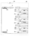
図2は、充電インフラ200の構成の一例を示す。この例の充電インフラ200は、デパートの駐車場のような多数の駐車スペース201a〜e(以下、駐車スペース201と総称する。)を備える駐車場において、一部の駐車スペース201a〜cを、電気自動車を充電させるための駐車スペース201として利用する例である。ここで、電気自動車を充電させるための駐車スペース201は、充電インフラ200を利用するための会員登録を事前に行った利用会員専用として運用されたり、利用会員のうち利用予約を事前に行った利用予約者専用として運用されたり、不特定の利用者が利用できるように運用されたりする。充電インフラ200の管理者は、いずれの運用方法を採用するか、駐車スペース201毎に設定することができるものとする。
FIG. 2 shows an example of the configuration of the
この例の充電インフラ200には、機器制御装置110、複数の充電器210a〜c(以下、充電器210と総称する。)、2つのDSRC路側無線装置220a、b(以下、DSRC路側無線装置220と総称する。)、複数のIC(Integrated Circuit)カードリーダ240a〜c(以下、ICカードリーダ240と総称する。)、複数のフラップ板250a〜c(以下、フラップ板250と総称する。)、複数のセンサー260a〜c(以下、センサー260と総称する。)、及び複数の自動精算機270a〜e(以下、自動精算機270と総称する。)が設けられている。機器制御装置110は、各充電器210、各DSRC路側無線装置220、各ICカードリーダ240、各フラップ板250、各センサー260、及び各自動精算機270とそれぞれ電気的に接続されている。なおまた、DSRC路側無線装置220は、この発明における「無線送信装置」の一例であってよい。また、ICカードリーダ240は、この発明における「利用会員データ読取装置」の一例であってよい。また、フラップ板250は、この発明における「進入規制装置」の一例であってよい。また、センサー260は、この発明における「検知器」の一例であってよい。
The
充電器210は、電力供給インターフェースを介して、電気自動車へ電力を供給する機器である。より具体的に説明すると、充電器210は、駐車スペース201a〜eのうち、電気自動車を充電させるための駐車スペース201として割り当てられた駐車スペース201a〜cにそれぞれ1つずつ設けられている。そして、充電器210は、給電を許可する旨を示す制御信号を機器制御装置110から受信すると、電気自動車へ電力を供給し得る状態となる。そして、充電器210は、電気自動車に電力供給インターフェースが接続されると、電気自動車から電力供給インターフェースを取外すことができないように、電気自動車に対して電力供給インターフェースをロックする。そして、充電器210は、電気自動車への電力の供給量を通知するよう要求する旨のデータを、機器制御装置110から受信すると、電気自動車への電力の供給量を示すデータを、機器制御装置110へ送信する。そして、充電器210は、電力供給インターフェースのロックの解除を許可する旨を示す制御信号を機器制御装置110から受信すると、電気自動車に対する電力供給インターフェースのロックを解除する。
The charger 210 is a device that supplies power to the electric vehicle via the power supply interface. More specifically, one charger 210 is provided in each of the
DSRC路側無線装置220は、電気自動車のDSRC車載器とDSRCによりデータを送受信する機器である。より具体的に説明すると、DSRC路側無線装置220aは、充電インフラ200の出入口202の近傍に設けられている。そして、DSRC路側無線装置220aは、充電インフラ200について案内する情報を含むデータを、DSRCにより通信エリアCa内にデータを常時送信している。ここで、充電インフラ200について案内する情報としては、例えば、充電スペース201a〜cの場所やその空き状況、充電インフラ200に入場したことに対するWelcomeメッセージ、充電インフラ200に併設されているデパート等の商業施設の広告等が考えられる。
The DSRC roadside apparatus 220 is a device that transmits and receives data to and from the DSRC onboard unit of the electric vehicle by DSRC. More specifically, the
一方、DSRC路側無線装置220bは、充電スペース201a〜cの近傍に設けられている。そして、DSRC路側無線装置220bは、DSRCにより通信エリアCb内にデータを常時送信している。そして、DSRC路側無線装置220bは、電気自動車のDSRC車載器からデータを受信すると、利用会員ID(identifier)とパスワードを送信するよう要求する旨のデータを、DSRCにより通信エリアCb内に送信する。そして、DSRC路側無線装置220bは、利用会員IDとパスワードを示すデータを、データ送信後の所定時間内に、DSRCにより電気自動車のDSRC車載器から受信すると、そのデータを機器制御装置110へ送信する。そして、DSRC路側無線装置220bは、利用させるべき駐車スペース201の場所を案内する情報を含むデータを、機器制御装置110から受信すると、そのデータをDSRCにより通信エリアCb内に送信する。なおまた、利用会員IDとパスワードを示すデータは、この発明における「利用会員データ」の一例であってよい。
On the other hand, the
ICカードリーダ240は、ICカードに記憶されているデータを読み出す機器である。より具体的に説明すると、ICカードリーダ240は、充電器210が設けられた駐車スペース201a〜cの近傍にそれぞれ設けられている。そして、ICカードリーダ240は、ICカードに記憶されているデータを読み出すと、そのデータを機器制御装置110へ送信する。
The IC card reader 240 is a device that reads data stored in the IC card. More specifically, the IC card reader 240 is provided in the vicinity of the
フラップ板250は、駐車スペース201への車両の進入を規制する機器である。より具体的に説明すると、フラップ板250は、充電器210が設けられた駐車スペース201a〜c内の地表にそれぞれ埋め込まれている。そして、フラップ板250は、板が上がっている状態において、駐車スペース201への車両の進入を規制する。そして、利用会員専用、又は利用予約者専用の駐車スペース201に設けられたフラップ板250は、その駐車スペース201内に車両が駐車していない場合、板が上がっている。そして、フラップ板250は、規制の解除を許可する旨を示す制御信号を機器制御装置110から受信すると、板が下がる。そして、フラップ板250は、規制を許可する旨を示す制御信号を機器制御装置110から受信すると、板が上がる。一方、不特定の利用者が利用できる駐車スペース201に設けられたフラップ板250は、常時、板が下がっている。
The flap plate 250 is a device that regulates entry of the vehicle into the parking space 201. More specifically, the flap plate 250 is embedded in the ground surface in the
センサー260は、車両を検知する機器である。より具体的に説明すると、センサー260は、充電器210が設けられた駐車スペース201a〜cにそれぞれ設けられている。そして、センサー260は、その駐車スペース201内の車両を検知すると、その旨を示す検知信号を機器制御装置110へ送信する。
The sensor 260 is a device that detects a vehicle. More specifically, the sensor 260 is provided in each of the
自動精算機270は、充電インフラ200の利用料金を精算する機器である。より具体的に説明すると、自動精算機270は、各駐車スペース201に設けられている。自動精算機270は、充電インフラ200の利用料金の支払いを開始するための支払開始スイッチと、貨幣が投入される投入口を備えている。そして、自動精算機270は、支払開始スイッチが押下されると、清算を要求する旨を示すデータを機器制御装置110へ送信する。そして、自動精算機270は、充電インフラ200の利用料金を示すデータを機器制御装置110から受信すると、その利用料金と同じ額の貨幣が投入口から投入されるまで待機状態となる。そして、自動精算機270は、利用料金と同じ額の貨幣が投入口から投入されると、その旨を示すデータを機器制御装置110へ送信する。
The automatic settlement machine 270 is a device that settles the usage fee for the
図3は、充電インフラ200の構成の他の例を示す。この例の充電インフラ200は、コインパーキングのような有料駐車場の駐車スペース201a〜cを、電気自動車を充電させるための駐車スペース201として利用する例である。
FIG. 3 shows another example of the configuration of the
この例の充電インフラ200には、機器制御装置110、複数の充電器210a〜c、DSRC路側無線装置220b、複数のICカードリーダ240a〜c、複数のフラップ板250a〜c、複数のセンサー260a〜c、及び複数の自動精算機270a〜cが設けられている。これら各構成要素の機能及び動作は、それぞれ図2に示す例の充電インフラ200における、対応する構成要素の機能及び動作と同一であるから説明を省略する。
The
コインパーキングのような有料駐車場は、デパートの駐車場と比較して駐車スペース201の数が少ないため、全ての駐車スペース201を、電気自動車を充電させるための駐車スペース201として利用している。したがって、この例の充電インフラ200は、図2に示す例の充電インフラ200と比較して、充電インフラ200について案内するために必要な機器であるDSRC路側無線装置220aが省かれている。
Pay parking lots such as coin parking have fewer parking spaces 201 than department store parking lots, so all parking spaces 201 are used as parking spaces 201 for charging electric vehicles. Accordingly, the
図4は、充電インフラ200の構成の更に他の例を示す。この例の充電インフラ200は、コンビニエンスストアの駐車場の駐車スペース201を、電気自動車を充電させるための駐車スペース201として利用する例である。また、この例の充電インフラ200は、ガソリンスタンドのような充電スタンドとする場合にも適用することができる。
FIG. 4 shows still another example of the configuration of the
この例の充電インフラ200には、機器制御装置110、複数の充電器210a〜c、及び複数の自動精算機270a〜cが設けられている。これら各構成要素の機能及び動作は、それぞれ図2に示す例の充電インフラ200における、対応する構成要素の機能及び動作と同一であるから説明を省略する。
The
コンビニエンスストアの駐車場や、ガソリンスタンドのような充電スタンドは、特定の会員や予約者にのみ利用させるような運用はあまり採用されない。したがって、この例の充電インフラ200は、図3に示す例の充電インフラ200と比較して、特定の会員や予約者にのみ利用させるために必要な機器であるDSRC路側無線装置220b、ICカードリーダ240、フラップ板250、及びセンサー260が更に省かれている。
Convenience store parking lots and charging stations such as gas stations are not often used by specific members or reservation users. Therefore, the
図5は、充電インフラ200の構成の更に他の例を示す。この例の充電インフラ200は、タクシー会社の駐車場や、カーシェアリングの駐車場の駐車スペース201を、電気自動車を充電させるための駐車スペース201として利用する例である。
FIG. 5 shows still another example of the configuration of the
この例の充電インフラ200には、機器制御装置110、及び複数の充電器210a〜cが設けられている。これら各構成要素の機能及び動作は、それぞれ図2に示す例の充電インフラ200における、対応する構成要素の機能及び動作と同一であるから説明を省略する。
The
図6は、機器制御装置110のブロック構成の一例を示す。機器制御装置110は、充電器設定受付部111、利用会員登録データ受信部112、利用会員データ受信部113、利用会員認証部114、利用予約判定部115、充電器特定部116、到着時有用データ送信部117、進入規制装置制御部118、充電器制御部119、検知信号受信部120、利用状況データ送信部121、精算データ受信部122、利用料金算出部123、利用料金データ送信部124、機器監視部125、管理有用データ送信部126、単価情報格納部127、利用会員情報格納部128、充電器情報格納部129、及び管理情報格納部130を有する。以下、各構成要素の機能及び動作を説明する。
FIG. 6 shows an example of a block configuration of the
充電器設定受付部111は、充電器210の稼働に関する設定を、充電インフラ200の管理者から受け付ける。より具体的に説明すると、充電器設定受付部111は、充電器210を稼働させるか否かの設定を、充電インフラ200の管理者から受け付ける。また、充電器設定受付部111は、充電器210を利用会員専用として稼働させるか否かの設定を、充電インフラ200の管理者から受け付ける。また、充電器設定受付部111は、充電器210を利用予約者専用として稼働させるか否かの設定を、充電インフラ200の管理者から受け付ける。
The charger
利用会員登録データ受信部112は、利用会員の登録情報を示すデータを、システム管理サーバ150から受信する。
The user member registration
利用会員データ受信部113は、利用会員IDとパスワードを示すデータを、DSRC路側無線装置220bから受信する。また、利用会員データ受信部113は、利用会員IDとパスワードを示すデータを、ICカードリーダ240から受信する。
The user member
利用会員認証部114は、充電インフラ用機器として、ICカードリーダ240を含む運用形態の充電インフラの場合に、ICカードリーダ240により読み取られた利用会員IDとパスワードを示すデータに基づいて、利用会員の認証を行う。また、利用会員認証部114は、充電インフラ用機器として、充電器210の他にDSRC路側無線装置220bが選択された場合に、DSRC路側無線装置220bがDSRC車載器から受信した利用会員IDとパスワードを示すデータに基づいて、利用会員の認証を行う。
In the case of a charging infrastructure of an operation form including the IC card reader 240 as the charging infrastructure device, the user
利用予約判定部115は、利用会員認証部114が認証した利用会員が充電器210を利用予約しているか否かを判定する。
The use
充電器特定部116は、複数の充電器210のうち、利用会員認証部114が認証した利用会員に利用させるべき充電器210を特定する。より具体的に説明すると、充電器特定部116は、利用会員が充電器210の利用予約者であると利用予約判定部115が判定した場合に、その利用会員に利用させるべき充電器を特定する。また、充電器特定部116は、利用会員が充電器210の利用予約者ではないと利用予約判定部115が判定した場合に、その利用会員に利用させるべき充電器210を特定する。
The
到着時有用データ送信部117は、充電インフラ用機器として、DSRC路側無線装置220を含む運用形態の充電インフラの場合に、充電インフラ200への到着時に有用な情報を含む到着時有用データを、DSRC車載器へDSRC路側無線装置220a、又はDSRC路側無線装置220bを介して送信する。より具体的に説明すると、到着時有用データ送信部117は、充電インフラ200への到着時に有用な情報として、充電器特定部116が特定した充電器を案内する情報を含む到着時有用データを、DSRC車載器へDSRC路側無線装置220bを介して送信する。また、到着時有用データ送信部117は、充電インフラ200への到着時に有用な情報として、充電インフラ200の関連事業の広告を示す情報を含む到着時有用データを、DSRC車載器へDSRC路側無線装置220aを介して送信する。
When the arrival useful
進入規制装置制御部118は、充電インフラ用機器として、フラップ板250を含む運用形態の充電インフラの場合に、充電器特定部116が特定した充電器が設けられた駐車スペース201への電気自動車の進入の規制を解除させるべくフラップ板250の動作を制御する。
In the case of the charging infrastructure of the operation form including the flap board 250 as the charging infrastructure device, the entry control
充電器制御部119は、電気自動車を充電させるための充電器210と、充電器210以外の各種の充電インフラ用機器との組合せによって決まる充電インフラの運用形態のパターンに応じて、電気自動車への充電時における充電器210の挙動が変わるように制御する。より具体的に説明すると、充電器制御部119は、利用会員認証部114が利用会員の認証を行った後に、充電が開始され得るように充電器210の動作を制御する。また、充電器制御部119は、利用会員が充電器210の利用予約者であると利用予約判定部115が判定した場合に、充電が開始され得るように充電器210の動作を制御する。また、充電器制御部119は、充電インフラ用機器として、充電器210の他に自動精算機270が選択された場合、少なくとも充電料金を含む充電インフラ200の利用料金が自動精算機270により清算された後に、電気自動車に接続された電力供給インターフェースを取外すことができるように充電器210の動作を制御する。また、充電器制御部119は、システム管理サーバ150が電子決済処理を行った後に、電気自動車に接続された電力供給インターフェースを取外すことができるように充電器210の動作を制御する。
また、充電器制御部119は、電気自動車への電力の供給量を通知するよう要求する旨のデータを、充電器210へ送信する。
The
In addition,
検知信号受信部120は、車両を検知したことを示す信号をセンサー260から受信する。
The detection
利用状況データ送信部121は、充電器210の利用状況を示すデータを、システム管理サーバ150へ送信する。
The usage status
清算データ受信部122は、充電インフラ200の利用料金の清算を要求する旨を示すデータを、自動精算機270から受信する。また、精算データ受信部122は、充電インフラ200の利用料金が精算された旨を示すデータを、自動精算機270から受信する。
また、精算データ受信部122は、充電インフラ200の利用料金が精算された旨を示すデータを、システム管理サーバ150から受信する。また、清算データ受信部122は、電気自動車への電力の供給量を示すデータを、充電器210から受信する。
The settlement
Further, the settlement
利用料金算出部123は、充電インフラ用機器として、自動精算機270を含む運用形態の充電インフラの場合に、少なくとも充電料金を含む充電インフラ200の利用料金を算出する。より具体的に説明すると、利用料金算出部123は、充電インフラ200への駐車時間に応じた駐車料金を更に含む充電インフラ200の利用料金を算出する。また、利用料金算出部123は、時間帯に応じた利用料金を算出する。
In the case of a charging infrastructure in an operation form including the automatic settlement machine 270 as a charging infrastructure device, the usage
利用料金データ送信部124は、利用料金を示すデータを、自動精算機270へ送信する。また、利用料金データ送信部124は、利用料金を示すデータを、システム管理サーバ150へ送信する。
The usage fee
機器監視部125は、充電インフラ200に設けられている各機器の稼働状態を監視する。
The
管理有用データ送信部126は、充電インフラ200の管理に有用な情報を含む管理有用データを、管理者装置190へ通信回線Iを介して送信する。より具体的に説明すると、管理有用データ送信部126は、充電インフラ200の管理に有用な情報として、充電インフラの利用状況を含む管理有用データを、管理者装置190へ通信回線Iを介して送信する。また、管理有用データ送信部126は、充電インフラ200の管理に有用な情報として、充電インフラ用機器の稼働状況を示す情報を含む管理有用データを、管理者装置190へ通信回線Iを介して送信する。また、管理有用データ送信部126は、充電インフラ200の管理に有用な情報として、充電インフラ200の売上を示す情報を含む管理有用データを、管理者装置190へ通信回線Iを介して送信する。また、管理有用データ送信部126は、充電インフラ200の管理に有用な情報として、充電インフラ200の電力消費量を示す情報を含む管理有用データを、管理者装置190へ通信回線Iを介して送信する。
The management useful
図7は、単価情報格納部127に格納されている情報の一例をマトリクス形式で示す。
単価情報格納部127には、充電単価(円/kWh)、及び時間単価(円/h)の各情報が曜日毎、及び時間帯毎に対応付けて格納されている。なおまた、曜日毎、及び時間帯毎は、この発明における「時間帯」の一例であってよい。
FIG. 7 shows an example of information stored in the unit price
In the unit price
充電単価(円/kWh)は、単位電力量あたりの充電単価である。時間単価(円/h)は、駐車場Pを利用するための単位時間当たりの時間単価である。 The charging unit price (yen / kWh) is a charging unit price per unit electric energy. The unit price per hour (yen / h) is a unit price per unit time for using the parking lot P.
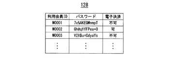
図8は、利用会員情報格納部128に格納される情報の一例をテーブル形式で示す。利用会員情報格納部128には、利用会員ID、パスワード、及び電子決済の各情報が対応付けて格納される。
FIG. 8 shows an example of information stored in the use member
利用会員IDは、充電インフラ200の利用会員を識別するために一人一人に割り当てられた識別符号である。パスワードは、利用会員IDによって識別される利用会員の本人確認に用いる秘密の文字列である。電子決済は、利用会員IDによって識別される利用会員が電子決済することができるか否かを示す情報である。
The use member ID is an identification code assigned to each person in order to identify the use member of the
図9は、充電器情報格納部129に格納される情報の一例をテーブル形式で示す。充電器情報格納部129には、充電器ID、運用形態、利用状況、利用開始時刻、利用予約者、及び予約時間帯の各情報が対応付けて格納される。
FIG. 9 shows an example of information stored in the charger
充電器IDは、充電インフラ200の充電器210を識別するために一台一台に割り当てられた識別符号である。運用形態は、充電器IDによって識別される充電器210が、利用予約者専用として運用されているか、利用会員専用として運用されているか、不特定の利用者用として運用されているか、稼働停止中であるかを示す情報である。利用状況は、充電器IDによって識別される充電器210が利用中か否かを示す情報である。利用開始時刻は、充電器IDによって識別される充電器210が設けられている駐車スペースが利用され始めた時刻を示す情報である。利用予約者は、充電器IDによって識別される充電器210を予約している利用会員の利用会員IDである。予約時間帯は、充電器IDによって識別される充電器210の予約が入っている時間帯を示す情報である。
The charger ID is an identification code assigned to each unit to identify the charger 210 of the
図10は、管理情報格納部130に格納される情報の一例をテーブル形式で示す。管理情報格納部130には、利用状況(利用台数/駐車スペース数)、稼働状況、売上(円)、及び電力消費量(kWh)の各情報が格納される。
FIG. 10 shows an example of information stored in the management
利用状況(利用台数/駐車スペース数)は、充電インフラ200の駐車スペース201のうち、現在、利用されている駐車スペース201の数を示す情報である。稼働状況は、充電インフラ200に設けられている各機器が正常に稼働しているか否かを示す情報である。売上(円)は、充電インフラ200の今月の売上を示す情報である。電力消費量(kWh)は、充電インフラ200の今月の電力消費量を示す情報である。
The usage status (number of used units / number of parking spaces) is information indicating the number of currently used parking spaces 201 among the parking spaces 201 of the
図11は、システム管理サーバ150のブロック構成の一例を示す。システム管理サーバ150は、利用会員登録受付部151、利用予約登録受付部152、利用会員登録データ送信部153、利用状況データ受信部154、利用料金データ受信部155、電子決済処理部156、清算データ送信部157、到着前有用データ送信要求受付部158、到着可能充電インフラ特定部159、到着前有用データ送信部160、利用会員情報格納部161、及び充電インフラ情報格納部162を有する。以下、各構成要素の機能及び動作を説明する。
FIG. 11 shows an example of a block configuration of the
利用会員登録受付部151は、充電インフラ200の充電器210を利用するための会員登録を受け付ける。
The user member
利用予約登録受付部152は、充電インフラ200の充電器210を利用するための利用予約を受け付ける。
The usage reservation
利用会員登録データ送信部153は、利用会員の登録情報を示すデータを、機器制御装置110へ送信する。
The user member registration
利用状況データ受信部154は、充電器210の利用状況を示すデータを、機器制御装置110から受信する。
The usage status
利用料金データ受信部155は、利用料金を示すデータを、機器制御装置110から受信する。
The usage fee
電子決済処理部156は、機器制御装置110が特定した利用会員が電子決済する旨の登録を事前に行っている場合に、機器制御装置110が算出した利用料金を電子決済処理する。
The electronic
清算データ送信部157は、充電インフラ200の利用料金が精算された旨を示すデータを、機器制御装置110へ送信する。
The settlement
到着前有用データ送信要求受付部158は、充電インフラ200への到着前に有用な情報を含む到着前有用データを送信する旨の要求を受け付ける。
The pre-arrival useful data transmission
到着可能充電インフラ特定部159は、電気自動車の位置情報と、その電気自動車の蓄電池の充電残量の情報と、充電インフラ200の位置情報とに基づいて、充電インフラ200の中から、その電気自動車が到着可能な充電インフラ200を特定する。
The reachable charging
到着前有用データ送信部160は、充電インフラ200への到着前に有用な情報を含む到着前有用データを、電気自動車のDSRC車載器へ通信回線Iを介して送信する。より具体的に説明すると、到着前有用データ送信部160は、充電インフラ200への到着前に有用な情報として、充電インフラ200の場所を示す情報を含む到着前有用データを、電気自動車のDSRC車載器へ通信回線Iを介して送信する。また、到着前有用データ送信部160は、充電インフラ200への到着前に有用な情報として、充電器210の利用状況を示す情報を含む到着前有用データを、電気自動車のDSRC車載器へ通信回線Iを介して送信する。また、到着前有用データ送信部160は、充電インフラ200への到着前に有用な情報として、充電器210の利用予約状況を示す情報を含む到着時有用データを、電気自動車のDSRC車載器へ通信回線Iを介して送信する。また、到着前有用データ送信部160は、充電インフラ200への到着前に有用な情報として、到着可能充電インフラ特定部159が特定した充電インフラ200の場所を示す情報を含む到着前有用データを、電気自動車のDSRC車載器へ通信回線Iを介して送信する。
The pre-arrival useful
図12は、利用会員情報格納部161に格納される情報の一例をテーブル形式で示す。
利用会員情報格納部161には、利用会員ID、パスワード、氏名、住所、クレジットカード会社、及びクレジットカード番号の各情報が対応付けて格納される。
FIG. 12 shows an example of information stored in the use member
In the use member
利用会員IDは、充電インフラ200の利用会員を識別するために一人一人に割り当てられた識別符号である。パスワードは、利用会員IDによって識別される利用会員の本人確認に用いる秘密の文字列である。氏名は、利用会員IDによって識別される利用会員の姓名である。住所は、利用会員IDによって識別される利用会員が住んでいる場所である。クレジットカード会社は、利用会員IDによって識別される利用会員が契約しているクレジットカード会社である。クレジットカード番号は、利用会員IDによって識別される利用会員が使用しているクレジットカードの番号である。
The use member ID is an identification code assigned to each person in order to identify the use member of the
図13は、充電インフラ情報格納部162に格納される情報の一例をテーブル形式で示す。充電インフラ情報格納部162には、充電インフラID、住所、満空状況、及び予約状況の各情報が対応付けて格納される。
FIG. 13 shows an example of information stored in the charging infrastructure
充電インフラIDは、充電インフラ200を識別するためにそれぞれに割り当てられた識別符号である。住所は、充電インフラIDによって識別される充電インフラ200の所在地である。満空状況は、充電インフラIDによって識別される充電インフラ200に空車があるか、満車であるかを示す情報である。予約状況は、充電インフラIDによって識別される充電インフラ200に設けられた充電器210の予約状況である。
The charging infrastructure ID is an identification code assigned to each to identify the
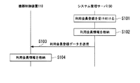
図14は、機器制御装置110、及びシステム管理サーバ150の動作シーケンスの一例を示す。この動作シーケンスは、充電インフラ200を利用するための会員登録を受け付ける動作を示す。なおまた、この動作シーケンスは、図1から図13を共に参照して説明する。
FIG. 14 shows an example of an operation sequence of the
電気自動車に乗る者は、充電インフラ200を利用するにあたり、充電器210を予約したり、充電インフラ200への到着前に有用な情報を取得したりする等の会員専用のサービスを受けようとする場合、例えば、パソコンや携帯電話等の利用者装置180を用いて、利用会員登録用のWebサイト等から充電インフラ管理システム100への利用会員登録を行う。その際、利用会員登録を行う者は、氏名、住所、クレジットカード会社、及びクレジットカード番号等の各情報を登録する。システム管理サーバ150の利用会員登録受付部151は、このような充電インフラ200の充電器210を利用するための会員登録を受け付けると(S101)、これら各情報を対応付けて利用会員情報格納部161に格納する(S102)。その際、新規に登録された利用会員には、利用会員IDとパスワードが発行されて、登録された各情報と対応付けて利用会員情報格納部161に格納される。このようにして、システム管理サーバ150の利用会員情報格納部161には、図12に示すような情報が格納されることになる。
A person who rides an electric vehicle intends to receive a member-only service such as reserving the charger 210 or acquiring useful information before arriving at the
そして、システム管理サーバ150の利用会員登録データ送信部153は、利用会員情報格納部161に新たな利用会員の情報が格納されると、その利用会員の利用会員ID、パスワード、電子決済への対応の可否の各情報を示すデータを、機器制御装置110へ送信する(S103)。そして、機器制御装置110の利用会員登録データ受信部112は、このようにシステム管理サーバ150から送信されたデータを受信すると、そのデータによって示される各情報を利用会員情報格納部128に格納する(S104)。このようにして、機器制御装置110の利用会員情報格納部128には、図8に示すような情報が格納されることになる。
When the new member information is stored in the user member
一方、充電インフラ管理システム100の事業者は、例えば、発行された利用会員IDとパスワードが記録されたICカードを、登録された住所宛に郵送する。ICカードを受け取った利用会員は、DSRC車載器を所有している場合、ICカードに記録されている利用会員IDとパスワードを、DSRC車載器に読み取らせる。このようにして、DSRC車載器には、充電インフラ200を利用するための利用会員IDとパスワードが記録されることになる。
On the other hand, the business operator of the charging
なおまた、ステップS103とS104の各処理は、利用会員限定の充電器210が用意されない場合、実行されない。 In addition, each process of step S103 and S104 is not performed when the charger 210 for exclusive use members is not prepared.
図15は、機器制御装置110、及びシステム管理サーバ150の動作シーケンスの他の例を示す。この動作シーケンスは、充電インフラ200を利用するための利用予約を受け付ける動作を示す。なおまた、この動作シーケンスは、図1から図14を共に参照して説明する。
FIG. 15 shows another example of the operation sequence of the
充電インフラ200の利用会員は、充電器210の利用予約を行う場合、利用者装置180を用いて、利用予約用のWebサイト等から充電器210の利用予約を行う。その際、利用会員は、予約したい充電インフラ200と、予約時間帯の各情報を登録する。システム管理サーバ150の利用予約登録受付部152は、このような予約登録を受け付けると(S201)、登録された各情報を含むデータを、利用会員登録データ送信部153へ送る。
When making a reservation for using the charger 210, a member using the
利用会員登録データ送信部153は、登録された各情報を示すデータを、利用予約登録受付部152から受け取ると、利用予約を行った利用会員の利用会員IDとパスワードを利用会員情報格納部161から読み出す。そして、利用会員登録データ送信部153は、利用予約登録受付部152から受け取ったデータに含まれる情報のうち、予約時間帯の情報と、利用会員情報格納部161から読み出した利用会員IDとパスワードの各情報を示すデータを、利用予約登録受付部152から受け取ったデータに含まれる利用会員が利用したい充電インフラ200の機器制御装置110へ送信する(S202)。そして、機器制御装置110の利用会員登録データ受信部112は、このようにシステム管理サーバ150から送信されたデータを受信すると、そのデータによって示される利用予約者の利用会員ID、及び予約時間帯の各情報を、充電器情報格納部129に格納されている情報のうち、利用予約者専用の運用形態の充電器210の情報と対応付けて格納する(S203)。このようにして、充電器情報格納部129には、図9に示すような利用予約者、及び予約時間帯の各情報が格納されることになる。
When the use member registration
なおまた、ステップS201からステップS203の各処理は、利用予約者限定の充電器210が用意されない場合、実行されない。 In addition, each process of step S201 to step S203 is not performed when the charger 210 limited to a use reservation person is not prepared.
なおまた、本実施形態においては、利用者からの予約を受け付ける度に、システム管理サーバ150から機器制御装置110へ、予約に関するデータが送信される動作シーケンスについて説明したが、他の動作シーケンスを採用することもできる。例えば、他の実施形態としては、利用者からの予約を受け付ける度に、システム管理サーバ150にてその予約情報を蓄積しておき、所定時間置きに、各機器制御装置110がシステム管理サーバ150に対して予約情報の問合せるような動作シーケンスとすることが考えられる。
In the present embodiment, the operation sequence in which the data related to the reservation is transmitted from the
図16は、システム管理サーバ150の動作フローの一例を示す。この動作フローは、充電インフラ200への到着前に有用な情報を含むデータを、充電インフラ200の利用会員へ送信する動作を示す。なおまた、この動作シーケンスは、図1から図15を共に参照して説明する。
FIG. 16 shows an example of the operation flow of the
充電インフラ200の利用会員は、充電インフラ200への到着前に有用な情報を得たい場合、例えば、DSRC車載器に接続されたタッチスクリーンを操作する等して、充電インフラ200への到着前に有用な情報を取得するためのWebサイトにアクセスする。
そして、利用会員は、例えば、このWebサイトにある選択メニューの中から、取得したい有用な情報を選択することによって、有用な情報を送信するよう要求する。有用な情報としては、例えば、充電インフラ200の場所、充電器210の利用状況、充電器210の利用予約状況、及び現在の蓄電池の充電残量で到着可能な充電インフラ200の場所等が考えられる。DSRC車載器は、現在の蓄電池の充電残量で到着可能な充電インフラ200の場所の情報の送信要求が選択された場合、電気自動車の現在位置と、蓄電池の充電残量とを示す車両データを、共に送信する。このようにして、システム管理サーバ150の到着前有用データ送信要求受付部158は、到着前に有用なデータの送信要求を受け付ける(S301)。
When a user who uses the
Then, for example, the use member requests to transmit useful information by selecting useful information to be acquired from a selection menu on this Web site. Useful information includes, for example, the location of the
到着前有用データ送信要求受付部158は、充電インフラ200の場所の情報の送信要求を受け付けた場合(S302:No)、各充電インフラ200の住所の情報を、充電インフラ情報格納部162から読み出す(S304)。そして、到着前有用データ送信部160は、読み出した各充電インフラ200の住所の情報を示すデータを、要求を行ったDSRC車載器へ送信する(S305)。
When the pre-arrival useful data transmission
また、到着前有用データ送信要求受付部158は、充電器210の利用状況の情報の送信要求を受け付けた場合(S302:No)、各充電インフラ200の満空状況の情報を、充電インフラ情報格納部162から読み出す(S304)。そして、到着前有用データ送信部160は、読み出した各充電インフラ200の満空状況の情報を示すデータを、要求を行ったDSRC車載器へ送信する(S305)。
In addition, when the pre-arrival useful data transmission
また、到着前有用データ送信要求受付部158は、充電器210の利用予約状況の情報の送信要求を受け付けた場合(S302:No)、各充電インフラ200の充電器210の予約状況の情報を、充電インフラ情報格納部162から読み出す(S304)。そして、到着前有用データ送信部160は、読み出した各充電インフラ200の充電器210の予約状況の情報を示すデータを、要求を行ったDSRC車載器へ送信する(S305)。
Moreover, when the useful data transmission
また、到着前有用データ送信要求受付部158は、現在の蓄電池の充電残量で到着可能な充電インフラ200の場所の送信要求を受け付けた場合(S302:Yes)、DSRC車載器から受信した車両データを、到着可能充電インフラ特定部159へ送る。システム管理サーバ150の到着可能充電インフラ特定部159は、車両データをDSRC車載器から受け取ると、各充電インフラ200の住所の情報を、充電インフラ情報格納部162から読み出す。そして、到着可能充電インフラ特定部159は、読み出した各充電インフラ200の住所と、車両データによって示される電気自動車の現在位置と、蓄電池の充電残量とに基づいて、各充電インフラ200の中から、その電気自動車の蓄電池の充電残量で到着可能な充電インフラ200を特定する(S303)。そして、到着可能充電インフラ特定部159は、特定した充電インフラ200の住所の各情報を示すデータを、到着前有用データ送信部160へ送る。そして、到着前有用データ送信部160は、到着可能充電インフラ特定部から受け取ったデータを、要求を行ったDSRC車載器へ送信する(S305)。
Moreover, the useful data transmission
図17は、機器制御装置110の動作フローの一例を示す。この動作フローは、充電器210の運用形態の設定を受け付ける動作を示す。なおまた、この動作フローは、図1から図16を共に参照して説明する。
FIG. 17 shows an example of the operation flow of the
充電インフラ200の管理者は、充電器210の運用形態を変更することができる。例えば、管理者は、充電器210を稼働させたり、稼働を停止させたりすることができる。
また、管理者は、充電器210を利用会員専用として稼働させたり、不特定の利用者が利用できるように稼働させたりすることができる。また、管理者は、充電器210を利用予約者専用として稼働させることもできる。管理者は、このような設定をするにあたり、例えば、管理者装置190を用いて、充電器210の運用形態の設定を変更するためのWebサイトを介して、充電器210の運用形態の設定を変更するよう要求する。機器制御装置110の充電器設定受付部111は、このようにして要求された充電器の設定を受け付けると(S401)、その設定情報を、充電器情報格納部129に格納する(S402)。このようにして、機器制御装置110の充電器情報格納部129には、図9に示すような運用形態の情報が格納されることになる。
The administrator of the
Further, the administrator can operate the charger 210 exclusively for the use member, or can operate the charger 210 so that an unspecified user can use it. Further, the administrator can operate the charger 210 exclusively for the use reservation person. In making such a setting, for example, the administrator uses the administrator device 190 to set the operation mode of the charger 210 via a website for changing the setting of the operation mode of the charger 210. Request to change. When the charger
機器制御装置110の進入規制装置制御部118は、充電器210の運用形態が変更されると、その運用形態に応じて、駐車スペース201に車両が駐車していない状態における、フラップ板250の板の上げ下げを制御する(S403)。例えば、稼働停止、利用会員専用、又は利用予約者専用に充電器210の運用形態が設定された場合、進入規制装置制御部118は、駐車スペース201に車両が駐車していない状態において、フラップ板250の板が上がっているように制御する。また、不特定の利用者が利用できるように充電器210の運用形態が設定された場合、進入規制装置制御部118は、駐車スペース201に車両が駐車していない状態において、フラップ板250の板が下がっているように制御する。
When the operation mode of the charger 210 is changed, the entry restriction
なおまた、ステップS403の処理は、フラップ板250が設けられていない場合、実行されない。 In addition, the process of step S403 is not executed when the flap plate 250 is not provided.
図18は、機器制御装置110の動作フローの他の例を示す。この動作フローは、充電インフラ200に設けられている各機器を監視する動作を示す。また、この動作フローは、図1から図17を共に参照して説明する。
FIG. 18 shows another example of the operation flow of the
機器制御装置110の機器監視部125は、充電インフラ200に設けられている各機器の稼働状況を常に監視している(S501)。そして、機器監視部125は、各機器を監視して得られる充電インフラ200の管理に有用な情報を、管理情報格納部130に格納する(S502)。充電インフラ200の管理に有用な情報としては、例えば、充電インフラ200の駐車スペース201の利用状況、各機器が正常に稼働しているか否かの稼働状況、充電インフラ200の売上、及び充電インフラ200の電力消費量等が考えられる。このようにして、管理情報格納部130には、図10に示すような情報が格納されることになる。
The
図19は、機器制御装置110の動作フローの更に他の例を示す。この動作フローは、充電インフラ200の管理に有用な情報を提供する動作を示す。また、この動作フローは、図1から図18を共に参照して説明する。
FIG. 19 shows still another example of the operation flow of the
充電インフラ200の管理者は、図18の動作フローにて説明したような、充電インフラ200の管理に有用な情報の提供を受けることができる。管理者は、このような情報の提供を受けるにあたり、管理者装置190を用いて、充電インフラ200の管理に有用な情報の提供を受けるためのWebサイトにアクセスすることによって、情報の提供を要求する。機器制御装置110の管理有用データ送信部126は、このような情報の提供要求を受けて、充電器情報格納部129、又は管理情報格納部130から必要な情報を読み出して(S601)、その情報を示すデータを、管理者装置190へ送信する。
The administrator of the
図20は、機器制御装置110、及びシステム管理サーバ150の動作シーケンスの更に他の例を示す。この動作シーケンスは、利用会員が充電インフラ200に入場したときの動作を示す。また、この動作シーケンスは、図1から図19を共に参照して説明する。
FIG. 20 shows still another example of the operation sequence of the
この動作フローの説明においては、充電インフラ200が図2に示すような構成であるものとする。即ち、この例の充電インフラ200は、大規模な駐車場の一部の駐車スペース201に、電気自動車を充電するための充電器210が設けられたものである。
In the description of this operation flow, it is assumed that the
DSRC路側無線装置220aは、充電インフラ200について案内する情報を含むデータを、DSRCにより通信エリアCa内にデータを送信している。例えば、DSRC路側無線装置220aは、充電インフラ200について案内する情報として、充電スペース201a〜cの場所やその空き状況、充電インフラ200に入場したことに対するWelcomeメッセージ、充電インフラ200に併設されているデパート等の商業施設の広告等情報を含むデータを送信する。このようして送信されたデータは、DSRC路側無線装置220aの通信エリアCa内に進入した電気自動車のDSRC車載器によって受信される。そして、DSRC車載器は、受信したデータに含まれている情報を、車内のタッチスクリーン等に表示させるべく出力する。このようにして、電気自動車の搭乗者は、充電器210が設けられている駐車スペース201の位置や、駐車スペース201の満空情報を容易に把握することができると共に、デパートや家電量販店等の充電インフラ200の関連事業の広告を取得することができる。
The
DSRC路側無線装置220bは、DSRCにより通信エリアCb内に、利用会員IDとパスワードを送信するよう要求する旨のデータを常時送信している。
The
電気自動車のDSRC車載器は、DSRC路側無線装置220bの通信エリアCb内に進入すると、DSRC路側無線装置220bから送信されたデータを受信する。そして、DSRC車載器は、受信したデータによって示される要求に応じて、DSRC車載器に記録されている利用会員IDとパスワードを示すデータを、DSRC路側無線装置220bへ送信する。
When the DSRC in-vehicle device of the electric vehicle enters the communication area Cb of the
DSRC路側無線装置220bは、DSRC車載器から送信されたデータを受信すると、そのデータを、機器制御装置110へ送信する。
When the
機器制御装置110の利用会員データ受信部113は、DSRC路側無線装置220bから送信されたデータを受信すると(S701)、そのデータを、利用会員認証部114へ送る。
When the usage member
機器制御装置110の利用会員認証部114は、利用会員IDとパスワードを示すデータを、利用会員データ受信部113から受け取ると、そのデータによって示される利用会員ID、及びパスワードと、利用会員情報格納部128に格納されている情報とに基づいて、利用会員の認証を行う(S702)。そして、利用会員認証部114は、正当な利用会員であることを認証すると、認証された利用会員の利用会員IDを示すデータを、利用予約判定部115、及び充電器特定部116へ送る。
When the user
機器制御装置110の利用予約判定部115は、利用会員IDを示すデータを、利用会員認証部114から受け取ると、充電器情報格納部129に格納されている利用予約者の情報の中に、利用会員認証部114から受け取ったデータによって示される利用会員IDがあるか否か、また、充電器情報格納部129に格納されている予約時間帯の時間内であるか否かにより、その利用会員IDの利用会員が充電器210を予約しているか否かを判定する(S703)。そして、利用予約判定部115は、その判定結果を示すデータを、充電器特定部116へ送る。
When the use
機器制御装置110の充電器特定部116は、利用会員IDを示すデータを、利用会員認証部114から受け取る。そして、充電器特定部116は、利用会員が充電器210を予約しているか否かの判定結果を示すデータを、利用予約判定部115から受け取ると、利用会員認証部114から受け取ったデータによって示される利用会員IDの利用者に利用させるべき充電器を特定する(S704)。例えば、利用予約判定部115から受け取ったデータによって示される判定結果が、利用会員が充電器210を予約しているとの判定結果である場合、充電器特定部116は、充電器情報格納部129に格納されている利用予約者情報を参照して、利用会員認証部114から受け取ったデータによって示される利用会員IDが対応付けられている充電器IDによって示される充電器210を、利用会員に使用させるべき充電器として特定する。また、利用予約判定部115から受け取ったデータによって示される判定結果が、利用会員が充電器210を予約していないとの判定結果である場合、充電器特定部116は、充電器情報格納部129に格納されている運用形態と、利用状況の各情報を参照して、利用会員専用の充電器210が空いていればその充電器を、利用会員専用の充電器210が全て使用中であれば、不特定の利用者が利用できる充電器210を、利用会員に使用させるべき充電器として特定する。そして、充電器特定部116は、その充電器IDを示すデータを、到着時有用データ送信部117、及び進入規制装置制御部118へ送る。
The
機器制御装置110の到着時有用データ送信部117は、充電器IDを示すデータを、充電器特定部116から受け取ると、そのデータを、DSRC路側無線装置220bへ送信する(S705)。
Upon receipt of the data indicating the charger ID from the
DSRC路側無線装置220bは、充電器IDを示すデータを、機器制御装置110から受信すると、そのデータによって示される充電器IDの充電器210が設けられている駐車スペース201への案内情報を含むデータを、DSRCにより通信エリアCb内に送信する。通信エリアCb内の電気自動車のDSRC車載器は、DSRC路側無線装置220bから送信されたデータを受信すると、そのデータによって示される駐車スペース201への案内情報を表示させるべく、DSRC車載器に接続されたタッチスクリーンへデータを出力する。このようにして、利用会員は、利用予約の有無に拘らず、利用すべき充電器210が設けられている駐車スペース201の場所を容易に把握することができる。
When the DSRC
一方、機器制御装置110の進入規制装置制御部118は、充電器IDを示すデータを、充電器特定部116から受け取ると、フラップ板250の板を下げるべく制御する制御信号を、充電器特定部116から受け取ったデータによって示される充電器IDの充電器210と共に駐車スペース201内に設けられているフラップ板250へ送信する(S706)。
On the other hand, when data indicating the charger ID is received from the
フラップ板250は、機器制御装置110から送信された制御信号を受信すると、上がっていた板が下がり、駐車スペース201への車両の進入規制を解除する。
When the flap plate 250 receives the control signal transmitted from the
一方、利用会員は、案内された駐車スペース201へ電気自動車を移動させる。そして、利用会員は、正当な利用会員であることを再び認証するために、ICカードをICカードリーダ240にかざす。 On the other hand, the user member moves the electric vehicle to the guided parking space 201. Then, the user member holds the IC card over the IC card reader 240 in order to authenticate again that the user member is a valid user member.
ICカードリーダ240は、ICカードがかざされると、そのICカードに記録されている利用会員IDとパスワードを読み出す。そして、ICカードリーダ240は、読み出した利用会員IDとパスワードを示すデータを、機器制御装置110へ送信する。
When the IC card is held over, the IC card reader 240 reads the use member ID and password recorded on the IC card. Then, the IC card reader 240 transmits data indicating the read use member ID and password to the
機器制御装置110の利用会員データ受信部113は、ICカードから送信されたデータを受信すると(S707)、そのデータを、利用会員認証部114へ送る。その後、利用会員認証部114は、ステップS702の処理と同様の処理により、利用会員の認証を行う(S708)。そして、利用会員認証部114は、認証された利用会員の利用会員IDを示すデータを、利用予約判定部115へ送る。
When the user member
機器制御装置110の利用予約判定部115は、利用会員IDを示すデータを、利用会員認証部114から受け取ると、ステップS703の処理と同様の処理により、利用会員が充電器210を予約しているか否かを判定する(S709)。そして、利用予約判定部115は、その判定結果を示すデータを、充電器特定部116へ送る。
When the use
機器制御装置110の充電器特定部116は、利用会員が充電器210を予約しているか否かの判定結果を示すデータを、利用予約判定部115から受け取ると、ステップS704の処理と同様の処理により、その利用会員に利用させるべき充電器を特定する(S710)。そして、充電器特定部116は、特定した充電器の充電器IDを示すデータを、進入規制装置制御部118、及び充電器制御部119へ送る。
When the
機器制御装置110の進入規制装置制御部118は、充電器IDを示すデータを、充電器特定部116から受け取ると、フラップ板250の板を下げるべく制御する制御信号を、充電器特定部116から受け取ったデータによって示される充電器IDの充電器210と共に駐車スペース201内に設けられているフラップ板250へ送信する(S711)。
When the entry control
フラップ板250は、機器制御装置110から送信された制御信号を受信すると、上がっていた板が下がり、駐車スペース201への車両の進入規制を解除する。但し、この例の場合、フラップ板250は、既に板を下げて、駐車スペース201への車両の進入規制を解除している。したがって、この例の場合、フラップ板250は、ステップS711の処理による制御信号を受信しても、何ら変化しない。例えば、車両にDSRC車載器が搭載されていない場合、機器制御装置110は、ステップS701からステップS706までの処理を実行しない。そのような場合に、フラップ板250は、ステップS711の処理による制御信号を受信して、上がっていた板が下がり、駐車スペース201への車両の進入規制を解除することになる。
When the flap plate 250 receives the control signal transmitted from the
一方、機器制御装置110の充電器制御部119は、充電器IDを示すデータを、充電器特定部116から受け取ると、充電が開始され得るように制御する制御信号を、充電器特定部116から受け取ったデータによって示される充電器IDの充電器210に送信する(S712)。
On the other hand, when the
充電器210は、機器制御装置110から送信された制御信号を受信すると、充電が開始され得る状態となる。利用者は、駐車スペース201内に電気自動車を駐車すると、充電器の電力供給インターフェースを電気自動車に接続して、充電を開始させる。電力供給インターフェースは、一旦、電気自動車に接続されると、ロックされて、充電インフラ200の利用料金が精算されるまで、取外すことができないようになる。
When the charger 210 receives the control signal transmitted from the
一方、駐車スペース201内に車両が進入すると、センサー260は、車両を検知して、その旨を示す検知信号を、機器制御装置110へ送信する。
On the other hand, when a vehicle enters the parking space 201, the sensor 260 detects the vehicle and transmits a detection signal indicating that to the
機器制御装置110の検知信号受信部120は、センサー260から送信された検知信号を受信すると、充電器情報格納部129に格納されている情報のうち、センサー260と同じ駐車スペース201に設けられた充電器210の充電器IDの情報に対応付けて、現在時刻を利用開始時刻として格納すると共に、利用状況の情報を利用中とする。
When the detection
このようにして、機器制御装置110の充電器情報格納部129に格納されている情報が更新されると、利用状況データ送信部121は、充電インフラ200の最新の満空状況を示すデータを、システム管理サーバ100へ送信する(S715)。
In this way, when the information stored in the charger
システム管理サーバ100の利用状況データ受信部154は、機器制御装置110から送信されたデータを受信すると、そのデータによって示される満空情報を、充電インフラ情報格納部162に反映させる。このようにして、システム管理サーバ100は、各充電インフラ200の最新の満空情報を常に管理することができる。
When the usage status
なおまた、充電器210は、不特定の利用者が利用し得るように設定されている場合、ステップS701からステップS712までの処理が実施されることなく、利用し得る状態になっている。 In addition, when the charger 210 is set to be usable by an unspecified user, the charger 210 is in a usable state without performing the processing from step S701 to step S712.
図21は、機器制御装置110の動作フローの更に他の例を示す。この動作フローは、清算処理の動作を示す。また、この動作フローは、図1から図20を共に参照して説明する。
FIG. 21 shows still another example of the operation flow of the
充電インフラ200の利用者は、充電インフラ200の利用料金を算出する場合、自動精算機270の支払開始スイッチを押下する。支払開始スイッチが押下されると、自動精算機270は、利用料金の精算を要求する旨のデータを、機器制御装置110へ送信する。
The user of the
機器制御装置110の清算データ受信部122は、自動精算機270から送信されたデータを受信すると(S801)、そのデータを、充電器制御部119、及び利用料金算出部123へ送る。
When the settlement
充電器制御部119は、利用料金の精算を要求する旨のデータを、清算データ受信部122から受け取ると、電気自動車への電力の供給量を通知するよう要求する旨のデータを、清算対象の充電器210へ送信する(S802)。
When the
充電器210は、電気自動車への電力の供給量を通知するよう要求する旨のデータを、機器制御装置110から受信すると、そのデータによって示される要求に応じて、電気自動車への電力の供給量を示すデータを、機器制御装置110へ送信する。
When charger 210 receives data requesting to notify the amount of power supplied to the electric vehicle from
機器制御装置110の清算データ受信部122は、充電器210から送信されたデータを受信すると(S803)、そのデータを、利用料金算出部123へ送る。
When the settlement
機器制御装置110の利用料金算出部123は、利用料金の精算を要求する旨のデータを、清算データ受信部122から受け取ると、充電器情報格納部129に格納されている情報のうち、清算対象の充電器210の充電器IDと対応付けて格納されている利用開始時刻の情報を読み出す。そして、利用料金算出部123は、読み出した利用開始時刻から現在時刻までの経過時間を算出する。そして、利用料金算出部123は、単価情報格納部127に格納されている情報のうち、現在時刻の時間帯に対応する時間単価(円/h)の情報を読み出す。そして、利用料金算出部123は、読み出した時間単価(円/h)に、経過時間を乗じた料金を、充電インフラ200への駐車時間に応じた駐車料金として算出する。そして、利用料金算出部123は、電気自動車への電力の供給量を示すデータを、清算データ受信部122から受け取ると、単価情報格納部127に格納されている情報のうち、現在時刻の時間帯に対応する充電単価(円/kWh)の情報を読み出す。そして、利用料金算出部123は、読み出した充電単価(円/kWh)に、電気自動車への電力の供給量を乗じた料金を、充電料金として算出する。そして、利用料金算出部123は、駐車料金と、充電料金と、予め定められた基本料金とを加算した料金を、充電インフラ200の利用料金として算出する(S804)。そして、利用料金算出部123は、算出した利用料金を示すデータを、利用料金データ送信部124へ送る。
When the usage
機器制御装置110の利用料金データ送信部124は、利用料金を示すデータを、利用料金算出部123から受け取ると、利用会員情報格納部128を参照して、清算対象の利用会員が電子決済を行うことができる場合(S805:Yes)、利用料金を示すデータを、システム管理サーバ150へ送信する(S806)。
When the usage fee
システム管理サーバ150の利用料金データ受信部155は、機器制御装置110から送信されたデータを受信すると、そのデータを、電子決済処理部145へ送る。
When the usage fee
システム管理サーバ150の電子決済処理部156は、利用料金を示すデータを、利用料金データ受信部155から受け取ると、利用会員情報格納部161に格納されている情報のうち、精査対象の利用会員の氏名、クレジットカード会社、及びクレジットカード番号の各情報に基づいて、対象のクレジットカード会社サーバ170との間で、利用料金を電子決済処理する。そして、電子決済処理部156は、電子決済処理が完了して利用料金が精算されると、その旨を示すデータを、清算データ送信部157へ送る。
When the electronic
システム管理サーバ150の清算データ送信部157は、利用料金が精算された旨のデータを、電子決済処理部156から受け取ると、そのデータを、利用料金を示すデータの送信元の機器制御装置110へ送信する。
When the settlement
機器制御装置110の清算データ受信部122は、システム管理サーバ150から送信されたデータを受信すると(S808)、そのデータを、充電器制御部119へ送る。
When the settlement
機器制御装置110の充電器制御部119は、利用料金が精算された旨のデータを、清算データ受信部122から受け取ると、対象の充電器210の電力供給インターフェースのロックを解除させるべく制御する。
When the
このようにして、利用者は、電気自動車から充電器210の電力供給インターフェースを取外して、退出することができるようになる。 In this way, the user can remove the power supply interface of the charger 210 from the electric vehicle and exit.
ところで、ステップS805において,清算対象の利用会員が電子決済を行うことができない場合(S805:No)、利用料金データ送信部124は、利用料金を示すデータを、自動精算機270へ送信する。
By the way, in step S805, when the user member to be cleared cannot make an electronic payment (S805: No), the usage fee
自動精算機270は、充電インフラ200の利用料金を示すデータを機器制御装置110から受信すると、その利用料金と同じ額の貨幣が投入口から投入されるまで待機状態となる。そして、自動精算機270は、利用料金と同じ額の貨幣が投入口から投入されると、利用料金が精算された旨を示すデータを機器制御装置110へ送信する。
When the automatic settlement machine 270 receives data indicating the usage fee of the
その後、機器制御装置110は、自動精算機270から送信されたデータを受信すると、上述したステップS808、S809の処理を行う。
After that, when receiving the data transmitted from the automatic checkout machine 270, the
以上説明したように、充電インフラ管理システム100は、充電器210の他に、任意の各種充電インフラ用機器が設けられた様々な運用形態の充電インフラ200を管理することができる。例えば、充電インフラ100は、特定の利用者が利用する充電インフラ200にも、不特定の利用者が利用する充電インフラ200にも対応して、その管理を行うことができる。
As described above, the charging
図22は、機器制御装置110、及びシステム管理サーバ150をコンピュータ等の電子情報処理装置でそれぞれ構成した場合のハードウェア構成の一例を示す。機器制御装置110、及びシステム管理サーバ150は、CPU(Central Processing Unit)周辺部と、入出力部と、レガシー入出力部とを備える。CPU周辺部は、ホスト・コントローラ801により相互に接続されるCPU802、RAM(Random Access Memory)803、グラフィック・コントローラ804、及び表示装置805を有する。入出力部は、入出力コントローラ806によりホスト・コントローラ801に接続される通信インターフェース807、ハードディスクドライブ808、及びDVD(Digital Versatile Disk)ドライブ809を有する。レガシー入出力部は、入出力コントローラ806に接続されるROM(Read Only Memory)810、及び入出力チップ812を有する。
FIG. 22 shows an example of a hardware configuration when the
ホスト・コントローラ801は、RAM803と、高い転送レートでRAM803をアクセスするCPU802、及びグラフィック・コントローラ804とを接続する。CPU802は、ROM810、及びRAM803に格納されたプログラムに基づいて動作して、各部の制御をする。グラフィック・コントローラ804は、CPU802等がRAM803内に設けたフレーム・バッファ上に生成する画像データを取得して、表示装置805上に表示させる。これに代えて、グラフィック・コントローラ804は、CPU802等が生成する画像データを格納するフレーム・バッファを、内部に含んでもよい。
The
入出力コントローラ806は、ホスト・コントローラ801と、比較的高速な入出力装置であるハードディスクドライブ808、通信インターフェース807、DVDドライブ809を接続する。ハードディスクドライブ808は、CPU802が使用するプログラム、及びデータを格納する。通信インターフェース807は、ネットワーク通信装置891に接続してプログラム又はデータを送受信する。DVDドライブ809は、DVD892からプログラム又はデータを読み取り、RAM803を介してハードディスクドライブ808、及び通信インターフェース807に提供する。
The input /
入出力コントローラ806には、ROM810、及び入出力チップ812の比較的低速な入出力装置とが接続される。ROM810は、機器制御装置110、及びシステム管理サーバ150が起動時に実行するブート・プログラム、あるいは機器制御装置110、及びシステム管理サーバ150のハードウェアに依存するプログラム等を格納する。入出力チップ812は、パラレル・ポート、シリアル・ポート、キーボード・ポート、マウス・ポート等を介して各種の入出力装置を接続する。
The input /
CPU802が実行するプログラムは、DVD892、又はIC(Integrated Circuit)カード等の記録媒体に格納されて利用者によって提供される。記録媒体に格納されたプログラムは圧縮されていても非圧縮であってもよい。プログラムは、記録媒体からハードディスクドライブ808にインストールされ、RAM803に読み出されてCPU802により実行される。CPU802により実行されるプログラムは、機器制御装置110を、図1から図21に関連して説明した充電器設定受付部111、利用会員登録データ受信部112、利用会員データ受信部113、利用会員認証部114、利用予約判定部115、充電器特定部116、到着時有用データ送信部117、進入規制装置制御部118、充電器制御部119、検知信号受信部120、利用状況データ送信部121、精算データ受信部122、利用料金算出部123、利用料金データ送信部124、機器監視部125、管理有用データ送信部126、単価情報格納部127、利用会員情報格納部128、充電器情報格納部129、及び管理情報格納部130として機能させ、システム管理サーバ150を、図1から図21に関連して説明した利用会員登録受付部151、利用予約登録受付部152、利用会員登録データ送信部153、利用状況データ受信部154、利用料金データ受信部155、電子決済処理部156、清算データ送信部157、到着前有用データ送信要求受付部158、到着可能充電インフラ特定部159、到着前有用データ送信部160、利用会員情報格納部161、及び充電インフラ情報格納部162として機能させる。
A program executed by the
以上に示したプログラムは、外部の記憶媒体に格納されてもよい。記憶媒体としては、DVD892の他に、PD(Phase Disk)等の光学記録媒体、MD(MiniDisk)等の光磁気記録媒体、テープ媒体、ICカード等の半導体メモリ等を用いることができる。また、専用通信ネットワークあるいはインターネットに接続されたサーバシステムに設けたハードディスク又はRAM等の記憶媒体を記録媒体として使用して、ネットワークを介したプログラムとして提供してもよい。 The program shown above may be stored in an external storage medium. As the storage medium, in addition to the DVD 892, an optical recording medium such as PD (Phase Disk), a magneto-optical recording medium such as MD (Mini Disk), a tape medium, a semiconductor memory such as an IC card, and the like can be used. Further, a storage medium such as a hard disk or a RAM provided in a server system connected to a dedicated communication network or the Internet may be used as a recording medium and provided as a program via the network.
以上、本発明を実施の形態を用いて説明したが、本発明の技術的範囲は、上記実施の形態に記載の範囲には限定されない。上記実施の形態に、多様な変更又は改良を加えることが可能であることが当業者に明らかである。そのような変更又は改良を加えた形態も本発明の技術的範囲に含まれ得ることが、特許請求の範囲の記載から明らかである。 As mentioned above, although this invention was demonstrated using embodiment, the technical scope of this invention is not limited to the range as described in the said embodiment. It will be apparent to those skilled in the art that various modifications or improvements can be added to the above embodiment. It is apparent from the scope of the claims that the embodiments added with such changes or improvements can be included in the technical scope of the present invention.
100 充電インフラ管理システム
110 機器制御装置
111 充電器設定受付部
112 利用会員登録データ受信部
113 利用会員データ受信部
114 利用会員認証部
115 利用予約判定部
116 充電器特定部
117 到着時有用データ送信部
118 進入規制装置制御部
119 充電器制御部
120 検知信号受信部
121 利用状況データ送信部
122 清算データ受信部
123 利用料金算出部
124 利用料金データ送信部
125 機器監視部
126 管理有用データ送信部
127 単価情報格納部
128 利用会員情報格納部
129 充電器情報格納部
130 管理情報格納部
150 システム管理サーバ
151 利用会員登録受付部
152 利用予約登録受付部
153 利用会員登録データ送信部
154 利用状況データ受信部
155 利用料金データ受信部
156 電子決済処理部
157 清算データ送信部
158 到着前有用データ送信要求受付部
159 到着可能充電インフラ特定部
160 到着前有用データ送信部
161 利用会員情報格納部
162 充電インフラ情報格納部
170 クレジット会社サーバ
180 利用者装置
190 管理者装置
200 充電インフラ
201 駐車スペース
202 出入口
210 充電器
220 DSRC路側無線装置
240 ICカードリーダ
250 フラップ板
260 センサー
270 自動精算機
801 ホスト・コントローラ
802 CPU
803 RAM
804 グラフィック・コントローラ
805 表示装置
806 入出力コントローラ
807 通信インターフェース
808 ハードディスクドライブ
809 DVDドライブ
810 ROM
812 入出力チップ
891 ネットワーク通信装置
892 DVD
C 通信エリア
I 通信回線
DESCRIPTION OF
803 RAM
804
812 I / O chip 891 Network communication device 892 DVD
C Communication area I Communication line
Claims (4)
前記電気自動車は、
前記充電インフラ管理システムにより制御される車載器と、
前記車載器へ入力されるデータ、前記車載器から出力されるデータを前記充電インフラ管理システムに送受信する通信器と、
充電器から電力を受電する電力供給インターフェースと、
を備え、
前記充電器が前記充電インフラ管理システムから給電を許可する制御信号を受信し、前記電力供給インターフェースが接続されると、前記充電インフラ管理システムから送信される要求に応じて前記充電器が前記充電インフラ管理システムに送信する前記電気自動車への電力の供給量を示すデータに基づいて決定される前記充電インフラの利用料金の決済処理が完了するまで、前記充電器から前記電力供給インターフェースを取り外すことができないように前記充電器によって前記電力供給インターフェースがロックされる、
ことを特徴とする、
電気自動車。 An electric vehicle powered by a charging infrastructure charger controlled by a charging infrastructure management system,
The electric vehicle is
An on-vehicle device controlled by the charging infrastructure management system;
Data input to the on-vehicle device, a communication device that transmits and receives data output from the on-vehicle device to the charging infrastructure management system,
A power supply interface for receiving power from the charger;
With
When the charger receives a control signal permitting power supply from the charging infrastructure management system and the power supply interface is connected, the charger responds to a request transmitted from the charging infrastructure management system. The power supply interface cannot be removed from the charger until the charging infrastructure usage fee settlement process determined based on the data indicating the amount of power supplied to the electric vehicle transmitted to the management system is completed. So that the power supply interface is locked by the charger,
It is characterized by
Electric car.
前記電気自動車は、
前記充電インフラ管理システムにより制御される車載器と、
前記車載器へ入力されるデータ、前記車載器から出力されるデータを前記充電インフラ管理システムに送受信する通信器と、
充電器から電力を受電する電力供給インターフェースと、
を備え、
前記充電インフラ管理システムから送信される要求に応じて前記充電器が前記充電インフラ管理システムに送信する前記電気自動車への電力の供給量を示すデータに基づいて決定される前記充電インフラの利用料金の決済処理が完了した後に、前記充電器が前記充電インフラ管理システムから給電を終了する制御信号を受信すると、前記充電器から前記電力供給インターフェースを取り外すことができるように前記充電器によって前記電力供給インターフェースがアンロックされる、
ことを特徴とする、
電気自動車。 An electric vehicle powered by a charging infrastructure charger controlled by a charging infrastructure management system,
The electric vehicle is
An on-vehicle device controlled by the charging infrastructure management system;
Data input to the on-vehicle device, a communication device that transmits and receives data output from the on-vehicle device to the charging infrastructure management system,
A power supply interface for receiving power from the charger;
With
In response to a request transmitted from the charging infrastructure management system, the charging infrastructure usage fee determined based on data indicating the amount of power supplied to the electric vehicle transmitted from the charger to the charging infrastructure management system . After the payment process is completed, when the charger receives a control signal for terminating power supply from the charging infrastructure management system, the power supply interface can be removed by the charger so that the power supply interface can be removed from the charger. Is unlocked,
It is characterized by
Electric car.
前記充電器は、
前記充電インフラ管理システムとの間でデータを送受信する通信器と、
電気自動車に電力を供給する電力供給インターフェースと、
を備え、
前記充電器は前記充電インフラ管理システムから給電を許可する制御信号を受信し、前記電力供給インターフェースが前記電気自動車に接続されると、前記充電インフラ管理システムから送信される要求に応じて前記充電器が前記充電インフラ管理システムに送信する前記電気自動車への電力の供給量を示すデータに基づいて決定される前記充電インフラの利用料金の決済処理が完了するまで、前記電気自動車から前記電力供給インターフェースを取り外すことができないように前記電気自動車に対して前記電力供給インターフェースをロックする
ことを特徴とする、
充電器。 A charging infrastructure charger controlled by a charging infrastructure management system,
The charger is
A communication device for transmitting and receiving data to and from the charging infrastructure management system;
A power supply interface for supplying power to the electric vehicle;
With
The charger receives a control signal for permitting power supply from the charging infrastructure management system, and when the power supply interface is connected to the electric vehicle, the charger responds to a request transmitted from the charging infrastructure management system. Until the payment infrastructure usage fee settlement process determined based on the data indicating the amount of power supplied to the electric vehicle transmitted to the charging infrastructure management system is completed from the electric vehicle to the power supply interface. The power supply interface is locked to the electric vehicle so that it cannot be removed.
Charger.
前記充電器は、
前記充電インフラ管理システムとの間でデータを送受信する通信器と、
電気自動車に電力を供給する電力供給インターフェースと、
を備え、
前記充電インフラ管理システムから送信される要求に応じて前記充電器が前記充電インフラ管理システムに送信する前記電気自動車への電力の供給量を示すデータに基づいて決定される前記充電インフラの利用料金の決済処理が完了した後に、前記充電器は前記充電インフラ管理システムから給電を終了する制御信号を受信すると、前記電気自動車から前記電力供給インターフェースを取り外すことができるように前記電気自動車に対して前記電力供給インターフェースをアンロックする
ことを特徴とする、
充電器。 A charging infrastructure charger controlled by a charging infrastructure management system,
The charger is
A communication device for transmitting and receiving data to and from the charging infrastructure management system;
A power supply interface for supplying power to the electric vehicle;
With
In response to a request transmitted from the charging infrastructure management system, the charging infrastructure usage fee determined based on data indicating the amount of power supplied to the electric vehicle transmitted from the charger to the charging infrastructure management system . When the charger receives a control signal for terminating power supply from the charging infrastructure management system after the settlement process is completed, the power supply to the electric vehicle so that the power supply interface can be removed from the electric vehicle. Characterized by unlocking the supply interface,
Charger.
Priority Applications (1)
| Application Number | Priority Date | Filing Date | Title |
|---|---|---|---|
| JP2016046050A JP6464531B2 (en) | 2011-07-26 | 2016-03-09 | Electric car and charger |
Applications Claiming Priority (2)
| Application Number | Priority Date | Filing Date | Title |
|---|---|---|---|
| JP2011163091A JP5901906B2 (en) | 2011-07-26 | 2011-07-26 | Charging infrastructure management system, control method, and program |
| JP2016046050A JP6464531B2 (en) | 2011-07-26 | 2016-03-09 | Electric car and charger |
Related Parent Applications (1)
| Application Number | Title | Priority Date | Filing Date |
|---|---|---|---|
| JP2011163091A Division JP5901906B2 (en) | 2011-07-26 | 2011-07-26 | Charging infrastructure management system, control method, and program |
Publications (2)
| Publication Number | Publication Date |
|---|---|
| JP2016123271A JP2016123271A (en) | 2016-07-07 |
| JP6464531B2 true JP6464531B2 (en) | 2019-02-06 |
Family
ID=47601147
Family Applications (2)
| Application Number | Title | Priority Date | Filing Date |
|---|---|---|---|
| JP2011163091A Active JP5901906B2 (en) | 2011-07-26 | 2011-07-26 | Charging infrastructure management system, control method, and program |
| JP2016046050A Active JP6464531B2 (en) | 2011-07-26 | 2016-03-09 | Electric car and charger |
Family Applications Before (1)
| Application Number | Title | Priority Date | Filing Date |
|---|---|---|---|
| JP2011163091A Active JP5901906B2 (en) | 2011-07-26 | 2011-07-26 | Charging infrastructure management system, control method, and program |
Country Status (4)
| Country | Link |
|---|---|
| EP (2) | EP3550502A1 (en) |
| JP (2) | JP5901906B2 (en) |
| SG (1) | SG10201610628SA (en) |
| WO (1) | WO2013015306A1 (en) |
Families Citing this family (28)
| Publication number | Priority date | Publication date | Assignee | Title |
|---|---|---|---|---|
| JP6054200B2 (en) * | 2013-02-22 | 2016-12-27 | 三菱重工業株式会社 | Charging system |
| CN103236177B (en) * | 2013-03-26 | 2015-02-18 | 清华大学 | Control method of intelligent interactive system with vehicular network multi-system fusion |
| WO2016019562A1 (en) | 2014-08-08 | 2016-02-11 | SZ DJI Technology Co., Ltd. | Systems and methods for uav battery power backup |
| WO2016019567A1 (en) | 2014-08-08 | 2016-02-11 | SZ DJI Technology Co., Ltd. | Systems and methods for uav battery exchange |
| CN106573684B (en) * | 2014-08-08 | 2019-05-21 | 深圳市大疆创新科技有限公司 | The battery change system of multi-region |
| WO2016078093A1 (en) | 2014-11-21 | 2016-05-26 | SZ DJI Technology Co., Ltd. | System and method for managing unmanned aerial vehicles |
| JP6057394B1 (en) * | 2015-06-25 | 2017-01-11 | ニチコン株式会社 | Charging system and charging start control method |
| JP6576816B2 (en) * | 2015-12-18 | 2019-09-18 | トヨタホーム株式会社 | Vehicle charging device and vehicle charging system |
| JP2017125825A (en) * | 2016-01-15 | 2017-07-20 | 株式会社東芝 | Electric vehicle running supporting device, on-vehicle device, and running supporting method |
| US10021354B2 (en) * | 2016-02-17 | 2018-07-10 | Siemens Industry, Inc. | Electric vehicle charging station with integrated camera |
| FR3053506B1 (en) | 2016-07-04 | 2022-09-16 | Omninov | MANAGEMENT OF AN ELECTRIC MOTOR VEHICLE BATTERY CHARGING INSTALLATION IN A COLLECTIVE PARKING |
| KR102618527B1 (en) | 2016-10-28 | 2023-12-28 | 삼성전자주식회사 | Apparatus for charging electric vehicle and controlling method thereof |
| JP6254665B1 (en) * | 2016-11-25 | 2017-12-27 | 本田技研工業株式会社 | Management system and program |
| ES2674979B1 (en) * | 2016-12-30 | 2019-04-09 | Atos Worldgrid Sl | Infrastructure management of vehicle charging points and their system |
| JP2017073179A (en) * | 2017-01-27 | 2017-04-13 | 三菱重工業株式会社 | On-vehicle unit, electric vehicle, charger, and charging station |
| ES2688106B1 (en) * | 2017-03-28 | 2019-08-08 | Univ Zaragoza | PROCEDURE AND RECHARGE SYSTEM OF ELECTRIC VEHICLES |
| JP6598817B2 (en) * | 2017-05-29 | 2019-10-30 | 京セラ株式会社 | Power feeding system, power feeding system control method, and power transmitting apparatus |
| KR102470999B1 (en) * | 2017-10-27 | 2022-11-25 | 현대자동차주식회사 | Charge management server and charge management server control method |
| JP2019170025A (en) * | 2018-03-22 | 2019-10-03 | 株式会社椿本チエイン | Charge and discharge device and server |
| CN108544950B (en) * | 2018-04-24 | 2019-06-18 | 上海工业控制安全创新科技有限公司 | A kind of charging pile management method based on new-energy automobile positioning |
| JP6526300B1 (en) * | 2018-08-02 | 2019-06-05 | デルタ電子株式会社 | Charge control system, application program and control method in charge control system |
| JP2020109585A (en) * | 2019-01-07 | 2020-07-16 | 林テレンプ株式会社 | Parking control system |
| DE102019107071A1 (en) * | 2019-03-20 | 2020-09-24 | Innogy Se | Charging station for charging electric vehicles |
| CN111063117A (en) * | 2019-12-31 | 2020-04-24 | 界首市迅立达电梯有限公司 | Intelligent charging station based on internet parking |
| CN111739337B (en) * | 2020-05-27 | 2021-08-10 | 深圳市元征科技股份有限公司 | Parking space management method, server, user terminal and storage medium |
| KR102429217B1 (en) * | 2020-10-26 | 2022-08-03 | 재단법인 한국기계전기전자시험연구원 | Error detecting method for charger of electric vehicle and charging managament system therewith |
| WO2023157516A1 (en) * | 2022-02-21 | 2023-08-24 | 株式会社プラゴ | Prediction management device and prediction management method |
| DE102022203292A1 (en) * | 2022-04-01 | 2023-10-05 | Robert Bosch Gesellschaft mit beschränkter Haftung | Electrical connection between a vehicle and a charging station |
Family Cites Families (28)
| Publication number | Priority date | Publication date | Assignee | Title |
|---|---|---|---|---|
| JP2726169B2 (en) * | 1991-01-14 | 1998-03-11 | 日本信号株式会社 | Charging device and charging device with parking device |
| US6081205A (en) * | 1992-05-19 | 2000-06-27 | Williams; Douglas J. | Electronic parking meter and electric automobile recharging station |
| JPH10262303A (en) * | 1997-03-18 | 1998-09-29 | Honda Motor Co Ltd | Battery charger for motor vehicle using battery at least as part of its power |
| JP2002354683A (en) * | 2001-05-29 | 2002-12-06 | Tokyo R & D Co Ltd | Charging system for battery |
| JP4825996B2 (en) * | 2001-06-11 | 2011-11-30 | 株式会社東京アールアンドデー | Electric vehicle shared use system |
| JP2004326673A (en) * | 2003-04-28 | 2004-11-18 | Nec Corp | Entrance and leaving management method and device |
| JP2006113892A (en) * | 2004-10-15 | 2006-04-27 | Fuji Heavy Ind Ltd | Automatic operation management system for electric vehicle |
| JP2006331405A (en) * | 2005-04-21 | 2006-12-07 | Ntt Facilities Inc | Secondary battery supply system and secondary battery supply method |
| JP4222355B2 (en) * | 2005-09-29 | 2009-02-12 | トヨタ自動車株式会社 | PARKING ASSISTANCE DEVICE AND POWER TRANSFER METHOD BETWEEN VEHICLE AND GROUND EQUIPMENT |
| JP2007148590A (en) * | 2005-11-24 | 2007-06-14 | Chugoku Electric Power Co Inc:The | Charging stand information providing server, system, method and program |
| JP5163238B2 (en) * | 2008-04-02 | 2013-03-13 | トヨタ自動車株式会社 | Charging service system and charging service station |
| US20100094496A1 (en) * | 2008-09-19 | 2010-04-15 | Barak Hershkovitz | System and Method for Operating an Electric Vehicle |
| JP2010114988A (en) * | 2008-11-05 | 2010-05-20 | Denso Corp | Vehicle charger device and vehicle charging system |
| JP5270328B2 (en) * | 2008-12-24 | 2013-08-21 | 株式会社アルファ | Electric vehicle charging system |
| JP2010166794A (en) * | 2009-01-19 | 2010-07-29 | Toshiba Corp | Charging stand system, charging method, and charging service providing method |
| JP5334604B2 (en) * | 2009-01-28 | 2013-11-06 | 中国電力株式会社 | Electric vehicle charging system |
| JP2010213497A (en) * | 2009-03-11 | 2010-09-24 | Omron Corp | Feeding apparatus and method |
| JP2010230615A (en) * | 2009-03-30 | 2010-10-14 | Hitachi Automotive Systems Ltd | Method of reserving electric vehicle charging stand |
| DE102009016869A1 (en) * | 2009-04-08 | 2010-10-14 | Li-Tec Battery Gmbh | Method for operating a vehicle |
| WO2010119508A1 (en) * | 2009-04-14 | 2010-10-21 | パイオニア株式会社 | Power supply device, charge device, information transmission method, information reception method, information transmission program, information reception program, and recording medium |
| JP5300610B2 (en) * | 2009-06-15 | 2013-09-25 | アルパイン株式会社 | Navigation device, facility search method, and facility search program |
| US8860362B2 (en) * | 2009-07-31 | 2014-10-14 | Deka Products Limited Partnership | System for vehicle battery charging |
| JP2011034500A (en) * | 2009-08-05 | 2011-02-17 | Enegate:Kk | Power supply charging system for electric vehicle |
| JP5106508B2 (en) * | 2009-10-09 | 2012-12-26 | 中国電力株式会社 | Charging stand guidance system, control server and stand server |
| US20110131083A1 (en) * | 2009-12-01 | 2011-06-02 | Liberty Pluglns, Inc. | Method and apparatus for parking lot management |
| JP5568772B2 (en) * | 2009-11-10 | 2014-08-13 | 昭和シェル石油株式会社 | In-vehicle battery charging system with exit guidance function |
| JP5534847B2 (en) | 2010-02-15 | 2014-07-02 | トヨタホーム株式会社 | Building cooling system |
| ES2346283B1 (en) * | 2010-03-03 | 2011-09-05 | Miguel Salamanques Claver | CONTROL SYSTEM AND MANAGEMENT OF ENERGY RECHARGE, COMMUNICATION AND LIGHTING. |
-
2011
- 2011-07-26 JP JP2011163091A patent/JP5901906B2/en active Active
-
2012
- 2012-07-25 EP EP19165644.6A patent/EP3550502A1/en not_active Withdrawn
- 2012-07-25 SG SG10201610628SA patent/SG10201610628SA/en unknown
- 2012-07-25 WO PCT/JP2012/068809 patent/WO2013015306A1/en unknown
- 2012-07-25 EP EP12817155.0A patent/EP2738735A4/en not_active Ceased
-
2016
- 2016-03-09 JP JP2016046050A patent/JP6464531B2/en active Active
Also Published As
| Publication number | Publication date |
|---|---|
| JP2013025753A (en) | 2013-02-04 |
| EP3550502A1 (en) | 2019-10-09 |
| EP2738735A1 (en) | 2014-06-04 |
| JP5901906B2 (en) | 2016-04-13 |
| WO2013015306A1 (en) | 2013-01-31 |
| EP2738735A4 (en) | 2016-04-20 |
| SG10201610628SA (en) | 2017-01-27 |
| JP2016123271A (en) | 2016-07-07 |
Similar Documents
| Publication | Publication Date | Title |
|---|---|---|
| JP6464531B2 (en) | Electric car and charger | |
| JP5163238B2 (en) | Charging service system and charging service station | |
| US20150324798A1 (en) | Power supply method, billing processing method, power supply system, power supply controller, power supply apparatus, power-supply control method, management server, electric vehicle, and billing serve | |
| WO2018079156A1 (en) | Management device, communication terminal, vehicle sharing system, information processing program, and recording medium | |
| US9806531B2 (en) | Power supply device and method, and program | |
| JP2011211880A (en) | In-vehicle mount type battery charging system, managing server, managing server control method, and program | |
| JP2010119162A (en) | Accounting system | |
| JP5997859B1 (en) | Parking lot management system and parking lot management method | |
| JP2011164771A (en) | Server and system for operation management of charging station | |
| JP2007183749A (en) | Automobile management device, on-vehicle device, portable terminal, and car sharing management system, method and program | |
| JP6426871B1 (en) | Bicycle parking lot management system | |
| JP2003044979A (en) | Vehicle common-use system | |
| JP2011018336A (en) | System for supplying power to electric vehicle on parking space | |
| JP2019113957A (en) | Charging system and charging method | |
| WO2018079155A1 (en) | Management device, shared vehicle, vehicle sharing system, information processing program, and recording medium | |
| JP7062231B2 (en) | Parking lot management system | |
| JP6315632B2 (en) | Information providing system, information device, and information providing method | |
| JP2022043089A (en) | Billing system for charging and billing method for charging | |
| WO2012169633A1 (en) | Accounting system, usage fee calculation device, control method, and program | |
| JP2013037598A (en) | Energy transaction management device, energy transaction management system, energy transaction management method, and program | |
| JP2012064114A (en) | Battery charge support system, battery charger management device, control method and program | |
| JP2018139040A (en) | Information processing device, information processing system, charge calculation device, information processing method, and charge calculation method and program | |
| JP6375957B2 (en) | Charging management system and reading terminal | |
| KR20070080364A (en) | Settlement system of taxi fare using wireless communication and method thereof | |
| JP4352767B2 (en) | Parking lot system and vehicle management apparatus |
Legal Events
| Date | Code | Title | Description |
|---|---|---|---|
| A977 | Report on retrieval |
Free format text: JAPANESE INTERMEDIATE CODE: A971007 Effective date: 20161121 |
|
| A131 | Notification of reasons for refusal |
Free format text: JAPANESE INTERMEDIATE CODE: A131 Effective date: 20161129 |
|
| A521 | Request for written amendment filed |
Free format text: JAPANESE INTERMEDIATE CODE: A523 Effective date: 20170130 |
|
| A521 | Request for written amendment filed |
Free format text: JAPANESE INTERMEDIATE CODE: A821 Effective date: 20170131 |
|
| A131 | Notification of reasons for refusal |
Free format text: JAPANESE INTERMEDIATE CODE: A131 Effective date: 20170214 |
|
| A521 | Request for written amendment filed |
Free format text: JAPANESE INTERMEDIATE CODE: A523 Effective date: 20170413 |
|
| A521 | Request for written amendment filed |
Free format text: JAPANESE INTERMEDIATE CODE: A821 Effective date: 20170414 |
|
| A02 | Decision of refusal |
Free format text: JAPANESE INTERMEDIATE CODE: A02 Effective date: 20170509 |
|
| A521 | Request for written amendment filed |
Free format text: JAPANESE INTERMEDIATE CODE: A523 Effective date: 20170809 |
|
| A911 | Transfer to examiner for re-examination before appeal (zenchi) |
Free format text: JAPANESE INTERMEDIATE CODE: A911 Effective date: 20170816 |
|
| A912 | Re-examination (zenchi) completed and case transferred to appeal board |
Free format text: JAPANESE INTERMEDIATE CODE: A912 Effective date: 20170929 |
|
| A61 | First payment of annual fees (during grant procedure) |
Free format text: JAPANESE INTERMEDIATE CODE: A61 Effective date: 20181221 |
|
| R150 | Certificate of patent or registration of utility model |
Ref document number: 6464531 Country of ref document: JP Free format text: JAPANESE INTERMEDIATE CODE: R150 |