JP6462071B2 - Sheet storage device - Google Patents
Sheet storage device Download PDFInfo
- Publication number
- JP6462071B2 JP6462071B2 JP2017167988A JP2017167988A JP6462071B2 JP 6462071 B2 JP6462071 B2 JP 6462071B2 JP 2017167988 A JP2017167988 A JP 2017167988A JP 2017167988 A JP2017167988 A JP 2017167988A JP 6462071 B2 JP6462071 B2 JP 6462071B2
- Authority
- JP
- Japan
- Prior art keywords
- stack
- jogger
- sheet
- belt
- alignment
- Prior art date
- Legal status (The legal status is an assumption and is not a legal conclusion. Google has not performed a legal analysis and makes no representation as to the accuracy of the status listed.)
- Active
Links
- 230000004308 accommodation Effects 0.000 claims description 8
- 238000010586 diagram Methods 0.000 description 9
- 238000001514 detection method Methods 0.000 description 4
- 238000011144 upstream manufacturing Methods 0.000 description 4
- 238000007599 discharging Methods 0.000 description 2
- 238000009825 accumulation Methods 0.000 description 1
- 238000013459 approach Methods 0.000 description 1
- 239000011248 coating agent Substances 0.000 description 1
- 238000000576 coating method Methods 0.000 description 1
- 230000000694 effects Effects 0.000 description 1
- 229920001971 elastomer Polymers 0.000 description 1
- 230000003028 elevating effect Effects 0.000 description 1
- 239000004744 fabric Substances 0.000 description 1
- -1 flocking sheets Substances 0.000 description 1
- 230000002452 interceptive effect Effects 0.000 description 1
- 239000000463 material Substances 0.000 description 1
- NJPPVKZQTLUDBO-UHFFFAOYSA-N novaluron Chemical compound C1=C(Cl)C(OC(F)(F)C(OC(F)(F)F)F)=CC=C1NC(=O)NC(=O)C1=C(F)C=CC=C1F NJPPVKZQTLUDBO-UHFFFAOYSA-N 0.000 description 1
- 230000003287 optical effect Effects 0.000 description 1
- 230000002093 peripheral effect Effects 0.000 description 1
- 239000005060 rubber Substances 0.000 description 1
- 238000004381 surface treatment Methods 0.000 description 1
- 239000002759 woven fabric Substances 0.000 description 1
Images


Description
本発明は、シート取扱機器から順次排出されるシートを収容して積み重ねてスタックを形成する装置に関するものであり、特に、積み重ねながらスタックの側端面を揃えるとともに、積み重ね後のスタックを自動的に搬出する装置に関するものである。 The present invention relates to an apparatus for storing sheets sequentially discharged from a sheet handling device and stacking them to form a stack, and in particular, aligning the side end surfaces of the stack while stacking and automatically unloading the stack after stacking. It is related with the apparatus which performs.
広告の種類別の束となって納品される広告の束を、複数設けられた給紙部に各々積載し、1枚ずつ取り出して重ね合わせて、配達単位の束とする丁合装置が、新聞販売店で使用されている。この丁合装置は、できあがった広告の束を蓄積部に複数積載して積み重ね(以下これを「スタック」という)を形成するが、各給紙部から供給された広告を、縦方向に設けられた搬送路を上方から下方に向けて搬送しながら重ねていくため、蓄積部は装置の最下位の床面近くに設けられている。したがって、スタックを取り出す際には腰をかがめて持ち上げなければならず、作業者の大きな負担となる。このため、蓄積部のスタックを作業者が取り出しやすいように、コンベアで搬出するとともに、エレベータでリフトアップする装置が広く使われている(例えば、特許文献1)。 A collating device that stacks a bundle of advertisements to be delivered as a bundle for each type of advertisement on a plurality of paper feed units, takes out one by one and superimposes them into a bundle of delivery units is a newspaper Used at dealers. This collating apparatus stacks a plurality of completed advertisement bundles in a storage unit to form a stack (hereinafter referred to as a “stack”). The advertisements supplied from each paper supply unit are provided in the vertical direction. Therefore, the accumulating section is provided near the lowest floor surface of the apparatus. Therefore, when taking out the stack, it is necessary to bend and lift, which is a heavy burden on the operator. For this reason, in order to make it easy for an operator to take out the stack of the storage unit, an apparatus that carries out the lift by an elevator while being carried out by a conveyor is widely used (for example, Patent Document 1).
このリフトアップ装置により、スタックの取出しは容易にはなるが、取り出したスタックは丁合装置から出てきた束をそのまま重ねたものであるので、束相互間の側端同士が十分に揃っておらず、配達に供する前に手作業で揃える作業が必要であった。
本発明は、このような問題点に鑑みてなされたもので、取出し後のスタックの揃え作業が不要なシート収容装置を提供することを目的とする。
This lift-up device makes it easy to take out the stack, but since the taken-out stack is a stack of the bundles coming out of the collating device, the side edges between the bundles are sufficiently aligned. In addition, it was necessary to prepare manually before delivery.
The present invention has been made in view of such problems, and an object of the present invention is to provide a sheet storage device that does not require stacking work after taking out.
上記課題を解決するための本発明のある態様は、排紙口から順次排出されるシートを積み重ねて蓄積し、スタックを形成する蓄積部と、蓄積部の底部を搬送面とし、その上に形成されたスタックを蓄積部から搬出する搬出ベルトと、スタックの積み重ね方向と平行な揃え部を有し、該揃え部がスタックの側端に対して当接する当接位置と、スタックの側端から離れた退避位置との間を往復移動可能に設けられたジョガーと、ジョガーの揃え部の当接位置を、スタック側端に対して直角方向に搬出ベルトの搬送面の端部を超えて調整可能とする揃え位置調整手段と、ジョガーの揃え部の下端から、スタック側端に対して直角方向に搬出ベルトの搬送面の端部を超えて延在し、スタックの側端方向に幅を有する支持面を備えた支持部材と、を有することを特徴とするシート収容装置である。 In one aspect of the present invention for solving the above-described problems, sheets sequentially discharged from a sheet discharge outlet are stacked and stored, and a storage section that forms a stack, and a bottom portion of the storage section is formed on a transport surface, and is formed thereon. A carry-out belt for carrying out the stacked stack from the accumulator, an aligning portion parallel to the stacking direction of the stack, a contact position where the aligning portion comes into contact with a side end of the stack, and a distance from the side end of the stack The jogger provided so that it can reciprocate between the retracted position and the contact position of the jogger alignment part can be adjusted in a direction perpendicular to the stack side end beyond the end of the transport surface of the carry-out belt. And a support surface extending from the lower end of the aligning portion of the jogger over the end of the conveying surface of the carry-out belt in a direction perpendicular to the stack side end and having a width in the side end direction of the stack A support member with It is a sheet accommodating apparatus according to claim.
この態様によれば、スタックの側端に対してジョガーを当接させてスタックの側縁を揃えることができるため、作業者によるスタック取出し後の揃え作業を不要とすることができる。また、スタックの底面のジョガー側が、ベルトの端部を超えた支持面で支持されることになるので、スタックの側端とベルトの端部との位置関係に関わらず、ベルトとジョガーとが干渉をすることなくジョガーを動作させることができる。このため、様々なサイズのスタックを揃えることが可能となる。
支持部材は、スタックの一方の側端に対して、間隔をおいて複数設けられていてもよい。この態様によれば、スタックの底面をより安定して支持することができる。
ジョガーの揃え部の下端の少なくとも一部は支持部材の支持面よりも下方に延び、且つその延びた部分の下端は搬出ベルトの搬送面よりも高い位置であってもよい。この態様によれば、薄いシートであってもスタックの最下位の一枚から確実に揃えることができる。
揃え部は、当接するスタックの側端面に平行な平面であり、該平面には滑り防止面が形成されていてもよい。この態様によれば、スタックの側端付近が支持部材により持ち上げられ、端部が上を向くように傾いていても、ジョガーが当接した際の座屈を防ぎ、適切に揃えを行うことができる。
According to this aspect, since the jogger can be brought into contact with the side edge of the stack to align the side edges of the stack, the alignment work after the stack is taken out by the operator can be made unnecessary. Also, since the jogger side of the bottom of the stack is supported by the support surface beyond the end of the belt, the belt and jogger interfere regardless of the positional relationship between the side end of the stack and the end of the belt. The jogger can be operated without having to For this reason, it becomes possible to arrange stacks of various sizes.
A plurality of support members may be provided at intervals with respect to one side end of the stack. According to this aspect, the bottom surface of the stack can be supported more stably.
At least a part of the lower end of the jogger aligning portion may extend below the support surface of the support member, and the lower end of the extended portion may be higher than the transport surface of the carry-out belt. According to this aspect, even a thin sheet can be surely aligned from the lowest sheet in the stack.
The aligning portion is a flat surface parallel to the side end surface of the abutting stack, and an anti-slip surface may be formed on the flat surface. According to this aspect, even when the vicinity of the side edge of the stack is lifted by the support member and the end portion is inclined so as to face upward, buckling when the jogger comes into contact can be prevented, and appropriate alignment can be performed. it can.
本発明によれば、シート取扱機器から順次排出されるシートを収容して積み重ねてスタックを形成するシート収容装置において、取出し後のスタックの揃え作業を不要とすることができるという効果がある。 According to the present invention, in the sheet storage device that stores and sequentially stacks sheets discharged sequentially from the sheet handling device, it is possible to eliminate the need for stack alignment work after removal.
以下、本発明の実施形態を図面を参照しつつ説明する。
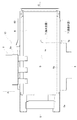
図1は本発明のシート収容装置を適用した丁合装置の実施形態の構造関係の説明図である。図2は、図1の操作パネル3側の方から、カバーを外して見た正面図である。給紙部2は、左右に10段ずつ設けられており、左右の各段からそれぞれ1枚ずつ給紙された用紙は中央の縦搬送路14で先端(下端)が揃うように丁合され、折り給紙部4から給紙されて折りナイフ17と折りローラ20で折目をつけられた折紙に挟み込まれた状態で排紙搬送路21で排紙口22まで搬送され排紙口22から蓄積部23(移動コンベア8上)へ排出される。
Embodiments of the present invention will be described below with reference to the drawings.
FIG. 1 is an explanatory view of the structural relationship of an embodiment of a collating apparatus to which a sheet storage apparatus of the present invention is applied. FIG. 2 is a front view of the operation panel 3 in FIG. The
図3は給紙部2を示す正面図である。
給紙板37上に用紙束36を斜めにずらして配置する。その用紙束36の先端には、給紙ローラ26とサパキ板32が圧接している。給紙ローラ26の軸は図示しない給紙モータで回転駆動される。
給紙ローラ26の給紙方向上流側に給紙ローラ26と同形状の補助給紙ローラ27が設けられている。補助給紙ローラ27の軸と給紙ローラ26の軸には共に歯つきプーリ28、29が設けられ、歯つきベルト30で駆動が伝達される。
FIG. 3 is a front view showing the
The
An auxiliary
給紙モータが回転すると、給紙ローラ26と補助給紙ローラ27が回転する。すると最上位の用紙が補助給紙ローラ27によって給紙ローラ26とサバキ板32の間に送り込まれる。この時2枚同時に通過しようとしても、サバキ板32と用紙との摩擦力によって、2枚目以降の前進が阻止されるので、最上位の1枚だけが送り出されることになる。
When the paper feed motor rotates, the
送り出された1枚は横搬送ローラ対33にくわえられ、矢印方向に送り出される。横搬送ローラ対33はメインモータ(図示せず)により常時回転駆動されている。この時、用紙検知センサ34が用紙の前端と後端を検知することにより、その間の搬送量を検知する。
One sheet fed out is added to the pair of
図2に示すように、各給紙部2から送り出された用紙は縦搬送路14へ合流し、重ねられながら、下方へ搬送される。縦搬送路14には所定間隔で縦搬送ローラ対24が設けられ、メインモータ(図示せず)により常時回転されている。
片面側の10段の給紙部2の列の下方には折り給紙部4が設けられている。折り給紙部4には折り用紙が積載され、構成は他の給紙部と同じである。送り出された折り用紙は折り搬送路16を通って折り込板19に入り、先端がストッパ18に当接して、折り用紙が縦搬送路14の下端をふさぐ形で停止する。上方から縦搬送路14を丁合された用紙束が下降してくるタイミングで折りナイフ17が下降する。停止していた折り用紙はその内側に上方から下降してきた用紙束を挟んで折りローラ20で二つ折りされる。こうして折り用紙で他の用紙を挟んだ形の束(配達に供される広告の束)が、その後排紙搬送路21を通って排紙口22から排出される。折り搬送路16、排紙搬送路21もメインモータにより常時駆動されている。
As shown in FIG. 2, the sheets fed from the respective
A folded paper feed unit 4 is provided below the row of 10-stage
図1、図2に示すように、折り給紙部4の下方に収容部10が設けられている。収容部10は排紙口22から排出された用紙束を受け入れて、周縁を揃え手段(バックジョガー9、サイドジョガー5)により揃えながら蓄積し、ある程度蓄積されて積み重ね(以下、スタックという)が形成されると、そのスタックを搬出する。
排紙口22から排出された用紙束は、先端ガイド6に当接して、移動コンベア8上に落下する。排出が繰り返されると、その上に順次積載され、スタックを形成する。
As shown in FIGS. 1 and 2, a
The sheet bundle discharged from the sheet discharge port 22 comes into contact with the
スタックが所定の高さまで積みあがって、満杯検知センサ(図示せず)により満杯が検知されると(或いは、予め定めた部数のスタックが形成されると)、用紙束の排出を中止し、開閉ガイド7(図4参照)を開いて退避位置にして、移動コンベア8のベルトを周回駆動させてスタックを矢印B方向に移動させ、矢印Cの方向に搬出させる
When the stack is stacked up to a predetermined height and full is detected by a full detection sensor (not shown) (or when a predetermined number of stacks are formed), the discharge of the stack of paper is stopped, and the stack is opened and closed. The guide 7 (see FIG. 4) is opened to the retracted position, the belt of the moving
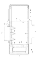
図4はその収容部10を示す上面図である。
丁合機から矢印Aの方向に排出された束は、先端ガイド6のガイド面6aに当接し、移動コンベア8上に排出される。排出を繰り返している間、揃え手段であるバックジョガー9とサイドジョガー5の可動部9a、5aが往復動作する。バックジョガー9の可動部9aと先端ガイド6のガイド面6aとの間で用紙束を挟んで揃える。同様にサイドジョガー5の可動部5aと揃え位置にある開閉ガイド7のガイド面7aとの間で用紙束を挟んで揃える。開閉ガイド7は支点7bを中心に揃え位置と退避位置とを旋回移動できる。用紙束が排出されている間は、揃え位置に位置している。
FIG. 4 is a top view showing the
The bundle discharged from the collating machine in the direction of arrow A comes into contact with the
図5は収容部を示す斜視図である。図5では理解が容易であるように、先端ガイド6と開閉ガイド7を図示省略してある。
FIG. 5 is a perspective view showing the accommodating portion. In FIG. 5, the
移動コンベア8は軸81、82にそれぞれ支持されたローラ間にかけられた幅広のベルト83を有する。軸81には駆動モータ84が直結され、軸81に支持されたローラを回転させてベルト83を周回駆動する。軸81,82はベルト83の両側端側に立設されたフレーム85、86間で支持されている。また、ベルト83の裏面にはフレーム85,86間には裏板が渡されており、ベルト83上面の平面性を維持している。
The moving
バックジョガー9は丁合機の架台25(図2参照)にネジ9cで固定された支持部9bと、矢印D方向に往復動作可能な可動部9aを有する。可動部9aは揃え面9d(揃え部)を有し、移動コンベア8上に積載されたスタックStの端面に揃え面9dが当接する当接位置と、揃え面9dがスタックStの端面から離れた退避位置との間を往復するようになっている。支持部9bの内部には駆動モータとクランク機構が設けられ、モータの回転運動を可動部9aの往復運動に変換する。
The
ネジ9cは揃え面9dの面方向の両側に1か所ずつ、計2か所設けられ、各々支持部9bに設けられた長穴9eに挿通されて架台25に穿たれたネジ穴に螺合されている。ネジ9cには上方にレバー9fが取り付けられ、手でネジ9cを緩めて、支持部9bの位置を、架台25に対して長穴9eの方向(矢印Dと同方向)に移動調整できるようになっている。
Two
揃え面9dの下端から、この揃え面9dに対して直角方向に、支持部材91が3個、架台25に固定されて設けられている。この支持部材91は、その上面にベルト83の搬送面と平行且つ所定の幅を持ち、さらにベルト83の端部83aを超えて延在する支持面91aを3個とも互いに同じ高さ位置に形成している。
Three
支持面91aの先端側のベルト83と重なっている部分には、滑り部材91bが各々貼付されている。この滑り部材91aは、支持部材の材質そのものよりも、少なくともベルト83の移動方向の摩擦係数の小さな滑り面を形成したシート状の部材で、ベルト83を駆動してスタックStを搬出するときに、スタックStの底面との摩擦を軽減する。
Sliding
支持部材91同士の間隔部分及びその両サイド部分では、揃え面9dの下端が、支持面91aよりも下方に延びている。また、揃え面9dの全面にわたって、当接したシートとの滑りを防止する滑り防止面が形成されている。具体的には、クラリーノ(登録商標)等の人工織布が貼付けられているが、その他の布類や植毛シート、ゴム類等、滑り防止効果があるものであれば何を貼り付けても良い。あるいは貼り付けるのではなく、揃え面9dにシボ面加工等の滑り止め表面処理や、滑り止め塗装を施しても良い。
The lower end of the
サイドジョガー5は、移動コンベア9のフレーム85,86間に渡された後方フレーム(図示せず)にネジ5cで固定された支持部5bと、矢印E方向に往復動作可能な可動部5aを有する。可動部5aは揃え面5d(揃え部)を有し、移動コンベア8上に積載されたスタックStの端面に揃え面5dが当接する当接位置と、揃え面5dがスタックStの端面から離れた退避位置との間を往復するようになっている。支持部5bの内部にも支持部9bと同様の駆動モータとクランク機構が設けられ、可動部5aが往復運動するようになっている。また、揃え面5dにも揃え面9dと同様の滑り防止面が形成されている。
The
ネジ5cもネジ9cと同様に揃え面5cの面方向の両側に設けられ、手でレバー5fを緩めて、後方フレームに対して長穴5eの方向(矢印Eと同方向)に移動調整することができる。
Similarly to the
サイドジョガー5の下方でベルト83が軸82に支持されたローラを周回しており、その部分を支持部5bに固定されたカバー5gが覆っている。長穴5eはこのカバー5gに穿たれている。
Below the
揃え面5dの下端及び両サイドから、この揃え面5dに対して直角方向に、支持部材51が3個設けられている。この支持部材51は、その上面にベルト83の搬送面と平行且つ所定の幅を持つ支持面51aを形成する。この支持面51aもカバー5gとともに、ベルト83の上流側周回部分を覆っており、すなわちベルト83の搬送面の上流側の端部を、支持面51aが乗り越えている。
Three
図1に示すように、移動コンベア8の出口側には昇降可能なエレベータ板11と、このエレベータ板11を昇降させる昇降機構13が設けられている。エレベータ板11は移動コンベア8のベルト面よりも若干低い位置で待機する。移動コンベア8により搬出されてきたスタックStは、エレベータ板11の上に移送される。エレベータ板11の積載センサ12がスタックStの到来を検知すると、昇降機構13が動作してエレベータ板11を上昇させ、スタックStを持ち上げて停止する。
As shown in FIG. 1, an
図6は本発明の制御系を示すブロック図である。
丁合装置1本体は、メイン制御部を有し、各給紙部2は個別に給紙制御部、収容部は収容制御部を有する。給紙制御部は給紙部の数分設けられている。
FIG. 6 is a block diagram showing a control system of the present invention.
The main body of the collating apparatus 1 has a main control unit, each
パルス出力手段は、メインモータで回転される軸のいずれかに、周方向に穴を環状配置した円板を設け、この円板の穴を検出できるように光軸を配置した光センサにより、メインモータ回転中は常時パルスを出力しているものである。このパルスはメイン制御部、給紙制御部に送られており、メインモータ動作中の各動作タイミングは、このパルスを計数することによりタイミングが取られている。以下、パルスと表記する場合は、このパルス出力手段により出力されているパルスを指す。 The pulse output means is provided with a circular plate having holes arranged in the circumferential direction on one of the shafts rotated by the main motor, and the optical sensor is arranged so that the hole of the circular plate can be detected. During motor rotation, pulses are always output. This pulse is sent to the main control unit and the paper feed control unit, and each operation timing during the operation of the main motor is timed by counting the pulses. Hereinafter, the term “pulse” refers to a pulse output by the pulse output means.
本体の操作パネル3(図1参照)に設けられたスタート/ストップスイッチを押すと、メインモータが回転開始する。次にメイン制御部は所定のタイミングで給紙トリガ信号を各給紙部2の給紙制御部に一斉に送信する。この給紙トリガ信号は給紙タイミングの基準となるタイミング基準信号である。各給紙部2の給紙制御部は、給紙トリガ信号を受信したタイミングから、所定の遅延パルス分だけ遅らせて、給紙モータを駆動して用紙の送り出しを開始する。この所定の遅延パルス数は、各給紙部によって異なるものであり、縦搬送路14で用紙の先端が揃って重なるように、下方に位置する給紙部2ほど多くなるように各々の給紙制御部に記憶されている。
When a start / stop switch provided on the operation panel 3 (see FIG. 1) of the main body is pressed, the main motor starts rotating. Next, the main control unit simultaneously transmits a paper feed trigger signal to the paper feed control units of the respective
従って、各々のタイミングで送り出された用紙は縦搬送路14で先端の揃った1束になる。折り給紙部4にも給紙制御部が設けられている。折り用紙は、この重なった束が縦搬送路14の最下位に到達するよりも少し前に、折り用紙の先端がストッパ18に当接して待機できるように、遅延パルスが設定されている。
Accordingly, the sheets sent out at each timing form a bundle with the leading ends aligned in the
こうして、折り用紙が折りナイフ17で折りローラ20間に挟まれて二つ折りすると同時に、上方から降りてきた束がその間に挟まれて束を形成し、その束が更に搬送されて、排紙口22から排紙される。
給紙トリガは所定パルス間隔で繰り返し発信されるので、次々に繰り返し用紙の束(配達に供する広告の束)が形成され、排紙口22から順次排出される。
In this way, the folded sheet is sandwiched between the
Since the paper feed trigger is repeatedly transmitted at a predetermined pulse interval, a bundle of sheets (a bundle of advertisements for delivery) is formed one after another, and the sheets are sequentially discharged from the paper discharge port 22.
メイン制御部は、スタート後、最初に給紙トリガが発生すると同時に、収容制御部にジョグ開始信号を送信する。収容制御部はジョグ開始信号を受信すると、バックジョガー駆動モータ、サイドジョガー駆動モータを駆動開始し、各ジョガーは往復動作を開始する。こうして、用紙束が繰り返し排出・蓄積されて形成するスタックStの端縁を各々揃える。 After the start, the main control unit transmits a jog start signal to the accommodation control unit at the same time as the first paper feed trigger is generated. When the accommodation control unit receives the jog start signal, it starts driving the back jogger drive motor and the side jogger drive motor, and each jogger starts a reciprocating operation. In this way, the edges of the stack St formed by repeatedly discharging and accumulating the sheet bundle are aligned.
満杯検知センサで満杯が検知されると、収容制御部は満杯信号をメイン制御部に送る。メイン制御部は満杯信号を受けると給紙トリガの発信を中止し、その時点で丁合が始まっているすべての束の丁合を完了させ、排出させた後、排出完了信号を収容制御部へ送る。この排出完了信号を受けると、収容制御部はサイドジョガー、バックジョガーの動作を停止させるとともに、開閉ガイド駆動モータを駆動して退避位置とする。更に移動コンベア駆動モータを回転させてコンベアを周回駆動させて、その上のスタックStをエレベータ板上に搬出する。 When fullness is detected by the fullness detection sensor, the accommodation control unit sends a full signal to the main control unit. When the main control unit receives the full signal, it stops sending the paper feed trigger, completes collation of all the bundles that have been collated at that time, discharges them, and then sends a discharge completion signal to the accommodation control unit send. Upon receiving this discharge completion signal, the accommodation control unit stops the operations of the side jogger and the back jogger and drives the open / close guide drive motor to the retracted position. Further, the moving conveyor drive motor is rotated to drive the conveyor so that the stack St thereon is carried onto the elevator plate.
載置センサによりエレベータ板上へのスタックStの到来が検知されると、収容制御部は、エレベータ昇降モータを駆動して、スタックStを持ち上げるとともに、開閉ガイド駆動モータを駆動させて開閉ガイド7をガイド位置とする。更にバックジョガー駆動モータ、サイドジョガー駆動モータを駆動開始し、各ジョガーの往復動作を再開する。メイン制御部には搬出完了信号を出し、メイン制御部はこれを受けて給紙トリガ(タイミング基準信号)発信の繰り返しを再開する。
When the placement sensor detects the arrival of the stack St on the elevator plate, the accommodation control unit drives the elevator lifting motor to lift the stack St and drives the opening / closing guide driving motor to move the opening /
エレベータ板11上のスタックStをユーザが取り出したことが載置センサにより検知されると、エレベータ板11は下降して、次に送り込まれるスタックStを待機する。
満杯検知センサに代えて、予め定めた部数分の束が形成されたら搬出するようにしてもよい。その数値は予め操作パネル3等に入力しておき、メイン制御部あるいは収容制御部に記憶しておく。
When the placement sensor detects that the user has taken out the stack St on the
Instead of the full detection sensor, it may be carried out when a bundle of a predetermined number of copies is formed. The numerical value is input to the operation panel 3 or the like in advance and stored in the main control unit or the accommodation control unit.
図7、図8は、揃え動作を示す図で、図7は排出口から排出された用紙束(シート)Sが移動コンベア8上に載置された状態を示す図である。図8はバックジョガー9とサイドジョガー5の可動部9a、5aが用紙束S側へ進出し、用紙束Sの側端が押されて揃えられている状態である。図9は開閉ガイド7を開き、移動コンベア8を駆動して、スタックStを送り出している状態である。
7 and 8 are diagrams showing the alignment operation, and FIG. 7 is a diagram showing a state in which the sheet bundle (sheet) S discharged from the discharge port is placed on the moving
排出口からは繰り返し用紙束Sが排出され、揃え面9d、5d、ガイド面6a、7aに囲まれた部分の移動コンベア8上(蓄積部)に重ねられ、スタックStを形成する。その間、可動部9a、5aは往復動作を継続するため、用紙束Sは常に揃え面9d、5dに押され、各々ガイド面6a、7aとの間で用紙束Sを図8に示す位置に揃えるので、スタックStの側端が揃う。こうして形成されたスタックStの最下位の用紙束Sの下面の、バックジョガー9寄りの部分が、支持部材91に支持されている。また同様に、サイドジョガー5寄りの部分は、支持部材51に支持されている。
The sheet bundle S is repeatedly discharged from the discharge port, and is stacked on the moving conveyor 8 (accumulation unit) surrounded by the alignment surfaces 9d and 5d and the guide surfaces 6a and 7a to form a stack St. Meanwhile, since the
移動コンベア8上に用紙束Sが無い状態で、最初の用紙束Sが排出されてきたときには、用紙束Sは、そのバックジョガー9寄りの部分が支持部材91の、サイドジョガー5寄りの部分が支持部材51の、各々の支持面上にそれぞれ直接載置されている。この状態でバックジョガー9とサイドジョガー5により用紙束Sの側端を押して図8の位置に移動させる。従って、各々支持部材で支持された部分において用紙束Sはベルト83の搬送面から離間されている。したがって、バックジョガー9とサイドジョガー5はベルト83と干渉することなく、確実に用紙束Sに当接して図8の位置に移動させることができる。
When the first sheet bundle S is discharged in a state where there is no sheet bundle S on the moving
また、用紙束Sは支持部材で支持されている部分が他の部分よりも高くなっているため、バックジョガー9側の側端とサイドジョガー5側の側端は上向きに傾斜していることになる。しかし揃え面9d、5dは各々滑り防止面が形成されているため、揃え面9d、5dが当接したときに、座屈することがない。
Further, in the sheet bundle S, the portion supported by the support member is higher than the other portions, so that the side end on the
さらに、揃え面9d、5dは支持部材91,51の無い部分で支持面91a,51aよりも下方に延びているため、シートSが薄い場合でも、シートSが揃え面9d、5dと支持面91a,51aとの隙間に入りこむことが無く、確実に側端を揃え面9d、5dに当接させて図8の位置に移動させることができる
スタックStが所定高さを超え、満杯が検知されると、図9のように開閉ガイド7が開き、移動コンベア8によって図示右方に移動され、エレベータ板11へ移動される。
Further, since the alignment surfaces 9d and 5d extend below the support surfaces 91a and 51a in the portions where the
図10、図11も揃え動作を示す図であるが、図7、図8の場合よりも、用紙束Sのサイズが小さい場合を示す図である。バックジョガー9とサイドジョガー5は、予め支持部9b、5bの位置が用紙束Sに合わせて調整されている。調整は、レバー9f、5fによりネジ9c、5cを緩め、支持部9b、5bをそれぞれ矢印D,Eg方向に動かして位置を決め、再度レバー9f、5fによりネジ9c、5cを締めて固定することによって行う(図4参照)。
FIGS. 10 and 11 are diagrams illustrating the alignment operation, and are diagrams illustrating a case where the size of the sheet bundle S is smaller than those in FIGS. 7 and 8. In the
バックジョガー9とサイドジョガー5の往復動作のストロークは不変であるので、用紙束Sのサイズが小さいほど、バックジョガー9の退避位置、当接位置ともに先端ガイド6に近づき、サイドジョガー5の退避位置、当接位置ともに開閉ガイド7に近づくことになる。
Since the stroke of the reciprocating operation of the
本実施例では支持部材91は架台25に固定されているため位置は不変で、支持部材51は支持部5bに固定されているため、支持部5bとともに移動しているが、支持部材は支持部9b、5bの位置調整に関わらず位置不変であっても、支持部9b、5bとともに移動するように構成しても、どちらでもよい。
In this embodiment, since the
図10では可動部9a、5aが退避位置にあり、用紙束Sは揃える前の位置、図11は可動部9b、5bが当接位置にあり、用紙束Sは揃えた後の位置にある。図10及び図11に示すように、揃えた後の用紙束Sのバックジョガー9側の側端は、ベルト83の端部83aよりも内側にあり、バックジョガー9の揃え面9dは退避位置と当接位置との間を移動する途中で、ベルト83の端部83aを超えることになる。しかし、支持部材91がベルト83の端部83aを超えて延在していることから、この部分で用紙束Sの下面はベルト83の搬送面から離間している。そして揃え面9dは支持部材91の両サイドと間隔の部分で支持面91aよりも下方に延びているとともに、その延びた部分の下端はベルト83の搬送面よりも高い位置になっているので、揃え面9dとベルト83の端部83aとが干渉することなく、確実に用紙束Sの側端に当接させることができる。
In FIG. 10, the
同様にサイドジョガー5においても、ベルト83の上流側端部を支持部材51が超えているため、揃え面5dはベルト83と干渉することなく、用紙束Sの側端に当接することができる。
Similarly, in the
このように本発明のシート収容装置は、シートSが厚いものでも薄いものでも、サイズが異なっていても、確実にジョガーを側端に当てながら積み重ねることにより、側端が揃ったスタックを得ることができる。従って取り出した後の揃え作業を不要とすることができる。 As described above, the sheet storage device of the present invention can obtain a stack with aligned side edges by stacking the joggers securely against the side edges, regardless of whether the sheets S are thick, thin, or different in size. Can do. Therefore, the alignment work after taking out can be made unnecessary.
なお、バックジョガー9とサイドジョガー5の往復動作は、ともに同時に当接位置に進出するように、あるいは互いに交互に当接位置に進出するように、互いに連動させてもよいし、個別に動作させてもよい。
The reciprocating operation of the
1 丁合装置、 5 サイドジョガー、 5a 可動部、 5b 可動部、 5c ネジ、 5d 揃え面、 5e 長穴、 5f レバー、 5g カバー、 6 先端ガイド、 6a ガイド面、 7 開閉ガイド、 7a ガイド面、 8 移動コンベア、 9 バックジョガー、 9a 可動部、 9b 可動部、 9c ネジ、 9d 揃え面、 9e 長穴、 9f レバー、 10 収容部、 11 エレベータ板、 23 蓄積部、 25 架台、 51 支持部材、 51a 支持面、 83 ベルト、 91 支持部材、 91a 支持面, 91b 滑り部材、 S 用紙束、 St スタック 1 collating device, 5 side jogger, 5a movable part, 5b movable part, 5c screw, 5d aligning surface, 5e oblong hole, 5f lever, 5g cover, 6 tip guide, 6a guide surface, 7 opening / closing guide, 7a guide surface, 8 moving conveyor, 9 back jogger, 9a movable part, 9b movable part, 9c screw, 9d alignment surface, 9e long hole, 9f lever, 10 accommodating part, 11 elevator plate, 23 storage part, 25 mount, 51 support member, 51a Support surface, 83 belt, 91 support member, 91a support surface, 91b sliding member, S paper bundle, St stack
Claims (8)
揃え部を有し、該揃え部が前記搬出ベルト上に積み重ねられたスタックの側面に当接する当接位置と、スタックの側面から離れた退避位置との間を往復移動可能に設けられたジョガーと、
搬送ベルト上で、前記揃え部の往復移動方向に延在し、前記スタックの下面を支持する支持部材と、
を有することを特徴とするシート収容装置。 An accumulator that stacks sheets on a carry-out belt to form a stack;
It has aligned portion, provided abutting contact position to the side of the stack該揃example portion are stacked on the transportable out belt, between a retracted position away from the side of the stack to reciprocate jogger When,
A support member that extends in a reciprocating direction of the alignment portion on the conveyor belt and supports a lower surface of the stack;
A sheet storage device comprising:
Priority Applications (1)
| Application Number | Priority Date | Filing Date | Title |
|---|---|---|---|
| JP2017167988A JP6462071B2 (en) | 2017-08-31 | 2017-08-31 | Sheet storage device |
Applications Claiming Priority (1)
| Application Number | Priority Date | Filing Date | Title |
|---|---|---|---|
| JP2017167988A JP6462071B2 (en) | 2017-08-31 | 2017-08-31 | Sheet storage device |
Related Parent Applications (1)
| Application Number | Title | Priority Date | Filing Date |
|---|---|---|---|
| JP2013238723A Division JP6212809B2 (en) | 2013-11-19 | 2013-11-19 | Sheet storage device |
Publications (3)
| Publication Number | Publication Date |
|---|---|
| JP2017206391A JP2017206391A (en) | 2017-11-24 |
| JP2017206391A5 JP2017206391A5 (en) | 2018-05-10 |
| JP6462071B2 true JP6462071B2 (en) | 2019-01-30 |
Family
ID=60416281
Family Applications (1)
| Application Number | Title | Priority Date | Filing Date |
|---|---|---|---|
| JP2017167988A Active JP6462071B2 (en) | 2017-08-31 | 2017-08-31 | Sheet storage device |
Country Status (1)
| Country | Link |
|---|---|
| JP (1) | JP6462071B2 (en) |
Families Citing this family (1)
| Publication number | Priority date | Publication date | Assignee | Title |
|---|---|---|---|---|
| JP7121704B2 (en) * | 2018-08-31 | 2022-08-18 | キヤノンファインテックニスカ株式会社 | Sheet bundle discharge device and bookbinding device |
Family Cites Families (4)
| Publication number | Priority date | Publication date | Assignee | Title |
|---|---|---|---|---|
| JPS6317767A (en) * | 1986-07-10 | 1988-01-25 | Japan Steel Works Ltd:The | Printed board aligner |
| JPH0517258Y2 (en) * | 1987-09-08 | 1993-05-10 | ||
| JPH0891675A (en) * | 1994-09-28 | 1996-04-09 | Toppan Printing Co Ltd | Delivering device for bag manufacturing machine |
| JP4169872B2 (en) * | 1999-07-13 | 2008-10-22 | ホリゾン・インターナショナル株式会社 | Paper transport device |
-
2017
- 2017-08-31 JP JP2017167988A patent/JP6462071B2/en active Active
Also Published As
| Publication number | Publication date |
|---|---|
| JP2017206391A (en) | 2017-11-24 |
Similar Documents
| Publication | Publication Date | Title |
|---|---|---|
| JP2008214102A (en) | Sheet post-processing apparatus | |
| JPS6071438A (en) | Method and device for carrying sheet of paper to printer under correct register state | |
| JP6212809B2 (en) | Sheet storage device | |
| EP0911287A2 (en) | Hopper loader for feeding vertical signatures to bindery equipment | |
| JPH11310363A (en) | Device for sending depositing and adjusting sheet into stack canister | |
| JP2014201394A (en) | Paper post-processing apparatus | |
| US7775514B2 (en) | Sheet post-processing apparatus | |
| JP6462071B2 (en) | Sheet storage device | |
| JP6566758B2 (en) | Paper stacking device | |
| JP5302040B2 (en) | Paper receiving device and printing machine | |
| JP6550597B2 (en) | Collation device | |
| US20180141775A1 (en) | Paper postprocessing apparatus | |
| JP7125783B2 (en) | Book block transfer device | |
| US7011302B2 (en) | Vertical pocket feeder | |
| JP6212808B2 (en) | Collating device | |
| JP2021130556A (en) | Sheet storage conveyance device and gathering system | |
| JP4766684B2 (en) | Paper transport device | |
| JP2004538225A (en) | Apparatus and method for aligning a stack of sequentially stacked sheets | |
| JP7204212B2 (en) | Article stacking and unloading device | |
| JP4758242B2 (en) | Paper post-processing device | |
| US11203503B2 (en) | Sheet discharging device, method of controlling sheet discharging device, processing device, and recording system | |
| JP2002302327A (en) | Recording material loading device and recording material processing device | |
| JP6480148B2 (en) | Sheet stacker | |
| JPH0741238A (en) | Image forming device | |
| JP2023142960A (en) | Paper classification device |
Legal Events
| Date | Code | Title | Description |
|---|---|---|---|
| A621 | Written request for application examination |
Free format text: JAPANESE INTERMEDIATE CODE: A621 Effective date: 20170919 |
|
| A521 | Request for written amendment filed |
Free format text: JAPANESE INTERMEDIATE CODE: A523 Effective date: 20180220 |
|
| A977 | Report on retrieval |
Free format text: JAPANESE INTERMEDIATE CODE: A971007 Effective date: 20180622 |
|
| A131 | Notification of reasons for refusal |
Free format text: JAPANESE INTERMEDIATE CODE: A131 Effective date: 20180719 |
|
| A521 | Request for written amendment filed |
Free format text: JAPANESE INTERMEDIATE CODE: A523 Effective date: 20180911 |
|
| TRDD | Decision of grant or rejection written | ||
| A01 | Written decision to grant a patent or to grant a registration (utility model) |
Free format text: JAPANESE INTERMEDIATE CODE: A01 Effective date: 20181128 |
|
| A61 | First payment of annual fees (during grant procedure) |
Free format text: JAPANESE INTERMEDIATE CODE: A61 Effective date: 20181226 |
|
| R150 | Certificate of patent or registration of utility model |
Ref document number: 6462071 Country of ref document: JP Free format text: JAPANESE INTERMEDIATE CODE: R150 |
|
| R250 | Receipt of annual fees |
Free format text: JAPANESE INTERMEDIATE CODE: R250 |
|
| R250 | Receipt of annual fees |
Free format text: JAPANESE INTERMEDIATE CODE: R250 |
|
| R250 | Receipt of annual fees |
Free format text: JAPANESE INTERMEDIATE CODE: R250 |