JP6452381B2 - Imaging device - Google Patents
Imaging device Download PDFInfo
- Publication number
- JP6452381B2 JP6452381B2 JP2014216615A JP2014216615A JP6452381B2 JP 6452381 B2 JP6452381 B2 JP 6452381B2 JP 2014216615 A JP2014216615 A JP 2014216615A JP 2014216615 A JP2014216615 A JP 2014216615A JP 6452381 B2 JP6452381 B2 JP 6452381B2
- Authority
- JP
- Japan
- Prior art keywords
- charge holding
- holding unit
- unit
- period
- charge
- Prior art date
- Legal status (The legal status is an assumption and is not a legal conclusion. Google has not performed a legal analysis and makes no representation as to the accuracy of the status listed.)
- Expired - Fee Related
Links
- 238000003384 imaging method Methods 0.000 title claims description 36
- 238000006243 chemical reaction Methods 0.000 claims description 64
- 230000003321 amplification Effects 0.000 claims description 32
- 238000003199 nucleic acid amplification method Methods 0.000 claims description 32
- 239000004065 semiconductor Substances 0.000 description 24
- 238000010586 diagram Methods 0.000 description 14
- 239000003990 capacitor Substances 0.000 description 8
- 238000009792 diffusion process Methods 0.000 description 7
- 230000000717 retained effect Effects 0.000 description 7
- 239000012535 impurity Substances 0.000 description 6
- 230000014759 maintenance of location Effects 0.000 description 6
- 230000015572 biosynthetic process Effects 0.000 description 3
- 238000000034 method Methods 0.000 description 3
- 238000009825 accumulation Methods 0.000 description 2
- 230000000052 comparative effect Effects 0.000 description 1
- 239000000470 constituent Substances 0.000 description 1
- 238000007599 discharging Methods 0.000 description 1
- 230000000694 effects Effects 0.000 description 1
- 238000002955 isolation Methods 0.000 description 1
- 239000011159 matrix material Substances 0.000 description 1
- 229910021420 polycrystalline silicon Inorganic materials 0.000 description 1
- 229920005591 polysilicon Polymers 0.000 description 1
- 229920006395 saturated elastomer Polymers 0.000 description 1
Images


Classifications
-
- H—ELECTRICITY
- H01—ELECTRIC ELEMENTS
- H01L—SEMICONDUCTOR DEVICES NOT COVERED BY CLASS H10
- H01L27/00—Devices consisting of a plurality of semiconductor or other solid-state components formed in or on a common substrate
- H01L27/14—Devices consisting of a plurality of semiconductor or other solid-state components formed in or on a common substrate including semiconductor components sensitive to infrared radiation, light, electromagnetic radiation of shorter wavelength or corpuscular radiation and specially adapted either for the conversion of the energy of such radiation into electrical energy or for the control of electrical energy by such radiation
- H01L27/144—Devices controlled by radiation
- H01L27/146—Imager structures
- H01L27/14601—Structural or functional details thereof
- H01L27/14609—Pixel-elements with integrated switching, control, storage or amplification elements
-
- H—ELECTRICITY
- H04—ELECTRIC COMMUNICATION TECHNIQUE
- H04N—PICTORIAL COMMUNICATION, e.g. TELEVISION
- H04N25/00—Circuitry of solid-state image sensors [SSIS]; Control thereof
- H04N25/70—SSIS architectures; Circuits associated therewith
- H04N25/76—Addressed sensors, e.g. MOS or CMOS sensors
- H04N25/77—Pixel circuitry, e.g. memories, A/D converters, pixel amplifiers, shared circuits or shared components
- H04N25/771—Pixel circuitry, e.g. memories, A/D converters, pixel amplifiers, shared circuits or shared components comprising storage means other than floating diffusion
Description
本発明は、撮像装置に関し、特に光電変換部で生じた電荷を保持する複数の電荷保持部を有する撮像装置に関する。 The present invention relates to an imaging device, and more particularly to an imaging device having a plurality of charge holding units that hold charges generated in a photoelectric conversion unit.
従来、グローバル電子シャッタ動作を可能とする電荷保持部を有する撮像装置が知られている。 2. Description of the Related Art Conventionally, an imaging apparatus having a charge holding unit that enables a global electronic shutter operation is known.
特許文献1に記載された撮像装置において、画素は1つの光電変換部で生じた電荷を保持する二つの電荷保持部を有しており、フレームごとにそれらの電荷保持部を使い分けることが記載されている。
In the image pickup apparatus described in
しかしながら特許文献1に記載された撮像装置は、各フレームの画像を形成するための電荷の保持が終了し、保持した電荷を読み出す前に光電変換部で生じた電荷は、オーバーフロードレインを介して排出されており、全ての電荷を用いていない。
However, the image pickup apparatus described in
本発明は上記課題に鑑み、連続して複数フレームの撮影を行なう場合に、光電変換部で生じた電荷を全て用いることを可能とする撮像装置を提供することを目的とする。 In view of the above problems, an object of the present invention is to provide an imaging apparatus that can use all the charges generated in the photoelectric conversion unit when continuously shooting a plurality of frames.
本発明の撮像装置は、光電変換部と、光電変換部で生じた電荷を保持する電荷保持部と、電荷保持部に保持された電荷に基づく信号を出力する増幅部と、を有する画素を複数有する撮像装置であって、電荷保持部は、第1電荷保持部、第2電荷保持部および第3電荷保持部を有し、前記複数の画素のそれぞれにおいて、第1時刻から第2時刻までの第1期間に複数の画素の光電変換部で生じた電荷を、第1期間に第1電荷保持部に転送し、且つ、第1期間よりも前の期間に第2電荷保持部および第3電荷保持部に保持された電荷を第1期間に増幅部の入力ノードへ転送し、第2時刻から第3時刻までの第2期間に複数の画素の光電変換部で生じた電荷を第2期間に第1電荷保持部および第3電荷保持部に転送して保持することを特徴とする。 An imaging apparatus according to the present invention includes a plurality of pixels each including a photoelectric conversion unit, a charge holding unit that holds charges generated in the photoelectric conversion unit, and an amplification unit that outputs a signal based on the charges held in the charge holding unit. The charge holding unit includes a first charge holding unit, a second charge holding unit, and a third charge holding unit, and each of the plurality of pixels includes a first time to a second time. The charges generated in the photoelectric conversion units of the plurality of pixels in the first period are transferred to the first charge holding unit in the first period, and the second charge holding unit and the third charge in the period before the first period. The charge held in the holding unit is transferred to the input node of the amplification unit in the first period, and the charge generated in the photoelectric conversion units of the plurality of pixels in the second period from the second time to the third time in the second period The first charge holding unit and the third charge holding unit are transferred and held.
本発明の撮像装置によれば、連続して複数フレームの撮影を行なう場合に、光電変換部で生じた電荷を全て用いることが可能となる。 According to the image pickup apparatus of the present invention, it is possible to use all the charges generated in the photoelectric conversion unit when shooting a plurality of frames continuously.
本発明の一実施形態である撮像装置について図1、2を用いて説明する。本実施形態の撮像装置は、画素に、1つの光電変換部で生じた電荷を保持する3つ以上の電荷保持部を有する。 An imaging apparatus according to an embodiment of the present invention will be described with reference to FIGS. The imaging device of this embodiment has three or more charge holding units that hold charges generated in one photoelectric conversion unit in a pixel.
図1は連続する二つのフレームにおける画素からの信号読み出しシーケンスを示す図であり、図2は光電変換部から各電荷保持部への電荷の移動を説明するための概念図である。 FIG. 1 is a diagram showing a signal reading sequence from pixels in two consecutive frames, and FIG. 2 is a conceptual diagram for explaining the movement of charges from the photoelectric conversion unit to each charge holding unit.
図1において、第1露光期間T12において光電変換部で生じた電荷がnフレームの画像形成に用いられ、第2露光期間T34において光電変換部で生じた電荷がn+1フレームの画像形成に用いられる。さらにこれらのフレームの前後にも複数のフレームの撮影を行なうことで動画撮影が可能となる。光電変換部で生じた電荷は、第1電荷保持部M1、第2電荷保持部M2、第3電荷保持部M3のいずれかで保持された後、増幅部の入力ノードへ転送される。 In FIG. 1, the charge generated in the photoelectric conversion unit in the first exposure period T12 is used for n-frame image formation, and the charge generated in the photoelectric conversion unit in the second exposure period T34 is used for n + 1 frame image formation. Furthermore, moving images can be shot by shooting a plurality of frames before and after these frames. The charges generated in the photoelectric conversion unit are held by any of the first charge holding unit M1, the second charge holding unit M2, and the third charge holding unit M3, and then transferred to the input node of the amplification unit.
図2(a)は、図1の第1期間T1における光電変換部、電荷保持部および増幅部の入力ノード間の電荷の移動を示している。同様に、図2(b)は図1の第2期間T2、図2(c)は第3期間T3、図2(d)は第4期間T4における、光電変換部、電荷保持部および増幅部の入力ノード間の電荷の移動を示している。 FIG. 2A shows the movement of charges between the input nodes of the photoelectric conversion unit, the charge holding unit, and the amplification unit in the first period T1 of FIG. Similarly, FIG. 2B illustrates the photoelectric conversion unit, the charge holding unit, and the amplification unit in the second period T2 in FIG. 1, FIG. 2C illustrates the third period T3, and FIG. 2D illustrates the fourth period T4. The charge transfer between the input nodes is shown.
第1期間T1は第1時刻t1から第2時刻t2までの期間であり、第2電荷保持部M2、第3電荷保持部M3において保持されている前フレーム(n−1フレーム)の画像形成に用いられる電荷を行毎に増幅部の入力ノードへ転送する期間である。図1の読出動作で示している部分が、各行において第2電荷保持部M2および第3電荷保持部M3での保持された電荷を増幅部の入力ノードへ転送し、その後、信号線へ信号を読出す期間を示している。 The first period T1 is a period from the first time t1 to the second time t2, and is used for image formation of the previous frame (n−1 frame) held in the second charge holding unit M2 and the third charge holding unit M3. This is a period in which the charge used is transferred to the input node of the amplifier for each row. 1 transfers the charges held in the second charge holding unit M2 and the third charge holding unit M3 in each row to the input node of the amplifying unit, and then sends a signal to the signal line. The period for reading is shown.
この読出し動作と平行して、第1期間T1において光電変換部で生じた電荷は第1電荷保持部M1に転送され保持される。入射光量が所定の値を超えた場合には、第1電荷保持部M1と光電変換部との両者で電荷が保持される。 In parallel with the reading operation, the charges generated in the photoelectric conversion unit in the first period T1 are transferred and held in the first charge holding unit M1. When the amount of incident light exceeds a predetermined value, charges are held in both the first charge holding unit M1 and the photoelectric conversion unit.
第2期間T2は第2時刻t2から第3時刻t3までの期間である。第2時刻t2において、全行の第2電荷保持部M2、第3電荷保持部M3において保持されていた電荷の増幅部の入力ノードへの転送が終了する。第2期間T2に生じた電荷は少なくとも第3電荷保持部M3へ転送され保持される。つまり第3電荷保持部M3はn−1フレームの画像を形成する電荷の保持と、nフレームの画像を形成する電荷の保持との両者に用いられる。 The second period T2 is a period from the second time t2 to the third time t3. At the second time t2, the transfer of the charges held in the second charge holding unit M2 and the third charge holding unit M3 in all rows to the input node of the amplification unit is completed. The charges generated in the second period T2 are transferred and held at least to the third charge holding unit M3. That is, the third charge holding unit M3 is used for both holding charges for forming an image of n−1 frames and holding charges for forming an image of n frames.
また、nフレームの画像を形成する電荷のうち第2期間T2に光電変換部で生じた電荷の保持は少なくとも第3電荷保持部M3で行われるが、入射光量が所定の値を超えた場合には光電変換部においても電荷が保持される。更に、第2期間T2に光電変換部で生じた電荷を、第3電荷保持部M3に加えて、第1電荷保持部M1に転送して保持してもよい。 In addition, among the charges forming the n-frame image, the charge generated in the photoelectric conversion unit in the second period T2 is held at least by the third charge holding unit M3, but when the incident light quantity exceeds a predetermined value The charge is also retained in the photoelectric conversion portion. Furthermore, the charge generated in the photoelectric conversion unit in the second period T2 may be transferred to and held in the first charge holding unit M1 in addition to the third charge holding unit M3.
全行において、第1期間T1において生じた電荷を第1電荷保持部M1で保持し第2期間T2において生じた電荷を少なくとも第3電荷保持部M3で保持することで、全行の露光時間を等しくすることが可能となる。 In all rows, the charge generated in the first period T1 is held in the first charge holding unit M1, and the charge generated in the second period T2 is held in at least the third charge holding unit M3, thereby reducing the exposure time of all rows. It can be made equal.
第3期間T3は第3時刻t3から第4時刻t4までの期間であり、第1電荷保持部M1、第3電荷保持部M3で保持された、第1露光期間T12において生じた電荷を、行毎に増幅部の入力ノードへ転送する期間である。 The third period T3 is a period from the third time t3 to the fourth time t4, and the charges generated in the first exposure period T12 held in the first charge holding unit M1 and the third charge holding unit M3 are transferred to the row. This is a period for each transfer to the input node of the amplifier.
図1の読出動作で示している部分が、各行において第1電荷保持部M1および第3電荷保持部M3で保持された電荷を増幅部の入力ノードへ転送し、その後、信号線へ信号を読出す期間を示している。 The portion shown by the read operation in FIG. 1 transfers the charges held in the first charge holding unit M1 and the third charge holding unit M3 in each row to the input node of the amplification unit, and then reads the signal to the signal line. It shows the period to put out.
この読み出し動作と平行して、第3期間T3において生じた電荷は第2電荷保持部M2に転送され保持される。入射光量が所定の値を超えた場合には、第2電荷保持部M2と光電変換部で電荷が保持される。これにより、第3期間T3において生じた電荷も失われることが無い。 In parallel with this read operation, the charges generated in the third period T3 are transferred to and held in the second charge holding unit M2. When the amount of incident light exceeds a predetermined value, charges are held in the second charge holding unit M2 and the photoelectric conversion unit. As a result, the charges generated in the third period T3 are not lost.
第4期間T4は第4時刻t4から第5時刻t5までの期間である。第4時刻t4において、全行の第1電荷保持部M1、第3電荷保持部M3において保持されていた電荷の増幅部の入力ノードへの転送が終了する。第4期間T4に生じた電荷は少なくとも第3電荷保持部M3へ転送され保持される。つまり第3電荷保持部M3はnフレームの画像を形成する電荷の保持と、n+1フレームの画像を形成する電荷の保持との両者に用いられる。 The fourth period T4 is a period from the fourth time t4 to the fifth time t5. At the fourth time t4, the transfer of the charges held in the first charge holding unit M1 and the third charge holding unit M3 of all rows to the input node of the amplification unit is completed. The charges generated in the fourth period T4 are transferred to and held at least by the third charge holding unit M3. That is, the third charge holding unit M3 is used for both holding charges for forming an image of n frames and holding charges for forming an image of n + 1 frames.
また、n+1フレームの画像を形成する電荷のうち第4期間T4に光電変換部で生じた電荷の保持は少なくとも第3電荷保持部M3で行われるが、入射光量が所定の値を超えた場合には光電変換部においても電荷が保持される。更に、第4期間T2に光電変換部で生じた電荷を、第3電荷保持部M3に加えて、第2電荷保持部M2に転送して保持してもよい。 Further, among the charges forming the image of the n + 1 frame, the charge generated in the photoelectric conversion unit in the fourth period T4 is held at least by the third charge holding unit M3, but when the incident light quantity exceeds a predetermined value The charge is also retained in the photoelectric conversion portion. Furthermore, the charge generated in the photoelectric conversion unit in the fourth period T2 may be transferred to and held in the second charge holding unit M2 in addition to the third charge holding unit M3.
上述の動作によれば、第1電荷保持部M1、第2電荷保持部M2の容量値は、少なくとも電荷保持部から増幅部の入力ノードへ転送を行なう期間に生じる電荷を、光電変換部と共に保持できる容量値であればよい。したがって特許文献1のように排他的に二つの電荷保持部を各フレームで使い分ける場合に比べて、第1電荷保持部M1、第2電荷保持部M2の容量値を小さくすることができる。
According to the above-described operation, the capacitance values of the first charge holding unit M1 and the second charge holding unit M2 hold at least the charge generated during the transfer period from the charge holding unit to the input node of the amplification unit together with the photoelectric conversion unit. Any capacity value can be used. Therefore, the capacitance values of the first charge holding unit M1 and the second charge holding unit M2 can be reduced as compared with the case where two charge holding units are selectively used in each frame as in
全行において、第3期間T3において生じた電荷を第2電荷保持部M2で保持し第4期間T4において生じた電荷を少なくとも第3電荷保持部M3で保持することで、全行の露光時間を等しくすることが可能となる。 In all rows, the charge generated in the third period T3 is held in the second charge holding unit M2, and the charge generated in the fourth period T4 is held in at least the third charge holding unit M3, thereby reducing the exposure time of all rows. It can be made equal.
これらの動作を複数フレームにわたって繰り返し行うことで動画撮影が可能となる。 Moving images can be taken by repeating these operations over a plurality of frames.
仮に、2つの電荷保持部(第1電荷保持部、第2電荷保持部)を各フレームで排他的に用いて動画撮影を行なう場合を考える。この場合には、n−1フレームの画像を形成する電荷の保持を第1電荷保持部で行い、第1電荷保持部からこの電荷の読出しを行なっている期間中に、第2電荷保持部でnフレームの画像を形成する電荷の保持が行われる。そして、全行において第1電荷保持部からの電荷の読出しが終了した時点で、第1電荷保持部においてn+1フレームの画像を形成する電荷の保持を行なわなければならない。 Consider a case where moving image shooting is performed using two charge holding units (first charge holding unit and second charge holding unit) exclusively in each frame. In this case, the charge that forms the image of the n−1 frame is held by the first charge holding unit, and the second charge holding unit performs the reading of the charge from the first charge holding unit. The charge that forms an image of n frames is held. Then, at the time when reading of charges from the first charge holding unit is completed in all rows, the first charge holding unit must hold charges that form an image of n + 1 frames.
途切れなく撮影を行なうためには、第1電荷保持部の読出し動作から保持する動作への切り替え時間を短くする必要がある。しかし、この期間が短すぎると、第1電荷保持部M1に、増幅部の入力ノードへ転送されなかった電荷(残電荷)が生じる恐れがある。この残電荷が画像に影響を与える場合がある。 In order to perform shooting without interruption, it is necessary to shorten the switching time from the reading operation of the first charge holding unit to the holding operation. However, if this period is too short, there is a possibility that a charge (residual charge) that has not been transferred to the input node of the amplifying unit is generated in the first charge holding unit M1. This residual charge may affect the image.
これに対し本実施形態の駆動方法によれば、第1電荷保持部M1、第2電荷保持部M2の読出しが終了した後は、次の保持の期間まで所定の期間が存在する。したがって上述の残電荷の影響を低減することが可能となる。もしくは仮に残電荷が生じたとしても、読出しが終了した後に電荷保持部をリセットすることでこの残電荷を低減することが可能となる。 On the other hand, according to the driving method of the present embodiment, after the reading of the first charge holding unit M1 and the second charge holding unit M2 is completed, there is a predetermined period until the next holding period. Therefore, it becomes possible to reduce the influence of the above-mentioned residual charge. Alternatively, even if a residual charge is generated, this residual charge can be reduced by resetting the charge holding portion after the reading is completed.
以下、本発明を具体的な実施例を用いて説明する。 Hereinafter, the present invention will be described using specific examples.
(実施例1)
図3〜図7を用いて本実施例の撮像装置を説明する。各図面において、図1、2と同様の機能を有する部分には同じ符号を付し詳細な説明は省略する。
Example 1
The image pickup apparatus according to the present embodiment will be described with reference to FIGS. In each drawing, portions having the same functions as those in FIGS. 1 and 2 are denoted by the same reference numerals, and detailed description thereof is omitted.
図3に本実施例の撮像装置のブロック図を示す。撮像装置501は、画素部502、駆動パルス生成部503、垂直走査回路504、信号処理部505、出力部506を有している。
FIG. 3 shows a block diagram of the imaging apparatus of the present embodiment. The
画素部502は、光を電気信号へ変換し、変換した電気信号を出力する画素100を複数有している。複数の画素100は行列状に配されている。駆動パルス生成部503は駆動パルスを生成し、垂直走査回路504は駆動パルス生成部503からの駆動パルスを受け、各画素に制御パルスを供給する。信号処理部505は、少なくとも、複数の画素列から並列に出力された信号を順次、出力部506に伝達する。更に信号処理部505は、各画素列に対応し、信号の増幅、AD変換等を行なう列回路を有していてもよい。
The
次に図4を用いて本実施例の画素の等価回路を説明する。 Next, an equivalent circuit of the pixel of this embodiment will be described with reference to FIG.
光電変換部101は、入射光量に応じた量の電荷対を光電変換により生じさせる。ここでは光電変換部101の例としてフォトダイオードを示している。
The
第1転送部102、103、104は、光電変換部101で生じた電荷を電荷保持部M1、M2、M3に転送する。第1転送部102、第1転送部103、第1転送部104を区別して説明する必要がある場合には、第1転送部102を第1の第1転送部、第1転送部103を第2の第1転送部、第1転送部104を第3の第1転送部とよぶ。第1転送部102、103、104のゲートには、それぞれ制御パルスpTx1、pTx2、pTx3が供給され、オン状態(導通)、オフ状態(非導通)が切り替えられる。
The
第2転送部108、109、110は、第1電荷保持部M1、第2電荷保持部M2、第3電荷保持部M3で保持された電荷を増幅トランジスタ(増幅部)111の入力ノード112に転送する。第2転送部108、第2転送部109、第2転送部110を区別して説明する必要がある場合には、第2転送部108を第1の第2転送部、第2転送部109を第2の第2転送部、第2転送部110を第3の第2転送部とよぶ。第2転送部108、109、110のゲートには制御パルスpTx4、pTx5、pTx6が供給され、オン状態、オフ状態が切り替えられる。
The
ここでは、第1転送部102、103、104、第2転送部108、109、110として転送トランジスタを用いているが、必ずしもこの限りではない。オン状態、オフ状態を切り替えられればスイッチ等でもよい。
Here, transfer transistors are used as the
増幅トランジスタ111は、第2転送部108、109、110によって、入力ノード112に転送された電荷に基づく信号を増幅して出力する。より具体的には、入力ノード112に転送された電荷は、その量に応じた電圧に変換され、その電圧に応じた信号が増幅トランジスタ111を介して画素外へ出力される。ここでは、増幅部の例としてMOSトランジスタを用いたソースフォロア回路を示している。また、入力ノード112は電荷を保持可能な構成となっている。なお、以下では増幅部を増幅トランジスタ111とする。
The
リセットトランジスタ113は、増幅トランジスタ111の入力ノード112に基準電位を供給する。また、リセットトランジスタ113と第2転送部108、109、110とのそれぞれのオン期間を重ねることにより、第1電荷保持部M1、第2電荷保持部M2、第3電荷保持部M3のそれぞれの電荷保持部の電位をリセットすることができる。更に、第1転送部102、103、104のオン期間を重ねることで光電変換部101のリセットを行なうことができる。リセットトランジスタ113のゲートには制御パルスpRESが供給され、オン状態、オフ状態が切り替えられる。
The
選択トランジスタ114は、1つの信号線621に対して複数設けられている画素の信号を、1画素ずつもしくは複数画素ずつ出力させる。増幅トランジスタ111のドレインは電源電圧が供給されている電源配線620に接続され、増幅トランジスタ111のソースは、選択トランジスタ114のドレインに接続され、選択トランジスタ114のソースは信号線621に接続されている。
The
更に画素は、光電変換部101で生じた過剰な電荷を排出するためのオーバーフロードレイン部(OFD部)を有していてもよい。
Further, the pixel may have an overflow drain part (OFD part) for discharging excess charges generated in the
本実施例の構成に代えて、選択トランジスタ114を増幅トランジスタ111のドレインと電源配線620との間に設けてもよい。いずれの場合も、選択トランジスタ114は、増幅トランジスタ111と信号線621との電気的導通を制御する。選択トランジスタ114のゲートには、制御パルスpSELが供給され、選択トランジスタ114のオン状態、オフ状態が切り替えられる。
Instead of the configuration of this embodiment, the
なお、選択トランジスタ114を設けずに、増幅トランジスタ111のドレインもしくは増幅トランジスタ111のゲートの電位を切り替えることにより、選択状態、非選択状態を切り替えてもよい。
Note that the selection state and the non-selection state may be switched by switching the potential of the drain of the
信号線621は、増幅トランジスタ111の出力を図示しない列回路に伝達する。
The
次に、図5を用いて本実施例の1つの画素の平面模式図を説明する。平面模式図とは、画素100を平面視で示した図である。本実施例の平面模式図は、本実施例の構成部材の配置を示す一例である。各領域は説明のために矩形で表しているが、各構成が矩形をしているわけではなく、この領域に配されている事を表している。また、1画素のみ示したが、本発明の撮像装置はこの様な画素が複数配されて画素領域を構成している。
Next, a schematic plan view of one pixel of this embodiment will be described with reference to FIG. The schematic plan view is a diagram showing the
図5において、第1電荷保持部M1は、光電変換部101に対して第1方向(図下方向)に配置されている。第2電荷保持部M2は、光電変換部101に対して第1方向と直交する第2方向(図右方向)に配置されている。第3電荷保持部M3は光電変換部101に対して第1方向と第2方向とのいずれとも異なる方向に配置される。
In FIG. 5, the first charge holding unit M <b> 1 is arranged in the first direction (downward direction in the drawing) with respect to the
画素には、増幅部の入力ノード112を構成する浮遊拡散領域115a、115bが配されており、浮遊拡散領域115aは第1電荷保持部M1および第3電荷保持部M3からの電荷が転送される。浮遊拡散領域115bは第2電荷保持部M2および第3電荷保持部M3からの電荷が転送される。
The pixels are provided with floating
増幅トランジスタ111、リセットトランジスタ113、選択トランジスタ114は互いに隣接して配置されている。このような配置とすることで、これら3つのトランジスタを同一の活性領域に配することができ、画素を微細化することができる。また、光電変換部と各トランジスタとの間、もしくは各電荷保持部と各トランジスタとの間には素子分離領域が配されていてもよい。
The
次に図6を用いて本実施例の1つの画素の断面模式図を説明する。図6(a)は図5のA−B線における断面模式図、図6(b)は図5のC−D線における断面模式図である。 Next, a schematic cross-sectional view of one pixel of this embodiment will be described with reference to FIG. 6A is a schematic cross-sectional view taken along the line AB of FIG. 5, and FIG. 6B is a schematic cross-sectional view taken along the line CD of FIG.
ここでは、第1導電型をP型とし、第2導電型を第1導電型と反対導電型のN型とし、信号電荷を電子とし、各トランジスタはN型のトランジスタとして説明する。ただし、導電型はこれに限られるものではなく、信号電荷としてホールを用い、トランジスタとしてP型のトランジスタを用いてもよい。 Here, the first conductivity type is P-type, the second conductivity type is N-type opposite to the first conductivity type, the signal charge is electron, and each transistor is described as an N-type transistor. However, the conductivity type is not limited to this, and holes may be used as signal charges and P-type transistors may be used as transistors.
光電変換部101は、P型半導体領域(第1半導体領域)801とN型半導体領域802を含んで構成されるフォトダイオードを有している。またN型半導体領域802の表面にP型半導体領域803が配されることで埋め込み型のフォトダイオードを構成している。
The
N型半導体領域(第2半導体領域)805a、805b、805cは、それぞれ、第1電荷保持部M1、第2電荷保持部M2、第3電荷保持部M3の一部を構成し、光電変換部101から転送された電荷を保持する。N型半導体領域805a、805b、805cは、不純物濃度、深さ共に同一な構成である。これらは、同一工程で形成することができる。
The N-type semiconductor regions (second semiconductor regions) 805a, 805b, and 805c constitute part of the first charge holding unit M1, the second charge holding unit M2, and the third charge holding unit M3, respectively, and the
ここで、N型半導体領域802と、N型半導体領域805a、805b、805cとの不純物濃度は異なっても構わない。例えば、N型半導体領域802の不純物濃度を薄くすることによりN型半導体領域802からN型半導体領域805a、805b、805cへの電荷転送効率が向上する。
Here, the N-
N型半導体領域806aは浮遊拡散領域115aを構成し、N型半導体領域806bは浮遊拡散領域115bを構成している。浮遊拡散領域115a、浮遊拡散領域115bは増幅トランジスタ111のゲートとプラグ等を介して電気的に接続される。
The N-
N型半導体領域804a、804b、804cは、N型半導体領域805a、805b、805cと、N型半導体領域802との間のチャネルに配される領域である。ここでは、低濃度のN型不純物がドープされ、埋め込みチャネルを構成している。
The N-
第1制御電極807a、807b、807cは、N型半導体領域804a、804b、804c上に絶縁膜816を介して配され、第1転送部102、103、104を構成する。第2制御電極808a、808b、808cは、第2転送部108、109、110を構成する。遮光膜809は、絶縁膜817を挟んで第1制御電極807a、807b、807cおよびN型半導体領域805a、805b、805c上に配されている。
The
この遮光膜809により光が、N型半導体領域805a、805b、805cに入射し、電荷が生じることを低減させることができる。更に、N型半導体領域805a、805b、805cの表面に不図示のP型半導体領域を設けてもよい。この構造により、各電荷保持部における暗電流を抑制することができる。
This
次に図7に、図4に示した撮像装置501の駆動パルスの一例を示す。ここでは、n行目(n)の画素と、n+1行目(n+1)の画素の駆動パルスを示している。
Next, FIG. 7 shows an example of drive pulses of the
ここでは、2行について示したが、更に複数行を有する場合には、蓄積駆動パルスは全行同一のパルスを印加し、読出し駆動パルスは行ごとにパルスの印加タイミングをシフトさせることにより、全画素行の信号を読み出すことが出来る。 Here, two rows are shown. However, when there are a plurality of rows, the accumulation drive pulse applies the same pulse to all rows, and the read drive pulse shifts the pulse application timing for each row, so that A pixel row signal can be read out.
図では時刻t11から時刻t30までが示されているが、時刻t21から時刻t30における動作は、時刻t11から時刻t20までの動作と類似の動作であるため説明が重複する部分は適宜省略して説明する。 In the figure, time t11 to time t30 are shown, but the operation from time t21 to time t30 is similar to the operation from time t11 to time t20, and therefore redundant description will be omitted as appropriate. To do.
ここで、図7の実線は入力される駆動パルスを示している。駆動パルスがハイレベル(H)の時に、対応するトランジスタまたはスイッチがオン状態である。駆動パルスがローレベル(L)の時に、対応するトランジスタまたはスイッチがオフ状態である。これらの駆動パルスは、撮像装置に配された駆動パルス生成部503によって生成された制御パルスを受けた垂直走査回路504により各画素に供給される。
Here, the solid line in FIG. 7 indicates an input drive pulse. When the drive pulse is at a high level (H), the corresponding transistor or switch is in the on state. When the driving pulse is at a low level (L), the corresponding transistor or switch is in an OFF state. These drive pulses are supplied to each pixel by a
図1の第1時刻t1が図7の時刻t11に対応し、図1の第2時刻t2が図7の時刻t20に対応する。更に、図1の第3時刻t3が図7の時刻t21に対応し、第4時刻t4が時刻t30に対応する。 The first time t1 in FIG. 1 corresponds to the time t11 in FIG. 7, and the second time t2 in FIG. 1 corresponds to the time t20 in FIG. Further, the third time t3 in FIG. 1 corresponds to the time t21 in FIG. 7, and the fourth time t4 corresponds to the time t30.
第1露光期間T12の開始時刻である時刻t11では、全行のpTx1がHレベルであり、pTx2、pTx3がLレベルである。したがって第1の第1転送部102がオン状態、第2および第3の第1転送部103、104はオフ状態である。またn行目のpResがHレベルであるため、n行目のリセットトランジスタはオン状態であり、入力ノード112の電位がリセットされている。この時、光電変換部で生じた電荷は、第1電荷保持部M1に転送され、第2電荷保持部M2、第3電荷保持部M3には転送されない。
At time t11, which is the start time of the first exposure period T12, pTx1 of all rows is at the H level, and pTx2 and pTx3 are at the L level. Therefore, the first
またpTx4、pTx5、pTx6はLレベルである。したがって、第2転送部108、109、110はオフ状態であり、第2電荷保持部M2、第3電荷保持部M3においてn−1フレームの画像を形成するための電荷が保持され、この期間において生じた電荷が第1電荷保持部M1に転送され保持される。
PTx4, pTx5, and pTx6 are at the L level. Therefore, the
時刻t12では、時刻t11の状態から、n行目のpResがLレベルに変化し、入力ノード112のリセット動作が終了する。
At time t12, from the state at time t11, pRes in the nth row changes to L level, and the reset operation of the
時刻t13では、時刻t12の状態から、n行目のpTx5、pTx6がHレベルに変化する。これによって、第2および第3の第2転送部109、110がオン状態となり、n行目の第2電荷保持部M2および第3電荷保持部M3に保持されていた電荷が、入力ノード112へ転送される。
At time t13, from the state at time t12, pTx5 and pTx6 in the nth row change to the H level. As a result, the second and third
n行目のpSELがHレベルであるため、n行目の選択トランジスタ114がオン状態であり、n行目の信号が増幅トランジスタ111、選択トランジスタ114を介して信号線621へ出力される。そして時刻t14では、時刻t13の状態から、n行目のpTx5、pTx6がLレベルに変化し、第2および第3の第2転送部109、110がオフ状態となり、不図示の列回路において、信号線621に出力された信号がサンプリングされる。
Since the pSEL in the n-th row is at the H level, the
時刻t15では、時刻t14の状態から、n行目のpSELがLレベルとなり、n+1行目のpSELがHレベルとなる。したがってn行目の選択トランジスタ114がオフ状態となり、n+1行目の選択トランジスタ114がオン状態となる。更にn+1行目のpRESがHレベルとなり、n+1行目のリセットトランジスタ113がオン状態となる。この動作によりn+1行目の入力ノード112の電位がリセットされる。
At time t15, from the state at time t14, the pSEL in the nth row becomes L level, and the pSEL in the n + 1th row becomes H level. Therefore, the
時刻t16では、時刻t15の状態から、n+1行目のpResがLレベルに変化し、n+1行目の入力ノード112のリセット動作が終了する。
At time t16, from the state at time t15, pRes in the (n + 1) th row changes to L level, and the reset operation of the
時刻t17では、時刻t16の状態から、n+1行目のpTx5、pTx6がHレベルに変化し、第2および第3の第2転送部109、110がオン状態となる。これによってn+1行目の第2電荷保持部M2および第3電荷保持部M3に保持されていた電荷が、入力ノード112へ転送される。n+1行目のpSELがHレベルであるため、n+1行目の選択トランジスタがオン状態であり、n+1行目の信号が増幅トランジスタ111、選択トランジスタ114を介して信号線621へ出力される。
At time t17, from the state at time t16, pTx5 and pTx6 in the (n + 1) th row are changed to the H level, and the second and third
そして時刻t18では、時刻t17の状態から、n+1行目のpTx5、pTx6がLレベルに変化し、第2および第3の第2転送部109、110がオフ状態となり不図示の列回路において、信号線621に出力された信号がサンプリングされる。
At time t18, from the state at time t17, pTx5 and pTx6 in the (n + 1) th row change to the L level, and the second and third
時刻t19では、時刻t18の状態から、n+1行目のpSELがLレベルとなり、n+1行目の選択トランジスタ114がオフ状態となる。尚、図7では簡略化のために示していないが、n+2行目以降の画素から信号線621に信号を出力する場合には、不図示のn+2行目のpSELがHレベルとなりn+2行目の選択トランジスタがオン状態となる。更にn+2行目のpRESがHレベルとなり、n+2行目のリセットトランジスタがオン状態となる。n+2行目の入力ノード112の電位がリセットされる。
At time t19, from the state at time t18, the pSEL of the (n + 1) th row becomes L level, and the
時刻t20では、時刻t19の状態(全行の画素から信号線621への出力が終わった状態)から、全行のpTx3がHレベルへ変化し、全行の第3の第1転送部104がオン状態となる。そしてその後、第1露光期間t12のうち、時刻t20から時刻t21の期間において光電変換部で生じた電荷は、第1電荷保持部M1、第3電荷保持部M3にて保持される。つまり第1期間T1中、第1の第1転送部102はオン状態を維持している。
At time t20, from the state at time t19 (the state where the output from the pixels of all rows to the
時刻t21では、時刻t20の状態から、全行のpTx1およびpTx3がLレベルに変化する。これにより、全行の第1および第3の第1転送部102、104がオフ状態となり、第1電荷保持部M1および第3電荷保持部M3と、光電変換部とが電気的に分離される。
At time t21, from the state at time t20, pTx1 and pTx3 in all rows change to the L level. As a result, the first and third
そして、全行のpTx2がHレベルとなる。これにより全行の第2の第1転送部103がオン状態となり、光電変換部で生じた電荷が第2電荷保持部M2に転送され、第2電荷保持部M2において電荷が保持される。これにより、第2露光期間T34においては、第1露光期間T12で電荷の保持を行なっていなかった第2電荷保持部M2において電荷を保持している。つまり第2期間T2中、第1の第1転送部102、第3の第1転送部104はオン状態を維持している。
Then, pTx2 of all rows becomes H level. As a result, the second
そして、第1露光期間T12において光電変換部で生じ、第1電荷保持部M1、第3電荷保持部M3で保持された電荷を、期間T3において読み出す。そして時刻t30において、全行のpTx3をHレベルとすることで、期間T4において生じた電荷を第2電荷保持部M2と第3電荷保持部M3を用いて保持する。また第3期間T3中、第2の第1転送部103はオン状態を維持し、第4期間T4中、第2の第1転送部103、第3の第1転送部104がオン状態を維持している。
Then, the charges generated in the photoelectric conversion unit in the first exposure period T12 and held in the first charge holding unit M1 and the third charge holding unit M3 are read out in the period T3. At time t30, pTx3 of all rows is set to the H level, whereby the charge generated in the period T4 is held using the second charge holding unit M2 and the third charge holding unit M3. In addition, the second
なお、時刻t19と時刻t20との間の期間に、全行のpTx5とpTx6とpRESとをHレベルへ変化させてオン状態とすることで、第2電荷保持部M2と第3電荷保持部M3のリセット動作を行ってもよい。また、時刻t29と時刻t30との間に、pTx4とpTx6とpRESとをHレベルへ変化させてオン状態とすることで、第1電荷保持部M1と第3電荷保持部M3のリセット動作を行ってもよい。 Note that, during the period between time t19 and time t20, pTx5, pTx6, and pRES of all the rows are changed to the H level to be in the on state, whereby the second charge holding unit M2 and the third charge holding unit M3. The reset operation may be performed. In addition, between the time t29 and the time t30, the pTx4, pTx6, and pRES are changed to the H level to be in the on state, thereby performing the reset operation of the first charge holding unit M1 and the third charge holding unit M3. May be.
もしくは、第2期間T2において、全行のpTx5とpRESをHレベルに変化させてオン状態とすることで、第2電荷保持部M2のリセット動作を行ってもよい。または、第4期間T4において、pTx4とpRESとをHレベルに変化させてオン状態とすることで、第1電荷保持部M1のリセット動作を行ってもよい。 Alternatively, in the second period T2, the reset operation of the second charge holding unit M2 may be performed by changing pTx5 and pRES of all rows to the H level and turning them on. Alternatively, in the fourth period T4, the reset operation of the first charge holding unit M1 may be performed by changing pTx4 and pRES to the H level and turning them on.
上述したように第3電荷保持部M3は、第1露光期間T12の一部の期間である第2期間T2に生じた電荷および第2露光期間T34の一部の期間である第4期間T4に生じた電荷の両者を保持する。 As described above, the third charge holding unit M3 has the charge generated in the second period T2, which is a part of the first exposure period T12, and the fourth period T4, which is a part of the second exposure period T34. Both generated charges are retained.
また、図5に示したように第3電荷保持部M3の平面視における面積が最も大きい構成とし、第3電荷保持部M3の容量値を一番大きくした。このような構成にすることで、第1露光期間T12および第2露光期間T34のどちらの露光期間でも用いられる第3電荷保持部M3の容量を増やすことができ、各露光期間における飽和電荷量を増やすことが出来る。 Further, as shown in FIG. 5, the third charge holding unit M3 is configured to have the largest area in plan view, and the capacitance value of the third charge holding unit M3 is maximized. With this configuration, it is possible to increase the capacity of the third charge holding unit M3 used in both the first exposure period T12 and the second exposure period T34, and to reduce the saturation charge amount in each exposure period. Can be increased.
なお、図7に示すように、電荷の転送を行う第1期間T1および第3期間T3よりも、電荷の保持のみを行う期間T2、T4の期間を長くするとよい。これにより第1電荷保持部M1および第2電荷保持部M2の容量値(面積)を小さくすることができる。これにより第1電荷保持部M1と第2電荷保持部M2の面積を小さくした分、第3電荷保持部M3の面積を大きくでき、画素の面積に対する第3電荷保持部M3の面積の占める割合を大きくすることが出来る。 Note that, as shown in FIG. 7, the periods T2 and T4 in which only charge holding is performed may be made longer than the first period T1 and third period T3 in which charge transfer is performed. Thereby, the capacitance values (areas) of the first charge holding unit M1 and the second charge holding unit M2 can be reduced. As a result, the area of the third charge holding unit M3 can be increased by reducing the areas of the first charge holding unit M1 and the second charge holding unit M2, and the ratio of the area of the third charge holding unit M3 to the area of the pixel can be increased. It can be enlarged.
本実施例では、電荷保持部を3つ備えた場合の例を示したが、電荷保持部を4つ以上備えていても構わない。その場合には、4つ目以降を第3電荷保持部と同時に駆動する。 In the present embodiment, an example in which three charge holding units are provided is shown, but four or more charge holding units may be provided. In this case, the fourth and subsequent drives are driven simultaneously with the third charge holding unit.
(実施例2)
本実施例の撮像装置を図8及び図9を用いて説明する。実施例1と同様の機能を有する部分には同様の符号を付し詳細な説明は省略する。本実施例の撮像装置は実施例1の撮像装置と等価回路が異なる。
(Example 2)
The imaging apparatus of the present embodiment will be described with reference to FIGS. Parts having the same functions as those in the first embodiment are denoted by the same reference numerals, and detailed description thereof is omitted. The imaging apparatus of the present embodiment is different from the imaging apparatus of
図8は本実施例の撮像装置の等価回路であり、図9は光電変換部101から各電荷保持部への電荷の移動を説明するための概念図である。
FIG. 8 is an equivalent circuit of the imaging apparatus of the present embodiment, and FIG. 9 is a conceptual diagram for explaining the movement of charges from the
図8に示すように本実施例では、光電変換部101に対して、第1電荷保持部M1および第2電荷保持部M2が並列に配されている。そして、第1電荷保持部M1、第2電荷保持部M2と入力ノード112との間の電気経路に第3電荷保持部M3が配されている。そして、第1電荷保持部M1の電荷を第3電荷保持部M3に転送する第3転送部1008、第2電荷保持部M2の電荷を第3電荷保持部M3に転送する第4転送部1009を有している。
As shown in FIG. 8, in the present embodiment, the first charge holding unit M1 and the second charge holding unit M2 are arranged in parallel to the
図9(a)は、図1の第1期間T1における光電変換部101、電荷保持部および増幅トランジスタ111の入力ノード112間の電荷の移動を示している。同様に、図9(b)は図1の第2期間T2、図9(c)は第3期間T3、図9(d)は第4期間T4における、光電変換部101、電荷保持部および増幅トランジスタ111の入力ノード112間の電荷の移動を示している。
FIG. 9A shows the movement of charges between the
図9(a)においては、全行の第1電荷保持部M1で第1期間T1に光電変換部101に生じた電荷を保持している。そして、第2電荷保持部M2および第3電荷保持部M3に保持された、前フレーム(n−1フレーム)の画像を形成するための電荷を、各行ごとに入力ノード112に転送する。この時、各行の第2転送部110、第4転送部1009が順次オン状態となる。
In FIG. 9A, charges generated in the
そして、図9(b)においては、全行において第2期間T2に生じた電荷を第1電荷保持部M1および第3電荷保持部M3に転送して保持する。この時、第1電荷保持部M1と第3電荷保持部M3は、第3転送部1008がオン状態となることで電気的に接続されている。
In FIG. 9B, the charges generated in the second period T2 in all rows are transferred to and held in the first charge holding unit M1 and the third charge holding unit M3. At this time, the first charge holding unit M1 and the third charge holding unit M3 are electrically connected when the
図9(c)においては、全行の第2電荷保持部M2で第3期間T3に光電変換部101で生じた電荷を保持している。そして、第1電荷保持部M1および第3電荷保持部M3に保持された、nフレームの画像を形成するための電荷を各行ごとに入力ノード112に転送する。この時、各行の第3転送部1008および第2転送部110が順次オン状態となる。
In FIG. 9C, the charges generated in the
そして、図9(d)においては、全行において、第4期間T4で光電変換部に生じた電荷を第2電荷保持部M2および第3電荷保持部M3に転送して保持する。この時、第2電荷保持部M2と第3電荷保持部M3は、第4転送部1009がオン状態となることで電気的に接続されている。
In FIG. 9D, the charges generated in the photoelectric conversion unit in the fourth period T4 are transferred to and held in the second charge holding unit M2 and the third charge holding unit M3 in all rows. At this time, the second charge holding unit M2 and the third charge holding unit M3 are electrically connected when the
本実施例の駆動方法によれば特に動画撮影を行なう場合などのように、途切れなく連続した撮影を行なう場合に、前フレームで生じた電荷の保持に用いていない電荷保持部を用いる。これにより、フレーム毎の露光期間が切り替わった際に途切れなく光電変換部で生じた電荷を用いることが可能となる。 According to the driving method of the present embodiment, a charge holding unit that is not used for holding charges generated in the previous frame is used particularly when shooting continuously without interruption, such as when shooting moving images. As a result, it is possible to use charges generated in the photoelectric conversion unit without interruption when the exposure period for each frame is switched.
(実施例3)
本実施例は実施例1、2の撮像装置において、第1電荷保持部M1、第2電荷保持部M2、第3電荷保持部M3の容量値の関係が以下の式1および式2に示す関係を満たす例である。
Example 3
In this embodiment, in the imaging devices of
式1では、第1電荷保持部M1と第3電荷保持部M3の容量値の和が、電荷保持部全体の容量値の半分よりも大きくなるように構成されることを示す。式2では第2電荷保持部M2と第3電荷保持部M3との容量値の和が、電荷保持部全体の容量値の半分よりも大きくなるように構成されることを示す。

C1:第1電荷保持部の容量値(fF)、C2:第2電荷保持部の容量値(fF)、C3:第3電荷保持部の容量値(fF) C1: capacitance value (fF) of the first charge holding unit, C2: capacitance value (fF) of the second charge holding unit, C3: capacitance value (fF) of the third charge holding unit
この構成を実施例1、2の撮像装置に適用することで、実施例1、2で述べた効果に加え、各フレームの飽和電荷量を大きくすることが出来る。比較例として二つの電荷保持部(第1電荷保持部、第2電荷保持部)を有し、この二つの電荷保持部を排他的に用いる構成においては、各フレームの飽和電荷量を電荷保持部全体の半分よりも大きくすることはできない。これに対し本実施例の容量値の関係にすることで、各フレームの飽和電荷量を、電荷保持部全体の容量値の半分よりも大きくすること可能となる。
By applying this configuration to the imaging devices of
また、更に、第1露光期間T12と第2露光期間T34とで共通に用いる第3電荷保持部M3の容量値を第1電荷保持部M1、第2電荷保持部M2の容量値よりも大きくするとさらに各フレームの飽和電荷量を大きくすることができるため好ましい。 Furthermore, if the capacitance value of the third charge holding unit M3 used in common in the first exposure period T12 and the second exposure period T34 is larger than the capacitance values of the first charge holding unit M1 and the second charge holding unit M2. Furthermore, the saturation charge amount of each frame can be increased, which is preferable.
次に本実施例の電荷保持部の構成について説明する。電荷保持部として用いられる容量として、例えばPN接合容量、MOS容量、誘電体をポリシリコンで挟んで形成されたような平行平板型の容量が挙げられる。これらの容量を各電荷保持部に設けた場合に、各電荷保持部で単位面積当たりの容量が異なる場合と、単位面積当たりの容量が同じとなる場合とが考えられる。 Next, the configuration of the charge holding unit of this embodiment will be described. Examples of the capacitor used as the charge holding unit include a PN junction capacitor, a MOS capacitor, and a parallel plate type capacitor formed by sandwiching a dielectric between polysilicon. When these capacitors are provided in each charge holding unit, there are cases where the capacity per unit area is different in each charge holding unit and the case where the capacity per unit area is the same.
まず各電荷保持部において単位面積当たりの容量値が同じ場合について説明する。例えば、各電荷保持部がPN接合容量である時に、添加された不純物の種類や濃度、深さが同一である場合がある。この時には同一マスクを用いて各電荷保持部を形成することができる。また、例えば、各電荷保持部が前述した平行平板型の容量の場合には、平行平板間の距離が同一の時である。また、例えば、各電荷保持部がMOS容量の場合には、MOS容量を構成するゲート電極の下部の半導体領域の不純物濃度、および深さが同一である場合である。 First, the case where the capacitance value per unit area is the same in each charge holding portion will be described. For example, when each charge holding portion is a PN junction capacitance, the type, concentration, and depth of the added impurity may be the same. At this time, each charge holding portion can be formed using the same mask. Further, for example, when each charge holding portion is the parallel plate type capacitor described above, the distance between the parallel plates is the same. For example, when each charge holding portion is a MOS capacitor, the impurity concentration and the depth of the semiconductor region under the gate electrode constituting the MOS capacitor are the same.
これらのような場合には、平面視における各電荷保持部の面積の大小関係が容量値の大小関係となる。 In such cases, the size relationship of the area of each charge holding portion in plan view is the size relationship of the capacitance values.
そして、上記のような場合を含み、容量値を決めるパラメータにおいて、面積が支配的な場合を除いて、面積以外の各パラメータがそれぞれの電荷保持部で異なる場合には、単位面積当たりの容量値が異なる。 In addition, including the above cases, in the parameters for determining the capacitance value, except for the case where the area is dominant, if each parameter other than the area is different in each charge holding unit, the capacitance value per unit area Is different.
ここでは例として電荷保持部を3つとして説明したが、4つ以上でもよい。その際は、4つ目以降は第3電荷保持部M3の一部とみなす。 Here, three charge holding units have been described as an example, but four or more may be used. In this case, the fourth and subsequent parts are regarded as a part of the third charge holding unit M3.
(実施例4)
本実施例の撮像装置は、電荷保持部の容量値の大きさと、各電荷保持部で電荷を保持する期間の長さを規定するものである。各図面において、同様の機能を有する部分には同じ符号を付し詳細な説明は省略する。
(Example 4)
The image pickup apparatus according to the present exemplary embodiment defines the size of the capacitance value of the charge holding unit and the length of the period for holding the charge in each charge holding unit. In the drawings, parts having the same functions are denoted by the same reference numerals, and detailed description thereof is omitted.
図1の第1露光期間T12において、第1電荷保持部M1の容量値をC1とし、第3電荷保持部M3の容量値をC3とする。この時、時刻T1において、第2電荷保持部M2と第3電荷保持部M3は、前フレームで生じた電荷を保持し、第1電荷保持部は第1フレームで生じた電荷を保持する。この期間をtc1とし、第2期間T2において、第1電荷保持部M1と第3電荷保持部M3とに第1フレームで生じた電荷を保持する期間をtc3とする。この時、本実施例の撮像装置は期間tc1と期間tc3の長さを用いて、C1とC3の関係が式3を少なくとも満たす。 In the first exposure period T12 of FIG. 1, the capacitance value of the first charge holding unit M1 is C1, and the capacitance value of the third charge holding unit M3 is C3. At this time, at time T1, the second charge holding unit M2 and the third charge holding unit M3 hold the charge generated in the previous frame, and the first charge holding unit holds the charge generated in the first frame. This period is tc1, and in the second period T2, a period in which charges generated in the first frame are held in the first charge holding unit M1 and the third charge holding unit M3 is tc3. At this time, the imaging apparatus of the present embodiment uses the lengths of the period tc1 and the period tc3, and the relationship between C1 and C3 satisfies at least Expression 3.
本実施例により、期間tc1とtc3において第1電荷保持部M1が飽和する前に第3電荷保持部M3に電荷の保持を開始することが可能となる。 According to the present embodiment, it becomes possible to start the charge holding in the third charge holding unit M3 before the first charge holding unit M1 is saturated in the periods tc1 and tc3.
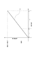
図10は保持時間と保持電荷量の関係を示すグラフである。 FIG. 10 is a graph showing the relationship between the retention time and the retained charge amount.
横軸に保持時間、縦軸に保持電荷量を示している。縦軸には第1電荷保持部M1の容量C1および第1電荷保持部M1および第3電荷保持部M3の容量C1とC3の容量値の和を示している。横軸には、保持期間tc1およびtc3を示している。また、時刻t1は期間tc1が終了する時刻、時刻t2は保持期間tc3が終了する時刻である。 The horizontal axis represents the retention time, and the vertical axis represents the retained charge amount. The vertical axis indicates the sum of the capacitance values of the capacitance C1 of the first charge holding unit M1 and the capacitances C1 and C3 of the first charge holding unit M1 and the third charge holding unit M3. On the horizontal axis, holding periods tc1 and tc3 are shown. Time t1 is the time when the period tc1 ends, and time t2 is the time when the holding period tc3 ends.
グラフ1101は、一定の光量下における保持期間tc1およびtc3における保持時間と保持電荷量の関係を示している。グラフ1101では、時刻t2において、第1電荷保持部M1および第3電荷保持部M3が飽和に達する。ここでは、時刻t1における保持電荷量は第1電荷保持部M1が飽和に達する量となっている。 A graph 1101 shows the relationship between the holding time and the holding charge amount in the holding periods tc1 and tc3 under a constant light amount. In the graph 1101, the first charge holding unit M1 and the third charge holding unit M3 reach saturation at time t2. Here, the retained charge amount at time t1 is an amount by which the first charge retaining unit M1 reaches saturation.
ただし、容量C1は式3で示される容量よりも大きくても構わない。なぜなら、C1がこれよりも大きい場合においても時刻t1において、第1電荷保持部M1が飽和に達することはないからである。よって、式4を満たせばよい。 However, the capacitance C1 may be larger than the capacitance indicated by Equation 3. This is because even when C1 is larger than this, the first charge holding unit M1 does not reach saturation at time t1. Therefore, it is sufficient to satisfy Expression 4.
ここで、第2電荷保持部M2と第3電荷保持部M3に電荷を保持する場合には、第2電荷保持部M2の容量をC2、蓄積期間をtc2(例えば実施例1の第4期間T4)とした時に、前述した第1電荷保持部M1と同様に考えられ、式5を満たせばよい。
Here, in the case where charges are held in the second charge holding unit M2 and the third charge holding unit M3, the capacitance of the second charge holding unit M2 is C2, and the accumulation period is tc2 (for example, the fourth period T4 in the first embodiment). ), It can be considered in the same manner as the first charge holding unit M1 described above, and it is sufficient to satisfy
以上のことから、式4を満たすように第1電荷保持部M1および第3電荷保持部M3の容量値を設定することにより、強い光量下においても、第1電荷保持部M1が飽和に達することなく第3電荷保持部M3への電荷保持を開始することができる。また、式4および式5を満たし、上述の実施例に記載した駆動を行うことで、途切れのない動画撮影が可能となる。
From the above, by setting the capacitance values of the first charge holding unit M1 and the third charge holding unit M3 so as to satisfy Expression 4, the first charge holding unit M1 reaches saturation even under a strong light amount. The charge retention to the third charge retention unit M3 can be started. In addition, by satisfying Expression 4 and
100 画素
101 光電変換部
M1 第1電荷保持部
M2 第2電荷保持部
M3 第3電荷保持部
111 増幅部
112 入力ノード
100
Claims (15)
前記光電変換部で生じた電荷を保持する電荷保持部と、
前記電荷保持部に保持された電荷に基づく信号を出力する増幅部と、
を有する画素を複数有する撮像装置であって、
前記電荷保持部は、第1電荷保持部、第2電荷保持部および第3電荷保持部を有し、
前記複数の画素のそれぞれにおいて、
第1時刻から第2時刻までの第1期間に前記光電変換部で生じた電荷を、前記第1期間に前記第1電荷保持部に転送し、且つ、前記第1期間よりも前の期間に前記第2電荷保持部および前記第3電荷保持部に保持された電荷を前記第1期間に前記増幅部の入力ノードへ転送し、
前記第2時刻から第3時刻までの第2期間に前記光電変換部で生じた電荷を前記第2期間に前記第1電荷保持部および前記第3電荷保持部に転送して保持することを特徴とする撮像装置。 A photoelectric conversion unit;
A charge holding unit for holding charges generated in the photoelectric conversion unit;
An amplification unit that outputs a signal based on the charge held in the charge holding unit;
An imaging device having a plurality of pixels having
The charge holding unit includes a first charge holding unit, a second charge holding unit, and a third charge holding unit,
In each of the plurality of pixels,
Charges generated in the photoelectric conversion unit in the first period from the first time to the second time are transferred to the first charge holding unit in the first period, and in a period before the first period. Transferring the charges held in the second charge holding unit and the third charge holding unit to the input node of the amplification unit in the first period;
The charge generated in the photoelectric conversion unit in the second period from the second time to the third time is transferred and held in the second period to the first charge holding unit and the third charge holding unit. An imaging device.
前記第3時刻から第4時刻までの第3期間に前記光電変換部で生じた電荷を前記第3期間に前記第2電荷保持部に転送して保持し、且つ、前記第1電荷保持部および前記第3電荷保持部において保持されている電荷を前記第3期間に前記増幅部の入力ノードへ転送し、
前記第4時刻から第5時刻までの第4期間に前記光電変換部で生じた電荷を前記第4期間に前記第2電荷保持部および前記第3電荷保持部に転送して保持することを特徴とする請求項1に記載の撮像装置。 In each of the plurality of pixels,
In the third period from the third time to the fourth time, the charge generated in the photoelectric conversion unit is transferred and held in the third period to the second charge holding unit, and the first charge holding unit and Transferring the charge held in the third charge holding unit to the input node of the amplification unit in the third period;
The charge generated in the photoelectric conversion unit in the fourth period from the fourth time to the fifth time is transferred and held in the fourth period to the second charge holding unit and the third charge holding unit. The imaging apparatus according to claim 1.
前記光電変換部で生じた電荷を前記第1電荷保持部に転送する第1の第1転送部と、
前記光電変換部で生じた電荷を前記第1電荷保持部に転送する第2の第1転送部と、
前記光電変換部で生じた電荷を前記第1電荷保持部に転送する第3の第1転送部と、を有することを特徴とする請求項2に記載の撮像装置。 The pixel is
A first first transfer unit that transfers charges generated in the photoelectric conversion unit to the first charge holding unit;
A second first transfer unit that transfers charges generated in the photoelectric conversion unit to the first charge holding unit;
The imaging apparatus according to claim 2, further comprising: a third first transfer unit that transfers charges generated in the photoelectric conversion unit to the first charge holding unit.
Priority Applications (2)
| Application Number | Priority Date | Filing Date | Title |
|---|---|---|---|
| JP2014216615A JP6452381B2 (en) | 2014-10-23 | 2014-10-23 | Imaging device |
| US14/887,003 US9560299B2 (en) | 2014-10-23 | 2015-10-19 | Image pickup apparatus |
Applications Claiming Priority (1)
| Application Number | Priority Date | Filing Date | Title |
|---|---|---|---|
| JP2014216615A JP6452381B2 (en) | 2014-10-23 | 2014-10-23 | Imaging device |
Publications (3)
| Publication Number | Publication Date |
|---|---|
| JP2016086242A JP2016086242A (en) | 2016-05-19 |
| JP2016086242A5 JP2016086242A5 (en) | 2017-11-30 |
| JP6452381B2 true JP6452381B2 (en) | 2019-01-16 |
Family
ID=55793006
Family Applications (1)
| Application Number | Title | Priority Date | Filing Date |
|---|---|---|---|
| JP2014216615A Expired - Fee Related JP6452381B2 (en) | 2014-10-23 | 2014-10-23 | Imaging device |
Country Status (2)
| Country | Link |
|---|---|
| US (1) | US9560299B2 (en) |
| JP (1) | JP6452381B2 (en) |
Families Citing this family (7)
| Publication number | Priority date | Publication date | Assignee | Title |
|---|---|---|---|---|
| JP2017183563A (en) * | 2016-03-31 | 2017-10-05 | ソニー株式会社 | Imaging apparatus, driving method, and electronic apparatus |
| JPWO2017203839A1 (en) * | 2016-05-24 | 2019-03-22 | ソニー株式会社 | Solid-state imaging device and imaging device |
| JP6776011B2 (en) * | 2016-06-10 | 2020-10-28 | キヤノン株式会社 | Imaging device and imaging system |
| JP6727938B2 (en) * | 2016-06-10 | 2020-07-22 | キヤノン株式会社 | IMAGING DEVICE, IMAGING DEVICE CONTROL METHOD, AND IMAGING SYSTEM |
| JP6746421B2 (en) * | 2016-07-29 | 2020-08-26 | キヤノン株式会社 | Imaging device |
| TW201817223A (en) * | 2016-10-20 | 2018-05-01 | 原相科技股份有限公司 | Global shutter high dynamic range pixel and global shutter high dynamic range image sensor |
| KR102493823B1 (en) * | 2018-03-08 | 2023-02-01 | 삼성전자주식회사 | Image sensor, image detecting system including the same, and operating method of the image sensor |
Family Cites Families (13)
| Publication number | Priority date | Publication date | Assignee | Title |
|---|---|---|---|---|
| CN101164334B (en) * | 2005-04-07 | 2010-12-15 | 国立大学法人东北大学 | Optical sensor, solid-state imaging device, and operation method of solid-state imaging device |
| JP2007329722A (en) * | 2006-06-08 | 2007-12-20 | Matsushita Electric Ind Co Ltd | Solid-state imaging element and digital camera |
| JP2008028678A (en) * | 2006-07-20 | 2008-02-07 | Pentax Corp | Imaging element |
| JP5167677B2 (en) * | 2007-04-12 | 2013-03-21 | ソニー株式会社 | Solid-state imaging device, driving method for solid-state imaging device, signal processing method for solid-state imaging device, and imaging device |
| EP2046022A1 (en) * | 2007-10-02 | 2009-04-08 | Melexis NV | Sensing element readout circuit and sensing array |
| US8625010B2 (en) | 2008-05-02 | 2014-01-07 | Canon Kabushiki Kaisha | Solid-state imaging apparatus with each pixel including a photoelectric converter portion and plural holding portions |
| US8860861B2 (en) * | 2008-08-11 | 2014-10-14 | Honda Motor Co., Ltd. | Pixel, pixel forming method, imaging device and imaging forming method |
| JP2010194291A (en) * | 2009-01-30 | 2010-09-09 | Fujifilm Corp | Endoscope device and method for driving the same |
| US8786745B2 (en) * | 2010-02-05 | 2014-07-22 | National University Corporation Shizuoka University | Solid-state image pickup device |
| JP5516960B2 (en) * | 2010-04-02 | 2014-06-11 | ソニー株式会社 | Solid-state imaging device, driving method of solid-state imaging device, and electronic apparatus |
| US9118883B2 (en) * | 2011-11-28 | 2015-08-25 | Semiconductor Components Industries, Llc | High dynamic range imaging with multi-storage pixels |
| US9007489B2 (en) * | 2012-02-28 | 2015-04-14 | Semiconductor Components Industries, Llc | Method and apparatus for image background removal and replacement |
| JP6141160B2 (en) * | 2013-09-25 | 2017-06-07 | ソニーセミコンダクタソリューションズ株式会社 | Solid-state imaging device and operation method thereof, electronic device and operation method thereof |
-
2014
- 2014-10-23 JP JP2014216615A patent/JP6452381B2/en not_active Expired - Fee Related
-
2015
- 2015-10-19 US US14/887,003 patent/US9560299B2/en not_active Expired - Fee Related
Also Published As
| Publication number | Publication date |
|---|---|
| JP2016086242A (en) | 2016-05-19 |
| US20160119566A1 (en) | 2016-04-28 |
| US9560299B2 (en) | 2017-01-31 |
Similar Documents
| Publication | Publication Date | Title |
|---|---|---|
| JP6452381B2 (en) | Imaging device | |
| JP6541523B2 (en) | Imaging device, imaging system, and control method of imaging device | |
| JP5115937B2 (en) | Solid-state imaging device and manufacturing method thereof | |
| JP5176215B2 (en) | Solid-state image sensor | |
| US20160360127A1 (en) | Global shutter high dynamic range sensor | |
| JP6448289B2 (en) | Imaging apparatus and imaging system | |
| US9723236B2 (en) | Photoelectric conversion apparatus and method for driving photoelectric conversion apparatus | |
| JP6299544B2 (en) | Solid-state imaging device | |
| JP7209340B2 (en) | Imaging device | |
| JP2009296574A (en) | Solid-state imaging device | |
| WO2017126232A1 (en) | Solid-state image pickup element and image pickup device | |
| JP2016111641A (en) | Solid-state imaging apparatus and driving method therefor | |
| JP6580069B2 (en) | Imaging device driving method, imaging device, and imaging system | |
| US9241119B2 (en) | Image pickup apparatus, method of driving image pickup apparatus, and image pickup system | |
| JP2021182770A (en) | Imaging element and imaging device | |
| JP6719958B2 (en) | Imaging device and method of driving imaging device | |
| JP2014239266A (en) | Solid state image pickup device and driving method of the same | |
| JP2016034101A (en) | Photoelectric conversion device and photoelectric conversion system | |
| JP6012195B2 (en) | Photoelectric conversion device and method for driving photoelectric conversion device | |
| JP2014096669A (en) | Driving method of photoelectric conversion device, photoelectric conversion device, photoelectric conversion system | |
| US8520109B2 (en) | Solid-state image pickup apparatus and image pickup system | |
| TWI613916B (en) | Pixel cell and imaging system | |
| JP6532265B2 (en) | Imaging device | |
| JP2016116214A (en) | Image pickup apparatus | |
| JP2017108275A (en) | Solid-state image pickup device, control method for solid-state image pickup device, and image pickup system |
Legal Events
| Date | Code | Title | Description |
|---|---|---|---|
| A521 | Request for written amendment filed |
Free format text: JAPANESE INTERMEDIATE CODE: A523 Effective date: 20171013 |
|
| A621 | Written request for application examination |
Free format text: JAPANESE INTERMEDIATE CODE: A621 Effective date: 20171013 |
|
| A977 | Report on retrieval |
Free format text: JAPANESE INTERMEDIATE CODE: A971007 Effective date: 20180803 |
|
| A131 | Notification of reasons for refusal |
Free format text: JAPANESE INTERMEDIATE CODE: A131 Effective date: 20180821 |
|
| A521 | Request for written amendment filed |
Free format text: JAPANESE INTERMEDIATE CODE: A523 Effective date: 20181018 |
|
| TRDD | Decision of grant or rejection written | ||
| A01 | Written decision to grant a patent or to grant a registration (utility model) |
Free format text: JAPANESE INTERMEDIATE CODE: A01 Effective date: 20181113 |
|
| A61 | First payment of annual fees (during grant procedure) |
Free format text: JAPANESE INTERMEDIATE CODE: A61 Effective date: 20181211 |
|
| R151 | Written notification of patent or utility model registration |
Ref document number: 6452381 Country of ref document: JP Free format text: JAPANESE INTERMEDIATE CODE: R151 |
|
| LAPS | Cancellation because of no payment of annual fees |