JP6447048B2 - motor - Google Patents

motor Download PDF

Info

Publication number
JP6447048B2
JP6447048B2 JP2014235760A JP2014235760A JP6447048B2 JP 6447048 B2 JP6447048 B2 JP 6447048B2 JP 2014235760 A JP2014235760 A JP 2014235760A JP 2014235760 A JP2014235760 A JP 2014235760A JP 6447048 B2 JP6447048 B2 JP 6447048B2
Authority
JP
Japan
Prior art keywords
control board
output side
power
power board
motor
Prior art date
Legal status (The legal status is an assumption and is not a legal conclusion. Google has not performed a legal analysis and makes no representation as to the accuracy of the status listed.)
Active
Application number
JP2014235760A
Other languages
Japanese (ja)
Other versions
JP2016100972A (en
Inventor
佳明 山下
佳明 山下
Current Assignee (The listed assignees may be inaccurate. Google has not performed a legal analysis and makes no representation or warranty as to the accuracy of the list.)
Nidec America Corp
Original Assignee
Nidec Corp
Priority date (The priority date is an assumption and is not a legal conclusion. Google has not performed a legal analysis and makes no representation as to the accuracy of the date listed.)
Filing date
Publication date
Application filed by Nidec Corp filed Critical Nidec Corp
Priority to JP2014235760A priority Critical patent/JP6447048B2/en
Priority to CN201580063311.5A priority patent/CN107005131B/en
Priority to US15/528,169 priority patent/US10263499B2/en
Priority to EP15861903.1A priority patent/EP3223408B1/en
Priority to PCT/JP2015/079385 priority patent/WO2016080127A1/en
Publication of JP2016100972A publication Critical patent/JP2016100972A/en
Application granted granted Critical
Publication of JP6447048B2 publication Critical patent/JP6447048B2/en
Active legal-status Critical Current
Anticipated expiration legal-status Critical

Links

Images

Classifications

    • HELECTRICITY
    • H02GENERATION; CONVERSION OR DISTRIBUTION OF ELECTRIC POWER
    • H02KDYNAMO-ELECTRIC MACHINES
    • H02K11/00Structural association of dynamo-electric machines with electric components or with devices for shielding, monitoring or protection
    • H02K11/30Structural association with control circuits or drive circuits
    • HELECTRICITY
    • H02GENERATION; CONVERSION OR DISTRIBUTION OF ELECTRIC POWER
    • H02KDYNAMO-ELECTRIC MACHINES
    • H02K11/00Structural association of dynamo-electric machines with electric components or with devices for shielding, monitoring or protection
    • H02K11/20Structural association of dynamo-electric machines with electric components or with devices for shielding, monitoring or protection for measuring, monitoring, testing, protecting or switching
    • H02K11/21Devices for sensing speed or position, or actuated thereby
    • H02K11/215Magnetic effect devices, e.g. Hall-effect or magneto-resistive elements
    • HELECTRICITY
    • H02GENERATION; CONVERSION OR DISTRIBUTION OF ELECTRIC POWER
    • H02KDYNAMO-ELECTRIC MACHINES
    • H02K11/00Structural association of dynamo-electric machines with electric components or with devices for shielding, monitoring or protection
    • H02K11/30Structural association with control circuits or drive circuits
    • H02K11/33Drive circuits, e.g. power electronics
    • HELECTRICITY
    • H02GENERATION; CONVERSION OR DISTRIBUTION OF ELECTRIC POWER
    • H02KDYNAMO-ELECTRIC MACHINES
    • H02K5/00Casings; Enclosures; Supports
    • H02K5/04Casings or enclosures characterised by the shape, form or construction thereof
    • H02K5/22Auxiliary parts of casings not covered by groups H02K5/06-H02K5/20, e.g. shaped to form connection boxes or terminal boxes
    • HELECTRICITY
    • H02GENERATION; CONVERSION OR DISTRIBUTION OF ELECTRIC POWER
    • H02KDYNAMO-ELECTRIC MACHINES
    • H02K5/00Casings; Enclosures; Supports
    • H02K5/24Casings; Enclosures; Supports specially adapted for suppression or reduction of noise or vibrations

Description

本発明は、モータに関する。   The present invention relates to a motor.

例えば、特許文献1には、電動機のシャフトの一方にコントローラを設けた電動装置が記載されている。コントローラは、制御基板とパワーモジュールとを有する。   For example, Patent Document 1 describes an electric device in which a controller is provided on one of the shafts of an electric motor. The controller has a control board and a power module.

特開2011−229228号公報JP2011-229228A

上記のような電動装置(モータ)を小型化する場合、例えば、制御基板とパワーモジュール(パワー基板)とを軸方向に近づけてコントローラの軸方向の寸法を小さくし、電動装置全体を軸方向に小型化することが考えられる。   When downsizing the electric device (motor) as described above, for example, the control board and the power module (power board) are moved closer to the axial direction to reduce the axial dimension of the controller, and the entire electric apparatus is moved in the axial direction. It is conceivable to reduce the size.

しかし、制御基板とパワーモジュールとを近づけると、パワーモジュールから発生するノイズが、制御基板に実装された位置センサ(回転センサ)に影響を与えやすい。そのため、位置センサの検出精度が低下する問題があった。   However, when the control board and the power module are brought close to each other, noise generated from the power module tends to affect the position sensor (rotation sensor) mounted on the control board. Therefore, there has been a problem that the detection accuracy of the position sensor is lowered.

本発明の一つの態様は、上記問題点に鑑みて、軸方向に小型化した場合に回転センサの検出精度が低下することを抑制できる構造を有するモータを提供することを目的の一つとする。   In view of the above problems, an aspect of the present invention has an object to provide a motor having a structure that can suppress a decrease in detection accuracy of a rotation sensor when the size is reduced in the axial direction.

本発明のモータの一つの態様は、軸方向に延びる中心軸を中心としたシャフトを有するロータと、前記ロータを囲むステータと、を有するモータ本体と、スイッチング素子を有し、前記モータ本体と電気的に接続されるパワー基板と、前記パワー基板と電気的に接続され、前記モータ本体の前記軸方向の反出力側に配置される制御基板と、前記モータ本体に取り付けられ、前記制御基板を保持する制御基板保持ユニットと、前記ステータよりも前記反出力側に位置し、前記シャフトに固定されるセンサマグネットと、前記制御基板に取り付けられ、前記センサマグネットと対向する回転センサと、前記モータ本体に直接的または間接的に取り付けられ、前記パワー基板を保持するパワー基板ケースと、を備え、前記パワー基板は、前記モータ本体よりも径方向外側に位置し、前記パワー基板の基板面は、前記制御基板の基板面に対して傾き、前記パワー基板の少なくとも一部は、前記制御基板保持ユニットと前記径方向において重なる。 One aspect of the motor of the present invention includes a rotor having a shaft centered on a central axis extending in the axial direction, a motor body having a stator surrounding the rotor, a switching element, and the motor body and the electric motor. Connected to the motor body, a control board electrically connected to the power board and disposed on the opposite side of the motor body in the axial direction, and attached to the motor body to hold the control board A control board holding unit, a sensor magnet positioned on the opposite side of the stator from the stator, fixed to the shaft, a rotation sensor attached to the control board and facing the sensor magnet, and the motor body A power board case that is directly or indirectly attached and holds the power board, wherein the power board is the motor. Positioned radially outward from the body, the substrate surface of the power substrate is inclined-out with respect to the substrate surface of the control board, at least a portion of the power substrate overlaps in the radial direction and the control board holding unit .

本発明の一つの態様によれば、軸方向に小型化した場合に回転センサの検出精度が低下することを抑制できる構造を有するモータが提供される。   According to one aspect of the present invention, there is provided a motor having a structure capable of suppressing a decrease in detection accuracy of a rotation sensor when the size is reduced in the axial direction.

図1は、第1実施形態のモータを示す斜視図である。FIG. 1 is a perspective view showing the motor of the first embodiment. 図2は、第1実施形態のモータを示す斜視図である。FIG. 2 is a perspective view showing the motor of the first embodiment. 図3は、第1実施形態のモータを示す斜視図である。FIG. 3 is a perspective view showing the motor of the first embodiment. 図4は、第1実施形態のモータを示す断面図である。FIG. 4 is a cross-sectional view showing the motor of the first embodiment. 図5は、第2実施形態のモータを示す断面図である。FIG. 5 is a cross-sectional view showing the motor of the second embodiment.

以下、図面を参照しながら、本発明の実施形態に係るモータについて説明する。なお、本発明の範囲は、以下の実施の形態に限定されず、本発明の技術的思想の範囲内で任意に変更可能である。また、以下の図面においては、各構成をわかりやすくするために、実際の構造と各構造における縮尺や数等を異ならせる場合がある。   Hereinafter, a motor according to an embodiment of the present invention will be described with reference to the drawings. The scope of the present invention is not limited to the following embodiments, and can be arbitrarily changed within the scope of the technical idea of the present invention. Moreover, in the following drawings, in order to make each structure easy to understand, the actual structure may be different from the scale, number, or the like in each structure.

また、図面においては、適宜3次元直交座標系としてXYZ座標系を示す。XYZ座標系において、Z軸方向は、図4に示す中心軸Jの軸方向と平行な方向とする。X軸方向は、図4に示す制御基板保持ケース33の長さ方向と平行な方向、すなわち、図4の左右方向とする。Y軸方向は、制御基板保持ケース33の幅方向と平行な方向、すなわち、X軸方向とZ軸方向との両方と直交する方向とする。   In the drawings, an XYZ coordinate system is appropriately shown as a three-dimensional orthogonal coordinate system. In the XYZ coordinate system, the Z-axis direction is a direction parallel to the axial direction of the central axis J shown in FIG. The X-axis direction is a direction parallel to the length direction of the control board holding case 33 shown in FIG. 4, that is, the left-right direction in FIG. The Y-axis direction is a direction parallel to the width direction of the control board holding case 33, that is, a direction orthogonal to both the X-axis direction and the Z-axis direction.

また、以下の説明においては、軸方向(Z軸方向)におけるモータ10の動力が伝達される側、すなわち、Z軸方向の負の側(−Z側)を「出力側」と呼ぶ。軸方向におけるモータ10の出力が取り出される側と反対側、すなわち、Z軸方向の正の側(+Z側)を「反出力側」と呼ぶ。なお、モータ10の出力が取り出される側とは、モータ10におけるシャフト22がモータ10の外部に露出している側である。   In the following description, the side on which the power of the motor 10 is transmitted in the axial direction (Z-axis direction), that is, the negative side (−Z side) in the Z-axis direction is referred to as “output side”. The side opposite to the side from which the output of the motor 10 is extracted in the axial direction, that is, the positive side (+ Z side) in the Z-axis direction is referred to as the “non-output side”. The side from which the output of the motor 10 is extracted is the side where the shaft 22 of the motor 10 is exposed to the outside of the motor 10.

また、特に断りのない限り、中心軸Jに平行な方向(Z軸方向)を単に「軸方向」と呼び、中心軸Jを中心とする径方向を単に「径方向」と呼び、中心軸Jを中心とする周方向、すなわち、中心軸Jの軸周り(θ方向)を単に「周方向」と呼ぶ。 Unless otherwise specified, a direction parallel to the central axis J (Z-axis direction) is simply referred to as an “axial direction”, and a radial direction around the central axis J is simply referred to as a “radial direction”. circumferential direction around the, i.e., about the axis of the central axis J of (theta Z direction) simply referred to as "circumferential direction".

<第1実施形態>
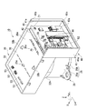
図1から図3は、本実施形態のモータ10を示す斜視図である。図4は、本実施形態のモータ10を示す断面図である。図2および図3においては、カバー32の図示を省略している。図3においては、制御基板36およびパワー基板43の図示を省略している。
<First Embodiment>
1 to 3 are perspective views showing a motor 10 of this embodiment. FIG. 4 is a cross-sectional view showing the motor 10 of the present embodiment. 2 and 3, the cover 32 is not shown. In FIG. 3, illustration of the control board 36 and the power board 43 is omitted.

本実施形態のモータ10は、ブラシレスモータである。本実施形態のモータ10は、図1から図4に示すように、モータ本体20と、制御基板36と、センサマグネット60と、回転センサ61と、電子部品62と、パワー基板43と、制御基板保持ユニット30と、パワー基板ケース40と、を備える。   The motor 10 of this embodiment is a brushless motor. As shown in FIGS. 1 to 4, the motor 10 of the present embodiment includes a motor body 20, a control board 36, a sensor magnet 60, a rotation sensor 61, an electronic component 62, a power board 43, and a control board. A holding unit 30 and a power board case 40 are provided.

図4に示すように、制御基板36はモータ本体20の反出力側(+Z側)に配置されている。センサマグネット60は、モータ本体20のシャフト22に固定されている。回転センサ61と電子部品62とは、制御基板36に取り付けられている。パワー基板43は、モータ本体20よりも径方向外側に位置している。制御基板保持ユニット30は、モータ本体20に取り付けられ、制御基板36を保持している。パワー基板ケース40は、モータ本体20に取り付けられ、パワー基板43を保持している。以下、各部品について詳細に説明する。   As shown in FIG. 4, the control board 36 is disposed on the non-output side (+ Z side) of the motor body 20. The sensor magnet 60 is fixed to the shaft 22 of the motor body 20. The rotation sensor 61 and the electronic component 62 are attached to the control board 36. The power board 43 is located on the radially outer side than the motor body 20. The control board holding unit 30 is attached to the motor body 20 and holds the control board 36. The power board case 40 is attached to the motor body 20 and holds the power board 43. Hereinafter, each component will be described in detail.

(モータ本体)
モータ本体20は、シャフト22を有するロータ21と、出力側ベアリング27aと、反出力側ベアリング(ベアリング)27bと、ステータ24と、ハウジング25と、を有する。
(Motor body)
The motor body 20 includes a rotor 21 having a shaft 22, an output side bearing 27 a, a counter output side bearing (bearing) 27 b, a stator 24, and a housing 25.

[ロータ]
ロータ21は、シャフト22と、ロータコア23aと、ロータマグネット23bと、を有する。シャフト22は、軸方向(Z軸方向)に延びる中心軸Jを中心とする。シャフト22は、出力側ベアリング27aと反出力側ベアリング27bとによって、軸周り(±θ方向)に回転可能に支持されている。シャフト22の出力側(−Z側)の端部は、後述するハウジング25における出力側蓋部25bに設けられた出力軸孔26aを介して、モータ10の外部に露出している。
[Rotor]
The rotor 21 includes a shaft 22, a rotor core 23a, and a rotor magnet 23b. The shaft 22 is centered on a central axis J extending in the axial direction (Z-axis direction). Shaft 22, by the output-side bearing 27a and the anti-output side bearing 27b, and is rotatably supported about the axis (± theta Z direction). An output side (−Z side) end portion of the shaft 22 is exposed to the outside of the motor 10 through an output shaft hole 26 a provided in an output side lid portion 25 b of the housing 25 described later.

ロータコア23aは、シャフト22を軸周り(θ方向)に囲んで、シャフト22に固定されている。ロータマグネット23bは、ロータコア23aの軸周りに沿った外側面に固定されている。ロータコア23aおよびロータマグネット23bは、シャフト22と一体となって回転する。 The rotor core 23a is, surrounds the shaft 22 about the axis (theta Z direction), and is fixed to the shaft 22. The rotor magnet 23b is fixed to the outer surface along the axis of the rotor core 23a. The rotor core 23a and the rotor magnet 23b rotate integrally with the shaft 22.

[ステータ]
ステータ24は、ロータ21を軸周り(θ方向)に囲み、ロータ21を中心軸J周りに回転させる。ステータ24は、コアバック部24aと、ティース部24bと、コイル24cと、インシュレータ24dと、を有する。
[Stator]
The stator 24 surrounds the rotor 21 about the axis (theta Z direction), rotated about axis J about the rotor 21. The stator 24 includes a core back portion 24a, a teeth portion 24b, a coil 24c, and an insulator 24d.

コアバック部24aの形状は、シャフト22と同心の円筒状である。ティース部24bは、コアバック部24aの内側面からシャフト22に向かって延びている。ティース部24bは、複数設けられ、コアバック部24aの内側面の周方向に均等な間隔で配置されている。   The shape of the core back portion 24 a is a cylindrical shape concentric with the shaft 22. The teeth portion 24b extends from the inner side surface of the core back portion 24a toward the shaft 22. A plurality of teeth portions 24b are provided, and are arranged at equal intervals in the circumferential direction of the inner surface of the core back portion 24a.

コイル24cは、導電線が巻き回されて構成される。コイル24cは、インシュレータ24dを介して、各ティース部24bに設けられている。インシュレータ24dは、ティース部24bに装着されている。   The coil 24c is configured by winding a conductive wire. The coil 24c is provided in each teeth part 24b via the insulator 24d. The insulator 24d is attached to the tooth portion 24b.

[ハウジング]
ハウジング25は、ステータ24と出力側ベアリング27aとを保持する。ハウジング25の材質は、例えば、金属である。ハウジング25は、筒部25aと、出力側蓋部25bと、を有する。
[housing]
The housing 25 holds the stator 24 and the output side bearing 27a. The material of the housing 25 is metal, for example. The housing 25 includes a cylinder portion 25a and an output side lid portion 25b.

筒部25aは、ステータ24を保持する筒状の部材である。本実施形態において筒部25aは、両端が開口した円筒形状である。筒部25aの内側面には、ステータ24の外側面、すなわち、コアバック部24aの外側面が嵌合されている。これにより、ハウジング25には、ステータ24が保持される。   The cylindrical portion 25 a is a cylindrical member that holds the stator 24. In the present embodiment, the cylindrical portion 25a has a cylindrical shape with both ends opened. The outer surface of the stator 24, that is, the outer surface of the core back portion 24a is fitted to the inner surface of the cylindrical portion 25a. Thereby, the stator 24 is held in the housing 25.

出力側蓋部25bは、筒部25aの出力側(−Z側)の端部に固定されている。筒部25aと出力側蓋部25bとは、図1から図3に示すように、フランジ部を介して互いに固定されている。図4に示すように、出力側蓋部25bは、ステータ24の出力側を覆っている。   The output side cover portion 25b is fixed to an end portion on the output side (−Z side) of the cylindrical portion 25a. The cylinder part 25a and the output side cover part 25b are mutually fixed via the flange part, as shown in FIGS. 1-3. As shown in FIG. 4, the output side cover portion 25 b covers the output side of the stator 24.

出力側蓋部25bには、出力側ベアリング保持部26が設けられている。出力側ベアリング保持部26は、径方向内側に出力側ベアリング27aを保持する。出力側ベアリング保持部26には、中心軸Jと同心の出力軸孔26aが設けられている。シャフト22の一部は、出力軸孔26aに挿入されている。上述したように、シャフト22の出力側(−Z側)の端部は、出力軸孔26aを介して、モータ10の外部に露出している。   An output side bearing holding portion 26 is provided in the output side lid portion 25b. The output side bearing holding part 26 holds the output side bearing 27a radially inside. The output side bearing holding portion 26 is provided with an output shaft hole 26a concentric with the central axis J. A part of the shaft 22 is inserted into the output shaft hole 26a. As described above, the output side (−Z side) end of the shaft 22 is exposed to the outside of the motor 10 through the output shaft hole 26a.

[出力側ベアリングおよび反出力側ベアリング]
出力側ベアリング27aは、ステータ24の出力側(−Z側)に配置されている。出力側ベアリング27aは、ハウジング25における出力側蓋部25bの出力側ベアリング保持部26に保持されている。
[Output-side bearing and anti-output-side bearing]
The output side bearing 27 a is disposed on the output side (−Z side) of the stator 24. The output side bearing 27 a is held by the output side bearing holding portion 26 of the output side lid portion 25 b in the housing 25.

反出力側ベアリング27bは、ステータ24の出力側(−Z側)と反対の反出力側(+Z側)に配置されている。反出力側ベアリング27bは、後述する制御基板保持ユニット30の反出力側ベアリング保持部(ベアリング保持部)34に保持されている。   The non-output side bearing 27 b is disposed on the counter output side (+ Z side) opposite to the output side (−Z side) of the stator 24. The non-output-side bearing 27b is held by a non-output-side bearing holding portion (bearing holding portion) 34 of the control board holding unit 30 described later.

出力側ベアリング27aと反出力側ベアリング27bとは、ロータ21のシャフト22を支持している。出力側ベアリング27aおよび反出力側ベアリング27bの構成は、特に限定されず、いかなる公知のベアリングを用いてもよい。   The output side bearing 27 a and the counter output side bearing 27 b support the shaft 22 of the rotor 21. The configurations of the output side bearing 27a and the non-output side bearing 27b are not particularly limited, and any known bearing may be used.

(制御基板)
制御基板36は、モータ本体20の反出力側(+Z側)に配置されている。制御基板36は、制御基板保持ユニット30に保持されている。制御基板36の基板面は、例えば、軸方向(Z軸方向)と直交している。制御基板36の基板面とは、反出力側の制御基板反出力側面36aおよび出力側(−Z側)の制御基板出力側面36bである。
(Control board)
The control board 36 is disposed on the non-output side (+ Z side) of the motor body 20. The control board 36 is held by the control board holding unit 30. The board surface of the control board 36 is orthogonal to the axial direction (Z-axis direction), for example. The board surface of the control board 36 is a control board non-output side face 36a on the non-output side and a control board output side face 36b on the output side (−Z side).

制御基板36の制御基板出力側面36bには、制御基板36とパワー基板43とを接続する配線部材52が固定されている。配線部材52は、制御基板出力側面36bのパワー基板43側(−X側)の端部から、パワー基板43側(−X側)に延びている。図2に示すように、配線部材52は、パワー基板43に設けられた貫通孔に差し込まれている。これにより、制御基板36はパワー基板43と電気的に接続される。制御基板36の制御基板反出力側面36aおよび制御基板出力側面36bのうちの少なくとも一方には、図示しないプリント配線が設けられている。   A wiring member 52 that connects the control board 36 and the power board 43 is fixed to the control board output side surface 36 b of the control board 36. The wiring member 52 extends from the end on the power board 43 side (−X side) of the control board output side surface 36 b to the power board 43 side (−X side). As shown in FIG. 2, the wiring member 52 is inserted into a through hole provided in the power board 43. As a result, the control board 36 is electrically connected to the power board 43. A printed wiring (not shown) is provided on at least one of the control board non-output side surface 36a and the control board output side surface 36b of the control board 36.

(センサマグネット)
センサマグネット60は、図3に示すように、例えば、円環状である。センサマグネット60は、周方向に沿ってN極とS極とが交互に配置されている。センサマグネット60は、図4に示すように、ステータ24よりも反出力側(+Z側)に位置する。センサマグネット60は、反出力側ベアリング27bよりも反出力側に位置する。
(Sensor magnet)
As shown in FIG. 3, the sensor magnet 60 has, for example, an annular shape. The sensor magnet 60 has N poles and S poles arranged alternately along the circumferential direction. As shown in FIG. 4, the sensor magnet 60 is located on the counter-output side (+ Z side) from the stator 24. The sensor magnet 60 is located on the counter-output side with respect to the counter-output side bearing 27b.

センサマグネット60は、シャフト22に固定されている。より詳細には、本実施形態においてセンサマグネット60は、シャフト22の反出力側(+Z側)の端部に固定された支持部材60aに径方向外側から嵌め合わされている。支持部材60aは、軸方向(Z軸方向)に延びるシャフト22と同心の部材である。本実施形態においてセンサマグネット60は、シャフト22の反出力側(+Z側)に位置する。   The sensor magnet 60 is fixed to the shaft 22. More specifically, in the present embodiment, the sensor magnet 60 is fitted from the radially outer side to a support member 60a fixed to the opposite end (+ Z side) of the shaft 22. The support member 60a is a member concentric with the shaft 22 extending in the axial direction (Z-axis direction). In the present embodiment, the sensor magnet 60 is positioned on the opposite output side (+ Z side) of the shaft 22.

(回転センサ)
回転センサ61は、制御基板36の制御基板出力側面36bに取り付けられている。回転センサ61は、例えば、磁気抵抗素子である。回転センサ61は、センサマグネット60と軸方向(Z軸方向)に対向している。
(Rotation sensor)
The rotation sensor 61 is attached to the control board output side surface 36 b of the control board 36. The rotation sensor 61 is, for example, a magnetoresistive element. The rotation sensor 61 is opposed to the sensor magnet 60 in the axial direction (Z-axis direction).

(電子部品)
電子部品62は、制御基板36の制御基板出力側面36bに取り付けられている。電子部品62は、制御基板出力側面36bから出力側(−Z側)に延びている。電子部品62は、制御基板36に取り付けられる素子のうち、比較的、軸方向(Z軸方向)の寸法が大きい素子である。本実施形態において電子部品62は、複数設けられている。電子部品62の少なくとも一部は、センサマグネット60の径方向外側に位置している。
(Electronic parts)
The electronic component 62 is attached to the control board output side surface 36 b of the control board 36. The electronic component 62 extends from the control board output side surface 36b to the output side (−Z side). The electronic component 62 is an element having a relatively large dimension in the axial direction (Z-axis direction) among elements attached to the control board 36. In the present embodiment, a plurality of electronic components 62 are provided. At least a part of the electronic component 62 is located on the radially outer side of the sensor magnet 60.

電子部品62の出力側(−Z側)の端部は、回転センサ61よりも出力側に位置する。本実施形態において、電子部品62の全体は、後述する制御基板保持ケース33の内側に設けられた電子部品収容空間AR内に収容されている。電子部品62は、例えば、電解コンデンサ、チョークコイル等である。   The end of the electronic component 62 on the output side (−Z side) is located on the output side of the rotation sensor 61. In the present embodiment, the entire electronic component 62 is accommodated in an electronic component accommodating space AR provided inside a control board holding case 33 described later. The electronic component 62 is, for example, an electrolytic capacitor or a choke coil.

(パワー基板)
パワー基板43は、モータ本体20よりも径方向外側に位置している。パワー基板43は、パワー基板ケース40に保持されている。パワー基板43の基板面は、制御基板36の基板面、すなわち、制御基板反出力側面36aおよび制御基板出力側面36bに対して傾いている。パワー基板43の基板面とは、パワー基板43の径方向外側のパワー基板外側面43aおよびパワー基板43の径方向内側のパワー基板内側面43bである。本実施形態においてパワー基板43の基板面は、例えば、制御基板36の基板面と直交している。すなわち、パワー基板43の基板面は、径方向と直交する。
(Power board)
The power board 43 is located on the radially outer side than the motor body 20. The power board 43 is held by the power board case 40. The board surface of the power board 43 is inclined with respect to the board surface of the control board 36, that is, the control board opposite output side surface 36a and the control board output side surface 36b. The board surface of the power board 43 is a power board outer side face 43 a radially outside the power board 43 and a power board inner side face 43 b radially inside the power board 43. In the present embodiment, the substrate surface of the power substrate 43 is orthogonal to the substrate surface of the control substrate 36, for example. That is, the substrate surface of the power substrate 43 is orthogonal to the radial direction.

なお、本明細書において、パワー基板がモータ本体よりも径方向外側に位置する、とは、パワー基板の径方向の位置が、モータ本体の径方向の位置、すなわち、本実施形態ではハウジング25の外側面の径方向位置、よりも外側であればよい。すなわち、本明細書において、パワー基板がモータ本体よりも径方向外側に位置する、とは、パワー基板がモータ本体と径方向において重なっていない構成も含む。   In this specification, the power board is located radially outside the motor body. The radial position of the power board is the radial position of the motor body, that is, the housing 25 in this embodiment. What is necessary is just to be outside the radial direction position of the outer surface. That is, in the present specification, the power board is positioned radially outside the motor body includes a configuration in which the power board does not overlap the motor body in the radial direction.

本実施形態においてパワー基板43の全体は、制御基板保持ユニット30と径方向において重なっている。本実施形態においてパワー基板43の一部は、後述する制御基板保持ユニット30の制御基板保持ケース33と径方向において重なっている。本実施形態においてパワー基板43の他の部分は、モータ本体20と径方向において重なっている。すなわち、本実施形態においてパワー基板43は、制御基板保持ケース33の径方向外側とモータ本体20の径方向外側とに亘って設けられている。   In the present embodiment, the entire power board 43 overlaps the control board holding unit 30 in the radial direction. In the present embodiment, a part of the power board 43 overlaps with a control board holding case 33 of the control board holding unit 30 described later in the radial direction. In the present embodiment, the other part of the power board 43 overlaps the motor body 20 in the radial direction. That is, in the present embodiment, the power board 43 is provided across the radial outside of the control board holding case 33 and the radial outside of the motor body 20.

パワー基板43における反出力側(+Z側)の端部は、制御基板36よりも反出力側に位置している。パワー基板43における出力側(−Z側)の端部は、制御基板36よりも出力側に位置している。パワー基板43の一部は、制御基板36と径方向において重なっている。   The end of the power board 43 on the counter-output side (+ Z side) is located on the counter-output side of the control board 36. The end of the power board 43 on the output side (−Z side) is located on the output side of the control board 36. A part of the power board 43 overlaps the control board 36 in the radial direction.

パワー基板43は、図2に示すように、スイッチング素子44を有する。スイッチング素子44は、パワー基板43のパワー基板外側面43aに取り付けられている。スイッチング素子44は、例えば、パワートランジスタである。本実施形態においてスイッチング素子44は、複数設けられている。複数のスイッチング素子44は、インバータ回路を構成している。   As shown in FIG. 2, the power board 43 includes a switching element 44. The switching element 44 is attached to the power board outer surface 43 a of the power board 43. The switching element 44 is, for example, a power transistor. In the present embodiment, a plurality of switching elements 44 are provided. The plurality of switching elements 44 constitute an inverter circuit.

パワー基板43には、後述するバスバー50が接続されている。パワー基板43は、バスバー50を介して、モータ本体20と電気的に接続される。   A bus bar 50 described later is connected to the power board 43. The power board 43 is electrically connected to the motor body 20 via the bus bar 50.

(制御基板保持ユニット)
制御基板保持ユニット30は、図4に示すように、内部に制御基板36を収容している。制御基板保持ユニット30は、制御基板保持ケース33と、カバー32と、反出力側ベアリング保持部(ベアリング保持部)34と、バスバー50と、コネクタ部37と、を有する。すなわち、モータ10は、バスバー50を備える。本実施形態においては、例えば、制御基板保持ケース33と、反出力側ベアリング保持部34と、コネクタ部37と、は単一の部材である。制御基板保持ケース33と、反出力側ベアリング保持部34と、コネクタ部37と、を含む単一の部材は、例えば、射出成形によって製造される。
(Control board holding unit)
As shown in FIG. 4, the control board holding unit 30 houses a control board 36 therein. The control board holding unit 30 includes a control board holding case 33, a cover 32, a non-output side bearing holding part (bearing holding part) 34, a bus bar 50, and a connector part 37. That is, the motor 10 includes a bus bar 50. In the present embodiment, for example, the control board holding case 33, the non-output side bearing holding portion 34, and the connector portion 37 are a single member. A single member including the control board holding case 33, the non-output side bearing holding portion 34, and the connector portion 37 is manufactured by, for example, injection molding.

[制御基板保持ケース]
制御基板保持ケース33は、制御基板36を保持する。制御基板保持ケース33は、図3に示すように、例えば、反出力側(+Z側)に開口する箱型である。制御基板保持ケース33の内側には、電子部品62を収容する電子部品収容空間(電子部品収容部)ARが設けられている。すなわち、制御基板保持ユニット30は、電子部品収容空間ARを有する。
[Control board holding case]
The control board holding case 33 holds the control board 36. As shown in FIG. 3, the control board holding case 33 is, for example, a box shape that opens to the non-output side (+ Z side). Inside the control board holding case 33, an electronic component storage space (electronic component storage portion) AR for storing the electronic component 62 is provided. That is, the control board holding unit 30 has an electronic component housing space AR.

本実施形態において、電子部品収容空間ARには、シャフト22の反出力側(+Z側)の端部が突出している。電子部品収容空間ARには、センサマグネット60が収容されている。すなわち、電子部品収容空間ARの一部は、センサマグネット60と径方向において重なっている。   In the present embodiment, the end of the shaft 22 on the counter-output side (+ Z side) protrudes from the electronic component housing space AR. A sensor magnet 60 is housed in the electronic component housing space AR. That is, a part of the electronic component housing space AR overlaps the sensor magnet 60 in the radial direction.

制御基板保持ケース33の平面視(XY面視)形状は、例えば、長方形状である。制御基板保持ケース33は、例えば、樹脂製である。制御基板保持ケース33は、底部33aと、側壁部33bと、を有する。   The plan view (XY view) shape of the control board holding case 33 is, for example, a rectangular shape. The control board holding case 33 is made of resin, for example. The control board holding case 33 has a bottom 33a and a side wall 33b.

底部33aは、図4に示すように、ハウジング25の反出力側(+Z側)の端部に取り付けられている。すなわち、底部33aは、モータ本体20の反出力側に取り付けられている。図示は省略するが、底部33aは、例えば、ハウジング25の出力側(+Z側)に設けられたフランジ部とネジ止めされている。これにより、底部33aは、ハウジング25に固定される。底部33aがハウジング25と固定されることで、制御基板保持ケース33、すなわち、制御基板保持ユニット30が、モータ本体20と固定される。   As shown in FIG. 4, the bottom 33 a is attached to the opposite end (+ Z side) of the housing 25. That is, the bottom 33 a is attached to the opposite side of the motor body 20. Although illustration is omitted, the bottom 33a is screwed to, for example, a flange provided on the output side (+ Z side) of the housing 25. Thereby, the bottom 33a is fixed to the housing 25. By fixing the bottom 33 a to the housing 25, the control board holding case 33, that is, the control board holding unit 30 is fixed to the motor body 20.

底部33aの出力側(−Z側)の面には、出力側に突出する内側突出部33gおよび外側突出部33hが設けられている。内側突出部33gは、周方向に沿って延びている。図示は省略するが、内側突出部33gは、例えば、複数設けられている。複数の内側突出部33gは、周方向に沿って、等間隔に並んでいる。内側突出部33gは、ハウジング25の内側に嵌め合わされている。   An inner projecting portion 33g and an outer projecting portion 33h projecting to the output side are provided on the output side (−Z side) surface of the bottom 33a. The inner protrusion 33g extends along the circumferential direction. Although illustration is omitted, for example, a plurality of inner projecting portions 33g are provided. The plurality of inner protruding portions 33g are arranged at equal intervals along the circumferential direction. The inner protruding portion 33g is fitted inside the housing 25.

外側突出部33hは、内側突出部33gの径方向外側に位置している。外側突出部33hは、周方向に延びている。図示は省略するが、内側突出部33gと同様に、外側突出部33hは、例えば、複数設けられている。複数の外側突出部33hは、周方向に沿って、等間隔に並んでいる。外側突出部33hの径方向内側には、ハウジング25が嵌め合わされている。   The outer protrusion 33h is located on the radially outer side of the inner protrusion 33g. The outer protrusion 33h extends in the circumferential direction. Although illustration is omitted, for example, a plurality of outer protrusions 33h are provided in the same manner as the inner protrusion 33g. The plurality of outer protrusions 33h are arranged at equal intervals along the circumferential direction. The housing 25 is fitted on the radially inner side of the outer protrusion 33h.

すなわち、内側突出部33gと外側突出部33hとの径方向の間には、ハウジング25の反出力側(+Z側)の端部が嵌め込まれている。これにより、ハウジング25が径方向に位置決めされる。   That is, the opposite end (+ Z side) end of the housing 25 is fitted between the radial direction of the inner protrusion 33g and the outer protrusion 33h. Thereby, the housing 25 is positioned in the radial direction.

底部33aの反出力側(+Z側)の面には、反出力側に突出する制御基板支持部35aおよび制御基板固定部35bが設けられている。制御基板支持部35aと制御基板固定部35bとは、それぞれ2つずつ設けられている。   A control board support part 35a and a control board fixing part 35b projecting to the non-output side are provided on the surface on the non-output side (+ Z side) of the bottom 33a. Two control board support portions 35a and two control board fixing portions 35b are provided.

制御基板支持部35aは、反出力側(+Z側)の端部の直径が小さくなる段付きの形状である。図4に示すように、制御基板支持部35aの直径が小さくなる先端部分は、制御基板36に設けられた貫通孔に通されている。制御基板36の制御基板出力側面36bは、制御基板支持部35aの段差面と接触している。これにより、制御基板36は、制御基板支持部35aによって出力側(−Z側)から支持されている。2つの制御基板支持部35aは、例えば、X軸方向に沿って設けられている。制御基板支持部35aの一方は、中心軸Jのコネクタ部37側(+X側)に設けられている。制御基板支持部35aの他方は、中心軸Jのパワー基板43側(−X側)に設けられている。   The control board support part 35a has a stepped shape in which the diameter of the end on the non-output side (+ Z side) is reduced. As shown in FIG. 4, the tip portion where the diameter of the control board support portion 35 a is reduced is passed through a through hole provided in the control board 36. The control board output side surface 36b of the control board 36 is in contact with the step surface of the control board support portion 35a. Thereby, the control board 36 is supported from the output side (-Z side) by the control board support part 35a. The two control board support portions 35a are provided, for example, along the X-axis direction. One of the control board support portions 35a is provided on the connector portion 37 side (+ X side) of the central axis J. The other of the control board support portions 35a is provided on the power board 43 side (−X side) of the central axis J.

制御基板固定部35bは、図3に示すように、反出力側(+Z側)の端部に爪部が設けられている。図2に示すように、制御基板固定部35bの爪部は、制御基板36の制御基板反出力側面36aと接触している。制御基板固定部35bは、制御基板36とスナップフィットによって固定されている。図3に示すように、2つの制御基板固定部35bは、例えば、Y軸方向に沿って設けられている。制御基板固定部35bの一方は、中心軸Jの一方側(+Y側)に設けられている。制御基板固定部35bの他方は、中心軸Jの他方側(−Y側)に設けられている。   As shown in FIG. 3, the control board fixing portion 35 b is provided with a claw portion at the end on the non-output side (+ Z side). As shown in FIG. 2, the claw portion of the control board fixing portion 35 b is in contact with the control board non-output side surface 36 a of the control board 36. The control board fixing portion 35b is fixed to the control board 36 by snap fit. As shown in FIG. 3, the two control board fixing portions 35b are provided, for example, along the Y-axis direction. One of the control board fixing portions 35b is provided on one side (+ Y side) of the central axis J. The other side of the control board fixing part 35b is provided on the other side (−Y side) of the central axis J.

このように制御基板支持部35aと制御基板固定部35bとによって、制御基板36は、制御基板保持ケース33に保持されている。すなわち、制御基板36は、制御基板保持ユニット30に保持されている。   Thus, the control board 36 is held by the control board holding case 33 by the control board support part 35a and the control board fixing part 35b. That is, the control board 36 is held by the control board holding unit 30.

底部33aには、図4に示すように、軸方向(Z軸方向)に貫通する貫通孔33c,33dが設けられている。貫通孔33cは、モータ本体20よりも径方向外側の位置に設けられている。貫通孔33cには、コネクタ部37の出力側(−Z側)の端部が挿入されている。   As shown in FIG. 4, the bottom 33a is provided with through holes 33c and 33d penetrating in the axial direction (Z-axis direction). The through hole 33 c is provided at a position radially outside of the motor body 20. An end portion on the output side (−Z side) of the connector portion 37 is inserted into the through hole 33c.

貫通孔33dは、モータ本体20と軸方向(Z軸方向)に重なる位置に設けられている。貫通孔33dには、バスバー50と接続されるコイル配線51が通されている。   The through hole 33d is provided at a position overlapping the motor body 20 in the axial direction (Z-axis direction). A coil wiring 51 connected to the bus bar 50 is passed through the through hole 33d.

側壁部33bは、図3に示すように、底部33aから反出力側(+Z側)に延びる枠状の部分である。側壁部33bの内側、すなわち、電子部品収容空間ARには、制御基板36、センサマグネット60、回転センサ61、電子部品62、およびコネクタ部37が収容されている。   As shown in FIG. 3, the side wall part 33b is a frame-like part extending from the bottom part 33a to the counter-output side (+ Z side). The control board 36, the sensor magnet 60, the rotation sensor 61, the electronic component 62, and the connector part 37 are accommodated inside the side wall 33b, that is, in the electronic component accommodating space AR.

側壁部33bの内側面には、図3および図4に示すように、段差部33eが設けられている。段差部33eは、側壁部33bの厚み、すなわち、X軸方向の寸法、またはY軸方向の寸法が反出力側(+Z側)に薄くなる部分である。図2および図4に示すように、段差部33eによって、制御基板36の外縁部が出力側(−Z側)から支持されている。   As shown in FIGS. 3 and 4, a step 33 e is provided on the inner surface of the side wall 33 b. The stepped portion 33e is a portion where the thickness of the side wall portion 33b, that is, the dimension in the X-axis direction or the dimension in the Y-axis direction becomes thinner on the non-output side (+ Z side). As shown in FIGS. 2 and 4, the outer edge portion of the control board 36 is supported from the output side (−Z side) by the step portion 33e.

図3に示すように、側壁部33bのうちパワー基板ケース40側(−X側)の壁部には、側壁部33bの一部としてバスバーホルダ38が設けられている。すなわち、制御基板保持ユニット30は、バスバーホルダ38を有する。本実施形態においてバスバーホルダ38と制御基板保持ケース33とは、例えば、単一の部材である。   As shown in FIG. 3, a bus bar holder 38 is provided as a part of the side wall portion 33 b on the wall portion of the side wall portion 33 b on the power board case 40 side (−X side). That is, the control board holding unit 30 has a bus bar holder 38. In the present embodiment, the bus bar holder 38 and the control board holding case 33 are, for example, a single member.

バスバーホルダ38は、バスバー50を保持する部分である。本実施形態においてバスバーホルダ38は、側壁部33bの反出力側(+Z側)の端部にバスバー50が嵌め込まれる切り欠きが設けられた部分である。   The bus bar holder 38 is a part that holds the bus bar 50. In the present embodiment, the bus bar holder 38 is a portion provided with a notch into which the bus bar 50 is fitted at the end on the side opposite to the output side (+ Z side) of the side wall 33b.

[カバー]
カバー32は、制御基板保持ケース33の反出力側を覆う。カバー32は、例えば、樹脂製である。カバー32は、図1に示すように、制御基板カバー部32aと、垂下部32cと、パワー基板カバー部32bと、を有する。本実施形態においてカバー32は、単一の部材である。
[cover]
The cover 32 covers the non-output side of the control board holding case 33. The cover 32 is made of resin, for example. As shown in FIG. 1, the cover 32 includes a control board cover part 32a, a hanging part 32c, and a power board cover part 32b. In the present embodiment, the cover 32 is a single member.

制御基板カバー部32aは、図4に示すように、制御基板36の反出力側(+Z側)を覆っている。すなわち、カバー32は、制御基板36の反出力側を覆っている。制御基板カバー部32aは、例えば、軸方向(Z軸方向)と直交している。制御基板カバー部32aの出力側(−Z側)のカバー出力側面32dは、パワー基板ケース40の反出力側の端部と接触している。図1に示すように、制御基板カバー部32aの平面視(XY面視)形状は、例えば、長方形状である。   As shown in FIG. 4, the control board cover portion 32 a covers the non-output side (+ Z side) of the control board 36. That is, the cover 32 covers the non-output side of the control board 36. For example, the control board cover portion 32a is orthogonal to the axial direction (Z-axis direction). The output side (−Z side) cover output side surface 32 d of the control board cover part 32 a is in contact with the end part on the opposite side of the power board case 40. As shown in FIG. 1, the plan view (XY view) shape of the control board cover portion 32a is, for example, a rectangular shape.

垂下部32cは、制御基板カバー部32aの外縁部を構成する4辺のうち、パワー基板ケース40側(−X側)の辺を除く3辺から出力側(−Z側)に延びる部分である。垂下部32cは、制御基板保持ケース33の反出力側(+Z側)の端部を外側から覆っている。垂下部32cは、例えば、スナップフィットによって制御基板保持ケース33と固定されている。これにより、カバー32と制御基板保持ケース33とが固定される。   The hanging portion 32c is a portion extending from three sides excluding the side on the power board case 40 side (−X side) to the output side (−Z side) among the four sides constituting the outer edge portion of the control board cover portion 32a. . The hanging portion 32c covers the end of the control board holding case 33 on the counter-output side (+ Z side) from the outside. The hanging portion 32c is fixed to the control board holding case 33 by, for example, snap fitting. Thereby, the cover 32 and the control board holding case 33 are fixed.

パワー基板カバー部32bは、制御基板カバー部32aの外縁部を構成する4辺のうち、パワー基板ケース40側(−X側)の辺から出力側(−Z側)に延びている。すなわち、制御基板カバー部32aとパワー基板カバー部32bとはL字形状に成形されている。パワー基板カバー部32bの出力側の端部は、後述するパワー基板ケース40の底板部41cと接触している。パワー基板カバー部32bは、図4に示すように、パワー基板43のパワー基板外側面43a側(−X側)を覆っている。   The power board cover portion 32b extends from the power board case 40 side (−X side) side to the output side (−Z side) among the four sides constituting the outer edge portion of the control board cover portion 32a. That is, the control board cover portion 32a and the power board cover portion 32b are formed in an L shape. The output side end of the power board cover part 32b is in contact with a bottom plate part 41c of the power board case 40 described later. As shown in FIG. 4, the power board cover portion 32 b covers the power board outer surface 43 a side (−X side) of the power board 43.

[ベアリング保持部]
反出力側ベアリング保持部34は、制御基板保持ケース33における底部33aの反出力側(+Z側)の面から、反出力側に突出している。反出力側ベアリング保持部34は、図3に示すように、円筒形状である。図4に示すように、反出力側ベアリング保持部34の径方向内側には、反出力側ベアリング27bが嵌め合わされている。これにより、反出力側ベアリング保持部34は、反出力側ベアリング27bを保持する。反出力側ベアリング保持部34は、制御基板36よりも出力側(−Z側)に位置している。本実施形態において反出力側ベアリング保持部34は、例えば、制御基板保持ケース33と単一の部材である。
[Bearing holding part]
The non-output side bearing holding part 34 protrudes from the non-output side (+ Z side) surface of the bottom 33a of the control board holding case 33 to the non-output side. As shown in FIG. 3, the non-output side bearing holding portion 34 has a cylindrical shape. As shown in FIG. 4, the non-output-side bearing 27 b is fitted inside the non-output-side bearing holding portion 34 in the radial direction. Thereby, the non-output side bearing holding part 34 holds the non-output side bearing 27b. The non-output side bearing holding portion 34 is located on the output side (−Z side) with respect to the control board 36. In the present embodiment, the non-output-side bearing holding portion 34 is a single member, for example, with the control board holding case 33.

[バスバー]
バスバー50は、パワー基板43とモータ本体20とを電気的に接続する。図3に示すように、本実施形態においてバスバー50は、例えば、3つ設けられている。バスバー50は、制御基板保持ケース33に設けられたバスバーホルダ38の切り欠きに嵌め込まれている。これにより、バスバー50は、バスバーホルダ38に保持されている。
[Bus bar]
The bus bar 50 electrically connects the power board 43 and the motor body 20. As shown in FIG. 3, for example, three bus bars 50 are provided in the present embodiment. The bus bar 50 is fitted into a notch in the bus bar holder 38 provided in the control board holding case 33. Thereby, the bus bar 50 is held by the bus bar holder 38.

バスバー50は、制御基板保持ケース33の内側から制御基板保持ケース33の外側に延びている。バスバー50における制御基板保持ケース33の内側の端部は、コイル配線51と接続されている。本実施形態においてバスバー50は、例えば、コイル配線51の反出力側(+Z側)の端部を把持している。   The bus bar 50 extends from the inside of the control board holding case 33 to the outside of the control board holding case 33. The inner end of the control board holding case 33 in the bus bar 50 is connected to the coil wiring 51. In the present embodiment, the bus bar 50 holds, for example, the opposite end side (+ Z side) of the coil wiring 51.

コイル配線51は、図4に示すように、ステータ24のコイル24cから、制御基板保持ケース33における底部33aの貫通孔33dを介して、制御基板保持ケース33内に延びる配線である。コイル配線51は、例えば、コイル24cを構成する導電線の端部である。本実施形態においてコイル配線51の反出力側(+Z側)の端部は、回転センサ61よりも出力側(−Z側)に位置する。なお、コイル配線51は、コイル24cを構成する導電線とは別部材であってもよい。   As shown in FIG. 4, the coil wiring 51 is a wiring extending from the coil 24 c of the stator 24 into the control board holding case 33 through the through hole 33 d of the bottom 33 a of the control board holding case 33. The coil wiring 51 is, for example, an end portion of a conductive wire that constitutes the coil 24c. In the present embodiment, the end on the counter-output side (+ Z side) of the coil wiring 51 is located on the output side (−Z side) with respect to the rotation sensor 61. Note that the coil wiring 51 may be a separate member from the conductive wire constituting the coil 24c.

図2および図4に示すように、バスバー50における制御基板保持ケース33の外側の端部は、パワー基板43に設けられた貫通孔に通されている。これにより、バスバー50およびコイル配線51を介して、モータ本体20のステータ24と、パワー基板43とが電気的に接続される。   As shown in FIGS. 2 and 4, the outer end of the control board holding case 33 in the bus bar 50 is passed through a through hole provided in the power board 43. Accordingly, the stator 24 of the motor body 20 and the power board 43 are electrically connected via the bus bar 50 and the coil wiring 51.

図4に示すように、本実施形態においてバスバー50の全体は、制御基板36に取り付けられた回転センサ61よりも出力側(+Z側)に位置している。すなわち、バスバー50とパワー基板43とが接続される位置は、回転センサ61よりも出力側である。   As shown in FIG. 4, in the present embodiment, the entire bus bar 50 is located on the output side (+ Z side) with respect to the rotation sensor 61 attached to the control board 36. That is, the position where the bus bar 50 and the power board 43 are connected is on the output side of the rotation sensor 61.

本実施形態においてバスバー50は、軸方向(Z軸方向)において、センサマグネット60の反出力側(+Z側)の端部と、ステータ24の出力側(−Z側)の端部との間に位置する。より詳細には、本実施形態においてバスバー50は、センサマグネット60と径方向に重なる位置に設けられている。   In the present embodiment, the bus bar 50 is arranged between the end on the non-output side (+ Z side) of the sensor magnet 60 and the output side (−Z side) end of the stator 24 in the axial direction (Z-axis direction). To position. More specifically, in this embodiment, the bus bar 50 is provided at a position overlapping the sensor magnet 60 in the radial direction.

[コネクタ部]
コネクタ部37は、制御基板保持ケース33内におけるパワー基板ケース40と反対側(+X側)の端部に配置されている。すなわち、コネクタ部37は、中心軸Jを基準としてパワー基板43の反対側に位置する。コネクタ部37は、コネクタ部本体37aと、コネクタ配線53と、を有する。
[Connector section]
The connector portion 37 is disposed at the end of the control substrate holding case 33 opposite to the power substrate case 40 (+ X side). That is, the connector portion 37 is located on the opposite side of the power board 43 with respect to the central axis J. The connector part 37 includes a connector part main body 37 a and a connector wiring 53.

なお、本明細書において、コネクタ部が中心軸を基準としてパワー基板の反対側に位置する、とは、平面視(XY面視)において、中心軸とパワー基板とを通る直線と、中心軸Jとコネクタ部とを通る直線との成す角が、90°以上であることを含む。すなわち、コネクタ部が中心軸を基準としてパワー基板の反対側に位置する、とは、例えば、コネクタ部37が、中心軸Jの±Y側に位置する構成も含む。   In the present specification, the connector portion is located on the opposite side of the power board with respect to the central axis. In plan view (XY plane view), the straight line passing through the central axis and the power board and the central axis J And an angle formed by a straight line passing through the connector portion includes 90 ° or more. That is, the connector part is located on the opposite side of the power board with respect to the central axis includes, for example, a configuration in which the connector part 37 is located on the ± Y side of the central axis J.

平面視(XY面視)において中心軸Jとパワー基板43とを結んだ線と直交し、かつ、中心軸Jを通る仮想線を規定する。本明細書において、コネクタ部37が中心軸Jを基準としてパワー基板43の反対側に位置する、とは、コネクタ部の少なくとも一部が、その仮想線で区切られた2つの領域のうち、パワー基板43が設けられている領域と反対側の領域に位置することを含む。   An imaginary line that is orthogonal to the line connecting the central axis J and the power board 43 in plan view (XY plane view) and passes through the central axis J is defined. In the present specification, the connector portion 37 is located on the opposite side of the power board 43 with respect to the central axis J, and that at least a part of the connector portion is a power of two regions separated by the virtual line. It includes being located in a region opposite to the region where the substrate 43 is provided.

コネクタ部本体37aの出力側(−Z側)の端部は、底部33aの貫通孔33cに挿入されている。コネクタ部本体37aの出力側の端面には、出力側(−Z側)に開口するコネクタ開口部37bが設けられている。コネクタ開口部37bは、モータ10の外部に開口している。本実施形態においてコネクタ部本体37aは、例えば、制御基板保持ケース33と単一の部材である。   An end portion on the output side (−Z side) of the connector portion main body 37a is inserted into the through hole 33c of the bottom portion 33a. A connector opening 37b that opens to the output side (−Z side) is provided on the output side end face of the connector portion main body 37a. The connector opening 37 b opens to the outside of the motor 10. In this embodiment, the connector part main body 37a is a single member with the control board holding case 33, for example.

コネクタ配線53は、コネクタ部本体37aに保持されている。コネクタ配線53の一部は、コネクタ部本体37aに埋め込まれている。コネクタ配線53の出力側(−Z側)の端部は、コネクタ開口部37bの内側面からコネクタ開口部37bの内部に突出している。すなわち、コネクタ配線53の出力側の端部は、モータ10の外部に露出している。   The connector wiring 53 is held by the connector part body 37a. A part of the connector wiring 53 is embedded in the connector part main body 37a. The end of the connector wiring 53 on the output side (−Z side) protrudes from the inner surface of the connector opening 37b into the connector opening 37b. That is, the output side end of the connector wiring 53 is exposed to the outside of the motor 10.

コネクタ配線53の反出力側(+Z側)の端部は、コネクタ部本体37aから反出力側に突出している。コネクタ配線53の反出力側の端部は、制御基板36と接続されている。   The end on the non-output side (+ Z side) of the connector wiring 53 protrudes from the connector portion main body 37a to the non-output side. The opposite end of the connector wiring 53 is connected to the control board 36.

コネクタ部37は、図示しない外部電源と接続される。外部電源は、コネクタ開口部37bの内部に露出するコネクタ配線53と電気的に接続される。これにより、コネクタ配線53を介して、外部電源から制御基板36に電源が供給される。   The connector part 37 is connected to an external power source (not shown). The external power source is electrically connected to the connector wiring 53 exposed inside the connector opening 37b. As a result, power is supplied from the external power source to the control board 36 via the connector wiring 53.

(パワー基板ケース)
パワー基板ケース40は、本実施形態においては、制御基板保持ユニット30に取り付けられている。すなわち、パワー基板ケース40は、制御基板保持ユニット30を介して、モータ本体20に直接的に取り付けられている。パワー基板ケース40は、軸方向(Z軸方向)に延びている。
(Power board case)
The power board case 40 is attached to the control board holding unit 30 in this embodiment. That is, the power board case 40 is directly attached to the motor body 20 via the control board holding unit 30. The power board case 40 extends in the axial direction (Z-axis direction).

図3に示すように、パワー基板ケース40は、パワー基板ケース本体41と、基板支持プレート42と、を有する。パワー基板ケース本体41は、底板部41cと、側板部41a,41bと、背板部41dと、を有する。   As shown in FIG. 3, the power board case 40 includes a power board case body 41 and a board support plate 42. The power board case main body 41 includes a bottom plate portion 41c, side plate portions 41a and 41b, and a back plate portion 41d.

底板部41cは、パワー基板ケース40の出力側(−Z側)の端部に位置する部分である。本実施形態において底板部41cは、Y軸方向に延びている。本実施形態において底板部41cは、モータ本体20の出力側の端部、すなわち、シャフト22の出力側の端部よりも反出力側(+Z側)に位置する。   The bottom plate portion 41 c is a portion located at the output side (−Z side) end portion of the power board case 40. In the present embodiment, the bottom plate portion 41c extends in the Y-axis direction. In the present embodiment, the bottom plate portion 41 c is located on the output side end (+ Z side) of the output side end portion of the motor body 20, that is, the output side end portion of the shaft 22.

側板部41aは、底板部41cの一方側(+Y側)の端部から反出力側(+Z側)に延びている。側板部41bは、底板部41cの他方側(−Y側)の端部から反出力側に延びている。   The side plate portion 41a extends from the end portion on one side (+ Y side) of the bottom plate portion 41c to the non-output side (+ Z side). The side plate portion 41b extends from the other end (−Y side) end portion of the bottom plate portion 41c to the non-output side.

図4に示すように、側板部41aの反出力側(+Z側)の端部は、制御基板カバー部32aのカバー出力側面32dと接触している。この構成は、側板部41bについても同様である。これにより、パワー基板ケース40の反出力側の端部は、カバー32の出力側(−Z側)の面と接触する。   As shown in FIG. 4, the end of the side plate portion 41a on the counter-output side (+ Z side) is in contact with the cover output side surface 32d of the control board cover portion 32a. This configuration is the same for the side plate portion 41b. As a result, the end of the power board case 40 on the opposite side to the output side comes into contact with the output side (−Z side) surface of the cover 32.

背板部41dは、底板部41cの反出力側(+Z側)の面から反出力側に延びている。図示は省略するが、背板部41dのY軸方向の両端部は、それぞれ側板部41a,41bと接続されている。   The back plate portion 41d extends from the non-output side (+ Z side) surface of the bottom plate portion 41c to the non-output side. Although illustration is omitted, both end portions in the Y-axis direction of the back plate portion 41d are connected to the side plate portions 41a and 41b, respectively.

図2に示すように、パワー基板ケース本体41の内側には、溝41eが設けられている。溝41eは、パワー基板43よりも径方向外側に設けられている。溝41eは、側板部41bの軸方向(Z軸方向)の全体と、底板部41cのY軸方向の全体と、図示は省略するが側板部41aの軸方向の全体と、に亘って設けられている。図1に示すように、溝41eには、カバー32のパワー基板カバー部32bの外縁部が嵌め込まれている。   As shown in FIG. 2, a groove 41 e is provided inside the power board case main body 41. The groove 41 e is provided on the outer side in the radial direction than the power substrate 43. The groove 41e is provided across the entire axial direction (Z-axis direction) of the side plate portion 41b, the entire Y-axis direction of the bottom plate portion 41c, and the entire axial direction of the side plate portion 41a although not shown. ing. As shown in FIG. 1, the outer edge portion of the power board cover portion 32b of the cover 32 is fitted into the groove 41e.

基板支持プレート42は、図3および図4に示すように、パワー基板ケース本体41の内側に設けられている。基板支持プレート42は、側板部41aと、側板部41bと、底板部41cと、背板部41dと、に接触している。基板支持プレート42は、例えば、背板部41dと2つのボルト72によって固定されている。基板支持プレート42は、例えば、制御基板保持ケース33とボルト70によって固定されている。   As shown in FIGS. 3 and 4, the substrate support plate 42 is provided inside the power substrate case main body 41. The substrate support plate 42 is in contact with the side plate portion 41a, the side plate portion 41b, the bottom plate portion 41c, and the back plate portion 41d. The substrate support plate 42 is fixed by, for example, a back plate portion 41d and two bolts 72. The substrate support plate 42 is fixed by, for example, the control substrate holding case 33 and bolts 70.

図2に示すように、基板支持プレート42には、パワー基板43が固定されている。パワー基板43は、例えば、ボルト71によって基板支持プレート42と固定されている。図4に示すように、パワー基板43のパワー基板内側面43bは、基板支持プレート42の径方向外側の面と接触している。   As shown in FIG. 2, a power substrate 43 is fixed to the substrate support plate 42. The power substrate 43 is fixed to the substrate support plate 42 by bolts 71, for example. As shown in FIG. 4, the power substrate inner side surface 43 b of the power substrate 43 is in contact with the radially outer surface of the substrate support plate 42.

本実施形態のモータ10においては、コネクタ部37に外部電源が接続されることで、制御基板36に駆動電流が供給される。駆動電流は、制御基板36から、パワー基板43を介して、ステータ24に供給される。ステータ24のコイル24cに駆動電流が流れることよって磁界が発生する。これにより、シャフト22を有するロータ21が回転する。このようにして、モータ10は回転動力を得る。   In the motor 10 of the present embodiment, an external power supply is connected to the connector unit 37, whereby a drive current is supplied to the control board 36. The drive current is supplied from the control board 36 to the stator 24 through the power board 43. A magnetic field is generated by the drive current flowing through the coil 24c of the stator 24. Thereby, the rotor 21 having the shaft 22 rotates. In this way, the motor 10 obtains rotational power.

回転センサ61は、センサマグネット60による磁界の変化を検出して、ロータ21の回転情報を検出する。パワー基板43に設けられたスイッチング素子44によって構成されるインバータ回路は、回転センサ61が検出したロータ21の回転情報に基づいて、ステータ24に供給される駆動電流の流れる方向の正逆をスイッチング制御している。   The rotation sensor 61 detects a change in the magnetic field generated by the sensor magnet 60 and detects rotation information of the rotor 21. The inverter circuit configured by the switching element 44 provided on the power board 43 performs switching control on the forward / reverse direction of the driving current supplied to the stator 24 based on the rotation information of the rotor 21 detected by the rotation sensor 61. doing.

本実施形態によれば、パワー基板43がモータ本体20よりも径方向外側に位置している。パワー基板43の基板面は、制御基板36の基板面に対して傾いている。そのため、モータ10を軸方向に小型化する場合、パワー基板43をモータ本体20の径方向外側、あるいは、制御基板保持ケース33の径方向外側に配置することで、軸方向に小型化しつつ、パワー基板43と制御基板36とをある程度離して配置できる。これにより、パワー基板43から生じるノイズが制御基板36に実装された回転センサ61に影響を与えることを抑制できる。したがって、本実施形態によれば、軸方向に小型化した場合に回転センサ61の検出精度が低下することを抑制できる構造を有するモータが得られる。   According to the present embodiment, the power board 43 is located on the radially outer side than the motor body 20. The substrate surface of the power substrate 43 is inclined with respect to the substrate surface of the control substrate 36. Therefore, when the motor 10 is miniaturized in the axial direction, the power board 43 is arranged on the outer side in the radial direction of the motor body 20 or the outer side in the radial direction of the control board holding case 33, so that the power board 43 can be reduced in size in the axial direction. The board | substrate 43 and the control board 36 can be spaced apart to some extent. Thereby, it is possible to suppress the noise generated from the power board 43 from affecting the rotation sensor 61 mounted on the control board 36. Therefore, according to the present embodiment, it is possible to obtain a motor having a structure capable of suppressing a decrease in detection accuracy of the rotation sensor 61 when the size is reduced in the axial direction.

このように本実施形態によれば、回転センサ61の検出精度が低下することを抑制しつつ、モータ10を軸方向に小型化できる。モータ10を小型化することで、モータ10の軸方向の寸法に対する、モータ本体20の軸方向の寸法の割合を大きくできる。これにより、小型で、かつ、高トルクを出力できるモータが得られる。   Thus, according to the present embodiment, the motor 10 can be reduced in size in the axial direction while suppressing a decrease in detection accuracy of the rotation sensor 61. By reducing the size of the motor 10, the ratio of the axial dimension of the motor body 20 to the axial dimension of the motor 10 can be increased. Thereby, a small motor that can output high torque can be obtained.

また、本実施形態によれば、パワー基板43は、制御基板保持ユニット30と径方向において重なっている。そのため、例えば、本実施形態のように、制御基板保持ユニット30に、回転センサ61、センサマグネット60、および反出力側ベアリング27bが保持されている場合、パワー基板43を回転センサ61、センサマグネット60、および反出力側ベアリング27bの径方向外側に配置しやすい。これにより、モータ10の軸方向の寸法が大きくなることを抑制しつつ、パワー基板43とステータ24のコイル24cとを接続することを容易にできる。   Further, according to the present embodiment, the power board 43 overlaps the control board holding unit 30 in the radial direction. Therefore, for example, when the rotation sensor 61, the sensor magnet 60, and the counter-output side bearing 27b are held by the control board holding unit 30 as in the present embodiment, the power board 43 is connected to the rotation sensor 61, the sensor magnet 60. , And the outer side in the radial direction of the non-output-side bearing 27b. Accordingly, it is possible to easily connect the power board 43 and the coil 24c of the stator 24 while suppressing an increase in the axial dimension of the motor 10.

また、パワー基板43とステータ24とを接続するバスバー50およびコイル配線51には、比較的大きい電流が流れる。そのため、バスバー50およびコイル配線51に流れる電流によって生じる磁界が、回転センサ61に影響を与えやすい。これにより、回転センサ61の検出精度が低下する場合があった。   A relatively large current flows through the bus bar 50 and the coil wiring 51 that connect the power board 43 and the stator 24. Therefore, the magnetic field generated by the current flowing through the bus bar 50 and the coil wiring 51 tends to affect the rotation sensor 61. As a result, the detection accuracy of the rotation sensor 61 may be reduced.

これに対して、本実施形態によれば、パワー基板43を回転センサ61、センサマグネット60、および反出力側ベアリング27bの径方向外側に配置しやすい。そのため、バスバー50の長さおよびコイル配線51の長さを小さくしやすい。これにより、パワー基板43とステータ24との間に流れる電流が流れる経路を短くできる。したがって、本実施形態によれば、回転センサ61に対するパワー基板43とステータ24との間に流れる電流によって生じる磁界の影響を低減できる。その結果、回転センサ61の検出精度が低下することを抑制できる。   On the other hand, according to this embodiment, it is easy to arrange the power board 43 on the radially outer side of the rotation sensor 61, the sensor magnet 60, and the counter-output side bearing 27b. Therefore, it is easy to reduce the length of the bus bar 50 and the length of the coil wiring 51. Thereby, the path | route through which the electric current which flows between the power board 43 and the stator 24 flows can be shortened. Therefore, according to this embodiment, the influence of the magnetic field generated by the current flowing between the power board 43 and the stator 24 on the rotation sensor 61 can be reduced. As a result, it can suppress that the detection accuracy of the rotation sensor 61 falls.

また、本実施形態によれば、パワー基板43が制御基板36を保持する制御基板保持ユニット30と径方向に重なるため、パワー基板43と制御基板36とを接続する配線部材52の長さを小さくしやすい。   In addition, according to the present embodiment, since the power board 43 overlaps the control board holding unit 30 that holds the control board 36 in the radial direction, the length of the wiring member 52 that connects the power board 43 and the control board 36 is reduced. It's easy to do.

また、本実施形態によれば、制御基板保持ユニット30は、制御基板保持ケース33を有している。パワー基板43は、制御基板保持ケース33と径方向において重なっている。そのため、パワー基板43を回転センサ61、センサマグネット60、および反出力側ベアリング27bの径方向外側に、より配置しやすい。これにより、モータ10の軸方向の寸法が大きくなることを抑制しつつ、パワー基板43とステータ24のコイル24cとを接続することをより容易にできる。また、バスバー50の長さ、コイル配線51の長さ、および配線部材52の長さ、をより小さくできる。   Further, according to the present embodiment, the control board holding unit 30 has the control board holding case 33. The power board 43 overlaps the control board holding case 33 in the radial direction. Therefore, it is easier to arrange the power board 43 on the radially outer side of the rotation sensor 61, the sensor magnet 60, and the counter-output side bearing 27b. Thereby, it is possible to more easily connect the power board 43 and the coil 24c of the stator 24 while suppressing the axial dimension of the motor 10 from increasing. Further, the length of the bus bar 50, the length of the coil wiring 51, and the length of the wiring member 52 can be further reduced.

また、本実施形態によれば、パワー基板43は、制御基板36と径方向において重なっている。そのため、パワー基板43と制御基板36との距離を近づけることができる。これにより、パワー基板43と制御基板36とを接続する配線部材52の長さをより小さくでき、パワー基板43と制御基板36とを電気的に接続しやすい。   Further, according to the present embodiment, the power board 43 overlaps the control board 36 in the radial direction. Therefore, the distance between the power board 43 and the control board 36 can be reduced. Thereby, the length of the wiring member 52 which connects the power board 43 and the control board 36 can be made smaller, and the power board 43 and the control board 36 can be easily connected electrically.

また、本実施形態によれば、制御基板36の基板面が軸方向と直交しているため、モータ10の軸方向の寸法を小さくできる。   Further, according to the present embodiment, since the board surface of the control board 36 is orthogonal to the axial direction, the dimension of the motor 10 in the axial direction can be reduced.

また、本実施形態によれば、パワー基板43の基板面が径方向と直交しているため、モータ10の径方向の寸法を小さくできる。   Further, according to the present embodiment, since the substrate surface of the power substrate 43 is orthogonal to the radial direction, the dimension in the radial direction of the motor 10 can be reduced.

また、本実施形態によれば、パワー基板ケース40の反出力側の端部は、制御基板保持ケース33の反出力側を覆うカバー32の出力側の面と接触している。これにより、パワー基板ケース40に保持されるパワー基板43と、制御基板保持ケース33に保持される制御基板36と、を径方向に重ねて配置することが容易である。したがって、上述したように、パワー基板43と制御基板36とを接続する配線部材52の長さを小さくでき、パワー基板43と制御基板36とを電気的に接続しやすい。   Further, according to the present embodiment, the end portion on the counter-output side of the power board case 40 is in contact with the output-side surface of the cover 32 that covers the counter-output side of the control board holding case 33. Accordingly, it is easy to arrange the power board 43 held by the power board case 40 and the control board 36 held by the control board holding case 33 so as to overlap each other in the radial direction. Therefore, as described above, the length of the wiring member 52 that connects the power board 43 and the control board 36 can be reduced, and the power board 43 and the control board 36 can be easily connected electrically.

また、例えば、バスバー50またはコイル配線51が、回転センサ61の軸方向位置と同じ軸方向位置を通る場合、バスバー50およびコイル配線51を流れる比較的大きい電流によって生じる軸周り(θ方向)の磁界が、回転センサ61により影響を与えやすい。これにより、回転センサ61の検出精度が低下する場合があった。 Further, for example, the bus bar 50 or the coil wire 51, when passing through the same axial position as the axial position of the rotation sensor 61, about the axis caused by the relatively large current flowing through the bus bar 50 and the coil wire 51 (theta Z-direction) The magnetic field is easily affected by the rotation sensor 61. As a result, the detection accuracy of the rotation sensor 61 may be reduced.

これに対して、本実施形態によれば、パワー基板43における出力側の端部は、制御基板36よりも出力側に位置している。そのため、バスバー50およびコイル配線51を回転センサ61よりも出力側に配置して、パワー基板43とステータ24とを接続することができる。これにより、バスバー50およびコイル配線51に流れる電流によって生じる磁界が、回転センサ61へ影響を与えることを抑制できる。したがって、本実施形態によれば、回転センサ61の検出精度が低下することを抑制できる。   On the other hand, according to the present embodiment, the output side end portion of the power board 43 is positioned on the output side of the control board 36. Therefore, the power bar 43 and the stator 24 can be connected by arranging the bus bar 50 and the coil wiring 51 on the output side of the rotation sensor 61. Thereby, it is possible to suppress the magnetic field generated by the current flowing through the bus bar 50 and the coil wiring 51 from affecting the rotation sensor 61. Therefore, according to this embodiment, it can suppress that the detection accuracy of the rotation sensor 61 falls.

また、本実施形態によれば、制御基板保持ユニット30がバスバー50を有している。そのため、パワー基板43と接続される部材、すなわち、制御基板36およびバスバー50を共に制御基板保持ユニット30に保持できる。これにより一つのユニットとして各配線部材をまとめられることで、モータ10全体を小型化しやすい。また、パワー基板43に対する配線作業を簡便にできる。   Further, according to the present embodiment, the control board holding unit 30 has the bus bar 50. Therefore, the members connected to the power board 43, that is, the control board 36 and the bus bar 50 can be held together in the control board holding unit 30. As a result, the wiring members can be combined as one unit, so that the entire motor 10 can be easily downsized. Further, the wiring work for the power board 43 can be simplified.

また、本実施形態によれば、バスバー50とパワー基板43とが接続される位置は、回転センサ61よりも出力側である。そのため、バスバー50の全体とコイル配線51の全体とを回転センサ61よりも出力側に配置することができる。すなわち、比較的大きな電流が流れる部材を回転センサ61よりも出力側に集中して配置できる。これにより、回転センサ61の検出精度が低下することをより抑制できる。   Further, according to the present embodiment, the position where the bus bar 50 and the power board 43 are connected is on the output side of the rotation sensor 61. Therefore, the entire bus bar 50 and the entire coil wiring 51 can be arranged on the output side with respect to the rotation sensor 61. In other words, members through which a relatively large current flows can be concentrated on the output side of the rotation sensor 61. Thereby, it can suppress more that the detection accuracy of the rotation sensor 61 falls.

また、例えば、モータ10を軸方向により小型化する場合、回転センサ61とステータ24との軸方向の距離がより小さくなる。そのため、ステータ24とパワー基板43との間に流れる比較的大きい電流の磁界によって、回転センサ61が影響をより受けやすい。このような場合であっても、本実施形態によれば、ステータ24とパワー基板43との間に流れる電流の経路、すなわち、バスバー50およびコイル配線51を、回転センサ61から軸方向に十分離した位置に配置しやすい。したがって、回転センサ61の検出精度が低下することを抑制できる。   For example, when the motor 10 is downsized in the axial direction, the axial distance between the rotation sensor 61 and the stator 24 becomes smaller. Therefore, the rotation sensor 61 is more easily affected by the magnetic field of a relatively large current flowing between the stator 24 and the power board 43. Even in such a case, according to the present embodiment, the path of the current flowing between the stator 24 and the power board 43, that is, the bus bar 50 and the coil wiring 51 are sufficiently separated from the rotation sensor 61 in the axial direction. Easy to place at the position. Therefore, it can suppress that the detection accuracy of the rotation sensor 61 falls.

また、本実施形態によれば、センサマグネット60が反出力側ベアリング27bよりも反出力側に位置する。そのため、センサマグネット60を回転センサ61に近づけて配置できる。これにより、本実施形態によれば、回転センサ61の検出精度を向上できる。   Further, according to the present embodiment, the sensor magnet 60 is positioned on the counter-output side with respect to the counter-output side bearing 27b. Therefore, the sensor magnet 60 can be disposed close to the rotation sensor 61. Thereby, according to this embodiment, the detection accuracy of the rotation sensor 61 can be improved.

また、センサマグネット60が反出力側ベアリング27bよりも反出力側に位置する構成を採用する場合、センサマグネット60と反出力側ベアリング27bとステータ24とのそれぞれの間の軸方向の距離は、ある程度以上には小さくできない。すなわち、センサマグネット60と反出力側ベアリング27bとステータ24とのそれぞれの間の軸方向の距離を縮めることによっては、モータ10を軸方向に小型化することには限界がある。そのため、センサマグネット60および反出力側ベアリング27bの径方向外側のスペースを有効に利用することで、モータ10の軸方向の寸法を大型化させずに、部材を配置することができる。   Further, when the configuration in which the sensor magnet 60 is positioned on the counter-output side than the counter-output side bearing 27b is adopted, the axial distance between the sensor magnet 60, the counter-output side bearing 27b, and the stator 24 is to some extent. It cannot be made smaller. That is, there is a limit to downsizing the motor 10 in the axial direction by reducing the axial distance between the sensor magnet 60, the non-output side bearing 27b, and the stator 24. Therefore, the members can be arranged without increasing the axial dimension of the motor 10 by effectively using the space outside the radial direction of the sensor magnet 60 and the counter-output side bearing 27b.

これに対して、本実施形態によれば、バスバー50は、センサマグネット60の反出力側の端部とステータ24の反出力側の端部との軸方向の間に位置している。そのため、モータ10の軸方向の寸法を大型化することなく、ステータ24とパワー基板43とを電気的に接続することができる。   On the other hand, according to the present embodiment, the bus bar 50 is located between the end of the sensor magnet 60 on the non-output side and the end of the stator 24 on the non-output side. Therefore, the stator 24 and the power substrate 43 can be electrically connected without increasing the axial dimension of the motor 10.

また、本実施形態によれば、制御基板保持ユニット30は、バスバーホルダ38を有している。そのため、バスバーホルダ38によってバスバー50を保持できる。これにより、バスバー50の位置決めを容易にできる。また、バスバーホルダ38の材質を絶縁性の部材とすることで、バスバー50を絶縁して配置することが容易である。   Further, according to the present embodiment, the control board holding unit 30 has the bus bar holder 38. Therefore, the bus bar 50 can be held by the bus bar holder 38. Thereby, the positioning of the bus bar 50 can be facilitated. Further, the bus bar holder 38 is made of an insulating member, so that the bus bar 50 can be easily insulated.

また、本実施形態によれば、バスバーホルダ38と制御基板保持ケース33とは、単一の部材である。そのため、バスバーホルダ38を別部材として設ける必要がなく、モータ10の部品点数を少なくできる。これにより、モータ10を製造する際の組み付け工数を少なくでき、生産性を向上できる。また、例えば、制御基板保持ケース33を射出成形等によって製造する際に、バスバーホルダ38を同時に製造できる。そのため、モータ10の製造コストが増大することを抑制できる。   Further, according to the present embodiment, the bus bar holder 38 and the control board holding case 33 are a single member. Therefore, it is not necessary to provide the bus bar holder 38 as a separate member, and the number of parts of the motor 10 can be reduced. Thereby, the assembly man-hour at the time of manufacturing the motor 10 can be reduced, and productivity can be improved. Further, for example, when the control board holding case 33 is manufactured by injection molding or the like, the bus bar holder 38 can be manufactured at the same time. Therefore, it can suppress that the manufacturing cost of the motor 10 increases.

また、例えば、本実施形態のように、電子部品62の出力側の端部が回転センサ61よりも出力側に位置する場合、電子部品62の軸方向の大きさによってモータ10の軸方向の寸法が大きくなる虞がある。   For example, when the output side end of the electronic component 62 is positioned on the output side of the rotation sensor 61 as in the present embodiment, the axial dimension of the motor 10 depends on the axial size of the electronic component 62. May increase.

これに対して、本実施形態によれば、制御基板36に取り付けられた電子部品62の少なくとも一部が、センサマグネット60の径方向外側に位置している。そのため、モータ10を軸方向に小型化できる。   On the other hand, according to the present embodiment, at least a part of the electronic component 62 attached to the control board 36 is located on the radially outer side of the sensor magnet 60. Therefore, the motor 10 can be reduced in size in the axial direction.

また、本実施形態によれば、制御基板保持ユニット30が電子部品収容空間ARを有している。これにより、電子部品収容空間AR、すなわち、制御基板保持ケース33の内側において、センサマグネット60と電子部品62とを径方向に重ねて配置することができる。したがって、本実施形態によれば、モータ10を軸方向に小型化できる。   Further, according to the present embodiment, the control board holding unit 30 has the electronic component housing space AR. Accordingly, the sensor magnet 60 and the electronic component 62 can be arranged in the radial direction in the electronic component housing space AR, that is, inside the control board holding case 33. Therefore, according to this embodiment, the motor 10 can be reduced in size in the axial direction.

また、本実施形態によれば、コネクタ部37は、中心軸Jを基準としてパワー基板43の反対側に位置している。そのため、コネクタ部37に外部電源を接続する際に、外部電源がパワー基板43およびパワー基板ケース40と接触することを抑制できる。これにより、本実施形態によれば、コネクタ部37に外部電源を接続しやすい。   Further, according to the present embodiment, the connector portion 37 is located on the opposite side of the power board 43 with respect to the central axis J. Therefore, when connecting an external power supply to the connector part 37, it can suppress that an external power supply contacts the power board 43 and the power board case 40. FIG. Thereby, according to this embodiment, it is easy to connect an external power supply to the connector part 37.

また、本実施形態によれば、カバー32は、制御基板カバー部32aとパワー基板カバー部32bとを含む。カバー32は、単一の部材である。そのため、制御基板36およびパワー基板43をそれぞれ覆うカバーを別々に設ける必要がない。これにより、本実施形態によれば、モータ10の部品点数を削減できる。   According to the present embodiment, the cover 32 includes the control board cover part 32a and the power board cover part 32b. The cover 32 is a single member. Therefore, it is not necessary to provide separate covers that cover the control board 36 and the power board 43, respectively. Thereby, according to this embodiment, the number of parts of the motor 10 can be reduced.

なお、本実施形態においては、以下の構成を採用することもできる。   In the present embodiment, the following configuration may be employed.

上記説明においては、パワー基板43の基板面が、制御基板36の基板面に対して、垂直に傾く構成としたが、これに限られない。本実施形態においては、パワー基板43の基板面の傾きは、制御基板36の基板面に対して傾いている範囲において、特に限定されない。
また、本実施形態においては、制御基板36の基板面の傾きは特に限定されず、制御基板36の基板面が軸方向と直交していなくてもよい。
In the above description, the substrate surface of the power substrate 43 is configured to be inclined perpendicularly to the substrate surface of the control substrate 36, but is not limited thereto. In the present embodiment, the inclination of the substrate surface of the power substrate 43 is not particularly limited as long as it is inclined with respect to the substrate surface of the control substrate 36.
In the present embodiment, the inclination of the substrate surface of the control substrate 36 is not particularly limited, and the substrate surface of the control substrate 36 may not be orthogonal to the axial direction.

また、上記説明においては、パワー基板ケース40は、制御基板保持ケース33を介して、モータ本体20に取り付けられる構成としたが、これに限られない。本実施形態においては、パワー基板ケース40は、モータ本体20に直接的に取り付けられていてもよい。すなわち、本実施形態においては、パワー基板ケース40が、モータ本体20に直接的または間接的に取り付けられる構成を採用できる。   In the above description, the power board case 40 is configured to be attached to the motor body 20 via the control board holding case 33, but is not limited thereto. In the present embodiment, the power board case 40 may be directly attached to the motor body 20. That is, in the present embodiment, a configuration in which the power board case 40 is directly or indirectly attached to the motor body 20 can be employed.

また、本実施形態においては、パワー基板43の少なくとも一部が、制御基板保持ユニット30と径方向において重なる構成を採用できる。すなわち、上記説明においては、パワー基板43の全体が径方向において制御基板保持ユニット30と重なる構成としたが、これに限られない。本実施形態においては、パワー基板43の一部のみが、制御基板保持ユニット30と径方向において重なる構成としてもよい。   In the present embodiment, a configuration in which at least a part of the power board 43 overlaps the control board holding unit 30 in the radial direction can be employed. That is, in the above description, the power board 43 as a whole overlaps the control board holding unit 30 in the radial direction, but is not limited thereto. In the present embodiment, only a part of the power board 43 may overlap the control board holding unit 30 in the radial direction.

また、本実施形態においては、パワー基板43の少なくとも一部が、制御基板保持ケース33と径方向において重なる構成を採用できる。すなわち、本実施形態においては、パワー基板43の全体が、径方向において制御基板保持ケース33と重なっていてもよい。   In the present embodiment, a configuration in which at least a part of the power board 43 overlaps the control board holding case 33 in the radial direction can be employed. That is, in the present embodiment, the entire power board 43 may overlap the control board holding case 33 in the radial direction.

また、本実施形態においては、パワー基板43の少なくとも一部が、制御基板36と径方向において重なる構成を採用できる。すなわち、本実施形態においては、パワー基板43の全体が、制御基板36と重なっていてもよい。   In the present embodiment, a configuration in which at least a part of the power board 43 overlaps the control board 36 in the radial direction can be employed. That is, in the present embodiment, the entire power board 43 may overlap the control board 36.

また、本実施形態においては、バスバーホルダ38が制御基板保持ケース33と別部材として設けられていてもよい。この場合においては、バスバーホルダ38が制御基板保持ケース33の径方向内側に位置する構成を採用できる。この構成によれば、例えば、バスバーホルダ38と制御基板保持ケース33とが軸方向に並ぶ構成に比べて、モータ10を軸方向に小型化できる。また、本実施形態においては、バスバーホルダ38は設けられていなくてもよい。   In the present embodiment, the bus bar holder 38 may be provided as a separate member from the control board holding case 33. In this case, it is possible to employ a configuration in which the bus bar holder 38 is positioned on the radially inner side of the control board holding case 33. According to this configuration, for example, the motor 10 can be reduced in size in the axial direction as compared with a configuration in which the bus bar holder 38 and the control board holding case 33 are aligned in the axial direction. In the present embodiment, the bus bar holder 38 may not be provided.

また、本実施形態においては、回転センサ61の構成は、特に限定されない。本実施形態において回転センサ61は、例えば、レゾルバであってもよいし、ホール素子であってもよい。   In the present embodiment, the configuration of the rotation sensor 61 is not particularly limited. In the present embodiment, the rotation sensor 61 may be, for example, a resolver or a Hall element.

また、本実施形態においては、制御基板保持ケース33と、反出力側ベアリング保持部34と、コネクタ部37と、はそれぞれ別部材であってもよい。   In the present embodiment, the control board holding case 33, the non-output side bearing holding portion 34, and the connector portion 37 may be separate members.

また、本実施形態においては、バスバー50は制御基板保持ユニット30に設けられていなくてもよい。例えば、本実施形態においては、バスバー50は、モータ本体20に設けられていてもよい。この場合、例えば、バスバー50は、ステータ24から出力側に延びたコイル配線とパワー基板43とを接続する。また、本実施形態においては、バスバー50はモータ10に設けられていなくてもよい。   In the present embodiment, the bus bar 50 may not be provided in the control board holding unit 30. For example, in the present embodiment, the bus bar 50 may be provided in the motor body 20. In this case, for example, the bus bar 50 connects the coil wiring extending from the stator 24 to the output side and the power board 43. In the present embodiment, the bus bar 50 may not be provided in the motor 10.

また、本実施形態においては、バスバー50の少なくとも一部は、反出力側ベアリング27bと径方向において重なる構成としてもよい。   In the present embodiment, at least a part of the bus bar 50 may be configured to overlap with the non-output-side bearing 27b in the radial direction.

また、本実施形態においては、電子部品収容空間ARに電子部品62の少なくとも一部が収容される構成を採用できる。すなわち、本実施形態においては、電子部品62の一部のみが、電子部品収容空間ARに収容されていてもよい。   Moreover, in this embodiment, the structure by which at least one part of the electronic component 62 is accommodated in the electronic component accommodation space AR is employable. That is, in the present embodiment, only a part of the electronic component 62 may be accommodated in the electronic component accommodating space AR.

なお、本明細書において、電子部品62の一部が電子部品収容空間ARに収容されるとは、一つの電子部品62のうちの一部分が電子部品収容空間ARに収容されることと、複数の電子部品62のうちの一部の電子部品62の全体が電子部品収容空間ARに収容されることと、を含む。   In the present specification, that a part of the electronic component 62 is accommodated in the electronic component accommodating space AR means that a part of one electronic component 62 is accommodated in the electronic component accommodating space AR, The whole electronic component 62 of the electronic components 62 is accommodated in the electronic component accommodating space AR.

また、本実施形態においては、底部33aに設けられた内側突出部33gおよび外側突出部33hは、それぞれ一つずつ設けられていてもよい。この場合、例えば、内側突出部33gおよび外側突出部33hは、円環状であってもよい。   Moreover, in this embodiment, the inner side protrusion part 33g and the outer side protrusion part 33h provided in the bottom part 33a may each be provided one each. In this case, for example, the inner protrusion 33g and the outer protrusion 33h may be annular.

<第2実施形態>
第2実施形態は、第1実施形態に対して、コネクタ部とパワー基板とが直接的に接続されている点において異なる。なお、第1実施形態と同様の構成については、適宜同一の符号を付す等により、説明を省略する場合がある。
Second Embodiment
The second embodiment differs from the first embodiment in that the connector portion and the power board are directly connected. In addition, about the structure similar to 1st Embodiment, description may be abbreviate | omitted by attaching | subjecting the same code | symbol suitably.

図5は、本実施形態のモータ110を示す断面図である。本実施形態のモータ110は、図5に示すように、モータ本体20と、制御基板36と、センサマグネット60と、回転センサ61と、電子部品62と、電子部品162と、パワー基板143と、制御基板保持ユニット130と、パワー基板ケース140と、を備える。   FIG. 5 is a cross-sectional view showing the motor 110 of the present embodiment. As shown in FIG. 5, the motor 110 of the present embodiment includes a motor body 20, a control board 36, a sensor magnet 60, a rotation sensor 61, an electronic component 62, an electronic component 162, a power board 143, A control board holding unit 130 and a power board case 140 are provided.

(電子部品)
電子部品162は、電子部品62に対して、軸方向(Z軸方向)の寸法が大きい。電子部品162の出力側(−Z側)の端部は、後述する電子部品挿入部133fに収容されている。電子部品162は、電子部品62と異なる素子であってもよいし、同じ素子であってもよい。電子部品162のその他の構成は、電子部品62の構成と同様である。
(Electronic parts)
The electronic component 162 has a larger dimension in the axial direction (Z-axis direction) than the electronic component 62. The end of the electronic component 162 on the output side (−Z side) is accommodated in an electronic component insertion portion 133f described later. The electronic component 162 may be an element different from the electronic component 62 or the same element. Other configurations of the electronic component 162 are the same as the configuration of the electronic component 62.

(パワー基板)
パワー基板143は、第1実施形態のパワー基板43に対して、軸方向(Z軸方向)の寸法が大きい点が異なる。パワー基板143には、例えば、第1実施形態のパワー基板43よりも多くのスイッチング素子が搭載されている。パワー基板143の出力側(−Z側)の端部は、モータ本体20よりも出力側に位置している。パワー基板143のその他の構成は、第1実施形態のパワー基板43の構成と同様である。
(Power board)
The power board 143 is different from the power board 43 of the first embodiment in that the dimension in the axial direction (Z-axis direction) is large. For example, more switching elements are mounted on the power board 143 than the power board 43 of the first embodiment. The end of the power board 143 on the output side (−Z side) is located on the output side with respect to the motor body 20. The other configuration of the power board 143 is the same as that of the power board 43 of the first embodiment.

(制御基板保持ユニット)
制御基板保持ユニット130は、制御基板保持ケース133と、カバー132と、反出力側ベアリング保持部34と、センサマグネット収容部139と、バスバー50と、導通部材155と、コネクタ部137と、を有する。
(Control board holding unit)
The control board holding unit 130 includes a control board holding case 133, a cover 132, a non-output side bearing holding portion 34, a sensor magnet housing portion 139, a bus bar 50, a conduction member 155, and a connector portion 137. .

[制御基板保持ケース]
制御基板保持ケース133は、底部133aと、側壁部33bと、を有する。すなわち、制御基板保持ユニット130は、底部133aと、側壁部33bと、を有する。
[Control board holding case]
The control board holding case 133 has a bottom part 133a and a side wall part 33b. That is, the control board holding unit 130 has a bottom portion 133a and a side wall portion 33b.

底部133aの反出力側(+Z側)の面には、電子部品挿入部133fが設けられている。本実施形態において電子部品挿入部133fは、例えば、底部133aを軸方向(Z軸方向)に貫通する貫通孔部である。電子部品挿入部133fの内側には、電子部品162の出力側(−Z側)の端部が収容されている。   An electronic component insertion portion 133f is provided on the surface on the side opposite to the output side (+ Z side) of the bottom portion 133a. In the present embodiment, the electronic component insertion portion 133f is a through-hole portion that penetrates the bottom portion 133a in the axial direction (Z-axis direction), for example. The output side (−Z side) end of the electronic component 162 is accommodated inside the electronic component insertion portion 133f.

底部133aのその他の構成は、第1実施形態の底部33aの構成と同様である。制御基板保持ケース133のその他の構成は、第1実施形態の制御基板保持ケース33の構成と同様である。   Other configurations of the bottom 133a are the same as the configurations of the bottom 33a of the first embodiment. Other configurations of the control board holding case 133 are the same as those of the control board holding case 33 of the first embodiment.

[カバー]
カバー132は、制御基板カバー部32aと、垂下部32cと、パワー基板カバー部132bと、を有する。パワー基板カバー部132bは、軸方向の寸法が大きくなった点を除いて、第1実施形態のパワー基板カバー部32bと同様である。カバー132のその他の構成は、第1実施形態のカバー32の構成と同様である。
[cover]
The cover 132 includes a control board cover part 32a, a hanging part 32c, and a power board cover part 132b. The power board cover part 132b is the same as the power board cover part 32b of the first embodiment except that the dimension in the axial direction is increased. The other configuration of the cover 132 is the same as the configuration of the cover 32 of the first embodiment.

[センサマグネット収容部]
センサマグネット収容部139は、反出力側ベアリング保持部34の反出力側(+Z側)の端部から反出力側に延びている。センサマグネット収容部139の反出力側の端部は、例えば、制御基板36の制御基板出力側面36bと接触している。センサマグネット収容部139は、筒状である。センサマグネット収容部139は、センサマグネット60と回転センサ61とを周方向に囲んでいる。センサマグネット収容部139は、例えば、反出力側ベアリング保持部34と単一の部材である。
[Sensor magnet housing]
The sensor magnet housing part 139 extends from the opposite output side (+ Z side) end of the opposite output side bearing holding part 34 to the opposite output side. The opposite end of the sensor magnet housing part 139 is in contact with, for example, the control board output side surface 36 b of the control board 36. The sensor magnet housing part 139 is cylindrical. The sensor magnet housing part 139 surrounds the sensor magnet 60 and the rotation sensor 61 in the circumferential direction. The sensor magnet housing part 139 is, for example, a single member with the non-output-side bearing holding part 34.

[導通部材]
導通部材155は、コネクタ部137とパワー基板143とを電気的に接続する部材である。導通部材155は、制御基板保持ケース133の内部とパワー基板ケース140の内部とに亘って設けられている。導通部材155は、回転センサ61よりも出力側(−Z側)に位置している。導通部材155の形状は、特に限定されない。
[Conductive member]
The conductive member 155 is a member that electrically connects the connector portion 137 and the power board 143. The conductive member 155 is provided across the inside of the control board holding case 133 and the inside of the power board case 140. The conducting member 155 is located on the output side (−Z side) with respect to the rotation sensor 61. The shape of the conductive member 155 is not particularly limited.

[コネクタ部]
コネクタ部137は、コネクタ部本体37aと、コネクタ配線153と、を有する。コネクタ配線153における制御基板保持ケース133内に突出する側の端部は、導通部材155と接続されている。これにより、コネクタ部137とパワー基板143とが直接電気的に接続される。
[Connector section]
The connector part 137 includes a connector part main body 37 a and connector wiring 153. The end of the connector wiring 153 that protrudes into the control board holding case 133 is connected to the conducting member 155. Thereby, the connector part 137 and the power board 143 are directly electrically connected.

なお、本明細書において、直接電気的に接続される、とは、接続される対象同士が、電気を導通させる機能のみを有する部材を介して接続されることを含む。例えば、本実施形態において、コネクタ部137とパワー基板143とが直接電気的に接続される、とは、制御基板36を介さずに、コネクタ部137とパワー基板143とが電気的に接続されることを含む。   Note that in this specification, the term “directly connected” includes that the objects to be connected are connected via a member having only a function of conducting electricity. For example, in the present embodiment, the connector part 137 and the power board 143 are directly electrically connected, and the connector part 137 and the power board 143 are electrically connected without the control board 36 being interposed. Including that.

コネクタ部137のその他の構成は、第1実施形態のコネクタ部37と同様である。なお、図示は省略するが、本実施形態においては、パワー基板43と直接電気的に接続されるコネクタ部137とは別に、第1実施形態と同様にして、制御基板36と直接電気的に接続されるコネクタ部も設けられている。   The other structure of the connector part 137 is the same as that of the connector part 37 of 1st Embodiment. Although not shown in the drawings, in the present embodiment, in addition to the connector portion 137 that is directly electrically connected to the power board 43, it is directly electrically connected to the control board 36 in the same manner as in the first embodiment. A connector portion is also provided.

制御基板保持ユニット130のその他の構成は、第1実施形態の制御基板保持ユニット30の構成と同様である。   Other configurations of the control board holding unit 130 are the same as those of the control board holding unit 30 of the first embodiment.

(パワー基板ケース)
パワー基板ケース140は、第1実施形態のパワー基板ケース40に対して、軸方向(Z軸方向)の寸法が大きい点が異なる。パワー基板ケース140は、パワー基板ケース本体141と、基板支持プレート142と、を有する。パワー基板ケース本体141は、底板部141cと、側板部141a,141bと、背板部141dと、を有する。
(Power board case)
The power board case 140 is different from the power board case 40 of the first embodiment in that the dimension in the axial direction (Z-axis direction) is large. The power board case 140 includes a power board case main body 141 and a board support plate 142. The power board case main body 141 includes a bottom plate portion 141c, side plate portions 141a and 141b, and a back plate portion 141d.

底板部141cは、モータ本体20よりも出力側(−Z側)に位置する。これにより、パワー基板ケース140の出力側の端部は、モータ本体20よりも出力側に位置する。底板部141cのその他の構成は、第1実施形態の底板部41cの構成と同様である。   The bottom plate portion 141 c is located on the output side (−Z side) with respect to the motor body 20. Thereby, the output side end of the power board case 140 is positioned on the output side of the motor body 20. Other configurations of the bottom plate portion 141c are the same as the configurations of the bottom plate portion 41c of the first embodiment.

側板部141a,141b、背板部141d、および基板支持プレート142は、軸方向(Z軸方向)の寸法が大きい点を除いて、第1実施形態の側板部41a,41b、背板部41d、および基板支持プレート142と同様である。   The side plate portions 141a and 141b, the back plate portion 141d, and the substrate support plate 142 are the same as the side plate portions 41a and 41b, the back plate portion 41d, The same as the substrate support plate 142.

モータ110のその他の構成は、第1実施形態のモータ10の構成と同様である。   Other configurations of the motor 110 are the same as the configurations of the motor 10 of the first embodiment.

本実施形態によれば、コネクタ部137とパワー基板143とは、直接電気的に接続されている。そのため、コネクタ部137に接続された外部電源から、制御基板36を介さずに直接、パワー基板143に駆動電流を供給できる。そのため、パワー基板143に電源を供給しやすい。また、パワー基板143に供給する駆動電流を大きくした場合であっても、パワー基板143に供給される駆動電流が、制御基板36に設けられた電子部品62,162および回転センサ61に影響を与えにくい。   According to this embodiment, the connector part 137 and the power board 143 are directly electrically connected. Therefore, the drive current can be supplied directly from the external power source connected to the connector unit 137 to the power board 143 without going through the control board 36. Therefore, it is easy to supply power to the power board 143. Even when the drive current supplied to the power board 143 is increased, the drive current supplied to the power board 143 affects the electronic components 62 and 162 and the rotation sensor 61 provided on the control board 36. Hateful.

また、本実施形態によれば、コネクタ部137とパワー基板143とは、導通部材155によって電気的に接続されている。そのため、コネクタ部137とパワー基板143との距離が大きい場合であっても、コネクタ部137とパワー基板143とを安定して電気的に接続できる。   Further, according to the present embodiment, the connector portion 137 and the power board 143 are electrically connected by the conductive member 155. Therefore, even if the distance between the connector part 137 and the power board 143 is large, the connector part 137 and the power board 143 can be stably electrically connected.

また、本実施形態によれば、導通部材155は、回転センサ61よりも出力側に位置している。そのため、導通部材155を流れる駆動電流による磁界が、回転センサ61に影響を与えることを抑制できる。また、導通部材155を制御基板保持ケース33の内側、すなわち、電子部品収容空間ARに配置できるため、モータ10の軸方向の寸法が大きくなることを抑制できる。   Further, according to the present embodiment, the conducting member 155 is located on the output side with respect to the rotation sensor 61. Therefore, it is possible to suppress the magnetic field caused by the drive current flowing through the conducting member 155 from affecting the rotation sensor 61. Further, since the conductive member 155 can be disposed inside the control board holding case 33, that is, in the electronic component housing space AR, it is possible to suppress an increase in the axial dimension of the motor 10.

また、本実施形態によれば、制御基板保持ユニット130は、センサマグネット60と回転センサ61とを周方向に囲むセンサマグネット収容部139を有する。そのため、電子部品62,162およびパワー基板143から生じるノイズが回転センサ61に影響を与えることを抑制できる。   Further, according to the present embodiment, the control board holding unit 130 has the sensor magnet housing part 139 that surrounds the sensor magnet 60 and the rotation sensor 61 in the circumferential direction. Therefore, it is possible to suppress the noise generated from the electronic components 62 and 162 and the power board 143 from affecting the rotation sensor 61.

また、本実施形態によれば、パワー基板ケース140の出力側の端部は、モータ本体20よりも出力側に位置する。そのため、パワー基板ケース140に保持されるパワー基板143の基板面の面積を大きくできる。これにより、パワー基板143に複数系統のスイッチング素子を搭載することができる。   Further, according to the present embodiment, the output side end of the power board case 140 is located on the output side with respect to the motor body 20. Therefore, the area of the substrate surface of the power substrate 143 held by the power substrate case 140 can be increased. Thereby, a plurality of switching elements can be mounted on the power board 143.

また、本実施形態によれば、底部133aには、電子部品挿入部133fが設けられている。そのため、制御基板36の制御基板出力側面36bに取り付けられた電子部品162の出力側の端部を、電子部品挿入部133fに収容することで、制御基板36を底部133aにより近づけて配置することができる。これにより、本実施形態によれば、モータ110の軸方向の寸法を小さくできる。   According to the present embodiment, the bottom 133a is provided with the electronic component insertion portion 133f. Therefore, it is possible to place the control board 36 closer to the bottom 133a by accommodating the output side end of the electronic component 162 attached to the control board output side surface 36b of the control board 36 in the electronic component insertion part 133f. it can. Thereby, according to this embodiment, the dimension of the axial direction of the motor 110 can be made small.

なお、本実施形態においては、以下の構成を採用することもできる。   In the present embodiment, the following configuration may be employed.

本実施形態においては、センサマグネット収容部139は、反出力側ベアリング保持部34と別部材であってもよい。   In the present embodiment, the sensor magnet housing part 139 may be a separate member from the non-output-side bearing holding part 34.

また、本実施形態においては、センサマグネット収容部139は、制御基板保持ユニット130のいずれの箇所に設けられていてもよい。本実施形態においては、センサマグネット収容部139は、例えば、底部133aから反出力側に突出する構成であってもよい。   In the present embodiment, the sensor magnet housing part 139 may be provided at any location of the control board holding unit 130. In the present embodiment, the sensor magnet housing portion 139 may be configured to protrude from the bottom portion 133a to the non-output side, for example.

また、上記説明においては、電子部品挿入部133fは貫通孔部としたが、これに限られない。電子部品挿入部133fは、底部133aの反出力側の面に設けられた凹部であってもよい。   In the above description, the electronic component insertion portion 133f is a through-hole portion, but is not limited thereto. The electronic component insertion portion 133f may be a recess provided on the surface on the opposite side of the bottom portion 133a.

また、本実施形態においては、電子部品挿入部133fに電子部品162の少なくとも一部が収容される構成を採用できる。すなわち、本実施形態においては、電子部品162の全体が電子部品挿入部133fに収容されてもよい。   Moreover, in this embodiment, the structure by which at least one part of the electronic component 162 is accommodated in the electronic component insertion part 133f is employable. That is, in the present embodiment, the entire electronic component 162 may be accommodated in the electronic component insertion portion 133f.

なお、第1実施形態および第2実施形態において説明したモータの用途は、特に限定されない。一例として、第1実施形態および第2実施形態において説明したモータは、コラム型のEPS(Electric Power Steering)等に用いられる。   In addition, the use of the motor demonstrated in 1st Embodiment and 2nd Embodiment is not specifically limited. As an example, the motor described in the first embodiment and the second embodiment is used for column-type EPS (Electric Power Steering) or the like.

なお、第1実施形態および第2実施形態において説明した各構成は、相互に矛盾しない範囲内において、適宜組み合わせることができる。   In addition, each structure demonstrated in 1st Embodiment and 2nd Embodiment can be suitably combined in the range which does not contradict each other.

10,110…モータ、20…モータ本体、21…ロータ、22…シャフト、24…ステータ、27b…反出力側ベアリング(ベアリング)、30,130…制御基板保持ユニット、32,132…カバー、33,133…制御基板保持ケース、33a,133a…底部、34…反出力側ベアリング保持部(ベアリング保持部)、36…制御基板、37,137…コネクタ部、38…バスバーホルダ、40,140…パワー基板ケース、43,143…パワー基板、44…スイッチング素子、50…バスバー、60…センサマグネット、61…回転センサ、62,162…電子部品、139…センサマグネット収容部、155…導通部材、AR…電子部品収容空間(電子部品収容部)、J…中心軸   DESCRIPTION OF SYMBOLS 10,110 ... Motor, 20 ... Motor main body, 21 ... Rotor, 22 ... Shaft, 24 ... Stator, 27b ... Non-output side bearing (bearing), 30, 130 ... Control board holding unit, 32, 132 ... Cover, 33, 133 ... Control board holding case, 33a, 133a ... Bottom, 34 ... Non-output side bearing holding part (bearing holding part), 36 ... Control board, 37, 137 ... Connector part, 38 ... Busbar holder, 40, 140 ... Power board Case, 43, 143 ... Power board, 44 ... Switching element, 50 ... Busbar, 60 ... Sensor magnet, 61 ... Rotation sensor, 62, 162 ... Electronic component, 139 ... Sensor magnet housing, 155 ... Conducting member, AR ... Electronics Component storage space (electronic component storage), J ... central axis

Claims (20)

軸方向に延びる中心軸を中心としたシャフトを有するロータと、前記ロータを囲むステータと、を有するモータ本体と、
スイッチング素子を有し、前記モータ本体と電気的に接続されるパワー基板と、
前記パワー基板と電気的に接続され、前記モータ本体の前記軸方向の反出力側に配置される制御基板と、
前記モータ本体に取り付けられ、前記制御基板を保持する制御基板保持ユニットと、
前記ステータよりも前記反出力側に位置し、前記シャフトに固定されるセンサマグネットと、
前記制御基板に取り付けられ、前記センサマグネットと対向する回転センサと、
前記モータ本体に直接的または間接的に取り付けられ、前記パワー基板を保持するパワー基板ケースと、
を備え、
前記パワー基板は、前記モータ本体よりも径方向外側に位置し、
前記パワー基板の基板面は、前記制御基板の基板面に対して傾き、
前記パワー基板の少なくとも一部は、前記制御基板保持ユニットと前記径方向において重なる、モータ。
A motor body having a rotor having a shaft centering on a central axis extending in the axial direction, and a stator surrounding the rotor;
A power board having a switching element and electrically connected to the motor body;
A control board that is electrically connected to the power board and disposed on the axially opposite output side of the motor body;
A control board holding unit that is attached to the motor body and holds the control board;
A sensor magnet located on the opposite side of the stator from the stator and fixed to the shaft;
A rotation sensor mounted on the control board and facing the sensor magnet;
A power board case that is directly or indirectly attached to the motor body and holds the power board;
With
The power board is located radially outside the motor body,
Substrate surface of the power substrate-out inclined with respect to the substrate surface of the control board,
The motor , wherein at least a part of the power board overlaps the control board holding unit in the radial direction .
前記制御基板保持ユニットは、前記制御基板を保持する制御基板保持ケースを有し、
前記パワー基板の少なくとも一部は、前記制御基板保持ケースと前記径方向において重なる、請求項1に記載のモータ。
The control board holding unit has a control board holding case for holding the control board,
The motor according to claim 1 , wherein at least a part of the power board overlaps the control board holding case in the radial direction.
前記パワー基板の少なくとも一部は、前記制御基板と前記径方向において重なる、請求項2に記載のモータ。 The motor according to claim 2 , wherein at least a part of the power board overlaps the control board in the radial direction. 前記制御基板の基板面は、前記軸方向と直交し、
前記パワー基板の基板面は、前記径方向と直交する、請求項3に記載のモータ。
The substrate surface of the control substrate is orthogonal to the axial direction,
The motor according to claim 3 , wherein a substrate surface of the power substrate is orthogonal to the radial direction.
前記制御基板保持ユニットは、前記制御基板の前記反出力側を覆うカバーを有し、
前記パワー基板ケースは、前記軸方向に延びており、
前記パワー基板ケースの前記反出力側の端部は、前記カバーの前記軸方向の出力側の面と接触する、請求項1から4のいずれか一項に記載のモータ。
The control board holding unit has a cover that covers the non-output side of the control board,
The power board case extends in the axial direction;
5. The motor according to claim 1 , wherein an end of the power board case on the side opposite to the output side contacts a surface on the output side in the axial direction of the cover.
前記パワー基板と前記モータ本体とを電気的に接続するバスバーを備え、
前記パワー基板における前記軸方向の出力側の端部は、前記制御基板よりも前記出力側に位置する、請求項1から5のいずれか一項に記載のモータ。
A bus bar for electrically connecting the power board and the motor body;
The motor according to any one of claims 1 to 5 , wherein an end portion on the output side in the axial direction of the power board is positioned on the output side with respect to the control board.
前記制御基板保持ユニットは、前記バスバーを有する、請求項6に記載のモータ。 The motor according to claim 6 , wherein the control board holding unit includes the bus bar. 前記バスバーと前記パワー基板とが接続される位置は、前記回転センサよりも前記出力側である、請求項6または7に記載にモータ。 The motor according to claim 6 or 7 , wherein a position where the bus bar and the power board are connected is closer to the output side than the rotation sensor. 前記制御基板保持ユニットは、外部電源と接続されるコネクタ部を有し、
前記コネクタ部と前記パワー基板とは、直接電気的に接続されている、請求項1から8のいずれか一項に記載のモータ。
The control board holding unit has a connector portion connected to an external power source,
The motor according to any one of claims 1 to 8 , wherein the connector portion and the power board are directly electrically connected.
前記制御基板保持ユニットは、前記コネクタ部と前記パワー基板とを電気的に接続する導通部材を有し、
前記導通部材は、前記回転センサよりも前記軸方向の出力側に位置する、請求項9に記載のモータ。
The control board holding unit has a conductive member that electrically connects the connector portion and the power board,
The motor according to claim 9 , wherein the conduction member is located on the output side in the axial direction with respect to the rotation sensor.
前記制御基板保持ユニットは、前記回転センサと前記センサマグネットとを周方向に囲むセンサマグネット収容部を有する、請求項1から10のいずれか一項に記載のモータ。 The motor according to claim 1 , wherein the control board holding unit includes a sensor magnet housing portion that surrounds the rotation sensor and the sensor magnet in a circumferential direction. 前記モータ本体は、前記シャフトを支持するベアリングを有し、
前記制御基板保持ユニットは、前記ベアリングを保持するベアリング保持部を有し、
前記ベアリング保持部は、前記制御基板よりも前記軸方向の出力側に位置する、請求項1から11のいずれか一項に記載のモータ。
The motor body has a bearing that supports the shaft,
The control board holding unit has a bearing holding portion for holding the bearing,
The motor according to any one of claims 1 to 11 , wherein the bearing holding portion is located on the output side in the axial direction with respect to the control board.
前記モータ本体は、前記シャフトを支持するベアリングを有し、
前記センサマグネットは、前記ベアリングよりも前記反出力側に位置する、請求項1から12のいずれか一項に記載のモータ。
The motor body has a bearing that supports the shaft,
The motor according to any one of claims 1 to 12 , wherein the sensor magnet is located on the side opposite to the output side than the bearing.
前記制御基板保持ユニットは、
前記パワー基板と前記モータ本体とを電気的に接続するバスバーと、
前記制御基板を保持する制御基板保持ケースと、
前記バスバーを保持するバスバーホルダと、
を有する、請求項1から13のいずれか一項に記載のモータ。
The control board holding unit is
A bus bar for electrically connecting the power board and the motor body;
A control board holding case for holding the control board;
A bus bar holder for holding the bus bar;
14. The motor according to claim 1 , comprising :
前記バスバーホルダは、前記制御基板保持ケースの前記径方向内側に位置する、請求項14に記載のモータ。 The motor according to claim 14 , wherein the bus bar holder is located on the radially inner side of the control board holding case. 前記バスバーホルダと前記制御基板保持ケースとは、単一の部材である、請求項14または15に記載のモータ。 The motor according to claim 14 or 15 , wherein the bus bar holder and the control board holding case are a single member. 前記制御基板の前記軸方向の出力側の面に取り付けられる電子部品を備え、
前記電子部品の少なくとも一部は、前記センサマグネットの前記径方向外側に位置する、請求項1から16のいずれか一項に記載のモータ。
Comprising an electronic component attached to the output side surface of the control board in the axial direction;
The motor according to any one of claims 1 to 16 , wherein at least a part of the electronic component is located on the outer side in the radial direction of the sensor magnet.
前記制御基板保持ユニットは、前記電子部品の少なくとも一部が収容される電子部品収容部を有し、
前記電子部品収容部の少なくとも一部は、前記センサマグネットと径方向において重なる、請求項17に記載のモータ。
The control board holding unit has an electronic component housing portion in which at least a part of the electronic component is housed,
The motor according to claim 17 , wherein at least a part of the electronic component housing portion overlaps the sensor magnet in a radial direction.
前記制御基板保持ユニットは、外部電源と接続されるコネクタ部を有し、
前記コネクタ部は、前記中心軸を基準として前記パワー基板の反対側に位置する、請求項1から18のいずれか一項に記載のモータ。
The control board holding unit has a connector portion connected to an external power source,
The motor according to any one of claims 1 to 18 , wherein the connector portion is located on an opposite side of the power board with respect to the central axis.
前記パワー基板ケースの前記軸方向の出力側の端部は、前記モータ本体よりも前記出力側に位置する、請求項1から19のいずれか一項に記載のモータ。
The motor according to any one of claims 1 to 19 , wherein an end portion on the output side in the axial direction of the power board case is located on the output side with respect to the motor body.
JP2014235760A 2014-11-20 2014-11-20 motor Active JP6447048B2 (en)

Priority Applications (5)

Application Number Priority Date Filing Date Title
JP2014235760A JP6447048B2 (en) 2014-11-20 2014-11-20 motor
CN201580063311.5A CN107005131B (en) 2014-11-20 2015-10-17 Motor
US15/528,169 US10263499B2 (en) 2014-11-20 2015-10-17 Motor
EP15861903.1A EP3223408B1 (en) 2014-11-20 2015-10-17 Motor
PCT/JP2015/079385 WO2016080127A1 (en) 2014-11-20 2015-10-17 Motor

Applications Claiming Priority (1)

Application Number Priority Date Filing Date Title
JP2014235760A JP6447048B2 (en) 2014-11-20 2014-11-20 motor

Publications (2)

Publication Number Publication Date
JP2016100972A JP2016100972A (en) 2016-05-30
JP6447048B2 true JP6447048B2 (en) 2019-01-09

Family

ID=56013684

Family Applications (1)

Application Number Title Priority Date Filing Date
JP2014235760A Active JP6447048B2 (en) 2014-11-20 2014-11-20 motor

Country Status (5)

Country Link
US (1) US10263499B2 (en)
EP (1) EP3223408B1 (en)
JP (1) JP6447048B2 (en)
CN (1) CN107005131B (en)
WO (1) WO2016080127A1 (en)

Families Citing this family (19)

* Cited by examiner, † Cited by third party
Publication number Priority date Publication date Assignee Title
US9903525B2 (en) 2015-08-31 2018-02-27 General Electronic Company Insulated fluid conduit
CN106514698A (en) * 2016-12-15 2017-03-22 深圳市优必选科技有限公司 Servo motor
CN110999040B (en) * 2017-07-28 2022-02-01 日本电产株式会社 Motor
JP6939201B2 (en) * 2017-07-28 2021-09-22 日本電産株式会社 motor
JP6897778B2 (en) * 2017-08-31 2021-07-07 日本電産トーソク株式会社 Circuit board assembly and electric oil pump equipped with it
WO2019044515A1 (en) * 2017-08-31 2019-03-07 日本電産トーソク株式会社 Electric oil pump
WO2019064765A1 (en) * 2017-09-28 2019-04-04 日本電産株式会社 Motor, and electric power steering device
JP2020165321A (en) * 2019-03-28 2020-10-08 日本電産トーソク株式会社 Electric oil pump
JP7281687B2 (en) * 2019-03-28 2023-05-26 ニデックパワートレインシステムズ株式会社 electric oil pump
JP7352790B2 (en) * 2019-03-29 2023-09-29 パナソニックIpマネジメント株式会社 Motors for power tools and power tools
JP7172825B2 (en) * 2019-04-16 2022-11-16 株式会社デンソー rotary actuator
DE112020004706T5 (en) * 2019-09-30 2022-06-30 Nidec Corporation ENGINE UNIT
CN218733686U (en) * 2020-01-27 2023-03-24 三菱电机株式会社 Drive control device for electric vehicle
JP7400655B2 (en) 2020-07-30 2023-12-19 日本精工株式会社 Electric drive device and electric power steering device
JP2022061246A (en) * 2020-10-06 2022-04-18 Ntn株式会社 Motor unit and electric pump with the same
JP2022081278A (en) * 2020-11-19 2022-05-31 日本電産株式会社 Driving device
JP2022113509A (en) * 2021-01-25 2022-08-04 日本電産トーソク株式会社 electric pump
IT202100001841A1 (en) * 2021-01-29 2022-07-29 Amer Spa CLOSING CAP FOR ELECTRIC MOTORS, AND MOTOR UNIT INCLUDING AN ELECTRIC MOTOR ASSOCIATED WITH THE ABOVE-MENTIONED CLOSING CAP
WO2023095217A1 (en) * 2021-11-24 2023-06-01 株式会社ジェイテクト Motor device and motor control device

Family Cites Families (17)

* Cited by examiner, † Cited by third party
Publication number Priority date Publication date Assignee Title
US6348752B1 (en) * 1992-04-06 2002-02-19 General Electric Company Integral motor and control
JP3774624B2 (en) * 2000-10-18 2006-05-17 三菱電機株式会社 Electric power steering device
JP2004023841A (en) 2002-06-13 2004-01-22 Mitsuba Corp Motor
JP3692108B2 (en) * 2002-10-01 2005-09-07 三菱電機株式会社 Motor device for electric power steering
WO2006109714A1 (en) * 2005-04-08 2006-10-19 Mitsuba Corporation Motor device
JP4246212B2 (en) * 2006-04-21 2009-04-02 三菱電機株式会社 Electric power steering device
JP4410230B2 (en) * 2006-10-19 2010-02-03 三菱電機株式会社 Electric power steering device
JP5287787B2 (en) 2010-04-16 2013-09-11 株式会社デンソー Electric device
JP2012186913A (en) 2011-03-04 2012-09-27 Asmo Co Ltd Motor and electric power steering motor
JP5619279B2 (en) * 2011-05-11 2014-11-05 三菱電機株式会社 Electric power steering device
JP5725343B2 (en) * 2011-05-11 2015-05-27 株式会社デンソー Drive device
JP5273573B2 (en) * 2011-05-13 2013-08-28 株式会社デンソー Motor drive device
JP2012245915A (en) * 2011-05-30 2012-12-13 Denso Corp Control unit and drive apparatus using the same
JP2013090532A (en) 2011-10-21 2013-05-13 Mitsuba Corp Brushless motor
CN103283130B (en) * 2011-12-22 2014-06-18 松下电器产业株式会社 Motor control unit and brushless motor
CN203072292U (en) * 2012-12-25 2013-07-17 中山大洋电机股份有限公司 Large-power motor controller structure
JP2014151850A (en) * 2013-02-13 2014-08-25 Hitachi Automotive Systems Ltd Electronic control device

Also Published As

Publication number Publication date
CN107005131A (en) 2017-08-01
EP3223408A4 (en) 2018-06-27
US20170324300A1 (en) 2017-11-09
EP3223408B1 (en) 2020-08-05
WO2016080127A1 (en) 2016-05-26
US10263499B2 (en) 2019-04-16
JP2016100972A (en) 2016-05-30
CN107005131B (en) 2019-05-14
EP3223408A1 (en) 2017-09-27

Similar Documents

Publication Publication Date Title
JP6447048B2 (en) motor
JP4688910B2 (en) Electric power steering motor
JP5642262B2 (en) Motor drive device
JP5354889B2 (en) Brushless motor
US8299664B2 (en) Drive apparatus and semiconductor module
JP6561592B2 (en) motor
JP5186180B2 (en) Brushless motor
US9929620B2 (en) Motor
JPWO2006109714A1 (en) Motor equipment
JP6362770B2 (en) Control device
JP6590535B2 (en) Pump device
US9398724B2 (en) Control device and motor unit including the control device
JPWO2019038849A1 (en) Electric drive
JP6396862B2 (en) Structure-integrated rotating electrical machine
US20200106329A1 (en) Motor unit and electric pump device
JP4996093B2 (en) Motor and module IC
JP2006352979A (en) Rotating electric machine
JP2016025814A (en) Rotary electric machine
JP2020124036A (en) motor
US20230094248A1 (en) Motor
JP2011083065A (en) Drive control device and motor unit
JP2007020266A (en) Electric motor
JP2023097904A (en) motor unit
JP2020099123A (en) Rotary electric machine
JP2019083612A (en) Motor unit

Legal Events

Date Code Title Description
A621 Written request for application examination

Free format text: JAPANESE INTERMEDIATE CODE: A621

Effective date: 20171102

A131 Notification of reasons for refusal

Free format text: JAPANESE INTERMEDIATE CODE: A131

Effective date: 20180703

A521 Request for written amendment filed

Free format text: JAPANESE INTERMEDIATE CODE: A523

Effective date: 20180803

TRDD Decision of grant or rejection written
A01 Written decision to grant a patent or to grant a registration (utility model)

Free format text: JAPANESE INTERMEDIATE CODE: A01

Effective date: 20181106

A61 First payment of annual fees (during grant procedure)

Free format text: JAPANESE INTERMEDIATE CODE: A61

Effective date: 20181119

R151 Written notification of patent or utility model registration

Ref document number: 6447048

Country of ref document: JP

Free format text: JAPANESE INTERMEDIATE CODE: R151

R250 Receipt of annual fees

Free format text: JAPANESE INTERMEDIATE CODE: R250

R250 Receipt of annual fees

Free format text: JAPANESE INTERMEDIATE CODE: R250

R250 Receipt of annual fees

Free format text: JAPANESE INTERMEDIATE CODE: R250