JP6446080B2 - Power system - Google Patents
Power system Download PDFInfo
- Publication number
- JP6446080B2 JP6446080B2 JP2017045861A JP2017045861A JP6446080B2 JP 6446080 B2 JP6446080 B2 JP 6446080B2 JP 2017045861 A JP2017045861 A JP 2017045861A JP 2017045861 A JP2017045861 A JP 2017045861A JP 6446080 B2 JP6446080 B2 JP 6446080B2
- Authority
- JP
- Japan
- Prior art keywords
- voltage
- power
- fuel cell
- current
- voltage converter
- Prior art date
- Legal status (The legal status is an assumption and is not a legal conclusion. Google has not performed a legal analysis and makes no representation as to the accuracy of the status listed.)
- Active
Links
Images


Description
この発明は、電源として燃料電池及び蓄電器を有し、前記燃料電池の電圧及び/又は前記蓄電器の電圧を変換して電動機等の電機負荷に出力する複数の電圧変換器を有する電源システムに関する。 The present invention relates to a power supply system including a fuel cell and a capacitor as a power source, and having a plurality of voltage converters that convert the voltage of the fuel cell and / or the voltage of the capacitor and output the converted voltage to an electric load such as an electric motor.
この種の電源システムとして、特許文献1−3には、燃料電池から入力された電力の電圧を変換して電動機に出力する燃料電池側の複数の電圧変換器と、蓄電器から入力された電力の電圧を変換して電動機に出力する蓄電器側の電圧変換器とを備えた燃料電池システムが開示されている(特許文献1−3の各図1)。 As this type of power supply system, Patent Documents 1-3 describe a plurality of voltage converters on the fuel cell side that convert the voltage of electric power input from the fuel cell and output it to the electric motor, and the electric power input from the capacitor. There has been disclosed a fuel cell system including a capacitor-side voltage converter that converts a voltage and outputs the converted voltage to an electric motor (FIGS. 1 to 3 of Patent Documents 1-3).
上記した燃料電池システムでは、燃料電池側の電圧変換器では、燃料電池の出力電圧を目標電圧として制御する(特許文献1の[0023]、特許文献2の[0025])一方、蓄電器側の電圧変換器では、インバータの入力電圧、ひいては前記電動機の入力電圧を目標電圧として制御するように構成されている(特許文献1の[0025]、特許文献2の[0028])。
In the fuel cell system described above, the voltage converter on the fuel cell side controls the output voltage of the fuel cell as a target voltage ([0023] of
しかしながら、上記した従来技術では、燃料電池の出力電圧を目標電圧として制御する際に、例えば、燃料電池の出力電力が大きい領域では、燃料電池の公知のIV(電流電圧)特性から理解できるように、電力の増加分に対する電圧の減少分の割合が小さい。 However, in the above-described conventional technology, when the output voltage of the fuel cell is controlled as the target voltage, for example, in a region where the output power of the fuel cell is large, it can be understood from the known IV (current voltage) characteristics of the fuel cell. The ratio of the decrease in voltage to the increase in power is small.
このため、燃料電池の出力電圧を目標電圧として制御した場合には、特に、燃料電池の出力電力が大きい領域にて、燃料電池の出力電力の変動を抑制することが困難になり、結果として制御性が低下する。 For this reason, when the output voltage of the fuel cell is controlled as the target voltage, it becomes difficult to suppress fluctuations in the output power of the fuel cell, particularly in a region where the output power of the fuel cell is large, and as a result Sex is reduced.
さらに、燃料電池側の電圧変換器及び蓄電器側の電圧変換器には、それぞれ、連続的に流せる通過電流制限値が定格あるいは上限値として決定されるが、仮に、蓄電器に比較して電力容量の大きい燃料電池の余剰電力の電流を蓄電器側の電圧変換器に供給するように構成されている場合には、蓄電器側の電圧変換器の通過電流制限値(上限値)を上回る事態が発生する虞がある。 Furthermore, the passing current limit value that can be continuously flowed is determined as a rating or an upper limit value for each of the voltage converter on the fuel cell side and the voltage converter on the capacitor side. When it is configured to supply a surplus power current of a large fuel cell to the voltage converter on the capacitor side, there is a possibility that a situation exceeding the passing current limit value (upper limit value) of the voltage converter on the capacitor side may occur. There is.
この発明は、このような種々の課題を考慮してなされたものであって、燃料電池の制御性を向上させることを可能とする電源システムを提供することを目的とする。 The present invention has been made in consideration of such various problems, and an object of the present invention is to provide a power supply system capable of improving the controllability of a fuel cell.
また、この発明は、燃料電池の制御性を向上させると共に、蓄電器側の電圧変換器の通過電流制限値を上回ることなく利用することが可能な新規な電源システムを提供することを目的とする。 Another object of the present invention is to provide a novel power supply system that improves the controllability of the fuel cell and can be used without exceeding the passing current limit value of the voltage converter on the capacitor side.
この発明に係る電源システムは、電機負荷と、燃料電池及び蓄電器と、を備える電源システムであって、前記燃料電池及び前記蓄電器の少なくとも一方の電力が入力され、入力された電力の電圧を変換して前記電機負荷に出力する複数の電圧変換器を有し、複数の前記電圧変換器中、少なくとも1つの電圧変換器が、前記燃料電池の電力及び前記蓄電器の電力が入力可能な共用電圧変換器として構成され、且つ少なくとも1つの電圧変換器が、前記燃料電池の電力が入力される燃料電池用電圧変換器として構成され、前記共用電圧変換器では、該共用電圧変換器の出力電圧が前記電機負荷の電力要求に応じた目標電圧となるように電圧フィードバック制御が実行され、前記燃料電池用電圧変換器では、該燃料電池用電圧変換器の通過電流が前記電機負荷の電力要求に応じた目標電流となるように電流フィードバック制御が実行されているように構成される。 A power supply system according to the present invention is a power supply system including an electrical load, a fuel cell, and a capacitor, and receives power of at least one of the fuel cell and the capacitor, and converts a voltage of the input power. And a plurality of voltage converters for outputting to the electric load, and at least one of the plurality of voltage converters is capable of inputting the fuel cell power and the storage battery power. And at least one voltage converter is configured as a fuel cell voltage converter to which electric power of the fuel cell is input, and in the shared voltage converter, an output voltage of the shared voltage converter is the electric machine. Voltage feedback control is executed so as to obtain a target voltage corresponding to the power demand of the load. In the fuel cell voltage converter, the current passing through the fuel cell voltage converter is Configured so that the current feedback control so that the target current corresponding to the power demand of the electric load is executed.
この発明によれば、共用電圧変換器では、該共用電圧変換器の出力電圧が前記電機負荷の電力要求に応じた目標電圧となるように昇圧比を変化させる電圧フィードバック制御が実行され、前記燃料電池用電圧変換器では、該燃料電池用電圧変換器の通過電流が前記電機負荷の電力要求に応じた目標電流となるように電流フィードバック制御が実行されている According to the present invention, in the shared voltage converter, voltage feedback control is performed to change the step-up ratio so that the output voltage of the shared voltage converter becomes a target voltage corresponding to the electric power demand of the electrical load, and the fuel In the battery voltage converter, current feedback control is executed so that the passing current of the fuel cell voltage converter becomes a target current corresponding to the electric power demand of the electrical load.
このため、例えば、電機負荷の電力要求が高いときに、燃料電池のIV特性による内部出力抵抗が低い領域、換言すれば、燃料電池の出力電流に対する出力電圧の変化の少ない領域(低内部出力抵抗領域)における電流フィードバック制御が燃料電池用電圧変換器にて実行されるので、該電流フィードバック制御の制御性を向上させることができる。 For this reason, for example, when the electric power demand of the electrical load is high, the region where the internal output resistance due to the IV characteristics of the fuel cell is low, in other words, the region where the change in the output voltage with respect to the output current of the fuel cell is small (low internal output resistance Since the current feedback control in the region) is executed by the fuel cell voltage converter, the controllability of the current feedback control can be improved.
この場合、電流フィードバック制御の目標値としての通過電流としては、燃料電池の出力電流を直接的に制御可能な燃料電池用電圧変換器の入力電流に限らず、該燃料電池用電圧変換器の出力電流を用いてもよい。 In this case, the passing current as the target value of the current feedback control is not limited to the input current of the fuel cell voltage converter capable of directly controlling the output current of the fuel cell, but the output of the fuel cell voltage converter An electric current may be used.
電機負荷としては、車両駆動用の電動機、空気調和装置(エアコン)用のコンプレッサ駆動用の電動機等を挙げることができる。 Examples of the electric load include an electric motor for driving a vehicle, an electric motor for driving a compressor for an air conditioner (air conditioner), and the like.
これら電機負荷の電力要求に応じた目標電圧となるよう、電圧フィードバック制御により、共用電圧変換器の出力電圧、すなわち電機負荷の入力電圧を可変しているので、電圧で制御される電機負荷の電圧要求に的確に応えることができる。 Since the output voltage of the shared voltage converter, that is, the input voltage of the electric load is varied by voltage feedback control so that the target voltage according to the electric power requirement of these electric loads is obtained, the voltage of the electric load controlled by the voltage is changed. It can respond to the request accurately.
この発明に係る電源システムは、さらに、前記電機負荷の要求電力を設定する電機負荷要求電力設定部と、設定された前記要求電力に応じて、燃料電池要求電力を設定する燃料電池要求電力設定部と、前記燃料電池が出力可能な出力電力が前記燃料電池要求電力を上回っている場合には、前記燃料電池用電圧変換器の前記目標電流を、前記燃料電池要求電力に応じた値に設定する通過電流監視部と、を備える。 The power supply system according to the present invention further includes an electric load required power setting unit that sets the required electric power of the electric load, and a fuel cell required power setting unit that sets the fuel cell required power according to the set required power When the output power that can be output by the fuel cell exceeds the fuel cell required power, the target current of the fuel cell voltage converter is set to a value corresponding to the fuel cell required power. A passing current monitoring unit.
この場合、特に電機負荷に対して過渡的に高い要求電力が設定されたときに、電流フィードバック制御を行っている燃料電池用電圧変換器側の通過電流(電流量)を目標電流に応じて優先して大きくすることで、電圧フィードバック制御を行っている共用電圧変換器に過剰な電流(通過電流)が流れることを回避することができる。 In this case, priority is given to the passing current (current amount) on the side of the voltage converter for the fuel cell that is performing current feedback control according to the target current, particularly when a transiently high required power is set for the electrical load. Thus, it is possible to avoid an excessive current (passing current) from flowing through the shared voltage converter performing the voltage feedback control.
なお、前記燃料電池用電圧変換器及び前記共用電圧変換器の各前記通過電流の上限値が予め設定され、前記通過電流監視部は、前記要求電力が大きくなり、前記燃料電池用電圧変換器における前記電流フィードバック制御の目標電流が前記上限値又は近傍の値になったとき、前記燃料電池用電圧変換器に流れる前記通過電流を、前記上限値又は前記近傍の値に固定すると共に、前記共用電圧変換器に対し、該共用電圧変換器の通過電流の設定上限値まで通過電流が流れることを許容するように構成してもよい。 The upper limit value of each passing current of the fuel cell voltage converter and the common voltage converter is set in advance, and the passing current monitoring unit increases the required power, and the fuel cell voltage converter When the target current of the current feedback control becomes the upper limit value or a nearby value, the passing current flowing through the fuel cell voltage converter is fixed to the upper limit value or the nearby value, and the shared voltage The converter may be configured to allow the passing current to flow up to the set upper limit value of the passing current of the shared voltage converter.
このように、電流フィードバック制御を行っている燃料電池用電圧変換器側の目標電流である通過電流が上限値に達するまでは、過渡的な電流が、電圧フィードバック制御を行っている共用電圧変換器に流れることを抑制しているので、共用電圧変換器の設定上限値、例えば定格電流値を上回る通過電流が流れることを回避することができる。 Thus, until the passing current, which is the target current on the side of the voltage converter for the fuel cell that is performing current feedback control, reaches the upper limit value, the transient current is shared voltage converter that is performing voltage feedback control. Therefore, it is possible to avoid a passing current exceeding the set upper limit value of the shared voltage converter, for example, the rated current value.
すなわち、この発明では、燃料電池用電圧変換器を優先的に使用するが、共用電圧変換器の通過電流余裕分も使うことができる。 That is, in this invention, although the voltage converter for fuel cells is used preferentially, the passage current margin of a shared voltage converter can also be used.
この場合、電流センサを、前記燃料電池用電圧変換器のそれぞれに配すると共に、前記共用電圧変換器の合成電流路に配することで、燃料電池用電圧変換器のそれぞれに配される各電流センサで取得された電流値と、共用電圧変換器の合成電流路に配される電流センサで取得される電流値との、合計電流値により燃料電池の出力電流を取得することができる。 In this case, a current sensor is disposed in each of the fuel cell voltage converters, and is disposed in a combined current path of the shared voltage converter, whereby each current disposed in each of the fuel cell voltage converters. The output current of the fuel cell can be acquired from the total current value of the current value acquired by the sensor and the current value acquired by the current sensor arranged in the combined current path of the shared voltage converter.
この発明によれば、共用電圧変換器では、該共用電圧変換器の出力電圧が電機負荷の電力要求に応じた目標電圧となるように昇圧比を変化させる電圧フィードバック制御が実行され、燃料電池用電圧変換器では、該燃料電池用電圧変換器の通過電流が前記電機負荷の電力要求に応じた目標電流となるように電流フィードバック制御が実行される。 According to the present invention, in the shared voltage converter, the voltage feedback control is performed to change the step-up ratio so that the output voltage of the shared voltage converter becomes a target voltage corresponding to the electric power demand of the electrical load, and the fuel cell In the voltage converter, current feedback control is executed so that the passing current of the fuel cell voltage converter becomes a target current corresponding to the electric power demand of the electric load.
このため、例えば、電機負荷の電力要求が高いときに、燃料電池のIV特性による内部出力抵抗が低い領域、換言すれば、燃料電池の出力電流に対する出力電圧の変化の少ない領域における電流フィードバック制御が燃料電池用電圧変換器にて実行されるので、該電流フィードバック制御の制御性を向上させることができる。 For this reason, for example, when the power demand of the electric load is high, current feedback control is performed in a region where the internal output resistance due to the IV characteristics of the fuel cell is low, in other words, in a region where the change in the output voltage with respect to the output current of the fuel cell is small. Since it is executed by the fuel cell voltage converter, the controllability of the current feedback control can be improved.
以下、この発明に係る電源システムについて、好適な実施形態を挙げ、添付の図面を参照して説明する。 DESCRIPTION OF EMBODIMENTS Hereinafter, a power supply system according to the present invention will be described with reference to the accompanying drawings by giving preferred embodiments.
[構成の説明]
図1は、この実施形態に係る電源システムが具現化された電動車両(車両ともいう。)10の概略構成図である。図1において、2重線は、機械連結を示している。また、図1において、電流の向きは、力行運転時を例として描いている。
[Description of configuration]
FIG. 1 is a schematic configuration diagram of an electric vehicle (also referred to as a vehicle) 10 in which a power supply system according to this embodiment is embodied. In FIG. 1, double lines indicate mechanical connection. In FIG. 1, the direction of the current is illustrated as an example during powering operation.
電源システムの具現化は、電動車両10に限らず、例えば、船舶、軌道車両、及び航空機等の電動車両以外の輸送機器、並びに、冷凍倉庫又は空調設備等の定置型機器等に適用することができる。
The realization of the power supply system is not limited to the
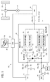
図2は、電動車両10を構成する電圧変換ユニット20の回路図である。
FIG. 2 is a circuit diagram of the
図1及び図2に示すように、電動車両10は、電源としての燃料電池(FC)12及び蓄電器(BAT)14と、力行運転時にトルクを出力可能であり、回生運転時に回生電力を出力可能な電動機(M)16を備える。
As shown in FIGS. 1 and 2, the
また、電動車両10は、燃料電池12の出力電力の電圧であるFC電圧Vfc及び蓄電器14の出力電力の電圧であるBAT電圧Vbatが入力され、これら出力電力の電圧を電圧変換し、直流電力の出力端電圧(負荷端電圧ともいう。)Vinvとして電動機16に印加する電圧変換ユニット20を備える。
In addition, the
さらに、電動車両10は、電動車両10の制御に必要な各構成要素と接続され、これら各構成要素を制御すると共に、電圧変換ユニット20を制御する制御部としてのECU(Electronic Control Unit)22を備える。
Further, the
具体的にECU22は、後述する各種センサ等の他に、車速センサ82、及びアクセルペダル84の踏込量センサ(アクセル開度センサともいう。)85等に接続される。
Specifically, the
電動車両10の力行運転時に、出力端電圧Vinvは、直流電圧の力行電圧Vprとしてインバータ(2相→3相、3相→2相の双方向電力変換器)24を介して、ここでは3相の交流電力に2相→3相変換されて電動機16に印加(給電)され、電動機16は、交流電力に応じたトルクを発生する。電動機16により発生されたトルクは、トランスミッション17を介して又は直接的に駆動輪18に供給される。
During the power running operation of the
また、電動機16は、アクセルペダル84を開放した回生運転時に交流電力の回生電力を発生する。この回生電力は、インバータ24を介して直流電力の電圧である回生電圧Vregに3相→2相変換される。出力端電圧Vinvとしての回生電圧Vregは、電圧変換ユニット20を介して蓄電器14の充電に適した電圧に変換され、蓄電器14を充電する。
Further, the
電圧変換ユニット20は、コンタクタ28を介して燃料電池12の出力端子30p、30n(正側端子30p、負側端子30n)に接続される入力端子32p、32nと、コンタクタ34を介して蓄電器14の入出力端子36p、36nに接続される入出力端子38p、38nと、インバータ24を介して電動機16に接続される入出力端子40p、40nと、を備える。
The
燃料電池12の出力電圧(FC電圧)Vfcと出力電流(FC電流)Ifcとがそれぞれ電圧センサ42と電流センサ44とで検出され、ECU22で取得される。
The output voltage (FC voltage) Vfc and the output current (FC current) Ifc of the
ECU22は、取得したFC電圧VfcとFC電流Ifcとから燃料電池12の電力(発電電力)を算出(取得)する。
The
蓄電器14の出力電圧(BAT電圧)Vbatと入出力電流(BAT電流)Ibatとがそれぞれ電圧センサ46と電流センサ48とで検出され、さらに蓄電器14の温度(BAT温度)Tbatが温度センサ49で検出され、それらがECU22で取得される。
The output voltage (BAT voltage) Vbat and the input / output current (BAT current) Ibat of the
ECU22は、取得したBAT電圧VbatとBAT電流IbatとBAT温度Tbatとから蓄電器14の電力を算出(取得)するとともに、予め記憶しているマップ(例えば、BAT温度TbatをパラメータとしたBAT電圧Vbatに対する残容量の特性)等を参照して蓄電器14の残容量としてのSOC(充電状態)を算出(取得)する。
The
電圧変換ユニット20の出力端電圧Vinv(力行電圧Vpr、回生電圧Vreg)と入出力電流Iinv(力行電流Ipr、回生電流Ireg)が、電圧センサ62と電流センサ64とで検出され、それぞれECU22で取得される。
The output terminal voltage Vinv (power running voltage Vpr, regenerative voltage Vreg) and input / output current Iinv (power running current Ipr, regenerative current Ireg) of the
この場合、ECU22は、取得した出力端電圧Vinv(力行電圧Vpr、回生電圧Vreg)と出力端電流Iinv(力行電流Ipr、回生電流Ireg)とから入出力端子40p、40nに係わる力行電力又は回生電力を算出(取得)する出力端電力(力行電力又は回生電力)取得部としての機も有する。
In this case, the
電圧変換ユニット20は、第1〜第4電圧変換器51〜54から構成される。
The
第1電圧変換器51は、インダクタ101とダイオード102と逆並列ダイオード104が接続されたスイッチング素子103とから構成され、燃料電池12の電力のFC電圧Vfcを力行電圧Vprの負荷端電圧Vinvに昇圧する昇圧コンバータである。
The
同様に、第2電圧変換器52は、インダクタ111とダイオード112と逆並列ダイオード114が接続されたスイッチング素子113とから構成され、第1電圧変換器51と同様に、燃料電池12の電力のFC電圧Vfcを負荷端電圧Vinvに昇圧する昇圧コンバータである。
Similarly, the
インダクタ101とインダクタ111とは、共通のコアにインダクタ101及びインダクタ111を形成する各コイルが逆極性に巻回された構成とされている。
The
インダクタ101とインダクタ111の共通接続点は、第1通電路71を介し、正側の入力端子32p、コンタクタ28を介して燃料電池12の正側端子30pに接続されている。
A common connection point between the
第3電圧変換器53は、インダクタ121と、逆並列ダイオード123が接続されたスイッチング素子124と、逆並列ダイオード125が接続されたスイッチング素子126とから構成され、蓄電器14の電力のBAT電圧Vbatを力行電圧Vprの負荷端電圧Vinvに昇圧する昇圧コンバータとして動作するとともに、回生電圧Vregの負荷端電圧VinvをBAT電圧Vbatに降圧する降圧コンバータとしても動作する。すなわち、第3電圧変換器53は、昇降圧コンバータとして動作する。
The
第4電圧変換器54は、インダクタ131と、逆並列ダイオード133が接続されたスイッチング素子134と、逆並列ダイオード135が接続されたスイッチング素子136とから構成され、第3電圧変換器53と同様に、基本的には、蓄電器14の電力のBAT電圧Vbatを力行電圧Vprの負荷端電圧Vinvに昇圧する昇圧コンバータとして動作するとともに、回生電圧Vregの負荷端電圧VinvをBAT電圧Vbatに降圧する降圧コンバータとしても動作する。すなわち、第4電圧変換器54も、昇降圧コンバータとして動作する。
The
インダクタ121とインダクタ131とは、共通のコアにインダクタ121及びインダクタ131を形成する各コイルが逆極性に巻回された構成とされている。
The
インダクタ121とインダクタ131の共通接続点は、第2通電路72を介し、バイパス通電路(第3通電路ともいう。)73を通じ、正側の入力端子32p及びコンタクタ28を介して燃料電池12の正側端子30pに接続されるとともに、正側の入出力端子38p及びコンタクタ34を介して蓄電器14の正側の入出力端子36pに接続される。
The common connection point of the
バイパス通電路73は、ダイオードD1と、逆並列ダイオードD2が接続され、ECU22によりオンオフ制御されるスイッチ素子(以下、単にスイッチともいう。)SW1との直列接続で構成される。
The
なお、通電路(共通通電路)74は、燃料電池12、蓄電器14、及び第1〜第4電圧変換器51〜54、及びインバータ24の基準電位(共通電位ともいう。)となる通電路である。
The energization path (common energization path) 74 is an energization path that serves as a reference potential (also referred to as a common potential) for the
第1通電路71の通過電流Ifは、第1分岐路151の通過電流I1及び第2分岐路152の通過電流I2の合成電流となるが、通過電流I1及び通過電流I2は、それぞれ、電流センサ161と電流センサ162により検出され、ECU22により取得される。ECU22は、通過電流Ifを算出(取得)する。
The passing current If of the first
スイッチSW1がオン状態(閉状態)にされているとき、Vfc>Vbatを前提条件として、燃料電池12から第3通電路73に流れる電流(通過電流)Itの値は、FC電流Ifcから通過電流Ifを差し引いた電流値(It=Ifc−If)としてECU22で算出(取得)される。
When the switch SW1 is in the on state (closed state), assuming that Vfc> Vbat, the value of the current (passing current) It flowing from the
第2通電路72の通過電流Isは、第3分岐路153の通過電流Is1及び第4分岐路154の通過電流Is2の合成電流となるが、それぞれ、電流センサ163と電流センサ164により検出され、ECU22により取得される。ECU22は、通過電流Isを算出(取得)する。
The passing current Is of the second energizing
なお、通過電流Is1、Is2において、力行電流を通過電流I3、I4という。 In addition, in the passing currents Is1 and Is2, the power running current is referred to as passing currents I3 and I4.
通過電流I1、I2、Is1(I3)、Is2(I4)の値により、第1、第2、第3、第4電圧変換器51、52、53、54の通過電流制限値である許容通過電流(許容通過電力)がECU22により管理される。
The allowable passing current which is the passing current limit value of the first, second, third, and
理解の便宜のために、この実施形態において、スイッチング素子103、113、124、126、134、136は、同一仕様の半導体チップを使用しているものとする。換言すれば、通過電流制限値である許容通過電流(許容通過電力)が各スイッチング素子で同一あるものとし、且つ力行時の通過電流の制限について説明する。
For convenience of understanding, in this embodiment, the switching
各通過電流(通過電力)I1、I2、Is1(I3)、Is2(I4)は、ECU22の通過電流監視部22cにより監視される。
Each passing current (passing power) I1, I2, Is1 (I3), Is2 (I4) is monitored by the passing
ECU22は、通過電流監視部22cとして機能する他、後述する電機負荷要求電力設定部としての電動機要求電力設定部22a及び燃料電池要求電力設定部22bとしても機能する。
In addition to functioning as a passing
コンデンサC1〜C3は、FC電圧VfcとBAT電圧Vbatと負荷端電圧Vinvをそれぞれ平滑化するコンデンサ、抵抗器R3は、コンデンサC3の放電用抵抗器である。 The capacitors C1 to C3 are capacitors that smooth the FC voltage Vfc, the BAT voltage Vbat, and the load end voltage Vinv, respectively. The resistor R3 is a discharging resistor for the capacitor C3.
なお、蓄電器14の出力側には、燃料電池12に、一方の反応ガスである圧縮空気を送給するエアコンプレッサ等の補機15が接続されている。補機15には、前記エアコンプレッサの他に、それぞれ不図示の、BAT電圧Vbatを+12Vに降圧する降圧器と、該降圧器により降圧された+12Vで充電される補助バッテリと、該補助バッテリから電力が供給される灯火器等の低電圧補機が含まれる。補機15には、蓄電器14等から補機電流Iauxが流れ込む。
Note that an
ここで、図3Aを参照して第1及び第2電圧変換器51(52)の[昇圧動作]と[直結動作]、及び図3Bを参照して第3及び第4電圧変換器53(54)の[昇降圧動作]と[直結動作]を、第1電圧変換器51及び第3電圧変換器53を代表として説明する。
Here, referring to FIG. 3A, the [boost operation] and [direct connection operation] of the first and second voltage converters 51 (52), and the third and fourth voltage converters 53 (54) with reference to FIG. 3B. The step-up / step-down operation and the direct-connection operation are described with the
[第1電圧変換器51の昇圧動作]
図3Aに示す第1電圧変換器51は、スイッチング素子103のオンオフ(スイッチング)を周期的に行うことで、1次側の入力端子32p、32n間に燃料電池12から入力される直流電力のFC電圧Vfcを昇圧した直流電力の力行電圧Vprを2次側の入出力端子40p、40nから出力することが可能な一方向型の電圧変換器である。この場合、スイッチング素子103のオンオフのデューティを調整することで、電圧の昇圧率(Vpr/Vfc)を可変的に制御することができる。
[Boosting Operation of First Voltage Converter 51]
The
[第1電圧変換器51の直結動作]
また、第1電圧変換器51は、スイッチング素子103をオフ状態に維持した場合には、第1電圧変換器51の1次側から2次側への一方向の電力伝送に関して、該第1電圧変換器51の1次側と2次側とが実質的に直結された状態となる。この状態では、1次側の入力端子32p、32nに入力される燃料電池12の直流電力を、そのまま(電圧変換をせずに)、力行電圧Vprとして2次側の入出力端子40p、40nから出力することが可能である。この直結状態では、第1電圧変換器51のいわゆるスイッチング損失がゼロ値となる。
[Direct operation of first voltage converter 51]
In addition, when the
図3Bに示す第3電圧変換器53は、双方向型の電圧変換器である。
The
[第3電圧変換器53の昇圧動作]
スイッチSW1がオフ状態であり、燃料電池12の直流電力が遮断されている状態の第1の昇圧時には、上記した第1電圧変換器51と同様に、スイッチング素子124をオフ状態とし、スイッチング素子126のオンオフ(スイッチング)を周期的に行うことで、1次側の入出力端子38p、38n間に蓄電器14から入力される直流電力のBAT電圧Vbatを昇圧した直流電力の力行電圧Vprを2次側の入出力端子40p、40nから出力する。この場合、スイッチング素子126のオンオフのデューティを調整することで、電圧の昇圧率(Vpr/Vfc)を可変的に制御することができる。
[Boosting Operation of Third Voltage Converter 53]
At the time of the first step-up in which the switch SW1 is in the off state and the direct current power of the
スイッチSW1がオン状態であり、燃料電池12からの直流電力が第3通電路73のダイオードD1及びスイッチSW1を通じて入出力端子38p、38nに供給されるとともに、蓄電器14からの直流電力が入出力端子38p、38nに供給されている状態(Vbat=Vfc)の第2の昇圧時には、上記した第1電圧変換器51と同様に、スイッチング素子124をオフ状態とし、スイッチング素子126のオンオフ(スイッチング)を周期的に行うことで、1次側の入出力端子38p、38n間に燃料電池12及び蓄電器14から入力される直流電力の電圧(Vbat=Vfc)を昇圧した直流電力の力行電圧Vprを2次側の入出力端子40p、40nから出力する。この場合、スイッチング素子126のオンオフのデューティを調整することで、電圧の昇圧率{(Vpr/Vbat)=(Vpr/Vfc)}を可変的に制御することができる。
The switch SW1 is in an ON state, and the DC power from the
[第3電圧変換器53の降圧動作]
この場合、スイッチSW1をオフ状態として、燃料電池12(第3通電路73)を遮断し、燃料電池12の発電電力を極小(発電を停止させないで継続させておく程度の最小限の発電)に制御した状態で、2次側の入出力端子40p、40nに入力される直流電力、具体的には、電動機16の回生電力がインバータ24を介して生成された直流電力の回生電圧Vregを入出力端子38p、38nのBAT電圧Vbatまで降圧させて出力する、すなわち、蓄電器14を回生電力により充電する。
[Step-down operation of third voltage converter 53]
In this case, the switch SW1 is turned off to cut off the fuel cell 12 (the third energization path 73), and the generated power of the
このため、スイッチング素子126をオフ状態に制御した状態で、スイッチング素子124のオンオフ(スイッチング)を周期的に行うことで、2次側の入出力端子40p、40nに入力される直流電力(電動機16の回生電力からインバータ24を介して生成された直流電力)の回生電圧Vregを降圧した直流電力を1次側の入出力端子38p、38nから出力することができる。この場合、スイッチSW1をオフ状態にしているので、回生電力を最大限、蓄電器14に充電することができる。なお、スイッチング素子124のオンオフのデューティを調整することで、電圧の降圧率(Vbat/Vreg)を可変的に制御することが可能である。
For this reason, the switching
[第3電圧変換器53の直結動作(力行運転時)]
また、第3電圧変換器53は、スイッチング素子124、126をオフ状態に維持した場合には、電圧変換器53の1次側から2次側への一方向の電力伝送に関して、該第3電圧変換器53の1次側と2次側とが実質的に直結された状態となる。この状態では、1次側の入出力端子38p、38nに入力される直流電力を、そのまま(電圧変換をせずに)、2次側の入出力端子40p、40nから出力することが可能である。
[Direct connection operation of third voltage converter 53 (during power running)]
Further, when the
[第3電圧変換器53の直結動作(回生運転時、力行運転時)]
さらに、第3電圧変換器53は、スイッチング素子126をオフ状態に維持し、且つスイッチング素子124をオン状態に維持した場合には、電圧変換器53の1次側と2次側との間の双方向の電力伝送に関して、該電圧変換器53の1次側と2次側とが実質的に直結された状態となる。この状態では、1次側の入出力端子38p、38n及び2次側の入出力端子40p、40nの一方側に入力した直流電力を、そのまま(電圧変換をせずに)、他方側から出力することが可能である。
[Direct connection operation of third voltage converter 53 (during regenerative operation, powering operation)]
Further, when the
ここで、図4Aのタイムチャートを参照して[第1及び第2電圧変換器51、52のスイッチング素子103、113の交互スイッチング動作]、又は[第3及び第4電圧変換器53、54のスイッチング素子124、134の交互スイッチング動作]について説明する。
Here, referring to the time chart of FIG. 4A, [alternating switching operation of the switching
[第1及び第2電圧変換器51、52のスイッチング素子103、113の交互スイッチング動作]
図4Aに示すように、第1及び第2電圧変換器51、52の上記の昇圧動作では、スイッチング素子103、113が、スイッチング周期Tcの間に交互にオン状態となるように(交互にオフ状態になるように)、スイッチング素子103、113の両方のスイッチングを周期的に行うようにしてもよい。
[Alternating switching operation of the switching
As shown in FIG. 4A, in the above step-up operation of the first and
このように交互制御することで、第1及び第2電圧変換器51、52の出力電圧である力行電圧Vprのリップルを低減することができる。
By alternately controlling in this way, the ripple of the power running voltage Vpr that is the output voltage of the first and
[第3及び第4電圧変換器53、54のスイッチング素子124、134の交互スイッチング動作]
図4Aに示すように、第3及び第4電圧変換器53、54の上記の降圧動作(スイッチング素子126、136がオフ状態)では、スイッチング素子124、134が、スイッチング周期Tcの間に交互にオン状態となるように(交互にオフ状態になるように)、スイッチング素子124、134の両方のスイッチングを周期的に行うようにしてもよい。
[Alternating switching operation of the switching
As shown in FIG. 4A, in the above-described step-down operation of the third and
このように交互制御することで、第3及び第4電圧変換器53、54の出力電圧である、回生電圧Vregを電圧変換したBAT電圧Vbatのリップルを低減することができる。
By alternately controlling in this way, the ripple of the BAT voltage Vbat obtained by converting the regenerative voltage Vreg, which is the output voltage of the third and
さらに、図4Bのタイムチャートを参照して[第1〜第4電圧変換器51〜54のスイッチング素子103、113、126、136の交替スイッチング動作]について説明する。
Furthermore, [alternate switching operation of the switching
[第1〜第4電圧変換器51〜54のスイッチング素子103、113、126、136の交替スイッチング動作]
図4Bに示すように、第1〜第4電圧変換器51〜54の上記の昇圧動作では、スイッチング素子124、134のオフ状態下に、スイッチング素子103、126、113、136のそれぞれがオン(又はオフ)になるタイミングが、スイッチング周期Tcを、スイッチング素子103、126、113、136の個数(=4)で除算した時間幅(=Tc/4)に相当する位相(すなわち、90degの位相)だけ順番に(第1、第3、第2、第4の順番で)ずれるように行われる。
[Alternating Switching Operation of
As shown in FIG. 4B, in the above-described step-up operation of the first to
このように交替制御することで、第1〜第4電圧変換器51〜54の出力電圧である力行電圧Vprのリップルを低減することができる。
By performing the alternating control in this way, it is possible to reduce the ripple of the power running voltage Vpr that is the output voltage of the first to
[動作の説明]
基本的には以上のように構成される、この実施形態に係る電源システムとしての電動車両10の動作について、以下、a.前提の説明、b.第1〜第6制御処理の説明、及びc.要部に係わる第2制御処理の詳細な動作説明の順に説明する。
[Description of operation]
About operation | movement of the
[a.前提の説明]
図2において、燃料電池12から第3及び第4電圧変換器53、54に電力を入力することは、燃料電池12の出力電圧であるFC電圧Vfcが蓄電器14の出力電圧であるBAT電圧Vbatよりも高くなっている状況下で、バイパス通電路73のスイッチSW1をオン状態に制御することで可能となる。
[A. Explanation of assumptions]
In FIG. 2, when power is input from the
また、蓄電器14の電力は、ダイオードD1により阻止されるので、第1及び第2電圧変換器51、52に入力することはできず、第3及び第4電圧変換器53、54だけに入力することが可能となっている。
In addition, since the electric power of the
このように、第1〜第4電圧変換器51〜54のうち、第3及び第4電圧変換器53、54は、燃料電池12及び蓄電器14の双方の電力を入力し得る電圧変換器(すなわち、燃料電池12及び蓄電器14に対しての共用電圧変換器)となっており、第1及び第2電圧変換器51、52は、燃料電池12の電力だけを入力し得る電圧変換器(すなわち、燃料電池12に対しての専用電圧変換器であるので燃料電池用電圧変換器ともいう。)となっている。
Thus, among the first to
そのため、以下、理解の便宜のために、第1及び第2電圧変換器51、52を燃料電池用電圧変換器51、52、第3及び第4電圧変換器53、54を共用電圧変換器53、54ということもある。
Therefore, hereinafter, for convenience of understanding, the first and
第3及び第4電圧変換器53、54のそれぞれは、インダクタ121、131と、入出力端子40pとの間に、スイッチング素子124、134を備えるため、電動機16の回生運転時においては、入出力端子40p、40n側から、第3及び第4電圧変換器53、54のスイッチング素子124、134を介して、蓄電器14に電力を供給して、該蓄電器14の充電を行うことが可能となっている。
Since each of the third and
あるいは、燃料電池12の電力を、第1及び/又は第2電圧変換器51、52と、第3及び/又は第4電圧変換器53、53とを経由させて、蓄電器14に充電することも可能である。
Alternatively, the electric power of the
以下、図5に示す電動車両10の制御処理表に沿って動作(制御処理)を説明する。
Hereinafter, the operation (control process) will be described along the control process table of the
ECU22は、コンタクタ28、34がオン状態となっている状態(電動車両10の走行可能な状態)で前記制御処理表に示す第1〜第6制御処理を適宜実行する。
The
[b.第1〜第6制御処理の説明]
[第1制御処理]
第1制御処理は、電動機16の力行運転時に、BAT電圧VbatがFC電圧Vfcよりも高くなっている場合に、図6に示すように、燃料電池12及び蓄電器14の双方の電力(主に、燃料電池12の電力)を電動機16に給電し、該電動機16に比較的小さな駆動力を発生させる制御処理である。
[B. Description of first to sixth control processes]
[First control processing]
In the first control process, when the BAT voltage Vbat is higher than the FC voltage Vfc during the power running operation of the
この第1制御処理は、例えば、電動機16の要求加速度(電動機16の出力軸の回転角加速度の要求値)又は要求駆動力(要求トルク、要求推進力)が所定の閾値よりも小さい状況(電動車両10の緩加速状況)、あるいは、電動機16の動作速度(電動機16の出力軸の回転角速度)が所定の閾値よりも低い低速域での電動機16のクルーズ運転状態等、電動機16に発生させるべき駆動力が比較的小さなものとなる力行運転時に実行される制御処理である。
In the first control process, for example, the required acceleration of the electric motor 16 (required value of the rotational angular acceleration of the output shaft of the electric motor 16) or the required driving force (required torque, required propulsive force) is smaller than a predetermined threshold (electric (Slow acceleration state of the vehicle 10), or the operation speed of the motor 16 (rotational angular speed of the output shaft of the motor 16) should be generated by the
換言すれば、第1制御処理は、電動機16の要求電力が比較的小さなものとなる力行運転時に実行される制御処理である。以下、前記要求加速度、前記要求駆動力、及び前記動作速度等を、理解の便宜、煩雑さの回避のために、電動機16の要求電力として説明する。
In other words, the first control process is a control process that is executed during powering operation in which the required power of the
電動機16のクルーズ運転状態は、該電動機16の出力軸の回転角速度がほぼ一定に保たれる運転状態である。そして、電動機16の動作速度が所定の閾値よりも低い低速域での電動機16のクルーズ運転状態は、換言すれば、車速が所定の閾値よりも低い低速域での電動車両10のクルーズ走行状態である。
The cruise operation state of the
回路的に、第1制御処理は、BAT電圧VbatがFC電圧Vfcよりも高くなっている状況で、第3及び第4電圧変換器53、54は直結状態(スイッチング素子124、126、134、136:オフ状態)に維持される。なお、バイパス通電路73のスイッチSW1はオフ状態に維持される。
In terms of circuit, the first control process is performed when the BAT voltage Vbat is higher than the FC voltage Vfc, and the third and
なお、スイッチSW1がオン状態に維持されても、Vbat>Vfcなので、ダイオードD1により第3通電路73の通過電流Itが阻止されるので、実質的に電流の流れない状態、換言すればオフ状態になっている。以下の関連する制御処理でも同様である。
Even if the switch SW1 is kept in the on state, since Vbat> Vfc, the diode D1 prevents the passing current It from passing through the
この場合、第3及び第4電圧変換器53、54は、それぞれ、一次側に入力される蓄電器14の電力を、そのまま(電圧変換を行わずに)二次側に出力する。このため、第3及び第4電圧変換器53、54のそれぞれの出力端電圧Vinv(=力行電圧Vpr)は、BAT電圧Vbatにほぼ一致する電圧{BAT電圧Vbatからダイオード123(133)の順方向電圧を引いた電圧}となる。
In this case, each of the third and
また、ECU22は、燃料電池12の電力が入力される第1及び第2電圧変換器51、52の出力端電圧Vinvを、第3及び第4電圧変換器53、54のそれぞれの出力端電圧Vinv≒BAT電圧Vbatに一致させるように、第1及び第2電圧変換器51、52の昇圧動作を行わせる。
Further, the
この昇圧動作では、図4Aに示したように、電圧変換器51、52のそれぞれのスイッチング素子103、113のスイッチング(オンオフ)が周期的に行われると共に、そのスイッチングのデューティを調整することで、電圧変換器51、52の出力電圧が制御される。
In this step-up operation, as shown in FIG. 4A, the switching
なお、電動機16への通電電流が十分に小さい場合には、電圧変換器51、52のいずれか一方だけに昇圧動作を行わせるようにしてもよい。
Note that when the energization current to the
[第2制御処理]
この実施形態の要部に係わる第2制御処理は、電動機16の力行運転時に、図7に示すように、燃料電池12及び蓄電器14の双方から比較的大きな電力を電動機16に給電して、該電動機16に比較的大きな駆動力を発生させる制御処理である。
[Second control process]
As shown in FIG. 7, the second control process related to the main part of this embodiment supplies relatively large electric power from both the
この第2制御処理は、例えば、電動機16の要求電力が大きい状況(例えば、車両10の急加速又は登坂時等の高負荷運転状況)で実行される制御処理である。
This second control process is, for example, a control process that is executed in a situation where the required power of the
回路的に、第2制御処理は、ECU22が、原則的に、前記バイパス通電路73のスイッチSW1をオン状態に制御した状態で、第1〜第4電圧変換器51、52、53、54にそれぞれの昇圧動作を、図4Bを参照して説明した交替スイッチング動作で行わせる。
As a circuit, in the second control process, in principle, the
この場合、ECU22は、第3及び第4電圧変換器53、54のそれぞれの出力端電圧Vinvを、所定の目標値に近づけるように、昇圧比を変化させる電圧フィードバック制御処理を実行することで、電圧変換器53、54のそれぞれのスイッチング素子126、136のスイッチングのデューティを決定する。そして、そのデューティに従って、スイッチング素子126、136のそれぞれのスイッチング(オンオフ)を行わせる。
In this case, the
また、ECU22は、燃料電池12の電力が入力される第1及び第2電圧変換器51、52のそれぞれの出力電流を、所定の目標値(例えば、電動機16の電流要求値から、第3及び第4電圧変換器53、54のトータルの出力電流を差し引いた電流量)に近づけるように、出力電流フィードバック制御処理を実行することで、電圧変換器51、52のそれぞれのスイッチング素子103、113のスイッチング(オンオフ)のデューティを決定する。そして、そのデューティに従って、スイッチング素子103、113のそれぞれのスイッチングを行わせる。この場合、出力電流フィードバック制御により、電圧変換器51、52の昇圧動作が行われる。
Further, the
なお、この実施形態においては、第1及び第2電圧変換器51、52の出力電流フィードバック制御は、図1に示した電流センサ161、162の接続とは異なり、ダイオード102、112の各カソードと両カソードの共通接続点の間に電流センサ161、162をそれぞれ挿入して行うこととなるが、図1、図2に示しているように、第1分岐路151及び第2分岐路152に電流センサ161、162を挿入し、前記出力電流と等価な通過電流I1、I2でフィードバック制御を行っている。
In this embodiment, the output current feedback control of the first and
図8AのIV特性及び図8BのIV特性の電流増分に対する電圧増分を表す電流微分特性(単位電流当たりの電圧変化量特性)に示すように、燃料電池12は、閾値Ifcth以上の比較的大きな電流を出力する状態では、電流の変化に対する電圧の変化の感度(ΔVfc/ΔIfc)が値1以下と低いため、換言すれば、低出力インピーダンスであるため、第2制御処理での燃料電池12の大きな電力を入力する電圧変換器51、52の昇圧動作の安定性を高める上でも、電圧制御よりも電流制御が適している。
As shown in the current differential characteristic (voltage variation characteristic per unit current) representing the voltage increment with respect to the current increment of the IV characteristic of FIG. 8A and the IV characteristic of FIG. 8B, the
以上のように、第2制御処理では、図7に示したように、第1〜第4電圧変換器51、52、53、54の昇圧動作を行いながら、燃料電池12及び蓄電器14の双方から電動機16に大きな電力が給電され、該電動機16の力行運転(大きな駆動力での力行運転)が行われる。
As described above, in the second control process, as shown in FIG. 7, the boost operation of the first to
この場合、バイパス通電路73のスイッチSW1をオン状態に制御しているので、第2制御処理の実行中に、蓄電器14の出力電圧が低下しても、矢印付き破線で示すように、燃料電池12から第3及び第4電圧変換器53、54を介して電動機16への供給電力を確保することができる。併せて、燃料電池12の電力を蓄電器14に充電することもできる。
In this case, since the switch SW1 of the
なお、この要部に係わる第2制御処理の詳細については、さらに後述する。 Details of the second control process related to the main part will be described later.
[第3制御処理]
蓄電器14は、出力密度が高い蓄電器であるので、蓄電器14の電力を頻繁に電動機16に給電すると、該蓄電器14の残容量が早期に小さくなる虞がある。
[Third control processing]
Since the
このため、燃料電池12の電力を、蓄電器14に適宜、充電することが行われる。この充電は、第3制御処理により行われる。
For this reason, the electric power of the
第3制御処理は、基本的には、車両10の停止時に、BAT電圧VbatがFC電圧Vfcよりも高くなっている状況、すなわち、燃料電池12の電力をバイパス通電路73を経由して蓄電器14に供給することがダイオードD1により阻止される状況で、図9に示すように、蓄電器14の充電を行う制御処理である。
In the third control process, basically, when the
この制御処理では、ECU22は、第1及び第2電圧変換器51、52のそれぞれの昇圧動作を図4Aに示したスイッチングタイミングで行わせる。この場合、ECU22は、例えば、第1及び第2電圧変換器51、52のそれぞれの出力電圧である負荷端電圧Vinvが、BAT電圧Vbatよりも若干高い電圧値になるように、電圧変換器51、52のそれぞれのスイッチング素子103、113のスイッチングのデューティを制御する。
In this control process, the
さらに、ECU22は、第3及び第4電圧変換器53、54を電力が二次側から一次側に向かう方向で直結状態にする。すなわち、スイッチング素子126、136をオフ状態に維持すると共に、スイッチング素子124、134をオン状態に維持する。これにより、第3及び第4電圧変換器53、54は、それぞれ、二次側に入力される電力を、そのまま(電圧変換を行わずに)、一次側から出力し得る直結状態となる。
Further, the
このため、図9に示すように、第1及び第2電圧変換器51、52の昇圧動作によって昇圧された燃料電池12の電力が、第3及び第4電圧変換器53、54の二次側から一次側に伝送され、さらに、該電圧変換器53、54の一次側から蓄電器14に充電される。
Therefore, as shown in FIG. 9, the power of the
なお、第3制御処理では、蓄電器14への充電電流が小さなものとなる状況では、第1及び第2電圧変換器51、52の一方の昇圧動作だけを行うようにしてもよい。
In the third control process, in a situation where the charging current to the
また、第3制御処理において、第3及び第4電圧変換器53、54の降圧動作(二次側に入力される電力の電圧を降圧して一次側に伝送する降圧動作)を行うことも可能である。この場合には、電圧変換器53、54のそれぞれのスイッチング素子124、134のスイッチングを、図4Aに示した態様と同様の態様で、位相をずらして行うことが好ましい。
In the third control process, it is also possible to perform the step-down operation of the third and
この場合、FC電圧VfcがBAT電圧Vbatよりも高い状況で、バイパス通電路73のスイッチSW1をオフ状態に維持した状態では、第1及び第2電圧変換器51、52と、第3及び第4電圧変換器53、54とを順に経由させて、蓄電器14に充電する(換言すれば、第3制御処理により蓄電器14を充電する)ことも可能である。
In this case, in a state where the FC voltage Vfc is higher than the BAT voltage Vbat and the switch SW1 of the
[第4制御処理の概要及び第5制御処理の概要]
第4制御処理は、図10に示すように、電動機16の力行運転時に、燃料電池12の電力を電動機16に給電することと、燃料電池12の電力を蓄電器14に充電することとを並行して行う制御処理、第5制御処理は、図11に示すように、電動機16の力行運転時に、燃料電池12の電力を電動機16に給電することと、前記第3制御処理と同様の回路接続・制御処理により、燃料電池12の電力を蓄電器14に充電することとを並行して行う制御処理である。
[Outline of Fourth Control Process and Outline of Fifth Control Process]
As shown in FIG. 10, the fourth control process is parallel to feeding the electric power of the
これらの第4制御処理及び第5制御処理は、例えば、電動機16の要求電力が小さなものとなる状況、例えば電動機16の動作速度(電動機16の出力軸の回転角速度)が所定の閾値よりも高いものとなる高速域での電動機16のクルーズ運転状態で実行される制御処理である。
In the fourth control process and the fifth control process, for example, the situation where the required power of the
なお、電動機16の動作速度(電動機16の出力軸の回転角速度)が所定の閾値よりも高いものとなる高速域での電動機16のクルーズ運転状態は、換言すれば、車速が所定の閾値よりも高い高速域での車両10のクルーズ走行状態である。
Note that the cruise operation state of the
[第4制御処理の詳細]
図10に示した第4制御処理は、次のように実行される。すなわち、ECU22は、FC電圧VfcがBAT電圧Vbatよりも高くなっている状況で、燃料電池12の電力を、バイパス通電路73を介して蓄電器14に充電することと並行して、第1〜第4電圧変換器51〜54のうちの1つ以上の電圧変換器の昇圧動作を行わせることで、該電圧変換器を介して燃料電池12の電力を電動機16に給電する。
[Details of the fourth control process]
The fourth control process shown in FIG. 10 is executed as follows. That is, the
この場合、ECU22は、電動機16に供給すべき電流が多くなるほど、昇圧動作を行わせる電圧変換器(以降、昇圧動作対象の電圧変換器という)の個数(相数)を多くするように、昇圧動作対象の電圧変換器を選定する。
In this case, the
例えば、ECU22は、電動機16に供給すべき電流が比較的小さい場合には、第1及び第2電圧変換器51、52の対、あるいは、第3及び第4電圧変換器53、54の対を昇圧動作対象の電圧変換器として選定し、電動機16に供給すべき電流が比較的大きい場合には、第1〜第4電圧変換器51〜54を昇圧動作対象の電圧変換器として選定する。
For example, when the current to be supplied to the
そして、ECU22は、昇圧動作対象の電圧変換器の出力端電圧Vinv=Vprが、電動機16の力行運転に必要な所定の電圧になるように、昇圧動作対象の電圧変換器の対象のスイッチング素子103、113、126、136のスイッチングのデューティを制御する。
Then, the
この場合、昇圧動作対象の電圧変換器が、第1及び第2電圧変換器51、52の対、あるいは、第3及び第4電圧変換器53、54の対である場合には、スイッチングは、図3Aに示した態様で位相をずらして行われる。また、昇圧動作対象の電圧変換器が、第1〜第4電圧変換器51〜54である場合には、スイッチングは、図3Bに示した態様で位相をずらして行われる。
In this case, when the voltage converter to be boosted is a pair of the first and
[第5制御処理の詳細]
一方、図11に示した第5制御処理は、次のように実行される。すなわち、ECU22は、BAT電圧VbatがFC電圧Vfcよりも高くなっている状況で、燃料電池12の電力を、第1及び第2電圧変換器51、52と、第3及び第4電圧変換器53、54とを順に経由させて蓄電器14に充電することと並行して、第1及び第2電圧変換器51、52を介して燃料電池12の電力を電動機16に給電する。
[Details of fifth control processing]
On the other hand, the fifth control process shown in FIG. 11 is executed as follows. That is, the
この場合、ECU22は、第1及び第2電圧変換器51、52の昇圧動作によって、該電圧変換器51、52の出力端電圧Vinvが、BAT電圧Vbatよりも高い電圧で、電動機16の力行運転に必要な所定の電圧になるように、図3Aに示した態様で、電圧変換器51、52のそれぞれのスイッチング素子103、113のスイッチングのデューティを制御する。
In this case, the
さらに、ECU22は、第3及び第4電圧変換器53、54のそれぞれのスイッチング素子126、136をオフ状態に維持した状態で、該電圧変換器53、54の降圧動作によって、該電圧変換器53、54の一次側の入出力端子38p、38nの出力電圧が、BAT電圧Vbatよりも若干高い電圧になるように、図3Aに示した態様で、電圧変換器53、54のそれぞれのスイッチング素子124、134のスイッチングのデューティを制御する。
Further, the
なお、電動機16に供給すべき電流が十分に小さい場合には、第1及び第2電圧変換器51、52のいずれか一方だけの昇圧動作を行い、あるいは、第3及び第4電圧変換器53、54のいずれか一方だけの降圧動作を行うようにしてもよい。
If the current to be supplied to the
以上のように、第4制御処理又は第5制御処理を実行することで、燃料電池12から電動機16への給電を行いながら、燃料電池12の電力を蓄電器14に充電することができる。このため、燃料電池12の電力だけで電動機16の力行運転を行い得る状況で、蓄電器14を充電して、該蓄電器14の残容量の極端な低下を予防することができる。
As described above, by executing the fourth control process or the fifth control process, the electric power of the
[第6制御処理]
第6制御処理は、図12に示すように、電動機16の回生運転時(車両10の回生制動時)に、電動機16から出力される回生電力を蓄電器14に充電することと、燃料電池12の電力を蓄電器14に並行して充電することを行う制御処理である。
[Sixth control process]
As shown in FIG. 12, the sixth control process includes charging the regenerative power output from the
第6制御処理は、次のように実行される。すなわち、ECU22は、アクセルペダル84が開放されて、踏込量センサ85による踏込量がゼロ値となる回生運転を検出したとき、電動機16の回生電力の回生電圧Vregを入力とする第3及び第4電圧変換器53、54の降圧動作を行わせることで、該電圧変換器53、54を介して電動機16の回生電力を蓄電器14に充電する。なお、FC電圧VfcがBAT電圧Vbatよりも高くなっている状況下では、並行して、燃料電池12の電力を、バイパス通電路73を介して蓄電器14に充電する。
The sixth control process is executed as follows. That is, the
この場合、ECU22は、第1及び第2電圧変換器51、52のそれぞれのスイッチング素子103、113をオフ状態に維持する。
In this case, the
さらに、ECU22は、第3及び第4電圧変換器53、54のそれぞれのスイッチング素子126、136をオフ状態に維持した状態で、該電圧変換器53、54の降圧動作によって、該電圧変換器53、54の1次側の出力電圧が、BAT電圧Vbatより若干高い電圧になるように、図4Aに示した態様で、電圧変換器53、54のそれぞれのスイッチング素子124、134のスイッチングのデューティを制御する。
Further, the
この第6制御処理を実行することで、図12に示したように、燃料電池12の電力をバイパス通電路73を介して蓄電器14に充電することと並行して、電動機16の回生電力を第3及び第4電圧変換器53、54を介して蓄電器14に充電することが行われる。
By executing this sixth control process, as shown in FIG. 12, the regenerative electric power of the
[c.要部に係わる第2制御処理の詳細な動作説明]
図1の概略構成図、図2の回路図、図7を再掲した図13の電力伝送の模式図、図14のフローチャート、及び図15のタイムチャートを参照して説明する。
[C. Detailed operation description of second control processing related to main part]
Description will be made with reference to the schematic configuration diagram of FIG. 1, the circuit diagram of FIG. 2, the schematic diagram of power transmission of FIG. 13 reprinted in FIG. 7, the flowchart of FIG. 14, and the time chart of FIG.
図14のフローチャートのステップS1にて、ユーザのアクセルペダル84の踏込操作に係わる踏込量がアクセルペダル84の踏込量センサ85により検出され、ECU22で取得される。
In step S <b> 1 of the flowchart of FIG. 14, the depression amount related to the depression operation of the
ステップS2にて、ECU22の電動機要求電力設定部22aは、この踏込量から、予め記憶されている特性(アクセルペダル踏込量に対する要求電力の特性)を参照して電動機16の要求電力(要求電流)、すなわち、電動機要求電力、電動機要求電流を決定する。
In step S2, the motor required
ステップS3にて、ECU22の燃料電池要求電力設定部22bは、電動機要求電力設定部22aにて決定された電動機要求電力(電動機要求電流)に応じた燃料電池要求電力を燃料電池12に設定する。
In step S3, the fuel cell required
ステップS3にて、燃料電池12の出力電流であるFC電流Ifcが、電動機要求電力に応じて増減するように制御される。同時に、第1及び第2電圧変換器51、52は、通過電流I1、I2が電動機16の要求電力に比例して増減するように指令値が設定されて入力側電流フィードバック制御される。
In step S3, the FC current Ifc, which is the output current of the
このため、負荷端電圧(出力側電圧)Vinvが電動機要求電力に対応するように設定される第3及び第4電圧変換器53、54の通過電流I3、I4は、基本的には、一定値の電流が流れる。
Therefore, the passing currents I3 and I4 of the third and
すなわち、基本的には、後述するように通過電流I1、I2が通過電流の上限値I1lim、I2limを上回らない領域では、次の(1)式のように制御される。
Ifc=I1(変動)+I2(変動)+I3(固定)+I4(固定)…(1)
That is, basically, as will be described later, in a region where the passing currents I1 and I2 do not exceed the upper limit values I1lim and I2lim of the passing current, control is performed as in the following equation (1).
Ifc = I1 (variation) + I2 (variation) + I3 (fixed) + I4 (fixed) (1)
この場合、電流センサ161、162によりそれぞれ検出される第1及び第2通過電流I1、I2が、それぞれ、通過電流の上限値I1lim、I2limを上回らないように通過電流監視部22cにより制御されるので、第1及び第2通過電流I1、I2が上限値I1lim、I2limまで上昇したときには、上限値I1lim、I2lim(を上回らないよう)に制限される。このときは、例外的に、電動機16の要求電力の増加に応じて第3及び第4電圧変換器53、54の通過電流I3、I4が増加する。
In this case, the first and second passing currents I1 and I2 detected by the
すなわち、例外的には、次の(2)式のように制御される。
Ifc=I1lim+I2lim+I3(変動)+I4(変動)…(2)
That is, exceptionally, control is performed as in the following equation (2).
Ifc = I1lim + I2lim + I3 (variation) + I4 (variation) (2)
次に、ステップS4にて、電圧変換ユニット20から出力される電力(力行電圧Vpr×力行電流Ipr)によりインバータ24を通じて電動機16が駆動される。
Next, in step S4, the
この場合の力行電流Iprは、(1)式又は(2)式に示したFC電流Ifcになる。 The power running current Ipr in this case is the FC current Ifc shown in the equation (1) or (2).
上記した図14のフローチャートを参照して説明した第2制御処理は、図15のタイムチャートを参照して説明すれば、電動機要求電力の変化に対応するようにFC電流Ifcが制御される。 If the second control process described with reference to the flowchart of FIG. 14 is described with reference to the time chart of FIG. 15, the FC current Ifc is controlled so as to correspond to the change in the required electric power of the motor.
この場合、第1通過電流I1及び第2通過電流I2の指令値が第1通過電流指令値I1com及び第2通過電流指令値I2comに設定され、この設定値となるように、第1通過電流I1及び第2通過電流I2が電流フィードバック制御される。 In this case, the command values of the first passing current I1 and the second passing current I2 are set to the first passing current command value I1com and the second passing current command value I2com, and the first passing current I1 is set to be this set value. The second passing current I2 is current feedback controlled.
第1通過電流I1及び第2通過電流I2が、上限値I1lim及び上限値I2limに達した場合、電流フィードバックにより第1通過電流I1及び第2通過電流I2は、上限値I1lim及び上限値I2limに制限され(時点t1〜時点t2間、及び時点t3〜時点t4間)、上限値を上回る分のFC電流Ifcは、第3電圧変換器53及び第4電圧変換器54の通過電流I3、I4を増加させることで賄われる。
When the first passing current I1 and the second passing current I2 reach the upper limit value I1lim and the upper limit value I2lim, the first passing current I1 and the second passing current I2 are limited to the upper limit value I1lim and the upper limit value I2lim by current feedback. The FC current Ifc that exceeds the upper limit increases the passing currents I3 and I4 of the
[まとめ]
以上説明したように上述した実施形態に係る電源システムが具現化された電動車両10は、電機負荷としての車両駆動用の電動機16と、燃料電池12及び蓄電器14と、燃料電池12及び蓄電器14の少なくとも一方の電力が入力され、入力された電力の電圧を変換して力行電圧Vprとして電動機16に出力する複数の電圧変換器(第1〜第4電圧変換器51〜54)を有している。
[Summary]
As described above, the
ここで、複数の電圧変換器(第1〜第4電圧変換器51〜54)中、少なくとも1つの電圧変換器(第3及び第4電圧変換器53、54)が、燃料電池12の電力及び蓄電器14の電力が入力可能な共用電圧変換器(第3及び第4電圧変換器53、54)として構成され、且つ少なくとも1つの電圧変換器(第1及び第2電圧変換器51、52)が、燃料電池12の電力が入力される燃料電池用電圧変換器(第1及び第2電圧変換器51、52)として構成されている。
Here, among the plurality of voltage converters (first to
この場合、共用電圧変換器(第3及び第4電圧変換器53、54)では、該共用電圧変換器(第3及び第4電圧変換器53、54)の出力端電圧Vinv(Vpr)が電動機16の電力要求に応じた目標電圧となるように電圧フィードバック制御が実行され、燃料電池用電圧変換器(第1及び第2電圧変換器51、52)では、該燃料電池用電圧変換器(第1及び第2電圧変換器51、52)の通過電流I1、I2が電動機16の電力要求に応じた目標電流となるように電流フィードバック制御が実行されている。
In this case, in the shared voltage converter (the third and
このように、共用電圧変換器(第3及び第4電圧変換器53、54)では、該共用電圧変換器(第3及び第4電圧変換器53、54)の出力電圧としての力行電圧Vprが電動機16の電力要求に応じた目標電圧となるように昇圧比(Vpr/Vbat)を変化させる電圧フィードバック制御が実行され、燃料電池用電圧変換器(第1及び第2電圧変換器51、52)では、該燃料電池用電圧変換器(第1及び第2電圧変換器51、52)の通過電流I1、I2が電動機16の電力要求に応じた目標電流となるように電流フィードバック制御が実行されている。
Thus, in the shared voltage converter (the third and
このため、例えば、電動機16の電力要求が高いときに、燃料電池のIV特性による内部出力抵抗が低い領域、換言すれば、燃料電池12の出力電流であるFC電流Ifcに対する出力電圧であるFC電圧Vfcの変化の少ない領域、例えば、図8A、図8B中の閾値Ifcthより大きいFC電流Ifcの領域における電流フィードバック制御が燃料電池用電圧変換器(第1及び第2電圧変換器51、52)にて実行されるので、該電流フィードバック制御の制御性を向上させることができる。
For this reason, for example, when the electric power requirement of the
この場合、電流フィードバック制御の目標値としての通過電流11、I2としては、燃料電池12の出力電流であるFC電流Ifcを直接的に制御可能な燃料電池用電圧変換器(第1及び第2電圧変換器51、52)の入力電流(図1中の通過電流I1、I2)に限らず、該燃料電池用電圧変換器(第1及び第2電圧変換器51、52)の出力電流(図2中、ダイオード102、112の各カソード側と各カソードの共通接続点との間に配すればよい。)を用いてもよい。
In this case, as the passing
電機負荷としては、車両駆動用の電動機16の他、空気調和装置(エアコン)用のコンプレッサ駆動用の電動機等を挙げることができる。これらの電機負荷の、特に大電力領域での制御性を向上させることができる。
Examples of the electric load include an
これら電機負荷の電力要求に応じた目標電圧となるよう、電圧フィードバック制御により、共用電圧変換器(第3及び第4電圧変換器53、54)の出力電圧、すなわち電機負荷の入力電圧を可変しているので、電圧で制御される電機負荷、この実施形態では電動機16の電圧要求に的確に応えることができる。
The output voltage of the common voltage converter (the third and
この場合、電源システムとしての電動車両10は、電動機16の要求電力を設定する電機負荷要求電力設定部としての電動機要求電力設定部22aと、設定された前記要求電力に応じて、燃料電池要求電力を設定する燃料電池要求電力設定部22bと、燃料電池12が出力可能な出力電力が前記燃料電池要求電力を上回っている場合には、燃料電池用電圧変換器(第1及び第2電圧変換器51、52)の前記目標電流を、前記燃料電池要求電力に応じた値に設定する通過電流監視部22cとを備える。
In this case, the
ここで、燃料電池12が出力可能な出力電力は、IV特性上で、FC電流Ifcを0値から増加させると所定電流値までは増加するが、該所定電流値を上回ると、燃料電池12の損失が急増して、出力電力が増加しなくなる(出力電力が低下する)、前記所定電流値でのピーク値の電力(最大FC電力)をいう。つまり、FC電流Ifcに対する出力電力の特性{横軸をFC電流Ifc、縦軸をFC電力(Ifc×Vfc)とした特性}は、上方に凸な曲線になる。
Here, the output power that can be output by the
燃料電池12を、前記ピーク値の電力を上回って動作させた場合(FC電流Ifcを引いた場合)には、燃料電池12が劣化する。
When the
なお、この発明を実施する際には、燃料電池12が出力可能な出力電力は、前記ピーク値の電力(前記最大FC電力)よりも小さい(前記所定電流値よりFC電流Ifcが小さい)電力に設定してもよい。
When the present invention is implemented, the output power that can be output by the
特に電動機16に対して過渡的に高い要求電力が設定されたときに、電流フィードバック制御を行っている燃料電池用電圧変換器(第1及び第2電圧変換器51、52)側の電流量、すなわち通過電流I1、I2を目標電流、この実施形態では、電動機要求電力に応じて優先して大きくすることで、電圧フィードバック制御を行っている共用電圧変換器(第3及び第4電圧変換器53、54)に過剰な電流(通過電流I3、I4)が流れることを回避することができる。
In particular, the amount of current on the voltage converter for the fuel cell (first and
図16は、比較例の動作説明に供されるタイムチャートである。 FIG. 16 is a time chart for explaining the operation of the comparative example.
電動機16の要求電力が変動しても、第1及び第2電圧変換器51、52の通過電流I1、I2が、上限値I1lim、I2limの近傍で一定になるように固定電流制御し、且つ共用電圧変換器としての第3及び第4電圧変換器53、54では、出力側の電圧である力行電圧Vprを電圧制御している。
Even if the required power of the
このため、燃料電池12からダイオードD1を介して第3及び第4電圧変換器53、54に流れ込む電流量を制御することができない。
For this reason, the amount of current flowing from the
その結果、図16に示すように、電動機16の要求電力が大きい側で変動した場合、第3及び第4電圧変換器53、54の通過電流I3、I4が上限値I3lim、I4limを上回る、いわゆるリミットオーバー状態に至る。
As a result, as shown in FIG. 16, when the required power of the
これに対して、図15を参照して説明したこの実施形態に係る電源システムでは、過渡動作を含め極力燃料電池12の電力を制御して電動機16に供給するように構成したので、第3及び第4電圧変換器53、54の通過電流I3、I4が上限値I3lim、I4limを上回ることを抑制できる。
On the other hand, the power supply system according to this embodiment described with reference to FIG. 15 is configured to control the power of the
このように、燃料電池用電圧変換器(第1及び第2電圧変換器51、52)の通過電流I1、I2の上限値I1lim、I2lim及び共用電圧変換器(第3及び第4電圧変換器53、54)の通過電流I3、I4の上限値I3lim、I4limが予め設定されている。
Thus, the upper limit values I1lim and I2lim of the passing currents I1 and I2 of the fuel cell voltage converters (first and
ECU22中の通過電流監視部22cは、電動機要求電力が大きくなり、燃料電池用電圧変換器(第1及び第2電圧変換器51、52)における電流フィードバック制御の目標電流が上限値又は近傍の値になったとき、通過電流を、上限値I1lim、I2lim又は近傍の値に固定すると共に、共用電圧変換器(第3及び第4電圧変換器53、54)に対し、該共用電圧変換器(第3及び第4電圧変換器53、54)の設定上限値I3lim、I4limまで通過電流I3、I4が流れることを許容している{通過電流余裕分(図15中、通過電流I3、I4と上限値I3lim、I4limとの差)を使うように構成している}(図15の時点t1〜t2間、時点t3〜t4間)。
The passing
このように、電流フィードバック制御を行っている燃料電池用電圧変換器(第1及び第2電圧変換器51、52)側の目標電流である通過電流I1、I2が上限値I1lim、I2limに達するまでは、過渡的な電流が、電圧フィードバック制御を行っている共用電圧変換器(第3及び第4電圧変換器53、54)に流れることを抑制しているので、共用電圧変換器(第3及び第4電圧変換器53、54)の設定上限値I3lim、I4lim、例えば定格電流値を上回る通過電流が流れることを回避することができる。すなわち、この実施形態では、燃料電池用電圧変換器(第1及び第2電圧変換器51、52)を優先的に使用するが、共用電圧変換器(第3及び第4電圧変換器53、54)の通過電流余裕分も使いきることができる。
In this way, until the passing currents I1 and I2 that are target currents on the side of the voltage converter for the fuel cell (first and
この場合、電流センサ161〜164が、第1〜第4電圧変換器51〜54の各通過電流I1〜I4を取得するようにそれぞれ配されると共に、燃料電池12から流れでるFC電流Ifcを取得するために、燃料電池12の出力側に直接に電流センサ44として、又は、燃料電池12から分岐して共用電圧変換器(第3及び第4電圧変換器53、54)に流れる側の前記分岐した第3通電路73(分岐路)に電流センサ44aとして配される。
In this case, the
このように、燃料電池12から流れでるFC電流Ifcを、燃料電池12の出力側に直接配された電流センサ44の取得電流により、又は、第1及び第2電圧変換器51、52の通過電流I1、I2を取得する電流センサ161、162と、燃料電池12から共用電圧変換器(第3及び第4電圧変換器53、54)に流れる側の分岐路(第3通電路73)に配された電流センサ44aとにより取得された電流(It)との合成電流(Ifc=It+If=It+I1+I2)により正確に読み取ることができる。
As described above, the FC current Ifc flowing from the
なお、この発明は、上述した実施形態に限らず、この明細書の記載内容に基づき、種々の構成を採り得ることはもちろんである。 Note that the present invention is not limited to the above-described embodiment, and it is needless to say that various configurations can be adopted based on the contents described in this specification.
10…電動車両 12…燃料電池
14…蓄電器 16…電動機
20…電圧変換ユニット 22…ECU
51〜54…第1及び第2電圧変換器 161〜164…電流センサ
I1〜I4…通過電流 SW1…スイッチ
DESCRIPTION OF
51-54 ... 1st and 2nd voltage converter 161-164 ... Current sensor I1-I4 ... Passing current SW1 ... Switch
Claims (4)
燃料電池及び蓄電器と、を備える電源システムであって、
前記燃料電池及び前記蓄電器の少なくとも一方の電力が入力され、入力された電力の電圧を変換して前記電機負荷に出力する複数の電圧変換器を有し、
複数の前記電圧変換器中、少なくとも1つの電圧変換器が、前記燃料電池の電力及び前記蓄電器の電力が入力可能な共用電圧変換器として構成され、且つ少なくとも1つの電圧変換器が、前記燃料電池の電力が入力される燃料電池用電圧変換器として構成され、
前記共用電圧変換器では、該共用電圧変換器の出力電圧が前記電機負荷の電力要求に応じた目標電圧となるように電圧フィードバック制御が実行され、
前記燃料電池用電圧変換器では、該燃料電池用電圧変換器の通過電流が前記電機負荷の電力要求に応じた目標電流となるように電流フィードバック制御が実行されている
ことを特徴とする電源システム。 Electric load,
A power supply system comprising a fuel cell and a capacitor,
A plurality of voltage converters that receive at least one of the electric power of the fuel cell and the capacitor, convert the voltage of the input electric power, and output the converted voltage to the electric load;
Among the plurality of voltage converters, at least one voltage converter is configured as a shared voltage converter capable of inputting the power of the fuel cell and the power of the battery, and at least one voltage converter is the fuel cell. Is configured as a fuel cell voltage converter that receives the power of
In the shared voltage converter, voltage feedback control is executed so that the output voltage of the shared voltage converter becomes a target voltage corresponding to the power demand of the electric load,
In the fuel cell voltage converter, current feedback control is executed such that the passing current of the fuel cell voltage converter becomes a target current corresponding to the power demand of the electric load. .
前記電機負荷の要求電力を設定する電機負荷要求電力設定部と、
設定された前記要求電力に応じて、燃料電池要求電力を設定する燃料電池要求電力設定部と、
前記燃料電池が出力可能な出力電力が前記燃料電池要求電力を上回っている場合には、前記燃料電池用電圧変換器の前記目標電流を、前記燃料電池要求電力に応じた値に設定する通過電流監視部と、を備える
ことを特徴とする電源システム。 The power supply system according to claim 1,
An electric load required power setting unit for setting the required electric power of the electric load;
A fuel cell required power setting unit configured to set the fuel cell required power in accordance with the set required power;
A passing current that sets the target current of the fuel cell voltage converter to a value corresponding to the required fuel cell power when the output power that can be output by the fuel cell exceeds the required fuel cell power A power supply system comprising: a monitoring unit.
前記燃料電池用電圧変換器及び前記共用電圧変換器の各前記通過電流の上限値が予め設定され、
前記通過電流監視部は、
前記要求電力が大きくなり、前記燃料電池用電圧変換器における前記電流フィードバック制御の目標電流が前記上限値又は近傍の値になったとき、前記燃料電池用電圧変換器に流れる前記通過電流を、前記上限値又は前記近傍の値に固定すると共に、前記共用電圧変換器に対し、該共用電圧変換器の通過電流の設定上限値まで通過電流が流れることを許容する
ことを特徴とする電源システム。 The power supply system according to claim 2,
The upper limit value of each passing current of the fuel cell voltage converter and the common voltage converter is preset,
The passing current monitoring unit includes:
When the required power increases and the target current of the current feedback control in the fuel cell voltage converter becomes the upper limit value or a value close to the upper limit value, the passing current flowing through the fuel cell voltage converter is A power supply system, wherein the power supply system is fixed to an upper limit value or a value in the vicinity thereof, and allows the shared voltage converter to pass a passing current up to a set upper limit value of a passing current of the shared voltage converter.
電流センサが、前記燃料電池用電圧変換器のそれぞれに配されると共に、前記燃料電池から前記共用電圧変換器側への分岐路に配される
ことを特徴とする電源システム。 The power supply system according to any one of claims 1 to 3,
A current sensor is disposed in each of the fuel cell voltage converters, and is disposed in a branch path from the fuel cell to the shared voltage converter side.
Priority Applications (1)
| Application Number | Priority Date | Filing Date | Title |
|---|---|---|---|
| JP2017045861A JP6446080B2 (en) | 2017-03-10 | 2017-03-10 | Power system |
Applications Claiming Priority (1)
| Application Number | Priority Date | Filing Date | Title |
|---|---|---|---|
| JP2017045861A JP6446080B2 (en) | 2017-03-10 | 2017-03-10 | Power system |
Publications (2)
| Publication Number | Publication Date |
|---|---|
| JP2018152939A JP2018152939A (en) | 2018-09-27 |
| JP6446080B2 true JP6446080B2 (en) | 2018-12-26 |
Family
ID=63679633
Family Applications (1)
| Application Number | Title | Priority Date | Filing Date |
|---|---|---|---|
| JP2017045861A Active JP6446080B2 (en) | 2017-03-10 | 2017-03-10 | Power system |
Country Status (1)
| Country | Link |
|---|---|
| JP (1) | JP6446080B2 (en) |
Family Cites Families (3)
| Publication number | Priority date | Publication date | Assignee | Title |
|---|---|---|---|---|
| JP2002354679A (en) * | 2001-05-29 | 2002-12-06 | Kyocera Corp | Power conversion device, and power supply system using it |
| JP2003134691A (en) * | 2001-10-26 | 2003-05-09 | Matsushita Electric Ind Co Ltd | Power supply system |
| US8274173B2 (en) * | 2008-12-02 | 2012-09-25 | General Electric Company | Auxiliary drive apparatus and method of manufacturing same |
-
2017
- 2017-03-10 JP JP2017045861A patent/JP6446080B2/en active Active
Also Published As
| Publication number | Publication date |
|---|---|
| JP2018152939A (en) | 2018-09-27 |
Similar Documents
| Publication | Publication Date | Title |
|---|---|---|
| US9315112B2 (en) | Power source apparatus for electrically powered vehicle and control method therefor | |
| KR101273995B1 (en) | Power source device | |
| US8486570B2 (en) | Apparatus for high efficiency operation of fuel cell systems and method of manufacturing same | |
| JP4764499B2 (en) | DC / DC converter and power supply system including the DC / DC converter | |
| JP2017221103A (en) | System and method for dc/dc converter | |
| US9698720B2 (en) | Method for providing a supply voltage and electrical drive system | |
| WO2011016199A1 (en) | Dc/dc power converter | |
| US8203294B2 (en) | Electric energy storage integrated within or proximate to electrically driven flight control actuators | |
| US20150043251A1 (en) | Power conversion system and method of controlling power conversion system | |
| JP2020010517A (en) | Charge control device and charge control system | |
| Al-Sheikh et al. | Power electronics interface configurations for hybrid energy storage in hybrid electric vehicles | |
| JP6505149B2 (en) | Power supply system | |
| JP7069075B2 (en) | Power system | |
| JP2016111886A (en) | Power supply system of vehicle | |
| JP6397872B2 (en) | Power system | |
| US20140203637A1 (en) | Power supply system for electric powered vehicle and method for controlling the same | |
| JP6446080B2 (en) | Power system | |
| US20190044327A1 (en) | Multiple output battery system with alternator architectures | |
| JP6397871B2 (en) | Power system | |
| JP2008079436A (en) | Power supply control unit | |
| JP2011211797A (en) | Step-up dc-dc converter | |
| US20190044347A1 (en) | Multiple output battery system | |
| JP2012210085A (en) | Power source control device, motor drive system including the same, and method of controlling power source control device | |
| JP2016073173A (en) | Power supply system | |
| JP2016123193A (en) | Power supply system, vehicle and voltage control method |
Legal Events
| Date | Code | Title | Description |
|---|---|---|---|
| A977 | Report on retrieval |
Free format text: JAPANESE INTERMEDIATE CODE: A971007 Effective date: 20181116 |
|
| TRDD | Decision of grant or rejection written | ||
| A01 | Written decision to grant a patent or to grant a registration (utility model) |
Free format text: JAPANESE INTERMEDIATE CODE: A01 Effective date: 20181120 |
|
| A61 | First payment of annual fees (during grant procedure) |
Free format text: JAPANESE INTERMEDIATE CODE: A61 Effective date: 20181130 |
|
| R150 | Certificate of patent or registration of utility model |
Ref document number: 6446080 Country of ref document: JP Free format text: JAPANESE INTERMEDIATE CODE: R150 |