JP6445698B2 - Power supply device for internal combustion engine - Google Patents
Power supply device for internal combustion engine Download PDFInfo
- Publication number
- JP6445698B2 JP6445698B2 JP2017529175A JP2017529175A JP6445698B2 JP 6445698 B2 JP6445698 B2 JP 6445698B2 JP 2017529175 A JP2017529175 A JP 2017529175A JP 2017529175 A JP2017529175 A JP 2017529175A JP 6445698 B2 JP6445698 B2 JP 6445698B2
- Authority
- JP
- Japan
- Prior art keywords
- power generation
- voltage
- generation coil
- coil
- load
- Prior art date
- Legal status (The legal status is an assumption and is not a legal conclusion. Google has not performed a legal analysis and makes no representation as to the accuracy of the status listed.)
- Expired - Fee Related
Links
Images


Classifications
-
- H—ELECTRICITY
- H02—GENERATION; CONVERSION OR DISTRIBUTION OF ELECTRIC POWER
- H02P—CONTROL OR REGULATION OF ELECTRIC MOTORS, ELECTRIC GENERATORS OR DYNAMO-ELECTRIC CONVERTERS; CONTROLLING TRANSFORMERS, REACTORS OR CHOKE COILS
- H02P9/00—Arrangements for controlling electric generators for the purpose of obtaining a desired output
- H02P9/14—Arrangements for controlling electric generators for the purpose of obtaining a desired output by variation of field
- H02P9/26—Arrangements for controlling electric generators for the purpose of obtaining a desired output by variation of field using discharge tubes or semiconductor devices
- H02P9/30—Arrangements for controlling electric generators for the purpose of obtaining a desired output by variation of field using discharge tubes or semiconductor devices using semiconductor devices
- H02P9/305—Arrangements for controlling electric generators for the purpose of obtaining a desired output by variation of field using discharge tubes or semiconductor devices using semiconductor devices controlling voltage
-
- H—ELECTRICITY
- H02—GENERATION; CONVERSION OR DISTRIBUTION OF ELECTRIC POWER
- H02K—DYNAMO-ELECTRIC MACHINES
- H02K21/00—Synchronous motors having permanent magnets; Synchronous generators having permanent magnets
- H02K21/02—Details
- H02K21/04—Windings on magnets for additional excitation ; Windings and magnets for additional excitation
- H02K21/046—Windings on magnets for additional excitation ; Windings and magnets for additional excitation with rotating permanent magnets and stationary field winding
-
- H—ELECTRICITY
- H02—GENERATION; CONVERSION OR DISTRIBUTION OF ELECTRIC POWER
- H02M—APPARATUS FOR CONVERSION BETWEEN AC AND AC, BETWEEN AC AND DC, OR BETWEEN DC AND DC, AND FOR USE WITH MAINS OR SIMILAR POWER SUPPLY SYSTEMS; CONVERSION OF DC OR AC INPUT POWER INTO SURGE OUTPUT POWER; CONTROL OR REGULATION THEREOF
- H02M7/00—Conversion of ac power input into dc power output; Conversion of dc power input into ac power output
- H02M7/02—Conversion of ac power input into dc power output without possibility of reversal
- H02M7/04—Conversion of ac power input into dc power output without possibility of reversal by static converters
- H02M7/12—Conversion of ac power input into dc power output without possibility of reversal by static converters using discharge tubes with control electrode or semiconductor devices with control electrode
- H02M7/145—Conversion of ac power input into dc power output without possibility of reversal by static converters using discharge tubes with control electrode or semiconductor devices with control electrode using devices of a thyratron or thyristor type requiring extinguishing means
- H02M7/155—Conversion of ac power input into dc power output without possibility of reversal by static converters using discharge tubes with control electrode or semiconductor devices with control electrode using devices of a thyratron or thyristor type requiring extinguishing means using semiconductor devices only
- H02M7/1555—Conversion of ac power input into dc power output without possibility of reversal by static converters using discharge tubes with control electrode or semiconductor devices with control electrode using devices of a thyratron or thyristor type requiring extinguishing means using semiconductor devices only with control circuit
- H02M7/1557—Conversion of ac power input into dc power output without possibility of reversal by static converters using discharge tubes with control electrode or semiconductor devices with control electrode using devices of a thyratron or thyristor type requiring extinguishing means using semiconductor devices only with control circuit with automatic control of the output voltage or current
-
- H—ELECTRICITY
- H02—GENERATION; CONVERSION OR DISTRIBUTION OF ELECTRIC POWER
- H02P—CONTROL OR REGULATION OF ELECTRIC MOTORS, ELECTRIC GENERATORS OR DYNAMO-ELECTRIC CONVERTERS; CONTROLLING TRANSFORMERS, REACTORS OR CHOKE COILS
- H02P1/00—Arrangements for starting electric motors or dynamo-electric converters
- H02P1/02—Details
-
- H—ELECTRICITY
- H02—GENERATION; CONVERSION OR DISTRIBUTION OF ELECTRIC POWER
- H02P—CONTROL OR REGULATION OF ELECTRIC MOTORS, ELECTRIC GENERATORS OR DYNAMO-ELECTRIC CONVERTERS; CONTROLLING TRANSFORMERS, REACTORS OR CHOKE COILS
- H02P1/00—Arrangements for starting electric motors or dynamo-electric converters
- H02P1/16—Arrangements for starting electric motors or dynamo-electric converters for starting dynamo-electric motors or dynamo-electric converters
-
- H—ELECTRICITY
- H02—GENERATION; CONVERSION OR DISTRIBUTION OF ELECTRIC POWER
- H02P—CONTROL OR REGULATION OF ELECTRIC MOTORS, ELECTRIC GENERATORS OR DYNAMO-ELECTRIC CONVERTERS; CONTROLLING TRANSFORMERS, REACTORS OR CHOKE COILS
- H02P11/00—Arrangements for controlling dynamo-electric converters
- H02P11/04—Arrangements for controlling dynamo-electric converters for controlling dynamo-electric converters having a dc output
-
- H—ELECTRICITY
- H02—GENERATION; CONVERSION OR DISTRIBUTION OF ELECTRIC POWER
- H02P—CONTROL OR REGULATION OF ELECTRIC MOTORS, ELECTRIC GENERATORS OR DYNAMO-ELECTRIC CONVERTERS; CONTROLLING TRANSFORMERS, REACTORS OR CHOKE COILS
- H02P9/00—Arrangements for controlling electric generators for the purpose of obtaining a desired output
- H02P9/04—Control effected upon non-electric prime mover and dependent upon electric output value of the generator
-
- H—ELECTRICITY
- H02—GENERATION; CONVERSION OR DISTRIBUTION OF ELECTRIC POWER
- H02P—CONTROL OR REGULATION OF ELECTRIC MOTORS, ELECTRIC GENERATORS OR DYNAMO-ELECTRIC CONVERTERS; CONTROLLING TRANSFORMERS, REACTORS OR CHOKE COILS
- H02P9/00—Arrangements for controlling electric generators for the purpose of obtaining a desired output
- H02P9/08—Control of generator circuit during starting or stopping of driving means, e.g. for initiating excitation
-
- H—ELECTRICITY
- H02—GENERATION; CONVERSION OR DISTRIBUTION OF ELECTRIC POWER
- H02P—CONTROL OR REGULATION OF ELECTRIC MOTORS, ELECTRIC GENERATORS OR DYNAMO-ELECTRIC CONVERTERS; CONTROLLING TRANSFORMERS, REACTORS OR CHOKE COILS
- H02P9/00—Arrangements for controlling electric generators for the purpose of obtaining a desired output
- H02P9/10—Control effected upon generator excitation circuit to reduce harmful effects of overloads or transients, e.g. sudden application of load, sudden removal of load, sudden change of load
- H02P9/107—Control effected upon generator excitation circuit to reduce harmful effects of overloads or transients, e.g. sudden application of load, sudden removal of load, sudden change of load for limiting effects of overloads
-
- H—ELECTRICITY
- H02—GENERATION; CONVERSION OR DISTRIBUTION OF ELECTRIC POWER
- H02P—CONTROL OR REGULATION OF ELECTRIC MOTORS, ELECTRIC GENERATORS OR DYNAMO-ELECTRIC CONVERTERS; CONTROLLING TRANSFORMERS, REACTORS OR CHOKE COILS
- H02P9/00—Arrangements for controlling electric generators for the purpose of obtaining a desired output
- H02P9/14—Arrangements for controlling electric generators for the purpose of obtaining a desired output by variation of field
- H02P9/26—Arrangements for controlling electric generators for the purpose of obtaining a desired output by variation of field using discharge tubes or semiconductor devices
- H02P9/30—Arrangements for controlling electric generators for the purpose of obtaining a desired output by variation of field using discharge tubes or semiconductor devices using semiconductor devices
-
- H—ELECTRICITY
- H02—GENERATION; CONVERSION OR DISTRIBUTION OF ELECTRIC POWER
- H02P—CONTROL OR REGULATION OF ELECTRIC MOTORS, ELECTRIC GENERATORS OR DYNAMO-ELECTRIC CONVERTERS; CONTROLLING TRANSFORMERS, REACTORS OR CHOKE COILS
- H02P9/00—Arrangements for controlling electric generators for the purpose of obtaining a desired output
- H02P9/48—Arrangements for obtaining a constant output value at varying speed of the generator, e.g. on vehicle
-
- H—ELECTRICITY
- H02—GENERATION; CONVERSION OR DISTRIBUTION OF ELECTRIC POWER
- H02P—CONTROL OR REGULATION OF ELECTRIC MOTORS, ELECTRIC GENERATORS OR DYNAMO-ELECTRIC CONVERTERS; CONTROLLING TRANSFORMERS, REACTORS OR CHOKE COILS
- H02P2201/00—Indexing scheme relating to controlling arrangements characterised by the converter used
- H02P2201/03—AC-DC converter stage controlled to provide a defined DC link voltage
Description
本発明は、内燃機関により駆動される発電機を電源として各種の電装品に電力を供給する電源装置に関するものである。 The present invention relates to a power supply apparatus that supplies electric power to various electrical components using a generator driven by an internal combustion engine as a power source.
内燃機関に取り付けられる発電機としては、永久磁石により界磁を構成した磁石回転子と、磁石回転子の磁極に対向する磁極部を有する電機子鉄心に発電コイルを巻回してなる固定子とを備えた磁石発電機が多く用いられている。磁石発電機は交流発電機であるのに対し、内燃機関を搭載した機器に設けられる電装品の殆どは直流負荷であるため、この種の発電機を電源として各種の電装品に電力を供給する電源装置を構成する場合には、発電機の出力電圧を直流電圧に変換する回路が必要になる。 The generator attached to the internal combustion engine includes a magnet rotor having a magnetic field formed by permanent magnets, and a stator formed by winding a power generation coil around an armature core having a magnetic pole portion facing the magnetic pole of the magnet rotor. Many magnet generators are provided. While the magnet generator is an AC generator, most of the electrical components provided in the equipment equipped with the internal combustion engine are DC loads, so that this type of generator is used as a power source to supply power to various electrical components. When configuring the power supply device, a circuit for converting the output voltage of the generator into a DC voltage is required.
内燃機関を搭載した機器にバッテリが設けられない場合には、内燃機関に燃料を供給する燃料噴射装置の燃料ポンプや、内燃機関を点火する点火装置のように、機関を動作させるために常時駆動することが必要とされる電装品負荷を、内燃機関により駆動される発電機を電源とした電源装置により駆動することが必要とされる。このような場合には、機関の始動性を向上させるために、機関の極低速回転時に発電機が発生する電圧を高くして、電源から負荷への電力の供給が開始される回転速度をできるだけ低くすることが必要とされるだけでなく、機関の高速回転時にも負荷を駆動するために必要にして十分な電圧を発生させることが必要とされる。 When a battery is not installed in equipment equipped with an internal combustion engine, it is always driven to operate the engine, such as a fuel pump of a fuel injection device that supplies fuel to the internal combustion engine or an ignition device that ignites the internal combustion engine. It is necessary to drive an electrical component load that is required to be performed by a power supply device that uses a generator driven by an internal combustion engine as a power source. In such a case, in order to improve the startability of the engine, the voltage generated by the generator during the extremely low speed rotation of the engine is increased so that the rotation speed at which the supply of power from the power source to the load is started as much as possible. Not only is it required to be low, but it is also necessary to generate sufficient voltage necessary to drive the load even at high engine speeds.
また内燃機関を搭載した機器にバッテリが設けられる場合には、機関により駆動される発電機を電源とした電源装置がバッテリを充電するために用いられるが、このような内燃機関用電源装置においても、機関の高速回転時の出力電圧を犠牲にすることなく、機関の低速時に大きな出力電圧を発生させることが必要とされる。 In addition, when a battery is provided in a device equipped with an internal combustion engine, a power supply device using a generator driven by the engine as a power source is used to charge the battery. In such a power supply device for an internal combustion engine, There is a need to generate a large output voltage at low engine speed without sacrificing the output voltage at high engine speed.
機関の極低速回転時に発電機の出力電圧を高くするためには、発電コイルの巻数を多くしておくことが必要であるが、発電コイルの巻数を多くすると、そのインダクタンスが大きくなる上に、コイルの抵抗値が高くなるため、機関の高速回転時に発生する電圧が低下するのを避けられない。このように、機関の低速時に発電する電圧を高めるという要求と、機関の高速回転時に発生する電圧を高める要求とは相反するものであるため、機関により駆動される発電機と、その出力を整流する回路とを設けるだけで、これらの要求の双方を満たす電源装置を構成することは困難である。 In order to increase the output voltage of the generator during extremely low speed rotation of the engine, it is necessary to increase the number of turns of the generator coil, but when the number of turns of the generator coil is increased, the inductance increases. Since the resistance value of the coil becomes high, it is inevitable that the voltage generated when the engine rotates at high speed is reduced. As described above, the demand to increase the voltage generated when the engine is low speed and the demand to increase the voltage generated when the engine is rotating at high speed are contradictory, so the generator driven by the engine and its output are rectified. Therefore, it is difficult to construct a power supply device that satisfies both of these requirements simply by providing a circuit that performs the above.
そこで、特許文献1に示されているように、発電機内に設けられた特定の発電コイルを通して流す電流を断続させるチョッパ制御(発電コイルに短絡電流または短絡電流に近い電流を流す動作とこの電流を遮断する動作とを繰り返し行う制御)を機関の低速回転時に行うことにより、発電コイルに昇圧された電圧を誘起させるようにした電源装置が提案されている。
Therefore, as shown in
特許文献1に記載された電源装置では、発電コイルの交流出力電圧を直流電圧に変換する回路として、ブリッジの上辺をダイオードにより構成すると共に、下辺をMOSFETにより構成した混合ブリッジ回路を用い、機関の低速回転時にブリッジの両下辺のMOSFETを同時にオンオフさせることにより発電コイルを流れる電流を断続させるチョッパ制御を行って、発電コイルに昇圧された電圧を誘起させ、この昇圧された電圧を、MOSFETの寄生ダイオードとブリッジの上辺のダイオードとにより構成される整流回路で整流して直流電圧に変換するようにしている。このように構成すれば、機関の低速時に発電コイルに誘起する電圧を高くして、負荷の駆動が開始される回転速度を低くすることができる。また発電コイルの巻数を多くすることなく、低速回転時に発電コイルの出力を増大させることができるため、機関の高速回転時に発電コイルが発生する電圧が低下するのを防ぐことができる。
In the power supply device described in
特許文献1に示された電源装置によった場合には、機関の高速回転時に負荷に供給する電圧が低下するのを防ぎつつ、機関の低速回転時に負荷に供給する電圧を高くして、負荷の駆動が開始される回転速度を低くすることができるが、負荷に供給する電力を発生する発電コイルを流れる電流を断続させただけでは、低速回転時の出力電圧を高める上で限界があり、低速回転時の出力電圧を更に高くすることが必要とされた場合に、その要求に応えることができないことがあった。
In the case of the power supply device disclosed in
本発明の目的は、機関により駆動される発電機内に設けられた発電コイルを通して流れる電流を断続させることによって発電コイルに誘起させた電圧を整流することにより、昇圧された直流電圧を得る内燃機関用電源装置において、低速回転時に得る直流電圧を従来よりも更に高くすることができるようにすることにある。 An object of the present invention is for an internal combustion engine that obtains a boosted DC voltage by rectifying a voltage induced in a power generation coil by intermittently passing a current flowing through a power generation coil provided in a generator driven by the engine. An object of the present invention is to make it possible to further increase the DC voltage obtained during low-speed rotation in the power supply device.
本願明細書には、上記の課題を解決するために少なくとも以下に示す第1ないし第12の発明が開示される。
<第1の発明>
第1の発明は、放射状に配置されたn個(nは2以上の整数)の歯部を有する電機子鉄心と、電機子鉄心に設けられているm個(mは2以上n以下の整数)の歯部にそれぞれ巻回されたm個の単位コイルとを備えた固定子と、電機子鉄心の各歯部の先端に形成された磁極部に対向する複数の磁極を備えた界磁を有して内燃機関により回転駆動される回転子とを備えた交流発電機と、交流発電機の出力電圧を直流電圧に変換する交直変換回路とを備えた内燃機関用電源装置を対象とする。ここで、「m個(mは2以上n以下の整数)の歯部にそれぞれ巻回されたm個の単位コイル」としているのは、n個の歯部のすべてに単位コイルを巻く構成をとる場合と、n個の歯部の内の一部の歯部を、単位コイルを巻かずに遊ばせておく構成をとる場合との双方を含む趣旨である。In the present specification, at least the following first to twelfth inventions are disclosed in order to solve the above problems.
<First invention>
The first invention is an armature core having n teeth (n is an integer of 2 or more) arranged radially, and m pieces (m is an integer of 2 to n) provided in the armature core. And a magnetic field provided with a plurality of magnetic poles opposed to the magnetic pole part formed at the tip of each tooth part of the armature core. A power supply device for an internal combustion engine including an AC generator having a rotor that is driven to rotate by the internal combustion engine and an AC / DC conversion circuit that converts an output voltage of the AC generator into a DC voltage is an object. Here, “m unit coils wound around m tooth portions (m is an integer of 2 or more and n or less)” is a configuration in which unit coils are wound around all n tooth portions. This is intended to include both the case of taking and the case of taking a configuration in which some of the n teeth are allowed to play without being wound by a unit coil.
本発明においては、上記m個の単位コイルが、少なくとも第1の発電コイル及び第2の発電コイルを構成するように結線される。ここで第1の発電コイルは、電機子鉄心に設けられたm個の歯部の内、一つ置きに配置された複数の歯部にそれぞれ巻回された複数の単位コイルを結線することにより構成され、第2の発電コイルは、前記m個の歯部の内、第1の発電コイルを構成している複数の単位コイルの何れかが巻回された歯部に隣接する位置関係を有する一つ置きの歯部にそれぞれ巻回された複数の単位コイルを結線することにより構成される。 In the present invention, the m unit coils are connected so as to constitute at least a first power generation coil and a second power generation coil. Here, the first power generating coil is formed by connecting a plurality of unit coils wound respectively around a plurality of teeth arranged every other tooth among m teeth provided on the armature core. The second power generation coil has a positional relationship adjacent to the tooth portion around which any of the plurality of unit coils constituting the first power generation coil is wound out of the m tooth portions. It is configured by connecting a plurality of unit coils wound around every other tooth part.
また本発明で用いる交直変換回路は、オンオフ制御された際に第1の発電コイルを通して流れる電流を断続させる第1のスイッチ手段と第1の発電コイルに誘起した電圧を整流して第1の負荷に供給する直流電圧に変換する第1の整流回路とを有する第1の電圧変換回路と、オンオフ制御された際に第2の発電コイルを通して流れる電流を断続させる第2のスイッチ手段と第2の発電コイルに誘起した電圧を整流して第2の負荷に供給する直流電圧に変換する第2の整流回路とを有する第2の電圧変換回路と、第2の電圧変換回路から第2の負荷への通電を制御する通電制御用スイッチとを備えた構成とする。 The AC / DC converter circuit used in the present invention rectifies the voltage induced in the first power generating coil and the first switch means for intermittently passing the current flowing through the first power generating coil when the on / off control is performed. A first voltage converting circuit having a first rectifying circuit for converting to a DC voltage supplied to the second voltage, a second switch means for intermittently passing a current flowing through the second power generation coil when on / off controlled, and a second A second voltage converter circuit having a second rectifier circuit that rectifies the voltage induced in the power generation coil and converts the voltage into a DC voltage supplied to the second load; and from the second voltage converter circuit to the second load And an energization control switch for controlling the energization of the.
本発明においてはまた、通電制御用スイッチをオフ状態にして第2の電圧変換回路から第2の負荷への通電を阻止した状態に保つか、又は前記第2の電圧変換回路から第2の負荷に流れる電流を制限するように前記通電制御用スイッチをオンオフさせた状態で、第1の負荷に供給される電圧を昇圧させるべく第1のスイッチ手段と第2のスイッチ手段の双方のオンオフ制御を行うスイッチ制御部が設けられる。 In the present invention, the energization control switch is turned off to keep the energization from the second voltage conversion circuit to the second load, or from the second voltage conversion circuit to the second load. On / off control of both the first switch means and the second switch means in order to boost the voltage supplied to the first load in a state in which the energization control switch is turned on / off so as to limit the current flowing through the first load. A switch controller for performing is provided.
周知のように、インダクタンスがLのコイルに流れていた電流iを遮断すると、電流iが流れていた間にコイルに蓄積されたエネルギ(L・i2)/2が放出されることにより、コイルに高い電圧が誘起する。上記のように、第1の発電コイルを構成する各単位コイルが巻回された歯部と、第2の発電コイルを構成する単位コイルが巻回されている歯部とを隣接させることにより第1の発電コイルと第2の発電コイルとの磁気結合を密にしておいて、通電制御用スイッチをオフにして第2の電圧変換回路から第2の負荷に電流が流れるのを阻止するか、又は通電制御用スイッチを1未満のデューティ比でオンオフさせることにより第2の電圧変換回路から第2の負荷に流れる電流を制限した状態で、第1の発電コイルを流れる電流と第2の発電コイルを流れる電流との双方を断続させるようにすると、第2の発電コイルを流れていた電流を遮断した際に該第2の発電コイルから放出されるエネルギを、該第2の発電コイルに密に磁気結合されている第1の発電コイルに移行させて、第1の発電コイルを流れていた電流を遮断した際に該第1の発電コイルから放出されるエネルギに重畳させることができるため、第1の発電コイルに誘起する電圧を、第1の発電コイルを流れていた電流のみを遮断した場合に誘起する電圧よりも更に高くすることができる。As is well known, when the current i flowing through the coil having the inductance L is interrupted, the energy (L · i 2 ) / 2 stored in the coil while the current i was flowing is released, so that the coil High voltage is induced in As described above, the tooth portion around which each unit coil constituting the first power generation coil is wound and the tooth portion around which the unit coil constituting the second power generation coil is wound are adjacent to each other. The magnetic coupling between the first power generation coil and the second power generation coil is made dense, and the current control switch is turned off to prevent the current from flowing from the second voltage conversion circuit to the second load. Alternatively, the current flowing through the first power generation coil and the second power generation coil in a state where the current flowing from the second voltage conversion circuit to the second load is restricted by turning on and off the energization control switch with a duty ratio of less than 1. When the current flowing through the second power generating coil is interrupted, the energy released from the second power generating coil when the current flowing through the second power generating coil is interrupted is closely packed in the second power generating coil. Magnetically coupled second When the current flowing through the first power generation coil is cut off and the energy released from the first power generation coil can be superimposed on the first power generation coil, it is induced in the first power generation coil. The voltage can be made higher than the voltage induced when only the current flowing through the first power generation coil is cut off.
従って上記のように構成すれば、第1の発電コイルを流れる電流のみを断続させることにより出力電圧を昇圧させていた従来技術によった場合よりも更に高い電圧を第1の発電コイルから出力させることができ、機関の回転速度が低い領域で第1の発電コイルから出力される電圧を従来よりも高くすることができる。 Therefore, if comprised as mentioned above, even higher voltage is output from the 1st generating coil than the case where the output voltage was boosted by making only the electric current which flows through the 1st generating coil intermittent. Therefore, the voltage output from the first power generation coil in the region where the rotational speed of the engine is low can be made higher than before.
<第2の発明>
第2の発明も第1の発明と同様の内燃機関用電源装置を対象としたもので、本発明においては、第1の発電コイルを構成している各単位コイルが、第2の発電コイルを構成している何れかの単位コイルと対をなすように設けられていて、第1の発電コイル及び第2の発電コイルの各対をなす単位コイルが電機子鉄心の同じ歯部に巻回されている。その他の構成は、第1の発明と同様である。<Second invention>
The second invention is also directed to an internal combustion engine power supply device similar to the first invention. In the present invention, each unit coil constituting the first power generation coil is replaced with the second power generation coil. The unit coil is provided so as to be paired with any of the constituting unit coils, and the unit coil forming each pair of the first power generation coil and the second power generation coil is wound around the same tooth portion of the armature core. ing. Other configurations are the same as those of the first invention.
このように構成した場合にも、第1の発電コイルと第2の発電コイルとを密に磁気結合することができるため、第2の発電コイルを流れていた電流を遮断した際に該第2の発電コイルから放出されるエネルギを、第1の発電コイルを流れていた電流を遮断した際に該第1の発電コイルから放出されるエネルギに重畳させて、第1の発電コイルに誘起する電圧を、第1の発電コイルを流れていた電流のみを遮断した場合に誘起する電圧よりも高くすることができる。 Even in such a configuration, the first power generation coil and the second power generation coil can be closely magnetically coupled. Therefore, when the current flowing through the second power generation coil is interrupted, the second power generation coil is cut off. A voltage induced in the first power generation coil by superimposing the energy released from the first power generation coil on the energy discharged from the first power generation coil when the current flowing through the first power generation coil is interrupted Can be made higher than the voltage induced when only the current flowing through the first power generation coil is cut off.
<第3の発明>
第3の発明は第1の発明及び第2の発明に適用されるもので、本発明においては、第1の負荷が、内燃機関を動作させるために駆動することが必須な電装品であり、第2の負荷は、ランプ負荷のように、内燃機関を始動する過程では駆動を停止することが許容される負荷である。本発明においては、回転子の回転速度が内燃機関のアイドリング回転速度よりも低く設定された第1の設定速度まで上昇した時、及び回転子の回転速度が第1の設定速度よりも高い第2の設定速度まで上昇した時にそれぞれ第1の電圧変換回路及び第2の電圧変換回路から負荷電流の出力が開始されるように第1の発電コイル及び第2の発電コイルの巻数が設定されている。<Third invention>
The third invention is applied to the first invention and the second invention. In the present invention, the first load is an electrical component that is essential to be driven to operate the internal combustion engine. The second load is a load that is allowed to stop driving in the process of starting the internal combustion engine, such as a ramp load. In the present invention, when the rotational speed of the rotor increases to the first set speed set lower than the idling rotational speed of the internal combustion engine, and the second rotational speed of the rotor is higher than the first set speed. The number of turns of the first power generation coil and the second power generation coil is set so that the output of the load current is started from the first voltage conversion circuit and the second voltage conversion circuit, respectively, when the speed increases to the set speed. .
このように構成すると、内燃機関を動作させるために駆動することが必須な電装品を、機関が駆動する発電機により駆動するようにして、内燃機関により駆動するシステムをバッテリレスの構成とする場合に、該電装品の駆動が開始される回転速度を低くすることができるため、機関の始動性を向上させることができる。 When configured in this way, the electrical component that is essential to drive the internal combustion engine is driven by the generator driven by the engine, and the system driven by the internal combustion engine has a battery-less configuration. In addition, since the rotational speed at which the driving of the electrical component is started can be lowered, the startability of the engine can be improved.
<第4の発明>
第4の発明は第3の発明に適用されるもので、本発明においては、スイッチ制御部が、内燃機関の始動が完了するまでの間第1のスイッチ手段のオンオフ制御と第2のスイッチ手段のオンオフ制御とを同時に行うように構成される。<Fourth Invention>
The fourth invention is applied to the third invention. In the present invention, the switch control unit controls the on / off control of the first switch means and the second switch means until the start of the internal combustion engine is completed. The on / off control is performed at the same time.
<第5の発明>
第5の発明は、第4の発明に適用されるもので、本発明においては、スイッチ制御部が、第1のスイッチ手段のオンオフ制御と第2のスイッチ手段のオンオフ制御とを同期させて行わせるように構成される。<Fifth invention>
The fifth invention is applied to the fourth invention. In the present invention, the switch control unit performs the on / off control of the first switch means and the on / off control of the second switch means in synchronization. Configured to let
<第6の発明>
第6の発明は、第3の発明、第4の発明又は第5の発明に適用される。本発明においては、第1の電圧変換回路が、各レグの上側アーム及び下側アームの一方及び他方がそれぞれダイオード及びMOSFETにより構成された第1のブリッジ回路からなっていて、第1のブリッジ回路の他方のアームを構成するMOSFETにより第1のスイッチ手段が構成されるとともに、第1のブリッジ回路の一方のアームを構成するダイオードと第1のブリッジ回路の他方のアームを構成するMOSFETのドレインソース間に形成された寄生ダイオードとにより第1の整流回路が構成される。また第2の電圧変換回路は、各レグの上側アーム及び下側アームの一方及び他方がそれぞれダイオード及びMOSFETにより構成された第2のブリッジ回路からなっていて、第2のブリッジ回路の他方のアームを構成するMOSFETにより第2のスイッチ手段が構成されるとともに、記第2のブリッジ回路の一方のアームを構成するダイオードと第2のブリッジ回路の他方のアームを構成するMOSFETのドレインソース間に形成された寄生ダイオードとにより第2の整流回路が構成される。<Sixth Invention>
The sixth invention is applied to the third invention, the fourth invention, or the fifth invention. In the present invention, the first voltage conversion circuit includes a first bridge circuit in which one and the other of the upper arm and the lower arm of each leg are each configured by a diode and a MOSFET, and the first bridge circuit The first switch means is constituted by the MOSFET constituting the other arm of the first, the diode constituting one arm of the first bridge circuit and the drain source of the MOSFET constituting the other arm of the first bridge circuit. A first rectifier circuit is configured by the parasitic diode formed therebetween. The second voltage conversion circuit includes a second bridge circuit in which one and the other of the upper arm and the lower arm of each leg are respectively configured by a diode and a MOSFET, and the other arm of the second bridge circuit. The second switch means is constituted by the MOSFET constituting the circuit, and is formed between the diode constituting one arm of the second bridge circuit and the drain source of the MOSFET constituting the other arm of the second bridge circuit. A second rectifier circuit is configured by the parasitic diode.
<第7の発明>
第7の発明は、第3の発明ないし第6の発明の何れかに適用されるもので、本発明では、第2の整流回路と該第2の整流回路の負荷との間に通電制御用スイッチが挿入される。この場合スイッチ制御部は、内燃機関の始動が完了するまでの間通電制御用スイッチをオフ状態に保ち、内燃機関の始動が完了した後に通電制御用スイッチがオン状態になるのを許容するように通電制御用スイッチを制御する。<Seventh Invention>
The seventh invention is applied to any one of the third to sixth inventions, and in the present invention, for energization control between the second rectifier circuit and the load of the second rectifier circuit. A switch is inserted. In this case, the switch control unit keeps the energization control switch off until the start of the internal combustion engine is completed, and allows the energization control switch to be turned on after the start of the internal combustion engine is completed. Control the energization control switch.
<第8の発明>
第8の発明は、第3の発明ないし第5の発明の何れかに適用されるもので、本発明においては、第1の電圧変換回路、第2の電圧変換回路及びスイッチ制御部が下記のように構成される。
第1の電圧変換回路は、各レグの上側アーム及び下側アームの一方及び他方がそれぞれダイオード及びMOSFETにより構成された第1のブリッジ回路からなっていて、第1のブリッジ回路の他方のアームを構成するMOSFETにより第1のスイッチ手段が構成され、第1のブリッジ回路の一方のアームを構成するダイオードと第1のブリッジ回路の他方のアームを構成するMOSFETのドレインソース間に形成された寄生ダイオードとにより第1の整流回路が構成される。
また第2の電圧変換回路は、各レグの上側アーム及び下側アームの一方及び他方がそれぞれサイリスタ及びMOSFETにより構成された第2のブリッジ回路からなっていて、第2のブリッジ回路の他方のアームを構成するMOSFETにより第2のスイッチ手段が構成され、第2のブリッジ回路の一方のアームを構成するサイリスタと第2のブリッジ回路の他方のアームを構成するMOSFETのドレインソース間に形成された寄生ダイオードとにより第2の整流回路が構成される。
この場合スイッチ制御部は、内燃機関の始動が完了するまでの間第2の電圧変換回路の各サイリスタへのトリガ信号の供給を停止し、内燃機関の始動が完了した後に第2の電圧変換回路の各サイリスタへのトリガ信号の供給を行なうように構成される。<Eighth Invention>
The eighth invention is applied to any one of the third to fifth inventions. In the present invention, the first voltage conversion circuit, the second voltage conversion circuit, and the switch control unit are as follows. Configured as follows.
The first voltage conversion circuit includes a first bridge circuit in which one and the other of the upper arm and the lower arm of each leg are respectively configured by a diode and a MOSFET, and the other arm of the first bridge circuit is A parasitic diode formed between a diode constituting one arm of the first bridge circuit and a drain source of the MOSFET constituting the other arm of the first bridge circuit, the first switch means being constituted by the MOSFET constituting Thus, a first rectifier circuit is configured.
The second voltage conversion circuit includes a second bridge circuit in which one and the other of the upper arm and the lower arm of each leg are respectively constituted by a thyristor and a MOSFET, and the other arm of the second bridge circuit. The second switch means is constituted by the MOSFET that constitutes the parasitic element, and is formed between the thyristor that constitutes one arm of the second bridge circuit and the drain source of the MOSFET that constitutes the other arm of the second bridge circuit. The diode forms a second rectifier circuit.
In this case, the switch control unit stops supplying the trigger signal to each thyristor of the second voltage conversion circuit until the start of the internal combustion engine is completed, and after the start of the internal combustion engine is completed, the second voltage conversion circuit A trigger signal is supplied to each thyristor.
<第9の発明>
第9の発明は、第1の発明が対象とする内燃機関用電源装置と同様の電源装置を対象とするもので、本発明においては、第2の発電コイルを流れる電流を断続させる制御を行うだけで第1の発電コイルの誘起電圧を昇圧する。<Ninth Invention>
The ninth invention is directed to a power supply device similar to the power supply device for an internal combustion engine that is the subject of the first invention. In the present invention, control for intermittently passing the current flowing through the second power generation coil is performed. Only the induced voltage of the first power generation coil is boosted.
本発明においては、第2の発電コイルが第1の発電コイルよりも多くの巻数を有している。また第1の発明と同様に、第1の発電コイルを構成している各単位コイルは、第2の発電コイルを構成している単位コイルのいずれかが巻回されている歯部に隣接する歯部に巻回されている。 In the present invention, the second power generation coil has a larger number of turns than the first power generation coil. Similarly to the first invention, each unit coil constituting the first power generation coil is adjacent to a tooth portion around which one of the unit coils constituting the second power generation coil is wound. It is wound around the teeth.
本発明においては、第2の発電コイルを流れる電流を断続させる制御を行うだけで第1の発電コイルの誘起電圧を昇圧するため、交直変換回路は、第1の発電コイルに誘起した電圧を整流して第1の負荷に供給する直流電圧に変換する第1の電圧変換回路と、オンオフ制御された際に前記第2の発電コイルを通して流れる電流を断続させる第2のスイッチ手段と前記第2の発電コイルに誘起した電圧を整流して第2の負荷に供給する直流電圧に変換する第2の整流回路とを有する第2の電圧変換回路と、前記第2の電圧変換回路と第2の負荷との間に挿入された通電制御用スイッチとを備えた構成とされる。この場合スイッチ制御部は、通電制御用スイッチをオフ状態に保つか、又は第2の発電コイルから第2の負荷に流れる電流を制限するように通電制御用スイッチをオンオフさせた状態で、第1の負荷に供給される電圧を昇圧させるべく第2のスイッチ手段のオンオフ制御を行うように構成される。 In the present invention, the AC / DC converter circuit rectifies the voltage induced in the first power generation coil in order to boost the voltage induced in the first power generation coil simply by controlling the current flowing through the second power generation coil intermittently. A first voltage conversion circuit that converts the DC voltage to be supplied to the first load, second switch means for intermittently passing a current flowing through the second power generation coil when on / off controlled, and the second A second voltage converter circuit having a second rectifier circuit that rectifies a voltage induced in the power generation coil and converts the voltage into a DC voltage supplied to the second load; and the second voltage converter circuit and the second load And a switch for energization control inserted between the two. In this case, the switch control unit keeps the energization control switch in the off state, or turns on the energization control switch so as to limit the current flowing from the second power generation coil to the second load. The second switch means is configured to perform on / off control so as to boost the voltage supplied to the load.
上記のように、第2の発電コイルの巻数を第1の発電コイルの巻数よりも多くておくと、第2の発電コイルは、第1の発電コイルのインダクタンスよりも大きいインダクタンスを持つことになる。インダクタンスが小さい第1の発電コイルとインダクタンスが大きい第2の発電コイルとを磁気的に密に結合させておいて、インダクタンスが大きい方の第2の発電コイルを流れる電流を断続させると、第2の発電コイルを流れる電流を遮断した際に放出されっる大きなエネルギを第1の発電コイルに移行させることができるため、インダクタンスが小さい方の第1の発電コイルを流れる電流を断続させなくても、該第1の発電コイルに誘起する電圧を、該第1の発電コイルに流れる電流を断続させた場合よりも高くすることができる。 As described above, if the number of turns of the second power generation coil is larger than the number of turns of the first power generation coil, the second power generation coil has an inductance larger than the inductance of the first power generation coil. . When the first power generating coil having a small inductance and the second power generating coil having a large inductance are magnetically coupled to each other and the current flowing through the second power generating coil having the larger inductance is intermittently connected, Since the large energy released when the current flowing through the power generating coil is interrupted can be transferred to the first power generating coil, the current flowing through the first power generating coil with the smaller inductance is not interrupted. The voltage induced in the first power generation coil can be made higher than when the current flowing in the first power generation coil is intermittent.
第9の発明のように構成すると、第1の発電コイルの通電電流を断続させる制御を行うことなく、第1の発電コイルの誘起電圧を昇圧させることができるため、電源装置の回路構成を複雑にすることなく、第1の発電コイルの出力で駆動する負荷に与える電圧を高めることができる。 According to the ninth aspect of the invention, since the induced voltage of the first power generation coil can be boosted without performing control for intermittently passing the energization current of the first power generation coil, the circuit configuration of the power supply apparatus is complicated. Therefore, the voltage applied to the load driven by the output of the first power generation coil can be increased.
<第10の発明>
第10の発明は、第1の発電コイルを構成している各単位コイルが、第2の発電コイルを構成している何れかの単位コイルと対をなすように設けられて、第1の発電コイル及び第2の発電コイルの各対をなす単位コイルが電機子鉄心の同じ歯部に巻回される点を除き、第9の発明と同様の構成を有する。<Tenth Invention>
According to a tenth aspect of the present invention, each unit coil constituting the first power generation coil is provided so as to be paired with any unit coil constituting the second power generation coil. The unit coil has a configuration similar to that of the ninth invention except that the unit coil forming each pair of the coil and the second power generating coil is wound around the same tooth portion of the armature core.
<第11の発明>
第11の発明は、第1ないし第10の発明の何れかに適用されるもので、本発明においては、交流発電機の電機子鉄心のm個の歯部にそれぞれ巻回されたm個の単位コイルが、更に他の発電コイルを構成する単位コイルを含んでいる。即ち、本発明においては、発電機の固定子に第1及び第2の発電コイルの他に更に発電コイルが設けられることを許容する。<Eleventh invention>
The eleventh aspect of the invention is applied to any one of the first to tenth aspects of the invention. In the present invention, m pieces of winding wound around m tooth portions of the armature core of the AC generator are respectively provided. The unit coil further includes a unit coil that constitutes another power generation coil. That is, in the present invention, it is allowed that a generator coil is further provided in addition to the first and second generator coils in the stator of the generator.
<第12の発明>
第12の発明は、第1の発明ないし第10の発明の何れかに適用されるもので、本発明においては、交流発電機の電機子鉄心のm個の歯部にそれぞれ巻回されたm個の単位コイルが、第1の発電コイルの巻数よりも多い巻数を持つ第3の発電コイルを構成する単位コイルを含み、第3の発電コイルの出力を一定の直流電圧に変換する制御用電源回路が設けられる。この場合、スイッチ制御部は、制御用電源回路から電源電圧を得て動作するように構成される。<Twelfth Invention>
The twelfth invention is applied to any one of the first invention to the tenth invention, and in the present invention, m wound around m tooth portions of the armature core of the AC generator. A control power source that includes a unit coil that constitutes a third power generating coil having a number of turns that is greater than the number of turns of the first power generating coil, and that converts the output of the third power generating coil into a constant DC voltage. A circuit is provided. In this case, the switch control unit is configured to operate by obtaining a power supply voltage from the control power supply circuit.
上記のように構成すると、第1の発電コイルが負荷の駆動を開始する回転速度よりも低い回転速度で制御用電源回路の出力電圧を確立させて、スイッチ制御部を動作可能な状態にすることができるため、バッテリを用いることなくスイッチ制御部を機能させて負荷を駆動するための電圧を発生させることができ、バッテリレスのシステムにも本発明に係る電源装置を適用することができる。 When configured as described above, the output voltage of the control power supply circuit is established at a rotational speed lower than the rotational speed at which the first power generation coil starts driving the load, and the switch control unit is made operable. Therefore, the voltage for driving the load can be generated by functioning the switch control unit without using a battery, and the power supply device according to the present invention can be applied to a battery-less system.
請求項1ないし8の何れかに記載された発明によれば、固定子に設ける第1の発電コイルと第2の発電コイルとを磁気的に密に結合しておくとともに、第2の発電コイルから負荷への通電を遮断するか又は制限した状態で、両コイルを流れる電流を同時に断続させるようにしたので、第2の発電コイルを流れる電流を遮断した際に該第2の発電コイルから放出されるエネルギを第1の発電コイルに移行させて、第1の発電コイルに誘起する電圧を、該第1の発電コイルを流れる電流のみを断続させる制御を行った場合に比べて更に高い電圧まで昇圧させることができる。従って本発明によれば、機関の回転速度が低い領域で第1の発電コイルに誘起する電圧を従来よりも高くして、第1の発電コイルの出力により駆動される負荷を、従来よりも更に低い回転速度で起動させることができる。
According to the invention described in any one of
また請求項9又は10に記載された発明によれば、第2の発電コイルの巻数を第1の発電コイルの巻数よりも多くして第2の発電コイルに第1の発電コイルよりも大きなインダクタンスを持たせるとともに、第1の発電コイルと第2の発電コイルとを磁気的に密に結合させて、インダクタンスが大きい方の第2の発電コイルを流れる電流を断続させることにより、第1の発電コイルに誘起する電圧を昇圧させるようにしたので、第1の発電コイルの通電電流を断続させる制御を行うことなく、第1の発電コイルの誘起電圧を従来よりも高い電圧まで昇圧させることができ、電源装置の回路構成を複雑にすることなく、第1の発電コイルの出力で駆動する負荷に与える電圧を高めることができる。
According to the invention described in
以下図面を参照して、内燃機関が搭載された機器のうち、バッテリが設けられていない所謂バッテリレスの機器に用いる内燃機関用電源装置に本発明を適用する場合を例にとって、本発明の実施形態を説明する。 Referring to the drawings, the present invention will be described by taking as an example the case where the present invention is applied to a power supply device for an internal combustion engine used in a so-called battery-less device in which an internal combustion engine is mounted. A form is demonstrated.
バッテリレスの機器において内燃機関に取り付けられる発電機が電力を供給する負荷としては、内燃機関を点火する点火装置や、機関に燃料を供給する燃料ポンプのように、機関を動作させるために常時駆動することが必要な(駆動することが必須な)負荷と、常時駆動することが必要な点火装置や燃料ポンプを制御するECU(電子制御ユニット)などの制御装置を含む負荷と、運転者が必要に応じて駆動するランプ等の負荷とがある。本明細書では、点火装置や燃料ポンプのように、機関を動作させるために常時駆動することが必要な負荷を「常時駆動負荷」又は「第1の負荷」と呼び、ヘッドランプのように、運転者が機関を始動した後に必要に応じて駆動する負荷を「随時駆動負荷」又は「第2の負荷」と呼ぶ。また常時駆動負荷を制御する制御装置などの負荷を「制御システム負荷」又は「第3の負荷」と呼ぶ。 In battery-less equipment, the load supplied by the generator attached to the internal combustion engine is constantly driven to operate the engine, such as an ignition device that ignites the internal combustion engine and a fuel pump that supplies fuel to the engine. A load that needs to be driven (must be driven), a load that includes a control device such as an ECU (electronic control unit) that controls an ignition device or a fuel pump that needs to be driven at all times, and a driver There are loads such as lamps that are driven according to the conditions. In the present specification, a load that needs to be constantly driven to operate the engine, such as an ignition device or a fuel pump, is referred to as “always driven load” or “first load”. A load that is driven as necessary after the driver starts the engine is referred to as an “anytime drive load” or a “second load”. A load such as a control device that controls the constantly driven load is referred to as a “control system load” or a “third load”.
内燃機関に搭載された交流発電機が駆動する必要がある負荷の内、常時駆動負荷(第1の負荷)は、機関の始動操作を開始した直後から動作を開始する必要があるため、始動操作開始直後の回転速度(始動完了時の回転速度よりも十分に低い回転速度)で動作を開始する必要がある。また制御システム負荷(第3の負荷)は、機関の始動時に常時駆動負荷が動作を開始する時点で、既に常時駆動負荷の制御を行うことができる状態になっている必要があるため、常時駆動負荷が動作を開始する回転速度よりも更に低い回転速度で動作を開始する必要がある。これに対し、随時駆動負荷(第2の負荷)は、機関の始動時には必ずしも動作させる必要がなく、機関の始動が完了した後に動作を開始させることが許容される。このように、バッテリレスの機器に適用される内燃機関用電源装置は、必要とされる駆動特性が異なる負荷に電力を供給する必要があり、単一の巻数を有する発電コイルですべての負荷に電力を供給することはできないため、それぞれの負荷に適した出力特性を持たせた発電コイルを設けている。 Of the loads that need to be driven by the AC generator mounted on the internal combustion engine, the always-on load (first load) needs to start operation immediately after the start operation of the engine is started. It is necessary to start the operation at the rotation speed immediately after the start (rotation speed sufficiently lower than the rotation speed at the completion of the start). The control system load (third load) needs to be in a state where the constant drive load can already be controlled when the constant drive load starts operation when the engine is started. It is necessary to start the operation at a lower rotational speed than the rotational speed at which the load starts the operation. On the other hand, the drive load (second load) at any time does not necessarily have to be operated when the engine is started, and is allowed to start operation after the start of the engine is completed. Thus, an internal combustion engine power supply device applied to a battery-less device needs to supply power to a load having different required drive characteristics, and a power generation coil having a single winding number is used for all loads. Since power cannot be supplied, a power generation coil having output characteristics suitable for each load is provided.
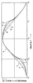
図12は、バッテリレスの機器に適用される電源装置で必要とされる発電コイルの出力特性(出力電流対回転速度特性)を概略的に示したものである。図12の横軸は、発電機の回転子の回転速度Nを示し、縦軸は発電コイルの出力電流iを示している。図12の曲線a及びbはそれぞれ制御システム負荷(第3の負荷)及び常時駆動負荷(第1の負荷)を駆動するための発電コイルの出力特性を示し、曲線cは、随時駆動負荷(第2の負荷)を駆動するための発電コイルの出力特性を示している。 FIG. 12 schematically shows output characteristics (output current vs. rotational speed characteristics) of a power generation coil required for a power supply device applied to a battery-less device. The horizontal axis of FIG. 12 shows the rotational speed N of the rotor of the generator, and the vertical axis shows the output current i of the generator coil. Curves a and b in FIG. 12 show the output characteristics of the power generation coil for driving the control system load (third load) and the constant drive load (first load), respectively, and the curve c shows the drive load (first load) at any time. 2 shows the output characteristics of the power generating coil for driving the load 2).
制御システム負荷を駆動する発電コイルは、図12に曲線aで示したように、機関の始動操作を開始した直後の極低速回転時から負荷を駆動する必要があるため、十分に多くの巻数を持たせて巻回しておく必要がある。発電コイルの巻数を多くすると、機関の高速回転時に出力が飽和したり低下したりするが、制御システム負荷を駆動するために必要な電力は僅かであるため支障を来さない。 Since the power generation coil for driving the control system load needs to drive the load from the very low speed rotation immediately after the start operation of the engine is started as shown by the curve a in FIG. It is necessary to have it wrapped. Increasing the number of turns of the power generation coil causes the output to saturate or decrease during high-speed rotation of the engine, but does not cause a problem because the power required to drive the control system load is small.
常時駆動負荷を駆動する発電コイルは、機関の始動時の回転速度でも負荷を駆動するために必要な出力を発生する必要があるだけでなく、機関の高速回転時にもある程度大きな出力を発生する必要があるため、制御システム負荷を駆動する発電コイルよりは巻数を少なくしておく必要がある。そのため、常時駆動負荷を駆動する発電コイルの出力特性は、図12の曲線bのように、制御システム負荷を駆動する発電コイルの出力が立ち上がる回転速度よりは高く、機関のアイドリング回転速度よりは十分に低い回転速度で出力が立ち上がり、機関の高速回転時には制御システム負荷を駆動する発電コイルよりも大きな出力を発生するような特性となる。 The power generation coil that drives a constantly driven load not only needs to generate the output necessary to drive the load even at the engine rotation speed, but also needs to generate a certain amount of output even at high engine speeds. Therefore, it is necessary to reduce the number of turns as compared with the power generation coil that drives the control system load. Therefore, the output characteristics of the power generation coil that drives the constantly driven load are higher than the rotational speed at which the output of the power generation coil that drives the control system load rises, as shown by the curve b in FIG. 12, and sufficiently higher than the idling rotational speed of the engine. The output rises at a very low rotational speed, and has a characteristic that generates a larger output than the power generation coil that drives the control system load when the engine rotates at high speed.
また随時駆動負荷を駆動する発電コイルは、機関の始動時には出力が不足していてもよいが、機関の始動が完了した後は十分に大きな出力を発生し、機関の高速回転時に出力が低下しないようにする必要があるため、巻数を最も少なくしてある。そのため、その出力特性は、図12の曲線cのように、常時駆動負荷を駆動する発電コイルの出力が立ち上がる回転速度よりも高い回転速度で出力が立ち上がり、機関の高速回転時には常時駆動負荷を駆動する発電コイルよりも大きな出力を発生する特性になる。 The power generation coil that drives the drive load at any time may have insufficient output when the engine is started, but generates a sufficiently large output after the start of the engine is completed and does not decrease during high-speed rotation of the engine. Therefore, the number of turns is minimized. Therefore, as shown by the curve c in FIG. 12, the output characteristic rises at a rotational speed higher than the rotational speed at which the output of the power generating coil that constantly drives the driving load rises, and always drives the driving load when the engine rotates at high speed. It becomes a characteristic that generates a larger output than the power generating coil.
バッテリレスの電源を用いる場合に内燃機関の始動性を向上させるためには、制御システム負荷を駆動する発電コイルの出力をできるだけ低い回転速度で立ち上げるだけでなく、常時駆動負荷を駆動する発電コイルの出力もできるだけ低い回転速度で立ち上げる必要がある。そのためには、機関の始動が完了するまでの間、常時駆動負荷を駆動する発電コイルの出力電圧を昇圧することができるように電源装置を構成しておけばよい。そこで、機関の始動が完了するまでの間常時駆動負荷を駆動する発電コイルの通電電流を断続させるチョッパ制御を行って、当該発電コイルの出力電圧を昇圧することが従来から行われているが、前述した通り、出力電圧を昇圧させようとする発電コイルを流れる電流をチョッパ制御しただけでは、低速回転時の出力電圧を高める上で限界がある。 In order to improve the startability of the internal combustion engine when using a battery-less power supply, not only the output of the power generation coil that drives the control system load is started at a rotational speed as low as possible, but also the power generation coil that drives the drive load at all times It is also necessary to start up the output at as low a rotational speed as possible. For this purpose, the power supply device may be configured so that the output voltage of the power generating coil that drives the driving load can be boosted until the start of the engine is completed. Therefore, it has been conventionally performed to increase the output voltage of the power generation coil by performing chopper control for intermittently passing the energization current of the power generation coil that drives the driving load until the start of the engine is completed. As described above, there is a limit in increasing the output voltage during low-speed rotation only by chopper-controlling the current flowing through the power generation coil for boosting the output voltage.
そこで本発明においては、通電電流を断続させるチョッパ制御を行って負荷に供給する電力の増大を図ろうとする発電コイル(本実施形態では常時駆動負荷を駆動する発電コイル)を「第1の発電コイル」とし、該第1の発電コイルの出力の増大を図るためのチョッパ制御を行っているときに自らの負荷への電力の供給を停止するかまたは制限することが許容される他の発電コイル(本実施形態では随時駆動負荷を駆動する発電コイル)を「第2の発電コイル」として、これら第1の発電コイルと第2の発電コイルとを磁気的に密に結合しておき、第1の発電コイル及び第2の発電コイルの双方を流れる電流をチョッパ制御することにより、従来よりも更に昇圧された直流電圧を負荷に供給することを可能にする。第1の発電コイル及び第2の発電コイルをそれぞれ流れる電流をチョッパ制御する際には、第2の発電コイルを流れる電流を遮断した際に該第2の発電コイルから放出されるエネルギのできるだけ多くの部分を、第1の発電コイルの誘起電圧を昇圧するために有効に利用するため、第2の発電コイルルから第2の負荷への電力の供給を停止させるか、又は制限した状態にしておく。 Therefore, in the present invention, a power generation coil (in this embodiment, a power generation coil that constantly drives a drive load) that attempts to increase the power supplied to the load by performing chopper control that interrupts the energization current is referred to as “first power generation coil. And other generator coils that are allowed to stop or limit the supply of power to their loads when performing chopper control to increase the output of the first generator coil ( In this embodiment, the power generation coil that drives the drive load at any time is defined as a “second power generation coil”, and the first power generation coil and the second power generation coil are magnetically and tightly coupled to each other. By performing chopper control on the current flowing through both the power generation coil and the second power generation coil, it is possible to supply a DC voltage that is further boosted compared to the conventional case to the load. When chopper-controlling the currents flowing through the first power generation coil and the second power generation coil, as much energy as possible is released from the second power generation coil when the current flowing through the second power generation coil is cut off. In order to effectively use this portion for boosting the induced voltage of the first power generation coil, the supply of power from the second power generation coil to the second load is stopped or kept in a restricted state. .
本実施形態では、第1の発電コイルに第2の発電コイルよりも多くの巻数を持たせて、内燃機関の回転速度(発電機の回転子の回転速度)が内燃機関のアイドリング回転速度よりも低く設定された第1の設定速度まで上昇した時、及び機関の回転速度が第1の設定速度よりも高い第2の設定速度まで上昇した時にそれぞれ第1の発電コイル及び第2の発電コイルからの負荷電流の出力が開始されるようにしておく。 In the present embodiment, the first power generation coil has a larger number of turns than the second power generation coil, and the rotation speed of the internal combustion engine (rotation speed of the rotor of the generator) is higher than the idling rotation speed of the internal combustion engine. From the first power generation coil and the second power generation coil when the engine speed increases to a first set speed set low and when the engine speed increases to a second set speed higher than the first set speed, respectively. The output of the load current is started.
また制御システム負荷を駆動する発電コイルを「第3の発電コイル」とし、この発電コイルは、第1の発電コイルが負荷電流の供給を開始する回転速度よりも更に低い回転速度で負荷電流の供給を開始することができるように、第1の発電コイルよりも更に多くの巻数を持たせて巻回しておく。 The power generation coil that drives the control system load is referred to as a “third power generation coil”, and this power generation coil supplies the load current at a lower rotational speed than the rotational speed at which the first power generation coil starts supplying the load current. In order to be able to start, winding is performed with a greater number of turns than the first power generation coil.
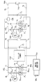
図1は本発明に係る内燃機関用電源装置の第1の実施形態の電気的な構成を示したものである。同図においてWa及びWbはそれぞれ内燃機関により駆動される交流発電機に設けられた第1及び第2の発電コイル、Ld1及びLd2はそれぞれ第1の発電コイル及び第2の発電コイルから電力が供給される第1及び第2の負荷である。またVC1は第1の発電コイルWaの出力電圧を第1の負荷Ld1に供給する直流電圧に変換する第1の電圧変換回路、VC2は第2の発電コイルWbの出力電圧を第2の負荷Ld2に供給する直流電圧に変換する第2の電圧変換回、CSは第2の電圧変換回路VC2と第2の負荷Ld2との間に挿入された通電制御用スイッチであり、第1及び第2の電圧変換回路VC1及びVC2と、通電制御用スイッチCSとにより、発電機の交流出力電圧を第1の負荷Ld1及び第2の負荷Ld2に供給する直流電圧に変換する交直変換回路が構成されている。 FIG. 1 shows an electrical configuration of a first embodiment of a power supply device for an internal combustion engine according to the present invention. In the figure, Wa and Wb are first and second power generation coils provided in an AC generator driven by an internal combustion engine, respectively, and Ld1 and Ld2 are supplied with power from the first power generation coil and the second power generation coil, respectively. Are the first and second loads. VC1 is a first voltage conversion circuit that converts the output voltage of the first power generation coil Wa into a DC voltage supplied to the first load Ld1, and VC2 is the output voltage of the second power generation coil Wb that is the second load Ld2. CS is a second voltage conversion circuit for converting the DC voltage supplied to the second voltage conversion circuit VC2 and the second load Ld2 between the second voltage conversion circuit VC2 and the second load Ld2. The AC / DC conversion circuit that converts the AC output voltage of the generator into the DC voltage supplied to the first load Ld1 and the second load Ld2 is configured by the voltage conversion circuits VC1 and VC2 and the energization control switch CS. .
第1の電圧変換回路VC1は、ブリッジの2つのレグの上側のアームをダイオードD11及びD12により構成し、該2つのレグの下側のアームをMOSFET F11及びF12により構成した第1のブリッジ回路B1からなっている。 In the first voltage conversion circuit VC1, the upper arm of the two legs of the bridge is configured by diodes D11 and D12, and the lower arm of the two legs is configured by MOSFETs F11 and F12. It is made up of.
本実施形態では、第1のブリッジ回路B1の下側アームを構成するMOSFET F11,F12により第1のスイッチ手段が構成されるとともに、第1のブリッジ回路B1の上側アームを構成するダイオードD11,D12と、第1のブリッジ回路B1の下側アームを構成するMOSFET F11,F12のドレインソース間に形成された寄生ダイオードDp11,Dp12とによりフルブリッジ型の第1の整流回路が構成されている。 In this embodiment, MOSFETs F11 and F12 constituting the lower arm of the first bridge circuit B1 constitute a first switch means, and diodes D11 and D12 constituting the upper arm of the first bridge circuit B1. And a parasitic diode Dp11, Dp12 formed between the drains and sources of MOSFETs F11, F12 constituting the lower arm of the first bridge circuit B1, constitutes a first full-bridge rectifier circuit.
ダイオードD11のアノードとMOSFET F11のドレインとの接続点a1及びダイオードD12のアノードとMOSFET F12のドレインとの接続点b1が第1の整流回路の入力端子となっていて、これらの入力端子間に第1の発電コイルWaに誘起する電圧が入力される。またダイオードD11,D12のカソードの共通接続点及びMOSFET F11及びF12のソースの共通接続点がそれぞれ第1の整流回路のプラス側及びマイナス側の出力端子c1及びd1となっており、これらの端子間に平滑用コンデンサC1が接続されている。第1の整流回路の出力端子c1及びd1から負荷接続端子e1及びf1が引き出され、これらの負荷接続端子間に第1の負荷Ld1が接続されている。 The connection point a1 between the anode of the diode D11 and the drain of the MOSFET F11 and the connection point b1 between the anode of the diode D12 and the drain of the MOSFET F12 serve as input terminals of the first rectifier circuit, A voltage induced in one power generation coil Wa is input. The common connection point of the cathodes of the diodes D11 and D12 and the common connection point of the sources of the MOSFETs F11 and F12 are the output terminals c1 and d1 on the plus side and the minus side of the first rectifier circuit, respectively. Is connected to a smoothing capacitor C1. Load connection terminals e1 and f1 are drawn from output terminals c1 and d1 of the first rectifier circuit, and a first load Ld1 is connected between these load connection terminals.
第2の電圧変換回路VC2は、ブリッジの2つのレグの上側のアームをダイオードD21及びD22により構成し、該2つのレグの下側のアームをMOSFET F21及びF22により構成した第2のブリッジ回路B22からなっている。 In the second voltage conversion circuit VC2, the upper arm of the two legs of the bridge is configured by diodes D21 and D22, and the lower arm of the two legs is configured by MOSFETs F21 and F22. It is made up of.
本実施形態では、第2のブリッジ回路B2の下側アームを構成するMOSFET F21,F22により第2のスイッチ手段が構成され、第2のブリッジ回路B2の上側アームを構成するダイオードD21,D22と第2のブリッジ回路B2の下側アームを構成するMOSFET F21,F22のドレインソース間に形成された寄生ダイオードDp21,Dp22とにより、フルブリッジ型の第2の整流回路が構成されている。ダイオードD21のアノードとMOSFET F21のドレインとの接続点a2及びダイオードD22のアノードとMOSFET F22のドレインとの接続点b2が第2の整流回路の入力端子となっていて、これらの入力端子間に第2の発電コイルWbに誘起する電圧が入力されている。 In the present embodiment, the second switch means is constituted by the MOSFETs F21 and F22 constituting the lower arm of the second bridge circuit B2, and the diodes D21 and D22 constituting the upper arm of the second bridge circuit B2 and the second A full-bridge type second rectifier circuit is constituted by the parasitic diodes Dp21 and Dp22 formed between the drains and sources of the MOSFETs F21 and F22 constituting the lower arm of the second bridge circuit B2. A connection point a2 between the anode of the diode D21 and the drain of the MOSFET F21 and a connection point b2 between the anode of the diode D22 and the drain of the MOSFET F22 are input terminals of the second rectifier circuit. The voltage induced in the second power generation coil Wb is input.
またダイオードD21,D22のカソードの共通接続点及びMOSFET F21及びF22のソースの共通接続点がそれぞれ第2の整流回路のプラス側及びマイナス側の出力端子c2及びd2となっていて、プラス側出力端子c2から通電制御用スイッチCSを通してプラス側負荷接続端子e2が引き出されている。また第2の整流回路のマイナス側出力端子d2からマイナス側負荷接続端子f2が引き出され、負荷接続端子e2,f2間にスイッチSWを介して第2の負荷Ld2が接続されている。第2の整流回路の出力端子c2,d2間にはまた、第2の負荷への通電を制御する通電制御用スイッチCSを介して平滑用コンデンサC2が接続されている。通電制御用スイッチCSは、MOSFETのようなオンオフ制御が可能なスイッチング素子により構成されていて、後述するスイッチ制御部により制御される。またスイッチSWは、内燃機関を始動した後、第2の負荷Ld2を動作させる際に閉じられるスイッチで、オンオフ操作が可能なスイッチ素子からなっている。 The common connection point of the cathodes of the diodes D21 and D22 and the common connection point of the sources of the MOSFETs F21 and F22 are respectively the positive side and negative side output terminals c2 and d2 of the second rectifier circuit, and the positive side output terminal. The positive side load connection terminal e2 is drawn out from c2 through the energization control switch CS. Further, a minus side load connection terminal f2 is drawn from the minus side output terminal d2 of the second rectifier circuit, and the second load Ld2 is connected between the load connection terminals e2 and f2 via the switch SW. A smoothing capacitor C2 is also connected between the output terminals c2 and d2 of the second rectifier circuit via an energization control switch CS for controlling energization to the second load. The energization control switch CS is composed of a switching element that can be turned on and off, such as a MOSFET, and is controlled by a switch control unit described later. The switch SW is a switch that is closed when the second load Ld2 is operated after the internal combustion engine is started, and includes a switch element that can be turned on and off.
図1においてCUは、MOSFET F11,F12により構成されている第1のスイッチ手段と、MOSFET F21,F22により構成されている第2のスイッチ手段と、通電制御用スイッチCSとを制御するスイッチ制御部である。スイッチ制御部CUは、発電機内に十分に多くの巻数を持って設けられて内燃機関の極低速時から電圧を出力する第3の発電コイルWcを電源として一定の直流電圧Vcc を出力する制御用電源回路PSから電源電圧が与えられて動作する。 In FIG. 1, CU is a switch control unit for controlling the first switch means constituted by MOSFETs F11 and F12, the second switch means constituted by MOSFETs F21 and F22, and the energization control switch CS. It is. The switch control unit CU is provided with a sufficiently large number of turns in the generator, and outputs a constant DC voltage Vcc using a third power generation coil Wc that outputs a voltage from an extremely low speed of the internal combustion engine as a power source. The power supply circuit PS operates by being supplied with a power supply voltage.
図示のスイッチ制御部CUは、内燃機関の始動時のように、機関の回転速度が低い領域で第1の負荷(本実施形態では常時駆動負荷)Ld1を動作させるために、第1の発電コイルWaの誘起電圧を昇圧して、第1の負荷Ld1に与える直流電圧を、第1の発電コイルWaの誘起電圧をそのまま整流した場合に得られる電圧よりも高くすることが必要とされるとき(本実施形態では機関の回転速度が始動完了速度未満の時)に、通電制御用スイッチCSをオフ状態にして第2の電圧変換回路から第2の負荷への通電を阻止した状態に保つか、又は第2の発電コイルWbから第2の負荷Ld2に流れる電流を制限するように通電制御用スイッチCSをオンオフさせた状態(PWM制御した状態)で、第1の負荷Ld1に供給される電圧を昇圧させるべく、第1のスイッチ手段(MOSFET F11,F12))と第2のスイッチ手段(MOSFET F21,F22)の双方をオンオフ制御して、第1の発電コイルWaを流れる電流と第2の発電コイルWbを流れる電流との双方のチョッパ制御を同時に行うように構成されている。 The illustrated switch control unit CU includes a first power generation coil for operating the first load (always driving load in the present embodiment) Ld1 in a region where the rotational speed of the engine is low, such as when the internal combustion engine is started. When the induced voltage of Wa is boosted and the DC voltage applied to the first load Ld1 needs to be higher than the voltage obtained when the induced voltage of the first power generation coil Wa is rectified as it is ( In this embodiment, when the rotational speed of the engine is less than the start completion speed), the energization control switch CS is turned off to keep the second voltage conversion circuit from energizing the second load, Alternatively, the voltage supplied to the first load Ld1 in the state where the energization control switch CS is turned on / off so as to limit the current flowing from the second power generation coil Wb to the second load Ld2 (a state in which PWM control is performed). Boosted Therefore, both the first switch means (MOSFETs F11, F12)) and the second switch means (MOSFETs F21, F22) are controlled to be turned on / off, and the current flowing through the first power generation coil Wa and the second power generation coil are controlled. The chopper control of both the current flowing through Wb is performed simultaneously.
上記第1及び第2の発電コイルWa及びWbは、内燃機関により駆動される交流発電機内に設けられている。内燃機関により駆動される交流発電機は、放射状に配置されたn個(nは2以上の整数)の歯部を有する電機子鉄心と、この電機子鉄心に設けられているm個(mは2以上n以下の整数)の歯部にそれぞれ巻回されたm個の単位コイルとを備えた固定子と、電機子鉄心の各歯部の先端に形成された磁極部に対向する複数の磁極を備えた界磁を有して内燃機関により回転駆動される回転子とにより構成される。何らかの理由により、電機子鉄心に設けられたn個の歯部の一部を、コイルを巻かずに遊ばせておく必要がある場合には、m<nとなるが、通常はm=nとする。 The first and second power generation coils Wa and Wb are provided in an AC generator driven by an internal combustion engine. An AC generator driven by an internal combustion engine has n armature cores having n (n is an integer of 2 or more) teeth arranged radially, and m pieces (m is a m) provided on the armature core. And a plurality of magnetic poles facing the magnetic pole portions formed at the tips of the respective tooth portions of the armature core. And a rotor that is driven to rotate by an internal combustion engine. If for some reason it is necessary to allow some of the n teeth provided on the armature core to be played without winding a coil, m <n, but usually m = n. .
本実施形態では、内燃機関により駆動する交流発電機として、回転子の界磁が永久磁石により構成される磁石発電機を用いる。本実施形態で用いている磁石発電機は、図6に示すように構成されている。図6において1は、18極の磁石回転子、2は18極の固定子である。磁石回転子1は、カップ状の回転子ヨーク(フライホイール)101と、回転子ヨーク101の周壁部101aの内周に等角度間隔で固定された18個の永久磁石M1〜M18とからなっていて、一連の永久磁石M1〜M18が交互に向きを異ならせて回転子ヨークの径方向に着磁されることにより、回転子ヨーク101の周壁部の内側に18極の磁石界磁が構成されている。
In this embodiment, a magnet generator in which the rotor field is composed of permanent magnets is used as an AC generator driven by an internal combustion engine. The magnet generator used in this embodiment is configured as shown in FIG. In FIG. 6, 1 is an 18-pole magnet rotor and 2 is an 18-pole stator. The
固定子2は、環状のヨークYの外周部から18個の歯部T1〜T18を等角度間隔で放射状に突出させた構造を有する電機子鉄心201と、電機子鉄心201の一連の歯部T1〜T18にそれぞれ巻回された単位コイルW1ないしW18とからなっている。固定子2は、磁石回転子1の内側に同心的に配置された状態で機関のケースやカバーなどに固定され、電機子鉄心の歯部T1〜T18のそれぞれの先端に形成された磁極部が、磁石回転子1の磁極M1〜M18にギャップを介して対向させられている。
The
本実施形態においては、固定子2に設けられた単位コイルW1〜W18が、第1ないし第3の発電コイルWa〜Wcを構成するように結線されている。これらの発電コイルの内、第1の発電コイルWaは、電機子鉄心に設けられた歯部の内、一つ置きに配置された複数の歯部にそれぞれ巻回された複数の単位コイルを結線することにより構成され、第2の発電コイルWbは、電機子鉄心に設けられた歯部の内、第1の発電コイルを構成している複数の単位コイルの何れかが巻回された歯部に隣接する位置関係を有する一つ置きの歯部にそれぞれ巻回された複数の単位コイルを結線することにより構成される。また第3の発電コイルWcは、他の単位コイルを結線することにより構成される。
In the present embodiment, unit coils W1 to W18 provided on the
即ち、第1の発電コイルを構成する各単位コイルが巻回された歯部を第2の発電コイルを構成する単位コイルの何れかが巻回された歯部に隣接させることにより、第1の発電コイルと第2の発電コイルとを密に磁気結合している。 That is, by making the tooth portion around which each unit coil constituting the first power generation coil is wound adjacent to the tooth portion around which any of the unit coils constituting the second power generation coil is wound, The power generation coil and the second power generation coil are closely magnetically coupled.
図示の例では、電機子鉄心の歯部T1〜T18にそれぞれ巻回された一連の単位コイルW1〜W18の内、一つ置きに配置された6個の単位コイルW2,W4,W6,W8,W10及びW12が直列に接続されることにより第1の発電コイルWaが構成され、単位コイルW2,W4,W6,W8,W10及びW12がそれぞれ巻回された歯部T2,T4,T6,T8,T10及びT12に隣接する一つ置きの歯部T1,T3,T5,T7,T9,T11及びT13にそれぞれ巻回された7個の単位コイルW1,W3,W5,W7,W9,W11及びW13が直列に接続されることにより第2の発電コイルWbが構成されている。また他の5個の単位コイルW14〜W18が直列に接続されることにより第3の発電コイルWcが構成されている。 In the example shown in the drawing, six unit coils W2, W4, W6, W8, which are alternately arranged, out of a series of unit coils W1 to W18 wound around the tooth portions T1 to T18 of the armature core, respectively. W10 and W12 are connected in series to form a first power generation coil Wa, and tooth portions T2, T4, T6, T8, in which unit coils W2, W4, W6, W8, W10 and W12 are wound, respectively. Seven unit coils W1, W3, W5, W7, W9, W11 and W13 wound around every other tooth T1, T3, T5, T7, T9, T11 and T13 adjacent to T10 and T12, respectively. The second power generation coil Wb is configured by being connected in series. The other five unit coils W14 to W18 are connected in series to form a third power generation coil Wc.
スイッチ制御部CUは例えば図2に示すように構成される。図2において、10は第1のスイッチ手段11を構成するMOSFET F11,F12と、第2のスイッチ手段12を構成するMOSFET F21,F22とに駆動信号を供給する駆動信号供給回路である。駆動信号供給回路10には、第1の発電コイルW1の出力電圧の各零クロス点(出力電圧が負の半波から正の半波に移行する際の零クロス点及び正の半波から負の半波に移行する際の零クロス点)を検出する零クロス検出回路13の出力と、第1の発電コイルW1の出力電圧の各ピーク点を検出するピーク検出回路14の出力と、昇圧要否判定手段15の出力とが入力されている。
The switch control unit CU is configured as shown in FIG. 2, for example. In FIG. 2,
駆動信号供給回路10は、第1の発電コイルWaに誘起する電圧を昇圧する動作を行なうことが必要なときに、MOSFET F11,F12及びMOSFET F21,F22のゲートにパルス波形の駆動信号を同時に与えて、第1の発電コイルWa及び第2の発電コイルWbに周期的に断続する波形の電流を流すべく、MOSFET F11,F12及びMOSFET F21,F22をオンオフさせることにより、第1の発電コイルWaを流れる電流のチョッパ制御及び第2の発電コイルWbを流れる電流のチョッパ制御を同時に行う。
The drive
本実施形態で用いる駆動信号供給回路10は、昇圧動作を行なうことが必要であるときに、零クロス検出回路13が発電コイルWa及びWbの出力電圧の各零クロス点を検出してからピーク検出回路14がピーク点を検出するまでの間、第1のスイッチ手段及び第2のスイッチ手段を構成するMOSFET F11,F12及びF21,F22のゲートに同時に高レベルの駆動信号を与えて第1のスイッチ手段及び第2のスイッチ手段を同時にオン状態にし、ピーク検出回路14が各ピーク点を検出してから零クロス検出回路13が零クロス点を検出するまでの間、第1のスイッチ手段及び第2のスイッチ手段を構成するMOSFETに与える駆動信号を零レベルにして、第1のスイッチ手段及び第2のスイッチ手段を同時にオフ状態にするように構成されている。
The drive
昇圧要否判定手段15は、第1の発電コイルWaの誘起電圧を昇圧する必要があるか否かを判定する手段である。図示の昇圧要否判定手段15は、内燃機関の回転速度を検出する回転速度検出手段16により検出された回転速度を、機関の始動が完了したことを判定するために適した速度に設定された設定速度(始動完了速度)と比較して、内燃機関の回転速度が設定速度未満であるとき(機関の始動が完了していないとき)に第1の発電コイルの出力電圧の昇圧が必要であると判定して、駆動信号供給回路10に駆動信号出力指令を与えるとともに、通電制御用スイッチCSにオフ指令を与えて該通電制御用スイッチをオフ状態にする。昇圧要否判定手段15はまた、内燃機関の回転速度が設定速度以上であるとき(機関の始動が完了したとき)に昇圧の必要性がなくなったと判定して、駆動信号供給回路10に駆動信号停止指令を与えるとともに、通電制御用スイッチCSにオン指令を与えて、該通電制御用スイッチをオン状態にする。
The boosting necessity determination unit 15 is a unit that determines whether or not it is necessary to boost the induced voltage of the first power generation coil Wa. The boosting necessity determination means 15 shown in the figure is set to a speed suitable for determining that the engine has been started, with the rotation speed detected by the rotation speed detection means 16 for detecting the rotation speed of the internal combustion engine. When the rotational speed of the internal combustion engine is lower than the set speed (when the start of the engine is not completed) as compared with the set speed (start completion speed), the output voltage of the first power generation coil needs to be boosted. And a drive signal output command is given to the drive
回転速度検出手段16は、任意の方法により機関の回転速度を検出する。回転速度検出手段16は例えば、零クロス検出回路13が各零クロス点を検出してから次の零クロス点を検出するまでの時間から機関の回転速度を検出するように構成することができる。また内燃機関が所定の回転角度回転する毎にパルス信号を発生する信号発生器が設けられている場合には、その信号発生器がパルスを発生する間隔から機関の回転速度を検出するようにすることができる。
The rotational speed detection means 16 detects the rotational speed of the engine by an arbitrary method. For example, the rotational speed detecting means 16 can be configured to detect the rotational speed of the engine from the time from when the zero
本実施形態に係る電源装置の動作を示す電圧、電流波形の一例を図8に示した。図8(A)は機関のクランク軸が回転したときに第1の発電コイルWa及び第2の発電コイルWbに誘起する交流電圧の波形を示し、同図(B)は駆動信号供給回路10がMOSFET F11,F12,F21及びF22に与える駆動信号V11,V12,及びV21,V22を示している。また図8(C)は,第1の発電コイルWaから第1の電圧変換回路VC1を通して出力される直流電流の波形を示し、図8(D)は第1の発電コイルWaから第1の電圧変換回路VC1を通して出力される直流電圧の波形を示している。また図8(E)は第1の発電コイルWaから第1の電圧変換回路VC1を通して出力される直流電力の変化を示している。 An example of voltage and current waveforms showing the operation of the power supply device according to the present embodiment is shown in FIG. FIG. 8A shows the waveform of the alternating voltage induced in the first power generation coil Wa and the second power generation coil Wb when the crankshaft of the engine rotates, and FIG. The drive signals V11, V12, and V21, V22 given to the MOSFETs F11, F12, F21 and F22 are shown. FIG. 8C shows the waveform of a direct current output from the first power generation coil Wa through the first voltage conversion circuit VC1, and FIG. 8D shows the first voltage from the first power generation coil Wa. The waveform of the DC voltage output through the conversion circuit VC1 is shown. FIG. 8E shows a change in DC power output from the first power generation coil Wa through the first voltage conversion circuit VC1.
駆動信号供給回路10は、零クロス検出回路13が第1の発電コイルWaの誘起電圧の各零クロス点を検出してからピーク検出回路14がピーク点を検出するまでの間高レベルの状態を保持し、ピーク検出回路が発電コイルWaの誘起電圧のピーク点を検出してから零クロス検出回路13が零クロス点を検出するまでの間零レベルを保持する矩形波状の駆動信号V11,V12をMOSFET F11,F12のゲートに同時に与える。
The drive
駆動信号供給回路10はまた、零クロス検出回路13が第2の発電コイルWbの誘起電圧の各零クロス点を検出してからピーク検出回路14が第2の発電コイルWbのピーク点を検出するまでの間高レベルの状態を保持し、ピーク検出回路14が発電コイルWbの誘起電圧のピーク点を検出してから零クロス検出回路13が零クロス点を検出するまでの間零レベルを保持する矩形波状の駆動信号V21,V22をMOSFET F21,F22のゲートに同時に与える。
The drive
第1の発電コイルWaの誘起電圧の各零クロス点でMOSFET F11及びF12(第1のスイッチ手段)に同時に駆動信号が与えられると、両MOSFETが同時にオン状態になって発電コイルWaを短絡するため、発電コイルWaに短絡電流が流れる。この短絡電流は発電コイルWaの誘起電圧の上昇に伴って大きくなっていく。発電コイルWaの誘起電圧がピークに達して駆動信号V11,V12が零になると、MOSFET F11,F12が同時にオフ状態になるため、それまで流れていた短絡電流が遮断される。この電流の遮断により、発電コイルWaにそれまで流れていた電流を流し続けようとする向きの昇圧された電圧が誘起する。本実施形態では、発電コイルWaの誘起電圧がピークに達したときに発電コイルWaを流れていた電流を遮断するため、発電コイルWaに誘起する電圧を高くすることができる。 When a drive signal is simultaneously applied to the MOSFETs F11 and F12 (first switch means) at each zero cross point of the induced voltage of the first generator coil Wa, both MOSFETs are simultaneously turned on to short-circuit the generator coil Wa. Therefore, a short-circuit current flows through the power generation coil Wa. This short circuit current increases as the induced voltage of the generator coil Wa increases. When the induced voltage of the power generation coil Wa reaches a peak and the drive signals V11 and V12 become zero, the MOSFETs F11 and F12 are simultaneously turned off, so that the short-circuit current that has flown until then is interrupted. The interruption of the current induces a boosted voltage in a direction in which the current that has been flowing through the power generation coil Wa continues to flow. In the present embodiment, since the current flowing through the power generation coil Wa when the induced voltage of the power generation coil Wa reaches a peak is cut off, the voltage induced in the power generation coil Wa can be increased.
また第2の発電コイルWbの誘起電圧の各零クロス点でMOSFET F21及びF22(第2のスイッチ手段)に同時に駆動信号が与えられると、両MOSFET F21,F22が同時にオン状態になって発電コイルWbを短絡するため、発電コイルWbに短絡電流が流れる。発電コイルWbの誘起電圧がピークに達して駆動信号V21,V22が零になると、MOSFET F21,F22が同時にオフ状態になって、それまで流れていた短絡電流が遮断されるため、発電コイルWbに昇圧された電圧が誘起する。 When a drive signal is simultaneously applied to the MOSFETs F21 and F22 (second switch means) at each zero cross point of the induced voltage of the second generator coil Wb, both MOSFETs F21 and F22 are simultaneously turned on and the generator coil is turned on. In order to short-circuit Wb, a short-circuit current flows through the power generation coil Wb. When the induced voltage of the power generation coil Wb reaches a peak and the drive signals V21 and V22 become zero, the MOSFETs F21 and F22 are simultaneously turned off, and the short-circuit current that has flown until then is interrupted. A boosted voltage is induced.
本発明に係る電源装置においては、第1の発電コイルWaと第2の発電コイルWbとが密に磁気結合されている上に、第2の発電コイルWbから第2の負荷Ld2への電力の供給が停止されているため、第2の発電コイルWbを流れていた電流を遮断した際に該第2の発電コイルから放出されるエネルギ(L・i2)/2の多くの部分を第1の発電コイルに移行させて、第1の発電コイルを流れる電流を遮断した際に該第1の発電コイルから放出されるエネルギに重畳することができする。そのため、第1の発電コイルWaに誘起する電圧を、第1の発電コイルWaを流れていた電流のみを遮断した場合に誘起する電圧よりも更に高くすることができる。In the power supply device according to the present invention, the first power generation coil Wa and the second power generation coil Wb are closely magnetically coupled, and the power from the second power generation coil Wb to the second load Ld2 Since the supply is stopped, a large part of the energy (L · i 2 ) / 2 released from the second power generation coil when the current flowing through the second power generation coil Wb is interrupted is the first. When the current flowing through the first power generation coil is interrupted, the energy released from the first power generation coil can be superimposed. Therefore, the voltage induced in the first power generation coil Wa can be made higher than the voltage induced when only the current flowing through the first power generation coil Wa is cut off.
第1の発電コイルWaを流れる電流のチョッパ制御のみを行った場合に、第1の電圧変換回路VC1から第1の負荷Ld1に供給される電流、電圧及び電力はそれぞれ図8(C)、(D)及び(E)の曲線aの通りであるが、第1の発電コイルWaを流れる電流及び第2の発電コイルを流れる電流の双方を同時にチョッパ制御した場合に第1の電圧変換回路VC1から第1の負荷Ld1に供給される電流、電圧及び電力はそれぞれ図8(C)、(D)及び(E)の曲線bのようになる。 When only chopper control of the current flowing through the first power generation coil Wa is performed, the current, voltage, and power supplied from the first voltage conversion circuit VC1 to the first load Ld1 are shown in FIGS. D) and (E) as indicated by curve a. When both the current flowing through the first power generating coil Wa and the current flowing through the second power generating coil are simultaneously controlled by the chopper, the first voltage conversion circuit VC1 The current, voltage, and power supplied to the first load Ld1 are as shown by curves b in FIGS. 8C, 8D, and 8E, respectively.
このように、本実施形態に係る電源装置によれば、第1の発電コイルに誘起する電圧を、第1の発電コイルを流れていた電流のみを遮断した場合に誘起する電圧よりも更に高くすることができるため、本実施形態の電源装置をバッテリレスの内燃機関駆動機器に適用した場合、機関の始動時に従来よりも更に低い回転速度から第1の発電コイルの出力電圧を立ち上げて、極低速回転時から燃料ポンプなどの常時駆動負荷を駆動して、機関の始動性を向上させることができる。 Thus, according to the power supply device according to the present embodiment, the voltage induced in the first power generation coil is made higher than the voltage induced when only the current flowing through the first power generation coil is cut off. Therefore, when the power supply device of the present embodiment is applied to a batteryless internal combustion engine drive device, the output voltage of the first power generation coil is raised at a lower rotational speed than before when starting the engine, It is possible to improve the startability of the engine by driving a constant drive load such as a fuel pump from a low speed rotation.
なお第1の発電コイルWa及び第2の発電コイルWbにそれぞれ誘起する交流電圧は厳密には同位相ではないが、両電圧の位相差は僅かであるので、両電圧の位相差により昇圧動作が支障を来すことはない。 Although the AC voltages induced in the first power generation coil Wa and the second power generation coil Wb are not strictly in the same phase, the phase difference between the two voltages is very small, so that the boosting operation is caused by the phase difference between the two voltages. There will be no hindrance.
本発明者は、第1の発電コイル及び第2の発電コイルを磁気的に密に結合した状態で、第1の発電コイルから出力を得ることを想定して行うチョッパ制御に関して、チョッパ制御の効果を確認するために下記の3通りの制御を行なう実験を行なった。
(1)第1の発電コイルWaと該第1の発電コイルよりも巻数が少ない第2の発電コイルとの双方をチョッパ制御する。
(2)第1の発電コイルWaのみをチョッパ制御する。
(3)第2の発電コイルWbのみをチョッパ制御する。The inventor of the present invention relates to chopper control performed assuming that an output is obtained from the first power generation coil in a state where the first power generation coil and the second power generation coil are magnetically tightly coupled, and the effect of the chopper control. In order to confirm the above, the following three types of control were conducted.
(1) Chopper-controlled both the first power generation coil Wa and the second power generation coil having a smaller number of turns than the first power generation coil.
(2) Chopper control is performed only on the first power generation coil Wa.
(3) Chopper control is performed only on the second power generation coil Wb.
図9は、上記(1)ないし(3)の制御を行った際に第1の発電コイルWaに鎖交する磁束の量の変化を、回転子の回転角θに対して模式的に示したものである。同図において曲線aは無負荷時に磁石回転子の回転に伴って第1の発電コイルに鎖交する磁束量の変化を示し、曲線bは、チョッパ制御を行わずに第1の発電コイルWaの出力を全波整流した場合に第1の発電コイルに鎖交する磁束量の変化を示している。また曲線cは、第2の発電コイルWbを無負荷状態として第1の発電コイルWaを流れる電流のみをチョッパ制御した場合に第1の発電コイルに鎖交する磁束量の変化を示し、曲線dは第1の発電コイルを無負荷状態として、第2の発電コイルWbを流れる電流のみをチョッパ制御した場合に第1の発電コイルに鎖交する磁束量の変化を示している。また曲線eは、第1の発電コイルWaを流れる電流と第2の発電コイルWbを流れる電流との双方をチョッパ制御した場合に第1の発電コイルWaに鎖交する磁束量の変化を示している。 FIG. 9 schematically shows changes in the amount of magnetic flux interlinked with the first power generation coil Wa when the controls (1) to (3) are performed, with respect to the rotation angle θ of the rotor. Is. In the figure, a curve a shows a change in the amount of magnetic flux interlinked with the first power generation coil as the magnet rotor rotates at no load, and a curve b shows the first power generation coil Wa without the chopper control. A change in the amount of magnetic flux linked to the first power generation coil when the output is subjected to full-wave rectification is shown. Curve c shows the change in the amount of magnetic flux interlinked with the first power generation coil when the second power generation coil Wb is in a no-load state and only the current flowing through the first power generation coil Wa is chopper-controlled. Shows a change in the amount of magnetic flux interlinking with the first power generation coil when the first power generation coil is in a no-load state and only the current flowing through the second power generation coil Wb is chopper-controlled. Curve e shows the change in the amount of magnetic flux interlinked with the first power generation coil Wa when both the current flowing through the first power generation coil Wa and the current flowing through the second power generation coil Wb are chopper-controlled. Yes.
なお図9に示した例では、第1の発電コイルWaを流れる電流をチョッパ制御する場合、第2の発電コイルWbを流れる電流をチョッパ制御する場合、及び第1の発電コイルWaを流れる電流及び第2の発電コイルWbを流れる電流の双方を同時にチョッパ制御する場合のいずれの場合にも、横軸に示した角度θ1、θ3及びθ5の位置をそれぞれの発電コイルに電流を流し始める位置とし、角度θ2の位置及び角度θ4の位置を、それまで流れていた電流を遮断する位置としている。 In the example shown in FIG. 9, when the current flowing through the first power generation coil Wa is chopper-controlled, when the current flowing through the second power generation coil Wb is chopper-controlled, and the current flowing through the first power generation coil Wa and In any case where both currents flowing through the second power generation coil Wb are simultaneously controlled by chopper control, the positions of the angles θ1, θ3, and θ5 shown on the horizontal axis are positions where the current starts to flow through the respective power generation coils, The position of the angle θ2 and the position of the angle θ4 are positions where the current that has been flowing so far is cut off.
第1の発電コイルWaの出力電圧を直流電圧に変換する第1の電圧変換回路VC1に負荷が接続されていないときには、図9の曲線aのように、磁石回転子の回転に伴って第1の発電コイルWaに鎖交する磁束量がほぼ正弦波状に変化する。また第1の発電コイルWa及び第2の発電コイルWbの何れに対してもチョッパ制御を行なわなかった場合も、第1の発電コイルWaに鎖交する磁束量は、回転子の回転に伴って図9の曲線bのようにほぼ正弦波状に変化する。 When a load is not connected to the first voltage conversion circuit VC1 that converts the output voltage of the first power generation coil Wa into a DC voltage, the first voltage is generated along with the rotation of the magnet rotor as indicated by a curve a in FIG. The amount of magnetic flux interlinked with the power generation coil Wa changes in a substantially sine wave shape. Further, even when the chopper control is not performed for either the first power generation coil Wa or the second power generation coil Wb, the amount of magnetic flux interlinked with the first power generation coil Wa is accompanied by the rotation of the rotor. As shown by a curve b in FIG.
これに対し、第2の発電コイルWbを無負荷状態に保って第1の発電コイルWaを流れる電流のみをチョッパ制御した場合(第1の発電コイルを流れる電流のみを断続させた場合)には、角度θ2及びθ4の位置において第1の発電コイルWaを流れていた電流を遮断した際に、第1の発電コイルから発生する磁束に変化が生じるため、曲線cに見られるように、角度θ2及びθ4の位置で第1の発電コイルと鎖交する磁束量が、チョッパ制御を行なわない場合の正弦波状の変化よりも大きな変化を示し、この磁束量の変化により、第1の発電コイルに昇圧された電圧が誘起する。 On the other hand, when chopper control is performed only on the current flowing through the first power generation coil Wa while keeping the second power generation coil Wb in an unloaded state (when only the current flowing through the first power generation coil is intermittent). When the current flowing through the first power generation coil Wa at the positions of the angles θ2 and θ4 is interrupted, a change occurs in the magnetic flux generated from the first power generation coil. Therefore, as shown in the curve c, the angle θ2 And the amount of magnetic flux interlinking with the first power generation coil at the position of θ4 shows a larger change than a sinusoidal change when chopper control is not performed, and the change in the amount of magnetic flux boosts the first power generation coil. Induced voltage is induced.
また第1の発電コイルWaを無負荷状態に保って第2の発電コイルWbを流れる電流のみをチョッパ制御した場合には、角度θ2及びθ4の位置において第2の発電コイルWaを流れていた電流を遮断した際に生じる磁束の変化が、磁気的に密に結合されている第1の発電コイルと鎖交する磁束量の変化に重畳されるため、第1の発電コイルに鎖交する磁束量に大きな変化が生じ、曲線dに見られるように、角度θ2及びθ4の位置で第1の発電コイルと鎖交する磁束量が、チョッパ制御を行なわない場合の正弦波状の変化よりも大きな変化を示し、この磁束量の変化により、第1の発電コイルWaに昇圧された電圧が誘起する。 Further, when only the current flowing through the second power generation coil Wb is chopper-controlled while keeping the first power generation coil Wa in a no-load state, the current flowing through the second power generation coil Wa at the positions of the angles θ2 and θ4 Since the change in magnetic flux generated when the power is interrupted is superimposed on the change in the amount of magnetic flux interlinked with the first power generation coil that is magnetically tightly coupled, the amount of magnetic flux interlinked with the first power generation coil As shown in the curve d, the amount of magnetic flux interlinking with the first power generation coil at the positions of the angles θ2 and θ4 changes more than the sinusoidal change when chopper control is not performed. It is shown that the boosted voltage is induced in the first power generation coil Wa due to the change in the amount of magnetic flux.
また第1の発電コイルWaを流れる電流及び第2の発電コイルWbを流れる電流の双方をチョッパ制御した場合には、角度θ2の位置及び角度θ4の位置で第1の発電コイルWaを流れる電流と第2の発電コイルWbを流れる電流とを同時に遮断した際に、第1の発電コイルと鎖交する磁束量に生じる変化に、第2の発電コイルを流れていた電流を遮断した際に生じる磁束量の変化が重畳されるため、第1の発電コイルWaと鎖交する磁束量は、図9の曲線eに見られるように、第1の発電コイルを流れる電流のみをチョッパ制御した場合(曲線c)よりも更に大きな変化を示す。従って、第1の発電コイルWaを流れる電流及び第2の発電コイルWbを流れる電流の双方をチョッパ制御した場合には、角度θ2の位置及び角度θ4の位置で通電電流を遮断した際に第1の発電コイルWaに誘起される電圧が、第1の発電コイルWaを流れる電流のみをチョッパ制御した場合(曲線cの場合)よりも更に高い電圧値を示す。 Further, when both the current flowing through the first power generation coil Wa and the current flowing through the second power generation coil Wb are chopper-controlled, the current flowing through the first power generation coil Wa at the position of the angle θ2 and the position of the angle θ4 Magnetic flux generated when the current flowing through the second power generation coil is interrupted due to a change in the amount of magnetic flux interlinked with the first power generation coil when the current flowing through the second power generation coil Wb is simultaneously interrupted. Since the change in the amount is superimposed, the amount of magnetic flux interlinking with the first power generation coil Wa is obtained when the current flowing through the first power generation coil is chopper-controlled as shown by the curve e in FIG. It shows a greater change than c). Accordingly, when both the current flowing through the first power generation coil Wa and the current flowing through the second power generation coil Wb are chopper-controlled, the first current is cut off when the energization current is cut off at the position of the angle θ2 and the position of the angle θ4. The voltage induced in the power generation coil Wa is higher than that in the case where only the current flowing through the first power generation coil Wa is chopper-controlled (in the case of the curve c).
図10は、第1の発電コイルを流れる電流及び第2の発電コイルを流れる電流の何れをもチョッパ制御しなかった場合に第1の発電コイルに誘起する電圧の波形aと、第1の発電コイルを流れる電流のみをチョッパ制御した場合に第1の発電コイルに誘起する電圧の波形bと、第2の発電コイルを流れる電流のみをチョッパ制御した場合に第1の発電コイルに誘起する電圧の波形cと、第1の発電コイルを流れる電流及び第2の発電コイルに流れる電流の双方をチョッパ制御した場合に第1の発電コイルWaに誘起する電圧の波形dとを示したものである。図10に示された波形から明らかなように、第1の発電コイルを流れる電流及び第2の発電コイルに流れる電流の双方を同時にチョッパ制御することにより、第1の発電コイルを流れる電流のみをチョッパ制御した場合よりも更に高い電圧を第1の発電コイルから出力させることができる。 FIG. 10 shows a waveform a of a voltage induced in the first power generation coil when neither the current flowing through the first power generation coil nor the current flowing through the second power generation coil is chopper-controlled, and the first power generation The voltage b induced in the first power generation coil when only the current flowing through the coil is chopper-controlled, and the voltage induced in the first power generation coil when only the current flowing through the second power generation coil is chopper-controlled. A waveform c and a waveform d of a voltage induced in the first power generation coil Wa when both the current flowing in the first power generation coil and the current flowing in the second power generation coil are chopper-controlled. As is apparent from the waveform shown in FIG. 10, only the current flowing through the first power generation coil is controlled by simultaneously performing chopper control on both the current flowing through the first power generation coil and the current flowing through the second power generation coil. A higher voltage can be output from the first power generation coil than when chopper control is performed.
図11は、第1の発電コイルから出力される電圧が図10のa,b,c及びdの波形を示す場合に、第1の発電コイルWaから第1の電圧変換回路VC1を通して第1の負荷Ld1に供給される直流電力の変化を示したものである。図11の曲線aは、第1の発電コイルWaを流れる電流及び第2の発電コイルWbを流れる電流の何れをもチョッパ制御しなかった場合に第1の発電コイルWaから第1の電圧変換回路VC1を通して負荷に供給される直流電力の変化を示し、曲線bは、第1の発電コイルWaを流れる電流のみをチョッパ制御した場合に第1の発電コイルWaから第1の電圧変換回路VC1を通して負荷に供給される直流電力の変化を示している。また曲線cは、第2の発電コイルWbを流れる電流のみをチョッパ制御した場合に第1の発電コイルWaから第1の電圧変換回路VC1を通して負荷に供給される直流電力の変化を示し,曲線dは、第1の発電コイルWaを流れる電流及び第2の発電コイルWbに流れる電流の双方を同時にチョッパ制御した場合に第1の発電コイルWaから第1の電圧変換回路VC1を通して負荷に供給される直流電力の変化を示している。 FIG. 11 shows the first output from the first power generation coil Wa through the first voltage conversion circuit VC1 when the voltage output from the first power generation coil shows the waveforms a, b, c and d in FIG. The change of the direct-current power supplied to load Ld1 is shown. A curve a in FIG. 11 indicates that the first voltage conversion circuit from the first power generation coil Wa when the current flowing through the first power generation coil Wa and the current through the second power generation coil Wb are not chopper-controlled. The change of the DC power supplied to the load through VC1 is shown, and curve b shows the load from the first power generation coil Wa through the first voltage conversion circuit VC1 when only the current flowing through the first power generation coil Wa is chopper-controlled. The change of the direct-current power supplied to is shown. Curve c shows a change in the DC power supplied from the first power generation coil Wa to the load through the first voltage conversion circuit VC1 when only the current flowing through the second power generation coil Wb is chopper-controlled. Is supplied from the first power generating coil Wa to the load through the first voltage conversion circuit VC1 when both the current flowing through the first power generating coil Wa and the current flowing through the second power generating coil Wb are simultaneously controlled by chopper control. It shows the change in DC power.
図11から、第1の発電コイルWaを流れる電流及び第2の発電コイルWbに流れる電流の双方を同時にチョッパ制御することにより、第1の第1の発電コイルWaを流れる電流のみをチョッパ制御した場合(従来技術によった場合)に第1の発電コイルWaから負荷に供給される出力よりも更に大きな出力を、第1の発電コイルから得ることができることが分る。 From FIG. 11, the current flowing through the first power generation coil Wa and the current flowing through the second power generation coil Wb are simultaneously controlled by chopper control, so that only the current flowing through the first power generation coil Wa is chopper controlled. It can be seen that an output larger than the output supplied to the load from the first power generation coil Wa can be obtained from the first power generation coil.
MOSFET F11,F12及びF21,F22wを同時にオンオフさせて、第1の発電コイルWaを流れる電流及び第2の発電コイルWbを流れる電流の双方を同時にチョッパ制御することにより第1の発電コイルWaに誘起する電圧を昇圧する動作を効果的に行なわせるためには、第2の発電コイルWbを流れていた電流を遮断した際に第2の発電コイルから放出されるエネルギが第2の負荷Ld2側に吸収されて喪失するのを防いで、第2の発電コイルから放出されたエネルギをできるだけ多く第1の発電コイル側に移行させることが望ましい。そのため上記の実施形態では、第1の発電コイルを流れる電流及び第2の発電コイルを流れる電流の双方のチョッパ制御を行う際に、通電制御用スイッチCSをオフ状態にして、第2の発電コイルWbから第2の負荷Ld2に電力が供給されないようにしている。 The MOSFETs F11, F12 and F21, F22w are simultaneously turned on and off, and both the current flowing through the first power generating coil Wa and the current flowing through the second power generating coil Wb are simultaneously chopper-controlled to induce the first power generating coil Wa. In order to effectively perform the operation of boosting the voltage to be generated, the energy released from the second power generation coil when the current flowing through the second power generation coil Wb is cut off is transferred to the second load Ld2 side. It is desirable to prevent absorption and loss and transfer as much energy released from the second power generation coil as possible to the first power generation coil. Therefore, in the above embodiment, when the chopper control of both the current flowing through the first power generation coil and the current flowing through the second power generation coil is performed, the energization control switch CS is turned off, and the second power generation coil Power is not supplied from Wb to the second load Ld2.
上記の説明では、第1の発電コイルを流れる電流及び第2の発電コイルを流れる電流の双方をチョッパ制御して第1の発電コイルの出力の増大を図る際に、第2の発電コイルWbと第2の負荷Ld2との間に設けた通電制御用スイッチCSをオフ状態に保つとしたが、通電制御用スイッチCSをオフ状態に保つ代わりに、通電制御用スイッチCSを所定のデューティ比でオンオフさせる(第2の発電コイルWbから第2の電圧変換回路VC2を通して第2の負荷Ld2に与えられる電力をPWM制御する)ことにより、第2の発電コイルから第2の負荷に供給される電力を制限しながら,第1の発電コイルを流れる電流と第2の発電コイルを流れる電流とを同時にチョッパ制御するようにしてもよい。このような構成をとる場合には、通電制御用スイッチCSのオンデューティ比を制御することにより、第1の発電コイルから出力される電圧値を調整することができる。 In the above description, when the current flowing through the first power generating coil and the current flowing through the second power generating coil are both chopper controlled to increase the output of the first power generating coil, Although the energization control switch CS provided between the second load Ld2 and the energization control switch CS is kept off, the energization control switch CS is turned on and off at a predetermined duty ratio instead of keeping the energization control switch CS in an off state. (The power supplied from the second power generation coil Wb to the second load Ld2 through the second voltage conversion circuit VC2 is PWM-controlled), so that the power supplied from the second power generation coil to the second load is changed. While limiting, the current flowing through the first power generation coil and the current flowing through the second power generation coil may be controlled by chopper simultaneously. In such a configuration, the voltage value output from the first power generation coil can be adjusted by controlling the on-duty ratio of the energization control switch CS.
上記の実施形態では、発電コイルの誘起電圧の零クロス点とピーク点とを検出して、誘起電圧の零クロス点で発電コイルに電流を流し始め、ピーク点で電流を遮断するように第1のスイッチ手段及び第2のスイッチ手段をオンオフさせるようにしたが、第1のスイッチ手段及び第2のスイッチ手段のオンオフのさせ方は上記の実施形態で示したものに限定されない。例えば、第1の発電コイル及び第2の発電コイルの出力周波数の最大値よりも高い周波数を有するパルス信号を第1のスイッチ手段及び第2のスイッチ手段を構成するMOSFETのゲートに同時に駆動信号として与えて、第1の発電コイル及び第2の発電コイルを流れる電流を、両発電コイルの出力電圧の最大周波数よりも十分に高い周波数で断続させるようにしてもよい。この場合には、図3に示すように、スイッチ制御部CUから零クロス検出回路とピーク検出回路とを省略することができる。 In the above embodiment, the first cross-point is detected so that the zero crossing point and the peak point of the induced voltage of the power generating coil are detected, the current starts to flow through the power generating coil at the zero crossing point of the induced voltage, and the current is cut off at the peak point. Although the switch means and the second switch means are turned on and off, the way to turn on and off the first switch means and the second switch means is not limited to that shown in the above embodiment. For example, a pulse signal having a frequency higher than the maximum value of the output frequency of the first power generation coil and the second power generation coil is simultaneously applied as a drive signal to the gates of MOSFETs constituting the first switch means and the second switch means. The current flowing through the first power generation coil and the second power generation coil may be intermittently provided at a frequency sufficiently higher than the maximum frequency of the output voltage of both power generation coils. In this case, as shown in FIG. 3, the zero cross detection circuit and the peak detection circuit can be omitted from the switch control unit CU.
スイッチ制御部CUは、上記の実施形態のように、第1のスイッチ手段のオンオフ制御と第2のスイッチ手段のオンオフ制御とを同期させて行わせるように構成することが好ましいが、第1のスイッチ手段のオンオフ制御と第2のスイッチ手段のオンオフ制御とを、第1及び第2の発電コイルの出力電圧の最大周波数よりも十分に高い周波数で行なう場合には、第1のスイッチ手段のオンオフ制御と第2のスイッチ手段のオンオフ制御とを非同期で行わせるようにしてもよい。 The switch control unit CU is preferably configured to synchronize the on / off control of the first switch means and the on / off control of the second switch means as in the above embodiment. When the on / off control of the switch means and the on / off control of the second switch means are performed at a frequency sufficiently higher than the maximum frequency of the output voltage of the first and second power generating coils, the on / off of the first switch means is performed. The control and the on / off control of the second switch means may be performed asynchronously.
上記の実施形態では、第1の発電コイルの誘起電圧を昇圧させる動作を行なう際に第2の発電コイルと第2の負荷との間を切り離すための通電制御用スイッチCSの他に、随時駆動負荷Ld2に通電するか否かを決定するスイッチSWを設けているが、スイッチSWを省略して、通電制御用スイッチCSにスイッチSWの機能を兼ねさせるように構成することもできる。 In the embodiment described above, in addition to the energization control switch CS for separating between the second power generation coil and the second load when performing the operation of boosting the induced voltage of the first power generation coil, it is driven as needed. Although the switch SW for determining whether or not the load Ld2 is energized is provided, the switch SW may be omitted, and the energization control switch CS may be configured to also function as the switch SW.
上記の実施形態では、第2の電圧変換回路VC2と第2の負荷Ld2との間に通電制御用スイッチCSを挿入しているが、通電制御用スイッチは、第2の電圧変換回路から第2の負荷への通電を制御し得るスイッチであればよく、必ずしも第2の電圧変換回路VC2と第2の負荷Ld2との間に挿入されたスイッチである必要はない。 In the above embodiment, the energization control switch CS is inserted between the second voltage conversion circuit VC2 and the second load Ld2. However, the energization control switch is connected to the second voltage conversion circuit from the second voltage conversion circuit. Any switch can be used as long as it can control the energization of the load, and the switch is not necessarily inserted between the second voltage conversion circuit VC2 and the second load Ld2.
例えば、図4に示したように、第2の電圧変換回路VC2を構成する第2のブリッジ回路B2の2つのレグの上側アーム及び下側アームをそれぞれサイリスタTh1,Th2及びMOSFET F21,F22により構成して、MOSFET F21,F22により第2のスイッチ手段を構成するとともに、第2のブリッジ回路B2の上側アームを構成するサイリスタと下側アームを構成するMOSFET F21,F22のドレインソース間に形成された寄生ダイオードとにより第2の整流回路を構成して、サイリスタTh1,Th2に通電制御用スイッチとしての機能を持たせるようにしてもよい。この場合、スイッチ制御部CUは、内燃機関の始動が完了するまでの間第2の電圧変換回路VC2のサイリスタTh1,Th2へのトリガ信号の供給を停止し、内燃機関の始動が完了した後にサイリスタTh1,Th2へのトリガ信号の供給を行なうように構成しておく。 For example, as shown in FIG. 4, the upper and lower arms of the two legs of the second bridge circuit B2 constituting the second voltage conversion circuit VC2 are constituted by thyristors Th1 and Th2 and MOSFETs F21 and F22, respectively. The MOSFETs F21 and F22 constitute the second switch means, and are formed between the thyristors constituting the upper arm of the second bridge circuit B2 and the drain sources of the MOSFETs F21 and F22 constituting the lower arm. A second rectifier circuit may be configured by a parasitic diode, and the thyristors Th1 and Th2 may have a function as an energization control switch. In this case, the switch control unit CU stops supplying the trigger signal to the thyristors Th1 and Th2 of the second voltage conversion circuit VC2 until the start of the internal combustion engine is completed, and after the start of the internal combustion engine is completed, the thyristor A trigger signal is supplied to Th1 and Th2.
上記の実施形態のように、第1の発電コイルWaの出力電圧を、第1の発電コイルWaを流れる電流自体をチョッパ制御した場合に得られる出力電圧よりも更に高い電圧まで昇圧するためには、第1の発電コイルWaを流れる電流と、該第1の発電コイルに磁気的に密に結合された第2の発電コイルWbを流れる電流とを同時にチョッパ制御することが望ましいが、第2の発電コイルWbの巻数を第1の発電コイルWaの巻数よりも多くして、第2の発電コイルWbのインダクタンスLを第1の発電コイルWaのインダクタンスよりも大きくすることができる場合には、第1の発電コイルWaを流れる電流をチョッパ制御しなくても、第2の発電コイルWbを流れる電流を遮断した際に第2の発電コイルWbから放出されるエネルギにより、第1の発電コイルWaの誘起電圧を、該第1の発電コイルWaを流れる電流のみをチョッパ制御するようにした場合よりも高い電圧まで昇圧することができる。従って、第1の発電コイルから出力される電圧を、該第1の発電コイルを流れる電流のみをチョッパ制御した場合よりは高くする必要があるが、第1の発電コイルを流れる電流及び第2の発電コイルを流れる電流の双方をチョッパ制御した場合に得られる電圧程高くする必要がない場合には、第2の発電コイルWbの巻数を第1の発電コイルWaの巻数よりも多くしておいて、第2の発電コイルWbを流れる電流のみをチョッパ制御することにより第1の発電コイルから出力される電圧を昇圧する構成をとることもできる。 In order to boost the output voltage of the first power generation coil Wa to a voltage higher than the output voltage obtained when the current itself flowing through the first power generation coil Wa is chopper-controlled as in the above embodiment. It is desirable that the current flowing through the first power generating coil Wa and the current flowing through the second power generating coil Wb magnetically tightly coupled to the first power generating coil be controlled simultaneously by chopper control. When the number of turns of the power generation coil Wb is larger than the number of turns of the first power generation coil Wa and the inductance L of the second power generation coil Wb can be made larger than the inductance of the first power generation coil Wa, Even if the current flowing through the first power generation coil Wa is not chopper-controlled, the energy released from the second power generation coil Wb when the current flowing through the second power generation coil Wb is cut off, The induced voltage in the generating coil Wa, can boost the only current flowing in the generator coil Wa of the first to a higher voltage than if you choose to chopper control. Therefore, the voltage output from the first power generation coil needs to be higher than when only the current flowing through the first power generation coil is chopper-controlled, but the current flowing through the first power generation coil and the second If it is not necessary to increase the voltage obtained when both currents flowing through the power generation coil are chopper-controlled, the number of turns of the second power generation coil Wb is set to be larger than the number of turns of the first power generation coil Wa. The voltage output from the first power generation coil can be boosted by chopper-controlling only the current flowing through the second power generation coil Wb.
上記のように構成する場合には、図5に示すように、第1の電圧変換回路VC1
を、ブリッジの上側アームを構成するダイオードD11,D12と、ブリッジの下側アームを構成するダイオードDa1及びDa2とを備えたフルブリッジ型のダイオードブリッジ整流回路により構成し、第2の電圧変換回路VC2のみを、ダイオードD21,D22とMOSFET F21,F22との混合ブリッジ回路により構成する。この場合、スイッチ制御部CUは、通電制御用スイッチCSをオフ状態にして第2の電圧変換回路から第2の負荷への通電を阻止するか、又は第2の発電コイルWbから第2の負荷Ld2に流れる電流を制限するように通電制御用スイッチCSをオンオフさせた状態で、第1の負荷Ld1に供給される電圧を昇圧させるべくMOSFET F21,F22(第2のスイッチ手段)のオンオフ制御を行うように構成しておく。In the case of the above configuration, as shown in FIG. 5, the first voltage conversion circuit VC1
Is constituted by a full-bridge type diode bridge rectifier circuit including diodes D11 and D12 constituting the upper arm of the bridge and diodes Da1 and Da2 constituting the lower arm of the bridge, and the second voltage conversion circuit VC2 Only is constituted by a mixed bridge circuit of diodes D21 and D22 and MOSFETs F21 and F22. In this case, the switch control unit CU turns off the energization control switch CS to prevent energization from the second voltage conversion circuit to the second load, or from the second power generation coil Wb to the second load. On / off control of the MOSFETs F21 and F22 (second switch means) is performed so as to boost the voltage supplied to the first load Ld1 in a state where the energization control switch CS is turned on and off so as to limit the current flowing through Ld2. Configure to do.
上記の実施形態では、図6に示すように、第1の発電コイルWaを構成する単位コイルと第2の発電コイルWbを構成する単位コイルとを隣り合う歯部に巻回することにより、第1の発電コイルと第2の発電コイルとを磁気的に密に結合しているが、図7に示すように、第1の発電コイルWaを構成する各単位コイルを、第2の発電コイルWbを構成する何れかの単位コイルと対をなすように設けて、第1の発電コイル及び第2の発電コイルの各対をなす単位コイルを電機子鉄心の同じ歯部に巻回することにより、第1の発電コイルと第2の発電コイルとを磁気的に密に結合するようにしてもよい。 In the above embodiment, as shown in FIG. 6, by winding the unit coil constituting the first power generation coil Wa and the unit coil constituting the second power generation coil Wb around the adjacent tooth portions, The first power generation coil and the second power generation coil are magnetically tightly coupled. As shown in FIG. 7, each unit coil constituting the first power generation coil Wa is replaced with the second power generation coil Wb. Is provided so as to be paired with any unit coil constituting the unit coil, and the unit coil forming each pair of the first power generation coil and the second power generation coil is wound around the same tooth portion of the armature core, The first power generation coil and the second power generation coil may be magnetically tightly coupled.
図7に示した例では、第1の発電コイルWaを単位コイルW1a〜W13aにより構成すると共に、第2の発電コイルWbを単位コイルW1b〜W13bにより構成している。そして、単位コイルW1a〜W13aがそれぞれ単位コイルW1b〜W13bと対をなすようにして、対をなす単位コイル(W1a, W1b),(W2a,W2b),…,(W13a,W13b)をそれぞれ電機子鉄心の歯部T1〜T13に巻回するようにしている。 In the example shown in FIG. 7, the first power generation coil Wa is constituted by unit coils W1a to W13a, and the second power generation coil Wb is constituted by unit coils W1b to W13b. The unit coils W1a to W13a are paired with the unit coils W1b to W13b, respectively, and the unit coils (W1a, W1b), (W2a, W2b),..., (W13a, W13b) are respectively armatured. It winds around the tooth parts T1 to T13 of the iron core.
図7に示した例では、各対をなす単位コイルを電機子鉄心の径方向に並べた状態で同じ歯部に巻回しているが、対をなす単位コイルは同じ歯部に重ね巻するようにしてもよい。 In the example shown in FIG. 7, the unit coils forming each pair are wound around the same tooth portion in a state of being arranged in the radial direction of the armature core, but the unit coils forming a pair are wound around the same tooth portion. It may be.
上記の実施形態では、発電機内に第1の発電コイルないし第3の発電コイルが設けられているが、発電機内に更に他の発電コイルが設けられていてもよい。 In the above embodiment, the first generator coil to the third generator coil are provided in the generator, but another generator coil may be provided in the generator.
上記の実施形態では、電圧変換回路に設ける第1のスイッチ手段及び第2のスイッチ手段をMOSFETにより構成しているが、第1のスイッチ手段及び第2のスイッチ手段はオンオフ制御が可能な他の半導体スイッチ素子により構成すればよく、IGBT等の他のスイッチ素子により第1のスイッチ手段及び第2のスイッチ手段を構成することもできる。第1のスイッチ手段及び第2のスイッチ手段を構成するスイッチ素子が、寄生ダイオードを有していない場合には、第1のスイッチ手段及び第2のスイッチ手段をそれぞれ構成するスイッチ素子と並列にダイオードを接続しておく。 In the above-described embodiment, the first switch means and the second switch means provided in the voltage conversion circuit are constituted by MOSFETs, but the first switch means and the second switch means are other types that can be controlled on and off. What is necessary is just to comprise by a semiconductor switch element, and a 1st switch means and a 2nd switch means can also be comprised by other switch elements, such as IGBT. When the switch elements constituting the first switch means and the second switch means do not have a parasitic diode, the diodes are arranged in parallel with the switch elements constituting the first switch means and the second switch means, respectively. Is connected.
上記の実施形態では、第1の電圧変換回路VC1及び第2の電圧変換回路VC2をそれぞれ構成する全波整流回路において、ダイオード又はサイリスタをブリッジの上側アームに配置し、第1のスイッチ手段又は第2のスイッチ手段を構成するスイッチ素子(上記実施形態ではMOSFET)をブリッジの下側アームに配置しているが、第1のスイッチ手段及び第2のスイッチ手段は、オン状態になったときに第1の発電コイル及び第2の発電コイルを短絡するように設ければよく、第1のスイッチ手段又は第2のスイッチ手段を構成するスイッチ素子をブリッジ回路の上側アームに配置し、ダイオード又はサイリスタをブリッジの下側アームに配置するようにしてもよい。 In the above embodiment, in the full-wave rectifier circuit constituting each of the first voltage conversion circuit VC1 and the second voltage conversion circuit VC2, the diode or thyristor is disposed on the upper arm of the bridge, and the first switch means or the first Although the switch element (MOSFET in the above embodiment) constituting the second switch means is disposed on the lower arm of the bridge, the first switch means and the second switch means are switched on when they are turned on. The first generator coil and the second generator coil may be provided so as to be short-circuited. The switch element constituting the first switch means or the second switch means is disposed on the upper arm of the bridge circuit, and the diode or thyristor is provided. It may be arranged on the lower arm of the bridge.
上記の実施形態では、発電機が単相交流電圧を出力するように構成したが、発電機が三相交流電圧を出力するように構成される場合にも本発明を適用することができる。 In the above embodiment, the generator is configured to output a single-phase AC voltage, but the present invention can also be applied to a case where the generator is configured to output a three-phase AC voltage.
1 磁石回転子
101 回転子ヨーク
M1〜M18 永久磁石
2 固定子
201 電機子鉄心
T1〜T18 電機子鉄心の歯部
W1〜W18 単位コイル
W1a〜W13a 単位コイル
W1b〜W13b 単位コイル
Wa 第1の発電コイル
Wb 第2の発電コイル
Wc 第3の発電コイル
VC1 第1の電圧変換回路
VC2 第2の電圧変換回路
B1 第1のブリッジ回路
B2 第2のブリッジ回路
CS 通電制御用スイッチ
Ld1 第1の負荷
Ld2 第2の負荷
CU スイッチ制御部
F11,F12,F21,F22 MOSFETDESCRIPTION OF
Claims (12)
前記m個の単位コイルは、少なくとも第1の発電コイル及び第2の発電コイルを構成するように結線され、
前記第1の発電コイルは、前記電機子鉄心に設けられたm個の歯部の内、一つ置きに配置された複数の歯部にそれぞれ巻回された複数の単位コイルを結線することにより構成され、
前記第2の発電コイルは、前記m個の歯部の内、前記第1の発電コイルを構成している複数の単位コイルの何れかが巻回された歯部に隣接する位置関係を有する一つ置きの歯部にそれぞれ巻回された複数の単位コイルを結線することにより構成され、
前記交直変換回路は、オンオフ制御された際に前記第1の発電コイルを通して流れる電流を断続させる第1のスイッチ手段と前記第1の発電コイルに誘起した電圧を整流して第1の負荷に供給する直流電圧に変換する第1の整流回路とを有する第1の電圧変換回路と、オンオフ制御された際に前記第2の発電コイルを通して流れる電流を断続させる第2のスイッチ手段と前記第2の発電コイルに誘起した電圧を整流して第2の負荷に供給する直流電圧に変換する第2の整流回路とを有する第2の電圧変換回路と、前記第2の電圧変換回路から第2の負荷への通電を制御する通電制御用スイッチとを備え、
前記通電制御用スイッチをオフ状態にして第2の電圧変換回路から第2の負荷への通電を阻止した状態に保つか、又は前記第2の発電コイルから第2の負荷に流れる電流を制限するように前記通電制御用スイッチをオンオフさせた状態で、前記第1の負荷に供給される電圧を昇圧させるべく前記第1のスイッチ手段と第2のスイッチ手段の双方のオンオフ制御を行うスイッチ制御部が設けられていること、
を特徴とする内燃機関用電源装置。An armature core having n (n is an integer of 2 or more) teeth arranged radially, and m (m is an integer of 2 or more and n or less) teeth provided in the armature core. An internal combustion engine having a stator including m unit coils wound around each of the coils and a field including a plurality of magnetic poles opposed to the magnetic poles formed at the tips of the respective tooth portions of the armature core. A power supply device for an internal combustion engine, comprising: an AC generator including a rotor that is driven to rotate by an engine; and an AC / DC converter circuit that converts an output voltage of the AC generator into a DC voltage,
The m unit coils are connected to form at least a first power generation coil and a second power generation coil,
The first power generation coil is formed by connecting a plurality of unit coils wound respectively around a plurality of tooth portions arranged alternately from among m tooth portions provided on the armature core. Configured,
The second power generation coil has a positional relationship adjacent to a tooth portion around which any of a plurality of unit coils constituting the first power generation coil is wound out of the m tooth portions. It is configured by connecting a plurality of unit coils wound around each tooth portion,
The AC / DC converter circuit rectifies the voltage induced in the first power generating coil and the first switch means for intermittently passing the current flowing through the first power generating coil when ON / OFF control is performed, and supplies the rectified voltage to the first load. A first voltage converting circuit having a first rectifying circuit for converting to a direct current voltage, second switch means for intermittently passing a current flowing through the second power generating coil when on / off controlled, and the second A second voltage converter circuit having a second rectifier circuit that rectifies the voltage induced in the power generation coil and converts the voltage into a DC voltage supplied to the second load; and a second load from the second voltage converter circuit An energization control switch for controlling energization to
The energization control switch is turned off to keep the second voltage conversion circuit from energizing the second load, or the current flowing from the second power generation coil to the second load is limited. In this way, the switch control unit performs on / off control of both the first switch means and the second switch means so as to boost the voltage supplied to the first load in a state where the switch for energization control is turned on / off. Is provided,
A power supply device for an internal combustion engine.
前記m個の単位コイルは、少なくとも第1の発電コイル及び第2の発電コイルを構成するように結線され、
前記第1の発電コイルを構成している各単位コイルは、前記第2の発電コイルを構成している何れかの単位コイルと対をなすように設けられていて、前記第1の発電コイル及び第2の発電コイルの各対をなす単位コイルが前記電機子鉄心の同じ歯部に巻回され、
前記交直変換回路は、オンオフ制御された際に前記第1の発電コイルを通して流れる電流を断続させる第1のスイッチ手段と前記第1の発電コイルに誘起した電圧を整流して第1の負荷に供給する直流電圧に変換する第1の整流回路とを有する第1の電圧変換回路と、オンオフ制御された際に前記第2の発電コイルを通して流れる電流を断続させる第2のスイッチ手段と前記第2の発電コイルに誘起した電圧を整流して第2の負荷に供給する直流電圧に変換する第2の整流回路とを有する第2の電圧変換回路と、前記第2の電圧変換回路から第2の負荷への通電を制御する通電制御用スイッチとを備え、
前記通電制御用スイッチをオフ状態にして第2の電圧変換回路から第2の負荷への通電を阻止した状態に保つか、又は前記第2の発電コイルから第2の負荷に流れる電流を制限するように前記通電制御用スイッチをオンオフさせた状態で、前記第1の負荷に供給される電圧を昇圧させるべく前記第1のスイッチ手段と第2のスイッチ手段の双方のオンオフ制御を行うスイッチ制御部が設けられていること、
を特徴とする内燃機関用電源装置。An armature core having n (n is an integer of 2 or more) teeth arranged radially, and m (m is an integer of 2 or more and n or less) teeth provided in the armature core. An internal combustion engine having a stator including m unit coils wound around each of the coils and a field including a plurality of magnetic poles opposed to the magnetic poles formed at the tips of the respective tooth portions of the armature core. A power supply device for an internal combustion engine, comprising: an AC generator including a rotor that is driven to rotate by an engine; and an AC / DC converter circuit that converts an output voltage of the AC generator into a DC voltage,
The m unit coils are connected to form at least a first power generation coil and a second power generation coil,
Each unit coil constituting the first power generation coil is provided so as to be paired with any unit coil constituting the second power generation coil, and the first power generation coil and Unit coils forming each pair of second power generation coils are wound around the same tooth portion of the armature core,
The AC / DC converter circuit rectifies the voltage induced in the first power generating coil and the first switch means for intermittently passing the current flowing through the first power generating coil when ON / OFF control is performed, and supplies the rectified voltage to the first load. A first voltage converting circuit having a first rectifying circuit for converting to a direct current voltage, second switch means for intermittently passing a current flowing through the second power generating coil when on / off controlled, and the second A second voltage converter circuit having a second rectifier circuit that rectifies the voltage induced in the power generation coil and converts the voltage into a DC voltage supplied to the second load; and a second load from the second voltage converter circuit An energization control switch for controlling energization to
The energization control switch is turned off to keep the second voltage conversion circuit from energizing the second load, or the current flowing from the second power generation coil to the second load is limited. In this way, the switch control unit performs on / off control of both the first switch means and the second switch means so as to boost the voltage supplied to the first load in a state where the switch for energization control is turned on / off. Is provided,
A power supply device for an internal combustion engine.
前記第2の負荷は、前記内燃機関を始動する過程では駆動を停止することが許容される負荷であり、
前記回転子の回転速度が前記内燃機関のアイドリング回転速度よりも低く設定された第1の設定速度まで上昇した時、及び前記回転子の回転速度が前記第1の設定速度よりも高い第2の設定速度まで上昇した時にそれぞれ前記第1の電圧変換回路及び第2の電圧変換回路から負荷電流の出力が開始されるように前記第1の発電コイル及び第2の発電コイルの巻数が設定されていることを特徴とする請求項1又は2に記載の内燃機関用電源装置。The first load is an electrical component that must be driven to operate the internal combustion engine,
The second load is a load that is allowed to stop driving in the process of starting the internal combustion engine,
When the rotational speed of the rotor rises to a first set speed set lower than the idling rotational speed of the internal combustion engine, and when the rotational speed of the rotor is higher than the first set speed. The number of turns of the first power generation coil and the second power generation coil is set so that output of load current is started from the first voltage conversion circuit and the second voltage conversion circuit, respectively, when the speed increases to a set speed. The power supply device for an internal combustion engine according to claim 1 or 2, wherein
前記第2の電圧変換回路は、各レグの上側アーム及び下側アームの一方及び他方がそれぞれダイオード及びMOSFETにより構成された第2のブリッジ回路からなっていて、前記第2のブリッジ回路の他方のアームを構成するMOSFETにより前記第2のスイッチ手段が構成されるとともに、前記第2のブリッジ回路の一方のアームを構成するダイオードと前記第2のブリッジ回路の他方のアームを構成するMOSFETのドレインソース間に形成された寄生ダイオードとにより前記第2の整流回路が構成されていること、
を特徴とする請求項3、4又は5に記載の内燃機関用電源装置。The first voltage conversion circuit includes a first bridge circuit in which one and the other of the upper arm and the lower arm of each leg are each configured by a diode and a MOSFET, and the other of the first bridge circuit The MOSFET constituting the arm constitutes the first switch means, the diode constituting one arm of the first bridge circuit, and the drain source of the MOSFET constituting the other arm of the first bridge circuit The first rectifier circuit is configured by a parasitic diode formed therebetween,
The second voltage conversion circuit includes a second bridge circuit in which one and the other of the upper arm and the lower arm of each leg are respectively configured by a diode and a MOSFET, and the other of the second bridge circuits. The MOSFET constituting the arm constitutes the second switch means, and the diode constituting one arm of the second bridge circuit and the drain source of the MOSFET constituting the other arm of the second bridge circuit The second rectifier circuit is constituted by a parasitic diode formed therebetween,
The power supply device for an internal combustion engine according to claim 3, 4 or 5.
前記第2の電圧変換回路は、各レグの上側アーム及び下側アームの一方及び他方がそれぞれサイリスタ及びMOSFETにより構成された第2のブリッジ回路からなっていて、前記第2のブリッジ回路の他方のアームを構成するMOSFETにより前記第2のスイッチ手段が構成されるとともに、前記第2のブリッジ回路の一方のアームを構成するサイリスタと前記第2のブリッジ回路の他方のアームを構成するMOSFETのドレインソース間に形成された寄生ダイオードとにより前記第2の整流回路が構成され、
前記スイッチ制御部は、前記内燃機関の始動が完了するまでの間前記第2の電圧変換回路の各サイリスタへのトリガ信号の供給を停止し、前記内燃機関の始動が完了した後に前記第2の電圧変換回路の各サイリスタへのトリガ信号の供給を行なうように構成されている請求項3、4又は5に記載の内燃機関用電源装置。The first voltage conversion circuit includes a first bridge circuit in which one and the other of the upper arm and the lower arm of each leg are each configured by a diode and a MOSFET, and the other of the first bridge circuit The MOSFET constituting the arm constitutes the first switch means, the diode constituting one arm of the first bridge circuit, and the drain source of the MOSFET constituting the other arm of the first bridge circuit The first rectifier circuit is configured by a parasitic diode formed therebetween,
The second voltage conversion circuit includes a second bridge circuit in which one and the other of the upper arm and the lower arm of each leg are respectively configured by a thyristor and a MOSFET, and the other of the second bridge circuits. The MOSFET constituting the arm constitutes the second switch means, and the thyristor constituting one arm of the second bridge circuit and the drain source of the MOSFET constituting the other arm of the second bridge circuit The second rectifier circuit is configured by a parasitic diode formed therebetween,
The switch control unit stops supplying a trigger signal to each thyristor of the second voltage conversion circuit until the start of the internal combustion engine is completed, and after the start of the internal combustion engine is completed, the second control circuit The power supply device for an internal combustion engine according to claim 3, 4 or 5, wherein a trigger signal is supplied to each thyristor of the voltage conversion circuit.
前記m個の単位コイルは、少なくとも第1の発電コイルと該第1の発電コイルよりも巻数が多い第2の発電コイルとを構成するように結線され、
前記第1の発電コイルは、前記電機子鉄心に設けられたm個の歯部の内、一つ置きに配置された複数の歯部にそれぞれ巻回された複数の単位コイルを結線することにより構成され、
前記第2の発電コイルは、前記m個の歯部の内、前記第1の発電コイルを構成している複数の単位コイルの何れかが巻回された歯部に隣接する位置関係を有する一つ置きの歯部にそれぞれ巻回された複数の単位コイルを結線することにより構成され、
前記交直変換回路は、前記第1の発電コイルに誘起した電圧を整流して第1の負荷に供給する直流電圧に変換する第1の電圧変換回路と、オンオフ制御された際に前記第2の発電コイルを通して流れる電流を断続させる第2のスイッチ手段と前記第2の発電コイルに誘起した電圧を整流して第2の負荷に供給する直流電圧に変換する第2の整流回路とを有する第2の電圧変換回路と、前記第2の電圧変換回路から第2の負荷への通電を制御する通電制御用スイッチとを備え、
前記通電制御用スイッチをオフ状態にして第2の電圧変換回路から第2の負荷への通電を阻止するか、又は前記第2の発電コイルから第2の負荷に流れる電流を制限するように前記通電制御用スイッチをオンオフさせた状態で、前記第1の負荷に供給される電圧を昇圧させるべく前記第2のスイッチ手段のオンオフ制御を行うスイッチ制御部が設けられていること、
を特徴とする内燃機関用電源装置。An armature core having n (n is an integer of 2 or more) teeth arranged radially, and m (m is an integer of 2 or more and n or less) teeth provided in the armature core. An internal combustion engine having a stator including m unit coils wound around each of the coils and a field including a plurality of magnetic poles opposed to the magnetic poles formed at the tips of the respective tooth portions of the armature core. A power supply device for an internal combustion engine, comprising: an AC generator including a rotor that is driven to rotate by an engine; and an AC / DC converter circuit that converts an output voltage of the AC generator into a DC voltage,
The m unit coils are connected so as to constitute at least a first power generation coil and a second power generation coil having a larger number of turns than the first power generation coil,
The first power generation coil is formed by connecting a plurality of unit coils wound respectively around a plurality of tooth portions arranged alternately from among m tooth portions provided on the armature core. Configured,
The second power generation coil has a positional relationship adjacent to a tooth portion around which any of a plurality of unit coils constituting the first power generation coil is wound out of the m tooth portions. It is configured by connecting a plurality of unit coils wound around each tooth portion,
The AC / DC converter circuit rectifies a voltage induced in the first power generating coil and converts the voltage into a DC voltage supplied to the first load, and the second voltage when ON / OFF control is performed. A second switch means for intermittently passing a current flowing through the power generation coil, and a second rectifier circuit for rectifying a voltage induced in the second power generation coil and converting it into a DC voltage supplied to the second load. A voltage conversion circuit, and an energization control switch for controlling energization from the second voltage conversion circuit to the second load,
The energization control switch is turned off to prevent energization from the second voltage conversion circuit to the second load, or the current flowing from the second power generation coil to the second load is limited. A switch control unit for performing on / off control of the second switch means to increase the voltage supplied to the first load in a state where the energization control switch is turned on / off;
A power supply device for an internal combustion engine.
前記m個の単位コイルは、少なくとも第1の発電コイルと該第1の発電コイルよりも巻数が多い第2の発電コイルとを構成するように結線され、
前記第1の発電コイルを構成している各単位コイルは、前記第2の発電コイルを構成している何れかの単位コイルと対をなすように設けられていて、前記第1の発電コイル及び第2の発電コイルの各対をなす単位コイルが前記電機子鉄心の同じ歯部に巻回され、
前記交直変換回路は、前記第1の発電コイルに誘起した電圧を整流して第1の負荷に供給する直流電圧に変換する第1の電圧変換回路と、オンオフ制御された際に前記第2の発電コイルを通して流れる電流を断続させる第2のスイッチ手段と前記第2の発電コイルに誘起した電圧を整流して第2の負荷に供給する直流電圧に変換する第2の整流回路とを有する第2の電圧変換回路と、前記第2の電圧変換回路から第2の負荷への通電を制御する通電制御用スイッチとを備え、
前記通電制御用スイッチをオフ状態にして前記第2の電圧変換回路から第2の負荷への通電を阻止した状態に保つか、又は前記第2の発電コイルから第2の負荷に流れる電流を制限するように前記通電制御用スイッチをオンオフさせた状態で、前記第1の負荷に供給される電圧を昇圧させるべく前記第2のスイッチ手段のオンオフ制御を行うスイッチ制御部が設けられていること、
を特徴とする内燃機関用電源装置。An armature core having n (n is an integer of 2 or more) teeth arranged radially, and m (m is an integer of 2 or more and n or less) teeth provided in the armature core. An internal combustion engine having a stator including m unit coils wound around each of the coils and a field including a plurality of magnetic poles opposed to the magnetic poles formed at the tips of the respective tooth portions of the armature core. A power supply device for an internal combustion engine, comprising: an AC generator including a rotor that is driven to rotate by an engine; and an AC / DC converter circuit that converts an output voltage of the AC generator into a DC voltage,
The m unit coils are connected so as to constitute at least a first power generation coil and a second power generation coil having a larger number of turns than the first power generation coil,
Each unit coil constituting the first power generation coil is provided so as to be paired with any unit coil constituting the second power generation coil, and the first power generation coil and Unit coils forming each pair of second power generation coils are wound around the same tooth portion of the armature core,
The AC / DC converter circuit rectifies a voltage induced in the first power generating coil and converts the voltage into a DC voltage supplied to the first load, and the second voltage when ON / OFF control is performed. A second switch means for intermittently passing a current flowing through the power generation coil, and a second rectifier circuit for rectifying a voltage induced in the second power generation coil and converting it into a DC voltage supplied to the second load. A voltage conversion circuit, and an energization control switch for controlling energization from the second voltage conversion circuit to the second load,
The energization control switch is turned off to keep the second voltage conversion circuit from energizing the second load, or the current flowing from the second power generation coil to the second load is limited. A switch control unit that performs on / off control of the second switch means to boost the voltage supplied to the first load in a state in which the energization control switch is turned on and off,
A power supply device for an internal combustion engine.
前記第3の発電コイルの出力を一定の直流電圧に変換する制御用電源回路が設けられ、
前記スイッチ制御部は、前記制御用電源回路から電源電圧を得て動作するように構成されている請求項1ないし10の何れか一つに記載の内燃機関用電源装置。The m unit coils wound around the m tooth portions of the armature core of the AC generator constitute a third power generating coil having a number of turns larger than that of the first power generating coil. Including coils,
A control power circuit for converting the output of the third power generation coil into a constant DC voltage is provided;
The power supply device for an internal combustion engine according to any one of claims 1 to 10, wherein the switch control unit is configured to operate by obtaining a power supply voltage from the control power supply circuit.
Applications Claiming Priority (1)
| Application Number | Priority Date | Filing Date | Title |
|---|---|---|---|
| PCT/JP2015/070494 WO2017013699A1 (en) | 2015-07-17 | 2015-07-17 | Internal-combustion engine power supply device |
Publications (2)
| Publication Number | Publication Date |
|---|---|
| JPWO2017013699A1 JPWO2017013699A1 (en) | 2018-04-26 |
| JP6445698B2 true JP6445698B2 (en) | 2018-12-26 |
Family
ID=57834101
Family Applications (1)
| Application Number | Title | Priority Date | Filing Date |
|---|---|---|---|
| JP2017529175A Expired - Fee Related JP6445698B2 (en) | 2015-07-17 | 2015-07-17 | Power supply device for internal combustion engine |
Country Status (5)
| Country | Link |
|---|---|
| US (1) | US10263554B2 (en) |
| EP (1) | EP3327924A4 (en) |
| JP (1) | JP6445698B2 (en) |
| CN (1) | CN107925372A (en) |
| WO (1) | WO2017013699A1 (en) |
Families Citing this family (2)
| Publication number | Priority date | Publication date | Assignee | Title |
|---|---|---|---|---|
| US11428116B2 (en) | 2019-11-29 | 2022-08-30 | Pratt & Whitney Canada Corp. | System and method for measuring an axial position of a rotating component of an engine |
| CN111555645B (en) * | 2020-04-09 | 2022-01-11 | 北京中航智科技有限公司 | Voltage stabilizing circuit capable of outputting controllable voltage |
Family Cites Families (25)
| Publication number | Priority date | Publication date | Assignee | Title |
|---|---|---|---|---|
| US4328427A (en) * | 1980-07-07 | 1982-05-04 | General Electric Company | Smooth series parallel transition for dual winding traction alternator |
| US4539515A (en) * | 1982-03-18 | 1985-09-03 | Mitsubishi Denki Kabushiki Kaisha | Vehicular direct-current three-wire electric system |
| US5057763A (en) * | 1988-09-12 | 1991-10-15 | Nippondenso Co., Ltd. | High power supply for motor vehicle |
| JP3161241B2 (en) | 1994-05-12 | 2001-04-25 | 国産電機株式会社 | Power supply for internal combustion engine |
| JP3161232B2 (en) * | 1994-07-05 | 2001-04-25 | 国産電機株式会社 | Power supply for internal combustion engine |
| US5808451A (en) * | 1995-12-29 | 1998-09-15 | Kokusan Denki Co., Ltd. | Power device for internal combustion engine |
| US6111390A (en) | 1998-01-20 | 2000-08-29 | Kokusan Kenki Co., Ltd. | Magneto-equipped power device |
| JP3480295B2 (en) | 1998-02-13 | 2003-12-15 | 国産電機株式会社 | Power supply using magnet type alternator |
| US6414400B1 (en) * | 1999-02-03 | 2002-07-02 | Coleman Powermate, Inc. | Small engine driven generator |
| JP3594004B2 (en) | 2001-09-05 | 2004-11-24 | 日産自動車株式会社 | Power generation drive control device for vehicles |
| US6674180B2 (en) * | 2001-10-12 | 2004-01-06 | Ford Global Technologies, Llc | Power supply for a hybrid electric vehicle |
| JP2004068792A (en) * | 2002-08-09 | 2004-03-04 | Kokusan Denki Co Ltd | Fuel injection/ignition device for internal combustion engine |
| JP3987833B2 (en) * | 2004-02-27 | 2007-10-10 | 株式会社日立製作所 | Vehicle drive device |
| JP2006345592A (en) * | 2005-06-07 | 2006-12-21 | Fuji Seratekku Kk | High output generator rotating at extremely low speed |
| JP4285458B2 (en) * | 2005-08-08 | 2009-06-24 | トヨタ自動車株式会社 | Vehicle power supply apparatus and control method thereof |
| US20080122463A1 (en) * | 2006-06-30 | 2008-05-29 | Sanjay Dabral | Testing microelectronic devices using electro-optic modulator probes |
| JP2008133735A (en) * | 2006-11-27 | 2008-06-12 | Kokusan Denki Co Ltd | Electronic control unit |
| DE102008023332B4 (en) * | 2008-05-13 | 2010-12-02 | Siemens Aktiengesellschaft | Diesel electric drive system |
| CN102237842A (en) * | 2010-04-23 | 2011-11-09 | 鸿富锦精密工业(深圳)有限公司 | Magnetic field generation and control circuit |
| DE102011003940A1 (en) * | 2011-02-10 | 2012-08-16 | Robert Bosch Gmbh | System with an electrically excited machine |
| US9358898B2 (en) * | 2011-12-15 | 2016-06-07 | Toyota Jidosha Kabushiki Kaisha | Hybrid vehicle |
| JP5716682B2 (en) * | 2012-01-13 | 2015-05-13 | 国産電機株式会社 | DC power supply |
| US9425726B2 (en) * | 2013-06-25 | 2016-08-23 | Masdar Institute Of Science And Technology | Fault-tolerant wind energy conversion system |
| US10355628B2 (en) * | 2015-10-01 | 2019-07-16 | Shindengen Electric Manufacturing Co., Ltd. | Starting power generation apparatus and starting power generation method |
| JP2017154637A (en) * | 2016-03-02 | 2017-09-07 | トヨタ自動車株式会社 | Motorcar |
-
2015
- 2015-07-17 EP EP15898861.8A patent/EP3327924A4/en not_active Withdrawn
- 2015-07-17 JP JP2017529175A patent/JP6445698B2/en not_active Expired - Fee Related
- 2015-07-17 WO PCT/JP2015/070494 patent/WO2017013699A1/en active Application Filing
- 2015-07-17 CN CN201580081776.3A patent/CN107925372A/en active Pending
- 2015-07-17 US US15/744,200 patent/US10263554B2/en not_active Expired - Fee Related
Also Published As
| Publication number | Publication date |
|---|---|
| JPWO2017013699A1 (en) | 2018-04-26 |
| US20180205336A1 (en) | 2018-07-19 |
| EP3327924A1 (en) | 2018-05-30 |
| EP3327924A4 (en) | 2019-04-17 |
| US10263554B2 (en) | 2019-04-16 |
| CN107925372A (en) | 2018-04-17 |
| WO2017013699A1 (en) | 2017-01-26 |
Similar Documents
| Publication | Publication Date | Title |
|---|---|---|
| US6787931B2 (en) | Starter generator for internal combustion engine | |
| US9716455B2 (en) | Power conversion device and method of controlling the same | |
| JP2011135695A (en) | Generator for vehicle | |
| US20120206076A1 (en) | Motor-driving apparatus for variable-speed motor | |
| WO2015093574A1 (en) | Engine unit and vehicle | |
| JP2005354897A (en) | Power generator | |
| JP2010035260A (en) | Inverter generator | |
| CN103780042A (en) | Brushless direct current reluctance starter generator | |
| JP6445698B2 (en) | Power supply device for internal combustion engine | |
| JP4802958B2 (en) | Rotating electrical machine equipment | |
| CN103236813A (en) | Control system of permanent magnet brushless direct current motor | |
| KR100978027B1 (en) | System for increasing power of recovery | |
| JP5690651B2 (en) | Inverter generator | |
| US9579982B2 (en) | Resonant motor system | |
| US7928676B2 (en) | Vehicle motor control apparatus | |
| CN108631463A (en) | A kind of polygon excitation magneto | |
| US11476787B2 (en) | Inverter type engine generator | |
| JP5623346B2 (en) | Rotating electric machine drive system | |
| JP4487736B2 (en) | Battery charger | |
| JP6590457B2 (en) | Vehicle drive control device and vehicle drive control method | |
| Sun et al. | Driving switched reluctance motor by full-bridge converter with ring structure | |
| WO2019159632A1 (en) | Inverter electricity generator | |
| JP2012244690A (en) | Inverter generator | |
| CN102324825A (en) | Five-phase permanent magnetism synchronization direct current brushless motor used for electric car | |
| JP4415439B2 (en) | Inverter device |
Legal Events
| Date | Code | Title | Description |
|---|---|---|---|
| A621 | Written request for application examination |
Free format text: JAPANESE INTERMEDIATE CODE: A621 Effective date: 20180220 |
|
| A131 | Notification of reasons for refusal |
Free format text: JAPANESE INTERMEDIATE CODE: A131 Effective date: 20180918 |
|
| TRDD | Decision of grant or rejection written | ||
| A01 | Written decision to grant a patent or to grant a registration (utility model) |
Free format text: JAPANESE INTERMEDIATE CODE: A01 Effective date: 20181127 |
|
| A61 | First payment of annual fees (during grant procedure) |
Free format text: JAPANESE INTERMEDIATE CODE: A61 Effective date: 20181129 |
|
| R150 | Certificate of patent or registration of utility model |
Ref document number: 6445698 Country of ref document: JP Free format text: JAPANESE INTERMEDIATE CODE: R150 |
|
| LAPS | Cancellation because of no payment of annual fees |