JP6429146B2 - Lighting control method, lighting control system using the same, and lighting system - Google Patents
Lighting control method, lighting control system using the same, and lighting system Download PDFInfo
- Publication number
- JP6429146B2 JP6429146B2 JP2014221852A JP2014221852A JP6429146B2 JP 6429146 B2 JP6429146 B2 JP 6429146B2 JP 2014221852 A JP2014221852 A JP 2014221852A JP 2014221852 A JP2014221852 A JP 2014221852A JP 6429146 B2 JP6429146 B2 JP 6429146B2
- Authority
- JP
- Japan
- Prior art keywords
- control device
- type
- lighting
- lighting control
- dimming
- Prior art date
- Legal status (The legal status is an assumption and is not a legal conclusion. Google has not performed a legal analysis and makes no representation as to the accuracy of the status listed.)
- Active
Links
Images


Classifications
-
- H—ELECTRICITY
- H05—ELECTRIC TECHNIQUES NOT OTHERWISE PROVIDED FOR
- H05B—ELECTRIC HEATING; ELECTRIC LIGHT SOURCES NOT OTHERWISE PROVIDED FOR; CIRCUIT ARRANGEMENTS FOR ELECTRIC LIGHT SOURCES, IN GENERAL
- H05B47/00—Circuit arrangements for operating light sources in general, i.e. where the type of light source is not relevant
- H05B47/10—Controlling the light source
- H05B47/105—Controlling the light source in response to determined parameters
- H05B47/11—Controlling the light source in response to determined parameters by determining the brightness or colour temperature of ambient light
-
- H—ELECTRICITY
- H05—ELECTRIC TECHNIQUES NOT OTHERWISE PROVIDED FOR
- H05B—ELECTRIC HEATING; ELECTRIC LIGHT SOURCES NOT OTHERWISE PROVIDED FOR; CIRCUIT ARRANGEMENTS FOR ELECTRIC LIGHT SOURCES, IN GENERAL
- H05B47/00—Circuit arrangements for operating light sources in general, i.e. where the type of light source is not relevant
- H05B47/10—Controlling the light source
- H05B47/105—Controlling the light source in response to determined parameters
- H05B47/115—Controlling the light source in response to determined parameters by determining the presence or movement of objects or living beings
- H05B47/125—Controlling the light source in response to determined parameters by determining the presence or movement of objects or living beings by using cameras
-
- Y—GENERAL TAGGING OF NEW TECHNOLOGICAL DEVELOPMENTS; GENERAL TAGGING OF CROSS-SECTIONAL TECHNOLOGIES SPANNING OVER SEVERAL SECTIONS OF THE IPC; TECHNICAL SUBJECTS COVERED BY FORMER USPC CROSS-REFERENCE ART COLLECTIONS [XRACs] AND DIGESTS
- Y02—TECHNOLOGIES OR APPLICATIONS FOR MITIGATION OR ADAPTATION AGAINST CLIMATE CHANGE
- Y02B—CLIMATE CHANGE MITIGATION TECHNOLOGIES RELATED TO BUILDINGS, e.g. HOUSING, HOUSE APPLIANCES OR RELATED END-USER APPLICATIONS
- Y02B20/00—Energy efficient lighting technologies, e.g. halogen lamps or gas discharge lamps
- Y02B20/40—Control techniques providing energy savings, e.g. smart controller or presence detection
Description
本発明は、照明制御技術に関し、特に照明機器の照明を制御する照明制御方法およびそれを利用した照明制御システム、照明システムに関する。 The present invention relates to a lighting control technique, and more particularly to a lighting control method for controlling lighting of a lighting device, a lighting control system using the lighting control method, and a lighting system.
画像センサによって撮像された撮像画像を用いて、照明空間に人が存在すると判断されたときに照明器具を点灯させるように構成された照明制御システムが知られている。照明制御システムに含まれる照明制御装置は、画像センサを用いて照明空間の人の存否を検知する第1のモードと、画像センサを用いて照明空間の明るさを検知する第2のモードとを交互に切り替える。そのため、照明制御装置は、第1のモードにおいて人の存在を検知すると照明器具の点灯状態を変化させ、第2のモードにおいて撮像画像の平均輝度値が目標範囲に含まれるように照明器具を調光制御する(例えば、特許文献1参照)。 2. Description of the Related Art There is known an illumination control system configured to turn on a lighting fixture when it is determined that a person exists in an illumination space using a captured image captured by an image sensor. The illumination control device included in the illumination control system includes a first mode for detecting the presence or absence of a person in the illumination space using an image sensor and a second mode for detecting the brightness of the illumination space using the image sensor. Switch alternately. Therefore, the lighting control device changes the lighting state of the lighting fixture when detecting the presence of a person in the first mode, and adjusts the lighting fixture so that the average luminance value of the captured image is included in the target range in the second mode. Light control is performed (see, for example, Patent Document 1).
照明制御装置は、画像センサを使用しながら、人の存在の検知と明るさの検知のいずれも実行しているが、それぞれの場合において、画像センサの設定が異なる。人の存在を検知する場合は、撮像画像を最適な明るさにするために、増幅率を適応的に制御しているが、明るさを検知する場合は、撮像画像の明るさ自体を検出するために、増幅率を固定している。そのため、人の存在の検知と明るさの検知は、同時に実行されない。 The illumination control apparatus performs both detection of the presence of a person and detection of brightness while using an image sensor, but the setting of the image sensor is different in each case. When detecting the presence of a person, the amplification factor is adaptively controlled in order to obtain the optimal brightness of the captured image. However, when detecting the brightness, the brightness of the captured image itself is detected. Therefore, the amplification factor is fixed. Therefore, the detection of the presence of a person and the detection of brightness are not performed simultaneously.
本発明はこうした状況に鑑みてなされたものであり、その目的は、任意のタイミングで、人の存在の検知と明るさの検知とを実行する技術を提供することにある。 The present invention has been made in view of such circumstances, and an object of the present invention is to provide a technique for executing the detection of the presence of a person and the detection of brightness at an arbitrary timing.
上記課題を解決するために、本発明のある態様の照明制御システムは、照明器具に接続可能であり、照明器具によって照明される照明空間における人の存在を検知する第1種の照明制御装置と、第1種の照明制御装置に接続され、照明空間における明るさを検知する第2種の照明制御装置と、第1種の照明制御装置が接続可能な照明器具とは別の照明器具に接続可能であり、別の照明器具によって照明される別の照明空間における人の存在を検知する第3種の照明制御装置とを備える。第2種の照明制御装置は、検知した明るさをもとに調光の程度を導出し、調光の程度を第1種の照明制御装置に通知し、第1種の照明制御装置は、人の存在を検知した場合、第2種の照明制御装置から通知された調光の程度に応じて、照明器具を調光制御し、第2種の照明制御装置は、調光の程度を第3種の照明制御装置に通知し、第3種の照明制御装置は、人の存在を検知した場合、第2種の照明制御装置から通知された調光の程度に応じて、別の照明器具を調光制御する。第2種の照明制御装置は、第1種の照明制御装置によって調光制御されている照明器具を消灯させ、第3種の照明制御装置によって調光制御されている別の照明器具を点灯させている場合において、照明空間を撮像する画像センサから撮像画像を取得する準備用取得部と、準備用取得部において取得した撮像画像から、周囲の人工光成分を導出する準備用導出部と、画像センサから撮像画像を取得する第1取得部と、第1取得部において取得した撮像画像から、照明空間における明るさとして、輝度値を導出する第1導出部と、第1種の照明制御装置によって調光制御されている照明器具の調光率を取得する第2取得部と、第1種の照明制御装置によって調光制御されている照明器具の調光率を変化させた場合の輝度変化量と、準備用導出部において導出した周囲の人工光成分とを記憶する記憶部と、記憶部に記憶した輝度変化量と、第2取得部において取得した調光率とを乗算し、第1導出部において導出した輝度値から、乗算結果および記憶部に記憶した周囲の人工光成分を減算することによって、外光成分を導出する第2導出部と、第2導出部において導出した外光成分をもとに、調光の程度を導出する第3導出部と、を備える。 In order to solve the above-described problems, a lighting control system according to an aspect of the present invention is a first type lighting control device that can be connected to a lighting fixture and detects the presence of a person in the lighting space illuminated by the lighting fixture. , Connected to the first type of lighting control device, connected to a second type of lighting control device that detects the brightness in the lighting space, and a lighting fixture that is connectable to the first type of lighting control device And a third type of illumination control device that detects the presence of a person in another illumination space illuminated by another illumination fixture . The second type of lighting control device derives the degree of dimming based on the detected brightness, notifies the first type of lighting control device of the degree of dimming, and the first type of lighting control device When the presence of a person is detected, the lighting fixture is dimmed and controlled according to the dimming level notified from the second type lighting control device, and the second type lighting control device sets the dimming level to the first level. The three types of lighting control devices are notified, and when the third type of lighting control device detects the presence of a person, another lighting fixture is provided according to the degree of dimming notified from the second type of lighting control device. Dimming control. The second type of lighting control device turns off the lighting fixture controlled by the first type of lighting control device and turns on another lighting fixture controlled by the third type of lighting control device. A preparation acquisition unit that acquires a captured image from an image sensor that captures the illumination space, a preparation derivation unit that derives a surrounding artificial light component from the captured image acquired by the preparation acquisition unit, and an image A first acquisition unit that acquires a captured image from the sensor, a first derivation unit that derives a luminance value as brightness in the illumination space from the captured image acquired by the first acquisition unit, and a first type of illumination control device Luminance change amount when changing the dimming rate of the lighting fixture controlled by the second acquisition unit and the first type of lighting control device, the second obtaining unit that acquires the dimming rate of the lighting fixture that is dimming controlled And preparation derivation unit The luminance derived in the first deriving unit by multiplying the storage unit storing the ambient artificial light component derived in step S4, the luminance change amount stored in the storage unit, and the dimming rate acquired in the second acquiring unit By subtracting the multiplication result and the surrounding artificial light component stored in the storage unit from the value, the second deriving unit for deriving the external light component and the external light component derived by the second deriving unit are used for the adjustment. A third deriving unit for deriving the degree of light .
本発明の別の態様は、照明システムである。この照明システムは、照明器具と、照明器具に接続可能であり、照明器具によって照明される照明空間における人の存在を検知する第1種の照明制御装置と、第1種の照明制御装置に接続され、照明空間における明るさを検知する第2種の照明制御装置と、第1種の照明制御装置が接続可能な照明器具とは別の照明器具に接続可能であり、別の照明器具によって照明される別の照明空間における人の存在を検知する第3種の照明制御装置とを備える。第2種の照明制御装置は、検知した明るさをもとに調光の程度を導出し、調光の程度を第1種の照明制御装置に通知し、第1種の照明制御装置は、人の存在を検知した場合、第2種の照明制御装置から通知された調光の程度に応じて、照明器具を調光制御し、第2種の照明制御装置は、調光の程度を第3種の照明制御装置に通知し、第3種の照明制御装置は、人の存在を検知した場合、第2種の照明制御装置から通知された調光の程度に応じて、別の照明器具を調光制御する。第2種の照明制御装置は、第1種の照明制御装置によって調光制御されている照明器具を消灯させ、第3種の照明制御装置によって調光制御されている別の照明器具を点灯させている場合において、照明空間を撮像する画像センサから撮像画像を取得する準備用取得部と、準備用取得部において取得した撮像画像から、周囲の人工光成分を導出する準備用導出部と、画像センサから撮像画像を取得する第1取得部と、第1取得部において取得した撮像画像から、照明空間における明るさとして、輝度値を導出する第1導出部と、第1種の照明制御装置によって調光制御されている照明器具の調光率を取得する第2取得部と、第1種の照明制御装置によって調光制御されている照明器具の調光率を変化させた場合の輝度変化量と、準備用導出部において導出した周囲の人工光成分とを記憶する記憶部と、記憶部に記憶した輝度変化量と、第2取得部において取得した調光率とを乗算し、第1導出部において導出した輝度値から、乗算結果および記憶部に記憶した周囲の人工光成分を減算することによって、外光成分を導出する第2導出部と、第2導出部において導出した外光成分をもとに、調光の程度を導出する第3導出部と、を備える。 Another aspect of the present invention is a lighting system. This lighting system is connectable to a lighting fixture, a lighting fixture that can be connected to the lighting fixture, and detects the presence of a person in the lighting space illuminated by the lighting fixture, and the first lighting control device. The second type of lighting control device that detects the brightness in the lighting space and the lighting fixture that can be connected to the first type of lighting control device can be connected to another lighting fixture. And a third type of lighting control device that detects the presence of a person in another lighting space . The second type of lighting control device derives the degree of dimming based on the detected brightness, notifies the first type of lighting control device of the degree of dimming, and the first type of lighting control device When the presence of a person is detected, the lighting fixture is dimmed and controlled according to the dimming level notified from the second type lighting control device, and the second type lighting control device sets the dimming level to the first level. The three types of lighting control devices are notified, and when the third type of lighting control device detects the presence of a person, another lighting fixture is provided according to the degree of dimming notified from the second type of lighting control device. Dimming control. The second type of lighting control device turns off the lighting fixture controlled by the first type of lighting control device and turns on another lighting fixture controlled by the third type of lighting control device. A preparation acquisition unit that acquires a captured image from an image sensor that captures the illumination space, a preparation derivation unit that derives a surrounding artificial light component from the captured image acquired by the preparation acquisition unit, and an image A first acquisition unit that acquires a captured image from the sensor, a first derivation unit that derives a luminance value as brightness in the illumination space from the captured image acquired by the first acquisition unit, and a first type of illumination control device Luminance change amount when changing the dimming rate of the lighting fixture controlled by the second acquisition unit and the first type of lighting control device, the second obtaining unit that acquires the dimming rate of the lighting fixture that is dimming controlled And preparation derivation unit The luminance derived in the first deriving unit by multiplying the storage unit storing the ambient artificial light component derived in step S4, the luminance change amount stored in the storage unit, and the dimming rate acquired in the second acquiring unit By subtracting the multiplication result and the surrounding artificial light component stored in the storage unit from the value, the second deriving unit for deriving the external light component and the external light component derived by the second deriving unit are used for the adjustment. A third deriving unit for deriving the degree of light .
本発明のさらに別の態様は、照明制御方法である。この方法は、照明器具に接続可能である第1種の照明制御装置と、第1種の照明制御装置に接続される第2種の照明制御装置と、第1種の照明制御装置が接続可能な照明器具とは別の照明器具に接続可能である第3種の照明制御装置とを備える照明制御システムにおける照明制御方法であって、第2種の照明制御装置において、照明器具によって照明される照明空間における明るさを検知するとともに、検知した明るさをもとに調光の程度を導出するステップと、第2種の照明制御装置において、導出した調光の程度を第1種の照明制御装置と第3種の照明制御装置に通知するステップと、第1種の照明制御装置において、照明空間における人の存在を検知した場合、第2種の照明制御装置から通知された調光の程度に応じて、照明器具を調光制御するステップと、第3種の照明制御装置において、別の照明器具によって照明される別の照明空間における人の存在を検知した場合、第2種の照明制御装置から通知された調光の程度に応じて、別の照明器具を調光制御するステップとを備える。第2種の照明制御装置において、第1種の照明制御装置によって調光制御されている照明器具を消灯させ、第3種の照明制御装置によって調光制御されている別の照明器具を点灯させている場合において、照明空間を撮像する画像センサから撮像画像を取得するステップと、取得した撮像画像から、周囲の人工光成分を導出するステップと、画像センサから撮像画像を取得するステップと、取得した撮像画像から、照明空間における明るさとして、輝度値を導出するステップと、第1種の照明制御装置によって調光制御されている照明器具の調光率を取得するステップと、第1種の照明制御装置によって調光制御されている照明器具の調光率を変化させた場合の輝度変化量と、導出した周囲の人工光成分とを記憶するステップと、記憶した輝度変化量と、取得した調光率とを乗算し、導出した輝度値から、乗算結果および周囲の人工光成分を減算することによって、外光成分を導出するステップと、導出した外光成分をもとに、調光の程度を導出するステップと、を備える。 Yet another embodiment of the present invention is a lighting control method. In this method, a first type of lighting control device that can be connected to a lighting fixture, a second type of lighting control device that is connected to the first type of lighting control device, and a first type of lighting control device can be connected. A lighting control method in a lighting control system comprising a third type of lighting control device that can be connected to a different lighting fixture, and the second type of lighting control device is illuminated by the lighting fixture. The step of detecting the brightness in the illumination space and deriving the degree of dimming based on the detected brightness, and the second type of illumination control device, the derived degree of dimming is controlled by the first type of illumination control. The step of notifying the device and the third type of lighting control device , and the degree of dimming notified from the second type of lighting control device when the presence of a person in the lighting space is detected in the first type of lighting control device Adjust the lighting fixtures accordingly. And controlling, In a third type of lighting control device, when detecting presence of a person in another illumination space to be illuminated by another light fixture, the degree of the notified dimming from the second type of lighting control device And dimming control of another luminaire. In the second type of lighting control device, the lighting fixture controlled by the first type lighting control device is turned off, and another lighting fixture controlled by the third type lighting control device is turned on. A captured image from the image sensor that captures the illumination space, a step of deriving a surrounding artificial light component from the captured image, a captured image from the image sensor, and acquisition A step of deriving a luminance value as brightness in the illumination space from the captured image, a step of obtaining a dimming rate of a lighting fixture that is dimmed and controlled by the first type of lighting control device, and a first type of Storing the amount of change in brightness when the dimming rate of the lighting fixture controlled by the lighting control device is changed, and the derived ambient artificial light component; The step of deriving the external light component by multiplying the amount of change by the acquired dimming rate and subtracting the multiplication result and the surrounding artificial light component from the derived luminance value, and the derived external light component And deriving the degree of dimming .
なお、以上の構成要素の任意の組合せ、本発明の表現を方法、装置、システム、記録媒体、コンピュータプログラムなどの間で変換したものもまた、本発明の態様として有効である。 It should be noted that any combination of the above-described constituent elements and a conversion of the expression of the present invention between a method, an apparatus, a system, a recording medium, a computer program, etc. are also effective as an aspect of the present invention.
本発明によれば、任意のタイミングで、人の存在の検知と明るさの検知とを実行できる。 According to the present invention, detection of the presence of a person and detection of brightness can be executed at an arbitrary timing.
(実施例1)
本発明の実施例1を具体的に説明する前に、基礎となった知見を説明する。本発明の実施例1は、人が存在しているか否かと、周囲の明るさに応じて、複数の照明器具の照明を制御する照明システムに関する。この照明システムは、例えば、オフィスに使用されており、複数の照明器具は天井に取り付けられた天井照明である。なお、照明システムの用途はこれに限定されない。前述のごとく、人の存在の検知、明るさの検知は、画像センサによって撮像された撮像画像をもとになされている。一方、人の存在を検知するための撮像画像と、明るさを検知するための撮像画像とは、画像センサの設定を変えながら撮像される。そのため、所定のタイミングにおいては、いずれか一方のための撮像画像しか撮像できず、人の存在の検知、明るさの検知のそれぞれを同時に実行できない。これは、これらの処理を任意のタイミングで実行できないことに相当する。
(Example 1)
Prior to specific description of the first embodiment of the present invention, the basic knowledge will be described. Embodiment 1 of the present invention relates to a lighting system that controls lighting of a plurality of lighting fixtures according to whether or not a person is present and ambient brightness. This lighting system is used in, for example, an office, and the plurality of lighting fixtures are ceiling lights attached to the ceiling. The application of the lighting system is not limited to this. As described above, the detection of the presence of a person and the detection of brightness are performed based on a captured image captured by an image sensor. On the other hand, a captured image for detecting the presence of a person and a captured image for detecting the brightness are captured while changing the setting of the image sensor. Therefore, at a predetermined timing, only a captured image for either one can be captured, and detection of the presence of a person and detection of brightness cannot be performed simultaneously. This corresponds to the fact that these processes cannot be executed at an arbitrary timing.
しかしながら、実際の環境に適するように、照明システムを制御するためには、人の存在の検知、明るさの検知を任意のタイミングで実行する方が好ましい。それを実現するために、実施例1では、人の存在を検知するための照明制御装置と、明るさを検知するための照明制御装置とが別々に構成される。各照明制御装置は、単一の処理を実行するので、構成の複雑化が抑制されながら、任意のタイミングでの処理が実行される。 However, in order to control the lighting system so as to suit the actual environment, it is preferable to detect the presence of a person and the brightness at an arbitrary timing. In order to realize this, in the first embodiment, an illumination control device for detecting the presence of a person and an illumination control device for detecting brightness are configured separately. Since each lighting control device executes a single process, the process at an arbitrary timing is executed while suppressing the complexity of the configuration.
図1は、本発明の実施例1に係る照明システム100の構成を示す。照明システム100は、照明器具10と総称される第1照明器具10a、第2照明器具10b、第3照明器具10c、第4照明器具10d、第5照明器具10e、第6照明器具10f、第7照明器具10g、第8照明器具10h、第1種照明制御装置12、第2種照明制御装置14、第3種照明制御装置16を含む。また、第1照明器具10a、第2照明器具10b、第3照明器具10c、第4照明器具10d、第1種照明制御装置12、第2種照明制御装置14によって第1小グループ18aが形成される。第5照明器具10e、第6照明器具10f、第7照明器具10g、第8照明器具10h、第3種照明制御装置16によって第2小グループ18bが形成される。ここで、第1小グループ18a、第2小グループ18bは、小グループ18と総称される。さらに、第1小グループ18a、第2小グループ18bによって大グループ20が形成される。
FIG. 1 shows a configuration of an
照明器具10は、前述の天井照明に相当し、照明空間を照明する。1つの小グループ18に含まれた複数の照明器具10、例えば、第1照明器具10aから第4照明器具10dは、調光信号線によってデイジーチェーン接続される。照明空間は、1つの照明器具10によって照明される空間を示す場合があれば、1つの小グループ18に含まれた複数の照明器具10の組合せによって照明される空間を示す場合もある。以下では、どちらの場合であるかを明示せずに、「照明空間」という用語を使用する。
The
第1種照明制御装置12は、照明器具10に接続可能である。ここでは、1つの照明器具10、例えば、第2照明器具10bに第1種照明制御装置12が接続される。照明器具10と第1種照明制御装置12との間の接続にも、調光信号線が使用される。第1種照明制御装置12は、照明空間における人の存在を検知するとともに、デイジーチェーン接続された複数の照明器具10の調光を制御する。人の存在の検知、調光の制御については、後述する。
The first type
第2種照明制御装置14は、制御信号を介して第1種照明制御装置12に接続される。なお、第2種照明制御装置14には、調光信号線が接続されないので、第2種照明制御装置14は、照明器具10に接続されない。また、第2種照明制御装置14は、第1種照明制御装置12の近くに設置されており、第1種照明制御装置12とペアリングされている。ペアリングは、例えば、リモコンでペアを組みたいアドレスを送信することによってなされたり、近距離無線通信システムを使用して互いに情報を交換することによってなされたりする。第2種照明制御装置14は、照明空間における明るさを検知する。ここでの照明空間は、第1種照明制御装置12での検知対象となる照明空間とほぼ一致している。以下では、説明を容易にするために、両者の検知対象となる照明空間は一致しているものとする。第2種照明制御装置14は、検知した明るさ、例えば外光量をもとに照明空間の照度が略一定になるように補正量を決定し、補正量を第1種照明制御装置12に伝送する。この処理については、後述する。
The second type
第3種照明制御装置16は、第1種照明制御装置12が接続可能な照明器具10とは別の照明器具10に接続可能である。ここでは、第6照明器具10fに第3種照明制御装置16が接続される。第3種照明制御装置16は、第2小グループ18bにおいて、第1種照明制御装置12と同様の処理を実行し、第2小グループ18bに含まれる複数の別の照明器具10によって照明される別の照明空間における人の存在を検知する。第3種照明制御装置16は、第1種照明制御装置12と異なって、第2種照明制御装置14との間のペアリングがなされていないが、制御信号線を介して第2種照明制御装置14に接続されている。そのため、第3種照明制御装置16は、第2種照明制御装置14からの補正量を受けつけ、デイジーチェーン接続された複数の別の照明器具10の調光を制御する。なお、照明システム100のうち、第1種照明制御装置12、第2種照明制御装置14、あるいは第1種照明制御装置12、第2種照明制御装置14、第3種照明制御装置16は、照明制御システムと呼ばれてもよい。
The third type
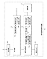
図2は、本発明の実施例1に係る照明システム100の別の構成を示す。これは、図1に示した照明システム100を実際のオフィスに展開した場合に相当し、天井面から見た配置を示す。図の上部に外光窓22が配置されているので、外光は、図の上から下の方向に外光が入射されている。そのため、外光窓22からの距離に応じて、つまり外光量の影響度合に応じて、第1大グループ20aと第2大グループ20bとが設定される。具体的には、第1大グループ20aの方が、第2大グループ20bよりも外光量が多い傾向にある。第1大グループ20aと第2大グループ20bとのそれぞれは、図1の大グループ20に相当する。第1大グループ20aには、第1−1小グループ18aa、第1−2小グループ18ab、第1−3小グループ18ac、第1−4小グループ18ad、第1−5小グループ18ae、第1−6小グループ18afが含まれる。また、第2大グループ20bには、第2−1小グループ18ba、第2−2小グループ18bb、第2−3小グループ18bc、第2−4小グループ18bd、第2−5小グループ18be、第2−6小グループ18bfが含まれる。
FIG. 2 shows another configuration of the
ここで、第1−3小グループ18ac、第2−3小グループ18bcには、第1種照明制御装置12、第2種照明制御装置14が含まれており、図1の第1小グループ18aに相当する。また、他の小グループ18には、第3種照明制御装置16が含まれており、図1の第2小グループ18bに相当する。各小グループ18内に含まれた4つの照明器具10と、第1種照明制御装置12あるいは第3種照明制御装置16とは、点線で示された調光信号線によって接続されている。また、第3種照明制御装置16、第2種照明制御装置14、第3種照明制御装置16は、実線で示された制御信号線によって接続されている。なお、第1大グループ20aと第2大グループ20bとの間も制御信号線によって接続されているが、本実施例では、この部分に有意な情報は伝送されない。つまり、第1大グループ20a内と、第2大グループ20b内とにおいて独立した処理が実行されている。
Here, the first-third small group 18ac and the second-third small group 18bc include the first type
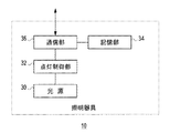
図3は、照明器具10の構成を示す。照明器具10は、光源30、点灯制御部32、記憶部34、通信部36を含む。光源30は、例えば、LED(Light Emitting Diode)、蛍光灯などであり、照明器具10と一体に設けられていてもよいし、照明器具10とは別に設けられていてもよい。また、各照明器具10は、図示しない筐体を複数有し、各筐体に光源30が設けられた一群の照明器具から構成されていてもよい。
FIG. 3 shows the configuration of the
点灯制御部32は、光源30の点灯状態を制御する。点灯制御部32は、第1種照明制御装置12あるいは第3種照明制御装置16から後述の通信部36が取得する制御信号にしたがって、光源30の点灯・消灯の切替制御、指示された調光率での調光制御などを実行する。つまり、点灯制御部32は、第1種照明制御装置12あるいは第3種照明制御装置16からの制御信号に含まれる調光率で、光源30を調光点灯させる。調光率は、全点灯を100%として全点灯に対する明るさの割合を表す値であり、例えば5〜100%の範囲で調節可能である。記憶部34は、固有のアドレスを記憶する。通信部36は、調光信号線に接続されており、第1種照明制御装置12あるいは第3種照明制御装置16との間で通信を実行する。
The
この構成は、ハードウエア的には、任意のコンピュータのCPU、メモリ、その他のLSIで実現でき、ソフトウエア的にはメモリにロードされたプログラムなどによって実現されるが、ここではそれらの連携によって実現される機能ブロックを描いている。したがって、これらの機能ブロックがハードウエアのみ、ハードウエアとソフトウエアの組合せによっていろいろな形で実現できることは、当業者には理解されるところである。 This configuration can be realized in terms of hardware by a CPU, memory, or other LSI of any computer, and in terms of software, it can be realized by a program loaded in the memory, but here it is realized by their cooperation. Draw functional blocks. Accordingly, those skilled in the art will understand that these functional blocks can be realized in various forms only by hardware, or by a combination of hardware and software.
図4は、第1種照明制御装置12の構成を示す。第1種照明制御装置12は、画像センサ40、画像処理部42、記憶部44、制御部46、通信部50を含み、通信部50は、第1通信部52、第2通信部54を含む。なお、第3種照明制御装置16も、第1種照明制御装置12と同様に構成されているので、ここでは説明を省略する。
FIG. 4 shows the configuration of the first type
画像センサ40は、複数の受光素子が二次元配列された固体撮像素子、各受光素子の出力値をアナログデータからデジタルデータに変換する変換部と、変換されたデジタル値を増幅する増幅部とを有する。固定撮像素子は、例えば、CCD(Charge Coupled Device)、CMOS(Complementary Metal Oxide Semiconductor)である。各受光素子が撮像画像の各画素に対応するので、各受光素子の出力値が撮像画像の画素値となる。そのため、受光素子での受光量が大きくなるほど対応する画素の画素値は大きくなる。
The
さらに、画像センサ40は、AGC(Automatic Gain Control)回路を有する。AGC回路は、増幅部の入力が変動する場合においても増幅部から一定の出力が得られるように、増幅部の増幅率を自動的に調整する。増幅率は、全受光素子の出力値の平均値に対する増幅部の全出力値の平均値の比率である。そのため、照明空間が比較的暗い場合でも、AGC回路が増幅率を増加させるので、画像センサ40は、撮像画像の適切な明るさを確保できる。このように、画像センサ40は、固体撮像素子にて照明空間の撮像画像を生成し、この撮像画像を変換部にて変換し、増幅部にて増幅してから、撮像画像の画像データとして画像処理部42に出力する。
Furthermore, the
画像処理部42は、画像センサ40からの撮像画像に対して画像処理、具体的には人の存在を検知するための画像処理を実行する。なお、画像処理に先だって、画像センサ40が、照明空間に人が存在しない状態で照明空間の画像(以下、「背景画像」という)を撮像し、記憶部44は、撮像された背景画像を記憶している。画像処理部42は、新たに撮像された撮像画像と背景画像との間で画素値の差分を画素ごとに計算することによって、差分画像を生成する。照明空間に人が存在している場合の差分画像の画素値の合計は、照明空間に人が存在していない場合の差分画像の画素値の合計よりも大きくなる。そこで、画像処理部42は、予めしきい値を保持しており、差分画像の画素値の合計がしきい値よりも大きければ、照明空間に人が存在していると判定する。一方、画像処理部42は、差分画像の画素値の合計がしきい値以下であれば、照明空間に人が存在していないと判定する。なお、しきい値との比較対象となる差分画像の画素値の合計は、差分画像全体の画素値の合計であってもよく、差分画像の一部の領域の画素値の合計であってもよい。
The
第1通信部52は、制御信号線に接続されており、第2種照明制御装置14との間で通信を実行する。第2種照明制御装置14との通信は、直接なされてもよく、他の第1種照明制御装置12、第3種照明制御装置16を介して間接的になされてもよい。第2通信部54は、調光信号線に接続されており、照明器具10との間で通信を実行する。なお、第2通信部54は、各照明器具10に固有に付与されたアドレスを保持しており、アドレスによって通信対象となる照明器具10を指定する。
The
制御部46は、第1種照明制御装置12の動作、特に調光処理を制御する。調光処理では、第2種照明制御装置14との通信を第1通信部52に実行させたり、第2通信部54から照明器具10に制御信号を送信することによって複数の照明器具10を制御したりする。このように、制御部46は、制御信号を送信することによって、照明器具10の点灯・消灯の切替制御や、指示した調光率での調光制御などを実行する。
The
調光処理に関して、第1種照明制御装置12に加えて、第2種照明制御装置14、第3種照明制御装置16でも、2段階の処理が規定されている。第1段階は、準備処理であり、調光制御を実行するための前処理に相当する。第2段階は、制御処理であり、実際に調光を制御するための処理に相当する。制御部46は、準備処理において、第1通信部52を介して第2種照明制御装置14からの消灯指示、点灯指示とを受けつける。消灯指示を受けつけた場合、制御部46は、第2通信部54を介して照明器具10へ、消灯を指示するための制御信号を送信する。一方、点灯指示を受けつけた場合、制御部46は、第2通信部54を介して照明器具10へ、点灯を指示するための制御信号を送信する。また、点灯指示を受けつけた場合、制御部46は、第1通信部52を介して第2種照明制御装置14へ、点灯させた照明器具10の調光率の値を返信する。ここで、第1種照明制御装置12によって複数の照明器具10が制御されているので、複数の照明器具10のそれぞれの調光率の平均値(以下、「平均調光率」という)が返信される。
Regarding the dimming processing, in addition to the first type
制御処理において、制御部46は、第1通信部52を介して第2種照明制御装置14からの補正量を受けつける。なお、補正量は、後述の第2種照明制御装置14において導出されており、現在の明るさレベルを、目標とする明るさレベルに近づけるために調節すべき量であり、輝度値によって示されている。一方、制御部46は、画像処理部42に対して、判定結果、つまり人が検知されたか否かを確認する。
In the control process, the
制御部46は、人の存在を検知した場合、受けつけた補正量から、照明器具10の調光率を導出する。例えば、制御部46は、補正量の単位を輝度値から調光率に変換し、調光率に変換された補正量によって、それまでの調光率を増減する。なお、制御部46は、輝度値と調光率との関係が示されたテーブルを予め保持しており、このテーブルを変換に使用する。導出した調光率は、第1種照明制御装置12に接続された複数の照明器具10に適用させるので、「平均調光率」ともいえる。制御部46は、第2通信部54に対して、平均調光率が含まれた制御信号を複数の照明器具10へ一斉に送信させる。これにより、制御部46は、人が存在する場合に、第2種照明制御装置14からの補正量に近づくように、複数の照明器具10の調光率を一斉に制御する。なお、制御部46は、第1通信部52に対して、平均調光率を第2種照明制御装置14へも送信させる。一方、制御部46は、人の存在を検知しなかった場合、第2通信部54に対して、消灯指示が含まれた制御信号を複数の照明器具10へ一斉に送信させる。これにより、制御部46は、人が存在しない場合に、複数の照明器具10を一括して消灯させる。なお、制御部46は、第1通信部52に対して、消灯に相当する「0%」の平均調光率を第2種照明制御装置14へ送信させる。なお、第2種照明制御装置14への平均調光率の送信は、適宜なされてもよい。
When detecting the presence of a person, the
前述のごとく、第3種照明制御装置16も、第1種照明制御装置12と同様の動作を実行するが、第3種照明制御装置16は、第2種照明制御装置14とペアリングされていないので、第2種照明制御装置14へ信号を送信する処理が省略されてもよい。
As described above, the third type
図5は、第2種照明制御装置14の構成を示す。第2種照明制御装置14は、画像センサ60、画像処理部62、記憶部64、制御部66、通信部68を含む。画像処理部62は、準備用取得部70、準備用導出部72、算出部74、第1取得部76、第1導出部78を含み、制御部66は、第2取得部80、第2導出部82、第3導出部84を含む。
FIG. 5 shows the configuration of the second type
画像センサ60は、前述の画像センサ40と同様に構成される。しかしながら、画像センサ60は、後述の画像処理部62において、照明空間の明るさを検知するために使用されるので、前述のAGC回路における増幅率の自動調整はなされずに、増幅部の増幅率は固定値にされる。これは、AGC回路によって撮像画像の明るさが調整されてしまうと、撮像画像から照明空間の明るさを検知できないからである。そのため、画像センサ60にAGC回路が含まれていなくてもよく、AGC回路の機能がオフにされていてもよい。
The
通信部68は、制御信号線に接続されており、第1種照明制御装置12との間で通信を実行する。また、通信部68は、制御信号線を使用して第3種照明制御装置16へ信号を送信する。
The
以下では、画像処理部62、記憶部64、制御部66を説明するが、説明を明瞭にするために、前述の準備処理と制御処理とに分けて説明する。まずは、準備処理を説明する。準備処理は、夜間など外光がない状態でなされる。制御部66は、通信部68に対して、第1種照明制御装置12への消灯指示を送信させ、第3種照明制御装置16への点灯指示を送信させる。これによって、制御部66は、第1種照明制御装置12によって調光制御されている照明器具10を消灯させ、第3種照明制御装置16によって調光制御されている別の照明器具10を点灯させる。これは、第2種照明制御装置14が含まれた小グループ18の照明器具10だけが消灯し、他の照明器具10が点灯している状況といえる。
Hereinafter, the
このような状況下において、画像センサ60は、照明空間の撮像画像を生成し、撮像画像を準備用取得部70に出力する。準備用取得部70は、画像センサ60から撮像画像を取得する。準備用導出部72は、準備用取得部70において取得した撮像画像における各画素の画素値の平均値を計算する。平均値は、周囲の照明器具10による人工光成分に相当し、輝度値の単位を有する。準備用導出部72は、周囲の人工光成分「A」を記憶部64に記憶する。
Under such circumstances, the
これに続いて、制御部66は、通信部68に対して、第1種照明制御装置12への点灯指示を送信させ、第3種照明制御装置16への消灯指示を送信させる。これによって、制御部66は、第1種照明制御装置12によって調光制御されている照明器具10を点灯させ、第3種照明制御装置16によって調光制御されている別の照明器具10を消灯させる。これは、第2種照明制御装置14が含まれた小グループ18の照明器具10だけが点灯し、他の照明器具10が消灯している状況といえる。さらに、第1種照明制御装置12への点灯指示の応答として、制御部66は、通信部68を介して、第1種照明制御装置12からの平均調光率を受けつける。制御部66は、平均調光率を算出部74に出力する。
Subsequently, the
このような状況下において、画像センサ60は、照明空間の撮像画像を生成し、撮像画像を算出部74に出力する。算出部74は、画像センサ60から撮像画像を取得し、取得した撮像画像における各画素の画素値の平均値を計算する。平均値は、平均輝度値といえる。一方、算出部74は、制御部66から平均調光率を受けつける。算出部74は、平均輝度値を平均調光率で除算することによって、照明器具10の調光率を1%変化させた場合の輝度値の変化量(以下、「輝度変化量」という)を導出する。例えば、平均輝度値が「200」であり、平均調光率が「100%」である場合、輝度変化量「B」は、「2」になる。算出部74は、導出した輝度変化量「B」を記憶部64に記憶する。
Under such circumstances, the
制御処理は、準備処理がなされた後、外光がある状態でなされる。画像センサ60は、照明空間の撮像画像を生成し、撮像画像を第1取得部76に出力する。第1取得部76は、画像センサ60から撮像画像を取得する。第1導出部78は、第1取得部76において取得した撮像画像における各画素の画素値の平均値を計算する。平均値は、照明空間における明るさに相当し、輝度値の単位を有する。第1導出部78は、照明空間における明るさ「C」を第2導出部82に出力する。
The control process is performed in a state where there is external light after the preparation process is performed. The
第2取得部80は、通信部68を介して、第1種照明制御装置12からの平均調光率を受けつける。これは、第1種照明制御装置12によって調光制御されている複数の照明器具10の調光率の平均値である。第2取得部80は、平均調光率「D」を第2導出部82に出力する。第2導出部82は、第2取得部80から平均調光率「D」を受けつけるとともに、第1導出部78から照明空間における明るさ「C」を受けつける。さらに、第2導出部82は、記憶部64から、周囲の人工光成分「A」と輝度変化量「B」とを抽出する。第2導出部82は、輝度変化量「B」と平均調光率「D」を乗算し、照明空間における明るさ「C」から乗算結果および周囲の人工光成分「A」を減算することによって、外光成分「E」を導出する。つまり、第2導出部82は、次の処理を実行する。
E=C−B×D−A
ここで、外光成分「E」は、輝度値の単位を有する。第2導出部82は、外光成分「E」を第3導出部84に出力する。
The
E = C−B × D−A
Here, the external light component “E” has a unit of luminance value. The
第3導出部84は、第2導出部82からの外光成分「E」が目標値「F」に近づくように、次のように補正量「G」を導出する。
G=F−E
このような補正量「G」によって、外光成分「E」が目標値「F」よりも低い場合には、複数の照明器具10の調光率が大きくされ、外光成分「E」が目標値「F」よりも高い場合には、複数の照明器具10の調光率が小さくされる。
The
G = FE
When the external light component “E” is lower than the target value “F” by such a correction amount “G”, the dimming rate of the plurality of
制御部66は、通信部68を介して、補正量を第1種照明制御装置12、第3種照明制御装置16に送信する。なお、補正量の送信対象となる第1種照明制御装置12、第3種照明制御装置16が特定されている場合、制御部66は、特定された装置に固有に付与されたアドレスを使用することによって、当該装置だけに補正量を送信してもよい。
The
以上の構成による照明システム100の動作を説明する。図6は、照明システム100における準備処理の手順を示すシーケンス図である。第2種照明制御装置14は、第1種照明制御装置12に消灯指示を送信し(S10)、第3種照明制御装置16に点灯指示を送信する(S12)。第1種照明制御装置12は、照明器具10を消灯させ(S14)、第3種照明制御装置16は、別の照明器具10を点灯させる(S16)。第2種照明制御装置14は、周囲の人工光成分(輝度値)を導出し(S18)、導出した人工光成分を記憶する(S20)。
The operation of the
第2種照明制御装置14は、第1種照明制御装置12に点灯指示を送信し(S22)、第3種照明制御装置16に消灯指示を送信する(S24)。第1種照明制御装置12は、照明器具10を点灯させ(S26)、第3種照明制御装置16は、別の照明器具10を消灯させる(S28)。第1種照明制御装置12は、第2種照明制御装置14に平均調光率を返信する(S30)。第2種照明制御装置14は、輝度変化量を算出し(S32)、算出した輝度変化量を記憶する(S34)。
The second type
図7は、照明システム100における制御処理の手順を示すシーケンス図である。第2種照明制御装置14は、周囲の明るさを導出する(S50)。第1種照明制御装置12は、第2種照明制御装置14に平均調光率を送信し(S52)、第2種照明制御装置14は、平均調光率を取得する(S54)。第2種照明制御装置14は、外光成分(輝度値)を導出する(S56)。第2種照明制御装置14は、補正量を導出する(S58)。第2種照明制御装置14は、第1種照明制御装置12に補正量を送信し(S60)、第3種照明制御装置16に補正量を送信する(S62)。
FIG. 7 is a sequence diagram illustrating a procedure of control processing in the
図8は、第1種照明制御装置12による調光制御の手順を示すフローチャートである。制御部46は、第1通信部52を介して補正量を取得する(S100)。画像処理部42において人を検知していれば(S102のY)、制御部46は、補正量を反映した調光率で照明器具10を調光制御を実行する(S104)。画像処理部42において人を検知していなければ(S102のN)、制御部46は、照明器具10を消灯する(S106)。
FIG. 8 is a flowchart showing the procedure of dimming control by the first type
本発明の実施例によれば、人検知のための照明制御装置と、明るさ検知のための照明制御装置とを別に構成したので、任意のタイミングで、人の存在の検知と明るさの検知とを実行できる。また、任意のタイミングで、人の存在の検知と明るさの検知とが実行されるので、調光を細かく制御できる。また、調光が細かく制御されるので、快適性と省エネルギー性を向上できる。また、ペアリングがなされた装置間の処理によって補正値が決定されるので、2つの装置が含まれる場合であっても、処理の複雑化を抑制できる。また、第2種照明制御装置とのペアリングがなされていない第3種照明制御装置は、第2種照明制御装置からの補正値を受けつけて、調光を制御するだけなので、処理を簡易にできる。 According to the embodiment of the present invention, since the illumination control device for human detection and the illumination control device for brightness detection are configured separately, detection of the presence of a person and detection of brightness at any timing. Can be executed. In addition, since the detection of the presence of a person and the detection of brightness are executed at an arbitrary timing, the light control can be finely controlled. In addition, since dimming is finely controlled, comfort and energy saving can be improved. In addition, since the correction value is determined by the processing between the paired devices, even if two devices are included, the processing complexity can be suppressed. In addition, the third type illumination control device that is not paired with the second type illumination control device simply receives the correction value from the second type illumination control device and controls the light control, so that the processing is simplified. it can.
また、準備処理において取得した周囲の人工光成分を減算することによって、外光成分を導出するので、第2種照明制御装置とのペアリングがなされていない第3種照明制御装置に対しても適した補正値を導出できる。また、準備処理の場合と比較して自然光および周囲の照明器具からの外光量が多い場合には大グループを一括して調光制御するが、人が存在すると判断された小グループの照明器具のみに対して、明るさレベルを補正するので、快適性および省エネ性を向上できる。 Further, since the external light component is derived by subtracting the surrounding artificial light component acquired in the preparation process, the third type illumination control device that is not paired with the second type illumination control device is also used. A suitable correction value can be derived. In addition, when the natural light and the amount of external light from the surrounding lighting fixtures are large compared to the case of the preparatory processing, dimming control is performed for a large group in a lump, but only a small group of lighting fixtures that are judged to have people. On the other hand, since the brightness level is corrected, comfort and energy saving can be improved.
一態様の概要は、次の通りである。本発明のある態様の照明制御システムは、
照明器具10に接続可能であり、照明器具10によって照明される照明空間における人の存在を検知する第1種照明制御装置12と、
第1種照明制御装置12に接続され、照明空間における明るさを検知する第2種照明制御装置14とを備える。
第2種照明制御装置14は、検知した明るさをもとに調光の程度を導出し、調光の程度を第1種照明制御装置12に通知し、
第1種照明制御装置12は、人の存在を検知した場合、第2種照明制御装置14から通知された調光の程度に応じて、照明器具10を調光制御する。
The outline of one aspect is as follows. A lighting control system according to an aspect of the present invention includes:
A first-type
A second type
The second type
When the first type
第1種照明制御装置12が接続可能な照明器具10とは別の照明器具10に接続可能であり、別の照明器具10によって照明される別の照明空間における人の存在を検知する第3種照明制御装置16をさらに備えてもよい。
第2種照明制御装置14は、調光の程度を第3種照明制御装置16に通知し、
第3種照明制御装置16は、人の存在を検知した場合、第2種照明制御装置14から通知された調光の程度に応じて、別の照明器具10を調光制御してもよい。
A third type that can be connected to a
The second type
When the third type
第2種照明制御装置14は、
照明空間を撮像する画像センサ60から撮像画像を取得する第1取得部76と、
第1取得部76において取得した撮像画像から、照明空間における明るさとして、輝度値を導出する第1導出部78と、
第1種照明制御装置12によって調光制御されている照明器具10の調光率を取得する第2取得部80と、
第1種照明制御装置12によって調光制御されている照明器具10の調光率を変化させた場合の輝度変化量を記憶する記憶部64と、
記憶部64に記憶した輝度変化量と、第2取得部80において取得した調光率を乗算し、第1導出部78において導出した輝度値から乗算結果を減算することによって、外光成分を導出する第2導出部82と、
第2導出部82において導出した外光成分をもとに、調光の程度を導出する第3導出部84と、
を備えてもよい。
The second type
A
A
A
A
The luminance change amount stored in the
A
May be provided.
第2種照明制御装置14は、
第1種照明制御装置12によって調光制御されている照明器具10を消灯させ、第3種照明制御装置16によって調光制御されている別の照明器具10を点灯させている場合において、照明空間を撮像する画像センサ60から撮像画像を取得する準備用取得部70と、
準備用取得部70において取得した撮像画像から、周囲の人工光成分を導出する準備用導出部72と、
画像センサ60から撮像画像を取得する第1取得部76と、
第1取得部76において取得した撮像画像から、照明空間における明るさとして、輝度値を導出する第1導出部78と、
第1種照明制御装置12によって調光制御されている照明器具10の調光率を取得する第2取得部80と、
第1種照明制御装置12によって調光制御されている照明器具10の調光率を変化させた場合の輝度変化量と、準備用導出部72において導出した周囲の人工光成分とを記憶する記憶部64と、
記憶部64に記憶した輝度変化量と、第2取得部80において取得した調光率を乗算し、第1導出部78において導出した輝度値から乗算結果および記憶部64に記憶した周囲の人工光成分を減算することによって、外光成分を導出する第2導出部82と、
第2導出部82において導出した外光成分をもとに、調光の程度を導出する第3導出部84と、
を備えてもよい。
The second type
In the case where the
A
A
A
A
A memory for storing the amount of change in luminance when the dimming rate of the
The luminance change amount stored in the
A
May be provided.
本発明の別の態様は、照明システム100である。この照明システムは、
照明器具10と、
照明器具10に接続可能であり、照明器具10によって照明される照明空間における人の存在を検知する第1種照明制御装置12と、
第1種照明制御装置12に接続され、照明空間における明るさを検知する第2種照明制御装置14とを備える。
第2種照明制御装置14は、検知した明るさをもとに調光の程度を導出し、調光の程度を第1種照明制御装置12に通知し、
第1種照明制御装置12は、人の存在を検知した場合、第2種照明制御装置14から通知された調光の程度に応じて、照明器具10を調光制御する。
Another aspect of the present invention is a
A
A first-type
A second type
The second type
When the first type
本発明のさらに別の態様は、照明制御方法である。この方法は、
照明器具10に接続可能である第1種照明制御装置12と、第1種照明制御装置12に接続される第2種照明制御装置14とを備える照明制御システムにおける照明制御方法であって、
第2種照明制御装置14において、照明器具10によって照明される照明空間における明るさを検知するとともに、検知した明るさをもとに調光の程度を導出するステップと、
第2種照明制御装置14において、導出した調光の程度を第1種照明制御装置12に通知するステップと、
第1種照明制御装置12において、照明空間における人の存在を検知した場合、第2種照明制御装置14から通知された調光の程度に応じて、照明器具10を調光制御するステップと、
を特徴とする。
Yet another embodiment of the present invention is a lighting control method. This method
A lighting control method in a lighting control system comprising a first type
In the second type
In the second type
In the first type
It is characterized by.
(実施例2)
実施例2は、実施例1と同様に、複数の照明器具の照明を制御する照明システムに関する。実施例1では、第1種照明制御装置と第2種照明制御装置は、それぞれ別の機能を有した装置として構成されている。実施例2は、これらの機能をすべて備えた照明制御装置として構成される。この照明制御装置は、照明器具に接続された場合、第1種照明制御装置として動作し、照明器具に接続されない場合、第2種照明制御装置として動作する。実施例2に係る照明システム100、照明器具10は、図1から図3と同様のタイプである。ここでは、実施例1との差異を中心に説明する。
(Example 2)
Example 2 is related with the illumination system which controls the illumination of several lighting fixtures similarly to Example 1. FIG. In the first embodiment, the first type illumination control device and the second type illumination control device are configured as devices having different functions. The embodiment 2 is configured as a lighting control device having all these functions. This lighting control device operates as a first type lighting control device when connected to the lighting fixture, and operates as a second type lighting control device when not connected to the lighting fixture. The
図9は、本発明の実施例2に係る照明制御装置200の構成を示す。照明制御装置200は、通信部210、判定部212、処理部214を含む。また、通信部210は、第1通信部216、第2通信部218を含み、処理部214は、第1種照明制御処理部220、第2種照明制御処理部222、第3種照明制御処理部224を含む。
FIG. 9 shows a configuration of the
第1通信部216は、図4の第1通信部52、図5の通信部68に相当し、第2通信部218は、図4の第2通信部54に相当する。第1種照明制御処理部220、第3種照明制御処理部224は、図4の画像センサ40、画像処理部42、記憶部44、制御部46に相当する。第2種照明制御処理部222は、図5の画像センサ60、画像処理部62、記憶部64、制御部66に相当する。なお、第1種照明制御処理部220から第3種照明制御処理部224に含まれた構成要素のうち、共通化できるものは共通してもよい。例えば、画像センサ40および画像センサ60に含まれた固体撮像素子等である。このように、少なくとも第1種照明制御装置12の機能と第2種照明制御装置14の機能とが、1つの照明制御装置200に実装される。
The
判定部212は、通信部210の接続状態を確認し、接続状態に応じて、第1種照明制御処理部220から第3種照明制御処理部224のいずれか1つの動作を選択する。第1通信部216が制御信号線に接続されているが、第2通信部218が調光信号線に接続されていない場合、判定部212は、第2種照明制御処理部222の動作を選択する。第1通信部216が制御信号線に接続され、第2通信部218が調光信号線に接続されている場合であって、かつ第2種照明制御装置14とのペアリングが確立している場合、判定部212は、第1種照明制御処理部220の動作を選択する。第1通信部216が制御信号線に接続され、第2通信部218が調光信号線に接続されている場合であって、かつ第2種照明制御装置14とのペアリングが確立していない場合、判定部212は、第3種照明制御処理部224の動作を選択する。このように、照明制御装置200は、照明器具10に接続されている場合に第1種照明制御装置12あるいは第3種照明制御装置16の機能を実行し、照明器具10に未接続である場合に第2種照明制御装置14の機能を実行する。
The
本発明の実施例によれば、複数種類の照明制御装置の機能を1つの照明制御装置に収容するので、1種類だけの照明制御装置を製造することを可能にする。また、1種類だけの照明制御装置が製造されるので、製造効率を向上できる。また、接続形態に応じて、実行すべき機能を自動的に選択するので、設置を容易にできる。 According to the embodiment of the present invention, since the functions of a plurality of types of illumination control devices are accommodated in one illumination control device, only one type of illumination control device can be manufactured. Moreover, since only one type of lighting control device is manufactured, manufacturing efficiency can be improved. In addition, since the function to be executed is automatically selected according to the connection form, installation can be facilitated.
一態様の概要は、次の通りである。第1種照明制御装置12の機能と第2種照明制御装置14の機能とは、1つの照明制御装置200に実装され、
当該1つの照明制御装置200は、照明器具10に接続されている場合に第1種照明制御装置12の機能を実行し、照明器具10に未接続である場合に第2種照明制御装置14の機能を実行してもよい。
The outline of one aspect is as follows. The function of the first type
The one
以上、本発明を実施例をもとに説明した。この実施例は例示であり、それらの各構成要素あるいは各処理プロセスの組合せにいろいろな変形例が可能なこと、またそうした変形例も本発明の範囲にあることは当業者に理解されるところである。 In the above, this invention was demonstrated based on the Example. This embodiment is an exemplification, and it will be understood by those skilled in the art that various modifications can be made to each of those constituent elements or combinations of processing processes, and such modifications are also within the scope of the present invention. .
本実施例1、2における小グループ18において、第1種照明制御装置12あるいは第3種照明制御装置16から一列に複数の照明器具10が配置されるデイジーチェーン接続がなされている。しかしながらこれに限らず例えば、第1種照明制御装置12あるいは第3種照明制御装置16を中心にして複数の照明器具10が配置されるスター接続であってもよい。本変形例によれば、接続形態の自由度を向上できる。
In the
本実施例1、2において、調光信号線および制御信号線が使用されることによって、照明システム100において有線通信が実行されている。しかしながらこれに限らず例えば、調光信号線および制御信号線、あるいはいずれか一方に対して無線通信が使用されてもよい。本変形例によれば、照明システム100の構成の自由度を向上できる。
In the first and second embodiments, the dimming signal line and the control signal line are used, and wired communication is executed in the
本実施例1、2において、第2種照明制御装置14は、補正値、つまり現在の値からの相対値を出力する。しかしながらこれに限らず例えば、第2種照明制御装置14は、調光率あるいは輝度値の絶対値を出力してもよい。そのため、このような絶対値、補正値は、調光の程度といえる。本変形例によれば、照明システム100の構成の自由度を向上できる。
In the first and second embodiments, the second type
本実施例1、2において、第2導出部82は、外光成分を導出する際に、周囲の人工光成分を使用している。しかしながらこれに限らず例えば、第2導出部82は、外光成分を導出する際に、周囲の人工光成分を使用しなくてもよい。本実施例によれば、処理を簡易にできる。
In the first and second embodiments, the
10 照明器具、 12 第1種照明制御装置、 14 第2種照明制御装置、 16 第3種照明制御装置、 18 小グループ、 20 大グループ、 40 画像センサ、 42 画像処理部、 44 記憶部、 46 制御部、 50 通信部、 52 第1通信部、 54 第2通信部、 60 画像センサ、 62 画像処理部、 64 記憶部、 66 制御部、 68 通信部、 70 準備用取得部、 72 準備用導出部、 74 算出部、 76 第1取得部、 78 第1導出部、 80 第2取得部、 82 第2導出部、 84 第3導出部、 100 照明システム。
DESCRIPTION OF
Claims (6)
前記第1種の照明制御装置に接続され、前記照明空間における明るさを検知する第2種の照明制御装置と、
前記第1種の照明制御装置が接続可能な前記照明器具とは別の照明器具に接続可能であり、前記別の照明器具によって照明される別の照明空間における人の存在を検知する第3種の照明制御装置とを備え、
前記第2種の照明制御装置は、検知した明るさをもとに調光の程度を導出し、調光の程度を前記第1種の照明制御装置に通知し、
前記第1種の照明制御装置は、人の存在を検知した場合、前記第2種の照明制御装置から通知された調光の程度に応じて、前記照明器具を調光制御し、
前記第2種の照明制御装置は、調光の程度を前記第3種の照明制御装置に通知し、
前記第3種の照明制御装置は、人の存在を検知した場合、前記第2種の照明制御装置から通知された調光の程度に応じて、前記別の照明器具を調光制御し、
前記第2種の照明制御装置は、
前記第1種の照明制御装置によって調光制御されている前記照明器具を消灯させ、前記第3種の照明制御装置によって調光制御されている前記別の照明器具を点灯させている場合において、前記照明空間を撮像する画像センサから撮像画像を取得する準備用取得部と、
前記準備用取得部において取得した撮像画像から、周囲の人工光成分を導出する準備用導出部と、
前記画像センサから撮像画像を取得する第1取得部と、
前記第1取得部において取得した撮像画像から、前記照明空間における明るさとして、輝度値を導出する第1導出部と、
前記第1種の照明制御装置によって調光制御されている前記照明器具の調光率を取得する第2取得部と、
前記第1種の照明制御装置によって調光制御されている前記照明器具の調光率を変化させた場合の輝度変化量と、前記準備用導出部において導出した周囲の人工光成分とを記憶する記憶部と、
前記記憶部に記憶した輝度変化量と、前記第2取得部において取得した調光率とを乗算し、前記第1導出部において導出した輝度値から、乗算結果および前記記憶部に記憶した周囲の人工光成分を減算することによって、外光成分を導出する第2導出部と、
前記第2導出部において導出した外光成分をもとに、調光の程度を導出する第3導出部と、
を備えることを特徴とする照明制御システム。 A first type of lighting control device that is connectable to a lighting fixture and detects the presence of a person in the lighting space illuminated by the lighting fixture;
A second type of lighting control device connected to the first type of lighting control device and detecting brightness in the lighting space ;
A third type that can be connected to a lighting fixture different from the lighting fixture to which the first type of lighting control device can be connected, and detects the presence of a person in another lighting space illuminated by the different lighting fixture. Lighting control device ,
The second type of lighting control device derives the degree of dimming based on the detected brightness, and notifies the first type of lighting control device of the degree of dimming,
When the first type of lighting control device detects the presence of a person, the dimming control of the lighting fixture is performed according to the degree of dimming notified from the second type of lighting control device ,
The second type lighting control device notifies the third type lighting control device of the degree of dimming,
When the third type lighting control device detects the presence of a person, the dimming control is performed on the other lighting fixture according to the degree of dimming notified from the second type lighting control device,
The second type of lighting control device is:
In the case where the lighting fixture controlled by the first type of lighting control device is turned off, and the other lighting fixture controlled by the third type of lighting control device is turned on, An acquisition unit for preparation that acquires a captured image from an image sensor that captures the illumination space;
A preparation derivation unit for deriving a surrounding artificial light component from the captured image acquired in the preparation unit for preparation;
A first acquisition unit for acquiring a captured image from the image sensor;
A first derivation unit for deriving a luminance value as brightness in the illumination space from the captured image acquired in the first acquisition unit;
A second acquisition unit that acquires a dimming rate of the lighting fixture that is dimmed and controlled by the first type of lighting control device;
A luminance change amount when the dimming rate of the lighting fixture controlled by the first type of lighting control device is changed and a surrounding artificial light component derived in the preparation deriving unit are stored. A storage unit;
The luminance change amount stored in the storage unit is multiplied by the dimming rate acquired in the second acquisition unit, and the multiplication result and the surroundings stored in the storage unit are calculated from the luminance value derived in the first derivation unit. A second deriving unit for deriving an external light component by subtracting the artificial light component;
A third deriving unit for deriving the degree of dimming based on the external light component derived in the second deriving unit;
Lighting control system comprising: a.
当該1つの照明制御装置は、前記照明器具に接続されている場合に前記第1種の照明制御装置の機能を実行し、前記照明器具に未接続であり、前記第1種の照明制御装置または前記第1種の照明制御装置の機能を有する当該1つの照明制御装置に接続されている場合に前記第2種の照明制御装置の機能を実行することを特徴とする請求項1に記載の照明制御システム。 The function of the first type of lighting control device and the function of the second type of lighting control device are implemented in one lighting control device,
The one lighting control device performs the function of the first kind of lighting control device when connected to the luminaire, Ri unconnected der to the luminaire, the first type of lighting control device or according to claim 1, characterized in that to perform the functions of the first kind of lighting control device functions the one second type when it is connected to the lighting control device of the lighting control device having the Lighting control system.
前記照明器具に接続可能であり、前記照明器具によって照明される照明空間における人の存在を検知する第1種の照明制御装置と、
前記第1種の照明制御装置に接続され、前記照明空間における明るさを検知する第2種の照明制御装置と、
前記第1種の照明制御装置が接続可能な前記照明器具とは別の照明器具に接続可能であり、前記別の照明器具によって照明される別の照明空間における人の存在を検知する第3種の照明制御装置とを備え、
前記第2種の照明制御装置は、検知した明るさをもとに調光の程度を導出し、調光の程度を前記第1種の照明制御装置に通知し、
前記第1種の照明制御装置は、人の存在を検知した場合、前記第2種の照明制御装置から通知された調光の程度に応じて、前記照明器具を調光制御し、
前記第2種の照明制御装置は、調光の程度を前記第3種の照明制御装置に通知し、
前記第3種の照明制御装置は、人の存在を検知した場合、前記第2種の照明制御装置から通知された調光の程度に応じて、前記別の照明器具を調光制御し、
前記第2種の照明制御装置は、
前記第1種の照明制御装置によって調光制御されている前記照明器具を消灯させ、前記第3種の照明制御装置によって調光制御されている前記別の照明器具を点灯させている場合において、前記照明空間を撮像する画像センサから撮像画像を取得する準備用取得部と、
前記準備用取得部において取得した撮像画像から、周囲の人工光成分を導出する準備用導出部と、
前記画像センサから撮像画像を取得する第1取得部と、
前記第1取得部において取得した撮像画像から、前記照明空間における明るさとして、輝度値を導出する第1導出部と、
前記第1種の照明制御装置によって調光制御されている前記照明器具の調光率を取得する第2取得部と、
前記第1種の照明制御装置によって調光制御されている前記照明器具の調光率を変化させた場合の輝度変化量と、前記準備用導出部において導出した周囲の人工光成分とを記憶する記憶部と、
前記記憶部に記憶した輝度変化量と、前記第2取得部において取得した調光率とを乗算し、前記第1導出部において導出した輝度値から、乗算結果および前記記憶部に記憶した周囲の人工光成分を減算することによって、外光成分を導出する第2導出部と、
前記第2導出部において導出した外光成分をもとに、調光の程度を導出する第3導出部と、
を備えることを特徴とする照明システム。 Lighting equipment,
A first type of lighting control device that is connectable to the lighting fixture and detects the presence of a person in the lighting space illuminated by the lighting fixture;
A second type of lighting control device connected to the first type of lighting control device and detecting brightness in the lighting space ;
A third type that can be connected to a lighting fixture different from the lighting fixture to which the first type of lighting control device can be connected, and detects the presence of a person in another lighting space illuminated by the different lighting fixture. Lighting control device ,
The second type of lighting control device derives the degree of dimming based on the detected brightness, and notifies the first type of lighting control device of the degree of dimming,
When the first type of lighting control device detects the presence of a person, the dimming control of the lighting fixture is performed according to the degree of dimming notified from the second type of lighting control device ,
The second type lighting control device notifies the third type lighting control device of the degree of dimming,
When the third type lighting control device detects the presence of a person, the dimming control is performed on the other lighting fixture according to the degree of dimming notified from the second type lighting control device,
The second type of lighting control device is:
In the case where the lighting fixture controlled by the first type of lighting control device is turned off, and the other lighting fixture controlled by the third type of lighting control device is turned on, An acquisition unit for preparation that acquires a captured image from an image sensor that captures the illumination space;
A preparation derivation unit for deriving a surrounding artificial light component from the captured image acquired in the preparation unit for preparation;
A first acquisition unit for acquiring a captured image from the image sensor;
A first derivation unit for deriving a luminance value as brightness in the illumination space from the captured image acquired in the first acquisition unit;
A second acquisition unit that acquires a dimming rate of the lighting fixture that is dimmed and controlled by the first type of lighting control device;
A luminance change amount when the dimming rate of the lighting fixture controlled by the first type of lighting control device is changed and a surrounding artificial light component derived in the preparation deriving unit are stored. A storage unit;
The luminance change amount stored in the storage unit is multiplied by the dimming rate acquired in the second acquisition unit, and the multiplication result and the surroundings stored in the storage unit are calculated from the luminance value derived in the first derivation unit. A second deriving unit for deriving an external light component by subtracting the artificial light component;
A third deriving unit for deriving the degree of dimming based on the external light component derived in the second deriving unit;
Illumination system comprising: a.
当該1つの照明制御装置は、前記照明器具に接続されている場合に前記第1種の照明制御装置の機能を実行し、前記照明器具に未接続であり、前記第1種の照明制御装置または前記第1種の照明制御装置の機能を有する当該1つの照明制御装置に接続されている場合に前記第2種の照明制御装置の機能を実行することを特徴とする請求項3に記載の照明システム。 The one lighting control device performs the function of the first type of lighting control device when connected to the lighting fixture and is not connected to the lighting fixture, and the first type of lighting control device or 4. The illumination according to claim 3, wherein the function of the second type of illumination control device is executed when connected to the one type of illumination control device having the function of the first type of illumination control device. system.
前記第2種の照明制御装置において、前記照明器具によって照明される照明空間における明るさを検知するとともに、検知した明るさをもとに調光の程度を導出するステップと、
前記第2種の照明制御装置において、導出した調光の程度を前記第1種の照明制御装置と前記第3種の照明制御装置に通知するステップと、
前記第1種の照明制御装置において、前記照明空間における人の存在を検知した場合、前記第2種の照明制御装置から通知された調光の程度に応じて、前記照明器具を調光制御するステップと、
前記第3種の照明制御装置において、前記別の照明器具によって照明される別の照明空間における人の存在を検知した場合、前記第2種の照明制御装置から通知された調光の程度に応じて、前記別の照明器具を調光制御するステップとを備え、
前記第2種の照明制御装置において、
前記第1種の照明制御装置によって調光制御されている前記照明器具を消灯させ、前記第3種の照明制御装置によって調光制御されている前記別の照明器具を点灯させている場合において、前記照明空間を撮像する画像センサから撮像画像を取得するステップと、
取得した撮像画像から、周囲の人工光成分を導出するステップと、
前記画像センサから撮像画像を取得するステップと、
取得した撮像画像から、前記照明空間における明るさとして、輝度値を導出するステップと、
前記第1種の照明制御装置によって調光制御されている前記照明器具の調光率を取得するステップと、
前記第1種の照明制御装置によって調光制御されている前記照明器具の調光率を変化させた場合の輝度変化量と、導出した周囲の人工光成分とを記憶するステップと、
記憶した輝度変化量と、取得した調光率とを乗算し、導出した輝度値から、乗算結果および周囲の人工光成分を減算することによって、外光成分を導出するステップと、
導出した外光成分をもとに、調光の程度を導出するステップと、
を備えることを特徴とする照明制御方法。 A first type of lighting control device connectable to a lighting fixture, a second type of lighting control device connected to the first type of lighting control device, and the first type of lighting control device connectable to the first type of lighting control device A lighting control method in a lighting control system comprising a third type lighting control device that can be connected to a lighting fixture different from the lighting fixture ,
In the second type illumination control device, detecting the brightness in the illumination space illuminated by the lighting fixture, and deriving the degree of dimming based on the detected brightness;
In the second type of illumination control device, notifying the derived type of light control to the first type of illumination control device and the third type of illumination control device ;
In the first type of illumination control device, when the presence of a person in the illumination space is detected, dimming control is performed on the luminaire according to the degree of dimming notified from the second type of illumination control device. Steps,
In the third type illumination control device, when the presence of a person in another illumination space illuminated by the other illumination fixture is detected, the lighting control device according to the degree of dimming notified from the second type illumination control device And dimming control the other lighting fixture,
In the second type of lighting control device,
In the case where the lighting fixture controlled by the first type of lighting control device is turned off, and the other lighting fixture controlled by the third type of lighting control device is turned on, Obtaining a captured image from an image sensor that images the illumination space;
Deriving ambient artificial light components from the acquired captured image;
Obtaining a captured image from the image sensor;
Deriving a luminance value as brightness in the illumination space from the acquired captured image;
Obtaining a dimming rate of the luminaire that is dimmed and controlled by the first type of lighting control device;
Storing the amount of change in luminance when the dimming rate of the luminaire that is dimming controlled by the first type of lighting control device is changed, and the derived ambient artificial light component;
Multiplying the stored luminance change amount and the acquired dimming rate, and subtracting the multiplication result and the surrounding artificial light component from the derived luminance value, and deriving the external light component;
Deriving the degree of dimming based on the derived external light component;
Lighting control method characterized by comprising a.
当該1つの照明制御装置において、前記照明器具に接続されている場合に前記第1種の照明制御装置の機能を実行し、前記照明器具に未接続であり、前記第1種の照明制御装置または前記第1種の照明制御装置の機能を有する当該1つの照明制御装置に接続されている場合に前記第2種の照明制御装置の機能を実行するステップをさらに備えることを特徴とする請求項5に記載の照明制御方法。 In the one lighting control device, when connected to the lighting fixture, the function of the first type lighting control device is executed, the function is not connected to the lighting fixture, and the first type lighting control device or 6. The method of claim 5, further comprising the step of executing the function of the second type of lighting control device when connected to the one type of lighting control device having the function of the first type of lighting control device. The lighting control method described in 1.
Priority Applications (2)
| Application Number | Priority Date | Filing Date | Title |
|---|---|---|---|
| JP2014221852A JP6429146B2 (en) | 2014-10-30 | 2014-10-30 | Lighting control method, lighting control system using the same, and lighting system |
| US14/928,497 US9480128B2 (en) | 2014-10-30 | 2015-10-30 | Illumination control method and illumination control system and illumination system using the same |
Applications Claiming Priority (1)
| Application Number | Priority Date | Filing Date | Title |
|---|---|---|---|
| JP2014221852A JP6429146B2 (en) | 2014-10-30 | 2014-10-30 | Lighting control method, lighting control system using the same, and lighting system |
Publications (2)
| Publication Number | Publication Date |
|---|---|
| JP2016091655A JP2016091655A (en) | 2016-05-23 |
| JP6429146B2 true JP6429146B2 (en) | 2018-11-28 |
Family
ID=55854355
Family Applications (1)
| Application Number | Title | Priority Date | Filing Date |
|---|---|---|---|
| JP2014221852A Active JP6429146B2 (en) | 2014-10-30 | 2014-10-30 | Lighting control method, lighting control system using the same, and lighting system |
Country Status (2)
| Country | Link |
|---|---|
| US (1) | US9480128B2 (en) |
| JP (1) | JP6429146B2 (en) |
Families Citing this family (4)
| Publication number | Priority date | Publication date | Assignee | Title |
|---|---|---|---|---|
| US9769900B2 (en) * | 2015-10-30 | 2017-09-19 | Cree, Inc. | Lighting fixture with image sensor module |
| JP7019371B2 (en) * | 2017-10-18 | 2022-02-15 | 清水建設株式会社 | Lighting control system |
| EP3708108A4 (en) * | 2017-12-06 | 2021-03-31 | Sony Olympus Medical Solutions Inc. | Medical control apparatus and control method |
| JP7183570B2 (en) * | 2018-05-17 | 2022-12-06 | 三菱電機株式会社 | lighting control system |
Family Cites Families (11)
| Publication number | Priority date | Publication date | Assignee | Title |
|---|---|---|---|---|
| JPH11233268A (en) * | 1998-02-13 | 1999-08-27 | Matsushita Electric Works Ltd | Lighting system |
| JP2002299070A (en) * | 2001-03-29 | 2002-10-11 | Toshiba Lighting & Technology Corp | Lighting control system |
| US9955551B2 (en) * | 2002-07-12 | 2018-04-24 | Yechezkal Evan Spero | Detector controlled illuminating system |
| US7122976B1 (en) * | 2002-09-25 | 2006-10-17 | The Watt Stopper | Light management system device and method |
| JP4224773B2 (en) * | 2002-11-29 | 2009-02-18 | 東芝ライテック株式会社 | Lighting control device and lighting device |
| US20100176733A1 (en) * | 2009-01-14 | 2010-07-15 | Purespectrum, Inc. | Automated Dimming Methods and Systems For Lighting |
| WO2011120065A1 (en) * | 2010-03-31 | 2011-10-06 | Tridonic Gmbh & Co. Kg | Method for illuminating a light box |
| US8890435B2 (en) * | 2011-03-11 | 2014-11-18 | Ilumi Solutions, Inc. | Wireless lighting control system |
| JP5903634B2 (en) | 2012-11-16 | 2016-04-13 | パナソニックIpマネジメント株式会社 | Lighting control device and lighting system |
| US9386665B2 (en) * | 2013-03-14 | 2016-07-05 | Honeywell International Inc. | System for integrated lighting control, configuration, and metric tracking from multiple locations |
| US9282597B2 (en) * | 2013-04-02 | 2016-03-08 | Magnitude Holdings Ltd., A Bermuda Exempt Company Limited By Shares | Device and method for controlled LED lighting |
-
2014
- 2014-10-30 JP JP2014221852A patent/JP6429146B2/en active Active
-
2015
- 2015-10-30 US US14/928,497 patent/US9480128B2/en active Active
Also Published As
| Publication number | Publication date |
|---|---|
| US20160128161A1 (en) | 2016-05-05 |
| US9480128B2 (en) | 2016-10-25 |
| JP2016091655A (en) | 2016-05-23 |
Similar Documents
| Publication | Publication Date | Title |
|---|---|---|
| JP5903634B2 (en) | Lighting control device and lighting system | |
| JP6429146B2 (en) | Lighting control method, lighting control system using the same, and lighting system | |
| US9414464B2 (en) | Lighting system | |
| JP2011228174A (en) | Illumination system | |
| US8860839B2 (en) | Light-emitting apparatus and camera system including the same | |
| JP2011113767A (en) | Illumination control device, illumination control system, and lighting up control device | |
| US20140214362A1 (en) | Method and system of detecting flickering frequency of ambient light source | |
| WO2019010005A1 (en) | Light-based communication using camera frame-rate based light modulation | |
| WO2015152388A1 (en) | Solid-state imaging device capable of detecting illuminance, camera using same, illumination instrument, display device | |
| JP2014186960A (en) | Illumination control system and illumination control method | |
| US20200029016A1 (en) | Moving object monitoring device and moving object monitoring system | |
| JP6516157B2 (en) | Lighting control method, lighting control system using the same, lighting system | |
| JP4972519B2 (en) | Brightness control device and lighting control system | |
| JP5624366B2 (en) | Lighting system | |
| JP5592637B2 (en) | Lighting control device, lighting control system, and lighting control device | |
| KR102019689B1 (en) | One-chip type sensing element for lighting | |
| US20160174342A1 (en) | Method for controlling lighting element and associated system | |
| JP6551780B2 (en) | Lighting control method, lighting control apparatus and lighting system using the same | |
| JP6958160B2 (en) | Sensor unit and control system | |
| JP2005285479A (en) | Lighting control system | |
| JP2017027858A (en) | Lighting control system | |
| JP2019003854A (en) | Imaging apparatus, controller, and lighting control system | |
| JP2016152124A (en) | Lighting system and controller | |
| JP2018166074A (en) | Lighting control device and lighting system | |
| JP2011139348A (en) | White balance control apparatus, and method of controlling the same |
Legal Events
| Date | Code | Title | Description |
|---|---|---|---|
| A621 | Written request for application examination |
Free format text: JAPANESE INTERMEDIATE CODE: A621 Effective date: 20170719 |
|
| A977 | Report on retrieval |
Free format text: JAPANESE INTERMEDIATE CODE: A971007 Effective date: 20180425 |
|
| A131 | Notification of reasons for refusal |
Free format text: JAPANESE INTERMEDIATE CODE: A131 Effective date: 20180508 |
|
| A521 | Written amendment |
Free format text: JAPANESE INTERMEDIATE CODE: A523 Effective date: 20180529 |
|
| TRDD | Decision of grant or rejection written | ||
| A01 | Written decision to grant a patent or to grant a registration (utility model) |
Free format text: JAPANESE INTERMEDIATE CODE: A01 Effective date: 20181016 |
|
| A61 | First payment of annual fees (during grant procedure) |
Free format text: JAPANESE INTERMEDIATE CODE: A61 Effective date: 20181019 |
|
| R150 | Certificate of patent or registration of utility model |
Ref document number: 6429146 Country of ref document: JP Free format text: JAPANESE INTERMEDIATE CODE: R150 |