JP6385715B2 - Rotating electric machine - Google Patents
Rotating electric machine Download PDFInfo
- Publication number
- JP6385715B2 JP6385715B2 JP2014103728A JP2014103728A JP6385715B2 JP 6385715 B2 JP6385715 B2 JP 6385715B2 JP 2014103728 A JP2014103728 A JP 2014103728A JP 2014103728 A JP2014103728 A JP 2014103728A JP 6385715 B2 JP6385715 B2 JP 6385715B2
- Authority
- JP
- Japan
- Prior art keywords
- magnet
- edge
- permanent magnet
- rotor core
- locking projection
- Prior art date
- Legal status (The legal status is an assumption and is not a legal conclusion. Google has not performed a legal analysis and makes no representation as to the accuracy of the status listed.)
- Active
Links
Images


Classifications
-
- Y—GENERAL TAGGING OF NEW TECHNOLOGICAL DEVELOPMENTS; GENERAL TAGGING OF CROSS-SECTIONAL TECHNOLOGIES SPANNING OVER SEVERAL SECTIONS OF THE IPC; TECHNICAL SUBJECTS COVERED BY FORMER USPC CROSS-REFERENCE ART COLLECTIONS [XRACs] AND DIGESTS
- Y02—TECHNOLOGIES OR APPLICATIONS FOR MITIGATION OR ADAPTATION AGAINST CLIMATE CHANGE
- Y02T—CLIMATE CHANGE MITIGATION TECHNOLOGIES RELATED TO TRANSPORTATION
- Y02T10/00—Road transport of goods or passengers
- Y02T10/60—Other road transportation technologies with climate change mitigation effect
- Y02T10/64—Electric machine technologies in electromobility
Description
本発明の実施形態は、回転子に永久磁石が埋め込まれた永久磁石型の回転電機に関する。 Embodiments described herein relate generally to a permanent magnet type rotating electrical machine in which a permanent magnet is embedded in a rotor.
近年、電気自動車、ハイブリット自動車向けのような車載用の回転電機では、排出ガスの抑制、燃費向上のため、高効率化を強く求められている。それに伴い、永久磁石を使用した回転電機の小型、高出力化が進められている。 In recent years, in-vehicle rotating electrical machines such as those for electric vehicles and hybrid vehicles have been strongly demanded to be highly efficient in order to suppress exhaust gas and improve fuel efficiency. Along with this, miniaturization and high output of rotating electrical machines using permanent magnets are being promoted.
車載用の回転電機は、限られた搭載スペースの中で高トルク、高出力化が要求される。そのため、例えば希土類(NdFeB)磁石のような高磁気エネルギー積の永久磁石をV字状に配置し、且つ永久磁石の外周側に空洞(磁極間空隙部)を配置した、永久磁石式リラクタンス型の回転電機が提案されている。この回転電機によれば、リラクタンストルクが増加し、高トルクを得ることで高出力、且つ可変速運転が可能となる。 In-vehicle rotating electrical machines are required to have high torque and high output in a limited mounting space. Therefore, for example, a permanent magnet type reluctance type permanent magnet having a high magnetic energy product, such as a rare earth (NdFeB) magnet, arranged in a V shape and a cavity (a gap between magnetic poles) arranged on the outer peripheral side of the permanent magnet. A rotating electrical machine has been proposed. According to this rotating electrical machine, reluctance torque increases, and high output and variable speed operation are possible by obtaining high torque.
一方で、車載用の回転電機として用いられる永久磁石回型転電機では、磁力が強く、高エネルギー積の希土類磁石(NdFeB)が多く用いられている。この希土類磁石は、小さい体積でより高いトルクを発生することができる。しかしながら、希土類金属は生産地が偏在し、資源量も乏しいことから、材料としての入手リスクと、将来の資源枯渇が問題となっている。 On the other hand, in a permanent magnet type rotary electric machine used as an on-vehicle rotating electric machine, a rare earth magnet (NdFeB) having a strong magnetic force and a high energy product is often used. This rare earth magnet can generate a higher torque with a small volume. However, since rare earth metals are unevenly distributed and the amount of resources is scarce, there is a problem with the availability of the materials and the future resource depletion.
そのため、資源量が豊富で、安価なフェライト磁石を用いた回転電機が検討されている。しかし、フェライト磁石は、磁力が希土類磁石に比べて1/3程度と低い。そこで、回転子に多層構造のスリットを設け、そのスリットに永久磁石を配置することにより、リラクタンストルク活用し、永久磁石による磁石トルクと合わせることで、発生トルクを高める永久磁石式リラクタンス型回転電機が提案されている。 Therefore, a rotating electrical machine using an inexpensive ferrite magnet, which has abundant resources, has been studied. However, ferrite magnets have a magnetic force as low as about 1/3 compared to rare earth magnets. Therefore, a permanent magnet type reluctance type rotating electrical machine that increases the generated torque by utilizing a reluctance torque by providing a slit with a multilayer structure in the rotor and arranging a permanent magnet in the slit and combining it with the magnet torque by the permanent magnet. Proposed.
また、車載用の回転電機では、小型化を図るために高速回転化した場合、回転子鉄心の遠心力による応力が大きくなり、問題となる。そこで、回転子鉄心に埋め込まれている永久磁石を突起により保持することで、永久磁石の回転遠心力を軽減し、回転子鉄心内に発生する応力を低減する永久磁石型の回転電機が提案されている。 In addition, in a rotating electrical machine for in-vehicle use, when it is rotated at a high speed in order to reduce the size, the stress due to the centrifugal force of the rotor core increases, which causes a problem. In view of this, a permanent magnet type rotating electrical machine has been proposed in which the permanent magnet embedded in the rotor core is held by protrusions to reduce the rotational centrifugal force of the permanent magnet and reduce the stress generated in the rotor core. ing.
上述したフェライト磁石を用いた永久磁石式リラクタンス型回転電機に、永久磁石用の保持突起を設けることにより、磁力の低いフェライト磁石を用いつつ、高速回転が可能な永久磁石式リラクタンス型の回転電機が得られる。 Permanent magnet type reluctance type rotating electrical machines using the above-described ferrite magnets are provided with permanent magnet holding projections, so that a permanent magnet type reluctance type rotating electrical machine that can rotate at high speed while using a ferrite magnet with low magnetic force is provided. can get.
しかしながら、永久磁石式リラクタンス型回転電機において、外周側上層磁石は、回転遠心力による変形により、磁石保持突起で十分に保持することが困難となる。また、回転子鉄心の埋め込み孔と磁石との片当たりが発生し、磁石の割れ、欠けが生じ、更に、モータ特性の低下、ロータ鉄心応力の増加、回転アンバランスの増加により、ロータ破損が生じる可能性がある。 However, in the permanent magnet type reluctance type rotating electrical machine, it is difficult to sufficiently hold the outer peripheral side upper layer magnet by the magnet holding projection due to the deformation due to the rotational centrifugal force. In addition, contact between the rotor core embedded hole and the magnet occurs, causing cracking and chipping of the magnet, and further rotor damage due to motor characteristics deterioration, rotor core stress increase, and rotation unbalance increase. there is a possibility.
この発明は以上の点に鑑みなされたもので、その課題は、永久磁石を確実に保持して永久磁石の移動、破損、及び回転子の破壊を回避することができ、高速回転が可能で、且つ信頼性の高い永久磁石型の回転電機を提供することにある。 The present invention has been made in view of the above points, and the problem is that the permanent magnet can be securely held and the movement of the permanent magnet, breakage, and destruction of the rotor can be avoided, and high-speed rotation is possible. It is another object of the present invention to provide a highly reliable permanent magnet type rotating electrical machine.
実施形態によれば、回転電機は、固定子鉄心及びこの固定子鉄心に取り付けられた電機子巻線を具備する固定子と、前記固定子に対して回転自在に設けられる回転子鉄心を具備する回転子とを具備し、前記回転子鉄心は、中央永久磁石を収容可能な内周側磁石収容孔と、前記内周側磁石収容孔よりも前記回転子鉄心の半径方向外側に前記回転子鉄心の周方向に2つの分割永久磁石を収容可能な外周側磁石収容孔と、が形成され、前記回転子鉄心の回転中心に対して垂直な前記回転子鉄心の断面における、前記外周側磁石収容孔を規定する前記回転中心側の第1の縁、前記第1の縁よりも前記半径方向外側に位置する第2の縁のそれぞれは、前記回転中心側に凸となる曲線に形成され、前記回転中心に対して垂直な前記回転子鉄心の断面における、前記内周側磁石収容孔を規定する前記回転中心側の第3の縁、前記第3の縁よりも前記半径方向外側に位置する第4の縁のそれぞれは、前記回転中心側に凸となる曲線に形成され、前記第2の縁において前記回転中心側に最も凸となる部分に、前記分割永久磁石に接触することによって前記分割永久磁石の位置を規定する、前記第1の縁に向かって突出する外周側中央係止突起が形成され、前記第1の縁の両端部近傍のそれぞれに、前記分割永久磁石に接触することによって前記分割永久磁石の位置を規定する、前記第2の縁に向かって突出する内周側係止突起が形成され、前記回転中心に垂直な磁石の断面が、前記回転中心と前記外周側中央係止突起とを結ぶ直線に関して線対称となるように、前記外周側中央係止突起と一端部近傍の前記内周側係止突起との間、並びに、前記外周側中央係止突起と他端部近傍の前記内周側係止突起との間に前記分割永久磁石がそれぞれ固定される、ことを特徴とする。 According to the embodiment, the rotating electrical machine includes a stator including a stator core and an armature winding attached to the stator core, and a rotor core provided rotatably with respect to the stator. comprising a rotor, wherein the rotor core includes an inner circumferential side magnet containing hole capable of containing a central permanent magnet, the rotor core radially outward of the rotor core than the inner circumference side magnet containing hole circumferential and two divided permanent magnets capable of accommodating the outer circumferential side magnet containing holes, are formed, in the cross section perpendicular the rotor core with respect to the rotation center of the rotor core, the outer circumferential side magnets the rotation center side of the first edge defining the accommodating hole, wherein each of the second edge located at the radially outer side than the first edge, is formed in a curve is convex prior Symbol rotation center side In the cross section of the rotor core perpendicular to the center of rotation. The rotation center of the third edge defining the inner circumference side magnet containing hole, each of the fourth edge located at the radially outer side than the third edge, and a convex to the rotation center side The position of the split permanent magnet is defined by contacting the split permanent magnet at the portion of the second edge that is most convex on the rotation center side of the second edge, toward the first edge. The second edge that defines a position of the split permanent magnet by contacting the split permanent magnet in each of the vicinity of both end portions of the first edge. An inner peripheral side locking projection that protrudes toward the center, and the cross section of the magnet perpendicular to the rotation center is axisymmetric with respect to a straight line connecting the rotation center and the outer side central locking projection. Outer side center locking projection and near one end Between the serial inner side locking projection, and, wherein the divided permanent magnets are fixed respectively, that between the outer peripheral side central locking projection and the other end portion the inner circumferential side locking projection in the vicinity And
以下に、図面を参照しながら、種々の実施形態について説明する。なお、実施形態を通して共通の構成には同一の符号を付すものとし、重複する説明は省略する。また、各図は実施形態とその理解を促すための模式図であり、その形状や寸法、比などは実際の装置と異なる個所があるが、これらは以下の説明と公知の技術を参酌して適宜、設計変更することができる。 Various embodiments will be described below with reference to the drawings. In addition, the same code | symbol shall be attached | subjected to a common structure through embodiment, and the overlapping description is abbreviate | omitted. In addition, each drawing is a schematic diagram for promoting the embodiment and its understanding, and its shape, dimensions, ratio, etc. are different from the actual device, but these are considered in consideration of the following description and known techniques. The design can be changed as appropriate.
(第1の実施形態)
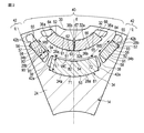
図1は、第1の実施形態に係る永久磁石式リラクタンス型の回転電機10の固定子および回転子の横断面図、図2は、回転子の一部を拡大して示す断面図である。
(First embodiment)
FIG. 1 is a cross-sectional view of a stator and a rotor of a permanent magnet type reluctance type rotating
本実施形態では、8極、48スロットの永久磁石式リラクタンス型の回転電機について説明するが、回転電機の極数、及びスロット数は適宜増減可能である。図1に示すように、回転電機10は、例えば、インナーロータ型の回転電機として構成され、図示しない固定枠に支持された環状の、ここでは、円筒形状の固定子12と、固定子の内側に回転自在にかつ固定子と同軸的に支持された回転子14と、を備えている。
In this embodiment, an 8-pole, 48-slot permanent magnet reluctance type rotating electrical machine will be described. However, the number of poles and the number of slots of the rotating electrical machine can be appropriately increased or decreased. As shown in FIG. 1, the rotating
固定子12は、円筒状の固定子鉄心16と固定子鉄心16に埋め込まれた電機子巻線18とを備えている。固定子鉄心16は、磁性材、例えば、円環状の電磁鋼板を多数枚、同芯状に積層して構成されている。固定子鉄心16の内周部には、それぞれ軸方向に延びた複数のスロット20が形成され、これにより、固定子鉄心16の内周部は、回転子14に面する多数の固定子ティース21を構成している。スロット数は48スロットで構成されている。そして、これらのスロット20に電機子巻線18が埋め込まれている。
The
回転子14は、両端が図示しない軸受により回転自在に支持された回転軸22と、この回転軸の軸方向ほぼ中央部に固定された円筒形状の回転子鉄心24と、回転子鉄心内に埋め込まれた複数の永久磁石と、を有し、固定子12の内側に僅かな隙間(エアギャップ)を置いて同軸的に配置されている。
The
回転子鉄心24は、磁性材、例えば、円環状の電磁鋼板を多数枚、同芯状に積層した積層体として構成されている。回転子鉄心24は、それぞれ回転子鉄心の半径方向あるいは放射方向に延びる磁化容易軸(磁束の通りやすい部分)(d軸)、および磁化困難軸(磁束が通り難い部分)(q軸)を有し、これらのd軸およびq軸は、回転子鉄心24の円周方向に交互に、かつ、所定の位相で形成されている。
The
回転子鉄心24の外周部に複数の凹所30が形成されている。凹所30は、それぞれ回転子鉄心24を軸方向に貫通して延びているとともに、それぞれd軸上に位置している。回転子鉄心24は、外周面に磁気的な凹凸を形成するために、複数の磁石埋め込み孔、および、これらの磁石埋め込み孔に埋め込まれた複数の永久磁石を備えている。永久磁石としては、例えば、フェライト磁石を用いる。
A plurality of
図1および図2に示すように、複数の磁石埋め込み孔は、回転子鉄心24の各d軸上において、回転子鉄心の半径方向に複数層、例えば、2層、並んで形成されている。回転子鉄心24の外周側の磁石埋め込み孔(外周側磁石収容孔)32は、横断面が円弧状に形成され、回転子鉄心24を軸方向に貫通して延びている。
As shown in FIGS. 1 and 2, the plurality of magnet embedding holes are formed side by side in a plurality of layers, for example, two layers, in the radial direction of the rotor core on each d-axis of the
ここで言う回転子鉄心24の軸とは、回転子鉄心24の回転中心Cである。言い換えると、回転子鉄心24の中心軸に垂直な断面において、外周側の磁石埋め込み孔32を規定する、回転中心C側の第1の縁51は、回転中心C側に凸となる曲線に形成されている。また、回転子鉄心24の回転中心Cに対して垂直な断面において、外周側の磁石埋め込み孔32を規定する、第1の縁51よりも回転子鉄心24の半径方向外側に位置する第2の縁52は、回転中心C側に凸となる曲線に形成されている。
The axis of the
同様に、回転子鉄心24の内周側、つまり、回転子鉄心の中心軸側、の磁石埋め込み孔34は、横断面がほぼ円弧状に形成され、回転子鉄心24を軸方向に貫通して延びている。
Similarly, the
外周側および内周側の2層の磁石埋め込み孔32、34は、回転子鉄心24のd軸(磁極中心軸)上に中心を持ち、かつ、回転子鉄心の中心側に凸となる円弧状に形成されている。各磁石埋め込み孔32、34の両端部は、回転子鉄心24の外周面の近傍まで延びている。
Two layers of
外周側の磁石埋め込み孔32は、回転子鉄心24の外周側に位置する外周面32aと、この外周面と一定の間隔をおいて対向する内周面32bと、により規定されている。外周面32aは、第1の縁51を含む面である。内周面32bは、第2の縁52を含む面である。
The magnet-embedded
本実施形態において、外周面32aおよび内周面32bは同芯の円弧状に形成されている。また、回転子鉄心24は、外周側の磁石埋め込み孔32の磁極中心軸dから離れた円弧方向両端の近傍において、内周面32bから埋め込み孔32内に突出した2つの内周側係止突起(係止構造部)36aと、磁石埋め込み孔32の円弧方向中心、すなわち、磁極中心軸d上において、外周面32aから埋め込み孔32内に突出した1つの外周側中央係止突起(中央係止構造部)36bと、を一体に有している。
In the present embodiment, the outer
言い換えると、回転中心Cに対して垂直な回転子鉄心24の断面において、第1の縁51の両端近傍には、内周側係止突起36aが形成されている。外周側中央係止突起36bは、第2の縁52の最も回転中心C側に凸となる部分に形成されており、第2の縁52において回転中心C側に最も凸となる部分と回転中心とを結ぶ直線が、磁極中心軸dとが重なる。
In other words, in the cross section of the
一方、内周側の磁石埋め込み34は、複数のブリッジにより複数の埋め込み孔に分割されている。実施形態において、回転子鉄心24は、内周側の磁石埋め込み孔34の外周部と内周部とをそれぞれ接続する複数、例えば2本のブリッジ38を有している。2本のブリッジ38は、磁極中心軸dの両側に、かつ、磁極中心軸dから等間隔離間して、設けられている。これにより、内周側の磁石埋め込み孔34は、磁極中心軸d上に位置する円弧状の中央埋め込み孔(内周側磁石収容孔)34aと、この中央埋め込み孔の両側にそれぞれ位置する2つの端側埋め込み孔(側方磁石収容孔)34bと、に分割されている。
On the other hand, the inner magnet embedded 34 is divided into a plurality of embedded holes by a plurality of bridges. In the embodiment, the
より具体的には、回転子鉄心24の回転中心Cに対して垂直な断面において、中央埋め込み孔34aを規定する、回転中心C側の第3の縁53は、回転中心C側に凸となる曲線に形成されている。また、回転子鉄心24の中心軸に垂直な断面において、中央埋め込み孔34aを規定する、第3の縁53よりも回転子鉄心24の半径方向外側に位置する第4の縁54は、回転中心C側に凸となる曲線に形成されている。
More specifically, in the cross section perpendicular to the rotation center C of the
回転子鉄心24の回転中心Cに対して垂直な断面において、端側埋め込み孔34bを規定する第5の縁55は、第3の縁53の延長方向に沿って直線状に形成されており、第5の縁55よりも回転中心C側に位置する第6の縁56は、第5の縁55に平行な直線状に形成されている。言い換えると、端側埋め込み孔34bを規定する回転中心C側の面91は平面であり、平面91に対向する面92は、面91に対して平行な平面である。面92は、第5の縁55を含み、面91は、第6の縁56を含む。
In a cross section perpendicular to the rotation center C of the
回転子鉄心24は、中央埋め込み孔34aの磁極中心軸dから離れた円弧方向両端部において、内周面から中央埋め込み孔34a内に突出した2つの係止突起(係止構造部)42aと、各端側埋め込み孔34bの外周側端部において、内周面から端側埋め込み孔内に突出した1つの外周側係止突起(係止構造部)42bと、を一体に有している。
The
図1および図2に示すように、複数の永久磁石は、外周側の磁石埋め込み孔32に埋め込まれた複数の外周側の永久磁石と、内周側の磁石埋め込み孔34に埋め込まれた複数の内周側の永久磁石と、を有している。各永久磁石は、回転子鉄心24の軸方向長さとほぼ等しい長さを有している。そして、各永久磁石は回転子鉄心24の回転中心Cに沿うほぼ全長に亘って埋め込まれている。これにより、複数の永久磁石は、回転子鉄心24の各d軸上において、回転子鉄心の半径方向に複数層、例えば、2層、並んで配置されている。
As shown in FIGS. 1 and 2, the plurality of permanent magnets includes a plurality of outer peripheral side permanent magnets embedded in the outer peripheral side magnet embedded
より詳細には、外周側の磁石埋め込み孔32内に埋め込まれた外周側の永久磁石は、外周側中央係止突起36bの両側に埋設された2つの分割永久磁石26a、26bを含んでいる。
More specifically, the outer peripheral permanent magnet embedded in the outer peripheral
各分割永久磁石26a、26bは、各々左右線対称であり、各々円弧状の断面形状を有し、磁石埋め込み孔32内に嵌め込まれ、接着剤等により回転子鉄心24に固定されている。また、各分割永久磁石26a、26bは、円弧方向両端部が外周側中央係止突起36bと内周側係止突起36aとに係合し、外周側の磁石埋め込み孔32に保持されている。2つの分割永久磁石26a、26bは、互いに同一の断面形状を有している。
Each of the divided
すなわち、分割永久磁石26aは、外周側の磁石埋め込み孔32の外周面32aに面接触する外周面(第2の面)61と、外周側の磁石埋め込み孔32の内周面32bに面接触する内周面(第1の面)62と、平坦な両端面(第3,4の面)63,64と、を有し、端面63が外周側中央係止突起36bに当接し、端面64が一端部近傍の内周側係止突起36aにそれぞれ当接し、円弧方向の位置が決められている。
That is, the split
同様に、分割永久磁石26bは、外周側の磁石埋め込み孔32の外周面32aに面接触する外周面(第2の面)65と、外周側の磁石埋め込み孔32の内周面32bに面接触する内周面(第1の面)66と、平坦な両端面(第3,4の面)67,68と、を有し、端面67が外周側中央係止突起36bに当接し、端面68が他端部近傍の内周側係止突起36aにそれぞれ当接し、円弧方向の位置が決められている。
Similarly, the split
分割永久磁石26a,26bは、回転中心Cに対して垂直な断面が、回転中心Cと外周側中央係止突起36bとを結ぶ直線に関して線対称となるように、固定されている。
The split
複数の内周側の永久磁石は、2本のブリッジ38間に位置する内周側の中央磁石埋め込み孔34aに埋設された左右線対称形状、例えば、断面が円弧形状、の中央永久磁石28aと、中央磁石埋め込み孔34aの両側に位置する2つの端側磁石埋め込み孔34bにそれぞれ埋設された左右線対称形状、例えば、断面が四辺形の2つの端側永久磁石28bと、を含んでいる。これらの永久磁石28a、28bは、磁石埋め込み孔34内に嵌め込まれ、接着剤等により回転子鉄心24に固定されている。各内周側永久磁石28a、28bは、左右線対称の断面形状を有している。また、中央永久磁石28aは、その円弧方向の両端面がそれぞれ係止突起42aに当接し、円弧方向の位置が決められている。各端側永久磁石28bは、その外周側の端面が外周側係止突起42bに当接し、円周方向の位置が決められている。
The plurality of permanent magnets on the inner peripheral side are symmetrical with the central
言い換えると、中央埋め込み孔34aに収容される中央永久磁石28aは、中央埋め込み孔34aの面71に面接触する81と、中央埋め込み孔34aの面72に面接触する82とを有する。面71は、第3の縁53を含む面である。面72は、面71に対して回転子鉄心24の半径方向外側に位置する面である。面72は、第4の縁54を含む面である。面71,81が互いに接着剤などで固定されている。面72,82が、互いに接着剤などで固定されている。
In other words, the central
端側永久磁石28bは、回転中心Cに対して垂直な断面が、矩形状に形成されている。具体的には、端側永久磁石28bは、回転中心Cに対して垂直な断面において、端側埋め込み孔34bの第5の縁55に対向する第7の縁57と、端側埋め込み孔34bの第6の縁56に対向する第8の縁58とを有している。第7の縁57と第8の縁58とは、互いに平行な直線形状に形成されている。端側永久磁石28bの第7の縁57を含む面93と、端側永久磁石28bの第8の縁58を含む面94とは、互いに平行な平面である。面91,93は、互いに面接触する。面92,94は、互いに面接触する。
The end-side
回転中心Cに対して垂直な中央永久磁石28aの断面において、第3の縁53に垂直な方向に沿う厚みL1は、回転中心Cに対して垂直な端側永久磁石28bの断面において、第5の縁55に垂直な方向に沿う厚みL2よりも大きい。
In the cross section of the central
これにより、外周側および内周側の2層の永久磁石は、回転子鉄心24のd軸(磁極中心軸)上に中心を持ち、かつ、回転子鉄心の中心側に凸となる円弧状に配置されている。
As a result, the two-layer permanent magnets on the outer peripheral side and the inner peripheral side have a center on the d-axis (magnetic pole central axis) of the
外周側および内周側の永久磁石は、その全体の磁化方向が磁極中心軸d側を向くように着磁されている。複数の永久磁石を上記のように配置することにより、回転子鉄心24の外周部において各d軸上の領域は磁極部40を形成し、各q軸上の領域は磁極間部42を形成している。そして、回転子14は、回転子鉄心24に装着された電機子巻線18に電流を流すことにより回転磁界が発生し、この回転磁界と永久磁石からの発生磁界との相互作用により、回転子14が回転軸22を中心に回転する。
The permanent magnets on the outer peripheral side and the inner peripheral side are magnetized so that the entire magnetization direction faces the magnetic pole central axis d side. By disposing a plurality of permanent magnets as described above, the regions on each d-axis form
(作用)
次に、上記のように構成された回転電機10の作用について説明する。回転電機10が運転される際、回転子14の回転により、永久磁石が径方向に飛び出そうとする遠心力が永久磁石に作用する。この際、外周側の永久磁石は、2つの分割永久磁石26a、26bで構成され、各分割永久磁石26a,26bは、左右線対称、且つ円弧形状とし、傾けて配置している。言い換えると、各分割永久磁石26a,26bは、円弧形状であることによって、回転子14の半径方向に対して傾く姿勢で、回転子鉄心24に固定されている。
(Function)
Next, the operation of the rotating
分割永久磁石26a、26bの重心位置は磁極中心軸d上ではなく、磁極間側に存在する。言い換えると、分割永久磁石26a,26bの重心位置は、磁極中心軸dよりも磁極間部42側にシフトした位置にある。また、各分割永久磁石26a、26bは、両端面が中央係止突起36bおよび1つの内周側係止突起36aにそれぞれ当接し、円弧方向の位置が決められている。
The positions of the center of gravity of the divided
これにより、回転により回転子鉄心24が遠心力により応力を受けて、歪んだ場合でも、係止突起36a、36bにより、分割永久磁石26a、26bを確実に保持し、磁石の移動、破損等が防止される。外周面中央部に中央係止突起36bを設けているため、2つの分割永久磁石26a、26b同士が接触することなく、永久磁石のズレなどの移動を防ぐことができる。また、磁極中央部にブリッジを配置する必要がなくなり、漏れ磁束が抑制される。
As a result, even if the
また、内周面32bと外周面32aとに沿って外側に飛び出そうとする力を受ける突起を、内周側係止突起36aとして第1の縁51に形成することによって、当該外側に飛び出そうとする力に対する突起の耐荷重性を高めることができる。
Further, by forming a protrusion that receives a force to protrude outward along the inner
この点について、具体的に説明する。各分割永久磁石26a,26bに作用する遠心力によって、各分割永久磁石26a,26bは、磁石埋め込み孔32の内周面32bと外周面32aとに沿って、外側に飛び出そうとする。
This point will be specifically described. Due to the centrifugal force acting on each divided
回転中心Cに対して垂直な断面において、第2の縁52と回転子鉄心24の外周面との間の厚みは、比較的小さくなるが、第1の縁51の周囲には、十分な厚みを確保することができる。このため、第1の縁51に内周側係止突起36aが形成されることによって、内周側係止突起36aの周囲には、内周側係止突起36aを支持する厚みが十分に確保されるので、内周側係止突起36aが耐えられる荷重、つまり耐荷重性を高めることができる。
In the cross section perpendicular to the rotation center C, the thickness between the
分割永久磁石26aは磁石埋め込み穴32の内周面に沿って回転中心Cから遠ざかろうとするが、内周側係止突起36aによってその運動が抑え込まれることにより、内周側係止突起36aとの接点を回転中心として、この接点とは反対側の端面を回転中心Cから遠ざけようとする回転モーメントが発生する。この回転モーメントにより、隣り合う各分割永久磁石の向かい合う端面が接触する方向に運動しようとする。
The divided
分割永久磁石26a,26bが互いに接触する方向に移動することを防止するための突起である突起を、外周側中央係止突起36bとして第2の縁52に形成することによって、分割永久磁石26a,26が互いに接触することを確実に防止しつつ、分割永久磁石26a,26bを大きくすることができる。
By forming a protrusion, which is a protrusion for preventing the divided
この点について、具体的に説明する。分割永久磁石26a,26bにおいて互いに対向する部分である第3の面63,67は、遠心力によって、互いに近づく方向に歪む傾向にある。さらに、第3の面63,67において、回転子14の半径方向外側の部分は、内側の部分に対して、より大きな遠心力が作用する。このため、第3の面63,67において、回転子14の半径方向外側の部分は、内側の部分に対して、より大きく歪む傾向にある。
This point will be specifically described. The third surfaces 63 and 67 which are the portions facing each other in the divided
しかしながら、第2の縁52に外周側中央係止突起36bを形成することによって、より大きく歪む傾向にある、第3の面63,67において回転子14の半径方向外側の部分を受けることによって、つまり接触すること受けることによって、分割永久磁石26a,26bが互いに近づく方向に歪むことを防止することができる。
However, by receiving the radially outer portion of the
このため、第1の縁51に、分割永久磁石26a,26bが互いに接触することを防止する突起を形成する必要がないため、分割永久磁石26a,26bにおいて回転子14の半径向内側の部分を、互いに接近する形状に形成できる。つまり、分割永久磁石26a,26bを大きくすることができる。
For this reason, since it is not necessary to form the protrusion which prevents the division | segmentation
内周側の永久磁石は、ブリッジ38間に位置する中央永久磁石28aと、中央永久磁石の両側に位置する2つ端側永久磁石28bと、に分割され、左右線対称、且つアーチ形状磁石と平板形状の磁石とを組合せて配置できる。また、ブリッジ38を複数本とすることにより、左右線対称の永久磁石を適用することが可能となり、従来と同等な回転子鉄心の磁路形状とすることができる。これにより、リラクタンストルクを活用した、高トルク、高出力特性を確保することができる。
The inner peripheral side permanent magnet is divided into a central
内周側に配置される磁石を複数に分けることによって、磁石の重心を磁極軸上ではなく、磁極軸の脇に磁極軸に関して線対称に配置することができる。また、磁石1個あたりの質量を半減させ、遠心力によって発生する力を低減させることができる。これにより、回転子鉄心24において中央永久磁石28aを受ける係止突起42aに作用する力を小さくすることができる。同様に、回転子鉄心24において端側永久磁石28bを受ける係止突起42bに作用する力を小さくすることができる。このため、端側永久磁石28bの回転子鉄心24に対する保持力を高めることができる。
By dividing the magnet arranged on the inner peripheral side into a plurality of parts, the center of gravity of the magnet can be arranged symmetrically with respect to the magnetic pole axis on the side of the magnetic pole axis, not on the magnetic pole axis. Moreover, the mass per magnet can be halved and the force generated by the centrifugal force can be reduced. Thereby, the force which acts on the latching
端側永久磁石28bは、中央永久磁石28aに対して、大きな遠心力が作用する。しかしながら、端側永久磁石28bの厚みL2を中央永久磁石28aの厚みL1よりも小さくすることによって、端側永久磁石28bの重さを小さくできるので、端側永久磁石28bに作用する、遠心力による影響を小さく抑えることができる。
A large centrifugal force acts on the end
内周側の磁石埋め込み孔34に設けるブリッジを複数本、例えば、2本とすることにより、磁極中央部における永久磁石の厚みを確保しつつ、モータ特性(トルク)を最大とするブリッジ幅およびブリッジ位置を設定することが可能となる。ブリッジが1本の場合、ブリッジの幅を狭くすることができるが、永久磁石の厚みが大きい磁極中央部にブリッジを配置する必要があるため、永久磁石量が少なくなってしまう。すなわち、モータのトルクが小さくなる。これに対して、ブリッジを2本設ける場合、磁極中心軸の両側にブリッジを配置することができ、2本のブリッジ間、すなわち、磁極中央部に永久磁石を配置することができる。これにより、磁極中央部における永久磁石の厚みを確保し、磁石量を増加することが可能となる。従って、ブリッジ幅を適宜設定することにより、モータ特性(トルク)を最大とすることができる。
By providing a plurality of, for example two, bridges provided in the
図3に示すように、中央永久磁石28aの円弧方向長さをWc、各端側永久磁石28bの長手方向長さをWsとした場合、図3は、磁石長さの比(Ws/Wc)、つまり、2本のブリッジ38の配設位置と、モータ特性(トルク)との関係を示している。図3に示すように、中央永久磁石の長さWcと端側永久磁石の長さWsとの比(Ws/Wc)が変化すると、モータ特性が変化することが分かる。中央永久磁石28aの長さWcを大きくすることで、すなわち、2本のブリッジ38間の間隔を大きくすることで、磁石面積(磁石量)が拡大し、トルク特性は向上する。しかし、長さ比(Ws/Wc)がある点(1.70)を越えると、遠心力により永久磁石に作用する応力が大きくなるため、ブリッジ38の幅を広げ強度を上げる必要が出てくる。ブリッジ幅の増大により、漏れ磁束が増加するため、モータのトルク特性は減少する。本実施形態では、永久磁石長さの比(Ws/Wc)が1.70付近となるように、2本のブリッジ38を配置している。そのため、各ブリッジ38の幅を広げる必要がなく、最適なモータ特性(トルク)が得られる。
As shown in FIG. 3, when the length in the arc direction of the central
ブリッジ幅については、製造的に最小幅として鉄心(電磁鋼板)板厚程度が限界であり、許容応力以内とするために、磁石量の増加に伴って、ブリッジ幅を広げる必要がある。従って、中央永久磁石長さと端側永久磁石長さとの関係、すなわち、2本のブリッジ間の間隔、ブリッジの位置、最適に保ちつつ、ブリッジ幅の選定を行うことが望ましい。ブリッジ幅を狭めることにより、漏れ磁束を低減でき、トルク特性を向上することができる。一方、ブリッジ幅を狭めていくと、回転子鉄心に作用する応力(ブリッジ部応力)が増大し、ブリッジの許容応力を超えてしまう場合がある。従って、許容応力以下とするブリッジ幅を設定することが望ましい。以上のことから、ブリッジの配設位置、ブリッジ幅を適宜設定することにより、モータ特性(トルク)を最大とすることができる。 Regarding the bridge width, the iron core (electromagnetic steel plate) thickness is the limit as the minimum width in terms of manufacturing, and in order to make it within the allowable stress, it is necessary to increase the bridge width as the amount of magnet increases. Therefore, it is desirable to select the bridge width while maintaining the relationship between the center permanent magnet length and the end permanent magnet length, that is, the distance between the two bridges, the position of the bridge, and the optimum. By narrowing the bridge width, the leakage magnetic flux can be reduced and the torque characteristics can be improved. On the other hand, when the bridge width is narrowed, the stress acting on the rotor core (bridge portion stress) increases and may exceed the allowable stress of the bridge. Therefore, it is desirable to set a bridge width that is less than the allowable stress. From the above, the motor characteristics (torque) can be maximized by appropriately setting the bridge disposition position and the bridge width.
(効果)
第1の実施形態によれば、回転により回転子鉄心および永久磁石が遠心力により応力を受けて、歪んだ場合でも、外周側中央係止突起および内周側係止突起により、分割永久磁石を確実に保持し、永久磁石角部の片当たり、曲げ応力発生による割れ、欠けなどの破損を防止し、また回転子鉄心内の応力を低減することが可能となる。これにより、高速回転が可能で、且つ信頼性の高い永久磁石式リラクタンス型の回転電機が得られる。
(effect)
According to the first embodiment, even if the rotor core and the permanent magnet are subjected to stress due to the centrifugal force due to the rotation and are distorted, the split permanent magnets are separated by the outer peripheral side central locking protrusion and the inner peripheral locking protrusion. It is possible to securely hold, prevent breakage such as cracking and chipping due to bending stress generation, and reduce stress in the rotor core. As a result, a highly reliable permanent magnet type reluctance type rotating electrical machine capable of high speed rotation is obtained.
また、外周側中央係止突起により、外周側の分割永久磁石同士の接触、位置ズレを防止でき、これにより、中央にブリッジを配置する必要がなくなり、漏れ磁束を抑制することができる。このことから、トルクの減少を抑え、高トルク、高出力が可能となる。 In addition, the outer peripheral side center locking projections can prevent contact between the outer peripheral divided permanent magnets and misalignment, thereby eliminating the need to place a bridge in the center and suppressing leakage magnetic flux. From this, it is possible to suppress torque reduction and to achieve high torque and high output.
内周側の永久磁石に左右線対称、且つアーチ形状の中央永久磁石を適用できることから、従来と同等な回転子鉄心の磁路形状となり、リラクタンストルクを活用した、高トルク、高出力特性を確保することができる。また、中央永久磁石の両側に配置する端側永久磁石を断面四辺形の平板形状とすることができ、磁石加工性の向上、製造コストの低減を図ることができる。 Since the inner permanent magnet can be symmetrical to the left and right, and an arch-shaped central permanent magnet can be used, the magnetic path shape of the rotor core is the same as before, ensuring high torque and high output characteristics utilizing reluctance torque. can do. In addition, the end permanent magnets arranged on both sides of the central permanent magnet can be formed into a flat plate shape having a quadrangular cross section, thereby improving magnet workability and reducing manufacturing costs.
以上のことから、安価で磁力の弱いフェライト磁石を用いた場合でも、高トルク、高出力、且つ高速回転が可能となり、信頼性の高い低コストの回転電機を提供することができる。 From the above, even when using a ferrite magnet that is inexpensive and weak in magnetic force, high torque, high output, and high-speed rotation are possible, and a highly reliable low-cost rotating electrical machine can be provided.
次に、他の実施形態に係る回転電機について説明する。なお、以下に説明する他の実施形態において、前述した第1の実施形態と同一の部分には、同一の参照符号を付してその詳細な説明を省略し、第1の実施形態と異なる部分を中心に詳しく説明する。 Next, a rotating electrical machine according to another embodiment will be described. In other embodiments described below, the same parts as those in the first embodiment described above are denoted by the same reference numerals, and detailed description thereof is omitted, and the parts different from those in the first embodiment. Will be described in detail.
(第2の実施形態)
図4は、第2の実施形態に係る永久磁石式リラクタンス型の回転電機10の回転子の一部を拡大して示す断面図である。
(Second Embodiment)
FIG. 4 is an enlarged cross-sectional view of a part of the rotor of the permanent magnet type reluctance type rotating
本実施形態では、内周側の永久磁石において、中央永久磁石28aの両側に設けられた端側永久磁石28bは、その断面が非平行な2辺を有する台形状に形成されている。具体的には、台形形状の端側永久磁石28bは、回転子14の外周側に位置する部分の第5の縁55に沿う部分の第5の縁55の延びる方向に沿う厚みL3が、内周側の第6の縁56に沿う部分の第6の縁56の延びる方向に沿う厚みL4に対して薄くなるように構成されている。
In the present embodiment, in the permanent magnet on the inner peripheral side, the end
なお、第2の実施形態において、回転電機の他の構成は、前述した第1の実施形態に係る回転電機と同一である。 In the second embodiment, other configurations of the rotating electrical machine are the same as those of the rotating electrical machine according to the first embodiment described above.
台形形状の端側永久磁石28bは、第1の実施形態における平板状(矩形状)の永久磁石に対し、回転子14の内周側に位置する部分の厚みを大きくすることができるため、磁石断面積を大きくすることができ、磁石トルクを増加することができる。また、従来構造の磁路形状と同様に内周側に向かって磁路幅が大きくなる形状とすることが可能となり、リラクタンストルクを活用できる。
The trapezoidal end-side
第2の実施形態によれば、端側永久磁石を非平行な2対の辺を有する台形形状とすることにより、永久磁石量を増加させ、磁石トルクを増加することができる。また、従来と同等な回転子鉄心の磁路形状となり、リラクタンストルクを活用した、高トルク、高出力特性を確保することができる。第2の実施形態においても、第1の実施形態と同様に、高速回転が可能で、且つ信頼性の高い永久磁石式リラクタンス型の回転電機を提供することできる。 According to the second embodiment, the permanent magnet amount can be increased and the magnet torque can be increased by forming the end-side permanent magnet into a trapezoidal shape having two pairs of non-parallel sides. Moreover, the magnetic path shape of the rotor core is the same as that of the conventional one, and high torque and high output characteristics utilizing reluctance torque can be ensured. In the second embodiment, as in the first embodiment, a permanent magnet reluctance type rotating electrical machine that can rotate at high speed and has high reliability can be provided.
なお、この発明は上記実施形態そのままに限定されるものではなく、実施段階ではその要旨を逸脱しない範囲で構成要素を変形して具体化可能である。また、上記実施の形態に開示されている複数の構成要素の適宜な組み合わせにより、種々の発明を形成できる。例えば、実施形態に示される全構成要素から幾つかの構成要素を削除してもよい。さらに、異なる実施形態にわたる構成要素を適宜組み合わせてもよい。 Note that the present invention is not limited to the above-described embodiment as it is, and can be embodied by modifying the constituent elements without departing from the scope of the invention in the implementation stage. Various inventions can be formed by appropriately combining a plurality of constituent elements disclosed in the embodiments. For example, some components may be deleted from all the components shown in the embodiment. Furthermore, constituent elements over different embodiments may be appropriately combined.
例えば、永久磁石型の回転電機は、インナーロータ型に限らず、アウターロータ型としてもよい。回転子の磁極数、寸法、形状等は、前述した実施形態に限定されることなく、設計に応じて種々変更可能である。また、回転子鉄心24内における永久磁石26の多層配置は、2層に限らず、3層以上としてもよい。
For example, the permanent magnet type rotating electrical machine is not limited to the inner rotor type, and may be an outer rotor type. The number of magnetic poles, the size, the shape, and the like of the rotor are not limited to the above-described embodiments, and can be variously changed according to the design. Further, the multilayer arrangement of the permanent magnets 26 in the
第1の実施形態において、外周側磁石収容孔に設けられた中央係止突起は、回転子鉄心の回転中心に対して垂直な断面において、外側収容孔を規定する回転中心側に位置する第1の縁よりも半径方向外側に位置する第2の縁に形成されている。しかしながら、例えば、内周側磁石収容孔に中央係止突起を設けてもよい。この場合、この中央係止突起は、回転鉄心の回転中心に対して垂直な断面において、内側磁石収容孔を規定する回転子鉄心の回転中心側の第3の縁よりも半径方向外側に位置する内周側磁石収容孔を規定する第4の縁に形成される。より具体的には、例えば、内周側の中央埋め込み孔34aに、分割永久磁石26a,26bのように、分割された磁石を収容する場合では、内周側磁埋め込み孔34aの第4の縁54に、外周側中央係止突起36bと同様の中央係止突起を設けてもよい。
以下、本願の出願当初の特許請求の範囲に記載された発明を付記する。
[1]固定子鉄心及びこの固定子鉄心に取り付けられた電機子巻線を具備する固定子と、前記固定子に対して回転自在に設けられる回転子鉄心を具備する回転子とを具備し、
前記回転子鉄心は、磁石を収容可能な内側磁石収容孔と、前記内側磁石収容孔よりも前記回転子鉄心の半径方向外側に磁石を収容可能な外側磁石収容孔が形成され、
前記回転子鉄心の回転中心に対して垂直な前記回転子鉄心の断面における、前記外側磁石収容孔を規定する前記回転中心側の第1の縁、前記第1の縁よりも前記半径方向外側に位置する第2の縁のそれぞれは、前記前記回転中心側に凸となる曲線に形成され、
前記回転中心に対して垂直な前記回転子鉄心の断面における、前記内側磁石収容孔を規定する前記回転中心側の第3の縁、前記第3の縁よりも前記半径方向外側に位置する第4の縁のそれぞれは、前記回転中心側に凸となる曲線に形成され、
前記第2の縁において前記回転中心側に最も凸となる部分に、磁石に接触することによって磁石の位置を規定する、前記第1の縁に向かって突出する外周側中央係止突起が形成され、
前記第1の縁の両端部近傍のそれぞれに、磁石に接触することによって磁石の位置を規定する、前記第2の縁に向かって突出する内周側係止突起が形成され、
前記回転中心に垂直な磁石の断面が、前記回転中心と前記外周側中央係止突起とを結ぶ直線に関して線対称となるように、前記外周側中央係止突起と一端部近傍の前記内周側係止突起との間に磁石を固定可能であり、前記外周側中央係止突起と他端部近傍の前記内周側係止突起との間に磁石を固定可能である
ことを特徴とする回転電機。
[2]前記外周側中央係止突起と前記一端部近傍の前記内周側係止突起との間に固定される磁石は、前記外周側磁石収容孔の前記第1の縁を含む面に面接触する第1の面と、前記外周側磁石収容孔の前記第2の縁を含む面に面接触する第2の面と、前記外周側中央係止突起に接触する平坦な第3の面と、前記一端部近傍の前記内周側係止突起に接触する平坦な第4の面とを具備し、
前記外周側中央係止突起と前記他端部近傍の前記内周側係止突起との間に固定される磁石は、前記外周側磁石収容孔の前記第1の縁を含む面に面接触する第5の面と、前記外周側磁石収容孔の前記第2の縁を含む面に面接触する第6の面と、前記外周側中央係止突起に接触する平坦な第7の面と、前記他端部近傍の前記内周側係止突起に接触する平坦な第8の面とを具備する
ことを特徴とする[1]に記載の回転電機。
[3]前記回転子鉄心は、前記内周側磁石収容孔に対して前記第3の縁の延びる方向に並ぶ、磁石を収容可能な側方磁石収容孔が少なくとも1つ形成される
ことを特徴とする[1]または[2]に記載の回転電機。
[4]前記回転子鉄心は、前記内周側磁石収容孔に対して前記第3の縁の延びる方向両側に前記側方磁石収容が1つずつ形成され、
前記回転中心に対して垂直な前記回転子鉄心の断面において、前記両側方磁石収容孔は、前記第3の縁の延長方向に延びる第5の縁と、前記第3の縁の延長方向に延びるとともに前記第5の縁よりも前記回転中心側に位置する第6の縁とを具備し、
前記両側方磁石収容孔に収容される磁石は、前記回転中心に垂直な断面において、前記第5の縁に対向する第7の縁と、前記第6の縁に対向する第8の縁とが互いに平行な直線に形成され、
前記内周側磁石収容孔に収容される磁石は、前記回転中心に垂直な断面が、前記回転中心と前記外周側中央突起とを結ぶ直線に関して線対称な形状に形成される
ことを特徴とする[3]に記載の回転電機。
[5]前記側方磁石収容孔に収容される磁石は、前記回転中心に対して垂直な断面が台形状に形成される、ことを特徴とする[4]に記載の回転電機。
[6]前記端側磁石収容孔に収容される磁石は、前記回転中心に対して垂直な断面が矩形状に形成される
ことを特徴とする[5]に記載の回転電機。
[7]前記側方磁石収容孔に収容される磁石の前記回転中心に対して垂直な断面における前記第5の縁に垂直な方向に沿う厚みは、前記内周側磁石収容孔に収容される磁石の前記回転中心に対して垂直な断面における前記第3の縁が延びる方向に垂直な方向に沿う厚みよりも、小さい
ことを特徴とする[4]〜[6]のうちのいずれか1項に記載の回転電機。
In the first embodiment, the central locking projection provided in the outer magnet receiving hole is a first position located on the rotation center side defining the outer receiving hole in a cross section perpendicular to the rotation center of the rotor core. It is formed in the 2nd edge located in the radial outside rather than the edge of. However, for example, a central locking projection may be provided in the inner peripheral side magnet accommodation hole. In this case, the central locking projection is located radially outside the third edge on the rotation center side of the rotor core that defines the inner magnet housing hole in a cross section perpendicular to the rotation center of the rotation core. It is formed in the 4th edge which prescribes | regulates an inner peripheral side magnet accommodation hole. More specifically, for example, when the divided magnets such as the divided
Hereinafter, the invention described in the scope of claims at the beginning of the application of the present application will be added.
[1] A stator including a stator core and an armature winding attached to the stator core, and a rotor including a rotor core provided to be rotatable with respect to the stator.
The rotor iron core is formed with an inner magnet housing hole capable of housing a magnet, and an outer magnet housing hole capable of housing a magnet on a radially outer side of the rotor core than the inner magnet housing hole,
In the cross section of the rotor core perpendicular to the rotation center of the rotor core, the first edge on the rotation center side that defines the outer magnet housing hole, the outer side in the radial direction from the first edge Each of the second edges located is formed in a curve that is convex toward the rotation center side,
In the cross section of the rotor core perpendicular to the rotation center, a third edge on the rotation center side that defines the inner magnet housing hole, a fourth edge located radially outward from the third edge. Each of the edges is formed in a curve that is convex toward the rotation center side,
An outer peripheral side central locking projection that protrudes toward the first edge and that defines the position of the magnet by contacting the magnet is formed at a portion of the second edge that is most convex toward the rotation center. ,
Inner peripheral side locking projections projecting toward the second edge, which define the position of the magnet by contacting the magnet, are formed in the vicinity of both ends of the first edge,
The outer peripheral side central locking projection and the inner peripheral side near one end so that the cross section of the magnet perpendicular to the rotational center is axisymmetric with respect to a straight line connecting the rotational center and the outer peripheral side central locking projection A magnet can be fixed between the locking protrusion and the magnet can be fixed between the outer peripheral center locking protrusion and the inner peripheral locking protrusion near the other end.
Rotating electric machine characterized by that.
[2] The magnet fixed between the outer peripheral side central locking projection and the inner peripheral locking projection in the vicinity of the one end portion faces the surface including the first edge of the outer magnet receiving hole. A first surface that makes contact, a second surface that makes surface contact with a surface that includes the second edge of the outer peripheral side magnet housing hole, and a flat third surface that makes contact with the outer peripheral side central locking projection. And a flat fourth surface in contact with the inner peripheral side locking projection near the one end,
The magnet fixed between the outer peripheral side central locking projection and the inner peripheral locking projection in the vicinity of the other end is in surface contact with the surface including the first edge of the outer peripheral magnet receiving hole. A fifth surface, a sixth surface in surface contact with the surface including the second edge of the outer peripheral side magnet accommodation hole, a flat seventh surface in contact with the outer peripheral side central locking projection, A flat eighth surface in contact with the inner peripheral side locking projection in the vicinity of the other end.
The rotating electrical machine according to [1], wherein
[3] The rotor core is formed with at least one side magnet accommodation hole that can accommodate the magnet and is arranged in a direction in which the third edge extends with respect to the inner circumference side magnet accommodation hole.
The rotating electrical machine according to [1] or [2], wherein
[4] The rotor core has one side magnet housing formed on each side in the extending direction of the third edge with respect to the inner circumferential magnet housing hole.
In the cross section of the rotor core perpendicular to the center of rotation, the both-side magnet receiving holes extend in the extension direction of the third edge and in the extension direction of the third edge. And a sixth edge located closer to the center of rotation than the fifth edge,
The magnet housed in the both-side magnet housing hole has a seventh edge facing the fifth edge and an eighth edge facing the sixth edge in a cross section perpendicular to the rotation center. Formed in straight lines parallel to each other,
The magnet accommodated in the inner circumference side magnet accommodation hole is formed so that a cross section perpendicular to the rotation center is axisymmetric with respect to a straight line connecting the rotation center and the outer circumference side central projection.
The rotating electrical machine according to [3], wherein
[5] The rotating electrical machine according to [4], wherein the magnet housed in the side magnet housing hole has a trapezoidal cross section perpendicular to the rotation center.
[6] The magnet accommodated in the end-side magnet accommodation hole has a rectangular cross section perpendicular to the rotation center.
The rotating electric machine according to [5], wherein
[7] The thickness along the direction perpendicular to the fifth edge in the cross section perpendicular to the rotation center of the magnet accommodated in the side magnet accommodation hole is accommodated in the inner circumference side magnet accommodation hole. Less than the thickness along the direction perpendicular to the direction in which the third edge extends in the cross section perpendicular to the rotation center of the magnet
The rotating electric machine according to any one of [4] to [6].
10…回転電機、12…固定子、14…回転子、16…固定子鉄心、
18…電機子巻線、20…スロット、22…回転軸、24…回転子鉄心、
26a、26b…分割永久磁石、28a…中央永久磁石、28b…端側永久磁石、
32…外周側磁石埋め込み孔、32a…外周面、32b…内周面、
34a…中央埋め込み孔、34b…端側埋め込み孔、42a…係止突起、
42b…外周側係止突起
DESCRIPTION OF
18 ... Armature winding, 20 ... Slot, 22 ... Rotating shaft, 24 ... Rotor core,
26a, 26b ... split permanent magnets, 28a ... center permanent magnets, 28b ... end side permanent magnets,
32 ... outer peripheral side magnet embedding hole, 32a ... outer peripheral surface, 32b ... inner peripheral surface,
34a ... center embedded hole, 34b ... end side embedded hole, 42a ... locking projection,
42b ... Outer peripheral side locking projection
Claims (7)
前記固定子に対して回転自在に設けられる回転子鉄心を具備する回転子と
を具備し、
前記回転子鉄心は、中央永久磁石を収容可能な内周側磁石収容孔と、前記内周側磁石収容孔よりも前記回転子鉄心の半径方向外側に前記回転子鉄心の周方向に2つの分割永久磁石を収容可能な外周側磁石収容孔と、が形成され、
前記回転子鉄心の回転中心に対して垂直な前記回転子鉄心の断面における、前記外周側磁石収容孔を規定する前記回転中心側の第1の縁、前記第1の縁よりも前記半径方向外側に位置する第2の縁のそれぞれは、前記回転中心側に凸となる曲線に形成され、
前記回転中心に対して垂直な前記回転子鉄心の断面における、前記内周側磁石収容孔を規定する前記回転中心側の第3の縁、前記第3の縁よりも前記半径方向外側に位置する第4の縁のそれぞれは、前記回転中心側に凸となる曲線に形成され、
前記第2の縁において前記回転中心側に最も凸となる部分に、前記分割永久磁石に接触することによって前記分割永久磁石の位置を規定する、前記第1の縁に向かって突出する外周側中央係止突起が形成され、
前記第1の縁の両端部近傍のそれぞれに、前記分割永久磁石に接触することによって前記分割永久磁石の位置を規定する、前記第2の縁に向かって突出する内周側係止突起が形成され、
前記回転中心に垂直な磁石の断面が、前記回転中心と前記外周側中央係止突起とを結ぶ直線に関して線対称となるように、前記外周側中央係止突起と一端部近傍の前記内周側係止突起との間、並びに、前記外周側中央係止突起と他端部近傍の前記内周側係止突起との間に前記分割永久磁石がそれぞれ固定される、ことを特徴とする回転電機。 A stator having a stator core and an armature winding attached to the stator core;
A rotor having a rotor core provided rotatably with respect to the stator,
The rotor core is divided into two parts in the circumferential direction of the rotor core, the inner circumference side magnet accommodation hole capable of accommodating a central permanent magnet and the radially outer side of the rotor core than the inner circumference side magnet accommodation hole. an outer circumferential side magnet containing hole capable of containing permanent magnets, is formed,
In the cross section perpendicular the rotor core with respect to the rotation center of the rotor core, said first edge of the rotation center side, the radial direction than the first edge defining the outer circumferential side magnet containing hole each of the second edge located outside, is formed in a curve is convex prior Symbol rotation center side,
In the cross section of the rotor core perpendicular to the center of rotation, the third edge on the side of the center of rotation that defines the inner peripheral magnet receiving hole is located on the radially outer side of the third edge. Each of the fourth edges is formed in a curve that is convex toward the rotation center side,
The center of the outer peripheral side protruding toward the first edge that defines the position of the divided permanent magnet by contacting the divided permanent magnet at the portion that is most convex on the rotation center side in the second edge A locking projection is formed,
Inner peripheral side locking projections projecting toward the second edge, which define the position of the split permanent magnet by contacting the split permanent magnet, are formed near both ends of the first edge, respectively. And
The outer peripheral side central locking projection and the inner peripheral side near one end so that the cross section of the magnet perpendicular to the rotational center is axisymmetric with respect to a straight line connecting the rotational center and the outer peripheral side central locking projection between the locking projection and the rotating electric machine, wherein the divided permanent magnets are fixed respectively, that between the outer peripheral side central locking projection and the other end portion the inner circumferential side locking projection in the vicinity .
前記外周側中央係止突起と前記他端部近傍の前記内周側係止突起との間に固定される前記分割永久磁石は、前記外周側磁石収容孔の前記第1の縁を含む面に面接触する第5の面と、前記外周側磁石収容孔の前記第2の縁を含む面に面接触する第6の面と、前記外周側中央係止突起に接触する平坦な第7の面と、前記他端部近傍の前記内周側係止突起に接触する平坦な第8の面とを具備する
ことを特徴とする請求項1に記載の回転電機。 The divided permanent magnet fixed between the outer peripheral side central locking projection and the inner peripheral locking projection in the vicinity of the one end portion faces the surface including the first edge of the outer magnet receiving hole. A first surface that makes contact, a second surface that makes surface contact with a surface that includes the second edge of the outer peripheral side magnet housing hole, and a flat third surface that makes contact with the outer peripheral side central locking projection. And a flat fourth surface in contact with the inner peripheral side locking projection near the one end,
The divided permanent magnet fixed between the outer peripheral side central locking projection and the inner peripheral locking projection in the vicinity of the other end is formed on a surface including the first edge of the outer magnet receiving hole. A fifth surface in surface contact, a sixth surface in surface contact with the surface including the second edge of the outer magnet receiving hole, and a flat seventh surface in contact with the outer central locking projection. The rotating electrical machine according to claim 1, further comprising: a flat eighth surface that comes into contact with the inner peripheral side locking protrusion in the vicinity of the other end portion.
ことを特徴とする請求項1または請求項2に記載の回転電機。 The rotor core is formed with at least one side magnet accommodation hole that is capable of accommodating an end-side permanent magnet that is arranged in a direction in which the third edge extends with respect to the inner circumference magnet accommodation hole. the rotating electrical machine according to claim 1 or claim 2,.
前記回転中心に対して垂直な前記回転子鉄心の断面において、前記側方磁石収容孔は、前記第3の縁の延長方向に延びる第5の縁と、前記第4の縁の延長方向に延びるとともに前記第5の縁よりも前記半径方向外側に位置する第6の縁とを具備し、
前記側方磁石収容孔に収容される前記端側永久磁石は、前記回転中心に垂直な断面において、前記第5の縁に対向する第7の縁と、前記第6の縁に対向する第8の縁とが互いに平行な直線に形成され、
前記内周側磁石収容孔に収容される前記中央永久磁石は、前記回転中心に垂直な断面が、前記回転中心と前記外周側中央係止突起とを結ぶ直線に関して線対称な形状に形成される
ことを特徴とする請求項3に記載の回転電機。 The rotor core, said lateral magnet containing holes in opposite sides of extension of said third edge to said inner circumference side magnet containing holes are formed one by one,
In a cross section perpendicular the rotor core with respect to the rotation center, front SL side magnet containing hole, a fifth edge extending in the extending direction of the third edge, the extending direction of the fourth edge A sixth edge extending and positioned radially outward from the fifth edge,
The end permanent magnets accommodated in the front SL side magnet containing hole, in a cross section perpendicular to the rotation center, a seventh edge opposing said fifth edge, the opposite to the sixth edge 8 edges are formed in a straight line parallel to each other,
The central permanent magnet housed in the inner circumferential magnet housing hole has a cross section perpendicular to the rotation center formed in a line-symmetric shape with respect to a straight line connecting the rotation center and the outer circumferential center locking projection. The rotating electrical machine according to claim 3.
ことを特徴とする請求項4に記載の回転電機。 The rotating electrical machine according to claim 4, wherein the end-side permanent magnet housed in the side magnet housing hole has a trapezoidal cross section perpendicular to the rotation center.
ことを特徴とする請求項5に記載の回転電機。 6. The rotating electrical machine according to claim 5, wherein the end-side permanent magnet housed in the side magnet housing hole has a rectangular cross section perpendicular to the rotation center.
ことを特徴とする請求項4乃至請求項6のうちのいずれか1項に記載の回転電機。 The thickness along the direction perpendicular to the fifth edge in the cross section perpendicular to the rotation center of the end-side permanent magnet accommodated in the side magnet accommodation hole is accommodated in the inner circumferential magnet accommodation hole. It said central than the thickness along the direction perpendicular to the third edge extending direction in a cross section perpendicular to the rotational center of the permanent magnet, of the claims 4 to 6, characterized in that small that The rotating electrical machine according to any one of claims.
Priority Applications (1)
| Application Number | Priority Date | Filing Date | Title |
|---|---|---|---|
| JP2014103728A JP6385715B2 (en) | 2013-05-21 | 2014-05-19 | Rotating electric machine |
Applications Claiming Priority (3)
| Application Number | Priority Date | Filing Date | Title |
|---|---|---|---|
| JP2013107260 | 2013-05-21 | ||
| JP2013107260 | 2013-05-21 | ||
| JP2014103728A JP6385715B2 (en) | 2013-05-21 | 2014-05-19 | Rotating electric machine |
Publications (2)
| Publication Number | Publication Date |
|---|---|
| JP2015006124A JP2015006124A (en) | 2015-01-08 |
| JP6385715B2 true JP6385715B2 (en) | 2018-09-05 |
Family
ID=51965122
Family Applications (1)
| Application Number | Title | Priority Date | Filing Date |
|---|---|---|---|
| JP2014103728A Active JP6385715B2 (en) | 2013-05-21 | 2014-05-19 | Rotating electric machine |
Country Status (3)
| Country | Link |
|---|---|
| JP (1) | JP6385715B2 (en) |
| CN (1) | CN104184296B (en) |
| IN (1) | IN2014DE01336A (en) |
Families Citing this family (11)
| Publication number | Priority date | Publication date | Assignee | Title |
|---|---|---|---|---|
| CN104993626A (en) * | 2015-06-23 | 2015-10-21 | 天津大学 | Built-in type permanent magnet motor capable of effectively reducing motor iron loss |
| JP6385588B2 (en) | 2015-10-09 | 2018-09-05 | 三菱電機株式会社 | Rotor and rotating electric machine |
| WO2017203618A1 (en) * | 2016-05-25 | 2017-11-30 | 三菱電機株式会社 | Rotor, electric motor, compressor, air conditioner, and method for manufacturing electric motor |
| CN106972663B (en) * | 2017-04-01 | 2023-09-01 | 上海英磁新能源科技有限公司 | High-torque permanent magnet motor |
| US10886802B2 (en) * | 2018-02-13 | 2021-01-05 | GM Global Technology Operations LLC | Rotor for an electric machine |
| CN110875655B (en) * | 2018-08-31 | 2021-11-12 | 比亚迪股份有限公司 | Motor rotor, motor and electric automobile |
| CN110875656B (en) * | 2018-08-31 | 2021-12-07 | 比亚迪股份有限公司 | Motor rotor, motor and electric automobile |
| JP6839376B1 (en) * | 2019-11-28 | 2021-03-10 | 三菱電機株式会社 | Rotating machine |
| CN111030339B (en) * | 2019-12-16 | 2022-01-28 | 珠海格力电器股份有限公司 | Electric motor rotor and alternating-pole electric motor |
| JP7256420B1 (en) * | 2021-09-29 | 2023-04-12 | ダイキン工業株式会社 | Rotors, motors, compressors, and refrigerators |
| CN114844259B (en) * | 2022-05-13 | 2023-12-15 | 浙江新能机电科技有限公司 | Motor rotor structure with high torque density |
Family Cites Families (7)
| Publication number | Priority date | Publication date | Assignee | Title |
|---|---|---|---|---|
| US6084496A (en) * | 1997-06-27 | 2000-07-04 | Matsushita Electric Industrial Co., Ltd. | Magnetizing method for a permanent-magnet motor |
| JP3597821B2 (en) * | 2002-01-17 | 2004-12-08 | 株式会社東芝 | Permanent magnet type reluctance type rotating electric machine |
| JP2008187802A (en) * | 2007-01-29 | 2008-08-14 | Toyota Industries Corp | Rotor for rotary electrical machine, and electric machine |
| JP5506152B2 (en) * | 2007-12-21 | 2014-05-28 | アイチエレック株式会社 | Permanent magnet rotating machine |
| DE102008004225A1 (en) * | 2008-01-14 | 2009-07-16 | Continental Automotive Gmbh | Electric machine |
| JP5104554B2 (en) * | 2008-06-02 | 2012-12-19 | 株式会社デンソー | Rotor |
| JP5659031B2 (en) * | 2011-02-02 | 2015-01-28 | 株式会社東芝 | Permanent magnet rotating electric machine |
-
2014
- 2014-05-19 JP JP2014103728A patent/JP6385715B2/en active Active
- 2014-05-20 IN IN1336DE2014 patent/IN2014DE01336A/en unknown
- 2014-05-21 CN CN201410214700.0A patent/CN104184296B/en active Active
Also Published As
| Publication number | Publication date |
|---|---|
| JP2015006124A (en) | 2015-01-08 |
| IN2014DE01336A (en) | 2015-06-12 |
| CN104184296A (en) | 2014-12-03 |
| CN104184296B (en) | 2016-10-19 |
Similar Documents
| Publication | Publication Date | Title |
|---|---|---|
| JP6385715B2 (en) | Rotating electric machine | |
| JP6319973B2 (en) | Permanent magnet type rotating electric machine | |
| EP3457534B1 (en) | Rotating electric machine | |
| JP5709907B2 (en) | Permanent magnet embedded rotary electric machine for vehicles | |
| CN108352744B (en) | Permanent magnet motor | |
| WO2014034344A1 (en) | Rotating electric machine | |
| JP5813254B2 (en) | Permanent magnet rotating electric machine | |
| JP2008136298A (en) | Rotator of rotary electric machine, and rotary electric machine | |
| JP6048191B2 (en) | Multi-gap rotating electric machine | |
| CN113853724B (en) | Quadrupole synchronous reluctance motor | |
| JP5439904B2 (en) | Rotating electric machine | |
| JP2013132124A (en) | Core for field element | |
| JP7166066B2 (en) | Rotating electric machine | |
| JP5310790B2 (en) | Rotating electrical machine rotor | |
| WO2017212575A1 (en) | Permanent magnet motor | |
| EP3499686A2 (en) | Switched reluctance electric machine including pole flux barriers | |
| JP2011193627A (en) | Rotor core and rotary electric machine | |
| JP5884464B2 (en) | Rotating electric machine | |
| KR101628150B1 (en) | Rotor structure of wrsm motor | |
| JP6877944B2 (en) | Synchronous reluctance type rotary electric machine | |
| JP2015006110A (en) | Motor device | |
| KR101150595B1 (en) | Rotor for synchronous reluctance motor | |
| US20240113575A1 (en) | Hybrid Permanent Magnet Motor Rotor, Hybrid Permanent Magnet Motor, and Vehicle | |
| US20230179042A1 (en) | Rotary electric machine | |
| WO2023105701A1 (en) | Rotor of rotary electric machine |
Legal Events
| Date | Code | Title | Description |
|---|---|---|---|
| A621 | Written request for application examination |
Free format text: JAPANESE INTERMEDIATE CODE: A621 Effective date: 20170223 |
|
| A711 | Notification of change in applicant |
Free format text: JAPANESE INTERMEDIATE CODE: A712 Effective date: 20170904 |
|
| A711 | Notification of change in applicant |
Free format text: JAPANESE INTERMEDIATE CODE: A711 Effective date: 20170905 |
|
| A977 | Report on retrieval |
Free format text: JAPANESE INTERMEDIATE CODE: A971007 Effective date: 20171130 |
|
| A131 | Notification of reasons for refusal |
Free format text: JAPANESE INTERMEDIATE CODE: A131 Effective date: 20171205 |
|
| A521 | Written amendment |
Free format text: JAPANESE INTERMEDIATE CODE: A523 Effective date: 20180205 |
|
| TRDD | Decision of grant or rejection written | ||
| A01 | Written decision to grant a patent or to grant a registration (utility model) |
Free format text: JAPANESE INTERMEDIATE CODE: A01 Effective date: 20180710 |
|
| A61 | First payment of annual fees (during grant procedure) |
Free format text: JAPANESE INTERMEDIATE CODE: A61 Effective date: 20180808 |
|
| R150 | Certificate of patent or registration of utility model |
Ref document number: 6385715 Country of ref document: JP Free format text: JAPANESE INTERMEDIATE CODE: R150 |