JP6382610B2 - Simulator system, gateway system test apparatus, and gateway system test method - Google Patents
Simulator system, gateway system test apparatus, and gateway system test method Download PDFInfo
- Publication number
- JP6382610B2 JP6382610B2 JP2014144760A JP2014144760A JP6382610B2 JP 6382610 B2 JP6382610 B2 JP 6382610B2 JP 2014144760 A JP2014144760 A JP 2014144760A JP 2014144760 A JP2014144760 A JP 2014144760A JP 6382610 B2 JP6382610 B2 JP 6382610B2
- Authority
- JP
- Japan
- Prior art keywords
- service
- data
- simulator
- gateway system
- information
- Prior art date
- Legal status (The legal status is an assumption and is not a legal conclusion. Google has not performed a legal analysis and makes no representation as to the accuracy of the status listed.)
- Active
Links
Images


Description
本発明は、シミュレータシステム、ゲートウェイシステムテスト装置及びゲートウェイシステムテスト方法に係り、特に、ゲートウェイシステムの単独保守テストを可能とするシミュレータシステム、ゲートウェイシステムテスト装置及びゲートウェイシステムテスト方法に関する。 The present invention relates to a simulator system, a gateway system test apparatus, and a gateway system test method, and more particularly to a simulator system, a gateway system test apparatus, and a gateway system test method that enable a single maintenance test of a gateway system.
近年、業務システムの複雑化に伴い、業務システム間のインタフェースの調整は困難になっている。そこで業務システム間の仲介処理を行うゲートウェイシステムが増加している。例えば通信キャリアが全国に展開するショップにおいて顧客のサービス申込受付や契約照会などをフロントエンドのショップ端末に入力し、バックエンドの契約管理システムへ問い合わせする処理においても、ショップ端末と契約管理システムとの間にはゲートウェイシステムが稼動することで両システムのインタフェースを取り持つケースが多い。このようなフロントエンドシステムとバックエンドシステムの仲介処理を果たす業務系のゲートウェイシステムにおいて、回帰テストなどの保守テストが行われる場合がある。 In recent years, with the complexity of business systems, it has become difficult to adjust the interface between business systems. Therefore, the number of gateway systems that perform mediation between business systems is increasing. For example, in a process where a communication carrier deploys nationwide, customer service application acceptance or contract inquiry is input to the front-end shop terminal, and inquiries to the back-end contract management system are also made between the shop terminal and the contract management system. In many cases, the interface between both systems is handled by operating the gateway system. A maintenance test such as a regression test may be performed in a business gateway system that performs an intermediary process between the front-end system and the back-end system.
特許文献1では、回帰テスト実行システムが開示されている。この回帰テスト実行システムは、概略、回帰テスト自動実行装置からのリクエストデータをアプリケーションに送信し、受信したレスポンスデータを回帰テスト自動実行装置内にある期待値と比較することで実行結果の正当性確認を可能としている。これにより保守テストにおいてテスト項目とテスト自動実行ツールを連携することにより、アプリケーションテストにおけるテストシナリオの再利用性を高めることを実現し、アプリケーション改修によるデグレードの検出などを効率化している。
In
しかしながら、特許文献1はフロントエンドシステム及びバックエンドシステムとの連携を前提としたゲートウェイシステムのアプリケーションを想定しておらず、フロントエンドシステム及びバックエンドシステムが切り離された、ゲートウェイシステムが単独で動作する保守テスト環境においてはゲートウェイシステムの動作を再現することが困難である。また、ゲートウェイシステムの動作を再現するためにはフロントエンド側装置とバックエンド側装置に、それぞれテストデータを保持させることが考えられるが、フロントエンド側で設定しているテストデータ、もしくはバックエンド側で設定しているテストデータが不正(不適切)な場合、ゲートウェイシステムのデグレードによるエラーかテストデータ不正によるエラーか切り分け調査が必要となりテスト効率は悪い。さらにバックエンド側のテストデータを参照し、フロントエンド側で設定したテストデータをゲートウェイシステムが処理する場合、フロントエンド側のテストデータとバックエンド側のテストデータは相互に整合性が取れている必要がある。例えばバックエンド側に設定されている契約サービスデータに追加でフロントエンド側からサービスを申込むというテストを実行する場合、バックエンド側の契約サービステストデータとフロントエンド側の申込サービステストデータが、サービス同士の従属性や排他性などの観点で正しく設定されている必要がある。
However,
以上の現状に鑑み、本発明は、フロントエンドシステムとバックエンドシステムの仲介処理を行うゲートウェイシステムに対し、フロントエンドシステムとバックエンドシステムを切り離して保守テストを行うシミュレータシステム、ゲートウェイシステムテスト装置及びゲートウェイシステムテスト方法を提供することを目的とする。 In view of the above-described situation, the present invention provides a simulator system, a gateway system test apparatus, and a gateway that perform a maintenance test by separating the front-end system and the back-end system from the gateway system that performs an intermediary process between the front-end system and the back-end system. The purpose is to provide a system test method.
本発明は、フロントエンドシステムとバックエンドシステムの仲介処理を果たす業務系のゲートウェイシステムにおいて、回帰テストなどの保守テストで使用するシミュレータ方式に関するものである。 The present invention relates to a simulator system used in a maintenance test such as a regression test in a business gateway system that performs an intermediary process between a front-end system and a back-end system.
本発明の第1の解決手段によると、
フロントエンドシステムとバックエンドシステムの仲介処理を行うゲートウェイシステムをテストするシミュレータシステムであって、
前記ゲートウェイシステムと接続されるフロントエンドシミュレータ装置と、
前記ゲートウェイシステムと接続されるバックエンドシミュレータ装置と、
前記フロントエンドシミュレータ装置とバックエンドシミュレータ装置に前記テストのためのデータを設定するシミュレータデータ出力装置と
を備え、
前記シミュレータデータ出力装置は、
前記フロントエンドシミュレータ装置が前記ゲートウェイシステムに送信する第1リクエストデータに含める第1情報と、前記ゲートウェイシステムが正常な場合に該第1リクエストデータに対して該ゲートウェイシステムから受信する第1レスポンスデータの予測情報とを前記フロントエンドシミュレータ装置に設定し、
第1リクエストデータに応じて前記ゲートウェイシステムから送信される第2リクエストデータに対して前記バックエンドシミュレータ装置が返信する第2レスポンスデータに含める第2情報を、前記バックエンドシミュレータ装置に設定し、
前記フロントエンドシミュレータ装置は、前記ゲートウェイシステムに送信した第1情報を含む第1リクエストデータに応答して返信される、前記ゲートウェイシステムからの第1レスポンスデータと、設定された前記予測情報とを比較して、前記ゲートウェイシステムの正常及び異常を判定する前記シミュレータシステムが提供される。
According to the first solution of the present invention,
A simulator system for testing a gateway system that mediates between a front-end system and a back-end system,
A front-end simulator device connected to the gateway system;
A back-end simulator device connected to the gateway system;
A simulator data output device for setting data for the test in the front-end simulator device and the back-end simulator device;
The simulator data output device
The first information included in the first request data transmitted from the front-end simulator device to the gateway system, and the first response data received from the gateway system for the first request data when the gateway system is normal Set prediction information in the front-end simulator device,
Second information to be included in the second response data returned by the backend simulator device in response to the second request data transmitted from the gateway system in response to the first request data is set in the backend simulator device,
The front-end simulator device compares first response data from the gateway system, which is returned in response to first request data including first information transmitted to the gateway system, and the set prediction information. Then, the simulator system for determining normality and abnormality of the gateway system is provided.
本発明の第2の解決手段によると、
フロントエンドシステムとバックエンドシステムの仲介処理を行うゲートウェイシステムをテストするゲートウェイシステムテスト装置であって、
前記ゲートウェイシステムと接続されるフロントエンドシミュレーション部と、
前記ゲートウェイシステムと接続されるバックエンドシミュレーション部と、
前記フロントエンドシミュレーション部とバックエンドシミュレーション部に前記テストのためのデータを設定するシミュレータデータ出力部と
を備え、
前記シミュレータデータ出力部は、
前記フロントエンドシミュレーション部が前記ゲートウェイシステムに送信する第1リクエストデータに含める第1情報と、前記ゲートウェイシステムが正常な場合に該第1リクエストデータに対して該ゲートウェイシステムから受信する第1レスポンスデータの予測情報とを前記フロントエンドシミュレーション部に設定し、
第1リクエストデータに応じて前記ゲートウェイシステムから送信される第2リクエストデータに対して前記バックエンドシミュレータ部が返信する第2レスポンスデータに含める第2情報を、前記バックエンドシミュレータ部に設定し、
前記フロントエンドシミュレーション部は、前記ゲートウェイシステムに送信した第1情報を含む第1リクエストデータに応答して返信される、前記ゲートウェイシステムからの第1レスポンスデータと、設定された前記予測情報とを比較して、前記ゲートウェイシステムの正常及び異常を判定する前記ゲートウェイシステムテスト装置が提供される。
According to the second solution of the present invention,
A gateway system test device for testing a gateway system that mediates between a front-end system and a back-end system,
A front-end simulation unit connected to the gateway system;
A back-end simulation unit connected to the gateway system;
A simulator data output unit for setting data for the test in the front-end simulation unit and the back-end simulation unit;
The simulator data output unit
The first information included in the first request data transmitted to the gateway system by the front end simulation unit, and the first response data received from the gateway system for the first request data when the gateway system is normal Prediction information is set in the front end simulation unit,
Second information to be included in second response data returned by the back-end simulator unit in response to second request data transmitted from the gateway system in response to the first request data is set in the back-end simulator unit,
The front-end simulation unit compares first response data from the gateway system, which is returned in response to first request data including the first information transmitted to the gateway system, and the set prediction information. Then, the gateway system test apparatus for determining normality and abnormality of the gateway system is provided.
本発明の第3の解決手段によると、
フロントエンドシステムとバックエンドシステムの仲介処理を行うゲートウェイシステムをテストするゲートウェイシステムテスト方法であって、
フロントエンドシミュレータ装置とバックエンドシミュレータ装置に前記テストのためのデータを設定するシミュレータデータ出力装置は、
フロントエンドシミュレータ装置がゲートウェイシステムに送信する第1リクエストデータに含める第1情報と、ゲートウェイシステムが正常な場合に該第1リクエストデータに対して該ゲートウェイシステムから受信する第1レスポンスデータの予測情報とをフロントエンドシミュレータ装置に設定し、
第1リクエストデータに応じてゲートウェイシステムから送信される第2リクエストデータに対してバックエンドシミュレータ装置が返信する第2レスポンスデータに含める第2情報を、バックエンドシミュレータ装置に設定し、
フロントエンドシミュレータ装置は、ゲートウェイシステムに送信した第1情報を含む第1リクエストデータに応答して返信される、ゲートウェイシステムからの第1レスポンスデータと、設定された予測情報とを比較して、ゲートウェイシステムの正常及び異常を判定するゲートウェイシステムテスト方法が提供される。
According to the third solution of the present invention,
A gateway system test method for testing a gateway system that mediates between a front-end system and a back-end system,
A simulator data output device for setting data for the test in the front-end simulator device and the back-end simulator device,
First information included in the first request data transmitted to the gateway system by the front-end simulator device, and prediction information of first response data received from the gateway system in response to the first request data when the gateway system is normal; To the front-end simulator device,
The second information included in the second response data returned by the back-end simulator device in response to the second request data transmitted from the gateway system in response to the first request data is set in the back-end simulator device,
The front-end simulator device compares the first response data from the gateway system, which is returned in response to the first request data including the first information transmitted to the gateway system, and the set prediction information. A gateway system test method for determining normality and abnormality of a system is provided.
本発明によれば、フロントエンドシステムとバックエンドシステムの仲介処理を行うゲートウェイシステムに対し、フロントエンドシステムとバックエンドシステムを切り離して保守テストを行うシミュレータシステム、ゲートウェイシステムテスト装置及びゲートウェイシステムテスト方法を提供することができる。 According to the present invention, a simulator system, a gateway system test apparatus, and a gateway system test method for performing a maintenance test by separating the front end system and the back end system from the gateway system that performs mediation processing between the front end system and the back end system. Can be provided.
以下、実施例を、図面を用いて説明する。
図1は、ゲートウェイシステムテストシステムの構成と、ゲートウェイシステムの通常運用時の構成を示すシステム構成図である。ゲートウェイシステムの通常運用時と本実施例を適用した保守テスト時を示す。
Hereinafter, examples will be described with reference to the drawings.
FIG. 1 is a system configuration diagram showing a configuration of a gateway system test system and a configuration during normal operation of the gateway system. A normal operation of the gateway system and a maintenance test to which this embodiment is applied are shown.
本実施例のシステム構成を説明する前提として、まずゲートウェイシステムの通常運用時のシステム構成を説明する。通常運用時はオペレータが端末を含むフロントエンドシステム31を操作し、各業務処理を行う。フロントエンドシステム31は申込受付処理や契約照会処理などの業務処理を受け付け、ゲートウェイシステム20へ業務処理に関するリクエストデータを送信する。さらにゲートウェイシステム20は、バックエンドシステム33へリクエストデータを送信し、バックエンドシステム32からのレスポンスデータを処理することで、フロントエンドシステム31へゲートウェイシステム20のレスポンスデータを送信する。オペレータは一連の業務処理を実行することで予め定められた業務フローを成立させている。
As a premise for explaining the system configuration of this embodiment, the system configuration during normal operation of the gateway system will be described first. During normal operation, the operator operates the front-
保守テスト時に使用されるゲートウェイシステムテストシステム131は、シミュレータデータ出力装置141と、フロントエンドシミュレータ装置142と、バックエンドシミュレータ装置143とを備え、テスト対象のゲートウェイシステム20に、フロントエンドシミュレータ装置142とバックエンドシミュレータ装置143を接続している。
The gateway
フロントエンドシミュレータ装置142は、ゲートウェイシステム20とのデータ送受信を行うAPI(Application Programming Interface)送受信部153と、API設定情報115を入力しリクエストデータの生成とプロトコル情報の設定及びAPI送受信部153へリクエストデータの送信命令を出すAPI操作部152と、業務処理の順番が設定されている業務フロー情報114を入力し順番にAPI操作部152に処理命令を出す試験自動実行部151と、ゲートウェイシステムから受信したレスポンスデータが正常な値であるかをチェックするための期待値(予測情報)が設定された比較元情報116を入力しアサーション処理(正常/異常判定処理)を行う比較処理部154とを有する。
The front-
バックエンドシミュレータ装置143は、ゲートウェイシステム20とのデータ送受信及びバックエンドシステム32と同等のインタフェースを有する処理受付部161と、テストシナリオで設定しているキー情報に紐づく処理結果データを処理結果DB123より抽出する処理結果選択部162とを有する。
The back-
シミュレータデータ出力装置141は、業務フロー雛形111を入力して業務フロー情報114を出力する業務フロー情報作成部101と、API雛形112を入力してAPI設定情報115を出力するAPI設定情報作成部102と、処理結果雛形113を入力して処理結果DB123にデータを出力する処理結果情報作成部103と、画面入出力装置105と、サービス従属DB121とサービス排他DB122の各情報を入力し、画面入出力装置105から入力したテストデータに含まれるサービス情報の整合性が取れているかチェックするデータチェック部104とを有する。
The simulator
画面入出力装置105は、例えば表示部と入力部を備える。表示部は、テストシナリオ及びシミュレーションデータ等を設定するための設定画面、テスト実行結果画面等を表示する。入力部は、マウス、キーボード及びタッチパネルのいずれか又は複数で構成されることができる。
なお、図1に示す各雛形及び各情報は、適宜の記憶部に記憶されることができる。
The screen input /
Each template and each information shown in FIG. 1 can be stored in an appropriate storage unit.
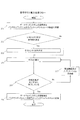
図2は一実施形態として、保守テスト方式を実行する際の全体フローチャートを示している。 FIG. 2 shows an overall flowchart when the maintenance test method is executed as one embodiment.
ステップ201では、ゲートウェイシステム20が、ゲートウェイシステム20の参照先をバックエンドシステム32からバックエンドシミュレータ装置143に変更する。例えば、障害の発生が検知されたときに自動的に切り替わってもよいし、ゲートウェイシステムテストシステム131から切替指示を送信し、ゲートウェイシステム20が切替指示に応じて参照先を切り替えてもよい。フロントエンドシミュレータ装置142に関しては、フロントエンドシステムと同じゲートウェイシステムの接続先に接続できる場合、保守テスト開始前から接続しておいてもよい。
In
ステップ202では、例えばシミュレータデータ出力装置141が、保守テストで使用するテストシナリオが存在するか確認する。例えば、テストシナリオが所定の記憶部に記憶されているか確認する。既にテストシナリオが存在する(記憶されている)場合、ステップ204に遷移し既存のテストシナリオを実行する。テストシナリオが未作成の場合(記憶されていない場合)、ステップ203のテストシナリオ作成を実施する。
In
ステップ203では、例えばシミュレータデータ出力装置141が、保守テストで実施したいテストシナリオを作成する。テストシナリオ作成のフローチャートを図3に示す。
In
ステップ204では、ゲートウェイシステムテストシステム131が、作成したテストシナリオを実行する。テスト実行のフローチャートを図6に示す。なお、テストシナリオの作成及び実行の詳細は後述する。
In
ステップ205では、例えばフロントエンドシミュレータ装置142が、ステップ204において実行される比較元情報116とレスポンスデータとのアサーション処理が全て正常に完了していることを確認する。アサーション処理でエラーになっている場合、ステップ207で原因調査及びアプリケーションの改修を行い、ステップ204に遷移し再びテストを実行する。一方、アサーション処理が全て正常に完了している場合はステップ206に遷移する。
In
ステップ206では、全ての保守テストが完了したら、ゲートウェイシステム20がゲートウェイシステムの参照先をバックエンドシミュレータ装置143からバックエンドシステム32に切り替え、通常運用時のシステム構成に戻す。
In
図3は一実施形態として、テストシナリオを作成する際のフローチャートを示している。ここでテストシナリオの例として、「フロントエンドシステムから申込受付処理と契約照会処理と追加申込処理を行う。なお契約照会処理と追加申込処理はバックエンドシステムの契約サービスデータを参照する。また追加申込処理は契約サービスデータに対し追加でサービスを申込む処理である」との内容を設定する。なお、テストシナリオの作成の際に、画面入出力装置105に設定画面(図9)を表示してもよい。
FIG. 3 shows a flowchart for creating a test scenario as one embodiment. As an example of a test scenario, “Application reception processing, contract inquiry processing, and additional application processing are performed from the front-end system. The contract inquiry processing and additional application processing refer to the contract service data of the back-end system. “The process is a process of applying for a service in addition to the contract service data”. Note that a setting screen (FIG. 9) may be displayed on the screen input /
ステップ301では、シミュレータデータ出力装置141(例えばデータチェック部104、又は図示しないシナリオ作成部。以下同様)は、テストシナリオで使用するキー情報を指定する。例えばキー情報として、契約照会処理のリクエストデータに含める契約IDを画面入出力装置105から入力する。契約IDは、顧客氏名(customer name)でもよいし、適宜の識別子でもよいし、これらを組み合わせたものでもよい。
In
ステップ302では、シミュレータデータ出力装置141(例えばデータチェック部104)は、テストシナリオで使用する業務フローの内容と順序を画面入出力装置105から入力する。業務フローとは申込受付処理や契約照会処理などの業務処理の組み合わせである。今回の例では「(1)申込受付処理、(2)契約照会処理、(3)追加申込処理」という3つの業務処理を組み合わせた業務フローを入力する。
In
ステップ303では、シミュレータデータ出力装置141(例えばデータチェック部104)は、ステップ302で定義した業務フローに申込受付処理が含まれているかチェックする。申込受付処理が含まれている場合、申込サービス内容の定義(ステップ304)に遷移し、申込受付処理が含まれていない場合はステップ306に遷移する。
In
ステップ304では、シミュレータデータ出力装置141(例えばデータチェック部104)は、申込サービス内容を画面入出力装置105から入力する。申込サービス内容とは、フロントエンドシステム31が送信するリクエストデータに含まれる、顧客が申し込むサービスの内容を示すデータであり、例えば「サービスA、サービスB、サービスC…を申込む」というように設定される。例えば、予め定められたサービス内容を画面入出力装置105に表示し、選択されたサービス内容をシミュレータデータ出力装置141が入力するようにしてもよい。
In
ステップ305では、シミュレータデータ出力装置141(例えばデータチェック部104)は、ステップ304で定義した申込サービス内容の整合性をチェックする。サービス内容整合性チェックフローを図4に示す。詳細は後述する。
In
ステップ306では、シミュレータデータ出力装置141(例えばデータチェック部104)は、ステップ302で定義した業務フローに契約照会処理が含まれているかチェックする。契約照会処理が含まれている場合、契約サービス内容の定義(ステップ307)に遷移し、契約照会処理が含まれていない場合はステップ309に遷移する。
In
ステップ307では、シミュレータデータ出力装置141(例えばデータチェック部104)は、照会する契約サービス内容を画面入出力装置105から入力する。契約サービス内容とは、バックエンドシステム32が保持する顧客が契約しているサービスの内容を示すデータであり、例えば「サービスA、サービスB、サービスC…を契約している」というように設定される。
In
ステップ308では、ステップ307で定義した契約サービス内容の整合性をチェックする。サービス内容整合性チェックフローについては、図4を参照して後述する。
In
ステップ309では、シミュレータデータ出力装置141(例えばデータチェック部104)は、ステップ302で定義した業務フローに追加申込処理が含まれるかチェックする。追加申込処理が含まれている場合、追加申込サービス内容の定義(ステップ310)に遷移し、追加申込処理が含まれていない場合はステップ312に遷移する。
In
ステップ310では、シミュレータデータ出力装置141(例えばデータチェック部104)は、追加申込サービス内容を画面入出力装置105から入力する。追加申込サービスとはバックエンドシステム32内に保持している契約サービス内容に対し、フロントエンドシステムから追加で申込むサービス内容であり、「サービスX、サービスY、サービスZ…の契約にサービスA、サービスB、サービスC…を追加申込する」というように、契約サービス内容と申込サービス内容が設定される。なお、契約サービス内容は契約IDなどの契約識別情報に対応して契約内容データベース(図示せず)に記憶し、追加申込サービス内容は、契約IDと、追加申し込みするサービスの識別情報(例えばサービスA、サービスB、サービスC)を設定してもよい。この場合、契約サービス内容を用いる場合は、契約IDに基づき契約内容データベースを参照すればよい。
In
ステップ311では、ステップ310で定義した追加申込サービス内容が、フロントエンド側の申込サービス内容とバックエンド側の契約サービス内容で相互に整合性が取れていることをチェックする。サービス内容相互整合性チェックフローを図5に示す。詳細は後述する。
In
ステップ312では、ステップ302で定義した業務フローを、業務フロー情報作成部101が業務フロー情報114としてフロントエンドシミュレータ装置142に出力する。このとき業務フロー雛形111を参照し、ステップ302で定義した業務フローが業務フロー雛形111に登録されていない場合、業務フロー情報作成部101は不正な業務フローと判定しエラーを画面入出力装置105に出力する。
In
ステップ313では、API設定情報作成部102がリクエストデータとプロトコル情報を設定したAPI設定情報(第1情報)115をフロントエンドシミュレータ装置142に出力する。このときAPI設定情報作成部102は、リクエストデータのデータ構造やインタフェースのプロトコル情報が設定されたAPI雛形112を入力して、ステップ301で設定したキー情報及び、ステップ304とステップ310で設定した申込サービス内容をAPI雛形112に埋め込むようにしてリクエストデータを設定する。例えばAPIのプロトコルとしてSOAP(Simple Object Access Protocol)による通信があるが、この場合リクエストデータで使用するXMLのデータ構造をAPI雛形112に定義することで、ゲートウェイシステムが受信できるリクエストデータを作成する。
In
ステップ314では、処理結果情報作成部103が、バックエンド側からのレスポンスデータを設定した処理結果情報(第2情報)を、バックエンドシミュレータ装置143の処理結果DB123に出力する。このとき処理結果情報作成部103は、レスポンスデータのデータ構造が設定された処理結果雛形113を入力して、ステップ301で設定したキー情報及び、ステップ307とステップ310で設定した契約サービス内容を処理結果雛形113に埋め込むようにして処理結果データを作成する。
In
ステップ315では、シミュレータデータ出力装置141(例えば図示しない比較元情報作成部)が、ゲートウェイシステムから送信されるレスポンスデータの期待値を比較元情報116として定義し、フロントエンドシミュレータ装置142に設定する。比較元情報はレスポンスデータ全体である必要はなく、「処理結果コードが正常」などレスポンスデータの一部を期待値として設定してもよい。
フロントエンドシミュレータ装置142に設定される、レスポンスデータの期待値と、バックエンドシミュレータ装置143から送信されるレスポンスデータとは異なってもよい。ゲートウェイシステム20は、バックエンドシミュレータ装置143からのレスポンスデータに対して予め定められた処理を実行して他のレスポンスデータを作成し、フロントエンドシミュレータ装置142へ送信する。フロントエンドシミュレータ装置142に設定される比較元情報は、バックエンドシミュレータ装置143に設定される処理結果情報に基づくレスポンスデータに対して、ゲートウェイシステム20での処理を実行して得られる予測情報である。
In
The expected value of the response data set in the front-
図4は一実施形態として、サービス内容整合性チェックフロー図を示す。図4には、図3の申込サービス内容を定義する処理(ステップ304)、もしくは契約サービス内容を定義する処理(ステップ307)で定義した各サービス内容に対し、データチェック部104がサービス内容整合性チェックを実行する際のフローチャートを示している。例として少なくとも一部のサービス同士には従属関係と排他関係があるとし、設定したサービス内容の整合性が取れているかチェックする。サービスの従属関係とは子サービスとして定義されているサービスは前提である親サービスがなければサービスの提供ができないものとする。また親サービスはサービス内容に必須で、かつひとつ設定できるものとする。なお、本実施例では、設定できる親サービスの数はひとつとして説明するが、複数の親サービスが設定できるようにしてもよい。さらに、サービスの排他関係とはあるサービスを設定している場合は別のあるサービスは提供できないものとする。
FIG. 4 shows a service content consistency check flowchart as an embodiment. In FIG. 4, the data check
ステップ411では、データチェック部104が、定義したサービス数分ステップ411のループ処理を繰り返す。例えばサービス内容が「サービスA、サービスB」と定義されている場合、サービス数は2である。また、例えばサービスAを1番目のサービス、サービスBを2番目のサービスとしてカウントし、ループ中は「i(iは0<iの整数)」を使用しi番目のサービスとしてカウントする。
In
ステップ412では、データチェック部104が、i番目のサービスが親サービスであるかチェックする。i番目のサービスが親サービスであるかチェックするために、データチェック部104は、サービス従属DB121を参照する。サービス従属DB121は、例えば図7(a)に示すように、各サービスの親サービスが記憶されている。本実施例では、親サービス自身の親サービスのフィールドはNULLである。従って、データチェック部104は、サービス従属DB121を参照し、i番目のサービスの親サービスがNULLであれば、i番目のサービスの親サービスは存在しないとし、i番目のサービス自身が親サービスであると判定できる。データチェック部104は、i番目のサービスが親サービスであった場合、ステップ413に遷移し、一方、i番目のサービスが親サービスでない場合、ステップ411に遷移しi+1番目のサービスについて処理をする。
In
ステップ413では、データチェック部104は、ステップ412で親サービスであると判定したサービスを親サービス情報として定義する。また、ステップ411に遷移しi+1番目のサービスについて処理をする。
In
ステップ414では、データチェック部104は、ステップ411のループ処理後、親サービス情報が定義されているかチェックする。親サービス情報が定義されていない、もしくは親サービス情報が2つ以上定義されている場合、サービス内容不正エラー処理(ステップ419)に進む。親サービス情報がひとつ定義されている場合、ステップ415に進む。
In
ステップ415では、データチェック部104は、定義したサービス数分ステップ415のループ処理を繰り返す。上述と同様、ループ中は「i(iは0<iの整数)」を使用しi番目のサービスとしてカウントする。
In
ステップ416では、データチェック部104は、i番目のサービスがステップ414で定義した親サービスに従属する子サービスか判定する。i番目のサービスが親サービスに従属する子サービスであるかチェックするために、データチェック部104は、サービス従属DB121を参照する。i番目のサービスの親サービスがステップ413で定義した親サービスと同一ならば、親サービスに従属する子サービスと判定してステップ417に遷移し、一方、i番目のサービスの親サービスがステップ413で定義した親サービスと異なる場合、サービス内容不正エラー処理(ステップ419)に遷移する。
In
ステップ417では、データチェック部104は、i番目のサービスがステップ418で定義した子サービス情報と排他関係にあるサービスかチェックする。i番目のサービスと子サービス情報が排他関係にあるかチェックするために、データチェック部104は、サービス排他DB122を参照する。サービス排他DB122には、例えば図7(b)に示すように、各サービスと排他関係にあるサービスが予め定義され記憶されている。データチェック部104は、i番目のサービスに対応する排他サービスの少なくともひとつがステップ418で定義された子サービスと合致する場合、サービス内容不正エラー処理(ステップ419)に遷移する。また、子サービスがj(jは0<jの整数)個定義されている場合、定義されているj個の子サービスとの排他関係をそれぞれチェックする。例えばi番目のサービスがサービスAで、1番目の子サービス情報にサービスB、2番目の子サービス情報にサービスCが定義されている場合、サービスAとサービスBの排他関係のチェック、サービスAとサービスCの排他関係のチェック、というように子サービスが2つ定義されている場合は排他関係のチェックを2回行う。
In
ステップ418では、データチェック部104は、i番目のサービスを子サービスとして定義する。この際、i番目のサービスと親サービス情報が同一の場合、i番目のサービスは子サービス情報として定義しない。また既にj個の子サービスが定義されている場合、j+1番目の子サービスとして定義する。さらにステップ415に遷移し、i+1番目のサービスについて処理を実行する。
In
ステップ419では、データチェック部104は、サービス内容が不正であることを例えば画面入出力装置105に表示する。この際、どのチェック(処理)で不正と判断されたかを画面入出力装置105に表示する。例としてステップ414のチェックで不正と判定された場合、例えば「親サービス情報が定義されていない」等のエラーメッセージを表示し、ステップ416のチェックで不正と判定された場合、例えば「子サービスの前提サービスが定義されていない」等のエラーメッセージを表示し、ステップ417のチェックで不正と判定された場合、例えば「排他関係にあるサービスを定義している」等のエラーメッセージを表示する。
In
例として図7に「子サービスの前提サービスが定義されていない」ときのチェックと、「排他関係にあるサービスを定義している」ときのチェック時のデータ関連図を示す。この例では、サービス内容としてサービスA、B、Cが設定されている。サービス従属DB121を参照すると、サービスBに対応する親サービスはNULLであり、データチェック部104は、サービスBを親サービスとして定義できる(ステップ412、413に相当)。また、サービスAについて、サービス従属DB121を参照すると、対応する親サービスにサービスBが設定されており、既に定義した親サービスと一致するため、サービスAは子サービスとして定義できる(ステップ416、418に相当)。一方、サービスCについては、サービス従属DB121を参照すると、対応する親サービスにサービスXが設定されており、既に定義した親サービスと一致しないため、サービス内容不正エラー処理にてエラーメッセージが表示される(ステップ416、419に相当)。
As an example, FIG. 7 shows a data relation diagram at the time of a check when “a prerequisite service of a child service is not defined” and a check when “a service having an exclusive relationship is defined”. In this example, services A, B, and C are set as service contents. Referring to the service
また、この例では、サービス排他DB122には図7(b)に示す情報が記憶されているものとする。初期の状態では、子サービスがまだ定義されていない。サービスAについて、サービス排他DB122を参照すると、対応する排他サービスと一致する子サービスはないため、サービスAは子サービスとして定義できる(ステップ417、418に相当)。サービスBについては、親サービスのため子サービスとして定義しない。サービスCについて、サービス排他DB122を参照すると、対応する排他サービスAと既に定義した子サービスが一致するため、サービス内容不正エラー処理にてエラーメッセージが表示される(ステップ417、419に相当)。
In this example, it is assumed that the
図5は、サービス内容相互整合性チェックフロー図である。一実施形態として、図3の追加申込サービス内容を定義する処理(ステップ310)で定義したサービス内容に対し、データチェック部104がサービス内容の相互整合性チェックを実行する際のフローチャートを示している。サービス内容の相互整合性の例として、追加申込サービス内容に含まれる申込サービス内容と契約サービス内容の各親サービス情報は一致している必要があり、契約サービス内容の親サービス情報に従属する子サービスのみが追加可能で、かつ契約サービス内容と申込サービス内容に排他関係のサービスがないこととする。また申込サービス数のカウンタには「i(iは、0<iの整数)」を使用し説明する。
FIG. 5 is a service content mutual consistency check flowchart. As an embodiment, a flowchart is shown when the data check
ステップ501では、データチェック部104は、上述のステップ310で入力した追加申込サービス内容のうち、申込サービス内容の整合性が取れているかチェックする。
In
ステップ502では、データチェック部104は、追加申込サービス内容のうち、契約サービス内容の整合性が取れているかチェックする。ステップ501及び502のサービス内容整合性チェックの処理は、図4のフローと同様である。
In
ステップ503では、データチェック部104は、追加申込サービス内容に定義されている申込サービス内容の親サービス情報と、契約サービス内容の親サービス情報が一致するかチェックする。申込サービス内容の親サービス情報は、ステップ501のサービス内容整合性チェックの処理で定義した親サービス情報を使用し、契約サービス内容の親サービス情報は、ステップ502のサービス内容整合性チェックの処理で定義した親サービス情報を使用する。申込サービス内容の親サービス情報と契約サービス内容の親サービス情報が不一致の場合、相互整合性不正エラー処理(ステップ507)へ遷移する。
In
ステップ504では、データチェック部104は、追加申込サービス内容のうち、申込サービス数分ステップ504のループ処理を繰り返す。
In
ステップ505では、データチェック部104は、i番目の申込サービスが契約サービス内容に追加可能なサービスであるかチェックする。データチェック部104は、i番目の申込サービスと契約サービス内容の親サービス情報として定義されているサービスとの従属関係をチェックするためにサービス従属DB121を参照する。i番目の申込サービスの親サービスが契約サービス内容の親サービスと異なる場合、相互整合性不正エラー処理(ステップ507)に遷移する。
In
ステップ506では、データチェック部104は、i番目の申込サービスと契約サービス内容の排他関係をチェックする。契約サービス内容にj(jは、0<jの整数)個のサービスが定義されている場合、「i番目の申込サービスと1番目の契約サービスの排他関係、i番目の申込サービスと2番目の契約サービスの排他関係…」というようにi番目の申込サービスとj個全ての契約サービスとの排他関係をチェックする。データチェック部104は、申込サービスと契約サービスの排他関係をチェックするためにサービス排他DB122を参照する。i番目の申込サービスが契約サービスと排他関係にある場合、相互整合性不正エラー処理(ステップ507)に遷移する。
In
ステップ507では、データチェック部104は、追加申込サービス内容が不正であることを示すエラーメッセージを表示する。この際、どのチェック(処理)で不正と判断されたかを画面入出力装置105に表示する。例えば、ステップ503のチェックで不正と判定された場合「親サービス情報が不一致」等のエラーメッセージを表示し、ステップ505のチェックで不正と判定された場合「契約サービスと従属関係のない申込サービスが定義されている」等のエラーメッセージを表示し、ステップ506のチェックで不正と判定された場合「契約サービスと排他関係にある申込サービスを定義している」等のエラーメッセージを表示する。
In
例として図8に「親サービス情報が不一致」のチェックと、「契約サービスと排他関係にある申込サービスを定義している」のチェック時のデータ関連図を示す。この例では、申込サービス内容として、サービスA、B、Cが設定され、そのうちサービスBが親サービスであり、サービスA、Cが子サービスである。図8(a)の例では、契約サービス内容としてサービスX、Y、Zが予め登録され、そのうちサービスXが親サービスである。この場合、申込サービス内容と契約サービス内容の各親サービスが異なるため、エラーとなる(ステップ503、507に相当)。
As an example, FIG. 8 shows a data relation diagram when checking “parent service information mismatch” and “defining application service in exclusive relationship with contract service”. In this example, services A, B, and C are set as application service contents, of which service B is a parent service and services A and C are child services. In the example of FIG. 8A, services X, Y, and Z are registered in advance as contract service contents, of which service X is a parent service. In this case, an error occurs (corresponding to
図8(b)の例は、契約サービス内容としてサービスB、Y、Zが登録され、そのうちサービスBが親サービスであり、サービスY、Zが子サービスである。この場合、各親サービスは一致している(ステップ503に相当)。一方、図8(b)に例示するサービス排他DB122を参照すると、サービスAと排他関係にある契約サービスはないものの、サービスCと契約サービスZが排他関係にあり、エラーとなる(ステップ506、507に相当)。
In the example of FIG. 8B, services B, Y, and Z are registered as contract service contents, of which service B is a parent service and services Y and Z are child services. In this case, the parent services match (corresponding to step 503). On the other hand, referring to the
図6は、テスト実行のフローチャートである。図6は、一実施形態として、ゲートウェイシステム20がフロントエンドシミュレータ装置142とバックエンドシミュレータ装置143と接続し、テストを実行する際のフローチャートを示している。テストは、ゲートウェイシステムテストシステム131の操作者の操作を契機に開始されてもよいし、ゲートウェイシステム20の障害の発生が検知されたときに自動的に実行されるなど適宜の契機でもよい。なお、図6のフローチャートは、処理の順序をわかり易く説明するため、各装置での処理をまとめて図示している。
FIG. 6 is a flowchart of test execution. FIG. 6 shows a flowchart when the
ステップ601〜606は、フロントエンドシミュレータ装置142の処理である。ステップ601では、試験自動実行部151は業務フロー情報114に定義されている業務処理の数分ステップ601のループ処理を行う。業務処理の数分とは、例えば業務フローに「申込受付処理、契約照会処理、追加申込処理」と業務処理が定義されている場合、申込処理を1番目の業務処理、契約照会処理を2番目の業務処理、追加申込処理を3番目の業務処理とカウントする。また業務処理数のカウンタには「i(0<iの整数)」を使用しi番目の業務処理としてカウントする。試験自動実行部151はAPI操作部152へi番目の業務処理を実行するよう処理命令を出す。
ステップ602では、API操作部152はi番目の業務処理用のAPI設定情報115を入力し、ゲートウェイシステム20への所定のフォームのリクエストデータ及びプロトコル情報を設定する。
In
ステップ603では、API操作部152はAPI設定情報115に、業務処理間のパラメタ引継ぎ設定があるかチェックする。業務処理間のパラメタとは、例えばx番目の業務処理が申込受付処理であり、i番目の業務処理が契約照会処理である場合、x番目(xは、例えばx<iの整数)の申込受付処理で取得したゲートウェイシステム20からのレスポンスデータに含まれる申込ID等をi番目の契約照会処理のリクエストで使用したい場合、x番目の申込受付処理のレスポンスデータに含まれる申込IDを業務処理間のパラメタとして、i番目の契約照会処理に渡すものである。業務処理間のパラメタ引継ぎ設定にはどの業務処理から何のデータを引き継ぎ、どのように使用するかを予め設定する。業務処理間のパラメタ引継ぎ設定がある場合、ステップ604に遷移し、設定がなければステップ605に遷移する。
In
ステップ604では、API操作部152はパラメタ引継ぎとして設定されているx番目のリクエストデータから予め設定された種別のパラメタを抽出し、i番目のリクエストデータの該当する埋め込み部分に抽出したパラメタを設定してリクエストデータを生成する。
ステップ605では、API操作部152はAPI送受信部153に対し、ゲートウェイシステム20へのリクエストデータの送信命令を出す。
ステップ606では、API送受信部153はゲートウェイシステム20へリクエストデータを送信する。
In
In
In
ステップ607〜608は、ゲートウェイシステム20の処理である。ステップ607では、API送受信部153からのリクエストデータを受信したゲートウェイシステム20は、バックエンド側のデータを参照する必要がある場合はステップ608へ遷移し、必要がない場合はステップ611に遷移する。例えば契約照会処理や追加申込処理でバックエンド側の契約サービス内容を参照する場合はステップ608へ遷移する。
ステップ608では、ゲートウェイシステム20は、バックエンド側のデータを参照するためにバックエンドシミュレータ装置143の処理受付部161へリクエストデータを送信する。例えば、ゲートウェイシステム20は、フロントエンドシミュレータ装置142から受信したリクエストデータをバックエンドシミュレータ装置143へ転送してもよいし、所望のリスエストデータを作成してバックエンドシミュレータ装置143へ送信してもよい。
In
ステップ609〜610は、バックエンドシミュレータ装置143の処理である。ステップ609では、リクエストデータを受信した処理結果受付部161はリクエストデータに含まれるキー情報を処理結果選択部162に引数として渡す。処理結果選択部162はキー情報を使用し、対応する処理結果情報を処理結果DB123から抽出する。
ステップ610では、処理結果受付部161は、処理結果選択部162が抽出した処理結果情報を含むレスポンスデータをゲートウェイシステム20へ送信する。
In
ステップ611では、ゲートウェイシステム20は、予め定められた業務処理を実行し、フロントエンドシミュレータ装置142のAPI送受信部161へレスポンスデータを送信する。ゲートウェイシステム20から送信されるレスポンスデータは、バックエンドシミュレータ装置143からのレスポンスデータが処理されたデータを含む場合があり、ゲートウェイシステム20から送信されるレスポンスデータと、バックエンドシミュレータ装置143から送信されるレスポンスデータは必ずしも同一ではない。
In
ステップ612では、比較処理部154はAPI送受信部153が受信したゲートウェイシステム20からのレスポンスデータを、比較元情報116と比較する。このとき、ゲートウェイシステムからのレスポンスデータが、期待値として予め設定された比較元情報116と異なる場合は、例えば画面入出力装置105にエラーを表示する。一方、レスポンスデータと比較元情報116が一致する場合、例えば正常である旨表示する。
In
ステップ613では、API操作部152はAPI送受信部153が受信したゲートウェイシステムからのレスポンスデータを、i+1番目の業務処理へ引き継ぐ。この引き継がれたレスポンスデータは後続の業務処理のステップ603でパラメタ引継ぎ設定がされていた場合使用される。また、ステップ601に遷移しi+1番目の業務処理を実行する。
In
図9は、シミュレーションデータ出力装置の設定画面例である。図10は、シミュレーションデータ出力装置のテスト実行結果画面例である。
図9(a)に、画面入出力装置105に表示されるテストシナリオ設定画面の例を示す。テストシナリオ設定画面901は、例えば、シナリオ名設定フィールド901aと、業務フロー設定フィールド901bと、キー情報設定フィールド901cと、設定完了ボタンとを含む。シナリオ名設定フィールド901aには、例えば所望のシナリオ名が入力される。業務フロー設定フィールド901bは、業務フローの処理順に、申込受付処理、契約照会処理及び追加申込処理等の業務処理を設定するフィールドであり、例えば、プルダウンメニューからこれらの業務処理を選択できる。キー情報設定フィールド901cは、キー情報の種別を示すパラメタ名と、キー情報の値が入力される。このような設定画面を画面入出力装置105に表示することで、ゲートウェイシステムテストシステム131又はシミュレータデータ出力装置141の操作者に各情報の設定を促す。
FIG. 9 is a setting screen example of the simulation data output apparatus. FIG. 10 is an example of a test execution result screen of the simulation data output apparatus.
FIG. 9A shows an example of a test scenario setting screen displayed on the screen input /
図9(b)に、画面入出力装置105に表示されるシミュレーションデータ設定画面の例を示す。ここでは、申込受付処理に対するシミュレーションデータの設定画面を例示する。申込受付処理に対するシミュレーションデータの設定画面902は、例えば、申込サービス内容(識別情報)の設定フィールド902aと、申込サービス内容以外の設定フィールド902bと、パラメタ引継設定フィールド902cと、比較元情報設定フィールド902dと、設定完了ボタンとを含む。申込サービス内容の設定フィールド902aは、新規に申し込むサービスが設定される。申込サービス内容以外の設定フィールド902bは、例えば、申込顧客氏名等の適宜の情報を設定するフィールドである。パラメタ引継設定フィールド902cは、他の業務処理から引き継ぐパラメタを設定するためのフィールドであり、例えば、引き継ぎ元の業務処理の識別情報と、パラメタ名が設定される。比較元情報設定フィールド902dは、例えば比較元情報を設定するフィールドであり、パラメタ名と値が設定される。
FIG. 9B shows an example of a simulation data setting screen displayed on the screen input /
なお、契約照会処理及び追加申込処理についても、入力するデータに応じたフィールドを有する設定画面を作成して画面入出力装置105に表示することができる。
As for the contract inquiry process and the additional application process, a setting screen having fields corresponding to input data can be created and displayed on the screen input /
図10にシミュレーションデータ出力装置のテスト実行結果画面例を示す。テスト実行結果画面1001は、テストシナリオ設定情報フィールドと、テスト実行結果フィールドを含む。テストシナリオ設定情報フィールドには、テストに用いた業務フロー情報、キー情報等が表示される。テスト実行結果フィールドは、各業務処理に対して、比較処理結果1001dの他、例えばフロントエンドシミュレータ装置142から送信したリクエストデータ1001b及びフロントエンドシミュレータ装置142が受信したレスポンスデータ1001cを表示してもよい。さらに、バックエンドシミュレータ装置143が送信したレスポンスデータを表示してもよい。これにより、どのようなデータがやりとりされて、テストの結果が導かれたのかを操作者に提示できる。なお、上述の各画面は一例であり、他の適宜の形態でもよい。
FIG. 10 shows an example of a test execution result screen of the simulation data output apparatus. The test
上述の例では、ゲートウェイシステムテストシステム131が、シミュレータデータ出力装置141、フロントエンドシミュレータ装置142及びバックエンドシミュレータ装置143の別々の装置で構成されたが、ゲートウェイシステムテストシステム131を物理的にひとつのゲートウェイシステムテスト装置として構成してもよい。この場合、ゲートウェイシステムテスト装置は、シミュレータデータ出力装置141に相当するシミュレータデータ出力部と、フロントエンドシミュレータ装置142に相当するフロントエンドシミュレーション部と、バックエンドシミュレータ装置143に相当するバックエンドシミュレーション部とを備える。各部の処理は上述の実施例と同様である。
In the above-described example, the gateway
本実施例によれば、ゲートウェイシステムがフロントエンドシステムとバックエンドシステムと切り離されて単独で動作する保守テスト環境において、ゲートウェイシステムの動作を再現するためのシステム及び装置を提供でき、かつテストデータの不正を防止することでゲートウェイシステムの保守テストの効率が向上する。 According to this embodiment, it is possible to provide a system and apparatus for reproducing the operation of the gateway system in a maintenance test environment in which the gateway system is separated from the front-end system and the back-end system and operates independently. Preventing fraud improves the efficiency of gateway system maintenance tests.
以上の説明では、業務システムで使用されるゲートウェイシステムの保守テストを例にとり説明したが、各種業務システムへ適用することができる。例えば通信キャリアにおいては全国に展開するフロントエンドのショップシステムとバックエンドの契約管理システムの仲介処理を果たすゲートウェイシステムに適用でき、また金融機関においては、入金処理を行うフロントエンドシステムと顧客情報を管理するバックエンドシステムがあり、両システムの仲介処理を果たすゲートウェイシステムが存在する場合、同様のシミュレータ方式を適用することが可能である。 In the above description, the maintenance test of the gateway system used in the business system has been described as an example, but it can be applied to various business systems. For example, it can be applied to a gateway system that acts as an intermediary between front-end shop systems and back-end contract management systems deployed nationwide in communication carriers, and in financial institutions, it manages front-end systems and customer information for deposit processing. If there is a back-end system and there is a gateway system that performs an intermediary process between both systems, a similar simulator system can be applied.
なお、本発明は上記した実施例に限定されるものではなく、様々な変形例が含まれる。例えば、上記した実施例は本発明を分かりやすく説明するために詳細に説明したものであり、必ずしも説明した全ての構成を備えるものに限定されるものではない。また、ある実施例の構成の一部について、他の構成の追加・削除・置換をすることが可能である。また、上記の各構成、機能、処理部、処理手段等は、それらの一部又は全部を、例えば集積回路で設計する等によりハードウェアで実現してもよい。また、上記の各構成、機能等は、プロセッサがそれぞれの機能を実現するプログラムを解釈し、実行することによりソフトウェアで実現してもよい。さらに各機能を実現するプログラム、テーブル、ファイル等の情報は、メモリや、ハードディスク、SSD(Solid State Drive)等の記録媒体、または、ICカード、SDカード、DVD等の記録媒体に置くことができる。また、制御線や情報線は説明上必要と考えられるものを示しており、製品上必ずしも全ての制御線や情報線を示しているとは限らない。実際には殆ど全ての構成が相互に接続されていると考えてもよい。 In addition, this invention is not limited to an above-described Example, Various modifications are included. For example, the above-described embodiments have been described in detail for easy understanding of the present invention, and are not necessarily limited to those having all the configurations described. Further, it is possible to add, delete, and replace other configurations for a part of the configuration of a certain embodiment. Each of the above-described configurations, functions, processing units, processing means, and the like may be realized by hardware by designing a part or all of them with, for example, an integrated circuit. Each of the above-described configurations, functions, and the like may be realized by software by interpreting and executing a program that realizes each function by the processor. Furthermore, information such as programs, tables, and files that realize each function can be placed in a recording medium such as a memory, a hard disk, or an SSD (Solid State Drive), or a recording medium such as an IC card, an SD card, or a DVD. . Further, the control lines and information lines indicate what is considered necessary for the explanation, and not all the control lines and information lines on the product are necessarily shown. Actually, it may be considered that almost all the components are connected to each other.
(構成例)
上述の実施例は、例えば、以下のように構成することもできるが、これに限定されるものではない。
(Configuration example)
For example, the above-described embodiment can be configured as follows, but is not limited thereto.
ゲートウェイシステムとのデータ送受信を実行するAPI送受信部153とリクエストデータを生成しAPI送受信部153に送信命令を出すAPI操作部152と業務フロー情報114を入力しAPI操作部152に処理命令を出す試験自動実行部151に加え、比較元情報116を入力しレスポンスデータのアサーション処理を実行する比較処理部154が連携することでテストを自動実行するフロントエンドシミュレータ装置142と、ゲートウェイシステムとのデータ送受信を行う処理受付部161と処理結果DB123からテストデータを抽出する処理結果選択部162が連携することでバックエンドシステムへの参照処理を再現するバックエンドシミュレータ装置143と、画面入出力装置105からテストデータを入力しデータチェック部104でテストデータの整合性をチェックしフロントエンドシミュレータ装置142とバックエンドシミュレータ装置143が入力するシミュレータデータを業務フロー情報作成部101とAPI設定情報作成部102と処理結果情報作成部103を使用して出力するシミュレータデータ出力装置141を、保守テスト時の環境に備える。
An API transmission /
[構成例1]
フロントエンドシステムとバックエンドシステムの仲介処理を果たすゲートウェイシステムにおいて、フロントエンドシステムの代わりとなるフロントエンドシミュレータ装置(142)と、バックエンドシステムの代わりとなるバックエンドシミュレータ装置(143)と、フロントエンドシミュレータ装置(142)とバックエンドシミュレータ装置(143)が入力するデータを生成するシミュレータデータ出力装置(141)を使用したゲートウェイシステムの保守テストにおけるシミュレータ方式。
[Configuration example 1]
In a gateway system that performs an intermediary process between a front-end system and a back-end system, a front-end simulator device (142) that replaces the front-end system, a back-end simulator device (143) that replaces the back-end system, and the front-end A simulator method in a gateway system maintenance test using a simulator data output device (141) that generates data input by a simulator device (142) and a back-end simulator device (143).
[構成例2]
構成例1において、フロントエンドシミュレータ装置(142)は業務処理の順番が設定されている業務フロー情報(114)と試験自動実行部(151)とリクエストデータとプロトコル情報が設定されたAPI設定情報(115)とAPI操作部(152)とAPI送受信部(153)をさらに有し、試験自動実行部(151)が業務フロー情報(114)を入力し、順番にAPI操作部(152)にAPI操作の処理命令を行い、API操作部(152)はAPI設定情報(115)を入力し設定されているリクエストデータの送信命令をAPI送受信部(153)に出すことで、フロントエンドシミュレータ装置(142)がゲートウェイシステムとフロントエンドシステムの連携を再現するシミュレータ方式。
[Configuration example 2]
In the configuration example 1, the front-end simulator device (142) includes business flow information (114) in which the order of business processing is set, an automatic test execution unit (151), API setting information (in which request data and protocol information are set) ( 115), an API operation unit (152), and an API transmission / reception unit (153), the test automatic execution unit (151) inputs the business flow information (114), and the API operation unit (152) sequentially performs API operations The API operation unit (152) inputs the API setting information (115) and issues a set request data transmission command to the API transmission / reception unit (153), whereby the front-end simulator device (142) Is a simulator that reproduces the linkage between the gateway system and the front-end system.
[構成例3]
構成例2において、フロントエンドシミュレータ装置(142)は比較元情報(116)と比較処理部(154)をさらに有し、期待したテスト結果であるかチェックするために、API送受信部(153)がゲートウェイシステムから受信したレスポンスデータと期待値を設定した比較元情報(116)とを比較処理部(154)がアサーション処理することでゲートウェイシステムのデグレードを検出するシミュレータ方式。
[Configuration example 3]
In the configuration example 2, the front-end simulator device (142) further includes comparison source information (116) and a comparison processing unit (154). In order to check whether the expected test result is obtained, the API transmission / reception unit (153) A simulator method in which a comparison processing unit (154) performs an assertion process on response data received from a gateway system and comparison source information (116) in which an expected value is set, thereby detecting a degradation of the gateway system.
[構成例4]
構成例1において、バックエンドシミュレータ装置(143)は処理受付部(161)と処理結果選択部(162)と処理結果DB(123)をさらに有し、ゲートウェイシステムからのリクエストデータを受信した処理受付部(161)は処理結果選択部(162)にテストシナリオで使用するキー情報を引数として渡し、処理結果選択部(162)は処理結果DB(123)からキー情報に紐づくテストデータを抽出し、処理結果受付部(161)がゲートウェイシステムへテストデータをレスポンスデータとして送信することでバックエンドシミュレータ装置(143)がゲートウェイシステムとバックエンドシステムの連携を再現するシミュレータ方式。
[Configuration Example 4]
In Configuration Example 1, the back-end simulator device (143) further includes a processing reception unit (161), a processing result selection unit (162), and a processing result DB (123), and receives the request data from the gateway system. The unit (161) passes the key information used in the test scenario as an argument to the processing result selection unit (162), and the processing result selection unit (162) extracts the test data associated with the key information from the processing result DB (123). A simulator method in which the backend simulator device (143) reproduces the cooperation between the gateway system and the backend system by transmitting the test data as response data from the processing result receiving unit (161) to the gateway system.
[構成例5]
構成例1において、シミュレータデータ出力装置(141)は業務フロー雛形(111)と業務フロー情報作成部(101)と画面入出力装置(105)を有し、業務フロー情報作成部(101)は、画面入出力装置(105)から入力した業務処理の組み合わせが業務フロー雛形(111)に定義されている正しい業務フローかチェックした上で、業務フロー情報(114)を自動生成し、フロントエンドシミュレータ装置(142)に出力するシミュレータ方式。
[Configuration Example 5]
In the configuration example 1, the simulator data output device (141) includes a business flow template (111), a business flow information creation unit (101), and a screen input / output device (105). The business flow information creation unit (101) After checking whether the combination of business processes input from the screen input / output device (105) is the correct business flow defined in the business flow template (111), the business flow information (114) is automatically generated, and the front-end simulator device (142) A simulator method for outputting.
[構成例6]
構成例1において、シミュレータデータ出力装置(141)はAPI設定情報作成部(102)とAPI雛形(112)をさらに有し、API設定情報作成部(102)はAPI雛形(112)に定義されているリクエストデータのデータ構造とプロトコルの設定情報を入力して、画面入出力装置(105)から入力したサービス情報とテストシナリオで使用するキー情報をゲートウェイシステムが処理できるリクエストデータの形式に変換してAPI設定情報(115)を生成し、フロントシミュレータ装置(142)に出力するシミュレータ方式。
[Configuration Example 6]
In the configuration example 1, the simulator data output device (141) further includes an API setting information creation unit (102) and an API template (112), and the API setting information creation unit (102) is defined in the API template (112). The request information data structure and protocol setting information are input, and the service information input from the screen input / output device (105) and the key information used in the test scenario are converted into a request data format that can be processed by the gateway system. A simulator method for generating API setting information (115) and outputting it to the front simulator device (142).
[構成例7]
構成例1において、シミュレータデータ出力装置(141)は処理結果雛形(113)と処理結果情報作成部(103)をさらに有し、ゲートウェイシステムがバックエンドシステムへ参照リクエストを出した際に返却するレスポンスデータを、画面入出力装置(105)から入力したサービス情報とテストシナリオで使用するキー情報を、処理結果情報作成部(103)が処理結果雛形(113)のデータ構造に合わせ生成し、処理結果データとして処理結果DB(123)に設定するシミュレータ方式。
[Configuration Example 7]
In the configuration example 1, the simulator data output device (141) further includes a processing result template (113) and a processing result information creation unit (103), and a response returned when the gateway system issues a reference request to the back-end system. The processing result information creation unit (103) generates the service information input from the screen input / output device (105) and the key information used in the test scenario according to the data structure of the processing result template (113). A simulator method set in the processing result DB (123) as data.
[構成例8]
構成例6、7において、シミュレータデータ出力装置(141)はデータチェック部(104)とサービス従属DB(121)とサービス排他DB(122)をさらに有し、フロントエンドシミュレータ装置(142)から送信するリクエストデータと、バックエンドシミュレータ装置(143)が返却するレスポンスデータの整合性、もしくはリクエストデータとレスポンスデータの相互の整合性について、データチェック部(104)はサービス従属DB(121)とサービス排他DB(122)を参照し、リクエストデータに含まれるサービス内容と処理結果データに含まれるサービス内容の従属関係のチェックと排他関係のチェックを実行することで、フロントエンドシミュレータ装置(142)とバックエンドシミュレータ装置(143)が有するテストデータの整合性、及び相互の整合性を確保するシミュレータ方式。
[Configuration Example 8]
In Configuration Examples 6 and 7, the simulator data output device (141) further includes a data check unit (104), a service subordinate DB (121), and a service exclusion DB (122), and transmits from the front-end simulator device (142). Regarding the consistency between the request data and the response data returned by the back-end simulator device (143), or the mutual consistency between the request data and the response data, the data check unit (104) includes the service subordinate DB (121) and the service exclusive DB. Referring to (122), the front-end simulator device (142) and the back-end simulator are checked by executing the dependency check and the exclusive check of the service content included in the request data and the service content included in the processing result data. apparatus( Integrity of test data 43) has, and the simulator system to ensure the mutual consistency.
20 ゲートウェイシステム
131 ゲートウェイシステムテストシステム
141 シミュレータデータ出力装置
142 フロントエンドシミュレータ装置
143 バックエンドシミュレータ装置
101 業務フロー情報作成部
102 API設定情報作成部
103 処理結果情報作成部
104 データチェック部
105 画面入出力装置
151 試験自動実行部
152 API操作部
153 API送受信部
154 比較処理部
161 処理受付部
162 処理結果選択部
111 業務フロー雛形
112 API雛形
113 処理結果雛形
114 業務フロー情報
115 API設定情報
116 比較元情報
121 サービス従属DB
122 サービス排他DB
123 処理結果DB
20
122 Service Exclusive DB
123 Processing result DB
Claims (11)
前記ゲートウェイシステムと接続されるフロントエンドシミュレータ装置と、
前記ゲートウェイシステムと接続されるバックエンドシミュレータ装置と、
前記フロントエンドシミュレータ装置とバックエンドシミュレータ装置に前記テストのためのデータを設定するシミュレータデータ出力装置とを備え、
前記シミュレータデータ出力装置は、
前記フロントエンドシミュレータ装置が前記ゲートウェイシステムに送信する第1リクエストデータに含める第1情報と、前記ゲートウェイシステムが正常な場合に該第1リクエストデータに対して該ゲートウェイシステムから受信する第1レスポンスデータの予測情報とを前記フロントエンドシミュレータ装置に設定し、
第1リクエストデータに応じて前記ゲートウェイシステムから送信される第2リクエストデータに対して前記バックエンドシミュレータ装置が返信する第2レスポンスデータに含める第2情報を、前記バックエンドシミュレータ装置に設定し、
前記フロントエンドシミュレータ装置は、前記ゲートウェイシステムに送信した第1情報を含む第1リクエストデータに応答して返信される、前記ゲートウェイシステムからの第1レスポンスデータと、設定された前記予測情報とを比較して、前記ゲートウェイシステムの正常及び異常を判定する前記シミュレータシステム。 A simulator system for testing a gateway system that mediates between a front-end system and a back-end system,
A front-end simulator device connected to the gateway system;
A back-end simulator device connected to the gateway system;
A simulator data output device for setting data for the test in the front-end simulator device and the back-end simulator device;
The simulator data output device
The first information included in the first request data transmitted from the front-end simulator device to the gateway system, and the first response data received from the gateway system for the first request data when the gateway system is normal Set prediction information in the front-end simulator device,
Second information to be included in the second response data returned by the backend simulator device in response to the second request data transmitted from the gateway system in response to the first request data is set in the backend simulator device,
The front-end simulator device compares first response data from the gateway system, which is returned in response to first request data including first information transmitted to the gateway system, and the set prediction information. The simulator system for determining normality and abnormality of the gateway system.
前記フロントエンドシミュレータ装置に設定される前記予測情報は、前記バックエンドシミュレータ装置に設定される前記第2情報に基づく前記第2レスポンスデータに対して、前記ゲートウェイシステムでの前記処理を実行して得られる予測情報である請求項2に記載のシミュレータシステム。 The gateway system executes a predetermined process on the second response data from the back-end simulator device to create the first response data, and transmits the first response data to the front-end simulator device.
The prediction information set in the front-end simulator device is obtained by executing the processing in the gateway system on the second response data based on the second information set in the back-end simulator device. The simulator system according to claim 2, which is prediction information to be generated.
前記シミュレータデータ出力装置は、
所定のサービス識別情報に対して、該サービスとともに申し込むことができない排他関係にあるサービス識別情報が予め記憶されたサービス排他データベースと、
前記第1情報に含まれる複数のサービス識別情報に基づき前記サービス排他データベースを参照し、排他関係にあるサービス情報が前記第1情報に含まれる場合はエラーを通知するデータチェック部とを有する請求項1に記載のシミュレータシステム。 The first request data is request data for a new application for a service including a plurality of service identification information, a contract inquiry for a service, or an additional application for a service,
The simulator data output device
A service exclusion database in which service identification information in an exclusive relationship that cannot be applied with the service for predetermined service identification information is stored in advance;
And a data check unit that refers to the service exclusion database based on a plurality of service identification information included in the first information and notifies an error when service information in an exclusive relationship is included in the first information. The simulator system according to 1.
前記シミュレータデータ出力装置は、
親サービスの識別情報と、サービスを申し込むために親サービスが必要な子サービスのサービス識別情報に対して、該親サービスのサービス識別情報とが予め記憶されたサービス従属データベースと、
前記第1情報に含まれる複数のサービス識別情報に基づき前記サービス従属データベースを参照して親サービスを特定し、前記第1情報に含まれる親サービス以外のサービス識別情報に基づき前記サービス従属データベースを参照して各サービス識別情報の親サービスを特定し、各親サービスが一致していない場合はエラーを通知するデータチェック部とを有する請求項1に記載のシミュレータシステム。 The first request data is request data for a new application for a service including a plurality of service identification information, a contract inquiry for a service, or an additional application for a service,
The simulator data output device
A service dependent database in which the identification information of the parent service and the service identification information of the child service that requires the parent service to apply for the service are stored in advance.
A parent service is identified by referring to the service dependent database based on a plurality of service identification information included in the first information, and the service dependent database is referenced based on service identification information other than the parent service included in the first information. The simulator system according to claim 1, further comprising: a data check unit that identifies a parent service of each service identification information and notifies an error when the parent services do not match.
前記シミュレータデータ出力装置は、
所定のサービス識別情報に対して、該サービスとともに申し込むことができない排他関係にあるサービス識別情報が予め記憶されたサービス排他データベースと、
前記第1情報に含まれるサービス識別情報に基づき前記サービス排他データベースを参照し、該サービス識別情報と排他関係にあるサービス識別情報が既に契約しているサービス識別情報に含まれる場合はエラーを通知するデータチェック部とを有する請求項1に記載のシミュレータシステム。 The first request data is request data for additional application of a service including one or a plurality of service identification information,
The simulator data output device
A service exclusion database in which service identification information in an exclusive relationship that cannot be applied with the service for predetermined service identification information is stored in advance;
The service exclusion database is referred to based on the service identification information included in the first information, and an error is notified if service identification information that is in an exclusive relationship with the service identification information is included in the contracted service identification information. The simulator system according to claim 1, further comprising a data check unit.
前記シミュレータデータ出力装置は、
親サービスの識別情報と、サービスを申し込むために親サービスが必要な子サービスのサービス識別情報に対して、該親サービスのサービス識別情報とが予め記憶されたサービス従属データベースと、
前記第1情報に含まれる複数のサービス識別情報に基づき前記サービス従属データベースを参照して親サービスを特定し、既に契約している親サービスのサービス識別情報と一致していない場合はエラーを通知するデータチェック部とを有する請求項1に記載のシミュレータシステム。 The first request data is request data for additional application of a service including one or a plurality of service identification information,
The simulator data output device
A service dependent database in which the identification information of the parent service and the service identification information of the child service that requires the parent service to apply for the service are stored in advance.
A parent service is identified by referring to the service subordinate database based on a plurality of service identification information included in the first information, and an error is notified if it does not match the service identification information of the parent service that has already contracted. The simulator system according to claim 1, further comprising a data check unit.
前記ゲートウェイシステムと接続されるフロントエンドシミュレーション部と、
前記ゲートウェイシステムと接続されるバックエンドシミュレーション部と、
前記フロントエンドシミュレーション部とバックエンドシミュレーション部に前記テストのためのデータを設定するシミュレータデータ出力部とを備え、
前記シミュレータデータ出力部は、
前記フロントエンドシミュレーション部が前記ゲートウェイシステムに送信する第1リクエストデータに含める第1情報と、前記ゲートウェイシステムが正常な場合に該第1リクエストデータに対して該ゲートウェイシステムから受信する第1レスポンスデータの予測情報とを前記フロントエンドシミュレーション部に設定し、
第1リクエストデータに応じて前記ゲートウェイシステムから送信される第2リクエストデータに対して前記バックエンドシミュレーション部が返信する第2レスポンスデータに含める第2情報を、前記バックエンドシミュレーション部に設定し、
前記フロントエンドシミュレーション部は、前記ゲートウェイシステムに送信した第1情報を含む第1リクエストデータに応答して返信される、前記ゲートウェイシステムからの第1レスポンスデータと、設定された前記予測情報とを比較して、前記ゲートウェイシステムの正常及び異常を判定するゲートウェイシステムテスト装置。 A gateway system test device for testing a gateway system that mediates between a front-end system and a back-end system,
A front-end simulation unit connected to the gateway system;
A back-end simulation unit connected to the gateway system;
A simulator data output unit for setting data for the test in the front-end simulation unit and the back-end simulation unit;
The simulator data output unit
The first information included in the first request data transmitted to the gateway system by the front end simulation unit, and the first response data received from the gateway system for the first request data when the gateway system is normal Prediction information is set in the front end simulation unit,
The second information to be included in the second response data to which the back-end simulation portion to the second request data transmitted from the gateway system according to the first request data replies, set to the back-end simulation unit ,
The front-end simulation unit compares first response data from the gateway system, which is returned in response to first request data including the first information transmitted to the gateway system, and the set prediction information. And a gateway system test apparatus for determining normality and abnormality of the gateway system.
フロントエンドシミュレータ装置とバックエンドシミュレータ装置に前記テストのためのデータを設定するシミュレータデータ出力装置は、
フロントエンドシミュレータ装置がゲートウェイシステムに送信する第1リクエストデータに含める第1情報と、ゲートウェイシステムが正常な場合に該第1リクエストデータに対して該ゲートウェイシステムから受信する第1レスポンスデータの予測情報とをフロントエンドシミュレータ装置に設定し、
第1リクエストデータに応じてゲートウェイシステムから送信される第2リクエストデータに対してバックエンドシミュレータ装置が返信する第2レスポンスデータに含める第2情報を、バックエンドシミュレータ装置に設定し、
フロントエンドシミュレータ装置は、ゲートウェイシステムに送信した第1情報を含む第1リクエストデータに応答して返信される、ゲートウェイシステムからの第1レスポンスデータと、設定された予測情報とを比較して、ゲートウェイシステムの正常及び異常を判定するゲートウェイシステムテスト方法。 A gateway system test method for testing a gateway system that mediates between a front-end system and a back-end system,
A simulator data output device for setting data for the test in the front-end simulator device and the back-end simulator device,
First information included in the first request data transmitted to the gateway system by the front-end simulator device, and prediction information of first response data received from the gateway system in response to the first request data when the gateway system is normal; To the front-end simulator device,
The second information included in the second response data returned by the back-end simulator device in response to the second request data transmitted from the gateway system in response to the first request data is set in the back-end simulator device,
The front-end simulator device compares the first response data from the gateway system, which is returned in response to the first request data including the first information transmitted to the gateway system, and the set prediction information. A gateway system test method for determining whether the system is normal or abnormal.
Priority Applications (1)
| Application Number | Priority Date | Filing Date | Title |
|---|---|---|---|
| JP2014144760A JP6382610B2 (en) | 2014-07-15 | 2014-07-15 | Simulator system, gateway system test apparatus, and gateway system test method |
Applications Claiming Priority (1)
| Application Number | Priority Date | Filing Date | Title |
|---|---|---|---|
| JP2014144760A JP6382610B2 (en) | 2014-07-15 | 2014-07-15 | Simulator system, gateway system test apparatus, and gateway system test method |
Publications (3)
| Publication Number | Publication Date |
|---|---|
| JP2016021161A JP2016021161A (en) | 2016-02-04 |
| JP2016021161A5 JP2016021161A5 (en) | 2017-08-17 |
| JP6382610B2 true JP6382610B2 (en) | 2018-08-29 |
Family
ID=55265961
Family Applications (1)
| Application Number | Title | Priority Date | Filing Date |
|---|---|---|---|
| JP2014144760A Active JP6382610B2 (en) | 2014-07-15 | 2014-07-15 | Simulator system, gateway system test apparatus, and gateway system test method |
Country Status (1)
| Country | Link |
|---|---|
| JP (1) | JP6382610B2 (en) |
Cited By (1)
| Publication number | Priority date | Publication date | Assignee | Title |
|---|---|---|---|---|
| KR102618465B1 (en) * | 2022-11-24 | 2023-12-28 | 쿠팡 주식회사 | Operating method for electronic apparatus for providing information and electronic apparatus supporting thereof |
Family Cites Families (6)
| Publication number | Priority date | Publication date | Assignee | Title |
|---|---|---|---|---|
| JPH07225707A (en) * | 1994-02-10 | 1995-08-22 | Fujitsu Ltd | Test method for application and test supporting device for the same |
| JP2000132425A (en) * | 1998-10-26 | 2000-05-12 | Hitachi Ltd | Software testing method |
| JP2007094631A (en) * | 2005-09-28 | 2007-04-12 | Hitachi Electronics Service Co Ltd | Application operation monitoring system, client application operation monitoring service providing system, and method, and client application operation monitoring service providing method |
| JP2009301352A (en) * | 2008-06-13 | 2009-12-24 | Hitachi Ltd | Test unit and test method |
| JP5052472B2 (en) * | 2008-09-30 | 2012-10-17 | 株式会社野村総合研究所 | Program setting information switching system and switching method |
| JP5651050B2 (en) * | 2011-03-08 | 2015-01-07 | 株式会社富士通マーケティング | Data generation apparatus and data generation program |
-
2014
- 2014-07-15 JP JP2014144760A patent/JP6382610B2/en active Active
Cited By (1)
| Publication number | Priority date | Publication date | Assignee | Title |
|---|---|---|---|---|
| KR102618465B1 (en) * | 2022-11-24 | 2023-12-28 | 쿠팡 주식회사 | Operating method for electronic apparatus for providing information and electronic apparatus supporting thereof |
Also Published As
| Publication number | Publication date |
|---|---|
| JP2016021161A (en) | 2016-02-04 |
Similar Documents
| Publication | Publication Date | Title |
|---|---|---|
| Vaandrager | Model learning | |
| US10193961B2 (en) | Building deployment pipelines for a production computing service using live pipeline templates | |
| US20170262298A1 (en) | Maintaining deployment pipelines for a production computing service using live pipeline templates | |
| US20180275986A1 (en) | Application management platform | |
| US20170180266A1 (en) | Matching and enforcing deployment pipeline configurations with live pipeline templates | |
| US20110016452A1 (en) | Method and system for identifying regression test cases for a software | |
| US20180217921A1 (en) | System and method for generating and executing automated test cases | |
| CN107526676B (en) | Cross-system test method and device | |
| US10761972B2 (en) | Method and system for recording and debugging process flows | |
| US7370101B1 (en) | Automated testing of cluster data services | |
| US8046638B2 (en) | Testing of distributed systems | |
| JP2019500680A (en) | Data processing method and apparatus | |
| CN108845940A (en) | A kind of enterprise information system automated function test method and system | |
| CN109901985B (en) | Distributed test apparatus and method, storage medium, and electronic device | |
| CN109977012B (en) | Joint debugging test method, device, equipment and computer readable storage medium of system | |
| CN113014445A (en) | Operation and maintenance method, device and platform for server and electronic equipment | |
| CN110109706A (en) | The system and method for component inventory and compliance are realized in platform | |
| JP6382610B2 (en) | Simulator system, gateway system test apparatus, and gateway system test method | |
| US20210042093A1 (en) | System and method that support production management | |
| US20210208872A1 (en) | Automated test authorization management | |
| CN106981146B (en) | Billing method based on multiple gold tax discs | |
| US11711261B2 (en) | Automated host management service | |
| CN111367796B (en) | Application program debugging method and device | |
| CN110618943B (en) | Security service test method and device, electronic equipment and readable storage medium | |
| US20210294729A1 (en) | Reducing a test suite for re-testing configured instances in a production environment |
Legal Events
| Date | Code | Title | Description |
|---|---|---|---|
| RD02 | Notification of acceptance of power of attorney |
Free format text: JAPANESE INTERMEDIATE CODE: A7422 Effective date: 20170307 |
|
| RD04 | Notification of resignation of power of attorney |
Free format text: JAPANESE INTERMEDIATE CODE: A7424 Effective date: 20170317 |
|
| A521 | Written amendment |
Free format text: JAPANESE INTERMEDIATE CODE: A523 Effective date: 20170630 |
|
| A621 | Written request for application examination |
Free format text: JAPANESE INTERMEDIATE CODE: A621 Effective date: 20170630 |
|
| A977 | Report on retrieval |
Free format text: JAPANESE INTERMEDIATE CODE: A971007 Effective date: 20180314 |
|
| A131 | Notification of reasons for refusal |
Free format text: JAPANESE INTERMEDIATE CODE: A131 Effective date: 20180424 |
|
| A521 | Written amendment |
Free format text: JAPANESE INTERMEDIATE CODE: A523 Effective date: 20180625 |
|
| TRDD | Decision of grant or rejection written | ||
| A01 | Written decision to grant a patent or to grant a registration (utility model) |
Free format text: JAPANESE INTERMEDIATE CODE: A01 Effective date: 20180703 |
|
| A61 | First payment of annual fees (during grant procedure) |
Free format text: JAPANESE INTERMEDIATE CODE: A61 Effective date: 20180802 |
|
| R150 | Certificate of patent or registration of utility model |
Ref document number: 6382610 Country of ref document: JP Free format text: JAPANESE INTERMEDIATE CODE: R150 |