JP6368579B2 - Video projection apparatus and head mounted display using the same - Google Patents
Video projection apparatus and head mounted display using the same Download PDFInfo
- Publication number
- JP6368579B2 JP6368579B2 JP2014159463A JP2014159463A JP6368579B2 JP 6368579 B2 JP6368579 B2 JP 6368579B2 JP 2014159463 A JP2014159463 A JP 2014159463A JP 2014159463 A JP2014159463 A JP 2014159463A JP 6368579 B2 JP6368579 B2 JP 6368579B2
- Authority
- JP
- Japan
- Prior art keywords
- light
- video
- unit
- light source
- image
- Prior art date
- Legal status (The legal status is an assumption and is not a legal conclusion. Google has not performed a legal analysis and makes no representation as to the accuracy of the status listed.)
- Active
Links
Images


Classifications
-
- G—PHYSICS
- G02—OPTICS
- G02B—OPTICAL ELEMENTS, SYSTEMS OR APPARATUS
- G02B27/00—Optical systems or apparatus not provided for by any of the groups G02B1/00 - G02B26/00, G02B30/00
- G02B27/01—Head-up displays
- G02B27/017—Head mounted
-
- G—PHYSICS
- G02—OPTICS
- G02B—OPTICAL ELEMENTS, SYSTEMS OR APPARATUS
- G02B27/00—Optical systems or apparatus not provided for by any of the groups G02B1/00 - G02B26/00, G02B30/00
- G02B27/01—Head-up displays
- G02B27/017—Head mounted
- G02B27/0176—Head mounted characterised by mechanical features
-
- G—PHYSICS
- G02—OPTICS
- G02B—OPTICAL ELEMENTS, SYSTEMS OR APPARATUS
- G02B27/00—Optical systems or apparatus not provided for by any of the groups G02B1/00 - G02B26/00, G02B30/00
- G02B27/01—Head-up displays
- G02B27/017—Head mounted
- G02B27/0172—Head mounted characterised by optical features
-
- G—PHYSICS
- G02—OPTICS
- G02B—OPTICAL ELEMENTS, SYSTEMS OR APPARATUS
- G02B27/00—Optical systems or apparatus not provided for by any of the groups G02B1/00 - G02B26/00, G02B30/00
- G02B27/09—Beam shaping, e.g. changing the cross-sectional area, not otherwise provided for
- G02B27/0927—Systems for changing the beam intensity distribution, e.g. Gaussian to top-hat
-
- G—PHYSICS
- G02—OPTICS
- G02B—OPTICAL ELEMENTS, SYSTEMS OR APPARATUS
- G02B17/00—Systems with reflecting surfaces, with or without refracting elements
- G02B17/006—Systems in which light light is reflected on a plurality of parallel surfaces, e.g. louvre mirrors, total internal reflection [TIR] lenses
-
- G—PHYSICS
- G02—OPTICS
- G02B—OPTICAL ELEMENTS, SYSTEMS OR APPARATUS
- G02B27/00—Optical systems or apparatus not provided for by any of the groups G02B1/00 - G02B26/00, G02B30/00
- G02B27/01—Head-up displays
- G02B27/0101—Head-up displays characterised by optical features
- G02B2027/0112—Head-up displays characterised by optical features comprising device for genereting colour display
-
- G—PHYSICS
- G02—OPTICS
- G02B—OPTICAL ELEMENTS, SYSTEMS OR APPARATUS
- G02B27/00—Optical systems or apparatus not provided for by any of the groups G02B1/00 - G02B26/00, G02B30/00
- G02B27/01—Head-up displays
- G02B27/0101—Head-up displays characterised by optical features
- G02B2027/0118—Head-up displays characterised by optical features comprising devices for improving the contrast of the display / brillance control visibility
-
- G—PHYSICS
- G02—OPTICS
- G02B—OPTICAL ELEMENTS, SYSTEMS OR APPARATUS
- G02B27/00—Optical systems or apparatus not provided for by any of the groups G02B1/00 - G02B26/00, G02B30/00
- G02B27/01—Head-up displays
- G02B27/0101—Head-up displays characterised by optical features
- G02B2027/014—Head-up displays characterised by optical features comprising information/image processing systems
-
- G—PHYSICS
- G02—OPTICS
- G02B—OPTICAL ELEMENTS, SYSTEMS OR APPARATUS
- G02B27/00—Optical systems or apparatus not provided for by any of the groups G02B1/00 - G02B26/00, G02B30/00
- G02B27/01—Head-up displays
- G02B27/0149—Head-up displays characterised by mechanical features
- G02B2027/015—Head-up displays characterised by mechanical features involving arrangement aiming to get less bulky devices
Description
本発明は、眼に映像を投射する映像投射装置とこれを用いたヘッドマウントディスプレイに関するものである。 The present invention relates to an image projection apparatus that projects an image on an eye and a head mounted display using the image projection apparatus.
ウエアラブルデバイスとしてのヘッドマウントディスプレイは、視界の一部にインターネット上のネットワーク情報等が常に得られる点で様々なアプリケーションの展開が可能となる。ヘッドマウントディスプレイでは、視界の一部に常に映像が表示されるため、映像以外の外界情報も得やすくすること、すなわちシースルー機能が必要である。 A head-mounted display as a wearable device can develop various applications in that network information on the Internet is always obtained as part of the field of view. In the head-mounted display, since an image is always displayed in a part of the field of view, it is necessary to make it easy to obtain external information other than the image, that is, a see-through function.
例えば特許文献1には、接眼窓保持部を構成する部材は、接眼窓から根元に向かって10mm以上の範囲にて、一部の突起を除き、使用者の視軸方向への投影断面の幅が4mm以下としてシーアラウンド機能を有し、また、接眼窓を構成する部材は、使用者の視軸方向への投影断面の幅が4mm以下としてシースルー機能を有する表示装置が開示されている。
For example, in
また、照明光学系の輝度分布を均一化し光利用効率を向上させるため、例えば特許文献2では、ライトパイプの側壁面の入射口側の領域に回折部を設けた構造が開示されている。
In order to make the luminance distribution of the illumination optical system uniform and improve the light utilization efficiency, for example,
ヘッドマウントディスプレイでは、映像以外の外界情報を得やすいこと(シースルー機能)と、小型、省電力であることが要求される。 A head-mounted display is required to easily obtain external information other than video (see-through function), and to be small and power-saving.
しかしながら特許文献1の構成では、接眼窓保持部で遮られた領域は、透過率が悪く外界像が遮られ、シースルー機能の妨げになっている。また、光軸を使用者の眼の方向に屈曲するために全反射の光学素子を用いているが、表示素子より光源の面積が大きいため、照明光学系の光利用効率が低下してしまう。
However, in the configuration of
また、特許文献2に記載されるライトパイプは、光源からの光利用効率を向上させることができるが、サイズの小型化が難しい。すなわち、従来のプロジェクターなどの大型装置には適用可能であるが、ヘッドマウントディスプレイのような小型装置に適用するのは困難である。
Moreover, although the light pipe described in
本発明の目的は、シースルー機能と、照明光学系の光利用効率向上を小スペースで実現できる映像投射装置及びヘッドマウントディスプレイを提供することである。 An object of the present invention is to provide a video projection apparatus and a head mounted display that can realize a see-through function and an improvement in light utilization efficiency of an illumination optical system in a small space.
本発明の映像投射装置は、映像を生成する表示素子と表示素子を照明する照明光学系とを有する映像生成部と、映像生成部で生成された映像を接眼部を介してユーザの眼に投射する投射部と、映像生成部と投射部とを筐体部で繋ぐ支持部とを備え、支持部は、映像生成部と投射部の間に、筐体部に囲まれ、投射部からの映像の投射方向と平行な方向に透過する少なくとも1個の透明領域を有する構成とした。 A video projection apparatus according to the present invention includes a video generation unit having a display element that generates a video and an illumination optical system that illuminates the display element, and the video generated by the video generation unit is passed to an eye of a user via an eyepiece unit. A projection unit that projects, and a support unit that connects the image generation unit and the projection unit with a housing unit, the support unit being surrounded by the housing unit between the image generation unit and the projection unit, It was set as the structure which has at least 1 transparent area | region which permeate | transmits in the direction parallel to the projection direction of an image | video.
また本発明のヘッドマウントディスプレイは、前記映像投射装置を搭載したものであって、照明光学系は、複数の波長帯の光を出射する光源を有し、前記映像投射装置から投射する映像を制御するとともに、光源の出力を制御するコントローラを備える構成とした。 The head-mounted display of the present invention is equipped with the video projection device, and the illumination optical system includes a light source that emits light in a plurality of wavelength bands, and controls the video projected from the video projection device. In addition, a controller for controlling the output of the light source is provided.
本発明によれば、視認しやすいシースルー機能を有し、小型で省電力の映像投射装置及びヘッドマウントディスプレイを実現できる。 ADVANTAGE OF THE INVENTION According to this invention, it has a see-through function which is easy to visually recognize, and can implement | achieve the small-sized and power-saving image projection apparatus and head mounted display.
以下、本発明を実施するための形態を図面を用いて説明する。 Hereinafter, embodiments for carrying out the present invention will be described with reference to the drawings.
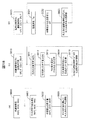
図1は、実施例1に係る映像投射装置001の構成を示す図であり、(a)は外観斜視図、(b)は眼の上方(y方向)から見た上面図(断面図)、(c)は眼側(z方向)から見た側面図である。なお、図中には、方向を説明するためにx、y、z軸を記述している。
FIG. 1 is a diagram illustrating a configuration of a
映像投射装置001は、映像を生成する映像生成部041、映像を眼に投射する投射部043と、映像生成部041と投射部043を繋ぐ支持部042で構成され、ユーザ(装着者)は、投射部043の出射部(接眼部)015から映像を見ることができる。各部の構造を説明する。
The
映像生成部041には、光源002と映像を生成する表示素子003及び保護板044がある。光源002は、例えば白色バックライトLEDを用いる。表示素子003は、例えば、画素毎に赤、緑、青のカラーフィルタを持つ液晶素子であり、表示素子003の領域004は、映像が表示される領域(映像表示領域)を示している。ここで光源002の発光面は、映像表示領域004よりも大きいサイズとする。表示素子003に照明光を照射する光源002を照明光学系と呼ぶ。
The
保護板044は、光学的に透明な平板であり、外部から埃や水滴などが入ることを防止する。さらに保護板044には、赤から青の帯域(波長430nm〜670nmの範囲)での反射防止膜を形成することで、光効率の損失を低減することができる。
The
映像生成部041は、光源002で発した光が映像表示領域004を通過することで映像を生成する。映像生成部041で生成された映像は、保護板044から出射され、支持部042内の空間を通過し、投射部043に伝搬される。
The
投射部043は、レンズユニット005を備え、レンズユニット005は、レンズ部013、反射部014、出射部(接眼部)015を有する。レンズ部013は焦点距離Fを持つレンズである。表示素子003の映像表示領域004からレンズ部013までの光学換算距離Aを焦点距離Fよりも近く設定することで(A<F)、眼020に投射される映像が虚像になる。眼020からレンズ部013までの距離Liは、焦点距離Fと距離Aを用いて、一般的なレンズの式(1)で算出できる。
1/Li=1/F−1/A (1)
なお、距離Liは、虚像であるため、符号が負である。
The
1 / Li = 1 / F-1 / A (1)
Since the distance Li is a virtual image, the sign is negative.
反射部014は、レンズ部013から進行してきた映像の進行方向を曲げて眼020へ投射させるミラーである。なお、破線006は映像光の進行を示し、破線075,076は映像光の伝搬範囲である。出射部015は平面であり、眼020に出射する最後の光学面となる。なお、レンズ部013、出射部015、保護板044は、埃、水滴、手油が付着し定着しないようにハードコートを施すことが望ましい。
The
支持部042は、映像生成部041と投射部043を繋ぐ機構であり、映像生成部041から投射部043へ映像が伝搬する空間(破線075、076で囲われた領域)を回避するよう構成されている。
The
図1(a)、(c)に示すように、映像投射装置001の上面と下面(y方向)は、筐体部016と筐体部017で覆われている。この筐体部016、017は、映像生成部041と投射部043を連結し支持するとともに、映像投射装置001の上下方向から装置内部(表示素子003など)に侵入する外光を遮断する機能を有している。
As shown in FIGS. 1A and 1C, the upper surface and the lower surface (y direction) of the
また図1(b)に示すように、映像投射装置001の側面は、筐体部007、008、009、010から構成されている。このうち筐体部007、008は、主に映像生成部041を形成する機構であり、筐体部009、010は、主に投射部043を形成する機構である。そして(a)、(c)に示すように、眼の側(z方向)から見ると、筐体部007、008と筐体部009、010の間には、z方向に透過する透明領域011が形成されている。この透明領域011を形成することで、シースルー機能を向上させている。ここでは、透明領域011は空間としているが、樹脂またはガラス等の保護用透明板や透明フィルムを設けても何ら構わない。このような場合は、透明板や透明フィルムをハードコートして汚れに対する耐性を向上させることが望ましい。
As shown in FIG. 1B, the side surface of the
ここで、外光の影響とこれを遮断する理由について説明する。
図3は、外光の到来する方向を示す図である。外光とは、太陽光や室内の蛍光灯などのことであり、ヘッドマウントディスプレイ055を装着したユーザ052に対して、矢印051で示すあらゆる方向から到来する。
Here, the influence of external light and the reason for blocking this will be described.
FIG. 3 is a diagram illustrating a direction in which external light arrives. External light refers to sunlight, indoor fluorescent lamps, and the like, and comes from all directions indicated by
このような外光051が、ヘッドマウントディスプレイ055の先端に搭載された映像投射装置001の内部、特に透明領域011から入射する場合がある。そして、映像生成部041の表示素子003(映像表示領域004)に外光が侵入すると、映像表示領域004が明るく輝いて本来の映像が見えにくくなる問題を生じる。さらには、外光が映像表示領域004に入射することで、表示している映像が本来の伝搬方向以外の方向に出射し、装着者052以外の人にその映像が見られる場合もある。よって、ユーザの見ている映像の秘匿性を保つことができないことになる。
Such
本実施例では、眼の前方から到来する外光を遮断するとともに、映像の秘匿性を確保するため、以下のように構成している。 In the present embodiment, the configuration is as follows in order to block external light coming from the front of the eye and ensure the confidentiality of the video.
図2は、映像投射装置001における外光を遮断する構造を説明する図である。図1(b)の上面図(断面図)に外光の線などを加えたものである。
FIG. 2 is a diagram for explaining a structure for blocking external light in the
外光は、線022と線024の間の範囲から到来するものを問題にする。それ以外の、線022よりも紙面右側(+x方向)から到来する光は、筐体部007で遮断されるので問題にしなくとも良い。また、線024よりも紙面下側(−z方向)から到来する光も、装着者の顔で遮断されるので、問題にしなくとも良い。
External light is a problem that comes from the range between
本実施例の映像投射装置001では、各筐体部007〜010の端部位置045〜050を、外光が映像表示領域004に入射しないように設定する。これらの端部位置の設定方法について説明する。
In the
まず、装着者の前方(+z方向)から到来する外光(矢印025)について述べる。眼020から筐体部007,009の透明領域011側に接線030,031を引き、接点を045,047とする。この接点045,047を結んだ線023が、映像表示領域004と交差しないように筐体部007,009の端部位置045,047を設定する。また筐体部008の端部位置050は、接線030よりも光源002側(紙面右側)に設定する。このように設定すると、線022と線023の範囲の外光(矢印025)が映像表示領域004に入射することを回避できる。
First, external light (arrow 025) coming from the front (+ z direction) of the wearer will be described.
次に、装着者の左側(−x方向)から到来する外光(矢印026)について述べる。装着者の顔で遮断されない外光の最大角度を設定し、その設定した限界角度で筐体部008の端部位置050に接する接線024を引く。この接線024に接するように、筐体部010の端部位置049を設定する。このように設定すると、線023と線024の範囲の外光(矢印026)が映像表示領域004に入射することを回避できる。
Next, external light (arrow 026) coming from the wearer's left side (−x direction) will be described. A maximum angle of external light that is not blocked by the wearer's face is set, and a
以上のように筐体部007〜010を設定することで、映像投射装置001は、線022と線024で示す範囲の外光(矢印025,026)を完全に遮断することができる。また、この条件を満足するときの透明領域011は、図2の線031と線022に挟まれた形状となり、出射部(接眼部)015に近い側でのx方向の開口幅(端部位置049から050までの距離)は、出射部(接眼部)015から遠い側でのx方向の開口幅(端部位置047から045までの距離)よりも大きくなる。
By setting the
次に、本実施例の映像投射装置001におけるシースルー機能について説明する。
図4は、映像投射装置001の前方(z方向)にある物体060から眼020に到達する光線を示す断面図である。(a)は、映像投射装置001の投射部043での断面を、(b)は映像投射装置001の支持部042での断面を示す。映像投射装置001は眼020から所定の距離を開けて配置され、物体060からの光線は映像投射装置001で一部が遮られて眼020に到達する。光線065は、物体060から眼020に入射可能な最大角度の範囲である。破線061は、眼020の法線方向を示している。
Next, the see-through function in the
FIG. 4 is a cross-sectional view showing light rays that reach the
(a)において、映像投射装置001の投射部043により、物体060の光線が遮断される領域063が発生する。投射部043には透明領域は存在しない。しかし、投射部043の高さ(y方向)を人間の眼020の瞳(4mm程度)より小さく設定することで、投射部043の上下(y方向)を通過した光線062が眼020に到達する。このため、装着者は、物体060の全体を視認することができる。このように、投射部043の高さを、物体060と眼020で成す最大角度の線065よりも小さく設定することで、シースルー機能を確保できる。
In (a), a
(b)において、映像投射装置001の支持部042には透明領域011が存在する。物体060の光線は支持部042で遮断される領域064が発生するが、支持部042の上下を通過した光線062と、透明領域011を通過した光線066が眼020に到達する。よって(a)の遮断領域063に比べて、(b)の遮断領域064は小さくなる。
このように、支持部042に透明領域011を形成したことにより、物体060をより視認しやすくなる効果が得られる。
In (b), a
As described above, by forming the
図5は、遮断物の高さと眼に届く光線の通過領域比率の関係を示す図である。図4(a)の場合を想定し、眼(瞳)020の大きさは一般的な値である4mm、眼から遮断物(投射部043)までの距離を50mmとした場合、物体060からの光線が遮断物(投射部043)の高さHdで遮られることなく眼に届く光線の通過領域比率を計算したものである。図では、横軸が幅Hdで、縦軸が眼に届く光線の比率を示す。光線の比率は、物体060を点として、投射部043が無い場合に眼に届く光線を基準(100%)としたときに、遮蔽されず届いた光線を通過領域比率として示している。通過領域比率は、高い方が視認し易いものとなる。
FIG. 5 is a diagram showing the relationship between the height of the blocking object and the ratio of the passing area of light rays reaching the eyes. Assuming the case of FIG. 4A, when the size of the eye (pupil) 020 is 4 mm, which is a general value, and the distance from the eye to the obstruction (projection unit 043) is 50 mm, the size from the
遮断物の高さHdが大きくなるほど、通過領域比率が低くなり、高さHdが3.76mmより大きくなると、通過領域比率が零となり視認できなくなる。このため、遮断物(投射部043)の高さは、3.76mmよりできるだけ小さくすることが望ましい。 As the height Hd of the blocking object increases, the passing area ratio decreases, and when the height Hd exceeds 3.76 mm, the passing area ratio becomes zero and cannot be visually recognized. For this reason, it is desirable to make the height of the obstruction (projection unit 043) as small as possible from 3.76 mm.
この結果を踏まえると、図4(b)の場合には、支持部042の透明領域011の高さをできるだけ大きくすることが望ましい。例えば、支持部042の高さを投射部043よりも大きくして、透明領域011の高さを拡大させることがより望ましい。
Based on this result, in the case of FIG. 4B, it is desirable to make the height of the
映像投射装置001の投射部043は、映像を眼に伝達させるため高さの制約があり、小さくするには限界がある。一方支持部042については、透明領域011を拡大して設けることで視認性(シースルー機能)を向上させることができる。
The
問題なく視認できるレベルである通過領域比率50%を確保するには、透明領域011の上下の筐体部016,017の高さを合計1.8mmより小さくすれば良い。
In order to secure a passing area ratio of 50%, which is a level that can be visually recognized without problems, the height of the upper and
上記のように本実施例の映像投射装置001は、支持部042に透明領域011を設けることで、シースルー機能の視認し易さを向上させることができる。さらに、透明領域011の配置(筐体部の端部位置)を適切に設定することで、透明領域011から入射する外光を遮断するとともに、装着者の見ている映像情報が他人に見られないよう秘匿性を確保することができる。
As described above, the
実施例2では、シースルー機能の向上と照明光学系の光利用効率の向上を図った映像投射装置について説明する。 In the second embodiment, an image projection apparatus that improves the see-through function and the light use efficiency of the illumination optical system will be described.
図6は、実施例2に係る映像投射装置101の構成を示す図であり、(a)は外観斜視図、(b)は眼の上方(y方向)から見た上面図(断面図)、(c)は眼側(z方向)から見た側面図である。
FIG. 6 is a diagram illustrating the configuration of the
映像投射装置101は、映像を生成する映像生成部191、映像を眼に投射する投射部193と、映像生成部191と投射部193を繋ぐ支持部192で構成され、ユーザ(装着者)は、投射部193の出射部(接眼部)115から映像を見ることができる。各部の構造を説明する。
The
映像生成部191には、光源102、光積分器103、レンズ105、偏光素子106、偏光素子195、偏光プリズム素子107、波長板108、反射素子109、表示素子110、保護板194、温度検知部471、光量検知部472がある。
The
光源102は、赤、緑、青の波長帯の光を出射する光源であり、光を出射する領域が出射面099である。光源102から出射した赤、緑、青色の光は、光積分器103でその強度が積分され均一な光となる。光源102と光積分器103の構成は後述する。
The
光積分器103を出射した光は、レンズ105でx軸に略平行な光に変換され、偏光素子106で垂直偏光(紙面と垂直なy方向の偏光)の光に選択されて、偏光プリズム素子107に入射する。
The light emitted from the
偏光プリズム素子107では、垂直偏光光を反射させ波長板108に入射させ、また、水平偏光光(紙面と平行なz方向の偏光)を透過させる。波長板108では、垂直偏光光は円偏光に変換され反射素子109に進行する。反射素子109で光は反射し、波長板108へ進行する。波長板108に再度入射した円偏光の光は、水平偏光の光に変換され、再度偏光プリズム素子107へ進行する。ここで用いる波長板108は、いわゆる1/4波長板の機能を有する。また、赤、緑、青の波長帯の光が進行するため、どの波長でも1/4波長板の機能を有する広帯域1/4波長板であることが望ましい。
The
再度偏光プリズム素子107へ進行した水平偏光光は、偏光プリズム素子107を透過して表示素子110への照明光として照射される。なお、光源102から出射される光を表示素子110に照射するまでの光学系が照明光学系である。
The horizontally polarized light that has traveled to the
ここでの表示素子110には、例えばカラーフィルタの無い反射型の液晶素子を用いる。このため、カラーフィルタの有る液晶素子と比べ画素サイズを1/3にできるため、高い解像度の映像が実現できる。表示素子110の領域111は映像が表示される映像表示領域を示している。なお、カラー映像は、光源102から赤、緑、青色の光を眼が追従できない速度で順に発光させることで生成できる。
As the
映像表示領域111は、画素毎に入射した水平偏光を、垂直偏光か水平偏光に変換する機能を有している。映像として有効にする場合は、垂直偏光に、無効にする場合は水平偏光に変換する。映像表示領域111で映像となった垂直偏光の光と、無効となり映像として作用しない水平偏光の光は、共に偏光プリズム素子107へ入射する。
The
偏光プリズム素子107では、垂直偏光の光を反射して偏光素子195へ進行させ、水平偏光の光を透過する。この偏光プリズム素子107により、映像情報を持つ光と無効の光を分離する。偏光素子195においても、垂直偏光だけが選択される。偏光プリズム素子107は、水平と垂直偏光に分離する機能を有するが、完全に分離することができず、わずかに水平偏光の光を反射させてしまう。このため、偏光素子195を用いることで、映像として無効の水平偏光の光を大幅に除去できるため、高いコントラストを実現できる。なお、偏光素子106、195は、偏光プリズム素子107に貼り付けて一体化することで、搭載する部品点数を削減し、部品保持部を少なくできて装置を小型化しやすくなる。
The
映像として有効な光である垂直偏光の光は、保護板194へ進行する。保護板194は、外部から埃や水滴などが入ることを防止する機能を有する光学的に透明な平板であり、赤から青の帯域での反射防止膜を形成することで、光効率の損失を低減する。保護板194を通過した映像光は、支持部192内の空間を通過し、投射部193に伝搬される。
Vertically polarized light, which is light that is effective as an image, travels to the
投射部193は、レンズユニット112を備え、レンズユニット112は、レンズ部113、反射部114、出射部(接眼部)115を有する。レンズ部113は焦点距離Fを持つレンズである。表示素子110の映像表示領域111からレンズ部113までの光学換算距離Aを焦点距離Fよりも近く設定することで、眼020に投射される映像が虚像になる。
The
反射部114は、レンズ部113から進行してきた映像の進行方向を曲げて眼020へ投射させるミラーである。なお、破線104は映像光の進行を示したものである。出射部115は、平面であり眼020に出射する最後の光学面である。なお、レンズ部113、出射部115、保護板194は、埃、水滴、手油が付着し定着しないようにハードコートを施すことが望ましい。
The
支持部192は、映像生成部191と投射部193を繋ぐ機構であり、映像生成部191から投射部193へ映像が伝搬する空間を回避するよう構成されている。
The
図6(a)、(c)に示すように、映像投射装置101の上面と下面は、筐体部116と筐体部117で覆われている。この筐体部116、117は、映像生成部191と投射部193を連結し支持するとともに、映像投射装置101の上下方向から装置内部(表示素子110など)に侵入する外光を遮断する機能を有している。
As shown in FIGS. 6A and 6C, the upper surface and the lower surface of the
また図6(b)に示すように、映像投射装置101の側面は、筐体部120〜126から構成されている。このうち筐体部120、121、126は、主に映像生成部191を形成する機構であり、筐体部123、124は、主に投射部043を形成する機構であり、筐体部122、125は、主に支持部192を形成する機構である。そして(a)、(c)に示すように眼の側から見ると、筐体部123(124)と筐体部125の間には透明領域130が、筐体部122と筐体部125の間には透明領域131が、筐体部122と筐体部121(120)の間には透明領域132が、それぞれz方向に透過するよう形成されている。このように透明領域130,131,132を増加して形成することで、シースルー機能をより向上させている。
Further, as shown in FIG. 6B, the side surface of the
温度検知部471は、光源102の近傍の温度を検知するサーミスタであり、光量検知部472は、光源102の出力している光量を検知する光検出器である。赤、緑、青の波長帯の光をLEDで実現する場合、赤の波長帯の光を出力するためには、緑、青とは異なる材料を用いるため、出力する光量の温度特性が異なる。このため、温度検知部471で温度を検知し、光量検知部472で光量を検知することで、光源102から出力される光量や赤、緑、青で合成される色の制御を行う。
The
次に、外光の遮断と秘匿性の確保について説明する。
図7は、映像投射装置101における外光を遮断する構造を説明する図である。図6(b)の上面図(断面図)に外光の線などを加えたものである。
Next, blocking of outside light and ensuring confidentiality will be described.
FIG. 7 is a diagram illustrating a structure for blocking external light in the
外光は、線150と線155の間の範囲から到来してくるものを問題にする。それ以外の、線150よりも紙面右側(+x方向)から進行する光は、筐体部120で遮断されるので、問題しなくとも良い。また、線155よりも紙面下側(−z方向)から到来する光も、装着者の顔で遮断されるので、問題にしなくとも良い。
External light causes problems that come from the range between the
本実施例の映像投射装置101では、各筐体部120〜125の端部位置160〜166を、外光が映像表示領域111に入射しないように設定する。これらの端部位置の設定方法について説明する。
In the
まず、装着者の前方(+z方向)から到来する外光(矢印156,157)について述べる。眼020から各筐体部120〜125の透明領域130,131,132側に接線140〜143を引き、筐体部120との接点を164、筐体部122との接点を166、163、筐体部125との接点を162、筐体部124との接点を161、筐体部123との接点を160とする。
First, external light (
接点164、166を結んだ線151が、映像表示領域111と交差しないように端部位置164、166を設定する。また筐体部121の端部位置165は、接線140より光源102側(紙面右側)に設定する。このように設定すると、線150と線151の範囲の外光(矢印156)が映像表示領域111に入射することを回避できる。また、接点160、163を結んだ線153が、映像表示領域111と交差しないように端部位置160、163を設定する。このように設定すると、線152と線153の範囲の外光(矢印157)が映像表示領域111に入射することを回避できる。
The end positions 164 and 166 are set so that the
次に、装着者の左側(−x方向)から到来する外光(矢印158)について述べる。装着者の顔で遮断されない外光の最大角度を設定し、その設定した限界角度で筐体部125の端部位置162に接するように接線155を引く。筐体部124,125の端部位置161、162は、各々を結んだ接線154が偏光プリズム素子107での反射を考慮しても映像表示領域111と交差しないように設定する。このように設定すると、線154と線155の範囲の外光(矢印158)が映像表示領域111に入射することを回避できる。なお、筐体部121に設ける開口部167は、外光が映像表示領域111に入射しないように配置することが望ましい。
Next, external light (arrow 158) coming from the wearer's left side (−x direction) will be described. The maximum angle of external light that is not blocked by the wearer's face is set, and a
以上のように筐体部120〜126を設定することで、映像投射装置101は、線150と線155で示す範囲の外光(矢印156、157、158)を完全に遮断することができる。また、この条件を満足するときの透明領域130〜132は、図7の線143と線150に挟まれた形状となり、出射部(接眼部)115に近い側でのx方向の開口幅(端部位置161から165までの距離)は、出射部(接眼部)115から遠い側でのx方向の開口幅(端部位置160から164までの距離)よりも大きくなる。
By setting the
本実施例の映像投射装置101は、筐体部122、125を追加したことで、装置の奥行方向(z方向)のサイズが小さくなる。すなわち、眼020から遠い側の筐体部120のz方向への突き出し量171は、実施例1(図2)における筐体部007の突き出し量070と比べて小さくすることができ、装置小型化の効果が得られる。
In the
また、筐体部120〜125の他の端部位置は、接線140〜141、142〜143の領域に食み出さないように設定する。このように設定することで、接線140〜141、接線142〜143の各範囲の角度の視界が確保できる。また、外光が映像表示領域111に入射しないことにより、外から映像表示領域111の映像情報を見られることがなくなるため、秘匿性も確保される。
Moreover, the other edge part position of the housing | casing parts 120-125 is set so that it may not protrude to the area | region of tangent lines 140-141, 142-143. By setting in this way, it is possible to secure a field of view of angles in each range of the
次に、照明光学系における光源102の構成と色ずれ補正について説明する。
図8は、光源の出射面の構成を示す図である。光源102の出射面099には、赤(R)、緑(G)、青(B)の波長帯の光を出射する光源体180、181、182を配置する。各々は、例えばLED発光素子を使用する。各光源体180〜182を囲む矩形領域を発光面185とする。
Next, the configuration of the
FIG. 8 is a diagram showing the configuration of the emission surface of the light source. On the
各光源体180〜182の位置は、それらの中心を結ぶと1角が90度以下の三角形(この場合は略正三角形)が形成されるようにする。なぜなら、発光面185の面積と発光の立体角の2乗との積はエネルギー保存されるので、発光面積は小さい方が望ましい。また、赤、緑、青色で発光位置が異なるため、発光面積が同じでも、表示素子に均一な輝度で照明するには、一辺の長さが小さいことが望ましいからである。このため、光源体の配置を1角が90度以下の三角形になるようにして、発光面185の幅Sxと高さSyが略等しくなるように設定した。
The positions of the
図9は、光学系の物点と結像点を示す図であり、これを用いて色ずれ発生について説明する。光源体201、202から出射した光は、照明用レンズ203で略並行になり、表示素子に相当する物点204に入射する。物点像は投射用レンズ205で投射され、眼の水晶体に相当するレンズ206を経て、網膜に相当する像点207に結像する。像点212は虚像の結像点を、軸209は眼の法線を示す。光量213は、光源体201から像点207に到達した光量、光量214は、光源体202から像点207に到達した光量を示す。光源体201、202は、軸209に対して対称位置に配置するものとする。
FIG. 9 is a diagram showing object points and image formation points of the optical system, and the occurrence of color misregistration will be described using these. The light emitted from the
一般に、光源体201,202から出射し物点204を通って到達する光量213,214は、光源体の位置が物点に近い場合に大きくなり、物点から遠ざかると小さくなる。
(a)は、軸209上に存在する物点2041の場合で、光源体201,202から物点までの距離が等しいので、像点207での光量213、214は等しい。
(b)は、軸209より紙面上側にある物点2042の場合で、光源体201の方が物点2042に近いため、像点207では光量213が光量214より大きくなる。
(c)は、軸209より紙面下側にある物点2043の場合で、光源体202の方が物点2043に近いため、像点207では光量214が光量213より大きくなる。
In general, the light amounts 213 and 214 emitted from the
(A) is the case of the
(B) is the case of the
(C) is the case of an
すなわち、光源体201、202が異なる波長の光を発光する場合、眼では、軸209から紙面上下方向にずれた物点2042、2043は、異なる色に見えることになる。このような現象を「色ずれ」と呼ぶ。
この色ずれを補正するために、本実施例では、光源102の出射側に光積分器103を配置させている。
That is, when the
In order to correct this color misregistration, in this embodiment, the
図10は、光積分器103の構成を示す図である。光積分器103は、長さL、高さH、幅Wの四角柱状の樹脂体であり、6つの面221〜226を有する。このうち面221は、光の拡散機能を有する面であり、その他の面222〜226は、散乱が起こらない平坦な面である。符号228は、樹脂成型時のゲートを示している。
FIG. 10 is a diagram illustrating a configuration of the
面221は光積分器103の出射面であり、レンズ105側に配置する。面226は光積分器103の入射面であり、光源102側に配置する。ゲート228は面222に配置し、可能な限り小さくすることで後述する積分機能への影響を少なくし、光の損失を最小とする。
A surface 221 is an exit surface of the
光源102から出射した光は、入射面226から光積分器103に入光して、面222ないし面225で内面反射を繰り返し出射面221に到達する。出射面221に達した光線は、その拡散機能により角度が変換されてレンズ105へ出射する。
The light emitted from the
ここで、光積分器103から出射する光の光積分器内での反射回数(積分回数)を見積もる。出射面221の拡散機能を表す拡散角(半値半角)θd、出射面221から出射したときに眼まで到達する光の角度θ、光積分器103の屈折率Nとすると、光積分器103内での積分回数Ipは、式(2)で示すことができる。
Ip=(π・L2/(W・H))・tan2(θ/N+θd) (2)
すなわち積分回数Ipは、出射するときの光の角度θと拡散時の半値半角θdで形成される角度(θ/N+θd)で距離Lだけ進行したときの面積を、光積分器221の断面積(W・H)で割ることで算出される。なお、出射時の光の角度θは、光積分器103内部に入射するときに屈折により角度が変換されるため、分母に屈折率Nがついている。
Here, the number of reflections (number of integrations) in the optical integrator of the light emitted from the
Ip = (π · L 2 / (W · H)) · tan 2 (θ / N + θd) (2)
That is, the number of integrations Ip is the cross-sectional area of the optical integrator 221 (the area when the light travels by the distance L at the angle (θ / N + θd) formed by the light angle θ when emitted and the half-value half angle θd when diffused). It is calculated by dividing by (W · H). In addition, since the angle θ of the light at the time of emission is converted by refraction when entering the
前述したように、発光面積と発光の立体角の2乗との積はエネルギー保存される。例えば、映像投射装置101から眼に到達する光の半値半角θdを3度、表示素子110の大きさを3×3mmとする。光源としてのLEDでは、発光面サイズが1mm以下程度であれば容易に入手できるので、出射面を1×1mmとすると、光積分器103から出射される光の角度θは約9度ということになる。積分回数Ipは、概ね20回以上積分することで、光は十分に均一化されると見なせる。すなわち、光源からの各波長の光は、光積分器103の中でその光路長が均一化されるため、図9で述べた色ずれの問題が解消される。
As described above, the product of the light emitting area and the square of the solid angle of light emission is energy conserved. For example, the half-value half angle θd of light reaching the eye from the
図11は、積分回数Ip=20とするための光積分器103の長さLと拡散角(半値半角)θdの関係を示す図である。
FIG. 11 is a diagram showing the relationship between the length L of the
光積分器103の必要な長さLは、出射面221の拡散角θdが大きくほど、短くなることが分かる。出射面221に拡散機能を付与しない場合(θd=0)には、長さLは25mm以上必要になる。この25mmを超える長さは、ヘッドマウントディスプレイの映像投射装置として外形上許容できない大きさである。出射面221に拡散機能を付与することで、必要な長さLを短くすることができる。完全拡散であるθd=60度とした場合でも、長さLは、3.1mm以上必要となる。これは、光積分器103を配置せずに完全拡散板だけを配置しても、積分機能がないため色ずれは改善できないことを示している。内面反射による積分機能と拡散機能との両方を付与することで、小さなスペースで均一化された光を所定の角度で出射する照明光学系を実現できる。
It can be seen that the required length L of the
臨界角度を越える角度の光は、光積分器103で内面反射できなくなる。このため、θdが40度を超えると光積分器103の必要な長さが3.1mm程度に飽和する。これより、光積分器103の好ましい条件は、長さL=3.1mmで拡散角θd=40度である。
Light having an angle exceeding the critical angle cannot be internally reflected by the
なお、光積分器103を樹脂成型で製造する場合、ゲート228が必要となる。このようなゲート228は、成型後に研磨処理をかけないと内面反射が行われないため、上記の計算通りの効果が得られない。このため、未処理のゲート228のサイズを例えば0.9mm角程度とすれば、光積分器103の長さはゲート分を加算して最低でも約4.0mmとなる。もちろん、成型でなく研磨だけで製造することも可能であり、その場合には、ゲートが不要なため、上記の通り3.1mmの長さで良い。
In addition, when manufacturing the
照明光の光利用効率は、光源から出射した光のうち使用できる角度の2乗で決まる。前記実施例1の映像投射装置001では、光源002からの光を集光するレンズがないため、上記した半角3度までの光しか使用できない。これに対して実施例2の映像投射装置101では、半角9度の光まで使用できるので、実施例1と比較して約9倍効率の高い光学系が実現できる。
The light utilization efficiency of the illumination light is determined by the square of the usable angle of the light emitted from the light source. In the
上述したように、実施例2の映像投射装置101は、支持部192に複数の透明領域130〜132を設けているので、シースルー機能の視認し易さをより向上させることができる。また、透明領域130〜132の配置を適切に設定することで、透明領域から入射する外光を遮断するとともに、装着者が見ている映像情報が他人に見られないよう秘匿性を確保することができる。
As described above, since the
さらに実施例2では、内面反射による積分機能と拡散機能との両方を有する光積分器103を設けることで、小型で高性能の光積分器を実現し、照明光学系の光利用効率を向上させることができる。
Further, in the second embodiment, by providing the
実施例3では、実施例2の映像投射装置101における光積分器103と光源102の変形例について説明する。
In the third embodiment, a modification of the
図12は、光積分器の第1の変形例を示す図である。光積分器300は入射面301と出射面302を有し、出射面302に拡散機能を持たせるとともに、入射面301には入射光線の角度を曲げる角度変換面303〜305を設けている。光源102からの入射光313〜315(図8の各光源体180〜182からの出射光に相当)は、角度変換面303〜305により、それぞれ出射面302の中心に向けて進行する。これにより、光源体位置ずれに伴う角度誤差が補完され、光がより積分されやすくなる(積分回数を減らすことができる)。よって、ゲート306を考慮しても光積分器300の長さLは4mmより短くすることができる。
FIG. 12 is a diagram illustrating a first modification of the optical integrator. The
図13は、光積分器の第2の変形例を示す図である。光積分器350は入射面351と出射面352を有し、出射面352に拡散機能を持たせるとともに、入射面351には入射光線の角度を曲げる凹レンズ353〜355を配置している。光源102からの入射光313〜315の各中心に対し凹レンズ353〜355の各中心をずらすことで、レンズの偏芯を利用して、入射光の角度を変換させ出射面352の中心に進行させることができる。これにより、光源体位置ずれに伴う角度誤差を補完する。また、凹レンズによる光の角度を発散させる機能を利用すれば、図12の光積分器300より短い距離で積分効果が得られるので、光積分器350の長さLをさらに短くすることができる。このような複雑な構成は、シミュレーションにより効果が確認できる。
FIG. 13 is a diagram illustrating a second modification of the optical integrator. The
図14は、光源の第1の変形例を示す図である。光源102の出射面500は、図8の出射面099における光源体180の位置をずらし、各光源体180、181,182をL型に配置している。各光源体の中心を結ぶと直角三角形になり、1角が90度以下の三角形になるのは変わらない。出射面500と出射面099の発光面185の大きさは、幅Sx、高さSy共に変わらない。すなわち、発光面積と発光の立体角の2乗との積で表されるエネルギーも保存されるので、出射面500の光源体の配置は、出射面099と同程度の光効率となる。
FIG. 14 is a diagram illustrating a first modification of the light source. The light emission surface 500 of the
図15は、光源の第2の変形例を示す図である。光源102の出射面550は、図14の出射面500に対して、光源体183を追加したものである。各光源体180、181,182、183を四角型に配置しているが、発光面185の大きさは、幅Sx、高さSy共に変わらない。この場合、光効率は同程度ながら照明光をより明るくできる。なお、光源体183として例えば白色の波長帯の光を出射すると、最も明るくできる。また、光源体183として例えば黄色の波長帯の光を出射すると、色再現範囲を拡大できる。
FIG. 15 is a diagram illustrating a second modification of the light source. The
実施例4では、映像投射装置101を搭載したヘッドマウントディスプレイ450について説明する。
In Example 4, a head mounted
図16は、ヘッドマウントディスプレイ450の装着状態を示す図で、ユーザが装着している状態を頭上から見たものである。また図17は、ヘッドマウントディスプレイ450の機能構成を示すブロック図である。
FIG. 16 is a diagram showing a wearing state of the head mounted
ヘッドマウントディスプレイ450には、映像投射装置101の他に、外部情報479を取得する撮像手段449、電力供給手段435、外部サーバ478と通信する通信手段433、音センシング素子439やタッチセンシング素子458などの操作入力手段475、コントローラ440、加速度センシング素子445、位置センシング素子446などの外部情報479を取得するセンシング手段490、データテーブル476などが具備されている。
In addition to the
電力供給手段435は、バッテリーのような充電可能な電源である。電源供給手段435は、コントローラ440を介し装置に必要な電力を供給する。このときコントローラ440は、状況に応じて、必要な装置に電力を供給する選択機能も有している。通信手段433は、インターネット上の情報や装着者(ユーザ)430が持っている電子機器などの外部サーバ478とアクセスできる通信装置である。タッチセンシング素子458は、タッチパネルのようなセンシング素子であり、音センシング素子439は、マイクなど装着者430の音声を検出する素子である。
The power supply means 435 is a rechargeable power source such as a battery. The
操作入力手段475は、音センシング素子439を用いた音声認識やタッチセンシング素子458を用いた指の位置情報などで、装着者430がヘッドマウントディスプレイ450を操作するための入力を行う。加速度センシング素子445は、圧電素子や静電容量などの原理を用い、加速度を検知する。位置センシング素子446は、GPSのような位置を検出する素子である。コントローラ440は、上記の各装置、各手段を制御するメインチップである。
The
ヘッドマウントディスプレイ450は、装着者430の視界437の中に映像投射装置101から投射された映像459が見ることができる。映像459が視界437の中で見られるように、映像投射装置101の投射方向を調整する角度調整機構432が具備されている。これにより装着者430は、映像459の位置を好みの位置に調整できる。なお、角度調整機構432は、例えば蝶番などで容易に実現できる。
The head mounted
図16では、映像投射装置101を右目441側に装着した状態を示すが、左目442側でも同様に装着できる。このためコントローラ440は、加速度センシング素子445で得られた情報を元に、映像の上下左右を反転させて装着者430に常に正しい映像を表示する機能を有している。ヘッドマウントディスプレイ450は、耳443、444や、固定部451〜453などで、頭部に固定して使用するため、両手がフリーになる。
FIG. 16 shows a state in which the
次に、ヘッドマウントディスプレイ450のいくつかの使用例について説明する。
(1)装着者430が歩行している際に前方の通路に段差などがある場合を想定する。コントローラ440は、撮像手段449で取得した映像情報(438で示す範囲)を処理し、通路に段差があることを認識して、映像投射装置101を用いて「段差有り注意」といったメッセージを映像459に表示し、装着者430に知らせることができる。このときコントローラ440は、光源102を発光させ、表示素子110に所定のメッセージの映像信号を送る。
Next, some usage examples of the head mounted
(1) When the
(2)装着者430にかかわる外部情報479であるソーシャルネットワーク情報として、例えば、通勤に使用している電車が事故で止まったなどの情報が発生した場合を想定する。通信手段433からコントローラ440に外部情報が伝達され、映像投射装置101により、「通勤電車事故で遅延」といったメッセージを装着者430に知らせることができる。このときコントローラ440は、装着者430の要望に応じてインターネット上の情報を常時監視する機能を有している。
(2) As the social network information, which is the
(3)装着者430が撮像手段449を利用して写真を取りたい場合、コントローラ440は、音センシング素子439を用いた音声認識か、タッチセンシング素子458を用いた指の位置情報などの操作入力手段475から装着者430の要望を検知し、撮像手段449を駆動し、写真を撮影することができる。この場合、撮影した写真情報は、通信手段433を用いてインターネット上の装着者430が持っているクラウドネットワーク上に送信することができる。もちろん映像459に撮影した映像を投射することもできる。この場合、コントローラ440は、操作入力手段475からの入力信号を常に優先させて処理することが望ましい。
(3) When the
(4)装着者430が電車の中で居眠りをしている場合、コントローラ440は、頭の揺れを加速度センシング素子445から検知し、また電車の中にいることを撮像手段449から検知して、映像投射装置101の電源を切り節電することもできる。
(4) When the
(5)装着者430が通常と異なる地域にいる場合、コントローラ440は、センシング手段490の位置情報からいつもと異なる位置にいることを検知する。そして、撮像手段449の情報から旅行なのか出張なのかを判別し、旅行のガイドや、付近の食べ物情報などを通信手段433から得て、装着者430へ知らせることができる。
上記のようにコントローラ440は、ユーザの状況を判断し、外部から取得した情報を映像投射装置101から映像情報としてユーザに提供する機能を有する。
(5) When the
As described above, the
また、コントローラ440は、映像投射装置101内にある温度検知部471からの温度情報と、光量検知部472からの光量情報をモニタし、光源102の出力を最適に制御する機能もある。
The
図18は、光源102の出力制御を示すフローチャートである。ここではカラー映像表示のため、光源102は表示素子110と同期させて赤、緑、青の波長帯の光を発光するフィールドシーケンシャルカラー(FSC)方式を想定する。以下、赤、緑、青色の各光量を調整するため、(a)〜(c)の3つの制御方法を説明する。
FIG. 18 is a flowchart showing output control of the
(a)の方法は、赤、緑、青色の各光量をそれぞれ測定する場合である。S600の初期設定では、所定の色の照明光になるよう、光源102から出射する赤、緑、青色の光量の初期値I0(R)、I0(G)、I0(B)を設定し、データテーブル476に格納しておく。
The method of (a) is a case where each light quantity of red, green, and blue is measured. In the initial setting in S600, initial values I0 (R), I0 (G), and I0 (B) of light amounts of red, green, and blue emitted from the
S601では、光量検知部472として波長依存のない光検出器を用いて、FSC方式により赤、緑、青が順次発光するタイミングと同期して各色光の光量を順次測定する。測定した光量をIa(R)、Ia(G)、Ia(B)とする。温度変化等により光量が変化した場合、S602では、初期値I0(R)、I0(G)、I0(B)との差分量ΔI(R)、ΔI(G)、ΔI(B)を求める。S603では、差分量に応じて、光量初期値と等しくなるように各色の光源103の出力をそれぞれ調整する。
In step S601, a light detector that does not depend on wavelength is used as the light
なお、光量検知部472が波長帯毎に光量を検出できるカラー光検出器の場合は、各光量Ia(R)、Ia(G)、Ia(B)を同時に測定することで、制御の精度がより向上する。
If the
(b)の方法は、赤色のみの光量を測定する場合である。これは、光源102のうち特に赤色の光量は発光材料の影響で温度依存性が大きいので、代表として赤色光量を測定するものである。S610の初期設定では、赤色の光量の初期値I0(R)と、赤、緑、青色の光量の温度依存性データI(R)−T、I(G)−T、I(B)−Tをデータテーブル476に格納しておく。
The method (b) is for measuring the amount of red light only. This is because the red light amount of the
S611では、光量検知部472にて赤色の光量Ia(R)のみを測定し、S612では、初期値I0(R)との差分量ΔI(R)を求める。S613では、差分量に応じて赤色の初期値と等しくなるように赤色光の出力を調整する。
In S611, only the red light amount Ia (R) is measured by the light
S614では、赤の温度依存性データI(R)−Tを参照し、S612で求めた差分量ΔI(R)から温度変化ΔTを求める。S615では、緑色の温度依存性データI(G)−T及び青の温度依存性データI(B)−Tを参照し、S614で求めた温度変化ΔTから、緑色光及び青色光の出力を調整する。
この方法では、赤色光のみの光量を測定すればよいので、簡単な構成となる。なお、測定光の色は、温度依存性を有していれば、赤色光以外でもよい。
In S614, the temperature change ΔT is obtained from the difference amount ΔI (R) obtained in S612 with reference to the red temperature dependency data I (R) -T. In S615, green temperature dependency data I (G) -T and blue temperature dependency data I (B) -T are referred to, and the outputs of green light and blue light are adjusted from the temperature change ΔT obtained in S614. To do.
This method has a simple configuration because only the amount of red light needs to be measured. The color of the measurement light may be other than red light as long as it has temperature dependency.
(c)の方法は、光量の代わりに温度変化のみを測定する場合である。S620の初期設定では、光源102の近傍温度の初期値T0と、赤、緑、青色の光量の温度依存性データI(R)−T、I(G)−T、I(B)−Tをデータテーブル476に格納しておく。
The method (c) is a case where only a temperature change is measured instead of the light amount. In the initial setting of S620, the initial value T0 of the temperature near the
S621では、温度検知部471により光源102近傍の温度Taを測定する。S622では、初期値T0からの温度変化ΔTを求める。S623では、各色の温度依存性データI(R)−T、I(G)−T、I(B)−Tを参照し、S622で求めた温度変化ΔTから、各色の光源103の出力をそれぞれ調整する。
この方法は、温度測定のみよいので、光量測定と比較して簡便な構成となる。
In step S621, the
Since this method only requires temperature measurement, the method is simpler than light quantity measurement.
上記のようにコントローラ440により、映像投射装置101の光源102の出力を最適に制御し、表示する映像の色変動を抑える効果を有している。
As described above, the
実施例4のヘッドマウントディスプレイ450によれば、映像投射装置101により装着者の視界の一部に様々な映像情報を提供することができる。その際、シースルー機能により視認性を向上し、また装着者が見ている映像情報の秘匿性を確保することができるので、安全で使い勝手が優れるものとなる。
According to the head mounted
001,101:映像投射装置、
002,102:光源、
003,110:表示素子、
005,112:レンズユニット、
007〜010,120〜126:筐体部、
011,130,131,132:透明領域、
015,115:出射部(接眼部)、
040,194:保護板、
041,191:映像生成部、
042,192:支持部、
043,193:投射部、
103、300,350:光積分器、
105:レンズ、
107:偏光プリズム素子、
180,181,182,183:光源体、
221,302,352:出射面(拡散機能)、
303,304,305:角度変換面、
353,354,355:凹レンズ、
430:装着者(ユーザ)、
440:コントローラ、
450:ヘッドマウントディスプレイ、
471:温度検知部、
472:光量検知部、
476:データテーブル。
001, 101: video projection device,
002, 102: light source,
003, 110: display element,
005, 112: Lens unit,
007 to 010, 120 to 126: housing part,
011, 130, 131, 132: transparent region,
015, 115: emitting part (eyepiece part),
040, 194: protective plate,
041, 191: video generation unit,
042, 192: support part,
043, 193: projection unit,
103, 300, 350: optical integrator,
105: Lens,
107: Polarizing prism element,
180, 181, 182, 183: light source body,
221, 302, 352: emission surface (diffusion function),
303, 304, 305: angle conversion plane,
353, 354, 355: concave lens,
430: Wearer (user),
440: Controller,
450: Head mounted display,
471: temperature detector,
472: Light amount detection unit,
476: Data table.
Claims (6)
映像を生成する表示素子と該表示素子を照明する照明光学系とを有する映像生成部と、
該映像生成部で生成された映像を接眼部を介してユーザの眼に投射する投射部と、
前記映像生成部と前記投射部とを筐体部で繋ぐ支持部とを備え、
該支持部は、前記映像生成部と前記投射部の間に、前記筐体部に囲まれ、前記投射部からの映像の投射方向と平行な方向に透過する少なくとも1個の透明領域を有するとともに、
前記支持部の前記筐体部は、前記透明領域を通過し前記表示素子へ入射する外光を遮断するよう配置し、
前記透明領域の前記映像生成部から前記投射部へ向かう方向の開口幅は、前記接眼部に近い側での開口幅を、前記接眼部から遠い側での開口幅よりも大きくしたことを特徴とする映像投射装置。 In a video projection device that projects video to the user's eyes,
An image generation unit having a display element for generating an image and an illumination optical system for illuminating the display element;
A projection unit that projects the video generated by the video generation unit to the user's eye via the eyepiece;
A support unit that connects the video generation unit and the projection unit with a housing unit;
The support portion, between the image generator the projecting portion, the surrounded casing, which has at least one transparent region passes in a direction parallel to the projection direction of the video from the projection unit ,
The housing portion of the support portion is arranged to block external light that passes through the transparent region and is incident on the display element,
The opening width of the transparent region in the direction from the image generation unit to the projection unit is such that the opening width on the side close to the eyepiece is larger than the opening width on the side far from the eyepiece. A featured image projection device.
前記映像生成部における前記照明光学系は、
複数の波長帯の光を出射する光源と、
該光源から出射する光を内面反射させて光強度を積分し均一な光とする四角柱状の光積分器と、
該光積分器から出射された光を略平行な光に変換するレンズ部と、を備え、
前記光積分器の前記レンズ部側の出射面は、光を拡散させる拡散機能を有することを特徴とする映像投射装置。 The video projection device according to claim 1,
The illumination optical system in the video generation unit is:
A light source that emits light in a plurality of wavelength bands;
A quadrangular prism-shaped light integrator that integrates the light intensity by internally reflecting the light emitted from the light source to obtain uniform light;
A lens unit that converts light emitted from the optical integrator into substantially parallel light,
The image projection apparatus according to claim 1, wherein an exit surface on the lens unit side of the optical integrator has a diffusion function of diffusing light .
前記光源は赤、緑、青の波長帯の光の出射する3個の光源体を有し、
前記各光源体の中心点は、1つの角度が90度以下の三角形の頂点位置となるように配置することを特徴とする映像投射装置。 The video projection device according to claim 2,
The light source has three light source bodies that emit light in the red, green, and blue wavelength bands,
The image projection device according to claim 1, wherein the center point of each light source body is arranged so that one angle is a vertex position of a triangle whose angle is 90 degrees or less .
前記光積分器の入射面に、前記光源から入射した赤、緑、青の波長帯の光が各々前記光積分器の出射面の中心に向かって進行させるように角度変換面を設けたことを特徴とする映像投射装置。 The video projection device according to claim 3 ,
An angle conversion surface is provided on the incident surface of the optical integrator so that light in the red, green, and blue wavelength bands incident from the light source travels toward the center of the output surface of the optical integrator. A featured image projection device.
前記光積分器の入射面に、前記光源から入射した赤、緑、青の波長帯の光が各々前記光積分器の出射面の中心に向かって進行させるように凹レンズを設けたことを特徴とする映像投射装置。 The video projection device according to claim 3 ,
A concave lens is provided on the incident surface of the optical integrator so that light in the red, green, and blue wavelength bands incident from the light source travels toward the center of the output surface of the optical integrator, respectively. Video projection device.
前記映像投射装置は、The video projection device is
映像を生成する表示素子と、該表示素子を照明するために赤色の波長帯の光を含む複数の波長帯の光を出射する光源からなる照明光学系とを有する映像生成部と、An image generation unit comprising: a display element that generates an image; and an illumination optical system that includes a light source that emits light in a plurality of wavelength bands including light in a red wavelength band to illuminate the display element;
前記光源の赤色の波長帯の光量を検知する赤色光量検知部と、A red light amount detector for detecting the light amount of the light source in the red wavelength band; and
前記映像生成部で生成された映像を接眼部を介してユーザの眼に投射する投射部と、A projection unit that projects the video generated by the video generation unit to the user's eye via the eyepiece;
前記映像生成部と前記投射部とを筐体部で繋ぐ支持部とを備え、A support unit that connects the video generation unit and the projection unit with a housing unit;
前記支持部は、前記映像生成部と前記投射部の間に、前記筐体部に囲まれ、前記投射部からの映像の投射方向と平行な方向に透過する少なくとも1個の透明領域を有するとともに、The support unit includes at least one transparent region that is surrounded by the casing unit and transmits in a direction parallel to the projection direction of the video from the projection unit between the video generation unit and the projection unit. ,
前記映像投射装置における前記光源の赤色の波長帯の光量の初期設定値と、各波長帯の出射光量の温度依存性データを格納するデータテーブルと、An initial setting value of the light amount in the red wavelength band of the light source in the video projection device, and a data table storing temperature-dependent data of the emitted light amount in each wavelength band;
前記データテーブルを参照して前記映像投射装置から投射する映像を制御するコントローラを備え、A controller for controlling an image projected from the image projection device with reference to the data table;
前記コントローラは、The controller is
前記赤色光量検知部で検知した赤色の波長帯の光量と前記データテーブルに格納した赤色の波長帯の光量の初期設定値とを比較し、その差分量から前記光源の赤色の波長帯の出力を制御するとともに、Compare the light amount of the red wavelength band detected by the red light amount detection unit with the initial setting value of the light amount of the red wavelength band stored in the data table, and output the red wavelength band of the light source from the difference amount As well as control
前記データテーブルに格納した赤色の波長帯の出射光量の温度依存性データを参照して前記光源の温度変化を求め、前記データテーブルに格納した赤色以外の各波長帯の出射光量の温度依存性データを参照し、前記温度変化に応じて前記光源の赤色以外の各波長帯の出力を制御することを特徴とするヘッドマウントディスプレイ。The temperature dependence data of the emitted light quantity of each wavelength band other than red stored in the data table is obtained by referring to the temperature dependence data of the emitted light quantity of the red wavelength band stored in the data table and stored in the data table. And controlling the output of each wavelength band other than red of the light source according to the temperature change.
Priority Applications (3)
| Application Number | Priority Date | Filing Date | Title |
|---|---|---|---|
| JP2014159463A JP6368579B2 (en) | 2014-08-05 | 2014-08-05 | Video projection apparatus and head mounted display using the same |
| CN201510463004.8A CN105334627B (en) | 2014-08-05 | 2015-07-31 | Image projection apparatus and use its head-mounted display |
| US14/817,652 US10466490B2 (en) | 2014-08-05 | 2015-08-04 | Video projection device and head mounted display using the same |
Applications Claiming Priority (1)
| Application Number | Priority Date | Filing Date | Title |
|---|---|---|---|
| JP2014159463A JP6368579B2 (en) | 2014-08-05 | 2014-08-05 | Video projection apparatus and head mounted display using the same |
Publications (3)
| Publication Number | Publication Date |
|---|---|
| JP2016038400A JP2016038400A (en) | 2016-03-22 |
| JP2016038400A5 JP2016038400A5 (en) | 2017-04-13 |
| JP6368579B2 true JP6368579B2 (en) | 2018-08-01 |
Family
ID=55267302
Family Applications (1)
| Application Number | Title | Priority Date | Filing Date |
|---|---|---|---|
| JP2014159463A Active JP6368579B2 (en) | 2014-08-05 | 2014-08-05 | Video projection apparatus and head mounted display using the same |
Country Status (3)
| Country | Link |
|---|---|
| US (1) | US10466490B2 (en) |
| JP (1) | JP6368579B2 (en) |
| CN (1) | CN105334627B (en) |
Families Citing this family (10)
| Publication number | Priority date | Publication date | Assignee | Title |
|---|---|---|---|---|
| JP6177998B2 (en) * | 2014-04-08 | 2017-08-09 | 日立マクセル株式会社 | Information display method and information display terminal |
| JP2016057530A (en) * | 2014-09-11 | 2016-04-21 | 株式会社テレパシージャパン | Video display device and head-mounted display |
| EP3260908B8 (en) | 2016-03-21 | 2021-08-04 | Shenzhen Dlodlo New Technology Co., Ltd. | Short-distance optical magnification module, glasses, helmet and vr system |
| US10203489B2 (en) | 2016-08-02 | 2019-02-12 | Apple Inc. | Optical system for head-mounted display |
| JP2019061198A (en) * | 2017-09-28 | 2019-04-18 | セイコーエプソン株式会社 | Virtual image display unit |
| US11668927B2 (en) * | 2018-01-23 | 2023-06-06 | Google Llc | Wavelength stabilization of laser diodes by temperature control |
| JP7374087B2 (en) * | 2018-06-25 | 2023-11-06 | ソニーセミコンダクタソリューションズ株式会社 | Video projection system for mobile objects, video projection device, optical element for diffraction of video display light, helmet, and video projection method |
| CN109870840A (en) * | 2019-03-26 | 2019-06-11 | 武汉华星光电技术有限公司 | Display device |
| US11740742B2 (en) * | 2019-09-23 | 2023-08-29 | Apple Inc. | Electronic devices with finger sensors |
| US11719936B2 (en) | 2020-03-23 | 2023-08-08 | Apple Inc. | Optical system for head-mounted display |
Family Cites Families (24)
| Publication number | Priority date | Publication date | Assignee | Title |
|---|---|---|---|---|
| JP4766913B2 (en) | 2004-05-17 | 2011-09-07 | オリンパス株式会社 | Head-mounted image display device |
| WO2005111693A1 (en) | 2004-05-17 | 2005-11-24 | Olympus Corporation | Head-mounted type image display device |
| JP2006042153A (en) * | 2004-07-29 | 2006-02-09 | Canon Inc | Display device, display control method, and imaging apparatus |
| JP3788622B2 (en) * | 2004-10-29 | 2006-06-21 | シャープ株式会社 | Optical integrator, illumination device, and projection-type image display device |
| US20070005826A1 (en) * | 2005-06-30 | 2007-01-04 | Hsien-Pao Yang | Termination control in memory systems |
| JP2007127782A (en) * | 2005-11-02 | 2007-05-24 | Konica Minolta Photo Imaging Inc | Image display device, and display system |
| JP2007322769A (en) * | 2006-06-01 | 2007-12-13 | Konica Minolta Holdings Inc | Video display system |
| KR20080058821A (en) * | 2006-12-22 | 2008-06-26 | 삼성전자주식회사 | Backlight unit and liquid crystal display |
| JP2009244360A (en) * | 2008-03-28 | 2009-10-22 | Brother Ind Ltd | Light pipe, illumination optical system and image projection device |
| JP2010039086A (en) * | 2008-08-01 | 2010-02-18 | Sony Corp | Illumination optical apparatus and virtual image display device |
| JP5434848B2 (en) * | 2010-08-18 | 2014-03-05 | ソニー株式会社 | Display device |
| JP5558289B2 (en) * | 2010-09-16 | 2014-07-23 | オリンパス株式会社 | Head-mounted display device |
| US9304319B2 (en) * | 2010-11-18 | 2016-04-05 | Microsoft Technology Licensing, Llc | Automatic focus improvement for augmented reality displays |
| JP5803120B2 (en) * | 2011-02-04 | 2015-11-04 | セイコーエプソン株式会社 | Virtual image display device |
| JP5760465B2 (en) * | 2011-02-04 | 2015-08-12 | セイコーエプソン株式会社 | Virtual image display device |
| US9042021B2 (en) * | 2011-04-14 | 2015-05-26 | Pioneer Corporation | Optical element, head-up display and light source unit |
| WO2013111471A1 (en) * | 2012-01-24 | 2013-08-01 | ソニー株式会社 | Display device |
| JP6020113B2 (en) * | 2012-02-24 | 2016-11-02 | セイコーエプソン株式会社 | Virtual image display device |
| US9977238B2 (en) | 2012-02-24 | 2018-05-22 | Seiko Epson Corporation | Virtual image display apparatus |
| JP6019918B2 (en) * | 2012-08-17 | 2016-11-02 | セイコーエプソン株式会社 | Virtual image display device |
| KR101989893B1 (en) * | 2012-10-29 | 2019-09-30 | 엘지전자 주식회사 | A Head Mounted Display and A Method of Outputting Audio Signal Using the Same |
| KR101991133B1 (en) * | 2012-11-20 | 2019-06-19 | 마이크로소프트 테크놀로지 라이센싱, 엘엘씨 | Head mounted display and the method for controlling the same |
| US9898661B2 (en) * | 2013-01-31 | 2018-02-20 | Beijing Lenovo Software Ltd. | Electronic apparatus and method for storing data |
| JP6163791B2 (en) * | 2013-03-04 | 2017-07-19 | セイコーエプソン株式会社 | Virtual image display device |
-
2014
- 2014-08-05 JP JP2014159463A patent/JP6368579B2/en active Active
-
2015
- 2015-07-31 CN CN201510463004.8A patent/CN105334627B/en active Active
- 2015-08-04 US US14/817,652 patent/US10466490B2/en active Active
Also Published As
| Publication number | Publication date |
|---|---|
| US20160041396A1 (en) | 2016-02-11 |
| CN105334627A (en) | 2016-02-17 |
| JP2016038400A (en) | 2016-03-22 |
| CN105334627B (en) | 2018-08-31 |
| US10466490B2 (en) | 2019-11-05 |
Similar Documents
| Publication | Publication Date | Title |
|---|---|---|
| JP6368579B2 (en) | Video projection apparatus and head mounted display using the same | |
| KR102416401B1 (en) | Waveguide eye tracking employing volume bragg grating | |
| KR102522813B1 (en) | Waveguide eye tracking employing switchable diffraction gratings | |
| KR102341225B1 (en) | Eye tracking apparatus, method and system | |
| TWI684790B (en) | Low profile image combiner for near-eye displays | |
| US8337015B2 (en) | Spectacles-mounted display device | |
| EP4081851A1 (en) | Gradient refractive index grating for display leakage reduction | |
| WO2015154643A1 (en) | Transmissive glasses display | |
| TW202026685A (en) | Light-guide display with reflector | |
| US11914161B2 (en) | Apparatus and methods for eye tracking based on eye imaging via light-guide optical element | |
| CN113302431A (en) | Volume Bragg grating for near-eye waveguide displays | |
| JP6670431B2 (en) | Imaging optics and smart glasses | |
| WO2015107750A1 (en) | Image projection device, head mounted display | |
| KR20150116142A (en) | Focus control optical system module for head mounted display | |
| JP5959571B2 (en) | Display device | |
| US20160147068A1 (en) | Virtual image display apparatus | |
| TWI696001B (en) | Binocular capable of measuring distance and prism module thereof | |
| WO2023172681A1 (en) | Suppression of first-order diffraction in a two-dimensional grating of an output coupler for a head-mounted display | |
| US20220026735A1 (en) | Optical device for augmented reality | |
| TWM564168U (en) | Viewing device |
Legal Events
| Date | Code | Title | Description |
|---|---|---|---|
| A521 | Written amendment |
Free format text: JAPANESE INTERMEDIATE CODE: A523 Effective date: 20170309 |
|
| A621 | Written request for application examination |
Free format text: JAPANESE INTERMEDIATE CODE: A621 Effective date: 20170309 |
|
| A131 | Notification of reasons for refusal |
Free format text: JAPANESE INTERMEDIATE CODE: A131 Effective date: 20171121 |
|
| A977 | Report on retrieval |
Free format text: JAPANESE INTERMEDIATE CODE: A971007 Effective date: 20171122 |
|
| A521 | Written amendment |
Free format text: JAPANESE INTERMEDIATE CODE: A523 Effective date: 20180104 |
|
| TRDD | Decision of grant or rejection written | ||
| A01 | Written decision to grant a patent or to grant a registration (utility model) |
Free format text: JAPANESE INTERMEDIATE CODE: A01 Effective date: 20180612 |
|
| A61 | First payment of annual fees (during grant procedure) |
Free format text: JAPANESE INTERMEDIATE CODE: A61 Effective date: 20180709 |
|
| R150 | Certificate of patent or registration of utility model |
Ref document number: 6368579 Country of ref document: JP Free format text: JAPANESE INTERMEDIATE CODE: R150 |
|
| R250 | Receipt of annual fees |
Free format text: JAPANESE INTERMEDIATE CODE: R250 |